

Page 1
Front cover
IBM xSeries
450 Planning and
Installation Guide
Describes the technical details of
the new 64-bit server
Covers Windows Server 2003 and
SuSE Linux Enterprise Server
Helps you prepare for and
perform an installation
ibm.com/redbooks
David Watts
Gerry McGettigan
Michael L. Nelson
Lubos Nikolini
Jose Rodriguez Ruibal
Page 2

Page 3
International Technical Support Organization
IBM ^ xSeries 450 Planning and Installation
Guide
July 2003
Page 4

Note: Before using this information and the product it supports, read the information in
“Notices” on page vii.
First Edition (July 2003)
This edition applies to the IBM ^ xSeries 450, machine type 8688.
This document was updated on July 1, 2003.
© Copyright International Business Machines Corporation 2003. All rights reserved.
Note to U.S. Government Users Restricted Rights -- Use, duplication or disclosure restricted by GSA ADP
Schedule Contract with IBM Corp.
Page 5

Contents
Notices . . . . . . . . . . . . . . . . . . . . . . . . . . . . . . . . . . . . . . . . . . . . . . . . . . . . . . vii
Trademarks . . . . . . . . . . . . . . . . . . . . . . . . . . . . . . . . . . . . . . . . . . . . . . . . . . . viii
Preface . . . . . . . . . . . . . . . . . . . . . . . . . . . . . . . . . . . . . . . . . . . . . . . . . . . . . . . ix
The team that wrote this redbook. . . . . . . . . . . . . . . . . . . . . . . . . . . . . . . . . . . .ix
Become a published author . . . . . . . . . . . . . . . . . . . . . . . . . . . . . . . . . . . . . . . xii
Comments welcome. . . . . . . . . . . . . . . . . . . . . . . . . . . . . . . . . . . . . . . . . . . . . xii
Chapter 1. Technical description . . . . . . . . . . . . . . . . . . . . . . . . . . . . . . . . . . 1
1.1 The x450 product line . . . . . . . . . . . . . . . . . . . . . . . . . . . . . . . . . . . . . . . . . 2
1.2 IBM XA-64 chipset. . . . . . . . . . . . . . . . . . . . . . . . . . . . . . . . . . . . . . . . . . . . 3
1.3 Extensible Firmware Interface. . . . . . . . . . . . . . . . . . . . . . . . . . . . . . . . . . . 5
1.3.1 GUID Partition Table disk . . . . . . . . . . . . . . . . . . . . . . . . . . . . . . . . . . 7
1.3.2 EFI System Partition . . . . . . . . . . . . . . . . . . . . . . . . . . . . . . . . . . . . . . 8
1.3.3 EFI and legacy-free concept . . . . . . . . . . . . . . . . . . . . . . . . . . . . . . . 10
1.4 Intel Itanium 2 processor . . . . . . . . . . . . . . . . . . . . . . . . . . . . . . . . . . . . . . 10
1.5 System assembly . . . . . . . . . . . . . . . . . . . . . . . . . . . . . . . . . . . . . . . . . . . 13
1.5.1 Memory-board assembly. . . . . . . . . . . . . . . . . . . . . . . . . . . . . . . . . . 14
1.5.2 Processor-board assembly . . . . . . . . . . . . . . . . . . . . . . . . . . . . . . . . 15
1.6 IBM XceL4 Server Accelerator Cache. . . . . . . . . . . . . . . . . . . . . . . . . . . . 17
1.7 System memory . . . . . . . . . . . . . . . . . . . . . . . . . . . . . . . . . . . . . . . . . . . . 17
1.8 PCI subsystem . . . . . . . . . . . . . . . . . . . . . . . . . . . . . . . . . . . . . . . . . . . . . 21
1.9 Redundancy . . . . . . . . . . . . . . . . . . . . . . . . . . . . . . . . . . . . . . . . . . . . . . . 23
1.10 Light path diagnostics . . . . . . . . . . . . . . . . . . . . . . . . . . . . . . . . . . . . . . . 25
1.11 Remote Supervisor Adapter . . . . . . . . . . . . . . . . . . . . . . . . . . . . . . . . . . 26
1.12 Operating system support . . . . . . . . . . . . . . . . . . . . . . . . . . . . . . . . . . . . 27
Chapter 2. Positioning . . . . . . . . . . . . . . . . . . . . . . . . . . . . . . . . . . . . . . . . . 29
2.1 x450 application solutions . . . . . . . . . . . . . . . . . . . . . . . . . . . . . . . . . . . . . 30
2.1.1 Database applications. . . . . . . . . . . . . . . . . . . . . . . . . . . . . . . . . . . . 30
2.1.2 Business logic . . . . . . . . . . . . . . . . . . . . . . . . . . . . . . . . . . . . . . . . . . 32
2.1.3 e-business and security transactions . . . . . . . . . . . . . . . . . . . . . . . . 33
2.1.4 In-house developed compute-intensive applications . . . . . . . . . . . . 34
2.1.5 Science and technology industries . . . . . . . . . . . . . . . . . . . . . . . . . . 35
2.2 Why choose x450? . . . . . . . . . . . . . . . . . . . . . . . . . . . . . . . . . . . . . . . . . . 35
Chapter 3. Planning. . . . . . . . . . . . . . . . . . . . . . . . . . . . . . . . . . . . . . . . . . . . 39
3.1 System hardware . . . . . . . . . . . . . . . . . . . . . . . . . . . . . . . . . . . . . . . . . . . 40
3.1.1 Processors . . . . . . . . . . . . . . . . . . . . . . . . . . . . . . . . . . . . . . . . . . . . 40
© Copyright IBM Corp. 2003. All rights reserved. iii
Page 6

3.1.2 Memory . . . . . . . . . . . . . . . . . . . . . . . . . . . . . . . . . . . . . . . . . . . . . . . 41
3.1.3 PCI slot configuration . . . . . . . . . . . . . . . . . . . . . . . . . . . . . . . . . . . . 44
3.1.4 Broadcom Gigabit Ethernet controller . . . . . . . . . . . . . . . . . . . . . . . . 47
3.2 Cabling and connectivity . . . . . . . . . . . . . . . . . . . . . . . . . . . . . . . . . . . . . . 48
3.2.1 Remote Supervisor Adapter connectivity . . . . . . . . . . . . . . . . . . . . . 50
3.2.2 Remote Expansion Enclosure. . . . . . . . . . . . . . . . . . . . . . . . . . . . . . 51
3.2.3 Serial connections. . . . . . . . . . . . . . . . . . . . . . . . . . . . . . . . . . . . . . . 55
3.3 Storage considerations . . . . . . . . . . . . . . . . . . . . . . . . . . . . . . . . . . . . . . . 56
3.3.1 xSeries storage solutions . . . . . . . . . . . . . . . . . . . . . . . . . . . . . . . . . 56
3.3.2 Tape backup . . . . . . . . . . . . . . . . . . . . . . . . . . . . . . . . . . . . . . . . . . . 61
3.4 Rack installation . . . . . . . . . . . . . . . . . . . . . . . . . . . . . . . . . . . . . . . . . . . . 62
3.5 Power considerations . . . . . . . . . . . . . . . . . . . . . . . . . . . . . . . . . . . . . . . . 63
3.6 Solution Assurance Review. . . . . . . . . . . . . . . . . . . . . . . . . . . . . . . . . . . . 64
Chapter 4. Installation. . . . . . . . . . . . . . . . . . . . . . . . . . . . . . . . . . . . . . . . . . 67
4.1 Using the Extensible Firmware Interface. . . . . . . . . . . . . . . . . . . . . . . . . . 68
4.1.1 The EFI shell. . . . . . . . . . . . . . . . . . . . . . . . . . . . . . . . . . . . . . . . . . . 70
4.1.2 Flash update . . . . . . . . . . . . . . . . . . . . . . . . . . . . . . . . . . . . . . . . . . . 80
4.1.3 Configuration and Setup utility . . . . . . . . . . . . . . . . . . . . . . . . . . . . . 83
4.1.4 Diagnostic utility . . . . . . . . . . . . . . . . . . . . . . . . . . . . . . . . . . . . . . . . 84
4.1.5 Boot maintenance menu . . . . . . . . . . . . . . . . . . . . . . . . . . . . . . . . . . 85
4.2 Installing Windows Server 2003 . . . . . . . . . . . . . . . . . . . . . . . . . . . . . . . . 86
4.2.1 Overall process . . . . . . . . . . . . . . . . . . . . . . . . . . . . . . . . . . . . . . . . . 87
4.2.2 Microsoft Reserved Partition. . . . . . . . . . . . . . . . . . . . . . . . . . . . . . . 88
4.2.3 Windows installation . . . . . . . . . . . . . . . . . . . . . . . . . . . . . . . . . . . . . 89
4.2.4 Pre-installation phase . . . . . . . . . . . . . . . . . . . . . . . . . . . . . . . . . . . . 89
4.2.5 Starting the installation . . . . . . . . . . . . . . . . . . . . . . . . . . . . . . . . . . . 90
4.2.6 Text-mode setup . . . . . . . . . . . . . . . . . . . . . . . . . . . . . . . . . . . . . . . . 91
4.2.7 GUI setup . . . . . . . . . . . . . . . . . . . . . . . . . . . . . . . . . . . . . . . . . . . . . 93
4.2.8 Post-setup phase . . . . . . . . . . . . . . . . . . . . . . . . . . . . . . . . . . . . . . . 93
4.3 Installing SuSE Linux Enterprise Server . . . . . . . . . . . . . . . . . . . . . . . . . . 98
4.3.1 Background . . . . . . . . . . . . . . . . . . . . . . . . . . . . . . . . . . . . . . . . . . . . 99
4.3.2 Linux IA-64 kernel overview . . . . . . . . . . . . . . . . . . . . . . . . . . . . . . 100
4.3.3 Choosing a Linux distribution . . . . . . . . . . . . . . . . . . . . . . . . . . . . . 101
4.3.4 Installing SuSE Linux Enterprise Server . . . . . . . . . . . . . . . . . . . . . 103
4.3.5 Linux boot process . . . . . . . . . . . . . . . . . . . . . . . . . . . . . . . . . . . . . 107
4.3.6 Information about the installed system . . . . . . . . . . . . . . . . . . . . . . 108
4.3.7 Using the serial port for the Linux console . . . . . . . . . . . . . . . . . . . 112
4.3.8 RXE-100 Expansion Enclosure. . . . . . . . . . . . . . . . . . . . . . . . . . . . 113
4.3.9 Upgrading drivers . . . . . . . . . . . . . . . . . . . . . . . . . . . . . . . . . . . . . . 114
Chapter 5. Management . . . . . . . . . . . . . . . . . . . . . . . . . . . . . . . . . . . . . . . 117
5.1 The Remote Supervisor Adapter. . . . . . . . . . . . . . . . . . . . . . . . . . . . . . . 118
iv IBM ^ xSeries 450 Planning and Installation Guide
Page 7

5.1.1 The Remote Supervisor Adapter. . . . . . . . . . . . . . . . . . . . . . . . . . . 119
5.1.2 Connecting via a Web browser . . . . . . . . . . . . . . . . . . . . . . . . . . . . 119
5.1.3 Configuring a static IP address . . . . . . . . . . . . . . . . . . . . . . . . . . . . 121
5.1.4 Connecting via the ASM interconnect . . . . . . . . . . . . . . . . . . . . . . . 124
5.1.5 Installing the device driver. . . . . . . . . . . . . . . . . . . . . . . . . . . . . . . . 125
5.1.6 Configuring the remote control password . . . . . . . . . . . . . . . . . . . . 125
5.2 Management using the Remote Supervisor Adapter . . . . . . . . . . . . . . . 126
5.2.1 Configuring which alerts to monitor. . . . . . . . . . . . . . . . . . . . . . . . . 126
5.2.2 Configuring SNMP . . . . . . . . . . . . . . . . . . . . . . . . . . . . . . . . . . . . . 127
5.2.3 Sending alerts directly to IBM Director . . . . . . . . . . . . . . . . . . . . . . 128
5.2.4 Creating a test event action plan in IBM Director . . . . . . . . . . . . . . 130
Related publications . . . . . . . . . . . . . . . . . . . . . . . . . . . . . . . . . . . . . . . . . . 135
IBM Redbooks . . . . . . . . . . . . . . . . . . . . . . . . . . . . . . . . . . . . . . . . . . . . . . . . 135
Referenced Web sites . . . . . . . . . . . . . . . . . . . . . . . . . . . . . . . . . . . . . . . . . . 135
How to get IBM Redbooks . . . . . . . . . . . . . . . . . . . . . . . . . . . . . . . . . . . . . . . 137
IBM Redbooks collections. . . . . . . . . . . . . . . . . . . . . . . . . . . . . . . . . . . . . 137
Index . . . . . . . . . . . . . . . . . . . . . . . . . . . . . . . . . . . . . . . . . . . . . . . . . . . . . . . 139
Contents v
Page 8

vi IBM ^ xSeries 450 Planning and Installation Guide
Page 9

Notices
This information was developed for products and services offered in the U.S.A.
IBM may not offer the products, services, or features discussed in this document in other countries. Consult
your local IBM representative for information on the products and services currently available in your area.
Any reference to an IBM product, program, or service is not intended to state or imply that only that IBM
product, program, or service may be used. Any functionally equivalent product, program, or service that
does not infringe any IBM intellectual property right may be used instead. However, it is the user's
responsibility to evaluate and verify the operation of any non-IBM product, program, or service.
IBM may have patents or pending patent applications covering subject matter described in this document.
The furnishing of this document does not give you any license to these patents. You can send license
inquiries, in writing, to:
IBM Director of Licensing, IBM Corporation, North Castle Drive Armonk, NY 10504-1785 U.S.A.
The following paragraph does not apply to the United Kingdom or any other country where such
provisions are inconsistent with local law: INTERNATIONAL BUSINESS MACHINES CORPORATION
PROVIDES THIS PUBLICATION "AS IS" WITHOUT WARRANTY OF ANY KIND, EITHER EXPRESS OR
IMPLIED, INCLUDING, BUT NOT LIMITED TO, THE IMPLIED WARRANTIES OF NON-INFRINGEMENT,
MERCHANTABILITY OR FITNESS FOR A PARTICULAR PURPOSE. Some states do not allow disclaimer
of express or implied warranties in certain transactions, therefore, this statement may not apply to you.
This information could include technical inaccuracies or typographical errors. Changes are periodically made
to the information herein; these changes will be incorporated in new editions of the publication. IBM may
make improvements and/or changes in the product(s) and/or the program(s) described in this publication at
any time without notice.
Any references in this information to non-IBM Web sites are provided for convenience only and do not in any
manner serve as an endorsement of those Web sites. The materials at those Web sites are not part of the
materials for this IBM product and use of those Web sites is at your own risk.
IBM may use or distribute any of the information you supply in any way it believes appropriate without
incurring any obligation to you.
Information concerning non-IBM products was obtained from the suppliers of those products, their published
announcements or other publicly available sources. IBM has not tested those products and cannot confirm
the accuracy of performance, compatibility or any other claims related to non-IBM products. Questions on
the capabilities of non-IBM products should be addressed to the suppliers of those products.
This information contains examples of data and reports used in daily business operations. To illustrate them
as completely as possible, the examples include the names of individuals, companies, brands, and products.
All of these names are fictitious and any similarity to the names and addresses used by an actual business
enterprise is entirely coincidental.
COPYRIGHT LICENSE:
This information contains sample application programs in source language, which illustrates programming
techniques on various operating platforms. You may copy, modify, and distribute these sample programs in
any form without payment to IBM, for the purposes of developing, using, marketing or distributing application
programs conforming to the application programming interface for the operating platform for which the
sample programs are written. These examples have not been thoroughly tested under all conditions. IBM,
therefore, cannot guarantee or imply reliability, serviceability, or function of these programs. You may copy,
modify, and distribute these sample programs in any form without payment to IBM for the purposes of
developing, using, marketing, or distributing application programs conforming to IBM's application
programming interfaces.
© Copyright IBM Corp. 2003. All rights reserved. vii
Page 10

Trademarks
The following terms are trademarks of the International Business Machines Corporation in the United States,
other countries, or both:
Redbooks (logo)™
iSeries™
pSeries™
xSeries™
zSeries™
Chipkill™
DB2 Universal Database™
DB2®
Enterprise Storage Server™
eServer™
The following terms are trademarks of other companies:
Intel, Intel Inside (logos), MMX, and Pentium are trademarks of Intel Corporation in the United States, other
countries, or both.
Microsoft, Windows, Windows NT, and the Windows logo are trademarks of Microsoft Corporation in the
United States, other countries, or both.
Java and all Java-based trademarks and logos are trademarks or registered trademarks of Sun
Microsystems, Inc. in the United States, other countries, or both.
UNIX is a registered trademark of The Open Group in the United States and other countries.
SET, SET Secure Electronic Transaction, and the SET Logo are trademarks owned by SET Secure
Electronic Transaction LLC.
Other company, product, and service names may be trademarks or service marks of others.
^™
ESCON®
FlashCopy®
FICON™
IBM®
Lotus®
Netfinity®
Predictive Failure Analysis®
PS/2®
™
Redbooks™
ServerProven®
ServeRAID™
Summit®
ThinkPad®
Tivoli®
TotalStorage™
Wake on LAN®
X-Architecture™
viii IBM ^ xSeries 450 Planning and Installation Guide
Page 11

Preface
The IBM ^ xSeries™ 450 is IBM®’s new 64-bit Itanium Processor Family
(IPF) Architecture server and is the first implementation of the 64-bit IBM XA-64
chipset, as part of the Enterprise X-Architecture™ strategy. This IBM Redbook is
a comprehensive resource on the technical aspects of the server, and is divided
into five key subject areas:
Chapter 1, “Technical description” introduces the server and its subsystems
Chapter 2, “Positioning” examines the types of applications that would be
Chapter 3, “Planning” describes the considerations when planning to
Chapter 4, “Installation” covers the process of installing Windows Server
Chapter 5, “Management” describes how to use the Remote Supervisor
and describes the key features and how they work. This includes the new
Extensible Firmware Interface, which provides a powerful replacement to the
BIOS facility found on the IA-32 platform.
used on a server such as the x450.
purchase and planning to install the x450. It covers such topics as
configuration, operating system specifics, scalability, and physical site
planning.
2003, Enterprise Edition and SuSE Linux Enterprise Server on the x450.
Adapter to send alerts to an IBM Director management environment.
The team that wrote this redbook
This redbook was produced by a team of specialists from around the world
working at the International Technical Support Organization, Raleigh Center.
David Watts is a Consulting IT Specialist at the International Technical Support
Organization in Raleigh. He manages residencies and produces IBM
Redbooks™ on hardware and software topics related to IBM xSeries systems
and associated client platforms. He has authored over 20 Redbooks; his most
recent books include the
Guide
. He has a Bachelor of Engineering degree from the University of
Queensland (Australia) and has worked for IBM for over 14 years. He is an
IBM ^ Certified Specialist for xSeries and an IBM Certified IT
Specialist.
© Copyright IBM Corp. 2003. All rights reserved. ix
IBM
^
xSeries 440 Planning and Installation
Page 12

Gerry McGettigan is an Advanced Technical Support engineer in EMEA working
in Greenock, Scotland. Before joining ATS in the summer of 2002, he provided
pre-sale and post-sale technical training on high-end xSeries systems and
solutions as part of the xSeries Academy. He holds a Bachelor of Science in
Multimedia Technology from Glasgow Caledonian University and has been with
IBM for over five years. His area of expertise is xSeries systems and hardware.
Michael L. Nelson is a Performance Consultant in IBM ^ Solutions
Engineering working in Raleigh. He was previously an architect for many of the
xSeries Web-based sizing tools. He is a Microsoft Certified Systems Engineer on
both Windows NT 4.0 and 2000, a Lotus® Certified Professional, a Cisco
Certified Network Associate, a Citrix Certified Administrator, and an
IBM ^ Certified Expert for xSeries. He also holds a Bachelor of Arts
degree from Whittier College. He has five years of experience with Intel-based
server hardware, and has worked for IBM for six years. His areas of expertise
include xSeries hardware, Microsoft Windows, and Citrix.
Lubos Nikolini is a Systems Engineer working for HT Computers a.s. in
Bratislava, Slovak Republic. He has six years of experience with Microsoft
operating systems, Intel-based hardware (including IBM xSeries and Netfinity®),
networking, and storage technologies. He is a Microsoft MCSE, Citrix CCEA and
a Compaq Proliant ASE. His areas of expertise include Active Directory
deployments, thin-client technology, and groupware solutions.
Jose Rodriguez Ruibal is a Linux Specialist in the Advanced Technical Support
(ATS) Products and Solutions Support Center (PSSC) for EMEA in Montpellier,
France. Prior to joining the ATS team, he worked for Red Hat in Spain and for the
INRIA (National French Institute for Research in Computing and Robotics) in
Linux-related activities. He has four years of experience in Linux and UNIX-like
network operating systems. He holds a Bachelor’s degree with Honors in
Computer Science from the Universidad Antonio de Nebrija in Madrid, Spain,
and he is also Red Hat Certified Engineer. His areas of expertise include xSeries
hardware and storage, and Linux. He has also authored a white paper about
Oracle 9i RAC installation under Linux on xSeries x360 and x440 machines.
x IBM ^ xSeries 450 Planning and Installation Guide
Page 13

The redbook team (l-r): David, Jose, Gerry, Mike, Lubos
Thanks to the following IBM employees for their contributions to this project:
Henry Artner, Service Education Curriculum Manager, Raleigh
Charlotte Brooks, ITSO Project Leader for Tivoli® Storage, San Jose
Pat Byers, Program Director, Linux xSeries Alliances & Marketing
Alex Candelaria, IBM Center for Microsoft Technologies, Seattle
Zeynep Dayar, xSeries Systems Management, Raleigh
Peter Figueroa, Technical Project Manager, Software Development, Raleigh
Amy Freeman, Manager Brand Communications, Linux on xSeries, Raleigh
Maynard Ferguson, x450 Product Development Team Lead, Raleigh
Mauro Gatti, EMEA xSeries Solution Architects, Italy
Barney Hallman, Server Development, Austin
Jim Hanna, xSeries Server Development, Austin
Roger Hellman, xSeries Global Product Manager, Raleigh
William L. Jones, IBM xSeries Preloads, Raleigh
Michael S Lee, IBM Center for Microsoft Technologies, Seattle
Grace Lennil, IBM Center for Microsoft Technologies, Seattle
Cecil Lockett, Senior Engineer, Engineering Software, Raleigh
John McAbel, Datacenter/Cluster Product Manager, Beaverton
Chris McDermott, Linux Technology Center, IA-64 Enablement, Beaverton
Willie Nathan, Systems Management Firmware Development, Raleigh
Charles Perkins, Course Developer, Service and Support Education, Raleigh
David Pfeffer, Global Service Planner, Beaverton
Steve Powell, Technical Advisor, Service & Support Education Team, Raleigh
Ajit Ravani, Firmware Project Manager, Austin
Mike Schiskey, Technical Support, x450 Development, Raleigh
Al Thomason, Senior Product Marketing Manager, Beaverton
Damon A. West, IBM ^ Technology Enablement Center
Bob Zuber, x450 World Wide Product Manager, Raleigh
Preface xi
Page 14

Also, thanks to the following people from Intel:
Scott Diaz
Tim Farrell
Dave Myron
John F Stewart
Become a published author
Join us for a two- to six-week residency program! Help write an IBM Redbook
dealing with specific products or solutions, while getting hands-on experience
with leading-edge technologies. You'll team with IBM technical professionals,
Business Partners and/or customers.
Your efforts will help increase product acceptance and customer satisfaction. As
a bonus, you'll develop a network of contacts in IBM development labs, and
increase your productivity and marketability.
Find out more about the residency program, browse the residency index, and
apply online at:
ibm.com/redbooks/residencies.html
Comments welcome
Your comments are important to us!
We want our Redbooks to be as helpful as possible. Send us your comments
about this or other Redbooks in one of the following ways:
Use the online Contact us review redbook form found at:
ibm.com/redbooks
Send your comments in an Internet note to:
redbook@us.ibm.com
Mail your comments to:
IBM Corporation, International Technical Support Organization
Dept. HZ8 Building 662
P.O. Box 12195
Research Triangle Park, NC 27709-2195
xii IBM ^ xSeries 450 Planning and Installation Guide
Page 15

Chapter 1. Technical description
The IBM ^ xSeries 450 is the latest IBM top-of-the-line server and is the
first full implementation of the 64-bit IBM XA-64 chipset, code named “Summit”,
as part of the Enterprise X-Architecture strategy. The x450 completes the
xSeries product family, leveraging the proven Enterprise X-Architecture used in
the x440 to deliver commercially viable 64-bit systems.
The following are the key features of the x450:
One or two-way Intel Itanium 2 models, upgradable to four-way
1
4U rack-dense design
64 MB XceL4 Server Accelerator Cache providing an extra level of cache
1 GB or 2 GB RAM standard, up to 40 GB total using 512 MB, 1 GB, and
2 GB ECC SDRAM DIMMs
Memory enhancement such as memory mirroring, Chipkill™, and Memory
ProteXion
Six Active PCI-X slots: two 64-bit 133 MHz, two 64-bit 100 MHz, two 64-bit
66 MHz
Connectivity to an RXE-100 external PCI-X enclosure for an additional 12
PCI-X slots
Integrated dual-channel Ultra 320 SCSI controller
Two hot-swap 1” drive bays
© Copyright IBM Corp. 2003. All rights reserved. 1
Page 16

Support for major storage subsystems, including Fibre Channel and
ServeRAID™
Light path diagnostics and the Remote Supervisor Adapter for systems
management
Integrated dual 10/100/1000 Mbps Ethernet controller
1.1 The x450 product line
Powered by XA-64 Enterprise X-Architecture and 64-bit Itanium 2 “Madison”
processors, xSeries 450 servers bring the future of 64-bit processing and
production-level reliability to your data centers today. Featuring
mainframe-inspired, advanced mission-critical function, you can depend on these
four-way-capable enterprise servers to run your complex business applications
around the clock.
The models of the x450 that will be available on July 1 are listed in Table 1-1.
Table 1-1 Initial x450 models
Model Standard processors Max SMP L2 cache L3 cache Std memory
8688-4RX 1x 1.3 GHz Intel Itanium 2 4-way 256 KB 3 MB 1 GB (2x 512 MB)
8688-5RX 1x 1.4 GHz Intel Itanium 2 4-way 256 KB 4 MB 2 GB (4x 512 MB)
8688-6RX 1x 1.5 GHz Intel Itanium 2 4-way 256 KB 6 MB 2 GB (4x 512 MB)
IBM had ealier announced models that were based on the Itanium 2 “McKinley”
processor, but these have been withdrawn due to a bug in these processors.
These models are listed in Table 1-2.
Table 1-2 Withdrawn “McKinley” processor-based models
Model Standard processors Max SMP L2 cache L3 cache Std memory
8688-1RX 1x 900 MHz Intel Itanium 2 4-way 256 KB 1.5 MB 1 GB (2x 512 MB)
8688-2RX 2x 1.0 GHz Intel Itanium 2 4-way 256 KB 1.5 MB 2 GB (4x 512 MB)
8688-3RX 2x 1.0 GHz Intel Itanium 2 4-way 256 KB 3 MB 2 GB (4x 512 MB)
The x450 models support one, two, three, and four processors.
The attachment of a single RXE-100 Remote Expansion Enclosure is also
supported using either a single or two remote I/O cables. The RXE-100 has six
PCI-X slots standard, upgradable to 12 PCI-X slots, giving the customer up to a
total of 12 PCI-X or 18 PCI-X slots respectively.
2 IBM ^ xSeries 450 Planning and Installation Guide
Page 17

1.2 IBM XA-64 chipset
The IBM XA-64 chipset is the product name describing the chipset developed
under the code name “Summit” and implemented on the IA-64 platform. A
product of the IBM Microelectronics Division, the XA-64 chipset leverages the
proven Enterprise X-Architecture chipset used in the x440 and applies those
same technologies to the IA-64 architecture. The XA-64 chipset is composed of
the following components:
Memory controller: a single memory controller, code named “Cyclone”,
located within the memory-board assembly.
Processor/cache controller: a single processor and cache controller, code
named “Tornado”, located within the processor-board assembly.
PCI bridges: two PCI bridges, code named “Winnipeg”, per x450 located on
the PCI-X board and the I/O board that control both the PCI-X and Remote
I/O.
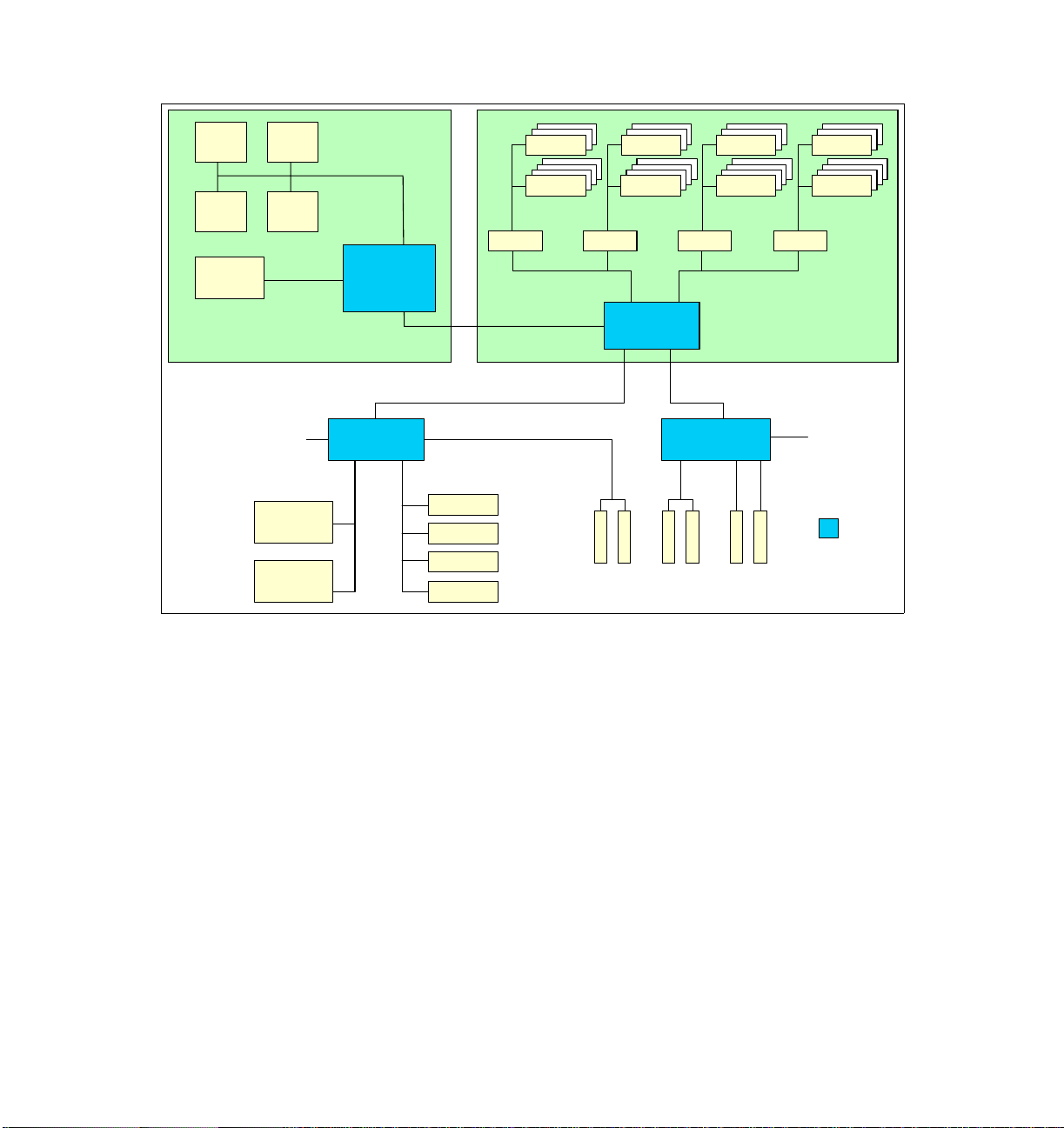
Figure 1-1 on page 4 shows the various IBM XA-64 components in an x450
configuration.
Chapter 1. Technical description 3
Page 18
CPU 1 CPU 2
6.4 GBps
CPU 3 CPU 4
400 MHz
64 MB
L4 cache
Processor-board assembly Memory-board assembly
6.4 GBps
RXE
Expansion
Port A
(1 GBps)
Processor &
cache
controller
PCI bridge PCI bridge
33 MHz66 MHz
SDRAM
SDRAM
SMI-E
3.2 GBps
SDRAM
SDRAM
SMI-E SMI-E SMI-E
Port 1
3.2 GBps
Memory
controller
Bus A66 MHz
B-100
Port 2
3.2 GBps
1 GBps1 GBps
SDRAM
SDRAM
SDRAM
SDRAM
200 MHz
2-way or 4-way
interleaved DDR
RXE
Expansion
Port B
(1 GBps)
D-133C-133
Ultra320
SCSI
Gigabit
Ethernet
Video
3x USB
Serial
RSA
Figure 1-1 xSeries 450 system block diagram
What was called the SMP Expansion module in the x440 has been divided into
two components in the x450. The component that contains the CPUs,
processor/cache controller, and cache is called the
The component that contains the memory controller and memory is called the
memory-board assembly.
The CPUs are connected together with a 200 MHz frontside bus, but supply data
at an effective rate of 400 MHz using the “dual-pump” design of the Intel
Itanium 2 architecture as described in 1.4, “Intel Itanium 2 processor” on
page 10. To ensure the processors are optimally used, the x450 has a 64 MB
XceL4 Server Accelerator Cache, comprised of 200 MHz DDR memory. This L4
system cache services all CPUs.
64-bit
66 MHz
IBM XA-64
64-bit
100 MHz
64-bit
133 MHz
("Summit")
core chipset
processor-board assembly.
4 IBM ^ xSeries 450 Planning and Installation Guide
Page 19
Memory used in the x450 is standard PC2100 ECC DDR SDRAM DIMMs. With
g
2 GB DIMMs, up to 40 GB can be installed using 20 of the 28 DIMM sockets. The
memory is two-way interleaved; however, four-way interleaving is also supported
in order to ensure that the memory subsystem can supply data fast enough to
match the throughput of the CPUs. Two-way interleaving means that DIMMs
must be installed in matched pairs and in specific DIMM sockets (see 3.1.2,
“Memory” on page 41)
The two PCI bridges in the XA-64 chipset provide support for 33, 66, 100, and
133 MHz devices using four PCI-X buses (labeled A-D in Figure 1-1 on page 4).
This is discussed further in 1.8, “PCI subsystem” on page 21.
The PCI bridge also has two 1 GBps bi-directional Remote Expansion I/O (RXE)
ports for connectivity to the RXE-100 enclosure. The RXE-100 provides up to an
additional 12 PCI-X slots and can be connected by a single cable to port A.
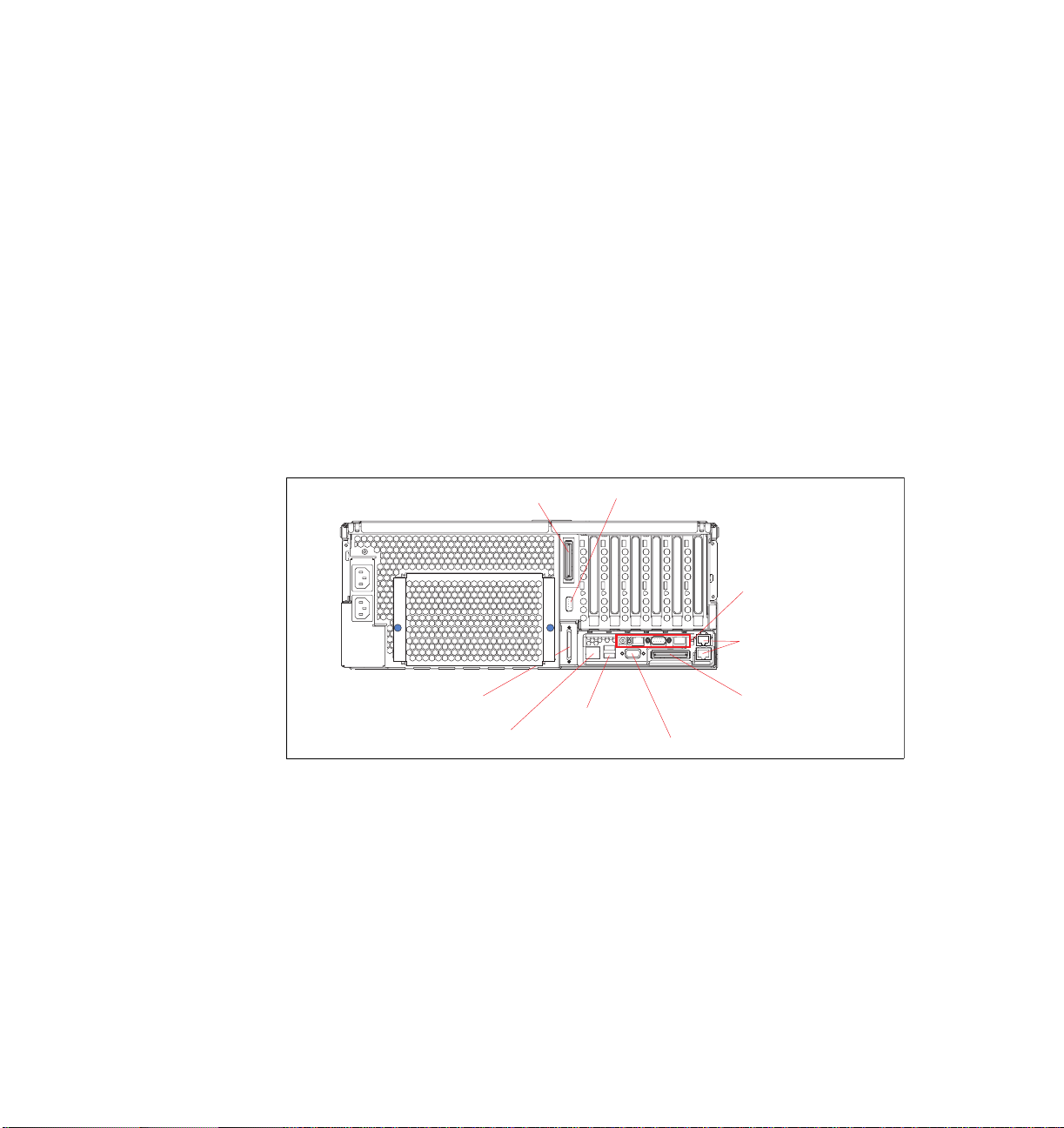
The rear panel of the x450, indicating the location of the RXE Expansion Ports, is
shown in Figure 1-2.
RXE Expansion Port (B)
connector
SCSI connector
USB ports
RXE Mana
Figure 1-2 Rear view of the x450
ement Port
1.3 Extensible Firmware Interface
The Extensible Firmware Interface (EFI) specification describes an interface
between the operating system and platform firmware as shown in Figure 1-3 on
page 6. The interface offers platform-related information to the operating system
as well as boot and runtime service calls that are available to the operating
system and OS loader. Together, these makes a well-defined environment for
booting the operating system and running pre-boot applications, such as
diagnostics and system setup.
Serial connector
Remote Supervisor
Adapter connectors
Gigabit Ethernet
connectors
RXE Expansion
Port (A) connector
Video connector
Chapter 1. Technical description 5
Page 20
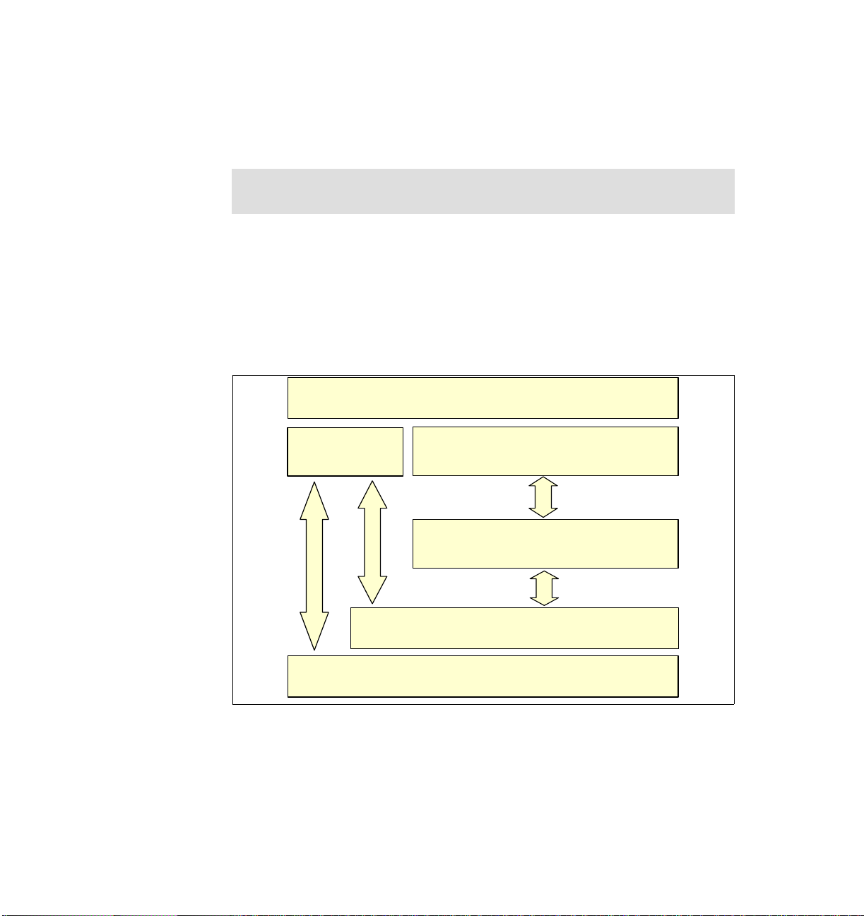
In comparison to a BIOS-based, legacy system, the EFI is an additional layer
between the operating system and the firmware. In a legacy system, the OS
loader calls BIOS functions directly. Consequently, to provide a stable boot
environment, changes in the OS loader and the platform firmware must go
hand-in-hand.
Note: All operating systems supported on x450 are EFI-aware. The OS loader
communicates with the firmware and hardware through the EFI interface.
The primary goal of this specification is to provide an abstract model both for
operating system and hardware developers. With such a model in a place, OS
loader customizations are not required if there are changes in the platform
hardware or firmware (added new boot or input devices for instance). The EFI
breaks up a tight dependency between the operating system and the firmware,
thus speeding up the process of releasing the new products and introducing the
new features and functionality (both operating system and hardware).
Operating system
Legacy OS
loader
Platform-specific firm ware (BIOS)
Platform hardware
Figure 1-3 The EFI concept
EFI OS loader
EFI
Consider, for example, the situation where a new type of boot device, for example
a USB key, is to be implemented. First the BIOS would have to offer an option to
choose this new device for booting, then new USB key-specific functions would
have to be added to the firmware to support booting from a USB device, and
finally, the OS loader would have to be modified to use these functions.
6 IBM ^ xSeries 450 Planning and Installation Guide
Page 21

The same situation with the EFI would be dramatically simplified. The OS loader
calls unified (not vendor-specific) EFI API functions for booting. These functions
are not dependent on the boot device used, so when a new boot device type is
added to the platform and the firmware is modified to recognize it, the operating
system can immediately boot.
The EFI architecture is modular, extensible and offers backward compatibility for
the older systems by default. This means there is a way for non-EFI-aware
operating systems to communicate directly with system BIOS as shown in
Figure 1-3 on page 6.
Note: The EFI concept was originally introduced with Itanium
Architecture-based computers, but is not restricted to 64-bit platforms. There
is a gradual transition from BIOS to the EFI expected on the IA-32 platform as
well.
1.3.1 GUID Partition Table disk
The GUID Partition Table (GPT) was introduced as part of the EFI initiative.
Every disk is assigned a global unique identifier (GUID) to allow self-identification
of the disks. GPT replaces the older Master Boot Record (MBR) partitioning
scheme that has been common to PCs.
There are several reasons for introducing a new partitioning scheme:
MBR disks support only four partition table entries. If more partitions are
wanted, a secondary structure — an extended partition — is necessary.
Extended partitions are then subdivided into one or more logical disks. On
any given drive, only one extended partition can be present.
In theory, a GPT disk can have an unlimited number of partitions. The number
of partitions is limited only by the amount of space reserved for making
partition entries.
GPT disks use primary and backup partition tables for redundancy and
CRC32 fields for improved partition data structure integrity.
GPT disks can grow to a very large size. In theory, a GPT disk can be up to
64
2
logical blocks in length (logical blocks are typically 512 bytes). In practice,
the maximum is less. For example, Windows Server 2003 supports GPT disks
up to approximately 18 Exabytes in size.
For backward compatibility with legacy MBR disk tools, all GPT disks contain a
protective MBR. The protective MBR, beginning in sector 0, precedes the GUID
Partition Table on the disk and contains only one partition that appears to span
the disk. The legacy tools are not aware of GPT and do not know how to properly
access a GPT disk. The benefit of protective MBR is that these tools will view a
Chapter 1. Technical description 7
Page 22

GPT disk as having a single encompassing (possibly unrecognized) partition,
rather than mistaking the disk for one that is unpartitioned. That is why
GPT-partitioned disk appears to have MBR.
Note: GPT disks can be converted to MBR disks and vice versa only if all
existing partitioning is first deleted, with associated loss of data.
In general, the structure of any GPT disk is as shown in Figure 1-4. The
protective MBR is followed by a theoretically unlimited number of data partitions.
Protective
MBR
Figure 1-4 General GPT disk structure
Note: Currently, only 64-bit operating systems have the ability to read, write,
and boot from GPT disks. 32-bit operating systems do not have built-in
support for GPT disks.
The specification for GPT disk partitioning can be found in Chapter 16 of the
Extensible Firmware Interface (EFI) specification. This document is available at:
http://developer.intel.com/technology/efi/download.htm
1.3.2 EFI System Partition
A special partition on the GPT disk is EFI System Partition (ESP). It contains the
OS loader files of all installed operating systems. These files are stored in the
EFI directory. The ESP may also contain other files necessary to boot the
system, such as drivers.
Data partition(s)
Note: The EFI System Partition is shareable among all installed operating
systems. To support multiple operating system installations, create multiple
data partitions.
8 IBM ^ xSeries 450 Planning and Installation Guide
Page 23

An example directory structure for an EFI System Partition present on a hard disk
with SuSE and Windows Server 2003 installed is as follows:
\EFI
\Microsoft
\WINNT50
\EFIDrivers
\SuSE
\MSUtils
There can be only one ESP on a single disk. The size of the ESP is determined
using the following algorithm:
ESP = max(100 MB, min(1% of physical disk, 1GB))
In other words, the size of the ESP must be the larger of these two numbers, 100
MB or 1% of the physical disk size (up to 1 GB). For example, for an 18 GB disk,
the size of the ESP is 184 MB. The value 1% of the physical disk is calculated at
the time that the ESP is created and does not change if the disk is extended later
(for example, via RAID).
Note: Each bootable GPT disk must contain an EFI System Partition.
The ESP should be the first partition on the disk, right after protective MBR as
shown in Figure 1-5.
EFI
Protective
MBR
Figure 1-5 Boot GPT disk structure
System
Partition
(ESP)
Data partition(s)
The EFI specification supports only FAT or FAT32 on the ESP partition.
Note: The ESP is not visible to the operating systems users by default but can
be accessed for read/write operations from within the operating system by
special commands. For Windows-specific information, see “Accessing EFI
System Partition from Windows” on page 96. For SuSE information, see
“Partitions on IA-64 Linux” on page 111.
Chapter 1. Technical description 9
Page 24

1.3.3 EFI and legacy-free concept
The EFI complements legacy-free concept of PCs. Legacy-free refers to PC
system designs that eliminate certain hardware and firmware elements of the
original PC architecture while advancing the PC's stability and usability.
Specifically, we are talking about a set of I/O options that have been part of the
PC architecture for a very long time, for example parallel, serial and game port,
ISA slots or devices, floppy disk controller (FDC), PS/2® mouse, and keyboard.
BIOS interfaces require the OS loader to have a specific knowledge of the
workings of hardware devices. The EFI abstract concept makes it possible to
build code that works on a range of hardware devices without having explicit
knowledge of the specifics of these devices. This EFI feature allows a
replacement of legacy devices and adding new boot devices. The legacy devices
are replaced by USB devices in x450.
Tip: One key interface that is no longer supported is INT 13, disk I/O.
For more information about the EFI specification, see the following:
http://www.intel.com/technology/efi/index.htm
http://www.microsoft.com/hwdev/platform/firmware/EFI/default.asp
1.4 Intel Itanium 2 processor
The Itanium 2 processor used in the x450 (code named “Madison”) uses a ZIF
socket design, although the socket is designed differently from the one on the
x440, for example. This small form factor is what permits the x450 to have up to
four processors in a 4U node.
Table 1-3 outlines some of the differences between the Itanium and Itanium 2
processors (both the “Madison” and the earlier “McKinley” processor):
Table 1-3 Itanium vs Itanium 2 processors
Feature Itanium Itanium 2 “McKinley” Itanium 2 “Madison”
Processor core speed 733 or 800 MHz 900 MHz or 1.0 GHz 1.3, 1.4 or 1.5 GHz
L3 Cache 2 or 4 MB 1.5 or 3 MB 3, 4 or 6 MB
Frontside bus 266 MHz 400 MHz, 128 bit 400 MHz, 128 bit
Frontside bus bandwidth 2.1 GBps 6.4 GBps 6.4 GBps
Pipeline stages 10 8 8
10 IBM ^ xSeries 450 Planning and Installation Guide
Page 25

Feature Itanium Itanium 2 “McKinley” Itanium 2 “Madison”
Issue ports 9 11 11
on-board registers 328 328 328
Integer units 3 6 6
Branch units 3 3 3
Floating point units 2 2 2
SIMD units 2 1 1
Load and store units 2 (total) 2 load and 2 store 2 load and 2 store
The Itanium 2 processor has three levels of cache, all of which are on the
processor die:
Level 3 cache is equivalent to L2 cache on the Pentium III Xeon, or the L3
cache on the Pentium Xeon MP processor. Itanium 2 processors in the x450
models contain either 3, 4 or 6 MB of L3 cache. Unlike the design of the
original Itanium processor, this L3 cache is now on the processor die, greatly
improving performance, up or 2 times greater than that of the original Itanium.
Level 2 cache is equivalent to L1 cache on the Pentium III Xeon and is 256 KB
in size.
A new level 1 cache, 32 KB in size, is “closest” to the processor and is used to
store micro-operations (that is, decoded executable machine instructions) and
serves those to the processor at rated speed. This additional level of cache
saves decode time on cache hits.
The x450 also implements a Level 4 cache as described in 1.6, “IBM XceL4
Server Accelerator Cache” on page 17.
Intel has also introduced a number of features associated with its Itanium
micro-architecture. These are available in the x450, including:
400 MHz frontside bus
The Pentium III Xeon processor had a 100 MHz frontside bus that equated to
a burst throughput of 800 MBps. With protocols such as TCP/IP, this had been
shown to be a bottleneck in high-throughput situations. The Itanium 2
processor improves on this by using a single 200 MHz clock and using both
edges of each clock to transmit data. This is shown in Figure 1-6 on page 12.
Chapter 1. Technical description 11
Page 26
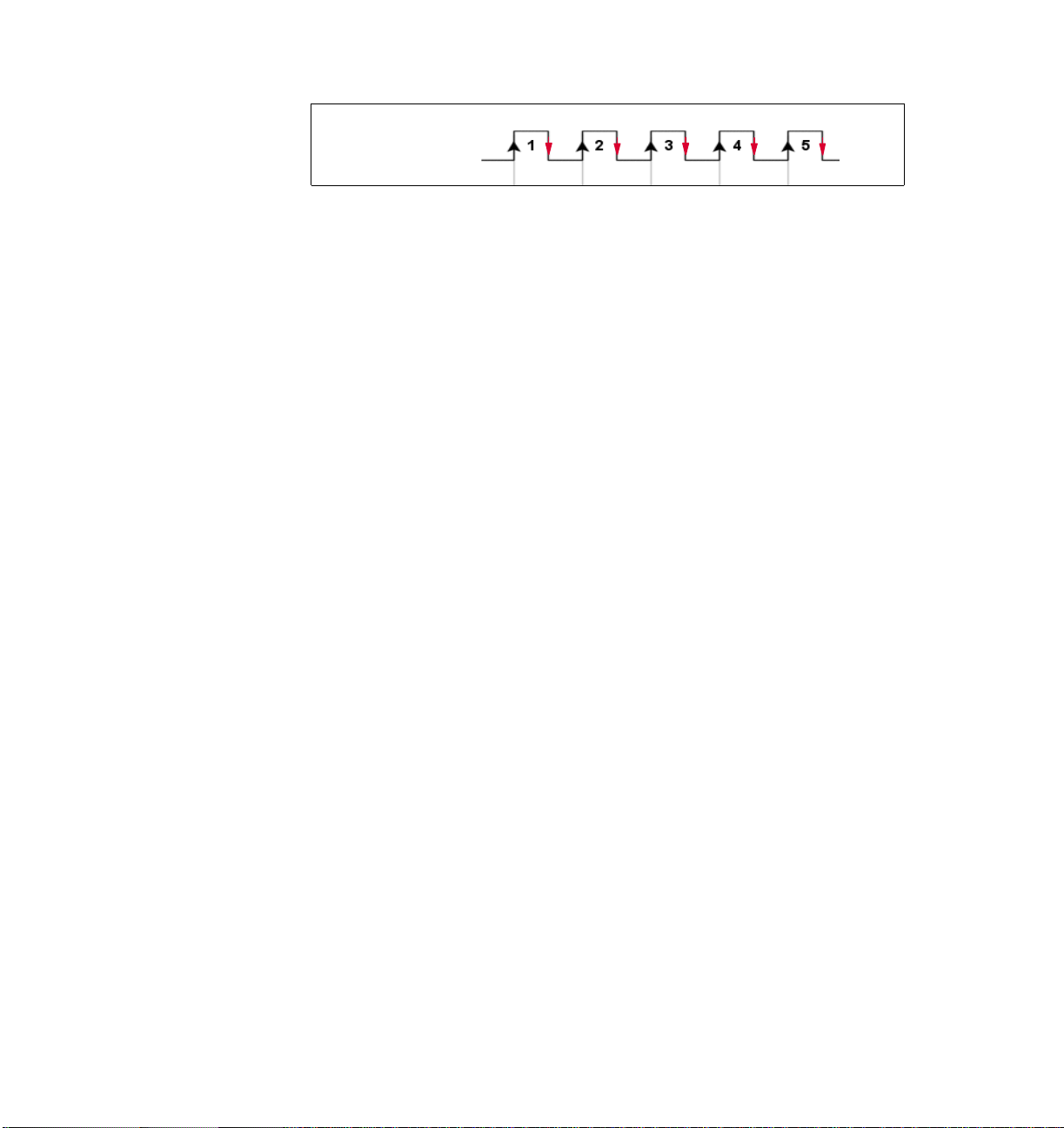
200 MHz clock
Figure 1-6 Dual-pumped frontside bus
This increases the performance of the frontside bus. The end result is an
effective burst throughput of 6.4 GBps (128-bit wide data path running at 400
MHz), which can have a substantial impact, especially on TCP/IP-based LAN
traffic. This is opposed to the Itanium processor, which had a burst throughput
of only 2.1 GBps (64-bit wide data path running at 266 MHz).
Explicitly Parallel Instruction Computing (EPIC)
EPIC technology, developed by Intel and HP, leads to more efficient, faster
processors because it eliminates numerous processing inefficiencies in
current processors and attacks the perennial data bottleneck problems by
increasing parallelism, rather than simply boosting the raw “clock” speed of
the processor.
Specifically, in today's 32-bit processors, much of the instruction
scheduling--the order in which computing instructions are executed--is done
on the chip itself, leading to a great deal of overhead and slowing down overall
processor performance. Moreover, today's processors are plagued by
instruction flow problems since the processor often has to stop what it's doing
and reconstruct the instruction flow due to inherent inefficiencies in instruction
handling.
EPIC makes the instruction scheduling more intelligent and handles much of
the scheduling off-chip, in the compiler program, before feeding “parallelized”
instructions to the Itanium 2 processor for execution. The parallelized
instructions allow the chip to process a number of instructions simultaneously,
increasing performance. A compiler prepares instructions for execution on the
processor.
The Itanium 2 architecture is based on EPIC technology and has the following
features:
– Provides faster online transaction processing
– Has the capability to execute multiple instructions simultaneously,
processing more data and allowing more users
– Enables faster calculations and data analysis
– Allows for faster storage and movement of large models (CAD, CAE)
– Speeds up simulation and rendering times
12 IBM ^ xSeries 450 Planning and Installation Guide
Page 27

For more information about the features of the Itanium 2 processor, go to:
http://www.intel.com/design/itanium2
1.5 System assembly
Unlike the x440, then x450 does not use a single SMP Expansion Module, which
contains the processors, memory, XceL4 Server Accelerator Cache, and
respective controller. Instead, there are now two separate assemblies:
A single memory-board assembly, located at the top of the system, which
contains the physical DIMM’s as well as the memory and I/O controller
A single processor-board assembly, located at the bottom of the system,
which contains the processors, XceL4 Server Accelerator Cache, and L4
Cache/Scalability Controller
See Figure 1-7 on page 14 for the location of the memory-board and
processor-board assemblies.
Tip: Be careful when removing or installing either the memory-board
assembly or the processor-board assembly, because it is possible to damage
the midplane.
Chapter 1. Technical description 13
Page 28
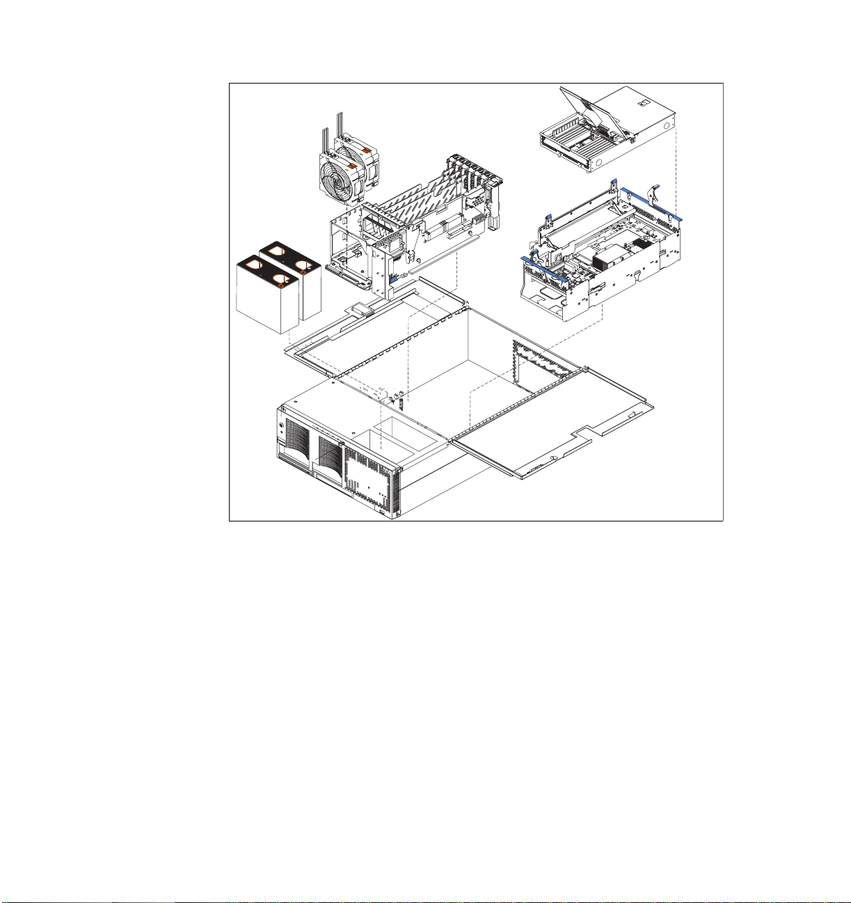
Memory-board
assembly
PCI-X
slots
N
O
T
E
:
F
O
R
P
R
O
P
E
R
A
IR
F
L
O
W, R
E
P
L
A
N
O
T
E
:
F
C
E
F
A
F
N
R
F
O
R
P
R
O
R
O
N
T
O
F
W
O
I
N
T
T
H
O
IN
F
2
B
P
E
R
A
I
R
F
B
O
X
M
O
IN
X
U
T
E
L
O
W, R
E
S
P
L
A
C
E
F
A
N
W
I
T
H
IN
2
M
I
N
U
T
E
S
Processor-board
assembly
Figure 1-7 Memory-board and processor-board assembly locations
1.5.1 Memory-board assembly
The x450 memory-board assembly is installed from the top of the server and
mounts to the side of the midplane using two levers on the top. This location
allows for easy access to all memory DIMMs without having to remove any
components from the system.
14 IBM ^ xSeries 450 Planning and Installation Guide
Page 29
Memory Port 1
There are 14 DIMM slots in each
of the two ports, for a total of 28
DIMMs.
Memory Port 2
Figure 1-8 Memory-board assembly, showing the two memory ports
The memory-board assembly contains 28 DIMM slots. All DIMM slots can be
used when 512 MB or 1 GB DIMMs are used. If 2 GB DIMMs are used, up to 20
DIMMs slots can be used. The maximum installable memory is 40 GB (using 2
GB DIMMs).
The memory-board assembly is also equipped with LEDs for light path
diagnostics for each DIMM. In addition, the assembly is equipped with LEDs for
the following:
Power to memory port 1
Power to memory port 2
Hot-plug memory enabled
Restriction: The ability to hot-add or hot-replace memory is not available in
the x450.
For information about installing memory in the memory-board assembly, see
3.1.2, “Memory” on page 41.
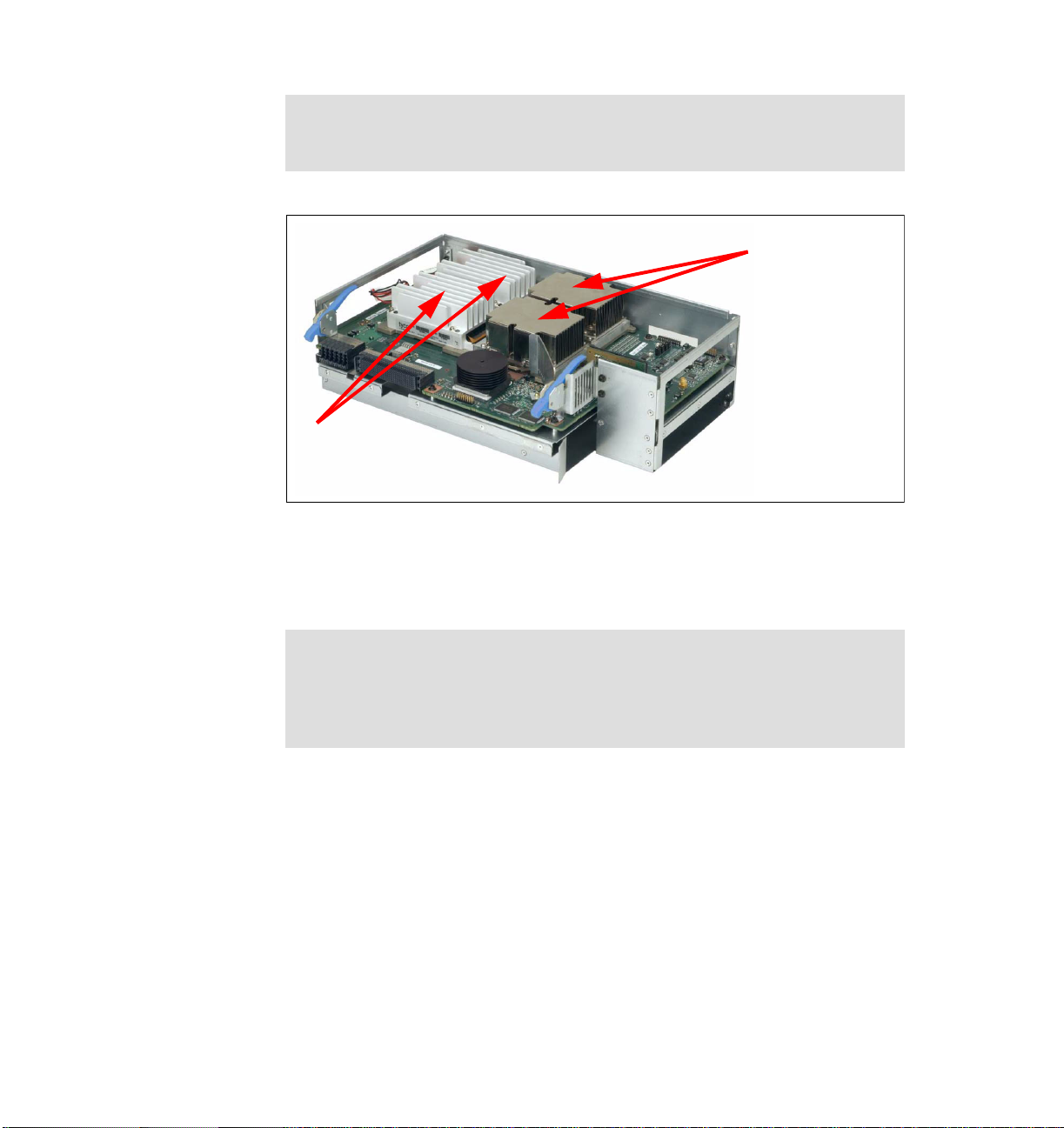
1.5.2 Processor-board assembly
The x450 processor-board assembly is located under the memory-board
assembly, as shown in Figure 1-7 on page 14. It is installed from the top of the
server and mounts to the side of the midplane using two levers on the side, as
shown in Figure 1-9 on page 16.
Chapter 1. Technical description 15
Page 30
Tip: Be careful when removing or installing either the memory-board
assembly or the processor-board assembly, since it is possible to damage the
midplane.
Processors 1 & 3
(processors 2 &
4 are on the
underside of the
circuit board)
Power modules
(“pods”) for each
processor
Figure 1-9 Processor-board assembly
x450 models have either one or two processors installed. The unused CPU
sockets will hold metal air baffles. The power pods shown in Figure 1-9 supply
power to the processors and are equivalent to VRMs in other systems.
Important: While processors should be installed in the order listed in
Figure 1-9, the bootstrap processor (BSP) may not necessarily be the
processor located in Processor Socket 1. The Intel Itanium Architecture
processors are initialized and tested in parallel. The first processor to
complete initialization becomes the BSP.
The processor-board assembly is also equipped with LEDs for light path
diagnostics for the following components:
Each processor
Each power module (“pod”)
In addition, a “remind” button is located on the upper side of the processor-board
assembly. Pressing this button while the processor-board assembly is not
attached to AC power will illuminate any light path LEDs that had been lit while
the system was under power for a total of 10 seconds.
16 IBM ^ xSeries 450 Planning and Installation Guide
Page 31

1.6 IBM XceL4 Server Accelerator Cache
Integrated into the processor-board assembly is 64 MB of Level 4 cache, which is
shown in Figure 1-1 on page 4. This XceL4 Server Accelerator Cache provides
the necessary extra level of cache to maximize CPU throughput by reducing the
need for main memory access under demanding workloads, resulting in an
overall enhancement to system performance.
Cache memory is two-way interleaved 200 MHz DDR memory and is faster than
the main memory because it is directly connected to the memory controller and
does not have additional latency associated with the large fan-out necessary to
support the 28 DIMM slots. Since the data interface to the controller is 400 MHz,
peak bandwidth for the XceL4 cache is 6.4 GBps.
1.7 System memory
The x450 has 1 GB or 2 GB of RAM standard, depending on the model. Memory
packaging is PC2100 ECC DDR SDRAM DIMMs, and standard memory is either
two or four 512 MB DIMMs. Memory options are 512 MB, 1 GB, or 2 GB DIMMs.
There are a total of 28 DIMM sockets (two ports of 14). All 28 DIMM sockets can
be used to install DIMMs, with the exception of the 2 GB DIMM option. If 2 GB
DIMMs are installed, the total number of DIMM sockets that can be used is
limited to 20. A maximum of 40 GB of system memory is supported by populating
20 DIMM sockets each with a 2 GB DIMM.
DIMMs must be installed in matched pairs, since the DIMMs are two-way
interleaved. However, if memory is installed in matched fours (a matched pair in
each port), the system automatically detects this and will enable four-way
interleaving. With this, memory access is performed simultaneously from both
ports (two separate paths into the memory controller as shown in Figure 1-1 on
page 4), leading to improved memory performance.
See 3.1.2, “Memory” on page 41 for a further discussion of how memory is
implemented in the x450 and what you should consider before an x450
installation.
There are a number of advanced features implemented in the x450 memory
subsystem, collectively known as
Restriction: The ability to hot-add or hot-replace memory is not available in
the x450.
Active Memory:
Chapter 1. Technical description 17
Page 32

Memory ProteXion
Memory ProteXion, also known as “redundant bit steering”, is the technology
behind using redundant bits in a data packet to provide backup in the event of
a DIMM failure.
Currently, other industry-standard servers use 8 bits of the 72-bit data packets
for ECC functions and the remaining 64 bits for data. However, the x450 uses
an advanced ECC algorithm that is based not on bits but on memory symbols.
Symbols are groups of multiple bits, and in the case of the x450, each symbol
is 4 bits wide. With two-way interleaved memory, the algorithm needs only
three symbols to perform the same ECC functions, thus leaving one symbol
free (2 bits on each DIMM). See Figure 1-10.
C0S1 S2
C0S1 S2
C0S1 S2
C1
C1
C2
C2
C2
C1
K1
K1
K1
S0
S0
S0
S16
S16
S16
S17 S18
S17 S18
S17 S18
S3 S4
S3 S4
S3 S4
S19 S20
S19 S20
S19 S20
S5 S6
S5 S6
S5 S6
S21 S22
S21 S22
S21 S22
S7
S7
S7
S23
S23
S23
S8
S8
S8
S24
S24
S24
S9
S9
S9
S25
S25
S25
S10
S10
S10
S26
S26
S26
S11
S11
S11
S27
S27
S27
S12
S12
S12
S28
S28
S28
S13
S13
S13
S29
S29
S29
S14
S14
S14
S30
S30
S30
S15
S15
S15
S31
S31
S31
S32C3S33 S34
S32C3S33 S34
S32C3S33 S34
S49 S50
S49 S50
S49 S50
S48
S48
S48
S35 S36
S35 S36
S35 S36
S51 S52
S51 S52
S51 S52
S37 S38
S37 S38
S37 S38
S53 S54
S53 S54
S53 S54
S39
S39
S39
S55
S55
S55
S40
S40
S40
S56
S56
S56
S41
S41
S41
S57
S57
S57
S42
S42
S42
S58
S58
S58
S43
S43
S43
S59
S59
S59
S44
S44
S44
S60
S60
S60
S45
S45
S45
S61
S61
S61
S46
S46
S46
S62
S62
S62
S47
S47
S47
S63
S63
S63
C4
C4
C4
C5
C5
C5
K2
K2
K2
Figure 1-10 Memory ProteXion
In the event that a chip failure on the DIMM is detected by memory scrubbing,
the memory controller can re-route data around that failed chip through the
spare symbol (similar to the hot-spare drive of RAID array). It can do this
automatically without issuing a Predictive Failure Analysis® (PFA) or light
path diagnostics alert to the administrator. After the second DIMM failure, PFA
and light path diagnostics alerts would occur on that DIMM as normal.
Memory scrubbing
Memory scrubbing is an automatic daily test of all the system memory that
detects and reports memory errors that might be developing before they
cause a server outage.
Memory scrubbing and Memory ProteXion work in conjunction with each
other, but they do not require memory mirroring (as described below) to be
enabled to work properly.
When a bit error is detected, memory scrubbing determines if the error is
recoverable or not. If it is recoverable, Memory ProteXion is enabled and the
data that was stored in the damaged locations is rewritten to a new location.
The error is then reported so that preventative maintenance can be
performed.
As long as there are enough good locations to allow the proper operation of
the server, no further action is taken other than recording the error in the error
18 IBM ^ xSeries 450 Planning and Installation Guide
Page 33

logs. Errors from scrubbing are not reported unless bit steering has already
been invoked.
If the error is not recoverable, then memory scrubbing sends an error
message to the light path diagnostics, which then turns on the proper lights
and LEDs to guide you to the defective DIMM. If memory mirroring is enabled,
then the mirrored copy of the data in the damaged DIMM is used until the
system is powered down and the DIMM replaced.
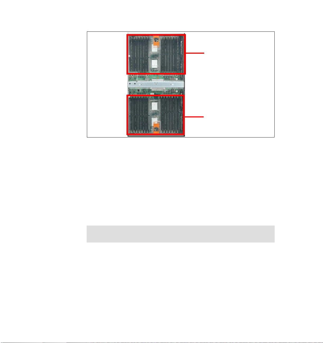
Memory mirroring
Memory mirroring is roughly equivalent to RAID-1 in disk arrays, in that
memory is divided in two ports and one port is mirrored to the other half (see
Figure 1-11). If 8 GB is installed, then the operating system sees 4 GB once
memory mirroring is enabled (it is disabled in BIOS by default). All mirroring
activities are handled by the hardware without any additional support required
from the operating system.
Por t 1 Port 2
Front of server
Figure 1-11 Memory DIMMs are divided into two ports
When memory mirroring is enabled (see “Enabling memory mirroring” on
page 83), the data that is written to memory is stored in two locations. One
copy is kept in the port 1 DIMMs, while a second copy is kept in the port 2
DIMMs.
During the execution of the read command, the data is read simultaneously
from both ports, and error-free data from either port is forwarded. This
Chapter 1. Technical description 19
Page 34

provides an extra level of error recovery capability. (In the x440, the read
command is read from the DIMM with the least amount of reported memory
errors through memory scrubbing).
If memory scrubbing determines the DIMM is damaged beyond use, read and
write operations are redirected to the partner DIMM in the other port. Memory
scrubbing then reports the damaged DIMM and the light path diagnostics
display the error. If memory mirroring is enabled, then the mirrored copy of the
data in the damaged DIMM is used until the system is powered down and the
DIMM replaced.
Certain restrictions exist with respect to placement and size of memory
DIMMs when memory mirroring is enabled. These are discussed in “Memory
mirroring” on page 42.
Chipkill memory
Chipkill is integrated into the XA-64 chipset and does not require special
Chipkill DIMMs. Chipkill corrects multiple single-bit errors to keep a DIMM
from failing. When combining Chipkill with Memory ProteXion and Active
Memory, the x450 provides very high reliability in the memory subsystem.
Chipkill memory is approximately 100 times more effective than ECC
technology, providing correction for up to 4 bits per DIMM, whether on a single
chip or multiple chips.
If a memory chip error does occur, Chipkill is designed to automatically take
the inoperative memory chip offline while the server keeps running. The
memory controller provides memory protection similar in concept to disk array
striping with parity, writing the memory bits across multiple memory chips on
the DIMM. The controller is able to reconstruct the “missing” bit from the failed
chip and continue working as usual.
Chipkill support is provided in the memory controller and implemented using
standard DIMMs, so it is transparent to the operating system.
In addition, to maintain the highest levels of system availability, if a memory error
is detected during POST or memory configuration, the server can automatically
disable the failing memory bank and continue operating with reduced memory
capacity. You can manually re-enable the memory bank after the problem is
corrected via the Setup menu in BIOS.
20 IBM ^ xSeries 450 Planning and Installation Guide
Page 35

Memory mirroring, Chipkill, and Memory ProteXion provide multiple levels of
redundancy to the memory subsystem. Combining Chipkill with Memory
ProteXion enables up to two memory chip failures per memory port (14 DIMMs)
on the x450. An x450 with its two memory ports could sustain up to four memory
chip failures. Memory mirroring provides additional protection with the ability to
continue operations with memory module failures.
1. The first failure detected by the Chipkill algorithm on each port doesn’t
generate a light path diagnostics error, since Memory ProteXion recovers
from the problem automatically.
2. Each memory port could then sustain a second chip failure without shutting
down.
3. Provided that memory mirroring is enabled, the third chip failure on that port
would send the alert and take the DIMM offline, but keep the system running
out of the redundant memory bank.
1.8 PCI subsystem
As shown in Figure 1-12 on page 22, there are six PCI-X slots internal to the
x450:
Two 133 MHz slots, which accept 32-bit or 64-bit, 3.3 V, PCI or PCI-X
adapters, from 33-133 MHz
Two 100 MHz slots, which accept 32-bit or 64-bit, 3.3 V, PCI or PCI-X
adapters, from 33-100 MHz
Two 66 MHz slots, which accept 32-bit or 64-bit, 3.3 V, 33 or 66 MHz, PCI or
PCI-X adapters
Chapter 1. Technical description 21
Page 36

PCI-X slot 3
(100 )MHz
PCI-X slot 2
(66 )MHz
PCI-X slot 1
(66 )MHz
PCI-X slot 5
(133 )MHz
PCI-X slot 6
(133 MHz)
Bus: D B AC
Figure 1-12 PCI slot information
PCI-X slot 4
(100 )MHz
Back of server
See 3.1.3, “PCI slot configuration” on page 44 for details on what adapters are
supported and in what combinations.
The PCI subsystem also supplies these I/O devices:
Two Wide Ultra320 SCSI ports, one internal and one external (LSI
LSI53C1030 chipset). This SCSI controller supports both single disks and
RAID-1 mirrored pairs of disks.
Dual Gigabit Ethernet ports (Broadcom 5704 chipset).
The x450 includes a dual-port Broadcom BCM5704 10/100/1000 Base-T
MAC (Media Access Controller) on a PCI 64-bit 66 MHz bus.
The BCM5704 supports full and half-duplex performance at all speeds
(10/100/1000 Mbps, auto-negotiated) and includes integrated on-chip
memory for buffering data transmissions to ensure the highest network
performance and dual onboard RISC processors for advanced packet parsing
and backwards compatibility with today's 10/100 network. The Broadcom
controller also includes software support for failover, layer-3 load balancing,
and comprehensive diagnostics.
Category 5 or better Ethernet cabling is required with RJ-45 connectors. If
you plan to implement a Gigabit Ethernet connection, ensure your network
infrastructure is capable of the necessary throughput to match the server’s I/O
capacity.
SVGA with 8 MB video memory (ATI RageXL chipset).
22 IBM ^ xSeries 450 Planning and Installation Guide
Page 37

Three USB ports (one on the front panel, two on the rear). All USB ports are
2.0 compliant.
One RS-232 serial port, located on the rear of the machine.
Remote Supervisor Adapter (RS-485 ASM interconnect bus, 10/100 Ethernet
and serial ports).
Note: There are no PS/2 keyboard or mouse ports on the x450. USB
keyboard and mice are supported, as well as serial connections via the
integrated serial port.
If you require KVM support the 1.5 M USB Conversion Option (UCO) (part
number 73P5832) enables the x450 to be attached to one of the Advanced
Connectivity Technology (ACT) switches for common management within the
rack. This smart cable is plugged into the USB and video ports on the server.
It converts KVM signals to CAT5 signals for transmission over a CAT5 cable to
either a Remote Console Manager (RCM) or Local Console Manager (LCM).
USB servers can be managed on the same set of switches as legacy
PS/2-based or C2T-based KVM servers.
With the addition of an RXE-100 Remote Expansion Enclosure, you can connect
an additional six or 12 PCI-X adapters to the x450. See 3.2.2, “Remote
Expansion Enclosure” on page 51 for details.
Note: Currently, only one RXE-100 can be connected to an x450 configuration.
1.9 Redundancy
The x450 has the following redundancy features to maintain high availability:
Four hot-swap multi-speed fans
With four hot-swap redundant fans, the x450 has adequate cooling for each of
its major component areas. There are two fans located at the front of the
server that direct air through the memory-board assembly and
processor-board assembly. These fans are accessible from the top of the
server without having to open the system panels. In the event of a fan failure,
the other fan will speed up to continue to provide adequate cooling until the
fan can be hot-swapped by the IT administrator.
The other two fans are located just behind the power supplies and provide
cooling for the I/O devices. Similar to the SMP Expansion Module fans, these
fans will speed up in the event that one should fail to compensate for the
reduction in air flow. In general, failed fans should be replaced within 24 hours
following failure.
Chapter 1. Technical description 23
Page 38

The four fans are shown in Figure 1-7 on page 14.
Important: Due to airflow requirements, fans should not be removed for
longer than two minutes. The fan compartments need to be fully populated
even if the fan is defective. Therefore, remove a defective fan only when a
new fan is available for immediate replacement.
Two hot-swap power supplies with separate power cords.
Note: For large configurations, redundancy is achieved only when connected
to a 220 V power supply. See 3.5, “Power considerations” on page 63 for
details.
Note: To ensure adequate power, a UPS with a rating of RMB 5000 or
more is recommended.
Two hot-swap hard disk drive bays. Using the onboard LSI chipset, these
drives can be configured to form a RAID-1 disk array for the operating system.
The memory subsystem has a number of redundancy features, including
memory mirroring, as described in 1.7, “System memory” on page 17.
The layout of the front panel of the x450, showing the location of the drive bays,
power supplies and fans, is shown in Figure 1-13.
Power-on light
Power button
Reset button
Hot swap
power supplies
Hot swap
drive bays
Blank media
bay
DVD/CD-RW drive
Light Path Diagnostics
panel (pulls out)
Figure 1-13 Front panel of the xSeries 450
24 IBM ^ xSeries 450 Planning and Installation Guide
Hot-swap fans
USB port
System-error light (amber)
Information light (amber)
SCSI activity light (green)
Locator light (blue)
Page 39

1.10 Light path diagnostics
CPU
VRM
M
E
M
O
R
Y
DASD
NMI
BOAR
D
EVENT LOG
FAN
POWER
SUPPLY
PC
I B
US
2
1
NON RED
OVER SPE
C
TE
MP
RE
MIND
To limit the need to slide the server out of the rack to diagnose problems, a light
path diagnostics panel has been incorporated in the front of the x450, as shown
in Figure 1-14. This panel can be ejected from the server to view all light path
diagnostics-monitored server subsystems. In the event that maintenance is then
required, the customer can slide the server out from the rack and, using the
LEDs, find the failed or failing component.
As illustrated in Figure 1-14, light path diagnostics is able to monitor and report
on the health of CPUs, main memory, hard disk drives, PCI-X and PCI slots, fans,
power supplies, VRMs, and the internal system temperature.
i
!
CPU
MEMORY
DASD
PCI-X BUS
FAN
1
POWER
SUPPLY
2
TEMP
Light Path
Diagnostics™
NMI
BOARD
EVENT LOG
VRM
NON REDUND
OVER SPEC
REMIND
Figure 1-14 Light path diagnostics panel on the x450
Important: If a light path diagnostics LED has been illuminated and system
power is removed, there is no way to redisplay the LEDs on the system tray
without re-applying AC power. If the fault has not been rectified when power is
restored, the LED will re-light.
The light path diagnostics on the x450 has four levels:
1. The first level is the front panel fault LED.
2. Level 2 is the pop-out panel as shown in Figure 1-14.
3. For further investigation, there are light path diagnostics LEDs visible through
the top of the server. This requires the server to be slid out of the rack.
Chapter 1. Technical description 25
Page 40

4. For the fourth level of diagnostics, LEDs on major system components
indicate the component causing the error.
As the processor-board assembly is not visible during normal operation, a light
path diagnostics button has been incorporated into it to assist with diagnosing
errors. You can light up the LEDs for a maximum of 2 minutes. After that time, the
circuit that powers the lights is exhausted.
The pop-out panel (Figure 1-14 on page 25) also has a remind button. This
places the front panel system-error LED into remind mode, which means it
flashes briefly every 2 seconds. By pressing the button, you acknowledge the
failure but indicate that you will not take immediate action. If a new failure occurs,
the system-error LED will turn on again and no longer blink. The system-error
LED remains in the remind mode until one of the following situations occurs:
All known problems are resolved
The system is restarted
A new problem occurs, at which time it then is illuminated continuously
Tip: The remind button on the pop-out LPD panel does not function when AC
power has been removed from the system. The button is just used to
acknowledge a system error as described above.
1.11 Remote Supervisor Adapter
The x450 includes a Remote Supervisor Adapter (RSA), which is positioned
horizontally in a dedicated PCI slot beneath the PCI-X adapter area of the
system.
Rear of x450
External power
supply
Error LED
(amber)
Figure 1-15 Remote Supervisor Adapter connectors
26 IBM ^ xSeries 450 Planning and Installation Guide
ASM interconnect
(RS-485) port
Power LED
(green)
10/100
Ethernet port
Management
COM port
Page 41

The Remote Supervisor Adapter offers the following capabilities:
In-band and out-of-band remote server access and alerting through IBM
Director
Full Web browser support with no other software required
Enhanced security features
Graphics/text console redirection for remote control
Dedicated 10/100 Ethernet access port
ASM interconnect bus for connection to other service processors
Serial dial in/out
E-mail, pager and SNMP alerting
Event log
Predictive Failure Analysis on memory, power, hard drives, and CPUs
Temperature and voltage monitoring with settable threshold
Light path diagnostics
Automatic Server Restart (ASR) for operating system and POST
Wake on LAN®
Remote firmware update
LAN access
Alert forwarding
See the IBM Redbook
Director
, SG24-6188 for more information on the Remote Supervisor Adapter.
Implementing Systems Management Solutions using IBM
1.12 Operating system support
In line with the overall message of providing application flexibility to meet the
varying needs of our enterprise customers, the x450 is optimized for several
operating system and application solutions. Table 1-4 lists the supported
operating systems for the x450. For the latest operating system support
information, go to:
http://www.pc.ibm.com/us/compat/nos/matrix.shtml
Note: Hyper-Threading is not available on systems with the Itanium 2
processor.
Table 1-4 x450 operating system support
Description Release SMP support
Windows Server 2003 Enterprise (64-bit) Supports up to four-way
SuSE Linux Enterprise Server 8.x Supports up to four-way
Chapter 1. Technical description 27
Page 42

Note: While operating systems may support large systems, scalability is a
function of both the operating system and the application/workload. Few
applications are designed to take advantage of larger SMP systems.
28 IBM ^ xSeries 450 Planning and Installation Guide
Page 43

Chapter 2. Positioning
In this chapter we discuss topics that help you to understand how the x450 can
be useful for your business. The topics covered are:
x450 application solutions
Why choose x450?
2
© Copyright IBM Corp. 2003. All rights reserved. 29
Page 44

2.1 x450 application solutions
With the x450 in the IA-64 environment, you are ready to deploy even larger
implementations of enterprise solutions.
As companies' performance demands grow, 64-bit technology becomes an
increasingly attractive option, due to increased memory addressability and true
parallel architecture. There are a number of ways the x450 can be deployed in
specific application solution environments. These include:
Database applications
Business logic
e-business and security transactions
In-house developed compute-intensive applications
Science and technology
Solutions
e-Business
Database applications
Figure 2-1 xSeries 450-based solutions
BI/ERP/SCM/CRM
Operating system
xSeries 450
2.1.1 Database applications
Four-way x450 configurations can be used as database servers and application
servers providing a highly available platform. These configurations require an
external storage enclosure or SAN, depending on the size of the database that is
driven by the number of users.
30 IBM ^ xSeries 450 Planning and Installation Guide
applications
In-house developed
technology
Science and
Page 45

Database applications with memory-sensitive workloads that require working
data sets larger than 4 GB to be loaded in memory will benefit from the larger
memory support of the 64-bit platform.
The following is an example from the field. Microsoft SQL Server Enterprise
Edition uses AWE memory only for the buffer pool. The AWE (Advanced
Windowing Extensions) API allows applications that are written to use the AWE
API to access more than 4 GB of RAM (basically anything between 4 GB and 64
GB). However, due to the AWE mapping overhead, it is not practical to try to use
it for sort areas, procedure cache, or any other type of work area. Many
applications do make heavy use of these areas and may not benefit by having
the large buffer pool. The most efficient solution in such cases is to move the
applications on to a 64-bit database server, which can access memory area
above 4 GB much more efficiently without AWE’s overhead.
Users will see a reasonable performance improvement on a 64-bit
implementation over a 32-bit implementation. Through the 64-bit memory paths,
all memory operations move twice as much data at the same speed as the 32-bit
platform.
The database server will also benefit from a larger 3 MB third-level and 64 MB
XceL4 cache. With such large cache, the need to go to memory or disk for
database transaction elements is greatly reduced and this directly implies a
performance increase, faster access to data, and improved throughput. Itanium 2
systems are likely to be able to hold database transaction records in cache
during the entire transaction, which enables the I/O portion of the transaction to
occur at speeds faster than memory access.
In-memory databases
Architectures with 64-bit addresses can store reasonably large databases in
memory and access them with little or no paging overhead. This is often done for
databases that are constantly being accessed and for databases that serve as
the basis for complex analysis. The theoretical maximum of 16 Exabytes for
memory has not yet been tested, but multi-Gigabyte databases are frequently
run on 64-bit machines.
A major challenge to providing high-performance access to database information
is the time it takes to access disk drives. When disk access is required, disk
access times add what can be an intolerable delay to efficient information access
and utilization. Access to disk is typically hundreds to thousands times slower
than access to memory.
Today, the disk access time challenge can be overcome. The price of random
access memory has come down to affordable levels for many systems. This price
Chapter 2. Positioning 31
Page 46

reduction means that an entire database can be stored in system memory if the
system processors can provide a very large linear address space.
A processor that supports a 64-bit address space may provide access to
in-memory databases that range from tens of Gigabytes to thousands of
Terabytes. In contrast, traditional 32-bit processors most often only address a
maximum of 4 Gigabytes.
Key database software available for Itanium 2 systems include IBM DB2®
Universal Database™ 8.1 (both Linux and Windows version), Microsoft SQL
Server 2000 (currently beta 2 version), and Oracle 9i Database (Linux/Windows).
2.1.2 Business logic
More and more enterprise applications such as ERP, SCM, CRM, and BI are
released or announced to be released on a 64-bit platform. Such applications
process large amounts of data and the large flat memory model means this
processing will be more efficient. That combined with up to four Itanium 2
processors and a highly efficient cache system make the x450 an ideal choice.
Market leaders offer 64-bit optimized versions of their enterprise applications for
use on the x450 now, including SAS Release 9.0 (Windows version) and SAP
R/3 4.6C (Windows/Linux), among others.
Independent software vendors such as JD Edwards, Baan/Invensys, i2
Technologies, PeopleSoft, Veritas, Computer Associates, BMC Software and
many others already offer a variety of products available in 64-bit version.
Business intelligence
Business intelligence (BI) is a broad category of applications and technologies
for gathering, storing, analyzing, and providing access to data to help enterprise
users make better business decisions. BI applications include the activities of
decision-support systems, query and reporting, online analytical processing
(OLAP), statistical analysis, forecasting, and data mining.
The x450 brings high I/O bandwidth and performance to handle
compute-intensive BI applications. A world-class floating-point engine, capable of
addressing much larger amounts of memory, helps speed up data-intensive BI
applications that help companies to increase employee productivity.
Enterprise Resource Planning
ERP is an industry term for the broad set of activities supported by multi-module
application software that helps manufacturers manage the important parts of
their business: product planning, procurement, inventory maintenance, supplier
32 IBM ^ xSeries 450 Planning and Installation Guide
Page 47

interaction, customer service, and order tracking. ERP can also include
application modules for the finance and human resources aspects of a business.
Typically, an ERP system uses or is integrated with a relational database system.
Key server attributes for ERP applications are availability, scalability, and
performance. The x450, with its flat memory model, Itanium 2 processors, and
Enterprise X-Architecture technology such as Active Memory and XceL4 Server
Accelerator Cache, provides a robust base on which to build and implement
successful ERP solutions.
Supply chain management
Supply chain management (SCM) is the oversight of materials, information, and
finances as they move in a process from supplier to manufacturer to wholesaler
to retailer to consumer. Supply chain management involves coordinating and
integrating these flows both within and among companies.
The x450 is a preferred platform for 64-bit SCM management applications. The
x450 offers a range of leading technologies that will help to deliver the uptime
required for business-critical applications at the lowest price/performance ratio.
The x450 covers all high-availability features for customers looking for servers to
power their SCM solutions.
Customer relationship management
Customer relationship management (CRM) is an information-industry term for
methodologies, software, and usually Internet capabilities that help an enterprise
manage customer relationships in an organized way.
The x450 provides a performance-based foundation upon which customers can
build and deploy CRM solutions in which the x450 will most likely be
implemented as an application server and/or a database server.
2.1.3 e-business and security transactions
e-business is the use of Internet technologies to improve and transform key
business processes.
This includes Web-enabling core processes to strengthen customer service
operations, streamlining supply chains and reaching existing and new customers.
In order to achieve these goals, e-business requires a highly scalable, reliable,
and secure server platform.
The x450 is a strong candidate for an application integration server that
integrates the back-end data with the servers containing end-user or client
programs. This involves data transformation, process flow, and other capabilities,
Chapter 2. Positioning 33
Page 48

thus allowing companies to integrate applications and other data sources. These
types of servers benefit from the processing power offered by the x450. The
performance of the server shows promise in Web servers that perform secure
e-commerce transactions, which is a market segment currently dominated by
Sun Microsystems and their SPARC machines.
To see Intel’s performance comparison of Intel Itanium 2 and Sun UltraSPARC III
processors, click
http://www.intel.com/products/server/processors/server/itanium2/index.htm
When using x450 as a Web server for your e-commerce solutions, you will
benefit from its highly parallel computation that can handle higher volumes of
secure data transmissions using complex encryption/decryption techniques.
The Itanium 2 micro-architecture is a perfect match for the significant compute
power requirements of Secure Sockets Layer (SSL), providing protection without
incurring delay. SSL uses advanced public key encryption technology to safely
move sensitive information across the Internet.
In today’s complex environments, encryption can occur at two levels
simultaneously. For example, the IPsec standard performs encryption on every
packet sent over the network. These packets frequently contain data that is
encrypted itself. As a result, enterprises need platforms that can encrypt and
decrypt data very quickly. This is the time to deploy x450 with its 4-way SMP
Itanium 2 processors, each with two (rather than one) floating-point units, two
memory/ALU, two integer ALU units, and three branch execution units, 128
integer and 128 floating-point registers.
Compare processor performance at:
To compare the performance in integer and floating-point operations with other
processors on the market, see SPECint_base2000 and SPECfp_base2000
benchmarks at:
http://www.spec.org
2.1.4 In-house developed compute-intensive applications
For developers, the 64-bit architecture allows creation of applications using a
familiar programming model that encourages the development of a wide-ranging
set of enterprise solutions. The experiences gained on the IA-32 platform can be
reused when creating applications for Itanium 2-based systems. Thus developers
are not required to start from scratch to make their transition to the 64-bit world
almost seamless. In most cases, existing 32-bit code will not require a complete
rewrite, but only recompilation.
******DAVID!!!*****The important message for developers is that IA-64 parallelism
managed by the compiler itself, application development is uncharged of using
34 IBM ^ xSeries 450 Planning and Installation Guide
Page 49

special techniques to employ it. Currently available compilers optimized for
Itanium 2 include Intel C++ Compiler, Intel Fortran Compiler, and Microsoft
SDK/C/C++ Compiler.
2.1.5 Science and technology industries
Science and technology industries (S&TC) require the processing of large and
complex calculations to solve challenging problems.
While S&TC industries are characterized by compute-intensive workloads that
require special server characteristics to meet their performance needs, each
industry -— petroleum, automotive, aerospace, weather or research — also has
its own set of S&TC applications, each demanding different computing solutions.
The Itanium 2-based systems are a solid base for compute-intensive
applications. It is for this reason that the Itanium and Itanium 2 processors were
chosen for the largest American-built supercomputer, the TeraGrid project
sponsored by the National Center for Supercomputing Applications. When finally
deployed with more than 3,000 Itanium 2 chips, TeraGrid will be capable of more
than 14 billion floating-point operations per second (teraflops).
Itanium 2 features, such as increased system memory bandwidth, total number
of 328 onboard registers (including 128 floating-point registers) and thus high
floating-point performance, speed up calculations and data analysis in S&TC
applications.
2.2 Why choose x450?
Modern enterprise applications require servers with significant processing power
that are able to process large quantities of data and store numerous transactions
in cache, and do it all with the highest possible availability and reliability. Systems
that cannot deliver at this level are destined to serve as solutions in non-critical
settings.
IBM, as a market leader, has been delivering top-of-the-line solutions for
enterprise environment for years and xSeries 450 is evidence that this is not
going to change with future IA-64 technology. With close cooperation between
IBM and Intel, the xSeries 450 will continue to be an excellent platform for the
most demanding 64-bit enterprise applications.
xSeries 450 combines the best of three worlds:
The best of the xSeries servers family, the x450 server is based on the
mainframe-inspired reliable components of the xSeries 440, IBM’s most
Chapter 2. Positioning 35
Page 50

scalable IA-32-based server, which has become a well-accepted and tested
solution in medium to large enterprises.
A replacement to the xSeries 380, the first xSeries server with a 64-bit
architecture targeted, tested, and proven by software and hardware
developers.
Unlike competitors without such background, IBM put many years of
invaluable experience with 64-bit technology (IBM pSeries™ and zSeries™
servers) into the development of the x450.
All of these advantages make the xSeries 450 production enterprise-level server
a viable alternative to RISC-based architectures, while protecting many years of
investments and knowledge gained from IA-32 platform development.
Intel expects the Itanium Architecture to be a product base for the next 25 years
or more.
The Itanium 2 processor used in the x450 is based on the
Instruction Computing
technologies, features, and capabilities that make it ideal for the high-end server
and workstation markets. EPIC allows users to take advantage of its large
memory addressability and parallel execution capabilities. The chip also supports
intelligent prediction and speculation of events to deduce redundancy and
improve performance. The Itanium's floating point engine enhances performance
for complex computations that are required for data-mining, scientific, and
technical applications.
The Itanium 2 processor is the second in a family of Intel enterprise-class
processors. For more information about the Intel Itanium 2 processor, see:
http://www.intel.com/products/server/processors/server/itanium2/
Intel Itanium Architecture-based microprocessors have the following features:
Advanced parallelism
High performance requires parallel execution, which is either very limited or
hardly achieved in today's architecture. The traditional PC systems are not
designed for parallelism, which is critical for current demanding applications
(for example databases and application servers).
Today’s processors using limited parallelism are often 60% idle. When source
code is compiled on today’s systems, the result of the compilation is
sequential machine code. A regular (non-Itanium processor family) compiler
takes sequential code and examines and optimizes it for parallelism but then
has to regenerate sequential code, but in such a way that the processor can
re-extract the parallelization from it. The processor will then be required to
read this implied parallelism from the machine code, re-build it, and execute it.
(EPIC) architecture, which incorporates a number of new
Explicitly Parallel
36 IBM ^ xSeries 450 Planning and Installation Guide
Page 51

The parallelism is there, but it is not as obvious to the processor and more
work has to be done by the hardware before it can be utilized.
Itanium 2 supports parallelism on multiple levels. Instruction-level parallelism
(ILP) is the ability to execute multiple bundles (three instructions in a bundle)
at the same time. The Itanium 2 micro-architecture can deliver faster
performance by executing multiple bundles per clock cycle. Parallelism, both
at the instruction level and at the SMP system level, permits more efficient
use of virtually all system resources to enable improved scalability.
The Itanium processor's instruction-level parallelism helps ensure the
scalability necessary to manage large data warehouses.
Note: Performance should no longer be measured by just the speed in
MHz, but also by the degree of parallelism that the processor achieves.
Large memory addressability
Another key advantage is that 64-bit operating systems can support far more
physical memory than a 32-bit operating system. The theoretical limit for
directly addressable memory was 4 GB in 32-bit architectures and is now 2
or 16 Exabytes.
The Itanium 2 processor memory subsystem has a three-level cache
structure consisting of first-level instruction cache, first-level data cache,
second-level cache (L2), and third-level cache (L3). In addition, to ensure the
processors are optimally used, the x450 has a fourth-level (L4) system cache
dedicated to the CPUs (the 64 MB XceL4 Server Accelerator Cache).
The increased physical memory includes the following benefits for
applications:
64
– Each application can support more users.
For a comparison of the number of maximum connected users in SAP for
various hardware platforms (including Itanium 2), visit the following link:
http://www.sap.com/benchmark/
– Each application has better performance. Increased physical memory
allows more applications to run simultaneously and remain completely
resident in the system's main memory. This reduces or eliminates the
performance penalty of swapping pages to and from disk.
– Each application has more memory for data storage and manipulation.
Databases can store more of their data in the physical memory of the
system. Data access is faster because disk reads are not necessary.
– Applications can manipulate large amounts of data easily and more
reliably. Video composition and modeling for scientific and financial
Chapter 2. Positioning 37
Page 52

applications benefit greatly from memory-resident data structures that are
not possible on 32-bit operating systems.
For the enterprise customer, a larger physical memory subsystem provides
access to more data more quickly from system memory, since much more
data can be held near the processor for faster calculations and data analysis.
Large memory addressability allows larger file system caches for read-ahead
and write-behind I/O operations, and also allows retention of large amounts of
data in memory instead of repeatedly reading the data from disk. Combined
with high memory bandwidth and a variety of performance optimization
techniques, this solution provides the performance the enterprise market
needs.
Compatibility
Another important aspect of Itanium 2 architecture is 32-bit compatibility.
Understanding that many applications will never need the processing power
of 64-bit computing, the chip will also support legacy software that relies on
IA-32 architectures.
The x86 binaries (applications running on IA-32), identical to those running on
Pentium and Xeon processor-based systems, may execute on Itanium 2
without modification. In fact, both x86 and 64-bit binaries can run
simultaneously on the same processor. This allows a system that is only
partially converted to 64 bits to run on x450. Of course, unless the
applications are recompiled, 32-bit applications will run slower on the Itanium
because of emulation overhead and an inability to extract all the benefits the
64-bit platform offers.
xSeries 450 is built to scale, process, and access larger amounts of data to
yield significant performance increases of data compute-intensive
applications than any other Intel-based server before.
38 IBM ^ xSeries 450 Planning and Installation Guide
Page 53

Chapter 3. Planning
In this chapter we discuss topics you need to consider before you finalize the
configuration of your x450 system and before you begin implementing the
system. The topics covered are:
System hardware
Cabling and connectivity
Storage considerations
Rack installation
Power considerations
Solution Assurance Review
3
© Copyright IBM Corp. 2003. All rights reserved. 39
Page 54

3.1 System hardware
The x450 provides a scalable and flexible hardware platform. There are a
number of important aspects of the system hardware to consider when planning
your configuration. These are discussed in this section.
3.1.1 Processors
xSeries 450 servers combines copper-based, XA-64 Enterprise X-Architecture
technologies with 64-bit, Intel Itanium 2 processors.
Table 3-1 lists the processors standard in each x450 model and the part number
of additional processors.
Table 3-1 Processors in each x450 model
Model Standard CPUs L2 cache L3 cache Max SMP Extra CPUs
8688-4RX One 1.3 GHz 256 KB 3 MB Four-way 73P7076
8688-5RX Two 1.4 GHz 256 KB 4 MB Four-way 73P7077
8688-6RX Two 1.5 GHz 256 KB 6 MB Four-way 73P7078
The L2 and L3 cache run at the full speed of the processor.
A total of four processors can be installed in the x450. One, two, three, or four
processors can be installed. Each processor within a node must be the same
speed and cache size. Each processor option includes the processor with
heatsink (pre-assembled) and its associated power module (which is referred to
as the
power pod).
Processors must be installed in a specific order, as shown in Figure 3-1 on
page 41. Special tools are required to install the processors and these are
included in the option.
40 IBM ^ xSeries 450 Planning and Installation Guide
Page 55

Center
plane
Side of
13
chassis
Figure 3-1 Processor installation order
3.1.2 Memory
A maximum of 28 DIMMs may be installed in the memory-board assembly of the
x450, depending on the size of the DIMMs used. Supported DIMMs are listed in
Table 3-2.
Table 3-2 Supported DIMMs
Go to the ServerProven® site for the latest information on supported memory
modules:
http://www.ibm.com/pc/us/compat
When installing memory DIMMs, they must be installed in matched pairs (size
and technology), in the order shown in Table 3-3.
4
Size Description Part number Max installable
512 MB PC2100 CL2.5 ECC DDR SDRAM 73P2027 28
1 GB PC2100 CL2.5 ECC DDR SDRAM 73P2028 28
2 GB PC2100 CL2.5 ECC DDR SDRAM 73P2030 20
2
Table 3-3 DIMM order
Pair Port 1 DIMM slots Pair Port 2 DIMM slots
1 1 and 14 2 15 and 28
3 4 and 11 4 18 and 25
5 2 and 13 6 16 and 27
Chapter 3. Planning 41
Page 56

Pair Port 1 DIMM slots Pair Port 2 DIMM slots
7 5 and 10 8 19 and 24
9 3 and 12 10 17 and 26
11 6 and 9 12 20 and 23
13 7 and 8 14 21 and 22
Restriction: When 2 GB DIMMs are used, a maximum of 20 DIMMs can be
installed. In such a configuration, the last four pairs of sockets as shown in
Table 3-3 must be left empty (that is, sockets 6, 7, 8, 9, and 20, 21, 22, 23).
Figure 3-2 shows the DIMM locations and the way the DIMMs are divided into
the two memory ports.
Por t 1 Port 2
Front of server
Figure 3-2 DIMM locations on the memory-board assembly
Memory mirroring
Memory mirroring is supported by the x450 for increased fault tolerance and high
levels of availability.
42 IBM ^ xSeries 450 Planning and Installation Guide
Page 57

Key configuration rules relating to memory mirroring:
Memory mirroring must be enabled in the System Setup (it is disabled by
default).
Enabling memory mirroring halves the amount of memory available to the
operating system.
You must install two pairs of DIMMs at a time. These four DIMMs (known as a
bank) must be identical. Table 3-4 shows the pairs that are in each bank.
Table 3-4 DIMMs that form a bank
Bank DIMM pairs (see Table 3-3)
1 1 and 2 (DIMMs 1, 14, 15, 28)
2 3 and 4 (DIMMs 4, 11, 18, 25)
3 5 and 6 (DIMMs 2, 13, 16, 27)
4 7 and 8 (DIMMs 5, 10, 19, 24)
5 9 and 10 (DIMMs 3, 12, 17, 26)
6 11 and 12 (DIMMs 6, 9, 20, 23)
7 13 and 14 (DIMMs 7, 8, 21, 22)
Note: The ability to hot-replace a failed DIMM or hot-add additional DIMMs is
currently not supported.
Memory performance considerations
As shown in the server block diagram in Figure 1-1 on page 4, there are two
memory ports to the memory controller, each with a throughput of up to 3.2
GBps. These ports correspond to the ports as shown in Figure 3-2 on page 42.
The front side bus of the processors is 6.4 GBps, so maximum performance is
achieved when both memory ports are used to access memory simultaneously.
Consequently, for maximum performance, you must install four DIMMs of the
same size at a time into a bank (see Table 3-4). In this configuration, all memory
addresses are spread across all four DIMMs in the bank and, when accessed,
both memory ports are used, resulting in 6.4 GBps burst transfer rates.
Maximum performance can also be achieved with DIMMs of different sizes, as
long as the total memory in port 1 matches the total memory in port 2. For
example, if you have 6 DIMMs (four 512 MB DIMMs and two 1 GB DIMMs for a
total of 4 GB), install all four 512 MB DIMMs (2 GB) in port 1 and the two 1 GB
DIMMs (also 2 GB) in port 2.
Chapter 3. Planning 43
Page 58

If there is a mismatch between the total memory in port 1 and the total memory in
port 2, then there will be a delay when accessing the upper memory. For example
if you have two 512 MB DIMMs and two 1 GB DIMMs, memory accesses to the
first 2 GB of memory (1 GB from each port) will be at maximum rate of 6.4 GBps.
However, the remaining 1 GB (the upper half of the 1 GB DIMMs) will only be at
3.2 GBps maximum.
3.1.3 PCI slot configuration
As shown in Figure 1-1 on page 4, there are six PCI-X slots internal to the x450.
These six slots are implemented using four PCI buses:
Bus A (slot 1 and slot 2): Two 64-bit 66 MHz slots
Bus B (slot 3 and slot 4): Two 64-bit 100 MHz slots (133 MHz if only one slot is
occupied)
Bus C (slot 5): One 64-bit 133 MHz slot
Bus D (slot 6): One 64-bit 133 MHz slot
These slots can accept adapters rated at speeds ranging from 33 MHz to 133
MHz.
You should also consider the following:
Each adapter has a maximum rated speed. Each bus also has a maximum
rated speed.
Installed adapters in a single bus will operate at the slowest of three speeds:
– The rated speed of adapter 1
– The rated speed of adapter 2 (if the bus the adapter is installed in has two
slots)
– The rated speed of the bus
Bus B supports one adapter at up to 133 MHz or two adapters at up to 100
MHz.
32-bit adapters can be installed in any of the slots and will run in 32-bit mode.
32-bit and 64-bit adapters can coexist in 64-bit slots in the same bus. The
32-bit adapters will run in 32-bit mode, and the 64-bit adapters will run in
64-bit mode.
Tip: Take the time to understand these rules and to select the best slots for
your adapters. Incorrect choices can result in a loss of PCI adapter
performance.
44 IBM ^ xSeries 450 Planning and Installation Guide
Page 59

As extreme configuration examples, you could configure either of the following:
Six 33 MHz PCI adapters, all operating at 33 MHz.
Six 133 MHz PCI-X adapters, with two operating at 133 MHz (buses C and
D), two at 100 MHz (bus B) and two at 66 MHz (bus A).
Important: A PCI-X and a PCI adapter can be installed in slots on the same
bus. However, those two adapters will both operate in PCI mode.
In addition, if you have a PCI-X adapter installed, you cannot hot-add a PCI
adapter to the same bus. This is because with just the PCI-X adapter installed,
the bus is running in PCI-X mode, and you cannot hot-add a PCI adapter into
a bus that is in PCI-X mode.
Table 3-5 summarizes the supported adapter speeds. Take into account the
speed reductions when there are two adapters installed in a bus, as described
above.
Table 3-5 Supported adapter speeds in each slot
Slot Bus Width (bits) Supported adapter speed (MHz)
1 A 32 or 64 33 or 66
2 A 32 or 64 33 or 66
3 B 32 or 64 33, 66, or 100 (133 as long as no adapter is in slot 4)
4 B 32 or 64 33, 66, or 100 (133 as long as no adapter is in slot 3)
5 C 32 or 64 33, 66, 100 or 133
6 D 32 or 64 33, 66, 100 or 133
The physical location of these slots in the server is shown in Figure 3-3 on
page 46.
Chapter 3. Planning 45
Page 60

PCI-X slot 3
(100 )MHz
PCI-X slot 2
(66 )MHz
PCI-X slot 5
(133 )MHz
PCI-X slot 6
(133 MHz)
Bus: D B AC
Figure 3-3 PCI-X slots in the x450
PCI-X slot 4
(100 )MHz
Back of server
Other configuration information:
The x450 server supports connection to a RXE-100.
Video adapters are not supported.
The PCI slots support 3.3 V adapters only.
PCI-X slot 1
(66 )MHz
Important: 5.0 V adapters are not supported.
Only the on-board SCSI/RAID controller is supported for connection to the
internal drive bays. The use of ServeRAID or Fibre Channel adapters is only
supported for connection to external disks.
Do not install a ServeRAID card in slot 1. This is because there is little space
between the top of the adapter and the cover when the covers are closed.
This could damage the SCSI cable.
Some long adapters have extension handles or brackets installed. Before
installing the adapter, you must remove the extension handle or bracket.
The system scans PCI-X slots to assign system resources. The system
attempts to start the first device found. The search order is:
a. CD-ROM
b. Disk drives
c. Integrated SCSI devices
d. x450 PCI-X slots (in the order 1, 2, 6, 5, 3, 4)
46 IBM ^ xSeries 450 Planning and Installation Guide
Page 61

e. Integrated Ethernet controller
If an RXE-100 is attached, the order is:
a. CD-ROM
b. Disk drives
c. Integrated SCSI devices
d. x450 PCI-X slots (1, 2, 6, 5, 3, 4)
e. RXE-100 slots (A5, A6, A3, A4, A1, A2, B6, B5, B3, B4, B1, B2)
f. Integrated Ethernet controller
3.1.4 Broadcom Gigabit Ethernet controller
The x450 offers a dual Gigabit Ethernet controller integrated standard in the
system. The x450 includes a single-port Broadcom BCM5704 10/100/1000
BASE-T controller on a PCI 64-bit 66 MHz bus.
The BCM5704 supports full and half-duplex performance at all speeds
(10/100/1000 Mbps, auto-negotiated) and includes integrated on-chip memory
for buffering data transmissions, and dual onboard RISC processors for
advanced packet parsing and backwards compatibility with 10/100 devices. The
Broadcom controller also includes software support for Wake on LAN, failover,
layer-3 load balancing, and comprehensive diagnostics.
Category 5 or better Ethernet cabling is required with RJ-45 connectors. If you
plan to implement a Gigabit Ethernet connection, ensure your network
infrastructure is capable of the necessary throughput to match the server’s I/O
capacity.
Adapter teaming
The Broadcom controller is capable of participating in an adapter team for the
purposes of failover, load balancing, and port trunking. The choice of adapters to
team with the onboard controller depends on whether you have a copper-only
network or a mixed copper/fiber network. Our recommendations are:
If you have a copper Gigabit environment, use the Broadcom-based
NetXtreme 1000T Ethernet adapter, part 31P6301. Alternatively, use the Intel
PRO/1000 XT Server adapter, part 22P6801. However, this may only be
supported in specific slots. See the following for details:
http://www.pc.ibm.com/us/compat/x450/ibm_22P6801.html
If you have a mixed fiber/copper Gigabit server switch network, use the
Broadcom-based 22P7801, NetXtreme 1000 SX Fiber Ethernet adapter.
Chapter 3. Planning 47
Page 62

You can also team any of the onboard Gigabit cards with 10/100 cards such as
06P3601 and 22P4901, but this is not a recommended configuration. You can
also team with the older Gigabit fiber card, 06P3701.
Adapter teaming and failover works by using software additional to the adapter
driver to provide the failover functionality. This software is operating system
dependent. Detailed instructions for installing the individual driver and failover
packages are available with the driver software.
For the latest network adapter drivers and software for the x450 server, go to the
xSeries support page:
http://www.pc.ibm.com/support
For details about compatibility, see the ServerProven LAN adapter page:
http://www.pc.ibm.com/us/compat/lan/matrix.html
3.2 Cabling and connectivity
There are a number of unique factors to consider when cabling the x450 server:
Remote Supervisor Adapter connectivity
RXE-100 connectivity
Serial connectivity
We discuss each of these in this section.
The rear panel of the x450 showing the locations of cable connectors is
illustrated in Figure 3-4 on page 49. For more details about ports on the Remote
Supervisor Adapter, refer to 3.2.1, “Remote Supervisor Adapter connectivity” on
page 50.
48 IBM ^ xSeries 450 Planning and Installation Guide
Page 63

RXE Expansion Port (B)
connector
Serial connector
Remote Supervisor
Adapter connectors
Gigabit Ethernet
connectors
SCSI connector
Figure 3-4 x450 rear view
USB ports
RXE Management Port
Video connector
RXE Expansion
Port (A) connector
Of note are the following items:
There are no PS/2 keyboard or mouse ports on the x450. Only USB devices
are supported.
For attachment to an Advanced Connectivity Technology (ACT) KVM switch, a
new USB Conversion Option (part number 73P5832) can be used. This smart
cable is plugged into the USB and video ports on the server and it converts
KVM signals to CAT5 signals for transmission over a CAT5 cable to either a
Remote Console Manager (RCM) or Local Console Manager (LCM). The
x450 can then be managed on the same set of switches as PS2- or
C2T-based KVM servers.
Unlike the x440, the x450 includes a dedicated external serial port. During the
boot process, the port acts as an auxiliary console for the EFI, as described in
1.3, “Extensible Firmware Interface” on page 5. After the operating system
has booted, the port is dedicated to the operating system as COM1.
The RXE Expansion Ports provide connectivity to a RXE-100. Either a single
cable in port A or two cables to both ports are supported. Using two cables
provides redundancy as well as additional throughput.
The external SCSI connector is for tape drive connectivity only.
There are two RJ-45 ports providing Gigabit Ethernet connectivity, as shown
in Figure 3-4. A third RJ-45 Ethernet connector is also on the Remote
Supervisor Adapter. This connector is only used to connect to the Remote
Supervisor Adapter for out-of-band management, as described in 5.1, “The
Remote Supervisor Adapter” on page 118.
Chapter 3. Planning 49
Page 64

3.2.1 Remote Supervisor Adapter connectivity
The x450 features an integrated Remote Supervisor Adapter, one of the products
in the Advanced System Management (ASM) family. It provides around-the-clock
remote access and system management of your server and supports the
following features:
Remote management regardless of the status of the server
Remote control of hardware and operating systems
Web-based management with standard Web browsers (no other software is
required)
Text-based user interface terminal access
The configuration and use of the Remote Supervisor Adapter is discussed in
Chapter 5, “Management” on page 117.
External power
supply
Error LED
(amber)
Figure 3-5 Remote Supervisor Adapter connectors
ASM interconnect
(RS-485) port
Power LED
(green)
10/100
Ethernet port
Management
COM port
The following RSA connections need to be considered when cabling the x450
(see Figure 3-5):
External power supply connector. This connector allows the RSA to be
connected to its own independent power source. This external power supply
is not included with the x450 and will need to be ordered as an option (order a
ThinkPad® 56W AC Adapter with a suitable power cord for your
country/region).
If this power supply is not used, the RSA will draw power from the server as
long as the server is connected to a functioning power source.
Important: An external power supply is not officially supported in the x450.
9-pin serial port, which supports systems management functions through null
modem or modem connections. This port is dedicated and can only be used
for RSA purposes.
50 IBM ^ xSeries 450 Planning and Installation Guide
Page 65

Ethernet port, which provides system management functions over the LAN.
Advanced Systems Management (ASM) RS-485 interconnect port to facilitate
advanced systems management connections to other servers.
For detailed instructions on cabling ASM interconnect networks, refer to the
redbook
SG24-6188.
Note: The x450 does not include the necessary dongle to connect the
Remote Supervisor Adapter to an ASM interconnect bus using the RS-485
port on the adapter. Consequently, you will need the Advanced System
Management Interconnect Cable Kit (part number 03K9309) for connection to
an ASM interconnect network.
Implementing Systems Management Solutions using IBM Director
3.2.2 Remote Expansion Enclosure
The RXE-100 can be connected to the x450 to provide an additional six or 12
PCI-X slots to the server. Only one RXE-100 can be connected to the x450,
although this can be with either one or two data cables.
The RXE-100 has six 133 MHz 64-bit PCI-X slots as standard and can accept
adapters with speeds ranging from 33 MHz to 133 MHz. With the optional six-slot
expansion kit (part number 31P5998) installed, the RXE-100 has 12 slots. Each
set of six adapter slots is divided into three buses of two slots each, as shown in
Figure 3-6 on page 52.
,
Note: As described in “Connecting the RXE-100” on page 53, when
connecting the RXE-100 to an x450 configuration using only one cable, the
RXE-100 can have six or 12 PCI-X slots.
Chapter 3. Planning 51
Page 66

RXE Expansion Port
Bus: BA
Slot:
Figure 3-6 RXE-100 PCI-X expansion board (six slots)
C
456
123
For each of the three buses (A, B, C), one of the following can be installed:
One 64-bit 3.3 V PCI-X 133 MHz adapter (in the odd-numbered slot), running
at up to 133 MHz
Two 64-bit 3.3 V PCI-X 133 MHz adapters running at up to 100 MHz
Two 64-bit 3.3 V PCI or PCI-X, 33 or 66 MHz adapters
Note: The PCI slots support 3.3 V adapters only. 5.0 V adapters are not
supported.
Like the x450, these slots can accept adapters rated at speeds ranging from 33
MHz to 133 MHz. When deciding which adapters to put in which slots, consider
the following:
Each adapter has a maximum rated speed. Each bus also has a maximum
rated speed.
Installed adapters will operate at the slowest of three speeds:
– The rated speed of adapter 1 in the bus
– The rated speed of adapter 2 in the bus
– The rated speed of the bus
32-bit adapters can be installed in any of the slots and will run in 32-bit mode.
32-bit and 64-bit adapters can coexist in 64-bit slots in the same bus. The
32-bit adapters will run in 32-bit mode, and the 64-bit adapters will run in
64-bit mode.
52 IBM ^ xSeries 450 Planning and Installation Guide
Page 67

When installing a 133 MHz PCI-X adapter, it must be installed in the first or
odd-numbered slot in the bus (that is in slots 1, 3 or 5).
Like the x450, a PCI-X and a PCI adapter can be installed in slots on the
same bus in the RXE-100. However, these two adapters will both operate in
PCI mode.
In addition, if you have a PCI-X adapter installed, you cannot hot-add a PCI
adapter to the same bus. This is because with just the PCI-X adapter
installed, the bus is running in PCI-X mode, and you cannot hot-add a PCI
adapter into a bus that is in PCI-X mode.
Connecting the RXE-100
There are two types of cables used to connect the RXE-100 to the x450:
Remote I/O cable, for data. Two lengths are available:
– 3.5 m Remote I/O cable kit (part number 31P6102), like the one shipped
with the RXE-100
– 8 m Remote I/O cable kit (part number 31P6103)
Interconnect management cable, for remote I/O management. This is a
standard Ethernet cable. The RXE-100 ships with a 3.5 m cable.
Two lengths are available:
– 3.5 m interconnect management cable kit (part number 31P6087)
– 8 m interconnect management cable kit (part number 31P6088)
Use the 8 m versions of each of these cables if the distances between the two
devices warrant the extra length (for example, in separate racks).
When the RXE-100 has only six PCI-X slots installed, connect a single
Remote I/O cable and a single management cable, as shown in Figure 3-7 on
page 54.
Important: Power to the RXE-100 is controlled by the x450 via the
interconnect management cable and under the control of the Remote
Supervisor Adapter.
Chapter 3. Planning 53
Page 68

RXE Expansion Port (A)
connector
RXE Management Port
connector
xSeries 450
RXE Management A (in)
Port connector
RXE Expansion Port
connector
RXE-100
Figure 3-7 Connecting the RXE-100 to the x450 (six slots in the RXE-100)
If the RXE-100 has the second set of six PCI slots installed, connect the two
devices as shown in Figure 3-8.
RXE Expansion Port (B)
connector
RXE Expansion Port (A)
connector
RXE Management Port
connector
A (in) PortRXE Management
connector
xSeries 450
RXE-100
connector
connector
RXE Expansion Port
connectors
A (out) PortRXE Management
(in) PortRXE Management B
Figure 3-8 Connecting the RXE-100 to the x450 (12 slots in the RXE-100)
54 IBM ^ xSeries 450 Planning and Installation Guide
Page 69

The short interconnect management cable to connect Management A (out)
Port to Management B (in) Port is supplied with the second set of PCI slots.
The second Remote I/O data cable is optional. However, it is recommended
because it provides redundancy if the other Remote I/O cable fails, and it also
increases throughput from the PCI adapters in the RXE-100 to the x450.
Tip: As described in Chapter 4, “Installation” on page 67, you should
disconnect the RXE-100 before installing an operating system.
3.2.3 Serial connections
The x450 has an integrated serial port as shown in Figure 3-4 on page 49. This
port has two purposes:
During the boot process (before the OS loader starts), the Extensible
Firmware Interface (EFI) has control of the port and uses it as an auxiliary
console where POST messages are transmitted, many even before the
server’s video port is enabled. This is especially useful in performing problem
determination on the system.
Once the operating system loads, it is made available to the operating system
as a standard (and dedicated) COM port.
To use the serial port, for use as an auxiliary console, you will need the following:
A null modem cable
A system running a terminal emulation program, such as HyperTerminal in
Windows or minicom in Linux
First, connect the RS-232 cable between the two systems. The cable should be
connected to the serial port of the server, not the serial port of the Remote
Supervisor Adapter.
Once the cable is connected, start HyperTerminal or your emulation program.
HyperTerminal should be set to the following settings:
Speed: 115200 bps
Data bits: 8
Parity: None
Stop Bits: 1
Flow Control: None
For HyperTerminal, you can leave emulation set to auto detect. If you are using
another program that does not have auto detect, you may need to set emulation
to ANSIW.
Chapter 3. Planning 55
Page 70

Once your session is configured, click Connect and, assuming there is no
operating system currently running, you should see POST messages or the EFI
Boot Manager menu.
Tip: If you are running Linux, you can redirect the console messages to the
serial port. For more information about this feature, refer to the “Console
messages over the serial port” section in Chapter 4 of the publication
Itanium 2
.
3.3 Storage considerations
When you are planning the storage configuration to accompany the x450, there
are important performance and sizing issues that need to be considered.
The two internal hot-swap 1” drive bays will typically be used for operating
system installation. We recommend these drives be configured as a two-drive
RAID-1 array to provide a higher degree of system availability. Drives up to
15,000 RPM and the converged tray design are supported. To configure RAID-1,
you must use the internal LSI controller that is provided onboard.
Restriction: ServeRAID adapter is supported on external disks only. For
internal disks, you must use the internal LSI controller.
Linux on
Typically the x450 will be attached to an external disk enclosure for data storage
requirements. Some of the supported IBM storage options are:
SCSI RAID adapters and storage enclosures
Fibre Channel adapters and Storage Area Networks (SANs)
Network Attached Storage (NAS)
SCSI over IP (iSCSI)
IBM Enterprise Storage Server™ (ESS)
ESCON® connectivity to a zSeries server
Note: You can also add as an option an LS-120 diskette drive that can be
used to upgrade the firmware or the EFI version. Please note that no diskette
drive is provided with the default configuration, and that this solution is not
supported.
3.3.1 xSeries storage solutions
This section discusses some of the available xSeries storage solutions and
related technologies, as well as tape backup and performance considerations.
56 IBM ^ xSeries 450 Planning and Installation Guide
Page 71

This section discusses some of the available xSeries storage solutions and
related technologies, as well as tape backup and performance considerations.
Note: All the IBM Storage Solutions are supported under Linux, as well as
under Windows. For more information see:
http://www.storage.ibm.com/linux
ServeRAID with external storage enclosures
The current ServeRAID-4 family of adapters includes the ServeRAID 4Mx and
4Lx. These 64-bit, Active PCI controllers include advanced features such as
Logical Drive Migration, nine RAID levels including RAID 1E, 1E0 and 5E, as well
as adapter and cluster failover.
Restriction: At the time of writing, the ServeRAID adapters were not
supported due to the unavailability of a 64-bit version of the ServeRAID
configuration CD-ROM.
ServeRAID-4Mx features two Ultra160 SCSI channels, 64 MB of
battery-backed ECC cache memory, and an Intel i80303 processor. Up to 28
Ultra160 and Ultra2 SCSI devices are supported.
ServeRAID-4Lx features one Ultra160 SCSI channel, 32 MB of ECC cache
memory, and an Intel i80303 processor. Up to 14 Ultra160 and Ultra2 SCSI
devices are supported.
Each ServeRAID adapter supports up to 14 drives (and 160 MBps
throughput) per channel (for an aggregate of up to 56 drives, for example).
Multiple adapters can be installed as needs and available slots dictate.
Note: ServeRAID 4H is not a supported option with the x450.
The EXP300 storage expansion unit has a maximum 1 TB of disk storage (14
146.8 GB drives) in a 3U package, allowing up to 14 expansion units to be
used in a standard 42U rack (meaning that a full rack of EXP300 units can
hold an amazing 14 TB). The EXP300 provides Predictive Failure Analysis
(PFA) on key components, including hot-swap fans, hard drives, and
redundant power supplies. The EXP300 is optimized for Ultra160 SCSI, with a
sustained data transfer rate of 160 MBps.
For more information on IBM SCSI RAID storage solutions, go to:
http://ibm.com/pc/ww/eserver/xseries/scsi_raid.html
Chapter 3. Planning 57
Page 72

Note: ServeRAID will be supported only on external disks on the x450 server.
Booting any operating system from the ServeRAID card will not be supported.
IBM Fibre Array Storage Technology
The IBM Fibre Array Storage Technology (FAStT) family of Fibre Channel storage
solutions is designed for high-availability, high-capacity requirements. FAStT
solutions can support transfers over distances up to 10 km (6.2 miles) at rates of
up to 200 MBps.
The FAStT Storage Server is a RAID controller device that contains Fibre
Channel (FC) interfaces to connect the host systems and the disk drive
enclosures. The Storage Server provides high system availability through the use
of hot-swappable and redundant components. We briefly discuss the following
three products:
The IBM TotalStorage™ FAStT200 Storage Server
The IBM TotalStorage FAStT500 Storage Server
The IBM TotalStorage FAStT700 Storage Server
Note: The FAStT700 is currently the only certified storage solution for
Microsoft clustered configurations. To check the Microsoft Hardware
Compatibility List (HCL) for updates to certified solutions, refer to
http://www.microsoft.com/hcl.
The IBM TotalStorage FAStT200 Storage Server
The FAStT200 Storage Server is a 3U rack-mountable Fibre Channel RAID
controller and disk drive enclosure. It targets the entry and midrange segment of
the FC storage market. A typical use of the FAStT200 would be in a two-node
cluster environment with up to 66 Fibre Channel disk drives attached to the
Storage Server.
Two models are available:
The FAStT200 Storage Server, with a single RAID controller.
The FAStT200 High Availability (HA) Storage Server, which contains two
RAID controllers and can therefore provide higher availability.
Both models feature hot-swap and redundant power supplies and fans and you
can install up to 10 slim-line or half-high FC disk drives. If you need to connect
more than 10 disks, you can use the EXP500 FC storage expansion enclosures.
Each EXP500 can accommodate 10 additional disk drives, and up to five
EXP500s are supported on the FAStT200. This means that the maximum
supported number of disk drives is 60.
58 IBM ^ xSeries 450 Planning and Installation Guide
Page 73

Hot-swappable and redundant components provide high availability for the
FAStT200 Storage Server. A fan or a power supply failure will not cause
downtime and such faults can be fixed while the system remains operational. The
same is true for a disk drive failure if fault-tolerant RAID levels are used. With two
RAID controller units and proper cabling, a RAID controller or path failure will not
cause loss of access to data.
Each RAID controller has one host and one drive FC connection. The FAStT200
HA model can use the two host and drive connections to provide redundant
connection to the host adapters and to EXP500 enclosures. Each RAID
controller unit also contains 128 MB of battery-backup cache.
Tip: The FAStT200 ships with IBM FAStT Storage Manager 7.10. When we
wrote this redbook, there was no Storage Manager version for IA-64
architecture. When available, you can download the latest version for IA-64
http://www.pc.ibm.com/support.
from
The IBM TotalStorage FAStT500 Storage Server
The FAStT500 Storage Server is a 4U rack-mountable Fibre Channel RAID
controller device. It provides the levels of performance, availability, and
expandability needed to satisfy high-end storage requirements. You would
typically use the FAStT500 Storage Server in advanced cluster environments
and possibly with heterogeneous operating systems running on the host
systems. Another application would be where multiple servers are being
consolidated onto one or more x450 systems and there is a requirement to
centralize storage for these systems.
The FAStT500 Storage Server features two RAID controller units, redundant
power supplies, and fans. All these components are hot-swappable, which
ensures excellent system availability. You use the EXP500 external storage
expansion enclosures to install the FC disk drives and you can connect up to 22
EXP500 enclosures to the FAStT500. This means a total of up to 220 disk drives.
The enclosures can be connected in a fully redundant manner, which provides a
very high level of availability. On the host-side FC connections, you can use up to
four mini-hubs.
This allows you to establish up to eight host connections without needing an
external hub or a switch. For performance and availability, each RAID controller
unit contains 256 MB of battery-backed cache and this amount can be further
expanded.
The IBM TotalStorage FAStT700 Storage Server
The FAStT700 Storage Server is the newest addition to the FAStT range of
products. As with the FAStT 500 Storage Server, you would typically implement
Chapter 3. Planning 59
Page 74

the FAStT 700 Storage Server in high-end cluster and server consolidation
environments and where multiple servers are being consolidated onto a smaller
number of x450 systems.
It is the same physical size as the FAStT500 with new higher performance
controllers. These new controllers are 2 Gbps and connect via mini-hubs to the
new FAStT FC-2 Host Bus Adapter (HBA) and the new 2109 F16 Fibre Channel
switch to give full 2 Gbps fabric.
Like the FAStT500, the FAStT700 attaches to up to 220 FC disks via 22 EXP500
expansion units or up to 224 FC disks via 16 EXP700 expansion units to provide
scalability for easy growth (18 GB up to 32.6 TB using 146.8 GB drives). To avoid
single points of failure, it also features dual hot-swappable RAID controllers, dual
redundant FC disk loops, write cache mirroring, redundant hot-swappable power
supplies, fans, and dual AC line cords.
FAStT Storage Manager Version 8.21 supports FlashCopy®, Dynamic Volume
Expansion, and Remote Mirroring with controller-based support for up to 64
storage partitions. RAID levels 0,1, 3, 5, and 10 are supported and for
performance it includes a total of 2 GB battery-backed cache (1 GB per
controller).
Restriction: At the time of writing, there was no 64-bit version of FAStT
Storage Manager. Consequently, all configuration and management must be
performed remotely.
Additional information on the entire range of FAStT storage solutions can be
found at:
http://www.storage.ibm.com/hardsoft/disk/fastt/index.html
Enterprise Storage Server (ESS)
ESS provides integrated caching and RAID support for the attached disk devices.
ESS can be configured in a variety of ways to provide scalability in capacity and
performance. One ESS can support in excess of 28 TB and can utilize 2 Gbps
Fibre Channel connectivity.
Redundancy within ESS provides continuous availability. It is packaged in one or
more enclosures, each with dual line cords and redundant power. The redundant
power system allows ESS to continue normal operation when one of the line
cords is deactivated.
ESS provides an image of a set of logical disk devices to attached servers. The
logical devices are configured to emulate disk device types that are compatible
with the attached servers. The logical devices access a logical volume that is
60 IBM ^ xSeries 450 Planning and Installation Guide
Page 75

implemented using multiple disk drives. This allows ESS to connect to all IBM
servers, from zSeries to iSeries™, pSeries and xSeries, directly or through a
SAN, thus helping the x450 fit into a heterogeneous environment containing a
variety of server architectures. ESS offers several choices of host I/O interface
attachment methods, including SCSI and Fibre Channel for xSeries.
For more information on the ESS, go to:
http://www.storage.ibm.com/hardsoft/products/ess/index.html
3.3.2 Tape backup
As with your disk subsystem, you need to carefully analyze backup requirements
before a tape solution is selected. Considerations when selecting a backup
solution should include:
Currently implemented backup solutions
If you are consolidating a number of servers onto a single x440 solution, for
example, you may want to take the opportunity to move from differing and
distributed tape technologies (such as DDS and DLT) and consolidate those
into a single, high-performance, automated solution. An example is the IBM
Ultrium Autoloader.
Current and projected capacity requirements
Select a solution that has the ability to scale as capacity requirements
increase.
Performance requirements
You need to consider the backup window available, as well as the amount of
data being backed up when determining what your backup performance
requirements will be. It is also important to consider the need for quick access
to data committed to tape when selecting a solution.
Connection requirements
Will the tape solution be connected to an existing SAN fabric and if so, will this
require additional fabric hardware?
Hardware and software compatibility
If you implement a new tape solution, you need to ensure that current backup
and management software is still suitable. IBM Tivoli Storage Manager has
plans to release 64-bit versions of their Linux and Windows clients, as do
other software vendors.
Disaster recovery procedures may also need to be revised.
Chapter 3. Planning 61
Page 76

IBM offers a full range of high-performance, high-capacity and automated tape
solutions for xSeries servers. For detailed information on these products, go to:
http://ibm.com/pc/ww/eserver/xseries/tape.html
Note: The x450 and RXE-100 support 3.3 Volt PCI adapters only. Make sure
any SCSI adapters you use to connect your tape subsystem are 3.3 V or dual
voltage adapters.
The following Redbooks discuss IBM tape solutions in greater detail:
IBM Tape Solutions for Storage Area Networks and FICON™
Netfinity Tape Solutions
The IBM LTO Ultrium Tape Libraries Guide
3.4 Rack installation
The x450 is 4U high and is intended for use as a rack-drawer server. Due to
power distribution considerations, it is recommended that no more than eight 4U
x450 chassis be installed in a single 42U rack, leaving 10U available for RXE-100
Remote I/O enclosures, disk or tape storage, or other devices.
The x450 is 27.5 inches deep, and is designed to be installed in a 19-inch rack
cabinet designed for 28-inch-deep devices, such as the NetBAY42 ER,
NetBAY42 SR, or NetBAY25 SR. Although the x450 system is rack optimized, it
may be converted into a tower by installing it in a NetBAY11 SR Standard Rack
Cabinet. The NetBAY11 rack supports shipment of fully configured xSeries 450
and other rack-optimized xSeries servers.
, SG24-5474
, SG24-5218
, SG24-5946
Installation considerations include the following:
The system is not designed to run vertically, and therefore must always be run
in a horizontal position.
For thermal considerations, the x450 must be installed with perforated doors
on both front and back. Do not install the x450 in a rack with a glass front
door.
Although installation is supported in non-enterprise racks, it is not
recommended, since cable management then becomes an issue.
The maximum weight of the system, depending on your configuration, is 50
kg (110 lb.). Therefore, this system requires two people to install it in a rack.
If you use a non-IBM rack, the cabinet must meet the EIA-310-D standards with a
depth of at least 28 inches. Also, adequate space (approximately two inches for
the front bezel and one inch for air flow) must be maintained from the slide
62 IBM ^ xSeries 450 Planning and Installation Guide
Page 77

assembly to the front door of the rack cabinet to allow sufficient space for the
door to close and provide adequate air flow.
Make sure all the cables attached to the x450 are long enough to permit the
server to be slid out of the rack. This would include the normal cables such as
power, network, and fiber cables, but also includes the Remote I/O cable for
connecting to the RXE-100. See 3.2.2, “Remote Expansion Enclosure” on
page 51 for RXE-100 cabling information.
Since the x450 is rack optimized, the IBM xSeries rack configurator should be
used to ensure correct placement. The configurator can be downloaded from:
For EMEA: http://www.pc.ibm.com/europe/configurators/
For USA:
http://www.pc.ibm.com/us/eserver/xseries/library/configtools.html
For other countries or regions:
a. Go to
b. Click
c. Select your country
d. Click
e. Click Intel-based servers
f. Click Too ls
g. Scroll down to find the Rack Configurator section
http://www.ibm.com
Select a country
Products and Services
3.5 Power considerations
The x450 ships with two redundant, hot-swappable power supplies that produce
1050 W each at 220 V, or 550 W each at 110 V. When the x450 is populated with
more than two processors, memory, and adapters, the power supplies may not
be redundant if they are connected to a 110 V power source.
Therefore, IBM recommends that the x450 be connected to a 220 V power
source to ensure power supply redundancy for large configurations.
Tip: If power is not redundant, the non-redundant LED will be lit in the Light
Path Diagnostic panel (see 1.10, “Light path diagnostics” on page 25).
Two system power-cord connectors are available on the back of the x450, one for
each of the power supplies. Connect each of these power connectors to separate
power circuits to ensure availability if one circuit should fail.
The x450 ships with two 2.8 m/9 ft. IEC 320-C13 to IEC 320-C14 power cables
for intra-rack power distribution. Models shipped in the US also include two 2.8
Chapter 3. Planning 63
Page 78

m/9 ft. IEC 320-C13 to NEMA 6-15P power cords for attachment to high-voltage
power sources.
3.6 Solution Assurance Review
Some level of Solution Assurance Review (SAR) should be performed for all IBM
solutions. The level of SAR (self, peer, or expert) should match the complexity of
the solution. For example, simpler solutions may need only a self review.
However, a combination of the customer environment risk combined with the
complexity of the solution may require that an expert level SAR take place,
facilitated by a Quality Assurance practitioner and supported by a team of
technical experts.
If a solution contains four or more Enterprise X-Architecture servers (currently
x360, x440 and x450), then an expert SAR is mandatory.
For further information on what is required, refer to the Solution Assurance Web
sites. EMEA and Americas information is available. Procedures for Asia Pacific
countries are currently in development.
Trigger Tool
The SAR Trigger Tool provides a recommendation on the level of Quality and
Solution Assurance that will be required. It is available from one of the Solution
Assurance Web sites.
The three levels are:
Expert
– For technically challenging, high-risk solutions
– Process dictates expert personnel's participation
– Formal, rigorous
Peer
– For low-to-medium-risk solutions
– Informal, inexpensive
Self
– For low-risk solutions
– Informal, inexpensive
64 IBM ^ xSeries 450 Planning and Installation Guide
Page 79

eSAR — Electronic Solution Assurance Review
There is also an eSAR tool available to help you establish whether you require an
expert review. This is available from:
For IBM employees: http://w3.ibm.com/support/assure, then click eSAR
For Business Partners: http://www.ibm.com/support/assure/esar
Chapter 3. Planning 65
Page 80

66 IBM ^ xSeries 450 Planning and Installation Guide
Page 81

Chapter 4. Installation
In this chapter, we describe both the basic Extensible Firmware Interface (EFI)
operations that administrators should know prior to installing an operating system
and the operating system installation procedures that are specific to the x450.
The following topics are discussed:
4.1, “Using the Extensible Firmware Interface” on page 68
4.2, “Installing Windows Server 2003” on page 86
4.3, “Installing SuSE Linux Enterprise Server” on page 98
4
Prior to commencing installation, you need to download the latest firmware and
drivers. These are all available from the x450 driver matrix at:
http://www.pc.ibm.com/qtechinfo/MIGR-4JTS2T.html
© Copyright IBM Corp. 2003. All rights reserved. 67
Page 82

4.1 Using the Extensible Firmware Interface
Intel has introduced the Extensible Firmware Interface (EFI) as a means of giving
greater control to the operating system and to the end user as to how the system
starts and works. In this chapter we familiarize you with this environment.
The concept of the EFI is described in 1.3, “Extensible Firmware Interface” on
page 5.
Table 4-1 shows the common tasks you would perform in either BIOS or via a
DOS diskette and how they are now performed on the x450.
Table 4-1 New ways to do familiar tasks in the EFI
If you want to On 32-bit xSeries system On the x450
Configure the internal
SCSI/RAID controller
Configure and set up
the server
Configure the Remote
Supervisor Adapter
Run system
diagnostics
Change the boot
sequence
Flash the firmware,
BIOS or Service
Processor
Make changes in disk
partitioning before the
operating system is
installed.
Enter adapter’s configuration
utility during server boot
Press F1 during server boot and
enter Configuration/Setup utility
Boot from Remote Supervisor
Adapter CD-ROM or diskette
and run the configuration utility
Press F2 during server boot and
enter the Diagnostic utility
Press F1 during server boot and
make the appropriate changes
in Configuration/Setup utility
Boot from a Flash diskette with
appropriate updates and run
flash utility
Boot from a DOS diskette and
run FDISK.EXE
Run the LSI Logic SCSI Setup utility from the
EFI shell. See “Configuring SCSI controller
and internal disks” on page 74.
Run the Configuration and Setup utility from
the EFI Boot Manager menu. See 4.1.3,
“Configuration and Setup utility” on page 83.
Run the Remote Supervisor utility from the
EFI shell. See “Remote Supervisor Adapter
firmware update” on page 82.
Run the Diagnostic utility from the EFI Boot
Manager menu. See 4.1.4, “Diagnostic
utility” on page 84.
Enter the Boot option maintenance menu
from the EFI Boot Manager. See 4.1.5, “Boot
maintenance menu” on page 85.
Run the Flash Update from the Boot
Manager menu. See 4.1.2, “Flash update”
on page 80.
Run DISKPART from the EFI shell. See
“Deleting the disk content” on page 78.
Basic file operations
on the FAT/FAT32
partitions
Boot from DOS diskette and use
cd, dir, copy, move, rm
commands
Enter the EFI shell from Boot Manager menu
and use
“File operations in the EFI shell” on page 71.
68 IBM ^ xSeries 450 Planning and Installation Guide
cd, dir, cp, mv, rm commands. See
Page 83

When you boot the x450, you automatically enter EFI Boot Manager menu (as
shown in Figure 4-1). The menu is a starting point from which you initiate any
actions. After installing an operating system, the option to start the operating
system becomes the first one. By default when booting the server, the first option
is loaded if no key is pressed for 30 seconds.
The menu itself may be altered as described in 4.1.5, “Boot maintenance menu”
on page 85.
EFI Boot Manager ver 1.10 [14.60]
Please select a boot option
EFI Shell [Built-in]
Acpi(PNP0A03,0)/Pci(5|1)/Ata(Primary,Master)
MemMap(0:FF000000-FFFFFFFF)
MemMap(0:FF800200-FFBFFFFF)
Acpi(PNP0A03,1)/Pci(4|0)/Mac(0002551F0113)
Acpi(PNP0A03,1)/Pci(4|1)/Mac(0002559F0113)
Flash Update
Configuration/Setup
Diagnostic
Boot option maintenance menu
CD-ROM
NVRAM
PXE boot
Use arrows to change option(s). Use Enter to select an option
Figure 4-1 EFI Boot Manager menu
In the menu, there are five options marked as CD-ROM, NVRAM and PXE boot
as shown in Figure 4-1. These indicate the CD-ROM drive, two default memory
mappings (discussed below in 4.1.1, “The EFI shell” on page 70) and two PXE
boot devices, referring to the two Broadcom network controllers. If you choose
any of these options, the system will try to boot from the selected device.
If it fails (for example, when trying to boot from CD-ROM without bootable media
inserted), the following message appears:
Loading.: Acpi(PNP0A03,0)/Pci(5|1)/Ata(Primary,Master)
Load of Acpi(PNP0A03,0)/Pci(5|1)/Ata(Primary,Master) failed: Not Found
Paused - press any key to continue
Choosing any of the MemMap mappings will always cause a similar failure
message because they both contain built-in EFI utilities and are not bootable.
Chapter 4. Installation 69
Page 84

When you select one of the network controllers (marked PXE boot), you initiate
F
F
the PXE remote boot process. When no PXE boot server is discovered on the
network during this process, a failure message appears as well.
Beyond the options mentioned, in this section we cover the following:
The EFI shell
Flash update
Configuration and Setup utility
Diagnostic utility
Boot maintenance menu
4.1.1 The EFI shell
The EFI shell allows the loading of EFI applications (including booting installed
operating systems) from any EFI-defined file system. The EFI environment
replaces DOS to perform maintenance operations, such as upgrading firmware
or running system diagnostics.
To start the EFI shell,
select EFI Shell [Built-in] from the Boot Manager menu. As
the shell starts, a device mapping table is displayed, as shown in Figure 4-2.
Loading.: EFI Shell [Built-in]
EFI Boot Manager ver 1.10 [14.60]
Device Mapping Table
fs0 : MemMap(0:FF000000-FFFFFFFF)
fs1 : MemMap(0:FF800200-FFBFFFFF)
fs2 : Acpi(PNP0A03,0)/Pci(5|1)/Ata(Primary,Master)/CDROM(Entry0)
fs3 : Acpi(PNP0A03,1)/Pci(3|0)/Scsi(Pun0,Lun0)/HD(Part1,Sig4879D0ED-F
blk0 : MemMap(0:FF000000-FFFFFFFF)
blk1 : MemMap(0:FF800200-FFBFFFFF)
blk2 : Acpi(PNP0A03,0)/Pci(5|1)/Ata(Primary,Master)
blk3 : Acpi(PNP0A03,0)/Pci(5|1)/Ata(Primary,Master)/CDROM(Entry0)
blk4 : Acpi(PNP0A03,1)/Pci(3|0)/Scsi(Pun0,Lun0)
blk5 : Acpi(PNP0A03,1)/Pci(3|0)/Scsi(Pun0,Lun0)/HD(Part1,Sig4879D0ED-F
Shell>
Figure 4-2 Entering EFI shell
This mapping table lists both block devices (blk) and file systems (fs). All fixed
disks, CD-ROM drives, and USB storage devices will appear as block devices. If
the server contains additional controllers and disks, they will appear as additional
block devices. The EFI automatically maps known file systems on the block
devices to their FSx mappings (FSx is referred to as the
file system identifier).
70 IBM ^ xSeries 450 Planning and Installation Guide
Page 85

Here are some tips for easier identification of devices in the list:
Even with no storage devices, the server has at least two default mappings —
the MemMap entries listed as
fs0: and fs1: in Example 4-2 on page 70.
These are read-only RAM disks created during POST so they will always be
available. The first MemMap file system is the content of the 4 MB of NVRAM
assigned to the EFI, and contains a number of drivers. The second MemMap
file system is the content of the NVRAM assigned to the server diagnostics.
The internal disks contain Scsi and HD strings. In Figure 4-2 on page 70:
Scsi(Pun0,Lun0)/HD(Part1,Sig4879D0ED-FFF4-456D-A15C-DD6C856DF2F5)
where Lun0 is disk’s SCSI ID, Part1 stands for Partition1, and Sig is the disk’s
GUID (discussed in 1.3.1, “GUID Partition Table disk” on page 7).
The disk partitions are numbered from 1 onwards: the first partition is Part1,
the second Part2, and so on.
EFI System Partition is easily identifiable in Figure 4-2 on page 70 if we
realize that EFI is always the first partition on the disk (that is, it is identified by
HD Part1 in the string). In this case it is fs3.
In Figure 4-2 on page 70, the CD-ROM is represented as fs2.
Note: Unless CD-ROM media is inserted, there is no FSx mapping created
for the CD-ROM.
The USB memory devices include the string USB.
File operations in the EFI shell
From the EFI shell you may access FAT/FAT32 file systems on existing disk
partitions, run EFI executables, and manipulate with disk contents on various
media. The EFI executables are text mode utilities similar to DOS or UNIX
commands. In general, EFI commands are not case-sensitive.
Tip: All the EFI executable files have an extension of .EFI. The executables
may be run only from within EFI, not from within any operating system.
Access to the file system on a device is done through the
n is the file system number shown in the device mapping table). This is similar in
concept to changing drive letters in DOS. You can use the
time to remind yourself of the available file systems.
FSn: command (where
map command at any
Chapter 4. Installation 71
Page 86

Tip: Adding or removing media may cause arbitrary reassignments of the FSx
designations. Always make sure you access the right media by issuing the
map
command.
As an example of the capability of accessing file systems, the following are the
steps to access data stored on the USB memory key device:
1. Insert the USB memory key into the USB port (can be hot-added).
2. Start the EFI shell from the Boot Manager menu.
3. Use the
map command to identify the appropriate mapping for the USB device
the EFI automatically created. Sample output of the command is in
Figure 4-3.
If the appropriate mapping does not appear, run
map -r, where parameter -r
forces EFI to refresh the device mapping table. You may also have to exit and
re-enter the shell before the FSx entry appears.
Shell> map
Device Mapping Table
fs0 : MemMap(0:FF000000-FFFFFFFF)
fs1 : MemMap(0:FF800200-FFBFFFFF)
fs2 : Acpi(PNP0A03,0)/Pci(5|2)/Usb(0, 0)/HD(Part1,Sig00000000)
blk0 : MemMap(0:FF000000-FFFFFFFF)
blk1 : MemMap(0:FF800200-FFBFFFFF)
blk2 : Acpi(PNP0A03,0)/Pci(5|1)/Ata(Primary,Master)
blk3 : Acpi(PNP0A03,0)/Pci(5|1)/Ata(Primary,Slave)
blk4 : Acpi(PNP0A03,1)/Pci(3|0)/Scsi(Pun0,Lun0)
blk5 : Acpi(PNP0A03,0)/Pci(5|2)/Usb(0, 0)
blk6 : Acpi(PNP0A03,0)/Pci(5|2)/Usb(0, 0)/HD(Part1,Sig00000000)
Figure 4-3 Map command
4. Look for the specific device in the FSx section. In our example, the entry is
highlighted in Figure 4-3. The entry will include the string
USB.
If the USB device is attached to a USB hub (for example a memory key
plugged into the USB port of a USB keyboard), then two USB strings will
appear in the entry, as shown in Figure 4-4 on page 73.
72 IBM ^ xSeries 450 Planning and Installation Guide
Page 87

Shell> map
Device Mapping Table
fs0 : MemMap(0:FF000000-FFFFFFFF)
fs1 : MemMap(0:FF800200-FFBFFFFF)
fs2 : Acpi(PNP0A03,0)/Pci(5|2)/Usb(0,0)/Usb(3,0)/HD(Part1,Sig00000000)
blk0 : MemMap(0:FF000000-FFFFFFFF)
blk1: MemMap(0:FF800200-FFBFFFFF)
blk2: Acpi(PNP0A03,0)/Pci(5|1)/Ata(Primary,Master)
blk3: Acpi(PNP0A03,1)/Pci(3|0)/Scsi(Pun1,Lun0)
blk4: Acpi(PNP0A03,0)/Pci(5|2)/Usb(0, 0)/Usb(3, 0)
blk5: Acpi(PNP0A03,0)/Pci(5|2)/Usb(0,0)/Usb(3,0)/HD(Part1,Sig00000000)
Figure 4-4 Map command - USB memory key connected to the USB keyboard
5. Access the device by its name followed by the colon. For example fs2:
6. Use the commands cd, dir (or ls), copy (or cp), move (or mv), rm to manipulate
the files on the device.
In the same way, you can access any other devices, for example removable
media, CD/DVD-ROM media, and the FAT/FAT32 disk partitions.
Tip: CD-ROM media supported in the x450 must comply with the ISO9660
(El-Torito) format. Joliet-formatted CD-ROMs (which is typically the default)
are not readable from within the EFI. When burning a CD-ROM that is to be
readable from within EFI shell, specify the following settings:
File system: ISO9660 or El-Torito
Physical format: Mode 2, CD-ROM XA
In Easy CD Creator, do this by clicking File → CD Properties, change the file
system to ISO9660, and ensure the physical format of the CD is set to
Mode 2: CD-ROM XA.
Note: Although x450 is equipped with a DVD/CD-RW device, writing to
writable or rewritable media from the EFI shell is not supported.
There are a variety of built-in shell commands. Of note are:
help -b displays a list of the available commands. The -b parameter pauses
the display after each screenful of information and can be used by many EFI
commands.
To view a content of text file, use the viewer command.
Chapter 4. Installation 73
Page 88

To edit any text file, use the edit command.
To restart the server (no confirmation), use reset. To power off the server, use
reset -s.
Configuring SCSI controller and internal disks
The internal LSI SCSI/RAID controller can treat the internal disks in two different
ways:
As two standalone disks
As two parts of a mirrored volume (that is, RAID-1 capability)
Both ways are supported for operating system installation, although installing on
the single non-redundant disk is not recommended.
The embedded LSI controller supports a RAID-1 (mirror) configuration of the two
drives in the internal drive bays. The only possible configuration consists of a
single logical drive spanning the two disks. There is no way to create multiple
logical volumes at the controller level.
The advantage of the embedded LSI controller is that the content of the primary
disk (the disk marked as Primary in the Mirroring Properties menu) stays intact
and is copied to the secondary disk during the first synchronization. This feature
means that the installation of the operating system and the creation of the mirror
can be done in any order.
Tip: Even though the content of the primary disk stays intact after mirror
creation, we recommend you create a full backup before the procedure.
In the following steps, we describe the process of first creating a RAID-1 array,
then installing the operating system once the logical volume has been created.
Boot devices: Booting from any disks other than those attached to the
internal LSI controller is not supported.
74 IBM ^ xSeries 450 Planning and Installation Guide
Page 89

To run the LSI Logic SCSI Setup utility to create and configure mirror volume,
perform the following steps:
1. Boot your server to the Boot Manager menu. Invoke the EFI shell from the
menu. Run
drvcfg to determine the device handle number for the LSI driver.
The output will be similar to the following:
Shell> drvcfg
Configurable Components
Drv[31] Ctrl[47] Lang[eng]
Drv[41] Ctrl[54] Lang[eng]
Drv[41] Ctrl[55] Lang[eng]
Drv[50] Ctrl[52] Lang[eng]
Drv[50] Ctrl[53] Lang[eng]
Note the driver handle dd, in Drv[dd] for each device.
2. For each driver handle, run
dh -d dd command to display the detailed
information. We are looking for the LSI device driver. In our example, we issue
the command three times:
dh -d 31
dh -d 41
dh -d 50
The output for driver handle 50 shows the LSI driver:
Shell> dh -d 50
50: Image(PciRom Seg=00000000 Bus=01 Dev=03 Func=00 Image=0000)
DriverBinding ComponentName Configuration Diagnostics
Driver Name : LSI Logic Ultra320 SCSI Driver
Image Name : PciRom Seg=00000000 Bus=01 Dev=03 Func=00
Image=0000
Driver Version : 01010200
Driver Type : DEVICE
Configuration : YES
Diagnostics : YES
Managing :
Ctrl[52] : LSI Logic Ultra320 SCSI Controller
Ctrl[53] : LSI Logic Ultra320 SCSI Controller
After identifying the LSI driver handle ( Driver Name: LSI Logic Ultra320
SCSI Driver
in the output above), invoke the LSI configuration for the
appropriate controller.
In our example, there are two controllers 52 and 53, displayed in the last two
lines of the
dh command. In the x450, only the first controller (in this case
Ctrl[52]) is used to connect the drives in the drive bays. The second controller
(Ctrl[53]) is for connecting the external devices.
Chapter 4. Installation 75
Page 90

Tip: The LSI driver handle number may change after each reboot. Each
time you configure the LSI controller, perform these steps starting at step
1.
3. To configure the first LSI controller, issue the command drvcfg dd cc -s.
Where:
dd is the LSI driver handle
–
cc is the controller to be configured
–
-s indicates that a Setup operation is required
–
In our example, the command would be
drvcfg 50 52 -s
The command starts the LSI Logic SCSI Setup utility.
4. On the first screen, select the adapter (in yellow text, there will be only one)
and press Enter. The Adapter Properties menu appears.
Low-level format: If you wish to perform a low-level format on the drives
before you create a mirrored pair, do the following:
1. From the Adapter Properties menu, select
Device Properties.
2. Use the down arrow key to scroll to the drive you wish to format.
3. Use the right arrow key to select
Format (initially this option is off the
screen to the right) and press Enter
4. Press Enter to begin the format.
5. Select
Mirroring Properties. A window similar to Figure 4-5 on page 77
appears.
76 IBM ^ xSeries 450 Planning and Installation Guide
Page 91

Figure 4-5 Enable mirroring on the LSI adapter
6. For both disks, change disk properties in the Mirrored Pair column.
The possible values are Primary, Secondary and Hot spare. Pressing the
Spacebar key marks one of the disks as Primary and the other as Secondary.
The physical disks in the internal drive bays are highlighted (SCSI ID 0 and 1).
7. Exit the window by pressing Esc. No changes are made to the configuration
at this point.
Tip: The option to mark the disk as hot spare is of no use on the x450.
Because of the physical limitation of the server (internal maximum of two
disks), it is not possible to add a hot spare disk to the mirrored volume
configuration anyway.
8. The following message appears:
Warning: Data on Secondary or Hot Spare! Mirroring will overwrite!
Confirm by pressing Enter and continue.
Note: After confirming the mirror creation, the data on the secondary disk
is lost. The secondary disk will be overwritten by the content of the primary
disk whose content stays intact.
9. Save the changes on the next window and exit the menu. The disks will
synchronize in the background.
Chapter 4. Installation 77
Page 92

Note: The initial mirror synchronization can take up to several hours. The
process itself runs in the background. You can begin the operating system
installation at any time, even while the synchronization is running.
During the synchronization, the server may be restarted or turned off as
needed. If not finished, the procedure will continue after restarting without
user intervention.
10.The following message appears:
Drv[dd] Ctrl[cc] Lang[eng] - Options set. Action Required is Stop
Controller
Press Enter to stop the controller.
11.Enter the command
connect dd, where dd is the previously used the LSI
driver handle to restart the controller.
In our example, the command would be
Note: Actions described in steps 10 and 11 do not affect the progress of
connect 50.
the mirror synchronization.
Deleting the disk content
There are situations when it is necessary to delete the contents of the disk. For
example, you want to install an operating system on a disk that was previously
used in a non-EFI system (that is, with a disk with a standard Master Boot
Record (MBR), or you want to delete a partition that is reserved and cannot be
deleted by other means (for example, a Microsoft Reserved Partition — see
“Microsoft Reserved Partition” on page 88).
Tip: If you need to perform a low-level format of the disk, use the LSI
Configuration utility, which was described in “Configuring SCSI controller and
internal disks” on page 74.
To delete the content of the disk, perform the following steps:
1. Download the DISKPART.EFI drive partitioning utility. Transfer it to the x450
using a device such as a USB memory key or CD-R. This is available from:
http://developer.intel.com/technology/efi/diskutil_overview.htm
78 IBM ^ xSeries 450 Planning and Installation Guide
Page 93

2. Invoke the EFI shell from the Boot Manager menu. Change to the device
where the diskpart utility is (for example, CD-ROM or USB memory key) and
run it. A DiskPart prompt appears, similar to the following:
DiskPart Version 1.0
Based on EFI core release Version 1.2.1.0
DiskPart>
3. Issue the following commands as shown in Figure 4-6:
list List all the disks in the system that can be deleted.
select dd Select the disk you will delete.
clean Erase the contents of the selected disk. Confirm the action as
prompted.
exit Exit the console and return to the EFI shell.
The overall process is shown in Figure 4-6.
DiskPart Version 1.0
Based on EFI core release Version 1.2.1.0
DiskPart> list
### BlkSize BlkCount
--- ------- --------------- 0 200 10BC001
DiskPart> select 0
Selected Disk = 0
DiskPart> clean
About to CLEAN (DESTROY) disk 0, are you SURE [y/n]?
CLEAN>> y
If you are REALLY SURE, type '$C'
CLEAN>> $C
DiskPart> exit
Exiting....
Figure 4-6 Diskpart commands to erase a disk
The described procedure can be used to delete both the MBR and GPT disks.
Tip: The hard drive partitioning utility DISKPART.EFI may be used also to
create the disk partitions, but to do this we recommend using tools available
during or after operating system installation.
Chapter 4. Installation 79
Page 94

4.1.2 Flash update
As part of your installation procedure for the x450, we recommend that you check
the firmware levels on the system components and update to the most current
revision:
System firmware
Onboard diagnostics
Remote Supervisor Adapter firmware
Additional devices if installed, such as ServeRAID adapters and FAStT Fibre
Channel host adapters
The latest updates and firmware code can be found at:
http://www.pc.ibm.com/qtechinfo/MIGR-4JTS2T.html
System firmware and diagnostics updates
Unlike an IA-32 platform, the normal boot process does not permit booting from a
diskette, so a flash update procedure must start differently. The flash program is
embedded in the system. To start a flash update, select
Boot Manager menu (Figure 4-1 on page 69).
Once the program loads, it looks exactly like the diskette version but with one
change in the EFI version. The diskette version searches for the update files on
the diskette, whereas the flash program on x450 reads the root directories of all
accessible file systems until it finds firmware update files. The implication is that
once the utility successfully locates a flash update file, it will stop searching.
Flash Update from the
Tip: The routine that searches all devices for suitable flash files stops as soon
as it finds the first one in the root directory of a file system. This may not be the
newest flash file. The routine does not search subdirectories.
We should realize this behavior when we have, for example, the latest firmware
updates on a USB memory key and an older version stored in the root of EFI
System Partition. In such situations, the flash update utility will keep offering only
the older file for update. To resolve the issue in this specific case, we have to
delete the firmware update files from the system partition and repeat the
procedure. If you want to delete the files from ESP, enter the EFI shell, identify
the EFI System Partition and use the
help command).
80 IBM ^ xSeries 450 Planning and Installation Guide
rm command (for the exact syntax, use the
Page 95

How to recognize update files used with Flash Update: Diagnostics
update file are named MZYT*.US1, where * will be a two-digit number
indicating the level of the ROM Diagnostics code followed by optional
additional characters. For example, MZYT05A.US1.
Firmware POST/BIOS update file are named MZKT*.FLS. For example,
MZKT19AUS.FLS.
To see the current version of system components, run ver in the EFI shell.
To update the system firmware and the diagnostics (we always recommend you
do both at once), follow these steps:
Tip: A full backup should be completed and verified prior to running this, or
any other system upgrade.
1. Select
Flash Update from the Boot Manager menu. The Flash Update utility
will display.
2. Press 1 to update the POST/BIOS from the menu.
3. You will be asked if you wish to change the serial number, the machine type
and the asset tag. Typically, you would answer no.
4. You will then be asked if you would like to save the current code to a disk.
If you select
Y, you need to specify a file name for the backup. The Flash
Update utility saves the backup file to the writable file system with lowest file
system identifier number (FSx). In most cases this is EFI System Partition, if it
exists. If the operation fails, make sure some sort of writable media is
attached to the system.
CD-R/W and MemMap mappings are not considered writable devices in EFI.
In our system, as shown in Figure 4-2 on page 70, the backup file would be
saved on fs3. Do not try to specify full path to the file name, because the utility
does not accept full path syntax.
5. At this point, the Flash Update utility should detect the presence of the update
files on the disk, and you will be asked to choose which language you wish to
use during POST and in Setup.
6. Once the flash update completes, you will be prompted to press Enter to
restart your system.
7. After rebooting, return to the Flash Update utility.
8. Enter
2 to select Update Diagnostics from the menu.
Chapter 4. Installation 81
Page 96

9. Follow the instructions in the window until you successfully update the
diagnostics. Press Enter to reboot the server when requested.
10.After rebooting, verify that you have successfully completed the update by
re-issuing the
ver command at the shell prompt.
Remote Supervisor Adapter firmware update
To update the Service Processor flash, we use the IBM Remote Supervisor utility,
which besides updating the flash allows us to configure RSA itself. The utility is
not a default part of EFI configuration and may be located on the media shipped
with the server or downloaded from
Unlike the Flash Update utility, which requires update files to be in the root
directory of any file system, to successfully update Service Processor flash, both
IBM Remote Supervisor utility (FLASH2.EFI) and the flash update files must
reside in the same directory.
Note: As well as updating RSA firmware, the utility updates firmware on
RXE-100 Remote Expansion Enclosure if connected.
To apply Service Processor updates, follow these steps:
1. Enter the EFI shell from the Boot Manager menu.
2. Navigate to the folder that contains FLASH2.EFI and the update files.
http://www.pc.ibm.com/support.
Note: The following files are required to be in the same directory as the
FLASH2.EFI utility to successfully update RSA and RXE-100 code:
CNETBRUS.PKT System Management Adapter Boot ROM
CNETMNUS.PKT System Management Adapter Main Application
DMCFLASH.PKT Integrated System Management Processor
Application
IIOEFLSH.PKT RXE-100 Remote Expansion Enclosure Application
IIOEFLPB.PKT RXE-100 Power Backplane Application
CNETRGUS.PKT Remote Graphics Application
3. Run the program from the prompt by typing
IBM Remote Supervisor utility will display.
4. Select
press Enter.
5. Read the warning window and press Enter. You will be presented with the
Firmware Update Options menu.
82 IBM ^ xSeries 450 Planning and Installation Guide
Update System Management Firmware from the main menu and
flash2 and pressing Enter. The
Page 97

6. Select Normal Flash - All subsystems and press Enter. This option will flash
all management code in the system. Follow the prompts to complete the flash.
7. Press Esc to return to the main menu and quit the utility.
4.1.3 Configuration and Setup utility
By selecting Configuration and Setup Utility from the Boot Manager menu, you
enter a boot time user setup interface similar to the others on xSeries servers.
This utility allows you to view or customize various configuration parameters.
Figure 4-7 Configuration and Set Up utility
Enabling memory mirroring
Memory mirroring (part of IBM’s Active Memory technology) provides an
additional level of fault tolerance to the memory subsystem. For detailed
information and guidelines on memory mirroring, see 1.7, “System memory” on
page 17.
To enable memory mirroring on the x450, perform the following steps:
1. Allow the system to boot to the EFI boot menu.
2. Start the Setup program by selecting the
from the boot menu.
3. On the main window of the Setup program, select
4. Select
right arrow key to change the value to Enabled.
Memory Configuration and in the Memory Mirroring section press the
Configuration and Set Up Utility
Advanced Set Up.
Chapter 4. Installation 83
Page 98

5. Exit the Setup program and save the changes. If you made any changes while
in the menus, the system will reboot. If you made no changes, you will be
returned to the EFI boot menu.
Note: When adding or replacing memory to the xSeries 450, you may need to
run the Setup program for the new memory to work.
Tips:
When memory is added, it should be detected automatically but may need
two reboots to complete the process.
When replacing faulty memory, you will need to re-enable the faulty DIMM(s)
by running Setup, saving the system changes and rebooting again.
To ensure your memory configuration is correct, enter Configuration and Set
Up utility and verify that the settings in the Memory Configuration option
match you configuration.
4.1.4 Diagnostic utility
The ROM-based diagnostics package may be started from the EFI Boot
Manager by selecting the
the command
The Diagnostic utility looks similar to the IA-32 ROM version.
Diagnostic Utility. Alternatively, you can start it using
amidiag from the MemMap filesystem (in our example, it was fs1:).
84 IBM ^ xSeries 450 Planning and Installation Guide
Page 99

Figure 4-8 Diagnostic utility
In the utility, only data non-destructive tests are available by default. To enable all
the tests (including destructive SCSI Disk Write/Format Tests), choose
Options → Toggle Hidden Test Display.
Note: Multiprocessor tests were not available in the Diagnostic utility at the
time of writing this book. They should be made available by a diagnostics
update.
The processor test only tests the bootstrap processor and does not verify the
whole processor system in a multi-processor setup. You can use the
Processor Tests option to test a single processor but, if more than one
processor is fitted, you will need to remove all the processors and fit each one
in turn to correctly test it. Because there is no way to identify what processor is
the system bootstrap processor from the EFI environment, this test has limited
use.
4.1.5 Boot maintenance menu
The boot maintenance menu allows you to modify the EFI boot menu records,
including the entries (add, delete, modify), and to change the order. The order is
important because that is the order that the system will try to boot from (similar to
the boot sequence option in Setup in IA-32 based xSeries systems).
Chapter 4. Installation 85
Page 100

Important: Do not delete the default boot menu entries, since it is difficult to
recreate them manually. If you do delete them, connect an auxiliary console
(ANSI terminal connected to the serial port) and press Shift+R when prompted
to restore the EFI defaults.
Similarly, operating system boot entries may also be hard to recreate. For
Windows-specific information about the Windows boot menu record, see
“Exporting and importing the operating system EFI boot record” on page 96.
EFI Boot Maintenance Manager ver 1.10 [14.60]
Main Menu. Select an Operation
Boot from a File
Add a Boot Option
Delete Boot Option(s)
Change Boot Order
Manage BootNext setting
Set Auto Boot TimeOut
Select Active Console Output Devices
Select Active Console Input Devices
Select Active Standard Error Devices
Cold Reset
Exit
SystemGuid-->[FFFFFFFF-FFFF-FFFF-FFFF-FFFFFFFFFFFF]
SerialNumber-->[No Data]
Figure 4-9 Boot option maintenance menu
4.2 Installing Windows Server 2003
In this section, we discuss the specifics of installing Windows Server 2003,
Enterprise Edition on the xSeries 450.
86 IBM ^ xSeries 450 Planning and Installation Guide
 Loading...