

Page 1

ERserver
xSeries 445 Type 8870
Option Installation Guide
Page 2

Page 3

ER s e r v e r
xSeries 445 Type 8870
Option Installation Guide
Page 4

Note: Before using this information and the product it supports, read the general information in “Getting
help and technical assistance”, on page 83.
First Edition (June 2003)
© Copyright International Business Machines Corporation 2003. All rights reserved.
US Government Users Restricted Rights – Use, duplication or disclosure restricted by GSA ADP Schedule Contract
with IBM Corp.
Page 5

Contents
Safety ............................v
Chapter 1. Introduction......................1
Related publications .......................1
Major components of the xSeries 445 server ..............2
Center plane connectors and LEDs .................3
SMP Expansion Module connectors and LEDs.............4
PCI-X planar internal connectors and LEDs ..............6
I/O board internal connectors ...................7
Remote Supervisor Adapter component locations............7
Chapter 2. Installing options....................9
Installation guidelines .......................9
System reliability guidelines....................9
Working inside the server with power on ..............10
Handling static-sensitive devices .................10
Safety information ........................11
Opening the cover .......................16
Removing and replacing the bezel..................17
Removing and replacing a hot-swap power supply ............18
PCI and PCI-X adapters .....................20
Cabling a ServeRAID adapter ..................23
Installing the serial port .....................25
Installing or replacing a drive....................28
Hot-swap hard disk drive ....................28
Diskette drive ........................29
DVD-ROM drive .......................30
SMP Expansion Module .....................31
Removing and Installing the SMP Expansion Module and cover ......32
Memory Module .......................38
Installing and replacing a microprocessor ..............46
Replacing and troubleshooting fans .................52
Replacing fans 1 and 2 .....................52
Replacing fans 3 and 4 .....................53
Replacing the battery ......................55
Closing the cover ........................57
Connecting the cables ......................58
SMP Expansion Port cabling ...................59
RXE Expansion Port cabling ...................64
RXE Management Port cabling ..................69
Power cabling .........................72
SCSI cabling..........................72
USB cabling ..........................72
Video cabling .........................72
Mouse cabling .........................73
Keyboard cabling .......................73
Gigabit Ethernet cabling .....................73
Remote Supervisor Adapter cabling .................73
Chapter 3. I/O connectors and LEDs ................75
Universal Serial Bus connectors ..................76
USB cables and hubs .....................76
USB-port connectors......................76
© Copyright IBM Corp. 2003 iii
Page 6

Keyboard connector .......................76
Video connector ........................76
Auxiliary-device (pointing device) connector ..............77
RXE Expansion Port .......................77
SMP Expansion Port.......................77
Serial Port ..........................77
Remote Supervisor Adapter communication connectors ..........78
Gigabit Ethernet port.......................80
Configuring the Gigabit Ethernet controller..............80
Ethernet port connectors ....................81
Appendix. Getting help and technical assistance ...........83
Before you call .........................83
Using the documentation .....................83
Getting help and information from the World Wide Web ..........83
Software service and support ...................84
Hardware service and support ...................84
Index ............................85
iv xSeries 445 Type 8870: Option Installation Guide
Page 7
Safety
Before installing this product, read the Safety Information.
Antes de instalar este produto, leia as Informações de Segurança.
Pred instalací tohoto produktu si prectete prírucku bezpecnostních instrukcí.
Læs sikkerhedsforskrifterne, før du installerer dette produkt.
Lees voordat u dit product installeert eerst de veiligheidsvoorschriften.
Ennen kuin asennat tämän tuotteen, lue turvaohjeet kohdasta Safety Information.
Avant d’installer ce produit, lisez les consignes de sécurité.
Vor der Installation dieses Produkts die Sicherheitshinweise lesen.
Prima di installare questo prodotto, leggere le Informazioni sulla Sicurezza.
Les sikkerhetsinformasjonen (Safety Information) før du installerer dette produktet.
Antes de instalar este produto, leia as Informações sobre Segurança.
© Copyright IBM Corp. 2003 v
Page 8
Antes de instalar este producto, lea la información de seguridad.
Läs säkerhetsinformationen innan du installerar den här produkten.
Statement 1:
DANGER
Electrical current from power, telephone, and communication cables is
hazardous.
To avoid a shock hazard:
v Do not connect or disconnect any cables or perform installation,
maintenance, or reconfiguration of this product during an electrical
storm.
v Connect all power cords to a properly wired and grounded electrical
outlet.
v Connect to properly wired outlets any equipment that will be attached to
this product.
v When possible, use one hand only to connect or disconnect signal
cables.
v Never turn on any equipment when there is evidence of fire, water, or
structural damage.
v Disconnect the attached power cords, telecommunications systems,
networks, and modems before you open the device covers, unless
instructed otherwise in the installation and configuration procedures.
v Connect and disconnect cables as described in the following table when
installing, moving, or opening covers on this product or attached
devices.
To Connect: To Disconnect:
1. Turn everything OFF.
2. First, attach all cables to devices.
3. Attach signal cables to connectors.
4. Attach power cords to outlet.
5. Turn device ON.
vi xSeries 445 Type 8870: Option Installation Guide
1. Turn everything OFF.
2. First, remove power cords from outlet.
3. Remove signal cables from connectors.
4. Remove all cables from devices.
Page 9
Statement 2:
CAUTION:
When replacing the lithium battery, use only IBM Part Number 33F8354 or an
equivalent type battery recommended by the manufacturer. If your system has
a module containing a lithium battery, replace it only with the same module
type made by the same manufacturer. The battery contains lithium and can
explode if not properly used, handled, or disposed of.
Do not:
v Throw or immerse into water
v Heat to more than 100°C (212°F)
v Repair or disassemble
Dispose of the battery as required by local ordinances or regulations.
Statement 3:
CAUTION:
When laser products (such as CD-ROMs, DVD drives, fiber optic devices, or
transmitters) are installed, note the following:
v Do not remove the covers. Removing the covers of the laser product could
result in exposure to hazardous laser radiation. There are no serviceable
parts inside the device.
v Use of controls or adjustments or performance of procedures other than
those specified herein might result in hazardous radiation exposure.
DANGER
Some laser products contain an embedded Class 3A or Class 3B laser
diode. Note the following.
Laser radiation when open. Do not stare into the beam, do not view directly
with optical instruments, and avoid direct exposure to the beam.
Safety vii
Page 10
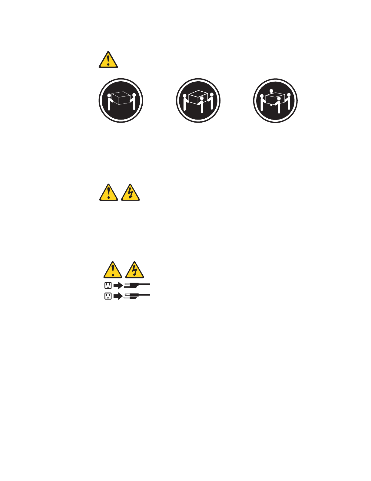
Statement 4:
≥ 18 kg (39.7 lb) ≥ 32 kg (70.5 lb) ≥ 55 kg (121.2 lb)
CAUTION:
Use safe practices when lifting.
Statement 5:
CAUTION:
The power control button on the device and the power switch on the power
supply do not turn off the electrical current supplied to the device. The device
also might have more than one power cord. To remove all electrical current
from the device, ensure that all power cords are disconnected from the power
source.
2
1
viii xSeries 445 Type 8870: Option Installation Guide
Page 11
Statement 8:
CAUTION:
Never remove the cover on a power supply or any part that has the following
label attached.
Hazardous voltage, current, and energy levels are present inside any
component that has this label attached. There are no serviceable parts inside
these components. If you suspect a problem with one of these parts, contact
a service technician.
Statement 10:
CAUTION:
Do not place any object weighing more than 82 kg (180 lb) on top of
rack-mounted devices.
>82 kg (180 lb)
Statement 13:
DANGER
Overloading a branch circuit is potentially a fire hazard and a shock hazard
under certain conditions. To avoid these hazards, ensure that your system
electrical requirements do not exceed branch circuit protection
requirements. Refer to the information that is provided with your device for
electrical specifications.
Safety ix
Page 12

WARNING: Handling the cord on this product or cords associated with accessories
sold with this product, will expose you to lead, a chemical known to the State of
California to cause cancer, and birth defects or other reproductive harm. Wash
hands after handling.
ADVERTENCIA: El contacto con el cable de este producto o con cables de
accesorios que se venden junto con este producto, pueden exponerle al plomo, un
elemento químico que en el estado de California de los Estados Unidos está
considerado como un causante de cancer y de defectos congénitos, además de
otros riesgos reproductivos. Lávese las manos después de usar el producto.
x xSeries 445 Type 8870: Option Installation Guide
Page 13

Chapter 1. Introduction
This Option Installation Guide contains instructions for installing, removing, and
connecting optional devices.
Related publications
In addition to this Option Installation Guide, the following xSeries 445
documentation is provided with your server:
v Installation Guide
This printed publication contains instructions for setting up your server and basic
instructions for installing some options.
v Rack Installation Instructions
This printed publication contains instructions for installing your server in a rack
cabinet.
v Safety Information
This publication is in PDF on the IBM
translated caution and danger statements. Each caution and danger statement
that appears in the documentation has a number that you can use to locate the
corresponding statement in your language in the Safety Information book.
v User’s Guide
This publication is in PDF on the IBM xSeries Documentation CD. It contains
general information about your server.
v Hardware Maintenance Manual and Troubleshooting Guide
This publication is in PDF on the IBM xSeries Documentation CD. It contains
information to help you solve problems yourself, and it contains information for
service technicians.
®
xSeries™Documentation CD. It contains
Depending on your server model, additional publications might be included on the
IBM xSeries Documentation CD.
© Copyright IBM Corp. 2003 1
Page 14
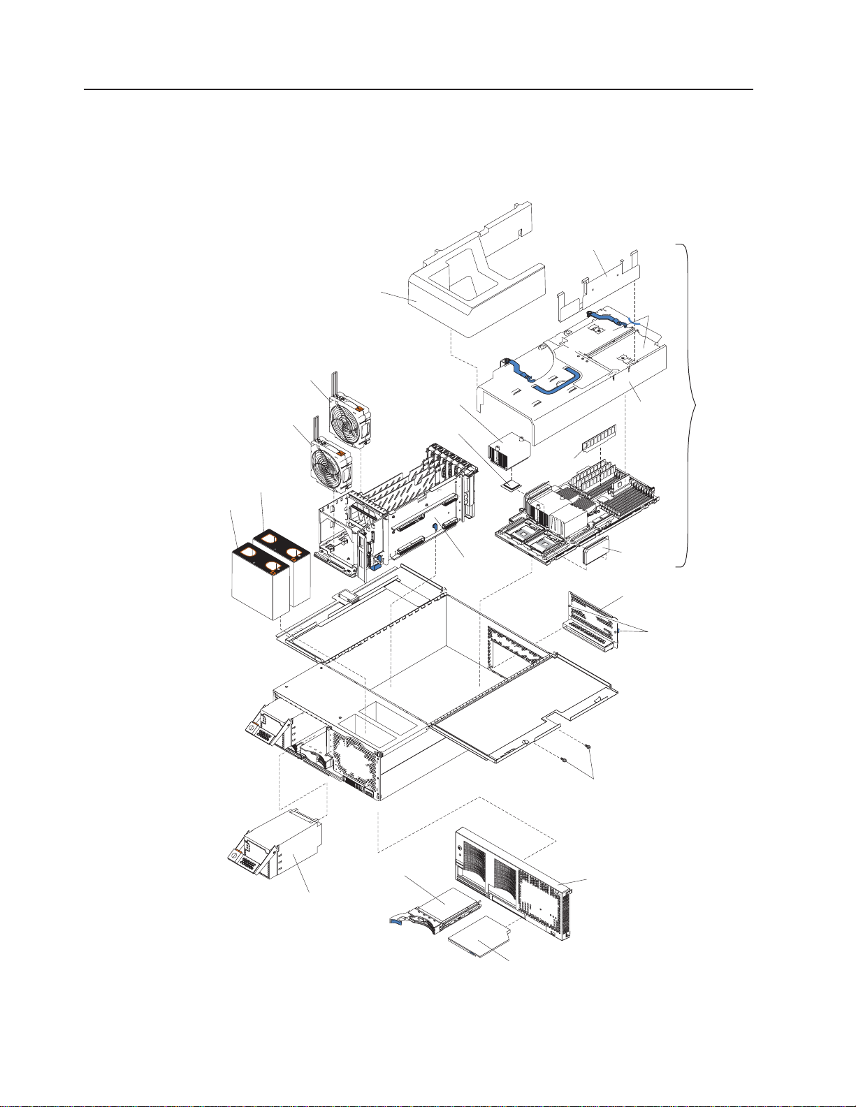
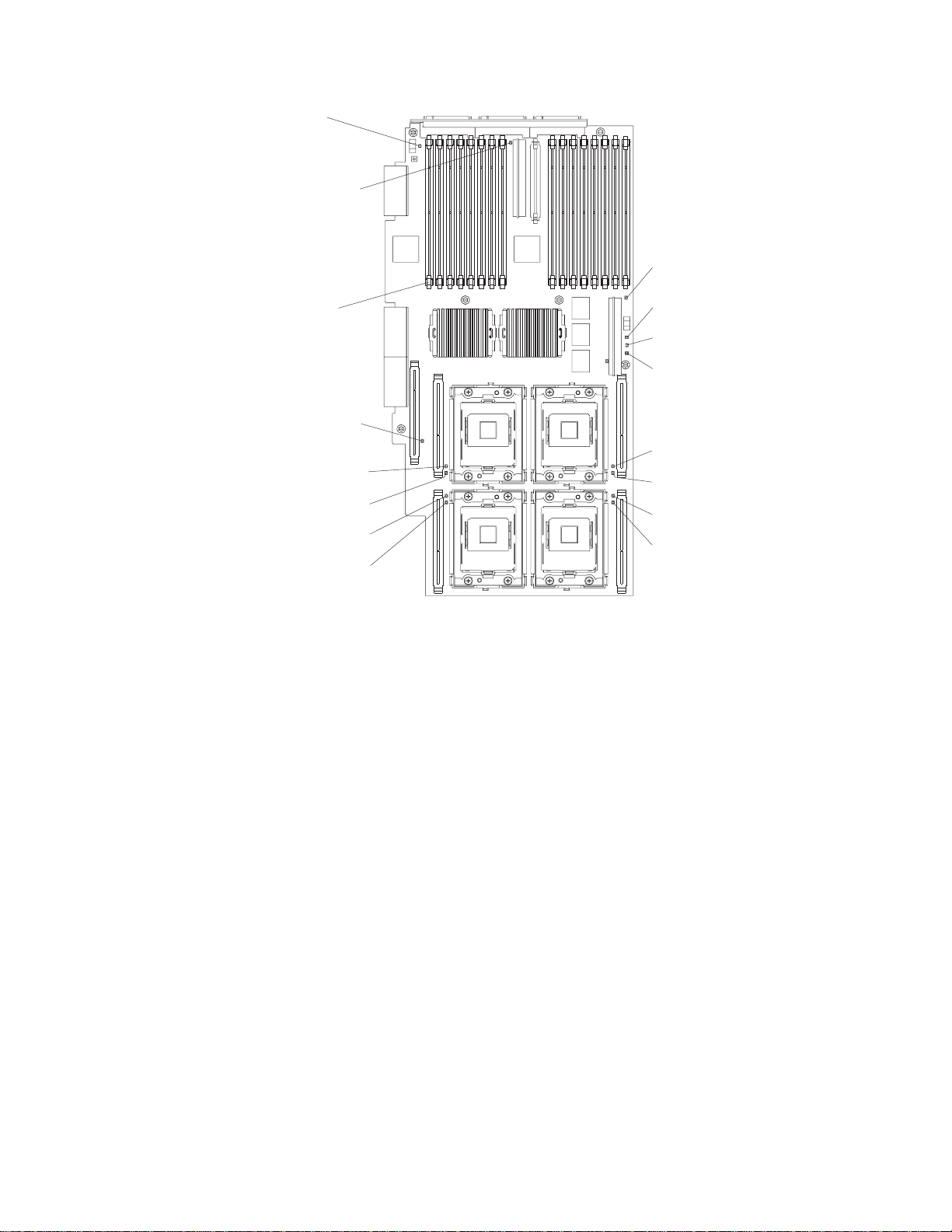
Major components of the xSeries 445 server
The following illustration shows the locations of major components in your server.
Note: The illustrations in this document might differ slightly from your hardware.
Retention bracket
Fan 1
N
O
T
E
:
F
F
R
Fan 2
O
R
P
R
O
P
E
R
A
IR
F
L
O
N
T
O
F
B
O
X
Fan 3
N
O
T
E
:
F
O
R
P
R
O
F
R
O
N
T
O
F
O
W,
R
E
P
L
A
C
E
F
A
N
W
IT
H
Fan 4
P
E
R
A
IR
F
L
O
W,
R
E
P
L
A
C
B
O
X
IN
2
M
IN
U
T
E
S
E
F
A
N
W
IT
H
IN
2
M
IN
U
T
E
S
SMP baffle
Heat-sink
Microprocessor
Center
plane
DIMM
DIMM
access
doors
SMP
Cover
Expansion
Module
VRM
EMC shield
(for single SMP
Expansion Module)
Thumbscrews
Hot-swap
power supply
Figure 1. Major components of the xSeries 445 server
2 xSeries 445 Type 8870: Option Installation Guide
Hard disk
drive
Shipping thumbscrews
Bezel
DVD-ROM
drive
Page 15
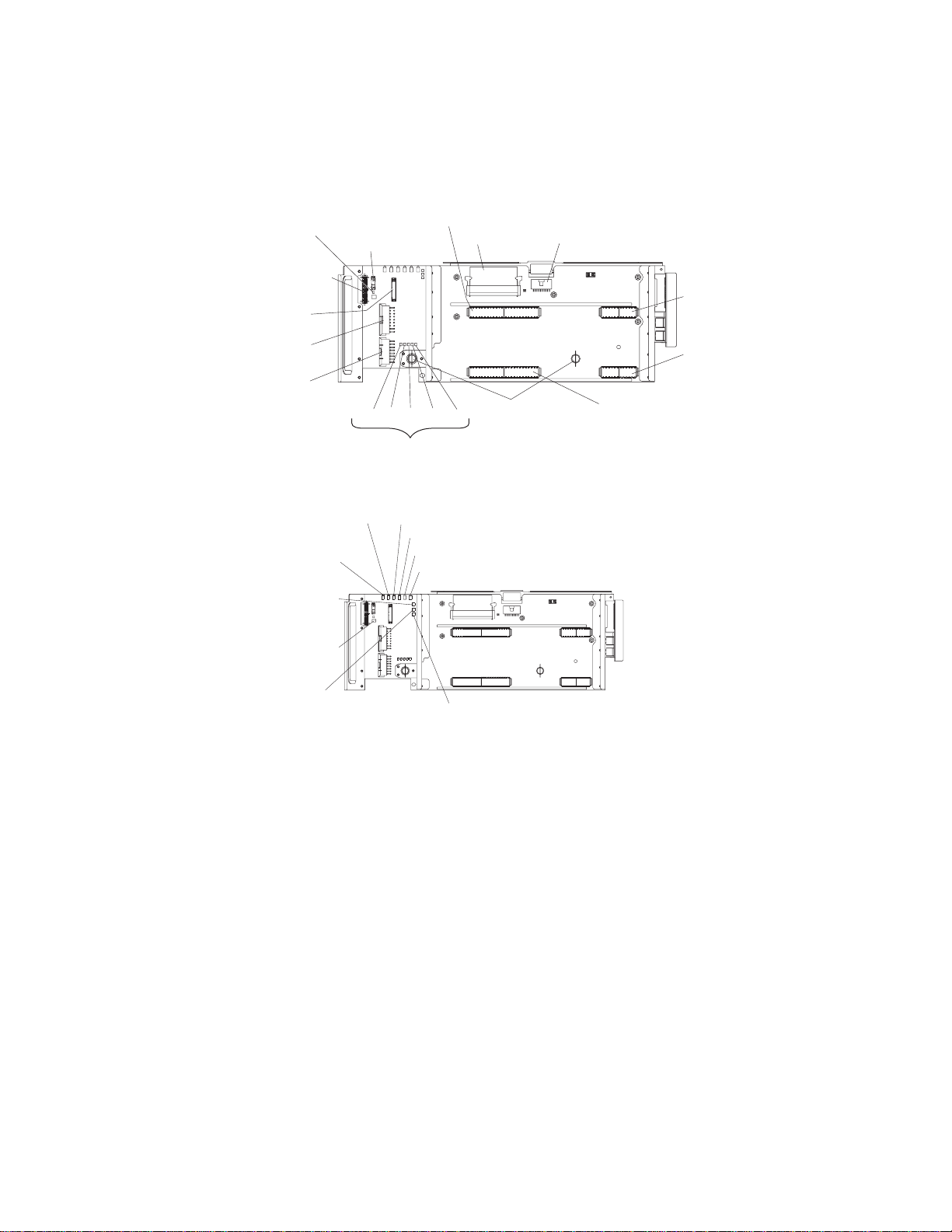
Center plane connectors and LEDs
The following illustrations identify the connectors and LEDs on the center plane.
This center plane is used to connect the power and signal paths for the SMP
Expansion Module, I/O board, and the Remote Supervisor Adapter.
Force power-on
(J37)
Light path (J8)
SMP 2 (J14)
SCSI
power (J9)
Power
(J11)
Power
(J19)
Power
(J23)
J30 J32 J31 J29 J28
Reserved
Figure 2. Center plane connectors
System management
power fault
LED (CR5)
I/O power fault
LED (CR6)
System power
present LED
(CR7)
Power present
(CR10)
PCI-X power fault LED (CR4)
Center plane power fault LED (CR3)
Lower SMP power fault LED (CR2)
Upper SMP power fault LED (CR1)
VRM (J12)
Thumbscrews
Serial port (J7)
SMP 2
(J15)
SMP 1
(J25)
SMP 1 (J24)
Lower SMP
power good LED
(CR8)
Figure 3. Center plane LEDs
Upper SMP
power good LED
(CR9)
Chapter 1. Introduction 3
Page 16
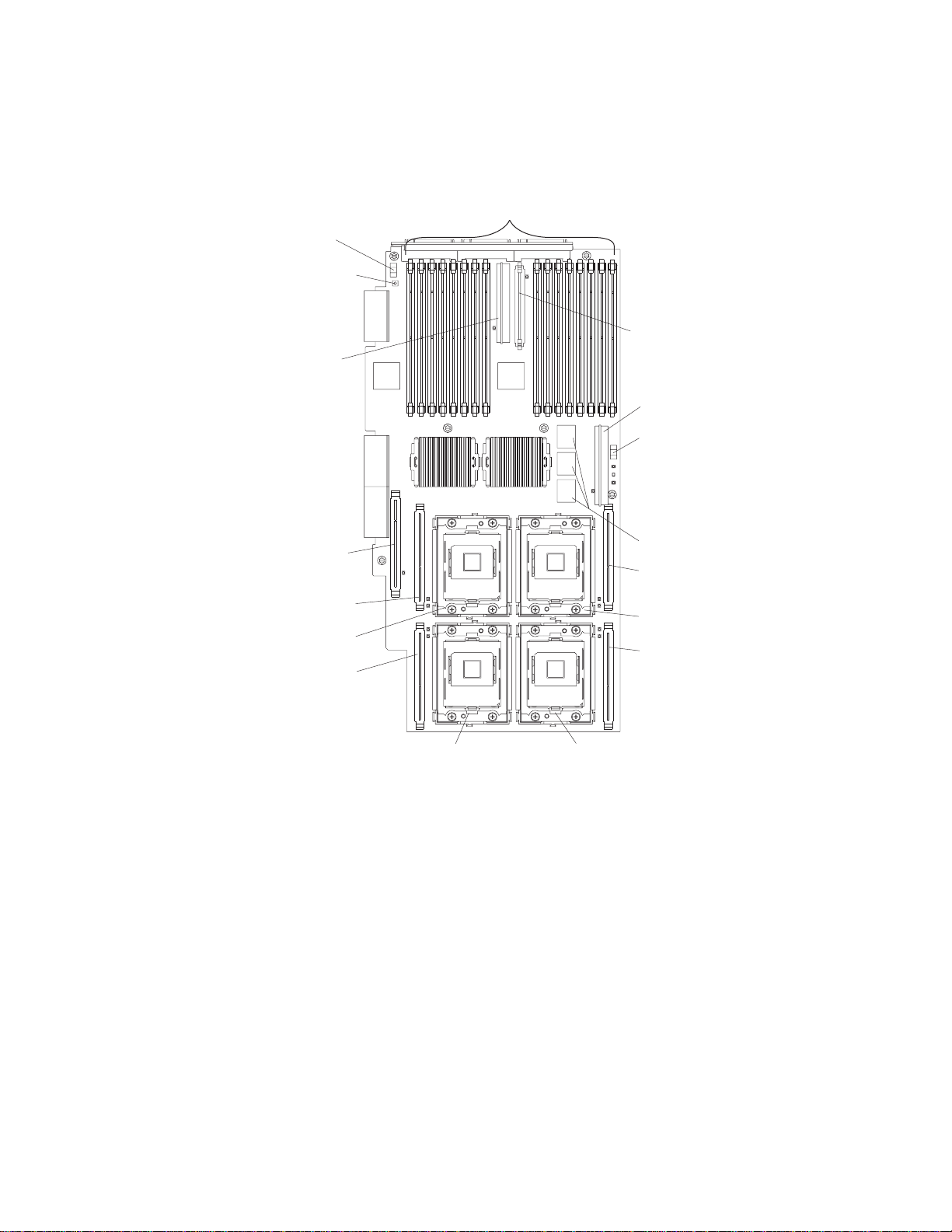
SMP Expansion Module connectors and LEDs
The following illustrations identify the connectors, switches, and LEDs on the SMP
Expansion Module.
DIMM connectors
(J1 - J16)
Memory port 1
switch (SN2)
Remind/Light Path
capacitor switch
(SW1)
Integrated
VRM connector
(U13)
VRM connector
(J44)
Microprocessor 1
VRM connector (J35)
Microprocessor 1
socket (U22)
Microprocessor 3
VRM connector (J36)
Figure 4. SMP Module connectors
IntegratedVRM
(U17)
VRM connector
(J28)
Memory port 2
power switch (SN1)
XceL4 cache
Microprocessor 4
VRM connector (J22)
Microprocessor 4
socket (U12)
Microprocessor 2
VRM connector (J23)
Microprocessor 2 socket (U13)Microprocessor 3 socket (U24)
4 xSeries 445 Type 8870: Option Installation Guide
Page 17
Light path
capacitor
LED (CR49)
SMP expansion
board bad error
LED (CR34)
VRM error LED
(CR33)
DIMM error
LED (16X)
(J1-J16)
VRM error LED
(CR47)
Microprocessor 1
VRM error LED (CR42)
Microprocessor 1
error LED (CR41)
Microprocessor 3
error LED (CR43)
Microprocessor 3
VRM error LED (CR44)
Figure 5. SMP Module LEDs
Memory port 2
power LED (CR17)
Hot-plug enabled
memory LED (CR18)
Memory port 1
power LED (CR19)
Microprocessor 4
VRM error LED (CR22)
Microprocessor 4
error LED (CR23)
Microprocessor 2
error LED (CR24)
Microprocessor 2
VRM error LED (CR25)
Chapter 1. Introduction 5
Page 18
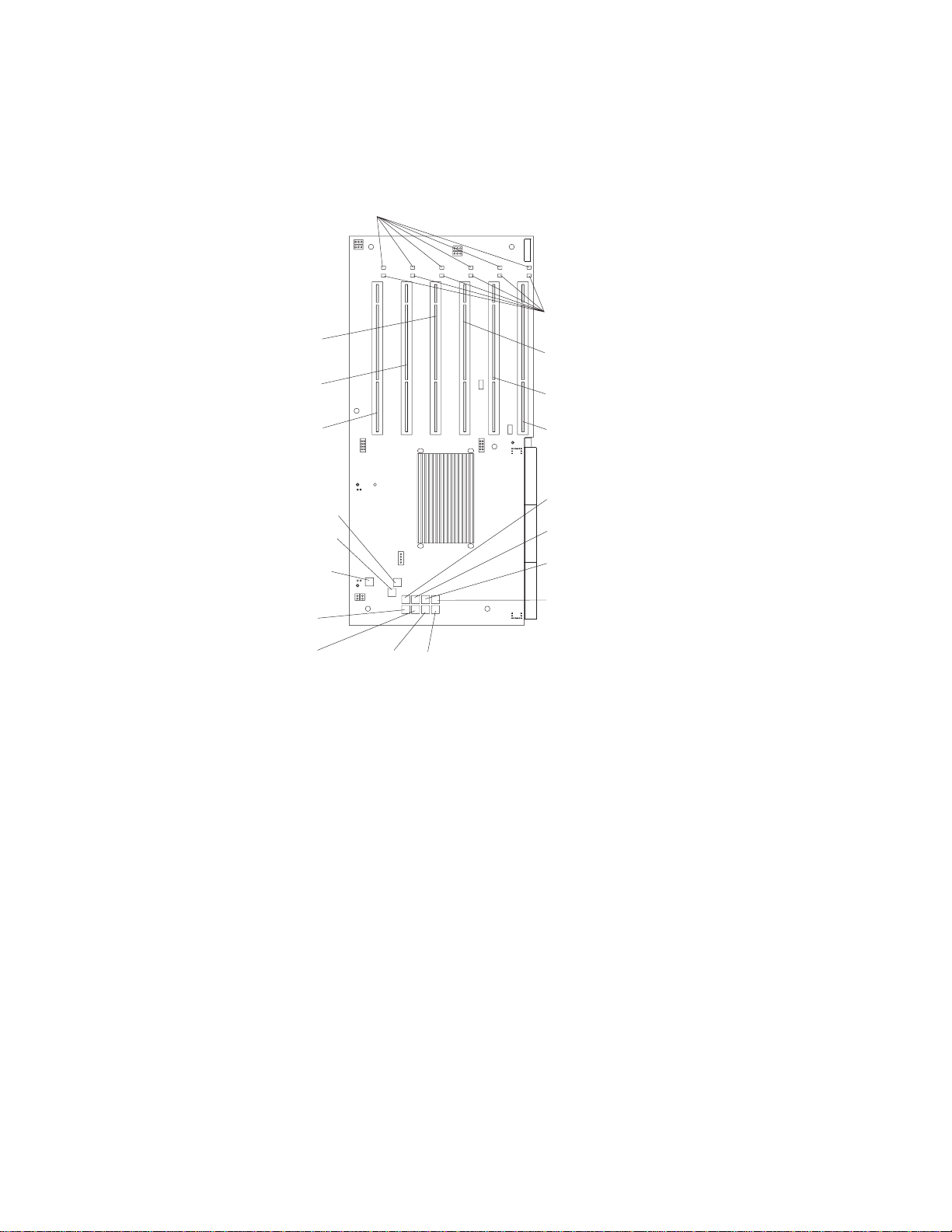
PCI-X planar internal connectors and LEDs
The following illustration identifies the internal connectors and LEDs on the PCI-X
planar. This planar enables you to install adapters in the server.
Attention LEDs
(CR20 - CR25)
PCI-X slot 4
(100 ) (J4)MHz
PCI-X slot 5
(133 ) (J5)MHz
PCI-X slot 6
(133 MHz) (J6)
Power LEDs
(CR14 - CR19)
PCI-X slot 3
(100 ) (J3)MHz
PCI-X slot 2
(66 ) (J2)MHz
PCI-X slot 1
(66 ) (J1)MHz
1.8V (CR6)
2.5V (CR1)
VRM present
(CR12)
PERR PCI
bus D (CR4)
PERR PCI
bus C (CR9)
PERR PCI
bus B (CR10)
PERR PCI
bus A (CR11)
Figure 6. PCI-X board connectors and LEDs
SERR PCI
bus D (CR2)
SERR PCI
bus C (CR7)
SERR PCI
bus B (CR3)
SERR PCI
bus A (CR8)
6 xSeries 445 Type 8870: Option Installation Guide
Page 19
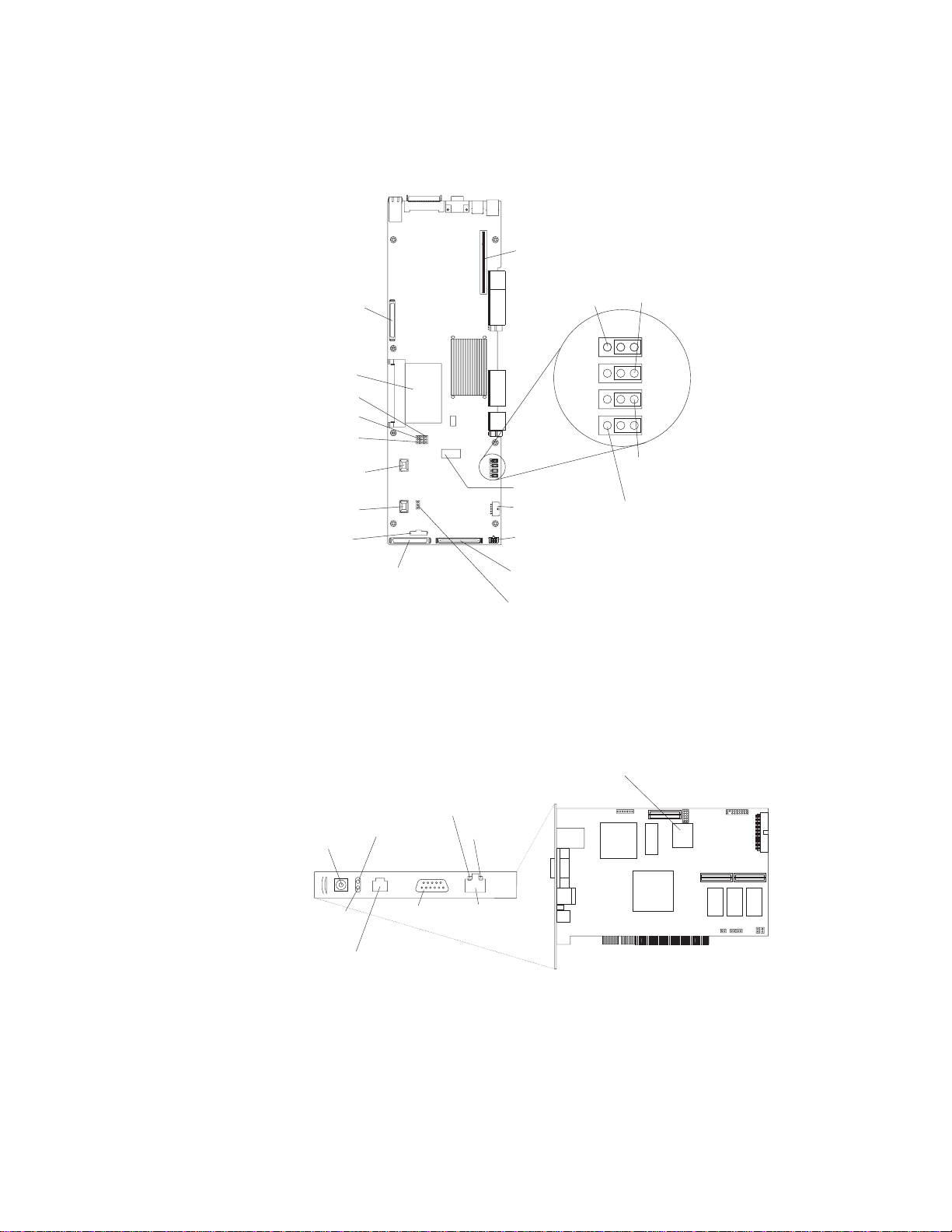
I/O board internal connectors
The following illustration identifies the internal connectors on the I/O board. This
board supports the input and output ports in the server.
SCSI B
connector (J38)
I/O VRM (J31)
Reserved (J12)
Reserved (J11)
Reserved (J10)
Fan 4
connector (J21)
Fan 3
connector (J9)
Power/Reset
connector (J5)
SCSI A
connector (J2)
Riser card
connector (J44)
Boot recovery
(BIOS) (J28)
3 2 13 2 1
Battery (BH1)
Fans 1 and 2
connectors (J8)
USB cable
connector (J1)
Media bays
connector (J3)
Reserved (J55)
Clear CMOS
(J19)
3 2 13 2 1
Power-on
password (J20)
WOL disable
(J14)
Figure 7. I/O board connectors
Remote Supervisor Adapter component locations
The following illustration identifies the connectors and LEDs on the Remote
Supervisor Adapter.
Lithium
battery
Ethernet activity
LED (green)
External power
supply connector
Power LED
(green)
ASM Interconnect port
Error LED
(amber)
P
P
Management
(RJ-14)
port
Figure 8. Remote Supervisor Adapter connectors and LEDs
Ethernet link
LED (green)
Ethernet port
(RJ-45)
Chapter 1. Introduction 7
Page 20

8 xSeries 445 Type 8870: Option Installation Guide
Page 21

Chapter 2. Installing options
This chapter provides instructions for installing hardware options in your server.
Some option-removal instructions are provided in case you need to remove one
option to install another. For a list of supported options for your server, see the
ServerProven
Installation guidelines
Before you begin to install options in your server, read the following information:
v Read the safety information beginning on page v and the guidelines in “Handling
static-sensitive devices” on page 10. This information will help you work safely
with your server and options.
v Make sure that you have an adequate number of properly grounded electrical
outlets for your server, monitor, and other devices that you will connect to the
server.
v Back up all important data before you make changes to disk drives.
v Have a small flat-blade screwdriver available.
v You do not need to turn off the server to install or replace hot-swap power
supplies, hot-swap fans, or hot-plug Universal Serial Bus (USB) devices.
v The orange color on components and labels identifies hot-swap or hot-plug
components. You can install or remove hot-swap and hot-plug components while
the server is running, provided that the server is configured to support this
capability. See the instructions in this chapter for more information about
removing and installing hot-swap and hot-plug components.
v The blue color on components and labels indicates touch points, where a
component can be gripped, a latch moved, and so on.
v For a list of supported options for your server, go to
http://www.ibm.com/pc/compat/.
®
list at http://www.ibm.com/pc/compat/.
System reliability guidelines
To help ensure proper cooling and system reliability, make sure that:
v Each of the drive bays has a drive or a filler panel and electromagnetic
compatibility (EMC) shield installed in it.
v If the server has only one SMP Expansion Module installed, the SMP baffle is
installed during normal operation.
v There is adequate space around the server to allow the server cooling system to
work properly. Leave approximately 50 mm (2.0 in.) of open space around the
front and rear of the server. Do not place objects in front of the fans.
v Do not leave open spaces above or below an installed server in a rack cabinet.
To prevent damage to server components, always install a blank filler panel to
cover the open space and to ensure proper air circulation.
v You have followed the cabling instructions that come with optional adapters.
v You have replaced a failed fan within 48 hours.
v You have replaced a hot-swap drive within 2 minutes of removal.
v Microprocessor socket 2 always contains either a microprocessor baffle or a
microprocessor and heat sink.
© Copyright IBM Corp. 2003 9
Page 22

Working inside the server with power on
Your server supports hot-swap or hot-replace devices and is designed to operate
safely while turned on with the cover removed. Follow these guidelines when you
work inside a server that is turned on:
v Avoid loose-fitting clothing on your forearms. Button long-sleeved shirts before
working inside the server; do not wear cuff links while you are working inside the
server.
v Do not allow your necktie or scarf to hang inside the server.
v Remove jewelry, such as bracelets, rings, necklaces, and loose-fitting wrist
watches.
v Remove items from your shirt pocket (such as pens or pencils) that could fall into
the server as you lean over it.
v Take care to avoid dropping any metallic objects, such as paper clips, hair pins,
or screws, into the server.
Handling static-sensitive devices
Attention: Static electricity can damage electronic devices and your system. To
avoid damage, keep static-sensitive devices in their static-protective packages until
you are ready to install them.
To reduce the possibility of electrostatic discharge, observe the following
precautions:
v Limit your movement. Movement can cause static electricity to build up around
you.
v Handle the device carefully, holding it by its edges or its frame.
v Do not touch solder joints, pins, or exposed printed circuitry.
v Do not leave the device where others can handle and possibly damage the
device.
v While the device is still in its anti-static package, touch it to an unpainted metal
part of the system unit for at least 2 seconds. (This drains static electricity from
the package and from your body.)
v Remove the device from its package and install it directly into your system unit
without setting it down. If it is necessary to set the device down, place it in its
static-protective package. Do not place the device on your system unit cover or
on a metal table.
v Take additional care when handling devices during cold weather because heating
reduces indoor humidity and increases static electricity.
10 xSeries 445 Type 8870: Option Installation Guide
Page 23
Safety information
Before installing this product, read the Safety Information.
Antes de instalar este produto, leia as Informações de Segurança.
Pred instalací tohoto produktu si prectete prírucku bezpecnostních instrukcí.
Læs sikkerhedsforskrifterne, før du installerer dette produkt.
Lees voordat u dit product installeert eerst de veiligheidsvoorschriften.
Ennen kuin asennat tämän tuotteen, lue turvaohjeet kohdasta Safety Information.
Avant d’installer ce produit, lisez les consignes de sécurité.
Vor der Installation dieses Produkts die Sicherheitshinweise lesen.
Prima di installare questo prodotto, leggere le Informazioni sulla Sicurezza.
Les sikkerhetsinformasjonen (Safety Information) før du installerer dette produktet.
Antes de instalar este produto, leia as Informações sobre Segurança.
Antes de instalar este producto, lea la información de seguridad.
Läs säkerhetsinformationen innan du installerar den här produkten.
Chapter 2. Installing options 11
Page 24
Statement 1:
DANGER
Electrical current from power, telephone, and communication cables is
hazardous.
To avoid a shock hazard:
v Do not connect or disconnect any cables or perform installation,
maintenance, or reconfiguration of this product during an electrical
storm.
v Connect all power cords to a properly wired and grounded electrical
outlet.
v Connect to properly wired outlets any equipment that will be attached to
this product.
v When possible, use one hand only to connect or disconnect signal
cables.
v Never turn on any equipment when there is evidence of fire, water, or
structural damage.
v Disconnect the attached power cords, telecommunications systems,
networks, and modems before you open the device covers, unless
instructed otherwise in the installation and configuration procedures.
v Connect and disconnect cables as described in the following table when
installing, moving, or opening covers on this product or attached
devices.
To Connect: To Disconnect:
1. Turn everything OFF.
2. First, attach all cables to devices.
3. Attach signal cables to connectors.
4. Attach power cords to outlet.
5. Turn device ON.
1. Turn everything OFF.
2. First, remove power cords from outlet.
3. Remove signal cables from connectors.
4. Remove all cables from devices.
12 xSeries 445 Type 8870: Option Installation Guide
Page 25

Statement 2:
CAUTION:
When replacing the lithium battery, use only IBM Part Number 33F8354 or an
equivalent type battery recommended by the manufacturer. If your system has
a module containing a lithium battery, replace it only with the same module
type made by the same manufacturer. The battery contains lithium and can
explode if not properly used, handled, or disposed of.
Do not:
v Throw or immerse into water
v Heat to more than 100°C (212°F)
v Repair or disassemble
Dispose of the battery as required by local ordinances or regulations.
Statement 3:
CAUTION:
When laser products (such as CD-ROMs, DVD drives, fiber optic devices, or
transmitters) are installed, note the following:
v Do not remove the covers. Removing the covers of the laser product could
result in exposure to hazardous laser radiation. There are no serviceable
parts inside the device.
v Use of controls or adjustments or performance of procedures other than
those specified herein might result in hazardous radiation exposure.
DANGER
Some laser products contain an embedded Class 3A or Class 3B laser
diode. Note the following.
Laser radiation when open. Do not stare into the beam, do not view directly
with optical instruments, and avoid direct exposure to the beam.
Chapter 2. Installing options 13
Page 26
Statement 4:
≥ 18 kg (39.7 lb) ≥ 32 kg (70.5 lb) ≥ 55 kg (121.2 lb)
CAUTION:
Use safe practices when lifting.
Statement 5:
CAUTION:
The power control button on the device and the power switch on the power
supply do not turn off the electrical current supplied to the device. The device
also might have more than one power cord. To remove all electrical current
from the device, ensure that all power cords are disconnected from the power
source.
2
1
Statement 8:
14 xSeries 445 Type 8870: Option Installation Guide
Page 27
CAUTION:
Never remove the cover on a power supply or any part that has the following
label attached.
Hazardous voltage, current, and energy levels are present inside any
component that has this label attached. There are no serviceable parts inside
these components. If you suspect a problem with one of these parts, contact
a service technician.
Statement 10:
CAUTION:
Do not place any object weighing more than 82 kg (180 lb) on top of
rack-mounted devices.
>82 kg (180 lb)
Chapter 2. Installing options 15
Page 28
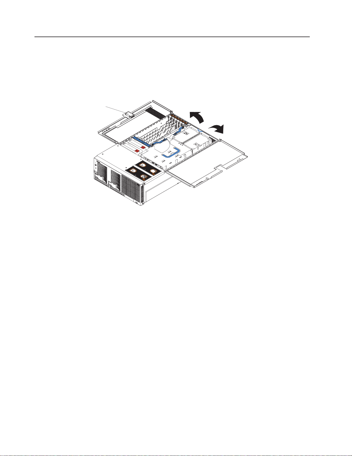
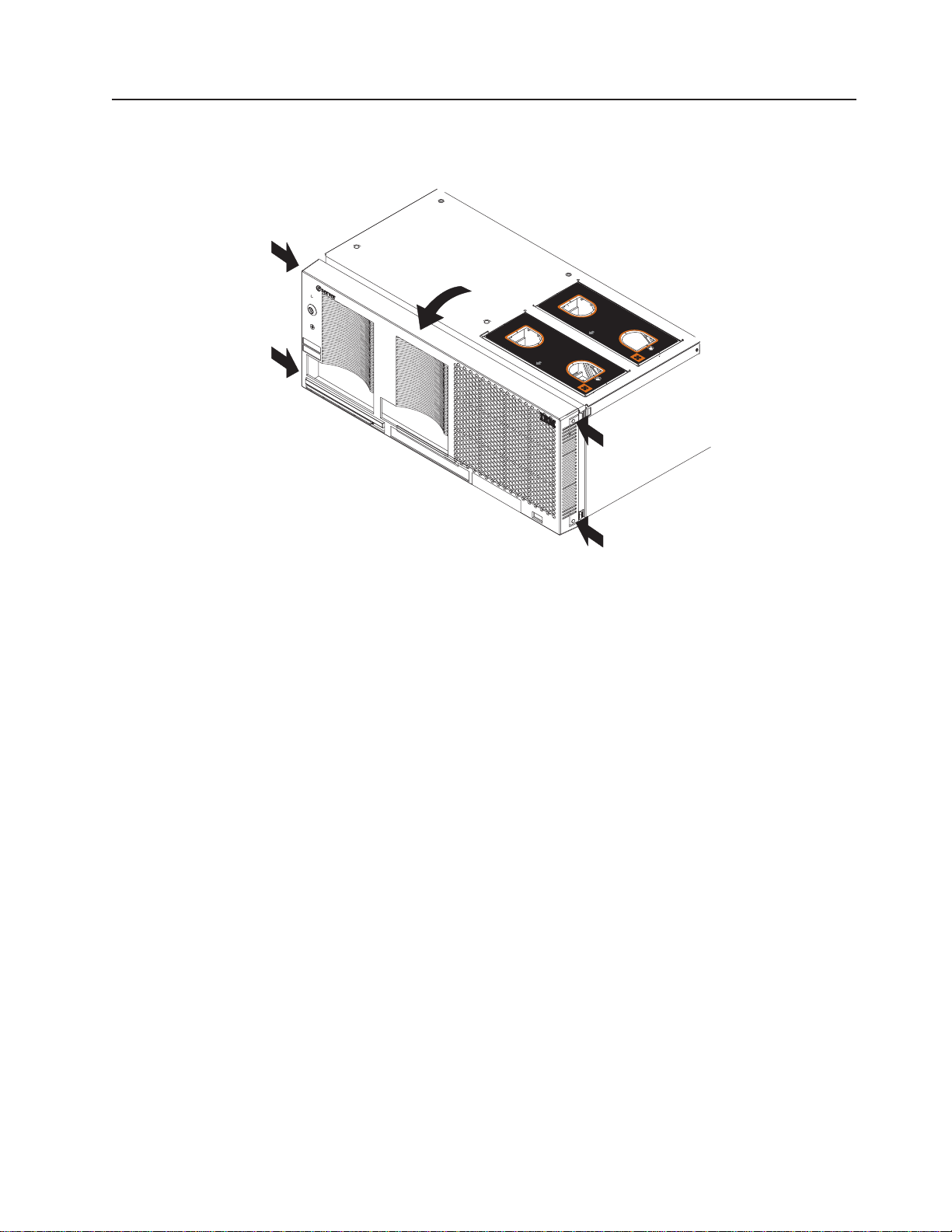
Opening the cover
Complete the following steps to open the server cover:
1. Read the safety information beginning on page v and “Installation guidelines” on
2. Pull out on the quick release latches on each side of the server; then, pull the
Latch
page 9.
server out of its rack enclosure until it stops.
N
O
T
E
:
F
O
R
P
R
O
P
E
R
A
IR
F
L
O
W,
R
E
P
N
O
T
E
:
F
R
L
A
C
E
F
F
O
R
P
O
N
T
A
F
N
R
W
O
IT
N
T
R
O
P
E
R
O
F
B
O
X
H
O
IN
F
2
B
M
O
A
I
R
F
L
I
X
N
U
T
E
O
W,
R
E
P
S
L
A
C
E
F
A
N
W
I
T
H
IN
2
M
IN
U
T
E
S
Figure 9. Opening the cover
3. Pull the release latch on the left half of the top cover to the right.
4. Using the finger hole in the release latch, open the left half of the cover; then,
open the right half of the cover.
Attention: For proper cooling and airflow, close the cover before turning on
the server. Operating the server for extended periods of time (more than 30
minutes) with the cover open might damage server components.
16 xSeries 445 Type 8870: Option Installation Guide
Page 29
Removing and replacing the bezel
Complete the following steps to remove and replace the server bezel:
N
O
T
E: FO
R
PR
O
P
ER
A
IR
FLO
W, R
E
N
OTE:
F
O
R PR
O
PE
R
A
IR
FLO
W, R
EP
LA
F
C
RON
T
O
F B
O
X
PLA
C
E F
FRO
N
E FANW
ANW
T O
F BO
ITHIN
ITH
IN
2 M
X
2 M
IN
U
TES
INU
TE
S
Figure 10. Removing the bezel
1. Removing the bezel.
a. Press on the two tabs at the top edge of the bezel, and pull the top of the
bezel slightly away from the server.
b. Press on the two tabs at the bottom edge of the bezel, and pull the bezel off
the server. Store the bezel in a safe place.
2. Replace the bezel.
a. Align the four tabs with the slots in the server chassis.
b. Press firmly against the front of the bezel until it snaps into place.
Chapter 2. Installing options 17
Page 30
Removing and replacing a hot-swap power supply
You can remove and replace the two hot-swap power supplies in your server
without turning off the server. This section provides instructions for removing and
installing the hot-swap power supplies.The following notes and safety information
contains information you must consider when removing or installing a hot-swap
power supply:
v During normal operation, both power supplies must be installed for proper
operation and cooling.
v The xSeries 445 server requires a 220 V power connection for full power-supply
redundancy. Whenever possible, use a 220 V connection for all configurations.
However, you can use a 110 V connection, but without power-supply redundancy.
Statement 8:
CAUTION:
Never remove the cover on a power supply or any part that has the following
label attached.
Hazardous voltage, current, and energy levels are present inside any
component that has this label attached. There are no serviceable parts inside
these components. If you suspect a problem with one of these parts, contact
a service technician.
Power light Power supply 1
Power supply 2
Power-on light
Power button
Reset button
Power supply
latch
Handle
Figure 11. Hot-swap power supply
Complete the following steps to remove and replace a power supply:
1. Read the safety information beginning on page v and “Installation guidelines” on
page 9.
2. Remove the front bezel (see “Removing and replacing the bezel” on page 17 for
instructions on removing the front bezel).
18 xSeries 445 Type 8870: Option Installation Guide
Page 31

Hot-swap
power supply
Release latch
Power supply handle
(in open position)
AC LED
DC LED
Figure 12. Removing a power supply
3. Press the release latch; then, lift the handle on the power supply to the open
position and remove the power supply.
Hot-swap
power supply
Release latch
Power supply handle
(in open position)
Figure 13. Installing a power supply
AC LED
DC LED
Chapter 2. Installing options 19
Page 32

4. Install the new power supply:
a. Place the handle on the power supply in the open position.
b. Slide the power supply into the chassis and press the handle to the closed
position.
5. Verify that the dc power LED and the ac power LED on the power supply are lit,
indicating that the power supply is operating properly.
6. Replace the front bezel on the server (see “Removing and replacing the bezel”
on page 17 for instructions).
PCI and PCI-X adapters
The following notes describe the types of adapters that your server supports and
other information that you must consider when installing an adapter:
v The following illustration shows the location of the PCI-X expansion slots on the
PCI-X board.
Note: The illustrations in this document might differ slightly from your hardware.
PCI-X slot 6
(133 MHz)
PCI-X slot 5
(133 )MHz
PCI-X slot 4
(100 )MHz
PCI-X slot 3
(100 )MHz
PCI-X slot 2
(66 )MHz
Attention LED
Power LED
PCI-X slot 1
(66 )MHz
Figure 14. PCI-X slots
v Locate the documentation that comes with the adapter and follow those
instructions in addition to the instructions in this chapter.
v If you need to change the switch settings or jumper settings on your adapter,
follow the instructions that come with the adapter.
v Video adapters are not supported.
v Some long adapters have extension handles or brackets installed. Before
installing the adapter, you must remove the extension handle or bracket.
20 xSeries 445 Type 8870: Option Installation Guide
Page 33

v Your server uses a rotational interrupt technique to configure PCI-X adapters.
You can use this technique to install PCI-X adapters that currently do not support
sharing of PCI-X interrupts.
v Your server scans devices and PCI-X slots to assign system resources in the
following order: DVD-ROM drive; disk drives; integrated SCSI devices; PCI-X
slots 1, 2, 3, 4, 5, 6; and the integrated Ethernet controller. If an RXE-100
enclosure is attached to the server, the scan continues in sequence with PCI
slots 7, 8, 9, 10, 11, 12, 13, 14, 15, 16, 17, and 18.
v You can use the Configuration/Setup Utility program to change the sequence and
have the server scan one of the first six PCI slots before it scans the integrated
devices. You cannot change the scan sequence of the PCI slots in an RXE-100
enclosure.
v You can install both PCI and PCI-X adapters in the same bus. However, if you
install a PCI adapter and a PCI-X adapter in the same bus, the PCI-X features of
the PCI-X adapter will be disabled, and the adapter will function as a PCI
adapter.
v You can install PCI or PCI-X adapters of speeds faster than what is labeled for a
particular PCI-X bus. For example, if you install two 133 MHz adapters into slots
that are labeled as 100 MHz slots, the adapters will operate at 100 MHz.
v If you install a 33 MHz and a 66 MHz adapter in the same bus, the bus speed
will match that of the slowest adapter.
v If a single 133 MHz adapter is installed in PCI-X Bus B (slot 3 and 4) and the
other slot in PCI-X Bus B is empty, the adapter will operate at 133 MHz.
v Your server supports six hot-plug 64-bit adapters in the expansion slots located
on the PCI-X board.
Note: You can add up to 12 PCI-X slots to your server by connecting your
server to a remote I/O expansion enclosure. For more information about
the expansion enclosure and how to connect your server to it, see the
documentation that comes with your expansion enclosure.
Bus Slot Supported adapter speed (MHz)
A166
A266
B 3 100 (133 if slot 4 is empty)
B 4 100 (133 if slot 3 is empty)
C 5 133
D 6 133
v Your server supports 3.3 V adapters; it does not support 5.0 V adapters.
v Do not install a PCI-X adapter in PCI-X slot 1 if you are going to install the serial
port that comes with your server. See “Installing the serial port” on page 25 for
instruction for installing the serial port.
Complete the following steps to install an adapter:
1. Read the safety information beginning on page v and “Installation guidelines”
on page 9.
Chapter 2. Installing options 21
Page 34

2. Use the operating system to disable the Active PCI-X slot; then, insert or
remove a hot-plug PCI or PCI-X adapter. Some operating systems do not
support the enabling and disabling of a PCI-X slot. If your operating system
does not support this function, then turn off your server, and disconnect all
power cords and external cables before proceeding.
3. Pull out on the quick release latches on each side of the server; then, pull the
server out of its rack enclosure until it stops.
4. Open the top cover.
Note: Inside your server there are six PCI-X slots: two 66 MHz, two 100 MHz,
and two 133 MHz. Before attempting to install a new adapter, be sure
there is an available slot for it. If you need additional PCI-X slots, you
can purchase a Remote Expansion Enclosure either from your IBM
marketing representative or authorized reseller.
Adapter
Adapter guide
PCI-X
divider
Tab
Attention
LED
Power
LED
retention
latch
Figure 15. PCI-X slot components
5. See the documentation that comes with your adapter for any cabling
instructions; then, set any jumpers or switches as described by the adapter
manufacturer.
Note: Route adapter cables before you install the adapter.
6. Install the adapter:
a. Open the blue adapter guide by lifting the front edge, as shown in the
illustration.
22 xSeries 445 Type 8870: Option Installation Guide
NOTE:FOR PROPER AIRFLOW, REPLACE FANWITHIN 2 MINUTES
NOTE:FOR PROPER AIRFLOW, REPLACE FANWITHIN 2 MINUTES
FRONT OF BOX
FRONT OF BOX
Page 35

b. Push the orange adapter retention latch toward the rear of the server and
open the tab.
c. Remove the expansion-slot cover and the PCI-X divider. If you are
hot-swapping a PCI or PCI-X adapter do not remove the PCI-X divider.
d. Carefully grasp the adapter by its top edge or upper corners and align it
with the connector on the PCI-X board.
e. If necessary remove the extension handles or bracket before installing a
long adapter.
Attention: When you install an PCI-X adapter, make sure that the
adapter is correctly seated in the connector slot. Improperly seated
adapters might cause damage to the board, the riser card, or the adapter.
f. Press the adapter firmly into the adapter connector.
g. If necessary reinstall the PCI-X dividers between the Active PCI-X adapter
slots.
h. Push down on the blue adapter guide to keep the adapter steady.
i. Close the tab. The orange adapter retention latch will click into place,
securing the adapter.
7. Connect the internal cables to the adapter. If you are installing a ServeRAID
adapter, see “Cabling a ServeRAID adapter” for instructions.
8. If you have other options to install or remove, do so now.
9. Close the cover on the server; then, reinstall the server in the rack and
connect all external cables.
10. Enable the slot or turn on the server, depending on your operating system.
™
Cabling a ServeRAID adapter
Some xSeries 445 models come with an optional IBM ServeRAID adapter installed
to control the internal hot-swap hard disk drives. If you are installing an optional
IBM ServeRAID adapter, see the ServeRAID documentation and the cabling
information in this section to install the ServeRAID adapter.
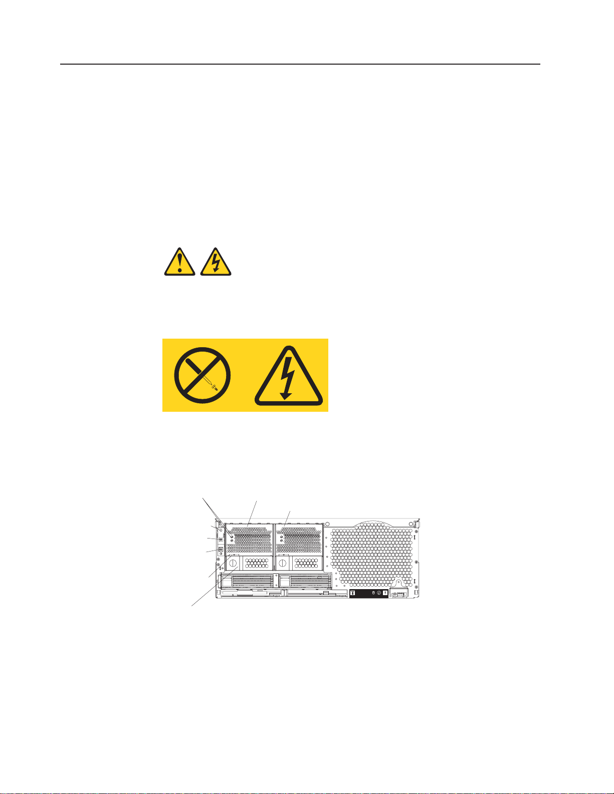
Servers that do not come with an IBM ServeRAID adapter installed come with two
SCSI cables:
v One end of the first SCSI cable is attached to the connector on the SCSI
backplane on the I/O board, and the other end is attached to the connector for
the integrated SCSI controller behind fans 3 and 4.
v The second SCSI cable is preinstalled along the inside of the server and both
ends are loose inside the server. When you install a ServeRAID adapter, you will
connect this cable to the adapter and to the SCSI backplane on the I/O board.
The following procedure describes the internal cabling for installing a ServeRAID
adapter.
Important: When installing multiple ServeRAID adapters in a server that has the
PCI-X slot enabled for high scan (boot) priority, make sure that the ServeRAID
adapter controlling the startup (boot) drive is installed in a PCI slot that is scanned
before the PCI slots that contain the other ServeRAID adapters. See “PCI and
PCI-X adapters” on page 20.
Complete the following steps to cable the ServeRAID adapter:
1. Read the safety information beginning on page v and “Installation guidelines”
on page 9.
Chapter 2. Installing options 23
Page 36

2. Turn off the server and disconnect all power cords and external cables; then,
open the server cover (see “Opening the cover” on page 16).
3. Remove fans 3 and 4, which are located just behind the PCI-X slots.
4. Disconnect the short SCSI cable from the SCSI backplane and the integrated
SCSI controller on the I/O board; then, store this short cable in a safe place for
future use.
5. Install the ServeRAID adapter in a PCI-X slot (see“PCI and PCI-X adapters” on
page 20).
6. Locate one end of the preinstalled SCSI cable and connect it to the
ServeRAID adapter.
Preinstalled
SCSI cable
Connect to
SCSI backplane
Figure 16. Location of preinstalled SCSI cable
Connect to
ServeRAID adapter
7. Locate the other end of the preinstalled SCSI cable and connect it to the SCSI
backplane.
24 xSeries 445 Type 8870: Option Installation Guide
Page 37

Front of server
SCSI backplane
connector
Figure 17. Connecting the SCSI cable to the SCSI backplane
8. Reinstall fans 3 and 4.
9. If you have other options to install or remove, do so now.
10. Close the cover on the server; then, reinstall the server in the rack and
connect all external cables.
11. Turn on the server.
Installing the serial port
Included with your server is a serial port that you can install at any time. This
section provides the instructions for installing the serial port.
Note: The serial port will occupy PCI-X slot one.
Complete the following steps to install the serial port:
1. Read the safety information beginning on page v and “Installation guidelines”
on page 9.
2. Pull out on the quick release latches on each side of the server; then, pull the
server out of its rack enclosure until it stops.
3. Open the top cover.
Chapter 2. Installing options 25
Page 38

Adapter guide
PCI-X
divider
N
O
T
E
:
F
O
R
P
R
O
P
E
R
A
I
N
R
O
T
E
:
F
F
O
R
O
R
N
P
T
R
O
O
F
P
E
B
R
O
X
A
I
R
F
L
O
W,
R
E
P
L
A
C
E
F
A
F
N
R
W
O
I
N
T
T
H
I
O
N
F
2
B
M
O
I
X
N
U
Attention
LED
Power
LED
F
L
O
W,
R
E
P
L
A
C
E
F
A
N
W
I
T
H
I
N
2
M
I
T
E
S
Adapter
Tab
retention
latch
N
U
T
E
S
Figure 18. PCI-X slot components
4. Open the blue adapter guide by lifting the front edge, as shown in the
illustration.
5. Remove the PCI-X slot cover and the PCI-X divider from slot one.
26 xSeries 445 Type 8870: Option Installation Guide
Page 39

Serial port
Tab
Serial connector
N
O
T
E
:
F
O
R
P
R
O
P
E
R
A
I
R
F
L
O
W,
R
E
P
N
O
T
E
:
F
O
R
P
R
O
P
E
F
R
O
N
T
O
F
B
O
L
A
C
E
F
A
F
N
R
W
O
I
N
T
T
H
I
O
N
F
2
B
R
A
I
R
F
L
O
W,
R
E
P
L
A
C
X
M
O
I
X
N
U
T
E
E
F
A
N
W
S
I
T
H
I
N
2
M
I
N
U
T
E
S
Figure 19. Insert the serial port into PCI-X slot 1
Adapter
retention
latch
6. Insert the serial port into the opening.
7. Close the tab; then, push down on the blue adapter retention latch until it
clicks into place.
Serial connector
Figure 20. Route the serial port ribbon cable through the slot
8. Route the ribbon cable through the lower slot in the center of the server.
9. Connect the serial ports ribbon to the connector on the center planar.
10. If you have other options to install or remove, do so now.
11. Close the top cover.
Chapter 2. Installing options 27
Page 40

12. Slide the server into the rack enclosure until it stops; then, secure the server in
the rack enclosure using the quick release latches.
13. Connect all external cables and turn on the server.
Note: Use the Configuration/Setup Utility program to configure the serial port.
Installing or replacing a drive
This section provides the instructions for installing and replacing a hot-swap hard
disk drive, diskette drive, and DVD-ROM drive.
Hot-swap hard disk drive
Complete the following steps to install or replace a hot-swap hard disk drive.
Attention: When you handle static-sensitive devices, take precautions to avoid
damage from static electricity. For details on handling these devices, see “Handling
static-sensitive devices” on page 10.
1. Read the safety information beginning on page v and “Installation guidelines” on
page 9.
2. Inspect the drive for any signs of damage.
3. Check the instructions that come with the drive for more information about
installing your drive.
4. Remove the filler panel or defective hard disk drive from the hard disk drive bay.
5. Install the new hard disk drive in the drive bay:
a. Ensure that the handle on the hard disk drive tray is in the open position.
b. Slide the drive into the bay until it stops.
c. Push the handle on the front of the hard disk drive closed.
Filler panel
Figure 21. Installing a hard disk drive
Note: When the hard disk drive activity LED is on, it indicates that the hard disk
drive is in use. When the drive is connected to the integrated SCSI
controller with RAID capabilities, a flashing status LED indicates that the
drive is a secondary drive in a mirrored pair and the drive is being
synchronized. When the drive is connected to an optional ServeRAID
controller, a slowly flashing (one flash per second) status LED indicates
28 xSeries 445 Type 8870: Option Installation Guide
Page 41

Diskette drive
that the drive is being rebuilt. When the LED is flashing rapidly (three
flashes per second), it indicates that the controller is identifying the drive.
6. If you have other options to install or remove, do so now.
The following notes contain information that you must consider when installing
diskette drive:
v Your xSeries 445 server supports the installation of up to two diskette drives.
v If only one diskette drive is installed, it must be installed in the right drive bay.
Complete the following steps to remove and install a diskette drive in your server:
1. Read the safety information beginning on page v and “Installation guidelines” on
page 9.
Attention: The IDE drives installed in your server are not hot-swappable.
2. Turn off the server and disconnect the power cord from the back of the server.
3. Push the diskette drive eject button to the right.
4. Using the tab, pull the diskette drive partially out of the server; then, grasp the
drive and remove it from the server.
5. Install the new diskette drive:
a. Inspect the drive for any signs of damage.
b. Slide the drive into the left drive bay until it stops.
Note: In the unlikely event that no other IDE drives are installed, the
diskette drive must be installed in the right external removable media
bay.
External removable
media bays
NOTE: FOR PROPER AIRFLOW, REPLACE FANW
NOTE: FOR PROPER AIRFLOW, REPLACE FANW
FRONT OF BOX
ITHIN 2 MINUTES
FRONT OF BOX
ITH
IN 2 MINUTES
Diskette
drive
Tab
Diskette drive
eject button
Figure 22. Installing a diskette disk drive
6. If you have other options to install or remove, do so now. Otherwise, connect
the power cords and turn on the server.
Chapter 2. Installing options 29
Page 42

DVD-ROM drive
The following notes contain information that you must consider when installing a
DVD-ROM:
v Your xSeries 445 server supports the installation of up to two DVD-ROM drives.
v If no other IDE drives are installed, the diskette drive must be installed in the
right external removable media bay. DVD-ROM drives can be installed in either
external removable media bay.
Complete the following steps to remove and install a DVD-ROM drive in your
server:
1. Read the safety information beginning on page v and “Installation guidelines” on
page 9.
Attention: The IDE drives installed in your server are not hot-swappable.
2. Turn off the server and disconnect the power cords from the back of the server.
3. Push the DVD-ROM eject button to the right.
4. Using the tab, pull the DVD-ROM drive partially out of the server; then, grasp
the drive and remove it from the server.
5. Install the new DVD-ROM drive:
a. Inspect the drive for any signs of damage.
b. Slide the DVD-ROM drive into the drive bay until it stops.
External removable
media bays
N
O
T
E
:
F
O
R
P
R
O
P
E
R
A
IR
F
L
O
W, R
E
P
L
A
C
E
F
A
F
N
R
W
O
IT
N
T
H
O
IN
F
2
B
M
O
IN
X
E
P
L
A
C
E
F
A
N
W
IT
H
IN
2
M
IN
U
T
E
S
DVD-ROM drive
U
T
E
S
DVD-ROM drive
N
O
T
E
:
F
O
R
P
R
O
P
E
R
A
IR
F
L
O
W, R
F
R
O
N
T
O
F
B
O
X
eject button
Tab
Figure 23. Installing a DVD-ROM drive
6. If you have other options to install or remove, do so now. Otherwise, connect
the power cords and turn on the server.
30 xSeries 445 Type 8870: Option Installation Guide
Page 43

SMP Expansion Module
The SMP Expansion Module contains the XceL4™system cache, DIMMs,
microprocessors, and voltage regulator modules (VRMs) needed to run your server.
This section contains the information needed to install and remove the SMP
Expansion Module, microprocessors, VRMs, and DIMMs.
The following notes describe components in the SMP Expansion Module and other
information that you must consider when installing an SMP Expansion Module:
v Use two hands to install or remove an SMP Expansion Module. Do not allow the
expansion module to come in contact with the center planar while lifting it out or
putting into the server.
v For your server to operate properly, there must be a minimum of one SMP
Expansion Module installed.
v An SMP Expansion Module must contain at least one microprocessor and two
DIMMs.
v If there is only one SMP Expansion Module installed in the server, an SMP baffle
must be installed in place of the upper SMP Expansion Module to ensure proper
cooling of the server.
v When the minimum number of microprocessors are installed in the SMP
Expansion Module, a microprocessor baffle must be installed in microprocessor
socket 4 to ensure proper cooling within the server.
v Before removing or installing SMP Expansion Modules, you must remove the
retention bracket or brackets and electromagnetic compatibility (EMC) shield from
the rear of the server.
v You must run the Configuration/Setup Utility program whenever you remove or
replace an SMP Expansion Module or one of its associated options.
Chapter 2. Installing options 31
Page 44

Removing and Installing the SMP Expansion Module and cover
This section describes how to remove and install an SMP Expansion Module and its
cover.
Removing the SMP Expansion Module and cover
Complete the following steps to remove an SMP Expansion Module from the server
and to remove the SMP Expansion Module cover:
1. Read the safety information beginning on page v and “Installation guidelines” on
page 9.
2. Turn off the server and peripheral devices, disconnect the power cords and all
external cables from the SMP Expansion Module.
3. Pull out on the quick release latches on each side of the server; then, pull the
server out of its rack enclosure until it stops.
4. Open the top cover.
5. If necessary, remove the SMP baffle.
6. Remove the retention bracket from the server:
a. Remove the shipping thumbscrews from the right side of the server.
Note: There are two shipping thumbscrews per retention bracket.
Retention bracket
removal handles
Retention bracket
SMP Expansion
Module
N
O
T
E
:
F
O
R
P
R
O
P
E
R
A
I
R
F
L
O
W,
R
E
P
N
O
T
E
:
F
F
R
L
A
C
E
F
A
F
O
R
P
R
O
O
N
T
O
F
N
R
W
O
I
N
T
T
H
I
O
N
F
P
E
R
A
I
R
B
O
X
2
B
M
O
I
X
N
U
F
L
O
W,
R
E
T
E
P
S
L
A
C
E
F
A
N
W
I
T
H
I
N
2
M
I
N
U
T
E
S
Shipping
thumbscrews
Figure 24. Removing the retention bracket and shipping thumbscrews
b. Grasp the retention bracket by the removal handles and lift it up and out of
the server. Store the retention bracket or brackets in a safe place for use
later.
Note: If there is one SMP Expansion Module installed, you will need to
remove the SMP baffle from the server; then, remove the retention
bracket from the lower SMP Expansion Module as described in steps
3a and 3b.
32 xSeries 445 Type 8870: Option Installation Guide
Page 45

7. Loosen the blue thumbscrews securing the EMC shield; then, remove the EMC
shield from the server.
EMC shields
ThumbscrewsThumbscrews
For use with one
SMP Module
For use with two
SMP Modules
Figure 25. EMC shields
8. Grasp each of the locking levers on the top of the SMP Expansion Module, and
lift them up slightly.
9. Working from the right side of the server, rotate the two locking levers toward
you until they are fully extended, as shown.
Latch
N
O
T
E
:
F
O
R
P
R
O
P
E
R
A
IR
F
L
O
W,
R
E
P
N
O
T
E
:
F
F
R
L
A
C
E
F
A
F
O
R
P
R
O
N
T
O
F
N
R
W
O
IT
N
T
H
O
O
P
E
R
A
B
O
X
IN
F
2
B
M
O
I
X
IR
F
L
O
N
U
T
E
W, R
S
E
P
L
A
C
E
F
A
N
W
IT
H
IN
2
M
IN
U
T
E
S
Locking
levers
Finger relief
Handle
Figure 26. Rotate the locking levers to remove the SMP Expansion Module
Attention: When removing the SMP Expansion Module from the server, lift it
out carefully, taking care not to damage the components on the center plane.
10. Use the handle and the finger relief on the SMP Expansion Module cover to
carefully lift the SMP Expansion Module out of the server.
11. Remove the SMP Expansion Module cover:
a. Place the SMP Expansion Module on a flat, level surface.
Chapter 2. Installing options 33
Page 46

Figure 27. Fully extending the locking levers to remove the SMP Expansion Module cover
b. Rotate the two locking levers until they are fully extended beyond the edge
of the SMP Expansion Module cover. Do not force the locking levers past
the position shown in the illustration.
c. Using the locking levers, lift the front edge of the cover off the SMP
Expansion Module.
d. Lift the cover off the SMP Expansion Module.
Figure 28. Lifting the cover off
Installing the SMP Expansion Module and cover
The following notes contain information that you must considered when installing
the SMP Expansion Module:
v If there are two SMP Expansion Modules installed in your server, you must install
the retention brackets for each of the SMP Expansion Module.
v If the server is going to shipped or moved over a long distance, you must
reinstall the retention brackets and shipping thumbscrews for each SMP
Expansion Module.
Complete the following steps to install the SMP Expansion Module cover and the
SMP Expansion Module:
1. Install the cover on the SMP Expansion Module:
a. Set the cover on top of the expansion module.
34 xSeries 445 Type 8870: Option Installation Guide
Page 47

b. Extend the locking levers as shown in the illustration; then, let the cam on
the front of the cover fall into the cam opening on the SMP Expansion
Module circuit board.
Locking levers
CAM opening
Figure 29. Installing the SMP Expansion Module cover
c. Release the locking levers and align the rear of the cover with the rear edge
of the circuit board.
d. Press down on the cover until it snaps into place.
Chapter 2. Installing options 35
Page 48

e. Lift slightly on the locking levers and rotate them back until they stop.
Locking
levers
Handle
Figure 30. Locking lever position for installing the SMP Expansion Module
2. Install the SMP Expansion Module into the server:
Locking
levers
Center plane
N
O
T
E
:
F
O
R
P
R
O
P
E
R
A
IR
F
L
O
W, R
E
P
N
O
T
E
:
F
R
L
A
C
E
F
F
O
R
P
O
N
T
A
F
N
R
W
O
IT
N
T
R
O
P
E
R
O
F
B
O
X
H
I
O
N
F
2
B
M
O
A
IR
F
IN
X
U
T
L
O
W, R
E
E
P
S
L
A
C
E
F
A
N
W
IT
H
IN
2
M
IN
U
T
E
S
Handle
Figure 31. SMP Expansion Module locking lever position
a. Lift the SMP Expansion Module by its handle and use the finger relief to
hold the SMP Expansion Module steady.
b. Being careful not to damage the components on the center planar, lower the
SMP Expansion Module into the server.
c. Release the handle and slide the SMP Expansion Module toward the center
planar until it stops.
36 xSeries 445 Type 8870: Option Installation Guide
Page 49

d. Rotate the SMP Expansion Module locking levers forward until the SMP
Expansion Module is securely fastened in place. See the following
illustration.
Center plane
Locking
levers
Cover
Handle
Figure 32. Locking lever position when the SMP Expansion Module is installed
3. Install the EMC shield on the rear of the server; then, hand tighten the blue
thumbscrews to secure the EMC shield.
EMC shields
ThumbscrewsThumbscrews
For use with one
SMP Module
For use with two
SMP Modules
Figure 33. EMC shields
4. If you have other options to install or remove, do so now.
5. Close the top cover.
6. Slide the server into the rack enclosure until it stops; then, secure the server in
the rack enclosure using the quick release latches.
7. Connect all external cables and turn on the server.
8. Turn on the server.
Chapter 2. Installing options 37
Page 50

Memory Module
This section contains instructions on installing, adding, hot-adding, removing, and
hot-replacing memory modules. It includes information about memory mirroring and
Memory ProteXion features of the Active Memory technology.
The following notes describe the types of dual inline memory modules (DIMMs) that
your server supports and other information that you must consider when installing
DIMMs:
v Your server comes with a minimum of two 512 MB DIMMs installed in slots 1,
and 3 in the SMP Expansion Module and supports 512 MB, 1 GB, and 2 GB
DIMMs, for a maximum of 64 GB of system memory depending on your
configuration.
v IBM periodically makes updates available to provide enhancements to the
standard features of your server. Currently, your xSeries 445 server supports the
memory mirroring and Memory ProteXion features of the Active Memory
technology. Check the IBM support Web site occasionally to make sure that you
have the most current levels of system software installed.
v The hot-add memory feature enables you to add DIMMs without turning off the
server. This feature is supported only in those servers using Windows Server
2003 Enterprise or Datacenter editions.
v To use the hot-add memory feature you must first disable memory mirroring in
the Configuration/Setup Utility program, and there cannot be any DIMMs present
in the port in which you want to add DIMMs.
v The hot-replace memory feature allows you to replace DIMMs of the same type,
size, and clock speed without turning off the server.
v To use the hot-replace memory feature you must enable memory mirroring in the
Configuration/Setup Utility program.
v When using memory mirroring, all of the DIMMs in each memory port must be
the same size and clock speed.
v Damaged or faulty DIMMs can be replaced without having to replace all the
DIMMs in the bank. Ensure the new DIMM is the same size and clock speed as
the other DIMMs in the bank.
v See the ServerProven list at http://www.ibm.com/pc/compat/ for a list of memory
modules for use with your server. For optimum performance, balance the amount
memory between the two ports.
v When installing or removing DIMMs, it must be done in pairs and in the following
order.
Table 1. Memory
Port Bank Slot number
1 1 1, 3
219,11
1 2 2, 4
2 2 10, 12
1 3 5, 7
2 3 13, 15
1 4 6, 8
2 4 14, 16
38 xSeries 445 Type 8870: Option Installation Guide
Page 51

Bank 1 Bank 1
Bank 3 Bank 3
DIMM error
indicators are
built into
each handle.
Bank 2 Bank 4
Port 1
Bank 2 Bank 4
Port 2
Figure 34. DIMM banks
v Each pair or bank of DIMMs must be of the same size and clock speed.
v When you install or remove a bank of DIMMs, the server configuration
information changes. Therefore, you must change and save the new
configuration information by using the Configuration/Setup Utility program. When
you restart the server, the server displays a message indicating that the memory
configuration has changed. Start the Configuration/Setup Utility program and
select Save Settings. If you need instructions, see ″Chapter 2. Configuring the
server″ in the User’s Guide on the IBM Documentation CD.
v The illustrations in this document might differ slightly from your hardware.
Chapter 2. Installing options 39
Page 52

Figure 35. DIMM installation
DIMM
Active Memory
Active Memory is an IBM technology that improves the reliability of the DIMMs
through memory mirroring, memory scrubbing, and Memory ProteXion™features.
The following notes describe the Active Memory features:
v Memory mirroring enables you to improve the reliability of the memory in your
server by creating a mirror of the data in memory port 1 and storing it in memory
port 2.
Note: For memory mirroring to work, you must have DIMMs of the same size
and clock speed in both memory ports.
Complete the following steps to enable memory mirroring:
1. Check your operating system documentation to make sure that it supports
memory mirroring.
2. Install DIMMs of the same size and clock speed in the two memory ports.
3. Enable memory mirroring in the Configuration/Setup Utility program:
a. Turn on the server and watch the monitor screen.
b. When the message Press F1 for Configuration/Setup appears, press
F1.
c. From the Configuration/Setup Utility main menu, select Advanced Setup.
d. Select Memory Settings.
e. Select Memory Mirroring Settings.
f. Enable the SMP Module memory mirroring setting from within this
window.
g. Save and exit the Configuration/Setup Utility program.
40 xSeries 445 Type 8870: Option Installation Guide
Page 53

When memory mirroring is enabled, the data that is written to memory is stored
in two locations. One copy is kept in the memory port 1 DIMMs, while a second
copy is kept in the memory port 2 DIMMs. During the execution of the read
command, the data is read from the DIMM with the least number of reported
memory errors through Memory scrubbing, which is enabled with memory
mirroring.
If memory scrubbing determines that a DIMM is damaged beyond use, read and
write operations are redirected to the remaining good DIMMs. Memory scrubbing
then reports the damaged DIMM and the Light Path Diagnostics feature displays
the error. After the damaged DIMM is replaced, memory mirroring then copies the
mirrored data back into the new DIMM.
v Memory scrubbing is an automatic daily test of all the system memory that
detects and reports memory errors that might be developing before they cause a
server outage.
Note: Memory scrubbing and Memory ProteXion technology work with each
other and do not require memory mirroring to be enabled to work.
When an error is detected, memory scrubbing determines whether the error is
recoverable. If it is recoverable, Memory ProteXion is enabled and the data that
was stored in the damaged locations is rewritten to a new location. The error is
then reported so that preventive maintenance can be performed. Provided that
there are enough good locations to enable the correct operation of the server, no
further action is taken other than recording the error in the error logs.
If the error is not recoverable, memory scrubbing sends an error message to the
Light Path Diagnostics feature, which then lights the applicable LEDs to guide
you to the damaged DIMM. If memory mirroring is enabled, the mirrored copy of
the data in the mirrored DIMM is used to refresh the new DIMM after it is
installed.
v Memory ProteXion reassigns memory bits to new locations within memory when
recoverable errors have been detected.
When a recoverable error is found by memory scrubbing, the Memory ProteXion
feature writes the data that was to be stored in the damaged memory locations to
spare memory locations within the same DIMM.
Removing and replacing DIMMs
Complete the following steps to remove and replace a DIMM in the SMP Expansion
Module with the server turned off.
Attention: When working with DIMMs or other options, you might need to remove
one or both of the SMP Expansion Modules. See “Hot-replace DIMMs” on page 43
for information on how to hot-replace DIMMs with the server turned on.
1. Read the safety information beginning on page v and “Installation guidelines”
on page 9.
2. Turn off the server and peripheral devices, disconnect the power cords, and all
external cables from the SMP Expansion Module.
3. Pull out on the quick release latches on each side of the server; then, pull the
server out of its rack enclosure until it stops.
4. Open the top cover.
5. If necessary, remove the top SMP Expansion Module or SMP baffle from the
server. See “Removing the SMP Expansion Module and cover” on page 32 for
instructions.
Chapter 2. Installing options 41
Page 54

6. Open the DIMM access door that covers the DIMM you will be removing.
DIMM access
door
Figure 36. Opening the DIMM access door
7. Open the retaining clip on each end of the DIMM connector.
8. Lift the DIMM straight up and out of the SMP Expansion Module.
9. Install a new DIMM:
a. Touch the static-protective package containing the DIMM to any unpainted
metal surface on the server. Then, remove the DIMM from the package.
Attention: To avoid breaking the retaining clips or damaging the DIMM
connectors, open and close the clips gently.
b. Insert the DIMM into the connector by aligning the DIMM edges with the
slots at each end of the DIMM connector. Firmly press the DIMM straight
down into the connector by applying pressure on both ends of the DIMM
simultaneously. Be sure that the retaining clips snap into the locked
position when the DIMM is firmly seated in the connector.
DIMM
Figure 37. Inserting a DIMM into a DIMM slot
Attention: If there is a gap between the DIMM and the retaining clips,
the DIMM has not been properly installed. In this case, open the retaining
clips and remove the DIMM; then, reinsert the DIMM.
c. Repeat steps 9a and 9b for each DIMM.
42 xSeries 445 Type 8870: Option Installation Guide
Retaining
clip
Page 55

10. Close the DIMM access door.
11. If necessary, reinstall either the top SMP Expansion Module or SMP baffle in
the server. See “Installing the SMP Expansion Module and cover” on page 34
for instructions.
12. Close the top cover.
13. Slide the server into the rack enclosure until it stops; then, secure the server in
the rack enclosure using the quick release latches.
14. Connect all external cables and turn on the server.
Note: When you install or remove banks of DIMMs, the server configuration
information changes. Therefore, you must change and save the new
configuration information by using the Configuration/Setup Utility program.
See the User’s Guide on the Documentation CD.
Hot-replace DIMMs
This section includes the instructions needed to hot-replace DIMMs in your server
SMP Expansion Module with the power on.
Note: Before you attempt to hot-replace a DIMM, make sure that the new DIMM is
the same size and clock speed and that memory mirroring is enabled.
Attention: If two SMP Expansion Modules are installed in a server, you cannot
hot-replace or hot-add the DIMMs in the lowest SMP Expansion Module. To gain
access to the DIMMs of a lower SMP Expansion Module, you must first remove the
upper SMP Expansion Module, which requires you to turn off the server. See
“Removing and replacing DIMMs” on page 41 for information about how to remove
and replace DIMMs while the server is turned off.
Complete the following steps to hot-replace a DIMM in your server SMP Expansion
Module:
1. Read the safety information beginning on page v and “Installation guidelines”
on page 9.
2. Pull out on the quick release latches on each side of the server; then, pull the
server out of its rack enclosure until it stops.
3. Open the top cover.
4. If necessary, remove the SMP baffle.
5. Open the DIMM access door on the SMP Expansion Module.
DIMM access
door
Figure 38. Opening the DIMM access door
Chapter 2. Installing options 43
Page 56

6. Open the retaining clip on each end of the DIMM connector.
7. Lift the DIMM to be hot-replaced straight up and out of the SMP Expansion
Module.
8. Install the new DIMM:
a. Touch the static-protective package containing the DIMM to any unpainted
metal surface on the server. Then, remove the DIMM from the package.
Attention: To avoid breaking the retaining clips or damaging the DIMM
connectors, open and close the clips gently.
b. Insert the DIMM into the connector by aligning the DIMM edges with the
slots at each end of the DIMM connector. Firmly press the DIMM straight
down into the connector by applying pressure on both ends of the DIMM
simultaneously. Be sure that the retaining clips snap into the locked
position when the DIMM is firmly seated in the connector.
DIMM
Retaining
clip
Figure 39. Inserting a DIMM into a DIMM slot
Attention: If there is a gap between the DIMM and the retaining clips,
the DIMM has not been properly installed. In this case, open the retaining
clips and remove the DIMM; then, reinsert the DIMM.
c. Repeat steps 8a and 8b for each DIMM.
9. Close the DIMM access door.
10. If necessary, reinstall the SMP baffle.
11. Close the top cover.
12. Slide the server into the rack enclosure until it stops; then, secure the server in
the rack enclosure using the quick release latches.
Hot-add DIMMs
This section provides the instructions for hot-adding DIMMs to your server SMP
Expansion Module with the power on.
Notes:
1. Ensure that you hot-add two DIMMs at a time, and that the new DIMMs are the
same size and clock speed.
2. Ensure that memory mirroring is disabled, and that the port which you intend to
add DIMMs is empty. To disable memory mirroring, complete the following
steps:
a. Start the Configuration/Setup Utility program.
44 xSeries 445 Type 8870: Option Installation Guide
Page 57

b. Select Advanced Setup from the menu.
c. Select Memory Settings.
d. Select Memory Mirroring Settings.
e. Disable the SMP Module memory mirroring setting from within this window.
f. Save and exit the Configuration/Setup Utility program.
Attention: If two SMP Expansion Modules are installed in a server, you cannot
hot-replace or hot-add the DIMMs in the lowest SMP Expansion Module. To gain
access to the DIMMs of a lower SMP Expansion Module, you must first remove the
upper SMP Expansion Module, which requires you to turn off the server. See
“Removing and replacing DIMMs” on page 41 for information on how to remove and
replace DIMMs while the server is turned off.
Complete the following steps to hot-add DIMMs to your server SMP Expansion
Module:
1. Read the safety information beginning on page v and “Installation guidelines”
on page 9.
2. Pull out on the quick release latches on each side of the server; then, pull the
server out of its rack enclosure until it stops.
3. Open the top cover.
4. If necessary, remove the SMP baffle.
5. Open the DIMM access door on the SMP Expansion Module.
DIMM access
door
Figure 40. Opening the DIMM access door
6. Open the retaining clip on each end of the DIMM connector.
7. Add new DIMMs:
a. Touch the static-protective package containing the DIMM to any unpainted
metal surface on the server. Then, remove the DIMM from the package.
Attention: To avoid breaking the retaining clips or damaging the DIMM
connectors, open and close the clips gently.
b. Insert the DIMM into the connector by aligning the DIMM edges with the
slots at each end of the DIMM connector. Firmly press the DIMM straight
down into the connector by applying pressure on both ends of the DIMM
simultaneously. Make sure that the retaining clips snap into the locked
position when the DIMM is firmly seated in the connector.
Chapter 2. Installing options 45
Page 58

DIMM
Figure 41. Inserting a DIMM into a DIMM slot
Attention: If there is a gap between the DIMM and the retaining clips,
the DIMM has not been properly installed. In this case, open the retaining
clips and remove the DIMM; then, reinsert the DIMM.
c. Repeat steps 7a and 7b for each DIMM.
8. Close the DIMM access door.
9. If necessary, reinstall the SMP baffle.
10. Close the top cover and slide the server into the rack enclosure until it stops;
then, secure the server in the rack enclosure using the quick release latches.
Installing and replacing a microprocessor
This section describes how to install and remove microprocessors and VRMs.
Retaining
clip
The following notes describe the types of microprocessors that your server supports
and other information that you must consider when installing a microprocessor:
v Read the documentation that comes with the microprocessor to determine
whether you need to update the basic input/output system (BIOS) code in your
server. To download the most current level of BIOS code for the server, go to
http://www.ibm.com/pc/support/.
v If your server comes with Intel Xeon MP microprocessors, obtain an
SMP-capable operating system. For a list of supported operating systems, go to
http://www.ibm.com/pc/us/compat/.
v To order additional microprocessor or SMP Expansion Module options, contact
your IBM marketing representative or authorized reseller.
v To avoid damage and ensure proper server operation after you install a
replacement or an additional microprocessor, use a microprocessor that has the
same cache size and type, clock speed, and internal and external clock
frequencies as the microprocessors already installed in the individual SMP
Expansion Module. For a list of microprocessors supported by your server, see
the ServerProven list at http://www.ibm.com/pc/compat/.
v The microprocessor in socket 1 of the bottom SMP Expansion Module is the
startup (boot) microprocessor.
v An air baffle or microprocessor must be installed in microprocessor socket 4,
depending on your configuration.
46 xSeries 445 Type 8870: Option Installation Guide
Page 59

v If you are adding Intel Xeon MP microprocessors, populate the empty
microprocessor sockets in numeric order, starting with socket 1. If you install the
microprocessors in the wrong order, the server will not start.
Attention: You must make sure that the locking lever on the microprocessor
socket is in the fully open position before you insert the microprocessor in the
socket. Failure to do so might result in permanent damage to the microprocessor,
microprocessor socket, and system board. See Figure 44 on page 49.
v Always install the heat sink that comes with the microprocessor.
v Server models that come with Intel Xeon DP microprocessors support a
maximum of two microprocessors per SMP Expansion Module, installed in
microprocessor sockets 1 and 4.
v Intel Xeon DP microprocessors are supported in microprocessor sockets 1 and 4
only. Intel Xeon MP microprocessors are supported in microprocessor sockets 1,
2, 3, and 4.Figure 42 shows the location of the startup microprocessor and its
VRM on the system board. It also shows the microprocessor baffles and the
VRM slots for the other microprocessor sockets.
Note: The illustrations in this document might differ slightly from your hardware.
Microprocessor 4
VRM connector
Microprocessor 1 VRM
Microprocessor 1
Microprocessor 3
VRM connector
Microprocessor 3 socket
Figure 42. Microprocessor connector and component locations
Microprocessor 2
Microprocessor 4
baffle
Microprocessor 2
VRM
Complete the following steps to install a microprocessor:
1. Read the safety information beginning on page v and “Installation guidelines”
on page 9.
2. Turn off the server and peripheral devices, disconnect the power cords, and
disconnect all external cables from the SMP Expansion Module.
3. Pull out on the quick release latches on each side of the server; then, pull the
server out of its rack enclosure until it stops.
4. Open the top cover.
5. If necessary, remove the SMP baffle or top SMP Expansion Module.
Chapter 2. Installing options 47
Page 60

6. Remove the SMP Expansion Module in which you plan to install the
microprocessor; then, remove the module cover and determine the socket
where the microprocessor is to be installed. For details, see “Removing and
Installing the SMP Expansion Module and cover” on page 32.
7. Determine which type of microprocessors are installed in your server. The
easiest way to do this is by the locations of the installed microprocessors in
the SMP Expansion Module. If the microprocessors are installed only in
connectors 1 and 4, your server came with Intel Xeon DP microprocessors. If
the microprocessors are installed in any other connectors, such as 1 and 2 or
1,2, and 3, your server came with Intel Xeon MP microprocessors.
Note: If your server contains only one SMP Expansion Module, remove the
SMP baffle above it to gain access to the module. If your server
contains two SMP Expansion Modules, remove the top module to gain
access to the bottom or lower SMP Expansion Module.
Attention: When you handle static-sensitive devices, take precautions to
avoid damage from static electricity. For details on handling these devices, see
“Handling static-sensitive devices” on page 10.
8. If you are installing a new microprocessor, go to step 9; otherwise, continue:
a. Verify that you have selected the correct microprocessor to be replaced.
The LED beside the failing microprocessor will be lit.
Attention: Before attempting to remove the heat sink from the
microprocessor, note that the heat-conducting grease between the heat
sink and the microprocessor might have formed a strong bond. Do not
force the components apart; doing so can damage the microprocessor
pins. If the heat sink does not separate from the microprocessor easily,
loosen one heat sink captive mounting screw first. This allows one corner
of the heat sink to be lifted off of the microprocessor; then, you can loosen
the other captive mounting screw and remove the heat sink.
Captive screws
VRM 3
Microprocessor
locking lever
Figure 43. Microprocessor installation
Heat sink 3
Microprocessor 3
48 xSeries 445 Type 8870: Option Installation Guide
Page 61

b. Using a screwdriver, loosen the two captive mounting screws on the heat
sink, alternating between screws until they release from the SMP board;
then, remove the heat sink.
c. Rotate the locking lever on the microprocessor socket from its closed and
locked position until it stops or clicks in the fully open position
(approximately a 135° angle), as shown.
Lever open
Figure 44. Microprocessor locking lever fully open
9. Install the VRM that comes with the microprocessor kit in the slot adjacent to
the microprocessor you are replacing or installing. Some microprocessor
options contain a VRM with a clip to secure the VRM in the slot. This clip is
not needed for installation and can be discarded.
a. If you are replacing a failed VRM, complete the following steps:
1) Verify that you have selected the correct VRM to be replaced. The LED
next to the failing VRM will be lit.
2) Grasp the VRM at both upper corners and lift it out of the slot.
Figure 45. Microprocessor VRM
b. Holding the new VRM by the upper corners, plug it firmly into the slot.
10. If necessary, remove the microprocessor baffle from the microprocessor
socket. Keep the microprocessor baffle for possible future use.
Chapter 2. Installing options 49
Page 62

11. Touch the static-protective package containing the new microprocessor to any
unpainted metal surface on the server; then, remove the microprocessor from
the package.
12. Install the microprocessor:
Important: When installing Intel Xeon DP microprocessors, you must install
them in the following order: socket 1 then socket 4. When installing Intel Xeon
MP microprocessors, you must install them in the following order: sockets 1, 2,
3, and then 4.
a. Remove the protective label from the microprocessor socket.
b. Rotate the locking lever on the microprocessor socket from its closed and
locked position until it stops or clicks in the fully open position
(approximately 135° angle), as shown.
Attention: You must ensure that the locking lever on the microprocessor
socket is in the fully open position before you insert the microprocessor in
the socket. Failure to do so might result in permanent damage to the
microprocessor, microprocessor socket, and system board.
Lever open
Figure 46. Microprocessor locking lever fully open
c. Align the triangle icon on the microprocessor with the triangle icon on the
socket and press the microprocessor gently into the socket.
Attention: Make sure that the microprocessor is aligned correctly before
you proceed. To avoid bending the pins on the microprocessor, do not use
excessive force when pressing it into the socket.
d. Close the locking lever to secure the microprocessor.
13. Install the heat sink:
a. Remove the heat sink from its package and detach the protective cover
from the bottom of the heat sink
Attention: Do not disturb or contaminate the heat-conducting grease on
the bottom of the new heat sink. Doing so damages its heat-conducting
capability and exposes the new microprocessor to overheating.
50 xSeries 445 Type 8870: Option Installation Guide
Page 63

Captive screws
Protective cover
Figure 47. Aligning the heat sink over the microprocessor
Heat sink
b. Align the heat sink over the microprocessor; then, carefully set it down on
top of the microprocessor.
c. Using a screwdriver, secure the heat sink to the microprocessor socket on
the SMP board using the two captive mounting screws. Press firmly on the
screws and tighten them, alternating between them. Do not overtighten the
screws.
14. Install the SMP Expansion Module cover; then, install the SMP Expansion
Module in the server. For details, see “Installing the SMP Expansion Module
and cover” on page 34.
15. If you have other options to install or remove, do so now.
16. Close the top cover.
17. Slide the server into the rack enclosure until it stops; then, secure the server in
the rack enclosure using the quick release latches.
18. Connect all external cables.
19. Turn on the server.
Important: If your server will not start after you replace or install a
microprocessor, you might have installed a microprocessor in the wrong socket
or installed a microprocessor of a different type, or the VRM is not seated
properly. Make sure that you have installed the microprocessor in the correct
location and that it is of the same type. Also ensure that the VRM is properly
seated in the slot.
Note: When you install or remove microprocessors, the server configuration
information changes. Therefore, you must change and save the new
configuration information by using the Configuration/Setup Utility
program. See the User’s Guide on the IBM xSeries Documentation CD.
Chapter 2. Installing options 51
Page 64

Replacing and troubleshooting fans
Your xSeries 445 server has four hot-swap fan assemblies, two 150 mm x 38 mm,
and two 150 mm x 51 mm fans. The two 150 mm x 38 mm fans (fan 3 and fan 4)
are located just in front of the PCI-X planar and are used to cool the power
supplies, PCI-X slots, and the I/O board. The two 150 mm x 51 mm fans (fan 1 and
fan 2) are located toward the front of the server and are used to cool the SMP
Expansion Modules. See the following illustration.
Note: The illustrations in this document might differ slightly from your hardware.
Fan 4
Latch release
Fan 3
NOTE:FOR PROPER AIRFLOW, REPLACE FANWITHIN 2 MINUTES
FRONT OF BOX
Fan 2
Figure 48. Fans
Each fan has an LED located on the top-left side. When the fan is operating
correctly, this LED is off. If a fan stops working, the Light Path Diagnostics feature
will light a system-error LED on the front of the server, indicating that there is a
problem and guide you to the defective fan. When this occurs, first identify the
defective fan; then, using the applicable procedure, remove and replace the fan.
Replacing fans 1 and 2
As shown in the following illustration, fans 1 and 2 are located on the right side of
the server and cool the SMP Expansion Modules. These fans are redundant,
meaning that if one fails, the remaining fan will temporarily speed up to properly
cool the SMP Expansion Modules. In the event of a failure, replace the
malfunctioning fan within 48 hours.
Complete the following steps to replace fans 1 and 2:
1. Read the safety information beginning on page v and “Installation guidelines” on
page 9.
Attention: All fans must be replaced within 48 hours of failing.
NOTE:FOR PROPER AIRFLOW, REPLACE FANWITHIN 2 MINUTES
FRONT OF BOX
Fan 1
52 xSeries 445 Type 8870: Option Installation Guide
Page 65

2. Pull out on the quick release latches on each side of the server; then, pull the
server out of its rack enclosure until it stops.
3. Remove the fan from the server:
a. Place your fingers into the two finger holes on the top of the fan and
squeeze them together.
Note: The illustrations in this document might differ slightly from your
hardware.
Fan 4
Latch release
NOTE:FOR PROPER AIRFLOW, REPLACE FANWITHIN 2 MINUTES
Fan 2
FRONT OF BOX
Fan 3
Figure 49. Fans
b. Lift the fan out of the server.
4. Orient the new fan so that the arrow on the top of the fan is pointing toward the
front of the server.
5. Push the replacement fan assembly into the server until it clicks into place.
6. If you have other options to install or remove, do so now.
7. Close the server cover. See “Closing the cover” on page 57.
8. Slide the server into the rack enclosure until it stops; then, secure the server in
the rack enclosure using the quick release latches.
Replacing fans 3 and 4
As shown in the illustration, fan 3 and fan 4 are located in front of the I/O board and
the PCI-X slots. These fans are redundant, meaning that if one fails, the remaining
fan will temporarily speed up to properly cool the I/O components in the server. In
the event of a failure, you must replace the malfunctioning fan within 48 hours.
NOTE:FOR PROPER AIRFLOW, REPLACE FANWITHIN 2 MINUTES
FRONT OF BOX
Fan 1
Complete the following steps to replace fans 3 and 4:
1. Read the safety information beginning on page v and “Installation guidelines” on
page 9.
Chapter 2. Installing options 53
Page 66

Attention: All fans must be replaced within 48 hours of failing.
2. Pull out on the quick release latches on each side of the server; then, pull the
server out of its rack enclosure until it stops.
3. Remove the fan from the server:
a. Press the latch release to the right and let the handle come up.
Note: The illustrations in this document might differ slightly from your
hardware.
Fan 4
Latch release
NOTE:FOR PROPER AIRFLOW, REPLACE FANWITHIN 2 MINUTES
Fan 2
FRONT OF BOX
Fan 3
NOTE:FOR PROPER AIRFLOW, REPLACE FANWITHIN 2 MINUTES
FRONT OF BOX
Fan 1
Figure 50. Fans
b. Grasp the handle and lift the fan out of the server.
4. Orient the new fan so that the latch release on the top of the fan is to the right
side of the server.
5. With the handle raised, push the replacement fan assembly into the server until
it clicks into place.
6. Push the handle down until it clicks into place under the latch release.
7. If you have other options to install or remove, do so now.
8. Slide the server into the rack enclosure until it stops; then, secure the server in
the rack enclosure using the quick release latches.
54 xSeries 445 Type 8870: Option Installation Guide
Page 67

Replacing the battery
When replacing the battery you must replace it with a lithium battery of the same
type, from the same manufacturer. To avoid possible danger, read and follow the
safety statement below.
To order replacement batteries, call 1-800-772-2227 within the United States, and
1-800-465-7999 or 1-800-465-6666 within Canada. Outside the U.S. and Canada,
call your IBM reseller or IBM marketing representative.
Note: After you replace the battery, you must reconfigure your server and reset the
system date and time.
Statement 2:
CAUTION:
When replacing the lithium battery, use only IBM Part Number 33F8354 or an
equivalent type battery recommended by the manufacturer. If your system has
a module containing a lithium battery, replace it only with the same module
type made by the same manufacturer. The battery contains lithium and can
explode if not properly used, handled, or disposed of.
Do not:
v Throw or immerse into water
v Heat to more than 100°C (212°F)
v Repair or disassemble
Dispose of the battery as required by local ordinances or regulations.
Complete the following steps to replace the battery:
1. Read the safety information beginning on page v and “Installation guidelines”
on page 9; then, follow any special handling and installation instructions
supplied with the replacement battery.
2. Turn off the server and peripheral devices, disconnect the power cords, and all
external cables from the server; then, open the cover (see “Opening the cover”
on page 16 for details).
3. Remove fans 3 and 4 from the server (see “Replacing fans 3 and 4” on
page 53 for details).
4. While standing in front of the server, locate the battery on the I/O planar just
under the leading edge of the PCI-X planar. With the fans removed the battery
is visible from the front of the server.
Chapter 2. Installing options 55
Page 68

5. Remove the battery:
a. Use one finger to press the top of the battery clip away from the battery.
b. Lift and remove the battery from the socket.
Figure 51. Removing the battery
6. Insert the new battery:
a. Position the battery so that the positive (+) symbol is facing away from you.
b. Use one finger to press the top of the battery clip away from the battery.
c. Press the battery into the socket until it clicks into place. Make sure that
the battery clip holds the battery securely.
Figure 52. Installing the battery
7. Install fans 3 and 4 in the server (see “Replacing fans 3 and 4” on page 53 for
details).
8. Close the server cover, and connect the cables.
9. Slide the server into the rack enclosure until it stops; then, secure the server in
the rack enclosure using the quick release latches.
10. Turn on the server.
11. Start the Configuration/Setup Utility program and set configuration parameters.
v Set the system date and time.
v Set the power-on password.
v Reconfigure your server.
56 xSeries 445 Type 8870: Option Installation Guide
Page 69

Closing the cover
Complete the following steps to install the server cover:
1. Close the cover by first closing the right side; then, close the left side and press
down to latch the two halves of the cover in place.
N
O
T
E
:
F
O
R
P
R
O
P
E
R
A
I
R
F
L
O
W,
R
E
P
N
O
T
E
:
F
O
R
P
R
O
P
E
F
R
O
N
T
O
F
B
O
L
A
C
E
F
A
F
N
R
W
O
I
N
T
T
H
I
O
N
F
2
B
R
A
I
R
F
L
O
W,
R
E
P
L
A
C
X
M
O
I
X
N
U
T
E
E
F
A
N
W
S
I
T
H
I
N
2
M
I
N
U
T
E
S
Figure 53. Closing the cover
2. Reconnect all external cables and power cords to the server; then, connect the
power cords to properly grounded electrical outlets. See Chapter 3, “I/O
connectors and LEDs”, on page 75 for connector locations.
3. Slide the server into the rack enclosure until it stops; then, secure the server in
the rack enclosure using the quick release latches.
4. Turn on your server.
Chapter 2. Installing options 57
Page 70

Connecting the cables
This section describes how to connect cables to the SMP Expansion Port, system
power connectors, RXE Expansion Port, SCSI connector, USB connector, video
connector, mouse connector, keyboard connector, Ethernet connector, and RXE
Management port for up to 16-way operation.
For details about the locations and functions of all of the ports, LEDs, and
connectors see Chapter 3, “I/O connectors and LEDs”, on page 75.
Notes:
1. The information in this publication is for single and dual server configurations
using up to 16 microprocessors and four SMP Expansion Modules.
2. There are two different SMP Expansion cables used to connect the SMP
Expansion Modules:
a. 2.5 m (8.2 feet) copper clad (comes in the IBM Eserver xSeries 445
Two-chassis 16-way Scalability Kit)
b. 25.4 cm (10 inches) black clad
3. Before connecting RXE or SMP Expansion cables to the server, make sure that
the protective cover is removed from the connectors on each end.
4. See the following illustration to locate the connectors on the back of your server.
The illustrations in this document might differ slightly from your hardware.
System power
connector 1
SMP Expansion Port 1
SMP Expansion Port 2
SMP Expansion Port 3
RXE Management Port
Figure 54. Rear view of server
System power
connector 2
SCSI connector
USB 1
USB 2
Video connector
RXE Expansion Port B
Mouse connector
Keyboard connector
Remote
Supervisor
Adapter
connectors
and LEDs
Gigabit Ethernet
connector
Upper Ethernet
status LED
Lower Ethernet
status LED
Gigabit Ethernet
connector
RXE Expansion
Port (A)
5. If your server model comes with an operating system, such as Microsoft
Windows®2000 Datacenter Server or VMware ESX server, see the software
documentation provided with your software for additional cabling instructions.
®
To effectively manage the cables on this server, keep groups of cables secured
together, and do not run cables across the back of the server. Use cable ties to
bundle similar cables together. Use hook-and-loop fasteners to secure the cable
bundles to the vertical rails of the rack cabinet.
58 xSeries 445 Type 8870: Option Installation Guide
Page 71

Attention: Do not secure cables too tightly. Overtightening can cause internal
damage to the cables.
SMP Expansion Port cabling
Your server has either three or six SMP Expansion Ports located on the back of the
server, depending on your configuration. Configurations that use only one SMP
Expansion Module do not require any cabling of the SMP Expansion Ports. The
cabling information in this section is for configurations using up to four SMP
Expansion Modules in two servers.
If you are installing a server with one SMP Expansion Module skip this section.
Continue to “One server with one SMP Expansion Module” on page 64 in the RXE
Expansion Port section and complete that procedure.
One server with two SMP Expansion Modules
Complete the following steps to cable two SMP Expansion Modules in a single
server together, using the two 25.4 cm (10 inches) SMP expansion Cables, for up
to 8-way operation. In the illustration, the SMP Expansion Modules are numbered 0
and 1, from bottom to top. The SMP Expansion Ports are numbered 1 through 3,
from left to right. If your server comes with two SMP Expansion Modules, the SMP
Expansion cables are included with the server. If you purchased a second SMP
Expansion Module, the cables are included with the option.
1 2
1
1 2 3
0
Figure 55. SMP Expansion Module numbering
3
1. Remove the protective covers from the connectors on the ends of the cables.
Protective cover
Figure 56. SMP Expansion cable with protective cover
2. Connect one end of a 25.4 cm (10 inches) SMP Expansion cable to port 1 of
SMP Expansion Module 0; then, connect the opposite end of the cable to port 1
of SMP Expansion Module 1.
Chapter 2. Installing options 59
Page 72

3. Connect one end of the second 25.4 cm (10 inches) SMP Expansion cable to
port 2 of SMP Expansion Module 0; then, connect the opposite end of the cable
to port 2 of SMP Expansion Module 1.
4. Go to “One server with two SMP Expansion Modules” on page 65 in the ″RXE
Expansion Port cabling″ section and complete that procedure.
Notes:
a. When multiple cables are connected between the SMP Expansion Module
ports, SMP data is interleaved between the cables for better performance.
b. The server will start and operate with one cable attached between the two
SMP Expansion Modules.
Two servers with four SMP Expansion Modules (16-way)
Complete the following steps to cable four SMP Expansion Modules and two
servers together, using the four 2.5 m (8.2 feet) and two 25.4 cm (10 inches) SMP
expansion cables that came with your servers, for up to 16-way operation. In the
illustration, the SMP Expansion Modules are numbered 0 through 3, from primary to
secondary. The SMP Expansion Ports are numbered 1 through 3, left to right.
1. Remove the protective covers from the connectors on the ends of the cables.
Protective cover
Figure 57. SMP Expansion cable with protective cover
2. Label each end of the 2.5 m (8.2 feet) SMP Expansion cables according to
where they will be connected to each server. See the following illustration. The
SMP Expansion module numbering shown in the following illustration is for
reference purposes only. These numbers do not appear on the servers.
60 xSeries 445 Type 8870: Option Installation Guide
Page 73

Primary server
1 2
1
1 2 3
0
1 2 3
3
1 2 3
2
Figure 58. 16-way SMP Expansion port cabling
3
Secondary server
3. Connect the SMP Expansion cables to the primary server:
a. Connect one end of a 2.5 m (8.2 feet) SMP Expansion cable to port 1 of
SMP Expansion Module 0 on the primary server; then, route the cable
through the cable-management arm.
Cable-management arm
Long SMP expansion cable
Figure 59. Routing cables through the cable management arm
b. Connect one end of a 2.5 m (8.2 feet) SMP Expansion cable to port 2 of
SMP Expansion Module 0 on the primary server; then, route the cable
beside the first cable in the cable-management arm.
Chapter 2. Installing options 61
Page 74

Cable-management arm
Long SMP expansion cables
Figure 60. Routing cables through the cable management arm
c. Connect one end of a 2.5 m (8.2 feet) SMP Expansion cable to port 1 of
SMP Expansion Module 1 on the primary server; then, route the cable
through the cable-management arm as in step 3a on page 61.
d. Connect one end of a 2.5 m (8.2 feet) SMP Expansion cable to port 2 of
SMP Expansion Module 1 on the primary server; then, route the cable
through the cable-management arm as in step 3b on page 61.
e. Verify that a 25.4 cm (10 inches) SMP Expansion cable is connected
between port 3 of SMP Expansion Module 0 and port 3 of SMP Expansion
Module 1.
4. Connect the SMP Expansion cables to the secondary server:
a. Locate the SMP Expansion cable that is connected to port 1 of SMP
Expansion Module 0 on the primary server; then, connect the opposite end
of the cable to port 1 of SMP Expansion Module 2. Next, route the cable
through the secondary cable-management arm.
b. Locate the SMP Expansion cable that is connected to port 2 of SMP
Expansion Module 1 on the primary server; then, connect the opposite end
of the cable to port 2 of SMP Expansion Module 2. Next, route the cable
through the secondary cable-management arm.
c. Locate the SMP Expansion cable that is connected to port 1 of SMP
Expansion Module 1 on the primary server; then, connect the opposite end
of the cable to port 1 of SMP Expansion Module 3. Next, route the cable
through the secondary cable-management arm.
d. Locate the SMP Expansion cable that is connected to port 2 of SMP
Expansion Module 0 on the primary server; then, connect the opposite end
of the cable to port 2 of SMP Expansion Module 3. Next, route the cable
through the secondary cable-management arm.
e. Verify that a 25.4 cm (10 inches) SMP Expansion cable is connected
between port 3 of SMP Expansion Module 2 and port 3 of SMP Expansion
Module 3.
62 xSeries 445 Type 8870: Option Installation Guide
Page 75

5. Connect the Remote Supervisor Adapter Ethernet port on each server to a
network or to each other with an Ethernet crossover cable. This connection is
needed so that the Remote Supervisor Adapters can communicate and perform
the necessary functions for the two servers to create or delete scalable
partitions.
6. Route any remaining cables through the cable-management arms.
7. Secure the cables in the cable-management arms with the hook-and-loop straps
that come with your server.
8. Go to “16-way configuration” on page 67 in the ″RXE Expansion Port cabling″
section of this publication and complete that procedure.
Chapter 2. Installing options 63
Page 76

RXE Expansion Port cabling
Your server has two RXE Expansion Ports located on the rear of the server. Use
these ports to connect the server to a remote I/O enclosure and to expand the
number of PCI-X slots that are available for use by the server. For detailed
information about cabling the RXE Expansion Ports, see the documentation that
comes with the remote I/O enclosure.
One server with one SMP Expansion Module
If your server has one SMP Expansion Module installed, complete the following
steps. For information about cabling the RXE Management Ports, see “RXE
Management Port cabling” on page 69.
1. Remove the protective covers from the connectors on the ends of the cables.
Protective cover
Figure 61. RXE Expansion cable with protective cover
2. Using an RXE Expansion cable, connect one end of the cable to RXE
Expansion Port A on the server.
xSeries 445
RXE Expansion Port A
RXE-100
RXE Expansion Port A
Figure 62. RXE Expansion Port cabling a server with one SMP Expansion Module
3. Connect the opposite end of the cable to an RXE Expansion Port on the remote
I/O enclosure.
4. Go to “One server” on page 69 in the ″RXE Management Port cabling″ section
and complete that procedure.
64 xSeries 445 Type 8870: Option Installation Guide
Page 77

One server with two SMP Expansion Modules
If your server has two SMP Expansion Modules installed complete the following
steps. For information about cabling the RXE Management Ports, see “RXE
Management Port cabling” on page 69.
1. Remove the protective covers from the connectors on the ends of the cables.
Protective cover
Figure 63. RXE Expansion cable with protective cover
2. Using an RXE Expansion cable, connect one end of the cable to RXE
Expansion Port B on the server.
xSeries 445
RXE Expansion Port B
RXE-100
RXE Expansion Port A
Figure 64. RXE Expansion port cabling a server with two SMP Expansion Modules
3. Connect the opposite end of the cable to an RXE Expansion Port on the remote
I/O enclosure.
Notes:
a. When two SMP Expansion Modules are installed, both of the RXE
Expansion ports are active.
b. To increase reliability connect a second RXE Expansion cable from the
server RXE Expansion Port A to the remote I/O enclosure RXE Expansion
Port B. This will create a redundant data path if either of the two cables fail.
4. Go to “One server” on page 69 in the ″RXE Management Port cabling″ section
and complete the procedure.
Chapter 2. Installing options 65
Page 78

Two stand-alone servers
To cable two stand-alone servers to a single remote I/O enclosure complete the
following steps. For information about cabling the RXE Management Ports, see
“RXE Management Port cabling” on page 69.
1. Determine which server will be connected to port A of the remote I/O enclosure
and which will be connected to port B.
2. Remove the protective covers from the connectors on the ends of the cables.
Protective cover
Figure 65. RXE Expansion cable with protective cover
3. Using an RXE Expansion cable, connect one end of the cable to RXE
Expansion Port A on the remote I/O enclosure.
xSeries 445
1
12 3
0
1
12 3
0
xSeries 445
Figure 66. RXE Expansion Port cabling of two stand-alone xSeries 445 servers to a single
remote I/O enclosure
First server RXE Expansion Port B
B
A
First server RXE Expansion Port A
B
A
Second server RXE Expansion Port A
Second server RXE Expansion Port B
RXE Expansion Port A
RXE Expansion Port B
4. Connect the opposite end of the cable to RXE Expansion Port A or B on the first
server.
Note: If the server has one SMP Expansion Module installed you must connect
the RXE Expansion cable to RXE Expansion Port A on the server. If
server has two SMP Expansion Modules installed, connect the cable to
RXE Expansion Port B.
66 xSeries 445 Type 8870: Option Installation Guide
Page 79

5. Using an RXE Expansion cable, connect one end of the cable to RXE
Expansion Port B on the remote I/O enclosure.
6. Connect one opposite end of the cable to RXE Expansion Port A or B on the
second server.
Note: When two SMP Expansion Modules are installed, both of the RXE
Expansion ports are active.
7. Go to “Two stand-alone servers” on page 70 in the ″RXE Management Port
cabling″ section and complete that procedure.
16-way configuration
Complete the following steps to connect an IBM RXE-100 Remote Expansion
Enclosure to a 16-way system. For information about cabling the RXE Management
Ports, see “RXE Management Port cabling” on page 69.
1. Remove the protective covers from the connectors on the ends of the cables.
Protective cover
Figure 67. RXE Expansion cable with protective cover
2. Using an RXE Expansion cable, connect RXE Expansion Port A on the primary
server to RXE Expansion Port A on the secondary server.
Primary server RXE Expansion Port B
Primary server
1
12
0
3
12 3
2
Secondary server
B
3
B
A
Primary server RXE Expansion Port A
A
Secondary server RXE Expansion Port A
Secondary server RXE Expansion Port B
RXE Expansion Port A
RXE Expansion Port B
Figure 68. RXE Expansion Port cabling in a 16-way configuration
Chapter 2. Installing options 67
Page 80

3. Using an RXE Expansion cable, connect RXE Expansion Port B on the primary
server to RXE Expansion Port A on the RXE-100.
4. Using an RXE Expansion cable, connect RXE Expansion Port B on the
secondary server to the RXE Expansion Port B on the RXE-100.
5. Go to “16-way configuration” on page 71 in the ″RXE Management Port cabling″
section and complete that procedure.
68 xSeries 445 Type 8870: Option Installation Guide
Page 81

RXE Management Port cabling
Your server has one RXE Management Port located on the back of the server. Use
this port to connect the server to the management port of an optional remote I/O
enclosure. This port is used to manage the PCI-X slots in a remote I/O enclosure,
including slot assignments and managing access. For details about how the server
and remote I/O enclosure work together, see the documentation that comes with the
enclosure.
One server
Complete the following steps to cable the RXE Management Port on the server to a
remote I/O enclosure RXE Management Port.
RXE Management Port
xSeries 445
A (in) PortRXE Management
Figure 69. Cabling RXE Management Port - one server
RXE-100
1. Using an RXE Management cable, connect one end of the cable to the RXE
Management Port on the server.
2. Connect the opposite end of the cable to the RXE Management A (in) Port on
the remote I/O enclosure. The RXE Management Port cabling is the same for a
server with two SMP Expansion Modules
3. Connect all remaining external cables to the servers; then, go to ″Creating a
scalable partition″ in the User’s Guide on the IBM xSeries Documentation CD
and follow the instructions for creating a scalable partition.
Chapter 2. Installing options 69
Page 82

Two stand-alone servers
Complete the following steps to cable the RXE Management Ports of two
stand-alone servers to a remote I/O enclosure RXE Management Port.
Note: The configuration shown in the following illustration is two 8-way servers that
are independent of each other. Notice that there are no interconnecting
cables between the two servers.
RXE Management A (in) PortRXE Management B (in) Port
xSeries 445
B
1
12 3
0
RXE Management Port
1
12 3
0
xSeries 445
RXE Management Port
B
A
A
Figure 70. Cabling an RXE Management port - two stand-alone servers
1. Using an RXE Management cable, connect one end of the cable to the RXE
Management Port on one of the servers.
2. Connect the opposite end of the cable to the RXE Management A (in) Port on
the remote I/O enclosure. The RXE Management Port cabling is the same for a
server with two SMP Expansion Modules.
3. Repeat steps 1 and 2 for the second server.
4. Connect all remaining external cables to the servers; then, go to ″Creating a
scalable partition″ in the User’s Guide on the IBM xSeries Documentation CD
and follow the instructions for creating a scalable partition.
70 xSeries 445 Type 8870: Option Installation Guide
Page 83

16-way configuration
Complete the following steps to connect an IBM RXE-100 Remote Expansion
Enclosure to a 16-way configuration.
Primary server RXE Management Port
RXE Management A (in) PortRXE Management B (in) Port
Primary server
B
1
12
0
3
A
B
3
12 3
2
Secondary server
Secondary server RXE Management Port
A
Figure 71. Cabling an RXE Management Port - 16-way configuration
1. Using an RXE Management cable, connect the RXE Management Port on the
primary server to RXE Management Port A (in) on the RXE-100.
2. Using an RXE Management cable, connect the RXE Management Port on the
secondary server to the RXE Management Port B (in) on the RXE-100.
3. Connect all remaining external cables to the servers; then, go to ″Creating a
scalable partition″ in the User’s Guide on the IBM xSeries Documentation CD
and follow the instructions for creating a scalable partition.
Chapter 2. Installing options 71
Page 84

Power cabling
Your server uses two power cords that can be connected to a primary power unit
inside the rack cabinet, such as a properly grounded power distribution unit or
uninterruptible power supply, or to an external source, such as a properly grounded
electrical outlet.
Complete the following steps to attach the power-supply cords:
1. Connect a power-supply cord to one of the system power connectors on the
rear of the server.
2. Connect the other end of the power-supply cord to a properly grounded
electrical outlet or a primary power unit inside the rack cabinet.
Note: Connecting the power-supply cords to an electrical outlet might cause the
server to start automatically. This is an acceptable action. See ″Turning
on the server″ in the User’s Guide on the IBM xSeries Documentation
CD for detailed information about turning on the server.
3. Repeat steps 1 and 2 for the second cable.
Note: The xSeries 445 server requires a 220 V power connection for full
power-supply redundancy. Whenever possible, use a 220 V connection
for all configurations. However, you can use a 110 V connection, but
without power-supply redundancy.
SCSI cabling
USB cabling
Video cabling
Your server has one SCSI connector located on the back of the server. Use this
connector to connect the server to an optional SCSI device such as one of the IBM
FAStT series of extended enclosures. For detailed information about this option and
how to connect it to your server, see the documentation that comes with the option.
Your server has three USB connectors, one on the front and two on the back of the
server. Use these connectors to connect the server to an optional USB device. For
detailed information about this USB option and how to connect it to your server, see
the documentation that comes with the option.
Your server has one video connector located on the back of the server. Use this
connector to connect the server to a monitor or optional console switch. For
detailed information about this option and how to connect it to your server, see the
documentation that comes with the option.
72 xSeries 445 Type 8870: Option Installation Guide
Page 85

Mouse cabling
Your server has one mouse connector located on the back of the server. Use this
connector to connect a mouse to the server. For detailed information about this
option and how to connect it to your server, see the documentation that comes with
the option.
Keyboard cabling
Your server has one keyboard connector on the back of the server. Use this port to
connect the server to a keyboard or optional console switch. You can also connect
a USB keyboard to the server using one of the USB connectors. After installing a
USB keyboard, you might need to use the Configuration/Setup Utility program to
enable keyboardless operation and prevent the POST error message 301 from
being displayed during startup. For detailed information about this option and how
to connect it to your server, see the documentation that comes with the option.
Gigabit Ethernet cabling
Your server has two Ethernet connectors on the back of the server. Use these
connectors to connect the server to a LAN.
Note: A third Ethernet connector is located on the Remote Supervisor Adapter. This
connector is used for specific supervisory functions and should not be
confused with the Gigabit Ethernet connector located next to the USB
connectors.
Remote Supervisor Adapter cabling
Your server comes with a Remote Supervisor Adapter. For information about cabling
the Remote Supervisor Adapter connectors, see the User’s Guide on the IBM
xSeries Documentation CD.
Chapter 2. Installing options 73
Page 86

74 xSeries 445 Type 8870: Option Installation Guide
Page 87

Chapter 3. I/O connectors and LEDs
This chapter provides the information about the I/O connectors and indicators on
the server.
Your server has the following I/O connectors:
v Universal Serial Bus (USB) connectors
v Keyboard connector
v Video connector
v Auxiliary-device (pointing device) connector
v System management connectors
v RXE Expansion Ports
v SCSI connectors
v SMP Expansion Ports
v Remote Supervisor Adapter connectors
– One ASM interconnect (peer-to-peer) port (RJ-14)
– One Ethernet port (remote server management using network, RJ-45)
– One management port (remote server management using modem)
v Ethernet connectors
System power
connector 1
SMP Expansion Port 1
SMP Expansion Port 2
SMP Expansion Port 3
RXE Management Port
System power
connector 2
SCSI connector
USB 1
Figure 72. Rear view of xSeries 445
RXE Expansion Port B
Mouse connector
Keyboard connector
Remote
Supervisor
Adapter
connectors
and LEDs
Gigabit Ethernet
connector
Upper Ethernet
status LED
Lower Ethernet
status LED
Gigabit Ethernet
connector
RXE Expansion
Port (A)
USB 2
Video connector
© Copyright IBM Corp. 2003 75
Page 88

Universal Serial Bus connectors
Your server has three Universal Serial Bus (USB) connectors, which are configured
automatically. USB is a serial interface standard for telephony and multimedia
devices. It uses Plug and Play technology to determine the type of device attached
to the connector.
USB cables and hubs
You need a 4-pin cable to connect devices to USB 1, USB 2, and USB 3. If you
plan to attach more than three USB devices, you must use a hub to connect the
devices. The hub provides multiple connectors for attaching additional external USB
devices.
USB technology provides up to 12 Mbps speed with a maximum of 127 external
devices and a maximum signal distance of 5 meters (16 ft) per segment.
USB-port connectors
There are two USB-port connectors on the rear of the server and one USB-port
connector on the front. These USB-port connectors are used to attach USB
compatible devices to the server.
The following illustration shows the pin-number assignments for the USB-port
connectors on your server.
14
Keyboard connector
There is one keyboard connector on the rear of the server.
Note: If you attach a standard keyboard to the keyboard connector, the USB
The following illustration shows the pin-number assignments for the keyboard
connector on the end of the cable.
Video connector
The following illustration shows the pin-number assignments for the 15-pin analog
video connector on the rear of the server.
connectors and devices will be disabled during the power-on self-test
(POST).
6
4
2
5
5
3
1
1
1115
76 xSeries 445 Type 8870: Option Installation Guide
Page 89

Auxiliary-device (pointing device) connector
There is one auxiliary-device connector that supports a mouse or other pointing
device located on the rear of the server just under the keyboard connector.
The following illustration shows the pin-number assignments for the auxiliary-device
connector on the end of the cable.
RXE Expansion Port
There are two RXE Expansion Ports that are used to connect your server to a
remote I/O enclosure.
The following illustration shows the pin-number assignments for the RXE Expansion
Port on the end of the cable.
48
47
SMP Expansion Port
There are up to six SMP Expansion Ports that are used to interconnect the SMP
Modules in your server.
The following illustration shows the pin-number assignments for the SMP Expansion
Port on the end of the cable.
48
6
4
2
2
1
2
5
3
1
Serial Port
47
1
The serial port comes with your server in the same box which contained this
publication and other components.
The following illustration shows the pin-number assignments for the serial port.
1
69
5
Chapter 3. I/O connectors and LEDs 77
Page 90

Remote Supervisor Adapter communication connectors
The server has four communication connectors that are used by the Remote
Supervisor Adapter. Three of the connectors are located on the adapter and one is
located at the lower left corner of the rear panel (as viewed from the rear).
If you want to use the Remote Supervisor Adapter to manage the server remotely
or to connect the server to another server, connect the appropriate cables to the
Remote Supervisor Adapter connectors.
To enable remote server management through a network, use the Remote
Supervisor Adapter Ethernet port (RJ-45). To enable remote server management
using a modem, use the Remote Supervisor Adapter management port. To connect
the server with another server, use the ASM interconnect port (RJ-14). See the
Remote Supervisor Adapter documentation on the IBM Documentation CD for more
information.
The following illustration shows the communication connectors on the Remote
Supervisor Adapter.
Ethernet activity LED
External power
connector
Error LED
(amber)
ASM interconnect
port
(green)
Ethernet link LED
(green)
Power LED
(green)
Management port
10/100
Ethernet port
External power connector
This connector provides power to the Remote Supervisor Adapter,
independent of the server power supply.
Note: This connector is not supported on this server.
Error LED
The amber Error LED indicates an error on the Remote Supervisor Adapter.
Advanced System Management (ASM) interconnect port
Attach an ASM Interconnect module (which comes with the server) to this
port to connect the Remote Supervisor Adapter to the other devices on the
ASM Interconnect network.
Ethernet activity LED
This green light, located on the left of the Ethernet port, lights when there is
activity on the Ethernet LAN connected to the Ethernet port.
Ethernet link LED
This green light, located on the right of the Ethernet port, lights when there
is an active link connection on the Ethernet controller for the Ethernet port.
10/100 Ethernet port
Connect a category 3 or category 5 Ethernet cable to this port to enable a
78 xSeries 445 Type 8870: Option Installation Guide
Page 91

LAN connection or TELNET session. The Ethernet port LEDs on the
Remote Supervisor Adapter indicate the link is good and activity is taking
place on the network.
Management port
Connect a serial cable to this port to enable system management through a
modem, or connect a null modem cable to enable system management
through a workstation or laptop computer.
Power LEDs
The green power LED indicates the status of the power connection.
Chapter 3. I/O connectors and LEDs 79
Page 92

Gigabit Ethernet port
Your server comes with an integrated Gigabit Ethernet controller. This controller
provides an interface for connecting to 10-Mbps, 100-Mbps, or 1000-Mbps networks
and provides full-duplex (FDX) capability, which enables simultaneous transmission
and reception of data on the Ethernet local area network (LAN).
To access the Ethernet port, connect a Category 3, 4, or 5 unshielded twisted-pair
(UTP) cable to the RJ-45 connector on the rear of your server.
Note: The 100BASE-TX/1000BASE-T Fast Ethernet standard requires that the
cabling in the network be Category 5 or higher.
The Ethernet (RJ-45) connector has two lights. The upper Ethernet status LED is
on the right and displays the link and activity status for the upper Gigabit Ethernet
port. When the LED is green the link is active. When the LED blinks green and
amber there is activity on the Ethernet LAN. The lower Ethernet status LED is on
the left and displays the link and activity status for the lower Gigabit Ethernet port.
When the LED is green the link is active. When the LED blinks green and amber
there is activity on the Ethernet LAN. See the User’s Guide on the IBM
Documentation CD.
Configuring the Gigabit Ethernet controller
The server comes with an integrated Ethernet controller. This controller provides an
interface for connecting to 10-Mbps, 100-Mbps, or 1000-Mbps networks and
provides full duplex (FDX) capability, which enables simultaneous transmission and
reception of data on the Ethernet local area network (LAN).
When you connect your server to the network, the Ethernet controller automatically
detects the data-transfer rate (10-Mbps, 100-Mbps, or 1000-Mbps) on the network
and then sets the controller to operate at the appropriate rate. In addition, if the
Ethernet ports that your server is connected to support auto-negotiation, the Gigabit
Ethernet controller will set the appropriate duplex state. That is, the Ethernet
controller will adjust to the network data rate, whether the data rate is standard
Ethernet (10BASE-T), Fast Ethernet (100BASE-TX/1000BASE-T), half duplex
(HDX), or full duplex (FDX). The controller supports half-duplex (HDX) and
full-duplex (FDX) modes at both speeds.
Note: See the documentation on the Broadcom NetXtreme Gigabit Ethernet
Software CD that came with your server for information about configuring the
Ethernet controller.
80 xSeries 445 Type 8870: Option Installation Guide
Page 93

Ethernet port connectors
The following illustration shows the dual Ethernet port RJ-45 connectors.
Lower Ethernet
status LED
Figure 73. Gigabit Ethernet port
Upper Ethernet
status LED
Chapter 3. I/O connectors and LEDs 81
Page 94

82 xSeries 445 Type 8870: Option Installation Guide
Page 95

Appendix. Getting help and technical assistance
If you need help, service, or technical assistance or just want more information
about IBM products, you will find a wide variety of sources available from IBM to
assist you. This appendix contains information about where to go for additional
information about IBM and IBM products, what to do if you experience a problem
with your xSeries or IntelliStation
necessary.
Before you call
Before you call, make sure that you have taken these steps to try to solve the
problem yourself:
v Check all cables to make sure that they are connected.
v Check the power switches to make sure that the system is turned on.
v Use the troubleshooting information in your system documentation, and use the
diagnostic tools that come with your system.
v Go to the IBM Support Web site at http://www.ibm.com/pc/support/ to check for
technical information, hints, tips, and new device drivers.
v Use an IBM discussion forum on the IBM Web site to ask questions.
You can solve many problems without outside assistance by following the
troubleshooting procedures that IBM provides in the online help or in the
publications that are provided with your system and software. The information that
comes with your system also describes the diagnostic tests that you can perform.
Most xSeries and IntelliStation systems, operating systems, and programs come
with information that contains troubleshooting procedures and explanations of error
messages and error codes. If you suspect a software problem, see the information
for the operating system or program.
®
system, and whom to call for service, if it is
Using the documentation
Information about your IBM xSeries or IntelliStation system and preinstalled
software, if any, is available in the documentation that comes with your system.
That documentation includes printed books, online books, readme files, and help
files. See the troubleshooting information in your system documentation for
instructions for using the diagnostic programs. The troubleshooting information or
the diagnostic programs might tell you that you need additional or updated device
drivers or other software. IBM maintains pages on the World Wide Web where you
can get the latest technical information and download device drivers and updates.
To access these pages, go to http://www.ibm.com/pc/support/ and follow the
instructions. Also, you can order publications through the IBM Publications Ordering
System at
http://www.elink.ibmlink.ibm.com/public/applications/publications/cgibin/pbi.cgi.
Getting help and information from the World Wide Web
On the World Wide Web, the IBM Web site has up-to-date information about IBM
xSeries and IntelliStation products, services, and support. The address for IBM
xSeries information is http://www.ibm.com/eserver/xseries/. The address for IBM
IntelliStation information is http://www.ibm.com/pc/intellistation/.
© Copyright IBM Corp. 2003 83
Page 96

You can find service information for your IBM products, including supported options,
at http://www.ibm.com/pc/support/.
Software service and support
Through IBM Support Line, you can get telephone assistance, for a fee, with usage,
configuration, and software problems with xSeries servers, IntelliStation
workstations, and appliances. For information about which products are supported
by Support Line in your country or region, go to
http://www.ibm.com/services/sl/products/.
For more information about Support Line and other IBM services, go to
http://www.ibm.com/services/, or go to http://www.ibm.com/planetwide/ for support
telephone numbers. In the U.S. and Canada, call 1-800-IBM-SERV
(1-800-426-7378).
Hardware service and support
You can receive hardware service through IBM Integrated Technology Services or
through your IBM reseller, if your reseller is authorized by IBM to provide warranty
service. Go to http://www.ibm.com/planetwide/ for support telephone numbers, or in
the U.S. and Canada, call 1-800-IBM-SERV (1-800-426-7378).
In the U.S. and Canada, hardware service and support is available 24 hours a day,
7 days a week. In the U.K., these services are available Monday through Friday,
from 9 a.m. to 6 p.m.
84 xSeries 445 Type 8870: Option Installation Guide
Page 97

Index
A
Active memory 40
adapter
installing 20, 21
PCI bus 21
ServeRAID 23
working with 20
B
battery replacement 55
C
cable
connectors on back 58
management 58
cabling
ServeRAID adapter 23
components
location of 2
Remote Supervisor Adapter 7
connector and port locations 75
connectors
Ethernet 81
cover
close 57
removing 16
H
handling static-sensitive devices 10
hard disk drive
IDE 28
installing 28
hardware, major 2
hot-swap and hot-plug devices
power supplies 18
hot-swap power supply
installing 18
I
I/O board
internal connectors 7
I/O connectors 75
installation
order, microprocessors 47
installing
adapters 20
battery 55
hot-swap power supply 18
options 9
internal connectors
I/O board 7
PCI-X 6
SMP Expansion Module 4
D
DIMMs 38
removing 41
E
Ethernet controller
configuring 80
Ethernet port 80
expansion slots
location 20
type 20
F
fan
assemblies 52
fans
replacing and troubleshooting 52
replacing SMP Expansion Module 52
replacing the PCI-X 53
Fast Ethernet 80
filler panel
power-supply bay 18
K
keyboard
connector 76
M
management cable 58
memory
configuration changes 39
Memory mirroring 40
microprocessor
order of installation 47
mouse
connector 77
O
option
installing 9
order of installation, microprocessors 47
P
PCI
expansion slots 20
PCI-X
internal connectors 6
© Copyright IBM Corp. 2003 85
Page 98

pointing device
connector 77
port
Ethernet 80
Remote Supervisor Adapter 78
USB 76
USB connector 76
power supply
installing 18
operating requirements 18
R
Remote Supervisor Adapter 78
component locations 7
port 78
replacing
PCI-X fans 53
SMP Expansion Module fans 52
RXE
Remote Expansion Enclosure 67, 71
RXE Expansion Port
connector 77
RXE-100 67, 71
S
ServeRAID adapter
cabling 23
slots
See expansion slots
SMP
Expansion Module 31
internal connectors 4
removing 32
removing the cover 32
Expansion Port
connector 77
fans 52
system reliability 9
U
USB
cables and hubs 76
connector 76
port connectors 76
W
Web site
compatible options 9, 38, 46
working inside server with power on 10
86 xSeries 445 Type 8870: Option Installation Guide
Page 99

Page 100

Part Number: 02R2729
Printed in U.S.A.
(1P) P/N: 02R2729
 Loading...