

Page 1
xSeries 445
Type 8870
Installation Guide
Install options,
if required
• Drives
• Microprocessors
• Adapters
• Memory
Install the server in
the rack cabinet,
if required
Cable the server
and options
Welcome. . .
Thank you for buying an
IBM xSeries server.
is based on the X-Architecture
technology, and it features
superior performance, availability,
and scalability.
This server
Installation Guide
contains information for setting
up and configuring your server.
For detailed information about
your server, view the publications
on the
Documentation CD.
You can also find the most
current information about your
server on the IBM Web site at:
http://www.ibm.com/pc/support
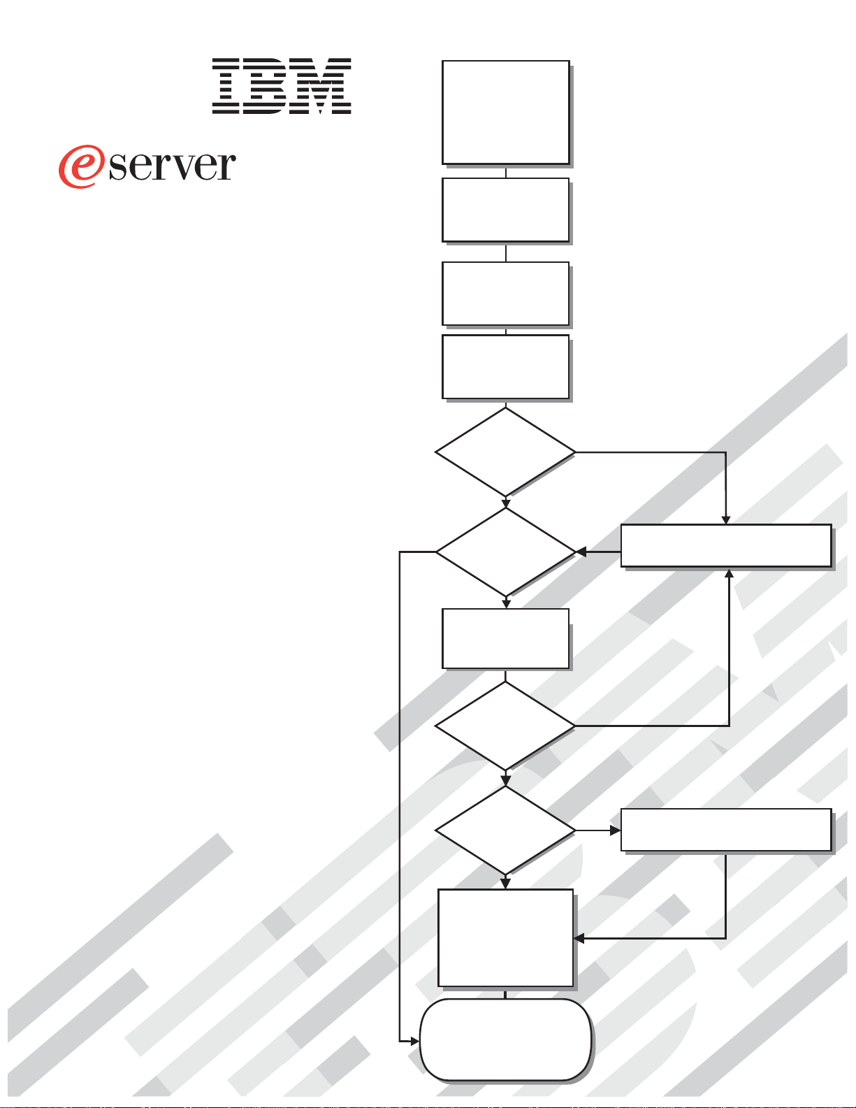
Your server
Start the server
Yes
preconfigured?
Use ServerGuide to
configure hardware
Did configuration
ServerGuide to
install operating
Did the server
start correctly?
Yes
Is the Server
No
set up and
complete?
Yes
Use
system?
No
No
No
Go to the Server Support
flow chart
Go to the Web for instructions,
http://www.ibm.com/pc/support
Yes
Install applications,
such as IBM systems
management software
and IBM ServeRAID
programs
System is ready to use.
Go to the Server Support
flow chart to register
and profile your server.
Page 2
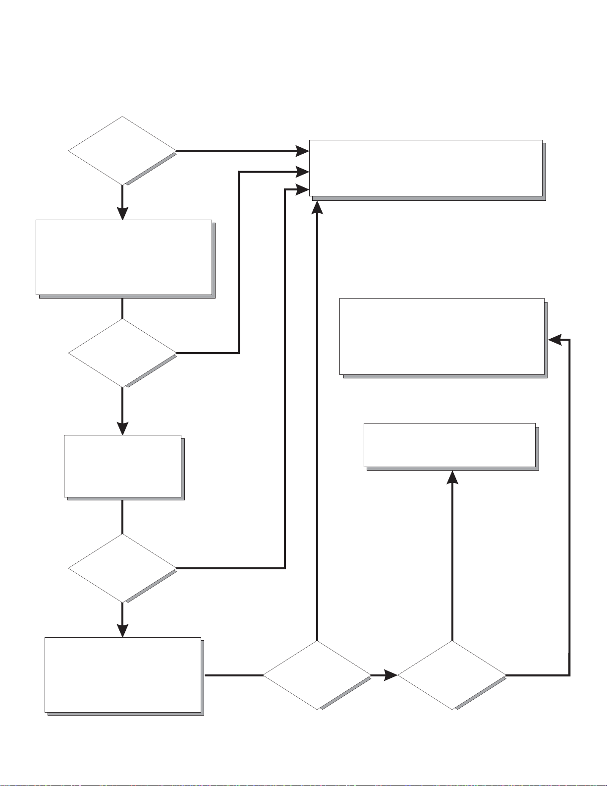
Server Support
Server working
properly?
Yes
No
Check all cables for loose connections
and verify that all optional devices you
installed are on the ServerProven list.
You can view the ServerProven list at
http://www.ibm.com/pc/compat/
Problem
solved?
®
Yes
No
Register your computer. Go to
http://www.ibm.com/pc/register/
View information about IBM support line at
http://www.ibm.com/services/sl/products/
or view support telephone numbers at
http://www.ibm.com/planetwide/
Use the troubleshooting
information provided with
your server to determine
the cause of the problem
and the action to take.
Problem
solved?
Yes
No
Flash the latest levels of BIOS,
service processor, diagnostics,
and RAID code.
You can download this code at
http://www.ibm.com/pc/support/
Yes
Problem
solved?
View support telephone numbers at
http://www.ibm.com/planetwide/
Hardware
No Software
Hardware or
software problem?
Page 3

ER s e r v e r
xSeries 445 Type 8870
Installation Guide
Page 4

©
US
Note: Before using this information and the product it supports, read the general information in
Appendix A, “Getting help and technical assistance,” on page 81, Appendix B, “IBM Statement of
Limited Warranty Z125-4753-07 11/2002,” on page 83, and Appendix C, “Notices,” on page 99.
Second Edition (January 2004)
Copyright International Business Machines Corporation 2004. All rights reserved.
Government Users Restricted Rights – Use, duplication or disclosure restricted by GSA ADP Schedule Contract
with IBM Corp.
Page 5

62
©
Contents
Safety . . . . . . . . . . . . . . . . . . . . . . . . . . . .v
Chapter 1. Introduction . . . . . . . . . . . . . . . . . . . . . .1
The IBM
Eserver
Documentation CD . . . . . . . . . . . . . . . . .2
Hardware and software requirements . . . . . . . . . . . . . . . .2
Using the Documentation Browser . . . . . . . . . . . . . . . . .2
Notices and statements used in this publication . . . . . . . . . . . . .3
Features and specifications . . . . . . . . . . . . . . . . . . . . .4
Major components of the xSeries 445 server . . . . . . . . . . . . . .5
Chapter 2. Installing options . . . . . . . . . . . . . . . . . . . .7
Installation guidelines . . . . . . . . . . . . . . . . . . . . . . .7
System reliability guidelines . . . . . . . . . . . . . . . . . . . .7
Working inside the server with the power on . . . . . . . . . . . . .8
Handling static-sensitive devices . . . . . . . . . . . . . . . . . .8
Opening the cover . . . . . . . . . . . . . . . . . . . . . . . .9
The SMP Expansion Module . . . . . . . . . . . . . . . . . . . .9
Removing an SMP Expansion Module and cover . . . . . . . . . . .11
Installing and replacing a microprocessor . . . . . . . . . . . . . .15
Installing a memory module . . . . . . . . . . . . . . . . . . .19
Installing DIMMs . . . . . . . . . . . . . . . . . . . . . . .21
Reinstalling an SMP Expansion Module and cover . . . . . . . . . . .23
Installing an adapter . . . . . . . . . . . . . . . . . . . . . . .26
Cabling a ServeRAID adapter . . . . . . . . . . . . . . . . . .29
Installing the serial port . . . . . . . . . . . . . . . . . . . . . .31
Completing the installation . . . . . . . . . . . . . . . . . . . . .33
Installing the server in the rack cabinet . . . . . . . . . . . . . . .33
Connecting the cables . . . . . . . . . . . . . . . . . . . . .34
Power cabling . . . . . . . . . . . . . . . . . . . . . . . .48
SCSI cabling . . . . . . . . . . . . . . . . . . . . . . . . .48
USB cabling . . . . . . . . . . . . . . . . . . . . . . . . .48
Video cabling . . . . . . . . . . . . . . . . . . . . . . . .48
Mouse cabling . . . . . . . . . . . . . . . . . . . . . . . .48
Keyboard cabling . . . . . . . . . . . . . . . . . . . . . . .49
Gigabit Ethernet cabling . . . . . . . . . . . . . . . . . . . .49
Remote Supervisor Adapter cabling . . . . . . . . . . . . . . . .49
Copyright IBM Corp. 2004
Chapter 3. Server controls, LEDs, and power . . . . . . . . . . . . .51
Front view . . . . . . . . . . . . . . . . . . . . . . . . . .51
Rear view . . . . . . . . . . . . . . . . . . . . . . . . . . .53
Server power features . . . . . . . . . . . . . . . . . . . . . .56
Turning on the server . . . . . . . . . . . . . . . . . . . . .56
Turning off the server . . . . . . . . . . . . . . . . . . . . .57
Chapter 4. Configuring your server . . . . . . . . . . . . . . . .59
Using the ServerGuide Setup and Installation CD . . . . . . . . . . . .60
Using the Configuration/Setup Utility program . . . . . . . . . . . . .60
Using the LSI Logic Configuration Utility program . . . . . . . . . . . .61
Using the ServeRAID configuration programs . . . . . . . . . . . . . .62
Using the Remote Supervisor Adapter . . . . . . . . . . . . . . . .62
Using the Integrated System Management Firmware Update Utility program
Configuring scalable partitions . . . . . . . . . . . . . . . . . . .63
Creating a scalable partition . . . . . . . . . . . . . . . . . . .63
iii
Page 6

iv
Deleting a scalable partition . . . . . . . . . . . . . . . . . . .65
Chapter 5. Updating IBM Director . . . . . . . . . . . . . . . . .67
Chapter 6. Solving problems . . . . . . . . . . . . . . . . . . .69
Diagnostic tools overview . . . . . . . . . . . . . . . . . . . . .69
POST beep code descriptions . . . . . . . . . . . . . . . . . . .70
ServerGuide startup problems . . . . . . . . . . . . . . . . . . .70
Troubleshooting charts . . . . . . . . . . . . . . . . . . . . . .71
Light path diagnostics feature overview . . . . . . . . . . . . . . . .76
Identifying problems using the light path diagnostics feature . . . . . . .77
Light path diagnostics table . . . . . . . . . . . . . . . . . . .78
Appendix A. Getting help and technical assistance . . . . . . . . . .81
Before you call . . . . . . . . . . . . . . . . . . . . . . . . .81
Using the documentation . . . . . . . . . . . . . . . . . . . . .81
Getting help and information from the World Wide Web . . . . . . . . . .82
Software service and support . . . . . . . . . . . . . . . . . . .82
Hardware service and support . . . . . . . . . . . . . . . . . . .82
Appendix B. IBM Statement of Limited Warranty Z125-4753-07 11/2002 . .83
Part 1 - General Terms . . . . . . . . . . . . . . . . . . . . . .83
Part 2 - Country-unique Terms . . . . . . . . . . . . . . . . . . .86
Part 3 - Warranty Information . . . . . . . . . . . . . . . . . . .97
Appendix C. Notices . . . . . . . . . . . . . . . . . . . . . .99
Edition notice . . . . . . . . . . . . . . . . . . . . . . . . .99
Trademarks . . . . . . . . . . . . . . . . . . . . . . . . . . 100
Important notes . . . . . . . . . . . . . . . . . . . . . . . . 101
Product recycling and disposal . . . . . . . . . . . . . . . . . . 101
Battery return program . . . . . . . . . . . . . . . . . . . . . 102
Electronic emission notices . . . . . . . . . . . . . . . . . . . . 102
Federal Communications Commission (FCC) statement . . . . . . . . 102
Industry Canada Class A emission compliance statement . . . . . . . . 103
Australia and New Zealand Class A statement . . . . . . . . . . . . 103
United Kingdom telecommunications safety requirement . . . . . . . . 103
European Union EMC Directive conformance statement . . . . . . . . 103
Taiwanese Class A warning statement . . . . . . . . . . . . . . . 103
Chinese Class A warning statement . . . . . . . . . . . . . . . . 104
Japanese Voluntary Control Council for Interference (VCCI) statement
104
Power cords . . . . . . . . . . . . . . . . . . . . . . . . . 104
Index . . . . . . . . . . . . . . . . . . . . . . . . . . . . 107
xSeries 445 Type 8870: Installation Guide
Page 7
©
Safety
Before installing this product, read the Safety Information.
Antes de instalar este produto, leia as Informações de Segurança.
Pred instalací tohoto produktu si prectete prírucku bezpecnostních instrukcí.
Læs sikkerhedsforskrifterne, før du installerer dette produkt.
Lees voordat u dit product installeert eerst de veiligheidsvoorschriften.
Ennen kuin asennat tämän tuotteen, lue turvaohjeet kohdasta Safety Information.
Avant d’installer ce produit, lisez les consignes de sécurité.
Vor der Installation dieses Produkts die Sicherheitshinweise lesen.
Prima di installare questo prodotto, leggere le Informazioni sulla Sicurezza.
Copyright IBM Corp. 2004
Les sikkerhetsinformasjonen (Safety Information) før du installerer dette produktet.
Antes de instalar este produto, leia as Informações sobre Segurança.
v
Page 8
To
v Do
v
v
v
v
v
v
To
To
1.
2.
3.
4.
5.
1.
2.
3.
4.
vi
Antes de instalar este producto, lea la información de seguridad.
Läs säkerhetsinformationen innan du installerar den här produkten.
Statement 1:
DANGER
Electrical
current from power, telephone, and communication cables is
hazardous.
avoid a shock hazard:
not connect or disconnect any cables or perform installation,
maintenance, or reconfiguration of this product during an electrical
storm.
Connect all power cords to a properly wired and grounded electrical
outlet.
Connect to properly wired outlets any equipment that will be attached to
this product.
When possible, use one hand only to connect or disconnect signal
cables.
Never turn on any equipment when there is evidence of fire, water, or
structural damage.
Disconnect the attached power cords, telecommunications systems,
networks, and modems before you open the device covers, unless
instructed otherwise in the installation and configuration procedures.
Connect and disconnect cables as described in the following table when
installing, moving, or opening covers on this product or attached
devices.
Connect:
Turn everything OFF.
First, attach all cables to devices.
Attach signal cables to connectors.
Attach power cords to outlet.
Turn device ON.
xSeries 445 Type 8870: Installation Guide
Disconnect:
Turn everything OFF.
First, remove power cords from outlet.
Remove signal cables from connectors.
Remove all cables from devices.
Page 9
a
Do
v
v
v
of
v Do
v
Statement 2:
CAUTION:
When replacing the lithium battery, use only IBM Part Number 33F8354 or an
equivalent type battery recommended by the manufacturer. If your system has
module containing a lithium battery, replace it only with the same module
type made by the same manufacturer. The battery contains lithium and can
explode if not properly used, handled, or disposed of.
not:
Throw or immerse into water
Heat to more than 100°C (212°F)
Repair or disassemble
Dispose
the battery as required by local ordinances or regulations.
Statement 3:
CAUTION:
When laser products (such as CD-ROMs, DVD drives, fiber optic devices, or
transmitters) are installed, note the following:
not remove the covers. Removing the covers of the laser product could
result in exposure to hazardous laser radiation. There are no serviceable
parts inside the device.
Use of controls or adjustments or performance of procedures other than
those specified herein might result in hazardous radiation exposure.
DANGER
Some
laser products contain an embedded Class 3A or Class 3B laser
diode. Note the following.
Laser radiation when open. Do not stare into the beam, do not view directly
with optical instruments, and avoid direct exposure to the beam.
Safety
vii
Page 10
≥ 18 kg
≥ 32 kg
≥ 55 kg
Statement 4:
(39.7 lb)
(70.5 lb)
(121.2 lb)
CAUTION:
Use safe practices when lifting.
Statement 5:
CAUTION:
The power control button on the device and the power switch on the power
supply do not turn off the electrical current supplied to the device. The device
also might have more than one power cord. To remove all electrical current
from the device, ensure that all power cords are disconnected from the power
source.
2
1
viii
xSeries 445 Type 8870: Installation Guide
Page 11
a
Do
a
Statement 8:
CAUTION:
Never remove the cover on a power supply or any part that has the following
label attached.
Hazardous voltage, current, and energy levels are present inside any
component that has this label attached. There are no serviceable parts inside
these components. If you suspect a problem with one of these parts, contact
service technician.
Statement 10:
CAUTION:
not place any object weighing more than 82 kg (180 lb) on top of
rack-mounted devices.
>82 kg (180 lb)
Statement 13:
DANGER
Overloading
branch circuit is potentially a fire hazard and a shock hazard
under certain conditions. To avoid these hazards, ensure that your system
electrical requirements do not exceed branch circuit protection
requirements. Refer to the information that is provided with your device for
electrical specifications.
Safety
ix
Page 12

x
WARNING: Handling the cord on this product or cords associated with accessories
sold with this product, will expose you to lead, a chemical known to the State of
California to cause cancer, and birth defects or other reproductive harm. Wash
hands after handling.
ADVERTENCIA: El contacto con el cable de este producto o con cables de
accesorios que se venden junto con este producto, pueden exponerle al plomo, un
elemento químico que en el estado de California de los Estados Unidos está
considerado como un causante de cancer y de defectos congénitos, además de
otros riesgos reproductivos. Lávese las manos después de usar el producto.
xSeries 445 Type 8870: Installation Guide
Page 13

on
v
v
v
v
to
1. Go to
2. In
3. On
4. In
5.
©
Chapter 1. Introduction
This Installation Guide contains instructions for setting up your IBM
xSeries
®
445 Type 8870 server and basic instructions for installing some options.
®
ERserver
™
More detailed instructions for installing options are in the Option Installation Guide
the IBM xSeries Documentation CD, which comes with your server.
This document contains information about:
Setting up and cabling your server
Starting and configuring your server
Installing some options
Solving problems
server might have features that are not described in the documentation that
Your
you received with the server. The documentation might be updated occasionally to
include information about those features, or technical updates might be available to
provide additional information that is not included in your server documentation.
These updates are available from the IBM Web site. Complete the following steps
check for updated documentation and technical updates:
http://www.ibm.com/pc/support/.
the Learn section, click Online publications.
the ″Online publications″ page, in the Brand field, select Servers.
the Family field, select xSeries 445.
Click Continue.
Your server comes with an IBM ServerGuide
™
Setup and Installation CD to help
you configure the hardware, install device drivers, and install the operating system.
Your server comes with a limited warranty. You can obtain up-to-date information
about your server and other IBM server products at
http://www.ibm.com/eserver/xseries/.
Record information about your server in the following table. You will need this
information when you register your server with IBM.
Product name
Machine type
Model number
Serial number
IBM
Eserver
xSeries 445 server
8870
_____________________________________________
_____________________________________________
The model and serial numbers are on a label on the lower-left side of the bezel, just
above the hard disk drives.
See the Rack Installation Instructions for complete rack installation and removal
instructions. For a list of supported options for your server, see the ServerProven
®
list at http://www.ibm.com/pc/compat/.
Copyright IBM Corp. 2004
1
Page 14
v
v
v 32 MB of
v
a
v If
2
4
P
C
I
B
o
a
r
d
t
e
m
M
a
n
a
g
e
m
e
n
t
B
o
a
r
d
M
id
p
l
a
n
e
B
o
a
r
L
i
g
h
t
P
a
t
h
D
i
a
g
d
n
o
s
t
i
c
s
U
p
p
e
r
C
E
C
L
o
w
e
r
C
E
C
3
1
2
ID label
NOTE: FOR PROPER
FRONT OF BOX
5
S
y
s
6
I
/
O
B
o
a
r
d
C
o
m
m
o
n
F
R
U
N
u
m
b
e
r
s
N
OTE: FOR
PR
OPER
AI
RFLO
W, REPLAC
E FANWITHIN
FRO
NT OF BO
AIRFLO
W, REPLACE
2 MINUTES
X
F
ANWI
THIN
2 MINUTES
Figure 1. xSeries 445 server
The IBM
Eserver
The IBM
Documentation CD
Eserver
Documentation CD contains documentation for your server in
Portable Document Format (PDF) and includes the IBM Documentation Browser to
help you find information quickly.
Hardware and software requirements
The IBM
hardware and software:
Eserver
Microsoft
®
xSeries 445 Documentation CD requires the following minimum
Windows NT
®
4.0 (with Service Pack 3 or later), Windows 98,
Windows 2000, or Red Hat Linux
100 MHz microprocessor
RAM
Adobe Acrobat Reader 3.0 (or later) or xpdf, which comes with Linux operating
systems
Note: Acrobat Reader software is included on the CD, and you can install it
when you run the Documentation Browser.
Using the Documentation Browser
Use the Documentation Browser to browse the contents of the CD, read brief
descriptions of the books, and view books using Adobe Acrobat Reader or xpdf.
The Documentation Browser automatically detects the regional settings in use in
your system and displays the books in the language for that region (if available). If
book is not available in the language for that region, the English version is
displayed.
Use one of the following procedures to start the Documentation Browser:
Autostart is enabled, insert the CD into your CD-ROM drive. The
Documentation Browser starts automatically.
xSeries 445 Type 8870: Installation Guide
Page 15

If
– If
– If
sh
To
v
v
v
v
to
v
v
Autostart is disabled or is not enabled for all users:
you are using a Windows operating system, insert the CD into your
CD-ROM drive and click Start --> Run. In the Open field, type
e:\win32.bat
where e is the drive letter of your CD-ROM drive, and click OK.
you are using Red Hat Linux, insert the CD into your CD-ROM drive; then,
run the following command from the /mnt/cdrom directory:
runLinux.sh
Select your server from the Product menu. The Available Topics list displays all
the books for your server. Some books might be in folders. A plus sign (+) indicates
each folder or book that has additional books under it. Click the plus sign to display
the additional books.
When you select a book, a description of the book appears under Topic
Description. To select more than one book, press and hold the Ctrl key while you
select the books. Click View Book to view the selected book or books in Acrobat
Reader or xpdf. If you selected more than one book, all the selected books are
opened in Acrobat Reader or xpdf.
search all the books, type a word or word string in the Search field and click
Search. The books in which the word or word string appears are listed in order of
the most occurrences. Click a book to view it, and press Crtl+F to use the Acrobat
search function or Alt+F to use the xpdf search function within the book.
Click Help for detailed information about using the Documentation Browser.
Notices and statements used in this publication
The caution and danger statements that appear in this publication are also in the
multilingual Safety Information publication, which is on the IBM xSeries
Documentation CD. Each statement is numbered for reference to the corresponding
statement in the Safety Information publication.
The following notices and statements are used in the documentation:
Notes: These notices provide important tips, guidance, or advice.
Important: These notices provide information or advice that might help you avoid
inconvenient or problem situations.
Attention: These notices indicate potential damage to programs, devices, or
data. An attention notice is placed just before the instruction or situation in which
damage could occur.
Caution: These statements indicate situations that can be potentially hazardous
you. A caution statement is placed just before the description of a potentially
hazardous procedure step or situation.
Danger: These statements indicate situations that can be potentially lethal or
extremely hazardous to you. A danger statement is placed just before the
description of a potentially lethal or extremely hazardous procedure step or
situation.
Chapter 1. Introduction
3
Page 16

v
– Up to 8
OR – Up to 4
to
v
v
v
v
v
MB
v
v
v
v
v
v
v
v
v
v
v
on
v
v
v
v
on
v
v
(4
v
v
v
v
v
v
v
v
–
–
–
–
–
–
v
v
v
v
v
v
v
v
–
–
–
–
–
v
v
v
v
–
–
–
–
–
–
1.
of
2.
by
in a
4
Features and specifications
The following information is a summary of the features and specifications for your
server.
Microprocessor:
Supports the following microprocessors:
Intel
®
Xeon MP
microprocessors (16 in a 16-way
configuration)
Intel Xeon DP
microprocessors
Note: Use the Information in BIOS
determine the type and speed of
the microprocessors installed in your
server.
v
IBM XA-32
™
chip set with integrated
memory, I/O, system cache, and remote
I/O controllers
Memory:
Minimum: 2 GB
Maximum: 64 GB
Type: 2-way interleaved PC1600, DDR
SDRAM, registered DIMMs only
Supports 512 MB, 1GB and 2 GB dual
inline memory modules (DIMMs)
™
XceL4
Server Accelerator Cache (64
per SMP Expansion Module)
Drives:
Diskette: 1.44 MB
DVD-ROM
Supports up to two internal Ultra320
SCSI hard disk drives
™
Active
PCI-X expansion slots:
Six 64-bit Active PCI-X expansion slots:
Two 66 MHz PCI-X slots
Two 100 MHZ PCI-X slots
Two 133 MHZ PCI-X slots
Additional PCI-X slots available in an
optional remote I/O expansion
enclosure
Cooling:
Four hot-swap fans:
Two 150 mm x 51 mm redundant fans
Two 150 mm x 38 mm fans
Acoustical
noise emissions:
Sound power, idling: 6.5 bel maximum
Sound power, operating: 6.5 bel
maximum
Power supply:
Two hot-swap power supplies (depending
model):
550 watts at 110 V ac or 1050 watts at
220 V ac
600 watts at 110 V ac or 1200 watts at
220 V ac
Video:
Models with the Remote Supervisor
Adapter II-EXA: ATI Radeon RV-100
video controller on the RSA II-EXA
adapter
Models with the Remote Supervisor
Adapter: ATI Rage XL video controller
the system board
PCI bus interface
Compatible with SVGA
U):
Size
Height: 17.8 cm (7 inches, 4 U)
Depth: 69.85 cm (27.5 inches)
Width: 48.3 cm (19 inches)
Maximum weight: 50 kg (110 lb)
depending on your configuration
Integrated
functions:
Broadcom 5704 Dual Gigabit
10/100/1000 Ethernet controller
Light path diagnostics feature
LSI Logic 1030 Dual Ultra320 SCSI
controller
Remote Supervisor Adapter II-EXA
ATI Radeon RV-100 video controller
Ethernet port
RSA II-EXA breakout port
Remote Supervisor Adapter
v
ASM interconnect port
Ethernet port
Management port
IDE controller
v
RXE Management Port
Three USB ports
Keyboard port
SCSI port
Mouse port
Symmetrical multiprocessing (SMP)
Expansion Ports (three or six ports
depending on your configuration)
Two remote I/O expansion enclosure
(RXE) Expansion Ports
Environment:
Air temperature:
Server on: 10° to 35°C (50.0° to
95.0°F). Altitude: 0 to 914 m (2998.7
ft).
Server on: 10° to 32° C (50.0° to
89.6° F). Altitude: 914 m (2998.7 ft) to
2133 m (6998.0 ft).
Server off: -40° to 60° C
(-104° to 140° F). Maximum altitude:
2133 m (6998.0 ft).
v
Humidity:
Server on: 8% to 80%
Server off: 5% to 100%
output:
Heat
Approximate heat output in British thermal
units (Btu) per hour:
Minimum configuration: 855 Btu (250
watts)
Maximum configuration: 2726 Btu (800
watts)
Electrical
input:
Sine-wave input (50 or 60 Hz) required
Input voltage low range:
Minimum: 100 V ac
Maximum: 127 V ac
v
Input voltage high range:
Minimum: 200 V ac
Maximum: 240 V ac
Input kilovolt-amperes (kVA)
v
approximately:
Minimum: 0.250 kVA
Maximum: 0.800 kVA
Notes:
Power consumption and heat output
vary depending on the number and type
optional features installed and the
power-management optional features in
use.
These levels were measured in
controlled acoustical environments
according to the procedures specified
the American National Standards
Institute (ANSI) S12.10 and ISO 7779
and are reported in accordance with
ISO 9296. Actual sound-pressure levels
given location might exceed the
average values stated because of room
reflections and other nearby noise
sources. The declared sound-power
levels indicate an upper limit, below
which a large number of computers will
operate.
xSeries 445 Type 8870: Installation Guide
Page 17

Major components of the xSeries 445 server
The following illustration shows the locations of major components in your server.
Note: The illustrations in this document might differ slightly from your hardware.
Chapter 1. Introduction
5
Page 18
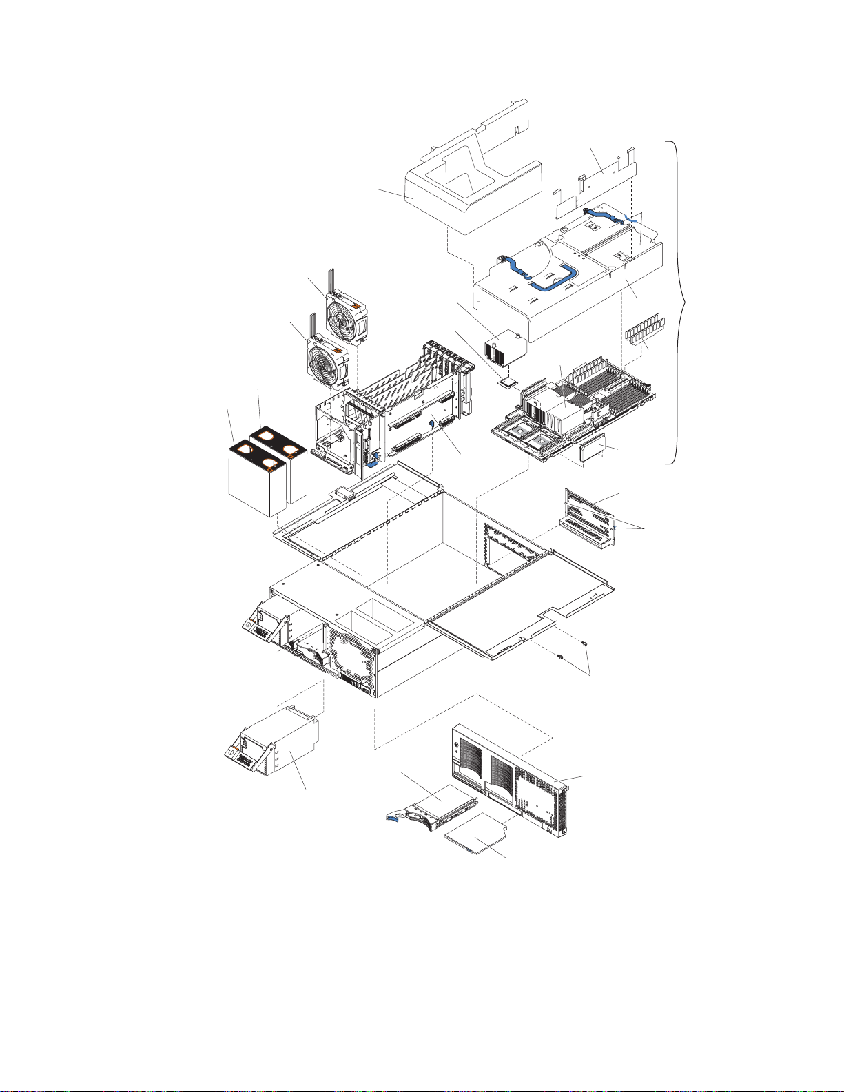
6
Retention bracket
Fan 1
N
O
T
E
:
F
O
F
R
O
Fan 2
R
P
R
O
P
E
R
A
I
R
F
L
N
T
O
F
B
O
X
Fan 3
N
O
T
E
:
F
O
R
P
R
O
P
E
R
F
R
O
N
T
O
F
B
O
X
O
W,
R
E
P
L
A
C
E
F
A
N
W
I
T
H
I
N
2
Fan 4
A
I
R
F
L
O
W,
R
E
P
L
A
C
E
F
A
N
W
I
T
M
I
N
U
T
E
S
H
I
N
2
M
I
N
U
T
E
S
SMP baffle
Heat-sink
Microprocessor
Center
plane
Microprocessor
baffle
DIMM
access
doors
SMP
Cover
Expansion
Module
DIMM
VRM
EMC shield
(for single SMP
Expansion Module)
Thumbscrews
Hot-swap
power supply
Figure 2. Major components of the xSeries 445 server
xSeries 445 Type 8870: Installation Guide
Hard disk
drive
Shipping thumbscrews
Bezel
DVD-ROM
drive
Page 19

up
v
v
v
v
v
v
to
v
v
To
v
v If
v
v Do
To
v
v
v
v
©
Chapter 2. Installing options
This chapter provides basic instructions for installing hardware options in your
server. These instructions are intended for users who are experienced with setting
IBM server hardware. If you need more detailed instructions, see the Option
Installation Guide on the IBM xSeries Documentation CD.
Installation guidelines
Before you begin to install options in your server, read the following information:
Read the safety information beginning on page v and the guidelines in “Handling
static-sensitive devices” on page 8. This information will help you work safely
with your server and options.
Make sure that you have an adequate number of properly grounded electrical
outlets for your server, monitor, and other devices that you will connect to the
server.
Back up all important data before you make changes to disk drives.
Have a small, flat-blade screwdriver available.
You do not need to turn off the server to install or replace hot-swap power
supplies, hot-swap fans, or hot-plug Universal Serial Bus (USB) devices.
Blue on a component indicates touch points, where you can grip the component
remove it from or install it in the server, open or close a latch, and so on.
Orange on a component or an orange label on or near a component indicates
that the component can be hot-swapped, which means that if the server and
operating system support hot-swap capability, you can remove or install the
component while the server is running. (Orange can also indicate touch points on
hot-swap components.) See the instructions for removing or installing a specific
hot-swap component for any additional procedures that you might have to
perform before you remove or install the component.
For a list of supported options for your server, go to
http://www.ibm.com/pc/compat/.
System reliability guidelines
help ensure proper cooling and system reliability, make sure that:
Each of the drive bays has a drive or a filler panel and electromagnetic
compatibility (EMC) shield installed in it.
the server has only one symmetrical multiprocessing (SMP) Expansion Module
installed, ensure that the SMP baffle is installed during normal operation.
There is adequate space around the server to allow the server cooling system to
work properly. Leave approximately 50 mm (2.0 in.) of open space around the
front and rear of the server. Do not place objects in front of the fans.
not leave open spaces above or below an installed server in a rack cabinet.
prevent damage to server components, always install a blank filler panel to
cover the open space and to ensure proper air circulation.
You have followed the cabling instructions that come with optional adapters.
You have replaced a failed fan within 48 hours.
You have replaced a hot-swap drive within 2 minutes of removal.
Microprocessor socket 4 always contains either a microprocessor baffle or a
microprocessor and heat sink.
Copyright IBM Corp. 2004
7
Page 20

v
v Do
v
v
v
To
To
v
v
v Do
v Do
v
v
on a
v
8
Working inside the server with the power on
Your server supports hot-plug, hot-add, and hot-swap devices and is designed to
operate safely while it is turned on and the cover is removed. Follow these
guidelines when you work inside a server that is turned on:
Avoid wearing loose-fitting clothing on your forearms. Button long-sleeved shirts
before working inside the server; do not wear cuff links while you are working
inside the server.
not allow your necktie or scarf to hang inside the server.
Remove jewelry, such as bracelets, necklaces, rings, and loose-fitting wrist
watches.
Remove items from your shirt pocket, such as pens and pencils, that could fall
into the server as you lean over it.
Avoid dropping any metallic objects, such as paper clips, hairpins, and screws,
into the server.
Handling static-sensitive devices
Attention: Static electricity can damage electronic devices, including your server.
avoid damage, keep static-sensitive devices in their static-protective packages
until you are ready to install them.
reduce the possibility of damage from electrostatic discharge, observe the
following precautions:
Limit your movement. Movement can cause static electricity to build up around
you.
Handle the device carefully, holding it by its edges or its frame.
not touch solder joints, pins, or exposed circuitry.
not leave the device where others can handle and damage it.
While the device is still in its static-protective package, touch it to an unpainted
metal part of the server for at least 2 seconds. This drains static electricity from
the package and from your body.
Remove the device from its package and install it directly into the server without
setting down the device. If it is necessary to set down the device, place it back
into its static-protective package. Do not place the device on your server cover or
metal surface.
Take additional care when handling devices during cold weather. Heating reduces
indoor humidity and increases static electricity.
xSeries 445 Type 8870: Installation Guide
Page 21
1.
2.
3.
4.
v
or
v
v An
v If
Opening the cover
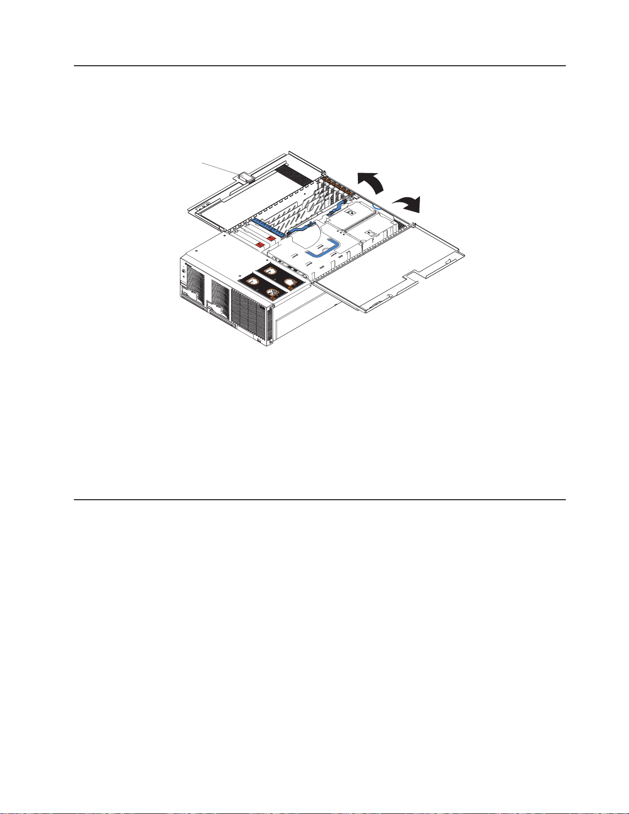
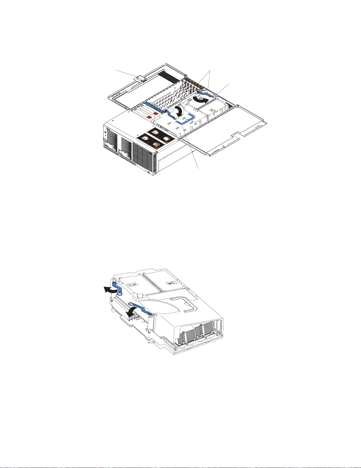
Complete the following steps to open the server cover:
Latch
Read the safety information beginning on page v and “Installation guidelines” on
page 7.
N
O
T
E
:
F
O
R
P
R
O
P
E
R
A
I
R
F
L
O
W,
R
E
P
N
O
T
E
:
F
F
R
L
A
C
E
F
A
F
O
R
P
R
O
P
O
N
T
O
F
B
O
N
R
W
O
I
N
T
T
H
I
O
N
F
2
E
B
R
A
I
R
F
L
O
X
M
O
I
X
N
U
T
E
W,
R
E
P
L
S
A
C
E
F
A
N
W
I
T
H
I
N
2
M
I
N
U
T
E
S
Figure 3. Opening the cover
Before opening the top cover, you must remove the rack-support wheels and
handles from the server. See the Rack Installation Instructions for information.
Press the release latch on the left half of the top cover to the right.
Using the finger hole in the release latch, open the left half of the cover; then,
open the right half of the cover.
Attention:
For proper cooling and airflow, close the cover before turning on
the server. Operating the server for extended periods of time (more than 30
minutes) with the cover open might damage server components.
The SMP Expansion Module
The SMP Expansion Module contains the XceL4 system cache, DIMMs,
microprocessors, and voltage regulator modules (VRMs). This section provides
instructions for removing and installing the SMP Expansion Module,
microprocessors, VRMs, and DIMMs.
The following notes describe components in the SMP Expansion Module and other
information that you must consider when installing an SMP Expansion Module:
Use two hands to install or remove an SMP Expansion Module. Do not allow the
expansion module to come in contact with the center plane while lifting it out of
setting it into the server.
For your server to operate properly, there must be a minimum of one SMP
Expansion Module installed.
SMP Expansion Module must contain at least one microprocessor and two
DIMMs.
there is only one SMP Expansion Module installed in the server, an SMP baffle
must be installed in place of the upper SMP Expansion Module to ensure proper
cooling of the server.
Chapter 2. Installing options
9
Page 22

v
v
10
v
When the minimum number of microprocessors are installed in the SMP
Expansion Module, a microprocessor baffle must be installed in microprocessor
socket 4 to ensure proper cooling within the server.
Before removing or installing SMP Expansion Modules, you must remove the
retention bracket or brackets and electromagnetic compatibility (EMC) shield from
the rear of the server.
You must run the Configuration/Setup Utility program whenever you remove or
replace an SMP Expansion Module or one of its associated options.
Locking levers
CAM opening
Figure 4. Complete SMP Expansion Module
xSeries 445 Type 8870: Installation Guide
Page 23
1.
2.
3.
a.
b.
Removing an SMP Expansion Module and cover
While installing options, you might need to remove one or both of the SMP
Expansion Modules. This section describes how to remove an SMP Expansion
Module from the server and how to remove the cover from the module.
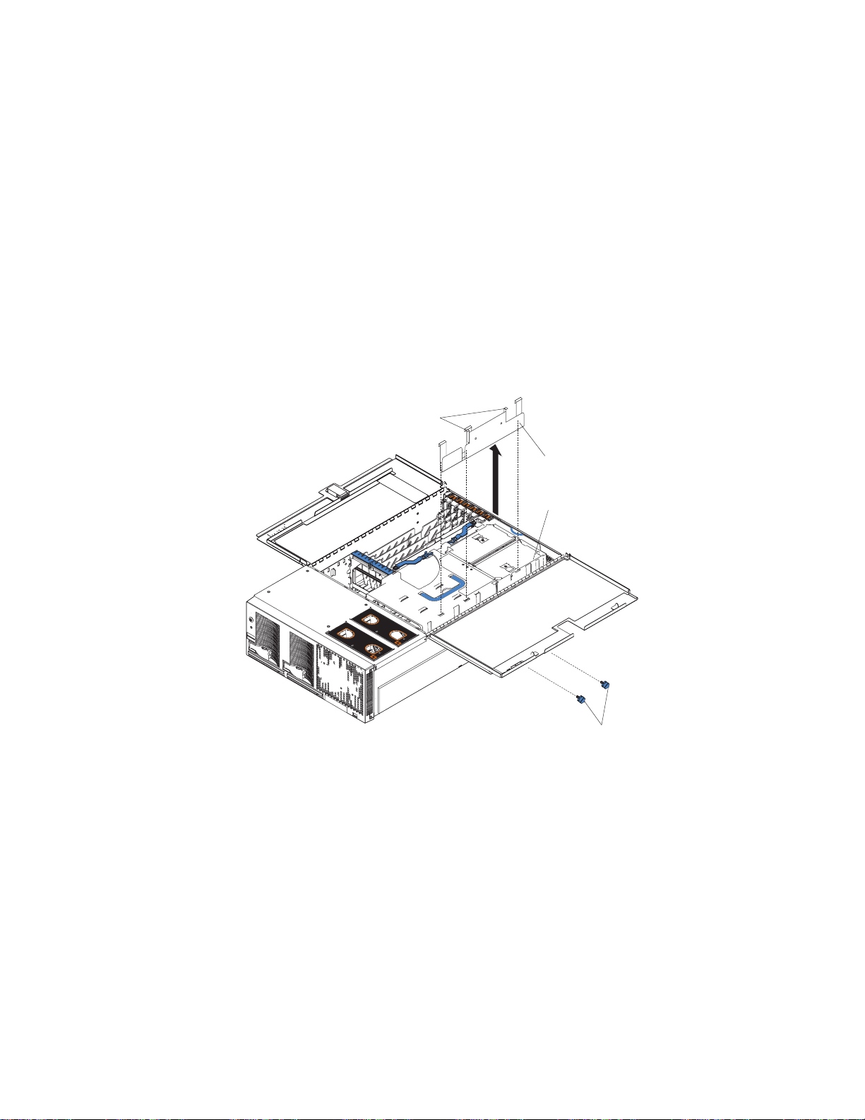
Complete the following steps to remove an SMP Expansion Module from the server:
Read the safety information beginning on page v and “Installation guidelines” on
page 7.
Turn off the server and peripheral devices, and disconnect the power cords and
external cables.
Open the top cover; then, remove the retention bracket or brackets from the
server.
Remove the shipping thumbscrews from the right side of the server.
Note: There are two shipping thumbscrews per retention bracket.
Retention bracket
removal handles
Retention bracket
SMP Expansion
Module
N
O
T
E
:
F
O
R
P
R
O
P
E
R
A
I
R
F
L
O
W,
R
E
P
N
O
T
E
:
F
F
R
O
L
A
C
E
F
A
F
O
R
P
R
O
P
N
T
O
F
B
O
N
R
W
O
I
N
T
T
H
I
O
N
F
2
E
B
R
A
I
R
F
L
O
X
M
O
I
X
N
U
T
E
W,
R
E
P
S
L
A
C
E
F
A
N
W
I
T
H
I
N
2
M
I
N
U
T
E
S
Shipping
thumbscrews
Figure 5. Removing the retention brackets and shipping thumbscrews
Grasp the retention bracket by the removal handles and lift it up and out of
the server. Store the retention bracket or brackets in a safe place for later
use.
Note: If there is one SMP Expansion Module installed, you will need to
remove the SMP baffle from the server; then, remove the retention
bracket from the lower SMP Expansion Module.
Chapter 2. Installing options
11
Page 24
a. If
b.
c.
5.
12
4.
Remove the EMC shield from the rear of the server:
necessary, disconnect the SMP Expansion Cables that are connected to
the SMP Expansion Modules.
Loosen the blue thumbscrews holding the EMC shield to the server.
EMC shields
ThumbscrewsThumbscrews
For use with one
SMP Module
Figure 6. EMC shields
Remove the EMC shield from the rear of the server.
N
O
T
E
:
F
O
R
P
R
O
P
E
R
A
I
R
F
L
O
W,
R
E
P
N
O
T
E
:
F
O
R
P
R
O
P
E
R
F
R
O
N
T
O
F
B
O
X
L
A
C
E
F
A
F
N
R
W
O
I
N
T
T
H
I
O
N
F
2
B
M
O
A
I
R
F
L
O
W,
R
E
P
L
A
C
E
F
I
X
N
U
T
E
A
N
W
S
I
T
H
I
N
2
M
I
N
U
T
E
S
For use with two
SMP Modules
SMP Expansion
Cables
EMC Shield
Figure 7. Removing the EMC shield
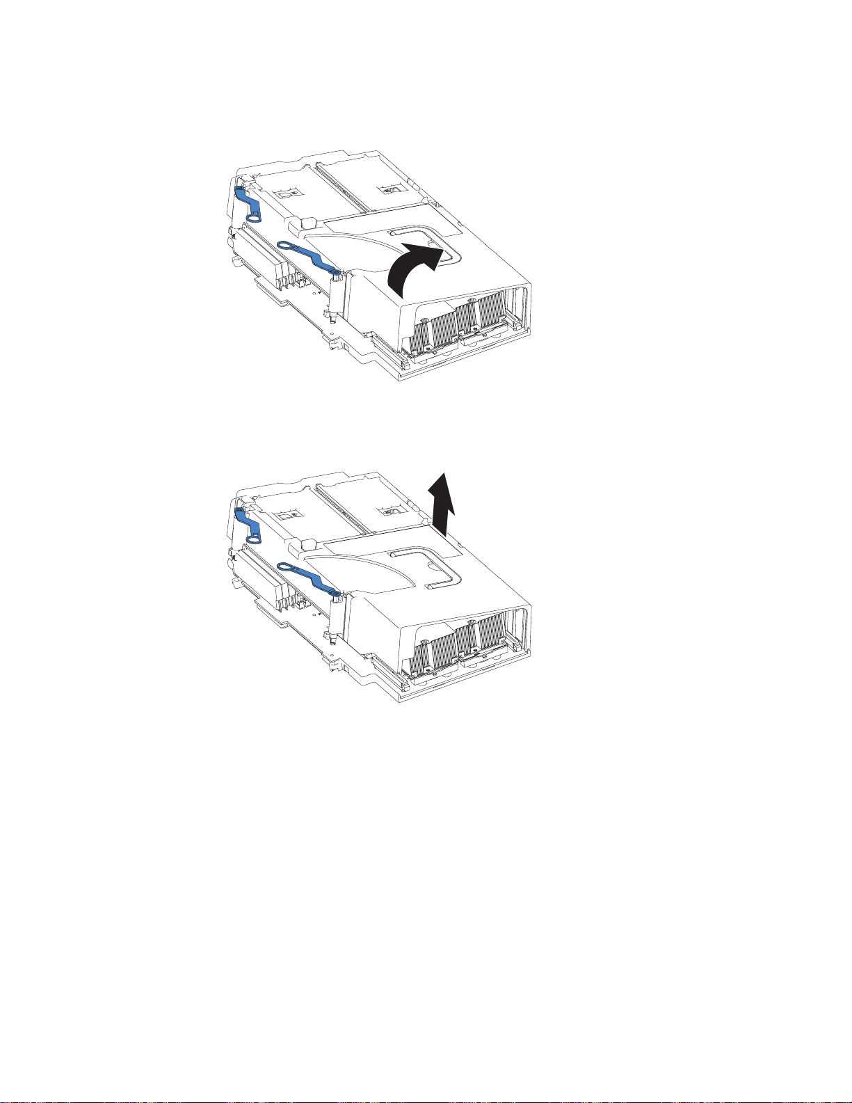
Grasp each of the locking levers on the top of the SMP Expansion Modules,
and lift them up slightly.
xSeries 445 Type 8870: Installation Guide
SMP baffle
Page 25
7.
8.
a.
b.
of
6.
Working from the right side of the server, rotate the two locking levers toward
you until they are fully extended, as shown.
Latch
Locking
levers
Finger relief
N
O
T
E
:
F
O
R
P
R
O
P
E
R
A
I
R
F
L
O
W,
R
E
P
N
O
T
E
:
F
F
R
L
A
C
E
F
A
F
O
R
P
R
O
P
O
N
T
O
F
B
O
N
R
W
O
I
N
T
T
H
I
O
N
F
2
E
B
R
A
I
R
F
L
O
X
M
O
I
X
N
U
T
E
W,
R
E
P
L
S
A
C
E
F
A
N
W
I
T
H
I
N
2
M
I
N
U
T
E
S
Handle
Figure 8. Rotate the locking levers to remove the SMP Expansion Module
Being careful not to damage the components on the center plane, use the
handle and the finger relief on the SMP Expansion Module cover to carefully lift
the SMP Expansion Module out of the server.
Remove the SMP Expansion Module cover:
Place the SMP Expansion Module on a flat, level surface.
Rotate the two locking levers until they are fully extended beyond the edge
the SMP Expansion Module cover. Do not force the locking levers past
the position shown in the illustration.
Figure 9. Fully extending the locking levers to remove the SMP Expansion Module cover
Chapter 2. Installing options
13
Page 26
d.
14
c.
Using the locking levers, lift the front edge of the cover off the SMP
Expansion Module.
Figure 10. Lifting the front of the cover
Lift the cover off the SMP Expansion Module.
Figure 11. Lifting the cover off the SMP Expansion Module
xSeries 445 Type 8870: Installation Guide
Page 27

v
v If
v To
v To
v
v An
v If
is in
v
v
v
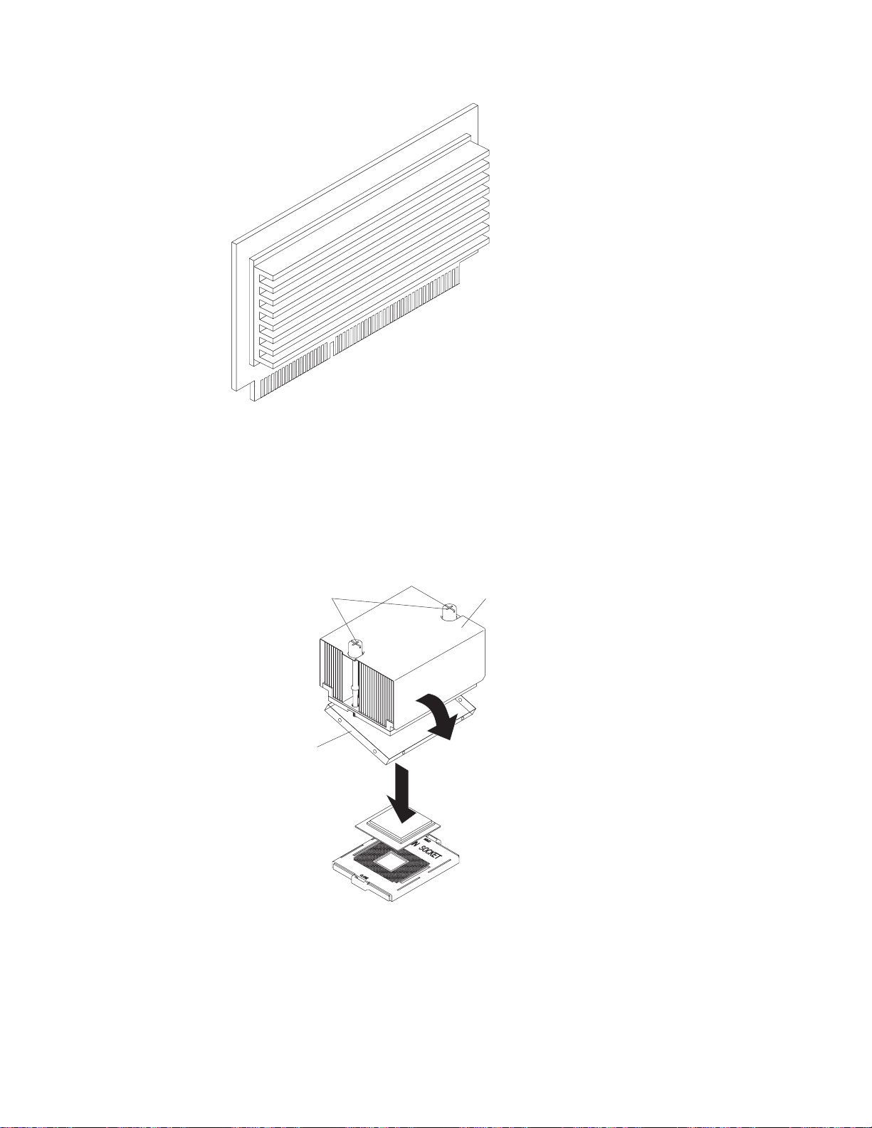
Installing and replacing a microprocessor
The following notes describe the types of microprocessors that your server supports
and other information that you must consider when installing a microprocessor:
Read the documentation that comes with the microprocessor to determine
whether you need to update the basic input/output system (BIOS) code in your
server. To download the most current level of BIOS code for the server, go to
http://www.ibm.com/pc/support/.
your server comes with Intel Xeon MP microprocessors, obtain an
SMP-capable operating system. For a list of supported operating systems, go to
http://www.ibm.com/pc/compat/.
order additional microprocessor or SMP Expansion Module options, contact
your IBM marketing representative or authorized reseller.
avoid damage and ensure proper server operation after you install a
replacement or an additional microprocessor, use a microprocessor that has the
same cache size, cache type, clock speed, and internal and external clock
frequencies as the microprocessors already installed in the individual SMP
Expansion Module. For a list of microprocessors supported by your server, see
the ServerProven list at http://www.ibm.com/pc/compat/ on the World Wide Web.
The microprocessor in socket 1 of the bottom SMP Expansion Module is the
startup (boot) microprocessor.
air baffle or microprocessor must be installed in microprocessor socket 4,
depending on your configuration.
you are adding Intel Xeon MP microprocessors, populate the empty
microprocessor sockets in numeric order, starting with socket 1. If you install the
microprocessors in the wrong order, the server will not start.
Attention: You must ensure that the locking lever on the microprocessor socket
the fully open position before you insert the microprocessor in the socket.
Failure to do so might result in permanent damage to the microprocessor,
microprocessor socket, and SMP expansion board. See Figure 13 on page 17.
Always install the heat sink that comes with the microprocessor.
Server models that come with Intel Xeon DP microprocessors support a
maximum of two microprocessors per SMP Expansion Module, installed in
microprocessor sockets 1 and 4.
Intel Xeon MP microprocessors are supported in microprocessor sockets 1, 2, 3,
and 4. Figure 12 on page 16 shows the location of the startup microprocessor
and its VRM on the SMP expansion board. It also shows the microprocessor
baffles and the VRM slots for the other microprocessor sockets.
Note: The illustrations in this document might differ slightly from your hardware.
Chapter 2. Installing options
15
Page 28
1.
on
2.
3. If
4.
5.
16
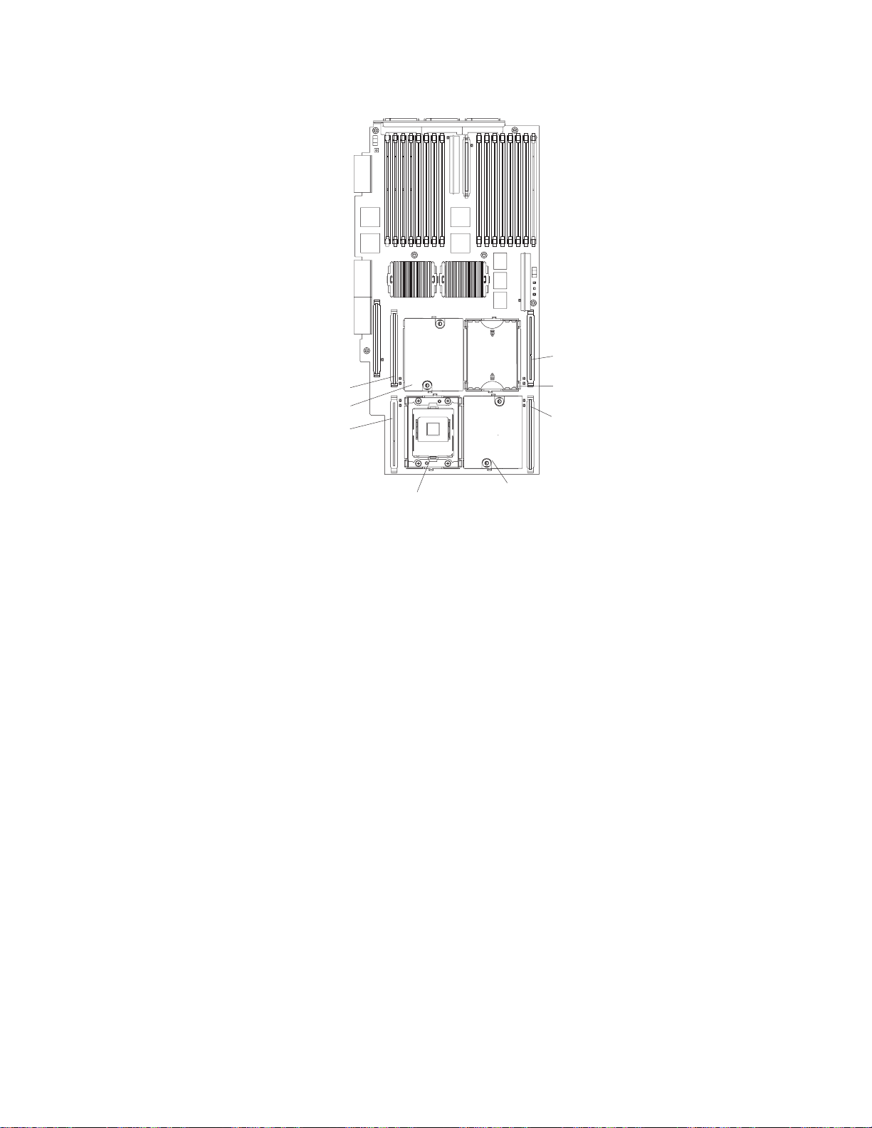
Microprocessor 4
VRM connector
Microprocessor 1 VRM
Microprocessor 1
Microprocessor 4
baffle
Microprocessor 2
Microprocessor 3
VRM
VRM connector
Microprocessor 3 socket
Microprocessor 2
Figure 12. Microprocessor connector and VRM locations
Complete the following steps to install a microprocessor:
Read the safety information beginning on page v and “Installation guidelines”
page 7.
Turn off the server and peripheral devices, disconnect the power cords, and
disconnect all external cables from the SMP Expansion Module; then, open the
cover (see “Opening the cover” on page 9 for details).
necessary, remove the SMP baffle or top SMP Expansion Module.
Note: If your server contains only one SMP Expansion Module, remove the
SMP baffle above it to gain access to the module. If your server
contains two SMP Expansion Modules, remove the top module to gain
access to the bottom or lower SMP Expansion Module.
Remove the SMP Expansion Module in which you plan to install the
microprocessor; then, remove the module cover and determine the socket
where the microprocessor is to be installed. For details, see “Removing an
SMP Expansion Module and cover” on page 11.
Determine which type of microprocessors are installed in your server. The
easiest way to do this is by the locations of the installed microprocessors in
the SMP Expansion Module. If the microprocessors are installed only in
sockets 1 and 4, your server came with Intel Xeon DP microprocessors. If the
microprocessors are installed in any other sockets, such as 1 and 2 or 1, 2,
and 3, your server came with Intel Xeon MP microprocessors.
xSeries 445 Type 8870: Installation Guide
Page 29
6. If
7.
8.
MP
3,
a.
b.
c.
d.
9.
Attention: When you handle static-sensitive devices, take precautions to
avoid damage from static electricity. For details about handling these devices,
see “Handling static-sensitive devices” on page 8.
necessary, remove the microprocessor baffle from the microprocessor
socket. Keep the microprocessor baffle for possible future use.
Touch the static-protective package containing the new microprocessor to any
unpainted metal surface on the server; then, remove the microprocessor from
the package.
Install the microprocessor:
Important: When installing Intel Xeon DP microprocessors, you must install
them in the following order: socket 1 then socket 4. When installing Intel Xeon
microprocessors, you must install them in the following order: sockets 1, 2,
and then 4.
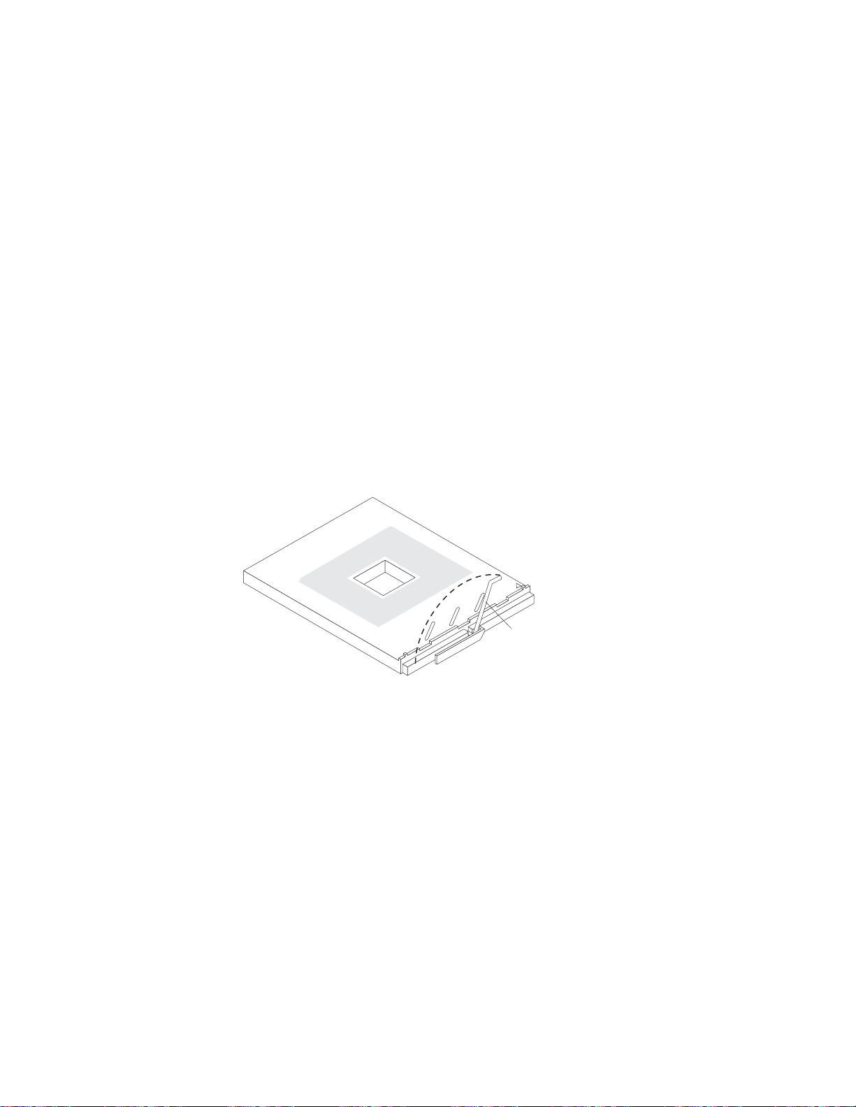
Remove the protective label from the microprocessor socket.
Rotate the locking lever on the microprocessor socket from its closed and
locked position until it stops or clicks in the fully open position
(approximately 135° angle), as shown.
Attention: You must ensure that the locking lever on the microprocessor
socket is in the fully open position before you insert the microprocessor in
the socket. Failure to do so might result in permanent damage to the
microprocessor, microprocessor socket, and SMP expansion board.
Lever open
Figure 13. Microprocessor locking lever fully open
Align the triangle icon on the microprocessor with the triangle icon on the
socket and press the microprocessor gently into the socket.
Attention: Make sure that the microprocessor is aligned correctly before
you proceed. To avoid bending the pins on the microprocessor, do not use
excessive force when pressing it into the socket.
Close the locking lever to secure the microprocessor.
Install the VRM in the slot adjacent to the microprocessor socket by holding
the new VRM by the upper corners, and plug it firmly into the slot.
Attention: The new microprocessor comes in a kit with a VRM. Some
microprocessor options contain a VRM with a clip to secure the VRM in the
slot. This clip is not needed for installations in your server and can be
discarded. When installing a new microprocessor, you must install the VRM
that comes in the kit.
Chapter 2. Installing options
17
Page 30
a.
b.
18
Figure 14. Microprocessor VRM
10.
Install the heat sink:
Remove the heat sink from its package and detach the protective cover
from the bottom of the heat sink.
Attention: Do not disturb or contaminate the heat-conducting grease on
the bottom of the new heat sink. Doing so damages its heat-conducting
capability and exposes the new microprocessor to overheating.
Captive screws
Protective cover
Heat sink
Figure 15. Placing the heat sink on the microprocessor
Align the heat sink over the microprocessor; then, carefully set it down on
top of the microprocessor.
xSeries 445 Type 8870: Installation Guide
Page 31

If
or
v
v To
v
v
c.
Using a screwdriver, secure the heat sink to the microprocessor socket on
the SMP board using the two captive mounting screws. Press firmly on the
screws and tighten them, alternating between them. Do not overtighten the
screws.
Close the SMP Expansion Module top cover; then, install the module in the
11.
server. For details, see “Reinstalling an SMP Expansion Module and cover” on
page 23.
12.
13.
you have other options to install or remove, do so now.
Close the cover on the server; then, install the server in the rack cabinet and
connect all external cables. For details, see “Installing the server in the rack
cabinet” on page 33.
14.
Turn on the server.
When you install or remove microprocessors, the server configuration
information changes. Therefore, you must change and save the new
configuration information by using the Configuration/Setup Utility program. See
the User’s Guide on the IBM xSeries Documentation CD.
Important: If your server will not start after replacing or installing a
microprocessor, you might have installed a microprocessor in the wrong socket
installed a microprocessor of a different type, or the VRM is not seated
properly. Ensure that you have installed the microprocessor in the correct
location and that it is of the same type. Also ensure that the VRM is properly
seated in the slot.
Installing a memory module
The following notes describe the types of dual inline memory modules (DIMMs) that
your server supports and other information that you must consider when installing
DIMMs:
IBM periodically makes updates available to provide enhancements to the
standard features of your server. Currently, your server supports the memory
mirroring and Memory ProteXion features of the Active Memory technology. Be
sure to check the IBM support Web site occasionally to ensure that you have the
most current levels of system software installed.
use the hot-add and hot-swap memory features, you must reconfigure your
server using the Configuration/Setup Utility program. See the User’s Guide on
the IBM xSeries Documentation CD for additional information.
Note: The server must have a minimum of 4 GB of memory installed before you
can configure the hot-add memory feature.
Your server operates with a minimum of two 512 MB DIMMs installed in slots 1
and 3 in the SMP Expansion Module. When installing or removing DIMMs, you
must install or remove the DIMMs two at a time and in the order described in this
section.
Use the instructions in “Installing DIMMs” on page 21 to help maintain
performance. See the ServerProven list at http://www.ibm.com/pc/compat/ for a
list of memory modules for use with your server.
Note: For optimum performance, balance the amount of memory between the
two ports.
Chapter 2. Installing options
19
Page 32

1 1 1 1, 3 2 1 2 9, 11 1 2 3 2, 4 2 2 4
1 3 5 5, 7 2 3 6
1 4 7 6, 8 2 4 8
v
v
v
20
Table 1. Memory installation order
Port
Bank
Pair
Slot number
10, 12
13, 15
14, 16
Bank 1 Bank 1
Bank 3 Bank 3
DIMM error
indicators are
built into
each handle.
Bank 2 Bank 4
Port 1
Bank 2 Bank 4
Port 2
Figure 16. DIMM banks
Each pair or bank of DIMMs must be of the same size and clock speed to ensure
the server will operate properly.
When you restart the server after you install or remove DIMMs, the server
displays a message indicating that the memory configuration has changed. You
must use the Configuration/Setup Utility program to save the new configuration
information. Start the Configuration/Setup Utility program and select Save
Settings. See the User’s Guide on the IBM xSeries Documentation CD for
additional information.
You can configure your server to use memory mirroring and memory scrubbing.
For detailed information about configuring your server and using these features,
see the User’s Guide on the IBM xSeries Documentation CD.
xSeries 445 Type 8870: Installation Guide
Page 33

1.
2.
9
3. If
4.
5.
Installing DIMMs
Complete the following steps to install a DIMM in your server:
Read the safety information beginning on page v and “Installation guidelines” on
page 7.
Turn off the server and peripheral devices, and disconnect all power cords and
external cables. Then, open the server cover (see “Opening the cover” on page
for details).
necessary, remove the top SMP Expansion Module from the server. See
“Removing an SMP Expansion Module and cover” on page 11 for instructions.
Open the DIMM access door on the SMP Expansion Module cover that covers
the memory port in which you will be installing the new DIMMs.
Note: The illustrations in this document might differ slightly from your hardware.
DIMM access
door
Figure 17. Open the DIMM access door
Attention: When you handle static-sensitive devices, take precautions to
avoid damage from static electricity. For details on handling these devices, see
“Handling static-sensitive devices” on page 8.
Touch the static-protective package containing the DIMM to any unpainted metal
surface on the server. Then, remove the DIMM from the package.
Chapter 2. Installing options
21
Page 34

a.
so
b.
c. If a
8. If
9.
22
6.
Install the DIMM:
DIMM
Retaining
clip
Figure 18. Installing a DIMM
Attention: To avoid breaking the retaining clips or damaging the DIMM
connectors, open and close the clips gently.
Open the retaining clip on each end of the DIMM connector. Turn the DIMM
that the pins align correctly with the connector.
Insert the DIMM into the connector by aligning the DIMM edges with the
slots at each end of the DIMM connector. Firmly press the DIMM straight
down into the connector by applying pressure on both ends of the DIMM
simultaneously. Be sure that the retaining clips snap into the locked position
when the DIMM is firmly seated in the connector.
gap exists between the DIMM and the retaining clips, the DIMM has not
been properly installed. In this case, open the retaining clips and remove the
DIMM; then, reinsert the DIMM.
Close the DIMM access door or reinstall the SMP Expansion Module cover (see
7.
“Reinstalling an SMP Expansion Module and cover” on page 23).
you have other options to install or remove, do so now.
Close the server cover; then, go to “Completing the installation” on page 33.
Note: When you restart the server after you install or remove DIMMs, the
server displays a message indicating that the memory configuration has
changed. You must use the Configuration/Setup Utility program to save
the new configuration information. Start the Configuration/Setup Utility
program and select Save Settings. See the User’s Guide on the IBM
xSeries Documentation CD for additional information.
xSeries 445 Type 8870: Installation Guide
Page 35

1.
a.
b.
c.
of
d.
Reinstalling an SMP Expansion Module and cover
After installing options in the SMP Expansion Module, you will need to reinstall the
SMP Expansion Module cover and reinstall the SMP Expansion Module in the
server.
Complete the following steps to reinstall the SMP Expansion Module cover:
Install the cover on the SMP Expansion Module:
Set the cover on top of the expansion module.
Extend the locking levers as shown in the illustration; then, let the cam on
the front of the cover fall into the cam opening on the SMP Expansion
Module circuit board.
Locking levers
CAM opening
Figure 19. Installing the SMP Expansion Module cover
Release the locking levers and align the rear of the cover with the rear edge
the circuit board.
Press down on the cover until it snaps into place.
Chapter 2. Installing options
23
Page 36

2.
a.
b.
c.
24
e.
Lift slightly on the locking levers and rotate them back until they stop.
Note: The illustrations in this document might differ slightly from your
hardware.
Locking
levers
Handle
Figure 20. Locking lever position for installing the SMP Expansion Module
Install the SMP Expansion Module into the server.
Locking
levers
Center plane
N
O
T
E
:
F
O
R
P
R
O
P
E
R
A
I
R
F
L
O
W,
R
E
P
N
O
T
E
:
F
F
R
L
A
C
E
F
A
F
O
R
P
R
O
P
O
N
T
O
F
B
O
N
R
W
O
I
N
T
T
H
I
O
N
F
2
E
B
R
A
I
R
F
L
O
X
M
O
I
X
N
U
T
E
W,
R
E
P
S
L
A
C
E
F
A
N
W
I
T
H
I
N
2
M
I
N
U
T
E
S
Handle
Figure 21. Installing the SMP Expansion Module
Lift the SMP Expansion Module by its handle and use the finger relief to
hold the SMP Expansion Module steady.
Being careful not to damage the components on the center plane, lower the
SMP Expansion Module into the server.
Release the handle and slide the SMP Expansion Module toward the center
plane until it stops.
xSeries 445 Type 8870: Installation Guide
Page 37

e.
1. If
2. If
d.
Rotate the SMP Expansion Module locking levers forward until the SMP
Expansion Module is securely fastened in place. See the following
illustration.
Center plane
Locking
levers
Cover
Handle
Figure 22. Locking lever position when the SMP Expansion Module is installed
Install the retention bracket.
Notes:
there are two SMP Expansion Modules installed in your server, you
must install the retention bracket for each of the SMP Expansion
Modules. Be sure to install the bottom retention bracket first, then repeat
steps 2a through 2e for the top SMP Expansion Module.
you are going to ship or move the server over a long distance, you
must reinstall the shipping thumbscrews.
Install the EMC shield. (See step 4c on page 12 if you need more detailed
f.
information.)
Chapter 2. Installing options
25
Page 38

v
v
on
v
v If
v
v
v
26
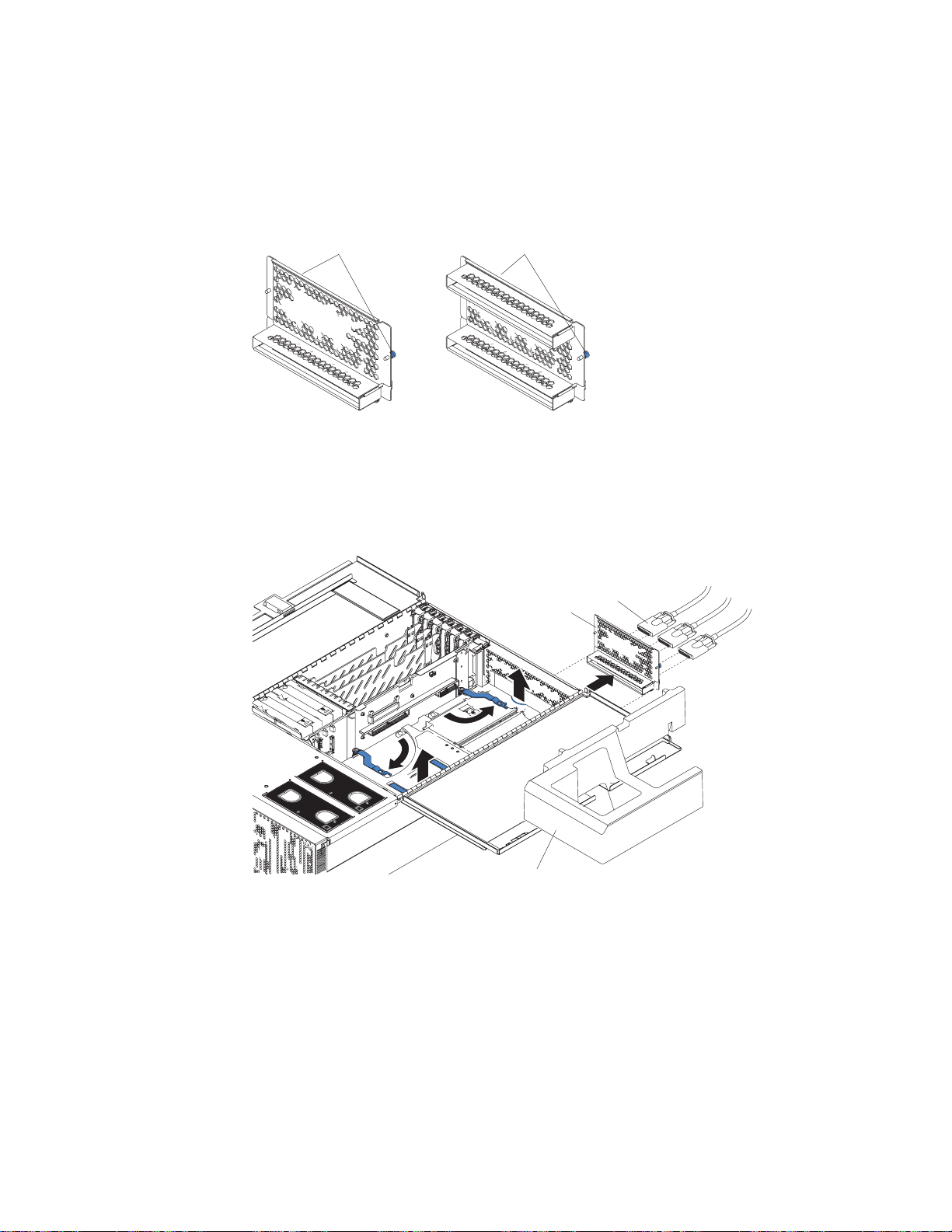
Installing an adapter
The following notes describe the types of adapters that your server supports and
other information that you must consider when installing an adapter:
The following illustration shows the location and bus speeds of the PCI-X
expansion slots.
Note: The illustrations in this document might differ slightly from your hardware.
PCI-X slot 6
(133 MHz)
PCI-X slot 5
(133 )MHz
PCI-X slot 4
(100 )MHz
PCI-X slot 3
(100 )MHz
PCI-X slot 2
(66 )MHz
Attention LED
Power LED
PCI-X slot 1
(66 )MHz
Figure 23. PCI-X slot bus speeds and locations
Your server supports six hot-plug 64-bit adapters in the expansion slots located
the PCI-X board.
Note: You can add up to 12 PCI-X slots to your server by connecting your
server to an RXE-100 enclosure. For more information about the
expansion enclosure, see the documentation that comes with your
expansion enclosure.
Locate the documentation that comes with the adapter and follow those
instructions in addition to the instructions in this chapter.
you need to change the switch settings or jumper settings on your adapter,
follow the instructions that come with the adapter.
Video adapters are not supported.
Some long adapters have extension handles or brackets installed. Before
installing the adapter, you must remove the extension handle or bracket.
Your server uses a rotational interrupt technique to configure PCI-X adapters.
You can use this technique to install PCI-X adapters that currently do not support
sharing of PCI-X interrupts.
xSeries 445 Type 8870: Installation Guide
Page 39

v
v
v
v If
v If a
v
v Do
1.
2.
v
Your server scans devices and PCI-X slots to assign system resources in the
following order: DVD-ROM drive; disk drives; integrated SCSI devices; PCI-X
slots 1, 2, 3, 4, 5, 6; and the integrated Ethernet controller. If an RXE-100
enclosure is attached to the server, the scan continues in sequence with PCI
slots 7, 8, 9, 10, 11, 12, 13, 14, 15, 16, 17, and 18.
You can use the Configuration/Setup Utility program to change the sequence and
have the server scan one of the first six PCI slots before it scans the integrated
devices. You cannot change the scan sequence of the PCI slots in an RXE-100
enclosure.
You can install both PCI and PCI-X adapters in the same bus. However, if you
install a PCI adapter and a PCI-X adapter in the same bus, the PCI-X features of
the PCI-X adapter will be disabled, and the adapter will function as a PCI
adapter.
You can install PCI or PCI-X adapters of speeds faster than what is labeled for a
particular PCI-X bus. For example, if you install two 133 MHz adapters into slots
that are labeled as 100 MHz slots, the adapters will operate at 100 MHz.
you install a 33 MHz and a 66 MHz adapter in the same bus, the bus speed
will match that of the slowest adapter.
single 133 MHz adapter is installed in PCI-X bus B (slot 3 or 4) and the other
slot in PCI-X bus B is empty, the adapter will operate at 133 MHz.
Your server supports 3.3 V adapters; it does not support 5.0 V adapters.
not install a PCI-X adapter in PCI-X slot 1 if you are going to install the serial
port that comes with your server. See “Installing the serial port” on page 31 for
instruction for installing the serial port.
Note:
Before hot-swapping any of the PCI-X adapters, read the information in
“Working inside the server with the power on” on page 8.
Complete the following steps to install an adapter:
Read the safety information beginning on page v and “Installation guidelines” on
page 7.
Open the top cover.
Note: There are six PCI-X slots inside your server: two 66 MHz, two 100 MHz,
and two 133 MHz. Before attempting to install a new adapter, be sure
that there is an available slot for it. If you need additional PCI-X slots,
you can purchase an RXE-100 enclosure through your IBM marketing
representative or authorized reseller.
Chapter 2. Installing options
27
Page 40

4.
5.
a.
b.
c.
d.
e. If
28
Adapter
Adapter guide
Tab
retention
latch
PCI-X
divider
Attention
LED
Power
LED
N
O
T
E
:
F
O
R
P
R
O
P
E
R
A
I
R
F
L
O
W,
R
E
P
N
O
T
E
:
F
O
R
F
R
O
N
T
L
A
C
E
F
A
F
N
R
W
O
I
N
P
R
O
P
E
R
A
I
R
F
O
F
B
O
X
T
T
H
I
O
N
F
2
B
M
O
I
X
N
U
T
L
O
W,
R
E
P
L
A
C
E
E
S
F
A
N
W
I
T
H
I
N
2
M
I
N
U
T
E
S
Figure 24. PCI-X slot components
3.
See the documentation that comes with your adapter for any cabling
instructions.
Note: Route adapter cables before you install the adapter.
Set any jumpers or switches as described by the adapter manufacturer.
Note: Do not install an adapter in PCI-X slot 1 if you are going to install the
serial port that comes with your server. See “Installing the serial port” on
page 31 for instructions for installing the serial port.
Install the adapter:
Open the blue adapter guide by lifting the front edge, as shown in the
illustration.
Push the orange adapter retention latch toward the rear of the server and
open the tab.
Remove the expansion-slot cover and the PCI-X divider.
Carefully grasp the adapter by its top edge or upper corners, and align it
with the connector on the PCI-X board.
necessary, remove the extension handles or bracket before installing a
long adapter.
Attention:
When you install an adapter, be sure the adapter is correctly
seated in the connector. Improperly seated adapters might cause damage to
the PCI-X board or to the adapter.
xSeries 445 Type 8870: Installation Guide
Page 41

g.
h.
i.
7. If
8.
v
v
on
1.
on
2.
3.
4.
5.
f.
Press the adapter firmly into the adapter connector.
Reinstall the PCI-X dividers between the Active PCI-X adapter slots.
Push down on the blue adapter guide to keep the adapter steady.
Close the tab; then, push down on the orange adapter retention latch until it
clicks into place, securing the adapter.
Connect the internal cables to the adapter.
6.
you have other options to install or remove, do so now.
Close the server cover; then, go to “Completing the installation” on page 33.
Cabling a ServeRAID adapter
Some xSeries 445 models come with an optional IBM ServeRAID
installed to control the internal hot-swap hard disk drives. If you are installing an
optional IBM ServeRAID adapter, see the ServeRAID documentation and the
cabling information in this section to install the ServeRAID adapter.
Servers that do not come with an IBM ServeRAID adapter installed come with two
SCSI cables:
One end of the first SCSI cable is attached to the connector on the SCSI
backplane, and the other end is attached to the connector for the integrated
SCSI controller under fans 3 and 4.
The second SCSI cable is preinstalled along the inside of the server and both
ends are loose inside the server. When you install a ServeRAID adapter, you will
connect this cable to the adapter and to the SCSI backplane.
™
adapter
following procedure describes the internal cabling for installing a ServeRAID
The
adapter.
Important: When installing multiple ServeRAID adapters in a server that has the
PCI-X slot enabled for high scan (boot) priority, ensure that the ServeRAID adapter
controlling the startup (boot) drive is installed in a PCI slot that is scanned before
the PCI slots that contain the other ServeRAID adapters. See “Installing an adapter”
page 26.
Complete the following steps to cable the ServeRAID adapter:
Read the safety information beginning on page v and “Installation guidelines”
page 7.
Turn off the server and disconnect all power cords and external cables; then,
open the server cover (see “Opening the cover” on page 9).
Remove fans 3 and 4, which are located just behind the PCI-X slots (see the
illustration on page 5 for the locations of the fans).
Disconnect the short SCSI cable from the SCSI backplane and the integrated
SCSI controller on the I/O board; then, store this short cable in a safe place for
future use.
Install the ServeRAID adapter in a PCI-X slot (see “Installing an adapter” on
page 26).
Chapter 2. Installing options
29
Page 42

7.
8.
9. If
30
Preinstalled
SCSI cable
Connect to
ServeRAID adapter
Connect to
SCSI backplane
Figure 25. Preinstalled SCSI cable for the ServeRAID adapter
6.
Locate the preinstalled SCSI cable; then, attach the connector on the cable to
the ServeRAID adapter.
Locate the connector on the opposite end of the SCSI cable and connect it to
the SCSI backplane connector.
Front of server
SCSI backplane
connector
Figure 26. Connecting the preinstalled SCSI cable
Reinstall fans 3 and 4.
you have other options to install or remove, do so now.
10.
Close the server cover; then, go to “Completing the installation” on page 33.
xSeries 445 Type 8870: Installation Guide
Page 43

1.
2.
1.
on
2.
3.
4.
Installing the serial port
Included with your server is a serial port that you can install at any time. This
section provides the instructions for installing the serial port.
Notes:
Installation of the serial port is optional. You do not have to install the serial port
for your server to operate properly. Also, the cabling information provided in this
publication covers some of the possible configurations.
The serial port will occupy PCI-X slot one.
Complete
the following steps to install the serial port:
Read the safety information beginning on page v and “Installation guidelines”
page 7.
Open the top cover.
Adapter
Adapter guide
PCI-X
divider
Tab
Attention
LED
Power
LED
retention
latch
N
O
T
E
:
F
O
R
P
R
O
P
E
R
A
I
R
F
L
O
W,
R
E
P
N
O
T
E
:
F
O
R
F
R
O
N
T
L
A
C
E
F
A
F
N
R
W
O
I
N
P
R
O
P
E
R
A
I
R
F
O
F
B
O
X
T
T
H
I
O
N
F
2
B
M
O
I
X
N
U
T
L
O
W,
R
E
P
L
A
C
E
E
S
F
A
N
W
I
T
H
I
N
2
M
I
N
U
T
E
S
Figure 27. PCI-X slot components
Open the blue adapter guide by lifting the front edge, as shown in the
illustration.
Remove the PCI-X slot cover and the PCI-X divider from slot one.
Chapter 2. Installing options
31
Page 44

6.
7.
8.
9. If
Go to
32
Serial port
Tab
Serial connector
N
O
T
E
:
F
O
R
P
R
O
P
E
R
A
I
R
F
L
O
W,
R
E
P
N
O
T
E
:
F
O
R
P
R
O
P
E
R
F
R
O
N
T
O
F
B
O
X
L
A
C
E
F
A
F
N
R
W
O
I
N
T
T
H
I
O
N
F
2
B
M
O
A
I
R
F
L
O
W,
R
E
P
L
A
C
I
X
N
U
T
E
E
F
A
N
W
S
I
T
H
I
N
2
M
I
N
U
T
E
S
Figure 28. Insert the serial port into PCI-X slot 1
Adapter
retention
latch
5.
Insert the serial port into the opening.
Close the tab; then, push down on the orange adapter retention latch until it
clicks into place.
Serial connector
Figure 29. Route the serial port ribbon cable through the slot
Route the ribbon cable through the lower slot in the center of the server.
Connect the serial port ribbon cable to the connector on the center plane.
you have other options to install or remove, do so now.
10.
xSeries 445 Type 8870: Installation Guide
“Installing the server in the rack cabinet” on page 33.
Page 45

34 in
Note: Use the Configuration/Setup Utility program to configure the serial port.
Completing the installation
This section provides information about installing the server in a rack and cabling
the server.
Installing the server in the rack cabinet
Close the cover and install the server into a rack cabinet. See the Rack Installation
Instructions that came with your server for detailed information on how to install the
server in a rack cabinet.
Note: After completing the rack installation, see “Connecting the cables” on page
this publication for instructions and information.
NOTE: FOR PROPER AIRFLOW, REPLACE FANWITHIN 2 MINUTES
FRONT OF BOX
Figure 30. Closing the cover
NOTE: FOR PROPER AIRFLOW, REPLAC
FRONT OF BOX
E F
ANWITHIN 2 MINUTES
Chapter 2. Installing options
33
Page 46

1.
2.
a.
b.
4.
34
Connecting the cables
This section describes how to connect cables to the SMP Expansion Port, system
power connectors, RXE Expansion Port, SCSI connector, USB connector, video
connector, mouse connector, keyboard connector, Ethernet connector, and RXE
Management port for up to 16-way operation.
For details about the locations and functions of all of the ports, LEDs, and
connectors, see Chapter 3, “Server controls, LEDs, and power,” on page 51.
Notes:
The information in this publication is for single and dual server configurations
using up to 16 microprocessors and four SMP Expansion Modules.
There are two different SMP Expansion cables used to connect the SMP
Expansion Modules.
2.5 m (8.2 ft) copper clad (comes in the IBM
Two-chassis 16-way Scalability Kit)
25.4 cm (10 in.) black clad
Before connecting RXE or SMP Expansion cables to the server, ensure that the
3.
protective cover is removed from the connectors on each end.
See the following illustrations to locate the connectors on the back of your
server, depending on your model. The illustrations in this document might differ
slightly from your hardware.
Eserver
xSeries 445
System power
connector 1
System power
connector 2
RXE Expansion Port B
Mouse connector
Keyboard connector
Remote
Supervisor
Adapter II - EXA
connectors
and LEDs
Gigabit Ethernet
connector
Upper Ethernet
status LED
SMP Expansion Port 1
SMP Expansion Port 2
SMP Expansion Port 3
SCSI connector
RXE Management Port
USB 1
USB 2
Video connector
(not supported)
Lower Ethernet
status LED
Gigabit Ethernet
connector
RXE Expansion
Port (A)
Figure 31. Rear view of Remote Supervisor Adapter II-EXA model
Important: If your server has a Remote Supervisor Adapter II-EXA installed,
the integrated video controller on your server is disabled. You must
connect a monitor or console switch to the video port on the
adapter.
xSeries 445 Type 8870: Installation Guide
Page 47

If
v If
v If
to
v If
v If
to
System power
connector 1
System power
connector 2
RXE Expansion Port B
Mouse connector
Keyboard connector
Remote
Supervisor
Adapter
connectors
and LEDs
Gigabit Ethernet
connector
Upper Ethernet
status LED
SMP Expansion Port 1
SMP Expansion Port 2
SMP Expansion Port 3
SCSI connector
RXE Management Port
USB 1
Lower Ethernet
status LED
Gigabit Ethernet
connector
RXE Expansion
Port (A)
USB 2
Video connector
Figure 32. Rear view of Remote Supervisor Adapter model
5.
your server model comes with an operating system, such as Microsoft
Windows
®
2000 Datacenter Server or VMware ESX server, see the software
documentation provided with your software for additional cabling instructions.
effectively manage the cables on this server, keep groups of cables secured
To
together, and do not run cables across the back of the server. Use cable ties to
bundle similar cables together. Use hook-and-loop fasteners to secure the cable
bundles to the vertical rails of the rack cabinet.
Attention: Do not secure cables too tightly. Overtightening can cause internal
damage to the cables.
SMP Expansion Port cabling
Depending upon your configuration, there are either three or six SMP Expansion
Ports located on the back of the server. The cabling information in this section is for
configurations using up to four SMP Expansion Modules in two servers.
Configurations that use only one SMP Expansion Module have three SMP
Expansion Ports and do not require any SMP Expansion Port cabling.
you are installing a server that has only one SMP Expansion Module and you
are connecting an RXE-100 enclosure, go to “RXE Expansion Port cabling for
one server with one SMP Expansion Module” on page 41.
you are installing a server that has only one SMP Expansion Module and you
are not connecting an RXE-100 enclosure, connect all remaining external cables
the server; then, go to “Creating a scalable partition” on page 63 and follow
the instructions for creating a scalable partition.
you are installing a server that has two SMP Expansion Modules, go to “SMP
Expansion Port cabling for one server with two SMP Expansion Modules” on
page 36.
you are installing two servers that each have two SMP Expansion Modules, go
“SMP Expansion Port cabling for two servers with four SMP Expansion
Modules (16-way)” on page 37.
Chapter 2. Installing options
35
Page 48

to
1.
2.
3.
of
4. If
1.
2.
36
SMP Expansion Port cabling for one server with two SMP Expansion
Modules:
Complete the following steps to cable two SMP Expansion Modules in a
single server together, using the two 25.4 cm (10 in.) SMP Expansion cables, for up
8-way operation. In the illustration, the SMP Expansion Modules are numbered 0
and 1, from bottom to top. The SMP Expansion Ports are numbered 1 through 3,
left to right. If your server comes with two SMP Expansion Modules, the SMP
Expansion cables are included with the server. If you purchased a second SMP
Expansion Module, the cables are included with the option.
1 2 3
1
1 2 3
0
Figure 33. SMP Expansion Module numbering
Remove the protective covers from the connectors on the ends of the cables.
Protective cover
Figure 34. SMP Expansion cable with protective cover
Connect one end of a 25.4 cm (10 in.) SMP Expansion cable to port 1 of SMP
Expansion Module 0; then, connect the opposite end of the cable to port 1 of
SMP Expansion Module 1.
Connect one end of the second 25.4 cm (10 in.) SMP Expansion cable to port 2
SMP Expansion Module 0; then, connect the opposite end of the cable to
port 2 of SMP Expansion Module 1.
you are connecting an RXE-100 enclosure, go to “RXE Expansion Port
cabling for one server with two SMP Expansion Modules” on page 43. If you are
not connecting an RXE-100 enclosure, connect all remaining external cables to
the server; then, go to “Creating a scalable partition” on page 63 and follow the
instructions for creating a scalable partition.
Notes:
When multiple cables are connected between the SMP Expansion Module
ports, SMP data is interleaved between the cables for better performance.
The server will start and operate with one cable attached between the two
SMP Expansion Modules.
xSeries 445 Type 8870: Installation Guide
Page 49

In
1.
2.
3.
SMP Expansion Port cabling for two servers with four SMP Expansion
Modules (16-way):
Complete the following steps to cable four SMP Expansion
Modules and two servers together, using the four 2.5 m (8.2 ft) and two 25.4 cm (10
in.) SMP expansion cables that came with your servers, for up to 16-way operation.
the illustration, the SMP Expansion Modules are numbered 0 through 3, from
primary to secondary server. The SMP Expansion Ports are numbered 1 through 3,
left to right.
Remove the protective covers from the connectors on the ends of the cables.
Protective cover
Figure 35. SMP Expansion cable with protective cover
Label each end of the 2.5 m (8.2 ft) SMP Expansion cables according to where
they will connect to each server. See the following illustration. The SMP
Expansion module numbering shown in the following illustration is for reference
purposes only. These numbers do not appear on the servers.
Primary server
1 2 3
1
1 2 3
0
Secondary server
1 2 3
3
1 2 3
2
Figure 36. 16-way SMP Expansion port cabling
Connect the SMP Expansion cables to the primary server:
Chapter 2. Installing options
37
Page 50

b.
38
a.
Connect one end of a 2.5 m (8.2 ft) SMP Expansion cable to port 1 of SMP
Expansion Module 0 on the primary server; then, route the cable through the
cable-management arm.
Cable-management arm
Long SMP expansion cable
Figure 37. Routing cables through the cable management arm
Connect one end of a 2.5 m (8.2 ft) SMP Expansion cable to port 2 of SMP
Expansion Module 0 on the primary server; then, route the cable beside the
first cable in the cable-management arm.
xSeries 445 Type 8870: Installation Guide
Page 51

d.
e.
a.
of
b.
of
c.
of
d.
of
e.
Cable-management arm
Long SMP expansion cables
Figure 38. Routing cables through the cable management arm
c.
Connect one end of a 2.5 m (8.2 ft) SMP Expansion cable to port 1 of SMP
Expansion Module 1 on the primary server; then, route the cable through the
cable-management arm as in step 3a on page 38.
Connect one end of a 2.5 m (8.2 ft) SMP Expansion cable to port 2 of SMP
Expansion Module 1 on the primary server; then, route the cable through the
cable-management arm as in step 3b on page 38.
Verify that a 25.4 cm (10 in.) SMP Expansion cable is connected between
port 3 of SMP Expansion Module 0 and port 3 of SMP Expansion Module 1.
4.
Connect the SMP Expansion cables to the secondary server:
Locate the SMP Expansion cable that is connected to port 1 of SMP
Expansion Module 0 on the primary server; then, connect the opposite end
the cable to port 1 of SMP Expansion Module 2. Next, route the cable
through the secondary cable-management arm.
Locate the SMP Expansion cable that is connected to port 2 of SMP
Expansion Module 1 on the primary server; then, connect the opposite end
the cable to port 2 of SMP Expansion Module 2. Next, route the cable
through the secondary cable-management arm.
Locate the SMP Expansion cable that is connected to port 1 of SMP
Expansion Module 1 on the primary server; then, connect the opposite end
the cable to port 1 of SMP Expansion Module 3. Next, route the cable
through the secondary cable-management arm.
Locate the SMP Expansion cable that is connected to port 2 of SMP
Expansion Module 0 on the primary server; then, connect the opposite end
the cable to port 2 of SMP Expansion Module 3. Next, route the cable
through the secondary cable-management arm.
Verify that a 25.4 cm (10 inches) SMP Expansion cable is connected
between port 3 of SMP Expansion Module 2 and port 3 of SMP Expansion
Module 3.
Chapter 2. Installing options
39
Page 52

or
6.
7.
40
5.
Connect the Remote Supervisor Adapter or Remote Supervisor Adapter II-EXA
Ethernet port on each server to a LAN or to each other with an Ethernet
crossover cable. This connection is needed so that the adapters can
communicate and perform the necessary functions for the two servers to create
delete scalable partitions.
Primary server
1 2 3
1
1 2 3
0
Ethernet
crossover cable
Secondary server
1 2 3
3
1 2 3
2
Figure 39. Using an Ethernet crossover cable to connect the Remote Supervisor Adapters.
Primary server
1 2
1
1 2 3
0
1 2 3
3
3
Ethernet
cable to
LAN
Secondary server
1 2 3
2
Figure 40. Connecting the Remote Supervisor Adapters to a LAN.
Route any remaining cables through the cable-management arms.
Secure the cables in the cable-management arms with the hook-and-loop straps
that come with your server.
xSeries 445 Type 8870: Installation Guide
Ethernet
cable to
LAN
Page 53

If
go to
If
1.
2.
8.
you are connecting an RXE-100 enclosure, go to “RXE Expansion Port
cabling for a 16-way configuration” on page 46. If you are not connecting an
RXE-100 enclosure, connect all remaining external cables to the server; then,
“Creating a scalable partition” on page 63 and follow the instructions for
creating a scalable partition.
RXE Expansion and Management Port cabling
There are two RXE Expansion Ports on the rear of the server. Use these ports to
connect the server to an RXE-100 enclosure and to expand the number of PCI-X
slots that are available for use by the server.
There is one RXE Management Port located on the back of the server. You can use
this port to connect the server to the management port of an optional RXE-100
enclosure. This port is used to manage the PCI-X slots in an RXE-100 enclosure,
including slot assignments and managing access.
For detailed information about how the server and RXE-100 enclosure work
together, see the documentation that comes with the RXE-100 enclosure.
RXE Expansion Port cabling for one server with one SMP Expansion Module:
your server has one SMP Expansion Module installed, complete the following
steps to connect an RXE-100 enclosure:
Remove the protective covers from the connectors on the ends of the cables.
Protective cover
Figure 41. RXE Expansion cable with protective cover
Using an RXE Expansion cable, connect one end of the cable to RXE
Expansion Port A on the server.
Chapter 2. Installing options
41
Page 54

4.
5.
6.
42
xSeries 445
RXE Expansion Port A
RXE-100
RXE Expansion Port A
Figure 42. RXE Expansion Port cabling a server with one SMP Expansion Module
3.
Connect the opposite end of the cable to an RXE Expansion Port on the
RXE-100 enclosure.
Using an RXE Management cable, connect one end of the cable to the RXE
Management Port on the server.
xSeries 445
RXE Management Port
RXE-100
A (in) PortRXE Management
Figure 43. Cabling RXE Management Port - one server
Connect the opposite end of the cable to the RXE Management A (in) Port on
the RXE-100 enclosure.
Connect all remaining external cables to the server; then, go to “Creating a
scalable partition” on page 63 and follow the instructions for creating a scalable
partition.
xSeries 445 Type 8870: Installation Guide
Page 55

If
1.
2.
3.
1.
2. To
on
RXE Expansion Port cabling for one server with two SMP Expansion
Modules:
your server has two SMP Expansion Modules installed, complete the
following steps to connect an RXE-100 enclosure:
Remove the protective covers from the connectors on the ends of the cables.
Protective cover
Figure 44. RXE Expansion cable with protective cover
Using an RXE Expansion cable, connect one end of the cable to RXE
Expansion Port B on the server.
xSeries 445
RXE Expansion Port B
RXE-100
RXE Expansion Port A
Figure 45. RXE Expansion port cabling a server with two SMP Expansion Modules
Connect the opposite end of the cable to an RXE Expansion Port on the
RXE-100 enclosure.
Notes:
When two SMP Expansion Modules are installed, both of the RXE
Expansion ports are active.
increase reliability, connect a second cable from RXE Expansion Port A
the server to RXE Expansion Port B on the enclosure. This will create a
redundant data path if either of the two cables fail.
Chapter 2. Installing options
43
Page 56

5.
6.
1.
2.
44
4.
Using an RXE Management cable, connect one end of the cable to the RXE
Management Port on the server.
xSeries 445
RXE Management Port
RXE-100
A (in) PortRXE Management
Figure 46. Cabling RXE Management Port - one server
Connect the opposite end of the cable to the RXE Management A (in) Port on
the RXE-100 enclosure.
Connect all remaining external cables to the server; then, go to “Creating a
scalable partition” on page 63 and follow the instructions for creating a scalable
partition.
Expansion Port cabling for two stand-alone servers:
RXE
Complete the
following steps to cable two stand-alone servers to a single RXE-100 enclosure:
Determine which server will be connected to port A of the RXE-100 enclosure
and which will be connected to port B.
Remove the protective covers from the connectors on the ends of the cables.
Figure 47. RXE Expansion cable with protective cover
xSeries 445 Type 8870: Installation Guide
Protective cover
Page 57

4.
5.
6.
3.
Using an RXE Expansion cable, connect one end of the cable to RXE
Expansion Port A on the RXE-100 enclosure.
xSeries 445
First server RXE Expansion Port B
RXE Expansion Port A
1
12 3
0
xSeries 445
B
A
First server RXE Expansion Port A
B
1
12 3
0
A
RXE Expansion Port B
Second server RXE Expansion Port A
Second server RXE Expansion Port B
Figure 48. RXE Expansion Port cabling of two stand-alone xSeries 445 servers to a single
RXE-100 enclosure
Connect the opposite end of the cable to RXE Expansion Port A or B on the
first server.
Note: If the server has one SMP Expansion Module installed, you must
connect the RXE Expansion cable to RXE Expansion Port A on the
server. If the server has two SMP Expansion Modules installed, connect
the cable to RXE Expansion Port B.
Using an RXE Expansion cable, connect one end of the cable to RXE
Expansion Port B on the RXE-100 enclosure.
Connect the opposite end of the cable to RXE Expansion Port A or B on the
second server.
Note: When two SMP Expansion Modules are installed, both of the RXE
Expansion ports are active.
Chapter 2. Installing options
45
Page 58

8.
9.
1.
46
7.
Using an RXE Management cable, connect one end of the cable to the RXE
Management Port on one of the servers.
xSeries 445
1
12 3
0
RXE Management B (in) Port
B
A
RXE Management A (in) Port
RXE Management Port
B
1
12 3
0
A
xSeries 445
RXE Management Port
Figure 49. Cabling an RXE Management port - two stand-alone servers
Connect the opposite end of the cable to the RXE Management A (in) Port on
the RXE-100 enclosure. The RXE Management Port cabling is the same for a
server with two SMP Expansion Modules.
Repeat steps 7 and 8 for the second server.
10.
Connect all remaining external cables to the servers; then, go to “Creating a
scalable partition” on page 63 and follow the instructions for creating a
scalable partition.
Expansion Port cabling for a 16-way configuration:
RXE
Complete the
following steps to connect an RXE-100 enclosure to a 16-way system:
Remove the protective covers from the connectors on the ends of the cables.
Protective cover
Figure 50. RXE Expansion cable with protective cover
xSeries 445 Type 8870: Installation Guide
Page 59

3.
4.
5.
6.
7.
2.
Using an RXE Expansion cable, connect RXE Expansion Port A on the primary
server to RXE Expansion Port A on the secondary server.
Primary server RXE Expansion Port B
Primary server
B
RXE Expansion Port A
1
0
12
3
A
Primary server RXE Expansion Port A
B
3
12 3
2
A
RXE Expansion Port B
Secondary server
Secondary server RXE Expansion Port A
Secondary server RXE Expansion Port B
Figure 51. RXE Expansion Port cabling in a 16-way configuration
Using an RXE Expansion cable, connect RXE Expansion Port B on the primary
server to RXE Expansion Port A on the RXE-100.
Using an RXE Expansion cable, connect RXE Expansion Port B on the
secondary server to the RXE Expansion Port B on the RXE-100.
Using an RXE Management cable, connect the RXE Management Port on the
primary server to RXE Management Port A (in) on the RXE-100.
Primary server RXE Management Port
Primary server
RXE Management B (in) Port
1
0
12
B
3
A
RXE Management A (in) Port
B
A
3
12 3
2
Secondary server
Secondary server RXE Management Port
Figure 52. Cabling an RXE Management Port - 16-way configuration
Using an RXE Management cable, connect the RXE Management Port on the
secondary server to the RXE Management Port B (in) on the RXE-100.
Connect all remaining external cables to the servers; then, go to “Creating a
scalable partition” on page 63 and follow the instructions for creating a scalable
partition.
Chapter 2. Installing options
47
Page 60

1.
2.
on
3.
a
a
48
Power cabling
Your server uses two power cords that can be connected to a primary power unit
inside the rack cabinet, such as a properly grounded power distribution unit or
uninterruptible power supply, or to an external source, such as a properly grounded
electrical outlet.
Complete the following steps to attach the power-supply cords:
Connect a power-supply cord to one of the system power connectors on the
rear of the server.
Connect the other end of the power-supply cord to a properly grounded
electrical outlet or to a primary power unit inside the rack cabinet.
Note: Connecting the power-supply cords to an electrical outlet might cause the
server to start automatically. This is an acceptable action. See “Turning
the server” on page 56 for detailed information about turning on the
server.
Repeat steps 1 and 2 for the second cable.
SCSI cabling
USB cabling
Video cabling
Note: The server requires a 220 V ac power connection for full power-supply
redundancy. Whenever possible, use a 220 V ac connection for all
configurations. However, you can use a 110 V ac connection, but without
full power-supply redundancy.
You can use the SCSI connector on the back of the server to attach an optional
SCSI device, such as one of the IBM external storage enclosures, to the server. For
detailed information about how to connect a SCSI device to your server, see the
documentation that comes with the SCSI device.
Your server has three USB connectors, one on the front and two on the back of the
server. You can use these connectors to attach an optional USB device to the
server. For detailed information about how to connect a USB device to your server,
see the documentation that comes with the USB device.
You can use the video connector on the back of the server to attach a monitor or
optional console switch to the server. For detailed information about how to connect
monitor or optional console switch to your server, see the documentation that
comes with the optional device.
Important: If your server has a Remote Supervisor Adapter II-EXA installed, the
Mouse cabling
You can use the mouse connector on the back of the server to attach a mouse to
the server. For detailed information about how to connect a mouse to your server,
see the documentation that comes with the mouse.
xSeries 445 Type 8870: Installation Guide
integrated video controller on your server is disabled. You must connect
monitor or console switch to the video port on the adapter.
Page 61

or
a
Keyboard cabling
You can use the keyboard connector on the back of the server to connect a
keyboard or optional console switch to the server. You can also connect a USB
keyboard to the server using one of the USB connectors. After installing a USB
keyboard, you might need to use the Configuration/Setup Utility program to enable
keyboardless operation and prevent the POST error message 301 from being
displayed during startup. For detailed information about how to connect a keyboard
console switch to your server, see the documentation that comes with the
keyboard or console switch.
Gigabit Ethernet cabling
Use the two Ethernet connectors on the back of the server to connect the server to
local area network (LAN).
Note: A third Ethernet connector is located on the Remote Supervisor Adapter. This
connector is used for specific supervisory functions and should not be
confused with the Gigabit Ethernet connector located next to the USB
connectors.
Remote Supervisor Adapter cabling
Your server comes with a Remote Supervisor Adapter or a Remote Supervisor
Adapter II-EXA. For information about cabling the Remote Supervisor Adapter
connectors, see the appropriate Remote Supervisor Adapter User’s Guide on the
IBM xSeries Documentation CD.
Chapter 2. Installing options
49
Page 62

50
xSeries 445 Type 8870: Installation Guide
Page 63

AC
dc
©
Chapter 3. Server controls, LEDs, and power
This chapter describes the controls and indicators, and provides the information
needed to turn on and turn off the server.
Front view
DC power LED
Hard disk drive activity LED
AC power LED
Power-on LED
Power-control
button
Reset button
Hard disk drive status LED
USB port
Power supply
latch
Diskette drive
activity LED
Diskette eject
button
Diskette drive
eject button
System-error LED
(amber)
Information LED
(amber)
SCSI activity LED
(green)
Locator LED
(blue)
DVD-ROM drive eject button
DVD eject button
DVD-ROM drive activity LED
Figure 53. Front view of xSeries 445
and DC power LED: Each hot-swap power supply has an ac power LED and a
power LED. During typical operation, both the ac and dc power LEDs are lit. For
any other combination of LEDs, see the Hardware Maintenance Manual and
Troubleshooting Guide on the IBM xSeries Documentation CD.
Hard disk drive activity LED: This green LED is lit when the hard disk drive is in
use.
Hard disk drive status LED: When the drive is connected to the integrated SCSI
controller with RAID capabilities, a flashing status LED indicates that the drive is a
secondary drive in a mirrored pair and the drive is being synchronized. When the
drive is connected to an optional ServeRAID controller, a slowly flashing (one flash
per second) status LED indicates that the drive is being rebuilt. When the LED is
flashing rapidly (three flashes per second), it indicates that the controller is
identifying the drive.
Copyright IBM Corp. 2004
USB port: Use this automatically configured port to connect one or more USB
devices to the front of the server, using Plug and Play technology.
System-error LED: This amber LED is lit when a system error has occurred.
51
Page 64

52
Information LED: This amber LED is lit when information about a system error has
been placed in the System Error log.
SCSI activity LED: This green LED is lit when there is activity on the SCSI bus.
Locator LED: The locator LED is on the left front of the Light Path Diagnostic
drawer. This blue LED identifies the primary and secondary servers. This LED
blinks on the primary server and remains lit solid on the secondary server.
DVD-ROM drive eject button: Press this button to release a DVD-ROM drive from
the server.
DVD eject button: Press this button to release a DVD from the DVD-ROM drive.
DVD-ROM drive activity LED: When this LED is lit, the DVD-ROM drive is in use.
Diskette drive eject button: Press this button to release a diskette drive from the
server.
Diskette eject button: Press this button to release a diskette from the diskette
drive.
Diskette drive activity LED: When this LED is lit, the diskette drive is in use.
Power-supply latch: This latch is used to secure the power supply in place.
Reset button: Press this button to reset the server and run the power-on self-test
(POST). You might have to use a pen or the end of a straightened paper clip to
press the button.
Power-control button: Press this button to turn the server on and off manually. A
power-control-button shield comes with your server. You can install this disk-shaped
shield to prevent the server from being turned off accidentally.
xSeries 445 Type 8870: Installation Guide
Page 65

Rear view
System power
connector 1
System power
connector 2
RXE Expansion Port B
Mouse connector
Keyboard connector
Remote
Supervisor
Adapter II - EXA
connectors
and LEDs
Gigabit Ethernet
connector
Upper Ethernet
status LED
SMP Expansion Port 1
SMP Expansion Port 2
SMP Expansion Port 3
SCSI connector
RXE Management Port
USB 1
USB 2
Video connector
(not supported)
Lower Ethernet
status LED
Gigabit Ethernet
connector
RXE Expansion
Port (A)
Figure 54. Rear view of model with Remote Supervisor Adapter II-EXA
System power
connector 1
SMP Expansion Port 1
SMP Expansion Port 2
SMP Expansion Port 3
SCSI connector
RXE Management Port
System power
connector 2
USB 1
Video connector
RXE Expansion Port B
Mouse connector
Keyboard connector
Remote
Supervisor
Adapter
connectors
and LEDs
Gigabit Ethernet
connector
Upper Ethernet
status LED
Lower Ethernet
status LED
Gigabit Ethernet
connector
RXE Expansion
Port (A)
USB 2
Figure 55. Rear view of model with Remote Supervisor Adapter
System power connectors (1 and 2): Connect the system power cords to these
two connectors to provide power to the system.
RXE Expansion Port B: Use this port to connect the server to a remote I/O
enclosure when two SMP Expansion Modules are installed.
Mouse connector: Connect a mouse to this connector.
Keyboard connector: Connect a keyboard to this connector.
Chapter 3. Server controls, LEDs, and power
53
Page 66

v
v
v
to
v
v
v
v
v
on
v
54
Remote Supervisor Adapter II-EXA connectors and LEDs: The connectors and
LEDs on the back of the server are used for system-management information and
control.
Ethernet activity LED
(green)
Ethernet link LED
(green)
10/100
Ethernet port
External power
connector
Heartbeat LED
(amber)
Power LED
(green)
RSA II - EXA
breakout port
Video port
Figure 56. Remote Supervisor Adapter II-EXA connectors
External power connector: You can connect an optional ac power adapter to
this connector.
Heartbeat LED: This amber LED flashes continuously to indicate that there is
activity on the Remote Supervisor Adapter II-EXA.
RSA II-EXA breakout port: Connect the RSA II-EXA breakout cable to this port
provide two ASM interconnect ports, one USB port, and one Management port.
Ethernet activity LED: This green LED is lit when there is activity on the
Ethernet LAN.
Ethernet link LED: This green LED is lit when the Ethernet link is active.
10/100 Ethernet port: Connect Ethernet signal cables to this port.
Video port: Connect a monitor or console switch to this port.
Important: The integrated video controller is disabled for models with a Remote
Supervisor Adapter II-EXA installed.
Power LED: This green LED comes on and stays lit when you plug in your
server.
Remote
Supervisor Adapter connectors and LEDs: The connectors and LEDs
the back of the server are used for system-management information and control.
Ethernet activity LED
External power
connector
Error LED
(amber)
Power LED
(green)
ASM interconnect
port
Management port
(green)
Ethernet link LED
(green)
10/100
Ethernet port
Figure 57. Remote Supervisor Adapter connectors
External power connector: You can connect an optional ac power adapter to
this connector.
xSeries 445 Type 8870: Installation Guide
Page 67

v
v
v
v
v
v
to
to
v
Error LED: This amber LED is lit when a system-management error has
occurred.
ASM interconnect port: Connect signal cables for managing expansion-module
resources to this port.
Ethernet activity LED: This green LED is lit when there is activity on the
Ethernet LAN.
Ethernet link LED: This green LED is lit when the Ethernet link is active.
10/100 Ethernet port: Connect Ethernet signal cables to this port.
Management port: Connect a serial cable to this port to enable system
management through a modem, or connect a null modem cable to this port to
enable system management through a workstation or laptop computer.
Power LED: This green LED comes on and stays lit when you plug in your
server.
Gigabit
Ethernet ports: Connect Gigabit Ethernet signal cables to these ports.
These ports support 10/100/1000 speed connections.
Upper Ethernet status LED: This LED displays the link and activity status for the
upper Gigabit Ethernet port. When the LED is lit green, the link is active. When the
LED blinks green and amber, there is activity on the Ethernet LAN.
Lower Ethernet status LED: This LED displays the link and activity status for the
lower Gigabit Ethernet port. When the LED is lit green, the link is active. When the
LED blinks green and amber, there is activity on the Ethernet LAN.
RXE Expansion Port A: Use this port to connect the server to a remote I/O
enclosure, when only one SMP Expansion Module is installed.
Video connector: Connect the signal cable for a monitor to this connector.
Important: If your server has a Remote Supervisor Adapter II-EXA installed, you
must connect a monitor or console switch to the video port on the
adapter. The integrated video controller on the server is disabled.
USB 2: Use this automatically configured port to connect one or more USB devices
the server, using Plug and Play technology.
USB 1: Use this automatically configured port to connect one or more USB devices
the server, using Plug and Play technology.
RXE Management Port: Use this port to connect a management cable from the
server to a remote I/O enclosure.
SCSI connector: Connect external SCSI devices to this connector.
SMP Expansion Port 3: Use this port to interconnect two SMP Expansion Modules
together in 16-way configurations.
SMP Expansion Port 2: Use this port to interconnect two SMP Expansion Modules
together.
SMP Expansion Port 1: Use this port to interconnect two SMP Expansion Modules
together.
Chapter 3. Server controls, LEDs, and power
55
Page 68

v If
v If a
v If
on
v If
56
Server power features
When the server is connected to an ac power source but is not turned on, the
operating system does not run, and all core logic except for the service processor is
shut down; however, the server can respond to requests from the service processor,
such as a remote request to turn on the server. The power-on LED flashes to
indicate that the server is connected to ac power but it is not turned on.
Turning on the server
Approximately 20 seconds after the server is connected to ac power, the
power-control button becomes active, and you can turn on the server and start the
operating system by pressing the power-control button.
You can also turn on the server in any of the following ways:
the server is connected to an Advanced System Management interconnect
network that contains at least one server with an optional Remote Supervisor
Adapter installed, the server can be turned on from the Remote Supervisor
Adapter user interface.
power failure occurs while the server is turned on, the server will restart
automatically when power is restored.
your operating system supports the system-management software for an
optional Remote Supervisor Adapter, the system-management software can turn
the server.
your operating system supports the Wake on LAN
feature can turn on the server.
®
feature, the Wake on LAN
Note:
When you press the power-control button on either the primary or secondary
server in a 16-way configuration, both servers will be turned on. If both
servers do not turn on when either power-control button is pressed, see the
Hardware Maintenance Manual and Troubleshooting Guide on the IBM
xSeries Documentation CD.
xSeries 445 Type 8870: Installation Guide
Page 69

on
v
v
v If
v If
v
v If
v
Turning off the server
When you turn off the server and leave it connected to ac power, the server can
respond to requests from the service processor, such as a remote request to turn
the server. To remove all power from the server, you must disconnect it from the
power source.
Some operating systems require an orderly shutdown before you turn off the server.
See your operating-system documentation for information about shutting down the
operating system.
Statement 5:
CAUTION:
The power control button on the device and the power switch on the power
supply do not turn off the electrical current supplied to the device. The device
also might have more than one power cord. To remove all electrical current
from the device, ensure that all power cords are disconnected from the power
source.
2
1
You can turn off the server in any of the following ways:
You can turn off the server from the operating system, if your operating system
supports this feature. After an orderly shutdown of the operating system, the
server will be turned off automatically.
You can press the power-control button to start an orderly shutdown of the
operating system and turn off the server, if your operating system supports this
feature.
the operating system stops functioning, you can press and hold the
power-control button until the server turns off.
the server is connected to an Advanced System Management interconnect
network that contains at least one server with an optional Remote Supervisor
Adapter installed, the server can be turned off from the Remote Supervisor
Adapter user interface.
The server can be turned off from the Remote Supervisor Adapter user interface.
the Wake on LAN feature turned on the server, the Wake on LAN feature can
turn off the server.
The Remote Supervisor Adapter can turn off the server as an automatic
response to a critical system failure.
Note:
When you press the power-control button on either the primary or secondary
server in a 16-way configuration, both servers will be turned off. If both
servers do not turn off when either power-control button is pressed, see the
Hardware Maintenance Manual and Troubleshooting Guide on the IBM
xSeries Documentation CD.
Chapter 3. Server controls, LEDs, and power
57
Page 70

58
xSeries 445 Type 8870: Installation Guide
Page 71

v
1. If
2. If
v
v
to
v
on
©
Chapter 4. Configuring your server
The following configuration programs are provided with your server:
IBM ServerGuide Setup and Installation CD
The ServerGuide Setup and Installation CD includes software setup and
installation tools that are specifically designed for IBM xSeries 445 servers. If you
did not purchase a preconfigured server, you can use this CD during the initial
installation of your server to configure the server hardware and to simplify your
operating system installation. See the User’s Guide on the IBM xSeries
Documentation CD for more detailed information.
Notes:
you are installing a Linux-based operating system, do not install the default
ATI video driver. Instead, install the Video Electronics Standards Association
(VESA) video driver and set the resolution to 1024 x 768.
your server model comes with an operating system, such as Microsoft
Windows 2000 Datacenter Server or VMware ESX server, see the software
documentation provided with your software for configuration information.
Configuration/Setup Utility
v
This program is part of the basic input/output system (BIOS) code that comes
with your server. You can use this program to configure the serial connector
assignment, change the drive startup sequence, set the date and time, and set
passwords. See “Using the Configuration/Setup Utility program” on page 60 for
more information.
Note: In a 16-way configuration, some options or settings are defined through
the primary server, while others must be defined on the individual server.
Ensure that options or settings on the secondary server are correct before
creating a scalable partition.
LSI Logic Configuration Utility
With the built-in LSI Logic Configuration Utility program, you can configure the
integrated SCSI controller and the devices that are attached to it. See “Using the
LSI Logic Configuration Utility program” on page 61.
ServeRAID configuration program
This program comes with the optional ServeRAID adapters and with server
models that have a ServeRAID adapter preinstalled. If the server has a
ServeRAID adapter installed, you must use the ServeRAID configuration program
define and configure the disk-array subsystem before you install the operating
system. If your server model came with an operating system installed, your
disk-array subsystem is already configured. For more information about using the
ServeRAID configuration program, see the ServeRAID information on the IBM
xSeries Documentation CD.
Note: If your server model comes with an operating system, such as Microsoft
Windows 2000 Datacenter Server or VMware ESX server, see the
software documentation provided with your software for configuration
information.
Remote Supervisor Adapter configuration process
Configuration activities are also required for the Remote Supervisor Adapter or
Remote Supervisor Adapter II-EXA. See “Using the Remote Supervisor Adapter”
page 62 for a description of features. For information about cabling,
configuring, and using the Remote Supervisor Adapter to manage the server
Copyright IBM Corp. 2004
59
Page 72

v
To
v
1.
2.
a.
b.
c.
d.
e.
f.
v
v
v
v
v
v
v
v
60
remotely, see “Using the Remote Supervisor Adapter” on page 62 and the
appropriate Remote Supervisor Adapter User’s Guide on the IBM xSeries
Documentation CD.
Integrated System Management update and configuration
update the integrated system management processor (ISMP) firmware, see
“Using the Integrated System Management Firmware Update Utility program” on
page 62.
Configuring Scalable Partitions
For the information and instructions needed to create or remove a scalable
partition, see “Configuring scalable partitions” on page 63.
Using the ServerGuide Setup and Installation CD
The ServerGuide Setup and Installation CD provides state-of-the-art programs to
detect the server model and hardware options that are installed, configure the
server hardware, provide device drivers, and help you install your operating system.
For information about the supported operating-system versions, see the label on the
CD.
Complete the following steps to start the ServerGuide Setup and Installation CD:
Insert the CD, and then restart the server. If the ServerGuide CD does not start,
see “ServerGuide startup problems” on page 70.
Follow the instructions on the screen to:
Select your language.
Select your keyboard layout and country.
View the overview to learn about the ServerGuide features.
Review the readme file for installation tips about your operating system and
adapters.
Start the setup and hardware configuration programs.
Start the operating-system installation. You will need your operating-system
CD.
Using the Configuration/Setup Utility program
The Configuration/Setup Utility program is part of the BIOS code. You can use it to:
Configure system devices and ports
Configure scalable partitions
Configure memory settings
Change the drive startup sequence
Enable USB keyboard and mouse support
Resolve configuration conflicts
Set the date and time
Set passwords and security settings
xSeries 445 Type 8870: Installation Guide
Page 73

1.
2.
3.
v
v
v
1.
2. If
1.
2.
3.
4.
Complete the following steps to start the Configuration/Setup Utility program:
Turn on the server and watch the monitor screen.
Note: In a 16-way configuration, some options or settings are defined through
the primary server, while others must be defined on the individual server.
Ensure that options or settings on the secondary server are correct
before creating a scalable partition.
When the message
Press F1 for Configuration/Setup
Note: Depending on your configuration, you might experience a delay before
the Configuration/Setup menu appears.
Follow the instructions on the screen.
Using the LSI Logic Configuration Utility program
LSI Logic Configuration is a built-in, menu-driven configuration utility program that
you can use to:
Set a SCSI device scan order
View or change SCSI IDs for attached devices
Set SCSI protocol parameters on SCSI hard disk drives
appears, press F1.
Notes:
The integrated SCSI controller with RAID capabilities in your server supports
only RAID level-1 and RAID level-1 Enhanced (RAID level-1E). Installing an
optional ServeRAID controller provides additional RAID levels. See “Using the
ServeRAID configuration programs” on page 62 for information about
configuring your server for RAID operation.
you install a different type of RAID adapter in your server, use the
configuration method supplied with the RAID adapter to view or change SCSI
settings for attached devices.
Complete the following steps to start the LSI Logic Configuration Utility program:
Turn on the server.
When the
<<<Press <CTRL><C> to start LSI Logic Configuration Utility>>>
prompt appears, press Ctrl+C.
Note: If an administrator password has been set, you are prompted to type the
password to start the LSI Logic Configuration Utility program.
Use the arrow keys to select a controller (channel) from the list of adapters;
then, press Enter.
Follow the instructions on the resulting screen to change the settings of the
selected items; then, press Enter. The Device Properties and Mirroring
Properties choices produce additional screens of parameters to review or
change.
Chapter 4. Configuring your server
61
Page 74

A
To
1.
2.
3.
4.
5.
62
Using the ServeRAID configuration programs
ServeRAID adapter enables you to use multiple physical SCSI hard-disk drives as
logical drives, operating as a disk array. To enable you to configure the ServeRAID
controller, the adapter comes with a CD containing the ServeRAID Manager
program and the ServeRAID Mini-Configuration program.
Note: If your server model came with an operating system, such as Microsoft
Windows 2000 Datacenter Server or VMware ESX server, see the software
documentation provided with your software for configuration information.
Use the IBM ServeRAID Support CD that comes with your server to configure your
integrated SCSI controller with RAID capabilities and to perform an initial RAID
configuration on your server. For details about using these programs, see the
documentation that comes with the ServeRAID adapter and the User’s Guide on the
IBM ServeRAID Support CD.
Using the Remote Supervisor Adapter
For information about cabling, configuring, and using the Remote Supervisor
Adapter or Remote Supervisor Adapter II-EXA to manage the server remotely, see
the User’s Guide and the appropriate Remote Supervisor Adapter User’s Guide on
the IBM Documentation CD.
Using the Integrated System Management Firmware Update Utility program
update the firmware for the integrated system management processor (ISMP),
download the Integrated System Management Processor Update utility program for
your server from the IBM Support Web site at http://www.ibm.com/pc/support/. Run
the utility program to create a diskette that you can use to update the firmware. The
utility program updates the integrated system management processor firmware only
and does not affect any device drivers.
Complete the following steps to update the firmware:
Turn off the server.
Insert the diskette into the diskette drive.
Turn on the server. If the server does not start from the diskette, use the
Configuration/Setup Utility program to configure the diskette drive as a startup
device. (For more information, see the information about Configuration/Setup
Utility start options in the User’s Guide). Then, start again at step 1 of this
procedure.
From the main menu, select Update System Management Firmware and
press Enter.
Follow the instructions on the screen to complete the update.
there is an error in updating the firmware, try updating the firmware again.
If
xSeries 445 Type 8870: Installation Guide
Page 75

v
v
v
v In
v In a
1. If
2.
3.
4.
5.
6.
a.
b.
0 - No
6 -
12 -
Configuring scalable partitions
The Scalable Systems Manager program is an extension to IBM Director that
provides a graphical user interface for creating and managing scalable partitions.
See the Scalable Systems Manager Installation and Users Guide for information on
how to use that program to configure scalable partitions on xSeries 445 servers.
You can also use the Configuration/Setup Utility program to configure scalable
partitions. This section provides information and instructions for creating and
deleting scalable partitions through the Configuration/Setup Utility program.
Before you create scalable partitions, read the following information:
Before you can create or delete a scalable partition, the Remote Supervisor
Adapters must have an IP address and must be connected to a network or to
each other with an Ethernet crossover cable. This connection is needed so that
the Remote Supervisor Adapters can communicate and perform the necessary
functions for the two servers to create or delete scalable partitions.
When creating a scalable partition consisting of an RXE-100, you must create the
scalable partition initially through the Configuration/Setup Utility program before
you can use Scalable Systems Manager.
When a scalable partition consisting of two servers in a 16-way configuration is
created, the DVD-ROM drive, diskette drive, keyboard, USB connectors, mouse,
and video are disabled on the secondary server.
the Configuration/Setup Utility program, Expansion Port A Destination and
Expansion Port B Destination refer to the RXE Expansion Port connection from
the expansion enclosure to the server.
16-way configuration, the SMP IDs of the Primary and Secondary Scalable
Nodes must be different.
Creating a scalable partition
Complete the following steps to create a scalable partition:
you have not already done so, connect the RXE expansion and RXE
management cables between the server and the remote expansion enclosure.
See “RXE Expansion and Management Port cabling” on page 41 for information
about RXE cabling.
Start the Configuration/Setup Utility program.
From the main menu, select Advanced Setup.
Select Scalable Partition Settings.
Select Create Scalable Partition Settings.
For 4-way and 8-way single chassis configurations, complete the following
steps:
Select 1 x445 chassis as the Scalable System Configuration.
Select the number of PCI-X slots available to the RXE Expansion Port in the
remote expansion enclosure. The following choices are available:
PCI-X slots are assigned to the RXE Expansion Port.
Only six of the 12 slots are assigned to the RXE Expansion Port.
All 12 PCI-X slots are assigned to the RXE Expansion Port.
Chapter 4. Configuring your server
63
Page 76

v
v
Go to
a.
b.
c.
of
d.
e.
f.
0 - No
6 -
12 -
g. If 12
B
9.
to
64
c.
Complete one of the following procedures, depending on the number of
SMP Expansion Modules that are installed:
One SMP Expansion Module - If six or 12 PCI-X slots are available,
select Primary Scalable Node, Port A for the RXE Port destination.
Two SMP Expansion Modules - If six or 12 PCI-X slots are available to
port A or port B, select Primary Scalable Node, Port B for the RXE Port
destination. If six PCI-X slots are available to port A and six PCI-X slots
are available to port B, select Primary Scalable Node, Port A for the RXE
Port A destination and Primary Scalable Node, Port B for the RXE Port B
destination.
d.
For a 16-way, two-chassis configuration, complete the following steps:
7.
step 8..
Select 2 x445 chassis as the Scalable System Configuration.
Enter a Scalable Partition ID 0000 through 9999.
For the primary boot node, select SMP ID 0.
Note: The SMP ID can be 0 or 2, but it must be different from the SMP ID
the secondary x445 scalable node.
Enter the Secondary ASM host name or IP address.
From the Secondary Scalable Node SMP ID menu, select Yes, SMP ID 2.
Note: This SMP ID must be different from the SMP ID for the primary boot
node.
Select the number of PCI-X slots available to the RXE Expansion Port in the
remote expansion enclosure. The following choices are available:
PCI-X slots are assigned to the RXE Expansion Port.
Only six of the 12 slots are assigned to the RXE Expansion Port.
All 12 PCI-X slots are assigned to the RXE Expansion Port.
PCI-X slots are available to port A, select Primary Scalable Node, Port
for the RXE Port A destination. If six PCI-X slots are available to port A
and six PCI-X slots are available to port B, select Primary Scalable Node,
Port A for the RXE Port A destination and Primary Scalable Node, Port B for
the RXE Port B destination.
Select Write Scalable Partition Settings and follow the prompts to exit the
8.
menu item.
Save and Exit the Configuration/Setup Utility Program.
Note: See the software documentation that comes with your operating system
install your operating system.
xSeries 445 Type 8870: Installation Guide
Page 77

1.
2.
3.
4.
5.
6.
7. If
to
8.
Deleting a scalable partition
Complete the following steps to delete the scalable partition:
Start the Configuration/Setup Utility on the primary server.
From the main menu, select Advanced Setup.
Select Scalable Partition Settings.
Select either Delete ALL Scalable Partition or Delete ONLY Local Scalable
Partition.
Note: Do not select Write Scalable Partition Settings when you delete the
scalable partition.
Exit the Configuration/Setup Utility program.
Turn off the servers.
necessary, remove the SMP Expansion cables and reconnect them according
your new configuration. See “Connecting the cables” on page 34 for
instructions.
Restart the servers.
Chapter 4. Configuring your server
65
Page 78

66
xSeries 445 Type 8870: Installation Guide
Page 79

If
To
1. If
a. Go to
b.
c.
d. In
e.
f.
3.
a. Go to
b.
c.
d. In
e.
f.
©
Chapter 5. Updating IBM Director
you plan to use IBM Director to manage your server, you must install the
applicable IBM Director updates for the xSeries 445 server.
Note: For Automatic Server Restart (ASR) support and environmental-sensor
support, you must install version 4.1 of IBM Director.
install the IBM Director updates, complete the following steps, in order:
you plan to enable the Automatic Server Restart (ASR) feature, install the
ASR device driver, which is available from the IBM Web site:
http://www.ibm.com.
Click Support & downloads.
Click Downloads & drivers.
the Enter search terms field, type
and click Submit.
Select the applicable IBM Advanced System Management device driver for
your server and operating system.
Click the file link for the executable file to download the file, and follow the
instructions in the readme file to install the device driver.
Install the IBM Director application.
2.
Check the IBM Web site to see if any updates are available for your server. If
updates are available, download them from the IBM web site; then, install them
according to the instructions in the readme files.
http://www.ibm.com.
Click Support & downloads.
Click Downloads & drivers.
the Enter search terms field, type
Select the update that you want to download.
Click the file link for the executable file to download the file, and follow the
instructions in the readme file to install the update.
advanced system management 8870
director 8870
and click Submit.
Copyright IBM Corp. 2004
67
Page 80

68
xSeries 445 Type 8870: Installation Guide
Page 81

If
v
– On
–
v
v
©
Chapter 6. Solving problems
This section provides basic troubleshooting information to help you solve some
common problems that might occur while you are setting up your server.
you cannot locate and correct the problem using the information in this section,
see Appendix A, “Getting help and technical assistance,” on page 81, the Hardware
Maintenance Manual and Troubleshooting Guide on the IBM xSeries Documentation
CD, and the “Server Support” flowchart in the front of this book.
Diagnostic tools overview
The following tools are available to help you identify and solve hardware-related
problems:
POST beep codes
The power-on self-test beep codes indicate the detection of a problem.
beep indicates successful completion of POST, with no errors.
More than one beep indicates that POST detected a problem. Error messages
also appear during startup if POST detects a hardware-configuration problem.
See “POST beep code descriptions” on page 70 and the Hardware
Maintenance Manual and Troubleshooting Guide on the IBM xSeries
Documentation CD for more information.
Troubleshooting charts
v
These charts list problem symptoms and steps to correct the problems. See
“Troubleshooting charts” on page 71 for more information.
Diagnostic programs and error messages
The system diagnostic programs are provided in ROM. These programs test the
major components of your server. See the Hardware Maintenance Manual and
Troubleshooting Guide on the IBM xSeries Documentation CD for more
information.
Light path diagnostics
Use the light path diagnostics feature to identify system errors quickly. See “Light
path diagnostics feature overview” on page 76 for more information.
Copyright IBM Corp. 2004
69
Page 82

A
A
CD
v
v If
in
If
v
v
70
POST beep code descriptions
POST emits one beep to signal successful completion. If POST detects a problem
during startup, other beep codes might occur. Use the following beep code
descriptions to help identify and solve problems that are detected during startup.
Note: See the Hardware Maintenance Manual and Troubleshooting Guide on the
IBM xSeries Documentation CD for more information about the POST beep
codes.
One beep
POST was completed successfully.
Repeating long beeps
memory error has occurred. Make sure that all DIMMs are correctly
installed.
One long beep and two short beeps
video error has occurred, and the BIOS cannot initialize the monitor
screen to display additional information.
ServerGuide startup problems
Look for the symptom in the left column of the chart. Probable solutions to the
problem are in the right column.
Note: If your server model came with an operating system, such as Microsoft
Windows 2000 Datacenter Server or VMware ESX server, see the software
documentation provided with your software for configuration information.
Symptom
Setup and Installation
will not start.
ServeRAID program
cannot view all installed
drives - or - cannot install
NOS.
The Operating System
Installation program
continuously loops.
ServerGuide will not start
your NOS CD.
Cannot install NOS option is grayed out.
Suggested action
Ensure that the system is a supported server with a startable (bootable) DVD-ROM
drive.
the startup (boot) sequence settings have been altered, be sure the DVD-ROM is first
the boot sequence.
you installed an optional ServeRAID adapter:
Ensure that there are no duplicate SCSI IDs or IRQ assignments.
Ensure that the hard disk drive is connected properly.
Free up more space on the hard disk drive.
Ensure that the NOS CD you have is supported by ServerGuide. See the Setup and
Installation CD label for a list of NOS versions supported.
Either there is no logical drive defined (ServeRAID systems) or the ServerGuide system
partition is not present. Run the ServerGuide setup and configuration program and ensure
that setup is complete
xSeries 445 Type 8870: Installation Guide
Page 83

v
v
v
If
v
v
v
v
v
v
v
A
v
v
v
Troubleshooting charts
The following table lists problem symptoms and suggested solutions.
Device
DVD-ROM drive
The DVD-ROM drive is not
recognized.
Diskette drive
Diskette drive in-use light stays
on, or the server bypasses the
diskette drive.
Other devices
Problems such as broken cover
locks or indicator lights not
working.
Intermittent problems
problem occurs only
occasionally and is difficult to
detect.
Suggested action
Verify that:
The primary IDE channel is enabled in the Configuration/Setup Utility program.
All cables and jumpers are installed correctly.
The correct device driver is installed for the DVD-ROM drive.
Note: When two servers are connected in a 16-way configuration, the
DVD-ROM, diskette drive, keyboard port, USB ports (except for Remote
Supervisor Adapter II-EXA functionality), mouse, and video are disabled on the
secondary server.
there is a diskette in the drive, verify that:
The diskette drive is enabled in the Configuration/Setup Utility program.
The diskette is good and not damaged. (Try another diskette if you have one.)
The diskette contains the necessary files to start the server.
Your software program is working properly.
Note: When two servers are connected in a 16-way configuration, the
DVD-ROM, diskette drive, keyboard port, USB ports (except for Remote
Supervisor Adapter II-EXA functionality), mouse, and video are disabled on the
secondary server.
If
the diskette drive in-use light stays on or the server continues to bypass the
diskette drive, call for service.
Call for service.
Verify that:
All cables and cords are connected securely to the rear of the server and
attached options.
When the server is turned on, air is flowing from the rear of the server at the fan
grille. If there is no air flow, the fan is not working. This causes the server to
overheat and shut down.
Ensure that the SCSI bus and devices are configured correctly and that the last
external device in each SCSI chain is terminated correctly.
Keyboard, mouse, or
pointing-device
All or some keys on the
keyboard do not work.
If
the problem remains, call for service.
Make sure that the keyboard cable is properly connected to the server.
Make sure that the server and the monitor are turned on.
Try using another keyboard.
Note: When two servers are connected in a 16-way configuration, the
DVD-ROM, diskette drive, keyboard port, USB ports (except for Remote
Supervisor Adapter II-EXA functionality), mouse, and video are disabled on the
secondary server.
If
the problem remains, call for service.
Chapter 6. Solving problems
71
Page 84

v
v
v
v
v
v
v
v
v
v
v
v
v If
v
v
v
v
If
72
Device
The mouse or pointing device
does not work.
USB Keyboard, mouse, or
pointing-device
All or some keys on the
keyboard do not work.
The USB mouse or USB
pointing device does not work.
Suggested action
Verify that the mouse or pointing-device cable is securely connected and the
device drivers are installed correctly.
Try using another mouse or pointing device.
Note: When two servers are connected in a 16-way configuration, the
DVD-ROM, diskette drive, keyboard port, USB ports (except for Remote
Supervisor Adapter II-EXA functionality), mouse, and video are disabled on the
secondary server.
If
the problem remains, call for service.
Make sure that the keyboard USB cable is properly connected to the server.
Make sure that the server and the monitor are turned on.
Ensure that the USB mouse and keyboard support are enabled in BIOS.
Try using another keyboard.
Note: When two servers are connected in a 16-way configuration, the
DVD-ROM, diskette drive, keyboard port, USB ports (except for Remote
Supervisor Adapter II-EXA functionality), mouse, and video are disabled on the
secondary server.
If the problem remains, call for service.
Make sure that the mouse or pointing-device USB cable is properly connected to
the server.
Make sure that the server and the monitor are turned on.
Ensure that the USB mouse and keyboard support are enabled in BIOS.
Try using another mouse or pointing device.
Note: When two servers are connected in a 16-way configuration, the
DVD-ROM, diskette drive, keyboard port, USB ports (except for Remote
Supervisor Adapter II-EXA functionality), mouse, and video are disabled on the
secondary server.
Memory
The amount of memory
displayed is less than the
amount of memory installed.
Monitor
The monitor works when you
turn on the server, but goes
blank when you start some
application programs.
If
the problem remains, call for service.
Verify that:
The memory modules are seated properly.
You have installed the correct type of memory.
you changed the memory, the memory configuration has been updated in the
Configuration/Setup Utility program.
All DIMM slots are enabled. The server might have automatically disabled a
DIMM slot if it detected a problem, or a DIMM slot might have been manually
disabled.
Memory mirroring is disabled. If memory mirroring is enabled, only half of the
installed memory will be displayed.
If
the problem remains, call for service.
Verify that:
The primary monitor cable is connected to the video port.
You installed the necessary device drivers for the applications.
Note: When two servers are connected in a 16-way configuration, the
DVD-ROM, diskette drive, keyboard port, USB ports (except for Remote
Supervisor Adapter II-EXA functionality), mouse, and video are disabled on the
secondary server.
Some
IBM monitors have their own self-tests. If you suspect a problem with your
monitor, see the information that comes with the monitor for adjusting and testing
instructions.
the problem remains, call for service.
xSeries 445 Type 8870: Installation Guide
Page 85

v
v
v
If
of
1. To
2.
3. An
If
If
v
v
v
v
v
An
Device
The screen is blank.
Only the cursor appears.
Wavy, unreadable, rolling,
distorted screen, or screen jitter.
Suggested action
Verify that:
The server power cord is plugged into the server and a working electrical outlet.
The monitor cables are connected properly.
Note: For server models that come with a Remote Supervisor Adapter II-EXA
installed, the integrated video controller on the server is disabled. You must
connect the monitor to the video port on the Remote Supervisor Adapter II-EXA.
The monitor is turned on and the brightness and contrast controls are adjusted
correctly.
Note: When two servers are connected in a 16-way configuration, the
DVD-ROM, diskette drive, keyboard port, USB ports (except for Remote
Supervisor Adapter II-EXA functionality), mouse, and video are disabled on the
secondary server.
If
the problem remains, call for service.
Call for service.
the monitor self-tests show the monitor is working properly, consider the location
the monitor. Magnetic fields around other devices (such as transformers,
appliances, fluorescent lights, and other monitors) can cause screen jitter or wavy,
unreadable, rolling, or distorted screen images. If this happens, turn off the monitor.
(Moving a color monitor while it is turned on might cause screen discoloration.)
Then move the device and the monitor at least 305 mm (12 in.) apart. Turn on the
monitor.
Notes:
prevent diskette drive read/write errors, be sure the distance between
monitors and diskette drives is at least 76 mm (3 in.).
Non-IBM monitor cables might cause unpredictable problems.
enhanced monitor cable with additional shielding is available for the 9521
and 9527 monitors. For information about the enhanced monitor cable, see
your IBM reseller or IBM marketing representative.
Wrong characters appear on the
screen.
Option
IBM option that was just
installed does not work.
If
the problem remains, call for service.
the wrong language is displayed, update the BIOS code with the correct
language.
the problem remains, call for service.
Verify that:
The option is designed for the server. See the “Server Support” flowchart on the
inside of the front cover for information about obtaining ServerProven
compatibility information from the World Wide Web.
You followed the installation instructions that came with the option.
The option is installed correctly.
You have not loosened any other installed options or cables.
You updated the configuration information in the Configuration/Setup Utility
program. Whenever memory or an option is changed, you must update the
configuration.
If
the problem remains, call for service.
Chapter 6. Solving problems
73
Page 86

An
If
If
v
v
v
v
v
v
v If
v
v
v
v
of
A
v
v
To
v
v
v
v
If
74
Device
IBM option that used to work
Suggested action
Verify that all of the option hardware and cable connections are secure.
does not work now.
the option comes with its own test instructions, use those instructions to test the
option.
the failing option is a SCSI option, verify that:
The cables for all external SCSI options are connected correctly.
The last option in each SCSI chain, or the end of the SCSI cable, is terminated
correctly.
All external SCSI options are turned on. You must turn on external SCSI options
before turning on the server.
If
the problem remains, call for service.
Power
Verify that:
The power cables are properly connected to the server.
The electrical outlet functions properly.
The type of memory installed is correct.
The server does not power on.
turns on, you might have installed more options than the power supply supports.
The LEDs on the power supply are on.
If
the problem remains, call for service.
Serial port
Verify that:
Each port is assigned a unique address by the Configuration/Setup Utility
The number of serial ports
identified by the operating
system is less than the number
serial ports installed.
program and none of the serial ports are disabled.
The ribbon cable is properly connected to the center plane.
The serial-port adapter, if you installed one, is seated properly.
the problem remains, call for service.
If
serial device does not work. Verify that:
The ribbon cable is properly connected to the center plane.
The serial port is enabled and is assigned a unique address.
the problem remains, call for service.
If
Software
determine if problems are caused by the software, verify that:
Your server has the minimum memory requirements needed to use the software.
For memory requirements, see the information that comes with the software.
Note: If you have just installed an adapter or memory, you might have a
memory-address conflict.
The software is designed to operate on your server.
Other software works on your server.
Suspected software problem.
The software that you are trying to use works on another server.
you just installed an option, remove it, and restart the server. If the server now
If
you received any error messages when using the software program, see the
information that comes with the software for a description of the messages and
solutions to the problem.
the problem remains, contact your place of purchase.
xSeries 445 Type 8870: Installation Guide
Page 87

1.
2.
3.
A
Device
Universal Serial Bus (USB)
ports
USB device does not work.
Suggested action
Verify that:
You are not trying to use a USB device during POST, if you have a standard
(non-USB) keyboard attached to the keyboard port.
Note: If a standard (non-USB) keyboard is attached to the keyboard port, then
the USB is disabled and the USB device might not work during POST.
The correct USB device driver is installed.
Your operating system supports USB devices.
Note: When two servers are connected in a 16-way configuration, the
DVD-ROM, diskette drive, keyboard port, USB ports (except for Remote
Supervisor Adapter II-EXA functionality), mouse, and video are disabled on the
secondary server.
If
the problem remains, call for service.
Chapter 6. Solving problems
75
Page 88

C
P
U
V
R
M
M
E
M
O
R
Y
DA
S
D
N
M
I
B
O
A
R
D
E
V
E
N
T
L
O
G
FA
N
P
O
W
E
R
S
U
P
P
L
Y
P
C
I
B
U
S
2
1
N
O
N
R
E
D
OV
E
R
S
P
E
C
T
E
M
P
R
E
M
IN
D
1.
2.
3.
76
Light path diagnostics feature overview
Use the light path diagnostics to quickly identify the system errors that occurred in
that server. The light path diagnostics panel is located inside the light path
diagnostics drawer, on the front right of the server. To access the light path
diagnostics panel, press on the front of the light path diagnostics drawer. The light
path diagnostics panel will be exposed.
N
O
T
E
:
F
O
R
P
R
O
P
E
R
A
I
R
F
L
O
W,
R
E
P
N
O
T
E
:
F
O
R
P
R
O
P
E
R
A
IR
F
L
O
W,
R
E
P
L
A
C
F
R
O
N
T
O
F
B
O
X
L
F
R
O
N
T
O
F
B
O
X
E
F
A
N
W
I
T
H
I
N
2
M
I
N
U
T
E
S
A
C
E
F
A
N
W
I
T
H
I
N
2
M
I
N
U
T
E
S
i
!
FAN
CPU
MEMORY
DASD
PCI-X BUS
1
POWER
SUPPLY
2
TEMP
Light Path
Diagnostics
NMI
BOARD
EVENT LOG
VRM
NON REDUND
OVER SPEC
REMIND
Figure 58. Light path diagnostics
Your server is designed so that any light path diagnostics LEDs that are lit can be lit
again without ac power after you open the cover. This feature helps you isolate a
problem if an error causes the server to shut down. See “Light path diagnostics
table” on page 78 for information about identifying problems using these LEDs.
Important: You have up to 12 hours to use the light path diagnostics LEDs after ac
power has been removed from the server. After 12 hours, you must turn on the
server again to be able to use the light path diagnostics LEDs to identify system
errors.
Complete the following steps to view the LEDs when the server cover has been
opened:
Turn off the server and all peripheral devices; then, disconnect all external
cables from the server.
Slide the server out of the rack cabinet.
Open the top cover.
xSeries 445 Type 8870: Installation Guide
Page 89

5.
To
A
4.
Press and hold the light path diagnostics (blue) button on the diagnostics panel.
The LEDs will be lit while the button is pressed.
Note: You can illuminate the LEDs for a maximum of two minutes. After that
time, the circuit that powers the LEDs is exhausted.
Close the cover on the server; then, slide the server into the rack cabinet and
connect all external cables. For more information, see “Installing the server in
the rack cabinet” on page 33 for instructions.
“Light path diagnostics table” on page 78 for information about identifying
See
problems using these LEDs.
Identifying problems using the light path diagnostics feature
This section provides information about using the light path diagnostics feature to
help you identify problems that might occur during installation.
The diagnostic panel
First look at the diagnostic panel for help in identifying problems. If a system error
occurs, the system-error LED on the front of this panel is lit. Press the front of the
panel to open it and look for any lit LEDs. Make a note of any LEDs that are lit,
then close the panel.
LEDs on the top of the server
After viewing the diagnostic panel, pull out the server from the rack and view the
top cover. In the center of the top cover is a set of six LEDs and the system service
labels. The numbers beside the LEDs correspond to the numbers located on the
system service label. Note the lit LED, and see the numbered block on the system
service label that corresponds to the lit LED. Then, follow the instructions, if any, in
the numbered block.
LEDs on the SMP Expansion Modules and system boards
locate the actual component that caused the error, locate the lit LED next to that
component.
For example:
system error has occurred and you note that the CPU LED on the diagnostic
panel is lit. Referring to the LEDs on the top cover, you see that LED 2 is lit. You
then locate the panel on the system service label with the number 2 on it. In this
case, the instructions in the panel tell you to remove the lower SMP Expansion
Module. This tells you that the problem occurred with one of the microprocessors in
the lower SMP Expansion Module. Follow the procedure in “Removing an SMP
Expansion Module and cover” on page 11 to remove the lower SMP Expansion
Module; then, remove the cover from the SMP Expansion Module. Located near the
edge connectors on the circuit board is the light-path capacitor switch. Press and
hold the switch until you locate the lit LED beside the defective microprocessor.
Follow the instructions in the Option Installation Guide on the IBM xSeries
Documentation CD to remove and replace the microprocessor.
Chapter 6. Solving problems
77
Page 90

An
An
by a
v
v If a
on
A
v
v
v
v
An
v
v If
A
If
v
v
78
Light path diagnostics table
Use the following table to help determine the cause of the error and the action you
should take.
Lit LED on
diagnostics panel Cause
None
CPU
error has occurred and cannot be
isolated, or the error log is full.
One of the microprocessors has failed.
Action
error has occurred that is not represented
light path diagnostics LED. Check the
system error log for more information about the
error.
Check the microprocessor failure LEDs on
the system board.
microprocessor failure LED is on, make
sure the microprocessor is installed
correctly. (See the Option Installation Guide
the IBM xSeries Documentation CD for
installation instructions.)
MEMORY
DASD
PCI-X BUS
FAN
TEMP
memory error occurred.
One of the hot-swap hard drives has failed
error occurred on a PCI bus.
fan has failed or is operating too slowly.
Note: A failing fan can also cause the
TEMP LED to be lit.
The system temperature has exceeded a
threshold level.
If
the problem remains, call for service.
Check the DIMM failure LEDs on the system
board.
Replace the DIMM indicated by the lit DIMM
failure LED.
If
the problem remains, call for service.
Make sure the hard drive is installed
correctly. Remove and re-install, if
necessary.
Check to see that the server fans are
operating correctly.
If
the problem remains, call for service.
Check the system error log.
you cannot isolate the failing adapter from
the information in the system error log, try to
determine the failing adapter by removing
one adapter at a time from the failing PCI-X
bus and restarting the server after each
adapter is removed.
If
the problem remains, call for service.
Check the LEDs on the fans and replace the
indicated fan.
the problem remains, call for service.
Check to see if a fan has failed. If it has,
replace the fan.
Make sure the room temperature is not too
hot. (See “Features and specifications” on
page 4 for temperature information.)
xSeries 445 Type 8870: Installation Guide
If
the problem remains, call for service.
Page 91

A
v
v If
v If
v
A
v
v
v
v
v
v
If
be
v
v If a
v
v
v
Lit LED on
diagnostics panel Cause
NMI
non-maskable interrupt occurred
Note: The PCI-X BUS or MEMORY LED
might also be lit.
BOARD
EVENT LOG
system board has failed
Non-optimal condition exists
POWER SUPPLY 1 Power supply 1 has failed
Action
Check the system error log.
the PCI-X BUS LED is lit, follow the
instructions for that LED.
the MEMORY LED is lit, follow the
instructions for that LED.
Restart the server.
If the problem remains, call for service.
Call for service.
Check the system error log.
Check the service processor log.
Make sure the power supply is installed
correctly.
Verify that the ac power cords are properly
connected to functional power sources.
POWER SUPPLY 2 Power supply 2 has failed
VRM
One of the VRMs on one of the SMP
Expansion Module boards has failed
NON REDUND
Power redundancy has been lost
Note: A POWER SUPPLY LED might also
lit.
OVER SPEC
Power supply rating exceeded
If
the problem remains, call for service.
Make sure the power supply is installed
correctly.
Verify that the ac power cords are properly
connected to functional power sources.
If
the problem remains, call for service.
Remove ac power from the server and then
restart the server.
the problem remains, call for service.
The server requires a 220 V ac power
connection for full power-supply redundancy.
Whenever possible, use a 220 V ac
connection for all configurations.
POWER SUPPLY LED is lit, follow the
instructions for that LED.
Verify that the ac power cords are properly
connected to functional power sources.
If
the problem remains, call for service.
The server requires a 220 V ac power
connection for full power-supply redundancy.
Whenever possible, use a 220 V ac
connection for all configurations.
Verify that the ac power cords are properly
connected to functional power sources.
If
the problem remains, call for service.
Chapter 6. Solving problems
79
Page 92

80
xSeries 445 Type 8870: Installation Guide
Page 93

If
v
v
v
v Go to
v
To
©
Appendix A. Getting help and technical assistance
you need help, service, or technical assistance or just want more information
about IBM products, you will find a wide variety of sources available from IBM to
assist you. This appendix contains information about where to go for additional
information about IBM and IBM products, what to do if you experience a problem
with your xSeries or IntelliStation
necessary.
Before you call
Before you call, make sure that you have taken these steps to try to solve the
problem yourself:
Check all cables to make sure that they are connected.
Check the power switches to make sure that the system is turned on.
Use the troubleshooting information in your system documentation, and use the
diagnostic tools that come with your system.
the IBM Support Web site at http://www.ibm.com/pc/support/ to check for
technical information, hints, tips, and new device drivers.
Use an IBM discussion forum on the IBM Web site to ask questions.
®
system, and whom to call for service, if it is
can solve many problems without outside assistance by following the
You
troubleshooting procedures that IBM provides in the online help or in the
publications that are provided with your system and software. The information that
comes with your system also describes the diagnostic tests that you can perform.
Most xSeries and IntelliStation systems, operating systems, and programs come
with information that contains troubleshooting procedures and explanations of error
messages and error codes. If you suspect a software problem, see the information
for the operating system or program.
Using the documentation
Information about your IBM xSeries or IntelliStation system and preinstalled
software, if any, is available in the documentation that comes with your system.
That documentation includes printed books, online books, readme files, and help
files. See the troubleshooting information in your system documentation for
instructions for using the diagnostic programs. The troubleshooting information or
the diagnostic programs might tell you that you need additional or updated device
drivers or other software. IBM maintains pages on the World Wide Web where you
can get the latest technical information and download device drivers and updates.
access these pages, go to http://www.ibm.com/pc/support/ and follow the
instructions. Also, you can order publications through the IBM Publications Ordering
System at
http://www.elink.ibmlink.ibm.com/public/applications/publications/cgibin/pbi.cgi.
Copyright IBM Corp. 2004
81
Page 94

On
at
by
In
7
82
Getting help and information from the World Wide Web
the World Wide Web, the IBM Web site has up-to-date information about IBM
xSeries and IntelliStation products, services, and support. The address for IBM
xSeries information is http://www.ibm.com/eserver/xseries/. The address for IBM
IntelliStation information is http://www.ibm.com/pc/intellistation/.
You can find service information for your IBM products, including supported options,
http://www.ibm.com/pc/support/.
Software service and support
Through IBM Support Line, you can get telephone assistance, for a fee, with usage,
configuration, and software problems with xSeries servers, IntelliStation
workstations, and appliances. For information about which products are supported
Support Line in your country or region, go to
http://www.ibm.com/services/sl/products/.
For more information about Support Line and other IBM services, go to
http://www.ibm.com/services/, or go to http://www.ibm.com/planetwide/ for support
telephone numbers. In the U.S. and Canada, call 1-800-IBM-SERV
(1-800-426-7378).
Hardware service and support
You can receive hardware service through IBM Integrated Technology Services or
through your IBM reseller, if your reseller is authorized by IBM to provide warranty
service. Go to http://www.ibm.com/planetwide/ for support telephone numbers, or in
the U.S. and Canada, call 1-800-IBM-SERV (1-800-426-7378).
the U.S. and Canada, hardware service and support is available 24 hours a day,
days a week. In the U.K., these services are available Monday through Friday,
from 9 a.m. to 6 p.m.
xSeries 445 Type 8870: Installation Guide
Page 95

of
v
v
v
v
©
Appendix B. IBM Statement of Limited Warranty Z125-4753-07 11/2002
Part 1 - General Terms
Part 1 - General Terms
This Statement of Limited Warranty includes Part 1 - General Terms, Part 2 Country-unique Terms, and Part 3 - Warranty Information. The terms of Part 2
replace or modify those of Part 1. The warranties provided by IBM in this Statement
Limited Warranty apply only to Machines you purchase for your use, and not for
resale. The term “Machine” means an IBM machine, its features, conversions,
upgrades, elements, or accessories, or any combination of them. The term
“Machine” does not include any software programs, whether pre-loaded with the
Machine, installed subsequently or otherwise. Nothing in this Statement of
Limited Warranty affects any statutory rights of consumers that cannot be
waived or limited by contract.
What this Warranty Covers
IBM warrants that each Machine 1) is free from defects in materials and
workmanship and 2) conforms to IBM’s Official Published Specifications
(“Specifications”) which are available on request. The warranty period for the
Machine starts on the original Date of Installation and is specified in Part 3 Warranty Information. The date on your invoice or sales receipt is the Date of
Installation unless IBM or your reseller informs you otherwise. Many features,
conversions, or upgrades involve the removal of parts and their return to IBM. A
part that replaces a removed part will assume the warranty service status of the
removed part. Unless IBM specifies otherwise, these warranties apply only in the
country or region in which you purchased the Machine.
THESE WARRANTIES ARE YOUR EXCLUSIVE WARRANTIES AND REPLACE
ALL OTHER WARRANTIES OR CONDITIONS, EXPRESS OR IMPLIED,
INCLUDING, BUT NOT LIMITED TO, THE IMPLIED WARRANTIES OR
CONDITIONS OF MERCHANTABILITY AND FITNESS FOR A PARTICULAR
PURPOSE. SOME STATES OR JURISDICTIONS DO NOT ALLOW THE
EXCLUSION OF EXPRESS OR IMPLIED WARRANTIES, SO THE ABOVE
EXCLUSION MAY NOT APPLY TO YOU. IN THAT EVENT, SUCH WARRANTIES
ARE LIMITED IN DURATION TO THE WARRANTY PERIOD. NO WARRANTIES
APPLY AFTER THAT PERIOD. SOME STATES OR JURISDICTIONS DO NOT
ALLOW LIMITATIONS ON HOW LONG AN IMPLIED WARRANTY LASTS, SO
THE ABOVE LIMITATION MAY NOT APPLY TO YOU.
Copyright IBM Corp. 2004
What this Warranty Does not Cover
This warranty does not cover the following:
any software programs, whether pre-loaded or shipped with the Machine, or
installed subsequently;
failure resulting from misuse (including but not limited to use of any Machine
capacity or capability, other than that authorized by IBM in writing), accident,
modification, unsuitable physical or operating environment, or improper
maintenance by you;
failure caused by a product for which IBM is not responsible; and
any non-IBM products, including those that IBM may procure and provide with or
integrate into an IBM Machine at your request.
83
Page 96

If
of
If
If
by
of
84
The warranty is voided by removal or alteration of identification labels on the
Machine or its parts.
IBM does not warrant uninterrupted or error-free operation of a Machine.
Any technical or other support provided for a Machine under warranty, such as
assistance via telephone with “how-to” questions and those regarding Machine
set-up and installation, is provided WITHOUT WARRANTIES OF ANY KIND.
How to Obtain Warranty Service
the Machine does not function as warranted during the warranty period, contact
IBM or your reseller to obtain warranty service. If you do not register the Machine
with IBM, you may be required to present proof of purchase as evidence of your
entitlement to warranty service.
What IBM Will Do to Correct Problems
When you call for service, you must follow the problem determination and resolution
procedures that IBM specifies. A technician will attempt to make an initial diagnosis
your problem and help you resolve it over the telephone.
The type of warranty service applicable to your Machine is specified in Part 3 Warranty Information.
You are responsible for downloading and installing designated Machine Code
(microcode, basic input/output system code (called “BIOS”), utility programs, device
drivers, and diagnostics delivered with an IBM Machine) and other software updates
from an IBM Internet Web site or from other electronic media, and following the
instructions that IBM provides.
your problem can be resolved with a Customer Replaceable Unit (“CRU”) (e.g.,
keyboard, mouse, speaker, memory, hard disk drive and other easily replaceable
parts), IBM will ship these parts to you for replacement by you.
the Machine does not function as warranted during the warranty period and your
problem cannot be resolved over the telephone, through your application of
Machine Code or software updates, or with a CRU, IBM or your reseller, if approved
IBM to provide warranty service, will either, at its discretion, 1) repair it to make it
function as warranted, or 2) replace it with one that is at least functionally
equivalent. If IBM is unable to do either, you may return the Machine to your place
purchase and your money will be refunded.
IBM or your reseller will also manage and install selected engineering changes that
apply to the Machine.
Exchange of a Machine or Part
When the warranty service involves the exchange of a Machine or part, the item
IBM or your reseller replaces becomes its property and the replacement becomes
yours. You represent that all removed items are genuine and unaltered. The
replacement may not be new, but will be in good working order and at least
functionally equivalent to the item replaced. The replacement assumes the warranty
service status of the replaced item.
xSeries 445 Type 8870: Installation Guide
Page 97

1.
2.
3.
a.
b.
c.
d.
of
1.
2.
12
Your Additional Responsibilities
Before IBM or your reseller exchanges a Machine or part, you agree to remove all
features, parts, options, alterations, and attachments not under warranty service.
You also agree to:
ensure that the Machine is free of any legal obligations or restrictions that
prevent its exchange;
obtain authorization from the owner to have IBM or your reseller service a
Machine that you do not own; and
where applicable, before service is provided:
follow the service request procedures that IBM or your reseller provides;
backup or secure all programs, data, and funds contained in the Machine;
provide IBM or your reseller with sufficient, free, and safe access to your
facilities to permit IBM to fulfill its obligations; and
inform IBM or your reseller of changes in the Machine’s location.
4.
(a) ensure all information about identified or identifiable individuals (Personal
Data) is deleted from the Machine (to the extent technically possible), (b) allow
IBM, your reseller or an IBM supplier to process on your behalf any remaining
Personal Data as IBM or your reseller considers necessary to fulfill its
obligations under this Statement of Limited Warranty (which may include
shipping the Machine for such processing to other IBM service locations around
the world), and (c) ensure that such processing complies with any laws
applicable to such Personal Data.
Limitation
Liability
IBM is responsible for loss of, or damage to, your Machine only while it is 1) in
IBM’s possession or 2) in transit in those cases where IBM is responsible for the
transportation charges.
Neither IBM nor your reseller are responsible for any of your confidential,
proprietary or personal information contained in a Machine which you return to IBM
for any reason. You should remove all such information from the Machine prior to its
return.
Circumstances may arise where, because of a default on IBM’s part or other
liability, you are entitled to recover damages from IBM. In each such instance,
regardless of the basis on which you are entitled to claim damages from IBM
(including fundamental breach, negligence, misrepresentation, or other contract or
tort claim), except for any liability that cannot be waived or limited by applicable
laws, IBM is liable for no more than
damages for bodily injury (including death) and damage to real property and
tangible personal property; and
the amount of any other actual direct damages, up to the charges (if recurring,
months’ charges apply) for the Machine that is subject of the claim. For
purposes of this item, the term “Machine” includes Machine Code and Licensed
Internal Code (“LIC”).
limit also applies to IBM’s suppliers and your reseller. It is the maximum for
This
which IBM, its suppliers, and your reseller are collectively responsible.
UNDER NO CIRCUMSTANCES IS IBM, ITS SUPPLIERS OR RESELLERS
LIABLE FOR ANY OF THE FOLLOWING EVEN IF INFORMED OF THEIR
POSSIBILITY: 1) THIRD PARTY CLAIMS AGAINST YOU FOR DAMAGES
(OTHER THAN THOSE UNDER THE FIRST ITEM LISTED ABOVE); 2) LOSS OF,
Appendix B. IBM Statement of Limited Warranty Z125-4753-07 11/2002
85
Page 98

OR
OR
TO
of
In
To
86
OR DAMAGE TO, DATA; 3) SPECIAL, INCIDENTAL, OR INDIRECT DAMAGES
FOR ANY ECONOMIC CONSEQUENTIAL DAMAGES; OR 4) LOST
PROFITS, BUSINESS REVENUE, GOODWILL OR ANTICIPATED SAVINGS.
SOME STATES OR JURISDICTIONS DO NOT ALLOW THE EXCLUSION OR
LIMITATION OF INCIDENTAL OR CONSEQUENTIAL DAMAGES, SO THE
ABOVE LIMITATION OR EXCLUSION MAY NOT APPLY TO YOU. SOME STATES
JURISDICTIONS DO NOT ALLOW LIMITATIONS ON HOW LONG AN
IMPLIED WARRANTY LASTS, SO THE ABOVE LIMITATION MAY NOT APPLY
YOU.
Governing Law
Both you and IBM consent to the application of the laws of the country in which you
acquired the Machine to govern, interpret, and enforce all of your and IBM’s rights,
duties, and obligations arising from, or relating in any manner to, the subject matter
this Statement of Limited Warranty, without regard to conflict of law principles.
THESE WARRANTIES GIVE YOU SPECIFIC LEGAL RIGHTS AND YOU MAY
ALSO HAVE OTHER RIGHTS WHICH VARY FROM STATE TO STATE OR
JURISDICTION TO JURISDICTION.
Jurisdiction
All of our rights, duties, and obligations are subject to the courts of the country in
which you acquired the Machine.
Part 2 - Country-unique Terms
AMERICAS
ARGENTINA
Governing Law: The following is added after the first sentence:
Any litigation arising from this Statement of Limited Warranty will be settled
exclusively by the Ordinary Commercial Court of the city of Buenos Aires.
BRAZIL
Governing Law: The following is added after the first sentence:
litigation arising from this Statement of Limited Warranty will be settled
Any
exclusively by the court of Rio de Janeiro, RJ.
PERU
Limitation of Liability: The following is added at the end of this section:
accordance with Article 1328 of the Peruvian Civil Code the limitations and
exclusions specified in this section will not apply to damages caused by IBM’s willful
misconduct (“dolo”) or gross negligence (“culpa inexcusable”).
NORTH AMERICA
How to Obtain Warranty Service: The following is added to this Section:
obtain warranty service from IBM in Canada or the United States, call
1-800-IBM-SERV (426-7378).
xSeries 445 Type 8870: Installation Guide
Page 99

1.
to
or
a
of
to
a
CANADA
Limitation of Liability: The following replaces item 1 of this section:
damages for bodily injury (including death) or physical harm to real property
and tangible personal property caused by IBM’s negligence; and
Governing
Law: The following replaces “laws of the country in which you acquired
the Machine” in the first sentence:
laws in the Province of Ontario.
UNITED STATES
Governing Law: The following replaces “laws of the country in which you acquired
the Machine” in the first sentence:
laws of the State of New York.
ASIA PACIFIC
AUSTRALIA
What this Warranty Covers: The following paragraph is added to this section:
The warranties specified in this Section are in addition to any rights you may have
under the Trade Practices Act 1974 or other similar legislation and are only limited
the extent permitted by the applicable legislation.
Limitation of Liability: The following is added to this section:
Where IBM is in breach of a condition or warranty implied by the Trade Practices
Act 1974 or other similar legislation, IBM’s liability is limited to the repair or
replacement of the goods or the supply of equivalent goods. Where that condition
warranty relates to right to sell, quiet possession or clear title, or the goods are of
kind ordinarily acquired for personal, domestic or household use or consumption,
then none of the limitations in this paragraph apply.
Governing Law: The following replaces “laws of the country in which you acquired
the Machine” in the first sentence:
laws of the State or Territory.
CAMBODIA, LAOS, AND VIETNAM
Governing Law: The following replaces “laws of the country in which you acquired
the Machine” in the first sentence:
laws
the State of New York, United States of America.
CAMBODIA, INDONESIA, LAOS, AND VIETNAM
Arbitration: The following is added under this heading:
Disputes arising out of or in connection with this Statement of Limited Warranty
shall be finally settled by arbitration which shall be held in Singapore in accordance
with the Arbitration Rules of Singapore International Arbitration Center (“SIAC
Rules”) then in effect. The arbitration award shall be final and binding for the parties
without appeal and shall be in writing and set forth the findings of fact and the
conclusions of law.
The number of arbitrators shall be three, with each side to the dispute being entitled
appoint one arbitrator. The two arbitrators appointed by the parties shall appoint
third arbitrator who shall act as chairman of the proceedings. Vacancies in the
Appendix B. IBM Statement of Limited Warranty Z125-4753-07 11/2002
87
Page 100

be
If
of
1.
2. as to
by
to
a
If
of
88
post of chairman shall be filled by the president of the SIAC. Other vacancies shall
filled by the respective nominating party. Proceedings shall continue from the
stage they were at when the vacancy occurred.
one of the parties refuses or otherwise fails to appoint an arbitrator within 30 days
the date the other party appoints its, the first appointed arbitrator shall be the
sole arbitrator, provided that the arbitrator was validly and properly appointed.
All proceedings shall be conducted, including all documents presented in such
proceedings, in the English language. The English language version of this
Statement of Limited Warranty prevails over any other language version.
HONG KONG S.A.R. OF CHINA AND MACAU S.A.R. OF CHINA
Governing Law: The following replaces “laws of the country in which you acquired
the Machine” in the first sentence:
laws of Hong Kong Special Administrative Region of China.
INDIA
Limitation of Liability: The following replaces items 1 and 2 of this section:
liability for bodily injury (including death) or damage to real property and tangible
personal property will be limited to that caused by IBM’s negligence; and
any other actual damage arising in any situation involving nonperformance
IBM pursuant to, or in any way related to the subject of this Statement of
Limited Warranty, the charge paid by you for the individual Machine that is the
subject of the claim. For purposes of this item, the term “Machine” includes
Machine Code and Licensed Internal Code (“LIC”).
Arbitration:
The following is added under this heading:
Disputes arising out of or in connection with this Statement of Limited Warranty
shall be finally settled by arbitration which shall be held in Bangalore, India in
accordance with the laws of India then in effect. The arbitration award shall be final
and binding for the parties without appeal and shall be in writing and set forth the
findings of fact and the conclusions of law.
The number of arbitrators shall be three, with each side to the dispute being entitled
appoint one arbitrator. The two arbitrators appointed by the parties shall appoint
third arbitrator who shall act as chairman of the proceedings. Vacancies in the
post of chairman shall be filled by the president of the Bar Council of India. Other
vacancies shall be filled by the respective nominating party. Proceedings shall
continue from the stage they were at when the vacancy occurred.
one of the parties refuses or otherwise fails to appoint an arbitrator within 30 days
the date the other party appoints its, the first appointed arbitrator shall be the
sole arbitrator, provided that the arbitrator was validly and properly appointed.
All proceedings shall be conducted, including all documents presented in such
proceedings, in the English language. The English language version of this
Statement of Limited Warranty prevails over any other language version.
xSeries 445 Type 8870: Installation Guide
 Loading...