

Page 1

xSeries 440
Type 8687
Option Installation Guide
Page 2

Page 3

xSeries 440
Option Installation Guide
IBM
SC59-P651-40
Page 4

Note: Before using this information and the product it supports, be sure to read the general information in Appendix A,
“Notices” on page 57.
Third Edition (July 2002)
© Copyright International Business Machines Corporation 2002. All rights reserved.
US Government Users Restricted Rights – Use, duplication or disclosure restricted by GSA ADP Schedule Contract with
IBM Corp.
Page 5

Contents
Safety. . . . . . . . . . . . . . . . . . . . . . . . . . . . . . . . . . . . . . . . . . . . . . . . . . . . . . . . . . . . . v
Chapter 1. Introduction . . . . . . . . . . . . . . . . . . . . . . . . . . . . . . . . . . . . . . . . . . . . . . 1
Major components of the xSeries 440 . . . . . . . . . . . . . . . . . . . . . . . . . . . . . . . . . . . . 2
Center plane connectors and LEDs . . . . . . . . . . . . . . . . . . . . . . . . . . . . . . . . . . . . 3
SMP Expansion Module connectors and lights . . . . . . . . . . . . . . . . . . . . . . . . . . . 4
PCI-X planar internal connectors and LEDs. . . . . . . . . . . . . . . . . . . . . . . . . . . . . . 6
I/O board internal connectors. . . . . . . . . . . . . . . . . . . . . . . . . . . . . . . . . . . . . . . . . 7
Remote Supervisor Adapter component locations. . . . . . . . . . . . . . . . . . . . . . . . . 7
Chapter 2. Installing options . . . . . . . . . . . . . . . . . . . . . . . . . . . . . . . . . . . . . . . . . . 9
Before you begin. . . . . . . . . . . . . . . . . . . . . . . . . . . . . . . . . . . . . . . . . . . . . . . . . . . . . 9
Working inside a server with power on . . . . . . . . . . . . . . . . . . . . . . . . . . . . . . . . . . . . 9
Handling static-sensitive devices . . . . . . . . . . . . . . . . . . . . . . . . . . . . . . . . . . . . . . . 10
System reliability considerations. . . . . . . . . . . . . . . . . . . . . . . . . . . . . . . . . . . . . . . . 10
Safety Information. . . . . . . . . . . . . . . . . . . . . . . . . . . . . . . . . . . . . . . . . . . . . . . . . . . 11
Opening the cover. . . . . . . . . . . . . . . . . . . . . . . . . . . . . . . . . . . . . . . . . . . . . . . . . . . 16
Removing and replacing the bezel . . . . . . . . . . . . . . . . . . . . . . . . . . . . . . . . . . . . 16
Removing and replacing a hot-swap power supply. . . . . . . . . . . . . . . . . . . . . . . . . . 17
PCI and PCI-X adapters . . . . . . . . . . . . . . . . . . . . . . . . . . . . . . . . . . . . . . . . . . . . . . 19
PCI and PCI-X adapter considerations. . . . . . . . . . . . . . . . . . . . . . . . . . . . . . . . . 19
Installing adapters . . . . . . . . . . . . . . . . . . . . . . . . . . . . . . . . . . . . . . . . . . . . . . . . 20
Cabling a ServeRAID adapter . . . . . . . . . . . . . . . . . . . . . . . . . . . . . . . . . . . . . . . 22
Installing or replacing a drive . . . . . . . . . . . . . . . . . . . . . . . . . . . . . . . . . . . . . . . . . . 24
Hot-swap hard disk drive . . . . . . . . . . . . . . . . . . . . . . . . . . . . . . . . . . . . . . . . . . . 24
Diskette drive . . . . . . . . . . . . . . . . . . . . . . . . . . . . . . . . . . . . . . . . . . . . . . . . . . . . 25
CD-ROM or DVD-ROM drive . . . . . . . . . . . . . . . . . . . . . . . . . . . . . . . . . . . . . . . . 26
SMP Expansion Module . . . . . . . . . . . . . . . . . . . . . . . . . . . . . . . . . . . . . . . . . . . . . 27
Removing an SMP Expansion Module and cover . . . . . . . . . . . . . . . . . . . . . . . . 28
DIMMs . . . . . . . . . . . . . . . . . . . . . . . . . . . . . . . . . . . . . . . . . . . . . . . . . . . . . . . . . 31
Installing and replacing a microprocessor . . . . . . . . . . . . . . . . . . . . . . . . . . . . . . 36
Reinstalling an SMP Expansion Module and cover . . . . . . . . . . . . . . . . . . . . . . . 41
Replacing and troubleshooting fans . . . . . . . . . . . . . . . . . . . . . . . . . . . . . . . . . . . . . 44
Replacing fans 1 and 2. . . . . . . . . . . . . . . . . . . . . . . . . . . . . . . . . . . . . . . . . . . . . 44
Replacing fans 3 and 4. . . . . . . . . . . . . . . . . . . . . . . . . . . . . . . . . . . . . . . . . . . . . 45
Replacing the battery . . . . . . . . . . . . . . . . . . . . . . . . . . . . . . . . . . . . . . . . . . . . . . . . 47
Closing the cover . . . . . . . . . . . . . . . . . . . . . . . . . . . . . . . . . . . . . . . . . . . . . . . . . . . 49
Cabling the server. . . . . . . . . . . . . . . . . . . . . . . . . . . . . . . . . . . . . . . . . . . . . . . . . . . 50
Chapter 3. I/O connectors and indicators . . . . . . . . . . . . . . . . . . . . . . . . . . . . . . 51
I/O connectors and indicators on your server. . . . . . . . . . . . . . . . . . . . . . . . . . . . . . 51
Universal Serial Bus ports . . . . . . . . . . . . . . . . . . . . . . . . . . . . . . . . . . . . . . . . . . 52
Keyboard connector . . . . . . . . . . . . . . . . . . . . . . . . . . . . . . . . . . . . . . . . . . . . . . . 52
Video connector . . . . . . . . . . . . . . . . . . . . . . . . . . . . . . . . . . . . . . . . . . . . . . . . . . 52
Auxiliary-device (pointing device) connector . . . . . . . . . . . . . . . . . . . . . . . . . . . . 53
RXE Expansion Port. . . . . . . . . . . . . . . . . . . . . . . . . . . . . . . . . . . . . . . . . . . . . . . 53
SMP Expansion Port . . . . . . . . . . . . . . . . . . . . . . . . . . . . . . . . . . . . . . . . . . . . . . 53
Remote Supervisor Adapter communication ports. . . . . . . . . . . . . . . . . . . . . . . . 53
Gigabit Ethernet port . . . . . . . . . . . . . . . . . . . . . . . . . . . . . . . . . . . . . . . . . . . . . . 54
Configuring the Gigabit Ethernet controller . . . . . . . . . . . . . . . . . . . . . . . . . . . . . 55
Ethernet port connector . . . . . . . . . . . . . . . . . . . . . . . . . . . . . . . . . . . . . . . . . . . . 55
Appendix A. Notices. . . . . . . . . . . . . . . . . . . . . . . . . . . . . . . . . . . . . . . . . . . . . . . . 57
Edition notice . . . . . . . . . . . . . . . . . . . . . . . . . . . . . . . . . . . . . . . . . . . . . . . . . . . . . . 57
© Copyright IBM Corp. 2002 iii
Page 6

Trademarks. . . . . . . . . . . . . . . . . . . . . . . . . . . . . . . . . . . . . . . . . . . . . . . . . . . . . . . . 58
Important notes . . . . . . . . . . . . . . . . . . . . . . . . . . . . . . . . . . . . . . . . . . . . . . . . . . . . 59
Electronic emission notices . . . . . . . . . . . . . . . . . . . . . . . . . . . . . . . . . . . . . . . . . . . 59
Federal Communications Commission (FCC) statement. . . . . . . . . . . . . . . . . . . 59
Industry Canada Class A emission compliance statement . . . . . . . . . . . . . . . . . 60
Australia and New Zealand Class A statement . . . . . . . . . . . . . . . . . . . . . . . . . . 60
United Kingdom telecommunications safety requirement . . . . . . . . . . . . . . . . . . 60
European Union EMC Directive conformance statement. . . . . . . . . . . . . . . . . . . 60
Taiwanese Class A warning statement . . . . . . . . . . . . . . . . . . . . . . . . . . . . . . . . 61
Japanese Voluntary Control Council for Interference (VCCI) statement . . . . . . . 61
Power cords . . . . . . . . . . . . . . . . . . . . . . . . . . . . . . . . . . . . . . . . . . . . . . . . . . . . . . . 61
Index . . . . . . . . . . . . . . . . . . . . . . . . . . . . . . . . . . . . . . . . . . . . . . . . . . . . . . . . . . . . 63
iv xSeries 440:Option Installation Guide
Page 7
Safety
Before installing this product, read the Safety Information.
Antes de instalar este produto, leia as Informações de Segurança.
Pred instalací tohoto produktu si prectete prírucku bezpecnostních instrukcí.
Læs sikkerhedsforskrifterne, før du installerer dette produkt.
Lees voordat u dit product installeert eerst de veiligheidsvoorschriften.
Ennen kuin asennat tämän tuotteen, lue tu rvaohjeet kohdasta Safety Information.
Avant d'installer ce produit, lisez les consignes de sécurité.
Vor der Installation dieses Produkts die Sicherheitshinweise lesen.
Prima di installare questo prodotto, leggere le Informazioni sulla Sicurezza.
Les sikkerhetsinformasjonen (Safety Information) før du installerer dette produktet.
Antes de instalar este produto, leia as Informações sobre Segurança.
© Copyright IBM Corp. 2002 v
Page 8

Antes de instalar este producto, lea la información de seguridad.
Läs säkerhetsinformationen innan du installerar den här produkten.
Statement 1:
DANGER
Electrical current from power, telephone, and communication cables is
hazardous.
To avoid a shock hazard:
• Do not connect or disconnect any cables or perform installation,
maintenance, or reconfiguration of this product during an electrical
storm.
• Connect all power cords to a properly wired and grounded electrical
outlet.
• Connect to properly wired outlets any equipment that will be attached
to this product.
• When possible, use one hand only to connect or disconnect signal
cables.
• Never turn on any equipment when there is evidence of fire, water, or
structural damage.
• Disconnect the attached power cords, telecommunications systems,
networks, and modems before you open the device covers, unless
instructed otherwise in the installation and configuration procedures.
• Connect and disconnect cables as described in the following table
when installing, moving, or opening covers on this product or
attached devices.
To Connect: To Disconnect:
1. Turn everything OFF.
2. First, attach all cables to devices.
3. Attach signal cables to connectors.
4. Attach power cords to outlet.
5. Turn device ON.
1. Turn everything OFF.
2. First, remove power cords from outlet.
3. Remove signal cables from connectors.
4. Remove all cables from de vices.
vi xSeries 440:Option Installation Guide
Page 9
Statement 2:
CAUTION:
When replacing the lithium battery, use only IBM Part Number 33F8354 or an
equivalent type battery recommen d ed by the manufacturer. If your system has
a module containing a lithium battery, replace it only with the same module type
made by the same manufacturer. The battery contains lithium and can explode
if not properly used, handled, or disposed of.
Do not:
• Throw or immerse into water
• Heat to more than 100°C (212°F)
• Repair or disassemble
Dispose of the battery as required by local ordinances or regulations.
Statement 3:
CAUTION:
When laser products (such as CD-ROMs, DVD drives, fiber optic devices, or
transmitters) are installed, note the following:
• Do not remove the covers. Removing the covers of the laser product could
result in exposure to hazar dous laser radiation. There are no serviceable
parts inside the device.
• Use of controls or adjustments or performance of procedures other than
those specified herein might result in hazardous radiation exposure.
DANGER
Some laser products contain an embedded Class 3A or Class 3B laser
diode. Note the following.
Laser radiation when open. Do not stare into the beam, do not view
directly with optical instruments, and avoid direct exposure to the beam.
Safety vii
Page 10
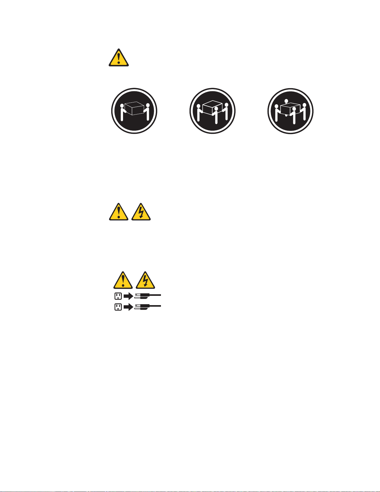
Statement 4:
≥ 18 kg (39.7 lb) ≥ 32 kg (70.5 lb) ≥ 55 kg (121.2 lb)
CAUTION:
Use safe practices when lifting.
Statement 5:
CAUTION:
The power control button on the device and the power switch on the power supply do not turn off th e e lect ri cal curre nt su ppl ied t o the device. The device also
might have more than one power cor d. To remove all electrical current from the
device, ensure that all power cords are disconnected from the power source.
2
1
viii xSeries 440:Option Installation Guide
Page 11
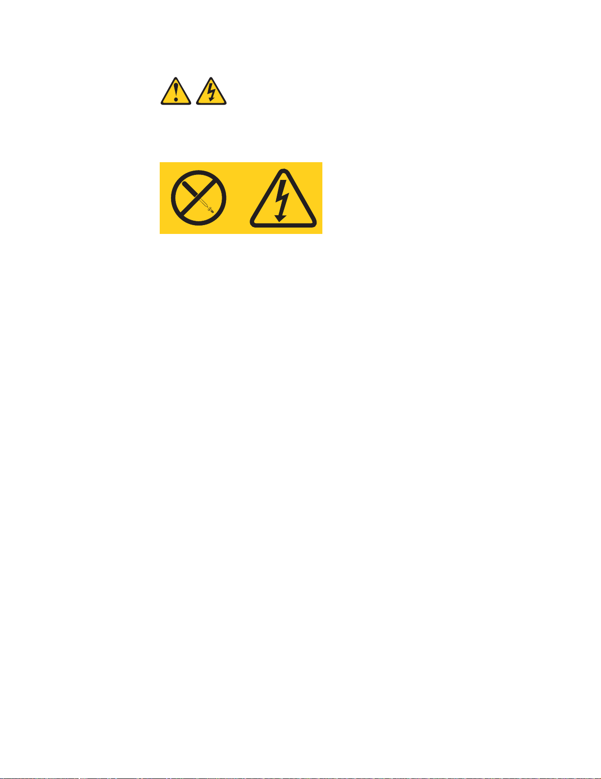
Statement 8:
CAUTION:
Never remove the cover on a power supply or any part that has the following
label attached.
Hazardous voltage, current, and energy levels are present inside any component that has this label attached. There are no serviceable parts inside these
components. If you suspect a pr oblem with one of these parts, contact a service technician.
Safety ix
Page 12

x xSeries 440:Option Installation Guide
Page 13

Chapter 1. Introduction
There are many optional devices supported by your server. This Option Installation
Guide provides the information needed to install, remove, and connect optional
devices supported by your server.
In addition to this Option Installation Guid e , the following xSeries 440 documentation
is provided with your server:
• Installation Guide
This printed publication contains setup and installation instructions. This publica-
tion is also provided in Portable Document Format (PDF) format on the IBM
xSeries
• Rack Installation Instructions
This printed publication contains the instructions needed to in stall y our server in a
rack cabinet. This publication is also provided in PDF format on the IBM xSeries
Documentation CD.
• Safety Book
This multilingual publication is provided in PDF format on the IBM xSeries Docu-
mentation CD. It contains translated versions of the caution and danger statements that appear in the documentation for your server. Each caution and danger
statement has an assigned number, which you can use to locate the corresponding statement in your native language.
• User’s Guide
This publication is provided in PDF format on the IBM xSeries Documentation CD.
It contains general information about your server.
• Troubleshooting Guide
This publication is provided in PDF format on the IBM xSeries Documentation CD.
It contains the info rmation needed to he lp you solve problems yourself, or provide
helpful information to a service technician.
™
Documentation CD.
®
Depending on your server model, additional pub lications might be included on the IBM
xSeries Documentation CD.
© Copyright IBM Corp. 2002 1
Page 14
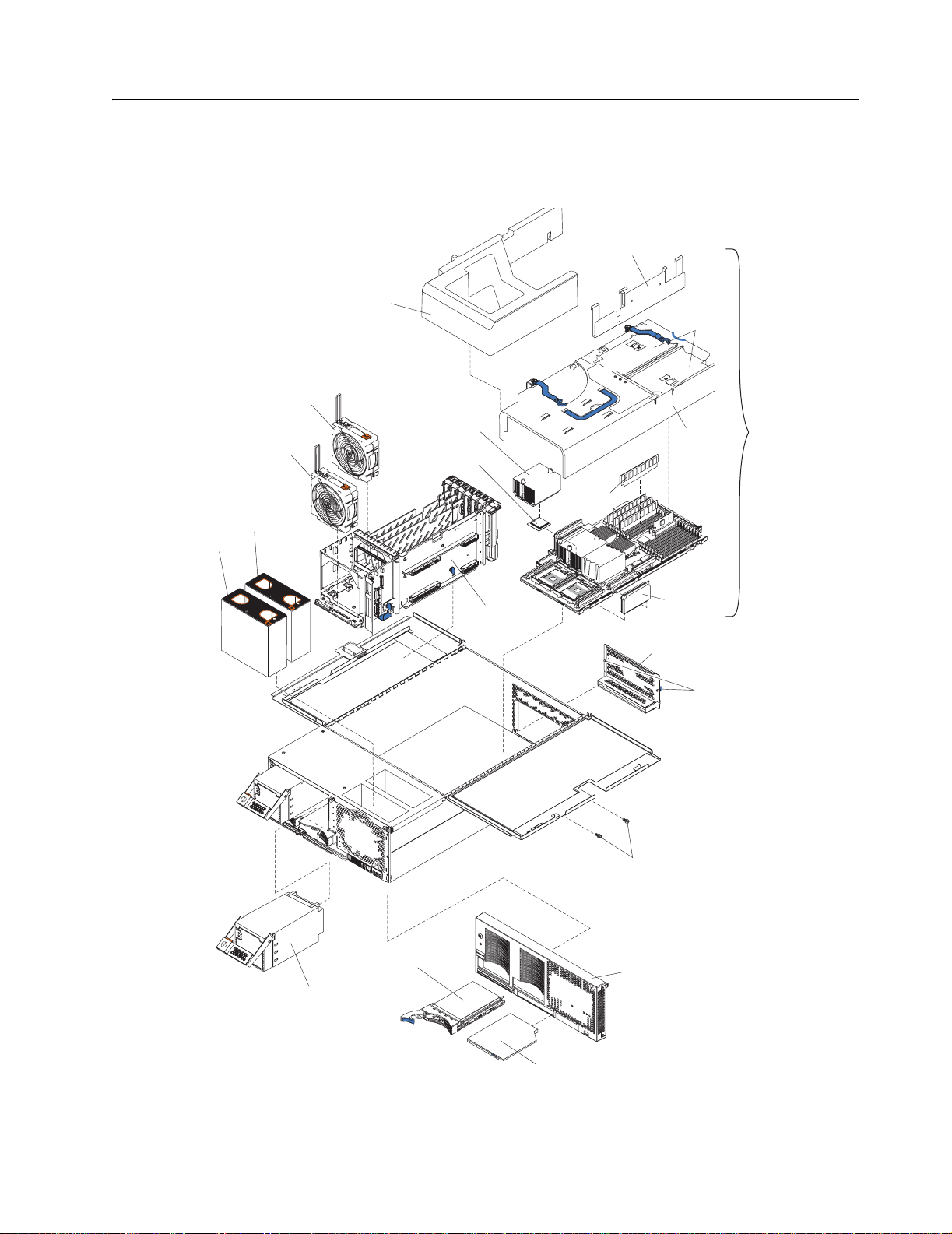
Major components of the xSeries 440
The following illustration sho ws the locations of major components in your server.
Note: The illustrations in this document might differ slightly from your hardware.
Retention bracket
Fan 1
N
O
T
E
:
F
O
F
R
O
Fan 2
R
P
R
O
P
E
R
A
I
R
F
L
O
W, R
N
T
O
F
B
O
X
Fan 4
Fan 3
N
O
T
E
:
F
O
R
P
R
O
P
E
R
A
IR
F
R
O
N
T
O
F
B
O
X
E
P
L
A
C
E
F
A
N
W
I
T
H
IN
2
M
I
N
SMP baffle
DIMM
access
doors
Heat-sink
Cover
SMP
Expansion
Module
Microprocessor
DIMM
F
L
O
W, R
E
P
L
A
C
E
F
A
N
W
I
T
H
IN
2
M
I
N
U
T
E
S
U
T
E
S
Center
plane
VRM
EMC Shield
(For single SMP Module)
Thumbscrews
Shipping thumbscrews
Hard disk
drive
Bezel
Hot-swap
power supply
CD-ROM
drive
2 xSeries 440:Option Installation Guide
Page 15
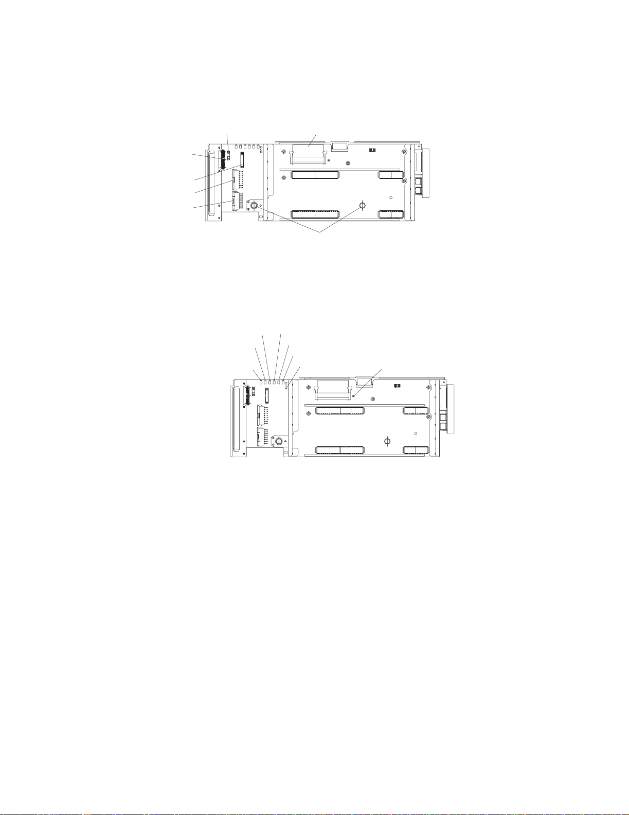
Center plane connectors and LEDs
The following illustrations identify the connectors and LEDs on the center plane. This
center plane is used to connect the power and signal paths for the SMP Expansion
Module, I/O board, and the Remote Supervisor Adapter.
Lightpath
SCSI
power
Power
Power
Power
PCI error LED
System management
error LED
I/O error LED
VRM
Thumbscrews
Center plane error LED
Lower SMP error LED
Upper SMP error LED
Power good LED
VRM error LED
Chapter 1. Introduction 3
Page 16
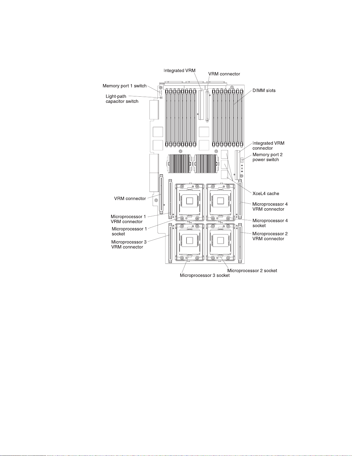
SMP Expansion Module connectors and lights
The following illustrations identify the connectors, switches, and lights on the SMP
Expansion Module.
4 xSeries 440:Option Installation Guide
Page 17
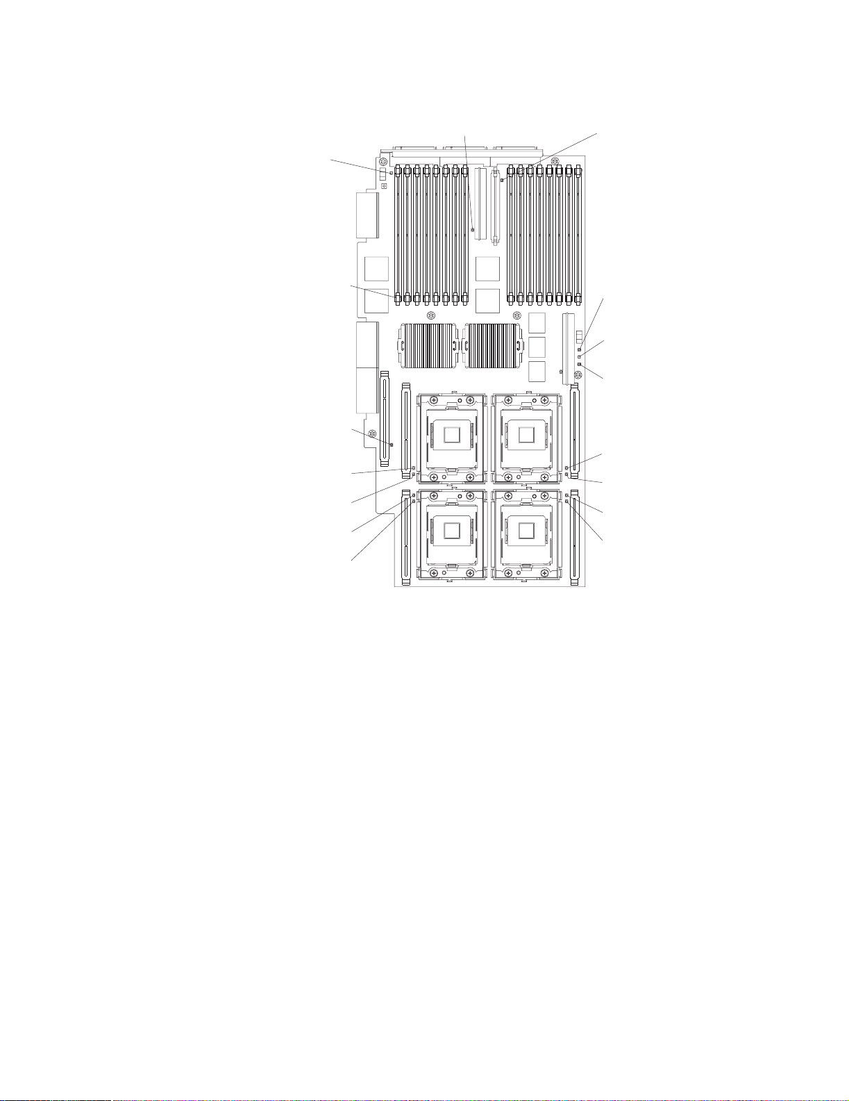
Light path capacitor
switch LED
DIMM error
LED (16X)
VRM error LED
Microprocessor 1
VRM error LED
Microprocessor 1
error LED
Microprocessor 3
error LED
Microprocessor 3
VRM error LED
SMP Expansion Module
board error LED
VRM error LED
Memory port 2
power LED
Hot-plug enabled
memory LED
Memory port 1
power LED
Microprocessor 4
VRM error LED
Microprocessor 4
error LED
Microprocessor 2
error LED
Microprocessor 2
VRM error LED
Chapter 1. Introduction 5
Page 18

PCI-X planar internal connectors and LEDs
The following illustration identifies the internal connectors and LEDs on the PCI-X planar. This planar enables you to install adapters in the server.
PCI-X slot 6
(133 MHz)
PCI-X slot 5
(133 )MHz
PCI-X slot 4
(100 )MHz
PCI-X slot 3
(100 )MHz
PCI-X slot 2
(66 )MHz
Attention LED
Power LED
PCI-X slot 1
(66 )MHz
6 xSeries 440:Option Installation Guide
Page 19
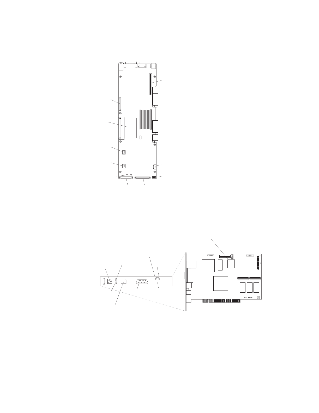
I/O board internal connectors
The following illustration identifies the internal connectors on the I/O board. This board
supports the input and output ports located on the server.
SCSI B
connector
I/O VRM
Fan 4
connector
Fan 3
connector
Power/Reset
connector
SCSI A
connector
Riser card
connector
Fans 1 and 2
connectors
USB cable
connector
Media bays
connector
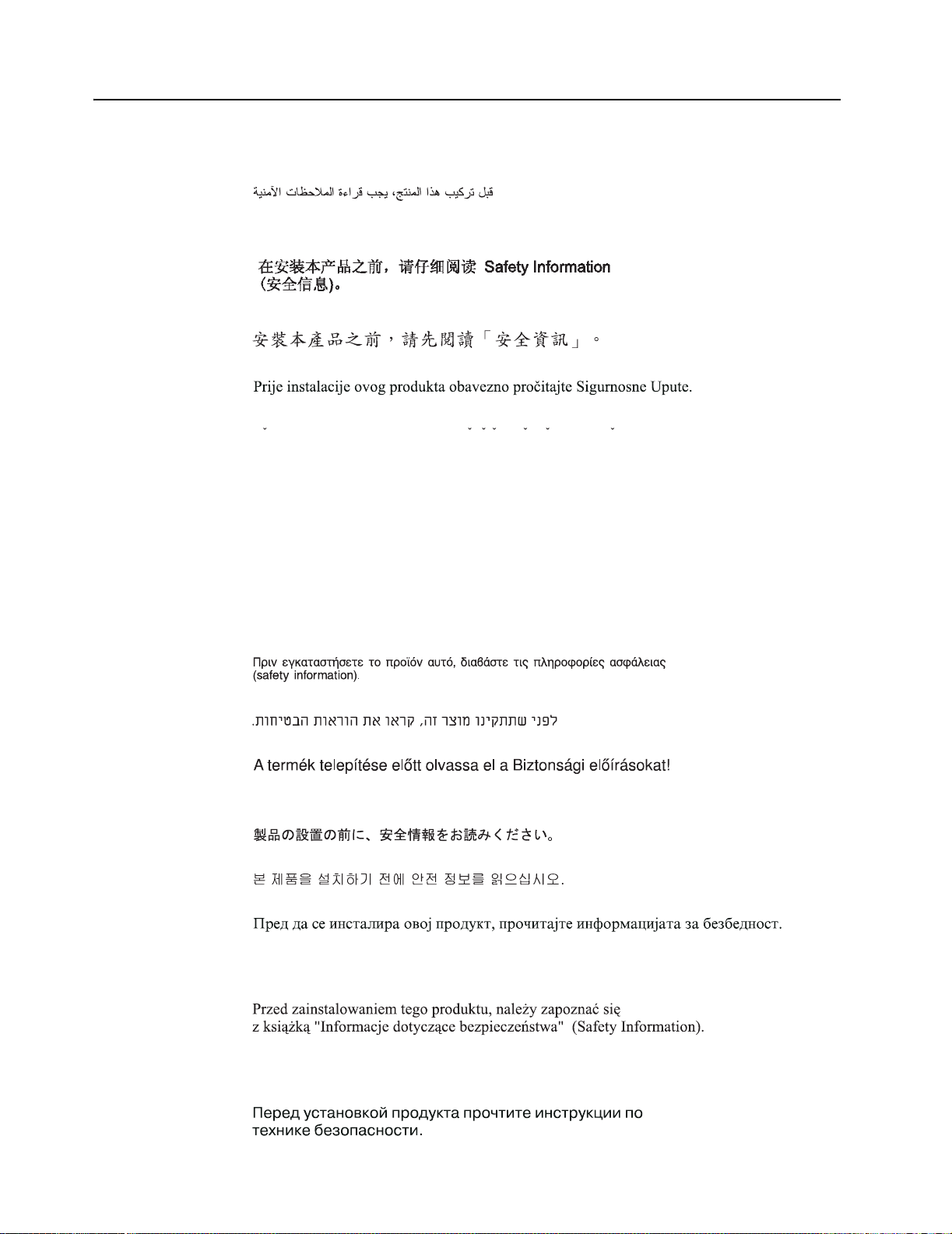
Remote Supervisor Adapter component locations
The following illustration identifies the connectors and lights on the Remote Supervisor Adapter.
Lithium
battery
Ethernet speed
External power
supply connector
Power LED
(green)
ASM Interconnect port
LED (green)
Error LED
(amber)
P
P
(RJ-14)
Serial port
(COM)
Ethernet link
LED (green)
Ethernet port
(RJ-45)
Chapter 1. Introduction 7
Page 20

8 xSeries 440:Option Installation Guide
Page 21

Chapter 2. Installing options
This chapter provides instructions to help you install options in your server. Some
option-removal inst ructions are provided in case you need to remove one option to
install another. For a list of supported options for your server, see the ServerProven
list at http://www.ibm.com/pc/compat/.
Before you begin
Before you begin to install options in your server, read the following information:
• Become familiar with the information provided in “Handling static-sensitive
devices” on page 10, and “Safety Information” on page 11. These guidelines will
help you work safely while working with your server or options.
• Make sure that you have an adequate number of properly grounded electrical outlets for your server, monitor, and any other options that you intend to install.
• Back up all important data before you make changes to disk drives.
• For a list of supported options for the xSeries 440, refer to
http://www.ibm.com/pc/us/compat/ on the World Wide Web.
Note: Some preconfigured servers have a unique list of supported op tio n s. See the
software documentation provided with those servers for more information.
®
Working inside a server with power on
Your server supports hot-swap de vice s and i s designed t o oper at e safely while turned
on with the cover removed. Follow these guidelines when you work inside a ser ver
that is turned on:
• Avoid loose-fitting clothing on your forearms. Button long-sleeved shirts before
working inside the server; do not wear cuff links while you are working inside the
server.
• Do not allow your necktie or scarf to hang inside the server.
• Remove jewelry, such as bracelets, rings, necklaces, and loose-fitting wrist
watches.
• Remove items from your shirt pocket (such as pens or pencils) that could fall into
the server as you lean over it.
• Take care to avoid dropping any metallic objects, such as paper clips, hair pins , or
screws, into the server.
© Copyright IBM Corp. 2002 9
Page 22

Handling static-sensitive devices
Attention: Static electricity can damage electronic devices an d y our system. To avoid
damage, keep static-sensiti ve devices in their static-protective package until you are
ready to install them.
To reduce the possibility of electrostatic discharge, observe the following precautions:
• Limit your movement. Movement can cause static electricity to build up around
you.
• Handle the device carefully, holding it by its edges or its frame.
• Do not touch solder joints, pins, or exposed printed circuitry.
• Do not leave the de vice wh ere others can handle and possib ly damage the de vice .
• While the device is still in its anti-static package, touch it to an unpainted metal
part of the system unit for at least 2 seconds. (This drains static electricity from the
package and from your body.)
• Remove the device from its package and install it directly into your system unit
without setting it down. If it is necessary to set the device down, place it in its
static-protective package. Do not place the device on your system unit cover or on
a metal table.
• Take additional care when handling devices during cold weather because heating
reduces indoor humidity and increases static electricity.
System reliability considerations
To help ensure proper cooling and system reliability, make sure that:
• Each of the drive bays has either a drive or a filler panel installed.
• There is space around the server to allow the cooling system to work properly.
• Cables for optional adapters are routed according to the instructions that are provided with the adapters.
• All microprocessors are the same size and clock speed.
• When two SMP Expansion modules are installed, they are connected together
through the SMP Expansion Ports.
• An SMP baffle is installed on top of the lower SMP Expansion module when only
one module is installed.
• For proper cooling, do not leave the cover open for more than 30 minutes.
• A failed fan is replaced within 48 hours.
• The top cover is closed during normal operation.
• Do not remove a defective power supply until a replacement is available.
10 xSeries 440:Option Installation Guide
Page 23
Safety Information
Before installing this product, read the Safety Information.
Antes de instalar este produto, leia as Informações de Segurança.
Pred instalací tohoto produktu si prectete prírucku bezpecnostních instrukcí.
Læs sikkerhedsforskrifterne, før du installerer dette produkt.
Lees voordat u dit product installeert eerst de veiligheidsvoorschriften.
Ennen kuin asennat tämän tuotteen, lue tu rvaohjeet kohdasta Safety Information.
Avant d'installer ce produit, lisez les consignes de sécurité.
Vor der Installation dieses Produkts die Sicherheitshinweise lesen.
Prima di installare questo prodotto, leggere le Informazioni sulla Sicurezza.
Les sikkerhetsinformasjonen (Safety Information) før du installerer dette produktet.
Antes de instalar este produto, leia as Informações sobre Segurança.
Chapter 2. Installing options 11
Page 24
Antes de instalar este producto, lea la información de seguridad.
Läs säkerhetsinformationen innan du installerar den här produkten.
Statement 1:
DANGER
Electrical current from power, telephone, and communication cables is
hazardous.
To avoid a shock hazard:
• Do not connect or disconnect any cables or perform installation,
maintenance, or reconfiguration of this product during an electrical
storm.
• Connect all power cords to a properly wired and grounded electrical
outlet.
• Connect to properly wired outlets any equipment that will be attached
to this product.
• When possible, use one hand only to connect or disconnect signal
cables.
• Never turn on any equipment when there is evidence of fire, water, or
structural damage.
• Disconnect the attached power cords, telecommunications systems,
networks, and modems before you open the device covers, unless
instructed otherwise in the installation and configuration procedures.
• Connect and disconnect cables as described in the following table
when installing, moving, or opening covers on this product or
attached devices.
To Connect: To Disconnect:
1. Turn everything OFF.
2. First, attach all cables to devices.
3. Attach signal cables to connectors.
4. Attach power cords to outlet.
5. Turn device ON.
1. Turn everything OFF.
2. First, remove power cords from outlet.
3. Remove signal cables from connectors.
4. Remove all cables from de vices.
12 xSeries 440:Option Installation Guide
Page 25

Statement 2:
CAUTION:
When replacing the lithium battery, use only IBM Part Number 33F8354 or an
equivalent type battery recommen d ed by the manufacturer. If your system has
a module containing a lithium battery, replace it only with the same module type
made by the same manufacturer. The battery contains lithium and can explode
if not properly used, handled, or disposed of.
Do not:
• Throw or immerse into water
• Heat to more than 100°C (212°F)
• Repair or disassemble
Dispose of the battery as required by local ordinances or regulations.
Statement 3:
CAUTION:
When laser products (such as CD-ROMs, DVD drives, fiber optic devices, or
transmitters) are installed, note the following:
• Do not remove the covers. Removing the covers of the laser product could
result in exposure to hazar dous laser radiation. There are no serviceable
parts inside the device.
• Use of controls or adjustments or performance of procedures other than
those specified herein might result in hazardous radiation exposure.
DANGER
Some laser products contain an embedded Class 3A or Class 3B laser
diode. Note the following.
Laser radiation when open. Do not stare into the beam, do not view
directly with optical instruments, and avoid direct exposure to the beam.
Chapter 2. Installing options 13
Page 26

Statement 4:
≥ 18 kg (39.7 lb) ≥ 32 kg (70.5 lb) ≥ 55 kg (121.2 lb)
CAUTION:
Use safe practices when lifting.
Statement 5:
CAUTION:
The power control button on the device and the power switch on the power supply do not turn off th e e lect ri cal curre nt su ppl ied t o the device. The device also
might have more than one power cor d. To remove all electrical current from the
device, ensure that all power cords are disconnected from the power source.
2
1
14 xSeries 440:Option Installation Guide
Page 27

Statement 8:
CAUTION:
Never remove the cover on a power supply or any part that has the following
label attached.
Hazardous voltage, current, and energy levels are present inside any component that has this label attached. There are no serviceable parts inside these
components. If you suspect a pr oblem with one of these parts, contact a service technician.
Chapter 2. Installing options 15
Page 28

Opening the cover
Complete the following steps to open the server cover:
1. Review th e information in "W orking inside a server with powe r on" and “Bef ore you
2. Slide the server out from the rack.
begin” on page 9.
Latch
N
O
T
E:
F
O
R
P
R
O
P
E
R
AI
R
F
L
O
W, R
E
P
N
O
T
E
:
FO
F
R
O
L
A
C
E
F
A
F
NW
R
O
R P
R
O
P
E
R
A
N
T O
F
B
O
X
ITH
N
T
O
IN
F
2
B
M
O
IN
X
IR
F
L
O
W,
U
T
E
R
E
P
L
A
S
C
E
F
A
N
W
IT
H
IN
2
M
IN
U
T
E
S
3. Pull the release latch on the left half of the to p cover to the right.
4. Using the finger hole in the release latch, open the left half of the cover; then,
open the right half of the cover.
Attention: For proper cooling and airflow, close the cover before turning on the
server. Operating the server for extended periods of time (over 30 minutes) with
the cover open might damage server components.
Removing and replacing the bezel
Complete the following steps to remove and replace the server bezel:
1. Remove the bezel.
a. Press on the two tabs at the top edge of the bezel, and pull the top of the
bezel slightly away from the server.
b. Press on the two tabs at the bottom edge of the bezel, and pull the bezel off
the server. Store the bezel in a safe place.
2. Replace the bezel.
a. Align the four tabs with the slots in the server chassis.
b. Press firmly against the front of the bezel until it snaps into place.
16 xSeries 440:Option Installation Guide
Page 29

Removing and replacing a hot-swap power supply
Your server comes with two hot-swap power supplies, which can be removed and
replaced without turning off the server. This section provides the information to properly remove and replace these power supplies.
Power light Power supply 1
Power supply 2
Power-on light
Power button
Reset button
Power supply
latch
Handle
Before you contin ue with the po w er supply-inst allation procedu re , re vie w th e f ollo wing.
Note: During normal operation, both power supplies must be installed for proper
operation and cooling.
If you install or remove a power supply, observe the following precautions.
Statement 8:
CAUTION:
Never remove the cover on a power supply or any part that has the following
label attached.
Hazardous voltage, current, and energy levels are present inside any component that has this label attached. There are no serviceable parts inside these
components. If you suspect a pr oblem with one of these parts, contact a service technician.
Complete the following steps to remove and replace a power supply.
Chapter 2. Installing options 17
Page 30

H
1. Review the information in “Before you begin” on page 9 through
“Safety Information” on page 11.
2. Remove the front bezel (see “Removing and replacing the bezel” on page 16 for
instructions on removing the front bezel).
3. To remove the power supply from the server, press the release latch; then, lift the
handle on the power supply to the open position and pull the power supply out
from the server.
ot-swap
power supply
elease latch
Power supply handle
(in open position)
AC LED
DC LED
4. To install the new power supply:
a. Place the handle on the powe r supply in the open position.
b. Slide the power supply into the chassis and press the handle to the closed
position.
5. Verify that the dc power light and the ac power light on the power supply are lit,
indicating that the power supply is operating properly.
6. Replace the front bezel o n the server ( see “Remo ving and replacing t he bez el” on
page 16 for instructions).
18 xSeries 440:Option Installation Guide
Page 31

PCI and PCI-X adapters
This section provides information about the expansion slots on the system board and
peripheral component interconnect (PCI or PCI-X) adapters.
The following illustration sho ws the location of the PCI-X expansion slots on the PCI-X
board.
Note: The illustrations in this document might differ slightly from your hardware.
PCI-X slot 6
(133 MHz)
PCI-X slot 5
(133 )MHz
PCI-X slot 4
(100 )MHz
PCI-X slot 3
(100 )MHz
PCI-X slot 2
(66 )MHz
Attention LED
Power LED
PCI-X slot 1
(66 )MHz
PCI and PCI-X adapter considerations
Before you install adapters, review the following:
• Locate the documentation that comes with the adapter and follow those instructions in addition to the instructions in this chapter.
• If you need to change the switch settings or jumper settings on your adapter, follow the instructions that come with the adapter.
• Video adapters are not supported.
• Some long adapters have extension handles or brackets installed. Before installing the adapter, you must remove the extension handle or bracket.
• You can install both PCI and PCI-X adapters in the same bus. However, if you
install a PCI adapter and a PCI-X adapter in the same bus, the PCI-X feat ures of
the PCI-X adapter will be disabled and the adapter will function as a PCI adapter.
• You can install PCI or PCI-X adapters of speeds faster than what is labeled for a
particular PCI-X bus. For example, if you install two 133 MHz adapters into slots
that are labeled as 100 MHz slots, the adapters will operate at 100MHz.
• If you install a 33 MHz and a 66 MHz adapter in the same bus, the bus speed will
match that of the slowest adapter.
Chapter 2. Installing options 19
Page 32

• If a single 133 MHz adapter is installed in PCI-X Bus B (slot 3 and 4), and the
other slot in PCI-X Bus B is empty, the adapter will operate at 133 MHz.
• Your server supports six hot-plug 64-bit adapters in the expansion slots locat ed on
the PCI-X board.
Note: You can add up to 12 additional PCI-X slots to your server by connecting
your server to a remote expansion enclosure. For more information about
the expansion enclosure and how to connect your server to it, refer to the
documentation that comes with your expansion enclosure.
Bus Slot Supported adapter speed (MHz)
A166
A266
B 3 100 (133 if slot 4 is empty)
B 4 100 (133 if slot 3 is empty)
C5133
D6133
• Your server supports 3.3 V adapters; it does not support 5.0 V adapters.
• Your server uses a rotational interrupt techn ique to configure PCI-X ad apters . You
can use this technique to install PCI-X adapters that currently d o not support sharing of PCI-X interrupts.
• The system scans PCI-X slots to assign system resources. The system attempts
to start the first device found. The search order is: CD-ROM, disk drives, integrated SCSI devices, PCI-X slots (1, 2, 6, 5, 3, 4), and the integrated Ethernet
controller.
Note: You can use the Configuration/Setup Utility program to change the boot prece-
dence for your server. Select Start Options from the Configuration/Setup Utility program main menu.
Installing adapters
Complete the following steps to install an adapte r:
Attention: When you handle static-sensitive devices, take precautions to avoid
damage from static electricity. For details on handling these devices, see “Handling
static-sensitive devices” on page 10.
1. Review the information in “Working inside a server with power on” on page 9,
“Before you begin” on page 9, and “Safety Information” on page 11.
2. You must disable the Active PCI-X slots in your server using the operating system
before you insert or remove a hot-plug PCI or PCI-X adapter.
Note: Some operating systems do not support the enabling and disabling of a
PCI-X slot. If your operating system does not support this function, then
turn off your server, and disconnect all external cables and power cords
before proceeding.
3. Pull out on the quick release latches on each side of the server; then, pull the
server out of its rack enclosure until it stops.
4. Open the top cover.
20 xSeries 440:Option Installation Guide
Page 33

Note: Inside your server there are six PCI-X slots: two 66 MHz, two 100 MHz,
and two 133 MHz. Before attempting to install a new adapter, be sure
there is an available slot for it. If you need additional PCI-X slots, y ou can
purchase a Remote Expansion Enclosure either from y our IBM marketing
representative or authorized reseller.
Adapter
Adapter guide
PCI-X
divider
Tab
Attention
LED
Power
LED
retention
latch
NOTE:FO
R PR
OP
ER A
IRFLO
W, R
EP
NOTE:FOR PROPER AIRFLOW, REPLACE FANWITHIN 2 MINUTES
FRONT OF BOX
LA
CE
F
ANW
FRONT OF BOX
ITH
IN 2 MINU
TE
S
5. Set any jumpers or switches as described by the adapter manufacturer.
6. Install the adapter:
a. Open the blue adapter guide by lifting the front edge, as shown in the illustra-
tion.
b. Remove the PCI-X divider from the PCI-X slot by grasping the divider along
the top edge and lifting it from the ser ver.
c. Push the orange adapter retention latch toward the rear of the server and
open the tab.
d. Remove the expansion-slot cover.
e. Carefully grasp the adapter by its top edge or upper corners and align it with
the connector on the PCI-X board.
Note: Some long adapters have extension handles or brackets installed.
Before installing a long adapter, you must remove the extension handle or bracket.
f. Press the adapter firmly into the adapter connector.
Chapter 2. Installing options 21
Page 34

Attention: When you install an I/O adapter, be sure the adapter is correctly
seated in the connector slot. Improperly seated adapters might cause dam-
age to the board, the riser card, or the adapt er.
g. Reinstall the PCI-X dividers between the Active PCI adapter slots.
h. Push down on the b lue adapter guide to keep the adapter steady.
i. Close the tab. The orange adapter retention latch will clic k into place, securing
the adapter.
7. Connect the internal cables to the adapter. If you are installing a ServeRAID
adapter, refer to “Cabling a ServeRAID adapter” for instructions.
8. If you have other options to install or remove, do so now.
9. Close the cover on the server.
10. Enable the slot or turn on the server, depending on your operat ing system.
Cabling a ServeRAID adapter
Some xSeries 440 models come with an optional IBM ServeRAID adapter installed to
control the internal hot-swap hard disk drives and external hard disk drives. If your
server did not come with an optional IBM ServeRAID adapter installed; then, refer to
your ServeRAID adapter option documentation for complete instructions on installing
a ServeRAID adapter in your server and for additional information on ServeRAID
adapters.
™
Servers without an optional IBM ServeRAID adapter installed come with two SCSI
cables:
• One end of the first SCSI cable is attached to the connector on the SCSI backplane, and the other end is attached to the connector for the integ rated SCSI controller behind fans 3 and 4.
• The second SCSI cable is preinstalled along the inside of the server chassis and
both ends are loose inside the server . Whe n yo u install a ServeRAID adapter, you
will connect this cable to the adapter and the SCSI backplane.
The following procedure describes the internal cabling needed to install a ServeRAID
adapter.
Complete the following steps to cable the ServeRAID adapter.
1. Review the information in “Before you begin” on page 9 through “Safety Information” on page 11.
2. Turn off the server and disconnect all power cords and ex ternal cables; then, open
the server cover (see “ Opening the cover” on page 16).
3. Remove fans 3 and 4, which are located just behind the PCI-X slots.
4. Disconnect the short SCSI cable from the SCSI backplane and the integrated
SCSI controller; then, store this short cable in a safe place for future use.
5. Install the ServeRAID adapter in the PCI-X slot (see“Installing adapters” on page
20).
22 xSeries 440:Option Installation Guide
Page 35

6. Locate one end of the preinstalled SCSI cable and connect it to the
ServeRAID adapter.
Preinstalled
SCSI cable
Connect to
SCSI backplane
Connect to
ServeRAID adapter
7. Locate the other end of the preinstalle d SCSI cable and connect it to the SCSI
backplane.
Front of server
SCSI backplane
connector
8. Reinstall fans 3 and 4.
9. If you have other options to install or remove, do so now.
10. Close the cov e r on the server; then, reinstall the server in the r ac k and connect all
external cables.
11. Turn on the server.
Chapter 2. Installing options 23
Page 36

Installing or replacing a drive
In this section, you will find the instructions needed to install or replace a hot-swap
hard disk drive, diskette drive, CD-ROM drive, and DVD-ROM drive.
Hot-swap hard disk drive
Complete the following steps to install or replace a hot-swap hard disk drive:
Attention: When you handle static-sensitive devices, take precautions to avoid
damage from static electricity. For details on handling these devices, see “Handling
static-sensitive devices” on page 10.
1. Inspect the drive for any signs of damage.
2. Review the information in “Before you begin” on page 9 and “Safety Information”
on page 11.
3. Check the instructions that come with the drive for more information about installing your drive.
4. Remove the filler panel or defective hard disk drive from the hard disk drive bay.
5. Install the new hard disk drive in the drive bay:
a. Ensure that the handle on the hard disk drive tray is in the open positio n.
b. Slide the drive into the bay until it stops.
c. Push the handle on the front of the hard disk drive closed.
Filler panel
6. If you have other options to install or remove, do so now.
Flashing green
light indicates
drive activity
Solid amber
light indicates
failed drive
Flashing amber
light indicates
drive rebuild.
24 xSeries 440:Option Installation Guide
Page 37

Diskette drive
Drive considerations:
• Your xSeries 440 server supports the installation of up to two diskette drives.
• If only one diskette drive is installed, it must be installed in the left drive bay.
Complete the following steps to remove and install a diskette drive in your server:
1. Review the information in “Before you begin” on page 9 and “Safety Information”
on page 11.
Attention: The IDE drives installed in your server are not hot-swappable.
2. Turn off the server and disconnect the power cord from the back of the server.
3. Push the diskette drive eject button to the right.
4. Using the tab, pull the diskette drive partially out of the server; then, grasp the
drive and remove it from the server.
5. Install the new diskette drive:
a. Inspect the drive for any signs of damage.
b. Slide the drive into the left drive bay until it stops.
Note: In the unlikel y event that no other IDE drives are installed, the diskette
drive must be installed in the right external removable media bay.
External removable
media bays
NOTE: FOR PROPER AIRFLOW, REPLACE FANWITHIN 2 MINUTES
NOTE: FOR PROPER AIRFLOW, REPLACE FANWITHIN 2 MINUTES
FRONT OF BOX
FRONT OF BOX
Diskette
drive
Tab
Diskette drive
eject button
6. If you have other options to install or remove, do so now. Ot herwise, connect the
power cords and turn on the server.
Chapter 2. Installing options 25
Page 38

CD-ROM or DVD-ROM drive
Drive considerations:
• Your xSeries 440 server supports the installation of up to two CD-ROM drives, or
two DVD-ROM drives.
• If no other IDE drives are installed, the disk ett e drive must be installed in the right
external remov able media bay. CD-ROM or DVD-ROM drives can be installed in
either external removable media bay.
Complete the following steps to remove and install a CD-ROM or DVD-ROM drive in
your server:
1. Review the information in “Before you begin” on page 9 and “Safety Information”
on page 11.
Attention: The IDE drives installed in your server are not hot-swappable.
2. Turn off the server and disconnect the power cords from the back of the server.
3. Push the CD-ROM or DVD-ROM eject button to the right.
4. Using the tab, pull the CD-ROM or DVD-ROM drive partially out of the server;
then, grasp the drive and remove it from the server.
5. Install the new CD-ROM or DVD-ROM drive:
a. Inspect the drive for any signs of damage.
b. Slide the CD-ROM or DVD-ROM drive into the drive bay until it stops.
External removable
media bays
CD-ROM
or DVD drive
Tab
NOTE: FOR PROPER AIRFLOW, REPLACE FANWITHIN 2 MINUTES
NOTE: FOR PROPER AIRFLOW, REPLACE FANWITHIN 2 MINUTES
FRONT OF BOX
FRONT OF BOX
CD-ROM drive
eject button
6. If you have other options to install or remove, do so now. Ot herwise, connect the
power cords and turn on the server.
26 xSeries 440:Option Installation Guide
Page 39

SMP Expansion Module
The SMP Expansion Module contains the XceL4™ system cache, DIMMs, microprocessors, and voltage regulator modules (VRMs) needed to run your server. This section contains the information needed to install and remove the SMP Expansion
Module, microprocessors, VRMs, and DIMMs.
SMP Expansion Module considerations:
• For your server to operate properly, there must be a minimum of one SMP Expansion Module and one SMP baffle installed.
• An SMP Expansion Module must contain at least one microprocessor and four
DIMMs.
• If it becomes necessary to remove or install DIMMs, do so through the DIMM
access doors on the SMP Expansion Module. Refer to the “Removing and replacing DIMMs:” on page 34 for the location of the DIMM access doors.
• Before removing or installing SMP Expansion Modules, you must remove the
electromagnetic compatibility (EMC) shield and SMP Expansion cables from the
rear of the server.
• You must run the Configuration/Setup Utility whenever you remove or replace an
SMP Expansion Module or one of its associated options.
Note: The illustrations in this document might differ slightly from your hardware.
Locking levers
CAM opening
Chapter 2. Installing options 27
Page 40

Removing an SMP Expansion Module and cover
While installing options, you might nee d to remove one or both of the SMP Expansion
Modules. This section provides instructions on removing an SMP Expansion Module
from the server and removing the cover from the module.
Complete the following steps to remove an SMP Expansion Module from the server:
1. Review the information in “Before you begin” on page 9, “Handling static-sensitive
devices” on page 10, and “Safety Information” on page 11.
2. Turn off the server and peripheral devices, disconnect the power cords and all
external cables from the SMP Expansion Module; then, open the cover (see
“Opening the cover” on page 16 for details).
3. If necessary, remove the SMP baffle and retention bracket from the server.
a. Remove the shipping thumbscrews from the right side of the server.
Retention bracket
removal handles
Retention bracket
SMP Expansion
Module
N
O
T
E
:
F
O
R
P
R
O
P
E
R
A
IR
FL
O
W, R
E
P
N
O
T
E
:
F
O
F
R
O
L
A
C
E
F
A
F
N
R
W
O
R
P
R
O
P
E
R
N
T
O
F
B
O
X
IT
N
T
H
IN
O
F
2
B
M
O
A
IR
F
L
O
W, R
IN
X
U
T
E
E
P
S
LA
C
E
F
A
N
W
IT
H
IN
2
M
IN
U
T
E
S
Shipping
thumbscrews
b. Open the cover.
c. Grasp the retention bracket b y the remov al handl es and lift it up and out of the
server.
Note: If there is one SMP Module installed, you will need to remov e the SMP
baffle from the server; then, remove the retention bracket from the
lower SMP Module as described in steps 3a through 3c.
4. To remove the EMC shield from the rear of the server:
a. If there are two SMP Expansion Modules installed in the server, you must dis-
connect the SMP Expansion Cables that are connected to the SMP Expansion Modules.
b. Remove the blue thumbscrews holding the EMC shield to the server.
28 xSeries 440:Option Installation Guide
Page 41

EMC shields
Thumbscrews
For use with one
SMP Module
For use with two
SMP Modules
c. Remove the EMC shield from the rear of the server.
SMP Expansion
Cables
EMC Shield
N
O
T
E
:
F
O
R
P
R
O
P
E
R
A
IR
F
L
O
W, R
E
P
N
O
T
E
:
F
O
R
P
R
O
P
E
R
F
R
O
N
T
O
F
B
O
X
L
A
C
E
F
A
F
N
R
W
O
IT
N
T
H
O
IN
F
2
B
M
O
A
I
R
F
L
O
W,
R
E
P
L
A
C
E
F
A
IN
X
U
T
E
N
W
S
I
T
H
I
N
2
M
IN
U
T
E
S
SMP baffle
5. Grasp each of the locking levers and lift them up slightly.
6. Working from the right side of the server, rotate the two locking levers toward you
until they are fully extended, as shown.
Latch
Locking
levers
Finger relief
N
O
TE
:
F
O
R
P
R
O
P
E
R
A
IR
F
LO
W, R
E
P
N
O
T
E
:
F
F
R
LA
C
E
F
A
F
O
R
P
R
O
O
N
T
O
F B
N
R
W
O
IT
N
T
H
O
IN
F
P
E
R
A
IR
F
L
O
X
2
B
M
O
IN
X
U
T
E
O
W, R
E
P
LA
S
C
E
F
A
N
W
IT
H
IN
2
M
IN
U
T
E
S
Handle
Attention: When removing the SMP Module from the server, lift it out carefully,
taking care not to damage the components on the center plane.
Chapter 2. Installing options 29
Page 42

7. Use the handle and the finger relief on the SMP Expansion Modu le cover to carefully lift the SMP Expansion Module out of the server.
Note: The illustrations in this document might differ slightly from your hardware.
8. Remove the SMP Expansion Module cover:
a. Place the SMP Expansion Module on a flat, level surface.
b. Rotate the two locking levers just beyond the edge of the SMP Expansion
Module cover until they stop; then, using the locking levers, lift the cover off
the circuit board.
30 xSeries 440:Option Installation Guide
Page 43

DIMMs
This section contains instructions on how to install, add, and remove DIMMS. It
includes information about Active Memory and Memory Mirroring. Before preforming
any of the procedures in this section, read the “Safety Information” on page 11, “Handling static-sensitive devices” on page 10, and the DIMM considerations 32.
Your xSeries 440 server supports up to sixteen 3.3 V, 168 pin, 133 MHZ ECC SDRAM
DIMMs in each SMP Expansion Module. With both SMP Expansion Modu les installed,
the server can support a maximum of 32 SDRAM DIMMS for a total of 32 GB of memory in your server.
Notes:
1. DIMMs can be removed and replaced through the access doors on the top of the
SMP Expansion Module.
2. The illustrations in this document might differ slightly from your hardware.
DIMM
bank 2
Chapter 2. Installing options 31
Page 44

DIMM considerations:
• Your xSeries 440 server supports 512 MB and 1 GB DIMMs, for a maximum of 32
GB of system memory depending on your configuration. See the ServerPro ven list
at http://www.ibm.com/pc/compat/ for a list of memory modules you can use with
your server.
• Your server comes with four 512 MB DIMMs installed in slots 1, 3, 5, and 7 in the
SMP Expansion Module. When installing additional memory modules, you must
install four DIMMS a t a time and in the order described to maintain performance.
(See the following figure for memory connector locations.)
• When installing or removing DIMMs, it must be done in banks of four and in the
following order:
1. Bank 1 = DIMM connectors 1, 3, 5, 7
2. Bank 2 = DIMM connectors 9, 11, 13, 15
3. Bank 3 = DIMM connectors 2, 4, 6, 8
4. Bank 4 = DIMM connectors 10, 12, 14, 16
Bank 1 (standard) Bank 2
DIMM error
indicators are
built into
Bank 3
Bank 4
each handle.
• Each DIMM in an individual bank must be of the same size and clock speed to
ensure the server will operate properly. For example, in bank 1 your server came
with four 512 MB DIMMs installed. In bank 2, y ou can inst all f our 512 MB or four 1
GB DIMMs.
• When using Memory Mirroring, all of the DIMMs in each memory port must be the
same size and clock speed.
• Memory ports:
— Memory Port one
– Bank 1 = DIMM connectors 1, 3, 5, 7
– Bank 3 = DIMM connectors 2, 4, 6, 8
— Memory Port two
– Bank 2 = DIMM connectors 9, 11, 13, 15
– Bank 4 = DIMM connectors 10, 12, 14, 16
32 xSeries 440:Option Installation Guide
Page 45

• When you install or remove DIMMs, the server configuration information changes.
Therefore, you must change and save the new configuration information by using
the Configuration/Setup Utility program. When you restart the server, the system
displays a message indicati ng that the memory configuration has changed. Start
the Configuration/Setup Utility program and select Save Settings. If you need
instructions, see Chapter 2. Configuring your server in the User’s Guide on the
IBM Documentation CD.
Active Memory: Active Memory is an IBM feature that improves the reliability of
the DIMMs through Memory Mirroring, Memory Scrubbing and Memory ProteXion
• Memory Mirroring allows you to improve the memory reliability of your server by
creating a mirror of the data in memory port one and storing it in memory port two.
Note: For Memory Mirroring to work, you must have the same amount of memory
in both memory ports. For more inf ormation about the memory ports, ref er
to the DIMM considerations 32.
Complete the following steps to enable Memory Mirroring.
1. Check your operating system documentation to be sure that it supports Mem-
ory Mirroring.
2. Install DIMMs of the same size and clock speed in the two memory ports.
3. Enable Memory Mirroring in the Configuration/Setup Utility:
a. Turn on the server and watch the monitor screen.
b. When the message Press F1 for Configuration/Setup appears, press
F1.
c. From the Configuration/Setup Utility main menu, select Advance Fea-
tures.
d. Select and enable Memory Mirroring.
e. Save and exit the Configuration/Setup Utility program.
How does Memory Mirroring work?
When Memory Mirroring is enabled, the data that is written to memo ry is stored in
two locations. One copy is kept in the memory port one DIMMs, while a second
copy is kept in t he memory port two DIMMs. During the e x ecution of t he read command, the data is read from the DIMM with the least amount of reported memory
errors through Memory Scrubbing, which is enabled with Memory Mirroring.
If Memory Scrubbing determines the DIMM is damaged beyond use, read and
write operations are redirected to the remaining good DIMM. Memory Scrubbing
then reports the damaged DIMM and the Light Path Diagnostics display the error.
After the damaged DIMM is replaced, Memory Mirroring then copies the mirrored
data back into the new DIMM.
• Memory Scrubbing is an automatic daily test of all the system memory that
detects and reports memory errors that might be developing before they cause a
server outage.
Note: Memory Scrubbing and Memory ProteXion work in conjunction with each
other and do not require Memory Mirroring to be enabled to work properly.
™
.
How does Memory Scrubbing work?
When an error is detected, Memory Scrubbing determines if the error is recoverable or not. If it is recoverable, Memory ProteXion is enabled and the data that
was stored in the damaged locations is rewritten to a new location. The error is
then reported so that preventative maintenance can be performed. As long as
Chapter 2. Installing options 33
Page 46

there are enough good locations to allow the proper operation of the server, no
further action is taken other than recording the error in the error logs.
If the error is not recov erab le , the n Memory Scrubbing sends an error message to
the Light Path Diagnostics, which then turns on the proper lights and LEDs to
guide you to the damaged DIMM. If Memory Mirroring is enabled, then the mirrored copy of the data in the damaged DIMM is used to refresh the ne w DIMM
once it is installed.
• Memory ProteXion reassigns memory bits to new locations within memory when
recoverable errors have been detected.
How does Memory ProteXion work?
Once a recoverable error is found by Memory Scrubbing, Memory ProteXion
writes the data that was to be stored in the damaged memory locations to spare
memory locations within the same DIMM.
Removing and replacing DIMMs: If you need to replace or upgrade the
DIMMs in your server, you must remove the old DIMMs before you insert new ones.
This section includes the instructions needed to properly remove and replace DIMMs
from the SMP Expansion Module in your server.
Attention: When working with DIMMs or other options, you might need to remove
one or both of the SMP Expansion Modules. Before removing an SMP Expansion
Module, be sure to turn off the server and peripheral devices; then, disconnect all
external cables and power cords.
Complete the following steps to remove a DIMM from your server SMP Expansion
Module:
1. Review the information in “Before you begin” on page 9, “Handling static-sensitive
devices” on page 10, and “Safety Information” on page 11.
2. Turn off the server and peripheral devices, disconnect the power cords, and all
external cables from the SMP Expansion Module; then, open the server cover
(see “Opening the cover” on page 16 for details).
3. If necessary, remove the top SMP Expansion Module from the server. Refer to
“Removing an SMP Expansion Module and cover” on page 28 for instructions.
4. Open the DIMM access door that covers the DIMM you will be removing.
DIMM access
door
5. Open the retaining clip on each end of the DIMM connector.
6. Lift the DIMM straight up and out of the SMP Expansion Module.
7. Install a new DIMM:
34 xSeries 440:Option Installation Guide
Page 47

a. Touch the static-protective package containing the DIMM to any unpainted
metal surface on the server. Then, remove the DIMM f rom the package.
Attention: To avoid breaking the retaining clips or damaging the DIMM con-
nectors, open and close the clips gently.
b. Insert the DIMM into the connector b y a ligning the DIMM edges with the slots
at each end of the DIMM connector . Firmly press the DIMM straigh t down int o
the connector by applying pressure on both ends of the DIMM sim ultaneously.
Be sure that the retaining clips snap into the locked position when the DIMM is
firmly seated in the connector.
DIMM
Retaining
clip
c. If a gap exists between the DIMM and the retaining clips, the DIMM has not
been properly installed. In this case, open the retaining clips and remove the
DIMM; then, reinsert the DIMM.
8. Close the DIMM access door or reinstall the SMP Expansion Module cover ( se e
“Reinstalling an SMP Expansion Module and cover” on page 41).
9. If you have other options to install or remove, do so now.
10. Close the server cover. See “Closing the cover” on page 49.
Note: When you install or remove DIMMs, the server configuration information
changes. Theref ore, you must change and save the new configur ati on information by using the Configuration/Setup Utility program. Ref er to the User’ s Guide
on the Documentation CD.
Chapter 2. Installing options 35
Page 48

Installing and replacing a microprocessor
This section describes how to install and remove microprocessors and VRMs. Before
performing any of the procedures in this section, read “Safety” on page v, “Handling
static-sensitive devices” on page 10, and Before you begin.
Your xSeries 440 Server supports up to two Intel Xeon DP or four Intel Xeon MP
microprocessors in each SMP Expansion Module. With both SMP Expansio n Modules
installed, the server can support a maximum of four Intel Xeon DP or eight Intel Xeon
MP microprocessors of the same type and speed.
Note: Do not install both Intel Xeon MP and Intel Xeon DP microprocessors in the
same server or SMP Expansion Module.
Before you begin:
• Read the documentation that comes with the microprocessor to determine if you
need to update the server basic input/output system (BIOS) code. For the most
current leve l of BIOS code f or the server, go to http://www.ibm.com/pc/su pport/ on
the World Wide Web.
• Obtain an SMP-capable operating system (optional). For a list of supported operating systems, go to http://www.ibm.com/pc/us/compat/ on the World Wide Web.
Attention: To avoid damage and ensure proper server operation after you install a
replacement or an additional microproce ssor , use a micro processor that has the same
cache size and type, clock speed, and internal and external clock frequencies as the
microprocessors already installed in the individual SMP Expansion Module. For a list
of microprocessors supported by your server, see the ServerProven list at
http://www.ibm.com/pc/us/compat/ on the World Wide Web.
Notes:
1. To order additional microprocessor options, contact y our IBM mark e ting re presentative or authorized reseller.
2. The microprocessor in socket 1 of the bottom SMP Expansion Module is the startup (boot) microprocessor.
3. If you are adding additional I ntel Xeon MP microprocessors to an SMP Expansion
Module, populate the empty microprocessor sockets in numeric order, starting
with socket 1. If y ou install the microprocessors in the wrong order, the server will
not power on.
4. If you are adding additional Intel Xeon DP microprocessors to your server, you
must have a second unpopulated SMP Expansion Module. Server models tha t
come with Intel Xeon DP microprocessors support a maximum of two microprocessors per SMP Expansion Module, and are installed in microp ro ce ssor sockets
1 and 4.
The following illustration sho ws the locations of the startup microprocessor and its
VRM on the system board. It also shows the microprocessor baffles and the VRM
slots for the other microprocessor sockets.
36 xSeries 440:Option Installation Guide
Page 49

Notes:
1. The illustrations in this document might differ slightly from your hardware.
2. Remember, Intel Xeon DP microprocessors are supported in microprocessor
sockets 1 and 4 only. Intel Xeon MP microprocessor are supported in microprocessor sockets 1,2,3, and 4.
Microprocessor 4
VRM connector
Microprocessor 1 VRM
Microprocessor 1
Microprocessor 3
VRM connector
Microprocessor 4
baffle
Microprocessor 2
VRM
Microprocessor 3 socket
Microprocessor 2
Complete the following steps to install a microprocessor:
1. Read the “Handling static-sensitive devices” on page 10 and “Safety Information”
on page 11.
2. Turn off the server and peripheral devices, disconnect the power cords, and disconnect all external cables from the SMP Expansion Module; then, open the cov er
(see “Opening the cover” on page 16 for details).
3. Remove the SMP Expa nsion Module in which you plan to install the microprocessor; then, remove the module co v er and determine the soc k et where the micr oprocessor is to be installed. For details, see “Removing an SMP Expansion Module
and cover” on page 28.
Important: Before continuing, you should determine which type of microprocessors are installed in your server. The easiest way to do this is by the locations of
the installed microprocessors in the SMP module. If the microprocessors are
installed only in socke ts 1 and 4, your server came with Intel Xeon DP microprocessors. If the microprocessors are installed in any other soc k ets, such as 1 and 2
or 1,2, and 3, then your server came with Intel Xeon MP microprocessors.
Note: If your server contain s only one SMP Expansi on Module , remo ve the SMP
baffle above it t o gain access to the module. If your server contains two
SMP Expansion Modules, remove the top module to gain access to the
bottom or lower SMP module.
Chapter 2. Installing options 37
Page 50

Attention: When you handle static-sensitive devices, take precautions to avoid damage from static electricity. For details on handling these devices, see “Handling staticsensitive devices” on page 10.
4. If you are installing a new microprocessor, go to step 5; otherwise, continue:
a. Verify that you have selected the correct microprocessor to be replaced. The
LED next to the failing microprocessor will be on.
Attention: Before attempting to remove the heat sink from the microproces-
sor, note t hat the heat-conducting grease between the heat sink and the
microprocessor might have formed a strong bond. Do not force the components apart; doing so can damage the microprocessor pins. If the heat sink
does not separate from the microprocessor ea sily, loosen one heat sink captive mounting scre w first. This a llows one corner of the hea t sink to be lifted of f
of the microprocessor; then, you can loo sen the other ca ptiv e mounting scre w
and remove the heat sink.
Captive screws
VRM 3
Microprocessor
locking lever
Heat sink 3
Microprocessor 3
b. Using a screwdriver , loosen the two captiv e mounting scre ws on the heat sink,
alternating between screws until they release from the SMP board; then,
remove the heat sink.
c. Lift the microprocessor locking lev er to the open position and remove the
microprocessor.
5. Install the VRM in the slot adjacent to the microprocessor socket.
Attention: If you are installing an additional microprocessor, note that the new
microprocessor comes in a kit with a VRM. Some microprocessor options contain
a VRM with a clip to secure the VRM in the slot. This clip is not needed for installations in your server and can be discarded. When installing a new microprocessor you must install the VRM that came in the kit.
a. If you are replacing a failed VRM:
1) Verify that you have selected the correct VRM to be replaced. The LED
next to the failing VRM will be on.
2) Grasp the VRM at both upper corners and lift it out of the slot.
38 xSeries 440:Option Installation Guide
Page 51

b. Holding the new VRM by the upper corners, plug it firmly into the slot.
6. If necessary, remove the microprocessor baffle from the microprocessor socket.
Keep the microprocessor baffle for possible future use.
7. Touch the static-protective package containing the new microprocessor to any
unpainted metal surfac e on th e se rver; then, remove the microprocessor from t he
package.
8. Install the microprocessor:
Important: When installing Intel Xeon DP microprocessors, you must install them
in the following order: socket 1 then socket 4. When installing Intel Xeon MP
microprocessors, you must in stall them in the following order: sockets 1,2,3, and
then 4.
a. Ensure that the microprocessor locking lever is in the open position to permit
plugging in the microprocessor.
b. Re m ove the protective tape from the microprocessor socket.
c. Align the triangle icon on the microprocessor with the triangle icon on the
socket and press the mi croprocessor gently into the soc ket.
Attention: Make sure that the microp rocessor is aligned correct ly befor e you
proceed. To avoid bending the pins on the microprocessor, do not use exces-
sive force when pressing it into the socket.
d. Close the locking lever to secure the microprocessor.
9. If you have installed an additional microprocessor:
a. Remove the heat sink from its package and detach the pr otective cover from
the bottom of the heat sink
Attention: Do not disturb or contaminate the heat-con ducting grease on the
bottom of the new heat sink. Doing so damages its heat-conducting capability
and exposes the new microprocessor to overheating.
Chapter 2. Installing options 39
Page 52

Captive screws
Protective cover
Heat sink
b. Align the heat sink over the microprocessor; then, carefully set it down on top
of the microprocessor.
c. Using a screwdriver, secu re the heat sink t o the microproce ssor soc ke t on the
SMP board using the two captive mounting screws. Press firmly on the
screws and tighten them, alternating between them. Do not overtighten the
screws.
10. Close the SMP Expansion Module top cover; then, install th e mo d ule in the
server. For details, see “Reinstalling an SMP Expansion Module and cover” on
page 41.
11. If you have other options to install or remove, do so now.
12. Close the cov e r on the server; then, reinstall the server in the rac k and connect all
external cables. For details, see “Closing the cover” on page 49.
13. Turn on the server.
Important: If your server will not start after replacing or installing a microproces-
sor, you might have inst alled a microprocessor of a different type or the VRM is
not installed properly. Verify that yo u hav e installed the proper microprocessor and
that the VRM is properly installed.
Note: When you install or remove microprocessors, the server configuration
information changes. Therefore, you must change and save the new configuration information by using the Configuration/Setup Utility program.
Refer to the User’s Guide on the Documentation CD.
40 xSeries 440:Option Installation Guide
Page 53

Reinstalling an SMP Expansion Module and cover
After installing options in the SMP Expansion Module, you will need to reinstall the
SMP Expansion Module cover and reinstall the SMP Expansion Module in the server.
Complete the following steps to reinstall the SMP Expansion Module cover:
1. Install the cover on the SMP Expansion Module:
a. Set the cover on top of the expansion module.
b. Extend the locking levers as shown in the illustration; then, let the cam on the
front of the cover fall into the cam opening on the SMP Expansion Module circuit board.
Locking levers
CAM opening
c. Release the locking levers and align the re ar of the cov er with the rear edge of
the circuit board.
d. Press down on the cover until it snaps into place.
Chapter 2. Installing options 41
Page 54

e. Lift slightly on the locking levers and rotate them back until they stop.
Note: The illustrations in this document might differ slightly from your hard-
ware.
Locking
levers
Handle
2. Install the SMP Expansion Module into the server.
Locking
levers
Center plane
N
O
T
E
:
F
O
R
P
R
O
P
E
R
A
IR
F
LO
W, R
E
P
N
O
TE
:
F
F
R
O
L
A
C
E
F
A
F
O
R
P
R
O
P
E
N
T
O
F
B
O
N
R
W
O
ITH
N
T
O
IN
F
2
B
R
A
IR
F
LO
X
M
O
IN
X
U
TE
W, R
E
P
L
S
A
C
E
F
A
N
W
IT
H
IN
2
M
IN
U
T
E
S
Handle
a. Lift the SMP Expansion Module by its handle and use the finger relief to hold
the SMP module steady.
b. Being careful not to damage the components on the center plane, place the
SMP Expansion Module into the server.
c. Release the handle and slide the SMP Expansion Module toward the center
plane until it stops.
42 xSeries 440:Option Installation Guide
Page 55

d. Ro ta te the SM P Expans ion Mo du le locking levers forward until the SMP
Expansion Module is securely fastened in place. Refer to the following illustration.
Note: The illustrations in this document might differ slightly from your hard-
ware.
Center plane
Locking
levers
Cover
Handle
3. If you have other options to install or remove, do so now.
4. Close the cover on the server; then, reinstall the server in the rack and conn ect all
external cables. For details, see “Closing the cover” on page 49.
5. Turn on the server.
Note: When you install or remove SMP Expansion Modules, the server configu-
ration information changes . Therefore, you must change and sav e the ne w
configuration information by using the Configuration/Setup Utility progr am.
Refer to the User’s Guide on the Documentation CD.
Chapter 2. Installing options 43
Page 56

Replacing and troubleshooting fans
Your xSeries 440 server has four hot-s w ap f an assemb lies, t wo 150 mm x 3 8 mm, and
two 150 mm x 51 mm fans. The two 150 mm x 38 mm fan s (fan 3 and f an 4) are
located just behind the PCI-X planar and are used to cool the power supplies, PCI-X
slots, and the I/O board. The two 150 mm x 51 mm fans (fan 1 and fan 2) are located
toward the front of t he server and are used to cool the SMP Expansion Mo dules. Ref er
to the following illustration.
Note: The illustrations in this document migh t differ slightly from yo ur hardware.
Fan 3
Fan 4
Latch release
N
O
T
E:
F
OR PROP
ER
AIRF
LO
W, REPLACE FA
Fan 2
F
N
R
W
ONT
ITHIN 2 MIN
O
F BO
X
UTES
Each fan has a light located on the top left side. When the fan is operating correctly,
this light is on. If a fan stops w orking, the Light Path Diagnostics feature will light a system-error light on the front of the server, indicating that there is a problem and guide
you to the defective fan. When this occurs, first identify the defective fan; then, using
the appropriate procedure, remove and replace the fan.
Replacing fans 1 and 2
As shown in the following illustration, fans 1 and 2 are located on the right side of the
server, and cool the SMP Expansion Modules. These fans are redundant, meaning
that if one fails, the remaining fan will temporarily speed up to properly cool the SMP
Expansion Modules. In the event of a failure, replace the malfunctioning fan within 48
hours.
Complete the following steps to replace fans 1 and 2:
1. Review the information in “Working inside a server with power on” on page 9 and
“Before you begin” on page 9.
Attention: All fans must be replaced within 48 hours of failing.
NOTE:FOR PROP
ER AIRFLO
W, REPLACE FANWITHIN 2 MINUTES
FRONT OF BOX
Fan 1
44 xSeries 440:Option Installation Guide
Page 57

2. Re m ove the fan from the server:
a. Place your fingers into the two finger holes on the top of the fan and squeeze
them together.
Note: The illustrations in this document might differ slightly from your hard-
ware.
Fan 4
Latch release
NOTE:FO
R P
R
O
PE
R AIRFLO
W, REPLACE FANW
Fan 2
FRO
ITH
NT
IN
OF
2 M
BO
INUT
X
ES
Fan 3
NOTE:FOR PROPE
R AIRFLO
W, REPLACE FANW
FRON
ITHIN 2
T OF BO
MINUTES
X
b. Lift the fan out of the server.
3. Orient the new fan so that the light on the top of the fan is to the right side of the
server.
4. Push the replacement fan assembly into the server until it clicks into place.
5. If you have other options to install or remove, do so now.
6. Close the server cover. See “Closing the cover” on page 49.
Replacing fans 3 and 4
As shown in the illustration, these two fans (f an 3 and fan 4) are located in front of the
I/O board and the PCI-X slots. They are used to cool the hard disk drives, I/O board,
and PCI-X slots.These f ans are redundant, mean ing that if one f ails, the remaining f an
will temporarily speed up to properly cool the I/O components in the server. In the
event of a failure, you must replace the malfunctioning fan within 48 hours.
Complete the following steps to replace fans 3 and 4:
1. Review the information in “Working inside a server with power on” on page 9 and
“Before you begin” on page 9.
Attention: All fans must be replaced within 48 hours of failing.
Fan 1
Chapter 2. Installing options 45
Page 58

2. Re m ove the fan from the server:
a. Pre s s the latch rele as e to th e right and let the handle come up.
Note: The illustrations in this document might differ slightly from your hard-
ware.
Fan 4
Latch release
NOTE:F
OR
PR
OPE
R AIR
FLO
W, RE
PLA
Fan 2
CE
F
ANWIT
FRON
T O
HIN 2 MI
F BO
X
NUTES
Fan 3
NOT
E:
FO
R PR
O
PER AIRF
LO
W, R
EPLA
C
E F
A
FRONT O
N
W
ITHIN
F BO
2 MIN
X
UTES
Fan 1
b. Grasp the handle and lift the fan out of the server.
3. Orient the new fan so that the latch release on the top of the f an is to the right side
of the server.
4. With the handle raised, push the replacement fan assembly into the server until it
clicks into place.
5. Push the handle down until it clicks into place under the latch release.
6. If you have other options to install or remove, do so now.
7. Close the server cover. See “Closing the cover” on page 49.
46 xSeries 440:Option Installation Guide
Page 59

Replacing the battery
When replacing the battery you must replac e it with a lithi um battery of the same type ,
from the same manufacturer. To avoid possible danger, read and follow the safety
statement below.
To order replacemen t ba tte ries, call 1-800-772-2227 within the United Stat es, and
1-800-465-7999 or 1-800-465-666 6 within Canada. Outsid e the U .S . and Canada , call
your IBM reseller or IBM market ing representative.
Note: After you replace the battery, you must reconfigure your server and reset the
system date and time.
Statement 2:
CAUTION:
When replacing the lithium battery, use only IBM Part Number 33F8354 or an
equivalent type battery recommen d ed by the manufacturer. If your system has
a module containing a lithium battery, replace it only with the same module type
made by the same manufacturer. The battery contains lithium and can explode
if not properly used, handled, or disposed of.
Do not:
• Throw or immerse into water
• Heat to more than 100°C (212°F)
• Repair or disassemble
Dispose of the battery as required by local ordinances or regulations.
Complete the following steps to replace the battery:
1. Read the “Safety Information” on page 11, and follow any special handling and
installation instructions supplied with the replacement battery.
2. Turn off the server and peripheral devices, disconnect the power cords, and all
external cables from the se rver; then, open the co v er (see “Openin g the co v er ” on
page 16 for details).
3. Remove fans 3 and 4 from the server (see “Replacing fans 3 and 4” on page 45
for details).
Chapter 2. Installing options 47
Page 60

4. Re m ove the battery:
a. Use one finger to lift the battery clip over the battery.
b. Use one finger to slightly slide the battery out from its socket. The spring
mechanism will push the battery out toward you as you slide it from the
socket.
c. Use your thumb and index finger to pull the b attery from under the battery clip.
d. Ensure that the battery clip is touching the base of the battery socket by
pressing gently on the clip.
5. Insert the new battery:
a. Tilt the battery so that you can insert it into the socket, under the battery clip.
b. As you slide it under the battery clip, press the battery down into the socket.
6. Install fans 3 and 4 in the server (see “Replacing fans 3 and 4” on page 45 for
details).
7. Close the server cover, and connect the cables.
8. Turn on the server.
9. Start the Configuration/Setup Utility program and set configuration parameters.
• Set the system date and time.
• Set the power-on password.
• Reconfigure your server.
48 xSeries 440:Option Installation Guide
Page 61

Closing the cover
Complete the following steps to install the server cover:
1. Close the cover by first closing the right side; then, close the left side and press
down to latch the two halves of the cover in place.
NOTE: FOR PROPER AIRFLOW, REPLACE FANWITHIN 2 MINU
NOTE: FOR PROPER AIRFLOW, REPLACE FANW
FRONT O
F BO
X
FRONT OF BOX
TES
ITHIN 2 MINUTES
2. Reconnect all external cables and power cords to th e server; then, plug the po w er
cords into properly grounded electrical outlets. Refer to “I/O connectors and indicators on your server” on page 51 for connector locations.
3. Turn on your server.
Chapter 2. Installing options 49
Page 62

Cabling the server
See “I/O connectors and indicators on you r server” on page 51 for a description of the
I/O connectors on the rear of the server.
The following illustration shows the cable routing for a typical server configuration.
Detailed cabling instructions, including the use of the cable management arm (that
came with the server) are in the Rack Installation Instructions provided with th e server.
Notes:
1. The illustrations in this document might differ slightly from your hardware.
2. See the documentation that comes with the options for additional cabling instruc-
3. If you have just plugged the po w er cords of the server in to an elect rical outlet, y ou
tions. It might be easier for you to route any cables before you install certain
options.
must wait 30 seconds before pressing the power-control button.
Cable straps
50 xSeries 440:Option Installation Guide
Page 63

Chapter 3. I/O connectors and indicators
This chapter provides the information about the I/O connectors and indicators on the
server.
I/O connectors and indicators on your server
Your server has the following I/O connectors:
• Universal Serial Bus (USB) connectors
• Keyboard connector
• Video connector
• Auxiliary-device (pointing device) connector
• System management ports
• RXE Expansion Ports
•SCSI port
• SMP Expansion Ports
• Remote Supervisor Adapter ports
— One ASM interconnect (peer-to-peer) port (RJ-14)
— One Ethernet port (remote server management using network, RJ-45)
— One serial port (remote server management using modem)
— One external power connector
• Ethernet connectors
System power
connector (1)
SMP Expansion Port 1
SMP Expansion Port 2
SMP Expansion Port 3
RXE Management Port
System power
connector (2)
SCSI port
USB 1
Video port
RXE Expansion Port (B)
Auxiliary pointing
device connector
Keyboard port
Remote
Supervisor
Adapter
ports
Ethernet
activity light
Ethernet
link light
Gigabit Ethernet
port
RXE Expansion
Port (A)
USB 2
© Copyright IBM Corp. 2002 51
Page 64

Universal Serial Bus ports
Your server has three Universal Serial Bus (USB) ports, which are configured automatically. USB is a serial interface standard for telephony and multimedia devices. It
uses Plug and Play technology to determine the type of device attached to the connector.
USB cables and hubs: You need a 4-pin cable to connect devices to USB 1,
USB 2, and USB 3. If you plan to atta ch more than three USB de vices, y ou m ust use a
hub to connect the devices. The hub provides multiple connectors for attaching additional external USB devices.
USB technology provides up to 12 Mbps speed with a maximum of 127 external
devices and a maximum signal distance of 5 meters (16 ft) per segment.
USB-port connectors: There are two USB-port connectors on the rear of the
server and one USB-port connector on the front. These USB-port connectors are
used to attach USB compatible devices to the server.
The following illustration sho ws the pin-nu mber assignments for the USB-port connectors on your server.
Keyboard connector
There is one keyboard connector on the rear of the server.
Note: If you attach a standard keyboard to the keyboard connector, the USB ports
The following illustr a t ion shows the pin-number assignments f o r the keyboard connector on the end of the cab le.
Video connector
The following illustration shows the pin-number assignments for the 15-pin analog
video connector on the rear of the server.
14
and devices will be disabled during the power-on self-test (POST).
6
4
2
5
5
3
1
1
1115
52 xSeries 440:Option Installation Guide
Page 65

Auxiliary-device (pointing device) connector
There is one auxiliary-device connector that supports a mouse or other pointing
device located on the rear of the server just under the keyboard connector.
The following illustration shows the pin-number assignments for the auxiliary-device
connector on the end of the cable.
RXE Expansion Port
There are two RXE Expansion Ports that are used to connect your server to a remote
I/O enclosure.
The following illustration shows the pin-number assignments for the RXE Expansion
Port on the end of the cable.
SMP Expansion Port
There are up to six SMP Expansion Ports that are used to interconnect the SMP Modules in your server.
The following illustration shows the pin-number assignments for the SMP Expansion
Port on the end of the cable.
48
47
6
4
2
5
3
1
2
1
48
47
2
1
Remote Supervisor Adapter communication ports
The server has four comm unication ports that are used by the Remote Supervisor
Adapter. Three of the ports are located on th e adapter and one is located at th e low er
left corner of the rear panel (as viewed from the rear).
If you want to use the Remote Supervisor Adapter to manage the server remotely or
to connect the server to another server, connect the appropriate cables to the Remote
Supervisor Adapter ports.
To enable remote server management through a ne twork, use the Remote Supervisor
Adapter Ethernet port (RJ-45). To enable remote server management using a
modem, use the Remote Supervisor Adapter serial port. To connect the server with
another server, use the ASM interconnect port (RJ-14). See the Remote Supervisor
Adapter documentation on the IBM Documentation CD for more information.
Chapter 3. I/O connectors and indicators 53
Page 66

The following illustration sho ws the communication ports on the Remote Supervisor
Adapter.
External power
connector
Error LED
(amber)
ASM interconnect
port
Ethernet link LED
(green)
Ethernet activity LED
(green)
Power LED
(green)
Management port
10/100
Ethernet port
External power connector
This connector provides power to the Remote Supervisor Adapter, independent of the server power supply.
Note: This connector is not supported on this server.
Error LED
The amber Error LED indicates an error on the Remote Supervisor Adapter.
Advanced System Management (ASM) interconnect port
Attach an ASM Interconnect module (which comes with the serv er) to this port
to connect the Remote Supervisor Adapter to the other devices on the ASM
Interconnect network.
Ethernet link LED
This green light, located on the right of the Ethernet port, lights when there is
an active link connection on the Ethernet controller for the Ethernet port.
Ethernet activity LED
This green light, located on the left of the Ethernet port, lights when there is
activity on the Ethernet LAN connected to the Ethernet port.
10/100 Ethernet port
Connect a category 3 or category 5 Ethernet cable to this port to enable a
LAN connection or TELNET session. The Ethernet port LEDs on the Remote
Supervisor Adapter indicate the link is good and activity is taking place on the
network.
Management port
Connect a serial cable to this port to enable system management through a
modem, or connect a null modem cable to enable system management
through a workstation or laptop computer.
Power LEDs
The green power LED indicates the status of the power connection.
Gigabit Ethernet port
Your server comes with an integrated Gigabit Ethernet controller. This controller provides an interface for connecting to 10-Mbps, 100-Mbps, or 1000-Mbps networks and
provides full-duplex (FDX) capability, which enables simultaneous transmission and
reception of data on the Ethernet local area network (LAN).
To access the Ethernet port, connect a Category 3, 4, or 5 unshielded twisted-pair
(UTP) cable to the RJ-45 conn ector on the rear of your server.
Note: The 100BASE-TX/1000BASE-T Fast Ethernet standard requires that the
cabling in the network be Category 5 or higher.
54 xSeries 440:Option Installation Guide
Page 67

The Ethernet (RJ-45) connector has two lights. The Ethernet-link status light is on the
left. When this green light is on, there is an active connection on the Ethernet port.
The Ethernet transmit/receive activity light is on the right. When t his amber light is on,
there is activity between the server an d the ne tw ork. These lights h a ve the same functions as the Ethernet-link status light and the Ethernet transmit/receiv e activity light on
the rear of the server (refer to the User’s Guide on the IBM Documentation CD).
Configuring the Gigabit Ethernet controller
The server comes with an integrated Ethernet controller. This con tr olle r pr ovides an
interface for connecting to 10-Mbps , 100-Mbps, or 1000-Mbps networks and provides
full duplex (FDX) capability, which enables simultaneous transmission and reception
of data on the Ethernet local area network (LAN).
When you connect your se rver to the network, the Ethernet controller automatically
detects the data-transf er rate (10- Mbps, 100-Mbps , or 1000-Mbps) on the net work and
then sets the controller to operate at the appropriate rate. In addition, if the Ethernet
ports that your server is connected to support auto-negotiation, the Gigabit Ethernet
controller will set the appropriate duplex state. That is, the Ethernet controller will
adjust to the network data rate, whether the data rate is standard Ethernet (10BASET), Fast Ethernet (100BASE-TX/1000BASE-T), half duplex (HDX), or full duplex
(FDX). The controller supports half-duplex (HDX) and full-duplex (FDX) modes at both
speeds.
Note: See the documentation on the Broadcom NetXtreme Gigabit Ethernet Soft-
ware CD that came with your server for information about configuring the
Ethernet controller.
Ethernet port connector
The following illustration shows the pin-number assignments for the RJ-45 connector.
These assignments apply to both 10BASE-T and 100/1000BASE-TX devices.
Activity LED
(green)
Link LED
(green)
8
1
Chapter 3. I/O connectors and indicators 55
Page 68

56 xSeries 440:Option Installation Guide
Page 69

Appendix A. Notices
This publication was developed for products and services offered in the U.S.A.
IBM may not offer the products, services, or features discussed in this document in
other countries. Consult your local IBM represent ative for information on the products
and services currently available in your area. Any reference to an IBM product, program, or service is not intended to state or imply that only that IBM product, program,
or service may be used. Any functionally equivalent product, program, or service that
does not infringe any IBM intellectual property right may be used instead. However, it
is the user’s responsibility to e v aluate and verify the operation of an y non-IBM product,
program, or service.
IBM may have patents or pending patent applications covering subject matter
described in this document. The furnishing of this document does not give you any
license to these patents. You can send license inquiries, in writing, to:
IBM Director of Licensing
IBM Corporation
North Castle Drive
Armonk, NY 10504-1785
U.S.A.
INTERNATIONAL BUSINESS MACHINES CORPORATION PROVIDES THIS PUBLICATION “AS IS” WITHOUT WARRANTY OF ANY KIND, EITHER EXPRESS OR
IMPLIED , INCLUDING, BUT NOT LIMITED TO, THE IMPLIED WARRANTIES OF
NON-INFRINGEMENT, MERCHANTABILITY OR FITNESS FOR A PARTICULAR
PURPOSE. Some jurisdictions do not allow disclaimer of expr ess or implied warranties in certain transactions, therefore, this statement may not apply to you.
Edition notice
This information could include technical inaccuracies or typographical errors.
Changes are periodically made to the information herein; these changes will be incorporated in new editions of the publication. IBM may make improvements and/or
changes in the product(s) and/or the program(s) described in this publication at any
time without notice.
Any references in this publication to non-IBM Web sites are provided for convenience
only and do not in any manner serve as an endorsement of those Web sites. The
materials at those Web sites are not part of the materials f or this IBM product, and use
of those Web sites is at your own risk.
IBM may use or distribute any of the information you supply in any way it believes
appropriate without incurring any obligatio n to you.
© COPYRIGHT INTERNATIONAL BUSINESS MACHINES CORPORATION, 2002.
All rights reserved.
Note to U.S. Government Users — Documentation related to restricted rights — Use,
duplication or disclosure is subject to restrictions set forth in GSA ADP Schedule Contract with IBM Corp.
© Copyright IBM Corp. 2002 57
Page 70

Trademarks
The following terms are tradem arks of International Business Machines Corporation in
the United States, other countries, or both:
Active Memory PS/2
Active PCI ServeRAID
Active PCI-X ServerGuide
Alert on LAN ServerProven
C2T Interconnect TechConnect
Chipkill Tivoli
EtherJet Tivoli Enterprise
e-business logo Update Connector
FlashCopy Wake on LAN
IBM XA-32
Light Path Diagnostics XA-64
NetBAY X-Architecture
Netfinity XceL4
NetView XpandOnDemand
OS/2 WARP xSeries
Predictive Failure Analysis
Lotus, Lotus Notes, SmartSuite, and Domino are trademarks of Lotus Development
Corporation and/or IBM Corporation in the United States, other countries, or both.
Intel, Celeron, LANDesk, MMX, NetBurst, Pentium, Pentium II Xeon, Pentium III Xeon,
and Xeon are trademarks of Intel Corporation in the United States, other count ries, or
both.
Microsoft, Windows, and Windo ws NT are trademarks of Microsoft Corporation in the
United States, other countries, or both.
UNIX is a registered trademark of The Open Group in the United States and other
countries.
Java and all Java-based trademarks and logos are trademarks or registered trademarks of Sun Microsystems, Inc. in the United States, other countries, or both.
Linux is a registered trademark of Linus Torvalds.
Other company, product, or service names may be trademarks or service marks of
others.
58 xSeries 440:Option Installation Guide
Page 71

Important notes
Processor speeds indicate the internal clock speed of the microprocessor; other factors also affect application performance.
CD-ROM drive speeds list the variable read rate. Actual speeds vary and are often
less than the maximum possible.
When referring to processor storage, real and virtual storage, or channel volume, KB
stands for approximately 1000 bytes, MB stands for approximately 1 000 000 bytes,
and GB stands for approximately 1 000 000 000 bytes.
When referring to hard disk drive capacity or communications volume, MB stands for
1000000 bytes, and GB stands for 1000 000 000 bytes. Total user-accessible capacity may vary depending on operating environments.
Maximum internal hard disk drive capacities assume t he replacem ent of an y stand ard
hard disk drives and population of all hard disk drive bays with the largest currently
supported drives available from IBM.
Maximum memory may require replacement o f th e sta ndard mem ory with an optional
memory module.
IBM makes no representation or w arr antie s regar ding non -IBM produ cts and services
that are ServerProven, including but not limited to the implied warranties of merchantability and fitness for a particular purpose. These products are offered and warranted
solely by third parties.
IBM makes no representations or warranties with respect to no n-IBM products. Support (if any) for the non-IBM products is provided by the third party, not IBM.
Some software may dif f er from its ret ail v ersion (if a v ailab le), and ma y not include user
manuals or all program fu nctionality.
Electronic emission notices
Federal Communications Commission (FCC) statement
Note: This equipment has been tested and fou nd to comply with th e limits for a Class
A digital device, pursuant to Part 15 of the FCC Rules. These limits are designed to
provide reasonable protection against harmful interference when th e equipment is
operated in a commercial en vironment. Th is equipment gen erates , uses , and can r adiate radio frequency energy and, if not installed and used in accordance with the
instruction manual, may cause harmful inter ference to radio communication s. Operation of this equipment in a residential area is likely to cause harmful interference, in
which case the user will be required to correct the interference at his own expense.
Properly shielded and grounded cab les and conne ctors must be u sed in order to me et
FCC emission limits. Properly shielded and grounded cables and connectors must be
used in order to meet FCC emission limits.IBM is not responsible for any radio or television interference caused by using other than recommended cables and connectors
or by using other than recommended cables and connectors or by unauthorized
changes or modifications to this equipment. Un au th orized changes or modifications
could void the user's authority to operate the equipment.
Appendix A. Notices 59
Page 72

This device complies with Part 15 of the FCC Rules. Operation is subject to the follo wing two conditions: (1) this device may not cause harmful interference, and (2) this
device must accept any interference received, including interference that may cause
undesired operation.
Industry Canada Class A emission compliance statement
This Class A digital apparatus complies with Canadian ICES-003.
Avis de conformité à la réglementation d'Industrie Canada
Cet appareil numérique de la classe A est conforme à la norme NMB-003 du Canada.
Australia and New Zealand Class A statement
Attention: This is a Class A product. In a domestic environment this product may
cause radio interference in which case the user may be required to take adequate
measures.
United Kingdom telecommunications safety requirement
Notice to Customers
This apparatus is approved under approval number NS/G/1234/J/100003 for indirect
connection to public telecommunication systems in the United Kingdom.
European Union EMC Directive conformance statement
This product is in conformity with the protection requirements of EU Council Directive
89/336/EEC on the approxima tion of the la ws of the Mem ber State s relating to electr omagnetic compatibility. IBM cannot accept responsibility for any failure to satisfy the
protection requirements resulting from a nonrecommended modification of the product, including the fitting of non-IBM option ca rd s.
This product has been tested and found to comply with the limits for Class A Information Technology Equipment according to CISPR 22/European Standard EN 55022.
The limits for Class A equipment were derived for commercial and industrial environments to provide reasonab le protect ion again st interference with licensed communication equipment.
Attention: This is a Class A product. In a domestic environment this product may
cause radio interference in which case the user may be required to take adequate
measures.
60 xSeries 440:Option Installation Guide
Page 73

Taiwanese Class A warning statement
Japanese Voluntary Control Council for Interference (VCCI) statement
Power cords
For your safety, IBM provides a power cord with a grounded attachment plug to use
with this IBM product. To avoid electrical shock, always use the power cord and plug
with a properly grounded outlet.
IBM power cords used in the United States and Ca nada are listed by Underwriter's
Laboratories (UL) and certified by the Canadian Standards Association (CSA).
For units intended to be operated at 115 v o lts: Use a UL-listed and CSA-certified cord
set consisting of a minimum 18 AWG, Type SVT or SJT, three-conductor cord, a maximum of 15 feet in length and a parallel blade, grounding-type attachment plug rated
15 amperes, 125 volts.
For units intended to be operated at 230 volts (U.S. use): Use a UL-listed and CSAcertified cord set consisting of a minimum 18 AWG, Type SVT or SJT, three-conductor
cord, a maximum of 15 fee t in len gt h and a ta nd em blade, grounding-type attachment
plug rated 15 amperes, 250 volts.
For units intended to be operated at 230 volts (outside the U.S.): Use a cord set with a
grounding-type attachment plug. Th e co rd set sh ou ld have the appropr ia te safety
approvals for the country in which the equipment will be installed.
IBM power cords for a specific country or region are usually available only in that
country or region.
Appendix A. Notices 61
Page 74

IBM power cord part
number
13F9940 Argentina, Australia, China (PRC), New Zealand, Papua New
Guinea, Paraguay, Uruguay, Western Samoa
13F9979 Afghanistan, Algeria, Andorra, Angola, Austria, Belgium, Benin,
Bulgaria, Burkina Faso, Burundi, Cameroon, Central African Rep.,
Chad, China (Macau S.A.R.), Czech Republic, Egypt, Finland,
France, French Gui ana, Germany, Greece, Guinea, Hungary,
Iceland, Indonesia, Iran, Ivory Coast, Jordan, Lebanon,
Luxembourg, Malagasy, Mali, Martinique, Mauritania, Mauritius,
Monaco, Morocco, Mozambique, Netherlands, New Caledonia,
Niger, Norway, Poland, Portugal, Romania, Senegal, Slovakia,
Spain, Sudan, Sweden, Syria, Togo, Tunisia, Turkey, former USSR,
Vietnam, former Yugoslavia, Zaire, Zimbabwe
13F9997 Denmark
14F0015 Bangladesh, Burma, Pakistan, South Africa, Sri Lanka
14F0033 Antigua, Bahrain, Brunei, Channel Islands, China (Hong Kong
S.A.R.), Cyprus, Dubai, Fiji, Ghana, India, Iraq, Ireland, Keny a,
Kuwait, Malawi, Malaysia, Malta, Nepal, Nigeria, Poly nesia, Qatar,
Sierra Leone, Singapore, Tanzania, Uganda, United Kingdom,
Yemen, Zambia
14F0051 Liechtenstein, Switzerland
14F0069 Chile, Ethiopia, Italy, Libya, Somalia
14F0087 Israel
Used in these countries and regions
1838574 Thailand
6952301 Bahamas, Barbados, Bermuda, Bolivia, Brazil, Canada, Cayman
Islands, Colombia, Costa Rica, Dominican Republic, Ecuador, El
Salvador, Guatemala, Guyana, Haiti, Honduras, Jamaica, Japan,
Korea (South), Liberia, Mexico, Netherlands Antilles, Nicaragua,
Panama, Peru, Philippines, Saudi Arabia, Suriname, Taiwan,
Trinidad (West Indies), United States of America, Venezuela
62 xSeries 440:Option Installation Guide
Page 75

Index
A
Active memory 33
adapter
installing 19, 20
PCI bus 20
ServeRAID 22
working with 19
B
battery replacement 47
C
cabling
external 50
ServeRAID adapter 22
Class A electronic emission notice 59
components
location of 2
Remote Supervisor Adapter 7
configuration
hardware, cabling for 50
connector and port locations 51
connectors
Ethernet 55
cooling 10
cover
close 49
removing 16
D
DIMMs
31
considerations 32
order of installation 32
removing 34
E
electronic emission Class A notice 59
Ethernet
connector pin-number assignments 55
port 55
Ethernet controller
configuring 55
Ethernet port 54
expansion slots
location 19
type 19
external
© Copyright IBM Corp. 2002 63
Page 76

cabling 50
F
fan
assemblies 44
fans
replacing and troubleshooting 44
replacing SMP Expansion Module 44
replacing the PCI-X 45
Fast Ethernet 55
FCC Class A notice 59
filler panel
power-supply bay 17
H
handling static-sensitive devices 10
hard disk drive
IDE 24
installing 24
hardware, major 2
hot-swap and hot-plug devices
power supplies 17
hot-swap power supply
installing 17
I
I/O board
internal connectors 7
I/O connectors 51
installation
order, microprocessors 36
installing
adapters 19
battery 47
hot-swap power supply 17
options 9
internal connectors
I/O board 7
PCI-X 6
SMP Expansion Module 4
K
keyboard
connector 52
M
memory
configuration changes 33
Memory mirroring 33
microprocessor
order of installation 36
64 xSeries 440:Option Installation Guide
Page 77

mouse
connector 53
N
notes, important 59
notices
electronic emission 59
FCC, Class A 59
O
option
installing 9
order of installation, microprocessors 36
P
PCI
expansion slots 19
PCI-X
internal connectors 6
pin-number assignments
Ethernet 55
pointing device
connector 53
port
Ethernet 54, 55
Remote Supervisor Adapter 53
USB 52
USB connector 52
power cords 61
power supply
installing 17
operating requirements 17
R
reinstalling
the SMP Expansion Module 41
reliability, system 10
Remote Supervisor Adapter 53
component locations 7
port 53
replacing
PCI-X fans 45
SMP Expansion Module fans 44
RXE Expansion Port
connector 53
S
ServeRAID adapter
cabling 22
slots See expansion slots 19
SMP
Index 65
Page 78

Expansion Module 27
internal connectors 4
removing 28
removing the cover 28
Expansion Port
connector 53
fans 44
SMP Expansion Module
reinstalling the cover 41
reinstalling the SMP Expansion Module 41
system
reliability 10
T
trademarks 58
U
United States electronic emission Class A notice 59
United States FCC Class A notice 59
USB
cables and hubs 52
connector 52
port connectors 52
W
Web site
compatible options 32, 36
working inside server with power on 9
66 xSeries 440:Option Installation Guide
Page 79

Page 80

IBM
Part Number: 59P6514
Printed in U.S.A.
59P6514
 Loading...