

Page 1

xSeries 440
Type 8687
Troubleshooting Guide
Page 2

Page 3

xSeries 440
Troubleshooting Guide
IBM
SC59-P651-50
Page 4

Note: Before using this information and the product it supports, be sure to read the general information in Appendix A,
“Notices” on page 51.
Second Edition (July 2002)
© Copyright International Business Machines Corporation 2002. All rights reserved.
US Government Users Restricted Rights – Use, duplication or disclosure restricted by GSA ADP Schedule Contract with
IBM Corp.
Page 5

Contents
Safety. . . . . . . . . . . . . . . . . . . . . . . . . . . . . . . . . . . . . . . . . . . . . . . . . . . . . . . . . . . . . v
Chapter 1. Introduction . . . . . . . . . . . . . . . . . . . . . . . . . . . . . . . . . . . . . . . . . . . . . . 1
Server controls and indicators . . . . . . . . . . . . . . . . . . . . . . . . . . . . . . . . . . . . . . . . . . 2
Front view. . . . . . . . . . . . . . . . . . . . . . . . . . . . . . . . . . . . . . . . . . . . . . . . . . . . . . . . 2
Rear view . . . . . . . . . . . . . . . . . . . . . . . . . . . . . . . . . . . . . . . . . . . . . . . . . . . . . . . . 4
Server power features. . . . . . . . . . . . . . . . . . . . . . . . . . . . . . . . . . . . . . . . . . . . . . . . . 6
Turning on the server . . . . . . . . . . . . . . . . . . . . . . . . . . . . . . . . . . . . . . . . . . . . . . . 6
Turning off the server . . . . . . . . . . . . . . . . . . . . . . . . . . . . . . . . . . . . . . . . . . . . . . . 7
Standby mode . . . . . . . . . . . . . . . . . . . . . . . . . . . . . . . . . . . . . . . . . . . . . . . . . . . . 8
Major components of the xSeries 440 . . . . . . . . . . . . . . . . . . . . . . . . . . . . . . . . . . . . 9
Center plane connectors and LEDs . . . . . . . . . . . . . . . . . . . . . . . . . . . . . . . . . . . 10
SMP Expansion Module connectors and lights . . . . . . . . . . . . . . . . . . . . . . . . . . 11
PCI-X planar internal connectors and LEDs. . . . . . . . . . . . . . . . . . . . . . . . . . . . . 13
I/O board internal connectors. . . . . . . . . . . . . . . . . . . . . . . . . . . . . . . . . . . . . . . . 14
Remote Supervisor Adapter component locations. . . . . . . . . . . . . . . . . . . . . . . . 14
Chapter 2. Solving Problems. . . . . . . . . . . . . . . . . . . . . . . . . . . . . . . . . . . . . . . . . 15
Diagnostic tools overview . . . . . . . . . . . . . . . . . . . . . . . . . . . . . . . . . . . . . . . . . . . . . 15
POST . . . . . . . . . . . . . . . . . . . . . . . . . . . . . . . . . . . . . . . . . . . . . . . . . . . . . . . . . . . . 17
POST beep code descriptions . . . . . . . . . . . . . . . . . . . . . . . . . . . . . . . . . . . . . . . 17
POST beep codes . . . . . . . . . . . . . . . . . . . . . . . . . . . . . . . . . . . . . . . . . . . . . . . . 18
POST error messages . . . . . . . . . . . . . . . . . . . . . . . . . . . . . . . . . . . . . . . . . . . . . 20
Error logs . . . . . . . . . . . . . . . . . . . . . . . . . . . . . . . . . . . . . . . . . . . . . . . . . . . . . . . 26
Identifying problems using the Light Path Diagnostics feature . . . . . . . . . . . . . . . . . 26
Light Path Diagnostics panel . . . . . . . . . . . . . . . . . . . . . . . . . . . . . . . . . . . . . . . . 27
Light Path Diagnostics table. . . . . . . . . . . . . . . . . . . . . . . . . . . . . . . . . . . . . . . . . 27
ServerGuide problems . . . . . . . . . . . . . . . . . . . . . . . . . . . . . . . . . . . . . . . . . . . . . . . 30
Small computer system interface (SCSI) messages. . . . . . . . . . . . . . . . . . . . . . . . . 31
Diagnostic programs and error messages . . . . . . . . . . . . . . . . . . . . . . . . . . . . . . . . 32
Text messages . . . . . . . . . . . . . . . . . . . . . . . . . . . . . . . . . . . . . . . . . . . . . . . . . . . 32
Starting the diagnostic programs . . . . . . . . . . . . . . . . . . . . . . . . . . . . . . . . . . . . . 33
Viewing the test log:. . . . . . . . . . . . . . . . . . . . . . . . . . . . . . . . . . . . . . . . . . . . . 34
Viewing the System Error log: . . . . . . . . . . . . . . . . . . . . . . . . . . . . . . . . . . . . . 34
Diagnostic error message tables . . . . . . . . . . . . . . . . . . . . . . . . . . . . . . . . . . . . . 34
Recovering BIOS code . . . . . . . . . . . . . . . . . . . . . . . . . . . . . . . . . . . . . . . . . . . . . . . 41
Troubleshooting charts . . . . . . . . . . . . . . . . . . . . . . . . . . . . . . . . . . . . . . . . . . . . . . . 42
Troubleshooting an Ethernet controller. . . . . . . . . . . . . . . . . . . . . . . . . . . . . . . . . 46
Network connection problems:. . . . . . . . . . . . . . . . . . . . . . . . . . . . . . . . . . . . . 46
Ethernet controller troubleshooting chart: . . . . . . . . . . . . . . . . . . . . . . . . . . . . 47
Getting help and technical assistance . . . . . . . . . . . . . . . . . . . . . . . . . . . . . . . . . . . 48
Before you call . . . . . . . . . . . . . . . . . . . . . . . . . . . . . . . . . . . . . . . . . . . . . . . . . . . 48
Using the documentation . . . . . . . . . . . . . . . . . . . . . . . . . . . . . . . . . . . . . . . . . . . 48
Getting help and information from the World Wide Web . . . . . . . . . . . . . . . . . . . 49
Software service and support. . . . . . . . . . . . . . . . . . . . . . . . . . . . . . . . . . . . . . . . 49
Hardware service and support . . . . . . . . . . . . . . . . . . . . . . . . . . . . . . . . . . . . . . . 49
Appendix A. Notices. . . . . . . . . . . . . . . . . . . . . . . . . . . . . . . . . . . . . . . . . . . . . . . . 51
Edition notice . . . . . . . . . . . . . . . . . . . . . . . . . . . . . . . . . . . . . . . . . . . . . . . . . . . . . . 51
Trademarks. . . . . . . . . . . . . . . . . . . . . . . . . . . . . . . . . . . . . . . . . . . . . . . . . . . . . . . . 52
Important notes. . . . . . . . . . . . . . . . . . . . . . . . . . . . . . . . . . . . . . . . . . . . . . . . . . . . . 53
Electronic emission notices . . . . . . . . . . . . . . . . . . . . . . . . . . . . . . . . . . . . . . . . . . . 53
Federal Communications Commission (FCC) statement . . . . . . . . . . . . . . . . . . . 53
Industry Canada Class A emission compliance statement . . . . . . . . . . . . . . . . . 54
© Copyright IBM Corp. 2002 iii
Page 6

Australia and New Zealand Class A statement . . . . . . . . . . . . . . . . . . . . . . . . . . 54
United Kingdom telecommunications safety requirement . . . . . . . . . . . . . . . . . . 54
European Union EMC Directive conformance statement. . . . . . . . . . . . . . . . . . . 54
Taiwanese Class A warning statement . . . . . . . . . . . . . . . . . . . . . . . . . . . . . . . . 54
Japanese Voluntary Control Council for Interference (VCCI) statement . . . . . . . 55
Power cords . . . . . . . . . . . . . . . . . . . . . . . . . . . . . . . . . . . . . . . . . . . . . . . . . . . . . . . 55
Index . . . . . . . . . . . . . . . . . . . . . . . . . . . . . . . . . . . . . . . . . . . . . . . . . . . . . . . . . . . . 57
iv xSeries 440:Troubleshooting Guide
Page 7

Safety
Before installing this product, read the Safety Information.
Antes de instalar este produto, leia as Informações de Segurança.
Pred instalací tohoto produktu si prectete prírucku bezpecnostních instrukcí.
Læs sikkerhedsforskrifterne, før du installerer dette produkt.
Lees voordat u dit product installeert eerst de veiligheidsvoorschriften.
Ennen kuin asennat tämän tuotteen, lue tu rvaohjeet kohdasta Safety Information.
Avant d'installer ce produit, lisez les consignes de sécurité.
Vor der Installation dieses Produkts die Sicherheitshinweise lesen.
Prima di installare questo prodotto, leggere le Informazioni sulla Sicurezza.
Les sikkerhetsinformasjonen (Safety Information) før du installerer dette produktet.
Antes de instalar este produto, leia as Informações sobre Segurança.
© Copyright IBM Corp. 2002 v
Page 8
Antes de instalar este producto, lea la información de seguridad.
Läs säkerhetsinformationen innan du installerar den här produkten.
Statement 1:
DANGER
Electrical current from power, telephone, and communication cables is
hazardous.
To avoid a shock hazard:
• Do not connect or disconnect any cables or perform installation,
maintenance, or reconfiguration of this product during an electrical
storm.
• Connect all power cords to a properly wired and grounded electrical
outlet.
• Connect to properly wired outlets any equipment that will be attached
to this product.
• When possible, use one hand only to connect or disconnect signal
cables.
• Never turn on any equipment when there is evidence of fire, water, or
structural damage.
• Disconnect the attached power cords, telecommunications systems,
networks, and modems before you open the device covers, unless
instructed otherwise in the installation and configuration procedures.
• Connect and disconnect cables as described in the following table
when installing, moving, or opening covers on this product or
attached devices.
To Connect: To Disconnect:
1. Turn everything OFF.
2. First, attach all cables to devices.
3. Attach signal cables to connectors.
4. Attach power cords to outlet.
5. Turn device ON.
1. Turn everything OFF.
2. First, remove power cords from outlet.
3. Remove signal cables from connectors.
4. Remove all cables from devices.
vi xSeries 440:Troubleshooting Guide
Page 9

Statement 2:
CAUTION:
When replacing the lithium battery, use only IBM Part Number 33F8354 or an
equivalent type battery recommen d ed by the manufacturer. If your system has
a module containing a lithium battery, replace it only with the same module type
made by the same manufacturer. The battery contains lithium and can explode
if not properly used, handled, or disposed of.
Do not:
• Throw or immerse into water
• Heat to more than 100°C (212°F)
• Repair or disassemble
Dispose of the battery as required by local ordinances or regulations.
Statement 3:
CAUTION:
When laser products (such as CD-ROMs, DVD driv es, fiber optic devices, or
transmitters) are installed, note the following:
• Do not remove the covers. Removing the covers of the laser product could
result in exposure to hazar dous laser radiation. There are no serviceable
parts inside the device.
• Use of controls or adjustments or performance of procedures other than
those specified herein might result in hazardous radiation exposure.
DANGER
Some laser products contain an embedded Class 3A or Class 3B laser
diode. Note the following.
Laser radiation when open. Do not stare into the beam, do not view
directly with optical instruments, and avoid direct exposure to the beam.
Safety vii
Page 10
Statement 4:
≥ 18 kg (39.7 lb) ≥ 32 kg (70.5 lb) ≥ 55 kg (121.2 lb)
CAUTION:
Use safe practices when lifting.
Statement 5:
CAUTION:
The power control button on the device and the power switch on the power supply do not turn off th e e lect ri cal curre nt su ppl ied t o the device. The device also
might have more than one power cor d. To remove all electrical current from the
device, ensure that all power cords are disconnected from the power source.
2
1
viii xSeries 440:Troubleshooting Guide
Page 11
Statement 8:
CAUTION:
Never remove the cover on a power supply or any part that has the following
label attached.
Hazardous voltage, current, and energy levels are present inside any component that has this label attached. There are no serviceable parts inside these
components. If you suspect a pr oblem with one of these parts, contact a service technician.
Safety ix
Page 12

x xSeries 440:Troubleshooting Guide
Page 13

Chapter 1. Introduction
Problems can be caused b y hardware, software, or some other error. This Troubleshooting Guide provides the information needed to help you solve the problem your-
self, or provide helpful information to a service technician.
In addition to this Troubleshooting Guide, the following xSeries 440 documentation is
provided with your server:
• Installation Guide
This printed publication contains setup and installation instructions. This publica-
tion is also provided in Portable Document Format (PDF) format on the IBM
xSeries
• Rack Installation Instructions
This printed publication contains the instructions needed to in stall y our server in a
rack cabinet. This publication is also provided in PDF format on the IBM xSeries
Documentation CD.
• Safety Book
This multilingual publication is provided in PDF format on the IBM xSeries Docu-
mentation CD. It contains translated versions of the caution and danger statements that appear in the documentation for your server. Each caution and danger
statement has an assigned number, which you can use to locate the corresponding statement in your native language.
• User’s Guide
This publication is provided in PDF format on the IBM xSeries Documentation CD.
It contains general information about your server.
• Option Installation Guide
This publication is provided in PDF format on the IBM xSeries Documentation CD.
It contains the information needed to install, r emov e, and connect opt ional devices
supported by your server.
™
Documentation CD.
®
Depending on your server model, additional pub lications might be included on the IBM
xSeries Documentation CD.
© Copyright IBM Corp. 2002 1
Page 14
Server controls and indicators
The following section id entifies the controls and indica tors on the front and r ear of your
server.
Front view
Power-on light
Power button
Reset button
Power supply
latch
Hard disk drive activity light (green)
Hard disk drive error light (amber)
USB port
Diskette drive
activity light
Diskette eject
button
Diskette drive
eject button
Locator light
(blue)
CD-ROM drive eject button
CD eject button
CD-ROM drive activity light
System-error light
(amber)
Information light
(amber)
SCSI activity light
(green)
Power -on light : This gr een light turns on and sta y s on when y ou t urn on your server,
and it blinks when the server is in Standby mode.
Hard disk drive activity light: When this green light is on, it indicates that the hard
disk drive is in use.
Hard disk drive error light: When this amber light is on, it indicates that there is a
problem with the hard disk drive.
USB port: This is an automatically configured port that you can use to connect one or
more USB devices to the front of the server, using Plug and Play technology.
System-error light: When this amber light is on, it indicates a system error has
occurred.
Information light: When this amber lig ht is on, it indicate s inf ormation about a system
error has been placed in the System Error log.
SCSI activity light: When this green light is on, it indicates that there is act ivity on the
SCSI bus.
Locator light: This blue light is used to help y ou locate other de vices connected to the
server.
CD-ROM drive eject button: Push this button to release a CD-R OM drive from the
server.
2 xSeries 440:Troubleshooting Guide
Page 15

CD eject button: Push this button to release a CD from the drive.
CD-ROM drive activity light: When this light is on, it indicates that the CD-ROM
drive is in use.
Diskette drive eject button: Push this button to release a diskette drive from the
server.
Diskette eject button: Push this button to release a diskette from the drive.
Diskette drive activity light: When this light is on, it indicates that the diskette drive
is in use.
Power supply latch: This latch is used to secure the power-supply in place.
Reset button: Press this button to reset the server and run the power-on self-test
(POST). You might need to use a pen or the end of a straightened paper clip to press
the button.
Power button: Press this button to manually turn the server on or off.
Chapter 1. Introduction 3
Page 16

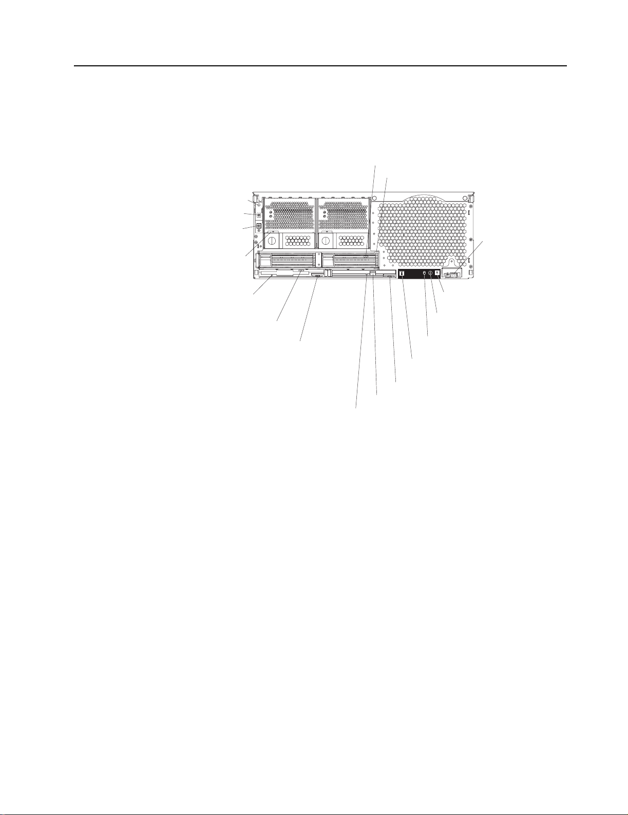
Rear view
System power
connector (1)
SMP Expansion Port 1
SMP Expansion Port 2
SMP Expansion Port 3
RXE Management Port
System power
connector (2)
SCSI port
USB 1
Video port
RXE Expansion Port (B)
Auxiliary pointing
device connector
Keyboard port
Remote
Supervisor
Adapter
ports
Ethernet
activity light
Ethernet
link light
Gigabit Ethernet
port
RXE Expansion
Port (A)
USB 2
System power connectors (1 and 2): The system pow er cords are connected to
these two connectors to provide power to the system.
RXE Expansion Port B: Use this port to connect the server to a remote I/O enclosure
when two SMP Expansion Modules are installed.
Auxiliary pointing device connector: Signal cables for a mouse, trackball, or other
pointing device are connected to the auxiliary pointing device connector.
Keyboard port: Signal cables for a keyboard are connected to the keyboard port.
Remote Supervisor Adapter ports and indicators: This group of ports and
indicators located on the back of the server are used for system management
information and control.
External power
connector
Error LED
(amber)
Power LED
(green)
ASM interconnect
port
Management port
Ethernet link LED
(green)
Ethernet activity LED
(green)
10/100
Ethernet port
• External power connector - This connector is not supported on this server.
• Error LED - This amber light goes on when a system management error has
occurred.
4 xSeries 440:Troubleshooting Guide
Page 17

• ASM interconnect port - Signal cables for managing expansion module
resources are connected to this port.
• Ethernet link light: This green light, located on the right of the Ethernet port,
goes on when there is an active link connection on the Ethernet controller for the
Ethernet port.
• Ethernet activity light: This green light, located on the left of th e Ethernet port,
goes on when there is activity on the Ethernet LAN connected to the Ethernet
port.
• 10/100 Ethernet port - Ethernet Signal cables are connecte d to the Ethernet port.
• Management port - Signal cables for modems or other serial devices are
connected to this por t.
• Power LED - This green light goes on and stay s on when you plug in your server.
Ethernet activity light: This green light, located on the left of the Gigabit Ethernet
port, blinks when there is activity on the Ethernet LAN.
Ethernet link light: This green light, located on the right of the Gi gabit Ethernet port,
goes on when there is an active link connection on the Gigabit Ethernet controller for
Ethernet port 1.
Gigabit Ethernet port: Gigabit Ethernet Signal cables are connected to the Gigabit
Ethernet port. This port supports 10/100/1000 speed connections.
RXE Expansion Port A: Use this port to connect the server to a remote I/O
enclosure, when only one SMP Expansion Module is installed.
Video port: The signal cable for a monitor connects to the video port.
USB 2: This is an automatically configured port that you can use to connect one or
more USB devices to the server, using Plug and Play technology.
USB 1: This is an automatically configured port that you can use to connect one or
more USB devices to the server, using Plug and Play technology.
RXE Management Port: Use this port to connect a management cab le from the
server to a remote I/O enclosure.
SCSI port: This port is used to connect external SCSI devices to the server.
SMP Expansion port 3: This port is intended for future use.
SMP Expansion port 2: This port is used to interconnect two SMP Expansion
Modules together.
SMP Expansion port 1: This port is used to interconnect two SMP Expansion
Modules together.
Chapter 1. Introduction 5
Page 18

Server power features
This section contains information on how to properly turn your server on and off.
Turning on the server
You can turn on the server in any of the fo llowing ways:
• If the power cords are connected to a pow er sour ce, y o u can press the po we r-control button on the front of the server.
Notes:
1. You can install a circular disk over the power-control button to prevent acci-
dental manual power-o ff. This disk, known as the po w er-contr ol b u tton shie ld,
comes with your server.
2. After you plug the power cords of your server into the electrical outlets, wait
approximately 20 seconds before pressing the power-control button. During
this time, the system-management adapter is initializing; therefore, the pow ercontrol button does not respond.
• If the server is turned on and a power failure occurs, the server will restart automatically when power is restored.
• If ac power is present a nd the server is in Standb y mode, the server can be turned
on from the Remote Supervisor Adapter user interface.
• When you plug in yo ur server for the first time, Wake on LAN
server.
• If your server was previously turned on, it must be properly placed in Standby
mode for the Wake on LAN feature to turn on the server.
®
can turn on the
Complete the following steps to manually turn on the server:
1. Review the information in “Safety” on page v.
2. Turn on all external devices, such as the monitor.
3. Plug the server power cords into the power source.
4. Press the power-control button on the front of the server.
Note: While the server is powering up, the power-on LED on the front of the
server is lit.
6 xSeries 440:Troubleshooting Guide
Page 19

Turning off the server
Complete the following steps to manually turn off the server:
1. Review the information in “Safety” on page v.
2. See your operat ing system documentation for the proper procedure to shut down
the operating system.
Statement 5:
CAUTION:
The power control button on the device and the power swit ch on the power
supply do not turn off the electrical current supplie d to the device. The
device also might have more than one power cord. To remove all electrical
current from the device, ensure that all power cords are disconnected from
the power source.
2
1
3. Press the power-contr ol butt on on the front of the server. This will put the server in
Standby mode.
Note: You might need to press and hold the power-control button for more than 4
seconds to cause an immediate shutdo wn of the serve r a nd to force it into
Standby mode. You can use this feature if the operating system stops functioning.
4. Disconnect the server from the pow er source.
Note: After disconnecting all the po wer cords , w ait appr o xima tely 15 seconds for
your system to stop running. Watch for the power-on LED on the front of
the server to stop flashing.
Chapter 1. Introduction 7
Page 20

Standby mode
Standby mode ref e rs to the co ndit io n in which the se rver is conn ected to an ac power
source but the server operating system is not running and all core logic is shut down
except for the service processor. In Standby mode, the server can respond to service
processor requests, such as a remote request to turn on the server. When the server
is in Standby mode, the power-on LED on the front of the server flashes (when the
server is running, the power-on LED stays on and does not flash).
You can put the server in Standby mode in any of the following ways:
• You can press the power-control button on the server. This starts an orderly shutdown of the operating system, if this feature is supported by your operating system.
• The server can be placed in Standby mode from the Remote Supervisor Adapter
user interface.
Complete the following steps to put the server into Standby mode:
1. See the operating system documentation for the proper procedure to shut down
the operating system.
Note: Each operating system is d ifferent. Read all the documentat ion about shut-
ting down the operating system before continuing.
2. Press the power-control button on the front of the server.
Notes:
a. After you place the server in Standby mode, wait at least 5 seconds before
you turn on the server again.
b. You might need to press and hold the power-control button for more than 4
seconds to cause an immediate shutdown of the operatin g sys tem an d to
force it into Standby mode. You can use this feature if the operating system
stops functioning.
8 xSeries 440:Troubleshooting Guide
Page 21

Major components of the xSeries 440
The following illustration sho ws the locations of major components in your server.
Note: The illustrations in this document might differ slightly from your hardware.
Retention bracket
Fan 1
N
O
T
E
:
F
F
R
O
Fan 2
O
R
P
R
O
P
E
R
A
IR
F
L
O
W,
N
T
O
F
B
O
X
Fan 4
Fan 3
N
O
T
E
:
F
O
R
P
R
O
P
E
R
A
I
R
F
F
R
O
N
T
O
F
B
O
X
R
E
P
L
A
C
E
F
A
N
W
IT
H
I
N
2
M
I
N
U
T
L
O
W, R
E
S
E
P
L
A
C
E
F
A
N
W
IT
H
IN
2
M
IN
U
T
E
S
SMP baffle
Heat-sink
Microprocessor
Center
plane
DIMM
DIMM
access
doors
SMP
Cover
Expansion
Module
VRM
EMC Shield
(For single SMP Module)
Thumbscrews
Shipping thumbscrews
Hard disk
drive
Bezel
Hot-swap
power supply
CD-ROM
drive
Chapter 1. Introduction 9
Page 22

Center plane connectors and LEDs
The following illustrations identify the connectors and LEDs on the center plane. This
center plane is used to connect the power and signal paths for the SMP Expansion
Module, I/O board, and the Remote Supervisor Adapter.
Lightpath
SCSI
power
Power
Power
Power
PCI error LED
System management
error LED
I/O error LED
VRM
Thumbscrews
Center plane error LED
Lower SMP error LED
Upper SMP error LED
Power good LED
VRM error LED
10 xSeries 440:Troubleshooting Guide
Page 23

SMP Expansion Module connectors and lights
The following illustrations identify the connectors, switches, and lights on the SMP
Expansion Module.
Chapter 1. Introduction 11
Page 24
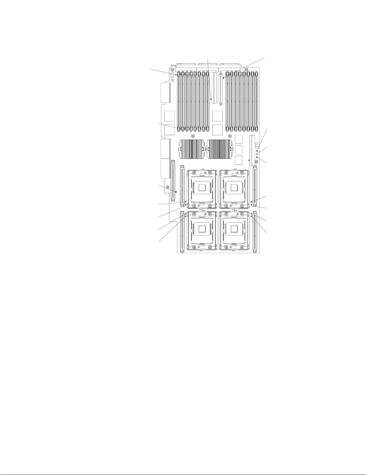
SMP Expansion Module
board error LED
Light path capacitor
switch LED
DIMM error
LED (16X)
VRM error LED
VRM error LED
Memory port 2
power LED
Hot-plug enabled
memory LED
Memory port 1
power LED
Microprocessor 1
VRM error LED
Microprocessor 1
error LED
Microprocessor 3
error LED
Microprocessor 3
VRM error LED
Microprocessor 4
VRM error LED
Microprocessor 4
error LED
Microprocessor 2
error LED
Microprocessor 2
VRM error LED
12 xSeries 440:Troubleshooting Guide
Page 25
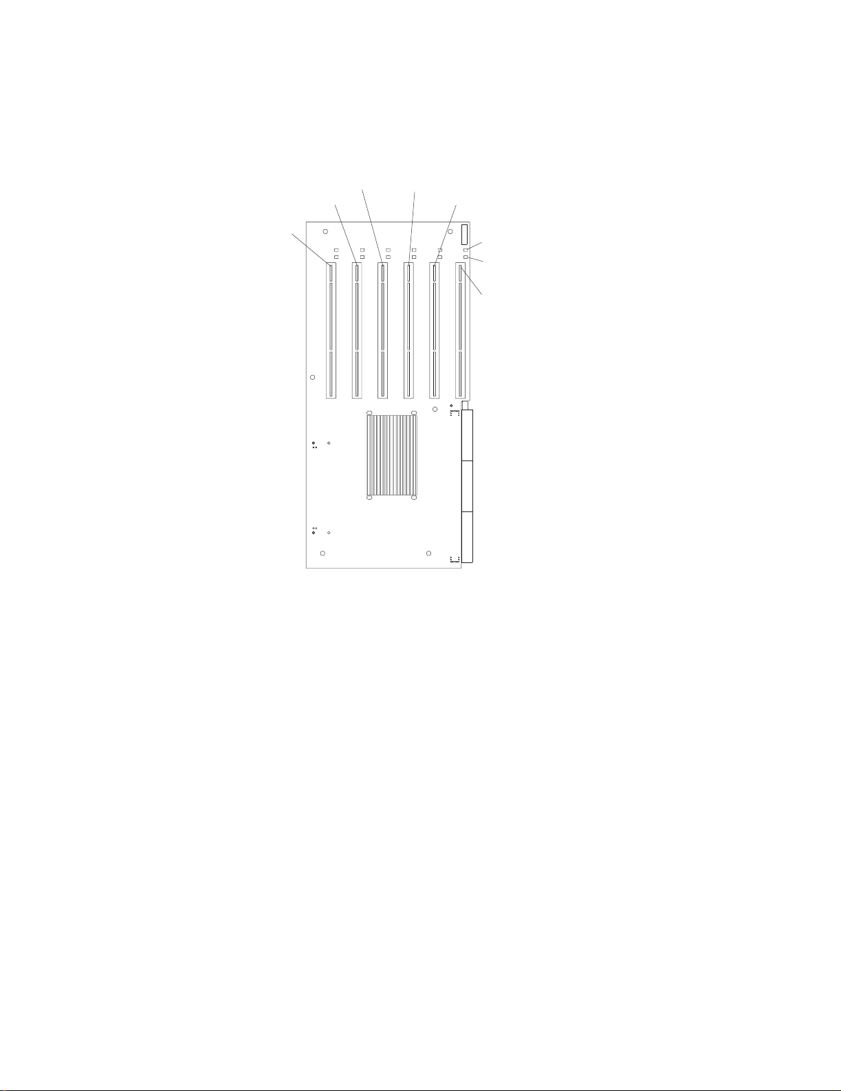
PCI-X planar internal connectors and LEDs
The following illustration identifies the internal connectors and LEDs on the PCI-X planar. This pl anar enables you to install adapters into the server.
PCI-X slot 5
(133 )MHz
PCI-X slot 6
(133 MHz)
PCI-X slot 4
(100 )MHz
PCI-X slot 3
(100 )MHz
PCI-X slot 2
(66 )MHz
Attention LED
Power LED
PCI-X slot 1
(66 )MHz
Chapter 1. Introduction 13
Page 26

I/O board internal connectors
The following illustration identifies the internal connectors on the I/O board. This board
supports the input and output ports located on the server.
SCSI B
connector
I/O VRM
Fan 4
connector
Fan 3
connector
Power/Reset
connector
SCSI A
connector
Riser card
connector
Fans 1 and 2
connectors
USB cable
connector
Media bays
connector
Remote Supervisor Adapter component locations
The following illustration identifies the connectors and lights on the Remote Supervisor Adapter.
Lithium
battery
Ethernet speed
External power
supply connector
Power LED
(green)
ASM Interconnect port
LED (green)
Error LED
(amber)
P
P
(RJ-14)
Serial port
(COM)
Ethernet link
LED (green)
Ethernet port
(RJ-45)
14 xSeries 440:Troubleshooting Guide
Page 27

Chapter 2. Solving Problems
This section provides basic troubleshooting information to help you resolve some
common problems that might occur with your server.
If you cannot locate and correct the problem using the information in this section, see
“Getting help and technical assistance” on page 48 for more information.
Diagnostic tools overview
The following tools are available to help you identify and resolve hardware-related
problems:
• POST beep codes, error messages, and error logs
The power-on self-test (POST) ge nerates beep codes and messages to indicate
successful test completion or the detection of a problem. See “POST” on page 17
for more information.
• Diagnostic programs and err or messages
The server diagnostic programs are stored in upgradable read-only memory
(ROM) on the system board. These programs are the primary method of testing
the major components of your server. See “Diagnostic programs and error
messages” on page 32 for more information.
• Light Path Diagnostics
Use the Light Path Diagnostics feature to identify system errors quickly.
• Troubleshooting cha rts
These charts list problem symptoms, along with suggested steps to correct the
problems. See the “Troubleshooting charts” on page 43 for more information.
• Customized support page
You can create a customized support page that is specific to your hardware,
complete with Fr equently Asked Questions , P arts Information, Technical Hints and
Tips, and Downloadable Files. In addition, you can choose to receive electronic
mail (e-mail) notifications whenever new information becomes available about
your registered products .
After you register and profile your xSeries products, you can diagnose problems
using the IBM Online Assistant and you can participate in the IBM discussion
forum. For more detailed information about registering and creating a customized
profile for your IBM products, visit the f ollowing addresses on the Web:
— http://www.ibm.com/pc/register
— http://www.ibm.com/pc/support
™
feature
© Copyright IBM Corp. 2002 15
Page 28

S
erver Support
Server working
properly?
Yes
No
Check all cables for loose connections
and verify that all optional devices you
installed are on the ServerProven list.
You can view the ServerProven list at
http://www.ibm.com/pc/compat/
Problem
solved?
®
Yes
No
Use the troubleshooting
information provided with
your server to determine
the cause of the problem
and the action to take.
Register and profile your server
After you register and profile, you will be able to:
• Diagnose problems using the IBM Online Assistant
• Participate in the IBM discussion forum
• Receive e-mail notifications of technical updates
related to your profiled products
Register:
Profile:
http://www.ibm.com/pc/register/
http://www.ibm.com/pc/support/
View information about IBM support line at
http://www.ibm.com/services/sl/products/
or view support telephone numbers at
http://www.ibm.com/planetwide/
View support telephone numbers at
http://www.ibm.com/planetwide/
Problem
solved?
Yes
No
Flash the latest levels of BIOS,
service processor, diagnostics,
and RAID code.
You can download this code at
http://www.ibm.com/pc/support/
Yes Hardware
Problem
solved?
No Software
Hardware or
software problem?
16 xSeries 440:Troubleshooting Guide
Page 29

POST
When you turn on the server, it performs a series of tests to check the operation of
server components and some of the option s installed in the serv er . Th is series of tests
is called the power-on self-test, or POST.
If POST finishes without detecting any problems, a single beep sounds, and the first
screen of your operating system or application program appears.
If POST detects a problem, more than one beep sounds, and an error message
appears on your screen. See “POST beep code descriptions” and “POST error
messages” on page 20 for more information.
Notes:
1. If you have a power-on password set, you must type the password and press
Enter, when prompted, before POST will continue.
2. A single problem might cause several error messages. When this occurs, work to
correct the cause of the first err or message . After you correct the cau se of the fir st
error message, the other error messages usually will not occur the next time you
run the test.
POST beep code descriptions
Beep codes are sounded in a series of long and short beeps.
The possible types of beep codes that your server might emit include the following:
No beeps
If no beep occurs after your server completes POST, call for service.
Continuous beep
Your startup (boot) microprocessor has failed, or your system board or
speaker subsystem might contain a failing component. If the system
continues through POST with no errors, call for service. If no video appears,
the startup proc e sso r ha s failed; replace the startup processor.
One short beep
One beep indicates that your server successfully completed POST. POST
detected no configuration or functional errors. One beep also occurs after
your server completes POST if you type an incorrect power-on pass word.
Two short beeps
POST encountered an error. The Configuration/Setup Utility program will
display additional information; follow the instructions that appear on the
screen. See “POST error messages” on page 20 for descriptions of the text
messages that might appear.
Three short beeps
A system memory error has occurred. This combination occurs only if the
video basic input/output system (BIOS) cannot display the error message.
Replace the failing memory module.
Repeating short beeps
The system board might contain a failing component, your ke yboard might be
defectiv e, or a key on the keyboard might be stuck. Ensure that:
• Nothing is resting on the keyboard and pressing a key.
• No key is stuck.
• The keyboard cable is connected correctly to the keyboard and to the
correct connector on the server.
Chapter 2. Solving Problems 17
Page 30

Running the diagnostic tests can isolate the server component that failed, but
you must have your system serviced. If the error message remains, call for
service.
Note: If you just connect ed a new mouse or ot her pointing de vice, turn off the
server and disconnect that device. Wait at least 5 seconds; then, turn
on the server. If the error message goes away, replace the device.
One long and one short beep
POST encountered an error on a video adapter. If you are using the
integrated video controller, call for service. If you are using an optional video
adapter, replace the failing video adapter.
One long and two short beeps
A video I/O adapter ROM is not readab le, or the video su bsystem is defective .
If you hear this beep combination twice, both the system board and an
optional video adapter have failed the test. This beep combination might also
indicate that the system board contains a failing component.
One long and three short beeps
The system-board video subsystem has not detected a monitor connect ion to
the server. Ensure that the monitor is connected to the server. If the problem
persists, replace the monitor.
Two long and two short beeps
POST does not support the optional video adapter. This beep combination
occurs when you install a video adapter that is incompatible with your server.
Replace the optional video adapter with one that the server supports, or use
the integrated video controller.
POST beep codes
In addition to the beep codes that are described in “POST beep code descriptions” on
page 17, your server might emit beep codes that are described in the following table.
For example, a 1-2-4 beep code sounds like one beep, a pause, two consecutive
beeps, another pause, and four more consecutive beeps.
Table 1. POST beep codes
Beep code Description Action
1-1-2 Microprocessor register test has failed. Call for service.
1-1-3 CMOS write/read test has failed.
1-1-4 BIOS ROM checksum has failed.
1-2-1 Programmable Interval Timer test has failed.
1-2-2 DMA initialization has failed.
1-2-3 DMA page register write/read test has failed.
1-2-4 RAM refresh verification has failed. Reseat the
1-3-1 First 64 Kb RAM test has failed.
1-3-2 First 64 Kb RAM parity test has failed.
memory modules
or install a
memory module.
If the problem
persists, call for
service.
18 xSeries 440:Troubleshooting Guide
Page 31

Table 1. POST beep codes (continued)
Beep code Description Action
1-4-3 Interrupt vector loading test has failed. Call for service.
2-1-1 Secondary DMA register test has failed.
2-1-2 Primary DMA register test has failed.
2-1-3 Primary interrupt mask register test has failed.
2-1-4 Secondary interrupt mask register test has failed.
2-2-1 Interrupt vector loading has failed.
2-2-2 Keyboard controller test has failed.
2-2-3 CMOS power failure and checksum checks have failed.
2-2-4 CMOS configuration information validation has failed.
2-3-1 Screen initialization has failed. Turn off the
computer and
then restart the
computer. If the
problem persists,
call for service.
2-3-2 Screen memory test has failed. Call for service.
2-3-3 Screen retrace tests have failed.
2-3-4 Search for video ROM has failed.
2-4-1 Screen test indicates the screen is operable.
3-1-1 Timer tick interrupt test has failed.
3-1-2 Interval timer channel 2 test has failed.
3-1-3 RAM test has failed above address hex 0FFFF.
3-1-4 Time-of-Day clock test has failed.
3-2-1 Serial port te st has failed.
3-2-2 Parallel port test has failed.
3-2-4 Comparison of CMOS memory size against actual has
failed.
3-3-1 A memory size mismatch has occurred. Reseat the
memory modules
or install a
memory module.
If the problem
persists, call for
service.
3-3-2 I2C bus has failed. Call for service.
3-3-3 Important: In some memory configurations, the 3-3-3
beep code might sound during POST, followed by a blank
display screen. If this occurs and the Boot Fail Count
feature in the Start Options of the Configuration/Setup
Utility program is set to Enabled (its default setting), you
must restart the computer three times to force the system
BIOS to reset the memory connector or bank of
Reseat the
memory modules
or install a
memory module.
If the problem
persists, call for
service.
connectors from Disabled to Enabled.
Chapter 2. Solving Problems 19
Page 32

POST error messages
The following tables provide information about the POST error messages that can
appear during startup.
Table 2. POST error messages
POST message Description
062 The server failed to start on three consecutive attempts.
All processor caches are disabled. Repeatedly turning the server on and then off or resetting the
server might cause this problem.
Note: Start the Configuration/Setup Utility p rogr a m and verify that all settings are correct . Use th e
Cache Control selection in the Advanced Setup menu of the Configuration/Setup Utility
program to enable the processor caches.
If the problem persists, call for service. When the problem is corrected, be sure to enable the
processor caches.
101 102 106 An error occurred during the system board and microprocessor test.
Note: Call for service.
114 An adapter read-only memory (ROM) error occurred.
Note: Remove the options. If you can start the server without the options installed, reinstall each
option one at a time and retest after each is reinstalled. When an option fails, replace it.
If you cannot isolate and correct the problem, call for service.
151 A real-time clock (RTC) error occurred.
Note: Call for service.
161 The real-time clock batter y has failed.
Note: Replace the battery yourself or call for service.
You can use the server until you replace the battery. Ho we v er, you m ust run the Config uratio n/Setup
Utility program and set the time and date and other custom settings each time you turn on the
server.
162 A change in device configuration occurred. This error occurs under one or more of the following
conditions:
• A new device has been installed.
• A device has been moved to a different location or cable connection.
• A device has been removed or disconnected from a cable.
• A device is failing and is no longer recognized by the server as being installed.
• An external device is not turned on.
• An invalid checksum is detected in the battery-backed memory.
Note: Verify that all external devices are turned on. You must turn on external devices before
turning on the server.
If you did not add, remove, or change the location of a device, a device is probably failing. Running
the diagnostic program might isolate the failing device.
If you cannot isolate and correct the problem, call for service.
163 The time of day has not been set.
Note: Set the correct date and time. If the date and time are set correctly and saved, but the 163
error message reappears, call for service.
You can use the server until the system is serviced, but any application programs that use the date
and time will be affected.
20 xSeries 440:Troubleshooting Guide
Page 33

Table 2. POST error messages (continued)
POST message Description
164 A change in the memory configuration occurred. Thi s message might appear after you add or
remove memory.
Notes:
1. The server can be used with decreased memory capacity.
2. If POST error message 289 also occurred, follow the instructions for that error message first.
3. If y o u ju st in stal le d or r emo ved memory, run the Configuratio n/Set up Util ity pr og ram; then, exit ,
saving the new configuration settings.
If the message appears again, shut down the server, reseat the memory modules, and restart
the server.
If the problem persists, call for service.
175 A vital product data (VPD) error occurred.
Note: Call for service.
176 177 178 A security hardware error occurred.
Note: Check for indications that someone has tampered with the server. If no one has tampered
with the server, call for service.
184 The power-on password information stored in your server has been removed.
Note: From the Configuration/Setup Utility program main menu, select System Security. Then,
follow the instructions on the screen.
If this information cannot be restored, call for service.
185 A power failure damaged the stored information about the drive-star tup sequence.
Note: From the Configuration/Setup Utility program main menu, select Start Options; then, follow
the instructions on the screen.
If this information cannot be restored, call for service.
186 A system board or hardware error occurred.
Note: Call for service.
187 The VPD serial number is not set.
Note: The system serial number is set in the VPD EEPROM at the time of manufacturing. If the
system board has been replaced, the system serial number will be invalid and should be
set. From the main menu of the Configuration/Setup Utility program, select System
Information, and then select Product Data. If the problem persists, call for service.
188 A vital product data (VPD) error occurred.
Note: Call for service.
189 An attempt has been made to access the server with invalid passwords. After three incorrect
attempts, the server locks up; that is, the logon data fields are no longer available to the user.
201 An error occurred during the memory controller test. This error can be caused by:
• Incorrectly installed memory
• A failing memory module
• A system board problem
Note:
1. If you just installed memory, verify that the new memory is correct for your server. Also
verify that the memory is installed and seated correctly.
2. If the problem persists, call for service.
Chapter 2. Solving Problems 21
Page 34

Table 2. POST error messages (continued)
POST message Description
289 An error occurred during POST memory tests and a failing DIMM was disabled.
Notes:
1. You can use the server with decreased memory.
2. If you just installed memory, verify that the new memory is correct for your server. Also verify
that the memory is installed and seated correctly. Start the Configuration/Setup Utility program
and select Memory Settings from the Advanced Setup menu to enable the DIMM.
3. If the problem remains, replace the failing DIMM.
If the problem persists, call for service.
301 303 An error occurred during the keyboard and keyboard controller test. These error messages also
might be accompanied by continuous beeping.
Notes:
1. Ensure that:
• Nothing is resting on the keyboard and pressing a key.
• No key is stuck.
• The keyboard cable is connected correctly to the keyboard and to the correct connector on
the server.
2. After installing a USB keyboard, you might need to use the Configuration/Setup utility to Enable
keyboardless operation and prevent the POST error message 301 from being displayed during
startup.
Running the diagnostic tests can isolate the server component that failed, but you must have your
system serviced. If the error message remains, call for service.
Note: If you just connected a new mouse or other pointing device, turn off the server and
disconnect that device. Wait at least 5 seconds; then, turn on the server. If the error
message goes away, replace the device.
602 Invalid diskette boot record
Note:
1. Replace the diskette.
2. If the problem persists, make sure that the diskette drive cables are correctly and
securely connected.
3. If the problem remains, replace the diskette drive.
If the problem persists, call for service.
604 An error occurred during a diskette drive test.
Note:
1. Verify that the Configuration/Setup Utility program correctly reflects the type of diskette
drive that you have installed.
2. Run the diagnostic tests. If the diagnostic tests fail, call for service.
662 A diskette drive configuration error occurred.
Note: If you removed a diskette drive, make sure that the diskette drive setting is correct in the
Configuration/Setup Utility program. If the setting is not correct, change it.
If the problem persists, call for service.
22 xSeries 440:Troubleshooting Guide
Page 35

Table 2. POST error messages (continued)
POST message Description
11xx An error occurred during the system-board serial port test.
Note: If you have a modem, serial printer, or other serial device attached to your server , v erify that
the serial cable is connected correctly. If it is, use the following procedure:
1. Turn off the server.
2. Disconnect the serial cable from the serial port.
3. Wait 5 seconds; then, turn on the ser ver.
If the POST error message does not reappear, either the serial cable or the device is probably
failing. See the documentation that comes with the serial device for additional testing information.
If the POST error message reappears, call for service.
1162 The serial port configuration conflic ts with ano t her device in the system.
Note:
1. Make sure the IRQ and I/O port assignments needed by the ser ia l po rt are available.
2. If all interrupts are being used by adapters, you might need to remove an adapter to
make an interrupt available to the serial port, or force other adapters to share an
interrupt.
1800 A PCI adapter has requested a hardware interrupt that is not available.
Note:
1. Make sure that the PCI adapter and all other adapters are set correctly in the
Configuration/Setup Utility program. If the interrupt resource settings are not correct,
change the settings.
2. If all interrupts are being used by other adapters, you might need to remove an adapter
to make an interrupt available to the PCI adapter, or force other adapters to share an
interrupt.
1962 No valid startup devices were found. The system cannot find the startup drive or operating system.
Note: Be sure that the drive you want to start from is in the startup sequence.
1. Select Start Options from the Configuration/Setup Utility program main menu. If you
are unable to set the startup sequence, call for service.
2. Check the list of startup devices in the Startup device data fields. Is the drive you want
to start from in the startup sequence?
Y es Exit from this screen; then, select Exit Setup to exit the Configuration/Setup
menu. Go to step 3..
No Follow the i nst ruction s on the s cree n to ad d the drive; then, sav e the c han ge s
and exit the Configuration/Setup menu. Restart the server.
3. Is an operating system installed?
Y es Turn off the server. Go to step 4..
No Install the operating system in your server; then, follow your operating system
instructions to shut down and restart the server.
4. During server startup, watch for messages indicating a hardware problem.
If the same error message appears, call for service.
2400 An error occurred during the testing of the video controller on the system board. This error can be
caused by a failing monitor, a failing system board, or a failing video adapter (if one is installed).
Note: Verify that the monitor is connected correctly to the video connector. If the monitor is
connected correctly, call for service.
2462 A video memory configuration error occurred.
Note: Make sure that the monitor cables are correctly and securely connected to the server.
If the problem persists, call for service.
Chapter 2. Solving Problems 23
Page 36

Table 2. POST error messages (continued)
POST message Description
5962 An IDE CD-ROM config uration error occurred.
Note: Check the signal and power cable connections to the CD-ROM drive.
If the problem persists, call for service.
8603 An error occurred during the mouse (pointing device) controller test. The addition or removal of a
mouse, or a failing system board can cause this error.
Note: This error also can occur if electrical po wer was lost for a very brief period and then
restored. In this case, turn off the server for at least 5 seconds; then, turn it back on.
Note: Ensure that the keyboard and mouse (pointing device) are attached to the correct
connectors. If they are connected correctly, use the following procedure:
1. Turn off the server.
2. Disconnect the mouse from the server.
3. Turn on the server.
If the POST error message does not reappear, the mouse is probably failing. See the
documentation that comes with the mouse for additional testing information. If the problem remains,
replace the mouse or pointing device.
If the POST error message reappears, run the diagnostic tests to isolate the problem. If the
diagnostic tests do not find a problem and the POST error message remains, call for service.
00012000 Processor machine check.
Note:
1. Update the system BIOS code.
2. If the problem persists, replace the microprocessor.
0001950n Processor n is not functioning.
Note: Replace microprocessor n.
If the problem persists, call for service.
0001970n Processor n failed the built-in self test.
Note: Replace microprocessor n.
If the problem persists, call for service.
00180100 A PCI adapter has requested memory resources that are not a vailable.
Note:
1. Make sure that the PCI adapter and all other adapters are set correctly in the
Configuration/Setup Utility program. If the memory resource settings are not correct,
change the settings.
2. If all memory resources are being used, you might need to remove an adapter to make
memory available to the PCI adapter. Disabling the adapter BIOS on the adapter might
correct the error. See the documentation provided with the adapter.
00180200 A PCI adapter has requested an I/O address that is not available, or the PCI adapter might be
defective.
Note:
1. Make sure that the I/O address for the PCI adapter and all other adapters are set
correctly in the Configuration/Setup Utility program.
2. If the I/O port resource settings are correct, the PCI adapter might be defective . Call for
service.
24 xSeries 440:Troubleshooting Guide
Page 37

Table 2. POST error messages (continued)
POST message Description
00180300 A PCI adapter has requested a memory address that is not available, or the PCI adapter might be
defective.
Note:
1. Make sure that the memory address for all other adapters are set correctly in the
Configuration/Setup Utility program. If the memory resource settings are not correct,
change the settings.
2. If the memory resource settings are correct, the PCI adapter might be defective. Call for
service.
00180400 A PCI adapter has requested a memory address that is not available.
Note: If all memory addresses are being used, you might need to remove an adapter to make
memory address space available to the PCI adapter. Disabling the adapter BIOS on the
adapter might correct the error. Refer to the documentation provided with the adapter.
00180500 A PCI adapter ROM error occurred.
Note: Remove the PCI adapters. If you can start the server without the adapters, reinstall each
adapter one at a time and retest after each is reinstalled. When a n ad apter fails, replace it.
If you cannot isolate and correct the problem, call for service.
00180600 A PCI-to-PCI bridge error occurred. More than one PCI bus tried to access memory below 1 MB.
Note: Remove the PCI adapter that has the PCI bridge. If you can start the server without the
adapter, reinstall and retest the adapter. If the adapter fails, replace it.
If you cannot isolate and correct the problem, call for service.
00180700 xxxxyyyy planar PCI device does not respond or disabled by user (where xxxx is the PCI vendor ID
and yyyy is the PCI device ID).
Note: Start the Configuration/Setup Utility program, select Devices and I/O P orts, and mak e sure
that the device is enabled. If the problem persists, call for service.
00180800 An unsupported PCI device is installed.
Note: Remove the PCI adapters. If you can start the server without the adapters, reinstall each
adapter one at a time and retest after each is reinstalled. When a n ad apter fails, replace it.
If the problem persists, call for service.
00181000 PCI error.
Note: Remove the PCI adapters. If you can start the server without the adapters, reinstall each
adapter one at a time and retest after each is reinstalled. When a n ad apter fails, replace it.
If the problem persists, call for service.
01295085 The ECC checking hardware test failed.
Note: Call for service.
0129800n No update data is available for processor n.
Note: Update the system BIOS code to a level that supports the microprocessors installed in the
server.
0129810n The update data for process or n is inc or r ec t.
Note: Update the system BIOS code to a level that supports the microprocessors installed in the
server.
I9990301 A hard disk drive error occurred.
Note: Call for service.
Chapter 2. Solving Problems 25
Page 38

Table 2. POST error messages (continued)
POST message Description
I9990305 POST could not find an operating system.
Note: Install an operating system. If you have already installed the operating system, check the
drive startup sequence. If the drive sequence is corre ct, run the diagnostic tests to verify
that the hard disk drive is functioning correctly. If there is a problem with the hard disk drive
(such as a bad sector), you might need to reinstall the operating system.
If you cannot reinstall the operating system, call for service.
I9990650 AC power has been res t o r ed .
Note: No action is required. This message appears each time ac power is restored to the server
after an ac power loss.
Other Numbers POST found an error.
Note: Follow the instructi on s on the sc re en.
Error logs
The POST error log contains the three most recent error codes and messages that the
system generated during POST. The System Error log contains all messages issued
during POST and all system status messages from the service processor.
You can view the contents of the System Error log from the Configuration/Setup Utility
program or from the diagnostic programs:
• Start the Configuration/Setup Utility program; then, select Error Logs from the
main menu. See "Using the Configuration/Setup Utility program" in the User’s
Guide on the IBM Documentation CD.
• Start the diagnostic programs; select Hard ware Inf o from the top o f the diagnostic
programs screen; select System Error Log from the list t hat appears; then, follow
the instructions on the screen. See “Starting the diagnostic programs” on page 33
for more information.
Identifying problems using the Light Path Diagnostics feature
If the system-error light in the operator information panel on the front of the server is
on, one or more lights inside the server might be on. Use the Light Path Diagnostics
panel to identify the type of error that occurred.
You can use the Light Path Diagnostics feature in your server to quickly identify the
type of system error that occurred. The Light Path Diagnostics panel is located inside
the Light Path Diagnostics drawer, located on the front right of the server. To access
the Light Path Diagnostic panel, press on the front of the Light Path Diagnostics
drawer, the Light Path Diagnostic panel will be exposed. For light locations, see “Light
Path Diagnostics panel” on page 27.
Your server is designed so that lights that are illuminated when the server is on, can
be illuminated again without ac power after you remove the cover. This feature helps
you isolate the problem if an error causes the server to shut down. See “Light Path
Diagnostics table” on page 27.
Important: You have up to 12 hours to use the Light Path Diagnostics lights after ac
power has been remo ved from the server. After 12 hours , you must power on the
26 xSeries 440:Troubleshooting Guide
Page 39

server again to be able to use the Light Path Diagnostics lights to help locate system
errors.
To view the lights on the various system boards:
1. Turn off the server and peripheral devices.
2. Press and hold the Light Path Diagnostics (blue) button on the diagnostics panel.
The lights will be illuminated while the switch is pressed.
Note: You can illuminate the lights for a maximum of 2 minutes. After that time,
the circuit that powers the lights is exhausted.
3. Close the server cover; then, reinstall the server in the ra ck and connect all
external cables.
Light Path Diagnostics panel
The following illustration shows the lights on the diagnostics panel on the system
board. See “Light P ath Diagnostics tab le” f or inf ormation on identifying problems using
these lights.
Light Path Diagnostics table
The system-error light on the operator information panel is lit when certain system
errors occur. If the system-error light on your server is lit, use the following table to
help determine the cause of the error and the action you should take.
Chapter 2. Solving Problems 27
Page 40

Table 3. Light Path Diagnostics
Lit light on
diagnostics
panel Cause Action
None An error has occurred and can not be isolated,
or the ASM processor has failed.
PS Power supply has failed. Have the system serviced.
TEMP The system temperature has exceeded a
threshold level.
FAN A fan has failed or is operating too slowly.
Note: A failing fan can also cause the TEMP
light to be on.
SP The service processor has failed. Remove ac power from the server and then
An error has occurred that is not represented by
a Light Path Diagnostics light. Check the
System Error log for more information about the
error.
1. Check to see if a fan has failed. If it has,
replace the fan.
2. Make sure the room temperature is not too
hot. (See "Features and specifications" in
the User’s Guide on the
IBM Documentation
If the problem persists, have the system
serviced.
Check the lights on the fans and replace the
indicated fan.
restart the server.
Note: Wait 30 seconds before turning on the
server.
CD.)
If the problem persists, have the system
serviced.
MEM A memory error occurred. 1. Check the DIMM failure lights on the system
board.
2. Replace the DIMM indicated by the lit DIMM
failure light.
CPU One of the microprocessors has failed. 1. Check the microprocessor failure lights on
the system board.
2. If a microprocessor failure light is on, make
sure the microprocessor is installed
correctly.
3. If the problem persists, replace the
microprocessor.
If the problem persists, have the system
serviced.
VRM One of the VRMs on the system board has
failed.
Remove ac power from the server and then
restart the server.
Note: Wait 30 seconds before turning on the
server.
If the problem persists have the system
serviced.
28 xSeries 440:Troubleshooting Guide
Page 41

Table 3. Light Path Diagnostics (continued)
Lit light on
diagnostics
panel Cause Action
PCI An error occurred on a PCI bus. The system
board caused the error.
1. Check the error log for additional
information.
2. If you cannot isolate the failing adapter from
the information in the error log, try to
determine the failing adapter by removing
one adapter at a time from the failing PCI-X
bus and restarting the server after each
adapter is removed.
If the problem persists, have the system
serviced.
Chapter 2. Solving Problems 29
Page 42

ServerGuide problems
If you are ex periencing problems with your ServerGuide™ CD use the following chart
to troubleshoot the problem. Look for the symptom in the left column of the chart.
Probable solutions to the problem are in the right column.
Table 4. Setup and Installation CD
Symptom Suggested action
Server will not start. • Ensure that the system is a supported server with a startable (bootable) CD-ROM drive.
• If the startup (boot) sequence settings have been altered, ensure that the CD-ROM
drive is first in the startup sequence.
• If more than one CD-ROM drive is installed, ensure that only one drive is set as the
primary drive. Start the CD from the primary drive.
™
ServeRAID
cannot view all installed
drives - or - cannot install
NOS.
The Operating System
Installation program
continuously loops.
ServerGuide will not
start your NOS CD.
Cannot install NOS option is unavailable.
program
• Ensure that there are no duplicate SCSI IDs or IRQ assignments.
• Ensure that the hard disk drive is connected properly.
Make more space available on the hard disk.
Ensure that the NOS CD you have is supported by the ServerGuide program. See the CD
label for a list of supported NOS versions.
Ensure that the NOS is supported on your server. If the NOS is supported, either there is no
logical drive defined (ServeRAID systems) or the ServerGuide System Partition is not
present. Run the ServerGuide setup and configuration program, and ensure that setup is
complete.
30 xSeries 440:Troubleshooting Guide
Page 43

Small computer system interface (SCSI) messages
If you receive a SCSI error message when running the SCSISelect Utility program,
one or more of the following might be causing the problem:
• A failing SCSI device (adapter, drive, controller)
• An improper SCSI configuration
• Duplicate SCSI IDs in the same SCSI chain
• An improperly installed SCSI terminator
• A defective SCSI terminator
• An improperly installed cable
• A defective cable
To solve the problem, verify that:
• The external SCSI devices are turned on. External SCSI devices must be turned
on before the server.
• The cables for all external SCSI devices are connected correctly.
• The last device in each SCSI chain is terminated properly.
• The SCSI devices are configured correctly.
If you have verified these items an d the problem persists, run the diag nostic pr ogr ams
to obtain additional information about the failing device. If the error remains or recurs,
call for service.
Note: If your server does not have a hard disk drive, ignore any message that
indicates that the BIOS code is not installed.
Chapter 2. Solving Problems 31
Page 44

Diagnostic programs and error messages
The server diagnostic programs are stored in up gradable read-only memory (ROM)
on the system board. These programs are the primary method of testing the major
components of your server.
Diagnostic error messages indicate that a pr oblem exists; they are not intended to be
used to identify a failing part. Troubleshooting and servicing of complex problems that
are indicated by error messages should be performed by trained service personnel.
Sometimes the first error to occur causes addition a l error s. In this case, the server
displays more than one erro r message. Always follow the suggested action
instructions for the first error message that appears.
The following sections contain the error codes that might appear in the detailed test
log and summary log when running the diagnostic programs.
The error code format is as follows:
fff-ttt-iii-date-cc-text message
where:
fff is the three-digit function code that indicates the
function being tested when the error occurred. For
example, funct ion code 089 is f or th e microproce ssor.
ttt is the three-digit failure code that indicates the exact
test failure that w as encountered. (These codes are
for trained se rvice personnel and are described in the
Hardware Maintenance Manual).
iii is the three-digit device ID. (These codes are for
trained service personnel and are described in the
Hardware Maintenance Manual).
date is the date that the diagnostic test was run and the
error recorded.
cc is the check value that is used to verify the validity of
the information.
text message is the diagnostic message that indicates the reaso n
for the problem.
Text messages
The diagnostic text message format is as follows:
Function Name: Result (test specific string)
where:
Function Name
is the name of the function being tested when the error occurred. This
corresponds to the function code (fff) shown in th e previous list.
Result
can be one of the following:
Passed This result occurs when the diagnostic test is
completed without any errors.
Failed This result occurs when the diagnostic test
discovers an error.
32 xSeries 440:Troubleshooting Guide
Page 45

User Aborted This result occurs when you stop the
Not Applicable This result occurs when you specify a
Aborted This result occurs when the test could not
Warning This result occurs when a possible problem
test specific string
This is additional information that you can use to analyze the problem.
Starting the diagnostic programs
You can press F1 while running the diagnostic programs to obtain help information.
You also can press F1 from within a help screen to obtain online documentation from
which you can select different categories. To exit from help and return to where you
left off, press Esc.
To start the diagnostic programs:
1. Turn on the server and watch the screen.
2. When the message F2 for Diagnostics appears, press F2.
If a power-on password is set, the server prompts you for it. Type the power-on
password, and press Enter.
3. When the Diagnostic Progra ms screen ap pe ar s, select either Extended or Basic
from the top of the screen.
4. Select the test you want to run from the list that appears; then, follow the
instructions on the screen.
Notes:
a. If the server stops during testing and you cannot continue, restart the server
and try running the diagnostic programs again. If the proble m persists , call for
service.
b. The keyboard and mouse (pointing device) tests assume that a keyboard and
mouse are attached to the server.
c. If you run the diagnostic programs with no mouse a ttached to y our server, you
will not be able to navigate between test categories using the Next Cat and
Prev Cat buttons. All other functions provided by mouse-selectable buttons
are also available using the function keys.
d. You can test the USB keyboard by using the regular keyboard test. The
regular mouse test can test a USB mouse. Also, you can run the USB
interface test only if there are no USB devices attached.
e. You can view server configuration information (such as system configuration,
memory contents, interrupt request (IRQ) use, direct memory access (DMA)
use, device driv ers , and so on ) b y selecting Har d ware Inf o from th e top of the
screen.
diagnostic test before it is complete.
diagnostic test for a device that is not
present.
proceed; for e xample, beca use of the system
configuration.
is reported during the diagnostic test, such
as when a device driver is not found.
If the diagnostic programs do not detect any hardware error but the problem persists
during normal server operations, a software e rror might b e the cause . If y ou susp ect a
software problem, see the information that comes with the software package.
Chapter 2. Solving Problems 33
Page 46

Viewing the test log: When the tests are completed, y ou can view the test lo g by
selecting Utility from the top of the screen and then selecting View Test Log.
Notes:
1. You can view the test log only while you are in the diagnostic pr ograms . When y ou
exit the diagnostic programs, the test log is cleared (saved test logs are not
affected). To save the test log so that y ou can view it later, click Save Log on the
diagnostic programs screen and specify a locat ion and n ame f or the sa ved log file.
2. To save the test log to a diskette , you must use a diskett e th at you hav e formatted
yourself; this function does not work with preformatted diskettes. If the diskette
has sufficient space for the test log, the diskette may contain other data.
Viewing the System Error log:You can also view the System Error log from
the diagnostic programs. See the instructions in “Error logs” on page 26.
Diagnostic error message tables
The following tables provide descriptions of the error me ssages that might appear
when you run the diagnostic programs.
Note: Not all messages in this table apply to your server.
Important: If diagnostic error messages appear that are not listed in the following
tables, call for service.
Code Function Result Description Action
001 Core system Failed Processor board, EC C Logic Call for service.
System board
005 Video port Processor and system boards
011 Serial port Integrated serial port
015 USB interface Aborted Can NOT test USB interface while it is in use.
Note: If you hav e a USB ke yboard, mouse, or other
USB device attached, you cannot run the
diagnostic program for the USB interface.
Failed USB interface failed Call for service.
020 PCI interface Failed PCI slot latch mechanism is defective Call for service.
030 SCSI interface Failed SCSI adapter in slot n failed register/counter/ power
test
(where n is the slot number of the failing adapter)
SCSI controller on system board failed
register/counter/power test
1. Turn off the server.
2. Disconnect all USB
devices from the
server. Replace any
USB keyboard and
mouse with a
standard keyboard
and mouse.
3. Turn on the server.
4. R un the diagnostic
test again.
If the problem persists,
call for service.
Refer to the information
provided with the
adapter for instructions.
If the problem persists,
call for service.
Call for service.
34 xSeries 440:Troubleshooting Guide
Page 47

Code Function Result Description Action
035 ServeRAID Aborted Test setup error: No ServeRAID adapter found on
system board or PCI bus
Make sure that the
ServeRAID adapter is
properly installed. If the
problem remains,
replace the ServeRAID
adapter. If the problem
persists, call for service.
Failed Adapter in slot n; adapter/drive configuration error
1. Run the ServeRAID
Configuration Utility.
(where n is the slot number of the failing adapter)
Adapter in slot n; internal error
2. If the problem
remains, replace the
ServeRAID adapter
(where n is the slot number of the failing adapter)
Logical drive m on adapter in slot n
(where m is the number of the failing logical drive and
in slot n.
If the problem persists,
call for service.
n is the slot number of the adapter)
On system board; internal error Run the ServeRAID
On system board; adapter/drive configuration error
Logical drive on system board adapter
Adapter in slot n; memory allocation error
Configuration Utility.
If the problem persists,
call for service.
Call for service.
(where n is the slot number of the failing adapter)
On system board; memory allocation er ror
On system board; PCI configuration error
On system board; POST error
Adapter in slot n; POST error
Replace the ServeRAID
adapter in slot n. If the
(where n is the slot number of the failing adapter)
Adapter in slot n; PCI configuration error
problem persists, call f or
service.
(where n is the slot number of the failing adapter)
SCSI drive on adapter in slot n, SCSI ID m
Check the cable and
power connections on
(where n is the slot number of the adapter and m is
the SCSI ID of the drive)
the drive. If the problem
persists, call for service.
075 Power supply Failed Voltage sensed by the system is out of range Call for service.
Chapter 2. Solving Problems 35
Page 48

Code Function Result Description Action
089 Microprocessor Failed Invalid microprocessor in slot xyz or BIOS setup
problem
(where xyz identifies the microprocessor that is
causing the error message)
Processor in socket id xyz is installed but not
functioning
(where xyz identifies the microprocessor that is
causing the error message)
Microprocessor in socket id xyz
(where xyz identifies the microprocessor that is
causing the error message)
1. Check the System
Error log for the
related error
messages.
2. If your server does
not have the latest
level BIOS code
installed, update the
BIOS code.
3. If the problem
remains, replace the
xyz microprocessor
and run the test
again.
If the problem persists,
call for service.
1. Reseat the
microprocessor.
2. If the problem
remains, replace the
microprocessor.
089
(contin
ued)
Processor in socket id xyz is defective
(where xyz identifies the microprocessor that is
causing the error message)
Test setup error: Application microprocessor not
installed or BIOS setup problem
Microprocessor Failed VRM corresponding to microprocessor in socket xyz
is defective
(where xyz identifies the micropro cessor whos e VRM
is causing the error message)
VRM corresponding to microprocessor in socket id
xyz is not installed
(where xyz identifies the mi cropro cessor whos e VRM
is causing the error message)
If the problem persists,
call for service.
Replace the
microprocessor.
If the problem persists,
call for service.
1. Verify that the
application
microprocessor is
installed and seated
correctly.
2. If your server does
not have the latest
level BIOS code
installed, update the
BIOS code.
3. If the problem
remains, replace the
application
microprocessor and
run the test again.
If the problem persists,
call for service.
Replace the VRM.
If the problem remains,
call for service.
Install a VRM.
If the problem persists,
call for service.
36 xSeries 440:Troubleshooting Guide
Page 49
Code Function Result Description Action
091 RIOG port
(also called:
RXE Expansion
port)
092 Scalability port
(also called:
SMP Expansion
port)
155 Active
™
Memory
Failed Ping r ate failure Verify that cables are
Receive threshold exceeded
Transmit threshold exceeded
Connection error
connected correctly and
securely, and try again.
If the problem persists,
call for service.
Failed Ping r ate failure Verify that cables are
Receive threshold exceeded
Transmit threshold exceeded
Connection error
connected correctly and
securely, and try again.
If the problem persists,
call for service.
Failed Active Memory latch mechanism is defective Call for service.
latch
165 Service
processor
Failed Service processor BIST indicate failed tests. Disconnect all server
Unable to restart service proc essor.
I2C Bus Error(s). See System Error Log for details
from both SERVPROC and DIAGS messages.
I2C Busses xyz bad or devices on these busses are
functioning incorrectly
and option power cords
from the server, wait 30
seconds, reconnect,
and try again.
If problem persists, call
for service.
(where xyz identifies the busses that are causing the
error message)
Failed I2C Bus xyz bad or devices on this bus are
functioning incorrectly
166 System
management
(where xyz identifies the busses that are causing the
error message)
Service processor is temporaril y unreachable or not
installed.
Failed ASM adapter may be busy 1. Make sure you have
ASM communication failed
I2C bus failure
I2C cable disconnected
Restart ASM error
System management failure
ASM BIST failed
System management hardware on system board
failed.
downloaded and
installed the latest
level of service
processor code, and
then try again.
2. Make sure the cable
is firmly connected
to the ASM adapter
and the system
board, and then try
again.
3. Reseat the Remote
Supervisor Adapter,
and then try again.
4. Disconnect all
server and option
power cords from
the server, w a it 30
seconds, reconnect,
and try again.
If problem persists, call
for service.
Chapter 2. Solving Problems 37
Page 50

Code Function Result Description Action
175 System thermal Failed Fan # n
(where n is the number of the failing fan)
Temperature sensed on processor board is out of
range
180 Status display
(light diagnostics
test)
201 System memory Aborted Test setup error: Corrupt BIOS code in ROM If your server does not
Failed Any failure message Call for service.
Fan light error Replace the fan.
Test setup error: Corrupt DMI BIOS, information in
BIOS is not as expected
Failed DIMMs in location DIMM n
(where n is the number of the sock et that cont ains the
failing DIMM)
Replace the indicated
fan.
Call for service.
have the latest level
BIOS code installed,
update the BIOS code
to the latest level.
If the problem persists,
call for service.
1. Reseat the failing
DIMM.
2. If the problem
remains, replace the
DIMM.
If the problem
persists, call for
service.
38 xSeries 440:Troubleshooting Guide
Page 51

Code Function Result Description Action
202 Processor cache Aborted Test setup error: BIOS cannot access VPD
information
Test setup error: Corrupt DMI BIOS. Information in
BIOS is not as expected
If your server does not
have the latest level
BIOS code installed,
update the BIOS code
to the latest level and
run the diagnostic
program again.
If the problem persists,
call for service.
Test setup error: No L2 cache detected on
microprocessor socket id xyz or BIOS setup problem
1. If your server does
not have the latest
level BIOS code
(where xyz identifies the microprocessor that is
causing the error message)
Test setup error: Unknown hardware problem
associated with microprocessor in socket id xyz.
installed, update the
BIOS code to the
latest level
2. R un the diagnostic
program again.
(where xyz identifies the microprocessor that is
causing the error message)
3. If the problem
remains, replace the
failing processor.
If the problem persists,
call for service.
Failed Microprocessor in socket ID xyz
1. Reseat the
identified
(where xyz identifies the microprocessor that is
causing the error message)
microprocessor.
2. If the problem
remains, replace the
microprocessor.
If the problem persists,
call for service.
Warning Test setup error: Processor cache is disabled. Use
system setup to enable before retrying the test
Use the Cache Control
choice from the
Advanced Setup menu
to enable the processor
cache.
If the problem persists,
call for service.
203 External cache Aborted Test setup error: Hardware problem associated with
Call for service.
microprocessor/system board
Failed Data pattern test failure
Directory test failure
Set associativity test failure
Memory controller: Internal register test failure
Warning External cache is disabled Run the
Configuration/Setup
Utility and enable the
external cache, then
rerun the test.
If the problem persists,
call for service.
206 Diskette drive Failed Internal diskette drive bay Call for service.
Chapter 2. Solving Problems 39
Page 52

Code Function Result Description Action
215 CD-ROM Failed On system board. Call for service.
Aborted The CD-ROM drive is not present. Verify that the cables
are properly connected
to the CD-ROM drive. If
the problem persists,
call for service.
217 Hard disk drive Failed BIOS drive # n (where n is the drive bay number) Call for service.
264 Magnetic tape
drive
Aborted Test setup error: No tape drive found. Check the cable and
power connections to
the drive.
See the information that
is provided with the tape
drive.
If the problem persists,
call for service.
Failed The load/mount test failed for device n on adapter m
(where n is the number of the device and m is the
adapter number)
The Self-diagnostic failed for device n on adapter m.
(where n is the number of the device and m is the
adapter number)
The unload/eject test failed for device n on adapter m
(where n is the number of the device and m is the
adapter number)
The unload/eject push button test failed for device n
on adapter m
Refer to the information
provided with the tape
drive.
If the problem persists,
call for service.
Note: The push button
test is
applicable only
to SCSI tape
drives that have
a push button.
(where n is the number of the device and m is the
adapter number)
The Read/Write Self-diagnostic failed for device n on
adapter m
(where n is the number of the device and m is the
adapter number)
Insert a new tape
cartridge; then, run the
diagnostic test again.
See the information that
is provided with the tape
drive.
If the problem persists,
call for service.
40 xSeries 440:Troubleshooting Guide
Page 53

Code Function Result Description Action
301 Keyboard Failed On system board keyboard test failed. 1. Verify that the
keyboard cable is
connected.
2. If the problem
remains, replace the
keyboard.
Note: After installing a
USB keyboard, you
might need to use the
Configuration/Setup
utility to Enable
keyboardle s s op eration
and prevent the POST
error message 301 from
being displayed during
startup.
If the problem persists,
call for service.
302 Mouse Failed On system board pointing device test failed. Replace the pointing
device. If the problem
persists, call for service.
305 Video monitor Any message See the information that
came with the monitor.
405 Ethernet Failed In PCI slot n
Replace the Ethernet
adapter in slot n. If the
(where n is the PCI slot number in which the failing
Ethernet adapter is installed)
problem persists, call f or
service.
On system board Call for service.
Chapter 2. Solving Problems 41
Page 54

Code Function Result Description Action
415 Analog/digital
modem
Not
applicable
Failed Modem reset failed Replace the modem.
No modem was detected 1. Verify that the
modem is properly
attached to the
server.
2. If the problem
remains, replace the
modem.
If the problem persists,
call for service.
PCI modem detected but not enabled 1. Change the
configuration to
enable the modem.
2. If the problem
remains, replace the
modem.
If the problem persists,
call for service.
Recovering BIOS code
If the BIOS code has become damaged, such as from a po wer failure during a flash
update, you can re cov er the BIOS code usin g the BIOS code page jump er and a BIOS
flash diskette.
Note: You can obtain a BIOS flash diskette from one of the following sources:
• Use the ServerGuide program to make a BIOS flash diskette.
• Download a BIOS flash diskette from the World Wide Web. Go to
• Contact your IBM service representative.
If the problem persists,
call for service.
No dialtone detected 1. Make sure that the
phone line attached
to the modem has a
dial tone. (Connect
a phone to the line
and listen, if
necessary.) If there
is no tone, have the
phone line serviced.
2. If the problem
remains, replace the
modem.
If the problem persists,
call for service.
http://www.ibm.com/pc/support/, click IBM Server Support, and make the
selections for your server.
To recover the BIOS code:
42 xSeries 440:Troubleshooting Guide
Page 55
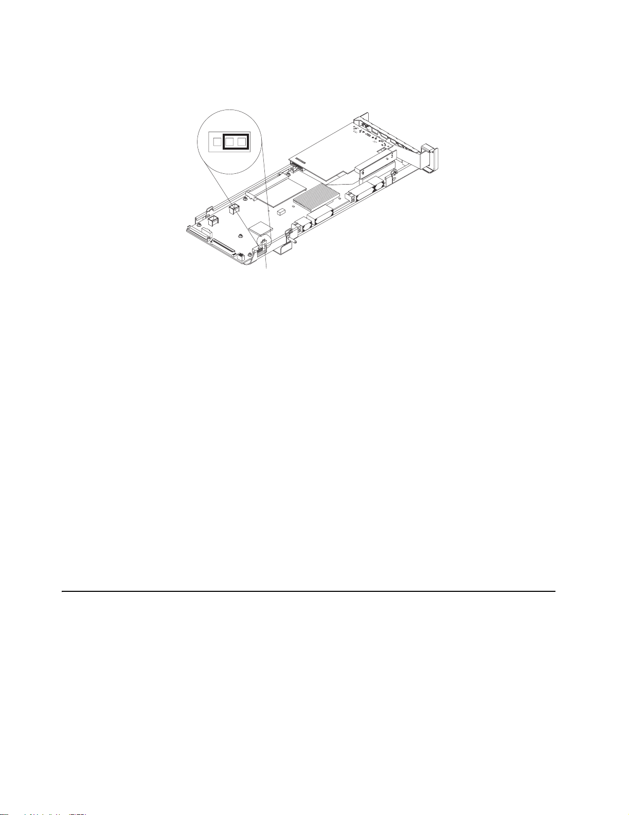
1. Turn off the server and peripheral devices and disconnect all external cables and
power cords; then, remove the cover.
2. Locate the BIOS code page jumper (J28) on the I/O board.
3
12
Jumper (J28)
3. Move the jumper from pins 1 and 2 to pins 2 and 3 to enable the BIOS back-up
image.
4. Reconnect all external cables an d pow er cords and turn on the peripheral de vices .
5. Insert the BIOS flash diskette into the diskette drive.
6. Restart the server. The system begins the power-on self-test (POST) and BIOS
flash.
7. Select 1 - Update POST/BIOS from the menu tha t contains v arious flash (update)
options.
8. When prompted as to whether you want to save the current code to a diskett e,
press N.
9. When prompted to choose a language, select a language (from 0 to 7) and press
Enter to accept your choice.
10. Do not restart your system at this time.
11. Remove the BIOS flash diskette from the diskette drive.
12. Turn off the server.
13. Move the jumper on J28 to pins 1 and 2 to return to normal startup mode.
14. Restart the server.
15. Replace the cover.
Troubleshooting charts
You can use the troubleshooting charts in this section to find solutions to problems
that have definite symptoms.
Look for the symptom in the left column of the chart. Instructions and probable
solutions to the problem are in the right column.
Note: If you have just added new software or a new option and your server is not
working, do the following before using the troubleshooting charts:
1. Remove the software or device that you just added.
2. Run the diagnostic tests to determine if your server is running correctly.
Chapter 2. Solving Problems 43
Page 56

See “Starting the diagnostic programs” on page 33 to test the server. If the
server still does not work and running the diagnostic test programs does
not reveal the prob lem, call for service.
3. If your server is running correctly, reinstall the new software or new device.
Table 5. Troubleshooting charts
Symptom Suggested action
CD-ROM drive problems Verify that:
CD-ROM drive is not
recognized.
Diskette drive problems If there is a diskette in the drive, verify that:
Diskette drive in-use light stays
on, or the system bypasses the
diskette drive.
Expansion enclosure
problems
The SCSI expansion encl o sure
used to work but does not work
now.
1. The IDE channels are enabled in the Configuration/Setup Utility program.
2. All cables and jumpers are installed correctly.
3. The correct device driver is installed for the CD-ROM drive.
1. The diskette drive is enabled in the Configuration/Setup Utility program.
2. The diskette is good and not damaged. (Try another diskette if you have one.)
3. The diskette contains the necessary files to start the server.
4. Your software program is working properly.
If the diskette drive in-use light stays on, or the system continues to bypass the
diskette drive, call for service.
Verify that:
1. The cables for all e xternal SCSI options are connected correctly.
2. The last option in each SCSI chain, or the end of the SCSI cable, is terminated
correctly.
3. Any external SCSI option is turned on. You must turn on an external SCSI option
before turning on the server.
For more information, see your SCSI and expansion enclosure documentation.
Hard disk drive problems 1. Remove the first drive not recognized and try the hard disk diagnostic test again.
Not all drives are recognized by
the hard disk diagnostic test
(Fixed Disk test).
System stops responding
during hard disk diagnostic.
General problems Call for service.
Problems such as broken co v er
locks or indicator lights not
working.
Intermittent problems Verify that:
A problem occurs only
occasionally and is difficult to
detect.
Keyboard, mouse, or
pointing-device problems.
All or some keys on the
keyboard do not work.
2. If the remaining drives are recognized, replace the drive you removed with a new
one.
1. Remove the hard disk drive being tested when the server stopped responding
and try the diagnostic again.
2. If the hard disk diagnostic runs successfully , replace the drive y ou remov ed with a
new one.
1. All cables and cords are connected securely to the rear of the server and
attached options.
2. When the server is turned on, air is flowing from the rear of the server at the fan
grill. If there is no air flow, the fan is not working. This causes the server to
overheat and shut down.
3. Ensure that the SCSI bus and devices are configured correctly and that the last
external device in each SCSI chain is terminated correctly.
If the items above are correct, call for service.
1. Make sure that the keyboard cable is properly connected to the server.
2. Make sure that the server and the monitor are turned on.
3. Try using another keyboard.
If the items above are correct, call for service.
44 xSeries 440:Troubleshooting Guide
Page 57
Table 5. Troubleshooting charts (continued)
Symptom Suggested action
The mouse or pointing device
does not work.
Memory problems Verify that:
The amount of system memory
displayed is less than the
amount of physical memory
installed.
1. Verify that the mouse or pointing-device cable is securely connected and the
device drivers are installed correctly.
2. Try using another mouse or pointing device.
If the problem remains, call for service.
1. The memory modules are seated properly.
2. You have installed the correct type of memory.
3. If you changed the memory, you updated the memory configuration with the
Configuration/Setup Utility program.
4. All banks of memory on the DIMMs are enabled. The server might have
automatically disabled a DIMM bank when it detected a problem, or a DIMM bank
could have been manually disabled.
Look in the POST error log for error message 289:
• If the DIMM was disabled by a system-management interrupt (SMI), replace the
DIMM.
• If the DIMM was disabled by the user or by POST:
1. Start the Configuration/Setup Utility program.
2. Enable the DIMM.
3. Save the configuration and restart the server.
• If you continue to get this error, replace the DIMM.
If the problem persists, call for service.
Microprocessor problems The startup (boot) microprocessor is not working properly.
The server emits a continuous
tone during POST.
Verify that the startup microprocessor is seated properly. If it is, replace the startup
microprocessor.
If the problem remains, call for service.
Monitor problems Some IBM monitors have their own self-tests. If you suspect a problem with your
Testing the monitor.
monitor, see the information that comes with the monitor for adjusting and testing
instructions.
If you still cannot find the problem, call for service.
The screen is blank. Verify that:
1. The server power cord is plugged into the server and a working electrical outlet.
2. The monitor cables are connected properly.
3. The monitor is turned on and the Brightness and Contrast controls are adjusted
correctly.
Important: In some memory configurations, the 3-3-3 beep code might sound during
POST followed by a blank display screen. If this occurs and the Boot Fail Count
feature in the Start Options of the Configuration/Setup Uti li ty p r ogram is set to
Enabled (its default setting), you must restart the server three times to force the
system BIOS to reset the CMOS values to the default configuration (memory
connector or bank of connectors Enabled).
If the items above are correct and the screen remains blank, call for service.
Only the cursor appears. Call for service.
Chapter 2. Solving Problems 45
Page 58

Table 5. Troubleshooting charts (continued)
Symptom Suggested action
The monitor works when you
turn on the server but goes
blank when you start some
application programs.
The screen is wavy,
unreadable, rolling, distorted, or
has screen jitter.
Wrong characters appear on
the screen.
Option problems Verify that:
An IBM option that was just
installed does not work.
Verify that:
1. The primary monitor cable is connected to the server.
2. You installed the necessary device drivers for the applications.
If the items above are correct and the screen remains blank, call for service.
If the monitor self-tests show the monitor is working properly, consider the location of
the monitor. Magnetic fields around other devices (such as transformers, appliances,
fluorescent lights, and other monitors) can cause screen jitter or wavy, unreadable,
rolling, or distorted screen images. If this happens, turn off the monitor. (Moving a
color monitor while it is turned on might cause screen discoloration.) Then move the
device and the monitor at least 305 mm (12 in.) apart. Turn on the monitor.
Notes:
1. To prevent diskette drive read/write errors, be sure the distance between
monitors and diskette drives is at least 76 mm (3 in.).
2. Non-IBM monitor cables might cause unpredictable problems.
3. An enhanced monitor cable with additional shielding is availab le f or the 9521 and
9527 monitors. For information about the enhanced monitor cable, contact your
IBM reseller or IBM marketing representative.
If the problem remains, call for service.
If the wrong language is displayed, update the BIOS code with the correct language.
If the problem remains, call for service.
1. The option is designed for the server. See the “Server Support” flowchart for
information about obtaining ServerProven
®
compatibility information from the
World Wide Web.
2. You followed the installation instructions that came with the option.
3. The option is installed correctly.
4. You have not loosened any other installed options or cables.
5. You updated the configuration information in th e Configuration/Setup Utility
program. Whenever memory or an option is changed, you must update the
configuration.
Note: If you just installed a microprocessor, ensure that you installed the VRM that
came in the microprocessor option.
If the problem remains, call for service.
An IBM option that used to work
Verify that all of the option hardware and cable connections are secure.
does not work now.
If the option comes with its own test instructions, use those instructions to test the
option.
If the failing option is a SCSI option, verify that:
1. The cables for all e xternal SCSI options are connected correctly.
2. The last option in each SCSI chain, or the end of the SCSI cable, is terminated
correctly.
3. Any external SCSI option is turned on. You must turn on an external SCSI option
before turning on the server.
If the problem remains, call for service.
46 xSeries 440:Troubleshooting Guide
Page 59

Table 5. Troubleshooting charts (continued)
Symptom Suggested action
Power problems Verify that:
The server does not power on.
The server does not power off. Verify whether you are using an ACPI or non-ACPI operating system.
Software problem To determine if problems are caused by the software, verify that:
Suspected software problem.
1. The power cables are properly connected to the server.
2. The electrical outlet functions properly.
3. The type of memory installed is correct.
4. If you just installed an option, remove it, and restart the server. If the server now
turns on, you might have installed more options than the power supply supports.
If the problem remains, call for service.
If you are using a non-ACPI operating system:
1. Press Ctrl+Alt+Delete.
2. Turn off the system by using the power-control button.
If the problem remains or if you are using an ACPI-aware operating system, call for
service.
1. Your server has the minimum memory requirements needed to use the software.
For memory requirements, refer to the information that comes with the software.
Note: If you have just installed an adapter or memory, you might have a
memory address conflict.
2. The software is designed to operate on your server.
3. Other software works on your server.
4. The software that you are using works on another system.
If you received any error messages when using the software program, refer to the
information that comes with the software for a description of the messages and
solutions to the problem.
If the items above are correct and the problem remains, contact your place of
purchase.
Universal Serial Bus (USB)
port problems
A USB device does not work.
Verify that:
1. You are not trying to use a USB device during POST if you have a standard (nonUSB) keyboard attached to the keyboard port.
Note: If a standard (non-USB) keyboard is attached to the keyboard port, the
USB is disabled and no USB device will work during POST.
2. The correct USB device driver is installed.
3. Your operating system supports USB devices.
If the problem still exists, call for service.
Troubleshooting an Ethernet controller
This section provides trouble shooting information for prob lems that migh t occur with a
10/100/1000-Mbps Ethernet controller.
Network connection problems: If an Ethernet controller cannot connect to
the network, check the following:
• Make sure that the cable is installed correctly.
The network cable must be securely attached at all connections. If the cable is
attached but the problem persists, try a different cable.
If you set the Ethernet controller to operate at 100 or 1000 Mbps, you must use
Category 5 cabling.
Chapter 2. Solving Problems 47
Page 60

If you directly connect two workstations (without a hub), or if you are not using a
hub with X ports, use a crossover cable.
Note: To determine whether a hub has an X port, check the port label. If the label
contains an X, the hub has an X port.
• Determine if the hub supports auto-negotiation. If not, try configuring the
integrated Ethernet controller manually to match the speed and duplex mode of
the hub.
• Make sure that you are using the correct device drivers, su pplied with your server.
• Check for operating-system-specific causes for the problem.
• Make sure that the device drivers on the client and server are using the same
protocol.
• Test the Ethernet controller.
How you test the Ethernet controller depends on which operating system you are
using (see the Ethernet controller device driver README file).
Ethernet controller troubleshooting chart: You can use the following
troubleshooting chart to find solutions to 10/100/1000-Mbps Ethernet controller
problems that ha ve definite symptoms.
Table 6. Ethernet troubleshooting chart
Ethernet controller problem Suggested action
The server stops running
when loading device drivers.
The PCI BIOS interrupt settings are incorrect.
Check the following:
• Determine if the interrupt (IRQ) setting assigned to the Ether net controller is also
assigned to another device in the Configuration/Setup Utility program.
Although interrupt sharing is allowed for PCI devices, some devices do not function
well when they share an interrupt with a dissimilar PCI device. Try changing the IRQ
assigned to the Ethernet controller or the other device. For example, for NetWare
Versions 3 and 4, it is recommended that disk control lers not share interrupts with
LAN controllers.
• Make sure that you are using the most recent device driver available from the World
Wide Web.
• Run the network diagnostic program.
If the problem remains, call for service.
Data is incorrect or sporadic. Check the following:
• Make sure that you are using Category 5 cabling when operating the server at 100
Mbps.
• Make sure that the cables do not run close to noise-inducing sources like fluorescent
lights.
The Ethernet controller
stopped working when
another adapter was added to
the server.
Check the following:
• Make sure that the cable is connected to the Ethernet controller.
• Make sure that your PCI system BIOS is current.
• Reseat the adapter.
• Determine if the interrupt (IRQ) setting assigned to the Ethernet adapter is also
assigned to another device in the Configuration/Setup Utility program.
Although interrupt sharing is allowed for PCI devices, some devices do not function
well when they share an interrupt with a dissimilar PCI device. Try changing the IRQ
assigned to the Ethernet adapter or the other device.
If the problem remains, call for service.
48 xSeries 440:Troubleshooting Guide
Page 61

Table 6. Ethernet troubleshooting chart (continued)
Ethernet controller problem Suggested action
The Ethernet controller
stopped working without
apparent cause.
Check the following:
• Run diagnostics for the Ethernet controller.
• Try a different connector on the hub.
• Reinstall the device drivers. Refer to your operating-system documentation and to the
ServerGuide information.
If the problem remains, call for service.
Getting help and technical assistance
If you need help, service, or technical assistance or just want more information about
IBM products, you will find a wide variety of sources available from IBM to assist you.
This appendix contains inf ormation about wher e to go for additional inf ormation about
IBM and IBM products, what to do if you experience a problem with your xSeries or
IntelliStation
®
system, and whom to call for service, if it is necessary.
Before you call
Before you ca ll, mak e sure th at y ou ha ve taken these steps to try to solve the prob lem
yourself:
• Check all cables to make sure that they are connected.
• Check the power switches to make sure that the system is turned on.
• Use the troubleshooting information in your system documentation, and use the
diagnostic tools that come with your system.
• Go to the IBM Support Web site at http://www.ibm.com/pc/support/ to check for
technical information, hints, tips, and new de vice drivers.
• Use an IBM discussion forum on the IBM Web site to ask questions.
You can solve many problems without outside assistance by following the troubleshooting procedures that IBM pro vides in the onlin e help or in the pu blicatio ns that are
provided with your syste m and softw are. The inf ormation that comes with y our system
also describes the diagnostic tests that you can perform. Most xSeries and IntelliStation systems, operating systems, and programs come with information that contains
troubleshooting procedures and explanations of error messages and error codes. If
you suspect a software problem, see the information for the operating system or program.
Using the documentation
Information about your IBM xSeries or IntelliStation system and preinstalled software,
if any, is available in the document ation that comes with your system. That documentation includes printed books, online books, README files, and help files. See the
troubleshooting inf ormation in your system documentatio n for instructions f or using the
diagnostic programs. The troubleshooting information or the diagnostic programs
might tell you that you need additional or updated device drivers or other software.
IBM maintains pages on the World Wide Web where you can get the latest technical
information and download device drivers and updates. To access these pages, go to
http://www.ibm.com/pc/support/ and follow the instructions. Also, you can order publications through the IBM Publications Ordering System at http://www.elink.ibmlink.ibm.com/public/applications/publications/cgibin/pbi.cgi.
Chapter 2. Solving Problems 49
Page 62

Getting help and information from the World Wide Web
On the World Wide Web, the IBM Web site has up-to-date information about IBM
xSeries and IntelliStation products, services, and support. The address for IBM
xSeries information is http://www.ibm.com/eserver/xseries/. The address for IBM IntelliStation information is http://www.ibm.com/pc/intellistation/.
You can find service information for y our IBM product s, including supported options, at
http://www.ibm.com/pc/support/. If you click Profile from the support page, you can
create a customized support page. The support page has many sources of information and ways for you to solve problems, including:
• Diagnosing problems, using the IBM Online Assistant
• Downloading the latest device drivers and updates for your products
• Viewing Frequently Asked Questions (FAQ)
• Viewing hints and tips to help you solve problems
• Participating in IBM discussion forums
• Setting up e-mail notification of technical update s ab ou t your produc ts
Software service and support
Through IBM Support Line, you can get telephone assistance, for a fee, with usage,
configuration, and software problems with xSeries servers, IntelliStation workstations,
and appliances. For information about which products are supported by Support Line
in your country or region, go to http://www.ibm.com/services/sl/products/.
For more information about Support Line and other IBM services, go to
http://www.ibm.com/services/, or go to http://www.ibm.com/planetwide/ for support
telephone numbers.
Hardware service and support
You can receive hardware service through IBM Integrated Technology Services or
through your IBM reseller , if y our reseller is authorized by IBM to provide warranty service. Go to http://www.ibm.com/planetwide/ for support telephone numbers.
In the U.S. and Canada, hardware service and support is available 24 hours a day, 7
days a week. In the U.K., these services are available Monday through Friday, from 9
a.m. to 6 p.m.
50 xSeries 440:Troubleshooting Guide
Page 63

Appendix A. Notices
This publication was developed for products and services offered in the U.S.A.
IBM may not offer the products, services, or features discussed in this document in
other countries. Consult your local IBM represent ative for information on the products
and services currently available in your area. Any reference to an IBM product, program, or service is not intended to state or imply that only that IBM product, program,
or service may be used. Any functionally equivalent product, program, or service that
does not infringe any IBM intellectual property right may be used instead. However, it
is the user’s responsibility to e v aluate and verify the operation of an y non-IBM product,
program, or service.
IBM may have patents or pending patent applications covering subject matter
described in this document. The furnishing of this document does not give you any
license to these patents. You can send license inquiries, in writing, to:
IBM Director of Licensing
IBM Corporation
North Castle Drive
Armonk, NY 10504-1785
U.S.A.
INTERNATIONAL BUSINESS MACHINES CORPORATION PROVIDES THIS PUBLICATION “AS IS” WITHOUT WARRANTY OF ANY KIND, EITHER EXPRESS OR
IMPLIED , INCLUDING, BUT NOT LIMITED TO, THE IMPLIED WARRANTIES OF
NON-INFRINGEMENT, MERCHANTABILITY OR FITNESS FOR A PARTICULAR
PURPOSE. Some jurisdictions do not allow disclaimer of expr ess or implied warranties in certain transactions, therefore, this statement may not apply to you.
Edition notice
This information could include technical inaccuracies or typographical errors.
Changes are periodically made to the information herein; these changes will be incorporated in new editions of the publication. IBM may make improvements and/or
changes in the product(s) and/or the program(s) described in this publication at any
time without notice.
Any references in this publication to non-IBM Web sites are provided for convenience
only and do not in any manner serve as an endorsement of those Web sites. The
materials at those Web sites are not part of the materials f or this IBM product, and use
of those Web sites is at your own risk.
IBM may use or distribute any of the information you supply in any way it believes
appropriate without incurring any obligatio n to you.
© COPYRIGHT INTERNATIONAL BUSINESS MACHINES CORPORATION, 2002.
All rights reserved.
Note to U.S. Government Users — Documentation related to restricted rights — Use,
duplication or disclosure is subject to restrictions set forth in GSA ADP Schedule Contract with IBM Corp.
© Copyright IBM Corp. 2002 51
Page 64

Trademarks
The following terms are tradem arks of International Business Machines Corporation in
the United States, other countries, or both:
Active Memory Predictive Failure Analysis
Active PCI PS/2
Active PCI-X ServeRAID
Alert on LAN ServerGuide
C2T Interconnect ServerProven
Chipkill TechConnect
EtherJet Tivoli
e-business logo Tivoli Enterprise
FlashCopy Update Connector
IBM Wake on LAN
IntelliStation XA-32
Light Path Diagnostics XA-64
NetBAY X-Architecture
Netfinity XceL4
NetView XpandOnDemand
OS/2 WARP xSeries
Lotus, Lotus Notes, SmartSuite, and Domino are trademarks of Lotus Development
Corporation and/or IBM Corporation in the United States, other countries, or both.
Intel, Celeron, LANDesk, MMX, NetBurst, Pentium, Pentium II Xeon, Pentium III Xeon,
and Xeon are trademarks of Intel Corporation in the United States, other count ries, or
both.
Microsoft, Windows, and Windo ws NT are trademarks of Microsoft Corporation in the
United States, other countries, or both.
UNIX is a registered trademark of The Open Group in the United States and other
countries.
Java and all Java-based trademarks and logos are trademarks or registered trademarks of Sun Microsystems, Inc. in the United States, other countries, or both.
Linux is a registered trademark of Linus Torvalds.
Other company, product, or service names may be trademarks or service marks of
others.
52 xSeries 440:Troubleshooting Guide
Page 65

Important notes
Processor speeds indicate the internal clock speed of the microprocessor; other factors also affect application performance.
CD-ROM drive speeds list the variable read rate. Actual speeds vary and are often
less than the maximum possible.
When referring to processor storage, real and virtual storage, or channel volume, KB
stands for approximately 1000 bytes, MB stands for approximately 1 000 000 bytes,
and GB stands for approximately 1 000 000 000 bytes.
When referring to hard disk drive capacity or communications volume, MB stands for
1000000 bytes, and GB stands for 1000 000 000 bytes. Total user-accessible capacity may vary depending on operating environments.
Maximum internal hard disk drive capacities assume t he replacem ent of an y stand ard
hard disk drives and population of all hard disk drive bays with the largest currently
supported drives available from IBM.
Maximum memory may require replacement o f th e sta ndard mem ory with an optional
memory module.
IBM makes no representation or w arr antie s regar ding non -IBM produ cts and services
that are ServerProven, including but not limited to the implied warranties of merchantability and fitness for a particular purpose. These products are offered and warranted
solely by third parties.
IBM makes no representations or warranties with respect to no n-IBM products. Support (if any) for the non-IBM products is provided by the third party, not IBM.
Some software may dif f er from its ret ail v ersion (if a v ailab le), and ma y not include user
manuals or all program fu nctionality.
Electronic emission notices
Federal Communications Commission (FCC) statement
Note: This equipment has been tested and fou nd to comply with th e limits for a Class
A digital device, pursuant to Part 15 of the FCC Rules. These limits are designed to
provide reasonable protection against harmful interference when th e equipment is
operated in a commercial en vironment. Th is equipment gen erates , uses , and can r adiate radio frequency energy and, if not installed and used in accordance with the
instruction manual, may cause harmful inter ference to radio communication s. Operation of this equipment in a residential area is likely to cause harmful interference, in
which case the user will be required to correct the interference at his own expense.
Properly shielded and grounded cab les and conne ctors must be u sed in order to me et
FCC emission limits. IBM is not responsible for any radio or television interference
caused by using other than recommended cables and connectors or by unauthorized
changes or modifications to this equipment. Un au th orized changes or modifications
could void the user's authority to operate the equipment.
This device complies with Part 15 of the FCC Rules. Operation is subject to the follo wing two conditions: (1) this device may not cause harmful interference, and (2) this
Appendix A. Notices 53
Page 66
device must accept any interference received, including interference that may cause
undesired operation.
Industry Canada Class A emission compliance statement
This Class A digital apparatus complies with Canadian ICES-003.
Avis de conformité à la réglementation d'Industrie Canada
Cet appareil numérique de la classe A est conforme à la norme NMB-003 du Canada.
Australia and New Zealand Class A statement
Attention: This is a Class A product. In a domestic environment this product may
cause radio interference in which case the user may be required to take adequate
measures.
United Kingdom telecommunications safety requirement
Notice to Customers
This apparatus is approved under approval number NS/G/1234/J/100003 for indirect
connection to public telecommunication systems in the United Kingdom.
European Union EMC Directive conformance statement
This product is in conformity with the protection requirements of EU Council Directive
89/336/EEC on the approxima tion of the la ws of the Mem ber State s relating to electr omagnetic compatibility. IBM cannot accept responsibility for any failure to satisfy the
protection requirements resulting from a nonrecommended modification of the product, including the fitting of non-IBM option ca rd s.
This product has been tested and found to comply with the limits for Class A Information Technology Equipment according to CISPR 22/European Standard EN 55022.
The limits for Class A equipment were derived for commercial and industrial environments to provide reasonab le protect ion again st interference with licensed communication equipment.
Attention: This is a Class A product. In a domestic environment this product may
cause radio interference in which case the user may be required to take adequate
measures.
Taiwanese Class A warning statement
54 xSeries 440:Troubleshooting Guide
Page 67
Japanese Voluntary Control Council for Interference (VCCI) statement
Power cords
For your safety, IBM provides a power cord with a grounded attachment plug to use
with this IBM product. To avoid electrical shock, always use the power cord and plug
with a properly grounded outlet.
IBM power cords used in the United States and Ca nada are listed by Underwriter's
Laboratories (UL) and certified by the Canadian Standards Association (CSA).
For units intended to be operated at 115 v o lts: Use a UL-listed and CSA-certified cord
set consisting of a minimum 18 AWG, Type SVT or SJT, three-conductor cord, a maximum of 15 feet in length and a parallel blade, grounding-type attachment plug rated
15 amperes, 125 volts.
For units intended to be operated at 230 volts (U.S. use): Use a UL-listed and CSAcertified cord set consisting of a minimum 18 AWG, Type SVT or SJT, three-conductor
cord, a maximum of 15 fee t in len gt h and a ta nd em blade, grounding-type at tachme nt
plug rated 15 amperes, 250 volts.
For units intended to be operated at 230 volts (outside the U.S.): Use a cord set with a
grounding-type attachment plug. Th e co rd set sh ou ld have the appropr ia te safety
approvals for the country in which the equipment will be installed.
IBM power cords for a specific country or region are usually available only in that
country or region.
IBM power cord part
number
13F9940 Argentina, Australia, China (PRC), New Zealand, Papua New
Guinea, Paraguay, Uruguay, Western Samoa
13F9979 Afghanistan, Algeria, Andorra, Angola, Austria, Belgium, Benin,
Bulgaria, Burkina Faso, Burundi, Cameroon, Central African Rep.,
Chad, China (Macau S.A.R.), Czech Republic, Egypt, Finland,
France, French Guiana, Germany, Greece, Guinea, Hungary,
Iceland, Indonesia, Iran, Ivory Coast, Jordan, Lebanon,
Luxembourg, Malagasy, Mali, Martinique, Mauritania, Mauritius,
Monaco, Morocco, Mozambique, Netherlands, New Caledonia,
Niger, Norway, Poland, Portugal, Romania, Senegal, Slovakia,
Spain, Sudan, Sweden, Syria, Togo, Tunisia, Turkey, former USSR,
Vietnam, former Yugoslavia, Zaire, Zimbabwe
13F9997 Denmark
14F0015 Bangladesh, Burma, Pakistan, South Africa, Sri Lanka
Used in these countries and regions
Appendix A. Notices 55
Page 68
IBM power cord part
number
14F0033 Antigua, Bahrain, Brunei, Channel Islands, China (Hong Kong
S.A.R.), Cyprus, Dubai, Fiji, Ghana, India, Iraq, Ireland, Keny a,
Kuwait, Malawi, Malaysia, Malta, Nepal, Nigeria, Polynesia, Qatar,
Sierra Leone, Singapore, Tanzania, Uganda, United Kingdom,
Yemen, Zambia
14F0051 Liechtenstein, Switzerland
14F0069 Chile, Ethiopia, Italy, Libya, Somalia
14F0087 Israel
1838574 Thailand
6952301 Bahamas, Barbados, Bermuda, Bolivia, Brazil, Canada, Cayman
Islands, Colombia, Costa Rica, Dominican Republic, Ecuador, El
Salvador, Guatemala, Guyana, Haiti, Honduras, Jamaica, Japan,
Korea (South), Liberia, Mexico, Netherlands Antilles, Nicaragua,
Panama, Peru, Philippines, Saudi Arabia, Suriname, Taiwan,
Trinidad (West Indies), United States of America, Venezuela
Used in these countries and regions
56 xSeries 440:Troubleshooting Guide
Page 69

Index
B
beep codes, POST 17
BIOS code, recovering 41
C
CD-ROM
problems 43
Class A electronic emission notice 53
components
location of 9
Remote Supervisor Adapter 14
D
diagnostic
error code format 32
error message tables 34
error messages 32
programs 32
programs, starting 33
text messages 32
tools 15
diskette drive
problem 43
display problems 44
E
electronic emission Class A notice 53
error
diagnostic code format 32
log 26
messages 32
error log, viewing 26, 34
error messages
diagnostic 32, 34
POST 20
SCSI 31
Ethernet
troubleshooting information 46
expansion
enclosure problems 43
F
FCC Class A notice 53
H
hardware
© Copyright IBM Corp. 2002 57
Page 70

problems 15
hardware, major 9
I
I/O board
internal connectors 14
intermittent problems 43
internal connectors
I/O board 14
PCI-X 13
SMP Expansion Module 11
J
jumper
BIOS code page 42
K
keyboard
problems 44
L
LEDs
front view 2
rear view 4
Light Path Diagnostics
feature 26
panel 27
using 26
Light Path Diagnostics table 27
M
memory
problems 44
messages
diagnostic error 32, 34
diagnostic text 32
POST error 20
SCSI error 31
microprocessor
problem 44
monitor problems 44
mouse
problems 44
N
network
connection problems 46
notes, important 53
notices
58 xSeries 440:Troubleshooting Guide
Page 71

electronic emission 53
FCC, Class A 53
O
option
problems 45
P
PCI-X
internal connectors 13
pointing device
problems 44
POST (Power-on self test)
beep codes 15, 17
error log 26
error logs 15
error messages 15, 20
POST (power-on self-test)
overview 17
power
problems 46
power cords 55
power-control button shield 6
problems
CD-ROM drive 43
diskette drive 43
expansion enclosure 43
hardware 15
intermittent 43
keyboard 44
memory 44
microprocessor 44
monitor 44
mouse 44
network connection 46
option 45
pointing device 44
power 46
software 46
solving 15
USB port 46
R
recovering BIOS 41
Remote Supervisor Adapter
component locations 14
restoring BIOS 41
S
SCSI
error messages 31
ServerGuide
error symptoms 30
Index 59
Page 72

shield, power-control button 6
SMP
Expansion Module
internal connectors 11
software
problems 46
starting the server 6
T
test log, viewing 34
trademarks 52
troubleshooting
charts 15, 42
Ethernet controller 46
tools 15
turning on the server 6
U
United States electronic emission Class A notice 53
United States FCC Class A notice 53
Universal Serial Bus (USB)
problems 46
60 xSeries 440:Troubleshooting Guide
Page 73

Page 74

IBM
Part Number: 59P6515
Printed in U.S.A.
59P6515
 Loading...