

Page 1

ERserver
IBM xSeries 365 Types 8861, 8862
Hardware Maintenance Manual and Troubleshooting
Guide
Page 2

Page 3

ER s e r v e r
IBM xSeries 365 Types 8861, 8862
Hardware Maintenance Manual and Troubleshooting
Guide
Page 4

Note
v Before using this information and the product it supports, read Appendix B, “Related service
information,” on page 147, and Appendix C, “Notices,” on page 191.
v The latest version of this document is available at www.ibm.com/pc/support/.
Tenth Edition (March 2005)
© Copyright International Business Machines Corporation 2003. All rights reserved.
US Government Users Restricted Rights – Use, duplication or disclosure restricted by GSA ADP Schedule Contract
with IBM Corp.
Page 5
About this manual
This manual contains diagnostic information, a Symptom-to-FRU index, service
information, error codes, error messages, and configuration information for the IBM
Eserver
™
xSeries
Important: This manual is intended for trained servicers who are familiar with IBM
xSeries products. Before servicing an IBM product, be sure to review
“Safety information” on page 147.
Important safety information
Be sure to read all caution and danger statements in this book before performing
any of the instructions.
Leia todas as instruções de cuidado e perigo antes de executar qualquer operação.
Prenez connaissance de toutes les consignes de type Attention et
Danger avant de procéder aux opérations décrites par les instructions.
Lesen Sie alle Sicherheitshinweise, bevor Sie eine Anweisung ausführen.
®
365 Type 8861 server.
®
Online support
Accertarsi di leggere tutti gli avvisi di attenzione e di pericolo prima di effettuare
qualsiasi operazione.
Lea atentamente todas las declaraciones de precaución y peligro ante de llevar a
cabo cualquier operación.
WARNING: Handling the cord on this product or cords associated with accessories
sold with this product, will expose you to lead, a chemical known to the State of
California to cause cancer, and birth defects or other reproductive harm. Wash
hands after handling.
ADVERTENCIA: El contacto con el cable de este producto o con cables de
accesorios que se venden junto con este producto, pueden exponerle al plomo, un
elemento químico que en el estado de California de los Estados Unidos está
considerado como un causante de cancer y de defectos congénitos, además de
otros riesgos reproductivos. Lávese las manos después de usar el producto.
You can download the most current diagnostic, BIOS flash, and device driver files
from http://www.ibm.com/pc/support/.
© Copyright IBM Corp. 2003 iii
Page 6

iv IBM xSeries 365 Types 8861, 8862: Hardware Maintenance Manual and Troubleshooting Guide
Page 7

Contents
About this manual . . . . . . . . . . . . . . . . . . . . . . . iii
Important safety information . . . . . . . . . . . . . . . . . . . . iii
Online support . . . . . . . . . . . . . . . . . . . . . . . . . iii
Chapter 1. Introduction . . . . . . . . . . . . . . . . . . . . . .1
Related publications . . . . . . . . . . . . . . . . . . . . . . .1
Notices and statements used in this publication . . . . . . . . . . . . .2
Features and specifications . . . . . . . . . . . . . . . . . . . . .3
Server controls, LEDs, and power . . . . . . . . . . . . . . . . . .4
Front view . . . . . . . . . . . . . . . . . . . . . . . . . .4
Rear view . . . . . . . . . . . . . . . . . . . . . . . . . .6
Light path diagnostics LED panel . . . . . . . . . . . . . . . . .8
Server power features . . . . . . . . . . . . . . . . . . . . . .8
Chapter 2. Configuring the server . . . . . . . . . . . . . . . . .11
Using the Configuration/Setup Utility program . . . . . . . . . . . . . .11
Using the ServerGuide Setup and Installation CD . . . . . . . . . . . .12
Using the PXE boot agent utility program . . . . . . . . . . . . . . .12
Using the RAID configuration programs . . . . . . . . . . . . . . . .13
Updating the integrated service processor firmware . . . . . . . . . . .13
Configuring the Gigabit Ethernet controllers . . . . . . . . . . . . . .13
Remote Supervisor Adapter II . . . . . . . . . . . . . . . . . . .13
Chapter 3. Diagnostics . . . . . . . . . . . . . . . . . . . . .15
General checkout . . . . . . . . . . . . . . . . . . . . . . . .15
Diagnostic tools overview . . . . . . . . . . . . . . . . . . . . .17
POST error logs . . . . . . . . . . . . . . . . . . . . . . . .17
Viewing error logs from the Configuration/Setup Utility program . . . . . .17
Viewing error logs from the diagnostic programs . . . . . . . . . . .18
Light path diagnostics . . . . . . . . . . . . . . . . . . . . . .18
Microprocessor LEDs . . . . . . . . . . . . . . . . . . . . .19
DIMM LEDs . . . . . . . . . . . . . . . . . . . . . . . . .20
Remind button . . . . . . . . . . . . . . . . . . . . . . . .21
Diagnostic programs and error messages . . . . . . . . . . . . . . .22
Diagnostic text messages . . . . . . . . . . . . . . . . . . . .22
Starting the diagnostic programs . . . . . . . . . . . . . . . . .23
Viewing the test log . . . . . . . . . . . . . . . . . . . . . .23
Viewing the system-error log . . . . . . . . . . . . . . . . . . .24
Recovering BIOS code . . . . . . . . . . . . . . . . . . . . . .24
Password override jumper . . . . . . . . . . . . . . . . . . . . .25
Forcing a power-on . . . . . . . . . . . . . . . . . . . . . . .26
Power checkout . . . . . . . . . . . . . . . . . . . . . . . .27
Ethernet controller troubleshooting . . . . . . . . . . . . . . . . . .27
Chapter 4. Installing options . . . . . . . . . . . . . . . . . . .29
Installation guidelines . . . . . . . . . . . . . . . . . . . . . .29
System reliability guidelines . . . . . . . . . . . . . . . . . . .29
Working inside a server with power on . . . . . . . . . . . . . . .30
Handling static-sensitive devices . . . . . . . . . . . . . . . . .30
Major components of the xSeries 365 server . . . . . . . . . . . . . .31
Removing the cover and bezel . . . . . . . . . . . . . . . . . . .32
PCI or PCI-X adapters . . . . . . . . . . . . . . . . . . . . . .33
Installing a PCI or PCI-X adapter . . . . . . . . . . . . . . . . .35
© Copyright IBM Corp. 2003 v
Page 8

Removing a PCI or PCI-X adapter . . . . . . . . . . . . . . . . .36
Installing a hot-swap hard disk drive . . . . . . . . . . . . . . . . .36
Replacing the CD-ROM drive . . . . . . . . . . . . . . . . . . .38
Memory modules . . . . . . . . . . . . . . . . . . . . . . . .39
DIMM banks and ports . . . . . . . . . . . . . . . . . . . . .40
DIMM installation . . . . . . . . . . . . . . . . . . . . . . .41
Installing a microprocessor . . . . . . . . . . . . . . . . . . . .44
Installing a hot-swap power supply . . . . . . . . . . . . . . . . .51
Replacing the battery . . . . . . . . . . . . . . . . . . . . . .53
Replacing a hot-swap fan . . . . . . . . . . . . . . . . . . . . .55
Replacing the memory cassette . . . . . . . . . . . . . . . . . . .56
Completing the installation . . . . . . . . . . . . . . . . . . . . .58
Installing the cover and bezel . . . . . . . . . . . . . . . . . .58
Connecting the cables . . . . . . . . . . . . . . . . . . . . .59
Updating the server configuration . . . . . . . . . . . . . . . . .60
I/O connectors . . . . . . . . . . . . . . . . . . . . . . . . .61
Server connectors . . . . . . . . . . . . . . . . . . . . . . .62
Chapter 5. FRU information (service only) . . . . . . . . . . . . . .67
Microprocessor tray assembly . . . . . . . . . . . . . . . . . . .68
Microprocessor board connectors, jumpers and LEDs . . . . . . . . .68
Microprocessor removal . . . . . . . . . . . . . . . . . . . .68
Thermal grease . . . . . . . . . . . . . . . . . . . . . . . .69
Diskette drive . . . . . . . . . . . . . . . . . . . . . . . . .71
Operator information panel . . . . . . . . . . . . . . . . . . . .72
Media interposer card . . . . . . . . . . . . . . . . . . . . . .73
SCSI backplane . . . . . . . . . . . . . . . . . . . . . . . .74
PCI switch card assembly . . . . . . . . . . . . . . . . . . . . .76
Adapter retainer bracket assembly . . . . . . . . . . . . . . . . . .77
Power-supply structure . . . . . . . . . . . . . . . . . . . . . .78
I/O board and power backplane assembly . . . . . . . . . . . . . . .79
I/O board connectors . . . . . . . . . . . . . . . . . . . . . .79
I/O board LEDs . . . . . . . . . . . . . . . . . . . . . . . .80
I/O board switches and jumpers . . . . . . . . . . . . . . . . .80
Replacing the I/O board and power backplane assembly . . . . . . . .81
Chapter 6. Symptom-to-FRU index . . . . . . . . . . . . . . . . .85
Beep symptoms . . . . . . . . . . . . . . . . . . . . . . . .86
No beep symptoms . . . . . . . . . . . . . . . . . . . . . . .87
POST error codes . . . . . . . . . . . . . . . . . . . . . . . .88
Light path LED errors . . . . . . . . . . . . . . . . . . . . . .93
Diagnostic error codes . . . . . . . . . . . . . . . . . . . . . .95
System-error log entries . . . . . . . . . . . . . . . . . . . . . 105
SMI handler messages . . . . . . . . . . . . . . . . . . . . . 106
Service processor messages . . . . . . . . . . . . . . . . . . . 109
Error symptoms . . . . . . . . . . . . . . . . . . . . . . . . 121
Power LED errors . . . . . . . . . . . . . . . . . . . . . . . 130
SCSI error messages . . . . . . . . . . . . . . . . . . . . . . 132
ServeRAID (ISPR) error procedures . . . . . . . . . . . . . . . . 132
ServeRAID error codes . . . . . . . . . . . . . . . . . . . . . 134
Undetermined problems . . . . . . . . . . . . . . . . . . . . . 136
Problem-determination tips . . . . . . . . . . . . . . . . . . . . 137
Chapter 7. Parts listing, Types 8861, 8862 . . . . . . . . . . . . . 139
System . . . . . . . . . . . . . . . . . . . . . . . . . . . 140
Keyboard CRUs . . . . . . . . . . . . . . . . . . . . . . . . 141
vi IBM xSeries 365 Types 8861, 8862: Hardware Maintenance Manual and Troubleshooting Guide
Page 9

Power cord FRUs . . . . . . . . . . . . . . . . . . . . . . . 142
Appendix A. Getting help and technical assistance . . . . . . . . . . 145
Before you call . . . . . . . . . . . . . . . . . . . . . . . . 145
Using the documentation . . . . . . . . . . . . . . . . . . . . . 145
Getting help and information from the World Wide Web . . . . . . . . . 145
Software service and support . . . . . . . . . . . . . . . . . . . 146
Hardware service and support . . . . . . . . . . . . . . . . . . . 146
Appendix B. Related service information . . . . . . . . . . . . . . 147
Safety information . . . . . . . . . . . . . . . . . . . . . . . 147
General safety . . . . . . . . . . . . . . . . . . . . . . . 147
Electrical safety . . . . . . . . . . . . . . . . . . . . . . . 148
Safety inspection guide . . . . . . . . . . . . . . . . . . . . 149
Handling electrostatic discharge-sensitive devices . . . . . . . . . . 150
Grounding requirements . . . . . . . . . . . . . . . . . . . . 150
Safety notices (multilingual translations) . . . . . . . . . . . . . . 150
Appendix C. Notices . . . . . . . . . . . . . . . . . . . . . . 191
Edition notice . . . . . . . . . . . . . . . . . . . . . . . . . 191
Trademarks . . . . . . . . . . . . . . . . . . . . . . . . . . 192
Important notes . . . . . . . . . . . . . . . . . . . . . . . . 192
Product recycling and disposal . . . . . . . . . . . . . . . . . . 193
Battery return program . . . . . . . . . . . . . . . . . . . . . 193
Electronic emission notices . . . . . . . . . . . . . . . . . . . . 194
Federal Communications Commission (FCC) statement . . . . . . . . 194
Industry Canada Class A emission compliance statement . . . . . . . . 194
Australia and New Zealand Class A statement . . . . . . . . . . . . 194
United Kingdom telecommunications safety requirement . . . . . . . . 194
European Union EMC Directive conformance statement . . . . . . . . 195
Taiwanese Class A warning statement . . . . . . . . . . . . . . . 195
Chinese Class A warning statement . . . . . . . . . . . . . . . . 195
Japanese Voluntary Control Council for Interference (VCCI) statement 195
Index . . . . . . . . . . . . . . . . . . . . . . . . . . . . 197
Contents vii
Page 10

viii IBM xSeries 365 Types 8861, 8862: Hardware Maintenance Manual and Troubleshooting Guide
Page 11

Chapter 1. Introduction
The IBM Eserver xSeries 365 server is a 3-U-high
high-volume network transaction processing. This high-performance, symmetric
multiprocessing (SMP) server is ideally suited for networking environments that
require superior microprocessor performance, input/output (I/O) flexibility, and high
manageability.
Performance, ease of use, reliability, and expansion capabilities were key
considerations in the design of your server. These design features make it possible
for you to customize the system hardware to meet your needs today and provide
flexible expansion capabilities for the future.
You can obtain up-to-date information about your server and other IBM server
products at http://www.ibm.com/eserver/xseries/.
Related publications
This Hardware Maintenance Manual and Troubleshooting Guide contains
information to help you solve problems yourself, and it contains information for a
service technician. In addition to this Hardware Maintenance Manual and
Troubleshooting Guide, the following documentation comes with the server:
v Installation Guide
This printed document contains instructions for setting up the server and basic
instructions for installing some options.
v User’s Guide
This document is in Portable Document Format (PDF) on the IBM xSeries
Documentation CD. It provides general information about the server, including
information about features, how to configure the server, and how to get help.
v Option Installation Guide
This document is in PDF on the IBM xSeries Documentation CD. It contains
detailed instructions for installing, removing, and connecting optional devices that
the server supports.
v Rack Installation Instructions
This printed document contains instructions for installing the server in a rack.
v Safety Information
This document is in PDF on the IBM xSeries Documentation CD. It contains
translated caution and danger statements. Each caution and danger statement
that appears in the documentation has a number that you can use to locate the
corresponding statement in your language in the Safety Information document.
1
rack model server for
Depending on the server model, additional documentation might be included on the
IBM xSeries Documentation CD.
1. Racks are marked in vertical increments of 1.75 inches each. Each increment is referred to as a unit, or a “U”. A 1-U-high device
is 1.75 inches tall.
© Copyright IBM Corp. 2003 1
Page 12

Notices and statements used in this publication
The caution and danger statements that appear in this document are also in the
multilingual Safety Information document, which is on the IBM xSeries
Documentation CD. Each statement is numbered for reference to the corresponding
statement in the Safety Information document.
The following notices and statements are used in this document:
v Notes: These notices provide important tips, guidance, or advice.
v Important: These notices provide information or advice that might help you avoid
inconvenient or problem situations.
v Attention: These notices indicate potential damage to programs, devices, or
data. An attention notice is placed just before the instruction or situation in which
damage could occur.
v Caution: These statements indicate situations that can be potentially hazardous
to you. A caution statement is placed just before the description of a potentially
hazardous procedure step or situation.
v Danger: These statements indicate situations that can be potentially lethal or
extremely hazardous to you. A danger statement is placed just before the
description of a potentially lethal or extremely hazardous procedure step or
situation.
2 IBM xSeries 365 Types 8861, 8862: Hardware Maintenance Manual and Troubleshooting Guide
Page 13

Features and specifications
The following information is a summary of the features and specifications of the
server. Depending on the server model, some features might not be available, or
some specifications might not apply.
Microprocessor:
v Intel Xeon
™
Processor MP
(frequency varies with server
model, each MP processor
functions as two logical processors)
– Minimum: One
– Maximum: Four
v
Level-3 cache size varies with
model
v 400 MHz front-side bus (FSB)
Memory:
v Type: error correcting code (ECC),
double-data rate (DDR) SDRAM,
PC2100 registered DIMMs with
™
Chipkill
v Supports 512 MB, 1 GB, and 2 GB
DIMMs
v Capacity and features depend on
server model:
– Memory cassette with
8-DIMM-connector memory
board
- Minimum: 1 GB
- Maximum: 16 GB
- Interleaved
–
Memory cassette with
16-DIMM-connector memory
board
- Minimum: 1 GB
- Maximum: 32 GB
- Interleaved
- Memory mirroring
- Memory ProteXion
™
- Redundant bit steering
Drives standard:
v Slim diskette: 1.44 MB
v Slim CD-ROM: IDE (upgradable to
DVD-ROM)
Hard
disk drives:
v Slim-high Ultra320 hot-swap SCSI
drives
v Maximum: Six
™
Active
PCI-X expansion slots:
v One 33 MHz/64-bit PCI
v One 100 MHz/64-bit PCI-X
v Four 133 MHZ/64-bit PCI-X
Hot-swap cooling:
Six hot-swap fans
Hot-swap power supplies:
950 W (100-240 V ac)
v Minimum: One or two, depending
on the server model
v Maximum: Two, for redundant
power
Video:
v AT I RageXL video controller on I/O
board, disabled when Remote
Supervisor Adapter II is installed
v Compatible with SVGA 4
v 8 MB SDRAM video memory
Size
v Height: 129 mm (5.07 in.)
v Depth: 715 mm (28.14 in.)
v Width: 444 mm (17.46 in.)
v Weight: 29 kg (63 lb) to 38 kg (83
lb) depending upon configuration
Integrated
v IBM XA-32
integrated memory, I/O controller,
and remote I/O controller.
v Service processor with support for
Remote Supervisor Adapter II
v Light Path Diagnostics
v LSI Ultra320 SCSI controller with
RAID level-1 capability
v Two Broadcom 1GB Ethernet
controllers with Wake on LAN
Alert Standard Format support
v Three universal serial bus (USB)
ports
v RXE Expansion Port
v RXE Management Port
v Serial port
v Keyboard port
v Mouse port
v SCSI port
Remote
v AT I Radeon RV-100 video controller
v ASM port
v Ethernet port
v Serial port
v Video port
(3 U)
functions:
™
Chipset with
Supervisor Adapter II:
Acoustical noise emissions:
v Sound power, idling: 6.6 bel
maximum
v Sound power, operating: 6.6 bel
maximum
v Sound pressure, operating: 50 dBa
maximum
Environment:
v Air temperature:
– Server on: 10° to 35°C (50° to
95°F). Altitude: 0 to 914 m (3000
ft)
– Server on: 10° to 32°C (50° to
89.6°F). Altitude: 914 m (3000 ft)
to 2133 m (7000 ft)
– Server off: 10° to 43°C (50° to
110°F). Maximum altitude: 2133
m (7000 ft)
v
Humidity:
– Server on: 8% to 80%
– Server off: 8% to 80%
Heat
output:
Approximate heat output in British
thermal units (Btu) per hour:
v Minimum configuration: 1262 Btu
(0.37 kilowatts)
v Maximum configuration: 4053 Btu
(1.188 kilowatts)
Electrical
input:
v Sine-wave input (50-60 Hz)
required
®
v Input voltage low range:
and
– Minimum: 100 V ac
– Maximum: 127 V ac
v
Input voltage high range:
– Minimum: 200 V ac
– Maximum: 240 V ac
v
Input kilovolt-amperes (kVA)
approximately:
– Minimum: 0.08 kVA (ac power
connected, server off)
– Minimum: 0.38 kVA (dc power
on, server idle)
– Maximum: 1.2 kVA
Chapter 1. Introduction 3
Page 14
Server controls, LEDs, and power
This section describes the controls and light-emitting diodes (LEDs) and how to turn
the server on and off.
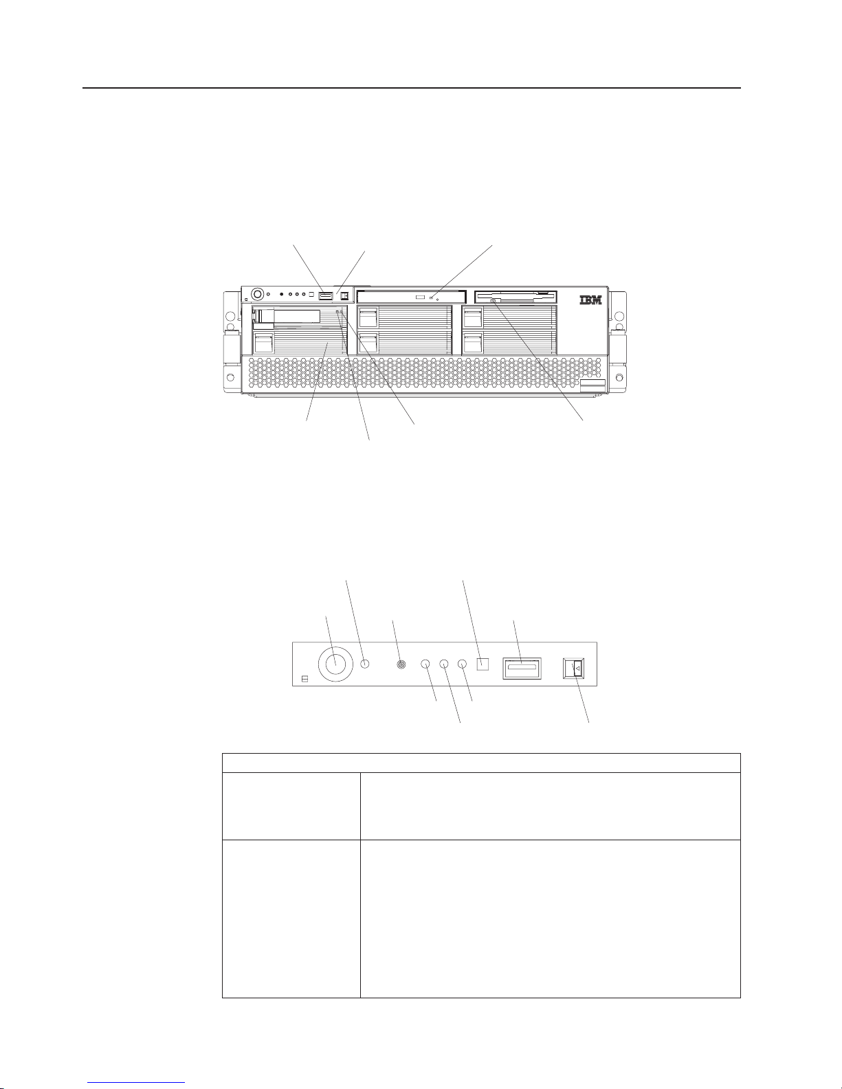
Front view
The following illustration shows the controls, LEDs, and connectors on the front of
the server.
USB port
Operator information panel CD-ROM activity LED
Hard disk drive
filler panel
Hard disk drive
activity LED
Diskette drive
activity LED
Hard disk drive
status LED
USB port: Yo u can connect a USB device to this connector.
Operator information panel: This panel contains controls, indicators, and a USB
port. Swing it open to see the light path diagnostics LEDs on the side surface.
Details about the operator information panel are listed below.
Power-control button
Power-control button: Press this button to turn the server on and off manually. A
Power-on LED: When this LED is lit and not flashing, it indicates that the server is
Power-on LED
SCSI activity LED Information LED
power-control-button shield comes with your server. You can install
this disk-shaped shield to prevent the server from being turned off
accidentally.
turned on. When this LED is flashing, it indicates that the server is
turned off and still connected to an ac power source. When this
LED is off, it indicates that ac power is not present, or the power
supply or the LED itself has failed. A power LED is also on the rear
of the server.
Note: If this LED is off, it does not mean that there is no electrical
power in the server. The LED might be burned out. To remove all
electrical power from the server, you must disconnect the power
cord from the electrical outlet.
System-error LED
Reset button USB connector
Locator LED Release latch
Operator information panel
4 IBM xSeries 365 Types 8861, 8862: Hardware Maintenance Manual and Troubleshooting Guide
Page 15

Operator information panel
Reset button: Press this button to reset the server and run the power-on self-test
(POST). You might have to use a pen or the end of a straightened
paper clip to press the button.
System-error LED: When this LED is lit, it indicates that a system error has occurred.
An LED on the diagnostic LED panel on the side of the operator
information panel is also lit to help isolate the error (see “Light path
diagnostics” on page 18).
USB connector: You can connect a USB device to this connector.
Release latch: Press this latch to release the operator information panel to access
the light path diagnostics LED panel.
Information LED: When this LED is lit, it indicates that a noncritical event has
occurred (see “Light path diagnostics” on page 18).
Locator LED: Use this blue LED to visually locate the server if it is in a location
with numerous other servers. A locator LED is also on the rear of
the server. You can use the Management Processor Assistant
(MPA) in IBM Director to cause this LED to be lit, off, or flashing
(see the User’s Guide on the IBM xSeries Documentation CD for
more information). If the server is connected to an RXE-100
Remote Expansion Enclosure, pressing the Locate button on the
enclosure causes this LED to be lit.
Note: This LED flashes while the server is being turned on or
restarted, and turns off when POST is complete.
SCSI activity LED: When this LED is lit, it indicates that there is activity on the SCSI
bus.
CD-ROM drive activity LED: When this LED is lit, it indicates that the CD-ROM
drive is in use.
Diskette drive activity LED: When this LED is lit, it indicates that the diskette drive
is in use.
Hard disk drive activity LED: When this LED is flashing, it indicates that the
associated hard disk drive is in use.
Hard disk drive status LED: When this LED is lit continuously, it indicates that the
associated hard disk drive has failed. The interpretation of a flashing status LED
depends on the SCSI controller that is connected to the hot-swap drive, as follows:
v When the drive is connected to the integrated SCSI controller with RAID
capabilities, a flashing status LED indicates that the drive is a secondary drive in
a mirrored pair and the drive is being synchronized.
™
v When the drive is connected to an optional ServeRAID
controller, a slowly
flashing (one flash per second) status LED indicates that the drive is being
rebuilt. When the LED is flashing rapidly (three flashes per second), it indicates
that the controller is identifying the drive.
disk drive filler panels: A filler panel and air baffle is used to cover empty
Hard
hard disk drive bays. A filler panel and air baffle must be installed in each empty
bay to ensure proper system cooling. Your server comes with five filler panels and
air baffles installed, and one completely empty bay.
Chapter 1. Introduction 5
Page 16
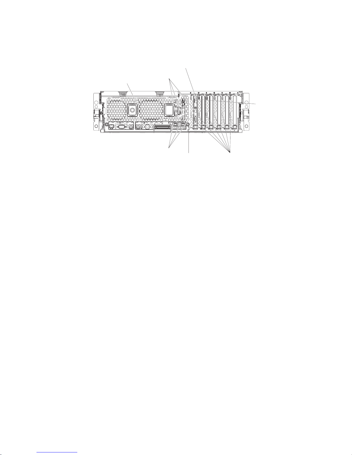
Rear view
The following illustration shows the LEDs on the rear of the server.
Ethernet
link LED
AC power LED
Remote Supervisor
Adapter II activity LED
AC
Ethernet
activity LED
AC
Remote Supervisor
Adapter II power LED
Locator LED Attention LED
AC power LED: Each hot-swap power supply has an ac power LED that is visible
from the rear of the server. The power supply also has an ac power LED and a dc
power LED on the top of the power supply, visible when the server cover is
removed. When the ac power LED is lit, ac input to the power module is present
and within specifications. During typical operation, both the ac and dc power LEDs
on the top of the power supply are lit. For any other combination of LEDs, see
“Power LED errors” on page 130.
Ethernet link LEDs: When these LEDs (one for the Remote Supervisor Adapter II,
two for the network) are lit, they indicate that the related Ethernet link is operational.
Remote Supervisor Adapter II activity LED: When this LED is flashing, the
Remote Supervisor Adapter II is functioning normally. When the LED is lit
continuously, there is a problem with the Remote Supervisor Adapter II. When the
LED is off, the Remote Supervisor Adapter II is not functioning.
Remote Supervisor Adapter II power LED: When this LED is lit, it indicates that
power is being supplied to the Remote Supervisor Adapter II.
Attention LED: When this LED is on steady, it indicates that the adapter in the
corresponding slot is ready to be removed (hot-pluggable adapter only) or there is a
problem with the adapter. When this LED is flashing, it indicates that an operation is
in progress or that the adapter requires attention, depending on the operating
system.
Locator LED: Use this blue LED to visually locate the server if it is in a location
with numerous other servers. A locator LED is also on the operation information
panel on the front of the server. You can use the Management Processor Assistant
(MPA) in IBM Director to cause this LED to be lit, off, or flashing (see the User’s
Guide on the IBM xSeries Documentation CD for more information on IBM
Director). If the server is connected to an RXE-100 Remote Expansion Enclosure,
pressing the Locate button on the enclosure causes this LED to be lit.
Note: This LED flashes while the server is being turned on or restarted, and turns
off when POST is complete.
6 IBM xSeries 365 Types 8861, 8862: Hardware Maintenance Manual and Troubleshooting Guide
Page 17
Ethernet activity LEDs: When these LEDs (one for the Remote Supervisor
Adapter II, two for the network) are lit, they indicate that activity is taking place on
the related network.
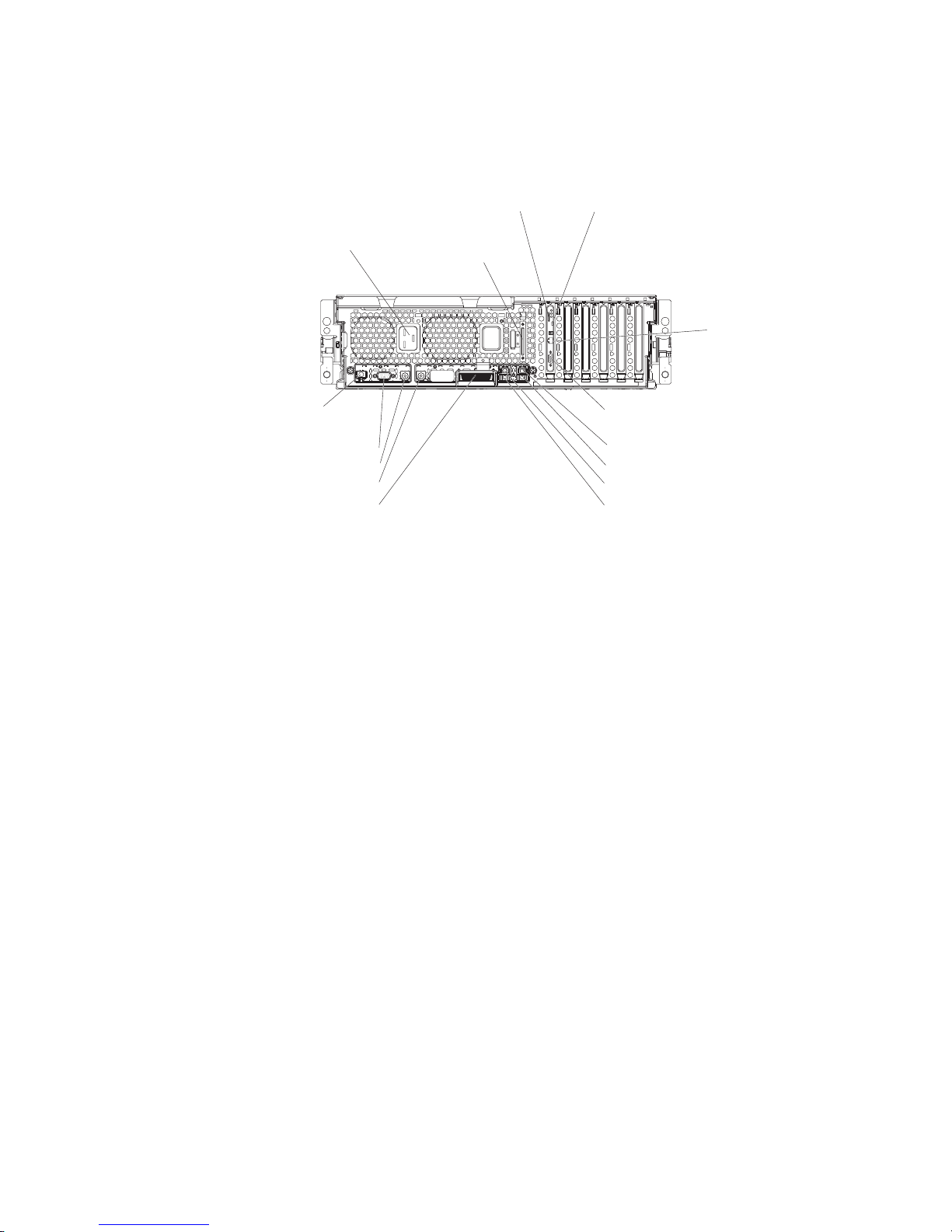
The following illustration shows the connectors on the rear of the server.
Power-supply
connector
Remote Supervisor Adapter II ASM
SCSI
Remote Supervisor Adapter II USB
AC
Remote Supervisor
Adapter II
Ethernet ( RJ-45)
12345 6
Remote Supervisor
Adapter II video
Ethernet 2
USB 2
Ethernet 1
USB 1
RXE Management
port
Serial
Keyboard
Mouse
RXE Expansion
port
AC
Remote Supervisor Adapter II ASM connector: Attach an ASM breakout cable to
this connector to enable system management through the serial connectors and
through the ASM RS-485 connectors.
Remote Supervisor Adapter II USB connector: This connector is not available for
use.
Remote Supervisor Adapter II Ethernet connector: Use this connector to connect
the Remote Supervisor Adapter II to a network to manage the server from a remote
location.
To enable remote server management through a network, use the Remote
Supervisor Adapter II Ethernet port. To enable remote server management using a
modem, use the Remote Supervisor Adapter II serial connector on the breakout
cable. To connect the server with another server, use the Remote Supervisor
Adapter II ASM interconnect connector.
Remote Supervisor Adapter II video connector: Connect the server monitor to
this connector.
Note: The external power connection on the Remote Supervisor Adapter II is not
supported on the xSeries 365 server.
Ethernet connectors: Use these connectors to connect the server to a network.
USB connectors: Connect USB devices to these connectors.
RXE Expansion port: Use this connector to connect the server to a remote I/O
enclosure. This port enables the exchange of data between the server and the
enclosure (see “RXE Expansion Port connector” on page 64).
Mouse connector: Connect a mouse or other pointing device to this connector.
Chapter 1. Introduction 7
Page 18

Keyboard connector: Connect a PS/2
Serial connector: Connect a serial device to this connector.
RXE Management Port: Connect the RXE Management A (In) Port of an optional
IBM RXE-100 Remote Expansion Enclosure to this connector (see “RXE connector
cabling” on page 60).
Power-supply connector: Connect one end of the power-supply power cord to this
connector and connect the other end to an ac power source. The server comes with
one or two hot-swap power supplies, depending on the configuration. You can add
a second hot-swap power supply to obtain full power redundancy. Connect each
power supply to an ac power source for power redundancy.
SCSI connector: Connect an external SCSI device to this connector.
Light path diagnostics LED panel
Swing the operator information panel out to see the light path diagnostics LED
panel on the side surface (see “Light path diagnostics” on page 18 and “Light path
LED errors” on page 93).
Server power features
When the server is connected to an ac power source but is not turned on, the
operating system does not run, and all core logic except for the service processor is
shut down; however, the server can respond to requests from the service processor,
such as a remote request to turn on the server. The power-on LED flashes to
indicate that the server is connected to ac power but not turned on.
®
(non-USB) keyboard to this connector.
Turning on the server
Approximately 20 seconds after the server is connected to ac power, the
power-control button becomes active, and you can turn on the server and start the
operating system by pressing the power-control button.
The server can also be turned on in any of the following ways:
v If a power failure occurs while the server is turned on, the server will restart
automatically when power is restored.
v If the server is connected to an Advanced System Management interconnect
network that contains at least one server with a Remote Supervisor Adapter or
Remote Supervisor Adapter II installed, the server can be turned on from the
Remote Supervisor Adapter or Remote Supervisor Adapter II user interface.
v The system-management software for the Remote Supervisor Adapter II in your
server can turn on the server.
v If your operating system supports the Wake on LAN feature, the Wake on LAN
feature can turn on the server.
When 4 GB or more of memory (physical or logical) is installed, some
Note:
memory is reserved for various system resources and is unavailable to the
operating system. The amount of memory that is reserved for system
resources depends on the operating system, the configuration of the server,
and the configured PCI options.
8 IBM xSeries 365 Types 8861, 8862: Hardware Maintenance Manual and Troubleshooting Guide
Page 19
Turning off the server
When you turn off the server and leave it connected to ac power, the server can
respond to requests from the service processor, such as a remote request to turn
on the server. To remove all power from the server, you must disconnect it from the
power source.
Note: Under some conditions, the two rear fans in front of the power supplies will
be operating when the server is turned off and connected to ac power. This
enables the power supplies to be cooled when they are generating power for
standby functions.
Some operating systems require an orderly shutdown before you turn off the server.
See your operating-system documentation for information about shutting down the
operating system.
Statement 5
CAUTION:
The power control button on the device and the power switch on the power supply do
not turn off the electrical current supplied to the device. The device also might have
more than one power cord. To remove all electrical current from the device, ensure
that all power cords are disconnected from the power source.
2
1
The server can be turned off in any of the following ways:
v You can turn off the server from the operating system, if your operating system
supports this feature. After an orderly shutdown of the operating system, the
server will be turned off automatically.
v You can press the power-control button to start an orderly shutdown of the
operating system and turn off the server, if your operating system supports this
feature.
v If the operating system stops functioning, you can press and hold the
power-control button for more than 5 seconds to turn off the server.
v The server can be turned off from the server Remote Supervisor Adapter II user
interface.
v If the Wake on LAN feature turned on the server, the Wake on LAN feature can
turn off the server.
v The service processor can turn off the server as an automatic response to a
critical system failure.
v You can turn off the server through a request from the service processor.
Chapter 1. Introduction 9
Page 20

10 IBM xSeries 365 Types 8861, 8862: Hardware Maintenance Manual and Troubleshooting Guide
Page 21

Chapter 2. Configuring the server
The following configuration programs and capabilities come with your server:
v Configuration/Setup Utility program
™
v IBM ServerGuide
v Preboot Execution Environment (PXE) boot agent utility program
v RAID configuration programs
– LSI Logic Configuration utility program
– ServeRAID Manager
Service processor firmware update utility
v
v Gigabit Ethernet controller configuration process
v Remote Supervisor Adapter II configuration process
Detailed information about these configuration programs is available in the User’s
Guide on the IBM xSeries Documentation CD.
Using the Configuration/Setup Utility program
The Configuration/Setup Utility program is part of the BIOS code. You can use it to:
v View configuration information
v View and change assignments for devices and I/O ports
v Set the date and time
v Set and change passwords
v Set the startup characteristics of the server and the order of startup devices
v Set and change settings for advanced hardware features
v View and clear error logs
v Change interrupt request (IRQ) settings
v Enable USB legacy keyboard and mouse support
v Resolve configuration conflicts
Setup and Installation CD
Complete
1. Turn on the server.
2. When the prompt Press F1 for Configuration/Setup appears, press F1. If you
have set both a power-on password and an administrator password, you must
type the administrator password to access the full Configuration/Setup Utility
menu. If you do not type the administrator password, a limited
Configuration/Setup Utility menu is available.
3. Select settings to view or change.
Detailed
in the User’s Guide on the IBM xSeries Documentation CD.
© Copyright IBM Corp. 2003 11
the following steps to start the Configuration/Setup Utility program:
information about the Configuration/Setup and Utility program is available
Page 22

Using the ServerGuide Setup and Installation CD
The ServerGuide Setup and Installation CD includes an easy-to-use setup and
installation program that is designed for your IBM server. The ServerGuide program
detects the server model and hardware options that are installed and uses that
information during setup to configure the hardware. The ServerGuide program
simplifies operating-system installations by providing updated device drivers and, in
some cases, installing them automatically.
Note: The ServerGuide program works only with 32-bit Windows
systems.
When you start the ServerGuide Setup and Installation CD, the program prompts
you to complete the following tasks:
v Select your language.
v Select your keyboard layout and country.
v View the overview to learn about ServerGuide features.
v View the readme file to review installation tips for your operating system and
adapter.
v Start the operating-system installation. You will need your operating-system CD.
®
operating
Detailed
information about using ServerGuide is available in the User’s Guide on
the IBM xSeries Documentation CD.
Using the PXE boot agent utility program
Use the Preboot Execution Environment (PXE) boot agent utility program to enable
or disable operating-system wake-up support.
Note: The server does not support changing the network boot protocol or
specifying the startup order of devices through the PXE boot agent utility
program.
Complete the following steps to start the PXE boot agent utility program:
1. Turn on the server.
2. When the Broadcom NetXtreme Ethernet Boot Agent V6.1.3 prompt appears,
press Ctrl+S. Yo u have 2 seconds (by default) to press Ctrl+S after the prompt
appears.
Note: If the PXE setup prompt is not displayed, use the Configuration/Setup
Utility program to set the Ethernet PXE startup option.
3. Use the arrow keys and press Enter to select a choice from the menu.
4. Follow the instructions on the screen to change the settings of the selected
items; then, press Enter.
Detailed
information about using the PXE boot agent utility program is available in
the User’s Guide on the IBM xSeries Documentation CD.
12 IBM xSeries 365 Types 8861, 8862: Hardware Maintenance Manual and Troubleshooting Guide
Page 23

Using the RAID configuration programs
Use the LSI Logic Configuration Utility program and ServeRAID Manager to
configure and manage redundant array of independent disks (RAID) arrays. Be sure
to use these programs as described in the User’s Guide.
v Use the LSI Logic Configuration Utility program to:
– Perform a low-level format on a SCSI hard disk drive
– View or change SCSI IDs for attached devices
– Set SCSI protocol parameters on SCSI hard disk drives
v Use ServeRAID Manager to:
– Configure arrays
– View your RAID configuration and associated devices
– Monitor operation of your RAID controllers
Detailed
information about using the RAID configuration programs is available in the
User’s Guide on the IBM xSeries Documentation CD.
Updating the integrated service processor firmware
To update only the firmware for the Remote Supervisor Adapter II and the
integrated service processor, download the firmware update package for the server
from the IBM Support Web site at http://www.ibm.com/pc/support/ and follow the
instructions in the text file on the Web site.
To update the server BIOS, device drivers, and other firmware including the
firmware for the Remote Supervisor Adapter II and integrated service processor,
download and apply the system service package for the server. Detailed information
is available in the User’s Guide on the IBM xSeries Documentation CD.
Configuring the Gigabit Ethernet controllers
The Ethernet controllers are integrated on the I/O board. They provide an interface
for connecting to a 10-Mbps, 100-Mbps, or 1-Gbps network and provide full-duplex
(FDX) capability, which enables simultaneous transmission and reception of data on
the network. If the Ethernet ports in your server support auto-negotiation, the
controllers detect the data-transfer rate (10BASE-T, 100BASE-TX, or 1000BASE-T)
and duplex mode (full-duplex or half-duplex) of the network and automatically
operate at that rate and mode.
You do not need to set any jumpers or configure the controllers. However, you must
install a device driver to enable the operating system to address the controllers. For
device drivers and information about configuring the Ethernet controllers, see the
Broadcom NetXtreme Gigabit Ethernet Software CD that comes with your server.
For updated information about configuring the controllers, go to
http://www.ibm.com/pc/support/.
Remote Supervisor Adapter II
The Remote Supervisor Adapter II can be used on an Advanced System
Management (ASM) network so that you can manage the server remotely.
For more information about how to configure and use an ASM network to manage
the server remotely through the Web-based interface or the text-based interface,
see the User’s Guide and the IBM Remote Supervisor Adapter II User’s Guide, both
of which can be found on the IBM xSeries Documentation CD.
Chapter 2. Configuring the server 13
Page 24

14 IBM xSeries 365 Types 8861, 8862: Hardware Maintenance Manual and Troubleshooting Guide
Page 25

Chapter 3. Diagnostics
This chapter provides basic troubleshooting information to help solve some common
problems that might occur with the server.
If you cannot locate and correct the problem using the information in this chapter,
see Appendix A, “Getting help and technical assistance,” on page 145 for more
information.
General checkout
Follow the checkout procedure for diagnosing hardware problems. Review the
following information before performing the checkout procedure:
v Read the safety information beginning on page 147.
v The diagnostics programs provide the primary methods of testing the major
components of the server, including the I/O board, Ethernet controller, RAM,
keyboard, mouse (pointing device), serial ports, hard disk drives, and parallel
port. You can also use them to test some external devices. If you are not sure
whether a problem is caused by the hardware or by the software, you can use
the diagnostics programs to confirm that the hardware is working correctly. The
diagnostic programs (see “Starting the diagnostic programs” on page 23) are in
the system flash erasable programmable read-only memory (EPROM) on the I/O
board.
v When you run the diagnostics programs, a single problem might cause several
error messages. If you receive several error messages, correct the cause of the
first error message. The other error messages might not occur the next time you
run the diagnostics programs.
v Before running the diagnostics programs, you must determine whether the failing
server is part of a shared hard disk drive cluster (two or more servers sharing
external storage devices). If you suspect that it is part of a cluster, you can run
all diagnostics programs except the ones that test the storage unit (that is, a hard
disk drive in the storage unit) or the storage adapter that is attached to the
storage unit. The failing server might be part of a cluster if any of the following
conditions is true:
– The customer identifies the failing server as part of a cluster.
– One or more external storage units are attached to the failing server and at
least one of the attached storage units is also attached to another server or
unidentifiable device.
– One or more servers are located near the failing server.
Important:
v
1. When testing a server that is part of a shared hard disk drive cluster, run only
one test at a time, in looped mode. Do not run all tests in looped mode,
because the hard disk drive tests might run.
2. If more than one error code is displayed, correct the first error. The other
error codes might not occur the next time you run the diagnostics programs.
3. If the server is suspended and a POST error code is displayed, see “POST
error logs” on page 17.
4. If the server is suspended and no error message is displayed, see “Error
symptoms” on page 121 and “Undetermined problems” on page 136.
5. For information about power-supply problems, see “Power checkout” on page
27.
© Copyright IBM Corp. 2003 15
Page 26

6. For intermittent problems, check the error log; see “POST error logs” on page
17 and “Diagnostic programs and error messages” on page 22.
Complete
the following steps to perform the checkout procedure:
001 IS THE SERVER PART OF A CLUSTER?
YES. Schedule maintenance for the server. Shut down all servers related to
the cluster. Run the storage test.
NO. Go to step 002.
002 IF THE SYSTEM IS NOT PART OF A CLUSTER:
If the operating system is running, complete the following steps:
1. Check the light path (see “Light path diagnostics” on page 18).
2. Check the service processor system-error logs:
a. If the system-error log indicates a damaged field replaceable unit
(FRU), replace the FRU, and run diagnostics to confirm that the
problem has been solved.
b. If the system-error log does not indicate a damaged FRU, see “Error
symptoms” on page 121 and “Undetermined problems” on page
136.
If the operating system is not running, complete the following steps:
1. Check the light path (see “Light path diagnostics” on page 18).
2. Check the service processor system-error logs.
a. If the error log indicates a damaged field replaceable unit (FRU),
replace the FRU, and run diagnostics to confirm that the problem
has been solved.
b. If the error log does not indicate a damaged FRU, check the
operating-system event logs; if these logs do not specify a particular
error, go to step 3.
Turn off the server and all external devices.
3.
4. Check all cables and power cords.
5. Set all display controls to the middle position.
6. Turn on all external devices.
7. Turn on the server.
8. Watch the screen and the serial port for POST errors, and record any
POST error messages that are displayed on the screen. If an error is
displayed, look up the first error (see “POST error codes” on page 88).
9. Run diagnostics (see “Starting the diagnostic programs” on page 23).
DID THE DIAGNOSTIC PROGRAM START?
003
NO. Find the failure symptom in “Error symptoms” on page 121.
YES. Run the diagnostic programs. If necessary, see “Diagnostic programs
and error messages” on page 22.
If you receive an error, see Chapter 6, “Symptom-to-FRU index,” on page
85.
If the diagnostic programs were completed successfully and you still
suspect a problem, see “Undetermined problems” on page 136.
If the server does not turn on, see “Error symptoms” on page 121.
16 IBM xSeries 365 Types 8861, 8862: Hardware Maintenance Manual and Troubleshooting Guide
Page 27

Diagnostic tools overview
The following tools are available to help you diagnose and solve hardware-related
problems:
v POST beep codes, error messages, and error logs
The power-on self-test (POST) generates beep codes and messages to indicate
successful test completion or the detection of a problem. See “POST error logs”
for more information.
v Light path diagnostics feature
Use the light path diagnostics feature to identify system errors quickly. See “Light
path diagnostics” on page 18 for more information.
v Diagnostic programs and error messages
The diagnostic programs are stored in the system flash EPROM on the I/O
board. These programs are the primary method of testing the major components
of the server. See “Diagnostic programs and error messages” on page 22 for
more information.
POST error logs
When you turn on the server, it performs a series of tests to check the operation of
server components and some of the options installed in the server. This series of
tests is called the power-on self-test, or POST.
If POST finishes without detecting any problems, a single beep sounds, and the first
screen of the operating system opens or an application program starts.
If POST detects a problem, more than one beep might sound, or an error message
appears on the screen. See “Beep symptoms” on page 86 and “POST error codes”
on page 88 for more information.
Notes:
1. If a power-on password is set, you must type the password and press Enter,
when prompted, before POST will continue.
2. A single problem might cause several error messages. When this occurs, work
to correct the cause of the first error message. After you correct the cause of
the first error message, the other error messages usually will not occur the next
time you run the test.
The POST error log contains the three most recent error codes and messages that
were generated during POST. The system-error log contains all messages that were
generated during POST and all system status messages from the service
processor.
You can view the contents of the system-error log from the Configuration/Setup
Utility program or from the diagnostic programs.
Note: When troubleshooting PCI-X slots, you will notice that the error logs report
the PCI-X buses numerically. The numerical assignment will change
depending on your configuration.
Viewing error logs from the Configuration/Setup Utility program
Start the Configuration/Setup Utility program; then, select Error Logs from the main
menu. See “Using the Configuration/Setup Utility program” on page 11 for more
information.
Chapter 3. Diagnostics 17
Page 28
Viewing error logs from the diagnostic programs
Start the diagnostic programs; select Hardware Info from the top of the diagnostic
programs screen; select System Error Log from the list that appears; then, follow
the instructions on the screen. See “Starting the diagnostic programs” on page 23
for more information.
Light path diagnostics
Many errors are first indicated by the illumination of the information LED or
system-error LED in the operator information panel on the front of the server. If one
or both of these lights are lit, one or more lights elsewhere in the server might also
be lit and can direct you to the source of the error.
This light path diagnostics feature provides a path that you can follow in three
phases to help identify the source of an error. The lights are designed to be
followed in an orderly progression, depending on the error.
Note: Read “Safety information” on page 147 and “Handling static-sensitive
devices” on page 30.
The lights are viewed in the following order:
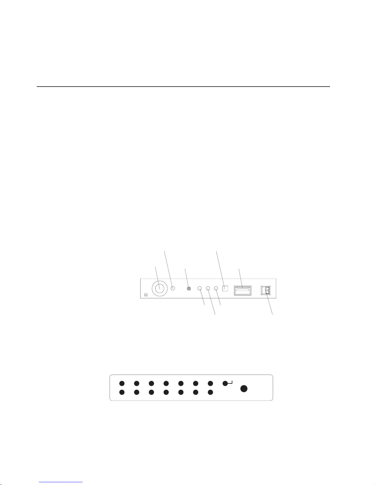
1. Begin on the front panel by checking the operator information panel.
v The information LED indicates that information concerning a sub-optimal
condition in the server is available in the system-error log.
v The system-error LED indicates that an error has occurred.
If the system-error LED on this panel is lit, go to step 2.
Power-on LED
System-error LED
Power-control button
Reset button USB connector
SCSI activity LED Information LED
Locator LED Release latch
Note: The LEDs and connectors on the operator information panel are
described in “Front view” on page 4.
2. Open the operator information panel by pressing the release latch to swing the
panel out and reveal the light path diagnostics panel. Lit LEDs on this panel
indicate the type of error that has occurred.
PS1
VRM OVER SPECTEMP
DASD NMIPCI EXP
NR SPMEM
LOGPS2 CPUFAN
REMIND
Then, check the system service label. This label gives an overview of internal
components that correspond to the LEDs on the light path diagnostics panel.
This information, combined with the information in the table “Light path LED
errors” on page 93, can often provide enough information to correct the
indicated error.
18 IBM xSeries 365 Types 8861, 8862: Hardware Maintenance Manual and Troubleshooting Guide
Page 29
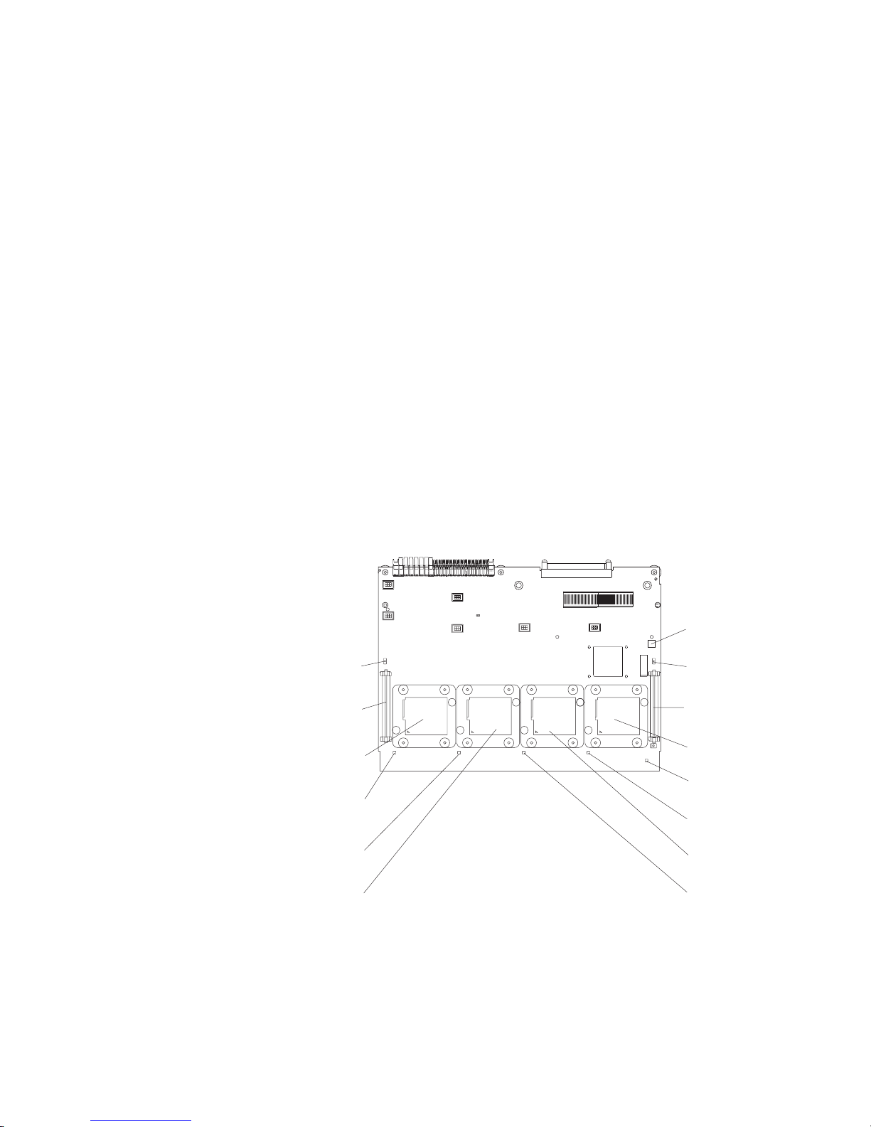
3. Look inside the server, if necessary. Certain components inside the server have
LEDs that will be lit to indicate the location of a problem. For example, a VRM
error will light the LED next to the failing VRM on the microprocessor tray
assembly.
path diagnostics LEDs for DIMMs and fans must be viewed from inside the
Light
server and will not be lit unless the serv.er is connected to a power source,
although the server does not have to be turned on to view these LED. The LEDs for
microprocessors and VRMs are viewed by removing the microprocessor-tray
assembly. The following sections describe the procedures to follow to view the
LEDs on the microprocessor-tray assembly and memory board.
Microprocessor LEDs
Complete the following steps to view the microprocessor LEDs:
1. Turn off the server and any peripheral devices; then, disconnect all external
cables from the server.
2. Slide the server out of the rack cabinet.
3. Remove the fans (see “Replacing a hot-swap fan” on page 55) and memory
cassette (see step 4 on page 46).
4. Remove the microprocessor tray:
a. Lift the microprocessor-tray release latch (see “Installing a microprocessor”
on page 44).
b. Open the microprocessor-tray levers.
c. Pull out the microprocessor tray.
Light-path
diagnostics button
Microprocessor 3
VRM error LED
Microprocessor 3
VRM connector
Microprocessor 1
socket
Microprocessor 1
error LED
Microprocessor 2
error LED
Microprocessor 2
socket
Microprocessor 4
VRM error LED
Microprocessor 4
VRM connector
Microprocessor 4
socket
Light-path
test LED
Microprocessor 4
error LED
Microprocessor 3
socket
Microprocessor 3
error LED
5. Press and hold down the light-path diagnostics button on the microprocessor
board. The LEDs will be lit while the button is pressed. Yo u can light the LEDs
for a maximum of 2 minutes, after which power is no longer available for the
LEDs.
Note: Yo u can press the light-path diagnostics button to relight the light path
diagnostics LEDs that are lit on the microprocessor tray without ac
Chapter 3. Diagnostics 19
Page 30

DIMM LEDs
power. After ac power has been removed from the server, power remains
available to these LEDs for up to 12 hours. After 12 hours, you must
reinstall the microprocessor tray and turn on the server to supply power
to the LEDs.
reinstall the microprocessor tray, reverse the preceding steps.
To
Complete the following steps to view the DIMM LEDs:
Note: The lit LEDs light the connector retaining clips; look for a lit retaining clip to
locate a failed DIMM.
1. Turn off the server and all peripheral devices.
2. Slide the server out of the rack cabinet.
3. Open the top cover.
a. The following illustration shows the internal connectors and LEDs on the
8-DIMM-connector memory board in the memory cassette.
DIMM 4 error LED
DIMM 3 error LED
DIMM 2 error LED
DIMM 1 error LED
DIMM 5 error LED
DIMM 6 error LED
DIMM 7 error LED
DIMM 8 error LED
DIMM connector 1
DIMM connector 2
20 IBM xSeries 365 Types 8861, 8862: Hardware Maintenance Manual and Troubleshooting Guide
DIMM connector 3
DIMM connector 4
DIMM connector 8
DIMM connector 7
DIMM connector 6
DIMM connector 5
Page 31

b. The following illustration shows the internal connectors and LEDs on the
16-DIMM-connector memory board in the memory cassette.
DIMM 4 error LED DIMM 13 error LED
DIMM 3 error LED DIMM 14 error LED
DIMM 2 error LED DIMM 15 error LED
DIMM 1 error LED DIMM 16 error LED
DIMM 8 error LED DIMM 9 error LED
DIMM 7 error LED DIMM 10 error LED
DIMM 6 error LED DIMM 11 error LED
DIMM 5 error LED DIMM 12 error LED
Remind button
DIMM connector 1
DIMM connector 2
DIMM connector 3
DIMM connector 4
DIMM connector 5
DIMM connector 6
DIMM connector 7
DIMM connector 8
DIMM connector 12
DIMM connector 11
DIMM connector 10
DIMM connector 9
DIMM connector 16
DIMM connector 15
DIMM connector 14
DIMM connector 13
4. If necessary, open the DIMM access doors on the memory cassette to view the
DIMM LEDs.
You can use the remind button to place the system-error LED on the front panel
into the remind mode (flashes every 2 seconds). By pressing this button, you
acknowledge the failure but indicate that you will not take immediate action. If a
new failure occurs, the system-error LED is lit again.
The system-error LED stays in remind mode until one of the following conditions
occurs:
v All known problems are solved.
v The server is restarted.
Chapter 3. Diagnostics 21
Page 32

v A new problem occurs.
can use the remind button to delay server maintenance until a later time.
You
Diagnostic programs and error messages
The diagnostic programs are in the system flash erasable programmable read-only
memory (EPROM) on the I/O board. These programs are the primary method of
testing the major components of the server.
Diagnostic error messages indicate that a problem exists; they are not intended to
be used to identify a failing part. Troubleshooting and servicing of complex
problems that are indicated by error messages should be performed by trained
service personnel.
Sometimes the first error to occur causes additional errors. In this case, the server
displays more than one error message. Always follow the suggested action
instructions for the first error message that appears.
Diagnostic text messages
While a test is running, the name of the test is displayed on the screen. If the test
detects an error or is abnormally ended, a message is displayed to indicate the
reason that the test stopped. The message is in the following form:
result test_specific_string
where:
result is one of the following results:
Passed
This test was completed without any errors.
Failed
This test discovered an error.
User Aborted
You stopped the test before it was completed.
Not Applicable
You attempted to test a device that is not present in the server.
Aborted
The test could not proceed because of the server configuration.
Warning
A possible problem was reported during the test (for example, a
device that was to be tested is not installed).
test specific string
is an error code or other information about the error.
22 IBM xSeries 365 Types 8861, 8862: Hardware Maintenance Manual and Troubleshooting Guide
Page 33

Starting the diagnostic programs
This section describes the general procedure to run the diagnostic programs.
You can press F1 while running the diagnostic programs to obtain help information.
You also can press F1 from within a help screen to obtain online documentation
from which you can select different categories. To exit from help, press Esc.
Complete the following steps to start the diagnostic programs:
1. Turn on the server and watch the screen.
2. When the message Press F1 for Configuration/Setup, Press F2 for
Diagnostics appears, press F2.
If a power-on password is set, the server prompts you for it. Type the power-on
password, and press Enter.
3. When the Diagnostic Programs screen appears, select either Extended or
Basic from the top of the screen.
4. Select the test you want to run from the list that appears; then, follow the
instructions on the screen.
Notes:
a. If the server stops during testing and you cannot continue, restart the server
and try running the diagnostic programs again. If the problem remains,
replace the component that was being tested when the server stopped.
b. The keyboard and mouse (pointing device) tests assume that a keyboard
and mouse are attached to the server.
c. If you run the diagnostic programs with no mouse attached to the server,
you will not be able to navigate between test categories using the Next Cat
and Prev Cat buttons. All other functions provided by mouse-selectable
buttons are also available using the function keys.
d. You can test the USB keyboard by using the regular keyboard test. The
regular mouse test can test a USB mouse. Yo u can run the USB interface
test only if there are no USB devices attached.
e. You can view server configuration information (such as system configuration,
memory contents, interrupt request (IRQ) use, direct memory access (DMA)
use, device drivers, and so on) by selecting Hardware Info from the top of
the screen.
the diagnostic programs do not detect any hardware error but the problem
If
remains during normal server operations, a software error might be the cause. If
you suspect a software problem, see the information that comes with the software
package.
Diagnostic error codes are listed in “Diagnostic error codes” on page 95.
Viewing the test log
When the tests are completed, you can view the test log by selecting Utility from
the top of the screen and then selecting View Test Log.
Notes:
1. You can view the test log only while you are in the diagnostic programs. When
you exit the diagnostic programs, the test log is cleared (saved test logs are not
affected). To save the test log so that you can view it later, click Save Log on
the diagnostic programs screen and specify a location and name for the saved
log file.
Chapter 3. Diagnostics 23
Page 34

2. To save the test log to a diskette, you must use a diskette that you have
formatted yourself; this function does not work with preformatted diskettes. If the
diskette has sufficient space for the test log, the diskette may contain other
data.
Viewing the system-error log
You can also view the system-error log from the diagnostic programs. See the
instructions in “POST error logs” on page 17.
Recovering BIOS code
If the BIOS code in the server has become damaged, such as from a power failure
during a flash update, you can recover the BIOS using the recovery boot block and
a BIOS flash diskette. You can download a BIOS flash diskette from
http://www.ibm.com/pc/support/.
The flash memory of the server consists of a primary page and a backup page. The
J19 jumper on the I/O board controls which page is used to start the server. If the
BIOS code in the primary page is damaged, you can use the backup page to start
the server; then start the BIOS flash diskette to restore the BIOS code to the
primary page.
To recover the BIOS code, complete the following steps:
1. Read “Safety information” on page 147 and “Handling static-sensitive devices”
on page 30.
2. Turn off the server and peripheral devices and disconnect all external cables
and power cords; then, remove the cover.
IXA voltage
jumper (J26)
3 2 1
Boot recovery (BIOS)
jumper (J19)
1 2 3
Power-on password override
jumper (J20)
1 2 3
Disable Wake on LAN
1 2 3
jumper (J24)
3. Locate the boot block recovery jumper (J19 on the I/O board).
4. Move J19 to pins 2 and 3 to enable secondary boot block page.
5. Insert the BIOS flash diskette into the diskette drive.
6. Restart the server.
24 IBM xSeries 365 Types 8861, 8862: Hardware Maintenance Manual and Troubleshooting Guide
Page 35

7. POST starts. Select 1 - Update POST/BIOS from the menu that contains
various flash (update) options.
8. When you are asked whether you want to move the current POST/BIOS image
to the backup ROM location, type N.
Attention: Typing Y will copy the damaged BIOS code into the secondary
page.
9. When you are asked whether you would like to save the current code to a
diskette, select N.
10. Type 1 and press Enter to continue.
Attention: Do not restart or power off the server until the update is
completed.
11. Turn off the server.
12. Move jumper J19 back to pins 1 and 2 to return to normal startup mode.
13. Replace the cover; then, restart the server.
Password override jumper
Change the position of the password override jumper by using the following
procedure:
1. Read “Safety information” on page 147 and “Handling static-sensitive devices”
on page 30.
2. Turn off the server and peripheral devices and disconnect all external cables
and power cords; then, remove the cover.
3 2 1
IXA voltage
jumper (J26)
3. Locate the power-on password override jumper (J20), removing any
components that impede access to the jumper.
Note: Yo u might have to remove the Remote Supervisor Adapter II to access
4. Move the jumper from pins 1 and 2 (default) to pins 2 and 3.
the jumper.
1 2 3
Boot recovery (BIOS)
jumper (J19)
1 2 3
Power-on password override
jumper (J20)
1 2 3
Disable Wake on LAN
jumper (J24)
Chapter 3. Diagnostics 25
Page 36

5. Reinstall the cover and reconnect the external cables and power cords; then,
turn on the server and access the Configuration/Setup Utility menu to change
the power-on password.
6. Repeat steps 2 on page 25 and 3 on page 25; then, move the jumper back to
pins 1 and 2.
7. Reinstall any components that were removed in step 3 on page 25; then,
reinstall the cover and reconnect the external cables and power cord.
Changing the position of this jumper does not affect the administrator password
check if an administrator password is set.
Attention: If an administrator password is set and then forgotten, it cannot be
overridden or removed. You must replace the operator information panel.
Forcing a power-on
Complete the following steps to turn on the server without pressing the power-on
button:
1. Read “Safety information” on page 147 and “Handling static-sensitive devices”
on page 30.
2. Turn off the server and peripheral devices and disconnect all external cables
and power cords; then, remove hot-swap fan number 2 (see “Replacing a
hot-swap fan” on page 55).
Force power-on
jumper (J10)
Light-path
diagnostics button
Microprocessor 3
VRM error LED
Microprocessor 3
VRM connector
Microprocessor 1
socket
Microprocessor 1
error LED
Microprocessor 2
error LED
Microprocessor 2
socket
Microprocessor 4
VRM error LED
Microprocessor 4
VRM connector
Microprocessor 4
socket
Light-path
test LED
Microprocessor 4
error LED
Microprocessor 3
socket
Microprocessor 3
error LED
3. Locate the force power-on jumper (J10), and place a jumper over the two pins.
4. Reinsert the microprocessor tray assembly fully into the server and reconnect
the cables and power cords. The server will turn on.
5. To return the jumper to its default position, repeat step 2; then, remove the
jumper from J10.
6. Reinsert the microprocessor tray assembly fully into the server and reconnect
the cables and power cords.
26 IBM xSeries 365 Types 8861, 8862: Hardware Maintenance Manual and Troubleshooting Guide
Page 37

Power checkout
Power problems can be difficult to solve. For example, a short circuit can exist
anywhere on any of the power distribution buses. Usually a short circuit will cause
the power subsystem to shut down because of an overcurrent condition. A general
procedure for troubleshooting power problems is as follows:
1. Turn off the server and disconnect all ac power cords.
2. Check for loose cables in the power subsystem. Also check for short circuits, for
example, if there is a loose screw causing a short circuit on a circuit board.
3. Remove adapters and disconnect the cables and power connectors to all
internal and external devices until the server is at the minimum configuration
required to start the server (see “Minimum operating requirements” on page
136).
4. Reconnect all ac power cords and turn on the server. If the server starts up
successfully, replace adapters and devices one at a time until the problem is
isolated.
If the server does not start up from the minimal configuration, replace FRUs of
minimal configuration one at a time until the problem is isolated.
To use this method, it is important to know the minimum configuration required for a
system to start (see “Minimum operating requirements” on page 136). For specific
problems, see “Power LED errors” on page 130.
Ethernet controller troubleshooting
The method of testing the Ethernet controller depends on which operating system is
being used (see the Ethernet controller device driver readme file).
If the problem remains after you check the operating system documentation, try the
following:
v Make sure that the Ethernet cable is installed correctly.
The network cable must be securely attached at all connections. If the cable is
attached but the problem remains, try a different cable.
If you set the Ethernet controller to operate at 100 Mbps, you must use Category
5 cabling.
If you directly connect two systems (without a hub), or if you are not using a hub
with X ports, use a crossover cable.
Note: To determine whether a hub has an X port, check the port label. If the
label contains an X, the hub has an X port.
v Determine whether the hub supports auto-negotiation. If it does not, try
configuring the integrated Ethernet controller manually to match the speed and
duplex mode of the hub.
v Check the Ethernet controller LEDs on the server rear panel. These LEDs
indicate whether a problem exists with the connector, cable, or hub.
– The Ethernet Link Status LED is lit when the Ethernet controller receives a
LINK pulse from the hub. If the LED is off, there might be a defective
connector or cable or a problem with the hub.
– The Ethernet transmit/receive activity LED is lit when the Ethernet controller
sends or receives data over the Ethernet Network. If the Ethernet
Transmit/Receive Activity light is off, make sure that the hub and network are
operating and that the correct device drivers are loaded.
Chapter 3. Diagnostics 27
Page 38

v Check the LAN activity LED on the rear of the server. The LAN activity LED is lit
when data is active on the Ethernet network. If the LAN activity LED is off, make
sure that the hub and network are operating and that the correct device drivers
are loaded.
v Make sure that you are using the correct device drivers, which come with the
server.
v Check for operating-system-specific causes for the problem.
v Make sure that the device drivers on the client and server are using the same
protocol.
If the Ethernet controller still cannot connect to the network, inform the network
administrator.
28 IBM xSeries 365 Types 8861, 8862: Hardware Maintenance Manual and Troubleshooting Guide
Page 39

Chapter 4. Installing options
This chapter provides basic instructions for installing hardware options in your
server. These instructions are intended for users who are experienced with setting
up IBM server hardware.
Installation guidelines
Before you begin installing options in your server, read the following information:
v Read “Safety information” on page 147 and “Handling static-sensitive devices” on
page 30. This information will help you work safely with your server and options.
v Make sure that you have an adequate number of properly grounded electrical
outlets for your server, monitor, and other devices that you will connect to the
server.
v Back up all important data before you make changes to disk drives.
v Have a small Phillips screwdriver available.
v Have a small flat-blade screwdriver available.
v You do not need to turn off the server to install or replace hot-swap power
supplies, hot-swap fans, or hot-plug Universal Serial Bus (USB) devices.
Attention: The Remote Supervisor Adapter II is not a hot-swap or hot-plug
device.
v The orange color on components and labels identifies hot-swap or hot-plug
components. You can install or remove hot-swap and hot-plug components while
the server is running, provided that the server is configured to support this
capability. See the instructions in this chapter for more information about
removing and installing hot-swap and hot-plug components.
v The blue color on components and labels indicates touch points, where a
component can be gripped, a latch moved, and so on.
v For a list of supported options for your server, go to
http://www.ibm.com/pc/compat/.
System reliability guidelines
To help ensure proper system cooling and system reliability, make sure that:
v Each of the drive bays has a drive or a filler panel and electromagnetic
compatibility (EMC) shield installed in it.
v There is adequate space around the server to allow the server cooling system to
work properly. See the documentation that comes with the rack.
v You have followed the cabling instructions that come with optional adapters.
v You have replaced a failed fan as soon as possible.
v You have replaced a hot-swap drive within 2 minutes of removal.
v Microprocessor sockets 2, 3, and 4 each contain either a microprocessor baffle
or a microprocessor and heat sink at all times.
v You do not operate the server without the cover for more than two minutes.
© Copyright IBM Corp. 2003 29
Page 40

Working inside a server with power on
Your server supports hot-swap devices and is designed to operate safely while it is
turned on and the cover is removed. Follow these guidelines when you work inside
a server that is turned on:
v Avoid wearing loose-fitting clothing on your forearms. Button long-sleeved shirts
before working inside the server; do not wear cuff links while you are working
inside the server.
v Do not allow your necktie or scarf to hang inside the server.
v Remove jewelry, such as bracelets, necklaces, rings, and loose-fitting wrist
watches.
v Remove items from your shirt pocket, such as pens and pencils, that could fall
into the server as you lean over it.
v Avoid dropping any metallic objects, such as paper clips, hairpins, and screws,
into the server.
Handling static-sensitive devices
Attention: Static electricity can damage electronic devices, including your server.
To avoid damage, keep static-sensitive devices in their static-protective packages
until you are ready to install them.
To reduce the possibility of damage from electrostatic discharge, observe the
following precautions:
v Limit your movement. Movement can cause static electricity to build up around
you.
v Handle the device carefully, holding it by its edges or its frame.
v Do not touch solder joints, pins, or exposed circuitry.
v Do not leave the device where others can handle and damage it.
v While the device is still in its static-protective package, touch it to an unpainted
metal part of the server for at least 2 seconds. This drains static electricity from
the package and from your body.
v Remove the device from its package and install it directly into the server without
setting down the device. If it is necessary to set down the device, put it back into
its static-protective package. Do not place the device on your server cover or on
a metal surface.
v Take additional care when handling devices during cold weather. Heating reduces
indoor humidity and increases static electricity.
30 IBM xSeries 365 Types 8861, 8862: Hardware Maintenance Manual and Troubleshooting Guide
Page 41

Major components of the xSeries 365 server
The following illustration shows the major components of the xSeries 365 server.
The orange color on components and labels in the server identifies hot-swap or
hot-plug components. Yo u can install or remove these components while the system
is running, provided that the server is configured to support this function.
The blue color on components and labels indicates touch points where a
component can be gripped, a latch moved, and so on.
Note: The illustrations in this document might differ slightly from your hardware.
Hot-swap fans
Operator information
panel
SCSI
backplane
PCI-X divider
Remote
Supervisor
Adapter II
P
PS2
S
2
P
PS1
S
1
Memory
cassette
Hard disk
drive air
baffle
Hard disk
drive filler
panel
CD-ROM
drive
Hot-swap
Hard disk
drive
Microprocessor
Heat sink
Hot-swap
power
supply
Diskette drive
x
S
e
r
i
e
s
3
6
5
Bezel
Microprocessor
baffle
Chapter 4. Installing options 31
Page 42

Removing the cover and bezel
Complete the following steps to remove the cover and bezel:
1. Read “Safety information” on page 147 and “Installation guidelines” on page 29.
2. If you are installing or replacing a non-hot-swap component, turn off the server
and all attached peripheral devices. Disconnect all power cords; then,
disconnect all external signal cables from the server.
3. Slide the server out of the rack until the slide rails lock into place.
Top cover
Cover release
latch
Bezel
x
S
e
r
i
e
s
3
6
5
4. Lift the cover-release latch. The cover slides to the rear approximately 13 mm
(0.5 inch). Lift the cover off the server.
Attention: For proper server performance, do not leave the top cover off for
more than two minutes while the server is running.
5. Press on the bezel retention tabs at the top edge of the bezel, and pull the top
of the bezel slightly away from the server.
6. Lift the bezel up to release the two tabs at the bottom edge of the bezel.
32 IBM xSeries 365 Types 8861, 8862: Hardware Maintenance Manual and Troubleshooting Guide
Page 43

PCI or PCI-X adapters
The following notes describe the types of adapters that your server supports and
other information that you must consider when installing a PCI or PCI-X adapter:
v The server supports 3.3 V and universal PCI and PCI-X adapters; it does not
support 5.0-V-only adapters.
v The following illustration shows the location and bus speeds of the PCI-X
expansion slots on the I/O board.
Note: The illustrations in this document might differ slightly from your hardware.
Attention LED
Power LED
PCI slot 1
33 MHz 64-bit
PCI-X slot 2
100 MHz 64-bit
PCI-X slot 3
133 MHz 64-bit
PCI-X slot 4
133 MHz 64-bit
PCI-X slot 5
133 MHz 64-bit
PCI-X slot 6
133 MHz 64-bit
SCSI internal
cable connector (J17)
v Each PCI/PCI-X slot is on a separate PCI bus.
Slot number PCI Bus
1 0
2 3
3 6
4 F (15)
5 C (12)
6 9
v Slot 1 is a PCI slot and is dedicated to the Remote Supervisor Adapter II. The
adapter will operate in PCI mode only. The bus speed is 33 MHz only. The
adapter is non-hot-swappable; turn off the server when removing and installing
the adapter.
v For slots 2 through 6, the bus speed will be set to the speed of the adapter; if a
PCI adapter is installed, the bus will run in PCI mode.
v If you install a ServeRAID 6i adapter, it must be installed in slot 2.
v If you install an IXA adapter, it must be installed in slot 3.
v Locate the documentation that comes with the adapter and follow those
instructions in addition to the instructions in this chapter.
Chapter 4. Installing options 33
Page 44

v If you need to change switch settings or jumper settings on the adapter, follow
the instructions that come with the adapter.
v The server scans devices and PCI-X slots to assign system resources in the
following order: CD-ROM drive; disk drives; integrated Ethernet controller;
integrated SCSI devices; and PCI-X slots 1, 2, 3, 4, 5, and 6. If an RXE-100
enclosure is attached to the server, the scan continues in sequence with PCI
slots 7, 8, 9, 10, 11, 12, 13, 14, 15, 16, 17, and 18.
Note: Yo u can use the Configuration/Setup Utility program to change the
sequence and have the server scan one of the first six PCI slots before it
scans the integrated devices. You cannot change the scan sequence of
the PCI slots in an RXE-100 enclosure.
v The PCI-X slot numbers in an RXE-100 enclosure are assigned in the following
order:
Slots in RXE-100 enclosure
6 slots on A side only 7 - 12* (A1 - A6) none
6 slots on B side only none 7 - 12* (B1 - B6)
12 slots 7 - 12 (A1 - A6) 13 - 18 (B1 - B6)
* Both sides are numbered 7-12 when an RXE-100 enclosure is shared.
Slot numbers assigned
to A side
Slot numbers assigned
to B side
v If you install a RAID adapter other than a ServeRAID 6i adapter to control
internal hot-swap hard disk drives, you might need to disconnect the internal
channel cable from the SCSI RAID cable connector (J17) on the I/O board and
connect it to the RAID adapter. No recabling is needed for a ServeRAID 6i
adapter. See the information that comes with your RAID adapter.
v If you install a RAID adapter to control external hard disk drives, connect one
end of the RAID external channel cable (separately orderable) to an external
channel connector on the edge of the RAID adapter that is accessible from the
rear of the server; then, route the cable to the external SCSI device and connect
it to the applicable connector.
Note: See the documentation that comes with the RAID adapter for any
additional cabling instructions. That documentation also provides
information about installing the RAID software and configuring the RAID
adapter. For a list of supported RAID adapters, go to
http://www.ibm.com/pc/us/compat/.
v Before attempting to install a new adapter, make sure that there is an available
slot at the correct bus speed for it. If you need additional PCI-X slots, you can
purchase a remote I/O expansion enclosure through your IBM marketing
representative or authorized reseller.
Notes:
1. Before hot-swapping any PCI-X adapters, read the information in “Working
inside a server with power on” on page 30.
2. For hot-pluggable adapters, make sure that the PCI hot-plug device driver is
installed. For details, see the documentation that comes with the adapter.
3. For information on cabling the Remote Supervisor Adapter II and on updating its
software and firmware, see the User’s Guide on the IBM xSeries Documentation
CD.
34 IBM xSeries 365 Types 8861, 8862: Hardware Maintenance Manual and Troubleshooting Guide
Page 45

Installing a PCI or PCI-X adapter
Complete the following steps to install a PCI/PCI-X adapter.
1. Read “Safety information” on page 147 and “Installation guidelines” on page 29.
2. If the adapter is not hot-pluggable, turn off the server and peripheral devices,
and disconnect the power cords and all external cables.
3. Remove the server cover (see “Removing the cover and bezel” on page 32) and
determine which PCI-X expansion slot you will use for the adapter.
Adapter guide
PCI-X
divider
Power
LED
(green)
Attention
LED
(yellow)
Ta b
Adapter
retention
latch
4. See the documentation that comes with your adapter for instructions for setting
jumpers or switches and for any cabling instructions.
Note: Route adapter cables before you install the adapter.
5. Set any jumpers or switches as described by the adapter manufacturer.
6. Install the adapter:
a. Open the blue adapter guide by lifting the front edge, as shown in the
illustration.
b. Push the orange adapter retention latch toward the rear of the server and
open the tab. The power LED turns off for the slot.
c. Remove the expansion-slot cover.
d. Carefully grasp the adapter by its top edge or upper corners, and align it
with the connector on the PCI-X board.
e. If necessary remove the extension handles or bracket before installing a
long adapter.
Chapter 4. Installing options 35
Page 46

Attention: When you install an adapter, avoid touching the components
and gold-edge connectors on the adapter. Be sure the adapter is correctly
seated in the connector. Incorrectly seated adapters might cause damage to
the I/O board or to the adapter.
f. Press the adapter firmly into the adapter connector.
g. Push down on the blue adapter guide to stabilize the adapter.
h. Close the tab; then, push down on the blue adapter retention latch until it
clicks into place, securing the adapter.
Connect any required cables to the adapter.
7.
8. If you have other options to install or remove, do so now; otherwise, go to
“Completing the installation” on page 58.
Removing a PCI or PCI-X adapter
To remove an adapter, complete the following steps:
1. Complete steps 1 on page 35 through 3 on page 35.
2. Open the blue adapter guide (see step 6a on page 35) and the orange adapter
retention latch (see step 6b on page 35).
3. If the adapter has any internal cables, disconnect them.
4. Carefully grasp the adapter by its top edge or upper corners and pull the
adapter up and out of the server.
5. If the adapter slot will remain empty, close the blue adapter guide and the
orange adapter retention latch, and replace the expansion slot cover.
6. If you have other options to install or remove, do so now; otherwise, go to
“Completing the installation” on page 58.
Installing a hot-swap hard disk drive
The following notes describe the types of hard disk drives that your server supports
and other information that you must consider when installing a hard disk drive:
v The server supports up to six 26 mm (1-inch), 3.5-inch, hot-swap hard disk drives
in the hot-swap bays.
v Each hot-swap drive is in a tray, which has a green activity LED and an amber
status LED in the upper-right corner. The activity LED flashes when the drive is
active; the status LED is lit if the drive has an error. Each hot-swap drive has a
single-connector-attached (SCA) connector, which connects directly into the
hot-swap SCSI hard disk drive backplane. The backplane controls the SCSI IDs
for the hot-swap drives.
v Before you install a hot-swap hard disk drive, take the following actions:
– Inspect the drive tray for any signs of damage.
– Make sure that the drive is installed in the tray correctly.
– If your server has an optional RAID adapter installed, see the documentation
that comes with the adapter for information about installing a hard disk drive.
Complete
1. Read “Safety information” on page 147 and “Installation guidelines” on page 29.
2. Remove the filler panel and air baffle from one of the empty hot-swap bays, if
the following steps to install a hard disk drive:
present.
Attention: To maintain proper system cooling, do not operate the server for
more than 10 minutes without either a drive or filler panel installed in each bay.
36 IBM xSeries 365 Types 8861, 8862: Hardware Maintenance Manual and Troubleshooting Guide
Page 47

Drive-tray assembly
Air baffle
Drive handle
(in open position)
Filler panel
3. Install the hard disk drive in the hot-swap bay:
a. Make sure that the tray handle is open (that is, perpendicular to the front of
the drive).
b. Align the drive assembly with the guide rails in the bay.
c. Gently push the drive assembly into the bay until the drive stops.
d. Push the tray handle to the closed (locked) position.
e. Check the hard disk drive status LED to make sure that the hard disk drive
is operating correctly. If the amber hard disk drive status LED for a drive is
lit continuously, that individual drive is faulty and needs to be replaced. If the
green hard disk drive activity LED is flashing, the drive is being accessed.
4. If you have other options to install or remove, do so now; otherwise, go to
“Completing the installation” on page 58.
Note: If the server has a RAID controller or adapter installed, you might need
to reconfigure the disk arrays after installing hard disk drives. See the
documentation that comes with the adapter for more information.
Chapter 4. Installing options 37
Page 48

Replacing the CD-ROM drive
Complete the following steps to replace the CD-ROM drive:
1. Read “Safety information” on page 147 and “Installation guidelines” on page 29.
2. Turn off the server, disconnect all power cords and external cables, and remove
the top cover (see “Removing the cover and bezel” on page 32).
Flex cable
Drive guide
Wire spring
Retention hook
CD-ROM drive
Diskette drive
Drive guide
Wire spring
Retention hook
3. Slip the wire spring from under the retention hook and pull it away from the
drive. Set the wire spring aside.
4. Slide the drive out of the front of the server.
5. Slide the replacement drive into the bay.
6. Align the holes in the side of the drive with the hole in each drive guide.
7. Push each end of the wire spring through the hole in the drive guide (beginning
with the front hole) and into the hole in the drive; then, push the middle of the
wire spring under the retention hook.
8. If you have other options to install or remove, do so now; otherwise, go to
“Completing the installation” on page 58
38 IBM xSeries 365 Types 8861, 8862: Hardware Maintenance Manual and Troubleshooting Guide
Page 49

Memory modules
The following notes describe the types of dual inline memory modules (DIMMs) that
your server supports and other information that you must consider when installing
DIMMs:
v Your server supports 2.5 V, 184-pin, error correcting code (ECC), double-data
v DIMMs can be removed and replaced through the of the memory cassette.
v You can increase the amount of memory in the server by replacing the DIMMs
v For a server with an 8-DIMM-connector memory cassette, you can increase the
v The server uses interleaved DIMMs, which requires that you install DIMMs in
You must populate the DIMM connectors in the following order with the largest
v
rate (DDR) SDRAM, PC2100 registered DIMMs with Chipkill memory protection.
with higher-capacity DIMMs or installing additional pairs of DIMMs in open
sockets. The server supports 512 MB, 1 GB, and 2 GB DIMMs. See the
ServerProven
®
list at http://www.ibm.com/pc/compat/ for an updated list of
memory modules supported by the server.
memory capabilities of your server by upgrading to the 16-connector memory
cassette. The 16-connector memory cassette supports memory mirroring and
Memory ProteXion. See the ServerProven list at http://www.ibm.com/pc/compat/
for a list of memory cassettes supported by the server. More information on
Memory ProteXion and memory mirroring is available in the User’s Guide on the
xSeries Documentation CD.
specific configurations:
– In the 8-DIMM-connector memory cassette, install DIMMs in pairs. Each pair
must be of the same type, capacity, and speed. The DIMM connectors are
arranged in two groups of four rows each; the server comes with one pair of
DIMMs installed in DIMM connectors 1 and 5 in the memory cassette.
– In the 16-DIMM memory cassette, the DIMM connectors are arranged in two
groups of eight rows each. In non-mirrored mode, install DIMMs in pairs; in
mirrored mode, install DIMMs in quads, or groups of 4. Each pair or quad
must be of the same type, capacity, and speed.
size first:
8-DIMM memory board
First pair DIMMs 1 and 5
Second pair DIMMs 2 and 6
Third pair DIMMs 3 and 7
Fourth pair DIMMs 4 and 8
16-DIMM memory board in non-mirrored mode
First pair DIMMs 1 and 3
Second pair DIMMs 14 and 16
Third pair DIMMs 2 and 4
Fourth pair DIMMs 13 and 15
Fifth pair DIMMs 5 and 7
Sixth pair DIMMs 10 and 12
Seventh pair DIMMs 6 and 8
Eighth pair DIMMs 9 and 11
Chapter 4. Installing options 39
Page 50

16-DIMM memory board in mirrored mode
First quad DIMMs 1, 3, 14, and 16
Second quad DIMMs 2, 4, 13, and 15
Third quad DIMMs 5, 7, 10 and 12
Fourth quad DIMMs 6, 8, 9 and 11
Note: When memory mirroring is enabled, reported memory is reduced to half of
Use the Configuration/Setup Utility program to enable or disable mirrored mode.
More information about memory mirroring is available in the Option Installation
Guide on the IBM xSeries Documentation CD.
DIMM banks and ports
The DIMMs constitute the following memory banks and use the following memory
ports:
8-DIMM memory board
installed memory.
Bank 1
Bank 2
Bank 3
Bank 4
Port 2
Port 1
40 IBM xSeries 365 Types 8861, 8862: Hardware Maintenance Manual and Troubleshooting Guide
Page 51

16-DIMM memory board
Bank 1 Bank 5
Bank 3 Bank 7
When you restart the server after adding or removing a pair or quad of DIMMs, the
server displays a message that the memory configuration has changed.
DIMM installation
Complete the following steps to install DIMMs:
Note: Depending on the model, the memory cassette in your server might not have
1. Read “Safety information” on page 147, “Installation guidelines” on page 29, and
2. Turn off the server and peripheral devices, and disconnect the power cords and
3. Open the two DIMM access doors on the top of the memory cassette.
Bank 2 Bank 6
Bank 4 Bank 8
Port 1Port 2
doors; this is normal. If the memory cassette has no doors, disregard any
instructions to open or close the doors.
the documentation that comes with the DIMMs.
all external cables. Remove the top cover (see “Removing the cover and bezel”
on page 32).
Chapter 4. Installing options 41
Page 52

PS2
AC
DC
PS1
4. Open the retaining clip on each end of the DIMM connector.
Attention: To avoid breaking the DIMM retaining clips or damaging the DIMM
connectors, open and close the clips gently.
5. Touch the static-protective package that contains the DIMM option to any
unpainted metal surface on the server. Then, remove the DIMM from the
package.
6. Turn the DIMM so that the DIMM keys align correctly with the slot.
Note: The following illustration shows installing DIMMs in an 8-DIMM-connector
memory board.
42 IBM xSeries 365 Types 8861, 8862: Hardware Maintenance Manual and Troubleshooting Guide
Page 53

DIMM 2
DIMM 6
DIMM 1
DIMM 5
DIMM connector 2
DIMM connector 6
Retaining clips
7. Insert the DIMM into the connector by aligning the edges of the DIMM with the
slots at the ends of the DIMM connector. Firmly press the DIMM straight down
into the connector by applying pressure on both ends of the DIMM
simultaneously. The retaining clips snap into the locked position when the DIMM
is firmly seated in the connector. If there is a gap between the DIMM and the
retaining clips, the DIMM has not been correctly inserted; open the retaining
clips, remove the DIMM, and then reinsert it.
8. Repeat steps 4 on page 42 through 7 for each additional DIMM that you install.
Close the DIMM access doors when you have finished.
9. If you have other options to install or remove, do so now; otherwise, go to
“Completing the installation” on page 58.
Chapter 4. Installing options 43
Page 54

Installing a microprocessor
The following notes describe information that you must consider when installing a
microprocessor in the server:
v The server comes with a minimum of one microprocessor installed on the
microprocessor board in the microprocessor tray and supports up to four
microprocessors. With more than one microprocessor, the server can operate as
a symmetric multiprocessing (SMP) server. With SMP, certain operating systems
and application programs can distribute the processing load among the
microprocessors. This enhances performance for database and point-of-sale
applications, integrated manufacturing solutions, and other applications. The
following illustration shows the microprocessor connectors and the
microprocessor voltage regulator module (VRM) connectors on the
microprocessor tray assembly.
Note: The voltage regulators for microprocessors 1 and 2 are integrated on the
microprocessor tray assembly; the VRMs for microprocessors 3 and 4
come with the microprocessor options and must be installed on the
microprocessor tray assembly.
Light-path
diagnostics button
Microprocessor 3
VRM error LED
Microprocessor 3
VRM connector
Microprocessor 1
socket
Microprocessor 1
error LED
Microprocessor 2
error LED
Microprocessor 2
socket
Microprocessor 4
VRM error LED
Microprocessor 4
VRM connector
Microprocessor 4
socket
Light-path
test LED
Microprocessor 4
error LED
Microprocessor 3
socket
Microprocessor 3
error LED
v If one microprocessor is installed:
– The microprocessor is installed in microprocessor connector 1 (U22).
– The microprocessor supports both the startup and application processes.
v If you install additional microprocessors in the server, microprocessor 2 is
installed in microprocessor connector 2 (U23); microprocessor 3 is installed in
connector 3 (U24); microprocessor 4 is installed in connector 4 (U25).
v A new microprocessor comes in a kit with a VRM and a heat sink. The VRM is
used only with microprocessor 3 or 4.
v Read the documentation that comes with the microprocessor to determine
whether you need to update the server basic input/output system (BIOS) code.
The most current level of BIOS code for the server is available from
http://www.ibm.com/pc/support.
44 IBM xSeries 365 Types 8861, 8862: Hardware Maintenance Manual and Troubleshooting Guide
Page 55

v To use SMP, obtain an SMP-capable operating system. For a list of supported
operating systems, go to http://www.ibm.com/pc/compat/.
Attention: To avoid damage and to ensure proper server operation, review the
following information before you install a microprocessor:
v Make sure that the microprocessors are the same type, have the same cache
size, and have the same clock speed.
v Make sure that the microprocessor internal and external clock frequencies are
identical.
v See the ServerProven list at http://www.ibm.com/pc/compat/ for a list of
microprocessors that are supported by the server.
v When installing additional microprocessors, populate the microprocessor
connectors in numeric order, starting with connector 2. If you install the
microprocessors in the wrong order, the server will not turn on.
v Avoid touching the components and pins on the microprocessor. Ensure that the
microprocessor is completely and correctly seated in the socket. Incomplete
insertion might cause damage to the microprocessor board or to the
microprocessor.
Complete
1. Read “Safety information” on page 147 and “Installation guidelines” on page
the following steps to install a microprocessor:
29.
2. Turn off the server and all peripheral devices. Disconnect all power cords;
then, disconnect all external signal cables from the server.
3. Remove the server cover and bezel (see “Removing the cover and bezel” on
page 32).
Chapter 4. Installing options 45
Page 56

4. Remove the memory cassette (see “Replacing the memory cassette” on page
56).
46 IBM xSeries 365 Types 8861, 8862: Hardware Maintenance Manual and Troubleshooting Guide
Page 57

Hot-swap fan 5
Hot-swap fan 6
Fan Error
LED
Hot-swap fan 3
Hot-swap fan 4
Hot-swap fan 1
Hot-swap fan 2
5. Remove all fans (see “Replacing a hot-swap fan” on page 55).
Microprocessor-tray
Microprocessor-tray
6. Remove the microprocessor tray:
levers
release latch
a. Lift the microprocessor-tray release latch (1).
b. Open the microprocessor-tray levers (2)).
Attention: The microprocessor tray is heavy. Pull the tray part-way out of
the server, reposition your hands to grasp the body of the tray, and then
pull the tray out the rest of the way.
Chapter 4. Installing options 47
Page 58

c. Pull out the microprocessor tray (3)).
Note: The new microprocessor comes in a kit with a VRM and a heat sink.
The VRM is used only with microprocessors 3 and 4.
Captive screws
Heat sink 3
Microprocessor 3
Microprocessor 3
VRM
Microprocessor
baffle
Microprocessor-tray
levers
7. Remove the microprocessor baffle from the empty microprocessor socket and
store the microprocessor baffle for future use.
8. Remove the protective cover, tape, or label from the surface of the
microprocessor socket, if any is present.
9. Lift the microprocessor-release lever to the open position (135°).
48 IBM xSeries 365 Types 8861, 8862: Hardware Maintenance Manual and Troubleshooting Guide
Lever closed
Lever
fully
open
Lever closed
Lever
fully
open
Page 59

Attention: You must ensure that the locking lever on the microprocessor
socket is in the fully-open position before you insert the microprocessor in the
socket. Failure to do so might result in permanent damage to the
microprocessor, microprocessor socket, and microprocessor-tray assembly.
10. Install the microprocessor:
a. Touch the static-protective package containing the new microprocessor to
any unpainted metal surface on the server; then, remove the
microprocessor from the package.
b. Position the microprocessor over the microprocessor connector as shown
in the following illustration. Carefully press the microprocessor into the
socket.
Attention: To avoid bending the pins on the microprocessor, do not use
excessive force when pressing it into the socket.
Microprocessor
Microprocessor
orientation indicator
Microprocessor
connector
Microprocessorrelease lever
11. Close the microprocessor-release lever to secure the microprocessor.
Attention:
v Do not disturb or contaminate the thermal material on the bottom of the new
heat sink. Doing so damages its heat-conducting capability and exposes the
new microprocessor to overheating.
v If you need to remove the heat sink after installing it, note that the thermal
material might have formed a strong bond between the heat sink and the
microprocessor. Do not force the heat sink and microprocessor apart; doing
so can damage the microprocessor pins. Loosening one captive screw fully
before loosening the other captive screw helps break the bond between the
components without damaging them.
Remove the heat sink from its package and remove the cover from the bottom
12.
of the heat sink. Make sure that the thermal material is still on the bottom of
the heat sink. Remove the release liner and orient the heat sink above the
microprocessor; then, press the heat sink into place. Press firmly on the
captive screws and tighten them, alternating between screws until they are
tight. Do not overtighten the screws.
13. If you installed microprocessor 3 or 4, install the VRM in the associated VRM
socket.
a. Open the retaining clips at either end of the VRM connector.
Attention: To avoid breaking the VRM retaining clips or damaging the
VRM connectors, open and close the clips gently.
Chapter 4. Installing options 49
Page 60

b. Turn the VRM so that the VRM keys align correctly with the connector.
c. Insert the VRM into the connector. Firmly press the VRM straight down into
the connector by applying pressure on both ends of the VRM
simultaneously. The retaining clips snap into the locked position when the
VRM is firmly seated in the connector. If there is a gap between the VRM
and the retaining clips, the VRM has not been correctly inserted; open the
retaining clips, remove the VRM, and then reinsert it.
Reinstall the microprocessor tray in the server.
14.
a. Make sure the microprocessor-tray release latch is open; then, push the
microprocessor tray into the server.
Attention: Before installing the microprocessor tray, fans must be
removed from the server and the microprocessor-tray release latch must
be open. Attempting to insert the microprocessor tray if any fans are
installed or if the latch not fully open will result in damage to the
microprocessor tray.
b. Close the tray levers and make sure they are securely latched.
c. Press the microprocessor tray release latch down.
d. Reinstall the fans and memory cassette in the server.
15. If you have other options to install or remove, do so now; otherwise, go to
“Completing the installation” on page 58.
50 IBM xSeries 365 Types 8861, 8862: Hardware Maintenance Manual and Troubleshooting Guide
Page 61

Installing a hot-swap power supply
Note: Under some conditions, the two rear fans in front of the power supplies will
be operating when the server is turned off and connected to ac power. This
enables the power supplies to be cooled when they are generating power for
standby functions.
The following notes describe information that you must consider when installing a
hot-swap power supply in the server:
v The server comes with a minimum of one power supply and supports up to two
power supplies.
v The power supplies are numbered from left to right (1 to 2) as viewed from the
rear of the server. Power supplies must be installed in the following sequence:
power supply 1, then power supply 2.
v If you install or remove a power supply, observe the following precautions:
Statement 8
CAUTION:
Never remove the cover on a power supply or any part that has the following label
attached.
Hazardous voltage, current, and energy levels are present inside any component that
has this label attached. There are no serviceable parts inside these components. If
you suspect a problem with one of these parts, contact a service technician.
Chapter 4. Installing options 51
Page 62

Locking handle
(open)
AC
DC
Locking latch
AC
DC
Power supply 2 (PS2)
AC power connector
cover
Power supply 1 (PS1)
AC power
LED (green)
AC
DC
DC power
LED (green)
Fan LED
(amber)
Complete the following steps to install a hot-swap power supply:
1. Read “Safety information” on page 147 and “Installation guidelines” on page 29.
2. Remove the cover (see “Removing the cover and bezel” on page 32).
3. If you are adding a power supply to an empty power bay, remove the cover
from the ac power connector opening on the rear of the server.
4. If you are replacing a failed power supply, remove the failed power supply from
the bay.
a. Unplug the power cord from the connector on the back of the failed power
supply.
b. Press the locking latch on the power supply handle and move the locking
handle to the open position.
c. Lift the failed power supply out of the bay.
Raise the power supply handle to the open position.
5.
6. Place the new power supply into the power bay in the chassis and fully close
the locking handle.
7. Connect one end of the power cord for the new power supply into the connector
on the back of the power supply; route the power cord through the
cable-management arm and connect the other end of the power cord into a
properly grounded electrical outlet.
8. Make sure that the ac power LED on the rear of the power supply and the ac
power LED on the top of the power supply are lit, indicating that the power
supply is operating correctly. If the server is turned on, make sure that the dc
power LED on the top of the power supply is lit also.
9. Continue with “Completing the installation” on page 58.
52 IBM xSeries 365 Types 8861, 8862: Hardware Maintenance Manual and Troubleshooting Guide
Page 63
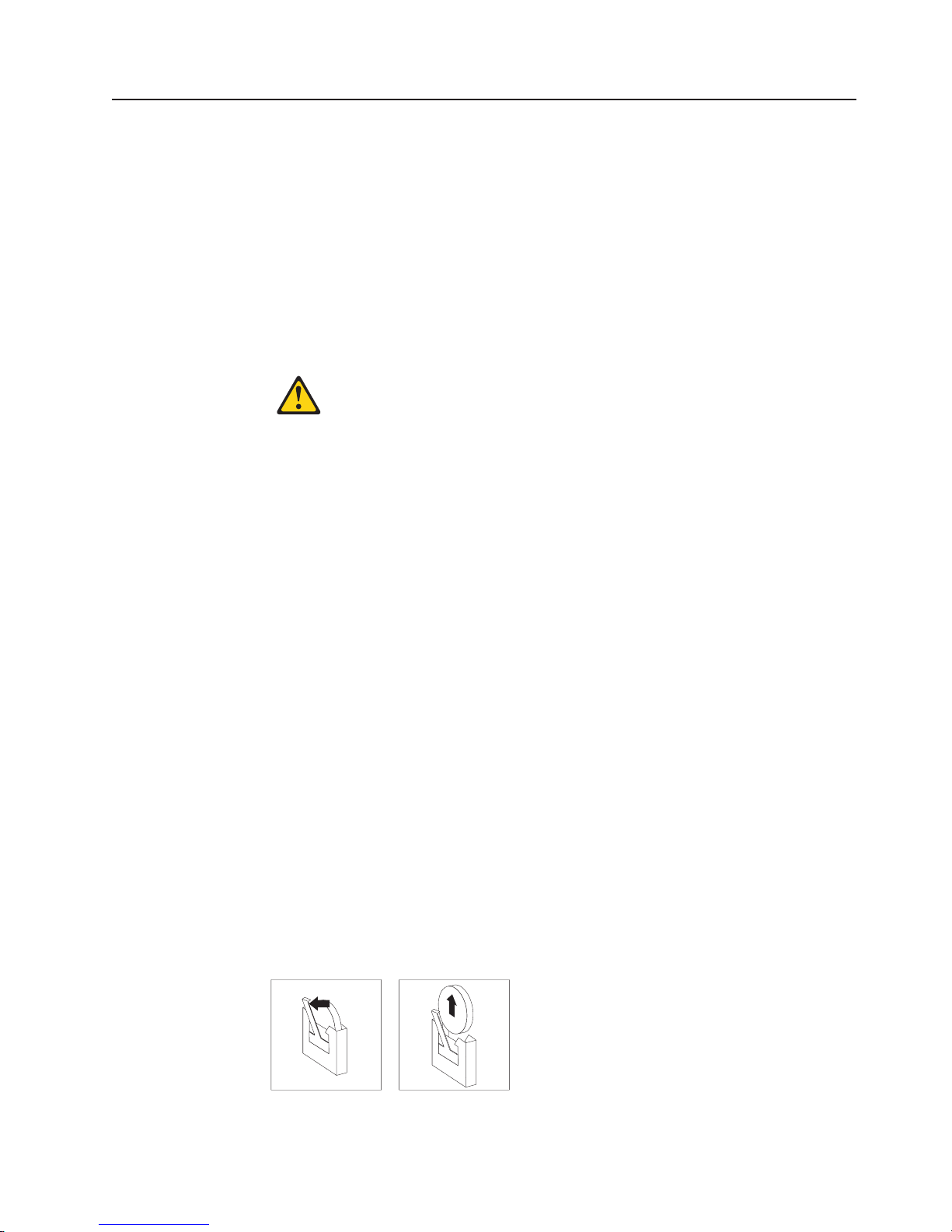
Replacing the battery
The following notes describe information that you must consider when replacing the
battery in the server.
v When replacing the battery, you must replace it with a lithium battery of the same
type from the same manufacturer.
v To order replacement batteries, call 1-800-426-7378 within the United States, and
1-800-465-7999 or 1-800-465-6666 within Canada. Outside the U.S. and
Canada, call your IBM reseller or IBM marketing representative.
v After you replace the battery, you must reconfigure the system and reset the
system date and time.
v To avoid possible danger, read and follow the following safety statement.
Statement 2
CAUTION:
When replacing the lithium battery, use only IBM Part Number 33F8354 or an
equivalent type battery recommended by the manufacturer. If your system has a
module containing a lithium battery, replace it only with the same module type made
by the same manufacturer. The battery contains lithium and can explode if not
properly used, handled, or disposed of.
Do not:
v Throw or immerse into water
v Heat to more than 100°C (212°F)
v Repair or disassemble
Dispose
Complete the following steps to replace the battery:
of the battery as required by local ordinances or regulations.
1. Read “Safety information” on page 147 and “Installation guidelines” on page 29,
and follow any special handling and installation instructions supplied with the
replacement battery.
2. Turn off the server and all peripheral devices. Disconnect all power cords; then,
disconnect all external signal cables from the server.
3. Remove the server cover (see “Removing the cover and bezel” on page 32
4. Using the illustrations at “Replacing the I/O board and power backplane
assembly” on page 81 as a reference, locate the battery on the I/O board.
5. Remove the battery:
a. Use one finger to press the top of the battery clip away from the battery.
b. Lift and remove the battery from the socket.
Figure 1. Removing the battery
Chapter 4. Installing options 53
Page 64

6. Insert the new battery:
a. Position the battery so that the positive (+) symbol is facing away from you.
b. Use one finger to press the top of the battery clip away from the battery.
c. Press the battery into the socket until it clicks into place. Make sure that the
battery clip holds the battery securely.
Figure 2. Installing the battery
7. Reinstall the server cover as described in “Installing the cover and bezel” on
page 58.
8. Reconnect the external cables; then, reconnect the power cords and turn on the
peripheral devices and the server.
Note: Yo u must wait approximately 20 seconds after you connect the power
cord of the server to an electrical outlet before the power-control button
becomes active.
9. Start the Configuration/Setup Utility program and set configuration parameters.
v Set the system date and time.
v Set the power-on password.
v Reconfigure the server.
the section about using the Configuration/Setup Utility program in the
See
User’s Guide on the IBM xSeries Documentation CD for details.
54 IBM xSeries 365 Types 8861, 8862: Hardware Maintenance Manual and Troubleshooting Guide
Page 65

Replacing a hot-swap fan
The following notes describe information that you must consider when replacing a
hot-swap fan in the server.
v The server comes with six hot-swap fans.
v You do not need to turn off the power to the server to replace a hot-swap fan.
Attention: If a fan fails, replace it within 48 hours to help ensure proper cooling.
Complete the following steps to replace a hot-swap fan:
1. Read “Safety information” on page 147 and “Installation guidelines” on page 29.
2. Remove the top cover (see “Removing the cover and bezel” on page 32).
Attention: To ensure proper system cooling, do not leave the top cover off the
server for more than two minutes.
3. Open the fan-locking handle by sliding the orange release latch in the direction
of the arrow.
4. Pull upward on the free end of the handle to lift the fan out of the server.
Fan Error
LED
Hot-swap fan 5
Hot-swap fan 6
Hot-swap fan 3
Hot-swap fan 4
Hot-swap fan 1
Hot-swap fan 2
5. Open the fan-locking handle on the replacement fan, lower the fan into its
socket, and rotate the handle to the locked position.
6. If you have other options to install or remove, do so now; otherwise, go to
“Completing the installation” on page 58.
Chapter 4. Installing options 55
Page 66

Replacing the memory cassette
The following notes describe information that you must consider when replacing the
8-DIMM-connector memory cassette in the server with a 16-DIMM-connector
memory cassette:
v The memory cassette is not hot-swappable; you must turn off the server before
replacing the memory cassette.
v For a server with an 8-DIMM-connector memory cassette, you can increase the
memory capabilities of your server by upgrading to the 16-connector memory
cassette. The 16-connector memory cassette supports memory mirroring and
Memory ProteXion. See the ServerProven list at http://www.ibm.com/pc/compat/
for a list of memory cassettes supported by the server.
Complete the following steps to replace the memory cassette in the server.
1. Read “Safety information” on page 147 and “Installation guidelines” on page 29.
2. Turn off the server and all peripheral devices. Disconnect all power cords; then,
disconnect all external signal cables from the server.
3. Remove the server cover (see “Removing the cover and bezel” on page 32).
4. Remove the current memory cassette:
a. Using both hands, pull the memory cassette locking handle in an arc toward
the front of the server (1) until the memory cassette is released.
b. Lift the memory cassette out of the server (2).
Install the new memory cassette in the server:
5.
56 IBM xSeries 365 Types 8861, 8862: Hardware Maintenance Manual and Troubleshooting Guide
Page 67

a. Pull the new memory cassette locking handle in an arc toward the front of
the cassette.
b. Orient the cassette as shown in the illustration in step 4; then, lower the
cassette into place.
c. Using both hands, rotate the locking handle toward the rear of the server,
making sure when you finish that the cassette is fully seated and the locking
handle is all the way down.
When the cassette is fully seated and the handle is all the way down,
Note:
two black pins protrude through the blue insert on the handle.
PS2
Indicator pins
PS1
6. Install DIMMs in the memory cassette; you can use the DIMMs from the
previous memory cassette. See “DIMM installation” on page 41 for the DIMM
population order to use.
Note: Use the Configuration/Setup Utility program to enable or disable mirrored
memory mode.
7. If you have other options to install or remove, do so now; otherwise, go to
“Completing the installation” on page 58.
Chapter 4. Installing options 57
Page 68

Completing the installation
This section describes how to complete the installation.
Installing the cover and bezel
Complete the following steps to install the server cover and bezel:
1. Before installing the cover, check that all internal cables, adapters, and other
components are installed and seated correctly and that you have not left loose
tools or parts inside the server.
2. Move the cover-release latch to the open (up) position.
Top cover
Cover release
latch
x
S
e
r
i
e
s
3
6
Bezel
5
3. Position the cover on top of the server and press down on the cover-release
latch. The cover slides forward into position.
4. Insert the tabs on the cover into the matching slots in the server chassis and
slide the cover forward.
5. Press down on the cover-release latch. The cover-release latch slides the cover
forward into position and locks the cover in place.
6. Insert the tabs on the bottom of the bezel into the matching holes on the server
chassis.
7. Push the top of the bezel toward the server until the two tabs at the top of the
sides of the bezel snap into place.
8. Slide the server fully into the rack cabinet.
9. If you disconnected any power cords or external cables from the server,
reconnect the external cables first. If you are adding any new peripheral devices
(see “Connecting the cables” on page 59 for details), you can then connect the
external cables from those devices. Then, connect the power cords to properly
grounded electrical outlets.
Depending on the options that you installed, you might need to run the
Note:
Configuration/Setup Utility program to update the server configuration. See
“Updating the server configuration” on page 60, “Using the
Configuration/Setup Utility program” on page 11, and the User’s Guide for
more information.
58 IBM xSeries 365 Types 8861, 8862: Hardware Maintenance Manual and Troubleshooting Guide
Page 69

Connecting the cables
This section describes how to connect cables to the server, with particular
instructions for the RXE Expansion Port, RXE Management Port, and Ethernet
connectors. When instructed, see the applicable documentation for more details.
Note: The external power connection on the Remote Supervisor Adapter II is not
supported on the xSeries 365 server.
For details about the locations and functions of all of the ports, indicators, and
connectors see “I/O connectors” on page 61.
Remote Supervisor Adapter II ASM
Power-supply
connector
Remote Supervisor Adapter II USB
SCSI
AC
AC
Remote Supervisor
Adapter II
Ethernet ( RJ-45)
12345 6
RXE Management
port
Serial
Keyboard
Mouse
RXE Expansion
port
Remote Supervisor
Adapter II video
Ethernet 2
USB 2
Ethernet 1
USB 1
The following illustration shows the cable routing for a typical server configuration.
Detailed cabling instructions, including the use of the cable management arm
(shipped with the server) are in the Rack Installation Instructions provided with the
server.
The illustrations in this document might differ slightly from your hardware.
See the documentation that comes with any option you install for additional cabling
instructions. It might be easier for you to route cables before you install certain
options.
If you have just connected the power cords of the server into an electrical outlet,
wait 20 seconds before pressing the power-control button.
Chapter 4. Installing options 59
Page 70

RXE connector cabling
Your server has one RXE Expansion Port and one RXE Management Port located
on the rear of the server. Use these connectors to connect the server to a remote
I/O enclosure and to expand the number of PCI-X slots that are available for use by
the server. For detailed information about cabling the RXE ports, see the
documentation that comes with the remote I/O enclosure.
Complete the following steps to cable your server to a remote I/O enclosure:
xSeries 365 Type 8861
RXE Expansion Port (A)
RXE Management Port
RXE Expansion Port
AC
A (in) PortRXE Management
AC
12345 6
RXE-100
1. Using an RXE Expansion cable, connect one end of the cable to the RXE
Expansion Port on the server.
2. Connect the opposite end of the cable to an RXE Expansion Port on the remote
I/O enclosure.
3. Using an RXE Management cable, connect one end of the cable to the RXE
Management Port on the server.
4. Connect the opposite end of the cable to the RXE Management A (in) Port on
the remote I/O enclosure.
Note: For details about cabling the server to the remote I/O enclosure and how
the server and remote I/O work together, see the documentation that
comes with the enclosure.
Gigabit Ethernet cabling
Your server has one dual-port Ethernet connector located on the back of the server.
Use these ports to connect the server to a LAN.
Note: Another Ethernet connector is located on the Remote Supervisor Adapter II.
This port is used for specific supervisory functions and should not be
confused with the Gigabit Ethernet connectors above the USB ports.
Updating the server configuration
When you start the server for the first time after you add or remove an internal
option or external SCSI device, you might receive a message that the configuration
has changed. The Configuration/Setup Utility program starts automatically so that
you can save the new configuration settings. For more information, see “Using the
Configuration/Setup Utility program” on page 11 and the section on configuring the
server in the User’s Guide on the IBM xSeries Documentation CD.
60 IBM xSeries 365 Types 8861, 8862: Hardware Maintenance Manual and Troubleshooting Guide
Page 71

I/O connectors
Some options have device drivers that you must install. See the documentation that
comes with each option for information about installing device drivers.
The server comes with at least one microprocessor on the microprocessor tray
assembly. If more than one microprocessor is installed, the server can operate as a
symmetric multiprocessing (SMP) server. You might have to upgrade the operating
system to support SMP. For more information, see the section about using the
ServerGuide Setup and Installation CD in the User’s Guide and the
operating-system documentation.
If the server has an optional RAID adapter and you have installed or removed a
hard disk drive, see the documentation that comes with the RAID adapter for
information about reconfiguring the disk arrays.
If you have installed a Remote Supervisor Adapter to manage the server remotely,
see the Remote Supervisor Adapter User’s Guide, which comes with the adapter,
for information about setting up, configuring, and using the adapter.
For information about configuring the integrated Gigabit Ethernet controller, see the
User’s Guide.
Your server has the following input/output (I/O) connectors:
v Serial (1, rear)
v Gigabit Ethernet (2, rear)
v Keyboard (1, rear)
v Mouse (1, rear)
v USB (2, rear; 1, front - on operator information panel)
v RXE expansion (1, rear)
v RXE management (1, rear)
v SCSI (1, rear)
Remote Supervisor Adapter II has the following connectors:
The
v Remote Supervisor Adapter II Ethernet (1, rear)
v Remote Supervisor Adapter II video (1, rear)
v Remote Supervisor Adapter II ASM (1, rear)
v Remote Supervisor Adapter II USB (reserved)
following illustration shows the USB connector on the operator information
The
panel on the front of the server.
USB connector
Chapter 4. Installing options 61
Page 72

The following illustration shows the I/O connectors on the rear of the server.
Power-supply
connector
RXE Management
port
RXE Expansion
port
The following sections describe these connectors.
Server connectors
The following connectors are on the server.
Remote Supervisor Adapter II ASM
SCSI
AC
Serial
Keyboard
Mouse
AC
Remote Supervisor Adapter II USB
Remote Supervisor
Adapter II
Ethernet ( RJ-45)
12345 6
Remote Supervisor
Adapter II video
Ethernet 2
USB 2
Ethernet 1
USB 1
Remote Supervisor Adapter II connectors
The following connectors are on the rear of the Remote Supervisor Adapter II:
Note: The external power connection on the Remote Supervisor Adapter II is not
supported on the xSeries 365 server.
Advanced
USB This connector is not available for use.
Ethernet (RJ-45) connector
Video connector
Attention: Do not connect the ASM connector to the RXE Management Port on
the server.
If you want to use the Remote Supervisor Adapter II to manage the server remotely
or to connect the server to another server, connect the applicable cables to the
Remote Supervisor Adapter II connectors.
v To enable remote server management through a network, use the Remote
Supervisor Adapter II Ethernet connector.
System Management (ASM) interconnect connector
Connect the ASM breakout cable to this connector to enable system
management through the serial connectors and through the ASM RS-485
connectors. See the Remote Supervisor Adapter User’s Guide for more
information about the breakout cable.
Connect a Category 3, 4, or 5 unshielded twisted-pair cable to this
connector to enable a LAN connection or Telnet session. The Ethernet
connector LEDs on the Remote Supervisor Adapter II indicate whether the
link is good and whether activity is taking place on the network.
Connect the cable from the server monitor to this connector.
62 IBM xSeries 365 Types 8861, 8862: Hardware Maintenance Manual and Troubleshooting Guide
Page 73

v To enable remote server management using a modem, use a Remote Supervisor
Adapter II serial connector on the breakout cable that you connect to the ASM
connector.
v To enable remote server management through a serial interface from a client
workstation using a terminal-emulation program or from a hardware terminal
server, connect the breakout cable to the ASM connector and make the following
connections:
– Use a null modem cable to connect your server serial connector to the serial
connector labeled COM1 on the breakout cable.
– Use a null modem cable to connect the serial connector labeled COM2 on the
breakout cable to a terminal server or client serial connector.
To connect the server with another server, use the ASM interconnect connector.
v
the Remote Supervisor Adapter II documentation on the IBM xSeries
See
Documentation CD for more information.
Ethernet connector
The following illustration shows an Ethernet connector.
8
1
Connect a Category 3, 4, or 5 unshielded twisted-pair cable to this connector. The
100BASE-TX and 1000BASE-T Fast Ethernet standards require Category 5 or
higher cabling.
For more information about the Ethernet controller, see the User’s Guide.
Universal Serial Bus connector
Use a Universal Serial Bus (USB) connector to connect a USB device. USB
technology transfers data at up to 12 Mb per second (Mbps) with a maximum of
127 devices and a maximum signal distance of 5 meters (16 ft) per segment. Using
Plug and Play technology, USB devices are configured automatically. The following
illustration shows a USB connector.
Use a 4-pin cable to connect a device to a USB connector. If you need to connect
more USB devices than the server has USB connectors for, use a USB hub to
connect additional devices.
If you connect a PS/2 (non-USB) keyboard to the keyboard connector, USB ports
and devices are disabled during POST.
4321
If you connect a USB keyboard that has a mouse port, the keyboard emulates a
mouse, and you cannot disable the mouse settings in the Configuration/Setup Utility
program.
Chapter 4. Installing options 63
Page 74

RXE Expansion Port connector
Use this connector to connect the server to the RXE Expansion port on an optional
IBM RXE-100 Remote Expansion Enclosure. The following illustration shows an
RXE Expansion Port connector.
48
47
2
1
Auxiliary-device (pointing device) connector
Use this connector to connect a mouse or other pointing device. The following
illustration shows an auxiliary-device connector.
6
4
2
5
3
1
Keyboard connector
Use this connector to connect a PS/2 (non-USB) keyboard to the server. The
following illustration shows a keyboard connector.
6
4
2
5
3
1
Serial connector
Use a serial connector to connect a serial device. The following illustration shows a
serial connector.
1
69
5
Connect a serial cable to this port to enable system management through a
modem, or connect a null modem cable to enable system management through a
workstation or mobile computer.
RXE Management Port connector
Use this connector to connect the server to the RXE Management A (In) Port on an
optional IBM RXE-100 Remote Expansion Enclosure. The following illustration
shows an RXE Management Port connector.
1
8
64 IBM xSeries 365 Types 8861, 8862: Hardware Maintenance Manual and Troubleshooting Guide
Page 75

Power supply connector
Connect one end of the power-supply power cord to this connector and connect the
other end to an ac power source. The server comes with one hot-swap power
supply. Yo u can add a second hot-swap power supply to obtain full power
redundancy. Connect each power supply to separate ac power circuits for power
redundancy.
SCSI connector
Use the external small computer system interface (SCSI) connector to connect an
external SCSI device to channel B of the Ultra 320 SCSI controller in the server.
The following illustration shows a 68-pin external SCSI connector.
34
1
68
35
Chapter 4. Installing options 65
Page 76

66 IBM xSeries 365 Types 8861, 8862: Hardware Maintenance Manual and Troubleshooting Guide
Page 77

Chapter 5. FRU information (service only)
Microprocessor tray assembly . . . . . . . . . . . . . . . . . . .68
Microprocessor board connectors, jumpers and LEDs . . . . . . . . .68
Microprocessor removal . . . . . . . . . . . . . . . . . . . .68
Thermal grease . . . . . . . . . . . . . . . . . . . . . . . .69
Diskette drive . . . . . . . . . . . . . . . . . . . . . . . . .71
Operator information panel . . . . . . . . . . . . . . . . . . . .72
Media interposer card . . . . . . . . . . . . . . . . . . . . . .73
SCSI backplane . . . . . . . . . . . . . . . . . . . . . . . .74
PCI switch card assembly . . . . . . . . . . . . . . . . . . . . .76
Adapter retainer bracket assembly . . . . . . . . . . . . . . . . . .77
Power-supply structure . . . . . . . . . . . . . . . . . . . . . .78
I/O board and power backplane assembly . . . . . . . . . . . . . . .79
I/O board connectors . . . . . . . . . . . . . . . . . . . . . .79
I/O board LEDs . . . . . . . . . . . . . . . . . . . . . . . .80
I/O board switches and jumpers . . . . . . . . . . . . . . . . .80
Replacing the I/O board and power backplane assembly . . . . . . . .81
This chapter describes the removal of certain server components.
Important: The field replaceable unit (FRU) procedures are intended for trained
servicers who are familiar with IBM Eserver products. See the parts
listing in “System” on page 140 to determine whether the component
being replaced is a customer replaceable unit (CRU) or a FRU.
© Copyright IBM Corp. 2003 67
Page 78

Microprocessor tray assembly
This section shows the locations of items on the microprocessor board and
describes how to remove a microprocessor.
Microprocessor board connectors, jumpers and LEDs
The following illustration shows the connectors, jumpers, and LEDs on the
microprocessor board.
Force power-on
jumper (J10)
Light-path
diagnostics button
Microprocessor 3
VRM error LED
Microprocessor 3
VRM connector
Microprocessor 1
socket
Microprocessor 1
error LED
Microprocessor 2
error LED
Microprocessor 2
socket
The microprocessor board contains the force power-on jumper (J10), a three-pin
jumper block. The default position is pins 1 and 2. Move the jumper to pins 2 and 3
to force the server to start up when you connect the server to ac power.
Microprocessor removal
This section contains information about removing a microprocessor.
Note:
v Read “Installation guidelines” on page 29.
v Read “Safety information” on page 147.
v Read “Handling static-sensitive devices” on page 30.
Microprocessor 4
VRM error LED
Microprocessor 4
VRM connector
Microprocessor 4
socket
Light-path
test LED
Microprocessor 4
error LED
Microprocessor 3
socket
Microprocessor 3
error LED
Complete
the following steps to remove a microprocessor:
1. Turn off the server and all peripheral devices; then, disconnect all power cords
and external cables.
2. Remove the top cover (see “Removing the cover and bezel” on page 32).
3. Remove all fans.
4. Remove the memory cassette.
5. Lift the microprocessor-tray release latch.
6. Remove the microprocessor tray assembly (see “Installing a microprocessor” on
page 44).
68 IBM xSeries 365 Types 8861, 8862: Hardware Maintenance Manual and Troubleshooting Guide
Page 79

Attention: The microprocessor tray is heavy. Pull the tray part-way out of the
server, reposition your hands to grasp the body of the tray, and then pull the
tray out the rest of the way.
7. Remove the heat sink by first fully loosening one screw; then, fully loosen the
other screw and lift the heat sink off of the microprocessor.
Lever
fully
open
Attention: Before attempting to remove the heat sink from the
Lever closed
Lever closed
Lever
fully
open
microprocessor, note that the heat-conducting grease between the heat sink and
the microprocessor might have formed a strong bond. Do not force the
components apart; doing so can damage the microprocessor pins. Loosening
one screw fully before loosening the other screw will help to break the thermal
bond that adheres the heat sink to the microprocessor.
8. Rotate the locking lever on the microprocessor socket from its closed and
locked position until it stops or clicks in the fully open position (approximately
135° angle), as shown.
9. Pull the microprocessor out of the socket.
Attention: You must ensure that the locking lever on the microprocessor
socket is in the fully open position before you insert the microprocessor in the
socket. Failure to do so might result in permanent damage to the
microprocessor, microprocessor socket, and microprocessor board.
information about installing a microprocessor, see “Installing a microprocessor”
For
on page 44.
Thermal grease
This section contains information about removing and replacing the thermal grease
between the heat sink and the microprocessor. The thermal grease must be
replaced whenever the heat sink has been removed from the top of the
microprocessor and is going to be reused or when debris is found in the grease.
Note:
v Read “Installation guidelines” on page 29.
v Read “Safety information” on page 147.
v Read “Handling static-sensitive devices” on page 30.
Chapter 5. FRU information (service only) 69
Page 80

Complete the following steps to replace damaged or contaminated thermal grease
on the microprocessor and heat sink:
1. Place the heat sink on a clean work surface.
2. Remove the cleaning pad from its package and unfold it completely.
3. Use the cleaning pad to wipe the thermal grease from the bottom of the heat
sink.
Note: Make sure that all of the thermal grease is removed.
4. Use a clean area of the cleaning pad to wipe the thermal grease from the
microprocessor; then, dispose of the cleaning pad after all of the thermal grease
is removed.
Microprocessor
0.01 mL of
thermal grease
5. Use the thermal-grease syringe to place 16 uniformly spaced dots of 0.01 mL
each on the top of the microprocessor.
Note: 0.01mL is one tick mark on the syringe. If the grease is properly applied,
approximately half (0.22 mL) of the grease will remain in the syringe.
6. Install the heat sink onto the microprocessor as described in “Installing a
microprocessor” on page 44.
70 IBM xSeries 365 Types 8861, 8862: Hardware Maintenance Manual and Troubleshooting Guide
Page 81

Diskette drive
This section contains information about removing and replacing the diskette drive.
Note:
v Read “Installation guidelines” on page 29.
v Read “Safety information” on page 147.
v Read “Handling static-sensitive devices” on page 30.
Complete
1. Turn off the server and all peripheral devices; then, disconnect all power cords
the following steps to replace the diskette drive:
and external cables.
2. Remove the cover and bezel (see “Removing the cover and bezel” on page
32).
3. Remove the diskette drive cable from the media interposer card by completing
the following steps:
a. Push the plastic lip on the outer edge of the cable connector toward the
rear of the server.
b. Remove the cable from the connector.
Metal hook
Drive retention
wire
4. Remove the wire from the right side of the diskette drive.
Note: The center of the wire fits into a metal hook. Be sure to return the wire
5. Slide the diskette drive out of the server by pulling it through the front bezel.
6. With the diskette drive out of the server, remove the cable from the diskette
drive by pulling up on the cable retention latch. Set this cable aside carefully
for reinstallation.
7. Attach the cable that was removed in step 6 to the replacement diskette drive,
making sure to close the cable retention latch.
8. Slide the diskette drive into the server through the front bezel, making sure to
route the cable in first.
9. When the diskette drive is in place, connect the cable to the media interposer
card.
a. Route the cable over the media interposer card.
to its position in the hook when replacing the diskette drive.
Chapter 5. FRU information (service only) 71
Page 82

b. Place the cable into the cable connector and pull the bottom edge of the
connector toward the front of the server to secure the cable.
Attach the wire to the diskette drive beginning with the front hole, making sure
10.
to guide the wire into the hook.
11. Replace the bezel and top cover.
12. Reconnect external cables and power cords.
Operator information panel
This section contains information about removing and replacing the operator
information panel.
Note:
v Read “Installation guidelines” on page 29.
v Read “Safety information” on page 147.
v Read “Handling static-sensitive devices” on page 30.
Complete
1. Turn off the server and all peripheral devices; then, disconnect all power cords
the following steps to replace the operator information panel assembly:
and external cables.
2. Remove the top cover and bezel (see “Removing the cover and bezel” on
page 32).
3. Remove the cable from the media interposer card.
4. Remove the screw securing the corner of the pivoting panel to the chassis.
When the screw is fully loosened, it might be necessary to insert the blade of
the screwdriver slightly under the head of the screw and lever it up.
Release latch
5. Press the blue latch on the front panel to release the assembly. Do not pivot
Curved channel
the assembly.
6. Pull the assembly slightly out of the server without pivoting the assembly.
7. Pull the assembly out of the front of the server. It might be necessary to lift the
assembly up slightly while sliding it out.
8. Assemble the replacement operator information panel and cable.
9. Guiding the cable through first, insert the assembly into the server through the
front. The shoulder screw on the bottom of the assembly will glide along the
straight guide channel in the chassis.
10. Gently slide the assembly into the server along the straight guide channel,
keeping the cable free. When the assembly is inserted all the way, the
72 IBM xSeries 365 Types 8861, 8862: Hardware Maintenance Manual and Troubleshooting Guide
Page 83

shoulder screw on the bottom of the assembly will slide into and along the
curved channel. This allows the panel to swing out.
11. Reinstall the screw that was removed in step 4 on page 72.
12. Verify that the assembly opens and closes smoothly.
13. Close and latch the operator information panel.
14. Connect the cable to the media interposer card.
15. Replace the bezel and top cover.
16. Reconnect external cables and power cords.
Media interposer card
This section contains information about removing and replacing the media
interposer card.
Note:
v Read “Installation guidelines” on page 29.
v Read “Safety information” on page 147.
v Read “Handling static-sensitive devices” on page 30.
Complete
the following steps to remove the media interposer card:
1. Turn off the server and all peripheral devices; then, disconnect all power cords
and external cables.
2. Remove the top cover (see “Removing the cover and bezel” on page 32).
3. Pull the CD-ROM drive or DVD-ROM drive out of the server slightly to
disengage it from the media interposer card.
4. Disconnect all cables from the media interposer card.
Pushpins
5. Pull out the two blue push pins.
Chapter 5. FRU information (service only) 73
Page 84

6. To release the media interposer card from the chassis, press down on the two
blue touchpoints on the rectangular steel flaps (1) that lie flush with the
chassis structure near the base of the media interposer card.
7. Pull the media interposer card out of the server.
SCSI backplane
To install the media interposer card, reverse the preceding steps.
Note: When inserting the media interposer card into the server, angle the card so
that the left side of the card goes in first and fits against the metal lip on the
chassis.
This section contains information about removing and replacing the SCSI
backplane.
Note:
v Read “Installation guidelines” on page 29.
v Read “Safety information” on page 147.
v Read “Handling static-sensitive devices” on page 30.
Complete
1. Turn off the server and all peripheral devices; then, disconnect all power cords
the following steps to remove the SCSI backplane:
and external cables.
2. Remove the top cover (see “Removing the cover and bezel” on page 32). It is
not necessary to remove the front bezel.
3. Pull the hard disk drives out of the server slightly to disengage them from the
SCSI backplane.
4. Disconnect the SCSI cable from the SCSI backplane.
5. Disconnect the cable connecting the I/O board to the media interposer card.
Note: This is the only cable that should be disconnected from the media
74 IBM xSeries 365 Types 8861, 8862: Hardware Maintenance Manual and Troubleshooting Guide
interposer card.
Page 85

Release tabs
Guide channels
6. Pull out the two blue pushpins.
7. Squeeze the two blue release tabs.
8. Lift the SCSI backplane out of the server slightly; then, disconnect the power
cable and remove the backplane.
9. Connect the power cable to the replacement backplane.
10. Slide the backplane into the two guide channels.
Note: The cables from steps 4 on page 74 and 5 on page 74 will be routed
over the top of the backplane after the backplane is installed.
11. Align the two slots in the backplane assembly onto the two guide tabs; then,
press firmly until the blue tabs latch. The backplane assembly will snap into
place.
12. Reconnect the cables that were disconnected in step 4 on page 74 and step 5
on page 74.
Note: Route cables into the cable channel (in between the fans). Do not allow
any cables to catch on any metal protrusions.
Chapter 5. FRU information (service only) 75
Page 86

PCI switch card assembly
The PCI switch card assembly, mounted on the top rear of the server frame
adjacent to the adapter slots, contains one switch for each of the six adapters. This
ensures that power is disconnected from the associated adapter if you attempt to
open the adapter latch and remove an adapter.
Note:
v Read “Installation guidelines” on page 29.
v Read “Safety information” on page 147.
v Read “Handling static-sensitive devices” on page 30.
Complete
the following steps to remove and replace the PCI switch card assembly:
1. Turn off the server and all peripheral devices; then, disconnect all power cords
and external cables.
2. Remove the top cover (see “Removing the cover and bezel” on page 32).
3. Remove all full-length adapters and adapter insulators (see “Removing a PCI or
PCI-X adapter” on page 36), making sure to place the adapters on a
static-protective surface.
4. Disconnect the PCI switch card assembly cable from the server.
5. Grasp the two adapter switch card release latches and slide the assembly away
from the server chassis; then, lift it out of the server.
Note: The illustrations in this document might differ slightly from the hardware
being serviced.
Release latches
6. To replace the PCI switch card assembly, lower the assembly into place so that
the lips on the bottom of the EMI shielding material fit into the chassis at the
rear of the server, and slide the card into place until the two release latches
snap securely.
7. Connect the cable from the PCI switch card assembly to the I/O board and
install the adapters and adapter insulators that were removed in step 3.
76 IBM xSeries 365 Types 8861, 8862: Hardware Maintenance Manual and Troubleshooting Guide
Page 87

Adapter retainer bracket assembly
This section contains information about removing and replacing the adapter retainer
bracket assembly.
Note:
v Read “Installation guidelines” on page 29.
v Read “Safety information” on page 147.
v Read “Handling static-sensitive devices” on page 30.
Complete
the following steps to remove the adapter retainer bracket assembly:
1. Turn off the server and all peripheral devices; then, disconnect all power cords
and external cables.
2. Remove the top cover (see “Removing the cover and bezel” on page 32).
3. Lift up the latch mechanism.
4. Remove all adapters and adapter insulators (see “Removing a PCI or PCI-X
adapter” on page 36), making sure to place the adapters on a static-protective
surface.
5. Disconnect one end of all cables that pass through the adapter bracket
assembly; then, remove them from the routing feature of the bracket assembly
and fold them out of the way.
Quarter-turn
fasteners
Latch mechanism
6. Turn the two blue quarter-turn fasteners to release the bracket assembly.
7. Lift the bracket assembly out of the server.
When replacing the adapter bracket assembly, complete the following steps:
1. Align the two tabs on the bracket assembly with the two slots on the chassis.
2. Set the bracket assembly firmly into place before securing the quarter-turn
fasteners.
3. Reconnect the cables that were set aside in step 5 and route them back into the
routing feature of the adapter retention assembly.
4. Install the adapters and insulators that were removed in step 4.
5. When replacing the insulators, make sure that:
Chapter 5. FRU information (service only) 77
Page 88

a. The tabs on the bottom of the insulators sit in the holes in the bottom of the
metal section of the bracket.
b. The tabs on the top of the insulators engage the plastic retainer section of
the bracket.
Power-supply structure
This section contains information about removing and replacing the power-supply
structure.
Note:
v Read “Installation guidelines” on page 29.
v Read “Safety information” on page 147.
v Read “Handling static-sensitive devices” on page 30.
Complete the following steps to remove the power-supply structure:
1. Turn off the server and all peripheral devices; then, disconnect all power cords
and external cables.
2. Remove the top cover (see “Removing the cover and bezel” on page 32).
3. Remove the fans (see “Replacing a hot-swap fan” on page 55).
4. Remove the memory cassette (see “Installing a microprocessor” on page 44).
5. Remove the power supplies (see “Installing a hot-swap power supply” on page
51).
6. Pull the two blue latches (1) on the power-supply structure toward the front of
the server; the structure will disengage from the chassis.
Latches
Handle
7. Grasp the handle in the middle of the structure and rotate the back of the
structure up (2), allowing the structure to pivot at the end closest to the front
of the chassis.
8. Slide the structure toward the rear of the server (3), disengaging the tabs on
the structure from the slots in the server (4).
78 IBM xSeries 365 Types 8861, 8862: Hardware Maintenance Manual and Troubleshooting Guide
Page 89

9. Lift the structure out of the server, making sure that the front alignment tabs
slide clear of the chassis.
Install the power supply structure by completing the following steps:
1. Align the tabs on the structure with the notches on the chassis; then, gently
lower the back of the structure into the server, making sure to line up the two
posts on the floor of the chassis with the two apertures in the structure.
Notes:
a. The structure will fit snugly against the metal flange in the center of the I/O
board and power backplane assembly.
b. Do not allow any cables to be pinched or caught on metal protrusions.
Push the two blue latches of the power supply structure toward the rear of the
2.
server until they lock the structure into position.
I/O board and power backplane assembly
This section shows the locations of items on the I/O board and contains information
about removing and replacing the I/O board and power backplane assembly.
Note: When replacing the I/O board, you must either update the server with the
latest firmware or restore the pre-existing firmware that the customer
provides on a diskette or CD image.
The I/O board and power backplane share a single metal backerplate. To replace
either board, the backerplate assembly must be removed from the server.
I/O board connectors
The following illustration shows the connectors on the I/O board.
PCI slot 1
33 MHz 64-bit
PCI-X slot 2
100 MHz 64-bit
PCI-X slot 3
133 MHz 64-bit
PCI-X slot 4
133 MHz 64-bit
PCI-X slot 5
133 MHz 64-bit
PCI-X slot 6
133 MHz 64-bit
RXE expansion (J11)
Ethernet 1 / USB 1 (J12)
Ethernet 2 / USB 2 (J15)
Mouse (J9)
Keyboard (J7)
Serial (J5)
RXE management (J3)
PCI switch card cable (J18)
Remote Supervisor
Adapter II cable (J16)
Battery
Media backplane cable (J13)
SCSI external cable (J21)
SCSI power (J14)
SCSI internal cable (J17)
Chapter 5. FRU information (service only) 79
Page 90

I/O board LEDs
The following illustration shows the LEDs on the I/O board.
PCI attention LEDs
PCI power LEDs
I/O board switches and jumpers
The following illustration shows the switches and jumpers on the I/O board.
3 2 1
IXA voltage
jumper (J26)
1 2 3
1 2 3
Boot recovery (BIOS)
jumper (J19)
1 2 3
Power-on password override
jumper (J20)
Disable Wake on LAN
jumper (J24)
The I/O board contains three-pin jumper blocks. The following table describes the
purposes of the jumpers.
80 IBM xSeries 365 Types 8861, 8862: Hardware Maintenance Manual and Troubleshooting Guide
Page 91

Jumper name Description
Boot recovery (BIOS) (J19) The default position is pins 1 and 2 (use the primary boot block
during startup). Move the jumper to pins 2 and 3 to use the
secondary boot block during startup. For more information about
recovering the BIOS code, see “Recovering BIOS code” on page 24.
Power-on password override (J20) The default position is pins 1 and 2. Changing the position of this
jumper to pins 2 and 3 bypasses the power-on password check.
Changing the position of this jumper does not affect the
administrator password check if an administrator password is set. If
the administrator password is lost, the operator information panel
must be replaced.
For more information about passwords, see “Password override
jumper” on page 25 and the section on using passwords in the
User’s Guide on the IBM xSeries Documentation CD.
Disable Wake on LAN (J24) The default position is pins 1 and 2. Move the jumper to pins 2 and
3 to prevent a Wake on LAN (WOL) packet from waking the system
when the system is in the powered-off state.
IXA voltage (J26) The default position is pins 1 and 2. Move the jumper to pins 2 and
3 when an IXA adapter is installed in PCI slot 3.
Replacing the I/O board and power backplane assembly
This section contains information about replacing the I/O board and power
backplane assembly.
Note:
v Read “Installation guidelines” on page 29.
v Read “Safety information” on page 147.
v Read “Handling static-sensitive devices” on page 30.
Complete
assembly:
1. Turn off the server and all peripheral devices; then, disconnect all power cords
2. Remove the top cover (see “Removing the cover and bezel” on page 32).
3. Remove all fans.
4. Remove the memory cassette.
5. Lift the microprocessor-tray release latch.
6. Remove the microprocessor tray assembly (see “Microprocessor tray
7. Remove the power supplies (see steps 4a on page 52 through 4c on page 52
8. Disconnect all cables from the I/O board.
the following steps to remove the I/O board and power backplane
and external cables.
Note: The Remote Supervisor Adapter II has external cable connections that
must also be disconnected.
assembly” on page 68).
Attention: The microprocessor tray is heavy. Pull the tray part-way out of the
server, reposition your hands to grasp the body of the tray, and then pull the
tray out the rest of the way.
at “Installing a hot-swap power supply” on page 51).
Chapter 5. FRU information (service only) 81
Page 92

9. Remove all adapters and adapter insulators (see “Removing a PCI or PCI-X
adapter” on page 36), making sure to place the adapters on a static-protective
surface.
AC
AC
1234
10. Remove the external SCSI cable assembly, located at the I/O port panel at the
rear of the server, by pushing up on the latch clip (1) with a flat-bladed
screwdriver to release the assembly, and then lifting it out of the server.
11. Remove the adapter retainer bracket assembly (see “Adapter retainer bracket
assembly” on page 77).
12. Remove the power supply structure (see “Power-supply structure” on page 78).
13. Reach behind the server and turn the two blue captive thumbscrews to release
the I/O board from the chassis.
82 IBM xSeries 365 Types 8861, 8862: Hardware Maintenance Manual and Troubleshooting Guide
Page 93

AC
AC
1
Note: Yo u might need a screwdriver to turn the thumbscrews.
Flange
Cable tie
Captive
thumb screws
14. Grasp the metal flange (in the center of the assembly between the power
backplane and the I/O board) and gently pull the assembly slightly toward the
front of the server so that the two notches on each side of the assembly align
with the two metal loops on each side of the chassis.
15. Grasp the cable tie and gently lift up the rear of the assembly; then, slide the
front end of the assembly toward the rear of the server and lift it out of the
chassis.
Attention: When moving the assembly, do not allow it to impact any
components or structures inside the server.
Chapter 5. FRU information (service only) 83
Page 94

16. Set the assembly on a firm and static-protective work surface; then, remove
the six screws that secure the power backplane to the backerplate and set the
screws in a safe place.
Note: Any serrated washers located at the screw holes remain in place.
17. If you are replacing the power backplane, remove the power backplane from
the backerplate; then, position the replacement power backplane on the
backerplate and attach it with the six screws that were removed in step 16.
Attention: Do not overtighten the screws.
18. If you are replacing the I/O board, remove the power backplane from the
backerplate and position it on the new backerplate containing the replacement
I/O board; then, attach it with the six screws that were removed in step 16.
Attention: Do not overtighten the screws.
19. Reinstall the I/O board and power backplane assembly by angling the front
end of the assembly into the chassis first; then, gently slide it toward the front
of the server while lowering the rear of the assembly into the chassis.
20. Align the two notches on each side of the assembly with the two metal loops
on each side of the chassis.
21. Grasping the center flange, slide the assembly toward the rear of the server
until it is in place.
22. Finger-tighten the two thumbscrews on the rear of the server.
Attention: Do not overtighten the screws.
23. Replace the power supply structure (see “Power-supply structure” on page 78).
24. Continue the reassembly procedure by following steps 1 on page 81 through
11 on page 82 in reverse order.
Notes:
a. Be sure to route the cables in between the fans, and then through the
channel with the plastic lip.
b. The SCSI backplane cable and the external SCSI cables have similar
connectors; be sure to reconnect them correctly.
c. The cable for the Remote Supervisor Adapter II must be routed over the
top of the PCI adapter insulator located closest to the center of the server.
Do not route the cable underneath this insulator.
d. Be sure to align the Remote Supervisor Adapter II cable correctly; the
Remote Supervisor Adapter II is keyed to accept the cable in one direction
only.
84 IBM xSeries 365 Types 8861, 8862: Hardware Maintenance Manual and Troubleshooting Guide
Page 95

Chapter 6. Symptom-to-FRU index
Beep symptoms . . . . . . . . . . . . . . . . . . . . . . . .86
No beep symptoms . . . . . . . . . . . . . . . . . . . . . . .87
POST error codes . . . . . . . . . . . . . . . . . . . . . . . .88
Light path LED errors . . . . . . . . . . . . . . . . . . . . . .93
Diagnostic error codes . . . . . . . . . . . . . . . . . . . . . .95
System-error log entries . . . . . . . . . . . . . . . . . . . . . 105
SMI handler messages . . . . . . . . . . . . . . . . . . . . . 106
Service processor messages . . . . . . . . . . . . . . . . . . . 109
Error symptoms . . . . . . . . . . . . . . . . . . . . . . . . 121
Power LED errors . . . . . . . . . . . . . . . . . . . . . . . 130
SCSI error messages . . . . . . . . . . . . . . . . . . . . . . 132
ServeRAID (ISPR) error procedures . . . . . . . . . . . . . . . . 132
ServeRAID error codes . . . . . . . . . . . . . . . . . . . . . 134
Undetermined problems . . . . . . . . . . . . . . . . . . . . . 136
Problem-determination tips . . . . . . . . . . . . . . . . . . . . 137
This index supports xSeries 365 servers.
The symptom-to-FRU index lists symptoms, errors, and the possible causes. The
most likely cause is listed first. Use this Symptom-to-FRU index to help you decide
which FRUs to have available when servicing the computer.
Notes:
1. Check the configuration before you replace a FRU. Configuration problems can
cause false errors and symptoms.
2. For IBM devices not supported by this index, refer to the manual for that device.
3. Always start with “General checkout” on page 15.
4. Take the action (or replace the FRU) suggested first in the list of the right
column, then restart the server to see if the problem has been corrected before
taking further action.
5. Try reseating a suspected component or reconnecting a cable before replacing
the component.
POST error codes and messages are displayed on the screen.
© Copyright IBM Corp. 2003 85
Page 96

Beep symptoms
Beep symptoms are short tones or a series of short tones separated by pauses
(intervals without sound). See the following examples.
Beeps Description
1-2-3
4 Four continuous beeps
One beep after successfully completing POST indicates that the server is
functioning correctly.
Note: See Chapter 7, “Parts listing, Types 8861, 8862,” on page 139 to determine which components are
replaceable by the customer and which components must be replaced by an IBM field service technician.
Beep/symptom FRU/action
1-1-3 (CMOS write/read test failed)
1-1-4 (BIOS ROM checksum failed)
1-2-1 (Programmable Interval Timer
failed)
1-2-2 (DMA initialization failed)
1-2-3 (DMA page register write/read
failed)
1-2-4 (RAM refresh verification failed)
1-3-1 (1st 64K RAM test failed)
2-1-1 (Secondary DMA register failed)
2-1-2 (Primary DMA register failed)
2-1-3 (Primary interrupt mask register
failed)
2-1-4 (Secondary interrupt mask register
failed)
2-2-2 (Keyboard controller failed)
3-1-1 (Timer tick interrupt failed)
3-1-2 (Interval timer channel 2 failed)
3-1-4 (Time-of-Day clock failed)
v One beep
v A pause (or break)
v Two beeps
v A pause (or break)
v Three beeps
1. Battery
2. I/O board
v I/O board
v I/O board
v I/O board
v I/O board
1. DIMM
2. Memory cassette
1. DIMM
2. Memory cassette
v I/O board
v I/O board
v I/O board
v I/O board
v I/O board
v I/O board
v I/O board
1. Battery
2. I/O board
86 IBM xSeries 365 Types 8861, 8862: Hardware Maintenance Manual and Troubleshooting Guide
Page 97

Note: See Chapter 7, “Parts listing, Types 8861, 8862,” on page 139 to determine which components are
replaceable by the customer and which components must be replaced by an IBM field service technician.
Beep/symptom FRU/action
3-3-2 (Critical SMBUS error occurred)
1. Disconnect power cord, wait 30 seconds, retry.
2. DIMM.
3. Memory cassette.
4. Microprocessor tray assembly.
5. I/O board.
3-3-3 (No operational memory in system)
1. Verify that lower SMP Expansion Module contains correct
number of DIMMs; install or reseat DIMMS, then reboot.
2. DIMM.
3. Memory cassette.
4. Microprocessor tray assembly.
Two short beeps (information only,
configuration has changed)
Three short beeps
1. Run Configuration/Setup.
2. Run diagnostic programs.
1. DIMM
2. Memory cassette
3. Microprocessor tray assembly
One continuous beep
1. Microprocessor
2. Optional microprocessor
3. Microprocessor tray assembly
Repeating short beeps
1. Keyboard
2. I/O board
Repeating long beeps
One long and one short beep
v Reseat DIMMs.
1. I/O board
2. Center plane
One long and two short beeps
Two long and two short beeps
v I/O board
v I/O board
No beep symptoms
Note: See Chapter 7, “Parts listing, Types 8861, 8862,” on page 139 to determine which components are
replaceable by the customer and which components must be replaced by an IBM field service technician.
No beep symptom FRU/action
No beep and the system
operates correctly.
No beeps occur after
successfully completing POST
(Power-On Status is disabled.)
No ac power (Power supply ac
LED is off)
No beep and no video
v Operator information panel
1. Run Configuration/Setup, set the Start Options Power-On Status to
enable.
2. Operator information panel.
1. Check the power cord.
2. Power supply (if two are installed, swap them to determine if one is defective.)
3. Power backplane
v See “Undetermined problems” on page 136.
Chapter 6. Symptom-to-FRU index 87
Page 98

Note: See Chapter 7, “Parts listing, Types 8861, 8862,” on page 139 to determine which components are
replaceable by the customer and which components must be replaced by an IBM field service technician.
No beep symptom FRU/action
System will not power-up
(Power supply ac LED is on)
v See “Power LED errors” on page 130.
POST error codes
In the following error codes, X can be any number or letter.
Note: See Chapter 7, “Parts listing, Types 8861, 8862,” on page 139 to determine which components are
replaceable by the customer and which components must be replaced by an IBM field service technician.
Error code/symptom FRU/action
062 (Three consecutive boot failures using the
default configuration.)
101, 102 (Tick timer internal interrupt, internal
timer channel 2)
106 (Diskette controller failure)
114 (Adapter read-only memory (ROM) error)
151 (Real time clock error)
161 (Real time clock battery error)
162 (Device Configuration Error)
Note: Be sure to load the default settings and
any additional desired settings; then, save the
configuration
163 (Real-Time Clock error)
175 (Hardware error)
177, 178 (Security hardware error)
184 (Power-on password corrupted)
186 (Security hardware control logic failed)
1. Flash system to latest level.
2. I/O board.
v I/O board
v I/O board
1. Remove adapters and reinstall one at a time; replace failing
adapter.
2. I/O board.
1. Battery
2. I/O board
1. Battery
2. I/O board
1. Run Configuration/Setup
2. Battery
3. Failing device
4. I/O board
1. Run Configuration/Setup.
2. Battery.
3. I/O board.
1. I/O board
2. Service processor
1. Run Configuration/Setup.
2. I/O board.
3. Service processor.
1. Run Configuration/Setup.
2. Battery.
3. I/O board.
1. Run Configuration/Setup.
2. I/O board.
3. Service processor.
88 IBM xSeries 365 Types 8861, 8862: Hardware Maintenance Manual and Troubleshooting Guide
Page 99

Note: See Chapter 7, “Parts listing, Types 8861, 8862,” on page 139 to determine which components are
replaceable by the customer and which components must be replaced by an IBM field service technician.
Error code/symptom FRU/action
187 (VPD serial number not set.)
1. Set serial number using flash update utility.
2. I/O board.
3. Service processor.
188 (Bad EEPROM CRC #2)
1. Run Configuration/Setup.
2. I/O board.
3. Service processor.
189 (An attempt was made to access the
server with invalid passwords)
289 (DIMM has been disabled by the user or
system)
v Run Configuration/Setup, enter the administrator password.
1. Run Configuration/Setup, if disabled by user.
2. Verify proper DIMM installation (see “Memory modules” on page
39).
3. Disabled DIMM, if not disabled by user.
301 (Keyboard or keyboard controller error)
Note: After installing a USB keyboard, you
might need to use the Configuration/Setup
1. Keyboard
2. I/O board
Utility program to enable keyboardless
operation and prevent the POST error
message 301 from being displayed during
startup.
303 (Keyboard controller error)
1. I/O board
2. Keyboard
602 (Invalid diskette boot record)
1. Diskette
2. Diskette drive
3. Cable
4. I/O board
604 (Diskette drive error)
1. Run Configuration/Setup and diagnostic programs.
2. Diskette drive.
3. Drive cable.
4. I/O board.
662 (Diskette drive configuration error)
1. Run Configuration/Setup and diagnostic programs.
2. Diskette drive.
3. Drive cable.
4. I/O board.
1600 (Service processor not functioning)
1. Cable connecting service processor with I/O board.
2. Service processor.
1762 (Fixed Disk Configuration error)
1. Hard disk drive cables.
2. Run Configuration/Setup.
3. Hard disk drive adapter.
4. Hard disk drive.
5. SCSI backplane.
6. I/O board.
Chapter 6. Symptom-to-FRU index 89
Page 100

Note: See Chapter 7, “Parts listing, Types 8861, 8862,” on page 139 to determine which components are
replaceable by the customer and which components must be replaced by an IBM field service technician.
Error code/symptom FRU/action
178x (Fixed Disk error)
1. Hard disk drive cables.
2. Run diagnostic programs.
3. Hard disk drive adapter.
4. Hard disk drive.
5. I/O board.
1800 (Unavailable PCI hardware interrupt)
1. Run Configuration/Setup and adjust adapter settings.
2. Remove an adapter.
1962 (Drive does not contain a valid boot
sector)
1. Verify a bootable operating system is installed.
2. Run diagnostic programs.
3. Hard disk drive.
4. SCSI backplane.
5. Cable.
6. I/O board.
5962 (IDE CD-ROM configuration error)
1. Run Configuration/Setup.
2. CD-ROM drive.
3. IDE cable.
4. I/O board.
8603 (Pointing Device Error)
1. Pointing device
2. I/O board
0001295 (ECC circuit check)
1. DIMM
2. Microprocessor tray assembly
00012000 (Processor machine check error)
1. Microprocessor
2. Microprocessor tray assembly
00019501 (Processor 1 is not functioning -
check VRM and processor LEDs)
00019502 (Processor 2 is not functioning -
check VRM and processor LEDs)
00019503 (Processor 3 is not functioning -
check VRM and processor LEDs)
1. Microprocessor 1
2. Microprocessor tray assembly
1. Microprocessor 2
2. Microprocessor tray assembly
1. VRM 3
2. Microprocessor 3
3. Microprocessor tray assembly
00019504 (Processor 4 is not functioning -
check VRM and processor LEDs)
1. VRM 4
2. Microprocessor 4
3. Microprocessor tray assembly
00019701 (Processor 1 failed BIST)
1. Microprocessor 1
2. Microprocessor tray assembly
00019702 (Processor 2 failed BIST)
1. Microprocessor 2
2. Microprocessor tray assembly
00019703 (Processor 3 failed BIST)
1. Microprocessor 3
2. VRM3
3. Microprocessor tray assembly
90 IBM xSeries 365 Types 8861, 8862: Hardware Maintenance Manual and Troubleshooting Guide
 Loading...