

Page 1

IBM
IBM xSeries 360 Type 8686
Installation Guide
Page 2

Note::
Before using this information and the product it supports, read the general information in Appendix A, “Warranty
information” on page 47 and Appendix B, “Notices” on page 57.
Second Edition (March 2002)
© Copyright International Business Machines Corporation 2001. All rights reserved.
US Government Users Restricted Rights – Use, duplication or disclosure restricted by GSA ADP Schedule Contract with
IBM Corp.
Page 3

© Copyright IBM Corp. 2001 iii
Contents
Safety. . . . . . . . . . . . . . . . . . . . . . . . . . . . . . . . . . . . . . . . . . . . . . . . . . . . . . . . . . . . . v
Chapter 1. Introduction . . . . . . . . . . . . . . . . . . . . . . . . . . . . . . . . . . . . . . . . . . . . . . 1
Specifications and features . . . . . . . . . . . . . . . . . . . . . . . . . . . . . . . . . . . . . . . . . . . . 2
Notices and statements used in this book . . . . . . . . . . . . . . . . . . . . . . . . . . . . . . . . . 3
Before you begin. . . . . . . . . . . . . . . . . . . . . . . . . . . . . . . . . . . . . . . . . . . . . . . . . . . . . 3
Handling static-sensitive devices . . . . . . . . . . . . . . . . . . . . . . . . . . . . . . . . . . . . . . . . 3
Major components of the xSeries 360 . . . . . . . . . . . . . . . . . . . . . . . . . . . . . . . . . . . . 4
Chapter 2. Installing options . . . . . . . . . . . . . . . . . . . . . . . . . . . . . . . . . . . . . . . . . 7
Working inside a server with power on . . . . . . . . . . . . . . . . . . . . . . . . . . . . . . . . . . . . 7
Removing the server top cover and bezel . . . . . . . . . . . . . . . . . . . . . . . . . . . . . . . . . 7
System board component locations . . . . . . . . . . . . . . . . . . . . . . . . . . . . . . . . . . . . . . 8
Adapter considerations. . . . . . . . . . . . . . . . . . . . . . . . . . . . . . . . . . . . . . . . . . . . . . . . 8
Installing a hot-plug PCI or PCI-X adapter . . . . . . . . . . . . . . . . . . . . . . . . . . . . . . . . . 9
Installing a hot-swap hard disk drive. . . . . . . . . . . . . . . . . . . . . . . . . . . . . . . . . . . . . 12
Installing memory modules. . . . . . . . . . . . . . . . . . . . . . . . . . . . . . . . . . . . . . . . . . . . 13
Installing a microprocessor . . . . . . . . . . . . . . . . . . . . . . . . . . . . . . . . . . . . . . . . . . . 15
Installing a hot-swap power supply. . . . . . . . . . . . . . . . . . . . . . . . . . . . . . . . . . . . . . 18
Completing the installation . . . . . . . . . . . . . . . . . . . . . . . . . . . . . . . . . . . . . . . . . . . . 19
Installing the server top cover and bezel . . . . . . . . . . . . . . . . . . . . . . . . . . . . . . . 19
Installing the server in the rack. . . . . . . . . . . . . . . . . . . . . . . . . . . . . . . . . . . . . . . 20
Cabling the server . . . . . . . . . . . . . . . . . . . . . . . . . . . . . . . . . . . . . . . . . . . . . . . . . . 21
Chapter 3. Server power, controls, and indicators . . . . . . . . . . . . . . . . . . . . . . . 23
Turning on the server . . . . . . . . . . . . . . . . . . . . . . . . . . . . . . . . . . . . . . . . . . . . . . . . 23
Turning off the server . . . . . . . . . . . . . . . . . . . . . . . . . . . . . . . . . . . . . . . . . . . . . . . . 23
Standby mode. . . . . . . . . . . . . . . . . . . . . . . . . . . . . . . . . . . . . . . . . . . . . . . . . . . . . . 24
Server controls and indicators . . . . . . . . . . . . . . . . . . . . . . . . . . . . . . . . . . . . . . . . . 25
Operator information panel . . . . . . . . . . . . . . . . . . . . . . . . . . . . . . . . . . . . . . . . . . . . 27
Chapter 4. Configuring the server. . . . . . . . . . . . . . . . . . . . . . . . . . . . . . . . . . . . . 29
Using the Configuration/Setup Utility program . . . . . . . . . . . . . . . . . . . . . . . . . . . . . 30
Using the SCSISelect utility program . . . . . . . . . . . . . . . . . . . . . . . . . . . . . . . . . . . . 30
Using the PXE Boot Agent Utility program . . . . . . . . . . . . . . . . . . . . . . . . . . . . . . . . 31
Using the ServerGuide CDs . . . . . . . . . . . . . . . . . . . . . . . . . . . . . . . . . . . . . . . . . . . 31
Using the Remote Supervisor Adapter . . . . . . . . . . . . . . . . . . . . . . . . . . . . . . . . . . . 32
Using the ServeRAID configuration programs . . . . . . . . . . . . . . . . . . . . . . . . . . . . . 32
Chapter 5. Solving problems. . . . . . . . . . . . . . . . . . . . . . . . . . . . . . . . . . . . . . . . . 33
Diagnostic tools overview . . . . . . . . . . . . . . . . . . . . . . . . . . . . . . . . . . . . . . . . . . . . . 33
POST beep code descriptions . . . . . . . . . . . . . . . . . . . . . . . . . . . . . . . . . . . . . . . . . 34
POST error messages . . . . . . . . . . . . . . . . . . . . . . . . . . . . . . . . . . . . . . . . . . . . . . . 35
ServerGuide problems . . . . . . . . . . . . . . . . . . . . . . . . . . . . . . . . . . . . . . . . . . . . . . . 36
Light Path Diagnostics . . . . . . . . . . . . . . . . . . . . . . . . . . . . . . . . . . . . . . . . . . . . . . . 37
Troubleshooting charts . . . . . . . . . . . . . . . . . . . . . . . . . . . . . . . . . . . . . . . . . . . . . . . 37
Getting information, help, and service . . . . . . . . . . . . . . . . . . . . . . . . . . . . . . . . . . . 42
Getting information . . . . . . . . . . . . . . . . . . . . . . . . . . . . . . . . . . . . . . . . . . . . . . . . 42
Getting help and service. . . . . . . . . . . . . . . . . . . . . . . . . . . . . . . . . . . . . . . . . . . . 43
Using the documentation and diagnostic programs: . . . . . . . . . . . . . . . . . . . . 43
Calling for service: . . . . . . . . . . . . . . . . . . . . . . . . . . . . . . . . . . . . . . . . . . . . . . 43
Telephone numbers:. . . . . . . . . . . . . . . . . . . . . . . . . . . . . . . . . . . . . . . . . . . . . 44
International Warranty Service . . . . . . . . . . . . . . . . . . . . . . . . . . . . . . . . . . . . . . . 44
Purchasing additional services. . . . . . . . . . . . . . . . . . . . . . . . . . . . . . . . . . . . . . . 45
Page 4

iv IBM xSeries 360 Type 8686:Installation Guide
Appendix A. Warranty information . . . . . . . . . . . . . . . . . . . . . . . . . . . . . . . . . . . . 47
Warranty period . . . . . . . . . . . . . . . . . . . . . . . . . . . . . . . . . . . . . . . . . . . . . . . . . . . . 47
Warranty service and support . . . . . . . . . . . . . . . . . . . . . . . . . . . . . . . . . . . . . . . . . 47
Before you call for service . . . . . . . . . . . . . . . . . . . . . . . . . . . . . . . . . . . . . . . . . . 48
Calling for service. . . . . . . . . . . . . . . . . . . . . . . . . . . . . . . . . . . . . . . . . . . . . . . . . 48
IBM Statement of Limited Warranty Z125-4753-06 8/2000 . . . . . . . . . . . . . . . . . 48
Part 1 - General Terms. . . . . . . . . . . . . . . . . . . . . . . . . . . . . . . . . . . . . . . . . . . . . 48
Part 2 - Country-unique Terms. . . . . . . . . . . . . . . . . . . . . . . . . . . . . . . . . . . . . . . 50
Appendix B. Notices. . . . . . . . . . . . . . . . . . . . . . . . . . . . . . . . . . . . . . . . . . . . . . . . 57
Edition notice . . . . . . . . . . . . . . . . . . . . . . . . . . . . . . . . . . . . . . . . . . . . . . . . . . . . . . 57
Trademarks. . . . . . . . . . . . . . . . . . . . . . . . . . . . . . . . . . . . . . . . . . . . . . . . . . . . . . . . 58
Important notes . . . . . . . . . . . . . . . . . . . . . . . . . . . . . . . . . . . . . . . . . . . . . . . . . . . . 58
Electronic emission notices . . . . . . . . . . . . . . . . . . . . . . . . . . . . . . . . . . . . . . . . . . . 59
Federal Communications Commission (FCC) statement. . . . . . . . . . . . . . . . . . . 59
Industry Canada Class A emission compliance statement . . . . . . . . . . . . . . . . . 59
Australia and New Zealand Class A statement . . . . . . . . . . . . . . . . . . . . . . . . . . 60
United Kingdom telecommunications safety requirement . . . . . . . . . . . . . . . . . . 60
European Union EMC Directive conformance statement. . . . . . . . . . . . . . . . . . . 60
Taiwan electrical emission statement. . . . . . . . . . . . . . . . . . . . . . . . . . . . . . . . . . 60
Japanese Voluntary Control Council for Interference (VCCI) statement . . . . . . . 60
Power cords . . . . . . . . . . . . . . . . . . . . . . . . . . . . . . . . . . . . . . . . . . . . . . . . . . . . . . . 61
Index . . . . . . . . . . . . . . . . . . . . . . . . . . . . . . . . . . . . . . . . . . . . . . . . . . . . . . . . . . . . 63
Page 5
© Copyright IBM Corp. 2001 v
Safety
Before installing this product, read the Safety Information.
Antes de instalar este produto, leia as Informações de Segurança.
Læs sikkerhedsforskrifterne, før du installerer dette produkt.
Lees voordat u dit product installeert eerst de veiligheidsvoorschriften.
Ennen kuin asennat tämän tuotteen, lue tu rvaohjeet kohdasta Saf ety Information.
Avant d'installer ce produit, lisez les consignes de sécurité.
Vor der Installation dieses Produkts die Sicherheitshinweise lesen.
Prima di installare questo prodotto, leggere le Informazioni sulla Sicurezza
Les sikkerhetsinformasjonen (Safety Information) før du installerer dette produktet.
Antes de instalar este produto, leia as Informações sobre Segurança.
Pred instalací tohoto produktu si prectete prírucku bezpecnostních instrukcí.
Page 6

vi IBM xSeries 360 Type 8686:Installation Guide
Antes de instalar este producto lea la información de seguridad.
Läs säkerhetsinformationen innan du installerar den här produkten.
Statement 1:
DANGER
To Connect: To Disconnect:
1. Turn everything OFF.
2. First, attach all cables to devices.
3. Attach signal cables to connectors.
4. Attach power cords to outlet.
5. Turn device ON.
1. Turn everything OFF.
2. First, remove power cords from outlet.
3. Remove signal cables from connectors.
4. Remove all cables from devices.
Electrical current from power, telephone, and communication cables is
hazardous.
To avoid a shock hazard:
• Do not connect or disconnect any cables or perform installation,
maintenance, or reconfiguration of this product during an electrical
storm.
• Connect all power cords to a properly wired and grounded electrical
outlet.
• Connect to properly wired outlets any equipment that will be attached
to this product.
• When possible, use one hand only to connect or disconnect signal
cables.
• Never turn on any equipment when there is evidence of fire, water, or
structural damage.
• Disconnect the attached power cords, telecommunications systems,
networks, and modems before you open the device covers, unless
instructed otherwise in the installation and configuration procedures.
• Connect and disconnect cables as described in the follow ing table
when installing, moving, or opening covers on this product or
attached devices.
Page 7
Safety vii
Statement 2:
CAUTION:
When replacing the lithium battery, use only IBM
®
Part Number 33F8354 or an
equivalent type battery recommen d ed by the manufacturer. If your system has
a module containing a lithium battery, replace it only with the same module type
made by the same manufacturer. The battery contains lithium and can explode
if not properly used, handled, or disposed of.
Do not:
• Throw or immerse into water
• Heat to more than 100°C (212°F)
• Repair or disassemble
Dispose of the battery as required by local ordinances or regulations.
Statement 3:
CAUTION:
When laser products (such as CD-ROMs, DVD drives, fiber optic devices, or
transmitters) are installed, note the following:
• Do not remove the covers. Removing the covers of the laser product could
result in exposure to hazar dous laser radiation. There are no serviceable
parts inside the device.
• Use of controls or adjustments or performance of procedures other than
those specified herein might result in hazardous radiation exposure.
DANGER
Some laser products contain an embedded Class 3A or Class 3B laser
diode. Note the following.
Laser radiation when open. Do not stare into the beam, do not view
directly with optical instruments, and avoid direct exposure to the beam.
Class 1 Laser Product
Laser Klasse 1
Laser Klass 1
Luokan 1 Laserlaite
Appareil A Laser de Classe 1
`
Page 8
viii IBM xSeries 360 Type 8686:Installation Guide
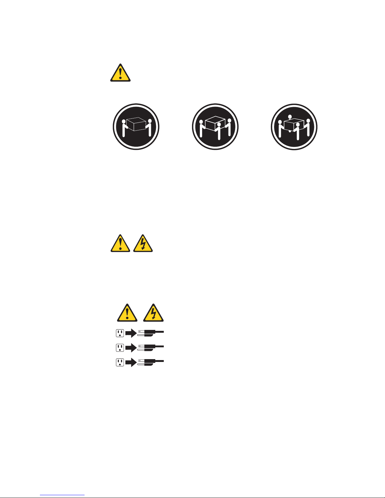
Statement 4:
CAUTION:
Use safe practices when lifting.
Statement 5:
CAUTION:
The power control button on the device and the power switch on the po wer supply do not turn off th e e lect ri cal curre nt su ppl ied t o the device. The device also
might have more than one power cor d. To remove all electrical current from the
device, ensure that all power cords are disconnected from the power source.
≥ 18 kg (39.7 lb) ≥ 32 kg (70.5 lb) ≥ 55 kg (121.2 lb)
1
2
3
Page 9
Safety ix
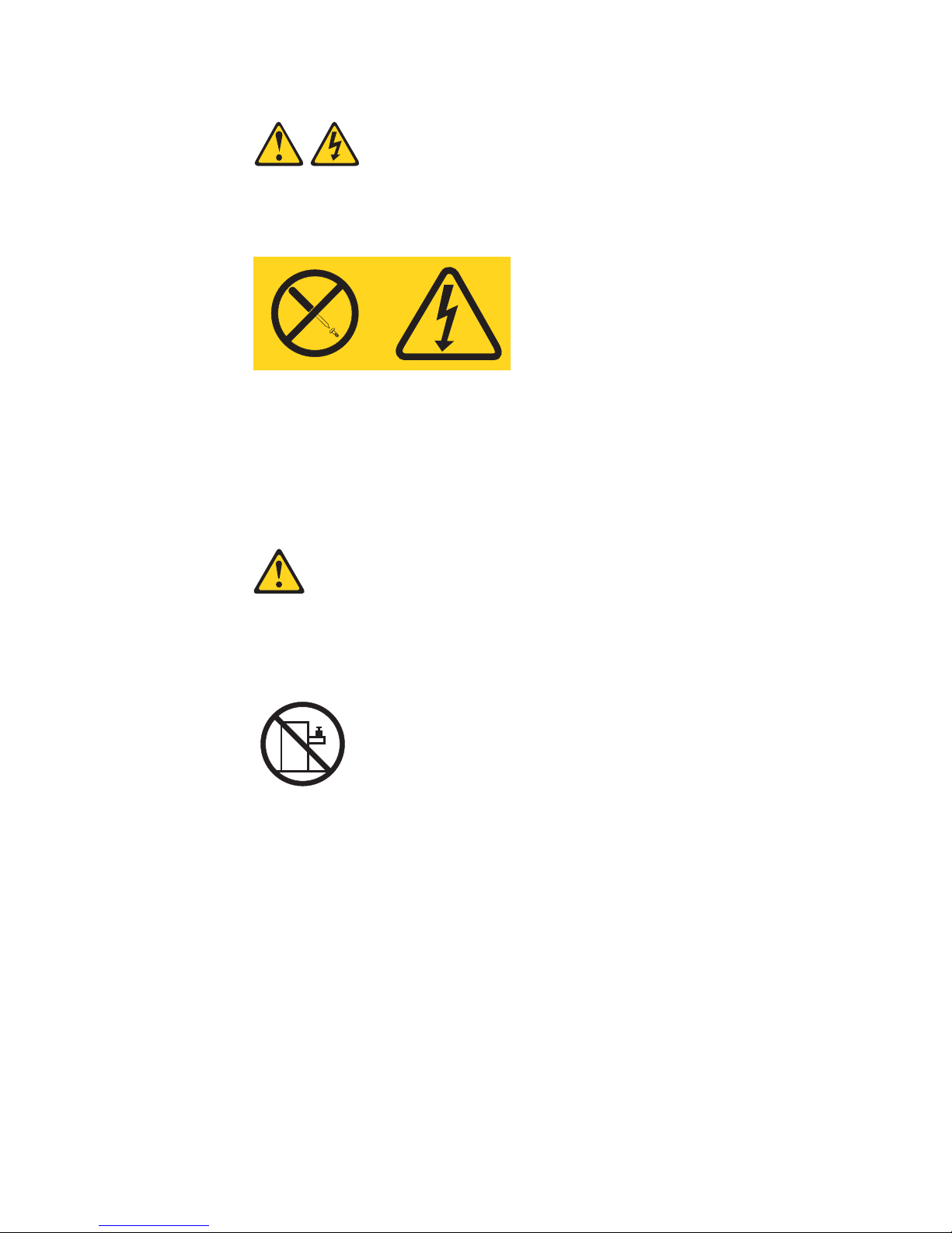
Statement 8:
CAUTION:
Never remove the cover on a power supply or any part that has the following
label attached.
Hazardous voltage, current, and energy levels are present inside any component that has this label attached. There are no serviceable parts inside these
components. If you suspect a pr oblem with one of these parts, contact a service technician.
Statement 10:
CAUTION:
Do not place any object weighing more than 82 kg (180 lb) on top of rackmounted devices.
>82 kg (180 lb)
Page 10

x IBM xSeries 360 Type 8686:Installation Guide
Page 11
© Copyright IBM Corp. 2001 1
Chapter 1. Introduction
Thank you for pur chasing an IBM Eserver xSeries 360™. This Installation Guide provides the information needed to:
• Set up and cable the server
• Start and configure the server
• Install the network operating system (NOS)
The xSeries 360 server features X-Architecture
™
technology. This technology is an
IBM design blueprint that takes full advantage of existing IBM technologies to build
powerful, scalable, and reliable Intel processor-based servers. For more information
about X-Architecture technology , go to http://www.pc.ibm.com/us/eserver/xseries/xarchitecture/index.html on th e World Wide Web.
Packaged with this Installation Guide are software CDs that help you configure hardware, install device drivers, and install the network operating system (NOS). Also
included is an IBM xSeries 360 Documentation CD, which provides detailed information about this server . F or complete r ac k installation an d remov a l instructions, see t he
Rack Installation Instructions provided with your server.
If you have access to the World Wide Web, you can obtain up-to-date information
about your xSeries 360 server and other IBM server products at
http://www.ibm.com/eserver/xseries/.
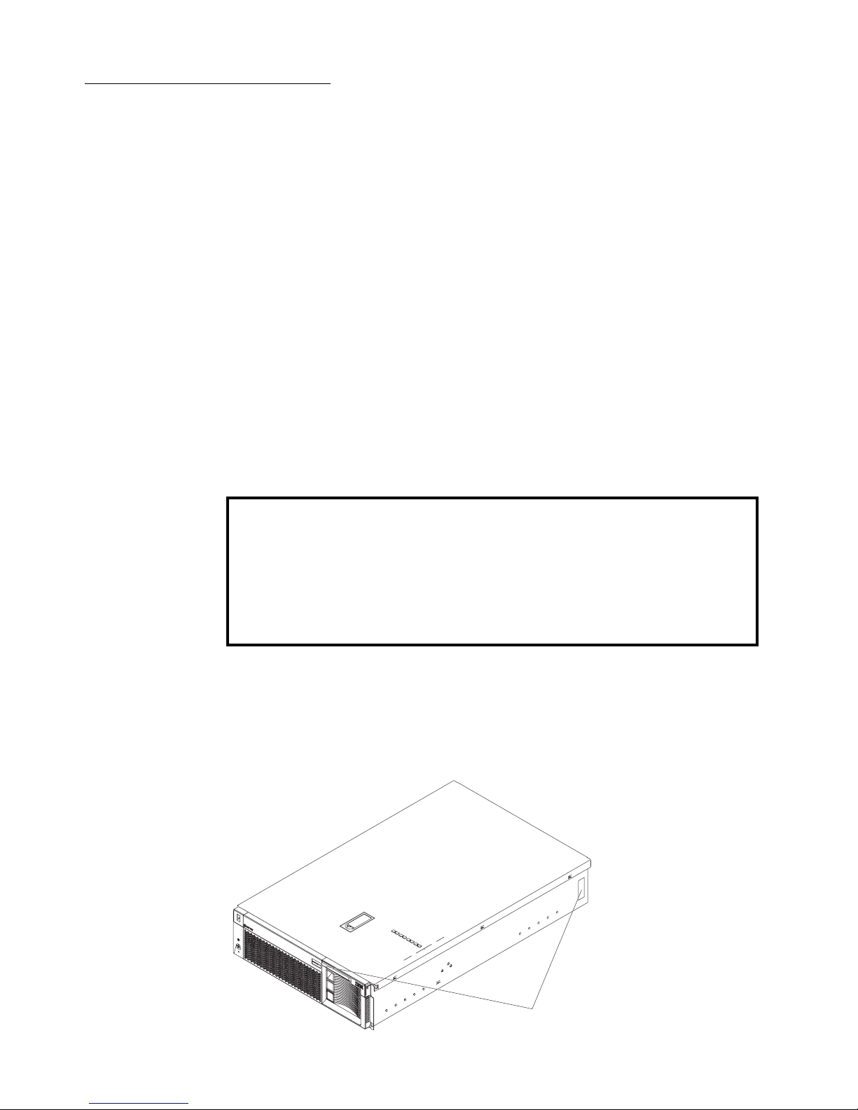
The machine type, model nu mber , and serial number ar e on the ID lab els, one located
on the bezel to the left of the CD- R OM d riv e an d the oth er at th e rear of th e right side ,
as shown in the following illustration. You will need these numbers when you register
your server with IBM.
Note: The illustrations in this document migh t differ slightly from your hardware.
Record your product information in this table.
Product name _________________________________________
Machine type _________________________________________
Model number _________________________________________
Serial number _________________________________________
ID labels
Page 12

2 IBM xSeries 360 Type 8686:Installation Guide
Specifications and features
The following table provides a summary of the specifications and features for the
xSeries 360 server.
Microprocessor:
• Intel Xeon
™
Processor MP
(frequency varies with server
model, each MP processor
functions as two logical
processors)
— Minimum: One
— Maximum: Four
• Level-3 cache size varies with
model
• 100 MHz front-side bus (FSB)
Chipset:
IBM XA-32
™
Chipset with integrated
memory, I/O controller, and remote I/O
controller.
Memory:
• DDR registered SDRAM DIMMs
with ECC and Chipkill
™
memory
— Minimum: 512 MB
— Maximum: 8 GB
• Slots: Interleaved, 8 slots
Drives standard:
• Slim diskette: 1.44 MB
• Slim CD-ROM: 24X-10X IDE
Hard disk drives:
• Slim-high hot-sw ap drives (n umber
of drives and drive capacity vary
with model)
•Maximum: Three
Active™ PCI-X expansion sl o t s:
• Two 100 MHz/64-bit PCI-X
• Four 66 MHz/64-bit PCI-X
Hot-swap power supplies:
370 W (115-230 V ac)
• Minimum: One
•Maximum: Three
Hot-swap cooling:
Six hot-swap fans
Video:
• S3 video controller
• Compatible with SVGA 4
• 8 MB SDRAM video memory
Size (3 U)
• Height: 134 mm (5.28 in.)
• Depth: 720 mm (28.35 in.)
• Width: 440 mm (17.32 in.)
• Weight: 25 kg (55.1 lb) to 31.7 kg
(70 lb) depending upon
configuration
Integrated functions:
• Light Path Diagnosti c s
™
• Ultra160 SCSI controller
• One 10BASE-T/100BASE-TX Intel
Ethernet controller
• Remote Supervisor Adap ter
(service processor)
— ASM in terconnect (peer-to-
peer) port
— RXE expansion port
— RXE management port
— Ethernet port
— Serial por t
• Three universal serial bus ports
• Keyboard port
•Mouse port
•Video port
Acoustical noise emissions:
• Sound power, idling: 6.3 bel
maximum
• Sound power, operating: 6.3 bel
maximum
• Sound pressure, operating: 47 dBa
maximum
Environment:
• Air temperature:
— Server on: 10° to 35°C (50° to
95°F). Altitude: 0 to 914 m
(3000 ft)
— Server on: 10° to 32°C (50° to
89.6°F). Altitude: 914 m (3000
ft) to 2133 m (7000 ft)
— Server off: 10° to 43°C (50° to
110°F). Maximum altitude:
2133 m (7000 ft)
• Humidity:
— Server on: 8% to 80%
— Server off: 8% to 80%
Heat output:
Approximate heat outp ut in British
thermal units (Btu) per hour
• Minimum configuration: 1232 Btu
(0.36 kilowatts)
• Maximum configuration: 3566 Btu
(1.045 kilowatts)
Electrical input:
• Sine-wave input (50-60 Hz)
required
• Input voltage low range:
— Minimum: 100 V ac
— Maximum: 127 V ac
• Input voltage high range:
— Minimum: 200 V ac
— Maximum: 240 V ac
• Input kilovolt-amperes (kVA)
approximately:
— Minimum: 0.08 kVA (ac power
connected, server off)
— Minimum: 0.38 kVA (dc power
on, server idle)
— Maximum: 1.1 kVA
Page 13

Chapter 1. Introduction 3
Notices and statements used in this book
The caution and danger statements used in this book also appear in the multilingual
Safety Information book, provided on the Documentation CD. Each caution and danger statement is numbered for easy reference to the corresponding statements in the
safety book.
The following types of noti ces and statements are used in this book:
• Note: These notices provide important tips, guidance, or advice.
• Important: These notices provide information or advice that might help you avoid
inconvenient or problem situations.
• Attention: These notices indicate possible damage to prog rams, de vices, or data.
An attention notice is placed just before the instruction or situation in which damage could occur.
• Caution: These statements indicate situations that ca n be potentially hazardous
to you. A caution statement is placed just before the description of a potentially
hazardous procedure step or situation.
• Danger: These statements indicate situations that can be potentially lethal or
extremely hazardous to you. A danger statement is placed just before the
description of a potentially lethal or extremely hazardous procedure step or situation.
Before you begin
Before you begin to install options in the server, read the following information:
• Become familiar with the information provided in “Safety” beginning on page v,
and “Handling static-sensitive devices”. These guidelines will help you work
safely while working with your server or options.
• Make sure that you have an adequate number of properly grounded electrical outlets for the server, monitor, and any other options that you intend to install.
• Back up all important data before you make changes to hard disk drives.
• For a list of supported options for the xSeries 360 server, refer to
http://www.ibm.com/pc/us/compat on the World Wide Web.
Handling static-sensitive devices
Attention: Static electricity can damage electronic devices and the system. To avoid
damage, keep static-sensitive devices in their static-protective packages until you are
ready to install them.
To reduce the possibility of electrostatic discharge, observe the following precautions:
• Limit your movement. Movement can cause static electricity to build up around
you.
• Handle the device carefully, holding it by its edges or its frame.
• Do not touch solder joints, pins, or exposed printed circuitry.
• Do not leave the de vice wh ere others can handle and possib ly damage the device.
• While the device is still in its static-protective package, touch it to an unpainted
metal part of the system unit for at least 2 seconds. (This drains static electricity
from the package and fro m your body.)
Page 14

4 IBM xSeries 360 Type 8686:Installation Guide
• Remove the device from its package and install it directly into the server without
setting it down. If it is necessary to set the device down, put it back in its staticprotective pac kage first. Do not pla ce the de vice on the server co ve r or on a metal
table.
• Take additional care when handling devices during cold weather as heating
reduces indoor humidity and increases static electricity.
Major components of the xSeries 360
The orange color on components and labels in the server identifies hot-swap or hotplug components. You can install or remove these components while the system is
running, provided that the system is configured to support this function.
The blue color on components and labels indicates touch points where a component
can be gripped, a latch moved, and so on.
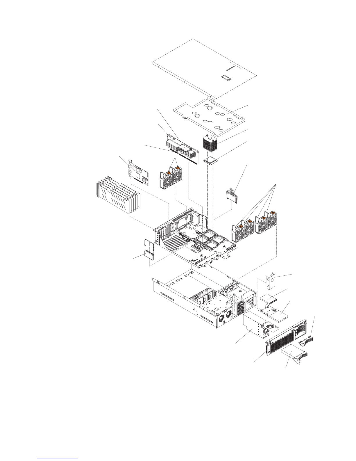
The following illustration shows the major components of the xSeries 360.
Note: The illustrations in this document migh t differ slightly from your hardware.
Page 15
Chapter 1. Introduction 5
Microprocessor heat sink
Heat sink stabilizer
Microprocessor
Microprocessor VRM
Hot-swap fans
Hot-swap fans
Hot-swap power supply
Power supply
filler panel
Bezel
Hot-swap hard drive
Hot-swap drive
filler panel
Memory board
Memory board
VRM
Dual inline
memory module
(DIMM)
Remote
Supervisor
Adapter
XA-32
chipset VRM
Diskette drive
CD-ROM drive
Page 16

6 IBM xSeries 360 Type 8686:Installation Guide
Page 17
© Copyright IBM Corp. 2001 7
Chapter 2. Installing options
This chapter provides the basic inf ormation needed to install options in the server . It is
for all users, but is written with the experienced user in mind. If you need more
detailed installation information, see the User’s Reference on the xSeries 360 Docu-
mentation CD.
Attention: When you handle Electrostatic Discharge-Sensitive devices (ESD), take
precautions to avoid damage from static electricity. For details on handling these
devices, see “Handling static-sensitive devices” on page 3.
Working inside a server with power on
The server supports hot-plug, hot-add, and hot-swap de vices an d is de signe d to ope rate safely while turned on with the cover removed. Follow these guidelines when you
work inside a server that is turned on:
Note: Operating the server for more than 30 minutes with the top cover removed
might damage server components.
• Avoid loose-fitting clothing on your forearms. Button long-sleeved shirts before
working inside the server; do not wear cufflinks while you are working inside the
server.
• Do not allow your necktie or scarf to hang inside the server.
• Remove jewelry, such as bracelets, necklaces, rings, and loose-fitting wrist
watches.
• Remove items from your shirt pocket (such as pens or pencils) that could fall into
the server as you lean over it.
• Take care to avoid dropping any metallic objects, such as paper clips, hair pins , or
screws, into the server.
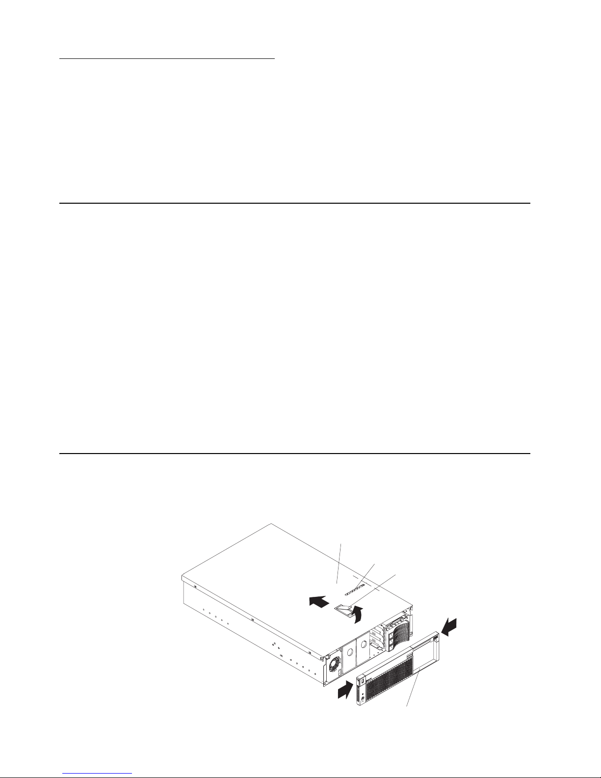
Removing the server top cover and bezel
Complete the following steps to remove the server top cover and bezel:
1. Review the safety precautions beginning on page v.
Top cover
Cover release latch
Bezel
Level 2 diagnostic panel
Page 18
8 IBM xSeries 360 Type 8686:Installation Guide
2. Lift the plastic cover-release latch on the top cover, as shown in the illustration.
Slide the top cover toward the rear of the server approximately one inch, lift it off
the server, and set it aside.
Attention: For proper cooling and airflow, replace the top cover before turning
on the server . Operating the server f or e xtended periods of t ime (ov er 30 minutes)
with the top cover removed might damage server components.
3. Press the bezel release latches and pull the top of the be zel slightly a w a y from the
server.
4. Pull the bezel up to release the two tabs at the bottom edg e of the bezel. Store
the bezel in a safe place.
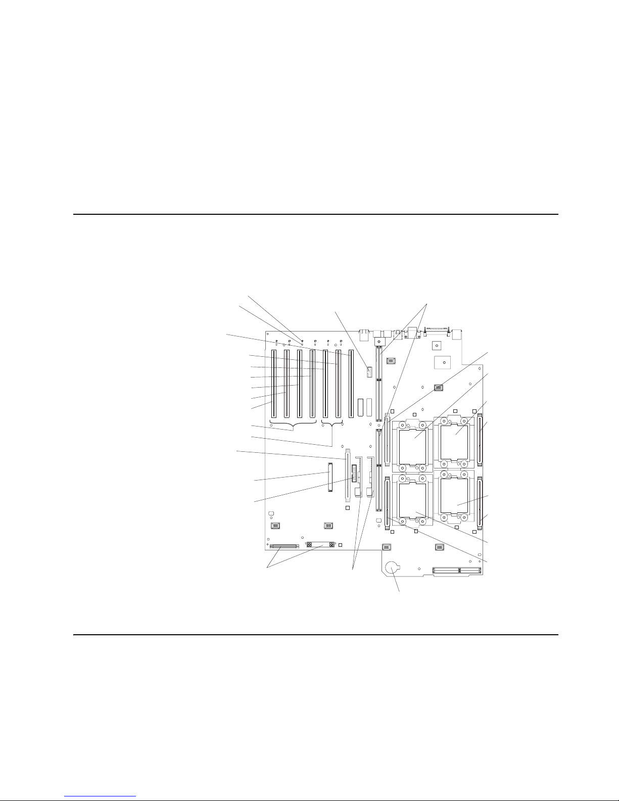
System board component locations
The following illustration sho ws the location of the connectors on the system board f or
pluggable components, and the location of the two nonpluggable VRMs used for the
PCI-X slots.
Adapter considerations
This server supports the following adapter configurations:
• Bus A (hot-plug)
— Four 66 MHz 64-bit PCI-X adapters (slots 3 through 6)
— Two 66 MHz 64-bit PCI adapters (slots 3 and 4)
— Four 33 MHz 64-bit PCI adapters (slots 3 through 6)
Microprocessor 4
VRM slot (J29)
Microprocessor 1
VRM slot (J2)
Microprocessor 3
VRM slot (J3)
Microprocessor 2
VRM slot (J30)
Microprocessor 4
socket (U22)
Microprocessor 1
socket (U11)
Microprocessor 3
socket (U12)
Microprocessor 2
socket (U23)
PCI-X slot 1
PCI-X slot 2
PCI-X slot 3
PCI-X slot 4
PCI-X slot 5
PCI-X slot 6
Remote
Supervisor
Adapter slot
(J40)
Remote Supervisor
Adapter cable
connector (J39)
XA-32 chipset
VRM slot (J41)
SCSI RAID cable
connector (J43)
Battery
Power distribution
connectors (J55, J49)
NonpluggableVRMs
PCI switch card cable
connector (J36)
Memory board connectors (J-32, J-33)
Bus A
Bus B
PCI power LED
PCI attention LED
Page 19

Chapter 2. Installing options 9
• Bus B (hot-plug)
— One 133 MHz 64-bit PCI-X adapter (slot 1)
— Two 100 MHz 64-bit PCI-X adapters (slots 1 and 2)
— Two 66 MHz 64-bit PCI-X adapters (slots 1 and 2)
— Two 66 MHz 64-bit PCI adapters (slots 1 and 2)
— Two 33 MHz 64-bit PCI adapters (slots 1 and 2)
To the right of PCI-X slot number 1 (as viewed from the front), th ere is a 33 MHz 64-bit
slot dedicated to the Remote Supervisor Adapter.
Before you install adapters, review the following:
• Locate the documentation that comes with the adapter and follow those instructions in addition to the instructions in this chapter. If you need to change switch
settings or jumper settings on the adapter, follow the instructions that come with
the adapter.
• Locate the documentation that comes with y our operati ng system. If the oper ating
system provides a way to disable or enable a hot-plug PCI/PCI-X slot, you will
need this documentation.
• If you install a ServeRAID
™
™ adapter for use with the in ternal hot-swap hard disk
drives, you must connect the internal channel cable between the adapter and the
SCSI RAID cable connector (J43) on the syste m board. However, if you do this,
you cannot install a full-length, wide adapter in PCI-X slot 1.
• The server supports only 3.3 V PCI or PCI-X adapters.
• The server uses a rotational interrupt tech nique to configu re PCI/PCI-X adap ters .
You can use this technique to install PCI/PCI-X adapter s that current ly do not support sharing of PCI interrupts.
• PCI-X slots 3 through 6 are on PCI bus A; PCI-X slots 1 and 2 are on PCI bus B.
• By default, the server st arts (boots) devices in the f ollowing or der: system IDE and
SCSI devices, then PCI/PCI-X devices.
Note: To change the startup order, start the Configuration/Setup Utility program
and select Start Options from the main menu. Then, select the Startup
Sequence Options.
Installing a hot-plug PCI or PCI-X adapter
This section describes how to install a hot-plug PCI/PCI-X adapter. Before you continue with the adapter-installation procedure, note that all six PCI-X slots support hotplug, 64-bit, PCI/PCI-X adapters. If PCI/PCI-X adapter s are installed in both slots 1
and 2, they operate at 100 MHz or less, depending on the capacity of the adapter. If
one adapter is installed in slot 1 and slot 2 is empty, the adapter in slot 1 can operate
at 133 MHz.
Note: Ensure that the PCI hot-plug de vice driv er is installed. For details, see the doc-
umentation that came with the adapter. For more detailed instructions and
information about installing PCI/PCI-X adapters, see the section on installing
options in the User’s Reference on the xSeries 360 Documentation CD.
Complete the following steps to install a hot-plug PCI/PCI-X adapter:
1. Review the safe ty precautio ns beginning o n page v a nd “Ha ndlin g st at ic-sensitive
devices” on page 3.
Page 20
10 IBM xSeries 360 Type 8686:Installation Guide
2. Remove the top cov er (see “Rem oving th e server top co v er and bez el” on page 7)
and determine which PCI-X expansion slot you will use for the adapter.
Note: All six PCI-X slots support hot-plug PCI/PCI-X adapters.
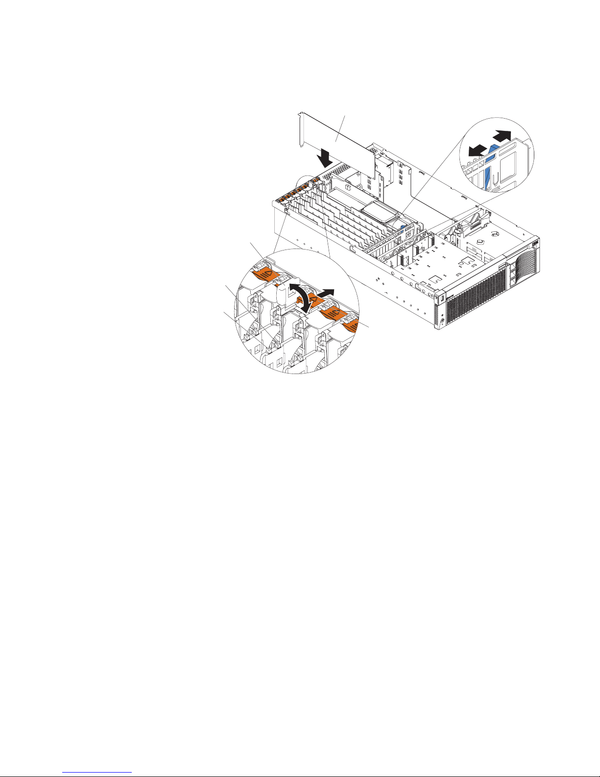
3. Slide the orange adapter-retention tab toward the rear of the server. Lift the
adapter-retention latch. The power LED turns off for the appropriate slot.
4. Slide the expansion-slot cover up and out of the server; then, move the blue PCIadapter locking lever to the right (as viewed from the front) to enable insertion of
the new adapter.
Attention: Avoid touching the components and gold-edge connectors on the
adapter. Ensure that the adapter is completely and correctly seated in the slot.
Incomplete insertion might cause damage to the system board or to the adapter.
Attention: When you handle Electrostatic Discharge-Sensitive devices (ESD),
take precautions to avoid damage from static electricity. For details on handling
these devices, see “Handling static-sensitive devices” on page 3.
5. Remove the adapter from the static-protective package and install the adapter,
pressing it firmly into the slot.
6. Move the blue PCI-adapter locking lever to the left (as viewed from the front) to
secure the adapter; then, lower the adapter-retention latch over the top corner of
the adapter. The orange adapter-retention tab snaps into place and the power
LED turns on for the slot.
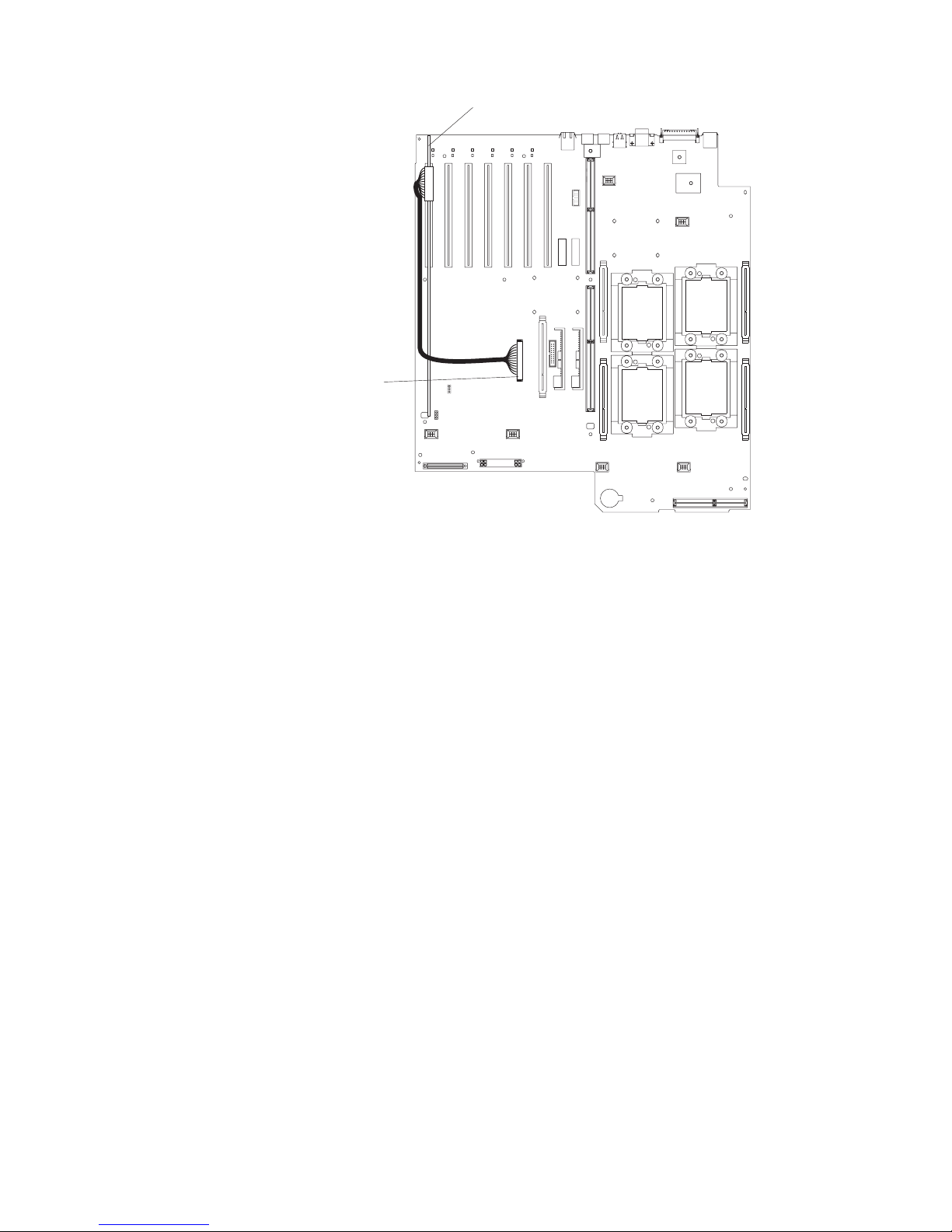
7. Connect any needed cables to the adapter. If you are installing a ServeRAID
adapter, continue with step 8. Otherwise, go t o step 12.
8. If you are installing a ServeRAID adapter and plan to use internal hard disk drives:
a. Plug in one end of the ServeRAID internal channel cable (shipped with the
server) to an internal ServeRAID channel connector on the top edge of the
ServeRAID adapter, as shown in the following illustration. You can install the
adapter in any PCI-X slot. It is shown in slot 6 here only as an example.
Unlock
Lock
Adapter locking lever
Adapter
retention
latch
Adapter
retention
tab
Adapter
Attention
LED
Power
LED
Page 21
Chapter 2. Installing options 11
b. Route the cable along the surface of the system board toward the front of the
server, then to the right under the adapters and dividers; then plug it into the
SCSI RAID cable connector (J43) on the system board.
Notes:
1) You cannot install a full-length, wide adapter in PCI-X slot 1 if the SCSI
RAID adapter cable connector is in use.
2) You might need to remo v e adapters o r plastic dividers to access the SCSI
RAID adapter cable connector.
3) The first time that you restart the server after connecting the cable, the
server issues POST error message 00180700 with modifier 9005008F;
this message is normal. It indicates that the onboard SCSI controller has
been disabled and that the RAID adapter is controlling the internal hard
disk drives.
9. If you are installing a ServeRAID adapter and plan to use external hard disk
drives:
a. Plug in one end of the ServeRAID external channel cable (separately ord er-
able) to an ex ternal channel connector on the edge of t he ServeRAID adapter
that is accessible from the rear of the server.
b. Route the cable to the external SCSI device and plug it into the appropriate
connector.
10. Install the latest ServeRAID drivers, using the ServerGuide
™
™ CDs.
11. Configure ServeRAID, using the ServeRAID adapter documentation on the
xSeries 360 Documentation CD.
12. If you have other options to install or remove, do so now; otherwise, go to “Completing the installation” on page 19.
ServeRAID adapter
SCSI RAID
cable connector
Page 22
12 IBM xSeries 360 Type 8686:Installation Guide
Installing a hot-swap hard disk drive
The server supports up to three 26 mm (1-inch), 3.5-inch, hot-sw ap hard disk driv es in
the hot-swa p ba ys . The ba ys are locate d at the right front of the server. The hot-swap
bays are connected to a hot- swap drive backplane. The backplan e i s a printed circuit
board behind the bays.
Complete the following steps to install a drive in a hot-swap bay:
1. Review the safety precautions beginning on page v.
2. Remove the filler panel from one of the empty hot-swap bays by inserting your finger into the depression at the left side of the filler panel and pulling the panel out
of the server, as shown in the following illustration.
Attention: To maintain proper system cooling, do not operate the server for
more than 10 minutes without either a drive or filler panel installed in each bay.
3. Install the hard disk drive in the hot-swap bay:
a. Ensure that the tray handle is open (that is, perpendicular to the drive).
b. Align the drive assembly with the guide rails in the bay.
c. Gently push the drive assembly into the bay until the drive stops.
d. Push the tray handle to the closed (locked) position.
e. Check the hard disk drive status LED to verify that the hard disk drive is oper-
ating properly. If the amber hard disk drive status LED for a drive is lit continuously, that individual drive is faulty and needs to be replaced. If the green
hard disk drive activity LED is flashing, the drive is being accessed.
4. If you have other options to install or remove, do so now; otherwise, go to “Completing the installation” on page 19.
Note: If the server has a ServeRAID controller or adapter installed, you might
need to reconfigure the disk arrays after installing hard disk drives. See
the ServeRAID documentation on the xSeries 360 Documentation CD for
more information.
Filler panel
Drive tray handle
(in open position)
Drive tray
assembly
Page 23
Chapter 2. Installing options 13
Installing memory modules
The server supports up to four pairs of DIMMs and supports memory interleaving.
Adding memory to the server is an easy way to ma ke programs run faster.
Notes:
1. The server supports a minimum of 512 MB of system memory and a maximum of
8 GB of system memory. The DIMM slots are arranged in two columns of four
rows each. The server supports DIMMs of 256 MB , 512 MB, and 1 GB capacities.
2. Each pair of DIMMs must be the same type, capacity, and speed. However, you
can install DIMM pairs of different capacities as long as both DIMMs in each pair
are the same.
3. Installing or removing DIMMs changes the configuration information in the server.
Therefore, after installing or removing DIMMs, you must save the ne w configuration information using the Configuration/Setup Utility program. When you restart
the server, the system displays a message indicating that the memory configuration has changed. Start the Configuration/Setup Utility program and select Save
Settings. See Chapter 4, “Configuring th e server” on page 29 for more information.
Complete the following steps to install DIMMs:
1. Review the safety precautions beginning on page v, “Handling static-sensitive
devices” on page 3, and the documentation that comes with the DIMMs.
2. Turn off the server, disconnect all power cords and external cables, and remove
the top cover (see “Removing the server top cover and bezel” on page 7).
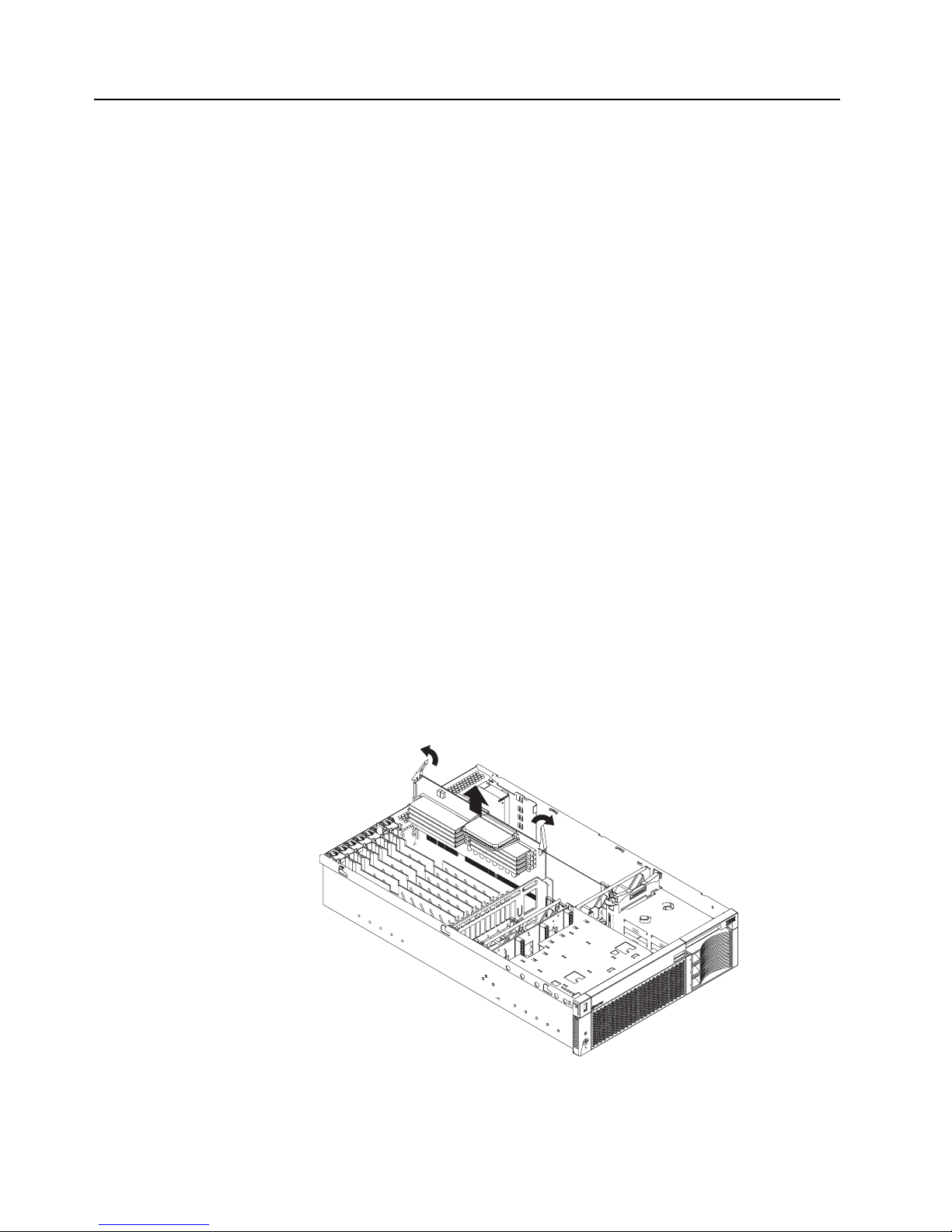
3. Remove the memory board, as shown in the following illustration:
Attention: When you handle Electrostatic Discharge-Sensitive devices (ESD),
take precautions to avoid damage from static electricity. For details on handling
these devices, see “Handling static-sensitive devices” on page 3.
a. Lift up the two memory-board locking latches to release the board.
b. Lift the memory board out of the server.
4. When installing additional DIMMs, determine the DIMM slots into which you will
install them. You must populate the slots in pairs, one DIMM in each column, proceeding from top to bottom. Use only 2.5 V, 184-pin, PC1600, DDR registered
Page 24

14 IBM xSeries 360 Type 8686:Installation Guide
synchronous dynamic random-access memory (SDRAM) with error correcting
code (ECC).
5. Touch the static-protective package that contains the DIMM option to any
unpainted metal surface on the server. Then, remove the DIMM from the package.
6. Turn the DIMM so that the DIMM keys align correctly with the slot.
Attention: To avoid breaking the DIMM locking latches or damaging the DIMM
slots, handle the latches gently.
7. Ensure that the DIMM locking latches are in the open position. Insert the DIMM
by pressing it straight into the slot. Make sure that the locking latches snap into
the closed position. If a gap exists between the DIMM and the latches, the DIMM
has not been properly installed. In this case, open the latches , remo v e the DIMM,
and reinsert it.
First pair DIMMs 1 and 2
Second pair DIMMs 3 and 4
Third pair DIMMs 5 and 6
Fourth pair DIMMs 7 and 8
DIMM 1
DIMM 3
DIMM 4
DIMM 2
DIMM slot 3
DIMM slot 4
Memory VRM
Test button
Test LED to show
capacitor is charged
Memory board VRM slot (J11)
DIMM 1 (J14)
DIMM 3 (J13)
DIMM 5 (J12)
DIMM 7 (J4)
DIMM 2 (J15)
DIMM 4 (J9)
DIMM 6 (J7)
DIMM 8 (J5)
Test buttonTest LED to show
capacitor is charged
Page 25

Chapter 2. Installing options 15
8. Repeat steps 3 through 7 for each additional DIMM that you install.
9. Install the memory board:
a. Align the board in the guides over the memory connector.
b. Open the memory-board locking latches and insert the memory board into the
connector. Be sure that the locking latches snap into the closed position.
10. If you have other options to install or remove, do so now; otherwise, go to “Completing the installation” on page 19.
Attention: When you restart the server, the system displays a message indicating
that the memory configuration has changed.
• If you installed additional memory, start the Configuration/Setup Utility program
and select Save Settings.
• If the 3-3-3 beep code sounds during POST, the memory board may not be fully
seated. In some memory configurations, if the 3-3-3 beep code is followed by a
blank display screen and the Boot Fail Count feature in the Start Options of the
Configuration/Setup Utility is set to Enabled (its default setting), you must restart
the server three times to f orc e the syste m BIOS to reset t he memory connector or
bank of connectors from Disabled to Enabled.
Installing a microprocessor
The server comes with a minimum of one microprocessor installed on the system
board and supports up to four microprocessors. With mor e tha n one micropro ce sso r,
the server can operate as a symmetric multiprocessing (SMP) server. With SMP, certain operating systems and application programs can distribute the processing load
among the microprocessors.
Before you begin:
• Read the documentation that comes with the microprocessor to determine if you
need to update the server basic input/output system (BIOS) code. The most current level of BIOS code for the server is available through the World Wide Web at
http://www.ibm.com/pc/support.
• Obtain an SMP-capable operating system (optional). For a list of supported operating systems, go to http://www.ibm.com/pc/us/compat/ on the World Wide Web.
Attention: To avoid damage and ensure proper server operation when you install a
microprocessor, use a microprocessor that has the same cache size and type, clock
speed, and internal and external clock frequencies as the microprocessor already
installed.
Notes:
1. To order additional microprocessor options, contact your IBM reseller or IBM marketing representative.
2. The microprocessor in socket 1 is the startup (boot) microprocessor.
If you want to install addit ional micro processors , populate the micr oprocessor sockets
in numeric order, starting with socket 2. The following illustration shows the locations
of the microprocessor sockets and VRMs on the system board.
Note: If you install the microprocessors in the wrong order, the server will not power
on.
Page 26

16 IBM xSeries 360 Type 8686:Installation Guide
Complete the following steps to install a microprocessor:
1. Review the safe ty precautio ns beginning o n page v and “Ha ndling st atic-sen sit ive
devices” on page 3.
2. Turn off the server, disconnect all power cords and external cables, and remove
the top cover (see “Removing the server top cover and bezel” on page 7).
Attention: When you handle Electrostatic Discharge-Sensitive devices (ESD), take
precautions to avoid damage from static electricity. For details on handling these
devices, see “Handling static-sensitive devices” on page 3.
3. Lift off the microprocessor heat sink stabilizer as shown in the following illustration
and determine the socket where the microprocessor is to be installed.
Microprocessor
connector 1 (U11)
Microprocessor
connector 2 (U23)
Microprocessor
connector 3 (U12)
Microprocessor
connector 4 (U22)
Microprocessor 4
VRM connector
(J29)
Microprocessor 2
VRM connector
(J30)
Microprocessor 1
VRM connector
(J2)
Microprocessor 3
VRM connector
(J3)
Page 27

Chapter 2. Installing options 17
Notes:
a. The new microprocessor comes in a kit with a VRM and a heat sink.
b. If you are replacing a failed micropr ocessor, verify that you have selected the
correct microprocessor to be replaced. The LED next to the failing microprocessor will be on. Remove the microprocessor heat sink (two thumbscrews).
c. If you are installing an additional microprocessor, first install a VRM in the slot
adjacent to the microprocessor socket you have selected and r emove the protective tape from the microprocessor socket.
4. Install the microprocessor:
a. T o uch the static-protectiv e pac kage contain ing the ne w microprocessor to an y
unpainted metal surf ace on the server; then, remove the microprocessor from
the package.
b. Lift the locking lever on the socket to permit plugging in the microprocessor.
c. Align the triangle icon on the microproces so r wi th the triangle icon on the
socket and press the mi croprocessor gently into the socket.
Attention: Make sure that the microp rocessor is aligned correct ly befor e you
proceed. To avoid bending the pins on the microprocessor, do not use exces-
sive force when pressing it into the socket.
d. Close the locking lever to secure the microprocessor.
5. Install the microprocessor heat sink.
Attention: Do not disturb or contaminate th e h eat- co nductin g grease on the bot-
tom of the new heat sink. Doing so damages its heat-conducting capability and
exposes the new micr oprocessor to overheating.
Microprocessor
Microprocessor
VRM
XA-32
chipset VRM
Heat sink
Heat sink stabilizer
Page 28

18 IBM xSeries 360 Type 8686:Installation Guide
6. Remove the heat sink from its package and secure it to the top of the micropr ocessor (two thumbscrews). Press firmly on the thumbscrews and tighten them,
alternating between screws until finger tight. Do not overtighten the screws.
7. Install the heat-sink stabilizer.
8. If you have other options to install or remove, do so now; otherwise, go to “Completing the installation” on page 19.
Installing a hot-swap power supply
The server comes with a minimum of one power supply and supports up to three
power supplies. If you install or remove a power supply, observe the following precautions.
Statement 8:
CAUTION:
Never remove the cover on a power supply or any part that has the following
label attached.
Hazardous voltage, current, and energy levels are present inside any component that has this label attached. There are no serviceable parts inside these
components. If you suspect a problem with one of these parts, contact a service technician.
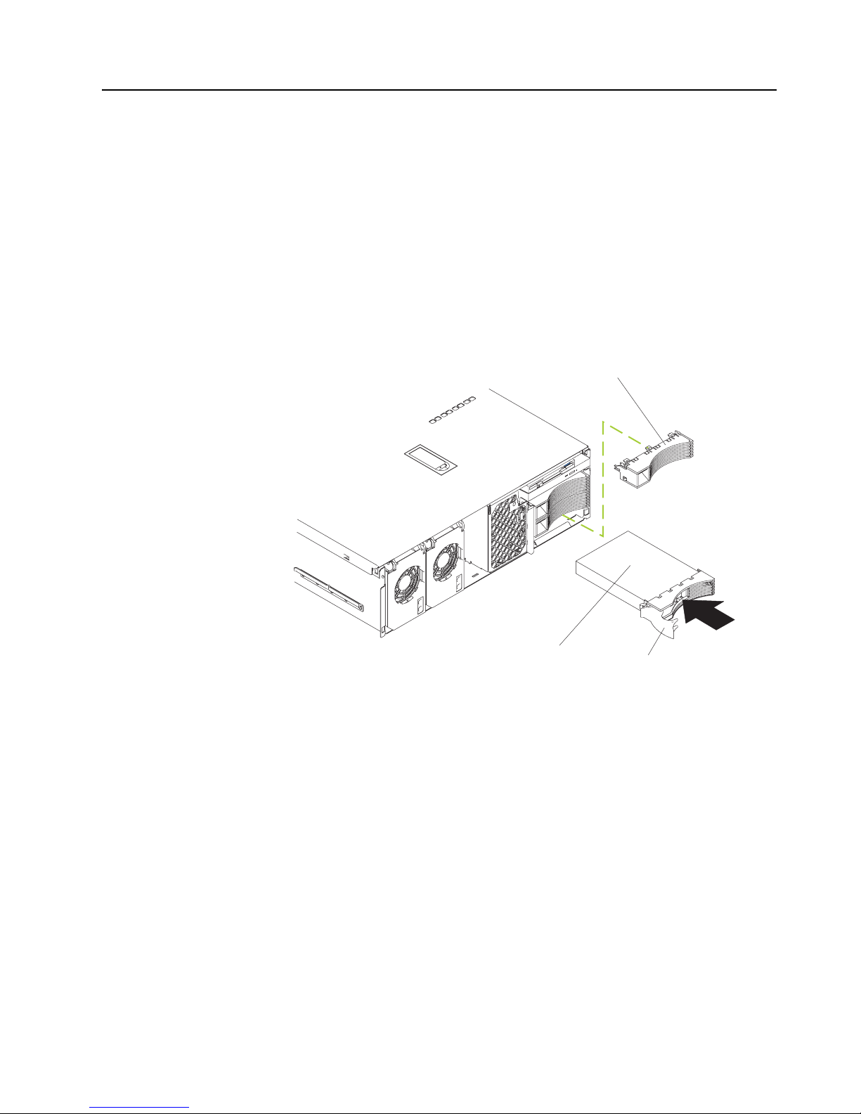
Complete the following steps to install a hot-swap power supply:
1. Review the safety precautions beginning on page v.
2. Remove the bezel. See “Removing the server top cover and bezel” on page 7.
3. Remove the appropriate power-supply filler panel by inserting a finger into the
hole and pulling the panel forward. The panel pivots at the top.
Page 29

Chapter 2. Installing options 19
Note: The power supplies are numbered from left to right (1 to 3) as viewed from
the front of the server. Power supplies do not have to be installed in a particular sequence.
Attention: To ensure proper system cooling, do not leave the filler panel off the
server for more than 30 minutes.
4. Press down on the locking latch and mov e the loc king handle to the open po sition,
as shown in the illustration.
5. Slide the power supply into the chassis and fully close the locking handle.
6. Plug one end of the power cord for the new power supply into the corresponding
connector on the back of the server (connectors are numbered 1 through 3 from
top to bottom, as illustrated at “Cabling the server” on page 21). Plug the other
end of the power cord into a prop erly grounded electrical outlet.
7. Ve rify that the dc power and ac power LEDs on the front of the power supply are
lit, indicating that the power supply is operating properly.
8. Continue with “Completing the installation”.
Completing the installation
This section provides the information needed to complete the installation.
Installing the server top cover and bezel
Complete the following steps to install the server top cover and bezel:
1. Before installing the cover, check that all internal cables, ada pters , and othe r components are installed and seated corr ectly and that y ou h av e not left loose tools or
parts inside the server.
2. Move the cover-release latch to the open (up) position.
Power supply 3
Power supply 2
Locking latch
Locking handle
AC power LED
DC power LED
Power supply 1
Page 30

20 IBM xSeries 360 Type 8686:Installation Guide
3. Insert the tabs on the top cover into the matching slots in the server chassis.
4. Close the cover-release latch to pull the top cover forward and lock the to p cover
in place.
5. Insert the tabs on the bottom of the bezel into the matching holes on the server
chassis.
6. Push the top of the bezel toward the server until the two tabs at the top of the
bezel snap into place.
7. Continue with “Installing the ser ver in the rack”.
Installing the server in the rack
Install the server in the rack cabinet. For complete rack installation and removal
instructions, see the Rack Installation Instructions provided with your server.
After you have installed the server in the rack, see “Cabling t he server” o n pag e 21 for
details about connecting external cables and power cords to the server and routing
the cables through the cable management arm.
Top cover
Cover release latch
Bezel
Level 2 diagnostic panel
Page 31

Chapter 2. Installing options 21
Cabling the server
The following illustration shows the I/O ports on the rear of the server. Use this illustration to connect the external cables to the rear of the server.
The following illustration shows the cable routing for a typical server configuration.
Detailed cabling instructions, including the use of the cable management arm
(shipped with the server) are in the Rack Installation Instructions provided with the
server.
Notes:
1. The illustrations in this document might differ slightly from your hardware.
2. See the documentation that comes with the options for additional cabling instructions. It might be easier for you to route any cables before you install certain
options.
3. If you have just plugged the power cords of the server into an electrical outlet, you
must wait 30 seconds before pressing the power-control button.
For inf ormation about configuring and cab ling the Remote Supervisor Adapter to manage the server remotely or to interconnect to another device, see the xSeries 360
User’s Referenc e. For information about using the Remote Supervisor Adapter, see
the Remote Supervisor Adapter User’s Guide. Both documents are on the xSeries
360 Documentation CD.
RXE management
port
ASM interconnect
port
RXE expansion
port
Video port
USB 1
USB 2
Mouse port
Keyboard port
Ethernet port
Remote Supervisor
Adapter fault LED
(amber)
Remote Supervisor
Adapter power LED
(green)
Remote Supervisor
Adapter serial port
Remote Supervisor
Adapter Ethernet port
AC power connector 1
AC power connector 2
AC power connector 3
Page 32

22 IBM xSeries 360 Type 8686:Installation Guide
After you ha ve i nstalled the server in the r ack and connected all the needed cables , go
to “Turning on the server” on page 23.
Page 33

© Copyright IBM Corp. 2001 23
Chapter 3. Server power, controls, and indicators
This chapter explains ho w to turn on and turn off the server and describes the controls
and indicators.
Turning on the server
Turning on the server refers to the act of plugging the server power cords into the
power source and pressing the power-control button. After you install the network
operating system in the server, this typically causes the operating system to start. For
more details, see the introduction in the User’s Reference on the xSeries 360 Docu-
mentation CD.
Complete the following steps to turn on the server.
1. Turn on all external devices, such as the monitor.
Note: After you plug the power cords into the pow er source, wait 30 seconds
before pressing the power-control button on the operator information
panel. During this time, the Remote Supervisor Adapter is initializing and
the power-control button does not respond. The power LED on the information panel blinks, indicating that ac power is present in the server.
2. Press the power control button on the operator information panel. The power LED
comes on and the power-on self-test (POST) begins.
If the server is turned on and a power failure occurs, it restarts automatically when
power is restored. You can turn on the server remotely by means of the Remote
Supervisor Adapter.
When you start the server for the first time after you add or remove an internal option
or an external SCSI device, y ou might see a message telling you that the configuration
has changed. The Configuration/Setup Utility prog ram automatically starts so that you
can save the new configuration information. See Chapter 4, “Configuring the server”
on page 29 for details.
Some options have device drivers that you need to install. See the documentation
that comes with the option for information about installing any required device drivers.
The server comes with at least one microprocessor installed on the system board . If
you have installed one or more additional microprocessors, the server can now operate as an SMP server. Therefor e, you might need to upgra de th e oper a ting syst em to
support SMP. See “Using the ServerGuide CDs” on page 31 and the operatin g-system documentation for additional information.
If the server has a ServeRAID adapter installed and you have installed or removed a
hard disk drive, see the do cumentation that comes with the ServeRAID adapter for
information about reconfiguring the disk arrays.
Turning off the server
Turning off the server refers to the act of stopping the operating system, pressing the
power-control button, and disconnecting the server power cords from the power
source.
Note: Each operating system is different. Some allow an immediate shutdown; oth-
ers require an orderly shutdown procedure.
Page 34

24 IBM xSeries 360 Type 8686:Installation Guide
See the operating system documentation for the proper procedure to shut down the
operating system.
Statement 5:
CAUTION:
The power control button on the device and the power switch on the po wer supply do not turn off th e e lect ri cal curre nt su ppl ied t o the device. The device also
might have more than one power cor d. To remove all electrical current from the
device, ensure that all power cords are disconnected from the power source.
You can turn off the server in any of the following ways:
• Press the power-control b utton on the oper ator inf ormation panel. This places the
server in standby mode. The po wer LED on the oper ator information panel b links.
This does not remove all power from the server.
Note: After doing this, w ait at least 30 seconds bef ore pressing the power- control
button to turn on the server again.
• You can disconnect the server power cords from the power source to shut off all
power immediately without damaging the server.
Note: Wa it appro ximately 15 se conds after discon necting the po wer cords f or th e
server to stop running. W a tch for the power LED on the operator information panel to stop blinking.
Standby mode
Standby mode refers to the condition in which the server operating system is not running and all core logic is shut down except for the Remote Supervisor Adapter.
Complete the following steps to put the server into standby mode:
1. See the operating system documentation for the proper procedure to shut down
the operating system.
Note: Each operating system is different. Read all the documentation about
shutting down the operating system before continuing.
2. Press the power-control button on the front of the server.
You can put the server into standby mode remotely by means of the Remote Supervisor Adapter.
1
2
3
Page 35

Chapter 3. Server power, controls, and indicators 25
Server controls and indicators
The following illustration shows the controls and indicators on the front of the server.
Operator information panel: This panel, also kno wn as the front LED panel, contains
controls, indicators, and one of the t hree USB ports. See “Operator inf ormation panel”
on page 27 for details.
AC LED: Each hot-swap pow er supply has an ac po we r LED to indicate that ac po we r
is available to the power supply.
DC LED: Each hot-swap po w er su pply has a dc power LED to indicate that the power
supply is active.
Diskette drive: The server contains one standard 3.5-inch diskette drive with an LED
to indicate when it is active.
CD-ROM drive: The server contains one standard I DE CD-ROM with an LED to indicate when it is active.
Hard disk drive filler panels: A filler panel is used to cover empty hard disk drive
bays. A filler panel must be installed in each empty bay to ensure proper system cooling.
Activity LED: Each hot-swap hard disk drive has an activity LED, which flashes if the
drive is being accessed.
Status LED: Each hot-swap hard disk driv e has a status LED. If this amber LED is on
continuously , the drive has fa iled. If an optional IBM ServeRAID adapter is installed in
the server and the LED flashes slowly (one flash per second), the drive is being
rebuilt. If the LED flashes rapidly (three flashes per second), the contro ller is identi fying the drive.
Hard disk drive: The server supports a maximum of three hot-swap hard disk drives.
Power supplies 1, 2, and 3: The server supports a maximum of three hot-swap
power supplies.
Power
supply 1
Power
supply 2
Power
supply 3
AC LED
DC LED
Hard disk drive
Diskette drive
CD-ROM drive
Hard disk drive
filler panels
Activity
(green)
LED
Status
(amber)
LED
Operator information
panel
Page 36

26 IBM xSeries 360 Type 8686:Installation Guide
The following illustration shows the indicators on the rear of the server.
Ethernet link LEDs: These LEDs (one for the Remote Supervisor Adapter, one for
the network) indicate that the related Ethernet link is operational.
Ethernet TX/RX LEDs: These LEDs (one for the Remote Supervisor Adapter, one for
the network) indicate that activity is taking place on the related network.
Remote Supervisor Adapter Ethernet port: This port enables you to manage the
server from a remote location.
Remote Supervisor Adapter fault LED: This LED indicates that the Remote Supervisor Adapter has failed.
Remote Supervisor Adapter power LED: This LED indicates that power is being
supplied to the Remote Supervisor Adapter.
Ethernet port: This port enables you to connect the server to a network.
Ethernet port
Remote Supervisor
Adapter fault
(amber)
LED
Remote Supervisor
Adapter power LED
(green)
Remote Supervisor
Adapter Ethernet port
Ethernet TX/RX LEDs
Ethernet link LEDs
Page 37

Chapter 3. Server power, controls, and indicators 27
Operator information panel
The following illustration shows the controls, indicators, and USB port on the operator
information panel (also known as the front LED panel).
USB port: This port enables you to attach a USB device to the front of the server.
SCSI bus activity LED: This green LED is on when there is activity on the SCSI bus.
Information LED: This amber LED is on if the server power supplies are nonredun-
dant or some other noncritical event has occurred. See the LEDs on the Level 2 diagnostic LED panel or on the system board for specific error information. For details,
see the User’s Reference on the xSeries 360 Documentation CD.
Fault LED: This amber LED is on if a system error has occurred. See the LEDs on
the Leve l 2 diagnostic LED panel or on the system board f or specific error inf ormation.
For details, see the User’s Reference on the xSeries 360 Documentation CD.
Reset button: Press this button to reset the server and run the power-on self-test
(POST).
Power-control button: If the server is in operational mode, press this button to put it
into standby mode. If the server is in standby mode, press this button to restore it to
operational mode. See Turning on the server and “Turning off the server” on page 23
for more information about applying and removing external power to the server.
Power LED: This green LED is on if ac and dc power are present in the server. If this
LED is flashing, the server is in standby mode (ac power is present, but the power
supplies are turned off). If this LED is off, either ac power, all power supplies, or the
LED has failed.
Note: If this LED is off, it does not mean there is no electrical current present in the
server. The LED might be b urned out. To remove all electrical current from the
server, you must unplug the server power cords from the electrical outlets.
USB port
SCSI bus activity LED
Fault LED
Information LED
Reset button
Power-control button
PowerLED
Page 38

28 IBM xSeries 360 Type 8686:Installation Guide
Page 39

© Copyright IBM Corp. 2001 29
Chapter 4. Configuring the server
This chapter provides the instructions for using the utility programs. F or more detailed
information about these utility programs, see the User’s Reference on the xSeries 360
Documentation CD.
You can use the following configuration programs to customize the server hardware:
• Configuration/Setup Utility program
This program is part of the basic input/output system (BIOS) code that comes with
the server. You can use this program to change interrupt request (IRQ) settings,
change the drive startup sequence, set the date and t ime, and set pass word s. F or
information about using this utility, see “Using the Configuration/Setup Utility program” on page 30.
• SCSISelect utility program
This program is part of the basic input/output system (BIOS) code that comes with
the server . You can use this prog ram t o configur e the de vice s that ar e attach ed to
the integrated SCSI controller. Use this program to change def ault v alues, resolv e
configuration conflicts, and perform a low-level format on a SCSI hard disk drive.
For information about using this utility, see “Using the SCSISelect utility program”
on page 30.
• PXE Boot Agent Utility program
The Preboot eXecution Environment (PXE) Boot Agent Utility program is part of
the BIOS code that comes with the server. Y ou can use this progr am to select th e
boot protocol and other boot options, to display the PXE setup prompt or to disable it, to set the prompt display duration, and to select a power management
option. For information about using this utility, see “Using the PXE Boot Agent
Utility program” on page 31.
Note: The RPL selection for the Boot Protocol option is not supported for this
server.
• ServerGuide CDs
The ServerGuide CDs provide software setup and installation tools that are spe-
cifically designed for your IBM server . Use these CDs during the initial installation
of your server to configure basic hardware features and to simplify your network
operating system (NOS) installation. The ServerGuide CDs also contain a collection of application programs, which you can install after the server is up and running. See “Using the ServerGuide CDs” on page 31 for more information.
• Remote Supervisor Adapter configuration process
Configuration activities are also required f or the Remo te Supervisor Adapter. See
“Using the Remote Supervisor Adapter” on page 32 for a description of Remote
Supervisor Adapter features. For information about cabling, configuring, and
using the Remote Supervisor Adapter to manage the server remo tely, see “Using
the Remote Supervisor Adapter” on page 32 and the Remote Supervisor Adapter
User’s Guide on the xSeries 360 Documentation CD.
• ServeRAID configuration program
This program comes with the optional ServeRAID ad apters and with server mod-
els that hav e a ServeRAID adapter preinstalled. If the server has a ServeRAID
adapter installed, you must use the ServeRAID config uration program to define
and configure the disk-array subsystem before you install the operating system.
For inf ormation about using th e ServeRAID configur ation pr ogr am, see “Usin g the
ServeRAID configuration programs” on page 32 and also the ServeRAID documentation that comes on the xSeries 360 Documentation CD.
Page 40

30 IBM xSeries 360 Type 8686:Installation Guide
Using the Configuration/Setup Utility program
Configuration/Setup is a menu-driven utility that is part of the BIOS code that comes
with the server. You can use it to:
• Change the drive startup sequence
• Enable USB keyboard and mouse support
• Resolve configuration conflicts
• Set the date and time
• Set passwo rds
Complete the following steps to start the Configuration/Setup Utility program:
1. Turn on the server and watch the monitor screen.
2. When the message Press F1 for Configuration/Setup appears, press F1.
3. Follow the instructions that appear on the screen.
For more information about using the Configuration/Setup Utility program, see the
section on the Configuration/Setup Utility program in the User’s Reference on the
xSeries 360 Documentation CD.
Using the SCSISelect utility program
SCSISelect is a built-in, menu-driven configuration utility program that y ou can use to:
• View the default SCSI IDs
• Locate and correct configuration conflicts
Note: If the server has a redundant arrays of independent disks (RAID) adapter
installed, use the configuration method that is supplied with the RAID adapter
to view or change SCSI settings for devices attached to the adapter.
Complete the following steps to start the SCSISelect utility program:
1. Turn on the server.
2. When the <<< Press <CTRL><A> for SCSISelect™ Utility! >>> prompt appears,
press Ctrl+A.
Note: If an administrat or pass word ha s been set, a pr ompt appears as king you t o
type the password to start the SCSISelect utility program.
3. When the Would you like to configure the host adapter or run the SCSI
disk utility? question appears, make a selection and press Enter.
4. Use the arrow keys to select a choice from the menu.
• Press Esc to exit from the SCSISelect utility program.
• Press the F5 key to switch between color and monochrome modes (if the
monitor permits).
5. Follow the instructions on the screen to change the settings of the selecte d items;
then, press Enter.
For more information about using the SCSISelect utility program, see the section on
the SCSISelect utility program in the User’s Reference on the xSeries 360 Documen-
tation CD.
Page 41

Chapter 4. Configuring the server 31
Using the PXE Boot Agent Utility program
This program is a built-in, menu-driven configuration utility program that you can use
to:
• Select the boot protocol and other boot op tions
• Select whether to display the PXE setup prompt and the display duration
• Select a power management option
Note: The RPL selection f or the Boot Protocol option is not supported for this server.
Complete the following steps to start the PXE Boot Agent Utility program:
1. Turn on the server.
2. When the Initializing Intel Boot Agent Version X.X (Dev Build XXX)
prompt appears, press Ctrl+S.
Notes:
a. If the PXE setup prompt does not display, use the Configuration/Setup Utility
program to set the Enable Ethernet PXE/DHCP option.
b. By default, you have 2 seconds after the prompt appears on the screen to
press Ctrl+S.
3. Use the arrow keys or press Enter to select a choice from the menu.
• Press Esc to return to the previous menu.
• Press the F4 key to exit.
4. Follow the instructions on the screen to change the settings of the selecte d items;
then, press Enter.
Using the ServerGuide CDs
The ServerGuide CDs provide state-of-the-art programs to detect the server model
and hardware options that are inst alled, configure th e server hardwar e, pro vide de vice
drivers, and install your network operating system (NOS).
Note: If the ServerGuide CD doe s not start, see “ServerGuide pro b lems” on page 36.
1. Insert the Setup and Installation CD, and restart the server.
2. Follow the instructions on the screen to:
a. Select your language.
b. Select your country an d keyboard layout.
c. View the Overview to learn about ServerGuide features.
d. View the ServerGuide README file to review installation tips about your
NOS.
e. Start the setup and hardware configuration programs.
f. Start the NOS installation. You will need your copy of the NOS CD.
Note: For information on the supported NOS versions, refer to the Setup and Installa-
tion CD label.
Page 42

32 IBM xSeries 360 Type 8686:Installation Guide
Using the Remote Supervisor Adapter
The Remote Supervisor Adapter is one of the products in the Advanced System Management (ASM) family. It provides around-the-clock remote access and system management of your server and supports the following:
• Remote management regardless of the status of the server
• Remote control of hardware and operating systems
• Web-based management wit h standard Web browsers (no other software is
required)
• Text-based user interface terminal access
The Remote Supervisor Adapter provides the following specific features:
• Continuous health monitoring and control
• Advanced Predictive Failure Analysis
®
(PFA)
• Configurable automatic notification and alerts
• Remote access through Ethernet, point-to-point protocol (PPP) connection, serial
port, and ASM interconnect peer-to-peer network
• Simple Network management Protocol (SNMP)
• Domain Name system (DNS) and Dynamic Host Configuration Protocol (DHCP)
support
• Remote power control
• Remote firmware update and access to critical server settings
•Microsoft
®
Windows NT® and Windows® 2000 blue screen capture
• Independent power, which enables around-the-clock access to the server even
when the server power is off
• E-mail alerts
• Event logs that are timestamped, saved by a battery power unit, and can be
attached to e-mail alerts
• Redirection of the server graphical or text console
• Access to Vital Product Data (VPD)
• Alphameric or numeric pag er alerts
For information about cabling, configuring, and using the Remote Supervisor Adapter
to manage the server remotely, see the xSeries 360 User’s Reference and the
Remote Supervisor Adapter User’s Guide on the xSeries 360 Documentation CD.
Using the ServeRAID configuration programs
A ServeRAID adapter enables you to use multiple physical SCSI hard-disk drives as
logical drives, operating as a disk array. To enable you to configure the ServeRAID
controller, the adapter comes with a CD containing the ServeRAID Manager program
and the ServeRAID Mini-Configuration program. For details about using these programs, see the documentation that comes with the ServeRAID adapter.
Page 43

© Copyright IBM Corp. 2001 33
Chapter 5. Solving problems
This chapter provides basic troubleshooting information to help you resolve some
common problems that might occur while sett ing up the server.
If you cannot locate and correct the problem using the information in this chapter, see
the section on solving problems in the User’s Ref erence on the xSeries 360 Documen-
tation CD and the “Server Support” flowchart in the front of this booklet.
Diagnostic tools overview
The following tools are available to help you identify and resolve hardware-related
problems:
• POST beep codes and error messages
The power-on self-test (POST) ge nerates beep codes and messages to indicate
successful test completion or the detection of a problem. See “POST beep code
descriptions” on page 34 and “POST error messages” on page 35 for more information.
• Diagnostic programs and err or messages
The server diagnostic programs are stored in upgradable read-only memory
(ROM) on the system board. These programs are the primary method of testing
the major components of the server. See the solving problems section in the
User’s Referenc e on the xSeries 360 Documentation CD for more information.
• Light Path Diagnostics feature
The server has light-emitting diodes (LEDs) to help you identify problems with
server components. By f ollowing the light path, you can quickly identif y the type of
problem that occurred. The light path begins with the LEDs on the operator information panel. See “Light Path Diagnostics” on page 37 for further information.
• Troubleshooting charts
These charts list problem symptoms and suggested steps to correct th e problems.
See “Troubleshooting charts” on page 37 for an abbr eviated chart. See the solving problems section in the User’s Reference on the xSeries 360 Documentation
CD for a complete chart.
• Customized support page
You can create a customized support page that is specific to your hardware, com-
plete with frequently asked questi ons, parts information, technical hints and tips,
and downloadable files. In addition, you can choose to receive electronic mail (email) notifications whenever new information becomes available about your registered products.
After you register and create a profile for your IBM products, you can diagnose
problems using the IBM Online Assistant and you can participate in the IBM discussion forum. For m ore detailed information about registering and creating a customized profile f or your IBM products, visit the following addresses on the World
Wide Web:
http://www.ibm.com/pc/register
http://www.ibm.com/pc/support
Page 44

34 IBM xSeries 360 Type 8686:Installation Guide
POST beep code descriptions
POST emits one beep to signal successful completion. If POST detects a problem
during startup, other beep codes might occur. You can use the following abbreviated
list of beep code descriptions to help identify and resolve problems that are detected
during startup.
Note: See the solving problems section in the User’s Reference on the xSeries 360
Documentation CD for a complete list of POST beep codes.
No beep
If no beep occurs after the server completes POST, call for service.
Continuous beep
The startup (boot) microprocessor has failed, or the system board or speaker
subsystem might contain a failing component. If the system continues
through POST with no errors, call f or service. If no video appears , the startup
microprocessor has failed; have the system serviced.
One short beep
One beep indicates that the server successfully completed POST and that
POST did not detect any configuration or functional errors. One beep also
occurs after the server completes POST if you type an incorrect power-on
password.
Two short beeps
POST encountered an error. The Configuration/Setup Utility program displays additional inf ormation; f ollow th e instructions that appear on the scree n.
See “POST error messages” on page 35 fo r descriptions of the te xt messages
that might appear.
Three short beeps
A system-memory error has occurred. This combination occurs only if the
video basic input/output system (BIOS) code cannot display the error message. Replace the failing memory module.
Repeating short beeps
The system board might contain a failing component, the keyboard might be
defective, or a key on the keyboard might be stuck. Ensure that:
• Nothing is resting on the keyboard and pressing a key.
• No key is stuck.
• The keyboard cable is connected correctly to the keyboard and to the correct connector on the server.
Running the diagnostic tests can isolate the server component that failed, but
you must hav e the syst em serviced. If the error code persists, ca ll fo r service.
Note: If you just connect ed a new mouse or ot her pointing de vice, turn off the
server and disconnect that device. Wait at least 5 seconds; then, turn
on the server. If the error code does not occur, replace the device.
One long and one short beep
POST encountered an error on the video adapter. Call for service.
One long and two short beeps
The video I/O adapter ROM is not readable, or the video subsystem is defective. This beep combinat ion might also indicate that the system board contains a failing component.
One long and three short beeps
The video subsystem has not detected a monitor connection to the server.
Ensure that the monitor is connected to the server. If the problem remains,
replace the monitor.
Page 45

Chapter 5. Solving problems 35
All other beep codes
1. Verify that the system memory modules (DIMMs) are installed correctly
and fully seated.
2. Turn off the server and unplug all power cords; then, reconnect all power
cords and restart th e se rver. If the problem remains, call for service.
POST error messages
The following table provides an abbreviated list of the error messages that might
appear during POST.
Note: See the solving problems section in the User’s Reference on the xSeries 360
Documentation CD for a complete list of POST error messages.
Table 1. Abbreviated list of POST error messages
POST message Description
162 A change in configuration occurred. Verify that any optional devices are
turned on and installed correctly
163 The time of day has not been set. Set the correct date and time.
164 A change in the memory configuration has occurred. Verify that the
memory is installed properly; then, restart the server and run the
Configuration/Setup Utility program.
201 An error occurred during the memory controller test. Verify that the
memory board is fully seated and installed properly.
289 An error occurred during the memory test and a DIMM was disabled.
Verify that the memory is correct for the server and that it is installed and
seated correctly.
301
303
An error occurred during the keyboard and keyboard controller test. These
errors might be accompanied by continuous beeping. Ensure that the
keyboard cable is connected and nothing is resting on the keyboard keys.
11xx An error occurred during the system board serial port test. Verify that the
serial cable is connected correctly.
1600 The Remote Supervisor Adapter is not functioning. Verify that the Remote
Supervisor Adapter is correctly installed.
1162 The serial port configuration conflicts with another device in the server.
Start the Configuration/Setup Utility program and ensure that the IRQ and
I/O port assignments needed by the serial port are available.
1800 A PCI/PCI-X adapter has requested a hardware interrupt that is not
available. Start the Configuration/Setup Utility program and verify that the
interrupt resource settings are correct.
2400
2462
An error occurred in either the video controller or the video memory. Verify
that the monitor is connected correctly.
00019x0y Processor y is not functioning or failed the built-in test. Verify that it is
installed correctly. If the problem remains, have the system serviced.
Page 46

36 IBM xSeries 360 Type 8686:Installation Guide
ServerGuide problems
Look for the symptom in the left column of the chart. Probable solutions to the problem are in the right column.
Setup and Installation CD
00180x00 A PCI/PCI-X adapter requested a resource that is not available. Start the
Configuration/Setup Utility program and ensure that the resources needed
by the PCI/PCI-X adapter are available.
If the server issues POST message 00180700 with modifier 9005008F and
you have just installed a RAID adapter to control internal hard disk drives,
this message is normal. It indicates that the onboard SCSI controller has
been disabled and that the RAID adapter is controlling the drives.
Start the Configuration/Setup Utility program, select Devices and I/O
Ports, and ensure that the device is enabled. If the problem remains, call
for service.
0129800x
0129810x
No update data or incorrect update data for processor x. Download and
install the most current system BIOS code level.
01298200 Microprocessor speed mismatch. Install microprocessors with identical
speeds.
I9990305 POST could not find an operating system. Install an operating system.
Symptom Suggested Action
Setup and Installation CD will
not start.
• Ensure that the system is a supported server with a startable (bootable) CDROM drive.
• If the startup (boot) sequence settings have been altered, ensure that the CDROM drive is first in the startup sequence.
ServeRAID program cannot
view all installed drives, or
cannot install the NOS.
• Ensure that there are no duplicate SCSI IDs or IRQ assignments.
• Ensure that the hard disk drive is connected properly.
The operating system
installation program loops
continuously.
Make more space available on the hard disk drive.
ServerGuide will not start the
NOS CD.
Ensure that the NOS CD you have is supported by the ServerGuide program. See
the Setup and Installation CD label for a list of supported NOS versions.
Cannot install NOS - option is
unavailable.
Ensure that the NOS is supported on the server. If the NOS is supported, either there
is no logical drive defined (ServeRAID systems) or the ServerGuide System Partition
is not present. Run the ServerGuide setup and configuration program and ensure
that setup is complete.
Table 1. Abbreviated list of POST error messages (continued)
POST message Description
Page 47

Chapter 5. Solving problems 37
System Updates and Applications CD
Light Path Diagnostics
The Light Path Diagnostics LEDs help you to identify problems with server components. By following the light path, you can quickly identify and fix the type of problem
that occurred. The light path begins with the LEDs on the op erator information panel.
If the server encounters a problem, it lights either the Information LED or the Fault
LED.
To isolate the source of the trouble, examine the Level 2 Light Path Diagnostics LEDs
through the special cutout on the server top cover. These LEDs can indicate a problem with a single component, or a prob lem with one o f se v e ral simila r components . In
the latter case, to isolate the specific failing component, remov e the server top cover
and look for a lit LED on the system board or on a component.
For example, if the Level 2 FAN LED is lit, the specific failing fan is indicated by an
LED viewable with the top cover removed. If the Level 2 MEM LED is lit, the specific
failing DIMM is indicated by an LED on the memory board. See the solving problems
section in the User’s Reference on the xSeries 360 Documentation CD for more infor-
mation.
Troubleshooting charts
You can use the troubleshooting charts in this section to find solutions to problems
that have definite symptoms.
Look for the symptom in the left column of the chart. Instructions and probable solutions to the problem are in the right column. If you have just added new software or a
new option and the server is not working, do the following before using the troubleshooting charts:
1. Remove the software or device that you just added.
2. Run the diagnostic programs to determine if the server is running correctly.
3. If the server works correctly , reinstall the new softw are or new de vice and continue
problem diagnosis using the troubleshooting charts.
Symptom Suggested Action
Get “time out” or “Unknown
host” errors
Ensure that you have access to the Internet through FTP directly.
Table 2. Tr oubleshooting charts
Symptom Suggested action
CD-ROM drive problems Verify that:
1. The primary IDE channel is enabled in the Configuration/Setup Utility program.
2. All cables and jumpers are installed correctly.
3. The correct device driver is installed for the CD-ROM drive.
If the problem remains, call for service.
CD-ROM drive is not
recognized.
Page 48

38 IBM xSeries 360 Type 8686:Installation Guide
Diskette drive problems
If there is a diskette in the drive, verify that:
1. The diskette drive is enabled in the Configuration/Setup Utility program.
2. The diskette is good, and not damaged. (Try another diskette if you have one.)
3. The diskette contains the necessary files to start the server.
4. The software program is working correctly.
If the diskette drive activity light stays on, or the system continues to bypass the
diskette drive, call for service.
Diskette drive activity light stays
on, or the system bypasses the
diskette drive.
General problems Call for service.
Problems such as broken cov er
locks or indicator lights not
working.
Intermittent problems Verify that:
1. All cables and cords are connected securely to the rear of the server and
attached options.
2. When the server is turned on, air is flowing from the grill at the rear of the server.
If there is no airflo w, the fans are not working. This causes the server to overheat
and shut down.
3. The SCSI bus and devices are configured correctly and that the last external
device in each SCSI chain is terminated correctly.
If the problem remains, call for service.
A problem occurs only
occasionally and is difficult to
detect.
Hard disk drive problems 1. Remove the first drive not recognized and try the hard disk drive diagnostic test
again.
2. If the remaining drives are recognized, replace the drive you removed with a new
one.
If the problem remains, call for service.
Not all hard disk drives are
recognized by the hard disk
drive diagnostic test (“Fixed
Disks” test).
System stops responding
during the hard disk drive
diagnostic test.
1. Remove the hard disk drive that was being tested when the server stopped
responding and try the hard disk drive diagnostic test again.
2. If the hard disk drive diagnostic test runs successfully, replace the drive you
removed with a new one.
If the problem remains, call for service.
Keyboard, mouse, or
pointing-device problems
1. Make sure that the keyboard cable is properly connected to the server.
2. Make sure that the server and the monitor are turned on.
3. Try using another keyboard.
If the problem remains, call for service.
All or some keys on the
keyboard do not work.
The mouse or pointing de vice
does not work.
1. Verify that the mouse or pointing-device cable is securely connected and the
device drivers are installed correctly.
2. Try using another mouse or pointing device.
If the problem remains, call for service.
Table 2. Troubleshooting charts (continued)
Symptom Suggested action
Page 49

Chapter 5. Solving problems 39
Memory problems Verify that:
1. The memory modules are seated properly.
2. You have installed the correct type of memory.
3. If you changed the memory, you updated the memory configuration with the
Configuration/Setup Utility program.
4. All banks of memory on the DIMMs are enabled. The server might have
automatically disabled a DIMM bank if it detected a problem, or a DIMM bank
might have been manually disabled.
If these items are correct, run the memory diagnostic program. The server might have
detected a bad memory module and automatically reallocated memor y to enable the
server to continue to operate. If the memory tests fail, call for service or replace the
failing DIMM.
Look in the POST error log for error message 289:
• If a DIMM was disabled by a system-management interrupt (SMI), replace the
DIMM.
• If a DIMM was disabled by the user or POST:
1. Start the Configuration/Setup Utility program.
2. Enable the DIMM.
3. Save the configuration and restart the server.
• If you continue to get this error, replace the DIMM.
If the problem remains, call for service.
The amount of memory
displayed is less than the
amount of memory that is
installed.
Microprocessor problems The startup (boot) microprocessor is not working properly.
Verify that the startup microprocessor is seated properly. If it is, have the startup
microprocessor replaced.
If the problem remains, call for service.
The server emits a continuous
tone during POST.
Monitor problems Some IBM monitors have their own self-tests. If you suspect a problem with the
monitor, refer to the information that comes with the monitor f o r adjusting and testing
instructions.
If you still cannot find the problem, call for service.
Testing the monitor.
The screen is blank. Verify that:
1. The server power cords are plugged into the server and a working electrical
outlet.
2. The monitor cables are connected properly.
3. The monitor is turned on and the Brightness and Contrast controls are adjusted
correctly.
If the screen remains blank, call for service.
Important: In some memory configurations, the 3-3-3 beep code might sound during
POST followed by a blank display screen. If this occurs and the Boot Fail Count
feature in the Start Options of the Configuration/Setup Utility program is set to
Enabled (its default setting), you must restart the server three times to force the
system BIOS code to reset the CMOS values to the default configuration (memory
connector or bank of connectors enabled).
Only the cursor appears. Call for ser v ice.
Table 2. Troubleshooting charts (continued)
Symptom Suggested action
Page 50

40 IBM xSeries 360 Type 8686:Installation Guide
The monitor works when you
turn on the server, but goes
blank when you start some
application programs.
Verify that:
1. The primary monitor cable is connected to the video port.
2. You installed the necessary device drivers for the applications.
If these items are correct and the screen remains blank, call for service.
Wavy, unreadable, rolling,
distorted screen, or screen
jitter.
If the monitor self-tests show the monitor is working correctly, consider the location of
the monitor. Magnetic fields around other devices (such as transformers, appliances,
fluorescent lights, and other monitors) can cause screen jitter or wavy, unreadable,
rolling, or distorted screen images. If this happens, turn off the monitor. (Moving a
color monitor while it is turned on might cause screen discoloration.) Then move the
device and the monitor at least 305 mm (12 in.) apart. Turn on the monitor.
Notes:
1. To prevent diskette drive read/write errors, be sure that the distance between
monitors and diskette drives is at least 76 mm (3 in.).
2. Non-IBM monitor cables might cause unpredictable problems.
3. An enhanced monitor cable with additional shielding is available for the IBM
model 9521 and 9527 monitors. For information about the enhanced monitor
cable, see your IBM reseller or IBM marketing representative.
If the problem remains, call for service.
Wrong characters appear on
the screen.
If the wrong language is displayed, update the BIOS code with the correct language.
If the problem remains, call for service.
Option problems Verify that:
1. The server supports the option. See the “Server Support” flowchart for
information about obtaining ServerProven
®
compatibility information from the
World Wide Web.
2. You followed the installation instructions that come with the option.
3. The option is installed correctly.
4. You have not loosened any other installed options or cables.
5. You updated the configuration information using the Configuration/Setup Utility
program. Whenever memory or an option is changed, you must update the
configuration.
If the problem remains, call for service.
An IBM option that you just
installed does not work.
An IBM option that used to work
does not work now.
Verify that all of the option hardware and cable connections are secure.
If the option comes with its own test instructions, use those instructions to test the
option.
If the failing option is a SCSI option, verify that:
1. The cables for all external SCSI options are connected correctly.
2. The last option in each SCSI chain, or the end of the SCSI cable, is terminated
correctly.
3. Any external SCSI option is turned on. You must turn on an external SCSI option
before turning on the server.
If the problem remains, call for service.
Table 2. Troubleshooting charts (continued)
Symptom Suggested action
Page 51

Chapter 5. Solving problems 41
Power problems Verify that:
1. The power cables are properly connected to the server.
2. The electrical outlet functions properly.
3. The type of installed memory is correct.
4. If you just installed an option, remove it, and restart the server. If the server now
powers on, you might have installed more options than the power supply
supports.
5. The LEDs on the power supply are on.
6. The microprocessors are installed in the correct sequence.
If the problem remains, call for service.
The server does not power on.
The server does not power off. Verify that you are using an ACPI or non-ACPI operating system.:
If you are using a non-ACPI operating system:
1. Press Ctrl+Alt+Delete.
2. Turn off the system by pressing the power-control button.
If the problem remains or if you are using an ACPI-aware operating system, call for
service.
Printer problems Verify that:
1. The printer is turned on and is online.
2. The printer signal cable is connected to the correct port on the server.
3. You have installed the latest printer device drivers.
If the printer still does not work, run the tests described in the documentation that
comes with the printer. If the tests show that the printer is working correctly, call for
service.
The printer does not work.
RXE remote expansion
enclosure problems
Verify that:
1. The cables between the server and the enclosure are connected correctly.
2. The enclosure is turned on.
For more information, see the RXE-100 Remote Expansion Enclosure documentation
and note whether any error LEDs on the enclosure are lit. If the problem remains, call
for service.
The RXE remote expansion
enclosure used to work but
does not work now.
SCSI Expansion enclosure
problems
Verify that:
1. The cables for all external SCSI options are connected correctly.
2. The last option in each SCSI chain, or the end of the SCSI cable, is terminated
correctly.
3. Any external SCSI option is turned on. You must turn on an external SCSI option
before turning on the server.
For more information, see the SCSI and expansion enclosure documentation.
If the problem remains, call for service.
The SCSI expansion encl o sure
used to work but does not work
now.
Table 2. Troubleshooting charts (continued)
Symptom Suggested action
Page 52

42 IBM xSeries 360 Type 8686:Installation Guide
Getting information, help, and service
If you need help, service, or technical assistance or just want more information about
IBM products, you will find a wide variety of sources available from IBM to assist you.
This section contains information about where to go for additional information about
IBM and IBM products, what to do if you experience a problem with your computer,
and whom to call for service should it be necessary.
Getting information
Information about your IBM server product and preinstalled software, if any, is available in the documentation that comes with your server. That documentation includes
printed books, online books, README files, and help files. In addition, information
about IBM products is available on the World Wide Web.
On the World Wide Web, the IBM Web site has up-to-date information about IBM
products and support. The address for the IBM Personal Computing home page is
http://www.ibm.com/pc/.
You can find support information for your IBM pr oducts at http://www.ibm.com/pc/support/.
If you click Profile from the support page, you can create a customized support page
that is specific to your hardware, complete with Frequently Asked Questions, Parts
Information, Technical Hints and Tips, and Downloadable Files. In addition, you can
choose to receive e-mail notifications whenever new information becomes available
about your registered products.
Software problems To determine if problems are caused by the software, verify that:
1. The server has the minimum memory requirements to use the software. For
memory requirements, see the information that comes with the software.
Note: If you have just installed an adapter or memory, you might hav e a
memory address conflict.
2. The software is designed to operate on the server.
3. Other software works on the server.
4. The software that you are using works on another system.
If you received any error messages when using the software program, see the
information that comes with the software for a description of the messages and
solutions to the problem.
If the problem remains, contact your place of purchase.
Suspected software problem.
Universal Serial Bus (USB)
port problems
Verify that:
1. You are not trying to use a USB device during POST if you have a standard (nonUSB) keyboard attached to the keyboard port.
Note: If a standard (non-USB) keyboard is attached to the keyboard port, the
USB is disabled and no USB device will work during POST.
2. The correct USB device driver is installed.
3. The operating system supports USB devices.
If the problem remains, call for service.
A USB device does not work.
Table 2. Troubleshooting charts (continued)
Symptom Suggested action
Page 53

Chapter 5. Solving problems 43
You also can order publications through the IBM Publications Ordering System at
http://www.elink.ibmlink.ibm.com/public/applications/publications/cgibin/pbi.cgi.
Getting help and service
If you have a problem with your server product, you will find a wide variety of sources
available to help you.
Using the documentation and diagnostic
programs: Many problems can be solved without outside assistance. If you expe-
rience a problem with your server product, the first place to start is the troubleshooting
information in your IBM documentation. If you suspect a software problem, see the
documentation, including README files and online help, that comes with the operating system or application program.
Most IBM server products come with a set of diag nosti c programs that you can use to
help you identify hardw are pr oblems. See the troubleshooting information in your I BM
documentation for instructions on using the diagnostic programs.
The troubleshooting information or the diagnostic programs might tell you that you
need additional or updated device drivers or other software. IBM maintains pages on
the World Wide Web where you can get the most current technical information and
download device drivers and updates. To access these pages, go to
http://www.ibm.com/pc/support/ and follow the instructions.
Calling for service: If you have tried to correct the problem yourself and still
need help, during the warranty period, you can get help and information by telephone
through the IBM HelpCenter
®
®. The following services are available during the war-
ranty period:
• Problem determination - Trained personnel are a v ailab le to assist y ou with determining if you have a hardware problem and deciding what action is necessary to
fix the problem.
• IBM hardware repair - If the problem is determined to be caused by IBM hardware under warranty, trained service personnel are available to provide the applicable level of service.
• Engineering Change management - Occasionally, there might be changes that
are required after a product has been sold. IBM or your reseller, if authorized by
IBM, will make selected Engineering Changes (ECs) available that apply to your
hardware.
The following items are not covered:
• Replacement or use of non-IBM parts or nonwarranted IBM parts. All warranted
parts contain a 7-character identification in the format IBM FRU XXXXXXX.
• Identification of software problem sources.
• Configuration of BIOS as part of an installation or upgrade.
• Changes, modifications, or upgrades to device drivers.
• Installation and maintenance of network operating systems (NOS).
• Installation and maintenance of application programs.
Refer to your IBM Statement of Limited Warranty for a full explanation of IBM warranty
terms. Be sure to retain your proof of purchase to obtain warranty service.
In the U.S. and Canada, these services are available 24 hours a day, 7 days a week.
In the U.K., these services are available Monday through Friday, from 9:00 a.m. to
6:00 p.m.
Page 54

44 IBM xSeries 360 Type 8686:Installation Guide
Note: Response times vary; may exclude some holidays.
Please have the following information ready when you call:
• Machine type and model
• Serial numbers of your IBM hardware products
• Description of the problem
• Exact wording of any error messages
• Hardware and software configuration information
Telephone numbers: Phone numbers are subject to change without notice. For
the most up-to-date phone numbers, go to http://www.ibm.com/pc/support/ and click
Support Phone List.
In all other countries or regions, contact your IBM reseller or IBM marketing representative.
International Warranty Service
If you travel with your server product or relocate it to a country where your server
machine type is sold, your server product migh t be eligible for International Warranty
Service, which automatically entitles you to obtain warranty service throughout the
warranty period. Service will be performed by IBM or by IBM resellers who are authorized to perform warranty service.
Country Telephone number
Austria Österreich 01-24 592 5901
Belgium - Dutch Belgie 02-210 9820
Belgium - French Belgique 02-210 9800
Canada Toronto only 416-383-3344
Canada Canada - all other 1-800-565-3344
Denmark Danmark 45 20 82 00
Finland Suomi 09-459 6960
France France 02 38 55 74 50
Germany Deutschland 07032-1549 201
Ireland Ireland 01-815 9202
Italy Italia 02-7031 6101
Luxembourg Luxembourg 298-977 5063
Netherlands Nederland 020-514 5770
Norway Norge 66 81 11 00
Portugal Portugal 21-791 51 47
Spain España 91-662 49 16
Sweden Sverige 08-477 4420
Switzerland Schweiz/Suisse/Svizzera 058-333 0900
United Kingdom United Kingdom 01475-555 055
U.S.A. and Puerto Rico U.S.A. and Puerto Rico 1-800-772-2227
Page 55

Chapter 5. Solving problems 45
Service methods and procedures vary by country, and some services might not be
available in all countries. International Warranty Service is delivered through the
method of service (such as depot, carry-in, or on-site service) that is provided in the
servicing country. Service centers in certain countries might not be able to service all
models of a particular machine type. In some countries, f ees and restrictions might
apply at the time of service.
To determine whether your server product is eligible f or Int ernational Wa rranty Service
and to view a list of the countries where service is available, go to
http://www.ibm.com/pc/support/, and click Warranty Lookup. Eligible IBM server
products are identified by their four-digit machine types. For more information about
International Warranty Service, see Service Announcement 601-034 at
http://www.ibm.com/. Clic k Support & downloads, click Announc ement letter s, and
click Announcements search. In the Search by letter number only field, type 601-
034, and click Search.
Purchasing additional services
During and after the warranty period, you can purchase additional services, such as
support for IBM and non-IBM hardware , operati ng systems, an d application progr ams;
network setup and configuration; u pgraded or e xtended hardwar e repair services; and
custom installations. Service availability and service name might vary by country or
region.
For more information about these services, contact your IBM marketing representative.
Page 56

46 IBM xSeries 360 Type 8686:Installation Guide
Page 57

© Copyright IBM Corp. 2001 47
Appendix A. Warranty information
This appendix contains the warr a nty p eriod for your product, information about obtaining warranty service and support, and the IBM Statement of Limited Warranty.
Warranty period
Contact your place of purchase for warranty service information. Some IBM Machines
are eligible for on-site warranty service depending on the country or region where service is performed.
Warranty service and support
With the original purchase of an IBM server product, you have access to extensive
support. During the IBM Machine warranty period, you may call IBM or your reseller
for problem -determination assistance under the terms of the IBM Statement o f Limited
Warranty.
The following services are available during the warranty period:
• Problem determination - Trained personnel are a v ailab le to assist y ou with determining if you have a hardware problem and deciding what action is necessary to
fix the problem.
• IBM hardware repair - If the problem is determined to be caused by IBM hardware under warranty, trained service personnel are available to provide the applicable level of service, either on-site or at an IBM service center as determined by
IBM.
• Engineering Change management - Occasionally, there might be changes that
are required after a product has been shipped from IBM. In those instances, IBM
will make Engineering Changes (ECs) available that apply to your hardware.
The following items are not covered under w arranty service:
• Replacement or use of non-IBM parts. All IBM parts contain a 7-character identification in the format IBM FRU XXXXXXX.
• Identification of non-IBM software problem sources.
• Installation of customer replaceable units (CRUs).
• Installation and configuration of machine code or licensed internal code that is
designated as customer installable.
If you do not register your server with IBM, you might be required to present proof of
purchase to obtain warranty service.
Machine - IBM Eserver xSeries 360 Type 8686
Warranty period - Three ye ars
Page 58

48 IBM xSeries 360 Type 8686:Installation Guide
Before you call for service
You can solve many problems without outside assistance by following the troub leshooting procedures that IBM pro vides in the online h elp or in the pub lications t hat are
provided with your server and software.
Most computers, operating systems, and application programs come with information
that contains troubleshooting procedures and explanations of error messages and
error codes. The info rmation that comes with your server also describes the diagnostic tests that you can perform.
If you suspect a software problem, refer to the information for the operating system or
application program.
Calling for service
Please have the following information ready:
• Machine type, model, and serial number
• Description of the problem
• Exact wording of any error messages
• Hardware and software configuration information
To find the telephone number for the HelpCenter nearest you, see “Telephone num-
bers:” on page 44.
IBM Statement of Limited Warranty Z125-4753-06 8/2000
This warranty statement consist s of two parts: Part 1 and Part 2. Be sure to read Part
1 and the country-unique terms in Part 2 that apply to your country or region.
Part 1 - General Terms
This Statement of Limited Warranty includes Part 1 - General Terms and Part 2 Country-unique Terms. The terms of Part 2 replace or modify those of Part 1. The warranties provided by IBM in this Statement of Limited Warranty apply only to Machines
you purchase for your use, and not for resale, from IBM or your reseller. The term
“Machine” means an IBM machine, its features, conversions, upgrades, elements, or
accessories, or any combination of them. The term “Machine” does not include any
software programs, whether pre-loaded with the Machine, installed subsequently or
otherwise. Unless IBM specifies otherwise, the following warranties apply only in the
country where you acquire the Machine. Nothing in this Statement of L imited W arra nty
affects any statutory rights of consumers that cannot be waived or limited by contract.
If you have any questions, contact IBM or your reseller.
The IBM Warranty for Machines: IBM warran ts that each Machine 1) is free from
defects in materials and workmanship and 2) conforms to IBM's Official Published
Specifications (“Specifications”). The warranty period for a Machine is a specified,
fixed period commencing on its Date of Installation. The date on your sales receipt is
the Date of Installation unless IBM or your reseller informs you otherwise.
If a Machine does not function as warranted during the warranty period, and IBM or
your reseller are unable to either 1) make it do so or 2) replace it with one that is at
least functionally equivalent, you may return it to your place of purchase and your
money will be refunded.
Extent of Warranty: The warranty does not cover the repair or exchange of a
Machine resulting from misuse, accident, modification, unsuitable physical or operat-
Page 59

Appendix A. Warranty information 49
ing environment, improper maint enance by you, or failure caused by a product for
which IBM is not responsible. The warranty is voided by removal or alteration of
Machine or parts identification labels.
THESE WARRANTIES ARE YOUR EXCLUSIVE WARRANTIES AND REPLACE
ALL OTHER WARRANTIES OR CONDITIONS, EXPRESS OR IMPLIED, INCLUDING, BUT NOT LIMITED TO, THE IMPLIED WARRANTIES OR CONDITIONS OF
MERCHANTABILITY AND FITNESS FOR A PARTICULAR PURPOSE. THESE
WARRANTIES GIVE YOU SPECIFIC LEGAL RIGHTS AND YOU MAY ALSO HAVE
OTHER RIGHTS WHICH VARY FROM JURISDICTION TO JURISDICTION. SOME
JURISDICTIONS DO NOT ALLOW THE EXCLUSION OR LIMITATION OF
EXPRESS OR IMPLIED WARRANTIES, SO THE ABOVE EXCLUSION OR LIMITATION MAY NOT APPLY TO YOU. IN THAT EVENT, SUCH WARRANTIES ARE LIMITED IN DURATION TO THE WARRANTY PERIOD. NO WARRANTIES APPLY
AFTER THAT PERIOD.
Items Not Covered by Warranty:IBM does not warr ant uninterrupted or error-free
operation of a Machine. Any technical or other support provided for a Machine under
warranty, such as assistance via telephone with “how-to” questions and those regarding Machine set-up and installation, will be provided WITHOUT WARRANTIES OF
ANY KIND.
Warranty Service: To obtain warranty service for a Machine, contact IBM or your
reseller. If you do not register your Machine with IBM, you may be required to present
proof of purchase.
During the warranty period, IBM or your reseller, if approved by IBM to provide warranty service, provides without ch arge ce rtain types of repair and exchange service to
keep Machines in, or restore them to, conformance with their Specifications. IBM or
your reseller will inform you of the av ailab le types of service for a Machine based on its
country of installation. At its discretion, IBM or your reseller will 1) either repair or
exchange the failing Machine and 2) provide the service either at your location or a
service center. IBM or your reseller will also manage and install selected engineering
changes that apply to the Machine.
Some parts of IBM Machines are designated as Customer Replaceable Units (called
“CRUs”), e.g., keyboards, memory, or hard disk drives. IBM ships CRUs to you for
replacement by you . You m ust r eturn all defective CRUs to IBM within 30 da ys of your
receipt of the replacement CRU. You are responsible for downloading designated
Machine Code and Licensed Internal Code updates from an IBM Internet Web site or
from other electronic media, and following the instructions that IBM provides.
When warranty service involves the exchange of a Machine or part, the item IBM or
your reseller replaces becomes its property and the replacement becomes y ours . You
represent that all remov ed items ar e genuine and unaltered. The replac ement ma y not
be new, but will be in good working order and at least functionally equivalent to the
item replaced. The replacement assumes the warranty service status of the replaced
item. Many features, conversions, or upgrades involve the removal of parts and their
return to IBM. A part that replaces a removed part will assume the warranty service
status of the removed part.
Before IBM or you r reseller e xcha nges a Ma chine or part, you ag ree to remo ve all features, parts, options, alter ations, and attachments not under warranty service.
You also agree to
1. ensure that the Machine is free of any legal ob ligatio ns or rest rictions that prevent
its exchange;
Page 60

50 IBM xSeries 360 Type 8686:Installation Guide
2. obtain authorization from the owner to have IBM or your reseller service a
Machine that you do not own; and
3. where applicable, before service is provided:
a. follow the problem determination, problem analysis, and service request pro-
cedures that IBM or your reseller provides;
b. secure all programs, data, and funds contained in a Machine;
c. provide IBM or your reseller with sufficient, free, and safe access to your facil-
ities to permit them to fulfill their obligations; and
d. inform IBM or your reseller of changes in a Machine's location.
IBM is responsible for loss of, or damage to, your Machine while it is 1) in IBM's possession or 2) in transit in those cases where IBM is responsible for the transportation
charges.
Neither IBM nor your reseller is responsible for any of your confidential, proprietary or
personal information contained in a Machine which you return to IBM or your reseller
for any reason. You should remove all such information from the Machine prior to its
return.
Limitation of Liability: Circumstances may arise where, because of a default on
IBM's part or other liability, you are entitled to recover damages from IBM. In each
such instance, regardless of the basis on which you are entitled to claim damages
from IBM (including fundamental breach, negligence, misrepresentation, or other contract or tort claim), except for any liability that cannot be waived or limited by applicab le
laws, IBM is liable for no more than
1. damages for bodily injury (including death) and damage to real property and tangible personal property; and
2. the amount of any other actual di rect d ama ges, up to the charges (if recurring, 12
months' charges apply) for the Machine that is subject of the claim. For purposes
of this item, the term “Machine” includes Machine Code and Licensed Internal
Code.
This limit also applies to IBM's suppliers and your reseller. It is the maximum for
which IBM, its suppliers, and your reseller are collectively responsible.
UNDER NO CIRCUMST ANCES IS IBM LIABLE FOR ANY OF THE FOLLO WING: 1)
THIRD-PARTY CLAIMS AGAINST YOU FOR DAMAGES (OTHER THAN THOSE
UNDER THE FIRST ITEM LISTED ABOVE); 2) LOSS OF, OR DAMAGE TO, YOUR
RECORDS OR DATA; OR 3) SPECIAL, INCIDENTAL, OR INDIRECT DAMAGES
OR FOR ANY ECONOMIC CONSEQUENTIAL DAMAGES, LOST PROFITS OR
LOST SAVINGS, EVEN IF IBM, ITS SUPPLIERS OR YOUR RESELLER IS
INFORMED OF THEIR POSSIBILITY. SOME JURISDICTIONS DO NOT ALLOW
THE EXCLUSION OR LIMITATION OF INCIDENTAL OR CONSEQUENTIAL DAMAGES, SO THE ABOVE LIMITATION OR EXCLUSION MAY NOT APPLY TO YOU.
Governing Law: Both you an d I BM consen t to th e a pplicat ion of t he laws of the coun-
try in which you acquired the Machine to gov e rn, interpret, and enf orce all of your and
IBM’s rights , dut ies , and obligations arising from, or relating in any mann er to, the subject matter of this Agreement, without regard to conflict of law principles.
Part 2 - Country-unique Terms
AMERICAS
BRAZIL
Governing Law: The following is added after the first sentence:
Any litigation arising from this Agreement will be settled exclusively by the court of Rio
de Janeiro.
Page 61

Appendix A. Warranty information 51
NORTH AMERICA
Warranty Service: The following is added to this Section:
To obtain warranty service from IBM in Canada or the United States, call 1-800-IBMSERV (426-7378).
CANADA
Governing Law: The following replaces “laws of the country in which you acquired
the Machine” in the first sentence:
laws in the Province of Ontario.
UNITED STATES
Governing Law: The following replaces “laws of the country in which you acquired
the Machine” in the first sentence:
laws of the State of New York.
ASIA PACIFIC
AUSTRALIA
The IBM Warranty for Machines: The following paragraph is added to this Section:
The warranties specified in this Section are in addition to any rights you may have
under the Trade Practices Act 1974 or other similar legislation and are only limited to
the extent permitted by the applicable legislation.
Limitation of Liability: The following is added to this Section:
Where IBM is in breach of a condition or warranty implied by the Trade Practices Act
1974 or other similar legislation, IBM's liability is limited to the repair or replacement of
the goods or the supply of equivalent goods. Where that condition or w arranty relates
to right to sell, quiet possession or clear title, or the goods ar e of a kind ordinarily
acquired for personal, domestic or household use or consumption, then none of the
limitations in this paragraph apply.
Governing Law: The following replaces “laws of the country in which you acquired
the Machine” in the first sentence:
laws of the State or Territory.
CAMBODIA, LAOS, AND VIETNAM
Governing Law: The following replaces “laws of the country in which you acquired
the Machine” in the first sentence:
laws of the State of New York.
The following is added to this Section:
Disputes and differences arising out of or in connection with this Agreement shall be
finally settled by arbitra tion which shall be held in Singapore in accordance with the
rules of the International Chamber of Commerce (ICC). The arbitrator or arbitrators
designated in conformity with those rules shall have the power to rule on their own
competence and on the validity of the Agreement to submit to arbitration. The arbitration award shall be final and binding for the parties without appeal and the arbitral
award shall be in writing and set forth the findings of fact and the conclusions of law.
All proceedings shall be conducted, including all documents presented in such proceedings, in the English language . Th e n umber of ar bitr ators shall be t hree , with each
side to the dispute being entitled to appoint one arbitrator.
Page 62

52 IBM xSeries 360 Type 8686:Installation Guide
The two arbitrators appointed by the parties shall appoint a third arbitrator before proceeding upon the reference. The third arbitrator shall act as chairman of the proceedings. Va cancies in the post of chairman shall be filled by the president of the ICC.
Other vacancies shall be filled by the respective nominating party. Proceedings shall
continue from the stage they were at when the vacancy occurred.
If one of the parties refuses or otherwise fails to appoint an arbitrator within 30 da ys of
the date the other party appoints its, the first appointed arbitrator shall be the sole
arbitrator, provided that the arbitrator was validly and properly appointed.
The English language version of this Agreement prevails over an y othe r lan guage version.
HONG KONG AND MACAU
Governing Law: The following replaces “laws of the country in which you acquired
the Machine” in the first sentence:
laws of Hong Kong Special Administrative Region.
INDIA
Limitation of Liability: The following replaces items 1 and 2 of this Section:
1. liability for bodily injury (including death) or damage to real property and tangible
personal property will be limited to that caused by IBM's negligence;
2. as to any other actual damage arising in any situation involving nonperformance
by IBM pursuant to, or in any way related to the subject of this Statement of Limited Warranty, IBM's liability will be limited to the charge paid by you for the individual Machine that is the subject of the claim.
JAPAN
Governing Law: The following sentence is added to this Section:
Any doubts concerning this Agreement will be initially resolved between us in good
faith and in accordance with the principle of mutual trust.
NEW ZEALAND
The IBM Warranty for Machines: The following paragraph is added to this Section:
The warranties specified in this Section are in addition to any rights you may have
under the Consumer Guarantees Act 1993 or other legislation which cannot be
excluded or limited. The Consumer Guarantees Act 1993 will not apply in respect of
any goods which IBM provides , if you require the goods f or the purposes of a business
as defined in that Act.
Limitation of Liability: The following is added to this Section:
Where Machines are not acquired f or the purposes of a business as defined in the
Consumer Guarantees Act 1993, the limitations in this Sec tio n ar e sub je ct to the limitations in that Act.
PEOPLE'S REPUBLIC OF CHINA (PRC)
Governing Law: The following replaces this Section:
Both you and IBM consent to the application of the laws of the State of New York
(except when local law requires otherwise) to govern, interpret, and enforce all your
and IBM’s rights , dutie s , and obligations arising from, or relating in any manner to, the
subject matter of this Agreement, without regard to conflict of law principles.
Page 63

Appendix A. Warranty information 53
Any disputes arising from or in connection with this Agreement will first be resolved by
friendly negotiations, failing which either of us has the right to submit the dispute to the
China International Economic and Trade Arbitration Commission in Beijing, the PRC,
for arbitration in accordance with its arbitration rules in force at the time. The arbitration tribunal will consist of three arbitrators. The language to be used therein will be
English and Chinese. An arbitral award will be final and binding on all the parties, and
will be enforceable under the Convention on the Recognition and Enforcement of Foreign Arbitral Awards (1958).
The arbitration fee will be borne by the losing party unless otherwise determined by
the arbitral award.
During the course of arbitration, this Agreement will continue to be performed except
for the part which the parties are disputing and which is undergoing arbitration.
EUROPE, MIDDLE EAST, AFRICA (EMEA)
THE FOLLOWING TERMS APPLY TO ALL EMEA COUNTRIES:
The terms of this Statement of Limited Warranty apply to Machines purchased from
IBM or an IBM reseller.
Warranty Service: If you purchase an IBM Machine in Austria, Belgium, Denmark,
Estonia, Finland, France, Germany, Greece, Iceland, Ireland, Italy, Latvia, Lithuania,
Luxembourg, Netherlands, Norway, Portugal, Spain, Sweden, Switzerland or United
Kingdom, you may obtain warranty service for that Machine in any of those countries
from either (1) an IBM re seller appro ved to perf orm warran ty service or (2) from IBM. I f
you purchase an IBM Personal Computer Machine in Albania, Armenia, Belarus, Bosnia and Herzegovina, Bulgaria, Croatia, Czech Republic, Georgia, Hungary, Kazakhstan, Kirghizia, Federal Republic of Yugoslavia, Former Yugoslav Republic of
Macedonia (FYROM), Moldo v a, Poland, Romania, Russia, Slovak Republic , Slovenia,
or Ukraine, you ma y ob tain w arranty service for t hat Machine in an y of those co untries
from either (1) an IBM reseller approved to perform warranty service or (2) from IBM.
If you purchase an IBM Machine in a Middle Eastern or African country, you may
obtain warranty service for that Machine from the IBM entity within the country of purchase, if that IBM entity provides warranty service in that country, or from an IBM
reseller, a ppro v ed by IBM to p erf o rm warran ty service on that Machine in t hat count ry.
Warranty service in Africa is available within 50 kilometers of an IBM autho rized service provider. You are responsible for transportation costs for Machines located out side 50 kilometers of an IBM authorized service provider.
Governing Law: The applicab le laws that govern, interpret and enforce rights, duties,
and obligations of each of us arising from, or relating in any manner to, the subject
matter of this Statement, without regard to conflict of laws principles, as well as Country-unique terms and competent court for this Statement are those of the country in
which the warranty service is being provided, except that in 1) Albania, Bosnia-Herzegovina, Bulgaria, Croatia, Hungary, Former Yugoslav Republic of Macedonia, Romania, Slovakia, Slovenia, Armenia, Azerbaijan, Belarus, Georgia, Kazakhstan,
Kyrgyzstan, Moldova, Russia, Tajikistan, Turkmenistan, Ukraine, and Uzbekistan, the
laws of Austria apply; 2) Estonia, Latvia, and Lithuania, the laws of Finland app ly; 3)
Algeria, Benin, Burkina Faso, Cameroon, Cape Verde, Central African Republic,
Chad, Congo, Djibouti, Democratic Republic of Congo, Equatorial Guinea, France,
Gabon, Gambia, Guinea, Guinea-Bissau, Ivory Coast, Lebanon, Mali, Mauritania,
Morocco, Niger , Senegal, Togo , and Tunisia, this Agreement will be construed and the
legal relations between the parties will be determined in accordance with the French
laws and all disputes arising out of this Agreement or related to its violation or execution, including summary proc ee d i ng s, will be settled exclusively by the Commercial
Court of Paris; 4) Angola, Bahrain, Botswana, Burundi, Egypt, Eritrea, Ethiopia,
Ghana, Jordan, Kenya, Kuwait, Liberia, Malawi, Malta, Mozambique, Nigeria, Oman,
Page 64

54 IBM xSeries 360 Type 8686:Installation Guide
Pakistan, Qatar, Rwanda, Sao Tome, Saudi Arabia, Sierra Leone, Somalia, Tanzania,
Uganda, United Arab Emirates, United Kingdom, West Bank/Gaza, Yemen, Zambia,
and Zimbabwe, this Agreement will be governed by English Law and disputes relating
to it will be submitted to the exclusive jurisdiction of the English courts; and 5) in
Greece, Israel, Italy, Portugal, and Spain any legal claim arising out of this Statement
will be brought before, and finally settled by, the competent court of Athens, Tel Aviv,
Milan, Lisbon, and Madrid, respectively.
THE FOLLOWING TERMS APPLY TO THE COUNTRY SPECIFIED:
AUSTRIA AND GERMANY
The IBM Warranty f or Machin es: The following r eplaces the first sentence of the first
paragraph of this Section:
The warranty f or an IBM Ma chine cov ers the functionality of the Machine f or its no rmal
use and the Machine's conformity to its Specification s.
The following paragraphs are added to this Section:
The minimum warranty period f or Machines is six months . In case IBM or your reseller
is unable to repair an IBM Machine, you can al ternatively ask f or a partial refund as far
as justified by the reduced value of the unrepaired Machine or ask for a cancellation of
the respective agreement for such Machine and get your money refunded.
Extent of Warranty: The second paragraph does not apply.
Warranty Service: The following is added to this Section:
During the warranty period, transportation for delivery of the failing Machine to IBM will
be at IBM's expense.
Limitation of Liability: The following paragraph is added to this Section:
The limitations and exclusions specified in the Statement of Limited Warranty will not
apply to damages caused by IBM with fraud or gross negligence and for express warranty.
The following sentence is added to the end of item 2:
IBM’s liability under this item is limited to the violation of essential contr actual terms in
cases of ordinary negligenc e.
EGYPT
Limitation of Liability: The following replaces item 2 in this Section:
as to any other actual direct damages, IBM's liability will be limited to the total amount
you paid for th e Machine that is the su bject of the claim. For purposes of this item, the
term “Machine” includes Machine Code and Licensed Internal Code.
Applicability of suppliers and resellers (unchanged).
FRANCE
Limitation of Liability: The following replaces the second sentence of the first para-
graph of this Section:
In such instances, regardless of the basis on which you are entitled to claim damages
from IBM, IBM is liable for no more than: (items 1 an d 2 un ch an ged).
IRELAND
Extent of Warranty: The following is added to this Section:
Except as expressly provided in these terms and conditions, all statutory conditions,
Page 65

Appendix A. Warranty information 55
including all warranties implied, but without prejudice to the generality of the foregoing
all warranties implied by the Sale of Goods Act 1893 or th e Sale of Goods and Supply
of Services Act 1980 are hereby excluded.
Limitation of Liability: The following replaces items one and two of the first para-
graph of this Section:
1. death or personal injury or physical damage to your real property solely caused by
IBM's negligence; and
2. the amount of any other actual direct damages, up to 125 percent of the charges (if
recurring, the 12 months' charges apply) for the Machine that is the subject of the
claim or which otherwise gives rise to the claim.
Applicability of suppliers and resellers (unchanged).
The following paragraph is added at the end of this Section:
IBM's entire liability and your sole remedy, whether in contract or in tort, in respect of
any default shall be limited to damages.
ITALY
Limitation of Liability: The following replaces the second sentence in the first para-
graph:
In each such instance unless otherwise provided by mandatory law, IBM is liable for
no more than:
1. (unchanged)
2. as to any other actual damage arising in all situations inv olving nonperformance by
IBM pursuant to, or in any way related to the subject matter of this Statement of Warranty, IBM's liability, will be limited to the total amount you paid for the Machine that is
the subject of the claim.
Applicability of suppliers and resellers (unchanged).
The following replaces the third paragraph of this Section:
Unless otherwise provided by manda tory law, IBM and your reseller are not liable for
any of the following: (items 1 and 2 unchanged) 3) indirect damages, even if IBM or
your reseller is informed of their possibility.
SOUTH AFRICA, NAMIBIA, BOTSWANA, LESOTHO AND SWAZILAND
Limitation of Liability: The following is added to this Section:
IBM's entire liability to you for actual damages arising in all situations in v olving nonperformance by IBM in respect of the subject matter of this Statement of Warranty will be
limited to the charge paid by y ou for the individual Machine that is the subject of your
claim from IBM.
UNITED KINGDOM
Limitation of Liability: The following replaces items 1 and 2 of the first paragraph of
this Section:
1. death or personal injury or physical damage to y our real property solely caused by
IBM's negligence;
2. the amount of any other actual direct damages or loss, up to 125 percent of the
charges (if recurring, the 12 months' charges apply) for the Machine that is the
subject of the claim or which otherwise gives rise to the claim;
The following item is added to this paragraph:
3. breach of IBM's obligations implied by Section 12 of the Sale of Goods Act 1979 or
Section 2 of the Supply of Goods and Services Act 1982.
Page 66

56 IBM xSeries 360 Type 8686:Installation Guide
Applicability of suppliers and resellers (unchanged).
The following is added to the end of this Section:
IBM's entire liability and your sole remedy, whether in contract or in tort, in respect of
any default shall be limited to damages.
Page 67

© Copyright IBM Corp. 2001 57
Appendix B. Notices
This publication was developed for products and services offered in the U.S.A.
IBM may not offer the products, services, or feat ures discussed in this document in
other countries. Consult your local IBM represent ative for information on the products
and services currently available in your area. Any reference to an IBM product, program, or service is not intended to state or imply that only that IBM product, program,
or service may be used. Any functionally equivalent product, program, or service that
does not infringe any IBM intellectual property right may be used instead. However, it
is the user’s responsibility to e v aluate and verify the operation of an y non-IBM product,
program, or service.
IBM may have patents or pending patent applications covering subject matter
described in this document. The furnishing of this document does not give you any
license to these patents. You can send license inquiries, in writing, to:
IBM Director of Licensing
IBM Corporation
North Castle Drive
Armonk, NY 10504-1785
U.S.A.
INTERNATIONAL BUSINESS MACHINES CORPORATION PROVIDES THIS PUBLICATION “AS IS” WITHOUT WARRANTY OF ANY KIND, EITHER EXPRESS OR
IMPLIED , INCLUDING, BUT NOT LIMITED TO, THE IMPLIED WARRANTIES OF
NON-INFRINGEMENT, MERCHANTABILITY OR FITNESS FOR A PARTICULAR
PURPOSE. Some jurisdictions do not allow disclaimer of expr ess or implied warranties in certain transactions, therefore, this statement may not apply to you.
This information could include technical inaccuracies or typographical errors.
Changes are periodically made to the information herein; these changes will be incorporated in new editions of the publication. IBM may make improvements and/or
changes in the product(s) and/or the program(s) described in this publication at any
time without notice.
Any references in this publication to non-IBM Web sites are provided for convenience
only and do not in any manner serve as an endorsement of those Web sites. The
materials at those Web sites are not part of the materials f or this IBM product, and use
of those Web sites is at your own risk.
IBM may use or distribute any of the information you supply in any way it believes
appropriate without incurring any obligatio n to you.
Edition notice
© COPYRIGHT INTERNATIONAL BUSINESS MACHINES CORPORATION, 2002.
All rights reserved.
Note to U.S. Government Users — Documentation related to restricted rights — Use,
duplication or disclosure is subject to restrictions set forth in GSA ADP Schedule Contract with IBM Corp.
Page 68

58 IBM xSeries 360 Type 8686:Installation Guide
Trademarks
The following terms are tradem arks of International Business Machines Corporation in
the United States, other countries, or both:
Lotus, Lotus Notes, and Domino are trademarks of Lotus Development Corporation
and/or IBM Corporation in the Unit ed Stat es, other co un tries, or both.
Intel, Celeron, MMX, LANDesk, P entium, P entium II Xeon, P entium III Xeon, and Xeon
are trademarks of Intel Corporation in the United States, other countries, or both.
Microsoft, Windows, and Windows NT are trademarks of Microsoft Corporation in the
United States, other countries, or both.
UNIX is a registered trademark of The Open Group in the United States and other
countries.
Linux
®
is a registered trademark of Linus Torvalds.
Java and all Java-based trademarks and logos are trademarks or registered trademarks of Sun Microsystems, Inc. in the United States, other countries, or both.
Other company, product, or service names may be the trademarks or service marks of
others.
Important notes
Processor speeds indicate the internal clock speed of the microprocessor; other factors also affect application performance.
CD-ROM drive speeds list the variable read rate. Actu al speeds vary and are often
less than the maximum possible.
When referring to hard disk drive capacity or communications volume, MB stands for
1000000 bytes, and GB stands f or 1000000000 bytes. Total user-accessible capacity
is less.
Active PCI Remote Connect
Alert on LAN ServeRAID
Chipkill ServerGuide
EtherJet ServerProven
e-business logo TechConnect
HelpCenter Update Connector
HelpWare Wake on LAN
IBM xSeries
Light Path Diagnostics X-Architecture
Predictive Failure Analysis XA-32
Page 69

Appendix B. Notices 59
Maximum internal hard disk drive capacities assume t he replacem ent of an y stand ard
hard disk drives and population of all hard disk drive bays with the largest currently
supported drives available from IBM.
Maximum memory may require replacement o f th e sta ndard mem ory with an optional
memory module.
IBM makes no representation or w arr antie s regar ding non -IBM produ cts and services
that are ServerProven, including but not limited to the implied warranties of merchantability and fitness for a particular purpose. These products are offered and warranted
solely by third parties.
IBM makes no representations or warranties with respect to non-IBM products. Support (if any) for the non-IBM products is provided by the third party, not IBM.
Some software may dif f er from its ret ail v ersion (if a v ailab le), and ma y not include user
manuals or all program fu nctionality.
Electronic emission notices
Federal Communications Commission (FCC) statement
Note: This equipment has been tested and fou nd to comply with th e limits for a Class
A digital device, pursuant to Part 15 of the FCC Rules. These limits are designed to
provide reasonable protection against harmful interference when the equipment is
operated in a commercial en vironment. Th is equipment gen erates , uses , and can r adiate radio frequency energy and, if not installed and used in accordance with the
instruction manual, may cause harmful inter ference to radio communication s. Operation of this equipment in a residential area is likely to cause harmful interference, in
which case the user will be required to correct the interference at his own expense.
Properly shielded and grounded cab les and conne ctors must be u sed in order to me et
FCC emission limits. Properly shielded and grounded cables and connectors must be
used in order to meet FCC emission limits.IBM is not responsible for any radio or television interference causedby using other than recommended cable s and connectors
or by using other than recommended cables and connectors or by unauthorized
changes or modifications to this equipment. Un au th orized changes or modifications
could void the user's authority to operate the equipment.
This device complies with Part 15 of the FCC Rules. Operation is subject to the follo wing two conditions: (1) this device may not cause harmful interference, and (2) this
device must accept any interference received, including interference that may cause
undesired operation.
Industry Canada Class A emission compliance statement
This Class A digital apparatus complies with Canadian ICES-003.
Avis de conformité à la réglementation d'Industrie Canada
Cet appareil numérique de la classe A est conforme à la norme NMB-003 du Canada.
Page 70

60 IBM xSeries 360 Type 8686:Installation Guide
Australia and New Zealand Class A statement
Attention: This is a Class A product. In a domestic environment this product may
cause radio interference in which case the user may be required to take adequate
measures.
United Kingdom telecommunications safety requirement
Notice to Customers
This apparatus is approved under approval number NS/G/1234/J/100003 for indirect
connection to public telecommunication systems in the United Kingdom.
European Union EMC Directive conformance statement
This product is in conformity with the protection requirements of EU Council Directive
89/336/EEC on the approxima tion of the la ws of the Mem ber State s relating to electr omagnetic compatibility. IBM cannot accept responsibility for any failure to satisfy the
protection requirements resulting from a nonrecommended modification of the product, including the fitting of non-IBM option ca rd s.
This product has been tested and found to comply with the limits for Class A Information Technology Equipment according to CISPR 22/European Standard EN 55022.
The limits for Class A equipment were derived for commercial and industrial environments to provide reasonab le protect ion again st interference with licensed communication equipment.
Attention: This is a Class A product. In a domestic environment this product may
cause radio interference in which case the user may be required to take adequate
measures.
Taiwan electrical emission statement
Japanese Voluntary Control Council for Interference (VCCI) statement
Page 71

Appendix B. Notices 61
Power cords
For your safety, IBM provides a power cord with a grounded attachment plug to use
with this IBM product. To avoid electrical shoc k, always use the power cord and plug
with a properly grounded outlet.
IBM power cords used in the United States and Ca nada are listed by Underwriter's
Laboratories (UL) and certified by the Canadian Standards Association (CSA).
For units intended to be operated at 115 v o lts: Use a UL-listed and CSA-certified cord
set consisting of a minimum 18 AWG, Type SVT or SJT, three-conductor cord, a maximum of 15 feet in length and a parallel blade, grounding-type attachment plug rated
15 amperes, 125 volts.
For units intended to be operated at 230 volts (U.S. use): Use a UL-listed and CSAcertified cord set consisting of a minimum 18 AWG, Type SVT or SJT, three-conductor
cord, a maximum of 15 fee t in len gt h and a ta nd em blade, grounding-type attachment
plug rated 15 amperes, 250 volts.
For units intended to be operated at 230 volts (outside the U.S.): Use a cord set with a
grounding-type attachment plug. Th e co rd set sh ou ld have the appropr ia te safety
approvals for the country in which the equipment will be installed.
IBM power cords for a specific country or region are usually available only in that
country or region.
IBM power cord part
number
Used in these countries and regions
13F9940 Argentina, Australia, China (PRC), New Zealand, Papua New
Guinea, Paraguay, Uruguay, Western Samoa
13F9979 Afghanistan, Algeria, Andorra, Angola, Austria, Belgium, Benin,
Bulgaria, Burkina Faso, Burundi, Cameroon, Central African Rep.,
Chad, China (Macau S.A.R.), Czech Republic, Egypt, Finland,
France, French Guiana, Germany, Greece, Guinea, Hungary,
Iceland, Indonesia, Iran, Ivory Coast, Jordan, Lebanon,
Luxembourg, Malagasy, Mali, Martinique, Mauritania, Mauritius,
Monaco, Morocco, Mozambique, Netherlands, New Caledonia,
Niger, Norway, Poland, Portugal, Romania, Senegal, Slovakia,
Spain, Sudan, Sweden, Syria, Togo, Tunisia, Turkey, former USSR,
Vietnam, former Yugoslavia, Zaire, Zimbabwe
13F9997 Denmark
14F0015 Bangladesh, Burma, Pakistan, South Africa, Sri Lanka
14F0033 Antigua, Bahrain, Brunei, Channel Islands, China (Hong Kong
S.A.R.), Cyprus, Dubai, Fiji, Ghana, India, Iraq, Ireland, Keny a,
Kuwait, Malawi, Malaysia, Malta, Nepal, Nigeria, Polynesia, Qatar,
Sierra Leone, Singapore, Tanzania, Uganda, United Kingdom,
Yemen, Zambia
14F0051 Liechtenstein, Switzerland
14F0069 Chile, Ethiopia, Italy, Libya, Somalia
14F0087 Israel
1838574 Thailand
Page 72

62 IBM xSeries 360 Type 8686:Installation Guide
6952301 Bahamas, Barbados, Bermuda, Bolivia, Brazil, Canada, Cayman
Islands, Colombia, Costa Rica, Dominican Republic, Ecuador, El
Salvador, Guatemala, Guyana, Haiti, Honduras, Jamaica, Japan,
Korea (South), Liberia, Mexico, Netherlands Antilles, Nicaragua,
Panama, Peru, Philippines, Saudi Arabia, Suriname, Taiwan,
Trinida d (West Indies), United States of America, Venezuela
IBM power cord part
number
Used in these countries and regions
Page 73

© Copyright IBM Corp. 2001 63
Index
A
acoustical noise emissions 2
adapter
considerations 9
hot-plug PCI-X, installing 9
specifications 2
B
beep codes, POST 34
bezel
installing 19
removing 7
C
cable routing 21
CD-ROM drive specifications 2
Class A electronic emission notice 59
components
major 4
system board 8
configuration
updating server 23
Configuration/Setup Utility 29, 30
controls and indicators 25
cooling specifications 2
cover
installing 19
removing 7
D
diagnostic tools 33
diskette drive specifications 2
documentation CD 1
E
electrical input specifications 2
electronic emission Class A notice 59
environment specifications 2
error messages, POST 35
F
FCC Class A notice 59
H
handling static-sensitive devices 3
heat output specifications 2
hot-swap drive
installing 12
specifications 2
I
information light 27
installation
completing 19
order, microprocessors 15
installing server in rack 20
L
LEDs
front of server 27
hard disk drive 27
Level 2 Light Path 37
Level 2 Light Path Diagnostics 37
M
major components 4
memory
installing 13
module
capacities supported 13
specifications 2
microprocessor
installing 15
order of installation 15
specifications 2
N
NOS
controlling remotely 32
installing 31
notes, important 58
notices
electronic emission 59
FCC, Class A 59
O
operating system
controlling remotely 32
installing 31
Page 74

64 IBM xSeries 360 Type 8686:Installation Guide
order of installation, microprocessors 15
P
PCI switch card cable connector 8
PCI-X expansion slot specifications 2
POST
beep codes 34
error messages 35
power supply
installing 18
specifications 2
problems, solving 33
PXE Boot Agent Utility program 29, 31
R
rack, installing server 20
Remote Supervisor Adapter 32
cable connector 8
configuration 29
S
Safety v
SCSI RAID cable connector 8, 11
SCSISelect utility 29
ServeRAID
adapter installation 10
configuration program 29, 32
ServerGuide
CDs 29, 31
error symptoms 36
service summary 43
size specifications 2
solving problems 33
specifications 2
standby mode 24
starting the server 23
static sensitive devices, handling 3
system board component locations 8
T
temperature specifications 2
trademarks 58
troubleshooting chart 37
U
United States electronic emission Class A notice 59
United States FCC Class A notice 59
utility
Configuration/Setup 30
PXE Boot Agent 31
SCSISelect 30
ServeRAID configuration programs 32
V
video specifications 2
W
Web site 1, 33
weight specifications 2
working inside a server with power on 7
 Loading...