

IBM 884015U, 8840D1U, xSeries 346 Types 8840, xSeries 346 Types 1880 Maintenance And Troubleshooting Manual
Page 1

xSeries 346 Ty pes 8840 an d 1880
Hardw are Maintenance Manual and
Troubleshooting Gui de
Page 2

Page 3

xSeries 346 Ty pe s 8840 an d 1880
Hardw are Maintenance Manual and
Troubleshooting Gui de
Page 4

Note: Before using this information and the product it supports, read the general information in Appendix B, “Safety information,” on
page 117.
13th Edition (February 2008)
© Copyright International Business Machines Corporation 2005, 2007. All rights reserved.
US Government Users Restricted Rights – Use, duplication or disclosure restricted by GSA ADP Schedule Contract
with IBM Corp.
Page 5

Contents
About this document . . . . . . . . . . . . . . . . . . . . . . vii
Important safety information . . . . . . . . . . . . . . . . . . . . vii
Online support . . . . . . . . . . . . . . . . . . . . . . . . . viii
Chapter 1. Introduction . . . . . . . . . . . . . . . . . . . . . .1
Related documentation . . . . . . . . . . . . . . . . . . . . . .1
Notices and statements in this book . . . . . . . . . . . . . . . . .2
Features and specifications . . . . . . . . . . . . . . . . . . . . .3
Server power, controls, and indicators . . . . . . . . . . . . . . . . .4
Front view . . . . . . . . . . . . . . . . . . . . . . . . . .4
Rear view . . . . . . . . . . . . . . . . . . . . . . . . . .5
Server power features . . . . . . . . . . . . . . . . . . . . . .6
Chapter 2. Configuring the server . . . . . . . . . . . . . . . . .9
Starting the Configuration/Setup Utility program . . . . . . . . . . . . .10
Chapter 3. Installing options . . . . . . . . . . . . . . . . . . .11
Installation guidelines . . . . . . . . . . . . . . . . . . . . . .11
System reliability guidelines . . . . . . . . . . . . . . . . . . .12
Working inside the server with the power on . . . . . . . . . . . . .12
Handling static-sensitive devices . . . . . . . . . . . . . . . . .13
Major components of the xSeries 346 Type 8640 server . . . . . . . . . .14
Removing the cover . . . . . . . . . . . . . . . . . . . . . . .16
Removing the air baffle . . . . . . . . . . . . . . . . . . . . . .17
Working with adapters . . . . . . . . . . . . . . . . . . . . . .18
Installing a hot-swap drive . . . . . . . . . . . . . . . . . . . . .26
Installing memory modules . . . . . . . . . . . . . . . . . . . .27
Installing a microprocessor . . . . . . . . . . . . . . . . . . . .30
Installing a hot-swap power supply . . . . . . . . . . . . . . . . .35
Replacing a hot-swap fan . . . . . . . . . . . . . . . . . . . . .37
Replacing the battery . . . . . . . . . . . . . . . . . . . . . .38
Completing the installation . . . . . . . . . . . . . . . . . . . . .39
Connecting the cables . . . . . . . . . . . . . . . . . . . . .40
Updating the server configuration . . . . . . . . . . . . . . . . .41
Connecting external options . . . . . . . . . . . . . . . . . . .42
Power-cage card internal cable connectors . . . . . . . . . . . . . .42
Input/output connectors . . . . . . . . . . . . . . . . . . . . . .43
Auxiliary-device (pointing device) connector . . . . . . . . . . . . .43
Ethernet connectors . . . . . . . . . . . . . . . . . . . . . .44
Advanced Systems Management (ASM) connectors . . . . . . . . . .44
Keyboard connector . . . . . . . . . . . . . . . . . . . . . .44
Serial connector . . . . . . . . . . . . . . . . . . . . . . .44
Ultra320 SCSI controller system-board connectors . . . . . . . . . . .44
Universal Serial Bus version 1.1 or 2.0 connectors . . . . . . . . . . .46
Video connector . . . . . . . . . . . . . . . . . . . . . . .46
Chapter 4. Field replaceable units . . . . . . . . . . . . . . . . .47
Thermal grease . . . . . . . . . . . . . . . . . . . . . . . . .47
Fan bracket . . . . . . . . . . . . . . . . . . . . . . . . . .48
Power cage assembly . . . . . . . . . . . . . . . . . . . . . .49
Hard disk drive backplane . . . . . . . . . . . . . . . . . . . . .50
Media cage . . . . . . . . . . . . . . . . . . . . . . . . . .51
Removing a microprocessor . . . . . . . . . . . . . . . . . . . .52
© Copyright IBM Corp. 2005, 2007 iii
Page 6

System board . . . . . . . . . . . . . . . . . . . . . . . . .54
System-board option connectors . . . . . . . . . . . . . . . . .54
System-board internal cable connectors . . . . . . . . . . . . . . .55
System-board external connectors . . . . . . . . . . . . . . . . .55
System-board switches and jumpers . . . . . . . . . . . . . . . .56
System-board LEDs . . . . . . . . . . . . . . . . . . . . . .57
Removing the system board and shuttle . . . . . . . . . . . . . .58
Chapter 5. Diagnostics . . . . . . . . . . . . . . . . . . . . .61
General checkout . . . . . . . . . . . . . . . . . . . . . . . .61
Diagnostic tools overview . . . . . . . . . . . . . . . . . . . . .62
POST error logs . . . . . . . . . . . . . . . . . . . . . . . .63
Viewing error logs from the Configuration/Setup Utility program . . . . . .63
Viewing error logs from diagnostic programs . . . . . . . . . . . . .63
ServerGuide error symptoms . . . . . . . . . . . . . . . . . . . .64
Small computer system interface messages . . . . . . . . . . . . . .64
Diagnostic programs and error messages . . . . . . . . . . . . . . .64
Diagnostic text message format . . . . . . . . . . . . . . . . . .65
Starting the diagnostic programs . . . . . . . . . . . . . . . . .65
Identifying problems using status LEDs . . . . . . . . . . . . . . . .66
Power-on password override . . . . . . . . . . . . . . . . . . .67
Power supply LEDs . . . . . . . . . . . . . . . . . . . . . .67
Light path diagnostics . . . . . . . . . . . . . . . . . . . . .67
Recovering the BIOS code . . . . . . . . . . . . . . . . . . . .68
Power checkout . . . . . . . . . . . . . . . . . . . . . . . .69
Troubleshooting the Ethernet controller . . . . . . . . . . . . . . . .70
Network connection problems . . . . . . . . . . . . . . . . . .70
Ethernet controller troubleshooting chart . . . . . . . . . . . . . .71
Ethernet controller messages . . . . . . . . . . . . . . . . . .71
Chapter 6. Symptom-to-FRU index . . . . . . . . . . . . . . . . .73
Beep symptoms . . . . . . . . . . . . . . . . . . . . . . . .74
No-beep symptoms . . . . . . . . . . . . . . . . . . . . . . .77
POST error codes . . . . . . . . . . . . . . . . . . . . . . . .78
Light path diagnostics LEDs . . . . . . . . . . . . . . . . . . . .83
Diagnostic error codes . . . . . . . . . . . . . . . . . . . . . .86
Error symptoms . . . . . . . . . . . . . . . . . . . . . . . .91
DVD-ROM drive error symptoms . . . . . . . . . . . . . . . . .92
Diskette drive error symptoms . . . . . . . . . . . . . . . . . .92
General error symptoms . . . . . . . . . . . . . . . . . . . .92
Hard disk drive error symptoms . . . . . . . . . . . . . . . . . .93
Intermittent error symptoms . . . . . . . . . . . . . . . . . . .93
Keyboard, mouse, or pointing device error symptoms . . . . . . . . . .93
Memory error symptoms . . . . . . . . . . . . . . . . . . . .94
Microprocessor error symptoms . . . . . . . . . . . . . . . . . .94
Monitor error symptoms . . . . . . . . . . . . . . . . . . . .94
Option error symptoms . . . . . . . . . . . . . . . . . . . . .96
Power error symptoms . . . . . . . . . . . . . . . . . . . . .96
Serial port error symptoms . . . . . . . . . . . . . . . . . . .97
ServerGuide error symptoms . . . . . . . . . . . . . . . . . . .98
Software error symptoms . . . . . . . . . . . . . . . . . . . .99
Power-supply LED errors . . . . . . . . . . . . . . . . . . . . . 100
Service processor error codes . . . . . . . . . . . . . . . . . . . 100
SCSI error codes . . . . . . . . . . . . . . . . . . . . . . . 100
Temperature error messages . . . . . . . . . . . . . . . . . . . 101
Fan error messages . . . . . . . . . . . . . . . . . . . . . . 102
iv xSeries 346 Types 8840 and 1880: Hardware Maintenance Manual and Troubleshooting Guide
Page 7

Power error messages . . . . . . . . . . . . . . . . . . . . . 102
System shutdown . . . . . . . . . . . . . . . . . . . . . . . 102
Voltage related system shutdown . . . . . . . . . . . . . . . . . 103
Temperature related system shutdown . . . . . . . . . . . . . . . 103
Hard disk drive checkout . . . . . . . . . . . . . . . . . . . . . 104
Host built-in self test (BIST) . . . . . . . . . . . . . . . . . . . . 104
Bus fault messages . . . . . . . . . . . . . . . . . . . . . . . 104
Undetermined problems . . . . . . . . . . . . . . . . . . . . . 104
Problem determination tips . . . . . . . . . . . . . . . . . . . . 105
Chapter 7. Parts listing xSeries 346 Types 8840 and 1880 . . . . . . . 107
System . . . . . . . . . . . . . . . . . . . . . . . . . . . 108
System replaceable units . . . . . . . . . . . . . . . . . . . . . 109
Keyboard CRUs . . . . . . . . . . . . . . . . . . . . . . . .112
Power cords . . . . . . . . . . . . . . . . . . . . . . . . .113
Appendix A. Getting help and technical assistance . . . . . . . . . .115
Before you call . . . . . . . . . . . . . . . . . . . . . . . .115
Using the documentation . . . . . . . . . . . . . . . . . . . . .115
Getting help and information from the World Wide Web . . . . . . . . .115
Software service and support . . . . . . . . . . . . . . . . . . .116
Hardware service and support . . . . . . . . . . . . . . . . . . .116
Appendix B. Safety information . . . . . . . . . . . . . . . . .117
General safety . . . . . . . . . . . . . . . . . . . . . . . . .117
Electrical safety . . . . . . . . . . . . . . . . . . . . . . . .118
Safety inspection guide . . . . . . . . . . . . . . . . . . . . .119
Handling electrostatic discharge-sensitive devices . . . . . . . . . . . 120
Grounding requirements . . . . . . . . . . . . . . . . . . . . . 120
Safety notices (multilingual translations) . . . . . . . . . . . . . . . 120
Appendix C. Notices . . . . . . . . . . . . . . . . . . . . . . 155
Edition notice . . . . . . . . . . . . . . . . . . . . . . . . . 155
Trademarks . . . . . . . . . . . . . . . . . . . . . . . . . . 156
Important notes . . . . . . . . . . . . . . . . . . . . . . . . 156
Product recycling and disposal . . . . . . . . . . . . . . . . . . 157
Battery return program . . . . . . . . . . . . . . . . . . . . . 157
Electronic emission notices . . . . . . . . . . . . . . . . . . . . 158
Federal Communications Commission (FCC) statement . . . . . . . . 158
Industry Canada Class A emission compliance statement . . . . . . . . 158
Australia and New Zealand Class A statement . . . . . . . . . . . . 158
United Kingdom telecommunications safety requirement . . . . . . . . 158
European Union EMC Directive conformance statement . . . . . . . . 159
Taiwanese Class A warning statement . . . . . . . . . . . . . . . 159
Chinese Class A warning statement . . . . . . . . . . . . . . . . 159
Japanese Voluntary Control Council for Interference (VCCI) statement 159
Index . . . . . . . . . . . . . . . . . . . . . . . . . . . . 161
Contents v
Page 8

vi xSeries 346 Types 8840 and 1880: Hardware Maintenance Manual and Troubleshooting Guide
Page 9
About this document
This document contains basic configuration information, diagnostic information, error
codes, error messages, service information, and a symptom-to-FRU index for the
xSeries® 346 Types 8840 and 1880 2-U1 -high server.
Important: The field replaceable unit (FRU) procedures in this document are
intended for trained servicers who are familiar with IBM® products. Customer
replacement units (CRUs) can be replaced by the customer. See Chapter 7, “Parts
listing xSeries 346 Types 8840 and 1880,” on page 107, to determine if the
component being replaced is a FRU or a CRU. Before servicing an IBM product, be
sure to read Appendix B, “Safety information,” on page 117.
Important safety information
Be sure to read all caution and danger statements in this book before performing
any of the instructions.
Leia todas as instruções de cuidado e perigo antes de executar qualquer operação.
Prenez connaissance de toutes les consignes de type Attention et
Danger avant de procéder aux opérations décrites par les instructions.
Lesen Sie alle Sicherheitshinweise, bevor Sie eine Anweisung ausführen.
Accertarsi di leggere tutti gli avvisi di attenzione e di pericolo prima di effettuare
qualsiasi operazione.
Lea atentamente todas las declaraciones de precaución y peligro ante de llevar a
cabo cualquier operación.
WARNING: Handling the cord on this product or cords associated with accessories
sold with this product, will expose you to lead, a chemical known to the State of
California to cause cancer, and birth defects or other reproductive harm. Wash
hands after handling.
ADVERTENCIA: El contacto con el cable de este producto o con cables de
accesorios que se venden junto con este producto, pueden exponerle al plomo, un
elemento químico que en el estado de California de los Estados Unidos está
considerado como un causante de cancer y de defectos congénitos, además de
otros riesgos reproductivos. Lávese las manos después de usar el producto.
1. Racks are measured in vertical increments of 1.75 inches each. Each increment is called a “U”. A 1-U-high device is 1.75 inches
tall.
© Copyright IBM Corp. 2005, 2007 vii
Page 10

Online support
You can download the most current diagnostic, BIOS flash, and device-driver files
from http://www.ibm.com/support.
viii xSeries 346 Types 8840 and 1880: Hardware Maintenance Manual and Troubleshooting Guide
Page 11

Chapter 1. Introduction
The IBM server that can be upgraded to a symmetric multiprocessing (SMP) server
through a microprocessor upgrade.
Performance, ease of use, reliability, and expansion capabilities were key
considerations in the design of your server. These design features make it possible
for you to customize the system hardware to meet your needs today and provide
flexible expansion capabilities for the future.
The server comes with a limited warranty. For more information about the terms of
the warranty, see the warranty appendix in the Installation Guide.
The server contains IBM Enterprise X-Architecture™ technologies, which help
increase performance and reliability.
You can obtain up-to-date information about the server and other IBM server
products at http://www.ibm.com/eserver/xseries/.
For service or assistance information, see Appendix A, “Getting help and technical
assistance,” on page 115.
Related documentation
This Hardware Maintenance Manual and Troubleshooting Guide is provided in
Portable Document Format (PDF) on the IBM xSeries Documentation CD. It
contains information to help you solve the problem yourself or to provide helpful
information to a service technician.
In addition to this Hardware Maintenance Manual and Troubleshooting Guide, the
following xSeries 346 Types 8840 and 1880 documentation is provided with your
server:
v Installation Guide
This printed document contains setup and installation instructions.
v Rack Installation Instructions
This printed document contains the instructions to install your server in a rack.
v Safety Book
This multilingual document is provided in PDF on the IBM xSeries Documentation
CD. It contains translated versions of the caution and danger statements that
appear in the documentation for your server. Each caution and danger statement
has an assigned number, which you can use to locate the corresponding
statement in your native language.
v User’s Guide
This document is provided in PDF on the IBM xSeries Documentation CD. It
contains general information about your server, including information about
features, how to configure your server, how to use the ServerGuide™ Setup and
Installation CD, and how to get help.
v Option Installation Guide
This document is provided in PDF on the IBM xSeries Documentation CD. It
contains instructions to install, remove, and connect optional devices supported
by your server.
© Copyright IBM Corp. 2005, 2007 1
Page 12

Depending on your server model, additional documents might be included on the
IBM xSeries Documentation CD.
Notices and statements in this book
The caution and danger statements used in this book also appear in the multilingual
Safety Information book provided on the IBM xSeries Documentation CD. Each
caution and danger statement is numbered for easy reference to the corresponding
statements in the safety book.
The following types of notices and statements are used in this book:
v Note: These notices provide important tips, guidance, or advice.
v Important: These notices provide information or advice that might help you avoid
inconvenient or problem situations.
v Attention: These notices indicate possible damage to programs, devices, or
data. An attention notice is placed just before the instruction or situation in which
damage could occur.
v Caution: These statements indicate situations that can be potentially hazardous
to you. A caution statement is placed just before the description of a potentially
hazardous procedure step or situation.
v Danger: These statements indicate situations that can be potentially lethal or
extremely hazardous to you. A danger statement is placed just before the
description of a potentially lethal or extremely hazardous procedure step or
situation.
2 xSeries 346 Types 8840 and 1880: Hardware Maintenance Manual and Troubleshooting Guide
Page 13

Features and specifications
The following information is a summary of the features and specifications of the
server. Depending on the server model, some features might not be available, or
some specifications might not apply.
Racks are marked in vertical increments of 1.75 inches. Each increment is referred
to as a unit, or “U.” A 1-U-high device is 1.75 inches tall.
Table 1. Features and specifications
Microprocessor:
v Intel® Xeon 2.8 GHz or higher
depending on server model
v 800 MHz front-side bus (FSB)
v Support for up to two microprocessors
with Intel Hyper-Threading Technology
Use the Configuration/Setup Utility
Note:
program to determine the type and speed
of the microprocessors.
Memory:
v Minimum: 512 MB
v Maximum: 16 GB
v Type: 2-way interleaved PC2-3200, ECC
DDR II SDRAM, registered DIMMs only
v Sizes: 256 MB, 512 MB, 1 GB, or 2 GB.
Drives:
v Diskette: 1.44 MB
v DVD-ROM: IDE
Expansion
bays:
v Six hot-swap, 3.5-inch drive bays
(hot-swap hard disk drives installed,
some models)
v One 5.25-inch bay (DVD-ROM drive
installed)
v One 3.5-inch removable-media drive bay
(diskette drive installed)
Expansion
slots:
v Two PCI-X non-hot-plug 100 MHz/64-bit
(low profile)
v Two PCI-X non-hot-plug 133 MHz/64-bit
Hot-swap
fans:
v Standard: Six
v Maximum: 12 - provide redundant
cooling
Hot-swap power supplies:
625 watts (100-240 V ac)
v Minimum: One
v Maximum: Two - provide redundant
power
Size
v Height: 85.4 mm (3.36 in.)
v Depth: 698 mm (27.48 in.)
v Width: 443.6 mm (17.5 in.)
v Weight: approximately 21.09 kg (46.5
lb) to 29.03 kg (64 lb) depending upon
configuration
Integrated
v Baseboard management controller
v Two Broadcom 10/100/1000 Ethernet
controllers (dual-port design) with
Wake on LAN® support
v One serial port
v One external and one internal Ultra320
SCSI port (dual-channel controller with
integrated RAID)
v Three Universal Serial Bus (USB) v1.1
ports
Note:
controller is also known as the service
processor.
Video controller:
v ATI Radeon 7000M IGP video on
system board
v Compatible with SVGA and VGA
v 16 MB DDR-SDRAM video memory
Environment:
v Air temperature:
– Server on: 10° to 35°C (50° to
– Server off: 10° to 43°C (50° to
– Shipment: -40° to +60°C (-40° to
v Humidity:
– Server on/off: 8% to 80%
– Shipment: 5% to 100%
(2 U):
functions:
The baseboard management
95°F); altitude: 0 to 914.4 m (3000
ft). Decrease system temperature
by 0.75°C for every 1000 feet
increase in altitude.
109.4°F); maximum altitude: 2133 m
(7000 ft).
140°F) ; maximum altitude: 2133 m
(7000 ft).
Acoustical noise emissions:
v Declared sound power, idle: 6.6 bel
v Declared sound power, operating: 6.6 bel
output:
Heat
Approximate heat output in British thermal
units (Btu) per hour:
v Minimum configuration: 1230 Btu (360
watts)
v Maximum configuration: 2840 Btu (830
watts)
Electrical
input:
v Sine-wave input (50-60 Hz) required
v Input voltage range automatically selected
v Input voltage low range:
– Minimum: 90 V ac
– Maximum: 137 V ac
Input voltage high range:
v
– Minimum: 180 V ac
– Maximum: 265 V ac
v Input kilovolt-amperes (kVA)
approximately:
– Minimum: 0.36 kVA
– Maximum: 0.83 kVA
Notes:
1. Power consumption and heat output
vary depending on the number and type
of optional features installed and the
power-management optional features in
use.
2. These levels were measured in
controlled acoustical environments
according to the procedures specified by
the American National Standards
Institute (ANSI) S12.10 and ISO 7779
and are reported in accordance with ISO
9296. Actual sound-pressure levels in a
given location might exceed the average
values stated because of room
reflections and other nearby noise
sources. The declared sound-power
levels indicate an upper limit, below
which a large number of computers will
operate.
Chapter 1. Introduction 3
Page 14
Server power, controls, and indicators
This chapter describes the controls and light-emitting diodes (LEDs) and how to
turn the server on and off.
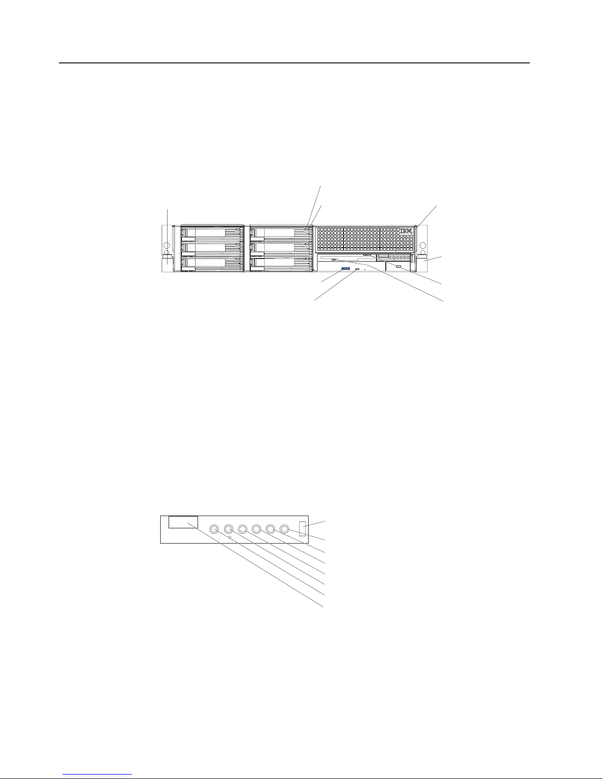
Front view
The following illustration shows the controls, LEDs, and connectors on the front of
the server.
Rack release
latch
DVD-ROM eject button
DVD-ROM drive
activity LED (green)
Hard disk drive
activity LED (green)
Hard disk drive
status LED (amber)
Operator information
panel
Rack release
latch
Diskette-eject button
Diskette drive
activity LED (green)
Rack release latches: Press these latches to release the server from the rack.
Hard disk drive activity LED: On some server models, each hot-swap hard disk
drive has an activity LED. When this LED is flashing, it indicates that the drive is in
use.
Hard disk drive status LED: On some server models, each hot-swap hard disk
drive has a status LED. When this LED is lit, it indicates that the drive has failed. If
an optional IBM ServeRAID™ controller is installed in the server, when this LED is
flashing slowly (one flash per second), it indicates that the drive is being rebuilt.
When the LED is flashing rapidly (three flashes per second), it indicates that the
controller is identifying the drive.
Operator information panel: This panel contains controls, LEDs, and connectors.
The following illustration shows the controls, LEDs, and connectors on the operator
information panel.
Release latch
System-error LED
Information LED
System-locator LED
SCSI activity LED
Power-control button
Power-on LED
USB connector
The following controls, LEDs, and connectors are on the operator information panel:
v Release latch: Slide this latch to the left to access the light path diagnostics
panel.
v System-error LED: When this LED is lit, it indicates that a system error has
occurred. An LED on the light path diagnostics panel is also lit to help isolate the
error.
4 xSeries 346 Types 8840 and 1880: Hardware Maintenance Manual and Troubleshooting Guide
Page 15
v Information LED: When this LED is lit, it indicates that a noncritical event has
occurred. An LED on the light path diagnostics panel is also lit to help isolate the
error.
v System-locator LED: Use this LED to visually locate the server among other
servers. You can use IBM Director to light this LED remotely.
v SCSI activity LED: When this LED is lit, it indicates that there is activity on the
SCSI or IDE bus.
v Power-control button: Press this button to turn the server on and off manually.
A power-control-button shield comes installed on the server to prevent the server
from being turned off accidentally.
v Power-on LED: When this LED is lit and not flashing, it indicates that the server
is turned on. When this LED is flashing, it indicates that the server is turned off
and still connected to an ac power source. When this LED is off, it indicates that
ac power is not present, or the power supply or the LED itself has failed.
Note: If this LED is off, it does not mean that there is no electrical power in the
server. The LED might be burned out. To remove all electrical power from the
server, you must disconnect the power cord from the electrical outlet.
v USB connector: Connect a USB device to this connector.
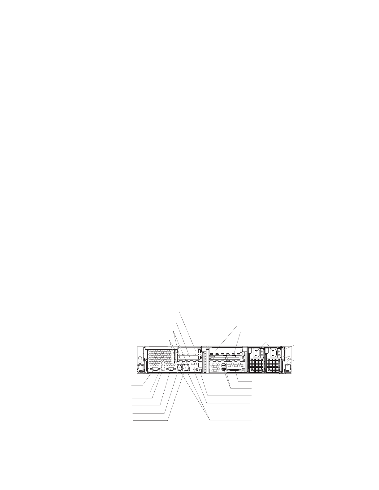
Rear view
Diskette-eject
button: Press this button to release a diskette from the diskette
drive.
Diskette drive activity LED: When this LED is lit, it indicates that the diskette drive
is in use.
DVD-eject button: Press this button to release a CD from the DVD-ROM drive.
DVD-ROM drive activity LED: When this LED is lit, it indicates that the DVD-ROM
drive is in use.
The following illustration shows the connectors and LEDs on the rear of the server.
Ethernet link status LEDs
Ethernet activity LEDs
PCI slot 1
PCI slot 2
TX/RX TX/RXLINK LINK
PCI slot 3
PCI slot 4
Power cords
AC power LED
DC power LED
Serial
Mouse
Keyboard
Video
Ethernet 2
Ethernet 1
Ethernet link status LEDs: When these LEDs are lit, they indicate that there is an
active link connection on the 10BASE-T, 100BASE-TX, or 1000BASE-TX interface
for the Ethernet port.
SCSI
ASM
System-locator LED
Remote Supervisor Adapter II
EthernetSlimLine
Universal Serial
Bus (USB)
Chapter 1. Introduction 5
Page 16

Ethernet activity LEDs: When these LEDs are lit, they indicate that the server is
transmitting to or receiving signals from the Ethernet LAN that is connected to the
Ethernet port.
Ethernet 1 connector: Use this connector to connect the server to a network.
Ethernet 2 connector: Use this connector to connect the server to a network.
Remote Supervisor Adapter II SlimLine Ethernet connector: Use this connector
to connect the server to a network for systems-management information control.
This connector is active only if you have installed a Remote Supervisor Adapter II
SlimLine.
Power-cord connectors: Connect the power cords to these connectors.
AC power LED: On some server models, each hot-swap power supply has an ac
power LED and a dc power LED. During typical operation, both the ac and dc
power LEDs are lit. For any other combination of LEDs, see “Power-supply LED
errors” on page 100.
DC power LED: On some server models, each hot-swap power supply has a dc
power LED and an ac power LED. During typical operation, both the ac and dc
power LEDs are lit. For any other combination of LEDs, see “Power-supply LED
errors” on page 100.
SCSI connector: Connect a SCSI device to this connector.
ASM connectors: Use either of these connectors to connect the server to an
Integrated xSeries Adapter (IXA) that is installed in the server.
System-locator LED: Use this LED to visually locate the server among other
servers. You can use IBM Director to light this LED remotely.
USB connectors: Connect USB devices to these connectors.
Video connector: Connect a monitor to this connector.
Mouse connector: Connect a mouse or other PS/2 device to this connector.
Keyboard connector: Connect a PS/2 keyboard to this connector.
Serial connector: Connect a 9-pin serial device to this connector.
Server power features
When the server is connected to an ac power source but is not turned on, the
operating system does not run, and all core logic except for the service processor is
shut down; however, the server can respond to requests from the service processor
(also called the baseboard management controller), such as a remote request to
turn on the server. The power-on LED flashes to indicate that the server is
connected to ac power but is not turned on.
Turning on the server
Approximately 5 seconds after the server is connected to ac power, the
power-control button becomes active, and you can turn on the server and start the
operating system by pressing the power-control button.
6 xSeries 346 Types 8840 and 1880: Hardware Maintenance Manual and Troubleshooting Guide
Page 17
The server can also be turned on in any of the following ways:
v If a power failure occurs while the server is turned on, the server will restart
automatically when power is restored.
v If your operating system supports the systems-management software for an
optional Remote Supervisor Adapter II SlimLine, the systems-management
software can turn on the server.
v If your operating system supports the Wake on LAN feature, the Wake on LAN
feature can turn on the server.
When 4 GB or more of memory (physical or logical) is installed, some
Note:
memory is reserved for various system resources and might be unavailable to the
operating system. The amount of memory that is reserved for system resources
depends on the operating system, the configuration of the server, and the
configured PCI options.
Turning off the server
When you turn off the server and leave it connected to ac power, the server can
respond to requests from the service processor, such as a remote request to turn
on the server. To remove all power from the server, you must disconnect it from the
power source.
Some operating systems require an orderly shutdown before you turn off the server.
See your operating-system documentation for information about shutting down the
operating system.
Statement 5
CAUTION:
The power-control button on the device and the power switch on the power supply do
not turn off the electrical current supplied to the device. The device also might have
more than one power cord. To remove all electrical current from the device, ensure
that all power cords are disconnected from the power source.
2
1
The server can be turned off in any of the following ways:
v Yo u can turn off the server from the operating system, if your operating system
supports this feature. After an orderly shutdown of the operating system, the
server will be turned off automatically.
v Yo u can press the power-control button to start an orderly shutdown of the
operating system and turn off the server, if your operating system supports this
feature.
v If the operating system stops functioning, you can press and hold the
power-control button for more than 4 seconds to turn off the server.
v The service processor can turn off the server as an automatic response to a
critical system failure.
v Yo u can turn off the server through a request from the service processor.
Chapter 1. Introduction 7
Page 18

8 xSeries 346 Types 8840 and 1880: Hardware Maintenance Manual and Troubleshooting Guide
Page 19

Chapter 2. Configuring the server
Detailed information about configuring the server is in the IBM xSeries User’s Guide
on the IBM Documentation CD.
The latest information about these programs and the most recent device-driver files
are available at http://www.ibm.com/support.
The following configuration programs and capabilities come with the server:
v Configuration/Setup Utility
The Configuration/Setup Utility program is part of the basic input/output system
(BIOS) code in your server. Use it to configure serial port assignments, change
interrupt request (IRQ) settings, change the startup-device sequence, set the
date and time, and set passwords.
v IBM ServerGuide Setup and Installation CD
The ServerGuide program provides software-setup tools and installation tools
that are designed for your server. Use this CD during the installation of your
server to configure basic hardware features, such as an integrated SCSI
controller with RAID capabilities, and to simplify the installation of your operating
system.
v SCSISelect Utility program for Adaptec® HostRAID™ configuration
Use the SCSI HostRAID feature of the SCSISelect Utility program to configure
the SCSI controller with integrated RAID and the devices that are attached to it.
v Ethernet controller configuration
Use the Ethernet controller configuration program to configure the integrated
Ethernet controllers.
v Baseboard management controller utility programs
Use the baseboard management controller utility programs to configure the
baseboard management controller. The programs also provide the capability to
update the firmware and sensor data record/field replaceable unit (SDR/FRU)
data and remotely manage a network.
v SCSISelect Utility program
Use the SCSISelect Utility program to configure devices that are attached to the
SCSI controller.
© Copyright IBM Corp. 2005, 2007 9
Page 20

Starting the Configuration/Setup Utility program
Complete the following steps to start the Configuration/Setup Utility program:
1. Turn on the server.
2. When the prompt Press F1 for Configuration/Setup appears, press F1. If you
have set both a power-on password and an administrator password, you must
type the administrator password to access the full Configuration/Setup Utility
menu. If you do not type the administrator password, a limited
Configuration/Setup Utility menu is available.
3. Select settings to view or change.
10 xSeries 346 Types 8840 and 1880: Hardware Maintenance Manual and Troubleshooting Guide
Page 21

Chapter 3. Installing options
Installation guidelines . . . . . . . . . . . . . . . . . . . . . .11
System reliability guidelines . . . . . . . . . . . . . . . . . . .12
Working inside the server with the power on . . . . . . . . . . . . .12
Handling static-sensitive devices . . . . . . . . . . . . . . . . .13
Major components of the xSeries 346 Type 8640 server . . . . . . . . . .14
Removing the cover . . . . . . . . . . . . . . . . . . . . . . .16
Removing the air baffle . . . . . . . . . . . . . . . . . . . . . .17
Working with adapters . . . . . . . . . . . . . . . . . . . . . .18
Installing a hot-swap drive . . . . . . . . . . . . . . . . . . . . .26
Installing memory modules . . . . . . . . . . . . . . . . . . . .27
Installing a microprocessor . . . . . . . . . . . . . . . . . . . .30
Installing a hot-swap power supply . . . . . . . . . . . . . . . . .35
Replacing a hot-swap fan . . . . . . . . . . . . . . . . . . . . .37
Replacing the battery . . . . . . . . . . . . . . . . . . . . . .38
Completing the installation . . . . . . . . . . . . . . . . . . . . .39
Connecting the cables . . . . . . . . . . . . . . . . . . . . .40
Updating the server configuration . . . . . . . . . . . . . . . . .41
Connecting external options . . . . . . . . . . . . . . . . . . .42
Power-cage card internal cable connectors . . . . . . . . . . . . . .42
Input/output connectors . . . . . . . . . . . . . . . . . . . . . .43
Auxiliary-device (pointing device) connector . . . . . . . . . . . . .43
Ethernet connectors . . . . . . . . . . . . . . . . . . . . . .44
Advanced Systems Management (ASM) connectors . . . . . . . . . .44
Keyboard connector . . . . . . . . . . . . . . . . . . . . . .44
Serial connector . . . . . . . . . . . . . . . . . . . . . . .44
Ultra320 SCSI controller system-board connectors . . . . . . . . . . .44
SCSI cabling requirements . . . . . . . . . . . . . . . . . .45
SCSI IDs . . . . . . . . . . . . . . . . . . . . . . . . .45
SCSI connector . . . . . . . . . . . . . . . . . . . . . .45
Universal Serial Bus version 1.1 or 2.0 connectors . . . . . . . . . . .46
Video connector . . . . . . . . . . . . . . . . . . . . . . .46
This chapter provides detailed instructions for installing hardware options in the
server.
Note: For a complete list of customer replaceable units (CRUs), see “System” on
page 108.
Installation guidelines
Before you begin installing options, read the following information:
v Read the safety information beginning on page Appendix B, “Safety information,”
on page 117 and the guidelines in “Handling electrostatic discharge-sensitive
devices” on page 120 This information will help you work safely with the server
and options.
v Make sure that you have an adequate number of properly grounded electrical
outlets for your server, monitor, and other devices.
v Back up all important data before you make changes to disk drives.
v Have a small flat-blade screwdriver available.
v Yo u do not have to turn off the server to install or replace hot-swap power
supplies, hot-swap fans, or hot-plug Universal Serial Bus (USB) devices.
© Copyright IBM Corp. 2005, 2007 11
Page 22

v Blue on a component indicates touch points, were you can grip the component to
remove it from or install it in the server, open or close a latch, and so on.
v Orange on a component or an orange label on or near a component indicates
that the component can be hot-swapped, which means that if the server and
operating system support hot-swap capability, you can remove or install the
component while the server is running. (Orange can also indicate touch points on
hot-swap components.) See the instructions for removing or installing a specific
hot-swap component for any additional procedures that you might have to
perform before you remove or install the component.
v For a list of supported options for the server, go to http://www.ibm.com/servers/
eserver/serverproven/compat/us/
System reliability guidelines
To help ensure proper cooling and system reliability, make sure that:
v Each of the drive bays has a drive or a filler panel and electromagnetic
compatibility (EMC) shield installed in it.
v Each of the power-supply bays has a power supply or power-supply blank
installed in it.
v There is adequate space around the server to allow the server cooling system to
work properly. Leave approximately 50 mm (2.0 in.) of open space around the
front and rear of the server. Do not place objects in front of the fans. For proper
cooling and airflow, replace the server cover before turning on the server.
Operating the server for extended periods of time (more than 30 minutes) with
the server cover removed might damage server components.
v Yo u have followed the cabling instructions that come with optional adapters.
v Yo u have replaced a failed fan within 48 hours.
v Yo u have replaced a hot-swap drive within 2 minutes of removal.
v Yo u do not remove the air baffle while the server is running. Operating the server
without the air baffle might cause the microprocessor to overheat.
v Microprocessor socket 2 always contains either a microprocessor baffle or a
microprocessor and heat sink.
.
Working inside the server with the power on
The server supports hot-plug, hot-add, and hot-swap devices and is designed to
operate safely while turned on with the cover removed. Follow these guidelines
when you work inside a server that is turned on:
v Avoid loose-fitting clothing on your forearms. Button long-sleeved shirts before
working inside the server; do not wear cuff links while you are working inside the
server.
v Do not allow your necktie or scarf to hang inside the server.
v Remove jewelry, such as bracelets, necklaces, rings, and loose-fitting wrist
watches.
v Remove items from your shirt pocket (such as pens or pencils) that could fall into
the server as you lean over it.
v Avoid dropping any metallic objects, such as paper clips, hair pins, or screws,
into the server.
12 xSeries 346 Types 8840 and 1880: Hardware Maintenance Manual and Troubleshooting Guide
Page 23

Handling static-sensitive devices
Attention: Static electricity can damage the server and other electronic devices.
To avoid damage, keep static-sensitive devices in their static-protective packages
until you are ready to install them.
To reduce the possibility of electrostatic discharge, observe the following
precautions:
v Limit your movement. Movement can cause static electricity to build up around
you.
v Wear an electrostatic-discharge wrist strap, if one is available.
v Handle the device carefully, holding it by its edges or its frame.
v Do not touch solder joints, pins, or exposed printed circuitry.
v Do not leave the device where others can handle and damage it.
v While the device is still in its static-protective package, touch it to an unpainted
metal part of the server for at least 2 seconds. This drains static electricity from
the package and from your body.
v Remove the device from its package and install it directly into the server without
setting it down. If it is necessary to set down the device, put it back into its
static-protective package. Do not place the device on the server cover or on a
metal surface.
v Take additional care when handling devices during cold weather. Heating reduces
indoor humidity and increases static electricity.
Chapter 3. Installing options 13
Page 24

Major components of the xSeries 346 Type 8640 server
Blue on a component indicates touch points, where you can grip the component to
remove it from or install it in the server, open or close a latch, and so on.
Orange on a component or an orange label on or near a component indicates that
the component can be hot-swapped, which means that if the server and operating
system support hot-swap capability, you can remove or install the component while
the server is running. (Orange can also indicate touch points on hot-swap
components.) See the instructions for removing or installing a specific hot-swap
component for any additional procedures that you might have to perform before you
remove or install the component.
14 xSeries 346 Types 8840 and 1880: Hardware Maintenance Manual and Troubleshooting Guide
Page 25
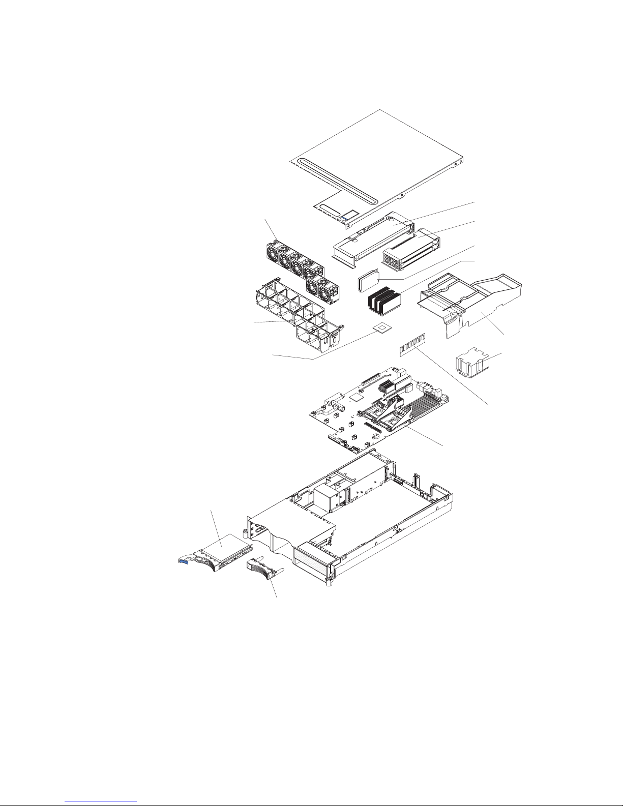
The following illustration shows the major components in the server. The
illustrations in this document might differ slightly from your hardware.
PCI riser-card cage
Hot-swap fans
Fan guide
assembly
PCI low-profile-card
cage
VRM
Heat sink
Air baffle
Microprocessor
Ultra-slim hard disk
drive tray
Microprocessor
baffle
Memory module
System board
Filler panel for
drive bay
Chapter 3. Installing options 15
Page 26
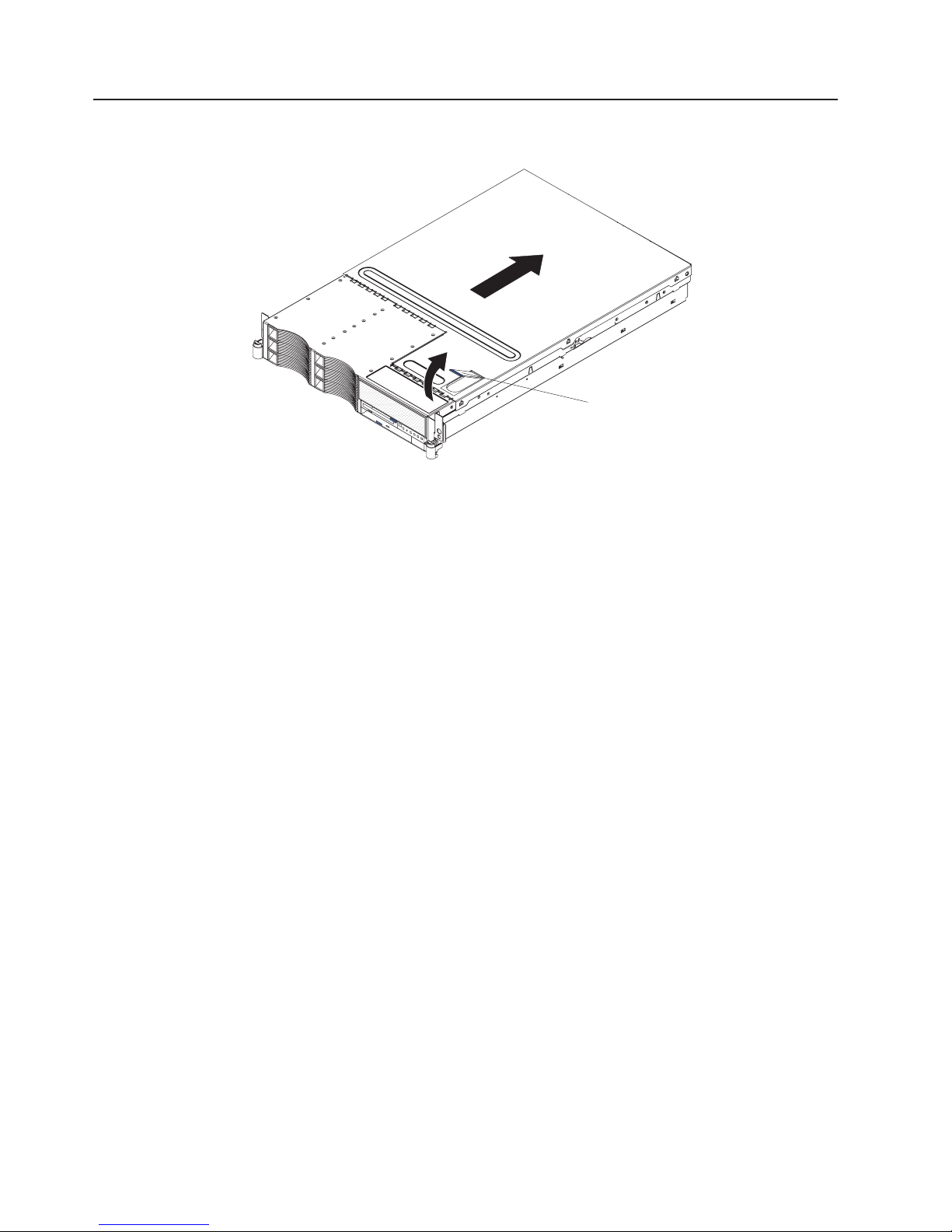
Removing the cover
The following illustration shows how to remove the cover.
Complete the following steps to remove the top cover:
1. Read the safety in formation beginning on page Appendix B, “Safety
information,” on page 117 and “Installation guidelines” on page 11.
2. If you are planning to install or remove a microprocessor, memory module, PCI
adapter, or battery, turn off the server and all attached devices and disconnect
all external cables and power cords (see “Turning off the server” on page 7).
3. Press down on the left and right side latches and pull the server out of the rack
enclosure until both slide rails lock.
Cover-release
latch
Note: You can reach the cables on the back of the server when the server is in
the locked position.
4. Lift the cover-release latch. Lift the cover off the server and set the cover aside.
Attention: For proper cooling and airflow, replace the cover before turning on
the server. Operating the server for extended periods of time (over 30 minutes)
with the cover removed might damage server components.
16 xSeries 346 Types 8840 and 1880: Hardware Maintenance Manual and Troubleshooting Guide
Page 27
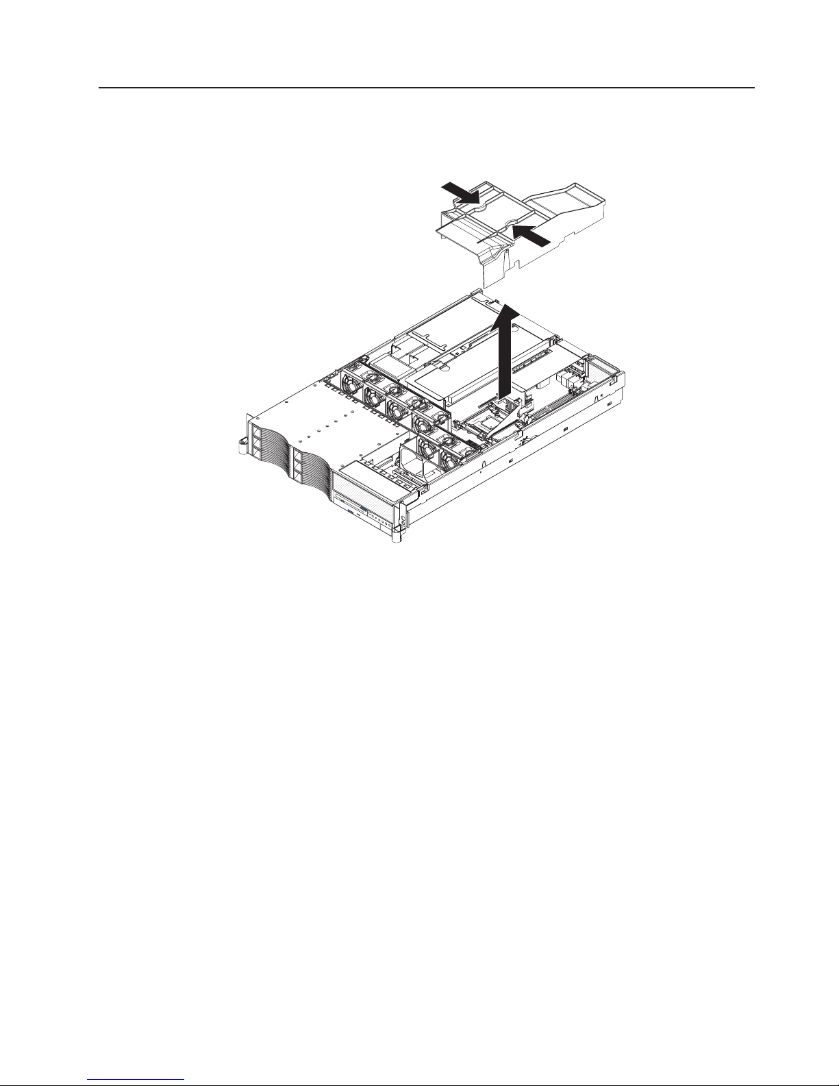
Removing the air baffle
When working with some options, you must first remove the air baffle to access
certain components or connectors on the system board. The following illustration
shows how to remove the air baffle.
Complete the following steps to remove the air baffle:
1. Read the safety information beginning on page Appendix B, “Safety information,”
on page 117 and “Installation guidelines” on page 11 .
2. Turn off the server and peripheral devices and disconnect all power cords and
external cables (see “Turning off the server” on page 7); then, remove the cover
(see “Removing the cover” on page 16).
3. Place your fingers into the two handles on the top of the air baffle.
4. Press the handles and lift the air baffle out of the server.
Attention: For proper cooling and airflow, replace the air baffle before turning
on the server. Operating the server with the air baffle removed might damage
server components.
Chapter 3. Installing options 17
Page 28
Working with adapters
The following notes describe the types of adapters that the server supports and
other information that you must consider when installing adapters:
Before you install an adapter, review the following information:
v Locate the documentation that comes with the adapter and follow those
instructions in addition to the instructions in this section. If you need to change
the switch or jumper settings on the adapter, follow the instructions that come
with the adapter.
v Yo u can install only low-profile adapters in slots 1 and 2 on the PCI low-profile
card.
v Yo u can install standard full-length adapters in slots 3 and 4 on the PCI riser
card.
v Your server supports only 3.3 V and universal PCI adapters.
v The PCI bus configuration is as follows:
– Non-hot-plug, 64-bit PCI-X slots 1 through 2 (PCI bus A, 100 MHz)
– Non-hot-plug, 64-bit PCI-X slot 3 (PCI bus B, 133 MHz)
– Non-hot-plug, 64-bit PCI-X slot 4 (PCI bus C, 133 MHz)
The system scans devices in the following order, if you have not changed the
v
default boot precedence: integrated Ethernet controllers, integrated SCSI
controller (SCSI channel B, then SCSI channel A), and then PCI and PCI-X slots
1, 2, 3, and 4.
v The optional Remote Supervisor Adapter II SlimLine can be installed only in a
dedicated slot on the system board. For details about installing a Remote
Supervisor Adapter II SlimLine, see the documentation that comes with the
adapter. The following illustration shows how to install the Remote Supervisor
Adapter II SlimLine.
Remote Supervisor
Adapter II SlimLine
Retainer bracket
Slip the free end of the card under the tab on the retainer bracket; then, press
the card in the connector and make sure that all tabs on the latch bracket secure
the card in place.
18 xSeries 346 Types 8840 and 1880: Hardware Maintenance Manual and Troubleshooting Guide
Latch bracket
Connector
Page 29
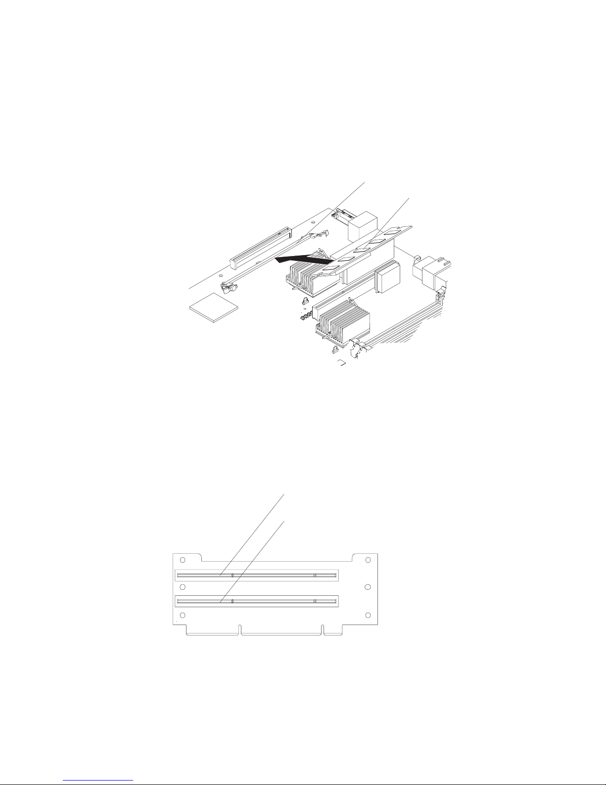
v If you are installing an optional ServeRAID-7k, review the following information:
– No rerouting of the internal SCSI cable is required if you are installing the
ServeRAID-7k.
– The ServeRAID-7k can be installed only in a dedicated slot on the system
board.
Attention: To avoid breaking the retaining clips or damaging the connectors,
handle the clips gently.
The following illustration shows how to install the ServeRAID-7k.
Connector
ServerRAID-7k
Note: If there is a gap between the card and the retaining clips, the card has not
been properly installed. In this case, open the retaining clips and remove the
card; then, reinsert the card.
following illustrations show the location of the PCI and PCI-X adapter
The
expansion slots on the PCI low-profile card and PCI riser card.
PCI low-profile card
PCI-X slot 1 64-bit
3.3V 100 MHz (PCI1)
PCI-X slot 2 64-bit
3.3V 100 MHz (PCI2)
Chapter 3. Installing options 19
Page 30
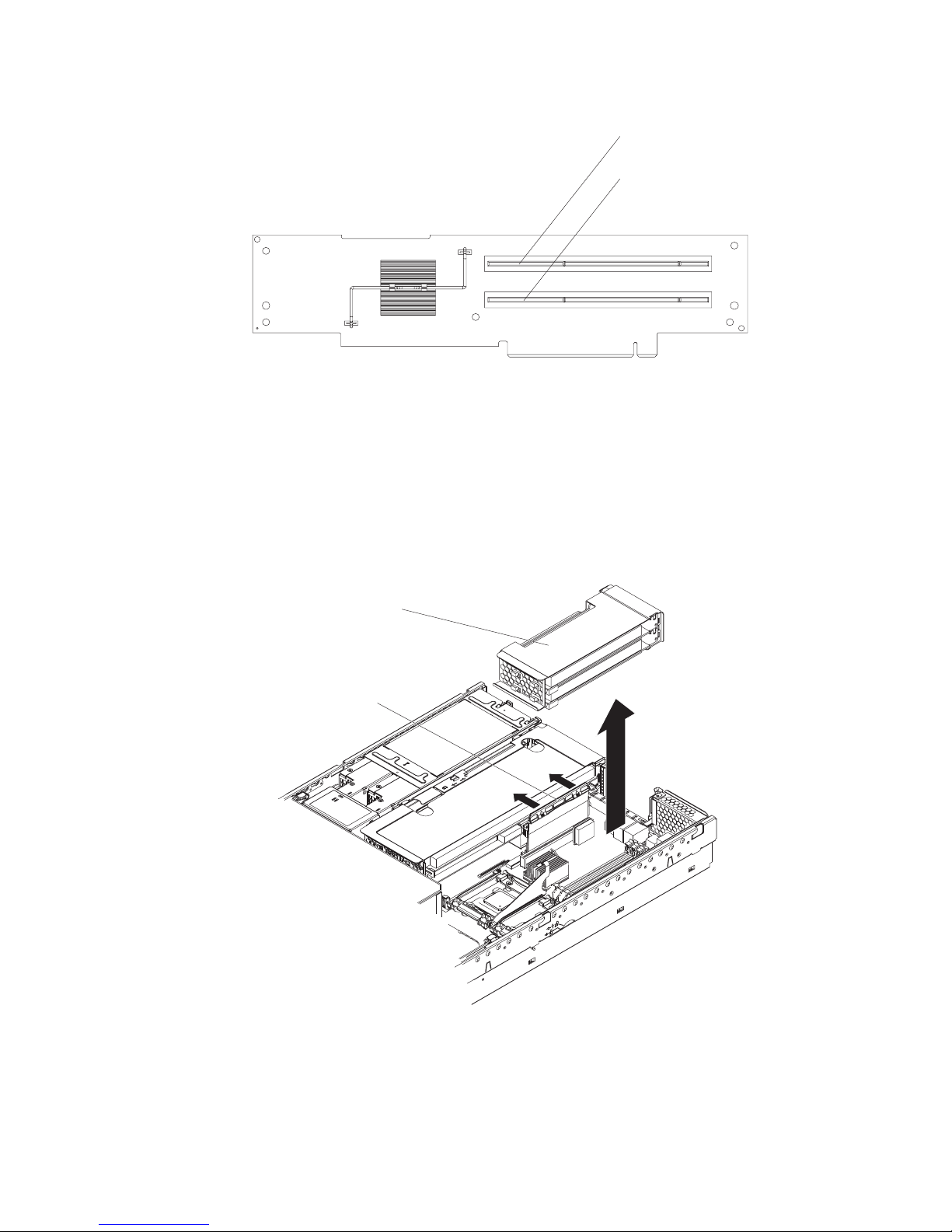
PCI riser card
PCI-X slot 3 64-bit
3.3V 133 MHz (PCI3)
PCI-X slot 4 64-bit
3.3V 133 MHz (PCI4)
Complete the following steps to install an adapter:
1. Read the safety information beginning on page Appendix B, “Safety information,”
on page 117 and “Installation guidelines” on page 11 .
2. Turn off the server and peripheral devices and disconnect all power cords and
external cables (see “Turning off the server” on page 7); then, remove the cover
(see “Removing the cover” on page 16).
3. Determine which expansion slot you will use for the adapter.
4. If you are installing an adapter in PCI slot 1 or 2, remove the PCI
low-profile-card cage.
PCI low-profilecard cage
Latch
20 xSeries 346 Types 8840 and 1880: Hardware Maintenance Manual and Troubleshooting Guide
Page 31

If you are installing an adapter in PCI slot 3 or 4, remove the PCI riser-card
cage.
Retention latch
PCI riser-card
cage
5. Slide the expansion-slot cover out of the PCI low-profile-card cage or PCI
riser-card cage.
Chapter 3. Installing options 21
Page 32

6. Install the adapter. The following illustration shows how to install an adapter in
the PCI low-profile-card cage.
PCI adapter
22 xSeries 346 Types 8840 and 1880: Hardware Maintenance Manual and Troubleshooting Guide
Page 33

The following illustration shows how to install an adapter in the PCI riser-card
cage.
PCI adapter
7. If you removed the PCI low-profile-card cage to install the adapter, press the
PCI low-profile-card cage firmly into the connector until the retention latch locks.
Chapter 3. Installing options 23
Page 34

PCI low-profile
-
card cage
Retention latch
If you removed the PCI riser-card cage to install the adapter, press the PCI
riser-card cage firmly into the connector and close the latch.
Retention latch
8. Connect any needed cables to the adapter.
PCI riser-card
cage
24 xSeries 346 Types 8840 and 1880: Hardware Maintenance Manual and Troubleshooting Guide
Page 35

Attention:
v When you route cables, do not block any connectors or the ventilated space
around any of the fans.
v Make sure that cables are not routed on top of components under the PCI
riser-card cage or the PCI low-profile-card cage.
v Make sure that cables are not pinched by the server components.
following illustration shows the cable routing for an adapter installed in the
The
PCI low-profile-card cage.
Note: Remove the PCI riser-card cage, the PCI low-profile card cage, and the
fan bracket before you route the cables. Reinstall the components when you
complete the cable routing.
Low profile
SCSI adapter
SCSI cable
connector
SCSI cable
The following illustration shows the cable routing for an adapter installed in the
PCI riser-card cage.
Note: Remove the fan bracket before you route the cables. Reinstall the fan
bracket when you complete the cable routing.
Chapter 3. Installing options 25
Page 36

SCSI adapter
9. Perform any configuration tasks that are required for the adapter.
If you installed a Remote Supervisor Adapter II SlimLine, see the documentation
that comes with the adapter for information about installing the firmware and
configuring the option. Create a backup copy of the configuration so that if you
need to replace the adapter in the future, you can restore the configuration.
If you have other options to install or remove, do so now. Otherwise, go to
“Completing the installation” on page 39.
Installing a hot-swap drive
The following notes describe the type of hard disk drive that the server supports
and other information that you must consider when installing a hard disk drive:
v The server supports six 1-inch (26 mm) slim, 3.5-inch low-voltage differential
(LVD) hard disk drives installed on Ultra-Slim hard disk drive trays. For a list of
supported hard disk drives, go to the ServerProven Web site at
http://www.ibm.com/servers/eserver/serverproven/compat/us/ .
v All hot-swap drives in the server should have the same throughput speed rating.
Mixing hard disk drives with different speed ratings will cause all drives to
operate at the lower throughput speed.
v The SCSI ID that is assigned to each bay is printed on the server front.
SCSI cable
following illustration shows how to install a hot-swap hard disk drive.
The
26 xSeries 346 Types 8840 and 1880: Hardware Maintenance Manual and Troubleshooting Guide
Page 37

Drive-tray assembly
Drive handle
Filler panel
Complete the following steps to install a drive in a hot-swap bay.
Attention: To maintain proper system cooling, do not operate the server for more
than 10 minutes without either a drive or a filler panel installed in each bay.
1. Read the safety information beginning on page Appendix B, “Safety information,”
on page 117 and “Installation guidelines” on page 11 .
2. Remove the filler panel from one of the empty hot-swap bays by inserting your
finger into the depression at the left side of the filler panel and pulling it away
from the server.
3. Install the hard disk drive in the hot-swap bay:
a. Make sure that the tray handle is open (that is, perpendicular to the drive).
b. Align the drive assembly with the guide rails in the bay.
c. Gently push the drive assembly into the bay until the drive stops.
d. Push the tray handle to the closed (locked) position.
e. Check the hard disk drive status LED to verify that the hard disk drive is
operating properly.
If the amber hard disk drive status LED for a drive is lit continuously, that
drive is faulty and must be replaced. If the green hard disk drive activity LED
is flashing, the drive is being accessed.
If you have a RAID configuration using the integrated SCSI controller
Note:
with RAID capabilities, or if the server has a RAID adapter installed, you might
have to reconfigure the disk arrays after installing hard disk drives. See the
RAID documentation on the IBM xSeries Documentation CD for information
about RAID adapters.
Installing memory modules
The following notes describe the types of dual inline memory modules (DIMMs) that
the server supports and other information that you must consider when installing
DIMMs:
v The server supports 256 MB, 512 MB, 1 GB, and 2 GB DIMMs, for a maximum
of 16 GB of system memory. The server supports up to eight 1.8 V, 240-pin,
PC2-3200, ECC DDR II SDRAM, 200 MHz DIMMs. Go to the ServerProven® list
at http://www.ibm.com/servers/eserver/serverproven/compat/us/ for a list of
memory modules that you can use with the server.
v The server comes with a minimum of two 256 MB DIMMs, installed in slots 1 and
2. When installing additional DIMMs, you must install two DIMMS at a time, in
the order shown in the following table, to maintain performance.
Chapter 3. Installing options 27
Page 38

Table 2. DIMM installation sequence
Pair DIMM connectors
1 1 and 2
2 3 and 4
3 5 and 6
4 7 and 8
v Each DIMM in a pair must be the same size and technology to ensure that the
server will operate properly.
v Yo u can configure the server to use memory mirroring. Memory mirroring stores
data in two pairs of DIMMs simultaneously. Memory mirroring reduces the
amount of available memory. Enable memory mirroring through the
Configuration/Setup Utility program. See the User’s Guide on the IBM xSeries
Documentation CD for details about enabling memory mirroring.
When using memory mirroring, you must install two pairs of DIMMs at a time.
The four DIMMs in each group must be identical. See Table 3 for the DIMM
connectors that are in each group.
Table 3. Memory mirroring DIMM installation sequence
Group DIMM connectors
1 1, 2, 3, and 4
2 5, 6, 7, and 8
v The server supports online-spare memory. This feature disables the failed
memory from the system configuration and activates an online-spare memory
pair of DIMMs to replace the failed active DIMM pair. Online-spare memory
reduces the amount of available memory. Before you can enable this feature, you
must install one additional pair of DIMMs. The online-spare memory DIMM pair
must be the same speed, type, and the same size, or larger, than the active
DIMM pair.
Enable online-spare memory through the Configuration/Setup Utility program.
The BIOS code assigns the online-spare memory DIMM pair according to your
DIMM configuration. See the User’s Guide on the IBM xSeries Documentation
CD for information about enabling online-spare memory. See Table 4 for the
online-spare memory DIMM connector assignments.
Table 4. Online-spare memory DIMM connector assignments
Active DIMM connectors Online-spare memory DIMM connectors
1 and 2 3 and 4
28 xSeries 346 Types 8840 and 1880: Hardware Maintenance Manual and Troubleshooting Guide
Page 39

Table 4. Online-spare memory DIMM connector assignments (continued)
Active DIMM connectors Online-spare memory DIMM connectors
1 and 2
5 and 6
3 and 4
1 and 2
7 and 8
3 and 4
5 and 6
v Yo u can enable either online-spare memory or memory mirroring, but not both at
the same time.
v When you install or remove DIMMs, the server configuration information
changes. When you restart the server, the system displays a message indicating
that the memory configuration has changed.
The following illustration shows how to install DIMMs on the system board.
Complete the following steps to install a DIMM:
1. Read the “Installation guidelines” on page 11.and the safety information
beginning on page Appendix B, “Safety information,” on page 117.
2. Turn off the server and disconnect all power cords and external cables (see
“Turning off the server” on page 7); then, remove the server cover (see
“Removing the cover” on page 16).
3. Remove the air baffle (see “Removing the air baffle” on page 17).
4. Locate the DIMM connectors on the system board and determine the
connectors into which you will install the DIMMs.
5. Touch the static-protective package that contains the DIMM to any unpainted
metal surface on the server. Then, remove the DIMM from the package.
6. Complete the following steps to install the DIMM. Repeat these steps for each
DIMM that you install.
a. Turn the DIMM so that the DIMM keys align correctly with the connector on
the system board.
Chapter 3. Installing options 29
Page 40

Attention: To avoid breaking the retaining clips or damaging the DIMM
connectors, handle the clips gently.
b. If the retaining clips are closed, open them; then, insert the DIMM by
pressing the DIMM straight into the connector. Make sure that the retaining
clips snap into the closed position.
Note: If there is a gap between the DIMM and the retaining clips, the DIMM
has not been properly installed. In this case, open the retaining clips and
remove the DIMM; then, reinsert the DIMM.
7. Install the air baffle over the system board.
If you have other options to install or remove, do so now. Otherwise, go to
“Completing the installation” on page 39.
Installing a microprocessor
The following notes describe the type of microprocessor that the server supports
and other information that you must consider when installing a microprocessor:
v The server supports up to two microprocessors. With two microprocessors, the
server can operate as a symmetric multiprocessing (SMP) server. With SMP,
certain operating systems and application programs can distribute the processing
load between the microprocessors. If the server comes with one microprocessor,
you can install a second microprocessor.
v Yo u might have to update the BIOS code. Be sure to read the documentation
that comes with the microprocessor, so that you can determine whether you have
to update the BIOS code. You can download the latest level of BIOS code and
many other code updates for your server at http://www.ibm.com/support/.
v (Optional) Obtain an SMP-capable operating system. For a list of supported
operating systems and other options, go to http://www.ibm.com/servers/eserver/
serverproven/compat/us/.
v To order additional microprocessor options, contact your IBM marketing
representative or authorized reseller.
v When you install an additional microprocessor in socket J23, you must also
install the voltage regulator module (VRM) that comes with the microprocessor in
VRM connector J72.
v The microprocessor speeds are automatically set for this server; therefore, you
do not have to set any microprocessor frequency-selection jumpers or switches.
v If you have to replace a microprocessor, call for service.
v If the thermal-grease protective cover (for example, a plastic cap or tape liner) is
removed from the heat sink or fan sink, do not touch the thermal grease on the
bottom of the heat sink or fan sink or set down the heat sink or fan sink.
Note: Removing the heat sink or fan sink from the microprocessor destroys the
even distribution of the thermal grease and requires replacing the thermal
grease. Setting down the heat sink or fan sink onto any surface when the
thermal-grease protective cover is removed will contaminate the thermal grease.
If the thermal grease becomes contaminated with particles, it must be replaced.
For information about replacing contaminated thermal grease on the heat sink or
fan sink, contact IBM Services. For support phone numbers, go to
http://www.ibm.com/planetwide/, or in the U.S. and Canada, call 1-800-IBM-SERV
(1-800-426-7378).
Have the following information ready when you call:
– Machine type and model
30 xSeries 346 Types 8840 and 1880: Hardware Maintenance Manual and Troubleshooting Guide
Page 41

– Serial number of your server or computer
Do not remove the first microprocessor from the system board to install the
v
second microprocessor.
The following illustration is a simplified layout of the microprocessor connector
locations and other microprocessor-related components on the system board.
VRM (J72)
Microprocessor 2 (J23)
Microprocessor 1 (J22)
Note: For additional illustrations of the system-board components, see
“System-board option connectors” on page 54.
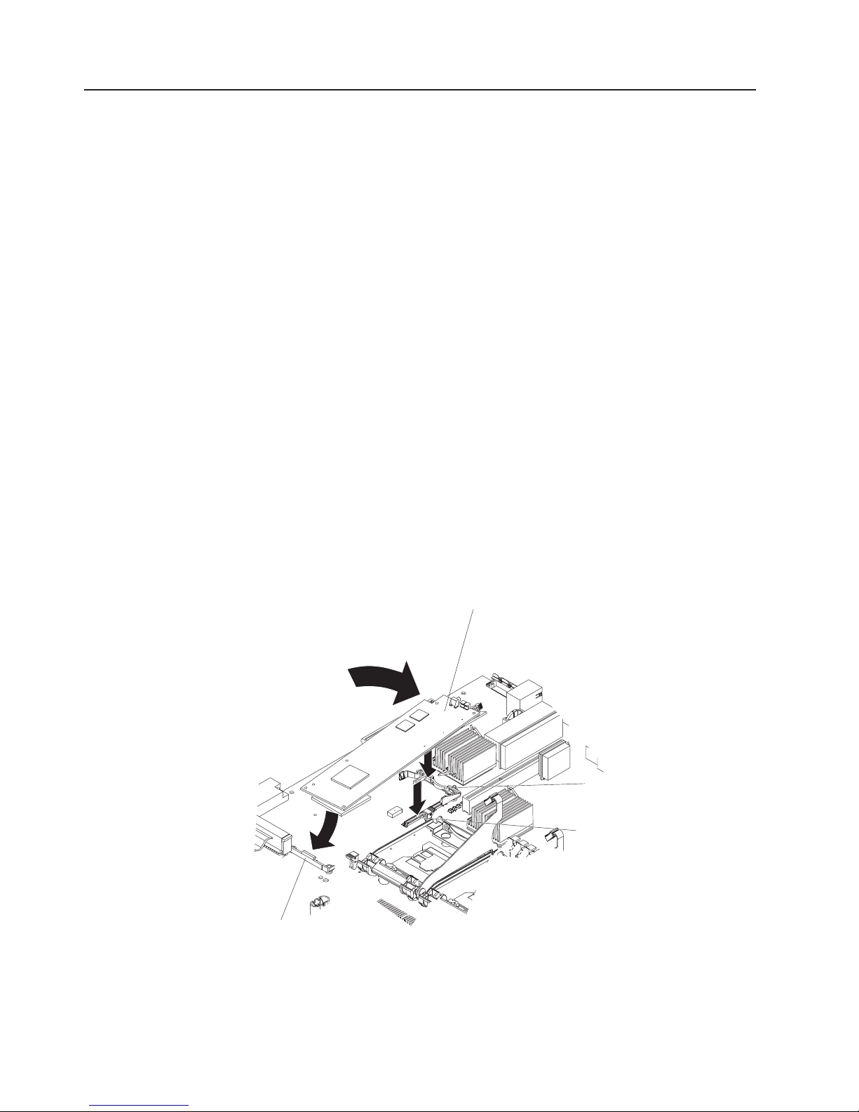
The following illustration shows how to install the second microprocessor on the
system board.
Chapter 3. Installing options 31
Page 42

VRM
Microprocessor
baffle
Heat sink
Microprocessor
Microprocessorrelease lever
Attention:
v A startup (boot) processor must always be installed in socket J22 on the system
board.
v To ensure proper server operation when you install an additional microprocessor,
use microprocessors that have the same cache size and type, and the same
clock speed. Microprocessor internal and external clock frequencies must be
identical.
Complete
the following steps to install an additional microprocessor:
1. Read the “Installation guidelines” on page 11.and the safety information
beginning on page Appendix B, “Safety information,” on page 117.
2. Turn off the server and disconnect all power cords and external cables (see
“Turning off the server” on page 7); then, remove the server cover (see
“Removing the cover” on page 16).
3. Remove the air baffle (see “Removing the air baffle” on page 17).
4. Locate the second microprocessor socket (connector J23) on the system board.
5. Remove the microprocessor baffle.
a. Press the heat-sink release lever to unhook it from the tab on the
microprocessor socket; then, pull the lever up.
b. Slide the microprocessor baffle while lifting the rear flange out of the
heat-sink socket; then, lift it off the heat-sink socket and store it in a safe
place.
Install a VRM in the VRM connector (J72).
6.
32 xSeries 346 Types 8840 and 1880: Hardware Maintenance Manual and Troubleshooting Guide
Page 43

7. Install the microprocessor:
a. Touch the static-protective package containing the microprocessor to any
unpainted metal surface on the server. Then, remove the microprocessor
from the package.
b. Remove the protective cover, tape, or label from the surface of the
microprocessor socket, if present.
Attention: Yo u must ensure that the locking lever on the microprocessor
socket is in the fully open position before you insert the microprocessor in
the socket. Failure to do so might result in permanent damage to the
microprocessor, microprocessor socket, and system board.
c. Rotate the locking lever on the microprocessor socket from its closed and
locked position until it stops or clicks in the fully open position
(approximately 135° angle).
Center the microprocessor over the microprocessor socket. Align the triangle
d.
Lever closed
Lever
fully
open
Lever closed
Attention:
v Do not use excessive force when pressing the microprocessor into the
socket.
v Make sure that the microprocessor is oriented and aligned with pin
number 1 in the socket before you try to close the lever.
on the corner of the microprocessor with the triangle on the corner of the
socket and carefully press the microprocessor into the socket.
Chapter 3. Installing options 33
Lever
fully
open
Page 44

Alignment marks
Microprocessor
socket 2
Microprocessor 2
Microprocessor 1
Lock tab
Microprocessor
socket 1
e. Carefully close the locking lever to secure the microprocessor in the socket.
Install a heat sink on the microprocessor.
8.
Attention:
v Do not set down the heat sink after you remove the plastic cover.
Thermal grease
Heat sink
v Do not touch the thermal grease on the bottom of the heat sink or set down
the heat sink. Touching the thermal grease will contaminate it. For details,
see the information about thermal grease on page 30.
Remove the plastic protective cover from the bottom of the heat sink.
a.
b. Make sure that the heat-sink lever is in the open position.
c. Align the heat sink above the microprocessor with the thermal grease side
down. Press firmly on the heat sink.
34 xSeries 346 Types 8840 and 1880: Hardware Maintenance Manual and Troubleshooting Guide
Page 45

Retainer bracket
d. Slide the flange of the heat sink into the opening beneath the retainer
bracket.
e. Press down firmly on the heat sink until it is seated securely.
f. Attach the heat sink to the microprocessor by rotating the heat-sink lever to
the closed position and hooking it underneath the lock tab.
Install the air baffle over the system board.
9.
If you have other options to install or remove, do so now. Otherwise, go to
“Completing the installation” on page 39.
Installing a hot-swap power supply
The server supports a maximum of two hot-swap power supplies.
Statement 8
CAUTION:
Never remove the cover on a power supply or any part that has the following label
attached.
Hazardous voltage, current, and energy levels are present inside any component that
has this label attached. There are no serviceable parts inside these components. If
you suspect a problem with one of these parts, contact a service technician.
The following illustration shows how to install a power supply.
Chapter 3. Installing options 35
Page 46

Handle
(open position)
Power supply
AC power
LED (green)
DC power
LED (green)
Power-supply blank
(some models)
Complete the following steps to install a power supply:
1. Read the “Installation guidelines” on page 11.and the safety information
beginning on page Appendix B, “Safety information,” on page 117.
2. (Some models) Remove the power-supply blank from the empty power-supply
bay by pinching the side clip and pulling the power-supply blank from the bay.
Save the power-supply blank in case you remove the power supply at a later
time.
Attention: During normal operation, each power-supply bay must have either
a power supply or power-supply blank installed for proper cooling.
3. Install the power supply in the bay:
a. Move the handle on the power supply into the open position, pinch the
side-clip, and slide the power supply into the chassis.
b. Gently close the handle to seat the power supply in the bay.
4. Connect the power cord for the new power supply to the power-cord connector
on the power supply.
The following illustration shows the power-supply connectors on the back of the
server.
Power supply 2
power cord connector
Power supply 1
power cord connector
36 xSeries 346 Types 8840 and 1880: Hardware Maintenance Manual and Troubleshooting Guide
TX/RX TX/RXLINK LINK
Page 47

5. Connect the power cord to a properly grounded electrical outlet.
6. Make sure that the dc power LED and ac power LED on the power supply are
lit, indicating that the power supply is operating correctly.
Replacing a hot-swap fan
The following notes describe information that you must consider when installing a
hot-swap fan.
Attention: To ensure proper server operation, if a fan fails, replace it as soon as
possible.
v The server supports a maximum of 12 hot-swap fans.
v The following illustration shows the locations of the hot-swap fans.
Fan 3
Fan 4
Optional
Fan 5
Fan 6
Fan 1
Fan 2
Fan 9
Fan 10
Fan 11
Fan 12
Fan 7
Fan 8
Complete the following steps to replace a hot-swap-fan:
1. Read the “Installation guidelines” on page 11.and the safety information
beginning on page Appendix B, “Safety information,” on page 117.
2. Remove the cover. See “Removing the cover” on page 16. The LED on the
failing fan assembly will be lit.
Attention: To ensure proper system cooling, do not remove the top cover for
more than 30 minutes during this procedure.
3. Place your fingers into the two handles on the top of the failing fan.
4. Press the handles and lift the fan out of the server.
Chapter 3. Installing options 37
Page 48

5. Orient the new fan so that the LED on top of the fan is to the right of the server.
6. Push the replacement fan assembly into the server until it clicks into place.
7. Replace the cover. See “Completing the installation” on page 39.
Replacing the battery
The following notes describe information that you must consider when replacing the
battery:
v IBM has designed this product with your safety in mind. The lithium battery must
be handled correctly to avoid possible danger. If you replace the battery, you
must adhere to the following instructions.
Note: In the U. S., call 1-800-IBM-4333 for information about battery disposal.
v If you replace the original lithium battery with a heavy-metal battery or a battery
with heavy-metal components, be aware of the following environmental
consideration. Batteries and accumulators that contain heavy metals must not be
disposed of with normal domestic waste. They will be taken back free of charge
by the manufacturer, distributor, or representative, to be recycled or disposed of
in a proper manner.
v To order replacement batteries, call 1-800-426-7378 within the United States, and
1-800-465-7999 or 1-800-465-6666 within Canada. Outside the U.S. and
Canada, call your IBM reseller or IBM marketing representative.
Note: After you replace the battery, you must reconfigure the server and reset
the system date and time.
Statement 2
CAUTION:
When replacing the lithium battery, use only IBM Part Number 33F8354 or an
equivalent type battery recommended by the manufacturer. If your system has a
module containing a lithium battery, replace it only with the same module type made
by the same manufacturer. The battery contains lithium and can explode if not
properly used, handled, or disposed of.
Do not:
v Throw or immerse into water
v Heat to more than 100°C (212°F)
v Repair or disassemble
Dispose
of the battery as required by local ordinances or regulations.
Complete the following steps to replace the battery:
1. Read the “Installation guidelines” on page 11.and the safety information
beginning on page Appendix B, “Safety information,” on page 117.
2. Follow any special handling and installation instructions that come with the
battery.
3. Turn off the server and all attached devices and disconnect all power cords
and external cables (see “Turning off the server” on page 7); then, remove the
server cover (see “Removing the cover” on page 16).
4. Remove the air baffle (see “Removing the air baffle” on page 17).
5. Disconnect any internal cables, as necessary.
38 xSeries 346 Types 8840 and 1880: Hardware Maintenance Manual and Troubleshooting Guide
Page 49

6. Locate the battery (connector BH1) on the system board.
Battery
(BH1)
7. Remove the battery:
a. Use one finger to press on the tab that secures the battery to its housing.
b. Use one finger to slide the battery from the socket.
8. Insert the new battery:
a. Hold the battery so that the larger side is facing up.
b. Place the battery into its socket, and press the battery down until it snaps
into place.
9. Reconnect the internal cables that you disconnected.
10. Connect all external cables and all power cords.
11. Reinstall the air baffle.
12. Reinstall the server cover (see “Completing the installation”).
13. Start the Configuration/Setup Utility program and set configuration parameters
as needed. See the User’s Guide on the IBM xSeries Documentation CD for
additional information about using the Configuration/Setup Utility program.
Completing the installation
Complete the following steps to complete the installation:
Chapter 3. Installing options 39
Page 50

1. If you removed the server cover, place the cover-release latch in the open (up)
position. Insert the bottom tabs of the top cover into the matching slots in the
server chassis. Press down on the cover-release latch to lock the cover in
place.
Cover-release
latch
2. Install the server in a rack. See the Rack Installation Instructions that come with
the server for complete rack installation and removal instructions.
Attention:
v Install the server only in a rack cabinet with perforated doors.
v Do not leave open spaces above or below an installed server in the rack
cabinet. To help prevent damage to server components, always install a blank
filler panel to cover the open space and to help ensure proper air circulation.
See the documentation that comes with the rack cabinet for more information.
v Install the server in a rack that meets the following requirements:
– Minimum depth of 70 mm (2.76 in.) between the front mounting flange and
the inside of the front door
– Minimum depth of 157 mm (6.18 in.) between the rear mounting flange
and the inside of the rear door
– Minimum depth of 718 mm (28.27 in.) and maximum depth of 762 mm
(30.00 in.) between the front and rear mounting flanges
3. To attach peripheral devices and connect the power cords, see “Connecting the
cables.”
Attention:
v For proper cooling and airflow, replace the server cover before or shortly after
turning on the server. Operating the server for extended periods of time (over 30
minutes) with the server cover removed might damage server components.
v To ensure proper server operation, do not remove the air baffle from the server
except when installing or removing the components that are located under the air
baffle.
Connecting the cables
Notes:
1. Yo u must turn off the server (see “Turning off the server” on page 7) before
connecting any cables to or disconnecting any cables from the server.
40 xSeries 346 Types 8840 and 1880: Hardware Maintenance Manual and Troubleshooting Guide
Page 51

2. See the documentation that comes with your options for additional cabling
instructions. It might be easier for you to route cables before you install certain
options.
3. Cable identifiers are printed on the cables that come with the server and
options. Use these identifiers to connect the cables to the correct connectors.
The following illustrations show the locations of the input and output connectors on
your server.
Rear view
Ethernet link status LEDs
Ethernet activity LEDs
PCI slot 1
PCI slot 2
PCI slot 3
PCI slot 4
Power cords
AC power LED
TX/RX TX/RXLINK LINK
Serial
Mouse
Keyboard
Video
Ethernet 2
Ethernet 1
Front view
Updating the server configuration
When you start the server for the first time after you add or remove an internal
option or external SCSI device, you might receive a message that the configuration
has changed. The Configuration/Setup Utility program starts automatically so that
you can save the new configuration settings. For more information, see the section
about configuring the server in the User’s Guide on the IBM xSeries Documentation
CD.
DC power LED
SCSI
ASM
System-locator LED
Remote Supervisor Adapter II
EthernetSlimLine
Universal Serial
Bus (USB)
USB
Some options have device drivers that you must install. See the documentation that
comes with each option for information about installing device drivers.
The server comes with at least one microprocessor. If more than one
microprocessor is installed, the server can operate as a symmetric multiprocessing
(SMP) server. You might have to upgrade the operating system to support SMP. For
more information, see the section about using the ServerGuide Setup and
Installation CD in the User’s Guide and the operating-system documentation.
Chapter 3. Installing options 41
Page 52

If the server has an optional RAID adapter and you have installed or removed a
hard disk drive, see the documentation that comes with the RAID adapter for
information about reconfiguring the disk arrays.
If the server has a RAID configuration using the SCSI controller with integrated
RAID and you have installed or removed a hard disk drive, you might have to
reconfigure the disk arrays. See the RAID documentation on the IBM ServeRAID-7e
(Adaptec HostRAID) Support CD for more information about reconfiguring the disk
arrays.
For information about configuring the integrated Gigabit Ethernet controllers, see
the User’s Guide.
Connecting external options
If you install a SCSI adapter or use the external SCSI connector, you can attach
external SCSI devices, such as a SCSI storage expansion enclosure, to the server.
You can attach additional external options to the other input/output (I/O) connectors
on the front and rear of the server. (See “Input/output connectors” on page 43 for
more information.)
Complete the following steps to attach an external device:
1. Read the “Installation guidelines” on page 11.and the safety information
beginning on page Appendix B, “Safety information,” on page 117. Also, read
the documentation that comes with the option.
2. Turn off the server and all attached devices (see “Turning off the server” on
page 7).
3. Follow the instructions that come with the option to prepare it for installation and
to connect it to the server.
If you are attaching an external SCSI device, see “Ultra320 SCSI controller
Note:
system-board connectors” on page 44 for information about SCSI cabling and SCSI
IDs.
Power-cage card internal cable connectors
The following illustration shows the internal connectors on the power-cage card.
Fan 3
Fan 9
42 xSeries 346 Types 8840 and 1880: Hardware Maintenance Manual and Troubleshooting Guide
Page 53
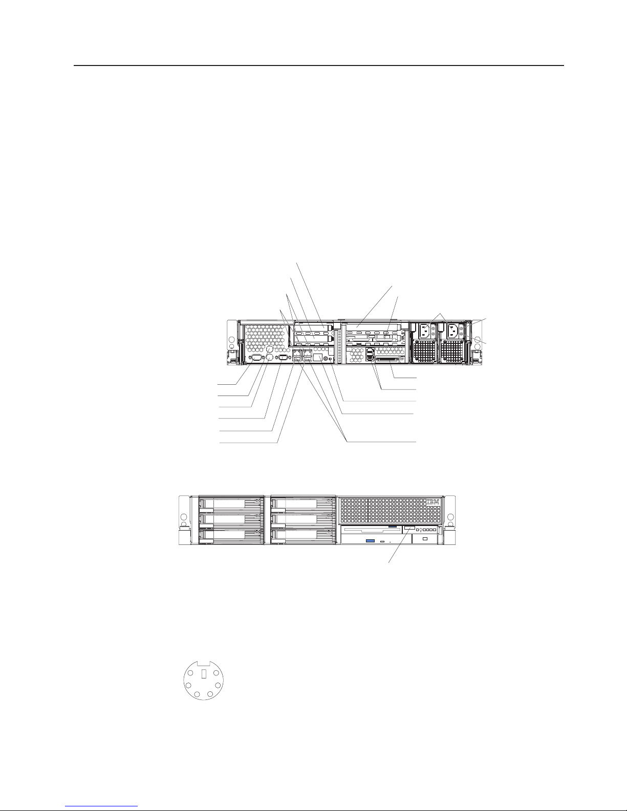
Input/output connectors
Your server has the following input/output (I/O) connectors:
v One auxiliary-device (pointing device)
v Three Ethernet (one for remote server management using network, RJ-45)
v Two Advanced Systems Management (ASM)
v One keyboard
v One serial
v One Ultra320 SCSI controller (LVD) SCSI
v Three Universal Serial Bus (USB) (one on the front and two on the rear)
v One video
The following illustrations show the locations of these connectors.
Rear view
Ethernet link status LEDs
Ethernet activity LEDs
PCI slot 1
PCI slot 2
PCI slot 3
PCI slot 4
Power cords
AC power LED
TX/RX TX/RXLINK LINK
Serial
Mouse
Keyboard
Video
Ethernet 2
Ethernet 1
Front view
The following sections describe these connectors.
Auxiliary-device (pointing device) connector
Use this connector to connect a mouse or other pointing device. The following
illustration shows an auxiliary-device connector.
6
4
2
5
3
1
DC power LED
SCSI
ASM
System-locator LED
Remote Supervisor Adapter II
EthernetSlimLine
Universal Serial
Bus (USB)
USB
Chapter 3. Installing options 43
Page 54

Ethernet connectors
The following illustration shows an Ethernet connector.
8
1
Connect a Category 3, 4, or 5 unshielded twisted-pair cable to this connector.
100BASE-TX and 1000BASE-T Fast Ethernet standards require Category 5 or
higher cabling.
The server has three Ethernet connectors. Two of the Ethernet connectors are
attached to the Ethernet controllers. See the User’s Guide on the IBM xSeries
Documentation CD for more information about the Ethernet controllers.
To enable remote server management through a network, use the Remote
Supervisor Adapter II SlimLine Ethernet connector. This connector is active only if
an optional Remote Supervisor Adapter II SlimLine is installed. See the
documentation that comes with the option for more information.
Advanced Systems Management (ASM) connectors
Use either of these dual RJ-45 connectors to connect the server to an Integrated
xSeries Adapter (IXA) that is installed in the server.
Keyboard connector
Use this connector to connect a PS/2 (non-USB) keyboard to the server. The
following illustration shows a keyboard connector.
6
4
2
If you attach a keyboard to this connector, USB ports and devices are disabled
during POST.
5
3
1
Serial connector
Use a serial connector to connect a serial device. The following illustration shows a
serial connector.
1
69
Ultra320 SCSI controller system-board connectors
The integrated dual channel small computer system interface (SCSI) controller with
integrated RAID supports two independent Ultra320 SCSI channels: one external
and one internal. Each channel supports up to 15 SCSI devices. You can use the
external LVD SCSI channel connector on the rear of the server to connect different
types of SCSI devices, such as drives or printers. This controller uses:
v Double-transition clocking to achieve up to 320 MB-per-second data-transfer
rates
44 xSeries 346 Types 8840 and 1880: Hardware Maintenance Manual and Troubleshooting Guide
5
Page 55

v Domain-name validation to negotiate compatible data-transfer speeds with each
device
v Cyclic redundancy checking (CRC), instead of the usual parity checking, to
improve data reliability
v An active terminator for SCSI bus termination
server comes with one SCSI cable, which connects the internal connector on
The
the system board to the standard hot-swap-drive backplane. If you plan to attach
external SCSI devices, you must order additional cables. To select and order the
correct cables for use with external devices, contact your IBM marketing
representative or authorized reseller.
SCSI cabling requirements
For information about the maximum length of SCSI cable, go to the American
National Standards Institute (ANSI) SCSI standards on the ANSI Web site at
http://www.ansi.org/. Adhering to these standards will help to ensure that the server
operates properly.
SCSI IDs
Each SCSI device that is connected to a SCSI controller must have a unique SCSI
ID. This ID enables the SCSI controller to identify the device and ensure that
different devices on the same SCSI channel do not attempt to transfer data
simultaneously. SCSI devices that are connected to different SCSI channels can
have duplicate SCSI IDs. Table 5 lists the SCSI IDs for the hard disk drives and
backplanes that are connected to one channel.
Table 5. SCSI IDs for standard hot-swap hard disk drives, controller, and backplane
Device SCSI ID
Drive bay 1 0
Drive bay 2 1
Drive bay 3 2
Drive bay 4 3
Drive bay 5 4
Drive bay 6 5
Controller 7
Backplane 8
The hot-swap-drive backplane controls the SCSI IDs for the internal hot-swap drive
bays. However, when you attach an external SCSI device to an optional SCSI
adapter, you must set a unique ID for the device. See the information that comes
with the device for instructions for setting its SCSI ID.
SCSI connector
The following illustration shows a SCSI connector.
34
1
68
35
Chapter 3. Installing options 45
Page 56

Universal Serial Bus version 1.1 or 2.0 connectors
Use a Universal Serial Bus (USB) connector to connect a USB device. USB version
1.1 technology transfers data at up to 12 Mb per second (Mbps) with a maximum of
127 devices and a maximum signal distance of 5 meters (16 ft) per segment. If
multiple USB devices are attached to the server, the USB hub must be version 2.0;
otherwise, all USB 2.0 devices will transfer data at 12 Mbps. USB devices are
configured automatically, using Plug and Play technology. The following illustration
shows a USB connector.
14
Use a 4-pin cable to connect a device to a USB connector. If you need to connect
more USB devices than the server has USB connectors for, use a USB hub to
connect additional devices.
If you connect a PS/2 (non-USB) keyboard to the keyboard connector, USB ports
and devices are disabled during POST.
If you connect a USB keyboard that has a mouse port, the keyboard emulates a
mouse, and you cannot disable the mouse settings in the Configuration/Setup Utility
program.
Video connector
The integrated super video graphics array (SVGA) video controller is not removable,
but you can disable it through the Configuration/Setup Utility program or by
installing a PCI video adapter.
Note: If you install a PCI video adapter, the BIOS will automatically disable the
integrated video controller.
The following illustration shows a video connector.
5
1
1115
46 xSeries 346 Types 8840 and 1880: Hardware Maintenance Manual and Troubleshooting Guide
Page 57

Chapter 4. Field replaceable units
Thermal grease . . . . . . . . . . . . . . . . . . . . . . . . .47
Fan bracket . . . . . . . . . . . . . . . . . . . . . . . . . .48
Power cage assembly . . . . . . . . . . . . . . . . . . . . . .49
Hard disk drive backplane . . . . . . . . . . . . . . . . . . . . .50
Media cage . . . . . . . . . . . . . . . . . . . . . . . . . .51
Removing a microprocessor . . . . . . . . . . . . . . . . . . . .52
System board . . . . . . . . . . . . . . . . . . . . . . . . .54
System-board option connectors . . . . . . . . . . . . . . . . .54
System-board internal cable connectors . . . . . . . . . . . . . . .55
System-board external connectors . . . . . . . . . . . . . . . . .55
System-board switches and jumpers . . . . . . . . . . . . . . . .56
System-board LEDs . . . . . . . . . . . . . . . . . . . . . .57
Removing the system board and shuttle . . . . . . . . . . . . . .58
The following information describes procedures for removing and installing certain
FRU inside the server. Only a qualified service technician is authorized to access
the FRU described in this section.
Important: The field-replaceable unit (FRU) procedures are intended for trained
servicers who are familiar with IBM xSeries products. See the parts listing in
“System” on page 108 to determine if the FRU being replaced is a
customer-replaceable unit (CRU) or a FRU.
Thermal grease
This section contains information about removing and replacing the thermal grease
between the heat sink and the microprocessor.
Important: If you are installing the heat sink on the same processor that it was
removed from, be sure that:
v The thermal grease on the heat sink and microprocessor is not contaminated.
v Addition thermal grease is not added to the existing thermal grease on the heat
sink and microprocessor.
Note:
v Read “Installation guidelines” on page 11.
v Read the safety notices at Appendix B, “Safety information,” on page 117.
v Read “Handling static-sensitive devices” on page 13.
Complete
the following steps to replace damaged or contaminated thermal grease
on the microprocessor and heat sink:
1. Place the heat sink on a clean work surface.
2. Remove the cleaning pad from its package and unfold it completely.
3. Use the cleaning pad to wipe the thermal grease from the bottom of the heat
sink.
Note: Be sure that all of the thermal grease is removed.
4. Use a clean area of the cleaning pad to wipe the thermal grease from the
microprocessor; then, dispose of the cleaning pad after all of the thermal grease
is removed.
© Copyright IBM Corp. 2005, 2007 47
Page 58

Microprocessor
0.01 mL of
thermal grease
5. Use the thermal grease syringe to place 16 uniformly spaced dots of 0.01mL
each on the top of the microprocessor.
Note: 0.01mL is one tick mark on the syringe. If the grease is properly applied,
approximately half (0.22mL) of the grease will remain in the syringe.
6. Install the heat sink onto the microprocessor as described in “Installing a
microprocessor” on page 30.
Fan bracket
This section contains instructions for removing and replacing the fan bracket.
Note:
v Read “Installation guidelines” on page 11.
v Read the safety notices at Appendix B, “Safety information,” on page 117.
v Read “Handling static-sensitive devices” on page 13.
Complete the following steps to remove the fan bracket:
1. Turn off the server and any attached devices.
2. Disconnect external cables and option cables from the back of the server.
3. Remove the server cover (see “Removing the cover” on page 16).
4. Remove the air baffle (see “Removing the air baffle” on page 17).
5. Release the fan bracket retention latches.
48 xSeries 346 Types 8840 and 1880: Hardware Maintenance Manual and Troubleshooting Guide
Page 59

6. Remove the fan bracket from the server.
7. Remove the fans (see “Replacing a hot-swap fan” on page 37).
To replace the fan bracket, reverse the previous steps.
Power cage assembly
This section contains instructions for removing and replacing the power cage
assembly.
Note:
v Read “Installation guidelines” on page 11.
v Read the safety notices at Appendix B, “Safety information,” on page 117.
v Read “Handling static-sensitive devices” on page 13.
Complete
1. Turn off the server and any attached devices.
2. Disconnect external cables and option cables from the back of the server.
3. Remove the server cover (see “Removing the cover” on page 16).
4. Remove the air baffle (see “Removing the air baffle” on page 17).
5. Remove the PCI riser-card assembly (see “Working with adapters” on page 18).
6. Disconnect the power supplies from the power cage assembly.
7. Looking from the front of the server, slide the power cage assembly toward the
left side of the server to disconnect the cage assembly from the system board
connector.
the following steps to remove the power cage assembly:
Chapter 4. Field replaceable units 49
Page 60

System board connector
8. Remove the power cage assembly from the server.
To replace the power cage assembly, reverse the previous steps.
Hard disk drive backplane
This section contains instructions for removing and replacing the hard disk drive
backplane.
Note:
v Read “Installation guidelines” on page 11.
v Read the safety notices at Appendix B, “Safety information,” on page 117.
v Read “Handling static-sensitive devices” on page 13.
Complete
1. Turn off the server and any attached devices.
2. Disconnect external cables and option cables from the back of the server.
3. Remove the server cover (see “Removing the cover” on page 16).
4. Remove the hard disk drives.
5. Remove the air baffle (see “Removing the air baffle” on page 17).
6. Remove the fan bracket (see “Fan bracket” on page 48).
7. Disconnect the two cables from the hard disk drive backplane.
8. Lift the two backplane release tabs, and remove the backplane from the server.
the following steps to remove the hard disk drive backplane:
50 xSeries 346 Types 8840 and 1880: Hardware Maintenance Manual and Troubleshooting Guide
Page 61

Hard disk drive backplane
Release lever
Release lever
To replace the hard disk drive backplane, reverse the previous steps.
Media cage
Note: When installing the hard disk drive backplane, engage the left-most tab (the
tab closest to the chassis) first. Push down until the tab clicks into place.
This section contains instructions for removing and replacing the media cage.
Note:
v Read “Installation guidelines” on page 11.
v Read the safety notices at Appendix B, “Safety information,” on page 117.
v Read “Handling static-sensitive devices” on page 13.
Complete
the following steps to remove the media cage:
1. Turn off the server and any attached devices.
2. Disconnect external cables and option cables from the back of the server.
3. Remove the server cover (see “Removing the cover” on page 16).
4. Remove the air baffle (see “Removing the air baffle” on page 17).
5. Remove the fan bracket (see “Fan bracket” on page 48).
6. Disconnect all cables from the media cage.
7. Press on the release lever and pull the media cage from the server.
Chapter 4. Field replaceable units 51
Page 62

Media assembly
Release latch
8. Remove the retaining wires on the DVD-ROM drive and pull the drive from the
media cage.
9. Press on the release lever on the diskette drive and remove the drive from the
media cage.
To replace the media cage , reverse the previous steps.
Removing a microprocessor
Complete the following steps to install an additional microprocessor:
1. Read the “Installation guidelines” on page 11.and the safety information
beginning on page Appendix B, “Safety information,” on page 117.
2. Turn off the server and disconnect all power cords and external cables (see
“Turning off the server” on page 7); then, remove the server cover (see
“Removing the cover” on page 16).
3. Remove the air baffle (see “Removing the air baffle” on page 17).
4. Locate the socket containing the microprocessor that you want to remove from
the system board.
52 xSeries 346 Types 8840 and 1880: Hardware Maintenance Manual and Troubleshooting Guide
Page 63

5. Attention: Be careful when handling the microprocessor and heat sink. If the
thermal grease between the microprocessor and heat sink will be reused, do not
contaminate it. If replacement thermal grease is provided with the replacement
part, be sure to remove all traces of existing thermal grease from the remaining
part before applying the new thermal grease. See “Thermal grease” on page 66
for instructions for removing and applying thermal grease.
Rotate the heat-sink lever to the open position and carefully remove the heat
sink.
6. Rotate the locking lever on the microprocessor socket from its closed and
locked position until it stops or clicks in the fully open position (approximately
135° angle).
Lever closed
Lever
fully
open
Lever closed
Lever
fully
open
7. Attention: Do not use excessive force when removing the microprocessor
form the socket.
Remove the microprocessor.
Chapter 4. Field replaceable units 53
Page 64

System board
This section provides information about the system board.
System-board option connectors
The following illustration shows the connectors on the system board for
user-installable options.
DIMM 1 (J1)
DIMM 2 (J2)
DIMM 3 (J3)
DIMM 4 (J4)
DIMM 5 (J5)
DIMM 6 (J6)
DIMM 7 (J7)
DIMM 8 (J8)
Microprocessor 1 (J22)
Microprocessor 2 (J23)
Battery
(BH1)
VRM (J72)
Remote
Supervisor
Adapter II
SlimLine (J21)
ServeRAID-7k card (J19)
PCI low-profile card (J18)
PCI riser card (J73)
54 xSeries 346 Types 8840 and 1880: Hardware Maintenance Manual and Troubleshooting Guide
Page 65
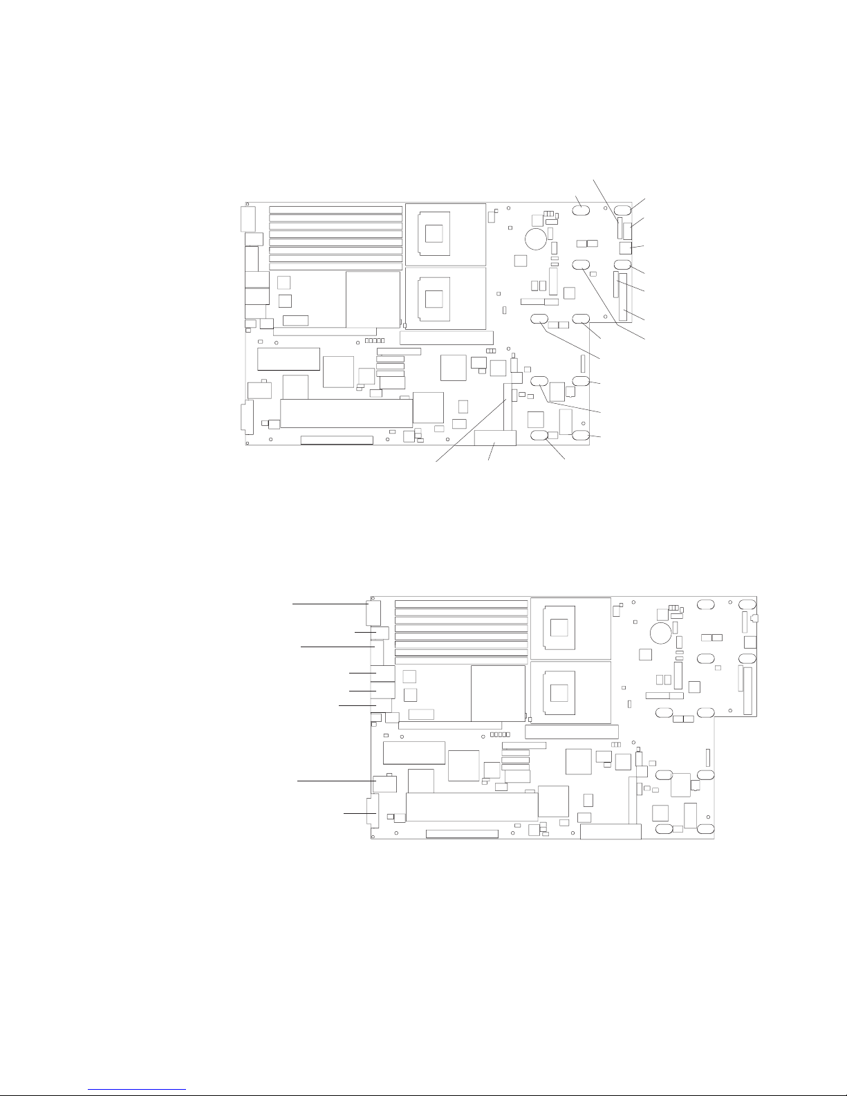
System-board internal cable connectors
The following illustration shows the internal connectors on the system board.
Internal
SCSI (J25)
System-board external connectors
The following illustration shows the external input/output connectors on the system
board.
Operator
panel (J37)
Fan 8
Power
backplane (J41)
Fan 10
Fan 6
Fan 12
Fan 5
Fan 11
Fan 4
Fan 2
USB operator
panel (J75)
Media power
(J63)
Fan 1
Diskette
signal (J39)
IDE (J67)
Fan 7
Serial (J9)
Keyboard/Mouse (J10)
Video (J11)
Ethernet 2/USB (J14)
Ethernet 1/USB (J12)
Remote Supervisor
Adapter II
SlimLine
Ethernet (J15)
ASM (J16)
External SCSI (J17)
Chapter 4. Field replaceable units 55
Page 66

System-board switches and jumpers
The following illustration shows the switches and jumpers on the system board.
Any switches or jumpers on the system board that are not shown in the illustration
are reserved. See “Recovering the BIOS code” on page 68 for information about
the boot block recovery jumper.
System board
switch block
(SW2)
ON
SW2
1 2 3 4 5 6 7 8
Boot block
recovery jumper (J60)
Table 6 describes the function of each switch on the switch block.
Table 6. Switches 1-8
Switch
number Default value
8 On Reserved.
7 Off Reserved.
6 Off Reserved.
5 Off Reserved.
4 Off Reserved.
3 Off Reserved.
2 Off Power-on password override. Changing the position of this switch bypasses the
Switch
description
power-on password check the next time the server is turned on and starts the
Configuration/Setup Utility program so that you can change or delete the power-on
password. Yo u do not have to move the switch back to the default position after the
password is overridden.
Changing the position of this switch does not affect the administrator password check
if an administrator password is set.
1 Off Power-on override. When toggled to On, this switch forces the power on, overriding
the power-on button.
Note: Before changing any switch settings or moving any jumpers, turn off the
server; then, disconnect all power cords and external cables. (Review “Installation
56 xSeries 346 Types 8840 and 1880: Hardware Maintenance Manual and Troubleshooting Guide
Page 67

guidelines” on page 11,, “Handling static-sensitive devices” on page 13,,
Appendix B, “Safety information,” on page 117, and “Turning off the server” on page
7.)
System-board LEDs
The following illustration shows the light-emitting diodes (LEDs) on the system
board.
PCI low-profile
card missing
LED (CR95)
System-locator
LED (CR65)
PCI riser-card
missing LED (CR94)
Remote Supervisor Adapter II
error LED (CR96)SlimLine
NVRAM battery
error LED (CR92)
RAID DIMM
error LED (CR93)
System board
error LED (CR63)
VRM (CPU2)
error LED (CR64)
DIMM 1 error LED (CR53)
DIMM 2 error LED (CR54)
DIMM 3 error LED (CR55)
DIMM 4 error LED (CR56)
DIMM 5 error LED (CR57)
DIMM 6 error LED (CR58)
DIMM 7 error LED (CR59)
DIMM 8 error LED (CR60)
Microprocessor 1 error LED (CR 61)
Microprocessor 2 error LED (CR 62)
3V battery error
LED (CR97)
Chapter 4. Field replaceable units 57
Page 68

Removing the system board and shuttle
This section contains instructions for removing and replacing the system board and
shuttle.
Note:
v Read “Installation guidelines” on page 11.
v Read the safety notices at Appendix B, “Safety information,” on page 117.
v Read “Handling static-sensitive devices” on page 13.
Complete
1. Turn off the server and any attached devices.
the following steps to remove the system board and shuttle:
Note: When replacing the system board, you must either update the server
with the latest firmware or restore the pre-existing firmware that the customer
provides on a diskette or CD image.
2. Disconnect external cables and option cables from the back of the server.
3. Remove the cover (see “Removing the cover” on page 16).
4. Remove the air baffle (see “Removing the air baffle” on page 17.
5. Remove the fan bracket (see “Fan bracket” on page 48).
6. Disconnect and remove the PCI low-profile-card assembly and PCI riser-card
assembly (see “Working with adapters” on page 18).
7. Disconnect all cables from the system board.
8. Remove all microprocessors and VRMs, and set them aside on a
static-protected surface for reinstallation (see “Installing a microprocessor” on
page 30).
9. Remove the memory modules, and set them aside on a static-protected
surface for reinstallation (see “Installing memory modules” on page 27).
10. Remove the power cage assembly (see “Power cage assembly” on page 49).
11. Release the shuttle locking latch, and remove the shuttle from the server.
Shuttle locking latch
58 xSeries 346 Types 8840 and 1880: Hardware Maintenance Manual and Troubleshooting Guide
Page 69

To install a shuttle with a preinstalled system board, slide the shuttle into the
server and close the shuttle locking latch. Reverse the previous steps to
replace the components that were removed. To remove the system board from
the shuttle, continue with the next step.
12. Remove the eight screws that secure the system board to the shuttle at the
microprocessor retention modules.
Heat sink retention
module screws (8)
13. Remove the four standoff screws that secure the system board to the shuttle
at the external connectors.
14. Remove the other ten screws that secure the system board to the shuttle.
15. Pull the system board carefully out of the shuttle.
Chapter 4. Field replaceable units 59
Page 70

Alignment pin
16. Align the replacement system board with the shuttle and replace the screws
that were removed.
Attention: Do not over-tighten the screws that secure the system board to
the shuttle.
install the shuttle and replacement system board, looking from the front of the
To
server, slide the shuttle under the retention tab on the right side of the chassis. Be
sure the alignment pin on the chassis shuttle is aligned with the alignment hole on
the shuttle and close the shuttle locking latch. Replace all components in the
reverse order from which they were removed.
60 xSeries 346 Types 8840 and 1880: Hardware Maintenance Manual and Troubleshooting Guide
Page 71

Chapter 5. Diagnostics
This section provides basic troubleshooting information to help you resolve some
common problems that might occur with your server.
If you cannot locate and correct the problem using the information in this section,
see Appendix A, “Getting help and technical assistance,” on page 115 for more
information.
General checkout
Follow the checkout procedure for diagnosing hardware problems. Review the
following information before performing the checkout procedure:
v Read Appendix B, “Safety information,” on page 117.
v The server diagnostic programs are stored in upgradeable read-only memory
(ROM) on the system board. These programs provide the primary methods of
testing the major components of the server. If you are not sure whether a
problem is caused by the hardware or by the software, you can run the
diagnostic programs (see “Diagnostic programs and error messages” on page
64) to confirm that the hardware is working correctly.
v When you run the diagnostic programs, a single problem might cause several
error messages. If you receive several error messages, correct the cause of the
first error message. The other error messages might not occur the next time you
run the diagnostic programs.
v Before running the diagnostic programs, you must determine whether the failing
server is part of a shared hard disk drive cluster (two or more servers sharing
external storage devices). If you suspect that it is part of a cluster, you can run
all diagnostic programs except the ones that test the storage unit (that is, a hard
disk drive in the storage unit) or the storage adapter that is attached to the
storage unit. The failing server might be part of a cluster if any of the following
conditions is true:
– The customer identifies the failing server as part of a cluster.
– One or more external storage units are attached to the failing server and at
least one of the attached storage units is also attached to another server or
unidentifiable device.
– One or more servers are located near the failing server.
Important:
v
1. For servers that are part of a shared hard disk drive cluster, run one test at a
time. Do not run any suite of tests, such as “quick” or “normal” tests, because
this could enable the hard disk drive diagnostic tests.
2. If more than one error code is displayed, correct the first error. The other
error codes might not occur the next time you run the diagnostic programs.
3. If the server is suspended and a POST error code is displayed, see “POST
error logs” on page 63.
4. If the server is suspended and no error message is displayed, see “Error
symptoms” on page 91 and “Undetermined problems” on page 104.
5. For information about power-supply problems, see “Power checkout” on page
69.
6. For intermittent problems, check the error logs; see “Diagnostic programs and
error messages” on page 64.
© Copyright IBM Corp. 2005, 2007 61
Page 72

Complete the following steps to perform the checkout procedure to identify system
problems.
001 IS THE SYSTEM PART OF A CLUSTER?
YES. Schedule maintenance for the system. Shut down all systems related
to the cluster. Run the storage test.
NO. Go to step 002.
002 IF THE SYSTEM IS NOT PART OF A CLUSTER:
1. Check the power supply LEDs, see “Power supply LEDs” on page 67.
2. Turn off the server and all external devices.
3. Check all internal and external devices for compatibility at
http://www.ibm.com/servers/eserver/serverproven/compat/us/.
4. Check all cables and power cords.
5. Set all display controls to the middle position.
6. Turn on all external devices.
7. Turn on the server.
8. Record any POST error messages that are displayed on the screen. If
an error is displayed, look up the first error in the “POST error codes”
on page 78.
9. Check the information LED panel system-error LED; if it is on, see
“Light path diagnostics LEDs” on page 83.
10. Check the system-error log and base-board management controller
(BMC) log. If the system recorded an error, see Chapter 6,
“Symptom-to-FRU index,” on page 73
11. Start the diagnostic programs.
12. Check for the following responses:
v One beep
v Readable instructions or the main menu
DID YOU RECEIVE BOTH OF THE CORRECT RESPONSES?
003
NO. Find the failure symptom in Chapter 6, “Symptom-to-FRU index,” on
page 73
YES. Run the diagnostic programs. If necessary, see “Diagnostic programs
and error messages” on page 64.
If you receive an error, see Chapter 6, “Symptom-to-FRU index,” on page
73
If the diagnostic programs were completed successfully and you still
suspect a problem, see “Undetermined problems” on page 104.
Diagnostic tools overview
The following tools are available to help you diagnose and solve hardware-related
problems:
v POST beep codes
The power-on self-test beep codes indicate the detection of a problem.
– One beep indicates successful completion of POST, with no errors.
– More than one beep indicates that POST detected a problem. Error messages
also appear during startup if POST detects a hardware-configuration problem.
See “POST error codes” on page 78 for a list of POST error codes.
Symptom-to-FRU index
v
62 xSeries 346 Types 8840 and 1880: Hardware Maintenance Manual and Troubleshooting Guide
Page 73

POST error logs
This index list problem symptoms, error codes, and steps to correct the
problems. See Chapter 6, “Symptom-to-FRU index,” on page 73 for more
information.
v Diagnostic programs and error messages
The system diagnostic programs are provided in ROM. These programs test the
major components of your server. See “Diagnostic programs and error
messages” on page 64.
v Light path diagnostics
Use light path diagnostics to diagnose system errors quickly. See “Light path
diagnostics” on page 67 for more information.
When you turn on the server, it performs a series of tests to check the operation of
server components and some of the options installed in the server. This series of
tests is called the power-on self-test, or POST.
If POST finishes without detecting any problems, a single beep sounds, and the first
screen of your operating system or application program appears.
If POST detects a problem, more than one beep sounds, and an error message
appears on your screen. See “Beep symptoms” on page 74 and “POST error
codes” on page 78 for more information.
Notes:
1. If you have a power-on password or administrator password set, you must type
the password and press Enter, when prompted, before POST will continue.
2. A single problem might cause several error messages. When this occurs, work
to correct the cause of the first error message. After you correct the cause of
the first error message, the other error messages usually will not occur the next
time you run the test.
The POST error log contains the three most recent error codes and messages that
the system generated during POST. The system-error log or base-board
management controller (BMC) log contains all messages issued during POST and
all system status messages from the service processor.
You can view the contents of the system-error log and BMC log from the
Configuration/Setup Utility program or from the diagnostic programs.
Viewing error logs from the Configuration/Setup Utility program
To view error logs from the Configuration/Setup Utility program, start the
Configuration/Setup Utility program; then, select Error Logs from the main menu.
See Chapter 2, “Configuring the server,” on page 9 for more information.
Viewing error logs from diagnostic programs
To view error logs from diagnostic programs, complete the following steps:
1. Start the diagnostic programs.
2. Select Hardware Info from the top of the diagnostic programs screen.
3. Select System Error Log or BMC Log from the list that appears; then, follow
the instructions on the screen.
“Starting the diagnostic programs” on page 65 for more information.
See
Chapter 5. Diagnostics 63
Page 74

ServerGuide error symptoms
Look for the symptom in the left column of the chart. Probable solutions to the
problem are in the right column.
Table 7. ServerGuide Setup and Installation CD
Symptom Suggested action
The ServerGuide Setup and Installation
CD will not start.
The SCSI RAID program cannot view all
installed drives, or the NOS cannot be
installed.
The Operating System Installation
program continuously loops.
The ServerGuide program will not start
your NOS CD.
The NOS cannot be installed; the option
is not available.
v Ensure that the server is supported and has a startable (bootable)
DVD-ROM drive.
v If the startup (boot) sequence settings have been altered, ensure that
the DVD-ROM drive is first in the startup sequence.
v If more than one DVD-ROM drive is installed, ensure that only one drive
is set as the primary drive. Start the CD from the primary drive.
v Ensure that there are no duplicate SCSI IDs or IRQ assignments.
v Ensure that the hard disk drive is connected properly.
Make more space available on the hard disk.
Ensure that the ServerGuide program supports the NOS CD you have.
See the ServerGuide Setup and Installation CD label for a list of supported
NOS versions.
Ensure that your server supports the NOS. If the NOS is supported, either
there is no logical drive defined (SCSI RAID systems) or the ServerGuide
System Partition is not present. Run the ServerGuide program, and ensure
that setup is complete.
Small computer system interface messages
If you receive a SCSI error message, see “SCSI error codes” on page 100.
Note: If your server does not have a hard disk drive, ignore any message that
indicates that the BIOS is not installed.
Diagnostic programs and error messages
The server diagnostic programs are stored in upgradeable read-only memory
(ROM) on the system board. These programs are the primary method of testing the
major components of your server.
Diagnostic error messages indicate that a problem exists; they are not intended to
be used to identify a failing part. Troubleshooting and servicing of complex
problems that are indicated by error messages should be performed by trained
service personnel.
Sometimes the first error to occur causes additional errors. In this case, the server
displays more than one error message. Always follow the suggested action
instructions for the first error message that appears.
Error codes that might be displayed are listed at “Diagnostic error codes” on page
86.
Notes:
1. Depending on the server configuration, some of the error codes might not
appear when you run the diagnostic programs.
64 xSeries 346 Types 8840 and 1880: Hardware Maintenance Manual and Troubleshooting Guide
Page 75

2. If diagnostic error codes appear that are not listed in the tables, make sure that
the server has the latest levels of BIOS, service processor, and ServeRAID
code installed.
Diagnostic text message format
The diagnostic text message format is as follows:
result test_specific_string
where:
result is one of the following results:
Passed
This test was completed without any errors.
Failed
This test discovered an error.
User Aborted
You stopped the test before it was completed.
Not Applicable
You attempted to test a device that is not present in the server.
Aborted
The test could not proceed because of the server configuration.
Warning
A hardware failure did not occur; the test could not be run
because of some other problem (for example, there might be a
configuration problem, the hardware is missing or is not being
recognized, or there is a hardware problem that is not related to
the hardware currently being tested).
test_specific_string
is an error code or other information about the error.
Starting the diagnostic programs
Complete the following steps to start the diagnostic programs:
1. Turn on the server, and watch the screen.
Note: To run the diagnostic programs, you must start the server with the
highest level password that is set. That is, if an administrator password is set,
you must enter the administrator password, not the power-on password, to run
the diagnostic programs.
2. When the message F2 for Diagnostics appears, press F2.
3. Type the appropriate password; then, press Enter.
4. Select either Extended or Basic from the top of the screen.
5. When the diagnostic programs screen appears, select the test you want to run
from the list that appears; then, follow the instructions on the screen.
Notes:
a. Yo u can press F1 while running the diagnostic programs to obtain help
information. You also can press F1 from within a help screen to obtain
online documentation from which you can select different categories. To exit
from the help information and return to where you left off, press Esc.
Chapter 5. Diagnostics 65
Page 76

b. If the server stops during testing and you cannot continue, restart the server
and try running the diagnostic programs again. If the problem remains,
replace the component that was being tested when the server stopped.
c. The keyboard and mouse (pointing device) tests assume that a keyboard
and mouse are attached to the server.
d. If you run the diagnostic programs with either no mouse or a USB mouse
attached to your server, you will not be able to navigate between test
categories using the Next Cat and Prev Cat buttons. All other functions
provided by mouse-selectable buttons are also available using the function
keys.
e. Yo u can test the USB keyboard by using the regular keyboard test. The
regular mouse test can test a USB mouse. Also, you can run the USB
interface test only if there are no USB devices attached.
f. Yo u can view server configuration information (such as system configuration,
memory contents, interrupt request (IRQ) use, direct memory access (DMA)
use, device drivers, and so on) by selecting Hardware Info from the top of
the screen.
the diagnostic programs do not detect any hardware errors but the problem
If
persists during normal server operations, a software error might be the cause. If
you suspect a software problem, see the information that comes with the software
package.
Viewing the test log
When the tests are completed, you can view the test log by selecting Utility from
the top of the screen and then selecting View Test Log. Yo u can save the test log
to a file on a diskette or to the hard disk.
The test-log data is maintained only while the diagnostic programs are active. When
you exit from the diagnostic programs, the test log is cleared (saved test logs are
not affected). To save the test log to a file on a diskette or to the hard disk so that
you can view it later, click Save Log on the diagnostic programs screen and specify
a location and name for the saved log file.
Note: To save the test log to a diskette, you must use a diskette that you have
formatted yourself; this function does not work with preformatted diskettes. If the
diskette has sufficient space for the test log, the diskette may contain other data.
Viewing the system-error log or BMC log
You can also view the system-error log and BMC log from the diagnostic programs.
See the instructions in “Viewing error logs from diagnostic programs” on page 63.
Identifying problems using status LEDs
If the system-error LED on the front of the server is on, one or more LEDs inside
the server or on the power supply will be on. Your server has LEDs to help you
identify problems with some server components. These LEDs are part of the light
path diagnostics feature built into the server. By following the path of lights, you can
quickly identify the type of system error that occurred.
Your server is designed so that any LEDs that are lit remain lit when the server
shuts down as long as the ac power source is good and the power supply can
supply +5 V dc current to the server. This feature helps you isolate the problem if
an error causes the server to shut down. See “Diagnosing problems using light path
diagnostics” on page 68.
66 xSeries 346 Types 8840 and 1880: Hardware Maintenance Manual and Troubleshooting Guide
Page 77

Power-on password override
Power-on password override. Changing the position of this switch bypasses the
power-on password check the next time the server is turned on and starts the
Configuration/Setup Utility program so that you can change or delete the power-on
password. You do not have to move the switch back to the default position after the
password is overridden.
Changing the position of this switch does not affect the administrator password.
Power supply LEDs
The ac and dc power LEDs on the power supply provide status information about
the power supply. The following illustration shows the location of the ac and dc
power LEDs.
AC power
(green)
LED
For more information about power supply LEDs, see “Power-supply LED errors” on
page 100.
Light path diagnostics
Use light path diagnostics to diagnose system errors. The light path diagnostics
panel is inside the light path diagnostics drawer, on the right front of the server. To
access the light path diagnostics panel, slide the latch to the left on the front of the
light path diagnostics drawer.
The following illustration shows the controls and LEDs on the light path diagnostics
panel.
REMIND
Light Path
Diagnostics
OVER SPEC
CPU
MEM
SP
PS1
VRM
NMI
DASD
PS2
CNFG
S ERR
RAID
DC power
(green)
LED
To acknowledge a system error but not take immediate action, press the remind
button and place light path diagnostics in remind mode. When the server is in
FAN
PCI A
TEMP BRD
PCI B
PCI C
Chapter 5. Diagnostics 67
Page 78

remind mode, the system-error LED on the front of the server flashes. If a new
failure occurs, the system-error LED is lit again.
Press the reset button to reset the server and run the power-on self-test (POST).
You might have to use a pen or the end of a straightened paper clip to press the
button.
The server is designed so that LEDs remain lit when the server is connected to an
ac power source but is not turned on, provided that the power supply is operating
correctly. This feature helps you to isolate the problem when the operating system
is shut down.
Diagnosing problems using light path diagnostics
LEDs in two locations on the server are available to help you diagnose problems
that might occur during installation. Use them in the following order:
1. Light path diagnostics panel – Look at this panel first. If a system error has
occurred, the system-error LED on the front of the light path diagnostics drawer
is lit. Slide the latch to the left on the front of the light path diagnostics drawer to
access the light path diagnostics panel. Note any LEDs that are lit, and then
close the drawer.
2. LEDs on the system board – To identify the component that is causing the
error, note the lit LED on or beside the component.
Light path diagnostics LEDs
For a complete list of the LEDs on the light path diagnostics panel, the problems
they indicate, and actions to solve the problems see “Light path diagnostics LEDs”
on page 83.
Recovering the BIOS code
If the BIOS code has become damaged, such as from a power failure during a flash
update, you can recover the BIOS code using the boot block jumper and a BIOS
recovery diskette.
Note: You can obtain a BIOS recovery diskette from one of the following sources:
v Use the ServerGuide Setup and Installation CD to make a BIOS recovery
diskette.
v Download a BIOS recovery diskette from the World Wide Web. Go to
http://www.ibm.com/support/, click IBM Server Support, and make the selections
for your server.
v Contact your IBM service representative.
flash memory of your server contains a protected area that cannot be
The
overwritten. The recovery boot block is a section of code in this protected area that
enables the server to start up and to read a recovery diskette. The recovery utility
recovers the system BIOS code from the BIOS recovery files on the diskette.
Complete the following steps to recover the BIOS code:
1. Turn off the server, and disconnect all power cords and external cables.
2. Remove the server cover. See “Removing the cover” on page 16 for more
information.
3. Locate the flash boot block recovery jumper block (J60) on the system board.
68 xSeries 346 Types 8840 and 1880: Hardware Maintenance Manual and Troubleshooting Guide
Page 79

System board
switch block
(SW2)
ON
SW2
1 2 3 4 5 6 7 8
Boot block
recovery jumper (J60)
4. Move the jumper from pins 1 and 2 to pins 2 and 3 to enable the BIOS
recovery mode.
5. Insert the BIOS recovery diskette into the diskette drive.
6. Reinstall the server cover; then, reconnect all power cords.
7. Restart the server. The system begins the power-on self test (POST).
8. Select 1 - Update POST/BIOS from the menu that contains various flash
update options.
9. When prompted as to whether you want to save the current code to a diskette,
press N.
10. When prompted to choose a language, select a language (from 0 to 7), and
press Enter to accept your choice.
11. Remove the BIOS recovery diskette from the diskette drive.
12. Turn off the server, and disconnect all power cords and external cables; then,
remove the server cover.
13. Remove the jumper from the flash boot block recovery jumper block, or move
it to pins 1 and 2 to return to normal startup mode.
14. Reconnect all external cables and power cords, and turn on the peripheral
devices; then, reinstall the server cover.
15. Restart the server. The server starts up normally.
Power checkout
Power problems can be difficult to solve. For example, a short circuit can exist
anywhere on any of the power distribution buses. Usually, a short circuit will cause
the power subsystem to shut down because of an overcurrent condition.
Chapter 5. Diagnostics 69
Page 80

A general procedure for troubleshooting power problems is as follows:
1. Turn off the server, and disconnect all ac power cords.
2. Check for loose cables in the power subsystem. Also check for short circuits, for
example, if there is a loose screw causing a short circuit on a circuit board.
3. Remove adapters, and disconnect the cables and power connectors to all
internal and external devices until the server is at the minimum configuration
required to start the server (see “Minimum operating requirements” on page
105).
4. Reconnect all ac power cords, and turn on the server. If the server starts up
successfully, replace adapters and devices one at a time until the problem is
isolated. If the server does not start up from the minimal configuration, replace
FRUs of minimal configuration one at a time until the problem is isolated.
To use this method, it is important to know the minimum configuration required for a
system to start (see page 105). For specific problems, see “Power-supply LED
errors” on page 100.
Troubleshooting the Ethernet controller
This section provides troubleshooting information for problems that might occur with
the 10/100/1000 Mbps Ethernet controller.
Network connection problems
If the Ethernet controller cannot connect to the network, check the following
conditions:
v Make sure that the cable is installed correctly.
The network cable must be securely attached at all connections. If the cable is
attached but the problem remains, try a different cable.
If you set the Ethernet controller to operate at either 100 Mbps or 1000 Mbps,
you must use Category 5 or higher cabling.
v Determine whether the hub supports auto-negotiation. If it does not, try
configuring the integrated Ethernet controller manually to match the speed and
duplex mode of the hub.
v Check the Ethernet controller LEDs on the rear of the server.
These LEDs indicate whether there is a problem with the connector, cable, or
hub:
– The Ethernet transmit/receive activity LED, on the rear of the server, is lit
when the Ethernet controller sends or receives data over the Ethernet
Network. If the Ethernet transmit/receive activity LED is off, make sure that
the hub and network are operating and that the correct device drivers are
installed.
– The Ethernet link status LED, on the rear of the server, is lit when the
Ethernet controller receives a LINK pulse from the hub. If the LED is off, there
might be a defective connector or cable or a problem with the hub.
v Make sure that you are using the correct device drivers, which are supplied with
the server.
v Check for operating-system-specific causes for the problem.
v Make sure that the device drivers on the client and server are using the same
protocol.
v Test the Ethernet controller.
The way the Ethernet controller is tested depends on which operating system
you are using (see the Ethernet controller device driver readme files).
70 xSeries 346 Types 8840 and 1880: Hardware Maintenance Manual and Troubleshooting Guide
Page 81

Ethernet controller troubleshooting chart
Use the following troubleshooting chart to find solutions to 10/100/1000 Mbps
Ethernet controller problems that have definite symptoms.
Description FRU/action
The server stops
running when loading
device drivers.
The Ethernet link status
LED does not work.
The Ethernet
transmit/receive activity
LED does not work.
Data is incorrect or
sporadic.
The Ethernet controller
stopped working when
another adapter was
added to the server.
The Ethernet controller
stopped working without
apparent cause.
The PCI BIOS interrupt settings are incorrect.
v Determine whether the interrupt (IRQ) setting that is assigned to the Ethernet controller
is also assigned to another device in the Configuration/Setup Utility program.
Although interrupt sharing is allowed for PCI devices, some devices do not function well
when they share an interrupt with a dissimilar PCI device. Try changing the IRQ
assigned to the Ethernet controller or the other device. For example, for NetWare
Versions 3 and 4, it is recommended that disk controllers not share interrupts with LAN
controllers.
v Make sure that you are using the most recent device driver that is available from the
World Wide Web.
v Reseat or replace the adapter.
v Make sure that the hub is turned on.
v Check all connections at the Ethernet controller and the hub.
v Use another port on the hub.
v If the hub does not support auto-negotiation, manually configure the Ethernet controller
to match the hub.
v If you manually configured the Duplex mode, make sure that you also manually
configure the speed.
v Reseat or replace the adapter.
v Make sure that you have installed the network device drivers.
v The network might be idle. Try sending data from this server.
v Make sure that you are using Category 5 or higher cabling when operating the server at
100 Mbps or at 1000 Mbps.
v Make sure that the cables do not run close to noise-inducing sources like fluorescent
lights.
v Make sure that the cable is connected to the Ethernet controller.
v Make sure that the PCI system BIOS code is current.
v Reseat the adapter.
v Determine whether the interrupt (IRQ) setting that is assigned to the Ethernet adapter is
also assigned to another device in the system. Use the Configuration/Setup Utility
program to determine whether this is the case.
Although interrupt sharing is allowed for PCI devices, some devices do not function well
when they share an interrupt with a dissimilar PCI device. Try changing the IRQ that is
assigned to the Ethernet adapter or the other device.
v Reseat or replace the adapter.
v Run diagnostics for the Ethernet controller.
v Try a different connector on the hub.
v Reinstall the device drivers. See the operating-system documentation and the
ServerGuide information.
v Reseat or replace the adapter.
Ethernet controller messages
The integrated Ethernet controller might display messages from certain device
drivers. The latest available information concerning these messages is at the IBM
Support Web site at http://www.ibm.com/support/.
Chapter 5. Diagnostics 71
Page 82

72 xSeries 346 Types 8840 and 1880: Hardware Maintenance Manual and Troubleshooting Guide
Page 83

Chapter 6. Symptom-to-FRU index
Beep symptoms . . . . . . . . . . . . . . . . . . . . . . . .74
No-beep symptoms . . . . . . . . . . . . . . . . . . . . . . .77
POST error codes . . . . . . . . . . . . . . . . . . . . . . . .78
Light path diagnostics LEDs . . . . . . . . . . . . . . . . . . . .83
Diagnostic error codes . . . . . . . . . . . . . . . . . . . . . .86
Error symptoms . . . . . . . . . . . . . . . . . . . . . . . .91
DVD-ROM drive error symptoms . . . . . . . . . . . . . . . . .92
Diskette drive error symptoms . . . . . . . . . . . . . . . . . .92
General error symptoms . . . . . . . . . . . . . . . . . . . .92
Hard disk drive error symptoms . . . . . . . . . . . . . . . . . .93
Intermittent error symptoms . . . . . . . . . . . . . . . . . . .93
Keyboard, mouse, or pointing device error symptoms . . . . . . . . . .93
Memory error symptoms . . . . . . . . . . . . . . . . . . . .94
Microprocessor error symptoms . . . . . . . . . . . . . . . . . .94
Monitor error symptoms . . . . . . . . . . . . . . . . . . . .94
Option error symptoms . . . . . . . . . . . . . . . . . . . . .96
Power error symptoms . . . . . . . . . . . . . . . . . . . . .96
Serial port error symptoms . . . . . . . . . . . . . . . . . . .97
ServerGuide error symptoms . . . . . . . . . . . . . . . . . . .98
Software error symptoms . . . . . . . . . . . . . . . . . . . .99
Power-supply LED errors . . . . . . . . . . . . . . . . . . . . . 100
Service processor error codes . . . . . . . . . . . . . . . . . . . 100
SCSI error codes . . . . . . . . . . . . . . . . . . . . . . . 100
Temperature error messages . . . . . . . . . . . . . . . . . . . 101
Fan error messages . . . . . . . . . . . . . . . . . . . . . . 102
Power error messages . . . . . . . . . . . . . . . . . . . . . 102
System shutdown . . . . . . . . . . . . . . . . . . . . . . . 102
Voltage related system shutdown . . . . . . . . . . . . . . . . . 103
Temperature related system shutdown . . . . . . . . . . . . . . . 103
Hard disk drive checkout . . . . . . . . . . . . . . . . . . . . . 104
Host built-in self test (BIST) . . . . . . . . . . . . . . . . . . . . 104
Bus fault messages . . . . . . . . . . . . . . . . . . . . . . . 104
Undetermined problems . . . . . . . . . . . . . . . . . . . . . 104
Problem determination tips . . . . . . . . . . . . . . . . . . . . 105
This index supports xSeries 346 servers.
Notes:
1. Check the configuration before you replace a component. Configuration
problems can cause false errors and symptoms.
2. For IBM devices not supported by this index, refer to the manual for that device.
3. Always start with “General checkout” on page 61.
The symptom-to-FRU index lists symptoms, errors, and the possible causes. The
most likely cause is listed first. Use this symptom-to-FRU index to help you decide
which FRUs to have available when servicing the server.
The first column of the two-column tables in this index lists error codes or
messages, and the last column lists one or more suggested actions or FRUs to
replace. Take the action (or replace the FRU) that is suggested first in the list, and
then try the server again to see whether the problem has been corrected.
© Copyright IBM Corp. 2005, 2007 73
Page 84

Note: Try reseating a suspected component or reconnecting a cable before
replacing the component.
The POST BIOS code displays POST error codes and messages on the screen.
Beep symptoms
Beep symptoms are short tones or a series of short tones separated by pauses
(intervals without sound). See the examples in the following table.
Beeps Description
1-2-3
4 Four continuous beeps
One beep after successfully completing POST indicates the system is functioning
properly.
v One beep
v A pause (or break)
v Two beeps
v A pause (or break)
v Three beeps
Note: See “System” on page 108 to determine which components a field service technician should replace.
Beep/symptom FRU/action
1-1-2
(Microprocessor register test failed)
1. Optional microprocessor (if installed)
2. Microprocessor
3. System board
1-1-3
(CMOS write/read test failed)
1. Battery
2. Clear CMOS (see “Recovering the BIOS code” on page 68).
3. System board
1-1-4
(BIOS EEPROM checksum failed)
1-2-1
1. Recover BIOS
2. System board
System board
(Programmable Interval Timer failed)
1-2-2
System board
(DMA initialization failed)
1-2-3
System board
(DMA page register write/read failed)
1-2-4
(RAM refresh verification failed)
1-3-1
(first 64K RAM test failed)
1. DIMM
2. System board
1. Reseat the DIMMs
2. Replace the lowest-numbered pair of DIMMs with an identical known good
pair of DIMMs; then, restart the server.Return one DIMM at a time from the
failed pair to its connector, restarting the server after each DIMM, to
identify the failed DIMM.
2-1-1
System board
(Secondary DMA register failed)
2-1-2
System board
(Primary DMA register failed)
74 xSeries 346 Types 8840 and 1880: Hardware Maintenance Manual and Troubleshooting Guide
Page 85

Note: See “System” on page 108 to determine which components a field service technician should replace.
Beep/symptom FRU/action
2-1-3
System board
(Primary interrupt mask register
failed)
2-1-4
System board
(Secondary interrupt mask register
failed)
2-2-1
System board
(Interrupt vector loading failed)
2-2-2
(Keyboard controller failed)
2-2-3
(CMOS power failure and checksum
checks failed)
1. System board
2. Keyboard
1. Battery
2. Clear CMOS (see “Recovering the BIOS code” on page 68).
3. System board
2-2-4
(CMOS configuration information
validation failed)
1. Battery
2. Clear CMOS (see “Recovering the BIOS code” on page 68).
3. System board
2-3-1
System board
(Screen initialization failed)
2-3-2
System board
(Screen memory failed)
2-3-3
System board
(Screen retrace failed)
2-3-4
System board
(Search for video ROM failed)
2-4-1
System board
(Video failed; screen believed
operable)
3-1-1
System board
(Timer tick interrupt failed)
3-1-2
System board
(Interval timer channel 2 failed)
3-1-3
(RAM test failed above address
OFFFFH))
3-1-4
(Time-Of-Day clock failed)
3-2-1
1. DIMM
2. System board
1. Battery
2. System board
System board
(Serial port failed)
3-2-2
System board
(Parallel port failed)
3-2-3
(Math coprocessor test failed)
3-2-3
(Failure comparing CMOS memory
size against actual)
1. Microprocessor
2. System board
1. DIMM
2. Battery
Chapter 6. Symptom-to-FRU index 75
Page 86

Note: See “System” on page 108 to determine which components a field service technician should replace.
Beep/symptom FRU/action
3-3-1
(Memory size mismatch occurred.)
3-3-2
(Critical SMBUS error occurred)
1. DIMM
2. Battery
1. Disconnect the server power cord from outlet, wait 30 seconds, and
retry.
2. System board.
3. DIMMs.
4. Hard disk drive backplane.
5. Power supply.
6. Power cage assembly.
3-3-3
(No operational memory in system)
1. Install or reseat the memory modules, and then do a 3 boot reset.
(For more information on a 3 boot reset, see Chapter 2, “Configuring the
server,” on page 9).
2. DIMMs.
3. Memory board.
4. System board.
4-4-4 (Optional system management
adapter not installed in slot 1 or not
functioning correctly)
1. Verify that the adapter is installed in the system management adapter
slot.
2. Adapter.
3. System board.
Two short beeps
(Information only, the configuration
has changed)
Three short beeps
1. Run Diagnostics.
2. Run the Configuration/Setup Utility program.
1. Reseat the DIMMs
2. Locate the failing DIMMs:
a. Remove all DIMMs from the server.
b. Beginning with the primary bank of DIMMs, return one bank of DIMMs
to the server at a time, restarting the server each time, until the beep
code error returns.
c. Replace one pair of DIMMs at a time in the failing bank with an
identical pair of known good DIMMs, restarting the server after each
pair, until the beep code error returns.
d. Replace one DIMM at a time in the failing pair with an identical known
good DIMM, restarting the server after each DIMM, to identify the failed
DIMM. If the beep code error remains after you have replaced both
DIMMs, go to step 3b.
e. Repeat steps 2b through 2d until you have checked all memory banks.
Replace the following components, one at a time, in the order shown:
3.
a. DIMMs
b. (Trained service technician only) System board
76 xSeries 346 Types 8840 and 1880: Hardware Maintenance Manual and Troubleshooting Guide
Page 87

Note: See “System” on page 108 to determine which components a field service technician should replace.
Beep/symptom FRU/action
One continuous beep
1. Reseat the following components, one at a time, in the order shown,
restarting the server each time:
v (Trained service technician only) Microprocessor 1
v (Trained service technician only) Microprocessor 2 (if installed)
(Trained service technician only) Remove microprocessor 2 and its VRM
2.
and restart the server.
v If no beep code occurs, microprocessor 2 might have failed; replace the
microprocessor.
v If the beep code remains, remove microprocessor 1 and install
microprocessor 2 in the connector for microprocessor 1; then, restart the
server. If no beep code occurs, microprocessor 1 might have failed;
replace the microprocessor.
Replace the following components, one at a time, in the order shown,
3.
restarting the server each time:
v (Trained service technician only) Microprocessor 1
v (Trained service technician only) Microprocessor 2 (if installed)
v (Trained service technician only) System board
Repeating short beeps
1. Keyboard
2. System board
One long and one short beep
1. Video adapter (if installed)
2. System board
One long and two short beeps
1. Video adapter (if installed)
2. System board
One long and three short beeps
1. Monitor
2. Video adapter, if installed
3. System board
Two long and two short beeps Video adapter
No-beep symptoms
Note: See “System” on page 108 to determine which components a field service technician should replace.
No-beep symptom FRU/action
No beep and the system
operates correctly.
No beeps occur after
successfully completing POST
(the power-on status is disabled)
1. Check speaker cables.
2. Speaker.
3. System board.
1. Run the Configuration/Setup Utility program, and set the Start Options
Power-On Status to enable.
2. Check the speaker connection.
3. System board.
Chapter 6. Symptom-to-FRU index 77
Page 88

Note: See “System” on page 108 to determine which components a field service technician should replace.
No-beep symptom FRU/action
No ac power (power supply ac
LED is off)
1. Check the power cord.
2. Power supply. (If two are installed, swap them to determine if one is
defective.)
3. Disconnect the ribbon cable from connector J25 on the system board. If the ac
power LED comes on, see “Undetermined problems” on page 104.
4. Power cage assembly.
No beep and no video See “Undetermined problems” on page 104.
System will not start (power
See “Power-supply LED errors” on page 100.
supply ac LED is on)
POST error codes
In the following error codes, X can be any number or letter.
Note: See “System” on page 108 to determine which components a field service technician should replace.
Error code/symptom FRU/action
062
(Three consecutive startup failures using
the default configuration.)
101, 102
(System and processor error)
106
(System and processor error)
111
(Channel check error)
114
(Adapter read-only memory error)
129
(Internal cache error)
151
(Real time clock error)
161
(Real time clock battery error)
162
(Device configuration error)
Note: Be sure to load the default settings
and any additional desired settings; then,
save the configuration.
1. Run the Configuration/Setup Utility program.
2. Battery.
3. System board.
4. Microprocessor.
System board
System board
1. Memory DIMM
2. System board
1. Failing adapter.
2. Run diagnostics.
1. Microprocessor
2. Optional microprocessor (if installed)
1. Run diagnostics.
2. Battery.
3. Clear CMOS (see “Recovering the BIOS code” on page 68).
4. System board.
1. Run the Configuration/Setup Utility program.
2. Battery.
3. Clear CMOS (see “Recovering the BIOS code” on page 68).
4. System board.
1. Run the Configuration/Setup Utility program.
2. Battery.
3. Failing device.
4. System board.
78 xSeries 346 Types 8840 and 1880: Hardware Maintenance Manual and Troubleshooting Guide
Page 89

Note: See “System” on page 108 to determine which components a field service technician should replace.
Error code/symptom FRU/action
163
(Real-time clock error)
1. Run the Configuration/Setup Utility program.
2. Battery.
3. Clear CMOS (see “Recovering the BIOS code” on page 68).
4. System board.
164
(Memory configuration changed.)
1. Run the Configuration/Setup Utility program.
2. DIMM.
3. System board.
175
System board
(Hardware error)
176
(Computer cover or cable cover was
removed without a key being used)
177, 178
(Security hardware error)
184
(Power-on password damaged)
1. Run the Configuration/Setup Utility program.
2. System board.
1. Run the Configuration/Setup Utility program.
2. System board.
1. Run the Configuration/Setup Utility program.
2. Clear CMOS (see “Recovering the BIOS code” on page 68).
3. System board.
185
(Drive startup sequence information
corrupted)
186
(Security hardware control logic failed)
187
(VPD serial number not set.)
188
(Bad EEPROM CRC #2)
189
(An attempt was made to access the
1. Run the Configuration/Setup Utility program.
2. System board.
1. Run the Configuration/Setup Utility program.
2. System board.
1. Set serial number in the Configuration/Setup Utility program.
2. System board.
1. Run the Configuration/Setup Utility program.
2. System board.
Run the Configuration/Setup Utility program, and type the
administrator password.
server with invalid passwords)
201
(Memory test error.) If the server does not
have the latest level of BIOS installed,
1. DIMM
2. System board
update the BIOS to the latest level and run
the diagnostic program again.
229
(Cache error)
262
(DRAM parity configuration error)
1. Microprocessor
2. Optional microprocessor (if installed)
1. Run the Configuration/Setup Utility program.
2. Battery.
3. System board.
289
(DIMM disabled by POST or user)
1. Run the Configuration/Setup Utility program, if the DIMM was
disabled by the user.
2. Disabled DIMM, if not disabled by user.
Chapter 6. Symptom-to-FRU index 79
Page 90

Note: See “System” on page 108 to determine which components a field service technician should replace.
Error code/symptom FRU/action
301
(Keyboard or keyboard controller error)
303
1. Keyboard
2. System board
System board
(Keyboard controller error)
602
(Invalid diskette boot record)
1. Diskette
2. Diskette drive
3. Cable
4. System board
604
(Diskette drive error)
1. Run the Configuration/Setup Utility program and diagnostics.
2. Diskette drive.
3. Drive cable.
4. System board.
605
(Unlock failure)
1. Diskette drive
2. Drive cable
3. System board
662
(Diskette drive configuration error)
1. Run the Configuration/Setup Utility program and diagnostics.
2. Diskette drive.
3. Drive cable.
4. System board.
762
(Coprocessor configuration error)
1. Run the Configuration/Setup Utility program.
2. Battery.
3. Microprocessor.
962
(Parallel port error)
1. Disconnect the external cable on the parallel port.
2. Run the Configuration/Setup Utility program.
3. System board.
11XX
(System board serial port 1 or 2 error)
1. Disconnect the external cable on the serial port.
2. Run the Configuration/Setup Utility program.
3. System board.
1301
(I2C cable to front panel not found)
1. Cable
2. Front panel
3. Power switch assembly
4. System board
1302
(I2C cable from system board to power on
and reset switches not found)
1. Cable
2. Power switch assembly
3. System board
1303
(I2C cable from system board to power
cage assembly not found)
1. Cable
2. Power-cage assembly
3. System board
1304
(I2C cable to diagnostic LED board not
found)
1. Power switch assembly
2. System board
80 xSeries 346 Types 8840 and 1880: Hardware Maintenance Manual and Troubleshooting Guide
Page 91

Note: See “System” on page 108 to determine which components a field service technician should replace.
Error code/symptom FRU/action
1600
System board
(The system management processor is not
functioning) Before replacing a FRU,
remove the ac power to the server, wait 20
seconds; then, reconnect the ac power.
Wait 30 seconds; then, turn on the server.
1601
(The system is able to communicate to the
system management processor, but the
1. Remote Supervisor Adapter, if installed
2. System board
system management processor failed to
respond at the start of POST.) Complete
the following steps before replacing a
FRU:
1. Remove the ac power to the server,
wait 20 seconds; then, reconnect the
ac power. Wait 30 seconds; then, turn
on the server.
2. Flash update the system management
processor.
1602
(Optional service processor not properly
Disconnect all server and option power cords from server, wait 30
seconds, reconnect, and retry.
installed.)
1762
(Hard disk configuration error)
1. Hard disk drive.
2. Hard disk cables.
3. Run the Configuration/Setup Utility program.
4. Hard disk adapter.
5. SCSI backplane.
6. System board.
178X
(Fixed disk error)
1. Hard disk cables.
2. Run diagnostics.
3. Hard disk adapter.
4. Hard disk drive.
5. System board.
1800
(No more hardware interrupt available for
PCI adapter)
1. Run the Configuration/Setup Utility program.
2. Failing adapter.
3. System board.
1962
(Drive does not contain a valid boot
sector)
1. Verify that a startable operating system is installed.
2. Run diagnostics.
3. Hard disk drive.
4. SCSI backplane.
5. Cable.
6. System board.
2400
(Video controller test failure)
2462
(Video memory configuration error)
1. Video adapter (if installed)
2. System board
1. Video adapter (if installed)
2. System board
Chapter 6. Symptom-to-FRU index 81
Page 92

Note: See “System” on page 108 to determine which components a field service technician should replace.
Error code/symptom FRU/action
5962
(IDE CD-ROM drive configuration error)
1. Run the Configuration/Setup Utility program.
2. DVD-ROM drive.
3. DVD-ROM power cable.
4. IDE cable.
5. System board.
6. Battery.
8603
(Pointing-device error)
0001200
(Machine check architecture error)
00012000
(Microprocessor machine check)
00019501
(Microprocessor 1 is not functioning -
check VRM and microprocessor LEDs)
1. Pointing device
2. System board
1. Microprocessor 1
2. Optional microprocessor 2
1. Microprocessor
2. System board
1. VRM 1
2. Microprocessor 1
3. System board
00019502
(Microprocessor 2 is not functioning -
check VRM and microprocessor LEDs)
00019701
(Microprocessor 1 failed)
00019702
(Microprocessor 2 failed)
00180100
(A PCI adapter has requested memory
resources that are not available.)
1. VRM 2
2. Microprocessor 2
1. Microprocessor 1
2. System board
1. Microprocessor 2
2. System board
1. Reorder the adapters in the PCI slots. It is important that your
startup device is positioned early in the startup-device order so
that it is run by POST.
2. Ensure that the PCI adapter and all other adapters are set correctly
in the Configuration/Setup Utility program Utility program. If the
memory resource settings are not correct, change the settings.
3. If all memory resources are being used, you might need to remove
an adapter to make memory available to the PCI adapter. Disabling
the adapter BIOS on the adapter might correct the error. (See the
documentation provided with the adapter.)
00180200
(No more I/O space available for PCI
adapter)
1. Run the Configuration/Setup Utility program.
2. Failing adapter.
3. System board.
00180300
(No more memory (above 1MB for PCI
adapter))
1. Run the Configuration/Setup Utility program.
2. Failing adapter.
3. System board.
00180400
(No more memory (below 1MB for PCI
adapter))
1. Run the Configuration/Setup Utility program.
2. Move the failing adapter to slot 1.
3. Failing adapter.
4. System board.
82 xSeries 346 Types 8840 and 1880: Hardware Maintenance Manual and Troubleshooting Guide
Page 93

Note: See “System” on page 108 to determine which components a field service technician should replace.
Error code/symptom FRU/action
00180500
(PCI option ROM checksum error)
00180600
(PCI to PCI bridge error)
1. Remove failing PCI card.
2. System board.
1. Run the Configuration/Setup Utility program.
2. Move the failing adapter to slot 1.
3. Failing adapter.
4. System board
00180700, 00180800
(General PCI error)
00181000
(PCI error)
01295085
(ECC checking hardware test error)
01298001
(No update data for microprocessor 1)
01298002
(No update data for microprocessor 2)
1. System board
2. PCI card
1. Adapter
2. System board
1. System board
2. Microprocessor
1. Ensure all processors have the same cache size.
2. Microprocessor 1.
1. Ensure all microprocessors have the same cache sizes, clock
speeds and clock frequencies.
2. Microprocessor 2.
01298101
(Bad update data for microprocessor 1)
1. Ensure all microprocessors have the same cache sizes, clock
speeds and clock frequencies.
2. Microprocessor 1.
01298102
(Bad update data for microprocessor 2)
1. Ensure all microprocessors have the same cache sizes, clock
speeds and clock frequencies.
2. Microprocessor 2.
I9990301
(Hard disk sector error)
1. Hard disk drive
2. SCSI backplane
3. Cable
4. System board
I9990305
Install operating system to hard disk.
(Hard disk sector error, no operating
system installed)
I9990650
(AC power has been restored)
1. Check cable.
2. Check for interruption of power.
3. Power cable.
Light path diagnostics LEDs
The following table lists the LEDs on the light path diagnostics panel, the problems
that they indicate, and actions to solve the problems.
Note: Check the system-error log and BMC log for additional information before
replacing a FRU.
Chapter 6. Symptom-to-FRU index 83
Page 94

LED Problem Action
None An error has occurred and cannot be
diagnosed, or the ASM processor has
Check the system-error log and BMC log for information about
the error.
failed. The error is not represented by a
light path diagnostics LED.
OVER
SPEC
PS 1 When the LED is lit, the power supply
The power supplies are using more
power than their maximum rating.
in bay 1 has failed. When the LED
flashes, an invalid power-supply
Replace the failing power supply, or remove optional devices
from the server.
If the power supply has failed, replace the power supply. If a
configuration error has occurred, make sure that the power
supply is installed correctly.
configuration has occurred.
PS 2 When the LED is lit, the power supply
in bay 2 has failed. When the LED
flashes, an invalid power-supply
If the power supply has failed, replace the power supply. If a
configuration error has occurred, make sure that the power
supply is installed correctly.
configuration has occurred.
CPU When the LED is lit, a microprocessor
has failed. When the LED flashes, an
invalid microprocessor configuration has
occurred.
If a lit LED on the system board indicates a problem with a
microprocessor, make sure that the microprocessor is installed
correctly. See the Option Installation Guide on the IBM xSeries
Documentation CD for information about installing a
microprocessor.
If the problem remains, replace the microprocessor.
If a configuration error has occurred, make sure that the
microprocessors have the same cache size and type, and the
same clock speed. Microprocessor internal and external clock
frequencies must be identical.
If the problem remains, replace the system board.
VRM When the LED is lit, an error occurred
on the microprocessor voltage regulator
module (VRM). When the LED flashes,
an invalid VRM configuration has
Check the system board LEDs to determine which VRM has
failed. If the option VRM has failed, replace the optional VRM. If
the VRM mounted on the system board has filed, replace the
system board.
occurred.
If a configuration error has occurred, make sure that the VRM is
installed correctly. If the problem remains, replace the VRM.
CNFG When this LED is lit, the front system
error LED will also be lit.
MEM When the LED is on, a memory error
has occurred. When the LED flashes,
an invalid DIMM configuration has
Check the microprocessor options just installed to ensure they
are compatible with each other and change as needed.
Replace the failing DIMM, which is indicated by the lit LED on
the system board. If a configuration error has occurred, make
sure the DIMMs are installed correctly.
occurred.
NMI A machine check error has occurred. Check the system-error log and BMC log for information about
the error.
S ERR Reserved
SP The service processor has failed. Remove ac power from the server; then, reconnect the server
to ac power and restart the server.
DASD A hard disk drive error has occurred. Check the LEDs on the hard disk drives and replace the
RAID A RAID controller error has occurred. Check the system-error log and BMC log for information about
84 xSeries 346 Types 8840 and 1880: Hardware Maintenance Manual and Troubleshooting Guide
If the problem remains, replace the system board.
indicated drive.
the error. See the documentation that comes with the RAID
controller.
Page 95

LED Problem Action
FAN When the LED is lit, a fan has failed or
is operating too slowly. A failing fan can
also cause the TEMP LED to be lit.
Replace the failing fan, which is indicated by the lit LED. If a
configuration error has occurred, make sure that the fans are
installed correctly.
When the LED flashes, an invalid fan
configuration has occurred.
TEMP The system temperature has exceeded
a threshold level.
v Determine whether a fan has failed. If it has, replace it.
v Make sure that the room temperature is not too high. See the
User’s Guide on the IBM xSeries Documentation CD for
temperature information.
v Make sure that the air vents are not blocked.
BRD An error has occurred on the system
board.
v Check the LEDs on the system board to identify the
component that is causing the error.
v Check the system-error log and BMC log for information
about the error.
PCI A
PCI B
PCI C
An error has occurred on a PCI bus. v Check the system-error log and BMC log for information
about the error.
v If you cannot isolate the failing adapter through the
information in the system error log or BMC log, remove one
adapter at a time from the failing PCI bus, and restart the
server after each adapter is removed.
If the problem remains, replace the system board.
Chapter 6. Symptom-to-FRU index 85
Page 96

Diagnostic error codes
Note: In the following error codes, if XXX is 000, 195, or 197, do not replace a
FRU. The description for these error codes are:
000 The test passed.
195 The Esc key was pressed to stop the test.
197 Warning; a hardware failure might not have occurred.
For all error codes, replace the FRU or take the action indicated.
Note: See “System” on page 108 to determine which components a field service technician should replace.
Error code/symptom FRU/action
001-XXX-000
(Failed core tests)
001-XXX-001
(Failed core tests)
001-250-001
(Failed system board ECC)
005-XXX-000
(Failed video test)
011-XXX-000
(Failed COM1 serial port test)
014-XXX-000
(Failed parallel port test)
015-XXX-001
(USB interface not found, board damaged)
015-XXX-015
(Failed USB external loopback test)
015-XXX-198
(USB device connected during USB test)
020-XXX-000
(Failed PCI interface test)
020-XXX-001
(Failed hot-swap slot 1 PCI latch test)
020-XXX-002
(Failed Hot-swap slot 2 PCI latch test)
020-XXX-003
(Failed hot-swap slot 3 PCI latch test)
020-XXX-004
(Failed hot-swap slot 4 PCI latch test)
030-XXX-000
(Failed internal SCSI interface test)
035-XXX-099(No adapters were found.) If adapter is installed re-check connection.
System board
System board
Processor board
System board
System board
System board
System board
1. Make sure the parallel port is not disabled.
2. Run the USB external loopback test again.
3. System board.
1. Remove USB devices from USB1 and USB2.
2. Run the USB external loopback test again.
3. System board.
System board
1. PCI hot-swap latch assembly
2. System board
1. PCI hot-swap latch assembly
2. System board
1. PCI hot-swap latch assembly
2. System board
1. PCI hot-swap latch assembly
2. System board
System board
86 xSeries 346 Types 8840 and 1880: Hardware Maintenance Manual and Troubleshooting Guide
Page 97

Note: See “System” on page 108 to determine which components a field service technician should replace.
Error code/symptom FRU/action
035-XXX-S99
(Failed RAID test on PCI slot S. S =
number of failing PCI slot. Check the
system-error log and BMC log before
1. Adapter
2. SCSI backplane
3. Cable
replacing a FRU.)
035-XXX-SNN
Hard disk drive with SCSI ID nn on RAID adapter in PCI slot s.
(Check system-error log and BMC log
before replacing a FRU. s = number of
failing PCI slot, nn = SCSI ID of failing fixed
disk.)
035-253-S99
(RAID adapter initialization failure)
1. ServeRAID adapter in slot s is not configured properly. Obtain
the basic and extended configuration status, and see the
ServeRAID Hardware Maintenance Manual for more
information.
2. Cable.
3. SCSI backplane.
4. Adapter.
075-XXX-000
Power supply
(Failed power supply test)
089-XXX-001
(Failed microprocessor test)
089-XXX-002
(Failed optional microprocessor test)
166-051-000 System Management: Failed
(Unable to communicate with RSA. It may
be busy. Run the test again.)
1. VRM 1 for microprocessor 1
2. Microprocessor 1
1. VRM 2 for optional microprocessor 2
2. Optional microprocessor 2
1. Flash latest levels of firmware (BIOS, service processor,
diagnostics)
2. Rerun diagnostic test.
3. Correct other error conditions (including failed system management
tests and items logged in Remote Supervisor Adapter II SlimLine
system-error log) and retry.
4. Disconnect all server and option power cords from server, wait 30
seconds, reconnect, and retry.
5. Remote Supervisor Adapter II SlimLine.
166-060-000 System Management: Failed
(Unable to communicate with RSA. It may
be busy. Run the test again.)
1. Flash latest levels of firmware (BIOS, service processor,
diagnostics)
2. Rerun diagnostic test.
3. Correct other error conditions (including failed system management
tests and items logged in Remote Supervisor Adapter II SlimLine
system-error log) and retry.
4. Disconnect all server and option power cords from server, wait 30
seconds, reconnect, and retry.
5. Remote Supervisor Adapter II SlimLine.
Chapter 6. Symptom-to-FRU index 87
Page 98

Note: See “System” on page 108 to determine which components a field service technician should replace.
Error code/symptom FRU/action
166-070-000 System Management: Failed
(Unable to communicate with RSA. It may
be busy. Run the test again.)
1. Flash latest levels of firmware (BIOS, service processor,
diagnostics)
2. Rerun diagnostic test.
3. Correct other error conditions (including failed system management
tests and items logged in Remote Supervisor Adapter II SlimLine
system-error log) and retry.
4. Disconnect all server and option power cords from server, wait 30
seconds, reconnect, and retry.
5. Remote Supervisor Adapter II SlimLine.
166-198-000 System Management:
Aborted
(Unable to communicate with RSA. It may
be busy. Run the test again.)
1. Run the diagnostic test again.
2. Correct other error conditions and retry. These include other failed
system management tests and items logged in the system-error log
of the optional Remote Supervisor Adapter II SlimLine.
3. Disconnect all server and option power cords from the server, wait
30 seconds, reconnect, and retry.
4. Remote Supervisor Adapter II SlimLine, if installed.
5. System board.
166-250-000 System Management: Failed
(I2C cable is disconnected. Reconnect I2C
cable between Remote Supervisor Adapter
1. Remote Supervisor Adapter II SlimLine.
2. System board.
and system board.)
166-260-000 System Management: Failed
(Restart RSA error. After restarting, RSA
communication was lost. Unplug and cold
boot to reset RSA.)
1. Disconnect all server and option power cords from the server,
wait 30 seconds, reconnect, and retry.
2. Reseat Remote Supervisor Adapter II SlimLine.
3. Remote Supervisor Adapter II SlimLine.
166-342-000 System Management: Failed
(RSA adapter BIST indicate failed tests.)
1. Ensure the latest firmware levels for Remote Supervisor
Adapter II SlimLine and BIOS are installed.
2. Disconnect all server and option power cords from server, wait 30
seconds, reconnect, and retry.
3. Remote Supervisor Adapter II SlimLine.
166-400-000 System Management: Failed
(BMC self test result failed tests: x where x
= Flash, RAM, or ROM.)
166-404-001 System Management: Failed
(BMC indicates failure in I2C bus test.)
1. Reflash or update firmware for BMC.
2. System board.
1. Disconnect all server and option power cords from the server,
wait 30 seconds, reconnect, and retry.
2. Reflash or update firmware for BMC.
3. Power backplane
4. System board.
166-406-001 System Management: Failed
(BMC indicates failure in I2C bus test.)
1. Disconnect all server and option power cords from the server,
wait 30 seconds, reconnect, and retry.
2. Reflash or update firmware for BMC.
3. SCSI cable.
4. SCSI backplane.
5. System board.
88 xSeries 346 Types 8840 and 1880: Hardware Maintenance Manual and Troubleshooting Guide
Page 99

Note: See “System” on page 108 to determine which components a field service technician should replace.
Error code/symptom FRU/action
166-407-001 System Management: Failed
(BMC indicates failure in I2C bus test.)
1. Disconnect all server and option power cords from the server,
wait 30 seconds, reconnect, and retry.
2. Reflash or update firmware for BMC.
3. Operator information panel cable.
4. Operator information panel.
5. System board.
166-NNN-001 System Management:
Failed (BMC indicates failure in self test
where NNN=300 to 320.)
1. Disconnect all server and option power cords from the server,
wait 30 seconds, reconnect, and retry.
2. Reflash or update firmware for BMC.
3. System board.
166-NNN-001 System Management:
Failed (BMC indicates failure in I2C bus
test where NNN=400 to 420 (excluding 412,
414, and 415).)
1. Disconnect all server and option power cords from the server,
wait 30 seconds, reconnect, and retry.
2. Reflash or update firmware for BMC.
3. System board.
166-412-001 System Management: Failed
(BMC indicates failure in I2C bus test
where NNN=400 to 420)
1. Disconnect all server and option power cords from the server,
wait 30 seconds, reconnect, and retry.
2. Reflash or update firmware for BMC.
3. Power backplane
4. System board.
166-414-001 System Management: Failed
(BMC indicates failure in I2C bus test
where NNN=400 to 420)
1. Disconnect all server and option power cords from the server,
wait 30 seconds, reconnect, and retry.
2. Reflash or update firmware for BMC.
3. SCSI cable
4. SCSI backplane
5. System board.
166-415-001 System Management: Failed
(BMC indicates failure in I2C bus test
where NNN=400 to 420)
1. Disconnect all server and option power cords from the server,
wait 30 seconds, reconnect, and retry.
2. Reflash or update firmware for BMC.
3. Operator panel cable
4. Operator panel
5. System board.
180-XXX-000 (Diagnostics LED failure) Run diagnostics panel LED test for the failing LED.
180-XXX-001
(Failed front LED panel test)
180-XXX-002
(Failed diagnostics LED panel test)
180-361-003
(Failed fan LED test)
180-XXX-003
1. Operator information panel
2. System board
1. Diagnostics panel
2. System board
1. Fan (s)
2. System board
System board
(Failed system board LED test)
180-XXX-005
(Failed SCSI backplane LED test)
1. SCSI backplane
2. SCSI backplane cable
3. System board
Chapter 6. Symptom-to-FRU index 89
Page 100

Note: See “System” on page 108 to determine which components a field service technician should replace.
Error code/symptom FRU/action
201-XXX-0NN
(Failed memory test.)
Note: nn = slot of failing DIMM
1. Replace the DIMM is slot NN.
2. Processor board
3. Memory adapter, if installed.
201-XXX-N99
(Multiple DIMM failure, see error text)
Note: n= is slot numbers of failing pair
1. See error text for failing DIMMs.N
2. Processor board
3. Memory adapter, if installed.
202-XXX-001
(Failed system cache test)
202-XXX-002
(Failed system cache test)
206-XXX-000
(Failed diskette drive test)
1. VRM 1
2. Microprocessor 1
1. VRM 2
2. Microprocessor 2
1. Rerun the test with a different diskette.
2. Cable.
3. Diskette drive.
4. System board.
215-XXX-000
(Failed IDE CD-ROM drive test)
1. Rerun the test with a different DVD-ROM drive.
2. DVD-ROM drive cables.
3. DVD-ROM drive.
4. System board.
217-198-XXX
(Could not establish drive parameters)
1. Check cable and termination.
2. SCSI backplane.
3. Hard disk.
217-XXX-000
Hard disk 1
(Failed BIOS hard disk test)
Note: If RAID is configured, the hard disk
number refers to the RAID logical array.
217-XXX-001
Hard disk 2
(Failed BIOS hard disk test)
Note: If RAID is configured, the hard disk
number refers to the RAID logical array.
217-XXX-002
Hard disk 3
(Failed BIOS hard disk test)
Note: If RAID is configured, the hard disk
number refers to the RAID logical array.
217-XXX-003
Hard disk 4
(Failed BIOS hard disk test)
Note: If RAID is configured, the hard disk
number refers to the RAID logical array.
217-XXX-004
Hard disk 5
(Failed BIOS hard disk test)
Note: If RAID is configured, the hard disk
number refers to the RAID logical array.
217-XXX-005
Hard disk 6
(Failed BIOS hard disk test)
Note: If RAID is configured, the hard disk
number refers to the RAID logical array
90 xSeries 346 Types 8840 and 1880: Hardware Maintenance Manual and Troubleshooting Guide
 Loading...