

IBM 88371RU, Type 1879 xSeries 336, Type 8837, xSeries 336 Type 1879, xSeries 336 Type 8837 Maintenance And Troubleshooting Manual
Page 1

xSeries 336 Ty pe 1879 and Ty p e 8837
Hardw are Maintenance Manual and
Troubleshooting Guide
Page 2

Page 3

xSeries 336 Ty pe 1879 and Ty p e 8837
Hardw are Maintenance Manual and
Troubleshooting Guide
Page 4

Notes:
v Before using this information and the product it supports, read Appendix B, “Safety information,” on page 129, and
Appendix C, “Notices,” on page 163.
v The most recent version of this document is available at http://www.ibm.com/support/.
11th Edition (May 2008)
© Copyright International Business Machines Corporation 2002, 2007. All rights reserved.
US Government Users Restricted Rights – Use, duplication or disclosure restricted by GSA ADP Schedule Contract
with IBM Corp.
Page 5
About this manual
This document contains basic configuration information, diagnostic information, error
codes, error messages, service information, and a symptom-to-FRU index for the
IBM® xSeries® 336 Type 1879 and Type 8837 server.
Important: The field replaceable unit (FRU) procedures in this document are
intended for trained servicers who are familiar with IBM products.
Customer replacement units (CRUs) can be replaced by the customer.
See Chapter 7, “Parts listing, Type 1879 and Type 8837,” on page 121,
to determine if the component being replaced is a FRU or a CRU.
Before servicing an IBM product, be sure to read Appendix B, “Safety
information,” on page 129.
Important safety information
Be sure to read all caution and danger statements in this book before performing
any of the instructions.
Leia todas as instruções de cuidado e perigo antes de executar qualquer operação.
Prenez connaissance de toutes les consignes de type Attention et
Danger avant de procéder aux opérations décrites par les instructions.
Lesen Sie alle Sicherheitshinweise, bevor Sie eine Anweisung ausführen.
Accertarsi di leggere tutti gli avvisi di attenzione e di pericolo prima di effettuare
qualsiasi operazione.
Lea atentamente todas las declaraciones de precaución y peligro ante de llevar a
cabo cualquier operación.
WARNING: Handling the cord on this product or cords associated with accessories
sold with this product, will expose you to lead, a chemical known to the State of
California to cause cancer, and birth defects or other reproductive harm. Wash
hands after handling.
ADVERTENCIA: El contacto con el cable de este producto o con cables de
accesorios que se venden junto con este producto, pueden exponerle al plomo, un
elemento químico que en el estado de California de los Estados Unidos está
considerado como un causante de cancer y de defectos congénitos, además de
otros riesgos reproductivos. Lávese las manos después de usar el producto.
© Copyright IBM Corp. 2002, 2007 iii
Page 6

Online support
You can download the most current diagnostic, BIOS flash, and device-driver files
from http://www.ibm.com/support/. For a list of supported options for the server, go
to http://www.ibm.com/servers/eserver/serverproven/compat/us/.
iv xSeries 336 Type 1879 and Type 8837: Hardware Maintenance Manual and Troubleshooting Guide
Page 7

Contents
About this manual . . . . . . . . . . . . . . . . . . . . . . . iii
Important safety information . . . . . . . . . . . . . . . . . . . . iii
Online support . . . . . . . . . . . . . . . . . . . . . . . . .iv
Chapter 1. General information . . . . . . . . . . . . . . . . . . .1
Related documentation . . . . . . . . . . . . . . . . . . . . . .1
Notices and statements used in this book . . . . . . . . . . . . . . .2
Features and specifications . . . . . . . . . . . . . . . . . . . . .3
Server controls and LEDs . . . . . . . . . . . . . . . . . . . . .6
Front view . . . . . . . . . . . . . . . . . . . . . . . . . .6
Rear view . . . . . . . . . . . . . . . . . . . . . . . . . .9
Server power features . . . . . . . . . . . . . . . . . . . . . .10
Turning on the server . . . . . . . . . . . . . . . . . . . . .10
Turning off the server . . . . . . . . . . . . . . . . . . . . .10
Chapter 2. Configuring the server . . . . . . . . . . . . . . . . .13
Configuration programs . . . . . . . . . . . . . . . . . . . . . .13
Starting the Configuration/Setup Utility program . . . . . . . . . . . . .13
Chapter 3. Customer replaceable units . . . . . . . . . . . . . . .15
Installation guidelines . . . . . . . . . . . . . . . . . . . . . .15
System reliability considerations . . . . . . . . . . . . . . . . .15
Working inside the server with the power on . . . . . . . . . . . . .15
Handling static-sensitive devices . . . . . . . . . . . . . . . . .16
Major components of the xSeries 336 Type 8837 server . . . . . . . . . .17
Removing and installing the cover . . . . . . . . . . . . . . . . . .18
Removing the cover . . . . . . . . . . . . . . . . . . . . . .18
Installing the cover . . . . . . . . . . . . . . . . . . . . . .19
Working with adapters . . . . . . . . . . . . . . . . . . . . . .20
Adapter considerations . . . . . . . . . . . . . . . . . . . . .20
Installing an adapter . . . . . . . . . . . . . . . . . . . . . .21
Installing a Remote Supervisor Adapter II SlimLine . . . . . . . . . . . .25
Hard disk drives . . . . . . . . . . . . . . . . . . . . . . . .26
Hard disk drive considerations . . . . . . . . . . . . . . . . . .26
Installing a hot-swap hard disk drive . . . . . . . . . . . . . . . .27
Installing a simple swap hard disk drive . . . . . . . . . . . . . . .28
Installing and removing an internal DVD-ROM drive or DVD-ROM blank bezel 29
Memory modules . . . . . . . . . . . . . . . . . . . . . . . .32
Memory module considerations . . . . . . . . . . . . . . . . . .32
Installing memory modules . . . . . . . . . . . . . . . . . . .34
Additional microprocessor installation . . . . . . . . . . . . . . . . .36
Microprocessor considerations . . . . . . . . . . . . . . . . . .36
Installing a microprocessor . . . . . . . . . . . . . . . . . . .37
Installing and removing a hot-swap power supply . . . . . . . . . . . .40
Installing a power supply . . . . . . . . . . . . . . . . . . . .41
Removing a power supply . . . . . . . . . . . . . . . . . . . .42
Using Y power-cord connectors for power backup . . . . . . . . . . .42
Replacing a hot-swap fan assembly . . . . . . . . . . . . . . . . .43
Replacing the battery . . . . . . . . . . . . . . . . . . . . . .45
Completing the installation . . . . . . . . . . . . . . . . . . . . .47
Connecting the cables . . . . . . . . . . . . . . . . . . . . .47
Updating the server configuration . . . . . . . . . . . . . . . . .48
Installing the server in a rack . . . . . . . . . . . . . . . . . . . .48
© Copyright IBM Corp. 2002, 2007 v
Page 8

Input/output connectors . . . . . . . . . . . . . . . . . . . . . .49
Auxiliary-device (pointing device) connector . . . . . . . . . . . . .50
Ethernet connectors . . . . . . . . . . . . . . . . . . . . . .50
Keyboard connector . . . . . . . . . . . . . . . . . . . . . .50
Serial connector . . . . . . . . . . . . . . . . . . . . . . .51
Universal Serial Bus connector . . . . . . . . . . . . . . . . . .51
Video connector . . . . . . . . . . . . . . . . . . . . . . .52
Chapter 4. Service replaceable units . . . . . . . . . . . . . . . .53
Removing a microprocessor and heat sink . . . . . . . . . . . . . . .54
Operator information panel . . . . . . . . . . . . . . . . . . . .55
Fan bracket . . . . . . . . . . . . . . . . . . . . . . . . . .56
Drive tray assembly . . . . . . . . . . . . . . . . . . . . . . .57
Front panel signal and USB cables . . . . . . . . . . . . . . . . .58
Power backplane . . . . . . . . . . . . . . . . . . . . . . . .59
System board . . . . . . . . . . . . . . . . . . . . . . . . .60
System-board option connectors . . . . . . . . . . . . . . . . .60
System-board internal connectors . . . . . . . . . . . . . . . . .61
System-board external connectors . . . . . . . . . . . . . . . . .61
System-board jumpers . . . . . . . . . . . . . . . . . . . . .62
System-board cable channels . . . . . . . . . . . . . . . . . .63
Removing the system board . . . . . . . . . . . . . . . . . . .64
Chapter 5. Diagnostics . . . . . . . . . . . . . . . . . . . . .67
General checkout . . . . . . . . . . . . . . . . . . . . . . . .67
Checkout procedure . . . . . . . . . . . . . . . . . . . . . . .68
Diagnostic tools overview . . . . . . . . . . . . . . . . . . . . .69
POST error logs . . . . . . . . . . . . . . . . . . . . . . . .69
Viewing error logs from the Configuration/Setup Utility program . . . . . .70
Viewing the system-error log from diagnostic programs . . . . . . . . .70
Diagnostic programs, error codes, and messages . . . . . . . . . . . .70
Diagnostic text message format . . . . . . . . . . . . . . . . . .71
Starting the diagnostic programs . . . . . . . . . . . . . . . . .71
Small computer system interface messages . . . . . . . . . . . . . .72
Light path diagnostics . . . . . . . . . . . . . . . . . . . . . .73
Remind button . . . . . . . . . . . . . . . . . . . . . . . .76
Reset button . . . . . . . . . . . . . . . . . . . . . . . . .76
Updating the BMC firmware . . . . . . . . . . . . . . . . . . . .76
Recovering the BMC firmware . . . . . . . . . . . . . . . . . . .76
Recovering the BIOS code . . . . . . . . . . . . . . . . . . . .77
Erasing a lost or forgotten password (clearing CMOS memory) . . . . . . .78
Updating Remote Supervisor Adapter II SlimLine firmware . . . . . . . . .79
Power checkout . . . . . . . . . . . . . . . . . . . . . . . .79
Troubleshooting the Ethernet controller . . . . . . . . . . . . . . . .80
Network connection problems . . . . . . . . . . . . . . . . . .80
Ethernet controller troubleshooting chart . . . . . . . . . . . . . .80
Ethernet controller messages . . . . . . . . . . . . . . . . . .81
Chapter 6. Symptom-to-FRU index . . . . . . . . . . . . . . . . .83
Beep symptoms . . . . . . . . . . . . . . . . . . . . . . . .84
No-beep symptoms . . . . . . . . . . . . . . . . . . . . . . .87
POST error codes . . . . . . . . . . . . . . . . . . . . . . . .88
Light path diagnostics errors . . . . . . . . . . . . . . . . . . . .93
Hot-swap power-supply LED errors . . . . . . . . . . . . . . . . .96
Diagnostic error codes . . . . . . . . . . . . . . . . . . . . . .97
Error symptoms . . . . . . . . . . . . . . . . . . . . . . . . 103
vi xSeries 336 Type 1879 and Type 8837: Hardware Maintenance Manual and Troubleshooting Guide
Page 9

CD-ROM drive error symptoms . . . . . . . . . . . . . . . . . 103
Diskette drive error symptoms . . . . . . . . . . . . . . . . . . 104
General error symptoms . . . . . . . . . . . . . . . . . . . . 104
Hard disk drive error symptoms . . . . . . . . . . . . . . . . . 104
Intermittent error symptoms . . . . . . . . . . . . . . . . . . . 105
Keyboard, mouse, or pointing device error symptoms . . . . . . . . . 105
Memory error symptoms . . . . . . . . . . . . . . . . . . . . 106
Microprocessor error symptoms . . . . . . . . . . . . . . . . . 106
Monitor error symptoms . . . . . . . . . . . . . . . . . . . . 106
Option error symptoms . . . . . . . . . . . . . . . . . . . . 108
Power error symptoms . . . . . . . . . . . . . . . . . . . . 108
Serial port error symptoms . . . . . . . . . . . . . . . . . . . 109
ServerGuide error symptoms . . . . . . . . . . . . . . . . . .110
Software error symptoms . . . . . . . . . . . . . . . . . . . . 111
Service processor error codes . . . . . . . . . . . . . . . . . . . 111
ServeRAID error codes . . . . . . . . . . . . . . . . . . . . . 111
POST (ISPR) error procedures . . . . . . . . . . . . . . . . . .113
SCSI error codes . . . . . . . . . . . . . . . . . . . . . . .115
Temperature error messages . . . . . . . . . . . . . . . . . . .115
Fan error messages . . . . . . . . . . . . . . . . . . . . . .116
Power error messages . . . . . . . . . . . . . . . . . . . . . .116
System shutdown . . . . . . . . . . . . . . . . . . . . . . .117
Voltage related system shutdown . . . . . . . . . . . . . . . . .117
Temperature related system shutdown . . . . . . . . . . . . . . .117
DASD checkout . . . . . . . . . . . . . . . . . . . . . . . .118
Host built-in self test (BIST) . . . . . . . . . . . . . . . . . . . .118
Bus fault messages . . . . . . . . . . . . . . . . . . . . . . .118
Undetermined problems . . . . . . . . . . . . . . . . . . . . .119
Problem determination tips . . . . . . . . . . . . . . . . . . . . 120
Chapter 7. Parts listing, Type 1879 and Type 8837 . . . . . . . . . . 121
System . . . . . . . . . . . . . . . . . . . . . . . . . . . 121
System replaceable units . . . . . . . . . . . . . . . . . . . . . 122
Keyboard CRUs . . . . . . . . . . . . . . . . . . . . . . . . 124
Power cords (CRUs) . . . . . . . . . . . . . . . . . . . . . . 125
Appendix A. Getting help and technical assistance . . . . . . . . . . 127
Before you call . . . . . . . . . . . . . . . . . . . . . . . . 127
Using the documentation . . . . . . . . . . . . . . . . . . . . . 127
Getting help and information from the World Wide Web . . . . . . . . . 127
Software service and support . . . . . . . . . . . . . . . . . . . 128
Hardware service and support . . . . . . . . . . . . . . . . . . . 128
IBM Taiwan product service . . . . . . . . . . . . . . . . . . . . 128
Appendix B. Safety information . . . . . . . . . . . . . . . . . 129
General safety . . . . . . . . . . . . . . . . . . . . . . . . 129
Electrical safety . . . . . . . . . . . . . . . . . . . . . . . . 130
Safety inspection guide . . . . . . . . . . . . . . . . . . . . . 131
Handling electrostatic discharge-sensitive devices . . . . . . . . . . . 132
Grounding requirements . . . . . . . . . . . . . . . . . . . . . 132
Safety notices (multilingual translations) . . . . . . . . . . . . . . . 133
Appendix C. Notices . . . . . . . . . . . . . . . . . . . . . . 163
Edition notice . . . . . . . . . . . . . . . . . . . . . . . . . 163
Trademarks . . . . . . . . . . . . . . . . . . . . . . . . . . 164
Important notes . . . . . . . . . . . . . . . . . . . . . . . . 165
Contents vii
Page 10

Product recycling and disposal . . . . . . . . . . . . . . . . . . 165
Battery return program . . . . . . . . . . . . . . . . . . . . . 165
Electronic emission notices . . . . . . . . . . . . . . . . . . . . 167
Federal Communications Commission (FCC) statement . . . . . . . . 167
Industry Canada Class A emission compliance statement . . . . . . . . 167
Australia and New Zealand Class A statement . . . . . . . . . . . . 168
United Kingdom telecommunications safety requirement . . . . . . . . 169
European Union EMC Directive conformance statement . . . . . . . . 169
Taiwanese Class A warning statement . . . . . . . . . . . . . . . 169
Chinese Class A warning statement . . . . . . . . . . . . . . . . 169
Japanese Voluntary Control Council for Interference (VCCI) statement 170
Index . . . . . . . . . . . . . . . . . . . . . . . . . . . . 171
viii xSeries 336 Type 1879 and Type 8837: Hardware Maintenance Manual and Troubleshooting Guide
Page 11
Chapter 1. General information
This Hardware Maintenance Manual and Troubleshooting Guide contains
information about servicing the IBM 336 server, Type 1879 and Type 8837.
The server might have features that are not described in the documentation that
was received with the server. The documentation might be updated occasionally to
include information about those features, or technical updates might be available to
provide additional information that is not included in the server documentation.
These updates are available from the IBM Web site at http://www.ibm.com/support/.
The xSeries 336 server is a 1-U server. Racks are marked in vertical increments of
1.75 inches; each increment is referred to as a unit, or “U.” A 1-U-high device is
1.75 inches tall.
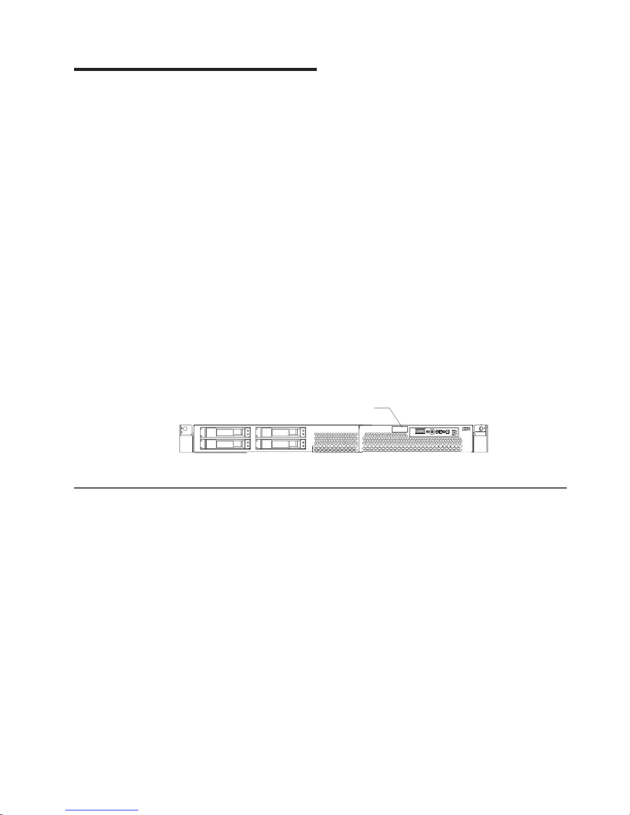
The model number and serial number are on the ID label, which is on the front of
the server on the lower-right corner, as shown in Figure 1.
Notes:
1. The illustrations in this document might differ slightly from the hardware.
2. Figure 1 shows a 2.5-inch SCSI hot-swap hard disk drive model. There is also a
3.5-inch hard disk drive model that is available with either a SCSI hot-swap or
SATA simple-swap configuration. This illustration might differ slightly from your
hardware.
Figure 1. Serial number location (model with SCSI hot-swap hard disk drive)
Related documentation
This Hardware Maintenance Manual and Troubleshooting Guide is provided in
Portable Document Format (PDF) on the IBM xSeries® Documentation CD. It
contains information to help you solve the problem yourself or to provide helpful
information to a service technician.
In addition to this Hardware Maintenance Manual and Troubleshooting Guide, the
following xSeries 336 Type 1879 and Type 8837 documentation is provided with the
server:
v User’s Guide
The User’s Guide is provided in PDF on the IBM xSeries Documentation CD and
contains general information about the server.
v Installation Guide
This printed document contains instructions for setting up the server and basic
instructions for installing some options.
v Option Installation Guide
This document is in PDF on the IBM xSeries Documentation CD. It contains
detailed instructions for installing, removing, and connecting optional devices that
the server supports.
ID label
Model #
Serial #
© Copyright IBM Corp. 2002, 2007 1
Page 12

v Safety Book
This multilingual document is provided in PDF on the IBM xSeries Documentation
CD. It contains translated versions of the caution and danger statements that
appear in the documentation for the server. Each caution and danger statement
has an assigned number, which you can use to locate the corresponding
statement in your native language.
v Rack Installation Instructions
This printed document contains the instructions for installing the server in a rack.
Depending on the server model, additional publications might be included on the
IBM xSeries Documentation CD.
Notices and statements used in this book
The caution and danger statements used in this book also appear in the multilingual
Safety Book provided on the IBM xSeries Documentation CD. Each caution and
danger statement is numbered for easy reference to the corresponding statements
in the safety book.
The following types of notices and statements are used in this book:
v Note: These notices provide important tips, guidance, or advice.
v Important: These notices provide information or advice that might help you avoid
inconvenient or problem situations.
v Attention: These notices indicate possible damage to programs, devices, or
data. An attention notice is placed just before the instruction or situation in which
damage could occur.
v Caution: These statements indicate situations that can be potentially hazardous
to you. A caution statement is placed just before the description of a potentially
hazardous procedure step or situation.
v Danger: These statements indicate situations that can be potentially lethal or
extremely hazardous to you. A danger statement is placed just before the
description of a potentially lethal or extremely hazardous procedure step or
situation.
2 xSeries 336 Type 1879 and Type 8837: Hardware Maintenance Manual and Troubleshooting Guide
Page 13

Features and specifications
This table provides a summary of the features and specifications for the server.
Depending on the server model, some features might not be available, or some
specifications might not apply.
Note: You can use the Configuration/Setup Utility program in the server to
determine the specific type of microprocessor on the system board.
Chapter 1. General information 3
Page 14

Microprocessor:
v Intel® Xeon® 2.8 GHz or higher
depending on server model
v Support for up to two
microprocessors with Intel
Hyper-Threading Technology and
EM64T (extended memory 64 bit
technology)
v 800 MHz front-side bus (FSB)
Memory:
v Minimum: 512 MB
v Maximum: 16 GB
v Type: 2-way interleaved PC3200,
400 MHz, ECC DDR II SDRAM,
registered DIMMs only
v Sizes: 256 MB, 512 MB, 1 GB, 2
GB (when available)
Drives:
v DVD-ROM drive (available only with
3.5-inch hard disk drive solution)
Expansion
bays:
Comes in 3 configurations:
v Configuration 1 and 2
– One 9.5-mm high DVD-ROM
drive (optional)
– Two 3.5-inch slim hot-swap
SCSI or two 3.5-inch
simple-swap SATA hard disk
drives
Configuration 3
v
– Four 2.5-inch hot-swap SCSI
hard disk drives
Expansion
slots:
v One PCI-X 133 MHz or PCI-E x8,
full-length, full height
Note: PCI-E x8 (PCI-E) requires
an optional riser card)
v One PCI-X 100 MHz, half length,
low-profile
Power supply:
v 585 watt hot-swap power supply
standard
v Optional redundant 585 watt
power supply
Integrated
functions:
v Baseboard management controller
(BMC)
v One LSI Ultra320 SCSI controller
with RAID level 1 capability
v Two Broadcom 10/100/1000
Ethernet controllers with Wake on
LAN® feature and Alert Standard
Format support
v Three Universal Serial Bus (USB)
ports
v One serial port
v Keyboard port
v Mouse port
v Video port
Acoustical
noise emissions:
v Sound power, idling: 6.9 bel
maximum
v Sound power, operating: 6.9 bel
maximum
Environment:
v Air temperature:
– Server on: 10° to 35°C (50.0°
to 95.0°F); altitude: 0 to 914.4
m (3000 ft) Decrease system
temperature by 0.75°C for
every 1000 feet increase in
altitude.
– Server off: 10°to 43°C (50.0° to
109.4°F); maximum altitude:
2133 m (7000 ft)
– Shipment: -40°to 60°C (-40° to
140°F): maximum altitude:
2133 m (7000 ft)
v
Humidity:
– Server on/off: 8% to 80%
– Shipment: 5% to 100%
Heat output:
Approximate heat output in British
thermal units (Btu) per hour:
v Minimum configuration: 587 Btu/hr
(172 watts)
v Maximum configuration: 1878 Btu/hr
(550 watts)
Electrical
input:
v Sine-wave input (50-60 Hz) required
v Input voltage low range:
– Minimum: 100 V ac
– Maximum: 127 V ac
v
Input voltage high range:
– Minimum: 200 V ac
– Maximum: 240 V ac
v
Input kilovolt-amperes (kVA),
approximately:
– Minimum: .172 kVA
– Maximum: .550 kVA
Notes:
1. Power consumption and heat
output vary depending on the
number and type of optional
features installed and the
power-management optional
features in use.
2. These levels were measured in
controlled acoustical environments
according to the procedures
specified by the American National
Standards Institute (ANSI) S12.10
and ISO 7779 and are reported in
accordance with ISO 9296. Actual
sound-pressure levels in a given
location might exceed the average
values stated because of room
reflections and other nearby noise
sources. The declared sound-power
levels indicate an upper limit, below
which a large number of computers
will operate.
v Air temperature:
– Server on: 10° to 35°C (50.0° to 95.0°F); altitude: 0 to 914.4 m (3000 ft)
Decrease system temperature by 0.75°C for every 1000 feet increase in
altitude.
– Server off: 10°to 43°C (50.0° to 109.4°F); maximum altitude: 2133 m (7000 ft)
– Shipment: -40°to 60°C (-40° to 140°F): maximum altitude: 2133 m (7000 ft)
Humidity:
v
4 xSeries 336 Type 1879 and Type 8837: Hardware Maintenance Manual and Troubleshooting Guide
Size:
v Height: 43 mm (1.69 in.)
v Depth: 686 mm (27.0 in.)
v Width: 440 mm (17.32 in.)
v Weight: approximately 15.6 kg
(34.5 lb) when fully configured or
12.7 kg (28 lb) minimum
Page 15

– Server on/off: 8% to 80%
– Shipment: 5% to 100%
Chapter 1. General information 5
Page 16
Server controls and LEDs
This section describes the controls and light-emitting diodes (LEDs), and how to
turn the server on and off.
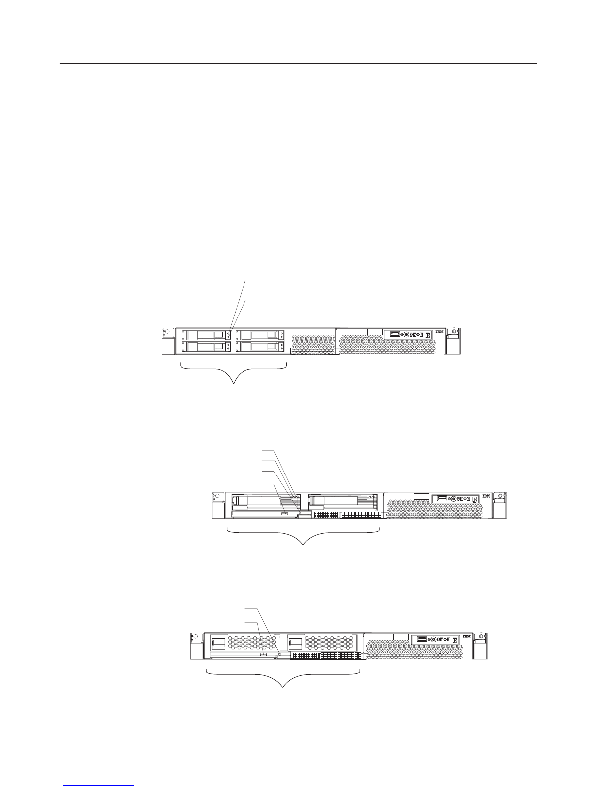
Front view
The following illustration shows the controls, LEDs, and connectors on the front of
the server. There are three different front views:
v 2.5-inch SCSI hot-swap hard disk drive
v 3.5-inch SCSI hot-swap hard disk drive
v 3.5-inch SATA non-hot-swap (simple swap) hard disk drive
Both 3.5-inch configurations support an optional DVD-ROM.
Note:
The following figures illustrate the three types of servers.
Hard disk drive activity LED
Hard disk drive status LED
SCSI ID 0
SCSI ID 1
SCSI ID 2
SCSI ID 3
Model #
Serial #
4 x 2.5” Hard disk drives
Figure 2. Server with a 2.5-inch SCSI hot-swap hard disk drive configuration
Hard disk drive status LED
Hard disk drive activity LED
DVD-ROM activity LED
DVD-ROM eject button
Model #
Serial #
SCSI ID 0 SCSI ID 1
2 x 3.5” Hard disk drives
Figure 3. Server with a 3.5-inch SCSI hot-swap hard disk drive configuration
DVD-ROM activity LED
DVD-ROM eject button
Model #
Serial #
Figure 4. Server with 3.5-inch SATA simple swap hard disk drive configuration
6 xSeries 336 Type 1879 and Type 8837: Hardware Maintenance Manual and Troubleshooting Guide
SATA 0 SATA 1
2 x 3.5” Hard disk drives
Page 17
The following information gives details about the controls, LEDs, and connectors on
the front of the server.
Hot-swap hard disk drive activity LED: This LED is used on SCSI hard disk
drives. Each hot-swap hard disk drive has an activity LED, and when this LED is
flashing, it indicates that the drive is in use.
Hot-swap hard disk drive status LED: This LED is used on SCSI hard disk
drives. When this LED is lit, it indicates that the drive has failed. If an optional IBM
ServeRAID™ controller is installed in the server, when this LED is flashing slowly
(one flash per second), it indicates that the drive is being rebuilt. When the LED is
flashing rapidly (three flashes per second), it indicates that the controller is
identifying the drive.
DVD-eject button: Press this button to release a DVD or CD from the DVD-ROM
drive.
DVD-ROM drive activity LED: When this LED is lit, it indicates that the DVD-ROM
drive is in use.
Note: The DVD-ROM option is available only on the 3.5-inch drive configurations
(either SCSI or SATA hard disk drives).
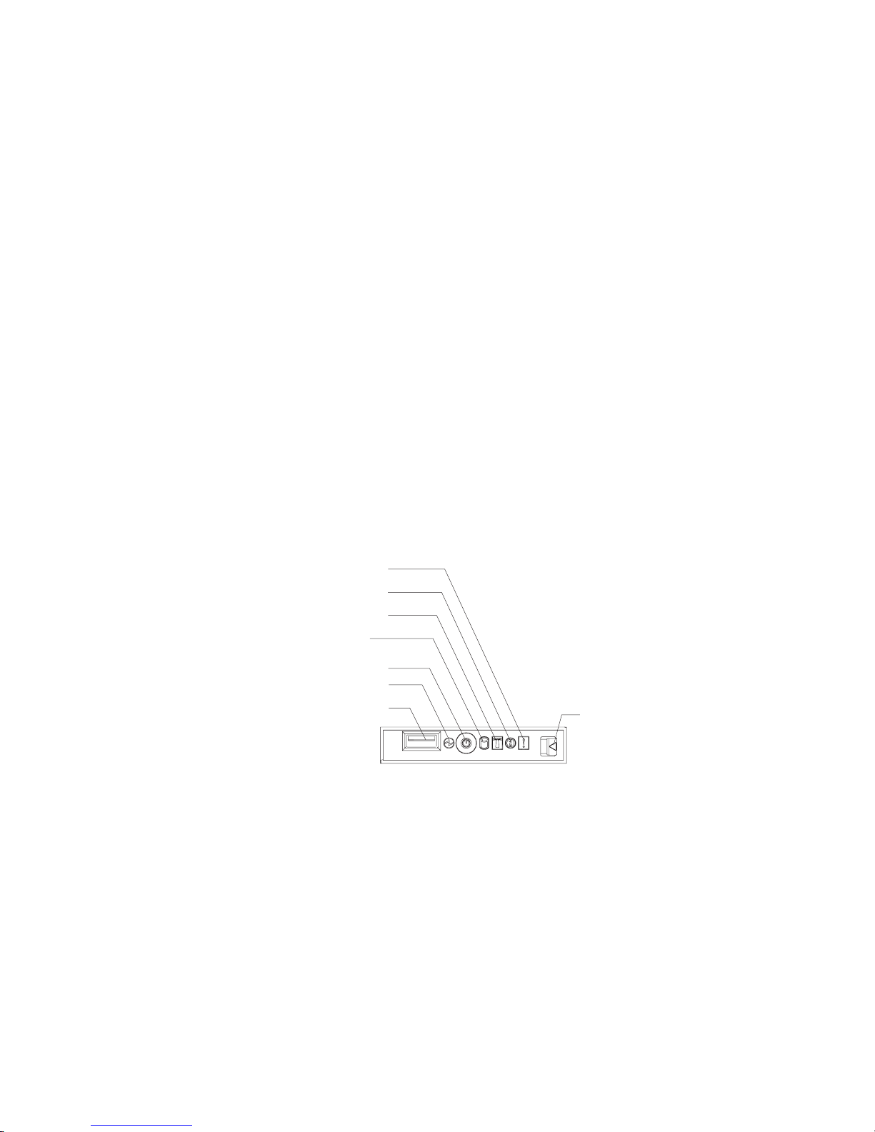
Operator information panel
The operator panel is on the front right side of the server. Figure 5 shows the LEDs
on the operator information panel.
System-error LED (amber)
Information LED (amber)
Location LED (blue)
Hard disk drive
activity LED (green)
Power control button
Power LED (green)
USB connector
Figure 5. Operator panel
v System-error LED: When this LED is lit, it indicates that a system error has
occurred. A system-error LED is also on the rear of the server. An LED on the
light path diagnostics panel on the system board is also lit to help isolate the
error. This LED is controlled by the BMC.
v Release latch: Press the release latch on the right side of the operator
information panel to slide out the operator information panel and view the light
path LEDs and buttons.
v USB connector: Connect a USB device to this connector.
v Power LED: When this green LED is lit and not flashing, it indicates that the
server is turned on. When this LED is flashing, it indicates that the server is
turned off and is still connected to an ac power source. When this LED is off, it
indicates that ac power is not present, or the power supply or the LED itself has
failed. A power LED is also on the rear of the server.
Release latch
Chapter 1. General information 7
Page 18
Note: If this LED is off, it does not mean that there is no electrical power in the
server. The LED might be burned out. To remove all electrical power from
the server, you must disconnect the power cord from the electrical outlet.
v Power-control button: Press this button to turn the server on and off manually.
A power-control-button shield comes with the server. You can install this
disk-shaped shield to prevent the server from being turned off accidentally.
v Hard disk drive activity LED: When this green LED is lit, it indicates that one of
the hard disk drives is in use.
Note: Hard disk drive activity for the SCSI drives is shown in two places: on the
hard disk drive itself, and also on the hard disk drive activity LED on the
operator information panel.
There is no hard disk drive activity LED for the SATA drive. The only place
the SATA drive indicates hard disk drive activity is on the operator
information panel.
v Location LED: Use this blue LED to visually locate the server if it is in a location
with numerous other servers. You can use IBM Director to light this LED
remotely. This LED is controlled by the BMC.
v Information LED: When this amber LED is lit, it indicates that a non-critical
event has occurred. Check the light path diagnostics panel (see “Light path
diagnostics” on page 73) and the error log (see “POST error logs” on page 69).
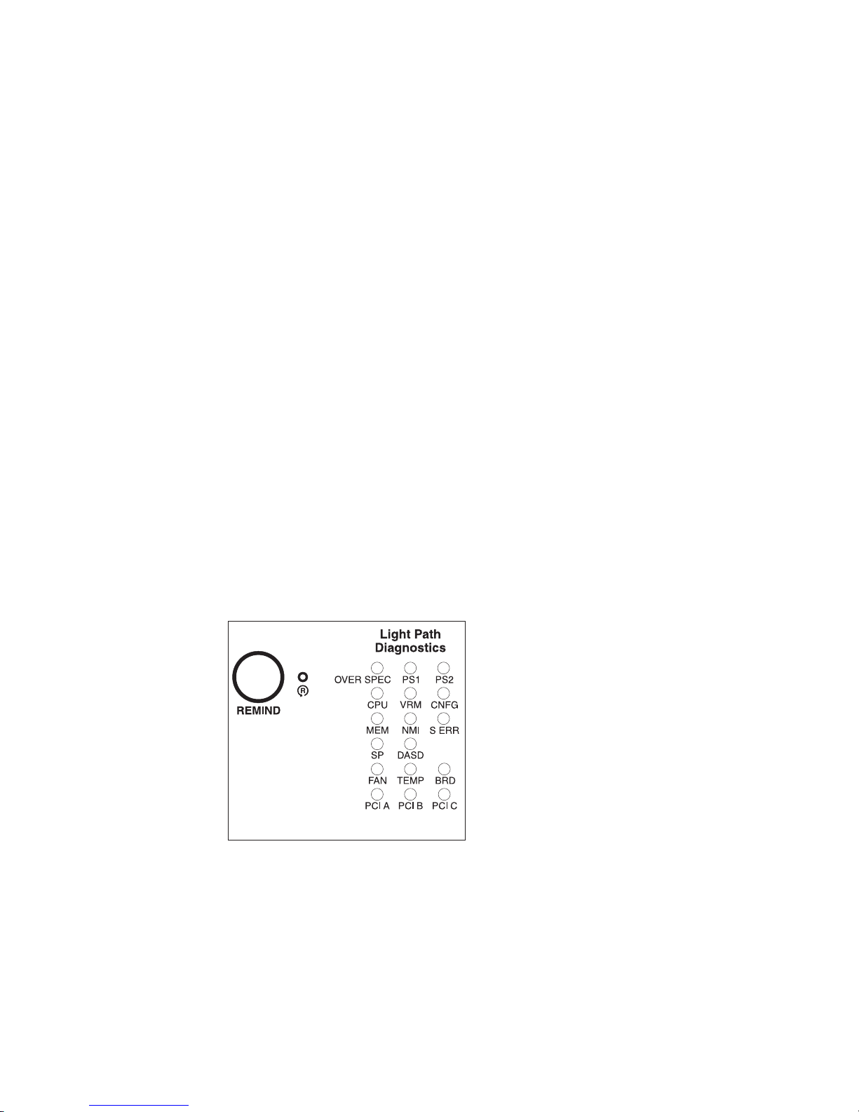
Light path diagnostics panel
The light path diagnostics feature on the xSeries 336 server provides a preliminary
method of determining the location of a problem.
The LEDs on the light path diagnostics panel are viewed by pressing the release
latch on the front right side of the operator panel and sliding the panel out.
Figure 6. Light path diagnostics panel
For more detailed information about light path diagnostics, see “Light path
diagnostics” on page 73.
8 xSeries 336 Type 1879 and Type 8837: Hardware Maintenance Manual and Troubleshooting Guide
Page 19
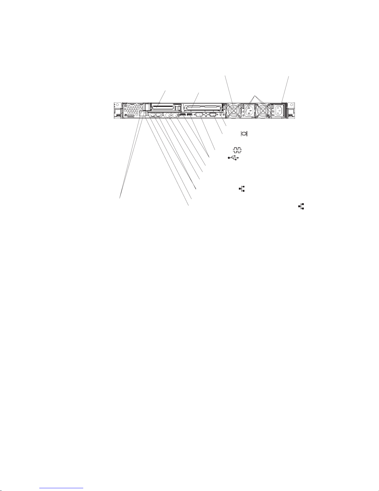
Rear view
Figure 7 shows the connectors and LEDs on the rear of the server.
Power supply 1Power supply 2
Remote Supervisor
Adapter II SlimLine
Ethernet LEDs
PCI slot 1 PCI slot 2
Serial
USBs
Keyboard
Mouse
Ethernet LEDs
Dual GB Ethernet
Ethernet LEDs
Remote Supervisor Adapter II EthernetSlimLine
AC and DC LEDs
3 rear LEDs (Power, Location, System-error)
Video
Figure 7. Rear view of the server
v PCI slot 1: This slot allows insertion of a low profile adapter.
v PCI slot 2: This slot allows insertion of any PCI-X or PCI-E type adapter.
v Power supply 2: Provides dc power to the server, usually is a redundant backup
power supply.
v AC LED: This LED is to the left of the power-cord connector and is the top LED.
This LED indicates that ac current is present in the server.
v DC LED: This LED is to the left of the power-cord connector and is the bottom
LED. This LED indicates that dc current is present in the server.
v Power supply 1: Provides dc power to the server, usually is the primary power
supply.
v Power LED: This is the top LED and it indicates that ac power is present on the
server.
v Location LED: This middle (blue) LED assists you in visually locating the server
when it is among other servers.
v System-error LED: This is the bottom LED that indicates that a system error
occurred.
v Video connector: Connect a monitor to this connector.
v Serial connector: Connect a 9-pin serial device to this connector.
v USB connectors: Connect a USB device to these connectors.
v Keyboard connector: Connect a PS/2 keyboard to this connector.
v Mouse connector: Connect a mouse or other PS/2 device to this connector.
v Ethernet LEDs: There is a set of LEDs for each Ethernet connector. The top
LED is the Ethernet link LED. When it is lit, it indicates that there is an active
connection on the Ethernet port.
Chapter 1. General information 9
Page 20

The bottom LED is the Ethernet activity LED. When it flashes, it indicates that
data is being transmitted or received between the server and a network device.
The flashing frequency is proportional to the amount of traffic on the network link.
v Dual GB Ethernet connectors: Use these connectors to connect the server to
an Ethernet network.
v Remote Supervisor Adapter II SlimLine Ethernet connector: Use this
connector to connect the server to a network for system-management information
control. This Ethernet connector is active only when you have installed the
Remote Supervisor Adapter II SlimLine option.
v Remote Supervisor Adapter II SlimLine Ethernet LEDs: These LEDs are
located on the Ethernet connector and are at the top left and top right positions.
The top left LED is the Ethernet link LED for the Remote Supervisor Adapter II
SlimLine; when lit, it indicates that there is an active connection on the Ethernet
port.
The top right LED is the Ethernet activity LED for the Remote Supervisor Adapter
II SlimLine. When this LED flashes it indicates that data is being transmitted or
received between the server and a network device. The flashing frequency is
proportional to the amount of traffic on the network link.
Server power features
When the server is connected to an ac power source but is not turned on, the
operating system does not run, and all core logic except for the BMC is shut down;
however, the server can respond to requests from the BMC, such as a remote
request to turn on the server. The power-on LED flashes to indicate that the server
is connected to ac power but not turned on.
Turning on the server
When you connect the server to an ac power source, the power supply fans turn on
immediately; then, approximately 20 seconds later, the power-control button
becomes active and you can turn on the server and start the operating system by
pressing the power-control button.
The server can also be turned on in any of the following ways:
v If a power failure occurs while the server is turned on, the server will restart
automatically when power is restored.
v If the operating system supports the system-management software for an
optional Remote Supervisor Adapter II SlimLine option, the system-management
software can turn on the server.
v If the operating system supports the Wake on LAN feature, the Wake on LAN
feature can turn on the server.
Turning off the server
When you turn off the server and leave it connected to ac power, the power supply
fans continue to run and the server can respond to requests from the BMC, such as
a remote request to turn on the server. To remove all power from the server, you
must disconnect it from the power source.
Some operating systems require an orderly shutdown before you turn off the server.
See the operating-system documentation for information about shutting down the
operating system.
10 xSeries 336 Type 1879 and Type 8837: Hardware Maintenance Manual and Troubleshooting Guide
Page 21
Statement 5
CAUTION:
The power control button on the device and the power switch on the power supply do
not turn off the electrical current supplied to the device. The device also might have
more than one power cord. To remove all electrical current from the device, ensure
that all power cords are disconnected from the power source.
2
1
The server can be turned off in any of the following ways:
v You can turn off the server from the operating system, if the operating system
supports this feature. After an orderly shutdown of the operating system, the
server will be turned off automatically.
v You can press the power-control button to start an orderly shutdown of the
operating system and turn off the server, if the operating system supports this
feature.
v If the operating system stops functioning, you can press and hold the
power-control button for more than 4 seconds to turn off the server.
v If an optional Remote Supervisor Adapter II SlimLine is installed in the server, the
server can be turned off from the Remote Supervisor Adapter II SlimLine user
interface.
v If the Wake on LAN feature turned on the server, the Wake on LAN feature can
turn off the server.
v The BMC can turn off the server as an automatic response to a critical system
failure.
v You can turn off the server through a request from the BMC.
Chapter 1. General information 11
Page 22

12 xSeries 336 Type 1879 and Type 8837: Hardware Maintenance Manual and Troubleshooting Guide
Page 23

Chapter 2. Configuring the server
The ServerGuide™ Setup and Installation CD provides software setup tools and
installation tools that are specifically designed for an IBM server. Use this CD during
the initial installation of the server to configure basic hardware features and to
simplify the operating-system installation.
Configuration programs
In addition to the ServerGuide Setup and Installation CD, you can use the following
configuration programs to customize the server hardware:
v Configuration/Setup utility program
v Ethernet controller configuration
v BMC firmware update utility program
v RAID configuration programs
– LSI Logic configuration utility program
– ServeRAID Manager
SCSISelect utility program
v
v Using the ServeRaid configuration programs
For more information about these programs, see “Configuring the server” in the
User’s Guide on the IBM xSeries Documentation CD.
Starting the Configuration/Setup Utility program
Complete the following steps to start the Configuration/Setup Utility program:
1. Turn on the server and watch the monitor screen.
2. When the message Press F1 for Configuration/Setup appears, press F1. If
an administrator password has been set, you must type the administrator
password to access the full Configuration/Setup Utility menu.
3. Follow the instructions on the screen.
© Copyright IBM Corp. 2002, 2007 13
Page 24

14 xSeries 336 Type 1879 and Type 8837: Hardware Maintenance Manual and Troubleshooting Guide
Page 25

Chapter 3. Customer replaceable units
This chapter provides instructions for installing, removing, and connecting optional
devices that the server supports.
Installation guidelines
Before you begin installing options, read the following information:
v Read Appendix B, “Safety information,” on page 129 and the guidelines in
“Handling static-sensitive devices” on page 16. This information will help you
work safely with the server and options.
v Make sure that you have an adequate number of properly grounded electrical
outlets for the server, monitor, and other devices.
v Back up all important data before you make changes to disk drives.
v You do not have to turn off the server to install or replace hot-swap power
supplies or hot-swap fans.
v Blue on a component indicates touch points, where you can grip the component
to remove it from or install it in the server, open or close a latch, and so on.
v Orange on a component or an orange label on or near a component indicates
that the component can be hot-swapped, which means that if the server and
operating system support hot-swap capability, you can remove or install the
component while the server is running. (Orange can also indicate touch points on
hot-swap components.) See the instructions for removing or installing a specific
hot-swap component for any additional procedures that you might have to
perform before you remove or install the component.
v For a list of supported options for the server, go to http://www.ibm.com/servers/
eserver/serverproven/compat/us/.
System reliability considerations
To help ensure proper cooling and system reliability, make sure that:
v Each of the drive bays has a drive or a filler panel and electromagnetic
compatibility (EMC) shield installed in it.
v If the server has redundant power, each of the power-supply bays has a power
supply installed in it.
v There is adequate space around the server to allow the server cooling system to
work properly. Leave approximately 50 mm (2.0 in.) of open space around the
front and rear of the server. Do not place objects in front of the fans. For proper
cooling and airflow, replace the server cover before turning on the server.
Operating the server for extended periods of time (more than 30 minutes) with
the server cover removed might damage server components.
v You have followed the cabling instructions that come with optional adapters.
v You have replaced a failed fan within 48 hours.
v When replacing a hot plug fan, you have 5 minutes to install the new fan or the
server will shut down.
v You have replaced a hot-swap drive within 2 minutes of removal.
Working inside the server with the power on
The server supports hot-swap devices and is designed to operate safely while it is
turned on and the cover is removed. Follow these guidelines when you work inside
a server that is turned on:
© Copyright IBM Corp. 2002, 2007 15
Page 26

v Avoid wearing loose-fitting clothing on your forearms. Button long-sleeved shirts
before working inside the server; do not wear cuff links while you are working
inside the server.
v Do not let your necktie or scarf to hang inside the server.
v Remove jewelry, such as bracelets, necklaces, rings, and loose-fitting wrist
watches.
v Remove items from your shirt pocket, such as pens and pencils, that could fall
into the server as you lean over it.
v Avoid dropping any metallic objects, such as paper clips, hairpins, and screws,
into the server.
Handling static-sensitive devices
Attention: Static electricity can damage the server and other electronic devices.
To avoid damage, keep static-sensitive devices in their static-protective packages
until you are ready to install them.
To reduce the possibility of damage from electrostatic discharge, observe the
following precautions:
v Limit your movement. Movement can cause static electricity to build up around
you.
v Wear an electrostatic-discharge wrist strap, if one is available.
v Handle the device carefully, holding it by its edges or its frame.
v Do not touch solder joints, pins, or exposed circuitry.
v Do not leave the device where others can handle and damage it.
v While the device is still in its static-protective package, touch it to an unpainted
metal part of the server for at least 2 seconds. This drains static electricity from
the package and from your body.
v Remove the device from its package and install it directly into the server without
setting down the device. If it is necessary to set down the device, put it back into
its static-protective package. Do not place the device on the server cover or on a
metal surface.
v Take additional care when handling devices during cold weather. Heating reduces
indoor humidity and increases static electricity.
16 xSeries 336 Type 1879 and Type 8837: Hardware Maintenance Manual and Troubleshooting Guide
Page 27
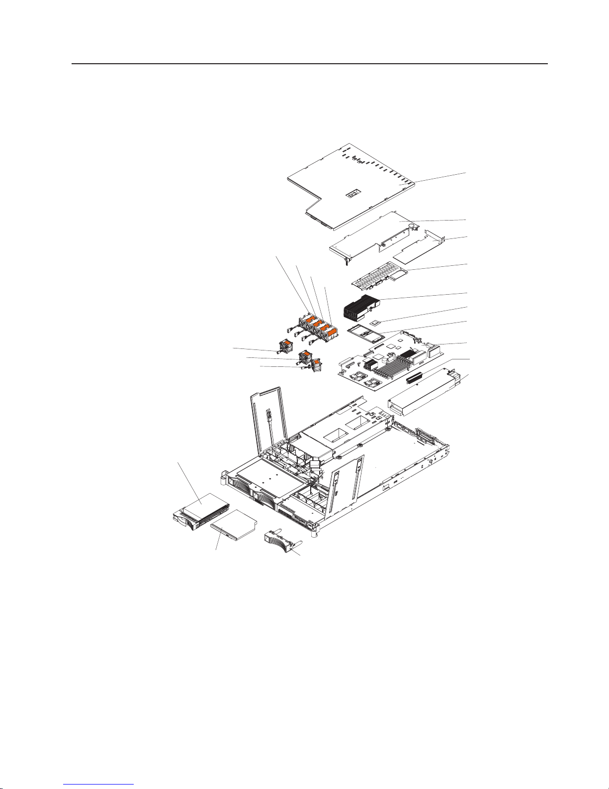
Major components of the xSeries 336 Type 8837 server
Figure 8 shows the major components in the server.
Note: The illustrations in this document might differ slightly from your hardware.
Fan 4 (optional)
Fan 5
Fan 6
Fan 7
Cover
Slot 2 adapter cover
Low profile adapter
(optional)
Remote Supervisor
Adapter II SlimLine
assembly (optional)
Heat sink
Microprocessor
Heat sink retainer
Fan 1
Fan 2
Fan 3
SCSI hard drive
DVD-ROM drive
Figure 8. Major components
System board
VRM
Power supply
Filler panel
Chapter 3. Customer replaceable units 17
Page 28
Removing and installing the cover
This section describes how to remove and install the cover.
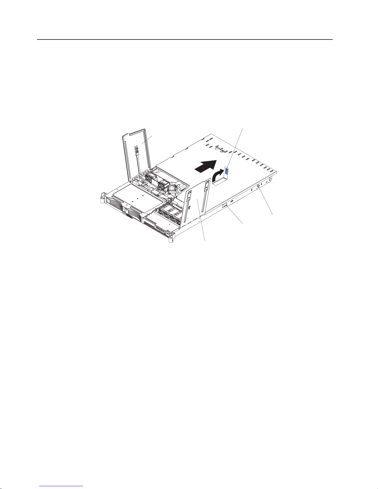
Removing the cover
Complete the following steps to remove the server cover:
Attention: Before removing the server cover, remove the server from the rack and
open the two fan doors as shown in Figure 9.
Fan door A
Cover release latch
Rail-lock
Side release
latch
Fan door B
pin
Figure 9. Cover removal
1. Read Appendix B, “Safety information,” on page 129 and “Installation guidelines”
on page 15.
2. Remove the server from the rack:
a. Pull the server out, about a third of the way, until it stops.
b. Slide both side release latches toward the front of the server. Make sure that
rail-lock pins are in a vertical position and pull the server out and remove it
from the rack.
Open both fan doors, fan door A and fan door B. To open fan door A slide the
3.
slide latch to the left, and lift the door panel up. To open fan door B slide the
two slide latches to the right, and lift the door panel up.
4. Remove the server cover:
a. Lift up the cover release latch and slide the cover to the rear of the server.
b. Make sure that the server cover slides away from the insets that are on the
front, rear and sides of the server cover.
c. Lift the cover off the server and set the cover aside.
Attention: For proper cooling and airflow, replace the server cover before turning
on the server. Operating the server for extended periods of time (more than 30
minutes) with the server cover removed might damage server components.
18 xSeries 336 Type 1879 and Type 8837: Hardware Maintenance Manual and Troubleshooting Guide
Page 29
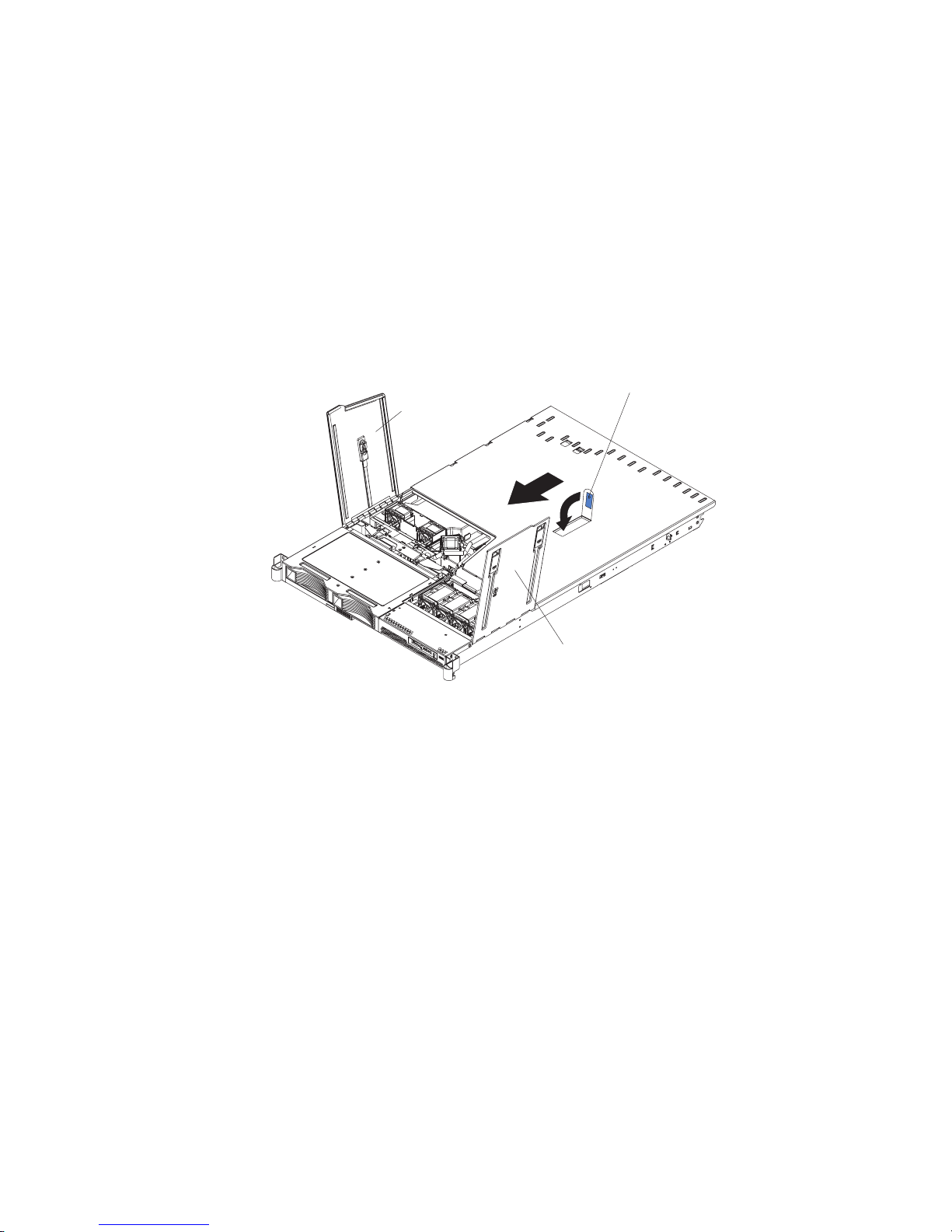
Installing the cover
Complete the following steps to install the server cover:
1. Position the internal cables so that they do not interfere with the cover
installation.
Important: Before sliding the cover forward, make sure that all the tabs on both
2. Position the cover on top of the server and slide it forward.
3. Press down on the cover release latch until the cover properly engages all the
inset tabs on the server.
the front, rear, and side of the cover engage the chassis correctly. If
all the tabs do not engage the chassis correctly, it will be very
difficult to remove the cover later.
Cover release latch
Fan door
Fan door
Figure 10. Cover installation
4. Close the fan doors.
5. Install the server in the rack. See the Rack Installation Instructions that come
with the server for details.
Chapter 3. Customer replaceable units 19
Page 30

Working with adapters
This section describes how to install an adapter in the server. Before you continue
with the adapter-installation procedures, review “Adapter considerations.”
Adapter considerations
The following information describes the types of adapters the server supports and
other information you must consider when installing an adapter:
v Locate the documentation that comes with the adapter and follow those
instructions in addition to the instructions in this section. If you need to change
the switch settings or jumper settings on the adapter, follow the instructions that
come with the adapter.
v There are several different types of adapters you can install depending on which
slots are available. The following information identifies what type adapters you
can connect to PCI slots 1 and 2, and where these slots are located on the
system board:
– Slot 1: Yo u can install only a PCI-X low-profile adapter into slot 1.
– Slot 2: Yo u can install any PCI-X or PCI Express adapter into slot 2.
Note: For the PCI Express adapter, you must install an optional riser card on
Figure 11 shows the location of, and access to, the riser card retention latches
for the slot 1 and 2 riser cards.
Riser-card
retention latches
the system board.
Slot 2 riser-card
connector
Riser-card
retention latches
Slot 1 riser-card
connector
Figure 11. Adapter connectors and latches
v When the system starts (boots), it starts the system devices in the following
order, if you have not changed the default boot precedence:
– Integrated Ethernet controllers
– Integrated SCSI controller
– PCI-X slot 1
– PCI-X or PCI-Express slot 2
20 xSeries 336 Type 1879 and Type 8837: Hardware Maintenance Manual and Troubleshooting Guide
Page 31

Installing an adapter
Complete the following steps to install an adapter:
1. Read Appendix B, “Safety information,” on page 129 and “Installation guidelines”
on page 15.
2. Turn off the server and peripheral devices (see “Turning off the server” on page
10); then, and disconnect all power cords and external cables.
3. Remove the cover (see “Removing the cover” on page 18).
4. Follow the cabling instructions, if any, that come with the adapter. Route the
adapter cables before you install the adapter.
5. Determine which slot you want to use for the adapter, either slot 1 for a
low-profile adapter or slot 2 for any type of adapter. See Figure 11 on page 20
for the locations of slot 1 and slot 2 on the system board.
6. Install the adapter:
v To install a low-profile adapter, continue with “Installing a low-profile adapter
v To install an adapter in slot 2 go to “Installing an adapter into slot 2” on page
Installing a low-profile adapter into slot 1
Complete the following steps to install the low-profile adapter:
1. Read Appendix B, “Safety information,” on page 129 and “Installation
guidelines” on page 15.
Attention: When you handle static-sensitive devices, take precautions to
avoid damage from static electricity (see “Handling static-sensitive devices” on
page 16).
2. Remove the expansion slot cover from slot 1. From the rear of the server,
push the slot 1 expansion cover to the left and then toward the inside of the
server. Remove the slot 1 expansion cover and store it in a safe place.
into slot 1.”
22.
Note: You might have to use a coin or screwdriver to slide the expansion slot
cover to the left.
3. Remove the adapter from the static-protective package and set any jumpers or
switches on the adapter as directed by the adapter manufacturer.
4. Slide the I/O connector portion of the adapter through the slot 1 opening.
Attention: When you install an adapter, make sure that the adapter is
correctly seated in the connector before you turn on the server. An improperly
seated adapter might cause damage to the system board, the riser card, or the
adapter.
5. As you start inserting the adapter through the slot 1 opening, align the edge
connector on the low-profile adapter with the connector on the riser card.
Press the edge connector firmly into the riser-card connector. Make sure that
the adapter snaps into the riser card securely and the adapter is lying on top
of the low-profile adapter support.
Chapter 3. Customer replaceable units 21
Page 32

Riser card
Low profile
adapter
Low profile
adapter support
Figure 12. Low-profile adapter installation, slot 1
6. Push the adapter down past the tab so that the adapter snaps into place on
the support.
7. Check the retention latches on the riser card and make sure that they are still
securely in place.
8. Connect any internal cables to the adapter. See the instructions that come with
the adapter for details.
Attention: Make sure that the cables do not block the flow of air from the
fans. See “System-board cable channels” on page 63 for cable routing areas
on the system board.
9. Perform any configuration tasks that are required for the adapter.
10. If you have other options to install or remove, do so now; otherwise, go to
“Completing the installation” on page 47.
Installing an adapter into slot 2
Complete the following steps to install an adapter into slot 2:
1. Read Appendix B, “Safety information,” on page 129 and “Installation
guidelines” on page 15.
Attention: When you handle static-sensitive devices, take precautions to
avoid damage from static electricity (see “Handling static-sensitive devices” on
page 16).
2. Open the retaining clips on both sides of the slot 2 riser card. Push the clips
down, away from the riser card, until the clips are no longer attached to the
riser card.
Note: Insert your finger into the access hole on the slot 2 adapter cover to
Figure 13 on page 23 shows the location of the access hole on the adapter
cover, the riser card and the riser-card retention latches.
22 xSeries 336 Type 1879 and Type 8837: Hardware Maintenance Manual and Troubleshooting Guide
open the retention latch at the rear of the server.
Page 33

Access hole to
retention latch
Slot 2 adapter cover
Riser card
Riser card
retention latches
Figure 13. Slot 2 connectors and latches
3. Lift up and remove the slot 2 adapter cover. The slot 2 riser card is attached to
the adapter cover, and you remove the riser card along with the adapter cover.
Figure 14 identifies the components that are referred to in this procedure.
Figure 14. Riser card and adapter cover removal
4. Remove the expansion-slot cover for slot 2, which is also attached to the slot 2
adapter cover, to provide an opening for the adapter.
Hold the adapter cover so that the expansion-slot cover faces you. Slide the
expansion slot cover first to the left, and then in and toward the inside of the
adapter cover. You can now remove the expansion slot 2 cover. Store the
cover in a place safe.
Notes:
a. You might have to use a coin or screwdriver to slide the expansion slot
cover to the left.
Chapter 3. Customer replaceable units 23
Page 34

b. If you are installing a PCI-Express adapter, you need an optional riser card
to plug the adapter into the system board.
5. If you are installing a full-length adapter, rotate the PCI-adapter retainer
bracket 90°, away from the adapter cover, so that you can insert the full-length
adapter.
6. Slide the I/O connector portion of the adapter through the slot opening from
which you removed the expansion slot cover.
7. As you start inserting the adapter through the slot opening, align the edge
connector on the adapter with the riser-card connector and press the adapter
firmly into the connector. Make sure that the adapter snaps into place securely
to secure the adapter in the riser-card connector.
Attention: When you install an adapter, make sure that you seat the adapter
correctly in the riser-card connector before you turn on the server. An
improperly seated adapter might cause damage to the system board, the riser
card, or the adapter.
8. If you are installing a full-length adapter, rotate the PCI adapter retainer
bracket 90°, toward the adapter cover. Place the adapter between the upper
guides and lower guide of the PCI-adapter retainer bracket. The spacer fits
between the top of the adapter and the bottom of the adapter cover.
9. Make sure that the PCI-adapter retainer bracket is flush against the adapter
cover.
10. Grasp the adapter cover by its top edge or upper corners and align the riser
card with the guides for the riser-card connector. Press the riser card edge
connector firmly into the slot 2 riser-card connector on the system board.
Slot 2 adapter cover
Riser card
Alignment /
retainer tabs
Riser-card retention
latches
Figure 15. Installing the slot 2 adapter and riser card assembly
11. Make sure that the retention latches snap into place to secure the slot 2 riser
card into the slot 2 riser-card connector.
Attention: When you install an adapter, make sure that you seat the riser
card edge connector correctly in the slot 2 riser-card connector before you turn
on the server. An improperly seated riser card might cause damage to the
system board, the riser card, or the adapter.
12. Connect any internal cables to the adapter. See the instructions that come with
the adapter for details.
24 xSeries 336 Type 1879 and Type 8837: Hardware Maintenance Manual and Troubleshooting Guide
Page 35

Attention: Make sure that the cables do not block the flow of air from the
fans. See “System-board cable channels” on page 63 for cable routing areas
on the system board.
13. Perform any configuration tasks that are required for the adapter.
14. If you have other options to install or remove, do so now.
15. Go to “Completing the installation” on page 47.
Installing a Remote Supervisor Adapter II SlimLine
The xSeries 336 server supports the Remote Supervisor Adapter II SlimLine. The
Remote Supervisor Adapter II SlimLine does not use a PCI slot in the xSeries 336;
instead, the Remote Supervisor Adapter II SlimLine option connects directly to the
system board.
Complete the following steps to install the Remote Supervisor Adapter II SlimLine:
1. Read Appendix B, “Safety information,” on page 129 and “Installation guidelines”
on page 15.
2. Turn off the server and disconnect the AC power cord.
3. Remove the slot 2 adapter cover to allow access to the mounting brackets for
the Remote Supervisor Adapter II SlimLine (see “Installing an adapter into slot
2” on page 22).
4. Place the Remote Supervisor Adapter II SlimLine cover over the top of the
adapter. On the right side of the adapter (the side closest to the power-supply
bay), hook the right four snaps on the cover underneath the bottom of the
adapter.
Cover snaps
Cover snaps
Figure 16. Installing the cover on the Remote Supervisor Adapter II SlimLine
5. Hook the left snaps from the cover so that it hooks underneath the bottom of
the adapter.
Note: Align the locating pin on the adapter to the alignment hole on the rear
mounting bracket.
6. The server comes with mounting brackets on the system board. There is a front
mounting bracket and a rear mounting bracket that hold the Remote Supervisor
Adapter II SlimLine. Slide the rear of the adapter underneath the flanges of the
rear mounting bracket.
Chapter 3. Customer replaceable units 25
Page 36

Front mounting
bracket
Figure 17. Installing the Remote Supervisor Adapter II SlimLine
Remote Supervisor
Adapter II SlimLine assembly
Rear mounting
bracket
Remote Supervisor
Adapter II
SlimLine connector
7. Push the front of the adapter down, onto the front mounting bracket, until it
snaps into place.
8. If you have other options to install or remove, do so now.
9. Go to “Completing the installation” on page 47.
Hard disk drives
This section describes how to install a hard disk drive in the server. Before you
continue with the hard disk drive installation procedures, review “Hard disk drive
considerations.”
Hard disk drive considerations
The following notes describe the types of hard disk drives that the server supports
and other information that you must consider when installing a hard disk drive:
v The server supports the following three configurations:
– Configuration 1
- Four 2.5-inch hot-swap SCSI hard disk drives
– Configuration 2
- Two 3.5-inch slim hot-swap SCSI hard disk drives
- One 9.5-mm-high DVD-ROM drive (optional)
– Configuration 3
- Two 3.5-inch non-hot-swap (simple swap) Serial ATA (SATA) hard disk
drives
- One 9.5-mm-high DVD-ROM drive (optional)
Both SCSI configuration models of the server come with a hot-swap SCSI
v
backplane.
v The SCSI server models support low voltage differential (LVD) hot-swap drives.
Each hot-swap drive is in a tray, which has a green activity LED and an amber
status LED in the upper-right corner. These LEDs are lit if the drive is active and,
in some cases, if the drive fails.
26 xSeries 336 Type 1879 and Type 8837: Hardware Maintenance Manual and Troubleshooting Guide
Page 37

v Each hot-swap drive has a single-connector-attached (SCA) connector, which
connects directly to the hot-swap SCSI backplane. The backplane attaches to
connector J-35 on the system board and controls the SCSI IDs for the hot-swap
drives.
v A simple swap disk drive does not have a backplane, and it does not have
indicator LEDs. Simple swap disk drives have a panel-mount connection at the
rear of the hard disk drive cage, which enables the simple swap disk drives to
easily connect to both the signal and power connections.
v Before you install any type of hard disk drive, read the following information:
– Inspect the drive tray for signs of damage before inserting the hard disk drive.
– Read Appendix B, “Safety information,” on page 129 and “Installation
guidelines” on page 15.
If you are installing a hot-swap drive, continue with “Installing a hot-swap hard
v
disk drive.” If you are installing a simple-swap drive, go to “Installing a simple
swap hard disk drive” on page 28.
Installing a hot-swap hard disk drive
If you are installing a 2.5-inch hot-swap drive, continue with “Installing a 2.5-inch
hot-swap hard disk drive.” If you are installing a 3.5-inch hot-swap drive, go to
“Installing a 3.5-inch hot-swap hard disk drive” on page 28.
Installing a 2.5-inch hot-swap hard disk drive
Complete the following steps to install a 2.5-inch hot-swap SCSI hard disk drive:
1. Read Appendix B, “Safety information,” on page 129 and “Installation guidelines”
on page 15.
2. Remove the filler panel from the drive bay.
Note: To make sure there is adequate system cooling, do not operate the
server for more than 2 minutes without either a hard disk drive or a filler
panel installed in each bay.
Drive-tray assembly
Drive handle
Filler panel
Figure 18. 2.5-inch hot-swap hard disk drive installation
3. Place the drive handle in the open position and slide the drive into the bay.
4. Close the drive handle.
5. Make sure that the drive is correctly installed in the tray.
6. Check the hard disk drive status LED and activity LED to verify that the drive is
operating correctly.
7. If you have other options to install or remove, do so now.
Chapter 3. Customer replaceable units 27
Page 38

8. Go to “Completing the installation” on page 47.
Installing a 3.5-inch hot-swap hard disk drive
Complete the following steps to install a 3.5-inch hot-swap SCSI hard disk drive:
1. Read Appendix B, “Safety information,” on page 129 and “Installation guidelines”
on page 15.
2. Remove the filler panel from the appropriate drive bay.
Note: To make sure there is adequate system cooling, do not operate the
server for more than 2 minutes without either a hard disk drive or a filler
panel installed in each bay.
Drive-tray assembly
Drive handle
Filler panel
Figure 19. 3.5-inch hot-swap hard disk drive installation
3. Place the drive handle in the open position and slide the drive into the bay.
4. Close the drive handle.
5. Check the hard disk drive status LED and activity LED to verify that the drive is
operating correctly.
6. If you have other options to install or remove, do so now.
7. Go to “Completing the installation” on page 47.
Installing a simple swap hard disk drive
Before you install a simple-swap SATA hard disk drive, turn off the server and all
attached peripheral devices. Disconnect all power cords; then, disconnect all
external signal cables from the server.
Complete the following steps to install a simple-swap SATA hard disk drive.
Drive-tray
assembly
Drive handle
Figure 20. Installing a simple-swap hard disk drive
28 xSeries 336 Type 1879 and Type 8837: Hardware Maintenance Manual and Troubleshooting Guide
Filler panel
Page 39

1. Read Appendix B, “Safety information,” on page 129 and “Installation guidelines”
on page 15.
2. Remove the filler panel for the drive from either bay.
Note: To make sure there is adequate system cooling, do not operate the
server for more than 2 minutes without either a hard disk drive or a filler
panel installed in each bay.
3. If you have only one simple swap hard disk drive, you can install it in either the
left bay or the right bay.
4. Insert the simple swap hard disk drive into the drive tray assembly.
5. Slide the drive into the bay until the rear of the drive snaps into place with the
rear panel-mount connector. This simple swap connector contains the signal
and power connections that are needed by the SATA drive.
6. Install the filler panel for the drive.
7. If you have other options to install, install them now. Otherwise, go to
“Completing the installation” on page 47.
Installing and removing an internal DVD-ROM drive or DVD-ROM blank
bezel
The following notes describe the type of DVD-ROM drive the server supports and
other information that you must consider when installing a DVD-ROM drive:
v The server supports the installation of an optional DVD-ROM drive only when
you are using a 3.5-inch hard disk drive configuration.
v The DVD-ROM drive must be a slim 9.5 mm drive and you install it underneath
the 3.5-inch hard disk drive, on the left side.
Note: DVD-ROM, CD-ROM and diskette drives can also be attached externally
using the USB connector.
you are removing an internal DVD-ROM drive or blank bezel, continue with
If
“Removing an internal DVD-ROM drive or DVD-ROM blank bezel” on page 29. If
you are installing an internal DVD-ROM drive or blank bezel, go to “Installing an
internal DVD-ROM drive” on page 31.
Removing an internal DVD-ROM drive or DVD-ROM blank bezel
Complete the following steps to remove an internal DVD-ROM drive or DVD-ROM
blank bezel:
1. Read Appendix B, “Safety information,” on page 129 and “Installation guidelines”
on page 15.
2. Turn off the server and peripheral devices and disconnect all power cords and
external cables (see “Turning off the server” on page 10); then, remove the
cover (see “Removing the cover” on page 18).
Chapter 3. Customer replaceable units 29
Page 40

Release latches
Figure 21. Removing the hard drive cage
3. Rotate the two release latches on the 3.5-inch hard drive cage up and then
forward to disconnect the electrical connectors and move the drive cage
forward; then, lift the 3.5-inch hard drive cage out of the server.
4. Remove the left hard disk drive from the 3.5-inch hard drive cage.
DVD-ROM drive
DVD-ROM drive
release latch
Release latch
Figure 22. Removing an internal DVD-ROM drive
5. Press the release latch on the left side of the DVD-ROM drive or DVD-ROM
blank bezel; then, pull the drive or blank bezel and attached retention clip out of
the drive cage.
30 xSeries 336 Type 1879 and Type 8837: Hardware Maintenance Manual and Troubleshooting Guide
DVD-ROM drive
retention clip
Page 41

6. Remove the retention clip from the DVD-ROM drive or DVD-ROM blank bezel.
This retention clip will be needed when you install a DVD-ROM drive or
DVD-ROM blank bezel in the hard drive cage.
7. Go to “Installing an internal DVD-ROM drive” on page 31.
Installing an internal DVD-ROM drive
Complete the following steps to install an internal DVD-ROM drive or DVD-ROM
blank bezel:
1. Read Appendix B, “Safety information,” on page 129 and “Installation guidelines”
on page 15.
2. Turn off the server and peripheral devices and disconnect all power cords and
external cables (see “Turning off the server” on page 10); then, remove the
cover (see “Removing the cover” on page 18).
DVD-ROM drive
DVD-ROM blank
bezel
Figure 23. Internal DVD-ROM drive and blank bezel
Note: Make sure that you disconnect all power to the server before removing
the hard disk drives.
3. Remove the DVD-ROM drive or DVD-ROM blank bezel (see “Removing an
internal DVD-ROM drive or DVD-ROM blank bezel” on page 29).
Chapter 3. Customer replaceable units 31
Page 42

DVD-ROM drive
Release latch
DVD-ROM drive
retention clip
Figure 24. Installing an internal DVD-ROM drive
4. Mount the DVD-ROM retention clip on the DVD-ROM drive or DVD-ROM blank
bezel that you are installing.
5. Slide the DVD-ROM drive or DVD-ROM blank bezel with the attached mounting
bracket into the drive cage, pushing it into the cage until the retention clip
engages.
6. Reinstall the previously removed hard disk drive in the 3.5-inch hard drive cage
(see “Hard disk drives” on page 26).
7. If you have other options to install or remove, do so now.
8. Go to “Completing the installation” on page 47.
Memory modules
This section provides information on the types of memory modules the server
supports, and describes how to install memory modules.
Memory module considerations
This section contains information that you must consider when installing DIMMs:
v The server supports up to eight PC3200 DDR II ECC Registered SDRAM DIMMs
in sizes ranging from 256 MB to 2 GB. The minimum memory size is 512 MB.
The maximum supported memory size is 16 GB.
v The server supports 256 MB, 512 MB, 1 GB, and 2 GB DIMMs. See the
ServerProven® list at http://www.ibm.com/servers/eserver/serverproven/compat/
us/ for a list of memory modules that the server supports.
v The server comes with one pair of DIMMs installed in DIMM slots 1 and 2 on the
system board. The server comes with either 512 MB (two 256 MB DIMM) for the
2.8GHz models or 1GB (two 512MB DIMM) for all other models.
v The server uses interleaved DIMMs; you must add, remove, or replace DIMMs in
pairs. Each pair must be of the same type, capacity, and speed.
32 xSeries 336 Type 1879 and Type 8837: Hardware Maintenance Manual and Troubleshooting Guide
Page 43

v You can increase the amount of memory in the server by replacing them with
higher-capacity DIMMs or installing an additional pair of DIMMs into the
remaining slots. Figure 25 shows the memory slots on the system board.
Slot 8
Slot 1
Figure 25. Memory module installation
Note: When installing additional DIMMs, always install in pairs starting with slots
1 and 2.
v The server supports Chipkill™ memory technology, which enables the server to
function with one bad chip on a DIMM. The bad memory module must be on an
x4 DIMM. The 256 MB and 512 MB DIMMs that are x8 DIMMs do not support
Chipkill memory (see Table 1).
Table 1. Supported Chipkill memory configurations
Supported by
DIMM size Type
Chipkill Minimum Maximum
256 MB 32Mx8 No 512 MB 2 GB
512 MB 64Mx8 No 1 GB 4 GB
512 MB 64Mx4 Yes 1 GB 4 GB
1 GB 128Mx4 Yes 2 GB 8 GB
2 GB 256Mx4 Yes 4 GB 16 GB
v You can configure the server to use memory mirroring. Memory mirroring stores
data in two pairs of DIMMs simultaneously. When using memory mirroring, you
must install two pairs of DIMMs at a time. All the DIMMs you use in memory
mirroring must be identical. See Table 2 for the DIMM pairs that are in each pair.
Note: The use of memory mirroring decreases the amount of available memory
by half.
Table 2. Memory mirroring DIMM installation sequence
Pair DIMM pairs
1 Slots 1 and 2
2 Slots 3 and 4
Chapter 3. Customer replaceable units 33
Page 44

Table 2. Memory mirroring DIMM installation sequence (continued)
Pair DIMM pairs
3 Slots 5 and 6
4 Slots 7 and 8
v The server also supports memory sparing; however, the sparing feature is
mutually exclusive with mirroring. The sparing feature disables the failed memory
from the system configuration and activates a memory sparing pair of DIMMs to
replace the failed active DIMM pair.
Before you can enable the memory sparing feature, you must install one
additional pair of DIMMs. The memory sparing DIMM pair must be the same
speed, type, and the same size as or larger than the active DIMM pair.
To enable memory mirroring or sparing through the Configuration/Setup Utility
program, select Advanced Setup from the main menu, and select Memory
Configuration. For more information about using the Configuration/Setup Utility
program, see the User’s Guide on the IBM Documentation CD. See Table 3 for
memory-sparing DIMM connector assignments.
Table 3. Memory-sparing DIMM connector assignments
Active DIMM connectors Memory sparing DIMM connectors
1 and 2 3 and 4
Slots 1 and 2
Slots 3 and 4
Slots 1 and 2
Slots 3 and 4
Slots 5 and 6
v When you restart the server after adding or removing a DIMM, the server
displays a message that the memory configuration has changed.
Installing memory modules
This section provides an overview of the procedure for installing memory modules.
Complete the following steps to install a DIMM:
1. Read Appendix B, “Safety information,” on page 129 and “Installation guidelines”
on page 15.
2. Turn off the server and peripheral devices, and disconnect the power cords and
external cables (see “Turning off the server” on page 10).
3. Remove the cover (see “Removing the cover” on page 18).
Attention:
v Avoid touching the components and gold-edge connectors on the DIMMs.
Make sure that the DIMMs are completely and correctly seated in the slots.
Incomplete insertion might cause damage to the system board or to the
DIMMs.
v When you handle static-sensitive devices, take precautions to avoid damage
from static electricity. For information about handling these devices, see
“Handling static-sensitive devices” on page 16.
v To avoid breaking the retaining clips or damaging the DIMM slots, open and
close the clips gently. Do not force a DIMM into a slot.
Open the retaining clips on the DIMM connector.
4.
5 and 6
7 and 8
34 xSeries 336 Type 1879 and Type 8837: Hardware Maintenance Manual and Troubleshooting Guide
Page 45

5. Touch the static-protective package containing the DIMM to any unpainted metal
surface on the server. Then, remove the DIMM from the package.
6. Align the DIMM with the slot and press it straight down into the connector until
the retainer clips snap into the locked position.
Figure 26. DIMM retainer clips
7. If you have other options to install or remove, do so now.
8. Go to “Completing the installation” on page 47.
Chapter 3. Customer replaceable units 35
Page 46

Additional microprocessor installation
This section provides information on adding an additional microprocessor. To
remove a microprocessor, see “Removing a microprocessor and heat sink” on page
54.
Microprocessor considerations
The following notes describe the type of microprocessor that the server supports
and other information that you must consider when installing a microprocessor:
v The server supports up to two microprocessors (two-way support); the IBM
xSeries 336 server comes with one Xeon microprocessor installed. With two
microprocessors, the server can operate as a symmetric multiprocessing (SMP)
server.
With SMP, application programs can distribute the processing load between the
microprocessors. This enhances performance for database and point-of-sale
applications, integrated manufacturing solutions, and other applications.
v Figure 27 shows the microprocessor sockets and the voltage regulator module
(VRM) slots on the system board.
VRM 1 (J1)
Microprocessor 1
(U16)
Microprocessor 2
(U32)
VRM 2 (J25)
Figure 27. Location of microprocessor and VRM sockets
v If you install a second microprocessor in the server, microprocessor 1 is installed
in microprocessor socket 1 (U16), and microprocessor 2 is installed in socket 2
(U32).
You must also install the following items that come with the second
microprocessor:
– Voltage regulator module (VRM), which you plug into VRM connector J25
– Cooling fan, which you plug into fan position 4
Notes:
1. Read the documentation that comes with the microprocessor to determine
whether you must update the basic input/output system (BIOS) code. The most
current level of BIOS code for the server is available at http://www.ibm.com/
support/.
2. A new microprocessor comes in a kit with a VRM, cooling fan, and a heat sink.
36 xSeries 336 Type 1879 and Type 8837: Hardware Maintenance Manual and Troubleshooting Guide
Page 47

3. To use SMP, obtain an SMP-capable operating system (optional). For a list of
supported operating systems, go to http://www.ibm.com/servers/eserver/
serverproven/compat/us/.
Attention: To avoid damage and to ensure proper server operation, review the
following information before you install a microprocessor:
v Make sure that the microprocessors are the same type, have the same cache
size, and have the same clock speed.
v Make sure that the microprocessor internal and external clock frequencies are
identical.
v See the ServerProven list at http://www.ibm.com/servers/eserver/serverproven/
compat/us/
for a list of microprocessors that the server supports.
Installing a microprocessor
Complete the following steps to install a microprocessor:
1. Read Appendix B, “Safety information,” on page 129 and “Installation
guidelines” on page 15.
2. Turn off the server and peripheral devices (see “Turning off the server” on
page 10); then, and disconnect all power cords and external cables.
3. Remove the server cover.
Attention: When you handle static-sensitive devices, take precautions to
avoid damage from static electricity. For details about handling these devices,
see “Handling static-sensitive devices” on page 16.
4. Touch the static-protective package that contains the new microprocessor to
any unpainted metal surface on the server; then, remove the microprocessor
from the package.
5. If you are installing a microprocessor in the microprocessor 2 socket, first
install a VRM in the microprocessor 2 VRM slot (J-25)
Figure 28. Microprocessor locking lever
6. Install the microprocessor:
a. Rotate the locking lever on the microprocessor socket from its closed and
Lever fully
open
Lever closed
locked position until it stops or clicks in the fully open position
(approximately 135° angle).
Attention:
v Do not use excessive force when pressing the microprocessor into the
socket.
v Center the microprocessor over the microprocessor socket. Align the
triangle on the corner of the microprocessor with the triangle on the
corner of the socket and carefully press the microprocessor into the
socket before you try to close the lever.
Chapter 3. Customer replaceable units 37
Page 48

Microprocessor
Microprocessor
orientation indicator
Microprocessor
connector
Microprocessorrelease lever
Figure 29. Microprocessor installation
7. Close the microprocessor-release lever to secure the microprocessor.
Attention:
v Do not set the heat sink down after you remove the plastic cover.
v Do not touch or contaminate the thermal grease on the bottom of the new
heat sink. Doing so damages its heat-conducting capability and exposes the
new microprocessor to overheating.
v If you must remove the heat sink after installing it, note that the thermal
grease might have formed a strong bond between the heat sink and the
microprocessor. Do not force the heat sink and microprocessor apart; doing
so can damage the microprocessor pins. Loosen one captive screw fully
before loosening the other captive screw to help break the bond between
the components without damaging them.
8. Remove the cover from the bottom of the heat sink and make sure that the
thermal grease is still on the bottom of the heat sink.
9. Install the heat sink on top of the microprocessor, and tighten the captive
screws. Alternate between the screws until they are tight, making sure that you
do not overtighten them.
38 xSeries 336 Type 1879 and Type 8837: Hardware Maintenance Manual and Troubleshooting Guide
Page 49

Microprocessor 2
Heat sink
VRM
Microprocessor 2
Figure 30. Heat sink installation
10. Install fan 4 into the proper location, in front of the second microprocessor.
Fan 4
Figure 31. Installing fan 4 after installing a second microprocessor
11. If you have other options to install or remove, do so now.
12. Go to “Completing the installation” on page 47
Chapter 3. Customer replaceable units 39
Page 50

Installing and removing a hot-swap power supply
The server supports a maximum of two hot-swap power supplies.
Statement 8
CAUTION:
Never remove the cover on a power supply or any part that has the following label
attached.
Hazardous voltage, current, and energy levels are present inside any component that
has this label attached. There are no serviceable parts inside these components. If
you suspect a problem with one of these parts, contact a service technician.
The following information describes the type of power supply that the server
supports and other information that you must consider when installing a power
supply:
v The server comes with one 585-watt hot-swap power supply as standard. The
input voltage is 110 VAC or 220 V ac auto-sensing.
v You can install an optional 585-watt hot-swap power supply to use as a
redundant power supply.
v These power supplies are designed for parallel operation. In the event of a
power supply failure, the redundant power supply continues to power the system.
The number of power supplies supported per system are a maximum of two.
v See “Using Y power-cord connectors for power backup” on page 42 for
information on how to properly connect Y power-cord connectors to back up
power units.
Figure 32 shows the power-supply connectors and their associated LEDs on the
back of the server.
Power supply 1Power supply 2
Figure 32. Power supply connectors and LEDs
40 xSeries 336 Type 1879 and Type 8837: Hardware Maintenance Manual and Troubleshooting Guide
AC and DC LEDs
Page 51

Installing a power supply
Complete the following steps to install a hot-swap power supply:
1. Read Appendix B, “Safety information,” on page 129 and “Installation guidelines”
on page 15.
2. Remove the power-supply blank from the empty power-supply bay by inserting
a coin or flat-tipped screwdriver into the slot in the middle of the power-supply
blank. Pull the power-supply blank from the power-supply bay. Save the
power-supply blank in case you remove the power supply at a later time.
Attention: During normal operation, each power-supply bay must have either
a power supply or power-supply blank installed for proper cooling.
Figure 33 shows power-supply 1 and power-supply 2 with a blank cover and
slot.
Figure 33. Blank cover, power supply 2
Power supply 1Power supply 2
Blank cover
3. Install the power supply in the bay:
a. Rotate the handle down on the rear of the power supply to the open
position, and then slide the power supply forward into the power-supply bay.
b. Gently lift the latch handle up until it clicks to securely seat the power supply
in the bay.
Figure 34 shows how to install a power supply.
Power supply
Handle
(open position)
AC power
LED (green)
DC power
LED (green)
Power supply
blank cover
Figure 34. Power supply installation
4. Connect the power cord for the new power supply to the power-cord connector
on the power supply.
5. Connect the power cord to a properly grounded electrical outlet.
Chapter 3. Customer replaceable units 41
Page 52

6. Make sure that the power-supply fan starts and the ac power LED (top) and dc
power LED (bottom) on the power supply are lit, indicating that the power
supply is operating correctly. The two green LEDs are to the left of the
power-cord connector.
Removing a power supply
To replace an existing power supply, you must remove the old one. Complete the
following steps to remove a hot-swap power supply:
1. Read Appendix B, “Safety information,” on page 129 and “Installation guidelines”
on page 15.
2. Turn off the server and peripheral devices (see “Turning off the server” on page
10); then, and disconnect all power cords and external cables.
3. If the server is in a rack, at the back of the server, pull back the cable
management arm to get access to the rear of the server to remove the power
supply.
4. Remove the power cord.
5. From the rear of the sever, push left on the orange release lever and then push
down to release the power-supply assembly and move the power supply back
slightly for easy removal.
6. Pull the power supply all the way out of the power-supply bay.
7. Install a new power supply by following the instructions in “Installing a power
supply” on page 41 or reinstall the blank cover, to keep the server from
overheating.
Using Y power-cord connectors for power backup
When you have multiple servers with redundant power supplies, use Y power-cord
connectors to provide the proper connection to the backup power-supply
(Back-UPS) units. The Back-UPS unit provides temporary power to the connected
devices in the case of a power outage in the network. The Back-UPS unit must be
connected correctly to ensure optimum power backup to the servers.
Connect the Y power cord to two power supplies, in two different servers, then
connect the other end of the Y power cord to a Back-UPS unit. Figure 35 on page
43 shows the connection between the servers with the Y power-cord.
42 xSeries 336 Type 1879 and Type 8837: Hardware Maintenance Manual and Troubleshooting Guide
Page 53

Server A
Server B
Power supply 2
Power supply 2
Y power cords
Backup
power supply
Power supply 1
Power supply 1
Backup
power supply
Figure 35. Using a Y power cord to connect two servers
This connection method provides the server with two different and independent
backup power sources: one Back-UPS unit for power supply 1 on both servers and
another Back-UPS unit for power supply 2 (redundant power supply) on both
servers.
Replacing a hot-swap fan assembly
The following information describes information you must consider when installing a
hot-swap fan.
Attention: To ensure proper server operation, replace a failed fan as soon as
possible.
v The server comes with a maximum of seven hot-swap fans.
Note: If the server has one microprocessor it has six fans. If you install a second
microprocessor, then an additional fan, fan 4, comes with the second
microprocessor.
v Figure 36 on page 44 shows the locations of the hot-swap fans.
Chapter 3. Customer replaceable units 43
Page 54

Fan 1
Fan 2
Fan door A
Fan 4 (optional)
Fan 5
Fan 6
Fan 7
Fan 3
Fan door B
Figure 36. Hot-swap fan locations
Complete the following steps to replace a hot-swap-fan:
1. Read Appendix B, “Safety information,” on page 129 and “Installation
guidelines” on page 15.
2. Open the fan door for the failing fan. The LED near the connector of the failing
fan assembly is lit.
Attention: To ensure proper system cooling, do not remove the top cover for
more than 30 minutes during this procedure.
3. Disconnect the cable of the failing fan from the connector.
4. Pull up on the orange tab on the side of the failing fan.
5. Lift the fan out of the server.
6. Orient the new fan in the same position as the fan you removed. Make sure
that the airflow indicator, on top of the fan, is pointing to the rear of the server.
7. Push the fan assembly down into the server until the blue grommets are
correctly seated.
8. Connect the cable of the replacement fan into the connector.
9. Close the fan door.
10. Go to “Completing the installation” on page 47.
44 xSeries 336 Type 1879 and Type 8837: Hardware Maintenance Manual and Troubleshooting Guide
Page 55

Replacing the battery
The following information describes information that you must consider when
replacing the battery:
v IBM has designed this product with your safety in mind. The lithium battery must
be handled correctly to avoid possible danger. If you replace the battery, you
must adhere to the following instructions.
Note: In the U. S., call 1-800-IBM-4333 for information about battery disposal.
v If you replace the original lithium battery with a heavy-metal battery or a battery
with heavy-metal components, be aware of the following environmental
consideration. Batteries and accumulators that contain heavy metals must not be
disposed of with normal domestic waste. They will be taken back free of charge
by the manufacturer, distributor, or representative, to be recycled or disposed of
in a proper manner.
v To order replacement batteries, call 1-800-426-7378 within the United States, and
1-800-465-7999 or 1-800-465-6666 within Canada. Outside the U.S. and
Canada, call your IBM reseller or IBM marketing representative.
Note: After you replace the battery, you must reconfigure the server and reset
the system date and time.
Statement 2
CAUTION:
When replacing the lithium battery, use only IBM Part Number 33F8354 or an
equivalent type battery recommended by the manufacturer. If your system has a
module containing a lithium battery, replace it only with the same module type made
by the same manufacturer. The battery contains lithium and can explode if not
properly used, handled, or disposed of.
Do not:
v Throw or immerse into water
v Heat to more than 100°C (212°F)
v Repair or disassemble
Dispose
of the battery as required by local ordinances or regulations.
Complete the following steps to replace the battery:
1. Read Appendix B, “Safety information,” on page 129 and “Installation
guidelines” on page 15.
2. Follow any special handling and installation instructions supplied with the
battery.
3. Turn off the server and all attached devices and disconnect all power cords
and external cables (see “Turning off the server” on page 10); then, remove
the server cover (see “Removing the cover” on page 18).
4. Disconnect any internal cables, as necessary.
Chapter 3. Customer replaceable units 45
Page 56

Battery
Figure 37. Battery location
5. Locate the battery (connector BH1) on the system board.
6. Remove the battery:
a. Use one finger to pull the retainer tab that secures the battery to its
housing.
b. Use one finger to slide the battery up and out from its socket.
Figure 38. Battery removal
7. Insert the new battery:
a. Hold the battery so that the plus side of the battery is facing toward the
center of the server, toward slots 1 and 2.
b. Pull the retainer tab out of the way so that you can slide the battery into its
socket.
c. Slide the battery down until it snaps into place.
8. Reconnect the internal cables that you disconnected.
9. Reinstall the server cover (see “Installing the cover” on page 19).
10. Connect all external cables and all power cords.
11. Start the Configuration/Setup Utility program and set configuration parameters
as needed (see “Starting the Configuration/Setup Utility program” on page 13).
See the User’s Guide on the IBM xSeries Documentation CD for additional
information about using the Configuration/Setup Utility program.
46 xSeries 336 Type 1879 and Type 8837: Hardware Maintenance Manual and Troubleshooting Guide
Page 57

Completing the installation
Complete the following steps to complete the installation:
1. Install the server cover (see “Installing the cover” on page 19).
2. Connect the cables and power cords (see “Connecting the cables”).
3. If you have added or removed hardware from the server, update the server
configuration as necessary (see “Starting the Configuration/Setup Utility
program” on page 13). See the User’s Guide on the IBM xSeries Documentation
CD for additional information about using the Configuration/Setup Utility
program.
Connecting the cables
The following illustrations show the locations of the input and output connectors on
the server. Detailed cabling instructions are in the Rack Installation Instructions that
come with the server.
Notes:
1. You must turn off the server before connecting cables to or disconnecting any
cables from the server (see “Turning off the server” on page 10).
2. See the documentation that comes with the options for additional cabling
instructions. It might be easier for you to route cables before you install certain
options.
3. Cable identifiers are printed on the cables that come with the server and
options. Use these identifiers to connect the cables to the correct connectors.
PCI slot 1 PCI slot 2
Serial
USBs
Keyboard
Mouse
Ethernet LEDs
Dual GB Ethernet
Remote Supervisor
Adapter II SlimLine
Ethernet LEDs
Ethernet LEDs
Remote Supervisor Adapter II EthernetSlimLine
Figure 39. Cable identifiers, rear view of server
Power supply 1Power supply 2
AC and DC LEDs
3 rear LEDs (Power, Location, System-error)
Video
Chapter 3. Customer replaceable units 47
Page 58

Figure 40. Front USB connector location
Updating the server configuration
When you start the server for the first time after you add or remove an internal
option or external SCSI device, you might receive a message that the configuration
has changed. The Configuration/Setup Utility program starts automatically so that
you can save the new configuration settings. For more information, see the section
about configuring the server in the User’s Guide on the IBM xSeries Documentation
CD.
Some options have device drivers that you must install. See the documentation that
comes with each option for information about installing device drivers.
The server comes with at least one microprocessor. If more than one
microprocessor is installed, the server can operate as a symmetric multiprocessing
(SMP) server. You might have to upgrade the operating system to support SMP. For
more information, see the section about using the ServerGuide Setup and
Installation CD in the IBM User’s Guide and the operating-system documentation.
USB connector
Model #
Serial #
If the server has an optional RAID adapter and you have installed or removed a
hard disk drive, see the documentation that comes with the RAID adapter for
information about reconfiguring the disk arrays.
For information about configuring the integrated Gigabit Ethernet controller, see the
User’s Guide.
Installing the server in a rack
Detailed cabling instructions for a typical rack server configuration are provided on
the IBM xSeries Documentation CD that come with the server. These instructions
also come with the Tower-to-Rack Conversion Kit.
48 xSeries 336 Type 1879 and Type 8837: Hardware Maintenance Manual and Troubleshooting Guide
Page 59

Input/output connectors
The server has the following input/output (I/O) connectors:
v Three Ethernet controller connectors
v One auxiliary-device (pointing device) connector
v One keyboard
v Three Universal Serial Bus (USB) one front and two rear
v One serial
v One video
v One low-profile adapter (slot 1)
v One adapter (any type) (slot 2)
41 shows the location of the USB connector on the front of the server.
Figure
Figure 41. Front USB connector location
Figure 42 shows the locations of the connectors on the rear of the server.
USB connector
PCI slot 1 PCI slot 2
Model #
Serial #
Video
Serial
USBs
Keyboard
Mouse
Ethernet LEDs
Dual GB Ethernet
Remote Supervisor Adapter II SlimLine Ethernet
Figure 42. Cable identifiers, rear view of server
Note: If an optional Remote Supervisor Adapter II SlimLine is installed on the
system board, the server has a dedicated Ethernet connector (Remote
Supervisor Adapter II SlimLine Ethernet) on the rear of the server. See the
documentation that comes with the Remote Supervisor Adapter for more
information.
The following sections describe these connectors.
Chapter 3. Customer replaceable units 49
Page 60

Auxiliary-device (pointing device) connector
Use this connector to connect a mouse or other pointing device. Figure 43 shows
an auxiliary-device connector.
6
4
2
Figure 43. Auxiliary-device connector
5
3
1
Ethernet connectors
Figure 44 shows an Ethernet connector.
8
Figure 44. Ethernet connector
Connect a Category 3, 4, or 5 unshielded twisted-pair cable to this connector. The
100BASE-TX and 1000BASE-T Fast Ethernet standards require Category 5 or
higher cabling.
Notes:
1. The server has three Ethernet connectors. Two of the Ethernet connectors are
attached to the Ethernet controllers. See the IBM xSeries 336 Type 8837 User’s
Guide on the IBM xSeries Documentation CD for more information about the
Ethernet controllers.
2. The third Ethernet connector is a dedicated connector that is active only when
you install an optional Remote Supervisor Adapter II SlimLine. This dedicated
connector is the Remote Supervisor Adapter II SlimLine Ethernet connector.
Keyboard connector
Use this connector to connect a PS/2 (non-USB) keyboard to the server. Figure 45
shows a keyboard connector.
6
4
1
5
3
1
2
Figure 45. Keyboard connector
If you attach a keyboard to this connector, USB ports and devices are disabled
during POST.
50 xSeries 336 Type 1879 and Type 8837: Hardware Maintenance Manual and Troubleshooting Guide
Page 61

Serial connector
Use a serial connector to connect a serial device. Figure 46 shows a serial
connector.
1
69
Figure 46. Serial connector
5
Universal Serial Bus connector
Use a Universal Serial Bus (USB) connector to connect a USB device. The USB
ports support both USB 1.0, 1.1 and 2.0. The following table contains the speeds
and cable lengths that USB 1.0, 1.1,and 2.0 support.
USB 1.0/1.1 USB 2.0
Speed 12 Mbps 480 Mbps
Maximum cable length 3.0m (low speed) 3.0m (low speed)
5.0m (high speed) 5.0m (high speed)
Using Plug and Play technology, USB devices are configured automatically and can
interface with a maximum of 127 devices. Figure 47 shows a USB connector.
14
Figure 47. USB connector
Use a 4-pin cable to connect a device to a USB connector. If you need to connect
more USB devices than the server has USB connectors for, use a USB hub to
connect additional devices.
If you connect a PS/2 (non-USB) keyboard to the keyboard connector, the USB
keyboard port is disabled during POST.
If you connect a USB keyboard that has a mouse port, the keyboard emulates a
mouse, and you cannot disable the mouse settings in the Configuration/Setup Utility
program.
Chapter 3. Customer replaceable units 51
Page 62

Video connector
Use this connector to connect a monitor to the server. The connector is dark blue to
help you identify it. Figure 48 shows a video connector.
Figure 48. Video connector
5
1
1115
52 xSeries 336 Type 1879 and Type 8837: Hardware Maintenance Manual and Troubleshooting Guide
Page 63

Chapter 4. Service replaceable units
Removing a microprocessor and heat sink . . . . . . . . . . . . . . .54
Operator information panel . . . . . . . . . . . . . . . . . . . .55
Fan bracket . . . . . . . . . . . . . . . . . . . . . . . . . .56
Drive tray assembly . . . . . . . . . . . . . . . . . . . . . . .57
Front panel signal and USB cables . . . . . . . . . . . . . . . . .58
Power backplane . . . . . . . . . . . . . . . . . . . . . . . .59
System board . . . . . . . . . . . . . . . . . . . . . . . . .60
System-board option connectors . . . . . . . . . . . . . . . . .60
System-board internal connectors . . . . . . . . . . . . . . . . .61
System-board external connectors . . . . . . . . . . . . . . . . .61
System-board jumpers . . . . . . . . . . . . . . . . . . . . .62
System-board cable channels . . . . . . . . . . . . . . . . . .63
Removing the system board . . . . . . . . . . . . . . . . . . .64
This chapter describes procedures for removing and installing certain components
inside the server. Only a qualified service technician is authorized to replace the
components described in this section.
Important: The field replaceable unit (FRU) procedures are intended for trained
servicers who are familiar with IBM xSeries products. See the parts
listing in “System replaceable units” on page 122 to determine if the
component being replaced is a customer replaceable unit (CRU) or a
FRU.
© Copyright IBM Corp. 2002, 2007 53
Page 64

Removing a microprocessor and heat sink
Note:
v Read “Installation guidelines” on page 15.
v Read the safety notices at Appendix B, “Safety information,” on page 129.
v Read “Handling static-sensitive devices” on page 16.
Complete
the following steps to remove a microprocessor and heat sink:
1. Turn off the server and all attached peripheral devices.
2. Disconnect all power cords and external cables from the back of the server.
3. If necessary, remove the server from the rack; then, remove the server cover
(see “Removing the cover” on page 18).
Microprocessor 2
VRM
Heat sink
Microprocessor 2
Figure 49. Microprocessor removal
4. Loosen one captive screw fully before loosening the other captive screw (this
helps to break the bond between the heat sink and the microprocessor). After
the captive screws are loosened, then remove the heat sink.
Note: It might be necessary to gently twist the heat sink to loosen it from the
microprocessor.
Important: Be careful when handling the microprocessor and heat sink. If the
thermal grease between the microprocessor and heat sink will be
reused, do not contaminate it. If replacement thermal grease is
provided with the replacement part, be sure to remove all traces of
existing thermal grease from the remaining part before applying the
new thermal grease.
5. Rotate the microprocessor socket lever arm upward to its maximum vertical
position (135°).
6. Remove the microprocessor from the socket.
54 xSeries 336 Type 1879 and Type 8837: Hardware Maintenance Manual and Troubleshooting Guide
Page 65

Operator information panel
Note:
v Read “Installation guidelines” on page 15.
v Read the safety notices at Appendix B, “Safety information,” on page 129.
v Read “Handling static-sensitive devices” on page 16.
Complete
1. Turn off the server.
2. Disconnect all power cords and external cables from the back of the server.
3. If necessary, remove the server from the rack; then, remove the server cover
the following steps to remove the operator information panel:
(see “Removing the cover” on page 18).
4. Press the operator panel release latch to slide it out of the server.
Figure 50. Operator information panel removal
5. Use a small screwdriver to push in the retention springs on the sides of the
operator information panel assembly (1).
6. Slide the assembly forward (2) and out of the server.
7. Push out on the two sides of the assembly cover to flare it out.
8. Rotate the assembly cover up and off of the operator information panel
assembly (3).
9. Unplug the two cables from the rear of the assembly (4).
10. Pull the assembly forward to remove it from the server.
To replace the operator information card, reverse the removal procedure,
connecting the two cables to the rear of the card and sliding it under the tabs on
the chassis until it is firmly anchored.
Chapter 4. Service replaceable units 55
Page 66

Fan bracket
Note:
v Read “Installation guidelines” on page 15.
v Read the safety notices at Appendix B, “Safety information,” on page 129.
v Read “Handling static-sensitive devices” on page 16.
Complete
the following steps to remove the fan brackets:
1. Turn off the server and all attached peripheral devices.
2. Disconnect all power cords and external cables from the back of the server.
3. If necessary, remove the server from the rack; then, remove the server cover
(see “Removing the cover” on page 18).
Figure 51. Fan bracket removal
4. Unplug the fans from the system board.
5. Remove the fans from the system (see “Replacing a hot-swap fan assembly” on
page 43).
6. Remove the screws and set them in a safe place.
7. Disconnect the fan cable.
8. Pull the fan bracket out of the server.
To install the fan brackets, reverse this procedure.
Note: When reinstalling the fan brackets on the front right side of the server,
remove the drive tray assembly (see “Drive tray assembly” on page 57) and
the fan cable cover. Pull the cable loose before plugging it into the fan power
distribution board on the fan bracket, then install the fan bracket in the
server.
56 xSeries 336 Type 1879 and Type 8837: Hardware Maintenance Manual and Troubleshooting Guide
Page 67

Drive tray assembly
Note:
v Read “Installation guidelines” on page 15.
v Read the safety notices at Appendix B, “Safety information,” on page 129.
v Read “Handling static-sensitive devices” on page 16.
Complete
the following steps to remove the drive tray assembly:
1. Turn off the server and all attached peripheral devices.
2. Disconnect all power cords and external cables from the back of the server.
3. If necessary, remove the server from the rack; then, remove the server cover
(see “Removing the cover” on page 18).
Release latches
Figure 52. Drive tray assembly removal
4. Remove the drives from the server (see “Hard disk drives” on page 26).
5. Lift up on the two blue levers on the rear of the drive tray to release it from the
server.
6. Slide the drive tray assembly forward.
7. Unplug the cables from the rear of the drive tray assembly.
8. Unplug the DVD cable from the system board and remove it from the server.
Attention: When you remove the cable from the server:
v Make sure that the cable does not snag on any server component.
v Note the routing of the cable for later reinstallation.
Lift the drive tray assembly out of the server.
9.
Chapter 4. Service replaceable units 57
Page 68

Front panel signal and USB cables
Note:
v Read “Installation guidelines” on page 15.
v Read the safety notices at Appendix B, “Safety information,” on page 129.
v Read “Handling static-sensitive devices” on page 16.
Complete
the following steps to remove the front panel signal (flat) cable.
1. Turn off the server and all attached peripheral devices.
2. Disconnect all power cords and external cables from the back of the server.
3. Remove the server from the rack; then, remove the server cover (see
“Removing the cover” on page 18).
4. Remove the operator information panel (see “Operator information panel” on
page 55).
5. Remove the front fan bracket and set it to the side (see “Fan bracket” on page
56). (It is not necessary to remove the fans from the bracket for this procedure.)
6. Remove the heat sink (see “Removing a microprocessor and heat sink” on page
54) from microprocessor 1 on the far right of the server (see “System-board
option connectors” on page 60).
7. Remove the VRM associated with the heat sink you just removed.
8. Note the routing of the signal cable as you remove it from the server. It is
attached to the server with hook-and-loop fasteners in various locations.
To install the signal cable, reverse this procedure making sure to line up the
hook-and-loop fasteners in the appropriate locations.
Complete the following steps to remove the front panel USB cable.
1. Remove the drive cage and note the routing of the USB cable.
2. Remove the USB cable from behind the retention tab, found under the drive tray
assembly.
3. Unplug the cable from the system board, then pull the cable through the
openings to remove it.
To install the USB cable, reverse these instructions.
58 xSeries 336 Type 1879 and Type 8837: Hardware Maintenance Manual and Troubleshooting Guide
Page 69

Power backplane
Note:
v Read “Installation guidelines” on page 15.
v Read the safety notices at Appendix B, “Safety information,” on page 129.
v Read “Handling static-sensitive devices” on page 16.
Complete
the following steps to remove the power backplane:
1. Turn off the server and all attached peripheral devices.
2. Disconnect all power cords and external cables from the back of the server.
3. Remove the server from the rack; then, remove the server cover (see
“Removing the cover” on page 18).
Figure 53. Power backplane removal
4. Disconnect the power supplies from the power backplane (see “Removing a
power supply” on page 42).
5. Slide the power backplane to the left, disconnecting it from the system board.
6. Remove the power backplane from the server.
To install the power backplane, reverse this procedure.
Chapter 4. Service replaceable units 59
Page 70

System board
This section contains service information for the system board.
System-board option connectors
Figure 54 shows the connectors on the system board for user-installable options.
Battery (BH1)
DIMM 1 (J5)
DIMM 2 (J7)
DIMM 3 (J8)
DIMM 4 (J10)
DIMM 5 (J12)
DIMM 6 (J13)
DIMM 7 (J14)
DIMM 8 (J15)
VRM 1 (J1)
Microprocessor 1
(U16)
Microprocessor 2
(U32)
Remote Supervisor
Slot 1:
PCI-X slot 1 64 bit/
100 MHz (U33)
Slot 2:
PCI-X 64 bit/133 MHz or
PCI-Express x8 (U34)
Adapter II SlimLine (J41)
Figure 54. System-board option connectors
VRM 2 (J25)
DVD connector (J39)
60 xSeries 336 Type 1879 and Type 8837: Hardware Maintenance Manual and Troubleshooting Guide
Page 71

System-board internal connectors
Figure 55 shows the internal connectors on the system board.
Front operator panel (J2)
SATA 1 connector (J31)
SATA 0 connector (J36)
Fan 1-3 connector (J30)
Fan 4-7 connector (J33)
Front USB connector (J38)
DVD-ROM connector (J39)
System-board connector
SCSI connector (J35)
Figure 55. System-board internal connectors
System-board external connectors
Figure 56 shows the external input/output connectors on the system board.
Remote Supervisor
Adapter II SlimLine
Ethernet (J9)
Dual Ethernet (J11)
Mouse (J16)
Keyboard (17)
USB 1 (J18)
USB 2 (J19)
Serial (J29)
Video (J37)
Figure 56. System-board external connectors
Chapter 4. Service replaceable units 61
Page 72

System-board jumpers
Figure 57 shows the location of the jumper blocks on the system board.
Password reset
(J22)
BIOS boot backup (J21)
321
3
2
1
Reserved (J43)
Force update BMC (J48)
Reserved (J24)
Force power-on (J40)
Reserved (J34)
Disable video (J27)
Figure 57. System-board jumpers
Table 4. System board jumpers
Jumper Default position
J21 (BIOS boot page) Pins 1 and 2
J22 (password override) Pins 1 and 2
J27 (disable video) No jumper
J40 (force power-on) No jumper
J48 (force-update BMC) No jumper
Note: Jumpers not illustrated or described are reserved.
62 xSeries 336 Type 1879 and Type 8837: Hardware Maintenance Manual and Troubleshooting Guide
Page 73

System-board cable channels
The following illustration shows the cable channels on the system board where you
should route the cables from user-installable options.
Hard disk drive
cable routing
Full length PCI and
SCSI cable routing
Low profile PCI
cable routing
System cable routing
Chapter 4. Service replaceable units 63
Page 74

Removing the system board
Note:
v Read “Installation guidelines” on page 15.
v Read the safety notices at Appendix B, “Safety information,” on page 129.
v Read “Handling static-sensitive devices” on page 16.
Complete
1. Turn off the server and any attached devices.
the following steps to remove the system board:
Note: When replacing the system board, you must either update the server
with the latest firmware or restore the pre-existing firmware that the
customer provides on a diskette or CD image.
2. Disconnect power cords and external cables from the back of the server.
3. Remove the server from the rack.
4. Remove the cover (see “Removing the cover” on page 18).
5. Remove all adapters, including the Remote Supervisor Adapter II SlimLine, if
installed (see “Working with adapters” on page 20).
6. Disconnect all cables from the system board.
7. Remove all heat sinks, microprocessors, and VRMs and set them aside on a
static-protected surface for reinstallation (see “Installing a microprocessor” on
page 37).
8. Remove the memory modules and set them aside on a static-protected surface
for reinstallation (see “Installing memory modules” on page 34).
Note: The illustrations in this publication might differ slightly from your
hardware.
64 xSeries 336 Type 1879 and Type 8837: Hardware Maintenance Manual and Troubleshooting Guide
Page 75

Heat-sink retainer
bracket screws (6 places)
System board
screws (8 places)
I/O port screws
(4 places)
Locator pin
Figure 58. System board removal
9. Disconnect the power backplane; then, slide it to the side and set it out of the
way (see “Power backplane” on page 59).
10. Remove the six screws securing the two heat sink retention modules to the
system board. These six screws also secure the system board to the chassis.
11. Remove the eight screws on the system board that secure the system board to
the chassis.
12. Remove the four stand-off screws from the rear of the server.
13. Lift the system board slightly so that it disengages from the locator pin.
14. Slide the system board slightly toward the front of the server.
15. Lift up the left side of the system board.
16. Lift the rest of the system board and carefully remove it from server, being
careful not to disturb any surrounding components.
17. To reinstall the board, place it carefully into position under the small ledge on
the right side of the server, then put it down and slide it to the rear of the
server. Ensure the locator pin engages the locator hole in the system board.
Chapter 4. Service replaceable units 65
Page 76

18. Reverse steps 5 on page 64 through 12 on page 65 to replace the
components that were removed.
Note: When reassembling the components in the server, be sure to route all
cables carefully so that they are not exposed to undue pressure.
66 xSeries 336 Type 1879 and Type 8837: Hardware Maintenance Manual and Troubleshooting Guide
Page 77

Chapter 5. Diagnostics
This section provides basic troubleshooting information to help solve some common
problems that might occur with the server.
If you cannot locate and correct the problem using the information in this section,
see Appendix A, “Getting help and technical assistance,” on page 127 for more
information.
General checkout
Follow the checkout procedure (see “Checkout procedure” on page 68) for
diagnosing hardware problems. Review the following information before performing
the checkout procedure:
v Read Appendix B, “Safety information,” on page 129.
v The server diagnostic programs are stored in upgradeable read-only memory
(ROM) on the system board. These programs provide the primary methods of
testing the major components of the server. If you are not sure whether a
problem is caused by the hardware or by the software, you can run the
diagnostic programs (see “Diagnostic programs, error codes, and messages” on
page 70) to confirm that the hardware is working correctly.
v When you run the diagnostic programs, a single problem might cause several
error messages. If you receive several error messages, correct the cause of the
first error message. The other error messages might not occur the next time you
run the diagnostic programs.
v Before running the diagnostic programs, you must determine whether the failing
server is part of a shared hard disk drive cluster (two or more servers sharing
external storage devices). If you suspect that it is part of a cluster, you can run
all diagnostic programs except the ones that test the storage unit (that is, a hard
disk drive in the storage unit) or the storage adapter that is attached to the
storage unit. The failing server might be part of a cluster if any of the following
conditions is true:
– The customer identifies the failing server as part of a cluster.
– One or more external storage units are attached to the failing server and at
least one of the attached storage units is also attached to another server or
unidentifiable device.
– One or more servers are located near the failing server.
Important:
v
1. For servers that are part of a shared hard disk drive cluster, run one test at a
time. Do not run any suite of tests, such as “quick” or “normal” tests, because
this could enable the hard disk drive diagnostic tests.
2. If more than one error code is displayed, correct the first error. The other
error codes might not occur the next time you run the diagnostic programs.
3. If the server is suspended and a POST error code is displayed, see “POST
error codes” on page 88.
4. If the server is suspended and no error message is displayed, see “Error
symptoms” on page 103 and “Undetermined problems” on page 119.
5. For information about power-supply problems, see “Power checkout” on page
79.
6. For intermittent problems, check the error logs; see “Diagnostic programs,
error codes, and messages” on page 70.
© Copyright IBM Corp. 2002, 2007 67
Page 78

Checkout procedure
Complete the following steps to perform the checkout procedure:
001 IS THE SERVER PART OF A CLUSTER?
002 IF THE SERVER IS NOT PART OF A CLUSTER:
YES. Schedule maintenance for the system. Shut down all systems related
to the cluster. Run the storage test.
NO. Go to step 002.
1. Check the power supply LEDs, see “Hot-swap power-supply LED
errors” on page 96.
2. Turn off the server and all external devices.
3. Check all internal and external devices for compatibility at
http://www.ibm.com/servers/eserver/serverproven/compat/us/.
4. Check all cables and power cords.
5. Set all display controls to the middle position.
6. Turn on all external devices.
7. Turn on the server.
8. Record any POST error messages that are displayed on the screen. If
an error is displayed, look up the first error in “POST error codes” on
page 88.
9. Check the operator information panel system-error LED; if it is on, see
“Light path diagnostics errors” on page 93.
10. Check the system-error log and the BMC log.
Note: The system-error log on the xSeries 336 server is available only
with the Remote Supervisor Adapter II SlimLine.
If an error was recorded by the server, see Chapter 6,
“Symptom-to-FRU index,” on page 83.
11. Start the diagnostic programs.
12. Check for the following responses:
v One beep
v Readable instructions or the main menu
DID YOU RECEIVE BOTH OF THE CORRECT RESPONSES?
003
NO. Find the failure symptom in Chapter 6, “Symptom-to-FRU index,” on
page 83.
YES. Run the diagnostic programs (see “Diagnostic programs, error codes,
and messages” on page 70).
If you receive an error, see Chapter 6, “Symptom-to-FRU index,” on page
83.
If the diagnostic programs were completed successfully and you still
suspect a problem, see “Undetermined problems” on page 119.
68 xSeries 336 Type 1879 and Type 8837: Hardware Maintenance Manual and Troubleshooting Guide
Page 79

Diagnostic tools overview
The following tools are available to help you identify and resolve hardware-related
problems:
v POST beep codes, error messages, and error logs
The power-on self-test (POST) generates beep codes and messages to indicate
successful test completion or the detection of a problem (see “POST error logs”).
The POST error log contains the three most recent error codes and messages
that the system has generated during POST.
The system-error log contains all the error messages that were issued during
POST.
Note: The system-error log on the xSeries 336 server is available only with the
Remote Supervisor Adapter II SlimLine.
v Diagnostic programs and error messages
The server diagnostic programs, stored in upgradable read-only memory (ROM)
on the system board, are the primary method of testing the major components of
the server (see “Diagnostic programs, error codes, and messages” on page 70).
v ServerGuide error symptoms
ServerGuide error symptoms are described at “ServerGuide error symptoms” on
page 110.
v SCSI error messages
For information on SCSI errors, see “Small computer system interface messages”
on page 72 and “SCSI error codes” on page 115.
v Light path diagnostics
The server has light-emitting diodes (LEDs) to help you identify problems with
server components. By following the light path, you can identify the type of
problem that occurred. The light path begins with the LEDs on the operator
information panel (see “Light path diagnostics” on page 73).
v Error symptom tables
These tables list problem symptoms, along with suggested steps to correct the
problems (see the “Error symptoms” on page 103).
POST error logs
When you turn on the server, it performs a series of tests to check the operation of
server components and some of the options installed in the server. This series of
tests is called the power-on self-test, or POST.
If POST finishes without detecting any problems, a single beep sounds, and the first
screen of the operating system or application program appears.
If POST detects a problem, more than one beep sounds, an error message appears
on the screen, or both (see “Beep symptoms” on page 84 and “POST error codes”
on page 88).
Note: A single problem might cause several error messages. When this occurs,
work to correct the cause of the first error message. After you correct the
cause of the first error message, the other error messages usually will not
occur the next time you run the test.
Chapter 5. Diagnostics 69
Page 80

The POST error log contains the three most recent error codes and messages that
the system generated during POST.
The system-error log or the BMC log contains all messages that were issued during
POST and all system status messages from the service processor.
Note: The system-error log on the xSeries 336 server is available only with the
Remote Supervisor Adapter II SlimLine.
You can view the contents of the system-error log and the BMC log from the
Configuration/Setup Utility program; you can also view the system-error log from the
diagnostic programs.
Viewing error logs from the Configuration/Setup Utility program
The POST error log and the BMC log are viewed from the Configuration/Setup
Utility program.
To view the POST error log, start the Configuration/Setup Utility program (see
“Starting the Configuration/Setup Utility program” on page 13); then, select Error
Logs from the main menu.
To view the BMC log, start the Configuration/Setup Utility program; then, select
Advanced Settings from the main menu. In the menus that follow, select BMC
Configuration; then, select BMC Error Log.
Viewing the system-error log from diagnostic programs
To view system-error log from the diagnostic programs, complete the following
steps:
1. Start the diagnostic programs (see “Starting the diagnostic programs” on page
71).
2. Select Hardware Info from the top of the diagnostic programs screen.
3. Select System Error Log.
Then, follow the instructions on the screen.
Note: The system-error log on the xSeries 336 server is available only with the
Remote Supervisor Adapter II SlimLine.
Diagnostic programs, error codes, and messages
The server diagnostic programs are stored in upgradeable read-only memory
(ROM) on the system board. These programs are the primary method of testing the
major components of the server.
Diagnostic error messages indicate that a problem exists. They are not intended to
be used to identify a failing part. Troubleshooting and servicing of complex
problems that are indicated by error messages should be performed by trained
service personnel.
Sometimes the first error to occur causes additional errors. In this case, the server
displays more than one error message. Always follow the suggested action
instructions for the first error message that appears.
Error codes that might be displayed are listed at “Diagnostic error codes” on page
97.
70 xSeries 336 Type 1879 and Type 8837: Hardware Maintenance Manual and Troubleshooting Guide
Page 81

Notes:
1. Depending on the server configuration, some of the error codes might not
appear when you run the diagnostic programs.
2. If diagnostic error codes appear that are not listed in the tables, make sure that
the server has the latest levels of BIOS, Remote Supervisor Adapter II SlimLine,
and ServeRAID code installed.
Diagnostic text message format
The diagnostic text message format is as follows:
result test_specific_string
where:
result is one of the following results:
Passed
This test was completed without any errors.
Failed
This test discovered an error.
User Aborted
You stopped the test before it was completed.
Not Applicable
You attempted to test a device that is not present in the server.
Aborted
The test could not proceed because of the server configuration.
Warning
A hardware failure did not occur; the test could not be run
because of some other problem (for example, there might be a
configuration problem, the hardware is missing or is not being
recognized, or there is a hardware problem that is not related to
the hardware currently being tested).
test_specific_string
is an error code or other information about the error.
Starting the diagnostic programs
Complete the following steps to start the diagnostic programs:
1. Turn off the server and any peripheral devices.
2. Turn on all attached devices; then, turn on the server.
Note: To run the diagnostic programs, you must start the server with the
highest level password that is set. That is, if an administrator password is
set, you must enter the administrator password, not the user password,
to run the diagnostic programs.
3. When the prompt F2 for Diagnostics appears, press F2.
4. Type the appropriate password; then, press Enter.
5. Select either Extended or Basic from the top of the screen.
6. When the diagnostic programs screen appears, select the test you want to run
from the list that appears; then, follow the instructions on the screen.
Chapter 5. Diagnostics 71
Page 82

Notes:
a. You can press F1 while running the diagnostic programs to obtain help
information. Yo u also can press F1 from within a help screen to obtain
online documentation from which you can select different categories. To exit
from the help information and return to where you left off, press Esc.
b. If the server stops during testing and you cannot continue, restart the server
and try running the diagnostic programs again. If the problem remains,
replace the component that was being tested when the server stopped.
c. The keyboard and mouse (pointing device) tests assume that a keyboard
and mouse are attached to the server.
d. If you run the diagnostic programs with either no mouse or a USB mouse
attached to the server, you will not be able to navigate between test
categories using the Next Cat and Prev Cat buttons. All other functions
provided by mouse-selectable buttons are also available using the function
keys.
e. You can test the USB keyboard by using the regular keyboard test. The
regular mouse test can test a USB mouse. Also, you can run the USB
interface test only if there are no USB devices attached.
f. You can view server configuration information (such as system configuration,
memory contents, interrupt request (IRQ) use, direct memory access (DMA)
use, device drivers, and so on) by selecting Hardware Info from the top of
the screen.
If the diagnostic programs do not detect any hardware errors but the problem
persists during normal server operations, a software error might be the cause. If
you suspect a software problem, see the information that comes with the software
package.
Viewing the test log
When the tests are completed, you can view the test log by selecting Utility from
the top of the screen and then selecting View Test Log. You can save the test log
to a file on a diskette or to the hard disk.
The test-log data is maintained only while the diagnostic programs are active. When
you exit from the diagnostic programs, the test log is cleared (saved test logs are
not affected). To save the test log to a file on a diskette or to the hard disk so that
you can view it later, click Save Log on the diagnostic programs screen and specify
a location and name for the saved log file.
Note: To save the test log to a diskette, you must use a diskette that you have
formatted yourself; this function does not work with preformatted diskettes. If
the diskette has sufficient space for the test log, the diskette may contain
other data.
For descriptions of the error messages that might appear when you run the
diagnostic programs, see “Diagnostic error codes” on page 97.
Small computer system interface messages
If you receive a SCSI error message, see “SCSI error codes” on page 115.
Note: If the server does not have a hard disk drive, ignore any message that
indicates that the BIOS is not installed.
72 xSeries 336 Type 1879 and Type 8837: Hardware Maintenance Manual and Troubleshooting Guide
Page 83

Light path diagnostics
The server’s light path diagnostics feature provides a path that can be followed in
three phases to help identify the source of an error. The lights are designed to be
followed in an orderly progression, depending on the error. The LEDs are viewed in
the following order:
1. Begin on the front panel.
2. Proceed to the light path diagnostics panel.
3. Check the system service label.
4. Look inside the server, if necessary.
Ethernet 1
activity / link
LED (CR9)
Ethernet 2
activity / link
LED (CR14)
Battery LED
DIMM 1 error LED (CR5)
DIMM 2 (CR6)error LED
DIMM 3 (CR8)error LED
DIMM 4 ( 10)error LED CR
DIMM 5 ( 11)error LED CR
DIMM 6 ( 12)error LED CR
DIMM 7 ( 13)error LED CR
DIMM 8 ( 15)error LED CR
VRM 1 error LED (CR3)
CPU 1
error LED
(CR1)
CPU 2
error LED
(CR23)
BMC heartbeat
LED (CR 47)
Power / Location /
System-error LEDs
Light Path diagnostic
button (SW 2)
Light Path
activity LED (CR 60)
System board
fault LED (CR4)
VRM 2 error LED (CR26)
Figure 59. System-board LEDs
Many errors are first indicated by the illumination of the system-error light in the
operator information panel on the front of the server (see “Server controls and
LEDs” on page 6). If the system-error light is lit, one or more lights inside the server
(see Figure 59) might also be lit that can direct you to the source of the error.
Complete the following steps to view the LEDs.
Note: Read Appendix B, “Safety information,” on page 129 and “Installation
guidelines” on page 15.
System-error LED (amber)
Release latch
Figure 60. System-error LED
Chapter 5. Diagnostics 73
Page 84

1. Check the system-error LED on the operator information panel on the front of
the server. A lit system-error LED indicates that a problem exists.
Release latch
Figure 61. Release latch for light path diagnostics panel
2. Check the light path diagnostics panel. Press the release latch on the operator
information panel; then, slide out the light path diagnostics panel to view the lit
LEDs. These LEDs indicate the type of error that has occurred and are
described in more detail at “Light path diagnostics errors” on page 93.
Figure 62. Light path diagnostics panel
3. Once you know the general type of error and the general location of the
component involved, the next step is to check the system service label on the
outside of the server.
This label gives an overview of internal components that correspond to many of
the LEDs on the light path diagnostics panel and can help to view lit LEDs
inside the server.
Note: Some of the LEDs on the light path diagnostics panel will not have a
corresponding LED lit on the system board. For example:
v LEDs for the power supplies and hard disk drives are located on or
near the individual power supply or hard disk drive.
v Some error conditions are corrected by taking an action not related to
one particular component; see step 5 on page 75.
If the lit LED on the light path diagnostics panel refers to a specific internal
4.
component as indicated in step 3, look inside the server to check the lit LEDs
on the system board (see Figure 59 on page 73). For example, a
microprocessor error will light the LED next to the failing microprocessor.
a. To view LEDs inside the server without turning off the server, read “Working
inside the server with the power on” on page 15; then, remove the cover
and look for any lit error LEDs.
b. To view LEDs inside the server without ac power to the server, complete the
following steps.
74 xSeries 336 Type 1879 and Type 8837: Hardware Maintenance Manual and Troubleshooting Guide
Page 85

Note: After ac power has been removed from the server, power remains
available to the LEDs for up to 12 hours, after which time you must
turn on the server to supply power to the LEDs.
1) Read Appendix B, “Safety information,” on page 129 and “Installation
guidelines” on page 15.
2) Turn off the server and all attached peripheral devices.
3) Disconnect all power cords and external cables from the back of the
server.
4) Remove the server cover (see “Removing the cover” on page 18).
Light Path
Light Path diagnostic
activity LED (CR 60)
button (SW 2)
Figure 63. Lighting the light path LEDs without ac power
5) Press and hold the blue light path diagnostic button (see Figure 63) to
illuminate the system board LEDs.
Important: You can press this button for no longer than two minutes to
light the LEDs. After this time, the power to the LEDs is
exhausted.
Note: If no LEDs are lit when you press the light path diagnostic button,
check the light path activity LED; if the light path activity LED
lights while you are pressing the light path diagnostic button, this
indicates that the light path is working properly and that there are
no LEDs lit with this particular error.
If the lit LED on the light path diagnostics panel does not refer to a specific
c.
internal component, continue with step 5.
Go to the table at “Light path diagnostics errors” on page 93 and find the entry
5.
for the associated lit LED; then, replace the indicated component or take the
indicated action.
Notes:
v The system-error log and the BMC log might contain additional information that will be
helpful before replacing a component.
v If an LED on the light path diagnostics panel is lit and the system-error LED is not lit, there
is probably an LED problem. Run LED diagnostics (see “Starting the diagnostic programs”
on page 71).
Chapter 5. Diagnostics 75
Page 86

Remind button
Reset button
When an error occurs that you are not able to correct immediately, use the remind
button feature to acknowledge the error and remain informed of any additional
errors that occur. The remind button is located on the light path diagnostics panel.
To activate this feature, press the remind button; this places the system-error LED
on the operator information panel in remind mode. When placed in remind mode,
the system-error LED will flash rapidly until one of the following occurs:
v When the problem is corrected, the system-error LED will no longer be lit.
v If an additional problem occurs, the system-error LED will again be lit
continuously.
v If the server is restarted and the problem is not yet corrected, the system-error
LED will again be lit continuously.
Press the reset button to reset the server and run the power-on self-test (POST).
The reset button is on the top of the operator panel, to the right of the remind
button. The reset button is recessed, and you might have to use a pen or the end
of a straightened paper clip to press the button.
Updating the BMC firmware
Use the baseboard management controller (BMC) firmware update utility program to
download a BMC firmware update or a SDR/FRU update. The firmware update
utility program updates the BMC firmware or SDR/FRU data only and does not
affect any device drivers.
Go to http://www.ibm.com/support/ to download the utility program; then, copy the
Flash.exe file to a firmware update diskette.
Note: To ensure proper server operation, be sure to update the server BMC
firmware code first before updating the BIOS code.
To update the firmware, use one of the following methods:
v If the Linux or Windows® operating-system update package is available from the
World Wide Web and you have obtained the applicable update package, follow
the instructions that come with the update package.
v If you are using a diskette, complete the following steps:
1. Insert the firmware update diskette into the USB diskette drive and restart the
server.
2. Follow the instructions on the screen.
Recovering the BMC firmware
If the BMC code in the server becomes damaged, the server might have difficulty
restarting (rebooting). If the server does not turn on and the heartbeat LED (CR 47;
see Figure 59 on page 73) is not on, you will need to force a BMC update.
Complete the following steps to force a BMC update:
1. Read Appendix B, “Safety information,” on page 129 and “Handling
static-sensitive devices” on page 16.
2. Turn off the server and all attached devices.
76 xSeries 336 Type 1879 and Type 8837: Hardware Maintenance Manual and Troubleshooting Guide
Page 87

3. Disconnect the power cord; then, disconnect all external cables.
4. Remove the cover (see “Removing the cover” on page 18).
BIOS boot backup (J21)
Password reset (J22)
Force update BMC (J48)
Figure 64. Force update BMC jumper location
5. Locate the force update BMC jumper block (J48) on the system board,
removing any components that impede access to the jumper.
6. Place a jumper on jumper on the force update BMC jumper block.
7. Replace any components that were removed.
8. Replace the cover.
9. Connect the server to a power source, keyboard, monitor, and mouse.
You will now be able to start the server. When you start the server, you must update
the BMC firmware code (see “Updating the BMC firmware” on page 76).
When the update is complete, repeat the previous procedure, removing the jumper
on jumper block J48.
Recovering the BIOS code
If power to the server is interrupted while POST/BIOS code is being updated (flash
update), the server might not restart (reboot) correctly or might not display video (no
video). If this happens, you will need a BIOS recovery diskette.
To create this diskette, download the BIOS recovery disk image from
http://www.ibm.com/support and follow the directions in the image’s included
readme file.
Using the BIOS recovery diskette, complete the following steps to recover the BIOS
code:
1. Read Appendix B, “Safety information,” on page 129 and “Handling
static-sensitive devices” on page 16.
2. Turn off the server and all attached devices.
3. Disconnect the power cord; then, disconnect all external cables.
4. Remove the cover (see “Removing the cover” on page 18).
5. Locate the BIOS boot backup jumper (J21) on the system board, removing any
components that impede access to the jumper.
Chapter 5. Diagnostics 77
Page 88

BIOS boot backup (J21)
Password reset (J22)
Force update BMC (J48)
Figure 65. BIOS boot backup jumper location
6. Remove the BIOS boot backup jumper from pins 1 and 2, and place it on pins
2 and 3.
7. Replace any components that were removed.
8. Replace the cover.
9. Connect the server to a power source, keyboard, monitor, and mouse.
10. If the diskette drive contains a diskette, remove it.
11. Insert into the diskette drive the BIOS recovery diskette that you have created
from http://www.ibm.com/support/.
12. Turn on the server and the monitor.
13. After the update session is completed, turn off the server and monitor.
14. Remove the diskette from the diskette drive.
15. Disconnect all power cords and external cables.
16. Remove the cover.
17. Remove any components that impede access to the jumper block.
18. Remove the BIOS boot backup jumper from pins 2 and 3, and place it on pins
1 and 2.
19. Replace any components that were removed.
20. Reinstall the cover.
21. Reconnect all external cables and power cords and turn on the peripheral
devices.
22. Turn on the server to restart the operating system.
Erasing a lost or forgotten password (clearing CMOS memory)
This section applies to a lost or forgotten power-on password. For general
information about passwords, see the User’s Guide on the IBM Documentation CD.
Attention: If an administrator password is lost or forgotten, there is no way to
change, override, or remove it. You must replace the system board.
To set the power-on password reset jumper and erase a forgotten password,
complete the following steps:
1. Read Appendix B, “Safety information,” on page 129 and “Handling
static-sensitive devices” on page 16.
2. Turn off the server and all attached devices.
78 xSeries 336 Type 1879 and Type 8837: Hardware Maintenance Manual and Troubleshooting Guide
Page 89

3. Disconnect the power cord, and disconnect all external cables.
4. Remove the cover (see “Removing the cover” on page 18).
5. Locate the password reset jumper (J22) on the system board, removing any
components that impede access to the jumper.
BIOS boot backup (J21)
Password reset (J22)
Force update BMC (J48)
Figure 66. Password reset jumper location
6. Remove the password reset jumper from pins 1 and 2, and place it on pins 2
and 3.
7. Replace any components that were removed.
8. Replace the cover.
You will be able to start the server one time, without having to use the
power-on password, and start the Configuration/Setup Utility program. You can
either delete the old password or set a new power-on password. If you do not
change or delete the password, the next time you start the server the original
power-on password will be reinstated.
9. Connect the server to a power source, keyboard, monitor, and mouse.
10. Turn on the server. The Configuration/Setup Utility program starts.
11. Follow the instructions to erase the existing password or create a new
password.
12. Select Save Settings and press Enter.
the password reset is completed, it is not necessary to return the jumper to
When
pins 1 and 2.
Updating Remote Supervisor Adapter II SlimLine firmware
Information about updating the firmware of the Remote Supervisor Adapter II
SlimLine can be found in the Remote Supervisor Adapter II User’s Guide.
Power checkout
Power problems can be difficult to solve. For example, a short circuit can exist
anywhere on any of the power distribution buses. Usually a short circuit will cause
the power subsystem to shut down because of an overcurrent condition.
A general procedure for troubleshooting power problems is as follows:
1. Turn off the server and disconnect all ac power cords.
Chapter 5. Diagnostics 79
Page 90

2. Check for loose cables in the power subsystem. Also check for short circuits, for
example, if there is a loose screw causing a short circuit on a circuit board.
3. Remove adapters and disconnect the cables and power connectors to all
internal and external devices until the server is at the minimum configuration
required to start the server (see “Minimum operating requirements” on page
119).
4. Reconnect all ac power cords and turn on the server. If the server starts up
successfully, replace adapters and devices one at a time until the problem is
isolated. If the server does not start up from the minimal configuration, replace
FRUs of minimal configuration one at a time until the problem is isolated.
To use this method, it is important to know the minimum configuration required for a
system to start (see page 119).
Troubleshooting the Ethernet controller
This section provides troubleshooting information for problems that might occur with
the 10/100/1000 Mbps Ethernet controller.
Network connection problems
If the Ethernet controller cannot connect to the network, check the following
conditions:
v Make sure that the cable is installed correctly.
The network cable must be securely attached at all connections. If the cable is
attached but the problem remains, try a different cable.
If you set the Ethernet controller to operate at either 100 Mbps or 1000 Mbps,
you must use Category 5 or higher cabling.
v Determine whether the hub supports auto-negotiation. If it does not, try
configuring the integrated Ethernet controller manually to match the speed and
duplex mode of the hub.
v Check the Ethernet controller LEDs on the rear of the server.
These LEDs indicate whether there is a problem with the connector, cable, or
hub:
– The Ethernet transmit/receive activity LED, on the rear of the server, is lit
when the Ethernet controller sends or receives data over the Ethernet
Network. If the Ethernet transmit/receive activity LED is off, make sure that
the hub and network are operating and that the correct device drivers are
installed.
– The Ethernet link status LED, on the rear of the server, is lit when the
Ethernet controller receives a LINK pulse from the hub. If the LED is off, there
might be a defective connector or cable or a problem with the hub.
Make sure that you are using the correct device drivers, which are supplied with
v
the server.
v Check for operating-system-specific causes for the problem.
v Make sure that the device drivers on the client and server are using the same
protocol.
v Test the Ethernet controller.
The way the Ethernet controller is tested depends on which operating system
you are using (see the Ethernet controller device driver readme files).
Ethernet controller troubleshooting chart
Use the following troubleshooting chart to find solutions to 10/100/1000 Mbps
Ethernet controller problems that have definite symptoms.
80 xSeries 336 Type 1879 and Type 8837: Hardware Maintenance Manual and Troubleshooting Guide
Page 91

Description FRU/action
The server stops
running when loading
device drivers.
The PCI BIOS interrupt settings are incorrect.
v Determine whether the interrupt (IRQ) setting that is assigned to the Ethernet controller
is also assigned to another device in the Configuration/Setup Utility program.
Although interrupt sharing is allowed for PCI devices, some devices do not function well
when they share an interrupt with a dissimilar PCI device. Try changing the IRQ
assigned to the Ethernet controller or the other device. For example, for NetWare
Versions 3 and 4, it is recommended that disk controllers not share interrupts with LAN
controllers.
v Make sure that you are using the most recent device driver that is available from the
World Wide Web.
v Reseat or replace the adapter.
The Ethernet link status
LED does not work.
v Make sure that the hub is turned on.
v Check all connections at the Ethernet controller and the hub.
v Use another port on the hub.
v If the hub does not support auto-negotiation, manually configure the Ethernet controller
to match the hub.
v If you manually configured the Duplex mode, make sure that you also manually
configure the speed.
v Reseat or replace the adapter.
The Ethernet
transmit/receive activity
v Make sure that you have installed the network device drivers.
v The network might be idle. Try sending data from this server.
LED does not work.
Data is incorrect or
sporadic.
v Make sure that you are using Category 5 or higher cabling when operating the server at
100 Mbps or at 1000 Mbps.
v Make sure that the cables do not run close to noise-inducing sources like fluorescent
lights.
The Ethernet controller
stopped working when
another adapter was
added to the server.
v Make sure that the cable is connected to the Ethernet controller.
v Make sure that the PCI system BIOS code is current.
v Reseat the adapter.
v Determine whether the interrupt (IRQ) setting that is assigned to the Ethernet adapter is
also assigned to another device in the system. Use the Configuration/Setup Utility
program to determine whether this is the case.
Although interrupt sharing is allowed for PCI devices, some devices do not function well
when they share an interrupt with a dissimilar PCI device. Try changing the IRQ that is
assigned to the Ethernet adapter or the other device.
v Reseat or replace the adapter.
The Ethernet controller
stopped working without
apparent cause.
v Try a different connector on the hub.
v Reinstall the device drivers. See the operating-system documentation and the
ServerGuide information.
v Reseat or replace the adapter.
Ethernet controller messages
The integrated Ethernet controller might display messages from certain device
drivers. The latest available information concerning these messages is at the IBM
Support Web site at http://www.ibm.com/support/.
Chapter 5. Diagnostics 81
Page 92

82 xSeries 336 Type 1879 and Type 8837: Hardware Maintenance Manual and Troubleshooting Guide
Page 93

Chapter 6. Symptom-to-FRU index
Beep symptoms . . . . . . . . . . . . . . . . . . . . . . . .84
No-beep symptoms . . . . . . . . . . . . . . . . . . . . . . .87
POST error codes . . . . . . . . . . . . . . . . . . . . . . . .88
Light path diagnostics errors . . . . . . . . . . . . . . . . . . . .93
Hot-swap power-supply LED errors . . . . . . . . . . . . . . . . .96
Diagnostic error codes . . . . . . . . . . . . . . . . . . . . . .97
Error symptoms . . . . . . . . . . . . . . . . . . . . . . . . 103
CD-ROM drive error symptoms . . . . . . . . . . . . . . . . . 103
Diskette drive error symptoms . . . . . . . . . . . . . . . . . . 104
General error symptoms . . . . . . . . . . . . . . . . . . . . 104
Hard disk drive error symptoms . . . . . . . . . . . . . . . . . 104
Intermittent error symptoms . . . . . . . . . . . . . . . . . . . 105
Keyboard, mouse, or pointing device error symptoms . . . . . . . . . 105
Memory error symptoms . . . . . . . . . . . . . . . . . . . . 106
Microprocessor error symptoms . . . . . . . . . . . . . . . . . 106
Monitor error symptoms . . . . . . . . . . . . . . . . . . . . 106
Option error symptoms . . . . . . . . . . . . . . . . . . . . 108
Power error symptoms . . . . . . . . . . . . . . . . . . . . 108
Serial port error symptoms . . . . . . . . . . . . . . . . . . . 109
ServerGuide error symptoms . . . . . . . . . . . . . . . . . .110
Software error symptoms . . . . . . . . . . . . . . . . . . . . 111
Service processor error codes . . . . . . . . . . . . . . . . . . . 111
ServeRAID error codes . . . . . . . . . . . . . . . . . . . . . 111
POST (ISPR) error procedures . . . . . . . . . . . . . . . . . .113
SCSI error codes . . . . . . . . . . . . . . . . . . . . . . .115
Temperature error messages . . . . . . . . . . . . . . . . . . .115
Fan error messages . . . . . . . . . . . . . . . . . . . . . .116
Power error messages . . . . . . . . . . . . . . . . . . . . . .116
System shutdown . . . . . . . . . . . . . . . . . . . . . . .117
Voltage related system shutdown . . . . . . . . . . . . . . . . .117
Temperature related system shutdown . . . . . . . . . . . . . . .117
DASD checkout . . . . . . . . . . . . . . . . . . . . . . . .118
Host built-in self test (BIST) . . . . . . . . . . . . . . . . . . . .118
Bus fault messages . . . . . . . . . . . . . . . . . . . . . . .118
Undetermined problems . . . . . . . . . . . . . . . . . . . . .119
Problem determination tips . . . . . . . . . . . . . . . . . . . . 120
This index supports xSeries 336 servers.
Notes:
1. Check the configuration before you replace a CRU or FRU. Configuration
problems can cause false errors and symptoms.
2. For IBM devices not supported by this index, see the documentation for that
device.
3. Always start with “General checkout” on page 67.
The symptom-to-FRU index lists symptoms, errors, and the possible causes. The
most likely cause is listed first. Use this symptom-to-FRU index to help you decide
which FRUs to have available when servicing the server.
The first column of the two-column tables in this index lists error codes or
messages, and the last column lists one or more suggested actions or FRUs to
© Copyright IBM Corp. 2002, 2007 83
Page 94

replace. Take the action (or replace the FRU) that is suggested first in the list, and
then try the server again to see whether the problem has been corrected.
Note: Try reseating a suspected component or reconnecting a cable before
replacing the component.
The POST BIOS code displays POST error codes and messages on the screen.
Beep symptoms
Beep symptoms are short tones or a series of short tones separated by pauses
(intervals without sound). See the examples in the following table.
Beeps Description
1-2-3 v One beep
v A pause (or break)
v Two beeps
v A pause (or break)
v Three beeps
4 Four continuous beeps
One beep after successfully completing POST indicates the system is functioning
properly.
Note: See “System replaceable units” on page 122 to determine which components should be replaced by a field
service technician.
Beep/symptom FRU/action
1-1-2
(Microprocessor register test failed)
1-1-3
(CMOS write/read test failed)
1-1-4
(BIOS EEPROM checksum failed)
1-2-1
(Programmable Interval Timer failed)
1-2-2
(DMA initialization failed)
1-2-3
(DMA page register write/read failed)
1-2-4
(RAM refresh verification failed)
1. Optional microprocessor (if installed)
2. Microprocessor
3. System board
1. Battery
2. Clear CMOS. See “Erasing a lost or forgotten password (clearing CMOS
memory)” on page 78.
3. System board
1. DIMM
2. System board
v System board
v System board
v System board
1. DIMM
2. System board
84 xSeries 336 Type 1879 and Type 8837: Hardware Maintenance Manual and Troubleshooting Guide
Page 95

Note: See “System replaceable units” on page 122 to determine which components should be replaced by a field
service technician.
Beep/symptom FRU/action
1-3-1
(first 64K RAM test failed)
1. Reseat the DIMM
2. Replace the lowest-numbered pair of DIMMs with an identical known good
pair of DIMMs; then, restart the server. If the beep code error remains, go
to 3. Return one DIMM at a time from the failed pair to its connector,
restarting the server after each DIMM, to identify the failed DIMM.
3. System board
1-3-2
(first 64K RAM parity test failed)
2-1-1
(Secondary DMA register failed)
2-1-2
(Primary DMA register failed)
2-1-3
(Primary interrupt mask register
1. DIMM
2. System board
v System board
v System board
v System board
failed)
2-1-4
(Secondary interrupt mask register
v System board
failed)
2-2-1
(Interrupt vector loading failed)
2-2-2
(Keyboard controller failed)
2-2-3
(CMOS power failure and checksum
checks failed)
v System board
1. Keyboard
2. System board
1. Battery
2. Clear CMOS. See “Erasing a lost or forgotten password (clearing CMOS
memory)” on page 78.
3. System board
2-2-4
(CMOS configuration information
validation failed)
1. Battery
2. Clear CMOS. See “Erasing a lost or forgotten password (clearing CMOS
memory)” on page 78.
3. System board
2-3-1
(Screen initialization failed)
2-3-2
(Screen memory failed)
2-3-3
(Screen retrace failed)
2-3-4
(Search for video ROM failed)
2-4-1
(Video failed; system believed
v System board
v System board
v System board
v System board
v System board
operable)
Chapter 6. Symptom-to-FRU index 85
Page 96

Note: See “System replaceable units” on page 122 to determine which components should be replaced by a field
service technician.
Beep/symptom FRU/action
2-4-4
(Invalid memory configuration)
1. Make sure that DIMMs are installed in the correct configuration (see
“Memory module considerations” on page 32).
2. Failing DIMM.
3. System board.
3-1-1
(Timer tick interrupt failed)
3-1-2
(Interval timer channel 2 failed)
3-1-3
(RAM test failed above address
OFFFFH))
3-1-4
(Time-Of-Day clock failed)
3-2-1
(Serial port failed)
3-2-2
(Parallel port failed)
3-2-3
(Math coprocessor test failed)
3-2-4
(Failure comparing CMOS memory
size against actual)
v System board
v System board
1. DIMM
2. System board
1. Battery
2. System board
v System board
v System board
1. Microprocessor
2. System board
1. DIMM
2. System board
3. Battery
3-3-1
(Memory size mismatch occurred.)
1. DIMM
2. System board
3. Battery
3-3-2
(Critical SMBUS error occurred)
1. Disconnect the server power cord from outlet, wait 30 seconds and
retry.
2. Remote Supervisor Adapter II SlimLine.
3. System board.
3-3-3
(No operational memory in system)
Note: In some memory
configurations, the 3-3-3 beep code
1. Install or reseat the memory modules, and then do a 3 boot reset.
2. DIMMs.
3. System board.
might sound during POST followed
by a blank display screen. If this
occurs and the Boot Fail Count
feature in the Start Options of the
Configuration/Setup Utility is set to
Enabled (its default setting), you
must restart the server three times to
force the system BIOS code to reset
the memory connector or bank of
connectors from Disabled to
Enabled.
86 xSeries 336 Type 1879 and Type 8837: Hardware Maintenance Manual and Troubleshooting Guide
Page 97

Note: See “System replaceable units” on page 122 to determine which components should be replaced by a field
service technician.
Beep/symptom FRU/action
4-4-4 (Optional system management
adapter not installed in slot 1 or not
functioning correctly)
1. Verify that the adapter is installed in slot 1.
2. Adapter.
3. System board.
Two short beeps
(Information only, the configuration
has changed)
Three short beeps
1. Run Diagnostics.
2. Run the Configuration/Setup Utility program.
1. Reseat the DIMMs
2. Locate the failing DIMMs:
a. Remove all DIMMs from the server.
b. Beginning with the primary bank of DIMMs, return one bank of DIMMs
to the server at a time, restarting the server each time, until the beep
code error returns.
c. Replace one pair of DIMMs at a time in the failing bank with an
identical pair of known good DIMMs, restarting the server after each
pair, until the beep code error returns.
d. Replace one DIMM at a time in the failing pair with an identical known
good DIMM, restarting the server after each DIMM, to identify the failed
DIMM. If the beep code error remains after you have replaced both
DIMMs, go to step 3.
e. Repeat steps 2b through 2d until you have checked all memory banks.
System board
3.
One continuous beep
1. Reseat the following components, one at a time, in the order shown,
restarting the server each time:
v (Trained service technician only) Microprocessor 1
v (Trained service technician only) Microprocessor 2 (if installed)
(Trained service technician only) Remove microprocessor 2 and its VRM
2.
and restart the server.
v If no beep code occurs, microprocessor 2 might have failed; replace the
microprocessor.
v If the beep code remains, remove microprocessor 1 and install
microprocessor 2 in the connector for microprocessor 1; then, restart the
server. If no beep code occurs, microprocessor 1 might have failed;
replace the microprocessor.
Microprocessor
3.
4. Optional microprocessor (if installed)
5. System board
Repeating short beeps
1. Keyboard
2. System board
No-beep symptoms
Note: See “System replaceable units” on page 122 to determine which components should be replaced by a field
service technician.
No-beep symptom FRU/action
No beep and the system
operates correctly.
1. System board
Chapter 6. Symptom-to-FRU index 87
Page 98

Note: See “System replaceable units” on page 122 to determine which components should be replaced by a field
service technician.
No-beep symptom FRU/action
No beep and no video (System
error LED is OFF)
No beep and no video (System
attention LED is ON)
v See “Undetermined problems” on page 119.
v See “Light path diagnostics errors” on page 93.
POST error codes
In the following error codes, X can be any number or letter.
Note: See “System replaceable units” on page 122 to determine which components should be replaced by a field
service technician.
Error code/symptom FRU/action
062
(Three consecutive startup failures using
the default configuration.)
101, 102, 106
(System and processor error)
111
(Channel check error)
114
(Adapter read-only memory error)
129
(Internal cache error)
151
(Real time clock error)
161
(Real time clock battery error)
162
(Device configuration error)
Note: Be sure to load default settings and
any additional desired settings; then, save
the configuration.
1. Run the Configuration/Setup Utility program.
2. Battery.
3. System board.
4. Microprocessor.
v System board
1. Failing adapter
2. DIMM
3. System board
1. Run diagnostics.
2. Failing adapter.
1. Microprocessor
2. Optional microprocessor (if installed)
3. System board
1. Battery
2. Clear CMOS. See “Erasing a lost or forgotten password (clearing
CMOS memory)” on page 78.
3. System board
1. Run the Configuration/Setup Utility program.
2. Battery.
3. Clear CMOS. See “Erasing a lost or forgotten password (clearing
CMOS memory)” on page 78.
4. System board.
1. Run the Configuration/Setup Utility program.
2. Battery.
3. Failing device.
4. System board.
88 xSeries 336 Type 1879 and Type 8837: Hardware Maintenance Manual and Troubleshooting Guide
Page 99

Note: See “System replaceable units” on page 122 to determine which components should be replaced by a field
service technician.
Error code/symptom FRU/action
163
(Real-time clock error)
1. Run the Configuration/Setup Utility program.
2. Battery.
3. Clear CMOS. See “Erasing a lost or forgotten password (clearing
CMOS memory)” on page 78.
4. System board.
164
(Memory configuration changed.)
1. Run the Configuration/Setup Utility program.
2. DIMM.
3. System board.
165
(Service Processor failure)
175
(Hardware error)
177, 178
(Security hardware error)
184
(Power-on password damaged)
v System board
v System board
1. Run the Configuration/Setup Utility program.
2. System board.
1. Run the Configuration/Setup Utility program.
2. Clear CMOS. See “Erasing a lost or forgotten password (clearing
CMOS memory)” on page 78.
3. System board.
185
(Drive startup sequence information
damaged)
186
(Security hardware control logic failed)
187
(VPD serial number not set.)
188
(Bad EEPROM CRC #2)
189
(Three attempts were made to access the
server with invalid passwords)
196
(Microprocessor mismatch error)
1. Run the Configuration/Setup Utility program.
2. System board.
1. Run the Configuration/Setup Utility program.
2. System board.
1. Set serial number in the Configuration/Setup Utility program.
2. System board.
1. Run the Configuration/Setup Utility program.
2. System board.
v Run the Configuration/Setup Utility program, and enter the
administrator password.
1. Move microprocessor in socket 1 to socket 2, and move
microprocessor in socket 2 to socket 1.
2. Microprocessor.
201
(Memory test error)
Note: If the server does not have the
1. DIMM
2. System board
latest level of BIOS code installed, update
the BIOS code to the latest level and run
the diagnostic program again.
229
(Internal cache error)
1. Microprocessor
2. Optional microprocessor (if installed)
Chapter 6. Symptom-to-FRU index 89
Page 100

Note: See “System replaceable units” on page 122 to determine which components should be replaced by a field
service technician.
Error code/symptom FRU/action
262
(DRAM parity configuration error)
1. Run the Configuration/Setup Utility program.
2. Battery.
3. System board.
289
(DIMM disabled by system or user)
1. Run the Configuration/Setup Utility program, if the DIMM was
disabled by the user.
2. Disabled DIMM, if not disabled by user.
3. System board
301
(Keyboard or keyboard controller error)
303
(Keyboard controller error)
602
(Invalid diskette boot record)
1. Keyboard
2. System board
v System board
1. Diskette
2. Diskette drive
3. Cable
4. System board
604
(Diskette drive error)
1. Run the Configuration/Setup Utility program and diagnostics.
2. Diskette drive.
3. Drive cable.
4. System board.
605
(Unlock failure)
1. Diskette drive
2. Drive cable
3. System board
662
(Diskette drive configuration error)
1. Run the Configuration/Setup Utility program and diagnostics.
2. Diskette drive.
3. Drive cable.
4. System board.
762
(Coprocessor configuration error)
1. Run the Configuration/Setup Utility program.
2. Battery.
3. Microprocessor.
962
(Parallel port error)
11XX
(System board serial port 1 or 2 error)
1600
1. Run the Configuration/Setup Utility program.
2. System board.
1. Run the Configuration/Setup Utility program.
2. System board.
System board
(The system management processor is not
functioning) Before replacing a FRU,
remove the ac power to the server, wait 20
seconds; then, reconnect the ac power.
Wait 30 seconds; then, turn on the server.
90 xSeries 336 Type 1879 and Type 8837: Hardware Maintenance Manual and Troubleshooting Guide
 Loading...