

IBM 8836, xSeries 306 Type 1878, xSeries 306 Type 8489, xSeries 306 Type 8836 Maintenance And Troubleshooting Manual
Page 1

xSeries 306 Ty pe 1 878, 8489 and 8836
Hardw are Maintenance Manual and
Troubleshooting Guide
Page 2

Page 3

xSeries 306 Ty pe 1 878, 8489 and 8836
Hardw are Maintenance Manual and
Troubleshooting Guide
Page 4

Note
The most recent version of this document is available at http://www.ibm.com/pc/support.
Sixth Edition (March 2005)
© Copyright International Business Machines Corporation 2004. All rights reserved.
US Government Users Restricted Rights – Use, duplication or disclosure restricted by GSA ADP Schedule Contract
with IBM Corp.
Page 5
About this manual
This manual contains diagnostic information, a Symptom-to-FRU index, service
information, error codes, error messages, and configuration information for the IBM
xSeries 306.
Important: The field replaceable unit (FRU) procedures are intended for trained
servicers who are familiar with IBM xSeries products. See the parts listing in to
determine if the component being replaced is a customer replaceable unit (CRU) or
a FRU.
The latest version of this publication is available from the IBM Web site. Go to
http://www.ibm.com/, and click Support & downloads. In the Technical support
keyword search field, type 8836 or 1878, and click Go. A list of publications for the
xSeries 306 server is displayed.
Important safety information
Be sure to read all caution and danger statements in this book before performing
any of the instructions. See Appendix B, “Safety information,” on page 83.
Leia todas as instruções de cuidado e perigo antes de executar qualquer operação.
Prenez connaissance de toutes les consignes de type Attention et Danger avant de
procéder aux opérations décrites par les instructions.
Lesen Sie alle Sicherheitshinweise, bevor Sie eine Anweisung ausführen.
Accertarsi di leggere tutti gli avvisi di attenzione e di pericolo prima di effettuare
qualsiasi operazione.
Lea atentamente todas las declaraciones de precaución y peligro ante de llevar a
cabo cualquier operación.
WARNING: Handling the cord on this product or cords associated with accessories
sold with this product, will expose you to lead, a chemical known to the State of
California to cause cancer, and birth defects or other reproductive harm. Wash
hands after handling.
ADVERTENCIA: El contacto con el cable de este producto o con cables de
accesorios que se venden junto con este producto, pueden exponerle al plomo, un
elemento químico que en el estado de California de los Estados Unidos está
considerado como un causante de cancer y de defectos congénitos, además de
otros riesgos reproductivos. Lávese las manos después de usar el producto.
© Copyright IBM Corp. 2004 iii
Page 6

Online support
You can download the most current diagnostic, BIOS flash, and device driver files
from http://www.ibm.com/support on the World Wide Web.
iv xSeries 306 Type 1878, 8489 and 8836: Hardware Maintenance Manual and Troubleshooting Guide
Page 7

Contents
About this manual . . . . . . . . . . . . . . . . . . . . . . . iii
Important safety information . . . . . . . . . . . . . . . . . . . . iii
Online support . . . . . . . . . . . . . . . . . . . . . . . . .iv
Chapter 1. General information . . . . . . . . . . . . . . . . . . .1
Related publications . . . . . . . . . . . . . . . . . . . . . . .1
Notices and statements used in this book . . . . . . . . . . . . . . .2
Features and specifications . . . . . . . . . . . . . . . . . . . . .3
What the xSeries 306 server offers . . . . . . . . . . . . . . . . . .4
Reliability, availability, and serviceability features . . . . . . . . . . . . .5
IBM Director . . . . . . . . . . . . . . . . . . . . . . . . . .5
The UpdateXpress program . . . . . . . . . . . . . . . . . . . .6
Server controls, LEDs, and power . . . . . . . . . . . . . . . . . .7
Front view . . . . . . . . . . . . . . . . . . . . . . . . . .7
Rear view . . . . . . . . . . . . . . . . . . . . . . . . . .8
Server power features . . . . . . . . . . . . . . . . . . . . . .8
Chapter 2. Configuring the xSeries 306 server . . . . . . . . . . . .11
Using the ServerGuide Setup and Installation CD . . . . . . . . . . . .11
Using the Configuration/Setup Utility program . . . . . . . . . . . . . .11
Using the Adaptec HostRAID configuration programs . . . . . . . . . . .12
Using the Adaptec RAID Configuration Utility programs (for Serial ATA
HostRAID) . . . . . . . . . . . . . . . . . . . . . . . . .12
Using the SCSISelect Utility program (for SCSI HostRAID) . . . . . . . .13
Using the SCSISelect utility program (SCSI models only) . . . . . . . . .14
Configuring the Gigabit Ethernet controllers . . . . . . . . . . . . . .15
Chapter 3. Diagnostics . . . . . . . . . . . . . . . . . . . . .17
General checkout . . . . . . . . . . . . . . . . . . . . . . . .17
Diagnostic tools overview . . . . . . . . . . . . . . . . . . . . .19
Power-on self-test . . . . . . . . . . . . . . . . . . . . . . . .19
POST beep codes . . . . . . . . . . . . . . . . . . . . . .19
POST error messages . . . . . . . . . . . . . . . . . . . . .20
Diagnostic programs and error messages . . . . . . . . . . . . . . .20
Text messages . . . . . . . . . . . . . . . . . . . . . . . .20
Downloading the diagnostic program . . . . . . . . . . . . . . . .21
Starting the diagnostic programs and viewing the test log . . . . . . . .21
Diagnostic error message tables . . . . . . . . . . . . . . . . .22
Error charts . . . . . . . . . . . . . . . . . . . . . . . . . .22
Small computer system interface (SCSI) messages (some models) . . . . .22
Error LEDs . . . . . . . . . . . . . . . . . . . . . . . . . .23
Updating BIOS code . . . . . . . . . . . . . . . . . . . . . . .23
Erasing a lost or forgotten password (clearing CMOS memory) . . . . . . .25
Updating the UUID . . . . . . . . . . . . . . . . . . . . . . .26
Updating the DMI/SMBIOS data . . . . . . . . . . . . . . . . . .26
Power checkout . . . . . . . . . . . . . . . . . . . . . . . .26
Chapter 4. Installing options . . . . . . . . . . . . . . . . . . .27
Installation guidelines . . . . . . . . . . . . . . . . . . . . . .27
System reliability guidelines . . . . . . . . . . . . . . . . . . .27
Handling static-sensitive devices . . . . . . . . . . . . . . . . .27
Major components of the xSeries 306 Type 1878, 8489 and 8836 . . . . . .28
System-board internal connectors . . . . . . . . . . . . . . . . . .29
© Copyright IBM Corp. 2004 v
Page 8

System-board switches and jumpers . . . . . . . . . . . . . . . . .29
System-board external connectors . . . . . . . . . . . . . . . . . .30
System-board LEDs . . . . . . . . . . . . . . . . . . . . . . .30
System-board option connectors . . . . . . . . . . . . . . . . . .31
Removing the cover . . . . . . . . . . . . . . . . . . . . . . .32
Installing an adapter . . . . . . . . . . . . . . . . . . . . . . .32
Installing a hard disk drive . . . . . . . . . . . . . . . . . . . . .34
Installing a simple swap Serial ATA hard disk drive . . . . . . . . . . .35
Installing a SCSI hard disk drive . . . . . . . . . . . . . . . . .36
Installing a memory module . . . . . . . . . . . . . . . . . . . .37
Replacing a fan assembly . . . . . . . . . . . . . . . . . . . . .38
Replacing the battery . . . . . . . . . . . . . . . . . . . . . .39
Completing the installation . . . . . . . . . . . . . . . . . . . . .41
Installing the cover . . . . . . . . . . . . . . . . . . . . . .41
Connecting the cables . . . . . . . . . . . . . . . . . . . . .41
Updating the server configuration . . . . . . . . . . . . . . . . .42
Input/output ports and connectors . . . . . . . . . . . . . . . . . .43
Auxiliary-device connector . . . . . . . . . . . . . . . . . . . .43
Ethernet connectors . . . . . . . . . . . . . . . . . . . . . .44
Keyboard connector . . . . . . . . . . . . . . . . . . . . . .44
Serial connector . . . . . . . . . . . . . . . . . . . . . . .44
Universal Serial Bus connectors . . . . . . . . . . . . . . . . .44
Video connector . . . . . . . . . . . . . . . . . . . . . . .44
Chapter 5. Service replaceable units . . . . . . . . . . . . . . . .45
Removing and replacing a microprocessor . . . . . . . . . . . . . . .45
Removing and replacing the retention module . . . . . . . . . . . . .46
Removing and replacing the system board . . . . . . . . . . . . . . .46
Removing and replacing the switch/LED/USB card . . . . . . . . . . . .48
Removing and replacing a power supply . . . . . . . . . . . . . . .49
Removing and replacing the PCI riser card . . . . . . . . . . . . . .50
Removing and replacing the fans . . . . . . . . . . . . . . . . . .51
Removing and replacing the air baffle . . . . . . . . . . . . . . . .52
Chapter 6. Symptom-to-FRU index . . . . . . . . . . . . . . . . .53
Beep symptoms . . . . . . . . . . . . . . . . . . . . . . . .53
No-beep symptoms . . . . . . . . . . . . . . . . . . . . . . .55
POST error codes . . . . . . . . . . . . . . . . . . . . . . . .55
Diagnostic error codes . . . . . . . . . . . . . . . . . . . . . .58
System board LED errors . . . . . . . . . . . . . . . . . . . . .61
Error symptoms . . . . . . . . . . . . . . . . . . . . . . . .62
Service processor error codes . . . . . . . . . . . . . . . . . . .68
ServeRAID error codes . . . . . . . . . . . . . . . . . . . . . .68
POST (ISPR) error procedures . . . . . . . . . . . . . . . . . . .69
SCSI error codes . . . . . . . . . . . . . . . . . . . . . . . .72
ServerGuide problems . . . . . . . . . . . . . . . . . . . . . .72
Undetermined problems . . . . . . . . . . . . . . . . . . . . .73
Problem determination tips . . . . . . . . . . . . . . . . . . . .74
Chapter 7. Parts listing xSeries 306 Type 1878, 8489 and 8836 . . . . . .75
Server . . . . . . . . . . . . . . . . . . . . . . . . . . . .76
Keyboard CRUs . . . . . . . . . . . . . . . . . . . . . . . .77
Power cords . . . . . . . . . . . . . . . . . . . . . . . . . .78
Appendix A. Getting help and technical assistance . . . . . . . . . .81
Before you call . . . . . . . . . . . . . . . . . . . . . . . . .81
vi xSeries 306 Type 1878, 8489 and 8836: Hardware Maintenance Manual and Troubleshooting Guide
Page 9

Using the documentation . . . . . . . . . . . . . . . . . . . . .81
Getting help and information from the World Wide Web . . . . . . . . . .82
Software service and support . . . . . . . . . . . . . . . . . . .82
Hardware service and support . . . . . . . . . . . . . . . . . . .82
Appendix B. Safety information . . . . . . . . . . . . . . . . . .83
General safety . . . . . . . . . . . . . . . . . . . . . . . . .83
Electrical safety . . . . . . . . . . . . . . . . . . . . . . . . .84
Safety inspection guide . . . . . . . . . . . . . . . . . . . . . .85
Handling electrostatic discharge-sensitive devices . . . . . . . . . . . .86
Grounding requirements . . . . . . . . . . . . . . . . . . . . .86
Safety notices (multi-lingual translations) . . . . . . . . . . . . . . .87
Notices . . . . . . . . . . . . . . . . . . . . . . . . . . . 121
Edition notice . . . . . . . . . . . . . . . . . . . . . . . . . 121
Trademarks . . . . . . . . . . . . . . . . . . . . . . . . . . 122
Important notes . . . . . . . . . . . . . . . . . . . . . . . . 122
Product recycling and disposal . . . . . . . . . . . . . . . . . . 123
Battery return program . . . . . . . . . . . . . . . . . . . . . 123
Electronic emission notices . . . . . . . . . . . . . . . . . . . . 124
Federal Communications Commission (FCC) statement . . . . . . . . 124
Industry Canada Class A emission compliance statement . . . . . . . . 124
Australia and New Zealand Class A statement . . . . . . . . . . . . 124
United Kingdom telecommunications safety requirement . . . . . . . . 124
European Union EMC Directive conformance statement . . . . . . . . 125
Taiwanese Class A warning statement . . . . . . . . . . . . . . . 125
Chinese Class A warning statement . . . . . . . . . . . . . . . . 125
Japanese Voluntary Control Council for Interference (VCCI) statement 125
Power cords . . . . . . . . . . . . . . . . . . . . . . . . . 126
Index . . . . . . . . . . . . . . . . . . . . . . . . . . . . 129
Contents vii
Page 10

viii xSeries 306 Type 1878, 8489 and 8836: Hardware Maintenance Manual and Troubleshooting Guide
Page 11

Chapter 1. General information
®
The IBM
xSeries
networking environments that require superior microprocessor performance, efficient
memory management, flexibility, and large amounts of reliable data storage.
Performance, ease of use, reliability, and expansion capabilities were key
considerations in the design of your server. These design features make it possible
for you to customize the system hardware to meet your needs today and provide
flexible expansion capabilities for the future.
Your server comes with a limited warranty. For more information about the terms of
your warranty, see the warranty appendix in the Installation Guide.
Your server contains IBM Enterprise X-Architecture
increase performance and reliability. For more information, see “What the xSeries
306 server offers” on page 4 and “Reliability, availability, and serviceability features”
on page 5.
You can obtain up-to-date information about your server and other IBM server
products at http://www.ibm.com/eserver/xseries/.
®
306 Type 1878, 8489 and 8836 servers are ideally suited for
™
technologies, which help
For service or assistance information, see Appendix A, “Getting help and technical
assistance,” on page 81.
Related publications
This Hardware Maintenance Manual and Troubleshooting Guide is provided in PDF
on the IBM xSeries Documentation CD. It contains information to help you solve the
problem yourself or to provide useful information to a service technician.
In addition to this Hardware Maintenance Manual and Troubleshooting Guide, the
following xSeries 306 Type 1878, 8489 and 8836 documentation comes with your
server:
v Installation Guide
This printed document contains instructions for setting up the xSeries 306 server
and basic instructions for installing some options.
v Option Installation Guide
This document is in Portable Document Format (PDF) on the IBM xSeries
Documentation CD. It contains detailed instructions for installing, removing, and
connecting optional devices that the xSeries 306 server supports.
v Rack Installation Instructions
This printed document contains instructions for installing the xSeries 306 server
in a rack.
v Safety Information
This document is in PDF on the IBM xSeries Documentation CD. It contains
translated caution and danger statements. Each caution and danger statement
that appears in the documentation has a number that you can use to locate the
corresponding statement in your language in the Safety Information document.
© Copyright IBM Corp. 2004 1
Page 12

v User’s Guide
This document is in PDF on the IBM xSeries Documentation CD. It contains
general information about your server, including information about how to
configure the xSeries 306 server, how to use the ServerGuide
™
Setup and
Installation CD, and how to get help.
Depending
on the server model, additional documentation might be included on the
IBM xSeries Documentation CD.
The xSeries 306 server might have features that are not described in the
documentation that came with the server. The documentation might be updated
occasionally to include information about those features, or technical updates might
be available to provide additional information that is not included in your server
documentation. These updates are available from the IBM Web site. Complete the
following steps to check for updated documentation and technical updates:
1. Go to http://www.ibm.com/support/.
2. In the Learn section, click Online publications.
3. On the ″Online publications″ page, in the Brand field, select Servers.
4. In the Family field, select xSeries 306.
5. Click Continue.
Notices and statements used in this book
The caution and danger statements that appear in this document are also in the
multilingual Safety Information document, which is on the IBM xSeries
Documentation CD. Each statement is numbered for reference to the corresponding
statement in the Safety Information document.
The following notices and statements are used in this document:
v Notes: These notices provide important tips, guidance, or advice.
v Important: These notices provide information or advice that might help you avoid
inconvenient or problem situations.
v Attention: These notices indicate potential damage to programs, devices, or
data. An attention notice is placed just before the instruction or situation in which
damage could occur.
v Caution: These statements indicate situations that can be potentially hazardous
to you. A caution statement is placed just before the description of a potentially
hazardous procedure step or situation.
v Danger: These statements indicate situations that can be potentially lethal or
extremely hazardous to you. A danger statement is placed just before the
description of a potentially lethal or extremely hazardous procedure step or
situation.
2 xSeries 306 Type 1878, 8489 and 8836: Hardware Maintenance Manual and Troubleshooting Guide
Page 13

Features and specifications
The following information is a summary of the features and specifications of the
xSeries 306 server. Depending on your server model, some features might not be
available, or some specifications might not apply.
Table 1. Features and specifications
Microprocessor:
v One Intel
(minimum) Level-2 cache and
MMX
Note:
™
Pentium
™
(MMX2) technology
Use the Configuration/Setup
®
4 1024 KB
Utility program to determine the type
and speed of the microprocessor in
your server.
Memory:
v Minimum: 512 MB
v Maximum: 4 GB
v Type: PC2700/3200,
266 MHz, ECC, SDRAM, registered
DIMMs only
v Slots: Four dual inline
Drives:
v Diskette: 1.44 MB
v CD-ROM: IDE
Expansion
bays:
v Two 3.5-inch slim-high bays for
hard disk drives
Expansion
slots:
v Two 66 MHz/64-bit PCI-X slots (one
low profile half-length, one
full-height three-quarter-length)
Video
controller:
v ATI Radeon 7000M IGP video on
system board
v Compatible with SVGA and VGA
v 16 MB DDR-SDRAM video memory
Power
supply:
v 300 watt (110 or 220 V ac
auto-sensing)
Size:
v Height: 43 mm (1.75 inches, 1 U)
v Depth: 508 mm (20 inches)
v Width: 430 mm (16.69 inches)
v Maximum weight: 12.7 kg (28 lb)
depending on your configuration
Integrated
v Two 1000Base-T, 100Base-T,
10Base-T (dual) Ethernet
controllers on the system board
with Wake on LAN
v Serial port
v Four USB ports (two on front and
two on rear of server)
v Keyboard port
v Mouse port
Hard
v Simple swap Serial ATA controller
with integrated RAID
v Ultra320 SCSI controller with
integrated RAID (SCSI models)
Acoustical
v Sound power, idling: 6.5 bel
maximum
v Sound power, operating: 6.5 bel
maximum
Environment:
v Air temperature:
– Server on: 10° to 35°C (50.0°
– Server off: -40° to 60°C
v
Humidity:
– Server on: 8% to 80%
– Server off: 8% to 80%
functions:
®
support
disk controller
noise emissions:
to 95.0°F); altitude: 0 to 914 m
(2998.7 ft)
(-104° to 140°F); maximum
altitude: 2133 m (6998.0 ft)
Heat output:
Approximate heat output in British
thermal units (Btu) per hour:
v Minimum configuration: 307 Btu (90
watts)
v Maximum configuration: 850 Btu
(250 watts)
Electrical
input:
v Sine-wave input (47-63 Hz) required
v Input voltage low range:
– Minimum: 100 V ac
– Maximum: 127 V ac
v
Input voltage high range:
– Minimum: 200 V ac
– Maximum: 240 V ac
v
Input kilovolt-amperes (kVA),
approximately:
– Minimum: 0.20 kVA
– Maximum: 0.45 kVA
Notes:
1. Power consumption and heat
output vary depending on the
number and type of optional
features installed and the
power-management optional
features in use.
2. These levels were measured in
controlled acoustical environments
according to the procedures
specified by the American National
Standards Institute (ANSI) S12.10
and ISO 7779 and are reported in
accordance with ISO 9296. Actual
sound-pressure levels in a given
location might exceed the average
values stated because of room
reflections and other nearby noise
sources. The declared sound-power
levels indicate an upper limit, below
which a large number of computers
will operate.
Chapter 1. General information 3
Page 14

What the xSeries 306 server offers
Your server uses the following features and technologies:
v IBM Director
IBM Director is a workgroup-hardware-management tool that you can use to
centrally manage xSeries servers. For more information about IBM Director, see
the IBM Director User’s Guide on the IBM xSeries Documentation CD.
v IBM Enterprise X-Architecture technology
IBM X-Architecture technology combines proven, innovative IBM designs to make
the server powerful, scalable, and reliable. For more information, go to
http://www.ibm.com/servers/eserver/xseries/xarchitecture/enterprise/index.html.
v Large system-memory capacity
The memory bus supports up to 4 GB of system memory. The memory controller
supports error correcting code (ECC) for up to four industry-standard
PC2100/2700/3200, 266 megahertz (MHz), 2.5 V, 184-pin, registered,
double-data-rate (DDR), synchronous dynamic random access memory (SDRAM)
dual inline memory modules (DIMMs).
v IBM ServerGuide Setup and Installation CD
The ServerGuide Setup and Installation CD that comes with your server provides
programs to help you set up your server and install a 32-bit Windows
system. The ServerGuide program detects installed hardware options and
provides the correct configuration programs and device drivers. For more
information about the ServerGuide Setup and Installation CD, see “Using the
ServerGuide Setup and Installation CD” on page 11.
v Integrated network support
The xSeries 306 server comes with an integrated Intel
controller, which supports connection to a 10-Mbps, 100-Mbps, or 1000-Mbps
network. For more information, see “Configuring the Gigabit Ethernet controllers”
on page 15.
v Large data-storage capacity
The xSeries 306 server supports up to two 25.4-mm (1-inch) slim-high, 3.5-inch
hard disk drives (serial advanced technology attachment (ATA) or SCSI,
depending on server model).
™
v ServeRAID
The xSeries 306 server supports ServeRAID adapters to create redundant array
of independent disks (RAID) configurations.
support
®
Gigabit Ethernet
®
operating
4 xSeries 306 Type 1878, 8489 and 8836: Hardware Maintenance Manual and Troubleshooting Guide
Page 15

Reliability, availability, and serviceability features
Three important computer design features are reliability, availability, and
serviceability (RAS). The RAS features help to ensure the integrity of the data that
is stored in the xSeries 306 server, the availability of the server when you need it,
and the ease with which you can diagnose and repair problems.
The xSeries 306 server has the following RAS features:
v AIC 7901 built-in self-test (BIST)
v Advanced Configuration and Power Interface (ACPI)
v Advanced Desktop Management Interface (DMI) features
v Automatic error retry or recovery
v Automatic restart after power failure
v Auto-restart initial program load (IPL) power supply
v Boot-block recovery
v Built-in, menu-driven configuration and setup programs
v Cooling fans with speed-sensing capability
v Customer-upgradeable basic input/output system (BIOS) code
v ECC memory
v Error codes and messages
v Failover Ethernet support
v Menu-driven diagnostic programs on CD
v Microprocessor serial number access
v Monitoring support for temperature, voltage, and fan speed
v Parity checking on the SCSI bus and PCI bus
v Power-on self-test (POST)
v Read-only memory (ROM) checksums
v SDRAM with serial presence detect (SPD)
v Server management
v Standby voltage for system management features and monitoring
v System error log (with an optional Remote Supervisor Adapter installed)
v Vital product data (VPD); includes information stored in nonvolatile memory for
easier remote viewing
v Wake on LAN and Alert Standard Format (ASF)
IBM Director
With IBM Director, a network administrator can:
v View the hardware configuration of remote systems, in detail
v Monitor the usage and performance of critical components, such as
microprocessors, disks, and memory
v Centrally manage individual or large groups of IBM and non-IBM Intel-based
servers, desktop computers, workstations, and mobile computers on a variety of
platforms
Chapter 1. General information 5
Page 16

IBM Director provides a comprehensive entry-level workgroup hardware manager.
Key features include:
v Advanced self-management capabilities for maximum system availability
®
v Multiple operating-system platform support, including Microsoft
Windows 2000
Server, Windows XP Professional, Red Hat Linux, SuSE Linux, Novell NetWare,
and Caldera OpenUNIX®. For a complete list of operating systems that support
IBM Director, see the IBM Director Compatibility Document. This document is in
Portable Document Format (PDF) at http://www.ibm.com/pc/support/site.wss/
document.do?lndocid=MIGR-61788.
It is updated every 6 to 8 weeks.
v Support for IBM and non-IBM servers, desktop computers, workstations, and
mobile computers
v Support for system-management industry standards
v Integration into leading workgroup and enterprise system-management
environments
v Ease of use, training, and setup
Director also provides an extensible platform that supports advanced server
IBM
tools that are designed to reduce the total cost of managing and supporting
networked systems. By deploying IBM Director, you can achieve reductions in
ownership costs through:
v Reduced downtime
v Increased productivity of IT personnel and users
v Reduced service and support costs
more information about IBM Director, see the IBM Director CD that comes with
For
your server, the IBM Director documentation on the CD, and the following Web
pages:
IBM xSeries Systems Management page
http://www-1.ibm.com/servers/eserver/xseries/systems_management/
xseries_sm.html
This Web page presents an overview of IBM Systems Management and
IBM Director.
IBM Universal Manageability page
http://www.ibm.com/pc/us/pc/um/index.html
This Web page links to an IBM portfolio of advanced management tools
that help reduce costs and increase availability throughout the life cycle of a
product.
The UpdateXpress program
The UpdateXpress program is available for most xSeries servers and server
options. It detects supported and installed device drivers and firmware in the
xSeries 306 server and installs available updates. You can download the
UpdateXpress program from the Web at no additional cost, or you can purchase it
on a CD. To download the program or purchase the CD, go to
http://www.ibm.com/servers/eserver/xseries/systems_management/ibm_director/
extensions/xpress.html.
6 xSeries 306 Type 1878, 8489 and 8836: Hardware Maintenance Manual and Troubleshooting Guide
Page 17
Server controls, LEDs, and power
This section describes the controls and light-emitting diodes (LEDs) and how to turn
the server on and off.
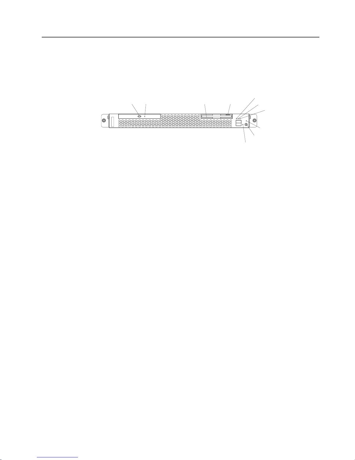
Front view
The following illustration shows the controls and LEDs on the front of the server.
CD-eject button: Press this button to release a CD from the CD-ROM drive.
CD-ROM drive activity LED: When this LED is lit, it indicates that the CD-ROM
drive is in use.
Diskette drive activity LED: When this LED is lit, it indicates that the diskette drive
is in use.
CD-eject
button
CD-ROM drive
activity LED
Diskette drive
activity LED
Diskette-eject
button
System-error LED
System-locator LED
Hard disk drive
activity LED
Power-on LED
Power-control button
Reset button
Diskette-eject button: Press this button to release a diskette from the diskette
drive.
System-error LED: When this LED is lit, it indicates that a system error has
occurred.
System-locator LED: Use this blue LED to visually locate the server if it is in a
location with numerous other servers. If your server supports IBM Director, you can
use IBM Director to light this LED remotely.
Hard disk drive activity LED: When this LED is flashing, it indicates that a hard
disk drive is in use.
Power-on LED: When this LED is lit and not flashing, it indicates that the server is
turned on. When this LED is flashing, it indicates that the server is turned off and
still connected to an ac power source. When this LED is off, it indicates that ac
power is not present, or the power supply or the LED itself has failed.
If this LED is off, it does not mean that there is no electrical power in the server.
The LED might be burned out. To remove all electrical power from the server, you
must disconnect the power cord from the electrical outlet.
Power-control button: Press this button to turn the server on and off manually.
Reset button: Press this button to reset the server and run the power-on self-test
(POST). Yo u might have to use a pen or the end of a straightened paper clip to
press the button.
Chapter 1. General information 7
Page 18
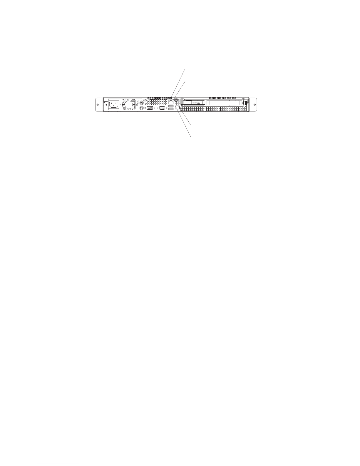
Rear view
The following illustration shows the LEDs on the rear of the server.
Ethernet 1 transmit/receive
activity LED
Ethernet 1 speed
1 Gbps LED
Ethernet 2 speed
1 Gbps LED
Ethernet 2 transmit/receive
activity LED
Ethernet 1 transmit/receive activity LED: This LED is on the Ethernet connector.
When this LED is lit, it indicates that there is activity between the server and the
network.
Ethernet 1 speed 1 Gbps LED: This LED is on the Ethernet connector. When this
LED is lit, it indicates that the Ethernet network speed is 1 Gbps. When this LED is
off, it indicates that the Ethernet network speed is 10 Mbps or 100 Mbps.
Ethernet 2 speed 1 Gbps LED: This LED is on the Ethernet connector. When this
LED is lit, it indicates that the Ethernet network speed is 1 Gbps. When this LED is
off, it indicates that the Ethernet network speed is 10 Mbps or 100 Mbps.
Ethernet 2 transmit/receive activity LED: This LED is on the Ethernet connector.
When this LED is lit, it indicates that there is activity between the server and the
network.
Server power features
When the server is connected to an ac power source but is not turned on, the
operating system does not run, and all core logic except for the service processor is
shut down; however, the server can respond to requests from the service processor,
such as a remote request to turn on the server. The power-on LED flashes to
indicate that the server is connected to ac power but not turned on.
Turning on the server
Approximately 20 seconds after the server is connected to ac power, the
power-control button becomes active, and you can turn on the server and start the
operating system by pressing the power-control button.
8 xSeries 306 Type 1878, 8489 and 8836: Hardware Maintenance Manual and Troubleshooting Guide
Page 19
The server can also be turned on in any of the following ways:
v If a power failure occurs while the server is turned on, the server will restart
automatically when power is restored.
v If the server is connected to an Advanced System Management interconnect
network that contains at least one server with an optional Remote Supervisor
Adapter installed, the server can be turned on from the Remote Supervisor
Adapter user interface.
v If your operating system supports the system-management software for an
optional Remote Supervisor Adapter, the system-management software can turn
on the server.
v If your operating system supports the Wake on LAN feature, the Wake on LAN
feature can turn on the server.
When 4 GB or more of memory (physical or logical) is installed, some
Note:
memory is reserved for various system resources and is unavailable to the
operating system. The amount of memory that is reserved for system resources
depends on the operating system, the configuration of the server, and the
configured PCI options.
Turning off the server
When you turn off the server and leave it connected to ac power, the server can
respond to requests from the service processor, such as a remote request to turn
on the server. To remove all power from the server, you must disconnect it from the
power source.
Some operating systems require an orderly shutdown before you turn off the server.
See your operating-system documentation for information about shutting down the
operating system.
Statement 5:
CAUTION:
The power control button on the device and the power switch on the power
supply do not turn off the electrical current supplied to the device. The device
also might have more than one power cord. To remove all electrical current
from the device, ensure that all power cords are disconnected from the power
source.
2
1
Chapter 1. General information 9
Page 20

The server can be turned off in any of the following ways:
v You can turn off the server from the operating system, if your operating system
supports this feature. After an orderly shutdown of the operating system, the
server will be turned off automatically.
v You can press the power-control button to start an orderly shutdown of the
operating system and turn off the server, if your operating system supports this
feature.
v If the operating system stops functioning, you can press and hold the
power-control button for more than 4 seconds to turn off the server.
v If the server is connected to an Advanced System Management interconnect
network that contains at least one server with an optional Remote Supervisor
Adapter installed, the server can be turned off from the Remote Supervisor
Adapter user interface.
v If an optional Remote Supervisor Adapter is installed in the server, the server can
be turned off from the Remote Supervisor Adapter user interface.
v If the Wake on LAN feature turned on the server, the Wake on LAN feature can
turn off the server.
v You can turn off the server through a request from the service processor.
10 xSeries 306 Type 1878, 8489 and 8836: Hardware Maintenance Manual and Troubleshooting Guide
Page 21

Chapter 2. Configuring the xSeries 306 server
The ServerGuide Setup and Installation CD provides software setup tools and
installation tools that are specifically designed for your IBM server. Use this CD
during the initial installation of the server to configure basic hardware features and
to simplify your operating-system installation.
In addition to the ServerGuide Setup and Installation CD, you can use the following
configuration programs to customize the server hardware:
v Configuration/Setup Utility program
®
v Adaptec
HostRAID
v SCSISelect utility program
more information about these programs, see “Configuring your server” in the
For
User’s Guide on the IBM xSeries Documentation CD.
Using the ServerGuide Setup and Installation CD
The ServerGuide Setup and Installation CD provides state-of-the-art programs to
detect the server model and hardware options that are installed, configures the
server hardware, provides device drivers, and helps you install your operating
system. For information about the supported operating-system versions, see the
label on the CD. If the ServerGuide Setup and Installation CD did not come with
your server, you can download the latest version from the ServerGuide Web page
at http://www.ibm.com/pc/qtechinfo/MIGR-4ZKPPT.html.
™
configuration programs
Complete the following steps to start the ServerGuide Setup and Installation CD:
1. Insert the CD, and restart the server. If the CD does not start, see “ServerGuide
problems” on page 72.
2. Follow the instructions on the screen to:
a. Select your language.
b. Select your keyboard layout and country.
c. View the overview to learn about ServerGuide features.
d. View the readme file to review installation tips about your operating system
and adapter.
e. Start the setup and hardware configuration programs.
f. Start the operating-system installation. You will need your operating-system
CD.
Using the Configuration/Setup Utility program
The Configuration/Setup Utility program is part of the BIOS code. Yo u can use it to:
v Change interrupt request (IRQ) settings
v Change the startup drive sequence
v Configure serial-port assignments
v Enable USB keyboard and mouse support
v Resolve configuration conflicts
v Set the date and time
v Set passwords and security settings
© Copyright IBM Corp. 2004 11
Page 22

Complete the following steps to start the Configuration/Setup Utility program:
1. Turn on the server and watch the monitor screen.
2. When the message Press F1 for Configuration/Setup appears, press F1. If a
supervisor (administrator) password has been set, you must type the supervisor
password to access the full Configuration/Setup Utility menu.
3. Follow the instructions on the screen.
Using the Adaptec HostRAID configuration programs
Use the Adaptec RAID Configuration Utility programs and SCSISelect Utility to add
RAID levels 0 and 1 functionality to the integrated Serial ATA controller and the
SCSI controller. Be sure to use these programs as described in this document. Use
these programs to:
v Configure a redundant array of independent disks (RAID) array
v View or change your RAID configuration and associated devices
Consider
the following information when using the Adaptec RAID Configuration
Utility programs and SCSISelect Utility program to configure and manage arrays:
v The SCSI controller with integrated SCSI RAID (SCSI models) and the integrated
Serial ATA controller (SATA models) with integrated SATA RAID support RAID
levels 0 and 1. Installing an optional ServeRAID controller provides additional
RAID levels.
v You cannot use the ServerGuide Setup and Installation CD to configure the
integrated Serial ATA controller with integrated RAID and the SCSI controller with
integrated RAID.
v Hard disk drive capacities affect how you create arrays. Drives in an array can
have different capacities, but the RAID controller treats them as if they all have
the capacity of the smallest hard disk drive.
v To help ensure signal quality, do not mix drives with different speeds and data
rates.
v To update the firmware and BIOS code for an optional ServeRAID controller, you
must use the IBM ServeRAID Support CD that comes with the ServeRAID
option.
v If you install a different type of RAID controller in your server, use the
configuration method described in the instructions that come with that RAID
controller to view or change SCSI settings for attached devices.
Using the Adaptec RAID Configuration Utility programs (for Serial ATA
HostRAID)
Use the Array Configuration Utility within the Adaptec RAID Configuration Utility
programs to add RAID levels 0 and 1 functionality to the integrated Serial ATA
(SATA) controller with integrated RAID. This utility is a part of the BIOS code in your
server. For additional information about using the Adaptec RAID Configuration Utility
programs, see the documentation on the IBM ServeRAID-7e (Adaptec HostRAID)
Support CD. If this CD did not come with your server, you can download the
ServeRAID-7e (Adaptec HostRAID) Support CD from the IBM Web site at:
http://www.ibm.com/pc/support/.
The Serial ATA RAID feature comes disabled by default. Yo u must enable the SATA
RAID feature and install the device drivers before you can use it. The SATA RAID
feature configuration utilities, device drivers, and information are available on the
ServeRAID-7e (Adaptec HostRAID) Support CD.
12 xSeries 306 Type 1878, 8489 and 8836: Hardware Maintenance Manual and Troubleshooting Guide
Page 23

Enabling the Serial ATA HostRAID feature
Complete the following steps to enable the SATA HostRAID feature:
1. Turn on the server and watch the monitor screen.
2. When the message Press F1 for Configuration/Setup appears, press F1. If
you have set a supervisor password, you are prompted to type the password.
3. Select Devices and I/O Ports.
4. Scroll down and select SATA RAID Enable.
5. Select Enabled.
6. Press Esc; then, select Yes to save your changes.
Using the Serial ATA HostRAID feature
The instructions in this section are for using the Array Configuration Utility program
to access and perform an initial RAID level-1 configuration. If you install a different
type of RAID adapter in your server, use the configuration method described in the
instructions that come with that adapter to view or change settings for the attached
devices.
See the documentation on the ServeRAID-7e (Adaptec HostRAID) Support CD for
additional information about using the Array Configuration Utility program to create,
configure, and manage arrays.
Configuring the controller: Complete the following steps to use the Array
Configuration Utility program to configure a RAID level-1 array on your server.
1. Turn on the server and watch the monitor screen.
2. When the message Press <CTRL><<A> for Adaptec RAID Configuration
Utility appears, press Ctrl+A.
3. Select Array Configuration Utility (ACU).
4. Select Create Array.
5. From the list of ready drives, select the two drives that you want to group into
the array.
6. Select RAID-1 when asked to select the RAID level.
7. (optional), Type an identifier for the array.
8. Select Quick Int when asked for the array build method.
9. Follow the instructions on the screen to complete the configuration, and select
Done to exit.
10. Restart the server.
Viewing
the configuration: Complete the following steps to view information
about the Serial ATA controller:
1. Start the Array Configuration Utility.
2. From the Array Configuration Utility window, select Manage Arrays.
3. Select an array and press Enter.
4. Press Esc to exit the program.
Using the SCSISelect Utility program (for SCSI HostRAID)
Use the SCSISelect Utility to add RAID levels 0 and 1 functionality to the SCSI
controller (SCSI models only). This utility is part of the BIOS code in your server.
The SCSI RAID feature comes disabled by default. You must enable the SCSI
RAID feature and install the device drivers before you can use it. SCSI RAID
configuration utilities, device drivers, and information are available on the
Chapter 2. Configuring the xSeries 306 server 13
Page 24

ServeRAID-7e (Adaptec HostRAID) Support CD. If this CD did not come with your
server, you can download the ServeRAID-7e (Adaptec HostRAID) Support CD from
the IBM Web site at http://www.ibm.com/pc/support/.
Enabling the SCSI HostRAID feature
Complete the following steps to enable the SCSI HostRAID feature:
1. Turn on the server and watch the monitor screen.
2. When the message Press <CTRL><A> for SCSISelect Utility appears, press
Ctrl+A. If you have set a supervisor password, you are prompted to type the
password.
3. Use the arrow keys to select the channel for which you want to change settings
and press Enter.
4. Select Configure/View SCSI Controller Setting; then, select HostRAID.
5. Select Enabled.
6. Press Esc; then, select Yes to save the changes.
Using the SCSI HostRAID feature
The instructions in this section describe how to access the SCSI HostRAID feature
from the SCSISelect Utility program and perform an initial RAID level-1
configuration on your server. If you install a different type of RAID adapter in your
server, use the configuration method described in the instructions that come with
that adapter to view or change SCSI settings for attached devices.
See the documentation on the ServeRAID-7e (Adaptec HostRAID) Support CD for
additional information about how to use the SCSI HostRAID feature.
Configuring the controller: Complete the following steps to use the SCSI
HostRAID feature to configure a RAID level-1 array on your server:
1. From the SCSISelect main menu, select Configure/View HostRAID Settings.
2. From the list of ready drives, type C to create an array.
3. Select RAID-1 when asked to select the RAID type.
4. From the list of ready drives, select the two drives that you want to group into
the array.
5. Select Create new RAID-1.
6. Type an identifier for the array.
7. Select Yes to create the array.
8. Press Esc to exit the utility.
9. Restart the server.
Viewing
the configuration: Yo u can use the SCSISelect Utility program to view
information about the SCSI controller. From the list of available arrays, select an
array and press Enter. Press Esc to exit the utility.
Using the SCSISelect utility program (SCSI models only)
Use the SCSISelect utility program to view or change SCSI controller settings and
view SCSI ID assignments. The SCSISelect utility program is available on SCSI
models only.
Complete the following steps to start the SCSISelect utility program:
1. Turn on the server and watch the monitor screen.
14 xSeries 306 Type 1878, 8489 and 8836: Hardware Maintenance Manual and Troubleshooting Guide
Page 25

2. When the message Press <CTRL><A> for SCSISelect Utility appears, press
Ctrl+A. If a supervisor password has been set, you are prompted to type the
password.
3. Select the channel for which you want to change settings, and press Enter.
4. When the message Would you like to configure the SCSI controller, or
run the SCSI Disk Utilities? appears, select a choice and press Enter.
5. Use the arrow keys to select a choice from the menu, and follow the instructions
on the screen.
Configuring the Gigabit Ethernet controllers
The Ethernet controllers are integrated on the system board. They provide an
interface for connecting to a 10-Mbps, 100-Mbps, or 1-Gbps network and provide
full-duplex (FDX) capability, which enables simultaneous transmission and reception
of data on the network. If the Ethernet ports in your server support auto-negotiation,
the controllers detect the data-transfer rate (10BASE-T, 100BASE-TX, or
1000BASE-T) and duplex mode (full-duplex or half-duplex) of the network and
automatically operate at that rate and mode.
You do not need to set any jumpers or configure the controllers. However, you must
install a device driver to enable the operating system to address the controllers. For
device drivers and information about configuring the Ethernet controllers, see the
Intel Ethernet Software CD that comes with your server. For updated information
about configuring the controllers, go to http://www.ibm.com/pc/support/.
Chapter 2. Configuring the xSeries 306 server 15
Page 26

16 xSeries 306 Type 1878, 8489 and 8836: Hardware Maintenance Manual and Troubleshooting Guide
Page 27

Chapter 3. Diagnostics
This chapter provides basic troubleshooting information to help solve some common
problems that might occur with the server.
If you cannot locate and correct the problem using the information in this chapter,
see Appendix A, “Getting help and technical assistance,” on page 81 for more
information.
General checkout
Follow the checkout procedure for diagnosing hardware problems. Review the
following information before performing the checkout procedure:
v Read the safety information beginning at page 83.
v The diagnostic programs are on the IBM Enhanced Diagnostics CD. These
programs are the primary method of testing the major components of the server:
the system board, Ethernet controller, video controller, RAM, keyboard, mouse
(pointing device), serial ports, hard disk drives, and parallel port. Yo u can also
use them to test some external devices. If you are not sure whether a problem is
caused by the hardware or by the software, you can use the diagnostic programs
to confirm that the hardware is working correctly.
v When you run the diagnostic programs, a single problem might cause several
error messages. If you receive several error messages, correct the cause of the
first error message. The other error messages might not occur the next time you
run the diagnostic programs.
v Before running the diagnostic programs, you must determine whether the failing
server is part of a shared hard disk drive cluster (two or more servers sharing
external storage devices). If you suspect that it is part of a cluster, you can run
all diagnostic programs except the ones that test the storage unit (that is, a hard
disk drive in the storage unit) or the storage adapter that is attached to the
storage unit. The failing server might be part of a cluster if any of the following
conditions is true:
– The customer identifies the failing server as part of a cluster.
– One or more external storage units are attached to the failing server and at
least one of the attached storage units is also attached to another server or
unidentifiable device.
– One or more servers are located near the failing server.
Important:
v
1. For servers that are part of a shared hard disk drive cluster, run one test at a
time. Do not run any suite of tests, such as ″quick″ or ″normal″ tests,
because this could enable the hard disk drive diagnostic tests.
2. If more than one error code is displayed, correct the first error. The other
error codes might not occur the next time you run the diagnostic programs.
3. If the server is suspended and a POST error code is displayed, see “POST
error codes” on page 55.
4. If the server is suspended and no error message is displayed, see “Error
symptoms” on page 62 and “Undetermined problems” on page 73.
5. For information about power-supply problems, see “Power checkout” on page
26.
6. For intermittent problems, check the error log; see “Diagnostic programs and
error messages” on page 20.
© Copyright IBM Corp. 2004 17
Page 28

Note: The system-error log is available on the xSeries 306 only when the
server has an optional Remote Supervisor Adapter II.
Complete
the following steps to perform the checkout procedure:
001 IS THE SERVER PART OF A CLUSTER?
YES. Schedule maintenance for the server. Shut down all servers related to
the cluster. Run the storage test.
NO. Go to step 002.
002 IF THE SERVER IS NOT PART OF A CLUSTER:
If the operating system is running, complete the following steps:
1. Check the system board for error LEDs (see “Error LEDs” on page 23).
2. If the xSeries 306 has an optional Remote Supervisor Adapter II, check
the service processor system-error logs:
a. If the system-error log indicates a damaged field replaceable unit
(FRU), replace the FRU, and run the diagnostic programs to confirm
that the problem has been solved.
b. If the system-error log does not indicate a damaged FRU, see “Error
symptoms” on page 62 and “Undetermined problems” on page 73.
If the operating system is not running, complete the following steps:
1. Check the system board for error LEDs (see “Error LEDs” on page 23).
2. If the xSeries 306 has an optional Remote Supervisor Adapter II, check
the service processor system-error logs:
a. If the system-error log indicates a damaged field replaceable unit
(FRU), replace the FRU, and run the diagnostic programs to confirm
that the problem has been solved.
b. If the error log does not indicate a damaged FRU, check the
operating-system event logs; if these logs do not specify a particular
error, go to step 3.
3. Turn off the server and all external devices.
4. Check all cables and power cords.
5. Set all display controls to the middle position.
6. Turn on all external devices.
7. Turn on the server.
8. Watch the screen and the serial port for POST errors, and record any
POST error messages that are displayed on the screen. If an error is
displayed, look up the first error (see “POST error codes” on page 55).
9. Run the diagnostic programs (see “Starting the diagnostic programs and
viewing the test log” on page 21).
003 DID THE DIAGNOSTIC PROGRAMS START ?
NO. Find the failure symptom in “Error symptoms” on page 62.
YES. Run the diagnostic programs (see “Starting the diagnostic programs
and viewing the test log” on page 21).
If you receive an error, see Chapter 6, “Symptom-to-FRU index,” on page
53.
If the diagnostics were completed successfully and you still suspect a
problem, see “Undetermined problems” on page 73.
If the server does not turn on, see “Error symptoms” on page 62.
18 xSeries 306 Type 1878, 8489 and 8836: Hardware Maintenance Manual and Troubleshooting Guide
Page 29

Diagnostic tools overview
The following tools are available to help you diagnose and solve hardware-related
problems:
v POST beep codes and error messages
The power-on self-test (POST) generates beep codes and messages to indicate
successful test completion or the detection of a problem. See “Power-on self-test”
for more information.
v Diagnostic programs
The diagnostic programs are stored on the IBM Enhanced Diagnostics CD.
These programs are the primary method of testing the major components of the
server. See “Diagnostic programs and error messages” on page 20 for more
information.
v Error charts
These charts list problem symptoms and steps to correct the problem. See “Error
charts” on page 22 for more information.
v Symptom-to-FRU index
This index lists problem symptoms and steps to correct each problem. See
Chapter 6, “Symptom-to-FRU index,” on page 53 for more information.
Power-on self-test
When you turn on the server, the power on self-test (POST) performs a series of
tests to check the operation of system components and some of the installed
options.
If POST finishes without detecting any problems, the first window of the operating
system opens or an application program appears.
If POST detects a problem, more than one beep might sound, and an error
message appears on the screen.
Notes:
1. If you have a user password set, you must type the password and press Enter,
2. A single problem might cause several error messages. When this occurs, work
POST beep codes
POST generates beep codes to indicate successful completion or the detection of a
problem.
v One short beep indicates the successful completion of POST.
v More than one beep indicates that POST detected a problem. For more
information, see “Beep symptoms” on page 53.
when prompted, before the operating system will start.
to correct the cause of the first error message. After you correct the cause of
the first error message, the other error messages usually will be resolved the
next time you run the test.
If POST detects a problem (more than one beep sounds), an error message
appears on the screen. See “Beep symptoms” on page 53 and “POST error codes”
on page 55 for more information.
Chapter 3. Diagnostics 19
Page 30

POST error messages
POST error messages can appear when a problem is detected during startup. For a
complete list of POST messages, see “POST error codes” on page 55.
Diagnostic programs and error messages
The system diagnostic programs are on the IBM Enhanced Diagnostics CD. These
programs are the primary method of testing the major components of the server.
An IBM Enhanced Diagnostics CD comes with the server. You can also download
the latest version of the diagnostic programs from http://www.ibm.com/support/ (see
“Downloading the diagnostic program” on page 21).
The IBM Enhanced Diagnostic programs isolate problems from the server hardware
and software. The programs run independently of the operating system and must
be run either from a CD or diskette.
Diagnostic error messages indicate that a problem exists; they are not intended to
be used to identify a failing part. Troubleshooting and servicing complex problems
indicated by error messages should be performed by trained service personnel.
Sometimes the first error to occur causes additional errors. In this case, the server
displays more than one error message. Always follow the suggested action
instructions for the first error message that appears.
Text messages
Error codes that might be displayed are listed at “Diagnostic error codes” on page
58.
The diagnostic text message format is as follows:
result test_specific_string
where:
result is one of the following results:
Passed
This test was completed without any errors.
Failed
This test discovered an error.
User Aborted
You stopped the test before it was completed.
Not Applicable
You attempted to test a device that is not present in the server.
Aborted
The test could not proceed because of the server configuration.
Warning
A possible problem was reported during the test (for example, a
device that was to be tested is not installed).
specific string
test
20 xSeries 306 Type 1878, 8489 and 8836: Hardware Maintenance Manual and Troubleshooting Guide
is an error code or other information about the error.
Page 31

Downloading the diagnostic program
Complete the following steps to download the latest image of the IBM Enhanced
Diagnostics and create a startable Enhanced Diagnostics diskette:
1. Go to http://www.ibm.com/support/.
2. Download the diagnostics file for the server to a hard disk drive directory (not to
a diskette).
Note: If you intend to create a diagnostics CD, download the file with the
extension .iso.
3. Go to a DOS prompt, and change to the directory where the file was
downloaded.
4. If you are creating a diagnostics diskette:
a. Insert a blank high-density diskette into the diskette drive.
b. Type in the following, and then press Enter: filename a: where filename is
the name of the file you downloaded from the Web.
If you are creating a diagnostics CD, use a blank CD in conjunction with the
5.
software you use to create a CD.
downloaded file is self-extracting when copied to the diskette or CD. When the
The
copy is completed, you have a startable or bootable IBM Enhanced Diagnostics
diskette or CD.
Starting the diagnostic programs and viewing the test log
The IBM Enhanced Diagnostic programs isolate problems from the server hardware
and software. The programs run independently of the operating system and must
be run either from a CD or diskette. This method of testing is generally used when
other methods are not accessible or have not been successful in isolating a
problem suspected to be hardware related.
The test log records data about system failures and other pertinent information. The
following sections describe the diagnostic procedure for the diagnostics CD and the
diagnostics diskette.
Note: The system-error log is available on the xSeries 306 server only when the
server has an optional Remote Supervisor Adapter II.
Using the diagnostics CD
To start the IBM Enhanced Diagnostics using the CD, complete the following steps:
1. Turn off the server and any peripheral devices.
2. Turn on all attached devices; then, turn on the server.
3. When you see Press F1 For Configuration/Setup, press the F1 key.
4. When the Configuration/Setup Utility menu appears, select Start Options.
5. From the Start Options menu, select Startup Sequence.
6. Note the device that is selected as the first startup device. Later, you must
restore this setting.
7. Select CD-ROM as the first startup device.
8. Press Esc two times to return to the Configuration/Setup Utility menu.
9. Insert the IBM Enhanced Diagnostics CD in the CD-ROM drive.
10. Select Save & Exit Setup and follow the prompts. The diagnostics will load.
Follow the instructions on the screen to run the diagnostics.
Chapter 3. Diagnostics 21
Page 32

11. When the tests are completed, view the test log by selecting Utility from the
top of the screen. You can save the test log to a file on a diskette or to the
hard disk.
Important: When you finish running the diagnostics and utilities, remove the
CD from the CD-ROM drive and turn off the server. Yo u must restore the first
startup device to the original setting. Use steps 2 on page 21 through 8 on
page 21 of this procedure to do this.
The test-log data is maintained only while the diagnostic programs are active.
When you exit from the diagnostic programs, the test log is cleared. Save the
test log to a file on a diskette or to the hard disk if you want to refer to it later.
Using the diagnostic diskette
Complete the following steps to start the IBM Enhanced Diagnostics using the
diagnostics diskette:
1. Turn off the server and any peripheral devices.
2. Insert the IBM Enhanced Diagnostics diskette into the external USB diskette
drive.
3. Turn on all attached devices; then, turn on the server.
4. Follow the instructions on the screen.
5. When the tests are completed, view the test log by selecting Utility from the top
of the screen. You can save the test log to a file on a diskette or to the hard
disk.
The test-log data is maintained only while the diagnostic programs are active.
When you exit from the diagnostic programs, the test log is cleared. Save the
test log to a file on a diskette or to the hard disk if you want to refer to it later.
6. When you have completed the diagnostics procedure, remove the diagnostic
diskette from the diskette drive before restarting the server.
If the hardware passes the Enhanced Diagnostics but the problem persists during
normal server operations, a software error might be the cause. If you suspect a
software problem, refer to the information that comes with the software package.
Diagnostic error message tables
For descriptions of the error messages that might appear when you run the
diagnostic programs, see “Diagnostic error codes” on page 58.
Note: Depending on the configuration, some of the error messages might not
appear when you run the diagnostic programs.
Error charts
You can use the error charts to find solutions to problems that have definite
symptoms (see “Error symptoms” on page 62).
Small computer system interface (SCSI) messages (some models)
If the server has an Ultra320 SCSI adapter and you receive a SCSI error message,
see “SCSI error codes” on page 72.
Note: If the server does not have a SCSI hard disk drive, ignore any message that
indicates that the BIOS code is not installed.
22 xSeries 306 Type 1878, 8489 and 8836: Hardware Maintenance Manual and Troubleshooting Guide
Page 33

Error LEDs
The system board has error LEDs for microprocessors, fans, and memory that will
help to locate the source of the error. Run the diagnostic programs (see “Starting
the diagnostic programs and viewing the test log” on page 21) to find out the cause
of the error.
Standby
power LED
Fan 1
error LED
Each error LED is lit to indicate a problem with a specific component. After a
problem is corrected, its LED will not be lit the next time the server is restarted; if
the problem remains, the LED will be lit again.
Updating BIOS code
The BIOS code can be updated by using an external USB diskette drive or by using
a Linux or Windows update package (if available).
DIMM 4
error LED
DIMM 3
error LED
DIMM 2
error LED
DIMM 1
error LED
Fan 3
error LED
Fan 4
error LED
Fan 2
error LED
The most current level of BIOS code for the server is available at
http://www.ibm.com/support/. After you make sure that the server has the latest
baseboard management controller firmware level, you can update the BIOS code
for the server through one of the following methods:
v Downloading the latest BIOS code from the IBM Web site, creating an update
diskette, and using an external USB diskette drive to install the BIOS code.
v Installing an update package for the Linux or Microsoft Windows operating
system, if available.
Chapter 3. Diagnostics 23
Page 34

If power to the server is interrupted while POST/BIOS code is being updated (flash
update), the server might not restart correctly or might not display video (no video).
If this happens, use the following procedure to recover:
1. Review the safety information beginning at page 83 and “Handling
static-sensitive devices” on page 27.
2. Turn off the server and all attached devices.
3. Disconnect the power cord.
4. Remove the cover (see “Removing the cover” on page 32).
5. Locate the boot block recovery jumper (JP1) on the system board, removing
any adapters that impede access to the jumper. The following illustration
shows the location of the jumper on the system board.
NMI switch
Clear CMOS jumper (JP2)
6. Remove the boot block recovery jumper from pins 1 and 2.
7. Replace any adapters that were removed; then, replace the support bracket
Boot block recovery jumper (JP1)
and replace the side cover (see “Installing the cover” on page 41).
8. Connect the server to a power source, keyboard, monitor, and mouse.
9. Insert the POST/BIOS update (flash) diskette into the diskette drive. Yo u can
download a file to create this diskette from http://www.ibm.com/support/.
10. Turn on the server and the monitor.
11. After the update session is completed, turn off the server and monitor.
12. Remove the diskette from the diskette drive.
13. Disconnect all power cords; then, remove the server cover.
14. Return the boot block recovery jumper to pins 1 and 2.
15. Reinstall the server cover; then, reconnect all external cables and power cords
and turn on the peripheral devices.
16. Turn on the server to restart the operating system.
24 xSeries 306 Type 1878, 8489 and 8836: Hardware Maintenance Manual and Troubleshooting Guide
Page 35

Erasing a lost or forgotten password (clearing CMOS memory)
Complete the following steps to set the CMOS recovery jumper and erase a
forgotten password:
1. Review the safety information beginning at Appendix B, “Safety information,”
on page 83 and “Handling static-sensitive devices” on page 27.
2. Turn off the server and all attached devices.
3. Unplug the power cord.
4. Remove the side cover. (See “Removing the cover” on page 32.)
5. Locate the CMOS recovery jumper (JP2) on the system board, removing any
adapters that impede access to the jumper. The following illustration shows the
location of the jumper on the system board.
NMI switch
Clear CMOS jumper (JP2)
6. Move the CMOS recovery jumper from pins 1 and 2 to pins 2 and 3.
7. Wait 60 seconds; then, return the CMOS recovery jumper to pins 1 and 2
8. Replace any adapters that were removed; then, replace the support bracket,
Boot block recovery jumper (JP1)
and replace the side cover. (See “Installing the cover” on page 41.)
You can now start the server one time without having to use the user
password and start the Configuration/Setup Utility program. At this time, you
can either delete the old password or set a new user password. If you do not
change or delete the password, the next time you start the server the original
user password will be reinstated.
9. Connect the server to a power source, keyboard, monitor, and mouse.
10. Turn on the server. The Configuration/Setup Utility program starts.
11. Follow the instructions to erase the existing password or create a new
password.
12. Select Save Settings, and press Enter.
Chapter 3. Diagnostics 25
Page 36

Updating the UUID
The Universal Unique Identifier (UUID) must be updated when the system board is
replaced. Complete the following steps to update the UUID:
1. Copy the UUID utility (uuid.exe) from the BIOS flash diskette to a DOS
bootable diskette.
2. Insert the diskette created in step 1 into the server.
3. Restart the server from the diskette.
4. At the a:\ prompt, type UUID /wr, and press Enter. The utility will generate a
random identifier.
5. Restart the server.
Updating the DMI/SMBIOS data
The Desktop Management Interface (DMI) must be updated when the system board
is replaced. Complete the following steps to update the DMI:
1. Copy the DMI/SMBIOS utility (extrmdmi.exe) from the BIOS flash diskette to a
DOS bootable diskette.
2. Insert the diskette created in step 1 into the server.
3. Restart the server from the diskette.
4. At the a:\ prompt, type extrmdmi.exe, and press Enter.
5. To change the machine type and model number, type mtm XXXXYYY where XXXX
is the model type and YYY is the model number; then, press Enter.
6. To change the serial number, type sn ZZZZZZZ where ZZZZZZZ is the serial
number; then, press Enter.
7. To change the asset tag, type asset AAAAAAAAAAAAAAAAAAAAAAAAAAAAAAAAA
where AAAAAAAAAAAAAAAAAAAAAAAAAAAAAAAAA is the asset tag number; then, press
Enter.
8. Restart the server.
Power checkout
Power problems can be difficult to solve. For example, a short circuit can exist
anywhere on any of the power distribution buses. Usually, a short circuit will cause
the power subsystem to shut down because of an overcurrent condition.
A general procedure for troubleshooting power problems is as follows:
1. Turn off the server, and disconnect all ac power cords.
2. Check for loose cables in the power subsystem. Also check for short circuits, for
example, if there is a loose screw causing a short circuit on a circuit board.
3. Remove adapters, and disconnect the cables and power connectors to all
internal and external devices until the server is at the minimum configuration
required to start the server (see “Minimum operating requirements” on page 73).
4. Reconnect all ac power cords, and turn on the server. If the server starts
successfully, replace adapters and devices one at a time until the problem is
isolated. If the server does not start from the minimal configuration, replace
FRUs of minimal configuration one at a time until the problem is isolated.
To use this method, you must know the minimum configuration that is required for
the server to start (see page 73).
26 xSeries 306 Type 1878, 8489 and 8836: Hardware Maintenance Manual and Troubleshooting Guide
Page 37

Chapter 4. Installing options
This chapter provides detailed instructions for installing hardware options in your
server.
Installation guidelines
Before you begin installing options in your server, read the following information:
v Read the safety information beginning on page 83 and the guidelines in
“Handling static-sensitive devices” on page 27. This information will help you
work safely with your server and options.
v Make sure that you have an adequate number of properly grounded electrical
outlets for your server, monitor, and other devices that you will connect to the
server.
v Back up all important data before you make changes to disk drives.
v Have a small flat-blade screwdriver available.
v You do not have to turn off the server to install or replace hot-plug Universal
Serial Bus (USB) devices.
v Blue on a component indicates touch points, where you can grip the component
to remove it from or install it in the server, open or close a latch, and so on.
v Orange on a component or an orange label on or near a component indicates
that the component can be hot-swapped, which means that if the server and
operating system support hot-swap capability, you can remove or install the
component while the server is running. (Orange can also indicate touch points on
hot-swap components.) See the instructions for removing or installing a specific
hot-swap component for any additional procedures that you might have to
perform before you remove or install the component.
v For a list of supported options for your server, go to http://www.ibm.com/support/.
System reliability guidelines
To help ensure proper cooling and system reliability, make sure that:
v Each of the drive bays has a drive tray installed in it.
v There is adequate space around the server to allow the server cooling system to
work properly. Leave approximately 50 mm (2.0 in.) of open space around the
front and rear of the server. Do not place objects in front of the fans.
v You have followed the cabling instructions that come with optional adapters.
v You have replaced a failed fan within 48 hours.
Handling static-sensitive devices
Attention: Static electricity can damage electronic devices, including your server.
To avoid damage, keep static-sensitive devices in their static-protective packages
until you are ready to install them.
To reduce the possibility of damage from electrostatic discharge, observe the
following precautions:
v Limit your movement. Movement can cause static electricity to build up around
you.
v Handle the device carefully, holding it by its edges or its frame.
v Do not touch solder joints, pins, or exposed circuitry.
v Do not leave the device where others can handle and damage it.
© Copyright IBM Corp. 2004 27
Page 38

v While the device is still in its static-protective package, touch it to an unpainted
metal part of the server for at least 2 seconds. This drains static electricity from
the package and from your body.
v Remove the device from its package and install it directly into the server without
setting down the device. If it is necessary to set down the device, put it back into
its static-protective package. Do not place the device on your server cover or on
a metal surface.
v Take additional care when handling devices during cold weather. Heating reduces
indoor humidity and increases static electricity.
Major components of the xSeries 306 Type 1878, 8489 and 8836
The following illustration shows the major components in the server.
Captive screw
Riser-card
assembly
Power supply
CD-ROM drive
SCSI hard disk
drive (some models)
Bezel
Fans
Heat sink
DIMM
System board
Diskette drive
28 xSeries 306 Type 1878, 8489 and 8836: Hardware Maintenance Manual and Troubleshooting Guide
Page 39

System-board internal connectors
The following illustration shows the internal connectors on the system board.
SCSI LED connector
Remote Supervisor
Adapter connector
Fan 1
connector
Wake-on-LAN
connector
USB operator
panel connector
Primary IDE
connector
SATA connectors
Operator information
panel connector
Power
connector
Microprocessor
power cable connector
Diskette drive
signal connector
Microprocessor
socket
Fan 3 connector
Fan 4 connector
Fan 2 connector
System-board switches and jumpers
The following illustration shows the switches and jumpers on the system board.
NMI switch
Clear CMOS jumper (JP2)
Boot block recovery jumper (JP1)
Chapter 4. Installing options 29
Page 40
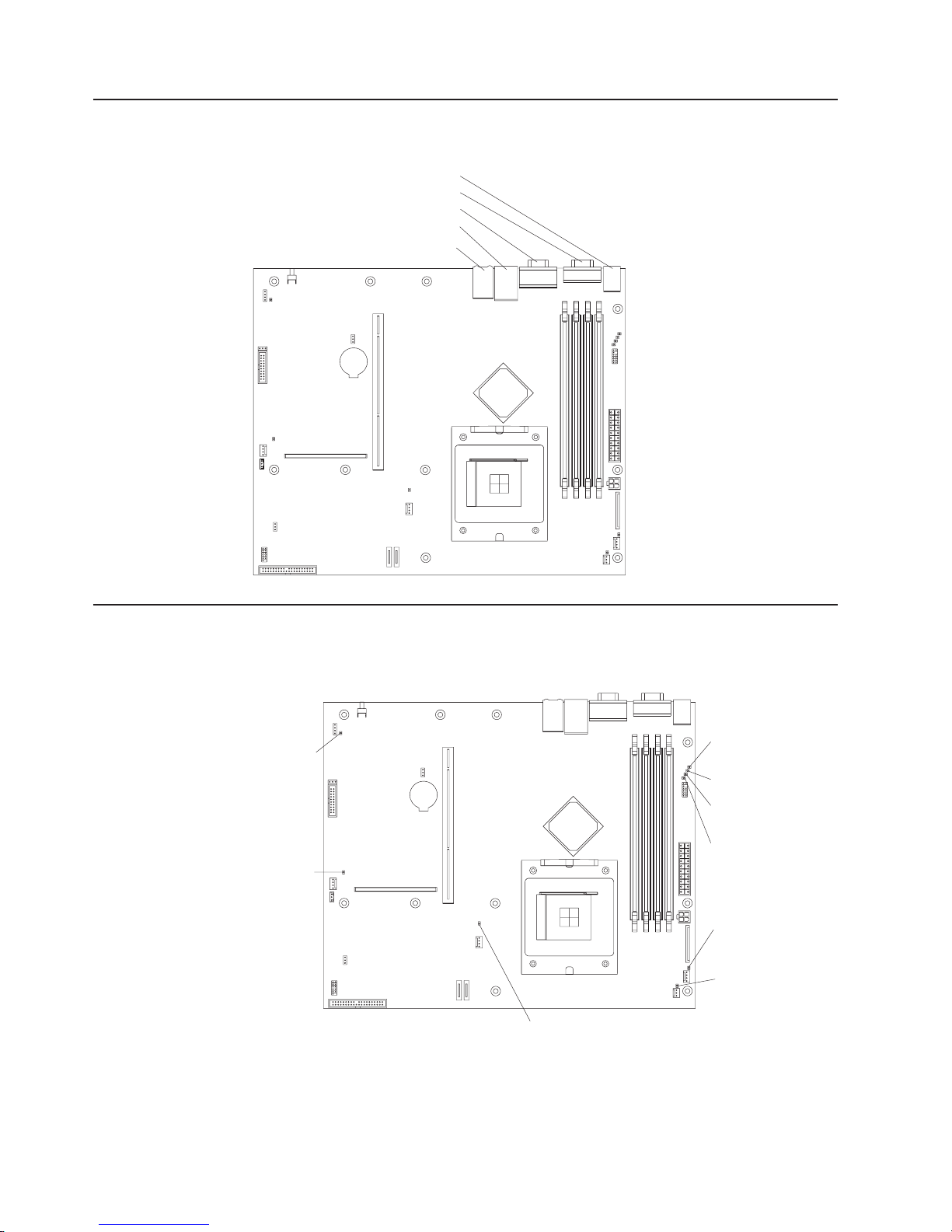
System-board external connectors
The following illustration shows the external connectors on the system board.
Keyboard/mouse connector
Serial connector
Video connector
Ethernet 1/USB connector
Ethernet 2 connector
System-board LEDs
The following illustration shows the light-emitting diodes (LEDs) on the system
board.
Standby
power LED
Fan 1
error LED
DIMM 4
error LED
DIMM 3
error LED
DIMM 2
error LED
DIMM 1
error LED
Fan 3
error LED
Fan 4
error LED
30 xSeries 306 Type 1878, 8489 and 8836: Hardware Maintenance Manual and Troubleshooting Guide
Fan 2
error LED
Page 41

System-board option connectors
The following illustration shows the connectors for user-installable options.
Battery
connector
PCI-X riser
card connector
DIMM 1 slot
DIMM 2 slot
DIMM 3 slot
DIMM 4 slot
The following illustration shows the location of the PCI-X slots on the riser-card
assembly.
PCI-X slot 1
64-bit 3.3 V 66 MHz
PCI-X slot 2
64-bit 3.3 V 66 MHz
Chapter 4. Installing options 31
Page 42

Removing the cover
Complete the following steps to remove the cover:
1. Read the safety information beginning on page 83 and “Installation guidelines”
on page 27.
2. Turn off the server and all attached devices (see “Turning off the server” on
page 9).
Captive screw
3. Disconnect all external cables and the power cord.
4. Loosen the captive screw on the rear of the cover.
5. Slide the cover back and off the server.
Installing an adapter
The following notes describe the types of adapters that your server supports and
other information that you must consider when installing an adapter:
v Locate the documentation that comes with the adapter and follow those
instructions in addition to the instructions in this section. If you need to change
the switch settings or jumper settings on the adapter, follow the instructions that
come with the adapter.
v Your server comes with two peripheral component interconnect-extended (PCI-X)
adapter slots located on the riser-card assembly. You must first remove the
riser-card assembly to access the PCI-X connectors.
v There are two 64-bit 66 MHz PCI-X slots.
v You can install one low profile half-length adapter in expansion slot 1 and one
full-height three-quarter-length adapter in expansion slot 2.
v Your server supports 3.3 V or universal adapters.
v Your server uses a rotational interrupt technique to configure PCI-X adapters so
that you can install PCI-X adapters that do not support sharing of PCI-X
interrupts.
v The server scans PCI-X slots to assign system resources. If you have not
changed the default startup sequence, the server starts devices in the following
order: the CD-ROM and diskette drives first; then, PCI-X slot 2, PCI-X slot 1, and
the integrated Ethernet controllers.
v The optional Remote Supervisor Adapter II can be installed only in PCI-X slot 2.
v You can install an optional RAID controller in your server to control the internal
hard disk drives, for example, to enable you to configure the internal hard disk
32 xSeries 306 Type 1878, 8489 and 8836: Hardware Maintenance Manual and Troubleshooting Guide
Page 43

drives into disk arrays. See your RAID controller option documentation for
complete instructions on installing a RAID controller in your server and for
additional information on RAID controllers.
v The optional ServeRAID-7t SATA controller can be installed only in PCI-X slot 1.
The low-profile bracket that comes with the controller is required to install the
controller.
v The optional ServeRAID-6i+ controller can be installed only in PCI-X slot 1. The
low-profile bracket that comes with the controller is required to install the
controller.
v No rerouting of the internal SCSI cable (SCSI models only) is required if you are
installing the ServeRAID-6i+ controller. The ServeRAID-6i+ controller uses the
SCSI connector (SCSI models only) for output.
Complete
the following steps to install an adapter.
PCI-X slots
Adapter support
bracket
Riser-card
assembly
Adapter
PCI-X riser card
connector
1. Read the safety information beginning on page 83 and “Installation guidelines”
on page 27.
2. Turn off the server and peripheral devices, and disconnect the power cord and
all external cables. Remove the cover (see “Removing the cover” on page 32).
3. Follow the cabling instructions, if any, that come with the adapter. Route the
adapter cables before you install the adapter.
4. Follow the instructions that come with the adapter to set jumpers or switches, if
any.
5. Loosen the captive screw on the rear of the server, and remove the riser-card
assembly. Place the riser-card assembly on a flat, static-protective surface.
Chapter 4. Installing options 33
Page 44

Expansion slot
cover (slot 1)
Expansion slot
cover (slot 2)
Riser-card
assembly
Captive screw
6. Remove the expansion-slot cover.
Attention: PCI expansion-slot covers must be installed on all vacant slots.
This maintains the electronic emissions characteristics of the server and
ensures proper cooling of server components.
7. Touch the static-protective package containing the adapter to any unpainted
metal surface on the server. Then, remove the adapter from the
static-protective package. Avoid touching the components and gold-edge
connectors on the adapter.
8. Place the adapter, component side up, on a flat, static-protective surface and
set any jumpers or switches as described by the adapter manufacturer, if
necessary.
Attention: When you install an adapter, make sure that it is completely and
correctly seated in the PCI expansion slot before you turn on the server.
Incomplete insertion might cause damage to the system board or the adapter.
9. To install the adapter in the riser-card assembly, carefully grasp the adapter by
its top edge or upper corners, and align it with the PCI-X expansion slot; then,
press the adapter firmly into the expansion slot.
10. Reinstall the riser-card assembly. Make sure that the riser-card assembly is
fully seated in the riser-card connector on the system board.
11. Tighten the captive screw on the rear of the server.
If you have other options to install, do so now. Otherwise, go to “Completing the
installation” on page 41.
Installing a hard disk drive
The following notes describe the type of hard disk drive that your server supports
and other information that you must consider when installing a hard disk drive:
v Locate the documentation that comes with the hard disk drive, and follow those
instructions in addition to the instructions in this chapter.
v The server comes with one integrated drive electronics (IDE) CD-ROM drive, one
1.44 MB diskette drive, and one serial advanced technology attachment (ATA) or
SCSI hard disk drive, depending on server model.
v If you are installing a SCSI hard disk drive, see the documentation that comes
with your drive before installing it.
34 xSeries 306 Type 1878, 8489 and 8836: Hardware Maintenance Manual and Troubleshooting Guide
Page 45
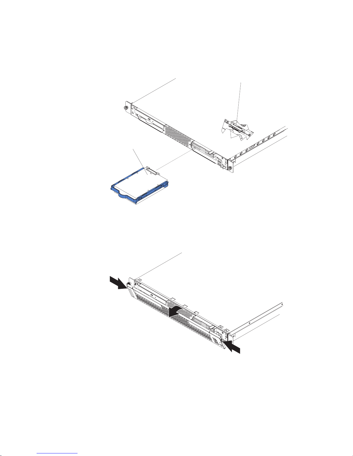
Installing a simple swap Serial ATA hard disk drive
Complete the following steps to install a simple swap Serial ATA hard disk drive.
Note: If you have only one hard disk drive, install it in the left drive bay.
Hard disk drive
SATA hard disk
drive connector
1. Read the safety information beginning on page 83 and “Installation guidelines”
on page 27.
2. Turn off the server and peripheral devices, and disconnect the power cord and
all external cables.
3. Press the release tabs on the bezel, and pull the bezel away from the server.
4. Slide the drive into the server until the drive connects to the backplane.
5. Reinstall the bezel.
If you have other options to install, do so now. Otherwise, go to “Completing the
installation” on page 41.
Chapter 4. Installing options 35
Page 46

Installing a SCSI hard disk drive
Complete the following steps to install a SCSI hard disk drive.
Note: If you have only one hard disk drive, install it in the left drive bay.
Hard disk drive
Screws
Drive tray
Screws
1. Read the safety information beginning on page 83 and “Installation guidelines”
on page 27.
2. Turn off the server and peripheral devices, and disconnect the power cord and
all external cables. Remove the cover (see “Removing the cover” on page 32).
3. Press the release tabs on the bezel, and pull the bezel away from the server.
4. Slide the drive tray out of the server.
5. Position the drive on the drive tray.
6. Secure the drive using the screws that come with the option.
7. Slide the drive tray back into the server.
8. Connect the signal and power cables to the drive.
9. Reinstall the bezel.
36 xSeries 306 Type 1878, 8489 and 8836: Hardware Maintenance Manual and Troubleshooting Guide
Page 47
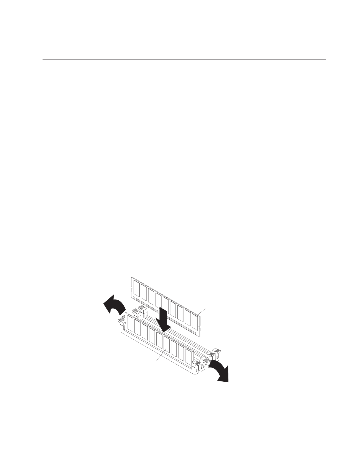
If you have other options to install, do so now. Otherwise, go to “Completing the
installation” on page 41.
Installing a memory module
The following notes describe the type of dual inline memory modules (DIMMs) that
your server supports and other information that you must consider when installing
DIMMs:
v Your server supports 256 MB, 512 MB, and 1 GB DIMMs, for a maximum of 4
GB of system memory. Go to the ServerProven
servers/eserver/serverproven/compat/us/
use with your server.
v The amount of usable memory will be reduced depending on the system
configuration. A certain amount of memory must be reserved for system
resources. The BIOS will display the total amount of installed memory and the
amount of configured memory.
v Your server comes with one 512 MB DIMM installed in DIMM connector 1. If your
system has one DIMM installed, when you install an additional DIMM, it must be
installed in DIMM connector 3, and must be the same size, speed, type, and
technology as the DIMM installed in DIMM connector 1. Yo u can mix compatible
DIMMs from various manufacturers.
v If you install a second pair of DIMMs in DIMM connectors 2 and 4, they do not
have to be the same size, speed, type, and technology as the DIMMs installed in
DIMM connectors 1 and 3. However, the size, speed, type, and technology of the
DIMMs you install in DIMM connectors 2 and 4 must match each other.
v Install only 2.5 V, 184-pin, double-data-rate (DDR), PC2700 or PC3200,
unbuffered synchronous dynamic random-access memory (SDRAM) with error
correcting code (ECC) DIMMs. These DIMMs must be compatible with the latest
PC2700 and PC3200 SDRAM unbuffered DIMM specification.
v When you restart the server, the system displays a message indicating that the
memory configuration has changed.
®
list at http://www.ibm.com/
for a list of memory modules you can
DIMM 3
DIMM 4
Chapter 4. Installing options 37
Page 48

Complete the following steps to install a DIMM:
1. Read the safety information beginning on page 83 and “Installation guidelines”
on page 27.
2. Turn off the server and peripheral devices, and disconnect the power cord and
all external cables. Remove the cover (see “Removing the cover” on page 32).
Attention: To avoid breaking the retaining clips or damaging the DIMM
connectors, open and close the clips gently.
3. Open the retaining clip on each end of the DIMM connector.
4. Touch the static-protective package containing the DIMM to any unpainted metal
surface on the server. Then, remove the DIMM from the package.
5. Turn the DIMM so that the DIMM keys align correctly with the slot.
6. Insert the DIMM into the connector by aligning the edges of the DIMM with the
slots at the ends of the DIMM connector. Firmly press the DIMM straight down
into the connector by applying pressure on both ends of the DIMM
simultaneously. The retaining clips snap into the locked position when the DIMM
is firmly seated in the connector. If there is a gap between the DIMM and the
retaining clips, the DIMM has not been correctly inserted; open the retaining
clips, remove the DIMM, and then reinsert it.
If you have other options to install, do so now. Otherwise, go to “Completing the
installation” on page 41.
Replacing a fan assembly
The server comes with four replaceable fans.
Complete the following steps to replace a fan assembly. Use this procedure to
replace any of the four replaceable fans.
1. Read the safety information beginning on page 83 and “Installation guidelines”
on page 27.
2. Turn off the server and peripheral devices, and disconnect the power cord and
all external cables. Remove the cover (see “Removing the cover” on page 32).
3. Determine which fan to replace by checking the LED at each fan; a lit LED
indicates the fan to replace.
Note: For more information about the LEDs, see “Error LEDs” on page 23.
38 xSeries 306 Type 1878, 8489 and 8836: Hardware Maintenance Manual and Troubleshooting Guide
Page 49

4. Remove the fan from the server:
a. Disconnect the fan cable from the system board.
b. Lift the fan out of the server.
Fan 1
Fan 2
Fan 3
Fan 4
5. Position the replacement fan so that the airflow arrow on the side of the fan is
pointing toward the rear of the server.
Note: Correct airflow is from the front to the rear of the server.
6. Install the replacement fan in the location from which you removed the failed
fan.
7. Connect the replacement fan cable to the system board.
If you have other options to install, do so now. Otherwise, go to “Completing the
installation” on page 41.
Replacing the battery
When replacing the battery, you must replace it with a lithium battery of the same
type from the same manufacturer. To avoid possible danger, read and follow the
safety statement below.
To order replacement batteries, call 1-800-426-7378 within the United States, and
1-800-465-7999 or 1-800-465-6666 within Canada. Outside the U.S. and Canada,
call your IBM reseller or IBM marketing representative.
Note: After you replace the battery, you must reconfigure your system and reset
the system date and time.
Chapter 4. Installing options 39
Page 50

Statement 2:
CAUTION:
When replacing the lithium battery, use only IBM Part Number 33F8354 or an
equivalent type battery recommended by the manufacturer. If your system has
a module containing a lithium battery, replace it only with the same module
type made by the same manufacturer. The battery contains lithium and can
explode if not properly used, handled, or disposed of.
Do not:
v Throw or immerse into water
v Heat to more than 100°C (212°F)
v Repair or disassemble
Dispose
Complete the following steps to replace the battery:
of the battery as required by local ordinances or regulations.
1. Read the safety information beginning on page 83 and follow any special
handling and installation instructions supplied with the replacement battery.
2. Turn off the server and peripheral devices, and disconnect the power cord and
all external cables. Remove the cover (see “Removing the cover” on page 32).
3. Remove the riser-card assembly.
4. Remove the battery:
a. Press the battery release tab to release the battery from the socket.
b. Lift the battery out of the socket.
5. Insert the new battery:
a. Tilt the battery so that you can insert it into the socket.
b. Press down on the battery after you insert it into the socket.
6. Reinstall the riser-card assembly.
7. Reinstall the server cover.
8. Reconnect all external cables and the power cord; then, turn on the peripheral
devices and the server.
9. Start the Configuration/Setup Utility program and set configuration parameters.
v Set the system date and time and the user (power-on) password.
v Reconfigure your server.
40 xSeries 306 Type 1878, 8489 and 8836: Hardware Maintenance Manual and Troubleshooting Guide
Page 51

Completing the installation
Complete the following steps to complete the installation:
1. Reinstall the cover. See “Installing the cover” for more information.
2. Install the server in the rack cabinet. See the Rack Installation Instructions that
come with your server for detailed information about how to install the server in
a rack cabinet.
Attention:
v Install your server only in a rack cabinet with perforated doors.
v Do not leave open space above or below an installed server in the rack
cabinet. To help prevent damage to server components, always install a filler
panel to cover the open space and to help ensure proper air circulation. See
the documentation that comes with the rack cabinet for more information.
Connect the cables and power cords. See “Connecting the cables” for more
3.
information.
4. Update the server configuration. See “Updating the server configuration” on
page 42 for more information.
Attention: For proper cooling and airflow, replace the server cover before or
shortly after turning on the server. Operating the server for extended periods of time
(more than 15 minutes) with the server cover removed might damage server
components.
Installing the cover
To install the cover, place it into position and slide it forward. Then, tighten the
captive screw.
Connecting the cables
The following illustrations show the locations of the input and output connectors on
the front and rear of your server.
Captive screw
Notes:
1. You must turn off the server before connecting or disconnecting cables from
your server.
2. See the documentation that comes with your external devices for additional
cabling instructions. It might be easier for you to route cables before you
connect the devices to the server.
Chapter 4. Installing options 41
Page 52

3. Cable identifiers are printed on the cables that come with your server and
options. Use these identifiers to connect the cables to the correct connectors.
4. If your server comes with an operating system installed, see the documentation
that comes with your software for additional cabling instructions.
5. There is one keyboard connector on the back of the server. Use this connector
to connect the server to a keyboard or optional console switch. You can also
connect a USB keyboard to the server using one of the USB ports. After
installing a USB keyboard, you might need to use the Configuration/Setup Utility
program to enable keyboardless operation and prevent the POST error
message 301 from being displayed during startup. For detailed information
about this option and how to connect it to your server, see the documentation
that comes with the option. If your server cables and connector panel have
color-coded connections, match the color of the cable end with the color of the
connector. For example, match a blue cable end with a blue panel connector, a
red cable end with a red connector, and so on.
Front
USB connectors
Rear
System power
connector
Keyboard
connector
Serial
connector
Mouse
connector
Video
connector
Updating the server configuration
When you start the server for the first time after you add or remove an internal
option or external SCSI device, you might receive a message that the configuration
has changed. The Configuration/Setup Utility program starts automatically so that
you can save the new configuration settings. For more information, see Chapter 2,
“Configuring the xSeries 306 server,” on page 11.
Some options have device drivers that you need to install. See the documentation
that comes with the device for information about installing any required device
drivers.
If the server has a RAID configuration using the SCSI controller with HostRAID
(SCSI models only) or the integrated Serial ATA controller with HostRAID and you
have installed or removed a hard disk drive, you might have to reconfigure your
disk arrays. See the RAID documentation on the Adaptec HostRAID Support CD for
more information about reconfiguring the disk arrays.
Ethernet 1 connector
Ethernet 2 connector
USB connectors
42 xSeries 306 Type 1878, 8489 and 8836: Hardware Maintenance Manual and Troubleshooting Guide
Page 53

If the server has an optional RAID adapter and you have installed or removed a
hard disk drive, see the documentation that comes with the RAID adapter for
information about reconfiguring the disk arrays.
For more information about configuring the integrated Gigabit Ethernet controllers,
see the User’s Guide.
Input/output ports and connectors
Your server has the following input/output (I/O) connectors:
v One auxiliary-device (pointing-device)
v Two Ethernet
v One keyboard
v One serial
v Four Universal Serial Bus (USB)
v One video
following illustration shows the locations of these connectors on the front of the
The
server.
USB connectors
The following illustration shows the locations of these connectors on the rear of the
server.
Keyboard
connector
Serial
connector
The following sections describe these connectors.
Auxiliary-device connector
Use this connector to connect a mouse or other pointing device. The following
illustration shows an auxiliary-device connector.
Mouse
connector
Video
connector
Ethernet 1 connector
Ethernet 2 connector
USB connectors
6
4
1
2
5
3
Chapter 4. Installing options 43
Page 54

Ethernet connectors
The following illustration shows an Ethernet connector.
Activity LED
(green)
Link LED
(green)
Connect a Category 3, 4, or 5 unshielded twisted-pair cable to this connector. The
100BASE-TX/1000BASE-T Fast Ethernet standard requires Category 5 or higher
cabling.
For more information about the Ethernet controllers, see the User’s Guide.
Keyboard connector
Use this connector to connect a PS/2 (non-USB) keyboard to the server. The
following illustration shows a keyboard connector.
If you attach a keyboard to this connector, USB ports and devices are disabled
during POST.
Serial connector
Use a serial connector to connect a serial device. The following illustration shows a
serial connector.
8
6
4
2
1
1
5
3
1
5
Universal Serial Bus connectors
Use a Universal Serial Bus (USB) connector to connect a USB device. USB
technology transfers data at up to 12 Mb per second (Mbps) with a maximum of
127 devices and a maximum signal distance of 5 meters (16 ft.) per segment. Using
Plug and Play technology, USB devices are configured automatically. The following
illustration shows a USB connector.
If you connect a PS/2 (non-USB) keyboard to the keyboard connector, USB ports
and devices are disabled during POST.
Video connector
The integrated video controller provides the video connector. The connector is on
the rear of the server. The following illustration shows a video connector.
69
14
5
1
1115
44 xSeries 306 Type 1878, 8489 and 8836: Hardware Maintenance Manual and Troubleshooting Guide
Page 55

Chapter 5. Service replaceable units
This chapter describes the removal of server components.
Important: The field replaceable unit (FRU) procedures are intended for trained
servicers who are familiar with IBM products. See the parts listing in Chapter 7,
“Parts listing xSeries 306 Type 1878, 8489 and 8836,” on page 75 to determine if
the component being replaced is a customer replaceable unit (CRU) or a FRU.
Removing and replacing a microprocessor
Microprocessor
Microprocessorrelease lever
Complete the following steps to remove a microprocessor.
Note:
v Read “Handling static-sensitive devices” on page 27.
v Read Appendix B, “Safety information,” on page 83.
Turn off the server, and disconnect all power cords and external cables; then,
1.
remove the server cover (see “Removing the cover” on page 32).
2. Remove the air baffle (see “Removing and replacing the air baffle” on page 52).
3. Remove the heat sink:
a. Loosen the screw on each of the two leaf springs on the retention module.
Note: Loosening one screw fully before loosening the other screw will help
to break the thermal bond that adheres the heat sink to the microprocessor.
b. Pivot the leaf-spring enclosure outward.
c. Gently twist the heat sink until you break the thermal bond, and pull the heat
sink away from the retention module and the microprocessor.
Important:
Be careful when handling the thermal bond material on the
processor. If the thermal bond material on the processor will be reused, do not
contaminate it. If replacement thermal bond material is provided with the
replacement part, be sure to remove all traces of existing thermal bond material
from the processor before applying the new thermal bond material.
4. Open the release lever of the microprocessor socket.
5. Pull the microprocessor out of the socket.
install a microprocessor, reverse the previous steps.
To
© Copyright IBM Corp. 2004 45
Page 56
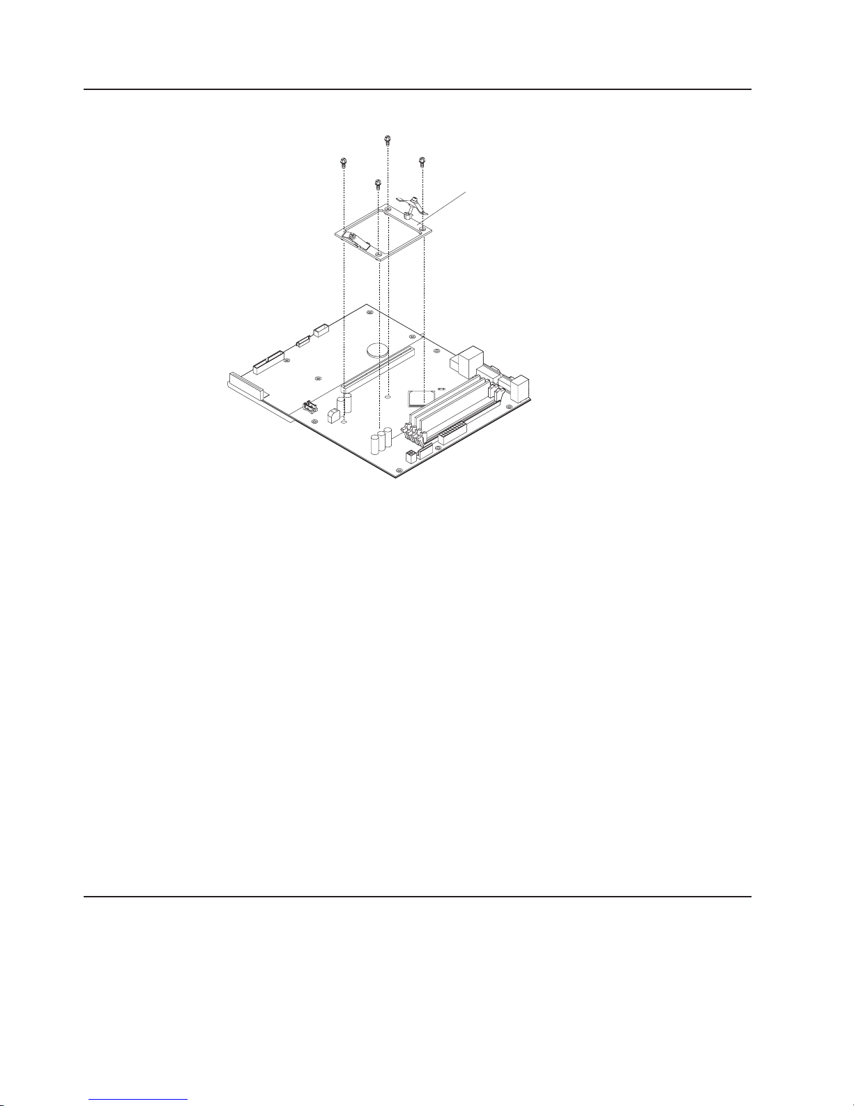
Removing and replacing the retention module
Retention module
Complete the following steps to remove the retention module.
Note:
v Read “Installation guidelines” on page 27.
v Read Appendix B, “Safety information,” on page 83.
v Read “Handling static-sensitive devices” on page 27.
1. Turn off the server, and disconnect all power cords and external cables; then,
remove the server cover (see “Removing the cover” on page 32).
2. Remove the air baffle (see “Removing and replacing the air baffle” on page 52).
3. Remove the heat sink:
a. Loosen the screw on each of the two leaf springs on the retention module.
Note: Loosening one screw fully before loosening the other screw will help
to break the thermal bond that adheres the heat sink to the microprocessor.
b. Pivot the leaf-spring enclosure outward.
c. Gently twist the heat sink until you break the thermal bond, and pull the heat
sink away from the retention module and the microprocessor.
Loosen the four screws on the corners of the retention module, and lift the
4.
retention module out of the server.
install a retention module, reverse the previous steps.
To
Removing and replacing the system board
Important: When replacing the system board, you must:
v Either update the firmware to the latest level, or restore the pre-existing firmware
that the customer provides on a diskette or CD.
v Update the UUID (see “Updating the UUID” on page 26).
v Update the DMI/SMBIOS (see “Updating the DMI/SMBIOS data” on page 26).
46 xSeries 306 Type 1878, 8489 and 8836: Hardware Maintenance Manual and Troubleshooting Guide
Page 57

System board
(4 screws)
Retention module
(4 screws)
System board
(5 screws)
Complete the following steps to remove the system board.
Note:
v Read “Installation guidelines” on page 27.
v Read Appendix B, “Safety information,” on page 83.
v Read “Handling static-sensitive devices” on page 27.
1. Turn off the server, and disconnect all power cords and external cables; then,
remove the server cover (see “Removing the cover” on page 32).
2. Remove the air baffle (see “Removing and replacing the air baffle” on page 52).
3. Remove all adapters, and place them on a static-protective surface for
reinstallation (see “Installing an adapter” on page 32).
4. Remove all DIMMs, and place them on a static-protective surface for
reinstallation (see “Installing a memory module” on page 37).
5. Disconnect all cables from the system board.
6. Remove the microprocessor and the retention module, and place them on a
static-protective surface for reinstallation (see “Removing and replacing a
microprocessor” on page 45 and “Removing and replacing the retention module”
on page 46).
7. Remove the screws that secure the system board with the chassis, and put the
screws in a safe place.
8. Lift the system board out of the server.
Chapter 5. Service replaceable units 47
Page 58

To reinstall the system board, align the system board with the chassis, and replace
the screws that you removed in step 7. Replace all components, including the
retention module and microprocessor, in the reverse order from which they were
removed.
Note: When reassembling the components in the server, be sure to route all cables
carefully so that they are not exposed to excessive pressure.
Removing and replacing the switch/LED/USB card
Switch/LED/USB
card
Complete the following steps to remove the Switch/LED/USB card.
Note:
v Read “Installation guidelines” on page 27.
v Read Appendix B, “Safety information,” on page 83.
v Read “Handling static-sensitive devices” on page 27.
1. Turn off the server, and disconnect all power cords and external cables; then,
remove the server cover (see “Removing the cover” on page 32).
2. Disconnect the cables from the switch/LED/USB card.
3. Loosen the screws on the switch/LED/USB card, and remove the card.
install the switch/LED/USB card, reverse the previous steps.
To
48 xSeries 306 Type 1878, 8489 and 8836: Hardware Maintenance Manual and Troubleshooting Guide
Page 59

Removing and replacing a power supply
Power supply
Captive screw
Complete the following steps to remove the power supply.
Note:
v Read “Installation guidelines” on page 27.
v Read Appendix B, “Safety information,” on page 83.
v Read “Handling static-sensitive devices” on page 27.
Turn off the server, and disconnect all power cords and external cables; then,
1.
remove the server cover (see “Removing the cover” on page 32).
2. Disconnect the cables near the power supply.
3. Loosen the captive screw that secures the power supply to the chassis.
4. Lift the power supply out of the server.
install the power supply, reverse the previous steps.
To
Chapter 5. Service replaceable units 49
Page 60

Removing and replacing the PCI riser card
Riser-card
assembly
Complete the following steps to remove the PCI riser card.
Riser card
Note:
v Read “Installation guidelines” on page 27.
v Read Appendix B, “Safety information,” on page 83.
v Read “Handling static-sensitive devices” on page 27.
1. Turn off the server, and disconnect all power cords and external cables; then,
remove the server cover (see “Removing the cover” on page 32).
2. Loosen the captive screw that secures the power supply to the chassis.
3. Remove the PCI riser-card assembly from the server.
4. Remove the screws from the PCI riser card.
50 xSeries 306 Type 1878, 8489 and 8836: Hardware Maintenance Manual and Troubleshooting Guide
Page 61

Removing and replacing the fans
Fan 1
Fan 2
Fan 3
Fan 4
The server comes with six replaceable fans. Complete the following steps to
replace a fan assembly.
Note:
v Read “Installation guidelines” on page 27.
v Read Appendix B, “Safety information,” on page 83.
v Read “Handling static-sensitive devices” on page 27.
Turn off the server, and disconnect all power cords and external cables; then,
1.
remove the server cover (see “Removing the cover” on page 32).
2. Determine which fan to replace by checking the LED at each fan; a lit LED
indicates the fan to replace.
Note:
a. When the fans 2 and 3 error LED is lit, it indicates fan 2 or fan 3 has failed
or is operating too slowly. Replace both fans, if the LED is lit.
b. When the Fans 4 and 5 error LED is lit, it indicates fan 4 or fan 5 has failed
or is operating too slowly. Replace both fans, if the LED is lit.
c. For more information about the LEDs, see “System-board LEDs” on page
30.
Disconnect the fan cable from the system board.
3.
4. Lift the fan out of the server, noting its orientation in the server.
install a fan, orient the fan so that the airflow arrow on the side of the fan is
To
facing or pointing toward the rear of the server; then, insert the fan in the fan cage.
Connect the fan cable to the system board.
Chapter 5. Service replaceable units 51
Page 62

Removing and replacing the air baffle
Air baffle
Complete the following steps to remove the air baffle.
Note:
v Read “Installation guidelines” on page 27.
v Read Appendix B, “Safety information,” on page 83.
v Read “Handling static-sensitive devices” on page 27.
Turn off the server, and disconnect all power cords and external cables; then,
1.
remove the server cover (see “Removing the cover” on page 32).
2. Grasp the air baffle on each side, and lift the air baffle from the server.
install the air baffle, reverse the previous steps.
To
52 xSeries 306 Type 1878, 8489 and 8836: Hardware Maintenance Manual and Troubleshooting Guide
Page 63

Chapter 6. Symptom-to-FRU index
The symptom-to-FRU index lists symptoms, errors, and the possible causes. The
most likely cause is listed first. Use this symptom-to-FRU index to help you decide
which FRUs to have available when servicing the server.
Notes:
1. Check the configuration before you replace a FRU. Configuration problems can
cause false errors and symptoms.
2. For IBM devices not supported by this index, refer to the manual for that device.
3. Always start with “General checkout” on page 17.
4. Some tables have more than two columns; in those instances, more than one
column on the left is required to describe the error symptom. Take the action (or
replace the FRU) suggested first in the list of the right-hand column, then try the
server again to see if the problem has been corrected before taking further
action.
5. Always try reseating a suspected component or reconnecting a cable before
replacing the component.
The left-hand column of the tables in this index lists error codes or messages, and
the right-hand column lists one or more suggested actions or FRUs to replace.
The POST BIOS code displays POST error codes and messages on the screen.
Beep symptoms
Beep symptoms are short tones or a series of short tones separated by pauses
(intervals without sound). See the examples in the following table.
Beeps Description
1-2-3
4 Four continuous beeps
One beep after successfully completing POST indicates that the server is
functioning correctly.
Note: See Chapter 7, “Parts listing xSeries 306 Type 1878, 8489 and 8836,” on page 75 to determine which
components are replaceable by the customer, and which components must be replaced by a field service technician.
Beep/symptom FRU/action
1-1-3
(CMOS write/read test failed)
1-1-4
(BIOS EEPROM checksum failed)
1-2-1
(Programmable Interval Timer failed)
v One beep
v A pause (or break)
v Two beeps
v A pause (or break)
v Three beeps
1. Battery
2. System board
System board
System board
© Copyright IBM Corp. 2004 53
Page 64

Note: See Chapter 7, “Parts listing xSeries 306 Type 1878, 8489 and 8836,” on page 75 to determine which
components are replaceable by the customer, and which components must be replaced by a field service technician.
Beep/symptom FRU/action
1-2-2
System board
(DMA initialization failed)
1-2-3
System board
(DMA page register write/read failed)
1-3-1
(first 64K RAM test failed)
1-3-2
(first 64K RAM test failed)
2-1-1
1. DIMM
2. System board
1. DIMM
2. System board
System board
(Secondary DMA register failed)
2-1-2
System board
(Primary DMA register failed)
2-1-3
System board
(Primary interrupt mask register
failed)
2-1-4
System board
(Secondary interrupt mask register
failed)
2-2-2
(Keyboard controller failed)
2-2-3
(CMOS power failure and checksum
checks failed)
2-4-1
1. Keyboard
2. System board
1. Battery
2. System board
System board
(Video failed; system believed
operable)
3-1-1
System board
(Timer tick interrupt failed)
3-1-2
System board
(Interval timer channel 2 failed)
3-1-3
(RAM test failed above address
OFFFFH))
3-1-4
(Time-of-Day clock failed)
3-2-1
1. DIMM
2. System board
1. Battery
2. System board
System board
(Serial port failed)
3-2-2
System board
(Parallel port failed)
3-2-4
(Failure comparing CMOS memory
size against actual)
1. DIMM
2. Battery
3. System board
54 xSeries 306 Type 1878, 8489 and 8836: Hardware Maintenance Manual and Troubleshooting Guide
Page 65

Note: See Chapter 7, “Parts listing xSeries 306 Type 1878, 8489 and 8836,” on page 75 to determine which
components are replaceable by the customer, and which components must be replaced by a field service technician.
Beep/symptom FRU/action
3-3-1
(Memory size mismatch occurred.)
1. DIMM
2. Battery
3. System board
3-3-2
(I2C bus error occurred)
3-3-3
(No memory installed)
1. Disconnect server power, wait 30 seconds, and try again.
2. System board
1. Install or reseat the memory modules.
2. DIMMs.
3. System board.
No-beep symptoms
Note: See Chapter 7, “Parts listing xSeries 306 Type 1878, 8489 and 8836,” on page 75 to determine which
components are replaceable by the customer, and which components must be replaced by a field service technician.
No-beep symptom FRU/action
No beep during POST. System board
POST error codes
In the following error codes, x can be any number or letter.
Note: See Chapter 7, “Parts listing xSeries 306 Type 1878, 8489 and 8836,” on page 75 to determine which
components are replaceable by the customer, and which components must be replaced by a field service technician.
Error code/symptom FRU/action
062
(Three consecutive startup failures using
the default configuration.)
101, 102
(System and processor error)
106
(System and processor error)
114
(Adapter read-only memory error.)
151
(Real time clock error)
161
(Real time clock battery error)
1. Run the Configuration/Setup Utility program.
2. Battery.
3. System board.
4. Microprocessor.
System board
System board
1. Run diagnostics.
2. Adapter
1. Battery
2. System board
1. Run the Configuration/Setup Utility program.
2. Battery.
3. System board.
Chapter 6. Symptom-to-FRU index 55
Page 66

Note: See Chapter 7, “Parts listing xSeries 306 Type 1878, 8489 and 8836,” on page 75 to determine which
components are replaceable by the customer, and which components must be replaced by a field service technician.
Error code/symptom FRU/action
162
(Device configuration error)
Note: Be sure to load the default settings
and any additional desired settings; then,
save the configuration.
163
(Real-time clock error)
1. Run the Configuration/Setup Utility program.
2. Battery.
3. Failing device.
4. System board.
1. Run the Configuration/Setup Utility program.
2. Battery.
3. System board.
164
(Memory configuration changed.)
1. Run the Configuration/Setup Utility program.
2. DIMM.
3. System board.
176
Run the Configuration/Setup Utility program.
(Computer cover or cable cover removed
without use of key.)
184
(Power-on password damaged)
185
1. Run the Configuration/Setup Utility program.
2. System board.
Run the Configuration/Setup Utility program.
(Drive startup sequence information
damaged.)
187
(VPD serial number not set.)
188
(Bad EEPROM CRC #2)
189
(An attempt was made to access the
1. Set serial number in the Configuration/Setup Utility program.
2. System board.
1. Run the Configuration/Setup Utility program.
2. System board.
Run the Configuration/Setup Utility program, and enter the
administrator password.
server with invalid passwords)
201
(Memory test error.) If the server does not
have the latest level of BIOS installed,
1. DIMM
2. System board
update the BIOS to the latest level and run
the diagnostic program again.
289
(DIMM disabled by POST or user)
1. Run the Configuration/Setup Utility program, if the DIMM was
disabled by the user.
2. Disabled DIMM, if not disabled by user.
3. System board
301
(Keyboard or keyboard controller error)
303
1. Keyboard
2. System board
System board
(Keyboard controller error)
602
(Invalid diskette boot record)
1. Diskette
2. Diskette drive
3. Cable
4. System board
56 xSeries 306 Type 1878, 8489 and 8836: Hardware Maintenance Manual and Troubleshooting Guide
Page 67

Note: See Chapter 7, “Parts listing xSeries 306 Type 1878, 8489 and 8836,” on page 75 to determine which
components are replaceable by the customer, and which components must be replaced by a field service technician.
Error code/symptom FRU/action
604
(Diskette drive error.)
1. Run the Configuration/Setup Utility program.
2. Diskette drive
3. Cable
4. System board
662
(Diskette drive configuration error)
1. Run the Configuration/Setup Utility program and diagnostics.
2. Diskette drive.
3. Drive cable.
4. System board.
962
(Parallel port error)
1. Disconnect the external cable on the parallel port.
2. Run the Configuration/Setup Utility program.
3. System board.
1162
(Serial port configuration conflicts)
1. Run the Configuration/Setup Utility program and ensure that the
IRQ and I/O port assignments needed by the serial port are
available.
2. If all interrupts are being used by adapters, remove an adapter or
force other adapters to share an interrupt.
1762
(Hard disk configuration error)
1. Hard disk drive.
2. Hard disk drive cables.
3. Run the Configuration/Setup Utility program.
4. SCSI backplane.
5. System board.
1800
(No more hardware interrupts available for
PCI adapter)
1801
(No more hardware interrupts available for
PCI adapter)
1. Run the Configuration/Setup Utility program.
2. Remove the adapter.
1. Run the Configuration/Setup Utility program.
2. Remove the adapter.
3. Disable the adapter BIOS, and run the Configuration/Setup Utility
program.
1962
(Drive does not contain a valid boot
sector)
1. Verify that a startable operating system is installed.
2. Run diagnostics.
3. Hard disk drive.
4. SCSI backplane.
5. Cable.
6. System board.
5962
(IDE CD-ROM drive configuration error)
1. Run the Configuration/Setup Utility program.
2. CD-ROM drive.
3. CD-ROM power cable.
4. IDE cable.
5. System board.
6. Battery.
8603
(Pointing-device error)
1. Pointing device
2. System board
Chapter 6. Symptom-to-FRU index 57
Page 68

Note: See Chapter 7, “Parts listing xSeries 306 Type 1878, 8489 and 8836,” on page 75 to determine which
components are replaceable by the customer, and which components must be replaced by a field service technician.
Error code/symptom FRU/action
0001200
(Machine check architecture error)
1. Microprocessor 1
2. Optional microprocessor 2
3. System board
00019701
(Microprocessor failed BIST)
00180200
(No more I/O space available for PCI
adapter.)
1. Microprocessor
2. System board
1. Run the Configuration/Setup Utility program.
2. Adapter.
3. System board.
00180300
(No more memory above 1 MB for PCI
adapter.)
1. Run the Configuration/Setup Utility program.
2. Adapter.
3. System board.
00180500
(PCI option ROM checksum error.)
00180600
(PCI device BIST failure.)
1. PCI adapter.
2. System board.
1. Run the Configuration/Setup Utility program.
2. Adapter.
3. System board.
00180700
(PCI device not responding.)
00181000
(No more I/O space available for PCI
adapter.)
I9990650
(AC power has been restored)
1. System board
2. Adapter
1. Adapter
2. System board
1. Check cable.
2. Check for interruption of power.
3. Power cable.
Diagnostic error codes
Note: In the following error codes, if XXX is 000, 195, or 197, do not replace a
FRU. The description for these error codes are:
000 The test passed.
195 The Esc key was pressed to stop the test.
197 Warning; a hardware failure did not occur. The test could not be run due to
some other problem.
all error codes, replace the FRU or take the action indicated.
For
58 xSeries 306 Type 1878, 8489 and 8836: Hardware Maintenance Manual and Troubleshooting Guide
Page 69

Note: See Chapter 7, “Parts listing xSeries 306 Type 1878, 8489 and 8836,” on page 75 to determine which
components are replaceable by the customer, and which components must be replaced by a field service technician.
Error code/symptom FRU/action
001-250-000
System board
(Failed system board ECC)
001-250-001
System board
(Failed system board ECC)
001-XXX-000
System board
(Failed core tests)
001-XXX-001
System board
(Failed core tests)
005-XXX-000
(Failed video test)
011-XXX-000
(Failed COM1 serial port test)
1. Video adapter (if installed)
2. System board
1. Check loopback plug connected to externalized serial port.
2. Check cable from externalized port to system board.
3. System board.
011-XXX-001
(Failed COM2 serial port test)
1. Check loopback plug connected to externalized serial port.
2. Check cable from externalized port to system board.
3. System board.
014-XXX-000
System board
(Failed parallel port test)
015-XXX-001
System board
(USB interface not found, board damaged)
015-XXX-015
(Failed USB external loopback test)
1. Make sure the parallel port is not disabled.
2. Run the USB external loopback test again.
3. System board.
015-XXX-198 (Remote Supervisor Adapter
II installed or USB device connected during
USB test)
1. If Remote Supervisor Adapter II is installed as an option,
remove it and rerun test.
Note: If Remote Supervisor Adapter II is present as a standard
installation, do not remove it; the test cannot be run.
2. Remove USB devices and rerun test.
3. System board.
020-XXX-000
System board
(Failed PCI interface test)
030-XXX-00N
If N=0, SCSI daughter card; if N>0, SCSI adapter in slot N.
(Failed SCSI interface test)
035-253-s99
(RAID adapter initialization failure)
1. ServeRAID adapter in slot s is not configured properly. Obtain
the basic and extended configuration status and see the ServeRAID
Hardware Maintenance Manual for more information.
2. Cable.
3. Adapter.
035-XXX-099
If adapter is installed re-check connection.
(No adapters were found.)
035-XXX-s99
(Failed RAID test on PCI slot s. s = number
of failing PCI slot.)
1. RAID adapter
2. Cable
3. System board
Chapter 6. Symptom-to-FRU index 59
Page 70

Note: See Chapter 7, “Parts listing xSeries 306 Type 1878, 8489 and 8836,” on page 75 to determine which
components are replaceable by the customer, and which components must be replaced by a field service technician.
Error code/symptom FRU/action
035-XXX-snn
Hard disk drive with SCSI ID nn on RAID adapter in PCI slot s.
(s = number of failing PCI slot, nn = SCSI
ID of failing fixed disk.)
089-XXX-001
(Failed microprocessor test)
1. Make sure that microprocessor 1 is installed and seated
correctly.
2. Make sure that BIOS code is at latest level.
3. Microprocessor 1.
4. System board.
089-XXX-002
(Failed optional microprocessor test)
1. Make sure that microprocessor 2 is installed and seated
correctly.
2. Make sure that BIOS code is at latest level.
3. Microprocessor 2.
4. System board.
201-XXX-0nn
(Failed memory test.)
1. DIMM Location slots 1-4 where nn = DIMM location.
Note: nn 1=DIMM 1; 2=DIMM 2; 3=DIMM 3; 4=DIMM 4.
2. System board.
201-XXX-999
(Multiple DIMM failure, see error text)
202-XXX-001
(Failed system cache test)
1. See error text for failing DIMMs.
2. System board.
1. Make sure that microprocessor 1 is installed and seated
correctly.
2. Make sure that BIOS code is at latest level.
3. Microprocessor 1.
4. System board.
202-XXX-002
(Failed system cache test)
1. Make sure that microprocessor 2 is installed and seated
correctly.
2. Make sure that BIOS code is at latest level.
3. Microprocessor 2.
4. System board.
206-XXX-000
(Failed diskette drive test)
1. Rerun the test using another diskette.
2. Cable.
3. Diskette drive.
4. System board.
215-XXX-000
(Failed IDE CD-ROM drive test)
1. Rerun the test using another CD-ROM.
2. CD-ROM drive cables.
3. CD-ROM drive.
4. System board.
217-198-XXX
(Could not establish drive parameters)
1. Check cable and termination.
2. DASD backplane.
3. SCSI daughter card
4. Hard disk drive.
60 xSeries 306 Type 1878, 8489 and 8836: Hardware Maintenance Manual and Troubleshooting Guide
Page 71

Note: See Chapter 7, “Parts listing xSeries 306 Type 1878, 8489 and 8836,” on page 75 to determine which
components are replaceable by the customer, and which components must be replaced by a field service technician.
Error code/symptom FRU/action
217-XXX-00n
(Failed hard disk drive test)
Note: If RAID is configured, the hard disk
drive number refers to the RAID logical
1. Hard disk drive n
2. SCSI card
3. DASD backplane
array.
301-XXX-000
(Failed keyboard test)
302-XXX-000
(Failed mouse test)
405-XXX-000
(Failed Ethernet test on controller on the
system board)
405-XXX-00n
(Failed Ethernet test on adapter in PCI slot
n)
1. Keyboard
2. System board
1. Mouse
2. System board
1. Make sure that Ethernet is not disabled in BIOS.
2. System board.
1. For n=0, system board
2. For n>0, adapter in PCI slot n
3. System board
405-XXX-a0n
(Failed Ethernet test on adapter in PCI slot
a)
415-XXX-000
(Failed Modem test)
Note: Error message may indicate modem
is not supported.
1. For a = 0, system board
2. For a > 0, adapter in PCI slot a
1. Cable
Note: Ensure modem is present and attached to server.
2. Modem
3. System board
System board LED errors
Note: See Chapter 7, “Parts listing xSeries 306 Type 1878, 8489 and 8836,” on page 75 to determine which
components are replaceable by the customer, and which components must be replaced by a field service technician.
LED FRU/action
DIMM x
Standby power
Note: Normal operation is
indicated when this LED is lit and
the server is connected to an ac
power source. A problem is
indicated if the LED is not lit
when connected to ac power.
System fan 2
System fan 1
Microprocessor
1. DIMM x
2. System board
1. Power supply
2. System board
1. Fan 2
2. System board
1. Fan 1
2. System board
1. Microprocessor
2. System board
Chapter 6. Symptom-to-FRU index 61
Page 72

Error symptoms
You can use the error symptom table to find solutions to problems that have definite
symptoms.
If you cannot find the problem in the error symptom charts, go to “Starting the
diagnostic programs and viewing the test log” on page 21 to test the server.
If you have just added new software or a new option and the server is not working,
use the following procedures before using the error symptom charts:
v Remove the software or device that you just added.
v Run the diagnostic tests to determine whether the server is running correctly.
v Reinstall the new software or new device.
the following table, if the entry in the FRU/action column is a suggested action,
In
perform that action; if it is the name of a component, reseat the component and
replace it if necessary. The most likely cause of the symptom is listed first.
Note: See Chapter 7, “Parts listing xSeries 306 Type 1878, 8489 and 8836,” on page 75 to determine which
components are replaceable by the customer, and which components must be replaced by a field service technician.
CD-ROM drive problems
Symptom FRU/action
CD-ROM drive is not
recognized.
1. Make sure that:
v The IDE channel to which the CD-ROM drive is attached (primary or
secondary) is enabled in the Configuration/Setup Utility program.
v All cables and jumpers are installed correctly.
v The correct device driver is installed for the CD-ROM drive.
Run CD-ROM drive diagnostics.
2.
3. CD-ROM drive.
Note: See Chapter 7, “Parts listing xSeries 306 Type 1878, 8489 and 8836,” on page 75 to determine which
components are replaceable by the customer, and which components must be replaced by a field service technician.
Expansion enclosure problems
Symptom FRU/action
The SCSI expansion enclosure
used to work but does not work
now.
1. Make sure that:
v The cables for all external SCSI options are connected correctly.
v The last option in each SCSI chain, or the end of the SCSI cable, is
terminated correctly.
v Any external SCSI option is turned on. You must turn on an external SCSI
option before turning on the server.
For more information, see the SCSI expansion enclosure documentation.
2.
Note: See Chapter 7, “Parts listing xSeries 306 Type 1878, 8489 and 8836,” on page 75 to determine which
components are replaceable by the customer, and which components must be replaced by a field service technician.
Hard disk drive problems
Symptom FRU/action
Not all drives are recognized by
the hard disk drive diagnostic
test (Fixed Disk test).
1. Remove the first drive not recognized and try the hard disk drive
diagnostic test again.
2. If the remaining drives are recognized, replace the drive you removed with a
new one.
62 xSeries 306 Type 1878, 8489 and 8836: Hardware Maintenance Manual and Troubleshooting Guide
Page 73

Note: See Chapter 7, “Parts listing xSeries 306 Type 1878, 8489 and 8836,” on page 75 to determine which
components are replaceable by the customer, and which components must be replaced by a field service technician.
Hard disk drive problems
Symptom FRU/action
System stops responding during
hard disk drive diagnostic test.
1. Remove the hard disk drive being tested when the server stopped
responding and try the diagnostic test again.
2. If the hard disk drive diagnostic test runs successfully, replace the drive you
removed with a new one.
Note: See Chapter 7, “Parts listing xSeries 306 Type 1878, 8489 and 8836,” on page 75 to determine which
components are replaceable by the customer, and which components must be replaced by a field service technician.
General problems
Symptom FRU/action
Problems such as broken cover
Broken CRU/FRU
locks or indicator LEDs not
working
Note: See Chapter 7, “Parts listing xSeries 306 Type 1878, 8489 and 8836,” on page 75 to determine which
components are replaceable by the customer, and which components must be replaced by a field service technician.
Intermittent problems
Symptom FRU/action
A problem occurs only
occasionally and is difficult to
detect.
1. Make sure that:
v All cables and cords are connected securely to the rear of the server and
attached options.
v When the server is turned on, air is flowing from the rear of the server at the
fan grill. If there is no airflow, the fan is not working. This causes the server
to overheat and shut down.
v Ensure that the SCSI bus and devices are configured correctly and that the
last external device in each SCSI chain is terminated correctly.
Check the system error log.
2.
Note: See Chapter 7, “Parts listing xSeries 306 Type 1878, 8489 and 8836,” on page 75 to determine which
components are replaceable by the customer, and which components must be replaced by a field service technician.
Symptom FRU/action
All or some keys on the
keyboard do not work.
The mouse or pointing device
does not work.
Keyboard, mouse, or pointing-device problems
1. Make sure that:
v The keyboard cable is securely connected to the system, and the keyboard
and mouse cables are not reversed.
v The server and the monitor are turned on.
Keyboard.
2.
3. System board.
1. Make sure that:
v The mouse or pointing-device cable is securely connected, and that the
keyboard and mouse cables are not reversed.
v The mouse device drivers are installed correctly.
Mouse or pointing device.
2.
3. System board.
Chapter 6. Symptom-to-FRU index 63
Page 74

Note: See Chapter 7, “Parts listing xSeries 306 Type 1878, 8489 and 8836,” on page 75 to determine which
components are replaceable by the customer, and which components must be replaced by a field service technician.
Memory problems
Symptom FRU/action
The amount of system memory
displayed is less than the
amount of physical memory
installed.
1. Make sure that:
v The memory modules are seated properly.
v Yo u have installed the correct type of memory.
v If you changed the memory, you updated the memory configuration with the
Configuration/Setup Utility program.
v All banks of memory on the DIMMs are enabled. The server might have
automatically disabled a DIMM bank when it detected a problem or a DIMM
bank could have been manually disabled.
2.
Check POST error log for error message 289:
v If the DIMM was disabled by a system-management interrupt (SMI), replace
the DIMM.
v If the DIMM was disabled by the user or by POST:
a. Start the Configuration/Setup Utility program.
b. Enable the DIMM.
c. Save the configuration and restart the server.
DIMM.
3.
4. System board.
Note: See Chapter 7, “Parts listing xSeries 306 Type 1878, 8489 and 8836,” on page 75 to determine which
components are replaceable by the customer, and which components must be replaced by a field service technician.
Microprocessor problems
Symptom FRU/action
The server emits a continuous
tone during POST. (The startup
(boot) microprocessor is not
1. Make sure that the startup microprocessor is seated properly.
2. Startup microprocessor.
working properly.)
Note: See Chapter 7, “Parts listing xSeries 306 Type 1878, 8489 and 8836,” on page 75 to determine which
components are replaceable by the customer, and which components must be replaced by a field service technician.
Monitor problems
Symptom FRU/action
Testing the monitor. See the information that comes with the monitor for adjusting and testing
instructions. (Some IBM monitors have their own self-tests.)
64 xSeries 306 Type 1878, 8489 and 8836: Hardware Maintenance Manual and Troubleshooting Guide
Page 75

Note: See Chapter 7, “Parts listing xSeries 306 Type 1878, 8489 and 8836,” on page 75 to determine which
components are replaceable by the customer, and which components must be replaced by a field service technician.
Monitor problems
Symptom FRU/action
The screen is blank.
1. Make sure that:
v The server power cord is plugged into the server and a working electrical
outlet.
v The monitor cables are connected properly.
v The monitor is turned on and the Brightness and Contrast controls are
adjusted correctly.
v If the servers are C2T chained together, verify that:
– The C2T chain cables are securely connected to the servers.
– The C2T breakout cable is connected properly.
– A server that is turned on is selected.
Important:
In some memory configurations, the 3-3-3 beep code might sound
during POST followed by a blank display screen. If this occurs and the Boot
Fail Count feature in the Start Options of the Configuration/Setup Utility
program is set to Enabled (its default setting), you must restart the server three
times to force the system BIOS to reset the CMOS values to the default
configuration (memory connector or bank of connectors enabled).
2. Make sure that damaged BIOS code is not affecting the video; see “Updating
BIOS code” on page 23.
3. If you have verified these items and the screen remains blank, replace:
a. Monitor
b. Video adapter, if installed
c. System board
Only the cursor appears. See “Undetermined problems” on page 73.
The monitor works when you
turn on the server but goes
blank when you start some
application programs.
1. Make sure that:
v The application program is not setting a display mode higher than the
capability of the monitor.
v The primary monitor cable is connected to the C2T device breakout cable.
v Yo u installed the necessary device drivers for the applications.
If you have verified these items and the screen remains blank, replace the
2.
monitor.
The screen is wavy, unreadable,
rolling, distorted, or has screen
jitter.
1. If the monitor self-tests show the monitor is working properly, consider
the location of the monitor. Magnetic fields around other devices (such as
transformers, appliances, fluorescent lights, and other monitors) can cause
screen jitter or wavy, unreadable, rolling, or distorted screen images. If this
happens, turn off the monitor. (Moving a color monitor while it is turned on
might cause screen discoloration.) Then move the device and the monitor at
least 305 mm (12 in.) apart. Turn on the monitor.
Notes:
a. To prevent diskette drive read/write errors, be sure the distance between
monitors and diskette drives is at least 76 mm (3 in.).
b. Non-IBM monitor cables might cause unpredictable problems.
c. An enhanced monitor cable with additional shielding is available for the
9521 and 9527 monitors. For information about the enhanced monitor
cable, contact your IBM reseller or IBM marketing representative.
Video adapter, if installed.
2.
3. System board.
Chapter 6. Symptom-to-FRU index 65
Page 76

Note: See Chapter 7, “Parts listing xSeries 306 Type 1878, 8489 and 8836,” on page 75 to determine which
components are replaceable by the customer, and which components must be replaced by a field service technician.
Monitor problems
Symptom FRU/action
Wrong characters appear on the
screen.
1. If the wrong language is displayed, update the BIOS code with the correct
language.
2. Video adapter, if installed.
3. System board.
Note: See Chapter 7, “Parts listing xSeries 306 Type 1878, 8489 and 8836,” on page 75 to determine which
components are replaceable by the customer, and which components must be replaced by a field service technician.
Option problems
Symptom FRU/action
An IBM option that was just
installed does not work.
1. Make sure that:
v The option is designed for the server (see the ServerProven list at
http://www.ibm.com/servers/eserver/serverproven/compat/us/).
v Yo u followed the installation instructions that came with the option.
v The option is installed correctly.
v Yo u have not loosened any other installed options or cables.
v Yo u updated the configuration information in the Configuration/Setup Utility
program. Whenever memory or an option is changed, you must update the
configuration.
Option you just installed.
2.
An IBM option that used to work
does not work now.
1. Make sure that all of the option hardware and cable connections are
secure.
2. If the option comes with its own test instructions, use those instructions to test
the option.
3. If the failing option is a SCSI option, verify that:
v The cables for all external SCSI options are connected correctly.
v The last option in each SCSI chain, or the end of the SCSI cable, is
terminated correctly.
v Any external SCSI option is turned on. You must turn on an external SCSI
option before turning on the server.
4.
Failing option.
Note: See Chapter 7, “Parts listing xSeries 306 Type 1878, 8489 and 8836,” on page 75 to determine which
components are replaceable by the customer, and which components must be replaced by a field service technician.
Symptom FRU/action
The server does not turn on.
1. Make sure that:
2.
3.
66 xSeries 306 Type 1878, 8489 and 8836: Hardware Maintenance Manual and Troubleshooting Guide
Power problems
v The power cables are properly connected to the server.
v The electrical outlet functions properly.
v The type of memory installed is correct.
v If you just installed an option, remove it, and restart the server. If the server
now turns on, you might have installed more options than the power supply
supports.
If LEDs for microprocessors or VRMs are on, verify that:
a. A VRM is installed if a second microprocessor is present.
b. All microprocessors have the same speed.
See “Undetermined problems” on page 73.
Page 77

Note: See Chapter 7, “Parts listing xSeries 306 Type 1878, 8489 and 8836,” on page 75 to determine which
components are replaceable by the customer, and which components must be replaced by a field service technician.
Power problems
Symptom FRU/action
The server does not turn off.
1. Verify whether you are using an ACPI or non-ACPI operating system. If
you are using a non-ACPI operating system:
a. Press Ctrl+Alt+Delete.
b. Turn off the system by holding the power-control button for 4 seconds.
c. If server fails during BIOS POST and power-control button does not work,
remove the AC power cord.
2.
If the problem remains or if you are using an ACPI-aware operating system,
suspect the system board.
Note: See Chapter 7, “Parts listing xSeries 306 Type 1878, 8489 and 8836,” on page 75 to determine which
components are replaceable by the customer, and which components must be replaced by a field service technician.
Serial port problems
Symptom FRU/action
The number of serial ports
identified by the operating
system is less than the number
of serial ports installed.
A serial device does not work.
1. Make sure that:
v Each port is assigned a unique address by the Configuration/Setup Utility
program and none of the serial ports is disabled.
v The serial-port adapter, if you installed one, is seated properly.
Failing serial port adapter.
2.
1. Make sure that:
v The device is compatible with the server.
v The serial port is enabled and is assigned a unique address.
v The device is connected to the correct port (see “Input/output ports and
connectors” on page 43).
Failing serial device.
2.
3. Serial adapter, if installed.
4. System board.
Note: See Chapter 7, “Parts listing xSeries 306 Type 1878, 8489 and 8836,” on page 75 to determine which
components are replaceable by the customer, and which components must be replaced by a field service technician.
Symptom FRU/action
Suspected software problem.
Software problem
1. To determine if problems are caused by the software, verify that:
v The server has the minimum memory needed to use the software. For
memory requirements, see the information that comes with the software.
Note: If you have just installed an adapter or memory, you might have a
memory address conflict.
v The software is designed to operate on the server.
v Other software works on the server.
v The software that you are using works on another system.
If you received any error messages when using the software program, see the
information that comes with the software for a description of the messages and
suggested solutions to the problem.
2. If you have verified these items and the problem remains, contact your place of
purchase.
Chapter 6. Symptom-to-FRU index 67
Page 78

Service processor error codes
When viewed from POST, service processor (baseboard management controller)
error codes will appear in hexadecimal form (generally beginning with A2, A3, A4,
A5, A6, A7, AD, AE, or E1), unless a Remote Supervisor Adapter is installed.
However, when viewed from the System Error Log, the messages will appear as
text. To determine a possible error condition for the service processor, see the
System Error log (see “Starting the diagnostic programs and viewing the test log”
on page 21).
ServeRAID error codes
In the following error codes, x can be any number or letter.
Note: See Chapter 7, “Parts listing xSeries 306 Type 1878, 8489 and 8836,” on page 75 to determine which
components are replaceable by the customer, and which components must be replaced by a field service technician.
Error code/symptom FRU/action
1xxx (Microcode checksum error) ServeRAID controller
2xxx (Code DRAM error)
3000-31xx (Code DRAM error)
3200 (Code DRAM error)
3300 (ServeRAID-5i only) Install ServeRAID-5i controller in an extended PCI
3E20 (ServeRAID-5i only)
3E2x
4xxx thru 5xxx (Code DRAM error)
6xxx (Cache DRAM error)
(ServeRAID-4H only)
1. Install download jumpers, flash latest level BIOS
and firmware for controller. Remove jumpers.
2. ServeRAID controller.
1. Install download jumpers, flash latest level BIOS
and firmware for controller. Remove jumpers.
2. ServeRAID controller.
1. Install download jumpers, flash latest level BIOS
code and firmware for controller. Remove
jumpers.
2. ServeRAID controller.
expansion slot. See the documentation that came with
the server for more information.
1. Remove the ServeRAID-5i controller from its slot
and install it in the proper PCI option slot.
2. Verify that the ServeRAID-5i controller is supported in
this server.
3. ServeRAID-5i controller.
4. System board.
1. Reseat the ServeRAID controller.
2. Flash latest level of BIOS code and firmware for
controller.
3. ServeRAID-5i controller.
4. Integrated RAID controller on serve).
1. Install download jumpers, flash latest level BIOS
code and firmware for controller; then, remove
jumpers.
2. ServeRAID controller.
1. Reseat daughter card.
2. Install download jumpers, flash latest level BIOS code
and firmware for controller; then, remove jumpers.
3. ServeRAID controller.
68 xSeries 306 Type 1878, 8489 and 8836: Hardware Maintenance Manual and Troubleshooting Guide
Page 79

Note: See Chapter 7, “Parts listing xSeries 306 Type 1878, 8489 and 8836,” on page 75 to determine which
components are replaceable by the customer, and which components must be replaced by a field service technician.
Error code/symptom FRU/action
7xxx thru 8xxx (Host/local PCI bus interface error)
1. Flash latest level of BIOS code and firmware for
controller.
2. If ServeRAID-4x controller, replace controller.
3. If ServeRAID-5i controller, integrated RAID controller
on the server.
9003
1. Flash latest level of BIOS code and firmware for
controller.
2. Confirm that this controller is a supported option for
this system.
3. ServeRAID controller.
4. Integrated RAID controller on the server).
9xxx thru BZxx (SCSI bus error caused by cables,
termination, defective drives, etc.). Z refers to the specific
channel or channels that cause the error.
1. Follow indications at “POST (ISPR) error
procedures.” Follow those instructions before
continuing with the next steps listed in this index.
2. SCSI cable.
3. SCSI backplane.
4. Hard disk drive.
5. ServeRAID controller.
EFFE (Firmware code corrupt or download jumpers are in
place)
1. Flash latest level BIOS and firmware for
controller; then, remove jumpers.
2. ServeRAID controller.
FFFF or other code not listed
1. Follow instructions at “POST (ISPR) error
procedures.”
2. SCSI cable.
3. SCSI backplane.
4. Hard disk drive.
5. ServeRAID controller.
POST (ISPR) error procedures
Use the ISPR error procedures to help you solve ServeRAID problems. A complete
list of error codes is listed at “ServeRAID error codes” on page 68.
Note: Where the ISPR error procedures refer to a SCSI backplane, see the
chapter of this publication that concerns service replaceable units.
EF10 (Default ISPR)
1. No ISPR error present.
Chapter 6. Symptom-to-FRU index 69
Page 80

9Zxx thru BZxx (SCSI bus error caused by cables, termination, defective drives, or
similar problem)
1. Isolate between SCSI subsystem and controller by disconnecting all SCSI
cables from suspect card, and restart.
Attention: Do not press F5. Doing so changes the server configuration.
If an ISPR error is still present, perform the following actions until the error is no
longer present:
a. Reseat the controller
b. Replace the controller
Notes:
a. SCSI channel cable details, if any, appear elsewhere in this publication.
b. The adapter/controller detects a configuration change. Do not select Save
Changes. Instead, press F10 to bypass any options to this effect.
If ISPR error is EF10 after disconnecting cables:
2.
a. Identify which channel is causing the error by the second digit (Z) of the
original ISPR code as indicated in the following table.
Note: ServeRAID-4H controllers have 4 channels; ServeRAID-4L and -4Lx
controllers have only one channel; and ServeRAID-4M and -4Mx controllers
have 2 channels. ServeRAID-5i controllers have no channels. The
ServeRAID-5i uses the channel connectors of the onboard integrated SCSI
controller.
Table 2. SCSI identifier
SCSI Channel Code (z) Descriptions
1 Channel 1
2 Channel 2
3 Channel 1 and 2
4 Channel 3
5 Channel 1 and 3
6 Channel 2 and 3
7 Channel 1, 2, and 3
8 Channel 4
9 Channel 1 and 4
A Channel 2 and 4
B Channel 1, 2, and 4
C Channel 3 and 4
D Channel 1, 3, and 4
E Channel 2, 3, and 4
F Channel 1, 2, 3, and 4
b. Confirm that the channels identified from the error in step 2a are the cause
of the error by verifying that the error presents itself only when the offending
channel is reconnected.
70 xSeries 306 Type 1878, 8489 and 8836: Hardware Maintenance Manual and Troubleshooting Guide
Page 81

c. Check termination of identified channel.
Note: SCSI channel termination details, if any, appear elsewhere in this
publication.
d. Check for proper backplane jumper configuration.
Note: SCSI channel jumper details, if any, appear elsewhere in this
publication.
e. Check for proper cabling configuration in systems that use DASD status
cables. Reconnect all cables removed in step 1 on page 70.
f. Disconnect one drive at a time attached to the channel identified in step 2a
on page 70; then, restart to determine which drive is causing the error.
g. Replace SCSI cable.
h. Replace SCSI backplane.
FFFF or other code not listed
1. Place download jumpers on the controller and try to flash the firmware code to
the card.
2. Isolate between SCSI subsystem and controller by disconnecting all SCSI
cables attached to the suspect card, and restart.
Attention: Do not press F5. Doing so changes the server configuration.
If ISPR code is EF10 after disconnecting cables, follow these steps until the
error is eliminated:
a. Identify which channel is causing the error by reconnecting cables one at a
time and restarting until the error returns.
b. Check termination of identified channel in step 2a.
Note: SCSI channel termination details, if any, appear elsewhere in this
publication.
c. Disconnect one drive at a time attached to channel identified in step 2a and
restart each time to determine which drive is causing the problem.
d. Replace SCSI cable attached to channel identified in step 2a.
e. Replace backplane attached to channel identified in step 2a.
If original ISPR code is still present after disconnecting all SCSI cables and
3.
restarting, perform the following actions until the error is no longer present:
v Reseat the controller
v Replace the controller
Chapter 6. Symptom-to-FRU index 71
Page 82

SCSI error codes
Error code FRU/action
All SCSI Errors One or more of the
following might be causing the problem:
v A failing SCSI device
(adapter, drive, controller)
v An improper SCSI configuration or SCSI
termination jumper setting
v Duplicate SCSI IDs in the same SCSI
chain
v A missing or improperly installed SCSI
terminator
1. External SCSI devices must be turned on before you turn on
the server.
2. Make sure that the cables for all external SCSI devices are
connected correctly.
3. If you have attached an external SCSI device to the server, make
sure the external SCSI termination is set to automatic.
4. Make sure that the last device in each SCSI chain is terminated
correctly.
5. Make sure that the SCSI devices are configured correctly.
v A defective SCSI terminator
v An improperly installed cable
v A defective cable
ServerGuide problems
The following table lists problem symptoms and suggested solutions.
Table 3. ServerGuide Setup and Installation CD
Symptom Suggested action
The ServerGuide Setup and
Installation CD will not start.
v Make sure that the server supports the ServerGuide program and has a
startable (bootable) CD-ROM (or DVD-ROM) drive.
v If the startup (boot) sequence settings have been altered, make sure that the
CD-ROM drive is first in the startup sequence.
v If more than one CD-ROM drive is installed, ensure that only one drive is set as
the primary drive. Start the CD from the primary drive.
The SCSI RAID program cannot
view all installed drives, or the
v Make sure that there are no duplicate SCSI IDs or IRQ assignments.
v Make sure that the hard disk drive is connected correctly.
operating system cannot be
installed.
The operating-system
Make more space available on the hard disk.
installation program
continuously loops.
The ServerGuide program will
not start the operating-system
CD.
The operating system cannot be
installed; the option is not
available.
Make sure that the operating-system CD is supported by the ServerGuide program.
See the ServerGuide Setup and Installation CD label for a list of operating-system
versions that support the ServerGuide program.
Make sure that the operating system is supported on your server. If the operating
system is supported, either there is no logical drive defined (SCSI RAID systems)
or the ServerGuide System Partition is not present. Run the ServerGuide program
and make sure that setup is complete.
72 xSeries 306 Type 1878, 8489 and 8836: Hardware Maintenance Manual and Troubleshooting Guide
Page 83

Undetermined problems
Use the information in this section if the diagnostic tests did not diagnose the
failure, the devices list is incorrect, or the server is inoperative.
Damaged data in CMOS memory or damaged BIOS code can cause undetermined
problems. To reset the CMOS data, use the CMOS recovery jumper to override the
power-on password and clear the CMOS memory; see “Erasing a lost or forgotten
password (clearing CMOS memory)” on page 25. If you suspect that the BIOS code
is damaged, see “Updating BIOS code” on page 23.
Check the LEDs on all the power supplies. If the LEDs indicate the power supplies
are working correctly, complete the following steps:
1. Turn off the server.
2. Make sure that the server is cabled correctly.
3. Remove or disconnect the following devices (one at a time) until you find the
failure (turn on the server and reconfigure each time):
v Any external devices
v Surge suppressor device (on the server)
v Modem, printer, mouse, or non-IBM devices
v Each adapter
v Drives
v Memory modules (minimum requirement = two 512 MB DIMMs)
Note: Minimum operating requirements are:
a. Power supply
b. System board
c. One microprocessor
d. Memory (with a minimum of two 512 MB DIMMs)
4. Turn on the server. If the problem remains, suspect the following FRUs in the
order listed:
v Power supply
v System board
Notes:
1. If the problem goes away when you remove an adapter from the system and
replacing that adapter does not correct the problem, suspect the system board.
2. If you suspect a networking problem and all the system tests pass, suspect a
network cabling problem external to the system.
Chapter 6. Symptom-to-FRU index 73
Page 84

Problem determination tips
Because of the variety of hardware and software combinations that can be
encountered, use the following information to assist you in problem determination. If
possible, have this information available when requesting assistance from Service
Support and Engineering functions.
v Machine type and model
v Microprocessor or hard disk upgrades
v Failure symptom
– Do diagnostics fail?
– What message appears in the diagnostics log?
– What, when, where, single, or multiple servers?
– Is the failure repeatable?
– Has this configuration ever worked?
– If it has been working, what changes were made before it failed?
– Is this the original reported failure?
Diagnostics version
v
– Type and version level
Hardware configuration
v
– Print (print screen) configuration currently in use
– BIOS level
v Operating system software
– Type and version level
To eliminate confusion, identical systems are considered identical only if
Note:
they:
v Are the exact machine type and models
v Have the same BIOS level
v Have the same adapters/attachments in the same locations
v Have the same address jumpers/terminators/cabling
v Have the same software versions and levels
v Have the same diagnostics code (version)
v Have the same configuration options set in the system
v Have the same setup for the operation system control files
Comparing
the configuration and software setup between working and non-working
servers will often lead to problem resolution.
74 xSeries 306 Type 1878, 8489 and 8836: Hardware Maintenance Manual and Troubleshooting Guide
Page 85

Chapter 7. Parts listing xSeries 306 Type 1878, 8489 and 8836
This parts listing supports the xSeries 306 Type 1878, 8489 and 8836. To check for
an updated parts listing on the Web, complete the following steps:
1. Go to http://www.ibm.com/support.
2. Under Search technical support, type 1878, 8489, or 8836 and click Search.
3. Under Document type, select Parts information and click Go.
1
2
3
4
13
5
12
11
10
9
8
6
7
© Copyright IBM Corp. 2004 75
Page 86

Server
Note: Field replaceable units (FRUs) must be serviced only by qualified field
service technicians. Customer replaceable units (CRUs) can be replaced by the
customer.
Index Server (xSeries 306, Type 1878, 8489, and 8836) FRU No. CRU/FRU
1 To p cover (all models) 26K4157 CRU
2 PCI-X riser card (all models) 26K3052 FRU
3 Power supply, 300 watt (all models) 26K4106 FRU
4 Memory, 512 PC 2700 ECC (all models) 06P4061 CRU
4 Memory, 512 PC 3200 ECC (models 31x, 35x, 41x, 45x, 99x) 06P4057 CRU
4 Memory, 256 PC 3200 ECC (option, all models) 06P4056 CRU
4 Memory, 1 GB PC 3200 ECC (option, all models) 06P4058 CRU
4 Memory, 1 GB PC 2700 ECC (option, all models) 06P4062 CRU
5 System board (all models) 13M8136 FRU
6 Diskette drive, 12.7 black (primary, all models) 39M0105 CRU
6 Diskette drive, 12.7 black (alternate, all models) 36L8645 CRU
7 LED board (all models) 26K4107 CRU
8 Front bezel assembly (all models) 26K4115 CRU
9 Hard disk drive, 36.4 GB SCSI (8836 models 11x, 21x, 31x, 41x) 24P3704 CRU
9 Hard disk drive, 36.4 GB SCSI (option, all models) 24P3725 CRU
9 Hard disk drive, 73.4 GB SCSI (model 99x) (option all models) 24P3706 CRU
9 Hard disk drive, 73.4 GB SCSI (option, all models) 24P3727 CRU
9 Hard disk drive, 80 GB SCSI (option, all models) 73P8000 CRU
9 Hard disk drive, 160 GB SCSI (option, all models) 73P8001 CRU
9 Hard disk drive, 146.8 GB SCSI (option, all models) 24P3708 CRU
9 Hard disk drive, 160 GB SATA (option, all models) 71P7297 CRU
10 CD-ROM drive, 24X (primary, all models) 39M3505 CRU
10 CD-ROM drive, 24X (alternate, all models) 33P3231 CRU
10 CD-ROM drive, 24X (alternate, all models) 26K5423 CRU
10 CD-RW/DVD drive (option, all models) 71P7359 CRU
10 CD-RW drive, slim (option, all models) 26K5439 CRU
10 DVD drive (option, all models) 39M3531 CRU
10 DVD drive, 12.7 mm (option, all models) 39M3525 CRU
11 Fan assembly, 40 mm (all models) 26K4281 CRU
12 Chassis (all models) 39Y8997 FRU
13 Heat sink, microprocessor 26K4116 FRU
Air baffle (all models) 26K4113 CRU
Battery, 3.0 volt lithium 33F8354 FRU
Bracket, SATA (models 15x, 25x, 35x, 45x) 26K4130 CRU
Cable, diskette drive (all models) 26K4110 CRU
CD-ROM adapter (all models) 26K4150 FRU
Cable, IDE (all models) 26K4111 CRU
Cable, panel mount (models 15x, 25x, 35x, 45x) 13N2413 CRU
Cable, SCSI signal (models 11x, 21x, 31x, 41x, 99x) 26K4118 CRU
Cable, USB and LED (all models) 26K4109 FRU
Fan bracket (all models) 26K4148 CRU
Heat sink retention module (all models) 24P4811 CRU
Kit, 1U toolless (all models) 24P1121 FRU
LED board (all models) 26K4107 CRU
Microprocessor, 2.8 GHz (8836 models 11x, 15x) 02R8743 FRU
Microprocessor, 3.0 GHz (8836 models 21x, 25x) 02R8742 FRU
Microprocessor, 3.2 GHz (1878 model 99x; 8836 models 31x, 35x) 02R8741 FRU
Microprocessor, 3.2 GHz (models 41x, 45x) 26K8430 FRU
76 xSeries 306 Type 1878, 8489 and 8836: Hardware Maintenance Manual and Troubleshooting Guide
Page 87

Index Server (xSeries 306, Type 1878, 8489, and 8836) FRU No. CRU/FRU
Miscellaneous parts kit (all models)
26K4131 FRU
v Bezel, blank (1)
v Bezel, diskette drive blank (1)
v Bezel, PCI blank (2)
v Heat sink (1)
v Screw, M 3x4 flat (4)
v Screw, M 3x5 pan (10)
v Screw, M 3.5x6 (4)
v Screw, M 3.5 steel (6)
v Screw, M 3x5 slotted (2)
v Screw, M 4x10 flat (2)
v Screw, M 4x5 pan (4)
v Spring, CD (2)
v Spring, diskette drive (2)
Power cord; see “Power cords” on page 78. (all models) 6952300 CRU
SATA RAID card, 4-port (option, all models) 71P8650 CRU
Riser card assembly (all models) 26K4149 FRU
SCSI adapter (models 11x, 21x, 31x, 41x, 99x) 26K3051 CRU
System service label (all models) 26K4158 FRU
Keyboard CRUs
Keyboard CRU No.
US English 83P8300
Arabic 83P8301
Belgium/French 83P8302
Belgium/UK 83P8303
Brazil/Portuguese 83P8304
Bulgarian 83P8305
Chinese/US 83P8306
Czech 83P8307
Danish 83P8308
Dutch 83P8309
French 83P8310
French Canadian (445) 83P8311
French Canadian (058) 83P8312
German 83P8313
Greek 83P8314
Hebrew 83P8315
Hungarian 83P8316
Iceland 83P8317
Italy 83P8319
Japanese 83P8320
Korean 83P8321
LA Spanish 83P8322
Norwegian 83P8323
Polish 83P8324
Portuguese 83P8325
Romanian 83P8326
Russian 83P8327
Serbian/Cyrllic 83P8328
Chapter 7. Parts listing xSeries 306 Type 1878, 8489 and 8836 77
Page 88

Keyboard CRU No.
Slovic 83P8329
Spanish 83P8330
Swedish/Finn 83P8331
Swiss, F/G 83P8332
Thailand 83P8333
Turkish (440) 83P8334
Turkish (179) 83P8335
UK English 83P8336
US English-EMEA 83P8337
Yugoslav/Lat 83P8338
Power cords
For your safety, IBM provides a power cord with a grounded attachment plug to use
with this IBM product. To avoid electrical shock, always use the power cord and
plug with a properly grounded outlet.
IBM power cords used in the United States and Canada are listed by Underwriter’s
Laboratories (UL) and certified by the Canadian Standards Association (CSA).
For units intended to be operated at 115 volts: Use a UL-listed and CSA-certified
cord set consisting of a minimum 18 AWG, Type SVT or SJT, three-conductor cord,
a maximum of 15 feet in length and a parallel blade, grounding-type attachment
plug rated 15 amperes, 125 volts.
For units intended to be operated at 230 volts (U.S. use): Use a UL-listed and
CSA-certified cord set consisting of a minimum 18 AWG, Type SVT or SJT,
three-conductor cord, a maximum of 15 feet in length and a tandem blade,
grounding-type attachment plug rated 15 amperes, 250 volts.
For units intended to be operated at 230 volts (outside the U.S.): Use a cord set
with a grounding-type attachment plug. The cord set should have the appropriate
safety approvals for the country in which the equipment will be installed.
IBM power cords for a specific country or region are usually available only in that
country or region.
IBM power cord part
number Used in these countries and regions
13F9940 Argentina, Australia, China (PRC), New Zealand, Papua New
Guinea, Paraguay, Uruguay, Western Samoa
13F9979 Afghanistan, Algeria, Andorra, Angola, Austria, Belgium, Benin,
Bulgaria, Burkina Faso, Burundi, Cameroon, Central African Rep.,
Chad, China (Macau S.A.R.), Czech Republic, Egypt, Finland,
France, French Guiana, Germany, Greece, Guinea, Hungary,
Iceland, Indonesia, Iran, Ivory Coast, Jordan, Lebanon,
Luxembourg, Malagasy, Mali, Martinique, Mauritania, Mauritius,
Monaco, Morocco, Mozambique, Netherlands, New Caledonia,
Niger, Norway, Poland, Portugal, Romania, Senegal, Slovakia,
Spain, Sudan, Sweden, Syria, Togo, Tunisia, Turkey, former
USSR, Vietnam, former Yugoslavia, Zaire, Zimbabwe
13F9997 Denmark
14F0015 Bangladesh, Burma, Pakistan, South Africa, Sri Lanka
78 xSeries 306 Type 1878, 8489 and 8836: Hardware Maintenance Manual and Troubleshooting Guide
Page 89

IBM power cord part
number Used in these countries and regions
14F0033 Antigua, Bahrain, Brunei, Channel Islands, China (Hong Kong
S.A.R.), Cyprus, Dubai, Fiji, Ghana, India, Iraq, Ireland, Kenya,
Kuwait, Malawi, Malaysia, Malta, Nepal, Nigeria, Polynesia, Qatar,
Sierra Leone, Singapore, Tanzania, Uganda, United Kingdom,
Yemen, Zambia
14F0051 Liechtenstein, Switzerland
14F0069 Chile, Ethiopia, Italy, Libya, Somalia
14F0087 Israel
1838574 Thailand
6952300 Bahamas, Barbados, Bermuda, Bolivia, Brazil, Canada, Cayman
Islands, Colombia, Costa Rica, Dominican Republic, Ecuador, El
Salvador, Guatemala, Guyana, Haiti, Honduras, Jamaica, Japan,
Korea (South), Liberia, Mexico, Netherlands Antilles, Nicaragua,
Panama, Peru, Philippines, Saudi Arabia, Suriname, Taiwan,
Trinidad (West Indies), United States of America, Venezuela
Chapter 7. Parts listing xSeries 306 Type 1878, 8489 and 8836 79
Page 90

80 xSeries 306 Type 1878, 8489 and 8836: Hardware Maintenance Manual and Troubleshooting Guide
Page 91

Appendix A. Getting help and technical assistance
If you need help, service, or technical assistance or just want more information
about IBM products, you will find a wide variety of sources available from IBM to
assist you. This appendix contains information about where to go for additional
information about IBM and IBM products, what to do if you experience a problem
with your xSeries or IntelliStation
necessary.
Before you call
Before you call, make sure that you have taken these steps to try to solve the
problem yourself:
v Check all cables to make sure that they are connected.
v Check the power switches to make sure that the system is turned on.
v Use the troubleshooting information in your system documentation, and use the
diagnostic tools that come with your system. Information about diagnostic tools is
in the Hardware Maintenance Manual and Troubleshooting Guide on the IBM
xSeries Documentation CD or in the IntelliStation Hardware Maintenance Manual
at the IBM Support Web site.
v Go to the IBM Support Web site at http://www.ibm.com/pc/support/ to check for
technical information, hints, tips, and new device drivers or to submit a request
for information.
®
system, and whom to call for service, if it is
can solve many problems without outside assistance by following the
You
troubleshooting procedures that IBM provides in the online help or in the
publications that are provided with your system and software. The information that
comes with your system also describes the diagnostic tests that you can perform.
Most xSeries and IntelliStation systems, operating systems, and programs come
with information that contains troubleshooting procedures and explanations of error
messages and error codes. If you suspect a software problem, see the information
for the operating system or program.
Using the documentation
Information about your IBM xSeries or IntelliStation system and preinstalled
software, if any, is available in the documentation that comes with your system.
That documentation includes printed books, online books, readme files, and help
files. See the troubleshooting information in your system documentation for
instructions for using the diagnostic programs. The troubleshooting information or
the diagnostic programs might tell you that you need additional or updated device
drivers or other software. IBM maintains pages on the World Wide Web where you
can get the latest technical information and download device drivers and updates.
To access these pages, go to http://www.ibm.com/pc/support/ and follow the
instructions. Also, you can order publications through the IBM Publications Ordering
System at http://www.elink.ibmlink.ibm.com/public/applications/publications/cgibin/
pbi.cgi.
© Copyright IBM Corp. 2004 81
Page 92

Getting help and information from the World Wide Web
On the World Wide Web, the IBM Web site has up-to-date information about IBM
xSeries and IntelliStation products, services, and support. The address for IBM
xSeries information is http://www.ibm.com/eserver/xseries/. The address for IBM
IntelliStation information is http://www.ibm.com/pc/intellistation/.
You can find service information for your IBM products, including supported options,
at http://www.ibm.com/pc/support/.
Software service and support
Through IBM Support Line, you can get telephone assistance, for a fee, with usage,
configuration, and software problems with xSeries servers, IntelliStation
workstations, and appliances. For information about which products are supported
by Support Line in your country or region, go to http://www.ibm.com/services/sl/
products/.
For more information about Support Line and other IBM services, go to
http://www.ibm.com/services/, or go to http://www.ibm.com/planetwide/ for support
telephone numbers. In the U.S. and Canada, call 1-800-IBM-SERV
(1-800-426-7378).
Hardware service and support
You can receive hardware service through IBM Integrated Technology Services or
through your IBM reseller, if your reseller is authorized by IBM to provide warranty
service. Go to http://www.ibm.com/planetwide/ for support telephone numbers, or in
the U.S. and Canada, call 1-800-IBM-SERV (1-800-426-7378).
In the U.S. and Canada, hardware service and support is available 24 hours a day,
7 days a week. In the U.K., these services are available Monday through Friday,
from 9 a.m. to 6 p.m.
82 xSeries 306 Type 1878, 8489 and 8836: Hardware Maintenance Manual and Troubleshooting Guide
Page 93

Appendix B. Safety information
Note: The service procedures are designed to help you isolate problems. They are
written with the assumption that you have model-specific training on all computers,
or that you are familiar with the computers, functions, terminology, and service
information provided in this manual.
The following section contains the safety information that you need to be familiar
with before servicing an IBM computer.
General safety
Follow these rules to ensure general safety:
v Observe good housekeeping in the area of the machines during and after
maintenance.
v When lifting any heavy object:
1. Ensure you can stand safely without slipping.
2. Distribute the weight of the object equally between your feet.
3. Use a slow lifting force. Never move suddenly or twist when you attempt to
lift.
4. Lift by standing or by pushing up with your leg muscles; this action removes
the strain from the muscles in your back. Do not attempt to lift any objects
that weigh more than 16 kg (35 lb) or objects that you think are too heavy for
you.
Do not perform any action that causes hazards to the customer, or that makes
v
the equipment unsafe.
v Before you start the machine, ensure that other service representatives and the
customer’s personnel are not in a hazardous position.
v Place removed covers and other parts in a safe place, away from all personnel,
while you are servicing the machine.
v Keep your tool case away from walk areas so that other people will not trip over
it.
v Do not wear loose clothing that can be trapped in the moving parts of a machine.
Ensure that your sleeves are fastened or rolled up above your elbows. If your
hair is long, fasten it.
v Insert the ends of your necktie or scarf inside clothing or fasten it with a
nonconductive clip, approximately 8 centimeters (3 inches) from the end.
v Do not wear jewelry, chains, metal-frame eyeglasses, or metal fasteners for your
clothing.
Remember: Metal objects are good electrical conductors.
v Wear safety glasses when you are: hammering, drilling soldering, cutting wire,
attaching springs, using solvents, or working in any other conditions that might be
hazardous to your eyes.
v After service, reinstall all safety shields, guards, labels, and ground wires.
Replace any safety device that is worn or defective.
v Reinstall all covers correctly before returning the machine to the customer.
© Copyright IBM Corp. 2004 83
Page 94

Electrical safety
CAUTION:
Electrical current from power, telephone, and communication cables can be
hazardous. To avoid personal injury or equipment damage, disconnect the
attached power cords, telecommunication systems, networks, and modems
before you open the server covers, unless instructed otherwise in the
installation and configuration procedures.
Observe the following rules when working on electrical equipment.
Important: Use only approved tools and test equipment. Some hand tools have
handles covered with a soft material that does not insulate you when working with
live electrical currents.
Many customers have, near their equipment, rubber floor mats that contain small
conductive fibers to decrease electrostatic discharges. Do not use this type of mat
to protect yourself from electrical shock.
v Find the room emergency power-off (EPO) switch, disconnecting switch, or
electrical outlet. If an electrical accident occurs, you can then operate the switch
or unplug the power cord quickly.
v Do not work alone under hazardous conditions or near equipment that has
hazardous voltages.
v Disconnect all power before:
– Performing a mechanical inspection
– Working near power supplies
– Removing or installing main units
v Before you start to work on the machine, unplug the power cord. If you cannot
unplug it, ask the customer to power-off the wall box that supplies power to the
machine and to lock the wall box in the off position.
v If you need to work on a machine that has exposed electrical circuits, observe
the following precautions:
– Ensure that another person, familiar with the power-off controls, is near you.
Remember: Another person must be there to switch off the power, if
necessary.
– Use only one hand when working with powered-on electrical equipment; keep
the other hand in your pocket or behind your back.
Remember: There must be a complete circuit to cause electrical shock. By
observing the above rule, you may prevent a current from passing through
your body.
– When using testers, set the controls correctly and use the approved probe
leads and accessories for that tester.
– Stand on suitable rubber mats (obtained locally, if necessary) to insulate you
from grounds such as metal floor strips and machine frames.
Observe the special safety precautions when you work with very high voltages;
these instructions are in the safety sections of maintenance information. Use
extreme care when measuring high voltages.
84 xSeries 306 Type 1878, 8489 and 8836: Hardware Maintenance Manual and Troubleshooting Guide
Page 95

v Regularly inspect and maintain your electrical hand tools for safe operational
condition.
v Do not use worn or broken tools and testers.
v Never assume that power has been disconnected from a circuit. First, check that
it has been powered-off.
v Always look carefully for possible hazards in your work area. Examples of these
hazards are moist floors, nongrounded power extension cables, power surges,
and missing safety grounds.
v Do not touch live electrical circuits with the reflective surface of a plastic dental
mirror. The surface is conductive; such touching can cause personal injury and
machine damage.
v Do not service the following parts with the power on when they are removed from
their normal operating places in a machine:
– Power supply units
– Pumps
– Blowers and fans
– Motor generators
and similar units. (This practice ensures correct grounding of the units.)
v If an electrical accident occurs:
– Use caution; do not become a victim yourself.
– Switch off power.
– Send another person to get medical aid.
Safety inspection guide
The intent of this inspection guide is to assist you in identifying potentially unsafe
conditions on these products. Each machine, as it was designed and built, had
required safety items installed to protect users and service personnel from injury.
This guide addresses only those items. However, good judgment should be used to
identify potential safety hazards due to attachment of non-IBM features or options
not covered by this inspection guide.
If any unsafe conditions are present, you must determine how serious the apparent
hazard could be and whether you can continue without first correcting the problem.
Consider these conditions and the safety hazards they present:
v Electrical hazards, especially primary power (primary voltage on the frame can
cause serious or fatal electrical shock).
v Explosive hazards, such as a damaged CRT face or bulging capacitor
v Mechanical hazards, such as loose or missing hardware
The guide consists of a series of steps presented in a checklist. Begin the checks
with the power off, and the power cord disconnected.
Checklist:
1. Check exterior covers for damage (loose, broken, or sharp edges).
2. Turn off the computer. Disconnect the power cord.
3. Check the power cord for:
a. A third-wire ground connector in good condition. Use a meter to measure
third-wire ground continuity for 0.1 ohm or less between the external ground
pin and frame ground.
Appendix B. Safety information 85
Page 96

b. The power cord should be the appropriate type as specified in the parts
listings.
c. Insulation must not be frayed or worn.
Remove the cover.
4.
5. Check for any obvious non-IBM alterations. Use good judgment as to the safety
of any non-IBM alterations.
6. Check inside the unit for any obvious unsafe conditions, such as metal filings,
contamination, water or other liquids, or signs of fire or smoke damage.
7. Check for worn, frayed, or pinched cables.
8. Check that the power-supply cover fasteners (screws or rivets) have not been
removed or tampered with.
Handling electrostatic discharge-sensitive devices
Any computer part containing transistors or integrated circuits (ICs) should be
considered sensitive to electrostatic discharge (ESD). ESD damage can occur when
there is a difference in charge between objects. Protect against ESD damage by
equalizing the charge so that the server, the part, the work mat, and the person
handling the part are all at the same charge.
Notes:
1. Use product-specific ESD procedures when they exceed the requirements noted
here.
2. Make sure that the ESD-protective devices you use have been certified (ISO
9000) as fully effective.
When handling ESD-sensitive parts:
v Keep the parts in protective packages until they are inserted into the product.
v Avoid contact with other people.
v Wear a grounded wrist strap against your skin to eliminate static on your body.
v Prevent the part from touching your clothing. Most clothing is insulative and
retains a charge even when you are wearing a wrist strap.
v Use the black side of a grounded work mat to provide a static-free work surface.
The mat is especially useful when handling ESD-sensitive devices.
v Select a grounding system, such as those in the following list, to provide
protection that meets the specific service requirement.
Note: The use of a grounding system is desirable but not required to protect
against ESD damage.
– Attach the ESD ground clip to any frame ground, ground braid, or green-wire
ground.
– Use an ESD common ground or reference point when working on a
double-insulated or battery-operated system. You can use coax or
connector-outside shells on these systems.
– Use the round ground-prong of the AC plug on AC-operated computers.
Grounding requirements
Electrical grounding of the computer is required for operator safety and correct
system function. Proper grounding of the electrical outlet can be verified by a
certified electrician.
86 xSeries 306 Type 1878, 8489 and 8836: Hardware Maintenance Manual and Troubleshooting Guide
Page 97

Safety notices (multi-lingual translations)
The caution and danger safety notices in this section are provided in the following
languages:
v English
v Brazilian/Portuguese
v Chinese
v French
v German
v Italian
v Japanese
v Korean
v Spanish
Important:
All caution and danger statements in this IBM documentation begin with
a number. This number is used to cross reference an English caution or danger
statement with translated versions of the caution or danger statement in this
section.
For example, if a caution statement begins with a number 1, translations for that
caution statement appear in this section under statement 1.
Be sure to read all caution and danger statements before performing any of the
instructions.
Statement 1
DANGER
Electrical current from power, telephone and communication cables is hazardous.
To avoid a shock hazard:
v Do not connect or disconnect any cables or perform installation, maintenance, or
reconfiguration of this product during an electrical storm.
v Connect all power cords to a properly wired and grounded electrical outlet.
v Connect to properly wired outlets any equipment that will be attached to this
product.
v When possible, use one hand only to connect or disconnect signal cables.
v Never turn on any equipment when there is evidence of fire, water, or structural
damage.
v Disconnect the attached power cords, telecommunications systems, networks, and
modems before you open the device covers, unless instructed otherwise in the
installation and configuration procedures.
v Connect and disconnect cables as described in the following table when installing,
moving, or opening covers on this product or attached devices.
To Connect To Disconnect
1. Turn everything OFF.
2. First, attach all cables to devices.
3. Attach signal cables to connectors.
4. Attach power cords to outlet.
1. Turn everything OFF.
2. First, remove power cords from outlet.
3. Remove signal cables from connectors.
4. Remove all cables from devices.
5. Turn device ON.
Appendix B. Safety information 87
Page 98

Statement 2
CAUTION:
When replacing the lithium battery, use only IBM Part Number 33F8354 or an
equivalent type battery recommended by the manufacturer. If your system has a
module containing a lithium battery, replace it only with the same module type made
by the same manufacturer. The battery contains lithium and can explode if not
properly used, handled, or disposed of.
Do not:
v Throw or immerse into water
v Heat to more than 100°C (212°F)
v Repair or disassemble
Dispose
Statement 3
of the battery as required by local ordinances or regulations.
CAUTION:
When laser products (such as CD-ROMs, DVD-ROM drives, fiber optic devices, or
transmitters) are installed, note the following:
v Do not remove the covers. Removing the covers of the laser product could result in
exposure to hazardous laser radiation. There are no serviceable parts inside the
device.
v Use of controls or adjustments or performance of procedures other than those
specified herein might result in hazardous radiation exposure.
DANGER
Some
laser products contain an embedded Class 3A or Class 3B laser diode. Note
the following:
Laser radiation when open. Do not stare into the beam, do not view directly with
optical instruments, and avoid direct exposure to the beam.
Statement 4
≥18 kg (39.7 lb) ≥32 kg (70.5 lb) ≥55 kg (121.2 lb)
CAUTION:
Use safe practices when lifting.
88 xSeries 306 Type 1878, 8489 and 8836: Hardware Maintenance Manual and Troubleshooting Guide
Page 99

Statement 5
CAUTION:
The power control button on the device and the power switch on the power supply do
not turn off the electrical current supplied to the device. The device also might have
more than one power cord. To remove all electrical current from the device, ensure
that all power cords are disconnected from the power source.
2
1
Statement 10
CAUTION:
Do not place any object weighing more than 82 kg (180 lbs.) on top of rack-mounted
devices.
Statement 20
CAUTION:
To avoid personal injury, before lifting the unit, remove all the blades to reduce the
weight.
Appendix B. Safety information 89
Page 100

Statement 21
CAUTION:
Hazardous energy is present when the blade server is connected to the power source.
Always replace the blade cover before installing the blade server.
90 xSeries 306 Type 1878, 8489 and 8836: Hardware Maintenance Manual and Troubleshooting Guide
 Loading...