

Page 1

Hard ware Mainte n ance Man u al
xSeries 300
Page 2

Page 3

Hard ware Mainte n ance Man u al
xSeries 300
Page 4

Note
Before using this information and the product it supports, be sure to read the general information under “Notices” on
page 109.
First Edition (May 2001) (Updated February 2002)
The following paragraph does not apply to the United Kingdom or any country where such provisions are
inconsistent with local law.
INTERNATIONAL BUSINESS MACHINES CORPORATION PROVIDES THIS PUBLICATION ″AS IS″ WITHOUT
WARRANTY OF ANY KIND, EITHER EXPRESS OR IMPLIED, INCLUDING, BUT NOT LIMITED TO, THE
IMPLIED WARRANTIES OF MERCHANTABILITY OR FITNESS FOR A PARTICULAR PURPOSE. Some states do
not allow disclaimer of express or implied warranties in certain transactions, therefore, this statement may not
apply to you.
This publication could include technical inaccuracies or typographical errors. Changes are periodically made to the
information herein; these changes will be incorporated in new editions of the publication. IBM may make
improvements and/or changes in the product(s) and/or the program(s) described in this publication at any time.
This publication was developed for products and services offered in the United States of America. IBM may not
offer the products, services, or features discussed in this document in other countries, and the information is subject
to change without notice.
Consult your local IBM representative for information on the products, services, and features available in your area.
Requests for technical information about IBM products should be made to your IBM reseller or IBM marketing
representative.
© Copyright International Business Machines Corporation 2000. All rights reserved.
US Government Users Restricted Rights – Use, duplication or disclosure restricted by GSA ADP Schedule Contract
with IBM Corp.
Page 5
About this manual
This manual contains diagnostic information, a Symptom-to-FRU index, service
information, error codes, error messages, and configuration information for the
®
IBM
Important: This manual is intended for trained servicers who are familiar with
Important safety information
Be sure to read all caution and danger statements in this book before performing
any of the instructions.
Leia todas as instruções de cuidado e perigo antes de executar qualquer operação.
xSeries 300 server.
IBM PC Server products.
Prenez connaissance de toutes les consignes de type Attention et
Danger avant de procéder aux opérations décrites par les instructions.
© Copyright IBM Corp. 2000 iii
Page 6
Lesen Sie alle Sicherheitshinweise, bevor Sie eine Anweisung ausführen.
Accertarsi di leggere tutti gli avvisi di attenzione e di pericolo prima di effettuare
qualsiasi operazione.
Lea atentamente todas las declaraciones de precaución y peligro ante de llevar a
cabo cualquier operación.
Online Support
IBM Online Addresses
Use the World Wide Web (WWW) to download Diagnostic, BIOS Flash, and Device
Driver files.
File download address is:
http://www.us.pc.ibm.com/files.html
The HMM manuals online address is:
http://www.us.pc.ibm.com/cdt/hmm.html
The IBM PC Company Support Page is:
http://www.us.pc.ibm.com/support/index.html
The IBM PC Company Home Page is:
http://www.pc.ibm.com
iv Hardware Maintenance Manual: xSeries 300
Page 7

Contents
About this manual ..........iii
Important safety information ........iii
Online Support .............iv
IBM Online Addresses ..........iv
Chapter 1. General checkout ......1
Chapter 2. General information .....3
Features and specifications..........4
What the IBM xSeries 300 offers ........5
Reliability, availability, and serviceability features . . 6
Servercontrolsandindicators ........7
Frontview..............7
Rearview..............8
Turning on the server ..........9
Turning off the server ..........9
Standby mode ............10
Chapter 3. Diagnostics ........11
Diagnostic tools overview .........11
POST ................11
POST beep code descriptions .......11
POST error messages ..........11
Small computer system interface messages (some
models)................12
Diagnostic programs and error messages ....12
Textmessages ............13
Starting the diagnostic programs ......14
Using the diagnostics CD........14
Downloading the diagnostics program . . . 14
Using the diagnostic diskette ......15
Viewing the test log ..........15
Diagnostic error message tables.......15
Power checkout .............16
Recovering BIOS code ...........17
ClearingCMOS.............19
Replacing the battery ...........19
Temperature checkout ...........21
Diagnosing errors ............21
Troubleshooting the Ethernet controller .....22
Network connection problems .......22
Ethernet controller troubleshooting chart . . . 22
Ethernet controller messages.........24
Novell NetWare or IntraNetWare system ODI
driverteamingmessages.........24
NDIS 4.0 (Windows NT) driver messages . . . 25
Ethernetteamingmessages:........27
Chapter 4. Configuring the server . . . 29
Starting the utility programs.........30
Using the Configuration/Setup Utility program 30
Starting the Configuration/Setup Utility
program.............30
Using the SCSISelect utility program (some
models)...............30
Starting the SCSISelect utility program . . . 30
Using the PXE boot agent utility program . . . 31
Starting the PXE boot agent utility program 31
UsingtheServerGuideCDs........32
ServerGuidestartupproblems.......33
Chapter 5. Installing Options .....35
Major components of the xSeries 300 server . . . 36
Before you begin ............36
Working inside the server with the power on . . 37
System reliability considerations ......37
Handling static-sensitive devices ......37
Removingthecover...........38
System board ..............39
System board internal cable connectors .....40
System board jumpers ...........41
Working with adapters ..........41
Adapter considerations .........42
Installing an adapter ..........42
Harddiskdrives ............44
Installing or replacing a hard disk drive ....44
WorkingwithDIMMs...........45
Installing DIMMs ...........45
Replacing the fan assembly .........47
Removing and installing a microprocessor ....47
Removing a microprocessor ........49
Installing a microprocessor ........51
Installing the cover ............53
Workingwithcables...........54
Chapter 6. FRU information (service
only)................55
Diskette/CD-ROM drives..........55
Diskette/CD-ROM drive bracket .......56
Power supply - AC ............57
Power supply - DC ............57
Beforeyoubegin ...........57
Wiring the – 48 V dc power connection to the
power supply ............57
Single input instructions ........58
Dual input instructions ........60
Disconnecting the DC Power Connection ....60
PCI riser card..............61
System board ..............62
Chapter 7. Symptom-to-FRU index . . . 63
Beepsymptoms.............63
Nobeepsymptoms............63
Diagnostic error codes ...........63
Errorsymptoms.............66
POST error codes ............69
ServeRAID ..............70
Undetermined problems ..........70
© Copyright IBM Corp. 2000 v
Page 8

Chapter 8. Parts listing ........71
Keyboards...............72
Powercords.............73
Chapter 9. Related service information 75
Safety information ............75
General safety ............75
Electrical safety ............76
Safety inspection guide .........77
Handling electrostatic discharge-sensitive devices 78
Grounding requirements .........79
Safety notices (multi-lingual translations) . . . 79
Send us your comments! .........108
Problem determination tips.........109
Notices ...............109
Trademarks..............110
vi Hardware Maintenance Manual: xSeries 300
Page 9

Chapter 1. General checkout
The server diagnostic programs are stored on CD-ROM. These programs are the
primary method of testing the major components of the server: the system board,
Ethernet controller, video controller, RAM, keyboard, mouse (pointing device),
diskette drive, serial ports, and hard drives. You can also use them to test some
external devices. See “Diagnostic programs and error messages” on page 12.
Also, if you cannot determine whether a problem is caused by the hardware or by
the software, you can run the diagnostic programs to confirm that the hardware is
working properly.
When you run the diagnostic programs, a single problem might cause several error
messages. When this occurs, work to correct the cause of the first error message.
After the cause of the first error message is corrected, the other error messages
might not occur the next time you run the test.
A failed system might be part of a shared DASD cluster (two or more systems
sharing the same external storage device(s)). Prior to running diagnostics, verify
that the failing system is not part of a shared DASD cluster.
A system might be part of a cluster if:
v The customer identifies the system as part of a cluster.
v One or more external storage units are attached to the system and at least one of
the attached storage units is additionally attached to another system or
unidentifiable source.
v One or more systems are located near the failing system.
If the failing system is suspected to be part of a shared DASD cluster, all
diagnostic tests can be run except diagnostic tests which test the storage unit
(DASD residing in the storage unit) or the storage adapter attached to the storage
unit.
Notes:
1. Safety information, see “Safety information” on page 75.
2. For systems that are part of a shared DASD cluster, run one test at a time in
looped mode. Do not run all tests in looped mode, as this could enable the
DASD diagnostic tests.
3. If multiple error codes are displayed, diagnose the first error code displayed.
4. If the computer hangs with a POST error, go to “POST error codes” on page 69.
© Copyright IBM Corp. 2000 1
Page 10

2 Hardware Maintenance Manual: xSeries 300
Page 11

Chapter 2. General information
The IBM
®
xSeries 300 server is a one U-high1rack-model server for
high-volume network transaction processing. This high-performance server is
ideally suited for networking environments that require superior microprocessor
performance, efficient memory management, flexibility, and reliable data storage.
The xSeries 300 server comes with a three-year limited warranty and IBM Server
Start Up Support. If you have access to the World Wide Web, you can obtain
up-to-date information about your xSeries 300 model and other IBM server
products at the following World Wide Web addresses:
http://www.ibm.com/eserver/xseries
http://www.ibm.com/
1. Racks are marked in vertical increments of 1.75 inches each. Each increment is referred to as a unit, or a ″U″. A one-U-high device
is 1.75 inches tall.
© Copyright IBM Corp. 2000
3
Page 12

Features and specifications
The following table provides a summary of the features and specifications for your
xSeries 300.
Microprocessor:
Supports either of the two listed
microprocessors (depending on your
model)
v One Intel
KB* Level-2 cache and MMX
®
Pentium®®III with 256
™™
(MMX2) technology
or
v One Intel Celeron
™
with 128 KB
Level-2 cache and MMX (MMX2)
technology
Memory:
v Minimum: 128 MB*
v Maximum: 1.5 GB*
v Type: PC133 MHz, ECC SDRAM,
unregistered DIMMs only
v Slots: Three dual inline
v Supports 128, 256, and 512 MB
DIMMs
Drives:
v Diskette: 1.44 MB
v CD-ROM: 24X IDE
v Supports up to two hard disk
drives
Expansion bays:
Two 3.5-in. slim-high bays for hard
disk drives
PCI expansion slots:
Two 33 MHz/32-bit on the system
board
Power supply:
200 watt (110 or 220 V ac
auto-sensing) with Wake on LAN
support
Video:
v S3 Savage 4 Pro video on system
board
v Compatible with SVGA and VGA
v 8 MB SDRAM video memory
Size:
v Height: 4.37 cm (1.75 inches, 1U)
v Depth: 63.5 cm (25 inches)
v Width: 44 cm (17.32 inches)
v Maximum weight: 19.05 kg (42 lb)
depending on your configuration
Integrated functions:
v Dual 10BASE-T/100BASE-TX
Ethernet controllers on the system
board with Alert on LAN
™
2
support
v Serial port
v Two USB ports
v Keyboard port
v Mouse port
v Dual-channel bus mastering IDE
controller
Hard disk controller:
v All models-Dual-channel bus
mastering IDE controller
v Some models-SCSI adapter
(Adaptec Ultra160) is installed in
one of the expansion-slots
Acoustical noise emissions:
v Sound power, idling: 6.6 bel
maximum
v Sound power, operating: 6.8 bel
maximum
Environment:
v Air temperature:
– Server on: 10° to 35° C (50.0° to
95.0° F). Altitude: 0 to 914 m
(2998.7 ft)
– Server on: 10° to 32° C (50.0° to
89.6° F). Altitude: 914 m (2998.7
ft) to 2133 m (6998.0 ft.)
– Server off: -40° to 60° C
(-104° to 140° F). Maximum
altitude: 2133 m (6998.0 ft)
v Humidity:
– Server on: 8% to 80%
– Server off: 5% to 100%
Heat output:
Approximate heat output in British
thermal unit (Btu) per hour
v Minimum configuration: 171 Btu (50
watts)
v Maximum configuration: 410 Btu
(120 watts)
Electrical input:
v Sine-wave input (47-63 Hz) required
v Input voltage low range:
– Minimum: 90 V ac
– Maximum: 137 V ac
v Input voltage high range:
– Minimum: 180 V ac
– Maximum: 265 V ac
v Input kilovolt-amperes (kVA)
approximately:
– Minimum: 0.095 kVA
– Maximum: 0.213 kVA
*KB equals approximately 1000 bytes. MB equals approximately 1000000 bytes. GB
equals approximately 1000000000 bytes.
4 Hardware Maintenance Manual: xSeries 300
Page 13

What the IBM xSeries 300 offers
The design of your server takes advantage of advancements in memory
management and data storage. Your server includes:
v Impressive performance using the latest microprocessor technology.
Your server comes with one Intel Celeron or one Pentium III microprocessor
installed.
v Large system memory
The memory bus in your server supports up to 1.5 GB of system memory. The
memory controller provides error code correction (ECC) support for up to three
industry-standard PC133, 3.3 V, 168-pin, 133 megahertz (MHz), unregistered,
synchronous dynamic random access memory (SDRAM) dual inline memory
modules (DIMMs).
v Systems-management capabilities
See the documentation provided with your systems-management software for
more information.
v Integrated network environment support
Your server comes with two Intel Ethernet controllers on the system board.
These Ethernet controllers have an interface for connecting to 10-Mbps or
100-Mbps networks. The server automatically selects between 10BASE-T and
100BASE-TX environments. The controller provides full-duplex (FDX) capability,
which enables simultaneous transmission and reception of data on the Ethernet
local area network (LAN). These controllers support Alert on LAN 2 technology.
®
v IBM
ServerGuide™™CDs
The ServerGuide CDs that are included with your server provide programs to
help you set up your server and install the network operating system (NOS).
The ServerGuide program detects the hardware options that are installed and
provides the correct configuration programs and device drivers. In addition, the
ServerGuide CDs include a variety of application programs for your server.
Chapter 2. General information 5
Page 14

Reliability, availability, and serviceability features
Three of the most important features in server design are reliability, availability,
and serviceability (RAS). These RAS features help to ensure the integrity of the
data stored on your server; that your server is available when you want to use it;
and that should a failure occur, you can easily diagnose and repair the failure with
minimal inconvenience.
The following is an abbreviated list of the RAS features that your server supports.
v Reliability features
– Boot block recovery
– Cooling fans with speed-sensing capability
– Customer-upgradable basic input and output system (BIOS) code
– ECC front-side buses (FSBs) and L2 cache
– Advanced configuration and power interface (ACPI)
– Power-on self-test (POST)
– SDRAM with serial presence detect (SPD)
v Availability features
– Advanced desktop management interface (DMI) features
– Auto-restart initial program load (IPL) power supply
– Automatic error retry or recovery
– Automatic server restart
– Automatic restart after power failure
– Built-in, menu-driven configuration programs
– Built-in, menu-driven setup programs
– Failover Ethernet support
– Menu-driven diagnostic programs on CD-ROM
– Microsoft
– Monitoring support for temperature, voltage, and fan speed
– Server management
– Wake on LAN
v Serviceability features
– 24 hours per day, seven days a week customer support
– Adaptec 29160LP built-in self-test (BIST)
– Alert on LAN 2
– CD-ROM-based diagnostics
– Diagnostic support of Ethernet controllers
– Error codes and messages
– Processor serial number access
– Read-only memory (ROM) checksums
– Standard cables present detection
– Standby voltage for system management features and monitoring
– System error logging
– Vital product data (VPD) (includes information stored in nonvolatile memory
for easier remote viewing)
®
Windows NT®failover support
®
capability
™
2
2. Service availability will vary by country. Response time will vary depending on the number and nature of incoming calls.
6 Hardware Maintenance Manual: xSeries 300
Page 15
Server controls and indicators
The following section identifies the controls and indicators on the front and rear of
your server.
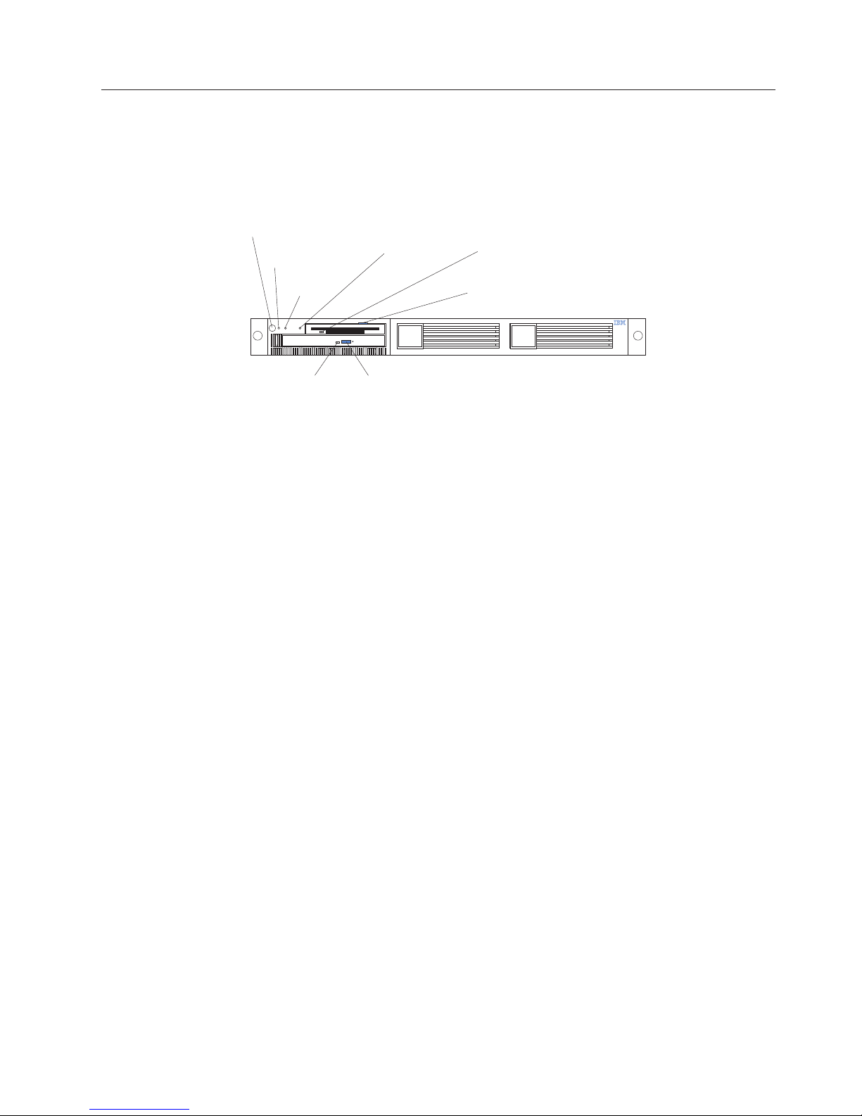
Front view
Power control
button
Power-on
light (green)
Reset
button
System error
light (amber)
Diskette drive
activity light
(green)
Diskette eject
button
light (green)
CD eject buttonCD activity
Power-control button: Press this button to manually turn the server on or off.
Power-on light: This green LED lights and stays on when you turn on your server,
and it blinks when the server is in standby mode.
Reset button: Press this button to reset the server and run the power-on self-test
(POST). You might need to use a pen or the end of a straightened paper clip to
press the button.
System-error light: This amber LED lights when a system error occurs.
Diskette drive activity light: When this LED is on, it indicates that the diskette
drive is in use.
Diskette-eject button: Push this button to release a diskette from the drive.
CD eject button: Push this button to release a CD from the drive.
CD drive activity light: When this light is on, it indicates that the CD-ROM drive
is in use.
Chapter 2. General information 7
Page 16
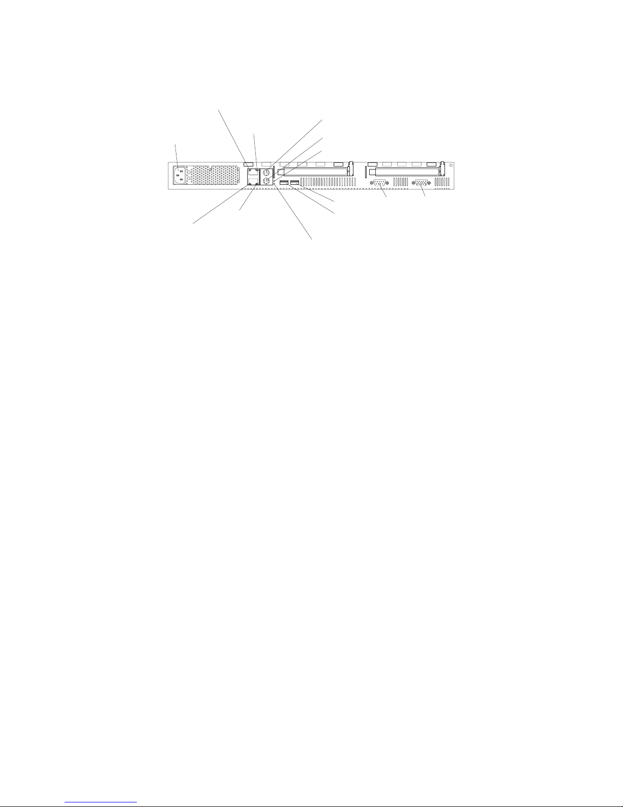
Rear view
System power
connector
Ethernet 1 link
indicator (amber)
Ethernet 1 speed
indicator (green)
Mouse or auxilary
pointing device connector
Keyboard port
Power-on light (green)
Video port
Ethernet 2 link
indicator (amber)
Ethernet 2 speed
indicator (green)
System error
light (amber)
USB 2
USB 1
Serial port
System power connector: The system power cord connects here to provide power
to the system.
Ethernet 1 link indicator: This amber LED lights when there is an active link
connection on the 10BASE-T or 100BASE-TX interface for Ethernet port 1.
Ethernet 1 speed indicator: This green LED lights when the speed of the Ethernet
LAN that is connected to Ethernet port 1 is 100 Mbps.
Auxiliary pointing device: Signal cables for a mouse, trackball, or other pointing
device connect to the Auxiliary pointing device connector.
Keyboard port: Signal cables for a keyboard connect to the keyboard port.
Power-on light: This green LED lights and stays on when you turn on your server
and will blink when the server is in standby mode. This light duplicates the power
on light on the front of the server.
Video port: The signal cable for a monitor connects to the video port.
Serial port: Signal cables for modems or other serial devices connect to the serial
port.
USB 2: This is an automatically configured port that you can use to connect one or
more USB devices to the server, using Plug and Play technology.
USB 1: This is an automatically configured port that you can use to connect one or
more USB devices to the server, using Plug and Play technology.
System-error light: This amber LED lights when a system error occurs. This light
duplicates the system error light on the front of the server.
Ethernet 2 speed indicator: This green LED lights when the speed of the Ethernet
LAN connected to Ethernet port 2 is 100 Mbps.
Ethernet 2 link indicator: This amber LED lights when there is an active link
connection on the 10BASE-T or 100BASE-TX interface for Ethernet port 2.
8 Hardware Maintenance Manual: xSeries 300
Page 17
Turning on the server
Turning on the server refers to the act of plugging the power cord of your server
into the power source and starting the operating system.
Complete the following steps to turn on the server:
1. Plug the power cord of your server into the power source.
Note: Plugging the power cord into a power source may cause the server to
start automatically. This is an acceptable action.
2. Wait 30 seconds, and then press the power control button on the front of the
server.
Turning off the server
Turning off the server refers to the act of disconnecting the server from the power
source.
Complete the following steps to turn off the server:
1. Refer to your operating system documentation for the proper procedure to shut
down the operating system.
Statement 5:
CAUTION:
The power control button on the device and the power switch on the power
supply do not turn off the electrical current supplied to the device. The
device also might have more than one power cord. To remove all electrical
current from the device, ensure that all power cords are disconnected from
the power source.
2
1
2. Press the power control button on the front of the server. This will put the
server in standby mode.
3. Disconnect the server from the power source.
Note: After you turn off the server, wait at least 5 seconds before you turn on
the server again.
Chapter 2. General information 9
Page 18

Standby mode
Standby mode puts the server into a wait state. When in a wait state, the server is
not running the operating system, and all core logic is shut down.
Complete the following steps to put the server into the standby mode:
1. Refer to your operating system documentation for the proper procedure to
shutdown the operating system.
2. Press the power control button on the front of the server.
10 Hardware Maintenance Manual: xSeries 300
Page 19

Chapter 3. Diagnostics
This section provides basic troubleshooting information to help you resolve some
common problems that might occur with the server.
If you cannot locate and correct the problem using the information in this section,
refer to Chapter 7, “Symptom-to-FRU index” on page 63 for more information.
Diagnostic tools overview
The following tools are available to help you identify and resolve hardware-related
problems:
v POST beep codes
The power-on self-test (POST) generates beep codes and messages to indicate
successful test completion or the detection of a problem. See “POST” for more
information.
v Diagnostic programs and error messages
The server diagnostic programs are provided on the IBM Enhanced Diagnostics
CD. These programs test the major components of the server. See “Diagnostic
programs and error messages” on page 12 for more information.
POST
When you turn on the server, it performs a series of tests to check the operation of
server components and some of the options installed in the server. This series of
tests is called the power-on self-test or POST.
If POST finishes without detecting any problems, the first window of the operating
system or application program appears.
Note:
1. If you have a power-on password or administrator password set, you
must type the password and press Enter, when prompted, before POST
will continue.
2. A single problem might cause several error messages. When this occurs,
work to correct the cause of the first error message. After you correct the
cause of the first error message, the other error messages usually will not
occur the next time you run the test.
POST beep code descriptions
POST generates beep codes to indicate successful completion or the detection of a
problem.
v One short beep indicates the successful completion of POST.
v More than one beep indicates that POST detected a problem. For more
information, see “Beep symptoms” on page 63“.
POST error messages
The possible types of beep codes that your system might emit are:
© Copyright IBM Corp. 2000 11
Page 20

Repeating long beeps
Indicates that a memory error has occurred. Ensure that all DIMMs are
correctly installed.
One long beep and two short beeps
Indicates that a video error has occurred and the BIOS cannot initialize the
video screen to display any additional information. Ensure that the video
adapter is correctly installed.
For a list of POST errors, see “POST error codes” on page 69.
Small computer system interface messages (some models)
The following table lists actions to take if you receive a SCSI error message.
Note: If the server does not have a hard disk drive, ignore any message that
indicates that the BIOS is not installed.
You will get these messages only when running the SCSI Select Utility.
Table 1. SCSI messages
SCSI Messages Description
All One or more of the following might be causing the problem.
v A failing SCSI device (adapter or drive)
v An improper SCSI configuration
v Duplicate SCSI IDs in the same SCSI chain
v An improperly installed SCSI terminator
v A defective SCSI terminator
v An improperly installed cable
v A defective cable
Action: Verify that:
v The external SCSI devices are turned on. External SCSI devices must
be turned on before the server.
v The cables for all external SCSI devices are connected correctly.
v The last device in each SCSI chain is terminated properly.
v The SCSI devices are configured correctly.
If the above items are correct, run the diagnostic programs to obtain
additional information about the failing device.
Diagnostic programs and error messages
The server diagnostic programs are stored on the IBM Enhanced Diagnostics CD.
These programs provide the primary methods of testing the major components of
the server.
Diagnostic error messages indicate that a problem exists; they are not intended to
be used to identify a failing part. Troubleshooting and servicing of complex
problems that are indicated by error messages should be performed by trained
service personnel.
12 Hardware Maintenance Manual: xSeries 300
Page 21

Sometimes the first error to occur causes additional errors. In this case, the server
displays more than one error message. Always follow the suggested action
instructions for the first error message that appears.
The following sections contain the error codes that might appear in the detailed
test log and summary log when running the diagnostic programs.
The error code format is as follows:
fff-ttt-iii-date-cc-text message
where:
fff is the three-digit function code that indicates the function being
tested when the error occurred. For example, function code 089 is
for the microprocessor.
ttt is the three-digit failure code that indicates the exact test failure
that was encountered.
iii is the three-digit device ID.
date is the date that the diagnostic test was run and the error recorded.
cc is the check digit that is used to verify the validity of the
information.
text message is the diagnostic message that indicates the reason for the problem.
Text messages
The diagnostic text message format is as follows:
Function Name: Result (test specific string)
where:
Function Name
is the name of the function being tested when the error occurred. This
corresponds to the function code (fff) given in the previous list.
Result can be one of the following:
Passed
Failed This result occurs when the diagnostic test discovers an error.
User Aborted
Not Applicable
Aborted
This result occurs when the diagnostic test completes without any
errors.
This result occurs when you stop the diagnostic test before it is
complete.
This result occurs when you specify a diagnostic test for a device
that is not present.
This result occurs when the test could not proceed because of the
server configuration.
Warning
This result occurs when a possible problem is reported during the
diagnostic test, such as when a device that is to be tested is not
installed.
Chapter 3. Diagnostics 13
Page 22

Test Specific String
This is additional information that is used to analyze the problem.
Starting the diagnostic programs
The IBM Enhanced Diagnostics programs will isolate your server hardware from
software that you have installed on your hard disk drive. The programs run
independently of the operating system, and must be run either from the CD or
diskette. This method of testing is generally used when other methods are not
accessible or have not been successful in isolating a problem suspected to be
hardware related.
An IBM Enhanced Diagnostics CD comes with the server. You can also download
the latest image of the diagnostics from the World Wide Web at
http://www.ibm.com/pc/support.
Note: When using diagnostics with a USB Keyboard and Mouse attached, go into
Setup and enable USB emulation.
1. Press F1 Config/Setup
2. Select Devices and I/O Ports
3. Select USB Setup
4. Make sure USB Keyboard and Mouse are enabled.
Using the diagnostics CD
To start the IBM Enhanced Diagnostics using the CD, do the following:
1. Turn off your server and any peripheral devices.
2. Turn on all attached devices; then, turn your server on.
3. When you see Press F1 For Configuration/Setup, press the F1 key.
4. When the Configuration/Setup Utility menu appears, select Start Options.
5. From the Start Options menu, select Startup Sequence.
6. Note the device selected as the First Startup Device. Later, you must restore
this setting.
7. Select CD-ROM as the First Startup Device.
8. Press Esc two times to return to the Configuration/Setup Utility menu.
9. Place the IBM Enhanced Diagnostics CD in the CD-ROM drive.
10. Select Save & Exit Setup and follow the prompts. The diagnostics will load.
Follow the instructions on the screen to run the diagnostics.
Important
When you finish running the diagnostics and utilities, remove the CD from the CD-ROM
drive and turn off the server. You must restore the First Startup Device to the original
setting. Use steps 2 through 8 of this procedure to do this.
Downloading the diagnostics program
Do the following to download the latest image of the IBM Enhanced Diagnostics
from the World Wide Web and create a startable Enhanced Diagnostics diskette:
1. Go to the following World Wide Web site: http://www.ibm.com/pc/support/
2. Download the diagnostics file for your server to a hard disk drive directory
(not to a diskette).
3. Go to a DOS prompt and change to the directory where the file was
downloaded.
14 Hardware Maintenance Manual: xSeries 300
Page 23

4. Insert a blank high-density diskette in diskette drive A.
5. Type in the following, and then press Enter: filename a: where filename is the
name of the file you downloaded from the Web.
The downloaded file is self-extracting and will be copied to the diskette. When the
copy completes, you have a startable IBM Enhanced Diagnostics diskette.
Using the diagnostic diskette
Do the following to start the IBM Enhanced Diagnostics using the diagnostics
diskette, do the following:
1. Turn off your server and any peripheral devices.
2. Insert the IBM Enhanced Diagnostics diskette into the diskette drive.
3. Turn on all attached devices; then, turn on the server.
4. Follow the instructions on the screen.
5. Place the IBM Enhanced Diagnostics CD in the CD-ROM drive. The diagnostics
will load. Follow the instructions on the screen to run the diagnostics.
When the tests have completed, you can view the Test Log by selecting Utility
from the top of the screen.
If the hardware checks out OK but the problem persists during normal server
operations, a software error might be the cause. If you suspect a software problem,
refer to the information that comes with the software package.
Viewing the test log
The test log records data about system failures and other pertinent information.
The test log will not contain any information until after the diagnostic program has
run.
Note: If you already are running the diagnostic programs, begin with step 4
1. Insert the IBM Enhanced Diagnostics CD.
2. Turn on the system and watch the screen.
If the system is on, shut down your operating system and restart the system.
3. If a power-on password is set, the system prompts you for it. Type in the
appropriate password; then, press Enter.
4. Run the appropriate diagnostics program and when the Diagnostic Programs
screen appears, select Utility.
5. Select View Test Log from the list that appears; then, follow the instructions on
the screen.
6. You can save the test log to a file on a diskette or to your hard disk drive.
Note: The system maintains the test-log data while the system is powered on.
When you turn off the power to the server, the test log is cleared.
Diagnostic error message tables
For descriptions of the error messages that might appear when you run the
diagnostic programs, see “Diagnostic error codes” on page 63. If diagnostic error
messages appear that are not listed in those tables, make sure that the server has
the latest levels of BIOS, Advanced System Management Processor, ServeRAID,
and diagnostics microcode installed.
Chapter 3. Diagnostics 15
Page 24

Power checkout
Power problems can be difficult to troubleshoot. For instance, a short circuit can
exist anywhere on any of the power distribution busses. Usually a short circuit will
cause the power subsystem to shut down because of an overcurrent condition.
A general procedure for troubleshooting power problems is as follows:
1. Power off the server and disconnect the AC cord(s).
2. Check for loose cables in the power subsystem. Also check for short circuits, for
instance if there is a loose screw causing a short circuit on a circuit board.
3. Remove adapters and disconnect the cables and power connectors to all
internal and external devices until server is at minimum configuration required
for power on (see ″Minimum operating requirements″ on page 70).
4. Reconnect the AC cord and power on the server. If the server powers up
successfully, replace adapters and devices one at a time until the problem is
isolated. If server does not power up from minimal configuration, replace FRUs
of minimal configuration one at a time until the problem is isolated.
To use this method it is important to know the minimum configuration required
for a server to power up (see page 70).
16 Hardware Maintenance Manual: xSeries 300
Page 25

Recovering BIOS code
If the BIOS code has become damaged, such as from a power failure during a flash
update, you can recover the BIOS using the boot block jumper and a BIOS flash
diskette. The boot block jumper selects between normal BIOS mode and flash
recovery mode. In the normal position, the jumper will be installed on pins 2 and
3. In the recovery position, the jumper will be installed on pins 1 and 2.
There are two choices when flashing BIOS. If you select flashing to Server mode,
internal only COM PORT 2 and USB keyboard and mouse emulation will be OFF
by default. These can be turned on, either individually or both, by going into F1
setup and turning them on. This will require a reboot. If you select flashing to
Appliance mode, internal only COM PORT 2 and USB keyboard and mouse
emulation will be ON by default. They can be turned off, either individually or
both, by going into F1 setup and turning them off. This will require a reboot.
If the only US devices attached are keyboard and mouse and they are not working,
investigate the F1 setup settings for these options. You can use a USB keyboard to
press F1 and get into setup.
Note: You can obtain a BIOS flash diskette from one of the following sources:
v Use the ServerGuide program to make a BIOS flash diskette.
v Download files to make a BIOS flash diskette from the World Wide Web.
Go to http://www.ibm.com/pc/support/, select IBM System Support,
and then make the selections for your system.
Complete the following steps to recover the BIOS code:
1. Turn off the server and peripheral devices and disconnect all external cables
and power cords; then, remove the cover, see “Removing the cover” on
page 38.
Chapter 3. Diagnostics 17
Page 26
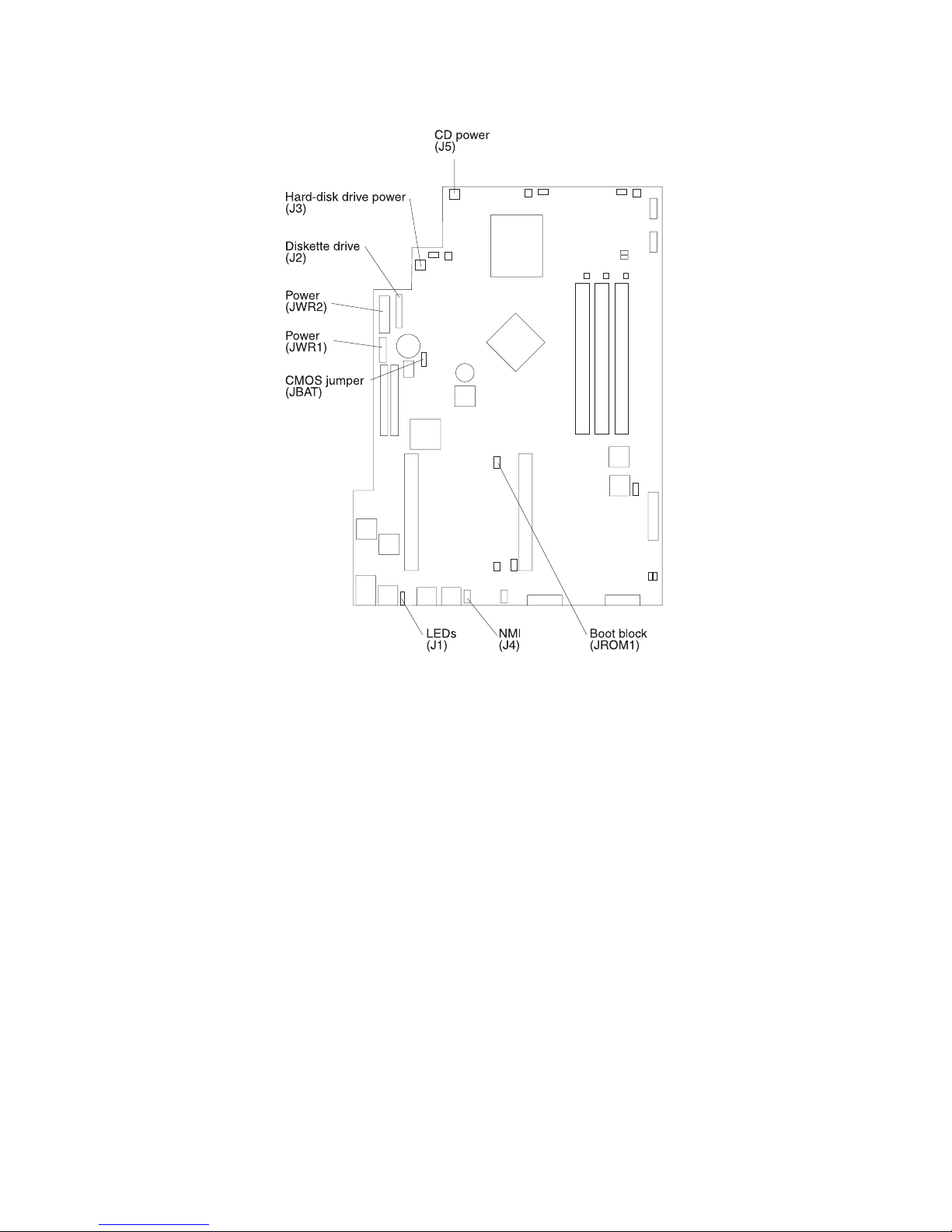
2. Locate jumper JROM1 on the system board.
3. Move the JROM1 jumper to the alternate position (pins 1 and 2) to enable the
BIOS recovery mode.
4. Reinstall the cover, see “Installing the cover” on page 53.
5. Reconnect all external cables and power cords and turn on the peripheral
devices.
6. Insert the BIOS flash diskette in the diskette drive.
7. Restart the server. The BIOS begins the power-on self-test.
8. The BIOS flash utility automatically starts.
9. When prompted as to whether you want to save the current code to a
diskette, type N.
10. When prompted, type Y to continue the flash process.
11. The system automatically starts the flash utility a second time.
12. When prompted as to whether you want to save the current BIOS code, stop
the process by removing the BIOS flash diskette from the diskette drive.
13. Turn off the server and peripheral devices and disconnect all external cables
and power cords; then, remove the cover, see “Removing the cover” on
page 38.
14. Move the JROM1 jumper to the normal position (pins 2 and 3) to return to
normal startup mode.
15. Reinstall the cover, see “Installing the cover” on page 53.
16. Reconnect all external cables and power cords and turn on the peripheral
devices.
18 Hardware Maintenance Manual: xSeries 300
Page 27
Clearing CMOS
17. Restart the server, which should start up normally.
If you need to erase configuration information, you must move the CMOS jumper.
See the illustration in “Recovering BIOS code” on page 17 for the location of the
CMOS jumper.
The default position is a jumper installed on pins 1 and 2. Before you change the
position of this jumper, you must turn off the server and peripheral devices, and
disconnect all external cables and power cords. Remove the cover and then move
the jumper to pins 2 and 3.
After moving the jumper, wait at least 5 minutes for the CMOS information to
clear.
Changing the position of this jumper erases all configuration and setup
information, including the power-on and administrator passwords. Therefore, you
must reconfigure the server after clearing CMOS memory (see Chapter 4,
“Configuring the server” on page 29). If possible, record your server configuration
information before moving the CMOS jumper.
After you clear the CMOS information, move the jumper back to its normal
position (pins 1 and 2). Reconnect the external cables and power cords; then, turn
on the peripheral devices and the server.
Replacing the battery
When replacing the battery, you must replace it with a lithium battery of the same
type from the same manufacturer. To avoid possible danger, read and follow the
safety statement below.
To order replacement batteries, call 1-800-772-2227 within the United States, and
1-800-465-7999 or 1-800-465-6666 within Canada. Outside the U.S. and Canada, call
your IBM reseller or IBM marketing representative.
Note: After you replace the battery, you must reconfigure your system and reset
the system date and time.
Chapter 3. Diagnostics 19
Page 28
CAUTION:
When replacing the battery, use only IBM Part Number 33F8354 or an equivalent
type battery recommended by the manufacturer. If your server has a module
containing a lithium battery, replace it only with the same module type made by
the same manufacturer. The battery contains lithium and can explode if not
properly used, handled, or disposed of.
Do not:
v Throw or immerse into water
v Heat to more than 100°C (212°F)
v Repair or disassemble
Dispose of the battery as required by local ordinances or regulations.
Do the following to replace the battery:
1. Read “Before you begin” on page 36, and follow any special handling and
installation instructions supplied with the replacement battery.
2. Turn off the server and peripheral devices and disconnect all external cables
and power cords; then, remove the server cover.
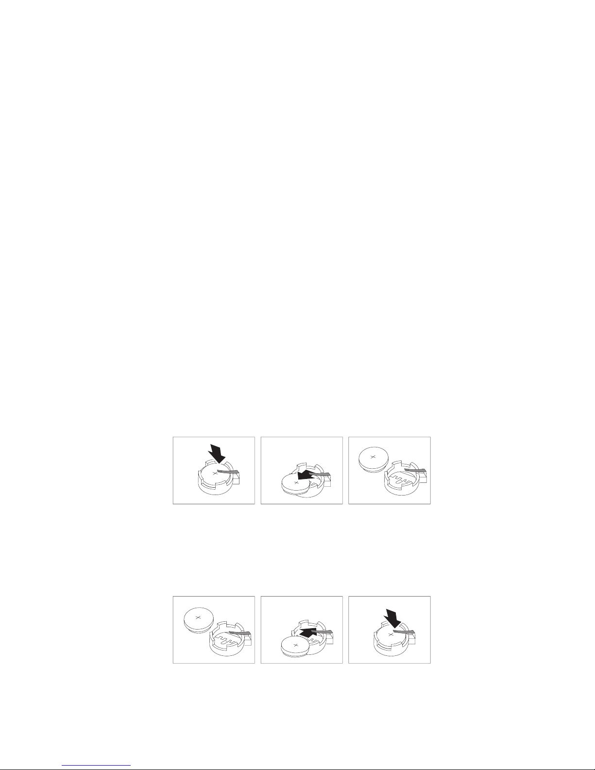
3. Remove the battery:
a. Use one finger to lift the battery clip over the battery.
b. Use one finger to slightly slide the battery out from its socket. The spring
mechanism will push the battery out toward you as you slide it from the
socket.
c. Use your thumb and index finger to pull the battery from under the battery
clip.
d. Ensure that the battery clip is touching the base of the battery socket by
pressing gently on the clip.
4. Do the following to insert the new battery:
a. Tilt the battery so that you can insert it into the socket under the battery
clip.
b. As you slide it under the battery clip, press the battery down into the
socket.
5. Reinstall the server cover and connect the cables.
6. Turn on the server.
20 Hardware Maintenance Manual: xSeries 300
Page 29

7. Start the Configuration/Setup Utility program and set configuration
parameters.
v Set the server date and time.
v Set the power-on password.
v Reconfigure your server.
Temperature checkout
Proper cooling of the server is important for proper operation and server reliability.
For a typical xSeries server, you should make sure:
v Each of the drive bays has either a drive or a filler panel installed
v Each of the power supply bays has either a power supply or a filler panel
installed
v The server cover is in place during normal operation
v There is at least 50 mm (2 inches) of ventilated space at the sides of the server
and 100 mm (4 inches) at the rear of the server
v The server cover is removed for no longer than 30 minutes while the server is
operating
v The processor housing cover covering the processor and memory area is
removed for no longer that ten minutes while the server is operating
v A removed hot-swap drive is replaced within two minutes of removal
v Cables for optional adapters are routed according to the instructions provided
with the adapters (ensure that cables are not restricting air flow)
v The fans are operating correctly and the air flow is good
v A failed fan is replaced within 48 hours
Attention:
If using AOL/2 or system supported monitoring software, and you are receiving a
thermal alert with no fan alert, check SYSFA1 and CPUFA2, which are
unmonitored and therefore cannot generate alerts, to make certain that those fans
are connected to planar power and are functional.
If the system powers itself down, the cause maybe an overheated processor
causing a thermal trip. One of your checks should be to ensure that both system
fans and both CPU fans are connected to planar power and are functional.
In addition, ensure that the environmental specifications for the server are met. See
“Features and specifications” on page 4.
Note: The speed of the fans will increase if:
Diagnosing errors
To find solutions to problems that have definite symptoms, see “Error symptoms”
on page 66.
If you cannot find the problem there, go to “Starting the diagnostic programs” on
page 14 to test the server.
v One fan fails.
v Ambient temperature gets too high.
Chapter 3. Diagnostics 21
Page 30

If you have just added new software or a new option and the server is not
working, do the following before using the error symptoms table:
v Remove the software or device that you just added.
v Run the diagnostic tests to determine if the server is running correctly.
v Reinstall the new software or new device.
Troubleshooting the Ethernet controller
This section provides troubleshooting information for problems that might occur
with the 10/100 Mbps Ethernet controller.
Network connection problems
If the Ethernet controller cannot connect to the network, check the following:
v Make sure that the cable is installed correctly.
The network cable must be securely attached at all connections. If the cable is
attached but the problem persists, try a different cable.
If you set the Ethernet controller to operate at 100 Mbps, you must use Category
5 cabling.
If you directly connect two workstations (without a hub), or if you are not using
a hub with X ports, use a crossover cable.
Note: To determine whether a hub has an X port, check the port label. If the
label contains an X, the hub has an X port.
v Determine if the hub supports auto-negotiation. If not, try configuring the
integrated Ethernet controller manually to match the speed and duplex mode of
the hub.
v Check the LAN activity light (if available) on the front of the server. The LAN
activity light illuminates when the Ethernet controller sends or receives data
over the Ethernet network. If the LAN activity light is off, make sure that the
hub and network are operating and that the correct device drivers are loaded.
v Make sure that you are using the correct device drivers, supplied with your
server.
v Check for operating server-specific causes for the problem.
v Make sure that the device drivers on the client and server are using the same
protocol.
v Test the Ethernet controller.
The way you test the Ethernet controller depends on which operating system
you are using (see the Ethernet controller device driver README file).
Ethernet controller troubleshooting chart
You can use the following troubleshooting chart to find solutions to 10/100 Mbps
Ethernet controller problems that have definable symptoms.
22 Hardware Maintenance Manual: xSeries 300
Page 31

Table 2. Ethernet troubleshooting chart
Ethernet controller
Suggested Action
problem
The server stops
The PCI BIOS interrupt settings are incorrect.
running when loading
device drivers.
Check the following:
v Determine if the IRQ setting assigned to the Ethernet controller
is also assigned to another device in the Configuration/Setup
Utility program.
Although interrupt sharing is allowed for PCI devices, some
devices do not function well when they share an interrupt with
a dissimilar PCI device. Try changing the IRQ assigned to the
Ethernet controller or the other device. For example, for
NetWare Versions 3 and 4 it is recommended that disk
controllers not share interrupts with LAN controllers.
v Make sure that you are using the most recent device driver
available from the World Wide Web.
v Run the network diagnostic program.
The LAN activity light
(when available) does
not light.
Check the following:
v Make sure that you have loaded the network device drivers.
v The network might be idle. Try sending data from this
workstation.
v Run diagnostics on the LEDs.
v The function of this LED can be changed by device driver load
parameters. If necessary, remove any LED parameter settings
when you load the device drivers.
Data is incorrect or
sporadic.
Check the following:
v Make sure that you are using Category 5 cabling when
operating the server at 100 Mbps.
v Make sure that the cables do not run close to noise-inducing
sources like fluorescent lights.
The Ethernet controller
stopped working when
another adapter was
added to the server.
Check the following:
v Make sure that the cable is connected to the Ethernet controller.
v Make sure that your PCI server BIOS is current.
v Reseat the adapter.
v Determine if the IRQ setting assigned to the Ethernet adapter is
also assigned to another device in the Configuration/Setup
Utility program.
Although interrupt sharing is allowed for PCI devices, some
devices do not function well when they share an interrupt with
a dissimilar PCI device. Try changing the IRQ assigned to the
Ethernet adapter or the other device.
The Ethernet controller
stopped working
without apparent
cause.
Check the following:
v Run diagnostics for the Ethernet controller.
v Try a different connector on the hub.
v Reinstall the device drivers. Refer to your operating system
documentation and to the ServerGuide information.
Chapter 3. Diagnostics 23
Page 32

Ethernet controller messages
The integrated Ethernet controller might display messages from the following
device drivers:
v Novell NetWare
™
v Network driver interface specification (NDIS) adapter for level 4.0 (Windows
NT)
Novell NetWare or IntraNetWare system ODI driver teaming
messages
This section provides explanations of the error messages for the Novell NetWare or
IntraNetWare system ODI driver, and suggested actions to resolve each problem.
Table 3. NetWare driver messages for the Ethernet controller
Message Description
Couldn’t allocate resources. Explanation: An unknown error has occurred when trying
AFT group for primary
adapter in slot nnn already
exists.
Error locating device control
table (DCT) addresses in
internal table. Make sure that
you have loaded LAN
drivers after loading
AFT.NLM.
Insufficient number of
arguments specified.
Duplicate slot numbers
detected.
’xxx’ is not supported for
AFT team.
Primary and Secondary
adapters do not match. AFT
group is not created.
Requested number of
Secondary cards are not
found.
or IntraNetWare system open data-link interface (ODI)
to allocate needed resources for the AFT Module. Action:
v Check the server configuration.
v Verify that the Ethernet controller is enabled. If the
Ethernet controller is enabled, run the diagnostic
programs.
Explanation: An attempt was made to rebind an adapter
already in an AFT group. Action: Check the AFT slot
numbers for existing AFT teams.
Explanation: The bind command was entered prior to
loading the device driver. The device driver must be loaded
after loading AFT.NLM, but before any bind command can
be issued. Action: Load the driver for the supported
adapter and try loading the AFT module again.
Explanation: The appropriate or expected number of
parameters was not entered in a command. Action: Check
the parameters required for the given command.
Explanation: An attempt has been made to bind the same
slot number more than once. Action: Check the slot
numbers entered during the bind. Adapter slot numbers
must be valid and unique.
Explanation: A bind command has been issued for adapters
not supported by AFT.NLM. Action: Make sure that you
attempt to bind only adapters supported by AFT.NLM.
Explanation: A bind command was entered for an adapter
team that is a combination of server and client adapters. An
AFT team must be a grouping of the same classification of
adapter. Action: Verify that all the adapters bound in a
team are of the same classification.
Explanation: The number of adapters specified in the bind
command could not be located. Action: Verify the numbers
and slot locations of the adapters to be bound.
24 Hardware Maintenance Manual: xSeries 300
Page 33

Table 3. NetWare driver messages for the Ethernet controller (continued)
Message Description
Failed to create AFT group.
Make sure that the drivers
for supported adapters are
loaded, primary adapter is
bound to protocols, and
secondary adapter is not
bound to any protocols.
Error identifying slot
numbers for the specified
board names.
Can’t unbind specified slot
from AFT group. Make sure
that the slot you specified is
for the primary adapter in an
AFT group.
LAN adapter at slot nnnn
(Port 0xaa) failed to reset.
Check the state of the
adapter.
AFT is not supported on this
version of NetWare
Failed to allocate resources
tags.
Please unload all LAN
drivers before unloading
AFT.NLM.
™
.
Explanation: Binding of protocol failed. Protocol is either
not bound to any adapter or is bound to more than one
adapter in the group. Action: Ensure that the protocol is
bound to only adapter in an AFT team.
Explanation: The mapping between the board name entered
and the slot number for an adapter could not be
established. Action: Check the board name for the adapter
before issuing the bind command.
Explanation: The number entered in the unbind command
was not the primary adapter in an AFT group. Action:
Reissue the unbind command and specify the slot number
for the primary adapter.
Explanation: The adapter that you specified could not be
initialized. Action:
1. Load the driver for the supported adapter.
2. Check that the adapter is seated properly in the slot and
try loading the AFT module again.
Explanation: The NetWare on your server is not a version
supported by AFT. Action: Load and bind AFT only on
supported versions of NetWare (currently version 4.11 and
above).
Explanation: An unknown error has occurred when trying
to allocate needed resources for the AFT module. Action:
Check server configuration.
Explanation: An attempt was made to unload the AFT.NLM
module before unloading the adapter driver. Action:
Unload the adapter driver before unloading the AFT
module.
NDIS 4.0 (Windows NT) driver messages
This section contains the error messages for the NDIS 4.0 drivers. The explanation
and recommended action are included with each message.
Table 4. NDIS (Windows NT or Windows 2000) driver messages for the Ethernet controller
Error code
(hex)
0x00 Explanation: The driver could not register the specified interrupt. Action:
0x01 Explanation: One of the PCI cards did not get the required resources.
0x02 Explanation: Bad node address (multicast address). Action: Make sure the
Description
Using the Configuration/Setup Utility program, make sure that a PCI
interrupt is assigned to your Ethernet card, and that Ethernet is enabled.
Action: Using the Configuration/Setup Utility program, make sure that a
PCI interrupt is assigned to your Ethernet card, and that Ethernet is
enabled.
locally administered address is valid, if one is specified. The address can
not be a multicast address.
Chapter 3. Diagnostics 25
Page 34

Table 4. NDIS (Windows NT or Windows 2000) driver messages for the Ethernet
controller (continued)
Error code
(hex)
0x03 Explanation: Failed self-test. Action: Make sure a cable is attached to the
0x0D Explanation: Could not allocate enough memory for transmit queues.
0x0E Explanation: Could not allocate enough memory for receive queue. Action:
0x0F Explanation: Could not allocate enough memory for other structures.
0x10 Explanation: Did not find any Ethernet controllers. Action: Using the
0x11 Explanation: Multiple Ethernet controllers found, but none matched the
0x13 Explanation: Did not find any Ethernet controllers that matched the
0x16 Explanation: Single adapter found, but multiple instances tried to load.
0x17 Explanation: Slot parameter not specified in the registry. Action: Remove
Description
Ethernet connector.
Action:
1. From the Windows NT desktop, select Start → Control Panel →
Networks → Adapters.
2. Select your IBM Ethernet adapter from the list.
3. Select Properties → Advanced.
4. Lower the resource values that apply to the transmit queue.
1. From the Windows NT desktop, select Start →Control Panel →Networks
→Adapters.
2. Select your IBM Ethernet adapter from the list.
3. Select Properties →Advanced.
4. Lower the resource values that apply to the receive queue.
Action:
1. From the Windows NT desktop, select Start → Control Panel →
Networks → Adapters.
2. Select your IBM Ethernet adapter from the list.
3. Select Properties →Advanced.
4. Lower the value for the resource named in the message.
Configuration/Setup Utility program, make sure that Ethernet is enabled.
required ID. Action: Using the Configuration/Setup Utility program, make
sure that Ethernet is enabled.
required subven/subdev. Action: Using the Configuration/Setup Utility
program, make sure that Ethernet is enabled.
Action: Using the Configuration/Setup Utility program, make sure that
Ethernet is enabled, and that the slot containing the IBM xSeries 200
10/100 Ethernet Adapter or the IBM 10/100 Etherjet PCI adapter is
enabled.
the adapter driver and reinstall it.
26 Hardware Maintenance Manual: xSeries 300
Page 35

Ethernet teaming messages:
This section displays the messages associated with Ethernet teaming.
Table 5. NDIS (Windows NT or Windows 2000) driver teaming messages for the Ethernet
controller
Event ID Type Description
01 Error Explanation: Team name and physical adapter name are
02 Error Explanation: Unable to allocate required resources.
03 Error Explanation: Unable to read required registry
04 Error Explanation: Unable to bind to physical adapter. Action:
05 Error Explanation: Unable to initialize an adapter team.
06 Informational Explanation: Te a m nn. Primary adapter is initialized.
07 Informational Explanation: Te a m nn. Secondary adapter is initialized.
08 Informational Explanation: Te a m nn. Virtual adapter or Team is
09 Informational Explanation: Te a m nn. Primary adapter is switching
10 Warning Explanation: Te a m nn. Adapter link down. Action:
11 Informational Explanation: Te am nn. Secondary adapter took over.
12 Warning Explanation: Te a m nn. Secondary adapter is deactivated
13 Informational Explanation: Te a m nn. Secondary adapter has rejoined
14 Informational Explanation: Te a m nn. Secondary adapter link is up.
15 Error Explanation: Te a m nn. The last adapter has lost its link.
16 Informational Explanation: Te a m nn. An adapter has reestablished the
17 Informational Explanation: Te a m nn. Preferred primary adapter has
the same. This is an invalid configuration. Action:
Reconfigure the adapter team by double-clicking the
PROSet icon in the control panel.
Action: Free some memory resources and restart.
parameters. Action: Reconfigure the adapter team by
double-clicking the PROSet icon in the control panel.
Reconfigure the adapter team by double-clicking the
PROSet icon in the control panel.
Action: Reconfigure the adapter team by double-clicking
the PROSet icon in the control panel.
Action: None.
Action: None.
initialized. Action: None.
over. Action: None.
Make sure the adapter is functioning properly.
Action: None.
from the Team. Action: Make sure the secondary
adapter is functioning properly and that the adapter
cable is securely connected to the LAN.
the Team. Action: None.
Action: None.
Network connection has been lost. Action: Shut down
the server and replace the adapters; then, restart the
server to reestablish the connection.
link. Network connection has been restored. Action:
None.
been detected. Action: None.
Chapter 3. Diagnostics 27
Page 36

Table 5. NDIS (Windows NT or Windows 2000) driver teaming messages for the Ethernet
controller (continued)
Event ID Type Description
18 Informational Explanation: Te a m nn. Preferred secondary adapter has
been detected. Action: None.
19 Informational Explanation: Te a m nn. Preferred primary adapter took
over. Action: None.
20 Informational Explanation: Te a m nn. Preferred secondary adapter took
over. Action: None.
21 Warning Explanation: Te a m nn. Primary adapter does not sense
any Probes. Possible reason: partitioned Team. Action:
Make sure the cables of the adapter team are connected
to the same LAN segment. Reconfigure the team if
necessary.
28 Hardware Maintenance Manual: xSeries 300
Page 37

Chapter 4. Configuring the server
The following configuration programs are provided with your server:
v Configuration/Setup Utility
This program is part of the basic input/output system (BIOS) code that comes
with your server. You can use this program to configure the serial connector
assignment, change the drive startup sequence, set the date and time, and set
passwords. For information on how to start this utility see, “Starting the
Configuration/Setup Utility program” on page 30.
v SCSISelect Utility
With the SCSISelect Utility program, you can configure the devices that are
attached to the SCSI adapter (provided in some models). Use this program to
change default values, resolve configuration conflicts, and perform a low-level
format on a SCSI hard disk drive. For information on how to start this utility,
see “Starting the SCSISelect utility program” on page 30.
v PXE Boot Agent Utility
The Preboot eXecution Environment (PXE) Boot Agent Utility program is part of
the BIOS code that comes with the server. You can use this program to change
network startup (boot) protocols and startup order, to select operating-system
wake-up support, and to set menu wait times. For information on how to start
this utility, see “Starting the PXE boot agent utility program” on page 31.
™
v ServerGuide
The ServerGuide CDs include software setup and installation tools that are
specifically designed for IBM xSeries 300 servers. You can use these CDs during
the initial installation of your server to configure the server hardware and to
simplify your NOS installation. The ServerGuide CDs also contain a collection of
application programs, which you can install after your server is up and running.
See “Using the ServerGuide CDs” on page 32 for more information.
CDs
© Copyright IBM Corp. 2000 29
Page 38

Starting the utility programs
This section provides the instructions for starting the utility programs. For more
detailed information about these utility programs, refer to the User’s Reference on
the IBM xSeries Documentation CD.
Using the Configuration/Setup Utility program
Configuration/Setup is a menu-driven utility that is part of the BIOS code that
comes with your server. You can use it to:
v Configure serial connector assignments
v Change the drive startup sequence
v Enable USB keyboard and mouse support
v Resolve configuration conflicts
v Set the date and time
v Set passwords
Starting the Configuration/Setup Utility program
Complete the following steps to start the Configuration/Setup Utility program:
1. Turn on the server and watch the monitor screen.
2. When the message Press F1 for Configuration/Setup appears, press F1.
3. Follow the instructions that appear on the screen.
Using the SCSISelect utility program (some models)
SCSISelect is a built-in, menu-driven configuration utility program that you can
use to:
v View the default SCSI IDs
v Locate and correct configuration conflicts
Note: If your server has a redundant arrays of independent disks (RAID) adapter
installed, use the configuration method that is supplied with the RAID
adapter to view or change SCSI settings for devices attached to the adapter.
Starting the SCSISelect utility program
Complete the following steps to start the SCSISelect Utility program:
1. Turn on the server.
™
2. When the <<< Press <CTRL><A> for SCSISelect
appears, press Ctrl+A.
3. When the Would you like to configure the host adapter or run the SCSI
disk utility? question appears, make your selection and press Enter.
4. Use the arrow keys to select a choice from the menu.
v Press Esc to exit the SCSISelect Utility program.
v Press the F5 key to switch between color and monochrome modes (if your
monitor permits).
5. Follow the instructions on the screen to change the settings of the selected
items; then, press Enter.
Utility! >>> prompt
30 Hardware Maintenance Manual: xSeries 300
Page 39

Using the PXE boot agent utility program
The PXE boot agent is a built-in, menu-driven configuration utility program that
you can use to:
v Change network startup (boot) protocols
v Change startup (boot) order
v Select whether or not to display setup prompt
v Set menu wait time
v Select OS wake up support
Starting the PXE boot agent utility program
The following sections provide the instructions needed to start the PXE Boot Agent
Utility and descriptions of the menu choices available.
To start the PXE Boot Agent Utility program:
1. Turn on the server.
2. When the Initializing Intel (R) Boot Agent Version X.X.XX PXE 2.0 Build
XXX (WfM 2.0) prompt appears, press Ctrl+S.
Note: By default you will have two seconds after the prompt appears on the
screen to press Ctrl+S.
3. Use the arrow keys or press Enter to select a choice from the menu.
v Press Esc to return to the previous menu.
v Press the F4 key to exit.
4. Follow the instructions on the screen to change the settings of the selected
items; then, press Enter.
Chapter 4. Configuring the server 31
Page 40

Using the ServerGuide CDs
The ServerGuide CDs provide state-of-the-art programs to detect the server model
and hardware options that are installed, configure the server hardware, provide
device drivers, and install your network operating system (NOS).
Note: If the ServerGuide CD does not start, see “ServerGuide startup problems” on
page 33.
1. Insert the Setup and Installation CD, and restart the server.
2. Follow the instructions on the screens to:
a. Select your language.
b. Select your keyboard layout and country.
c. View the Overview to learn about ServerGuide features.
d. View the README file to review installation tips about your NOS and
adapter.
e. Start the setup and hardware configuration programs.
f. Start the NOS installation. You will need your copy of the NOS CD.
Note: For information on the supported NOS versions, refer to the Setup and
Installation CD label.
32 Hardware Maintenance Manual: xSeries 300
Page 41

ServerGuide startup problems
Look for the symptom in the left column of the chart. Probable solutions to the
problem are in the right column.
Table 6. ServerGuide startup problems
Setup Suggested action
Setup and Installation CD
will not start.
™
ServeRAID
cannot view all installed
drives - or - cannot
install NOS.
The Operating System
Installation program
continuously loops.
ServerGuide will not
start your NOS CD.
Cannot install NOS option is grayed out.
program
v Ensure that the system is a supported server with a startable (bootable) CD-ROM
drive.
v If the startup (boot) sequence settings have been altered, be sure the CD-ROM is first
in the boot sequence.
If you installed an optional ServeRAID adapter:
v Ensure that there are no duplicate SCSI IDs or IRQ assignments.
v Ensure that the hard disk drive is connected properly.
Free up more space on the hard disk drive.
Ensure that the NOS CD you have is supported by ServerGuide. See the Setup and
Installation CD label for a list of NOS versions supported.
Either there is no logical drive defined (ServeRAID systems) or the ServerGuide system
partition is not present. Run the ServerGuide setup and configuration program and
ensure that setup is complete
Table 7. System updates and applications CD
System updates and
applications CD
Get “time out” or
“Unknown host” errors
Suggested action
Ensure that you have access to the Internet through FTP directly.
Chapter 4. Configuring the server 33
Page 42

34 Hardware Maintenance Manual: xSeries 300
Page 43

Chapter 5. Installing Options
This chapter provides basic information that is needed to install hardware options
in your server. For more detailed installation information, refer to the User’s
Reference on the IBM xSeries Documentation CD.
© Copyright IBM Corp. 2000 35
Page 44

Major components of the xSeries 300 server
The following illustration shows the locations of major components in your server.
Note: The illustrations in this document might differ slightly from your hardware.
Clip
Memory module
Air baffle
Heat sink
Microprocessor
Fans
Blanks
Hard disk drive
Hard disk drive
filler panel
Before you begin
Before you begin to install options in the server, read the following information:
v Become familiar with the safety and handling guidelines provided in:
–“Safety information” on page 75;
–“Handling electrostatic discharge-sensitive devices” on page 78; and
–“Safety notices (multi-lingual translations)” on page 79.
These guidelines will help you work safely while working with the server or
options.
36 Hardware Maintenance Manual: xSeries 300
Page 45

v Make sure that you have an adequate number of properly grounded electrical
outlets for the server, monitor, and any other options that you intend to install.
v Back up all important data before you make changes to disk drives.
v For a list of supported options for the 200, refer to
http://www.ibm.com/pc/us/compat on the World Wide Web.
Working inside the server with the power on
The server is designed with safety in mind. Follow these guidelines when you
work inside a server that is turned on:
v Avoid loose-fitting clothing on your forearms. Button long-sleeved shirts before
working inside the server; do not wear cuff links while you are working inside
the server.
v Do not allow your necktie to hang inside the server.
v Remove jewelry, such as bracelets, necklaces, rings, and loose-fitting wrist
watches.
v Remove items from your shirt pocket (such as pens or pencils) that could fall
into the server as you lean over it.
v Avoid dropping any metallic objects, such as paper clips, hair pins, or screws,
into the server.
System reliability considerations
To help ensure proper cooling and system reliability, make sure that:
v Each of the drive bays either has a drive, or a filler panel and electromagnetic
compatibility (EMC) shield installed.
v There is space around the server to allow the server cooling system to work
properly. Leave about 127 mm (5 in.) of space around the front and rear of the
server.
v Cables for optional adapters are routed according to the instructions that are
provided with the adapters.
v A failed fan is replaced within 1 hour.
Handling static-sensitive devices
Attention: Static electricity can damage electronic devices and your system. To
avoid damage, keep static-sensitive devices in their static-protective bag until you
are ready to install them.
To reduce the possibility of electrostatic discharge, observe the following
precautions:
v Limit your movement. Movement can cause static electricity to build up around
you.
v Handle the device carefully, holding it by its edges or its frame.
v Do not touch solder joints, pins, or exposed printed circuitry.
v Do not leave the device where others can handle and possibly damage the
device.
v While the device is still in its anti-static package, touch it to an unpainted metal
part of the system unit for at least two seconds. (This drains static electricity
from the package and from your body.)
v Remove the device from its package and install it directly into your system unit
without setting it down. If it is necessary to set the device down, place it on its
Chapter 5. Installing Options 37
Page 46

static-protective package. (If your device is an adapter, place it component side
up.) Do not place the device on your system unit cover or on a metal table.
v Take additional care when handling devices during cold weather as heating
reduces indoor humidity and increases static electricity.
Removing the cover
Complete the following steps to remove the server cover:
1. Review the information in “Before you begin” on page 36.
2. Turn off the server and all attached devices and disconnect all external cables
and power cords.
Cover release
lever
Screws
3. Remove the two screws from the rear of the server.
4. Pull out on the cover-release lever at the back of the server to release the cover.
5. Slide the cover back, then up and off the server.
Attention: For proper cooling and airflow, replace the cover before turning
on the server. Operating the server for extended periods of time (over 30
minutes) with the cover removed might damage server components.
38 Hardware Maintenance Manual: xSeries 300
Page 47

System board
To remove the system board:
Note: Read“Safety information” on page 75 and “Before you begin” on page 36.
1. Power off the server.
2. Remove the cover. See “Removing the cover” on page 38.
3. Disconnect all cables from the system board.
4. Remove the adapter retaining latch (see “Removing a microprocessor” on
page 49).
5. Remove the microprocessors. See “Removing a microprocessor” on page 49.
6. Remove the memory modules. See “Installing DIMMs” on page 45.
7. Remove screws from the system board.
8. Remove the four screws from the rear of the server.
9. Pull up on the system board to remove from the chassis.
Chapter 5. Installing Options 39
Page 48

System board internal cable connectors
The following illustration identifies the internal connectors on the system board.
System fan 1
(SYSFAN1)
Battery
Primary IDE
(IDE1)
Secondary IDE
(IDE2)
PCI slot 1
(PCI 1)
PCI slot 2
(PCI 2)
System fan 2
(SYSFAN2)
CPU fan A
(CPUFAA)
CPU fan B
(CPUFAB)
Microprocessor
(U21)
Front panel
(FPI)
DIMM 1
DIMM 2
DIMM 3
40 Hardware Maintenance Manual: xSeries 300
Page 49

System board jumpers
The following illustration identifies the jumpers on the system board.
Working with adapters
Your server comes with two peripheral component interconnect (PCI) adapter slots
on the system board with riser cards installed in them.
Note: Some models come with a SCSI adapter card installed in PCI slot 2.
Attention: Your server comes with an integrated video controller on the system
board. When you install a video adapter in a PCI slot, the server BIOS
automatically disables the integrated video controller. This enables the video
adapter in the PCI slot to control the video functions for your monitor.
The following illustration shows the location of the 33 MHz PCI expansion slots on
the system board.
Chapter 5. Installing Options 41
Page 50

Note: The illustrations in this document might differ slightly from your hardware.
PCI slot 1
(PCI 1)
PCI slot 2
(PCI 2)
Adapter considerations
Before you install adapters, review the following:
v Locate the documentation that comes with the adapter and follow those
instructions in addition to the instructions in this chapter.
v If you need to change the switch settings or jumper settings on your adapter,
follow the instructions that come with the adapter.
v You can install 32-bit full-length or half-length adapters in the expansion slots.
Full-length adapters are installed in slot 1 only; half-length adapters are installed
in either slot 1 or 2.
v Your server supports 5.0 V and universal PCI adapters; it does not support 3.3
V only adapters.
v Your server uses a rotational interrupt technique to configure PCI adapters. You
can use this technique to install PCI adapters that currently do not support
sharing of PCI interrupts.
v The system scans PCI slots to assign system resources. By default the system
starts (boots) the CD-ROM and diskette drives first. Then it starts PCI slot 2, PCI
slot 1, and the integrated Ethernet.
Note: You can use the Configuration/Setup Utility program to change the boot
precedence for your server. Select Start Options from the
Configuration/Setup Utility program main menu.
Installing an adapter
Complete the following steps to install an adapter:
Attention: When you handle static-sensitive devices, take precautions to avoid
damage from static electricity. For details on handling these devices, see “Handling
static-sensitive devices” on page 37.
42 Hardware Maintenance Manual: xSeries 300
Page 51

1. Review the information in ″“Safety information” on page 75″, and “Before you
begin” on page 36.
2. Turn off the server and peripheral devices.
3. Remove all external cables from the server.
4. Remove the server cover.
Cover release
lever
Screws
5. Remove the expansion-slot clip that holds the expansion-slot cover in place by
sliding it upward and off the frame of the server.
Note: The illustrations in this document might differ slightly from your
hardware.
Expansion-slot
Adapter
Retention
latch
Ta b
Expansion
slot
clip
Expansionslot cover
6. Remove the expansion-slot cover.
7. Refer to the documentation that comes with your adapter for any cabling
instructions.
Attention: You should route adapter cables before you install the adapter.
8. Set any jumpers or switches as described by the adapter manufacturer.
9. Install the adapter:
Chapter 5. Installing Options 43
Page 52

Note: When installing an adapter into slot 2, skip steps a and d.
a. Open the adapter-retention latch by pushing the blue tab to release it.
Then, push the latch up to the full open position.
b. Carefully grasp the adapter by its top edge or upper corners, and align it
with the connector on the PCI riser-card.
c. Press the adapter firmly into the riser card connector.
Attention: When you install an adapter, be sure the adapter is correctly
seated in the riser-card connector before you turn on the server.
Improperly seated adapters might cause damage to the system board, the
riser card, or the adapter.
d. Push down on the blue adapter retention latch until it clicks into place,
securing the adapter.
e. Replace the expansion-slot clip by sliding it down until it latches into place
and holds the adapter securely.
10. Connect the internal cables to the adapter.
Attention: Route cables so that they do not block the flow of air from the
fans.
11. If you have other options to install or remove, do so now.
12. Replace the cover on the server; then, install the server in the rack and
connect all external cables. For more information, see “Installing the cover” on
page 53, and the ″Rack installation″ flyer for instructions.
Hard disk drives
Depending on the model, your server supports two SCSI or two IDE hard disk
drives.
Installing or replacing a hard disk drive
Complete the following steps to install or replace a hard disk drive:
Attention: When you handle static-sensitive devices, take precautions to avoid
damage from static electricity. For details on handling these devices, see “Handling
static-sensitive devices” on page 37.
1. Inspect the drive for any signs of damage.
2. Review the information in ″“Safety information” on page 75″, and “Before you
3. Check the instructions that come with the drive for more information about
4. Turn off the server and peripheral devices and disconnect all external cables
5. Remove the server cover.
begin” on page 36.
installing your drive.
Notes:
a. If you are installing an IDE hard disk drive, you must set the drive to
primary (master) or secondary (subordinate), depending on the
configuration of your server. See the documentation that comes with the
drive for instructions.
b. If you are installing a SCSI hard disk drive, refer to the documentation that
comes with your drive before installing it.
and power cords.
Note: If you are replacing a failing hard disk drive, remove the fans behind the
44 Hardware Maintenance Manual: xSeries 300
drive bay in which you are working; then, disconnect the power and
Page 53

signal cables from the hard disk drive. For information on how to
remove the fan, see ″Fan assembly replacement″,ontheIBM xSeries
Documentation CD.
6. Remove the filler panel from one of the hard disk drive bays.
7. Install the new hard disk drive in the drive bay:
a. Slide the drive into the bay and align the screw holes in the drive with the
screw holes in the server chassis.
b. Use a screwdriver to secure the hard disk drive to the server chassis.
Hard disk drive
Filler panel
c. Connect the signal cable and power cable to the rear of the drive. Ensure
that the cables do not obstruct the fan behind the drive bay.
8. If you have other options to install or remove, do so now.
9. Replace the server cover. See “Installing the cover” on page 53.
Working with DIMMs
Your xSeries 300 server supports 128 MB, 256 MB, and 512 MB DIMMs. See the
ServerProven list at http://www.ibm.com/pc/compat for a list of DIMMs for use
with your server.
Install additional DIMMs in DIMM connector 2 first, then in DIMM connector 3.
(See the following illustration for memory connector locations.)
Note: The illustrations in this document might differ slightly from your hardware.
Installing DIMMs
Complete the following steps to install a DIMM:
1. Review the safety precautions beginning on page 111.
2. Turn off the server and peripheral devices.
3. Remove all external cables from the server; then, remove the cover. For more
information, see “Removing the cover” on page 38.
Attention: When you handle static-sensitive devices, take precautions to
avoid damage from static electricity. For details on handling these devices, refer
to “Handling static-sensitive devices” on page 37.
4. If necessary, remove the PCI adapter in slot 2 for easier access to the DIMM
connectors.
Chapter 5. Installing Options 45
Page 54

5. Touch the static-protective package containing the DIMM to any unpainted
metal surface on the server. Then, remove the DIMM from the package.
Connector 1
Connector 2
Connector 3
Connector 4
Attention: To avoid breaking the retaining clips or damaging the DIMM
connectors, handle the clips gently.
6. Install the DIMM in the connector.
Attention: To prevent damage to the DIMM connectors, do not force the
DIMM into the connector.
a. Turn the DIMM so that the index slots align correctly with the connector.
Note: The DIMM has two index slots, one in the center and the other on
the left half of the DIMM connector edge.
b. Insert the DIMM into the connector by pressing on both corners of the
DIMM at the same time. Be sure to press it straight into the connector.
c. When installing a DIMM, be sure that no gap exists between the DIMM and
the retaining clips. If a gap does exist between the DIMM and the retaining
clips, remove the DIMM; then, reinsert it properly.
7. If you removed the PCI adapter as described in step 4, install it now.
8. If you have other options to install or remove, do so now.
9. Replace the server cover. For more information on replacing the cover, see
“Installing the cover” on page 53.
46 Hardware Maintenance Manual: xSeries 300
Page 55

Replacing the fan assembly
Complete the following steps to replace the fan assembly:
1. Review the information in “Before you begin” on page 36.
2. Turn off the server and peripheral devices.
3. Remove all external cables from the server; then, remove the server from the
rack and remove the cover. For more information, see “Removing the cover”
on page 38 for instructions.
4. Remove the fan from the server:
a. Disconnect the fan cable from the system board.
b. Lift the fan away from the server.
5. Orientate the fan so that the air flow arrow on the side of the fan is facing or
pointing toward the rear of the server.
Note: Proper air flow is from the front to the rear of the server.
Air flow
6. Push the replacement fan assembly into the server until it clicks into place.
7. Connect the fan cable to the system board.
8. If you have other options to install or remove, do so now.
9. Replace the cover. See “Installing the cover” on page 53.
10. Reconnect the external cables and power cords; then, turn on the peripheral
devices and the server.
Attention: If the system is shut down and there are no other problems indicated,
visually check the fans for operation.
Removing and installing a microprocessor
The server only supports one microprocessor, which is installed on the system
board in the microprocessor connector (U5).
Notes:
1. Before you install a new microprocessor, review the documentation that comes
with the microprocessor, so that you can determine whether you need to
update the server BIOS. The latest level of the BIOS for your server is available
through the World Wide Web.
Chapter 5. Installing Options 47
Page 56

2. For a list of supported operating systems, see
http://www.ibm.com/pc/us/compat/ on the World Wide Web.
Note: The illustrations in this document might differ slightly from your hardware
Attention: To avoid damage and ensure correct server operation when you
install a new microprocessor, use a microprocessor that has the same cache size
and type, and the same clock speed. Microprocessor internal clock frequencies and
external clock frequencies must be identical. See the ServerProven list at
http://www.ibm.com/pc/compat for a list of microprocessors for use with your
server.
48 Hardware Maintenance Manual: xSeries 300
Page 57

Removing a microprocessor
Complete the following steps to remove a microprocessor.
Microprocessor
connector
Microprocessor
Heat sink
Heat sink
retainer
Microprocessor
orientation indicator
Lever
Attention: When you handle ESD-sensitive devices, take precautions to avoid
damage from static electricity. For details on handling these devices, see “Handling
static-sensitive devices” on page 37.
1. Review the safety precautions listed in “Safety information” on page 75.
2. Turn off the server and peripheral devices and disconnect all external cables
and power cords; then, remove the cover (see “Removing the cover” on page 38
for details).
3. Push down and back on the heat-sink retainer to remove it from the heat sink.
4. To remove the heat sink, follow the direction on the picture below by pushing
the clip toward the front of the chassis and push back on the handle to lift the
Chapter 5. Installing Options 49
Page 58

front of the clip.
If the handle breaks, remove the handle by placing a screw driver in between
both sides of the handle as in the picture above, and twist the screw driver to
break off the handle to relieve the pressure from the clip to the heat sink, as in
the picture below.
CAUTION:
Exercise extreme caution when removing the heatsink. Be careful not to
damage the system board or processor beneath.
50 Hardware Maintenance Manual: xSeries 300
Page 59

Note: Once you remove the heat sink from the microprocessor, you must
replace it with a new device.
Pull out and lift up the release lever and remove the microprocessor from the
connector. Store the microprocessor in a static-protective bag for possible future
use.
5. If you are installing a new microprocessor, continue with step 4 in “Installing a
microprocessor”.
Installing a microprocessor
Complete the following steps to install a microprocessor:
Attention: When you handle ESD-sensitive devices, take precautions to avoid
damage from static electricity. For details on handling these devices, refer to IBM
Web site http://www.ibm.com/ and use a search term of ESD.
1. Review the safety precautions listed in “Safety information” on page 75.
2. Turn off the server and peripheral devices and disconnect all external cables
and power cords; then, remove the cover (see “Removing the cover” on page 38
for details).
3. Install the microprocessor:
a. Touch the static-protective package containing the new microprocessor to
any unpainted metal surface on the server; then, remove the microprocessor
from the package.
b. Pull out and lift up on the microprocessor release lever to unlock the
microprocessor connector.
c. Orient the microprocessor over the microprocessor connector as shown in
the following illustration. Carefully press the microprocessor into the
connector.
Lever
Microprocessor
connector
Microprocessor
Microprocessor
orientation indicator
Note: Do not use excessive force when pressing the microprocessor into the
connector.
4. Push the microprocessor release lever down to lock the microprocessor into the
connector.
5. Install a heat sink.
Chapter 5. Installing Options 51
Page 60

v
Heat sink
retainer
Lever
Microprocessor
connector
Microprocessor
Heat sink
Microprocessor
orientation indicator
a. Peel the plastic protective strip off the bottom of the heat sink. Make sure
the square of thermal material is still on the bottom of the heat sink; if
not, replace the it with a new heat sink.
b. Align and place the heat sink on top of the microprocessor.
c. Align and push the heat-sink retainer through the groove in the center of
the fan sink.
d. Insert a small, flat-bladed screwdriver into the tab on the heat-sink
retainer.
e. Press the screwdriver down to snap the heat-sink retainer into place.
f. Connect the heat-sink power cable to the microprocessor heat-sink
connector (CPUFA1) on the system board. See “System board internal
cable connectors” on page 40 for the location of the microprocessor
heat-sink connector.
6. If you have other options to install or remove, do so now; otherwise, replace
the cover. See “Installing the cover” on page 53 for instructions on installing the
cover.
7. Reconnect the external cables and power cords; then, turn on the peripheral
devices and the server.
52 Hardware Maintenance Manual: xSeries 300
Page 61

Installing the cover
Complete the following steps to install the server cover:
1. Install the cover by placing it into position and sliding it forward. Make sure
that the cover engages the tabs at the front and rear of the server.
Attention: Before sliding the cover forward, place the cover over 80% of the
box, to ensure that cables are covered, and make sure that all of the tabs on the
cover will engage the ledge at the front of the server properly. If all the tabs do
not engage the ledge properly, it will be extremely difficult to remove the cover
later.
2. Install the screws to secure the cover as shown.
3. Install the server in the rack. See the ″Rack installation instuctions″ included
with your server documentation for instructions.
4. Connect the power cord and all external cables to the server, and then plug the
power cords into properly grounded electrical outlets. See “Working with
cables” on page 54 for connector locations.
Screws
Chapter 5. Installing Options 53
Page 62

Working with cables
There are many different cables that connect to the rear of the server. These include
Ethernet, USB, video, pointing device, serial, and power cables. This section
describes how to manage these cables.
Notes:
1. Refer to the following illustration to locate the connectors on the back of your
server.
2. The illustrations in this document might differ slightly from your hardware.
Ethernet 1 connector
Ethernet 2 connector
Mouse or auxiliary
pointing device connector
Keyboard connector
USB 2
USB 1
Serial
connector
Video
connector
To effectively manage the cables on this server, keep groups of cables secured
together, and do not run cables across the back of the server.
Notes:
1. Use cable ties to bundle like cables together.
2. Use hook-and-loop straps to secure the cable bundles to the vertical rails of the
rack.
3. When possible, separate data and power cables. For more information on cable
routing, see the cabling instructions for your xSeries 300 server on the World
Wide Web at http://www.pc.ibm.com/support.
4. Do not secure cables too tightly. Overtightening can cause internal damage to
cables.
54 Hardware Maintenance Manual: xSeries 300
Page 63

Chapter 6. FRU information (service only)
Field Replacement Units (FRUs) should be replaced by qualified service personnel
only.
Note: Read“Safety information” on page 75 and “Before you begin” on page 36.
Diskette/CD-ROM drives
To remove the diskette/CD-ROM drive:
1. Power off the server.
2. Remove the cover. See “Removing the cover” on page 38.
3. Disconnect the cables for the floppy disk drive and the CD-ROM drive from
the system board.
4. Remove the fans. See “Replacing the fan assembly” on page 47.
5. Remove the screws.
6. Gently pull the CD-ROM/diskette drive subassembly up and back
simultaneously to remove it from the system.
© Copyright IBM Corp. 2000 55
Page 64

Diskette/CD-ROM drive bracket
Diskette drive
retaining wire
Metal tab
CD-ROM drive
retaining wire
To remove the diskette/CD-ROM drive bracket:
Slim adapter board
Diskette drive
Bracket
CD-ROM drive
Note: Read“Safety information” on page 75 and “Before you begin” on page 36.
1. Remove the diskette/CD-ROM drive. See “Diskette/CD-ROM drives” on
page 55.
2. Remove the diskette drive:
a. Remove the diskette drive retaining wire by releasing it from the metal tab
and removing it from the holes, and put it in a safe place.
b. Lift the diskette drive up on one side until it will separates from the
bracket.
c. Diskette drive cable:
1) The diskette drive cable is removed by gently pulling the cable up until
it is released from the connector.
2) To replace the diskette drive cable, pull up on the connector latch until it
is unlocked; then, insert the end of the cable into the connector and
gently push down on the connector latch until it clicks into place.
3. Remove the CD-ROM drive:
a. Remove the CD-ROM drive retaining wire by releasing it from the metal tab
and removing it from the holes, and put it in a safe place.
b. Gently loosen the connector of the slim adapter board from the CD-ROM
drive connector until it pulls free; slide the slim adapter board down until it
clears the notches on the bracket and remove it.
c. Slide the bracket toward the rear and remove it.
56 Hardware Maintenance Manual: xSeries 300
Page 65

Power supply - AC
To remove the power supply:
Note: Read“Safety information” on page 75 and “Before you begin” on page 36.
1. Power off the server.
2. Remove the cover. See “Removing the cover” on page 38.
3. Disconnect the cables that connect the power supply to the system board.
4. Remove the screws (2) from the side of the chassis.
5. Remove the screws at the back of the chassis and power supply.
6. Slide the power supply away from the side of the chassis and lift up to remove.
Power supply - DC
Use this documentation in conjunction with the xSeries documentation that comes
with your server. The information contained in this document replaces the
instructions for connecting and disconnecting the power cable from the rear of
your server in your xSeries documentation.
Before you begin
v Read this publication completely before making the power connections.
v Review the safety statements
Wiring the – 48 V dc power connection to the power supply
The information in this section replaces the instructions for connecting the power
cable to the rear of the server in your xSeries documentation.
Notes:
1. There are two sets of terminals for connecting dc power connections to the rear
of the server. As shown in the following illustration, they are labeled A and B
on the terminal block cover. Each set consists of a return or 0 V (+) terminal
and a – 48V(–) terminal.
2. For instructions on how to connect dual inputs to the terminal block, refer to
“Dual input instructions” on page 60.
Chapter 6. FRU information (service only) 57
Page 66

-48 V terminals ( )
Return or 0 V
terminals ( )
+
--
Terminal block
cover
Protective
ground terminal
Single input instructions
Complete the following steps to connect a single – 48 V dc input to the power
supply terminals.
Note: Make all connections on the A set of terminals located on the left side of the
terminal block.
1. Pull down on the terminal cover to open it.
Protective
ground terminal
Terminal block
cover
2. Connect the wires to the power supply in the following order:
a. Connect the protective ground wire to the protective ground terminal
located in the center of the terminal block.
58 Hardware Maintenance Manual: xSeries 300
Page 67

Note: The wires must be connected in the order described to ensure proper
safety and operation of the – 48 V power supply.
Protective
ground terminal
Terminal block
Return terminal
0V ( )
+
-48 V terminals ( )
cover
--
b. Connect the return or 0 V wire to the return (+) terminal on the terminal
block.
c. Connect the – 48V(–) wire to the (–) terminal on the terminal block.
Note: Torque the wiring-terminal screws to 12 inch-pounds (1.4
newton-meters).
3. Close the terminal block cover.
Chapter 6. FRU information (service only) 59
Page 68

Dual input instructions
Complete the following steps to connect dual – 48 V dc power inputs to the power
supply terminals.
Note: For instructions on how to connect a single input to the terminal block, refer
to “Single input instructions” on page 58.
1. Pull down on the terminal cover to open it.
2. Connect the protective ground wire to the protective ground terminal located in
the center of the terminal block.
Note: The wires must be connected in the order described to ensure the proper
operation of the – 48 V.
Protective
ground terminal
Return terminal
0V ( )
+
-48 V terminals ( )
3. Connect the first set of inputs to the A set of terminals as follows:
a. Connect the return or 0 V wire to the A return (+) terminal on the terminal
block.
b. Connect the – 48V(–) wire to the A (–) terminal on the terminal block.
4. Connect the first set of inputs to the B set of terminals as follows:
a. Connect the return or 0 V wire to the B return (+) terminal on the terminal
block.
b. Connect the – 48V(–)wiretotheB(–) terminal on the terminal block.
Note: Torque the wiring-terminal screws to 12 inch-pounds (1.4
newton-meters).
5. Close the terminal block cover.
Disconnecting the DC Power Connection
The information in this section replaces the instructions for turning off the server
and disconnecting the power cable from the rear of the server in your xSeries
documentation.
Statement 19
Terminal block
cover
--
CAUTION:
60 Hardware Maintenance Manual: xSeries 300
Page 69

The power-control button on the device does not turn off the electrical current
supplied to the device. The device might also have more than one connection to dc
power. To remove all electrical current from the device, ensure that all connections
to dc power are disconnected at the dc power input terminals.
OFF
Note: Turning off the server refers to the act of disconnecting the server from the
power source.
Complete the following steps to turn off your server and to disconnect the dc
power connection from the power supply.
1. Refer to your operating system documentation for the proper procedure to shut
down the operating system.
Note: Each operating system is different. Some will allow an immediate shut
down, while others require an orderly shut-down procedure.
2. Press the power control button on the front of the server. This will put the
server in stand-by mode.
3. Trip the circuit breaker.
4. Pull down on the terminal block cover to open it.
5. Disconnect all – 48 V wires from the (–) terminals.
6. Disconnect all 0 V wires from the return (+) terminals.
7. Disconnect the protective ground wire from the protective ground terminal
located in the center or the terminal block.
8. Close the terminal block cover.
PCI riser card
To remove the PCI riser card:
Note: Read“Safety information” on page 75 and “Before you begin” on page 36.
1. Power off the server.
2. Remove the cover. See “Removing the cover” on page 38.
3. Remove any adapters and put them in a safe place.
4. Disconnect cables.
5. Gently lift up on the card to disconnect it from the system board port.
Chapter 6. FRU information (service only) 61
Page 70

System board
To remove the system board:
Note: Read“Safety information” on page 75 and “Before you begin” on page 36.
1. Power off the server.
2. Remove the cover. See “Removing the cover” on page 38.
3. Disconnect all cables from the system board.
4. Remove the adapter retaining latch (see “Removing a microprocessor” on
page 49).
5. Remove the microprocessors. See “Removing a microprocessor” on page 49.
6. Remove the memory modules. See “Installing DIMMs” on page 45.
7. Remove screws from the system board.
8. Remove the four screws from the rear of the server.
9. Pull up on the system board to remove from the chassis.
62 Hardware Maintenance Manual: xSeries 300
Page 71

Chapter 7. Symptom-to-FRU index
This index supports xSeries 300 server. The Symptom-to-FRU lists symptoms,
errors, and the possible causes. The most likely cause is listed first. Use this
Symptom-to-FRU index to help you decide which FRUs to have available when
servicing the computer.
The POST BIOS displays POST error codes and messages on the screen.
Beep symptoms
Currently there are two kinds of beep codes in BIOS. This code indicates that a
video error has occurred and the BIOS cannot initialize the video screen to display
any additional information. This beep code consists of a single long beep followed
by two short beeps. The other code indicates that your DRAM error has occurred.
This beep code consists of a single long repeating beep.
No beep symptoms
No Beep Symptom FRU/Action
No beep and the system
operates correctly.
No Beeps occur after
successfully completing
POST
No ac power
No beep and no video
1. Check speaker cables
2. Speaker
3. System board
1. Check speaker connections
2. Speaker
3. System board
1. Check the power cord.
2. Power supply.
1. See “Undetermined problems” on page 70
Diagnostic error codes
Note: In the following error codes, if XXX is 000, 195,or197,do not replace a FRU.
The description for these error codes are:
000 The test passed.
195 The Esc key was pressed to abort the test.
197 This is a warning error and may not indicate a hardware failure.
For all error codes, replace/follow the FRU/Action indicated.
Error Code/Symptom FRU/Action
001-XXX-000
(Failed core tests)
© Copyright IBM Corp. 2000 63
1. System Board
Page 72

Error Code/Symptom FRU/Action
001-XXX-001
(Failed core tests)
001-250-000
(Failed System Board ECC)
001-250-001
(Failed System Board ECC)
005-XXX-000
(Failed Video test)
011-XXX-000
(Failed COM1 Serial Port
test)
011-XXX-001
(Failed COM2 Serial Port
test)
014-XXX-000
(Failed Parallel Port test)
015-XXX-001
(USB interface not found,
board damaged)
015-XXX-015
(Failed USB External
Loopback test)
015-XXX-198
(USB device connected
during USB test)
020-XXX-000
(Failed PCI Interface test)
030-XXX-000
(Failed Internal SCSI interface
test)
030-XXX-00N
(Failed SCSI test on PCI slot
N. Check system error log
before replacing a FRU.)
035-XXX-099
1. System Board
1. System Board
1. System Board
1. Video Adapter (if installed)
2. System Board
1. System Board
1. System Board
1. System Board
1. System Board
1. Make sure parallel port is not disabled
2. Re-run USB External Loopback test
3. System Board
1. Remove USB devices from USB1 and USB2
2. Re-run test
3. System Board
1. System Board
1. System Board
1. Adapter in Slot N
1. No adapters were found.
2. If adapter is installed re-check connection.
64 Hardware Maintenance Manual: xSeries 300
Page 73

Error Code/Symptom FRU/Action
035-XXX-S99
(Failed RAID test on PCI slot
S. S = number of failing PCI
1. Adapter
2. SCSI Backplane
3. Cable
slot. Check System Error Log
before replacing a FRU.)
035-XXX-SNN
1. Fixed Disk with SCSI ID NN on RAID adapter in PCI slot S.
(Check System Error Log
before replacing a FRU. S =
number of failing PCI slot;
NN = SCSI ID of failing fixed
disk.)
035-253-S99
(RAID adapter initialization
failure)
1. ServeRAID Adapter in slot S is not configured properly. Obtain the basic and
extended configuration status and refer to the ServeRAID Hardware Maintenance
Manual for more information.
2. Cable
3. Adapter
075-XXX-000
1. Power Supply
(Failed Power Supply test)
089-XXX-001
1. Microprocessor
(Failed Microprocessor test)
180-XXX-003
1. System Board
(Failed System Board LED
test)
201-XXX-0NN
(Failed Memory test) NN =
1. DIMM Location J1-J4
2. Memory card
DIMM location.
201-XXX-999
1. See error text for failing DIMMs
(Multiple DIMM failure, see
error text.)
202-XXX-001
1. Microprocessor CPU 1
(Failed System Cache test)
206-XXX-000
(Failed Diskette Drive test)
1. Cable
2. Diskette Drive
3. System Board
215-XXX-000
(Failed IDE CD-ROM test)
1. CD-ROM Drive Cables
2. CD-ROM Drive
3. System Board
217-XXX-000
1. Fixed Disk 1
(Failed BIOS Fixed Disk test)
Note: If RAID is configured,
the fixed disk number refers
to the RAID logical array.
Chapter 7. Symptom-to-FRU index 65
Page 74

Error Code/Symptom FRU/Action
217-XXX-001
(Failed BIOS Fixed Disk test)
Note: If RAID is configured,
the fixed disk number refers
to the RAID logical array.
217-XXX-002
(Failed BIOS Fixed Disk test)
Note: If RAID is configured,
the fixed disk number refers
to the RAID logical array.
264-XXX-0NN
(NN = SCSI ID of failing
Tape Drive)
264-XXX-999
(Errors on multiple tape
drives, see error text for more
info)
301-XXX-000
(Failed Keyboard test)
405-XXX-000
(Failed Ethernet test on
controller on the System
Board)
405-XXX-00N
(Failed Ethernet test on
adapter in PCI slot N)
415-XXX-000
(Failed Modem test)
1. Fixed Disk 2
1. Fixed Disk 3
1. Tape Cartridge, if user executed the Read/Write Tape Drive test (XXX = 256)
2. SCSI or power cable connected to the tape drive with SCSI ID NN
3. Tape drive with SCSI ID NN – refer to Help and Service Information appendix of
tape drive’s User Guide.
4. I/O Legacy Board or SCSI Controller – run SCSI Controller diagnostic to
determine of SCSI bus is functioning properly.
1. See error messages/text in the PC Doctor error log for detailed information on
each individual tape drive error.
1. Keyboard
1. Verify that Ethernet is not disabled in BIOS.
2. System Board
1. Adapter in PCI slot N.
2. System Board
1. Cable
2. Modem
3. System Board
Error symptoms
General FRU/Action
CD is not working properly.
CD-ROM drive tray is not
working.
(The server must be
powered-on.)
66 Hardware Maintenance Manual: xSeries 300
1. Clean the CD.
2. Run CD-ROM diagnostics.
3. CD-ROM Drive
1. Insert the end of a paper clip into the manual tray-release opening.
2. Run CD-ROM diagnostics.
3. CD-ROM Drive
Page 75

General FRU/Action
CD-ROM drive is not
recognized.
1. Run Configuration/Setup, enable primary IDE channel.
2. Check cables and jumpers.
3. Check for correct device driver.
4. Run CD-ROM diagnostics.
5. CD-ROM drive
6. System Board
Power switch does not work.
1. Verify that switch number 5 of switch block is Off.
2. Power Switch Assembly
3. System Board
CD-ROM drive cable is not
plugged in.
Diskette drive in-use light
stays on, or the system
bypasses the diskette drive,
or the diskette drive does
not work.
1. Make sure CD-ROM drive cable is plugged in.
1. If there is a diskette in the drive, verify that:
a. The diskette drive is enabled in the Configuration/Setup utility program.
b. The diskette is good and not damaged. (Try another diskette if you have one.)
c. The diskette is inserted correctly in the drive.
d. The diskette contains the necessary files to start the server.
e. The software program is OK.
f. Cable is installed correctly (proper orientation)
2. Run Diskette Drive Diagnostics.
3. Cable
4. Diskette Drive
5. System Board
Drives not recognized by
Fixed Disk diagnostic. e.g.
there are 6 drives, but the
fixed-disk test only shows 3
Hang during Fixed Disk
diagnostic
Monitor problems (general).
Some IBM monitors have
their own self-tests. If you
1. Remove the first drive that doesn’t show up and rerun the Fixed Disk
diagnostic. If the remaining drives then show up, replace the drive you
removed.
1. Remove the hard file being tested at the time of the hang. Rerun the
diagnostic. If successful, replace the drive you removed.
1. Monitor
2. Run Video Diagnostics. If diagnostics pass, the problem may be a video driver.
3. Display Adapter / System Board
suspect a problem with the
monitor, refer to the
information that comes with
the monitor for adjusting and
testing instructions.
System Error and DIMM X
LED on
System Error and CPU X
LED on
System is shut down with
no apparent cause
1. Replace DIMM X
1. Replace CPU X
1. Visually check the system fans for operation.
Chapter 7. Symptom-to-FRU index 67
Page 76

Setup Action
Setup and Installation CD
won’t start.
ServeRAID program cannot
view all installed drives - or cannot install NOS.
The Operating System
Installation program
continuously loops.
ServerGuide won’t start your
NOS CD.
Can’t install NOS - option is
grayed out.
Setup Action
Setup and Installation CD
won’t start.
ServeRAID program cannot
view all installed drives - or cannot install NOS.
The Operating System
Installation program
continuously loops.
ServerGuide won’t start your
NOS CD.
Can’t install NOS - option is
grayed out.
v Be sure the server is supported; all eServers with a startable (bootable) CD-ROM
drive are supported.
v If the startup (boot) sequence settings have been altered, be sure the CD-ROM is
first in the boot sequence.
v If more than one CD-ROM drive is installed, be sure that only one drive is set as
the primary drive. Start the CD from the primary drive.
v Be sure there are no duplicate SCSI IDs or IRQ assignments.
v Be sure that the hard disk drive is connected properly.
Free up more space on the hard disk.
Be sure the NOS CD you have is supported by ServerGuide. See the Setup and
Installation CD label for a list of NOS versions supported.
Either there is no logical drive defined (ServeRAID systems) or the ServerGuide
system partition is not present. Run the setup and configuration program.
TechConnect CD Action
Can’t start TechConnect CD. Be sure you’re starting the CD on a system with Microsoft Windows installed.
Can’t view publications from
TechConnect CD, or text is
unreadable.
Diskette Factory CD Action
Get “time out” or “Unknown
host” errors
Be sure you have the Adobe reader installed (available from the TechConnect CD).
Be sure you have access to the Internet through FTP directly.
68 Hardware Maintenance Manual: xSeries 300
Page 77

POST error codes
Error Code/Symptom FRU/Action
CMOS battery has failed Cause: CMOS battery is no longer functional. Action: Replace CMOS battery.
CMOS checksum error Cause: Checksum of COMS is incorrect. This can indicate that CMOS has become
corrupt. This error may have been caused by a weak battery. Action: Check the
battery and replace if necessary.
Disk boot failure, insert
system disk and press enter
Diskette drives or types
mismatch error
Display switch is set
incorrectly
Display type has changed
since last boot
EISA configuration
checksum error
EISA configuration is not
complete
Error encountered
initializing hard drive
Error initializing hard disk
controller
Floppy disk cntrlr error or
no cntrlr present
Invalid EISA configuration Cause: The non-volatile memory containing EIS configuration information was
Keyboard error or no
keyboard present
Memory address error at ... Cause: Memory address error at specific location. Action: Use this location along
Memory parity error at ... Cause: Memory parity error at a specific location. Action: Use this location along
Memory size has changed
since last boot
Memory verify error at ... Cause: Error verifying a value already written to memory. Action: Use the location
Cause: No boot device was found. This could mean that either a boot drive was not
detected or the drive does not contain proper system boot files. Action: Insert a
system disk into drive A: and press <Enter>. Make sure the controller is inserted
correctly and all cables are properly attached. Also be sure the disk is formatted as a
boot device. Then reboot the system.
Cause: Type of diskette drive installed in the system is different from the CMOS
definition. Action: Run Setup to reconfigure the drive type correctly.
Cause: Display switch on the motherboard can be set to either monochrome or color.
This indicates the switch is set to a different setting than indicated in setup. Action:
Determine which setting is correct, and then either turn off the system and change
the jumper, or enter setup and change the video selection.
Cause: Since last powering off the system, the display adapter has been changed.
Action: Configure the system for the new display type.
Cause: The EISA non-volatile RAm checksum is incorrect or can not correctly read
the EIS slot. This can indicate either the EISA non-volatile memory has become
corrupt or the slot has been configured incorrectly. Ensure the card is installed firmly
in the slot. Action: Run EISA configuration utility.
Cause: The slot configuration information stored in the EISA non-volatile memory is
incomplete. Action: Run EISA configuration utility.
Cause: Hard drive cannot be initialized. Action: Ensure adapter is installed correctly
and all cables are correctly and firmly attached. Ensure the correct hard drive type is
selected in setup.
Cause: Cannot initialize controller. Action: Ensure the cable is correctly and firmly
installed in the bus. Ensure the correct hard drive type is selected in setup. Check to
see if any jumper needs to be set correctly on the hard drive.
Cause: Can not find or initialize the floppy disk controller. Action: Make sure the
controller is installed correctly and firmly. If there are no floppy drives installed, be
sure the diskette drive selection in setup is set to None.
programmed incorrectly or has become corrupt. Action: Re-run EIS configuration
utility to correctly program the memory.
Cause: Cannot initialize the keyboard. Action: Make sure the keyboard is attached
correctly and no keys are being pressed during the boot. If configuring the system
without a keyboard, set the error halt condition in setup to HALT ON ALL BUT
KEYBOARD. This will cause the BIOS to ignore the missing keyboard and continue
the boot.
with the memory map for the system to find and replace the failed memory DIMM.
with the memory map for the system to find and replace the failed memory DIMM.
Cause: Memory has been added or removed since the last boot. Action: In EISA
mode, use configuration utility to reconfigure the memory. In ISA mode, enter setup
and enter the new memory size in the memory fields.
along with your system memory map to locate and replace the defective DIMM.
Chapter 7. Symptom-to-FRU index 69
Page 78

Error Code/Symptom FRU/Action
Offending address not
found
Press a key to reboot Cause: An error has occurred that requires a reboot. Action: Press any key.
Press F1 to disable NMI, F2
to reboot
RAM parity error - checking
for segment...
Should be empty but EIS
board found
Cause: This message is used in conjunction with the I/O channel check and RAM
PARITY error message when the segment that has caused the problem cannot be
isolated.
Cause: BIOS detected a non-maskable interrupt condition during boot. Action: Press
F1 to disable NMI or F2 to reboot the system with NMI enabled.
Cause: Parity error in Random Access Memory.
Cause: A valid board ID was found in a slot that was configured as having no board
ID. Action: Run EISA configuration utility.
ServeRAID
For ServeRAID error codes and procedures, refer to the Hardware Maintenance
Manual for the particular RAID adapter in the system being serviced.
Undetermined problems
You are here because the diagnostic tests did not identify the failure, the Devices
List is incorrect, or the system is inoperative.
Note: A corrupt CMOS can cause undetermined problems.
If power problems are suspected:
1. Power-off the computer.
2. Be sure the system is cabled correctly.
3. Remove or disconnect the following (one at a time) until you find the failure
(power-on the computer and reconfigure each time).
v Any external devices
v Surge suppressor device (on the computer)
v Modem, printer, mouse, or non-IBM devices
v Each adapter
v Drives
v Memory Modules (Minimum requirement = one 128 MB DIMM)
Note: Minimum operating requirements are:
a. 1 Power Supply
b. System Board
c. 1 Microprocessor
d. 1 Terminator Card in Slot 2
e. 1 Memory Module (minimum of 1 DIMM in slot labeled DIMM 1)
4. Power-on the computer. If the problem remains, suspect the following FRUs in
the order listed:
Power Supply
System Board
Notes:
1. If the problem goes away when you remove an adapter from the system, and
replacing that adapter does not correct the problem, suspect the system board,
then the power supply.
2. If you suspect a networking problem and all the system tests pass, suspect a
network cabling problem external to the system.
70 Hardware Maintenance Manual: xSeries 300
Page 79

Chapter 8. Parts listing
The xSeries 300 Parts Listing supports the following models: 21x, 22x, 23x, 2Ax,
51x, 52x, 53x, 81x, 82x, 83x
17
16
15
14
1
2
3
4
5
6
13
12
11
7
8
9
10
© Copyright IBM Corp. 2000 71
Page 80

Index System Part (Model Number) FRU Number
1 Bracket/Baffle (All models) 00N6993
2 Heat Sink/Clip Assembly (All models) 00N6987
3 Terminator Card (All models) 09N8007
4 Fan with Connector (All models) 00N6991
5 3.5 Floppy Disk Drive, 12.7MM (All models) 36L8645
6 Floppy Disk Drive/CD Bracket (All models) 00N6999
7 CD-ROM drive, 24X LG (All models) 09N0883
8 Power Supply, 200 Watt, -48V (Model 2Ax) 24P6843
8 Power Supply, 200 Watt (All models not previously listed) 00N7711
9 Blank Hard Disk Drive (All models) 06P6245
10 Bezel, Right Front (All models) 24P0651
11 Switch card (All models) 09N7225
12 Chassis (All models) 24P0652
13 Planar (All models) 32P8401
14 Slim Adapter Board (All models) 19K1351
15 Coppermine 100/800 MHz Processor (Models 21x, 22x 23x,
2Ax)
15 Celeron 100/950-128 MHz Process (Models 51x, 52x, 53x) 49P2890
15 1000/133 MHz Processor (Models 81x, 82x, 83x) 25P2782
16 PCI Riser Card (All models) 24P0646
17 Memory, 256MB/133MHz ECC (All models) 33L3145
17 Memory, 256MB/133MHz 3VED (Models 81x, 82x, 83x) 33L3084
17 Memory, 128MB/133MHz ECC (All models) (optional) 33L3143
17 Memory, 128MB/133MHz 3VED (Models 21x, 22x, 23x, 2Ax,
51x, 52x, 53x)
Hardware Kit (All models) 00N6997
Rail Assembly (All models) 32P9216
External Interface Adapter Bracket (All models) 00N6995
Cable, CD-Power (All models) 00N6989
Cable, FDD Signal (All models) 00N6998
Battery, 3.0 Volt (8590) (All models) 33F8354
Line Cord (All models) 36L8886
Heatsink clip (All models) 06P6240
Fan Blank (All models) 24P0637
Bezel, Left Front (All models) 24P0641
Service Label (All models) 24P0649
Cable, SCSI 68-Pin (All models) 06P6237
Cable, HDD 4-Pin Power (All models) 24P0622
Cable, IDE Signal (All models) 24P0657
HDD, 18.2 SCSI (Models 23x, 2Ax, 53x, 83x) 19K1485
HDD, 20.0 GB ATA-100 (Models 22x, 2Ax, 52x, 82x) 19K1565
25P4418
33L3082
Keyboards
Keyboard FRU No.
US English 37L2551
French Canadian 37L2552
LA Spanish 37L2553
Arabic 37L2555
Belgium/French 37L2556
Belgium/UK 37L2557
Bulgarian 37L2558
Czech 37L2559
72 Hardware Maintenance Manual: xSeries 300
Page 81

Keyboard FRU No.
Danish 37L2560
Dutch 37L2561
French 37L2562
German 37L2563
Greek 37L2564
Hebrew 37L2565
Hungarian 37L2566
Korean 02K0901
Iceland 37L2567
Italy 37L2568
Norwegian 37L2569
Polish 37L2570
Portuguese 37L2571
Romanian 37L2572
Russian 37L2573
Serbian/Cyrillic 37L2574
Slavic 37L2575
Spanish 37L2576
Swedish/Finn 37L2577
Swiss, F/G 37L2578
Turkish 37L2579
Turkish 37L2580
UK English 37L2581
Yugosl/Lat 37L2582
US English-EMEA 37L2583
Chinese/US 37L2585
Thailand 37L2587
French Canadian 37L0913
Power cords
Power cord FRU No.
China (PRC) 01K9851
Japan 01K9853
Thailand 12J5120
Israel 12J5122
Bangladesh, Burma, India, Pakistan, South Africa, Sri Lanka 12J5124
Chile, Ethiopia, Italy, Libya, Somalia 12J5126
Argentina, Australia, New Zealand, Papua New Guinea, Paraguay,
Uruguay, Western Samoa
Antigua, Bahrain, Brunei, Channel Islands, Cyprus, Dubai, Fiji,
Ghana, China (Hong Kong S.A.R.), Iraq, Ireland, Kenya, Kuwait,
Malawi, Malaysia, Malta, Nepal, Nigeria, Polynesia, Qatar, Sierra
Leone, Singapore, Tanzania, Uganda, United Kingdom, Yemen,
Zambia
Afghanistan, Algeria, Andorra, Angola, Austria, Belgium, Benin,
Bulgaria, Burkina Faso, Burundi, Cameroon, Central African Rep.,
Chad, Czech Republic, Egypt, Finland, France, French Guyana,
Germany, Greece, Guinea, Hungary, Iceland, Indonesia, Iran, Ivory
Coast, Jordan, Lebanon, Luxembourg, China (Macao S.A.R.),
Malagasy, Mali, Martinique, Mauritania, Mauritius, Monaco,
Morocco, Mozambique, Netherlands, New Caledonia, Niger,
Norway, Poland, Portugal, Romania, Senegal, Slovakia, Spain,
Sudan, Sweden, Syria, Togo, Tunisia, Turkey, former USSR,
Vietnam, former Yugoslavia, Zaire, Zimbabwe
12J5128
12J5987
55H6643
Chapter 8. Parts listing 73
Page 82

Power cord FRU No.
Denmark, Switzerland, Liechtenstein 55H6646
Bahamas, Barbados, Bermuda, Bolivia, Brazil, Canada, Cayman
Islands, Colombia, Costa Rica, Dominican Republic, Ecuador, El
Salvador, Guatemala, Guyana, Haiti, Honduras, Jamaica, Korea
(South), Liberia, Mexico, Netherlands Antilles, Nicaragua, Panama,
Peru, Philippines, Saudi Arabia, Suriname, Taiwan, Trinidad (West
Indies), Venezuela
United States of America 6952301 (110) 1838574
76H4865
(220) 36L8886
(220V/15A)
74 Hardware Maintenance Manual: xSeries 300
Page 83

Chapter 9. Related service information
Note: The service procedures are designed to help you isolate problems. They are
written with the assumption that you have model-specific training on all
computers, or that are familiar with the computers, functions, terminology,
and service information provided in this manual.
Safety information
The following section contains the safety information that you need to be familiar
with before servicing an IBM mobile computer.
General safety
Follow these rules to ensure general safety:
v Observe good housekeeping in the area of the machines during and after
maintenance.
v When lifting any heavy object:
1. Ensure you can stand safely without slipping.
2. Distribute the weight of the object equally between your feet.
3. Use a slow lifting force. Never move suddenly or twist when you attempt to
lift.
4. Lift by standing or by pushing up with your leg muscles; this action removes
the strain from the muscles in your back. Do not attempt to lift any objects that
weigh more than 16 kg (35 lb) or objects that you think are too heavy for you.
v Do not perform any action that causes hazards to the customer, or that makes
the equipment unsafe.
v Before you start the machine, ensure that other service representatives and the
customer’s personnel are not in a hazardous position.
v Place removed covers and other parts in a safe place, away from all personnel,
while you are servicing the machine.
v Keep your tool case away from walk areas so that other people will not trip over
it.
v Do not wear loose clothing that can be trapped in the moving parts of a
machine. Ensure that your sleeves are fastened or rolled up above your elbows.
If your hair is long, fasten it.
v Insert the ends of your necktie or scarf inside clothing or fasten it with a
nonconductive clip, approximately 8 centimeters (3 inches) from the end.
v Do not wear jewelry, chains, metal-frame eyeglasses, or metal fasteners for your
clothing.
Remember: Metal objects are good electrical conductors.
v Wear safety glasses when you are: hammering, drilling soldering, cutting wire,
attaching springs, using solvents, or working in any other conditions that might
be hazardous to your eyes.
v After service, reinstall all safety shields, guards, labels, and ground wires.
Replace any safety device that is worn or defective.
v Reinstall all covers correctly before returning the machine to the customer.
© Copyright IBM Corp. 2000 75
Page 84

Electrical safety
CAUTION:
Electrical current from power, telephone, and communication cables can be
hazardous. To avoid personal injury or equipment damage, disconnect the
attached power cords, telecommunication systems, networks, and modems before
you open the server covers, unless instructed otherwise in the installation and
configuration procedures.
Observe the following rules when working on electrical equipment.
Important: Use only approved tools and test equipment. Some hand tools have
handles covered with a soft material that does not insulate you when
working with live electrical currents.
Many customers have, near their equipment, rubber floor mats that
contain small conductive fibers to decrease electrostatic discharges. Do
not use this type of mat to protect yourself from electrical shock.
v Find the room emergency power-off (EPO) switch, disconnecting switch, or
electrical outlet. If an electrical accident occurs, you can then operate the switch
or unplug the power cord quickly.
v Do not work alone under hazardous conditions or near equipment that has
hazardous voltages.
v Disconnect all power before:
– Performing a mechanical inspection
– Working near power supplies
– Removing or installing main units
v Before you start to work on the machine, unplug the power cord. If you cannot
unplug it, ask the customer to power-off the wall box that supplies power to the
machine and to lock the wall box in the off position.
v If you need to work on a machine that has exposed electrical circuits, observe
the following precautions:
– Ensure that another person, familiar with the power-off controls, is near you.
Remember: Another person must be there to switch off the power, if
necessary.
– Use only one hand when working with powered-on electrical equipment;
keep the other hand in your pocket or behind your back.
Remember: There must be a complete circuit to cause electrical shock. By
observing the above rule, you may prevent a current from passing through
your body.
– When using testers, set the controls correctly and use the approved probe
leads and accessories for that tester.
– Stand on suitable rubber mats (obtained locally, if necessary) to insulate you
from grounds such as metal floor strips and machine frames.
76 Hardware Maintenance Manual: xSeries 300
Page 85

Observe the special safety precautions when you work with very high voltages;
these instructions are in the safety sections of maintenance information. Use
extreme care when measuring high voltages.
v Regularly inspect and maintain your electrical hand tools for safe operational
condition.
v Do not use worn or broken tools and testers.
v Never assume that power has been disconnected from a circuit. First, check that it
has been powered-off.
v Always look carefully for possible hazards in your work area. Examples of these
hazards are moist floors, nongrounded power extension cables, power surges,
and missing safety grounds.
v Do not touch live electrical circuits with the reflective surface of a plastic dental
mirror. The surface is conductive; such touching can cause personal injury and
machine damage.
v Do not service the following parts with the power on when they are removed
from their normal operating places in a machine:
– Power supply units
– Pumps
– Blowers and fans
– Motor generators
and similar units. (This practice ensures correct grounding of the units.)
v If an electrical accident occurs:
– Use caution; do not become a victim yourself.
– Switch off power.
– Send another person to get medical aid.
Safety inspection guide
The intent of this inspection guide is to assist you in identifying potentially unsafe
conditions on these products. Each machine, as it was designed and built, had
required safety items installed to protect users and service personnel from injury.
This guide addresses only those items. However, good judgment should be used to
identify potential safety hazards due to attachment of non-IBM features or options
not covered by this inspection guide.
If any unsafe conditions are present, you must determine how serious the apparent
hazard could be and whether you can continue without first correcting the
problem.
Consider these conditions and the safety hazards they present:
v Electrical hazards, especially primary power (primary voltage on the frame can
cause serious or fatal electrical shock).
v Explosive hazards, such as a damaged CRT face or bulging capacitor
v Mechanical hazards, such as loose or missing hardware
The guide consists of a series of steps presented in a checklist. Begin the checks
with the power off, and the power cord disconnected.
Checklist:
1. Check exterior covers for damage (loose, broken, or sharp edges).
2. Power-off the computer. Disconnect the power cord.
Chapter 9. Related service information 77
Page 86

3. Check the power cord for:
a. A third-wire ground connector in good condition. Use a meter to measure
third-wire ground continuity for 0.1 ohm or less between the external
ground pin and frame ground.
b. The power cord should be the appropriate type as specified in the parts
listings.
c. Insulation must not be frayed or worn.
4. Remove the cover.
5. Check for any obvious non-IBM alterations. Use good judgment as to the safety
of any non-IBM alterations.
6. Check inside the unit for any obvious unsafe conditions, such as metal filings,
contamination, water or other liquids, or signs of fire or smoke damage.
7. Check for worn, frayed, or pinched cables.
8. Check that the power-supply cover fasteners (screws or rivets) have not been
removed or tampered with.
Handling electrostatic discharge-sensitive devices
Any computer part containing transistors or integrated circuits (ICs) should be
considered sensitive to electrostatic discharge (ESD). ESD damage can occur when
there is a difference in charge between objects. Protect against ESD damage by
equalizing the charge so that the machine, the part, the work mat, and the person
handling the part are all at the same charge.
Notes:
1. Use product-specific ESD procedures when they exceed the requirements noted
here.
2. Make sure that the ESD protective devices you use have been certified (ISO
9000) as fully effective.
When handling ESD-sensitive parts:
v Keep the parts in protective packages until they are inserted into the product.
v Avoid contact with other people.
v Wear a grounded wrist strap against your skin to eliminate static on your body.
v Prevent the part from touching your clothing. Most clothing is insulative and
retains a charge even when you are wearing a wrist strap.
v Use the black side of a grounded work mat to provide a static-free work surface.
The mat is especially useful when handling ESD-sensitive devices.
v Select a grounding system, such as those listed below, to provide protection that
meets the specific service requirement.
Note: The use of a grounding system is desirable but not required to protect
against ESD damage.
– Attach the ESD ground clip to any frame ground, ground braid, or green-wire
ground.
– Use an ESD common ground or reference point when working on a
double-insulated or battery-operated system. You can use coax or
connector-outside shells on these systems.
– Use the round ground-prong of the ac plug on ac-operated computers.
78 Hardware Maintenance Manual: xSeries 300
Page 87

Grounding requirements
Electrical grounding of the computer is required for operator safety and correct
system function. Proper grounding of the electrical outlet can be verified by a
certified electrician.
Safety notices (multi-lingual translations)
The caution and danger safety notices in this section are provided in the following
languages:
v English
v Brazilian/Portuguese
v Chinese
v French
v German
v Italian
v Korean
v Spanish
Important: All caution and danger statements in this IBM documentation begin
with a number. This number is used to cross reference an English
caution or danger statement with translated versions of the caution or
danger statement in this section.
For example, if a caution statement begins with a number 1,
translations for that caution statement appear in this section under
statement 1.
Be sure to read all caution and danger statements before performing
any of the instructions.
v Statement 1
DANGER
Electrical current from power, telephone and communication cables is hazardous.
To avoid a shock hazard:
v Do not connect or disconnect any cables or perform installation, maintenance,
or reconfiguration of this product during an electrical storm.
v Connect all power cords to a properly wired and grounded electrical outlet.
v Connect to properly wired outlets any equipment that will be attached to this
product.
v When possible, use one hand only to connect or disconnect signal cables.
v Never turn on any equipment when there is evidence of fire, water, or
structural damage.
v Disconnect the attached power cords, telecommunications systems, networks,
and modems before you open the device covers, unless instructed otherwise
in the installation and configuration procedures.
Chapter 9. Related service information 79
Page 88

v Connect and disconnect cables as described in the following table when
installing, moving, or opening covers on this product or attached devices.
To Connect To Disconnect
1. Turn everything OFF.
2. First, attach all cables to devices.
3. Attach signal cables to connectors.
4. Attach power cords to outlet.
5. Turn device ON.
1. Turn everything OFF.
2. First, remove power cords from outlet.
3. Remove signal cables from connectors.
4. Remove all cables from devices.
v Statement 2
CAUTION:
When replacing the lithium battery, use only IBM Part Number 33F8354 or an
equivalent type battery recommended by the manufacturer. If your system has a
module containing a lithium battery, replace it only with the same module type
made by the same manufacturer. The battery contains lithium and can explode if
not properly used, handled, or disposed of.
Do not:
v Throw or immerse into water
v Heat to more than 100°C (212°F)
v Repair or disassemble
Dispose of the battery as required by local ordinances or regulations.
v Statement 3
CAUTION:
When laser products (such as CD-ROMs, DVD-ROM drives, fiber optic devices,
or transmitters) are installed, note the following:
v Do not remove the covers. Removing the covers of the laser product could
result in exposure to hazardous laser radiation. There are no serviceable parts
inside the device.
v Use of controls or adjustments or performance of procedures other than those
specified herein might result in hazardous radiation exposure.
DANGER: Some laser products contain an embedded Class 3A or Class 3B laser
diode. Note the following:
Laser radiation when open. Do not stare into the beam, do not view
directly with optical instruments, and avoid direct exposure to the
beam.
v Statement 4
80 Hardware Maintenance Manual: xSeries 300
Page 89

≥18 kg (37 lbs) ≥32 kg (70.5 lbs) ≥55 kg (121.2 lbs)
CAUTION:
Use safe practices when lifting.
v Statement 5
CAUTION:
The power control button on the device and the power switch on the power
supply do not turn off the electrical current supplied to the device. The device
also might have more than one power cord. To remove all electrical current from
the device, ensure that all power cords are disconnected from the power source.
2
1
v Statement 10
CAUTION:
Do not place any object weighing more than 82 kg (180 lbs.) on top of
rack-mounted devices.
Chapter 9. Related service information 81
Page 90

Importante:
Todas as instruções de cuidado e perigo da IBM documentation começam com um
número. Este número é utilizado para fazer referência cruzada de uma instrução
de cuidado ou perigo no idioma inglês com as versões traduzidas das instruções
de cuidado ou perigo encontradas nesta seção.
Por exemplo, se uma instrução de cuidado é iniciada com o número1,as
traduções para aquela instrução de cuidado aparecem nesta seção sob a instrução
1.
Certifique-se de ler todas as instruções de cuidado e perigo antes de executar
qualquer operação.
Instrução1
PERIGO
A corrente elétrica proveniente de cabos de alimentação, de telefone e de
comunicações é perigosa.
Para evitar risco de choque:
v Não conecte ou desconecte cabos e não realize instalação, manutençãoou
reconfiguração deste produto durante uma tempestade com raios.
v Conecte todos os cabos de alimentação a tomadas elétricas corretamente
instaladas e aterradas.
v Conecte todos os equipamentos ao qual esse produto será conectado a tomadas
corretamente instaladas.
v Sempre que possível, utilize apenas uma das mãos para conectar ou desconectar
cabos de sinal.
v Nunca ligue qualquer equipamento quando existir evidência de danos por fogo,
água ou na estrutura.
v Desconecte cabos de alimentação, sistemas de telecomunicação, redes e modems
antes de abrir as tampas dos dispositivos, a menos que especificado de maneira
diferente nos procedimentos de instalação e configuração.
v Conecte e desconecte cabos conforme descrito na seguinte tabela, ao instalar ou
movimentar este produto ou os dispositivos conectados, ou ao abrir suas
tampas.
Para Conectar: Para Desconectar:
1. DESLIGUE Tudo.
2. Primeiramente, conecte todos os cabos
aos dispositivos.
3. Conecte os cabos de sinal aos
conectores.
4. Conecte os cabos de alimentação às
tomadas.
5. LIGUE os dispositivos.
1. DESLIGUE Tudo.
2. Primeiramente, remova os cabos de
alimentação das tomadas.
3. Remova os cabos de sinal dos conectores.
4. Remova todos os cabos dos dispositivos.
82 Hardware Maintenance Manual: xSeries 300
Page 91

Instrução2
CUIDADO:
Ao substituir a bateria de lítio, utilize apenas uma bateria IBM, NúmerodePeça
33F8354 ou uma bateria de tipo equivalente, recomendada pelo fabricante. Se o seu
sistema possui um móídulo com uma bateria de lítio, substitua-o apenas pelo
mesmo tipo de mídulo, do mesmo fabricante. A bateria contémlítio e pode
explodir se não for utilizada, manuseada e descartada de maneira correta.
Não:
v Jogue ou coloque na água
v Aqueça a mais de 1006C (2126F)
v Conserte nem desmonte
Para descartar a bateria, entre em contato com a área de atendimento a clientes
IBM, pelo telefone (011) 889-8986, para obter informações sobre como enviar a
bateria pelo correio para a IBM.
Instrução3
PRECAUCIÓN:
Quando produtos a laser (unidades de CD-ROM, unidades de DVD, dispositivos
de fibra ítica, transmissores, etc.) estiverem instalados, observe o seguinte:
v Não remova as tampas. A remoção das tampas de um produto a laser pode
resultar em exposição prejudicial à radiação de laser. Nenhuma peça localizada
no interior do dispositivo pode ser consertada.
v A utilização de controles ou ajustes ou a execução de procedimentos diferentes
dos especificados aqui pode resultar em exposição prejudicial à radiação.
PERIGO
Alguns produtos a laser contêm um diodo laser da Classe 3A ou Classe 3B
embutido. Observe o seguinte:
Radiação de laser quando aberto. Não olhe diretamente para o raio a olho nu ou
com instrumentos íticos, e evite exposição direta ao raio.
Instrução4
Chapter 9. Related service information 83
Page 92

≥18 kg (37 lbs) ≥32 kg (70.5 lbs) ≥55 kg (121.2 lbs)
CUIDADO:
Ao levantar a máquina, faça-o com segurança.
Instrução5
CUIDADO:
Os botões Liga/Desliga localizados no dispositivo e na fonte de alimentaçãonão
desligam a corrente elétrica fornecida ao dispositivo. O dispositivo também pode
ter mais de um cabo de alimentação. Para remover toda a corrente elétrica do
dispositivo, assegure que todos os cabos de alimentação estejam desconectados da
fonte de energia elétrica.
2
1
CUIDADO:
Instrução10
CUIDADO:
Não coloque nenhum objeto com peso superior a 82 kg (180 lbs.) sobre dispositivos
montados em rack.
84 Hardware Maintenance Manual: xSeries 300
Page 93

Chapter 9. Related service information 85
Page 94

86 Hardware Maintenance Manual: xSeries 300
Page 95

Chapter 9. Related service information 87
Page 96

88 Hardware Maintenance Manual: xSeries 300
Page 97

Chapter 9. Related service information 89
Page 98

90 Hardware Maintenance Manual: xSeries 300
Page 99

Chapter 9. Related service information 91
Page 100

92 Hardware Maintenance Manual: xSeries 300
 Loading...