

Page 1

ERserver
xSeries 255 Type 8685
Hardware Maintenance Manual and Troubleshooting
Guide
Page 2

Page 3

ER s e r v e r
xSeries 255 Type 8685
Hardware Maintenance Manual and Troubleshooting
Guide
Page 4

Note
Before using this information and the product it supports, be sure to read Appendix C, “Notices,” on
page 209.
14th Edition (June 2005)
The following paragraph does not apply to the United Kingdom or any country where such provisions are
inconsistent with local law:
INTERNATIONAL BUSINESS MACHINES CORPORATION PROVIDES THIS PUBLICATION ″AS IS″ WITHOUT
WARRANTY OF ANY KIND, EITHER EXPRESS OR IMPLIED, INCLUDING, BUT NOT LIMITED TO, THE IMPLIED
WARRANTIES OF MERCHANTABILITY OR FITNESS FOR A PARTICULAR PURPOSE. Some states do not allow
disclaimer of express or implied warranties in certain transactions, therefore, this statement may not apply to you.
This publication could include technical inaccuracies or typographical errors. Changes are periodically made to the
information herein; these changes will be incorporated in new editions of the publication. IBM may make
improvements and/or changes in the product(s) and/or the program(s) described in this publication at any time.
This publication was developed for products and services offered in the United States of America. IBM may not offer
the products, services, or features discussed in this document in other countries, and the information is subject to
change without notice. Consult your local IBM representative for information on the products, services, and features
available in your area.
Requests for technical information about IBM products should be made to your IBM reseller or IBM marketing
representative.
© Copyright International Business Machines Corporation 2002. All rights reserved.
US Government Users Restricted Rights – Use, duplication or disclosure restricted by GSA ADP Schedule Contract
with IBM Corp.
Page 5
About this manual
This manual contains diagnostic information, a Symptom-to-FRU index, service
information, error codes, error messages, and configuration information for the IBM
Eserver xSeries
®
Important: The field replaceable unit (FRU) procedures are intended for trained
servicers who are familiar with IBM xSeries products. See the parts
listing in “System” on page 160 to determine if the component being
replaced is a customer replaceable unit (CRU) or a FRU.
Important safety information
Be sure to read all caution and danger statements in this book before performing
any of the instructions. See “Safety information” on page 167.
Leia todas as instruções de cuidado e perigo antes de executar qualquer operação.
Prenez connaissance de toutes les consignes de type Attention et Danger avant de
procéder aux opérations décrites par les instructions.
Lesen Sie alle Sicherheitshinweise, bevor Sie eine Anweisung ausführen.
255.
®
Online support
Accertarsi di leggere tutti gli avvisi di attenzione e di pericolo prima di effettuare
qualsiasi operazione.
Lea atentamente todas las declaraciones de precaución y peligro ante de llevar a
cabo cualquier operación.
WARNING: Handling the cord on this product or cords associated with accessories
sold with this product, will expose you to lead, a chemical known to the State of
California to cause cancer, and birth defects or other reproductive harm. Wash
hands after handling.
ADVERTENCIA: El contacto con el cable de este producto o con cables de
accesorios que se venden junto con este producto, pueden exponerle al plomo, un
elemento químico que en el estado de California de los Estados Unidos está
considerado como un causante de cancer y de defectos congénitos, además de
otros riesgos reproductivos. Lávese las manos después de usar el producto.
You can download the most current diagnostic, BIOS flash, and device driver files
from http://www.ibm.com/pc/support on the World Wide Web.
© Copyright IBM Corp. 2002 iii
Page 6

iv xSeries 255 Type 8685: Hardware Maintenance Manual and Troubleshooting Guide
Page 7

Contents
About this manual . . . . . . . . . . . . . . . . . . . . . . . iii
Important safety information . . . . . . . . . . . . . . . . . . . . iii
Online support . . . . . . . . . . . . . . . . . . . . . . . . . iii
Chapter 1. General information . . . . . . . . . . . . . . . . . . .1
Related publications . . . . . . . . . . . . . . . . . . . . . . .1
Notices and statements used in this book . . . . . . . . . . . . . . .2
Features and specifications . . . . . . . . . . . . . . . . . . . . .3
Server controls and indicators . . . . . . . . . . . . . . . . . . . .4
Front view . . . . . . . . . . . . . . . . . . . . . . . . . .4
Rear view . . . . . . . . . . . . . . . . . . . . . . . . . .5
Turning on the server . . . . . . . . . . . . . . . . . . . . . .6
Turning off the server . . . . . . . . . . . . . . . . . . . . . .8
Standby mode . . . . . . . . . . . . . . . . . . . . . . . .8
Chapter 2. Configuration . . . . . . . . . . . . . . . . . . . . .11
Using the Configuration/Setup Utility program . . . . . . . . . . . . . .11
Starting the Configuration/Setup Utility program . . . . . . . . . . . .11
Choices available from the Configuration/Setup Utility main menu . . . . .11
Additional Configuration/Setup Utility menu choices . . . . . . . . . .15
Using passwords . . . . . . . . . . . . . . . . . . . . . . .16
Using the SCSISelect utility program . . . . . . . . . . . . . . . . .18
Starting the SCSISelect utility program . . . . . . . . . . . . . . .18
Choices available from the SCSISelect menu . . . . . . . . . . . . .18
Using the ServerGuide Setup and Installation CD . . . . . . . . . . . .20
ServerGuide features . . . . . . . . . . . . . . . . . . . . .20
Setup and configuration overview . . . . . . . . . . . . . . . . .21
System Partition . . . . . . . . . . . . . . . . . . . . . . .22
Typical NOS installation . . . . . . . . . . . . . . . . . . . .22
Setting up or updating multiple servers . . . . . . . . . . . . . . .23
Installing your NOS without ServerGuide . . . . . . . . . . . . . .23
Configuring the Gigabit Ethernet controller . . . . . . . . . . . . . . .23
High-performance Ethernet modes . . . . . . . . . . . . . . . . .24
Ethernet port connector . . . . . . . . . . . . . . . . . . . . .24
Chapter 3. Diagnostics . . . . . . . . . . . . . . . . . . . . .25
General checkout . . . . . . . . . . . . . . . . . . . . . . . .25
Diagnostic tools overview . . . . . . . . . . . . . . . . . . . . .27
POST error logs . . . . . . . . . . . . . . . . . . . . . . . .27
Viewing error logs from the Configuration/Setup Utility program . . . . . .28
Viewing error logs from diagnostic programs . . . . . . . . . . . . .28
Diagnostic programs and error messages . . . . . . . . . . . . . . .28
Text messages . . . . . . . . . . . . . . . . . . . . . . . .28
Starting the diagnostic programs . . . . . . . . . . . . . . . . .29
Diagnostic error message tables . . . . . . . . . . . . . . . . .30
Identifying problems using status LEDs . . . . . . . . . . . . . . . .30
LEDs for Active PCI slots . . . . . . . . . . . . . . . . . . . .31
Power-supply LEDs . . . . . . . . . . . . . . . . . . . . . .31
Light path diagnostics . . . . . . . . . . . . . . . . . . . . .32
Error symptoms . . . . . . . . . . . . . . . . . . . . . . . .33
Error symptom charts . . . . . . . . . . . . . . . . . . . . .33
Small computer system interface messages . . . . . . . . . . . . .33
Memory errors . . . . . . . . . . . . . . . . . . . . . . . .34
© Copyright IBM Corp. 2002 v
Page 8

ServerGuide error symptoms . . . . . . . . . . . . . . . . . . .34
Power checkout . . . . . . . . . . . . . . . . . . . . . . .35
Troubleshooting the Ethernet controller . . . . . . . . . . . . . . .35
Recovering the BIOS code . . . . . . . . . . . . . . . . . . . .37
Chapter 4. Customer replaceable units . . . . . . . . . . . . . . .39
Before you begin . . . . . . . . . . . . . . . . . . . . . . . .39
System reliability considerations . . . . . . . . . . . . . . . . .39
Working inside the server with the power on . . . . . . . . . . . . .39
Handling static-sensitive devices . . . . . . . . . . . . . . . . .40
Major components of the xSeries 255 Type 8685 server . . . . . . . . . .40
System-board component locations . . . . . . . . . . . . . . . . .42
System-board option connectors . . . . . . . . . . . . . . . . .42
System-board internal cable connectors . . . . . . . . . . . . . . .43
System-board external port connectors . . . . . . . . . . . . . . .44
System-board switches and jumpers . . . . . . . . . . . . . . . .45
System-board LED locations . . . . . . . . . . . . . . . . . . .47
Memory-board component locations . . . . . . . . . . . . . . . .48
Removing the top cover and bezel . . . . . . . . . . . . . . . . . .49
Removing the top cover (all models) . . . . . . . . . . . . . . . .49
Removing the bezel (rack model) . . . . . . . . . . . . . . . . .49
Removing the bezel (tower model) . . . . . . . . . . . . . . . . .50
Working with adapters . . . . . . . . . . . . . . . . . . . . . .51
Adapter considerations . . . . . . . . . . . . . . . . . . . . .51
Installing an adapter . . . . . . . . . . . . . . . . . . . . . .53
Cabling a RAID or SCSI adapter . . . . . . . . . . . . . . . . .56
Working with the optional xSeries 6-Pack Hot-Swap Hard Drive Expansion Kit 61
Installing the optional 6-Pack hot-swap drive backplane . . . . . . . . .63
Installing internal drives . . . . . . . . . . . . . . . . . . . . . .71
Internal drive bays . . . . . . . . . . . . . . . . . . . . . .71
Installing a hot-swap hard disk drive . . . . . . . . . . . . . . . .73
Installing a 5.25-inch removable-media drive . . . . . . . . . . . . .74
Installing memory modules . . . . . . . . . . . . . . . . . . . .80
Installing an additional microprocessor . . . . . . . . . . . . . . . .87
Installing a hot-swap power supply . . . . . . . . . . . . . . . . .96
Replacing a hot-swap fan . . . . . . . . . . . . . . . . . . . . .99
Replacing an internal fan . . . . . . . . . . . . . . . . . . . . 100
Replacing an external fan . . . . . . . . . . . . . . . . . . . 101
Replacing the battery . . . . . . . . . . . . . . . . . . . . . . 101
Completing the installation . . . . . . . . . . . . . . . . . . . . 104
Installing the top cover and bezel . . . . . . . . . . . . . . . . . 105
Updating your server configuration . . . . . . . . . . . . . . . . 107
Connecting external options . . . . . . . . . . . . . . . . . . . . 107
SCSI cabling requirements . . . . . . . . . . . . . . . . . . . 108
Input/output connectors . . . . . . . . . . . . . . . . . . . . . 108
Video port . . . . . . . . . . . . . . . . . . . . . . . . . 109
Keyboard port . . . . . . . . . . . . . . . . . . . . . . . . 109
Auxiliary-device (pointing device) port . . . . . . . . . . . . . . .110
Ultra160 SCSI connectors . . . . . . . . . . . . . . . . . . .110
Serial ports . . . . . . . . . . . . . . . . . . . . . . . . .112
Universal Serial Bus ports . . . . . . . . . . . . . . . . . . .113
Gigabit Ethernet port . . . . . . . . . . . . . . . . . . . . .113
Integrated system management processor (ISMP) interconnect ports . . .114
Cabling the server . . . . . . . . . . . . . . . . . . . . . .114
Chapter 5. Service replaceable units . . . . . . . . . . . . . . . .117
vi xSeries 255 Type 8685: Hardware Maintenance Manual and Troubleshooting Guide
Page 9

Microprocessor removal . . . . . . . . . . . . . . . . . . . . .117
SCSI backplane . . . . . . . . . . . . . . . . . . . . . . . .118
Hot-swap board . . . . . . . . . . . . . . . . . . . . . . . .119
Front-panel assembly . . . . . . . . . . . . . . . . . . . . . . 120
Power backplane . . . . . . . . . . . . . . . . . . . . . . . 121
AC power box . . . . . . . . . . . . . . . . . . . . . . . . . 122
System board and shuttle . . . . . . . . . . . . . . . . . . . . 123
Thermal grease . . . . . . . . . . . . . . . . . . . . . . . . 125
Chapter 6. Symptom-to-FRU index . . . . . . . . . . . . . . . . 127
Beep symptoms . . . . . . . . . . . . . . . . . . . . . . . . 127
No-beep symptoms . . . . . . . . . . . . . . . . . . . . . . . 130
Diagnostic panel system error LED . . . . . . . . . . . . . . . . . 130
Diagnostic error codes . . . . . . . . . . . . . . . . . . . . . 133
Error symptoms . . . . . . . . . . . . . . . . . . . . . . . . 138
Power-supply LED errors . . . . . . . . . . . . . . . . . . . . . 145
POST error codes . . . . . . . . . . . . . . . . . . . . . . . 146
Service processor error codes . . . . . . . . . . . . . . . . . . . 153
SCSI error codes . . . . . . . . . . . . . . . . . . . . . . . 153
Temperature error messages . . . . . . . . . . . . . . . . . . . 153
Fan error messages . . . . . . . . . . . . . . . . . . . . . . 154
Power error messages . . . . . . . . . . . . . . . . . . . . . 154
System shutdown . . . . . . . . . . . . . . . . . . . . . . . 155
Voltage related system shutdown . . . . . . . . . . . . . . . . . 155
Temperature related system shutdown . . . . . . . . . . . . . . . 155
DASD checkout . . . . . . . . . . . . . . . . . . . . . . . . 156
Host built-in self test (BIST) . . . . . . . . . . . . . . . . . . . . 156
Bus fault messages . . . . . . . . . . . . . . . . . . . . . . . 156
Undetermined problems . . . . . . . . . . . . . . . . . . . . . 157
Problem determination tips . . . . . . . . . . . . . . . . . . . . 158
Chapter 7. Parts listing, Type 8685 . . . . . . . . . . . . . . . . 159
System . . . . . . . . . . . . . . . . . . . . . . . . . . . 160
Keyboard CRUs . . . . . . . . . . . . . . . . . . . . . . . . 162
Power cord CRUs . . . . . . . . . . . . . . . . . . . . . . . 163
Appendix A. Getting help and technical assistance . . . . . . . . . . 165
Before you call . . . . . . . . . . . . . . . . . . . . . . . . 165
Using the documentation . . . . . . . . . . . . . . . . . . . . . 165
Getting help and information from the World Wide Web . . . . . . . . . 165
Software service and support . . . . . . . . . . . . . . . . . . . 166
Hardware service and support . . . . . . . . . . . . . . . . . . . 166
Appendix B. Related service information . . . . . . . . . . . . . . 167
Safety information . . . . . . . . . . . . . . . . . . . . . . . 167
General safety . . . . . . . . . . . . . . . . . . . . . . . 167
Electrical safety . . . . . . . . . . . . . . . . . . . . . . . 168
Safety inspection guide . . . . . . . . . . . . . . . . . . . . 169
Handling electrostatic discharge-sensitive devices . . . . . . . . . . 170
Grounding requirements . . . . . . . . . . . . . . . . . . . . 170
Safety notices (multilingual translations) . . . . . . . . . . . . . . 170
Appendix C. Notices . . . . . . . . . . . . . . . . . . . . . . 209
Edition notice . . . . . . . . . . . . . . . . . . . . . . . . . 209
Trademarks . . . . . . . . . . . . . . . . . . . . . . . . . . 210
Important notes . . . . . . . . . . . . . . . . . . . . . . . . 210
Contents vii
Page 10

Product recycling and disposal . . . . . . . . . . . . . . . . . . .211
Battery return program . . . . . . . . . . . . . . . . . . . . . .211
Electronic emission notices . . . . . . . . . . . . . . . . . . . . 212
Federal Communications Commission (FCC) statement . . . . . . . . 212
Industry Canada Class A emission compliance statement . . . . . . . . 212
Australia and New Zealand Class A statement . . . . . . . . . . . . 212
United Kingdom telecommunications safety requirement . . . . . . . . 212
European Union EMC Directive conformance statement . . . . . . . . 212
Taiwanese Class A warning statement . . . . . . . . . . . . . . . 213
Chinese Class A warning statement . . . . . . . . . . . . . . . . 213
Japanese Voluntary Control Council for Interference (VCCI) statement 213
viii xSeries 255 Type 8685: Hardware Maintenance Manual and Troubleshooting Guide
Page 11
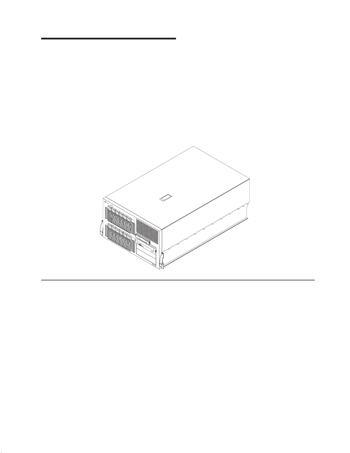
Chapter 1. General information
The IBM Eserver xSeries 255 Type 8685 server, which features IBM
X-Architecture
™™
technology, is a high-performance server that can be upgraded to
a symmetric multiprocessing (SMP) server through a microprocessor upgrade. It is
ideally suited for networking environments that require superior microprocessor
performance, efficient memory management, flexibility, and large amounts of reliable
data storage.
If you have access to the World Wide Web, you can obtain up-to-date information
about your server model and other IBM server products at
http://www.ibm.com/eserver/xseries/ on the World Wide Web.
Note: The illustrations in this document might differ slightly from your hardware.
Related publications
This Hardware Maintenance Manual and Troubleshooting Guide is provided in
Portable Document Format (PDF). It contains information to help you solve the
problem yourself or to provide helpful information to a service technician.
In addition to this Hardware Maintenance Manual and Troubleshooting Guide, the
following xSeries 255 Type 8685 documentation is provided with the server:
v User’s Guide
The User’s Guide provides general information about the server, including
information about features, how to configure the server, how to use the
ServerGuide
v Installation Guide
This printed publication contains setup and installation instructions.
v Rack Installation Instructions
This printed publication contains the instructions to install the server in a rack.
v Safety Information Book
This multilingual publication is provided in PDF on the IBM xSeries
Documentation CD. It contains translated versions of the caution and danger
© Copyright IBM Corp. 2002 1
™
Setup and Installation CD, and how to get help.
Page 12

statements that appear in the documentation for the server. Each caution and
danger statement has an assigned number, which you can use to locate the
corresponding statement in your native language.
v Option Installation Guide
This publication is provided in PDF on the IBM xSeries Documentation CD. It
contains instructions to install, remove, and connect optional devices supported
by your server.
Depending on your server model, additional publications might be included on the
IBM xSeries Documentation CD.
Notices and statements used in this book
The caution and danger statements used in this book also appear in the multilingual
Safety Information book provided on the IBM xSeries Documentation CD. Each
caution and danger statement is numbered for easy reference to the corresponding
statements in the safety book.
The following types of notices and statements are used in this book:
v Note: These notices provide important tips, guidance, or advice.
v Important: These notices provide information or advice that might help you avoid
inconvenient or problem situations.
v Attention: These notices indicate possible damage to programs, devices, or
data. An attention notice is placed just before the instruction or situation in which
damage could occur.
v Caution: These statements indicate situations that can be potentially hazardous
to you. A caution statement is placed just before the description of a potentially
hazardous procedure step or situation.
v Danger: These statements indicate situations that can be potentially lethal or
extremely hazardous to you. A danger statement is placed just before the
description of a potentially lethal or extremely hazardous procedure step or
situation.
2 xSeries 255 Type 8685: Hardware Maintenance Manual and Troubleshooting Guide
Page 13

Features and specifications
Table 1 provides a summary of the features and specifications for your server.
Table 1. Features and specifications
Microprocessor:
™®
™
v Intel
Xeon
MP
v 1 MB or 512 KB level-3 cache
depending upon model
v 400 MHz front-side bus (FSB)
v Support for up to four
microprocessors with Intel
Hyper-Threading technology and
Intel NetBurst
Memory:
™
microarchitecture
v Maximum: 12 GB
v Type: ECC, double-data rate (DDR),
SDRAM, registered DIMMs
v Slots: 2-way or 4-way interleaved, 12
slots
v Hot Spare memory
standard:
Drives
v Diskette: 1.44 MB
v CD-ROM: IDE
Available expansion bays:
v Hot-swap:
– Six slim-high in upper drive cage
– Six slim-high in lower drive cage
with optional SCSI backplane
installed
v Non-hot-swap: Two 5.25-inch
Expansion
slots:
v Six hot-plug PCI-X 100 MHz/64-bit
v One non-hot-plug PCI 33 MHz/32-bit
Hot-swap
power supplies:
370 W (115-230 V ac)
v Minimum: Two
v Maximum: Four for redundancy
Redundant
cooling:
Nine hot-swap fans
Video:
v ATI RageXL video controller
v Compatible with SVGA and VGA
v 8 MB video memory
Size (tower model with sides and
wheels):
v Height: 391 mm (15.4 in)
v Depth: 767 mm (30.2 in)
v Width: 446 mm (17.6 in)
v Weight: 47 kg (104 lb) to 55 kg (121.2
lb) depending upon configuration
Size (7 U) (rack model without sides or
wheels):
v Height: 307 mm (12.1 in)
v Depth: 767 mm (30.2 in)
v Width: 446 mm (17.6 in)
v Weight: 47 kg (104 lb) to 55 kg (121.2
lb) depending upon configuration
Integrated
v Dual-channel Ultra160 SCSI controller
(one internal and one external channel)
v Wake on LAN
v One Broadcom 10/100/1000 Mbps
Ethernet controller
v One serial port
v Four Universal Serial Bus ports
v Keyboard port
v Mouse port
v Video port
v Integrated system management
processor (ISMP) with two ISMP
(RS-485) RJ-45 connectors
Acoustical
v Sound power, idle: 6.3 bel maximum
v Sound power, operating: 6.3 bel
maximum
v Bystander (1 m) Sound pressure,
operating: 47 dBa maximum
v Bystander (1 m) Sound pressure, idle:
47 dBa maximum
functions:
®
support
noise emissions:
1
Environment:
v Air temperature:
– Server on: 10° to 35°C (50° to 95°F).
Altitude: 0 to 914 m (3000 ft).
– Server on: 10° to 32°C (50° to 89.6°F).
Altitude: 914 m (3000 ft) to 2133 m
(7000 ft).
– Server off: 10° to 43°C (50° to 110°F).
Maximum altitude: 2133 m (7000 ft).
Humidity:
v
– Server on: 8% to 80%
– Server off: 8% to 80%
Heat output:
Approximate heat output in British thermal
units (Btu) per hour:
v Minimum configuration: 461 Btu (0.14
kilowatts)
v Maximum configuration: 3412 Btu (1.0
kilowatts)
Electrical
input:
v Sine-wave input (50-60 Hz) required
v Input voltage low range:
– Minimum: 100 V ac
– Maximum: 127 V ac
v Input voltage high range:
– Minimum: 200 V ac
– Maximum: 240 V ac
Input kilovolt-amperes (kVA) approximately:
v
– Minimum: 0.08 kVA
– Maximum: 1.07 kVA
1. Racks are marked in vertical increments of 1.75 inches each. Each increment is referred to as a unit, or ″U.″ A 1-U-high device is
1.75 inches tall.
Chapter 1. General information 3
Page 14
Server controls and indicators
This section identifies the controls and indicators on the front and rear of your
server.
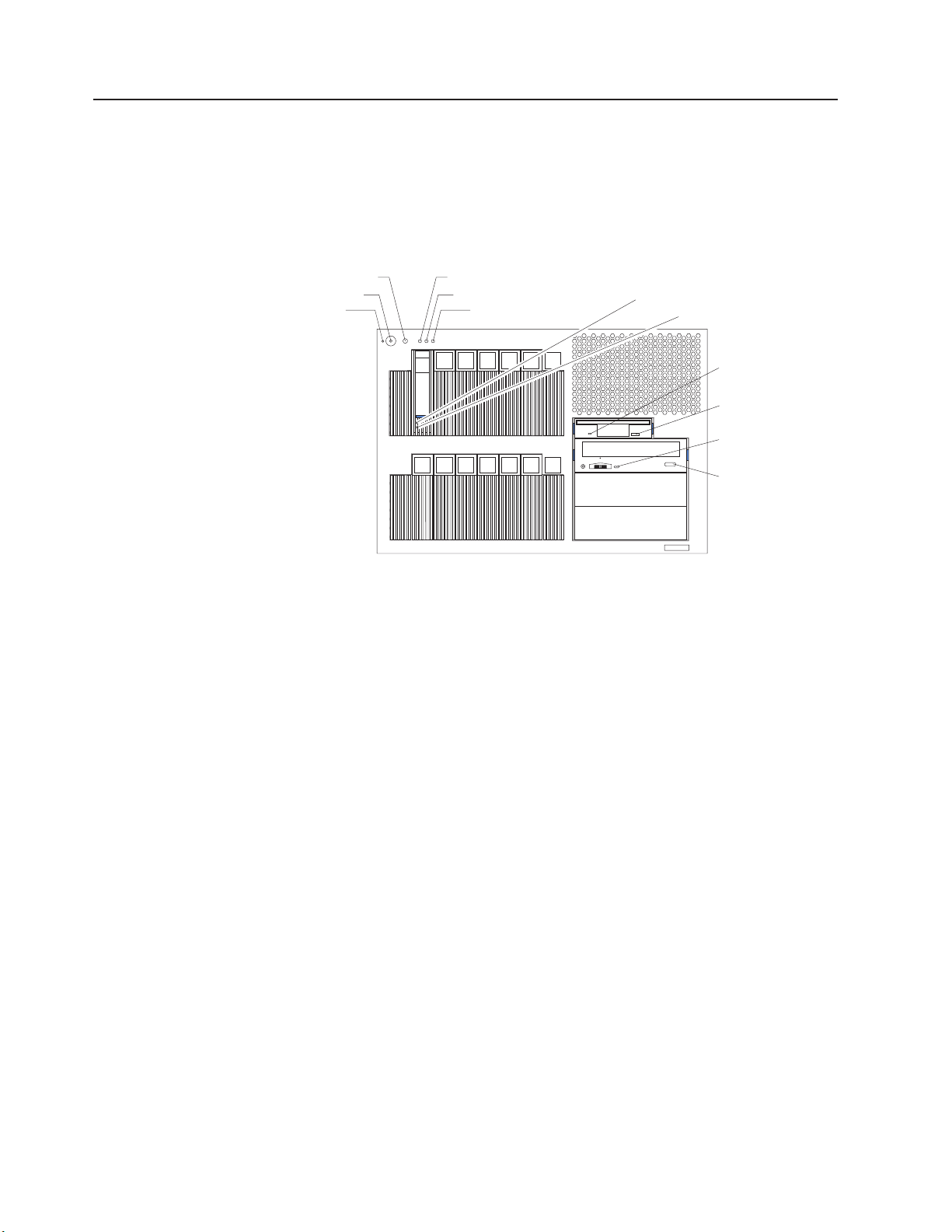
Front view
Tower and rack models
Power-control button
Reset button
Power-on LED
Activity LED
System information LED
System error LED
Hard disk drive
activity LED
Hard disk drive
status LED
Diskette drive
activity LED
Diskette-eject
button
CD-ROM drive
activity LED
CD-eject button
Notes:
1. The illustrations in this document might differ slightly from your hardware.
2. An amber LED illuminates when a system error or event has occurred. To
identify the error or event, check the LEDs on the light path diagnostics panel
located on the server (see “Light path diagnostics” on page 32), or review the
Error Log in the Configuration/Setup Utility program (see “Viewing error logs
from the Configuration/Setup Utility program” on page 28). For more information
about the Configuration/Setup Utility program, see “Choices available from the
Configuration/Setup Utility main menu” on page 11.
Power-on (system power) LED: When this green LED is on, system power is
present in the server. When this LED flashes, the server is in Standby mode (the
system power supply is turned off and ac current is present). When this LED is off,
a power supply, ac power, or an LED has failed.
Power-control button: Press this button to manually turn the server on or off or to
place the server in Standby mode (see “Standby mode” on page 8).
Power-control button shield: You can install this circular disk over the
power-control button to prevent accidental manual power-off. This disk is provided
with your server.
Reset button: Press this button to reset the server and run the power-on self-test
(POST).
ACT (activity) LED: This green LED is on when there is activity on the server.
INFO (system information) LED: When this amber LED is on, the server power
supplies are nonredundant, or some other noncritical event has occurred. The event
4 xSeries 255 Type 8685: Hardware Maintenance Manual and Troubleshooting Guide
Page 15

is recorded in the Error log. Check the light path diagnostics panel for more detailed
information (see “Light path diagnostics” on page 32).
FAULT (system-error) LED: This amber LED is on when a system error occurs. An
LED on the light path diagnostics panel will also be on to further isolate the error.
Hard disk drive activity LED: Each hot-swap drive has a hard disk drive activity
LED. When this green LED is flashing, the drive is being accessed.
Hard disk drive status LED: Each hot-swap drive has a hard disk drive status
LED. When this amber LED is on continuously, the drive has failed. If an optional
SCSI or RAID adapter is installed in the server, when the LED flashes slowly (one
flash per second), the drive is being rebuilt. When the LED flashes rapidly (three
flashes per second), the controller is identifying the drive.
Diskette drive activity LED: When this LED is on, it indicates that the diskette
drive is in use.
Diskette-eject button: Press this button to release a diskette from the drive.
CD-ROM drive activity LED: When this LED is on, it indicates that the CD-ROM
drive is in use.
Rear view
CD-eject button: Press this button to release a CD from the drive.
Notes:
1. The illustrations in this document might differ slightly from your hardware.
2. An amber LED illuminates when a system error or event has occurred. To
identify the error or event, check the LEDs on the light path diagnostics panel
located on the server, or review the Error Log in the Configuration/Setup Utility
program. For complete details about the light path diagnostics panel, see “Light
path diagnostics” on page 32. For more information about the
Configuration/Setup Utility program, see “Choices available from the
Configuration/Setup Utility main menu” on page 11.
Chapter 1. General information 5
Page 16
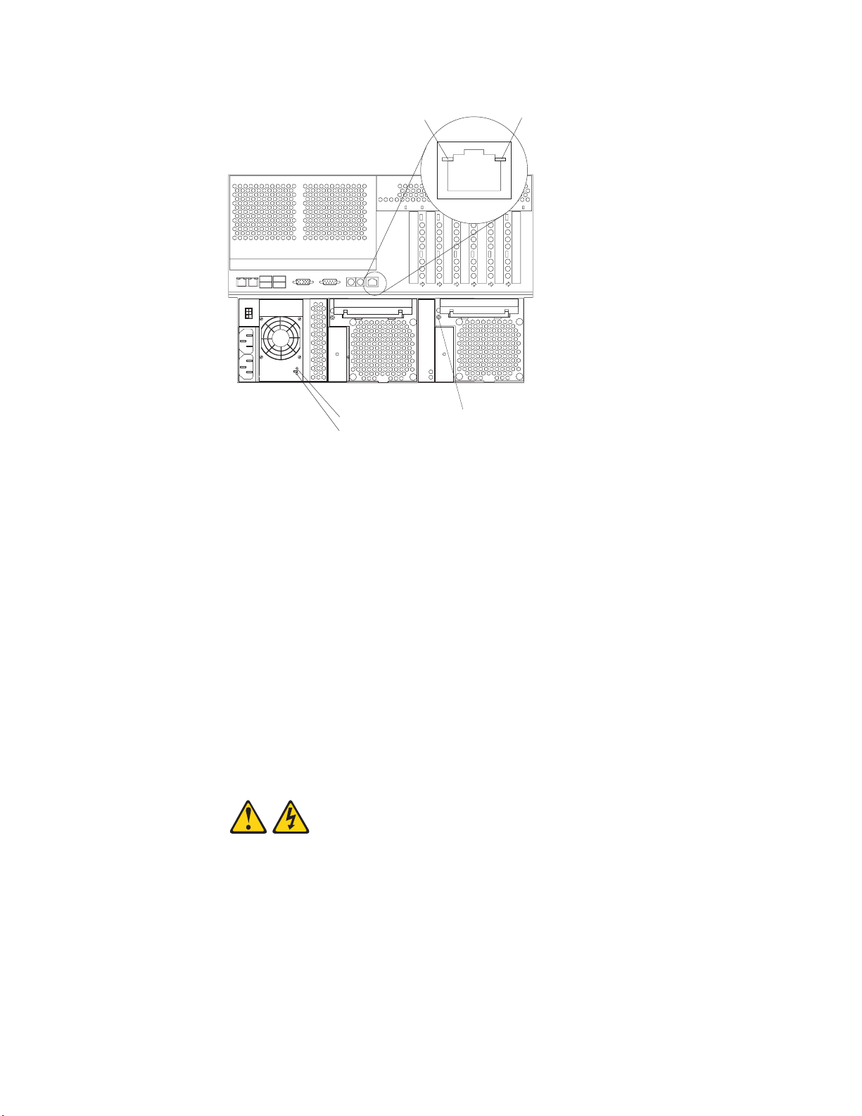
Ethernet activity
LED
AC power LED
DC power LED
Hot-swap fan error LED
Ethernet link
LED
Ethernet activity LED: When this green LED is on, there is activity between the
server and the network. The Ethernet activity LED is located on the Ethernet
(RJ-45) connector on the rear of the server.
Ethernet link LED: When this green LED is on, there is an active connection on
the Ethernet port. The Ethernet link LED is located on the Ethernet (RJ-45)
connector on the rear of the server.
Hot-swap fan error LEDs: These LEDs provide status information about fans 7, 8,
and 9 (the bottom rear fans in the power-supply bays).
AC power LED: This green LED provides status information about the power
supply. During typical operation, both the ac and dc power LEDs are on.
DC power LED: This green LED provides status information about the power
supply. During typical operation, both the ac and dc power LEDs are on.
Turning on the server
Statement 13:
6 xSeries 255 Type 8685: Hardware Maintenance Manual and Troubleshooting Guide
Page 17

DANGER
Overloading
a branch circuit is potentially a fire hazard and a shock hazard
under certain conditions. To avoid these hazards, ensure that your system
electrical requirements do not exceed branch circuit protection
requirements. Refer to the information that is provided with your device for
electrical specifications.
After you plug one end of each server power cord into the power-supply outlets on
the rear of the server and the other end of each power cord into an electrical outlet,
the server can start in any of the following ways:
v You can press the power-control button on the front of the server to start the
server.
Notes:
1. You can install a circular disk over the power-control button to prevent
accidental manual power-off. This disk, known as the power-control button
shield, comes with your server.
2. After you plug the power cords of your server into the electrical outlets, wait
approximately 20 seconds before pressing the power-control button. During
this time, the ISMP is initializing; therefore, the power-control button does not
respond.
If the server is turned on and a power failure occurs, the server will start
v
automatically when power is restored.
v If ac power is present, the server is in Standby mode, and the server is
connected to an Advanced System Management (ASM) interconnect network that
contains at least one system with an optional Remote Supervisor Adapter
installed, the server can be turned on from the Remote Supervisor Adapter user
interface.
v If ac power is present, the server is in Standby mode, and an optional Remote
Supervisor Adapter is installed in the server, the server can be turned on from
the Remote Supervisor Adapter user interface.
v When you plug in your server for the first time, the Wake on LAN feature can
turn on the server.
v If your server was previously turned on, it must be properly placed in Standby
mode for the Wake on LAN feature to turn on the server.
v If your operating system supports the Preboot eXecution Environment (PXE)
option and the PXE option is enabled through the Planar Ethernet PXE/DHCP
menu choice under Start Options on the Configuration/Setup Utility program
menu (see “Using the Configuration/Setup Utility program” on page 11), the
integrated Gigabit Ethernet controller (see “Configuring the Gigabit Ethernet
controller” on page 23) can turn on the server.
Complete the following steps to manually turn on the server:
1. Review the information in “Before you begin” on page 39, “Handling
static-sensitive devices” on page 40, and “Safety information” on page 167.
2. Turn on all external devices, such as the monitor.
3. Plug the server power cords into the power source.
4. Press the power-control button on the front of the server.
Note: While the server is turning on, the power-on LED on the front of the
server is lit.
Chapter 1. General information 7
Page 18
Turning off the server
The server can be turned off in any of the following ways:
v If the system is connected to an ASM interconnect network that contains at least
one system with an optional Remote Supervisor Adapter installed, the system
can be turned off from the Remote Supervisor Adapter user interface.
v If an optional Remote Supervisor Adapter is installed in the system, the system
can be turned off from the Remote Supervisor Adapter user interface.
Complete the following steps to manually turn off the server:
1. Review the information in “Before you begin” on page 39, “Handling
static-sensitive devices” on page 40, and “Safety information” on page 167.
2. See your operating system documentation for the proper procedure to shut
down the operating system.
When you turn off the server, observe the following precaution.
Statement 5:
CAUTION:
The power control button on the device and the power switch on the
power supply do not turn off the electrical current supplied to the device.
The device also might have more than one power cord. To remove all
electrical current from the device, ensure that all power cords are
disconnected from the power source.
Standby mode
2
1
3. Press the power-control button on the front of the server. This will put the server
in Standby mode.
Note: Yo u might need to press and hold the power-control button for more than
4 seconds to cause an immediate shutdown of the server and to force it
into Standby mode. You can use this feature if the operating system
stops functioning.
4. Disconnect the server from the power source.
Note: After disconnecting all the power cords, wait approximately 15 seconds
for your system to stop running. Watch for the power-on LED on the front
of the server to stop flashing.
Standby mode refers to the condition in which the server operating system is not
running and all core logic is shut down except for the optional Remote Supervisor
Adapter. In Standby mode, the server can respond to ISMP requests, such as a
remote request to turn on the server. When the server is in Standby mode, the
power-on LED on the front of the server flashes (when the server is running, the
power-on LED stays on and does not flash).
8 xSeries 255 Type 8685: Hardware Maintenance Manual and Troubleshooting Guide
Page 19

You can put the server in Standby mode in any of the following ways:
v You can press the power-control button on the server. This starts an orderly
shutdown of the operating system, if this feature is supported by your operating
system.
v If the server is connected to an ASM interconnect network that contains at least
one system with an optional Remote Supervisor Adapter installed, the server can
be placed in Standby mode from the Remote Supervisor Adapter user interface.
v If an optional Remote Supervisor Adapter is installed in the server, the server can
be placed in Standby mode from the Remote Supervisor Adapter user interface.
Attention: You must disconnect all the server power cords from the electrical
outlets to remove all power from the server.
Complete
the following steps to put the server in Standby mode:
1. See the operating-system documentation for the proper procedure to shut down
the operating system.
Note: Each operating system is different. Read all the documentation about
shutting down the operating system before continuing.
2. Press the power-control button on the front of the server.
Notes:
a. After you place the server in Standby mode, wait at least 5 seconds before
you turn on the server again.
b. You might need to press and hold the power-control button for more than 4
seconds to cause an immediate shutdown of the operating system and to
force it into Standby mode. Yo u can use this feature if the operating system
stops functioning.
ISMP can put the server in Standby mode as an automatic response to a
The
critical system failure. You can also put the server into Standby mode remotely by
means of an optional Remote Supervisor Adapter or through connection to an ASM
interconnect network.
Chapter 1. General information 9
Page 20

10 xSeries 255 Type 8685: Hardware Maintenance Manual and Troubleshooting Guide
Page 21

Chapter 2. Configuration
The following configuration programs are provided with your server:
v Configuration/Setup Utility
This program is part of the basic input/output system (BIOS) code that comes
with your server. Yo u can use this program to configure serial and parallel port
assignments, change interrupt request (IRQ) settings, change the drive startup
sequence, set the date and time, and set passwords. See “Using the
Configuration/Setup Utility program” for more information.
v SCSISelect Utility program
With the built-in SCSISelect Utility program, you can configure the devices that
are attached to the integrated SCSI controller. Use this program to change
default values, resolve configuration conflicts, and perform a low-level format on
a SCSI hard disk drive. See “Using the SCSISelect utility program” on page 18
for more information.
v ServerGuide CD
The ServerGuide CD includes software setup and installation tools that are
specifically designed for your IBM server. Yo u can use this CD during the initial
installation of your server to configure the server hardware and simplify your
network operating system installation. See “Using the ServerGuide Setup and
Installation CD” on page 20 for more detailed information.
v SCSI or RAID programs
The SCSI or RAID programs come with the optional SCSI or RAID adapter and
with server models that have a SCSI or RAID adapter preinstalled. If your server
has a SCSI or RAID adapter installed, you must use the SCSI or RAID
Configuration program to define and configure your disk-array subsystem before
you install your operating system.
Using the Configuration/Setup Utility program
This section provides the instructions to start the Configuration/Setup Utility program
and descriptions of the available menu choices.
Starting the Configuration/Setup Utility program
Complete the following steps to start the Configuration/Setup Utility program:
1. Turn on the server and watch the monitor screen.
2. When the message Press F1 for Configuration/Setup appears, press F1.
Note: If you have set both levels of passwords (user and administrator), you
must type the administrator password to access the full
Configuration/Setup Utility menu.
3. Follow the instructions that appear on the screen.
Choices available from the Configuration/Setup Utility main menu
From the Configuration/Setup Utility main menu, you can select settings that you
want to change. The Configuration/Setup Utility main menu is similar to the
following.
© Copyright IBM Corp. 2002 11
Page 22

Configuration/Setup Utility
•
System Summary
•
System Information
•
Devices and I/O Ports
•
Date and Time
•
System Security
•
Start Options
•
Advanced Setup
•
Error Logs
Save Settings
Restore Settings
Load Default Settings
Exit Setup
<F1> Help < > < > Move
<Esc> Exit <Enter> Select
↑↓
Notes:
1. You can press F1 to display help information for a selected menu item.
2. The choices on some menus might differ slightly, depending on the BIOS
version in your server.
The following choices are available from the main menu:
v System Summary
Select this choice to display configuration information. This includes the type and
speed of the microprocessors and the amount of memory that is installed.
Select this choice to view the microprocessor settings, such as identifiers, cache
sizes, and speeds.
Changes that you make to configuration settings appear on this summary screen.
You cannot edit the fields.
This choice appears on both the full and limited Configuration/Setup Utility
menus.
v System Information
Select this choice to display information about your server. Changes that you
make on other menus might appear on this summary screen. You cannot edit
any fields. The System Information choice appears only on the full
Configuration/Setup Utility main menu.
– Product Data
Select this choice to view system information, such as the machine type and
model, the server serial number, and the revision level or issue date of the
BIOS that is stored in the flash electrically erasable programmable ROM
(EEPROM).
Devices and I/O Ports
v
Select this choice to view or change the assignments for devices and
input/output ports. This choice appears only on the full Configuration/Setup Utility
main menu.
You can use this choice to enable or disable the integrated SCSI, video, and
Ethernet controllers.
– The default setting is Enable for all the controllers. If you select Disable, the
system will not configure the disabled device, and the operating system will
not detect the device. (This is equivalent to unplugging the device.)
12 xSeries 255 Type 8685: Hardware Maintenance Manual and Troubleshooting Guide
Page 23

– If the on-board SCSI controller is disabled and no other controller and mass
storage device are installed, operating-system startup cannot occur.
– If the video controller is disabled and no video adapter is installed, the server
will have no video capability.
Select System Service Processor Settings to view the interrupt-request setting
(IRQ) that is used by the ISMP (service processor). You can then use the arrow
keys to select a new IRQ setting for the ISMP from the list of available choices.
v Date and Time
Select this choice to set the system date and time and to change the system
time that is sent to the ISMP (service processor) when the server is started. This
choice appears only on the full Configuration/Setup Utility main menu.
The system time is in a 24-hour format (hour:minute:second).
v System Security
Select this choice to set passwords or a system owner’s name. This choice
appears only on the full Configuration/Setup Utility main menu.
You can implement two levels of password protection:
– Power-on Password
Select this choice to set or change a power-on password. See “Using
passwords” on page 16 for more information.
– Administrator Password
If an optional Remote Supervisor Adapter is installed in the server, you can
also set the administrator password and the remote-control password.
Select this choice to set or change an administrator password.
Attention: If an administrator password is set and then forgotten, it cannot
be overridden or removed. You must replace the Remote Supervisor Adapter
in PCI slot 1.
The administrator password provides access to all choices on the
Configuration/Setup Utility main menu. You can set, change, or delete both
the administrator and power-on passwords and allow a power-on password to
be changed by the user.
See “Using passwords” on page 16 for more information.
Start Options
v
Select this choice to view or change the start options. This choice appears only
on the full Configuration/Setup Utility main menu. Start options take effect when
you start your server.
You can select keyboard operating characteristics, such as the keyboard speed.
You also can specify whether the keyboard number lock starts on or off. You also
can enable the server to run without a diskette drive, monitor, or keyboard.
Note: If you attach a standard (non-USB) keyboard to the keyboard port, the
USB ports and devices will be disabled during the power-on self-test
(POST). You might need to enable keyboardless operation to prevent the
POST error message 301 from being displayed during startup. For
detailed information about this option and how to connect it to your server,
refer to the documentation that comes with the option.
The server uses a startup sequence to determine the device from which the
operating system is loaded. For example, you can define a startup sequence that
checks for a startable diskette in the diskette drive, then checks the hard disk
drive in bay 1, and then checks a network adapter.
You can set the Planar Ethernet PXE/DHCP menu choice to enable or disable
the Preboot eXecution Environment (PXE) option for the integrated Gigabit
Chapter 2. Configuration 13
Page 24

Ethernet controller. The default setting for this menu item is Planar Ethernet,
which enables the PXE option. To disable this option, select Disabled.
If the Boot Fail Count choice is enabled, you can restore the BIOS system
defaults after three consecutive boot failures. If this choice is disabled, the BIOS
system defaults can be loaded only from the Configuration/Setup Utility main
menu.
You can enable a virus-detection test that checks for changes in the master boot
record at startup.
v Advanced Setup
Select this choice to change values for advanced hardware features, such as
cache control, PCI configuration, Hot Spare Memory, and Hyper-Threading
technology. This choice appears only on the full Configuration/Setup Utility main
menu.
A warning message appears above the choices on this menu to alert you that the
system might malfunction if these options are configured incorrectly. Follow the
instructions on the screen carefully.
– System Partition Visibility
Select this choice to indicate whether the System Partition is visible. To make
the System Partition visible, set this value to Visible. To make the System
Partition invisible, set this value to Hidden. See “Using the ServerGuide Setup
and Installation CD” on page 20 for additional information about the System
Partition.
– Core Chipset Control
Select this choice to modify settings that control features of the core chip set
on the system board.
To maintain optimum system operation in the event of a memory failure, you
can enable the Hot Spare Memory feature on the Core Chipset Control
menu. This feature removes the failed memory from the system configuration
and activates a Hot Spare Memory pair or quad of DIMMs to replace the
failed memory pair or quad of DIMMs. Before you can enable the Hot Spare
Memory feature, you must also install at least one additional memory pair or
quad of DIMMs and adhere to special requirements as described in “Installing
memory modules” on page 80. Yo u can also enable the Memory Remapping
feature on the Core Chipset Control menu. To enable the Hot Spare Memory
and Memory Remapping features, change the values from No to Yes.
– CPU Options
Select this choice to enable or disable the microprocessor cache. In addition,
you can set the microprocessor cache mode to write-back (WB) or
write-through (WT). Selecting write-back mode will provide better system
performance.
– PCI Bus Control
Select this choice to view and identify system resources that are used by PCI
and PCI-X devices. PCI and PCI-X devices automatically communicate with
the server configuration information. This usually results in automatic
configuration of a PCI or PCI-X device.
After making changes, select:
- PCI MLT to assign Master Latency Timer (MLT) values for the PCI and
PCI-X devices in the server.
- PCI Interrupt Routing to assign interrupt values for the PCI and PCI-X
devices in the server.
Memory Settings
–
14 xSeries 255 Type 8685: Hardware Maintenance Manual and Troubleshooting Guide
Page 25

Select this choice to manually enable a pair or quad of memory.
Notes:
1. A pair or quad is also known as a memory bank.
2. You cannot disable memory. Memory can only be disabled by the server.
3. For details on enabling the Hot Spare Memory feature, see the description
of the Core Chipset Control menu under Advanced Setup.
If a memory error is detected during POST or memory configuration, the
server can automatically disable the failing memory pair or quad and continue
operating with reduced memory capacity. If this occurs, you must manually
enable the memory pair or quad after the problem is corrected. Select
Memory Settings from the Advanced Setup menu, and use the arrow keys
to highlight the pair or quad that you want to enable; then, use the arrow keys
to select Enable.
Note: For details on enabling the Hot Spare Memory feature, see the
description of the Core Chipset Control menu under Advanced Setup.
– Integrated System Management Processor Settings
Select this choice to set the server to automatically restart after a
nonmaskable interrupt (NMI) occurs. The default setting for this menu item is
Enabled.
Error Logs
v
Select this choice to view or clear error logs.
– Select POST Error Log to view the three most recent error codes and
messages that the system generated during POST.
Select Clear event/error logs from the POST Error Log menu to clear the
Error log.
– Select System Event/Error Log to view the System Event/Error log. The
System Event/Error log contains all the system error and warning messages
that the system has generated. Yo u can use the arrow keys to move between
pages in the System Event/Error log.
Select Clear event/error logs from the System Event/Error Log menu to
clear the Error or Event log.
v Save Settings
Select this choice to save your customized settings.
v Restore Settings
Select this choice to delete your changes and restore the previous settings.
v Load Default Settings
Select this choice to cancel your changes and restore the factory settings.
v Exit Setup
If you have made any changes, the program will prompt you to save the changes
or exit without saving the changes.
Additional Configuration/Setup Utility menu choices
When you install an optional Remote Supervisor Adapter in your server, you can
view additional menu choices in the Configuration/Setup Utility program, such as:
v System Card Data on the System Information menu
Select this choice to view vital product data (VPD) for some server components.
v PCI Slot Information
Chapter 2. Configuration 15
Page 26

Select this choice to view the properties of adapters that are installed in PCI and
PCI-X slots.
Important: You must use the menu selections to save custom settings for the
PCI Slot/Device Information choice. The Save Settings, Restore Settings, and
Load Default Settings choices on the main menu of the Configuration/Setup
Utility do not save the PCI Slot/Device Information settings.
After making changes, select:
– Save and exit the PCI Utility to save the changes and return to the
Advanced Setup choice.
– Exit the PCI Utility without saving changes to ignore the changes, restore
the previous settings, and return to the Advanced Setup choice.
You can use PCI Device Control to enable or disable the PCI and PCI-X slots
from this menu. The default setting is Enable for all the PCI slots. If you select
Disable, the system will not configure the disabled device, and the operating
system will not detect the device. (This is equivalent to unplugging the device.)
v Administrator Password
Select this choice to set or change the administrator password.
v Remote Control Security Settings
Select this choice to set a remote-control password. When you set a
remote-control password, you can also set the number of failed attempts to enter
the correct remote-control password, and the required duration before another
attempt can be made.
For a list of supported options for your server, go to
http://www.ibm.com/us/compat/ on the World Wide Web. To order an optional
Remote Supervisor Adapter, contact your IBM reseller or IBM marketing
representative.
Using passwords
The System Security choice appears only on the full Configuration/Setup Utility
menu. After you select this choice, you can implement two levels of password
protection: power-on password and administrator password.
Power-on password
After you set a power-on password, you can enable the Unattended Start mode.
This locks the keyboard and mouse but allows the operating system to start. The
keyboard and mouse remain locked until you type the correct password.
You can use any combination of up to seven characters (A–Z, a–z, and 0–9) for
your power-on password. Keep a record of your password in a secure place. When
a power-on password is set, POST is not completed until you type the password. If
you forget the power-on password, you can regain access to the server through one
of the following methods:
v Type the administrator password at the power-on prompt, if an administrator
v Change the position of the power-on password override switch (switch 6 on
password has been set. (If necessary, see “Administrator password” on page 17
for details.) Start the Configuration/Setup Utility program, and change the
power-on password.
switch block 2 on the system board) to bypass the power-on password check.
You can then start the Configuration/Setup Utility program and change the
power-on password (see “Starting the Configuration/Setup Utility program” on
page 11).
16 xSeries 255 Type 8685: Hardware Maintenance Manual and Troubleshooting Guide
Page 27

Notes:
1. Before changing any switch settings or moving any jumpers, turn off the
server; then, disconnect all power cords and external cables.
2. Any system-board switch or jumper blocks that are not shown in the
illustrations in this book are reserved.
Power-on password override (switch 6 on switch block 2)
v
Changing the position of this switch bypasses the power-on password check if
the switch has been moved since the server was last turned on. Yo u do not need
to move the switch back to the default position after the password is overridden.
The default position is Off. To bypass the power-on password check, change the
position to On
Changing the position of this switch does not affect the administrator password
check if an administrator password is set.
v Remove the battery and then reinstall the battery (see “Replacing the battery” on
page 101).
Administrator password
Select this choice to set an administrator password. The administrator password
provides access to all choices on the Configuration/Setup Utility main menu. Yo u
can set, change, or delete both the administrator and power-on passwords and
allow a power-on password to be changed by the user.
Attention: If an administrator password is set and then forgotten, it cannot be
overridden or removed. You must replace the Remote Supervisor Adapter in PCI
slot 1.
The following table provides a summary of the password features.
Table 2. Power-on and administrator password features
Type of password Features
Power-on password v Type the password to complete the system startup.
v All choices are available on the Configuration/Setup Utility main
menu.
Administrator password v No password is required to start the system.
v Type the password to access the Configuration/Setup Utility
program.
v All choices are available on the Configuration/Setup Utility main
menu.
Administrator and
power-on password
v Yo u can type either password to complete the system startup.
v The administrator password provides access to all choices on
the Configuration/Setup Utility main menu. Yo u can set,
change, or delete both the administrator and power-on
passwords and allow a power-on password to be changed by
the user.
v The power-on password provides access to a limited set of
choices on the Configuration/Setup Utility main menu. This
limited access might include changing or deleting the power-on
password.
Chapter 2. Configuration 17
Page 28

Using the SCSISelect utility program
SCSISelect is a built-in, menu-driven configuration utility program that you can use
to:
v View the default SCSI IDs
v Locate and correct configuration conflicts
v Perform a low-level format on a SCSI hard disk (some servers)
The following sections provide the instructions to start the SCSISelect Utility and
descriptions of the available menu choices.
Note: If your server has a RAID adapter installed, use the configuration method
supplied with the RAID adapter to view or change SCSI settings for attached
devices.
Starting the SCSISelect utility program
Complete the following steps to start the SCSISelect utility program:
1. Turn on the server.
2. When the <<< Press <CTRL><A> for SCSISelect Utility! >>> prompt appears,
press Ctrl+A.
Note: If an administrator password has been set, you are prompted to type the
password to start the SCSISelect Utility program.
3. When prompted, select either channel A (external) or channel B (internal).
4. Use the arrow keys to select a choice from the menu.
v Press Esc to return to the previous menu.
v Press F5 to switch between color and monochrome modes (if your monitor
permits).
Follow the instructions on the screen to change the settings of the selected
5.
items; then, press Enter.
Choices available from the SCSISelect menu
The following choices appear on the SCSISelect Utility menu:
v Configure/View Host Adapter Settings
Select this choice to view or change the SCSI controller settings. To reset the
SCSI controller to its default values, press F6; then, follow the instructions that
appear on the screen.
You can view or change the following controller settings:
– Host Adapter SCSI ID
Select this choice to view the SCSI controller ID, which is usually 7.
– SCSI Parity Checking
The assigned value for this setting is Enabled, and it cannot be changed.
– Host Adapter SCSI Termination
The assigned value for this setting is Enabled, and it cannot be changed.
– Boot Device Options
Select this choice to configure startable device parameters. Before you can
make updates, you must know the ID of the device whose parameters you
want to configure.
– SCSI Device Configuration
18 xSeries 255 Type 8685: Hardware Maintenance Manual and Troubleshooting Guide
Page 29

Select this choice to configure SCSI device parameters. Before you can make
updates, you must know the ID of the device whose parameters you want to
configure.
Note: The Maximum Sync Transfer Rate represents the transfer rate for Ultra
SCSI devices.
- The transfer rate for Ultra160 LVD devices is 160.0 MBps.
- The transfer rate for Ultra2 SCSI LVD devices is 80.0 MBps.
- The transfer rate for Fast SCSI devices is 20.0 MBps.
Advanced Configuration Options
–
Select this choice to view or change the settings for advanced configuration
options.
SCSI Disk Utilities
v
Select this choice to view the SCSI IDs that are assigned to each device or to
format a SCSI device.
To use the utility program, select a drive from the list. Read the screens carefully
before making a selection.
Note: If you press Ctrl+A before the selected drives are ready, an Unexpected
SCSI Command Failure screen might appear. Restart the server and
watch the SCSISelect messages as each drive spins up. After the drive
that you want to view or format spins up, press Ctrl+A.
v Format Disk
Attention: The Low-Level Format program erases all data and programs.
If this choice appears on the SCSISelect menu, select this choice to perform a
low-level format on a hard disk drive. Depending on the hard disk drive capacity,
the Low-Level Format program could take up to 2 hours.
Use the Low-Level Format program:
– When you are installing software that requires a low-level format
– When you get recurring messages from the diagnostic tests directing you to
run the Low-Level Format program on the hard disk drive
– As a last resort before replacing a failing hard disk drive
If your server has a PCI RAID adapter installed, see the RAID adapter
Note:
documentation for instructions for performing low-level formats on hard
disk drives attached to the adapter.
To start the Low-Level Format program:
1. If the hard disk drive is working, make a backup copy of all the files and
programs on the hard disk. (See your operating-system information for
instructions.)
2. Select Format Disk; then, follow the instructions on the screen.
Note: A hard disk typically contains more tracks than its stated capacity (to
allow for defective tracks). A message appears on the screen if the
defect limit is reached. If this happens, replace the hard disk drive.
Chapter 2. Configuration 19
Page 30

Using the ServerGuide Setup and Installation CD
The ServerGuide Setup and Installation CD includes an easy-to-use setup and
installation program that is specifically designed for your IBM server. The
ServerGuide program detects the server model and hardware options that are
installed and uses that information during setup to configure the hardware. The
ServerGuide program simplifies network operating system (NOS) installations by
providing updated device drivers and, in some cases, installing them automatically.
If a later version of the ServerGuide program is available, you can download a free
image of the ServerGuide Setup and Installation CD, or you can purchase the CD.
To download the latest ServerGuide program, go to the IBM ServerGuide Web page
at http://www.ibm.com/pc/qtechinfo/MIGR-4ZKPPT.html. To purchase the latest
ServerGuide Setup and Installation CD, see the “ServerGuide Updates” flyer that
comes with your server library, or go to the ServerGuide fulfillment Web site at
http://www.ibm.com/pc/coupon/.
The ServerGuide program has the following features to make setup easier:
v An easy-to-use interface with online help
v Diskette-free setup, and configuration programs that are based on detected
hardware
v Performance Optimizer program, which easily tunes your SCSI RAID adapter
settings for your server environment
v A system BIOS update program, which updates the BIOS code directly from the
CD
v Device drivers that are provided for your server model and detected hardware
v NOS partition size and file-system type that are selectable during setup
ServerGuide features
Features and functions can vary slightly with different versions of the ServerGuide
program. To learn more about the version that you have, start the ServerGuide
Setup and Installation CD and view the online overview. Not all features are
supported on all server models.
The ServerGuide program requires a supported IBM server with an enabled
startable (bootable) CD-ROM drive. In addition to the ServerGuide Setup and
Installation CD, you must have your NOS CD to install your NOS.
The ServerGuide program has the following features:
v Sets system date and time.
v Detects the SCSI RAID adapter or controller and runs the SCSI RAID
configuration program.
v Updates the licensed internal code (firmware) level without diskettes.
v Checks the system BIOS code and microcode (firmware) levels of supported
options to determine whether a later level is available from the CD. Yo u can
perform updates without using diskettes.
v Provides the Performance Optimizer program to easily tune your SCSI RAID
adapter settings for your server environment.
v Creates a System Partition on the default drive. Yo u can run server-specific utility
programs after setup.
v Detects installed hardware options and provides updated device drivers for most
adapters and devices.
v Creates a setup-replication diskette for replicating setup selections for other
servers of the same model.
20 xSeries 255 Type 8685: Hardware Maintenance Manual and Troubleshooting Guide
Page 31

v Provides diskette-free installation for supported operating systems.
v Provides a replicated installation path for multiple installations of supported
operating systems.
v Includes an online README file with links to tips for your hardware and NOS
installation.
Setup and configuration overview
When you use the ServerGuide Setup and Installation CD, you do not need setup
diskettes. You can use the CD to configure any supported IBM server model. The
ServerGuide program checks your system BIOS, service processors, and other
system hardware to determine if system updates are available. The setup program
provides a list of tasks that are required to set up your server model. On SCSI
RAID servers, you can run the SCSI RAID configuration program to create logical
drives.
Note: Features and functions can vary slightly with different versions of the
ServerGuide program.
When you start the ServerGuide Setup and Installation CD, the program performs
the following tasks:
v The ServerGuide program prompts you for your language, country, and keyboard
layout. (This information is stored and later passed to the NOS installation
program.)
v The ServerGuide program displays choices for running the configuration
programs. For example:
– The Express Configuration method runs the required programs for your
server, based on the hardware that is detected.
– The Custom Configuration method displays all programs that are available for
your server, and you decide which programs to run.
– The Replicated Configuration method provides the option of duplicating your
setup selections to other servers that are the same model.
If you select the Custom Configuration method, the following features are
v
optional. If you select the Express Configuration method, some or all of these
features are run, depending on the hardware that is detected:
– The Set Date and Time feature is provided so that you do not have to use the
Configuration/Setup Utility program to access these settings.
– The Clear Hard Disks feature is provided so you can delete all partitions on all
hard disk drives. If the server has a SCSI RAID adapter installed, you can
select to restore the configuration on the SCSI RAID adapter to the factory
default settings.
– The ServerGuide program checks the server BIOS code and microcode
(firmware) levels for supported options and then checks the CD for a newer
level. The CD content might be newer than the BIOS code and firmware level.
The ServerGuide program can perform a flash update of the BIOS code and
supported microcode (firmware) options without using diskettes.
– The SCSI RAID configuration program starts, leading you through the entire
configuration process.
– The Performance Optimizer program easily tunes your server for your
environment.
– The ServerGuide program creates a System Partition on the default drive.
Chapter 2. Configuration 21
Page 32

v The ServerGuide program displays a confirmation summary, so that you will
know when you have completed all the required tasks. Then, you are ready to
install your NOS.
Notes:
1. Plug and Play adapters are configured automatically. Non-Plug and Play
adapters or non-IBM adapters might require switch settings, additional device
drivers, and installation after the NOS is installed. See the documentation that
comes with the adapter.
2. Diagnostics for your server come in BIOS code or on a separate diagnostics
CD.
System Partition
The ServerGuide program creates a 50 MB System Partition on the default drive.
The System Partition contains server-specific utility programs such as service
processor disk operating system (DOS) utilities, system diagnostics, flash BIOS
updates, and other programs. Programs in the System Partition vary by server
model, and not all server models run utility programs from the System Partition. To
determine which ones do, start the ServerGuide Setup and Installation CD and view
the online overview.
After setup is complete, you can access programs in the System Partition by
restarting the server and pressing Alt+F1 when the prompt is displayed. The
System Partition menu displays the programs that are available on your server
model.
Typical NOS installation
You can use the ServerGuide program to shorten your installation time. The
ServerGuide program provides the device drivers that are required for your
hardware and for the NOS that you are installing. This section describes a typical
ServerGuide NOS installation.
Note: Features and functions can vary slightly with different versions of the
ServerGuide program.
1. After you have completed the setup process, the NOS installation program
starts. (You will need your NOS CD to complete the installation.)
2. The ServerGuide program stores information about the server model, service
processor, hard disk drive controllers, and network adapters. Then, the program
checks the CD for newer device drivers. This information is stored and then
passed to the NOS installation program.
3. With some NOS installations, you can create a NOS-replication diskette for
setting up additional servers. This diskette contains the Internet protocol (IP)
address, server name, and other selections.
4. The ServerGuide program presents NOS partition options that are based on
your NOS selection and the installed hard disk drives.
5. If you are installing the NOS from diskette, the ServerGuide program lists the
diskettes that you must create and the optional diskettes that you might want to
create. The diskettes that you can create are the device-driver diskettes for the
installed adapters or controllers.
6. The ServerGuide program prompts you to insert your NOS CD and restart the
server. At this point, the installation program for the NOS takes control to
complete the installation.
22 xSeries 255 Type 8685: Hardware Maintenance Manual and Troubleshooting Guide
Page 33

Setting up or updating multiple servers
You can use the ServerGuide program to create diskettes that help you set up or
update multiple servers. You can modify information on the diskettes as you use
them to set up or update other servers.
Note: Availability and function can vary by server model and by the hardware that
is installed.
You can create a setup-replication diskette, which contains your hardware
configuration selections. Use this diskette to replicate selections to other servers
that are of the same model.
You can create a NOS-replication diskette, which contains information that you need
to complete multiple installations. Not all operating systems support NOS-replication
diskettes.
Installing your NOS without ServerGuide
If you have already configured the server hardware and you decide not to use the
ServerGuide program to install your NOS, complete the following steps to download
the latest NOS installation instructions from the IBM Support Web page:
1. Go to http://www.ibm.com/pc/support/.
2. Under Browse, click Servers.
3. From the Family drop-down list, select your server model.
4. If NOS installation instructions are available for your server model, OS
installation is in the list in the upper-left corner of the Web page. Click OS
installation and select the instructions for your NOS.
Configuring the Gigabit Ethernet controller
The Ethernet controller is integrated on the system board. This controller provides
an interface for connecting to 10-Mbps, 100-Mbps, or 1000-Mbps networks and
provides full duplex (FDX) capability, which enables simultaneous transmission and
reception of data on the Ethernet local area network (LAN). You do not need to set
any jumpers or configure the controller for your operating system before you use
the Ethernet controller. However, you must install a device driver to enable your
operating system to address the Ethernet controller. The device drivers are provided
on the ServerGuide Setup and Installation CD.
When you connect your server to the network, the Ethernet controller automatically
detects the data-transfer rate (10-Mbps, 100-Mbps, or 1000-Mbps) on the network
and then sets the controller to operate at the appropriate rate. In addition, if the
Ethernet ports that your server is connected to support auto-negotiation, the Gigabit
Ethernet controller will set the appropriate duplex state. That is, the Ethernet
controller will adjust to the network data rate, whether the data rate is standard
Ethernet (10BASE-T), Fast Ethernet (100BASE-TX/1000BASE-T), half duplex
(HDX), or full duplex (FDX). The controller supports half-duplex (HDX) and
full-duplex (FDX) modes at both speeds.
For information on configuring your Ethernet controller, see the Broadcom
NetXtreme Gigabit Ethernet Software CD that comes with your server. For updated
information about configuring your Ethernet controller, go to the IBM Support Web
site at http://www.ibm.com/pc/support and navigate to the area for your specific
server type. From this area you can download documentation, the most current
Chapter 2. Configuration 23
Page 34

device drivers for your server, and software that supports advanced networking
functions. After downloading, run the downloaded program launch.exe.
High-performance Ethernet modes
Your Ethernet controller supports optional modes, such as teaming, priority packets,
load balancing, fault tolerance, and virtual LANs, which provide higher performance,
security, and throughput for your server. These modes apply to the integrated
Ethernet controller and to the controllers on supported Ethernet adapters.
Ethernet port connector
The following illustration shows the pin-number assignments for the RJ-45
connector. These assignments apply to the 10BASE-T, 100BASE-TX, and
1000BASE-T devices.
8
1
24 xSeries 255 Type 8685: Hardware Maintenance Manual and Troubleshooting Guide
Page 35

Chapter 3. Diagnostics
This section provides basic troubleshooting information to help you resolve some
common problems that might occur with your server.
If you cannot locate and correct the problem using the information in this section,
see Appendix A, “Getting help and technical assistance,” on page 165 for more
information.
General checkout
The server diagnostic programs are stored in upgradeable read-only memory
(ROM) on the system board. These programs are the primary method of testing the
major components of the server: the system board, Ethernet controller, video
controller, RAM, keyboard, mouse (pointing device), diskette drive, serial ports, and
hard disk drives. You can also use the diagnostic programs to test some external
devices. See “Diagnostic programs and error messages” on page 28.
If you cannot determine whether a problem is caused by the hardware or by the
software, you can run the diagnostic programs to confirm that the hardware is
working properly.
When you run the diagnostic programs, a single problem might cause several error
messages. When this occurs, work to correct the cause of the first error message.
After the cause of the first error message is corrected, the other error messages
might not occur the next time you run the test.
A failed system might be part of a shared DASD cluster (two or more systems
sharing one or more external storage devices). Before you run diagnostics, verify
that the failing system is not part of a shared DASD cluster.
A system might be part of a cluster if:
v The system is identified as part of a cluster.
v One or more external storage units are attached to the system and at least one
of the attached storage units is also attached to another system or unidentifiable
source.
v One or more systems are located near the failing system.
If the failing system is suspected to be part of a shared DASD cluster, you can run
all diagnostic tests except the diagnostic tests that test the storage unit (DASD
residing in the storage unit) or the storage adapter attached to the storage unit.
Notes:
1. For systems that are part of a shared DASD cluster, run one test at a time in
looped mode. Do not run all tests in looped mode, because this could enable
the DASD diagnostic tests.
2. If multiple error codes are displayed, diagnose the first error code that is
displayed.
3. If the computer stops with a POST error, go to “POST error codes” on page
146.
4. If the computer stops and no error is displayed, go to “Undetermined problems”
on page 157.
5. For power supply problems, see “Power-supply LED errors” on page 145.
© Copyright IBM Corp. 2002 25
Page 36

6. For safety information, see “Safety information” on page 167.
7. For intermittent problems, check the error log.
001 IS THE SYSTEM PART OF A CLUSTER?
YES. Schedule maintenance for the system. Shut down all systems related
to the cluster. Run the storage test.
NO. Go to step 002.
002 IF THE SYSTEM IS NOT PART OF A CLUSTER:
1. Turn off the server and all external devices.
2. Check all cables and power cords.
3. Set all display controls to the middle position.
4. Turn on all external devices.
5. Turn on the server.
6. Record any POST error messages that are displayed on the screen. If
an error is displayed, look up the first error in the “POST error codes”
on page 146.
7. Check the information LED panel System Error LED; if it is on, see
“Diagnostic panel system error LED” on page 130.
8. Check the System Error log. If an error was recorded by the system,
see Chapter 6, “Symptom-to-FRU index,” on page 127.
9. Start the diagnostic programs.
10. Check for the following responses:
v One beep.
v Readable instructions or the main menu.
DID YOU RECEIVE BOTH OF THE CORRECT RESPONSES?
003
NO. Find the failure symptom in Chapter 6, “Symptom-to-FRU index,” on
page 127.
YES. Run the diagnostic programs. If necessary, see “Diagnostic programs
and error messages” on page 28.
If you receive an error, see Chapter 6, “Symptom-to-FRU index,” on page
127.
If the diagnostic programs were completed successfully and you still
suspect a problem, see “Undetermined problems” on page 157.
26 xSeries 255 Type 8685: Hardware Maintenance Manual and Troubleshooting Guide
Page 37

Diagnostic tools overview
The following tools are available to help you identify and resolve hardware-related
problems:
v POST beep codes, error messages, and error logs
The power-on self-test (POST) generates beep codes and messages to indicate
successful test completion or the detection of a problem. See “POST error logs”
for more information.
v Diagnostic programs and error messages
The server diagnostic programs are stored in upgradeable read-only memory
(ROM) on the processor board. These programs are the primary method of
testing the major components of your server. See “Diagnostic programs and error
messages” on page 28 for more information.
v Light path diagnostics
Your server has light-emitting diodes (LEDs) to help you identify problems with
server components. These LEDs are part of the light path diagnostics that are
built into your server. By following the path of lights, you can quickly identify the
type of system error that occurred. See “Identifying problems using status LEDs”
on page 30 for more information.
v Error symptoms
Other error symptoms, along with suggested steps to correct the problems, are
described at “Error symptoms” on page 138.
POST error logs
When you turn on the server, it performs a series of tests to check the operation of
server components and some of the options that are installed in the server. This
series of tests is called the power-on self-test, or POST.
If POST finishes without detecting any problems, a single beep sounds, and the first
screen of your operating system or application program appears.
If POST detects a problem, more than one beep sounds, and an error message
appears on your screen. See “Beep symptoms” on page 127 and “POST error
codes” on page 146 for more information.
Notes:
1. If you have a power-on password or administrator password set, you must type
the password and press Enter, when prompted, before POST will continue.
2. A single problem might cause several error messages. When this occurs, work
to correct the cause of the first error message. After you correct the cause of
the first error message, the other error messages usually will not occur the next
time you run the test.
The POST error log contains the three most recent error codes and messages that
the system generated during POST. The System Error log contains all messages
issued during POST and all system status messages from the service processor.
You can view the contents of the System Error log from the Configuration/Setup
Utility program or from the diagnostic programs.
Chapter 3. Diagnostics 27
Page 38

Viewing error logs from the Configuration/Setup Utility program
Start the Configuration/Setup Utility program; then, select Error Logs from the main
menu. See “Using the Configuration/Setup Utility program” on page 11 for more
information.
Viewing error logs from diagnostic programs
Start the diagnostic programs (“Starting the diagnostic programs” on page 29);
select Hardware Info from the top of the diagnostic programs screen; select
System Error Log from the list that appears; then, follow the instructions on the
screen.
Diagnostic programs and error messages
The server diagnostic programs are stored in upgradeable read-only memory
(ROM) on the system board. These programs are the primary method of testing the
major components of your server.
Diagnostic error messages indicate that a problem exists; they are not intended to
be used to identify a failing part. Troubleshooting and servicing of complex
problems that are indicated by error messages should be performed by trained
service personnel.
Sometimes the first error to occur causes additional errors. In this case, the server
displays more than one error message. Always follow the suggested action
instructions for the first error message that appears.
The following sections contain the error codes that might appear in the detailed test
log and summary log when the diagnostic programs are run.
The error code format is as follows:
fff-ttt-iii-date-cc-text message
where:
fff is the three-digit function code that indicates the function being
tested when the error occurred. For example, function code 089 is
for the microprocessor.
ttt is the three-digit failure code that indicates the exact test failure that
was encountered. (These codes are for trained service personnel;
see “Diagnostic error codes” on page 133).
iii is the three-digit device ID. (These codes are for trained service
personnel; see “Diagnostic error codes” on page 133).
date is the date that the diagnostic test was run and the error recorded.
cc is the check value that is used to verify the validity of the
information.
text message is the diagnostic message that indicates the reason for the problem.
Text messages
The diagnostic text message format is as follows:
Function Name: Result (test specific string)
where:
28 xSeries 255 Type 8685: Hardware Maintenance Manual and Troubleshooting Guide
Page 39

Function Name
is the name of the function being tested when the error occurred. This
corresponds to the function code (fff) shown in the error code format in the
previous section.
Result
can be one of the following:
Passed This result occurs when the diagnostic test
is completed without any errors.
Failed This result occurs when the diagnostic test
discovers an error.
User Aborted This result occurs when you stop the
diagnostic test before it is complete.
Not Applicable This result occurs when you specify a
diagnostic test for a device that is not
present.
Aborted This result occurs when the test could not
proceed, for example, because of the
system configuration.
Warning This result occurs when a possible problem
is reported during the diagnostic test, such
as when a device driver is not found.
specific string
test
is additional information that you can use to analyze the problem.
Starting the diagnostic programs
You can press F1 while running the diagnostic programs to obtain help information.
You also can press F1 from within a help screen to obtain online documentation
from which you can select different categories. To exit from the help information and
return to where you left off, press Esc.
Complete the following steps to start the diagnostic programs:
1. Turn on the server and watch the screen.
Note: To run the diagnostic programs, you must start the server with the
highest level password that is set. That is, if an administrator password is
set, you must enter the administrator password, not the power-on
password, to run the diagnostic programs.
2. When the message F2 for Diagnostics appears, press F2.
3. Type the appropriate password; then, press Enter.
4. Select either Extended or Basic from the top of the screen.
5. When the Diagnostic Programs screen appears, select the test you want to run
from the list that appears; then, follow the instructions on the screen.
Notes:
a. If the server stops during testing and you cannot continue, restart the server
and try running the diagnostic programs again. If the problem remains,
replace the component that was being tested when the server stopped.
b. The keyboard and mouse (pointing device) tests assume that a keyboard
and mouse are attached to the server.
Chapter 3. Diagnostics 29
Page 40

c. If you run the diagnostic programs with either no mouse or a USB mouse
attached to your server, you will not be able to navigate between test
categories using the Next Cat and Prev Cat buttons. All other functions
provided by mouse-selectable buttons are also available using the function
keys.
d. You can test the USB keyboard by using the regular keyboard test. The
regular mouse test can test a USB mouse. Also, you can run the USB
interface test only if there are no USB devices attached.
e. You can view server configuration information (such as system configuration,
memory contents, interrupt request (IRQ) use, direct memory access (DMA)
use, device drivers, and so on) by selecting Hardware Info from the top of
the screen.
the diagnostic programs do not detect any hardware errors but the problem
If
persists during normal server operations, a software error might be the cause. If
you suspect a software problem, see the information that comes with the software
package.
Viewing the test log
When the tests are completed, you can view the test log by selecting Utility from
the top of the screen and then selecting View Test Log.
Notes:
1. You can view the test log only while you are in the diagnostic programs. When
you exit the diagnostic programs, the test log is cleared (saved test logs are not
affected). To save the test log so that you can view it later, click Save Log on
the diagnostic programs screen and specify a location and name for the saved
log file.
2. To save the test log to a diskette, you must use a diskette that you have
formatted yourself; this function does not work with preformatted diskettes. If the
diskette has sufficient space for the test log, the diskette may contain other
data.
Viewing the System Error log
You can also view the System Error log from the diagnostic programs. See the
instructions in “Viewing error logs from diagnostic programs” on page 28.
Diagnostic error message tables
For descriptions of the error messages that might appear when you run the
diagnostic programs, see “Diagnostic error codes” on page 133.
Notes:
1. Depending on your server configuration, some of these error messages might
not appear when you run the diagnostic programs.
2. If diagnostic error messages appear that are not listed in the following tables,
make sure that your server has the latest levels of BIOS, Advanced System
Management Processor, ServeRAID™, and diagnostics microcode installed.
Identifying problems using status LEDs
Your server has LEDs to help you identify problems with some server components.
These LEDs are part of the light path diagnostics built into the server. By following
the path of lights, you can quickly identify the type of system error that occurred.
30 xSeries 255 Type 8685: Hardware Maintenance Manual and Troubleshooting Guide
Page 41

LEDs for Active PCI slots
Each Active (hot-plug) PCI slot has two LEDs associated with it: one Power-on LED
and one Attention LED. The illustration in “System-board LED locations” on page 47
shows the location of these LEDs.
Power-on LED
This LED is on when the hot-plug PCI slot has power. An adapter must not
be added to or removed from the PCI slot when the Power-on LED is on.
When this LED is off, the hot-plug PCI slot has no power applied. An
adapter can be added to or removed from the PCI slot when the Power-on
LED is off.
See your operating-system documentation to determine if your operating
system supports hot-plug PCI adapters and, if so, how to disable the
hot-plug PCI slot.
Attention LED
Each hot-plug PCI slot has an Attention LED that can be seen from inside
the server.
An Attention LED flashes approximately once per second when it is on. The
meaning of the Attention LED is defined by your operating system. See
your operating-system documentation to determine if your operating system
supports hot-plug PCI adapters and, if so, what the Attention LED indicates.
The following table describes the Power-on and Attention LEDs.
Power-on LED Attention LED Description and action
On Flashing The adapter requires attention. The slot still
On Off Normal operation; no intervention is
Off Flashing The adapter requires intervention. Power is
Off Off Power is removed from the slot. An adapter
Power-supply LEDs
The ac and dc power LEDs on the power supply provide status information about
the power supply. The following illustration shows the location of the ac and dc
power LEDs.
has power applied. Do not remove or install
an adapter in the slot. See your
operating-system documentation for
instructions.
required.
removed from the slot. An adapter can be
removed or installed in the slot.
can be removed or installed in the slot.
Chapter 3. Diagnostics 31
Page 42

Hot-swap fan
Release
latch
Power supply
Release latch
AC power LED
DC power LED
Handle
(open position)
For more information about the ac and dc power LEDs, see “Power-supply LED
errors” on page 145.
Light path diagnostics
You can use the light path diagnostics feature built into your server to quickly
identify the type of system error that occurred. Your server is designed so that LEDs
remain illuminated when the server shuts down, as long as the power supplies are
operating properly. This feature helps you to isolate the problem if an error causes
the server to shut down.
Diagnostic panel LEDs
The following illustration shows the location of the error LEDs and the Remind
button on the light path diagnostics panel. See “Diagnostic panel system error LED”
on page 130 for information on identifying problems using these LEDs.
ISMP
NMI
PCIA
PCIB
PS1
PS2
PS3
PS4
Light Path
Diagnostics™
LOG
PCIC PCID DASD
VRM
OVER
SPEC
REMIND
TEMP
NON
REDUND
CPU
FAN
MEMORY
D7
D1
D2
D9
D3
D10
D4
D11
D5
D12
D6
D8
Notes:
1. If the memory is configured for 2-way or 4-way memory interleaving and a
single DIMM fails, the lights for all of the interleaved DIMMs on that bank will be
lit. See “Memory errors” on page 34.
2. The light path diagnostics panel is also called the LED card or the diagnostic
LED panel.
32 xSeries 255 Type 8685: Hardware Maintenance Manual and Troubleshooting Guide
Page 43

3. Depending on your server model, these items might appear in a different
orientation on the light path diagnostics panel.
4. If an integrated system board VRM or memory board VRM has failed, run
diagnostics (“Starting the diagnostic programs” on page 29) and see Chapter 6,
“Symptom-to-FRU index,” on page 127.
5. See the documentation that comes with the system-management software for
more information on the ISMP and system-management adapter.
Remind button
You can use the Remind button to place the front panel system-error LED into the
Remind mode. By pressing the button, you acknowledge the failure but indicate that
you will not take immediate action. If a new failure occurs, the system-error LED will
turn on again.
In the Remind mode, the system-error LED flashes every 2 seconds. The
system-error LED remains in the Remind mode until one of the following situations
occurs:
v All known problems are resolved
v The system is restarted
v A new problem occurs
can use the Remind button to delay server maintenance until a later time. Also,
You
resetting the system-error LED enables the LED to react to another error. If the LED
is still on from the first error, it will not indicate additional errors. If you press the
Remind button (causing the LED to flash every 2 seconds) and another error
occurs, the LED will stop flashing and will instead be lit continuously to alert you to
the new error.
Light path diagnostics
The system-error LED on the operator information panel is lit when certain system
errors occur. If the system-error LED on your server is lit, you can determine the
cause of the error and the action you should take by checking the table at
“Diagnostic panel system error LED” on page 130.
Error symptoms
This section describes methods for troubleshooting other error symptoms.
Error symptom charts
You can use the error symptom charts to find solutions to problems that have
definite symptoms (see “Error symptoms” on page 138).
If you cannot find the problem in the error symptom charts, go to “Starting the
diagnostic programs” on page 29 to test the server.
Small computer system interface messages
If your receive a SCSI error message when running the SCSISelect Utility program,
see “SCSI error codes” on page 153.
Note: If your server does not have a hard disk drive, ignore any message that
indicates that the BIOS is not installed.
Chapter 3. Diagnostics 33
Page 44

Memory errors
If the memory is configured for 2-way or 4-way memory interleaving and a single
DIMM fails, the lights for all of the interleaved DIMMs on that bank will be lit. Before
replacing all DIMMs on that bank:
1. Reseat all DIMMs on that bank.
2. Check for a memory mismatch.
3. Run the diagnostic programs (see “Starting the diagnostic programs” on page
29) and Chapter 6, “Symptom-to-FRU index,” on page 127.
a memory error is identified by the bank in which the failing DIMM is located, use
If
the following table to determine the correct group of DIMMs:
Table 3. Memory bank installation
Pairs 2-way installation order 4-way installation order Bank number
1 1. D2, D8 (std) 1. D2, D8, D1, D7 Bank 3
2 2. D4, D10 2. D4, D10, D3, D9 Bank 2
3 3. D6, D12 3. D6, D12, D5, D11 Bank 1
ServerGuide error symptoms
Look for the symptom in the left column of the chart. Probable solutions to the
problem are in the right column.
Table 4. ServerGuide Setup and Installation CD
Symptom Suggested action
The ServerGuide
Setup and
Installation CD will
not start.
The SCSI RAID
program cannot
view all installed
drives, or the NOS
cannot be installed.
The Operating
System Installation
program
continuously loops.
The ServerGuide
program will not
start your NOS CD.
The NOS cannot
be installed; the
option is not
available.
v Ensure that the server is supported and has a startable (bootable)
CD-ROM drive.
v If the startup (boot) sequence settings have been altered, ensure
that the CD-ROM drive is first in the startup sequence.
v If more than one CD-ROM drive is installed, ensure that only one
drive is set as the primary drive. Start the CD from the primary
drive.
v Ensure that there are no duplicate SCSI IDs or IRQ assignments.
v Ensure that the hard disk drive is connected properly.
Make more space available on the hard disk.
Ensure that the NOS CD you have is supported by the ServerGuide
program. See the ServerGuide Setup and Installation CD label for a
list of supported NOS versions.
Ensure that the NOS is supported on your server. If the NOS is
supported, either there is no logical drive defined (SCSI RAID
systems) or the ServerGuide System Partition is not present. Run the
ServerGuide program, and ensure that setup is complete.
34 xSeries 255 Type 8685: Hardware Maintenance Manual and Troubleshooting Guide
Page 45

Power checkout
Power problems can be difficult to solve. For example, a short circuit can exist
anywhere on any of the power distribution buses. Usually a short circuit will cause
the power subsystem to shut down because of an overcurrent condition.
A general procedure for troubleshooting power problems is as follows:
1. Turn off the server and disconnect all ac power cords.
2. Check for loose cables in the power subsystem. Also check for short circuits, for
example, if there is a loose screw causing a short circuit on a circuit board.
3. Remove adapters and disconnect the cables and power connectors to all
internal and external devices until the server is at the minimum configuration
required to start the server (see “Minimum operating requirements” on page
157).
4. Reconnect all ac power cords and turn on the server. If the server starts up
successfully, replace adapters and devices one at a time until the problem is
isolated. If the server does not start up from the minimal configuration, replace
FRUs of minimal configuration one at a time until the problem is isolated.
To use this method, it is important to know the minimum configuration required for a
system to start (see page 157). For specific problems, see “Power-supply LED
errors” on page 145.
Troubleshooting the Ethernet controller
This section provides troubleshooting information for problems that might occur with
the 10/100/1000 Mbps Ethernet controller.
Network connection problems
If the Ethernet controller cannot connect to the network, check the following
conditions:
v Make sure that the cable is installed correctly.
The network cable must be securely attached at all connections. If it does the
cable is attached but the problem remains, try a different cable.
If you set the Ethernet controller to operate at either 100 Mbps or 1000 Mbps,
you must use Category 5 or higher cabling.
v Determine whether the hub supports auto-negotiation. If it does not, try
configuring the integrated Ethernet controller manually to match the speed and
duplex mode of the hub.
v Check the Ethernet controller LEDs on the operator information panel and on the
rear of the server.
These LEDs indicate whether a problem exists with the connector, cable, or hub.
– The Ethernet transmit/receive activity LED, on the operator information panel,
is lit when the Ethernet controller sends or receives data over the Ethernet
Network. If the Ethernet transmit/receive activity LED is off, make sure that
the hub and network are operating and that the correct device drivers are
installed.
– The Ethernet link status LED, on the rear of the server, is lit when the
Ethernet controller receives a LINK pulse from the hub. If the LED is off, there
might be a defective connector or cable or a problem with the hub.
Make sure that you are using the correct device drivers which are supplied with
v
your server.
v Check for operating-system-specific causes for the problem.
v Make sure that the device drivers on the client and server are using the same
protocol.
Chapter 3. Diagnostics 35
Page 46

v Test the Ethernet controller.
How you test the Ethernet controller depends on which operating system you are
using (see the Ethernet controller device driver README file).
Ethernet controller troubleshooting chart
Use the following troubleshooting chart to find solutions to 10/100/1000 Mbps
Ethernet controller problems that have definite symptoms.
Table 5. Ethernet troubleshooting chart
Ethernet controller
problem
The server stops
running when loading
device drivers.
Ethernet link status LED
does not work.
The Ethernet
transmit/receive activity
LED does not work.
Data is incorrect or
sporadic.
The Ethernet controller
stopped working when
another adapter was
added to the server.
FRU/actions
The PCI BIOS interrupt settings are incorrect.
Check the following:
v Determine if the interrupt (IRQ) setting assigned to the Ethernet controller is also
assigned to another device in the Configuration/Setup Utility program.
Although interrupt sharing is allowed for PCI devices, some devices do not function well
when they share an interrupt with a dissimilar PCI device. Try changing the IRQ
assigned to the Ethernet controller or the other device. For example, for NetWare
Versions 3 and 4, it is recommended that disk controllers not share interrupts with LAN
controllers.
v Make sure that you are using the most recent device driver available from the World
Wide Web.
v Run the network diagnostic program.
v Reseat or replace the adapter.
Check the following:
v Make sure that the hub is turned on.
v Check all connections at the Ethernet controller and the hub.
v Use another port on the hub.
v If the hub does not support auto-negotiation, manually configure the Ethernet controller
to match the hub.
v If you manually configured the Duplex mode, make sure that you also manually
configure the speed.
v Run diagnostics on the LEDs.
v Reseat or replace the adapter.
Check the following:
Note: The Ethernet transmit/receive activity LED is lit only when data is sent to or by this
Ethernet controller.
v Make sure that you have loaded the network device drivers.
v The network might be idle. Try sending data from this server.
v Run diagnostics on the LEDs.
Check the following:
v Make sure that you are using Category 5 or higher cabling when operating the server at
100 Mbps or at 1000 Mbps.
v Make sure that the cables do not run close to noise-inducing sources like fluorescent
lights.
Check the following:
v Make sure that the cable is connected to the Ethernet controller.
v Make sure that your PCI system BIOS code is current.
v Reseat the adapter.
v Determine if the interrupt (IRQ) setting assigned to the Ethernet adapter is also assigned
to another device in the system. Use the Configuration/Setup Utility program to
determine if this is the case.
Although interrupt sharing is allowed for PCI devices, some devices do not function well
when they share an interrupt with a dissimilar PCI device. Try changing the IRQ
assigned to the Ethernet adapter or the other device.
v Reseat or replace the adapter.
36 xSeries 255 Type 8685: Hardware Maintenance Manual and Troubleshooting Guide
Page 47

Table 5. Ethernet troubleshooting chart (continued)
Ethernet controller
FRU/actions
problem
The Ethernet controller
stopped working without
apparent cause.
Check the following:
v Run diagnostics for the Ethernet controller.
v Try a different connector on the hub.
v Reinstall the device drivers. See your operating-system documentation and the
ServerGuide information.
v Reseat or replace the adapter.
Ethernet controller messages
The integrated Ethernet controller might display messages from certain device
drivers. The latest information available concerning these messages will be made
available at the IBM Support Web site at http://www.ibm.com/pc/support.
Note: See the documentation on the Broadcom NetXtreme Gigabit Ethernet
Software CD that came with the server for information about configuring the
Ethernet controller.
Recovering the BIOS code
If your BIOS code has become damaged, such as from a power failure during a
flash update, you can recover your BIOS code using the flash ROM page-swap
jumper (J50) and a BIOS flash diskette.
Note: Use one of the following methods to obtain a BIOS flash diskette:
v Use the ServerGuide program to make a BIOS flash diskette.
v Download a BIOS flash diskette from the World Wide Web. Go to
http://www.ibm.com/pc/support/, click IBM Server Support, and make the
selections for your server.
v Contact your IBM service representative.
flash memory of your server consists of a primary page and a backup page.
The
The J50 jumper controls which page is used to start the server. If the BIOS code in
the primary page is damaged, you can use the backup page to start the server;
then, start the BIOS flash diskette to restore the BIOS code to the primary page.
To recover the BIOS code, complete the following steps:
1. Turn off the server and peripheral devices and disconnect all power cords and
external cables; then, remove the cover.
2. Locate jumper J50 (flash ROM page-swap) on the system board.
Chapter 3. Diagnostics 37
Page 48

Flash ROM page-swap
jumper (J50)
3 2 1
3. Move J50 to pins 2 and 3 to enable BIOS recovery mode.
4. Reconnect all external cables and power cords and turn on the peripheral
devices.
5. Insert the BIOS flash diskette into the diskette drive.
6. Restart the server. The system begins the power-on self-test (POST).
7. Select 1 - Update POST/BIOS from the menu that contains various flash
(update) options.
8. When you are prompted whether you want to move the current POST/BIOS
image to the backup ROM location, press N.
Attention: If you press Y, the damaged BIOS will be copied into the
secondary page.
9. When you are prompted whether you want to save the current code to a
diskette, press N.
10. Select your language (0 through 5) and press Enter to accept your choice.
11. Attention: Do not restart the server at this time.
Remove the flash diskette from the diskette drive.
12. Turn off the server.
13. Move J50 to pins 1 and 2 to return to normal startup mode.
14. Restart the server. The system starts up.
38 xSeries 255 Type 8685: Hardware Maintenance Manual and Troubleshooting Guide
Page 49

Chapter 4. Customer replaceable units
Your server supports many optional devices. This chapter provides instructions to
install, remove, and connect the optional devices that your server supports.
Before you begin
Before you begin to install options in your server, read the following information:
v Become familiar with the safety and handling guidelines specified under
“Handling static-sensitive devices” on page 40, and read the safety statements in
“Safety information” on page 167.
v You do not need to turn off the server to install or replace hot-swap power
supplies, hot-swap drives, hot-swap fans, Active
(hot-plug) adapters, or hot-plug Universal Serial Bus (USB) devices.
v The orange color on components and labels in your server identifies hot-swap or
hot-plug component. Yo u can install or remove hot-swap and hot-plug
components while the system is running, provided that your system is configured
to support this function.
v The blue color on components and labels identifies touch points where you can
grip a component, move a latch, and so on.
v Make sure that you have an adequate number of properly grounded electrical
outlets for your server, monitor, and any other options that you intend to install.
v Back up all important data before you make changes to disk drives.
v For a list of supported options for your server, go to
http://www.ibm.com/pc/us/compat/ on the World Wide Web.
™
PCI and Active PCI-X
System reliability considerations
To help ensure proper cooling and system reliability, make sure that:
v Each of the drive bays has either a drive or a filler panel installed.
v Each of the fan bays has a fan installed.
v The first two power-supply bays have a power supply installed.
v There is at least 50 mm (2 inches) of ventilated space at the sides of the server
and 150 mm (6 inches) at the rear of the server.
v The server cover is in place during normal operation.
v The server cover is removed for no longer than 30 minutes while the server is
operating.
v A removed hot-swap drive is replaced within 2 minutes of removal.
v Cables for optional adapters are routed according to the instructions provided
with the adapters.
v A failed fan is replaced as soon as possible.
v The air baffle is always installed in the server except when you are:
– Checking the LEDs that are located under the air baffle
– Installing, removing, disconnecting, or reconnecting the components that are
located under the air baffle
Working inside the server with the power on
Your server supports hot-plug, hot-add, and hot-swap devices and is designed to
operate safely while turned on with the cover removed. Follow these guidelines
when you work inside a server that is turned on:
© Copyright IBM Corp. 2002 39
Page 50

v Avoid loose-fitting clothing on your forearms. Button long-sleeved shirts before
working inside the server; do not wear cuff links while you are working inside the
server.
v Do not allow your necktie or scarf to hang inside the server.
v Remove jewelry, such as bracelets, necklaces, rings, and loose-fitting wrist
watches.
v Remove items from your shirt pocket (such as pens or pencils) that could fall into
the server as you lean over it.
v Avoid dropping any metallic objects, such as paper clips, hair pins, or screws,
into the server.
Handling static-sensitive devices
Attention: Static electricity can damage electronic devices and your system. To
avoid damage, keep static-sensitive devices in their static-protective packages until
you are ready to install them.
To reduce the possibility of electrostatic discharge, observe the following
precautions:
v Limit your movement. Movement can cause static electricity to build up around
you.
v Handle the device carefully, holding it by its edges or its frame.
v Do not touch solder joints, pins, or exposed printed circuitry.
v Do not leave the device where others can handle and possibly damage the
device.
v While the device is still in its static-protective package, touch it to an unpainted
metal part of the system unit for at least 2 seconds. (This drains static electricity
from the package and from your body.)
v Remove the device from its package and install it directly into your server without
setting it down. If it is necessary to set the device down, place it in its
static-protective package. Do not place the device on your server cover or on a
metal table.
v Take additional care when handling devices during cold weather because heating
reduces indoor humidity and increases static electricity.
Major components of the xSeries 255 Type 8685 server
The orange color on components and labels in your server identifies hot-swap or
hot-plug components. Yo u can install or remove hot-swap or hot-plug components
while the system is running, provided that your system is configured to support this
function.
The blue color on components and labels indicates touch points where a
component can be gripped, a latch moved, and so on.
The following illustration shows the major components in your server.
Notes:
1. The illustrations in this document might differ slightly from your hardware.
2. The xSeries 255 server is also available as a floor-standing tower model that
contains the same components as the rack model. The tower model also
includes a door with a key lock on the front of the server and wheels on the
bottom of the server for easier mobility.
40 xSeries 255 Type 8685: Hardware Maintenance Manual and Troubleshooting Guide
Page 51

Fans
Dividers
Adapter
support
bracket
Air baffle
System
handles
Fans
Memory module
Memory board
Microprocessor VRM
with plastic handle
Microprocessor VRM
with metal
retaining-clip housing
Heat sink
8
8
Microprocessor
System board
SCSI backplane
support bracket
Light Path
Diagnostics panel
Power-supply fans
Microprocessor
baffle
Power supplies
Shuttle assembly
Microprocessor
airflow guide
Chapter 4. Customer replaceable units 41
Page 52

System-board component locations
This section provides illustrations of the system board showing the locations of
connectors, switch and jumper blocks, and LEDs.
System-board option connectors
The following illustration shows the location of the system-board connectors for
user-installable options.
PCI Slot 1
32-bit
33 MHz (J26)
PCI-X Slot 2
64-bit
100 MHz (J27)
PCI-X Slot 3
64-bit
100 MHz (J28)
PCI-X Slot 4
64-bit
100 MHz (J29)
PCI-X Slot 5
64-bit
100 MHz (J30)
PCI-X Slot 6
64-bit
100 MHz (J31)
PCI-X Slot 7
64-bit
100 MHz (J32)
Microprocessor 4
(CPU4)
VRM 4 (J37)
Microprocessor 1
(CPU1)
VRM 1 (J34)
Battery (BH1)
VRM 3 (J36)
Microprocessor 3
(CPU3)
VRM 2 (J35)
Microprocessor 2
(CPU2)
42 xSeries 255 Type 8685: Hardware Maintenance Manual and Troubleshooting Guide
Page 53

System-board internal cable connectors
The following illustration shows the internal cable connectors on the system board.
Hot-plug PCI-X switch card (J20)
Internal rear fans
3 and 4 (J49)
Remote Supervisor
Adapter (J16)
External
SCSI A (J14)
Diskette drive
(J19)
Internal
front fans
1 and 2 (J48)
CD-ROM drive
Fan 6 (J9)
Internal
SCSI B (J15)
Light Path Diagnostics
panel (J46)
Power backplane
signal (J40)
Fan 5 (J11)
12 V power (J38)
5 V power
(J39)
(J24)
Notes:
1. The internal center fans are connected directly into the system-board
connectors. Cable connectors are not required.
2. A cable is attached to the hot-plug PCI-X switch card connector (J20) on the
system board so that the hot-plug function will work properly for PCI-X slots 2
through 7. Do not disconnect this cable.
Note:
Chapter 4. Customer replaceable units 43
Page 54

System-board external port connectors
The following illustration shows the location of the input/output external port
connectors on the system board.
Serial (J10)
Keyboard (J33)
Mouse (J1)
Ethernet (J56)
Video (J22)
USB 3 and 4 (J21)
USB 1 and 2 (J18)
ISMP A and B (J2)
Note: ISMP ports (ISMP A and B) are used for the RS-485 interconnect network
communications. These ports become inactive if you install an optional IBM
Remote Supervisor Adapter in this server. If you install an optional IBM
Remote Supervisor Adapter in this server, you must use the RJ-45 connector
on the adapter for interconnect network communications.
44 xSeries 255 Type 8685: Hardware Maintenance Manual and Troubleshooting Guide
Page 55

System-board switches and jumpers
The following illustration shows the location of the switch block (SW2) on the
system board.
Switch block 2 (SW2)
ON
1 2 3 4 5 6 7 8
The following illustration shows the switches on the switch block (SW2).
8
Reserved
7
6
Power-on password override
5
4
Reserved
3
2
1
Chapter 4. Customer replaceable units 45
Page 56

Table 6 describes the function of each switch on the switch block.
Table 6. Switches 1-8
Switch
number Default value
Switch
description
7 to 8 Off Reserved.
6 Off Power-on password override. Changing the position of this switch bypasses the
power-on password check if the switch setting has been changed since the server
was last powered on. You do not need to move the switch back to the default position
after the password is overridden.
Changing the position of this switch does not affect the administrator password check
if an administrator password is set.
See “Power-on password” on page 16 for additional information about the power-on
password.
1 to 5 Off Reserved.
The following illustration shows the location of the flash ROM page-swap jumper
(J50) on the system board. When this jumper is moved to the non-default position,
it recovers the server BIOS code (see “Recovering the BIOS code” on page 37).
The default position is pins 1 and 2.
Flash ROM page-swap
jumper (J50)
3 2 1
Notes:
1. Before changing any switch settings or moving any jumpers, turn off the server;
then, disconnect all power cords and external cables.
2. Any system-board switch or jumper blocks that are not shown in the illustrations
in this book are reserved.
46 xSeries 255 Type 8685: Hardware Maintenance Manual and Troubleshooting Guide
Page 57

System-board LED locations
The following illustration shows the location of the LEDs on the system board. You
might need to refer to this illustration when solving problems with the server.
PCI-X slot 5 attention (CR17)
PCI-X slot 5 power (CR22)
PCI-X slot 6 attention (CR18)
PCI-X slot 6 power (CR23)
PCI-X slot 7 attention (CR25)
PCI-X slot 7 power (CR24)
SCSI channel A in
LVD mode (CR32)
Light Path Diagnostics
panel (CR44)
PCI-X slot 4 attention (CR16)
PCI-X slot 4 power (CR21)
PCI-X slot 3 attention (CR15)
PCI-X slot 3 power (CR20)
PCI-X slot 2 attention (CR14)
PCI-X slot 2 power (CR19)
Memory board
VRM (CR46)
VRM 4 (CR39)
Microprocessor 4
(CR30)
Microprocessor 1
(CR43)
VRM 1 (CR31)
System board
VRM (CR45)
VRM 3 (CR37)
Microprocessor 3
(CR38)
Microprocessor 2
(CR42)
VRM 2 (CR34)
ISMP activity (CR13)
SCSI channel B in
LVD mode (CR33)
Important: The amber CR44 LED also illuminates if the cable interface from the
system board to the light path diagnostics panel is missing or incorrectly connected.
Therefore, verify that the required cable is present and correctly connected before
you replace the light path diagnostics panel.
Chapter 4. Customer replaceable units 47
Page 58

Memory-board component locations
The following illustration shows the location of the dual inline memory module
(DIMM) connectors on the memory board.
Note: The DIMM error LEDs (D1 through D12, not included in this illustration) are
located on the light path diagnostics panel (see “Light path diagnostics” on
page 32).
DIMM 1
DIMM 2
DIMM 3
DIMM 4
DIMM 5
DIMM 6
DIMM 7
DIMM 8
DIMM 9
DIMM 10
DIMM 11
DIMM 12
48 xSeries 255 Type 8685: Hardware Maintenance Manual and Troubleshooting Guide
Page 59

Removing the top cover and bezel
The following procedures show how to remove the top cover and bezel or door from
your server.
Removing the top cover (all models)
Complete the following steps to remove the server top cover.
1. Review the information in “Before you begin” on page 39, “Handling
static-sensitive devices” on page 40, and “Safety information” on page 167.
2. Lift the plastic cover-release latch near the edge of the top cover.
3. Slide the top cover slightly toward the rear of the server; the cover will stop after
moving approximately 25 mm (1 inch). Lift the cover off the server, and set the
cover aside.
Attention: To maintain proper cooling and airflow, install the server cover
before turning on the server. Operating the server for extended periods of time
(over 30 minutes) with the server cover removed might damage server
components.
Removing the bezel (rack model)
Before you can install any removable-media drives in a rack model server, you must
first remove the bezel.
Complete the following steps to remove the rack model bezel.
Chapter 4. Customer replaceable units 49
Page 60

1. Review the information in “Before you begin” on page 39, “Handling
Lock
static-sensitive devices” on page 40, and “Safety information” on page 167.
2. Press on the two release latches at the top edge of the bezel, and pull the top
of the bezel slightly away from the server.
3. Lift the bezel to release the two tabs at the bottom edge of the bezel.
4. Store the bezel in a safe place.
Removing the bezel (tower model)
Before you can access the controls on the front of a tower model server or install
any internal drives in a tower model server, you must first remove the bezel.
Complete the following steps to remove the tower model bezel.
1. Unlock the bezel, if it has not already been unlocked.
2. Press on the two release latches at the top edge of the bezel, and pull the top
of the bezel slightly away from the server.
50 xSeries 255 Type 8685: Hardware Maintenance Manual and Troubleshooting Guide
Page 61

3. Lift the bezel to release the two tabs at the bottom edge of the bezel.
4. Store the bezel in a safe place.
Working with adapters
This section describes how to install hot-plug and non-hot-plug PCI and PCI-X
adapters. Before you continue with the adapter-installation procedures, review
“Adapter considerations.”
The following illustration shows the location of the PCI and PCI-X adapter
expansion slots on the system board. Slots 2 through 7 are Active PCI-X slots.
Active PCI and Active PCI-X slots are also called hot-plug PCI and PCI-X slots.
Notes:
1. A cable is attached to the hot-plug PCI-X switch card connector (J20) on the
system board so that the hot-plug function will work properly for PCI-X slots 2
through 7. Do not disconnect this cable.
2. See “Identifying problems using status LEDs” on page 30 for additional
information about identifying problems through LEDs.
PCI Slot 1
32-bit
33 MHz (J26)
PCI-X Slot 2
64-bit
100 MHz (J27)
PCI-X Slot 3
64-bit
100 MHz (J28)
PCI-X Slot 4
64-bit
100 MHz (J29)
PCI-X Slot 5
64-bit
100 MHz (J30)
PCI-X Slot 6
64-bit
100 MHz (J31)
PCI-X Slot 7
64-bit
100 MHz (J32)
Hot-plug PCI-X switch card (J20)
Adapter considerations
Before you install an adapter, review the following:
v Read the documentation that comes with your operating system.
v Locate the documentation that comes with the adapter and follow those
instructions in addition to the instructions in this chapter. If you need to change
the switch or jumper settings on your adapter, follow the instructions that come
with the adapter.
v You can install full-length adapters and non-hot-plug adapters in any expansion
slot.
Chapter 4. Customer replaceable units 51
Page 62

v The 32-bit slot supports 5.0 V and universal PCI and PCI-X adapters; this slot
does not support 3.3 V adapters.
v The 64-bit slots support 3.3 V and universal PCI and PCI-X adapters; they do
not support 5.0 V adapters.
v If you install an optional IBM Remote Supervisor Adapter in this server, you must
install the adapter in PCI slot 1. However, you can install other compatible
adapters in this slot.
If you install an optional IBM Remote Supervisor Adapter in the server, use the
ribbon cable that comes with the adapter to connect the adapter to the
system-management connector (J16) on the system board. The external power
adapter that comes with the IBM Remote Supervisor Adapter is not required with
this server.
v If you install an optional Integrated xSeries Adapter (IXA) in this server, you must
install the adapter in PCI-X slot 2 and move the jumper on J57 to pins 2 and 3
(J57 is located between PCI slots 1 and 2). IXAs are wide and require two
adjacent slots; therefore, if you install an IXA in the server, you cannot install an
adapter in PCI-X slot 3. In addition, you must remove the divider between PCI-X
slots 2 and 3 before you can install an IXA in the server. Go to
http://www.ibm.com/pc/us/compat/ on the World Wide Web for information about
the IXAs that this server supports. See the documentation that comes with your
IXA for additional information about IXAs.
Attention: Although an optional IXA can be installed only in slots 2 through 3, it
is not a hot-plug adapter. See “Installing an adapter” on page 53 for instructions
for installing a non-hot-plug adapter.
v The server might require additional power supplies if you install adapters that
have electrical current requirements that exceed the installed power-supply
capabilities.
v The PCI bus configuration is:
– Non-hot-plug, 32-bit PCI slot 1 (on PCI bus A, 33 MHz, 5.0 V)
PCI bus A also includes the video controller.
– Hot-plug, 64-bit PCI-X slots 2 and 3 (on PCI bus B, 100 MHz, 3.3 V)
PCI bus B also includes the Ethernet controller.
– Hot-plug, 64-bit PCI-X slots 4 and 5 (on PCI bus C, 100 MHz, 3.3 V)
– Hot-plug, 64-bit PCI-X slots 6 and 7 (on PCI bus D, 100 MHz, 3.3 V)
– SCSI controller (on a separate PCI bus operating at 66 MHz).
If there is a PCI bus failure on the SCSI controller, the PCI-A error LED lights.
The SCSI controller is on PCI bus 1; PCI bus B is often referred to as bus
Note:
2; PCI bus C is often referred to as bus 3; and PCI bus D is often referred
to as bus 4. However, the bus numbers vary according to the adapters
that are installed.
v If you install an adapter with a speed of less than 100 MHz, the speed of that
PCI bus will be reduced to the speed of the slowest device on that bus.
To maintain an optimum speed for the Ethernet controller on PCI bus B (PCI-X
slots 2 and 3), install the following types of adapters in PCI-X slots 4 through 7:
– Redundant array of independent disks (RAID) adapters
– 33 MHz or 66 MHz speed adapters
– PCI adapters
v To assign system resources, the system scans the PCI and PCI-X devices in the
following order: PCI slot 1, PCI-X slots 4 through 7, system board SCSI devices,
52 xSeries 255 Type 8685: Hardware Maintenance Manual and Troubleshooting Guide
Page 63

and then PCI-X slots 2 and 3. Then, the system starts (boots) the PCI and PCI-X
devices in this order, if you have not changed the default boot precedence.
Note: To change the boot precedence for PCI and PCI-X devices, you must
Installing an adapter
This section contains the procedure for installing a hot-plug or non-hot-plug PCI or
PCI-X adapter. If your operating system supports hot-plug PCI or PCI-X adapters,
you can replace a failing hot-plug PCI or PCI-X adapter with a new hot-plug PCI or
PCI-X adapter of the same type without turning off power to the server. If your
operating system and adapter also support the hot-add feature, you can install a
new adapter without turning off the power to the server.
Note: Yo u do not have to turn off the server to install hot-plug adapters in the
Important: Do not remove a hot-plug PCI or PCI-X adapter before performing the
operating-system-defined procedure for disabling the Active PCI-X (hot-plug) slot
that contains the adapter. Failure to do so might cause your system to lock up. See
your operating-system documentation.
disable the devices through the Configuration/Setup Utility program. Start
the Configuration/Setup Utility program, and select Start Options from the
main menu (see “Starting the Configuration/Setup Utility program” on page
11).
hot-plug slots. However, you must turn off the server when performing any
steps that involve installing or removing cables.
The following illustration shows how to install a hot-plug PCI or PCI-X adapter.
Chapter 4. Customer replaceable units 53
Page 64

Adapter locking lever
Unlock
Lock
Adapter
Attention
LED
Power
LED
Adapterretention
latch
Adapterretention
tab
NMI
PCIA
SP
PCIB
LOG
PS1
PCIC
PS2
PS3
DASD
CPU
PS4
VRM
FAN
J1
TEMP
OVER
SPEC
J2
J7
NON
RED.
J8
J3
RE
MIND
J9
J4
J10
J5
J11
J6
J12
88
54 xSeries 255 Type 8685: Hardware Maintenance Manual and Troubleshooting Guide
Page 65

Complete the following steps to install an adapter.
Attention: When you handle static-sensitive devices, take precautions to avoid
damage from static electricity. For details about handling these devices, see
“Handling static-sensitive devices” on page 40.
1. Review the information in “Before you begin” on page 39 and “Safety
information” on page 167.
2. If you are installing a hot-plug adapter, continue with the next step.
If you are installing a non-hot-plug adapter, you must turn off the server and
peripheral devices and disconnect all power cords and external cables.
3. Remove the server cover (see “Removing the top cover and bezel” on page
49).
4. Select the slot in which you want to install the adapter.
Note: PCI-X slots 2 through 7 support hot-plug PCI and PCI-X adapters. If
you are using the hot-add feature to install an adapter in PCI-X slot 2 or
3, you must install an adapter with a speed of 100 MHz or higher. This
maintains an optimum speed for the Ethernet controller on PCI bus B
(PCI-X slots 2 and 3).
5. If you are installing a non-hot-plug adapter, continue with the next step.
If you are installing a hot-plug adapter or using the hot-add feature, disable the
selected PCI-X slot from your operating system. (See the documentation that
comes with your operating system for information about disabling a hot-plug
PCI-X slot.) Disabling the PCI-X slot turns off the power-on LED for that PCI-X
slot.
Attention: Make sure that the power-on LED for the hot-plug PCI slot is off
before you continue with the next step.
6. Remove the expansion-slot cover:
a. Press the adapter-retention latch as indicated by the arrow to move the
latch to the unlocked (open) position.
b. Lift the adapter-retention tab on the top of the expansion-slot cover; then,
remove the expansion-slot cover from the server. Store it in a safe place
for future use.
Attention: Expansion-slot covers must be installed on all empty slots.
This maintains the electronic emissions characteristics of the system and
ensures proper cooling of system components.
7. If you are installing a full-length adapter, move the adapter locking lever to the
unlocked (open) position on the adapter-support bracket as indicated by the
arrows. Otherwise, continue with the next step.
8. See the documentation that comes with your adapter for any cabling
instructions. It might be easier for you to route cables before you install the
adapter.
9. Touch the static-protective package that contains the adapter to any unpainted
metal surface on the server; then, remove the adapter from the package.
Attention: Avoid touching the components and gold-edge connectors on the
adapter. If you need to place the adapter down before installing it, place the
adapter component side up, on a flat, static-protective surface.
10. Set any jumpers or switches on the adapter according to the documentation
that comes with the adapter.
Chapter 4. Customer replaceable units 55
Page 66

11. Install the adapter:
a. Carefully grasp the adapter by its top edge or upper corners, and align it
with the expansion slot on the system board.
b. Press the adapter firmly into the expansion slot.
Attention: When you install an adapter in the server, be sure that it is
completely and correctly seated in the system-board connector. Incomplete
insertion might cause damage to the system board or the adapter.
c. Lower the adapter-retention tab over the top corner of the adapter. When
the adapter-retention tab is completely closed, the adapter-retention latch
snaps (locks) into place.
If you installed a full-length adapter, move the adapter locking lever to the
12.
locked (closed) position on the adapter-support bracket as indicated by the
arrows.
13. Connect any needed cables to the adapter.
14. If you installed a non-hot-plug adapter, continue with the next step.
If you installed a hot-plug adapter or used the hot-add feature, enable the
PCI-X slot from your operating system. (See the documentation that comes
with your operating system for information about enabling a hot-plug PCI-X
slot.) Make sure that the power-on LED for the hot-plug PCI-X slot comes on.
If the power-on LED does not come on, see “Identifying problems using status
LEDs” on page 30.
15. If you have other options to install or remove, do so now; otherwise, go to
“Completing the installation” on page 104.
Cabling a RAID or SCSI adapter
You can install an optional RAID or SCSI adapter in your server to control the
internal hot-swap hard disk drives, for example, so that you can configure the
internal hot-swap hard disk drives into disk arrays. The illustrations in this section
show the cabling for internal hot-swap hard disk drives. Yo u can also cable a RAID
or SCSI adapter to external hard disk drives. See your RAID or SCSI adapter
option documentation for complete instructions about installing a RAID or SCSI
adapter in your server and for additional information about RAID or SCSI adapters.
Your server comes with one SCSI cable. One end of this cable is attached to the
connector on the standard SCSI backplane, and the other end is attached to the
internal SCSI channel connector (J15) on the system board.
The following procedures describe the single-channel cable routing that is
necessary when you install a RAID or SCSI adapter. The illustrations in this section
are examples. The cabling that you use for your server depends on your system
configuration.
Notes:
1. For details on connecting two SCSI channels, see “Working with the optional
xSeries 6-Pack Hot-Swap Hard Drive Expansion Kit” on page 61.
2. See the documentation that comes with your adapter for any cabling
instructions.
3. Cable identifiers are printed on the cables that come with your server and
options. Use these identifiers to connect the cables to the correct connectors.
For example, the hard disk drive cables are labeled “HDD option.”
56 xSeries 255 Type 8685: Hardware Maintenance Manual and Troubleshooting Guide
Page 67

Cabling a single SCSI channel using the standard hot-swap drive SCSI backplane
Complete the following steps to cable a single SCSI channel on a RAID or SCSI
adapter using the standard hot-swap drive SCSI backplane:
1. Review the information in “Before you begin” on page 39, “Handling
static-sensitive devices” on page 40, and “Safety information” on page 167.
2. Turn off the server and peripheral devices and disconnect all power cords and
external cables.
3. If your server is a tower model, continue with the next step.
If your server is a rack model and you have already installed the server in a
rack enclosure, you must disconnect the cable-management-arm bracket from
the server.
a. Disconnect the cable-management-arm bracket from the server.
Cable-management
arm bracket
Cable-management
arm
Captive screw
Ta b
Fan bay 7
(fan removed)
1) Loosen the captive screw on the cable-management-arm bracket.
2) Slide the tab on the cable-management-arm bracket out of the slot on
the server; then, remove the bracket from the server.
Slide the server out of the rack enclosure until it locks into place.
b.
4. Remove the top cover (see “Removing the top cover (all models)” on page 49).
5. Remove the air baffle:
a. Pull out the two plastic fasteners on the front of the air baffle.
Note: Do not remove the fasteners from the air baffle.
Chapter 4. Customer replaceable units 57
Page 68

b. Grasp the handle on the air baffle; then, lift the air baffle from the server.
Handle
Fasteners
Air baffle
N
M
I
PC
S
P
IA
P
LO
P
C
S
I
G
1
B
P
P
P
C
S
S3
IC
2
DA
C
P
P
S
S
U
4
D
V
FA
R
J
N
M
1
T
O
E
V
S
M
E
J
J
P
2
7
R
P
E
C
NO
R
J
J3
N
8
E
D
.
R
E
M
J
J4
I
9
ND
J
J
1
5
0
J
J6
11
J
12
6. Open the microprocessor airflow guide located between the front fans and the
88
microprocessors.
Locking tabs
Microprocessor
airflow guide
(open position)
88
Microprocessor
airflow guide
(closed position)
58 xSeries 255 Type 8685: Hardware Maintenance Manual and Troubleshooting Guide
Page 69

7. Unlock the metal-hinge latch that secures the shuttle assembly in place. Then,
slide the shuttle assembly toward the rear of the server, approximately 10 cm
(4 in.).
Shuttle latch
88
NMI
P
S
CIA
P
PCI
L
P
O
S
G
1
B
P
PS
PS3
C
IC
2
D
CPU
P
ASD
S
4
VR
FAN
J
M
1
TE
OVER
SPE
MP
J2
J7
C
N
O
RED
J
J3
N
8
.
REMI
J9
J4
ND
J1
J5
0
J11
J
6
J12
8. Disconnect the internal integrated drive electronics (IDE) signal cable from the
IDE system-board connector. Disconnect the diskette-drive signal cable and
front-fan signal cable from the corresponding system-board connectors. See
“System-board internal cable connectors” on page 43 for cable locations.
9. If you have not yet installed a RAID or SCSI adapter, install it now. Otherwise,
continue with the next step. See “Installing an adapter” on page 53 and the
option documentation for additional information about installing a RAID or SCSI
adapter in your server.
10. Disconnect the SCSI signal cable from the internal SCSI connector (J15) on
the system board.
Adapter
External
SCSI A (J14)
Internal
SCSI B (J15)
Attention: Do not block the ventilated space in front of the fan assembly.
11. Slide the shuttle assembly back into place and secure it by locking the
metal-hinge latch.
Chapter 4. Customer replaceable units 59
Page 70

12. Route the SCSI cable from the standard SCSI backplane through the opening
in the adapter-support bracket to the internal channel connector on the RAID
or SCSI adapter.
SCSI cable
N
M
I
P
S
C
P
I
A
P
L
P
C
O
S
I
G
1
B
P
P
P
C
S
S
I
2
3
C
DA
C
P
P
S
S
U
4
D
V
FA
R
J
N
M
1
T
OV
E
S
M
E
J
J
P
2
7
R
P
E
C
N
O
R
J
J
N
8
3
E
D
.
R
E
M
J
J
I
9
4
N
D
J
J
1
5
0
J
J
1
6
1
J
1
2
SCSI cable
connector
88
Adapter
SCSI cable
connector
SCSI backplane
13. Reconnect the internal IDE signal cable to the IDE system-board connector.
Reconnect the diskette-drive signal cable and front-fan signal cable to the
corresponding system-board connectors. See “System-board internal cable
connectors” on page 43 for cable locations.
14. Close the microprocessor airflow guide located between the front fans and the
microprocessors. Insert the tabs into the corresponding slots.
15. Reinstall the air baffle:
a. Align and insert the two tabs on the rear of the air baffle into the
corresponding slots on the rear of the server.
b. Align the hole on the front of the air baffle over the corresponding
alignment pin on the chassis; then, lower the air baffle into place.
Note: The alignment pin is located near the plastic fastener behind fan 1.
c. Press firmly on the two plastic fasteners until they snap into place on the
front of the air baffle. This secures the air baffle in the server.
16. If your server is a tower model, continue with the next step.
If your server is a rack model and you have already installed the server in a
rack enclosure, you must reconnect the cable-management-arm bracket to the
server.
a. Slide the server into the rack.
b. Reattach the cable-management-arm bracket to the server.
60 xSeries 255 Type 8685: Hardware Maintenance Manual and Troubleshooting Guide
Page 71

Cable-management
arm bracket
Cable-management
arm
Captive screw
Ta b
Fan bay 7
(fan removed)
1) Remove the fan from fan bay 7.
2) Insert the tab on the cable-management-arm bracket into the
corresponding slot on the server.
3) Tighten the captive screw on the cable-management-arm bracket to the
server.
4) Reinstall the fan in fan bay 7.
If you have other options to install or remove, do so now; otherwise, go to
17.
“Completing the installation” on page 104.
Working with the optional xSeries 6-Pack Hot-Swap Hard Drive Expansion Kit
Your server contains hardware that enables you to replace a failed hard disk drive
without turning off the server. Therefore, you have the advantage of continuing to
operate your system while a hard disk drive is removed or installed. These drives
are known as hot-swap drives. The hot-swap drives are attached to a hot-swap
hard disk drive backplane. The backplane is a printed circuit board behind the drive
bays. For more information about drive bays and drive installation, see “Installing
internal drives” on page 71. The low voltage differential (LVD) SCSI hot-swap hard
disk drive backplane supports a maximum of six slim-high, hot-swap hard disk
drives.
If you install the optional 6-Pack hot-swap drive backplane, you can attach up to six
additional drives. The optional xSeries 6-Pack Hot-Swap Hard Drive Expansion Kit
Chapter 4. Customer replaceable units 61
Page 72

contains a hot-swap hard disk drive backplane that you install below the standard
hot-swap hard disk drive backplane. Your server supports a maximum of two
hot-swap drive backplanes.
You can configure the channels on the two SCSI backplanes as follows:
v You can configure each SCSI channel (bus) independently. This is the only
available (typical) backplane configuration. In this configuration:
– The hard disk drives (bays 1 through 6) that are connected to the standard
SCSI backplane are attached to channel B through the internal SCSI
connector (J15) on the system board. This is the standard configuration.
You can also attach the drives in bays 1 through 6 to an optional RAID or
SCSI adapter, as described in this section.
– The hard disk drives (bays 7 through 12) that are connected to the optional
6-Pack hot-swap drive backplane are attached to an optional RAID or SCSI
adapter.
Notes:
1. To use the optional xSeries 6-Pack Hot-Swap Hard Drive Expansion Kit, you
must install a RAID or SCSI adapter in your server. For more information about
installing an adapter, see “Installing an adapter” on page 53.
2. The standard SCSI backplane is also known as the hot-swap hard disk drive
backplane.
3. The SCSI backplane that comes with the optional xSeries 6-Pack Hot-Swap
Hard Drive Expansion Kit is also known as the 6-Pack backplane.
4. When you install hard disk drives, they must have the same speed. If you install
drives with different speeds, the server will operate at the slower speed. For a
list of supported options for your server, go to http://www.ibm.com/pc/us/compat/
on the World Wide Web.
5. Table 12 on page 111 lists the SCSI identifiers (IDs) for the standard SCSI
backplane and hard disk drives. Table 13 on page 111 lists the SCSI IDs for the
6-Pack backplane and hard disk drives.
6. Cable identifiers are printed on the cables that come with your server and
options. Use these identifiers to connect the cables to the correct connectors.
For example, the hard disk drive cables are labeled “HDD option.”
62 xSeries 255 Type 8685: Hardware Maintenance Manual and Troubleshooting Guide
Page 73

Installing the optional 6-Pack hot-swap drive backplane
Note: The optional xSeries 6-Pack Hot-Swap Hard Drive Expansion Kit might
contain some components that you will not need for this procedure. For
information about the contents of this option kit, see the documentation that
comes with the option kit.
Complete the following steps to install the optional 6-Pack hot-swap drive
backplane.
Note: The server does not support an optional SCSI repeater card or a
single-channel configuration for the hard disk drives.
Attention: When you handle static-sensitive devices, take precautions to avoid
damage from static electricity. For details about handling these devices, see
“Handling static-sensitive devices” on page 40.
1. Review the information in “Before you begin” on page 39 and “Safety
information” on page 167.
2. Turn off the server and peripheral devices and disconnect all power cords and
external cables.
3. Disconnect all the hot-swap hard disk drives from the standard SCSI
backplane; then, slide the drives forward, approximately 7.6 cm (3 in.).
Note: It is not necessary to remove the drives from the server.
4. If your server is a tower model, continue with the next step.
If your server is a rack model and you have already installed the server in a
rack enclosure, you must disconnect the cable-management-arm bracket from
the server.
a. Disconnect the cable-management-arm bracket from the server.
Chapter 4. Customer replaceable units 63
Page 74

Cable-management
arm bracket
Cable-management
arm
Captive screw
Ta b
Fan bay 7
(fan removed)
1) Loosen the captive screw on the cable-management-arm bracket.
2) Slide the tab on the cable-management-arm bracket out of the slot on
the server; then, remove the bracket from the server.
Slide the server out of the rack enclosure until it locks into place.
b.
5. Remove the top cover (see “Removing the top cover (all models)” on page 49).
6. Remove the air baffle:
a. Pull out the two plastic fasteners on the front of the air baffle.
Note: Do not remove the fasteners from the air baffle.
b. Grasp the handle on the air baffle; then, lift the air baffle from the server.
64 xSeries 255 Type 8685: Hardware Maintenance Manual and Troubleshooting Guide
Page 75

Fasteners
N
M
I
P
C
IA
P
P
CI
S
1
B
P
P
S
S
2
3
CP
P
S
U
4
FA
N
OVE
S
P
R
E
C
RE
R
E
M
IN
D
J
6
Handle
Air baffle
S
P
LO
G
P
C
IC
DA
S
D
V
R
J
M
1
TE
M
J
J
2
7
P
N
O
J
J
N
8
3
D
.
J
J
9
4
J
J
1
5
0
J
11
J
12
88
7. Open the microprocessor airflow guide located between the front fans and the
microprocessors.
Locking tabs
Microprocessor
airflow guide
(open position)
88
Microprocessor
airflow guide
(closed position)
8. Unlock the metal-hinge latch that secures the shuttle assembly in place. Then,
slide the shuttle assembly toward the rear of the server, approximately 10 cm
(4 in.).
Chapter 4. Customer replaceable units 65
Page 76

Shuttle latch
88
N
MI
PC
S
P
IA
P
LO
P
C
S1
IB
G
PCI
PS
P
S3
2
C
DAS
C
P
PU
S4
D
V
FAN
RM
J
1
TE
OV
S
M
E
J2
J
P
7
R
P
E
C
NO
RE
J8
J
N
3
D
.
R
E
MI
J9
J
4
ND
J
J5
1
0
J
J6
11
J1
2
9. Disconnect the internal IDE signal cable from the IDE system-board connector.
Disconnect the diskette-drive signal cable and front-fan signal cable from the
corresponding system-board connectors. See “System-board internal cable
connectors” on page 43 for cable locations.
10. Disconnect the internal cables from the front of the system board, near the
center fans. See “System-board internal cable connectors” on page 43 for
cable locations.
11. If you have not yet installed a RAID or SCSI adapter, install it now. Otherwise,
continue with the next step. See “Installing an adapter” on page 53 and your
RAID or SCSI adapter option documentation for additional information about
installing a RAID or SCSI adapter in your server and connecting the SCSI
cables to a RAID or SCSI adapter.
12. Disconnect the signal and power cables that are attached to the standard
SCSI backplane.
66 xSeries 255 Type 8685: Hardware Maintenance Manual and Troubleshooting Guide
Page 77

13. Loosen the captive screw on top of the metal backplane support bracket by
turning the screw counterclockwise. Lift the metal backplane support bracket
from the server.
SCSI backplane
Captive screw
N
M
I
P
S
C
P
IA
P
L
P
C
O
S
IB
G
1
P
P
P
C
S
S
IC
2
3
DA
C
P
P
S
S
U
4
D
V
FA
R
N
M
T
OV
E
S
M
E
P
R
P
E
C
N
O
R
J3
N
E
D
.
R
E
M
J
IN
4
D
J
J
10
5
J
J6
11
J1
2
J
1
J2
J
7
J
8
J
9
Power connector
Screws
Power cable
Signal cable
Signal connector
88
14. Touch the static-protective package that contains the optional SCSI backplane
to any unpainted metal surface on the server; then, remove the SCSI
backplane from the package and place it on a static-protective surface.
15. Locate the two alignment pins on the metal backplane support bracket. Attach
the optional SCSI backplane to the lower drive cage slots on the backplane
support bracket by matching the two alignment pins on the rear of the bracket
with the corresponding holes on the SCSI backplane. Use the six screws that
come with the option kit to secure the SCSI backplane to the backplane
support bracket.
16. Reinstall the backplane support bracket in the server. Tighten the captive
screw on top of the metal backplane support bracket by turning the screw
clockwise until it snaps into place. This secures the backplane support bracket
in the server.
Note: Make sure that no cables are under the backplane support bracket.
Chapter 4. Customer replaceable units 67
Page 78

17. Locate the SCSI signal cable that comes with this option kit.
a. Connect the end of the cable that is labeled “HDD backplane” to the new
6-Pack hot-swap drive backplane.
b. Route the SCSI signal cable through the opening in the adapter-support
bracket. Do not connect the cable to the adapter at this time.
Attention: Do not block the ventilated space in front of the fan assembly.
SCSI cable
NMI
PCIA
SP
PCIB
LOG
P
S1
PCIC
PS2
PS3
DASD
CPU
PS4
VRM
FAN
J1
TEMP
OVER
SPEC
J2
J7
NON
RED.
J8
J3
REMIND
J9
J4
J10
J5
J11
J6
J12
SCSI cable
connector
88
Adapter
SCSI cable
connector
SCSI backplane
18. Locate the power cable that comes with this option kit.
a. Remove the protective cover from the end of the cable and connect one
end of the cable to the lower power backplane connector.
12 V Power
Power backplane signal
SCSI backplane power (standard)
SCSI backplane power (optional)
b. Connect the other end of the cable (labeled “HDD2”) to the new 6-Pack
hot-swap drive backplane.
68 xSeries 255 Type 8685: Hardware Maintenance Manual and Troubleshooting Guide
Page 79

19. Reconnect the SCSI signal cable and power cable to the standard SCSI
backplane:
a. Make sure that one end of the power cable is still connected to the upper
power backplane connector.
b. Connect the other end of the power cable (labeled “HDD1”) to the standard
SCSI backplane.
c. Connect the end of the SCSI signal cable that is labeled “HDD backplane”
to the standard SCSI backplane.
d. If you want to attach the upper drive cage (bays 1 through 6) to a RAID or
SCSI adapter, route the SCSI signal cable through the opening in the
adapter-support bracket. Do not connect the cable to the adapter at this
time.
Attention: Do not block the ventilated space in front of the fan assembly.
If you do not plan to attach the upper drive cage (bays 1 through 6) to a
RAID or SCSI adapter, reconnect the SCSI signal cable to the internal
SCSI connector (J15) on the system board.
Reconnect the internal cables, except for the IDE signal cable, diskette-drive
20.
signal cable, front-fan signal cable, and the cable that you disconnected from
the internal SCSI connector (J15) on the system board.
21. Slide the shuttle assembly back into place and secure it by locking the
metal-hinge latch.
22. Reconnect the internal IDE signal cable to the IDE system-board connector.
Reconnect the diskette-drive signal cable and front-fan signal cable to the
corresponding system-board connectors. See “System-board internal cable
connectors” on page 43 for cable locations.
23. Close the microprocessor airflow guide located between the front fans and the
microprocessors. Insert the tabs into the corresponding slots.
24. Reinstall the air baffle:
a. Align and insert the two tabs on the rear of the air baffle into the
corresponding slots on the rear of the server.
b. Align the hole on the front of the air baffle over the corresponding
alignment pin on the chassis; then, lower the air baffle into place.
Note: The alignment pin is located near the plastic fastener behind fan 1.
c. Press firmly on the two plastic fasteners until they snap into place on the
front of the air baffle. This secures the air baffle in the server.
25. In step 17 on page 68, you connected one end of the optional SCSI signal
cable to the new 6-Pack hot-swap drive backplane and routed the cable
through the opening in the adapter-support bracket. Now complete the
procedure by routing the optional SCSI signal cable to a dual-channel RAID or
SCSI adapter and connecting the unattached end of the cable to an internal
channel connector on the adapter (see “Cabling a RAID or SCSI adapter” on
page 56).
Attention: Do not block the ventilated space in front of the fan assembly.
26. If you decided to attach the upper drive cage (bays 1 through 6) to a RAID or
SCSI adapter in step 19, you must disconnect the SCSI signal cable from the
internal SCSI connector (J15) on the system board (see “System-board
internal cable connectors” on page 43 for the system-board connector
locations). In step 19, you connected one end of the standard SCSI signal
cable to the standard SCSI backplane and routed the cable through the
opening in the adapter-support bracket. Now complete the procedure by
routing the standard SCSI signal cable to the RAID or SCSI adapter and
Chapter 4. Customer replaceable units 69
Page 80

connecting the unattached end of the cable to an internal channel connector
on the adapter (see “Cabling a RAID or SCSI adapter” on page 56).
Attention: Do not block the ventilated space in front of the fan assembly.
27. Slide the hot-swap hard disk drives back into bays 1 through 6 to reconnect
the drives to the standard SCSI backplane.
28. Install additional internal hot-swap hard disk drives in bays 7 through 12 to
connect the drives to the optional 6-Pack hot-swap drive backplane (see
“Installing a hot-swap hard disk drive” on page 73).
Note: The optional 6-Pack hot-swap drive backplane sets the SCSI IDs for
these hot-swap hard disk drives. See “Setting SCSI IDs” on page 111
for additional information.
29. If your server is a tower model, continue with the next step.
If your server is a rack model and you have already installed the server in a
rack enclosure, you must reconnect the cable-management-arm bracket to the
server.
a. Slide the server into the rack.
b. Reattach the cable-management-arm bracket to the server.
Cable-management
arm bracket
Cable-management
arm
Captive screw
Ta b
Fan bay 7
(fan removed)
1) Remove the fan from fan bay 7.
2) Insert the tab on the cable-management-arm bracket into the
corresponding slot on the server.
3) Tighten the captive screw on the cable-management-arm bracket to the
server.
70 xSeries 255 Type 8685: Hardware Maintenance Manual and Troubleshooting Guide
Page 81

4) Reinstall the fan in fan bay 7.
If you have other options to install or remove, do so now; otherwise, go to
30.
“Completing the installation” on page 104.
Installing internal drives
If you add different types of drives, your system can read multiple types of media
and store more data. Several types of drives are available, such as:
v Diskette
v Hard disk
v CD-ROM
v Tape, including digital linear tape (DLT), super digital linear tape (SDLT), and
linear tape-open (LTO)
The server supports both internal and external tape drives.
Note:
Your server contains hardware that enables you to replace a failed hard disk drive
without turning off the server. Therefore, you have the advantage of continuing to
operate your system while a hard disk drive is removed or installed. These drives
are known as hot-swap drives.
Each hot-swap drive has two indicator lights (see “Server controls and indicators”
on page 4). If the amber hard disk drive status light for a drive is lit continuously,
that individual drive is faulty and requires replacement. When the hard disk drive
status light indicates a drive fault, you can replace a hot-swap drive without turning
off the server.
Each hot-swap drive that you plan to install must be mounted in a hot-swap-drive
tray. The drive must have a single connector attachment (SCA) connector.
Hot-swap-drive trays come with hot-swap drives.
Internal drive bays
Internal drives are installed in bays. The following illustration identifies the bays for
the tower and rack models.
Standard
drive cage, hot-swap
drive bays 1 - 6
Optional
drive cage,
drive bays 7 - 12
(Optional SCSI
backplane required)
v Your server comes with one integrated drive electronics (IDE) CD-ROM drive and
one 3.5-inch, 1.44 MB diskette drive.
v The CD-ROM drive bay (bay B, right front) supports 5.25-inch, half-high,
removable-media drives. A CD-ROM drive comes preinstalled in the server.
hot-swap
Non-hot-swap
drive bay A
Non-hot-swap
drive bay B
Non-hot-swap
drive bay C
Non-hot-swap
drive bay D
Chapter 4. Customer replaceable units 71
Page 82

v You cannot install hot-swap hard disk drives or non-hot-swap hard disk drives in
the right-front bays (bays A through D). You can install hot-swap hard disk drives
only in the hot-swap hard disk drive bays on the left-front side of the server.
v Your server supports a maximum of six standard 26 mm (1-inch) slim-high,
3.5-inch, hot-swap hard disk drives in the hot-swap bays. The standard hot-swap
bays are bays 1 through 6, located in the standard (upper) drive cage.
v You can install six additional hot-swap hard disk drives in the server after you
install the optional 6-Pack hot-swap backplane in the optional (lower) drive cage.
The optional hot-swap bays are bays 7 through 12, located in the optional (lower)
drive cage.
v The SCSI IDs for the hot-swap drives are printed on the bezel, immediately
adjacent to the hot-swap drive bays. The IDs are:
– 0 through 5 for bays 1 through 6
– 10 through 15 for bays 7 through 12
The server does not support half-high hot-swap drives.
v
v To minimize the possibility of damage to the hard disk drives when you are
installing a hard disk drive in a rack model, install the rack model in the rack
enclosure before installing the hard disk drives.
v You do not have to turn off the server to install hot-swap drives in the hot-swap
drive bays. However, you must turn off the server when performing any steps
that involve installing or removing cables.
v Before you install any internal drives in a tower model server, you must first
remove the bezel (see “Removing the bezel (tower model)” on page 50). Before
you install 5.25-inch removable-media drives in a rack model server, you must
first remove the bezel (see “Removing the bezel (rack model)” on page 49).
v Your server supports one IDE device. Yo u must first disconnect the IDE cable
from the CD-ROM drive that comes with your server and remove the CD-ROM
drive before you install another IDE device.
Note: Attach the black connector end of the IDE cable to the IDE device; attach
the blue connector end of the IDE cable to the system board.
v For a list of supported IDE and SCSI options for your server, go to
http://www.ibm.com/pc/us/compat/ on the World Wide Web.
72 xSeries 255 Type 8685: Hardware Maintenance Manual and Troubleshooting Guide
Page 83

Installing a hot-swap hard disk drive
Complete the following steps to install a drive in a hot-swap bay.
Attention: When you handle static-sensitive devices, take precautions to avoid
damage from static electricity. For details about handling these devices, see
“Handling static-sensitive devices” on page 40.
1. Review the information in “Before you begin” on page 39 and “Safety
information” on page 167.
2. If you are installing drives in a tower model, remove the bezel (see “Removing
the bezel (tower model)” on page 50).
3. Touch the static-protective package that contains the drive to any unpainted
metal surface on the server; then, remove the drive from the package and place
it on a static-protective surface.
4. Determine the bay into which you will install the drive.
Note: If you are installing a hard disk drive in one of the bays 7 through 12
(lower drive cage), you must first install an optional hot-swap SCSI
backplane and a SCSI or RAID adapter. See “Working with the optional
xSeries 6-Pack Hot-Swap Hard Drive Expansion Kit” on page 61 for
complete detailed installation instructions.
5. Remove the filler panel from one of the empty hot-swap bays by inserting your
finger into the depression at the left side of the filler panel and pulling the panel
away from the server.
Attention: To maintain proper system cooling, do not operate the server for
more than 10 minutes without either a drive or a filler panel installed in each
bay.
6. Install the hard disk drive in the hot-swap bay:
a. Ensure that the tray handle is open (that is, perpendicular to the drive).
b. Align the drive assembly with the guide rails in the bay.
c. Gently push the drive assembly into the bay until the drive stops.
d. Push the tray handle to the closed (locked) position.
Filler panel
Hard disk drive
Drive tray
Drive tray handle
(in open position)
e. Check the hard disk drive status LED on the front of the drive to verify that
the hard disk drive is operating properly.
If the amber hard disk drive status LED for a drive is lit continuously, that
individual drive is faulty and needs to be replaced. If the green hard disk
drive activity LED is flashing, the drive is being accessed.
Chapter 4. Customer replaceable units 73
Page 84

Note: If your server has a RAID controller or adapter installed, you might need
to reconfigure your disk arrays after installing hard disk drives. See your
RAID adapter option documentation for complete instructions for
installing a RAID adapter in your server and for additional information
about RAID adapters.
7. Reinstall the bezel:
v If you installed drives in a tower model, see “Installing the bezel (tower
model)” on page 106.
v If you installed drives in a rack model, see “Installing the bezel (rack model)”
on page 106.
Installing a 5.25-inch removable-media drive
Your server also comes with one integrated drive electronics (IDE) CD-ROM drive.
The CD-ROM drive bay (bay B) supports a 5.25-inch, half-high, removable-media
drive. Your server supports one IDE device.
You can install two additional 5.25-inch, half-high, removable-media drives or one
additional 5.25-inch, full-high, removable-media drive in the removable-media drive
bays (C and D).
A three-drop power cable and a one-drop IDE signal cable come with your server.
Use these cables to connect the removable-media drives. If you plan to install SCSI
devices in the removable-media drive bays, you must purchase a SCSI cable or
use the cable that comes with your option. Consult your IBM marketing
representative or reseller for additional information about the number and types of
cables that your server configuration requires.
Before you install a SCSI device, such as a tape drive, you must install a RAID or
SCSI adapter in your server and connect the standard hot-swap drive backplane to
the RAID or SCSI adapter. Then, you can use a SCSI cable to connect the SCSI
device to the internal SCSI connector (J15) on the system board. See “Installing an
adapter” on page 53 for additional information.
Check the instructions that come with the drive to see if you need to set any
switches or jumpers on the drive.
Complete the following steps to install a removable-media drive in bay C or D (see
“Internal drive bays” on page 71 for the locations of the drive bays).
Attention: When you handle static-sensitive devices, take precautions to avoid
damage from static electricity. For details about handling these devices, see
“Handling static-sensitive devices” on page 40.
1. Review the information in “Before you begin” on page 39 and “Safety
information” on page 167.
2. Turn off the server and peripheral devices and disconnect all power cords and
external cables.
3. If your server is a tower model, continue with the next step.
If your server is a rack model and you have already installed the server in a
rack enclosure, you must disconnect the cable-management-arm bracket from
the server.
a. Disconnect the cable-management arm -racket from the server.
74 xSeries 255 Type 8685: Hardware Maintenance Manual and Troubleshooting Guide
Page 85

Cable-management
arm bracket
Cable-management
arm
Captive screw
Ta b
Fan bay 7
(fan removed)
1) Loosen the captive screw on the cable-management-arm bracket.
2) Slide the tab on the cable-management-arm bracket out of the slot on
the server; then, remove the bracket from the server.
Slide the server out of the rack enclosure until it locks into place.
b.
4. Remove the top cover and bezel (see “Removing the top cover and bezel” on
page 49).
5. Remove the air baffle:
a. Pull out the two plastic fasteners on the front of the air baffle.
Note: Do not remove the fasteners from the air baffle.
b. Grasp the handle on the air baffle; then, lift the air baffle from the server.
Chapter 4. Customer replaceable units 75
Page 86

Fasteners
N
M
I
P
C
IA
P
P
CI
S
1
B
P
P
S
S
2
3
C
P
P
S
U
4
FA
N
OVE
S
P
R
E
C
RE
R
E
M
IN
D
J
6
Handle
Air baffle
S
P
LO
G
P
C
IC
DA
S
D
V
R
J
M
1
TE
M
J
J
2
7
P
N
O
J
J
N
8
3
D
.
J
J
9
4
J
J
1
5
0
J
11
J
12
88
6. Open the microprocessor airflow guide located between the front fans and the
microprocessors.
Locking tabs
Microprocessor
airflow guide
(open position)
88
Microprocessor
airflow guide
(closed position)
7. Unlock the metal-hinge latch that secures the shuttle assembly in place. Then,
slide the shuttle assembly toward the rear of the server, approximately 10 cm
(4 in.).
76 xSeries 255 Type 8685: Hardware Maintenance Manual and Troubleshooting Guide
Page 87

Shuttle latch
88
N
MI
PCI
S
P
A
PC
LO
P
S1
IB
G
P
PS2
P
CI
S3
C
D
C
P
AS
PU
S4
D
V
FAN
RM
J
1
TE
OV
SP
M
E
J2
J7
R
P
EC
NO
RE
J8
J3
N
D
.
R
EMI
J9
J
4
N
D
J10
J
5
J1
J
6
1
J
12
8. Disconnect the internal IDE signal cable from the IDE system-board connector.
Disconnect the diskette-drive signal cable and front-fan signal cable from the
corresponding system-board connectors. See “System-board internal cable
connectors” on page 43 for cable locations.
9. If you have not yet installed a RAID or SCSI adapter, install it now. Otherwise,
continue with the next step. See “Installing an adapter” on page 53 and your
RAID or SCSI adapter option documentation for additional information about
installing a RAID or SCSI adapter in your server and connecting the SCSI
cables to a RAID or SCSI adapter.
10. Disconnect the SCSI signal cable from the internal SCSI connector (J15) on
the system board.
Adapter
External
SCSI A (J14)
Internal
SCSI B (J15)
Attention: Do not block the ventilated space in front of the fan assembly.
11. Choose the bay in which you want to install the drive.
12. Remove the filler panel from the removable-media bay opening.
Note: The server electromagnetic interference (EMI) integrity and cooling are
both protected by having the bays covered or occupied. When you
install a drive, save the filler panel from the bay, in case you later
remove the drive and do not replace it with another.
Chapter 4. Customer replaceable units 77
Page 88

13. Touch the static-protective package that contains the drive to any unpainted
metal surface on the server; then, remove the drive from the package and
place it on a static-protective surface.
14. Set any jumpers or switches on the drive according to the documentation that
comes with the drive.
15. Install the drive:
See the following illustration when installing a 5.25-inch removable-media
drive.
Blue slide rails
Filler panel
Non-hot-swap
drive
Slide rails
Non-hot-swap bay
v Use the blue plastic slide rails that come with the server as described in this
step, unless the drive comes with custom metal slide rails.
v If you are installing an SDLT drive, use the custom metal slide rails and
screws that come with the option package. Follow the installation
instructions that come with the option package; then, continue with step 15c.
v If you are installing a full-high DLT drive, use the custom metal slide rails
and screws that are located inside the server, under the microprocessor
airflow guide. See the illustration in step 6 on page 76 for the location of the
microprocessor airflow guide.
Follow the installation instructions that come with the option package; then,
continue with step 15c.
Remove the blue snap-on slide rails from inside the filler panel.
a.
b. Clip the slide rails onto the sides of the drive.
c. Store the filler panel for later use.
d. Align the slide rails on the drive with the guide rails in the bay; then, slide
the drive into the bay until it snaps into place.
Connect a compatible signal cable to the device that you just installed (see
16.
“System-board internal cable connectors” on page 43 for cable locations):
v If you installed an IDE device, connect the black end of the IDE signal cable
to the rear of the IDE device. Make sure that the blue end of the IDE signal
cable is still connected to the system board.
v If you installed a SCSI device, install a SCSI signal cable by attaching one
end of the cable to the rear of the SCSI device that you installed. Attach the
other end of the cable to the internal SCSI connector (J15) on the system
board.
78 xSeries 255 Type 8685: Hardware Maintenance Manual and Troubleshooting Guide
Page 89

Important: At this time, you must connect a RAID or SCSI adapter to the
hard disk drives in the upper drive cage (see “Cabling a RAID or SCSI
adapter” on page 56 for additional information).
17. Connect a power cable to the rear of the drive. A three-drop power cable for
removable-media drives comes installed in your server. It is attached to the
standard CD-ROM drive. The connectors are keyed and can be inserted only
one way.
18. Reconnect the remaining internal cables (if any), except for the IDE signal
cable, diskette-drive signal cable, front-fan signal cable, and the cable that you
disconnected from the internal SCSI connector (J15) on the system board.
19. Slide the shuttle assembly back into place and secure it by locking the
metal-hinge latch.
20. Route the standard SCSI signal cable from the standard SCSI backplane
through the opening in the adapter-support bracket to the RAID or SCSI
adapter. Connect the unattached end of the cable to an internal channel
connector on the adapter (see “Cabling a RAID or SCSI adapter” on page 56).
SCSI cable
connector
SCSI cable
Adapter
88
N
M
I
P
S
C
P
I
A
P
L
P
C
O
S
I
G
1
B
P
P
P
C
S
S
I
2
3
C
DA
C
P
P
S
S
U
4
D
V
FA
R
J
N
M
1
T
OV
E
S
M
E
J
J
P
2
7
R
P
E
C
N
O
R
J
J
N
8
3
E
D
.
R
E
M
J
J
I
9
4
N
D
J
J
1
5
0
J
J
1
6
1
J
1
2
SCSI cable
connector
SCSI backplane
21. Reconnect the internal IDE signal cable to the IDE system-board connector.
Reconnect the diskette-drive signal cable and front-fan signal cable to the
corresponding system-board connectors. See “System-board internal cable
connectors” on page 43 for cable locations.
22. Close the microprocessor airflow guide located between the front fans and the
microprocessors. Insert the tabs into the corresponding slots.
23. Reinstall the air baffle:
a. Align and insert the two tabs on the rear of the air baffle into the
corresponding slots on the rear of the server.
b. Align the hole on the front of the air baffle over the corresponding
alignment pin on the chassis; then, lower the air baffle into place.
Note: The alignment pin is located near the plastic fastener behind fan 1.
c. Press firmly on the two plastic fasteners until they snap into place on the
front of the air baffle. This secures the air baffle in the server.
If your server is a tower model, continue with the next step.
24.
If your server is a rack model and you have already installed the server in a
rack enclosure, you must reconnect the cable-management-arm bracket to the
server.
Chapter 4. Customer replaceable units 79
Page 90

a. Slide the server into the rack.
b. Reattach the cable-management-arm bracket to the server.
Cable-management
arm bracket
Cable-management
arm
1) Remove the fan from fan bay 7.
2) Insert the tab on the cable-management-arm bracket into the
corresponding slot on the server.
3) Tighten the captive screw on the cable-management-arm bracket to the
server.
4) Reinstall the fan in fan bay 7.
If you have other options to install or remove, do so now; otherwise, go to
25.
“Completing the installation” on page 104.
Installing memory modules
Adding memory to your server is an easy way to make programs run faster. You
can increase the amount of memory in your server by installing memory-module
options. When you install memory, you must install a set of two or four matched
dual inline memory modules (DIMMs).
Captive screw
Ta b
Fan bay 7
(fan removed)
Before you install memory, review the following:
Notes:
1. The DIMM options available for your server are 256 MB, 512 MB, and 1 GB.
Your server supports a minimum of 512 MB and a maximum of 12 GB of
system memory.
80 xSeries 255 Type 8685: Hardware Maintenance Manual and Troubleshooting Guide
Page 91

2. The amount of usable memory will be reduced depending on the system
configuration. A certain amount of memory must be reserved below the amount
of installed memory for system resources. The BIOS will display the amount of
installed memory.
3. Your server comes with a minimum of two 256 MB DIMMs (for a total of 512
MB memory) installed in the DIMM 2 and DIMM 8 memory connectors (D2 and
D8, respectively). Yo u must have DIMMs installed in these connectors at all
times.
4. When you install additional DIMMs, be sure to install them in pairs or quads
and follow the DIMM installation sequence in the illustration in this section. A
pair or quad is also known as a memory bank. See Table 7 on page 82 for the
DIMM connectors in each pair or quad.
5. All the DIMMs in a single pair or quad must be the same size, speed, and
type.
6. Multiple pairs or quads of DIMMs do not have to contain DIMMs of the same
size, speed, and type, unless the Hot Spare Memory feature is enabled.
7. The memory board contains 12 DIMM connectors and supports two-way and
four-way memory interleaving.
To use the four-way memory interleaving technology in your server, you must
install DIMMs in all four connectors in each populated set.
8. Install only 2.5 V, 184-pin, 72-bit, 100 MHz, double-data-rate (DDR), PC1600,
registered synchronous dynamic random-access memory (SDRAM) dual inline
memory modules (DIMMs) with error correcting code (ECC). Only 100 MHz,
72-bit, registered, synchronous memory is supported for the 256 MB, 512 MB,
and 1 GB DIMMs. These DIMMs must be compatible with the latest PC1600
SDRAM Registered DIMM specification. For a list of supported options for your
server, go to http://www.ibm.com/us/compat/ on the World Wide Web.
9. Installing or removing DIMMs changes the configuration information in the
server. The Configuration/Setup Utility program automatically saves the new
configuration information. When you restart the server, the system displays a
message indicating that the memory configuration has changed (see “Starting
the Configuration/Setup Utility program” on page 11).
10. Your server supports the Hot Spare Memory feature in the event of an active
memory pair or quad of DIMM failure. This feature, when enabled, disables the
failed memory from the system configuration and activates a Hot Spare
Memory pair or quad of DIMMs to replace the failed pair or quad of DIMMs.
Before you can enable this feature, you must also install at least one additional
pair or quad of DIMMs as described in this book. To ensure proper server
operation and to avoid disabling the Hot Spare Memory feature, all additional
pairs or quads of DIMMs must be the same size, speed, and type as the failed
pair or quad of DIMMs.
You can enable the Hot Spare Memory feature through the Configuration/Setup
Utility program (see “Starting the Configuration/Setup Utility program” on page
11). After you enable the Hot Spare Memory feature, the Configuration/Setup
Utility program assigns the Hot Spare Memory bank according to your server
configuration. If your server has a two-way interleaved configuration, the Hot
Spare Memory bank becomes the DIMMs in connectors D2 and D8. If your
server has a four-way interleaved configuration, the Hot Spare Memory bank
becomes the DIMMs in connectors D1, D2, D7, and D8.
Chapter 4. Customer replaceable units 81
Page 92

When you install DIMMs, install them in the order listed in Table 7.
Table 7. DIMM installation order
Interleaving Number of DIMMs Install DIMMs in these connectors
Two-way 2 D2, D8 (standard)
Two-way 4 D2, D8 (standard) (Hot Spare memory
bank for two-way interleaving)
D4, D10
Two-way 6 D2, D8 (standard) (Hot Spare memory
bank for two-way interleaving)
D4, D10
D6, D12
Four-way 4 D2, D8, D1, D7
Four-way 8 D2, D8, D1, D7 (Hot Spare memory bank
for four-way interleaving)
D4, D10, D3, D9
Four-way 12 D2, D8, D1, D7 (Hot Spare memory bank
for four-way interleaving)
D4, D10, D3, D9
D6, D12, D5, D11
Complete the following steps to install a DIMM.
Attention: When you handle static-sensitive devices, take precautions to avoid
damage from static electricity. For details about handling these devices, see
“Handling static-sensitive devices” on page 40.
1. Review the information in “Before you begin” on page 39 and “Safety
information” on page 167.
2. Turn off the server and disconnect all power cords and external cables; then,
remove the server cover (see “Removing the top cover and bezel” on page
49).
3. Remove the air baffle:
a. Pull out the two plastic fasteners on the front of the air baffle.
Note: Do not remove the fasteners from the air baffle.
b. Grasp the handle on the air baffle; then, lift the air baffle from the server.
82 xSeries 255 Type 8685: Hardware Maintenance Manual and Troubleshooting Guide
Page 93

Fasteners
Handle
Air baffle
N
M
I
P
S
C
P
IA
P
LO
P
CI
S
G
1
B
P
P
P
C
S
S
IC
2
3
DA
CP
P
S
S
U
4
D
V
FA
R
J
N
M
1
TE
OVE
S
M
J
J
P
2
7
R
P
E
C
N
O
RE
J
J
N
8
3
D
.
R
E
M
J
J
IN
9
4
D
J
J
1
5
0
J
J
11
6
J
12
88
Chapter 4. Customer replaceable units 83
Page 94

4. Remove the memory-board assembly:
a. Open the release latches located on both ends of the memory-board
assembly.
b. Lift up on the memory-board assembly and remove it from the server.
Release latch
Velcro
tabs
Memory-board
Release latch
airflow guide
(closed position)
N
M
I
P
S
C
P
IA
P
LO
P
C
S
IB
G
1
P
P
P
C
S
S
IC
2
3
DA
C
P
P
S
S
U
4
D
V
FA
R
J
N
M
1
T
OV
E
S
M
E
J
J
P
2
7
R
P
E
C
N
O
R
J8
J
N
3
E
D
.
R
E
M
J
J4
IN
9
D
J1
J5
0
J
J
1
6
1
J1
2
88
c. Place the memory-board assembly on a static-protective surface.
84 xSeries 255 Type 8685: Hardware Maintenance Manual and Troubleshooting Guide
Page 95

5. Open (to the unlocked position) the memory-board airflow guide away from the
memory-board assembly.
Airflow guide velcro
retention tabs
Release latch
Memory-board
airflow guide
6. Locate the DIMM connectors on the memory board. Determine the DIMM
(open position)
Release latch
Memory board
Memory-board
airflow guide
(closed position)
connectors into which you will install the DIMMs. For more information, see the
notes at the beginning of this procedure.
Retaining clips
DIMM 7
DIMM 8
DIMM 9
DIMM 10
DIMM 11
DIMM 12
DIMM 1
DIMM 2
DIMM 3
DIMM 4
DIMM 5
DIMM 6
7. Open the retaining clips located on the ends of the DIMM connector, if
necessary.
Attention: To avoid breaking the retaining clips or damaging the DIMM
connectors, handle the clips gently.
8. Touch the static-protective package that contains the DIMM option to any
unpainted metal surface on the server. Then, remove the DIMM from the
package.
9. Turn the DIMM so that the DIMM keys align correctly with the connector. The
DIMM can be inserted only one way.
10. Insert the DIMM by pressing the DIMM straight into the connector. Be sure that
the retaining clips snap into the closed positions.
Chapter 4. Customer replaceable units 85
Page 96

11. Make sure that the retaining clips are in the closed position. If a gap exists
between the DIMM and the retaining clips, the DIMM has not been properly
installed. In this case, open the retaining clips and remove the DIMM; then,
reinsert the DIMM.
12. Repeat steps 6 through 11 for each additional DIMM that you install.
13. Close the memory-board airflow guide and press the Velcro tabs together to
secure the airflow guide to the memory-board assembly.
Airflow guide velcro
retention tabs
Release latch
Release latch
Memory board
Memory-board
airflow guide
(closed position)
Memory-board
airflow guide
(open position)
14. Reinstall the memory-board assembly:
a. Make sure that the release latches are in the open position before you
install the memory-board assembly in the server.
b. Align the memory-board assembly into the card guides and over the
memory-board connector.
c. Align the holes on each side of the memory-board bracket over the
corresponding alignment pins on the chassis; then, slide the memory-board
bracket over the alignment pins.
Note: The alignment pins are located near the release latches. The left
alignment pin is located between the air baffle and the center
internal fans. The right alignment pin is located between the air
baffle and the rear internal fans and the adapter slots.
d. Close (to the locked position) the release latches to seat the memory board
in the connector.
Notes:
1) To ensure proper server operation, make sure that the memory-board
airflow guide is in the closed position.
2) When installing the memory board, make sure that the memory board
airflow guide is positioned in between the VRMs and the heat sinks.
e. Firmly press the memory-board assembly down into the connector until it
snaps into place. This secures the memory board in the server.
15. Reinstall the air baffle:
a. Align and insert the two tabs on the rear of the air baffle into the
corresponding slots on the rear of the server.
86 xSeries 255 Type 8685: Hardware Maintenance Manual and Troubleshooting Guide
Page 97

b. Align the hole on the front of the air baffle over the corresponding
alignment pin on the chassis; then, lower the air baffle into place.
Note: The alignment pin is located near the plastic fastener behind fan 1.
c. Press firmly on the two plastic fasteners until they snap into place on the
front of the air baffle. This secures the air baffle in the server.
16. If you have other options to install or remove, do so now; otherwise, go to
“Completing the installation” on page 104.
When you restart the server, the system displays a message indicating that
Note:
the memory configuration has changed.
v If you installed additional memory, the Configuration/Setup Utility program
automatically saves the new configuration information.
v If you just replaced a failed DIMM, you must start the Configuration/Setup
Utility program, select Advanced Setup, select Memory Settings,
highlight the DIMM or pair or quad of DIMMs that you want to enable, and
then select Enable (see “Starting the Configuration/Setup Utility program”
on page 11).
v In some memory configurations, the 3-3-3 beep code might sound during
POST followed by a blank display screen. If this occurs and the Boot Fail
Count feature in the Start Options menu of the Configuration/Setup Utility
program is set to Enabled (its default setting), you must restart the server
three times to force the system BIOS to reset the DIMM or pair or quad of
DIMMs from Disabled to Enabled.
If this procedure does not enable the DIMMs, either the memory board or
at least one DIMM is improperly seated, or a memory component has
failed. Verify that the memory board and all the DIMMs are properly
seated. If the memory board or a DIMM is improperly seated, remove and
correctly reinstall it. If all of these components are properly seated, check
the memory-board VRM LED on the system board (see “System-board
LED locations” on page 47 for the LED location). If the memory-board
VRM LED is on or the problem remains, see “Diagnostic programs and
error messages” on page 28.
Installing an additional microprocessor
Your server comes with one microprocessor installed on the system board. Your
server supports up to four microprocessors. If you install at least one additional
microprocessor, your server can operate as a symmetric multiprocessing (SMP)
server. With SMP, certain operating systems and application programs can
distribute the processing load among the microprocessors.
If you need to remove a microprocessor, see “Microprocessor removal” on page
117.
Before you begin:
v Review the information in “Before you begin” on page 39, “Handling
static-sensitive devices” on page 40, and “Safety information” on page 167.
v Thoroughly review the documentation that comes with the microprocessor, so
that you can determine whether you need to update the server BIOS code. The
latest level of BIOS code for your server is available through the World Wide
Web (see “Recovering the BIOS code” on page 37).
Chapter 4. Customer replaceable units 87
Page 98

v (Optional) Obtain an SMP-capable operating system. For a list of supported
operating systems, go to http://www.ibm.com/pc/us/compat/ on the World Wide
Web.
Attention: To avoid damage and ensure proper server operation when you install
an additional microprocessor, use microprocessors that have the same cache size
and type, and the same clock speed. Microprocessor internal and external clock
frequencies must be identical.
®
For a list of microprocessors supported by your server, see the ServerProven
list
at http://www.ibm.com/pc/us/compat/ on the World Wide Web.
Notes:
1. To order additional microprocessor options, contact your IBM reseller or IBM
marketing representative.
2. When you install an additional microprocessor, you must also install the voltage
regulator module (VRM) that comes with the microprocessor in the
corresponding VRM connector.
A VRM metal retaining-clip housing comes installed in the empty microprocessor
VRM connectors for microprocessors 3 and 4. When you install a VRM in
connector 3 or 4, you must first remove the VRM metal retaining-clip housing
from the appropriate VRM connector. You must also remove the metal retaining
clip from the VRM metal retaining-clip housing when installing a VRM.
3. Your server comes with one microprocessor installed in microprocessor socket 1
(labeled CPU1) on the system board. The microprocessor in socket 1 is the
startup (boot) microprocessor. If more than one microprocessor is installed, the
microprocessor installed in the highest-numbered socket is the microprocessor
from which the server will start. Therefore, the microprocessors installed in the
lowest-numbered sockets are used as application microprocessors.
4. The microprocessor speed is automatically set for your server; therefore, you do
not have to set any microprocessor-speed jumpers or switches.
5. The microprocessor sockets in this server contain built-in termination for the
microprocessor bus; therefore, terminator cards are not required for empty
microprocessor sockets. However, each empty microprocessor socket contains
a protective, flat plastic cover that you must remove before you install a
microprocessor in these sockets.
6. To ensure proper server operation, microprocessor socket 4 contains a plastic
microprocessor baffle that resembles a heat sink. You must remove the
microprocessor baffle when you install a microprocessor in socket 4. Otherwise,
the microprocessor baffle must remain in place to ensure proper airflow in your
server.
If you need to install additional microprocessors and VRMs, install them in the order
listed in Table 8. The corresponding VRM connector is located adjacent to the
microprocessor socket.
Important: If you do not install the microprocessors in the correct order, the server
will not operate properly.
Table 8. Microprocessor and VRM installation order
Microprocessor
Microprocessor number
1 (standard) CPU1 J34 (standard, plastic retaining clip
socket label VRM connector
88 xSeries 255 Type 8685: Hardware Maintenance Manual and Troubleshooting Guide
provided on VRM housing)
Page 99

Table 8. Microprocessor and VRM installation order (continued)
Microprocessor
Microprocessor number
socket label VRM connector
2 CPU2 J35 (plastic retaining clip provided on
VRM housing)
3 CPU3 J36 (standard, metal retaining clip
provided on VRM housing)
4 CPU4 J37 (standard, metal retaining clip
provided on VRM housing)
The following illustration is a layout of the microprocessor socket locations and
other microprocessor-related components on the system board.
Microprocessor 4
(CPU4)
VRM 4 (J37)
VRM 3 (J36)
Microprocessor 3
(CPU3)
Microprocessor 1
(CPU1)
VRM 1 (J34)
VRM 2 (J35)
Microprocessor 2
(CPU2)
Note: For additional illustrations of the system-board components, see
“System-board option connectors” on page 42.
The following illustration shows how to install an additional microprocessor on the
system board.
Chapter 4. Customer replaceable units 89
Page 100

Captive screws
Heat sink
VRM handle
Microprocessor
Microprocessor
VRM
orientation indicator
88
Microprocessor
release lever
Complete the following steps to install an additional microprocessor.
Attention: When you handle static-sensitive devices, take precautions to avoid
damage from static electricity. For details about handling these devices, see
“Handling static-sensitive devices” on page 40.
1. Review the information in “Before you begin” on page 39 and “Safety
information” on page 167.
2. Turn off the server and disconnect all power cords and external cables; then,
remove the server cover (see “Removing the top cover and bezel” on page
49).
90 xSeries 255 Type 8685: Hardware Maintenance Manual and Troubleshooting Guide
 Loading...