

Page 1
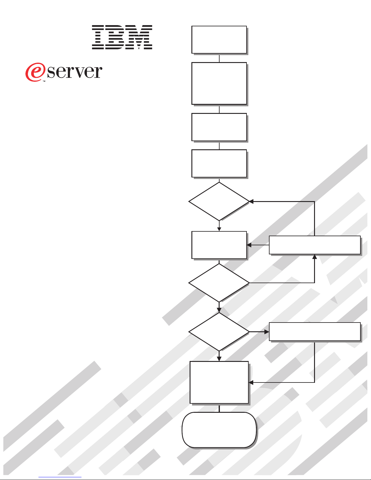
Install the server in
®
xSeries 240
Installation Guide
the rack, if required
Install options:
• Drives
• Microprocessors
• Adapters
• Power supplies
• Memory
Cable the server
and options
Welcome. . .
Thank you for buying an
IBM xSeries server.
Start the server
This server
Installation Guide
contains information for setting
up and configuring your server.
For detailed information
about your server, view the
User's Reference
on the
Documentation CD.
You can also find the most
current information about your
server on the IBM Web site at:
http://www.ibm.com/pc/support
Did the server
start correctly?
Ye s
Use ServerGuide™
to setup and
configure hardware
Did configuration
complete?
Ye s
Use
ServerGuide to
install operating
system?
Ye s
Use ServerGuide to
install applications,
such as IBM systems
management software
and IBM ServeRAID
programs
No
No
No
Go to the Server Support
flow chart
Go to the Web for Instructions,
http://www.ibm.com/pc/support
System is ready to use.
Go to the Server Support
flow chart to register
and profile your server.
Page 2
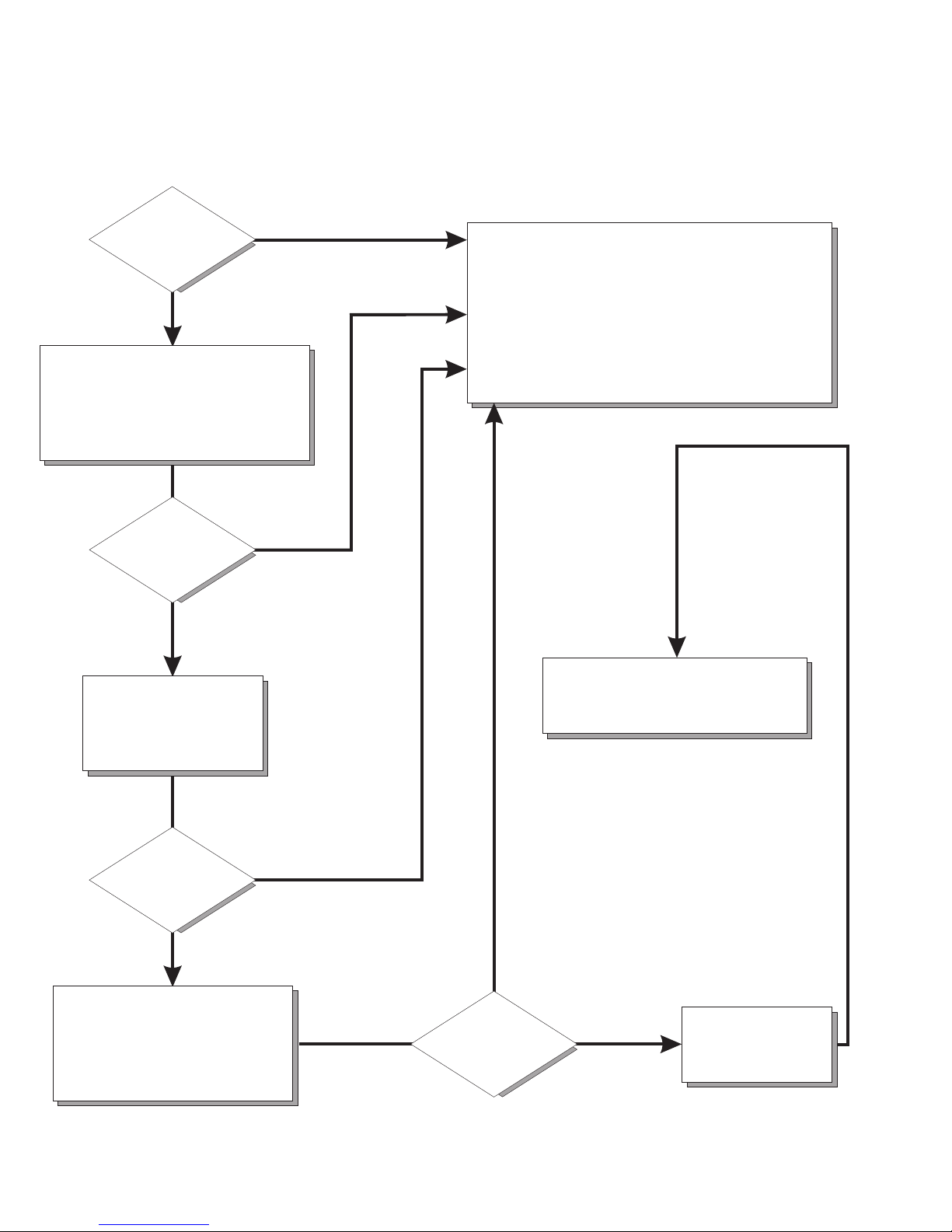
Server Support
Server working
properly?
Ye s
No
Check all cables for loose connections
and verify that all optional devices you
installed are on the ServerProven list.
You can view the ServerProven list at:
http://www.ibm.com/pc/compat
Problem
solved?
Ye s
No
Use the troubleshooting
information provided with
your server to determine
the cause of the problem
and the action to take.
Register and profile your server
After you register and profile, you will be able to:
• Diagnose problems using the IBM Online Assistant
• Participate in the IBM discussion forum
• Receive e-mail notifications of technical updates
related to your profiled products
Register at:
Profile at:
http://www.ibm.com/pc/register
http://www.ibm.com/pc/support
You can view a list of
IBM Help Center phone numbers at:
http://www.ibm.com/pc/support
Problem
solved?
Ye s
No
Flash the latest levels of BIOS,
service processor, diagnostics,
and RAID code.
You can download this code at:
http://www.ibm.com/pc/support
Ye s
Problem
solved?
No
Phone an
IBM Help Center
Page 3

IBM xSeries 240
Installation Guide
Page 4

Note
Before using this information and the product it supports, be sure to read the general information in Appendix A,
“Product warranties and notices” on page 41.
First Edition (October 2000)
Copyright International Business Machines Corporation 2000. All rights reserved.
Note to U.S. Government Users — Documentation related to restricted rights — Use, duplication or disclosure is subject to
restrictions set forth in GSA ADP Schedule Contract with IBM Corp.
Page 5

Contents
Safety . . . . . . . . . . . . . . . . . . . . . . . . . . . . . . . . . . . . . . . . . . . v
Handling static-sensitive devices ............................ x
Chapter 1. Introduction . . . . . . . . . . . . . . . . . . . . . . . . . . . . . . . . 1
Features and specifications ............................... 2
Notices used in this book ................................ 4
Major components of the xSeries 240 server ..................... 4
Chapter 2. Installing options . . . . . . . . . . . . . . . . . . . . . . . . . . . . . 9
Working inside a server with power on ........................ 9
Working with adapters .................................. 9
Installing memory modules .............................. 16
Installing a hot-swap drive ............................... 18
Installing a microprocessor .............................. 21
Installing a power supply ............................... 24
Cabling the server ................................... 27
Chapter 3. Starting the server ........................... 29
Controls and indicators ................................ 29
Operator information panel .............................. 32
Chapter 4. Configuring your server ....................... 33
Using the ServerGuide CDs .............................. 34
System management solutions ............................ 34
Chapter 5. Solving problems . . . . . . . . . . . . . . . . . . . . . . . . . . . 35
POST beep code descriptions ............................ 35
POST error messages ................................. 36
ServerGuide startup problems ............................ 37
Troubleshooting charts . . . . . . . . . . . . . . . . . . . . . . . . . . . . . . . . . 38
Appendix A. Product warranties and notices ................. 41
Warranty Statements . . . . . . . . . . . . . . . . . . . . . . . . . . . . . . . . . . 41
Notices . . . . . . . . . . . . . . . . . . . . . . . . . . . . . . . . . . . . . . . . . . 51
Electronic emission notices .............................. 53
Power cords . . . . . . . . . . . . . . . . . . . . . . . . . . . . . . . . . . . . . . . 54
Index . . . . . . . . . . . . . . . . . . . . . . . . . . . . . . . . . . . . . . . . . . . 57
Copyright IBM Corp. 2000 iii
Page 6

iv IBM xSeries 240 Installation Guide
Page 7
Safety
Before installing this product, read the Safety Information.
Antes de instalar este produto, leia as Informações de Segurança.
Před instalací tohoto produktu si přečtěte příručku bezpečnostních instrukcí.
Læs sikkerhedsforskrifterne, før du installerer dette produkt.
Ennen kuin asennat tämän tuotteen, lue turvaohjeet kohdasta Safety Information.
Avant d'installer ce produit, lisez les consignes de sécurité.
Vor der Installation dieses Produkts die Sicherheitshinweise lesen.
Prima di installare questo prodotto, leggere le Informazioni sulla Sicurezza
Lees voordat u dit product installeert eerst de veiligheidsvoorschriften.
Les sikkerhetsinformasjonen (Safety Information) før du installerer dette produktet.
Antes de instalar este produto, leia as Informações sobre Segurança.
Pred inštaláciou tohto zariadenia si pečítaje Bezpečnostné predpisy.
Antes de instalar este producto lea la información de seguridad.
Läs säkerhetsinformationen innan du installerar den här produkten.
Copyright IBM Corp. 2000 v
Page 8

1
DANGER
Electrical current from power, telephone, and communication
cables is hazardous.
To avoid a shock hazard:
– Do not connect or disconnect any cables or perform instal-
lation, maintenance, or reconfiguration of this product
during an electrical storm.
– Connect all power cords to a properly wired and grounded
electrical outlet.
– Connect to properly wired outlets any equipment that will be
attached to this product.
– When possible, use one hand only to connect or disconnect
signal cables.
– Never turn on any equipment when there is evidence of fire,
water, or structural damage.
– Disconnect the attached power cords, telecommunications
systems, networks, and modems before you open the
device covers, unless instructed otherwise in the installation
and configuration procedures.
– Connect and disconnect cables as described in the fol-
lowing table when installing, moving, or opening covers on
this product or attached devices.
To Connect:
1. Turn everything OFF.
2. First, attach all cables to devices.
3. Attach signal cables to connectors.
4. Attach power cords to outlet.
5. Turn device ON.
To Disconnect:
1. Turn everything OFF.
2. First, remove power cords from outlet.
3. Remove signal cables from connectors.
4. Remove all cables from devices.
vi IBM xSeries 240 Installation Guide
Page 9

2
CAUTION:
When replacing the lithium battery, use only IBM Part Number 33F8354
or an equivalent type battery recommended by the manufacturer. If
your system has a module containing a lithium battery, replace it only
with the same module type made by the same manufacturer. The
battery contains lithium and can explode if not properly used, handled,
or disposed of.
Do not:
– Throw or immerse into water
– Heat to more than 100°C (212°F)
– Repair or disassemble
Dispose of the battery as required by local ordinances or regulations.
Safety vii
Page 10
Some server models are equipped from the factory with a CD-ROM drive.
CD-ROM drives are also sold separately as options. The CD-ROM drive is a laser
product. The CD-ROM drive is certified in the U.S. to conform to the requirements
of the Department of Health and Human Services 21 Code of Federal Regulations
(DHHS 21 CFR) Subchapter J for Class 1 laser products. Elsewhere, the drive is
certified to conform to the requirements of the International Electrotechnical Commission (IEC) 825 and CENELEC EN 60 825 for Class 1 laser products.
3
CAUTION:
When laser products (such as CD-ROMs, DVD drives, fiber optic
devices, or transmitters) are installed, note the following:
– Do not remove the covers. Removing the covers of the laser
product could result in exposure to hazardous laser radiation.
There are no serviceable parts inside the device.
– Use of controls or adjustments or performance of procedures other
than those specified herein might result in hazardous radiation
exposure.
DANGER
Some laser products contain an embedded Class 3A or Class
3B laser diode. Note the following.
Laser radiation when open. Do not stare into the beam, do not
view directly with optical instruments, and avoid direct exposure to the beam.
viii IBM xSeries 240 Installation Guide
Page 11
4
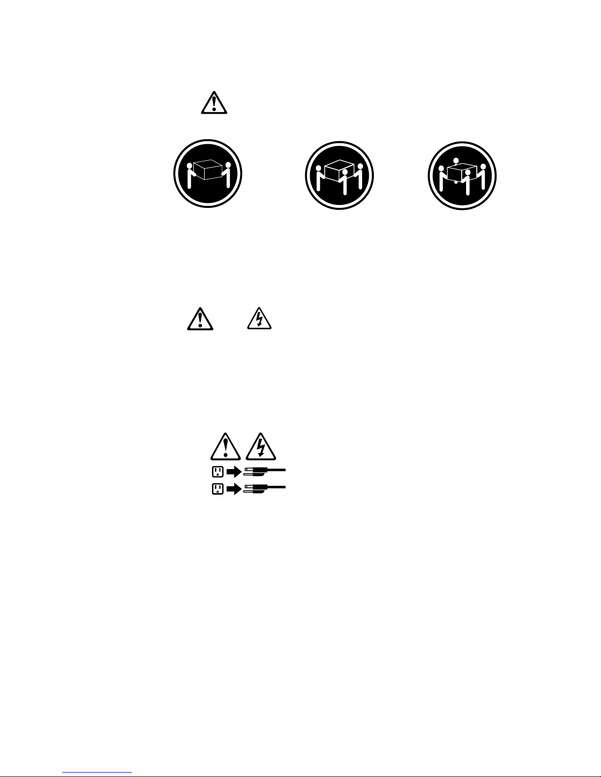
18 kg (37 lbs)
CAUTION:
Use safe practices when lifting.
5
CAUTION:
The power control button on the device and the power switch on the
power supply do not turn off the electrical current supplied to the
device. The device also might have more than one power cord. To
remove all electrical current from the device, ensure that all power
cords are disconnected from the power source.
2
1
32 kg (70.5 lbs) 55 kg (121.2 lbs)
Safety
ix
Page 12

Handling static-sensitive devices
Attention: Static electricity can damage electronic devices and your system. To
avoid damage, keep static sensitive devices in their static protective bag until you
are ready to install them.
To reduce the possibility of electrostatic discharge, observe the following precautions:
Limit your movement. Movement can cause static electricity to build up around
you.
Handle the device carefully, holding it by its edges or its frame.
Do not touch solder joints, pins, or exposed printed circuitry.
Do not leave the device where others can handle and possibly damage the
device.
While the device is still in its anti-static package, touch it to an unpainted metal
part of the system unit for at least two seconds. (This drains static electricity
from the package and from your body.)
Remove the device from its package and install it directly into your system unit
without setting it down. If it is necessary to set the device down, place it on its
static-protective package. (If your device is an adapter, place it component side
up.) Do not place the device on your system unit cover or on a metal table.
Take additional care when handling devices during cold weather as heating
reduces indoor humidity and increases static electricity.
x IBM xSeries 240 Installation Guide
Page 13

Chapter 1. Introduction
Thank you for purchasing an IBM
xSeries 240. This Installation Guide
provides the information needed to:
Set up and cable your server
Start and configure your server
Install your network operating system (NOS)
Packaged with this Installation Guide are software CDs that you can use to configure hardware, install device drivers, and install the network operating system
(NOS).
Also included is an IBM xSeries Documentation CD, which provides detailed information about your server.
Your server comes with a three-year limited warranty and IBM Server Start Up
Support. If you have access to the World Wide Web, you can obtain up-to-date
information about your server model and other IBM server products at the following
World Wide Web address:
http://www.ibm.com/eserver/xseries
If you purchased a rack model of the xSeries 240 server, use the Rack Installation
Instructions provided with this book to install the server in a rack.
Record and retain the following information.
Product name
Machine type
Model
Serial number
Key serial number
The server serial number and other identification numbers are located on labels on
the rear of the server and on the front of the server under the trim bezel.
Note: Your server keys cannot be duplicated by locksmiths. If you lose them,
order replacement keys from the key manufacturer. The key serial number
and phone number of the manufacturer are on a tag attached to the keys.
Copyright IBM Corp. 2000 1
Page 14

Features and specifications
The following table summarizes the features of the xSeries 240 server.
Microprocessor
Intel
32 KB of level-1 cache
256 KB of level-2 cache (min.)
Expandable to two microprocessors
Memory
Standard: 128 MB (min), expandable
133 MHz, registered, error correcting
Four dual inline memory-module
Diskette Drive
Standard: One 3.5-inch, 1.44 MB
Hard Disk Drives
Up to six hot-swappable hard disk
CD-ROM Drive
Standard: 40X IDE
Keyboard and Auxiliary Device
(standard only on tower models)
Keyboard
Mouse
Expansion Bays
Six slim (1-inch) or three half-high
Three 5.25-inch non-hot-swap bays
Pentium III microprocessor
with MMX technology and SIMD
extensions
to 4 GB
code (ECC), synchronous dynamic
random access memory (SDRAM)
(complying with PC 133 SDRAM Registered DIMM Specification, Revision
1.0 or later). When installed in
systems using 100 MHz front-side
bus microprocessors, the memory
operates at 100 MHz.
(DIMM) sockets
drives supported
(1.6-inch) hot-swap drive bays
(one contains the CD-ROM drive)
Table 1. Server features
Expansion Slots
Up to five PCI adapters supported.
Three 64-bit hot-plug PCI slots
Two standard (non-hot-plug) 32-bit
PCI slots
Upgradable Microcode
BIOS, diagnostics, and Advanced
System Management Processor
upgrades (when available) can
update EEPROMs on the system
board
Security Features
Door and side cover lock (tower
model only)
Power-on and administrator pass-
words
Selectable drive-startup
Keyboard password
System management security
– User log-in password
– Read-only or read/write access
– Dial back
Predictive Failure Analysis (PFA)
Alerts
Power supplies
Fans
Memory
Hard disk drives
Microprocessors
Voltage regulator modules (VRMs)
Integrated Functions
Two serial ports
Two universal serial bus (USB) ports
One parallel port
Mouse port
Keyboard port
Video port
Advanced System Management Inter-
connect port
Two SCSI ports (one internal, one
external)
10BASE-T/100BASE-TX Ethernet port
(controller on system board)
Redundant Ethernet capability,
through the use of an optional
network interface card (NIC)
Advanced System Management
Processor on system board
Dedicated Advanced System Man-
agement I/O port
Video controller (with 4MB video
memory) compatible with:
– Super video graphics array
(SVGA)
– Video graphics adapter (VGA)
Power Supply
Two 250 W (115–230 V ac)
– Standard - 500 W non-redundant,
250 W redundant
– Optional - Additional 250 W
power supply is available for
500 W redundancy
Automatic voltage range selection
Built-in overload and surge protection
Automatic restart after a loss of
power
Redundant Cooling
Three hot-swap fans
2 IBM xSeries 240 Installation Guide
Page 15

The following table provides the specifications for the xSeries 240 server.
Size (Tower Model)
– Depth: 659.3 mm (26 in.)
– Height: 426.5 mm (16.8 in.)
– Width: 217.3 mm (8.6 in.)
Size (Rack Model)
– Depth: 629.3 mm (24.8 in.)
– Height: 217.3 mm (8.6 in.)
(5 U)
– Width: 426.6 mm (16.8 in.)
Weight (Tower Model)
Minimum configuration: 26.6 kg
(58.6 lb)
Maximum configuration: 37.5 kg
(82.7 lb)
Weight (Rack Model)
Minimum configuration: 25.3 kg
(55.8 lb)
Maximum configuration: 36.2 kg
(79.8 lb)
Heat Output
Approximate heat output in British
Thermal Units (Btu) per hour:
– Minimum configuration:
683 Btu (200 watts)
– Maximum configuration:
2048 Btu (600 watts)
Table 2. Server specifications
Electrical Input
Sine-wave input (50 to 60 Hz) is
required
Input voltage:
– Low range:
- Minimum: 90 V ac
- Maximum: 137 V ac
– High range:
- Minimum: 180 V ac
- Maximum: 265 V ac
– Input kilovolt-amperes (kVA)
approximately:
- Minimum configuration as
shipped: 0.08 kVA
- Maximum configuration:
0.52 kVA
Power Available for Drives
Each hot-swap drive bay:
– +5 V dc line: 15 A
– +12 V dc line: 17.2 A
Acoustical Noise Emissions Values
Sound power, idling: 6.6 bel
maximum
Sound power, operating: 6.8 bel
maximum
Sound pressure, operating: 67 dBa
maximum
Environment
Air temperature:
– Server on: 10° to 35° C
(50° to 95° F)
Altitude: 0 to 914 m (3000 ft.)
– Server on: 10° to 32° C
(50° to 90° F)
Altitude: 914 m (3000 ft.) to
2133 m (7000 ft.)
– Server off: 10° to 43° C
(50° to 110° F)
Maximum Altitude: 2133 m
(7000 ft.)
Humidity:
– Server on: 8% to 80%
– Server off: 8% to 80%
Maximum altitude: 2133 m
(7000 ft)
Chapter 1. Introduction 3
Page 16

Notices used in this book
This book contains information notices that relate to a specific topic. The Caution
and Danger notices also appear in the multilingual Safety Information book provided on the IBM xSeries Documentation CD. Each notice is numbered for easy
reference to the corresponding notices in the multilingual book.
The notice definitions are as follows:
Notes
These notices provide important tips, guidance, or advice.
Attention
These notices indicate possible damage to programs, devices, or data. An
attention notice is placed just before the instruction or situation in which
damage could occur.
Caution
These notices indicate situations that can be potentially hazardous to you. A
caution notice is placed just before a description of a potentially hazardous procedure step or situation.
Danger
These notices indicate situations that can be potentially lethal or extremely hazardous to you. A danger notice is placed just before a description of a potentially lethal or extremely hazardous procedure step or situation.
Major components of the xSeries 240 server
The orange color on components and labels in your server identifies hot–swap
components. This means that you can install or remove the component while the
system is running, provided that your system is configured to support this function.
The blue color on components and labels indicates touch points where a component can be gripped, a latch moved and so on.
4 IBM xSeries 240 Installation Guide
Page 17

The following illustration shows the locations of major components in your server.
Note: The illustrations in this document might differ slightly from your hardware.
C
P
U
V
R
M
M
E
M
O
P
H
R
C
D
Y
I
D
B
U
S
A
B
N
M
P
I
O
W
S
M
E
R
I
S
U
S
P
E
1
P
R
L
V
BU
Y
I
C
2
S
E
P
3
R
O
C
E
FA
S
N
S
N
O
O
N
R
R
E
D
U
N
1
D
A
2
N
T
3
T
E
M
P
E
R
A
T
U
R
E
1 Operator information panel
2 Diskette drive
3 Removable-media-bay filler panel
4 CD-ROM drive
5 Bezel
6 Front door
7 Hot-swap hard disk drive
8 Side cover release lever
9 Diagnostic panel
12 Processor board
13 System board
14 Side cover
15 Microprocessor 1
16 Microprocessor terminator
(or microprocessor 2)
17 DIMM sockets
18 Fan
19 Power supply
1 Adapter support bracket
11 Fan assembly
Chapter 1. Introduction 5
Page 18
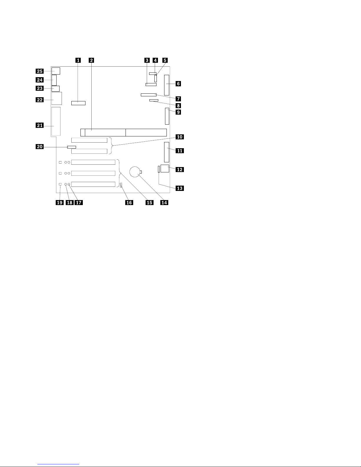
System board component locations
1 Dual serial and PCI hot-plug control switch con-
nector (J1)
2 Processor board connector (J4, J8)
3 Operator information panel connector (J29)
4 Reserved (J32)
5 Reserved (J10)
6 Diskette drive connector (J23)
7 Diagnostic LED panel connector (J6)
8 Reserved (J17)
9 Internal LVD (low voltage differential) SCSI con-
nector (J25) (with extender cable on bracket)
1 PCI slots 1 and 2 (on primary PCI bus A)
11 IDE connector (J27)
12 Power control and reset panel cable connector
(J18)
13 Advanced System Management Interconnect con-
nector (J35)
14 Battery
15 PCI (hot-plug) slots 3–5 (on primary PCI bus B)
16 Jumper block (J20)
17 PCI slot Power Good LEDs
18 Internal PCI slot Attention LEDs
19 External PCI slot Attention LEDs
2 Advanced System Management adapter connector
(J21)
21 External LVD SCSI/parallel port connector (J19)
22 Serial/video port connector (J11)
23 USB 1 and USB 2 port connectors (J9) (USB 2 is
below USB 1.)
24 Ethernet port connector (J7)
25 Mouse and keyboard connectors (J5) (The mouse
connector is above the keyboard connector.)
6 IBM xSeries 240 Installation Guide
Page 19
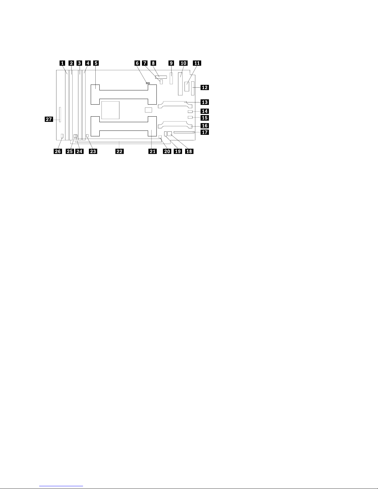
Processor board component locations
1 DIMM connector 4 (J1)
2 DIMM connector 3 (J2)
3 DIMM connector 2 (J3)
4 DIMM connector 1 (J4)
5 Microprocessor 2 connector (U6)
6 Reserved (J15)
7 Microprocessor 2 Error LED (CR13)
8 Reserved (J19)
9 Power supply connector (J6)
1 Power supply connector (J11)
11 Power supply connector (J12)
12 Power supply connector (J14)
13 VRM 2 connector (J13)
14 VRM 2 Error LED (CR19)
15 VRM 1 Error LED (CR17)
16 VRM 1 connector (J5)
17 Fans 1 and 2 connector (J8)
18 Switch block 2 (SW2)
19 Switch block 1 (SW1) (might not be present on
your server)
2 Microprocessor 1 Error LED (CR12)
21 Microprocessor 1 connector (U5)
22 System board connectors (J9 and J25) (on
reverse side of processor board)
23 DIMM 1 Error LED (CR8)
24 DIMM 2 Error LED (CR9)
25 DIMM 3 Error LED (CR10)
26 DIMM 4 Error LED (CR11)
27 Fan 3 connector (J10)
Chapter 1. Introduction 7
Page 20

8 IBM xSeries 240 Installation Guide
Page 21

Chapter 2. Installing options
This chapter provides the basic information needed to install hardware options in
your server. This section is for all users, but is written with the experienced user in
mind.
If you need more detailed installation information, refer to the User's Reference on
the xSeries Documentation CD.
Working inside a server with power on
Your server supports hot-swap drives, fans, and power supplies and is designed to
operate safely while turned on with the cover removed. Follow these guidelines
when you work inside a server that is turned on:
Avoid loose-fitting clothing on your forearms. Button long-sleeved shirts before
working inside the server; do not wear cuff links while you are working inside
the server.
Do not allow your necktie or scarf to hang inside the server.
Remove jewelry, such as bracelets, rings, necklaces, and loose-fitting wrist
watches.
Remove items from your shirt pocket (such as pens and pencils) that could fall
into the server as you lean over it.
Take care to avoid dropping any metallic objects, such as paper clips, hair pins,
or screws, into the server.
Working with adapters
You can install up to five peripheral component interconnect (PCI) adapters in the
expansion slots on the system board.
In three of the PCI slots, you can install a new PCI adapter or replace an existing
PCI adapter with the same type of adapter without turning off the server power and
restarting the system, if these features are supported by your operating system.
These slots are called hot-pluggable PCI slots. They are also referred to as hotplug PCI or Active PCI slots.
The two remaining PCI slots support standard (non-hot-plug) PCI adapters.
Copyright IBM Corp. 2000 9
Page 22
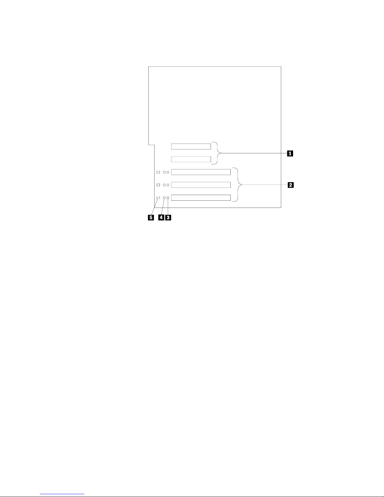
The following illustration shows the location of the PCI expansion slots on the
system board.
1 Non-hot-plug 32-bit PCI slots 1 and 2 (on PCI bus A)
2 Hot-plug 64-bit PCI slots 3–5 (on PCI bus B)
3 Power LEDs for hot-swap slots
4 Internal Attention LEDs for hot-swap slots
5 External Attention LEDs for hot-swap slots
LEDs for hot-plug PCI slots
Each hot-plug PCI slot has three LEDs associated with it — two Attention LEDs
and one Power LED.
Power LED: This LED is on when the hot-plug PCI slot is active and has
power. An adapter must not be added to or removed from the PCI slot when
the Power LED is on. When this LED is off, the PCI slot is inactive and has no
power applied. An adapter can be installed when the Power LED for the PCI
slot is off. Refer to your operating system documentation to determine if it supports hot-plug PCI adapters, and, if so, how to disable the hot-plug PCI slot.
Attention LEDs: Each hot-plug PCI slot has an Attention LED that is visible
from the rear of the server and one that can be seen from inside the server.
(The LEDs have the same meaning; they are duplicated to be visible from
outside or inside the server.) An Attention LED flashes approximately once per
second when it is on. The meaning of the Attention LEDs is defined by your
operating system. Refer to your operating system documentation to determine
if it supports hot-plug PCI adapters and, if so, what the Attention LEDs indicate.
10 IBM xSeries 240 Installation Guide
Page 23

The following table describes the LEDs:
Power LED Attention LED Description
On Flashing The adapter requires attention. Slot still has
On Off Normal operation; no intervention is required.
Off Flashing The adapter requires intervention. Power is
Off Off Power is removed from the slot. An adapter
Adapter considerations
Before you continue with the adapter-installation procedure:
Review the documentation that comes with the adapter and follow those
instructions in addition to the instructions given in this chapter. If you need to
change the switch or jumper settings on your adapter, follow the instructions
that come with the adapter documentation.
power applied. Do not remove or install an
adapter in the slot. Refer to your operating
system documentation for instructions.
removed from the slot. An adapter can be
removed or installed in the slot.
can be removed or installed in the slot.
You can install full-length adapters in all expansion slots.
You can install hot-plug PCI adapters in PCI slots 3–5, if your operating system
supports this feature. Non-hot-plug PCI adapters can also be installed in these
slots.
Your server supports 5.0V and universal PCI adapters; it does not support
3.3 V adapters.
Note: A universal PCI adapter supports both 3.3V and 5.0V operation.
PCI slots 1 and 2 are on PCI bus A, and PCI slots 3–5 are on PCI bus B. Both
PCI buses are primary buses. The system scans PCI slots 1 through 5 to
assign system resources; then the system starts (boots) the PCI devices in the
following order, if the default boot precedence has not been changed: PCI
slots 1 and 2, system board SCSI devices, and then PCI slots 3 through 5.
Enabling hot-plug PCI support
Your xSeries 240 server has hot-plug PCI capability. To enable this feature, you
must install the operating system services for hot-plug PCI support code. To obtain
the operating system hot-plug PCI support code, access
http://www.ibm.com/pc/support on the World Wide Web.
Chapter 2. Installing options 11
Page 24

Installing a PCI adapter
This section contains the procedure for installing a hot-plug PCI adapter.
Attention:
All hot-plug operations must be done through the operating system console (or supported user interface). Otherwise, the system might lock up or serious damage to
the adapter or system unit might occur.
Refer to the following illustrations of the rack model while you perform the steps in
this procedure.
12 IBM xSeries 240 Installation Guide
Page 25

1 Expansion-slot cover
2 Tab
3 Adapter retention latch
4 Adapter retention flap
5 Plastic divider
6 Power light
7 Attention light
8 Adapter
9 SCSI cable extender
Note: For some models of the xSeries 240 server, the SCSI cable extender differs
slightly from what is shown in the preceding illustration. In these models,
the retaining bracket holding the cable connector has been removed.
To install a hot-plug PCI adapter:
1. Review the information in “Safety” on page v and “Handling static-sensitive
devices” on page x.
2. If you are installing a non-hot-plug adapter, turn off the server and peripheral
devices; then, remove the server cover.
3. Determine which PCI adapter expansion slot you will use for the adapter.
Notes:
a. Only PCI slots 3–5 support hot-plug PCI adapters.
b. If you are installing a hot-plug adapter, disable the selected PCI slot from
Chapter 2. Installing options 13
your operating system. (Refer to the documentation that comes with your
operating system for information about disabling a hot-plug PCI slot.) Disabling the PCI slot turns off the Power light for that PCI slot.
Page 26

Attention:
Make sure the Power light 6 for the hot-plug PCI slot is off before you continue to the next step.
4. Remove the expansion-slot cover 1:
a. Rotate the adapter retention latch 3 counterclockwise.
b. Lift the tab 2, if required, covering the top of the expansion-slot cover
1 and then remove the expansion-slot cover from the server. Store it in a
safe place for future use.
Attention:
Expansion-slot covers must be installed on all vacant slots. This maintains the
electromagnetic emissions characteristics of the system and ensures proper
cooling of system components.
5. Refer to the documentation that comes with your adapter for any cabling
instructions. It might be easier for you to route any cables before you install
the adapter.
6. Press on the touchpoint on the adapter retainer flap 4 at the end of the slot
nearest the front of the server and rotate the adapter retainer flap upward.
7. Remove the adapter from the static-protective package.
Attention:
Avoid touching the components and gold-edge connectors on the adapter.
8. Place the adapter, component-side up, on a flat, static-protective surface.
9. Set any jumpers or switches as described by the adapter manufacturer.
10. Install the adapter:
a. Carefully grasp the adapter 8 by its top edge or upper corners, and align
it with the expansion slot on the system board.
b. Press the adapter firmly into the expansion slot.
Attention:
When you install an adapter in the server, be sure that it is completely and
correctly seated in the system-board connector. Incomplete insertion might
cause damage to the system board or the adapter.
c. Lower the tab 2 on the adapter guide over the tab on the top corner of
adapter; then, rotate the adapter retention latch 3 clockwise until it snaps
into place.
Attention:
Power cannot be restored to the adapter slot if the tab is not lowered into
place.
d. Close the adapter retainer flap 4.
11. Connect any needed cables to the adapter.
Notes:
a. Route cables so that the flow of air from the fans is not blocked.
b. If you installed a hot-plug adapter, enable the PCI slot from your operating
system. (Refer to the documentation that comes with your operating
system for information about enabling a hot-plug PCI slot.) Make sure that
the Power light 6 for the hot-plug PCI slot is on.
14 IBM xSeries 240 Installation Guide
Page 27

12. If you have other options to install or remove, do so now.
Special considerations for installing a ServeRAID adapter
You can install an optional ServeRAID adapter in your server to control the hotswap hard disk drives.
To install the ServeRAID adapter:
1. Disconnect the SCSI cable from the SCSI cable extender on the system board.
See the illustration in “Installing a PCI adapter” on page 12 for the location of
the SCSI cable extender. (The other end of the SCSI cable is connected to the
SCSI hard disk drive backplane.) The Service label on the inside of the cover
of your server shows cable routing for an optional ServeRAID adapter.
2. Connect the end of the SCSI cable that you disconnected from the SCSI cable
extender to the ServeRAID adapter. The other end of the cable is connected
to the SCSI hard disk drive backplane; the drives in the hot-swap bays are now
connected to the ServeRAID adapter.
3. Connect the 2-drop SCSI cable to the SCSI cable extender on the system
board, and attach the device in the non-hot-swap bay to one of the drops on
the other end of the 2-drop SCSI cable. The device is attached to the integrated SCSI controller.
Refer to the documentation provided with the ServeRAID adapter for more information about installing the adapter and configuring a disk array.
Chapter 2. Installing options 15
Page 28

Installing memory modules
Your server comes with a DIMM installed on the processor board in DIMM connector 4 (J1). You must install the largest DIMM in the memory connector farthest
from the microprocessor (DIMM connector 4). If you install two DIMMs, you must
install the second one in the memory connector closest to the microprocessor
(DIMM connector 1). If you install three DIMMs, you must install the third one in
DIMM connector 2. If you install four DIMMs, you must install the fourth one in
DIMM connector 3.
Note: The size of the DIMMs in the other memory connectors (DIMM connectors
1, 2, and 3) does not matter. Refer to the following table for some typical
memory configurations.
DIMM 4 DIMM 3 DIMM 2 DIMM 1
512 MB 128 MB
512 MB 256 MB 128 MB
512 MB 512 MB 256 MB 512 MB
512 MB 512 MB 512 MB 512 MB
Table 3. Typical memory configurations
Your xSeries 240 server supports 128MB, 256MB, 512MB, and 1GB DIMMs.
Your server supports a minimum of 128MB and a maximum of 4GB of system
memory. Only 133MHz, 3.3 V, 168-pin, 8-byte, 72-bit registered, synchronousdynamic-random-access memory (SDRAM), error correcting code (ECC) with x4
configuration DIMM memory complying with PC 133 Registered DIMM Specification, Revision 1.0 or later is supported. When installed in systems using 100MHz
front-side bus processors, the memory operates at 100MHz.
5
4
3
1 DIMM
2 Retaining clips
3 DIMM connector 1 (J4)
4 DIMM connector 2 (J3)
5 DIMM connector 3 (J2)
6 DIMM connector 4 (J1)
16 IBM xSeries 240 Installation Guide
Page 29

To install a DIMM:
1. Review the information in “Safety” on page v and “Handling static-sensitive
devices” on page x.
2. Turn off the server and peripheral devices and disconnect all external cables
and power cords; then, remove the cover.
3. Determine the DIMM connector into which you will install the DIMM.
4. Touch the static-protective package containing the DIMM to any unpainted
metal surface on the server. Then, remove the DIMM from the package.
Note: To avoid breaking the retaining clips or damaging the DIMM connectors,
handle the clips gently.
5. Install the DIMM:
a. Turn the DIMM 1 so that the pins align correctly with the connector 5.
b. Insert the DIMM into the connector by pressing on one edge of the DIMM
and then on the other edge of the DIMM. Be sure to press the DIMM
straight into the connector.
c. Make sure the retaining clips 2 snap into the closed position. If a gap
exists between the DIMM and the retaining clips, the DIMM has not been
installed properly. In this case, open the retaining clips and remove the
DIMM; then, reinsert the DIMM.
d. Repeat these steps for each DIMM that you install.
6. If you have other options to install or remove, do so now.
Attention:
When you restart the server, the system displays a message indicating that the
memory configuration has changed.
If you installed additional memory, start the Configuration/Setup Utility program
and select Save Settings.
If you just replaced a failed DIMM, you must start the Configuration/Setup Utility
program, select Advanced Setup, select Memory Settings, highlight the connector or bank of connectors that you want to enable, then select Enable.
In some memory configurations, the 3-3-3 beep code might sound during a
POST followed by a blank display screen. If this occurs and the Boot Fail
Count feature in the Start Options of the Configuration/Setup Utility is set to
Enabled (its default setting), you must restart the server three times to force the
system BIOS to reset the memory connector or bank of connectors from Disabled to Enabled.
Chapter 2. Installing options 17
Page 30

Installing a hot-swap drive
This section contains the instructions for installing a hot-swap hard disk drive.
Notes:
1. The hot-swap drive bays support hot-swap drives only.
2. To minimize the possibility of damage to the hard disk drives when you are
installing a hard disk drive in a rack model of the xSeries 240, install the server
in the rack before installing the hard disk drives.
3. You do not need to turn off the server to install hot-swap drives. However, you
must turn off the server when performing any steps that involve installing or
removing cables.
Refer to the following illustrations of the tower model while you perform the steps in
this procedure.
18 IBM xSeries 240 Installation Guide
Page 31

1 Filler panel for use with half-high drives
2 Filler panel (slim-high)
HDD
NMI
SMI
SERVICE PROCESSO
BUS
NON REDUNDANT
R
TEMPERATURE
3 Drive
4 Screws
5 Drive tray
6 Drive tray handle (in open position)
Chapter 2. Installing options 19
Page 32

To install a drive in a hot-swap drive bay:
1. Review the information in “Safety” on page v and “Handling static-sensitive
devices” on page x.
2. If your server is a tower model, unlock and open the server door.
Attention:
To maintain proper system cooling, do not operate the server for more than two
minutes without either a drive or a filler panel installed in each bay.
3. Remove the filler panel 2 from one of the empty hot-swap bays by inserting
your finger into the depression at the left side of the filler panel and pulling it
away from the server.
Note: If you are installing a half-high hard disk drive, you will need to remove
two adjacent filler panels. The two filler panels should be from either
the top pair of bays, the middle pair of bays, or the bottom pair of bays.
4. If your hard disk drive is not installed on the drive tray 5, place the drive in
the drive tray and, being careful not to over-tighten the screws, attach the drive
to the tray using the four screws provided with the option kit.
5. Install the hard disk drive 3 in the hot-swap bay:
a. Ensure the tray handle 6 is open (that is, perpendicular to the drive).
b. Align the drive/tray assembly so that it engages the guide rails in the bay.
c. Gently push the drive/tray assembly into the bay until the drive connects to
the backplane.
d. Push the tray handle to the right until it locks.
6. If you installed a half-high hard disk drive, install a filler panel 1 in the gap
above the drive:
a. Locate the smaller filler panel 1 that is designed for use with half-high
drives. It is stored on the slim-high filler panel 2 that you removed earlier
in this procedure.
b. Pull the half-high filler panel off the slim-high filler panel.
c. Gently push the half-high filler panel 1 into place in the gap above the
drive.
7. Check the hard disk drive status indicators to verify that the hard disk drives
are operating properly.
8. If your server is a tower model, close and lock the server door.
Note: If your server has a RAID adapter installed, see your RAID documenta-
tion for the instructions needed to configure the hard disk drives.
20 IBM xSeries 240 Installation Guide
Page 33

Installing a microprocessor
Your server comes with one microprocessor installed on the processor board. If
you install an additional microprocessor kit, your server can operate as a symmetric
multiprocessing (SMP) server. With SMP, certain operating systems and application programs can distribute the processing load between the microprocessors.
This enhances performance for database and point-of-sale applications, integrated
manufacturing solutions, and other applications.
Attention:
To avoid damage and ensure proper server operation when you install a new or an
additional microprocessor, use microprocessors that have the same cache size and
type, and the same clock speed. Microprocessor internal and external clock frequencies must be identical.
The microprocessor that is installed in microprocessor connector U5 is CPU or
processor 1. If a microprocessor is installed in microprocessor connector U6, it is
CPU or processor 2. If the server has only one microprocessor installed, that
microprocessor is installed in microprocessor connector U5 and is the startup (boot)
processor. If more than one microprocessor is installed, the microprocessor with
the lower stepping level is the startup processor, and the microprocessor with the
higher stepping level is the application processor. If both microprocessors have the
same stepping level, the microprocessor installed in microprocessor connector U6
is the startup processor, and the microprocessor installed in U5 is the application
processor.
Note: You can determine the stepping levels of the installed microprocessors
using the Configuration/Setup utility.
Before you begin:
Thoroughly review the documentation that comes with the microprocessor,
so that you can determine whether you need to update the server basic
input/output system (BIOS) code. The latest level of BIOS code for your
server is available through the World Wide Web.
Obtain an SMP-capable operating system (optional). For a list of supported
operating systems, see http://www.ibm.com/pc/us/compat/ on the World
Wide Web.
Chapter 2. Installing options 21
Page 34

Refer to the following illustrations while you perform the steps in this section.
6
5
4
Note: The illustrations in this section might differ slightly from your hardware.
22 IBM xSeries 240 Installation Guide
Page 35

1 Terminator card
2 Microprocessor connector 2 (U6)
3 Voltage regulator module (VRM) connector for second VRM
4 VRM for first microprocessor (VRM 1)
5 Microprocessor connector 1 (U5)
6 Microprocessor 1
7 Microprocessor handle
8 Microprocessor 2
9 VRM for second microprocessor (VRM 2)
To install an additional microprocessor kit:
1. Review the information in “Safety” on page v and “Handling static-sensitive
devices” on page x.
2. Turn off the server and peripheral devices and disconnect all external cables
and power cords; then, remove the cover.
3. Remove the terminator card 1 from the microprocessor connector 2. Store
the terminator card in a safe place in the static-protective package that your
new microprocessor is shipped in; you will need to install it again if you ever
remove the microprocessor.
4. Install the microprocessor:
a. Touch the static-protective package containing the new microprocessor to
any unpainted metal surface on the server; then, remove the microprocessor from the package.
b. Center the microprocessor 8 over the microprocessor connector 2 and
carefully press the microprocessor into the connector.
5. Install the VRM 9 included in the microprocessor kit:
Attention:
When installing or replacing a VRM, use only VRMs specified for use with the
xSeries 240 server. Use of other VRMs might cause your server to overheat.
a. Center the VRM 9 over the VRM connector 3. Make sure that the
VRM is oriented and aligned correctly.
b. Press the VRM into the connector.
Notes:
1) To remove a microprocessor, pull upward on the microprocessor
handle 7.
2) If you remove the microprocessor later, remember to install the terminator card in the appropriate microprocessor connector and to remove
the VRM for that microprocessor.
6. If you have other options to install or remove, do so now.
Chapter 2. Installing options 23
Page 36

Installing a power supply
The following illustrations show the power supplies and power lights on your server.
Tower model
Rack model
24 IBM xSeries 240 Installation Guide
Page 37

1 Power Supply 1: Your server comes with two hot-swap power supplies
installed. (See “Installing a power supply” on page 24 for instructions about
installing an additional power supply and information about power redundancy.)
2 Power Supply 2: Your server comes with two hot-swap power supplies
installed.
3 Filler Panel: You can remove this filler panel and install a third hot-swap
power supply on power supply bay 3.
4 Power Supply 2 Power Connector: The power cord for power supply 2
connects here.
5 Power Supply 1 Power Connector: The power cord for power supply 1
connects here.
6 DC Power Light: This light provides status information about the power
supply. During normal operation, both the AC and DC Power lights are on.
7 AC Power Light: This light provides status information about the power
supply. During normal operation, both the AC and DC Power lights are on.
8
CAUTION:
Never remove the cover on a power supply or any part that has the
following label attached.
Hazardous voltage, current, and energy levels are present inside any
component that has this label attached. There are no serviceable parts
inside these components. If you suspect a problem with one of these
parts, contact a service technician.
Chapter 2. Installing options 25
Page 38

Adding a power supply
Your server comes with two power supplies. You can add a third power supply.
After you install a power supply, check the power-supply status indicators to verify
that the power supply is operating properly.
Refer to the following illustration of the tower model while performing the steps in
this procedure.
Note: You do not need to turn off the power to the server to install hot-swap
power supplies.
1 Power supply
2 Filler panel
3 Cable-restraint bracket
4 Power cord connector
5 Handle on power supply (in open position)
6 AC Power light
7 DC Power light
26 IBM xSeries 240 Installation Guide
Page 39

To add a power supply:
1. Review the information in “Safety” on page v and “Handling static-sensitive
devices” on page x.
2. Remove the filler panel 2 from the empty power supply bay by inserting your
finger into the depression on the filler panel and pulling it away from the server.
Save the filler panel in case you remove the power supply at a later time.
Note: During normal operation, each power-supply bay must have either a
power supply or filler panel installed for proper cooling.
3. Install the power supply 1 in the bay:
a. Place the handle 5 on the power supply in the open position (that is, per-
pendicular to the power supply) and slide the power supply into the
chassis.
b. Gently close the handle to seat the power supply in the bay.
4. Plug the power cord for the added power supply into the power cord connector
2.
5. Route the power cord through the cable-restraint bracket 3.
6. Plug the power cord into a properly grounded electrical outlet.
7. Verify that the DC Power light 7 and AC Power light 6 on the power supply
8. If you have other options to install or remove, do so now.
Cabling the server
Use the following procedure to attach the cables to your xSeries 240 server.
1. Select a location that will allow for air circulation. Be sure to maintain the fol-
2. Connect the device cables to the server. For the location of cable connectors,
are lit, indicating that the power supply is operating correctly.
lowing minimum clearances around the server:
Front 102 mm (4 in.)
Rear 127 mm (5 in.)
Left and Right Sides 51 mm (2 in.)
see “Cable connectors” on page 28.
Important
To connect the server 10BASE-T or 100BASE-TX port to a hub, use an
unshielded twisted pair (UTP) cable with RJ-45 connectors at both ends.
An EIA/TIA-568 category 5 cable must be used for 100BASE-TX connectors
to meet various standards, including electromagnetic compatibility.
3. Connect the power cord(s) to the server.
4. Connect all power cords to electrical outlets.
After you plug the server power cord into an outlet and before you press the
power control button, the power-on light will blink to indicate that power is
present.
Chapter 2. Installing options 27
Important
Page 40

Cable connectors
Tower model
Rack model
DC
AC
DC
AC
AC
DC
AC
DC
1 Advanced System Management
Interconnect Knockout
2 External Connector Knockout
3 PCI Expansion Slots
4 Serial A Connector
5 Serial B Connector
6 Hot-Plug PCI Expansion Slots
7 Attention Lights for Hot-Plug PCI Slots
8 Non-Hot-Plug PCI Expansion Slots
9 Parallel Connector
1 SCSI Connector
11 Management Port C Connector
12 Video Connector
13 Universal Serial Bus 1 and 2 Connectors
14 Ethernet Connector
15 Mouse Connector
16 Keyboard Connector
17 Power Connectors
28 IBM xSeries 240 Installation Guide
Page 41

Chapter 3. Starting the server
Use the following procedure to start your server.
1. Turn on all external devices, such as the monitor.
Note: After you plug the power cord into an outlet, wait 20 seconds before
pressing the power control button. During this time, the power control
button will not respond because the Advanced System Management
Processor is being initialized.
2. Press the power control button on the front of the server. The power control
light comes on and the power-on self-test (POST) begins.
Controls and indicators
The most commonly used controls and indicators on the front of the server appear
in the following illustrations.
Tower model
Copyright IBM Corp. 2000 29
Page 42

Rack model
1 Operator Information Panel: The lights on this panel provide status informa-
tion for your server. See “Operator information panel” on page 32 for more
information.
2 Diskette-Eject Button: Press this button to eject a diskette from the drive.
3 Diskette Drive In-Use Light: When this light is on, the diskette drive is being
accessed.
4 CD-ROM Eject/Load Button: Press this button to eject or retract the
CD-ROM tray so that you can insert or remove a CD.
5 Hard Disk Status Light: Each of the hot-swap drive bays has a Hard Disk
Status light. When this amber light is on continuously, the drive has failed.
When the light flashes slowly (one flash per second), the drive is being rebuilt.
When the light flashes rapidly (three flashes per second), the controller is
identifying the drive.
6 Hard Disk Activity Light: Each of the hot-swap drive bays has a Hard Disk
Activity light. When this green light is flashing, the drive is being accessed.
7 Cover Release Lever: Use this lever to release the left-side cover on the
tower model or the top cover on the rack model.
8 Reset Button: Press this button to reset the server and run the power-on
self-test (POST).
9 Power Control Button: Press this button to manually turn the server on or
off.
1 CD-ROM Drive In-Use Light: When this light is on, the CD-ROM drive is
being accessed.
11 CD-ROM Manual Tray-Release Opening: Insert a straightened paper clip in
the opening to release the CD-ROM tray when using the CD-ROM eject
button is not successful.
30 IBM xSeries 240 Installation Guide
Page 43

Turning on the server
Use the following instructions to turn on the server.
You can turn on the server by pressing the Power Control button on the front of
the server.
Note: If you have just plugged the power cord of your server into an electrical
If the server is turned on and a power failure occurs, the server will start auto-
matically when power is restored.
The Advanced System Management Processor also can turn on the server.
Turning off the server
Use the following instructions to turn off the server.
5
outlet, you will have to wait approximately 20 seconds before pressing
the Power Control button.
CAUTION:
The power control button on the device and the power switch on the
power supply do not turn off the electrical current supplied to the
device. The device also might have more than one power cord. To
remove all electrical current from the device, ensure that all power
cords are disconnected from the power source.
2
1
You can turn off the server by pressing the Power Control button on the front of
the server. Pressing the Power Control button starts an orderly shutdown of
the operating system, if this feature is supported by your operating system, and
places the server in standby mode.
Note: After turning off the server, wait at least 5 seconds before pressing the
Power Control button to power the server on again.
You can press and hold the Power Control button for more than 4 seconds to
cause an immediate shutdown of the server and place the server in standby
mode. This feature can be used if the operating system halts.
You must disconnect the server power cords from the electrical outlets to shut
off all power to the server.
Note: Wait about 15 seconds after disconnecting the power cords for your
Chapter 3. Starting the server
system to stop running. Watch for the System Power light on the operator information panel to stop blinking.
31
Page 44

Operator information panel
The operator information panel on the front of the server contains status lights.
OK
LINK
100
OK
MB
1 System Power Light: When this green light is on, system power is present
in the server. When this light flashes, the server is in standby mode (the
system power supply is turned off and ac current is present). When this light
is off, either a power supply, ac power, or a light has failed.
Attention:
If this light is off, it does not mean there is no electrical current present in the
server. The light might be burned out. To remove all electrical current from
the server, you must unplug the server power cords from the electrical outlets.
2 System POST Complete Light: This green light is on when the power-on
self-test (POST) completes without any errors.
3 SCSI Hard Disk Drive Activity Light: This green light is on when there is
activity on a hard disk drive.
4 Processor 1 Activity Light: This green light is on when there is micro-
processor 1 activity.
1 2
TX
RX
5 Processor 2 Activity Light: This green light is on when there is micro-
processor 2 activity.
6 Information Light: This amber light is on when the information log contains
information about certain conditions in your server that might affect performance. For example, the light will be on if your server does not have redundant power. A light on the diagnostic LED panel will also be on.
7 System Error Light: This amber light is on when a system error occurs. A
light on the diagnostic LED panel will also be on to further isolate the error.
8 Ethernet Transmit/Receive Activity Light: When this green light is on,
there is transmit or receive activity to or from the server.
9 Ethernet Link Status Light: When this green light is on, there is an active
connection on the Ethernet port.
1 Ethernet Speed 100 Mbps Light: When this green light is on, the Ethernet
speed is 100 Mbps. When the light is off, the Ethernet speed is 10 Mbps.
32 IBM xSeries 240 Installation Guide
Page 45

Chapter 4. Configuring your server
The ServerGuide CDs provide software setup tools and installation tools that are
specifically designed for your IBM server. Use these CDs during the initial installation of your server to configure basic hardware features and to simplify your
network operating system installation. (See "Using the ServerGuide CDs" for more
information.) The ServerGuide CDs also contain a collection of application programs, which you can install after your server is up and running.
In addition to the ServerGuide CDs, you can use the following configuration programs to customize your server hardware:
Configuration/Setup Utility
The Configuration/Setup Utility program is part of the basic input/output system
(BIOS) code that comes with your server. You can use this program to configure serial and parallel port assignments, change interrupt request (IRQ) settings, change the drive startup sequence, set the date and time, and set
passwords.
SCSISelect Utility
With the built-in SCSISelect Utility program, you can configure the devices that
are attached to the integrated SCSI controller. Use this program to change
default values, resolve configuration conflicts, and perform a low-level format on
a SCSI hard disk drive.
ServeRAID programs
If you have a ServeRAID adapter installed in your server, you must use the
ServeRAID configuration program to define and configure your disk-array subsystem before you install your operating system.
Refer to the User's Reference on the xSeries Documentation CD for detailed
instructions for using the configuration programs and ServerGuide CDs.
Copyright IBM Corp. 2000 33
Page 46

Using the ServerGuide CDs
The ServerGuide CDs provide state-of-the-art programs to detect the server model
and hardware options that are installed, configure xSeries server hardware, provide
device drivers, and install your network operating system (NOS).
Note: If the ServerGuide CD does not start, see “ServerGuide startup problems”
on page 37.
1. Insert the Setup and Installation CD, and restart the server.
2. Follow the instructions on the screens to:
a. Select the language.
b. Select your keyboard layout and country.
c. View the Overview to learn about ServerGuide features.
d. View the README file to review installation tips about your NOS and
adapter.
e. Start the setup and hardware configuration programs.
f. Start the NOS installation. You will need your copy of the NOS CD.
Note: For information on the supported NOS versions, refer to the Setup
and Installation CD label.
System management solutions
The IBM systems-management software provided with your server enables you to
manage Intel-processor-based server, desktop, workstation, and notebook systems
when using Microsoft, SCO, Novell, or IBM network operating systems. This software supports multiple protocols, including TCP/IP, IPX, NetBIOS, SNA, SLIP, and
HTTP. (See the documentation provided on the systems-management CD for more
information.)
34 IBM xSeries 240 Installation Guide
Page 47

Chapter 5. Solving problems
This section provides basic troubleshooting information to help you resolve some
common problems that might occur while setting up your server. If you cannot
locate and correct the problem using the information in this section, refer to the
“Solving problems” section on the xSeries Documentation CD and the “Server
Support” flowchart in the front of this Installation Guide.
POST beep code descriptions
POST emits one beep to signal successful completion. If POST detects a problem
during startup, other beep codes might occur. You can use the following beep
code descriptions to help identify and resolve problems that are detected during
startup.
Beep code Descriptions of the POST beep codes
No beep Call for service.
Continuous If no video appears, the startup microprocessor failed. Verify that the
startup microprocessor is installed correctly. If it is, replace the startup
microprocessor. If the problem persists, call for service.
One short POST completed successfully. One beep also occurs after POST if you
enter an incorrect password.
Two short Follow the instructions that appear on the screen.
Three short POST detected a system memory error. Verify that the memory is
installed correctly. If it is, replace the failing memory module.
Attention:
In some memory configurations, the 3-3-3 beep code might sound during
POST followed by a blank display screen. If this occurs and the Boot
Fail Count feature in the Start Options of the Configuration/Setup Utility
is set to Enabled (its default setting), you must restart the server three
times to force the system BIOS to reset the memory connector or bank of
connectors from Disabled to Enabled.
Repeating short The system board might contain a failing component.
1. Verify that the keyboard and pointing devices are connected properly.
2. Ensure that nothing is resting on the keyboard.
3. Disconnect the pointing device; then, restart the server. If the
One long and one
short
One long and two
short
One long and three
short
Two long and two
short
All other beep codes 1. Verify that the system memory modules are installed correctly.
Table 4. POST beep code descriptions
If the video controller on the system board is being used, call for service.
If you installed an optional video adapter, replace the failing adapter.
A video I/O adapter ROM is not readable, or the video subsystem is
defective. If you installed an optional video adapter, replace the failing
adapter. If the problem remains, call for service.
The system-board video subsystem has not detected a monitor con-
nection to the server. Ensure that the monitor is connected to the server.
If the problem persists, replace the monitor.
POST does not support the optional video adapter. Replace the optional
video adapter with one that is supported by the server or use the inte-
grated video controller.
2. Turn off the server; then, restart the server. If the problem remains,
problem goes away, replace the pointing device. If the problem
remains, call for service.
call for service.
Copyright IBM Corp. 2000 35
Page 48

Note: See the “Solving problems” section of the User's Reference on the xSeries
Documentation CD for more information about the POST beep codes.
POST error messages
The following table provides an abbreviated list of the error messages that might
appear during POST.
Note: See the “Solving problems” section of the User's Reference on the xSeries
Documentation CD for more information about the POST error messages.
POST message Failing device or problem
found
129 L1 cache of a microprocessor Check the installation of your micro-
162 Change in device configura-
tion
163 Time of day has not been set Set the correct date and time.
164 Change in memory configura-
tion
201 Change in memory configura-
tion
229 L2 cache of a microprocessor Check the installation of your micro-
289 Failing DIMM was disabled Verify that your memory is correct for
301
303
962 Parallel port configuration
11xx Serial port error Verify that the serial cable is connected
1162 Serial port configuration con-
1601 BIOS update needed Download and install the latest system
1800 PCI adapter hardware inter-
2400
2462
00019xxx Processor x is not functioning
00180xxx A PCI adapter requested a
012980xx
012981xx
Keyboard and keyboard con-
troller
error
flict
rupt
Video controller and memory Verify that the monitor is connected cor-
or failed the built-in test
resource that is not available
Data for processor x Download and install the latest system
Suggested action
processors.
Verify that your optional devices are
turned on and installed correctly.
Verify that your memory is installed properly; then, restart the server and run the
Configuration/Setup Utility program.
Verify that your memory is fully seated
and installed properly.
processors.
your server and that it is installed properly.
Ensure that the keyboard cable is connected and nothing is resting on the keyboard keys.
Start the Configuration/Setup program
and verify that the parallel-port setting is
correct.
correctly.
Start the Configuration/Setup program
and ensure that the IRQ and I/O port
assignments needed by the serial port
are available.
BIOS level.
Start the Configuration/Setup program
and verify that the interrupt resource settings are correct.
rectly.
Verify that processor x is installed cor-
rectly. If the problem remains, replace
processor x.
Start the Configuration/Setup program
and ensure that the resources needed by
the PCI adapter are available.
BIOS level.
36 IBM xSeries 240 Installation Guide
Page 49

POST message Failing device or problem
01298200 Microprocessor speed mis-
I9990305 POST could not find an oper-
Table 5. Abbreviated list of POST error messages
ServerGuide startup problems
Look for the symptom in the left column of the chart. Probable solutions to the
problem are in the right column.
Setup Suggested action
Setup and Installation CD will
not start.
ServeRAID program cannot
view all installed drives - or cannot install NOS.
The Operating System Instal-
lation program continuously
loops.
ServerGuide will not start your
NOS CD.
Cannot install NOS - option is
grayed out.
Get "time out" or "Unknown
host" errors
Table 6. ServerGuide startup problems
found
match
ating system.
Suggested action
Install microprocessors with identical
speeds.
Install your operating system.
Ensure that the system is a supported server with a startable
(bootable) CD-ROM drive.
If the startup (boot) sequence settings have been altered, be
sure the CD-ROM is first in the boot sequence.
If more than one CD-ROM drive is installed, be sure that
only one drive is set as the primary drive. Start the CD from
the primary drive.
Ensure that there are no duplicate SCSI IDs or IRQ assign-
ments.
Ensure that the hard disk drive is connected properly.
Free up more space on the hard disk drive.
Ensure that the NOS CD you have is supported by ServerGuide.
See the Setup and Installation CD label for a list of NOS versions supported.
Either there is no logical drive defined (ServeRAID systems) or
the ServerGuide System Partition is not present. Run the
ServerGuide setup and configuration program and ensure that
setup is complete.
Ensure that you have access to the Internet through FTP
directly.
Chapter 5. Solving problems 37
Page 50

Troubleshooting charts
Note: Refer to the “Solving problems” section of the User's Reference on the
xSeries Documentation CD for more detailed troubleshooting charts.
Expansion enclosure problems
The SCSI expansion enclosure used to work, but does
not work now.
Suggested action
Verify that:
1. The cables for all external SCSI options are connected correctly.
2. The last option in each SCSI chain, or the end of the SCSI
cable, is terminated correctly.
3. Any external SCSI option is turned on. You must turn on an
external SCSI option before turning on the server.
For more information, see your SCSI and expansion enclosure
documentation.
Table 7. Expansion enclosure problems
Memory problems Suggested action
The amount of memory displayed is less than the
amount of memory installed.
Verify that:
1. The memory modules are seated properly.
2. You have installed the correct type of memory.
3. If you changed the memory, you updated the memory configuration with the Configuration/Setup Utility program.
4. All banks of memory on the DIMMs are enabled. The server
might have automatically disabled a DIMM bank when it
detected a problem or a DIMM bank could have been manually disabled.
If the above items are correct, run the memory diagnostic
program. The system might have detected a bad memory
module and automatically reallocated memory to enable you to
continue to operate. If the memory tests fail, call for service or
replace the failing DIMM.
Table 8. Memory problems
Microprocessor problems Suggested action
The server emits a continuous
tone during POST.
Table 9. Microprocessor problems
38 IBM xSeries 240 Installation Guide
The startup (boot) microprocessor is not working properly.
Verify that the startup microprocessor is seated properly. If it is,
replace the startup microprocessor.
If the problem remains, call for service.
Page 51

Monitor problems Suggested action
The screen is blank. Verify that:
1. The server power cord is plugged into the server and a
working electrical outlet.
2. The monitor cables are connected properly.
3. The monitor is turned on and the Brightness and Contrast
controls are adjusted correctly.
Attention:
In some memory configurations, the 3-3-3 beep code might
sound during POST followed by a blank display screen. If this
occurs and the Boot Fail Count feature in the Start Options of
the Configuration/Setup Utility is set to Enabled (its default
setting), you must restart the server three times to force the
system BIOS to reset the memory connector or bank of connectors from Disabled to Enabled.
If the items above are correct and the screen remains blank, call
for service.
Only the cursor appears. Call for service.
The monitor works when you
turn on the server, but goes
blank when you start some
application programs.
Wavy, unreadable, rolling, distorted screen, or screen jitter.
Wrong characters appear on
the screen.
Table 10. Monitor problems
Verify that:
1. The primary monitor cable is connected to the video port.
2. You installed the necessary device drivers for the applications.
If the items above are correct and the screen remains blank, call
for service.
Some IBM monitors have their own self-tests. If you suspect a
problem with your monitor, refer to the information that comes
with the monitor for adjusting and testing instructions.
If the monitor self-tests show the monitor is OK, consider the
location of the monitor. Magnetic fields around other devices
(such as transformers, appliances, fluorescent lights, and other
monitors) can cause screen jitter or wavy, unreadable, rolling, or
distorted screen images. If this happens, turn off the monitor.
(Moving a color monitor while it is turned on might cause screen
discoloration.) Then move the device and the monitor at least
305 mm (12 in.) apart. Turn on the monitor.
Notes:
1. To prevent diskette drive read/write errors, be sure the distance between monitors and diskette drives is at least 76
mm (3 in.).
2. Non-IBM monitor cables might cause unpredictable problems.
3. An enhanced monitor cable with additional shielding is available for the 9521 and 9527 monitors. For information about
the enhanced monitor cable, see your IBM reseller or IBM
marketing representative.
If the problem remains, call for service.
If the wrong language is displayed, update the BIOS with the
correct language.
If the problem remains, call for service.
Chapter 5. Solving problems 39
Page 52

Option problems Suggested action
An IBM option that was just
installed does not work.
Verify that:
1. The option is designed for the server. Refer to the "Server
Support" flowchart for information about obtaining
ServerProven compatibility information from the World
Wide Web.
2. You followed the installation instructions that came with the
option.
3. The option is installed correctly.
4. You have not loosened any other installed options or cables.
5. You updated the configuration information in the
Configuration/Setup Utility program. Whenever memory or
an option is changed, you must update the configuration.
If the problem remains, call for service.
Table 11. Option problems
Power problems Suggested action
The server does not power
on.
Verify that:
1. The power cables are properly connected to the server.
2. The electrical outlet functions properly.
3. The type of memory that is installed is correct.
4. If you just installed an option, remove it, and restart the
server. If the server now powers on, you might have installed
more options than the power supply supports.
5. The LEDs on the power supply are on.
If the problem remains, call for service.
Table 12. Power problems
Service processor problems Suggested action
Service Processor reports a
general monitor failure
Disconnect the server from all electrical sources, wait for 30
seconds, reconnect the server to the electrical sources, and
restart the server. If the problem remains, call for service.
Table 13. Service processor problems
40 IBM xSeries 240 Installation Guide
Page 53

Appendix A. Product warranties and notices
This chapter contains warranty and emission notices. It also contains trademarks
and general-information notices.
Warranty Statements
The warranty statements consist of two parts: Part 1 and Part 2. Part 1 varies by
country. Part 2 is the same for both statements. Be sure to read both the Part 1
that applies to your country and Part 2.
United States, Puerto Rico, and Canada (Z125-4753-05 11/97)
(Part 1 - General Terms on page 41)
Worldwide except Canada, Puerto Rico, Turkey, and United States
(Z125-5697-01 11/97)
(Part 1 - General Terms on page 43)
Worldwide Country-Unique Terms
(Part 2 - Country-Unique Terms on page 45)
IBM Statement of Limited Warranty for United States, Puerto Rico, and
Canada (Part 1 - General Terms)
This Statement of Limited Warranty includes Part 1 - General Terms and Part 2 - Country-unique Terms.
The terms of Part 2 may replace or modify those of Part 1. The warranties provided by IBM in this
Statement of Limited Warranty apply only to Machines you purchase for your use, and not for resale,
from IBM or your reseller. The term “Machine” means an IBM machine, its features, conversions,
upgrades, elements, or accessories, or any combination of them. The term “Machine” does not include
any software programs, whether pre-loaded with the Machine, installed subsequently or otherwise.
Unless IBM specifies otherwise, the following warranties apply only in the country where you acquire the
Machine. Nothing in this Statement of Warranty affects any statutory rights of consumers that cannot be
waived or limited by contract. If you have any questions, contact IBM or your reseller.
Machine - IBM xSeries 240
Warranty Period* - Three Years
*Contact your place of purchase for warranty service information. Some
IBM Machines are eligible for On-site warranty service depending on the
country where service is performed.
The IBM Warranty for Machines
IBM warrants that each Machine 1) is free from defects in materials and workmanship and 2) conforms
to IBM's Official Published Specifications. The warranty period for a Machine is a specified, fixed period
commencing on its Date of Installation. The date on your sales receipt is the Date of Installation, unless
IBM or your reseller informs you otherwise.
During the warranty period IBM or your reseller, if approved by IBM to provide warranty service, will
provide repair and exchange service for the Machine, without charge, under the type of service designated for the Machine and will manage and install engineering changes that apply to the Machine.
If a Machine does not function as warranted during the warranty period, and IBM or your reseller are
unable to either 1) make it do so or 2) replace it with one that is at least functionally equivalent, you may
return it to your place of purchase and your money will be refunded. The replacement may not be new,
but will be in good working order.
Copyright IBM Corp. 2000 41
Page 54

Extent of Warranty
The warranty does not cover the repair or exchange of a Machine resulting from misuse, accident, modification, unsuitable physical or operating environment, improper maintenance by you, or failure caused
by a product for which IBM is not responsible. The warranty is voided by removal or alteration of
Machine or parts identification labels.
THESE WARRANTIES ARE YOUR EXCLUSIVE WARRANTIES AND REPLACE ALL
OTHER WARRANTIES OR CONDITIONS, EXPRESS OR IMPLIED, INCLUDING, BUT
NOT LIMITED TO, THE IMPLIED WARRANTIES OR CONDITIONS OF
MERCHANTABILITY AND FITNESS FOR A PARTICULAR PURPOSE. THESE WARRANTIES GIVE YOU SPECIFIC LEGAL RIGHTS AND YOU MAY ALSO HAVE OTHER
RIGHTS WHICH VARY FROM JURISDICTION TO JURISDICTION. SOME JURISDICTIONS DO NOT ALLOW THE EXCLUSION OR LIMITATION OF EXPRESS OR IMPLIED
WARRANTIES, SO THE ABOVE EXCLUSION OR LIMITATION MAY NOT APPLY TO
YOU. IN THAT EVENT, SUCH WARRANTIES ARE LIMITED IN DURATION TO THE
WARRANTY PERIOD. NO WARRANTIES APPLY AFTER THAT PERIOD.
Items Not Covered by Warranty
IBM does not warrant uninterrupted or error-free operation of a Machine.
Unless specified otherwise, IBM provides non-IBM machines
WITHOUT WARRANTIES OF ANY
KIND.
Any technical or other support provided for a Machine under warranty, such as assistance via telephone
with “how-to” questions and those regarding Machine set-up and installation, will be provided
WITHOUT WARRANTIES OF ANY KIND.
Warranty Service
To obtain warranty service for the Machine, contact your reseller or IBM. In the United States, call IBM
at 1-800-772-2227. In Canada, call IBM at 1-800-565-3344. (In Toronto, call 416-383-3344.) You may
be required to present proof of purchase.
IBM or your reseller provides certain types of repair and exchange service, either at your location or at a
service center, to keep Machines in, or restore them to, conformance with their Specifications. IBM or
your reseller will inform you of the available types of service for a Machine based on its country of
installation. IBM may repair the failing Machine or exchange it at its discretion.
When warranty service involves the exchange of a Machine or part, the item IBM or your reseller
replaces becomes its property and the replacement becomes yours. You represent that all removed
items are genuine and unaltered. The replacement may not be new, but will be in good working order
and at least functionally equivalent to the item replaced. The replacement assumes the warranty service
status of the replaced item.
Any feature, conversion, or upgrade IBM or your reseller services must be installed on a Machine which
is 1) for certain Machines, the designated, serial-numbered Machine and 2) at an engineering-change
level compatible with the feature, conversion, or upgrade. Many features, conversions, or upgrades
involve the removal of parts and their return to IBM. A part that replaces a removed part will assume
the warranty service status of the removed part.
Before IBM or your reseller exchanges a Machine or part, you agree to remove all features, parts,
options, alterations, and attachments not under warranty service.
You also agree to
1. ensure that the Machine is free of any legal obligations or restrictions that prevent its exchange;
2. obtain authorization from the owner to have IBM or your reseller service a Machine that you do not
own; and
3. where applicable, before service is provided
a. follow the problem determination, problem analysis, and service request procedures that IBM or
your reseller provides,
b. secure all programs, data, and funds contained in a Machine,
c. provide IBM or your reseller with sufficient, free, and safe access to your facilities to permit them
to fulfill their obligations, and
d. inform IBM or your reseller of changes in a Machine's location.
IBM is responsible for loss of, or damage to, your Machine while it is 1) in IBM's possession or 2) in
transit in those cases where IBM is responsible for the transportation charges.
42 IBM xSeries 240 Installation Guide
Page 55

Neither IBM nor your reseller is responsible for any of your confidential, proprietary or personal information contained in a Machine which you return to IBM or your reseller for any reason. You should remove
all such information from the Machine prior to its return.
Production Status
Each IBM Machine is manufactured from new parts, or new and used parts. In some cases, the
Machine may not be new and may have been previously installed. Regardless of the Machine's production status, IBM's appropriate warranty terms apply.
Limitation of Liability
Circumstances may arise where, because of a default on IBM's part or other liability, you are entitled to
recover damages from IBM. In each such instance, regardless of the basis on which you are entitled to
claim damages from IBM (including fundamental breach, negligence, misrepresentation, or other contract
or tort claim), IBM is liable for no more than
1. damages for bodily injury (including death) and damage to real property and tangible personal property; and
2. the amount of any other actual direct damages, up to the greater of U.S. $100,000 (or equivalent in
local currency) or the charges (if recurring, 12 months' charges apply) for the Machine that is the
subject of the claim.
This limit also applies to IBM's suppliers and your reseller. It is the maximum for which IBM, its
suppliers, and your reseller are collectively responsible.
UNDER NO CIRCUMSTANCES IS IBM LIABLE FOR ANY OF THE FOLLOWING: 1)
THIRD-PARTY CLAIMS AGAINST YOU FOR DAMAGES (OTHER THAN THOSE UNDER
THE FIRST ITEM LISTED ABOVE); 2) LOSS OF, OR DAMAGE TO, YOUR RECORDS OR
DATA; OR 3) SPECIAL, INCIDENTAL, OR INDIRECT DAMAGES OR FOR ANY ECONOMIC CONSEQUENTIAL DAMAGES (INCLUDING LOST PROFITS OR SAVINGS),
EVEN IF IBM, ITS SUPPLIERS OR YOUR RESELLER IS INFORMED OF THEIR POSSIBILITY. SOME JURISDICTIONS DO NOT ALLOW THE EXCLUSION OR LIMITATION OF
INCIDENTAL OR CONSEQUENTIAL DAMAGES, SO THE ABOVE LIMITATION OR
EXCLUSION MAY NOT APPLY TO YOU.
IBM Statement of Warranty Worldwide except Canada, Puerto Rico,
Turkey, United States (Part 1 - General Terms)
This Statement of Warranty includes Part 1 - General Terms and Part 2 - Country-unique Terms. The
terms of Part 2 may replace or modify those of Part 1. The warranties provided by IBM in this
Statement of Warranty apply only to Machines you purchase for your use, and not for resale, from IBM
or your reseller. The term “Machine” means an IBM machine, its features, conversions, upgrades, elements, or accessories, or any combination of them. The term “Machine” does not include any software
programs, whether pre-loaded with the Machine, installed subsequently or otherwise. Unless IBM specifies otherwise, the following warranties apply only in the country where you acquire the Machine.
Nothing in this Statement of Warranty affects any statutory rights of consumers that cannot be waived or
limited by contract. If you have any questions, contact IBM or your reseller.
Machine - IBM xSeries 240
Warranty Period* - Three Years
*Contact your place of purchase for warranty service information. Some
IBM Machines are eligible for On-site warranty service depending on the
country where service is performed.
The IBM Warranty for Machines
IBM warrants that each Machine 1) is free from defects in materials and workmanship and 2) conforms
to IBM's Official Published Specifications. The warranty period for a Machine is a specified, fixed period
commencing on its Date of Installation. The date on your sales receipt is the Date of Installation, unless
IBM or your reseller informs you otherwise.
Appendix A. Product warranties and notices
43
Page 56

During the warranty period IBM or your reseller, if approved by IBM to provide warranty service, will
provide repair and exchange service for the Machine, without charge, under the type of service designated for the Machine and will manage and install engineering changes that apply to the Machine.
If a Machine does not function as warranted during the warranty period, and IBM or your reseller are
unable to either 1) make it do so or 2) replace it with one that is at least functionally equivalent, you may
return it to your place of purchase and your money will be refunded. The replacement may not be new,
but will be in good working order.
Extent of Warranty
The warranty does not cover the repair or exchange of a Machine resulting from misuse, accident, modification, unsuitable physical or operating environment, improper maintenance by you, or failure caused
by a product for which IBM is not responsible. The warranty is voided by removal or alteration of
Machine or parts identification labels.
THESE WARRANTIES ARE YOUR EXCLUSIVE WARRANTIES AND REPLACE ALL
OTHER WARRANTIES OR CONDITIONS, EXPRESS OR IMPLIED, INCLUDING, BUT
NOT LIMITED TO, THE IMPLIED WARRANTIES OR CONDITIONS OF
MERCHANTABILITY AND FITNESS FOR A PARTICULAR PURPOSE. THESE WARRANTIES GIVE YOU SPECIFIC LEGAL RIGHTS AND YOU MAY ALSO HAVE OTHER
RIGHTS WHICH VARY FROM JURISDICTION TO JURISDICTION. SOME JURISDICTIONS DO NOT ALLOW THE EXCLUSION OR LIMITATION OF EXPRESS OR IMPLIED
WARRANTIES, SO THE ABOVE EXCLUSION OR LIMITATION MAY NOT APPLY TO
YOU. IN THAT EVENT, SUCH WARRANTIES ARE LIMITED IN DURATION TO THE
WARRANTY PERIOD. NO WARRANTIES APPLY AFTER THAT PERIOD.
Items Not Covered by Warranty
IBM does not warrant uninterrupted or error-free operation of a Machine.
Unless specified otherwise, IBM provides non-IBM machines
WITHOUT WARRANTIES OF ANY
KIND.
Any technical or other support provided for a Machine under warranty, such as assistance via telephone
with “how-to” questions and those regarding Machine set-up and installation, will be provided
WITHOUT WARRANTIES OF ANY KIND.
Warranty Service
To obtain warranty service for the Machine, contact your reseller or IBM. You may be required to
present proof of purchase.
IBM or your reseller provides certain types of repair and exchange service, either at your location or at a
service center, to keep Machines in, or restore them to, conformance with their Specifications. IBM or
your reseller will inform you of the available types of service for a Machine based on its country of
installation. IBM may repair the failing Machine or exchange it at its discretion.
When warranty service involves the exchange of a Machine or part, the item IBM or your reseller
replaces becomes its property and the replacement becomes yours. You represent that all removed
items are genuine and unaltered. The replacement may not be new, but will be in good working order
and at least functionally equivalent to the item replaced. The replacement assumes the warranty service
status of the replaced item.
Any feature, conversion, or upgrade IBM or your reseller services must be installed on a Machine which
is 1) for certain Machines, the designated, serial-numbered Machine and 2) at an engineering-change
level compatible with the feature, conversion, or upgrade. Many features, conversions, or upgrades
involve the removal of parts and their return to IBM. A part that replaces a removed part will assume
the warranty service status of the removed part.
Before IBM or your reseller exchanges a Machine or part, you agree to remove all features, parts,
options, alterations, and attachments not under warranty service.
You also agree to
1. ensure that the Machine is free of any legal obligations or restrictions that prevent its exchange;
2. obtain authorization from the owner to have IBM or your reseller service a Machine that you do not
own; and
3. where applicable, before service is provided
44 IBM xSeries 240 Installation Guide
Page 57

a. follow the problem determination, problem analysis, and service request procedures that IBM or
your reseller provides,
b. secure all programs, data, and funds contained in a Machine,
c. provide IBM or your reseller with sufficient, free, and safe access to your facilities to permit them
to fulfil their obligations, and
d. inform IBM or your reseller of changes in a Machine's location.
IBM is responsible for loss of, or damage to, your Machine while it is 1) in IBM's possession or 2) in
transit in those cases where IBM is responsible for the transportation charges.
Neither IBM nor your reseller is responsible for any of your confidential, proprietary or personal information contained in a Machine which you return to IBM or your reseller for any reason. You should remove
all such information from the Machine prior to its return.
Production Status
Each IBM Machine is manufactured from new parts, or new and used parts. In some cases, the
Machine may not be new and may have been previously installed. Regardless of the Machine's production status, IBM's appropriate warranty terms apply.
Limitation of Liability
Circumstances may arise where, because of a default on IBM's part or other liability, you are entitled to
recover damages from IBM. In each such instance, regardless of the basis on which you are entitled to
claim damages from IBM (including fundamental breach, negligence, misrepresentation, or other contract
or tort claim), IBM is liable for no more than
1. damages for bodily injury (including death) and damage to real property and tangible personal property; and
2. the amount of any other actual direct damages, up to the greater of U.S. $100,000 (or equivalent in
local currency) or the charges (if recurring, 12 months' charges apply) for the Machine that is the
subject of the claim.
This limit also applies to IBM's suppliers and your reseller. It is the maximum for which IBM, its
suppliers, and your reseller are collectively responsible.
UNDER NO CIRCUMSTANCES IS IBM LIABLE FOR ANY OF THE FOLLOWING: 1)
THIRD-PARTY CLAIMS AGAINST YOU FOR DAMAGES (OTHER THAN THOSE UNDER
THE FIRST ITEM LISTED ABOVE); 2) LOSS OF, OR DAMAGE TO, YOUR RECORDS OR
DATA; OR 3) SPECIAL, INCIDENTAL, OR INDIRECT DAMAGES OR FOR ANY ECONOMIC CONSEQUENTIAL DAMAGES (INCLUDING LOST PROFITS OR SAVINGS),
EVEN IF IBM, ITS SUPPLIERS OR YOUR RESELLER IS INFORMED OF THEIR POSSIBILITY. SOME JURISDICTIONS DO NOT ALLOW THE EXCLUSION OR LIMITATION OF
INCIDENTAL OR CONSEQUENTIAL DAMAGES, SO THE ABOVE LIMITATION OR
EXCLUSION MAY NOT APPLY TO YOU.
Part 2 - Worldwide Country-Unique Terms
ASIA PACIFIC
AUSTRALIA: The IBM Warranty for Machines: The following paragraph is added to this Section:
The warranties specified in this Section are in addition to any rights you may have under the Trade
Practices Act 1974 or other legislation and are only limited to the extent permitted by the applicable
legislation.
Extent of Warranty: The following replaces the first and second sentences of this Section:
The warranty does not cover the repair or exchange of a Machine resulting from misuse, accident, modification, unsuitable physical or operating environment, operation in other than the Specified Operating
Environment, improper maintenance by you, or failure caused by a product for which IBM is not responsible.
Limitation of Liability: The following is added to this Section:
Where IBM is in breach of a condition or warranty implied by the Trade Practices Act 1974, IBM's
liability is limited to the repair or replacement of the goods or the supply of equivalent goods. Where
that condition or warranty relates to right to sell, quiet possession or clear title, or the goods are of a
kind ordinarily acquired for personal, domestic or household use or consumption, then none of the limitations in this paragraph apply.
Appendix A. Product warranties and notices
45
Page 58

PEOPLE'S REPUBLIC OF CHINA: Governing Law: The following is added to this Statement:
The laws of the State of New York govern this Statement.
INDIA: Limitation of Liability: The following replaces items 1 and 2 of this Section:
1. liability for bodily injury (including death) or damage to real property and tangible personal property
will be limited to that caused by IBM's negligence;
2. as to any other actual damage arising in any situation involving nonperformance by IBM pursuant to,
or in any way related to the subject of this Statement of Warranty, IBM's liability will be limited to the
charge paid by you for the individual Machine that is the subject of the claim.
NEW ZEALAND: The IBM Warranty for Machines: The following paragraph is added to this Section:
The warranties specified in this Section are in addition to any rights you may have under the Consumer
Guarantees Act 1993 or other legislation which cannot be excluded or limited. The Consumer Guarantees Act 1993 will not apply in respect of any goods which IBM provides, if you require the goods for the
purposes of a business as defined in that Act.
Limitation of Liability: The following is added to this Section:
Where Machines are not acquired for the purposes of a business as defined in the Consumer Guarantees Act 1993, the limitations in this Section are subject to the limitations in that Act.
EUROPE, MIDDLE EAST, AFRICA (EMEA)
The following terms apply to all EMEA countries.
The terms of this Statement of Warranty apply to Machines purchased from an IBM reseller. If you
purchased this Machine from IBM, the terms and conditions of the applicable IBM agreement prevail
over this warranty statement.
Warranty Service
If you purchased an IBM Machine in Austria, Belgium, Denmark, Estonia, Finland, France, Germany,
Greece, Iceland, Ireland, Italy, Latvia, Lithuania, Luxembourg, Netherlands, Norway, Portugal, Spain,
Sweden, Switzerland or United Kingdom, you may obtain warranty service for that Machine in any of
those countries from either (1) an IBM reseller approved to perform warranty service or (2) from IBM.
If you purchased an IBM Personal Computer Machine in Albania, Armenia, Belarus, Bosnia and
Herzegovina, Bulgaria, Croatia, Czech Republic, Georgia, Hungary, Kazakhstan, Kirghizia, Federal
Republic of Yugoslavia, Former Yugoslav Republic of Macedonia (FYROM), Moldova, Poland, Romania,
Russia, Slovak Republic, Slovenia, or Ukraine, you may obtain warranty service for that Machine in any
of those countries from either (1) an IBM reseller approved to perform warranty service or (2) from IBM.
The applicable laws, Country-unique terms and competent court for this Statement are those of the
country in which the warranty service is being provided. However, the laws of Austria govern this Statement if the warranty service is provided in Albania, Armenia, Belarus, Bosnia and Herzegovina, Bulgaria,
Croatia, Czech Republic, Federal Republic of Yugoslavia, Georgia, Hungary, Kazakhstan, Kirghizia,
Former Yugoslav Republic of Macedonia (FYROM), Moldova, Poland, Romania, Russia, Slovak
Republic, Slovenia, and Ukraine.
The following terms apply to the country specified:
EGYPT: Limitation of Liability: The following replaces item 2 in this Section:
2. as to any other actual direct damages, IBM's liability will be limited to the total amount you paid for
the Machine that is the subject of the claim.
Applicability of suppliers and resellers (unchanged).
FRANCE: Limitation of Liability: The following replaces the second sentence of the first paragraph of
this Section:
In such instances, regardless of the basis on which you are entitled to claim damages from IBM, IBM is
liable for no more than: (items 1 and 2 unchanged).
GERMANY: The IBM Warranty for Machines: The following replaces the first sentence of the first
paragraph of this Section:
The warranty for an IBM Machine covers the functionality of the Machine for its normal use and the
Machine's conformity to its Specifications.
The following paragraphs are added to this Section:
The minimum warranty period for Machines is six months.
46 IBM xSeries 240 Installation Guide
Page 59

In case IBM or your reseller are unable to repair an IBM Machine, you can alternatively ask for a partial
refund as far as justified by the reduced value of the unrepaired Machine or ask for a cancellation of the
respective agreement for such Machine and get your money refunded.
Extent of Warranty: The second paragraph does not apply.
Warranty Service: The following is added to this Section:
During the warranty period, transportation for delivery of the failing Machine to IBM will be at IBM's
expense.
Production Status: The following paragraph replaces this Section:
Each Machine is newly manufactured. It may incorporate in addition to new parts, re-used parts as well.
Limitation of Liability: The following is added to this Section:
The limitations and exclusions specified in the Statement of Warranty will not apply to damages caused
by IBM with fraud or gross negligence and for express warranty.
In item 2, replace “U.S. $100,000” with “1.000.000 DEM.”
The following sentence is added to the end of the first paragraph of item 2:
IBM's liability under this item is limited to the violation of essential contractual terms in cases of ordinary
negligence.
IRELAND: Extent of Warranty: The following is added to this Section:
Except as expressly provided in these terms and conditions, all statutory conditions, including all warranties implied, but without prejudice to the generality of the foregoing all warranties implied by the Sale of
Goods Act 1893 or the Sale of Goods and Supply of Services Act 1980 are hereby excluded.
Limitation of Liability: The following replaces items one and two of the first paragraph of this Section:
1. death or personal injury or physical damage to your real property solely caused by IBM's negligence;
and 2. the amount of any other actual direct damages, up to the greater of Irish Pounds 75,000 or 125
percent of the charges (if recurring, the 12 months' charges apply) for the Machine that is the subject of
the claim or which otherwise gives rise to the claim.
Applicability of suppliers and resellers (unchanged).
The following paragraph is added at the end of this Section:
IBM's entire liability and your sole remedy, whether in contract or in tort, in respect of any default shall
be limited to damages.
ITALY: Limitation of Liability: The following replaces the second sentence in the first paragraph:
In each such instance unless otherwise provided by mandatory law, IBM is liable for no more than: (item
1 unchanged) 2)as to any other actual damage arising in all situations involving non-performance by IBM
pursuant to, or in any way related to the subject matter of this Statement of Warranty, IBM's liability, will
be limited to the total amount you paid for the Machine that is the subject of the claim.
Applicability of suppliers and resellers (unchanged).
The following replaces the second paragraph of this Section:
Unless otherwise provided by mandatory law, IBM and your reseller are not liable for any of the following: (items 1 and 2 unchanged) 3) indirect damages, even if IBM or your reseller is informed of their
possibility.
SOUTH AFRICA, NAMIBIA, BOTSWANA, LESOTHO AND SWAZILAND: Limitation of Liability: The
following is added to this Section:
IBM's entire liability to you for actual damages arising in all situations involving nonperformance by IBM
in respect of the subject matter of this Statement of Warranty will be limited to the charge paid by you
for the individual Machine that is the subject of your claim from IBM.
TURKIYE: Production Status: The following replaces this Section:
IBM fulfils customer orders for IBM Machines as newly manufactured in accordance with IBM's production standards.
UNITED KINGDOM: Limitation of Liability: The following replaces items 1 and 2 of the first paragraph
of this Section:
1. death or personal injury or physical damage to your real property solely caused by IBM's negligence;
2. the amount of any other actual direct damages or loss, up to the greater of Pounds Sterling 150,000
or 125 percent of the charges (if recurring, the 12 months' charges apply) for the Machine that is the
subject of the claim or which otherwise gives rise to the claim.
Appendix A. Product warranties and notices
47
Page 60

The following item is added to this paragraph:
3. breach of IBM's obligations implied by Section 12 of the Sale of Goods Act 1979 or Section 2 of the
Supply of Goods and Services Act 1982.
Applicability of suppliers and resellers (unchanged).
The following is added to the end of this Section:
IBM's entire liability and your sole remedy, whether in contract or in tort, in respect of any default will be
limited to damages.
NORTH AMERICA
CANADA: Warranty Service: The following is added to this Section:
To obtain warranty service from IBM, call 1-800-565-3344. In Toronto, call 416-383-3344.
UNITED STATES OF AMERICA: Warranty Service: The following is added to this Section:
To obtain warranty service from IBM, call 1-800-772-2227.
ASIA PACIFIC
AUSTRALIA: The IBM Warranty for Machines: The following paragraph is added to this Section:
The warranties specified in this Section are in addition to any rights you may have under the Trade
Practices Act 1974 or other legislation and are only limited to the extent permitted by the applicable
legislation.
Extent of Warranty: The following replaces the first and second sentences of this Section:
The warranty does not cover the repair or exchange of a Machine resulting from misuse, accident, modification, unsuitable physical or operating environment, operation in other than the Specified Operating
Environment, improper maintenance by you, or failure caused by a product for which IBM is not responsible.
Limitation of Liability: The following is added to this Section:
Where IBM is in breach of a condition or warranty implied by the Trade Practices Act 1974, IBM's
liability is limited to the repair or replacement of the goods or the supply of equivalent goods. Where
that condition or warranty relates to right to sell, quiet possession or clear title, or the goods are of a
kind ordinarily acquired for personal, domestic or household use or consumption, then none of the limitations in this paragraph apply.
PEOPLE'S REPUBLIC OF CHINA: Governing Law: The following is added to this Statement:
The laws of the State of New York govern this Statement.
INDIA: Limitation of Liability: The following replaces items 1 and 2 of this Section:
1. liability for bodily injury (including death) or damage to real property and tangible personal property
will be limited to that caused by IBM's negligence;
2. as to any other actual damage arising in any situation involving nonperformance by IBM pursuant to,
or in any way related to the subject of this Statement of Warranty, IBM's liability will be limited to the
charge paid by you for the individual Machine that is the subject of the claim.
NEW ZEALAND: The IBM Warranty for Machines: The following paragraph is added to this Section:
The warranties specified in this Section are in addition to any rights you may have under the Consumer
Guarantees Act 1993 or other legislation which cannot be excluded or limited. The Consumer Guarantees Act 1993 will not apply in respect of any goods which IBM provides, if you require the goods for the
purposes of a business as defined in that Act.
Limitation of Liability: The following is added to this Section:
Where Machines are not acquired for the purposes of a business as defined in the Consumer Guarantees Act 1993, the limitations in this Section are subject to the limitations in that Act.
EUROPE, MIDDLE EAST, AFRICA (EMEA)
The following terms apply to all EMEA countries.
The terms of this Statement of Warranty apply to Machines purchased from an IBM reseller. If you
purchased this Machine from IBM, the terms and conditions of the applicable IBM agreement prevail
over this warranty statement.
48 IBM xSeries 240 Installation Guide
Page 61

Warranty Service
If you purchased an IBM Machine in Austria, Belgium, Denmark, Estonia, Finland, France, Germany,
Greece, Iceland, Ireland, Italy, Latvia, Lithuania, Luxembourg, Netherlands, Norway, Portugal, Spain,
Sweden, Switzerland or United Kingdom, you may obtain warranty service for that Machine in any of
those countries from either (1) an IBM reseller approved to perform warranty service or (2) from IBM.
If you purchased an IBM Personal Computer Machine in Albania, Armenia, Belarus, Bosnia and
Herzegovina, Bulgaria, Croatia, Czech Republic, Georgia, Hungary, Kazakhstan, Kirghizia, Federal
Republic of Yugoslavia, Former Yugoslav Republic of Macedonia (FYROM), Moldova, Poland, Romania,
Russia, Slovak Republic, Slovenia, or Ukraine, you may obtain warranty service for that Machine in any
of those countries from either (1) an IBM reseller approved to perform warranty service or (2) from IBM.
The applicable laws, Country-unique terms and competent court for this Statement are those of the
country in which the warranty service is being provided. However, the laws of Austria govern this Statement if the warranty service is provided in Albania, Armenia, Belarus, Bosnia and Herzegovina, Bulgaria,
Croatia, Czech Republic, Federal Republic of Yugoslavia, Georgia, Hungary, Kazakhstan, Kirghizia,
Former Yugoslav Republic of Macedonia (FYROM), Moldova, Poland, Romania, Russia, Slovak
Republic, Slovenia, and Ukraine.
The following terms apply to the country specified:
EGYPT: Limitation of Liability: The following replaces item 2 in this Section:
2. as to any other actual direct damages, IBM's liability will be limited to the total amount you paid for
the Machine that is the subject of the claim.
Applicability of suppliers and resellers (unchanged).
FRANCE: Limitation of Liability: The following replaces the second sentence of the first paragraph of
this Section:
In such instances, regardless of the basis on which you are entitled to claim damages from IBM, IBM is
liable for no more than: (items 1 and 2 unchanged).
GERMANY: The IBM Warranty for Machines: The following replaces the first sentence of the first
paragraph of this Section:
The warranty for an IBM Machine covers the functionality of the Machine for its normal use and the
Machine's conformity to its Specifications.
The following paragraphs are added to this Section:
The minimum warranty period for Machines is six months.
In case IBM or your reseller are unable to repair an IBM Machine, you can alternatively ask for a partial
refund as far as justified by the reduced value of the unrepaired Machine or ask for a cancellation of the
respective agreement for such Machine and get your money refunded.
Extent of Warranty: The second paragraph does not apply.
Warranty Service: The following is added to this Section:
During the warranty period, transportation for delivery of the failing Machine to IBM will be at IBM's
expense.
Production Status: The following paragraph replaces this Section:
Each Machine is newly manufactured. It may incorporate in addition to new parts, re-used parts as well.
Limitation of Liability: The following is added to this Section:
The limitations and exclusions specified in the Statement of Warranty will not apply to damages caused
by IBM with fraud or gross negligence and for express warranty.
In item 2, replace “U.S. $100,000” with “1.000.000 DEM.”
The following sentence is added to the end of the first paragraph of item 2:
IBM's liability under this item is limited to the violation of essential contractual terms in cases of ordinary
negligence.
IRELAND: Extent of Warranty: The following is added to this Section:
Except as expressly provided in these terms and conditions, all statutory conditions, including all warranties implied, but without prejudice to the generality of the foregoing all warranties implied by the Sale of
Goods Act 1893 or the Sale of Goods and Supply of Services Act 1980 are hereby excluded.
Limitation of Liability: The following replaces items one and two of the first paragraph of this Section:
Appendix A. Product warranties and notices
49
Page 62

1. death or personal injury or physical damage to your real property solely caused by IBM's negligence;
and 2. the amount of any other actual direct damages, up to the greater of Irish Pounds 75,000 or 125
percent of the charges (if recurring, the 12 months' charges apply) for the Machine that is the subject of
the claim or which otherwise gives rise to the claim.
Applicability of suppliers and resellers (unchanged).
The following paragraph is added at the end of this Section:
IBM's entire liability and your sole remedy, whether in contract or in tort, in respect of any default shall
be limited to damages.
ITALY: Limitation of Liability: The following replaces the second sentence in the first paragraph:
In each such instance unless otherwise provided by mandatory law, IBM is liable for no more than: (item
1 unchanged) 2)as to any other actual damage arising in all situations involving non-performance by IBM
pursuant to, or in any way related to the subject matter of this Statement of Warranty, IBM's liability, will
be limited to the total amount you paid for the Machine that is the subject of the claim.
Applicability of suppliers and resellers (unchanged).
The following replaces the second paragraph of this Section:
Unless otherwise provided by mandatory law, IBM and your reseller are not liable for any of the following: (items 1 and 2 unchanged) 3) indirect damages, even if IBM or your reseller is informed of their
possibility.
SOUTH AFRICA, NAMIBIA, BOTSWANA, LESOTHO AND SWAZILAND: Limitation of Liability: The
following is added to this Section:
IBM's entire liability to you for actual damages arising in all situations involving nonperformance by IBM
in respect of the subject matter of this Statement of Warranty will be limited to the charge paid by you
for the individual Machine that is the subject of your claim from IBM.
TURKIYE: Production Status: The following replaces this Section:
IBM fulfils customer orders for IBM Machines as newly manufactured in accordance with IBM's production standards.
UNITED KINGDOM: Limitation of Liability: The following replaces items 1 and 2 of the first paragraph
of this Section:
1. death or personal injury or physical damage to your real property solely caused by IBM's negligence;
2. the amount of any other actual direct damages or loss, up to the greater of Pounds Sterling 150,000
or 125 percent of the charges (if recurring, the 12 months' charges apply) for the Machine that is the
subject of the claim or which otherwise gives rise to the claim.
The following item is added to this paragraph:
3. breach of IBM's obligations implied by Section 12 of the Sale of Goods Act 1979 or Section 2 of the
Supply of Goods and Services Act 1982.
Applicability of suppliers and resellers (unchanged).
The following is added to the end of this Section:
IBM's entire liability and your sole remedy, whether in contract or in tort, in respect of any default will be
limited to damages.
NORTH AMERICA
CANADA: Warranty Service: The following is added to this Section:
To obtain warranty service from IBM, call 1-800-565-3344. In Toronto, call 416-383-3344.
UNITED STATES OF AMERICA: Warranty Service: The following is added to this Section:
To obtain warranty service from IBM, call 1-800-772-2227.
50 IBM xSeries 240 Installation Guide
Page 63

Notices
References in this publication to IBM products, programs, or services do not imply
that IBM intends to make these available in all countries in which IBM operates.
Any reference to an IBM product, program, or service is not intended to state or
imply that only that IBM product, program, or service may be used. Subject to
IBM’s valid intellectual property or other legally protectable rights, any functionally
equivalent product, program, or service may be used instead of the IBM product,
program, or service. The evaluation and verification of operation in conjunction with
other products, except those expressly designated by IBM, are the responsibility of
the user.
IBM may have patents or pending patent applications covering subject matter in
this document. The furnishing of this document does not give you any license to
these patents. You can send license inquiries, in writing, to:
IBM Director of Licensing
IBM Corporation
North Castle Drive
Armonk, NY 10504-1785
U.S.A.
Edition Notice
This section contains trademarks, electronic emission notices, and other important
information.
Any references in this publication to non-IBM Web sites are provided for convenience only and do not in any manner serve as an endorsement of those Web sites.
The materials at those Web sites are not part of the materials for this IBM product
and use of those Web sites is at your own risk.
INTERNATIONAL BUSINESS MACHINES CORPORATION PROVIDES THIS PUBLICATION “AS IS” WITHOUT WARRANTY OF ANY KIND, EITHER EXPRESS OR
IMPLIED, INCLUDING, BUT NOT LIMITED TO, THE IMPLIED WARRANTIES OF
MERCHANTABILITY OR FITNESS FOR A PARTICULAR PURPOSE. Some jurisdictions do not allow disclaimer of express or implied warranties in certain transactions, therefore, this statement may not apply to you.
This publication could include technical inaccuracies or typographical errors.
Changes are periodically made to the information herein; these changes will be
incorporated in new editions of the publication. IBM may make improvements
and/or changes in the product(s) and/or the program(s) described in this publication
at any time.
This publication was developed for products and services offered in the United
States of America and the United Kingdom. It is possible that this publication may
contain reference to, or information about, IBM products (machines and programs),
programming, or services that are not announced in your country. Such references
or information must not be construed to mean that IBM intends to announce such
IBM products, programming, or services in your country.
Requests for technical information about IBM products should be made to your IBM
reseller or IBM marketing representative.
Appendix A. Product warranties and notices 51
Page 64

No part of this publication may be reproduced or distributed in any form or by any
means without prior permission in writing from the International Business Machines
Corporation.
Processing date data
This IBM hardware product and IBM software products that might be packaged with
it have been designed, when used in accordance with their associated documentation, to process date data correctly within and between the 20th and 21st centuries,
provided all other products (for example, software, hardware, and firmware) used
with these products properly exchange accurate date data with them.
IBM cannot take responsibility for the date data processing capabilities of non-IBM
products, even if those products are preinstalled or otherwise distributed by IBM.
You should contact the vendors responsible for those products directly to determine
the capabilities of their products and update them if needed. This IBM hardware
product cannot prevent errors that might occur if software, upgrades, or peripheral
devices you use or exchange data with do not process date data correctly.
The foregoing is a Year 2000 Readiness Disclosure.
Trademarks
The following terms are trademarks of the IBM Corporation in the United States or
other countries or both:
Active PCI
Alert on LAN
Chipkill
EtherJet
HelpCenter
Lotus and Domino are trademarks or registered trademarks of Lotus Development
Corporation.
Intel, MMX, Pentium, and Pentium II Xeon are trademarks or registered trademarks
of Intel Corporation.
Java and all Java-based trademarks and logos are trademarks of Sun Microsystems, INC. in the United States and/or other countries.
Microsoft, Windows, and Windows NT are trademarks or registered trademarks of
Microsoft Corporation.
IBM
Predictive Failure Analysis
ServeRAID
ServerGuide
ServerProven
Wake on LAN
UNIX is a registered trademark in the United States and other countries licensed
exclusively through X/Open Company Limited.
Other company, product, and service names may be trademarks or service marks
of others.
52 IBM xSeries 240 Installation Guide
Page 65

Important notes
Processor speeds indicate the internal clock speed of the microprocessor; other
factors also affect application performance.
When referring to hard disk drive capacity, MB stands for 1000000 bytes and GB
stands for 1000000000 bytes. Total user-accessible capacity may vary depending
on operating environments.
Maximum internal hard disk drive capacities assume the replacement of any
standard hard disk drives and population of all hard disk drive bays with the largest
currently supported drives available from IBM.
Unless otherwise stated, IBM makes no representations or warranties with respect
to non-IBM products. Support (if any) for the non-IBM products is provided by the
third party, not IBM.
Some software may differ from its retail version (if available), and may not include
user manuals or all program functionality.
Electronic emission notices
Federal Communications Commission (FCC) Statement
Note: This equipment has been tested and found to comply with the limits for a
Class A digital device, pursuant to Part 15 of the FCC Rules. These limits are
designed to provide reasonable protection against harmful interference when the
equipment is operated in a commercial environment. This equipment generates,
uses, and can radiate radio frequency energy and, if not installed and used in
accordance with the instruction manual, may cause harmful interference to radio
communications. Operation of this equipment in a residential area is likely to cause
harmful interference, in which case the user will be required to correct the interference at his own expense.
Properly shielded and grounded cables and connectors must be used in order to
meet FCC emission limits. IBM is not responsible for any radio or television interference caused by using other than recommended cables and connectors or by
unauthorized changes or modifications to this equipment. Unauthorized changes or
modifications could void the user's authority to operate the equipment.
This device complies with Part 15 of the FCC Rules. Operation is subject to the
following two conditions: (1) this device may not cause harmful interference, and
(2) this device must accept any interference received, including interference that
may cause undesired operation.
Industry Canada Class A emission compliance statement
This Class A digital apparatus complies with Canadian ICES-003.
Avis de conformité à la réglementation d'Industrie Canada
Cet appareil numérique de classe A est conforme à la norme NMB-003 du Canada.
Appendix A. Product warranties and notices 53
Page 66

Australia and New Zealand Class A statement
Attention: This is a Class A product. In a domestic environment this product may
cause radio interference in which case the user may be required to take adequate
measures.
United Kingdom telecommunications safety requirement
Notice to Customers
This apparatus is approved under approval number NS/G/1234/J/100003 for indirect connection to public telecommunication systems in the United Kingdom.
European community directive conformance statement
This product is in conformity with the protection requirements of EC Council Directive 89/336/EEC on the approximation of the laws of the Member States relating to
electro-magnetic compatibility.
Attention: This is a Class A product. In a domestic environment this product may
cause radio interference in which case the user may be required to take adequate
measures.
Taiwan electrical emission statement
Japanese Voluntary Control Council for Interference (VCCI) statement
Power cords
For your safety, IBM provides a power cord with a grounded attachment plug to use
with this IBM product. To avoid electrical shock, always use the power cord and
plug with a properly grounded outlet.
IBM power cords used in the United States and Canada are listed by Underwriter's
Laboratories (UL) and certified by the Canadian Standards Association (CSA).
54 IBM xSeries 240 Installation Guide
Page 67

For units intended to be operated at 115 volts: Use a UL-listed and CSA-certified
cord set consisting of a minimum 18 AWG, Type SVT or SJT, three-conductor cord,
a maximum of 15 feet in length and a parallel blade, grounding-type attachment
plug rated 15 amperes, 125 volts.
For units intended to be operated at 230 volts (U.S. use): Use a UL-listed and
CSA-certified cord set consisting of a minimum 18 AWG, Type SVT or SJT, threeconductor cord, a maximum of 15 feet in length and a tandem blade, groundingtype attachment plug rated 15 amperes, 250 volts.
For units intended to be operated at 230 volts (outside the U.S.): Use a cord set
with a grounding-type attachment plug. The cord set should have the appropriate
safety approvals for the country in which the equipment will be installed.
IBM power cords for a specific country or region are usually available only in that
country or region.
IBM power
cord part
number
13F9940 Argentina, Australia, China (PRC), New Zealand, Papua New Guinea,
13F9979 Afghanistan, Algeria, Andorra, Angola, Austria, Belgium, Benin, Bulgaria,
13F9997 Denmark
14F0015 Bangladesh, Burma, Pakistan, South Africa, Sri Lanka
14F0033 Antigua, Bahrain, Brunei, Channel Islands, China (Hong Kong S.A.R.), Cyprus,
14F0051 Liechtenstein, Switzerland
14F0069 Chile, Ethiopia, Italy, Libya, Somalia
14F0087 Israel
1838574 Thailand
62X1045 Bahamas, Barbados, Bermuda, Bolivia, Brazil, Canada, Cayman Islands,
Used in these countries and regions
Paraguay, Uruguay, Western Samoa
Burkina Faso, Burundi, Cameroon, Central African Rep., Chad, China (Macau
S.A.R.), Czech Republic, Egypt, Finland, France, French Guiana, Germany,
Greece, Guinea, Hungary, Iceland, Indonesia, Iran, Ivory Coast, Jordan,
Lebanon, Luxembourg, Malagasy, Mali, Martinique, Mauritania, Mauritius,
Monaco, Morocco, Mozambique, Netherlands, New Caledonia, Niger, Norway,
Poland, Portugal, Romania, Senegal, Slovakia, Spain, Sudan, Sweden, Syria,
Togo, Tunisia, Turkey, former USSR, Vietnam, former Yugoslavia, Zaire,
Zimbabwe
Dubai, Fiji, Ghana, India, Iraq, Ireland, Kenya, Kuwait, Malawi, Malaysia,
Malta, Nepal, Nigeria, Polynesia, Qatar, Sierra Leone, Singapore, Tanzania,
Uganda, United Kingdom, Yemen, Zambia
Colombia, Costa Rica, Dominican Republic, Ecuador, El Salvador, Guatemala,
Guyana, Haiti, Honduras, Jamaica, Japan, Korea (South), Liberia, Mexico,
Netherlands Antilles, Nicaragua, Panama, Peru, Philippines, Saudi Arabia,
Suriname, Taiwan, Trinidad (West Indies), United States of America,
Venezuela
Appendix A. Product warranties and notices 55
Page 68

56 IBM xSeries 240 Installation Guide
Page 69

Index
A
AC Power light 25
acoustical emission values 3
adapter, installing 9
advanced system management interconnect port 2
advantages of product 1
altitude, server 3
Attention LEDs for hot-plug PCI slots 10
attention notices, definition 4
Australian electronic emission Class A notice 54
B
banks, memory 16
bay, hot-swap drive 18
beep code descriptions 35
C
cabling your server 27
Canadian electronic emission Class A notice 53
caution notices, definition 4
CD-ROM drive
controls and indicators 30
laser compliance statement viii
Class A electronic emission notice 53—54
Configuration/Setup Utility program 33
connectors, system board 6
controls, front panel 29
cord, power 54
D
date data, processing 52
DC Power light 25
diagnosing server problems 35, 38
door lock 2
drive
hot-swap 18
status indicators 30
dual inline memory module (DIMM) 16
duplicate keys 1
E
electrical safety vi
electronic emission Class A notice 53
electronic emission notice, European community 54
European Community electronic emission notice 54
expansion slots
adapter locations 10
description 9
expansion slots (continued)
hot-swap PCI adapter installation 12
exploded view of the xSeries 240 server 5
F
FCC Class A notice 53
features and specification 2
features, server 2
filler panel
hot-swap drive bay 20
power supply bay 25
front panel controls 29
G
general information
controls 29
features 2
specifications, server 3
status indicators 32
H
Hard Drive Activity light 32
heat output of server 3
hot-plug PCI adapters 9
humidity, server environment 3
I
identification numbers 1
Industry Canada electronic emission Class A notice 53
Information light 32
installing
adapters 9
hard disk drives 18
memory 16
microprocessor kit 21
power supply 26
K
keyboard, connector 2
keys, replacing 1
L
laser compliance statement viii
LEDs (light-emitting diode)
Activity 32
for hot-plug PCI slots 10
information 32
Copyright IBM Corp. 2000 57
Page 70

LEDs (light-emitting diode) (continued)
operator information panel 30
system 29
M
memory
installing 16
problems 38
supported types 16
messages 36
microprocessor 2, 21
monitor problems 39
monitor, connector 2
mouse, connector 2
N
notices
battery vii
electronic emission, Class A 53
electronic emission, European community 54
laser compliance statement viii
miscellaneous 53
product 51
safety information v
Taiwan electrical emission 54
trademarks 52
notices, used in this book 4
O
operator information panel 30, 32
options
adapters 9
hot-swap drive 18
memory 16
microprocessor 21
power supply 24, 26
ordering
replacement keys 1
P
parallel port 2
POST
beep codes 35
error messages 36
power
connector 25
Control button 30
Power lights 25
supplies 25
Power Control button 30
power cord
available, list of 54
cable-restraint bracket 27
Power LED for hot-plug PCI slot 10
power supply, hot-swap
installing 26
power-on
light 32
Power control button 30
precautions, electrical safety vi
problems, solving 35
processing date data 52
Processor Activity lights 32
processor board
DIMM connectors 16
R
Reset button 30
S
safety
battery vii
electrical vi
notices v
working in server with power on 9
SCSI Hard Drive Activity light 32
server
adapters 9
adding memory 16
cabling 27
controls 29
disk arrays 20
exploded view 5
features 2
features and specifications 2
identification numbers 1
installing drives 18
memory 16
PCI adapter expansion slots 10
power supply 26
specifications, server 3
side-cover release lever 30
size of server 3
solving problems 35
sound, acoustical noise output 3
specification and features 2
specifications, server 3
summary of features 2
supplies, power 25
SVGA video controller 2
system board
connectors 6
LEDs 7
System Error light 32
System Power light 32
58 IBM xSeries 240 Installation Guide
Page 71

T
temperature of server environment 3
tower model controls 29
trademarks 52
troubleshooting 38
U
United Kingdom
electronic emission notice, European community 54
safety information vii
telephone line requirements vii
United States
FCC Class A notice 53
safety information vii
V
VRM 23
W
weight of server 3
Y
year 2000 readiness disclosure 52
Index 59
Page 72

IBM
Part Number: 21P9013
Printed in the United States of America.
21P913
 Loading...