

Page 1

xSeries 236 Ty pe 8841
Hardw are Maintenance Manual and
Troubleshooting Guide
Page 2

Page 3

xSeries 236 Ty pe 8841
Hardw are Maintenance Manual and
Troubleshooting Guide
Page 4

Note
v Before using this information and the product it supports, read Appendix B, “Safety information,” on page 153 and
Appendix C, “Notices,” on page 187.
v The most recent version of this document is available on the World Wide Web at http://www.ibm.com/pc/support/.
11th Edition (October 2007)
The most recent version of this document is available on the World Wide Web at http://www.ibm.com/
support.
© Copyright International Business Machines Corporation 2004, 2007. All rights reserved.
US Government Users Restricted Rights – Use, duplication or disclosure restricted by GSA ADP Schedule Contract
with IBM Corp.
Page 5
About this manual
This document contains basic configuration information, diagnostic information, error
codes, error messages, service information, and a symptom-to-FRU index for the
IBM® xSeries® 236 Type 8841 server.
Important: The field replaceable unit (FRU) procedures in this document are
intended for trained servicers who are familiar with IBM products.
Customer replacement units (CRUs) can be replaced by the customer.
See Chapter 7, “Parts listing Type 8841,” on page 143, to determine if
the component being replaced is a FRU or a CRU. Before servicing an
IBM product, be sure to read Appendix B, “Safety information,” on page
153.
Important safety information
Be sure to read all caution and danger statements in this book before performing
any of the instructions.
Leia todas as instruções de cuidado e perigo antes de executar qualquer operação.
Prenez connaissance de toutes les consignes de type Attention et
Danger avant de procéder aux opérations décrites par les instructions.
Lesen Sie alle Sicherheitshinweise, bevor Sie eine Anweisung ausführen.
Accertarsi di leggere tutti gli avvisi di attenzione e di pericolo prima di effettuare
qualsiasi operazione.
Lea atentamente todas las declaraciones de precaución y peligro ante de llevar a
cabo cualquier operación.
WARNING: Handling the cord on this product or cords associated with accessories
sold with this product, will expose you to lead, a chemical known to the State of
California to cause cancer, and birth defects or other reproductive harm. Wash
hands after handling.
ADVERTENCIA: El contacto con el cable de este producto o con cables de
accesorios que se venden junto con este producto, pueden exponerle al plomo, un
elemento químico que en el estado de California de los Estados Unidos está
considerado como un causante de cancer y de defectos congénitos, además de
otros riesgos reproductivos. Lávese las manos después de usar el producto.
© Copyright IBM Corp. 2004, 2007 iii
Page 6

Online support
You can download the most current diagnostic, BIOS flash, and device-driver files
from http://www.ibm.com/support/. For a list of supported options for the server, go
to http://www.ibm.com/pc/us/compat/.
iv xSeries 236 Type 8841: Hardware Maintenance Manual and Troubleshooting Guide
Page 7

Contents
About this manual . . . . . . . . . . . . . . . . . . . . . . . iii
Important safety information . . . . . . . . . . . . . . . . . . . . iii
Online support . . . . . . . . . . . . . . . . . . . . . . . . .iv
Chapter 1. General information . . . . . . . . . . . . . . . . . . .1
Related documentation . . . . . . . . . . . . . . . . . . . . . .1
Notices and statements used in this document . . . . . . . . . . . . . .2
Features and specifications . . . . . . . . . . . . . . . . . . . . .3
Server controls, LEDs, and power . . . . . . . . . . . . . . . . . .3
Front view . . . . . . . . . . . . . . . . . . . . . . . . . .4
Rear view . . . . . . . . . . . . . . . . . . . . . . . . . .6
Server power features . . . . . . . . . . . . . . . . . . . . . . .7
Turning on the server . . . . . . . . . . . . . . . . . . . . . .7
Turning off the server . . . . . . . . . . . . . . . . . . . . . .8
Chapter 2. Configuration . . . . . . . . . . . . . . . . . . . . .9
Starting the Configuration/Setup Utility program . . . . . . . . . . . . .9
Chapter 3. Installing options . . . . . . . . . . . . . . . . . . .11
Installation guidelines . . . . . . . . . . . . . . . . . . . . . .11
System reliability guidelines . . . . . . . . . . . . . . . . . . .11
Working inside the server with the power on . . . . . . . . . . . . .12
Handling static-sensitive devices . . . . . . . . . . . . . . . . .12
Removing the server door . . . . . . . . . . . . . . . . . . . . .13
Removing the server left-side cover air baffle and bezel . . . . . . . . . .14
Removing the left-side cover . . . . . . . . . . . . . . . . . . .14
Removing the air baffle . . . . . . . . . . . . . . . . . . . . .15
Removing the bezel . . . . . . . . . . . . . . . . . . . . . .16
Replacing hot-swap fans . . . . . . . . . . . . . . . . . . . . .17
Replacing a front fan (1 or 2) . . . . . . . . . . . . . . . . . . .18
Replacing a center fan (3 or 4) . . . . . . . . . . . . . . . . . .19
Replacing a rear fan (5 or 6) . . . . . . . . . . . . . . . . . . .20
Installing the 670-Watt hot-swap power-supply option . . . . . . . . . . .21
Replacing a hot-swap power supply . . . . . . . . . . . . . . . .24
Installing or replacing an adapter . . . . . . . . . . . . . . . . . .25
Installing or replacing a hot-plug adapter (slot 6) . . . . . . . . . . .28
Installing an IBM Remote Supervisor Adapter II SlimLine . . . . . . . .29
Installing the ServeRAID-7k adapter . . . . . . . . . . . . . . . .31
Installing a hot-swap hard disk drive . . . . . . . . . . . . . . . . .32
Installing memory modules . . . . . . . . . . . . . . . . . . . .33
Installing a microprocessor . . . . . . . . . . . . . . . . . . . .35
Replacing a microprocessor and heat sink . . . . . . . . . . . . . .39
Replacing the battery . . . . . . . . . . . . . . . . . . . . . .42
Completing the installation . . . . . . . . . . . . . . . . . . . . .45
Installing the server bezel and left-side cover . . . . . . . . . . . . .46
Installing the server door . . . . . . . . . . . . . . . . . . . .48
Connecting the cables . . . . . . . . . . . . . . . . . . . . .49
Updating the server configuration . . . . . . . . . . . . . . . . .50
Input/output connectors . . . . . . . . . . . . . . . . . . . . . .51
Auxiliary-device connector . . . . . . . . . . . . . . . . . . . .52
Ethernet connector . . . . . . . . . . . . . . . . . . . . . .52
Integrated system management (Remote Supervisor Adapter II SlimLine
Ethernet and ASM) connector . . . . . . . . . . . . . . . . .52
© Copyright IBM Corp. 2004, 2007 v
Page 8

Keyboard connector . . . . . . . . . . . . . . . . . . . . . .53
Parallel port connector . . . . . . . . . . . . . . . . . . . . .53
Serial-port connectors . . . . . . . . . . . . . . . . . . . . .53
Universal Serial Bus connectors . . . . . . . . . . . . . . . . .54
Video connector . . . . . . . . . . . . . . . . . . . . . . .54
Chapter 4. Service replaceable units . . . . . . . . . . . . . . . .55
Microprocessor removal . . . . . . . . . . . . . . . . . . . . .56
Thermal grease . . . . . . . . . . . . . . . . . . . . . . . . .58
Operator information panel (external LED card) . . . . . . . . . . . . .59
Diagnostics panel card . . . . . . . . . . . . . . . . . . . . . .61
Power reset card . . . . . . . . . . . . . . . . . . . . . . . .62
Diskette drive . . . . . . . . . . . . . . . . . . . . . . . . .63
CD-ROM drive . . . . . . . . . . . . . . . . . . . . . . . . .64
Hard disk drive backplane . . . . . . . . . . . . . . . . . . . . .65
Power supply cage assembly . . . . . . . . . . . . . . . . . . .66
Center-fan and adapter-support bracket . . . . . . . . . . . . . . . .67
Center-fan support bracket (dual fan guide) . . . . . . . . . . . . .69
Adapter-support bracket . . . . . . . . . . . . . . . . . . . .70
Front fan housing (PCI fan guide) . . . . . . . . . . . . . . . . . .72
Front USB connector assembly . . . . . . . . . . . . . . . . . . .73
Switch card assembly . . . . . . . . . . . . . . . . . . . . . .74
System board . . . . . . . . . . . . . . . . . . . . . . . . .76
System-board internal connectors . . . . . . . . . . . . . . . . . .78
System-board internal cable connectors . . . . . . . . . . . . . . . .79
System-board switches and jumpers . . . . . . . . . . . . . . . . .80
System-board external connectors . . . . . . . . . . . . . . . . . .82
System-board LEDs . . . . . . . . . . . . . . . . . . . . . . .83
Light path diagnostics panel . . . . . . . . . . . . . . . . . . . .84
Chapter 5. Diagnostics . . . . . . . . . . . . . . . . . . . . .87
General checkout . . . . . . . . . . . . . . . . . . . . . . . .87
Checkout procedure . . . . . . . . . . . . . . . . . . . . . . .88
Diagnostic tools overview . . . . . . . . . . . . . . . . . . . . .89
POST error logs . . . . . . . . . . . . . . . . . . . . . . . .90
Viewing error logs from the Configuration/Setup Utility program . . . . . .90
Viewing error logs from the diagnostic programs . . . . . . . . . . .90
Diagnostic programs, error codes and messages . . . . . . . . . . . .91
Diagnostic text message format . . . . . . . . . . . . . . . . . .91
Starting the diagnostic programs . . . . . . . . . . . . . . . . .92
Light path diagnostics . . . . . . . . . . . . . . . . . . . . . .93
Power-supply LEDs . . . . . . . . . . . . . . . . . . . . . . .95
Updating the BMC firmware . . . . . . . . . . . . . . . . . . . .95
Resetting the BMC firmware . . . . . . . . . . . . . . . . . . . .96
Small computer system interface messages . . . . . . . . . . . . . .97
Recovering the BIOS code . . . . . . . . . . . . . . . . . . . .97
Erasing a lost or forgotten password (clearing CMOS memory) . . . . . . .99
Updating Remote Supervisor Adapter II SlimLine firmware . . . . . . . . 100
Power checkout . . . . . . . . . . . . . . . . . . . . . . . . 100
Troubleshooting the Ethernet controller . . . . . . . . . . . . . . . 101
Network connection problems . . . . . . . . . . . . . . . . . . 101
Ethernet controller troubleshooting chart . . . . . . . . . . . . . . 101
Ethernet controller messages . . . . . . . . . . . . . . . . . . 102
Chapter 6. Symptom-to-FRU index . . . . . . . . . . . . . . . . 103
Beep symptoms . . . . . . . . . . . . . . . . . . . . . . . . 104
vi xSeries 236 Type 8841: Hardware Maintenance Manual and Troubleshooting Guide
Page 9

No-beep symptoms . . . . . . . . . . . . . . . . . . . . . . . 108
POST error codes . . . . . . . . . . . . . . . . . . . . . . . 108
Light path diagnostic errors . . . . . . . . . . . . . . . . . . . .114
Power-supply LED errors . . . . . . . . . . . . . . . . . . . . .116
Diagnostic error codes . . . . . . . . . . . . . . . . . . . . . .116
Error symptoms . . . . . . . . . . . . . . . . . . . . . . . . 122
CD-ROM drive error symptoms . . . . . . . . . . . . . . . . . 123
Diskette drive error symptoms . . . . . . . . . . . . . . . . . . 123
General error symptoms . . . . . . . . . . . . . . . . . . . . 124
Hard disk drive error symptoms . . . . . . . . . . . . . . . . . 124
Intermittent error symptoms . . . . . . . . . . . . . . . . . . . 124
Keyboard, mouse, or pointing device error symptoms . . . . . . . . . 125
Memory error symptoms . . . . . . . . . . . . . . . . . . . . 125
Microprocessor error symptoms . . . . . . . . . . . . . . . . . 126
Monitor error symptoms . . . . . . . . . . . . . . . . . . . . 126
Option error symptoms . . . . . . . . . . . . . . . . . . . . 128
Power error symptoms . . . . . . . . . . . . . . . . . . . . 129
Serial port error symptoms . . . . . . . . . . . . . . . . . . . 130
ServerGuide error symptoms . . . . . . . . . . . . . . . . . . 131
Software error symptoms . . . . . . . . . . . . . . . . . . . . 132
Service processor error codes . . . . . . . . . . . . . . . . . . . 132
SCSI error codes . . . . . . . . . . . . . . . . . . . . . . . 132
ServeRAID error codes . . . . . . . . . . . . . . . . . . . . . 133
POST (ISPR) error procedures . . . . . . . . . . . . . . . . . . 134
Temperature error messages . . . . . . . . . . . . . . . . . . . 136
Fan error messages . . . . . . . . . . . . . . . . . . . . . . 136
Power error messages . . . . . . . . . . . . . . . . . . . . . 137
System shutdown . . . . . . . . . . . . . . . . . . . . . . . 137
Voltage related system shutdown . . . . . . . . . . . . . . . . . 137
Temperature related system shutdown . . . . . . . . . . . . . . . 138
DASD checkout . . . . . . . . . . . . . . . . . . . . . . . . 138
Host built-in self test (BIST) . . . . . . . . . . . . . . . . . . . . 139
Bus fault messages . . . . . . . . . . . . . . . . . . . . . . . 139
Undetermined problems . . . . . . . . . . . . . . . . . . . . . 140
Problem determination tips . . . . . . . . . . . . . . . . . . . . 141
Chapter 7. Parts listing Type 8841 . . . . . . . . . . . . . . . . 143
System . . . . . . . . . . . . . . . . . . . . . . . . . . . 143
System replaceable units . . . . . . . . . . . . . . . . . . . . . 144
Keyboards (CRUs) . . . . . . . . . . . . . . . . . . . . . . . 147
Power cords (CRUs) . . . . . . . . . . . . . . . . . . . . . . 148
Appendix A. Getting help and technical assistance . . . . . . . . . . 151
Before you call . . . . . . . . . . . . . . . . . . . . . . . . 151
Using the documentation . . . . . . . . . . . . . . . . . . . . . 151
Getting help and information from the World Wide Web . . . . . . . . . 151
Software service and support . . . . . . . . . . . . . . . . . . . 152
Hardware service and support . . . . . . . . . . . . . . . . . . . 152
Appendix B. Safety information . . . . . . . . . . . . . . . . . 153
General safety . . . . . . . . . . . . . . . . . . . . . . . . 153
Electrical safety . . . . . . . . . . . . . . . . . . . . . . . . 154
Safety inspection guide . . . . . . . . . . . . . . . . . . . . . 155
Handling electrostatic discharge-sensitive devices . . . . . . . . . . . 156
Grounding requirements . . . . . . . . . . . . . . . . . . . . . 156
Safety notices (multilingual translations) . . . . . . . . . . . . . . . 157
Contents vii
Page 10

Appendix C. Notices . . . . . . . . . . . . . . . . . . . . . . 187
Edition notice . . . . . . . . . . . . . . . . . . . . . . . . . 187
Trademarks . . . . . . . . . . . . . . . . . . . . . . . . . . 188
Important notes . . . . . . . . . . . . . . . . . . . . . . . . 189
Product recycling and disposal . . . . . . . . . . . . . . . . . . 189
Battery return program . . . . . . . . . . . . . . . . . . . . . 189
Electronic emission notices . . . . . . . . . . . . . . . . . . . . 190
Federal Communications Commission (FCC) statement . . . . . . . . 190
Industry Canada Class A emission compliance statement . . . . . . . . 190
Australia and New Zealand Class A statement . . . . . . . . . . . . 190
United Kingdom telecommunications safety requirement . . . . . . . . 191
European Union EMC Directive conformance statement . . . . . . . . 191
Taiwanese Class A warning statement . . . . . . . . . . . . . . . 191
Chinese Class A warning statement . . . . . . . . . . . . . . . . 191
Japanese Voluntary Control Council for Interference (VCCI) statement 192
Index . . . . . . . . . . . . . . . . . . . . . . . . . . . . 193
viii xSeries 236 Type 8841: Hardware Maintenance Manual and Troubleshooting Guide
Page 11
Chapter 1. General information
This Hardware Maintenance Manual and Troubleshooting Guide contains
information about servicing the IBM xSeries 236 Type 8841 server.
You can obtain up-to-date information about the server and other IBM server
products at http://www.ibm.com/eserver/xseries/.
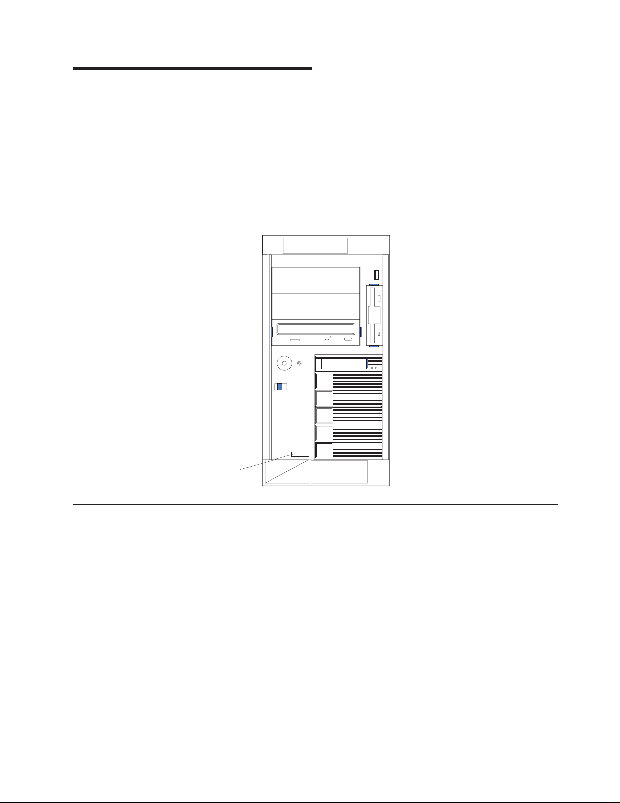
The model number and serial number are on labels on the bottom of the server and
on the front, visible through the bezel, as shown in the following illustration.
Note: The illustrations in this document might differ slightly from your hardware.
Model type/serial
number
Related documentation
This Hardware Maintenance Manual and Troubleshooting Guide is provided in
Portable Document Format (PDF). It contains information to help a user solve
problems or to provide helpful information to a service technician. The following
documents also come with the server:
v User’s Guide
This document is in PDF on the IBM xSeries® Documentation CD. It contains
general information about the server.
v Installation Guide
This printed document contains instructions for setting up the server and basic
instructions for installing some options.
v Option Installation Guide
This document is in PDF on the IBM xSeries Documentation CD. It contains
information that customers can use to install options in the server.
© Copyright IBM Corp. 2004, 2007 1
Page 12

v Safety Information
This document is in PDF on the IBM xSeries Documentation CD. It contains
translated caution and danger statements. Each caution and danger statement
that appears in the documentation has a number that you can use to locate the
corresponding statement in your language in the Safety Information document.
Depending
on the server model, additional documentation might be included on the
IBM xSeries Documentation CD.
The server might have features that are not described in the documentation that
was received with the server. The documentation might be updated occasionally to
include information about those features, or technical updates might be available to
provide additional information that is not included in the server documentation.
These updates are available from the IBM Web site at http://www.ibm.com/support/.
Notices and statements used in this document
The caution and danger statements that appear in this document are also in the
multilingual Safety Information document, which is on the IBM xSeries
Documentation CD. Each statement is numbered for reference to the corresponding
statement in the Safety Information document.
The following notices and statements are used in this document:
v Notes: These notices provide important tips, guidance, or advice.
v Important: These notices provide information or advice that might help you avoid
inconvenient or problem situations.
v Attention: These notices indicate potential damage to programs, devices, or
data. An attention notice is placed just before the instruction or situation in which
damage could occur.
v Caution: These statements indicate situations that can be potentially hazardous
to you. A caution statement is placed just before the description of a potentially
hazardous procedure step or situation.
v Danger: These statements indicate situations that can be potentially lethal or
extremely hazardous to you. A danger statement is placed just before the
description of a potentially lethal or extremely hazardous procedure step or
situation.
2 xSeries 236 Type 8841: Hardware Maintenance Manual and Troubleshooting Guide
Page 13
Features and specifications
The following information is a summary of the features and specifications of the
server. Depending on the server model, some features might not be available, or
some specifications might not apply.
Table 1. Features and specifications
Microprocessor:
v Intel® Xeon™, 2.8 GHz or higher depending
on server model
v 1 MB Level-2 cache
v 800 MHz front-side bus (FSB)
v Support for up to two microprocessors
Note: Use the Configuration/Setup Utility
program to determine the type and speed
of the microprocessor.
Memory:
v Standard: 512 MB, or 1 GB depending on
server model, expandable to 16 GB
v Type: 400 MHz, registered, ECC,
PC2-3200 double data rate II, SDRAM
v Sizes: 256 MB, 512 MB, 1 GB, or
2 GB (when available) in pairs
v Connectors: two-way interleaved, eight
dual inline memory module (DIMM)
connectors
v Maximum: Four pairs of single-ranked
PC2-3200 DDRII DIMMs
Drives
standard:
v Diskette: 1.44 MB
v CD-ROM: IDE
Expansion
bays:
v Six open hot-swap, slim-high, 3.5-inch
drive bays
v Three 5.25-inch bays (CD-ROM drive
installed in one bay)
v One 3.5-inch removable-media drive bay
(diskette drive installed)
PCI
expansion slots:
v One Active PCI-X™ (hot-plug) 133
MHz/64-bit
v Two PCI-X non-hot-plug 100 MHz/64-bit
v Two PCI Express x4 non-hot-plug
v One PCI non-hot-plug 33 MHz/32-bit
Upgradeable
microcode:
BIOS, diagnostics, and IBM integrated system
management upgrades (when available) can
update EEPROMs on the system board
Predictive Failure Analysis® (PFA) alerts:
v Power supplies
v Fans
v Memory
v Hard disk drives
v Microprocessors
v Voltage regulator modules (VRMs)
Integrated functions:
v Baseboard management controller
– Service processor with light path
diagnostics
– RS-485 (ASM interconnect)
– RJ-45 (Ethernet 10/100 ASM interconnect)
– Support for IBM Remote Supervisor
Adapter II SlimLine
v
Dual Broadcom 5721 10/100/1000 Ethernet
controllers (dual stacked RJ-45 connectors)
v Two serial connectors
v One parallel connector
v Support for one external and one optional
external or internal Ultra320 SCSI connector
(dual-channel SCSI controller with RAID
capabilities)
v Three Universal Serial Bus (USB) v1.1 or v2.0
connectors (one on the front and two on the
rear of the enclosure)
v Keyboard connector
v Mouse connector
v AT I Radeon RV7000-M video
– Compatible with SVGA
– 16 MB video memory
The baseboard management controller
Note:
is also known as the service processor.
Security
v Door lock
v Power-on and administrator passwords
v Remote-control security settings
v Selectable drive startup
v Keyboard password
v System-management security
– User login password
– Read-only or read/write access
– Dial-in call-back
Power
supplies:
v Standard: One 670 watts (115-230 V ac)
v Upgradeable to two hot-swap power supplies
features:
Acoustical noise emissions:
v Without redundant fans installed
– Sound power, idle: 5.8 bel
– Sound power, operating: 5.8 bel
– Bystander sound pressure, idle: 43 dBa
– Bystander sound pressure, operating: 43 dBa
With optional redundant fans installed
v
– Sound power, idle: 6.1 bel
– Sound power, operating: 6.1 bel
– Bystander sound pressure, idle: 46 dBa
– Bystander sound pressure, operating:
46 dBa
Electrical
input:
v Sine-wave input (50-60 Hz) required
v Input voltage range automatically selected
v Input voltage low range:
– Minimum: 100 V ac
– Maximum: 127 V ac
v
Input voltage high range:
– Minimum: 200 V ac
– Maximum: 240 V ac
v Input kilovolt-amperes (kVA) approximately:
– Minimum: 0.1 kVA
– Maximum: 0.8 kVA
Heat
output:
Approximate heat output in British thermal units (Btu)
per hour
v Minimum configuration: 341 Btu (100 watts/hour)
v Maximum configuration: 2600 Btu (760 watts/hour)
Environment:
v Air temperature:
– Server on: 10° to 35°C (50° to 95°F)
Altitude: 0 to 2134 m (7000 ft)
– Server off: -40° to +60°C (-40° to 140°F)
Maximum altitude: 2133 m (7000 ft)
v Humidity:
– Server on: 8% to 80%
– Server off: 8% to 80%
Size:
v Height: 440 mm (17.3 in.)
v Depth: 700 mm (27.5 in.)
v Width: 221 mm (8.7 in.)
v Weight: 33.5 kg (74 lb) to 45.8 kg (101 lb)
depending upon configuration
Server controls, LEDs, and power
This section describes the controls and light-emitting diodes (LEDs) and how to turn
the server on and off.
Note: The illustrations in this document might differ slightly from your hardware.
Chapter 1. General information 3
Page 14
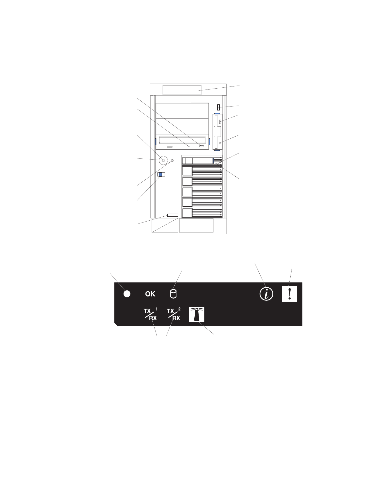
Front view
The following illustration shows the controls, LEDs, and connectors on the front of
the server.
Note: The front bezel door is not shown so that the drive bays are visible.
CD-eject button
CD-ROM drive
activity LED
(green)
Operator
information
panel
USB 3 connector
Disketteeject button
Power-control
button shield
Diskette drive
activity LED
(if installed)
Hard disk
Power-control
button
drive status
LED (amber)
Hard disk
Reset
button
drive activity
LED (green)
Cover-
release
latch
Model type/serial
number
Operator information panel: This panel contains LEDs. The following illustration
shows the LEDs on the operator information panel.
System
Power-on
LED
Hard Disk Drive
Activity LED
Information LED
System
Error LED
The following LEDs are on the operator information panel:
4 xSeries 236 Type 8841: Hardware Maintenance Manual and Troubleshooting Guide
Ethernet
Transmit/Receive
LEDs
System Locator LED
Page 15

v System power-on LED: When this LED is lit and not flashing, it indicates that
the server is turned on. When this LED is flashing, it indicates that the server is
turned off and still connected to an ac power source. When this LED is off, it
indicates that ac power is not present, or the power supply or the LED itself has
failed. A power LED is also on the rear of the server.
v OK LED: This green LED is lit only when the Front Panel LED test is performed
by the Enhanced Diagnostics.
v Hard disk drive activity LED: When this green LED is flashing rapidly it
indicates that there is activity on a hard disk drive.
v System-information LED: When this amber LED is on, the server power
supplies are nonredundant, or some other noncritical event has occurred. The
event is recorded in the error log. Check the light path diagnostic panel for more
information (see the “Light path diagnostics” on page 93.
v System-error LED: When this amber LED is lit it indicates that a system error
has occurred. Use the diagnostic LED panel and the system service label on the
inside of the left-side cover to further isolate the error. See “Light path
diagnostics” on page 93 for additional information.
v System locator LED: Use this LED to visually locate the server among other
servers. You can use IBM Director to light this LED remotely.
v Ethernet transmit/receive activity LED (Tx/Rx 1 or Tx/Rx 2): When these two
green LEDs are lit they indicate that there is activity between the server and the
network.
3 connector: Connect a USB device to this connector.
USB
Diskette-eject button: Press this button to release a diskette from the diskette
drive.
Diskette drive activity LED: When this LED is lit, it indicates that the diskette drive
is in use.
Hard disk drive activity LED: When this LED is flashing, it indicates that the
associated hard disk drive is in use.
Hard disk drive status LED: When this LED is lit, it indicates that the associated
hard disk drive has failed. If an optional RAID adapter is installed in the server and
the LED flashes slowly (one flash per second), the drive is being rebuilt. If the LED
flashes rapidly (three flashes per second), the controller is identifying the drive.
Reset button: Press this button to reset the server and run the power-on self-test
(POST). You might have to use a pen or the end of a straightened paper clip to
press the button.
Power-control button: Press this button to turn the server on and off manually. A
power-control-button shield comes with the server. You can install this disk-shaped
shield to prevent the server from being turned off accidentally.
Power-control-button shield: You can install this circular disk over the
power-control button to prevent the server from being turned off accidently.
CD-ROM drive activity LED: When this LED is lit, it indicates that the CD-ROM
drive is in use.
CD-eject button: Press this button to release a CD from the CD-ROM drive.
Chapter 1. General information 5
Page 16
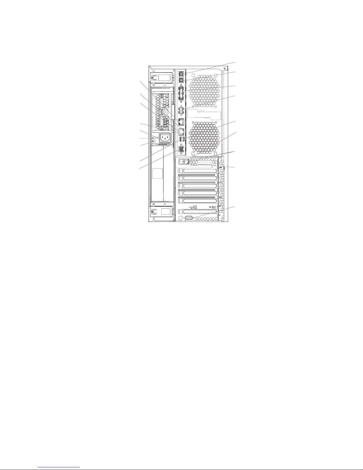
Rear view
The following illustration shows the connectors and LEDs on the rear of the server.
ASM
Ethernet link LED
Remote Supervisor
Adapter II
SlimLine Ethernet
Ethernet activity LED
Power cord connector
AC power LED
DC power LED
Keyboard connector
Mouse connector
Parallel connector
Serial 1 connector
USB 1 connector
Ethernet link 2
status LED
Ethernet connectors 1 and 2
USB 2 connector
Video connector
DO NOTTHROW AWAY
DO NOTTHROW AWAY
WITH EMPTY SLOT
WITH EMPTY SLOT
SYSTEM COOLING
SYSTEM COOLING
ATTENTION:
ATTENTION:
REQUIRED FOR
REQUIRED FOR
POWER SUPPLY
POWER SUPPLY
FILLER
FILLER
Ethernet link 1
status LED
Serial 2 connector
Keyboard connector: Connect a PS/2 keyboard to this connector.
Mouse connector: Connect a mouse or other PS/2 device to this connector.
Parallel connector: Connect a parallel device to this connector.
Serial 1 connector: Connect a 9-pin serial device to this connector.
USB 1 connector: Connect a USB device to this connector.
Ethernet link 1 status LED: This LED is on the Ethernet connector. When this
LED is lit, there is an active connection on the Ethernet port 1.
Ethernet connectors 1 and 2: Use these connectors to connect the server to a
network.
Ethernet link 2 status LED: This LED is on the Ethernet connector. When this
LED is lit, there is an active connection on the Ethernet port 2.
Serial 2 connector: Connect a 9-pin serial device to this connector.
Video connector: Connect a monitor to this connector.
USB 2 connector: Connect a USB device to this connector.
DC power LED: This green LED provides status information about the power
supply. During typical operation, both the ac and dc power LEDs are lit. For any
other combination of LEDs, see “Light path diagnostics” on page 93.
6 xSeries 236 Type 8841: Hardware Maintenance Manual and Troubleshooting Guide
Page 17

AC power LED: This green LED provides status information about the power
supply. During typical operation, both the ac and dc power LEDs are lit. For any
other combination of LEDs, see “Light path diagnostics” on page 93.
Power-cord connector: Connect the power cord to this connector.
Ethernet Activity LED: This LED is on the Ethernet connector. When it flashes, it
indicates that data is being transmitted or received between the server and the
network device that is connected to the connector. The flashing frequency is
proportional to the amount of traffic on the network link.
ASM: Use this connector to connect the server to an Advanced System
Management (ASM) network.
Ethernet link status LED: This LED is on the Ethernet connector. When this LED
is lit, there is an active connection on the Ethernet port.
Remote Supervisor Adapter II SlimLine Ethernet: Use this connector to connect
the server to an optional Remote Supervisor Adapter II SlimLine installed in another
server. This connector is enabled when the Remote Supervisor II SlimLine option is
installed.
Server power features
When the server is connected to an ac power source but is not turned on, the
operating system does not run, and all core logic except for the service processor is
shut down; however, the server can respond to requests from the service processor
(also called the baseboard management controller), such as a remote request to
turn on the server. The power-on LED flashes to indicate that the server is
connected to ac power but is not turned on.
Turning on the server
Approximately 20 seconds after the server is connected to ac power, the
power-control button becomes active, one or more fans might start running, and you
can turn on the server and start the operating system by pressing the power-control
button.
The server can also be turned on in any of the following ways:
v If a power failure occurs while the server is turned on, the server will restart
automatically when power is restored.
v If the server is connected to an Advanced System Management interconnect
network that contains at least one server with an optional Remote Supervisor
Adapter installed, the server can be turned on from the Remote Supervisor
Adapter user interface.
v If your operating system supports the systems-management software for an
optional Remote Supervisor Adapter, the systems-management software can turn
on the server.
v If your operating system supports the Wake on LAN® feature, the Wake on LAN
feature can turn on the server.
Chapter 1. General information 7
Page 18
Note: When 4 GB or more of memory (physical or logical) is installed, some
memory is reserved for various system resources and is unavailable to the
operating system. The amount of memory that is reserved for system
resources depends on the operating system, the configuration of the server,
and the configured PCI options.
Turning off the server
When you turn off the server and leave it connected to ac power, the server can
respond to requests from the service processor, such as a remote request to turn
on the server. While the server remains connected to ac power, one or more fans
might continue to run. To remove all power from the server, you must disconnect it
from the power source.
Some operating systems require an orderly shutdown before you turn off the server.
See the operating-system documentation for information about shutting down the
operating system.
Statement 5
CAUTION:
The power control button on the device and the power switch on the power supply do
not turn off the electrical current supplied to the device. The device also might have
more than one power cord. To remove all electrical current from the device, ensure
that all power cords are disconnected from the power source.
2
1
The server can be turned off in any of the following ways:
v Yo u can turn off the server from the operating system, if your operating system
supports this feature. After an orderly shutdown of the operating system, the
server will be turned off automatically.
v Yo u can press the power-control button to start an orderly shutdown of the
operating system and turn off the server, if your operating system supports this
feature.
v If the operating system stops functioning, you can press and hold the
power-control button for more than 4 seconds to turn off the server.
v If the server is connected to an Advanced System Management interconnect
network that contains at least one server with an optional Remote Supervisor
Adapter installed, the server can be turned off from the Remote Supervisor
Adapter user interface.
v If an optional Remote Supervisor Adapter is installed in the server, the server can
be turned off from the Remote Supervisor Adapter user interface.
v If the Wake on LAN feature turned on the server, the Wake on LAN feature can
turn off the server.
v The integrated system management processor can turn off the server as an
automatic response to a critical system failure.
v Yo u can turn off the server through a request from the service processor.
8 xSeries 236 Type 8841: Hardware Maintenance Manual and Troubleshooting Guide
Page 19

Chapter 2. Configuration
Detailed information about configuring the server is in the IBM xSeries User’s Guide
on the IBM Documentation CD.
The latest information about these programs and the most recent device-driver files
are available at http://www.ibm.com/support/.
The following configuration programs and capabilities come with the server:
v Configuration/Setup Utility program
v Baseboard management controller utility programs
v SCSISelect Utility program for Adaptec® HostRAID™ configuration
v Preboot Execution Environment (PXE) boot agent utility program
Starting the Configuration/Setup Utility program
To start the Configuration/Setup Utility program:
1. Turn on the server and watch the monitor screen.
2. When the message Press F1 for Configuration/Setup appears, press F1.
Note: If you have set both levels of passwords (power-on and administrator),
you must type the administrator password to access the full
Configuration/Setup Utility menu. Without the administrator password,
limited Configuration/Setup Utility program functions are available.
3. Follow the instructions that appear on the screen.
© Copyright IBM Corp. 2004, 2007 9
Page 20

10 xSeries 236 Type 8841: Hardware Maintenance Manual and Troubleshooting Guide
Page 21

Chapter 3. Installing options
This chapter provides detailed instructions for installing hardware options in the
server.
Installation guidelines
Before you begin installing options in the server, read the following information:
v For a list of supported options for the server, go to http://www.ibm.com/us/
compat/.
v Read the safety information beginning on page v and the guidelines in “Handling
static-sensitive devices” on page 12. This information will help you work safely
with the server and options.
v Make sure that you have an adequate number of properly grounded electrical
outlets for the server, monitor, and other devices.
v Back up all important data before you make changes to disk drives.
v Have a small flat-blade screwdriver available.
v Yo u do not have to turn off the server to install or replace hot-swap power
supplies, hot-swap fans, or hot-plug Universal Serial Bus (USB) devices.
v Blue on a component indicates touch points, where you can grip the component
to remove it from or install it in the server, open or close a latch, and so on.
v Orange on a component or an orange label on or near a component indicates
that the component can be hot-swapped, which means that if the server and
operating system support hot-swap capability, you can remove or install the
component while the server is running. (Orange can also indicate touch points on
hot-swap components.) See the instructions for removing or installing a specific
hot-swap component for any additional procedures that you might have to
perform before you remove or install the component.
v When you need to access the inside of the server, you might find it easier to lay
the server on its side.
System reliability guidelines
To help ensure proper cooling and system reliability, make sure that:
v Each of the drive bays has a drive or a filler panel and electromagnetic
compatibility (EMC) shield installed in it.
v There is adequate space around the server to allow the server cooling system to
work properly. Leave approximately 50 mm (2.0 in.) of open space around the
front and rear of the server. Do not place objects in front of the fans. For proper
cooling and airflow, replace the left-side cover before turning on the server.
Operating the server for extended periods of time (more than 30 minutes) with
the left-side cover removed might damage server components.
v Yo u have followed the cabling instructions that come with optional adapters.
v Yo u have replaced a failed fan within 48 hours.
v Yo u have replaced a hot-swap drive within 2 minutes of removal.
v Yo u do not remove the air baffle while the server is running. Operating the server
without the air baffle might cause the microprocessor to overheat.
v Microprocessor socket 2 always contains either a microprocessor baffle or a
microprocessor and heat sink.
© Copyright IBM Corp. 2004, 2007 11
Page 22

Working inside the server with the power on
The server supports hot-swap devices and is designed to operate safely while it is
turned on and the cover is removed. Follow these guidelines when you work inside
a server that is turned on:
v Avoid wearing loose-fitting clothing on your forearms. Button long-sleeved shirts
before working inside the server; do not wear cuff links while you are working
inside the server.
v Do not allow your necktie or scarf to hang inside the server.
v Remove jewelry, such as bracelets, necklaces, rings, and loose-fitting wrist
watches.
v Remove items from your shirt pocket, such as pens and pencils, that could fall
into the server as you lean over it.
v Avoid dropping any metallic objects, such as paper clips, hairpins, and screws,
into the server.
Handling static-sensitive devices
Attention: Static electricity can damage electronic devices, including the server.
To avoid damage, keep static-sensitive devices in their static-protective packages
until you are ready to install them.
To reduce the possibility of damage from electrostatic discharge, observe the
following precautions:
v Limit your movement. Movement can cause static electricity to build up around
you.
v Handle the device carefully, holding it by its edges or its frame.
v Do not touch solder joints, pins, or exposed circuitry.
v Do not leave the device where others can handle and damage it.
v While the device is still in its static-protective package, touch it to an unpainted
metal part of the server for at least 2 seconds. This drains static electricity from
the package and from your body.
v Remove the device from its package and install it directly into the server without
setting down the device. If it is necessary to set down the device, put it back into
its static-protective package. Do not place the device on the server cover or on a
metal surface.
v Take additional care when handling devices during cold weather. Heating reduces
indoor humidity and increases static electricity.
12 xSeries 236 Type 8841: Hardware Maintenance Manual and Troubleshooting Guide
Page 23
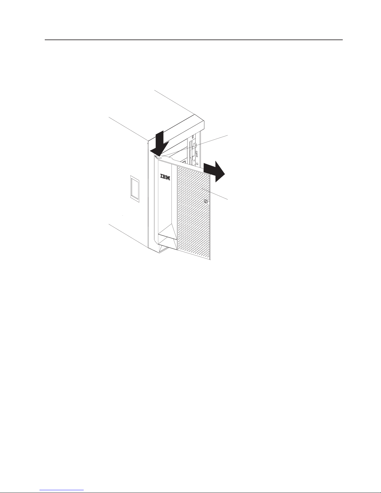
Removing the server door
The following illustration shows how to remove the door from the server.
Note: The illustrations in this document might differ slightly from your hardware.
PCI BUS
A B
POWER SUPPLY
1 2 3
FAN
1 2 3
Flange
C
PU
VRM
MEMORY
HDD
NMI
SMI
SERVICE PROCESSOR
BUS
NON REDUNDANT
TEMPERATURE
Server door
Complete the following steps to remove the server door:
1. Read the safety information beginning on page v and “Installation guidelines” on
page 11.
2. Unlock and open the server door.
3. Locate the flange on the top edge of the door.
4. Press the flange downward while pressing outward on the door; then, lift the
door up and off the hinge. Set the door aside in a safe place.
Chapter 3. Installing options 13
Page 24
Removing the server left-side cover air baffle and bezel
Before you remove the left-side cover, air-baffle, or bezel, read the safety
information beginning on page v and “Installation guidelines” on page 11.
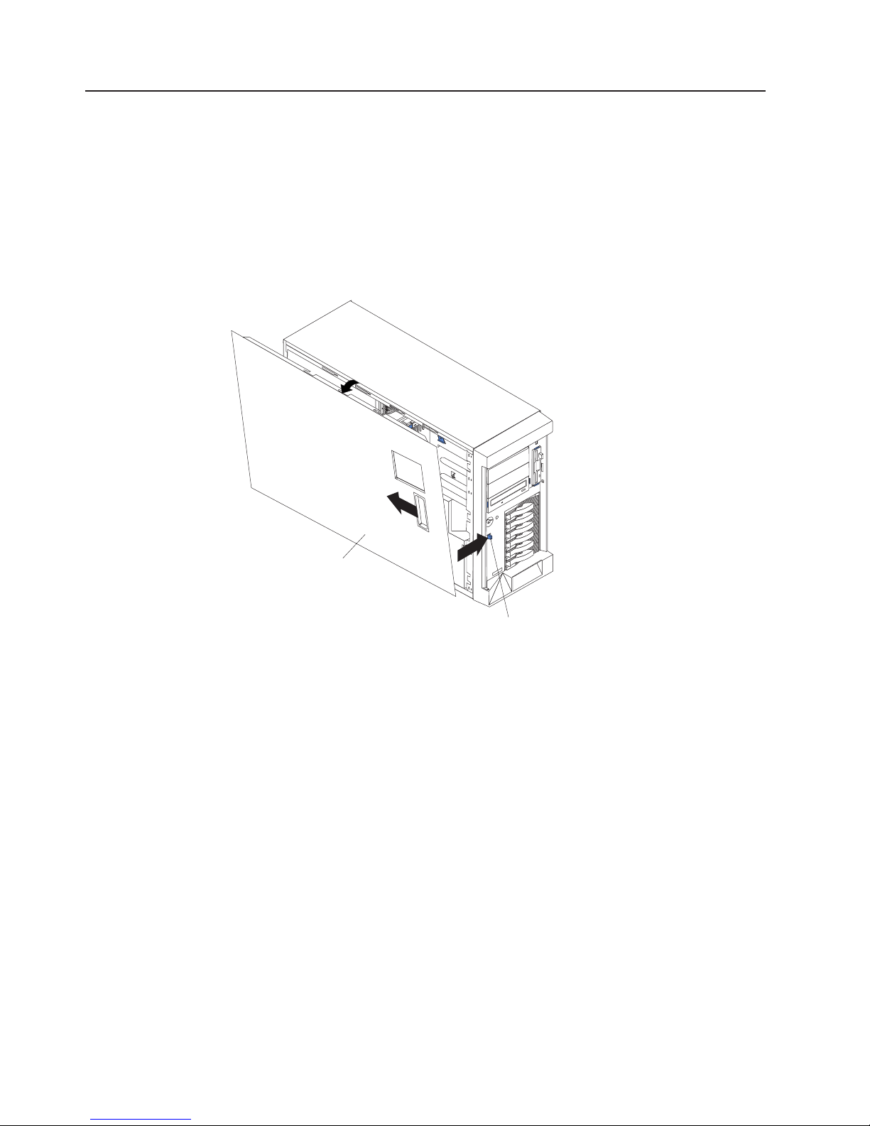
Removing the left-side cover
The following illustration shows how to remove the left-side cover from the server.
Note: If you have not already removed the door, remove it as described in
“Removing the server door” on page 13.
Left-side cover
Coverrelease
latch
Complete the following steps to remove the server left-side cover:
1. Push the plastic cover-release latch near the edge of the side cover to the right
to release the cover.
2. While pushing the plastic cover-release latch, slide the side cover slightly toward
the rear of the server; the cover will stop after approximately 25 mm (1 inch).
Lift the cover off the server and set the cover aside.
Attention: For proper cooling and airflow, replace the cover before turning on
the server. Operating the server for extended periods of time (more than 30
minutes) with the cover removed might damage server components.
14 xSeries 236 Type 8841: Hardware Maintenance Manual and Troubleshooting Guide
Page 25
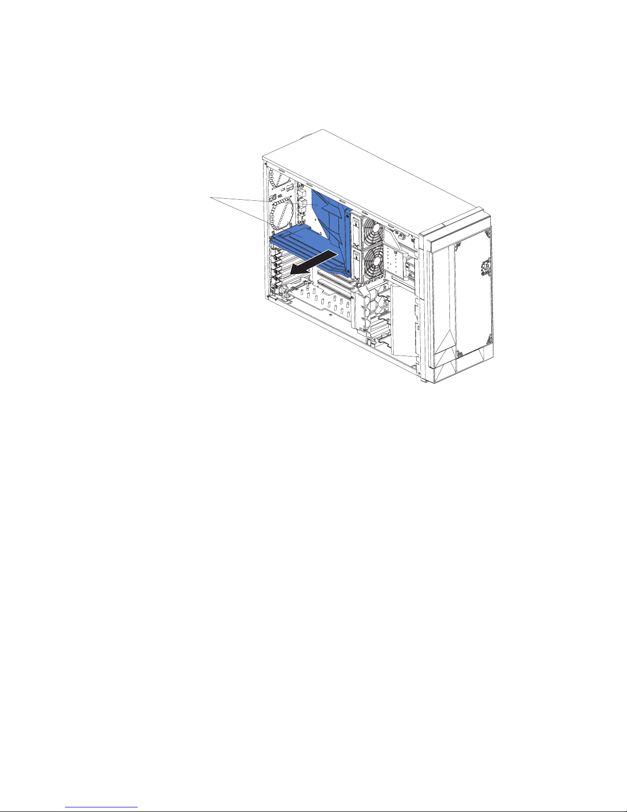
Removing the air baffle
When working with some options, you must first remove the air baffle to access
certain components or connectors on the system board. The following illustration
shows how to remove the air baffle.
Air-baffle assembly
Complete the following steps to remove the air baffle:
1. Read the safety information beginning on page v and “Installation guidelines” on
page 11.
2. Turn off the server and peripheral devices and disconnect all power cords and
external cables (see “Turning on the server” on page 7); then, remove the cover
(see “Removing the left-side cover” on page 14).
3. Place your fingers on each side of the air baffle.
4. Press in on the sides and lift the air baffle out of the server.
Attention: For proper cooling and airflow, replace the air baffle before turning
on the server. Operating the server with the air baffle removed might damage
server components.
Chapter 3. Installing options 15
Page 26
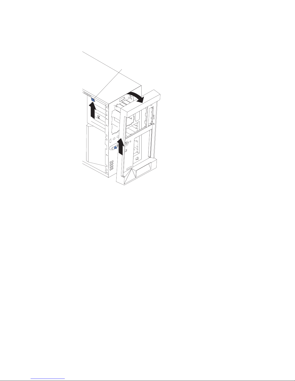
Removing the bezel
The following illustration shows how to remove the bezel from the server.
Bezel-release lever
Complete the following steps to remove the bezel:
1. Remove the left-side cover and locate the bezel-release lever.
2. Press up on the bezel-release lever.
3. Pull the top of the bezel away from the chassis; then, lift the bezel to disengage
the bottom tabs.
4. Remove the bezel from the server and store the bezel in a safe place.
16 xSeries 236 Type 8841: Hardware Maintenance Manual and Troubleshooting Guide
Page 27
Replacing hot-swap fans
The server comes with four hot-swap fans: two front fans (fans 1 and 2), and two
center fans (fans 3 and 4). Yo u do not have to turn off the power to the server to
replace a hot-swap fan.
If the server is equipped with the IBM xSeries 670-Watt Hot-swap Power-Supply
option, two rear fans (fans 5 and 6) must also be installed on the server. For
information on replacing these fans or installing this option, see “Replacing a rear
fan (5 or 6)” on page 20 or “Installing the 670-Watt hot-swap power-supply option”
on page 21.
Attention: To help ensure proper cooling, if a fan fails, replace it within 48 hours.
The following illustration shows how to replace hot-swap fans.
Center fan
3 or 4
Release
lever
Hot-swap fan
Front fan
1 or 2
Hot-swap fan
assembly
Determine which fan to replace by checking the LEDs on the fans. The front fans,
center fans, and rear fans are installed differently from each other. This section
contains separate instructions for each group of fans.
Chapter 3. Installing options 17
Page 28
Replacing a front fan (1 or 2)
Complete the following steps to replace fan 1 or 2:
Attention: To ensure proper server operation, if a fan fails, replace it within 48
hours.
Fan-assembly
latch
Hot-swap fan
assembly
Front fan
1or 2
Complete the following steps to replace hot-swap-fan 1 or 2:
1. Read the safety information beginning on page v and “Installation guidelines” on
page 11.
2. Remove the cover. See “Removing the left-side cover” on page 14. The LED on
the failing fan assembly will be lit.
Attention: To ensure proper system cooling, do not remove the left-side cover
for more than 30 minutes during this procedure.
3. Place your fingers into the fan-assembly latch on the top of the failing fan.
4. Squeeze the fan-assembly latch together and lift the fan out of the server.
5. Position the new fan so that the LED on the fan is closest to the front of the
server.
6. Push the replacement fan assembly into the server until it clicks into place.
7. Make sure that the FAN LED on the diagnostic LED panel (see “Light path
diagnostics panel” on page 84) is not lit. If the FAN LED is lit, reseat the fan.
8. Replace the cover. See “Installing the server bezel and left-side cover” on page
46.
18 xSeries 236 Type 8841: Hardware Maintenance Manual and Troubleshooting Guide
Page 29
Replacing a center fan (3 or 4)
Complete the following steps to replace hot-swap fan 3 or 4:
Hot-swap fan
Release
lever
Center fan
3 or 4
1. Read the safety information beginning on page v and “Installation guidelines” on
page 11.
2. Remove the cover. See “Removing the left-side cover” on page 14. The LED on
the failing fan assembly will be lit.
Attention: To ensure proper system cooling, do not remove the left-side cover
for more than 30 minutes during this procedure.
3. Press the orange fan-release latch in the direction indicated by the arrow on the
latch to open the release lever.
4. Pull the fan out of the server using the release lever.
5. Press the orange fan-release latch in the direction indicated by the arrow on the
latch and open the release lever on the replacement fan.
6. Position the replacement fan so that the orange fan-release latch is away from
you; then, slide the fan into the server. Press the release latch into place and
secure the fan in the server.
7. Make sure that the FAN LED on the diagnostic LED panel (see “Light path
diagnostics panel” on page 84) is not lit. If the FAN LED is lit, reseat the fan.
8. Reinstall the server cover. See “Installing the server bezel and left-side cover”
on page 46.
Chapter 3. Installing options 19
Page 30
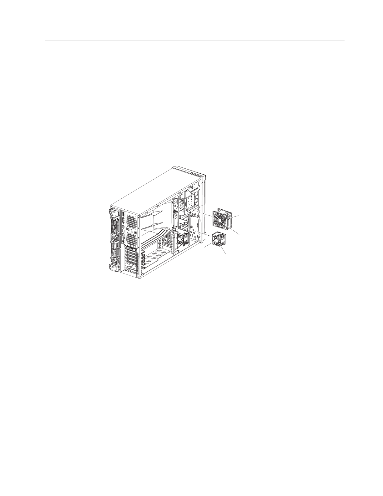
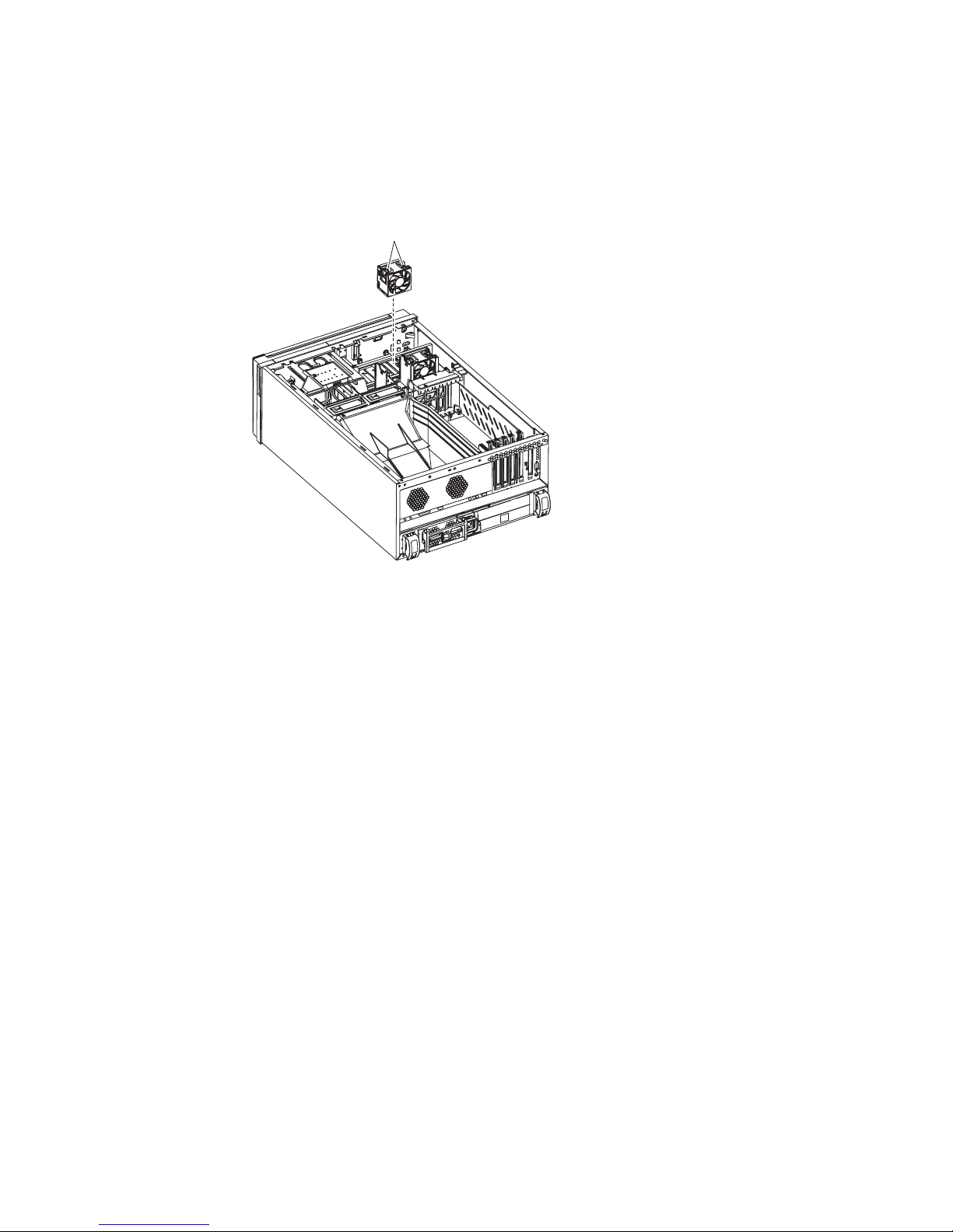
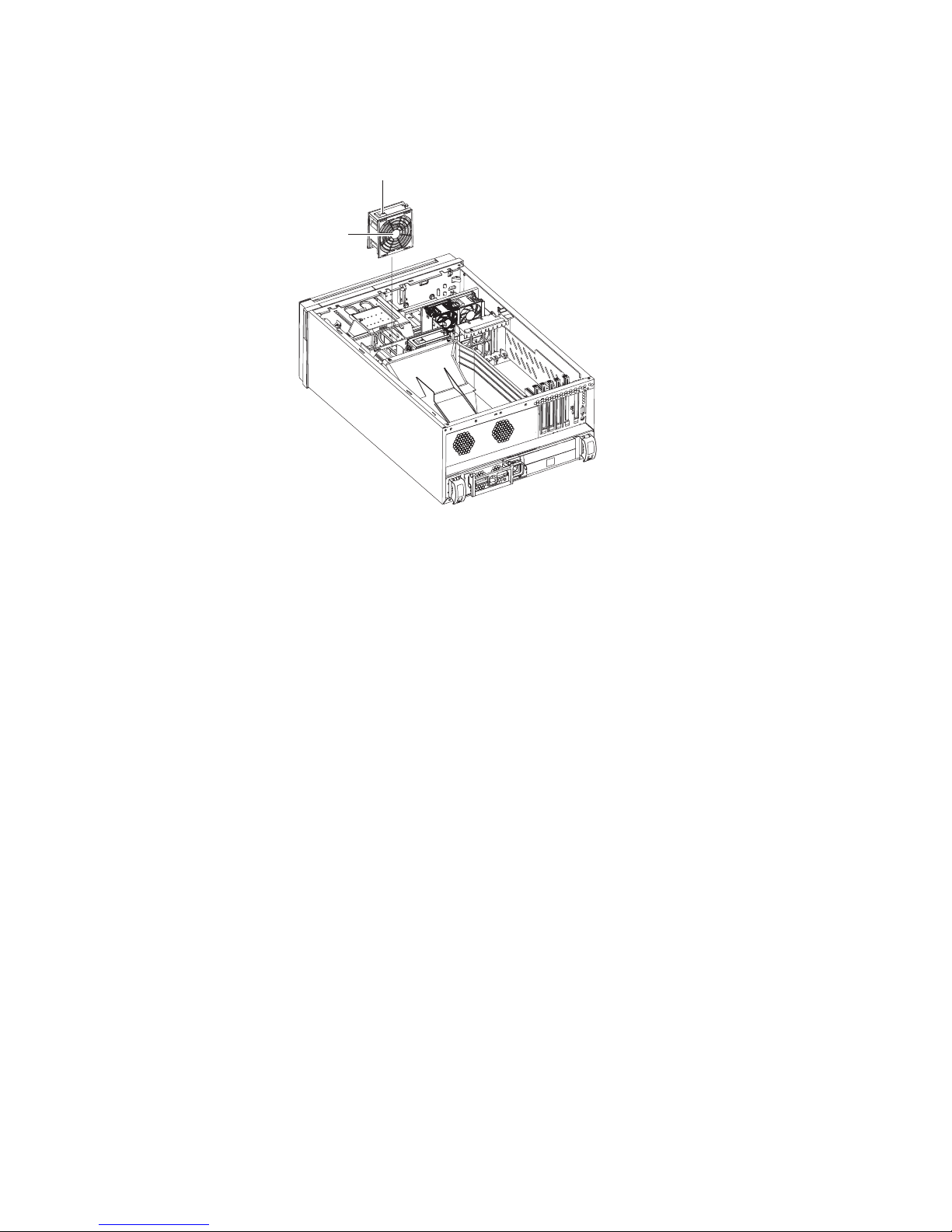
Replacing a rear fan (5 or 6)
Hot-swap fans 5 and 6 are included in the power-supply option. With these two
additional hot-swap fans installed, the server supports the variable fan-speed
control and redundant cooling features. For information on installing the option see
“Installing the 670-Watt hot-swap power-supply option” on page 21.
Complete the following steps to replace hot-swap-fans 5 and 6:
1. Read the safety information beginning on page v and “Installation guidelines” on
page 11.
2. Press in on the orange fan-release latch on the side of the fan; then, rotate the
fan away from the server.
3. Pull the fan off the server.
4. Slide the two tabs of the replacement fan into the back of the server; then,
rotate the fan toward the server until the fan-release latch clicks.
5. Make sure that the FAN LED on the diagnostic LED panel (see “Light path
diagnostics panel” on page 84) is not lit. If the FAN LED is lit, reseat the fan.
Rear fan 5 or 6
Fan-release
latch
20 xSeries 236 Type 8841: Hardware Maintenance Manual and Troubleshooting Guide
Page 31

Installing the 670-Watt hot-swap power-supply option
The server comes with a power supply in the power supply 1 (PS1) position and a
filler panel in the power supply 2 (PS2) position. Yo u can install a 670-Watt
hot-swap power-supply option, which includes a hot-swap power supply and two
hot-swap fans.
Power supply 1
AC power LED
DC power LED
Power supply 2
AC power LED
DC power LED
Fan 5 LED
Fan 6 LED
Before you continue, review the following information:
v During normal nonredundant operation, a power supply must be installed in the
power supply 1 position and a filler panel in the power supply 2 position.
v During normal redundant operation, a second hot-swap power supply and the
two rear hot-swap fans must be installed in the server.
Attention: To help ensure proper cooling, if a fan fails, replace it within 48
hours.
v When the 670-Watt hot-swap power supply option is installed in the server, the
addition of the two fans enables the redundant cooling feature. If any of the fans
fail the other fans will speed up when needed to help keep the server cool and
working properly.
v Two cable-restraint brackets are on the rear of the server. After you install the
670-Watt hot-swap power-supply option and connect the cables to the selected
devices, you can use these cable-restraint brackets to manage the cable routing.
Route the power cords through the power-cord restraint bracket. Route the
remaining cables (for example, the cables that are connected to the I/O
connectors) through the I/O cable-restraint bracket.
Chapter 3. Installing options 21
Page 32

If you install or remove a power supply, observe the following precautions.
Statement 8:
CAUTION:
Never remove the cover on a power supply or any part that has the following
label attached.
Hazardous voltage, current, and energy levels are present inside any
component that has this label attached. There are no serviceable parts inside
these components. If you suspect a problem with one of these parts, contact
a service technician.
Complete the following steps to install the 670-Watt hot-swap power-supply option:
1. Read the safety information beginning on page v and “Installation guidelines” on
page 11.
2. Remove the filler panel from the power supply 2 opening.
22 xSeries 236 Type 8841: Hardware Maintenance Manual and Troubleshooting Guide
Page 33

3. Install the second hot-swap power-supply.
Power supply 1
Fan 5 LED
Fan 6 LED
AC power LED
DC power LED
Power supply 2
AC power LED
DC power LED
a. Make sure that the handle on the power supply is in the open position.
b. Slide the power supply into the power supply 2 opening until it stops; then,
push the handle down into the closed position.
Install the fans on the back of the server:
4.
a. Position the first fan so that the notched area is facing up and the mounting
surface is toward the server.
b. Tilt the bottom of the fan toward the server and insert the tabs into the
corresponding holes.
c. Press in on the top half of the fan until it clicks into place.
d. Position the second fan so that the notched area is facing down and the
mounting surface is toward the server.
e. Repeat steps 5b and 5c; then, continue to step 6.
Connect one end of each power cord to the corresponding connector on each
5.
power supply; then, connect the other end of each power cord to a properly
grounded electrical outlet.
Note: You can route the power cords through the power-cord restraint bracket
6. Make sure that the dc power LED and the ac power LED on each power supply
is lit, indicating that the power supplies are operating properly.
on the rear of the server.
Chapter 3. Installing options 23
Page 34

Replacing a hot-swap power supply
The server comes with one power supply.
If you install or remove a power supply, observe the following precautions.
Statement 8:
CAUTION:
Never remove the cover on a power supply or any part that has the following
label attached.
Hazardous voltage, current, and energy levels are present inside any
component that has this label attached. There are no serviceable parts inside
these components. If you suspect a problem with one of these parts, contact
a service technician.
Complete the following steps to remove and replace a hot-swap power supply:
1. Read the safety information beginning on page v and “Installation guidelines” on
page 11.
2. Disconnect the power cord from the power supply.
3. Push on the orange release latch in the center of the power-supply handle;
then, pull out on the handle.
4. Extend the handle to the open position and pull the power supply out of the
server.
5. Make sure that the handle on the new power supply is in the fully open position
and slide it into the opening until it stops.
6. Push down on the handle until the release latch clicks.
7. Connect the power cord to the new power supply.
8. Make sure that the dc power LED and the ac power LED on the power supply is
lit, indicating that the power supply is operating properly.
24 xSeries 236 Type 8841: Hardware Maintenance Manual and Troubleshooting Guide
Page 35

Installing or replacing an adapter
The following notes describe the types of adapters that the server supports and
other information that you must consider when installing an adapter:
v Locate the documentation that comes with the adapter and follow those
instructions in addition to the instructions in this section. If you must change the
switch or jumper settings on the adapter, follow the instructions that come with
the adapter.
v Avoid touching the components and gold-edge connectors on the adapter.
v Yo u can install full-length adapters and non-hot-plug adapters in slots 4 and 5.
v A full-length adapter cannot be installed in slot 1 if the ServeRAID-7k option is
installed.
v The hot-plug slot (slot 6) supports full and half-length hot-plug and non-hot-plug
adapters. The hot-plug feature is operating system dependant. See the
documentation that comes with your operating system to see if it supports this
feature.
v The 32-bit PCI slot (slot 1) supports 5.0 V and 3.3 V PCI adapters, with the
exception that you cannot install a long adapter in slot 1 on servers with
ServeRAID-7k installed.
v The 64-bit PCI-X slots 4 through 6 support 3.3 V signaling PCI or PCI-X
adapters; they do not support 5.0 V signaling adapters.
v The PCI bus configuration is as follows:
– Non-hot-plug, 33 MHz 32-bit PCI slot 1 is on PCI bus A.
– Non-hot-plug, 64-bit PCI Express x4 slot 2 is on PCI bus B (independent of
slots 1, 3, 4, 5, and 6).
– Non-hot-plug, 64-bit PCI Express x4 slot 3 is on PCI bus C (independent of
slots 1, 2, 4, 5, and 6).
– Non-hot-plug, 100 MHz 64-bit PCI-X slots 4 and 5 and the integrated SCSI
controller with RAID capabilities are on PCI bus D.
– Hot-plug, 133 MHz 64-bit PCI-X slot 6 is on PCI bus F.
If an optional ServeRAID controller is installed, it overrides the standard
Note:
functionality of the integrated SCSI controller with RAID capabilities. The
ServeRAID controller must be installed in its dedicated connector on the
system board.
v The system scans PCI and PCI-X slots 1 through 6 to assign system resources.
The system then starts (boots) the system devices in the following order, if you
have not changed the default boot precedence: integrated Ethernet controller,
integrated SCSI controller with RAID capabilities, and then PCI and PCI-X slots 1
through 6.
Note: To change the boot precedence for PCI and PCI-X devices, start the
Configuration/Setup Utility program and select Start Options from the
main menu. See the User’s Guide on the IBM xSeries Documentation CD
for details about using the Configuration/Setup Utility program.
v The server uses a rotational interrupt technique to configure PCI adapters so that
you can install PCI adapters that do not support sharing of PCI interrupts.
Chapter 3. Installing options 25
Page 36
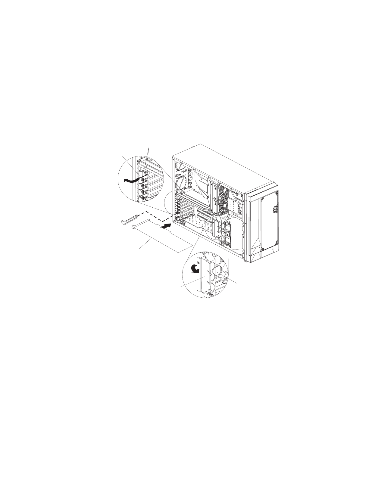
Complete the following steps to install or replace an adapter:
Note: If you are installing a hot-plug adapter go to “Installing or replacing a
hot-plug adapter (slot 6)” on page 28.
1. Read the safety information beginning on page v and “Installation guidelines” on
page 11.
2. Turn off the server and peripheral devices, and disconnect the power cords and
all external cables. Remove the cover.
3. See the documentation that comes with the adapter for any cabling instructions
and information about jumper or switch settings. (It might be easier for you to
route cables before you install the adapter.)
4. Lift the adapter-retention latch and remove the expansion-slot cover.
Adapterretention
latch
Backup expansion-slot
screws
Expansionslot cover
Adapter
Adapterretention
clip
Adapter-support
bracket
26 xSeries 236 Type 8841: Hardware Maintenance Manual and Troubleshooting Guide
Page 37
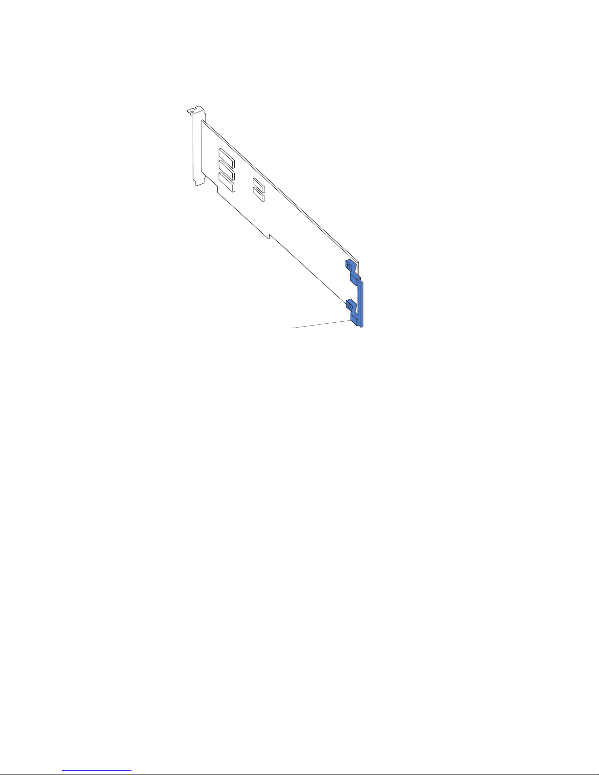
5. If you are installing a full-length adapter, remove the blue adapter guide (if any)
from the end of the adapter; then, lift the adapter-retention clip on the
adapter-support bracket. Otherwise, continue with the next step.
Adapter guide
6. Press the adapter firmly into the expansion slot, lower the adapter-retention
latch, and make sure that the latch is in the locked (closed) position.
Attention: Incomplete insertion might cause damage to the system board or
the adapter.
7. Connect any needed cables to the adapter.
8. If you have other options to install or remove, do so now.
9. Replace the cover. Go to “Completing the installation” on page 45.
Chapter 3. Installing options 27
Page 38
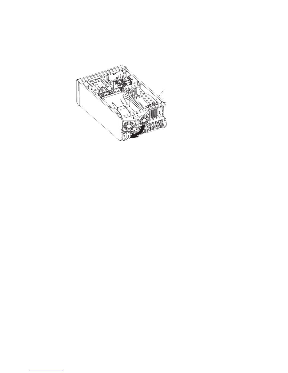
Installing or replacing a hot-plug adapter (slot 6)
You do not have to turn off the server to install hot-plug adapters in the hot-plug
slots. However, you must turn off the server when performing any steps that involve
installing or removing cables.
The following illustration shows how to install a PCI or PCI-X hot-plug adapter.
Adapterretention
latch
Ta b
PCI-X
divider
Adapter
Adapterretention
clip
Adapter-support
bracket
Complete the following steps to install or replace a hot-plug PCI or PCI-X adapter:
1. Read the safety information beginning on page v and “Installation guidelines” on
page 11.
2. Remove the cover.
3. Open the adapter-retention latch and remove the expansion-slot cover from the
server.
Attention: Expansion slot covers must be installed on all empty slots. This
maintains the electronic emissions characteristics of the server and ensures
proper cooling of system components.
28 xSeries 236 Type 8841: Hardware Maintenance Manual and Troubleshooting Guide
Page 39

4. If you are installing a full-length adapter, lift the adapter-retention clip on the
adapter-support bracket. Otherwise, continue with the next step.
Adapter guide
5. See the documentation that comes with the adapter for any cabling instructions
and information about jumper or switch settings.
Attention: Incomplete insertion might cause damage to the system board or
the adapter.
6. Press the adapter firmly into the expansion slot.
7. Close the adapter-retention latch and, if necessary, the adapter-retention clip.
Important: Power cannot be provided to the adapter slot if the latch is not
lowered into place.
8. Connect any needed cables to the adapter. You must turn the server off before
installing any cables.
Note: See the documentation that comes with the operating system for
information about enabling a hot-plug PCI-X slot.
9. If you have other options to install or remove, do so now; otherwise, go to
“Completing the installation” on page 45.
Installing an IBM Remote Supervisor Adapter II SlimLine
This section provides instructions for installing an IBM Remote Supervisor Adapter II
SlimLine. The optional IBM Remote Supervisor Adapter II SlimLine must be
installed in its dedicated connector on the system board. See “System-board
internal connectors” on page 78 for the location of the connector. The Remote
Supervisor Adapter II SlimLine is not cabled to the system board.
Complete the following steps to install the Remote Supervisor Adapter II SlimLine:
1. Read the safety information beginning on page v and “Installation guidelines” on
page 11.
2. Turn off the server and peripheral devices, and disconnect the power cords and
all external cables. Remove the cover and air baffle assembly.
Chapter 3. Installing options 29
Page 40

3. Assemble the Remote Supervisor Adapter II SlimLine and Interposer card:
Connector
Standoffs
Standoffs
Interposer card
Mounting hole
Remote Supervisor
Adapter II SlimLine
Standoffs
Mounting hole
a. Insert the standoffs that come with the option into the mounting holes in the
Remote Supervisor Adapter II SlimLine.
b. Align the mounting holes in the Interposer card with the standoffs; then,
align the connector on the card with the connector on the Remote
Supervisor Adapter II SlimLine.
c. Press the Interposer card and Remote Supervisor Adapter II SlimLine
together until fastened.
Press the Remote Supervisor Adapter II SlimLine Guide into place on the
4.
system board.
Remote Supervisor Adapter II
SlimLine
Remote Supervisor Adapter II
SlimLine guide
Remote Supervisor Adapter II
SlimLine connector
5. Position the entire assembly so that the edge connector on the Interposer card
is at the rear of the server.
6. Carefully grasp the assembly by its top edge or upper corners, and align it with
the Remote Supervisor Adapter II SlimLine Guide and the connector on the
system board.
Attention: Incomplete insertion might cause damage to the system board or
the adapter.
7. Press the assembly firmly into the connector and under the retention latch on
the Remote Supervisor Adapter II SlimLine Guide.
30 xSeries 236 Type 8841: Hardware Maintenance Manual and Troubleshooting Guide
Page 41

8. If you have other options to install or remove, do so now.
9. Replace the air-baffle assembly and cover. Go to “Completing the installation”
on page 45.
Installing the ServeRAID-7k adapter
The optional ServeRAID-7k adapter must be installed in its dedicated connector on
the system board. See the following illustration for the location of the connector on
the system board. The ServeRAID-7k adapter is not cabled to the system board
and no rerouting of the SCSI cable is required.
Complete the following steps to install the ServeRAID-7k adapter:
ServeRAID-7k
adapter
ServeRAID-7k
connector
1. Read the safety information beginning on page v and “Installation guidelines” on
page 11.
2. Turn off the server and peripheral devices, and disconnect the power cords and
all external cables. Remove the cover and air baffle assembly.
Attention: To avoid breaking the retaining clips or damaging the
ServeRAID-7k adapter connector, open and close the clips gently.
3. Open the retaining clip on each end of the ServeRAID-7k adapter connector.
4. Touch the static-protective package containing the ServeRAID-7k adapter to any
unpainted metal surface on the server. Then, remove the ServeRAID-7k adapter
from the package.
5. Turn the ServeRAID-7k adapter so that the ServeRAID-7k adapter keys align
correctly with the connector. The green battery pack of the ServeRAID-7k
adapter should be facing away from the microprocessor sockets.
Attention: Incomplete insertion might cause damage to the system board or
the ServeRAID-7k adapter.
6. Press the ServeRAID-7k adapter firmly into the connector.
7. If you have other options to install or remove, do so now.
8. Replace the air-baffle assembly and cover. Go to “Completing the installation”
on page 45.
Chapter 3. Installing options 31
Page 42

Installing a hot-swap hard disk drive
The following notes describe the types of hard disk drives that the server supports
and other information that you must consider when installing a hard disk drive:
v The server supports up to six 1-inch (26 mm) slim-high, 3.5-inch, hot-swap hard
disk drives in the standard hot-swap bays.
v The hot-swap bays are arranged vertically in the standard hard disk drive cage;
the bay numbers are 0 through 5 (from bottom to top).
v For a list of supported options for the server, go to http://www.ibm.com/us/
compat/.
v Inspect the drive tray for signs of damage.
v Make sure that the drive is correctly installed in the tray.
v If the server has an optional RAID adapter, see the documentation that comes
with the adapter for instructions on installing a hard disk drive.
v All hot-swap drives in the server should have the same throughput speed rating;
mixing speed ratings might cause all drives to operate at the lower throughput
speed.
v To minimize the possibility of damage to the hard disk drives when you are
installing them in a rack configuration, install the server in the rack before
installing the hard disk drives.
v Yo u do not have to turn off the server to install hot-swap drives in the hot-swap
drive bays. However, you must turn off the server when performing any steps
that involve installing or removing cables.
v Yo u can install three additional hot-swap hard disk drives in the server after you
install the 3-Pack Ultra320 Hot-Swap Expansion option. These drives are in the
optional hard disk drive cage. Connect the cable to J58 SCSI channel A on the
system board. See the instructions that are provided with the option for
installation instructions and additional information.
v Some filler panels come with a slim filler.
v The SCSI ID for each hot-swap hard disk drive is printed on the bezel.
following illustration shows how to install a hot-swap hard disk drive.
The
Slim
filler panel
Hard disk drive
Drive tray
Drive tray handle
(in open position)
Complete the following steps to install a hot-swap hard disk drive:
1. Read the safety information beginning on page v and “Installation guidelines” on
page 11.
2. Remove the filler panel from one of the empty hot-swap bays.
3. Make sure that the tray handle is open; then, install the hard disk drive into the
hot-swap bay.
32 xSeries 236 Type 8841: Hardware Maintenance Manual and Troubleshooting Guide
Page 43

Notes:
a. When you turn on the server, check the hard disk drive status LEDs to verify
that the hard disk drive is operating properly.
If the amber hard disk drive status LED for a drive is lit continuously, that
drive is faulty and must be replaced. If the green hard disk drive activity LED
is flashing, the drive is being accessed.
b. If the server will be configured for RAID operation using the integrated SCSI
controller with RAID capabilities or an optional ServeRAID™ controller, you
must configure the disk arrays before installing the operating system. See
the ServeRAID documentation on the IBM ServeRAID Support CD for
additional information about RAID operation and complete instructions for
using ServeRAID Manager.
Installing memory modules
The following notes describe the types of dual inline memory modules (DIMMs) that
the server supports and other information that you must consider when installing
DIMMs:
v The server supports 400 MHz, 1.8 V, 240-pin, single-stacked, double-data-rate
(DDR) II, registered synchronous dynamic random-access memory (SDRAM)
with error correcting code (ECC) DIMMs. These DIMMs must be compatible with
the latest PC3200 SDRAM Registered DIMM specification. For a list of supported
options for the server, go to http://www.ibm.com/us/compat/.
v The server comes with a minimum of two 512 MB DIMMs, installed in slots 1 and
2. When you install additional DIMMs, be sure to install them in pairs. All the
DIMMs in a single pair must be the same size and type. Yo u can mix compatible
DIMMs from various manufacturers.
Table 2. DIMM installation sequence
Pair DIMM connectors Pair DIMM connectors
1 1 and 2 2 3 and 4
3 5 and 6 4 7 and 8
v The second pair does not have to contain DIMMs of the same size, speed, type,
and technology as the first pair.
v The server supports Chipkill™ memory if all DIMMs are type x4 and larger than
512 MB. Using any 256 MB DIMMs, or any DIMM that is not of type x4, disables
Chipkill memory.
Table 3. Chipkill memory supported configurations
DIMM type Minimum DIMM size
x4 512 MB
v The server supports Online-Spare memory. See Table 4 for the supported
Online-Spare memory configurations.
Table 4. Online-Spare memory supported configurations
System
DIMM Pair DIMM connectors
Online-Spare
DIMM Pair DIMM connectors
1 1 and 2 2 3 and 4
3 5 and 6 4 7 and 8
Chapter 3. Installing options 33
Page 44

v Yo u do not have to save new configuration information when installing or
removing DIMMs. The only exception is if you replace a faulty DIMM that was
marked as Disabled in the Memory Settings menu. In this case, you must
re-enable that memory row in the Configuration/Setup Utility program or reload
the default memory settings. See the User’s Guide on the IBM xSeries
Documentation CD for more information.
v When you restart the server after adding or removing a DIMM, the server
displays a message that the memory configuration has changed.
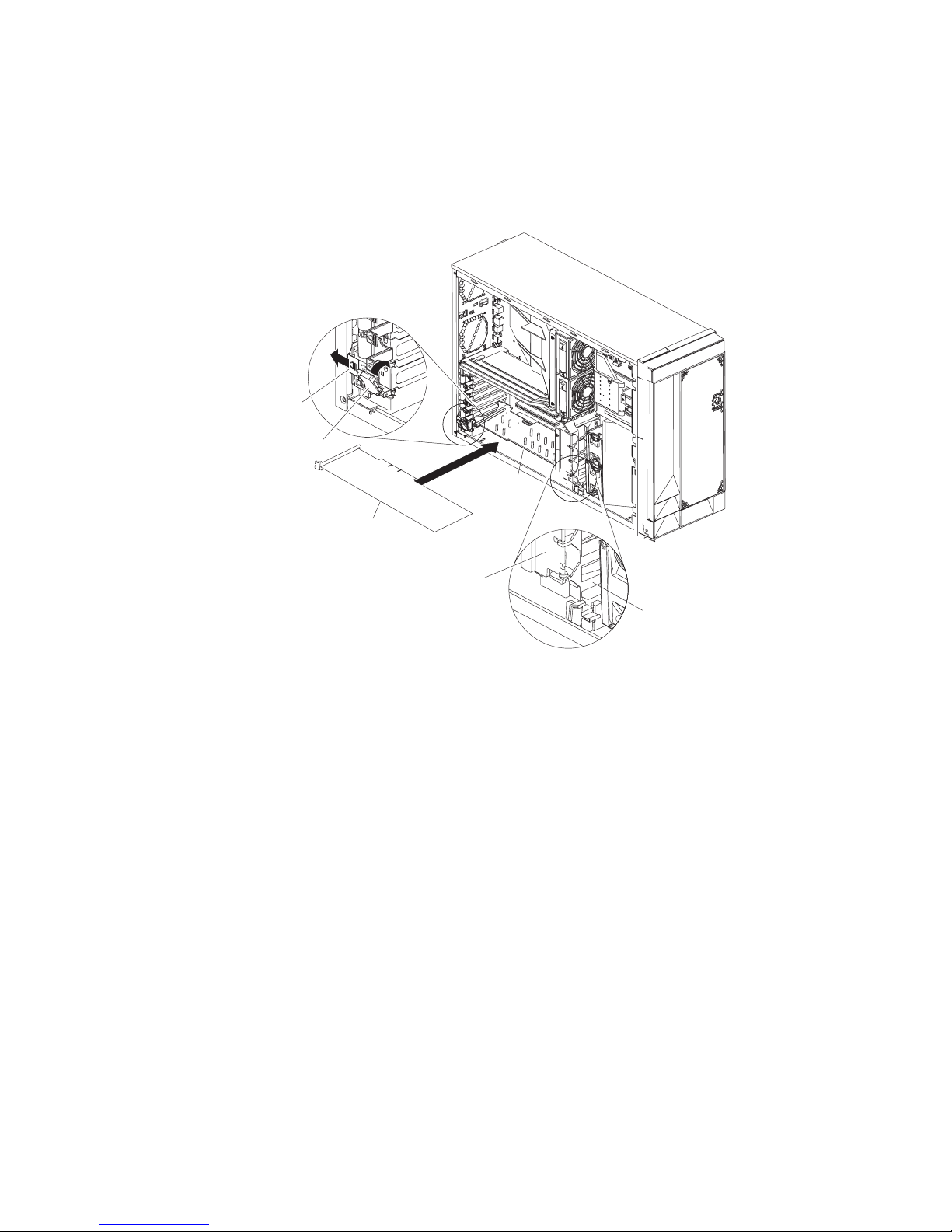
following illustration shows how to install a pair of DIMMs on the system board.
The
DIMM 8
DIMM 7
DIMM 6
DIMM 5
DIMM 4
DIMM 3
DIMM 2
DIMM 1
Complete the following steps to install a pair of DIMMs:
1. Read the safety information beginning on page v and “Installation guidelines” on
page 11.
2. Turn off the server and peripheral devices, and disconnect the power cords and
all external cables. Remove the cover and air-baffle assembly.
Attention: To avoid breaking the retaining clips or damaging the DIMM
connectors, open and close the clips gently.
3. Open the retaining clip on each end of the DIMM connector.
4. Touch the static-protective package containing the DIMM to any unpainted metal
surface on the server. Then, remove the DIMM from the package.
5. Turn the DIMM so that the DIMM keys align correctly with the slot.
6. Insert the DIMM into the connector.
7. Repeat steps 1 through 6 for the second DIMM; then, continue to step 8. If you
are replacing a single DIMM, continue to step 8.
8. If you have other options to install or remove, do so now.
9. Replace the air-baffle assembly and cover. Go to “Completing the installation”
on page 45.
34 xSeries 236 Type 8841: Hardware Maintenance Manual and Troubleshooting Guide
Page 45

Installing a microprocessor
The following notes describe the type of microprocessor that the server supports
and other information that you must consider when installing a microprocessor:
v For a list of supported options for the server, go to http://www.ibm.com/us/
compat/.
v The server supports Intel Xeon 2.8 GHz or higher microprocessors in each
socket. If you are installing two microprocessors, they must be the same cache
size and type, and the same clock speed.
v Read the documentation that comes with the microprocessor to determine
whether you must update the basic input/output system (BIOS) code in the
server. To download the most current level of BIOS code for the server, go to
http://www.ibm.com/support/.
v Obtain an SMP-capable operating system. For a list of supported operating
systems, go to http://www.ibm.com/pc/us/compat/.
v Yo u can use the Configuration/Setup Utility program to determine the specific
type of microprocessor in the server.
v If the thermal-grease protective cover (for example, a plastic cap or tape liner) is
removed from the heat sink or fan sink, do not touch the thermal grease on the
bottom of the heat sink or fan sink or set down the heat sink or fan sink.
Note: Removing the heat sink or fan sink from the microprocessor destroys the
even distribution of the thermal grease and requires replacing the thermal
grease. Setting down the heat sink or fan sink on any surface when the
thermal-grease protective cover is removed will contaminate the thermal
grease. If the thermal grease becomes contaminated with particles, it must
be replaced.
For information about replacing contaminated thermal grease on the heat sink,
contact IBM Service. For support phone numbers, go to http://www.ibm.com/
planetwide/, or in the U.S. and Canada, call 1-800-IBM-SERV (1-800-426-7378).
Have the following information ready when you call:
– Machine type and model
– Serial number of the server
Complete
the following steps to install a microprocessor:
1. Read the safety information beginning on page v and “Installation guidelines” on
page 11.
2. Turn off the server and peripheral devices, and disconnect the power cords and
all external cables. Remove the cover and air-baffle assembly.
Attention: When you handle static-sensitive devices, take precautions to
avoid damage from static electricity. For details about handling these devices,
see “Handling static-sensitive devices” on page 12.
Chapter 3. Installing options 35
Page 46

3. Remove the microprocessor baffle and protective film from the second
microprocessor socket.
Heatsink 2
Microprocessor 2
Microprocessor 2 VRM
Microprocessor
release lever
Microprocessor
baffle
4. Install a VRM in the VRM connector.
a. Center the VRM over the connector. Make sure that the VRM is oriented
and aligned correctly.
b. Carefully but firmly push down the VRM to seat the VRM in the connector.
c. Make sure that the VRM clips on both sides of the VRM connector lock.
36 xSeries 236 Type 8841: Hardware Maintenance Manual and Troubleshooting Guide
Page 47

5. Install the microprocessor:
a. Touch the static-protective package containing the new microprocessor to
any unpainted metal surface on the server; then, remove the microprocessor
from the package.
b. Rotate the locking lever on the microprocessor socket from its closed and
locked position until it stops or clicks in the fully open position
(approximately 135° angle).
Lever fully
open
Lever closed
c. Center the microprocessor over the microprocessor socket. Align the triangle
on the corner of the microprocessor with the triangle on the corner of the
socket and carefully press the microprocessor into the socket.
Attention:
v Do not use excessing force when pressing the microprocessor into the
socket.
v Make sure that the microprocessor is oriented and aligned correctly with
pin number 1 in the socket before you try to close the
microprocessor-release lever.
Microprocessor
Microprocessor
orientation indicator
Microprocessor
connector
Microprocessorrelease lever
d. Carefully close the microprocessor-release lever to secure the
microprocessor in the socket.
Chapter 3. Installing options 37
Page 48

6. Install the heat sink on the microprocessor:
Heat sink
Retainer spring
Heat-sink locking
lever
Microprocessor
a. Pull out and lift up on the heat-sink locking lever to open the heat sink
retention bracket.
b. Make sure that the lever is fully extended.
c. Remove the protective plastic cap from the bottom of the heat sink.
Notes:
1) Do not set down the heat sink after you remove the protective plastic
cap.
Thermal grease
Heat sink
2) Do not touch the thermal grease on the bottom of the heat sink.
Touching the thermal grease on the bottom will contaminate it. If the
thermal grease on the heat sink becomes contaminated, contact your
service technician.
38 xSeries 236 Type 8841: Hardware Maintenance Manual and Troubleshooting Guide
Page 49
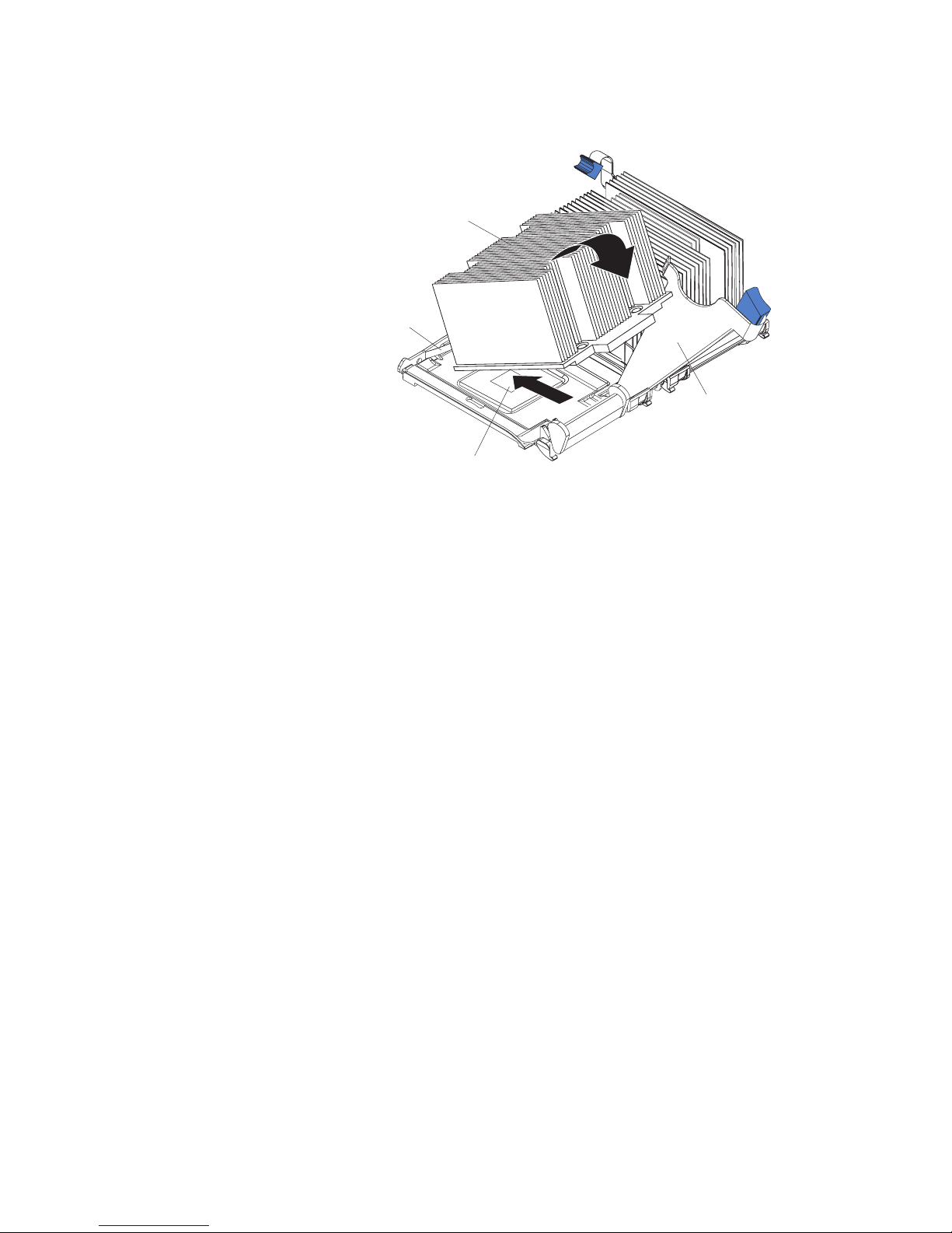
d. Position the heat sink over the microprocessor and slide one of the tabs on
the heat sink into the slot under the retainer spring.
Heat sink
Retainer spring
Heat-sink locking
lever
Microprocessor
e. Push the heat sink into position firmly; then, let it rest on the microprocessor.
f. Close the heat-sink locking lever to secure the heat sink to the
microprocessor.
7. If you have other options to install or remove, do so now.
8. Replace the air-baffle assembly and cover. Go to “Completing the installation”
on page 45.
Replacing a microprocessor and heat sink
This section provides instructions for replacing a microprocessor and heat sink.
Complete the following steps to replace a microprocessor and heat sink:
1. Read the safety information beginning on page v and “Installation guidelines” on
page 11.
2. Turn off the server and peripheral devices, and disconnect the power cords and
all external cables. Remove the cover and air-baffle assembly.
Attention: When you handle static-sensitive devices, take precautions to
avoid damage from static electricity. For details about handling these devices,
see “Handling static-sensitive devices” on page 12.
Chapter 3. Installing options 39
Page 50

3. Remove the heat sink from the microprocessor:
Heat sink
Retainer spring
Heat-sink locking
lever
Microprocessor
a. Pull out and lift up on the heat-sink locking lever.
b. Lift the heat sink up and out of the server.
4. Remove the microprocessor:
a. Pull out and lift up on the microprocessor-release lever to unlock the
microprocessor socket.
b. Remove the microprocessor from the socket and discard it.
5. Install the VRM. If you are replacing the microprocessor in socket 1, go to step
6.
a. Center the VRM over the connector. Make sure that the VRM is orientated
and aligned correctly.
b. Carefully but firmly push down the VRM to seat the VRM in the connector.
c. Make sure that the VRM clips on both sides of the VRM connector lock.
Install the new microprocessor:
6.
a. Touch the static-protective package containing the new microprocessor to
any unpainted metal surface on the server; then, remove the microprocessor
from the package.
b. Rotate the locking lever on the microprocessor socket from its closed and
locked position until it stops or clicks in the fully open position
(approximately 135° angle).
40 xSeries 236 Type 8841: Hardware Maintenance Manual and Troubleshooting Guide
Lever fully
open
Lever closed
Page 51
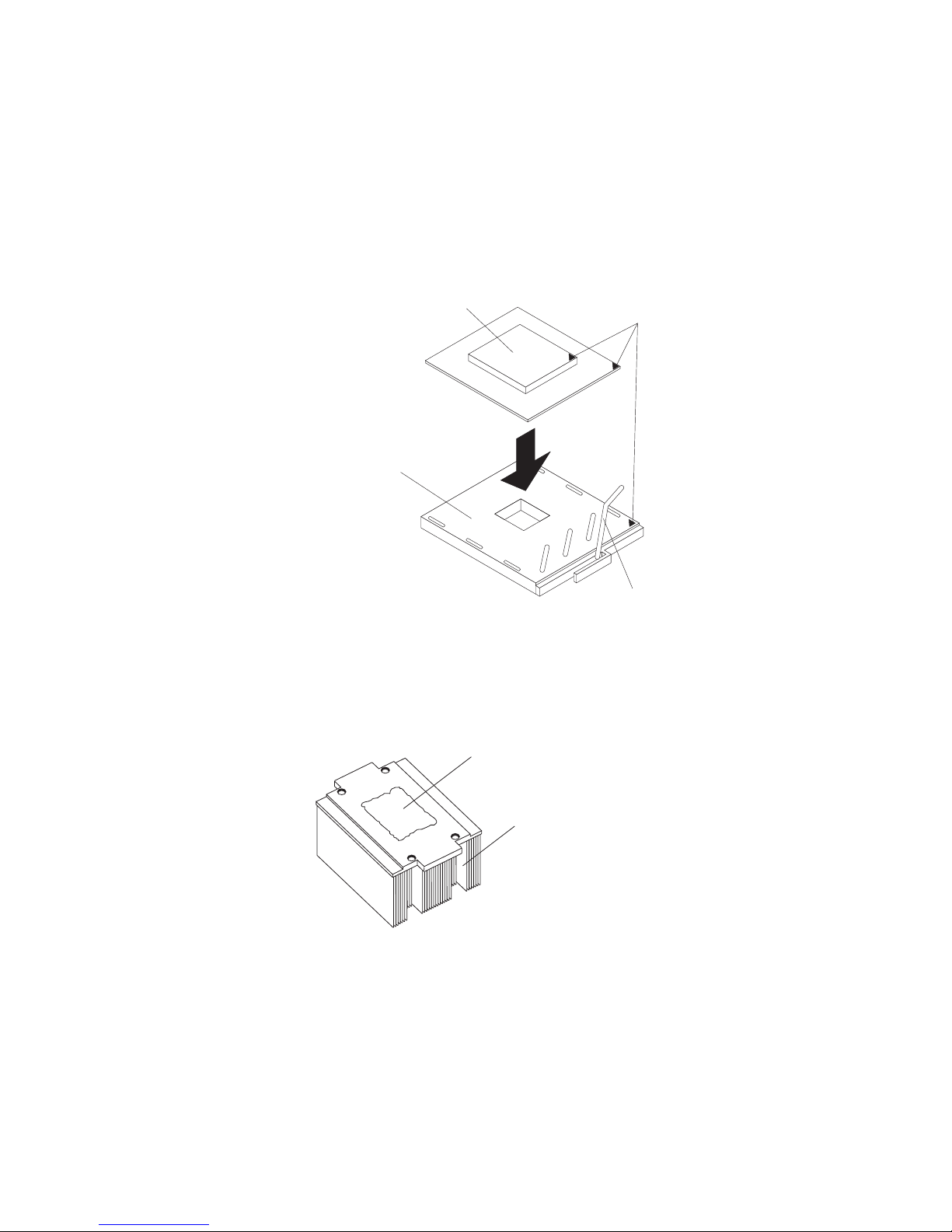
c. Center the microprocessor over the microprocessor socket. Align the triangle
on the corner on the microprocessor with the triangle on the corner of the
socket and carefully press the microprocessor into the socket.
Attention:
v Do not use excessive force when pressing the microprocessor into the
socket.
v Make sure that the microprocessor is oriented and aligned correctly with
pin number 1 in the socket before you try to close the microprocessor
release lever.
Microprocessor
Microprocessor
connector
Microprocessor
orientation indicator
Microprocessorrelease lever
v Carefully close the microprocessor-release lever to secure the
microprocessor in the socket.
Install a heat sink on the microprocessor.
7.
Attention:
v Do not set down the heat sink after you remove the plastic cover.
Thermal grease
Heat sink
v Do not touch the thermal grease on the bottom of the heat sink or set down
the heat sink. Touching the thermal grease will contaminate it. For details,
see the information about thermal grease on page 35.
a. Remove the plastic protective cover from the bottom of the heat sink.
b. Make sure that the heat-sink lever is in the open position.
Chapter 3. Installing options 41
Page 52

c. Position the heat sink over the microprocessor and slide one of the tabs on
the heat sink into the slot on the retention bracket.
Heat sink
Retainer spring
Heat-sink locking
lever
d. Push the heat sink into position firmly; then, let it rest on the microprocessor.
e. Close the heat-sink locking lever to secure the heat sink to the
microprocessor.
8. Replace the air-baffle assembly and cover. Go to “Completing the installation”
on page 45.
Replacing the battery
The following notes describe information that you must consider when replacing the
battery:
v When the battery voltage becomes low, the Battery Error LED on the system
board is lit and the battery should be replaced as quickly as possible.
v IBM has designed this product with your safety in mind. The lithium battery must
be handled correctly to avoid possible danger. If you replace the battery, you
must adhere to the following instructions.
Note: In the U. S., call 1-800-IBM-4333 for information about battery disposal.
v If you replace the original lithium battery with a heavy-metal battery or a battery
with heavy-metal components, be aware of the following environmental
consideration. Batteries and accumulators that contain heavy metals must not be
disposed of with normal domestic waste. They will be taken back free of charge
by the manufacturer, distributor, or representative, to be recycled or disposed of
in a proper manner.
v To order replacement batteries, call 1-800-426-7378 within the United States, and
1-800-465-7999 or 1-800-465-6666 within Canada. Outside the U.S. and
Canada, call your IBM reseller or IBM marketing representative.
Microprocessor
Note: After you replace the battery, you must reconfigure the server and reset
the system date and time.
42 xSeries 236 Type 8841: Hardware Maintenance Manual and Troubleshooting Guide
Page 53

Statement 2
CAUTION:
When replacing the lithium battery, use only IBM Part Number 33F8354 or an
equivalent type battery recommended by the manufacturer. If your system has a
module containing a lithium battery, replace it only with the same module type made
by the same manufacturer. The battery contains lithium and can explode if not
properly used, handled, or disposed of.
Do not:
v Throw or immerse into water.
v Heat to more than 100° C (212° F)
v Repair or disassemble
Dispose
of the battery as required by local ordinances or regulations.
Complete the following steps to replace the battery:
1. Read the safety information beginning on page v and “Installation guidelines”
on page 11.
2. Follow any special handling and installation instructions that come with the
battery.
3. Turn off the server and all attached devices and disconnect all power cords
and external cables (see “Turning on the server” on page 7); then, remove the
server cover (see “Removing the left-side cover” on page 14).
4. Remove the air baffle. See “Removing the air baffle” on page 15.
5. Disconnect any internal cables, as necessary.
6. Locate the battery connector on the system board.
Chapter 3. Installing options 43
Page 54

7. Remove the battery:
a. Use one finger to press on the tab that secures the battery to its housing.
b. Use one finger to slide the battery from the socket.
44 xSeries 236 Type 8841: Hardware Maintenance Manual and Troubleshooting Guide
Page 55

8. Insert the new battery:
a. Hold the battery so that the larger side is facing up.
b. Place the battery into its socket, and press the battery down until it snaps
into place.
9. Reconnect the internal cables that you disconnected.
10. Connect all external cables and all power cords.
11. Reinstall the air baffle.
12. Reinstall the server cover. See “Completing the installation.”
13. Start the Configuration/Setup Utility program and set configuration parameters
as needed. See the User’s Guide on the IBM xSeries Documentation CD for
additional information about using the Configuration/Setup Utility program.
Completing the installation
To complete the installation, reinstall the bezel, reinstall the server cover, reinstall
the door, reconnect all the cables that you disconnected earlier, and for certain
options, run the Configuration/Setup Utility program. Follow the instructions in this
section.
Attention:
v For proper cooling and airflow, replace the server cover before or shortly after
turning on the server. Operating the server for extended periods of time (over 30
minutes) with the server cover removed might damage server components.
v To ensure proper server operation, do not remove the air-baffle assembly from
the server except when installing or removing the components that are under the
air-baffle cover.
If you have just connected the power cords to electrical outlets, you must
Note:
wait approximately 20 seconds before pressing the power-control button.
Chapter 3. Installing options 45
Page 56
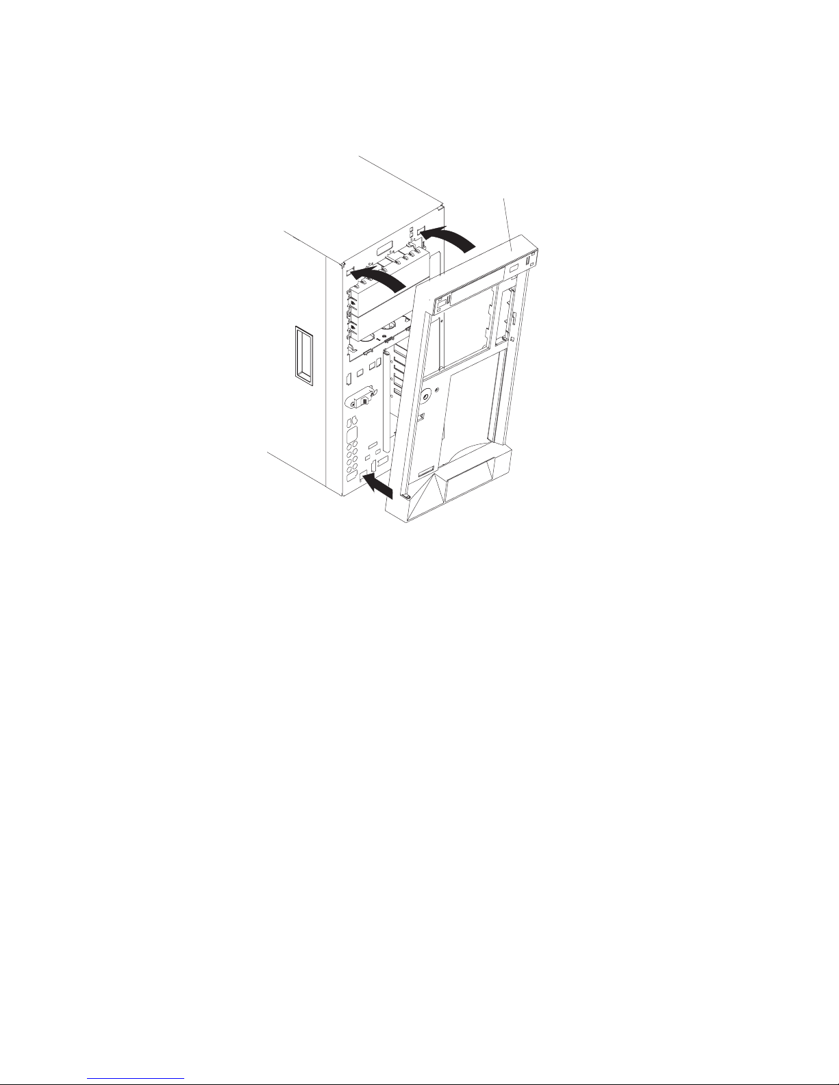
Installing the server bezel and left-side cover
The following illustration shows how to install the bezel on the server.
Bezel
Complete the following steps to install the bezel:
1. Read the safety information beginning on page v and “Installation guidelines” on
page 11.
2. Insert the two tabs on the bottom of the bezel into the matching holes on the
server chassis.
3. Push the top of the bezel toward the server until the two tabs at the top of the
bezel snap into place.
46 xSeries 236 Type 8841: Hardware Maintenance Manual and Troubleshooting Guide
Page 57
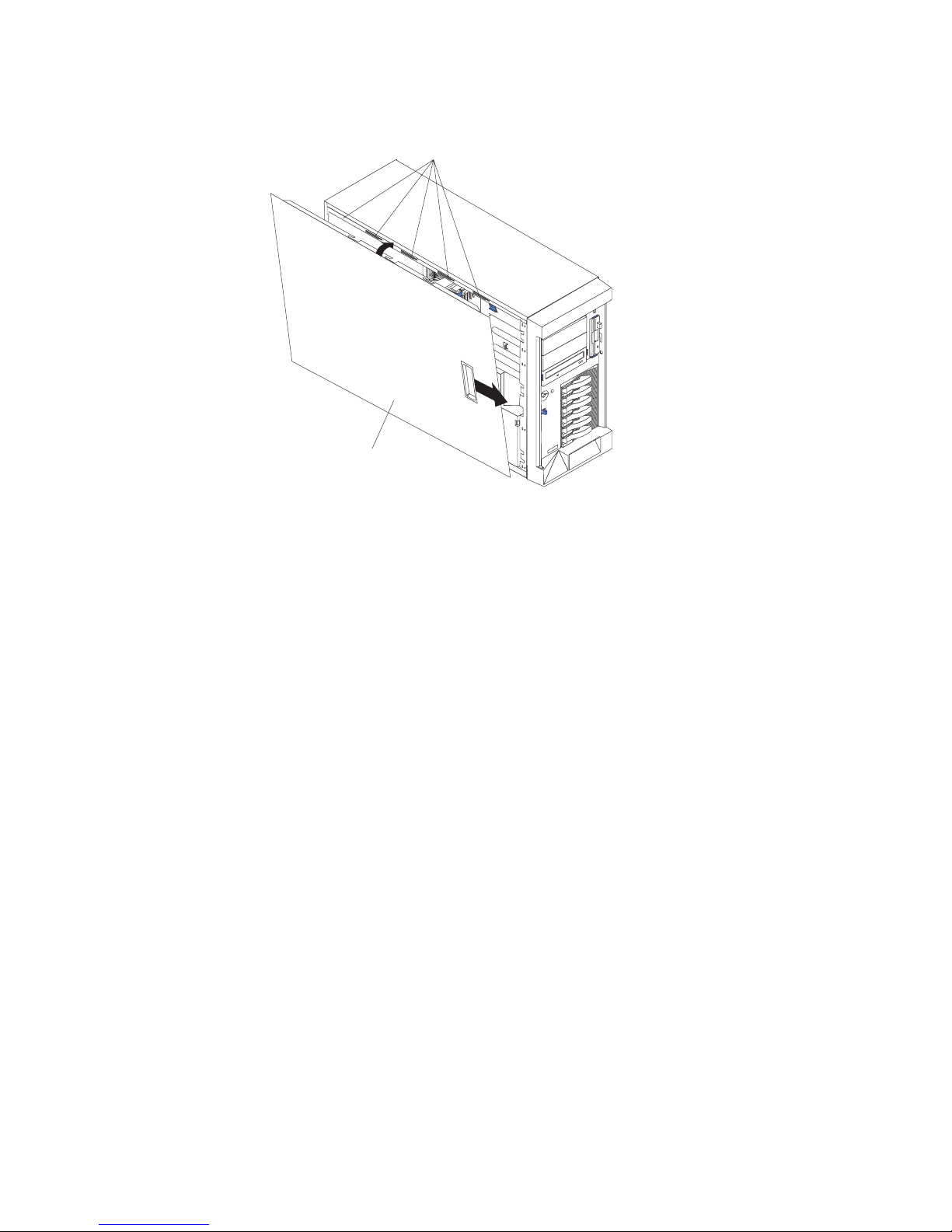
The following illustration shows how to install the left-side cover on the server.
Slots
Left-side cover
Complete the following steps to install the server left-side cover:
1. Before installing the cover, check that all cables, adapters, and other
components are installed and seated correctly and that you have not left loose
tools or parts inside the server.
2. Place the bottom lip of the left-side cover over the bottom edge of the server
chassis.
3. Rotate the left-side cover to a vertical position, inserting the tabs at the top of
the left-side cover into the matching slots in the server chassis.
4. Slide the left-side cover forward until it locks in place.
5. If you disconnected any cables from the back of the server, reconnect the
cables; then, connect the power cords to properly grounded electrical outlets.
Note: If necessary, see “Input/output connectors” on page 51 for connector
locations.
Chapter 3. Installing options 47
Page 58
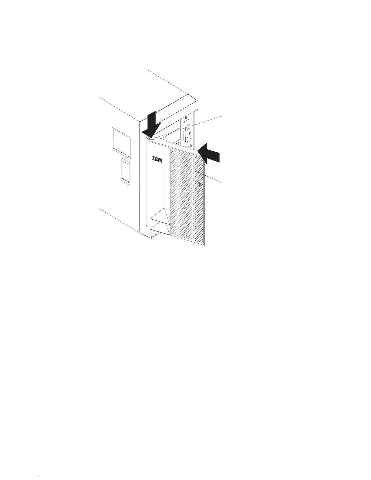
Installing the server door
The following illustration shows how to install the door on the server.
Flange
C
P
U
VR
M
M
EM
PC
O
R
I B
H
Y
D
U
D
S
A B
N
POW
M
I
ER
SM
S
I
U
1
PP
SE
2 3
L
R
Y
BU
V
IC
S
E P
R
FAN
O
C
NO
ES
SO
N
R
R
E
1 2 3
DU
N
D
AN
T
T
EM
PE
R
A
TU
R
E
Server door
Complete the following steps to install the server door:
1. Read the safety information beginning on page v and “Installation guidelines” on
page 11.
2. Set the door on the bottom hinge.
3. Locate the flange on the top edge of the door.
4. Press the flange downward while pressing the top of the door toward the server
until the flange connects with the top hinge. Release the flange.
5. Close the server door.
Attention: Be sure to maintain a clearance of at least 100 mm (4 inches) on
the front and rear of the server to allow for air circulation.
48 xSeries 236 Type 8841: Hardware Maintenance Manual and Troubleshooting Guide
Page 59

Connecting the cables
Notes:
1. Make sure you turn off the server before connecting any cables to or
disconnecting any cables from the server or hot-plug adapter.
2. For additional cabling instructions, see the User’s Guide on the IBM xSeries
Documentation CD and the documentation that comes with the options. It might
be easier for you to route any cables before you install certain options.
3. Cable identifiers are printed on the cables that come with the server and
options. Use these identifiers to connect the cables to the correct connectors.
For example, the hard disk drive cables are labeled “HDD option.”
Two cable-restraint brackets are on the rear of the server. Route the power cords
through the power-cord restraint bracket. After you connect the cables to the
selected devices, route the cables (for example, the cables that are connected to
the I/O connectors) through the I/O cable-restraint bracket.
See the following illustrations for the locations of the input and output connectors on
the server.
Note: The USB 3 connector is on the front of the server.
Ethernet link LED
Remote Supervisor
Adapter II
SlimLine Ethernet
Ethernet activity LED
Power cord connector
AC power LED
DC power LED
Keyboard connector
Mouse connector
ASM
Parallel connector
Serial 1 connector
USB 1 connector
Ethernet link 2
status LED
Ethernet connectors 1 and 2
USB 2 connector
Video connector
DO NOTTHROW AWAY
DO NOTTHROW AWAY
WITH EMPTY SLOT
WITH EMPTY SLOT
SYSTEM COOLING
SYSTEM COOLING
ATTENTION:
ATTENTION:
REQUIRED FOR
REQUIRED FOR
POWER SUPPLY
POWER SUPPLY
FILLER
FILLER
Ethernet link 1
status LED
Serial 2 connector
Chapter 3. Installing options 49
Page 60

Updating the server configuration
When you start the server for the first time after you add or remove an internal
option or external SCSI device, you might receive a message that the configuration
has changed. The Configuration/Setup Utility program starts automatically so that
you can save the new configuration settings. For more information, see the section
about configuring the server in the User’s Guide on the IBM xSeries Documentation
CD.
Some options have device drivers that you must install. See the documentation that
comes with each option for information about installing device drivers.
The server comes with at least one microprocessor. If more than one
microprocessor is installed, the server can operate as a symmetric multiprocessing
(SMP) server. You might have to upgrade the operating system to support SMP. For
more information, see the section about using the ServerGuide™ Setup and
Installation CD in the User’s Guide and the operating-system documentation.
If the server has an optional RAID adapter and you have installed or removed a
hard disk drive, see the documentation that comes with the RAID adapter for
information about reconfiguring the disk arrays.
If you have installed a Remote Supervisor Adapter II SlimLine to manage the server
remotely, see the Remote Supervisor Adapter II SlimLine and Remote Supervisor
Adapter II User’s Guide, which comes with the adapter, for information about setting
up, configuring, and using the adapter.
For information about configuring the integrated Gigabit Ethernet controller, see the
User’s Guide.
50 xSeries 236 Type 8841: Hardware Maintenance Manual and Troubleshooting Guide
Page 61

Input/output connectors
The server has the following input/output (I/O) connectors:
v One auxiliary-device (mouse)
v Two Gigabit Ethernet (RJ-45)
v Two integrated system management (Remote Supervisor Adapter II SlimLine
Ethernet and ASM)
v One keyboard
v One parallel
v Two serial
v Three Universal Serial Bus (USB)
– Two on the rear of the server
– One on the front of the server (not shown)
v One video
following illustration shows the locations of the connectors on the rear of the
The
server.
Keyboard
Mouse
Parallel
Serial 1
USB 1
USB 2
ASM
Remote Supervisor
Adapter II
SlimLine Ethernet
Video
DO NOTTHROW AWAY
DO NOTTHROW AWAY
WITH EMPTY SLOT
WITH EMPTY SLOT
SYSTEM COOLING
SYSTEM COOLING
POWER SUPPLY
POWER SUPPLY
ATTENTION:
ATTENTION:
REQUIRED FOR
REQUIRED FOR
FILLER
FILLER
Serial 2
The following sections describe these connectors.
External SCSI
(Knockout)
Ethernet
(System)
Chapter 3. Installing options 51
Page 62

Auxiliary-device connector
Use this connector to connect a mouse or other pointing device. The following
illustration shows an auxiliary-device connector.
6
4
2
5
3
1
Ethernet connector
Connect a Category 3, 4, or 5 unshielded twisted-pair cable to this connector. The
100BASE-TX and 1000BASE-T Fast Ethernet standards require Category 5 or
higher cabling.
For more information about the Ethernet controllers, see the User’s Guide.
8
1
Integrated system management (Remote Supervisor Adapter II
SlimLine Ethernet and ASM) connector
Use these connectors to connect an optional Remote Supervisor Adapter II
SlimLine. The following illustrations show the integrated system management
connectors.
ASM (RS-485)
6
1
Remote Supervisor Adapter II SlimLine Ethernet (RJ-45)
8
1
52 xSeries 236 Type 8841: Hardware Maintenance Manual and Troubleshooting Guide
Page 63

Keyboard connector
Use this connector to connect a PS/2 (non-USB) keyboard to the server. The
following illustration shows a keyboard connector.
6
4
2
5
3
1
If you attach a keyboard to this connector, USB ports and devices are disabled
during POST.
Parallel port connector
Use this connector to connect a parallel device. The following illustration shows a
parallel connector.
13
1
25
The parallel connector supports three Institute of Electrical and Electronics
Engineers (IEEE) 1284 modes of operation: Standard Parallel Port (SPP),
Enhanced Parallel Port (EPP), and Extended Capability Port (ECP). If you configure
the parallel port to operate in bidirectional mode, it supports the EPP and ECP
modes of operation. To configure the parallel port, use the Devices and I/O Ports
option in the Configuration/Setup Utility program. See the User ’s Guide for more
information. If you configure the parallel port to operate in bidirectional mode, use
an IEEE 1284-compliant cable that does not exceed 3 meters (9.8 ft).
Serial-port connectors
Use a serial connector to connect a serial device. The following illustration shows a
serial connector.
1
69
14
5
Chapter 3. Installing options 53
Page 64

Universal Serial Bus connectors
The server has one Universal Serial Bus (USB) version 2.0 connector on the front
of the server and two USB version 2.0 connectors on the rear of the server.
USB is a serial interface standard for telephony and multimedia devices. It uses
Plug and Play technology to determine the type of device that is attached to the
connector.
Notes:
1. If you attach a standard (non-USB) keyboard to the keyboard connector, the
USB ports and devices will be disabled during the power-on self-test (POST).
2. If you install a USB keyboard that has a mouse port, the USB keyboard
emulates a mouse, and you will not be able to disable the mouse settings in the
Configuration/Setup Utility program.
3. Check to make sure that your NOS supports USB devices.
4. For additional information about USB version 1.1 or 2.0 devices, go to
http://www.usb.org/.
14
Use a 4-pin cable to connect a device to a USB connector. If you need to connect
more USB devices than the server has USB connectors for, use a USB hub to
connect additional devices.
Video connector
Use this connector to connect a monitor to the server. The connector is dark blue to
help you identify it. The following illustration shows a video connector.
5
1
1115
54 xSeries 236 Type 8841: Hardware Maintenance Manual and Troubleshooting Guide
Page 65

Chapter 4. Service replaceable units
Microprocessor removal . . . . . . . . . . . . . . . . . . . . .56
Thermal grease . . . . . . . . . . . . . . . . . . . . . . . . .58
Operator information panel (external LED card) . . . . . . . . . . . . .59
Diagnostics panel card . . . . . . . . . . . . . . . . . . . . . .61
Power reset card . . . . . . . . . . . . . . . . . . . . . . . .62
Diskette drive . . . . . . . . . . . . . . . . . . . . . . . . .63
CD-ROM drive . . . . . . . . . . . . . . . . . . . . . . . . .64
Hard disk drive backplane . . . . . . . . . . . . . . . . . . . . .65
Power supply cage assembly . . . . . . . . . . . . . . . . . . .66
Center-fan and adapter-support bracket . . . . . . . . . . . . . . . .67
Center-fan support bracket (dual fan guide) . . . . . . . . . . . . .69
Adapter-support bracket . . . . . . . . . . . . . . . . . . . .70
Front fan housing (PCI fan guide) . . . . . . . . . . . . . . . . . .72
Front USB connector assembly . . . . . . . . . . . . . . . . . . .73
Switch card assembly . . . . . . . . . . . . . . . . . . . . . .74
System board . . . . . . . . . . . . . . . . . . . . . . . . .76
System-board internal connectors . . . . . . . . . . . . . . . . . .78
System-board internal cable connectors . . . . . . . . . . . . . . . .79
System-board switches and jumpers . . . . . . . . . . . . . . . . .80
System-board external connectors . . . . . . . . . . . . . . . . . .82
System-board LEDs . . . . . . . . . . . . . . . . . . . . . . .83
Light path diagnostics panel . . . . . . . . . . . . . . . . . . . .84
This chapter describes procedures for removing and installing certain components
inside the server. Only a qualified service technician is authorized to replace the
components described in this section.
Important: The field replaceable unit (FRU) procedures are intended for trained
servicers who are familiar with IBM xSeries products. See the parts
listing in Chapter 7, “Parts listing Type 8841,” on page 143 to determine
if the component being replaced is a customer replaceable unit (CRU)
or a FRU.
© Copyright IBM Corp. 2004, 2007 55
Page 66

Microprocessor removal
Complete the following steps to remove a microprocessor.
Note:
v Read “Installation guidelines” on page 11.
v Read Appendix B, “Safety information,” on page 153.
v Read “Handling static-sensitive devices” on page 12.
Turn off the server and disconnect all power cords and external cables; then,
1.
remove the server cover (see “Removing the left-side cover” on page 14).
2. Remove the air-baffle.
Air-baffle assembly
Note: It might be easier to turn the server on its side to remove the air baffle
and access the microprocessors.
3. Identify the microprocessor to be removed.
56 xSeries 236 Type 8841: Hardware Maintenance Manual and Troubleshooting Guide
Page 67

4. Remove the heat sink from the microprocessor:
Heat sink
Retainer spring
Heat-sink locking
lever
Microprocessor
a. Pull out and lift up on the heat-sink locking lever to unlock the heat sink
retention bracket.
b. Lift the heat sink up and out of the server.
Rotate the locking lever on the microprocessor socket from its closed and
5.
locked position until it stops or clicks in the fully open position (approximately
135° angle), as shown. Then, see the documentation provided with the
microprocessor option for complete installation instructions.
Attention: You must ensure that the locking lever on the microprocessor
socket is in the fully open position before you insert the microprocessor in the
socket. Failure to do so might result in permanent damage to the
microprocessor, microprocessor socket, and system board.
Lever closed
Lever
fully
open
Lever closed
Lever
fully
open
Chapter 4. Service replaceable units 57
Page 68
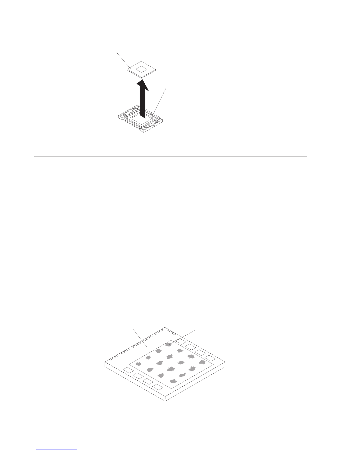
Thermal grease
6. Pull the microprocessor out of the socket.
Microprocessor
Microprocessorrelease lever
To install a microprocessor, see “Installing a microprocessor” on page 35
This section contains information about removing and replacing the thermal grease
between the heat sink and the microprocessor. The thermal grease must be
replaced anytime the heat sink has been removed from the top of the
microprocessor and is going to be reused, or when debris is found in the grease.
Note:
v Read “Installation guidelines” on page 11.
v Read Appendix B, “Safety information,” on page 153.
v Read “Handling static-sensitive devices” on page 12.
Complete
the following steps to replace damaged or contaminated thermal grease
on the microprocessor and heat sink:
1. Place the heat sink on a clean work surface.
2. Remove the cleaning pad from its package and unfold it completely.
3. Use the cleaning pad to wipe the thermal grease from the bottom of the heat
sink.
Note: Be sure that all of the thermal grease is removed.
4. Use a clean area of the cleaning pad to wipe the thermal grease from the
microprocessor; then, dispose of the cleaning pad after all of the thermal grease
is removed.
Microprocessor
0.01 mL of
thermal grease
58 xSeries 236 Type 8841: Hardware Maintenance Manual and Troubleshooting Guide
Page 69
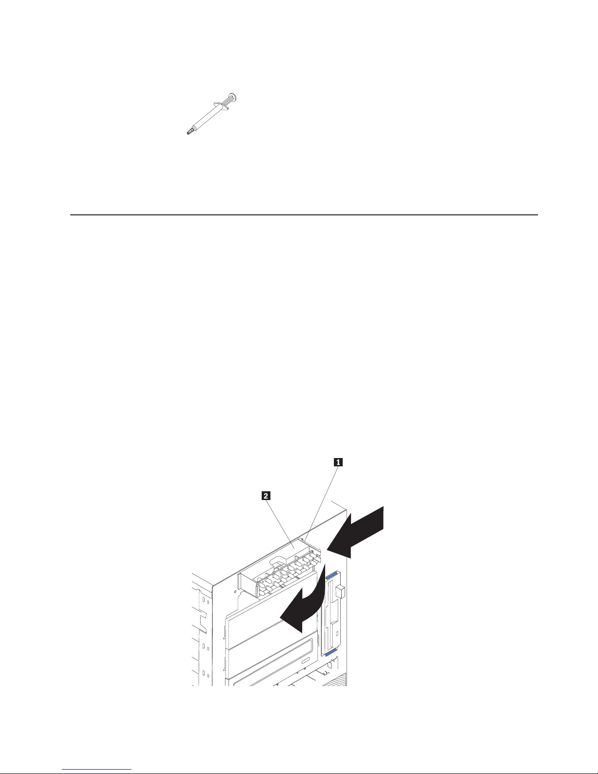
5. Use the thermal grease syringe to place 16 uniformly spaced dots of 0.01mL
each on the top of the microprocessor.
Note: 0.01mL is one tick mark on the syringe. If the grease is properly applied,
approximately half (0.22mL) of the grease will remain in the syringe.
6. Install the heat sink onto the microprocessor as described in “Installing a
microprocessor” on page 35.
Operator information panel (external LED card)
Complete the following steps to remove the operator information panel.
Note:
v Read “Installation guidelines” on page 11.
v Read Appendix B, “Safety information,” on page 153.
v Read “Handling static-sensitive devices” on page 12.
1. Turn off the server and any attached devices.
2. Disconnect all external cables and power cords from the back of the server.
3. Remove the server cover (see “Removing the left-side cover” on page 14).
4. Remove the front bezel (see “Removing the bezel” on page 16).
5. Disconnect and remove adapters and spacers (see “Installing or replacing an
adapter” on page 25).
6. Remove the two central fans (see “Replacing a center fan (3 or 4)” on page
19).
7. Remove the plastic baffle.
8. Disconnect the operator information panel cable from the system board.
9. From outside the server, push the tab 1 on the panel 2, making sure to
press the tab near the chassis; the panel will disengage from the chassis.
Chapter 4. Service replaceable units 59
Page 70

10. Remove the panel, carefully threading the cable past the other components
and through the opening in the chassis.
Note: If the cable has been secured in the cable clamps, gently pull it out of
the clamps before pulling the cable through the opening in the chassis.
install the operator information panel, reverse the previous steps.
To
Notes:
1. Thread the cable through the opening in the chassis and extend it into the
server before attaching the operator information panel.
2. Secure the cable in the cable clamps along the inside of the chassis.
3. Fit the left tab (in the rack configuration, this is the top tab) into the lip on the
chassis, and then press on the right tab (in the rack configuration, this is the
bottom tab) until it snaps into place.
60 xSeries 236 Type 8841: Hardware Maintenance Manual and Troubleshooting Guide
Page 71
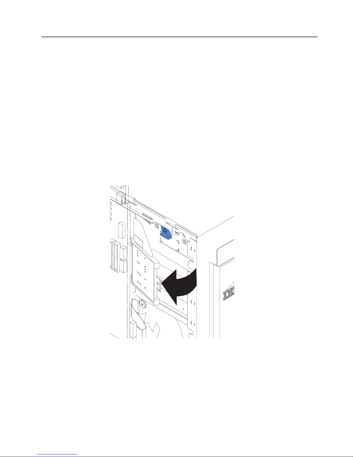
Diagnostics panel card
Complete the following steps to remove the diagnostics panel card.
Note:
v Read “Installation guidelines” on page 11.
v Read Appendix B, “Safety information,” on page 153.
v Read “Handling static-sensitive devices” on page 12.
Turn off the server.
1.
2. Disconnect all external cables and power cords from the back of the server.
3. Remove the server cover (see “Removing the left-side cover” on page 14).
4. Disconnect and remove adapters and spacers (see “Installing or replacing an
adapter” on page 25).
5. Remove the two center fans (see “Replacing a center fan (3 or 4)” on page 19).
6. Remove the plastic baffle.
7. Disconnect the diagnostics panel card cable from the system board (J36).
Note: The illustrations in this publication might differ slightly from your
hardware.
8. Grasp the tab on the diagnostics panel card and gently pull up and to the right
until the card assembly releases.
To replace the diagnostics panel card, line up the two notches on the left and snap
the assembly into place; then, connect the cable to the system board.
Chapter 4. Service replaceable units 61
Page 72
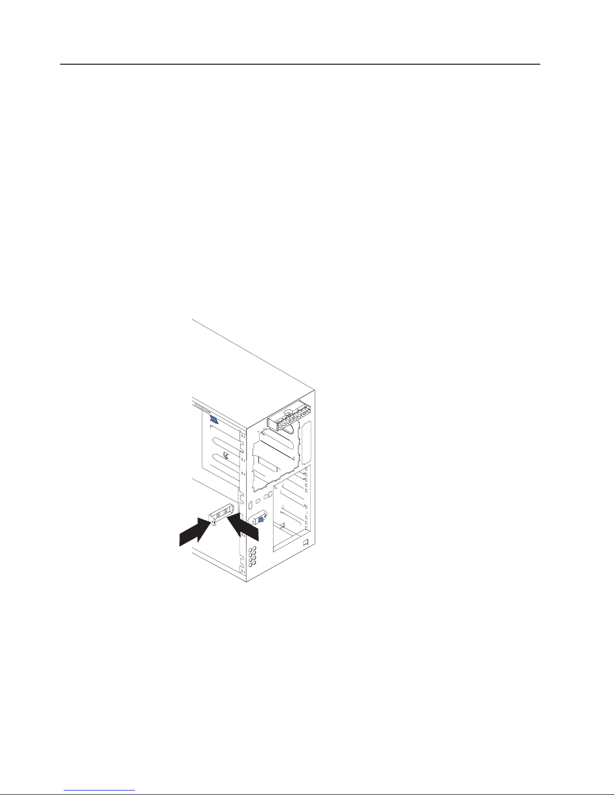
Power reset card
Complete the following steps to remove the power reset card.
Note:
1.
2. Disconnect all external cables and power cords from the back of the server.
3. Remove the bezel (see “Removing the bezel” on page 16).
4. Remove the server cover (see “Removing the left-side cover” on page 14).
5. Disconnect and remove adapters and spacers (see “Installing or replacing an
6. Remove the central-fan and adapter-support bracket (see “Center-fan and
7. Remove the air baffle.
8. Disconnect the power reset card cable from the system board (J42).
v Read “Installation guidelines” on page 11.
v Read Appendix B, “Safety information,” on page 153.
v Read “Handling static-sensitive devices” on page 12.
Turn off the server.
adapter” on page 25).
adapter-support bracket” on page 67).
9. Press the tab on the front of the power reset card and lift it out from inside the
chassis.
To replace the power reset card, reverse the previous steps, threading the cable
carefully.
62 xSeries 236 Type 8841: Hardware Maintenance Manual and Troubleshooting Guide
Page 73
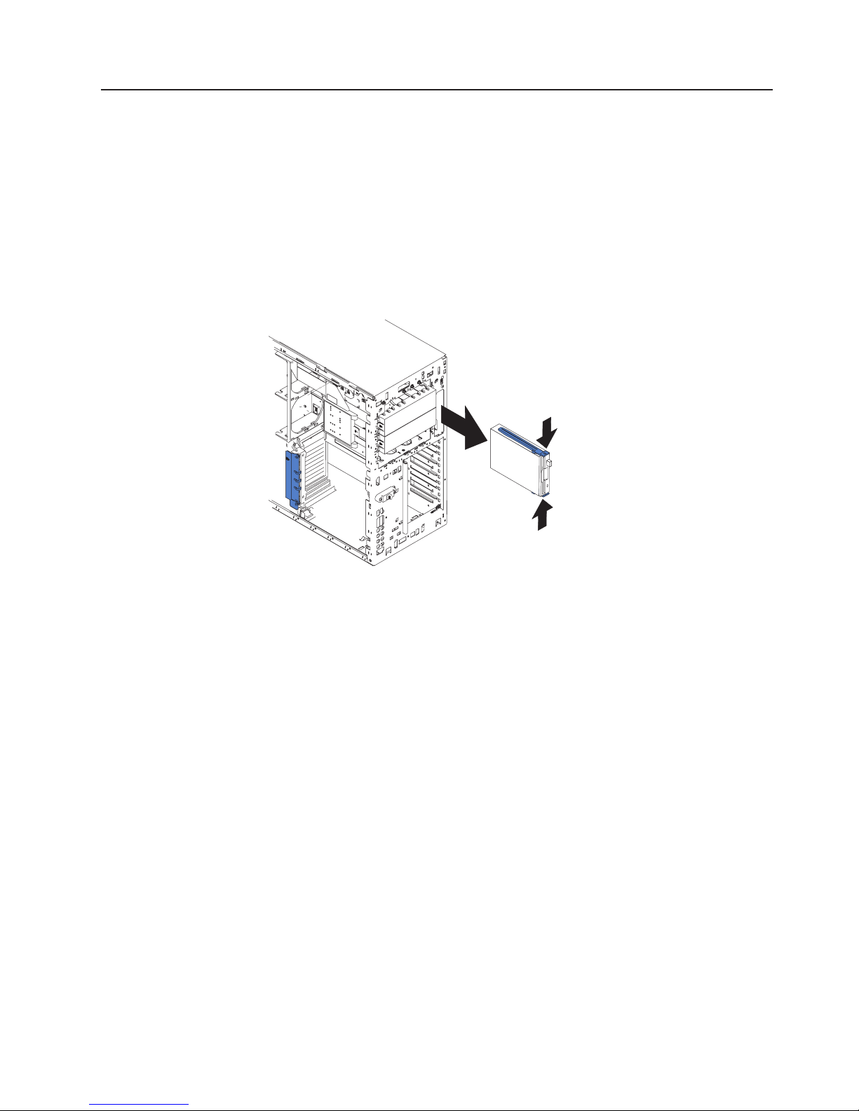
Diskette drive
Complete the following steps to remove the diskette drive.
Note:
v Read “Installation guidelines” on page 11.
v Read Appendix B, “Safety information,” on page 153.
v Read “Handling static-sensitive devices” on page 12.
Turn off the server and all attached devices.
1.
2. Disconnect all external cables and power cords from the back of the server.
3. Remove the server cover (see “Removing the left-side cover” on page 14).
4. Remove the front bezel (see “Removing the bezel” on page 16).
5. Press in on the two blue diskette drive release tabs until the drive is released
from the chassis.
6. Carefully pull the drive away from the chassis until the cables at the rear of the
drive are accessible.
7. Remove the two cables from the back of the drive and pull the drive out.
To replace the diskette drive, reverse the previous steps.
Note: If you are replacing the drive, prepare the new drive for the server with the
following procedure:
1. Remove the side rails from the drive by gently pulling them away from
the drive until they detach.
2. Insert one pin of the rail into the notch near the rear of the drive.
3. Pushing the rail gently toward the rear of the drive, insert the other pin
into the notch near the front of the drive.
4. Press in on the metal strip in the rail to secure the rail to the drive.
Chapter 4. Service replaceable units 63
Page 74

CD-ROM drive
Complete the following steps to remove the CD-ROM drive.
Note:
v Read “Installation guidelines” on page 11.
v Read Appendix B, “Safety information,” on page 153.
v Read “Handling static-sensitive devices” on page 12.
Turn off the server and all attached devices.
1.
2. Disconnect all external cables and power cords from the back of the server.
3. Remove the server cover (see “Removing the left-side cover” on page 14).
4. Remove the front bezel (see “Removing the bezel” on page 16).
5. Press in on the two blue CD-ROM drive release tabs until the drive is released
from the chassis.
6. Carefully pull the drive away from the chassis until the cables at the rear of the
drive are accessible.
7. Remove the two cables from the back of the drive and pull the drive out.
64 xSeries 236 Type 8841: Hardware Maintenance Manual and Troubleshooting Guide
Page 75

To replace the CD-ROM drive, reverse the previous steps.
Note: If you are replacing the drive, prepare the new drive for the server with the
following procedure:
1. Remove the side rails from the drive by gently pulling them away from
the drive until they detach.
2. Insert one pin of the rail into the notch near the rear of the drive.
3. Pushing the rail gently toward the rear of the drive, insert the other pin
into the notch near the front of the drive.
4. Press in on the metal strip in the rail to secure the rail to the drive.
Hard disk drive backplane
Complete the following steps to remove the hard disk drive backplane.
Note:
v Read “Installation guidelines” on page 11.
v Read Appendix B, “Safety information,” on page 153.
v Read “Handling static-sensitive devices” on page 12.
1. Turn off the server.
2. Disconnect all external cables and power cords from the back of the server.
3. Pull out the hard drives.
4. Remove the server cover (see “Removing the left-side cover” on page 14).
5. Remove the two front fans (see “Replacing a front fan (1 or 2)” on page 18).
6. Disconnect and remove adapters and spacers (see “Installing or replacing an
adapter” on page 25).
7. Remove the two central fans (see “Replacing a center fan (3 or 4)” on page
19).
8. Remove the plastic baffle.
9. Disconnect the hard disk drive backplane cable from the hard disk drive
backplane.
Chapter 4. Service replaceable units 65
Page 76

10. Press the release latches and pull the backplane out of the server.
To replace the hard disk drive backplane, reverse the previous steps, making sure
to place the backplane assembly over the two guide pins on the chassis floor.
Power supply cage assembly
Complete the following steps to remove the power supply cage assembly.
Note:
v Read “Installation guidelines” on page 11.
v Read Appendix B, “Safety information,” on page 153.
v Read “Handling static-sensitive devices” on page 12.
Turn off the server.
1.
2. Disconnect all external cables and power cords from the back of the server.
3. Remove the adapter-support bracket. See “Center-fan and adapter-support
bracket” on page 67 for instructions.
4. Disconnect all power-supply cable from the system board (J4), hard disk drive
backplane, and other backplanes or devices.
66 xSeries 236 Type 8841: Hardware Maintenance Manual and Troubleshooting Guide
Page 77

5. From the rear of the server, remove the two screws at each side of the power
supply cage.
2
1
6. Gently pull the power supply cage from the server, making sure the cables do
not snag on the chassis or system board.
Note: You might need to insert the blade of a screwdriver behind one corner of
the power supply cage to begin moving it.
Center-fan and adapter-support bracket
Note:
v Read “Installation guidelines” on page 11.
v Read Appendix B, “Safety information,” on page 153.
v Read “Handling static-sensitive devices” on page 12.
working with some options, you must first remove the center-fan and or
When
adapter-support bracket to access certain components or connectors on the system
board.
Note: The adapter-support bracket is attached to the center-fan bracket. Both
brackets can be removed and installed together as a single unit or
individually. See “Center-fan support bracket (dual fan guide)” on page 69 or
“Adapter-support bracket” on page 70 for instructions on how to remove
these support brackets separately.
Chapter 4. Service replaceable units 67
Page 78

Complete the following steps to remove the center-fan and adapter-support
brackets as a single unit:
1. Turn off the server and disconnect all power cords and external cables (“Turning
off the server” on page 8); then, remove the server cover (see “Removing the
left-side cover” on page 14).
2. Slide the air-baffle assembly out of the guides; then, remove it from the server.
Air-baffle assembly
3. Disconnect any cables that are connected to the full-length adapters.
4. Lift the adapter-retention clip on top of the adapter-support bracket (for the
location of this clip, see the illustration at “Installing or replacing a hot-plug
adapter (slot 6)” on page 28); then, remove the full-length adapters and plastic
dividers.
5. Disconnect the end of the cable that is attached to the center-fans connector on
the system board (see “System-board internal connectors” on page 78).
68 xSeries 236 Type 8841: Hardware Maintenance Manual and Troubleshooting Guide
Page 79

6. Remove the center-fan and adapter-support bracket.
a. Press the release tab on each adapter-support bracket latch. There are two
latches; one at each end of the adapter-support bracket.
b. Slide the adapter-support bracket and fan-support bracket unit out of the
guides; then, remove it from the server.
To reinstall the adapter-support bracket and other components that you
Note:
removed or disconnected, reverse the preceding steps. Remember to
reroute the cables that you disconnected and to reconnect the center-fan
cable to the system board (see “System-board internal connectors” on
page 78).
Center-fan support bracket (dual fan guide)
Note:
v Read “Installation guidelines” on page 11.
v Read Appendix B, “Safety information,” on page 153.
v Read “Handling static-sensitive devices” on page 12.
working with some options, you must first remove the center-fan to access
When
certain components or connectors on the system board.
Chapter 4. Service replaceable units 69
Page 80
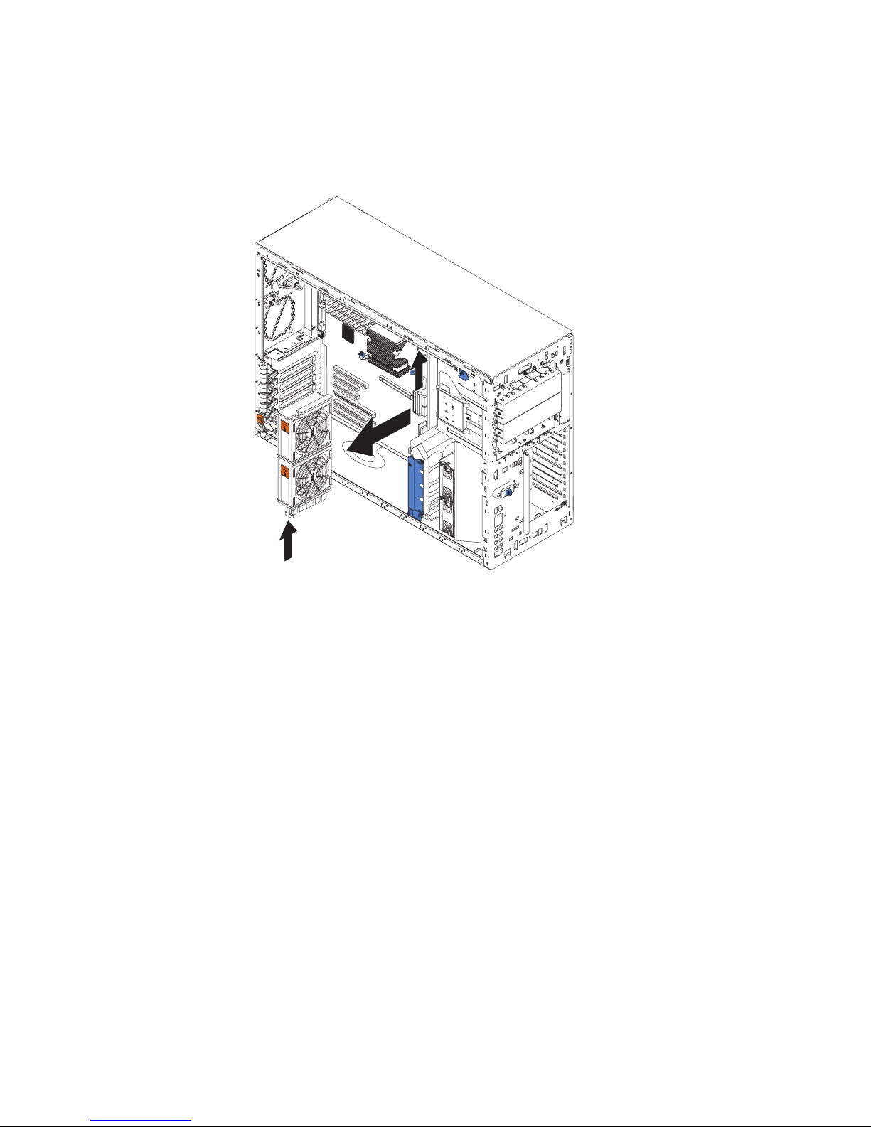
Complete the following steps to remove the center-fan support bracket as a single
unit:
1. Disconnect the cable that is attached to the center-fans connector on the
system board (see “System-board internal connectors” on page 78).
2. Remove the center-fan support bracket.
a. Press the release tab on each end of the center-fan support bracket. There
are two latches; one at each end of the center-fan support bracket.
b. Slide the center-fan support bracket unit out of the guides; then, remove it
from the server.
To reinstall the center-fan support bracket and other components that you
Note:
removed or disconnected, reverse the preceding steps. Remember to
reroute the cables that you disconnected and to reconnect the center-fan
cable to the system board (see “System-board internal connectors” on
page 78).
Adapter-support bracket
Note:
v Read “Installation guidelines” on page 11.
v Read Appendix B, “Safety information,” on page 153.
v Read “Handling static-sensitive devices” on page 12.
working with some options, you must first remove the adapter-support
When
bracket to access certain components or connectors on the system board.
70 xSeries 236 Type 8841: Hardware Maintenance Manual and Troubleshooting Guide
Page 81

Complete the following steps to remove the adapter-support bracket as a single
unit:
1. Disconnect any cables that are connected to the full-length adapters.
2. Lift the adapter-retention clip on top of the adapter-support bracket (for the
location of this clip, see the illustration at “Installing or replacing a hot-plug
adapter (slot 6)” on page 28; then, remove the full-length adapters and plastic
dividers.
3. Remove the adapter-support bracket.
a. Press the release tab on each end of the adapter-support bracket. There are
b. Slide the adapter-support bracket out of the guides; then, remove it from the
Note:
two latches; one at each end of the adapter-support bracket.
server.
To reinstall the adapter-support bracket and other components that you
removed or disconnected, reverse the preceding steps. Remember to
reroute the cables that you disconnected and to reconnect the center-fan
cable to the system board (see “System-board internal connectors” on
page 78).
Chapter 4. Service replaceable units 71
Page 82

Front fan housing (PCI fan guide)
Complete the following steps to remove the blower housing.
Note:
v Read “Installation guidelines” on page 11.
v Read Appendix B, “Safety information,” on page 153.
v Read “Handling static-sensitive devices” on page 12.
1. Turn off the server.
2. Disconnect all external cables and power cords from the back of the server.
3. Remove the front bezel (see “Removing the bezel” on page 16).
4. Remove the server cover (see “Removing the left-side cover” on page 14).
5. Remove the two front fans (see “Replacing a front fan (1 or 2)” on page 18).
6. Disconnect and remove adapter cards and spacers (see “Installing or replacing
an adapter” on page 25).
7. Remove the two central fans (see “Replacing a center fan (3 or 4)” on page
19).
8. Remove the plastic baffle.
9. Remove the hard disk drive backplane (see “Hard disk drive backplane” on
page 65).
10. Disconnect the fan cable from the system board.
72 xSeries 236 Type 8841: Hardware Maintenance Manual and Troubleshooting Guide
Page 83
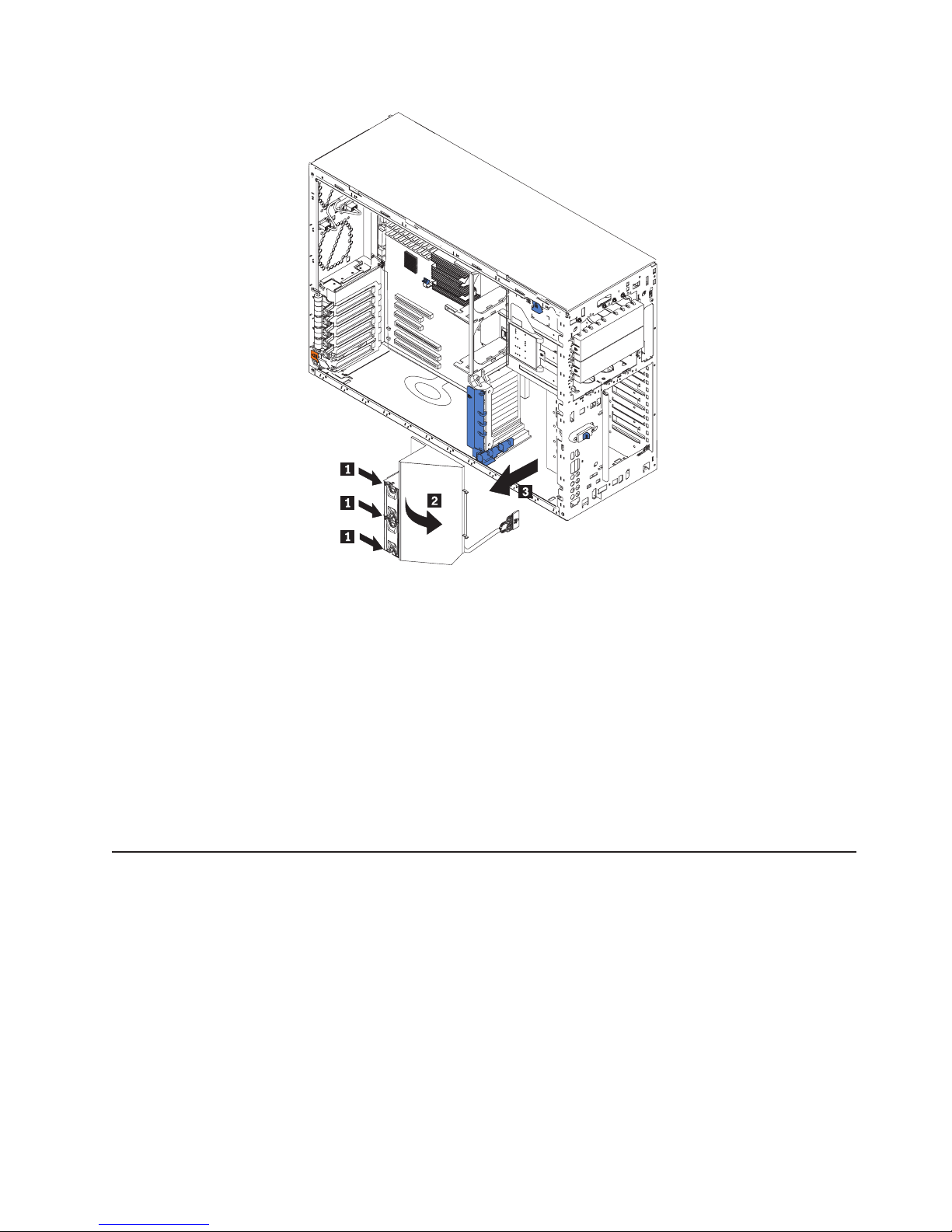
11. Press in the tabs (1) with the tip of a flat-blade screwdriver until the housing
releases and tilts up (2); then, pull the housing out of the two notches on the
front of the chassis and lift (3) the housing out of the server.
To install the blower housing, reverse the previous steps, making sure that the two
tabs are inserted into the notches on the front of the chassis.
Front USB connector assembly
Complete the following steps to remove the front USB connector.
Note:
v Read “Installation guidelines” on page 11“Installation guidelines” on page
11.
v Read Appendix B, “Safety information,” on page 153.
v Read “Handling static-sensitive devices” on page 12.
Turn off the server.
1.
2. Disconnect all external cables and power cords from the back of the server.
3. Remove the bezel (see “Removing the bezel” on page 16).
4. Remove the server cover (see “Removing the left-side cover” on page 14).
Chapter 4. Service replaceable units 73
Page 84
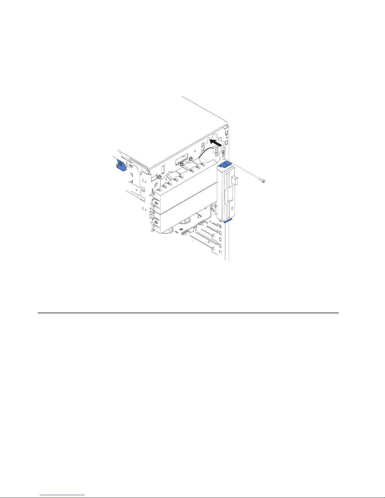
5. Disconnect and remove adapters and spacers (see “Installing or replacing an
adapter” on page 25).
6. Remove the central fan and adapter-support bracket (see “Center-fan and
adapter-support bracket” on page 67).
7. Remove the air baffle.
8. Disconnect the front USB cable from the system board (J41).
9. Use a Phillips screwdriver to remove the mounting screw from the front of the
server; then, remove the USB cable from the server.
To replace the front USB connector assembly, reverse the previous steps, threading
the cable carefully.
Switch card assembly
Complete the following steps to remove the switch card assembly.
Note:
v Read “Installation guidelines” on page 11.
v Read Appendix B, “Safety information,” on page 153.
v Read “Handling static-sensitive devices” on page 12.
1. Turn off the server.
2. Disconnect all external cables and power cords from the back of the server.
3. Remove the server cover (see “Removing the left-side cover” on page 14).
4. Remove all adapters and spacers (see “Installing or replacing an adapter” on
page 25).
5. Disconnect the switch card cable from the system board.
74 xSeries 236 Type 8841: Hardware Maintenance Manual and Troubleshooting Guide
Page 85
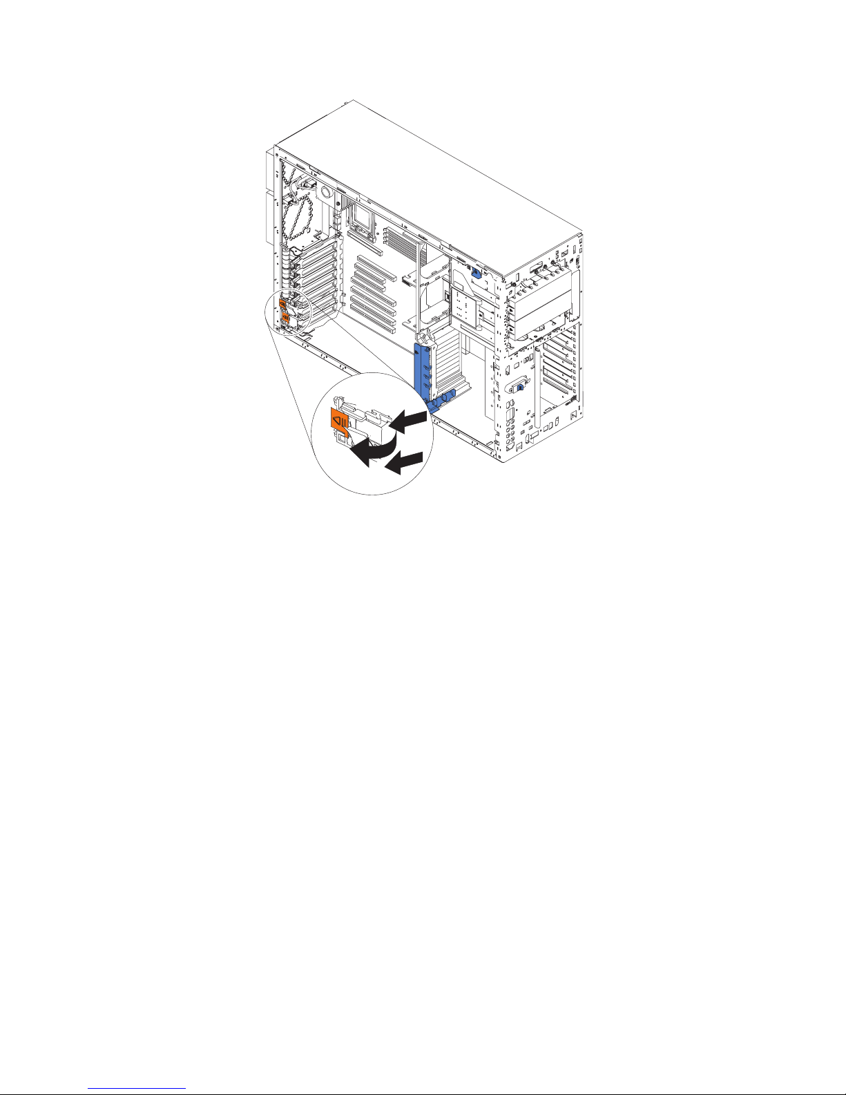
6. Press the two tabs on the switch card and remove it from the chassis.
Note: It might be easier to remove this component if the server is placed on its
side.
install the switch card assembly, line up the two tabs with the notches on the
To
chassis and snap the assembly into place; then, connect the cable to the system
board.
Chapter 4. Service replaceable units 75
Page 86

System board
Complete the following steps to remove the system board.
Note:
v Read “Installation guidelines” on page 11.
v Read Appendix B, “Safety information,” on page 153.
v Read “Handling static-sensitive devices” on page 12.
1. Turn off the server and any attached devices.
Note: When replacing the system board, you must either update the system
with the latest firmware or restore the pre-existing firmware that the
customer provides on a diskette or CD image.
2. Disconnect external cables and option cables from the back of the server.
3. Lay the server so that the cover is facing up.
4. Remove the left-side cover (see “Removing the left-side cover” on page 14).
5. Disconnect and remove adapters and spacers (see “Installing or replacing an
adapter” on page 25).
6. Remove the center-fan and adapter support bracket (see “Center-fan and
adapter-support bracket” on page 67).
7. Remove the air-baffle.
8. Disconnect all cables from the system board.
Note: Place all disconnected cables carefully to the side so that they do not
come in contact with the center of the system board.
9. Remove all microprocessors and VRMs and set them aside on a
static-protected surface for reinstallation (see “Microprocessor removal” on
page 56).
10. Remove the memory modules and set them aside on a static-protected surface
for reinstallation (see “Installing memory modules” on page 33).
Note: When you set the DIMMs aside, be sure to keep track of the slots they
belong to; DIMMs must be installed in pairs of the same size, speed,
type, and technology.
76 xSeries 236 Type 8841: Hardware Maintenance Manual and Troubleshooting Guide
Page 87
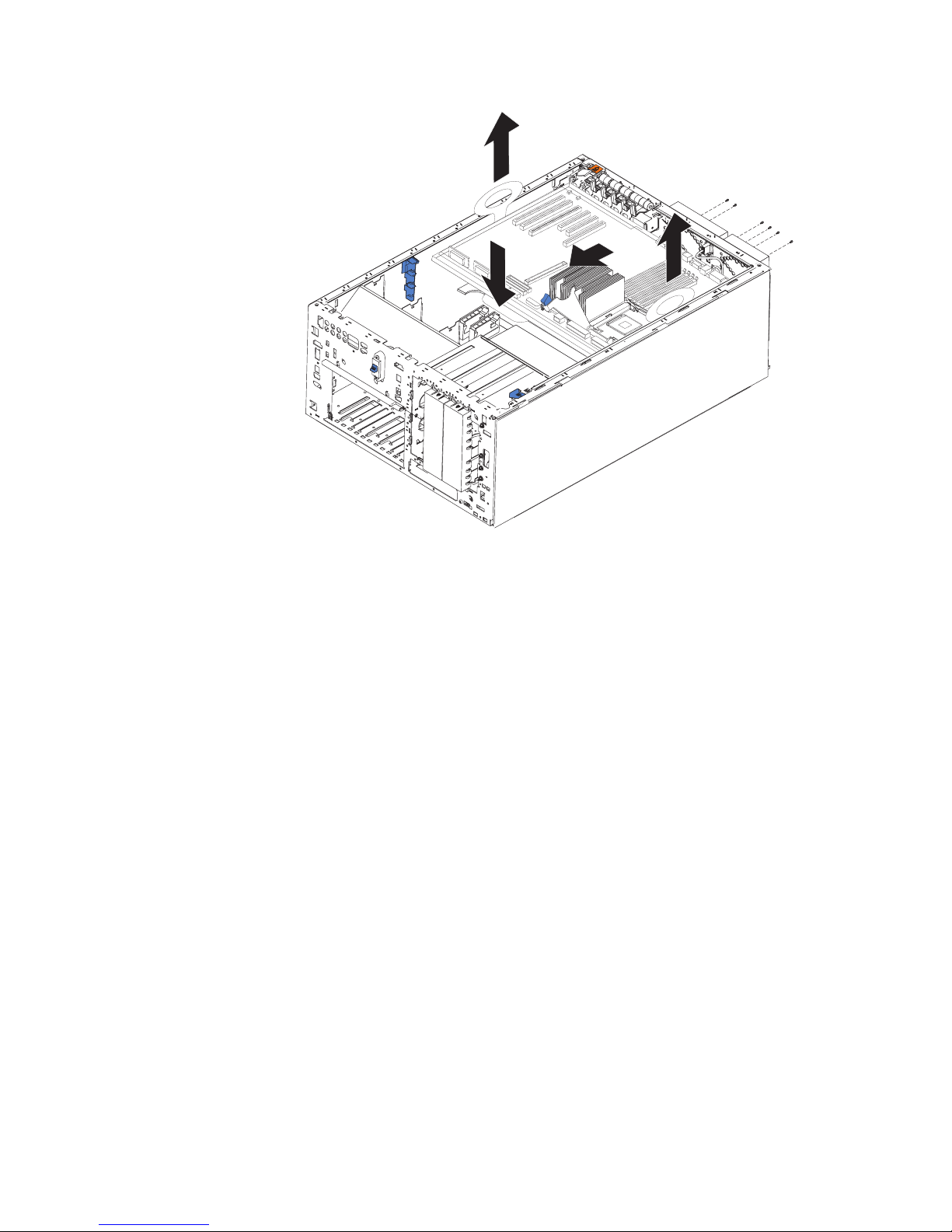
11. Push and hold the system-board release latch down; then, push the system
board toward the front of the server.
12. Using the plastic handle on the system board, lift the right side (or PCI-X
adapter side) of the system board partially out of the server.
13. Grasp the other plastic handle and carefully lift the system board out of the
server.
To reinstall the system board, complete the following steps:
1. Lower the left, or microprocessor, side of the system board into the server
chassis first.; then, slide the system board to that side until it stops and lower
the right or adapter side of the system board.
2. Slide the system board toward the rear of the server until it stops.
3. Reverse steps 5 on page 76 through 10 on page 76 to replace the components
that were removed.
Note: When reassembling the components in the server, be sure to route all
cables carefully so that they are not exposed to undue pressure.
Chapter 4. Service replaceable units 77
Page 88
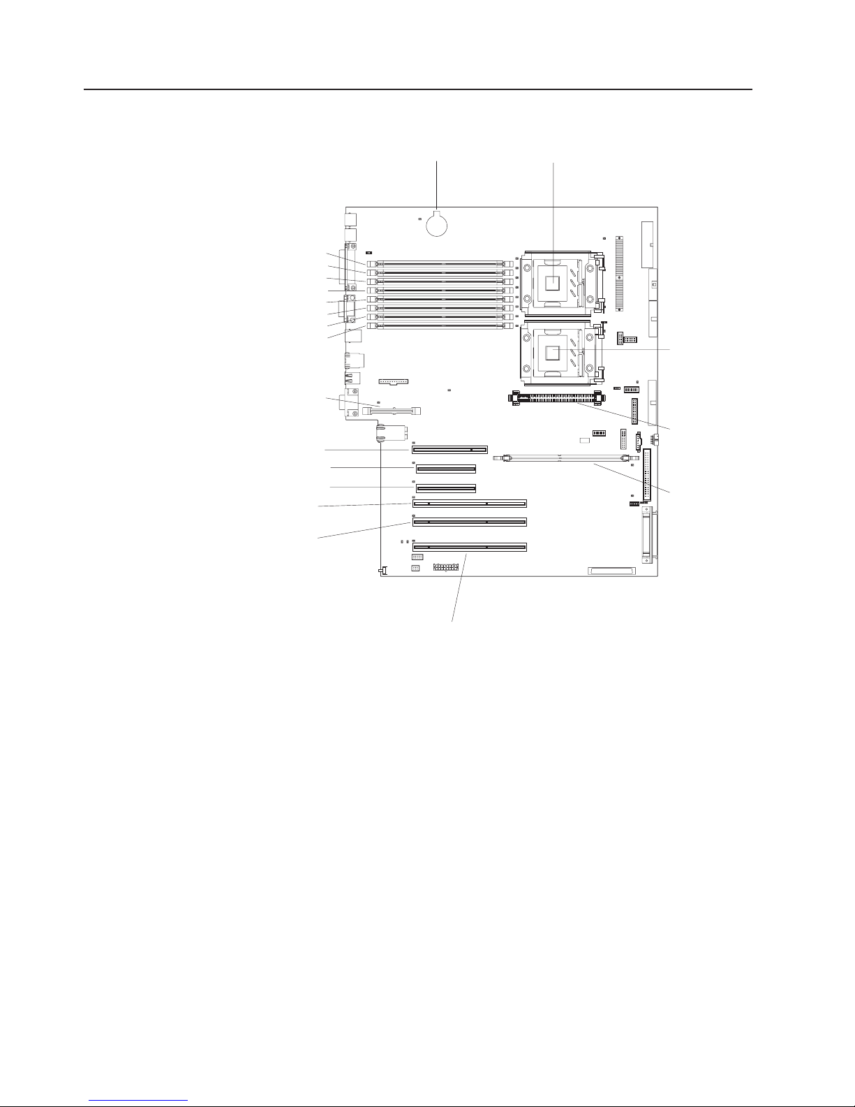
System-board internal connectors
The following illustration shows the internal connectors on the system board.
DIMM 1
DIMM 2
DIMM 3
DIMM 4DIMM 4
DIMM 5
DIMM 6
DIMM 7
DIMM 8
Remote Supervisor
Adapter II Slimline
PCI slot 1 32-bit 5.0V
PCI- Express x4 slot 2
PCI- Express x4 slot 3
PCI- X slot 4 64-bit
3.3V (100 MHz)
PCI- X slot 5 64-bit
3.3V (100 MHz)
Battery
Microprocessor 1
Microprocessor 2
VRM
ServeRAID-7k
PCI- X slot 6 64-bit
3.3V (133 MHz)
hot-swap
78 xSeries 236 Type 8841: Hardware Maintenance Manual and Troubleshooting Guide
Page 89

System-board internal cable connectors
The following illustration shows the internal connectors on the system board.
Power (J4)
Fans 3 and 4 (J10)
Power signal (J17)
Diskette drive (J35)
Diagnostic panel (J36)
Operator panel (J40)
Front USB (J41)
Power switch (J42)
IDE (J46)
SCSI channel B (J58)
SCSI channel A (J51)
Front fans
Fans 5 and 6
(J28)
Serial port 2 (J53)
1 and 2 (J56)
Chapter 4. Service replaceable units 79
Page 90

System-board switches and jumpers
The following illustration shows the jumpers on the system board.
Boot block
recovery jumper
3
2
1
1-2
Normal
3
2
2-3
Recovery
8
7
5
6
42
Force
BMC
override
3
1
Password
override
Force
power-on
NMI button
Table 5 describes the function of each switch on the switch block.
Table 5. Switches 1-8
Switch
number Default value
Switch
description
8 Off Reserved.
7 Off Reserved.
6 Off Reserved.
5 Off Reserved.
4 Off Force baseboard management controller (BMC) override.
3 Off Reserved.
80 xSeries 236 Type 8841: Hardware Maintenance Manual and Troubleshooting Guide
Page 91

Table 5. Switches 1-8 (continued)
Switch
number Default value
Switch
description
2 Off Power-on password override. Changing the position of this switch bypasses the
power-on password check the next time the server is turned on and starts the
Configuration/Setup Utility program so that you can change or delete the power-on
password. Move the switch back to the default position after the password is
overridden.
Changing the position of this switch does not affect the administrator password
check, if an administrator password is set.
See the User’s Guide on the IBM xSeries Documentation CD for additional
information about the power-on password.
1 Off Force power-on. When toggled to On, this switch forces the server to turn on,
overriding the power-on button.
Notes:
1. Before moving any jumpers, turn off the server; then, disconnect all power cords
and external cables. (Review Appendix B, “Safety information,” on page 153,
“Installation guidelines” on page 11, and “Turning off the server” on page 8)
2. Any system-board switch or jumper blocks that are not shown in the illustrations
in this document are reserved.
Chapter 4. Service replaceable units 81
Page 92

System-board external connectors
The following illustration shows the external input/output connectors on the system
board.
82 xSeries 236 Type 8841: Hardware Maintenance Manual and Troubleshooting Guide
Page 93

System-board LEDs
The following illustration shows the light-emitting diodes (LEDs) on the system
board.
DIMM 4 error LED
DIMM 5 error LED
DIMM 6 error LED
DIMM 7 error LED
DIMM 8 error LED
Machine temperature
error LED
Remote Supervisor Adapter II
SlimLine error LED
PCI-X bus A error LED (slot 1)
PCI-X bus A error LED (slot 1)
PCI-X bus B error LED (slot 2)
PCI-X bus C error LED (slot 3)
PCI-X bus D error LED (slot 4)
PCI-X bus D error LED (slot 5)
PCI-X bus F error LED (slot 6)
Low Battery error LED
DIMM 1 error LED
DIMM 2 error LED
DIMM 3 error LED
PCI- X slot 6
power LED
CPU 1
error LED
CPU mismatch
error LED
CPU 2 error LED
Heartbeat LED
VRM 2 error LED
ServeRAID-7k error LED
RAID error LEDs
(Bit 0-4)
PCI- X slot 6
attention LED
Chapter 4. Service replaceable units 83
Page 94

Light path diagnostics panel
The following illustration shows the remind button and the LEDs on the light path
diagnostics panel. The light path diagnostics panel is inside the server under the
left-side cover and the error LEDs are also visible through the left-side cover.
1
POWER
SUPPLY
2
CONFIG
TEMP
CPU
SERVICE
PROCESSOR
BUS
VRMS_ERR
REMIND
MEMORY
DASD/
RAID
FAN
PCI
BUS
NMI
Use the remind button on the light path diagnostic panel to acknowledge that an
error has occurred without taking further action. When you push the remind button,
the system error LED will flash every 2 seconds until the error is fixed. If another
error occurs, the system error LED will then stop flashing and return to a solid on
state.
For more information about light path diagnostics, see “Light path diagnostics” on
page 93.
The following table lists the light path diagnostics LEDs, the problems that they
indicate, and actions to solve the problems.
LED Problem Action
POWER SUPPLY 1 Lit LED: Power supply 1 has failed. 1. Remove ac power from the server.
2. Replace the power supply; then, reconnect the server
to ac power and restart the server.
Flashing LED: Power supply 1 was
Install a new power supply in the PS1 location.
removed in a redundant
power-supply configuration.
POWER SUPPLY 2 Lit LED: Power supply 2 has failed. 1. Remove ac power from the server.
2. Replace the power supply; then, reconnect the server
to ac power and restart the server.
Flashing LED: Power supply 2 was
Install a new power supply in the PS2 location.
removed in a redundant power
supply configuration.
MEMORY A memory error has occurred. Replace the failing DIMM, indicated by the lit LED on the
system board.
CONFIG A configuration error has occurred. Locate the second flashing LED and fix the configuration
problem associated with the blinking LED.
84 xSeries 236 Type 8841: Hardware Maintenance Manual and Troubleshooting Guide
Page 95

LED Problem Action
DASD/RAID A hard disk drive, integrated SCSI
controller, or integrated RAID error
has occurred.This LED will also be
lit when a hard disk drive is
removed from the server.
v Check the LEDs on the hard disk drives and replace
the indicated drive.
v Check the LEDs on the system board and replace the
indicated component.
v If a hard disk drive LED remains lit after being
replaced, call for service.
TEMP The system temperature has
exceeded a threshold level.
v Determine whether a fan has failed. If it has, replace
it.
v Make sure that the room temperature is not too high.
See ″Features and specifications″ on page 5 of the
Installation Guide for temperature information.
v Make sure that the air vents are not blocked.
If
the problem remains, call for service.
FAN A fan has failed or is operating too
Replace the failing fan, indicated by the lit LED.
slowly. A failing fan can also cause
the TEMP LED to be lit.
CPU A microprocessor has failed. If a lit LED on the system board indicates a problem with
a microprocessor, make sure that the microprocessor is
installed correctly.
Replace the failing microprocessor.
S_ERR A soft error has occurred. 1. Restart the server.
2. Update the firmware and adapter drivers.
3. Check the POST error log
VRM The VRM or integrated VRD has
failed.
v Remove ac power from the server, and then restart
the server.
v If the LED next to the VRM is lit, replace the
pluggable VRM.
v If the LED next to the integrated VRD is lit, replace
the system board.
PCI BUS An error has occurred on a PCI
bus.
v Check the system error log for information about the
error.
v If you cannot isolate the failing adapter through the
information in the system error log, remove one
adapter at a time from the failing PCI bus, and restart
the server after each adapter is removed.
SERVICE
The service processor has failed. Remove ac power from the server; then, reconnect the
PROCESSOR BUS
NMI A machine check error has
occurred.
Replace
the system board.
server to ac power and restart the server.
Replace the failing service processor.
Check the error log to diagnose the condition.
Chapter 4. Service replaceable units 85
Page 96

86 xSeries 236 Type 8841: Hardware Maintenance Manual and Troubleshooting Guide
Page 97

Chapter 5. Diagnostics
This section provides basic troubleshooting information to help solve some common
problems that might occur with the server.
If you cannot locate and correct the problem using the information in this section,
see Appendix A, “Getting help and technical assistance,” on page 151 for more
information.
General checkout
Follow the checkout procedure for diagnosing hardware problems. Review the
following information before performing the checkout procedure:
v Read Appendix B, “Safety information,” on page 153.
v The server diagnostic programs are stored in electrically erasable programmable
read-only memory (EEPROM) on the system board that is shared with the BIOS
code. These programs provide the primary methods of testing the major
components of the server. If you are not sure whether a problem is caused by
the hardware or by the software, you can run the diagnostic programs (see
“Diagnostic programs, error codes and messages” on page 91) to confirm that
the hardware is working correctly.
v When you run the diagnostic programs, a single problem might cause several
error messages. If you receive several error messages, correct the cause of the
first error message. The other error messages might not occur the next time you
run the diagnostic programs.
v Before running the diagnostic programs, you must determine whether the failing
server is part of a shared hard disk drive cluster (two or more servers sharing
external storage devices). If you suspect that it is part of a cluster, you can run
all diagnostic programs except the ones that test the storage unit (that is, a hard
disk drive in the storage unit) or the storage adapter that is attached to the
storage unit. The failing server might be part of a cluster if any of the following
conditions is true:
– The customer identifies the failing server as part of a cluster.
– One or more external storage units are attached to the failing server and at
least one of the attached storage units is also attached to another server or
unidentifiable device.
– One or more servers are located near the failing server.
Important:
v
1. For servers that are part of a shared hard disk drive cluster, run one test at a
time. Do not run any suite of tests, such as “quick” or “normal” tests, because
this could enable the hard disk drive diagnostic tests.
2. If more than one error code is displayed, correct the first error. The other
error codes might not occur the next time you run the diagnostic programs.
3. If the server is suspended and no beep or more than one beep sounds, see
“Beep symptoms” on page 104 or “No-beep symptoms” on page 108.
4. If the server is suspended and a POST error code is displayed, see “POST
error codes” on page 108.
5. If the server is suspended and no error message is displayed, see “Error
symptoms” on page 122 and “Undetermined problems” on page 140.
© Copyright IBM Corp. 2004, 2007 87
Page 98

6. For information about power-supply problems, see “Power checkout” on page
7. For intermittent problems, check the error logs; see “Diagnostic programs,
Checkout procedure
Complete the following steps to perform the checkout procedure:
001 IS THE SERVER PART OF A CLUSTER?
002 IF THE SERVER IS NOT PART OF A CLUSTER:
100.
error codes and messages” on page 91.
YES. Schedule maintenance for the system. Shut down all systems related
to the cluster. Run the storage test.
NO. Go to step 002.
1. Check the power supply LEDs, see “Power-supply LEDs” on page 95.
2. Turn off the server and all external devices.
3. Check all internal and external devices for compatibility at
http://www.ibm.com/servers/eserver/serverproven/compat/us/.
4. Check all cables and power cords.
5. Set all display controls to the middle position.
6. Turn on all external devices.
7. Turn on the server.
8. Record any beep codes that sound or POST error messages that are
displayed on the screen. If no beep or more than one beep sounds,
look up the error in “Beep symptoms” on page 104 or “No-beep
symptoms” on page 108; if an error is displayed, look up the first error
in “POST error codes” on page 108.
9. Check the operator information panel system-error LED; if it is on, see
“Light path diagnostics” on page 93.
10. Check the system-error log and the BMC log.
Note: The system-error log is available only with the Remote
Supervisor Adapter II SlimLine.
If an error was recorded by the server, see Chapter 6,
“Symptom-to-FRU index,” on page 103.
11. Start the diagnostic programs.
12. Check for the following responses:
v One beep
v Readable instructions or the main menu
003 DID YOU RECEIVE BOTH OF THE CORRECT RESPONSES?
NO. Find the failure symptom in Chapter 6, “Symptom-to-FRU index,” on
page 103.
YES. Run the diagnostic programs (see “Diagnostic programs, error codes
and messages” on page 91).
If you receive an error, see Chapter 6, “Symptom-to-FRU index,” on page
103.
If the diagnostic programs were completed successfully and you still
suspect a problem, see “Undetermined problems” on page 140.
88 xSeries 236 Type 8841: Hardware Maintenance Manual and Troubleshooting Guide
Page 99

Diagnostic tools overview
The following tools are available to help you identify and resolve hardware-related
problems:
v POST beep codes, error messages, and error logs
The power-on self-test (POST) generates beep codes and messages to indicate
successful test completion or the detection of a problem (see “POST error logs”
on page 90).
The POST error log contains the three most recent error codes and messages
that the system has generated during POST.
The system-error log contains all the error messages that were issued during
POST.
Note: The system-error log is available only with the Remote Supervisor Adapter
II SlimLine.
v Diagnostic programs and error messages
The server diagnostic programs, stored in upgradable read-only memory (ROM)
on the system board, are the primary method of testing the major components of
the server (see “Diagnostic programs, error codes and messages” on page 91).
v ServerGuide error symptoms
ServerGuide error symptoms are described at “ServerGuide error symptoms” on
page 131.
v SCSI error messages
For information on SCSI errors, see “Small computer system interface messages”
on page 97 and “SCSI error codes” on page 132
v Light path diagnostics
The server has light-emitting diodes (LEDs) to help you identify problems with
server components. By following the light path, you can identify the type of
problem that occurred. The light path begins with the LEDs on the operator
information panel (see “Light path diagnostics” on page 93).
v Error symptom tables
These tables list problem symptoms, along with suggested steps to correct the
problems (see the “Error symptoms” on page 122).
Chapter 5. Diagnostics 89
Page 100

POST error logs
When you turn on the server, it performs a series of tests to check the operation of
server components and some of the options installed in the server. This series of
tests is called the power-on self-test, or POST.
If POST finishes without detecting any problems, a single beep sounds, and the first
screen of the operating system or application program appears.
If POST detects a problem, more than one beep sounds, an error message appears
on the screen, or both (see “Beep symptoms” on page 104 and “POST error codes”
on page 108).
Note: A single problem might cause several error messages. When this occurs,
work to correct the cause of the first error message. After you correct the
cause of the first error message, the other error messages usually will not
occur the next time you run the test.
The POST error log contains the three most recent error codes and messages that
the system generated during POST.
The system-error log or the BMC log contains all messages that were issued during
POST and all system status messages from the service processor.
Note: The system-error log is available only with the Remote Supervisor Adapter II
SlimLine.
Viewing error logs from the Configuration/Setup Utility program
To view the POST error log, the system-error log, or the BMC log from the
Configuration/Setup Utility program, start the Configuration/Setup Utility program
(see “Starting the Configuration/Setup Utility program” on page 9) and make the
appropriate choices:
v To view the POST error log or the system-error log, select Error Logs from the
main menu.
v To view the BMC log, start the Configuration/Setup Utility program; then, select
Advanced Settings from the main menu. In the menus that follow, select BMC
Configuration; then, select BMC Error Log.
Viewing error logs from the diagnostic programs
To view the diagnostic test log, see “Starting the diagnostic programs” on page 92.
To view the system-error log from the diagnostic programs, complete the following
steps:
1. Start the diagnostic programs (see “Starting the diagnostic programs” on page
92).
2. Select Hardware Info from the top of the diagnostic programs screen.
3. Select System Error Log from the list that appears; then, follow the instructions
on the screen.
90 xSeries 236 Type 8841: Hardware Maintenance Manual and Troubleshooting Guide
 Loading...