

Page 1

ERserver
IBM xSeries 236 Type 8841
Option Installation Guide
Page 2

Page 3

ER s e r v e r
IBM xSeries 236 Type 8841
Option Installation Guide
Page 4

Note:
Before using this information and the product it supports, read the general information in “Notices,” on
page 57.
Second Edition (September 2005)
© Copyright International Business Machines Corporation 2005. All rights reserved.
US Government Users Restricted Rights – Use, duplication or disclosure restricted by GSA ADP Schedule Contract
with IBM Corp.
Page 5

Contents
Safety . . . . . . . . . . . . . . . . . . . . . . . . . . . .v
Chapter 1. Introduction . . . . . . . . . . . . . . . . . . . . . .1
Related documentation . . . . . . . . . . . . . . . . . . . . . .1
Notices and statements used in this document . . . . . . . . . . . . . .2
Major components of the xSeries 236 Type 8841 server . . . . . . . . . .3
System-board internal connectors . . . . . . . . . . . . . . . . . .4
System-board switches and jumpers . . . . . . . . . . . . . . . . .5
System-board external connectors . . . . . . . . . . . . . . . . . .6
System-board LEDs . . . . . . . . . . . . . . . . . . . . . . .7
Light path diagnostics panel . . . . . . . . . . . . . . . . . . . .8
Chapter 2. Installing options . . . . . . . . . . . . . . . . . . .11
Installation guidelines . . . . . . . . . . . . . . . . . . . . . .11
System reliability guidelines . . . . . . . . . . . . . . . . . . .11
Working inside the server with the power on . . . . . . . . . . . . .12
Handling static-sensitive devices . . . . . . . . . . . . . . . . .12
Server power features . . . . . . . . . . . . . . . . . . . . . .12
Turning on the server . . . . . . . . . . . . . . . . . . . . .12
Turning off the server . . . . . . . . . . . . . . . . . . . . .13
Removing the server door . . . . . . . . . . . . . . . . . . . . .15
Removing the server left-side cover air baffle and bezel . . . . . . . . . .16
Removing the left-side cover . . . . . . . . . . . . . . . . . . .16
Removing the air baffle . . . . . . . . . . . . . . . . . . . . .17
Removing the bezel . . . . . . . . . . . . . . . . . . . . . .18
Replacing hot-swap fans . . . . . . . . . . . . . . . . . . . . .19
Replacing a front fan (1 or 2) . . . . . . . . . . . . . . . . . . .20
Replacing a center fan (3 or 4) . . . . . . . . . . . . . . . . . .21
Replacing a rear fan (5 or 6) . . . . . . . . . . . . . . . . . . .21
Installing the 670-Watt hot-swap power-supply option . . . . . . . . . . .23
Replacing a hot-swap power supply . . . . . . . . . . . . . . . .26
Installing or replacing an adapter . . . . . . . . . . . . . . . . . .27
Installing or replacing a hot-plug adapter (slot 6) . . . . . . . . . . .29
Installing an IBM Remote Supervisor Adapter II SlimLine . . . . . . . .30
Installing the ServeRAID-7k adapter . . . . . . . . . . . . . . . .32
Installing a hot-swap hard disk drive . . . . . . . . . . . . . . . . .32
Installing memory modules . . . . . . . . . . . . . . . . . . . .34
Installing a microprocessor . . . . . . . . . . . . . . . . . . . .36
Replacing a microprocessor and heat sink . . . . . . . . . . . . . .40
Replacing the battery . . . . . . . . . . . . . . . . . . . . . .43
Completing the installation . . . . . . . . . . . . . . . . . . . . .46
Installing the server bezel and left-side cover . . . . . . . . . . . . .47
Installing the server door . . . . . . . . . . . . . . . . . . . .49
Connecting the cables . . . . . . . . . . . . . . . . . . . . .50
Updating the server configuration . . . . . . . . . . . . . . . . .51
Chapter 3. Input/output connectors . . . . . . . . . . . . . . . .53
Auxiliary-device connector . . . . . . . . . . . . . . . . . . . . .54
Ethernet connector . . . . . . . . . . . . . . . . . . . . . . .54
Integrated system management (Remote Supervisor Adapter II SlimLine
Eithernet and ASM) connector . . . . . . . . . . . . . . . . . .54
Keyboard connector . . . . . . . . . . . . . . . . . . . . . . .55
Parallel port connector . . . . . . . . . . . . . . . . . . . . . .55
© Copyright IBM Corp. 2005 iii
Page 6

Serial-port connectors . . . . . . . . . . . . . . . . . . . . . .55
Universal Serial Bus connectors . . . . . . . . . . . . . . . . . .56
Video connector . . . . . . . . . . . . . . . . . . . . . . . .56
Appendix. Notices . . . . . . . . . . . . . . . . . . . . . . .57
Before you call . . . . . . . . . . . . . . . . . . . . . . . . .57
Using the documentation . . . . . . . . . . . . . . . . . . . . .57
Getting help and information from the World Wide Web . . . . . . . . . .58
Software service and support . . . . . . . . . . . . . . . . . . .58
Hardware service and support . . . . . . . . . . . . . . . . . . .58
Index . . . . . . . . . . . . . . . . . . . . . . . . . . . .59
iv IBM xSeries 236 Type 8841: Option Installation Guide
Page 7
Safety
Before installing this product, read the Safety Information.
Antes de instalar este produto, leia as Informações de Segurança.
Pred instalací tohoto produktu si prectete prírucku bezpecnostních instrukcí.
Læs sikkerhedsforskrifterne, før du installerer dette produkt.
Lees voordat u dit product installeert eerst de veiligheidsvoorschriften.
Ennen kuin asennat tämän tuotteen, lue turvaohjeet kohdasta Safety Information.
Avant d’installer ce produit, lisez les consignes de sécurité.
Vor der Installation dieses Produkts die Sicherheitshinweise lesen.
Prima di installare questo prodotto, leggere le Informazioni sulla Sicurezza.
Les sikkerhetsinformasjonen (Safety Information) før du installerer dette produktet.
Antes de instalar este produto, leia as Informações sobre Segurança.
© Copyright IBM Corp. 2005 v
Page 8

Antes de instalar este producto, lea la información de seguridad.
Läs säkerhetsinformationen innan du installerar den här produkten.
Important:
All caution and danger statements in this documentation begin with a number. This
number is used to cross reference an English caution or danger statement with
translated versions of the caution or danger statement in the IBM Safety Information
book.
For example, if a caution statement begins with a number 1, translations for that
caution statement appear in the IBM Safety Information book under statement 1.
Be sure to read all caution and danger statements in this documentation before
performing the instructions. Read any additional safety information that comes with
the server or optional device before you install the device.
vi IBM xSeries 236 Type 8841: Option Installation Guide
Page 9
Statement 1:
DANGER
Electrical
current from power, telephone, and communication cables is
hazardous.
To avoid a shock hazard:
v Do not connect or disconnect any cables or perform installation,
maintenance, or reconfiguration of this product during an electrical
storm.
v Connect all power cords to a properly wired and grounded electrical
outlet.
v Connect to properly wired outlets any equipment that will be attached to
this product.
v When possible, use one hand only to connect or disconnect signal
cables.
v Never turn on any equipment when there is evidence of fire, water, or
structural damage.
v Disconnect the attached power cords, telecommunications systems,
networks, and modems before you open the device covers, unless
instructed otherwise in the installation and configuration procedures.
v Connect and disconnect cables as described in the following table when
installing, moving, or opening covers on this product or attached
devices.
To Connect: To Disconnect:
1. Turn everything OFF.
2. First, attach all cables to devices.
3. Attach signal cables to connectors.
4. Attach power cords to outlet.
1. Turn everything OFF.
2. First, remove power cords from outlet.
3. Remove signal cables from connectors.
4. Remove all cables from devices.
5. Turn device ON.
Safety vii
Page 10
Statement 2:
CAUTION:
When replacing the lithium battery, use only IBM Part Number 33F8354 or an
equivalent type battery recommended by the manufacturer. If your system has
a module containing a lithium battery, replace it only with the same module
type made by the same manufacturer. The battery contains lithium and can
explode if not properly used, handled, or disposed of.
Do not:
v Throw or immerse into water
v Heat to more than 100°C (212°F)
v Repair or disassemble
Dispose
Statement 3:
of the battery as required by local ordinances or regulations.
CAUTION:
When laser products (such as CD-ROMs, DVD drives, fiber optic devices, or
transmitters) are installed, note the following:
v Do not remove the covers. Removing the covers of the laser product could
result in exposure to hazardous laser radiation. There are no serviceable
parts inside the device.
v Use of controls or adjustments or performance of procedures other than
those specified herein might result in hazardous radiation exposure.
DANGER
laser products contain an embedded Class 3A or Class 3B laser
Some
diode. Note the following.
Laser radiation when open. Do not stare into the beam, do not view directly
with optical instruments, and avoid direct exposure to the beam.
viii IBM xSeries 236 Type 8841: Option Installation Guide
Page 11
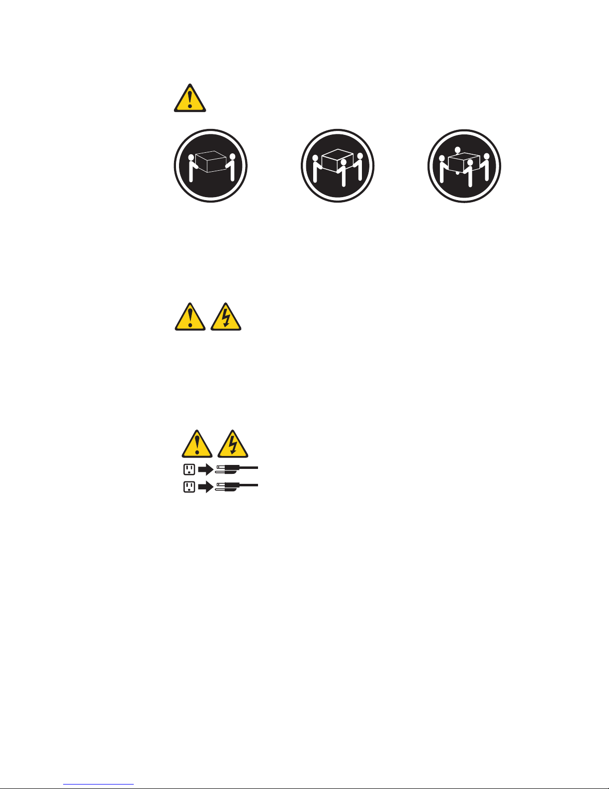
Statement 4:
≥ 18 kg (39.7 lb) ≥ 32 kg (70.5 lb) ≥ 55 kg (121.2 lb)
CAUTION:
Use safe practices when lifting.
Statement 5:
CAUTION:
The power control button on the device and the power switch on the power
supply do not turn off the electrical current supplied to the device. The device
also might have more than one power cord. To remove all electrical current
from the device, ensure that all power cords are disconnected from the power
source.
2
1
Safety ix
Page 12
Statement 8:
CAUTION:
Never remove the cover on a power supply or any part that has the following
label attached.
Hazardous voltage, current, and energy levels are present inside any
component that has this label attached. There are no serviceable parts inside
these components. If you suspect a problem with one of these parts, contact
a service technician.
x IBM xSeries 236 Type 8841: Option Installation Guide
Page 13

Chapter 1. Introduction
This Option Installation Guide contains instructions for installing, removing, and
connecting optional devices that the server supports.
Related documentation
In addition to this Option Installation Guide, the following documentation comes with
the server:
v User’s Guide
This document is in Portable Document Format (PDF) on the IBM
Documentation CD. It contains general information about the server, including
information about features, how to configure the server, and how to get help.
v Installation Guide
This printed document contains instructions for setting up the server and basic
instructions for installing some options.
v Safety Information
This document is in PDF on the IBM xSeries Documentation CD. It contains
translated caution and danger statements. Each caution and danger statement
that appears in the documentation has a number that you can use to locate the
corresponding statement in your language in the Safety Information document.
v Hardware Maintenance Manual and Troubleshooting Guide
This document is in PDF on the IBM xSeries Documentation CD. It contains
information to help you solve problems yourself, and it contains information for
service technicians.
®
xSeries
®
Depending
on the server model, additional documentation might be included on the
IBM xSeries Documentation CD.
The server might have features that are not described in the documentation that
you received with the server. The documentation might be updated occasionally to
include information about those features, or technical updates might be available to
provide additional information that is not included in the server documentation.
These updates are available from the IBM Web site. To check for updated
documentation and technical updates, complete the following steps:
Note: Changes are made periodically to the IBM Web site. The actual procedure
might vary slightly from what is described in this document.
1. Go to http://www.ibm.com/support/.
2. Under Search technical support, type xSeries 236 and click Search.
© Copyright IBM Corp. 2005 1
Page 14

Notices and statements used in this document
The caution and danger statements that appear in this document are also in the
multilingual Safety Information document, which is on the IBM xSeries
Documentation CD. Each statement is numbered for reference to the corresponding
statement in the Safety Information document.
The following notices and statements are used in this document:
v Notes: These notices provide important tips, guidance, or advice.
v Important: These notices provide information or advice that might help you avoid
inconvenient or problem situations.
v Attention: These notices indicate potential damage to programs, devices, or
data. An attention notice is placed just before the instruction or situation in which
damage could occur.
v Caution: These statements indicate situations that can be potentially hazardous
to you. A caution statement is placed just before the description of a potentially
hazardous procedure step or situation.
v Danger: These statements indicate situations that can be potentially lethal or
extremely hazardous to you. A danger statement is placed just before the
description of a potentially lethal or extremely hazardous procedure step or
situation.
2 IBM xSeries 236 Type 8841: Option Installation Guide
Page 15
Major components of the xSeries 236 Type 8841 server
Blue on a component indicates touch points, where you can grip the component to
remove it from or install it in the server, open or close a latch, and so on.
Orange on a component or an orange label on or near a component indicates that
the component can be hot-swapped, which means that if the server and operating
system support hot-swap capability, you can remove or install the component while
the server is running. (Orange can also indicate touch points on hot-swap
components.) See the instructions for removing or installing a specific hot-swap
component for any additional procedures that you might have to perform before you
remove or install the component.
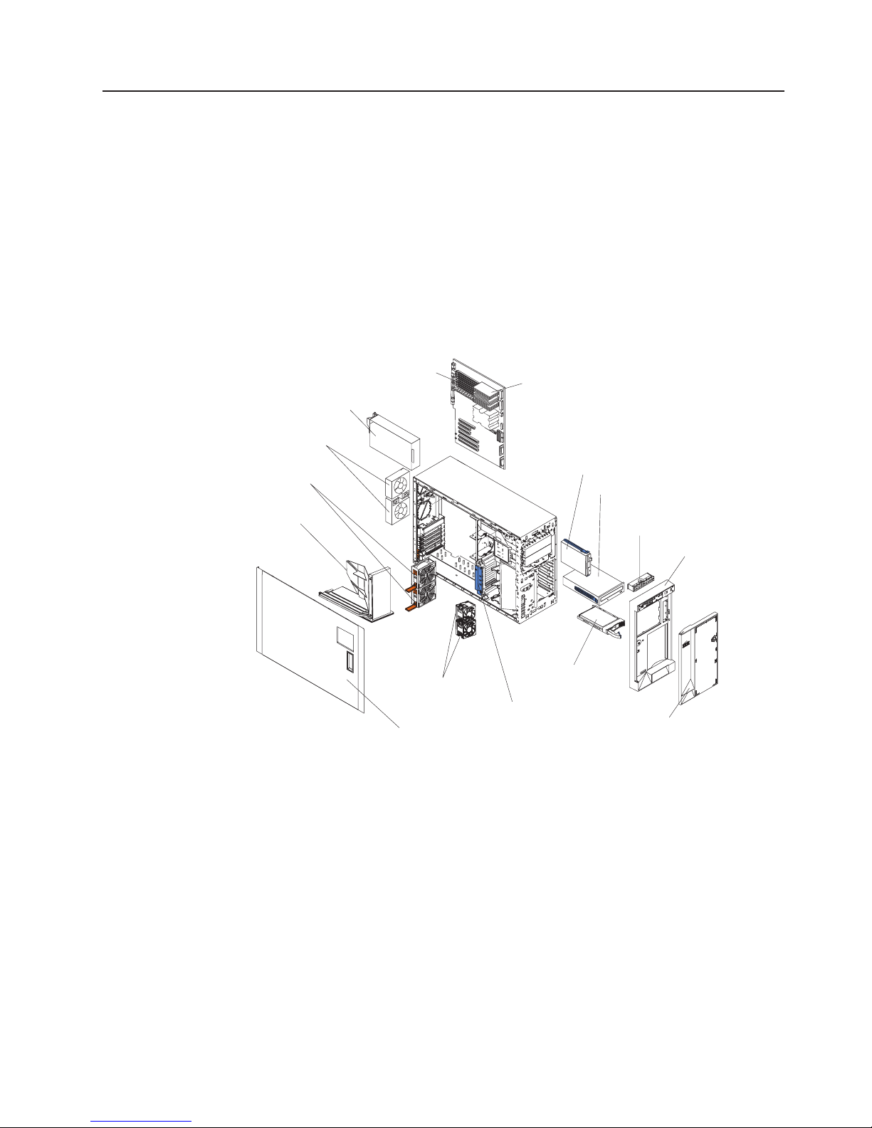
The following illustration shows the major components in the server. The
illustrations in this document might differ slightly from your hardware.
Power supply
Rear fans
5 and 6
(optional)
Center fans
3 and 4
Air-baffle
Memory modules
Microprocessor
Diskette drive
CD-Rom drive
Operator information
panel
Bezel
Hard disk
Front fans
drive
1 and 2
Adapter-support
Left-side cover
bracket
Server door
Chapter 1. Introduction 3
Page 16
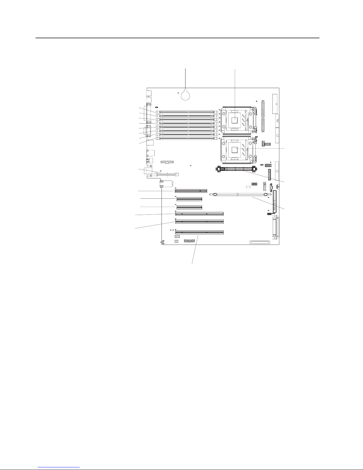
System-board internal connectors
The following illustration shows the internal connectors on the system board.
DIMM 1
DIMM 2
DIMM 3
DIMM 4DIMM 4
DIMM 5
DIMM 6
DIMM 7
DIMM 8
Remote Supervisor
Adapter II Slimline
PCI slot 1 32-bit 5.0V
PCI- Express x4 slot 2
PCI- Express x4 slot 3
PCI- X slot 4 64-bit
3.3V (100 MHz)
PCI- X slot 5 64-bit
3.3V (100 MHz)
Battery
Microprocessor 1
Microprocessor 2
VRM
ServeRAID-7k
PCI- X slot 6 64-bit
3.3V (133 MHz)
hot-swap
4 IBM xSeries 236 Type 8841: Option Installation Guide
Page 17
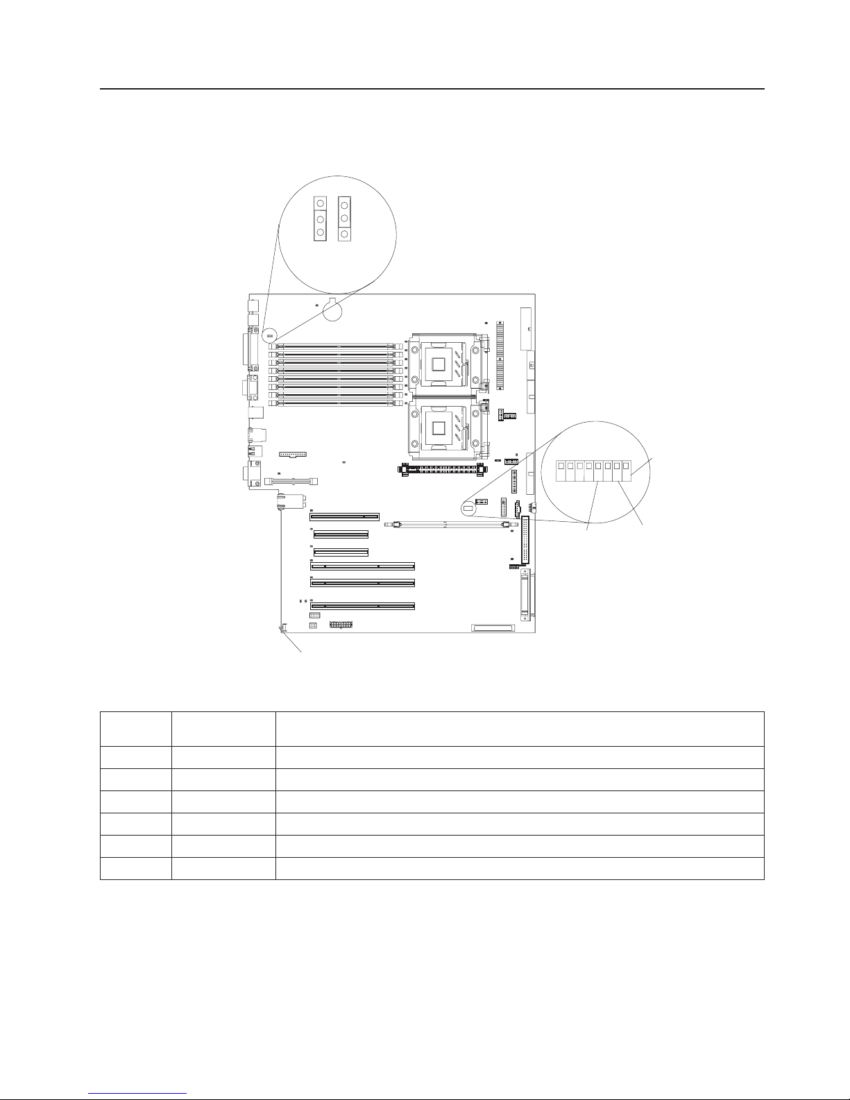
System-board switches and jumpers
The following illustration shows the jumpers on the system board.
Boot block
recovery jumper
3
2
1
1-2
Normal
3
2
2-3
Recovery
8
7
5
6
42
Force
BMC
override
3
1
Password
override
Force
power-on
NMI button
Table 1 describes the function of each switch on the switch block.
Table 1. Switches 1-8
Switch
number Default value
8 Off Reserved.
7 Off Reserved.
6 Off Reserved.
5 Off Reserved.
4 Off Force baseboard management controller (BMC) override.
3 Off Reserved.
Switch
description
Chapter 1. Introduction 5
Page 18
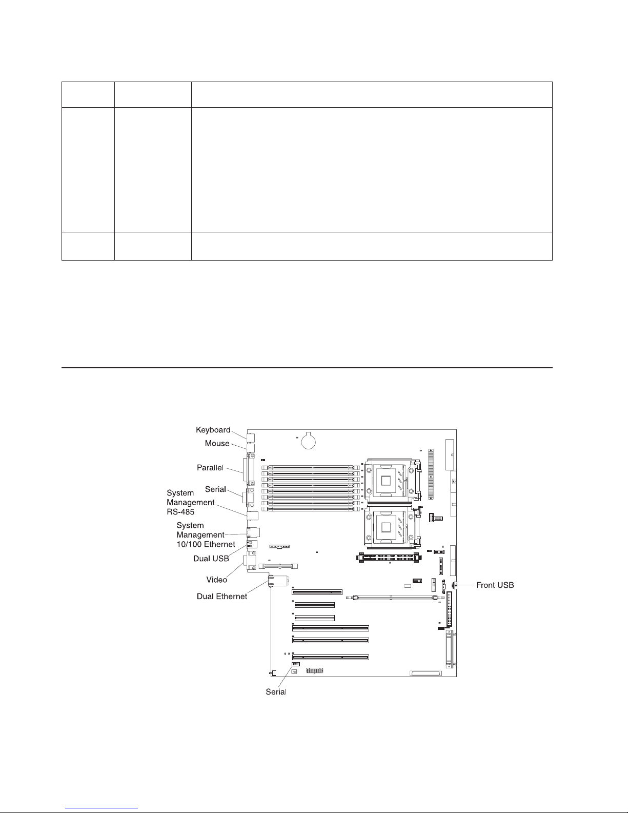
Table 1. Switches 1-8 (continued)
Switch
number Default value
Switch
description
2 Off Power-on password override. Changing the position of this switch bypasses the
power-on password check the next time the server is turned on and starts the
Configuration/Setup Utility program so that you can change or delete the power-on
password. Move the switch back to the default position after the password is
overridden.
Changing the position of this switch does not affect the administrator password
check, if an administrator password is set.
See the User’s Guide on the IBM xSeries Documentation CD for additional
information about the power-on password.
1 Off Force power-on. When toggled to On, this switch forces the server to turn on,
overriding the power-on button.
Notes:
1. Before moving any jumpers, turn off the server; then, disconnect all power cords
and external cables. (Review the information in “Safety” on page v, “Installation
guidelines” on page 11, and “Turning off the server” on page 13.)
2. Any system-board switch or jumper blocks that are not shown in the illustrations
in this document are reserved.
System-board external connectors
The following illustration shows the external input/output connectors on the system
board.
6 IBM xSeries 236 Type 8841: Option Installation Guide
Page 19
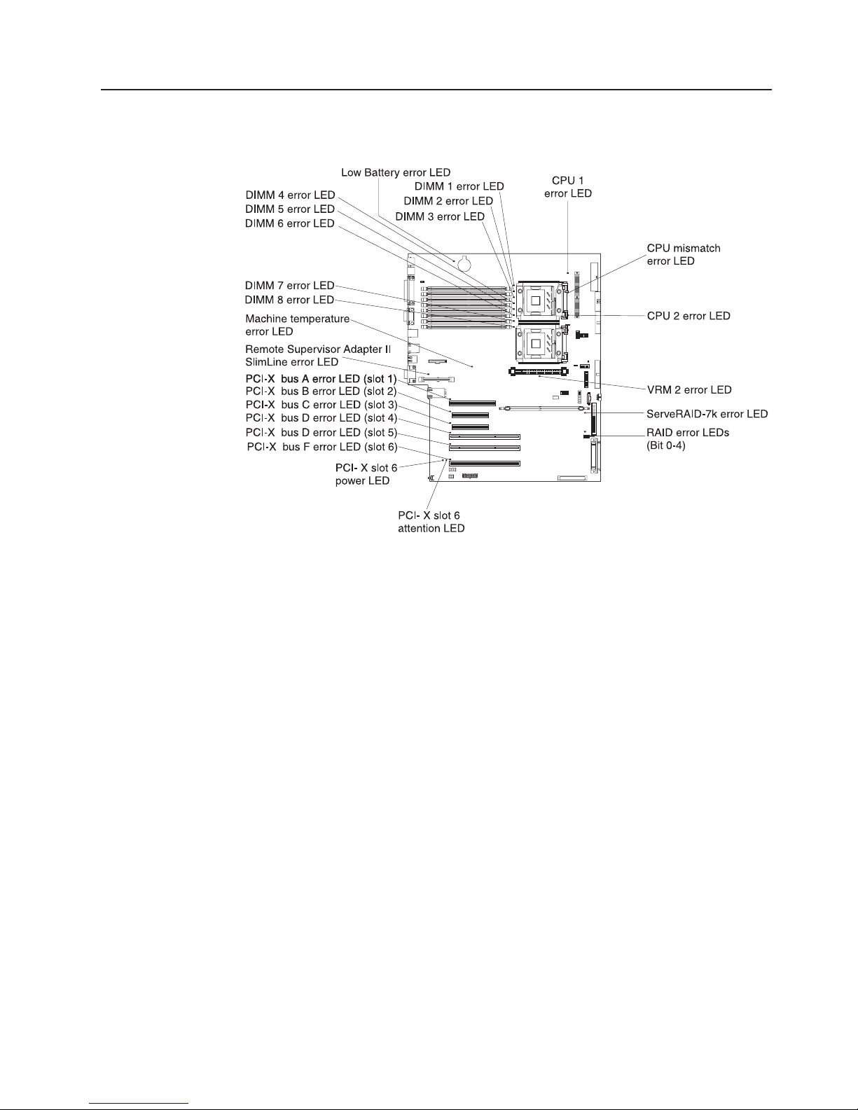
System-board LEDs
The following illustration shows the light-emitting diodes (LEDs) on the system
board.
Chapter 1. Introduction 7
Page 20
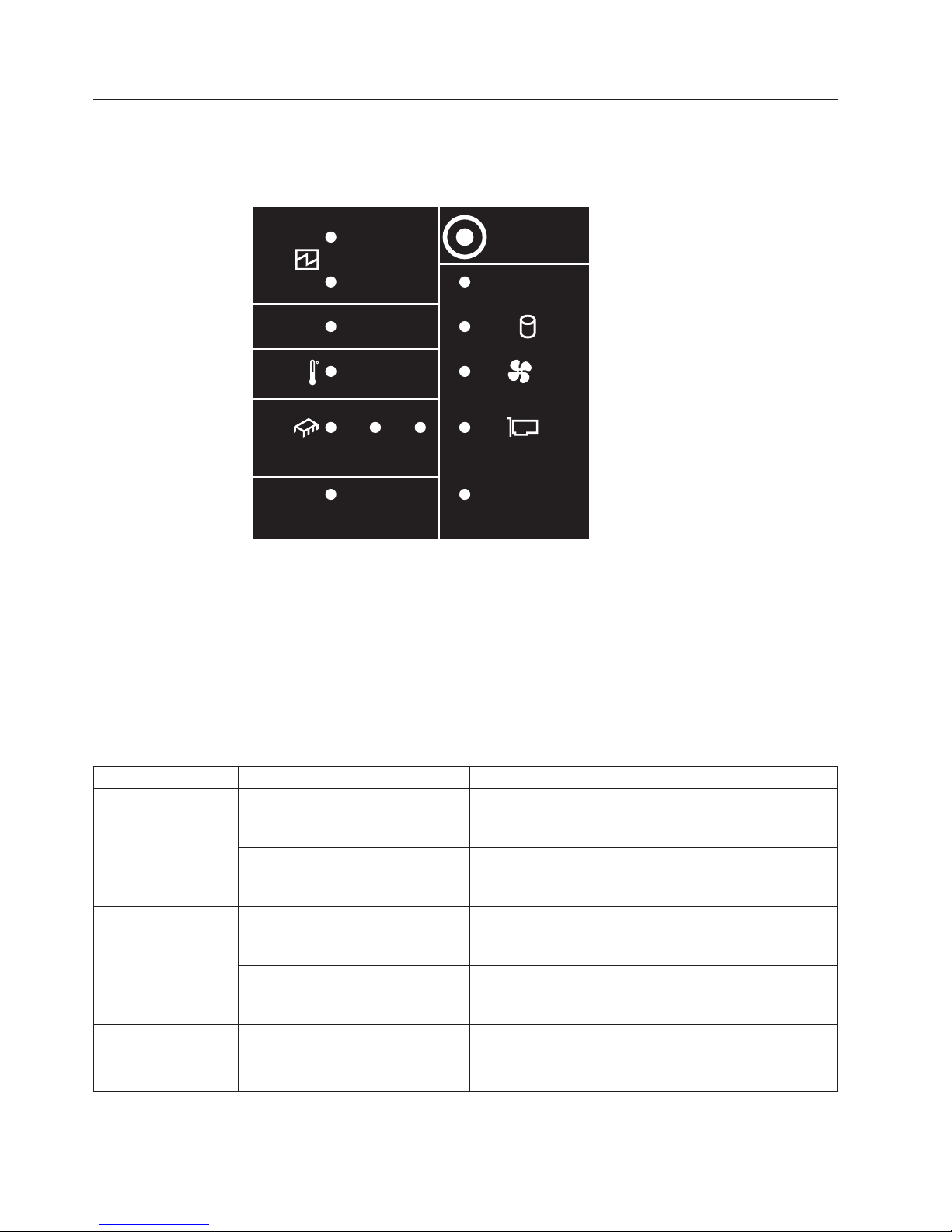
Light path diagnostics panel
The following illustration shows the remind button and the LEDs on the light path
diagnostics panel. The light path diagnostics panel is inside the server under the
left-side cover and the error LEDs are also visible through the left-side cover.
1
POWER
SUPPLY
2
CONFIG
TEMP
CPU
SERVICE
PROCESSOR
BUS
VRMS_ERR
REMIND
MEMORY
DASD/
RAID
FAN
PCI
BUS
NMI
Use the remind button on the light path diagnostic panel to acknowledge that an
error has occurred without taking further action. When you push the remind button,
the system error LED will flash every 2 seconds until the error is fixed. If another
error occurs, the system error LED will then stop flashing and return to a solid on
state.
For more information about light path diagnostics, see the Hardware Maintenance
Manual and Troubleshooting Guide on the IBM xSeries Documentation CD.
The following table lists the light path diagnostics LEDs, the problems that they
indicate, and actions to solve the problems.
LED Problem Action
POWER SUPPLY 1 Lit LED: Power supply 1 has failed. 1. Remove ac power from the server.
2. Replace the power supply; then, reconnect the server
to ac power and restart the server.
Flashing LED: Power supply 1 was
Install a new power supply in the PS1 location.
removed in a redundant
power-supply configuration.
POWER SUPPLY 2 Lit LED: Power supply 2 has failed. 1. Remove ac power from the server.
2. Replace the power supply; then, reconnect the server
to ac power and restart the server.
Flashing LED: Power supply 2 was
Install a new power supply in the PS2 location.
removed in a redundant power
supply configuration.
MEMORY A memory error has occurred. Replace the failing DIMM, indicated by the lit LED on the
system board.
CONFIG See the note following this table. See the note following this table.
8 IBM xSeries 236 Type 8841: Option Installation Guide
Page 21

LED Problem Action
DASD/RAID A hard disk drive, integrated SCSI
controller, or integrated RAID error
has occurred.This LED will also be
lit when a hard disk drive is
removed from the server.
v Check the LEDs on the hard disk drives and replace
the indicated drive.
v Check the LEDs on the system board and replace the
indicated component.
v If a hard disk drive LED remains lit after being
replaced, call for service.
TEMP The system temperature has
exceeded a threshold level.
v Determine whether a fan has failed. If it has, replace
it.
v Make sure that the room temperature is not too high.
See ″Features and specifications″ on page 5 of the
Installation Guide for temperature information.
v Make sure that the air vents are not blocked.
If
the problem remains, call for service.
FAN A fan has failed or is operating too
Replace the failing fan, indicated by the lit LED.
slowly. A failing fan can also cause
the TEMP LED to be lit.
CPU A microprocessor has failed. If a lit LED on the system board indicates a problem with
a microprocessor, make sure that the microprocessor is
installed correctly.
If the problem remains, call for service.
S_ERR A soft error has occurred. 1. Restart the server.
2. Update the firmware and adapter drivers.
3. Check the POST error log
VRM The VRM or integrated VRD has
failed.
PCI BUS An error has occurred on a PCI
bus.
SERVICE
The service processor has failed. Remove ac power from the server; then, reconnect the
PROCESSOR BUS
NMI A machine check error has
occurred.
Note: The amber CONFIG LED is lit only when the Diagnostics Panel LED test is
performed by Enhanced Diagnostics.
If
the problem remains, call for service.
v Remove ac power from the server, and then restart
the server.
v If the LED next to the VRM is lit, replace the
pluggable VRM.
v If the LED next to the integrated VRD is lit, call for
service.
v Check the system error log for information about the
error.
v If you cannot isolate the failing adapter through the
information in the system error log, remove one
adapter at a time from the failing PCI bus, and restart
the server after each adapter is removed.
If
the problem remains, call for service.
server to ac power and restart the server.
If the problem remains, call for service.
Check the error log to diagnose the condition.
Chapter 1. Introduction 9
Page 22

10 IBM xSeries 236 Type 8841: Option Installation Guide
Page 23

Chapter 2. Installing options
This chapter provides detailed instructions for installing hardware options in the
server.
Installation guidelines
Before you begin installing options in the server, read the following information:
v For a list of supported options for the server, go to
http://www.ibm.com/servers/eserver/severproven/compat/us/.
v Read the safety information beginning on page v and the guidelines in “Handling
static-sensitive devices” on page 12. This information will help you work safely
with the server and options.
v Make sure that you have an adequate number of properly grounded electrical
outlets for the server, monitor, and other devices.
v Back up all important data before you make changes to disk drives.
v Have a small flat-blade screwdriver available.
v Yo u do not have to turn off the server to install or replace hot-swap power
supplies, hot-swap fans, or hot-plug Universal Serial Bus (USB) devices.
v Blue on a component indicates touch points, where you can grip the component
to remove it from or install it in the server, open or close a latch, and so on.
v Orange on a component or an orange label on or near a component indicates
that the component can be hot-swapped, which means that if the server and
operating system support hot-swap capability, you can remove or install the
component while the server is running. (Orange can also indicate touch points on
hot-swap components.) See the instructions for removing or installing a specific
hot-swap component for any additional procedures that you might have to
perform before you remove or install the component.
v When you need to access the inside of the server, you might find it easier to lay
the server on its side.
System reliability guidelines
To help ensure proper cooling and system reliability, make sure that:
v Each of the drive bays has a drive or a filler panel and electromagnetic
compatibility (EMC) shield installed in it.
v There is adequate space around the server to allow the server cooling system to
work properly. Leave approximately 50 mm (2.0 in.) of open space around the
front and rear of the server. Do not place objects in front of the fans. For proper
cooling and airflow, replace the left-side cover before turning on the server.
Operating the server for extended periods of time (more than 30 minutes) with
the left-side cover removed might damage server components.
v Yo u have followed the cabling instructions that come with optional adapters.
v Yo u have replaced a failed fan within 48 hours.
v Yo u have replaced a hot-swap drive within 2 minutes of removal.
v Yo u do not remove the air baffle while the server is running. Operating the server
without the air baffle might cause the microprocessor to overheat.
v Microprocessor socket 2 always contains either a microprocessor baffle or a
microprocessor and heat sink.
© Copyright IBM Corp. 2005 11
Page 24

Working inside the server with the power on
The server supports hot-swap devices and is designed to operate safely while it is
turned on and the cover is removed. Follow these guidelines when you work inside
a server that is turned on:
v Avoid wearing loose-fitting clothing on your forearms. Button long-sleeved shirts
before working inside the server; do not wear cuff links while you are working
inside the server.
v Do not allow your necktie or scarf to hang inside the server.
v Remove jewelry, such as bracelets, necklaces, rings, and loose-fitting wrist
watches.
v Remove items from your shirt pocket, such as pens and pencils, that could fall
into the server as you lean over it.
v Avoid dropping any metallic objects, such as paper clips, hairpins, and screws,
into the server.
Handling static-sensitive devices
Attention: Static electricity can damage electronic devices, including the server.
To avoid damage, keep static-sensitive devices in their static-protective packages
until you are ready to install them.
To reduce the possibility of damage from electrostatic discharge, observe the
following precautions:
v Limit your movement. Movement can cause static electricity to build up around
you.
v Handle the device carefully, holding it by its edges or its frame.
v Do not touch solder joints, pins, or exposed circuitry.
v Do not leave the device where others can handle and damage it.
v While the device is still in its static-protective package, touch it to an unpainted
metal part of the server for at least 2 seconds. This drains static electricity from
the package and from your body.
v Remove the device from its package and install it directly into the server without
setting down the device. If it is necessary to set down the device, put it back into
its static-protective package. Do not place the device on the server cover or on a
metal surface.
v Take additional care when handling devices during cold weather. Heating reduces
indoor humidity and increases static electricity.
Server power features
When the server is connected to an ac power source but is not turned on, the
operating system does not run, and all core logic except for the service processor is
shut down; however, the server can respond to requests from the service processor
(also called the baseboard management controller), such as a remote request to
turn on the server. The power-on LED flashes to indicate that the server is
connected to ac power but is not turned on.
Turning on the server
Approximately 20 seconds after the server is connected to ac power, the
power-control button becomes active, one or more fans might start running, and you
can turn on the server and start the operating system by pressing the power-control
button.
12 IBM xSeries 236 Type 8841: Option Installation Guide
Page 25

The server can also be turned on in any of the following ways:
v If a power failure occurs while the server is turned on, the server will restart
automatically when power is restored.
v If the server is connected to an Advanced System Management interconnect
network that contains at least one server with an optional Remote Supervisor
Adapter II SlimLine installed, the server can be turned on from the Remote
Supervisor Adapter II SlimLine user interface.
v If your operating system supports the systems-management software for an
optional Remote Supervisor Adapter II SlimLine, the systems-management
software can turn on the server.
v If your operating system supports the Wake on LAN
feature can turn on the server.
When 4 GB or more of memory (physical or logical) is installed, some
Note:
memory is reserved for various system resources and is unavailable to the
operating system. The amount of memory that is reserved for system resources
depends on the operating system, the configuration of the server, and the
configured PCI options.
Turning off the server
When you turn off the server and leave it connected to ac power, the server can
respond to requests from the service processor, such as a remote request to turn
on the server. While the server remains connected to ac power, one or more fans
might continue to run. To remove all power from the server, you must disconnect it
from the power source.
®
feature, the Wake on LAN
Some operating systems require an orderly shutdown before you turn off the server.
See your operating-system documentation for information about shutting down the
operating system.
Statement 5:
CAUTION:
The power control button on the device and the power switch on the power
supply do not turn off the electrical current supplied to the device. The device
also might have more than one power cord. To remove all electrical current
from the device, ensure that all power cords are disconnected from the power
source.
2
1
The server can be turned off in any of the following ways:
v Yo u can turn off the server from the operating system, if your operating system
supports this feature. After an orderly shutdown of the operating system, the
server will be turned off automatically.
Chapter 2. Installing options 13
Page 26

v Yo u can press the power-control button to start an orderly shutdown of the
operating system and turn off the server, if your operating system supports this
feature.
v If the operating system stops functioning, you can press and hold the
power-control button for more than 4 seconds to turn off the server.
v If the server is connected to an Advanced System Management interconnect
network that contains at least one server with an optional Remote Supervisor
Adapter II SlimLine installed, the server can be turned off from the Remote
Supervisor Adapter II SlimLine user interface.
v If an optional Remote Supervisor Adapter II SlimLine is installed in the server, the
server can be turned off from the Remote Supervisor Adapter II SlimLine user
interface.
v If the Wake on LAN feature turned on the server, the Wake on LAN feature can
turn off the server.
v The integrated system management processor can turn off the server as an
automatic response to a critical system failure.
v Yo u can turn off the server through a request from the service processor.
14 IBM xSeries 236 Type 8841: Option Installation Guide
Page 27

Removing the server door
The following illustration shows how to remove the door from the server.
Note: The illustrations in this document might differ slightly from your hardware.
PCI BUS
A B
POWER SUPPLY
1 2 3
FAN
1 2 3
Flange
CPU
VRM
MEMORY
HDD
NMI
SMI
SERVICE PROCESSOR
BUS
NON REDUNDANT
TEMPERATURE
Server door
Complete the following steps to remove the server door:
1. Read the safety information beginning on page v and “Installation guidelines” on
page 11.
2. Unlock and open the server door.
3. Locate the flange on the top edge of the door.
4. Press the flange downward while pressing outward on the door; then, lift the
door up and off the hinge. Set the door aside in a safe place.
Chapter 2. Installing options 15
Page 28

Removing the server left-side cover air baffle and bezel
Before you remove the left-side cover, air-baffle, or bezel, read the safety
information beginning on page v and “Installation guidelines” on page 11.
Removing the left-side cover
The following illustration shows how to remove the left-side cover from the server.
Note: If you have not already removed the door, remove it as described in
“Removing the server door” on page 15.
Left-side cover
Coverrelease
latch
Complete the following steps to remove the server left-side cover:
1. Push the plastic cover-release latch near the edge of the side cover to the right
to release the cover.
2. While pushing the plastic cover-release latch, slide the side cover slightly toward
the rear of the server; the cover will stop after approximately 25 mm (1 inch).
Lift the cover off the server and set the cover aside.
Attention: For proper cooling and airflow, replace the cover before turning on
the server. Operating the server for extended periods of time (more than 30
minutes) with the cover removed might damage server components.
16 IBM xSeries 236 Type 8841: Option Installation Guide
Page 29

Removing the air baffle
When working with some options, you must first remove the air baffle to access
certain components or connectors on the system board. The following illustration
shows how to remove the air baffle.
Air-baffle assembly
Complete the following steps to remove the air baffle:
1. Read the safety information beginning on page v and “Installation guidelines” on
page 11.
2. Turn off the server and peripheral devices and disconnect all power cords and
external cables (see “Turning on the server” on page 12); then, remove the
cover (see “Removing the left-side cover” on page 16).
3. Place your fingers on each side of the air baffle.
4. Press in on the sides and lift the air baffle out of the server.
Attention: For proper cooling and airflow, replace the air baffle before turning
on the server. Operating the server with the air baffle removed might damage
server components.
Chapter 2. Installing options 17
Page 30

Removing the bezel
The following illustration shows how to remove the bezel from the server.
Bezel-release lever
Complete the following steps to remove the bezel:
1. Remove the left-side cover and locate the bezel-release lever.
2. Press up on the bezel-release lever.
3. Pull the top of the bezel away from the chassis; then, lift the bezel to disengage
the bottom tabs.
4. Remove the bezel from the server and store the bezel in a safe place.
18 IBM xSeries 236 Type 8841: Option Installation Guide
Page 31

Replacing hot-swap fans
The server comes with four hot-swap fans: two front fans (fans 1 and 2), and two
center fans (fans 3 and 4). You do not have to turn off the power to the server to
replace a hot-swap fan.
If the server is equipped with the IBM xSeries 670-Watt Hot-swap Power-Supply
option, two rear fans (fans 5 and 6) must also be installed on the server. For
information on replacing these fans or installing this option, see “Replacing a rear
fan (5 or 6)” on page 21 or “Installing the 670-Watt hot-swap power-supply option”
on page 23.
Attention: To help ensure proper cooling, if a fan fails, replace it within 48 hours.
The following illustration shows how to replace hot-swap fans.
Center fan
3 or 4
Release
lever
Hot-swap fan
Front fan
1 or 2
Hot-swap fan
assembly
Determine which fan to replace by checking the LEDs on the fans. The front fans,
center fans, and rear fans are installed differently from each other. This section
contains separate instructions for each group of fans.
Chapter 2. Installing options 19
Page 32

Replacing a front fan (1 or 2)
Complete the following steps to replace fan 1 or 2:
Attention: To ensure proper server operation, if a fan fails, replace it within 48
hours.
Fan-assembly
latch
Hot-swap fan
assembly
Front fan
1or 2
Complete the following steps to replace hot-swap-fan 1 or 2:
1. Read the safety information beginning on page v and “Installation guidelines” on
page 11.
2. Remove the cover. See “Removing the left-side cover” on page 16. The LED on
the failing fan assembly will be lit.
Attention: To ensure proper system cooling, do not remove the left-side cover
for more than 30 minutes during this procedure.
3. Place your fingers into the fan-assembly latch on the top of the failing fan.
4. Squeeze the fan-assembly latch together and lift the fan out of the server.
5. Position the new fan so that the LED on the fan is closest to the front of the
server.
6. Push the replacement fan assembly into the server until it clicks into place.
7. Make sure that the FAN LED on the diagnostic LED panel (see the Hardware
Maintenance Manual and Troubleshooting Guide on the IBM xSeries
Documentation CD for the location of the LED) is not lit. If the FAN LED is lit,
reseat the fan.
8. Replace the cover. See “Installing the server bezel and left-side cover” on page
47.
20 IBM xSeries 236 Type 8841: Option Installation Guide
Page 33

Replacing a center fan (3 or 4)
Complete the following steps to replace hot-swap fan 3 or 4:
Hot-swap fan
Release
lever
Center fan
3 or 4
1. Read the safety information beginning on page v and “Installation guidelines” on
page 11.
2. Remove the cover. See “Removing the left-side cover” on page 16. The LED on
the failing fan assembly will be lit.
Attention: To ensure proper system cooling, do not remove the left-side cover
for more than 30 minutes during this procedure.
3. Press the orange fan-release latch in the direction indicated by the arrow on the
latch to open the release lever.
4. Pull the fan out of the server using the release lever.
5. Press the orange fan-release latch in the direction indicated by the arrow on the
latch and open the release lever on the replacement fan.
6. Position the replacement fan so that the orange fan-release latch is away from
you; then, slide the fan into the server. Press the release latch into place and
secure the fan in the server.
7. Make sure that the FAN LED on the diagnostic LED panel (see the Hardware
Maintenance Manual and Troubleshooting Guide on the IBM xSeries
Documentation CD for the location of the LED) is not lit. If the FAN LED is lit,
reseat the fan.
8. Reinstall the server cover. See “Installing the server bezel and left-side cover”
on page 47.
Replacing a rear fan (5 or 6)
Hot-swap fans 5 and 6 are included in the power-supply option. With these two
additional hot-swap fans installed, the server supports the variable fan-speed
control and redundant cooling features. For information on installing the option see
“Installing the 670-Watt hot-swap power-supply option” on page 23.
Chapter 2. Installing options 21
Page 34

Rear fan 5 or 6
Fan-release
latch
Complete the following steps to replace hot-swap-fans 5 and 6:
1. Read the safety information beginning on page v and “Installation guidelines” on
page 11.
2. Press in on the orange fan-release latch on the side of the fan; then, rotate the
fan away from the server.
3. Pull the fan off the server.
4. Slide the two tabs of the replacement fan into the back of the server; then,
rotate the fan toward the server until the fan-release latch clicks.
5. Make sure that the FAN LED on the diagnostic LED panel (see the Hardware
Maintenance Manual and Troubleshooting Guide on the IBM xSeries
Documentation CD for the location of the LED) is not lit. If the FAN LED is lit,
reseat the fan.
22 IBM xSeries 236 Type 8841: Option Installation Guide
Page 35

Installing the 670-Watt hot-swap power-supply option
The server comes with a power supply in the power supply 1 (PS1) position and a
filler panel in the power supply 2 (PS2) position. You can install a 670-Watt
hot-swap power-supply option, which includes a hot-swap power supply and two
hot-swap fans.
Power supply 1
AC power LED
DC power LED
Power supply 2
AC power LED
DC power LED
Fan 5 LED
Fan 6 LED
Before you continue, review the following information:
v During normal nonredundant operation, a power supply must be installed in the
power supply 1 position and a filler panel in the power supply 2 position.
v During normal redundant operation, a second hot-swap power supply and the
two rear hot-swap fans must be installed in the server.
Attention: To help ensure proper cooling, if a fan fails, replace it within 48
hours.
v When the 670-Watt hot-swap power supply option is installed in the server, the
addition of the two fans enables the redundant cooling feature. If any of the fans
fail the other fans will speed up when needed to help keep the server cool and
working properly.
v Two cable-restraint brackets are on the rear of the server. After you install the
670-Watt hot-swap power-supply option and connect the cables to the selected
devices, you can use these cable-restraint brackets to manage the cable routing.
Route the power cords through the power-cord restraint bracket. Route the
remaining cables (for example, the cables that are connected to the I/O
connectors) through the I/O cable-restraint bracket.
you install or remove a power supply, observe the following precautions.
If
Chapter 2. Installing options 23
Page 36

Statement 8:
CAUTION:
Never remove the cover on a power supply or any part that has the following
label attached.
Hazardous voltage, current, and energy levels are present inside any
component that has this label attached. There are no serviceable parts inside
these components. If you suspect a problem with one of these parts, contact
a service technician.
Complete the following steps to install the 670-Watt hot-swap power-supply option:
1. Read the safety information beginning on page v and “Installation guidelines” on
page 11.
2. Remove the filler panel from the power supply 2 opening.
3. Install the second hot-swap power-supply.
Power supply 1
AC power LED
DC power LED
Power supply 2
AC power LED
DC power LED
a. Make sure that the handle on the power supply is in the open position.
24 IBM xSeries 236 Type 8841: Option Installation Guide
Fan 5 LED
Fan 6 LED
Page 37

b. Slide the power supply into the power supply 2 opening until it stops; then,
push the handle down into the closed position.
Install the fans on the back of the server:
4.
a. Position the first fan so that the notched area is facing up and the mounting
surface is toward the server.
b. Tilt the bottom of the fan toward the server and insert the tabs into the
corresponding holes.
c. Press in on the top half of the fan until it clicks into place.
d. Position the second fan so that the notched area is facing down and the
mounting surface is toward the server.
e. Repeat steps 5b and 5c; then, continue to step 6.
5. Connect one end of each power cord to the corresponding connector on each
power supply; then, connect the other end of each power cord to a properly
grounded electrical outlet.
Note: Yo u can route the power cords through the power-cord restraint bracket
on the rear of the server.
6. Make sure that the dc power LED and the ac power LED on each power supply
is lit, indicating that the power supplies are operating properly.
Chapter 2. Installing options 25
Page 38

Replacing a hot-swap power supply
The server comes with one power supply.
If you install or remove a power supply, observe the following precautions.
Statement 8:
CAUTION:
Never remove the cover on a power supply or any part that has the following
label attached.
Hazardous voltage, current, and energy levels are present inside any
component that has this label attached. There are no serviceable parts inside
these components. If you suspect a problem with one of these parts, contact
a service technician.
Complete the following steps to remove and replace a hot-swap power supply:
1. Read the safety information beginning on page v and “Installation guidelines” on
page 11.
2. Disconnect the power cord from the power supply.
3. Push on the orange release latch in the center of the power-supply handle;
then, pull out on the handle.
4. Extend the handle to the open position and pull the power supply out of the
server.
5. Make sure that the handle on the new power supply is in the fully open position
and slide it into the opening until it stops.
6. Push down on the handle until the release latch clicks.
7. Connect the power cord to the new power supply.
8. Make sure that the dc power LED and the ac power LED on the power supply is
lit, indicating that the power supply is operating properly.
26 IBM xSeries 236 Type 8841: Option Installation Guide
Page 39

Installing or replacing an adapter
The following notes describe the types of adapters that the server supports and
other information that you must consider when installing an adapter:
v Locate the documentation that comes with the adapter and follow those
instructions in addition to the instructions in this section. If you must change the
switch or jumper settings on the adapter, follow the instructions that come with
the adapter.
v Avoid touching the components and gold-edge connectors on the adapter.
v Yo u can install full-length adapters and non-hot-plug adapters in slots 4 and 5.
v A full-length adapter cannot be installed in slot 1 if the ServeRAID-7k option is
installed.
v The hot-plug slot (slot 6) supports full and half-length hot-plug and non-hot-plug
adapters. The hot-plug feature is operating system dependant. See the
documentation that comes with your operating system to see if it supports this
feature.
v The 32-bit PCI slot (slot 1) supports 5.0 V and 3.3 V PCI adapters, with the
exception that you cannot install a long adapter in slot 1 on servers with
ServeRAID-7k installed.
v The 64-bit PCI-X slots 4 through 6 support 3.3 V signaling PCI or PCI-X
adapters; they do not support 5.0 V signaling adapters.
v The PCI bus configuration is as follows:
– Non-hot-plug, 33 MHz 32-bit PCI slot 1 is on PCI bus A.
– Non-hot-plug, 64-bit PCI Express x4 slot 2 is on PCI bus B (independent of
slots 1, 3, 4, 5, and 6).
– Non-hot-plug, 64-bit PCI Express x4 slot 3 is on PCI bus C (independent of
slots 1, 2, 4, 5, and 6).
– Non-hot-plug, 100 MHz 64-bit PCI-X slots 4 and 5 and the integrated SCSI
controller with RAID capabilities are on PCI bus D.
– Hot-plug, 133 MHz 64-bit PCI-X slot 6 is on PCI bus F.
If an optional ServeRAID controller is installed, it overrides the standard
Note:
functionality of the integrated SCSI controller with RAID capabilities. The
ServeRAID controller must be installed in its dedicated connector on the system
board.
v The system scans PCI and PCI-X slots 1 through 6 to assign system resources.
The system then starts (boots) the system devices in the following order, if you
have not changed the default boot precedence: integrated Ethernet controller,
integrated SCSI controller with RAID capabilities, and then PCI and PCI-X slots 1
through 6.
Note: To change the boot precedence for PCI and PCI-X devices, start the
Configuration/Setup Utility program and select Start Options from the main
menu. See the User’s Guide on the IBM xSeries Documentation CD for details
about using the Configuration/Setup Utility program.
v The server uses a rotational interrupt technique to configure PCI adapters so that
you can install PCI adapters that do not support sharing of PCI interrupts.
Complete
the following steps to install or replace an adapter:
Note: If you are installing a hot-plug adapter go to “Installing or replacing a
hot-plug adapter (slot 6)” on page 29.
Chapter 2. Installing options 27
Page 40

1. Read the safety information beginning on page v and “Installation guidelines” on
page 11.
2. Turn off the server and peripheral devices, and disconnect the power cords and
all external cables. Remove the cover.
3. See the documentation that comes with the adapter for any cabling instructions
and information about jumper or switch settings. (It might be easier for you to
route cables before you install the adapter.)
4. Lift the adapter-retention latch and remove the expansion-slot cover.
Adapterretention
latch
Expansionslot cover
Backup expansion-slot
screws
Adapter
Adapterretention
clip
Adapter-support
bracket
5. If you are installing a full-length adapter, remove the blue adapter guide (if any)
from the end of the adapter; then, lift the adapter-retention clip on the
adapter-support bracket. Otherwise, continue with the next step.
28 IBM xSeries 236 Type 8841: Option Installation Guide
Adapter guide
Page 41

6. Press the adapter firmly into the expansion slot, lower the adapter-retention
latch, and make sure that the latch is in the locked (closed) position.
Attention: Incomplete insertion might cause damage to the system board or
the adapter.
7. Connect any needed cables to the adapter.
8. If you have other options to install or remove, do so now.
9. Replace the cover. Go to “Completing the installation” on page 46.
Installing or replacing a hot-plug adapter (slot 6)
You do not have to turn off the server to install hot-plug adapters in the hot-plug
slots. However, you must turn off the server when performing any steps that involve
installing or removing cables.
The following illustration shows how to install a PCI or PCI-X hot-plug adapter.
Adapterretention
latch
Ta b
PCI-X
divider
Adapter
Adapterretention
clip
Adapter-support
bracket
Complete the following steps to install or replace a hot-plug PCI or PCI-X adapter:
1. Read the safety information beginning on page v and “Installation guidelines” on
page 11.
2. Remove the cover.
3. Open the adapter-retention latch and remove the expansion-slot cover from the
server.
Attention: Expansion slot covers must be installed on all empty slots. This
maintains the electronic emissions characteristics of the server and ensures
proper cooling of system components.
Chapter 2. Installing options 29
Page 42

4. If you are installing a full-length adapter, lift the adapter-retention clip on the
adapter-support bracket. Otherwise, continue with the next step.
Adapter guide
5. See the documentation that comes with the adapter for any cabling instructions
and information about jumper or switch settings.
Attention: Incomplete insertion might cause damage to the system board or
the adapter.
6. Press the adapter firmly into the expansion slot.
7. Close the adapter-retention latch and, if necessary, the adapter-retention clip.
Important: Power cannot be provided to the adapter slot if the latch is not
lowered into place.
8. Connect any needed cables to the adapter. You must turn the server off before
installing any cables.
Note: See the documentation that comes with the operating system for
information about enabling a hot-plug PCI-X slot.
9. If you have other options to install or remove, do so now; otherwise, go to
“Completing the installation” on page 46.
Installing an IBM Remote Supervisor Adapter II SlimLine
This section provides instructions for installing an IBM Remote Supervisor Adapter II
SlimLine. The optional IBM Remote Supervisor Adapter II SlimLine must be
installed in its dedicated connector on the system board. See “System-board
internal connectors” on page 4 for the location of the connector. The Remote
Supervisor Adapter II SlimLine is not cabled to the system board.
Complete the following steps to install the Remote Supervisor Adapter II SlimLine:
1. Read the safety information beginning on page v and “Installation guidelines” on
page 11.
2. Turn off the server and peripheral devices, and disconnect the power cords and
all external cables. Remove the cover and air baffle assembly.
30 IBM xSeries 236 Type 8841: Option Installation Guide
Page 43

3. Assemble the Remote Supervisor Adapter II SlimLine and Interposer card:
Connector
Standoffs
Standoffs
Interposer card
Mounting hole
Remote Supervisor
Adapter II SlimLine
Standoffs
Mounting hole
a. Insert the standoffs that come with the option into the mounting holes in the
Remote Supervisor Adapter II SlimLine.
b. Align the mounting holes in the Interposer card with the standoffs; then,
align the connector on the card with the connector on the Remote
Supervisor Adapter II SlimLine.
c. Press the Interposer card and Remote Supervisor Adapter II SlimLine
together until fastened.
Press the Remote Supervisor Adapter II SlimLine Guide into place on the
4.
system board.
Remote Supervisor Adapter II
SlimLine
Remote Supervisor Adapter II
SlimLine guide
Remote Supervisor Adapter II
SlimLine connector
5. Position the entire assembly so that the edge connector on the Interposer card
is at the rear of the server.
6. Carefully grasp the assembly by its top edge or upper corners, and align it with
the Remote Supervisor Adapter II SlimLine Guide and the connector on the
system board.
Attention: Incomplete insertion might cause damage to the system board or
the adapter.
7. Press the assembly firmly into the connector and under the retention latch on
the Remote Supervisor Adapter II SlimLine Guide.
8. If you have other options to install or remove, do so now.
Chapter 2. Installing options 31
Page 44

9. Replace the air-baffle assembly and cover. Go to “Completing the installation”
on page 46.
Installing the ServeRAID-7k adapter
The optional ServeRAID-7k adapter must be installed in its dedicated connector on
the system board. See the following illustration for the location of the connector on
the system board. The ServeRAID-7k adapter is not cabled to the system board
and no rerouting of the SCSI cable is required.
Complete the following steps to install the ServeRAID-7k adapter:
ServeRAID-7k
adapter
ServeRAID-7k
connector
1. Read the safety information beginning on page v and “Installation guidelines” on
page 11.
2. Turn off the server and peripheral devices, and disconnect the power cords and
all external cables. Remove the cover and air baffle assembly.
Attention: To avoid breaking the retaining clips or damaging the
ServeRAID-7k adapter connector, open and close the clips gently.
3. Open the retaining clip on each end of the ServeRAID-7k adapter connector.
4. Touch the static-protective package containing the ServeRAID-7k adapter to any
unpainted metal surface on the server. Then, remove the ServeRAID-7k adapter
from the package.
5. Turn the ServeRAID-7k adapter so that the ServeRAID-7k adapter keys align
correctly with the connector. The green battery pack of the ServeRAID-7k
adapter should be facing away from the microprocessor sockets.
Attention: Incomplete insertion might cause damage to the system board or
the ServeRAID-7k adapter.
6. Press the ServeRAID-7k adapter firmly into the connector.
7. If you have other options to install or remove, do so now.
8. Replace the air-baffle assembly and cover. Go to “Completing the installation”
on page 46.
Installing a hot-swap hard disk drive
The following notes describe the types of hard disk drives that the server supports
and other information that you must consider when installing a hard disk drive:
v The server supports up to six 1-inch (26 mm) slim-high, 3.5-inch, hot-swap hard
disk drives in the standard hot-swap bays.
v The hot-swap bays are arranged vertically in the standard hard disk drive cage;
the bay numbers are 0 through 5 (from bottom to top).
32 IBM xSeries 236 Type 8841: Option Installation Guide
Page 45

v For a list of supported options for the server, go to
http://www.ibm.com/servers/eserver/serverproven/compat/us.
v Inspect the drive tray for signs of damage.
v Make sure that the drive is correctly installed in the tray.
v If the server has an optional RAID adapter, see the documentation that comes
with the adapter for instructions on installing a hard disk drive.
v All hot-swap drives in the server should have the same throughput speed rating;
mixing speed ratings might cause all drives to operate at the lower throughput
speed.
v To minimize the possibility of damage to the hard disk drives when you are
installing them in a rack configuration, install the server in the rack before
installing the hard disk drives.
v Yo u do not have to turn off the server to install hot-swap drives in the hot-swap
drive bays. However, you must turn off the server when performing any steps
that involve installing or removing cables.
v Yo u can install three additional hot-swap hard disk drives in the server after you
install the 3-Pack Ultra320 Hot-Swap Expansion option. These drives are in the
optional hard disk drive cage. Connect the cable to J58 SCSI channel A on the
system board. See the instructions that are provided with the option for
installation instructions and additional information.
v Some filler panels come with a slim filler.
v The SCSI ID for each hot-swap hard disk drive is printed on the bezel.
Chapter 2. Installing options 33
Page 46

The following illustration shows how to install a hot-swap hard disk drive.
Slim
filler panel
Hard disk drive
Drive tray
Drive tray handle
(in open position)
Complete the following steps to install a hot-swap hard disk drive:
1. Read the safety information beginning on page v and “Installation guidelines” on
page 11.
2. Remove the filler panel from one of the empty hot-swap bays.
3. Make sure that the tray handle is open; then, install the hard disk drive into the
hot-swap bay.
Notes:
a. When you turn on the server, check the hard disk drive status LEDs to verify
that the hard disk drive is operating properly.
If the amber hard disk drive status LED for a drive is lit continuously, that
drive is faulty and must be replaced. If the green hard disk drive activity LED
is flashing, the drive is being accessed.
b. If the server will be configured for RAID operation using the integrated SCSI
controller with RAID capabilities or an optional ServeRAID
must configure the disk arrays before installing the operating system. See
the ServeRAID documentation on the IBM ServeRAID Support CD for
additional information about RAID operation and complete instructions for
using ServeRAID Manager.
Installing memory modules
The following notes describe the types of dual inline memory modules (DIMMs) that
the server supports and other information that you must consider when installing
DIMMs:
v The server supports 400 MHz, 1.8 V, 240-pin, single-stacked, double-data-rate
(DDR) II, registered synchronous dynamic random-access memory (SDRAM)
with error correcting code (ECC) DIMMs. These DIMMs must be compatible with
the latest PC3200 SDRAM Registered DIMM specification. For a list of supported
options for the server, go to
http://www.ibm.com/servers/eserver/serverproven/compat/us/.
v The server comes with a minimum of two 512 MB DIMMs, installed in slots 1 and
2. When you install additional DIMMs, be sure to install them in pairs. All the
DIMMs in a single pair must be the same size and type. You can mix compatible
DIMMs from various manufacturers.
™
controller, you
Table 2. DIMM installation sequence
Pair DIMM connectors Pair DIMM connectors
1 1 and 2 2 3 and 4
34 IBM xSeries 236 Type 8841: Option Installation Guide
Page 47

Table 2. DIMM installation sequence (continued)
Pair DIMM connectors Pair DIMM connectors
3 5 and 6 4 7 and 8
v The second pair does not have to contain DIMMs of the same size, speed, type,
and technology as the first pair.
™
v The server supports Chipkill
memory if all DIMMs are type x4 and larger than
512 MB. Using any 256 MB DIMMs, or any DIMM that is not of type x4, disables
Chipkill memory.
Table 3. Chipkill memory supported configurations
DIMM type Minimum DIMM size
x4 512 MB
v The server supports Online-Spare memory. See Table 4 for the supported
Online-Spare memory configurations.
Table 4. Online-Spare memory supported configurations
System
DIMM Pair DIMM connectors
Online-Spare
DIMM Pair DIMM connectors
1 1 and 2 2 3 and 4
3 5 and 6 4 7 and 8
v Yo u do not have to save new configuration information when installing or
removing DIMMs. The only exception is if you replace a faulty DIMM that was
marked as Disabled in the Memory Settings menu. In this case, you must
re-enable that memory row in the Configuration/Setup Utility program or reload
the default memory settings. See the User’s Guide on the IBM xSeries
Documentation CD for more information.
v When you restart the server after adding or removing a DIMM, the server
displays a message that the memory configuration has changed.
following illustration shows how to install a pair of DIMMs on the system board.
The
DIMM 8
DIMM 7
DIMM 6
DIMM 5
DIMM 4
DIMM 3
DIMM 2
DIMM 1
Chapter 2. Installing options 35
Page 48

Complete the following steps to install a pair of DIMMs:
1. Read the safety information beginning on page v and “Installation guidelines” on
page 11.
2. Turn off the server and peripheral devices, and disconnect the power cords and
all external cables. Remove the cover and air-baffle assembly.
Attention: To avoid breaking the retaining clips or damaging the DIMM
connectors, open and close the clips gently.
3. Open the retaining clip on each end of the DIMM connector.
4. Touch the static-protective package containing the DIMM to any unpainted metal
surface on the server. Then, remove the DIMM from the package.
5. Turn the DIMM so that the DIMM keys align correctly with the slot.
6. Insert the DIMM into the connector.
7. Repeat steps 1 through 6 for the second DIMM; then, continue to step 8. If you
are replacing a single DIMM, continue to step 8.
8. If you have other options to install or remove, do so now.
9. Replace the air-baffle assembly and cover. Go to “Completing the installation”
on page 46.
Installing a microprocessor
The following notes describe the type of microprocessor that the server supports
and other information that you must consider when installing a microprocessor:
v For a list of supported options for the server, go to
http://www.ibm.com/servers/eserver/serverproven/compat/us.
™
v The server supports Intel Xeon
2.8 GHz or higher microprocessors in each
socket. If you are installing two microprocessors, they must be the same cache
size and type, and the same clock speed.
v Read the documentation that comes with the microprocessor to determine
whether you must update the basic input/output system (BIOS) code in the
server. To download the most current level of BIOS code for the server, go to
http://www.ibm.com/support/.
v Obtain an SMP-capable operating system. For a list of supported operating
systems, go to http://www.ibm.com/us/compat/.
v Yo u can use the Configuration/Setup Utility program to determine the specific
type of microprocessor in the server.
v If the thermal-grease protective cover (for example, a plastic cap or tape liner) is
removed from the heat sink or fan sink, do not touch the thermal grease on the
bottom of the heat sink or fan sink or set down the heat sink or fan sink.
Note: Removing the heat sink or fan sink from the microprocessor destroys the
even distribution of the thermal grease and requires replacing the thermal
grease. Setting down the heat sink or fan sink on any surface when the
thermal-grease protective cover is removed will contaminate the thermal grease.
If the thermal grease becomes contaminated with particles, it must be replaced.
For information about replacing contaminated thermal grease on the heat sink,
contact IBM Service. For support phone numbers, go to
http://www.ibm.com/planetwide/, or in the U.S. and Canada, call 1-800-IBM-SERV
(1-800-426-7378).
Have the following information ready when you call:
– Machine type and model
– Serial number of the server
36 IBM xSeries 236 Type 8841: Option Installation Guide
Page 49

Complete the following steps to install a microprocessor:
1. Read the safety information beginning on page v and “Installation guidelines” on
page 11.
2. Turn off the server and peripheral devices, and disconnect the power cords and
all external cables. Remove the cover and air-baffle assembly.
Attention: When you handle static-sensitive devices, take precautions to
avoid damage from static electricity. For details about handling these devices,
see “Handling static-sensitive devices” on page 12.
3. Remove the microprocessor baffle and protective film from the second
microprocessor socket.
Heatsink 2
Microprocessor 2
Microprocessor 2 VRM
Microprocessor
release lever
Microprocessor
baffle
4. Install a VRM in the VRM connector.
a. Center the VRM over the connector. Make sure that the VRM is oriented
and aligned correctly.
b. Carefully but firmly push down the VRM to seat the VRM in the connector.
c. Make sure that the VRM clips on both sides of the VRM connector lock.
Chapter 2. Installing options 37
Page 50

5. Install the microprocessor:
a. Touch the static-protective package containing the new microprocessor to
any unpainted metal surface on the server; then, remove the microprocessor
from the package.
b. Rotate the locking lever on the microprocessor socket from its closed and
locked position until it stops or clicks in the fully open position
(approximately 135° angle).
Lever fully
Lever closed
open
c. Center the microprocessor over the microprocessor socket. Align the triangle
on the corner of the microprocessor with the triangle on the corner of the
socket and carefully press the microprocessor into the socket.
Attention:
v Do not use excessing force when pressing the microprocessor into the
socket.
v Make sure that the microprocessor is oriented and aligned correctly with
pin number 1 in the socket before you try to close the
microprocessor-release lever.
Microprocessor
Microprocessor
orientation indicator
Microprocessor
connector
d. Carefully close the microprocessor-release lever to secure the
microprocessor in the socket.
6. Install the heat sink on the microprocessor:
38 IBM xSeries 236 Type 8841: Option Installation Guide
Microprocessorrelease lever
Page 51

Heat sink
Retainer spring
Heat-sink locking
lever
Microprocessor
a. Pull out and lift up on the heat-sink locking lever to open the heat sink
retention bracket.
b. Make sure that the lever is fully extended.
c. Remove the protective plastic cap from the bottom of the heat sink.
Notes:
1) Do not set down the heat sink after you remove the protective plastic
cap.
Thermal grease
Heat sink
2) Do not touch the thermal grease on the bottom of the heat sink.
Touching the thermal grease on the bottom will contaminate it. If the
thermal grease on the heat sink becomes contaminated, contact your
service technician.
d. Position the heat sink over the microprocessor and slide one of the tabs on
the heat sink into the slot under the retainer spring.
Chapter 2. Installing options 39
Page 52

Heat sink
Retainer spring
Heat-sink locking
lever
Microprocessor
e. Push the heat sink into position firmly; then, let it rest on the microprocessor.
f. Close the heat-sink locking lever to secure the heat sink to the
microprocessor.
7. If you have other options to install or remove, do so now.
8. Replace the air-baffle assembly and cover. Go to “Completing the installation”
on page 46.
Replacing a microprocessor and heat sink
This section provides instructions for replacing a microprocessor and heat sink.
Complete the following steps to replace a microprocessor and heat sink:
1. Read the safety information beginning on page v and “Installation guidelines” on
page 11.
2. Turn off the server and peripheral devices, and disconnect the power cords and
all external cables. Remove the cover and air-baffle assembly.
Attention: When you handle static-sensitive devices, take precautions to
avoid damage from static electricity. For details about handling these devices,
see “Handling static-sensitive devices” on page 12.
3. Remove the heat sink from the microprocessor:
40 IBM xSeries 236 Type 8841: Option Installation Guide
Page 53

Heat sink
Retainer spring
Heat-sink locking
lever
Microprocessor
a. Pull out and lift up on the heat-sink locking lever.
b. Lift the heat sink up and out of the server.
Remove the microprocessor:
4.
a. Pull out and lift up on the microprocessor-release lever to unlock the
microprocessor socket.
b. Remove the microprocessor from the socket and discard it.
Install the VRM. If you are replacing the microprocessor in socket 1, go to step
5.
6.
a. Center the VRM over the connector. Make sure that the VRM is orientated
and aligned correctly.
b. Carefully but firmly push down the VRM to seat the VRM in the connector.
c. Make sure that the VRM clips on both sides of the VRM connector lock.
Install the new microprocessor:
6.
a. Touch the static-protective package containing the new microprocessor to
any unpainted metal surface on the server; then, remove the microprocessor
from the package.
b. Rotate the locking lever on the microprocessor socket from its closed and
locked position until it stops or clicks in the fully open position
(approximately 135° angle).
c. Center the microprocessor over the microprocessor socket. Align the triangle
Lever fully
Lever closed
open
on the corner on the microprocessor with the triangle on the corner of the
socket and carefully press the microprocessor into the socket.
Attention:
v Do not use excessive force when pressing the microprocessor into the
socket.
Chapter 2. Installing options 41
Page 54

v Make sure that the microprocessor is oriented and aligned correctly with
pin number 1 in the socket before you try to close the microprocessor
release lever.
Microprocessor
Microprocessor
connector
Microprocessor
orientation indicator
Microprocessorrelease lever
v Carefully close the microprocessor-release lever to secure the
microprocessor in the socket.
7. Install a heat sink on the microprocessor.
Attention:
v Do not set down the heat sink after you remove the plastic cover.
Thermal grease
Heat sink
v Do not touch the thermal grease on the bottom of the heat sink or set down
the heat sink. Touching the thermal grease will contaminate it. For details,
see the information about thermal grease on page 36.
Remove the plastic protective cover from the bottom of the heat sink.
a.
b. Make sure that the heat-sink lever is in the open position.
c. Position the heat sink over the microprocessor and slide one of the tabs on
the heat sink into the slot on the retention bracket.
42 IBM xSeries 236 Type 8841: Option Installation Guide
Page 55

Heat sink
Retainer spring
Heat-sink locking
lever
Microprocessor
d. Push the heat sink into position firmly; then, let it rest on the microprocessor.
e. Close the heat-sink locking lever to secure the heat sink to the
microprocessor.
8. Replace the air-baffle assembly and cover. Go to “Completing the installation”
on page 46.
Replacing the battery
The following notes describe information that you must consider when replacing the
battery:
v When the battery voltage becomes low, the Battery Error LED on the system
board is lit and the battery should be replaced as quickly as possible.
v IBM has designed this product with your safety in mind. The lithium battery must
be handled correctly to avoid possible danger. If you replace the battery, you
must adhere to the following instructions.
Note: In the U. S., call 1-800-IBM-4333 for information about battery disposal.
v If you replace the original lithium battery with a heavy-metal battery or a battery
with heavy-metal components, be aware of the following environmental
consideration. Batteries and accumulators that contain heavy metals must not be
disposed of with normal domestic waste. They will be taken back free of charge
by the manufacturer, distributor, or representative, to be recycled or disposed of
in a proper manner.
v To order replacement batteries, call 1-800-426-7378 within the United States, and
1-800-465-7999 or 1-800-465-6666 within Canada. Outside the U.S. and
Canada, call your IBM reseller or IBM marketing representative.
Note: After you replace the battery, you must reconfigure the server and reset
the system date and time.
Chapter 2. Installing options 43
Page 56

Statement 2
CAUTION:
When replacing the lithium battery, use only IBM Part Number 33F8354 or an
equivalent type battery recommended by the manufacturer. If your system has a
module containing a lithium battery, replace it only with the same module type made
by the same manufacturer. The battery contains lithium and can explode if not
properly used, handled, or disposed of.
Do not:
v Throw or immerse into water.
v Heat to more than 100° C (212° F)
v Repair or disassemble
Dispose
of the battery as required by local ordinances or regulations.
Complete the following steps to replace the battery:
1. Read the safety information beginning on page v and “Installation guidelines”
on page 11.
2. Follow any special handling and installation instructions that come with the
battery.
3. Turn off the server and all attached devices and disconnect all power cords
and external cables (see “Turning off the server” on page 13); then, remove
the server cover (see “Removing the left-side cover” on page 16).
4. Remove the air baffle. See “Removing the air baffle” on page 17.
5. Disconnect any internal cables, as necessary.
6. Locate the battery connector on the system board.
44 IBM xSeries 236 Type 8841: Option Installation Guide
Page 57

7. Remove the battery:
a. Use one finger to press on the tab that secures the battery to its housing.
b. Use one finger to slide the battery from the socket.
Chapter 2. Installing options 45
Page 58

8. Insert the new battery:
a. Hold the battery so that the larger side is facing up.
b. Place the battery into its socket, and press the battery down until it snaps
into place.
9. Reconnect the internal cables that you disconnected.
10. Connect all external cables and all power cords.
11. Reinstall the air baffle.
12. Reinstall the server cover. See “Completing the installation.”
13. Start the Configuration/Setup Utility program and set configuration parameters
as needed. See the User’s Guide on the IBM xSeries Documentation CD for
additional information about using the Configuration/Setup Utility program.
Completing the installation
To complete the installation, reinstall the bezel, reinstall the server cover, reinstall
the door, reconnect all the cables that you disconnected earlier, and for certain
options, run the Configuration/Setup Utility program. Follow the instructions in this
section.
Attention:
v For proper cooling and airflow, replace the server cover before or shortly after
turning on the server. Operating the server for extended periods of time (over 30
minutes) with the server cover removed might damage server components.
v To ensure proper server operation, do not remove the air-baffle assembly from
the server except when installing or removing the components that are under the
air-baffle cover.
If you have just connected the power cords to electrical outlets, you must
Note:
wait approximately 20 seconds before pressing the power-control button.
46 IBM xSeries 236 Type 8841: Option Installation Guide
Page 59

Installing the server bezel and left-side cover
The following illustration shows how to install the bezel on the server.
Bezel
Complete the following steps to install the bezel:
1. Read the safety information beginning on page v and “Installation guidelines” on
page 11.
2. Insert the two tabs on the bottom of the bezel into the matching holes on the
server chassis.
3. Push the top of the bezel toward the server until the two tabs at the top of the
bezel snap into place.
Chapter 2. Installing options 47
Page 60

The following illustration shows how to install the left-side cover on the server.
Left-side cover
Slots
Complete the following steps to install the server left-side cover:
1. Before installing the cover, check that all cables, adapters, and other
components are installed and seated correctly and that you have not left loose
tools or parts inside the server.
2. Place the bottom lip of the left-side cover over the bottom edge of the server
chassis.
3. Rotate the left-side cover to a vertical position, inserting the tabs at the top of
the left-side cover into the matching slots in the server chassis.
4. Slide the left-side cover forward until it locks in place.
5. If you disconnected any cables from the back of the server, reconnect the
cables; then, connect the power cords to properly grounded electrical outlets.
Note: If necessary, see Chapter 3, “Input/output connectors,” on page 53 for
connector locations.
48 IBM xSeries 236 Type 8841: Option Installation Guide
Page 61

Installing the server door
The following illustration shows how to install the door on the server.
Flange
C
P
U
VR
M
M
EM
P
O
C
R
I B
H
Y
D
US
D
A B
N
P
M
O
I
W
E
SM
R
SU
I
1
PP
SE
2 3
L
R
Y
BUS
V
IC
E P
R
FAN
O
C
NO
ES
S
N RE
OR
1 2 3
D
UN
D
AN
T
T
E
M
P
ER
A
TU
R
E
Server door
Complete the following steps to install the server door:
1. Read the safety information beginning on page v and “Installation guidelines” on
page 11.
2. Set the door on the bottom hinge.
3. Locate the flange on the top edge of the door.
4. Press the flange downward while pressing the top of the door toward the server
until the flange connects with the top hinge. Release the flange.
5. Close the server door.
Attention: Be sure to maintain a clearance of at least 100 mm (4 inches) on
the front and rear of the server to allow for air circulation.
Chapter 2. Installing options 49
Page 62

Connecting the cables
Notes:
1. Make sure you turn off the server before connecting any cables to or
disconnecting any cables from the server or hot-plug adapter.
2. For additional cabling instructions, see the User’s Guide on the IBM xSeries
Documentation CD and the documentation that comes with the options. It might
be easier for you to route any cables before you install certain options.
3. Cable identifiers are printed on the cables that come with the server and
options. Use these identifiers to connect the cables to the correct connectors.
For example, the hard disk drive cables are labeled “HDD option.”
Two cable-restraint brackets are on the rear of the server. Route the power cords
through the power-cord restraint bracket. After you connect the cables to the
selected devices, route the cables (for example, the cables that are connected to
the I/O connectors) through the I/O cable-restraint bracket.
See the following illustrations for the locations of the input and output connectors on
the server.
Note: The USB 3 connector is on the front of the server.
ASM
Ethernet link LED
Remote Supervisor
Adapter II
SlimLine Ethernet
Ethernet activity LED
Power cord connector
AC power LED
DC power LED
USB 2 connector
Video connector
DO NOTTHROW AWAY
DO NOTTHROW AWAY
WITH EMPTY SLOT
WITH EMPTY SLOT
SYSTEM COOLING
SYSTEM COOLING
REQUIRED FOR
REQUIRED FOR
ATTENTION:
ATTENTION:
FILLER
FILLER
Keyboard connector
Mouse connector
Parallel connector
Serial 1 connector
USB 1 connector
Ethernet link 2
status LED
Ethernet connectors 1 and 2
POWER SUPPLY
POWER SUPPLY
Ethernet link 1
status LED
Serial 2 connector
50 IBM xSeries 236 Type 8841: Option Installation Guide
Page 63

Updating the server configuration
When you start the server for the first time after you add or remove an internal
option or external SCSI device, you might receive a message that the configuration
has changed. The Configuration/Setup Utility program starts automatically so that
you can save the new configuration settings. For more information, see the section
about configuring the server in the User’s Guide on the IBM xSeries Documentation
CD.
Some options have device drivers that you must install. See the documentation that
comes with each option for information about installing device drivers.
The server comes with at least one microprocessor. If more than one
microprocessor is installed, the server can operate as a symmetric multiprocessing
(SMP) server. You might have to upgrade the operating system to support SMP. For
more information, see the section about using the ServerGuide
Installation CD in the User’s Guide and the operating-system documentation.
If the server has an optional RAID adapter and you have installed or removed a
hard disk drive, see the documentation that comes with the RAID adapter for
information about reconfiguring the disk arrays.
If you have installed a Remote Supervisor Adapter II SlimLine to manage the server
remotely, see the Remote Supervisor Adapter II SlimLine and Remote Supervisor
Adapter II User’s Guide, which comes with the adapter, for information about setting
up, configuring, and using the adapter.
™
Setup and
For information about configuring the integrated Gigabit Ethernet controller, see the
User’s Guide.
Chapter 2. Installing options 51
Page 64

52 IBM xSeries 236 Type 8841: Option Installation Guide
Page 65

Chapter 3. Input/output connectors
The server has the following input/output (I/O) connectors:
v One auxiliary-device (mouse)
v Two Gigabit Ethernet (RJ-45)
v Two integrated system management (Remote Supervisor Adapter II SlimLine
Ethernet and ASM)
v One keyboard
v One parallel
v Two serial
v Three Universal Serial Bus (USB)
– Two on the rear of the server
– One on the front of the server (not shown)
One video
v
following illustration shows the locations of the connectors on the rear of the
The
server.
Keyboard
Mouse
Parallel
Serial 1
ASM
Remote Supervisor
Adapter II
SlimLine Ethernet
Video
DO NOTTHROW AWAY
DO NOTTHROW AWAY
WITH EMPTY SLOT
WITH EMPTY SLOT
SYSTEM COOLING
SYSTEM COOLING
POWER SUPPLY
POWER SUPPLY
ATTENTION:
ATTENTION:
REQUIRED FOR
REQUIRED FOR
FILLER
FILLER
Serial 2
The following sections describe these connectors.
USB 1
USB 2
External SCSI
(Knockout)
Ethernet
(System)
© Copyright IBM Corp. 2005 53
Page 66

Auxiliary-device connector
Use this connector to connect a mouse or other pointing device. The following
illustration shows an auxiliary-device connector.
6
4
2
5
3
1
Ethernet connector
Connect a Category 3, 4, or 5 unshielded twisted-pair cable to this connector. The
100BASE-TX and 1000BASE-T Fast Ethernet standards require Category 5 or
higher cabling.
For more information about the Ethernet controllers, see the User’s Guide.
8
1
Integrated system management (Remote Supervisor Adapter II
SlimLine Eithernet and ASM) connector
Use these connectors to connect an optional Remote Supervisor Adapter II
SlimLine. The following illustrations show the integrated system management
connectors.
ASM (RS-485)
6
1
Remote Supervisor Adapter II SlimLine Eithernet (RJ-45)
8
1
54 IBM xSeries 236 Type 8841: Option Installation Guide
Page 67

Keyboard connector
Use this connector to connect a PS/2 (non-USB) keyboard to the server. The
following illustration shows a keyboard connector.
6
4
2
5
3
1
If you attach a keyboard to this connector, USB ports and devices are disabled
during POST.
Parallel port connector
Use this connector to connect a parallel device. The following illustration shows a
parallel connector.
13
1
25
The parallel connector supports three Institute of Electrical and Electronics
Engineers (IEEE) 1284 modes of operation: Standard Parallel Port (SPP),
Enhanced Parallel Port (EPP), and Extended Capability Port (ECP). If you configure
the parallel port to operate in bidirectional mode, it supports the EPP and ECP
modes of operation. To configure the parallel port, use the Devices and I/O Ports
option in the Configuration/Setup Utility program. See the User’s Guide for more
information. If you configure the parallel port to operate in bidirectional mode, use
an IEEE 1284-compliant cable that does not exceed 3 meters (9.8 ft).
Serial-port connectors
Use a serial connector to connect a serial device. The following illustration shows a
serial connector.
1
69
14
5
Chapter 3. Input/output connectors 55
Page 68

Universal Serial Bus connectors
The server has one Universal Serial Bus (USB) version 2.0 connector on the front
of the server and two USB version 2.0 connectors on the rear of the server.
USB is a serial interface standard for telephony and multimedia devices. It uses
Plug and Play technology to determine the type of device that is attached to the
connector.
Notes:
1. If you attach a standard (non-USB) keyboard to the keyboard connector, the
USB ports and devices will be disabled during the power-on self-test (POST).
2. If you install a USB keyboard that has a mouse port, the USB keyboard
emulates a mouse, and you will not be able to disable the mouse settings in the
Configuration/Setup Utility program.
3. Check to make sure that your NOS supports USB devices.
4. For additional information about USB version 1.1 or 2.0 devices, go to
http://www.usb.org/.
14
Use a 4-pin cable to connect a device to a USB connector. If you need to connect
more USB devices than the server has USB connectors for, use a USB hub to
connect additional devices.
If you connect a PS/2 (non-USB) keyboard to the keyboard connector, USB ports
and devices are disabled during POST.
If you connect a USB keyboard that has a mouse port, the keyboard emulates a
mouse, and you cannot disable the mouse settings in the Configuration/Setup Utility
program.
Video connector
Use this connector to connect a monitor to the server. The connector is dark blue to
help you identify it. The following illustration shows a video connector.
5
1
1115
56 IBM xSeries 236 Type 8841: Option Installation Guide
Page 69

Appendix. Notices
If you need help, service, or technical assistance or just want more information
about IBM products, you will find a wide variety of sources available from IBM to
assist you. This appendix contains information about where to go for additional
information about IBM and IBM products, what to do if you experience a problem
with your Eserver
for service, if it is necessary.
Before you call
Before you call, make sure that you have taken these steps to try to solve the
problem yourself:
v Check all cables to make sure that they are connected.
v Check the power switches to make sure that the system and any optional
devices are turned on.
v Use the troubleshooting information in your system documentation, and use the
diagnostic tools that come with your system. Information about diagnostic tools is
in the Hardware Maintenance Manual and Troubleshooting Guide or Problem
Determination and Service Guide on the IBM Documentation CD that comes with
your system.
®
or IntelliStation
®
system or optional device, and whom to call
Note: For some IntelliStation models, the Hardware Maintenance Manual and
Troubleshooting Guide is available only from the IBM support Web site.
v Go to the IBM support Web site at http://www.ibm.com/support/ to check for
technical information, hints, tips, and new device drivers or to submit a request
for information.
can solve many problems without outside assistance by following the
You
troubleshooting procedures that IBM provides in the online help or in the
documentation that is provided with your IBM product. The documentation that
comes with Eserver and IntelliStation systems also describes the diagnostic tests
that you can perform. Most Eserver and IntelliStation systems, operating systems,
and programs come with documentation that contains troubleshooting procedures
and explanations of error messages and error codes. If you suspect a software
problem, see the documentation for the operating system or program.
Using the documentation
Information about your IBM Eserver or IntelliStation system and preinstalled
software, if any, or optional device is available in the documentation that comes with
the product. That documentation can include printed documents, online documents,
readme files, and help files. See the troubleshooting information in your system
documentation for instructions for using the diagnostic programs. The
troubleshooting information or the diagnostic programs might tell you that you need
additional or updated device drivers or other software. IBM maintains pages on the
World Wide Web where you can get the latest technical information and download
device drivers and updates. To access these pages, go to
http://www.ibm.com/support/ and follow the instructions. Also, some documents are
available through the IBM Publications Center at
http://www.ibm.com/shop/publications/order/.
© Copyright IBM Corp. 2005 57
Page 70

Getting help and information from the World Wide Web
On the World Wide Web, the IBM Web site has up-to-date information about IBM
Eserver and IntelliStation systems, optional devices, services, and support. The
address for IBM xSeries and BladeCenter
®
information is
http://www.ibm.com/eserver/xseries/. The address for IBM IntelliStation information
is http://www.ibm.com/intellistation/.
You can find service information for IBM systems and optional devices at
http://www.ibm.com/support/.
Software service and support
Through IBM Support Line, you can get telephone assistance, for a fee, with usage,
configuration, and software problems with xSeries servers, BladeCenter products,
IntelliStation workstations, and appliances. For information about which products are
supported by Support Line in your country or region, see
http://www.ibm.com/services/sl/products/.
For more information about Support Line and other IBM services, see
http://www.ibm.com/services/, or see http://www.ibm.com/planetwide/ for support
telephone numbers. In the U.S. and Canada, call 1-800-IBM-SERV
(1-800-426-7378).
Hardware service and support
You can receive hardware service through IBM Services or through your IBM
reseller, if your reseller is authorized by IBM to provide warranty service. See
http://www.ibm.com/planetwide/ for support telephone numbers, or in the U.S. and
Canada, call 1-800-IBM-SERV (1-800-426-7378).
In the U.S. and Canada, hardware service and support is available 24 hours a day,
7 days a week. In the U.K., these services are available Monday through Friday,
from 9 a.m. to 6 p.m.
58 IBM xSeries 236 Type 8841: Option Installation Guide
Page 71

Index
A
adapter
boot
option 27
hot-plug devices 29, 30, 32
installing
hot-plug
29, 30, 32
PCI bus, identification 27
ServeRAID 29, 30, 32
air baffle
removing
17
auxiliary-device connector 54
B
battery
replacing
43
bezel
installing
47
removing 18
C
cable
connectors
4, 6
cable routing 50
cabling
external
50
system-board external connectors 6
system-board internal connectors 4
the server 50
connectors 53
cable 4
external port 6
internal cable 4
port 6
Universal Serial Bus 56
cover
installing
48
removing 16
D
door
installing
49
removing 15
drive
hot-swap
installing
34
E
external cabling 50
filler panel
power-supply
bay 23
filler panel, hard disk drive bay 34
H
hot-plug adapter.
See
adapter
hot-swap and hot-plug devices
adapters
29, 30, 32
fans 19
power supplies 23
hot-swap drive
installing
34
hot-swap fan, replacing 19
hot-swap power supply
installing
23
I
installing
bezel
47
cover 48
door 49
hot-plug adapter 29, 30, 32
hot-swap fan 19
hot-swap power supply 23
VRM 37
integrated system management connector 54
K
keyboard connector 55
L
LEDs
system
board 7
left-side cover
installing
48
removing 16
Light Path Diagnostics
LEDs
8
M
microprocessor
heat
sink 38, 42
VRM 37
microprocessor,replacing the 40
mouse (auxiliary-device) connector 54
F
fan, replacing 19
© Copyright IBM Corp. 2005 59
N
notices
attention
book 2
2
Page 72

notices (continued)
caution
2
danger 2
important 2
P
parallel connector 55
PCI
bus
A 27
bus B 27
bus C 27
pointing-device (auxiliary-device) connector 54
port
connectors
6
Universal Serial Bus 56
power supply
installing
23
operating requirements 23
power-on password override switch 6
R
related publications 1
removing
bezel
18
cover 16
door 15
replacing
battery
43
hot-swap fan 19
RS-485 connector 54
turning on the server 12, 13
U
Universal Serial Bus
connector
56
port 56
V
video connector 56
voltage regulator module
installing
37
voltage regulator module installing 37
VRM
See
voltage regulator module
W
Web site
DIMM
specification 35
S
SCSI adapter boot option 27
SCSI connector
location
4
serial connector 55
starting
the
server 12
statements
attention
2
caution 2
danger 2
important 2
switch, power-on password override 6
system board
connectors
external
port 6
internal cable 4
SCSI 4
LEDs 7
T
thermal material
heat
sink 42
thermal material, heat sink 41
turning off the server 13
60 IBM xSeries 236 Type 8841: Option Installation Guide
Page 73

Page 74

Part Number: 31R1191
Printed in USA
(1P) P/N: 31R1191
 Loading...