

IBM ValuePoint 6472, ValuePoint 6484, ValuePoint 6492, ValuePoint 6482, ValuePoint 6494 Hardware Maintenance Manual Supplement
Page 1

ValuePoint
Hardware Maintenance
Manual Supplement
April 1994
Types 6472, 6482, 6484, 6492, and 6494
This package contains a supplement to the IBM
PS/ValuePoint
Hardware Maintenance Manual
(part
number 71G5388, form number S61G-1423-01).
Insert this package in the back of the manual. (Align
the pages in the manual, then press the pages into
place with your fingers.)
IBM, ValuePoint, and PS/ValuePoint are trademarks of the
International Business Machines Corporation.
Copyright International Business Machines Corporation
1994. All rights reserved. Note to U.S. Government
users–Documentation related to Restricted rights–Use,
duplication, or disclosure is subject to restrictions set forth
in the GSA ADP Schedule Contract with IBM Corp.
Part Number 83G7790
Form Number S83G-7790-00
Page 2

Page 3

Model 64XX Service Information
This supplement contains a general checkout and
diagnostic test procedure, a Symptom-to-FRU Index,
procedures for isolating problems to a FRU, a parts
catalog, system specifications, a system board layout,
exploded views, and a 64XX computer features table for
the IBM* ValuePoint* Models 6472, 6482, 6484, 6492, and
6494.
The diagnostic tests in this manual are intended to test
only
64XX ValuePoint products. Other products, prototype
cards, or modified options can give false errors and invalid
computer responses.
Important
Use the ValuePoint Advanced Diagnostics
Diskette Type 5 for all models in this supplement.
For systems preloaded with Windows
**
,
QAPlus/WIN** for ValuePoint is available in the
Windows environment as an additional diagnostic
aid.
Call 1-800-772-2227 for the latest BIOS level for
the system you are servicing.
Before Replacing 64XX System Boards
For all 64XX models, the processor is a separate FRU
from the system board; the processor is not included with
the system board FRU.
If you are instructed to replace the system board, do the
following:
1. Install the processor from the old system board on the
new system board.
2. If any of the following options are on the old system
board, install them on the new system board.
external cache memory and cache tag RAM
memory modules
extended video memory
3. Ensure that all the new system board jumper settings
match the old system board jumper settings.
If the new system board does not correct the problem,
reinstall the options on the old system board, reinstall the
old system board, then replace the processor.
*
Trademark of the IBM Corporation.
**
Trademark of the MicroSoft Corporation.
**
Trademark of DiagSoft Inc.
Copyright IBM Corp. 1994 1
Page 4
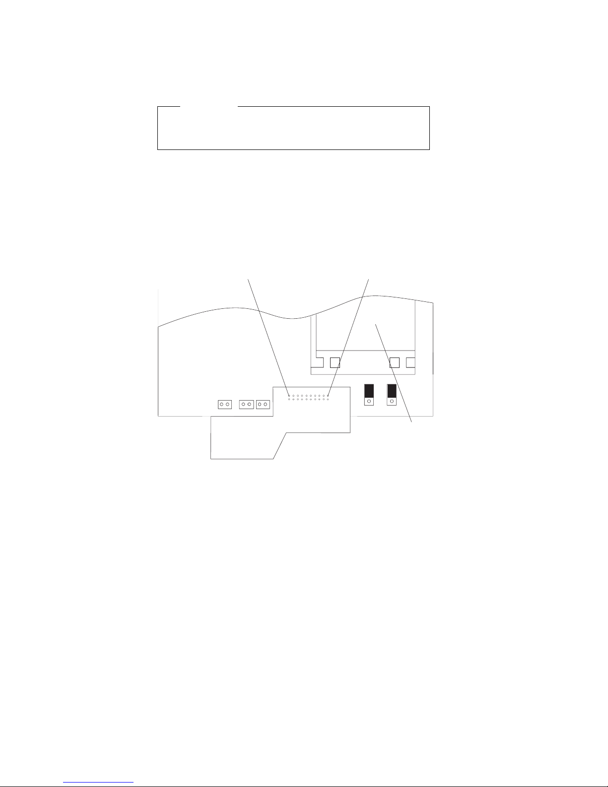
How to Install 64XX Processors
Install all model 64XX processors with the bevelled corner
located at the front-left corner of the processor socket.
Important
If the processor is not installed correctly, the system
board and the processor will be damaged.
How to Diagnose 64XX system boards with
486DX4 Processors
The 486DX4 processor FRU consists of the processor and
a voltage regulator. If you are instructed to replace the
system board, first check for 3.5 V dc between pin 1 and
pin 19 on the regulator board.
19
Processor
1
1. If the voltage is correct (approximately 3.5 V dc)
replace the system board.
2. If the voltage is incorrect, replace the processor FRU.
The general checkout procedure starts on the next page.
2 ValuePoint HMM - April 1994
Page 5

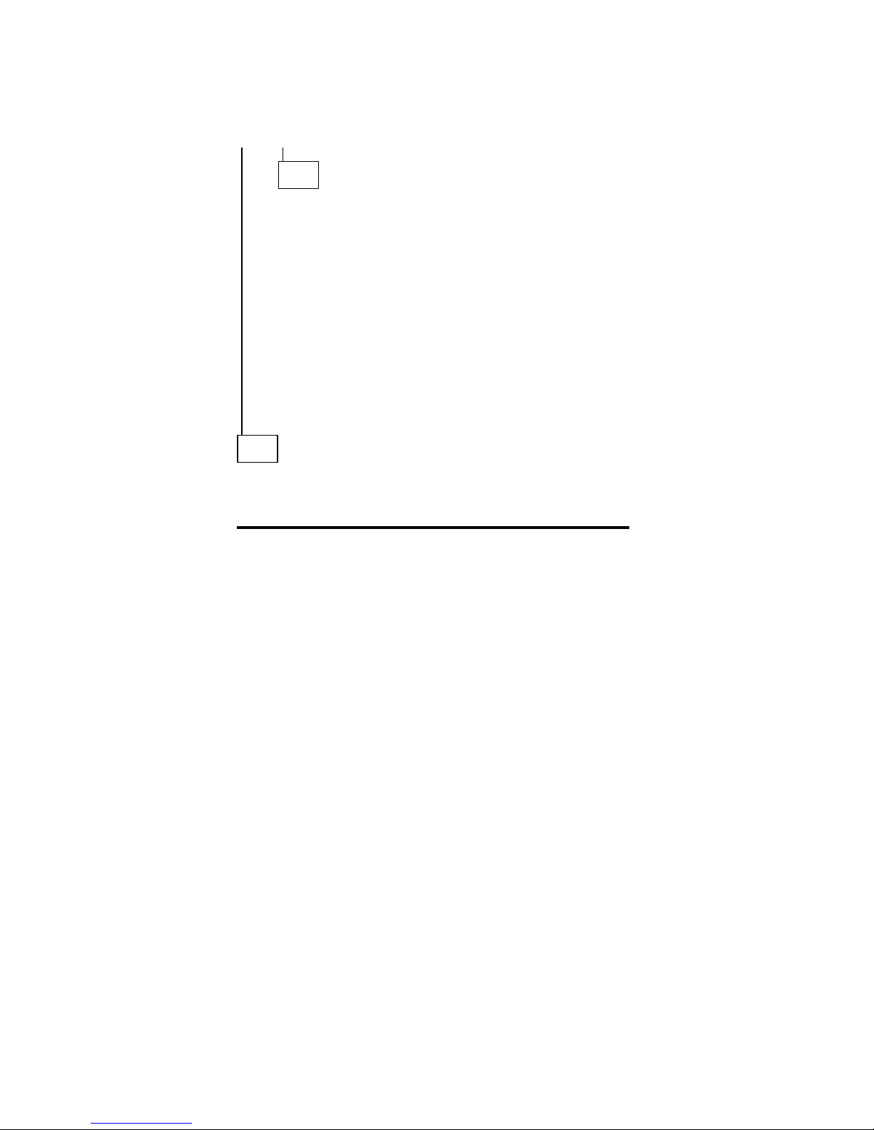
General Checkout
001
– Power-off the computer and all external devices.
– Check all cables and power cords.
– Make sure there are no diskettes in the drives.
– Power-on all external devices.
– Power-on the computer.
Note: You can press Esc to speed through the
memory count when the system is first powered
on.
– Watch the screen for a POST error message.
DID YOU RECEIVE A POST ERROR MESSAGE?
Yes No
002
Go to Step 008.
003
IS THE ERROR 162?
Yes No
004
If you remove or install memory, a 164 error is
displayed. Follow the instructions on the screen.
Otherwise, go to “Symptom-to-FRU Index” on
page 12 in this supplement. If that does not solve
the problem, go to Step 008.
005
HAS THE CONFIGURATION BEEN INTENTIONALLY
CHANGED?
Yes No
006
Go to Step 008.
007
Press Enter to run the Configuration Utility program and
verify that the error is no longer present. If you return to
this point again, go to Step 008.
008
– Insert your diagnostics diskette.
– Press Ctrl+Alt+Del.
(Step 008 continues)
Model 64XX Service Information
3
Page 6

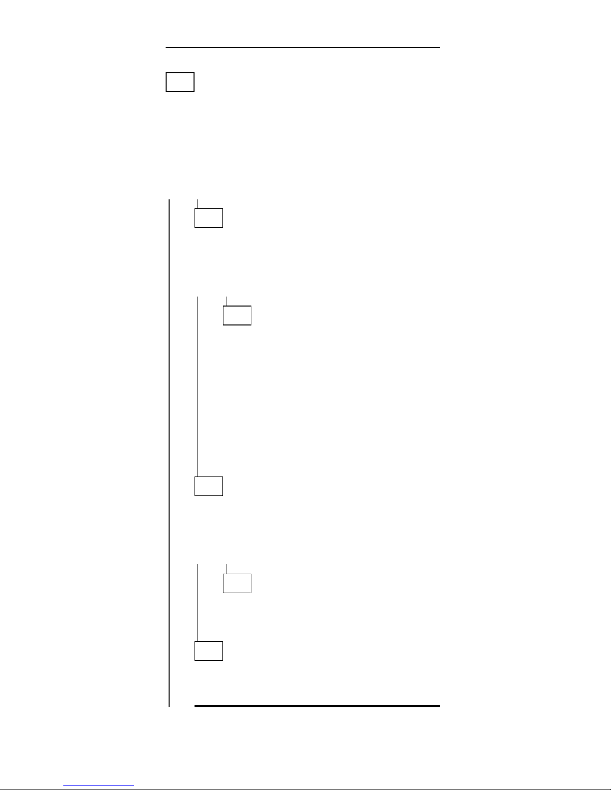
(CONTINUED)
008 (continued)
DID THE COMPUTER BOOT FROM THE DIAGNOSTIC
DISKETTE AND DID THE IBM HARDWARE
DIAGNOSTIC LOGO SCREEN APPEAR?
Yes No
009
Go to “Symptom-to-FRU Index” on page 12 in this
supplement.
010
– Select Test the System.
– Press Enter.
– If you need to create a formatted test diskette for this
test, press Y, press Enter, then follow the instructions
on the screen.
Otherwise, press N, press Enter, then go to Step 011.
011
IS THE INSTALLED DEVICES LIST CORRECT?
Yes No
012
Press N, then press Enter. Go to “Installed Devices
List” on page 8 in this supplement. If that does not
resolve the problem, continue with Step 016 on
page 5.
013
– Press Y, then press Enter
DID THE “SYSTEM CHECKOUT” MENU APPEAR?
Yes No
014
Go to “Symptom-to-FRU Index” on page 12 in this
supplement.
015
– Run the diagnostics tests.
If the test stops and you cannot continue, replace
the last device tested.
If the computer has incorrect keyboard responses,
go to “Keyboard” on page 9 in the PS/ValuePoint
Hardware Maintenance Manual
.
If the printer has incorrect responses, go to
“Printer” on page 9 in the PS/ValuePoint
Hardware
Maintenance Manual
.
If the display has problems such as jittering, rolling,
shifting, or being out-of-focus, go to “Display” on
page 7 in this supplement.
4 ValuePoint HMM - April 1994
Page 7
DID THE TESTS IDENTIFY A FAILURE?
Note: If the test stops and you cannot continue, replace
the last device tested.
Yes No
016
Check the “Symptom-to-FRU Index” on page 12 in
this supplement for any POST error or other error
symptom you might have. If your error symptom is
not listed, go to “Undetermined Problem” on page 6
in this supplement. If you cannot find a problem, it
might be intermittent:
Check for damaged cables and connectors.
Reseat all adapters, drives, and modules.
Check the system unit fan for proper operation.
Start an error log and run the tests multiple
times (see “Error Log” on page 42 in this
supplement).
017
Follow the instructions on the display. If that does not
correct the problem, go to “Symptom-to-FRU Index” on
page 12 in this supplement.
Model 64XX Service Information 5
Page 8

Undetermined Problem
Check the power supply voltages (see “Power Supply” on
page 6 in the PS/ValuePoint
Hardware Maintenance
Manual
). If the voltages are correct, return here and
continue with the following steps:
1. Power-off the computer.
2. Remove or disconnect the following, one at a time:
a. Non-IBM devices
b. External devices (modem, printer, or mouse)
c. Math coprocessor
d. Any adapters
e. Riser card
f. Memory modules (see “Computer Memory” on
page 11 in this supplement).
g. Extended video memory
h. External Cache
i. External Cache tag RAM
j. Hard disk drive
k. Diskette drive
3. Power-on the computer to re-test the system.
4. Repeat steps 1 through 3 until you find the failing
device or adapter.
If all devices and adapters have been removed, and the
problem continues, replace the system board (see “Before
Replacing 64XX System Boards” on page 1 in this
supplement).
6 ValuePoint HMM - April 1994
Page 9

Display
If the screen is rolling, replace the display assembly. If
that does not correct the problem, replace the system
board.
If the screen is not rolling, do the following to run the
display self-test:
Note: The following test does not work on all ValuePoint
displays. If the test does not work, but you suspect
the display, replace it. If that does not solve the
problem, reinstall the original display, then replace
the system board.
1. Power-off the computer and display.
2. Disconnect the display signal cable.
3. Power-on the display.
4. Turn the brightness and contrast controls to their
maximum setting.
5. Check for the following conditions:
You should be able to vary the screen intensity
by adjusting the contrast and brightness controls.
The screen should be white or light gray, with a
black margin (test margin) on the screen.
Note: The location of the test margin varies
with the type of display. The test margin
might be on the top, bottom, or one or
both sides.
If you do not see any test margin on the screen,
replace the display. If there is a test margin on the
screen, replace the system board.
Note: During the first two or three seconds after the
display is powered on, the following might
occur while the display synchronizes with the
computer.
Unusual patterns or characters
Static, crackling, or clicking sounds
A “power-on hum” on larger displays
A noticeable odor might occur on new
displays or displays recently removed from
storage.
These sounds, display patterns, and odors are
normal; do not replace any parts.
If you are unable to correct the problem, go to
“Undetermined Problem” on page 6 in this
supplement.
Model 64XX Service Information
7
Page 10

Installed Devices List
Follow the instructions on the screen for the installed
devices list.
Warning: A customized setup configuration (other than
default settings) might exist on the computer you are
servicing. Running the Configuration Utility program might
alter those settings. Note the current configuration settings
and verify that the settings are in place when service is
complete.
If the number of diskette drives shown in the installed
devices list is not correct
, do the following:
1. Restart the computer.
2. Run the Configuration Utility program to correct the
drive information (see “Diagnostics and Test
Information” on page 32 in this supplement).
3. Run the diagnostic tests.
If you cannot correct the drive information, replace FRUs,
in the following order, until the problem goes away:
Diskette drive
Diskette-drive cable
System board
If the number of hard disk drives shown in the installed
devices list is not correct
, do the following:
1. Check the hard disk drive jumper settings (see “Hard
Disk Drive Jumper Settings” on page 44 in this
supplement).
2. Check the voltages to the hard disk drives (see
“Power Supply” on page 6 in the PS/ValuePoint
Hardware Maintenance Manual
).
3. Restart the computer and check the configuration.
If the first drive is missing, replace the primary
drive.
If any other drive is missing, replace that drive.
If all drives are missing, replace the primary
drive.
If the problem remains, replace the drive cable. If
that does not fix the problem, replace the system
board.
If any other adapter or device is missing from the installed
devices list, run the Configuration Utility program (see
“Diagnostics and Test Information” on page 32 in this
supplement). Check to see if any adapter or device is set
to a conflicting address with any other adapter or device.
Also be sure that any adapter or device missing from the
list is not set to “disabled.”
Note: If the device is still missing from the list, run the
diagnostics provided with that device. Devices
missing from a model 64XX installed devices list
cannot be added to the list.
8 ValuePoint HMM - April 1994
Page 11
Memory
001
– Power-off the computer.
– Insert the diagnostics diskette into drive A.
– Power-on the computer.
– Make a note of any POST errors you receive. Disregard
164 errors (memory size).
DID YOU RECEIVE A 2XX POST ERROR?
Yes No
002
DID THE COMPUTER BOOT FROM THE
DIAGNOSTIC DISKETTE AND DID THE IBM
HARDWARE DIAGNOSTIC LOGO SCREEN
APPEAR?
Yes No
003
You might have to press Esc to continue.
– Select “Test the System.” Run the memory
tests. (Use the RUN TESTS ONE TIME
option.)
– Continue with the question in Step 004.
– or –
If the computer did not boot from the
diagnostic diskette with the IBM hardware
diagnostic logo screen displayed, go to
“Symptom-to-FRU Index” on page 12 in this
supplement.
004
– Select “Test the System.” Run the memory tests.
(Use the RUN TESTS ONE TIME option.)
DID THE MEMORY TESTS FINISH WITHOUT AN
ERROR?
Yes No
005
Follow the instructions on the display. If there
are no instructions on the display, go to Step
007 on page 10 in this supplement.
006
Your computer memory is now functioning correctly.
If you suspect an intermittent problem, start an error
log (see “Error Log” on page 42 in this supplement).
Model 64XX Service Information 9
Page 12

(CONTINUED)
007
Press Esc to continue.
– Select “Test the System.” Run the memory tests. (Use
the RUN TESTS ONE TIME option.) If you cannot run
the memory test or the test does not find a problem,
replace the memory modules, one at a time, until the
problem goes away. Refer to “Computer Memory” on
page 11 in this supplement. When the problem goes
away, replace the last memory module removed. If that
does not fix the problem, replace the system board.
10 ValuePoint HMM - April 1994
Page 13

Computer Memory
Four 72-pin connectors are available to add memory
modules. Memory modules supported are 4MB, 8MB,
16MB, and 32MB with a maximum of 128MB. Memory
module speed supported is 70 ns.
Notes:
1. QAPlus/WIN for ValuePoint and most applications do
not recognize more than 64MB of memory.
2. A memory module must be installed in memory
module connector 1 at all times. Additional memory
modules must be installed in connector 2, then in
connector 3, then in connector 4.
3. Smaller size memory modules must be installed into
lower numbered memory module connectors. For
example, to install two 4MB memory modules with
two 8MB memory modules, the 4MB memory
modules must be installed in memory module
connectors 1 and 2 and the 8MB memory modules in
memory module connectors 3 and 4.
ValuePoint Memory Module Chart
FRU
Number
Size
and
Speed
6
3
8
1
S
6
3
8
2
S
6
3
8
4
6
3
8
4
D
P
6
0
6
3
8
7
6
4
X
X
60G2950 16-70ns X X X X X X
64F3606 8-70ns X X X X
64F3607 8-80ns X X X X
73G3233 4-70ns X X X
73G3234 8-70ns X X
73G3235 32-70ns X
92F0102 2-70ns X X X X
92F0103 2-80ns X X X X
92F0104 2-85ns X X X X
92F0105 4-70ns X X X X
92F3337 4-80ns X X X X
93F0058 1-80ns X
96F9289 4-80ns X
71G0801 32-70ns X
Model 64XX Service Information 11
Page 14

Symptom-to-FRU Index
The Symptom-to-FRU Index lists error symptoms and
possible causes. The most likely cause is listed first.
Always begin with “General Checkout” on page 3 in this
supplement. This index can also be used to help you
decide which FRUs to have available when servicing a
computer. If you are unable to correct the problem using
this index, go to “Undetermined Problem” on page 5 in this
supplement.
Notes:
1. If you have both an error message and an incorrect
audio response, diagnose the error message first.
2. If you cannot run the diagnostic tests, but did receive
a POST error message, diagnose the POST error
message.
3. If you did not receive any error message, look for a
description of your error symptoms in the first part of
this index.
4. Check all power supply voltages before you replace
the system board. (See “Power Supply” on page 6 in
the PS/ValuePoint
Hardware Maintenance Manual
.)
5. Check the hard disk drive jumper settings before you
replace a hard disk drive. (See “Hard Disk Drive
Jumper Settings” on page 44 in this supplement.)
Important
1. For all 64XX models, some errors are indicated
with a series of beep codes (see “Model 64XX
Beep Code Index” on page 13 in this
supplement).
2. For all 64XX models, the processor is a separate
FRU from the system board; the processor is not
included with the system board FRU (see “Before
Replacing 64XX System Boards” on page 1 in
this supplement).
3. The 486DX4 processor FRU consists of the
processor and a voltage regulator. See “How to
Diagnose 64XX system boards with 486DX4
Processors” on page 2 in this supplement before
replacing the system board on models with this
processor installed.
12 ValuePoint HMM - April 1994
Page 15
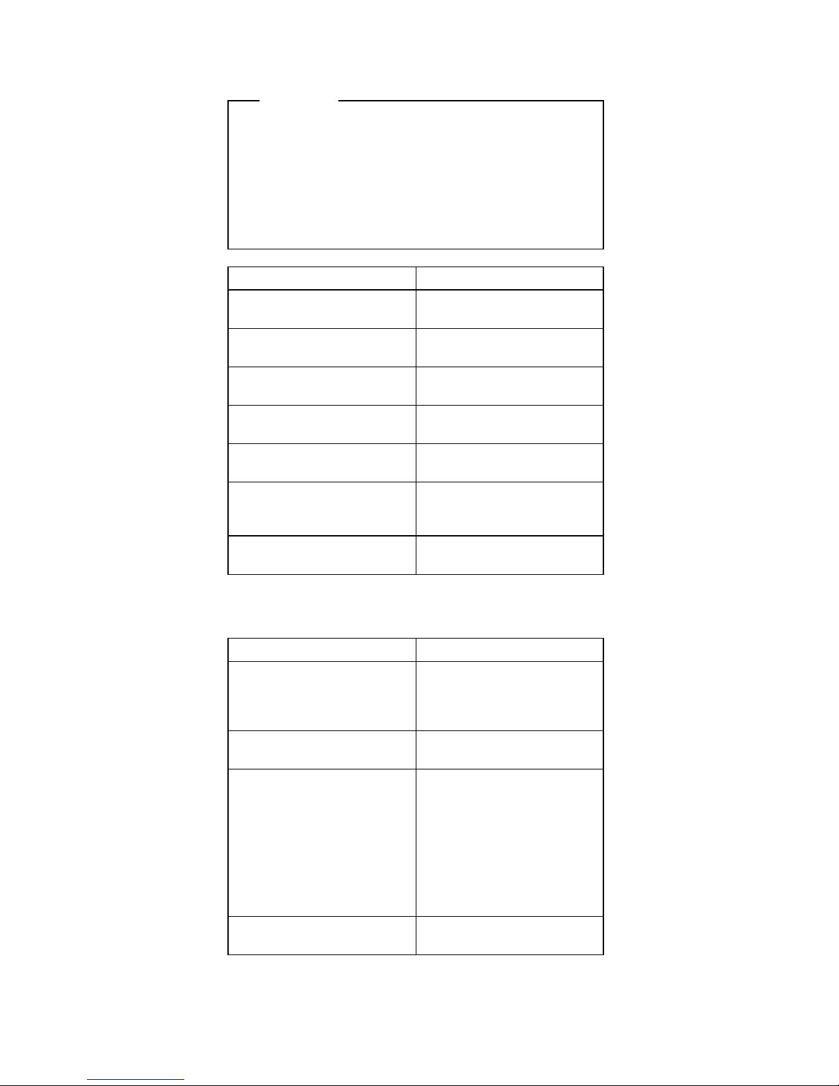
Model 64XX Beep Code Index
Important
In the following Beep Code Index, the numbers
indicate the sequence and number of beeps. For
example, a “2-3-2” error symptom (a burst of two
beeps, three beeps, then a burst of two beeps)
indicates a memory module problem. (Continue with
the Symptom-to-FRU index below for other
beep/no-beep symptoms.)
Beep Code FRU/Action
1-3-1, 1-3-2 Memory Module
System Board
1-4-4 Keyboard
System Board
2-1-1, 2-1-2 Run Setup
System Board
2-2-2 Video Card
System Board
2-3-2 Memory Module
System Board
2-4-3, 2-4-4 Run Setup
Memory Module
System Board
All other beep code
sequences
System Board
In the following index, an “X” in an error message can
represent any number.
Symptom/Error FRU/Action
No power, or fan not
running
See “Power Supply” on
page 6 in the
PS/ValuePoint
Hardware
Maintenance Manual
.
No beep during POST but
computer works correctly
System Board
No beep during POST See “Undetermined
Problem” on page 6 in
this supplement.
System Board
Memory Module
Any Adapter or Device
Riser Card
Power Cord
Power Supply
One long and two short
beeps during POST
System Board
Model 64XX Service Information 13
Page 16
Symptom/Error FRU/Action
Three short beeps during
POST
See “Computer Memory”
on page 11 in this
supplement.
System Board
Continuous beep System Board
Repeating short beeps Keyboard (stuck key?)
Keyboard Cable
System Board
Changing colors Display
Intensity or color varies from
left to right of characters
and color bars
Display
System Board
Flashing cursor with an
otherwise blank display
System Board
Primary Hard Disk Drive
Hard Disk Drive Cable
Other display symptoms not
listed above (including blank
or illegible display)
See “Display” on page 7
in this supplement.
System Board
Display
Power-on indicator or hard
disk drive in-use light
not on, but computer
works correctly
Power Supply
System Board
LED Cables
Diskette drive in-use light
remains on or does not light
when drive is active
Diskette Drive
System Board
Diskette Drive Cable
The “Insert a Diskette” icon
appears with a known-good
diagnostics diskette in the
first 3.5-inch diskette drive
Diskette Drive
System Board
Diskette Drive Cable
Network Adapter
Program loads from the
hard disk with a
known-good diagnostics
diskette in the first 3.5-inch
diskette drive
Check Configuration
Utility
Diskette Drive
Diskette Drive Cable
System Board
Power Supply
A nonsystem disk or disk
error-type message
with a known-good
diagnostic diskette
Diskette Drive
System Board
Diskette Drive Cable
Cannot read a 5.25-inch
diskette
The button on the PS/VP
5.25-inch diskette drive
bezel must be pressed
after inserting a diskette.
Incorrect memory size
during POST
See “Memory” on page 9
in this supplement.
Memory Module
System Board
Printer problems See “Printer” on page 9 in
the PS/ValuePoint
Hardware Maintenance
Manual
.
14 ValuePoint HMM - April 1994
Page 17

Symptom/Error FRU/Action
Serial or parallel port device
failure (system board port)
External Device Self-Test
OK?
External Device
Cable
System Board
Serial or parallel port device
failure (adapter port)
External Device Self-Test
OK?
External Device
Cable
Alternate Adapter
System Board
Riser Card
Some or all keys on the
keyboard do not work
Keyboard
Keyboard Cable
System Board
Clock Battery inaccurate Clock Battery
System Board
110 Follow screen instructions
Memory Module
System Board
161 Run Configuration Utility
Clock Battery
System Board
162
(and unable to run
diagnostics)
Diskette Drive
System Board
Diskette Drive Cable
162 Run Configuration Utility
Clock Battery
System Board
163 Time and Date Set?
Clock Battery
System Board
164 Run Configuration Utility
See “Memory” on page 9 in
this supplement.
System Board
199 See “Installed Devices
List” on page 8 in this
supplement.
1XX
(not listed above)
System Board
225 Unsupported Memory
2XX See “Memory” on page 9
in this supplement.
Memory Module
System Board
303
(with an 8603 error)
Mouse
Keyboard
Keyboard Cable
System Board
Model 64XX Service Information 15
Page 18

Symptom/Error FRU/Action
303
(with no 8603 error)
Keyboard
Keyboard Cable
System Board
305 System Board
Keyboard
Keyboard Cable
Mouse
3XX
(not listed above)
Keyboard
Keyboard Cable
System Board
604
(and unable to run
diagnostics)
Diskette Drive A
Diskette Drive Cable
System Board
604
(and able to run diagnostics)
Diskette Drive B
Diskette Drive Cable
System Board
662 Wrong diskette drive type
663 Wrong media type
6XX
(not listed above)
Diskette Drive
System Board
External Drive Adapter
Diskette Drive Cable
Power Supply
7XX Math Coprocessor
System Board
9XX System Board
1047 16-bit AT Fast SCSI
Adapter
10XX
(not listed above)
Alternate Parallel Adapter
Riser Card
11XX System Board
12XX Alternate Serial Adapter
Riser Card
13XX
(A properly functioning
joystick or paddle must be
attached)
Game Control Adapter
Riser Card
14XX See “Printer” on page 9 in
the PS/ValuePoint
Hardware Maintenance
Manual
.
15XX SDLC Communications
Adapter
Riser Card
16 ValuePoint HMM - April 1994
Page 19

Symptom/Error FRU/Action
17X0 (1st Disk Drive)
17X1 (2nd Disk Drive)
17X2 (3rd Disk Drive)
17X3 (4th Disk Drive)
See “Power Supply” on
page 6 in the
PS/ValuePoint
Hardware
Maintenance Manual
.
Hard Disk Drive
System Board
Hard Disk Cable
Power Supply
209X Diskette Drive
Diskette Cable
16-bit AT Fast SCSI
Adapter
20XX
(not listed above)
BSC Adapter
Riser Card
21XX SCSI Device
16-bit AT Fast SCSI
Adapter
Alternate BSC Adapter
Riser Card
2401, 2402 System Board
Display
2409 Display
2410 System Board
30XX PC Network Adapter
LF Translator
Cable Problem?
Riser Card
31XX Alternate PC Network
Adapter
LF Translator
Cable Problem?
Riser Card
86XX Mouse
System Board
12902 Run Diagnostics
System Board
12904 Run Diagnostics
L2 Cache Adapter
I9990301
(Hard disk reset failure)
Possible hard
disk drive problem
I9990305
(No startable device found)
Restart computer from
diskette or check for valid
startup sequence
System Board
I999XXXX (not listed
above)
(There is an optional SCSI
adapter installed)
SCSI Hard Disk Drive
SCSI Adapter
SCSI Cable
Model 64XX Service Information 17
Page 20

Type 6472 Parts
1
2
3
4
5
6
7
8
9
10
11
12
18 ValuePoint HMM - April 1994
Page 21

Type 6482, 6484 Parts
1
2
3
4
5
6
7
8
9
10
11
12
Model 64XX Service Information 19
Page 22

Type 6492, 6494 Parts
1
2
3
4
5
7
8
10
11
12
13
14
9
15
16
17
20 ValuePoint HMM - April 1994
Page 23

64XX Parts Listing
Note: Not all parts in this listing apply to all countries.
(R) indicates restricted parts.
Index System Unit
1 Top Cover Assembly (6472) 92F0414
1 Top Cover Assembly (6482, 6484) 92F0410
1 Top Cover Assembly (6492, 6494) 61G2169
Logo (R) 06H3159
Power Button (6472, 6482, 6484) 61G3204
Power Button (6492, 6494) 61G3205
Front Bezel w/ labels (6472) 06H3196
Front Bezel w/ labels (6482, 6484) 06H3197
Front Bezel w/ labels (6492, 6494) 06H3198
Foot (4) 93F2386
2 Riser Card (6472) 06H3095
2 Riser Card (6482) 06H3096
2 Riser Card PCI (6484) 82G3555
2 Riser Card (6492) 06H3097
2 Riser Card PCI (6494) 82G3563
3 System Board (no memory or processor) 82G2397
Processors
486SX 25Mhz 71G0790
486SX 33Mhz 71G0791
486SX2 25/50Mhz 71G0792
486DX 33Mhz 71G0793
486DX2 25/50Mhz 71G0794
486DX2 33/66Mhz 71G0795
486DX4 50/100Mhz 71G0796
Lithium Battery - CR2032 33F8354
L2 Cache 128KB 92G7430
L2 Cache 256KB 92G7431
Video DRAM, 1MB 16ns 92G7432
Jumper, 2 position - 4 pack 93F0067
EMC Clips - 7 pack 92F0420
EMC Clips - 3 pack (6492, 6494) 61G3206
4 100 W Power Supply (6472) 92F0415
4 200 W Power Supply (6482, 6484) 92F0411
4 250 W Power Supply (6492, 6494) 82G5874
5 Diskette Drive Cable 92F0423
5 Hard Disk Drive Cable 92F0424
7 Base Frame Assembly (6472) (R) 92F0416
7 Base Frame Assembly (6482, 6484) (R) 92F0412
7 Base Frame Assembly (6492, 6494) (R) 92F0422
Adapter Card Guides (2) (6472, 6482, 6484) 52G8746
Speaker 92F0421
8 LED and Cable, Power 93F2389
9 LED and Cable, Hard Disk Drive 93F2388
10 72-Pin Memory Module, 4MB (70 ns) 73G3233
72-Pin Memory Module, 8MB (70 ns) 73G3234
72-Pin Memory Module, 16MB (70 ns) 60G2950
72-Pin Memory Module, 32MB (70 ns) 73G3135
Cover Lock w/ pawl (6472, 6482, 6484) 52G8744
13 Cover Lock w/ pawl (6492, 6494) 61G2177
14 Riser Card Support Clip (6492, 6494) 61G2365
15 Base Stand (6492, 6494) 61G2174
16 Adapter Card Guide (2) (6492, 6494) 61G2173
Miscellaneous Parts Kit 53G0387
Hardware Kit (Type 2 system board) 82G5894
Model 64XX Service Information 21
Page 24

Index DASD
6 5.25-in. 1.2MB Diskette Drive (optional) 82G1824
11 3.5-in. 1.44MB Diskette Drive 93F2361
11 3.5-in. 2.88MB Diskette Drive 82G1887
3.5-in. Blank Drive Bezel (6472, 6482, 6484) 92F0419
3.5-in. Blank Drive Bezel (6492, 6494) 06H3201
3.5-in. Tray / Riser Support (6472) 61G2175
3.5-in. Tray / Riser Support (6482, 6484) 71G6112
3.5-in. Adapter Guide Holder (6492, 6494) 52G8746
Hard Disk Drive Mounting Screws (4) 93F0041
12 5.25-in. Blank Bezel (6472, 6482, 6484) 06H3199
12 5.25-in. Blank Bezel (6492, 6494) 06H3200
12 Blank Drive Bezel (6492, 6494) 82G1875
5.25-in. Diskette Drive Tray (6472) 71G6111
5.25-in. Diskette Drive Tray (6482, 6484) 71G6113
5.25-in. Diskette Drive Tray (6492, 6494) 61G3207
5.25-in. to 3.5-in. Tray Conversion Kit 70G8165
17 170MB Hard Disk Drive 71G4958
17 270MB Hard Disk Drive 82G5926
17 340MB Hard Disk Drive 92F0404
17 364MB Hard Disk Drive 82G5927
17 527MB Hard Disk Drive 82G3300
17 540MB Hard Disk Drive 82G5928
17 728MB Hard Disk Drive 82G5929
Multimedia
CD ROM Drive 61G4109
Jazz 16 06H3086
Audio/Data Cable 06H3085
22 ValuePoint HMM - April 1994
Page 25

Communication Adapters
Ethernet Adapter (twisted pair) 92F0386
Ethernet Adapter (coaxial) 92F0387
Token Ring Adapter 03F0212
Keyboard Cable and Mouse
Keyboards
Keyboard Cable Assembly 0.9 m (3 ft.) 61X8898
Keyboard Parts Kit 33F8174
Mouse 33G5420
Mouse (6381, 6384 P60/D, 64XX) 96F9258
— Mouse Ball and Pop-Off Retainer 33F8461
— Mouse Ball and Twist-Off Retainer 33F8462
— Mouse Ball and Clip (6381, 6384 P60/D) 96F9279
Arabic 1391490
Belgian 1391414
Belgian/French 1391526
Brazil (6381, 6384 P60/D, 64XX) 61G3976
Bulgarian 1399583
Canadian French 1392022
Canadian French (attached cable) 92F0334
Czechoslovakian 1399570
Cyrillic 1393866
Danish 1391407
Dutch 1391511
Finnish/Swedish 1391411
French 1391402
German 1391403
Greek 1399046
Hebrew 1391408
Hungarian 1399581
Italian 1393395
Latin-American Spanish 1392025
Latin-American Spanish (attached cable) 92F0333
Latin-American Spanish (6381, 6384 P60/D) 61G3976
Norwegian 1391409
Polish 1399580
Portuguese 1391410
Portuguese (6381, 6384 P60/D, 64XX) 61G3976
Romanian 1399582
Russian/Cyrillic 1399579
Serbian/Cyrillic 1399578
Slovakian 1399571
Spanish 1391405
Swedish/Finnish 1391411
Swiss 1391412
Swiss/French 1395881
Swiss/German 1395882
Turkish 1393286
U.K. English 1391406
U.S. English 1392090
U.S. English (attached cable) 92F0332
U.S. English (E/ME/A only) 1396790
Yugoslavian 1393669
Model 64XX Service Information 23
Page 26

Displays
6312 Color Display
6314 Color Display
6317 Color Display
6319 Color Display
6321 Color Display
6324 Color Display
6325 Color Display
6327 Color Display
90/137 V ac (U.S. and Canada) 39G3321
180/264 V ac (Northern Hemisphere) 39G3322
180/264 V ac (Equatorial) 39G3323
180/264 V ac (Southern Hemisphere) 39G3494
Tilt/Swivel Stand 39G3496
98/264 V ac (U.S. and Canada) 39G3352
98/264 V ac (Northern Hemisphere) 39G3353
98/264 V ac (Equatorial) 39G3454
98/264 V ac (Southern Hemisphere) 39G3498
Tilt/Swivel Stand 39G3502
Signal Cable 39G3331
98/264 V ac (U.S. and Canada) 39G3359
98/264 V ac (Northern Hemisphere) 39G3360
98/264 V ac (Southern Hemisphere) 39G3361
98/264 V ac (U.S. and Canada) 39G3385
98/264 V ac (Northern Hemisphere) 39G3386
98/264 V ac (Equatorial) 39G3387
98/264 V ac (Southern Hemisphere) 39G3500
Tilt/Swivel Stand 39G3503
Signal Cable 39G3331
98/264 V ac (U.S. and Canada) 72G8785
ITC Assembly for 72G8785 72G8784
Card Assembly for 72G8785 72G8783
Card Tray for 72G8785 68G3011
98/264 V ac (U.S. and Canada) 68G1356
ITC Assembly for 68G1356 68G1419
Card Tray Assembly for 68G1356 39G6257
98/264 V ac (U.S. and Canada) 68G1443
ITC Assembly for 68G1443 39G6292
Card Tray Assembly for 68G1443 68G1321
98/264 V ac (U.S. and Canada) 39G3362
ITC Assembly for 39G3362 72G8486
Card Tray Assembly for 39G3362 72G8489
24 ValuePoint HMM - April 1994
Page 27

Power Cords
Arabic Countries 14F0033
Australia 93F2365
Belgium 13F9979
Bulgaria 13F9979
Canada 93F2364
Czechoslovakia 13F9979
Denmark 13F9997
Finland 13F9979
France 13F9979
Germany 13F9979
Hungary 13F9979
Israel 14F0087
Italy 14F0069
Latin-America 93F2366
Netherlands 13F9979
New Zealand 93F2365
Norway 13F9979
Poland 13F9979
Portugal 13F9979
Serbia 13F9979
Slovakia 13F9979
South Africa 14F0015
Spain 13F9979
Switzerland 13F9979
Switzerland (French, German) 14F0051
U.S. 93F2364
UK, Ireland 14F0033
Yugoslavia 13F9979
Display Power Cord 38F3908
Special Tools
The following special tools are required to service these
computers:
A meter similar to the Triplett
**
Model 310
(IBM P/N 9900167)
Wrap Plug, IBM P/N 72X8546
**
Trademark of the Triplett Corporation
Model 64XX Service Information 25
Page 28

Product Description
Type 6472 computers contain three drive bays and three
I/O adapter card slots. Type 6482 computers contain five
drive bays and five I/O adapter card slots. Type 6484
computers contain five drive bays and four I/O adapter
card slots. Type 6492 computers contain six drive bays
and eight I/O adapter card slots. Type 6494 computers
contain six drive bays and seven I/O adapter card slots.
Security
– Administrator password
– Cover lock
– Hard Disk password
– Power-on password
– U-bolt and cable
System Board (All Type 64XX)
Model 6472, 6482, 6484, 6492, and 6494
– 64XX models using the 486SX processor have
no math coprocessor. All other 64XX models
have a built-in math coprocessor.
– Supports at least 8KB internal cache and up to
256KB external cache.
– RAM is installed directly onto the system board
using industry standard, 72-pin, 70 ns parity
memory modules. There are four sockets to
allow a maximum of 128 MB (4MB, 8MB, 16MB,
and 32MB memory modules are supported).
Refer to “Computer Memory” on page 11.
– 1 MB of Video memory (DRAM) is soldered on
the system board. Two video DRAM sockets
allow a maximum of 2MB of video DRAM.
– Ports include: two serial, one parallel, one
keyboard, one mouse, and one video.
– Connectors for AT
*
riser card (120-pin), VESA** /
PCI (116-pin), input power (12-pin), AT diskette
drives (34-pin), Two AT hard disk drive
connectors (40-pin each), power LED (2-pin),
hard disk LED (2-pin), speaker (2-pin), and video
feature (26-pin).
– Lithium battery
Power Supplies (with CPU power switch)
– Type 64XX computers have either a 100W,
200W, or a 250W universal voltage power supply
with a fan and a connector for a detachable
grounded 3-wire power cord. The power cable
has five DASD connectors (one 3.5-inch diskette
drive minipower connector, and four standard
4-pin power connectors).
*
Trademark of the IBM Corporation.
**
Trademark of the Video Electronics Standards Association.
26 ValuePoint HMM - April 1994
Page 29

The 250W power supply has an additional PCI
riser connector.
When the computer is powered off for 15
seconds or more and then powered on, the
power supply generates a “power good” signal
that resets the computer logic.
Cables
– Two signal cables for hard disk drives and one
signal cable for diskette drives
Diskette Drives
– 3.5-inch 1.44MB Slimline diskette drive
– 3.5-inch 2.88MB Slimline diskette drive (optional)
– 5.25-inch 1.2MB diskette drive (optional)
IDE Hard Disk Drives
Hard disks are 3.5-inch Slimline AT drives
– 170MB with 96/128KB read/write buffer
– 270MB with 96KB read/write buffer
– 340MB with 96/128KB read/write buffer
– 364MB with 96KB read/write buffer
– 527MB with 256KB read/write buffer
– 540MB with 96KB read/write buffer
– 728MB with 96KB read/write buffer
Keyboard
– Enhanced 101- or 102-key keyboard
– 84-key keyboard (optional)
– 122 Host-Connected keyboard (optional)
– TrackPointII (optional)
with 1.8 m (6 ft.) cable
Mouse 2-button PS/2 with 1.8 m (6 ft.) cable
Power-On Password
A power-on password denies access to the computer by
an unauthorized user when the computer is powered on.
When a power-on password is active, the password
prompt appears on the screen each time the computer is
powered on. The computer starts after the proper
password is entered.
Removing a Power-on Password: To service a
64XX computer with an active and unknown power-on
password, power-off the computer and do the following:
1. Remove the battery for 15 minutes.
2. Reinstall the battery.
3. Power-on the computer. The password is erased
from memory.
Note: Remind the user to enter a new password when
service is complete.
Model 64XX Service Information
27
Page 30

Specifications (6472)
(Minimum configuration)
System Unit Size:
Width: 360 mm (14.2 in.)
Depth: 420 mm (16.5 in.)
Height: 122 mm (4.8 in.)
System Unit Weight:
8.1 kg (17.8 lb)
Environment:
Temperature (System Unit and Display)
– Power on: 10 to 32 degrees C (50 to 90
degrees F)
– Power off: 10 to 43 degrees C (50 to 110
degrees F)
Humidity (System Unit and Display)
– Power on: 8% to 80%
– Power off: 8% to 80%
Maximum altitude: 2134 m (7000 ft.)
Heat output:
120 BTU/hr
Electrical:
Input voltage (sinewave input is required)
– Low Range
- Minimum: 90 V ac
- Maximum: 137 V ac
– High Range
- Minimum: 180 V ac
- Maximum: 265 V ac
28 ValuePoint HMM - April 1994
Page 31

Specifications (6482, 6484)
(Minimum configuration)
System Unit Size:
Width: 404 mm (15.9 in.)
Depth: 420 mm (16.5 in.)
Height: 147 mm (5.8 in.)
System Unit Weight:
9.7 kg (21.4 lb)
Environment:
Temperature (System Unit and Display)
– Power on: 10 to 32 degrees C (50 to 90
degrees F)
– Power off: 10 to 43 degrees C (50 to 110
degrees F)
Humidity (System Unit and Display)
– Power on: 8% to 80%
– Power off: 8% to 80%
Maximum altitude: 2134 m (7000 ft.)
Heat output:
120 BTU/hr
Electrical:
Input voltage (sinewave input is required)
– Low Range
- Minimum: 90 V ac
- Maximum: 137 V ac
– High Range
- Minimum: 180 V ac
- Maximum: 265 V ac
Model 64XX Service Information
29
Page 32

Specifications (6492, 6494)
(Minimum configuration)
System Unit Size:
Width: 187 mm (7.4 in.)
Depth: 429 mm (16.9 in.)
Height: 413 mm (16.3 in.)
System Unit Weight:
11.4 kg (25 lb)
Environment:
Temperature, System Unit and Display
– Power on: 10 to 32 degrees C (50 to 90
degrees F)
– Power off: 10 to 43 degrees C (50 to 110
degrees F)
Humidity, System Unit and Display
– Power on: 8% to 80%
– Power off: 8% to 80%
Maximum altitude: 2134 m (7000 ft.)
Heat output:
934 Btu/hr (maximum configuration)
Electrical:
Input voltage (sinewave input is required)
– Low Range
- Minimum: 90 V ac
- Maximum: 137 V ac
– High Range
- Minimum: 180 V ac
- Maximum: 265 V ac
30 ValuePoint HMM - April 1994
Page 33

Hard Disk Drive Specifications
Size (MB) 170 270 270 340 364
Bytes/Sector
Sectors/Track
Cylinders
Heads
512
34
984
10
512
40
944
14
512
40
944
14
512
55/48
1010/
872
6/16
512
48
929
16
Rotate Speed
(RPM)
3600/
3551
4500 4500 3322/
3600
4500
Transfer Rate
(Mb/sec)
13.3/
9.0
30-44/
24-46
66/48 17-30/
19-26
30-44/
66
Seek Time (ms):
Track-to-Track
Average
Maximum
5.0
18.5
32.5
12
2/4
25/23
12
2/4
25/23
4.5
14.0
29.0
12
2
25
Interleave Factor 1:1 1:1 1:1 1:1 1:1
Recording
Method
1,7
RLL
PRML
RLL
1,7
RLL
1,7
RLL
1,7
RLL
dc Power:
+5 V Tolerance
+12 V Tolerance
±5%
±8%
±5%
±8%
±5%
±8%
±5%
±8%
±5%
±8%
Power (W):
Idle (typical)
Seek (typical)
Startup (typical)
3.2/3.7
3.5/3.9
8.3/10.0
2.6/3.2
5.3/6.7
15.9/13
2.6/3.2
5.3/6.7
15.9/13
2.0
3.0
12.0
2.6
5.3
15.9
Size (MB) 527 540 540 728
Bytes/Sector
Sectors/Track
Cylinders
Heads
512
63
1024
16
512
63
1049
16
512
63
1049
16
512
63
1416
16
Rotate Speed (RPM) 6300 4500 4500 4500
Transfer Rate
(Mb/sec)
22-44 30-44/
24-46
66/48 30-44/
66
Seek Time (ms):
Track-to-Track
Average
Maximum
2.0
9.0
20.0
12
2/4
25/23
12
2/4
25/23
12
2
25
Interleave Factor 1:1 1:1 1:1 1:1
Recording Method 1, 7
RLL
1, 7
RLL
PRML
RLL
1, 7
RLL
dc Power:
+5 V Tolerance
+12 V Tolerance
±5%
±8%
±5%
±8%
±5%
±8%
±5%
±8%
Power (W):
Idle (typical)
Seek, R/W (typical)
Startup (typical)
7.0
11.0
30.5
2.7/3.8
5.4/7.4
15.9/13.3
2.7/3.8
5.4/7.4
15.9/13.3
2.7
5.4
15.9
Model 64XX Service Information 31
Page 34

Diagnostics and Test Information
The following information is helpful when diagnosing
computer problems on types 6472, 6482, 6484, 6492, and
6494.
Power-On Self Test
Each time you power-on the computer, the power-on self
test (POST) is initiated. The POST takes up to 90
seconds to complete, depending on the options installed.
The POST checks the following:
System board
Memory
Video
Hard disk drive(s)
Diskette drive(s)
Keyboard
Mouse
Parallel port
Serial port(s)
To start the POST, power-on the display and the
computer. The following happens:
1. The following icon
appears at the upper-right corner of the display.
Pressing F1 at this time causes the Configuration
Utility menu to appear after the POST has completed.
2. A count of the computer memory appears at the
upper-left corner of the display.
Note: You can press Esc to speed through the
memory count during POST.
3. If an error is detected, an error code appears under
the computer memory count.
Note: Memory errors appear as 2XX in the
upper-left corner of the display
(X can be a number or letter).
4. Successful completion of POST is attained when
there are no errors detected in the computer.
5. The computer attempts to load the operating system.
If an operating system is not found, a graphic
message (icon) is displayed requesting the user to
insert a diskette into drive A and press the F1 key to
resume operation.
6. If a critical error is encountered, the POST is halted.
32 ValuePoint HMM - April 1994
Page 35

Diagnostics Diskette
Important
Use the ValuePoint Advanced Diagnostics
Diskette Type 5 for all models in this supplement.
For systems preloaded with Windows,
QAPlus/WIN for ValuePoint is available in the
Windows environment as an additional diagnostic
aid.
The diagnostics program is intended to test only
ValuePoint Models 6472, 6482, 6484, 6492, and 6494.
Other products, prototype cards, or modified options can
give false errors and invalid computer responses.
To load the diagnostics diskette:
1. Power-off the computer.
2. Install the diagnostics diskette in Drive A.
3. Power-on the computer.
4. Do not press F1 when the icon appears.
5. If any POST error(s) appear after POST, make a note
of the error(s) and press the Esc key.
6. An IBM hardware diagnostics logo screen appears,
followed by the Diagnostic Diskette Main Menu.
7. Select “Test the System.”
8. If you want to test diskette drives, you will need a
formatted test diskette for each diskette drive in your
system. Press Y or N, then press Enter.
Note: Press F1 for repair action and help whenever
“F1=?” appears in the upper right corner of the
screen.
Model 64XX Service Information
33
Page 36

64XX Diagnostic Menus
The following menus are available in the advanced
diagnostics tests.
Diagnostic Diskette Main Menu: This menu
appears each time the diskette is loaded.
à ð
Diagnostic Diskette Main Menu
1 - Test the System
2 - Create Test Diskette
3 - Backup Hardware Diagnostic Diskette
4 - Display Error Log
5 - Access the Editor
6 - Display System Information
Press Esc to exit or
select a number and press Enter.
á
ñ
1 - Test the System: Starts the computer checkout
procedure. Follow the instructions on the screen run the
tests.
2 - Create Test Diskette: Formats a scratch diskette for
diagnostic use only.
3 - Backup Hardware Diagnostic Diskette: Copies the
ValuePoint Diagnostic Diskette to another diskette.
4 - Display Error Log: Displays information in the error log.
5 - Access the Editor: Starts a text editor for DOS based
text files.
6 - Display System Information: Displays memory map,
device drivers, hardware configuration, and the DOS
environment.
34 ValuePoint HMM - April 1994
Page 37

System Checkout: This menu appears if the
computer options are correctly set.
à ð
System Checkout
1 - Run tests ONE time
2 - Run tests MULTIPLE times
3 - Start Error Log
4 - End Error Log
Press Esc to exit or
select a number and press Enter.
á
ñ
1 - Run tests ONE time: Takes you to the Diagnostic Test
Selection Menu. Follow the instructions on the menu to
select the test(s) to run, then press Enter to run the tests.
Follow the instructions on the screen to proceed through
the tests.
2 - Run tests MULTIPLE times: Takes you to the
Diagnostic Test Selection Menu. Follow the instructions on
the menu to select the test(s) to run, then press Enter to
run the tests. Enter the number of times to run tests or
press Enter to run continuously. Follow the instructions on
the screen to proceed through the tests.
3 - Start Error Log: Starts a log of errors found during
testing.
4 - End Error Log: Stops logging entries into the error log.
Model 64XX Service Information
35
Page 38

Diagnostic Test Select Menu: This menu allows
you to select the hardware components to test.
à ð
Diagnostic Test Select Menu
Instructions: - To select (\) or bypass ( ) a test,
type the test number and press Enter.
- To run selected (\) tests, press Enter.
(\) 1 Processor Unit
(\) 2 System Board
(\) 3 Keyboard
(\) 4 Pointing Device
(\) 5 X MB Memory
(\) 6 XXXX Kbytes External Cache Module
(\) 7 Super VGA Display
(\) 8 System Board Parallel Port
(\) 9 2 System Board Serial Port(s)
(\) 1ð X Diskette Drive(s)
(\) 11 X Hard Disk(s)
98 Select (\) all tests.
99 Bypass ( ) all tests.
Selection:
á
ñ
Follow the instructions on the menu to select or bypass
any test.
Note: The numbers for the options on the Diagnostic Test
Select Menu above can change depending on the
options installed in the system you are servicing.
36 ValuePoint HMM - April 1994
Page 39

Diskette Test Select Menu: This menu allows
you to test the diskette drives and the control logic on the
system board.
à ð
Diskette Test Select Menu
1 - Seek Test
2 - Write, Read, Compare Test
3 - Verify Diskette Test
4 - Speed Test
5 - Diskette Change Test
Press Esc to exit or
select a number and press Enter.
á
ñ
1 - Seek Test: Tests the basic diskette seek operations,
including sequential and random diskette drive head
positioning.
2 - Write, Read, Compare Test: Tests the basic diskette
operations, including a series of random seeks. Each seek
is followed by a write, read, and comparison of data.
3 - Verify Diskette Test: Verifies data accessing and each
sector.
4 - Speed Test: Measures the time required for one
revolution of the diskette.
5 - Diskette Change Test: Tests the diskette change
signal and write-protect feature as you remove and insert a
diskette.
Model 64XX Service Information
37
Page 40

Hard Disk Drive Test Select Menu: This menu
allows you to test the hard disk drive and the integrated
controller.
à ð
Hard Disk Drive ð
Hard Disk Drive Test Select Menu
1 - Self-Diagnostics
2 - Seek Test
3 - Write, Read, Compare (on test cylinder)
4 - Error Detection and Correction
5 - Run Tests 1 through 4
6 - Read Verify
7 - Format Hard Disk
Press Esc to exit or
select a number and press Enter.
á
ñ
1 - Self-Diagnostics: Runs self tests on the hard disk
drive.
2 - Seek Test: Sequentially moves the hard disk heads
inward one cylinder at a time until the last cylinder is
reached. The heads then reset to the first cylinder and a
random seek test is performed.
3 - Write, Read, Compare (on test cylinder): Data is
written to the test cylinder by each hard disk head; the
data is then read and checked for any errors.
4 - Error Detection and Correction: Tests the hard disk
error checking and correction circuits by reading data,
altering the data, and writing the data on the test cylinder.
A comparison test is made to detect any errors.
5 - Run Tests 1 through 4: Runs tests 1, 2, 3, and 4; also
reads track 0.
6 - Read Verify: A read operation is performed on the
entire hard disk drive; any tracks that cannot be read are
reported with existing defects.
7 - Format Hard Disk: Selects the Format Selection menu
for the hard disk drives.
38 ValuePoint HMM - April 1994
Page 41

Formatting a Hard Disk Drive: Hard disk drives
normally contain tracks in excess of their stated capacity to
allow for defective tracks. The user is notified by a
diagnostic message when the defect limit has been
reached and service is recommended.
The Diagnostics Format program is different from the
operating system format program. Before the customer
can transfer information from the backup diskettes to the
hard disk drive, the hard disk drive must be formatted
using the operating system format program. Have the
customer refer to the operating system manual for a
description of the hard disk preparation commands.
Note: The Diagnostics Format program on this diskette
might damage non-IBM hard disk drives. Refer to
the documentation that came with the drive for
low-level formatting information.
Warning: All data on the selected hard disk drive is
destroyed during a format operation or surface analysis.
Warning: Formatting results in a complete loss of data on
the hard disk drive, including system programs. If you are
directed to or elect to format the hard disk drive, prior to
formatting you must have the customer back up all
information, if possible.
Model 64XX Service Information 39
Page 42

Formatting Procedure: Before replacing a failing
hard disk drive, try to format it as follows:
1. Power-off the computer. Check that the hard disk
drive cable is tightly connected.
2. Insert the diagnostics diskette into drive A.
3. Power-on the computer.
4. Press 1 (Test the System), then press Enter.
5. Depending on the options installed in the computer,
questions about attached devices appears on the
screen. Answer as required, then press Enter.
6. If the list is incorrect, run the Configuration Utility
program (see “Diagnostics and Test Information” on
page 32 in this supplement). Check to see if any
adapter or device is set to a conflicting address with
any other adapter or device. Also be sure that any
adapter or device missing from the list is not set to
“disabled.”
Press Y (Is this list correct? (Y/N)), then press
Enter.
7. Press 1 (Run tests ONE time), then press Enter.
8. Press 99 (Bypass ( ) all tests), then press Enter.
9. Select Hard Disk Drive, then press Enter. The Hard
Disk Drive test begins.
10. At the Hard Disk Drive Test Select Menu, press 7,
then press Enter.
11. Press Y (Do you want to continue? (Y/N)), then
press Enter.
12. Press Y (This is your last chance to cancel! Do
you want to continue? (Y/N)), then press Enter.
Formatting progress is displayed on the screen.
40 ValuePoint HMM - April 1994
Page 43

Video Test Select Menu: This menu allows you to
test the SVGA displays and control logic on the system
board.
à ð
Video Test Select Menu
1 - SVGA/Video Memory Test
2 - Text Mode Tests
3 - Screen Paging Test
4 - Run Tests 1 through 3
5 - VGA Graphics Mode Test Menu
6 - SVGA Graphics Mode Test Menu
7 - Full Screen Raster
8 - Focus
Press Esc to exit or
select a number and press Enter.
á
ñ
1 - SVGA/Video Memory Test: Verifies the video portion
of the system board.
2 - Text Mode Tests: Shows the following character
attributes: normal and high intensity, reverse video,
blinking, non-display, and (for color displays) 15 EGA color
attributes.
3 - Screen Paging Test: Preloads 8 pages of video
memory with appropriate page numbers, then displays
each page for verification.
4 - Run Tests 1 through 3: Performs tests 1 through 3 on
an SVGA or ValuePoint display.
5 - VGA Graphics Mode Test Menu: Displays a menu to
select the display VGA graphics modes.
6 - SVGA Graphics Mode Test Menu: Displays a menu to
select the display SVGA graphics modes.
7 - Full Screen Raster: Cycles through a full raster of
white, pure blue, green, and red. Press any key to cycle.
8 - Focus: Displays a screen of black/white and
white/black 'M's. Press any key to toggle from one to the
other.
Model 64XX Service Information
41
Page 44

Error Log
Use the following steps to create an error log, run the
diagnostic tests, and automatically record any error
messages in an error log. This procedure is normally used
to diagnose an intermittent problem.
Notes:
1. The errors can be logged to a diskette drive, to a
hard disk drive, or to a printer.
(You cannot run any diskette test when logging to
a diskette drive.)
2. OS/2 systems must be logged to a diskette drive.
Creating the Error Log
1. Load the diagnostics diskette from drive A.
2. Press 1 (Test the System), then press Enter.
3. Press N to answer the test diskette question, then
press Enter.
4. Press Y or N (Is this list correct?), then press
Enter.
5. Press 3 (Start Error Log), then press Enter.
6. Press 1 to log to a diskette or hard disk, or press 2 to
log to a printer, then press Enter.
7. If you are logging to a hard disk drive, press C, D, E,
or F (Enter the error log drive ID), then press
Enter. Go to “Starting the Test” below.
8. If you are logging to a diskette, press A or B (Enter
the error log drive ID), then press Enter.
9. Verify that the diagnostic diskette is installed in the
error log drive, A or B, and that it is not
write-protected, then press Enter.
Starting the Test
1. Press 2 (Run tests MULTIPLE times), then press
Enter.
2. Press Enter at the Diagnostic Test Select Menu to
run all tests.
3. Select the number of times to run the tests, then
press Enter.
4. Press N (Wait each time an error occurs? (Y/N)),
then press Enter.
5. Follow any instructions on the screen and select any
requested tests.
Note: Do not press any keys during the
keyboard test.
6. To end a continuous test, press Ctrl+C. The
computer completes testing, then returns to the
System Checkout menu.
42 ValuePoint HMM - April 1994
Page 45

Displaying the Error Log
1. Depending on the options installed in the computer,
questions about attached devices appear on the
screen. Answer as required, then press Enter.
2. From the System Checkout menu, Press Esc.
3. Press 4 (Display Error Log), then press Enter.
4. Press A, B, C, D, E, or F (Enter the error log drive
ID), then press Enter. (If logging to a diskette drive,
the ValuePoint diagnostic diskette must be in the
error log drive selected.) The error log is displayed.
5. Press F3 to leave the error log. If errors are
displayed, go to “Model 64XX Service Information” on
page 1 in this supplement.
Model 64XX Service Information
43
Page 46

Hard Disk Drive Jumper Settings
Hard disk drives for ValuePoint computers use jumpers or
tabs to set the drives as primary or secondary. Match your
hard disk drive to one of the following figures. Set the first
drive as the primary (master) drive .1/. If a second drive
is installed, set it as the secondary (slave) drive .2/.
170MB and 340MB AT Drives with Tabs
270MB, 364MB, 540MB, and 728MB AT Drives with
Tabs
270MB and 540MB AT Drive with Jumpers
527MB AT Drive with Jumpers
44 ValuePoint HMM - April 1994
Page 47
Computer Exploded View (6472)
Model 64XX Service Information 45
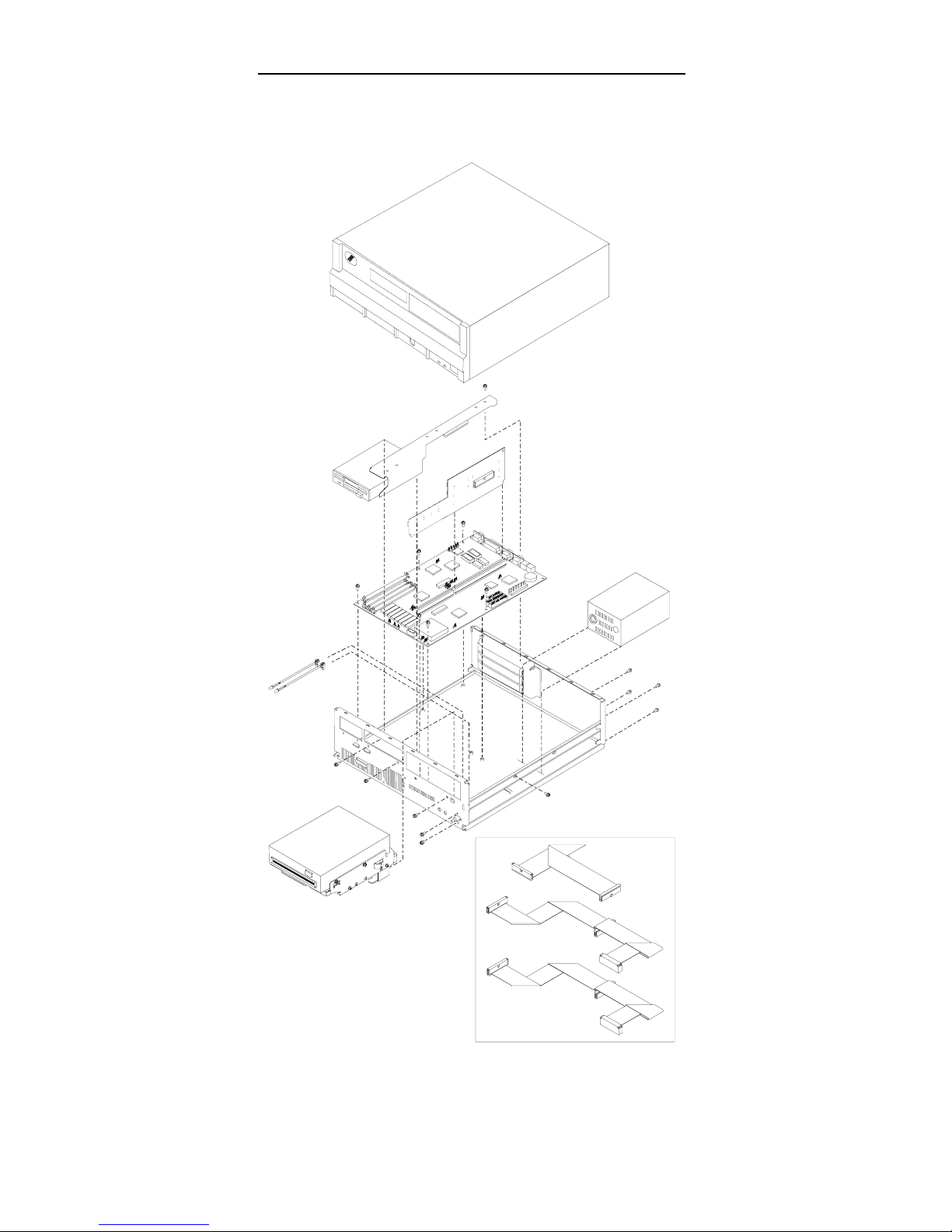
Page 48

Computer Exploded View (6482, 6484)
46 ValuePoint HMM - April 1994
Page 49

Computer Exploded View (6492, 6494)
Model 64XX Service Information 47
Page 50

64XX System Board
33
34
37
32
35
38
39
40
41
31
36
Figure 1. 64XX
48 ValuePoint HMM - April 1994
Page 51

64XX System Board
.1/ Video Port
.2/ Parallel Port
.3/ Serial Port (Comm B)
.4/ Serial Port (Comm A)
.5/ Mouse Port
.6/ Keyboard Port
.7/ Battery
.8/ Riser Connector
.9/ IRQ1 & IRQ2
.1ð/ Power Supply Connector
.11/ Diskette Drive Cable Connector
.12/ Hard Disk Drive Cable Connector
.13/ Hard Disk Drive Cable Connector
.14/ Write-Protect Jumper
.15/ Riser Connector Extension
.16/ Cache Tag RAM
.17/ Fan Power Connector
.18/ Processor Socket
.19/ SL to non-SL Processor Jumper
.2ð/ Overdrive / DX Jumper
.21/ DX4 Voltage Regulator Connector
.22/ Power-on LED
.23/ Hard Disk LED
.24/ Speaker
.25/ 128/256KB External Cache Connectors
.26/ Memory Module Connector, Bank 1
.27/ Memory Module Connector, Bank 2
.28/ Memory Module Connector, Bank 3
.29/ Memory Module Connector, Bank 4
.3ð/ 128K Cache Jumper (to rear)
.31/ 128K Cache Jumper (to rear)
.32/ Cache Tag RAM
.33/ VESA / PCI Jumper (VESA to rear)
.34/ VESA / PCI Jumper (VESA to rear)
.35/ VESA / PCI Jumper (VESA to rear)
.36/ Frequency Synthesizer
.37/ Frequency Synthesizer
.38/ Video Enable/Disable
.39/ Extended Video Memory Connector
.4ð/ Video Feature Connector
.41/ Extended Video Memory Connector
Model 64XX Service Information
49
Page 52

64XX Memory Module—72 Pin
Figure 2 (Part 1 of 2). 64XX Memory Module—72 Pin
Pin Signal Name I/O
1 Ground
2 SIMMD0 I/O
3 SIMMD16 I/O
4 SIMMD1 I/O
5 SIMMD17 I/O
6 SIMMD2 I/O
7 SIMMD18 I/O
8 SIMMD3 I/O
9 SIMMD19 I/O
10 +5 V dc I
11 CASP I
12 MA0 I
13 MA1 I
14 MA2 I
15 MA3 I
16 MA4 I
17 MA5 I
18 MA6 I
19 MA10 I
20 SIMMD4 I/O
21 SIMMD20 I/O
22 SIMMD5 I/O
23 SIMMD21 I/O
24 SIMMD6 I/O
25 SIMMD22 I/O
26 SIMMD7 I/O
27 SIMMD23 I/O
28 MA7 I
29 BS0 I
30 +5 V dc I
31 MA8 I
32 MA9 I
33 RAS3 I
34 RAS2 I
35 MP2 I
36 MP0 I
50 ValuePoint HMM - April 1994
Page 53

64XX Memory Module—72 Pin
Figure 2 (Part 2 of 2). 64XX Memory Module—72 Pin
Pin Signal Name I/O
37 MP1 I
38 MP3 I
39 Ground I
40 BCAS0 I
41 BCAS2 I
42 BCAS3 I
43 BCAS1 I
44 RAS0 I
45 RAS1 I
46 BS1 I
47 AWE I
48 Open
49 SIMMD8 I/O
50 SIMMD24 I/O
51 SIMMD9 I/O
52 SIMMD25 I/O
53 SIMMD10 I/O
54 SIMMD26 I/O
55 SIMMD11 I/O
56 SIMMD27 I/O
57 SIMMD12 I/O
58 SIMMD28 I/O
59 +5 V dc I
60 SIMMD29 I/O
61 SIMMD13 I/O
62 SIMMD30 I/O
63 SIMMD14 I/O
64 SIMMD31 I/O
65 SIMMD15 I/O
66 BS2 I
67 PD1 O
68 PD2 O
69 PD3 O
70 PD4 I
71 BS3 I
72 Ground
Model 64XX Service Information 51
Page 54

Model 64XX Computer Features
Notes:
1. In the following table, DD refers to Diagnostic Diskette
type, S/B refers to Slots and Bays.
2. Multi-media models are designated with “MM” in the
far-right column.
3. OS/2
*
models are designated with “OS/2” in the
far-right column. All other models (with a hard disk
drive) have DOS and Windows installed.
4. Models 6484 and 6494 have a PCI bus riser card.
Type Processor DD S/B Memory Hrd Dsk
6472-C0D 486SX-33 5 3/3 4M/128M None
6472-C2B 486SX-33 5 3/3 4M/128M 170M
6472-C3B 486SX-33 5 3/3 4M/128M 270M
6472-H0D 486DX-33 5 3/3 4M/128M None
6472-H2B 486DX-33 5 3/3 4M/128M 170M
6472-H3B 486DX-33 5 3/3 4M/128M 270M
6472-H4F 486DX-33 5 3/3 8M/128M 364M
6472-L0D 486DX2-33/66 5 3/3 4M/128M None
6472-L4F 486DX2-33/66 5 3/3 8M/128M 364M
6472-L4G 486DX2-33/66 5 3/3 8M/128M 364M OS/2
6482-C0D 486SX-33 5 5/5 4M/128M None
6482-C2B 486SX-33 5 5/5 4M/128M 170M
6482-C3B 486SX-33 5 5/5 4M/128M 270M
6482-CNB 486SX-33 5 5/5 4M/128M 270M MM
6482-H0D 486DX-33 5 5/5 4M/128M None
6482-H3B 486DX-33 5 5/5 4M/128M 270M
6482-H3G 486DX-33 5 5/5 8M/128M 270M OS/2
6482-H4F 486DX-33 5 5/5 8M/128M 364M
6482-K3B 486DX2-25/50 5 5/5 4M/128M 270M
6482-L0D 486DX2-33/66 5 5/5 4M/128M None
6482-L4F 486DX2-33/66 5 5/5 8M/128M 364M
6482-LNF 486DX2-33/66 5 5/5 8M/128M 364M MM
6482-L5F 486DX2-33/66 5 5/5 8M/128M 527M
6482-X0D 486DX4-50/100 5 5/5 4M/128M None
6482-X4F 486DX4-50/100 5 5/5 8M/128M 364M
6482-X4G 486DX4-50/100 5 5/5 8M/128M 364M OS/2
6484-H3B 486DX-33 5 4/5 4M/128M 270M
6484-H4G 486DX-33 5 4/5 8M/128M 364M OS/2
6484-L4F 486DX2-33/66 5 4/5 8M/128M 364M
6484-L4G 486DX2-33/66 5 4/5 8M/128M 364M OS/2
6484-X5F 486DX4-50/100 5 4/5 8M/128M 527M
6484-X5G 486DX4-50/100 5 4/5 8M/128M 527M OS/2
6492-H3F 486DX-33 5 8/6 8M/128M 270M
6492-L4F 486DX2-33/66 5 8/6 8M/128M 364M
6492-L4G 486DX2-33/66 5 8/6 8M/128M 364M OS/2
6492 L5F 486DX2-33/66 5 8/6 8M/128M 527M
6492 X4F 486DX4-50/100 5 8/6 8M/128M 364M
6492 X5F 486DX4-50/100 5 8/6 8M/128M 527M
6494-L5F 486DX2-33/66 5 7/6 8M/128M 527M
6494-X5G 486DX4-50/100 5 7/6 8M/128M 527M OS/2
*
Trademark of the IBM Corporation.
52 ValuePoint HMM - April 1994
Page 55

Model 64XX Service Information 53
Page 56

P/N 83G7790
Printed in U.S.A.
54 ValuePoint HMM - April 1994
 Loading...