

Page 1

Front cover
Click here to check for updates
IBM Flex System V7000
Storage Node
Introduction and Implementation Guide
Introduction to IBM Flex System family,
features, and functions
IBM Flex System V7000 Storage
Node hardware overview
Host configuration guide
John Sexton
Tilak Buneti
Eva Ho
Massimo Rosati
ibm.com/redbooks
Page 2

Page 3

International Technical Support Organization
IBM Flex System V7000 Storage Node
Introduction and Implementation Guide
September 2013
SG24-8068-01
Page 4

Note: Before using this information and the product it supports, read the information in “Notices” on
page xi.
Second Edition (September 2013)
This edition applies to IBM Flex System V7000 Storage Node Version 7.1.
© Copyright International Business Machines Corporation 2013. All rights reserved.
Note to U.S. Government Users Restricted Rights -- Use, duplication or disclosure restricted by GSA ADP Schedule
Contract with IBM Corp.
Page 5

Contents
Notices . . . . . . . . . . . . . . . . . . . . . . . . . . . . . . . . . . . . . . . . . . . . . . . . . . . . . . . . . . . . . . . . . xi
Trademarks . . . . . . . . . . . . . . . . . . . . . . . . . . . . . . . . . . . . . . . . . . . . . . . . . . . . . . . . . . . . . . xii
Preface . . . . . . . . . . . . . . . . . . . . . . . . . . . . . . . . . . . . . . . . . . . . . . . . . . . . . . . . . . . . . . . . xiii
Authors. . . . . . . . . . . . . . . . . . . . . . . . . . . . . . . . . . . . . . . . . . . . . . . . . . . . . . . . . . . . . . . . . xiii
Now you can become a published author, too! . . . . . . . . . . . . . . . . . . . . . . . . . . . . . . . . . . . xv
Comments welcome. . . . . . . . . . . . . . . . . . . . . . . . . . . . . . . . . . . . . . . . . . . . . . . . . . . . . . . .xv
Stay connected to IBM Redbooks . . . . . . . . . . . . . . . . . . . . . . . . . . . . . . . . . . . . . . . . . . . . . xv
Summary of changes. . . . . . . . . . . . . . . . . . . . . . . . . . . . . . . . . . . . . . . . . . . . . . . . . . . . . xvii
September 2013, Second Edition . . . . . . . . . . . . . . . . . . . . . . . . . . . . . . . . . . . . . . . . . . . . xvii
Chapter 1. Introduction to IBM Flex Systems and IBM PureSystems offerings . . . . . . 1
1.1 IBM PureSystems overview . . . . . . . . . . . . . . . . . . . . . . . . . . . . . . . . . . . . . . . . . . . . . . 2
1.1.1 Product names . . . . . . . . . . . . . . . . . . . . . . . . . . . . . . . . . . . . . . . . . . . . . . . . . . . . 3
1.1.2 IBM PureFlex System . . . . . . . . . . . . . . . . . . . . . . . . . . . . . . . . . . . . . . . . . . . . . . . 4
1.1.3 IBM PureApplication System. . . . . . . . . . . . . . . . . . . . . . . . . . . . . . . . . . . . . . . . . . 6
1.2 IBM PureFlex System building blocks. . . . . . . . . . . . . . . . . . . . . . . . . . . . . . . . . . . . . . . 8
1.2.1 Highlights . . . . . . . . . . . . . . . . . . . . . . . . . . . . . . . . . . . . . . . . . . . . . . . . . . . . . . . . 8
1.2.2 Components . . . . . . . . . . . . . . . . . . . . . . . . . . . . . . . . . . . . . . . . . . . . . . . . . . . . . . 9
1.3 IBM Flex System Enterprise Chassis . . . . . . . . . . . . . . . . . . . . . . . . . . . . . . . . . . . . . . 10
1.3.1 Chassis power supplies . . . . . . . . . . . . . . . . . . . . . . . . . . . . . . . . . . . . . . . . . . . . 13
1.3.2 Fan modules and cooling . . . . . . . . . . . . . . . . . . . . . . . . . . . . . . . . . . . . . . . . . . . 14
1.4 Compute nodes . . . . . . . . . . . . . . . . . . . . . . . . . . . . . . . . . . . . . . . . . . . . . . . . . . . . . . . 15
1.4.1 IBM Flex System x440 Compute Node. . . . . . . . . . . . . . . . . . . . . . . . . . . . . . . . . 15
1.4.2 IBM Flex System x240 Compute Node. . . . . . . . . . . . . . . . . . . . . . . . . . . . . . . . . 16
1.4.3 IBM Flex System x220 Compute Node. . . . . . . . . . . . . . . . . . . . . . . . . . . . . . . . . 19
1.4.4 IBM Flex System p260 and p24L Compute Nodes . . . . . . . . . . . . . . . . . . . . . . . . 20
1.4.5 IBM Flex System p460 Compute Node. . . . . . . . . . . . . . . . . . . . . . . . . . . . . . . . . 22
1.5 I/O modules. . . . . . . . . . . . . . . . . . . . . . . . . . . . . . . . . . . . . . . . . . . . . . . . . . . . . . . . . . 24
1.5.1 IBM Flex System Fabric CN4093 10 Gb Converged Scalable Switch . . . . . . . . . 25
1.5.2 IBM Flex System Fabric EN4093 and EN4093R 10 Gb Scalable Switch . . . . . . . 26
1.5.3 IBM Flex System EN4091 10 Gb Ethernet Pass-thru . . . . . . . . . . . . . . . . . . . . . . 27
1.5.4 IBM Flex System EN2092 1 Gb Ethernet Scalable Switch . . . . . . . . . . . . . . . . . . 27
1.5.5 IBM Flex System FC5022 16 Gb SAN Scalable Switch . . . . . . . . . . . . . . . . . . . . 28
1.5.6 IBM Flex System FC3171 8 Gb SAN Switch . . . . . . . . . . . . . . . . . . . . . . . . . . . . 28
1.5.7 IBM Flex System FC3171 8 Gb SAN Pass-thru . . . . . . . . . . . . . . . . . . . . . . . . . . 29
1.5.8 IBM Flex System IB6131 InfiniBand Switch . . . . . . . . . . . . . . . . . . . . . . . . . . . . . 29
1.6 Introduction to IBM Flex System storage . . . . . . . . . . . . . . . . . . . . . . . . . . . . . . . . . . . 30
1.6.1 IBM Storwize V7000 and IBM Flex System V7000 Storage Node . . . . . . . . . . . . 30
1.6.2 Benefits and value proposition . . . . . . . . . . . . . . . . . . . . . . . . . . . . . . . . . . . . . . . 34
1.6.3 Data Protection features . . . . . . . . . . . . . . . . . . . . . . . . . . . . . . . . . . . . . . . . . . . . 34
1.7 External storage . . . . . . . . . . . . . . . . . . . . . . . . . . . . . . . . . . . . . . . . . . . . . . . . . . . . . . 35
1.7.1 Storage products. . . . . . . . . . . . . . . . . . . . . . . . . . . . . . . . . . . . . . . . . . . . . . . . . . 35
1.7.2 IBM Storwize V7000 . . . . . . . . . . . . . . . . . . . . . . . . . . . . . . . . . . . . . . . . . . . . . . . 36
Chapter 2. Introduction to IBM Flex System V7000 Storage Node . . . . . . . . . . . . . . . . 37
2.1 IBM Flex System V7000 Storage Node overview . . . . . . . . . . . . . . . . . . . . . . . . . . . . . 38
2.2 IBM Flex System V7000 Storage Node terminology . . . . . . . . . . . . . . . . . . . . . . . . . . . 39
© Copyright IBM Corp. 2013. All rights reserved. iii
Page 6

2.3 IBM Flex System V7000 Storage Node . . . . . . . . . . . . . . . . . . . . . . . . . . . . . . . . . . . . 41
2.3.1 IBM Flex System V7000 Storage Node releases . . . . . . . . . . . . . . . . . . . . . . . . . 42
2.3.2 IBM Flex System V7000 Storage Node capabilities . . . . . . . . . . . . . . . . . . . . . . . 42
2.3.3 IBM Flex System V7000 Storage Node functions . . . . . . . . . . . . . . . . . . . . . . . . . 43
2.4 IBM Flex System V7000 Storage Node licensing . . . . . . . . . . . . . . . . . . . . . . . . . . . . . 46
2.4.1 Mandatory licensing . . . . . . . . . . . . . . . . . . . . . . . . . . . . . . . . . . . . . . . . . . . . . . . 46
2.4.2 Optional licensing . . . . . . . . . . . . . . . . . . . . . . . . . . . . . . . . . . . . . . . . . . . . . . . . . 47
2.5 IBM Flex System V7000 Storage Node hardware . . . . . . . . . . . . . . . . . . . . . . . . . . . . 51
2.5.1 Control canister . . . . . . . . . . . . . . . . . . . . . . . . . . . . . . . . . . . . . . . . . . . . . . . . . . . 51
2.5.2 Expansion canister . . . . . . . . . . . . . . . . . . . . . . . . . . . . . . . . . . . . . . . . . . . . . . . . 55
2.5.3 Supported disk drives . . . . . . . . . . . . . . . . . . . . . . . . . . . . . . . . . . . . . . . . . . . . . . 56
2.5.4 IBM Storwize V7000 expansion enclosure . . . . . . . . . . . . . . . . . . . . . . . . . . . . . . 57
2.5.5 SAS cabling requirements . . . . . . . . . . . . . . . . . . . . . . . . . . . . . . . . . . . . . . . . . . 58
2.6 IBM Flex System V7000 Storage Node components . . . . . . . . . . . . . . . . . . . . . . . . . . 59
2.6.1 Hosts. . . . . . . . . . . . . . . . . . . . . . . . . . . . . . . . . . . . . . . . . . . . . . . . . . . . . . . . . . . 60
2.6.2 Control canisters . . . . . . . . . . . . . . . . . . . . . . . . . . . . . . . . . . . . . . . . . . . . . . . . . . 60
2.6.3 I/O groups . . . . . . . . . . . . . . . . . . . . . . . . . . . . . . . . . . . . . . . . . . . . . . . . . . . . . . . 61
2.6.4 Clustered system . . . . . . . . . . . . . . . . . . . . . . . . . . . . . . . . . . . . . . . . . . . . . . . . . 61
2.6.5 RAID . . . . . . . . . . . . . . . . . . . . . . . . . . . . . . . . . . . . . . . . . . . . . . . . . . . . . . . . . . . 62
2.6.6 Managed disks . . . . . . . . . . . . . . . . . . . . . . . . . . . . . . . . . . . . . . . . . . . . . . . . . . . 63
2.6.7 Quorum disks . . . . . . . . . . . . . . . . . . . . . . . . . . . . . . . . . . . . . . . . . . . . . . . . . . . . 63
2.6.8 Storage pools . . . . . . . . . . . . . . . . . . . . . . . . . . . . . . . . . . . . . . . . . . . . . . . . . . . . 64
2.6.9 Volumes . . . . . . . . . . . . . . . . . . . . . . . . . . . . . . . . . . . . . . . . . . . . . . . . . . . . . . . . 67
2.6.10 Thin-provisioned volumes . . . . . . . . . . . . . . . . . . . . . . . . . . . . . . . . . . . . . . . . . . 69
2.6.11 Mirrored volumes . . . . . . . . . . . . . . . . . . . . . . . . . . . . . . . . . . . . . . . . . . . . . . . . 70
2.6.12 Easy Tier. . . . . . . . . . . . . . . . . . . . . . . . . . . . . . . . . . . . . . . . . . . . . . . . . . . . . . . 71
2.6.13 Real-time Compression. . . . . . . . . . . . . . . . . . . . . . . . . . . . . . . . . . . . . . . . . . . . 72
2.6.14 iSCSI. . . . . . . . . . . . . . . . . . . . . . . . . . . . . . . . . . . . . . . . . . . . . . . . . . . . . . . . . . 72
2.6.15 Fibre Channel over Ethernet (FCoE) . . . . . . . . . . . . . . . . . . . . . . . . . . . . . . . . . 74
2.7 Advanced copy services . . . . . . . . . . . . . . . . . . . . . . . . . . . . . . . . . . . . . . . . . . . . . . . . 75
2.7.1 FlashCopy . . . . . . . . . . . . . . . . . . . . . . . . . . . . . . . . . . . . . . . . . . . . . . . . . . . . . . . 75
2.7.2 IBM Flex System V7000 Remote Mirroring software . . . . . . . . . . . . . . . . . . . . . . 76
2.7.3 Synchronous / Asynchronous Remote Copy . . . . . . . . . . . . . . . . . . . . . . . . . . . . 77
2.7.4 Copy Services configuration limits . . . . . . . . . . . . . . . . . . . . . . . . . . . . . . . . . . . . 78
2.8 Management and support tools. . . . . . . . . . . . . . . . . . . . . . . . . . . . . . . . . . . . . . . . . . . 78
2.8.1 IBM Assist On-site and remote service. . . . . . . . . . . . . . . . . . . . . . . . . . . . . . . . . 79
2.8.2 Event notifications . . . . . . . . . . . . . . . . . . . . . . . . . . . . . . . . . . . . . . . . . . . . . . . . . 79
2.8.3 SNMP traps. . . . . . . . . . . . . . . . . . . . . . . . . . . . . . . . . . . . . . . . . . . . . . . . . . . . . . 79
2.8.4 Syslog messages . . . . . . . . . . . . . . . . . . . . . . . . . . . . . . . . . . . . . . . . . . . . . . . . . 80
2.8.5 Call Home email . . . . . . . . . . . . . . . . . . . . . . . . . . . . . . . . . . . . . . . . . . . . . . . . . . 80
2.9 Useful references from Storwize V7000 websites. . . . . . . . . . . . . . . . . . . . . . . . . . . . . 81
2.10 IBM virtual storage learning videos on YouTube . . . . . . . . . . . . . . . . . . . . . . . . . . . . 82
Chapter 3. Systems management . . . . . . . . . . . . . . . . . . . . . . . . . . . . . . . . . . . . . . . . . . 83
3.1 System Management overview . . . . . . . . . . . . . . . . . . . . . . . . . . . . . . . . . . . . . . . . . . . 84
3.1.1 Integrated platform management tools . . . . . . . . . . . . . . . . . . . . . . . . . . . . . . . . . 84
3.1.2 IBM Flex System storage management . . . . . . . . . . . . . . . . . . . . . . . . . . . . . . . . 86
3.1.3 Storage management interfaces. . . . . . . . . . . . . . . . . . . . . . . . . . . . . . . . . . . . . . 87
3.2 IBM Flex System Chassis Management Module (CMM). . . . . . . . . . . . . . . . . . . . . . . . 90
3.2.1 Overview of IBM Flex System Chassis Management Module . . . . . . . . . . . . . . . 90
3.2.2 Accessing the CMM . . . . . . . . . . . . . . . . . . . . . . . . . . . . . . . . . . . . . . . . . . . . . . . 92
3.2.3 Viewing and configuring IP addresses of chassis components . . . . . . . . . . . . . . 94
3.2.4 Accessing I/O modules using CMM . . . . . . . . . . . . . . . . . . . . . . . . . . . . . . . . . . . 96
iv IBM Flex System V7000 Storage Node Introduction and Implementation Guide
Page 7

3.2.5 Managing storage using IBM Flex System Chassis Management Module . . . . . . 99
3.2.6 Data collection using CMM . . . . . . . . . . . . . . . . . . . . . . . . . . . . . . . . . . . . . . . . . 109
3.3 Flex System Manager . . . . . . . . . . . . . . . . . . . . . . . . . . . . . . . . . . . . . . . . . . . . . . . . . 113
3.3.1 Overview of IBM Flex System Manager (FSM). . . . . . . . . . . . . . . . . . . . . . . . . . 113
3.3.2 IBM Flex System Manager storage management features. . . . . . . . . . . . . . . . . 115
3.3.3 Logging in to the IBM Flex System Manager Node. . . . . . . . . . . . . . . . . . . . . . . 119
3.3.4 Overview of IBM Flex System Manager and IBM FSM Explorer . . . . . . . . . . . . 120
3.3.5 Accessing I/O modules using FSM . . . . . . . . . . . . . . . . . . . . . . . . . . . . . . . . . . . 135
3.3.6 Data collection using FSM . . . . . . . . . . . . . . . . . . . . . . . . . . . . . . . . . . . . . . . . . 139
3.3.7 Managing storage using IBM Flex System Manager . . . . . . . . . . . . . . . . . . . . . 143
Chapter 4. IBM Flex System V7000 Storage Node initial configuration . . . . . . . . . . . 157
4.1 Planning overview . . . . . . . . . . . . . . . . . . . . . . . . . . . . . . . . . . . . . . . . . . . . . . . . . . . . 158
4.1.1 Hardware planning . . . . . . . . . . . . . . . . . . . . . . . . . . . . . . . . . . . . . . . . . . . . . . . 158
4.1.2 SAN configuration planning . . . . . . . . . . . . . . . . . . . . . . . . . . . . . . . . . . . . . . . . 159
4.1.3 LAN configuration planning. . . . . . . . . . . . . . . . . . . . . . . . . . . . . . . . . . . . . . . . . 159
4.1.4 Management IP address considerations. . . . . . . . . . . . . . . . . . . . . . . . . . . . . . . 160
4.1.5 Service IP address considerations . . . . . . . . . . . . . . . . . . . . . . . . . . . . . . . . . . . 160
4.1.6 Management interface planning . . . . . . . . . . . . . . . . . . . . . . . . . . . . . . . . . . . . . 161
4.2 Initial setup for IBM Flex System V7000 Storage Node . . . . . . . . . . . . . . . . . . . . . . . 162
4.2.1 Using FSM for initial setup . . . . . . . . . . . . . . . . . . . . . . . . . . . . . . . . . . . . . . . . . 163
4.2.2 Using CMM for initial setup . . . . . . . . . . . . . . . . . . . . . . . . . . . . . . . . . . . . . . . . . 167
4.3 IBM Flex System V7000 Storage Node Setup Wizard . . . . . . . . . . . . . . . . . . . . . . . . 170
4.4 System management . . . . . . . . . . . . . . . . . . . . . . . . . . . . . . . . . . . . . . . . . . . . . . . . . 181
4.4.1 Graphical User Interface (GUI) . . . . . . . . . . . . . . . . . . . . . . . . . . . . . . . . . . . . . . 181
4.4.2 Launching IBM Flex System V7000 Storage Node GUI from CMM . . . . . . . . . . 183
4.5 Service Assistant. . . . . . . . . . . . . . . . . . . . . . . . . . . . . . . . . . . . . . . . . . . . . . . . . . . . . 184
4.5.1 Changing the Service IP address . . . . . . . . . . . . . . . . . . . . . . . . . . . . . . . . . . . . 184
4.6 Command-Line interface (CLI) . . . . . . . . . . . . . . . . . . . . . . . . . . . . . . . . . . . . . . . . . . 186
4.7 Recording system access information . . . . . . . . . . . . . . . . . . . . . . . . . . . . . . . . . . . . 187
Chapter 5. IBM Flex System V7000 Storage Node GUI interface . . . . . . . . . . . . . . . . 189
5.1 Overview of IBM Flex System V7000 Storage Node management software . . . . . . . 190
5.1.1 Access to the Graphical User Interface. . . . . . . . . . . . . . . . . . . . . . . . . . . . . . . . 190
5.1.2 Graphical User Interface layout. . . . . . . . . . . . . . . . . . . . . . . . . . . . . . . . . . . . . . 191
5.1.3 Navigation . . . . . . . . . . . . . . . . . . . . . . . . . . . . . . . . . . . . . . . . . . . . . . . . . . . . . . 192
5.1.4 Multiple selections. . . . . . . . . . . . . . . . . . . . . . . . . . . . . . . . . . . . . . . . . . . . . . . . 195
5.1.5 Status Indicators menus . . . . . . . . . . . . . . . . . . . . . . . . . . . . . . . . . . . . . . . . . . . 196
5.2 Home menu. . . . . . . . . . . . . . . . . . . . . . . . . . . . . . . . . . . . . . . . . . . . . . . . . . . . . . . . . 198
5.3 Monitoring menu . . . . . . . . . . . . . . . . . . . . . . . . . . . . . . . . . . . . . . . . . . . . . . . . . . . . . 199
5.3.1 Monitoring System Details menu . . . . . . . . . . . . . . . . . . . . . . . . . . . . . . . . . . . . 199
5.3.2 Monitoring Events menu . . . . . . . . . . . . . . . . . . . . . . . . . . . . . . . . . . . . . . . . . . . 204
5.3.3 Monitoring Performance menu . . . . . . . . . . . . . . . . . . . . . . . . . . . . . . . . . . . . . . 212
5.4 Pools menu . . . . . . . . . . . . . . . . . . . . . . . . . . . . . . . . . . . . . . . . . . . . . . . . . . . . . . . . . 214
5.4.1 Volumes by Pool menu . . . . . . . . . . . . . . . . . . . . . . . . . . . . . . . . . . . . . . . . . . . . 215
5.4.2 Internal Storage menu . . . . . . . . . . . . . . . . . . . . . . . . . . . . . . . . . . . . . . . . . . . . 216
5.4.3 External Storage menu . . . . . . . . . . . . . . . . . . . . . . . . . . . . . . . . . . . . . . . . . . . . 217
5.4.4 System Migration tools . . . . . . . . . . . . . . . . . . . . . . . . . . . . . . . . . . . . . . . . . . . . 217
5.4.5 MDisks by Pools menu . . . . . . . . . . . . . . . . . . . . . . . . . . . . . . . . . . . . . . . . . . . . 218
5.5 Volumes menu . . . . . . . . . . . . . . . . . . . . . . . . . . . . . . . . . . . . . . . . . . . . . . . . . . . . . . 221
5.5.1 The Volumes menu . . . . . . . . . . . . . . . . . . . . . . . . . . . . . . . . . . . . . . . . . . . . . . . 222
5.5.2 Volumes by Pool menu . . . . . . . . . . . . . . . . . . . . . . . . . . . . . . . . . . . . . . . . . . . . 224
5.5.3 Volumes by Host menu . . . . . . . . . . . . . . . . . . . . . . . . . . . . . . . . . . . . . . . . . . . . 226
Contents v
Page 8

5.6 Hosts menu . . . . . . . . . . . . . . . . . . . . . . . . . . . . . . . . . . . . . . . . . . . . . . . . . . . . . . . . . 228
5.6.1 Hosts menu . . . . . . . . . . . . . . . . . . . . . . . . . . . . . . . . . . . . . . . . . . . . . . . . . . . . . 229
5.6.2 Ports by Host menu . . . . . . . . . . . . . . . . . . . . . . . . . . . . . . . . . . . . . . . . . . . . . . 231
5.6.3 Host Mappings menu . . . . . . . . . . . . . . . . . . . . . . . . . . . . . . . . . . . . . . . . . . . . . 233
5.6.4 Volumes by Host menu . . . . . . . . . . . . . . . . . . . . . . . . . . . . . . . . . . . . . . . . . . . . 235
5.7 Copy Services menu . . . . . . . . . . . . . . . . . . . . . . . . . . . . . . . . . . . . . . . . . . . . . . . . . . 235
5.7.1 FlashCopy menu . . . . . . . . . . . . . . . . . . . . . . . . . . . . . . . . . . . . . . . . . . . . . . . . . 236
5.7.2 FlashCopy Consistency Group menu . . . . . . . . . . . . . . . . . . . . . . . . . . . . . . . . . 238
5.7.3 FlashCopy Mapping menu . . . . . . . . . . . . . . . . . . . . . . . . . . . . . . . . . . . . . . . . . 239
5.7.4 Remote Copy and the Partnerships menu . . . . . . . . . . . . . . . . . . . . . . . . . . . . . 239
5.8 Access menu. . . . . . . . . . . . . . . . . . . . . . . . . . . . . . . . . . . . . . . . . . . . . . . . . . . . . . . . 240
5.8.1 Users menu. . . . . . . . . . . . . . . . . . . . . . . . . . . . . . . . . . . . . . . . . . . . . . . . . . . . . 241
5.8.2 Audit Log menu . . . . . . . . . . . . . . . . . . . . . . . . . . . . . . . . . . . . . . . . . . . . . . . . . . 243
5.9 Settings menu . . . . . . . . . . . . . . . . . . . . . . . . . . . . . . . . . . . . . . . . . . . . . . . . . . . . . . . 244
5.9.1 Event Notification menu . . . . . . . . . . . . . . . . . . . . . . . . . . . . . . . . . . . . . . . . . . . 245
5.9.2 Directory Services . . . . . . . . . . . . . . . . . . . . . . . . . . . . . . . . . . . . . . . . . . . . . . . . 246
5.9.3 Network menu . . . . . . . . . . . . . . . . . . . . . . . . . . . . . . . . . . . . . . . . . . . . . . . . . . . 247
5.9.4 Support menu . . . . . . . . . . . . . . . . . . . . . . . . . . . . . . . . . . . . . . . . . . . . . . . . . . . 249
5.9.5 General menu . . . . . . . . . . . . . . . . . . . . . . . . . . . . . . . . . . . . . . . . . . . . . . . . . . . 254
Chapter 6. Basic volume and host configuration. . . . . . . . . . . . . . . . . . . . . . . . . . . . . 255
6.1 Storage provisioning from IBM Flex System V7000 Storage Node. . . . . . . . . . . . . . . 256
6.1.1 Creating a generic volume . . . . . . . . . . . . . . . . . . . . . . . . . . . . . . . . . . . . . . . . . 258
6.1.2 Creating a thin-provisioned volume. . . . . . . . . . . . . . . . . . . . . . . . . . . . . . . . . . . 260
6.1.3 Creating a mirrored volume. . . . . . . . . . . . . . . . . . . . . . . . . . . . . . . . . . . . . . . . . 262
6.1.4 Creating a thin-mirror volume . . . . . . . . . . . . . . . . . . . . . . . . . . . . . . . . . . . . . . . 266
6.1.5 IBM Real-time Compression . . . . . . . . . . . . . . . . . . . . . . . . . . . . . . . . . . . . . . . . 269
6.2 Creating a new host . . . . . . . . . . . . . . . . . . . . . . . . . . . . . . . . . . . . . . . . . . . . . . . . . . 273
6.2.1 Creating a Fibre Channel attached host . . . . . . . . . . . . . . . . . . . . . . . . . . . . . . . 273
6.2.2 Creating an iSCSI attached host. . . . . . . . . . . . . . . . . . . . . . . . . . . . . . . . . . . . . 276
6.3 Mapping a volume to the host . . . . . . . . . . . . . . . . . . . . . . . . . . . . . . . . . . . . . . . . . . . 279
6.3.1 Mapping newly created volumes to the host using the wizard . . . . . . . . . . . . . . 279
6.3.2 Additional features . . . . . . . . . . . . . . . . . . . . . . . . . . . . . . . . . . . . . . . . . . . . . . . 281
6.4 Scalability enhancements made in v7.1 compared to v6.4 . . . . . . . . . . . . . . . . . . . . . 282
Chapter 7. Storage Migration Wizard . . . . . . . . . . . . . . . . . . . . . . . . . . . . . . . . . . . . . . 283
7.1 Preparing for data migration . . . . . . . . . . . . . . . . . . . . . . . . . . . . . . . . . . . . . . . . . . . . 284
7.2 Migrating data using the Storage Migration Wizard . . . . . . . . . . . . . . . . . . . . . . . . . . 285
7.2.1 Check the Windows 2008 host before the migration. . . . . . . . . . . . . . . . . . . . . . 285
7.2.2 Remapping the disk to IBM Flex System V7000 Storage Node . . . . . . . . . . . . . 286
7.2.3 Storage Migration Wizard on IBM Flex System V7000 Storage Node . . . . . . . . 289
7.2.4 Verifying the disks on the Windows server . . . . . . . . . . . . . . . . . . . . . . . . . . . . . 301
7.2.5 Finalizing the migration . . . . . . . . . . . . . . . . . . . . . . . . . . . . . . . . . . . . . . . . . . . . 304
7.2.6 Mapping disk to host after the migration has begun . . . . . . . . . . . . . . . . . . . . . . 306
7.2.7 Renaming the volume . . . . . . . . . . . . . . . . . . . . . . . . . . . . . . . . . . . . . . . . . . . . . 309
Chapter 8. Storage pools . . . . . . . . . . . . . . . . . . . . . . . . . . . . . . . . . . . . . . . . . . . . . . . . 313
8.1 Working with internal drives . . . . . . . . . . . . . . . . . . . . . . . . . . . . . . . . . . . . . . . . . . . . 314
8.1.1 Actions on internal drives . . . . . . . . . . . . . . . . . . . . . . . . . . . . . . . . . . . . . . . . . . 318
8.1.2 Configuring internal storage . . . . . . . . . . . . . . . . . . . . . . . . . . . . . . . . . . . . . . . . 321
8.2 Working with MDisks . . . . . . . . . . . . . . . . . . . . . . . . . . . . . . . . . . . . . . . . . . . . . . . . . . 335
8.2.1 Adding MDisks to storage pools . . . . . . . . . . . . . . . . . . . . . . . . . . . . . . . . . . . . . 337
8.2.2 Importing MDisks . . . . . . . . . . . . . . . . . . . . . . . . . . . . . . . . . . . . . . . . . . . . . . . . 342
8.2.3 RAID action for MDisks . . . . . . . . . . . . . . . . . . . . . . . . . . . . . . . . . . . . . . . . . . . . 351
vi IBM Flex System V7000 Storage Node Introduction and Implementation Guide
Page 9

8.2.4 Selecting the tier for MDisks . . . . . . . . . . . . . . . . . . . . . . . . . . . . . . . . . . . . . . . . 353
8.2.5 Additional actions on MDisks . . . . . . . . . . . . . . . . . . . . . . . . . . . . . . . . . . . . . . . 355
8.2.6 Properties for Mdisks . . . . . . . . . . . . . . . . . . . . . . . . . . . . . . . . . . . . . . . . . . . . . 357
8.3 Working with storage pools . . . . . . . . . . . . . . . . . . . . . . . . . . . . . . . . . . . . . . . . . . . . . 359
Chapter 9. IBM Flex System V7000 Storage Node Copy Services . . . . . . . . . . . . . . . 363
9.1 Services provided . . . . . . . . . . . . . . . . . . . . . . . . . . . . . . . . . . . . . . . . . . . . . . . . . . . . 364
9.2 FlashCopy . . . . . . . . . . . . . . . . . . . . . . . . . . . . . . . . . . . . . . . . . . . . . . . . . . . . . . . . . . 364
9.2.1 Business requirements for FlashCopy . . . . . . . . . . . . . . . . . . . . . . . . . . . . . . . . 364
9.2.2 FlashCopy functional overview . . . . . . . . . . . . . . . . . . . . . . . . . . . . . . . . . . . . . . 365
9.2.3 Planning for FlashCopy. . . . . . . . . . . . . . . . . . . . . . . . . . . . . . . . . . . . . . . . . . . . 373
9.2.4 Managing FlashCopy using the GUI . . . . . . . . . . . . . . . . . . . . . . . . . . . . . . . . . . 375
9.2.5 Managing FlashCopy mapping . . . . . . . . . . . . . . . . . . . . . . . . . . . . . . . . . . . . . . 381
9.3 Remote Copy . . . . . . . . . . . . . . . . . . . . . . . . . . . . . . . . . . . . . . . . . . . . . . . . . . . . . . . 402
9.3.1 Remote Copy concepts. . . . . . . . . . . . . . . . . . . . . . . . . . . . . . . . . . . . . . . . . . . . 402
9.3.2 Global Mirror with Change Volumes . . . . . . . . . . . . . . . . . . . . . . . . . . . . . . . . . . 409
9.3.3 Remote Copy planning . . . . . . . . . . . . . . . . . . . . . . . . . . . . . . . . . . . . . . . . . . . . 414
9.4 Troubleshooting Remote Copy . . . . . . . . . . . . . . . . . . . . . . . . . . . . . . . . . . . . . . . . . . 417
9.4.1 1920 error . . . . . . . . . . . . . . . . . . . . . . . . . . . . . . . . . . . . . . . . . . . . . . . . . . . . . . 418
9.4.2 1720 error . . . . . . . . . . . . . . . . . . . . . . . . . . . . . . . . . . . . . . . . . . . . . . . . . . . . . . 420
9.5 Managing Remote Copy using the GUI . . . . . . . . . . . . . . . . . . . . . . . . . . . . . . . . . . . 420
9.5.1 Managing cluster partnerships . . . . . . . . . . . . . . . . . . . . . . . . . . . . . . . . . . . . . . 420
9.5.2 Deleting a partnership. . . . . . . . . . . . . . . . . . . . . . . . . . . . . . . . . . . . . . . . . . . . . 426
9.5.3 Managing a Remote Copy consistency group . . . . . . . . . . . . . . . . . . . . . . . . . . 436
Chapter 10. Volume mirroring and migration . . . . . . . . . . . . . . . . . . . . . . . . . . . . . . . . 447
10.1 Volume mirroring and migration options . . . . . . . . . . . . . . . . . . . . . . . . . . . . . . . . . . 448
10.2 Tunable timeout . . . . . . . . . . . . . . . . . . . . . . . . . . . . . . . . . . . . . . . . . . . . . . . . . . . . 448
10.3 Usage of mirroring for migration . . . . . . . . . . . . . . . . . . . . . . . . . . . . . . . . . . . . . . . . 448
10.4 Managing Volume Mirror and migration with the GUI . . . . . . . . . . . . . . . . . . . . . . . . 450
Chapter 11. SAN connections and configuration. . . . . . . . . . . . . . . . . . . . . . . . . . . . . 457
11.1 Storage Area Network overview . . . . . . . . . . . . . . . . . . . . . . . . . . . . . . . . . . . . . . . . 458
11.2 Connection to chassis I/O modules. . . . . . . . . . . . . . . . . . . . . . . . . . . . . . . . . . . . . . 459
11.2.1 I/O module configurations . . . . . . . . . . . . . . . . . . . . . . . . . . . . . . . . . . . . . . . . . 459
11.2.2 I/O module connection summary . . . . . . . . . . . . . . . . . . . . . . . . . . . . . . . . . . . 460
11.3 iSCSI connectivity . . . . . . . . . . . . . . . . . . . . . . . . . . . . . . . . . . . . . . . . . . . . . . . . . . . 461
11.3.1 Session establishment and management . . . . . . . . . . . . . . . . . . . . . . . . . . . . . 462
11.3.2 iSCSI initiators . . . . . . . . . . . . . . . . . . . . . . . . . . . . . . . . . . . . . . . . . . . . . . . . . 462
11.3.3 iSCSI multisession configuration and support. . . . . . . . . . . . . . . . . . . . . . . . . . 464
11.3.4 iSCSI multipath connectivity . . . . . . . . . . . . . . . . . . . . . . . . . . . . . . . . . . . . . . . 465
11.3.5 Configuring multiple iSCSI host links . . . . . . . . . . . . . . . . . . . . . . . . . . . . . . . . 466
11.4 FCoE connectivity . . . . . . . . . . . . . . . . . . . . . . . . . . . . . . . . . . . . . . . . . . . . . . . . . . . 468
11.4.1 FCoE protocol stack . . . . . . . . . . . . . . . . . . . . . . . . . . . . . . . . . . . . . . . . . . . . . 469
11.4.2 Converged Network Adapters. . . . . . . . . . . . . . . . . . . . . . . . . . . . . . . . . . . . . . 470
11.4.3 FCoE port types . . . . . . . . . . . . . . . . . . . . . . . . . . . . . . . . . . . . . . . . . . . . . . . . 471
11.4.4 Configuring CN4093 for FCoE connectivity . . . . . . . . . . . . . . . . . . . . . . . . . . . 473
11.5 Fibre Channel connectivity . . . . . . . . . . . . . . . . . . . . . . . . . . . . . . . . . . . . . . . . . . . . 491
11.5.1 The concept of layers . . . . . . . . . . . . . . . . . . . . . . . . . . . . . . . . . . . . . . . . . . . . 492
11.5.2 Fibre Channel topologies . . . . . . . . . . . . . . . . . . . . . . . . . . . . . . . . . . . . . . . . . 494
11.5.3 FC addressing and port types. . . . . . . . . . . . . . . . . . . . . . . . . . . . . . . . . . . . . . 495
11.5.4 Zoning a compute node for storage allocation . . . . . . . . . . . . . . . . . . . . . . . . . 496
11.5.5 Multipathing. . . . . . . . . . . . . . . . . . . . . . . . . . . . . . . . . . . . . . . . . . . . . . . . . . . . 506
11.5.6 FC Switch Transparent Mode and N_Port ID Virtualization (NPIV) . . . . . . . . . 507
Contents vii
Page 10

11.6 Storage Area Network summary . . . . . . . . . . . . . . . . . . . . . . . . . . . . . . . . . . . . . . . . 509
Chapter 12. Host configuration . . . . . . . . . . . . . . . . . . . . . . . . . . . . . . . . . . . . . . . . . . . 511
12.1 Host configuration overview . . . . . . . . . . . . . . . . . . . . . . . . . . . . . . . . . . . . . . . . . . . 512
12.2 Discovering volumes from the host and multipath settings . . . . . . . . . . . . . . . . . . . . 513
12.3 Windows host attachment . . . . . . . . . . . . . . . . . . . . . . . . . . . . . . . . . . . . . . . . . . . . . 514
12.3.1 Windows 2012 R2 Fibre Channel volume attachment . . . . . . . . . . . . . . . . . . . 514
12.3.2 Windows 2008 R2 iSCSI volume attachment . . . . . . . . . . . . . . . . . . . . . . . . . . 520
12.3.3 Windows 2008 R2 FCoE volume attachment . . . . . . . . . . . . . . . . . . . . . . . . . . 533
12.4 VMware ESX host attachment . . . . . . . . . . . . . . . . . . . . . . . . . . . . . . . . . . . . . . . . . 538
12.4.1 VMware ESX Fibre Channel attachment . . . . . . . . . . . . . . . . . . . . . . . . . . . . . 538
12.4.2 VMware ESX iSCSI attachment . . . . . . . . . . . . . . . . . . . . . . . . . . . . . . . . . . . . 544
12.5 AIX host attachment . . . . . . . . . . . . . . . . . . . . . . . . . . . . . . . . . . . . . . . . . . . . . . . . . 552
12.5.1 Configuring the AIX compute node for FC connectivity . . . . . . . . . . . . . . . . . . 552
12.5.2 Operating system versions and maintenance levels. . . . . . . . . . . . . . . . . . . . . 553
12.5.3 Checking connectivity to IBM Flex System V7000 Storage Node. . . . . . . . . . . 554
12.5.4 Installing the 2145 host attachment support package. . . . . . . . . . . . . . . . . . . . 555
12.5.5 Subsystem Device Driver Path Control Module . . . . . . . . . . . . . . . . . . . . . . . . 556
12.6 Linux host attachment . . . . . . . . . . . . . . . . . . . . . . . . . . . . . . . . . . . . . . . . . . . . . . . . 560
12.6.1 Linux Fibre Channel attachment . . . . . . . . . . . . . . . . . . . . . . . . . . . . . . . . . . . . 560
12.6.2 Applying device drivers . . . . . . . . . . . . . . . . . . . . . . . . . . . . . . . . . . . . . . . . . . . 561
12.6.3 Creating and preparing the SDD volumes for use . . . . . . . . . . . . . . . . . . . . . . 564
12.6.4 Using the operating system Device Mapper Multipath (DM-MPIO) . . . . . . . . . 566
12.6.5 Creating and preparing DM-MPIO volumes for use . . . . . . . . . . . . . . . . . . . . . 567
Chapter 13. Maintenance and troubleshooting . . . . . . . . . . . . . . . . . . . . . . . . . . . . . . 571
13.1 Reliability, availability, and serviceability (RAS) . . . . . . . . . . . . . . . . . . . . . . . . . . . . 572
13.2 Hardware and LED descriptions . . . . . . . . . . . . . . . . . . . . . . . . . . . . . . . . . . . . . . . . 573
13.2.1 Understanding the system state using the control enclosure LEDs . . . . . . . . . 573
13.2.2 Understanding the system state using the expansion enclosure LEDs . . . . . . 579
13.2.3 Power-on self-test . . . . . . . . . . . . . . . . . . . . . . . . . . . . . . . . . . . . . . . . . . . . . . . 582
13.2.4 Powering on using LED indicators . . . . . . . . . . . . . . . . . . . . . . . . . . . . . . . . . . 583
13.3 Monitoring system status and health. . . . . . . . . . . . . . . . . . . . . . . . . . . . . . . . . . . . . 584
13.3.1 Using FSM for status and health. . . . . . . . . . . . . . . . . . . . . . . . . . . . . . . . . . . . 584
13.3.2 System Status and Health tasks . . . . . . . . . . . . . . . . . . . . . . . . . . . . . . . . . . . . 586
13.4 Managing storage nodes. . . . . . . . . . . . . . . . . . . . . . . . . . . . . . . . . . . . . . . . . . . . . . 588
13.4.1 Using FSM Chassis Manager to manage a storage node . . . . . . . . . . . . . . . . 588
13.4.2 Using FSM Storage Management to manage a storage node . . . . . . . . . . . . . 591
13.4.3 Using CMM Chassis Manager to manage a storage node . . . . . . . . . . . . . . . . 592
13.5 Configuration backup and restore process . . . . . . . . . . . . . . . . . . . . . . . . . . . . . . . . 593
13.6 Software upgrade . . . . . . . . . . . . . . . . . . . . . . . . . . . . . . . . . . . . . . . . . . . . . . . . . . . 594
13.6.1 Choosing an upgrade method. . . . . . . . . . . . . . . . . . . . . . . . . . . . . . . . . . . . . . 594
13.6.2 Upgrading the system software using IBM Flex System V7000 Storage Node
management GUI . . . . . . . . . . . . . . . . . . . . . . . . . . . . . . . . . . . . . . . . . . . . . . . . 595
13.7 Drive firmware upgrade . . . . . . . . . . . . . . . . . . . . . . . . . . . . . . . . . . . . . . . . . . . . . . . 601
13.7.1 Multi drive upgrade utility . . . . . . . . . . . . . . . . . . . . . . . . . . . . . . . . . . . . . . . . . 601
13.7.2 Upgrade procedure . . . . . . . . . . . . . . . . . . . . . . . . . . . . . . . . . . . . . . . . . . . . . . 602
13.8 Troubleshooting . . . . . . . . . . . . . . . . . . . . . . . . . . . . . . . . . . . . . . . . . . . . . . . . . . . . 602
13.8.1 Using the CMM for troubleshooting tasks . . . . . . . . . . . . . . . . . . . . . . . . . . . . . 603
13.8.2 Using IBM Flex System V7000 Storage Node management GUI for troubleshooting
tasks . . . . . . . . . . . . . . . . . . . . . . . . . . . . . . . . . . . . . . . . . . . . . . . . . . . . . . . . . . 606
13.8.3 Removing and replacing parts for troubleshooting and resolving problems . . . 608
13.8.4 Event reporting . . . . . . . . . . . . . . . . . . . . . . . . . . . . . . . . . . . . . . . . . . . . . . . . . 608
viii IBM Flex System V7000 Storage Node Introduction and Implementation Guide
Page 11

13.8.5 Viewing the event log . . . . . . . . . . . . . . . . . . . . . . . . . . . . . . . . . . . . . . . . . . . . 609
13.8.6 Error event IDs and error codes . . . . . . . . . . . . . . . . . . . . . . . . . . . . . . . . . . . . 610
13.9 Audit log navigation . . . . . . . . . . . . . . . . . . . . . . . . . . . . . . . . . . . . . . . . . . . . . . . . . . 613
13.10 Support data collection . . . . . . . . . . . . . . . . . . . . . . . . . . . . . . . . . . . . . . . . . . . . . . 613
13.10.1 Collecting System Management Server service data using the CMM . . . . . . 615
13.10.2 Collecting support files using FSM . . . . . . . . . . . . . . . . . . . . . . . . . . . . . . . . . 616
13.11 Using event notifications . . . . . . . . . . . . . . . . . . . . . . . . . . . . . . . . . . . . . . . . . . . . . 617
13.12 Configuring Call Home . . . . . . . . . . . . . . . . . . . . . . . . . . . . . . . . . . . . . . . . . . . . . . 618
13.12.1 Configuring Call Home if FSM is not included. . . . . . . . . . . . . . . . . . . . . . . . . 618
13.12.2 Configuring Call Home if FSM is included. . . . . . . . . . . . . . . . . . . . . . . . . . . . 620
13.13 IBM Flex System V7000 Storage Node power on and off. . . . . . . . . . . . . . . . . . . . 625
13.13.1 Powering on the system . . . . . . . . . . . . . . . . . . . . . . . . . . . . . . . . . . . . . . . . . 626
13.13.2 Powering off the system using management GUI. . . . . . . . . . . . . . . . . . . . . . 627
13.13.3 Shutting down using IBM Flex System V7000 Storage Node command-line
interface . . . . . . . . . . . . . . . . . . . . . . . . . . . . . . . . . . . . . . . . . . . . . . . . . . . . . . . 628
13.13.4 Powering off a node using the CMM. . . . . . . . . . . . . . . . . . . . . . . . . . . . . . . . 628
Appendix A. CLI setup and configuration. . . . . . . . . . . . . . . . . . . . . . . . . . . . . . . . . . . 629
Command-line interface . . . . . . . . . . . . . . . . . . . . . . . . . . . . . . . . . . . . . . . . . . . . . . . . . . . 630
Basic setup . . . . . . . . . . . . . . . . . . . . . . . . . . . . . . . . . . . . . . . . . . . . . . . . . . . . . . . . . . 630
Example commands . . . . . . . . . . . . . . . . . . . . . . . . . . . . . . . . . . . . . . . . . . . . . . . . . . . 639
Related publications . . . . . . . . . . . . . . . . . . . . . . . . . . . . . . . . . . . . . . . . . . . . . . . . . . . . 645
IBM Redbooks publications . . . . . . . . . . . . . . . . . . . . . . . . . . . . . . . . . . . . . . . . . . . . . . . . 645
Other publications . . . . . . . . . . . . . . . . . . . . . . . . . . . . . . . . . . . . . . . . . . . . . . . . . . . . . . . 645
Online resources . . . . . . . . . . . . . . . . . . . . . . . . . . . . . . . . . . . . . . . . . . . . . . . . . . . . . . . . 646
Help from IBM . . . . . . . . . . . . . . . . . . . . . . . . . . . . . . . . . . . . . . . . . . . . . . . . . . . . . . . . . . 646
Contents ix
Page 12

x IBM Flex System V7000 Storage Node Introduction and Implementation Guide
Page 13

Notices
This information was developed for products and services offered in the U.S.A.
IBM may not offer the products, services, or features discussed in this document in other countries. Consult
your local IBM representative for information on the products and services currently available in your area. Any
reference to an IBM product, program, or service is not intended to state or imply that only that IBM product,
program, or service may be used. Any functionally equivalent product, program, or service that does not
infringe any IBM intellectual property right may be used instead. However, it is the user's responsibility to
evaluate and verify the operation of any non-IBM product, program, or service.
IBM may have patents or pending patent applications covering subject matter described in this document. The
furnishing of this document does not grant you any license to these patents. You can send license inquiries, in
writing, to:
IBM Director of Licensing, IBM Corporation, North Castle Drive, Armonk, NY 10504-1785 U.S.A.
The following paragraph does not apply to the United Kingdom or any other country where such
provisions are inconsistent with local law: INTERNATIONAL BUSINESS MACHINES CORPORATION
PROVIDES THIS PUBLICATION "AS IS" WITHOUT WARRANTY OF ANY KIND, EITHER EXPRESS OR
IMPLIED, INCLUDING, BUT NOT LIMITED TO, THE IMPLIED WARRANTIES OF NON-INFRINGEMENT,
MERCHANTABILITY OR FITNESS FOR A PARTICULAR PURPOSE. Some states do not allow disclaimer of
express or implied warranties in certain transactions, therefore, this statement may not apply to you.
This information could include technical inaccuracies or typographical errors. Changes are periodically made
to the information herein; these changes will be incorporated in new editions of the publication. IBM may make
improvements and/or changes in the product(s) and/or the program(s) described in this publication at any time
without notice.
Any references in this information to non-IBM websites are provided for convenience only and do not in any
manner serve as an endorsement of those websites. The materials at those websites are not part of the
materials for this IBM product and use of those websites is at your own risk.
IBM may use or distribute any of the information you supply in any way it believes appropriate without incurring
any obligation to you.
Any performance data contained herein was determined in a controlled environment. Therefore, the results
obtained in other operating environments may vary significantly. Some measurements may have been made
on development-level systems and there is no guarantee that these measurements will be the same on
generally available systems. Furthermore, some measurements may have been estimated through
extrapolation. Actual results may vary. Users of this document should verify the applicable data for their
specific environment.
Information concerning non-IBM products was obtained from the suppliers of those products, their published
announcements or other publicly available sources. IBM has not tested those products and cannot confirm the
accuracy of performance, compatibility or any other claims related to non-IBM products. Questions on the
capabilities of non-IBM products should be addressed to the suppliers of those products.
This information contains examples of data and reports used in daily business operations. To illustrate them
as completely as possible, the examples include the names of individuals, companies, brands, and products.
All of these names are fictitious and any similarity to the names and addresses used by an actual business
enterprise is entirely coincidental.
COPYRIGHT LICENSE:
This information contains sample application programs in source language, which illustrate programming
techniques on various operating platforms. You may copy, modify, and distribute these sample programs in
any form without payment to IBM, for the purposes of developing, using, marketing or distributing application
programs conforming to the application programming interface for the operating platform for which the sample
programs are written. These examples have not been thoroughly tested under all conditions. IBM, therefore,
cannot guarantee or imply reliability, serviceability, or function of these programs.
© Copyright IBM Corp. 2013. All rights reserved. xi
Page 14

Trademarks
IBM, the IBM logo, and ibm.com are trademarks or registered trademarks of International Business Machines
Corporation in the United States, other countries, or both. These and other IBM trademarked terms are
marked on their first occurrence in this information with the appropriate symbol (® or ™), indicating US
registered or common law trademarks owned by IBM at the time this information was published. Such
trademarks may also be registered or common law trademarks in other countries. A current list of IBM
trademarks is available on the Web at http://www.ibm.com/legal/copytrade.shtml
The following terms are trademarks of the International Business Machines Corporation in the United States,
other countries, or both:
Active Cloud Engine™
Active Memory™
AIX®
BladeCenter®
DS4000®
DS6000™
DS8000®
Easy Tier®
Electronic Service Agent™
EnergyScale™
FlashCopy®
HACMP™
IBM Flex System™
IBM Flex System Manager™
IBM PureData™
IBM®
Power Systems™
POWER7®
PowerVM®
POWER®
PureApplication™
PureData™
PureFlex™
PureSystems™
Real-time Compression™
Redbooks®
Redbooks (logo) ®
ServerProven®
Storwize®
System i®
System p®
System Storage DS®
System Storage®
System x®
Tivoli®
X-Architecture®
XIV®
The following terms are trademarks of other companies:
Intel Xeon, Intel, Pentium, Intel logo, Intel Inside logo, and Intel Centrino logo are trademarks or registered
trademarks of Intel Corporation or its subsidiaries in the United States and other countries.
Linux is a trademark of Linus Torvalds in the United States, other countries, or both.
Microsoft, Windows, and the Windows logo are trademarks of Microsoft Corporation in the United States,
other countries, or both.
Java, and all Java-based trademarks and logos are trademarks or registered trademarks of Oracle and/or its
affiliates.
Other company, product, or service names may be trademarks or service marks of others.
xii IBM Flex System V7000 Storage Node Introduction and Implementation Guide
Page 15

Preface
IBM® Flex System™ products are ideally suited for data center environments that require
flexible, cost-effective, secure, and energy-efficient hardware. IBM Flex System V7000
Storage Node is the latest addition to the IBM Flex Systems product family and is a modular
storage system designed to fit into the IBM Flex System Enterprise chassis.
When purchased in the IBM PureFlex™ configurations, IBM Flex System V7000 Storage
Node is configured from the factory into the hardware solution purchased. If, however, the
configuration wanted is not offered in the predefined offerings, then a “Build to Order”
configuration is designed to meet your needs.
IBM Flex System V7000 Storage Node includes the capability to virtualize its own internal
storage in the same manner as the IBM Storwize® V7000 does. It is designed to be a
scalable internal storage system to support the compute nodes of the IBM Flex System
environment.
This IBM Redbooks® publication introduces the features and functions of IBM Flex System
V7000 Storage Node through several examples. This book is aimed at pre-sales and
post-sales technical support and marketing personnel and storage administrators. It can help
you understand the architecture of IBM Flex System V7000 Storage Node, how to implement
it, and how to take advantage of the industry leading functions and features.
Authors
This book was produced by a team of specialists from around the world working at the
International Technical Support Organization, Raleigh Center.
John Sexton is temporarily assigned at the International Technical Support Organization,
Raleigh Center as team leader for this project. He is a Certified Consulting IT Specialist,
based in Wellington, New Zealand, and has over 25 years of experience working in IT. He has
worked at IBM for the last 17 years. His areas of expertise include IBM System p®, IBM AIX®,
IBM HACMP™, virtualization, storage, cloud, IBM Tivoli® Storage Manager, SAN, SVC, and
business continuity. He provides pre-sales support and technical services for clients
throughout New Zealand, including consulting, solution design and implementation,
troubleshooting, performance monitoring, system migration, and training. Prior to joining IBM
in New Zealand, John worked in the United Kingdom building and maintaining systems in the
UK financial and advertising industries.
Tilak Buneti is an IBM Real-time Compression™ Development Support Engineer based in
North Carolina, USA and has over 15 years of experience working in Storage and IT fields.
He joined IBM directly as a professional and holds a Bachelor degree in Electronics and
Communication Engineering. He has expertise in various technologies used in NAS, SAN,
backup, and storage optimization technologies. He has certifications for CCNA, MCSE,
NACP, and NACA. In his current role, he is responsible for worldwide product support for IBM
Real-time Compression and documentation updates.
Eva Ho is a worldwide Product Engineer support for IBM Flex System V7000 with the IBM
Systems Technology Group. She has 28 years of working experience within IBM, which
includes product development, L2/PFE support, and Product Engineer experience working
with IBM products such as servers, networking products, IBM Network Attached Storage
© Copyright IBM Corp. 2013. All rights reserved. xiii
Page 16

appliances, IBM DS6000™, IBM System Storage® N series, Storwize V7000, Storwize
V7000 Unified, and IBM Flex System V7000. She also worked as technical team lead when
she joined the STG worldwide N series PFE support team in Research Triangle Park, North
Carolina. Eva has a System Storage Certification with IBM. She was a participant in
developing IBM Storage Networking Solutions V1 and V2 Certification test. She holds a
Masters degree in Computer Science.
Massimo Rosati is a Certified Senior Storage IT Specialist in IBM Italy. He has 28 years of
experience in the delivery of Professional Services and SW Support. His areas of expertise
include storage hardware, SANs, storage virtualization, disaster recovery, and business
continuity solutions. He has achieved Brocade and Cisco SAN Design Certifications, and is
supporting critical and complex client engagements in the SAN and storage areas. Massimo
has written extensively about SAN and virtualization products in several IBM Redbooks
publications.
Thanks to the following people for their contributions to this project:
Sangam Racherla
Matt Riddle
Karen Brown
Scott Piper
Roger Bullard
Walter Tita
Andy Sylivant
John Fasano
Bill Wiegand
Andrew Martin
Dan Braden
Marisol Diaz Amador
Royce Espey
Andrew P. Jones
Carlos Fuente
Tayf un Ar li
IBM
International Technical Support Organization, Raleigh Center
Tam ik ia B ar row
Ilya Krutov
David Watts
Thanks also to the authors of the previous editions of this book:
Authors of the first edition, IBM Flex System V7000 Storage Node Introduction and
Implementation Guide, published in March 2013:
– Sangam Racherla
–Eva Ho
– Carsten Larsen
–Kim Serup
– John Sexton
– Mansoor Syed
– Alexander Watson
xiv IBM Flex System V7000 Storage Node Introduction and Implementation Guide
Page 17

Now you can become a published author, too!
Here’s an opportunity to spotlight your skills, grow your career, and become a published
author—all at the same time! Join an ITSO residency project and help write a book in your
area of expertise, while honing your experience using leading-edge technologies. Your efforts
will help to increase product acceptance and customer satisfaction, as you expand your
network of technical contacts and relationships. Residencies run from two to six weeks in
length, and you can participate either in person or as a remote resident working from your
home base.
Find out more about the residency program, browse the residency index, and apply online at:
ibm.com/redbooks/residencies.html
Comments welcome
Your comments are important to us!
We want our books to be as helpful as possible. Send us your comments about this book or
other IBM Redbooks publications in one of the following ways:
Use the online Contact us review Redbooks form found at:
ibm.com/redbooks
Send your comments in an email to:
redbooks@us.ibm.com
Mail your comments to:
IBM Corporation, International Technical Support Organization
Dept. HYTD Mail Station P099
2455 South Road
Poughkeepsie, NY 12601-5400
Stay connected to IBM Redbooks
Find us on Facebook:
http://www.facebook.com/IBMRedbooks
Follow us on Twitter:
http://twitter.com/ibmredbooks
Look for us on LinkedIn:
http://www.linkedin.com/groups?home=&gid=2130806
Explore new Redbooks publications, residencies, and workshops with the IBM Redbooks
weekly newsletter:
https://www.redbooks.ibm.com/Redbooks.nsf/subscribe?OpenForm
Stay current on recent Redbooks publications with RSS Feeds:
http://www.redbooks.ibm.com/rss.html
Preface xv
Page 18

xvi IBM Flex System V7000 Storage Node Introduction and Implementation Guide
Page 19

Summary of changes
This section describes the technical changes made in this edition of the book and in previous
editions. This edition might also include minor corrections and editorial changes that are not
identified.
Summary of Changes
for SG24-8068-01
for IBM Flex System V7000 Storage Node Introduction and Implementation Guide
as created or updated on March 12, 2014.
September 2013, Second Edition
This revision reflects the addition, deletion, or modification of new and changed information
described below.
IBM Storwize Family Software for Storwize V7000 V7.1.x is now available on IBM Flex
System V7000 Storage Node for upgrade to and new purchases.
New hardware
Larger drives increase the maximum internal capacity by up to 33% using 1.2 TB 2.5 inch 10K
RPM SAS drives instead of 900 GB 10K RPM SAS drives. Or, the capacity can be increased
by up to 20% using 1.2 TB 2.5 inch10K RPM SAS drives instead of 1 TB 7.2K RPM NL SAS
drives, which was formerly the maximum size drive available.
Changed information
Scalability enhancements enable the Storwize Software family to handle larger configurations
with more hosts using more volumes with more virtual machines:
Increases the number of hosts per I/O group from 256 to 512.
For a cluster, increases the host limit from 1024 to 2048.
Increases the number of volumes or LUNs per host from 512 to 2048. This increase is
applicable to any host type subject to host type limitations. The increase is applicable to
FC and FCoE host attachment types (subject to host limitations), but not for iSCSI.
Increases the number of host WWPNS per I/O group to 2048 and per cluster to 8192.
This increase applies equally to native FC and FCoE WWPNs.
Ability to use IBM Real-time Compression and EasyTier together enables users to get high
performance and high efficiency at the same time.
Copy services now has a new function that permits to switch from Metro Mirror to Global
Mirror (with or without change volumes) without the need to re-synchronize.
© Copyright IBM Corp. 2013. All rights reserved. xvii
Page 20

xviii IBM Flex System V7000 Storage Node Introduction and Implementation Guide
Page 21

Chapter 1. Introduction to IBM Flex Systems
1
and IBM PureSystems offerings
This chapter provides an overview of the IBM PureSystems offerings and how IBM Flex
System V7000 Storage Node adds to a cloud ready solution within a single IBM Flex System
Enterprise Chassis. Such a solution consists of compute nodes, storage systems, LAN, and
SAN-infrastructure, allowing connectivity.
IBM Flex System products are ideally suited for data center environments that require flexible,
cost-effective, secure, with energy-efficient hardware.
The innovative design features of the IBM Flex System products make it possible for you to
configure totally integrated, customized, secure solutions that meet your data center needs
today and provide flexible expansion capabilities for the future. The scalable hardware
features and the unprecedented cooling capabilities of the IBM Flex System products help
you optimize hardware utilization, minimize cost, and simplify the overall management of your
data center.
The primary focus of this book is to describe features and functions of IBM Flex System
V7000 Storage Node. However, in early versions of the IBM Flex System, the integrated
storage is provided by IBM Storwize V7000. Further developments were made from the time
of initial product GA announcement, and IBM Flex System V7000 Storage Node is now
supported as an integrated storage inside the IBM Flex System chassis. Hence this
introduction covers both storage systems. In the following chapters, IBM Flex System V7000
Storage Node and its functions are described.
For more information about IBM PureSystems, see the following website:
http://www.ibm.com/ibm/puresystems/us/en/index.html
© Copyright IBM Corp. 2013. All rights reserved. 1
Page 22

1.1 IBM PureSystems overview
During the last 100 years, information technology has moved from a specialized tool to a
pervasive influence on nearly every aspect of life. From tabulating machines that simply
counted with mechanical switches or vacuum tubes to the first programmable computers, IBM
has been a part of this growth, while always helping customers to solve problems.
Information Technology (IT) is a constant part of business and of our lives. IBM expertise in
delivering IT solutions has helped the planet become smarter. And as organizational leaders
seek to extract more real value from their data, business processes and other key
investments, IT is moving to the strategic center of business.
To meet those business demands, IBM is introducing a new category of systems, systems
that combine the flexibility of general-purpose systems, the elasticity of cloud computing and
the simplicity of an appliance that is tuned to the workload. Expert integrated systems are
essentially the building blocks of capability. This new category of systems represents the
collective knowledge of thousands of deployments, established best practices, innovative
thinking, IT leadership, and distilled expertise.
The offerings in IBM PureSystems are designed to deliver value in the following ways:
Built-in expertise helps you to address complex business and operational tasks
automatically.
Integration by design helps you to tune systems for optimal performance and efficiency.
Simplified experience, from design to purchase to maintenance, creates efficiencies
quickly.
IBM PureSystems offerings are optimized for performance and virtualized for efficiency.
These systems offer a no-compromise design with system-level upgradeability. IBM
PureSystems is built for cloud, containing “built-in” flexibility and simplicity.
At IBM, expert integrated systems come in two types:
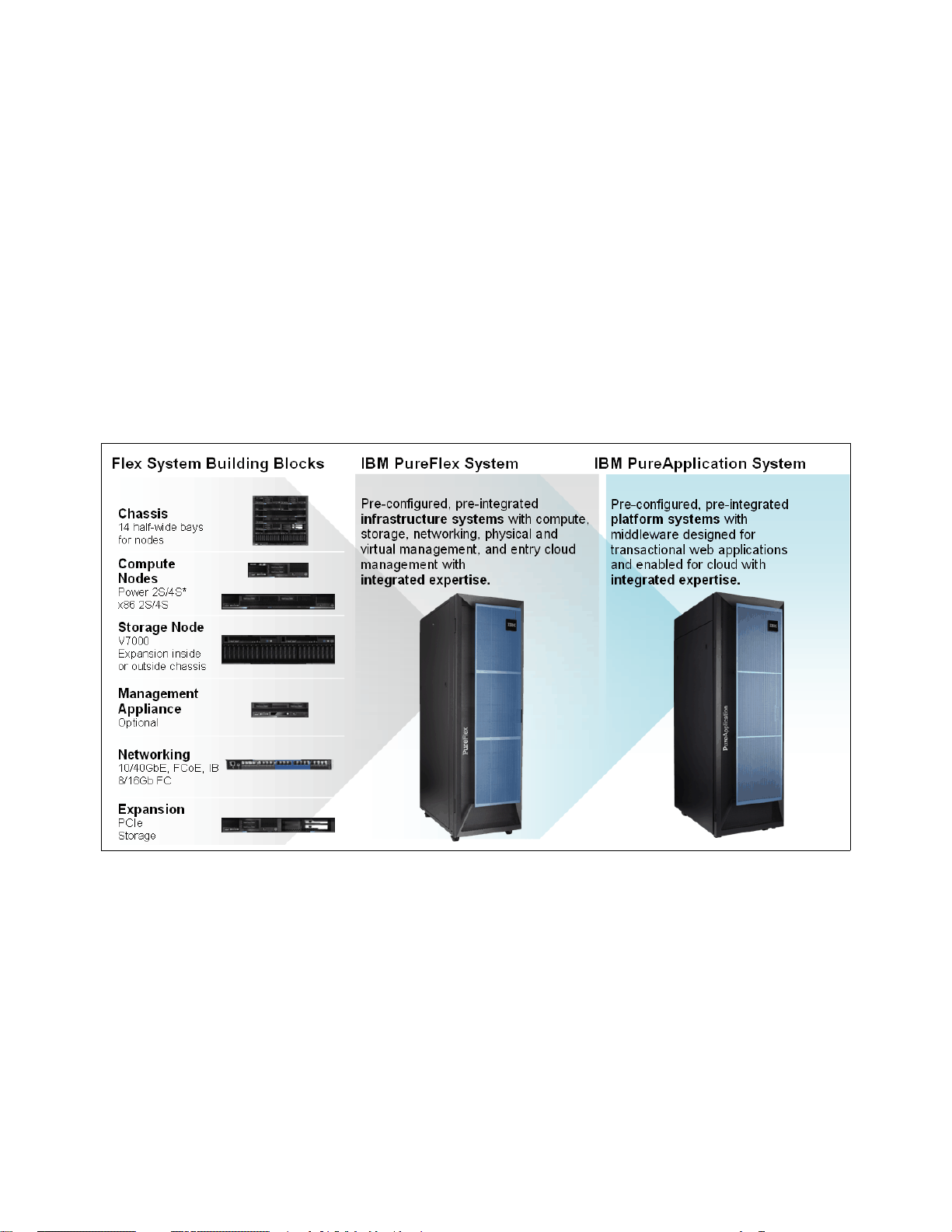
IBM PureFlex System: Infrastructure systems deeply integrate the IT elements and
expertise of your system infrastructure.
IBM PureApplication™ System: Platform systems include middleware and expertise for
deploying and managing your application platforms.
IBM PureSystems are built for cloud with integrated elasticity and virtualization capabilities to
provision new services in minutes and improve business flexibility while reducing cost.
IBM Flex System is a build-to-order offering that is integrated by the client or a partner and
does not deliver against all of the three attributes of expert integrated systems (built-in
expertise, integration by design, simplified experience). IBM Flex System allows clients to
build their own system to meet unique IT requirements with a set of no-compromise
components including compute, storage, networking, and systems management.
IBM PureFlex System and IBM PureApplication System are built on elements of the IBM Flex
System. It has been designed for clients that need pre-integrated hardware infrastructure
comprised of compute, storage and networking nodes as well as a choice of operating
systems and hypervisors.
The new offering, IBM Flex System V7000 Storage Node, is supported with IBM PureFlex
System and other IBM Flex System configurations.
2 IBM Flex System V7000 Storage Node Introduction and Implementation Guide
Page 23

1.1.1 Product names
The primary product names for the IBM PureSystems components are as follows:
IBM PureSystems:
– The overall name for IBMs new family of expert integrated systems
IBM Flex System:
– A build-to-order offering with clients choice of IBM Flex System components
– IBM Flex System that can help you go beyond blades
– An innovative Enterprise Chassis designed for new levels of simplicity, flexibility,
integration, reliability, and upgradability
– A broad range of x86 and IBM POWER® compute nodes
– New IBM Flex System V7000 Storage Node built into the Enterprise Chassis
IBM PureFlex System:
– A solution that combines compute nodes, storage, networking, virtualization and
management into a single infrastructure system. It is expert at sensing and anticipating
resource needs to optimize your infrastructure.
IBM PureApplication System:
– A platform system designed and tuned specifically for transactional web and database
applications. Its workload-aware, flexible platform is designed to be easy to deploy,
customize, safeguard, and manage.
IBM PureData™ System:
– PureData System is the newest member of the IBM PureSystems™ family that is
optimized exclusively for delivering data services to today’s demanding applications
with simplicity, speed, and lower cost.
– Like IBM PureApplication System, it offers built-in expertise, integration by design, and
a simplified experience throughout its life cycle.
IBM Flex System V7000 Storage Node:
– The product name for the IBM Flex System V7000 Storage Node family of controller
and expansion enclosures. The IBM Flex System V7000 Storage Node is an add-on for
the IBM Flex System Enterprise Chassis.
IBM Flex System V7000 Control Enclosure:
– The controller enclosure of the IBM Flex System V7000 Storage Node. The IBM Flex
System V7000 Control Enclosure is an add-on for the IBM Flex System Enterprise
Chassis and mounts internally into it.
– The IBM Flex System V7000 Control Enclosure provides 24 disk drive bays.
– The IBM Flex System V7000 Control Enclosure supports block workloads only.
IBM Flex System V7000 Expansion Enclosure:
– A SAS disk shelf with 24 disk drive bays that connects to the IBM Flex System V7000
Control Enclosure. The IBM Flex System V7000 Expansion Enclosure is an add-on for
the IBM Flex System Enterprise Chassis and mounts internally into it.
IBM Storwize V7000:
– The IBM Storwize V7000 is a disk system with built in IBM SAN Volume Controller
(SVC) functionality. It has the ability to virtualize a wide range of external storage
systems from either IBM or other Storage vendors.
– The IBM Storwize V7000 Control Enclosure provides a choice of 24 x 2.5" Small Form
Factor (SFF) disk drives or 12 x 3.5" Large Form Factor (LFF) disk drive form factors.
– The IBM Storwize V7000 supports block workloads only.
Chapter 1. Introduction to IBM Flex Systems and IBM PureSystems offerings 3
Page 24
IBM Storwize V7000 Unified:
– IBM Storwize V7000 Unified is like the IBM Storwize V7000 a disk system that provides
internal storage and external virtualization. However, the IBM Storwize V7000 Unified
also has file modules that provide NAS functionality like the CIFS and NFS protocols.
– The Storwize V7000 Unified consolidates block and file workloads into a single system.
IBM Storwize V7000 Control Enclosure:
– This component is the controller enclosure of the IBM Storwize V7000 storage system.
– The IBM Storwize V7000 Control Enclosure provides 12 or 24 disk drive bays,
depending on the model.
IBM Storwize V7000 Expansion Enclosure:
– A SAS disk shelf with either 12 or 24 disk drive bays that can connect to either the IBM
Storwize V7000 Control Enclosure or the IBM Flex System V7000 Control Enclosures.
Figure 1-2 shows the different IBM PureSystems and their building blocks.
Figure 1-1 IBM PureSystems
1.1.2 IBM PureFlex System
To meet today’s complex and ever-changing business demands, you need a solid foundation
of server, storage, networking, and software resources that is simple to deploy and can
quickly and automatically adapt to changing conditions. You also need access to, and the
ability to take advantage of, broad expertise and proven best practices in systems
management, applications, hardware maintenance, and more.
IBM PureFlex System is a comprehensive infrastructure system that provides an expert
integrated computing system, combining servers, enterprise storage, networking,
virtualization, and management into a single structure. Its built-in expertise enables
organizations to simply manage and flexibly deploy integrated patterns of virtual and
4 IBM Flex System V7000 Storage Node Introduction and Implementation Guide
Page 25
hardware resources through unified management. These systems are ideally suited for
customers interested in a system that delivers the simplicity of an integrated solution but who
also want control over tuning middleware and the run-time environment.
IBM PureFlex System recommends workload placement based on virtual machine
compatibility and resource availability. Using built-in virtualization across servers, storage,
and networking, the infrastructure system enables automated scaling of resources and true
workload mobility.
IBM PureFlex System undergoes significant testing and experimentation, so it can mitigate IT
complexity without compromising the flexibility to tune systems to the tasks businesses
demand. By providing both flexibility and simplicity, IBM PureFlex System can provide
extraordinary levels of IT control, efficiency, and operating agility that enable businesses to
rapidly deploy IT services at a reduced cost. Moreover, the system is built on decades of
expertise, enabling deep integration and central management of the comprehensive,
open-choice infrastructure system and dramatically cutting down on the skills and training
required for managing and deploying the system.
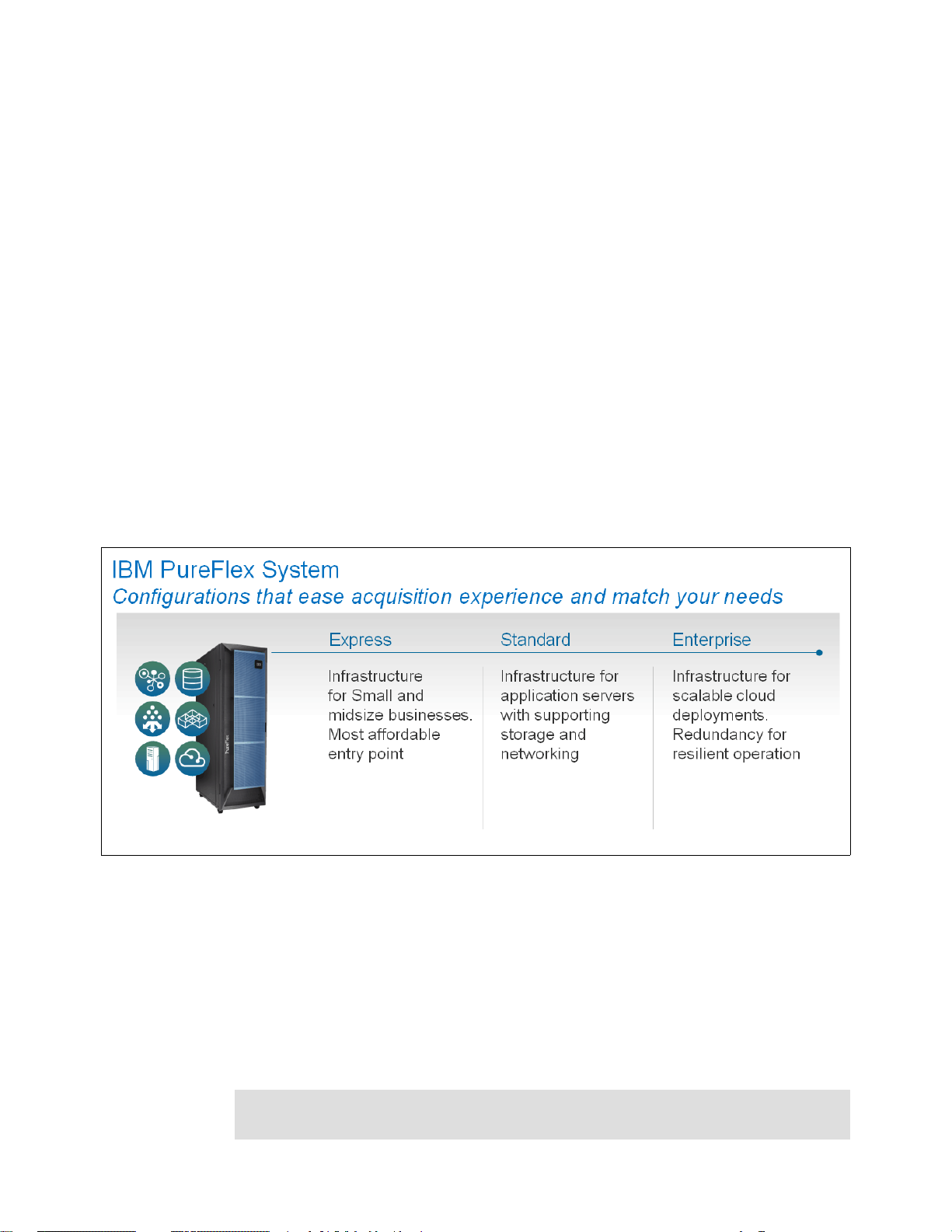
IBM PureFlex System combine advanced IBM hardware and software along with patterns of
expertise and integrate them into three optimized configurations that are simple to acquire
and deploy so you get fast time to value for your solution.
Figure 1-2 shows the IBM PureFlex System with its three different chassis implementations.
Figure 1-2 IBM PureFlex System
The three PureFlex System configurations are as follows:
IBM PureFlex System Express: Designed for small and medium businesses, it is the most
affordable entry point for the PureFlex System.
IBM PureFlex System Standard: Optimized for application servers with supporting storage
and networking, it is designed to support your key ISV solutions.
IBM PureFlex System Enterprise: Optimized for transactional and database systems, it
has built-in redundancy for highly reliable and resilient operation to support your most
critical workloads.
Note: IBM Flex System allows you to build your own system to meet the unique IT
requirements.
Chapter 1. Introduction to IBM Flex Systems and IBM PureSystems offerings 5
Page 26

The components of the PureFlex System are summarized in Table 1-1.
Table 1-1 IBM PureFlex System components
Component IBM PureFlex System
Express
IBM PureFlex System
Standard
IBM PureFlex System
Enterprise
IBM PureFlex System 42U
Rack
IBM Flex System Enterprise
Chassis
IBM Flex System Fabric
EN4093 10Gb Scalable Switch
IBM Flex System FC3171 8 Gb
SAN Switch
IBM Flex System Manager
Node
IBM Flex System Manager
software license
IBM Flex System Chassis
Management Module
Chassis power supplies
(std/max)
IBM Flex System Enterprise
Chassis 80 mm Fan Module
Pair (std/max)
IBM Flex System V7000
Storage Node
111
111
1 1 2 with both port-count
upgrades
122
111
IBM Flex System Manager
with 1-year service and
support
222
2 / 6 4 / 6 6 / 6
4 / 8 6 / 8 8 / 8
Yes (redundant controller) Yes (redundant controller) Yes (redundant controller)
IBM Flex System Manager
Advanced with 3-year
service and support
IBM Flex System Manager
Advanced with 3-year
service and support
IBM Flex System V7000 Base
Software
Base with 1-year software
maintenance agreement
The fundamental building blocks of IBM PureFlex System solutions are the IBM Flex System
Enterprise Chassis complete with compute nodes, networking, and storage. See the next
sections for more information about the building blocks of the IBM PureFlex System.
1.2, “IBM PureFlex System building blocks” on page 8
1.3, “IBM Flex System Enterprise Chassis” on page 10
1.4, “Compute nodes” on page 15
1.5, “I/O modules” on page 24
1.1.3 IBM PureApplication System
The IBM PureApplication System is a platform system that pre-integrates a full application
platform set of middleware and expertise in with the IBM PureFlex System with a single
management console. It is a workload-aware, flexible platform that is designed to be easy to
deploy, customize, safeguard, and manage in a traditional or private cloud environment,
ultimately providing superior IT economics.
Availability: IBM Flex System V7000 Storage Node is currently not offered in IBM
PureApplication Systems. Currently the only available storage for IBM PureApplication
System is IBM Storwize V7000.
Base with 3-year software
maintenance agreement
Base with 3-year software
maintenance agreement
6 IBM Flex System V7000 Storage Node Introduction and Implementation Guide
Page 27

With the IBM PureApplication System, you can provision your own patterns of software,
middleware, and virtual system resources. You can provision these patterns within a unique
framework that is shaped by IT best practices and industry standards. Such standards have
been developed from many years of IBM experience with clients and from a deep
understanding of smarter computing. These IT best practices and standards are infused
throughout the system.
With IBM PureApplication System, you enjoy the following benefits:
IBM builds expertise into preintegrated deployment patterns, which can speed the
development and delivery of new services.
By automating key processes such as application deployment, PureApplication System
built-in expertise capabilities can reduce the cost and time required to manage an
infrastructure.
Built-in application optimization expertise reduces the number of unplanned outages
through best practices and automation of the manual processes identified as sources of
those outages.
Administrators can use built-in application elasticity to scale up or to scale down
automatically. Systems can use data replication to increase availability.
Patterns of expertise can automatically balance, manage, and optimize the elements
necessary, from the underlying hardware resources up through the middleware and software.
These patterns of expertise help deliver and manage business processes, services, and
applications by encapsulating best practices and expertise into a repeatable and deployable
form. This best-practice knowledge and expertise has been gained from decades of
optimizing the deployment and management of data centers, software infrastructures, and
applications around the world.
These patterns help you achieve the following types of value:
Agility: As you seek to innovate to bring products and services to market faster, you need
fast time-to-value. Expertise built into a solution can eliminate manual steps, automate
delivery, and support innovation.
Efficiency: To reduce costs and conserve valuable resources, you must get the most out of
your systems with energy efficiency, simple management, and fast, automated response
to problems. With built-in expertise, you can optimize your critical business applications
and get the most out of your investments.
Increased simplicity: You need a less complex environment. Patterns of expertise help you
to easily consolidate diverse servers, storage and applications onto an easier-to-manage,
integrated system.
Control. With optimized patterns of expertise, you can accelerate cloud implementations
to lower risk by improving security and reducing human error.
IBM PureApplication System is available in four configurations. These configuration options
enable you to choose the size and compute power that meets your needs for application
infrastructure. You can upgrade to the next size when your organization requires more
capacity, and in most cases, you can do so without application downtime.
Chapter 1. Introduction to IBM Flex Systems and IBM PureSystems offerings 7
Page 28

Table 1-2 provides a high-level overview of the configurations.
Table 1-2 IBM PureApplication System configurations
IBM
PureApplication
System
W1500-96
Cores 96 192 384 608
RAM 1.5 TB 3.1 TB 6.1 TB 9.7 TB
SSD Storage 6.4 TB
HDD Storage 48.0 TB
Application
Services
Entitlement
IBM
PureApplication
System
W1500-192
Included
For more details about IBM PureApplication System, see the following website:
http://ibm.com/expert
1.2 IBM PureFlex System building blocks
IBM PureFlex System provides an integrated computing system, combining servers,
enterprise storage, networking, virtualization, and management into a single structure. The
built-in expertise lets organizations simply manage and flexibly deploy integrated patterns of
virtual and hardware resources through unified management.
IBM
PureApplication
System
W1500-384
IBM
PureApplication
System
W1500-608
1.2.1 Highlights
Each system consists of IBM System x® nodes, IBM Power Systems™ compute nodes, or a
combination of these two types, which is known as a hybrid configuration. The bundled,
on-site services provide some initial compute node configuration and might differ for IBM
System x nodes and Power Systems compute nodes. A client-specified primary node
(POWER or x86) is pre-configured with a hypervisor (IBM PowerVM®, VMWare, KVM,
HyperV) to allow virtual server configuration by IBM services personnel. Services also include
skills transfer to the client personnel.
Important: Initial IBM PureFlex System configuration is carried out by IBM services and is
included with the purchase. To ensure configuration success, the default shipped
configuration must not be changed until these services are completed by IBM.
8 IBM Flex System V7000 Storage Node Introduction and Implementation Guide
Page 29

1.2.2 Components
The IBM PureFlex System offerings comprise of the following components as illustrated in
Figure 1-3. With these components pre-configured, pre-integrated infrastructure systems with
compute, storage, networking, physical and virtual management, and entry cloud
management with integrated expertise are delivered by the IBM PureFlex System.
Figure 1-3 IBM PureFlex System Building Bocks
Storage components
The storage capabilities of IBM Flex System allows you to gain advanced functionality with
storage nodes in your system while taking advantage of your existing storage infrastructure
through advanced virtualization. For early versions of the IBM Flex System, the only
integrated storage was the IBM Storwize V7000 that was external to the IBM Flex System
Enterprise Chassis. With the introduction of IBM Flex System V7000 Storage Node, storage
is provided internally from the IBM Flex System Enterprise Chassis.
Simplified management
The IBM Flex System simplifies storage administration with a single user interface for all your
storage with a management console that is integrated with the comprehensive management
system. These management and storage capabilities allow you to virtualize third-party
storage with non-disruptive migration of the current storage infrastructure. You can also take
advantage of intelligent tiering so you can balance performance and cost for your storage
needs. The solution also supports local and remote replication and snapshots for flexible
business continuity and disaster recovery capabilities.
Chapter 1. Introduction to IBM Flex Systems and IBM PureSystems offerings 9
Page 30

Infrastructure
The IBM Flex System Enterprise Chassis is the foundation of the offering, supporting
intelligent workload deployment and management for maximum business agility. The 10U
high chassis has the capacity of up to 14 compute nodes, or a mix of compute nodes and
Storage, which mounts from the front. From the rear, it mounts power supplies, fans, and
different options of LAN and SAN switches. The IBM Flex System Enterprise Chassis delivers
high-performance connectivity for your integrated compute nodes, storage, networking, and
management resources. The chassis is designed to support multiple generations of
technology and offers independently scalable resource pools for higher utilization and lower
cost per workload.
We now review the various components of the IBM Flex System in order to understand how
IBM Flex System V7000 Storage Node integrates with the PureFlex Systems solution. All of
the components are used in the three pre-integrated offerings to support compute, storage,
and networking requirements. You can select from these offerings, which are designed for key
client initiatives and help simplify ordering and configuration.
While we only provide a summary of the IBM Flex System components in the following
sections, its important to understand the various available options for IBM Flex System before
we describe IBM Flex System V7000 Storage Node in detail in Chapter 2, “Introduction to
IBM Flex System V7000 Storage Node” on page 37.
For detailed information about the components, see IBM PureFlex System and IBM Flex
System Products and Technology, SG24-7984.
1.3 IBM Flex System Enterprise Chassis
The IBM Flex System Enterprise Chassis is a 10U next-generation server platform with
integrated chassis management. It is a compact, high-density, high-performance, rack-mount,
scalable server platform system. It supports up to 14 one-bay compute nodes that can share
common resources, such as power, cooling, management, and I/O resources within a single
Enterprise Chassis. In addition, it can also support up to seven 2-bay compute nodes or three
4-bay compute nodes (three IBM Flex System V7000 Storage Nodes or expansion
enclosures) when the shelves are removed from the chassis. The1-bay, 2-bay, and 4-bay
components can be “mixed and matched” to meet specific hardware requirements.
10 IBM Flex System V7000 Storage Node Introduction and Implementation Guide
Page 31

Figure 1-4 shows the chassis with IBM Flex System V7000 Storage Node occupying 4 x
compute bays, which is partially inserted into the chassis for identification.
Figure 1-4 Front view of IBM Enterprise Flex System Chassis with an IBM Flex System V7000 Storage Node
The chassis has the following features on the front:
The front information panel, located on the lower left of the chassis
Bays 1 to 14 supporting Nodes, storage enclosures and FSM
Lower airflow inlet apertures that provides air cooling for switches, IBM Flex System
Chassis Management Module and power supplies
Upper airflow inlet apertures that provide cooling for power supplies
For proper cooling, each bay in the front or rear of the chassis must contain either a device or
a filler.
The Enterprise Chassis provides several LEDs on the front information panel that can be
used to obtain the status of the chassis. The Identify, Check log and the Fault LED also
appear on the rear of the chassis for ease of use.
The major components of Enterprise Chassis are as follows:
Fourteen 1-bay compute node bays (can also support seven 2-bay or three 4-bay compute
nodes with shelves removed).
Six 2500-watt power modules that provide N+N or N+1 redundant power.
Chapter 1. Introduction to IBM Flex Systems and IBM PureSystems offerings 11
Page 32

Ten fan modules (eight 80 mm fan modules and two 40 mm fan modules).
Four physical I/O modules.
An I/O architectural design capable of providing:
– Up to 8 lanes of I/O to an I/O adapter card; each lane capable of up to 16 Gbps
– A maximum of 16 lanes of I/O to a half wide-node with two adapters
– A wide variety of networking solutions including Ethernet, Fibre Channel, FCoE, and
InfiniBand
Up to two IBM Flex System Manager (FSM) management appliances for redundancy. The
FSM provides multiple-chassis management support for up to four chassis.
Two IBM Flex System Chassis Management Module (CMMs). The CMM provides
single-chassis management support.
The chassis can be configured with the following information about the chassis location:
Rack Room
Rack Location
Position in Rack (the lowest Rack Unit occupied by the Chassis)
Chassis Name
Bay ID
Individual components will then be able to work out their bay in the chassis, the IBM Flex
System V7000 Storage Node enclosure uses 4 bays (double wide and double tall) per
enclosure and will report its bay as the lowest left bay that it occupies.
Figure 1-5 shows the rear of the chassis where the I/O modules and chassis management
modules can be seen.
Figure 1-5 Rear view of the IBM Enterprise Flex System Chassis
12 IBM Flex System V7000 Storage Node Introduction and Implementation Guide
Page 33

The following components can be installed into the rear of the chassis:
Up to two IBM Flex System Chassis Management Modules (CMM).
Up to six 2500W power supply modules.
Up to six fan modules consisting of four 80 mm fan modules and two 40 mm fan modules.
Additional fan modules can be installed, up to a total of ten modules.
Up to four I/O modules.
1.3.1 Chassis power supplies
A maximum of six power supplies can be installed within the Enterprise Chassis. The PSUs
and empty PSU bays can be seen in Figure 1-5 on page 12. The power supplies are 80 PLUS
Platinum certified and are 2100 Watts and 2500 Watts output rated at 200VAC, with
oversubscription to 2895 Watts and 3538 Watts output at 200VAC respectively. The power
supply operating range is 200-240VAC. The power supplies also contain two independently
powered 40 mm cooling fan modules that pick power up from the midplane, not from the
power supply.
Availability: The 2100W power supplies are only available by Configure to Order (CTO).
For more information about the 2100W power supply, see IBM PureFlex System and IBM
Flex System Products and Technology, SG24-7984.
Highlights
The chassis allows configurations of power supplies to give N+N or N+1 redundancy. A fully
configured chassis will operate on just three 2500 W power supplies with no redundancy, but
N+1 or N+N is likely to be preferred. Using three (or six with N+N redundancy) power supplies
allows for a balanced 3-phase configuration.
All power supply modules are combined into a single power domain within the chassis, which
distributes power to each of the compute nodes, I/O modules, and ancillary components
through the Enterprise Chassis midplane. The midplane is a highly reliable design with no
active components. Each power supply is designed to provide fault isolation and is hot
swappable.
There is power monitoring of both the DC and AC signals from the power supplies, which
allows the IBM Flex System Chassis Management Module to accurately monitor these
signals. The integral power supply fans are not dependent upon the power supply being
functional, they operate and are powered independently from the midplane.
Each power supply in the chassis has a 16A C20 3 pin socket and can be fed by a C19 power
cable, from a suitable supply.
The chassis power system is designed for efficiency using data center power consisting of
3 phase 60A Delta 200 VAC (North America) or 3 phase 32A wye 380-415 VAC
(international). The Chassis can also be fed from single phase 200-240 VAC supplies if
required.
Chapter 1. Introduction to IBM Flex Systems and IBM PureSystems offerings 13
Page 34

Power supply redundancy
There are different vendors that can vary slightly in the terminology when describing power
supply unit (PSU) redundancy. In general, ‘N’ is the minimum number of PSUs required to
keep the server operational, in this case, to keep the populated IBM Flex System Enterprise
Chassis operational. The term ‘N+1’ is the minimum number of PSUs plus one. It is not the
best option for redundancy, it is the equivalent of a “hot spare” and will protect against PSU
failure only.
The minimum number of PSUs required to keep the server or chassis operational duplicated
or doubled is referred to as ‘N+N’. The PSUs are fully redundant where there will be an even
number for minimum ‘N+N’ support.
An IBM Flex System Enterprise Chassis would typically be connected to at least two power
distribution units (PDU) in a computer room with the PSUs connected evenly across the
PDUs. With ‘N+N’ redundancy the IBM Flex System Enterprise Chassis in this configuration
is also protected against PDU failure within the computer room.
1.3.2 Fan modules and cooling
The Enterprise Chassis supports up to ten hot pluggable fan modules consisting of two
40 mm fan modules and eight 80 mm fan modules.
Highlights
A chassis can operate with a minimum of six hot-swap fan modules installed, consisting of
four 80 mm fan modules and two 40 mm fan modules. The fan modules plug into the chassis
and connect to the fan distribution cards. The 80 mm fan modules can be added as required
to support chassis cooling requirements.
The two 40 mm fan modules in fan bays 5 and 10 (top two) distribute airflow to the I/O
modules and chassis management modules. These modules ship pre installed in the chassis.
Each 40 mm fan module contains two 40 mm fans internally, side by side.
The 80 mm fan modules distribute airflow to the compute nodes through the chassis from
front to rear. Each 80 mm fan module contains two 80 mm fan modules, back to back at each
end of the module, which are counter rotating.
Both fan modules have an EMC (electromagnetic compatibility) mesh screen on the rear
internal face of the module. The design of this also has an additional benefit for the airflow, by
providing a laminar flow through the screen, which reduces turbulence of the exhaust air and
improves the efficiency of the overall fan assembly. Laminar flow is a smooth flow of air,
sometimes called streamline flow. The opposite of a laminar flow is a turbulent flow. The
design of the whole fan assembly, the fan blade design, the distance between and size of the
fan modules together with the EMC mesh screen ensures a highly efficient fan design that
provides the best cooling for lowest energy input.
The minimum number of 80 mm fan modules is four. The maximum number of 80 mm fan
modules that can be installed is eight. When the modules are ordered as an option, they are
supplied as a pair.
14 IBM Flex System V7000 Storage Node Introduction and Implementation Guide
Page 35

Environmental specifications
The chassis is designed to operate in temperatures up to 40°c (104°F), in ASHRAE class A3
operating environments.
The airflow requirements for the Enterprise Chassis are from 270 CFM (cubic feet per minute)
to a maximum of 1020 CFM.
Environmental specifications are as follows:
Humidity, non-condensing: -12°C dew point (10.4°F) and 8% - 85% relative humidity
Maximum dew point: 24°C (75°F)
Maximum elevation: 3050 m (10.006 ft.)
Maximum rate of temperature change: 5°C/hr. (41°F/hr.)
Heat output (approximate):
Maximum configuration: potentially 12.9kW
The 12.9 kW figure is only a potential maximum, where the most power hungry configuration
is chosen and all power envelopes are maximum. For a more realistic figure, the IBM Power
Configurator tool can be made to establish specific power requirements for a given
configuration.
The Power Configurator tool can be found at the following website:
http://www.ibm.com/systems/x/hardware/configtools.html
1.4 Compute nodes
The IBM Flex System portfolio of compute nodes includes those with Intel Xeon processors or
with IBM POWER7® processors. Depending on the compute node design, it can come in one
of two different form factors:
Half-wide node: Occupies one chassis bay, half the width of the chassis (approximately
215 mm or 8.5”).
Full-wide node: Occupies two chassis bays side-by-side, the full width of the chassis
(approximately 435 mm or 17”).
The applications installed on the compute nodes can be running on an operating system run
natively on a dedicated physical server or can be virtualized in a virtual machine managed by
a hypervisor layer. Here we provide a summary of the compute nodes. For further detailed
information about these topics, see the IBM Flex System p260 and p460 Planning and
Implementation Guide, SG24-7989 and IBM PureFlex System and IBM Flex System Products
and Technology, SG24-7984.
1.4.1 IBM Flex System x440 Compute Node
The IBM Flex System x440 Compute Node (machine type 7917) is a high-density four socket
server, optimized for high-end virtualization, mainstream database deployments,
memory-intensive and high performance environments.
The IBM Flex System x440 Compute Node is a double-wide compute node providing
scalability to support up to four Intel Xeon E5-4600 processors. The node’s width allows for a
significant I/O capability.
Chapter 1. Introduction to IBM Flex Systems and IBM PureSystems offerings 15
Page 36

Figure 1-6 shows the front of the compute node, showing the location of the controls, LEDs,
and connectors. The light path diagnostic panel is located on the upper edge of the front
panel bezel, in the same place as the x220 and x240.
Figure 1-6 IBM Flex System x440 Compute Node
See IBM Flex System x440 Compute Node, TIPS0886 for more information.
1.4.2 IBM Flex System x240 Compute Node
The IBM Flex System x240 Compute Node, available as machine type 8737, is a half-wide,
two-socket server running the latest Intel Xeon processor E5-2600 family processors. It is
ideal for infrastructure, virtualization, and enterprise business applications and is compatible
with the IBM Flex System Enterprise Chassis. The x240 supports up to two Intel Xeon
E5-2600 series multi-core processors, 24 DIMM modules, two hot-swap drives, two PCI
Express I/O adapter cards, and has an option for two internal USB connectors. Figure 1-7
shows the single bay x240 compute node.
Figure 1-7 The x240 type 8737
16 IBM Flex System V7000 Storage Node Introduction and Implementation Guide
Page 37

The IBM Flex System x240 Compute Node type 8737 features the Intel Xeon E5-2600 series
LSI2004
SAS
Controller
Hot-Swap
Storage
Device 1
Hot-Swap
Storage
Device 2
SAS 0
SAS 1
SAS 0
SAS 1
processors with two, four, six, or eight cores per processor, with up to 16 threads per socket.
The processors have up to 20 MB of shared L3 cache, Hyper-Threading, Turbo Boost
Technology 2.0 (depending on processor model), two QuickPath Interconnect (QPI) links that
run at up to 8 GT/s, one integrated memory controller, and four memory channels supporting
up to three DIMMs each.
The x240 includes 8 GB of memory (2 x 4 GB DIMMs) running at either 1600 MHz or 1333
MHz depending on model. Some models include an Embedded 10 Gb Virtual Fabric Ethernet
LAN-on-motherboard (LOM) controller as standard; this embedded controller precludes the
use of an I/O adapter in I/O connector 1. Model numbers in the form x2x (for example,
8737-L2x) include an Embedded 10 Gb Virtual Fabric Ethernet LAN-on-motherboard (LOM)
controller as standard. Model numbers in the form x1x (for example, 8737-A1x) do not include
this embedded controller.
The x240 with the Intel Xeon E5-2600 series processors can support up to 768 GB of
memory in total when using 32 GB LRDIMMs and with both processors installed. The x240
uses Double Data Rate-3 (DDR-3) low-profile (LP) DIMMs. The x240 supports three types of
DIMM memory:
Registered DIMM (RDIMM) modules
Unbuffered DIMM (UDIMM) modules
Load-reduced (LRDIMM) modules
The mixing of these different memory DIMM types is not supported.
The x240 compute node features an onboard LSI 2004 SAS controller with two small form
factor (SFF) hot-swap drive bays that are accessible from the front of the compute node. The
onboard LSI SAS2004 controller provides RAID 0, RAID 1, or RAID 10 capability and
supports up to two SFF hot-swap SAS or SATA HDDs or two SFF hot-swap solid state drives.
Figure 1-8 shows how the LSI2004 SAS controller and hot-swap storage devices connect to
the internal HDD interface.
Figure 1-8 The LSI2004 SAS controller connections to HDD interface
Each x240 server has an Integrated Management Module version 2 (IMMv2) onboard and
uses the Unified Extensible Firmware Interface (UEFI) to replace the older BIOS interface.
Chapter 1. Introduction to IBM Flex Systems and IBM PureSystems offerings 17
Page 38

Embedded 10 Gb Virtual Fabric Adapter
I/O Connector 1
I/O Connector 2
Some models of the x240 include an Embedded 10 Gb Virtual Fabric Adapter (VFA, also
known as LAN on Motherboard or LOM), built into the system board. Each of these models
that includes the embedded 10 Gb VFA also has the Compute Node Fabric Connector
installed in I/O connector 1 (and physically screwed onto the system board) to provide
connectivity to the Enterprise Chassis midplane.
I/O expansion
The x240 has two PCIe 3.0 x16 I/O expansion connectors for attaching I/O adapter cards.
There is also another expansion connector designed for future expansion options. The I/O
expansion connectors are a very high-density 216 pin PCIe connector. By installing I/O
adapter cards, it allows the x240 to connect with switch modules in the IBM Flex System
Enterprise Chassis.
Figure 1-9 shows the rear of the x240 compute node and the locations of the I/O connectors.
18 IBM Flex System V7000 Storage Node Introduction and Implementation Guide
Figure 1-9 Rear of the x240 compute node showing the locations of the I/O connectors
Page 39

1.4.3 IBM Flex System x220 Compute Node
The IBM Flex System x220 Compute Node, machine type 7906, is the next generation
cost-optimized compute node designed for less demanding workloads and low-density
virtualization. The x220 is efficient and equipped with flexible configuration options and
advanced management to run a broad range of workloads. It is a high-availability, scalable
compute node optimized to support the next-generation microprocessor technology. With a
balance between cost and system features, the x220 is an ideal platform for general business
workloads. This section describes the key features of the server.
Highlights
Figure 1-10 shows the front of the compute node indicating location of the controls, LEDs,
and connectors.
Figure 1-10 IBM Flex System x220 Compute Node
The IBM Flex System x220 Compute Node features the Intel Xeon E5-2400 series
processors. The Xeon E5-2400 series processor has models with either four, six, or eight
cores per processor with up to 16 threads per socket. The processors have up to 20 MB of
shared L3 cache, Hyper-Threading, Turbo Boost Technology 2.0 (depending on processor
model), one QuickPath Interconnect (QPI) link that runs at up to 8 GT/s, one integrated
memory controller, and three memory channels supporting up to two DIMMs each.
The x220 also supports an Intel Pentium 1403 or 1407 dual-core processor for entry-level
server applications. Only one Pentium processor is supported in the x220. CPU socket 2 must
be left unused and only six DIMM socks are available.
The x220 supports Low Profile (LP) DDR3 memory registered DIMMs (RDIMMs) and
unbuffered DIMMs (UDIMMs). The server supports up to six DIMMs when one processor is
installed and up to 12 DIMMs when two processors are installed. Each processor has three
memory channels, and there are two DIMMs per channel.
The x220 server has two 2.5-inch hot-swap drive bays accessible from the front of the blade
server as shown in Figure 1-10. The server optionally supports three internal disk controllers
allowing a greater number of internal drives up to a maximum of eight with the ServeRAID
M5115 controller and also supports 1.8-inch solid-state drives.
Chapter 1. Introduction to IBM Flex Systems and IBM PureSystems offerings 19
Page 40

Each IBM Flex System x220 Compute Nodehas an Integrated Management Module version 2
(IMMv2) onboard and uses the Unified Extensible Firmware Interface (UEFI).
Embedded 1 Gb Ethernet controller
Some models of the x220 include an Embedded 1 Gb Ethernet controller (also known as LAN
on Motherboard or LOM) built into the system board. Each x220 model that includes the
controller also has the Compute Node Fabric Connector installed in I/O connector 1 (and
physically screwed onto the system board) to provide connectivity to the Enterprise Chassis
midplane.
The Fabric Connector enables port 1 on the controller to be routed to I/O module bay 1 and
port 2 to be routed to I/O module bay 2. The Fabric Connector can be unscrewed and
removed, if required, to allow the installation of an I/O adapter on I/O connector 1.
1.4.4 IBM Flex System p260 and p24L Compute Nodes
The IBM Flex System p260 Compute Node and IBM Flex System p24L Compute Node are
based on IBM POWER architecture technologies. These compute nodes run in IBM Flex
System Enterprise Chassis units to provide a high-density, high-performance compute node
environment, using advanced processing technology. The IBM Flex System p24L Compute
Node shares several similarities to the IBM Flex System p260 Compute Node in that it is a
half-wide, Power Systems compute node with two POWER7 processor sockets,16 memory
slots, two I/O adapter slots, and an option for up to two internal drives for local storage. The
IBM Flex System p24L Compute Node is optimized for lower-cost Linux installations.
Highlights
The IBM Flex System p260 Compute Node has the following features:
Two processors with up to 16 POWER7 processing cores, up to 8 per processor
Sixteen DDR3 memory DIMM slots supporting IBM Active Memory™ Expansion
Supports VLP (Very Low Profile) and LP (Low Profile) DIMMs
Two P7IOC I/O hubs
RAID-compatible SAS controller supporting up to 2 SSD or HDD drives
Two I/O adapter slots
Flexible Support Processor (FSP)
System management alerts
IBM Light Path Diagnostics
USB 2.0 port
IBM EnergyScale™ technology
The front panel of Power Systems compute nodes has the following common elements, as
shown in Figure 1-11:
USB 2.0 port
Power-control button and light path, light-emitting diode (LED) (green)
Location LED (blue)
Information LED (amber)
Fault LED (amber)
20 IBM Flex System V7000 Storage Node Introduction and Implementation Guide
Page 41

Figure 1-11 IBM Flex System p260 Compute Node with front panel details
USB 2.0 port
Power button LEDs (left-right):
location, info, fault
There is no onboard video capability in the Power Systems compute nodes. The machines
have been designed to be accessed using Serial Over LAN (SOL) or the IBM Flex System
Manager (FSM).
The IBM POWER7 processor represents a leap forward in technology and associated
computing capability. The multi-core architecture of the POWER7 processor has been
matched with a wide range of related technologies to deliver leading throughput, efficiency,
scalability, and reliability, availability, and serviceability (RAS).
Although the processor is an important component in servers, many elements and facilities
have to be balanced across a server to deliver maximum throughput. As with previous
generations of systems based on POWER processors, the design philosophy for POWER7
processor-based systems is one of system-wide balance in which the POWER7 processor
plays an important role.
Each POWER7 processor has an integrated memory controller. Industry standard DDR3
Registered DIMM (RDIMM) technology is used to increase reliability, speed, and density of
memory subsystems.
The p260 and p24L has an onboard SAS controller that can manage up to two,
non-hot-pluggable internal drives. Both 2.5-inch hard disk drives (HDDs) and 1.8-inch
solid-state drives (SSDs) are supported. The maximum number of drives that can be installed
in the p260 or p24L is two. SSD and HDD drives cannot be mixed.
There are several advanced system management capabilities built into the p260 and p24L.
A Flexible Service Processor handles most of the server-level system management. It has
features, such as system alerts and Serial-Over-LAN capability.
Chapter 1. Introduction to IBM Flex Systems and IBM PureSystems offerings 21
Page 42

A Flexible Service Processor (FSP) provides out-of-band system management capabilities,
such as system control, run-time error detection, configuration, and diagnostics. Generally,
you do not interact with the FSP directly but, rather, using tools, such as IBM Flex System
Manager, IBM Flex System Chassis Management Module, and external IBM Systems
Director Management Console. The FSP provides a Serial-over-LAN interface, which is
available with the IBM Flex System Chassis Management Module and the console command.
The p260 and p24L do not have an on-board video chip and do not support keyboard, video,
and mouse (KVM) connection. Server console access is obtained by a SOL connection only.
SOL provides a means to manage servers remotely by using a command-line interface (CLI)
over a Telnet or secure shell (SSH) connection. SOL is required to manage servers that do
not have KVM support or that are attached to the IBM Flex System Manager. SOL provides
console redirection for both System Management Services (SMS) and the server operating
system. The SOL feature redirects server serial-connection data over a LAN without requiring
special cabling by routing the data using the IBM Flex System Chassis Management Module
network interface. The SOL connection enables Power Systems compute nodes to be
managed from any remote location with network access to the IBM Flex System Chassis
Management Module.
The IBM Flex System Chassis Management Module CLI provides access to the text-console
command prompt on each server through a SOL connection, enabling the p260 and p24L to
be managed from a remote location.
I/O adapter slots
There are two I/O adapter slots on the p260 and the p24L which are identical in shape (form
factor). Also different is that the I/O adapters for the Power Systems compute nodes have
their own connector that plugs into the IBM Flex System Enterprise Chassis midplane.
The I/O is controlled by two P7-IOC I/O controller hub chips. This provides additional flexibility
when assigning resources within Virtual I/O Server (VIOS) to specific Virtual Machine/LPARs.
1.4.5 IBM Flex System p460 Compute Node
The IBM Flex System p460 Compute Node is also based on IBM POWER architecture
technologies. This compute node is a full-wide, Power Systems compute node with four
POWER7 processor sockets, 32 memory slots, four I/O adapter slots, and an option for up to
two internal drives for local storage. It runs in IBM Flex System Enterprise Chassis units to
provide a high-density, high-performance compute node environment, using advanced
processing technology.
Highlights
The IBM Flex System p460 Compute Node has the following features:
Four processors with up to 32 POWER7 processing cores
Thirty-two DDR3 memory DIMM slots that support IBM Active Memory Expansion
Supports Very Low Profile (VLP) and Low Profile (LP) DIMMs
Four P7IOC I/O hubs
RAID-capable SAS controller that support up to two SSD or HDD drives
Four I/O adapter slots
Flexible Support Processor (FSP)
System management alerts
IBM Light Path Diagnostics
USB 2.0 port
IBM EnergyScale technology
22 IBM Flex System V7000 Storage Node Introduction and Implementation Guide
Page 43

The front panel of Power Systems compute nodes has the following common elements, as
Power button
LEDs (left-right):
location, info, fault
USB 2.0 port
shown by the p460 in Figure 1-12:
USB 2.0 port
Power-control button and light path, light-emitting diode (LED) (green)
Location LED (blue)
Information LED (amber)
Fault LED (amber)
Figure 1-12 IBM Flex System p460 Compute Node showing front indicators
The USB port on the front of the Power Systems compute nodes is useful for a variety of
tasks, including out-of-band diagnostics, hardware RAID setup, operating system access to
data on removable media, and local OS installation. It might be helpful to obtain a USB optical
(CD or DVD) drive for these purposes, in case the need arises, as there is no optical drive in
the IBM Flex System Enterprise Chassis.
Although the processor is an important component in servers, many elements and facilities
have to be balanced across a server to deliver maximum throughput. As with previous
generations of systems based on POWER processors, the design philosophy for POWER7
processor-based systems is one of system-wide balance in which the POWER7 processor
plays an important role.
Each POWER7 processor has two integrated memory controllers in the chip. Industry
standard DDR3 Registered DIMM (RDIMM) technology is used to increase reliability, speed,
and density of memory subsystems. The functional minimum memory configuration for the
machine is 4 GB (2 x 2 GB) but that is not sufficient for reasonable production use of the
machine. It is recommended for the IBM Flex System p460 Compute Node a minimum of
32 GB of memory, with 32 x 16 GB DIMMs the maximum memory configurable is 512 GB.
The p460 has an onboard SAS controller that can manage up to two, non-hot-pluggable
internal drives. Even though the p460 is a full-wide server, it has the same storage options as
the p260 and the p24L.
The type of local drives used impacts the form factor of your memory DIMMs. If HDDs are
chosen, then only very-low-profile (VLP) DIMMs can be used because of internal spacing.
There is not enough room for the 2.5-inch drives to be used with low-profile (LP) DIMMs
(currently the 2 GB and 16 GB sizes). Verify your memory choice to make sure it is
compatible with the local storage configuration. The use of SSDs does not have the same
limitation, and LP DIMMs can be used with SSDs.
The p460 System Management is the same as the p260 and p24L POWER compute nodes.
Chapter 1. Introduction to IBM Flex Systems and IBM PureSystems offerings 23
Page 44

I/O adapter slots
1
3
2
4
The networking subsystem of the IBM Flex System Enterprise Chassis has been designed to
provide increased bandwidth and flexibility. The new design also allows for more ports on the
available expansion adapters, which will allow for greater flexibility and efficiency with your
system’s design.
There are four I/O adapter slots on the IBM Flex System p460 Compute Node. The I/O
adapters for the p460 have their own connector that plugs into the IBM Flex System
Enterprise Chassis midplane. There is no onboard network capability in the Power Systems
compute nodes other than the Flexible Service Processor (FSP) NIC interface.
The I/O is controlled by four P7-IOC I/O controller hub chips. This provides additional
flexibility when assigning resources within Virtual I/O Server (VIOS) to specific Virtual
Machine/LPARs.
1.5 I/O modules
The Enterprise Chassis can accommodate a total of four I/O modules which are installed in
vertical orientation into the rear of the chassis, as shown in Figure 1-13, where the four
modules at the back of the chassis with the bays numbered. In addition to the two types of
switches listed in Table 1-1 on page 6, there are alternative I/O modules that provide external
connectivity, as well as connecting internally to each of the nodes within the chassis. They
can be either Switch or Pass through modules with a potential to support other types in the
future. These models can be ordered in “build to order” IBM Flex Systems solutions.
Figure 1-13 IBM Flex System Enterprise Chassis with I/O module bays numbered
24 IBM Flex System V7000 Storage Node Introduction and Implementation Guide
Page 45

If a node has a two port integrated LAN on Motherboard (LOM) as standard, Module 1 and 2
Node
bay 1
with LOM
Node
bay 2
with I/O
expansion
adapter
Node
bay 14
LOM
LOM connector
(remove when
I/O expansion
adapter is installed)
I/O module 1
I/O module 3
I/O module 2
I/O module 4
LOM
4 lanes (KX-4) or
4 10 Gbps lanes (KR)
14 internal groups
(of 4 lanes each),
one to each node.
are connected to it. If an I/O adapter is installed in the nodes I/O expansion bay 1, then
Module 1 and 2 would be connected to this. Module 3 and 4 connect to the I/O adapter that is
installed within I/O expansion bay 2 on the node. See Figure 1-14.
1.5.1 IBM Flex System Fabric CN4093 10 Gb Converged Scalable Switch
Figure 1-14 LOM, I/O adapter and switch module connection for node bays
The node in Bay 1 in Figure 1-14 shows that when shipped with a LOM, the LOM connector
provides the link from the node motherboard to the midplane. Some nodes do not ship with
LOM.
If required, this LOM connector can be removed and an I/O expansion adapter installed in its
place. It is shown on the node in Bay 2 in Figure 1-14.
The IBM Flex System Fabric CN4093 10 Gb Converged Scalable Switch provides support for
L2 and L3 switching, Converged Enhanced Ethernet (PFC, ETS, DCBX), Fibre Channel over
Ethernet (FCoE), NPV Gateway, and Full Fabric Fibre Channel Forwarder (FCF).
The switch has the following major components:
42 10 Gb Ethernet internal ports and twenty-two external ports. External ports are
arranged as two (small form-factor pluggable plus) SFP+ ports
12 SFP+ Omni Ports
2 Quad Small Form-Factor Pluggable Plus (QSFP+) ports.
Chapter 1. Introduction to IBM Flex Systems and IBM PureSystems offerings 25
Page 46

Each Omni Port is capable of running in 10 Gb Ethernet or 4/8 Gb FC mode with
auto-negotiation capability.
Support for Converged Enhanced Ethernet (CEE) and Fibre Channel over Ethernet
(FCoE) over all Ethernet ports including Omni Ports (in Ethernet mode).
Support for the Full Fabric FCF (Fibre Channel Forwarder) and NPV gateway.
Support for full fabric FC services including Name Server, hardware-based Zoning.
Support for IBM vNIC (virtual network interface card) Virtual Fabric Adapter with Single
Root I/O Virtualization (SR-IOV) capability.
The 10 Gb Ethernet switch supports single compute node port capability (14 ports). Dual
compute node port capability (28 ports) and triple compute node port capability (42 ports) are
available with optional licenses.
The base model of this scalable switch provides the following features:
14 internal 10 Gb Ethernet/FCoE ports
2 external 1 Gb/10 Gb Ethernet/FCoE ports
6 external flexible ports, usable for either 10 Gb Ethernet/FCoE or 4/8 Gb Fibre Channel.
With the optional licensing for pay-as-you-grow scalability, you can easily and cost-effectively
enable additional internal 10 Gb Ethernet/FCoE ports, external 10 Gb/40 Gb Ethernet/FCoE
ports and external flexible ports, usable for either 10 Gb Ethernet/FCoE or 4/8 Gb Fibre
Channel.
For switch management, access can be provided through the following connections:
A SSHv2/Telnet connection to the embedded command-line interface (CLI)
A terminal emulation program connection to the serial port interface
A Web browser-based interface (https/http) connection to the switch
1.5.2 IBM Flex System Fabric EN4093 and EN4093R 10 Gb Scalable Switch
The IBM Flex System Fabric EN4093 and EN4093R 10 Gb Scalable Switches are 10 Gb
64-port upgradable midrange to high-end switch module, offering Layer 2/3 switching
designed to install within the I/O module bays of the Enterprise Chassis. The switch has the
following features:
Up to 42 internal 10 Gb ports
Up to 14 external 10 Gb uplink ports (SFP+ connectors)
Up to 2 external 40 Gb uplink ports (QSFP+ connectors)
The switch is considered particularly suited for these needs:
Building a 10 Gb infrastructure
Implementing a virtualized environment
Investment protection for 40 Gb uplinks
TCO reduction, improving performance, while maintaining high levels of availability and
security
Oversubscription avoidance (traffic from multiple internal ports attempting to pass through
a lower quantity of external ports, leading to congestion and performance impact)
26 IBM Flex System V7000 Storage Node Introduction and Implementation Guide
Page 47

The rear of the switch has 14 SPF+ module ports and 2QSFP+ module ports. The QSFP+
ports can be used to provide either two 40 Gb uplinks or eight 10 Gb ports, using one of the
supported QSFP+ to 4x 10 Gb SFP+ cables. This cable splits a single 40 Gb QSPFP port into
4 SFP+ 10 Gb ports.
For management of the switch, a mini USB port and also an Ethernet management port are
provided.
IBM Flex System Fabric EN4093R: IBM Flex System Fabric EN4093R’s stacking
capabilities simplify management for clients by stacking up to eight switches that share one
IP address and one management interface. Support for Switch Partition (SPAR) allows
clients to virtualize the switch with partitions that isolate communications for multitenancy
environments.
For more information about the IBM Flex System Fabric EN4093 and EN4093R 10 Gb
Scalable Switches, see IBM Flex System Fabric EN4093 and EN4093R 10Gb Scalable
Switches, TIPS0864.
1.5.3 IBM Flex System EN4091 10 Gb Ethernet Pass-thru
The EN4091 10Gb Ethernet Pass-thru module offers a 1 for 1 connection between a single
node bay and an I/O module uplink. It has no management interface and can support both
1 Gb and 10 Gb dual-port adapters installed in the compute nodes. If quad-port adapters are
installed in the compute nodes, only the first two ports will have access to the pass-thru
module’s ports.
The necessary 1 GbE or 10 GbE module (SFP, SFP+ or DAC) must also be installed in the
external ports of the pass-thru, to support the speed wanted (1 Gb or 10 Gb) and medium
(fiber optic or copper) for adapter ports on the compute nodes.
Four-port adapters: The EN4091 10 Gb Ethernet Pass-thru has only 14 internal ports. As a
result, only two ports on each compute node are enabled, one for each of two pass-thru
modules installed in the chassis. If four-port adapters are installed in the compute nodes,
ports 3 and 4 on those adapters are not enabled.
For more information about the IBM Flex System EN4091 10 Gb Ethernet Pass-thru, see IBM
Flex System EN4091 10Gb Ethernet Pass-thru Module, TIPS0865.
1.5.4 IBM Flex System EN2092 1 Gb Ethernet Scalable Switch
The EN2092 1 Gb Ethernet Switch provides support for L2/L3 switching and routing. The
switch has:
Up to 28 internal 1 Gb ports
Up to 20 external 1 Gb ports (RJ45 connectors)
Up to 4 external 10 Gb uplink ports (SFP+ connectors)
The switch comes standard with 14 internal and 10 external Gigabit Ethernet ports enabled.
Further ports can be enabled, including the four external 10 Gb uplink ports.
For more information about the IBM Flex System EN2092 1 Gb Ethernet Scalable Switch, see
IBM Flex System EN2092 1Gb Ethernet Scalable Switch, TIPS0861.
Chapter 1. Introduction to IBM Flex Systems and IBM PureSystems offerings 27
Page 48

1.5.5 IBM Flex System FC5022 16 Gb SAN Scalable Switch
The IBM Flex System FC5022 16 Gb SAN Scalable Switch is a high-density, 48-port 16 Gbps
Fibre Channel switch that is used in the Enterprise Chassis. The switch provides 28 internal
ports to compute nodes by way of the midplane, and 20 external SFP+ ports. These SAN
switch modules deliver an embedded option for IBM Flex System users deploying storage
area networks in their enterprise. They offer end-to-end 16 Gb and 8 Gb connectivity.
The N_Port Virtualization mode streamlines the infrastructure by reducing the number of
domains to manage while enabling the ability to add or move servers without impact to the
SAN. Monitoring is simplified by an integrated management appliance, or clients using
end-to-end Brocade SAN can leverage the Brocade management tools.
Two versions are available, a 12-port switch module and a 24-port switch with the Enterprise
Switch Bundle (ESB) software. The port count can be applied to internal or external ports
using a a feature called Dynamic Ports on Demand (DPOD).
With DPOD, ports are licensed as they come online. With the FC5022 16Gb SAN Scalable
Switch, the first 12 ports reporting (on a first-come, first-served basis) on boot-up are
assigned licenses. These 12 ports can be any combination of external or internal Fibre
Channel (FC) ports. After all licenses have been assigned, you can manually move those
licenses from one port to another. As it is dynamic, no defined ports are reserved except ports
0 and 29. The FC5022 16Gb ESB Switch has the same behavior, the only difference is the
number of ports.
For more information about the IBM Flex System FC5022 16 Gb SAN Scalable Switch, see
IBM Flex System FC5022 16Gb SAN Scalable Switches, TIPS0870.
1.5.6 IBM Flex System FC3171 8 Gb SAN Switch
The IBM Flex System FC3171 8 Gb SAN Switch is a full-fabric Fibre Channel switch module
that can be converted to a pass-thru module when configured in transparent mode. It can be
done using the switch GUI or CLI and then the Module can be converted back to a full
function SAN switch at some future date. The switch requires a reset when turning
transparent mode on or off.
The I/O module has 14 internal ports and 6 external ports. All ports are licensed on the switch
as there are no port licensing requirements.
On this switch, when in Full Fabric mode, access to all of the Fibre Channel Security features
is provided. Security includes additional services available, such as Secure Socket Layer
(SSL) and Secure Shell (SSH). In addition, RADIUS servers can be used for device and user
authentication. After SSL/SSH is enabled, then the Security features are available to be
configured. This allows the SAN administrator to configure which devices are allowed to login
to the Full Fabric Switch module, by creating security sets with security groups. They are
configured on a per switch basis. The security features are not available when in pass-thru
mode.
28 IBM Flex System V7000 Storage Node Introduction and Implementation Guide
Page 49

The switch can be configured either by command line or by QuickTools:
Command Line: Access the switch by the console port through the IBM Flex System
Chassis Management Module or through the Ethernet Port. This method requires a basic
understanding of the CLI commands.
QuickTools: Requires a current version of the JRE on your workstation before pointing a
web browser to the switch’s IP address. The IP Address of the switch must be configured.
QuickTools does not require a license and code is included.
For more information about the IBM Flex System FC3171 8 Gb SAN Switch, see IBM Flex
System FC3171 8Gb SAN Switch and Pass-thru, TIPS0866.
1.5.7 IBM Flex System FC3171 8 Gb SAN Pass-thru
The IBM Flex System FC3171 8 Gb SAN Pass-thru I/O module is an 8 Gbps Fibre Channel
pass-thru SAN module that has 14 internal ports and six external ports. It is shipped with all
ports enabled.
Tip: If there is a potential future requirement to enable full fabric capability, then this switch
should not be purchased and instead the FC3171 8Gb SAN Switch should be considered.
The FC3171 8 Gb SAN Pass-thru can be configured using either command line or
QuickTools.
Command Line: Access the module by the console port through the IBM Flex System
Chassis Management Module or through the Ethernet Port. This method requires a basic
understanding of the CLI commands.
QuickTools: Requires a current version of the JRE on your workstation before pointing a
web browser to the modules IP address. The IP Address of the module must be
configured. QuickTools does not require a license and code is included.
For more information about the IBM Flex System FC3171 8 Gb SAN Pass-thru, see IBM Flex
System FC3171 8Gb SAN Switch and Pass-thru, TIPS0866.
1.5.8 IBM Flex System IB6131 InfiniBand Switch
The IBM Flex System IB6131 InfiniBand Switch is a 32 port InfiniBand switch. It has 18
FDR/QDR (56/40 Gbps) external ports and 14 FDR/QDR (56/40 Gbps) internal ports for
connections to nodes. This switch ships standard with QDR and can be upgraded to FDR.
Running the MLNX-OS, this switch has one external 1 Gb management port and a mini USB
Serial port for updating software and debug use, along with InfiniBand internal and external
ports.
The switch has fourteen internal QDR links and eighteen CX4 uplink ports. All ports are
enabled. The switch can be upgraded to FDR speed (56 Gbps) by the Feature On Demand
(FOD) process.
Note: InfiniBand is not a supported protocol for IBM Flex System V7000 Storage Node nor
IBM Storwize V7000.
For more information about the IBM Flex System IB6131 InfiniBand Switch, see IBM Flex
System IB6131 InfiniBand Switch, TIPS0871.
Chapter 1. Introduction to IBM Flex Systems and IBM PureSystems offerings 29
Page 50

1.6 Introduction to IBM Flex System storage
Either the IBM Storwize V7000 or IBM Flex System V7000 Storage Node is an integrated part
of the IBM PureFlex System, depending on the model. Figure 1-15 shows an IBM Flex
System V7000 Storage Node, where the left controller, called a cannister, is taken out. For the
IBM Storwize V7000 products, the cannisters mount from the rear, whereas in IBM Flex
System V7000 Storage Node, the controllers mount from the front.
Figure 1-15 IBM Flex System V7000 Storage Node
The IBM Storwize V7000 product is described in detail in the Implementing the IBM Storwize
V7000 V6.3, SG24-7938.
For more information about IBM Flex System V7000 Storage Node, see Chapter 2,
“Introduction to IBM Flex System V7000 Storage Node” on page 37.
1.6.1 IBM Storwize V7000 and IBM Flex System V7000 Storage Node
IBM Storwize V7000 and IBM Flex System V7000 Storage Node are virtualized storage
systems designed to complement virtualized server environments. They provide unmatched
performance, availability, advanced functions, and highly scalable capacity. IBM Storwize
V7000 and IBM Flex System V7000 Storage Node are powerful disk systems that have been
designed to be easy to use and enable rapid deployment without additional resources.
IBM Storwize V7000 and IBM Flex System V7000 Storage Node support block workloads,
whereas Storwize V7000 Unified (not covered in this book) consolidates block and file
workloads into a single storage system for simplicity of management and reduced cost.
IBM Storwize V7000 and IBM Flex System V7000 Storage Node offer greater efficiency and
flexibility through built-in solid state drive (SSD) optimization and thin provisioning
technologies. IBM Storwize V7000 and IBM Flex System V7000 Storage Node advanced
functions also enable non-disruptive migration of data from existing storage, simplifying
implementation and minimizing disruption to users. Finally, these systems also enable you to
virtualize and reuse existing disk systems, supporting a greater potential return on investment
(ROI).
30 IBM Flex System V7000 Storage Node Introduction and Implementation Guide
Page 51

IBM Flex System V7000 Storage Node is designed to integrate into the IBM PureFlex System
or IBM Flex System to enable extremely rapid storage deployment and breakthrough
management simplicity. This new class of storage system combines no-compromise design
along with virtualization, efficiency, and performance capabilities of IBM Storwize V7000. It
helps simplify and speed PureFlex System and IBM Flex System infrastructure deployment
with superior server and storage management integration to automate and streamline
provisioning and to help organizations achieve greater responsiveness to business needs
while reducing costs.
For more information about IBM Real-time Compression in relation to IBM SAN Volume
Controller and IBM Storwize V7000, see Real-time Compression in SAN Volume Controller
and Storwize V7000, REDP-4859.
Highlights
Here are the highlights of IBM Storwize V7000 and IBM Flex System V7000 Storage Node:
Delivers sophisticated enterprise-class storage function for businesses of all sizes
Supports your growing business requirements while controlling costs
Provides up to 200 percent performance improvement with automatic migration to
high-performing Solid State Drives
IBM Storwize V7000 and IBM Flex System V7000 Storage Node enable storing up to five
times as much active data in the same physical disk space using IBM Real-time
Compression
1
Enables near-continuous availability of applications through dynamic migration
Supports faster and more efficient data copies for online backup, testing or data mining
Offers flexible server and storage management with easy to use GUI for block and file
storage management
IBM Storwize V7000 and IBM Flex System V7000 Storage Node are powerful block storage
systems that combine hardware and software components to provide a single point of control
to help support improved storage efficiency. By enabling virtualization, consolidation, and
tiering in business of all sizes, it is designed to improve application availability and resource
utilization. The system offers easy-to-use, efficient, and cost-effective management
capabilities for both new and existing storage resources in your IT infrastructure.
Enhancing access with Easy Tier
IBM Easy Tier® provides automatic migration of frequently accessed data to high performing
Solid State Drives (SSDs), enhancing usage efficiencies. Operating at a fine granularity, the
Easy Tier function automatically repositions pieces of the data to the appropriate class of
drives based on I/O patterns and drive characteristics with no further administrative
interaction.
Easy Tier makes it easy and economical to deploy SSDs in your environment. A hybrid pool
of storage capacity is created containing two tiers: SSD and Hard Disk Drive (HDD). The
busiest portions of volumes are identified and automatically relocated to high-performance
SSDs. Remaining data can take advantage of higher capacity, price-optimized drives for the
best customer value. Volumes in an SSD-managed or HDD-managed disk group are
monitored and can be managed automatically or manually by moving hot extents to SSD and
cold extents to HDD.
1
IBM lab measurements
Chapter 1. Introduction to IBM Flex Systems and IBM PureSystems offerings 31
Page 52

With an online database workload, Easy Tier improved throughput up to 200 percent and
reduced transaction response time by up to 30 percent compared to a configuration using
only HDD.
1
Extraordinary storage efficiency
IBM Storwize V7000 and IBM Flex System V7000 Storage Node combine a variety of IBM
technologies including thin provisioning, automated tiering, storage virtualization, Real-time
Compression, clustering, replication, multi-protocol support, and a next-generation graphical
user interface (GUI). Together, these technologies enable IBM Storwize V7000 and IBM Flex
System V7000 Storage Node to deliver extraordinary levels of storage efficiency.
Newest of these technologies is IBM Real-time Compression, which is designed to improve
efficiency by compressing data as much as 80 percent, enabling you to store up to five times
as much data in the same physical disk space. Unlike other approaches to compression, IBM
Real-time Compression is designed to be used with active primary data such as production
databases and e-mail applications, which dramatically expands the range of candidate data
that can benefit from compression. As its name implies, IBM Real-time Compression
operates in real time, meaning that host write is compressed as it passes through the
compression software that is part of the SVC and IBM Flex System V7000 software stack
before it is written to disk, so no space is wasted storing uncompressed data awaiting
post-processing.
The benefits of using IBM Real-time Compression together with other efficiency technologies
are very significant and include reduced acquisition cost (because less hardware is required),
reduced rack space, and lower power and cooling costs throughout the lifetime of the system.
When combined with external storage virtualization, IBM Real-time Compression can
significantly enhance the usable capacity of your existing storage systems, extending their
useful life even further.
IBM Real-time Compression is available for IBM Storwize V7000 and IBM Flex System V7000
Storage Node.
Avoiding disruptions with dynamic migration
IBM Storwize V7000 and IBM Flex System V7000 Storage Node use virtualization technology
to help insulate host applications from physical storage changes. This ability can help enable
applications to run without disruption while you make changes to your storage infrastructure.
Your applications keep running so you can stay open for business.
Moving data is one of the most common causes of planned downtime. IBM Storwize V7000
and IBM Flex System V7000 Storage Node include a dynamic data migration function that is
designed to move data from existing block storage into the new system or between arrays in a
IBM Storwize V7000 and IBM Flex System V7000 Storage Node, while maintaining access to
the data. The data migration function might be used, for example, when replacing older
storage with newer storage, as part of load balancing work or when moving data in a tiered
storage infrastructure.
Using the dynamic migration capabilities can provide efficiency and business value. Dynamic
migration can speed time-to-value from weeks or months to days, minimize downtime for
migration, eliminate the cost of add-on migration tools, and can help avoid penalties and
additional maintenance charges for lease extensions. The result can be real cost savings to
your business.
32 IBM Flex System V7000 Storage Node Introduction and Implementation Guide
Page 53

Foundation for cloud deployments
Improving efficiency and delivering a flexible, responsive IT infrastructure are essential
requirements for any cloud deployment. Key technologies for delivering this infrastructure
include virtualization, consolidation, and automation.
With their virtualized storage design and tight affinity with technologies such as IBM PowerVM
and VMware, IBM Storwize V7000, IBM Flex System V7000 Storage Node, and IBM Storwize
V7000 Unified are the ideal complement for virtualized servers that are at the heart of cloud
deployments.
IBM Storwize V7000 and IBM Flex System V7000 Storage Node help enable consolidation of
multiple storage systems for greater efficiency. With IBM Storwize V7000 and IBM Flex
System V7000 Storage Node, clustered systems drive the value of consolidation much
further, and IBM Real-time Compression improves the cost effectiveness even more.
Automated tiering technologies such as Easy Tier, IBM Active Cloud Engine™, and Tivoli
software help make the best use of the storage resources available.
Protecting data with replication services
IBM Storwize V7000 and IBM Flex System V7000 Storage Node support block data, while
Storwize V7000 Unified supports both file and block data in the same system with replication
functions optimized for the specific needs of each type of data.
Integrated management
IBM Storwize V7000 and IBM Flex System V7000 Storage Node provide a tiered approach to
management designed to meet the diverse needs of different organizations. The systems’
management interface is designed to give administrators intuitive control of these systems
and provides a single integrated approach for managing both block and file storage
requirements in the same system.
For organizations looking to manage both physical and virtual server infrastructures and the
storage they consume (including provisioning and monitoring for higher availability,
operational efficiency and infrastructure planning), IBM Storwize V7000, IBM Flex System
V7000 Storage Node are integrated with IBM Systems Director Storage Control and IBM Flex
System Manager™. A single administrator can manage and operate IBM servers
(IBM System x, IBM Power Systems, IBM BladeCenter®, and IBM PureFlex System) along
with networking infrastructure and IBM storage from a single management panel.
High-performance SSD support
For applications that demand high disk speed and quick access to data, IBM provides support
for SSDs in 200 and 400 GB 2.5-inch E-MLC (enterprise-grade multilevel cell) capacity. For
ultra-high-performance requirements, IBM Storwize V7000 and IBM Flex System V7000
Storage Node can be configured with only SSDs for up to 96 TB of physical capacity in a
single system (384 TB in a clustered system), enabling scale-out high performance SSD
support.
External storage virtualization
External storage virtualization is the ability of IBM Storwize V7000 and IBM Flex System
V7000 Storage Node to manage capacity in other disk systems. When IBM Storwize V7000
and IBM Flex System V7000 Storage Node virtualize a disk system, its capacity becomes
part of the IBM Storwize V7000 and IBM Flex System V7000 Storage Node systems and is
managed in the same way as capacity on internal drives. Capacity in external disk systems
inherits all the functional richness and ease-of-use of IBM Storwize V7000 and IBM Flex
System V7000 Storage Node including advanced replication, thin provisioning, Real-time
Chapter 1. Introduction to IBM Flex Systems and IBM PureSystems offerings 33
Page 54

Compression, and Easy Tier. Virtualizing external storage helps improve administrator
productivity and boost storage utilization while also enhancing and extending the value of an
existing storage asset.
External storage virtualization: This function is only supported over FC or FCoE
interface at this time. ISCSI is not supported for this function.
For more information about External storage virtualization, see Chapter 7, “Storage Migration
Wizard” on page 283.
1.6.2 Benefits and value proposition
With IBM Storwize V7000 and IBM Flex System V7000 Storage Node, you get the following
benefits:
Simplified management and intuitive Graphical User Interface (GUI) aid in rapid
implementation and deployment.
Virtualization of existing storage infrastructure improves administrator productivity.
You can improve space utilization up to 33 - 50 percent and up to 75 percent less capacity
needed with IBM FlashCopy® snapshots.
With IBM Storwize V7000 and IBM Flex System V7000 Storage Node IBM Real-time
Compression is designed to improve efficiency by storing up to five times as much active
primary data in the same physical disk space. By significantly reducing storage
requirements, you can keep up to five times more information online, use the improved
efficiency to reduce storage costs, or achieve a combination of greater capacity and
reduced cost.
Storage performance is increased up to 200 percent using Easy Tier technology.
Dynamic migration helps decreasing migration times from weeks or months to days,
eliminate the cost of add-on migration tools and provides continuous availability of
applications by eliminating downtime.
Thin provisioning allows you to purchase only the disk capacity needed.
With IBM Storwize V7000 and IBM Flex System V7000 Storage Node, clustered systems
support the needs of growing business while enabling you to buy additional hardware only
as needed.
1.6.3 Data Protection features
The following Data Protection features are supported with With IBM Storwize V7000 and IBM
Flex System V7000 Storage Node:
Volume Mirroring allows a volume to remain online even when the storage pool backing it
becomes inaccessible. The mirror copy is local to the system.
Metro Mirror is a type of Remote Copy that creates a synchronous copy of data from a
master volume to an auxiliary volume. The mirror copy is placed on a remote system and
is an exact copy of the primary volume.
Global Mirror provides an asynchronous copy, which means that the secondary volume is
not an exact match of the primary volume at every point in time. The Global Mirror function
provides the same function as Metro Mirror Remote Copy without requiring the hosts to
wait for the full round-trip delay of the long-distance link. Like Metro Mirror, the mirror copy
is placed on a remote system.
34 IBM Flex System V7000 Storage Node Introduction and Implementation Guide
Page 55

Mirroring limitations: Global (long distance of greater than 300 Km) mirroring is
supported only over an FC SAN infrastructure. Local Mirroring (less than 300 Km) is
supported over either an FC or FCoE/FC SAN infrastructure. Mirroring over iSCSI fabric
is not supported at this time. Consult System Storage Interoperability Center for
supported configurations.
Remote replication functions create exact copies of your data at remote locations to help
you stay up and running in case of an emergency.
FlashCopy and snapshot functions create instant copies of data to minimize data loss.
1.7 External storage
In addition to IBM Flex System V7000 Storage Node, the IBM Flex System Enterprise
Chassis offers several possibilities for integration into storage infrastructure, such as Fibre
Channel, iSCSI, and Converged Enhanced Ethernet.
There are several options for attaching external storage systems to Enterprise Chassis,
including these possibilities:
Storage area networks (SANs) based on Fibre Channel technologies
SANs based on iSCSI
Converged Networks based on 10 Gb Converged Enhanced Ethernet (CEE)
1.7.1 Storage products
Fibre Channel-based SANs are the most common and advanced design of external storage
infrastructure. They provide high levels of performance, availability, redundancy, and
scalability. However, the cost of implementing FC SANs will be higher in comparison with
CEE or iSCSI. The major components of almost every FC SAN include server’s HBAs, FC
switches, FC storage servers, FC tape devices, and optical cables for connecting these
devices to each other.
iSCSI-based SANs provide all the benefits of centralized shared storage in terms of storage
consolidation and adequate levels of performance, but use traditional IP-based Ethernet
networks instead of expensive optical cabling. iSCSI SANs consist of server hardware iSCSI
adapters or software iSCSI initiators, traditional network components such as switches,
routers, and so forth, and storage servers with an iSCSI interface, such as IBM System
Storage DS3500 or IBM N Series.
Converged Networks are capable of carrying both SAN and LAN types of traffic over the
same physical infrastructure. Such consolidation allows you to decrease costs and increase
efficiency in building, maintaining, operating, and managing of the networking infrastructure.
iSCSI, FC-based SANs, and Converged Networks can be used for diskless solutions to
provide greater levels of utilization, availability, and cost effectiveness.
At the time of writing, the following IBM System Storage products are supported with the
Enterprise Chassis:
IBM Storwize V7000
IBM Flex System V7000 Storage Node
IBM XIV® Storage System series
IBM System Storage DS8000® series
Chapter 1. Introduction to IBM Flex Systems and IBM PureSystems offerings 35
Page 56

IBM System Storage DS5000 series
IBM System Storage DS3000 series
IBM Storwize V3500
IBM Storwize V3700
IBM System Storage N series
IBM System Storage TS3500 Tape Library
IBM System Storage TS3310 Tape Library
IBM System Storage TS3100 Tape Library
For the latest support matrices for storage products, see the storage vendors’ interoperability
guides. IBM storage products can be referenced in the IBM System Storage Interoperability
Center (SSIC):
http://www.ibm.com/systems/support/storage/ssic/interoperability.wss
For the purpose of this book, we limit the information to IBM Storwize V7000. For more
information about the other supported IBM System Storage products, see IBM PureFlex
System and IBM Flex System Products and Technology, SG24-7984.
1.7.2 IBM Storwize V7000
IBM Storwize V7000 is an innovative storage offering that delivers essential storage efficiency
technologies and exceptional ease of use and performance, all integrated into a compact,
modular design. IBM Flex System V7000 Storage Node architecture is the same as that of the
IBM Storwize V7000 and is managed from the IBM Flex System Chassis Management
Module or IBM Flex System Manager node. IBM Storwize V7000 is considered external
storage from a IBM PureFlex System perspective.
There are four levels of integration of Storwize V7000 with IBM Flex System as shown in
Ta bl e 1 - 3 .
Table 1-3 Levels of integration
Level Integration
Starting Level IBM Flex System Single Point of Management
Higher Level Data Center Management
IBM Flex System Manager Storage Control
Detailed Level Data Management
Storwize V7000 Storage User GUI
Upgrade Level Data Center Productivity
For further information about IBM Storwize V7000, see the Redbooks publication,
Implementing the IBM Storwize V7000 V6.3, SG24-7938, as well as the following website:
http://www.ibm.com/systems/storage/disk/storwize_v7000/overview.html
36 IBM Flex System V7000 Storage Node Introduction and Implementation Guide
Page 57

Chapter 2. Introduction to IBM Flex System
2
V7000 Storage Node
This chapter introduces IBM Flex System V7000 Storage Node and the enclosures and
capabilities on which it is based. We describe in detail the controller and the expansion
enclosures that make up the hardware of IBM Flex System V7000 Storage Node and point
out the differences between them. We present the concepts of virtualized storage and show
how it works with IBM Flex System V7000 Storage Node, as well as briefly describing the
many software features and capabilities that are available with this environment.
© Copyright IBM Corp. 2013. All rights reserved. 37
Page 58

2.1 IBM Flex System V7000 Storage Node overview
When virtualizing external storage arrays, IBM Flex System V7000 Storage Node can provide
up to 32 PB of usable capacity. IBM Flex System V7000 Storage Node supports a range of
external disk systems similar to what the IBM Storwize V7000 system supports today. A
control enclosure contains two control canisters; an expansion enclosure contains two
expansion canisters. Both of these enclosures can contain up to 24 disk drives of the 2.5 inch
form factor.
IBM Flex System V7000 Storage Node is a modular storage system designed to fit into the
IBM Flex System Enterprise chassis. When purchased in the IBM PureFlex configurations,
IBM Flex System V7000 Storage Node is configured from the factory into the hardware
solution purchased. If, however, the configuration wanted is not offered in the predefined
offerings, then a “Build to Order” configuration is designed to meet your needs.
IBM Flex System V7000 Storage Node includes the capability to virtualize its own internal
storage in the same manner as the IBM Storwize V7000 does. IBM Flex System V7000
Storage Node is built upon the software base of the IBM Storwize V7000, which uses
technology from the IBM System Storage SAN Volume Controller (SVC) for virtualization and
the advanced functions of the IBM System Storage DS8000 family for its RAID configurations
of the internal disks, and the highly flexible graphical user interface (GUI) of the IBM XIV
Storage Subsystem for management.
IBM Flex System V7000 Storage Node provides a number of configuration options that are
aimed at simplifying the implementation process. It also includes automated instruction steps,
called
Directed Maintenance Procedures (DMP), to assist in resolving any events that might
occur. IBM Flex System V7000 Storage Node is a clusterable, scalable, storage system, and
an external virtualization device.
IBM Flex System V7000 Storage Node is designed to be a scalable internal storage system to
support the compute nodes of the IBM Flex System environment. It will contain a control
enclosure that contains a pair of clustered node canisters and accommodates up to
twenty-four 2.5-inch disk drives within the enclosure. Each control enclosure can additionally
attach a maximum of two IBM Flex System V7000 Expansion Enclosures that can reside in
the IBM Flex System Enterprise chassis with it.
Optionally, up to nine IBM Storwize V7000 Expansion Enclosures can be installed externally.
However, a total of no more than nine expansion enclosures using either IBM Flex System
V7000 internal Expansion Enclosures (maximum 2), IBM Storwize V7000 external Expansion
Enclosures (maximum 9), or any combination thereof, are supported.
Note: Maximum capacity can be reached by either raw capacity or total number of drives:
1. With the configuration of a single IBM Flex System V7000 Control Enclosure using
twenty-four 1 TB 2.5" disks attached to nine external IBM Storwize V7000 Expansion
enclosures (2076-212); with twelve 3 TB 3.5" SAS Nearline drives installed in each
2076-212, the system can manage a raw capacity of almost 353 TB.
2. The control enclosure can support the addition of up to nine IBM Storwize V7000
expansion enclosures connected externally. The additional expansions allow for a total
of 240 disk drives; or for a maximum raw capacity of 288 TB supported per control
enclosure each with 24 drive expansion enclosures (2076-224) with 1.2 TB drives.
3. IBM Flex System V7000 Storage Node can contain up to four control enclosures in a
cluster configuration, each supporting the full configuration described, resulting in a
maximum total raw capacity of 1412 TB.
38 IBM Flex System V7000 Storage Node Introduction and Implementation Guide
Page 59

Figure 2-1 shows a representation of the IBM virtual storage environment.
Figure 2-1 IBM virtual storage environment
2.2 IBM Flex System V7000 Storage Node terminology
IBM Flex System V7000 Storage Node introduces some new terminology, which is defined in
Table 2-1. We also include the terms first introduced with the IBM SVC and the IBM Storwize
V7000, which are important in order to understand the rest of the implementation procedures
described in this publication.
Table 2-1 IBM Flex System V7000 Storage Node terminology
IBM Flex System
V7000 Storage
Node term
Chain The SAS2 connections by which expansion enclosures are attached which
Clone A copy of a volume on a server at a particular point in time. The contents of
Control canister A hardware unit that includes all the management and control hardware,
Control enclosure A hardware unit chassis that inserts into the IBM Flex System that includes
Definition
provides redundant access to the drives that are inside the enclosures. Each
IBM Flex System V7000 Storage Node control canister has one chain
connection.
the copy can be customized while the contents of the original volume are
preserved.
fabric and service interfaces, and the SAS2 expansion port.
control canisters including backup batteries, and 24 drive slots. It is the initial
building block for IBM Flex System V7000 Storage Node.
Event An occurrence that is significant to a task or system. Events can include
completion or failure of an operation, a user action, or the change in the state
of a process.
Chapter 2. Introduction to IBM Flex System V7000 Storage Node 39
Page 60

IBM Flex System
V7000 Storage
Node term
Expansion canister A hardware unit that includes the serial-attached SCSI (SAS2) interface
Expansion enclosure A hardware unit chassis that inserts into the IBM Flex System that includes
Definition
hardware that enables the control enclosure to use the drives of the
expansion enclosure as well as other expansions to be daisy-chained on
behind it.
expansion canisters, and 24 drive slots used for connecting additional internal
capacity to the IBM Flex System V7000 Storage Control Enclosure.
External V7000
expansion
External Virtualized
storage
Host mapping The process of controlling which hosts have access to specific volumes within
Internal storage The storage that resides in the control and expansion enclosures or the IBM
Lane The name given for a single 6Gbps SAS2 PHY (channel). There are four
Managed disk
(MDisk)
PHY A term used to define a single 6Gbps SAS lane. There are four PHYs in each
Quorum disk A disk that contains a reserved area that is used exclusively for cluster
A 2076-212 or 2076-224 IBM Storwize V7000 expansion that is connected to
the IBM Flex System V7000 Storage Control Enclosure by the SAS2 chain to
provide additional storage capacity which resides outside of the IBM Flex
System.
Managed disks (MDisks) that are presented as logical drives by external
storage systems that are to be attached to IBM Flex System V7000 Storage
Node for additional virtual capacity.
a clustered system.
Storwize V7000 expansions connected through the SAS2 chain that make up
IBM Flex System V7000 Storage Node.
lanes (PHY) that make up each SAS2 chain.
A component of a storage pool that is managed by a clustered system. An
MDisk is either a RAID array created using the internal storage, or a Small
Computer System Interface (SCSI) logical unit (LU) for external storage being
virtualized. An MDisk is not visible to a host system on the storage area
network.
SAS cable.
management. The quorum disk is accessed when it is necessary to
determine which half of the cluster continues to read and write data. Quorum
disks can either be on an MDisks or internal drives.
Snapshot An image backup type that consists of a point-in-time view of a volume.
Storage pool A collection of storage capacity on mdisks that can be used to provide the
capacity requirements for a volume.
Strand The serial-attached SCSI (SAS) connectivity of a set of drives within multiple
enclosures. The enclosures can be either the IBM Flex System V7000
Storage control enclosures or expansion enclosures, or the IBM Storwize
V7000 expansion enclosures.
Thin provisioning or
Thin provisioned
Volume As used with IBM Flex System V7000 Storage Node environments, it is the
The ability to define a storage unit (full system, storage pool, or volume) with
a logical capacity size that is larger than the physical capacity assigned to that
storage unit.
virtually defined device created for use by the host or IBM Flex System V7000
Storage Node cluster to store I/O data.
40 IBM Flex System V7000 Storage Node Introduction and Implementation Guide
Page 61

2.3 IBM Flex System V7000 Storage Node
A
C
B
IBM Flex System V7000 Storage Node is based on two enclosure types; the IBM Flex System
V7000 Control Enclosure and the IBM Flex System V7000 Expansion Enclosure. Both of
these enclosures reside in a newly designed common chassis that fits into the IBM Flex
System Enterprise chassis. This new enclosure requires a space equal to two high and
double wide slots to be available for each internal enclosure. Figure 2-2 shows an IBM Flex
System V7000 Storage Node that has been built with a control enclosure and one expansion
enclosure.
Figure 2-2 IBM Flex System V7000 Storage Node
Both the control and expansion enclosures connect to the Flex System Enterprise chassis
through the midplane interconnect for their power and internal control connections. The
control enclosure (A) also connects to the IBM Flex System I/O modules and switches for
host I/O and replication features through this midplane. The control enclosure also houses a
pair of redundant control canisters along with their cache batteries for backup.
The expansion enclosure (B) uses the Serial Attached SCSI (SAS2) 6 Gbps chain connection
on the front of the control and expansion canisters (C) for connecting the chain together for
drive I/O and expansion control operations. The expansion enclosure houses a pair of
expansion canisters instead of the control canisters through which it connects and manages
the SAS chain connections to its disk drives. It also has a second SAS2 port through which it
provides a connection for continuing the chain to additional expansions behind it.
IBM Flex System V7000 Storage Node is mainly intended to be a scalable, internal storage
system, to support the internal compute nodes of the IBM Flex System. When needed, it can
be expanded in its capacity by attaching external IBM Storwize V7000 expansion enclosures
to its SAS2 chain. Both the 2076-212 and the 2076-224 model of the Storwize V7000
expansions are supported.
Chapter 2. Introduction to IBM Flex System V7000 Storage Node 41
Page 62

The control enclosure can support a combination of up to nine expansion enclosures using a
combination of internal IBM Flex System V7000 Expansion Enclosures (maximum 2) and
external IBM Storwize V7000 Expansion Enclosures (maximum 9) connected through the
SAS2 connection on each of the control canisters. With the additional expansions, it is
capable of up to 240 disk drives; or a maximum capacity of 348 TB per control enclosure.
2.3.1 IBM Flex System V7000 Storage Node releases
There are several software upgrade versions available since the IBM Flex System V7000
Storage Node was first introduced.
Concurrent compatibility between software releases
Table 2-2 shows the concurrent compatibility tables that illustrate the upgrade code levels
available for IBM Flex System V7000 Storage Node.
Note: The latest upgrade package available, including any recent enhancements and
improvements, can be found at the following website:
http://www.ibm.com/support/docview.wss?uid=ssg1S4001072
Table 2-2 Concurrent compatibility table
Current code stream
and build level
Upgrade to
7.1.x
Release update
6.4.1.2
(75.0.1211301000)
6.4.1.3
(75.2.1302012000)
6.4.1.4
(75.3.1303080000)
Supported This is the initial product General Availability (GA)
release
Supported This maintenance release includes the following fixes:
High mportance fixes,
Critical fixes,
Suggested fixes
Supported This release includes the following fixes:
High mportance fixes,
Critical fixes,
Suggested fixes
2.3.2 IBM Flex System V7000 Storage Node capabilities
Various new scalability enhancements are included in IBM Flex System V7000 Storage Node
releases when they become available. These enhancements allow the Storwize Software
family to handle larger configurations, with more hosts using more volumes with more virtual
machines:
Table 2-3 shows that the maximum number of hosts, LUNs, and WWPNs have been
increased for version 7.1.x or later to enhance the scalability of IBM Flex System V7000
Storage Node and meet high demand customer environments.
42 IBM Flex System V7000 Storage Node Introduction and Implementation Guide
Page 63

Table 2-3 Version 7.1.x enhancements
New enhancements Details
Increased hosts Increased number of host objects per I/O group from 256 to 512, and per
cluster limit from 1024 to 2048.
Note: The increased host objects can be used for FC and FCoE attached
hosts only. Any host type is subject to limit restrictions for that host type.
such as iSCSI names/IQNs (iSCSI Qualified Names).
Increased LUNs Increased LUNs per host from 512 to 2048 and is available to any FC and
FCoE host attachment types (subject to host limitations), not for iSCSI.
Note: There is no change in the overall host-vdisk mapping limit per
cluster (currently 20,000).
Increased host
WWPNs
Increased number of host WWPNs per I/O group/cluster to 2048/8192.
Note: Current limits are 512/2048 per iogrp/cluster (generally available)
and 2048/8192 per cluster (RPQ required).
This increase would apply equally to native FC and FCoE WWPNs
For a complete and updated list of IBM Flex System V7000 Storage Node configuration limits
and restrictions, see the following website:
http://www.ibm.com/support/docview.wss?uid=ssg1S1004369
2.3.3 IBM Flex System V7000 Storage Node functions
The following functions are available with IBM Flex System V7000 Storage Node:
Thin provisioning (included with the base IBM Flex System V7000 Storage Node license):
Traditional fully allocated volumes allocate real physical disk capacity for an entire volume
even if that capacity is never used. Thin-provisioned volumes allocate real physical disk
capacity only when data is written to the logical volume.
Volume mirroring (included with the base IBM Flex System V7000 Storage Node license):
Provides a single volume image to the attached host systems while maintaining pointers to
two copies of data in separate storage pools. Copies can be on separate disk storage
systems that are being virtualized. If one copy is failing, IBM Flex System V7000 Storage
Node provides continuous data access by redirecting I/O to the remaining copy. When the
copy becomes available, automatic re-synchronization occurs.
FlashCopy (included with the base IBM Flex System V7000 Storage Node license):
Provides a volume level point-in-time copy function for any storage being virtualized by
IBM Flex System V7000 Storage Node. This function is designed to create copies for
backup, parallel processing, testing, and development, and have the copies available
almost immediately.
IBM Flex System V7000 Storage Node includes the following FlashCopy functions:
– Full / Incremental copy:
This function copies only the changes from either the source or target data since the
last FlashCopy operation and is designed to enable completion of point-in-time online
backups much more quickly than using traditional FlashCopy.
Chapter 2. Introduction to IBM Flex System V7000 Storage Node 43
Page 64

– Multitarget FlashCopy:
IBM Flex System V7000 Storage Node supports copying of up to 256 target volumes
from a single source volume. Each copy is managed by a unique mapping and, in
general, each mapping acts independently and is not affected by other mappings
sharing the source volume.
– Cascaded FlashCopy:
This function is used to create copies of copies and supports full, incremental, or
nocopy operations.
– Reverse FlashCopy:
This function allows data from an earlier point-in-time copy to be restored with minimal
disruption to the host.
– FlashCopy nocopy with thin provisioning:
This function provides a combination of using thin-provisioned volumes and FlashCopy
together to help reduce disk space requirements when making copies. There are two
variations of this option:
• Space-efficient source and target with background copy:
Copies only the allocated space.
• Space-efficient target with no background copy:
Copies only the space used for changes between the source and target and is
generally referred to as “snapshots”.
This function can be used with multi-target, cascaded, and incremental FlashCopy.
– Consistency groups:
Consistency groups address the issue where application data is on multiple volumes.
By placing the FlashCopy relationships into a consistency group, commands can be
issued against all of the volumes in the group. This action enables a consistent
point-in-time copy of all of the data, even though it might be on a physically
separate volume.
FlashCopy mappings can be members of a consistency group, or they can be operated
in a stand-alone manner, that is, not as part of a consistency group. FlashCopy
commands can be issued to a FlashCopy consistency group, which affects all
FlashCopy mappings in the consistency group, or to a single FlashCopy mapping if it is
not part of a defined FlashCopy consistency group.
Remote Copy feature:
Remote Copy is an optional licensed feature that is based on the number of enclosures
that are being used at the configuration location. See “Remote Copy (Advanced Copy
Services: Metro Mirror / Global Mirror)” on page 48 for licensing details. Remote Copy
provides for the capability to perform either Metro mirror or Global Mirror operations:
– Metro Mirror:
Provides a synchronous remote mirroring function up to approximately 300 km
between sites. As the host I/O only completes after the data is cached at both
locations, performance requirements might limit the practical distance. Metro Mirror is
designed to provide fully synchronized copies at both sites with zero data loss after the
initial copy is completed.
Metro Mirror can operate between multiple IBM Flex System V7000 Storage Node
systems and is only supported on either FC or FCoE host interfaces.
44 IBM Flex System V7000 Storage Node Introduction and Implementation Guide
Page 65

– Global Mirror:
Provides long distance asynchronous remote mirroring function up to approximately
8,000 km between sites. With Global Mirror, the host I/O completes locally and the
changed data is sent to the remote site later. This function is designed to maintain a
consistent recoverable copy of data at the remote site, which lags behind the local site.
Global Mirror can operate between multiple IBM Flex System V7000 Storage Node
systems and is only supported on FC host interfaces.
If both clusters are running 7.1.x or later, customers will be able to change between Metro
Mirror and Global Mirror (with or without change volumes) without the need to
re-synchronize. However, the relationship or consistency group needs to be in the stopped
state before changing.
Note: If customers change from Global Mirror with change volumes to Metro Mirror,
then the Metro Mirror can still have a redundant change volume attached to it.
Data Migration (no licensing required for temporary usage):
With the benefit of external virtualization, IBM Flex System V7000 Storage Node allows
you to bring a system into your storage environment, and very quickly and easily migrate
data from existing storage systems to IBM Flex System V7000 Storage Node. For
licensing requirements, see “License requirements for migration” on page 50.
This function allows you to accomplish the following tasks:
– Move volumes non-disruptively onto a newly installed storage system
– Move volumes to rebalance a changed workload
– Migrate data from other back-end storage to IBM Flex System V7000 Storage Node
managed storage
IBM System Storage Easy Tier (license included on the base license for IBM Flex System
V7000 Storage Node):
Provides a mechanism to seamlessly migrate hot spots to the most appropriate tier within
the IBM Flex System V7000 Storage Node solution. This migration could be to internal
drives within IBM Flex System V7000 Storage Node or to external storage systems that
are virtualized by IBM Flex System V7000 Storage Node.
Note: The Easy Tier feature on compressed volumes previously was disabled, since
compression I/O looked random to Easy Tier; this prevented Easy Tier from detecting
hot extents correctly. EasyTier improvements are included in IBM Flex System V7000
Storage Node version 7.1.x or later to count only read I/Os and not count write I/Os on
compressed volumes.
Workload still needs to be considered for suitability to Easy Tier. If possible, move
uncompressed vdisks to a separate pool.
Real-time Compression:
Provides for data compression using the IBM Random-Access Compression Engine
(RACE), which can be performed on a per volume basis in real time on active primary
workloads. Real-time Compression can provide as much as a 50% compression rate for
data that is not already compressed. It can help with reducing the amount of capacity
needed for storage which can help with delaying further growth purchases. Real-time
Compression supports all storage that is attached to IBM Flex System V7000 Storage
Node whether internal, external, or external virtualized storage.
Chapter 2. Introduction to IBM Flex System V7000 Storage Node 45
Page 66

A compression evaluation tool called the IBM Comprestimator can be used to determine
the value of using compression on a specific workload for your environment. More details
can be found at the following website:
http://www-304.ibm.com/support/customercare/sas/f/comprestimator/home.html
There are compression performance enhancements included in IBM Flex System V7000
Storage Node version 7.1.x or later, which result in improvements on performance and
cache destage latency utilization. The most notable improvement is when the
compression software detects a block which is unlikely to achieve reasonable
compression ratio, it will write the block to the back-end storage without compressing it to
avoid unnecessary overhead.
External Storage Virtualization (Licensed per enclosure of the external storage
subsystem):
With this feature, an external storage subsystem can be attached through the Fibre
Channel or by FCoE to IBM Flex System V7000 Storage Node. These devices cannot be
presented through an iSCSI connection. The devices presented are treated as mdisks and
can be mapped to storage pools for volume creation and management. After the storage
from the external system is integrated into IBM Flex System V7000 Storage Node and
added to a storage pool, it is available to be virtualized and used by any of the features
and functions of IBM Flex System V7000 Storage Node.
External virtualization: External Storage Virtualization is supported only on FC and
FCoE but
not iSCSI.
2.4 IBM Flex System V7000 Storage Node licensing
IBM Flex System V7000 Storage Node has both optional and mandatory licenses.
2.4.1 Mandatory licensing
The following IBM Flex System V7000 Storage Node mandatory licenses are included.
Base Enclosure Licensing
Each IBM Flex System V7000 Control Enclosure and each IBM Flex System V7000 Disk
Expansion Enclosure uses the IBM Storwize Family Software for Flex System V7000. A
quantity of one IBM Storwize Family Software for Flex System V7000 license is required for
each enclosure, whether control or expansion enclosure.
For example, an IBM Flex System V7000 Storage Node order consisting of one control
enclosure and two IBM Flex System V7000 Disk Expansion enclosures requires three IBM
Storwize Family Software for Flex System V7000 licenses, one license for each enclosure.
IBM Storwize Family Software for IBM Flex System V7000 Storage Node includes the
following features and capabilities:
Simplified management with an intuitive GUI to aid rapid implementation and deployment.
Easy Tier technology for increased storage performance.
FlashCopy and snapshot functions help to support the creation of instant copies of data to
help avoid data loss and improve space utilization.
Thin provisioning to help capacity planning.
46 IBM Flex System V7000 Storage Node Introduction and Implementation Guide
Page 67

Dynamic migration to help speed data migrations from weeks or months to days,
eliminating the cost of add-on migration tools and providing continuous availability of
applications by eliminating downtime.
Non-disruptive volume moves across clustered systems. Data mobility has been
enhanced with greater flexibility for non-disruptive volume moves. IBM Flex System V7000
Storage Node provides the ability to move volumes non-disruptively between the dual
controllers within one enclosure. IBM Flex System V7000 Storage Node supports moving
volumes anywhere within a clustered system without disruption of host access to storage.
Four way clustering of Flex System V7000 control enclosures. IBM Flex System V7000
Storage Node provides increased scalability and performance with four-way clustered
systems. Flex System V7000 supports clustered systems with up to four control
enclosures, essentially quadrupling the maximum capacity and performance of a single
IBM Flex System V7000 Storage Node.
IBM Storwize Family Software for Storwize V7000 for use with Storwize V7000 External
Expansion Enclosures includes the following features and capabilities:
When Storwize V7000 Expansion Enclosures are used as external expansions enclosures
with the Flex System V7000 Control Enclosure, each IBM Storwize V7000 Disk Expansion
Enclosure (2076-212/224) must have the IBM Storwize Family Software for Storwize
V7000 license. A quantity of one IBM Storwize Family Software for Storwize V7000 license
is required for each Storwize V7000 Expansion Enclosure.
Consider an IBM Flex System V7000 Storage Node configuration comprised of one Flex
System V7000 Control Enclosure, one Flex System V7000 Disk Expansion Enclosure,
and three Storwize V7000 expansion enclosures (2076-212/224). This configuration would
require three IBM Storwize Family Software for Storwize V7000 licenses, one for each
enclosure, and two IBM Storwize Family Software for Flex System V7000.
2.4.2 Optional licensing
IBM Flex System V7000 Storage Node optional licenses are described next.
External Virtualization
Each IBM Flex System V7000 Storage Node Disk Control Enclosure has the ability to attach
and manage external storage devices on the SAN in the same way as the SAN Volume
Controller. To authorize use of this function, you must license the IBM Flex System V7000
Storage Node External Virtualization Software. You will need to license the number of storage
enclosures attached externally to IBM Flex System V7000 Node. IBM Flex System V7000
Control Enclosures and IBM Flex System V7000 Expansion Enclosures which are clustered
do not need to be included in this External Virtualization license. However, any IBM Flex
System V7000 Control Enclosures or Expansion Enclosures which are SAN attached and
virtualized are included in this license.
A storage enclosure externally managed by IBM Flex System V7000 Storage Node is defined
as an independently powered, channel-attached device that stores data on magnetic disks or
SSDs, such as disk controllers and their respective expansion units, each constituting
separate enclosures. Therefore, an enclosure can be either the main controller housing disk
(or SSD) drives or the expansion chassis that house additional disk (or SSD) drives for the
purpose of expanding the total capacity of the storage system. If there exists any confusion
for an external storage enclosure that does not conform to this definition, consult your IBM
sales representative for an equivalent measure based on a disk drive count.
Chapter 2. Introduction to IBM Flex System V7000 Storage Node 47
Page 68

For example, adding a DS5020 consisting of three enclosures to an IBM Flex System V7000
Storage Node consisting of one control enclosure and one expansion enclosure, then you will
need one license with quantity of three enclosure authorization feature codes (one for each of
the DS5020 enclosures) of the IBM Flex System V7000 External Virtualization software.
Remote Copy (Advanced Copy Services: Metro Mirror / Global Mirror)
To authorize the use of Remote Copy capabilities of IBM Flex System V7000 Storage Node
where the primary and secondary systems have the same number of enclosures at each site,
you must purchase a license for IBM Flex System V7000 Remote Mirroring Software with the
quantity of licenses that matches the number of licensed enclosures managed by IBM Flex
System V7000 Storage Node, including each internal enclosure licensed with the IBM Flex
System V7000 Base Software, each attached Storwize V7000 expansion enclosure with the
Storwize V7000 Base Software, and each external enclosure licensed with the IBM Flex
System V7000 External Virtualization Software.
For example, if your primary system has a DS5020 consisting of three enclosures managed
by IBM Flex System V7000 Storage Node consisting of one control enclosure and one
expansion enclosure, and you have the same total count of enclosures at the secondary
system. Then, in order to authorize remote mirroring for the primary system, you will need to
license the IBM Flex System V7000 Remote Mirroring Software, with a quantity of five
enclosures. Assuming the matching secondary system is also a IBM Flex System V7000
Storage Node, you will need an additional five enclosure licenses for the secondary system,
for a total of 10 enclosure licenses.
For primary and secondary systems with differing numbers of enclosures using Remote
Mirroring, the number of licenses needed for each system is the number of enclosures on the
smaller of the two systems (see scenarios 1 and 2 next).
When multiple production systems replicate to a single disaster recovery system, the number
of licenses at the disaster recover system must equal the sum of the licenses at the
production systems (see scenario 3 next).
The following scenarios show examples of how to license Remote Mirroring Software under
these licensing rules.
Scenario 1: The primary system is a three-enclosure IBM Flex System V7000 Storage Node
with nothing externally virtualized, therefore it has three base enclosure licenses (IBM
Storwize Family Software for Flex System V7000). The secondary system is a two-enclosure
IBM Flex System V7000 Storage Node with nothing externally virtualized, therefore it has two
base enclosure (IBM Storwize Family Software for Flex System V7000) licenses. The Flex
System V7000 Remote Mirroring licensing would be as follows: two licenses for the primary
system plus two licenses for the secondary system, for a total of four licenses required.
Scenario 2: The primary system is a one-enclosure IBM Flex System V7000 Storage Node
managing a DS5020 consisting of three enclosures, therefore it has one base system license
(IBM Storwize Family Software for Flex System V7000) license plus three licenses for IBM
Flex System V7000 External Virtualization Software licenses. The secondary system is a
three-enclosure Flex System V7000 with nothing externally virtualized, therefore it has three
base system licenses (IBM Storwize Family Software for Flex System V7000) licenses. The
Flex System V7000 Remote Mirroring licensing would be as follows: three licenses for the
primary system plus three licenses for the secondary system, for a total of six licenses
required.
48 IBM Flex System V7000 Storage Node Introduction and Implementation Guide
Page 69

Scenario 3: There are three primary systems replicating to a central disaster recovery
system. The three primary systems are as follows:
A two-enclosure IBM Flex System V7000 Storage Node with nothing externally virtualized,
therefore it has two base system (IBM Storwize Family Software for Flex System V7000)
licenses.
A one-enclosure Flex System V7000 managing a DS5020 consisting of three enclosures,
therefore it has one base system (IBM Storwize Family Software for Flex System V7000)
license plus three IBM Flex System V7000 External Virtualization Software licenses.
A one-enclosure Flex System V7000 with nothing externally virtualized, therefore it has
one base system IBM Storwize Family Software for Flex System V7000 license.
The central disaster recovery system is a nine-enclosure Flex System V7000 with nothing
externally virtualized, therefore it has nine base system (IBM Storwize Family Software for
Flex System V7000) licenses.
The Flex System V7000 Remote Mirroring licensing would be as follows: a sum of seven
licenses for the primary systems plus seven licenses for the central disaster recovery system,
for a total of fourteen licenses required.
Real-time Compression
To authorize use of Real-time Compression capabilities of the IBM Flex System V7000, you
must purchase a license for IBM Flex System V7000 Storage Node.
Real-time Compression for each licensed enclosure managed by the IBM Flex System V7000
Storage Node, including each internal enclosure licensed with the IBM Flex System V7000
Base Software and each external enclosure licensed with the IBM Flex System V7000
External Virtualization Software.
For example, if you have IBM Flex System V7000 consisting of one control enclosure and one
expansion enclosures, managing a DS5020 consisting of four enclosures (four External
Virtualization licenses), in order to authorize Real-time Compression for this configuration,
you will need a license for the IBM Flex System V7000 Real-time Compression with a quantity
of six enclosure authorization features.
Chapter 2. Introduction to IBM Flex System V7000 Storage Node 49
Page 70

Table 2-4 shows a summary of all the license options.
Table 2-4 Optional license summary
License type Unit License name License required?
Enclosure Base+expansion
Physical Enclosure
Number
External Virtualization Physical Enclosure
Number Of External
Storage
Remote Copy See “Remote Copy
(Advanced Copy
Services: Metro Mirror
/ Global Mirror)” on
page 48
Real-time
Compression
FlashCopy N/A N/A No
Volume Mirroring N/A N/A No
Thin Provisioning N/A N/A No
Volume Migration N/A N/A No
Easy Tier N/A N/A No
Physical Enclosure
Number
IBM Storwize Family
Software for Flex
System V7000
IBM Flex System
V7000 External
Virtualization Software
IBM Flex System
V7000 Remote
Mirroring Software
IBM Flex System
V7000 Real-time
Compression Software
Yes, software license
per enclosure.
Optional add-on
feature Yes, software
license per external
storage enclosure.
Optional add-on
feature Yes, software
license per enclosure.
Optional add-on
feature Yes, software
license per enclosure.
License requirements for migration
With the benefit of external virtualization, IBM Flex System V7000 Storage Node allows
customers to bring a system into their storage environment and very quickly and easily
migrate data from existing storage systems to IBM Flex System V7000 Storage Node.
In order to facilitate this migration, IBM allows customers 45 days from the date of purchase of
IBM Flex System V7000 Storage Node to use the external virtualization function for the
purpose of migrating data from an existing storage system to IBM Flex System V7000
Storage Node. Any use thereafter, and ongoing use of the external virtualization function of
IBM Flex System V7000 Storage Node, requires the purchase of a Flex System V7000
External Virtualization license at a quantity equal to the capacity managed under IBM Flex
System V7000 Storage Node.
Migrations performed at later points in time that are to completely replace other storage
systems with IBM Flex System V7000 Storage Node, thereby requiring temporary
virtualization of that external storage system to perform that replacement activity, are granted
a 45-day period for use of external virtualization without having to purchase a license to
complete such a migration effort.
You must make your sales representative aware of your intent and when you will be starting
this migration so that an end date can be tracked. It is your responsibility to ensure that they
are properly licensed for all external storage managed by IBM Flex System V7000 Storage
Node after those 45 days.
50 IBM Flex System V7000 Storage Node Introduction and Implementation Guide
Page 71

2.5 IBM Flex System V7000 Storage Node hardware
The IBM Flex System V7000 Storage Node solution is a modular storage system that is built
to interface and reside within the IBM Flex System Enterprise Chassis. When sold in the IBM
PureFlex system, it will come with a four port FC host interface card (HIC) preinstalled in it
and configured to the FC switches in the Flex Enterprise Chassis. For the “Build to Order”
(BTO) solutions you can select the configuration of the interface capability you require for your
specific environment.
Host connectivity to compute nodes is provided through optional Flex System V7000 control
enclosure network cards that connect to the Flex System Enterprise Chassis midplane and its
switch modules. Available options are as follows:
10 Gb Converged Network Adapter (CNA) 2 Port Daughter Card for FCoE and iSCSI
fabric connections
8 Gb Fibre Channel (FC) 4 Port Daughter Card for Fibre Channel fabric connections.
The Flex System V7000 Storage Node has two available slots in each control canister for
populating with host network adapters. The adapters in each of the node canisters must be of
the same type in each of the slots; so the adapters are installed in pairs (one adapter per
node canister) and the following adapter configurations are supported for the entire Flex
System V7000 Storage Node:
Two or four 10 Gb CNA network adapters
Two 4-port 8 Gb FC network adapters
Two 10 Gb CNA network adapters and two 4-port 8 Gb FC network adapters
The 2-port 10 Gb Ethernet network adapters (up to two per canister) are used for iSCSI host
attachment and/or FCoE attachment.
The configuration of the host attachments on one control canister must match the
configuration of the second.
There is a 6 Gbps SAS port on the front of the canister for connecting optional expansions
enclosures.
2.5.1 Control canister
The control canister is responsible for the management of all the virtualization, RAID
functions, advanced features and functions of IBM Flex System V7000 Storage Node and all
command and I/O to its internal drive slots and the expansions that it is connected to.
The control canister is a Customer Replaceable Unit (CRU). Figure 2-3 shows a picture of the
control canister with its cover removed.
Chapter 2. Introduction to IBM Flex System V7000 Storage Node 51
Page 72

Figure 2-3 Components and board layout of the control canister
A
B
C
D
In Figure 2-3, the processor (A) is a quad core Jasper. There are also two DIMMs which make
up the cache memory and the battery backup unit (B) which beside the control canister is also
a Customer Replaceable Unit (CRU).
As described before, the two host network adapter card locations (C and D) can also be seen.
These provide the connections to the Flex System Enterprise Chassis through the midplane
and the switch modules. It is important to remember that both control canisters must be
populated with the same type of host network adapter cards in each of these locations.
Adapter locations: The first network adapter (slot1) location can only be populated by a
2-port 10 Gbps Ethernet CNA network adapter. The second location can be populated by
either a 2-port 10 Gbps Ethernet CNA network adapter or a 4 port 8 Gbps Fibre Channel
network adapter.
Figure 2-4 is a logical block diagram of the components and flow of the control canister.
Figure 2-4 Logical block diagram for control canister
52 IBM Flex System V7000 Storage Node Introduction and Implementation Guide
Page 73

As shown in Figure 2-5, the control canister has only one SAS2 port per canister for the
connection of expansion enclosures to add capacity. There are also two USB connections
available for support use to perform maintenance actions as required.
Figure 2-5 Control enclosure with connection ports and indicators
Chapter 2. Introduction to IBM Flex System V7000 Storage Node 53
Page 74

In Table 2-5, the LED indicators are defined for the control enclosure; some of them are also
used on the expansion enclosure as well.
Table 2-5 Control enclosure LED description
LED group LED name Meaning
Enclosure Indicator
The Enclosure Indicator LEDs
on the righthand control
canister are used as the
primary enclosure LEDs.
The left hand control canister
LEDs are used when the
righthand is not available.
Controller Indicators Power Slow Blink - Power
Controller FRU
Control canister hardware fault
Check Log Software fault telling you to
check the errorlog for details.
Identify Used for identifying the
selected enclosure.
Fault Indicates that a hardware fault
has occurred.
available but Processor
shutdown.
Fast blink - doing POST.
On solid - Powered up.
Status Off - not operational.
Solid - in a cluster.
Slow blinking - in cluster or
service state.
Fast blink - is upgrading.
Activity Activity LED blinks to show that
there is I/O activity.
Control Hardware problem with the
control canister.
Internal FRU Problem with an internal FRU
such as the network adapters.
Battery Indicators In Use Fast blink - System is shutting
down on battery power.
Status Slow blink - Charging, but
has enough power to boot
the canister.
Fast blink - Charging, and
does not have enough.
power to boot the canister
(Error 656).
On solid - Fully charged.
Fault On - Hardware fault detected.
54 IBM Flex System V7000 Storage Node Introduction and Implementation Guide
Page 75

2.5.2 Expansion canister
A
The expansion canister connects the expansion disks to the control canister using the SAS2
6 Gbps chain interface. This module also enables the daisy-chaining of additional expansions
to be connected behind it to further expand the capacity of the system’s storage. The
expansion canister is also a Customer Replaceable Unit (CRU). Figure 2-6 shows a picture of
the expansion canister with its cover removed.
Figure 2-6 Components and board layout of the expansion canister
As shown in Figure 2-6, the expansion canister does not contain a battery backup unit as the
control canister does. It does have an additional SAS2 connection (A) on it to allow for the
continuation of the chain to additional expansions. Figure 2-7 shows the SAS connection
ports and the status indicators on the front of the expansion enclosures.
Figure 2-7 Expansion enclosure with connection ports and indicators
As the indicators on the expansion enclosure are a subset of the ones that are available on
the control enclosure, Table 2-5 on page 54 provides the details of their definitions.
Chapter 2. Introduction to IBM Flex System V7000 Storage Node 55
Page 76

Figure 2-8 is a logical block diagram of the expansion canister.
Figure 2-8 Logical block diagram for control canister
2.5.3 Supported disk drives
Both the IBM Flex System V7000 Control Enclosure and the IBM Flex System V7000
Expansion Enclosure support up to 24 2.5 inch disk drives in their enclosures. Table 2-6
shows all the possible drive types that can be used in the internal enclosure drive slots at the
time of writing.
Table 2-6 IBM Flex System V7000 Storage Node internal supported drives
Drive capacity Drive speed Drive physical size
146 GB 15K RPM SAS 2.5 inch
300 GB 15K RPM SAS 2.5 inch
300 GB 10K RPM SAS 2.5 inch
600 GB 10K RPM SAS 2.5 inch
900 GB 10K RPM SAS 2.5 inch
1.2 TB 10K RPM SAS 2.5 inch
500 GB 7.2K RPM NL SAS 2.5 inch
1 TB 7.2K RPM NL SAS 2.5 inch
200 GB SSD SAS 2.5 inch
400 GB SSD SAS 2.5 inch
Note: Using the newly supported large drive 1.2 TB 10K RPM SAS drives instead of 900
GB 10K RPM SAS drives increases the maximum internal capacity by 33%, or increases it
by 20% if using 1.2 TB 10K RPM SAS drives instead of 1 TB NL SAS drives.
56 IBM Flex System V7000 Storage Node Introduction and Implementation Guide
Page 77

The disk drives connect to the Flex System Enterprise chassis through the midplane
B
A
interconnect for their power. Also, in the control enclosure, the midplane interconnect is used
for the internal control and I/O paths. The expansion enclosures use Serial Attached SCSI
(SAS) connections on the front of the control and expansion canisters for disk I/O and control
commands.
2.5.4 IBM Storwize V7000 expansion enclosure
The IBM Storwize V7000 expansion enclosure can be optionally attached to IBM Flex System
V7000 Storage Node externally for added capacity beyond that of the internal enclosures.
These expansion enclosures contain two IBM Storwize V7000
drives, and two power supplies. There are two models of the expansion enclosures with the
2076-212 providing 12 disk slots of the 3.5 inch form factor, and the 2076-224 providing 24
disk slots of the 2.5 inch drives form factor.
Figure 2-9 shows the components of the expansion enclosure.
expansion canisters, disk
Figure 2-9 Component side view Expansion enclosure
The expansion enclosure power supplies have a single power lead connector on the power
supply unit. The PSU has an IEC C14 socket and the mains connection cable has a C13 plug.
As shown in Figure 2-9, the PSU has one green status LED indicator (A) to show it is
powered on and working properly.
Each expansion canister provides two SAS interfaces that are used to connect to either IBM
Flex System V7000 Storage Node control or expansion enclosures or to a preceding IBM
Storwize V7000
V7000
expansion enclosure behind it. The ports are numbered 1 on the left and 2 on the
right. SAS port 1 is the IN port and SAS port 2 is the OUT port. There is also a symbol printed
at the ports to identify whether it is an IN or an OUT bound port.
Use of the SAS connector 1 is mandatory when installed, as the expansion enclosure must
be attached to either a control enclosure or another expansion enclosure. SAS connector 2 is
optional, as it is used to attach to the next additional expansion enclosure in the chain.
Each port connects four SAS physical links (PHYs) to the drives. As shown in Figure 2-9,
there is an LED associated with each PHY in each port (eight LEDs in total per canister). The
LEDs are green and grouped together next to the ports (B); for each port they are numbered
1 through 4. These LEDs indicate when there is activity on the PHY.
expansion enclosure, as well as to connect any additional IBM Storwize
Chapter 2. Introduction to IBM Flex System V7000 Storage Node 57
Page 78

Figure 2-10 shows the front view of the 2076-212 enclosure.
Figure 2-10 IBM Storwize V7000 front view for 2076-212 enclosure
The drives are positioned in four columns of three horizontally mounted drive slots in the
expansion enclosure. The drive slots are numbered 1 - 12, starting at the upper left and going
from left to right, top to bottom.
Figure 2-11 shows the front view of the 2076-224 enclosure.
Figure 2-11 IBM Storwize V7000 front view for 2076-224 enclosure
The drives are positioned in one row of 24 vertically mounted row in the drive assemblies. The
drive slots are numbered 1 - 24, starting from the left. (There is a vertical center drive bay
molding between slots 12 and 13.)
Though the IBM Storwize V7000 2076-224 enclosure is a 2.5 inch, 24 drive slot chassis; the
drives of this subsystem are not interchangeable with IBM Flex System V7000 Storage Node
drives. Both drives use a different carrier and contain a different product identifier in their
code.
Therefore, the IBM Storwize V7000 expansions support their own drive types in their
enclosures and should be created in their own configurations and storage pools when used
with IBM Flex System V7000 Storage Node.
IBM Flex System V7000 Storage Node enclosures currently support SSD, SAS, and Nearline
SAS drive types. Each SAS drive has two ports (two PHYs) and I/O can be issued down both
paths simultaneously.
For a list of supported drives for the IBM Storwize V7000 and other details, see the
Information Center at the following website:
http://pic.dhe.ibm.com/infocenter/storwize/ic/index.jsp
2.5.5 SAS cabling requirements
IBM Flex System V7000 Storage Node uses new smaller SAS2 cable connectors. These
connectors are based on the high density (HD) mini SAS connectors.
For the connections between the IBM Flex System V7000 Control enclosure and the IBM Flex
System V7000 Expansion enclosure in the chassis, you have to use these short cables
(shown in Figure 2-2 on page 41) that can be ordered with your storage.
58 IBM Flex System V7000 Storage Node Introduction and Implementation Guide
Page 79

With the addition of external IBM Storwize V7000 expansion, there is an adapter that changes
the HD mini SAS to the mini SAS connection that is on the expansion. Figure 2-12 shows the
cabling scheme and the differences in the cable connections of the two expansions.
Figure 2-12 Node cabling internal SAS and external
Notice that IBM Flex System V7000 Storage Node cabling is done directly from top to bottom
down through its expansions, including any additional external expansions.
2.6 IBM Flex System V7000 Storage Node components
IBM Flex System V7000 Storage Node is an integrated entry / midrange virtualization RAID
storage to support and interface with the IBM Flex System. It brings with it the following
benefits:
Offers a single point of management for server, network, internal storage, and external
storage, virtualized by the integrated IBM Flex System V7000 Storage Node.
Gives improved access to critical data by keeping data close to the servers by minimizing
switch and cable hops.
Provides virtual servers fast shared storage access to better enable dynamic workload
assignments.
Moves the control of the virtual server storage over to the server administrators rather than
in the hands of the SAN administrators.
Chapter 2. Introduction to IBM Flex System V7000 Storage Node 59
Page 80

Uses the IBM Flex System Enterprise Chassis for lower solution costs, thus eliminating
the need of external switches, cables, SFPs, fans, power supplies, for production
environments.
Note: Even though no external switches are required, the appropriate internal switch I/O
modules must be available in order for the necessary host interfacing to work.
IBM Flex System V7000 Storage Node consists of a set of drive enclosures. Control
enclosures contain disk drives and two control canisters and form an I/O group for its
management of additional internal and external storage. Expansion enclosures contain drives
and are attached to control enclosures.
The simplest use of IBM Flex System V7000 Storage Node is as a traditional RAID
subsystem. The internal drives are configured into RAID arrays and virtual disks created from
those arrays.
IBM Flex System V7000 Storage Node can also be used to virtualize other storage
controllers. An example of it is described in Chapter 7, “Storage Migration Wizard” on
page 283.
IBM Flex System V7000 Storage Node supports regular and solid-state drives. It can use IBM
System Storage Easy Tier to automatically place volume hot spots on better-performing
storage.
2.6.1 Hosts
A host system is an IBM Flex System compute node that is connected to IBM Flex System
V7000 Storage Node through a Fibre Channel connection or through an Ethernet connection
using either iSCSI or Fibre Channel over Ethernet (FCoE) connection through the switch
modules of the IBM Flex System. At the time of writing, attachment of external hosts to IBM
Flex System V7000 Storage Node is not supported.
Note: Direct attachment of AIX and SAS to IBM Flex System V7000 Storage Node
products is not supported at the time of writing this book.
Hosts are defined to IBM Flex System V7000 Storage Node by identifying their worldwide port
names (WWPNs) for Fibre Channel hosts. For iSCSI hosts, they are identified by using their
iSCSI names. The iSCSI names can either be iSCSI qualified names (IQNs) or extended
unique identifiers (EUIs).
2.6.2 Control canisters
IBM Flex System V7000 Storage Node can have two to eight hardware components called
control canisters that provide the virtualization of internal and external volumes, and cache
and copy services (Remote Copy) functions. Within IBM Flex System V7000 Storage Node a
pair of the control canisters are housed within a control enclosure. A clustered system
consists of a one to four control enclosures.
One of the control canisters within the system is known as the configuration node and it is the
canister that manages configuration activity for the clustered system. If this canister fails, the
system nominates another canister to become the configuration node. During initial setup, the
system will automatically select a canister for this role from the first control enclosure pair.
60 IBM Flex System V7000 Storage Node Introduction and Implementation Guide
Page 81

2.6.3 I/O groups
Within IBM Flex System V7000 Storage Node, there can be one to four control enclosures
that also are defined as
control enclosures in the clustered system, which provides four I/O groups.
When a host server performs I/O to one of its volumes, all the I/Os for a specific volume are
directed to the owning I/O group. Also, under normal conditions, the I/Os for that specific
volume are always processed by the same canister within the I/O group.
Both canisters of the I/O group act as preferred nodes for their own specific subset of the total
number of volumes that the I/O group presents to the host servers (a maximum of 2048
volumes). However, both canisters also act as the failover canister for its partner within the I/O
group, so a canister can take over the I/O workload from its partner, if required.
In IBM Flex System V7000 Storage Node environments, using active-active architecture, the
I/O handling for a volume can be managed by both canisters of the I/O group. Therefore, it is
mandatory for servers that are connected through Fibre Channel connectors to use multipath
device drivers to be able to handle this capability.
The I/O groups are connected to the SAN so that all application servers accessing volumes
from the I/O group have access to them. Up to 512 host server objects can be defined in two
I/O groups.
Important: The active / active architecture provides ability to process I/Os for both control
canisters and allows the application to continue running smoothly, even if the server has
only one access route or path to the storage. This type of architecture eliminates the path /
LUN thrashing that can exist with an active / passive architecture.
I/O groups. IBM Flex System V7000 Storage Node supports four
2.6.4 Clustered system
A clustered system consists of one to four control enclosures. All configuration, monitoring,
and service tasks are performed at the system level and the configuration settings are
replicated across all control canisters in the clustered system. To facilitate these tasks, one or
two management IP addresses are set for the system.
There is a process provided to back up the system configuration data on to disk so that the
clustered system can be restored in the event of a disaster. This method does not back up
application data, only IBM Flex System V7000 Storage Node configuration information.
System configuration backup: After backing up the system configuration, save the
backup data on your hard disk (or at the least outside of the SAN). When you are unable to
access IBM Flex System V7000 Storage Node, you do not have access to the backup data
if it is on the SAN.
For the purposes of remote data mirroring, two or more clustered systems (IBM Flex System
V7000 Storage Nodes, Storwize V7000, or SAN Volume Controller systems starting from
Version 6.4) must form a partnership before creating relationships between mirrored volumes.
Chapter 2. Introduction to IBM Flex System V7000 Storage Node 61
Page 82

2.6.5 RAID
Important: From IBM Flex System V7000 Storage Node code version 6.4 onwards, the
layer parameter can only be changed by running chsystem using the CLI. The default is
the storage layer, and you must change it to replication if you need to set up a copy
services relationship between IBM Flex System V7000 Storage Node with either the IBM
Storwize V7000 or SAN Volume Controller.
As mentioned earlier, one canister is designated as the configuration node and it is the
canister that activates the system IP address. If the configuration node fails, the system
chooses a new canister as the configuration node and the new canister takes over the system
IP addresses.
The system can be configured using either IBM Flex System V7000 Storage Node
management software or the command-line interface (CLI),
The IBM Flex System V7000 Storage Node setup contains a number of internal disk drive
objects known as candidate drives, but these drives cannot be directly added to storage
pools. The drives need to be included in a Redundant Array of Independent Disks (RAID)
grouping used for performance and to provide protection against the failure of individual
drives.
These drives are referred to as members of the array. Each array has a RAID level. Different
RAID levels provide different degrees of redundancy and performance, and have different
restrictions regarding the number of members in the array.
IBM Flex System V7000 Storage Node supports hot spare drives. When an array member
drive fails, the system automatically replaces the failed member with a hot spare drive and
rebuilds the array to restore its redundancy (the exception being RAID 0). Candidate and
spare drives can be manually exchanged with array members.
Each array has a set of goals that describe the wanted location and performance of each
array. A sequence of drive failures and hot spare takeovers can leave an array unbalanced,
that is, with members that do not match these goals. The system automatically rebalances
such arrays when the appropriate drives are available.
The following RAID levels are available:
RAID 0 (striping, no redundancy)
RAID 1 (mirroring between two drives)
RAID 5 (striping, can survive one drive fault)
RAID 6 (striping, can survive two drive faults)
RAID 10 (RAID 0 on top of RAID 1)
RAID 0 arrays stripe data across the drives. The system supports RAID 0 arrays with just one
member, which is similar to traditional JBOD attach. RAID 0 arrays have no redundancy, so
they do not support hot spare takeover or immediate exchange. A RAID 0 array can be
formed by one to eight drives.
RAID 1 arrays stripe data over mirrored pairs of drives. A RAID 1 array mirrored pair is rebuilt
independently. A RAID 1 array can be formed by two drives only.
RAID 5 arrays stripe data over the member drives with one parity strip on every stripe. RAID 5
arrays have single redundancy. The parity algorithm means that an array can tolerate no more
than one member drive failure. A RAID 5 array can be formed by 3 to 16 drives.
62 IBM Flex System V7000 Storage Node Introduction and Implementation Guide
Page 83

RAID 6 arrays stripe data over the member drives with two parity stripes (known as the
P-parity and the Q-parity) on every stripe. The two parity strips are calculated using different
algorithms, which give the array double redundancy. A RAID 6 array can be formed by 5 to 16
drives.
RAID 10 arrays have single redundancy. Although they can tolerate one failure from every
mirrored pair, they cannot tolerate two-disk failures. One member out of every pair can be
rebuilding or missing at the same time. A RAID 10 array can be formed by 2 to 16 drives.
2.6.6 Managed disks
A managed disk (MDisk) refers to the unit of storage that IBM Flex System V7000 Storage
Node virtualizes. This unit could be a logical volume from an external storage array presented
to IBM Flex System V7000 Storage Node or a RAID array created on internal drives, or an
external Storwize V7000 expansion that is managed by IBM Flex System V7000 Storage
Node. IBM Flex System V7000 Storage Node can allocate these MDisks into various storage
pools for different usage or configuration needs.
An MDisk should not be visible to a host system on the storage area network, as it should
only be zoned to IBM Flex System V7000 Storage Node system.
An MDisk has four possible modes:
Array:
Array mode MDisks are constructed from drives using the RAID function. Array MDisks
are always associated with storage pools.
Unmanaged:
Unmanaged MDisks are not being used by the system. This situation might occur when an
MDisk is first imported into the system, for example.
Managed:
Managed MDisks are assigned to a storage pool and provide extents so that volumes can
use it.
Image:
Image MDisks are assigned directly to a volume with a one-to-one mapping of extents
between the MDisk and the volume. This situation is normally used when importing logical
volumes into the clustered system that already have data on them, which ensures that the
data is preserved as it is imported into the clustered system.
2.6.7 Quorum disks
A quorum disk is a managed disk (MDisk) that contains a reserved area for use exclusively by
the system. In IBM Flex System V7000 Storage Node, any managed disks can be considered
as a quorum candidate. The clustered system uses quorum disks to break a tie when exactly
half the control canisters in the system remain active after a SAN failure. IBM Flex System
V7000 Storage Node dynamically assigns which quorum drive will be the active member
(DQ).
Chapter 2. Introduction to IBM Flex System V7000 Storage Node 63
Page 84

The diagram in Figure 2-13 shows a preferred quorum drive layout for a dual control
enclosure clustered IBM Flex System V7000 Storage Node system.
Figure 2-13 Preferred quorum drive layout
The clustered system automatically forms the quorum disk by taking a small amount of space
from a managed disk (MDisk). It allocates space from up to three different MDisks for
redundancy, although only one quorum disk is active.
If the environment has multiple storage systems, then to avoid the possibility of losing all of
the quorum disks because of a failure of a single storage system, you should allocate the
quorum disk on different storage systems. The preferred internal drives are the ones in the
control enclosure and hot spares. However when an external virtualized storage system is
being managed, it is preferred to have the active quorum disk located on it for better access
when needed. It is possible to manage the quorum disks by using the CLI.
2.6.8 Storage pools
A storage pool is a collection of MDisks (up to 128) that are grouped together to provide
capacity for the creation of the virtual volumes. All MDisks in the pool are split into extents
with the same size. Volumes are then allocated out of the storage pool and are mapped to a
host system.
Names: All object names must begin with an alphabetic character and cannot be numeric.
The name can be a maximum of 63 characters. Valid characters are uppercase (A-Z),
lowercase letters (a-z), digits (0 - 9), underscore (_), period (.), hyphen (-), and space;
however, the names must not begin or end with a space.
64 IBM Flex System V7000 Storage Node Introduction and Implementation Guide
Page 85

MDisks can be added to a storage pool at any time to increase the capacity of the storage
pool. MDisks can belong in only one storage pool and only MDisks in unmanaged mode can
be added to the storage pool. When an MDisk is added to the storage pool, the mode
changes from unmanaged to managed and vice versa when you remove it.
Each MDisk in the storage pool is divided into a number of extents. The size of the extent is
selected by the administrator at creation time of the storage pool and cannot be changed
later. The size of the extent ranges from 16 MB up to 8 GB.
The extent size has a direct impact on the maximum volume size and storage capacity of the
clustered system. A system can manage 4 million (4 x 1024 x 1024) extents. For example, a
system with a 16 MB extent size can manage up to 16 MB x 4 MB = 64 TB of storage.
The effect of extent size on the maximum volume size is shown inTable 2-7, and lists the
extent size and the corresponding maximum clustered system size.
Table 2-7 Maximum volume capacity by extent size
Extent size Maximum volume capacity for normal
volumes (GB)
16 MB 2048 (2 TB)
32 MB 4096 (4 TB)
64 MB 8192 (8 TB)
128 MB 16384 (16 TB)
256 MB 32768 (32 TB)
512 MB 65536 (64 TB)
1024 MB 131072 (128 TB)
2048 MB 262144 (256 TB)
4096 MB 528288 (512 TB)
8192 MB 1056576 (1,024 TB)
The effect of extent size on the maximum clustered system capacity is shown inTable 2-8.
Table 2-8 Extent size and effect on clustered system capacity
Extent size Maximum storage capacity of cluster
16 MB 64 TB
32 MB 128 TB
64 MB 256 TB
128 MB 512 TB
256 MB 1 PB
512 MB 2 PB
1024 MB 4 PB
2048 MB 8 PB
4096 MB 16 PB
8192 MB 32 PB
Chapter 2. Introduction to IBM Flex System V7000 Storage Node 65
Page 86

Use the same extent size for all storage pools in a storage system, when they are supporting
volume migration between two storage pools. If the storage pool extent sizes are not the
same, this will not be possible. Use volume mirroring to copy volumes between storage pools,
as described in Chapter 10, “Volume mirroring and migration” on page 447.
For most IBM Flex System V7000 Storage Nodes, a maximum of capacity of 1 PB is
sufficient; and an extent size value of 256 MB should be used.
Default extent size: The GUI of IBM Flex System V7000 Storage Node sets a default
extent size value of 256 MB when you define a new storage pool.
A storage pool can have a threshold warning set that automatically issues a warning alert
when the used capacity of the storage pool exceeds the set limit.
Single-tiered storage pool
MDisks that are used in a single-tiered storage pool need to have the following characteristics
to prevent performance and other problems:
They must have the same hardware characteristics, disk type, disk size, and disk speeds
(revolutions per minute (rpms)).
They must have the same RAID type, RAID array size, and disk spindle count in the RAID
grouping.
The disk subsystems providing the MDisks must have similar characteristics, for example,
maximum input/output operations per second (IOPS), response time, cache, and
throughput.
When possible, make all MDisks of the same size, and ensure that the MDisks provide the
same number of extents per volume. If this configuration is not feasible, you need to check
the distribution of the volumes’ extents in that storage pool.
Multi-tiered storage pool
A multi-tiered storage pool has a mix of MDisks with more than one type of disk tier attribute,
for example, a storage pool containing a mix of generic_hdd AND generic_ssd MDisks.
A multi-tiered storage pool contains MDisks with different characteristics as opposed to the
single-tiered storage pool. However, each tier should have MDisks of the same size and
MDisks that provide the same number of extents.
66 IBM Flex System V7000 Storage Node Introduction and Implementation Guide
Page 87

A multi-tiered storage pool is used to enable automatic migration of extents between disk tiers
using the IBM Flex System V7000 Storage Node Easy Tier function. Figure 2-14 shows these
components.
Figure 2-14 IBM Flex System V7000 Storage Node with single tier and multi tier pools
2.6.9 Volumes
A volume is a virtual logical disk that is presented to a host system by the clustered system. In
our virtualized environment, the host system has a volume mapped to it by IBM Flex System
V7000 Storage Node. IBM Flex System V7000 Storage Node translates this volume into a
number of extents, which are allocated across MDisks. The advantage with storage
virtualization is that the host is “decoupled” from the underlying storage, so the virtualization
appliance can move the extents around without impacting the host system.
The host system cannot directly access the underlying MDisks in the same manner as it could
access RAID arrays in a traditional storage environment.
Chapter 2. Introduction to IBM Flex System V7000 Storage Node 67
Page 88

There are three types of volumes:
Striped volume:
A striped volume is allocated using one extent from each MDisk at a time in the storage
pool. This process continues until the space required for the volume has been satisfied. It
is also possible to supply a list of MDisks to use.
Sequential volume:
A sequential volume is where the extents are allocated one after the other from one Mdisk.
If there is not enough space on a single Mdisk, the creation of the sequential volume fails.
If a volume is required to be expanded, the sequential volume is converted to a striped
volume by policy when the expansion occurs.
Figure 2-15 shows examples of the striped and sequential volume types.
Figure 2-15 Striped and sequential volumes
Image mode:
Image mode volumes are special volumes that have a direct relationship with one MDisk.
They are used to migrate existing data into and out of IBM Flex System V7000 Storage
Node.
When the image mode volume is created, a direct mapping is made between extents that
are on the MDisk and the extents that are on the volume. The logical block address (LBA)
x on the MDisk is the same as the LBA x on the volume, which ensures that the data on
the MDisk is preserved as it is brought into the clustered system (Figure 2-16).
68 IBM Flex System V7000 Storage Node Introduction and Implementation Guide
Page 89

Figure 2-16 Image mode volume
Some virtualization functions are not available for image mode volumes, so it is often useful to
migrate the volume into a new storage pool. After it is migrated, the MDisk becomes a
managed MDisk.
If you add an MDisk containing data to a storage pool, any data on the MDisk is lost. Ensure
that you create image mode volumes from MDisks that contain data before adding MDisks to
the storage pools.
2.6.10 Thin-provisioned volumes
Volumes can be configured to either be thin provisioned or fully allocated. A thin-provisioned
volume behaves with respect to application reads and writes as though they were fully
allocated. When a volume is created, the user specifies two capacities: the real capacity of
the volume and its virtual capacity.
The real capacity determines the quantity of MDisk extents that are allocated for the volume.
The virtual capacity is the capacity of the volume reported to IBM Flex System V7000 Storage
Node and to the host servers.
The real capacity is used to store both the user data and the metadata for the thin-provisioned
volume. The real capacity can be specified as an absolute value or a percentage of the virtual
capacity.
The thin provisioning feature can be used on its own to create overallocated volumes, or it can
be used with FlashCopy. Thin-provisioned volumes can be used with the mirrored volume
feature as well.
A thin-provisioned volume can be configured to
V7000 Storage Node to automatically expand the real capacity of a thin-provisioned volume
as its real capacity is used. Autoexpand attempts to maintain a fixed amount of unused real
capacity on the volume. This amount is known as the
Chapter 2. Introduction to IBM Flex System V7000 Storage Node 69
autoexpand, which causes IBM Flex System
contingency capacity.
Page 90

The contingency capacity is initially set to the real capacity that is assigned when the volume
is created. If the user modifies the real capacity, the contingency capacity is reset to be the
difference between the used capacity and real capacity.
A volume that is created with a zero contingency capacity goes offline as soon as it needs to
expand. A volume with a non-zero contingency capacity stays online until it has been used
up.
Autoexpand does not cause the real capacity to grow much beyond the virtual capacity. The
real capacity can be manually expanded to more than the maximum that is required by the
current virtual capacity, and the contingency capacity is recalculated.
To support the autoexpansion of thin-provisioned volumes, the storage pools from which they
are allocated have a configurable warning capacity. When the used free capacity of the group
exceeds the warning capacity, a warning is logged. For example, if a warning of 80% has
been specified, the warning is logged when 20% of the free capacity remains.
A thin-provisioned volume can be converted to a fully allocated volume using
mirroring
(and vice versa).
2.6.11 Mirrored volumes
IBM Flex System V7000 Storage Node provides a function called volume mirroring, which
enables a volume to have two physical copies. Each volume copy can belong to a different
storage pool and can be on different managed physical storage systems, which can help
provide a better level of high-availability to a solution.
When a host system issues a write to a mirrored volume, IBM Flex System V7000 Storage
Node writes the data to both copies. When a host system issues a read to a mirrored volume,
IBM Flex System V7000 Storage Node requests it from the primary copy. If one of the
mirrored volume copies is temporarily unavailable, IBM Flex System V7000 Storage Node
automatically uses the alternate copy without any outage for the host system. When the
mirrored volume copy is repaired, IBM Flex System V7000 Storage Node resynchronizes the
data.
A mirrored volume can be converted into a non-mirrored volume by deleting one copy or by
splitting one copy to create a new non-mirrored volume.
The mirrored volume copy can be any type; image, striped, sequential, and thin provisioned
or not. The two copies can be different volume types.
Using mirrored volumes can also assist with migrating volumes between storage pools that
have different extent sizes and can provide a mechanism to migrate fully allocated volumes to
thin-provisioned volumes without any host outages.
volume
You can change the time-out value setting to either latency, which prioritizes low host latency
(default) or redundancy, which prioritizes redundancy (longer timeout).
Unmirrored volumes: An unmirrored volume can be migrated from one location to
another by adding a second copy to the wanted destination, waiting for the two copies to
synchronize, and then removing the original copy. This operation can be stopped at any
time.
70 IBM Flex System V7000 Storage Node Introduction and Implementation Guide
Page 91

2.6.12 Easy Tier
Easy Tier is a performance function that automatically migrates or moves extents from a
volume to, or from, SSD storage to HDD storage. Easy Tier monitors the host I/O activity and
latency on the extent of all volumes with the Easy Tier function turned on in a multi-tiered
storage pool over a 24-hour period. It then creates an extent migration plan based on this
activity and then dynamically moves high activity or hot extents to a higher disk tier within the
storage pool. It also moves extents’ activity that has dropped off or cooled from the high tiered
MDisk back to lower tiered MDisk.
It should be understood that Easy Tier does not do any operations unless the results will have
a level of positive value that makes the activity worth performing. In an environment with low
total workload on a volume, even if the volume has a specific hot spot, it might be judged to be
too cool to justify the required operations to perform the move. Likewise, the downgrading of
an extent will not take place until the space is needed for a hotter extent. Figure 2-17 shows
the basic structure and concepts of this function.
Figure 2-17 Easy Tier overview
The Easy Tier function can be turned on or off at the storage pool and volume level.
It is possible to demonstrate the potential benefit of Easy Tier in your environment before
installing a solid-state disk. By turning on the Easy Tier function for a single level storage pool
and the Easy Tier Function for the volumes within that pool, Easy Tier creates a migration
report every 24 hours on the number of extents it would move if the pool was a multi-tiered
pool. Easy Tier statistics measurement is enabled.
Using Easy Tier can make it more appropriate to use smaller storage pool extent sizes.
The usage statistics file can be offloaded from IBM Flex System V7000 Storage Node and
then an IBM Storage Advisor Tool can be used to create a summary report from the data.
Contact your IBM representative or IBM Business Partner for more information about the
Storage Advisor Tool. For more information about Easy Tier, see Implementing the IBM
Storwize V7000 V6.3, SG24-7938.
Chapter 2. Introduction to IBM Flex System V7000 Storage Node 71
Page 92

Note: IBM Flex System V7000 Storage Node version 7.1.x or later supports the use of
Real-time Compression and Easy Tier together, which enables users to gain high
performance and high efficiency at the same time.
2.6.13 Real-time Compression
With IBM Flex System V7000 Storage Node, there is a capability to create a volume as a
compressed volume type. With this type of volume, storage capacity needs can be lowered by
more than half. IBM Flex System V7000 Storage Node Real-time Compression function is
based on the same proven Random-Access Compression Engine (RACE) as the IBM
Real-time Compression Appliances (RtCA).
With compression, storage growth can be curbed and the need for additional storage
purchases can be delayed and spread out over greater periods of time. Real-time
Compression dynamically works with active workloads now, compressing the data while it is
being processed for the first time.
To implement Real-time Compression, the volume must be created with compressed type
selected. You cannot convert a volume from uncompressed to compressed after creation.
However, a compressed volume can be a target of a volume mirror, allowing the copying of
the uncompressed volume to a compressed copy.
The Real-time Compression feature is licensed on an enclosure basis for IBM Flex System
V7000 Storage Node.
2.6.14 iSCSI
Real-time Compression resource needs should be considered when planning for the use of
compression. Resource requirements must be planned. Understanding the best balance of
performance and compression is an important factor to consider when designing a mixed
compressed environment.
Real-time Compression can be purchased to run on one control enclosure (I/O Group) of a
cluster and not for another, allowing for shared environments that exist depending on need
and providing environments that meet the needs.
To gain insight of what should be expected, a tool has been created that can be used to
gather details and provide input on the workload type and pattern to show its level of
compressibility. An IBM tool called the Comprestimator can be used to analyze data gathered.
For more information about the usage and capabilities of this feature, see Real-time
Compression in SAN Volume Controller and Storwize V7000, REDP-4859, at this website:
http://w3.itso.ibm.com/redpieces/abstracts/redp4859.html?Open
iSCSI is an alternative means of attaching hosts to IBM Flex System V7000 Storage Node. All
communications with external back-end storage subsystems or other IBM virtual storage
systems must be done through a Fibre Channel or FCOE connection.
The iSCSI function is a
Node code, not hardware. In the simplest terms, iSCSI allows the transport of SCSI
commands and data over a TCP/IP network, based on IP routers and Ethernet switches.
iSCSI is a block-level protocol that encapsulates SCSI commands into TCP/IP packets and
uses an existing IP network, instead of requiring expensive FC HBAs and a SAN fabric
infrastructure.
software function that is provided by IBM Flex System V7000 Storage
72 IBM Flex System V7000 Storage Node Introduction and Implementation Guide
Page 93

A pure SCSI architecture is based on the client/server model. A client (for example, server or
workstation) initiates read or write requests for data from a target server (for example, a data
storage system).
Commands, which are sent by the client and processed by the server, are put into the
Command Descriptor Block (CDB). The server runs a command, and completion is indicated
by a special signal alert.
The major functions of iSCSI include encapsulation and the
transactions between initiators and targets through the Internet Protocol network, especially
over a potentially unreliable IP network.
The concepts of names and addresses have been carefully separated in iSCSI:
An
iSCSI name is a location-independent, permanent identifier for an iSCSI node. An
iSCSI node has one iSCSI name, which stays constant for the life of the node. The terms
reliable delivery of CDB
initiator name and target name also refer to an iSCSI name.
An
iSCSI address specifies not only the iSCSI name of an iSCSI node, but also a location
of that node. The address consists of a host name or IP address, a TCP port number (for
the target), and the iSCSI name of the node. An iSCSI node can have any number of
addresses, which can change at any time, particularly if they are assigned by way of
Dynamic Host Configuration Protocol (DHCP). An IBM Flex System V7000 Storage Node
control canister represents an iSCSI node and provides statically allocated IP addresses.
Each iSCSI node, that is, an initiator or target, has a unique iSCSI Qualified Name (IQN),
which can have a size of up to 255 bytes. The IQN is formed according to the rules adopted
for Internet nodes.
The iSCSI qualified name format defined in RFC3720 contains these elements (in order):
The string “iqn”.
A date code specifying the year and month in which the organization registered the
domain or subdomain name used as the naming authority string.
The organizational naming authority string, which consists of a valid, reversed domain or a
subdomain name.
Optionally, a colon (:), followed by a string of the assigning organization’s choosing, which
must make each assigned iSCSI name unique.
For IBM Flex System V7000 Storage Node the IQN for its iSCSI target is specified as:
iqn.1986-03.com.ibm:2145.<clustername>.<nodename>
On a Windows server, the IQN, that is, the name for the iSCSI initiator, can be defined as:
iqn.1991-05.com.microsoft:<computer name>
The IQNs can be abbreviated by using a descriptive name, known as an
be assigned to an initiator or a target. The alias is independent of the name and does not
need to be unique. Because it is not unique, the alias must be used in a purely informational
way. It cannot be used to specify a target at login or used during authentication. Both targets
and initiators can have aliases.
An iSCSI name provides the correct identification of an iSCSI device irrespective of its
physical location. Remember that the IQN is an
Chapter 2. Introduction to IBM Flex System V7000 Storage Node 73
identifier, not an address.
alias. An alias can
Page 94

Changing names: Observe the following precautions when changing system or node
names for an IBM Flex System V7000 Storage Node clustered system that has servers
connected to it using SCSI. Be aware that because the system and node name are part of
the IQN for IBM Flex System V7000 Storage Node, you can lose access to your data by
changing these names. The IBM Flex System V7000 Storage Node GUI shows a specific
warning, but the CLI does
The iSCSI session, which consists of a login phase and a full feature phase, is completed with
a special command.
The login phase of the iSCSI is identical to the FC port login process (PLOGI). It is used to
adjust various parameters between two network entities and to confirm the access rights of
an initiator.
If the iSCSI login phase is completed successfully, the target confirms the login for the
initiator; otherwise, the login is not confirmed and the TCP connection breaks.
As soon as the login is confirmed, the iSCSI session enters the full feature phase. If more
than one TCP connection was established, iSCSI requires that each command / response
pair goes through one TCP connection. Thus, each separate read or write command is
carried out without the necessity to trace each request for passing separate flows. However,
separate transactions can be delivered through separate TCP connections within
one session.
For further details about configuring iSCSI, see Chapter 11, “SAN connections and
configuration” on page 457.
not.
2.6.15 Fibre Channel over Ethernet (FCoE)
Fibre Channel over Ethernet (FCoE) is a standard specified by ANSI T11 committee within
the FC-BB-5 for enabling the transmission of FC protocol and data across an Ethernet
network. As shown in Figure 2-18, the new environment supports both FCoE and TCP/IP
traffic to be able to share a common Ethernet network.
Figure 2-18 New enhanced Ethernet environment support
74 IBM Flex System V7000 Storage Node Introduction and Implementation Guide
Page 95

Table 2-9 shows differences between the use of FCoE and iSCSI for transfer environments.
Table 2-9 FCoE and iSCSI differences
FCoE iSCSI
Local-area, lossless links, no routing allowed Allows many hops, lossy connections and high
Simple encapsulation of Fibre Channel Substantial complexity on top of TCP
Low overhead – similar to Fibre Channel Overhead varies - typically higher
Storage administrators know Fibre Channel well TCP/iP well understood by most IT staff
Frame loss can quickly become catastrophic Frame loss recovery built into protocol stack
FCoE allows for fewer network adapters to be required, as both protocols can share the same
adapter, reducing hardware cost and freeing up bus slots in hosts.
For in-depth details and recommendations for using these protocols, see Storage and
Network Convergence Using FCoE and iSCSI, SG24-7986 available at this website:
http://w3.itso.ibm.com/abstracts/sg247986.html?Open
2.7 Advanced copy services
latency
IBM Flex System V7000 Storage Node supports the following copy services:
FlashCopy
Synchronous Remote Copy
Asynchronous Remote Copy
2.7.1 FlashCopy
FlashCopy makes a copy of a source volume on a target volume. After the copy operation has
started, the target volume has the contents of the source volume as they existed at a single
point in time. Although the copy operation takes time, the resulting data at the target appears
as though the copy was made instantaneously.
FlashCopy is sometimes described as an instance of a time-zero (T0) copy or a point in time
(PiT) copy technology.
FlashCopy can be performed on multiple source and target volumes. FlashCopy permits the
management operations to be coordinated so that a common single point in time is chosen
for copying target volumes from their respective source volumes.
IBM Flex System V7000 Storage Node also permits multiple target volumes to be
FlashCopied from the same source volume. This capability can be used to create images
from separate points in time for the source volume, and to create multiple images from a
source volume at a common point in time. Source and target volumes can be thin-provisioned
volumes.
Reverse FlashCopy enables target volumes to become restore points for the source volume
without breaking the FlashCopy relationship and without waiting for the original copy
operation to complete. IBM Flex System V7000 Storage Node supports multiple targets and
thus multiple rollback points.
Chapter 2. Introduction to IBM Flex System V7000 Storage Node 75
Page 96

Most clients aim to integrate the FlashCopy feature for point in time copies and quick recovery
of their applications and databases. IBM Support is provided by Tivoli Storage FlashCopy
Manager, which is described at the following website:
http://www-01.ibm.com/software/tivoli/products/storage-flashcopy-mgr/
You can read a detailed description about the FlashCopy copy services in 9.2, “FlashCopy” on
page 364.
2.7.2 IBM Flex System V7000 Remote Mirroring software
The IBM Flex System V7000 Remote Mirroring software provides both Metro and Global
mirroring capabilities between IBM Flex System V7000 Storage Nodes, or between IBM Flex
System V7000 Storage Nodes and IBM Storwize V7000s or IBM SAN Volume Controllers
(SVCs). This capability means that customers have greater flexibility in their expanding
environments using IBM Flex System V7000 Storage Node, Storwize V7000, and SVC, with
the ability now to perform remote mirror from one system to the other.
With the wide variety of storage systems that can be managed under any of these systems,
the options available for replicating data between a number of storage systems are multiplied.
Remote deployments for disaster recovery for current SVC and Storwize V7000 environments
can easily be fitted with IBM Flex System V7000 Storage Node or vice versa.
The Copy Services layer sits above and operates independently of the function or
characteristics of the underlying disk subsystems used to provide the storage resources to
IBM Flex System V7000 Storage Node. Figure 2-19 shows an example of possible copy
service relationships (they must be at Version 6.4 or later).
Figure 2-19 Example of possible copy services relationships
With Metro Mirroring, IBM Flex System V7000 Remote Mirroring provides synchronous data
replication at distances less than 300 Km. This capability is supported across either an FC or
FCoE/FC SAN fabric infrastructure. Mirroring over iSCSI connections is not currently
supported.
Global Mirroring provides for long distances of greater than 300 Km and is only supported
over an FC SAN infrastructure. Tunneling over a WAN network is frequently used for the
greater distance needs.
76 IBM Flex System V7000 Storage Node Introduction and Implementation Guide
Page 97

Customers who want to use the global mirror capability with Flex System V7000 on a low
bandwidth link between sites can do so with the use of the low bandwidth remote mirroring.
This capability provides options to help administrators balance network bandwidth
requirements and
operation costs for disaster recovery solutions. Remote mirroring supports higher RPO times
by allowing the data at the disaster recovery site to get further out of sync with the production
site if the communication link limits replication, and then approaches synchronicity again
when the link is not as busy. This low bandwidth remote mirroring uses space-efficient
FlashCopy targets as sources in remote copy relationships to increase the time allowed to
complete a remote copy data cycle.
See 9.3, “Remote Copy” on page 402 for more information about the Remote Copy services.
For details regarding Remote Copy licensing, see 2.4, “IBM Flex System V7000 Storage
Node licensing” on page 46.
recovery point objective (RPO) times for applications, helping reduce
2.7.3 Synchronous / Asynchronous Remote Copy
The general application of Remote Copy seeks to maintain two copies of data. Often, the two
copies are separated by distance, but not always.
The Remote Copy can be maintained in one of two modes: synchronous or asynchronous.
With IBM Flex System V7000 Storage Node, Metro Mirror and Global Mirror are the IBM
branded terms for the functions that are synchronous Remote Copy and asynchronous
Remote Copy.
Synchronous Remote Copy ensures that updates are committed at both the primary and the
secondary before the application considers the updates complete; therefore, the secondary is
fully up to date if it is needed in a failover. However, the application is fully exposed to the
latency and bandwidth limitations of the communication link to the secondary. In a truly
remote situation, this extra latency can have a significant adverse effect on application
performance.
Special configuration guidelines exist for SAN fabrics that are used for data replication. It is
necessary to consider the distance and available bandwidth total network links to determine
the appropriate method to use. See 9.3, “Remote Copy” on page 402 for details on planning,
configuring and using Remote Copy for replication functions.
With the Global Mirror method, there is a design option that assists with low bandwidth for
IBM Flex System V7000 Storage Node and the other IBM virtual storage systems that are
mirroring to it running code level 6.4.x and higher. This option uses change volumes
associated with the primary and secondary volumes. For more details on Remote Copy with
changed volumes, see 9.3.2, “Global Mirror with Change Volumes” on page 409.
Chapter 2. Introduction to IBM Flex System V7000 Storage Node 77
Page 98

2.7.4 Copy Services configuration limits
In Table 2-10, we describe the Copy Services configuration limits. For the most up-to-date list
of these limits, see the following website:
http://www.ibm.com/support/docview.wss?uid=ssg1S1004369
Table 2-10 Copy Services configuration limits
Properties Maximum number Comments
Remote Copy (Metro Mirror and
Global Mirror) relationships per
clustered system
Remote Copy relationships per
consistency group
Remote Copy consistency
groups per clustered system
Total Metro Mirror and Global
Mirror volume capacity per I/O
group
FlashCopy mappings per
clustered system
FlashCopy targets per source 256 -
Cascaded Incremental
FlashCopy maps
4096 This configuration can be any
4096 No additional limit is imposed
256 -
1024 TB This limit is the total capacity for
4096 -
4 A volume can be the source of
mix of Metro Mirror and Global
Mirror relationships.
beyond the Remote Copy
relationships per clustered
system limit.
all master and auxiliary
volumes in the I/O group.
up to four incremental
FlashCopy maps. If this number
of maps is exceeded, then the
FlashCopy behavior for that
cascade becomes
non-incremental.
FlashCopy mappings per
consistency group
FlashCopy consistency groups
per clustered system
Total FlashCopy volume
capacity per I/O group
512 -
127 -
1024 TB 4096 for a full four node
2.8 Management and support tools
The IBM Flex System V7000 Storage Node system can be managed through the IBM Flex
System Management Node (FSM), or by using the native management software that runs in
the hardware itself.
The FSM simplifies storage management in the following ways:
Centralizes the management of storage network resources with IBM storage
management software.
78 IBM Flex System V7000 Storage Node Introduction and Implementation Guide
clustered system with four I/O
groups.
Page 99

Provides greater synergy between storage management software and IBM
storage devices.
Reduces the number of servers that are required to manage your software infrastructure.
Provides higher-level functions.
2.8.1 IBM Assist On-site and remote service
The IBM Assist On-site tool is a remote desktop-sharing solution that is offered through the
IBM website. With it, the IBM service representative can remotely view your system to
troubleshoot a problem.
You can maintain a chat session with the IBM service representative so that you can monitor
this activity and either understand how to fix the problem yourself or allow the representative
to fix it for you.
To use the IBM Assist On-site tool, the SSPC or master console must be able to access the
Internet. The following website provides further information about this tool:
http://www.ibm.com/support/assistonsite/
When you access the website, you sign in and enter a code that the IBM service
representative provides to you. This code is unique to each IBM Assist On-site session.
A plug-in is downloaded on to your SSPC or master console to connect you and your IBM
service representative to the remote service session. The IBM Assist On-site contains several
layers of security to protect your applications and your computers.
You can also use security features to restrict access by the IBM service representative.
Your IBM service representative can provide you with more detailed instructions for using the
tool.
2.8.2 Event notifications
IBM Flex System V7000 Storage Node can use Simple Network Management Protocol
(SNMP) traps, syslog messages, and a Call Home email to notify you and the IBM Support
Center when significant events are detected. Any combination of these notification methods
can be used simultaneously.
Each event that IBM Flex System V7000 Storage Node detects is assigned a notification type
of Error, Warning, or Information. You can configure IBM Flex System V7000 Storage Node to
send each type of notification to specific recipients.
2.8.3 SNMP traps
SNMP is a standard protocol for managing networks and exchanging messages. IBM Flex
System V7000 Storage Node can send SNMP messages that notify personnel about an
event. You can use an SNMP manager to view the SNMP messages that IBM Flex System
V7000 Storage Node sends. You can use the management GUI or the IBM Flex System
V7000 Storage Node command-line interface to configure and modify your SNMP settings.
You can use the Management Information Base (MIB) file for SNMP to configure a network
management program to receive SNMP messages that are sent by IBM Flex System V7000
Storage Node. This file can be used with SNMP messages from all versions of
IBM Flex System V7000 Storage Node Software.
Chapter 2. Introduction to IBM Flex System V7000 Storage Node 79
Page 100

2.8.4 Syslog messages
The syslog protocol is a standard protocol for forwarding log messages from a sender to a
receiver on an IP network. The IP network can be either IPv4 or IPv6. IBM Flex System
V7000 Storage Node can send syslog messages that notify personnel about an event. IBM
Flex System V7000 Storage Node can transmit syslog messages in either expanded or
concise format. You can use a syslog manager to view the syslog messages that IBM Flex
System V7000 Storage Node sends. IBM Flex System V7000 Storage Node uses the User
Datagram Protocol (UDP) to transmit the syslog message. You can use the management GUI
or IBM Flex System V7000 Storage Node command-line interface to configure and modify
your syslog settings.
2.8.5 Call Home email
The Call Home feature transmits operational and error-related data to you and IBM through a
Simple Mail Transfer Protocol (SMTP) server connection in the form of an event notification
email. When configured, this function alerts IBM service personnel about hardware failures
and potentially serious configuration or environmental issues. You can use the Call Home
function if you have a maintenance contract with IBM or if IBM Flex System V7000 Storage
Node is within the warranty period.
To send email, you must configure at least one SMTP server. You can specify as many as five
additional SMTP servers for backup purposes. The SMTP server must accept the relaying of
email from the IBM Flex System V7000 Storage Node clustered system IP address. You can
then use the management GUI or the command-line interface to configure the email settings,
including contact information and email recipients. Set the reply address to a valid email
address. Send a test email to check that all connections and infrastructure are set up
correctly. You can disable the Call Home function at any time using the management GUI or
the command-line interface as well.
Note: If IBM Flex System V7000 Storage Node is managed by the IBM Flex System
Manager, Call Home function is disabled on the Storage Node and managed through IBM
Flex System Manager.
Before installing IBM Flex System V7000 Storage Node, make sure that you review the
content of this document: “Limitations with the Management of IBM Flex System V7000
Storage Node, Storwize V7000, and SAN Volume Controller Storage by IBM Flex System
Manager,” available at the following link:
http://publib.boulder.ibm.com/infocenter/flexsys/information/topic/com.ibm.acc.
commontasks.doc/flex_storage_management.pdf
80 IBM Flex System V7000 Storage Node Introduction and Implementation Guide
 Loading...