

Page 1

User’s Manual
Fire Alarm Back-up
UPS1481 UNIT
Emergency Power Systems
Doc #. 6002-1646
Revision X8
Installation and Operating Documentation
Page 2

OnLine Power
FIRE ALARM BACK-UP UPS1481 UNIT,
Congratulations on selecting one of the fine products from On-Line Power, the Leader in Power Protection
Technology. Our wide product offering includes Uninterruptible Power Systems (UPS), Power
Conditioners, Automatic Voltage Regulators and Specialty Transformers (e.g. computer-grade, medical-
grade). Since our beginning, On-Line Power has shipped many of these fine products around the world, to
discerning customers, for use on sensitive equipment and critical applications. Our customers, both new
and long-time, continue to enjoy security and peace of mind as they realize what it means to ” W hen the
lights go out, we turn on”.
One of our goals is to make these manuals both comprehensive and easy to use. This new-format
Technical Manual is the result of ideas and inputs from customers who have taken an active interest in our
continued success. We invite constructive feedback on our products and documentation via fax, mail or
telephone.
HEADQUARTERS
On-Line Power
5701 Smith Street
Commerce, CA 90040
SALES
Phone (800) 227-8899
Phone (323) 721-5017
FAX No. (323) 721-3929
email: sales@onlinepower.com
Office H o u r s
7:30 AM to 5:00 PM PST
(6002-1646) REV.X8 a
Page 3

OnLine Power
On-Line Power, Inc.
Proprietary Reproduction or Distribution forbidden
NOTICE: THIS DOCUMENT CONTAINS PROPRIETARY
INFORMATION
This document contains proprietary and confidential information of On-Line Power,
Inc. (”On-Line Power”). In consideration of the receipt of this document, the
recipient agrees not to copy any of its contents, nor disclose them to or allow them
to be used by any person not currently a On-Line Power employee or an employee
of the recipient having a need to know, without the express written consent of On-
Line Power, and further agrees to surrender this document to On-Line Power when
the reason for its receipt has terminated.
SAF ETY
Safety precautions are important when operating or servicing electrical equipment. The following symbols
are used extensively throughout this manual. Always need these precautions since they are essential to the
safe operation and servicing of this product.
(6002-1646) REV.X8 b
Page 4

OnLine Power
DANGER!!
CAUTION
THIS DANGER SYMBOL IDENTIFIES A CONDITION OR ACTION WHICH
WILL RESULT IN SEVERE INJURY OR DEATH TO AN INDIVIDUAL OR
SEVERE DAMAGE TO E QUIPMENT OR OTHER PROPERTY.
Th is Ca ution symbo l ide ntif ies a cond itio n or action wh ich may result i n min or inj ury
to an individual or min or damage to the eq uipment or other property.
This unit was designed for specific applications. It should not be modified and/or used for any application other
than for that which it was designed. Optional equipment not described in the sales literature or this manual
should not be installed without first checking with the Service department. If you have any questions about
this unit’s application call the Service department at the number shown on the previous page.
IMP ORTANT SA FETY I NSTRUCTIONS
SAVE THESE INSTRUCTIONS
This technical manual contains important instructions for models WR3.0, W5.0R, WR7.5, WR010, WR012
and WR015 that should be followed during installation and maintenance of the UPS and batteries.
(6002-1646) REV.X8 c
Page 5

OnLine Power
TABLE OF CONTENTS
SECTION PAGE
SECTION 1 OPERATION 1
1-1 INTRODUCTION 1
1-2 BENEFITS 2
1-3 PRODUCT FEATURES 1, 5
1-4 CUSTOMERS CONNECTIONS
1-5 Fire Alarm Back-up UPS1481 SIZING 9
1-6 OUTPUT LOADS 9
1-7 OPTIONS
SECTION 2 PREINSTALLATION 11
2-1 SITE P LANNING AND PREPARATION 12
2-1-1 LOCATION CONSIDERA TIONS 13
2-2 PRE-INSTALLATION 14
2-3 ELECTRICAL CONNECTIONS 14
2-3-1 REMOTE SIGNALING CONNECTIONS 15
2-4 STORAGE 16
SECTION 3 OPERATION 18
3-1 START-UP PROCEDURES 18
3-2 OPERATION 19
3-2-1 TURN-ON THE Fire Alarm Back-up UPS1481 19
3-2-2 TURN-OFF THE Fire Alarm Back-up UPS1481 19
3-3 THEORY OF OPERATION 19-20
3-4 COMPONENT LOCATION 22-24
3-5 MAJOR COMPONENTS 25
3-5-1 CONTROL BOARD 25
3-5-2 OTHER PARTS 25
3-5-3 HEATSINK ASSEMBLY 25
APPENDIX A - EXTENDED BATTERY RUN CHART 26
APPENDIX B - OPTIONAL MAIN INPUT & OUTPUT CIRCUIT BREAKER 27-28
APPENDIX C - LCD DISPLAY MENU AND TROUBLE SHOOTING 29-31
APPENDIX D - SPECIFICATIONS. 32-33
S/D:6120-795, 6120-796 34-35
BATTERY DIAGRAMS 36-43
6-9
9
(6002-1646) Rev. X8
i
Page 6

OnLine Power
REVISIO N HIST ORY
REV DATE PRIMARY REASON FOR CHANGE
X1 APRIL 4, 2004 RELEASE FOR PRODUCTION
X2 FEB 22, 2005 RELEASE FOR PRODUCTION
X3 OCT 30, 2006 UPDATE
X4 NOV 03, 2006 UPDATE P11, P29.
X5 MAY 21, 2007 UPDATE
X6 JUN 21, 2007 UPDATE
X7 Nov. 15, 2007 Per UL Review
X8 MAY 30, 2008 PER UL REVIEW
LIST OF EFFECTIVE PAGES
PAGE REV
a X7 X8
ii X7 X8
1 X7 X8
5 - 9 X7 X8
12 – 13 X7 X8
18 – 19 X7 X8
22 X7 X8
26 – 27 X7 X8
29 X7 X8
31-40 X7 X8
PAGE REV PAGE REV
(6002-1646) REV.X8 ii
Page 7

OnLine Power
SECTION 1
— OPERATION
1-1 INTRODUCTION
The Fire Al arm Back-u p UPS1481 provid es an except ional level of load pr ot ec t ion and
monitorin g c apabiliti es . Th e c ritical loa d is provide d with conditioned, regulated, c omputer grade
power at all times. There is co mp let e electric al is olation between th e input and o ut put voltag e of
the UPS.
When input power to th e UPS is lost, such as d uring a powe r outage, t he UPS aut omatically
draws po w er f rom its internal batte ry s upply. The c rit ic al load receives only c lean sine wav e
power. There are no dis t urbances or power interru pt ions on the output when t he UPS tra ns f ers
to battery o peration. T ransfers to and from bat t ery operation are “No Break” tra ns f ers . The
internal m aintenance-free batt eries prov ide ten (1 0) t o f if t een (15) minutes (depending upon
model) of b ac k up power. The 10 and 15 kVA mo dels have s eparate bat t ery cabinet s .
Upon restoration of input po wer, t he UPS aut omatic ally resumes normal operation. Also the
UPS immediately begins to r ec harge the b at t eries.
The Fire Alarm Back-u p UPS1 48 1 provid es com prehe nsiv e mon itori ng capa biliti es. In additio n
to the LED indicators and audible alarm, the Fire Alar m Bac k-up U PS1481 c ont ains a 160
alpha-nu m eric display and touc h pad. UPS s t at us , ev ent his t ory, and operating parameters
(such as input, output v oltage) ar e readily av ailable t o t he operator via the touch pad and
display. T he UPS 148 1 c ontains, as s t andard fe at ures , an AS/40 0 int erface, RS-232 interface,
and printer interfac e.
The Fire Al arm Back-u p UPS1481 is an on —line singl e phase UPS available in outp ut rat ings of
3, 5, 7.5, 10, 12.5 and 1 5k VA. The UP S 1481 is U . L. lis t ed under UL1 481. The Fir e Alarm Back up UPS1481 is available with input voltages of 120 and 240/ VAC and output voltages of
120/240/ VAC. This inf ormatio n is provided o n t he name plate located on the rear panel of the
UPS. See Appendix A for a complete listing of the U PS 1481 sp ec if ications.
1-2 BENEFITS
The Fire Al arm Back-u p UPS1481 is designed to fit t he needs of virtually all po wer conditioning
and UPS applications . I t has been spe c if ic ally designed to po wer all f orms of modern data
processing, com mu nic at ion, and process c ont rol equipment. The Fire Alarm Back-u p UPS148 1
does not re quire any d ec orating as ot her UPS products m ay when powering 1 00% electronic
loads incl uding switch—mode power supplies.
The Fire Al arm Back-u p UPS1481 protect s s ens it ive electrical equipment, s uc h as c omputer
systems, telecommunication networks, LANs and m ult i—user syste ms, and instrumentation
(6002-1646) Rev. X8
1
Page 8

OnLine Power
systems, from electrical interference. The Fire Alarm Back-up UPS1481 protects these systems
from power problems associ at ed with po or quality AC power inc luding co mplete po w er Outages.
Electrical dis t urbanc es c an c ome fro m prac t ic ally anywhere: f rom the inco mi ng power lines and
even fro m within a building. Outside electric al dist urbances inc lude light ning strikes , ut ilit y
switching, brown —outs, and ac c idents. Elec t rical dist urbances f rom within a building ca n be
caused by load cycling (elevators, HVA C systems), fault conditions, weld ers , and other
electrically noisy equipment . W het her the elect rical dist urbances are generat ed outside or from
within the f ac ilit y , t he f ollowing p ower problems wil l oc c ur:
1-3 PRODUCT FEATURES
The follo wing d escribes the major bl ocks within th e Fire A larm B ack-up UPS14 81. Ple ase refe r
to Illustration. Block Di agram for additional informat ion.
Bypass S tatic Switch — The SCR solid st at e switc h by pas ses the complete U PS and pr ov ides
utility input directly to t he load in cas e of problem with UPS. Th is switch also s upplies i nput
power to the load during the start up. It is c onnected on t he primary s ide of the o pt ional outp ut
isolation Tr ans f ormer, wh en used. Th is s w it c h maintains it ’s s t at us opposite of t hat of t he output
SCR solid s t at e switch.
Output Static Switch — This S C R solid stat e s wi t c h c onnects the output of the invert er (UPS)
to the load. I t is c onnec ted on the primary s ide of the opt ional outp ut is olation tra ns f ormer, wh en
used. This switch shut s—off in cas e of a problem or failure within the UP S and transf ers t he
load direct ly t o t he ut ilit y input via by pass st at ic s w it c h. I t main t ains it ’s s t at us opposite t o t hat of
bypass s witc h.
Power Board with IGBTs — The Power bo ard is bolted onto the IGBT block s t hat are mounted
on a heat sink. The com plet e heat s ink as s embly with IGBT and power board is re placeable as
one part. This as sembly processes ail the po we r, ie. input AC pow er c onvert ed t o DC bus,
battery power boost ed t o DC bus a nd f inally D C b us power conv ert ed to output AC power using
PWM tech nology for smooth AC Sine wave. The c omplete h eat s ink as sembly is eas ily
replaceable using o nly a s c rewdriv er, in case of a c at as t rophic failure, if requ ired. This b oard
also has the housekeeping p ower supplies and dri v er c irc uit s f or I GBTs. T his board als o
provides the landing place for all internal input, output, an d D C cables as well as it monitors the
input-out put c urrent for c ont rol and metering.
Control Board — The mic roproces s or with programma ble logic cont rollers an d on board
memory is loc at ed on this board. I t is mou nt ed on the do or and communicates, controls, and
monitors t he power bo ard via a ribbon cabl e. T his board also senses the input A C a nd s ends
the comm and to close/open the input cont ac tor, by pas s s t at ic s witc h and output static s witch.
This boar d als o s ends all the data to th e LCD display panel l oc at ed on the d oor. It als o has
modem, AS400, RS232, and R S485 output capabilities.
LCD Di s pla y Pa nel — This f ront panel prov ides all the metering data for in put , output and
battery; al arm data and UPS status f or customer use in a c onstantly c hangin g and updat ing, the
3 sets of the s c reens.
(6002-1646) REV.X8 2
Page 9

OnLine Power
Optional Output Isolation Trans f ormer — This tran s f ormer is provided wh en t he input an d output
voltages are different , or multipl e output voltages are r equired or an isolati on at output is
required. The power t o t he primary of this tra ns f ormer is sel ec t ed either f rom UPS via o ut put
static switc h and from ut ilit y input via bypass stat ic switch. The two s t at ic s witc hes toggle on/off
as controlled by cont rol board.
Battery Char ger — Th e bat t ery charger maint ains the bat t eries at full charge. Af t er a battery
discharg e, t he c harger will aut omatically recharge the batt eries upo n res t oration of input po we r.
Battery Ban k — Th e battery b ank c onsists of s ealed, maint enance free batteries . The batteries
provide emergen c y power during power outages. The battery b ank inc ludes a br eaker for
overcurr ent protectio n and DC disconnect .
Inp ut C ont a ct or — The input contactor serves several functions. First, the input contactor
provides connections for the i nput pow er t o t he U PS. Secondly , t he c ontacto r dis c onnects t he
input line w hen an outa ge occurs so t hat ther e is no back fee ding of po we r int o t he power line.
Thirdly, t he c ontactor al lows for aut omatic UPS operati on upon a complete dis c harge of the
batteries. N o operator i nt ervention is require d w hen power to t he Lips is res t ored after a
complete battery discharge.
Control Electronics — The c ontrol elect ronics, utilizing a micro_processor, f or monit oring
provides a ll required logic signals within t he UPS and i nt erfaces with remote devices via the
interface ports such as t he AS/40 0 int erface.
(6002-1646) REV.X8 3
Page 10
OnLine Power
(6002-1646) REV.X8 4
Page 11
OnLine Power
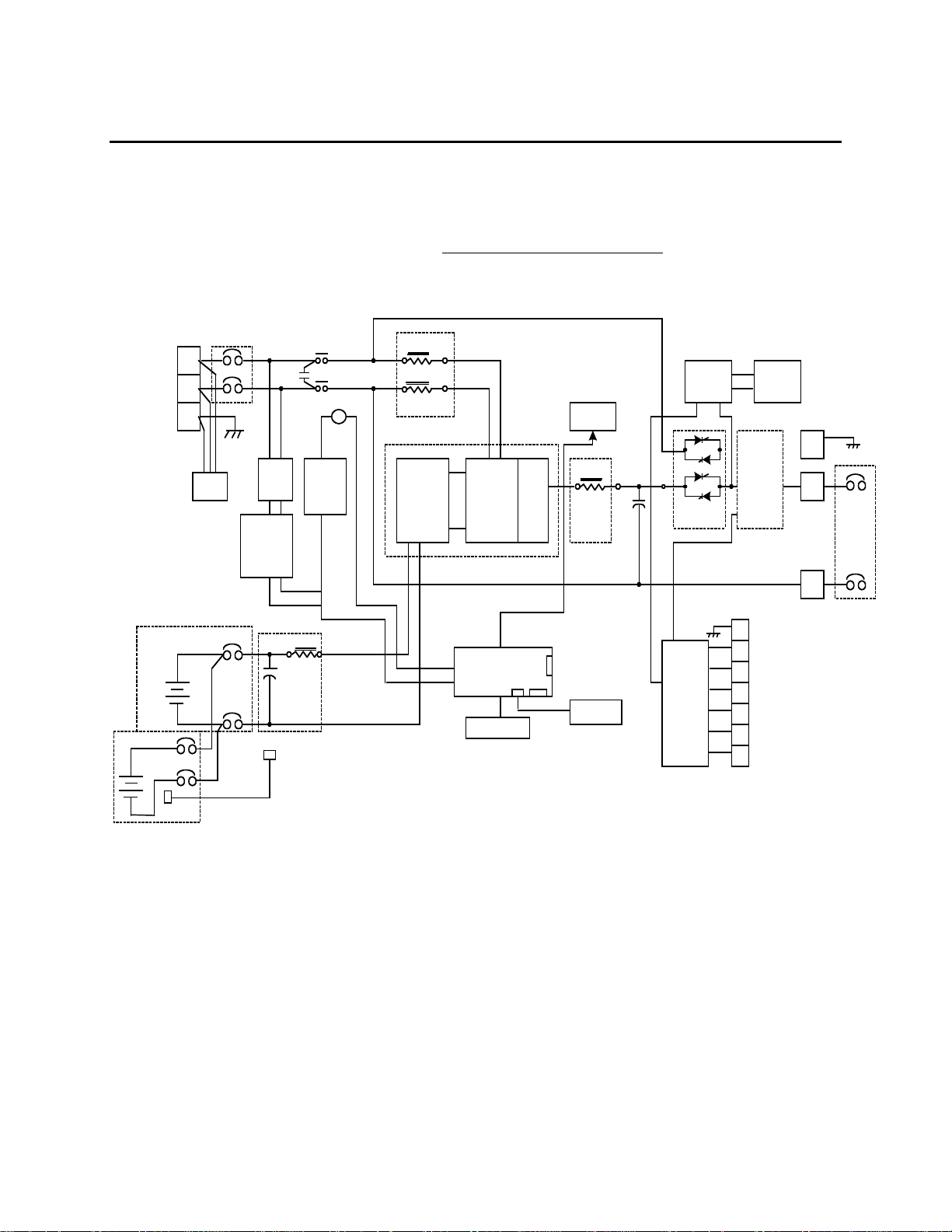
1-3 FUNCTIONAL BLOCK DIAGRAM (CONTINUED)
THE FUNTIONAL BLOCK DIAGRAM OF U.P.S
INPUT POWER
T.B.
BATT
(+)
(-)
TB1
INPUT
FILTER
INPUT
CONTACTOR
K1
C1
L1
L2
K
FILTER
SCR
DRIVER
T2
FAX
XFMR
FANS
INPUT
C.B.
1
2
(OPTION)
3
7
tvss
(+)
(-)
CB2
BATT C.B.
T2
STEP
DOW
N
FULL
BRIDGE
RECTIFIER
BR1
FILTER CKT
UNIT GND
T4
CONTACTOR
COIL
P4/J4
L4
C3
CHOPPER
UP/DOWN
CHARGER
CONTACTOR
CONTROL
(+)
FACTOR
CONTLR
(-)
INVERTER
A2
LCD DISPLAY
Q3/4
Q5/6
POWER
CONTROL
DC
BATT.
(A1) POWER BOARD ASSY.
P12/J12
SIGNAL
BOARD
J7
Q1 /
Q2
RS232
OUTPUT
FILTER
AS400
OUTPUT
L2
LED
DISPLAY
(OPTION)
BYPASS
PRIMARY
OUTPUT
SCR
XFMR
T1
BYPASS
OUTPUT
XFMR
ONLY USED FOR
MULTIPLE
VOLTAGE
OUTPUT UNIT
OUTPUT
C.B.
7
6
5
4
3
2
1
T1
240V
-
120V
0
2
OUTPUT
C.B.
OUTPUT
C.B.
1
GND
EXTERNAL BATT C.B.
(6002-1646) REV.X8 5
Page 12
OnLine Power
)
)
- 5
(
)
)
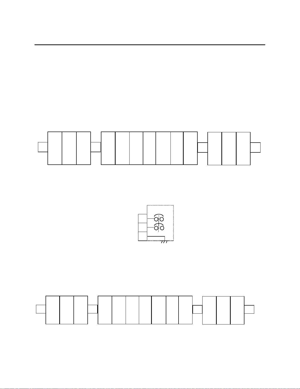
1-4 CUSTOMERS CONNECTIONS
1-4-1 Input Power Connection by Customer (with no input C/B option)
Connect input (Hot) at T B-1
Connect input Hot / N eut ral at TB1-2
Connect input grou nd at TB1-3
INPUT (TB1)
(TO CUSTOMER’S LOAD)
OUTPUT (TB2
1
2
HOT
3
HOT
(
N)
GND
1
OV
2
3
4
5
120V
OV
120V
PROTECTOR CUSTOMER’S CONNECTION TERMINAL BLOCK
ILLUSTRATION 1
Input wirings for various input voltages are same.
When input cirucit breaker is used, input CB1 is instal led in inside of the UPS.
(From External Battery Cabinet)
CONNECTION (TB3
6
7
GND
1
(+)
BATTERY
2
(-)
3
GND
INPUT
TB1
CUSTOMER
WIRES
TO CB1
PROTECTOR CUSTOMER'S CONNECTION TERMINAL BLOCK
ILLUSTRATION 1-6
CB1
1
2
3
1
HOT
INPUT (TB1)
2
HOT
N)
(
3
GND
(TO CUSTOMER’S LOAD)
1
2
120
V
OV
OUTPUT (TB2
3
4
OV
5
120
V
6
From External Battery Cabinet
BATTERY
7
GND
1
(+)
2
(-)
GND
3
(6002-1646) REV.X8 6
Page 13
OnLine Power
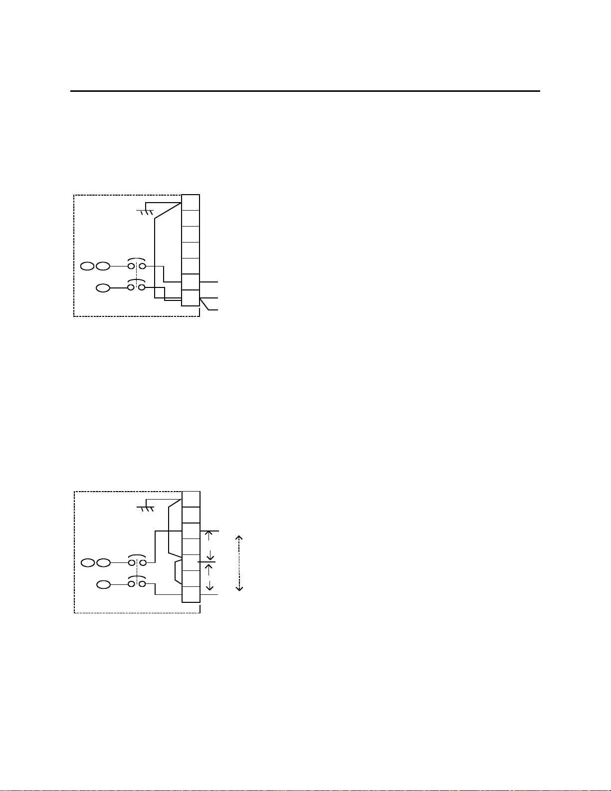
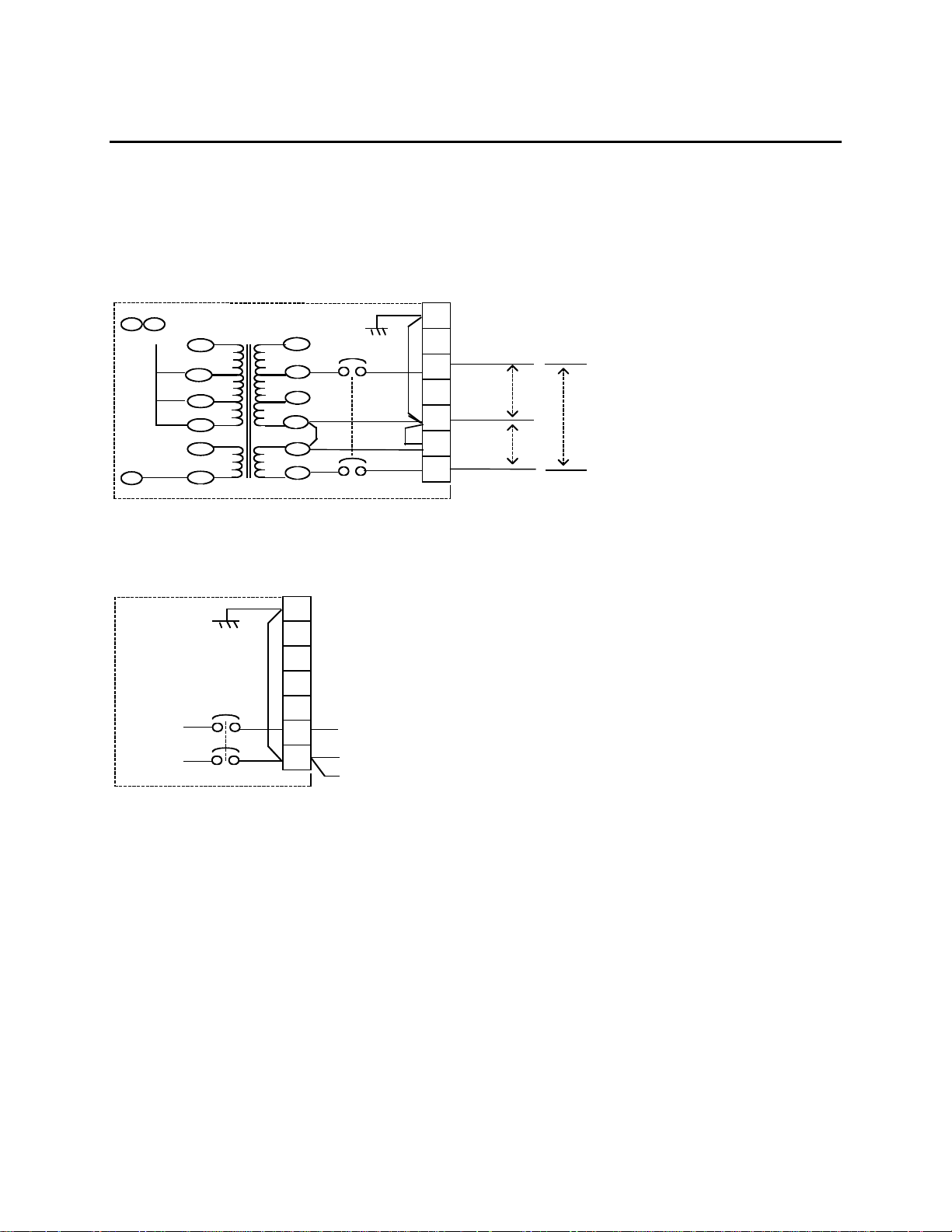
1-4-2 OUTPUT POWER CONNECTION BY CUSTOMER FOR
SAME INPUT AND OUTPUT VOLTAGE UNIT @ WITHOUT OUTPUT XFMR.
1. 120V IN/OUTPUT UNIT
TB2
7
N/C
6
5
PB2/1
B A
OUTPUT
CB
C
(OPTION) UPS CABINET
N/C
4
3
2
1
H
TO CUSTOMER LOAD
120V OUT
N
GND
2. 240V IN/OUTPUT UNIT
7
6
PB2/1
B A
OUTPUT
CB
C
(OPTION) UPS CABINET
TO CUSTOMER LOAD
5
4
120V
3
120V
2
1
H1
N
240V
H2
(6002-1646) REV.X8 7
Page 14
OnLine Power
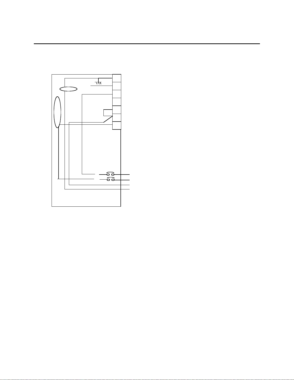
1-4-3 OUTPUT POWER CONNECTION BY CUSTOMER FOR DIFFERENT INPUT /
OUTPUT VOLTAGES USING O UTPUT XFMR.
1. 240V/120 OUTPUT UNIT
PB2/1
BA
240V
120V
C
2. 120V OUTPUT UNIT
SAME AS (1)
157V
1
120V
2
88V
4
0V
5
120V
6
0V
7
OUTPUT
CB
8
9
11
12
13
14
(OPTION) FOR EACH OUTPUT VOLT
TB2
7
6
TO CUSTOMER LOAD
5
4
3
2
1
120V
OUTPUT
N
GND
TB2
7
TO CUSTOMER LOAD
6
5
4
3
2
1
CONNECT TO TB2-1 FOR 120 VOLT UNITS, BUT
240/120V UNIT CONNECT TO TB2-3
H1
120V
120V
H2
240V
N
(6002-1646) REV.X8 8
Page 15
OnLine Power
3. WITH EXTRA AUX. OUTPUT CIRCUIT BREAKERS FOR
VARIOUS OUTPUT VOLTAGES.
GND
N
E
U
T
R
A
L
OUTPUT
CB
TB2
7
a). ALL AUX OUTPUT CIRCUIT BREAKERS ARE CONNECTED AT
6
UPS SIDE (HOT SIDE) AND CUSTOMER LOAD SHALL BE
CONNECTED TO THE INDIVIDUAL AUX CBX NEUTRAL WIRES TO
5
NEUTRAL TB AND GROUND WIRES TO GROUND TB
b). OUTPUT RECEPTACLES ARE CONNECTED TO TB2-OUTPUT
4
TB AT UPS SIDE (HOT SIDE) AND CUSTOMER LOAD SHALL BE
CONNECTED TO THE INDIVIDUAL AUX. RECEPTACLES.
3
OPTION: REFER TO SECTION 4-2
2
1
ALL AUX OUTPUT CB
[1P,20AMP RATED CB'S AS A STANDARD
THE CURRENT AVAILABLE FROM THIS AUX
CB IS LIMITED TO THE TOTAL KW OF EACH
UNIT].
H1
H2
N
GND
240V/120V OUTPUT
H1-N-120V
H2-N-120V
1-5 The Fire Alarm Back-up UPS1481 SIZING
Each mod el of t he Fire Alar m Bac k -up UPS1481 is des igned to supply a max imum load which is
given by its k VA (1000’s of v olt -amperes) and K W rat ing. It is v ery imp ort ant that the load is
within the rat ing of the FIRE ALARM BAC K-UP ups1481 to ensure that the c onnected loads will
be properly s upporte d.
Volt - ampe res (VA) are th e number of c urrent in a m ps a device d raws multiplied by the nominal
voltage supplied to the device. T he total kVA of all the loads to be c onnecte d t o t he Fire Alar m
Back-up U PS1481 is simply the sum of the k VA requirements of each devic e.
Each electrical devic e t o be po wer ed by the Fir e Alarm Back -up UPS1481 sho uld have a
specification sheet at t ached to it which specifies the am ount of pow er it requires. I n addition,
this inform at ion shoul d als o be liste d in t he manua l s upplied with each piec e of equipm ent . T he
device’s nameplate s hould list t he electrical requirement s of t he device in so m e or all of the
following unit s : nominal volt age, current, VA o r k VA, and wat t s or KW. If VA or k VA is not give n,
then multiply t he nomin al input voltage by the c urrent shown on the nameplate. Add up the kVA
require me nt s of each devic e t o be powered by the Fir e Alarm Back -up UPS1 481.
(6002-1646) REV.X8 9
Page 16

OnLine Power
The total loa d to b e po wer ed by th e Fire Ala rm B ac k-up UPS 1481 must n ot ex cee d its rat ing. If
the total l oad is exce eded, t he Fire Alarm Back -up UP S1481 monitori ng will sens e an ov erloa d
condition and a summary alarm will occur. The overload condition must be corrected by
increasin g t he kVA rating of the Fire Alarm Back -up UPS1481.
1-6 OUTPUT LOADS
The Fire Alarm Back-up UPS1481 is designed to power any critical, computer, flo rescent, or
incandes cent lig htin g. There are s o me t yp es of lo ads w hich r equire an exc essiv e in rus h cu rre nt
when first t urned on or at other times during its operati on.
The capacit y of the Fire Alarm Back-u p UPS1481 may need to be gre ater than what would b e
estimated based on the nameplate requirements of loads previously discussed. Contact your
On Line Power dealer or the factory direct ly if y ou hav e any questi ons ab out po wering unusu al
loads fro m your Fire Ala rm Back-up UPS1 481 .
1-7 OPTIONS
The follo wi ng options are available with th e Fire Alar m B ac k -up UPS1481 :
AS400
RS232
"Connect to these circuits are to remain in the same
room. DB9 connectors on the control PCBD".
Normally On / Off circ uit (s ) at output.
Extended battery run times.
(6002-1646) REV.X8 10
Page 17

OnLine Power
SECTION 2
- INSTALLATION
2-1 SITE PLANNING AND PREPARATION
The Fire Al arm Back-u p UPS1481 is designed for inst allation ind oors and me et s N EMA
specifications for operating temperat ure, humidit y , and utilit y voltage. T hese cabinet s are
corrosion r es is t ant and ru gged. The footprint of t he Fire Alar m Bac k -up UPS1481 is l es s t han 6
square fe et . Lis t ed below are the enviro nmenta l s pec if ic at ions for th e Fire Alarm Back-u p
UPS1481.
Adequate c learanc e in t he f ront of the equipment should b e provided for service access.
OPERATING ENVIRONMENT
• AMBIENT TEMPERATURE 0°C to 49° C
• OPERATING ALTITUDE 1,829 M (6,000 FT) DERATE 10% FOR EACH ADDITIONAL
305 M (1,0 00 F~) UP T O 2, 744 m (9,000 FT)
• RELATIVE HUMI DITY 0% to 95% (n on-conde ns ing)
Operating t he Fire Ala rm Back-up UPS1 481 and bat t eries at either ext reme of the t emperature
range may af f ec t t he long-ter m r eliability of t he system. This is especially true of the sealed,
mainten anc e-free batt eries. Sealed, ma int enance- f ree batter ies are design ed t o operate at
normal room tempe rat ures (72 t o 77°F).
STORAGE ENVIRONMENT.
Provide a s t orage envir onment wh ic h meets the f ollowing c onditions:
• AMBIENT TEMPERATURE -30°C to 70°C
• RELATIVE HUMIDITY 0% to 95% non-condensing
(6002-1646) REV.X8 11
Page 18

OnLine Power
TABLE 2-1
SITE PLANNING SPECIFICATIONS FOR KVA UNIT
1
2
3
5
6
7
9
10
12
13
15
16
18
19
21
22
23
25
26
27
29
30
32
33
35
36
38
39
NOTE: FP DENOTES – FIRE PROTECTION Fire Alarm Back-up UPS1481 SERIES.
MODEL
NUMBER
WR3.0A58FPT1 3.0 120 40 120/240 25.00 @120 96V 43A 8
WR3.0B58FPT1 3.0 208 19 120/240 96V 43A 8
WR3.0D58FPT1 3.0 240 19 120/240 12.50 @240 96V 43A 8
WR5.0A58FPT1 5.0 120 58 120/240 41.70 @120 120V 57A 10
WR5.0B58FPT1 5.0 208 30 120/240 120V 57A 10
WR5.0D58FPT1 5.0 240 30 120/240 21.00 @240 120V 57A 10
WR7.5B58FPT1 7.5 208 44 120/240 62.5 @ 120 120V 86A 10
WR7.5D58FPT1 7.5 240 41 120/240 31.3 @240 120V 86A 10
WR010B58FPT1 70.0 208 44 120/240 83.0 @ 120 192V 71A 16
WR010D58FPT1 10.0 240 58 120/240 41.5 @240 192V 71A 16
WR012B58FPT1 12.5 208 73 120/240 104.2 @ 120 192V 88A 16
WR012D58FPT1 12.5 240 69 120/240 52.1 @240 192V 88A 16
WR015B58 FPT1 15.0 208 85 120/240 125.0 @ 120 240V 84A 20
WR015D58FPT1 15.0 240 83 120/240 62.5 @240 240V 84A 20
WR3.0A01FPN1 3.0 120 40 120 25.00 @ 120 96V 43A 8
WR5.0A01FPN1 5.0 120 58 120 41.70 @ 120 120V 57A 10
IkW / kVA
INPUT
VOLTAGE
INPUT
AMP
OUTPUT
VOLTAGE
OUTPUT
AMP
DC
VOLT
DC
AMP
QTY. BATT
PER SET
APPROX.
W/O BATT
WEIGHT
(6002-1646) REV.X8 12
Page 19

OnLine Power
UL1481 MICRO-C HIPS & OT H ER COMPONENT ’S LIST
1
2
3
5
6
7
9
10
11
12
13
14
15
16
17
18
19
20
21
25
MODEL
NUMBER
WR3.0A58FPT1 120 120/240V 9100-1319-018UL 9100-1312-11 9100-1295-02 1680-242 2025-769 1000-036
WR3.0B58FPT1 208 120/240V 9100-1319-023UL
WR3.0D58FPT1 240 120/240V 9100-1319-025UL 9100-1312-11
WR5.0A58FPT1 120 120/240 9100-1319-050UL 9100-1312-11 ‘’ 1680-093 2025-768 ‘’
WR5.0B58FPT1 208 120V/240 9100-1319-055UL 9100-1312-11 " " "
WR5.0D58FPT1 240 120/240 9100-1319-057UL 9100-1312-11 " " ‘’ ‘’
WR7.5B58FPT1 208 120/240 9100-1319-77UL 9100-1312-11 ‘’ 1680-093 2025-759 ‘’
WR7.5D58FPT1 240 120/240V 9100-1319-081UL 9100-1312-11 " "
‘’ ‘’ ‘’ ‘’
WR010B58FPT1 208 120/240V 9100-1319-101UL 9100-1312-11 " 1680-139 2025-772
WR010D58FPT1 240 120/240 9100-1319-105UL 9100-1312-11 ‘’ ‘’ ‘’ ‘’
WR012B58FPT1 208 120/240 9100-1319-125UL 9100-1312-11 ' 1680-187 2025-759
WR012D58FPT1 240 120/240 9100-1319-129UL 9100-1312-11 " " "
WR015B58FPT1 208 120/240 9100-1319-149UL 9100-1312-11 ‘’ ‘’ "
WR015D58FPT1 240 120/240V 9100-1319-153UL 9100-1312-11 " ‘’ ‘’ ‘’
WR3.0401FPN1 120 120 9100-1319-017UL 9100-1312-10 ‘’ 1680-242 2025-769 ‘’
WR5.0A01FPN1 120 120 9100-1319-049UL 9100-1312-10 1680-093 2025-768
MODEL PART NUMBER NOM ENCLATURE
WR
Basic Model
Output Voltage
01=120V
58=120V 120/240V
Example of prime
INPUT
OUTPUT
KW /
VOLTAGE
KVA
KVA Ratin g
Input Voltage
AC
A=120V
B=208V
MICRO-CHIP
SOFTWARE
3.0 A 01 FP N 1 -XXX
BASIC UPS KIT
LABEL KIT
‘’ " " ‘’
INPUT
CONTACTOR
BATT
C.B.
FANS
Reserve for
designated option or
Single Phase
Output XFMN
N=No output
XFMN
Designate
( Fire Protective UPS)
(6002-1646) REV.X8 13
Page 20

OnLine Power
2-2 Pre-Installation
The Fire Al arm Back-u p UPS1481 is designed for ind oor installat ions. All cus t omer connections
are broug ht t hrough knock outs located on the t op or side of t he Fire Alar m B ack-up UP S1481.
The Fire Al arm Back-u p UPS1481 consists of one (1) inte grated cabinet — housing both the
electronics and batteries (depending on KVA). B ef ore unpacking the equipment, inspect the
exterior the s hipping c ontainer and the eq uipment it s elf f or damage t hat may have oc c urred
during trans it . I f t he s hipping container or equipme nt it s elf s hows evide nc e of damage, note the
damage on t he receiving document bef ore signin g for recei pt of t he equipme nt . D amage claims
should be f iled directly with the ca rrier.
2-2-1 Equipment Unpacking
Remove t he equipm ent f rom the shipping ca rt on. Since t he 68” cabin et f or 15KVA is d es igned
for pad — m ount install at ions, there are no casters. I t is sugges t ed that a fork lif t be used t o
remove the Fire Alar m Bac k -up UPS1481 fro m its shipping pallet.
Before plac ing the Fire Alarm Back -up UPS1481 ont o t he mounting bolts or l ev eller (whe re it will
be installe d), t he c onduit knoc kouts n eeds to be r emoved.
1. The conduit k noc k outs are located o n t he back-si de of the cabinet for 3-15 KVA
2. Remove the conduit knockouts.
3. M easure th e locations for the conduits on the conduit k nockouts.
4. Dr ill or punch holes in the c onduit knoc kouts for t he conduit s .
Anchor th e F ire Alarm Back-up U PS1481 to the mounting pad at t he f our (4) mounting
locations, by lowering l ev ellers for 3 -15 KVA unit s .
1. Anchor the conduits t o t he conduit k nockouts
2. This concludes the mechanic al instal lat ion.
2-3 Electrical Connections: “ CAUTION & DE-ENERGIZE UNIT PRIOR TO SERVICING”
CAUTIONS CAUTION
Veri t y that a ll c ust omer-supplied w iring Is de-e ne rgi zed before pe rf ormi ng an y
electrical work,
CAUTIONS CAUTION
Even whe n t h e Fire Alarm Back- u p UP S1481 is of f, th er e are pote n ti al l y
danger o us voltages within th e Fir e Alarm Ba ck-up UPS1481 d ue t o t h e b atteries.
Extreme care must be take n w hen working withi n t he Fir e Alarm B ack-up U PS1481
enclosure.
(6002-1646) REV.X8 14
Page 21

OnLine Power
1. Verif y t hat the mai n input circuit breaker, battery circuit br eak er, and output circuit
breaker(s ), if prov ided are in t he “OFF” pos it ion. See ill us t rat ion 1-2 for t he locations of t he
circuit breakers. Se e under Section 2-5, Storage for accessing the ins ide of the unit .
2. Run the power wir es up t hrough t he c enter are a of the Fire Alarm Back -up UPS1481.
Exercise c are when working ar ound the battery area.
3. R ef er t o Sectio n 1-4 for various different ins t allation c onf iguratio ns .
4. C onnect the i nput wires to t he input terminal block, TB1. Th ree (3) wires t ot al: “hot”, n eut ral
(or Hot), and ground.
5. C onnect the o ut put wires t o t he output t erminal bl oc k , TB 2. Three (3) wires total: “hot ”,
neutral (or Hot), and ground t o t he appropriat e design at e locations.
6. C onnect the b at t ery wires from extern al battery cabinet (if prov ided) to b at t ery t erminal
block, TB3, t hree (3) wir es t ot al for (+), (-) and Ground.
7. Th is c onc ludes the electrical connect ions. Do n ot apply power t o t he Fire Alarm Back- up
UPS1481 at t his t ime.
2-3-1 Remote Signaling Connections (AS400)
The Fire Al arm Back-u p UPS1481 includ es t he f eature of prov iding dry relay contac t s f or remote
signaling c apabilities. Signals availabl e of remote annunciat ion are:
“UTI LI T Y F AI L URE ” — This is a nor m ally open contac t which clos es upon loss of input po w er
to the Fire Alarm Back -up UPS1481 . “LOW BATTERY” — This is a nor m ally open contact
which clos es when the Fi re Alarm Bac k -up UPS 1481 is on bat t ery operati on and the b at teries
are appro ac hing complete discharge.
“ON INVERTER or ON BYPASS” — This is a n ormally open contact which closes whe n t he
Fire Alarm Bac k -up UPS 1481 goes t o battery o peration.
“SUMMARY ALARM” — This is a norma lly open contac t which clos ed when the Fire Alarm
Back-up U PS1481 has any one of the alarm co ndition.
If there are no requirements f or remote sig naling, sec t ion 2-4-1 may be skipped.
1. Th e dry relay c ont ac t s f or remote si gnaling are provided on con nec t or (P5) of control board
(A2) locat ed on the right door insi de of the Fire Alarm B ac k -up UPS1 481. See illus t ration 12 for exact locations.
2. Th e dry relay c ont ac t s have the fo llowing max imum r at ings:
200V (AC or DC) maximum
1.25 amp eres maxi mu m
30 watts /50 VA maxim um, Po we r F ac t or 1.0PF
It is imperativ e t hat the relay c ontact rat ings are n ot ex c eeded. Otherwise, damag e t o t he
relays within the Fire Alar m Back -up UPS 1481 wi ll occur.
(6002-1646) REV.X8 15
Page 22

OnLine Power
3. D et ermine w hic h s ignals will b e us ed. Connec t wires (cus t omer-supplied) to the connect or.
4. Th is c onc ludes t he remote si gnaling co nnection procedur es .
5. This c onc ludes the ins tallati on proced ures . Please proc eed to Section 3-St art -Up for th es e
necessary t o s t art - up the Fire Alarm Bac k -up UPS1 481.
AS400 CONNECTION DETAILS (J2)
K1
K2
K3
K4
9
INPUT FAIL
8
LOW BATT.
7
SUM-ALARM
6
BYPASS ON
5
COMMON
2-3-2 RS232 Connection
Control PCBD
J8 – connector / P8 IBM PC Serial Port
J2 – connector / P8 to 2 to 2
J3 – connector / P8 to 3 to 3
J5 – connector / P8 to 5 to 5
Pin 1, 4, 6, 7, 9 no connection
Pin 2 : Receive
Pin 3 : Transmit
Pin 5 : GND
2-4 Storage
The Fire Al arm Back-u p UPS1481 Series can be plac ed in s t orage wh ile not in use. Provide a
protected environ m ent which me et s t he environ m ent al para m et ers lis t ed below.
• AMBIENT TEMPERATURE -22° to 158°F
-30° to 70°C
• RELATIVE HUMIDITY 0% to 95% non-condensing
The Fire Al arm Back-u p UPS148 1 Series wi ll be stored fo r s ev eral months or long er, it s hould
be serviced by charging the bat t eries for 24 hours at regular, t hree-month interva ls . W hile in
storage, s erv ic e t he unit using the procedures in this sect ion.
(6002-1646) REV.X8 16
Page 23

OnLine Power
During long-term storage, the batteri es are subject t o aging and det erioration. I f af t er v is ual
inspection, t he batteries need to be replace d c ontact your OnLine Power dealer or the OnLine
Power fact ory directly to obtain ne w bat t eries.
The UPS is s t ored in its original pack aging, un pack UPS using unpac k ing procedures o ut lined in
Section 2- 3-1.
If the UPS is not c onnected t o a source of power, firs t c onnect the UP S t o an appropriate so urc e
of power using the procedures in Section 2-4, Electric al C onnections .
When the U PS is unpacked and firs t c onnected to an AC power s ource, rec harge batt eries as
follows:
1. Unlock and r emove the f ront pane l by pushing it up and out, pull both t he s ide panel up and
out.
2. Visually ins pec t batteries for signs of deterior at ion and leak age. Repl ac e batteries if
required.
3. Set AC power source to ON.
4. Close input C B, if prov ided (CB 2)
5. Close battery CB, if prov ided (CB1 )
6. The UPS aut omatically recharg es bat t eries. Th e LCD pan el will indicat e t he battery voltage
and charging curre nt .
7. Allow UPS to r un f or 24 hou rs t o f ully c harge batteries.
• When batteries have reached pa rt ial c harge, the battery c ha rging current will be
under 1 Amps on LCD panel.
8. Turn OFF inp ut power to th e U PS.
9. Close and replace all t he panels b ac k .
(6002-1646) REV.X8 17
Page 24

OnLine Power
SECTION 3
- OPERATION
3-1 Start-U p Proce dure s
1. Verif y t hat the mai n input circuit breaker, battery b reaker, an d output circuit breaker(s), if
provided, are in the “O F F” o r “down” pos it ions.
Refer to illus t rat ion 1-2 for the locati ons of t he circuit breakers .
CAUTION CAUTION
It during the start- up procedures anything unusual occurs, immediately turn off
the I nput c irc uit break e r, a nd co ntact OnLine Power a t (80 0 ) 797 - 778 2 for t e chnical
assistan ce. I f there are a n y questions or ad ditional information Is re q uir ed, please
contact O n -Line Power at (800) 7 97 -7782 f or technical assista n ce.
2. Apply input power to the Fire Ala rm Back-u p U PS148 1 Series
• Verify t hat the volt age appearing on t he input ter minal block is 120/240 VAC and is
same as on nameplate. lithe voltage is not s ame as on nameplate approximately , do
not proce ed any furth er. C ontact On-Line Power at (800) 797-7782 for technical
assistance.
• Verify t hat ther e are no voltages appe aring on the output t erminal block .
3. Tu rn on the m ain input circ uit breaker, supplyi ng power to th e unit.
4. Af t er t urning on the Syste m, wait one ( 1) minute w hile t he Fire Ala rm Back-up UPS1 481
runs throu gh it s int ernal diagnostic ro utines.
• Hear the sound of contactor closing.
• See the fan(s) running.
• See the LCD panel dis play ing corr ect mess ages . Se e Appendix D for LC D displays.
• Verify t hat the L C D d is play panel i ndicates al l c orrect par ameters — see Appendix D
for details.
• Verify t hat the output volta ge is 120/24 0 per the nameplate.
5. Cl os e battery breaker i n t he UPS cabinet [and i n battery cabinet(s), if prov ided.
(6002-1646) REV.X8 18
Page 25

OnLine Power
6. At t his point in ti me, t he Fire Alar m Bac k -up UPS1481 s hould be prov iding AC line powe r.
The Fire Al arm Back-u p UPS1481 is not operating in t he normal mode, turn of f t he input
circuit breaker. Contact OnLine Power at (800) 7 97-7782 f or t ec hnical ass istance.
7. Rechec k t hat the out put v oltage is 120/240 VAC.
• If t he out put v oltage is ap prox imate ly s ame as nam eplate, turn on the lo ads which will
be powered from
the Fire Ala rm Back-u p U PS148 1 .
8. The n ex t s t eps v erif y battery op eration and the invert er t es t switch.
• To place the Fir e Alarm Back -up UPS1481 in bat t ery operatio n (t o s imulate l os s of
input pow er), press and hold yello w Invert er T es t Switch. With switch i n t he hold
position, t he Fire Alar m B ac k -up UPS1481 sh ould be running on its internal bat t eries .
• Verify t hat the L C D p anel displays s uch.
• Verify t hat the “B at t ery Charger ” is OFF in LCD pa nel.
Note: Be sur e t o release the switch, af t er the test, s o it will n ot deplete the batteri es .
9. Th e Fire Alarm Back-u p UPS148 1 is now fully f unctional - providing clean, sine wave
power to the load with battery back—up in case of an input po wer failure. T his c oncludes
the start-u p procedur es .
3-2 Operation
3-2-1 Tur ning On the Fir e Alarm Back-up U PS1481 :
1. Apply input power.
2. With input power available, turn on the m ain input circ uit breaker, C B2 (if provi ded).
3. Cl os e battery breaker ( C B1), only after the LCD display is lit & displays sc reens per
Appendix D.
4. W ait t ill y ou hear the input cont ac t or closing and fan ru nning.
5. Verif y t hat all parameters on LCD disp lay panel ar e proper. See Appendix D for display
details.
6. Cl os e t he output c irc uit breaker, CB2 (if prov ided).
7. Turn load breakers On.
(6002-1646) REV.X8 19
Page 26

OnLine Power
3-2-2 Turni ng off the Fire Alarm Bac k-u p UPS14 81 :
1. Tu rn of f t he Output Breaker(s ), if provided.
2. Turn off the Battery Breaker.
3. Tu rn of f t he I nput Bre ak er, if provided.
3-3 Theory of Operation
Illustratio n NO TAG is a simplifi ed block diagram of t he Fire Alarm Bac k -up UPS 1481. This
diagram provides an ex cellent t ool in identifying the m ajor build ing blocks within the Fire
Alarm Back-u p UPS14 81 .
1. External Main input circuit breaker (CB2) — The main input c irc uit power pr ov ides
overcurr ent protectio n t o t he input s ide of t he Fire Alar m Bac k-up U PS1481 .
2. Input Contactor (KI) — The microprocessor base d c ont rol circuitry:
• Verifies UPS t o be normal condition and not t he one ‘at fa ult ”.
• Verif ies correc t input voltage and fr equency t o be within acceptable range and
commands t he closure of t his . C ontactor v ia c ontrol trans f ormer T 2 and fuse Fl.
3. Input Chokes (LI, U) — T hey ac t as a f ilt er and a n important c irc uit ry of an up chop per,
boosting i nput voltag e t o a higher int ernal DC b us v olt age.
4. Batter y charger — The batt ery c harger co nv ert s AC pow er into regul at ed DC pow er t o
charge and t o maintain t he charge on the batt ery bank. Th e c harger is f ully automat ic with
a current li miting feature so that damage wil l not occur to the batteri es in c as e of a charger
malfunct ion. The charger is sized such that t he batteries will be maint ained at f ull c harge
even whe n t he input volt age is at the lo w l ine limit for indefinite periods of t im e.
5. Battery — The bat t ery bank, consisting of eight (8), t en (10), sixt een (16), or tw ent y (20),
12 volt, VR LA batteries , provides the reserve energy t o power the load when s uitable A C
input pow er is not present. T he batteries are seal ed, maint enance—f ree const ruc t ion.
6. Inverter — When t he AC input power is not available to power t he load, the inv erter
converts t he energy st ored in the batt ery bank to AC power to supply the powers the load.
The pulse wi dt h modulated (PWM ) inverter ut iliz es high speed, high ef f ic iency IG BT5 for
fast respo ns e, s inusoidal power.
7. DC Choke (U) — If helps boosting batt ery v oltage to an internal higher DC bus voltage.
8. Output AC Choke (L4) — This acts as a buc k c ircuit co mp onent connec t ing high D C bus
voltage to an appropriate AC out put voltage.
(6002-1646) REV.X8 20
Page 27

OnLine Power
9. Opt iona l Outpu t Isol a t ion Tra nsf ormer (TI) — T he t ransfor m er performs a number of
critical funct ions. First , it prov ides excellent common mo de and normal mod e noise
isolation of t he load fro m the input or i nv erter power. Sec ondly, it provides voltage
transform at ion and tig ht regulation of the out put voltage while the Fi re Alarm Back -up
UPS1481 is operatin g f rom its internal invert er or directly f rom utility v ia bypass circuitry.
10. lnverter Test Swi tc h (SW2) — This switch is a manually operate d switch which tests t he
Fire Alarm Bac k -up UPS1481 and t he batteries f or proper operation. When the Fire Alar m
Back-up U PS1481 is ru nning and Switch SW2 is pushe d and held in, the Fire Al arm Backup UPS1481 will auto mat ical ly transfe r to battery ope rati on. The Fire Alar m Back- up
UPS1481 will conti nue to run on b at t eries until the switch is released bac k t o t he “nor mal ”
position ( Switch is a mo m entary switch). Wh en t he switc h is released, t he Fire Alar m
Back-up U PS1481 ret urns t o normal operatio n (provid ed input po wer is present ).
11. Control Transformer (T2) — This transf ormer wit h f use (Fl), prov ides (internal
houseke eping) pow er s upply as w ell as 120 VA C for the coil of t he input cont ac t or. The
primary of t his t rans former has vari ous t aps t hat needs t o be matc hed with the various
input voltages.
12. Fan Tr ansfor m e r (T3) — Th is t rans f ormer wit h f us e (F2) prov ides 120 V AC to the fan(s )
for various output voltages that are matched at its pri m ary t aps .
(6002-1646) REV.X8 21
Page 28

OnLine Power
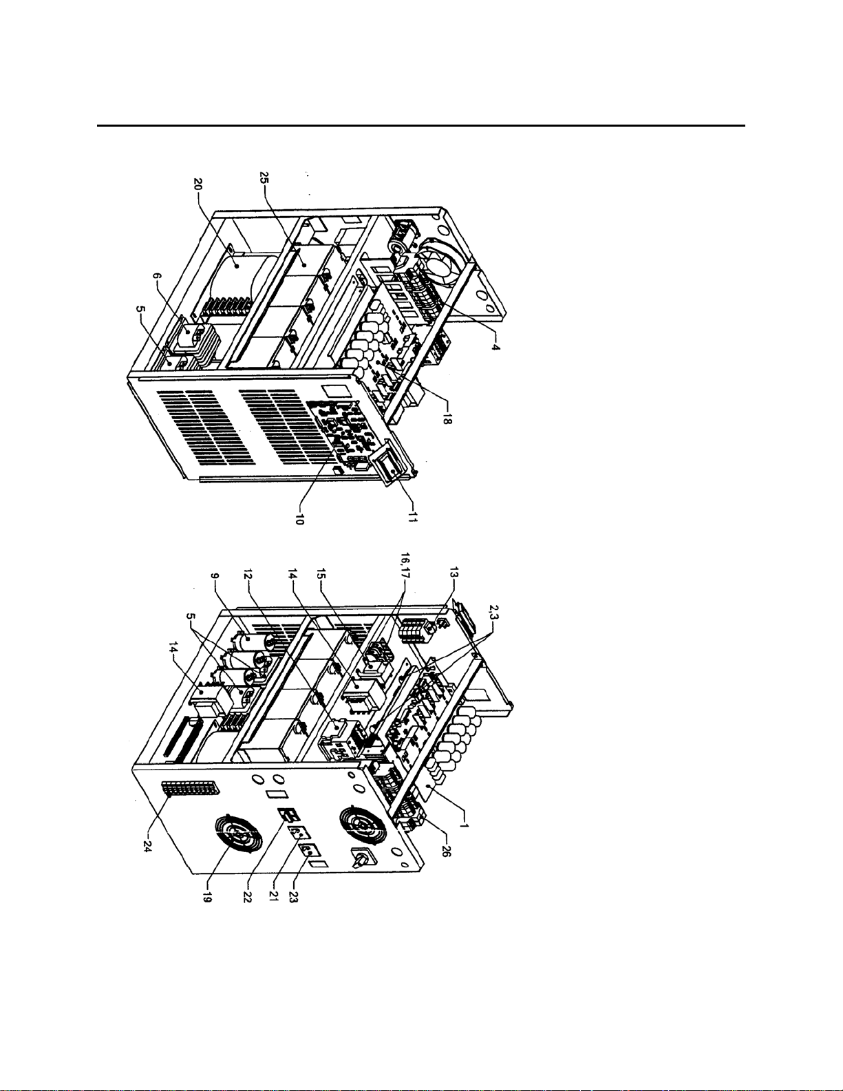
3-4 CO MPONENT’S LOCATION & LIST
(6002-1646) REV.X8 22
Page 29

OnLine Power
COMPONENT’S TABLE
(6002-1646) REV.X8 23
Page 30

OnLine Power
(6002-1646) REV.X8 24
Page 31

OnLine Power
3-4 ITEM 18 (CONTINUED)
(6002-1646) REV.X8 25
Page 32

OnLine Power
APPENDIX A: EXTENDED BATTERY RUN CHART
Battery
kitPart#
LoadKV
A
Minutes -015 -015 -015 -015 -015 -015 015 -015 -015 -015 -015 -015
Batt.AH 8x25 8x25 8x25 8x25 8x25 8x35 10x35 10x35 10x50 16x50 16x65 20X50
Cabinet A A A A A A A A A+B A+B A+B A+C
orA+A
Minutes -030 -030 -030 -030 -030 -030 -030 -030 -030 -030 -030 -030
Batt.A.H 8X25 8X25 8X25 8X35 8X35 8X50 10X50 10x65 10x120 16x90 16x120 20x120
Cabinet A A A A A A+B A+B A+B A+B A+C A+B A+C
orA+A orA+A orA+A
Minutes -060 -060 -060 -060 -060 -060 -060 -060 -060 -060 -060 -060
Batt.A.H 8X25 8X25 8X35 8X50 8X50 8x90 10x90 10x120 20x90 32x65 32x90 40x90
Cabinet A A A A+B A+B A+B A+B A+B A+C A+B+C A+B+C A+2C
orA+A orA+A orA+A
Minutes -120 -120 -120 -120 -120 -120 -120 -120 -120 -120 -120 -120
Batt.A.H 8X35 8x50 8x50 8x90 8x100 16x90 20x90 20x90 30x90 40x120 60x90 60x90
Cabinet A A+B A+B A+B A+B A+C A+C A+C A+B+C A+2C A+B+2C A+B+2C
orA+A orA+A orA+A orA+A
Minutes -240 -240 -240 -240 -240 -240 -240 -240 -240 -240 -240 N/A
Batt.A.H 8x50 8x90 8x100 8x120 16x90 20x120 20x120 30x120 30x120 60x120 80x120
Cabinet A+B A+B A+B A+B A+C A+C A+C A+B+C A+B+C A+2C+B A+B+2C
orA+A orA+A orA+A orA+A
Minutes -480 -480 -480 -480 -480 -480 -480 -480 -480 -480 N/A N/A
Batt.A.H 16X65 16X90 16x90 16x120 24x120 40x120 40x120 50x120 100x90 100x120
Cabinet A+B A+C A+C A+C A+C A+2C A+2C A+2C A+4C A+4C
Minutes -1440 1440 1440 1440 1440 1440 1440 1440 N/A N/A N/A N/A
Batt.A.H 24X
Cabinet A+C A+C A+C A+C A+2C A+3C+B A+4C A+4C
7050354
0.5 0.75 1.0 1.5 2.0 3.0 4.0 5.0 7.5 10.0 12.5
120
7050355
24X
120
7050356
32X
100
7050357
40X
120
7050358
50X
120
7050359
80X
120
7050360
100X
120
7050361
100X
150
7050362-
7050363-
7050364-
7050365-
Note: 0.5 KVA-3K VA: Load only c hange usin g s ame 3KW unit.
4-5KW: Load only change using 5KW unit. TABLE 4-10
Battery P ar t Number Nomenclature.
7050 354 -XXX
Designate Designate KVA.
Basic Model
Cabinet Types:A
C
*UL LISTING WAS PERFORMED ONLY FOR 15 MINUTES RUN TIME.
(6002-1646) REV.X8 26
=Internal batteries located on the bottom shelf of smal cabinet. B=48" Tall,one cabinet.
=68"Tall,one cabinet NB=48" Tall,N nunber of cabinets NC=68" Tall, number of cabi nets.
Page 33

OnLine Power
OTHERS ARE CALCULATED VALUES BASED ON THE BATTERY MANUFACTURER'S DATA FOR BACK UP
TIME.
APPENDIX B – Optional Main Input & Main Output Breakers
for various models (*Al l Values are typical as refere nce only)
TABLE B-1: External Output Breaker (Standard KAIC)
KVA
3
5
7.5
10
12.5
15
KVA
3
5
7.5
10
12.5
15
120 Vac 240 /120 VAC
40 Amps, 120 VAC,
1 Pole , 1 4 K AIC
OLP P/N: 2025-783
70 Amps, 120 VAC,
1 Pole , 1 4 K AIC
OLP P/N: 2025-997
100 Amps, 120 VAC,
2 Pole , 1 0 K AIC
OLP P/N: 2025-999
125 Amps, 120 VAC,
2 Pole , 1 0 K AIC
OLP P/N: 2025-759
1750 Amps, 120 VAC,
2 Pole , 1 0 K AIC
OLP P/N: 2025-468
200 Amps, 120 VAC,
2 Pole , 6 5 K AIC
OLP P/N: 2025-541
TABLE B-2: Output Breaker (High KAIC)
120 Vac 240 Vac
40 Amps, 120 VAC,
1 Pole , 4 2 K AIC
OLP P/N: 2025-799
70 Amps, 120 VAC,
1 Pole , 4 2 K AIC
OLP P/N: 2025-998
100 Amps, 120 VAC,
2 Pole , 4 2 K AIC
OLP P/N: 2025-803
125 Amps, 120 VAC,
2 Pole , 6 5 K AIC
OLP P/N: 2025-759
1750 Amps, 120 VAC,
2 Pole , 6 5 K AIC
OLP P/N: 2025-468
200 Amps, 120 VAC,
2 Pole , 6 5 K AIC
OLP P/N: 2025-541
Output Voltages
Output Voltages
20 Amps, 240 VAC,
2 Pole , 1 0 K AIC
OLP P/N: 2025-788
40 Amps, 240 VAC,
2 Pole , 1 0 K AIC
OLP P/N: 2025-791
50 Amps, 240 VAC,
2 Pole , 1 0 K AIC
OLP P/N: 2025-792
70 Amps, 240 VAC,
2 Pole , 1 0 K AIC
OLP P/N: 2025-794
80 Amps, 240 VAC,
2 Pole , 1 0 K AIC
OLP P/N: 2025-795
100 Amps, 240 VAC,
2 Pole , 1 0 K AIC
OLP P/N: 2025-797
20 Amps, 240 VAC,
2 Pole , 6 5 K AIC
OLP P/N: 2025-762
40 Amps, 240 VAC,
2 Pole , 6 5 K AIC
OLP P/N: 2025-766
50 Amps, 240 VAC,
2 Pole , 6 5 K AIC
OLP P/N: 2025-767
70 Amps, 240 VAC,
2 Pole , 6 5 K AIC
OLP P/N: 2025-769
80 Amps, 240 VAC,
2 Pole , 6 5 K AIC
OLP P/N: 2025-770
100 Amps, 240 VAC,
2 Pole , 6 5 K AIC
OLP P/N: 2025-894
(6002-1646) REV.X8 27
Page 34

OnLine Power
INPUT CIRCUIT BREAKER
TABLE B-3: Input Breaker Ampacity (Standard KAIC)
KVA
3
5
7.5 N/A
10 N/A
12.5 N/A
15 N/A
120 Vac 240 V/ or 208V
50 Amps, 120 VAC,
1 Pole , 1 4 K AIC
OLP P/N: 2025-784
70 Amps, 120 VAC,
1 Pole , 1 4 K AIC
OLP P/N: 2025-997
TABLE B-4: Input Breaker Ampacity (hIGH KAIC)
KVA
3
5
7.5 N/A
10 N/A
12.5 N/A
15 N/A
120 Vac 240 Vac or 208VAC
50 Amps, 120 VAC,
1 Pole , 4 2 K AIC
OLP P/N: 2025-800
70 Amps, 120 VAC,
1 Pole , 4 2 K AIC
OLP P/N: 2025-998
Input Voltages
Input Voltages
30 Amps, 240 VAC,
2 Pole , 1 4 K AIC
OLP P/N: 2025-790
40 Amps, 240 VAC,
2 Pole , 1 0 K AIC
OLP P/N: 2025-791
60 Amps, 240 VAC,
2 Pole , 1 0 K AIC
OLP P/N: 2025-793
70 Amps, 240 VAC,
2 Pole , 1 0 K AIC
OLP P/N: 2025-794
90 Amps, 240 VAC,
2 Pole , 1 0 K AIC
OLP P/N: 2025-796
125 Amps, 240 VAC,
2 Pole , 6 5 K AIC
OLP P/N: 2025-759
30 Amps, 240 VAC,
2 Pole , 6 5 K AIC
OLP P/N: 2025-764
40 Amps, 240 VAC,
2 Pole , 6 5 K AIC
OLP P/N: 2025-766
60 Amps, 240 VAC,
2 Pole , 6 5 K AIC
OLP P/N: 2025-768
70 Amps, 240 VAC,
2 Pole , 6 5 K AIC
OLP P/N: 2025-769
90 Amps, 240 VAC,
2 Pole , 6 5 K AIC
OLP P/N: 2025-771
125 Amps, 240 VAC,
2 Pole , 6 5 K AIC
OLP P/N: 2025-759
(6002-1646) REV.X8 28
Page 35

OnLine Power
APPENDIX C: LCD DISPLAY MENU & TROUBLSHOOTING GUIDE
Two scree ns (A, B) are updat ed continuously f or units without optional output t rans f ormer.
Three screens (A, B, C) are updated conti nuous ly for units with opt ional out put transfo rme r.
Start-up Screen
When input power is applied for the unit, L C D p anel lights up and displ ay s
If LCD display panel is n ot lit , unit has a probl em. Contact f ac t ory s ervice at 1 –800–PWRSRVC at OnLine Po wer.
SCREEN A: The screen appears as below.
It may show
1.
7KW indicates the KW rating of the unit
STANDBY is shown for testing or start up
NORMAL indicating normal UPS oper ati on
PROBLEM UPS having problem
Try to reset the unit by shutting off and restart ing, or else contact f actory
FAILURE indicates UPS failed or had al arm condition
Reset unit as above. Shut it off till LCD is shut-off. Restart unit, or else contact the factor y
OnLine Power
UPS Project
Line 1
Line 2
Line 3
Line 4
UPS NORMAL @ 7KW
UPS NORMAL @ 7 KW
INPUT OK @ CHRG ON
BATTERY OK @ DC OK
ON INVERTER @ OUT OK
(6002-1646) REV.X8 29
Page 36

OnLine Power
OUTPU
SCREEN B: The screen appears as below.
Line 1
Line 2
Line 3
Line 4
4. Indicates outp ut v olt age and p ower in wat ts, when output transformer is not used. It indicates
primary volt age of the output tra ns f ormer (T1 ) (120 VAC, t y pically) when T1 is us ed.
5. Indicates input v olt s and Amps.
6. Indicates inter nal DC buss c ondition f or f ac t ory use.
7. Indicates battery v oltage. Th e (+) curre nt in Amps indic ates charging Am ps , while (-) indicates
dischargi ng Amps.
SCREEN C: When optional output transformer is used, various output voltages are
indicated as such.
Line 1
Line 2
Line 3
Line 4
OUTPUT: ______V @ ______ W
INPUT : ______V @ ______ A
DC BUSS: ______V @ NA A
BATT: ________V @ +______ A
OUTPUT VOLTAGE 120 V
OUTPUT VOLTAGE N/A
OUTPUT VOLTAGE 240 V
T VOLTAGE N/A
(6002-1646) REV.X8 30
Page 37

OnLine Power
(6002-1646) REV.X8 31
Page 38

OnLine Power
APPENDIX D: SPECIF ICATION
POWER RATING (KW)
VOLTAGE (VAC) I NPUT
MAXIMUM CURRENT 40/19/16 58/30/28 41/36 58/50 69/60 83/72
TOLERANCE
FREQ U ENCY (H z )
POWER FACTOR
OVERCURRENT PROTECTION
NUMBER OF WIRES
POWER CONNECTION
3.0
Single Phase,
120/208/240
5.0
7.5
0.98 to 1.0 (Typical)
Electronic / Circuit Breaker
2 Wires plus Ground
Hard Wired (Terminal Block)
OUTPUT
RATING (KVA/KW)
VOLTAGE (VAC) 120/120/240 120/120/240120/240 120/240 120/240 120/240
VOLTAGE REGULATION
FREQ U ENCY (H z )
WAVESHAPE
HARMONIC DISTORTION
CREST FACTOR
POWER FACTOR
STEADY-STATE CURRENT 25/12.5 42/20.8 62.5/31.3 83.3/41.7 104/52 125/62.5
OVERLOAD
PROTECTION
NOISE REJECTION
NUMBER OF WIRES
POWER CONNECTION
3.0
5.0
+/-3% No Load to Full Load; +/-3% High Line to Low Line
-120 kB Common Mode; -60 kB Normal Mode
7.5
60 Hz +/-0.25 Hz (When on Inverter)
<5% THD; <3% Single Harmonic
125 % for One (1) minu tes, surge 1 5 0 %
Electronic / Circuit Breaker
2 Wires plus Ground
Hard Wired (Terminal Block)
10
12.5 15
Single Phase, 240/208VAC
+10% to -15%
60 +/- 3%
10
Sine Wave
Up to 3 to 1
1.0PF
12.5 15
(6002-1646) REV.X8 32
Page 39

OnLine Power
POWER RATING (KVA/KW)
3.0
5.0
7.5
BATTERY
BATTERY RUN TIME See Appendix C for various Run time
BATTERY TYPE Sealed, Maintenance-Free, AGM, VRLA type
NOMINAL DC VOLTAGE 96 VDC 120 VDC 120 VDC 192 VDC 192 VDC 240 VDC
OVERCURRENT PROTECTION Circuit Breaker
PACKAGING Batteries Housed in Same Enclosure and/or additional battery ca binet (See Table 2-1)
MONITORING AND COMMUNICATIONS
LCD SCREEN Input Voltage , Batt. Charger, UPS Output; On Batt.; Low Batt.; Summary Ala rm
INDICATORS LCD Display Panel
RELAY INTERFACE Dry Contacts for:
CONTACT RATING 125 Volts (AC or DC) Maximum; 1.25 Amperes Maximum; 30 Watts / 50 VA Maximum
INTERFACE CONNECTION Hard Wired (Terminal Block)
UPS On (N.C.); On Inverter (N.O.); Loss of Input Power (N.O.); Low Battery (N.O.)
ENVIRONMENTAL
USRGE WITHSTANDABILITY ANSI C62.41-1980 Categories A & B
OPERATING TEMPERATURE Meets NEMA Requirements
OPERATING RELATIVE HUMIDITY 0 to 95% Non-Condensing
ALTITUDE Up to 6,000 Feet (1,829 Meters) with No De-Rating
COOLIN G Air Cooled-Forced Fan
PHYSICAL
SIZE WxHxD in. (cm) 18 x 35 x 32 (45.7 x 88.9 x 84.3 cm)
WEIGHT ibs (kg) with batteries 600(273) 900(409) 1150(523) 1600(727) 1850(841) 2250(1023)
CONSTRUCTION Painted Steel Enclosure with 3 Point Double Locking Front Door; and Full-Length Door Hinge.
ENCLOSURE Designed for Inside Installations
COLOR Natural finish
ACCESSIBILITY Front - All Servicing is Through the Front; No Side or Rear Access is Required.
CABLE ENTRY Bottom or sides
MOUNTING Four (4) Holes Provided to Anchor Enclosure to Pedestal (Supplied by Others)
10
12.5 15
(6002-1646) REV.X8 33
Page 40

OnLine Power
(6002-1646) REV.X8 34
Page 41

OnLine Power
(6002-1646) REV.X8 35
Page 42

2ND
LEVEL
1ST
LEVEL
4TH
LEVEL
3RD
LEVEL
2ND
LEVEL
1ST
LEVEL
OnLine Power
BATTERY CABINET "B"
+ +
+ +
+
+ +
+ +
+ +
B" CABINET BATTERY )QTY:10) SYSTEM
+ + +
+ + +
+ + +
#12
+ + +
+ + +
"B" OR "C" BATTERY (QTY 16) SYSTEM
BATT C.B
BATT C.B
120VDC
BUSS
TB3
2
3
TB3
2
3
BATT
C.B
BATT
C.B
(6002-1646) REV.X8 36
Page 43

4TH
LEVEL
3RD
LEVEL
2ND
LEVEL
1ST
LEVEL
OnLine Power
+
#16
+ +
+ +
+ +
2ND
LEVEL
1ST
LEVEL
+ +
#17 #18
"C" CABINET BATTERY (QTY:20) SYSTEM
UPS CONTROL CABINET "A"
+
+
3KW/5KW (8X35AH) BATERRY SYSTEM ONLY
+ +
+ + +
+ +
#12
+
+ + +
+ + +
+ + +
96VDC
BATT C.B
TB3
BATT
C.B
+
VDC BUSS
-
3
2
3
TB3 BATT C.B
+
2
-
3
(6002-1646) REV.X8 37
Page 44

OnLine Power
2ND
LEVEL
1ST
LEVEL
+
+
BATTERY CABINET "B"
+ + +
+ + +
B CABINET BATTERY (QTY: 8 ) SYSTEM
96VDC
BATT C.B
TB3
2
3
BATT
C.B
(6002-1646) REV.X8 38
Page 45

OnLine Power
(6002-1646) REV.X8 39
Page 46

OnLine Power
(6002-1646) REV.X8 40
Page 47

OnLine Power
(6002-1646) REV.X8 41
Page 48

OnLine Power
(6002-1646) REV.X8 42
Page 49

OnLine Power
(6002-1646) REV.X8 43
Page 50

OnLine Power
(6002-1646) REV.X8 44
 Loading...