

IBM IC35L036UCDY10, Ultrastar 146Z10, IC35L036UWDY10, IC35L073UWDY10, IC35L073UCDY10 Specifications
...Page 1
IBM storage products
Hard disk drive specifications
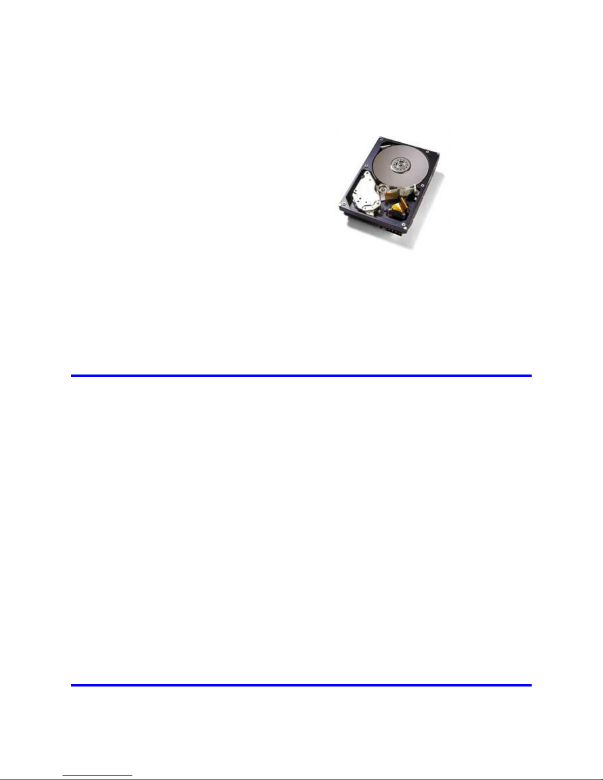
Ultrastar 146Z10
3.5 inch SCSI hard disk drive
ibm
ibm
ibmibm
Models:
Revision 2.2 02 February 2002
IC35L018UWDY10
IC35L018UCDY10
IC35L036UWDY10
IC35L036UCDY10
IC35L073UWDY10
IC35L073UCDY10
IC35L146UWDY10
IC35L146UCDY10
S07N9742-03 Publication number 3630
Page 2

This page intentionally left blank.
Page 3

IBM storage products
Hard disk drive specifications
Ultrastar 146Z10
3.5 inch SCSI hard disk drive
ibm
ibm
ibmibm
Models:
Revision 2.2 02 February 2002
IC35L018UWDY10
IC35L018UCDY10
IC35L036UWDY10
IC35L036UCDY10
IC35L073UWDY10
IC35L073UCDY10
IC35L146UWDY10
IC35L146UCDY10
S07N9742-03 Publication number 3630
Page 4

1st Edition (Rev. 2.0) S07N9742-01 (31 January 2002)
2nd Edition (Rev. 2.1) S07N9742-02 (01 February 2002)
3rd Edition (Rev. 2.2) S07N9742-03 (02 February 2002)
The following paragraph does not apply to the United Kingdom or any country where such provisions are
inconsistent with local law: INTERNATIONAL BUSINESS MACHINES CORPORATION PROVIDES THIS
PUBLICATION “AS IS” WITHOUT WARRANTY OF ANY KIND, EI THER EXPRESS OR IMPLIED, INCLUDING, BUT NOT LIMITED TO, THE IMPLIED WARRANTIES OF MERCHANTABILITY OR FITNESS
FOR A PARTICULAR PURPOSE. Some states do not allow disclaimer or express or implied warranties in certain
transactions, therefore, this statement may not apply to you.
This publication could include technical inaccuracies or typographical errors. Changes are periodically made to the
information herein; these changes will be incorporated in new editions of the publication. IBM may make improvements and/or changes in the product(s) and/or the program(s) described in this publication at any time.
It is possible that this publication may contain reference to, or information about, IBM products (machines and
programs), programming, or services that are not announced in your country. Such references or information must
not be construed to mean that IBM intends to announce such IBM products, programming, or services in your
country.
Technical information about this product is available by contacting your local IBM representative or the following:
Internet: http://www.ibm.com/harddrive
IBM may have patents or pending patent applications covering subject matter in this document. The furnishing of
this document does not give you any license to these patents. You can send license inquiries, in writing, to the IBM
Director of Commercial Relations, IBM Corporation, Armonk, NY 10577.
©Copyright International Business Machines Corporation 2002. All rights reserved.
Note to U.S. Government Users —Documentation related to restricted rights —Use, duplication or disclosure is
subject to restrictions set forth in GSA ADP Schedule Contract with IBM Corp.
Page 5

Table of contents
ixFigures ...........................................................................
11.0 General .......................................................................
11.1 Introduction ....................................................................
11.2 Glossary .......................................................................
21.3 General caution .................................................................
32.0 Outline of the drive .............................................................
5Part 1. Functional specification .....................................................
73.0 Fixed disk subsystem description ...............................................
73.1 Control electronics ..............................................................
73.2 Head disk assembly .............................................................
73.3 Actuator .......................................................................
94.0 Drive characteristics ...........................................................
94.1 Formatted capacity ..............................................................
94.2 Data sheet .....................................................................
104.3 Inquiry Information .............................................................
104.3.1 Product ID ...............................................................
104.3.2 World Wide ID - Block assignment ...........................................
114.4 Cylinder allocation ..............................................................
124.5 Performance characteristics .....................................................
124.5.1 Command overhead .......................................................
134.5.2 Mechanical positioning .....................................................
144.5.3 Drive ready time ..........................................................
144.5.4 Spindle stop time .........................................................
154.5.5 Data transfer speed .......................................................
154.5.6 Buffering operation (read ahead/write cache) .................................
164.5.7 Throughput ..............................................................
175.0 Data integrity .................................................................
175.1 Equipment status ..............................................................
175.2 Error recovery procedure ........................................................
196.0 Physical format ...............................................................
196.1 Shipped format (P-List) .........................................................
196.2 Reassigned format (G-List) ......................................................
217.0 Specification .................................................................
217.1 Electrical interface specification ..................................................
217.1.1 Power connector ..........................................................
227.1.2 SCSI bus connector .......................................................
247.1.3 SCSI cable ...............................................................
247.1.4 SCSI bus terminator .......................................................
247.1.5 Hot plug/unplug ...........................................................
247.1.6 SCSI bus electrical characteristics ...........................................
257.1.7 Auxiliary connector on 68-pin model .........................................
267.2 Option jumper block ............................................................
277.2.1 Jumper signal description on J6 .............................................
287.2.2 Jumper signal description on J4 .............................................
307.3 Environment ...................................................................
307.3.1 Corrosion test ............................................................
317.4 Cooling requirements ...........................................................
327.5 DC power requirements .........................................................
327.5.1 Input voltage .............................................................
Ultrastar 146Z10 hard disk drive specifications
iii
Page 6

Ultrastar 146Z10 hard disk drive specifications
iv
327.5.2 Power supply current ......................................................
337.5.3 Ripple voltage ............................................................
337.5.4 Power consumption efficiency index .........................................
347.6 Reliability .....................................................................
347.6.1 Start/stop cycles ..........................................................
347.6.2 Data reliability ............................................................
347.6.3 Seek/ID miscompare errors ................................................
347.6.4 Equipment errors .........................................................
347.6.5 Failure prediction (PFA/S.M.A.R.T.) .........................................
347.6.6 Preventive maintenance ...................................................
357.6.7 Temperature Warning .....................................................
367.7 Mechanical specifications .......................................................
367.7.1 Outline ..................................................................
377.7.2 Mechanical dimensions ....................................................
387.7.3 Interface connector ........................................................
397.7.4 Mounting positions and tappings ............................................
407.7.5 Heads unload and actuator lock .............................................
407.7.6 Breather hole .............................................................
417.8 Vibration and shock ............................................................
417.8.1 Operating vibration ........................................................
417.8.2 Non-operating vibrations ...................................................
427.8.3 Operating shock ..........................................................
427.8.4 Non-operating shock ......................................................
437.9 Acoustics .....................................................................
447.10 Identification labels ............................................................
457.11 Electromagnetic compatibility ...................................................
457.11.1 CE Mark ................................................................
457.11.2 C-Tick Mark .............................................................
457.11.3 BSMI Mark ..............................................................
467.12 Safety .......................................................................
467.12.1 UL and CSA standard conformity ..........................................
467.12.2 European Standards Compliance ..........................................
467.12.3 German Safety Mark .....................................................
467.12.4 Flammability ............................................................
47Part 2. Interface specification .....................................................
498.0 SCSI Command Set ...........................................................
508.1 SCSI Control Byte ..............................................................
508.2 Abbreviations ..................................................................
508.3 Byte ordering conventions .......................................................
518.4 FORMAT UNIT (04h) ...........................................................
528.4.1 Defect list ................................................................
538.4.2 Defect descriptor .........................................................
558.5 INQUIRY (12h) ................................................................
578.5.1 Inquiry DATA .............................................................
648.6 LOG SELECT (4Ch) ............................................................
658.7 LOG SENSE (4Dh) .............................................................
668.7.1 Log Page parameters .....................................................
678.7.2 Log Sense Page 0 ........................................................
688.7.3 Log Sense Page 2 ........................................................
708.7.4 Log Sense Page 3 ........................................................
728.7.5 Log Sense Page 5 ........................................................
738.7.6 Log Sense Page 6 ........................................................
748.7.7 Log Sense Page D ........................................................
758.7.8 Log Sense Page E ........................................................
Page 7

768.7.9 Log Sense Page F ........................................................
778.7.10 Log Sense Page 10 ......................................................
798.7.11 Log Sense Page 2F ......................................................
808.8 MODE SENSE (6) (1A) .........................................................
818.8.1 Mode Parameter List ......................................................
858.8.2 Mode Page 0 (Vendor Unique Parameters) ...................................
888.8.3 Mode Page 1 (Read/Write Error Recovery Parameters) ........................
928.8.4 Mode Page 2 (Disconnect/Reconnect Parameters) ............................
948.8.5 Mode Page 3 (Format Device Parameters) ...................................
968.8.6 Mode Page 4 (Rigid Disk Drive Geometry Parameters) .........................
978.8.7 Mode Page 7 (Verify Error Recovery Parameters) .............................
988.8.8 Mode Page 8 (Caching Parameters) .........................................
1008.8.9 Mode Page A (Control Mode Page Parameters) ..............................
1028.8.10 Mode Page 0C (Notch Parameters) .......................................
1048.8.11 Mode Page 19 (Port Control) .............................................
1108.8.12 Mode Page 1A (Power Control Parameters) ................................
1118.8.13 Mode Page 1C (Informational Exceptions Control) ...........................
1138.9 MODE SENSE (10) (5Ah) ......................................................
1148.10 MODE SELECT (6) (15h) .....................................................
1158.11 MODE SELECT (10) (55h) ....................................................
1168.12 PERSISTENT RESERVE IN (5Eh) .............................................
1168.12.1 Service Action ..........................................................
1178.12.2 Parameter data for Read Keys ............................................
1178.12.3 Parameter data for Read Reservations .....................................
1188.12.4 Parameter data for Read Reservation Descriptor ............................
1198.13 PERSISTENT RESERVE OUT (5Fh) ...........................................
1208.13.1 Service Action .........................................................
1228.13.2 Scope .................................................................
1228.13.3 Type ..................................................................
1248.13.4 Parameter list ..........................................................
1248.13.5 Summary ..............................................................
1268.14 PRE-FETCH (34h) ...........................................................
1278.15 READ (6) (08h) ..............................................................
1288.16 READ (10) (28h) .............................................................
1298.17 READ BUFFER (ACH) ........................................................
1308.17.1 Combined Header And Data (Mode 0000b) .................................
1308.17.2 Read Data (Mode 0010b) ................................................
1308.17.3 Descriptor (Mode 0011b) ................................................
1318.17.4 Read Data from Echo Buffer (Mode 1010b) .................................
1318.17.5 Echo Buffer Descriptor (Mode 1011b) ......................................
1328.18 READ CAPACITY (25h) .......................................................
1348.19 READ DEFECT DATA (10) (37h) ...............................................
1358.19.1 Defect List Header ......................................................
1358.19.2 Bytes from Index Format (100b) ..........................................
1368.19.3 Physical Sector Format (101b) ............................................
1378.20 READ DEFECT DATA (12) (B7h) ..............................................
1388.20.1 Defect List Header ......................................................
1388.20.2 Bytes from Index Format (100b) ..........................................
1398.20.3 Physical Sector Format (101b) ............................................
1408.21 READ LONG (3Eh) ...........................................................
1418.22 REASSIGN BLOCKS (07h) ....................................................
1438.23 RECEIVE DIAGNOSTICS RESULTS (1Ch) ......................................
1438.23.1 Receive Diagnostic Results Page 0 ........................................
Ultrastar 146Z10 hard disk drive specifications
v
Page 8

1448.23.2 Receive Diagnostic Results Page 40 ......................................
1458.23.3 Receive Diagnostic Results Page 80 ......................................
1468.24 RELEASE (6) (17h) ..........................................................
1478.25 RELEASE (10) (57h) .........................................................
1488.26 REPORT DEVICE IDENTIFIER (A3h) ...........................................
1508.27 REPORT LUN (A0h) .........................................................
1518.28 REQUEST SENSE (03h) ......................................................
1528.29 RESERVE (6) (16h) ..........................................................
1538.30 RESERVE (10) (56h) .........................................................
1548.31 REZERO UNIT (01h) .........................................................
1558.32 SEEK (6) (0Bh) ..............................................................
1568.33 SEEK EXTENDED (10) (2Bh) ..................................................
1578.34 SEND DIAGNOSTIC (1Dh) ....................................................
1598.34.1 Send Diagnostic Page 0 .................................................
1598.34.2 Send Diagnostic Page 40 ................................................
1608.34.3 Send Diagnostic Page 80 ................................................
1618.35 SET DEVICE IDENTIFIER (A4h) ...............................................
1628.36 START STOP Unit (1Bh) ......................................................
1638.37 SYNCHRONIZE CACHE (35h) .................................................
1648.38 TEST UNIT READY (00h) .....................................................
1658.39 VERIFY (2Fh) ...............................................................
1668.40 WRITE (6) (0Ah) .............................................................
1678.41 WRITE (10) (2Ah) ............................................................
1688.42 WRITE AND VERIFY (2Eh) ...................................................
1698.43 WRITE BUFFER (3Bh) .......................................................
1708.43.1 Combined Header And Data (Mode 0000b) .................................
1708.43.2 Write Data (Mode 0010b) ................................................
1718.43.3 Download Microcode (Mode 0100b) .......................................
1718.43.4 Download Microcode and Save (Mode 0101b) ..............................
1728.43.5 Download Microcode and Save (Mode 0111b) ..............................
1728.43.6 Write Data to Echo Buffer (Mode 1010b) ...................................
1738.44 WRITE LONG (3Fh) ..........................................................
1748.45 WRITE SAME (41h) ..........................................................
1759.0 SCSI Status Byte .............................................................
17710.0 SCSI Message System .......................................................
17710.1 Supported Messages .........................................................
17810.1.1 TASK COMPLETE (00h) .................................................
17810.1.2 SYNCHRONOUS DATA TRANSFER REQUEST (010301H) ..................
18110.1.3 WIDE DATA TRANSFER REQUEST (010203H) ............................
18310.1.4 PARALLEL PROTOCOL REQUEST (01,06,04H) ............................
18510.1.5 SAVE DATA POINTER (02h) .............................................
18510.1.6 RESTORE POINTERS (03h) .............................................
18510.1.7 DISCONNECT (04h) ....................................................
18510.1.8 INITIATOR DETECTED ERROR (05h) .....................................
18610.1.9 ABORT (06h) ..........................................................
18610.1.10 MESSAGE REJECT (07h) ..............................................
18610.1.11 NO OPERATION (08h) .................................................
18610.1.12 MESSAGE PARITY ERROR (09h) .......................................
18610.1.13 LINKED COMMAND COMPLETE (0Ah) ..................................
18710.1.14 LINKED COMMAND COMPLETE WITH FLAG (0Bh) .......................
18710.1.15 TARGET RESET (0Ch) .................................................
18710.1.16 ABORT TAG (0Dh) ....................................................
18710.1.17 CLEAR QUEUE TAG (0Eh) .............................................
Ultrastar 146Z10 hard disk drive specifications
vi
Page 9

18710.1.18 QUEUE TAG MESSAGES (20xxh, 21xxh, 22xxh) ..........................
18810.1.19 IGNORE WIDE RESIDUE (2301h) .......................................
18810.1.20 IDENTIFY (80 - FFh) ...................................................
18910.2 Supported Message Functions .................................................
19010.3 Attention Condition ...........................................................
19110.4 SCSI Bus Related Error Handling Protocol .......................................
19110.4.1 Unexpected BUS FREE Phase Error Condition .............................
19110.4.2 MESSAGE OUT Phase Parity Error .......................................
19110.4.3 MESSAGE IN Phase Parity Error (Message Parity Error) .....................
19110.4.4 COMMAND Phase Parity Error ...........................................
19110.4.5 DATA OUT Phase Parity Error ............................................
19210.4.6 INITIATOR DETECTED ERROR Message .................................
19210.4.7 MESSAGE REJECT Message ............................................
19311.0 Additional information ......................................................
19311.1 SCSI Protocol ...............................................................
19311.1.1 Priority of SCSI Status Byte Reporting .....................................
19411.1.2 Invalid LUN in Identify Message ...........................................
19411.1.3 Incorrect Initiator Connection .............................................
19411.1.4 Command Processing during execution of active I/O process .................
19611.1.5 Unit Attention Condition ..................................................
19711.1.6 Command Processing During Startup and Format Operations .................
19711.1.7 Deferred Error ..........................................................
19711.1.8 Degraded Mode ........................................................
20311.1.9 Command processing while reserved ......................................
20411.2 Priority commands ...........................................................
20411.3 Command queuing ...........................................................
20511.3.1 Queue depth ...........................................................
20511.3.2 Tagged queuing ........................................................
20511.3.3 Untagged queuing ......................................................
20511.3.4 Command queuing rule ..................................................
20511.3.5 Queue Full status .......................................................
20511.3.6 Device behavior on Command queuing ....................................
20611.4 Command reordering .........................................................
20611.5 Concurrent I/O Process .......................................................
20611.6 Back to Back Write ...........................................................
20711.7 Write Cache .................................................................
20711.8 Automatic Defect Reallocation .................................................
20811.9 Segmented Caching ..........................................................
20811.10 Reselection Timeout ........................................................
20811.11 Single Initiator Selection .....................................................
20811.12 Non-arbitrating systems ......................................................
20811.13 Selection without ATN .......................................................
20911.14 Multiple Initiator Environment .................................................
20911.14.1 Initiator Sense Data ....................................................
20911.14.2 Initiator Mode Select/Mode Sense Parameters .............................
20911.14.3 Initiator Data Transfer Mode Parameter ...................................
20911.15 Contingent Allegiance Condition ..............................................
21011.16 Reset .....................................................................
21011.16.1 Reset Sources ........................................................
21011.16.2 Power On Reset .......................................................
21111.16.3 SCSI Bus Reset and TARGET RESET Message ...........................
21111.16.4 Self-initiated Reset .....................................................
21211.17 Diagnostics ................................................................
Ultrastar 146Z10 hard disk drive specifications
vii
Page 10

21211.17.1 Power on Diagnostics ..................................................
21211.17.2 Self-test by Send Diagnostic Command ...................................
21411.18 Idle Time Function ..........................................................
21411.19 Information Unit Support .....................................................
21512.0 SCSI Sense Data ............................................................
21512.1 SCSI Sense Data Format .....................................................
21612.2 Sense Data Description .......................................................
21612.2.1 Valid (Bit 7 of byte 0) ....................................................
21612.2.2 Error Code (Bit 6 - 0 of byte 0) ............................................
21612.2.3 ILI: Incorrect Length Indicator (Bit 5 of byte 2) ...............................
21612.2.4 Sense Key (Bit 3 - 0 of byte 2) ............................................
21712.2.5 Information Bytes (Byte 3 through 6) .......................................
21712.2.6 Additional Sense Length (Byte 7) ..........................................
21712.2.7 Command Specific Information (Byte 8 through 11) ..........................
21812.2.8 Additional Sense Code/Qualifier (Byte 12 and 13) ...........................
22212.2.9 FRU : Field Replaceable Unit (Byte 14) ....................................
22212.2.10 Sense Key Specific (Byte 15 through 17) ..................................
22412.2.11 Vendor Unique Error Information (Byte 18 through 19) ......................
22512.2.12 Vendor unique error information (Byte 20 through 23) .......................
23012.2.13 Physical Error Record (Byte 24 thru 29) ...................................
23012.2.14 Reserved (Byte 30 through 31) ..........................................
231Index ...........................................................................
Ultrastar 146Z10 hard disk drive specifications
viii
Page 11

Figures
Figure 19. Table of signals
..........................................................
9Figure 1. Formatted capacity .........................................................
9Figure 2. Data sheet ................................................................
10Figure 3. Product ID in Inquiry Command .............................................
10Figure 4. Block assignment of World Wide ID in Inquiry Command ........................
11Figure 5. Cylinder allocation .........................................................
12Figure 6. Command overhead .......................................................
13Figure 7. Mechanical positioning performance .........................................
13Figure 8. Full stroke seek time ......................................................
14Figure 9. Cylinder Skew ............................................................
14Figure 10. Head skew ..............................................................
14Figure 11. Latency time ............................................................
14Figure 12. Drive ready time .........................................................
14Figure 13. Spindle stop time ........................................................
15Figure 14. Data transfer speed (sector size 512 bytes case) .............................
16Figure 15. Simple sequential access performance (sector size 512 byte case) .............
16Figure 16. Random access performance (sector size 512 bytes case) ....................
19Figure 17. P-List physical format ....................................................
21Figure 18. Power connector pin assignments ..........................................
22
23Figure 20. Table of signals ..........................................................
25Figure 21. Auxiliary connector .......................................................
26Figure 22. Jumper pins .............................................................
27Figure 23. Auto Start Delay & Delay Start 6/12 drive behavior ............................
28Figure 24. LED circuit ..............................................................
29Figure 25. SCSI device ID ..........................................................
30Figure 26. Operating and non-operating conditions .....................................
30Figure 27. Temperature and relative humidity ..........................................
31Figure 28. Maximum allowable module surface temperature .............................
31Figure 29. Module location ..........................................................
32Figure 30. Input voltage ............................................................
32Figure 31. Power supply current of 146-GB models ....................................
32Figure 32. Power supply current of 73-GB models ......................................
33Figure 32. Power supply current of 36-GB models ......................................
33Figure 33. Power supply current of 18-GB models ......................................
33Figure 34. Power supply generated ripple at drive power connector .......................
33Figure 35. Power consumption efficiency index ........................................
36Figure 36. Outline of the 68-pin model ................................................
36Figure 37. Outline of the 80-pin model ................................................
37Figure 38. Physical dimensions ......................................................
37Figure 39. Mechanical dimensions ...................................................
38Figure 40. Interface connector for 68-pin models .......................................
38Figure 41. Interface connector for 80-pin models .......................................
39Figure 42. Mounting positions and tappings ...........................................
40Figure 43. Breather hole location ....................................................
41Figure 44. Random vibration PSD profile breakpoints (operating) .........................
41Figure 45. Random vibration PSD profile breakpoints (non-operating) .....................
43Figure 46. A-weighted sound power levels ............................................
44Figure 47. Interface definition mark, SCSI LVD/SE multimode ............................
49Figure 48. Supported SCSI commands ...............................................
50Figure 49. SCSI Control Byte ........................................................
Ultrastar 146Z10 hard disk drive specifications
ix
Page 12

51Figure 50. FORMAT UNIT (04h) .....................................................
52Figure 51. Format of Defect List Header ...............................................
53Figure 52. Defect descriptor - Block format. ...........................................
54Figure 53. Defect descriptor - Bytes from Index format. .................................
54Figure 54. Defect descriptor - Physical Sector format. ..................................
55Figure 55. INQUIRY (12) ............................................................
56Figure 56. Page code descriptions ....................................................
57Figure 57. INQUIRY Data - CmdDt = 0EVPD = 0 .......................................
59Figure 58. Command support data format .............................................
60Figure 59. SUPPORT values and meanings ...........................................
61Figure 60. INQUIRY DATA - EVPD = 1 (Page Code = 00) ...............................
62Figure 61. INQUIRY DATA - EVPD = 1 (Page Code = 80h) ..............................
63Figure 62. INQUIRY DATA - EVPD = 1 (Page Code = 83h) ..............................
64Figure 63. LOG SELECT (4C) .......................................................
65Figure 64. LOG SENSE .............................................................
67Figure 65. Log Sense Page 0 ........................................................
68Figure 66. Log Sense Page 2 (part 1 of 2) .............................................
69Figure 67. Log Sense Page 2 (part 2 of 2) .............................................
70Figure 68. Log Sense Page 3 (part 1 of 2) .............................................
71Figure 69. Log Sense Page 3 (part 2 of 2) .............................................
72Figure 70. Log Sense Page 5 (part 1 of 2) .............................................
73Figure 71. Log Sense Page 5 (part 2 0f 2) .............................................
73Figure 72. Log Sense Page 6 ........................................................
74Figure 73. Log Sense Page D ........................................................
75Figure 74. Log Sense Page E ........................................................
76Figure 75. Log Sense Page F Application Client Log ....................................
77Figure 76. Log Sense Page 10, Self-Test Results .......................................
78Figure 77. Log Sense Page 10 Self-Test Results .......................................
79Figure 78. Log Sense Page 10 Extended Segment Number ..............................
79Figure 79. Log Sense Page 2F .......................................................
80Figure 80. MODE SENSE (1A) .......................................................
81Figure 81. Page Code Usage ........................................................
81Figure 82. Mode parameter header (6) ................................................
82Figure 83. Mode parameter header (10) ...............................................
83Figure 84. MODE Parameter Block Descriptor .........................................
84Figure 85. MODE Parameter Page Format ............................................
84Figure 86. Page Code Usage ........................................................
85Figure 87. Vendor Unique Parameters - Page 0 ........................................
88Figure 88. Mode Page 1 (Vendor Unique Parameters ) ..................................
92Figure 89. Mode Page 2 (Disconnect/Reconnect Parameters ) ...........................
94Figure 90. Mode Page 3 (Format Device Parameters) ...................................
96Figure 91. Mode Page 4 (Rigid Disk Drive Geometry Parameters) ........................
97Figure 92. Mode Page 7 (Verify Error Recovery Parameters) .............................
98Figure 93. Page 8 (Caching Parameters) ..............................................
100Figure 94. Page A (Control Mode Page Parameters) ...................................
102Figure 95. Page 0C (Notch Parameters) ..............................................
104Figure 96. Page 19 (Port Control parameters) Short format .............................
105Figure 97. Page 19 (Port Control Parameters) Long Format .............................
106Figure 98. Margin Control Subpage ..................................................
107Figure 99. Saved Training Configuration Subpage .....................................
108Figure 100. Negotiated Settings Subpage ............................................
109Figure 101. Report Transfer Capabilities Subpage .....................................
110Figure 102. Page 1A (Power Control) ................................................
111Figure 103. Page 1C (Informational Exceptions Control) ................................
Ultrastar 146Z10 hard disk drive specifications
x
Page 13

113Figure 104. MODE SENSE (10) .....................................................
114Figure 105. MODE SELECT (6) .....................................................
115Figure 106. MODE SELECT (10) ....................................................
116Figure 107. Persistent Reserve In ...................................................
116Figure 108. Persistent Reserve In Service Action Codes ................................
117Figure 109. PERSISTENT RESERVE IN parameter data for Read Keys ..................
117Figure 110. PERSISTENT RESERVE IN parameter data for Read Reservations ...........
118Figure 111. PERSISTENT RESERVE IN Read Reservation Descriptor ...................
119Figure 112. Persistent Reserve Out (5F) .............................................
120Figure 113. Persistent Reservation Service Action Code ................................
122Figure 114. Persistent Reservation Scope Code .......................................
122Figure 115. Persistent Reservation Type Code ........................................
123Figure 116. Conflict between new and existing PERSISTENT RESERVATION .............
124Figure 117. PERSISTENT RESERVATION OUT parameter list ..........................
124Figure 118. Service Action and parameters and generation counter ......................
125Figure 119. APTPL and information held by a drive ....................................
126Figure 120. Pre-Fetch .............................................................
127Figure 121. READ (6) ..............................................................
128Figure 122. READ (10) ............................................................
129Figure 123. READ BUFFER ........................................................
130Figure 124. READ BUFFER Header .................................................
131Figure 125. Read Buffer Descriptor ..................................................
131Figure 126. Echo Buffer Descriptor ..................................................
132Figure 127. READ CAPACITY ......................................................
133Figure 128. Format of READ CAPACITY command reply ...............................
134Figure 129. Read Defect Data (10) ..................................................
135Figure 130. Defect List Header ......................................................
135Figure 131. Defect Descriptors of Bytes from Index Format .............................
136Figure 132. Defect Descriptors of Physical Sector Format ...............................
137Figure 133. Read Defect Data (12) ..................................................
138Figure 134. Defect List Header ......................................................
138Figure 135. Defect Descriptors of Bytes from Index Format .............................
139Figure 136. Defect Descriptors of Physical Sector Format ...............................
140Figure 137. READ LONG ..........................................................
141Figure 138. REASSIGN BLOCKS ...................................................
142Figure 139. Format of REASSIGN BLOCKS data ......................................
143Figure 140. RECEIVE DIAGNOSTIC ................................................
143Figure 141. Receive Diagnostic Results Page 0 .......................................
144Figure 142. Receive Diagnostic Results Page 40 ......................................
145Figure 143. Translated address .....................................................
145Figure 144. Receive Diagnostic Results Page 80 .....................................
146Figure 145. RELEASE (6) ..........................................................
147Figure 146. RELEASE (10) .........................................................
148Figure 147. REPORT DEVICE IDENTIFIER ..........................................
149Figure 148. REPORT DEVICE IDENTIFIER parameter list ..............................
150Figure 149. REPORT LUN .........................................................
150Figure 150. LUN Reporting Parameter List Format .....................................
151Figure 151. REQUEST SENSE .....................................................
152Figure 152. RESERVE (6) ..........................................................
153Figure 153. RESERVE (10) ........................................................
154Figure 154. REZERO UNIT .........................................................
155Figure 155. SEEK (6) ..............................................................
156Figure 156. SEEK (10) .............................................................
157Figure 157. SEND DIAGNOSTIC ....................................................
Ultrastar 146Z10 hard disk drive specifications
xi
Page 14

Figure 195. Spindle Motor Degraded Mode - Spindle Stopped by Start Stop Unit
Command ....................................................................
158Figure 158. SEND DIAGNOSTIC (1D) ...............................................
159Figure 159. Diagnostic Page 0 ......................................................
159Figure 160. Diagnostic Page 40 .....................................................
160Figure 161. Address to translate ....................................................
160Figure 162. Send Diagnostic Page 80 ................................................
161Figure 163. SET DEVICE IDENTIFIER ...............................................
161Figure 164. SET DEVICE IDENTIFIER Parameter List .................................
162Figure 165. START STOP Unit ......................................................
163Figure 166. SYNCHRONIZE CACHE ................................................
164Figure 167. TEST UNIT READY ....................................................
165Figure 168. VERIFY ...............................................................
166Figure 169. WRITE (6) .............................................................
167Figure 170. WRITE (10) ............................................................
168Figure 171. WRITE AND VERIFY ...................................................
169Figure 172. WRITE BUFFER (3B) ...................................................
170Figure 173. WRITE BUFFER Header ................................................
173Figure 174. WRITE LONG .........................................................
174Figure 175. WRITE SAME (41) .....................................................
175Figure 176. SCSI Status Byte. Format of the SCSI STATUS byte. .......................
177Figure 177. Supported Messages ...................................................
178Figure 178. Synchronous Data Transfer Request. .....................................
179Figure 179. Initiator Request/Drive Response (LVD mode) ..............................
179Figure 180. Initiator Request/Drive Response (SE mode) ...............................
180Figure 181. Target Response to Initiator's Transfer Period (LVD mode) ...................
180Figure 182. Drive Response to Initiator's Transfer Period (SE mode) .....................
181Figure 183. Wide Data Transfer Request. ............................................
181Figure 184. Initiator Request/Target Response ........................................
182Figure 185. Target Request to Initiator ...............................................
183Figure 186. Parallel Protocol Request. ...............................................
183Figure 187. Initiator Request/Target Response (DT_REQ = 1, IU_REQ = 1) ...............
184Figure 188. Initiator Request/Target Response (DT_REQ = 1, IU_REQ = 0 ................
184Figure 189. Initiator Request/Target Response (DT_REQ = 0, IU_REQ = 0 ................
187Figure 190. Queue Tag Messages ...................................................
188Figure 191. Ignore Wide Residue Message Format ....................................
198Figure 192. Spindle Motor Degraded Mode - Disable Auto Start .........................
199Figure 193. Spindle Motor Degraded Mode - Auto Start Delay/Spinning Up ................
200Figure 194. Spindle Motor Degraded Mode - Spindle Start Failure ........................
201
202Figure 196. Self Configuration Failure Degraded Mode .................................
203Figure 197. Format Command Failure Degraded Mode .................................
213Figure 198. Self-test menu for SEND DIAGNOSTIC command ..........................
215Figure 199. Format of Sense Data. ..................................................
218Figure 200. Sense Key / Sense Code / Qualifier combinations (1 of 4) ....................
219Figure 201. Sense Key / Sense Code / Qualifier combinations (2 of 4) ....................
220Figure 202. Sense Key / Sense Code / Qualifier combinations (3 of 4) ....................
221Figure 203. Sense Key / Sense Code / Qualifier combinations (4 of 4) ...................
222Figure 204. Field Pointer Bytes .....................................................
223Figure 205. Actual Retry Count .....................................................
223Figure 206. Progress Indication .....................................................
224Figure 207. Sense Data Byte 18 for Error Information ..................................
225Figure 208. Sense Data Byte 20 for POR Step .......................................
225Figure 209. Sense Data Byte 21 for POR Step ........................................
226Figure 210. Sense Data Byte 22 POR Error ...........................................
Ultrastar 146Z10 hard disk drive specifications
xii
Page 15

227Figure 211. Sense Data Byte 23 for POR Error ........................................
228Figure 212. Sense Data Byte 20 for Read/Write Error ..................................
228Figure 213. Sense Data Byte 21 for Read/Write Error ..................................
229Figure 214. Sense Data Byte 22 for Read/Write Error ..................................
229Figure 215. Sense Data Byte 23 for Read/Write Error ..................................
230Figure 216. Sense Data Byte 21 for SMART Alert Reason Code .........................
Ultrastar 146Z10 hard disk drive specifications
xiii
Page 16

Ultrastar 146Z10 hard disk drive specifications
xiv
Page 17

1.0 General
1.1 Introduction
This document describes the specifications of the following IBM 3.5-inch SCSI drives:
! IC35L018UWDY10 (68 pin)
! IC35L018UCDY10 (80 pin)
! IC35L036UWDY10 (68 pin)
! IC35L036UCDY10 (80 pin)
! IC35L073UWDY10 (68 pin)
! IC35L073UCDY10 (80 pin)
! IC35L146UWDY10 (68 pin)
! IC35L146UCDY10 (80 pin)
The specifications in this document are subject to change without notice.
1.2 Glossary
Word
Kb
Kbpi
Mb
Mbps
GB
MB
KB
TPI
MLC
PFA
S.M.A.R.T.
ADM
SE
LVD
FC-AL
Meaning
Kilobit
Kilobits per inch
Megabit
Megabits per second
Gigabyte
Megabyte
Kilobyte
Tracks per inch
Machine Level Control
Predictive Failure Analysis (Trademark of IBM Corp.)
Self-Monitoring Analysis and Reporting Technology
Automatic Drive Maintenance
Single Ended SCSI
Low Voltage Differential SCSI
Fibre Channel - Arbitrated Loop
Ultrastar 146Z10 hard disk drive specifications
1
Page 18

1.3 General caution
This drive can be damaged by ESD (Electric Static Discharge). Any damages incurred to the drive after
its removal from the shipping package and the ESD protective bag are the responsibility of the user.
Ultrastar 146Z10 hard disk drive specifications
2
Page 19

2.0 Outline of the drive
! Storage capacities of 146.8 GB, 73.4 GB, 36.7 GB, and 18.3 GB
! Ultra 320 and Ultra 160
! Interleave factor 1:1
! Variable Sector Size (512-528 bytes/sector)
! Tagged Command Queuing support
! Automatic read/write data transfer
! 8 MB segmented sector buffer (from 1 through 256)
! 4.7 ms seek time in read operation
! Adaptive read ahead algorithm
! Write Cache
! Back to back write
! ECC on the fly
! Automatic defect reallocation
! Self diagnostics at power on
! Closed loop actuator servo
! High level of integration of the electronics
! Non head disk contact start stop
! Spindle rotation of 10,000 RPM
! Automatic actuator lock
! PFA (SMART)
! Glass substrate disks
NOTE: PFA (Predictive Failure Analysis) is a trademark of the IBM Corporation
Ultrastar 146Z10 hard disk drive specifications
3
Page 20

This page intentionally left blank.
Page 21

Part 1. Functional specification
Ultrastar 146Z10 hard disk drive specifications
5
Page 22

This page intentionally left blank.
Page 23

3.0 Fixed disk subsystem description
3.1 Control electronics
The drive is electronically controlled by a microprocessor, logic modules, digital/analogue modules, and
various drivers and receivers. The control electronics perform the following major functions:
! Perform self-checkout (diagnostics).
! Conduct a power-up sequence and calibrate the servo.
! Monitor various timers for head settling, servo failure, etc.
! Analyze servo signals to provide closed loop control. These include position error signal and
estimated velocity.
! Control the voice coil motor driver to align the actuator onto a desired position.
! Monitor the actuator position and determine the target track for a seek operation.
! Constantly monitor error conditions of the servo and take corresponding action if an error occurs.
! Control starting, stopping, and rotating speed of the spindle.
! Control and interpret all interface signals between the host controller and the drive.
! Control read write accessing of the disk media, including defect management and error recovery.
3.2 Head disk assembly
The head disk assembly (HDA) is assembled in a clean room environment and contains disks, a spindle
motor, actuator assembly, and voice coil motor. Air is constantly circulated and filtered when the drive is
operational. Venting of the HDA is accomplished via a breather filter.
The spindle is driven directly by a brushless, sensorless DC drive motor. Dynamic braking is used to stop
the spindle quickly.
3.3 Actuator
The read/write heads are mounted in the actuator. The actuator is a swing-arm assembly driven by a
voice coil motor. A closed-loop positioning servo controls the movement of the actuator. An embedded
servo pattern supplies feedback to the positioning servo to keep the read/write heads centered over the
desired track.
The actuator assembly is balanced to allow vertical or horizontal mounting without adjustment.
When the drive is powered off, the actuator automatically moves the head to aparking position outside of
the disk, where the actuator is locked.
Ultrastar 146Z10 hard disk drive specifications
7
Page 24

This page intentionally left blank.
Page 25

4.0 Drive characteristics
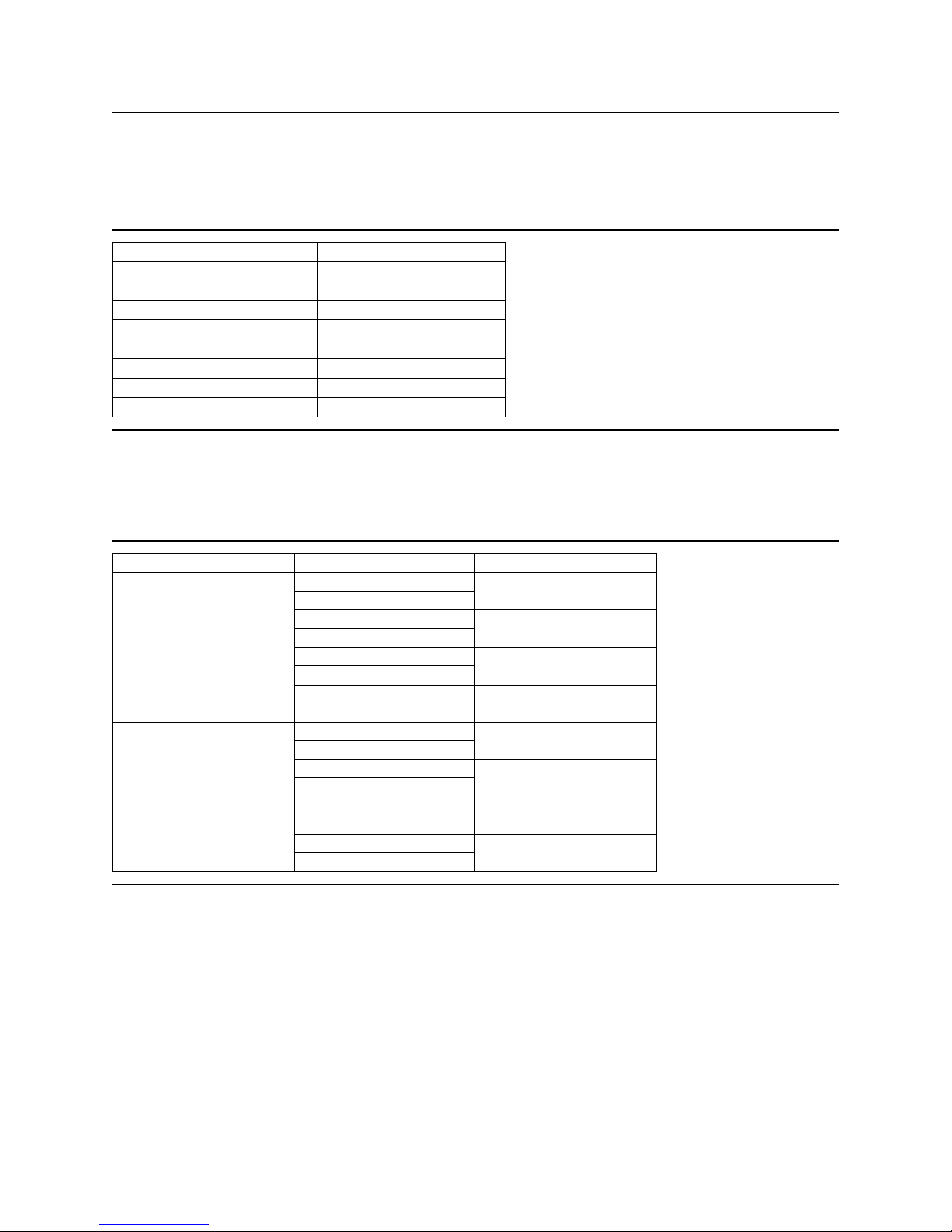
4.1 Formatted capacity
Description
Total data bytes
(512 bytes/sector)
Total logical data
blocks
Figure 1. Formatted capacity
IC35L146UWDY10
IC35L146UCDY10
286,749,610
(111773AAh)
4.2 Data sheet
Host to/from buffer (interface transfer rate)
[MB/sec]
IC35L073UWDY10
IC35L073UCDY10
143,374,805
(88BB9D5h
433 - 825 MbpsBuffer to/from media [Mb/sec]
320
8192 KB Data buffer size
1 - 256Number of buffer segments
10,000Rotational speed [RPM]
548Recording density [Kbpi] (Max)
47.9Track density [TPI] (average)
26,263Areal density [Mb/sq.in.]
15Data zone
IC35L036UWDY10
IC35L036UCDY10
71,687,340
(445DCACh)
IC35L018UWDY10
IC35L018UCDY10
18.35 GB36.7 GB73.4 GB146.8 GBLabel capacity
23612Number of heads
1236Number of disks
18,351,959,04036,703,918,08073,407,900,160146,815,800,320
35,843,670
(222EE56h)
Figure 2. Data sheet
NOTE: KB = 1,024 bytes
Ultrastar 146Z10 hard disk drive specifications
9
Page 26
4.3 Inquiry Information
4.3.1 Product ID
Product ID in Section 8.5.1, "Inquiry data format - CmdDt = 0 EVPD = 0" on page 57 is as follows.
DescriptionProduct ID
IC35L018UWDY10-0
IC35L018UCDY10-0
IC35L036UWDY10-0
IC35L036UCDY10-0
IC35L073UWDY10-0
IC35L073UCDY10-0
IC35L146UWDY10-0
IC35L146UCDY10-0
Figure 3. Product ID in Inquiry Command
4.3.2 World Wide ID - Block assignment
Block assignment of World Wide ID in 8.5.1.5 on Page 63 is as follows.
SFV, Hungary
Singapore
18.3 GB, 68 pin
18.3 GB, 80 pin
36.7 GB, 68 pin
36.7 GB, 80 pin
73.4 GB, 68 pin
73.4 GB, 80 pin
146.8 GB, 68 pin
146.8 GB, 80 pin
IC35L018UWDY10-0
IC35L018UCDY10-0
IC35L036UWDY10-0
IC35L036UCDY10-0
IC35L073UWDY10-0
IC35L073UCDY10-0
IC35L146UWDY10-0
IC35L146UCDY10-0
IC35L018UWDY10-0
IC35L018UCDY10-0
IC35L036UWDY10-0
IC35L036UCDY10-0
IC35L073UWDY10-0
IC35L073UCDY10-0
IC35L146UWDY10-0
IC35L146UCDY10-0
Block assignmentProductManufacturing site
212h, 213h
214h, 215h
216h, 217h
218h, 219h, 21Ah
716h, 717h
718h, 719h
71Ch, 71Dh
71Eh, 71Fh, 720h
Figure 4. Block assignment of World Wide ID in INQUIRY Command
Ultrastar 146Z10 hard disk drive specifications
10
Page 27
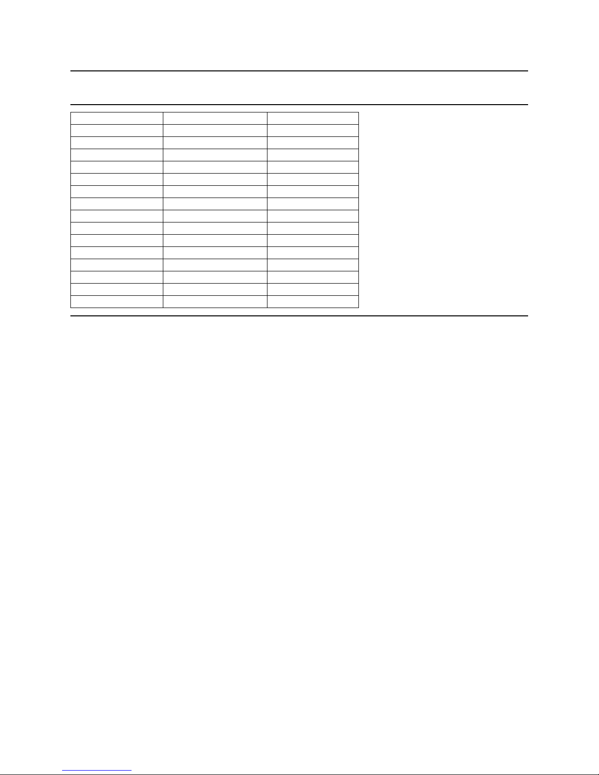
4.4 Cylinder allocation
Sectors/TrackPhysical CylindersZone
864 0 - 383Data Zone 0
840 384 - 3967Data Zone 1
8003968 - 5631Data Zone 2
7805632 - 6527Data Zone 3
7686528 - 8703Data Zone 4
720 8704 - 15359Data Zone 5
67215360 - 18047Data Zone 6
66018048 - 19199Data Zone 7
64019200 - 21503Data Zone 8
600 21504 - 24959Data Zone 9
560 24960 - 27775Data Zone 10
540 27776 - 29183Data Zone 11
520 29184 - 30719Data Zone 12
480 30720 - 35199Data Zone 13
440 35200 - 36735Data Zone 14
Figure 5. Cylinder allocation
NOTE: Mode Page 3 (Format Device Parameters) on page 94 and Mode Page 0C (Notch Parameters) on
page 102 provide methods to determine medium format and zone parameters.
Ultrastar 146Z10 hard disk drive specifications
11
Page 28

4.5 Performance characteristics
The performance of a drive is characterized by the following parameters:
! Command overhead
! Mechanical head positioning
- Seek time
- Latency
! Data transfer speed
! Buffering operation (read ahead/write cache)
NOTE: All the above parameters contribute to drive performance. There are other parameters that contribute to the performance of the actual system. This specification tries to define the bare drive characteristics, not the system throughput, which depends on the system and the application.
4.5.1 Command overhead
Command overhead is defined as the time required:
! from last byte of command phase
! to the first byte of data phase
! excluding
- Physical seek time
- Latency time
- Initiator delay with reconnections
Cache Not Hit
Cache Hit
Figure 6. Command overhead
TimeRead Command Case (Drive is in quiescent state)
<400 µs
<30 µs
Ultrastar 146Z10 hard disk drive specifications
12
Page 29
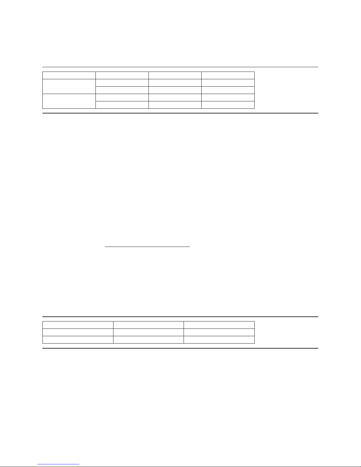
4.5.2 Mechanical positioning
4.5.2.1 Average seek time (including settling)
Max (ms)Typical (ms)Command Type
Read
Write
Figure 7. Mechanical positioning performance
“Typical” and “Max” are given throughout the performance specification by:
Typical Average of the drive population tested at nominal environmental and voltage conditions.
Max Maximum value measured on any one drive over the full range of the environmental and
voltage conditions. (See Section 7.3, "Environment" on page 30 and Section 7.5,
"DC power requirements" on page 32 for ranges.)
The seek time is measured from the start of the actuator's motion to the start of a reliable read or write
operation. “Reliable read or write” implies that error correction or recovery is not used to correct arrival
problems. The average seek time is measured as the weighted average of all possible seek combinations.
5.94.7146 GB model
5.74.7all other models
6.95.9146 GB model
6.95.3all other models
max
Sum
(max+1-n) (Tn.in+Tn.out)
Weighted average =
n=1
(max+1) (m ax)
Where
max = Maximum seek length
n = Seek length (1 to max)
Tn.in = Inward measured seek time for an n track seek
Tn.out = Outward measured seek time for an n track seek
4.5.2.2 Full stroke seek time
Maximum (ms)Typical (ms)Function
11.510.5Read
12.511.5Write
Figure 8. Full stroke seek time
Full stroke seek is measured as the average of 1000 full stroke seeks with a random head switch from
both directions (inward and outward).
Ultrastar 146Z10 hard disk drive specifications
13
Page 30

4.5.2.3 Cylinder switch time (cylinder skew)
Typical (ms)
0.70Cylinder skew
Figure 9. Cylinder Skew
A cylinder switch time is defined as the amount of time required by the fixed disk to access the next
sequential block after reading the last sector in the current cylinder.
4.5.2.4 Head switch time (head skew)
Typical (ms)
0.63Head skew
Figure 10. Head skew
A head switch time is defined as the amount of time required by the fixed disk to access the next
sequential block after reading the last sector in the current track.
4.5.2.5 Average latency
Rotation
Figure 11. Latency time
Time for a revolution
4.5.3 Drive ready time
Figure 12. Drive ready time
4.5.4 Spindle stop time
(ms)
Average Latency
(ms)
3.06.010,000 RPM
Maximum (sec)Typical (sec)Model
29.918.0146-GB Model
29.915.0 73-GB Model
29.912.0 36-GB Model
29.911.0 18-GB Model
Maximum (sec)Typical (sec)Model
3020146-GB Model
301473-GB Model
301436-GB Model
301418-GB Model
Figure 13. Spindle stop time
The period from power off to complete stop of spindle is categorized as operating, and Operating Shock
criteria are applied until complete stop of spindle. Refer to Section 7.8.3, "Operating Shock" on page 42.
Ultrastar 146Z10 hard disk drive specifications
14
Page 31

4.5.5 Data transfer speed
Typical (Mbyte/s)Description
Disk-Buffer Transfer (Zone 0)
All models 73.7Instantaneous
146-GB Model 66.7
Sustained
Disk-Buffer Transfer (Zone 16)
Sustained
Buffer-Host
Figure 14. Data transfer speed (sector size 512 bytes case)
! Instantaneous disk-buffer transfer rate is derived by
(Number of sectors on a track)*512*(revolution/sec)
NOTE: The number of sectors per track varies because of the linear density recording.
73-GB Model 66.6
36-GB Model 66.4
18-GB Model 66.2
All models 37.5Instantaneous
146-GB Model 33.9
73-GB Model 33.9
36-GB Model 33.8
18-GB Model 45.9
32068/80pin Ultra 320
! Sustained disk-buffer transfer rate is defined by considering head/cylinder change time. This gives a
local average data transfer rate. It is derived by
(Sustained Transfer Rate) = A/(B +C)
A = (Number of data sectors per cylinder) * 512
B = Average track change time
C = (# of Surface) * (One revolution time)
! Buffer-host transfer rate defines the maximum data transfer rate on SCSI Bus. It also depends on the
speed of the host.
4.5.6 Buffering operation (read ahead/write cache)
This hard disk drive has a buffer for read ahead and write caching. For details, refer to the SCSI interface
specification.
Ultrastar 146Z10 hard disk drive specifications
15
Page 32

4.5.7 Throughput
4.5.7.1 Simple sequential access
Max (ms)Typical (ms)Operation
Sequential read/write
Figure 15. Simple sequential access performance (sector size 512 byte case)
The above table gives the time required to read/write for a total of 8000x consecutive blocks
(16,777,216 bytes) accessed by 128 read/write commands. Typical and Max values are given by 100%
and 110% of T respectively throughput the following performance description.
NOTE: It is asumed that a host system responds instantaneously.
T = A + B + C + 16,777,216/D
where
T = Calculated Time
A = Command Overhead (Cache No Hit)
B = Average Seek Time
C = Average Latency
D = Sustained Disk-Buffer Transfer Rate
Zone 0 <260
Zone 14 <510
Zone 0 <290
Zone 11 <560
4.5.7.2 Random access
Maximum (sec) Typical (sec)Operation
3734Random read
4138Random write
Figure 16. Random access performance (sector size 512 bytes case)
The above table gives the time required to execute a total of 1000x read/write commands which access a
random LBA.
T = (A + B + C) * 4096
Where
T = Calculated Time
A = Command Overhead (Cache No Hit)
B = Average Seek Time
C = Average Latency
Ultrastar 146Z10 hard disk drive specifications
16
Page 33

5.0 Data integrity
The drive retains recorded information under all non-write operations.
No more than one sector will be lost by power down during write operation while write cache is disabled.
If power down occurs before completion of data transfer from write cache to disk while write cache is
enabled, the data remaining in write cache will be lost. To prevent this data loss at power off, the following
action is recommended:
! Confirm successful completion of SYNCHRONIZE CACHE (35h) command.
5.1 Equipment status
Equipment status is available to the host system any time the drive is not ready to read, write, or seek.
This status normally exists at power-on time and will be maintained until the following conditions are
satisfied:
! Access recalibration/tuning is complete.
! Spindle speed meets requirements for reliable operations.
! Self-check of drive is complete.
Appropriate error status is made available to the host system if any of the following condition occurs after
the drive has become ready:
! Spindle speed goes outside of requirements for reliable operation.
! “Write fault” is detected.
5.2 Error recovery procedure
Errors occurring with the drive are handled by the error recovery procedure.
Errors that are uncorrectable after application of the error recovery procedures are reported to the host
system as non-recoverable errors.
Ultrastar 146Z10 hard disk drive specifications
17
Page 34

This page intentionally left blank.
Page 35

6.0 Physical format
Media defects are remapped to the next available sector during the Format Process in manufacturing. The
mapping from LBA to the physical locations is calculated by an internally maintained table.
6.1 Shipped format (P-List)
! Data areas are optimally used
! No extra sector is wasted as a spare throughout user data areas
! All pushes generated by defects are absorbed by spare tracks of the inner zone
Figure 17. P-List physical format
NOTE: Defects are skipped without any constraint, such as track or cylinder boundary. The calculation
from LBA to physical is done automatically by internal table.
6.2 Reassigned format (G-List)
! G-List is prepared for 1078 LBAs
! Multiple reassignment of the same LBA does not increase G-List entry
! A cylinder for spare sectors is prepared every 512 physical cylinders
NOTE: G-List entries are part of the normal maintenance work of hard disk drives. G-List entries are
possible during early drive usage and are caused mainly by handling.
Ultrastar 146Z10 hard disk drive specifications
19
Page 36

This page intentionally left blank.
Page 37

7.0 Specification
7.1 Electrical interface specification
7.1.1 Power connector
The power connector of 68-pin models complies with the SFF-8009 Rev. 4.2. Power pin assignment of
68-pin models is as shown below.
Pin Voltage
4 3 2 1
Figure 18. Power connector pin assignments
Eighty-pin SCA-2 models use a DDK connector (PN HD2-PA080-A14B) or equivalent, which is compatible
with the Specification of “Single Attachment for Small SCSI Disk Drives” SPI-3 document, Annex C.
Power pin assignment of the 80-pin (SCA-2) model is shown in Section 7.1.2.1 on page 22.
1 +12 V
2GND
3GND
4+5V
Ultrastar 146Z10 hard disk drive specifications
21
Page 38

7.1.2 SCSI bus connector
The Ultrastar 146Z10 has 68-pin models and 80-pin SCA-2 models.
7.1.2.1 SCSI signal connector (68-pin model)
The pin assignments of the interface signals conform to SPI-4 as shown in the table below.
Connector contact
number
01
02
03
04
05
06
07
08
09
10
11
12
13
14
15
16
17
18
19
20
21
22
23
24
25
26
27
28
29
30
31
32
33
34
Signal name
+DB(12)
+DB(13)
+DB(14)
+DB(15)
+DB(P1)
+DB(0)
+DB(1)
+DB(2)
+DB(3)
+DB(4)
+DB(5)
+DB(6)
+DB(7)
+P_CRCA
Ground
DIFFSENS(*2)
TERMPWR(*1)
TERMPWR(*1)
Reserved
Ground
+ATN
Ground
+BSY
+ACK
+RST
+MSG
+SEL
+C/D
+REQ
+I/O
+DB(8)
+DB(9)
+DB(10)
+DB(11)
Connector contact
number
35
36
37
38
39
40
41
42
43
44
45
46
47
48
49
50
51
52
53
54
55
56
57
58
59
60
61
62
63
64
65
66
67
68
Signal name
-DB(12)
-DB(13)
-DB(14)
-DB(15)
-DB(P1)
-DB(0)
-DB(1)
-DB(2)
-DB(3)
-DB(4)
-DB(5)
-DB(6)
-DB(7)
-P_CRCA
Ground
Ground
TERMPWR(*1)
TERMPWR(*1)
Reserved
Ground
-ATN
Ground
-BSY
-ACK
-RST
-MSG
-SEL
-C/D
-REQ
-I/O
-DB(8)
-DB(9)
-DB(10)
-DB(11)
Figure 19. Table of signals
NOTES: *1 TERMPWR can be disabled.
*2 HVD is not supported.
Ultrastar 146Z10 hard disk drive specifications
22
Page 39

7.1.2.2 SCSI signal connector (80 pin SCA-2 model)
The 80-pin SCA-2 model uses a DDK connector which is compatible with SPI-4.
Connector contact
number
01
02
03
04
05
06
07
08
09
10
11
12
13
14
15
16
17
18
19
20
21
22
23
24
25
26
27
28
29
30
31
32
33
34
35
36
37
38
39
40
Signal name
12 Volt Charge
12 Volt
12 Volt
12 Volt
Opt 3.3 V/NC
Opt 3.3 V/NC
-DB(11)
-DB(10)
-DB(9)
-DB(8)
-I/O
-REQ
-C/D
-SEL
-MSG
-RST
-ACK
-BSY
-ATN
-P_CRCA
-DB(7)
-DB(6)
-DB(5)
-DB(4)
-DB(3)
-DB(2)
-DB(1)
-DB(0)
-DB(P1)
-DB(15)
-DB(14)
-DB(13)
-DB(12)
5 Volt
5 Volt
5 Volt Charge
Spindle Sync/NC
RMT START
SCSI ID (0)
SCSI ID (2)
Connector contact
number
41
42
43
44
45
46
47
48
49
50
51
52
53
54
55
56
57
58
59
60
61
62
63
64
65
66
67
68
69
70
71
72
73
74
75
76
77
78
79
80
Signal name
12V Ground
12V Ground
12V Ground
MATED 1
Opt 3.3 V charge/NC
DIFFSENS(*1)
+DB(11)
+DB(10)
+DB(9)
+DB(8)
+I/O
+REQ
+C/D
+SEL
+MSG
+RST
+ACK
+BSY
+ATN
+P_CRCA
+DB(7)
+DB(6)
+DB(5)
+DB(4)
+DB(3)
+DB(2)
+DB(1)
-DB(0)
+DB(P1)
+DB(15)
+DB(14)
+DB(13)
+DB(12)
MATED 2
5V Ground
5V Ground
ACTIVE LED OUT
DELAYED START
SCSI ID (1)
SCSI ID (3)
Figure 20. Table of signals
NOTE*1: HVD is not supported.
NOTE: SCA-2 connector is not mechanically compatible with the 68 pin “P” connector as defined in the
ANSI SCSI standard. The connector is intended for direct back plane attachment and is not intended to
be cable attached to the bus.
Eight-bit devices which connect to the SCA-2 connector should have the following signals inactive (high):
-DB(8), -DB(9), -DB(10), -DB(11), -DB(12), -DB(13), -DB(14), -DB(15), -DB(P1). All other signals shall be
connected as defined.
Ultrastar 146Z10 hard disk drive specifications
23
Page 40

7.1.3 SCSI cable
Refer to ANSI SPI-4.
7.1.4 SCSI bus terminator
Onboard SCSI active termination feature is not supported. The using system is responsible for making
sure that all required signals are terminated at both ends of the bus cable.
Terminator power
Termination power can be provided by the drive 5V supply through the current limiter and Schottky diode.
This function can be selected by jumper.
The 80-pin SCA-2 models do not support SCSI bus termination power.
7.1.5 Hot plug/unplug
The term 'Hot Plug' refers to the action of mechanically engaging a device to the power and/or bus when
other devices may be active on the same bus. A comprehensive classification of the state of the SCSI bus
during this event is located in the SCSI-3 Parallel Interface Standard.
While every effort was made to design the drive not to influence the SCSI bus during these events, it is the
responsibility of the system to insure voltage regulation and conformance to operational and nonoperational shock limits. During Hot Plug events the non-operational shock levels should not be exceeded. The operational shock levels of adjacent drives should also not be exceeded. The recommended
procedure is to prohibit write operations to adjacent drives during Hot Plug and Hot Unplug actions.
During Hot Unplug the operational shock limit specifications should not be exceeded. If this cannot be
guaranteed, the drive should be issued a SCSI Stop Unit command that is allowed to complete before
unplugging. The basic requirement is that while the drive is operational or spinning down the operational
shock limits are in effect. When the drive has completely stopped, the non-operational shock limits are in
effect. The recommended procedure is to allow the unplugged drive to rest in the drive bay for a minimum
of 15 seconds and then complete the removal. During Hot Plug or Unplug events the power supply ripple
on adjacent operational drives should not be outside the ±5 % regulation tolerance. It is recommended
that the system have current limiter for in-rush current as described in ANSI SPI-4.
Hot plugging/unplugging the 68-pin model drive to the power supply or to SCSI bus connector is not
allowed since provisions are not available to determine which electrical contact is made first. It may cause
glitches on the system SCSI bus and/or electrical over stress that may result in permanent damage of
electrical components of the drive. It is the responsibility of the system to protect the drive from these
situations when the 68-pin model is connected to the power supply or to SCSI bus.
7.1.6 SCSI bus electrical characteristics
Refer to ANSI SPI-4 for bus electrical characteristics.
NOTE: If the drive is connected to an HVD bus, the drive I/O will be permanently damaged.
Ultrastar 146Z10 hard disk drive specifications
24
Page 41

7.1.7 Auxiliary connector on 68-pin model
D
In addition to the Option Jumper Block the 68-pin models have an Auxiliary Connector between the power
connector and the 68-pin SCSI connector. The settings at the Option Jumper Block and the Auxiliary
Connector work as a logical OR. The drive conforms SFF-8009, Rev 4.2.
! Pin #1,3,5,7 specify SCSI-ID as -DAS0, 1 ,2, 3. Tie-down to the ground is to assert
! Pin #2,4,6,12 are reserved and should be open
! Pin #8 is for external LED cathode
34
68
+5V
(Reserved)
LED cathode
Ground
1
35
NC
911
12 10 8 6 4 2
1357
Bit 3
Bit 2
Bit 1
Bit 0
(Reserved)
(Reserved)
(Reserved)
SCSI I
Figure 21. Auxiliary connector
Ultrastar 146Z10 hard disk drive specifications
25
Page 42

7.2 Option jumper block
(
V+5V
Two jumper blocks, J4 and J6, are located on the card of 68- and 80-pin models as shown in the figure
below.
J4 has 14 positions numbered #1 - #14 and controls Terminator Power supply.
As described in Section 7.1.7, "Auxiliary connector on 68-pin model" on page 25, some of the jumper pins
on J4 of the 68-pin models can also be controlled through the Auxiliary Connector. These controls work
as logical OR between the Option Jumper Block and the Auxiliary Connector.
As described in Section 7.1.2.2, "SCSI signal connector (80-pin SCA-2 model)" on page 23 some of the
jumper pins on J4 of the 80-pin models can also be controlled through the 80 pin SCA-2 connector. These
controls work as a logical OR between the Option Jumper Block the SCA-2 connector.
J6 has 14 positions numbered #1 - #14.
+5
Connected to 5V via Polyswitch for 68-pin an d
Resistor
150 ohms)
NC for 80-pin models.
J4
J6
To
transistor
collector
Term power (SCSI I/F for 68-pin models
NC for 80-pin models)
To LED pin 8 Aux connector (68-pin models)
To LED out pin 77 (80-pin models)
Resistor
68-pin = 150 Ohm
80-pin = 0 Ohm
Figure 22. Jumper pins
ID bit 2
ID bit 1
ID bit 0
Force SE mode
ID bit 3
TI sync negotiation
Disable parity
Delay start 6/12
Auto start delay
Enable auto spin (68-pin models)
Disable auto spin (80-pin models)
Reserved
Disable unit atten ti on
Note: J4 pin 3 is connected to 5V via Polyswitch for 68 pin and NC for 80 pin models.
Ultrastar 146Z10 hard disk drive specifications
26
Page 43

7.2.1 Jumper signal description on J6
7.2.1.1 Position #1-2
! Enable Auto Spin Up (68-pin model)
If a jumper is installed, the drive will spin up automatically after power on reset. If a jumper is not
installed, the drive will not spin up unless a START UNIT command is received.
! Disable Auto Spin Up (80-pin model)
If a jumper is not installed, the drive will spin up automatically after power on reset. If a jumper is
installed, the drive will not spin up unless a START UNIT command is received.
7.2.1.2 Position #3-4 and #5-6: Auto Start Delay & Delay Start 6/12
These pins control when and how the drive spins up with the combination of Position #1-2 on J6. When
both Auto Spin up and Auto Start Delay are enabled, the drive start will be delayed by a period of time
multiplied by its own SCSI address. If Auto Spin up is disabled, these jumpers will be ignored. Placing a
jumper on delay start 6/12 results in a start up delay of 12 seconds times the SCSI ID.
Note: In the table below, 'on' means a jumper is installed and 'off' means that a jumper is not installed.
Auto Start DelayModel
Figure 23. Auto Start Delay & Delay Start 6/12 drive behavior
Auto Spin
Up
Delay
Start 6/12
Auto Start
Delay
Multiplier
-NOoffoffoff68 pin
0YESoffonoff68 pin
-NOoffoffon68 pin
6YESoffonon68 pin
-NOonoffoff68 pin
0YESononoff68 pin
-NOonoffon68 pin
12YESononon68 pin
0YESoffoffoff80 pin
-NOoffonoff80 pin
6YESoffoffon80 pin
- NOoffonon80 pin
0YESonoffoff80 pin
-NOononoff80 pin
12YESonoffon80 pin
-NOononon80 pin
Ultrastar 146Z10 hard disk drive specifications
27
Page 44

7.2.1.3 Position #7-8: Disable SCSI Parity Check
Installing a jumper disables SCSI Parity checking.
7.2.1.4 Position #9-10
: Enable TI-SDTR
Installing a jumper enables Target Initiated Synchronous Data Transfer Request (SDTR) and Wide Data
Transfer Request (WDTR) negotiation. If this jumper is not installed, SSM (Synchronous select Mode) bit
in Mode Page 0 controls Target Initiated SDTR and WDTR negotiation. If this jumper is installed, SSM bit
is ignored.
7.2.1.5 Position #11-12: Disable Unit Attention
Installing a jumper enables control of UAI (Unit Attention Inhibit) bit in Mode Page 0.
7.2.1.6 Position #13-14
Reserved.
7.2.2 Jumper signal description on J4
7.2.2.1 Position #1-2: LED pins
The LED pins are used to drive an external Light Emitting Diode. Up to 30 mA of sink current capability
is provided. The LED Anode must be tied to the current limited + 5 V source provided on the pin for LED
Anode at the Location #1 on J4 jumper block. The LED Cathode is then connected to the pin for LED
Cathode at the Location #2 on J4 jumper block to complete the circuit.
68pin
+5V
+5V
80pin
+5V
150 Ohms
150 Ohms
Positions #1,#2 on
J-4 Jumper Block
(pin 1 of J - 4) to LED Anode
(pin2 of J-4) to LED Cathode
pin 8 of AUX connect or
620 Ohms
(on board) LED
150 Ohms
Positions #1,#2 on
J-4 Jumper Block
(pin 1 of J - 4) to LED Anode
(pin2 of J -4) to LED Cathode
pin 77 of 80pin connector
0 Ohms
Figure 24. LED circuit
7.2.2.2 Position #3-4 on J4: Term Power
Not connected for 80-pin models. If a jumper is installed on 68-pin models, termination power is supplied
to pins 17, 18, 51, and 52 of the 68-pin SCSI interface.
7.2.2.3 Position #5-6 on J4: Force SE mode
If a jumper is installed, the drive functions as a single-ended mode drive.
Ultrastar 146Z10 hard disk drive specifications
28
Page 45

7.2.2.4 Position #7-8 to #13-14: Device ID
These four lines (-DAS0, -DAS1, -DAS2, -DAS3) define device ID on the SCSI BUS. -DAS0 is the least
significant bit and -DAS3 is the most significant bit. Device ID is defined in the table below.
In the table 'on' means a jumper is installed and 'off' means that no jumper is installed.
-DAS3
(1)
Figure 25. SCSI device ID
-DAS2
(2)
-DAS1
(3)
-DAS0
(4)
Device ID
0 - shipping default of 80 pinoffoffoffoff
1onoffoffoff
2offonoffoff
3ononoffoff
4offoffonoff
5onoffonoff
6 - shipping default of 68 pinoffononoff
7onononoff
8offoffoffon
9onoffoffon
10offonoffon
11onon offon
12offoffonon
13onoffonon
14offononon
15onononon
Ultrastar 146Z10 hard disk drive specifications
29
Page 46

7.3 Environment
Operating conditions
Temperature
Relative Humidity
Maximum Wet Bulb Temperature
Maximum Temperature Gradient
Altitude
Non-operating conditions
Temperature
Relative Humidity
Maximum Wet Bulb Temperature
Maximum Temperature Gradient
Altitude
Figure 26. Operating and non-operating conditions
NOTE: The system must provide sufficient ventilation to maintain a surface temperature not to exceed
60 °C at the center of the drive top cover. Non-condensing conditions should be maintained at all times.
Maximum storage period within shipping package is one year.
5 to 55°C (See note)
8 to 90%, non-condensing
29.4°C, non-condensing
15°C/Hour
–300 to 3048 m
–40 to 65°C
5 to 95%, non-condensing
35°C, non-condensing
15°C/Hour
–300 to 12,000 m
100
90
80
70
60
50
40
Relative Humidity (%)
30
20
10
0
-50 -40 -30 -20 -10 0 10 20 30 40 50 60 70
Shipping/Storage Operating
Temperature (C)
31'C/90%
36'C/95%
Wet Bulb 35C
Wet Bulb 29.4C
65'C/14%
55'C/15%
Figure 27. Temperature and relative humidity
7.3.1 Corrosion test
The hard disk drive shows no signs of corrosion inside or outside of the hard disk assembly and remains
functional after being exposed to a temperature of 50°C and relative humidity of 90% for seven days.
Ultrastar 146Z10 hard disk drive specifications
30
Page 47

7.4 Cooling requirements
Drive component temperatures must remain within the limits specified in the following table. Maximum
component temperature ratings must not be exceeded under any operating condition. The drive may require forced air cooling to meet specified operating temperatures.
LocationModule name
Figure 28. Maximum allowable module surface temperature
Maximum allowable surface
temperature
95°C1MPU + HDC integration module
95°C2DRAM
95°C3VCM + Spindle Driver
95°C4Channel module
Figure 29. Module location
Ultrastar 146Z10 hard disk drive specifications
31
Page 48

7.5 DC power requirements
The following voltage specification applies at the drive power connector. Connections to the drive should
be made in a safety extra low voltage (SELV) circuit. There is no special power on/off sequencing
required.
Adequate secondary over-current protection is the responsibility of the system. A limit of 10 A is required
for safety purposes.
7.5.1 Input voltage
During run and
spin up
Figure 30. Input voltage
* NOTE: –8% is acceptable during spin up, but the spin up time is not guaranteed.
CAUTION: To avoid damage to the drive electronics, power supply voltage spikes must not exceed
5.5 V.
Absolute max
spike voltage
Supply rise time
0-200 ms5.5 V5 V ± 5%+5 volts supply
0-400 ms15 V12 V ± 5% *+12 volts supply
7.5.2 Power supply current
Note: Seek power is at 50 IOPS and R/W power is at 30 IOPS with 4 KB R/W.
146-GB models
(All values in Amps.)
+5 Volts
Pop Mean
+5 Volts
Std. Dev
+12 Volts
Pop Mean
+12 Volts
Std. Dev
Total (W)
10.20.030.640.020.50Idle Average
n/a0.100.420.020.22Idle ripple (peak-to-peak)
16.00.031.100.020.55Seek average
n/a0.102.400.050.91Seek peak
n/a0.132.400.031.07Start up (max)
n/a0.102.400.101.40Random R/W peak
14.90.030.970.020.66Random R/W average
Figure 31. Power supply current of 146-GB models
73-GB models
(All values in Amps.)
Figure 32. Power supply current of 73-GB models
+5 Volts
Pop Mean
Ultrastar 146Z10 hard disk drive specifications
+5 Volts
Std. Dev
32
+12 Volts
Pop Mean
+12 Volts
Std. Dev
Total (W)
7.70.030.430.020.50Idle Average
n/a0.100.400.020.22Idle ripple (peak-to-peak)
13.80.030.920.020.55Seek average
n/a0.102.230.050.91Seek peak
n/a0.132.230.031.07Start up (max)
n/a0.102.230.101.40Random R/W peak
12.80.030.790.020.66Random R/W average
Page 49

36-GB models
(All values in Amps.)
Figure 32. Power supply current of 36-GB models
+5 Volts
Pop Mean
+5 Volts
Std. Dev
+12 Volts
Pop Mean
+12 Volts
Std. Dev
Total (W)
7.00.030.370.020.50Idle Average
n/a0.100.400.020.22Idle ripple (peak-to-peak)
13.10.030.860.020.55Seek average
n/a0.102.120.050.91Seek peak
n/a0.132.120.031.07Start up (max)
n/a0.102.120.101.40Random R/W peak
12.10.030.730.020.66Random R/W average
18-GB models
(All values in Amps.)
Figure 33. Power supply current of 18-GB models
+5 Volts
Pop Mean
+5 Volts
Std. Dev
+12 Volts
Pop Mean
+12 Volts
Std. Dev
Total (W)
5.90.030.280.020.50Idle Average
n/a0.100.400.020.22Idle ripple (peak-to-peak)
12.00.030.770.020.55Seek average
n/a0.101.960.050.91Seek peak
n/a0.131.980.031.07Start up (max)
n/a0.101.980.101.40Random R/W peak
11.10.030.640.020.66Random R/W average
7.5.3 Ripple voltage
MHzMaximum (mV pp)
0-10250+5V DC
0-10250+12V DC
Figure 34. Power supply generated ripple at drive power connector
During drive start up and seeking 12-volt ripple is generated by the drive (referred to as dynamic loading).
If the power of several drives is daisy-chained, the power supply ripple plus other drive dynamic loading
must remain within the regulation tolerance of ±5%. A common supply with separate power leads to each
drive is a more desirable method of power distribution.
To prevent external electrical noise from interfering with the drive's performance, the drive must be held by
four screws in a user system frame which has no electrical level difference at the four screws position, and
has less than ±300 milivolts peak to peak level difference to the drive power connector ground.
7.5.4 Power consumption efficiency index
Power consumption efficiency
index- idle mode (W/GB)
Figure 35. Power consumption efficiency index
18-GB Model36-GB Model73-GB Model146-GB Model
0.330.190.110.07
Ultrastar 146Z10 hard disk drive specifications
33
Page 50

7.6 Reliability
7.6.1 Start/stop cycles
The drive is designed to withstand a minimum of 50,000 start/stop cycles at ambient environment.
The drive is designed to withstand a minimum of 10,000 start/stop cycles at operating environment
conditions specified on page 30.
7.6.2 Data reliability
The probability of uncorrectable data error rate is 10 in 1x1016 bits read.
The following ECC on the fly correction is implemented:
! 1 Symbol : 8 bits
! 3 Interleave
! 15 Symbols, 5 symbols per each interleave, for on the fly correction. This implementation always
recovers 5 random burst errors and a 113 bit continuous burst error.
7.6.3 Seek/ID miscompare errors
A non-recoverable seek/ID miscompare error is defined as a seek operation that cannot be recovered by
the error recovery procedure of the drive. The drive reports sense key 04 and sense code 02 for this
error.
No drive has more than one non-recoverable seek/ID miscompare error per 100 million seek operations
(1 in 1x10
8
) when operated at the full range of voltage and environmental conditions.
7.6.4 Equipment errors
A recoverable equipment error is any error other than a seek/ID mis-compare error or read error that is
detected and corrected by the drive error recovery procedure. Examples are Write Fault, Drive Not Ready
and internal drive errors.
No drive has more than one recoverable equipment error per 10
when operated at the full range of voltage and environmental conditions.
Non-recoverable equipment errors indicate a defective drive.
8
read, 108 write or 10 6 seek operations
7.6.5 Failure prediction (PFA/S.M.A.R.T.)
The drive supports Informational Exceptions Control Page (1C) defined in the SCSI-3 Parallel Interface
Standard. The function enables the drive to report sense codes of FAILURE PREDICTION THRESHOLD
EXCEEDED to the host system. The Mode page 1C specifies enable/disable, reporting method, and
report count.
If the drive exceeds the failure prediction threshold, the drive returns Check Condition on any command.
Per the specified reporting method in Mode Page 1C, 0/5D/00, 1/5D/00, or 6/5D/00 as sense key/code/
qualifier is then sent to the host as a response of Request Sense command.
As the default the function is enabled but no reporting of informational exception condition is made.
The details are described in Section 8.8.13, "Mode Page 1C (Informational Exceptions Control)" on
page 111.
7.6.6 Preventive maintenance
None.
Ultrastar 146Z10 hard disk drive specifications
34
Page 51

7.6.7 Temperature Warning
Temperature Warning is enabled by setting EWASC (Enable Warning Additional Sense Code) bit to 1 and
setting DEXCPT (Disable Exception Control) bit to 0 in Mode Page 1C. For the mode page setting refer to
Section 8.8.13, "Mode Page 1C (Informational Exceptions Control)" on page 111. The warning is issued
as sense data (Sense Key 01h, Code 0Bh, Qual 01h).
The drive temperature can be detected by Log Sense Page 2F. Refer to Section 8.7.11 on page 79.
Ultrastar 146Z10 hard disk drive specifications
35
Page 52

7.7 Mechanical specifications
7.7.1 Outline
7.7.1.1 68-pin model
Figure 36. Outline of the 68-pin model
7.7.1.2 80-pin model
Figure 37. Outline of the 80-pin model
Ultrastar 146Z10 hard disk drive specifications
36
Page 53

7.7.2 Mechanical dimensions
The drive complies with SFF-8301 with the exception of tolerance of width which is ±0.4 mm rather than
±0.25 mm.
25.4 ± 0.4Height [mm]
101.6 ± 0.4Width [mm]
146.0 ± 0.6Length [mm]
780Weight [grams - maximum]
Figure 39. Physical dimensions
25.4 +/- 0.4
101.6 +/- 0.4
BREATHER
HOLE (*)
146 +/- 0.6
LEFT
Figure 40. Mechanical dimensions
FRONT
* DO NOT BLOCK THE
BREATHER HOLE
Ultrastar 146Z10 hard disk drive specifications
37
Page 54

7.7.3 Interface connector
1.3
7.7.3.1 68-pin model
2.54 ± 0.1
1.27 ± 0.1 TYP
5
Pin 1
± 0.5
Pin 68
4.5 ± 0.5
Figure 40. Interface connector for 68-pin models
7.7.3.2 80-pin model
Pin 41
P
Y
T
1
.
0
±
2
32.5 ± 0.5
2 ± 0.1 TYP
10.4 ± 0.5
5.08 ± 0.1
4.6 ± 0.7
Figure 41. Interface connector for 80-pin models
Pin 1
Ultrastar 146Z10 hard disk drive specifications
38
Page 55

7.7.4 Mounting positions and tappings
1111
1111
(2X)
(2X)
44.45 +/- 0.2
44.45 +/- 0.2
(2X)
(2X)
44.45 +/- 0.2
44.45 +/- 0.2
(2X)
(2X)
44.45 +/- 0.2
44.45 +/- 0.2
(2X)
(2X)
44.45 +/- 0.2
44.45 +/- 0.2
(2X)
(2X)
41.28 +/- 0.5
41.28 +/- 0.5
(2X)
(2X)
41.28 +/- 0.5
41.28 +/- 0.5
(2X)
(2X)
41.28 +/- 0.5
41.28 +/- 0.5
(2X)
(2X)
41.28 +/- 0.5
41.28 +/- 0.5
(2X) 95.25 +/- 0.2
(2X) 95.25 +/- 0.2
(2X) 95.25 +/- 0.2
(2X) 95.25 +/- 0.2
(2X) 95.25 +/- 0.2(2X) 95.25 +/- 0.2
(2X) 95.25 +/- 0.2(2X) 95.25 +/- 0.2
(6X) 6.35 +/- 0.2
(6X) 6.35 +/- 0.2
(6X) 6.35 +/- 0.2
(6X) 6.35 +/- 0.2
(6X) 6.35 +/- 0.2(6X) 6.35 +/- 0.2
(6X) 6.35 +/- 0.2(6X) 6.35 +/- 0.2
(6X) 6-32 UNC
(6X) 6-32 UNC
(6X) 6-32 UNC
(6X) 6-32 UNC
(6X) 6-32 UNC(6X) 6-32 UNC
(6X) 6-32 UNC(6X) 6-32 UNC
(2X)
(2X)
60 +/- 0.2
60 +/- 0.2
(2X)
(2X)
60 +/- 0.2
60 +/- 0.2
(2X)
(2X)
60 +/- 0.2
60 +/- 0.2
(2X)
(2X)
60 +/- 0.2
60 +/- 0.2
(2X)
(2X)
41.6 +/- 0.2
41.6 +/- 0.2
(2X)
(2X)
41.6 +/- 0.2
41.6 +/- 0.2
(2X)
(2X)
41.6 +/- 0.2
41.6 +/- 0.2
(2X)
(2X)
41.6 +/- 0.2
41.6 +/- 0.2
(4X)
(4X)
(4X)
(4X)
(4X)(4X)
(4X)(4X)
6-32 UNC
6-32 UNC
6-32 UNC
6-32 UNC
6-32 UNC6-32 UNC
6-32 UNC6-32 UNC
2222
2222
REAR
REAR
REAR
REAR
REARREAR
RIGHT
RIGHT
RIGHT
RIGHT
RIGHTRIGHT
RIGHTRIGHT
(2X) 28.5 +/- 0.5
(2X) 28.5 +/- 0.5
(2X) 28.5 +/- 0.5
(2X) 28.5 +/- 0.5
(2X) 28.5 +/- 0.5
(2X) 28.5 +/- 0.5
(2X) 28.5 +/- 0.5
(2X) 28.5 +/- 0.5
RECOMMENDED TORQUE 0.6 - 1.0 Nm
RECOMMENDED TORQUE 0.6 - 1.0 Nm
RECOMMENDED TORQUE 0.6 - 1.0 Nm
RECOMMENDED TORQUE 0.6 - 1.0 Nm
RECOMMENDED TORQUE 0.6 - 1.0 NmRECOMMENDED TORQUE 0.6 - 1.0 Nm
RECOMMENDED TORQUE 0.6 - 1.0 NmRECOMMENDED TORQUE 0.6 - 1.0 Nm
1111
1111
MAX ALLOWABLE PENETRATION OF NOTED SCREW TO BE 4.5 mm .
MAX ALLOWABLE PENETRATION OF NOTED SCREW TO BE 4.5 mm .
MAX ALLOWABLE PENETRATION OF NOTED SCREW TO BE 4.5 mm .
MAX ALLOWABLE PENETRATION OF NOTED SCREW TO BE 4.5 mm .
MAX ALLOWABLE PENETRATION OF NOTED SCREW TO BE 4.5 mm .MAX ALLOWABLE PENETRATION OF NOTED SCREW TO BE 4.5 mm .
MAX ALLOWABLE PENETRATION OF NOTED SCREW TO BE 4.5 mm .MAX ALLOWABLE PENETRATION OF NOTED SCREW TO BE 4.5 mm .
2222
2222
MAX ALLOWABLE PENETRATION OF NOTED SCREW TO BE 4.0 mm .
MAX ALLOWABLE PENETRATION OF NOTED SCREW TO BE 4.0 mm .
MAX ALLOWABLE PENETRATION OF NOTED SCREW TO BE 4.0 mm .
MAX ALLOWABLE PENETRATION OF NOTED SCREW TO BE 4.0 mm .
MAX ALLOWABLE PENETRATION OF NOTED SCREW TO BE 4.0 mm .MAX ALLOWABLE PENETRATION OF NOTED SCREW TO BE 4.0 mm .
MAX ALLOWABLE PENETRATION OF NOTED SCREW TO BE 4.0 mm .MAX ALLOWABLE PENETRATION OF NOTED SCREW TO BE 4.0 mm .
REARREAR
SCREW 6-32 UNC
SCREW 6-32 UNC
SCREW 6-32 UNC
SCREW 6-32 UNC
SCREW 6-32 UNCSCREW 6-32 UNC
SCREW 6-32 UNCSCREW 6-32 UNC
THICKNESS OF BRACKET
THICKNESS OF BRACKET
THICKNESS OF BRACKET
THICKNESS OF BRACKET
THICKNESS OF BRACKETTHICKNESS OF BRACKET
THICKNESS OF BRACKETTHICKNESS OF BRACKET
1111 2222
1111 2222
Figure 42. Mounting positions and tappings
Drive mounting
The drive will operate in all axes (six directions). Performance and error rate will stay within specification
limits if the drive is operated in the other orientations from which it was formatted.
The recommended mounting screw torque is 0.6 – 1.0 Nm (6 – 10 Kgf.cm). The recommended mounting
screw depth is 4 mm maximum for bottom and 4.5 mm maximum for horizontal mounting.
To avoid performance degradation, mount the drive in the system securely enough to prevent excessive
motion or vibration of the drive at seek operation or spindle rotation, using appropriate screws or
equivalent mounting hardwares. Consult with the issuer of this specification for actual application if necessary.
Ultrastar 146Z10 hard disk drive specifications
39
Page 56

Drive level vibration test and shock test are to be conducted with the drive mounted to the table using the
bottom four screws.
7.7.5 Heads unload and actuator lock
Heads are moved out from disks (unload) to protect the disk data during shipping, moving or storage. At
power down, the heads are automatically unloaded from the disk area and the head actuator locking
mechanism will secure the heads in the unload position.
7.7.6 Breather hole
The breather hole must be kept clear and unobstructed at all times. Do not cover the breather hole.
Breather Hole
Figure 43. Breather hole location
Ultrastar 146Z10 hard disk drive specifications
40
Page 57

7.8 Vibration and shock
All vibration and shock measurements in this section are made with a drive that has no mounting attachments for the systems. The input power for the measurements is applied to the normal drive mounting
points.
7.8.1 Operating vibration
7.8.1.1 Random vibration
The drive is designed to operate without unrecoverable errors while being subjected to the following
vibration levels.
The measurements are carried out during 30 minutes of random vibration using the power spectral density
(PSD) levels as following.
Random vibration PSD profile breakpoints (operating)
RMS
(G)
0.670.50.51.01.08.08.01.11.10.02
0.560.080.081.01.08.08.01.11.10.02
Horizontal
3 [G2
3 [G2
/Hz]
/Hz]
x10
Vertical
x10
Figure 44. Random vibration PSD profile breakpoints (operating)
Overall RMS (root mean square) level of horizontal vibration is 0.67 G RMS.
Overall RMS (root mean square) level of vertical vibration is 0.56 G RMS.
NOTE: The specified levels are measured at the mounting points.
500 Hz200 Hz150 Hz65 Hz62 Hz48 Hz45 Hz17 Hz5 HzDirection
7.8.1.2 Swept sine vibration
The hard disk drive will meet the criteria shown below while operating in respective conditions.
No errors 0.5 G 0-peak, 5-300-5 Hz sine wave, 0.5 oct/min sweep rate
No data loss 1 G 0-peak, 5-300-5 Hz sine wave, 0.5 oct/min sweep rate
7.8.2 Non-operating vibrations
The drive does not sustain permanent damage or loss of recorded data after being subjected to the
environment described below.
7.8.2.1 Random vibration
The test consists of a random vibration applied for each of three mutually perpendicular axes with the time
duration of 10 minutes per axis. The PSD levels for the test simulates the shipping and relocation
environment which is shown below.
Random vibration PSD profile breakpoints (non-operating)
2
/Hz]
Figure 45. Random vibration PSD profile breakpoints (non-operating)
RMS (G)200 Hz70 Hz55 Hz40 Hz8 Hz4 Hz2 HzFrequency
1.040.0010.010.010.0030.030.030.001[G
Ultrastar 146Z10 hard disk drive specifications
41
Page 58

Overall RMS (Root Mean Square) level of vibration is 1.04G (RMS).
The disk drive does not sustain permanent hardware damage or loss of previously recorded data after
being subjected to the environment described above.
7.8.2.2 Swept sine vibration
! 2 G (Zero to peak), 5 to 500 to 5 Hz sine wave
! 0.5 oct/min sweep rate
7.8.3 Operating shock
The drive meets the following criteria:
! No data loss with 10G, 11 ms half-sine shock pulse
! No data loss with 45G, 2 ms half-sine shock pulse
The shock pulses of each level are applied to the drive, ten pulses for each direction and for all three
axes. There must be a minimum of 30 seconds delay between shock pulses. The input level is applied to
a base plate where the drive is attached with four screws.
7.8.4 Non-operating shock
The drive withstands the following square shock pulse with no permanent damage:
! Accelerating level of 50 G
! Duration time of 11 ms
! Rise and fall time of 1 ms
! Minimum velocity change of 4.23 ms
The drive withstands the following half-sine shock pulse:
! No data loss with 75G, 11 ms
! No data loss with 225G, 2 ms (146-GB model)
! No data loss with 300G, 2 ms (all other models)
The shocks are applied in each direction of the drive for three mutually perpendicular axes and one axis at
a time. Input levels are measured on a base plate where the drive is attached with four screws.
The drive withstands the following Rotational Shock:
! No data loss with Rotational Shock 30000rad/s
NOTE: Actuator is automatically locked at power-off to keep the heads on a landing zone.
2
, 1 ms applied around the axis of actuator pivot.
Ultrastar 146Z10 hard disk drive specifications
42
Page 59

7.9 Acoustics
The upper limit criteria of the A-weighted sound power levels are given in Bel relative to one pico watt and
are shown in the following table. The measurement method is in accordance with ISO7779. Drives are to
meet this criteria in both board up and board down orientations.
A-weighted sound power level
ModeModel
146 GB
all other models
Figure 46. A-weighted sound power levels
Background power levels of the acoustic test chamber for each octave band are to be recorded. Sound
power levels are measured with the drive supported by spacers so that the lower surface of the drive is
located 25 ± 3mm height from the chamber desk. No sound absorbing material shall be used. The
acoustical characteristics of the drive subsystem are measured under the following conditions.
Idle mode:
Powered on, disks spinning, track following, unit ready to receive and respond to control line commands except approximately once per minute when the idle time function sweeps the disk surface.
(Bel)
MaximumTypical
4.13.7Idle
4.84.5Operating
3.83.4Idle
4.84.5Operating
Operating mode:
Continuous random cylinder selection and seek operation of the actuator with a dwell time at each
cylinder. Seek rate for the drive is calculated per the formula below:
Ns = 0.4 / (Tt + Tl)
Ns = average seek rate in seeks/sec.
Tt = published random seek time.
Tl = time for the drive to rotate by half a revolution.
Ultrastar 146Z10 hard disk drive specifications
43
Page 60

7.10 Identification labels
The following labels are affixed to every hard disk drive shipped from the drive manufacturing location in
accordance with appropriate hard disk drive assembly drawing:
! A label containing IBM logo, IBM part number and the statement “Made by IBM Japan Ltd.”, or IBM
approved equivalent
! A label containing drive model number, manufacturing date, formatted capacity, country of origin or
IBM approved equivalent and UL, CSA, TUV, CE, and C-Tick logos
! A bar code label containing the drive serial number
! Jumper setting label
! A user designed label, per agreement
! Interface definition mark, SCSI LVD/SE multimode
SCSI
Figure 47. Interface definition mark, SCSI LVD/SE multimode
The labels may be integrated with other labels
LVD/SE
Ultrastar 146Z10 hard disk drive specifications
44
Page 61

7.11 Electromagnetic compatibility
The drive, when installed in a suitable enclosure and exercised with a random accessing routine at
maximum data rate, meets the worldwide EMC requirements listed below.
IBM will provide technical support to meet the requirements to comply with the EMC specifications.
! United States Federal Communications Commission (FCC) Rules and Regulations (Class B), Part 15
! IBM Corporate Standard C-S 2-0001-005
! CISPR Publication 22; 1997 (Class B)
! Electrostatic Discharge Susceptibility limits for a Class 2 ESD environment specified in IBM Corporate
Standard C-S 2-0001-034
! Radiated Electromagnetic Susceptibility (RES) as specified in IBM Corporate Standard C-S
2-0001-037
7.11.1 CE Mark
The drive is declared to be in conformity with requirements of the following EC directives under the sole
responsibility of IBM United Kingdom Ltd. or Yamato Lab, IBM Japan Ltd.
Council Directive 89/336/EEC on the approximation of laws of the Member States relating to electromagnetic compatibility.
7.11.2 C-Tick Mark
The drive complies with the following Australian EMC standard.
Limits and methods of measurement of radio disturbance characteristics of information technology
equipment, AS/NZS 3548:1995 Class B.
7.11.3 BSMI Mark
The drive complies with the following Taiwan EMC standard.
Limits and methods of measurement of radio disturbance characteristics of information technology
equipment, CNS 13438 Class B.
Ultrastar 146Z10 hard disk drive specifications
45
Page 62

7.12 Safety
The following shows the safety standards for different countries.
7.12.1 UL and CSA standard conformity
The drive is qualified per UL1950 third edition and CAN/CSA C22.2 No. 950-95 third edition, for the use in
Information Technology Equipment, including Electric Business Equipment. The UL recognition, or the
CSA certification, is maintained for the product life. The UL and C-UL recognition mark, or CSA monogram for CSA certification, appears on the drive.
7.12.2 European Standards Compliance
The drive is certified for compliance to EN60950 and conforms with these requirements for the life of the
product.
7.12.3 German Safety Mark
All Ultrastar 146Z10 models are to be approved by TUV on Test requirement: EN 60950, but the GS mark
is not applicable to internal devices such as these drives.
7.12.4 Flammability
The printed circuit boards used in this drive are made of material with the UL recognized flammability
rating of V-1 or better. The flammability rating is marked or etched on the board. All other parts not considered electrical components are made of material with the UL recognized flammability rating of V-1 or
better. However, small mechanical parts such as cable ties, washers, screws, and PC board mounts may
be made of material with a UL recognized flammability rating of V-2.
Ultrastar 146Z10 hard disk drive specifications
46
Page 63

Part 2. Interface specification
Ultrastar 146Z10 hard disk drive specifications
47
Page 64

This page intentionally left blank.
Page 65

8.0 SCSI Command Set
Summaries of the SCSI commands supported by the drive are listed below.
O = optional, M = mandatory.
DescriptionCodeType
FORMAT UNIT04hM
INQUIRY12hM
LOG SELECT4ChO
LOG SENSE4DhO
MODE SELECT (6)15hO
MODE SELECT (10)55hO
MODE SENSE (6)1AhO
MODE SENSE (10)5AhO
PERSISTENT RESERVE IN5EhO
PERSISTENT RESERVE OUT5FhO
PRE-FETCH34hO
READ (6)08hM
READ (10)28hM
READ BUFFER3ChO
READ CAPACITY25hM
READ DEFECT DATA (10)37hO
READ DEFECT DATA (12)B7hO
READ LONG3EhO
REASSIGN BLOCKS07hO
RECEIVE DIAGNOSTICS RESULTS1ChO
RELEASE (6)17hM
RELEASE (10)57hO
REPORT DEVICE IDENTIFIERA3hO
REPORT LUNA0hO
REQUEST SENSE03hM
RESERVE (6)16hM
RESERVE (10)56hO
REZERO UNIT01hO
SEEK (6)0BhO
SEEK (10)2BhO
SEND DIAGNOSTIC1DhM
START/STOP UNIT1BhO
SYNCHRONIZE CACHE35hO
TEST UNIT READY00hM
VERIFY2FhO
WRITE (6)0AhM
WRITE (10)2AhM
WRITE AND VERIFY2EhO
WRITE BUFFER3BhO
WRITE LONG3FhO
WRITE SAME41hO
Figure 48. Supported SCSI commands
Note: When it is not necessary to differentiate commands with different length such as READ (6) and
READ (10), a simpler form of READ will be used for both commands.
Ultrastar 146Z10 hard disk drive specifications
49
Page 66

8.1 SCSI Control Byte
The Control Byte is the last byte of every CDB. The format of this byte is shown below.
Bit
01234567
LINKFLAGReserved = 0VU=0
Figure 49. SCSI Control Byte
VU VU stands for Vendor Unique.
FLAG The Flag bit specifies which message the drive shall return to the initiator if the link bit is one
and the command completes without any error. If Link is zero, Flag must also be zero. If Link is
one and the command terminates successfully, the drive will send either the LINKED
COMMAND COMPLETE message (FLAG=0) or the LINKED COMMAND COMPLETE WITH
FLAG message (FLAG=1). Typically this bit is used to cause an interrupt in the initiator between linked commands.
LINK This bit is set to one to indicate that the initiator desires an automatic link to the next command
upon successful completion of the current command. Upon successful completion of the
command, the drive will return INTERMEDIATE GOOD status and then send one of the two
messages defined under Flag above.
Upon unsuccessful completion of the command, the drive will return CHECK CONDITION
status or RESERVATION CONFLICT status and then send the COMMAND COMPLETE
message. No further commands in the chain are executed.
8.2 Abbreviations
These abbreviations are used throughout the following sections:
Command descriptor blockCDB
Logical Block AddressLBA
Least significant bitLSB
Logical Unit Number. An encoded three-bit identifier for the logical unitLUN
Most significant bitMSB
ReservedRSVD
Vendor unique bitsVU
8.3 Byte ordering conventions
In this specification, where it is not explicitly stated, all multibyte values are stored with the most significant
byte first. For example, in a 4-byte field byte 0 will contain the MSB and byte 3 the LSB.
Ultrastar 146Z10 hard disk drive specifications
50
Page 67

8.4 FORMAT UNIT (04h)
Byte
Command Code = 04h0
Reserved1
3
4
Figure 50. FORMAT UNIT (04h)
The FORMAT UNIT command performs a physical formatting of the drive media. This includes handling
defective sectors and overwriting all data areas with a constant data pattern. (Reserved areas of the
media are not affected by the FORMAT UNIT command.)
! FmtData set to one specifies that a Data Out phase follows the Command phase. FmtData set to zero
! CmpList set to one specifies that the G-List (Grown Defect List) existing prior to the format not be
(MSB) Interleave Factor
specifies that no Data Out phase follows.
used and is discarded. The drive is formatted with P-List and D-List (if specified). D-List becomes the
new G-List.
Note: The drive manages two internal defect lists and one external. The primary defect list (“P”List) is
created at time of manufacture. The grown defect list (G-List) is built after manufacture by the
Initiators use of the REASSIGN BLOCK command and the Automatic Reallocate functions. The data
defect list (D-List) is an external list. It is supplied by the initiator in the DATA OUT phase of the
FORMAT UNIT command.
Bit
01234567
CmpListFmtData
VU=02
Defect List Format
(LSB)
LINKFLAGReserved = 0VU=05
! Defect List Format specifies the format of the defect descriptor transferred to the drive when
FmtData bit is set to one. The drive supports three defect descriptor formats for the Format Unit
command as following:
Format Description
000b Block format
100b Bytes From Index format
101b Physical Sector format
If the FmtData bit is set to zero, this field must also be zero. Otherwise the command will complete
with a CHECK CONDITION with a sense key of ILLEGAL REQUEST and an additional sense code of
INVALID FIELD in CDB.
! Interleave Factor may be zero or one, either of which specifies an interleave of 1:1. Other Interleave
Factors are ignored because of the extensive buffering implemented in the drive.
Ultrastar 146Z10 hard disk drive specifications
51
Page 68

8.4.1 Defect list
Following is the format of the Defect List Header sent during the DATA OUT phase when FmtData is set
to one.
Byte
(MSB) Defect List Length
2
3
Figure 51. Format of Defect List Header
The drive has a limited implementation of the Format Option bits located in Bits 2 through 7 of Byte 1 of
the Defect List Header (See Figure 48). If the initiator attempts to select any function not implemented by
the drive, the drive terminates the command with CHECK CONDITION Status. The sense key is set to
ILLEGAL REQUEST and the additional sense code is set to INVALID FIELD IN PARAMETER LIST.
! FOV (Format Options Valid) bit of zero causes the drive to verify that the setting for the DPRY
(Disable Primary), DCRT (Disable Certification), STPF (Stop Format), IP (Initialize Pattern), and DSP
(Disable Saving Parameters) bits are zero. If any of these bits are not zero, the drive terminates the
command with CHECK CONDITION Status. The sense key is set to ILLEGAL REQUEST and the
additional sense code is set to INVALID FIELD IN PARAMETER LIST.
Note: When FOV bit is one, three combinations of the DPRY, DCRT, STPF, IP and DSP bits are
allowed. Any other combinations return a Check Condition Status With a sense key of ILLEGAL
REQUEST and an additional sense code of INVALID FIELD IN PARAMETER List. The supported
combination is
DPRY=0 DCRT=1 STPF=1 IP=0 DSP=0
DPRY=1 DCRT=1 STPF=1 IP=0 DSP=0
DPRY=0 DCRT=0 STPF=1 IP=0 DSP=0
Bit
01234567
Reserved = 00
0ImmedDSP= 0IP=0STPF=1DCRTDPRYFOV1
(LSB)
! DPRY (Disable Primary) bit set to zero indicates that the drive does not use portions of the medium
identified as defective in the primary defect P-LIST for Initiator addressable logical blocks. If the drive
cannot locate the P-List or it cannot determine whether a P-List exists, the drive terminates the
FORMAT UNIT command as described for STPF=1. A DPRY bit of one indicates that the drive does
not use the P-list to identify defective areas of the medium. The P-list is not deleted.
! DCRT (Disable Certification) bit of ZERO indicates that the drive performs a medium certification
operation and generates a Certification List (CList) and the drive adds the Clist to the G-List. A DCRT
bit of one indicates that the drive does not generate a CList (Certification List) nor perform a certification process while executing the FORMAT UNIT Command.
Note: Since the DCRT bit is part of the DATA OUT phase that follows the format command, the
FCERT bit in Mode Page 0 is provided to control certification when the format command is issued with
no DATA OUT phase. If a format command is issued with a DATA OUT phase then FCERT is
ignored.
! STPF (Stop Format) bit must be set to one. If one or both of the following conditions occurs, the drive
terminates the Format Unit command with CHECK CONDITION Status. The sense key is set to
MEDIUM ERROR and the additional sense code is set to either DEFECT LIST NOT FOUND if the
first condition occurred or it is set to DEFECT LIST ERROR if the second condition occurred.
Ultrastar 146Z10 hard disk drive specifications
52
Page 69

1. The drive cannot locate a required defect list nor determine that the list exists.
2. The drive encounters an unrecoverable error while accessing a required defect list.
! IP (Initialization Pattern) bit must be set to zero. The drive initializes all data with zeros.
! DSP (Disable Saving Parameters) bit must be set to zero. The drive saves all the MODE SELECT
savable parameters during the format operation.
! Immed (Immediate) bit set to zero requests that status be returned at the end of the format operation.
An immediate bit set to one requests that status be returned immediately. GOOD Status is returned
following the CDB validation and transfer of data in the DATA OUT phase. If the immediate format
operation terminates in error, Deferred Error Sense data is generated. With the immediate bit set to
one, the Link bit must be set to zero.
8.4.2 Defect descriptor
The Defect List Length field specifies the total length in bytes of the defect descriptors that follow. The
drive has an implementation limitation for the number of defect descriptors. The number of defect
descriptors shall be less than 128. The defect list length must be equal to four times the number of defect
descriptors to follow for the BLOCK format or eight times the number of defect descriptors to follow for the
BYTES FROM INDEX and PHYSICAL SECTOR format. Otherwise the command is terminated with
CHECK CONDITION STATUS, the sense key is set to ILLEGAL REQUEST, and the additional sense
code is set to INVALID FIELD In PARAMETER LIST. The defect descriptors must specify the defect
based on the current Format Device parameters reported by the MODE SENSE command.
The drive supports three Defect List formats.
8.4.2.1 Block format
The Block format of the defect list supported by the drive is by logical block where the location of defective
sectors is given by their LBA.
Byte
(MSB)
0
1
2
3
4n 4n +3
Figure 52. Defect descriptor - Block format.
Format of the defect list sent during the DATA OUT phase when FmtData set to one.
Defective Logical Block Address
Defective Logical Block Address n
Bit
01234567
(LSB)
Ultrastar 146Z10 hard disk drive specifications
53
Page 70

8.4.2.2 Bytes From Index format
Each defect descriptor for the Bytes From Index format specifies that the sector containing this byte be
marked defective. The defect descriptor is comprised of the cylinder number of the defect, the head
number of the defect, and the defect bytes from index.
Byte
0
1
2
4
5
6
7
8n 8n +7
Figure 53. Defect descriptor - Bytes from Index format.
Format of the defect list sent during the DATA OUT phase when FmtData is set to one.
(MSB)
Cylinder Number of Defect
Head Number of Defect3
(MSB)
Defect Bytes from Index
Defect Descriptor n
Bit
01234567
(LSB)
(LSB)
8.4.2.3 Physical Sector format
Each defect descriptor for the Physical Sector format specifies a defect that is the length of a sector. The
defect descriptor is comprised of the cylinder number of the defect, the head number of the defect, and the
defect sector number.
Byte
0
1
2
4
5
6
7
8n 8n+7
Figure 54. Defect descriptor - Physical Sector format.
Format of the defect list sent during the DATA OUT phase when FmtData set to one.
(MSB)
Cylinder Number of Defect
Head Number of Defect3
(MSB)
Defect Sector Number
Defect Descriptor n
Ultrastar 146Z10 hard disk drive specifications
Bit
01234567
(LSB)
(LSB)
54
Page 71

8.5 INQUIRY (12h)
Byte
Bit
01234567
Command Code = 12h0
EVPDCmdDtReserved = 0Reserved1
Page Code2
Reserved = 03
Allocation Length4
LINKFLAGReserved = 0VU =05
Figure 55. INQUIRY (12)
The INQUIRY command requests the parameters of the drive to be sent to the initiator.
! CmdDT bit of one specifies that the drive shall return the command support data information
identified by the Page Code field in the CDB.
! EVPD bit of one specifies that the drive return the vital product data page identified by the Page Code
field in the CDB
1
.
! Page code specifies which page of vital product data information the drive shall return.
1
The available VPD pages are defined in the addendum provided for each different drive model in the section
entitled Inquiry Data Format.
Ultrastar 146Z10 hard disk drive specifications
55
Page 72

DescriptionPAGE CODEEVPDCmdDt
The drive returns the standard INQUIRY data.000
The drive returns CHECK CONDITION status with the
Non Zero00
sense key of ILLEGAL REQUEST and the additional sense
code of INVALID FIELD IN CDB.
Supported10
The drive returns the vital product data of page code
requested.
The drive returns CHECK CONDITION status with the
Unsupported10
sense key of ILLEGAL REQUEST and the additional sense
code of INVALID FIELD IN CDB
Supported01
The drive returns command support data of page code
requested.
The drive returns 2 bytes data ( 0001h as unsupported).Unsupported01
The drive returns CHECK CONDITION status with the
Any values11
sense key of ILLEGAL REQUEST and the additional sense
code of INVALID FIELD IN CDB.
Figure 56. Page code descriptions
! Allocation Length specifies the number of bytes that the initiator has allocated for INQUIRY data to
be returned. An allocation length of zero implies that no data returned. The drive will terminate the
DATA IN phase when all available INQUIRY data has been transferred or when allocation length
bytes have been transferred, whichever is less.
If an INQUIRY command is received from an initiator with a pending unit attention condition (before the
drive reports CHECK CONDITION status), the drive processes the INQUIRY command. The unit attention
condition is not cleared by this action.
Ultrastar 146Z10 hard disk drive specifications
56
Page 73

8.5.1 INQUIRY DATA
Fields with a value shown inside quotes (e.g. Value = 'xyz') are character fields. A value not in quotes is a
numeric value. Character fields are alphanumeric and represented in either ASCII or EBCDIC as stated.
8.5.1.1 INQUIRY data format - CmdDt = 0 EVPD = 0
Byte
3
6
7
RSVD
=0
RSVD
=0
REL_A
=0
TrmTsk
=0
EncSer
=0
Wb_32
=0
Device-Type Modifier = 0RMB=01
Norm
ACA=0
Additional Length = 159 (9Fh)4
Reserved = 05
RSVD
=0
Wb_16
=1
Vendor ID = 'IBM ' (ASCII)8-15
Product ID (ASCII)16-31
Product Revision Level (ASCII)32-35
Unit Serial Number (ASCII)36-43
Peripheral Device Type = 0Qualifier = 00
RSVD
=0
MultiP
=0
Sync
=1
Bit
MChngr
Link
ANSI = 3ECMA = 0ISO=02
Response Data Format
=2
Addr32
=0
CmdQu
=1
=0
=1
ACKREQ
=0
TTD
=0
01234567
Addr16
=1
RSVD
=0
Reserved = 044-52
IUSQASClocking=11bReserved = 053
Reserved = 054-95
Copyright Notice (ASCII)96-145
Reserved = 0146-163
Figure 57. INQUIRY Data - CmdDt = 0EVPD = 0
! Qualifier is set to zero to indicate that the LUN specified in the IDENTIFY message is currently sup-
ported. Qualifier is set to 011b when the LUN specified in the IDENTIFY message is not present.
! Peripheral Device Type is set to zero to indicate that the device is Direct Access. Peripheral Dev.
Type is set to 1Fh when the LUN specified in the IDENTIFY message is not present.
! Removal Media Bit (RMB) is always set to zero to indicate no removal media exist.
! Device-Type Modifier is set to zero.
2
For all commands, except INQUIRY and REQUEST SENSE, if an invalid lun is specified, a CHECK CONDITION
will be returned.
Ultrastar 146Z10 hard disk drive specifications
57
2
Page 74

! ISO is set to zero to indicate that this drive does not claim compliance to the International
Organization for Standardization (ISO) version of SCSI (ISO DP 9316).
! ECMA is set to zero to indicate that this drive does not claim compliance to the European Computer
Manufacturers Association (ECMA) version of SCSI (ECMA-111).
! ANSI indicates the level of the ANSI standard that is supported by the drive. The drive supports ANSI
SCSI version 3.
! TrmTsk (Terminate Task) filed of 0 indicates the drive does not support the TERMINATE TASK task
management function as defined in the SAM.
! NormACA (Normal ACA) field of 0 indicates the drive does not support setting the NACA bit to one in
the Control Byte of the CDB as defined in the SAM.
! Response Data Format is set to two to indicate that the Inquiry Data Format as specified in ANSI
SCSI version 2 is supported by the drive.
! Additional Length indicates the number of bytes of inquiry information that follows.
! EncSer (Enclosure Services) bit of 0 indicates that the drive does not contain an embedded enclosure
service component.
! MultiP (MultiPort) bit of 0 indicates that the drive has a single port and does not implement multi- port
requirements.
! MChngr (Medium Changer) bit is only supported when the RMB bit is one.
! ACKREQQ (ACKQ/REQQ) bit of 0 indicates that the drive does not support a request and acknow-
ledge data transfer handshake on a Q cable.
! Addr32 (Wide SCSI Address 32) bit of 0 indicates that the drive does not support 32 bit wide SCSI
Addresses.
! Addr16 (Wide SCSI Address 16) bit of 1 indicates that the drive supports 16 bit wide SCSI Addresses.
! REL_A is set to zero to indicate that the drive does not support 'Relative Address Mode'.
! Wb_32 is set to zero to indicate that the drive does not support 32-bit wide data transfers.
! Wb_16 is set to one to indicate that the drive supports 16-bit wide data transfers.
! Sync is set to one to indicate that the drive supports synchronous data transfer.
! Link is set to one to indicate that the drive supports linked commands.
! TTD is set to zero to indicate that the drive does not support the CONTINUE I/O PROCESS and
TARGET TRANSFER DISABLE message for this logical unit.
! CmdQu is set to one to indicate that the drive supports command queuing.
! Vendor ID is 'IBM' padded with ASCII blanks.
! Product ID is specified in ASCII characters. Refer to Section 4.3.1, "Product ID" on page 10.
! Product Revision Level indicates the level of microcode. It indicates RAM microcode level.
! Unit Serial Number contains the drive serial number.
! Clocking 11b indicates the drive supports ST (Single Transition) and DT (Double Transition) on
synchronous transfer.
! QAS (Quick Arbitrate Supported) bit of one indicates that the drive supports the quick arbitrate
feature; a bit of zero indicates that the drive does not support the quick arbitrate feature.
! IUS (Information Unit Supported) bit of one indicates that the drive supports information unit; a bit of
zero indicates that the drive does not support information unit.
Ultrastar 146Z10 hard disk drive specifications
58
Page 75

8.5.1.2 Inquiry data format - CmdDt = 1
Byte
Bit
01234567
Peripheral Device TypePeripheral Qualifier0
Reserved1
Support
Version2
Reserved3
Reserved4
CDB Size = m-55
6
CDB Usage Data
m
Figure 58. Command support data format
! Peripheral Qualifier is set to zero to indicate that the LUN specified in the IDENTIFY Message is cur-
rently supported. Peripheral Qualifier is set to 011b when the LUN specified in the IDENTIFY
Message is not present.
3
! Peripheral Device Type is set to zero to indicate that the device is a Direct-Access. Peripheral
Device Type is set to 1Fh when the LUN specified in the IDENTIFY Message is not present.
! Support indicates the type of command support. The following table defines the values and mean-
ings of the Support field.
3
For all commands except INQUIRY and REQUEST SENSE if an invalid LUN is specified, a CHECK
CONDITION will be returned.
Ultrastar 146Z10 hard disk drive specifications
59
Page 76

DescriptionSupport
Data about the requested SCSI operation code is not currently available.000b
001b
The drive does not support the tested SCSI operation code. All data after
byte 1 is undefined.
Reserved.010b
011b
The drive supports the tested SCSI operation code in conformance with
the SCSI standard.
Vendor-specific100b
101b
The drive supports the tested SCSI operation code in a vendor-specific
manner.
Vendor-specific110b
Reserved111b
Figure 59. SUPPORT values and meanings
! Version indicates the level of the ANSI standard supported by the drive. The drive supports ANSI
SCSI version 3.
! CDB Size indicates the number of bytes in the CDB for the operation, code, and size of the CDB
Usage Data field in the return data.
! CDB Usage Data contains information about the CDB for the operation code. The first byte of the
CDB Usage Data contains the operation code. All bytes except the first byte of the CDB Usage Data
contain a usage map for bits in the CDB. In the usage map, the bit that is all or part of a field in the
CDB is set to one, otherwise it is set to zero.
Ultrastar 146Z10 hard disk drive specifications
60
Page 77

8.5.1.3 Inquiry data format - EVPD = 1 - Page Code = 00
Byte
Bit
01234567
Peripheral Device Type = 0Qualifier = 00
Page Code = 00h1
Reserved = 02
Page Length = 03h3
Supported Page Code = 00h4
Supported Page Code = 80h5
Supported Page Code = 83h6
Figure 60. INQUIRY DATA - EVPD = 1 (Page Code = 00)
! Qualifier is set to zero to indicate that the LUN specified in the Command Block is currently sup-
ported.
! Peripheral Device Type is set to zero to indicate that the device is Direct Access.
! Page Code is set to 0; this field contains the same value as in the page code field of the INQUIRY
command descriptor block.
! Page length specifies the length of the following page data.
! The Supported Page Code field contains the Page Codes supported by the drive. The list is in
ascending order.
Ultrastar 146Z10 hard disk drive specifications
61
Page 78

8.5.1.4 Inquiry data format - EVPD = 1 - Page Code = 80h
Byte
Bit
01234567
Peripheral Device Type = 0Qualifier = 00
Page Code = 80h1
Reserved = 02
Page Length = 16 (10h)3
Serial Number (ASCII)4-19
Figure 61. INQUIRY DATA - EVPD = 1 (Page Code = 80h)
! Qualifier is set to zero to indicate that the LUN specified in the Command Block is currently
supported.
! Peripheral Device Type is set to zero to indicate that the device is Direct Access.
! Page Code is set to 80h, and this field contains the same value as in the page code field of the
INQUIRY command descriptor block.
! Page length is set to 16; this field specifies the length of the following page data.
! Serial Number gives the drive serial number right aligned.
Ultrastar 146Z10 hard disk drive specifications
62
Page 79

8.5.1.5 Inquiry data format - EVPD = 1 - Page Code = 83h
Byte
Page Code = 83h1
Reserved = 02
Page Length = 12 (0Ch)3
Reserved = 04
5
6
7
8-15
Figure 62. INQUIRY DATA - EVPD = 1 (Page Code = 83h)
! Qualifier is set to zero to indicate that the LUN specified in the Command Block is currently sup-
! Peripheral Device Type is set to zero to indicate that the device is Direct Access.
Reserved
=0
(MSB) World Wide ID
ported.
Association
=0
Reserved = 0
Identifier Length = 8
Bit
01234567
Peripheral Device Type = 0Qualifier = 00
Code Set = 1
Identifier Type = 3
(LSB)
! Page Code is set to 83h, and this field contains the same value as in the page code field of the
INQUIRY command descriptor block.
! Page length is set to 12, and this field specifies the length of the following page data.
! Code Set field specifies the code set used for the identifier field. The drive supports binary.
! Association field specifies the entity with which the identifier field is associated. The drive supports
value of 0h, the Identifier field is associated with the addressed physical or logical device.
! Identifier Type field specifies the format and assignment authority for the identifier. The drive sup-
ports the value of 03h.
! World Wide ID is a 64-bit unique identification for each drive. The format is
where
! xxx is the 12-bit Block assignment defined for each model and manufacturing site. Refer to
Section 4.3.2, "World Wide ID - Block assignment" on page 10.
! yy is the 2-bit Port/Node ID select. This is 11b as for parallel SCSI interface devices.
! n is the 22-bit drive unique serial number.
5005076hxxxyyn
Ultrastar 146Z10 hard disk drive specifications
63
Page 80

8.6 LOG SELECT (4Ch)
Byte
Command Code = 4Ch0
3
4
5
6
7
8
Figure 63. LOG SELECT (4C)
The LOG SELECT command provides a means for the initiator to clear statistical information maintained
by the drive and reported via the LOG SENSE command.
! PCR The Parameter Code Reset determines whether the LOG SENSE parameters will be cleared
and unit attention posted for all other initiators. A value of 1 indicates that the parameters be cleared,
while a value of zero (except when PC = 11b) indicates that the parameters not be cleared.
(MSB) Parameter List Length
Reserved = 0
Bit
01234567
SPPCRReserved = 0Reserved = 01
Reserved = 0PC2
(LSB)
LINKFLAGReserved = 09
! SP The Save Parameters bit value of zero indicates that the page parameters not be saved. A value
of 1 indicates that the page parameters that are savable be saved after they have been changed.
! PC The Page Control field defines the type of parameters to be selected. The PC field set to 11b (and
PCR is then a don't care) indicates that the Default Cumulative values are set to their default values of
0. If the PC field is set to 01b and PCR is set to 1, the Current Cumulative values are also set to their
default values.
! Parameter List Length The Parameter List Length field specifies the length in bytes of the parameter
list that shall be located in the DATA OUT buffer. A parameter list length zero indicates that no pages
shall be transferred.
If one or more fields of the CDB are not set correctly the command will be terminated with a CHECK
CONDITION status. The Sense Key shall be set to ILLEGAL REQUEST and the additional sense code set
to INVALID FIELD IN CDB.
The LOG SELECT command will reset the counter variables to their default values of zero. These variables are listed in the LOG SENSE command.
To indicate that parameters have changed, the drive generates a unit attention condition for all initiators
except the one that issued the LOG SELECT command.
Ultrastar 146Z10 hard disk drive specifications
64
Page 81

8.7 LOG SENSE (4Dh)
Byte
Command Code = 4Dh0
3
4
5
6
7
8
Figure 64. LOG SENSE
The LOG SENSE command allows the initiator to retrieve the statistical data regarding the drive.
! PPC (Parameter Pointer Control) bit must be set to zero. This specifies that the drive start transferring
data starting from the field specified in the parameter pointer field for the number of bytes specified by
the allocation length. If the PPC bit is set to 1, CHECK CONDITION status is returned with a Sense
Key of ILLEGAL REQUEST and additional sense code of INVALID FIELD IN CDB.
(MSB) Parameter Pointer
(MSB) Allocation Length
Reserved = 0
Bit
01234567
SPPPC= 0Reserved = 0Reserved = 01
Page CodePC2
(LSB)
(LSB)
LINKFLAGReserved = 09
! SP (Save Parameters) bit set to 0 specifies that the drive does not save any log parameters. If it is
set to 1, all page parameters that are savable (those pages denoted by a DS = 0 in the parameter
header control byte) are saved.
! PC (Page Control) field defines the type of parameters to be selected. This field must be set to 01b to
specify the current cumulative values. The drive does not support current threshold values, default
threshold values and default cumulative values; therefore any value other than 01h will cause the
command to end with a CHECK CONDITION with a sense key of ILLEGAL REQUEST and an additional sense code of INVALID FIELD IN CDB.
! Page Code field identifies which page is being requested. This field must be set to the values indi-
cated in Page 0. If the Page Code value is invalid a CHECK CONDITION status is returned with a
Sense Key of Illegal Request and additional sense code of INVALID FIELD IN CDB.
Parameter Pointer Field specifies the beginning field for the transfer. This field is only available for
Page Code = 0Fh. If the parameter pointer field is greater than 3Fh for Page Code = 0Fh, or if the field
is not zero for Page Code other than 0Fh, a CHECK CONDITION status is returned with a sense key
of ILLEGAL REQUEST and additional sense code of INVALID FIELD IN CDB.
! Allocation Length field specifies the maximum number of bytes the Initiator has allocated for
returned Log Sense Data. No bytes are transferred if the length is zero. This condition is not considered an error. The drive terminates the Data In phase when all available LOG SENSE data has
been transferred or when the number of bytes equals the allocation length, whichever is less.
Ultrastar 146Z10 hard disk drive specifications
65
Page 82

8.7.1 Log Page parameters
Each log page begins with a four-byte page header followed by zero or more variable-length log parameters.
! Page Header
Page Code field identifies which log page is being transferred.
The Page Length field specifies the length in bytes of the following log parameters.
! Log Parameters
Each log parameter begins with a four-byte parameter header followed by one or more bytes of parameter value data.
The Parameter Code field identifies which log parameter is being transferred for that log page.
The Parameter Control field, the 3rd byte of each parameter header, contains several fields:
• DU (Disable Update) bit is set to 0 which indicates that the drive updates the log parameter value
to reflect events that should be noted by that parameter.
• DS (Disable Save) bit is set to 1 to indicate the parameter is non-savable and is set to 0 to
indicate that the parameter is savable.
• TSD (Drive Save Disable) bit is set to zero which indicates that the drive provides a drive defined
method for saving log parameters.
• ETC (Enable Threshold Comparison) bit is set to 0 which indicates the drive does not perform
comparisons between cumulative and any threshold values.
• TMC (Threshold Met Criteria) field is not valid because this drive does not perform threshold
comparisons. This field is set to 0.
• LBIN (List Binary) bit is only valid if the LP is 1. If the LP bit is 1 and the LBIN bit is 0, the list para-
meter is a string of ASCII graphic code (20h - 7Eh). If the LP bit is 1 and the LBIN bit is 1, the list
parameter is a list of binary information.
• LP (List Parameter) bit is set to 0 for parameters that are data counters. The LP bit is set to 1 for
parameters that are lists.
Ultrastar 146Z10 hard disk drive specifications
66
Page 83

8.7.2 Log Sense Page 0
Page 0 indicates the supported log sense pages. This page is used to determine which additional pages
can be requested by an Initiator.
Byte
Page Length = 000Ah (Number of Pages Supported)2-3
Figure 65. Log Sense Page 0
Bit
01234567
Page code = 0Reserved0
Reserved1
First supported page 0h4
Second supported page 2h5
Third supported page 3h6
Fourth supported page 5h7
Fifth supported page 6h8
Sixth supported page Dh9
Seventh supported page Eh10
Eighth supported page Fh11
Ninth supported page 10h12
Tenth supported page 2Fh13
Ultrastar 146Z10 hard disk drive specifications
67
Page 84

8.7.3 Log Sense Page 2
This page contains counters for write errors.
Byte
6
30
DU =
0
DU =
0
DS =
0
Errors recovered without delay = 08-15
DS =
0
Count of AE write fault errors20-27
Parameter Code = 00h4-5
TSD =
0
Parameter Length = 08h7
Parameter Code = 01h16-17
Parameter Length = 08h19
Parameter Code = 02h28-29
TSD =
0
PageLength = 54h2-3
Reserved1
ETC =
0
ETC =
0
Bit
Page code = 02hReserved0
TMC=0
TMC=0
LBIN =
0
LBIN
=0
01234567
LP
=0
LP=0LBIN=0TMC=0ETC=0TSD=0DS=0DU=018
LP
=0
Parameter Length = 08h31
Count of sector overrun errors32-39
Parameter Code = 03h40-41
42
54
Figure 66. Log Sense Page 2 (part 1 of 2)
DU =
0
DU =
0
DS =
0
DS =
0
TSD =
0
Parameter Length = 08h43
Total number of soft errors44-51
Parameter Code = 04h52-53
TSD =
0
Parameter Length = 08h55
Total of soft errors and hard errors56-63
ETC =
0
ETC =
0
TMC=0
TMC=0
LBIN
=0
LBIN =
0
LP
=0
LP
=0
Ultrastar 146Z10 hard disk drive specifications
68
Page 85

Byte
Bit
01234567
Parameter Code = 05h64-65
66
DU =
0
DS =
0
TSD =
0
Parameter Length = 08h67
Total bytes written68-75
Parameter Code = 06h76-77
78
DU =
0
DS =
0
TSD =
0
Parameter Length = 08h79
Total number of hard errors80-87
Figure 67. Log Sense Page 2 (part 2 of 2)
ETC =
0
ETC =
0
TMC=0
TMC=0
LBIN =
0
LBIN
=0
LP
=0
LP
=0
Ultrastar 146Z10 hard disk drive specifications
69
Page 86

8.7.4 Log Sense Page 3
This page contains counters for read errors.
Byte
6
18
30
DU =
0
DU =
0
Count of errors recovered by off-line ECC corrections20-27
DU =
0
DS =
0
Errors recovered without delay = 08-15
DS =
0
DS =
0
Parameter Code = 00h4-5
TSD =
0
Parameter Length = 08h7
Parameter Code = 01h16-17
TSD =
0
Parameter Length = 08h19
Parameter Code = 02h28-29
TSD =
0
PageLength = 54h2-3
Reserved1
ETC =
0
ETC =
0
ETC =
0
Bit
Page code = 03hReserved0
TMC=0
TMC=0
TMC=0
LBIN
=0
LBIN
=0
LBIN
=0
01234567
LP
=0
LP
=0
LP
=0
Parameter Length = 08h31
Count of ID CRC errors32-39
Parameter Code = 03h40-41
42
54
Figure 68. Log Sense Page 3 (part 1 of 2)
DU =
0
DU =
0
DS =
0
DS =
0
Times of soft errors and hard errors56-63
TSD =
0
Parameter Length = 08h43
Total number of soft errors44-51
Parameter Code = 04h52-53
TSD =
0
Parameter Length = 08h55
Parameter Code = 05h64-65
ETC =
0
ETC =
0
TMC=0
TMC=0
LBIN
=0
LBIN
=0
LP
=0
LP
=0
Ultrastar 146Z10 hard disk drive specifications
70
Page 87

Byte
Bit
01234567
66
DU =
0
DS =
0
TSD =
0
Parameter Length = 08h67
Parameter Code = 06h76-77
78
DU =
0
DS =
0
TSD =
0
Parameter Length = 08h79
Total number of hard errors80-87
Figure 69. Log Sense Page 3 (part 2 of 2)
Total bytes read68-75
ETC =
0
ETC =
0
TMC=0
TMC=0
LBIN
=0
LBIN
=0
LP
=0
LP
=0
Ultrastar 146Z10 hard disk drive specifications
71
Page 88

8.7.5 Log Sense Page 5
This page contains counters for VERIFY command and the verify portion of WRITE AND VERIFY
command.
Byte
6
18
30
DU =
0
DU =
0
Count of errors recovered by off-line ECC corrections20-27
DU =
0
DS =
0
Errors recovered without delay = 08-15
DS =
0
DS =
0
Parameter Code = 00h4-5
TSD =
0
Parameter Length = 08h7
Parameter Code = 01h16-17
TSD =
0
Parameter Length = 08h19
Parameter Code = 02h28-29
TSD =
0
PageLength = 54h2-3
Reserved1
ETC =
0
ETC =
0
ETC =
0
Bit
Page code = 05hReserved0
TMC=0
TMC=0
TMC=0
LBIN
=0
LBIN
=0
LBIN
=0
01234567
LP
=0
LP
=0
LP
=0
Parameter Length = 08h31
Count of ID CRC errors32-39
Parameter Code = 03h40-41
42
54
Figure 70. Log Sense Page 5 (part 1 of 2)
DU =
0
DU =
0
DS =
0
DS =
0
Times of soft errors and hard errors56-63
TSD =
0
Parameter Length = 08h43
Total number of soft errors44-51
Parameter Code = 04h52-53
TSD =
0
Parameter Length = 08h55
Parameter Code = 05h64-65
Ultrastar 146Z10 hard disk drive specifications
ETC =
0
ETC =
0
TMC=0
TMC=0
72
LBIN
=0
LBIN
=0
LP
=0
LP
=0
Page 89

Byte
Bit
01234567
66
78
Figure 71. Log Sense Page 5 (part 2 0f 2)
DU =
0
DU =
0
DS =
0
DS =
0
TSD =
Total number of hard errors80-87
ETC =
0
Parameter Length = 08h67
Total Bytes Verified68-75
Parameter Code = 06h76-77
Parameter Length = 08h79
0
TSD =
0
8.7.6 Log Sense Page 6
This page contains counters for seek errors.
Byte
0
1
Reserved
Bit
Page code = 06hReserved
TMC=0
TMC=0
LBIN
=0
LBIN
=0
LP= 0
LP
=0
01234567
2-3
6
7
8-15
Figure 72. Log Sense Page 6
DU =
0
DS =
0
PageLength =0Ch
Parameter Code = 00h4-5
TSD =
0
Parameter Length = 08h
ETC =
0
Error count
TMC=0
LBIN
=0
LP
=0
Ultrastar 146Z10 hard disk drive specifications
73
Page 90

8.7.7 Log Sense Page D
This page contains temperature information.
Byte
6
12
DU
=0
DU
=0
Current temperature (degrees Celsius)9
DS
=1
DS
=1
SMART threshold for temperature15
Parameter Code = 0000h4-5
TSD
=0
Parameter Length = 02h7
Parameter Code 0001h10-11
TSD
=0
Parameter Length = 02h13
PageLength = 0Ch2-3
Bit
Reserved1
ETC =
0
Reserved8
ETC =
0
Reserved14
Page code = 0DhReserved0
TMC=0
TMC=0
LBIN
=1
LBIN
=1
01234567
LP
=0
LP
=0
Figure 73. Log Sense Page D
Ultrastar 146Z10 hard disk drive specifications
74
Page 91

8.7.8 Log Sense Page E
This page contains the start-stop cycle information.
Byte
6
16
DU
=0
DU
=0
Accounting Date Year (4 ASCII characters)18-21
Accounting Date Week (2 ASCII characters)22-23
Year of Manufacture (4 ASCII characters)8-11
Week of Manufacture (2 ASCII characters)12-13
DS
=1
DS
=1
Parameter Code = 0001h4-5
TSD =
0
Parameter Length = 06h7
Parameter Code 0002h14-15
TSD =
0
Parameter Length = 06h17
PageLength = 24h2-3
Reserved1
ETC =
0
ETC =
0
Bit
Page code = 0EhReserved0
TMC=0
TMC=0
LBIN
=0
LBIN
=0
01234567
LP
=1
LP
=1
Parameter Code 0003h24-25
26
34
Figure 74. Log Sense Page E
The date of manufacture cannot be saved using the LOG SELECT command. The accounting date
specified by parameter code 0002h is blank when the drive is manufactured, it can be saved using the
LOG SELECT command. The start-stop cycles for lifetime is a value of 10000 as the specifications for
start-stop cycle of spindle motor by power on or START STOP UNIT command. The accumulated startstop cycle is the count of start-stop cycle of spindle motor by power on or START STOP UNIT command.
DU
=0
DU
=0
DS
=1
DS
=1
TSD =
Parameter Length = 04h27
Start-stop cycles for lifetime28-31
TSD =
Parameter Length = 04h35
Accumulated start-stop cycles36-39
ETC =
0
Parameter Code 0004h32-33
0
0
ETC =
0
TMC=0
TMC=0
LBIN
=1
LBIN
=1
LP
=1
LP
=1
Ultrastar 146Z10 hard disk drive specifications
75
Page 92

8.7.9 Log Sense Page F
This page contains the Application Client Log.
Byte
Page length = 4000h2-3
Application client log parameter
First application client log parameter4-
Last application client log parameter-4003h
The following table describes the application client log parameter structure.
Byte
Parameter code0-1
2
DU
=1
DS
=0
TSD
=0
Parameter length = FCh3
Bit
Reserved1
Bit
ETC =
0
Page code = 0FhReserved0
TMC=0
LBIN
=1
01234567
01234567
LP
=1
First parameter byte4-
Last parameter byte255
Figure 75. Log Sense Page F Application Client Log
Parameter code 0000h through 003Fh are supported.
The values stored in the parameter bytes represent data sent to the device in a previous LOG SELECT
command.
Ultrastar 146Z10 hard disk drive specifications
76
Page 93

8.7.10 Log Sense Page 10
This page contains Self-test results.
Byte
PageLength = 190h2-3
Self-test results log parameters
First self-test results log parameter4-
Last self-test results log parameter-403h
The results of the twenty most recent self-tests are stored in this Log page. The following table describes
the self-test results log parameter structure.
Byte
Parameter code0-1
2
DU
=0
DS
=0
TSD
=0
Bit
Page code = 10hReserved0
Reserved1
Bit
ETC =
0
TMC=0
LBIN
=1
01234567
01234567
LP
=1
Parameter Length = 10h3
RSVDFunction Code4
Extended Segment Number5
Timestamp6-7
LBA of First Failure8-15
Additional Sense Code17
Additional Sense Code Qualifier18
Vendor specific19
Figure 76. Log Sense Page 10, Self-Test Results
! Parameter Code identifies the log parameter for the log page. The parameter Code field for the
results of the most recent test will be 0001h. The parameter for the next most recent will be 0002h.
! Function Code contains the content of the Function Code field in the SEND DIAGNOSTIC command
that initiated this self-test.
! Self-Test Results Value is described in the table below.
Self-Test Results
Value
Sense KeyReserved16
Ultrastar 146Z10 hard disk drive specifications
77
Page 94

1h
DescriptionValue
The self-test routine completed without error0h
The background self-test routine was aborted by the
initiator using a SEND DIAGNOSTICS command with the
Abort Background self-test function
2h
The self-test routine was aborted by the application
client by a Task Management function of a reset
An unknown error occurred while the drive was
3h
executing the self-test routine and the drive was
unable to complete the self-test routine
4h
The self-test completed with a test element that
failed and it is not known which test element failed
The first segment of the self-test failed5h
The second segment of the self-test failed6h
7h
The third or greater segment of the self-test failed
(see the Extended segment number field)
Reserved8h-Eh
The self-test is in progressFh
Figure 77. Log Sense Page 10 Self-Test Results
! Extended Segment Number This field will be used to identify the number of the segment that failed
during self-test. If no segment failed, this field will be 00h.
! Timestamp This field contains the total accumulated power-on hours of the drive at the time the self-
test completed.
! LBA of first failure This field contains the LBA of the first error where a self-test error occurred. If no
errors occurred during the self-test or the error is not related to a LBA, the field will be
FFFFFFFFFFFFFFFFh.
! Sense Key, Additional Sense Code and Additional Sense Code Qualifier These fields will contain
the additional information relating to the error or exception conditions during self-test.
Ultrastar 146Z10 hard disk drive specifications
78
Page 95

Extended
Segment
Number
Background TestForeground Test
NANA0h
Drive ready checkDrive ready check1h
RAM test2h
7h
8h
9h
Ah
Bh
Figure 78. LOG SENSE Page 10 Extended Segment Number
NA
Spin checkSpin check3h
Write, read and compare testWrite, read and compare test4h
ECC circuit testECC circuit test5h
Seek testSeek test6h
SMART checkSMART check
Low level format checkLow level format check
Physical head testPhysical head test
Read scan testRead scan test
SMART checkSMART check
8.7.11 LOG SENSE Page 2F
This page contains SMART Status and Temperature Reading.
Byte
Bit
01234567
6
Figure 79. Log Sense Page 2F
DU
=0
DS
=0
Current Temperature (degrees Celsius)10
SMART Threshold for Temperature11
Page code = 2FhReserved0
Reserved1
PageLength = 82-3
Parameter Code = 0000h4-5
TSD =
0
Parameter Length = 04h7
SMART Sense Code Byte8
SMART Sense Byte 219
Ultrastar 146Z10 hard disk drive specifications
ETC =
0
TMC=0
79
LBIN
=1
LP
=1
Page 96

8.8 MODE SENSE (6) (1A)
Byte
Command Code = 1Ah0
Allocation Length4
Figure 80. MODE SENSE (1A)
The MODE SENSE (1A) command provides a means for the drive to report various device parameters to
the initiator. It is the complement to the MODE SELECT command.
If the DBD (Disable Block Descriptor) bit is zero, the drive will return the Block Descriptor. If the DBD bit is
set to 1, the drive will not return the Block Descriptor.
Allocation Length indicates the maximum number of bytes which the initiator has set aside for the DATA
IN phase. A value of zero is not considered an error. If the allocation length is smaller than the amount
available, that portion of the data up to the allocation length will be sent. This may result in only a portion
of a multi-byte field being sent.
Page Control Field: PCF (Page Control Field) defines the type of Page Parameter values to be returned.
Bit
01234567
Reserved = 0DBDRSVDReserved1
Page CodePCF2
Subpage Code3
LINKFLAGReserved = 0VU=05
PCF Meaning
0 0 Report current values. The drive returns the current values under which the logical unit is pre-
sently configured for the page code specified. The current values returned are
1. The parameters set in the last successful MODE SELECT command.
2. The saved values if a MODE SELECT command has not been executed since the last
power-on, hard RESET condition, or TARGET RESET message.
Note: The drive will not process the Mode Select command until the completion of spin-up.
Therefore the initiator cannot modify the current values prior to the saved values being read in.
0 1 Report changeable value. The drive returns the changeable values for the page code specified.
The page requested is returned containing information that indicates which fields are changeable.
All bits of parameters that are changeable shall be set to one. Parameters that are defined by the
drive shall be set to zero. If any part of a field is changeable, all bits in that field shall be set to
one.
Note: For a value field such as the buffer ratios of page 2 the bit field will not indicate the range of
supported values but rather that the field is supported.
1 0 Report default value. The drive returns the default values for the page code specified. The para-
meters not supported by the drive are set to zero.
Ultrastar 146Z10 hard disk drive specifications
80
Page 97

1 1 Report saved value. The drive returns the saved value for the page code specified. Saved
values are one of following:
! the values saved as a result of MODE SELECT command
! identical to the default values
! zero when the parameters are not supported
The Page Length byte value of each page returned by the drive indicates up to which fields are
supported on that page.
Page Code: This field specifies which page or pages to return. Page code usage is defined in the figure
below.
DescriptionPage Code
00h - 1Ch
3Fh
Figure 81. Page Code Usage
Subpage Code: This field specifies the subpage to return. Subpages are supported for Port Control
Mode Page. For other Mode Pages this field should be zero.
Return specific page
Return all available pages
8.8.1 Mode Parameter List
The mode parameter list contains a header followed by zero or more block descriptors followed by zero or
more variable length pages.
8.8.1.1 Header
The six-byte command descriptor block header is defined below.
Mode parameter header (6)
Byte
Mode Data Length0
Medium Type = 01
Reserved = 0WP2
Bit
01234567
Block Descriptor Length (= 0 or 8)3
Figure 82. Mode parameter header (6)
The ten-byte command descriptor block header is defined below.
Ultrastar 146Z10 hard disk drive specifications
81
Page 98

Mode parameter header (10)
Byte
Bit
01234567
(MSB) Mode Data Length
0
1
(LSB)
Medium Type = 02
Reserved = 0WP3
4
5
(MSB) Block Descriptor Length
6
7
Figure 83. Mode parameter header (10)
Reserved = 0
(=0or8)
(LSB)
! Mode Data Length. When using the MODE SENSE command, the mode data length field specifies
the length in bytes of the following data that is available to be transferred. The mode data length does
not include the length byte itself. When using the MODE SELECT command, this field is reserved.
! Medium Type field is always set to zero in the drive (Default Medium Type).
! WP. When used with the MODE SELECT command, the Write Protect (WP) bit is reserved.
When used with the MODE SENSE command, a Write Protect (WP) bit of zero indicates that the
medium is write enabled.
! Block Descriptor Length specifies the length in bytes of the block descriptors.
When used with the MODE SELECT command, zero or eight is supported by the drive.
When used with the MODE SENSE command, the drive returns eight to indicate that only a single
block descriptor is available.
Ultrastar 146Z10 hard disk drive specifications
82
Page 99

8.8.1.2 Block Descriptor
Byte 0
Number of Blocks (MSB)
Byte 1
Byte 2
Byte 3
(LSB)
Density code = 0Byte 4
Block LengthByte 5
Byte 6
Byte 7
Figure 84. MODE Parameter Block Descriptor
The Block descriptor provides formatting information about the Number of Blocks (user addressable) to
format at the specified Block Length.
! Number of Blocks
When used with the MODE SELECT command, the Number of Blocks field must be
- Zero to indicate not to change available blocks
- 0xFFFFFFFF to indicate all available blocks
- The exact number of blocks in the data area of the drive, which can be obtained with the MODE
SENSE
- The number of blocks less than exact one, in order to CLIP the number of blocks
Any other value is invalid and causes the command to fail with CHECK CONDITION status.
When used with the MODE SENSE command, the field contain exact number of blocks.
! Block Length
When used with the MODE SELECT command, the Block length field must contain the value from
512 to 528 (2 bytes step) or zero. Otherwise the drive will terminate the command with CHECK
CONDITION status.
A Format Unit command is required to cause these parameters to become current only if the block
length parameter is different from the current block length.
When used with the MODE SENSE command, the field is dependent on how the media is currently
formatted.
Ultrastar 146Z10 hard disk drive specifications
83
Page 100

8.8.1.3 Page Descriptor
RSVD=
PSByte 0
0
Page Code
Page LengthByte 1
Byte
2-n
Figure 85. MODE Parameter Page Format
Mode Parameters
Each mode page contains a page code, a page length, and a set of mode parameters.
When using the MODE SENSE command, a Parameter Savable (PS) bit of one indicates that the mode
page can be saved by the drive in the reserved area of the drive. A PS bit of zero indicates that the supported parameters cannot be saved. When using the MODE SELECT command, the PS bit is reserved
(zero).
The drive supports the following mode page code:
PSDescriptionPage
1Vendor Unique Parameters00
1Read-Write Error Recovery Parameters01
1Disconnect/Reconnect Control Parameters02
0Format Device Parameters03
0Rigid Disk Geometry Parameters04
1Verify Error Recovery Parameters07
1Caching Parameters08
1Control Mode Page0A
1Notch Parameters0C
1Port Control Page19
1Power Control Parameters1A
1Informational Exceptions Control1C
Figure 86. Page Code Usage
The page length field specifies the length in bytes of the mode parameters that follow. If the initiator does
not set this value to the value that is returned for the page by the MODE SENSE command, the drive will
terminate the command with CHECK CONDITION status.
Ultrastar 146Z10 hard disk drive specifications
84
 Loading...