

Page 1
System x3500
Type 7977
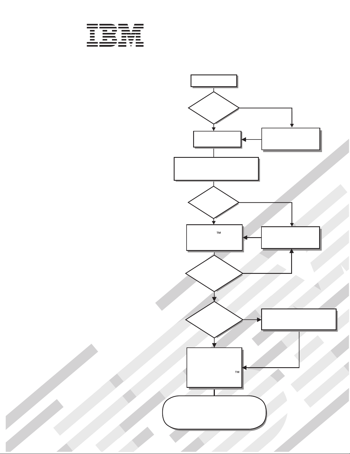
Start the server.
Installation Guide
Welcome.
Thank you for buying an
IBM server.
is based on the X-Architecture
technology, and it features
superior performance, availability,
and affordability.
This server
contains information for setting
up and configuring your server.
For detailed information about
your server, view the documentation
on the IBM System
Your server
Installation Guide
Documentation
Did the server
start correctly?
Ye s
Turn off the server
and install options.
Cable the server and options;
then, restart the server.
Did the server
start correctly?
Ye s
Use the IBM
ServerGuide program
to set up and
configure hardware.
Was the
CD.
server setup
completed?
No
Go to the Server Support
flow chart on the reverse
side of this page.
No
Go to the Server Support
flow chart on the reverse
side of this page.
No
You can also find the most
current information about
your server at
http://www.ibm.com/systems/support/
http://www.ibm.com/support/mysupport/
Ye s
Use
ServerGuide to
install the operating
system?
Ye s
Install applications,
such as IBM systems
management software
and IBM ServeRAID
programs
The server is ready to use.
Go to
to register the server.
No
Go to the Web for instructions:
http://www.ibm.com/systems
/support/
Page 2
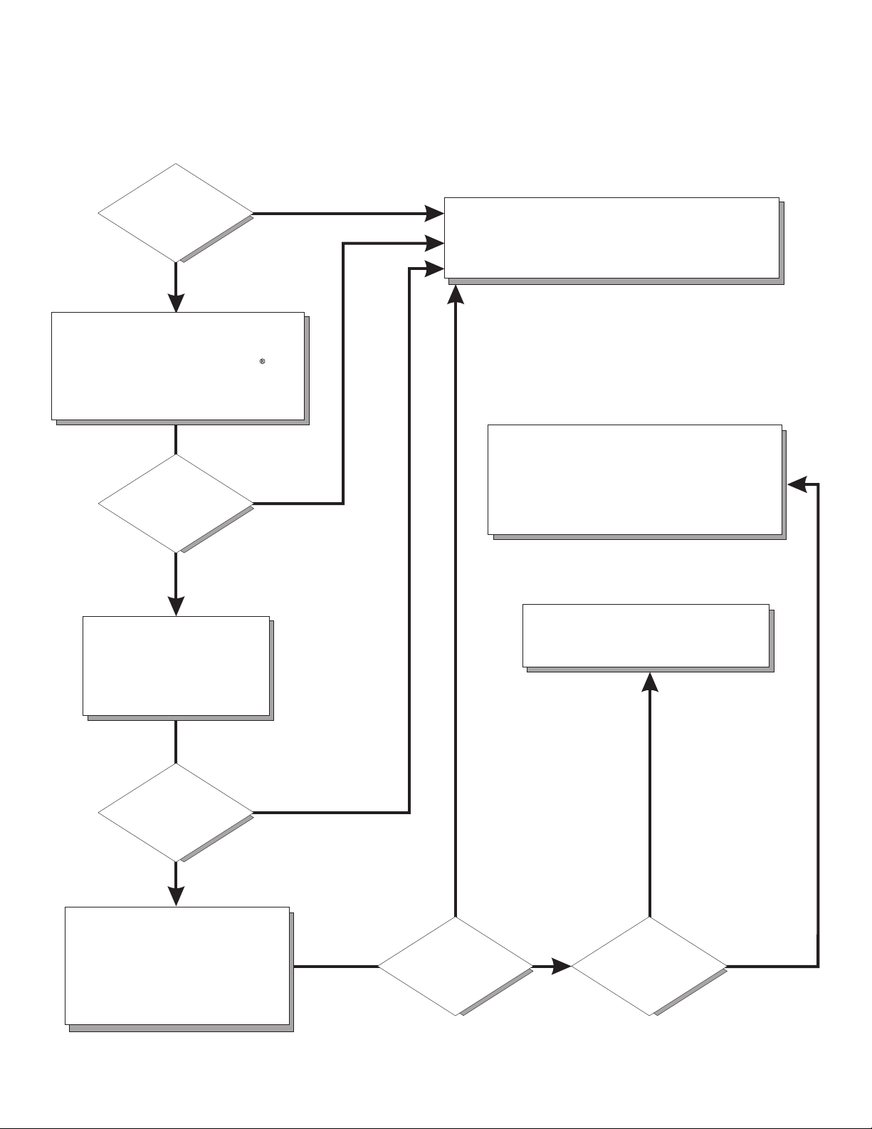
Server Support
Is the server working
correctly?
Ye s
No
Check all cables for loose connections
and verify that all optional devices you
installed are on the ServerProven list at
http://www.ibm.com/servers/eserver/
serverproven/compat/us/.
Is the problem
solved?
Ye s
No
Register the server. Go to
http://www.ibm.com/support/mysupport/.
View information about IBM Support Line at
http://www.ibm.com/services/sl/products/
or view support telephone numbers at
http://www.ibm.com/planetwide/.
See the troubleshooting
information that comes with
the server to determine
the cause of the problem
and the action to take.
Is the problem
solved?
Ye s
No
Update the firmware to the
latest level.
You can download firmware from
http://www.ibm.com/systems/
support/
.
Ye s
Is the problem
solved?
View support telephone numbers at
http://www.ibm.com/planetwide/.
Hardware
No Software
Hardware or
software problem?
Page 3

IBM System x3500 Ty pe 7977
Installation Guid e
Page 4

Note: Before using this information and the product it supports, read the general information in Appendix B, “Notices,” on page 97
and the Warranty and Support Information document on the IBM Documentation CD.
Sixth Edition (October 2008)
© Copyright International Business Machines Corporation 2008.
US Government Users Restricted Rights – Use, duplication or disclosure restricted by GSA ADP Schedule Contract
with IBM Corp.
Page 5

Contents
Safety . . . . . . . . . . . . . . . . . . . . . . . . . . . .v
Chapter 1. Introduction . . . . . . . . . . . . . . . . . . . . . .1
The IBM System x Documentation CD . . . . . . . . . . . . . . . . .2
Hardware and software requirements . . . . . . . . . . . . . . . .2
Using the Documentation Browser . . . . . . . . . . . . . . . . .3
Notices and statements in this document . . . . . . . . . . . . . . . .4
Features and specifications . . . . . . . . . . . . . . . . . . . . .5
Major components of the server . . . . . . . . . . . . . . . . . . .6
Chapter 2. Installing optional devices . . . . . . . . . . . . . . . .7
Installation guidelines . . . . . . . . . . . . . . . . . . . . . . .7
System reliability guidelines . . . . . . . . . . . . . . . . . . . .8
Working inside the server with the power on . . . . . . . . . . . . .8
Handling static-sensitive devices . . . . . . . . . . . . . . . . . .9
Opening the bezel . . . . . . . . . . . . . . . . . . . . . . . .10
Removing the left-side cover . . . . . . . . . . . . . . . . . . . .11
Installing a memory module . . . . . . . . . . . . . . . . . . . .11
Installing redundant power and cooling . . . . . . . . . . . . . . . .19
Installing a hot-swap hard disk drive . . . . . . . . . . . . . . . . .23
Installing an additional microprocessor . . . . . . . . . . . . . . . .25
Installing an adapter . . . . . . . . . . . . . . . . . . . . . . .27
Installing an IBM Remote Supervisor Adapter II SlimLine . . . . . . . . .29
Completing the installation . . . . . . . . . . . . . . . . . . . . .30
Connecting the cables . . . . . . . . . . . . . . . . . . . . .31
Reattaching the bezel . . . . . . . . . . . . . . . . . . . . .32
Updating the server configuration . . . . . . . . . . . . . . . . .33
Chapter 3. Server controls, connectors, LEDs, and power . . . . . . . .35
Front view . . . . . . . . . . . . . . . . . . . . . . . . . .35
Rear view . . . . . . . . . . . . . . . . . . . . . . . . . . .37
Server power features . . . . . . . . . . . . . . . . . . . . . .39
Turning on the server . . . . . . . . . . . . . . . . . . . . .39
Turning off the server . . . . . . . . . . . . . . . . . . . . .40
Chapter 4. Configuring the server . . . . . . . . . . . . . . . . .41
Using the ServerGuide Setup and Installation CD . . . . . . . . . . . .41
Using the Configuration/Setup Utility program . . . . . . . . . . . . .42
Using the Integrated System Management Firmware Update Utility program 42
Using the baseboard management controller . . . . . . . . . . . . . .43
Enabling and configuring SOL using the OSA SMBridge management utility
program . . . . . . . . . . . . . . . . . . . . . . . . .43
Installing the OSA SMBridge management utility program . . . . . . . .51
Using the baseboard management controller utility programs . . . . . . .53
Using the ServeRAID configuration programs . . . . . . . . . . . . . .54
Configuring hot-swap SAS or hot-swap SATA RAID . . . . . . . . . . .54
Using the IBM ServeRAID Configuration Utility program . . . . . . . . .55
Using ServeRAID Manager . . . . . . . . . . . . . . . . . . .56
Using the RAID configuration programs . . . . . . . . . . . . . . . .57
Starting the Adaptec RAID Configuration Utility program . . . . . . . . .58
Adaptec RAID Configuration Utility menu choices . . . . . . . . . . .58
Creating a RAID array . . . . . . . . . . . . . . . . . . . . .58
Viewing the array configuration . . . . . . . . . . . . . . . . . .59
© Copyright IBM Corp. 2008 iii
Page 6

Using ServeRAID Manager . . . . . . . . . . . . . . . . . . .59
Using the Boot Menu program . . . . . . . . . . . . . . . . . . .61
Enabling the Broadcom Gigabit Ethernet Utility program . . . . . . . . . .61
Configuring the Broadcom Gigabit Ethernet controller . . . . . . . . . . .61
Chapter 5. Solving problems . . . . . . . . . . . . . . . . . . .63
Diagnostic tools overview . . . . . . . . . . . . . . . . . . . . .63
POST beep code descriptions . . . . . . . . . . . . . . . . . . .63
POST error codes . . . . . . . . . . . . . . . . . . . . . . . .64
Troubleshooting tables . . . . . . . . . . . . . . . . . . . . . .77
DVD drive problems . . . . . . . . . . . . . . . . . . . . . .77
General problems . . . . . . . . . . . . . . . . . . . . . . .78
Hard disk drive problems . . . . . . . . . . . . . . . . . . . .78
Intermittent problems . . . . . . . . . . . . . . . . . . . . . .79
Keyboard, mouse, or pointing-device problems . . . . . . . . . . . .80
Memory problems . . . . . . . . . . . . . . . . . . . . . . .81
Microprocessor problems . . . . . . . . . . . . . . . . . . . .82
Monitor problems . . . . . . . . . . . . . . . . . . . . . . .82
Optional-device problems . . . . . . . . . . . . . . . . . . . .85
Power problems . . . . . . . . . . . . . . . . . . . . . . .86
Serial port problems . . . . . . . . . . . . . . . . . . . . . .87
ServerGuide problems . . . . . . . . . . . . . . . . . . . . .88
Software problems . . . . . . . . . . . . . . . . . . . . . .89
Universal Serial Bus (USB) port problems . . . . . . . . . . . . . .89
Video problems . . . . . . . . . . . . . . . . . . . . . . . .89
Light path diagnostics . . . . . . . . . . . . . . . . . . . . .90
Appendix A. Getting help and technical assistance . . . . . . . . . .95
Before you call . . . . . . . . . . . . . . . . . . . . . . . . .95
Using the documentation . . . . . . . . . . . . . . . . . . . . .95
Getting help and information from the World Wide Web . . . . . . . . . .95
Software service and support . . . . . . . . . . . . . . . . . . .96
Hardware service and support . . . . . . . . . . . . . . . . . . .96
IBM Taiwan product service . . . . . . . . . . . . . . . . . . . .96
Appendix B. Notices . . . . . . . . . . . . . . . . . . . . . .97
Trademarks . . . . . . . . . . . . . . . . . . . . . . . . . .97
Important notes . . . . . . . . . . . . . . . . . . . . . . . . .98
Product recycling and disposal . . . . . . . . . . . . . . . . . . .99
Battery return program . . . . . . . . . . . . . . . . . . . . . 100
Electronic emission notices . . . . . . . . . . . . . . . . . . . . 102
Federal Communications Commission (FCC) statement . . . . . . . . 102
Industry Canada Class A emission compliance statement . . . . . . . . 102
Avis de conformité à la réglementation d’Industrie Canada . . . . . . . 102
Australia and New Zealand Class A statement . . . . . . . . . . . . 102
United Kingdom telecommunications safety requirement . . . . . . . . 102
European Union EMC Directive conformance statement . . . . . . . . 102
Taiwanese Class A warning statement . . . . . . . . . . . . . . . 103
Chinese Class A warning statement . . . . . . . . . . . . . . . . 103
Japanese Voluntary Control Council for Interference (VCCI) statement 103
Index . . . . . . . . . . . . . . . . . . . . . . . . . . . . 105
iv IBM System x3500 Type 7977: Installation Guide
Page 7
Safety
Before installing this product, read the Safety Information.
Antes de instalar este produto, leia as Informações de Segurança.
Pred instalací tohoto produktu si prectete prírucku bezpecnostních instrukcí.
Læs sikkerhedsforskrifterne, før du installerer dette produkt.
Lees voordat u dit product installeert eerst de veiligheidsvoorschriften.
Ennen kuin asennat tämän tuotteen, lue turvaohjeet kohdasta Safety Information.
Avant d’installer ce produit, lisez les consignes de sécurité.
Vor der Installation dieses Produkts die Sicherheitshinweise lesen.
Prima di installare questo prodotto, leggere le Informazioni sulla Sicurezza.
Les sikkerhetsinformasjonen (Safety Information) før du installerer dette produktet.
Antes de instalar este produto, leia as Informações sobre Segurança.
© Copyright IBM Corp. 2008 v
Page 8

Antes de instalar este producto, lea la información de seguridad.
Läs säkerhetsinformationen innan du installerar den här produkten.
Important:
Each caution and danger statement in this document is labeled with a number. This
number is used to cross reference an English-language caution or danger
statement with translated versions of the caution or danger statement in the IBM
Safety Information book.
For example, if a caution statement is labeled "Statement 1", translations for that
caution statement are in the Safety Information document under "Statement 1".
Be sure to read all caution and danger statements in this document before you
perform the procedures. Read any additional safety information that comes with the
server or optional device before you install the device.
vi IBM System x3500 Type 7977: Installation Guide
Page 9
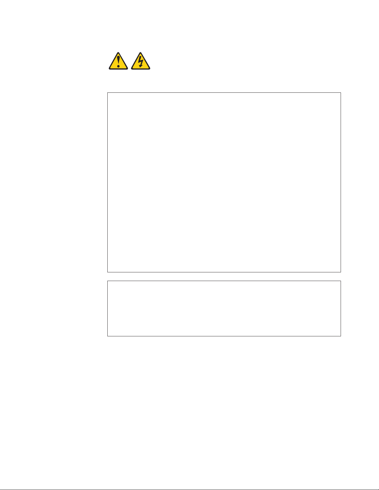
Statement 1:
DANGER
Electrical
current from power, telephone, and communication cables is
hazardous.
To avoid a shock hazard:
v Do not connect or disconnect any cables or perform installation,
maintenance, or reconfiguration of this product during an electrical
storm.
v Connect all power cords to a properly wired and grounded electrical
outlet.
v Connect to properly wired outlets any equipment that will be attached to
this product.
v When possible, use one hand only to connect or disconnect signal
cables.
v Never turn on any equipment when there is evidence of fire, water, or
structural damage.
v Disconnect the attached power cords, telecommunications systems,
networks, and modems before you open the device covers, unless
instructed otherwise in the installation and configuration procedures.
v Connect and disconnect cables as described in the following table when
installing, moving, or opening covers on this product or attached
devices.
To Connect: To Disconnect:
1. Turn everything OFF.
2. First, attach all cables to devices.
3. Attach signal cables to connectors.
4. Attach power cords to outlet.
1. Turn everything OFF.
2. First, remove power cords from outlet.
3. Remove signal cables from connectors.
4. Remove all cables from devices.
5. Turn device ON.
Safety vii
Page 10

Statement 2:
CAUTION:
When replacing the lithium battery, use only IBM Part Number 33F8354 or an
equivalent type battery recommended by the manufacturer. If your system has
a module containing a lithium battery, replace it only with the same module
type made by the same manufacturer. The battery contains lithium and can
explode if not properly used, handled, or disposed of.
Do not:
v Throw or immerse into water
v Heat to more than 100°C (212°F)
v Repair or disassemble
Dispose
of the battery as required by local ordinances or regulations.
viii IBM System x3500 Type 7977: Installation Guide
Page 11
Statement 3:
CAUTION:
When laser products (such as CD-ROMs, DVD drives, fiber optic devices, or
transmitters) are installed, note the following:
v Do not remove the covers. Removing the covers of the laser product could
result in exposure to hazardous laser radiation. There are no serviceable
parts inside the device.
v Use of controls or adjustments or performance of procedures other than
those specified herein might result in hazardous radiation exposure.
DANGER
laser products contain an embedded Class 3A or Class 3B laser
Some
diode. Note the following.
Laser radiation when open. Do not stare into the beam, do not view directly
with optical instruments, and avoid direct exposure to the beam.
Class 1 Laser Product
Laser Klasse 1
Laser Klass 1
Luokan 1 Laserlaite
Appareil A Laser de Classe 1
`
Safety ix
Page 12
Statement 4:
≥ 18 kg (39.7 lb) ≥ 32 kg (70.5 lb) ≥ 55 kg (121.2 lb)
CAUTION:
Use safe practices when lifting.
Statement 5:
CAUTION:
The power control button on the device and the power switch on the power
supply do not turn off the electrical current supplied to the device. The device
also might have more than one power cord. To remove all electrical current
from the device, ensure that all power cords are disconnected from the power
source.
2
1
x IBM System x3500 Type 7977: Installation Guide
Page 13
Statement 8:
CAUTION:
Never remove the cover on a power supply or any part that has the following
label attached.
Hazardous voltage, current, and energy levels are present inside any
component that has this label attached. There are no serviceable parts inside
these components. If you suspect a problem with one of these parts, contact
a service technician.
Statement 11:
CAUTION:
The following label indicates sharp edges, corners, or joints nearby.
Statement 17:
CAUTION:
The following label indicates moving parts nearby.
Attention: This product is suitable for use on an IT power distribution system
whose maximum phase to phase voltage is 240 V under any distribution fault
condition.
Safety xi
Page 14

xii IBM System x3500 Type 7977: Installation Guide
Page 15

Chapter 1. Introduction
This Installation Guide contains instructions for setting up your IBM® System x3500
Type 7977 server and basic instructions for installing some optional devices. More
detailed instructions for installing optional devices are in the User’s Guide on the
IBM System x Documentation CD, which comes with the server. This document
contains information about:
v Setting up and cabling the server
v Starting and configuring the server
v Installing some optional devices
v Solving problems
firmware and documentation updates are available, you can download them from
If
the IBM Web site. The server might have features that are not described in the
documentation that comes with the server, and the documentation might be updated
occasionally to include information about those features, or technical updates might
be available to provide additional information that is not included in the server
documentation. To check for updates, complete the following steps.
Changes are made periodically to the IBM Web site. Procedures for locating
Note:
firmware and documentation might vary slightly from what is described in this
document.
1. Go to http://www.ibm.com/systems/support/.
2. Under Product support, click System x.
3. Under Popular links, click Software and device drivers for firmware updates,
or click Publications lookup for documentation updates.
server comes with an IBM ServerGuide
The
™
Setup and Installation CD to help you
configure the hardware, install device drivers, and install the operating system.
The server comes with a limited warranty. Yo u can obtain up-to-date information
about the server and other IBM server products at http://www.ibm.com/systems/x/.
Record information about the server in the following table. Yo u will need this
information when you register the server with IBM.
Product name IBM System x3500
Machine type 7977
Model number _____________________________________________
Serial number _____________________________________________
Key serial number _____________________________________________
Key manufacturer _____________________________________________
Key phone number _____________________________________________
The model number and serial number are on labels on the bottom of the server and
on the front, visible through the bezel, as shown in the following illustration.
© Copyright IBM Corp. 2008 1
Page 16
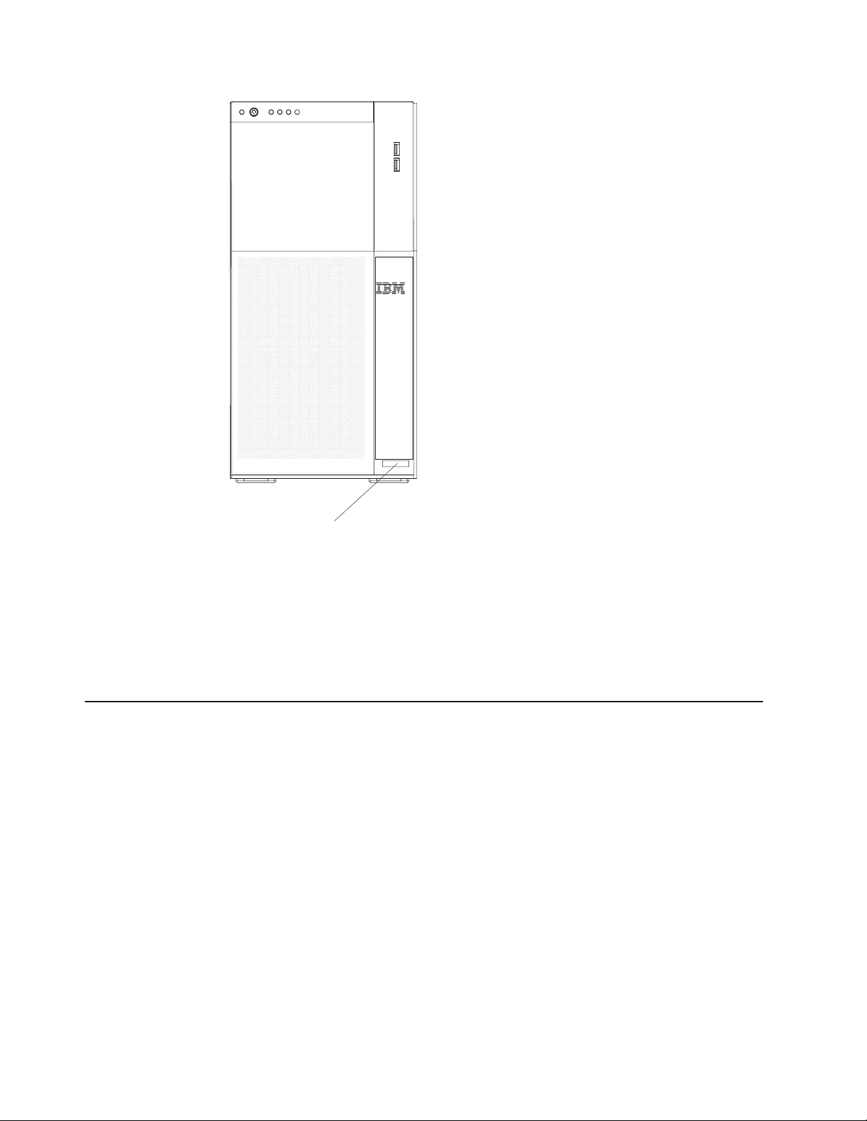
Model type/serial
number
Important: The server keys cannot be duplicated by a locksmith. If you lose them,
order replacement keys from the key manufacturer. The key serial number and the
telephone number of the manufacturer are on a tag that is attached to the keys.
If you plan to install the server in a rack, you must purchase a Tower-to-Rack Kit.
For a list of supported optional devices for the server, see http://www.ibm.com/
servers/eserver/serverproven/compat/us/.
The IBM System x Documentation CD
The IBM System x Documentation CD contains documentation for the server in
Portable Document Format (PDF) and includes the IBM Documentation Browser to
help you find information quickly.
Hardware and software requirements
The IBM System x Documentation CD requires the following minimum hardware
and software:
v Microsoft® Windows NT® XP, Windows® 2000, or Red Hat Linux
v 100 MHz microprocessor
v 32 MB of RAM
v Adobe Acrobat Reader 3.0 (or later) or xpdf, which comes with Linux operating
systems.
2 IBM System x3500 Type 7977: Installation Guide
Page 17

Using the Documentation Browser
Use the Documentation Browser to browse the contents of the CD, read brief
descriptions of the documents, and view documents, using Adobe Acrobat Reader
or xpdf. The Documentation Browser automatically detects the regional settings in
your server and displays the documents in the language for that region (if
available). If a document is not available in the language for that region, the
English-language version is displayed.
Use one of the following procedures to start the Documentation Browser:
v If Autostart is enabled, insert the CD into the CD drive. The Documentation
Browser starts automatically.
v If Autostart is disabled or is not enabled for all users, use one of the following
procedures:
– If you are using a Windows operating system, insert the CD into the drive and
click Start --> Run. In the Open field, type
e:\win32.bat
where e is the drive letter of the drive, and click OK.
– If you are using Red Hat Linux, insert the CD into the drive; then, run the
following command from the /mnt/cdrom directory:
sh runlinux.sh
Select the server from the Product menu. The Available Topics list displays all the
documents for the server. Some documents might be in folders. A plus sign (+)
indicates each folder or document that has additional documents under it. Click the
plus sign to display the additional documents.
When you select a document, a description of the document is displayed under
Topic Description. To select more than one document, press and hold the Ctrl key
while you select the documents. Click View Book to view the selected document or
documents in Acrobat Reader or xpdf. If you selected more than one document, all
the selected documents are opened in Acrobat Reader or xpdf.
To search all the documents, type a word or word string in the Search field and
click Search. The documents in which the word or word string appears are listed in
order of the most occurrences. Click a document to view it, and press Crtl+F to use
the Acrobat search function or press Alt+F to use the xpdf search function within the
document.
Click Help for detailed information about using the Documentation Browser.
Chapter 1. Introduction 3
Page 18

Notices and statements in this document
The caution and danger statements in this document are also in the multilingual
Safety Information document, which is on the IBM System x Documentation CD.
Each statement is numbered for reference to the corresponding statement in the
Safety Information document.
The following notices and statements are used in this document:
v Note: These notices provide important tips, guidance, or advice.
v Important: These notices provide information or advice that might help you avoid
inconvenient or problem situations.
v Attention: These notices indicate potential damage to programs, devices, or
data. An attention notice is placed just before the instruction or situation in which
damage might occur.
v Caution: These statements indicate situations that can be potentially hazardous
to you. A caution statement is placed just before the description of a potentially
hazardous procedure step or situation.
v Danger: These statements indicate situations that can be potentially lethal or
extremely hazardous to you. A danger statement is placed just before the
description of a potentially lethal or extremely hazardous procedure step or
situation.
4 IBM System x3500 Type 7977: Installation Guide
Page 19

Features and specifications
The following information is a summary of the features and specifications of the
server. Depending on the server model, some features might not be available, or
some specifications might not apply.
Table 1. Features and specifications
Microprocessor:
v Intel® Xeon™ dual-core or quad-core with 12
MB Level-2 cache
Important: Do not use dual-core and
quad-core processors in the same server.
v Support for up to two microprocessors
v Support for Intel Extended Memory 64
Technology (EM64T)
Note:
Use the Configuration/Setup Utility
program to determine the type and speed of the
microprocessors.
Memory:
v Minimum: 1 GB depending on server model,
expandable to 48 GB
v Type: 667 MHz, PC2-5300, ECC Fully
Buffered DIMMs (FBD) with double data rate
(DDR) II, SDRAM
v Connectors: Twelve 240-pin dual inline
memory module (DIMM) connectors
Drives:
v IDE:
– DVD (standard)
– CD, CD-RW, DVD/CD-RW (optional)
– Maximum of two devices can be installed
v Diskette (optional): External USB 1.44 MB
v Supported hard disk drives:
– Serial Attached SCSI (SAS)
– Serial Advanced Technology Attachment
(S ATA)
Expansion
bays:
v Eight hot-swap SAS, 3.5-inch bays or 12
hot-swap SAS, 2.5-inch bays
v Three half-high 5.25-inch bays (DVD drive
installed)
Note: Full-high devices such as an optional
tape drive will occupy two half-high
5.25-inch bays.
PCI
and PCI-X expansion slots:
v Six PCI expansion slots
– Three PCI Express x8 (two x8 links and
one x4 link)
– One PCI 33 MHz/32-bit
– Two PCI-X 2.0 133 MHz/64-bit slots
Upgradeable
microcode:
System BIOS, service microprocessor, BMC, and
SAS microcode
Power supply:
Note: To upgrade to two 835-watt hot-swap
power supplies, install the redundant power and
cooling option kit. Kit includes one 835-watt
power-supply and three hot-swap fans.
v Standard: One 835-watt 11 0 V or 240 V ac
input dual-rated power supply
v Upgradeable to two 835-watt hot-swap power
supplies
Hot-swap fans:
v Three (standard)
v Upgradeable to six fans (for redundant
cooling)
Note:
the redundant power and cooling option kit. Kit
includes one 835-watt hot-swap power-supply
and three hot-swap fans.
Size:
v Tower
– Height: 440 mm (17.3 in.)
– Depth: 747 mm (29.4 in.)
– Width: 218 mm (8.6 in.)
– Weight: approximately 38 kg (84 lb) when
v Rack
– 5 U
– Height: 218 mm (8.6 in.)
– Depth: 696 mm (27.4 in.)
– Width: 424 mm (16.7 in.)
– Weight: approximately 34 kg (75 lb) when
Racks
cm (1.75 inches). Each increment is referred to
as a unit, or “U.” A 1-U-high device is 4.45 cm
(1.75 inches) tall.
Integrated functions:
v Baseboard management controller (Intelligent
Platform Management Interface (IPMI) 2.0
compliant)
v Service microprocessor support for Remote
Supervisor Adapter II SlimLine
v Light path diagnostics
v ServeRAID-8k (512 MB with battery backup)
and ServeRAID-8s SAS Controllers support
RAID levels 0, 1, 1E,,5, 6, 10, 50, and 60
Note: The server will not start without a
RAID controller installed.
– Eight 3.5–inch hard disk drive models:
– Twelve 2.5-inch hard disk drive models:
v Four Universal Serial Bus (USB) ports (2.0)
– Two on rear of server
– Two on front of server
v
Broadcom 5721 and 5721KFB3 10/100/1000
Gigabit Ethernet controllers
v AT I PCI ES1000 video
– 16 MB video memory
– VGA and SVGA compatible
v ATA-100 single-channel IDE controller (bus
mastering)
v Vitesse VSC7250 SAS/SATA RAID controller
v Mouse connector
v Keyboard connector
v Serial connector
To upgrade to redundant cooling, install
fully configured or 20 kg (42 lb) minimum
fully configured or 20 kg (42 lb) minimum
are marked in vertical increments of 4.45
ServeRAID-8k
ServeRAID-8k and ServeRAID-8s
Acoustical noise emissions:
v Sound power, idle: 5.5 bel declared
v Sound power, operating: 6.0 bel declared
Environment:
v Air temperature:
– Server on: 10° to 35°C (50.0° to 95.0°F);
altitude: 0 to 2134 m (7000 ft)
– Server off: -40° to 60°C (-40.0° to 140.4°F);
maximum altitude: 2134 m (7000 ft)
v
Humidity:
– Server on: 8% to 80%
– Server off: 8% to 80%
Heat
output:
Approximate heat output in British thermal units
(Btu) per hour:
v Minimum configuration: 2013 Btu per hour (590
watts)
v Maximum configuration: 2951 Btu per hour (865
watts)
Electrical
input:
v Sine-wave input (50-60 Hz) required
v Input voltage low range:
– Minimum: 100 V ac
– Maximum: 127 V ac
v
Input voltage high range:
– Minimum: 200 V ac
– Maximum: 240 V ac
v Approximate input kilovolt-amperes (kVA):
– Minimum: 0.60 kVA
– Maximum: 0.88 kVA
Notes:
1. Power consumption and heat output vary
depending on the number and type of optional
features that are installed and the
power-management optional features that are
in use.
2. These levels were measured in controlled
acoustical environments according to the
procedures that are specified by the American
National Standards Institute (ANSI) S12.10 and
ISO 7779 and are reported in accordance with
ISO 9296. Actual sound-pressure levels in a
given location might exceed the average stated
values because of room reflections and other
nearby noise sources. The declared
sound-power levels indicate an upper limit,
below which a large number of computers will
operate.
Chapter 1. Introduction 5
Page 20
Major components of the server
Blue on a component indicates touch points, where you can grip the component to
remove it from or install it in the server, open or close a latch, and so on.
Orange on a component or an orange label on or near a component indicates that
the component can be hot-swapped, which means that if the server and operating
system support hot-swap capability, you can remove or install the component while
the server is running. (Orange can also indicate touch points on hot-swap
components.) See the instructions for removing or installing a specific hot-swap
component for any additional procedures that you might have to perform before you
remove or install the component.
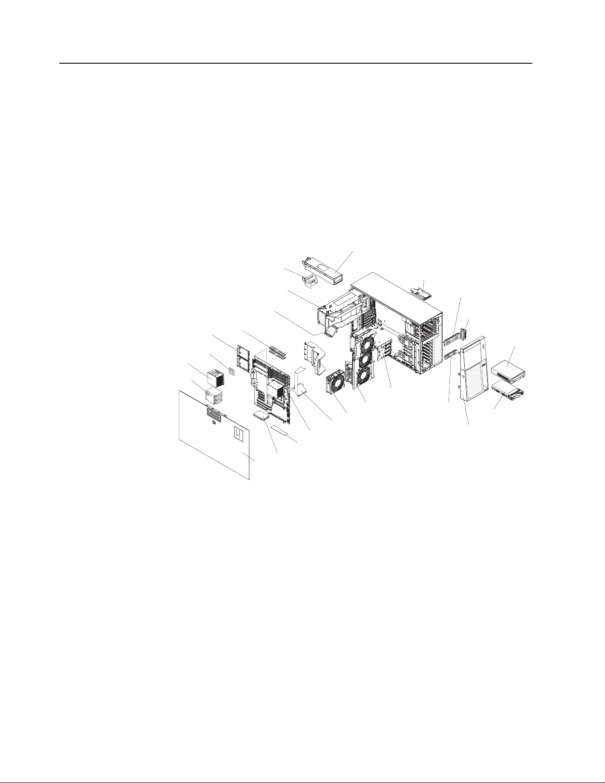
The following illustration shows the major components in the server.
Heat-sink
retention bracket
Microprocessor
Heat sink
Heat-sink
filler
Power-supply filler
Power-supply cage
DIMM air duct
DIMMs
Cover
VRM
Processor baffle
System board
ServeRAID-8k
Power supply
Fan assembly
Hot-swap fan
Control panel assembly
SAS backplane
Hard disk drive
EMC shield
Drive bay EMC shield
USB cable assembly
DVD
drive
Hard disk drive
Bezel
6 IBM System x3500 Type 7977: Installation Guide
Page 21

Chapter 2. Installing optional devices
This chapter provides basic instructions for installing optional hardware devices in
the server. These instructions are intended for users who are experienced with
setting up IBM server hardware. If you need more detailed instructions, see the
User’s Guide on the IBM System x Documentation CD.
Installation guidelines
Before you install optional devices, read the following information:
v Read the safety information that begins on page vii and the guidelines in
“Handling static-sensitive devices” on page 9. This information will help you work
safely.
v When you install your new server, take the opportunity to download and apply
the most recent firmware updates. This step will help to ensure that any known
issues are addressed and that your server is ready to function at maximum levels
of performance. To download firmware updated to your server, complete the
following steps.
Changes are made periodically to the IBM Web site. Procedures for
Note:
locating firmware and documentation might vary slightly from what is described in
this document.
1. Go to http://www.ibm.com/systems/support/.
2. Under Product support, click System x.
3. Under Popular links, click Software and device drivers.
For additional information about tools for updating, managing, and deploying
firmware, see the System x and xSeries Tools Center at http://
publib.boulder.ibm.com/infocenter/toolsctr/v1r0/index.jsp.
v Before you install optional hardware, make sure that the server is working
correctly. Start the server, and make sure that the operating system starts, if an
operating system is installed, or that a 19990305 error code is displayed,
indicating that an operating system was not found but the server is otherwise
working correctly. If the server is not working correctly, see Chapter 5, “Solving
problems,” on page 63 for diagnostic information.
v Observe good housekeeping in the area where you are working. Place removed
covers and other parts in a safe place.
v If you must start the server while the cover is removed, make sure that no one is
near the server and that no tools or other objects have been left inside the
server.
v Do not attempt to lift an object that you think is too heavy for you. If you have to
lift a heavy object, observe the following precautions:
– Make sure that you can stand safely without slipping.
– Distribute the weight of the object equally between your feet.
– Use a slow lifting force. Never move suddenly or twist when you lift a heavy
object.
– To avoid straining the muscles in your back, lift by standing or by pushing up
with your leg muscles.
Make sure that you have an adequate number of properly grounded electrical
v
outlets for the server, monitor, and other devices.
v Back up all important data before you make changes to disk drives.
© Copyright IBM Corp. 2008 7
Page 22

v Have a small flat-blade screwdriver available.
v You do not have to turn off the server to install or replace hot-swap power
supplies, hot-swap hard disk drives, hot-swap fans, or hot-plug Universal Serial
Bus (USB) devices.
v Blue on a component indicates touch points, where you can grip the component
to remove it from or install it in the server, open or close a latch, and so on.
v Orange on a component or an orange label on or near a component indicates
that the component can be hot-swapped, which means that if the server and
operating system support hot-swap capability, you can remove or install the
component while the server is running. (Orange can also indicate touch points on
hot-swap components.) See the instructions for removing or installing a specific
hot-swap component for any additional procedures that you might have to
perform before you remove or install the component.
v When you have to access the inside of the server, you might find it easier to lay
the server on its side.
v You can install a maximum of two IDE devices in the server.
v For a list of supported optional devices for the server, go to http://www.ibm.com/
servers/eserver/serverproven/compat/us/.
System reliability guidelines
To help ensure proper cooling and system reliability, make sure that the following
requirements are met:
v Each of the drive bays has a drive or an electromagnetic compatibility (EMC)
shield installed in it.
v If the server has redundant power, each of the power-supply bays has a power
supply installed in it.
v There is adequate space around the server to allow the server cooling system to
work properly. Leave approximately 50 mm (2.0 in.) of open space around the
front and rear of the server. Do not place objects in front of the fans. For proper
cooling and airflow, replace the left-side cover before you turn on the server.
Operating the server for extended periods of time (more than 30 minutes) with
the left-side cover removed might damage server components.
v You have followed the cabling instructions that come with optional adapters.
v You have replaced a failed fan within 48 hours.
v You have replaced a hot-swap drive within 2 minutes of removal.
v You do not remove the air ducts or air baffles while the server is running.
Operating the server without the air ducts or air baffles might cause the
microprocessor to overheat.
v Microprocessor socket 2 always contains either a microprocessor baffle or a
microprocessor and heat sink.
Working inside the server with the power on
The server supports hot-swap devices and is designed to operate safely while it is
turned on and the cover is removed. Follow these guidelines when you work inside
a server that is turned on:
v Avoid wearing loose-fitting clothing on your forearms. Button long-sleeved shirts
before you work inside the server; do not wear cuff links while you are working
inside the server.
v Do not allow your necktie or scarf to hang inside the server.
v Remove jewelry, such as bracelets, necklaces, rings, and loose-fitting wrist
watches.
8 IBM System x3500 Type 7977: Installation Guide
Page 23

v Remove items from your shirt pocket, such as pens and pencils, that might fall
into the server as you lean over it.
v Avoid dropping any metallic objects, such as paper clips, hairpins, and screws,
into the server.
Handling static-sensitive devices
Attention: Static electricity can damage the server and other electronic devices.
To avoid damage, keep static-sensitive devices in their static-protective packages
until you are ready to install them.
To reduce the possibility of damage from electrostatic discharge, observe the
following precautions:
v Limit your movement. Movement can cause static electricity to build up around
you.
v Wear an electrostatic-discharge wrist strap, if one is available.
v Handle the device carefully, holding it by its edges or its frame.
v Do not touch solder joints, pins, or exposed circuitry.
v Do not leave the device where others can handle and damage it.
v While the device is still in its static-protective package, touch it to an unpainted
metal part of the server for at least 2 seconds. This drains static electricity from
the package and from your body.
v Remove the device from its package and install it directly into the server without
setting down the device. If it is necessary to set down the device, put it back into
its static-protective package. Do not place the device on the server cover or on a
metal surface.
v Take additional care when handling devices during cold weather. Heating reduces
indoor humidity and increases static electricity.
Chapter 2. Installing optional devices 9
Page 24
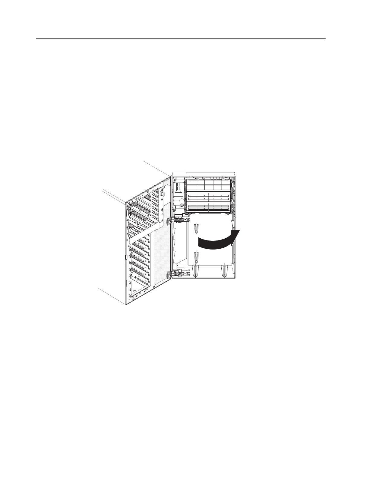
Opening the bezel
Important: Before you install optional hardware, make sure that the server is
working correctly. Start the server, and make sure that the operating system starts,
if an operating system is installed, or that a 19990305 error code is displayed,
indicating that an operating system was not found but the server is otherwise
working correctly. If the server is not working correctly, see the Problem
Determination and Service Guide for diagnostic information.
The following illustration shows how to remove the bezel from the server.
Notes:
1. You do not have to remove the left-side cover to remove the bezel from the
2. You must unlock the left-side cover lock to open or remove the bezel.
server.
To remove the bezel, complete the following steps:
1. Read the safety information that begins on page vii and “Installation guidelines”
on page 7.
2. Using the supplied key, unlock the left-side cover and bezel.
3. Press on the left edge of the bezel and rotate it away from the server until it is
fully open to 180°. The right edge of the bezel will be resting against the side of
the server chassis when the bezel is fully open. If the bezel is rotated further
than 180°, the break-away hinges will come apart without damaging the bezel.
To reattach the bezel, see “Reattaching the bezel” on page 32.
10 IBM System x3500 Type 7977: Installation Guide
Page 25

Removing the left-side cover
The following illustration shows how to remove the left-side cover from the server.
Cover release latch
Lock
To remove the server left-side cover, complete the following steps:
1. Read the safety information that begins on page vii and the guidelines in
“Handling static-sensitive devices” on page 9.
2. Using the supplied key, unlock the left-side cover.
3. Pull the cover-release latch down and rotate the top edge of the cover away
from the server.
Attention: For proper cooling and airflow, replace the cover before you turn
on the server. Operating the server for extended periods of time (more than 30
minutes) with the cover removed might damage server components.
4. Remove the left-side cover from the server.
Left-side cover
Installing a memory module
The following notes describe the types of dual inline memory modules (DIMMs) that
the server supports and other information that you must consider when you install
DIMMs:
v The server supports 667 MHz, 1.8 V, 240-pin, PC2-5300 double-data-rate (DDR)
II, fully buffered synchronous dynamic random-access memory (SDRAM) with
error correcting code (ECC) DIMMs. These DIMMs must be compatible with the
latest 5300 SDRAM Fully Buffered DIMM (FBD) specification. For a list of
supported optional devices for the server, go to http://www.ibm.com/servers/
eserver/serverproven/compat/us/.
v When you install additional DIMMs, be sure to install them in pairs. The DIMMs
in each pair must be the same size and type. You can mix compatible DIMMs
from various manufacturers.
v The second pair does not have to contain DIMMs of the same size, speed, type,
and technology as the first pair when the server is operating in a non-mirroring
mode.
Chapter 2. Installing optional devices 11
Page 26
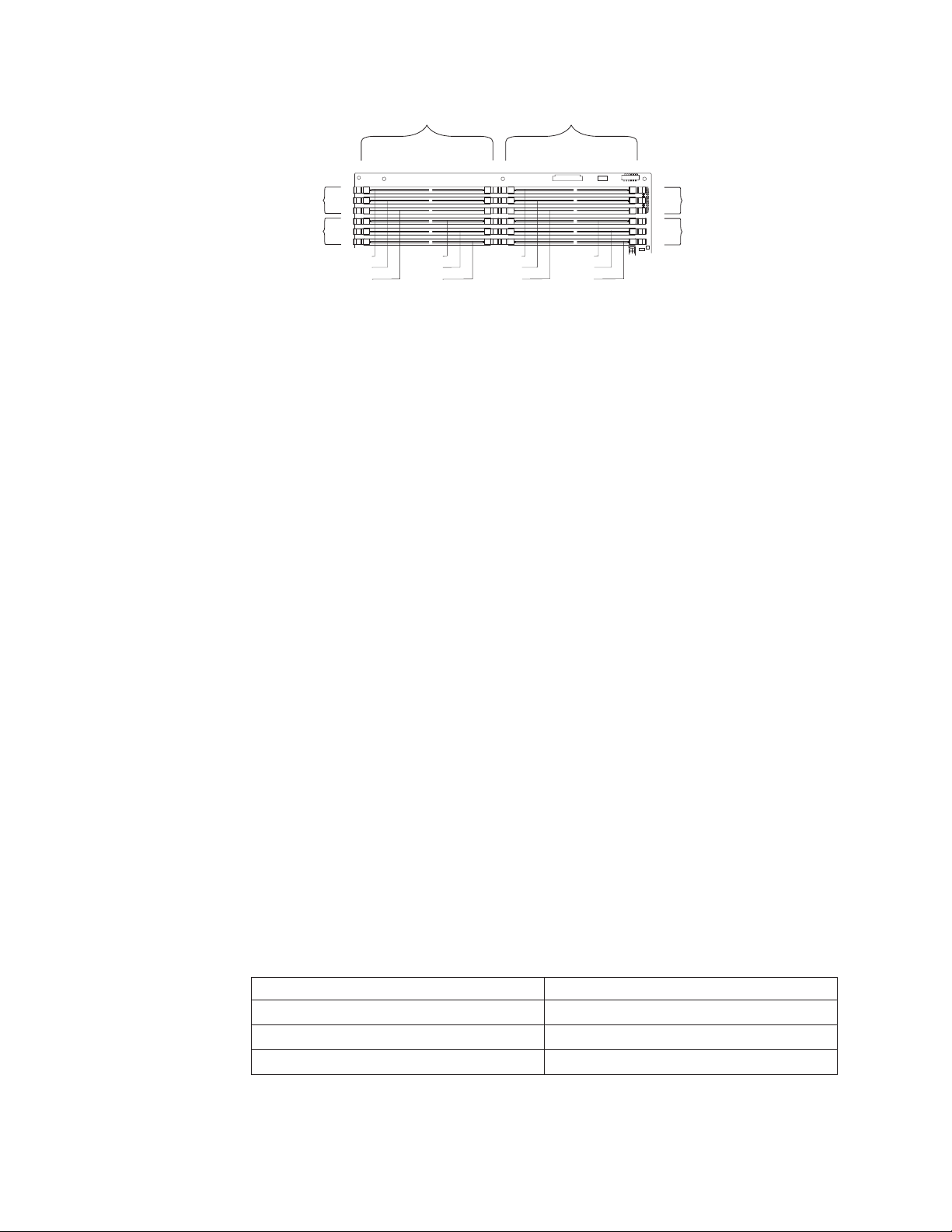
Channel 1
Channel 0
DIMM 6
DIMM 5
DIMM 4
Branch 0
DIMM 3
DIMM 2
DIMM 1
DIMM 12
DIMM 11
DIMM 10
Branch 1
DIMM 9
DIMM 8
DIMM 7
Channel 3
Channel 2
v Installing additional DIMMs in both memory branches will improve system
performance.
v The server supports memory mirroring (mirroring mode) and online-spare
memory.
– Memory mirroring replicates and stores data on DIMMs within two branches
simultaneously. You must enable memory mirroring through the
Configuration/Setup Utility program (for more information, see the section
about configuring the server in the User’s Guide on the IBM System x
Documentation CD). To enable memory mirroring in the Configuration/Setup
Utility program, select Devices and I/O Ports → Advanced Chipset Control →
Memory Branch Mode. Use the arrow keys to change the Memory Branch
Mode setting to Mirror; then, save your changes. When you use memory
mirroring, consider the following information:
- The maximum available memory is reduced to 16 GB; 32 GB is available in
non-mirroring mode.
- The minimum memory configuration is four identical DIMMs. Yo u must
install identical pairs of fully buffered, dual inline memory modules (DIMMs)
in all four DIMM connectors (same size, type, speed, and technology).
These DIMMs must span both branches and all four channels. For
example, when you install the first four DIMMs, you must install two DIMMs
in branch 0 (one in channel 0 and one in channel 1) and two DIMMs in
branch 1 (one in channel 2 and one in channel 3). See Table 2 for the
DIMM installation sequence.
- When you upgrade the server to eight DIMMs, the DIMMs that are next to
each other (for example, DIMM connector 1 and DIMM connector 4) within
the channels of a branch must be identical in size, type, speed, and
technology. However, the DIMMs in the connectors above and below each
other within the channels of a branch do not have to be identical to each
other (for example, the DIMMs in DIMM connector 1 and DIMM connector
2).
- Both branches operate in dual-channel mode.
The following table shows the DIMM configuration upgrade sequence for
mirroring mode.
Table 2. DIMM upgrade configuration sequence in mirroring mode
Number of DIMMs DIMM connectors
4 1, 4, 7, 10
8 1, 4, 7, 10, 2, 5, 8, 11
12 1, 4, 7, 10, 2, 5, 8, 11, 3, 6, 9, 12
12 IBM System x3500 Type 7977: Installation Guide
Page 27

– Online-spare memory disables a failed rank pair of DIMMs from the system
configuration and activates an online-spare rank pair of DIMMs to replace the
failed rank pair of DIMMs. For an online-spare pair of DIMMs to be activated,
you must enable this feature and have installed an additional rank pair of
DIMMs of the same speed, type, size (or larger), and technology as the failed
pair of DIMMs. You must enable the feature through the Configuration/Setup
Utility program. To enable online-spare memory in the Configuration/Setup
Utility program, select Devices and I/O Ports → Advanced Chipset Control →
Memory Branch Mode. Use the arrow keys to change the setting for Branch
0 Rank Sparing or Branch 1 Rank Sparing to Enabled; then, save your
changes. For more information, see the section about configuring the server in
the User’s Guide on the IBM System x Documentation CD. When you use
online-spare memory, you must consider the following information:
- You cannot enable online-spare memory while the server is operating in
mirroring mode.
- When using online-spare memory the two memory branches operate
independently of each other. You can enable online-spare memory for one
or both branches.
- Online-spare memory reduces the amount of available memory.
- The BIOS code assigns the online-spare DIMM pairs according to your
DIMM configuration.
- Online-spare memory works by copying information from a failed DIMM
rank to another good DIMM rank within the same memory branch.
- Online-spare memory can not copy information from one branch to the
other.
Chapter 2. Installing optional devices 13
Page 28
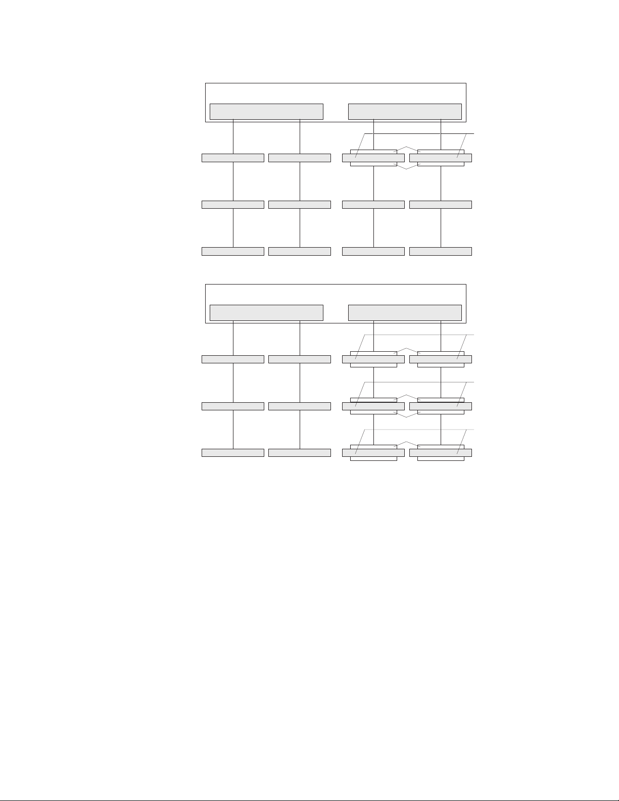
CH3
DIMM 10
Minimum configuration: one pair of DIMMs
(Branch 0 works independently of Branch 1)
BR1
CH2
DIMM 7
CH1
DIMM 4
Rank 1 is sparing to Rank 0
BR0
Rank 0
Rank 1
CH0
DIMM 1
A pair of two identical
double rank modules:
same size, speed,
and organization
DIMM 11
DIMM 12
CH3
DIMM 10
DIMM 11
DIMM 12
Rank 4 is used to spare any defective rank of rank 0, 2, and 3
DIMM 8
DIMM 9
Other Configuration: Multiple Pairs of DIMMs
(Branch 0 works independently of Branch 1)
BR1
CH2
DIMM 7
DIMM 8
DIMM 9
DIMM 5
DIMM 6
CH1
DIMM 4
DIMM 5
DIMM 6
BR0
Rank 0 512 MB
Rank 1 Empty
Rank 2 512 MB
Rank 3 512 MB
Rank 4 1 GB
Rank 5 Empty
DIMM 2
DIMM 3
CH0
DIMM 1
DIMM 2
DIMM 3
A pair of two identical
single rank modules
(512MB)
A pair of two identical
double rank modules
(1GB)
A pair of two identical
single rank modules
(1GB)
- A rank is defined as an area or block of 64 bits that is created by using
some or all of the chips on a DIMM. For an ECC DIMM, a memory rank is
a block of 72 data bits (64 bits plus 8 ECC bits).
- The minimum memory configuration is two single-rank DIMMs that are
installed in branch 0, DIMM connector 1 (in channel 0) and connector 4 (in
channel 1); however, online-sparing is not supported with this configuration.
- To support online-sparing in branch 0, you must add a second pair of
DIMMs. The spare pair of DIMMs can be single-rank or double-rank and
must be the same speed, type, size (or larger), and technology as the
failed pair of DIMMs. The spare pair must be installed in branch 0, DIMM
connector 2 (in channel 0) and connector 5 (in channel 1). Branch 0 and
branch 1 operate independently.
The following notes apply when the server operates in non-mirroring mode
v
(normal mode):
– DIMMs must be installed in matched pairs. If you install a second pair of
DIMMs in DIMM connector 7 and DIMM connector 10, they do not have to be
the same size, speed, type, and technology as the DIMMs in DIMM connector
14 IBM System x3500 Type 7977: Installation Guide
Page 29
1 and DIMM connector 4. However, the size, speed, type, and technology of
the DIMMs that you install in DIMM connector 7 and DIMM connector 10 must
match each other.
– The following table shows the DIMM upgrade configuration sequence for
operating in non-mirroring mode (normal mode).
Table 3. 5. DIMM upgrade configuration sequence in non-mirroring mode
Number of DIMMs DIMM connectors
2 1, 4
4 1, 4, 7, 10
6 1, 4, 7, 10, 2, 5
8 1, 4, 7, 10, 2, 5, 8, 11
10 1, 4, 7, 10, 2, 5, 8, 11, 3, 6
12 1, 4, 7, 10, 2, 5, 8, 11, 3, 6, 9, 12
v You do not have to save new configuration information when you install or
remove DIMMs.
v See the User’s Guide on the IBM System x Documentation CD for more
information about memory mirroring and online-spare memory.
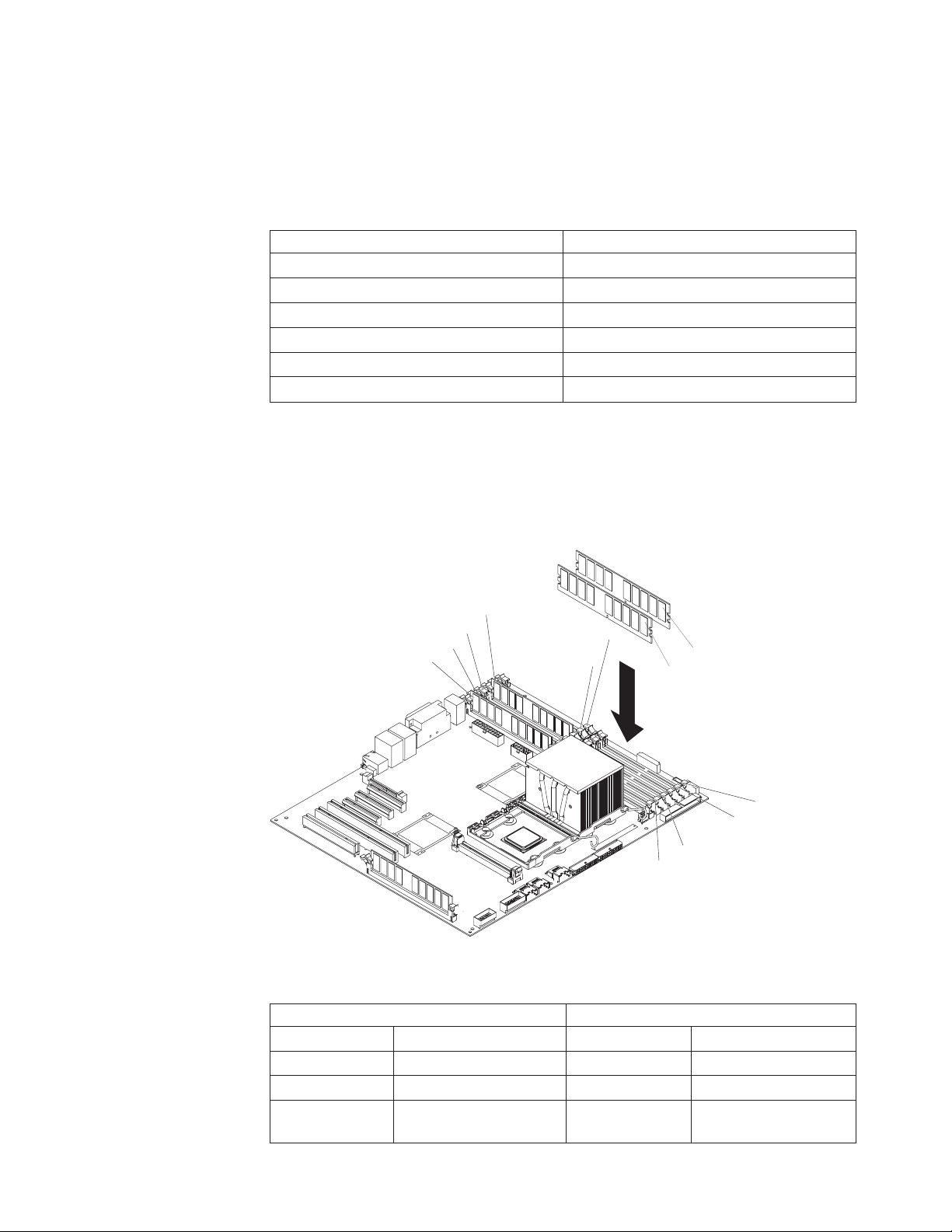
following illustration shows how to install DIMMs on the system board.
The
DIMM 4
DIMM 3
DIMM 2
DIMM 1
DIMM 6
DIMM 5
DIMM 10
DIMM 7
DIMM 12
DIMM11
DIMM 9
DIMM 8
v Install the DIMMs in the order shown in the following table.
Table 4. DIMM installation sequence
Memory in Non-mirroring mode Memory in mirroring mode
Number of DIMMs DIMM connectors Number of DIMMs DIMM connectors
1 1 4 1, 4, 7, 10
2 1, 4 8 1, 4, 7, 10, 2, 5, 8, 11
4 1, 4, 7, 10 12 1, 4, 7, 10, 2, 5, 8, 11,
3, 6, 9, 12
Chapter 2. Installing optional devices 15
Page 30
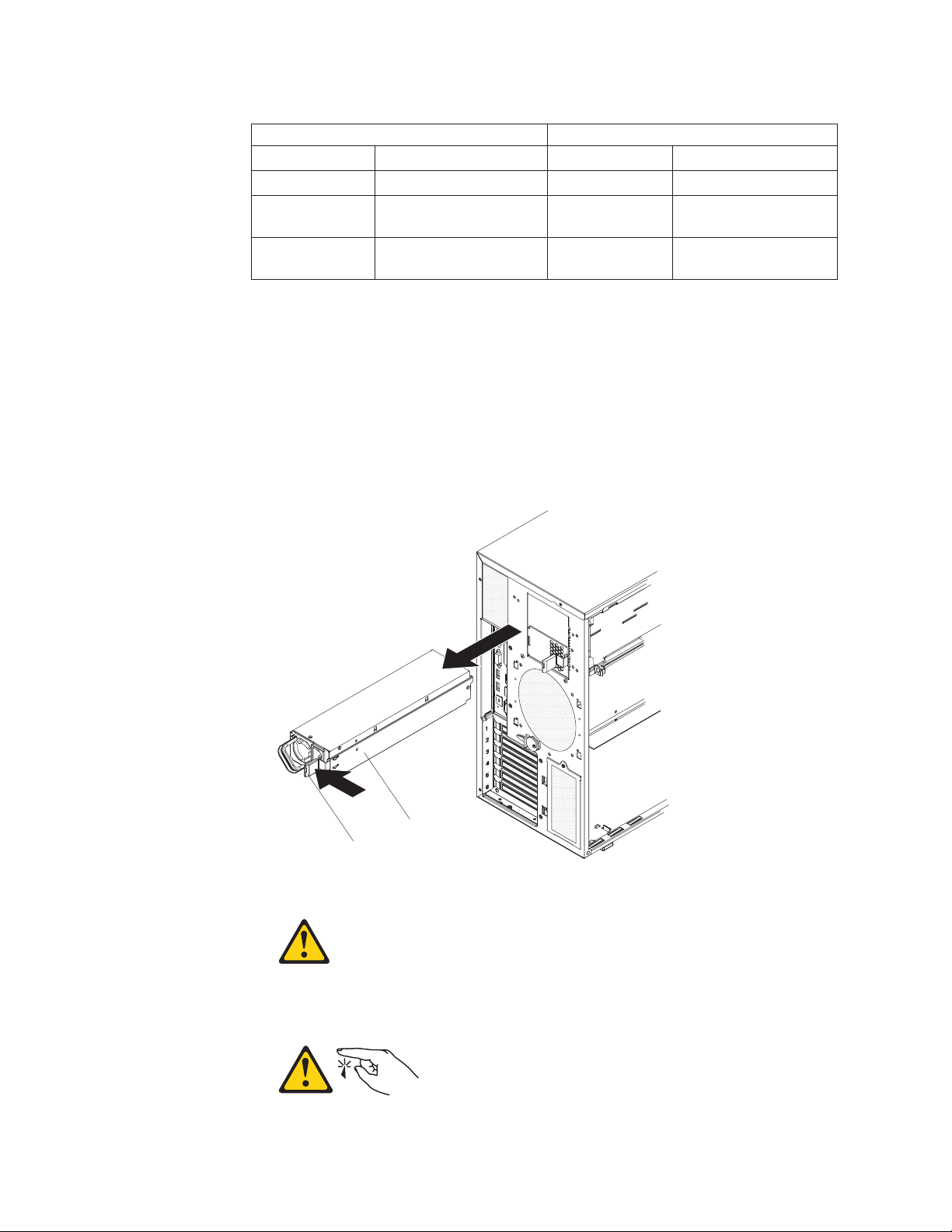
Table 4. DIMM installation sequence (continued)
Memory in Non-mirroring mode Memory in mirroring mode
6 1, 4, 7, 10, 2, 5
8 1, 4, 7, 10, 2, 5, 8, 11
10 1, 4, 7, 10, 2, 5, 8, 11, 3,
6
12 1, 4, 7, 10, 2, 5, 8, 11, 3,
6, 9, 12
To install DIMMs in the server, complete the following steps:
1. Read the safety information that begins on page vii and “Installation guidelines”
on page 7.
2. Turn off the server and peripheral devices, and disconnect the power cords and
all external cables.
3. Remove the left-side cover.
Attention: When you handle static-sensitive devices, take precautions to
avoid damage from static electricity. For details about handling these devices,
see “Handling static-sensitive devices” on page 9.
Statement 11:
Release latch
CAUTION:
The following label indicates sharp edges, corners, or joints nearby.
16 IBM System x3500 Type 7977: Installation Guide
Power supply
Page 31

Statement 17:
CAUTION:
The following label indicates moving parts nearby.
4. Remove the power supply and power-supply filler from the server by pressing
down on the release latch while you pull out on the plastic handle.
Note: The power supply, power-supply filler, or power supplies must be
removed before you attempt to rotate the power-supply cage out of the way.
Power-supply
Power-supply
cage assembly
cage handle
5. Lift the power-supply cage handle on the rear of the power supply cage, and
rotate the power-supply cage out of the way until it latches in place. Let the
power-supply cage rest on the rear power-supply structure support bracket.
Attention: To avoid breaking the retaining clips or damaging the DIMM
connectors, open and close the clips gently.
6. Install the DIMMs into DIMM connectors:
Chapter 2. Installing optional devices 17
Page 32

a. Open the retaining clip on each end of the DIMM connector.
b. Touch the static-protective package that contains the DIMM to any unpainted
metal surface on the server. Then, remove the DIMM from the package.
c. Turn the DIMM so that the DIMM keys align correctly with the slot.
d. Insert the DIMM into the connector.
Power supply
support bracket
Power supply
release tab
7. Raise the power-supply cage slightly and press and hold the release tab on the
rear power-supply support bracket; then, lower the power-supply structure into
position. For clarity, the power-supply cage is not shown in the illustration for
clarity.
8. Install the power supply or power supplies in the power-supply cage.
you have other devices to install or remove, do so now. Otherwise, go to
If
“Completing the installation” on page 30.
18 IBM System x3500 Type 7977: Installation Guide
Page 33

Installing redundant power and cooling
You can install a second 835-watt hot-swap power supply. This upgrade option
includes a hot-swap power supply, two hot-swap fans, a fan structure with an air
duct and a single hot-swap fan, and a fan power cable. Yo u must also purchase a
second power cord to connect the power supply to the power source.
To install the redundant power and cooling option, complete the following steps:
1. Read the safety information that begins on page vii and the guidelines in
“Handling static-sensitive devices” on page 9.
Attention: Static electricity that is released to internal server components
when the server is powered-on might cause the server to halt, which might
result in the loss of data. To avoid this potential problem, always use an
electrostatic-discharge wrist strap or other grounding system when you work
inside the server with the power on.
2. Turn off the server and peripheral devices, and disconnect the power cords
and all external cables. Remove the left-side cover.
3. Remove all adapters.
Fan air baffle
4. Remove the fan air baffle from the fan cage assembly by pushing in on the tab
Hot-swap fan
on the back of the air baffle; then, push the baffle to the left and lift it out of the
fan cage assembly.
5. Install two hot-swap fans in the empty bays of the fan cage assembly.
Chapter 2. Installing optional devices 19
Page 34

Power supply
Release latch
6. Remove the power supply and power supply filler from the server by pressing
down on the release latch while you pull out.
Power-supply
Power-supply
cage assembly
cage handle
7. Lift the power-supply cage handle on the rear of the power-supply cage, and
rotate the power-supply cage out of the way until it latches in place. Let the
power-supply cage rest on the rear power-supply structure support bracket.
8. Install the transition duct on the edge of the DIMM air baffle.
20 IBM System x3500 Type 7977: Installation Guide
Page 35

Positioning pins
DIMM air duct
Plastic
push pins
Transition duct
Pin
Rivet
a. Remove the plastic push pins that secure the DIMM air duct to the
power-supply cage.
1) Grasp the top of the plastic push pins and pull them out of the rivets.
2) Grasp the rivets and pull them out of the mounting holes and set them
to the side.
If the DIMM air duct in your server is secured with screws,
Note:
remove the screws.
Push the air duct up toward the rear of the power-supply cage. When the
b.
locator pins are free of the power-supply cage, you can remove the air duct
from the server.
c. Position the transition duct so that the two tabs are directly over the slots
on the side of the DIMM air duct.
d. Slide the transition duct into the slots until it clicks into place.
9. Reinstall the DIMM air duct onto the power-supply cage.
Chapter 2. Installing optional devices 21
Page 36

Power supply
support bracket
Power supply
release tab
10. Raise the power-supply cage slightly and press and hold the release tab on
the rear power-supply support bracket; then, lower the power-supply structure
into position. For clarity, the power-supply cage is not shown in the illustration.
Rear fan assembly
with baffle
11. Install the rear fan and fan structure on the chassis:
a. Align the clips on the rear fan assembly with the holes in the chassis.
b. Slide the assembly toward the power-supply cage until it stops.
22 IBM System x3500 Type 7977: Installation Guide
Page 37

Rear Fan
Connector
c. Connect the fan power cable to the connector on the system board.
Install the adapters.
12.
13. Install the left-side cover.
14. From the rear of the server, install the power supplies into the server. Push
each power supply until it stops and clicks into place.
15. Connect one end of each power cord into the connector on the back of each
power supply, and connect the other end of each power cord to a properly
grounded electrical outlet.
16. Make sure that the ac power LED on the top of each power supply is lit,
indicating that the power supply is operating correctly. If the server is turned
on, make sure that the dc power LED on the top of the power supply is lit also.
17. Reconnect the external cables.
you have other devices to install or remove, do so now. Otherwise, go to
If
“Completing the installation” on page 30.
Installing a hot-swap hard disk drive
The following notes describe the types of hard disk drives that the server supports
and other information that you must consider when installing a hard disk drive:
v Depending on model, the server supports up to eight 1-inch (26 mm) slim high,
3.5-inch SAS/SATA hot-swap hard disk drives or up to twelve 1-inch (26 mm)
slim-high, 2.5-inch, SAS/SATA hot-swap hard disk drives in the standard
hot-swap bays.
Chapter 2. Installing optional devices 23
Page 38

v The hot-swap bays are arranged vertically in the standard hard disk drive cage;
the bay numbers are 0 through 7 (from top to bottom) on models with eight hard
disk drives and 0 through 11 (from top to bottom) on models with twelve hard
disk drives.
v For a list of supported optional devices for the server, see http://www.ibm.com/
servers/eserver/serverproven/compat/us/.
v Inspect the drive tray for signs of damage.
v Make sure that the drive is correctly installed in the tray.
v See the documentation for the ServeRAID-8k, ServeRAID-8s, and the optional
ServeRAID-10is SAS controllers for instructions for installing a hard disk drive.
v All hot-swap drives in the server must have the same throughput speed rating;
using drives with different speed ratings might cause all drives to operate at the
throughput speed of the slowest drive.
v To minimize the possibility of damage to the hard disk drives when you are
installing them in a rack configuration, install the server in the rack before you
install the hard disk drives.
v You do not have to turn off the server to install hot-swap drives in the hot-swap
drive bays. However, you must turn off the server when you perform any steps
that involve installing or removing cables.
v Do not mix SAS and SATA drives in the same array.
v The drive ID of each hot-swap hard disk drive is printed on the label on the side
of the drive cage.
following illustration shows how to install a hot-swap hard disk drive.
The
EMC shield
Hard disk drive
Drive tray
Drive tray handle
(in open position)
To install a hot-swap hard disk drive, complete the following steps:
1. Read the safety information that begins on page vii and “Installation guidelines”
on page 7.
2. Remove the bezel from the server.
3. Remove the EMC shield from one of the empty hot-swap bays.
4. Make sure that the tray handle is open; then, install the hard disk drive into the
hot-swap bay.
Notes:
1. When you turn on the server, check the hard disk drive status LEDs to verify
that the hard disk drive is operating correctly.
If the amber hard disk drive status LED for a drive is lit continuously, that drive
is faulty and must be replaced. If the green hard disk drive activity LED is
flashing, the drive is being accessed.
24 IBM System x3500 Type 7977: Installation Guide
Page 39

2. If you plan to configure the server for RAID operations through the
ServeRAID-8k controller, the ServeRAID-8s controller, the optional
ServeRAID-10is controller, or a combination of these controllers, you must
configure the disk arrays before you install the operating system. See the
ServeRAID™ documentation on the IBM ServeRAID Support CD for additional
information about RAID operation and complete instructions for using
ServeRAID Manager.
Installing an additional microprocessor
The following notes describe the type of microprocessor that the server supports
and other information that you must consider when you install a microprocessor:
v For a list of supported optional devices for the server, see http://www.ibm.com/
servers/eserver/serverproven/compat/us/.
v See the System x3500 Type 7977 User’s Guide on the IBM System x
Documentation CD for details about how to install a microprocessor.
v The server supports Intel Xeon dual-core or quad-core 1.6 GHz or higher
microprocessors in each socket. If you are installing two microprocessors, they
must be the same cache size and type, and the same clock speed.
v Some models support dual-core processors and quad-core processors. Do not
mix dual-core processors and quad-core processors in the same server. Install all
dual-core or all quad-core processors in the server.
v Read the documentation that comes with the microprocessor to determine
whether you must update the basic input/output system (BIOS) code in the
server. To download the most current level of BIOS code for the server, go to
http://www.ibm.com/systems/support/.
v Obtain an SMP-capable operating system. For a list of supported operating
systems, see http://www.ibm.com/servers/eserver/serverproven/compat/us/.
v You can use the Configuration/Setup Utility program to determine the specific
type of microprocessor in the server.
install a microprocessor, complete the following steps:
To
1. Read the safety information that begins on page vii and “Installation guidelines”
on page 7.
2. Turn off the server and peripheral devices, and disconnect the power cords and
all external cables.
3. Lay the server on its side; then, remove the left-side cover.
Attention: When you handle static-sensitive devices, take precautions to
avoid damage from static electricity. For details about handling these devices,
see “Handling static-sensitive devices” on page 9.
4. Remove the microprocessor air duct from the fan structure. Squeeze the two
tabs on the top of the air duct together and lift the air duct out of the server.
5. Remove the microprocessor baffle and the protective film from the second
microprocessor socket.
Chapter 2. Installing optional devices 25
Page 40

Heatsink 2
Microprocessor
Microprocessor 2
release lever
Microprocessor 2
VRM
6. Install the VRM.
7. Install the microprocessor:
a. Touch the static-protective package that contains the new microprocessor to
any unpainted metal surface on the server; then, remove the microprocessor
from the package.
b. Release the microprocessor retention latch by pressing down on the end,
moving it to the side, and slowly releasing it to the open (up) position.
Microprocessor
release lever
(fully open)
Microprocessor
bracket frame
c. Close the microprocessor bracket frame; then, close the microprocessor
retention latch and lock it securely in place.
d. Close the microprocessor-release lever to secure the microprocessor.
Open the heat-sink release lever and install a heat sink on the microprocessor
8.
with the thermal grease side down; then, close the release lever.
26 IBM System x3500 Type 7977: Installation Guide
Page 41

Attention: Do not touch the thermal grease on the bottom of the heat sink
after you remove the plastic cover. Touching the thermal grease will contaminate
it.
9. Reinstall the microprocessor air duct on the fan cage.
you have other devices to install or remove, do so now. Otherwise, go to
If
“Completing the installation” on page 30.
Installing an adapter
The following notes describe the types of adapters that the server supports and
other information that you must consider when you install an adapter:
v Locate the documentation that comes with the adapter and follow those
instructions in addition to the instructions in this section. If you must change the
switch or jumper settings on the adapter, follow the instructions that come with
the adapter.
v Avoid touching the components and gold-edge connectors on the adapter.
v PCI slot 6 supports half-length 5.0 V PCI adapters only.
v PCI slot 1 supports half-length 3.3 V PCI adapters only.
v PCI slots 2 through 5 support full-length 3.3 V signaling adapters only.
v The PCI configuration:
– Slot 1 is a PCI-Express x8 slot with x4 links, PCI Express 1.0a compliant.
– Slot 2 and 3 are PCI-Express x8 slots with x8 links, PCI Express 1.0a
compliant. is the default slot for the optional ServeRAID-10is controller or the
ServeRAID-8s controller.
– Slots 4 and 5 are PCI-X 133/64 slots, PCI-X 2.0 compliant.
– Slot 6 is a PCI 33/32 slot, PCI 2.2 compliant.
The ServeRAID-8k, ServeRAID-8s, and the optional ServeRAID-10is SAS
Note:
controllers override the standard functionality of the integrated SAS/SATA
controller with RAID capabilities.
v The system scans PCI slots 1 through 6 to assign system resources. The system
then starts (boots) the system devices in the following order, if you have not
changed the default boot precedence: integrated Ethernet controller,
ServeRAID-8k SAS controller, and then PCI, PCI-X, and PCI-Express slots.
Note: To change the boot precedence for PCI and PCI-X devices, start the
Configuration/Setup Utility program and select Start Options from the main
menu. See the User’s Guide on the IBM System x Documentation CD for details
about using the Configuration/Setup Utility program.
v The server uses a rotational interrupt technique to configure PCI adapters so that
you can install PCI adapters that do not support sharing of PCI interrupts.
v In models with 12 hard disk drives, a ServeRAID-8s controller must be installed
in PCI slot 2 and a ServeRAID-8k controller in the ServeRAID connector on the
system board.
install an adapter, complete the following steps:
To
1. Read the safety information that begins on page vii and “Installation guidelines”
on page 7.
2. Turn off the server and peripheral devices, and disconnect the power cords and
all external cables. Remove the left-side cover.
Chapter 2. Installing optional devices 27
Page 42

3. See the documentation that comes with the adapter for any cabling instructions
and information about jumper or switch settings. (It might be easier for you to
route cables before you install the adapter.)
Rear adapter
retention bracket
Adapter
Front adapter
retention bracket
4. Open the front and rear adapter retention brackets.
5. Remove the expansion-slot cover.
6. If you are installing a full-length adapter, remove the blue adapter guide (if any)
from the end of the adapter; then, lift the adapter-retention clip on the
adapter-support bracket. Otherwise, continue with the next step.
Adapter guide
7. Press the adapter firmly into the expansion slot, lower the adapter retention
brackets, and make sure that the brackets are closed. To release the rear
adapter retention bracket, press up on the retention clip while you rotate the
bracket forward.
Attention: Incomplete insertion might cause damage to the system board or
the adapter.
28 IBM System x3500 Type 7977: Installation Guide
Page 43

8. Connect any required cables to the adapter.
you have other devices to install or remove, do so now. Otherwise, go to
If
“Completing the installation” on page 30.
Installing an IBM Remote Supervisor Adapter II SlimLine
An optional IBM Remote Supervisor Adapter II SlimLine can be installed only in its
dedicated connector on the system board. The Remote Supervisor Adapter II
SlimLine is not cabled to the system board.
To install a Remote Supervisor Adapter II SlimLine, complete the following steps:
1. Read the safety information that begins on page vii and “Installation guidelines”
on page 7.
2. Turn off the server and peripheral devices, and disconnect the power cords and
all external cables.
3. Remove the left-side cover.
4. Carefully lay the server on its right side and remove the left-side cover.
Adapter retention bracket
Remote Supervisor Adapter II
SlimLine retention tab
Remote Supervisor Adapter II SlimLine
5. Open the rear adapter retention bracket and install the Remote Supervisor
Adapter II SlimLine retention tab that comes with the adapter on the bracket by
clipping it onto the adapter retention bracket.
Chapter 2. Installing optional devices 29
Page 44

Remote Supervisor II
SlimLine adapter
6. Carefully grasp the Remote Supervisor Adapter II SlimLine by its top edge or
upper corners, and align it with the Remote Supervisor Adapter II SlimLine
guide and the connector on the system board.
Attention: Incomplete insertion might cause damage to the system board or
the adapter.
7. Press the Remote Supervisor Adapter II SlimLine firmly into the connector and
under the retention clip on the Remote Supervisor Adapter II SlimLine support
bracket.
8. Close the rear adapter retention bracket.
you have other devices to install or remove, do so now. Otherwise, go to
If
“Completing the installation.”
Completing the installation
To complete the installation, complete the following steps:
1. Install the bezel:
a. Align the tabs on the left-side of the bezel with the slots on the server
chassis.
b. Insert the tabs into the slots and close the bezel.
Install the left-side cover.
2.
Remote Supervisor II
SlimLine adapter retainer clip
Remote Supervisor II
SlimLine adapter support bracket
30 IBM System x3500 Type 7977: Installation Guide
Page 45

Cover release latch
Lock
Left-side cover
a. Position the left-side cover so that the handle is at the top.
b. Place the bottom edge of the cover onto the bottom edge of the server.
c. Rotate the top edge of left-side cover toward the server; then, press down
on the cover until it clicks into place.
d. Using the supplied key, lock the left-side cover and bezel.
3. Connect the cables and power cords. See “Connecting the cables” for more
information.
Connecting the cables
Notes:
1. Turn off the server before you connect any cables to or disconnect any cables
from the server or hot-plug adapter.
2. For additional cabling instructions, see the User’s Guide on the IBM System x
Documentation CD and the documentation that comes with the optional devices.
It might be easier for you to route any cables before you install certain optional
devices.
3. Cable identifiers are printed on the cables that come with the server and
optional devices. Use these identifiers to connect the cables to the correct
connectors.
The following illustration shows the location of the input and output connectors on
the rear of the server.
Note: There are two USB connectors on the front of the server. (See “Front view”
on page 35 for the location of these two USB connectors.)
Chapter 2. Installing optional devices 31
Page 46

Power cord
AC power LED
DC power LED
Mouse
Keyboard
Serial 1
(COM 1)
Parallel
Video
USB 4
Ethernet 10/100/1000
USB 3
Ethernet 10/100/1000
RJ-45
Serial 2
(COM 2)
Reattaching the bezel
The bezel comes with break-away hinges that are designed so that you can easily
reattach the bezel if the bezel is opened beyond 180° or if excessive pressure is
applied to the bezel.
Sliding hinge mount
To reattach the bezel, complete the following steps:
1. Press on the rear of the sliding hinge mount on the bezel until it extends beyond
the edge of the bezel and hold it in place.
2. Align the two halves of the hinge.
3. Press the two halves of the hinge together until they click into place; then,
release the hinge assembly.
32 IBM System x3500 Type 7977: Installation Guide
Page 47

4. Repeat step 2 for the remaining hinge.
Updating the server configuration
When you start the server for the first time after you add or remove an internal or
external device, you might receive a message that the configuration has changed.
The Configuration/Setup Utility program starts automatically so that you can save
the new configuration settings. For more information, see the section about
configuring the server in the User’s Guide on the IBM System x Documentation CD.
Some optional devices have device drivers that you must install. See the
documentation that comes with each device for information about installing device
drivers.
The server comes with at least one microprocessor. If more than one
microprocessor is installed, the server can operate as a symmetric multiprocessing
(SMP) server. You might have to upgrade the operating system to support SMP. For
more information, see the section about using the ServerGuide Setup and
Installation CD in the User’s Guide and the operating-system documentation.
If the server has an optional RAID adapter and you have installed or removed a
hard disk drive, see the documentation that comes with the RAID adapter for
information about reconfiguring the disk arrays.
If you have installed a Remote Supervisor Adapter II SlimLine to manage the server
remotely, see the Remote Supervisor Adapter II SlimLine User’s Guide, which
comes with the adapter, for information about setting up, configuring, and using the
adapter.
For information about configuring the integrated Gigabit Ethernet controller, see the
User’s Guide.
Chapter 2. Installing optional devices 33
Page 48

34 IBM System x3500 Type 7977: Installation Guide
Page 49

Chapter 3. Server controls, connectors, LEDs, and power
This chapter describes the controls and light-emitting diodes (LEDs) and how to
turn the server on and off.
Front view
The following illustration shows the controls and LEDs on the front of the server.
Note: The front bezel door is not shown so that the drive bays are visible.
DVD drive
activity LED
(green)
System power LED
Power-control button
Hard disk drive activity LED
System locator LED
System-information LED
System-error LED
USB 2
USB 1
DVD-eject button
Hard disk
drive status
LED (amber)
Hard disk
drive activity
LED (green)
System power LED: When this LED is lit and not flashing, it indicates that the
server is turned on. When this LED is flashing, it indicates that the server is turned
off and is still connected to an ac power source. When this LED is off, it indicates
that ac power is not present, or the power supply or the LED itself has failed. A
power LED is also on the rear of the server.
Power-control button: Press this button to turn the server on and off manually. A
power-control-button shield comes with the server. You can install this disk-shaped
shield to prevent the server from being turned off accidentally.
Hard disk drive activity LED: When this LED is flashing, it indicates that a hard
disk drive is in use.
System locator LED: Use this LED to visually locate the server among other
servers. You can use IBM Director to light this LED remotely.
© Copyright IBM Corp. 2008 35
Page 50

System-information LED: When this amber LED is on, the server power supplies
are nonredundant, or some other noncritical event has occurred. The event is
recorded in the error log. Check the light path diagnostic panel for more information
(see the Problem Determination and Service Guide on the IBM System x
Documentation CD).
System-error LED: When this amber LED is lit, it indicates that a system error has
occurred. Use the diagnostic LED panel and the system service label on the inside
of the left-side cover to further isolate the error. See the Problem Determination and
Service Guide on the IBM System x Documentation CD for additional information.
USB 2 connector: Connect a USB device to this connector.
USB 1 connector: Connect a USB device to this connector.
DVD-eject button: Press this button to release a CD or DVD from the DVD drive.
Hard disk drive status LED: When this LED is lit, it indicates that the associated
hard disk drive has failed. If an optional RAID adapter is installed in the server and
the LED flashes slowly (one flash per second), the drive is being rebuilt. If the LED
flashes rapidly (three flashes per second), the controller is identifying the drive.
Hard disk drive activity LED: When this LED is flashing, it indicates that the drive
is in use.
DVD drive activity LED: When this LED is lit, it indicates that the DVD drive is in
use.
36 IBM System x3500 Type 7977: Installation Guide
Page 51

Rear view
The following illustration shows the connectors and LEDs on the rear of the server.
Ethernet 10/100/1000
Ethernet 10/100/1000
Power cord
AC power LED
DC power LED
Mouse
Keyboard
Serial 1
(COM 1)
Parallel
Video
USB 4
USB 3
RJ-45
Serial 2
(COM 2)
Power-cord connector: Connect the power cord to this connector.
Mouse connector: Connect a mouse or other PS/2 device to this connector.
Keyboard connector: Connect a PS/2 keyboard to this connector.
Serial 1 (COM 1) connector: Connect a 9-pin serial device to this connector.
Parallel connector: Connect a parallel device to this connector.
Video connector: Connect a monitor to this connector.
USB 4 connector: Connect a USB device to this connector.
Ethernet connector: Use this connector to connect the server to a network.
USB 3 connector: Connect a USB device to this connector.
Ethernet connector: Use this connector to connect the server to a network.
RJ-45 connector: Use this connector to connect the optional Remote Supervisor
Adapter II SlimLine to a network.
Chapter 3. Server controls, connectors, LEDs, and power 37
Page 52

Serial 2 (COM 2) connector: Connect a 9-pin serial device to this connector. This
connector can also be redirected in the Configuration/Setup Utility program for use
with the baseboard management controller (BMC) or Remote Supervisor Adapter II
SlimLine to control the server remotely. Do not connect any 9-pin serial devices to
this connector when it is configured for use with the BMC or Remote Supervisor
Adapter II SlimLine.
Note: When this connector is configured for use with the system management, do
not connect any other 9-pin serial devices to this connector.
38 IBM System x3500 Type 7977: Installation Guide
Page 53

Server power features
When the server is connected to an ac power source but is not turned on, the
operating system does not run, and all core logic except for the service
microprocessor is shut down; however, the server can respond to requests from the
service microprocessor (also called the baseboard management controller), such as
a remote request to turn on the server. The power-on LED flashes to indicate that
the server is connected to ac power but is not turned on.
Turning on the server
Approximately 20 seconds after the server is connected to ac power, the
power-control button becomes active, one or more fans might start running, and you
can turn on the server and start the operating system by pressing the power-control
button.
The server can also be turned on in any of the following ways:
v If a power failure occurs while the server is turned on, the server will restart
automatically when power is restored.
v If the server is connected to an Advanced System Management interconnect
network that contains at least one server with an optional Remote Supervisor
Adapter II SlimLine installed, the server can be turned on from the Remote
Supervisor Adapter user interface.
v If your operating system supports the systems-management software for an
optional Remote Supervisor Adapter II SlimLine, the systems-management
software can turn on the server.
v If your operating system supports the Wake on LAN® feature, the Wake on LAN
feature can turn on the server.
When 4 GB or more of memory (physical or logical) is installed, some
Note:
memory is reserved for various system resources and is unavailable to the
operating system. The amount of memory that is reserved for system resources
depends on the operating system, the configuration of the server, and the
configured PCI devices.
Chapter 3. Server controls, connectors, LEDs, and power 39
Page 54

Turning off the server
When you turn off the server and leave it connected to ac power, the server can
respond to requests from the service microprocessor, such as a remote request to
turn on the server. While the server remains connected to ac power, one or more
fans might continue to run. To remove all power from the server, you must
disconnect it from the power source.
Some operating systems require an orderly shutdown before you turn off the server.
See your operating-system documentation for information about shutting down the
operating system.
Statement 5:
CAUTION:
The power control button on the device and the power switch on the power
supply do not turn off the electrical current supplied to the device. The device
also might have more than one power cord. To remove all electrical current
from the device, ensure that all power cords are disconnected from the power
source.
2
1
The server can be turned off in any of the following ways:
v You can turn off the server from the operating system, if your operating system
supports this feature. After an orderly shutdown of the operating system, the
server will be turned off automatically.
v You can press the power-control button to start an orderly shutdown of the
operating system and turn off the server, if your operating system supports this
feature.
v If the operating system stops functioning, you can press and hold the
power-control button for more than 4 seconds to turn off the server.
v If the server is connected to an Advanced System Management interconnect
network that contains at least one server with an optional Remote Supervisor
Adapter II SlimLine installed, the server can be turned off from the Remote
Supervisor Adapter II SlimLine user interface.
v If an optional Remote Supervisor Adapter II SlimLine is installed in the server, the
server can be turned off from the Remote Supervisor Adapter II SlimLine user
interface.
v The integrated system management microprocessor can turn off the server as an
automatic response to a critical system failure.
v You can turn off the server through a request from the service microprocessor.
40 IBM System x3500 Type 7977: Installation Guide
Page 55

Chapter 4. Configuring the server
The ServerGuide Setup and Installation CD provides software setup tools and
installation tools that are specifically designed for your IBM server. Use this CD
during the initial installation of the server to configure basic hardware features and
to simplify the operating-system installation. (See “Using the ServerGuide Setup
and Installation CD” for more information.)
In addition to the ServerGuide Setup and Installation CD, you can use the following
configuration programs to customize the server hardware:
v Configuration/Setup Utility program
v Integrated System Management Firmware Update Utility program
v Baseboard management controller utility programs
v RAID configuration programs
– Use the IBM ServeRAID Configuration Utility program or ServeRAID Manager
to configure an array of hot-swap SAS or hot-swap S ATA hard disk drives. For
information about using these programs, see “Configuring hot-swap SAS or
hot-swap SATA RAID” on page 54.
– Adaptec RAID Configuration Utility program
– ServeRAID Manager
Boot Menu program
v
v Broadcom Gigabit Ethernet Utility program
more information about these programs, see “Configuring the server” in the
For
User’s Guide on the IBM System x Documentation CD.
Using the ServerGuide Setup and Installation CD
The ServerGuide Setup and Installation CD provides state-of-the-art programs to
detect the server model and installed optional hardware devices, configure the
server hardware, provide device drivers, and help you install the operating system.
For information about the supported operating-system versions, see the label on the
CD. If the ServerGuide Setup and Installation CD did not come with the server, you
can download the latest version from http://www.ibm.com/systems/management/
serverguide/sub.html.
To start the ServerGuide Setup and Installation CD, complete the following steps:
1. Insert the CD, and restart the server. If the CD does not start, see “ServerGuide
problems” on page 88.
2. Follow the instructions on the screen to:
a. Select your language.
b. Select your keyboard layout and country.
c. View the overview to learn about ServerGuide features.
d. View the readme file to review installation tips about your operating system
and adapter.
e. Start the setup and hardware configuration programs.
f. Start the operating-system installation. Yo u will need your operating-system
CD.
© Copyright IBM Corp. 2008 41
Page 56

Using the Configuration/Setup Utility program
The Configuration/Setup Utility program is part of the BIOS. Yo u can use it to
perform the following tasks:
v Change interrupt request (IRQ) settings
v Change the startup drive sequence
v Configure serial-port assignments
v Enable USB keyboard and mouse support
v Resolve configuration conflicts
v Set the date and time
v Set passwords and security settings
start the Configuration/Setup Utility program, complete the following steps:
To
1. Turn on the server.
2. When the message Press F1 for Configuration/Setup is displayed, press F1.
If an administrator password has been set, you must type the administrator
password to access the full Configuration/Setup Utility menu.
If you forget the power-on password or administrator password, you can
Note:
toggle switch 2 (SW4) on the system board to bypass the password check. This
enables you to reset the passwords.
3. Follow the instructions on the screen.
Using the Integrated System Management Firmware Update Utility program
To update the firmware for the integrated system management microprocessor
(ISMP), download the Integrated System Management Firmware Update Utility
program from http://www.ibm.com/systems/support/, and run the utility program to
create a diskette that you can use to update the firmware. The utility program
updates the integrated system management firmware only and does not affect any
device drivers.
To update the firmware, complete the following steps:
1. Turn off the server.
2. Insert the diskette into the diskette drive.
3. Turn on the server. If the server does not start from the diskette, use the
Configuration/Setup Utility program to configure the diskette drive as a startup
device. (For more information, see the information about Configuration/Setup
Utility start options in the User’s Guide.) Then, start again at step 1 of this
procedure.
4. From the main menu, select Update System Management Firmware and
press Enter.
5. Follow the instructions on the screen to complete the update.
there is an error in updating the firmware, try installing the firmware again.
If
42 IBM System x3500 Type 7977: Installation Guide
Page 57

Using the baseboard management controller
The baseboard management controller provides environmental monitoring for the
server. If environmental conditions exceed thresholds or if system components fail,
the baseboard management controller lights LEDs to help you diagnose the
problem and also records the error in the system event/error log.
The baseboard management controller also provides the following remote server
management capabilities through the OSA SMBridge management utility program:
v Command-line interface (IPMI Shell)
The command-line interface provides direct access to server management
functions through the IPMI protocol. Use the command-line interface to issue
commands to control the server power, view system information, and identify the
server. Yo u can also save one or more commands as a text file and run the file
as a script.
v Serial over LAN
Establish a Serial over LAN (SOL) connection to manage servers from a remote
location. You can remotely view and change the BIOS settings, restart the server,
identify the server, and perform other management functions. Any standard Telnet
client application can access the SOL connection.
Enabling and configuring SOL using the OSA SMBridge management utility program
To enable and configure the server for SOL by using the OSA SMBridge
management utility program, you must update and configure the BIOS code; update
and configure the baseboard management controller (BMC) firmware; update and
configure the Ethernet controller firmware; and enable the operating system for an
SOL connection.
BIOS update and configuration
Complete the following steps to update and configure the BIOS code to enable
SOL:
1. Update the BIOS code:
a. Download the latest version of the BIOS code from http://www.ibm.com/
systems/support/.
b. Update the BIOS code, following the instructions that come with the update
file that you downloaded.
2. Update the BMC firmware:
a. Download the latest version of the BMC firmware from http://www.ibm.com/
systems/support/.
b. Update the BMC firmware, following the instructions that come with the
update file that you downloaded.
Configure the BIOS settings:
3.
a. Restart the server and press F1 when you are prompted to start the
Configuration/Setup Utility program.
b. Select Devices and I/O Ports; then, make sure that the values are set as
follows:
v Serial Port A: Auto-configure
v Serial Port B: Auto-configure
Select Remote Console Redirection; then, make sure that the values are
c.
set as follows:
Chapter 4. Configuring the server 43
Page 58

v Remote Console Active: Enabled
v Remote Console COM Port: COM 2
v Remote Console Baud Rate: 19200 or higher
v Remote Console Data Bits: 8
v Remote Console Parity: None
v Remote Console Stop Bits: 1
v Remote Console Text Emulation: ANSI
v Remote Console Keyboard Emulation: ANSI
v Remote Console Active After Boot: Enabled
v Remote Console Flow Control: Hardware
Press Esc twice to exit the Remote Console Redirection and Devices and
d.
I/O Ports sections of the Configuration/Setup Utility program.
e. Select Advanced Setup; then, select Baseboard Management Controller
(BMC) Settings.
f. Set BMC Serial Port Access Mode to Dedicated.
g. Press Esc twice to exit the Baseboard Management Controller (BMC)
Settings and Advanced Setup sections of the Configuration/Setup Utility
program.
h. Select Save Settings; then, press Enter.
i. Press Enter to confirm.
j. Select Exit Setup; then, press Enter.
k. Make sure that Yes, exit the Setup Utility is selected; then, press Enter.
Linux configuration
For SOL operation on the server, you must configure the Linux® operating system to
expose the Linux initialization (booting) process. This enables users to log in to the
Linux console through an SOL session and directs Linux output to the serial
console. See the documentation for your specific Linux operating-system type for
information and instructions.
Use one of the following procedures to enable SOL sessions for your Linux
operating system. Yo u must be logged in as a root user to perform these
procedures.
Red Hat Enterprise Linux ES 2.1 configuration:
Note: This procedure is based on a default installation of Red Hat Enterprise Linux
ES 2.1. The file names, structures, and commands might be different for other
versions of Red Hat Linux.
Complete the following steps to configure the general Linux parameters for SOL
operation when you use the Red Hat Enterprise Linux ES 2.1 operating system.
Note: Hardware flow control prevents character loss during communication over a
serial connection. Yo u must enable it when you use a Linux operating system.
1. Add the following line to the end of the # Run gettys in standard runlevels
section of the /etc/inittab file. This enables hardware flow control and enables
users to log in through the SOL console.
7:2345:respawn:/sbin/agetty -h ttyS0 19200 vt102
2. Add the following line at the bottom of the /etc/securetty file to enable a user to
log in as the root user through the SOL console:
44 IBM System x3500 Type 7977: Installation Guide
Page 59

ttyS0
LILO configuration: If you are using LILO, complete the following steps:
1. Complete the following steps to modify the /etc/lilo.conf file:
a. Add the following text to the end of the first default=linux line
-Monitor
b. Comment out the map=/boot/map line by adding a # at the beginning of this
line.
c. Comment out the message=/boot/message line by adding a # at the beginning
of this line.
d. Add the following line before the first image= line:
# This will allow you to only Monitor the OS boot via SOL
e. Add the following text to the end of the first label=linux line:
-Monitor
f. Add the following line to the first image= section. This enables SOL.
append="console=ttyS0,19200n8 console=tty1"
g. Add the following lines between the two image= sections:
# This will allow you to Interact with the OS boot via SOL
image=/boot/vmlinuz-2.4.9-e.12smp
label=linux-Interact
initrd=/boot/initrd-2.4.9-e.12smp.img
read-only
root=/dev/hda6
append="console=tty1 console=ttyS0,19200n8 "
The following examples show the original content of the /etc/lilo.conf file and the
content of this file after modification.
Original /etc/lilo.conf contents
prompt
timeout=50
default=linux
boot=/dev/hda
map=/boot/map
install=/boot/boot.b
message=/boot/message
linear
image=/boot/vmlinuz-2.4.9-e.12smp
label=linux
initrd=/boot/initrd-2.4.9-e.12smp.img
read-only
root=/dev/hda6
image=/boot/vmlinuz-2.4.9-e.12
label=linux-up
initrd=/boot/initrd-2.4.9-e.12.img
read-only
root=/dev/hda6
Chapter 4. Configuring the server 45
Page 60

Modified /etc/lilo.conf contents
prompt
timeout=50
default=linux-Monitor
boot=/dev/hda
#map=/boot/map
install=/boot/boot.b
#message=/boot/message
linear
# This will allow you to only Monitor the OS boot via SOL
image=/boot/vmlinuz-2.4.9-e.12smp
label=linux-Monitor
initrd=/boot/initrd-2.4.9-e.12smp.img
read-only
root=/dev/hda6
append="console=ttyS0,19200n8 console=tty1"
# This will allow you to Interact with the OS boot via SOL
image=/boot/vmlinuz-2.4.9-e.12smp
label=linux-Interact
initrd=/boot/initrd-2.4.9-e.12smp.img
read-only
root=/dev/hda6
append="console=tty1 console=ttyS0,19200n8 "
image=/boot/vmlinuz-2.4.9-e.12
label=linux-up
initrd=/boot/initrd-2.4.9-e.12.img
read-only
root=/dev/hda6
2. Run the lilo command to store and activate the LILO configuration.
When the Linux operating system starts, a LILO boot: prompt is displayed instead
of the graphical user interface. Press Ta b at this prompt to install all of the boot
options that are listed. To load the operating system in interactive mode, type
linux-Interact and then press Enter.
GRUB configuration: If you are using GRUB, complete the following steps to
modify the /boot/grub/grub.conf file:
1. Comment out the splashimage= line by adding a # at the beginning of this line.
2. Add the following line before the first title= line:
# This will allow you to only Monitor the OS boot via SOL
3. Append the following text to the first title= line:
SOL Monitor
4. Append the following text to the kernel/ line of the first title= section:
console=ttyS0,19200 console=tty1
5. Add the following five lines between the two title= sections:
# This will allow you to Interact with the OS boot via SOL
title Red Hat Linux (2.4.9-e.12smp) SOL Interactive
root (hd0,0)
46 IBM System x3500 Type 7977: Installation Guide
Page 61

kernel /vmlinuz-2.4.9-e.12smp ro root=/dev/hda6 console=tty1
console=ttyS0,19200
initrd /initrd-2.4.9-e.12smp.img
Note: The entry that begins with kernel /vmlinuz is shown with a line break after
console=tty1. In your file, the entire entry must all be on one line.
The following examples show the original content of the /boot/grub/grub.conf file
and the content of this file after modification.
Original /boot/grub/grub.conf contents
#grub.conf generated by anaconda
#
# Note that you do not have to rerun grub after making changes to this file
# NOTICE: You have a /boot partition. This means that
# all kernel and initrd paths are relative to /boot/, eg.
# root (hd0,0)
# kernel /vmlinuz-version ro root=/dev/hda6
# initrd /initrd-version.img
#boot=/dev/hda
default=0
timeout=10
splashimage=(hd0,0)/grub/splash.xpm.gz
title Red Hat Enterprise Linux ES (2.4.9-e.12smp)
root (hd0,0)
kernel /vmlinuz-2.4.9-e.12smp ro root=/dev/hda6
initrd /initrd-2.4.9-e.12smp.img
title Red Hat Enterprise Linux ES-up (2.4.9-e.12)
root (hd0,0)
kernel /vmlinuz-2.4.9-e.12 ro root=/dev/hda6
initrd /initrd-2.4.9-e.12.img
Chapter 4. Configuring the server 47
Page 62

Modified /boot/grub/grub.conf contents
#grub.conf generated by anaconda
#
# Note that you do not have to rerun grub after making changes to this file
# NOTICE: You have a /boot partition. This means that
# all kernel and initrd paths are relative to /boot/, eg.
# root (hd0,0)
# kernel /vmlinuz-version ro root=/dev/hda6
# initrd /initrd-version.img
#boot=/dev/hda
default=0
timeout=10
# splashimage=(hd0,0)/grub/splash.xpm.gz
# This will allow you to only Monitor the OS boot via SOL
title Red Hat Enterprise Linux ES (2.4.9-e.12smp) SOL Monitor
root (hd0,0)
kernel /vmlinuz-2.4.9-e.12smp ro root=/dev/hda6 console=ttyS0,19200 console=tty1
initrd /initrd-2.4.9-e.12smp.img
# This will allow you to Interact with the OS boot via SOL
title Red Hat Linux (2.4.9-e.12smp) SOL Interactive
root (hd0,0)
kernel /vmlinuz-2.4.9-e.12smp ro root=/dev/hda6 console=tty1 console=ttyS0,19200
initrd /initrd-2.4.9-e.12smp.img
title Red Hat Enterprise Linux ES-up (2.4.9-e.12)
root (hd0,0)
kernel /vmlinuz-2.4.9-e.12 ro root=/dev/hda6
initrd /initrd-2.4.9-e.12.img
You must restart the Linux operating system after you complete these procedures
for the changes to take effect and to enable SOL.
SUSE SLES 8.0 configuration:
Note: This procedure is based on a default installation of SUSE Linux Enterprise
Server (SLES) 8.0. The file names, structures, and commands might be different for
other versions of SUSE LINUX.
Complete the following steps to configure the general Linux parameters for SOL
operation when you use the SLES 8.0 operating system.
Note: Hardware flow control prevents character loss during communication over a
serial connection. Yo u must enable it when you use a Linux operating system.
1. Add the following line to the end of the # getty-programs for the normal
runlevels section of the /etc/inittab file. This enables hardware flow control and
enables users to log in through the SOL console.
7:2345:respawn:/sbin/agetty -h ttyS0 19200 vt102
2. Add the following line after the tty6 line at the bottom of the /etc/securetty file to
enable a user to log in as the root user through the SOL console:
ttyS0
3. Complete the following steps to modify the /boot/grub/menu.lst file:
48 IBM System x3500 Type 7977: Installation Guide
Page 63

a. Comment out the gfxmenu line by adding a # in front of the word gfxmenu.
b. Add the following line before the first title line:
# This will allow you to only Monitor the OS boot via SOL
c. Append the following text to the first title line:
SOL Monitor
d. Append the following text to the kernel line of the first title section:
console=ttyS0,19200 console=tty1
e. Add the following four lines between the first two title sections:
# This will allow you to Interact with the OS boot via SOL
title linux SOL Interactive
kernel (hd0,1)/boot/vmlinuz root=/dev/hda2 acpi=oldboot vga=791
console=tty1 console=ttyS0,19200
initrd (hd0,1)/boot/initrd
The following examples show the original content of the /boot/grub/menu.lst
file and the content of this file after modification.
Original /boot/grub/menu.lst contents Notes
gfxmanu (hd0,1)/boot/message
color white/blue black/light-gray
default 0
timeout 8
title linux
kernel (hd0,1)/boot/vmlinuz root=/dev/hda2 acpi=oldboot vga=791 1
initrd (hd0,1)/boot/initrd
title floppy
root
chainloader +1
title failsafe
kernal (hd0,1)/boot/vmlinuz.shipped root=/dev/hda2 ide=nodma apm=off vga=normal nosmp 1
disableapic maxcpus=0 3
initrd (hd0,1)/boot/initrd.shipped
Note 1: The kernel line is shown with a line break. In your file, the entire entry must all be on one line.
Modified /boot/grub/menu.lst contents Notes
#gfxmanu (hd0,1)/boot/message
color white/blue black/light-gray
default 0
timeout 8
# This will allow you to only Monitor the OS boot via SOL
title linux SOL Monitor
kernel (hd0,1)/boot/vmlinuz root=/dev/hda2 acpi=oldboot vga=791 console=ttyS1,19200 1
console=tty1
initrd (hd0,1)/boot/initrd
# This will allow you to Interact with the OS boot via SOL
title linux SOL Interactive
kernel (hd0,1)/boot/vmlinuz root=/dev/hda2 acpi=oldboot vga=791 console=tty1 console=ttyS0,19200
initrd (hd0,1)/boot/initrd
title floppy
Chapter 4. Configuring the server 49
Page 64

Modified /boot/grub/menu.lst contents Notes
root
chainloader +1
title failsafe
kernel (hd0,1)/boot/vmlinuz.shipped root=/dev/hda2 ide=nodma apm=off vga=normal nosmp 1
disableapic maxcpus=0 3
initrd (hd0,1)/boot/initrd.shipped
Note 1: The kernel line is shown with a line break. In your file, the entire entry must all be on one line.
You must restart the Linux operating system after you complete these procedures
for the changes to take effect and to enable SOL.
Microsoft Windows 2003 Standard Edition configuration
Note: This procedure is based on a default installation of the Microsoft Windows
2003 operating system.
Complete the following steps to configure the Windows 2003 operating system for
SOL operation. You must be logged in as a user with administrator access to
perform this procedure.
1. Complete the following steps to determine which boot entry ID to modify:
a. Type bootcfg at a Windows command prompt; then, press Enter to display
the current boot options for your server.
b. In the Boot Entries section, locate the boot entry ID for the section with an
OS friendly name of Windows Server 2003, Standard. Write down the boot
entry ID for use in the next step.
To enable the Microsoft Windows Emergency Management System (EMS), at a
2.
Windows command prompt, type
bootcfg /EMS ON /PORT COM1 /BAUD 19200 /ID boot_id
where boot_id is the boot entry ID from step 1b; then, press Enter.
3. Complete the following steps to verify that the EMS console is redirected to the
COM2 serial port:
a. Type bootcfg at a Windows command prompt; then, press Enter to display
the current boot options for your server.
b. Verify the following changes to the bootcfg settings:
v In the Boot Loader Settings section, make sure that redirect is set to
COM2 and that redirectbaudrate is set to 19200.
v In the Boot Entries section, make sure that the OS Load Options: line
has /redirect appended to the end of it.
following examples show the original bootcfg program output and the output
The
after modification.
50 IBM System x3500 Type 7977: Installation Guide
Page 65

Original bootcfg program output
Boot Loader Settings
----------------------------
timeout: 30
default: multi(0)disk(0)rdisk(0)partition(1)\WINDOWS
Boot Entries
----------------
Boot entry ID: 1
OS Friendly Name: Windows Server 2003, Standard
Path: multi(0)disk(0)rdisk(0)partition(1)\WINDOWS
OS Load Options: /fastdetect
Modified bootcfg program output
Boot Loader Settings
----------------------------
timeout: 30
default: multi(0)disk(0)rdisk(0)partition(1)\WINDOWS
redirect: COM1
redirectbaudrate: 19200
Boot Entries
----------------
Boot entry ID: 1
OS Friendly Name: Windows Server 2003, Standard
Path: multi(0)disk(0)rdisk(0)partition(1)\WINDOWS
OS Load Options: /fastdetect /redirect
You must restart the Windows 2003 operating system after you complete this
procedure for the changes to take effect and to enable SOL.
Installing the OSA SMBridge management utility program
Complete the following steps to install the OSA SMBridge management utility
program on a server running a Windows operating system:
1. Go to http://www.ibm.com/systems/support/ and download the utility program
and create the OSA BMC Management Utility CD.
2. Insert the OSA BMC Management Utility CD into the drive. The InstallShield
wizard starts, and a window similar to that shown in the following illustration
opens.
Chapter 4. Configuring the server 51
Page 66

3. Follow the prompts to complete the installation.
The installation program prompts you for a TCP/IP port number and an IP
address. Specify an IP address, if you want to limit the connection requests that
will be accepted by the utility program. To accept connections from any server,
type INADDR_ANY as the IP address. Also specify the port number that the utility
program will use. These values will be recorded in the smbridge.cfg file for the
automatic startup of the utility program.
Complete
the following steps to install the OSA SMBridge management utility
program on a server running a Linux operating system. Yo u must be logged in as a
root user to perform these procedures.
1. Go to http://www.ibm.com/systems/support/ and download the utility program
and create the OSA BMC Management Utility CD.
2. Insert the OSA BMC Management Utility CD into the drive.
3. Type mount/mnt/cdrom.
4. Locate the directory where the installation RPM package is located and type
cd/mnt/cdrom.
5. Type the following command to run the RPM package and start the installation:
rpm -ivh smbridge-2.0-XX.rpm
6. Follow the prompts to complete the installation. When the installation is
complete, the utility copies files to the following directories:
/etc/init.d/SMBridge
/etc/smbridge.cfg
/usr/sbin/smbriged
/var/log/smbridge/Liscense.txt
/var/log/smbridge/Readme.txt
utility starts automatically when the server is started. Yo u can also locate the
The
/ect/init.d directory to start the utility and use the following commands to manage
the utility:
52 IBM System x3500 Type 7977: Installation Guide
Page 67

smbridge status
smbridge start
smbridge stop
smbridge restart
Using the baseboard management controller utility programs
Use the baseboard management controller utility programs to configure the
baseboard management controller, download firmware updates and SDR/FRU
updates, and remotely manage a network.
Using the baseboard management controller configuration utility program
Use the baseboard management controller configuration utility program to view or
change the baseboard management controller configuration settings. Yo u can also
use the utility program to save the configuration to a file for use on multiple servers.
Complete the following steps to start the baseboard management controller
configuration utility program:
1. Insert the configuration utility diskette into the diskette drive and restart the
server.
2. From a command-line prompt, type bmc_cfg and press Enter.
3. Follow the instructions on the screen.
Using the baseboard management controller firmware update utility program
Use the baseboard management controller firmware update utility disk to update the
baseboard management controller firmware and SDR/FRU data. The firmware
update utility updates the baseboard management controller firmware and
SDR/FRU data only and does not affect any device drivers.
Note: To ensure correct server operation, be sure to update the server baseboard
management controller firmware before you update the BIOS code.
To update the firmware, if the Linux or Windows operating-system update package
is available from the World Wide Web and you have obtained the applicable update
package, follow the instructions that come with the update package.
Using the OSA SMBridge management utility program
Use the OSA SMBridge management utility program to remotely manage and
configure a network. The utility program provides the following remote management
capabilities:
v CLI (command-line interface) mode
Use CLI mode to remotely perform power-management and system identification
control functions over a LAN or serial port interface from a command-line
interface. Use CLI mode also to remotely view the system event/error log.
Use the following commands in CLI mode:
– identify
Control the system-locator LED on the front of the server.
– power
Turn the server on and off remotely.
– sel
Perform operations with the BMC System Event Log.
Chapter 4. Configuring the server 53
Page 68

– sysinfo
Display general system information that is related to the server and the
baseboard management controller.
Serial over LAN
v
Use the Serial over LAN capability to remotely perform control and management
functions over a Serial over LAN (SOL) network. Yo u can also use SOL to
remotely view and change the server BIOS settings.
At a command prompt, type Telnet localhost 623 to access the SOL network.
Type help at the smbridge> prompt for more information.
Use the following commands in an SOL session:
– connect
Connect to the LAN. Type connect -ip ip_address -u username -p
password.
– identify
Control the system-locator LED on the front of the server.
– power
Turn the server on and off remotely.
– reboot
Force the server to restart.
– sel get
Display the system event/error log.
– sol
Configure the SOL function.
– sysinfo
Display system information that is related to the server and the globally
unique identifier (GUID).
Using the ServeRAID configuration programs
The ServeRAID-8k SAS Controller enables you to configure multiple physical SAS
hard disk drives to operate as logical drives in a disk array. The server comes with
a CD that contains the ServeRAID Manager program, which you can use to
configure the ServeRAID-8k, ServeRAID-8s, and the optional ServeRAID-10is SAS
controllers. For information about these programs, see the User’s Guide on the IBM
System x Documentation CD. If your server comes with an operating system
installed, such as Microsoft Windows 2000 Datacenter Server, see the software
documentation that comes with the server for configuration information.
Configuring hot-swap SAS or hot-swap SATA RAID
Use the IBM ServeRAID Configuration Utility program or ServeRAID Manager to
configure and manage hot-swap SAS or hot-swap S ATA redundant array of
independent disks (RAID). Be sure to use these programs as described in this
document.
v Use the IBM ServeRAID Configuration Utility program to:
– Perform a low-level format on a hard disk drive
– View or change IDs for some attached devices
– Set protocol parameters on hard disk drives
Use ServeRAID Manager to:
v
– Configure arrays
54 IBM System x3500 Type 7977: Installation Guide
Page 69

– View the RAID configuration and associated devices
– Monitor operation of the RAID controller
Consider the following information when you use the IBM ServeRAID Configuration
Utility program or ServeRAID Manager to configure and manage arrays:
v The ServeRAID-8s SAS controller supports RAID levels 0, 1, 1E, 5. 6, 10, 50,
and 60.
v Servers that come with twelve 2.5-inch hot-swap SAS drives also come with two
ServeRAID SAS controllers; a ServeRAID-8k controller in the ServeRAID
connector on the system board and a ServeRAID-8s controller in PCI Express
slot 2. The ServeRAID-8k controller supports the first eight hard disk drives, and
the ServeRAID-8s controller supports the four remaining hard disk drives.
v The integrated ServeRAID-8k controller is disabled when BIOS detects an
optional ServeRAID-10is has been installed in the server.
v When you configure the 12 hard disk drives, you may configure the first eight
drives into an array that is attached to the ServeRAID-8k and the remaining four
drives into an array that is attached to the ServeRAID-8s.
v Hard disk drive capacities affect how you create arrays. The drives in an array
can have different capacities, but the ServeRAID controllers treat them as if they
all have the capacity of the smallest hard disk drive.
v To help ensure signal quality, do not use drives with different speeds and data
rates.
v Do not include SAS and SATA drives in the same array.
v To update the firmware and BIOS code for an optional ServeRAID controller or
controllers, you must use the IBM ServeRAID Support CD that comes with the
ServeRAID option.
Using the IBM ServeRAID Configuration Utility program
Use the IBM ServeRAID Configuration Utility program to perform the following
tasks:
v Configure a redundant array of independent disks (RAID) array
v View or change the RAID configuration and associated devices
Starting the IBM ServeRAID Configuration Utility program
To start the IBM ServeRAID Configuration Utility program, complete the following
steps:
1. Turn on the server.
2. When the prompt <<< Press <CTRL><A> for IBM ServeRAID Configuration
Utility! >>> is displayed, press Ctrl+A.
3. To select the channel for which you want to change settings, use the arrow keys
and press Enter.
4. To change the settings of the selected items, follow the instructions on the
screen. Be sure to press Enter to save your changes.
IBM ServeRAID Configuration Utility menu choices
The following choices are on the IBM ServeRAID Configuration Utility menu:
v Array Configuration Utility
Select this choice to create, manage, or delete arrays or to initialize drives.
v SerialSelect Utility
Select this choice to configure the controller interface definitions or to configure
the physical transfer and SAS address of the selected drive.
Chapter 4. Configuring the server 55
Page 70

v Disk Utilities
Select this choice to format a disk or verify the disk media. Select a device from
the list and read the instructions on the screen carefully before you make a
selection.
Using ServeRAID Manager
Use ServeRAID Manager, which is on the IBM ServeRAID Manager Application CD,
to perform the following tasks:
v Configure a redundant array of independent disks (RAID) array
v Erase all data from a hard disk drive and return the disk to the factory-default
settings
v View the RAID configuration and associated devices
v Monitor the operation of the RAID controller
perform some tasks, you can run ServeRAID Manager as an installed program.
To
However, to configure the RAID controller and perform an initial RAID configuration
on the server, you must run ServeRAID Manager in Startable CD mode, as
described in the instructions in this section.
See the ServeRAID documentation on the IBM ServeRAID Support CD for
additional information about RAID technology and instructions for using ServeRAID
Manager to configure the RAID controller. Additional information about ServeRAID
Manager is also available from the Help menu. For information about a specific
object in the ServeRAID Manager tree, select the object and click Actions --> Hints
and tips.
Configuring the RAID controller
By running ServeRAID Manager in Startable CD mode, you can configure the RAID
controller before you install the operating system. The information in this section
assumes that you are running ServeRAID Manager in Startable CD mode.
To run ServeRAID Manager in Startable CD mode, turn on the server; then, insert
the CD into the CD-RW/DVD drive. If ServeRAID Manager detects an unconfigured
controller and ready drives, the Configuration wizard starts.
In the Configuration wizard, you can select express configuration or custom
configuration. Express configuration automatically configures the controller by
grouping the first two physical drives in the ServeRAID Manager tree into an array
and creating a RAID level-1 logical drive. If you select custom configuration, you
can select the physical drives that you want to group into an array and create a
hot-spare drive.
Using express configuration: To use express configuration, complete the
following steps:
1. In the ServeRAID Manager tree, click the controller.
2. Click Express configuration.
3. Click Next.
4. In the “Configuration summary” window, review the information. To change the
configuration, click Modify arrays.
5. Click Apply; when you are asked whether you want to apply the new
configuration, click Yes. The configuration is saved in the controller and in the
physical drives.
6. Exit from ServeRAID Manager and remove the CD from the CD-RW/DVD drive.
56 IBM System x3500 Type 7977: Installation Guide
Page 71

7. Restart the server.
custom configuration: To use custom configuration, complete the
Using
following steps:
1. In the ServeRAID Manager tree, click the controller.
2. Click Custom configuration.
3. Click Next.
4. In the “Create arrays” window, from the list of ready drives, select the drives
that you want to group into the array.
5. Click the (Add selected drives) icon to add the drives to the array.
6. If you want to configure a hot-spare drive, complete the following steps:
a. Click the Spares tab.
b. Select the physical drive that you want to designate as the hot-spare drive,
and click the (Add selected drives) icon.
7. Click Next.
8. In the “Configuration summary” window, review the information. To change the
configuration, click Back.
9. Click Apply; when you are asked whether you want to apply the new
configuration, click Yes. The configuration is saved in the controller and in the
physical drives.
10. Exit from ServeRAID Manager and remove the CD from the CD-RW/DVD
drive.
11. Restart the server.
Viewing the configuration
You can use ServeRAID Manager to view information about RAID controllers and
the RAID subsystem (such as arrays, logical drives, hot-spare drives, and physical
drives). When you click an object in the ServeRAID Manager tree, information about
that object appears in the right pane. To display a list of available actions for an
object, click the object and click Actions.
Using the RAID configuration programs
Use the Adaptec RAID Configuration Utility program and ServeRAID Manager to
configure and manage redundant array of independent disks (RAID) arrays. Be sure
to use these programs as described in this document.
v Use the Adaptec RAID Configuration Utility program to:
– Perform a low-level format on a SAS/SATA hard disk drive
– View or change IDs for attached devices
– Set protocol parameters on SAS/SATA hard disk drives
v Use ServeRAID Manager to:
– Configure arrays
– View the RAID configuration and associated devices
– Monitor operation of the RAID controllers
Consider
Utility program and ServeRAID Manager to configure and manage arrays:
v The ServeRAID-8k SAS controller that comes with some server models supports
the following information when you use the Adaptec RAID Configuration
RAID levels 0, 1, 1e, 5, 6, and 10.
Chapter 4. Configuring the server 57
Page 72

v The optional ServeRAID-10is SAS controller that you can install in your server,
supports RAID levels 0, 1, 5, 6, 10, 50, and 60.
v Servers that come with twelve 2.5-inch hot-swap SAS drives also come with two
ServeRAID SAS controllers; a ServeRAID-8k Controller in the ServeRAID
connector on the system board and a ServeRAID-8s controller in PCI Express
slot 2. The ServeRAID-8k controller supports the first eight hard disk drives, and
the ServeRAID-8s supports the four remaining hard disk drives.
v The integrated ServeRAID-8k controller is disabled when BIOS detects an
optional ServeRAID-10is controller in the server.
v Hard disk drive capacities affect how you create arrays. The drives in an array
can have different capacities, but the ServeRAID controllers treat them as if they
all have the capacity of the smallest hard disk drive.
v To help ensure signal quality, do not use drives with different speeds and data
rates in the array.
v You can set up a mirror after the operating system is installed on the primary
drive. You must make sure that the primary drive has the lower ID (for example,
0).
v To update the firmware and BIOS code for the ServeRAID-8k SAS Controller,
you must use the IBM ServeRAID Support CD that comes with the server.
v If you install a different type of RAID controller, see the documentation that
comes with the controller for information about viewing and changing SAS
settings for attached devices.
Starting the Adaptec RAID Configuration Utility program
To start the Adaptec RAID Configuration Utility program, complete the following
steps:
1. Turn on the server.
2. When the prompt <<< Press <CTRL><A> for Adaptec RAID Configuration
Utility! >>> is displayed, press Ctrl+A.
3. To select a choice from the menu, use the arrow keys to highlight it and press
Enter.
Adaptec RAID Configuration Utility menu choices
The following choices are on the Adaptec RAID Configuration Utility menu:
v Array Configuration Utility
Select this choice to create, manage, or delete arrays or to initialize drives.
v SerialSelect Utility
Select this choice to configure the controller interface definitions or to configure
the physical transfer and SAS address of the selected drive.
v Disk Utilities
Select this choice to format a disk or verify the disk media. Select a device from
the list and read the instructions on the screen carefully before you make a
selection.
Creating a RAID array
To create a RAID array, complete the following steps:
1. Start the Adaptec RAID Configuration Utility program.
2. Select Array Configuration Utility.
3. From the Main menu, select Create Array.
58 IBM System x3500 Type 7977: Installation Guide
Page 73

Note: Hard disk drives in an array can have different capacities, but the
ServeRAID-8k, ServeRAID-8s, and the optional ServeRAID-10is SAS controllers
treat them as if they all have the capacity of the smallest hard disk drive.
4. From the list of available drives, select the drives that you want to include in the
array and press Enter.
5. From the list of available RAID levels, select the one that you want to use.
6. Follow the instructions on the screen to complete the configuration; then, select
Done to exit.
7. Restart the server.
Viewing the array configuration
To view information about the RAID array, complete the following steps:
1. Start the Adaptec RAID Configuration Utility program.
2. Select Array Configuration Utility.
3. From the Main menu, select Manage Arrays.
4. Select an array and press Enter.
5. To exit from the program, press Esc.
Using ServeRAID Manager
Use ServeRAID Manager, which is on the IBM ServeRAID Support CD, to:
v Configure a redundant array of independent disks (RAID) array
v Restore a SAS hard disk drive to the factory-default settings, erasing all data
from the disk
v View the RAID configuration and associated devices
v Monitor the operation of the RAID controllers
perform some tasks, you can run ServeRAID Manager as an installed program.
To
However, to configure the installed ServeRAID controller and perform an initial
RAID configuration on the server, you must run ServeRAID Manager in Startable
CD mode, as described in the instructions in this section. If you install a different
type of RAID adapter in the server, use the configuration method that is described
in the instructions that come with that adapter to view or change SAS settings for
attached devices.
See the ServeRAID documentation on the IBM ServeRAID Support CD for
additional information about RAID technology and instructions for using ServeRAID
Manager to configure the installed ServeRAID controller. Additional information
about ServeRAID Manager is also available from the Help menu. For information
about a specific object in the ServeRAID Manager tree, select the object and click
Actions --> Hints and tips.
Configuring the controller
By running ServeRAID Manager in Startable CD mode, you can configure the
installed controller before you install the operating system. The information in this
section assumes that you are running ServeRAID Manager in Startable CD mode.
To run ServeRAID Manager in Startable CD mode, turn on the server; then, insert
the CD into the CD drive. If ServeRAID Manager detects an unconfigured controller
and ready drives, the Configuration wizard starts.
In the Configuration wizard, you can select express configuration or custom
configuration. Express configuration automatically configures the controller by
Chapter 4. Configuring the server 59
Page 74

grouping the first two physical drives in the ServeRAID Manager tree into an array
and creating a RAID level-1 logical drive. If you select custom configuration, you
can select the two physical drives that you want to group into an array and create a
hot-spare drive.
Using express configuration: To use express configuration, complete the
following steps:
1. In the ServeRAID Manager tree, click the controller.
2. Click Express configuration.
3. Click Next. The “Configuration summary” window opens.
4. In the “Configuration summary” window, review the information. To change the
configuration, click Modify arrays.
5. Click Apply; when you are asked whether you want to apply the new
configuration, click Yes. The configuration is saved in the controller and in the
physical drives.
6. Exit from ServeRAID Manager and remove the CD from the CD drive.
7. Restart the server.
custom configuration: To use custom configuration, complete the
Using
following steps:
1. In the ServeRAID Manager tree, click the controller.
2. Click Custom configuration.
3. Click Next. The “Create arrays” window opens.
4. From the list of ready drives, select the two drives that you want to group into
the array.
5. Click the (Add selected drives) icon to add the drives to the array.
6. If you want to configure a hot-spare drive, complete the following steps:
a. Click the Spares tab.
b. Select the physical drive that you want to designate as the hot-spare drive,
and click the (Add selected drives) icon.
7. Click Next. The “Configuration summary” window opens.
8. Review the information in the “Configuration summary” window. To change the
configuration, click Back.
9. Click Apply; then, click Yes when asked if you want to apply the new
configuration. The configuration is saved in the controller and in the physical
drives.
10. Exit from ServeRAID Manager and remove the CD from the CD-RW/DVD
drive.
11. Restart the server.
Viewing the configuration
You can use ServeRAID Manager to view information about RAID controllers and
the RAID subsystem (such as arrays, logical drives, hot-spare drives, and physical
drives). When you click an object in the ServeRAID Manager tree, information about
that object is displayed in the right pane. To display a list of available actions for an
object, click the object and click Actions.
60 IBM System x3500 Type 7977: Installation Guide
Page 75

Using the Boot Menu program
The Boot Menu program is a built-in, menu-driven configuration program that you
can use to temporarily redefine the first startup device without changing settings in
the Configuration/Setup Utility program.
To use the Boot Menu program, complete the following steps:
1. Turn off the server.
2. Restart the server.
3. Press F12.
4. Select the startup device.
next time the server is started, it returns to the startup sequence that is set in
The
the Configuration/Setup Utility program.
Enabling the Broadcom Gigabit Ethernet Utility program
The Broadcom Gigabit Ethernet Utility is part of the BIOS. You can use it to
configure the network as a startable device, and you can customize where the
network startup option appears in the startup sequence.
To enable the Broadcom Gigabit Ethernet Utility program, complete the following
steps:
1. From the Configuration/Setup Utility main menu, select Devices and I/O Ports
and press Enter.
2. Select Planar Ethernet and use the Right Arrow (→) key to set it to Enabled.
3. Select Save Settings and press Enter.
Configuring the Broadcom Gigabit Ethernet controller
The Ethernet controller is integrated on the system board. It provides an interface
for connecting to a 10 Mbps, 100 Mbps, or 1 Gbps network and provides full duplex
(FDX) capability, which enables simultaneous transmission and reception of data on
the network. If the Ethernet port in the server supports auto-negotiation, the
controller detects the data-transfer rate (10BASE-T, 100BASE-TX, or 1000BASE-T)
and duplex mode (full-duplex or half-duplex) of the network and automatically
operates at that rate and mode.
You do not have to set any jumpers or configure the controller. However, you must
install a device driver to enable the operating system to address the controller. To
find updated information about configuring the controller, complete the following
steps.
Note: Changes are made periodically to the IBM Web site. The actual procedure
might vary slightly from what is described in this document.
1. Go to http://www.ibm.com/systems/support/.
2. Under Product support, click System x.
3. Under Popular links, click Publications lookup .
4. From the Product family menu, select System 7977 and click Continue.
Chapter 4. Configuring the server 61
Page 76

62 IBM System x3500 Type 7977: Installation Guide
Page 77

Chapter 5. Solving problems
This chapter provides basic troubleshooting information to help you solve some
common problems that might occur while you are setting up the server.
If you cannot diagnose and correct a problem by using the information in this
chapter, see Appendix A, “Getting help and technical assistance,” on page 95, the
Problem Determination and Service Guide on the IBM System x Documentation
CD, and the “Server Support” flowchart in the front of this document.
Diagnostic tools overview
The following tools are available to help you diagnose and solve hardware-related
problems:
v POST beep codes
The power-on self-test beep codes indicate the detection of a problem.
– One beep indicates successful completion of POST, with no errors.
– More than one beep indicates that POST detected a problem. Error messages
also appear during startup if POST detects a hardware-configuration problem.
See “POST beep code descriptions” and the Problem Determination and
Service Guide on the IBM System x Documentation CD for more information.
Troubleshooting charts
v
These tables list problem symptoms and actions to correct the problems. See
“Troubleshooting tables” on page 77 for more information.
v Diagnostic programs and error messages
The system diagnostic programs are provided on the IBM Enhanced Diagnostics
CD. These diagnostic programs are used to troubleshoot problems in the server.
See the Problem Determination and Service Guide on the IBM System x
Documentation CD for more information about the diagnostic programs and error
messages.
v Light path diagnostics
Use light path diagnostics to diagnose system errors quickly. See “Light path
diagnostics” on page 90 for more information.
v IBM Electronic Service Agent
IBM Electronic Service Agent is a software tool that monitors the server for
hardware error events and automatically submits electronic service requests to
the IBM Support Center. Also, it can collect and transmit system configuration
information on a scheduled basis so that the information is available to you and
your support representative. It uses minimal system resources, is available free
of charge, and can be downloaded from the Web. For more information and to
download Electronic Service Agent, go to http://www.ibm.com/support/electronic/.
POST beep code descriptions
POST emits one beep to signal successful completion. If POST detects a problem
during startup, other beep codes might occur. Use the following beep code
descriptions to help diagnose and solve problems that are detected during startup.
Note: See the Problem Determination and Service Guide on the IBM System x
Documentation CD for more information about the POST beep codes.
© Copyright IBM Corp. 2008 63
Page 78

One beep
POST was completed successfully without detecting any errors.
Other beep codes
See the Problem Determination and Service Guide on the IBM System x
Documentation CD for information about other beep codes.
POST error codes
The following table provides an abbreviated list of the error messages that might
appear during POST. See the Problem Determination and Service Guide on the
IBM System x Documentation CD for more information about the POST error
messages. To check for updated technical information, complete the following steps.
Changes are made periodically to the IBM Web site. The actual procedure
Note:
might vary slightly from what is described in this document.
1. Go to http://www.ibm.com/systems/support/.
2. Under Product support, click System x.
3. Under Popular links, click Publications lookup .
4. From the Product family menu, select System 7977 and click Continue.
v Follow the suggested actions in the order in which they are listed in the Action column until the problem
is solved.
v See the Problem Determination and Service Guide on the IBM System x Documentation CD to determine which
components are customer replaceable units (CRU) and which components are field replaceable units
(FRU).
v If an action step is preceded by “(Trained service technician only),” that step must be performed only by a
trained service technician.
Error code Description Action
062 Three consecutive boot failures using the
default configuration.
101 Tick timer internal interrupt, internal timer
channel 2.
102 Internal timer channel 2 test failure (Trained service technician only) Replace the system
151 Real-time clock error.
1. Flash the system firmware to the latest level (see
the Problem Determination and Service Guide on
the IBM System x Documentation CD).
2. (Trained service technician only) Replace the
system board.
(Trained service technician only) Replace the system
board.
board.
1. Reseat the battery.
2. Clear CMOS memory. See the Problem
Determination and Service Guide on the IBM
System x Documentation CD for information
about how to clear CMOS memory.
3. Replace the following components, one at a time,
in the order shown, restarting the server each
time:
a. Battery
b. (Trained service technician only) System
board
64 IBM System x3500 Type 7977: Installation Guide
Page 79

v Follow the suggested actions in the order in which they are listed in the Action column until the problem
is solved.
v See the Problem Determination and Service Guide on the IBM System x Documentation CD to determine which
components are customer replaceable units (CRU) and which components are field replaceable units
(FRU).
v If an action step is preceded by “(Trained service technician only),” that step must be performed only by a
trained service technician.
Error code Description Action
161 Real-time clock battery error.
1. Reseat the battery.
2. Clear CMOS memory. See the Problem
Determination and Service Guide on the IBM
System x Documentation CD for information
about how to clear CMOS memory.
3. Replace the following components, one at a time,
in the order shown, restarting the server each
time:
a. Battery
b. (Trained service technician only) System
board
162 A device configuration has changed
1. Run the Configuration/Setup Utility program,
select Load Default Settings, and save the
settings.
2. Clear CMOS memory. See the Problem
Determination and Service Guide on the IBM
System x Documentation CD for information
about how to clear CMOS memory.
3. Reseat the following components:
a. Battery
b. Failing device
Replace the following components, one at a time,
4.
in the order shown, restarting the server each
time:
a. Battery
b. Failing device
c. (Trained service technician only) System
board
163 Real-time clock error.
1. Run the Configuration/Setup Utility program,
select Load Default Settings, make sure that the
date and time are correct, and save the settings.
2. Clear CMOS memory. See the Problem
Determination and Service Guide on the IBM
System x Documentation CD for information
about how to clear CMOS memory.
3. Reseat the battery.
4. Replace the following components, one at a time,
in the order shown, restarting the server each
time:
a. Battery
b. (Trained service technician only) System
board
Chapter 5. Solving problems 65
Page 80

v Follow the suggested actions in the order in which they are listed in the Action column until the problem
is solved.
v See the Problem Determination and Service Guide on the IBM System x Documentation CD to determine which
components are customer replaceable units (CRU) and which components are field replaceable units
(FRU).
v If an action step is preceded by “(Trained service technician only),” that step must be performed only by a
trained service technician.
Error code Description Action
175 Service processor flash code damaged or
not installed.
Note: In this case, the service processor is
the optional Remote Supervisor Adapter II
SlimLine.
1. Update the Remote Supervisor Adapter II
firmware (see the Problem Determination and
Service Guide on the IBM System x
Documentation CD).
2. Replace the Remote Supervisor Adapter II
SlimLine.
184 Power-on password damaged.
1. Run the Configuration/Setup Utility program,
select Load Default Settings, and save the
settings.
2. Clear CMOS memory. See the Problem
Determination and Service Guide on the IBM
System x Documentation CD for information
about how to clear CMOS memory.
3. Reseat the battery.
4. Replace the following components, one at a time,
in the order shown, restarting the server each
time:
a. Battery
b. (Trained service technician only) System
board
187 VPD serial number not set.
1. Set the serial number by updating the BIOS code
level (see the Problem Determination and Service
Guide on the IBM System x Documentation CD).
2. Reseat the Remote Supervisor Adapter II
SlimLine.
3. Replace the following components, one at a time,
in the order shown, restarting the server each
time:
a. Remote Supervisor Adapter II SlimLine
b. (Trained service technician only) System
board
188 Remote Supervisor Adapter II SlimLine
Replace the Remote Supervisor Adapter II SlimLine.
EEPROM error
189 An attempt was made to access the server
with an incorrect password.
Restart the server and enter the administrator
password; then, run the Configuration/Setup Utility
program and change the power-on password.
Note: If you forgot the power-on password or
administrator password, you can change the position
of the jumper on pin 2 on SW4 to the ON position to
bypass the password check. This enables you to
reset the passwords.
196 Microprocessors do not have the same L2
or L3 cache size.
Install microprocessors with the same L2 or L3 cache
size.
Note: Do not mix dual-core and quad-core
processors in the same system.
66 IBM System x3500 Type 7977: Installation Guide
Page 81

v Follow the suggested actions in the order in which they are listed in the Action column until the problem
is solved.
v See the Problem Determination and Service Guide on the IBM System x Documentation CD to determine which
components are customer replaceable units (CRU) and which components are field replaceable units
(FRU).
v If an action step is preceded by “(Trained service technician only),” that step must be performed only by a
trained service technician.
Error code Description Action
198 Microprocessors are not the same speed Install microprocessor of the same speed.
Note: Do not mix dual-core and quad-core
processors in the same system.
289 A DIMM has been disabled by the system.
1. Replace the lowest-numbered pair of DIMMs with
an identical known good pair of DIMMs; then,
restart the server. If the beep code error remains,
return one DIMM at a time from the failed pair to
its connector, restarting the server after each
DIMM, to identify the failed DIMM.
2. Make sure that the DIMM is installed correctly
(see “Installing a memory module” on page 11).
3. Reseat the DIMM.
4. Replace the DIMM.
301, 303 Keyboard or keyboard controller error.
1. If you have installed a USB keyboard, run the
Configuration/Setup Utility program and enable
keyboardless operation to prevent the POST error
message 301 from being displayed during startup.
2. Reseat the keyboard.
3. Replace the following components, one at a time,
in the order shown, restarting the server each
time:
a. Keyboard
b. (Trained service technician only) System
board
1604 Machine type mismatch detected
1. Run the Configuration/Setup Utility program,
select Load Default Settings, and save the
settings.
2. Update the BIOS code and BMC firmware (see
the Problem Determination and Service Guide on
the IBM System x Documentation CD.
3. (Trained service technician only) Replace the
system board.
Chapter 5. Solving problems 67
Page 82

v Follow the suggested actions in the order in which they are listed in the Action column until the problem
is solved.
v See the Problem Determination and Service Guide on the IBM System x Documentation CD to determine which
components are customer replaceable units (CRU) and which components are field replaceable units
(FRU).
v If an action step is preceded by “(Trained service technician only),” that step must be performed only by a
trained service technician.
Error code Description Action
1762 Fixed disk configuration error.
1. Run the Configuration/Setup Utility program and
load the defaults.
2. Reseat the following components:
a. SAS cables
b. SAS hard disk drive
Replace the following components, one at a time,
3.
in the order shown, restarting the server each
time:
a. SAS cables
b. SAS hard disk drive
c. (Trained service technician only) System
board
178x Fixed disk error.
1. Reseat the hard disk drive cables.
2. Replace the hard disk drive cables.
3. Run the hard disk drive diagnostic tests.
4. Reseat the following components:
a. Optional ServeRAID-8i adapter
b. Hard disk drive
Replace the following components, one at a time,
5.
in the order shown, restarting the server each
time:
a. Optional ServeRAID-8i adapter
b. Hard disk drive
c. (Trained service technician only) System
board
1800 Unavailable PCI hardware interrupt.
1. Run the Configuration/Setup Utility program and
adjust the adapter settings.
2. Remove each adapter one at a time, restarting
the server each time, until the problem is isolated.
68 IBM System x3500 Type 7977: Installation Guide
Page 83

v Follow the suggested actions in the order in which they are listed in the Action column until the problem
is solved.
v See the Problem Determination and Service Guide on the IBM System x Documentation CD to determine which
components are customer replaceable units (CRU) and which components are field replaceable units
(FRU).
v If an action step is preceded by “(Trained service technician only),” that step must be performed only by a
trained service technician.
Error code Description Action
1962 A drive does not contain a valid boot sector.
1. Make sure that a bootable operating system is
installed.
2. Run the hard disk drive diagnostic tests.
3. Reseat the following components:
a. SAS drive
b. SAS hard disk drive backplane cable
Replace the following components, one at a time,
4.
in the order shown, restarting the server each
time:
a. SAS drive
b. SAS hard disk drive backplane
c. (Trained service technician only) System
board
5962 IDE DVD drive configuration error.
1. Run the Configuration/Setup Utility program and
load the default settings (see the Problem
Determination and Service Guide on the IBM
System x Documentation CD).
2. Reseat the following components:
a. DVD drive cable
b. DVD drive
Replace the following components, one at a time,
3.
in the order shown, restarting the server each
time:
a. DVD drive cable
b. DVD drive
c. (Trained service technician only) System
board
8603 Pointing-device error.
1. Reseat the pointing device.
2. Replace the following components, one at a time,
in the order shown, restarting the server each
time:
a. Pointing device
b. (Trained service technician only) System
board
0001295 ECC circuit check.
1. Reseat DIMMs
2. Replace the DIMMs, one at a time, restarting the
server each time.
Chapter 5. Solving problems 69
Page 84

v Follow the suggested actions in the order in which they are listed in the Action column until the problem
is solved.
v See the Problem Determination and Service Guide on the IBM System x Documentation CD to determine which
components are customer replaceable units (CRU) and which components are field replaceable units
(FRU).
v If an action step is preceded by “(Trained service technician only),” that step must be performed only by a
trained service technician.
Error code Description Action
00012000 Processor machine check error.
1. (Trained service technician only) Reseat the
microprocessor.
2. (Trained service technician only) Remove
microprocessor 2 and restart the server.
v If no error code occurs, microprocessor 2 might
have failed; replace the microprocessor.
v If the error code remains, remove
microprocessor 1 and install microprocessor 2
in the connector for microprocessor 1; then,
restart the server. If no error code occurs,
microprocessor 1 might have failed; replace the
microprocessor.
Replace the following components one at a time,
3.
in the order shown, restarting the server each
time:
a. (Trained service technician only)
Microprocessor
b. (Trained service technician only) System
board
00019501 Processor 1 is not functioning; check
processor LEDs.
1. (Trained service technician only) Reseat the
microprocessor 1.
2. (Trained service technician only) Remove
microprocessor 2 and restart the server.
v If no error code occurs, microprocessor 2 might
have failed; replace the microprocessor.
v If the error code remains, remove
microprocessor 1 and install microprocessor 2
in the connector for microprocessor 1; then,
restart the server. If no error code occurs,
microprocessor 1 might have failed; replace the
microprocessor.
Replace the following components one at a time,
3.
in the order shown, restarting the server each
time:
a. (Trained service technician only)
Microprocessor 1
b. (Trained service technician only) System
board
70 IBM System x3500 Type 7977: Installation Guide
Page 85

v Follow the suggested actions in the order in which they are listed in the Action column until the problem
is solved.
v See the Problem Determination and Service Guide on the IBM System x Documentation CD to determine which
components are customer replaceable units (CRU) and which components are field replaceable units
(FRU).
v If an action step is preceded by “(Trained service technician only),” that step must be performed only by a
trained service technician.
Error code Description Action
00019502 Processor 2 is not functioning; check
processor LEDs.
1. (Trained service technician only) Reseat
microprocessor 2
2. Replace the following components one at a time,
in the order shown, restarting the server each
time:
a. (Trained service technician only)
Microprocessor 2
b. (Trained service technician only) System
board
00019701 Processor 1 failed BIST.
1. (Trained service technician only) Reseat
microprocessor 1.
a. (Trained service technician only)
Microprocessor 1
(Trained service technician only) Remove
2.
microprocessor 2 and restart the server.
v If no error code occurs, microprocessor 2 might
have failed; replace the microprocessor.
v If the error code remains, remove
microprocessor 1 and install microprocessor 2
in the connector for microprocessor 1; then,
restart the server. If no error code occurs,
microprocessor 1 might have failed; replace the
microprocessor.
Replace the following components one at a time,
3.
in the order shown, restarting the server each
time:
a. (Trained service technician only)
Microprocessor 1
b. (Trained service technician only) System
board
00019702 Processor 2 failed BIST.
1. (Trained service technician only) Reseat
microprocessor 2.
2. Replace the following components one at a time,
in the order shown, restarting the server each
time:
a. (Trained service technician only)
Microprocessor 2
b. (Trained service technician only) System
board
Chapter 5. Solving problems 71
Page 86

v Follow the suggested actions in the order in which they are listed in the Action column until the problem
is solved.
v See the Problem Determination and Service Guide on the IBM System x Documentation CD to determine which
components are customer replaceable units (CRU) and which components are field replaceable units
(FRU).
v If an action step is preceded by “(Trained service technician only),” that step must be performed only by a
trained service technician.
Error code Description Action
1801 A PCI adapter has requested memory
resources that are not available.
1. Make sure that no devices have been disabled in
the Configuration/Setup Utility program.
2. Change the order of the adapters in the PCI-X
slots. Make sure that the boot device is
positioned early in the scan order (see the User’s
Guide for information about the scan order).
3. Make sure that the settings for the adapter and all
other adapters in the Configuration/Setup Utility
program are correct. If the memory resource
settings are not correct, change them.
4. If all memory resources are being used, remove
an adapter to make memory available to the
adapter. Disabling the BIOS on the adapter
should correct the error. See the documentation
that comes with the adapter.
1802 No more I/O space is available for a PCI
adapter.
1. Make sure that the settings for the adapter and all
other adapters in the Configuration/Setup Utility
program are correct.
2. If the error code indicates a particular PCI or
PCI-X slot or device, remove that device.
3. Reseat each adapter
4. Replace the following components one at a time,
in the order shown, restarting the server each
time:
a. Each adapter
b. (Trained service technician only) PCI-X board
1803 No more memory (above 1 MB for a PCI
adapter).
1. Make sure that the settings for the adapter and all
other adapters in the Configuration/Setup Utility
program are correct.
2. If the error code indicates a particular PCI or
PCI-X slot or device, remove that device.
3. Reseat each adapter
4. Replace the following components one at a time,
in the order shown, restarting the server each
time:
a. Each adapter
b. (Trained service technician only) PCI-X board
72 IBM System x3500 Type 7977: Installation Guide
Page 87

v Follow the suggested actions in the order in which they are listed in the Action column until the problem
is solved.
v See the Problem Determination and Service Guide on the IBM System x Documentation CD to determine which
components are customer replaceable units (CRU) and which components are field replaceable units
(FRU).
v If an action step is preceded by “(Trained service technician only),” that step must be performed only by a
trained service technician.
Error code Description Action
1804 No more memory (below 1 MB for a PCI
adapter).
1. Remove the failing adapter
2. Reseat each adapter
3. Replace the following components one at a time,
in the order shown, restarting the server each
time:
a. Each adapter
b. (Trained service technician only) PCI-X board
1805 PCI option ROM checksum error.
1. Make sure that the settings for the adapter and all
other adapters in the Configuration/Setup Utility
program are correct.
2. If the error code indicates a particular PCI or
PCI-X slot or device, remove that device.
3. Reseat each adapter
4. Replace the following components one at a time,
in the order shown, restarting the server each
time:
a. Each adapter
b. (Trained service technician only) PCI-X board
1806 PCI built-in self-test failure.
1. Make sure that the settings for the adapter and all
other adapters in the Configuration/Setup Utility
program are correct.
2. If the error code indicates a particular PCI or
PCI-X slot or device, remove that device.
3. Reseat each adapter
4. Replace the following components one at a time,
in the order shown, restarting the server each
time:
a. Each adapter
b. (Trained service technician only) PCI-X board
1807, 1808 General PCI error.
1. Make sure that no devices have been disabled in
the Configuration/Setup Utility program.
2. Reseat the failing adapter.
Note: If an error LED is lit for a specific adapter,
reseat that adapter first; if no LEDs are lit, reseat
each adapter one at a time, restarting the server
each time, to isolate the failing adapter.
3. Replace the following components one at a time,
in the order shown, restarting the server each
time:
a. Each adapter
b. (Trained service technician only) PCI-X board
Chapter 5. Solving problems 73
Page 88

v Follow the suggested actions in the order in which they are listed in the Action column until the problem
is solved.
v See the Problem Determination and Service Guide on the IBM System x Documentation CD to determine which
components are customer replaceable units (CRU) and which components are field replaceable units
(FRU).
v If an action step is preceded by “(Trained service technician only),” that step must be performed only by a
trained service technician.
Error code Description Action
1810 PCI error.
1. Make sure that no devices have been disabled in
the Configuration/Setup Utility program.
2. Reseat the failing adapter.
Note: If an error LED is lit for a specific adapter,
reseat that adapter first; if no LEDs are lit, reseat
each adapter one at a time, restarting the server
each time, to isolate the failing adapter.
3. Replace the following components one at a time,
in the order shown, restarting the server each
time:
a. Each adapter
b. (Trained service technician only) PCI-X board
01295085 ECC checking hardware test error.
1. Reseat the following components:
a. DIMM
b. (Trained service technician only)
Microprocessor
Replace the following components one at a time,
2.
in the order shown, restarting the server each
time:
a. (Trained service technician only)
Microprocessor
b. DIMM
c. (Trained service technician only) System
board
01298001 No update data for processor 1.
1. Make sure that all microprocessors have the
same cache size (see the Problem Determination
and Service Guide on the IBM System x
Documentation CD).
2. Update the BIOS code.
3. (Trained service technician only) Reseat
microprocessor 1.
4. (Trained service technician only) Replace
microprocessor 1.
01298002 No update data for processor 2.
1. Make sure that all microprocessors have the
same cache size (see the Problem Determination
and Service Guide on the IBM System x
Documentation CD).
2. Update the BIOS code again (see the Problem
Determination and Service Guide on the IBM
System x Documentation CD).
3. (Trained service technician only) Reseat
microprocessor 2.
4. (Trained service technician only) Replace
microprocessor 2.
74 IBM System x3500 Type 7977: Installation Guide
Page 89

v Follow the suggested actions in the order in which they are listed in the Action column until the problem
is solved.
v See the Problem Determination and Service Guide on the IBM System x Documentation CD to determine which
components are customer replaceable units (CRU) and which components are field replaceable units
(FRU).
v If an action step is preceded by “(Trained service technician only),” that step must be performed only by a
trained service technician.
Error code Description Action
01298101 Bad update data for processor 1.
1. Make sure that all microprocessors have the
same cache size (see the Problem Determination
and Service Guide on the IBM System x
Documentation CD).
2. Update the BIOS code.
3. (Trained service technician only) Reseat
microprocessor 1.
4. (Trained service technician only) Replace
microprocessor 1.
01298102 Bad update data for processor 2.
1. Make sure that all microprocessors have the
same cache size (see the Problem Determination
and Service Guide on the IBM System x
Documentation CD).
2. Update the BIOS code.
3. (Trained service technician only) Reseat
microprocessor 2.
4. (Trained service technician only) Replace
microprocessor 2.
0I298200 Processor speed mismatch. Make sure that all microprocessors have the same
cache size (see “Using the Configuration/Setup Utility
program” on page 42.
I9990301 Fixed disk sector error.
1. Reseat the following components:
a. Hard disk drive
b. SAS hard disk drive backplane
Replace the following components one at a time,
2.
in the order shown, restarting the server each
time:
a. Hard disk drive
b. SAS hard disk drive backplane
c. (Trained service technician only) System
board
Chapter 5. Solving problems 75
Page 90

v Follow the suggested actions in the order in which they are listed in the Action column until the problem
is solved.
v See the Problem Determination and Service Guide on the IBM System x Documentation CD to determine which
components are customer replaceable units (CRU) and which components are field replaceable units
(FRU).
v If an action step is preceded by “(Trained service technician only),” that step must be performed only by a
trained service technician.
Error code Description Action
I9990305 An operating system was not found.
1. Make sure that a bootable operating system is
installed.
2. Run the hard disk drive diagnostic tests.
3. Reseat the following components:
a. Hard disk drive
b. SAS hard disk drive backplane and cables
c. DVD drive and cables
Replace the following components one at a time,
4.
in the order shown, restarting the server each
time:
a. Hard disk drive
b. SAS hard disk drive backplane and cables
c. DVD drive and cables
d. (Trained service technician only) System
board
I9990650 AC power has been restored.
1. Check the power cables.
2. Check for interruption of the power supply (see
the Problem Determination and Service Guide on
the IBM System x Documentation CD for
information on the power-supply LEDs).
3. Reseat the following components:
a. Power supply
b. (Trained service technician only) Power
backplane
Replace the components listed in step 3, one at a
4.
time, in the order shown, restarting the server
each time.
76 IBM System x3500 Type 7977: Installation Guide
Page 91

Troubleshooting tables
Use the troubleshooting tables to find solutions to problems that have identifiable
symptoms.
If you cannot find the problem in these tables, see the Problem Determination and
Service Guide on the IBM System x Documentation CD for information about
testing the server.
If you have just added new software or a new optional device and the server is not
working, complete the following steps before using the troubleshooting tables:
1. Check the light path diagnostics LEDs on the operator information panel (see
“Light path diagnostics” on page 90).
2. Remove the software or device that you just added.
3. Run the diagnostic tests to determine whether the server is running correctly.
4. Reinstall the new software or new device.
DVD drive problems
v Follow the suggested actions in the order in which they are listed in the Action column until the problem
is solved.
v See the Problem Determination and Service Guide on the IBM System x Documentation CD to determine which
components are customer replaceable units (CRU) and which components are field replaceable units
(FRU).
v If an action step is preceded by “(Trained service technician only),” that step must be performed only by a
trained service technician.
Symptom Action
The DVD drive is not
recognized.
A DVD is not working correctly.
1. Make sure that:
v The IDE channel to which the DVD drive is attached (primary or secondary)
is enabled in the Configuration/Setup Utility program.
v All cables and jumpers are installed correctly.
v The signal cable and connector are not damaged and the connector pins are
not bent.
v The correct device driver is installed for the DVD drive.
Run the DVD drive diagnostic programs.
2.
3. Reseat the following components:
a. DVD drive
b. DVD drive cable
Replace the following components one at a time, in the order shown, restarting
4.
the server each time:
a. DVD drive
b. DVD drive and cables
c. (Trained service technician only) System board
1. Clean the DVD.
2. Run the DVD drive diagnostic programs.
3. Reseat the DVD drive.
4. Replace the DVD drive.
Chapter 5. Solving problems 77
Page 92

v Follow the suggested actions in the order in which they are listed in the Action column until the problem
is solved.
v See the Problem Determination and Service Guide on the IBM System x Documentation CD to determine which
components are customer replaceable units (CRU) and which components are field replaceable units
(FRU).
v If an action step is preceded by “(Trained service technician only),” that step must be performed only by a
trained service technician.
Symptom Action
The DVD drive tray is not
working.
1. Make sure that the server is turned on.
2. Insert the end of a straightened paper clip into the manual tray-release
opening.
3. Reseat the DVD drive.
4. Replace the DVD drive.
General problems
v Follow the suggested actions in the order in which they are listed in the Action column until the problem
is solved.
v See the Problem Determination and Service Guide on the IBM System x Documentation CD to determine which
components are customer replaceable units (CRU) and which components are field replaceable units
(FRU).
v If an action step is preceded by “(Trained service technician only),” that step must be performed only by a
trained service technician.
Symptom Action
A cover lock is broken, an LED
is not working, or a similar
problem has occurred.
If the part is a CRU, replace it. If the part is a FRU, the part must be replaced by a
trained service technician.
Hard disk drive problems
v Follow the suggested actions in the order in which they are listed in the Action column until the problem
is solved.
v See the Problem Determination and Service Guide on the IBM System x Documentation CD to determine which
components are customer replaceable units (CRU) and which components are field replaceable units
(FRU).
v If an action step is preceded by “(Trained service technician only),” that step must be performed only by a
trained service technician.
Symptom Action
Not all drives are recognized by
the hard disk drive diagnostic
tests.
The server stops responding
during the hard disk drive
diagnostic test.
A hard disk drive was not
detected while the operating
system was being started.
Remove the drive that is indicated by the diagnostic tests; then, run the hard disk
drive diagnostic tests again. If the remaining drives are recognized, replace the
drive that you removed with a new one.
Remove the hard disk drive that was being tested when the server stopped
responding, and run the diagnostic test again. If the hard disk drive diagnostic test
runs successfully, replace the drive that you removed with a new one.
Reseat all hard disk drives and cables; then, run the hard disk drive diagnostic
tests again.
78 IBM System x3500 Type 7977: Installation Guide
Page 93

v Follow the suggested actions in the order in which they are listed in the Action column until the problem
is solved.
v See the Problem Determination and Service Guide on the IBM System x Documentation CD to determine which
components are customer replaceable units (CRU) and which components are field replaceable units
(FRU).
v If an action step is preceded by “(Trained service technician only),” that step must be performed only by a
trained service technician.
Symptom Action
A hard disk drive passes the
diagnostic Fixed Disk Test, but
the problem remains.
Run the diagnostic SCSI Fixed Disk Test (see Problem Determination and Service
Guide on the IBM System x Documentation CD).
Note: This test is not available on servers that have RAID arrays or servers that
have SATA hard disk drives.
Intermittent problems
v Follow the suggested actions in the order in which they are listed in the Action column until the problem
is solved.
v See the Problem Determination and Service Guide on the IBM System x Documentation CD to determine which
components are customer replaceable units (CRU) and which components are field replaceable units
(FRU).
v If an action step is preceded by “(Trained service technician only),” that step must be performed only by a
trained service technician.
Symptom Action
A problem occurs only
occasionally and is difficult to
diagnose.
Make sure that:
v All cables and cords are connected securely to the rear of the server and
attached devices.
v When the server is turned on, air is flowing from the rear of the server at the fan
grille. If there is no airflow, the fan is not working. This can cause the server to
overheat and shut down.
If
the problem remains, call for service.
Chapter 5. Solving problems 79
Page 94

Keyboard, mouse, or pointing-device problems
v Follow the suggested actions in the order in which they are listed in the Action column until the problem
is solved.
v See theProblem Determination and Service Guide on the IBM System x Documentation CD to determine which
components are customer replaceable units (CRU) and which components are field replaceable units
(FRU).
v If an action step is preceded by “(Trained service technician only),” that step must be performed only by a
trained service technician.
Symptom Action
All or some keys on the
keyboard do not work.
The mouse or pointing device
does not work.
1. Make sure that:
v The keyboard cable is securely connected.
v If you are using a PS/2 keyboard, the keyboard and mouse cables are not
reversed.
v The server and the monitor are turned on.
See http://www.ibm.com/servers/eserver/serverproven/compat/us/ for keyboard
2.
compatibility.
3. If you are using a USB keyboard, run the Configuration/Setup Utility program
and enable keyboardless operation to prevent the 301 POST error message
from being displayed during startup.
4. If you are using a USB keyboard and it is connected to a USB hub, disconnect
the keyboard from the hub and connect it directly to the server.
5. Replace the following components one at a time, in the order shown, restarting
the server each time:
a. Keyboard
b. (Trained service technician only) System board
1. Make sure that:
v The mouse or pointing device is compatible with the server. See
http://www.ibm.com/servers/eserver/serverproven/compat/us/
v The mouse or pointing-device cable is securely connected to the server.
v If you are using a PS/2 mouse or pointing device, the keyboard and mouse
or pointing-device cables are not reversed.
v The mouse or pointing-device device drivers are installed correctly.
v The server and the monitor are turned on.
v The mouse option is enabled in the Configuration/Setup Utility program.
If you are using a USB mouse or pointing device and it is connected to a USB
2.
hub, disconnect the mouse or pointing device from the hub and connect it
directly to the server.
3. Replace the following components one at a time, in the order shown, restarting
the server each time:
a. Mouse or pointing device
b. (Trained service technician only) System board
80 IBM System x3500 Type 7977: Installation Guide
Page 95

Memory problems
v Follow the suggested actions in the order in which they are listed in the Action column until the problem
is solved.
v See the Problem Determination and Service Guide on the IBM System x Documentation CD to determine which
components are customer replaceable units (CRU) and which components are field replaceable units
(FRU).
v If an action step is preceded by “(Trained service technician only),” that step must be performed only by a
trained service technician.
Symptom Action
The amount of system memory
that is displayed is less than the
amount of installed physical
memory.
Multiple rows of DIMMs in a
branch are identified as failing.
1. Make sure that:
v No error LEDs are lit on the operator information panel or on the DIMM.
v Memory mirroring does not account for the discrepancy.
v The memory modules are seated correctly.
v Yo u have installed the correct type of memory.
v If you changed the memory, you updated the memory configuration in the
Configuration/Setup Utility program.
v All banks of memory are enabled. The server might have automatically
disabled a memory bank when it detected a problem, or a memory bank
might have been manually disabled.
Check the POST error log for error message 289:
2.
v If a DIMM was disabled by a system-management interrupt (SMI), replace
the DIMM.
v If a DIMM was disabled by the user or by POST, run the Configuration/Setup
Utility program and enable the DIMM.
Make sure that there is no memory mismatch when the server is at the
3.
minimum memory configuration.
4. Add one pair of DIMMs at a time, making sure that the DIMMs in each pair are
matching.
5. Reseat the DIMMs.
6. Replace the DIMMs, one at a time, restarting the server each time.
1. Reseat the DIMMs; then, restart the server.
2. Replace the lowest-numbered pair of DIMMs with an identical known good pair
of DIMMs; then, restart the server. Repeat as necessary. If the failures continue
after all identified pairs are replaced, go to 4.
3. Return the removed DIMMs, one pair at a time, to their original connectors,
restarting the server after each pair, until pair fails. Replace each DIMM in the
failed pair with an identical known good DIMM, restarting the server after each
DIMM. Replace the failed DIMM. Repeat step 3 until you have tested all
removed DIMMs.
4. (Trained service technician only) Replace the system board.
Chapter 5. Solving problems 81
Page 96

Microprocessor problems
v Follow the suggested actions in the order in which they are listed in the Action column until the problem
is solved.
v See the Problem Determination and Service Guide on the IBM System x Documentation CD to determine which
components are customer replaceable units (CRU) and which components are field replaceable units
(FRU).
v If an action step is preceded by “(Trained service technician only),” that step must be performed only by a
trained service technician.
Symptom Action
The server emits a continuous
beep during POST, indicating
that the startup (boot)
microprocessor is not working
correctly.
1. Correct any errors that are indicated by the light path diagnostics LEDs (see
“Light path diagnostics LEDs” on page 91).
2. Make sure that the server supports all the microprocessors and that the
microprocessors match in speed and cache size.
3. (Trained service technician only) Reseat Microprocessor 1
4. (Trained service technician only) If there is no indication of which
microprocessor has failed, isolate the error by testing with one microprocessor
at a time.
5. Replace the following components one at a time, in the order shown, restarting
the server each time:
a. (Trained service technician only) microprocessor 2
b. VRM 2
c. (Trained service technician only) System board
(Trained service technician only) If there are multiple error codes or light path
6.
diagnostics LEDs that indicate a microprocessor error, reverse the locations of
two microprocessors to determine whether the error is associated with a
microprocessor or with a microprocessor socket.
v If the error is associated with a microprocessor, replace the microprocessor.
v If the error is associated with a VRM, replace the VRM.
v If the error is associated with a microprocessor socket, replace the system
board.
Monitor problems
Some IBM monitors have their own self-tests. If you suspect a problem with your
monitor, see the documentation that comes with the monitor for instructions for
testing and adjusting the monitor. If you cannot diagnose the problem, call for
service.
82 IBM System x3500 Type 7977: Installation Guide
Page 97

v Follow the suggested actions in the order in which they are listed in the Action column until the problem
is solved.
v See the Problem Determination and Service Guide on the IBM System x Documentation CD to determine which
components are customer replaceable units (CRU) and which components are field replaceable units
(FRU).
v If an action step is preceded by “(Trained service technician only),” that step must be performed only by a
trained service technician.
Symptom Action
Testing the monitor
1. Make sure that the monitor cables are firmly connected.
2. Try using a different monitor on the server, or try using the monitor that is being
tested on a different server.
3. Run the diagnostic programs. If the monitor passes the diagnostic programs,
the problem might be a video device driver.
4. Reseat the Remote Supervisor Adapter II SlimLine.
5. Replace the following components one at a time, in the order shown, restarting
the server each time:
a. Remote Supervisor Adapter II SlimLine
b. (Trained service technician only) System board
The screen is blank.
1. If the server is attached to a KVM switch, bypass the KVM switch to eliminate it
as a possible cause of the problem: connect the monitor cable directly to the
correct connector on the rear of the server.
2. Make sure that:
v The server is turned on. If there is no power to the server, see “Power
problems” on page 86.
v The monitor cables are connected correctly.
v The monitor is turned on and the brightness and contrast controls are
adjusted correctly.
v No beep codes sound when the server is turned on.
Important:
In some memory configurations, the 3-3-3 beep code might sound
during POST, followed by a blank monitor screen. If this occurs and the Boot
Fail Count option in the Start Options of the Configuration/Setup Utility
program is enabled, you must restart the server three times to reset the
configuration settings to the default configuration (the memory connector or
bank of connectors enabled).
3. Make sure that the correct server is controlling the monitor, if applicable.
4. See the Problem Determination and Service Guide on the IBM System x
Documentation CD.
The monitor works when you
turn on the server, but the
screen goes blank when you
start some application
programs.
If
the problem remains, call for service.
1. Make sure that:
v The application program is not setting a display mode that is higher than the
capability of the monitor.
v Yo u installed the necessary device drivers for the application.
Run video diagnostics (see the Problem Determination and Service Guide on
2.
the IBM System x Documentation CD).
v If the server passes the video diagnostics, the video is good; see the
Problem Determination and Service Guide on the IBM Documentation CD
that comes with your system.
v (Trained service technician only) If the server fails the video diagnostics,
replace the system board.
If
the problem remains, call for service.
Chapter 5. Solving problems 83
Page 98

v Follow the suggested actions in the order in which they are listed in the Action column until the problem
is solved.
v See the Problem Determination and Service Guide on the IBM System x Documentation CD to determine which
components are customer replaceable units (CRU) and which components are field replaceable units
(FRU).
v If an action step is preceded by “(Trained service technician only),” that step must be performed only by a
trained service technician.
Symptom Action
The monitor has screen jitter, or
the screen image is wavy,
unreadable, rolling, or distorted.
1. If the monitor self-tests show that the monitor is working correctly, consider the
location of the monitor. Magnetic fields around other devices (such as
transformers, appliances, fluorescent lights, and other monitors) can cause
screen jitter or wavy, unreadable, rolling, or distorted screen images. If this
happens, turn off the monitor.
Attention: Moving a color monitor while it is turned on might cause screen
discoloration.
Move the device and the monitor at least 305 mm (12 in.) apart, and turn on
the monitor.
Notes:
a. To prevent diskette drive read/write errors, make sure that the distance
between the monitor and any external diskette drive is at least 76 mm (3
in.).
b. Non-IBM monitor cables might cause unpredictable problems.
Reseat the following components:
2.
a. Monitor
b. Remote Supervisor Adapter II SlimLine (if one is present)
Replace the following components one at a time, in the order shown, restarting
3.
the server each time:
a. Monitor
b. Remote Supervisor Adapter II SlimLine (if one is present)
c. (Trained service technician only) System board
Wrong characters appear on the
screen.
1. If the wrong language is displayed, update the BIOS code with the correct
language (see the Problem Determination and Service Guide on the IBM
System x Documentation CD).
2. Reseat the following components:
a. Failing serial device
b. Serial cable
c. Remote Supervisor Adapter II SlimLine (if one is present)
Replace the following components one at a time, in the order shown, restarting
3.
the server each time:
a. Failing serial device
b. Serial cable
c. Remote Supervisor Adapter II SlimLine (if one is present)
d. (Trained service technician only) System board
84 IBM System x3500 Type 7977: Installation Guide
Page 99

Optional-device problems
v Follow the suggested actions in the order in which they are listed in the Action column until the problem
is solved.
v See the Problem Determination and Service Guide on the IBM System x Documentation CD to determine which
components are customer replaceable units (CRU) and which components are field replaceable units
(FRU).
v If an action step is preceded by “(Trained service technician only),” that step must be performed only by a
trained service technician.
Symptom Action
An IBM optional device that was
just installed does not work.
An IBM optional device that
used to work does not work
now.
1. Make sure that:
v The device is designed for the server (see http://www.ibm.com/servers/
eserver/serverproven/compat/us/).
v Yo u followed the installation instructions that came with the device and the
device is installed correctly.
v Yo u have not loosened any other installed devices or cables.
v Yo u updated the configuration information in the Configuration/Setup Utility
program. Whenever memory or any other device is changed, you must
update the configuration.
Reseat the device that you just installed.
2.
3. Replace the device that you just installed.
1. Make sure that all of the hardware and cable connections for the device are
secure.
2. If the device comes with test instructions, use those instructions to test the
device.
3. If the failing device is a SCSI device, make sure that:
v The cables for all external SCSI devices are connected correctly.
v The last device in each SCSI chain, or the end of the SCSI cable, is
terminated correctly.
v Any external SCSI device is turned on. Yo u must turn on an external SCSI
device before turning on the server.
Reseat the failing device.
4.
5. Replace the failing device.
Chapter 5. Solving problems 85
Page 100

Power problems
v Follow the suggested actions in the order in which they are listed in the Action column until the problem
is solved.
v See the Problem Determination and Service Guide on the IBM System x Documentation CD to determine which
components are customer replaceable units (CRU) and which components are field replaceable units
(FRU).
v If an action step is preceded by “(Trained service technician only),” that step must be performed only by a
trained service technician.
Symptom Action
The power-control button does
not work (the server does not
start).
Note: The power-control button
will not function until 20
seconds after the server has
been connected to ac power.
The server does not turn off.
1. Make sure that the power-control button is working correctly:
a. Disconnect the server power cords.
b. Reconnect the power cords.
c. (Trained service technician only) Reseat the operator information panel
cables, and then repeat steps 1a and 1b.
v (Trained service technician only) If the server starts, reseat the operator
information panel. If the problem remains, replace the operator
information panel.
Make sure that:
2.
v The power cords are correctly connected to the server and to a working
electrical outlet.
v The type of memory that is installed is correct.
v The DIMM is fully seated.
v The LEDs on the power supply do not indicate a problem.
v The microprocessors are installed in the correct sequence.
Reseat the following components:
3.
a. DIMMs
b. (Trained service technician only) Power switch connector
c. (Trained service technician only) Power backplane
Replace the following components one at a time, in the order shown, restarting
4.
the server each time:
a. DIMMs
b. (Trained service technician only) Power switch connector
c. (Trained service technician only) Power backplane
d. (Trained service technician only) System board
If you just installed an optional device, remove it, and restart the server. If the
5.
server now starts, you might have installed more devices than the power supply
supports.
6. See the Problem Determination and Service Guide on the IBM System x
Documentation CD.
1. Determine whether you are using an Advanced Configuration and Power
Interface (ACPI) or a non-ACPI operating system. If you are using a non-ACPI
operating system, complete the following steps:
a. Press Ctrl+Alt+Delete.
b. Turn off the server by pressing the power-control button for 5 seconds.
c. Restart the server.
d. If the server fails POST and the power-control button does not work,
disconnect the power cord for 20 seconds; then, reconnect the power cord
and restart the server.
If the problem remains or if you are using an ACPI-aware operating system,
2.
suspect the System board.
86 IBM System x3500 Type 7977: Installation Guide
 Loading...