

Page 1

BladeCenterEType8677and1881
Hardw are Maintenance Man ual and
Troubleshooting Guide
Page 2

Page 3

BladeCenterEType8677and1881
Hardw are Maintenance Man ual and
Troubleshooting Guide
Page 4

Note
Before using this information and the product it supports, be sure to read the information in Appendix C, “Notices,” on page
131, and the IBM Safety Information and IBM Systems Environmental Notices and User Guide documents on the IBM
Documentation CD.
The most recent version of this document is available at http://www.ibm.com/systems/support/.
18th Edition (June 2011)
© Copyright IBM Corporation 2011.
US Government Users Restricted Rights – Use, duplication or disclosure restricted by GSA ADP Schedule Contract
with IBM Corp.
Page 5

Contents
About this manual .......................vii
Important safety information ....................vii
Online support .........................viii
Support telephone numbers ....................viii
Chapter 1. General information...................1
The IBM Documentation CD ....................3
Hardware and software requirements ................3
Using the Documentation Browser .................3
Related publications .......................4
Notices and statements used in this book ...............5
Features and specifications.....................5
Major components of the BladeCenter Type 8677 and 1881 unit .......8
Front view ..........................9
Rear view ..........................10
BladeCenter unit power, controls, and indicators.............11
Starting the BladeCenter unit ...................11
Shutting down the BladeCenter unit ................12
BladeCenter components, controls, and LEDs ............13
Setting up the BladeCenter unit ...................17
Connecting to the default IP address on a new BladeCenter .......19
Registering and profiling the BladeCenter products ..........19
Chapter 2. Configuring your BladeCenter unit ............21
BladeCenter unit power requirement .................22
BladeCenter power configuration ..................22
Firmware updates ........................22
Configuring the BladeCenter unit ..................23
Configuring the management module................23
Communicating with the IBM Director software ............23
Configuring I/O modules ....................24
Configuring blade servers ....................24
Using IBM Director .......................24
About the wizard .......................25
Starting the wizard ......................25
Using Remote Deployment Manager Version 4.1 or later .........26
BladeCenter networking guidelines .................26
Chapter 3. Diagnostics .....................29
Diagnostic tools overview .....................29
Identifying problems using the Light Path Diagnostics feature ........29
Chapter 4. Installing options ...................31
Installing the BladeCenter unit in a rack................31
Installation guidelines ......................31
System reliability considerations .................32
Handling static-sensitive devices .................32
Installing and removing modules ..................33
The BladeCenter modules....................33
Installing a module ......................37
Removing a module ......................38
Installing and removing the acoustic module option ...........40
Installing the acoustic module option ................40
© Copyright IBM Corp. 2011 iii
Page 6

Removing the acoustic module option ...............41
Installing and removing blade servers ................41
Blade server expansion options ..................41
Installing a blade server ....................43
Removing a blade server ....................45
Completing the installation.....................46
Input/output connectors ......................46
Chapter 5. Service replaceable units ................47
Replacing a blower module ....................47
Media tray ..........................48
Removing the media tray ....................48
Removing the media-tray cover ..................48
Optical or diskette drive......................49
Installing SuSE to a SCSI drive ...................50
Customer interface card and USB connector ..............50
CD interposer board .......................51
Switch, power, and cooling (SPC) chassis ...............52
Media-cable tray ........................53
Midplane ...........................55
System LED panel .......................55
Front system LED panel ....................56
Rear system-LED panel ....................57
Chapter 6. Symptom-to-FRU index .................59
Error symptoms ........................59
Light Path Diagnostics table ....................71
Temperature error messages ....................72
Blower error messages ......................72
Power error messages ......................73
Blade server error messages....................74
KVM error message .......................74
I/O module error messages ....................74
Management-module error messages ................75
Bus error messages .......................76
Undetermined problems .....................77
Problem determination tips ....................78
Chapter 7. Parts listing, BladeCenter Type 8677 and 1881 ........79
Front view ..........................79
Rear view ...........................81
Appendix A. Getting help and technical assistance ..........85
Before you call .........................85
Using the documentation .....................85
Getting help and information from the World Wide Web ..........85
Software service and support ...................86
Hardware service and support ...................86
IBM Taiwan product service ....................86
Appendix B. Related service information ..............87
Safety information ........................87
General safety ........................87
Electrical safety........................88
Safety inspection guide .....................89
Handling electrostatic discharge-sensitive devices ...........90
iv BladeCenter E Type 8677 and 1881: Hardware Maintenance Manual and Troubleshooting Guide
Page 7

Grounding requirements ....................91
Safety notices (multi-lingual translations) ..............91
Appendix C. Notices ......................131
Trademarks..........................131
Important notes ........................132
Electronic emission notices ....................133
Federal Communications Commission (FCC) statement ........133
Industry Canada Class A emission compliance statement ........133
Avis de conformité à la réglementation d'Industrie Canada .......133
Australia and New Zealand Class A statement ............133
United Kingdom telecommunications safety requirement ........133
European Union EMC Directive conformance statement ........133
Taiwanese Class A warning statement ...............134
Chinese Class A warning statement ................134
Japanese Voluntary Control Council for Interference (VCCI) statement 134
Korean Class A warning statement ................134
Power cords .........................135
Index ............................137
Contents v
Page 8

vi BladeCenter E Type 8677 and 1881: Hardware Maintenance Manual and Troubleshooting Guide
Page 9
About this manual
This manual contains diagnostic information, a Symptom-to-FRU index, service
information, error codes, error messages, and configuration information for the
BladeCenter
Important safety information
Be sure to read all caution and danger statements in this book before performing
any of the instructions. See “Safety information” on page 87.
Lea todas as instruções de cuidado e perigo antes de executar qualquer operação.
®
E Type 8677 and 1881 unit.
Prenez connaissance de toutes les consignes de type Attention et Danger avant de
procéder aux opérations décrites par les instructions.
Lesen Sie alle Sicherheitshinweise, bevor Sie eine Anweisung ausführen.
Accertarsi di leggere tutti gli avvisi di attenzione e di pericolo prima di effettuare
qualsiasi operazione.
© Copyright IBM Corp. 2011 vii
Page 10

Lea atentamente todas las declaraciones de precaución y peligro ante de llevar a
cabo cualquier operación.
Online support
You can download the most current diagnostic, H8 flash, and device driver files
from http://www.ibm.com/systems/support on the World Wide Web.
Support telephone numbers
View support telephone numbers at http://www.ibm.com/planetwide/ on the World
Wide Web.
viii BladeCenter E Type 8677 and 1881: Hardware Maintenance Manual and Troubleshooting Guide
Page 11

Chapter 1. General information
The IBM®BladeCenter E Type 8677 and 1881 unit is a high-density,
high-performance rack-mounted system developed for medium-to-large businesses.
It supports up to 14 blade servers, making it ideally suited for networking
environments that require a large number of high-performance servers in a small
amount of space. The BladeCenter system provides common resources that are
shared by the blade servers, such as power, cooling, system management, network
connections, and input/output (I/O) ports (diskette drive, optical drive, ports for USB,
keyboard, video, mouse, and network interfaces). The use of common resources
enables small blade server size, minimizes the cabling required in a working
configuration, and eliminates resources sitting idle.
Performance, ease of use, reliability, and expansion capabilities were key
considerations during the design of your BladeCenter system. These design
features make it possible for you to customize the system hardware to meet your
needs today, while providing flexible expansion capabilities for the future.
Notes:
1. Current BladeCenter E models do not have a diskette drive in the media tray.
Older BladeCenter E models do have a diskette drive in the media tray. In this
document, this difference is noted, when necessary, to describe differences that
exist between current and older model offerings.
2. The illustrations in this document might differ slightly from your actual hardware:
the illustrations do not depict a particular model offering unless noted in text.
3. Throughout this document, the terms I/O module and switch module are used to
refer to switch modules and all other types of I/O module.
This Hardware Maintenance Manual and Troubleshooting Guide provides
information to troubleshoot your BladeCenter unit and replace damaged parts.
This Hardware Maintenance Manual and Troubleshooting Guide and other
publications that provide detailed information about your BladeCenter unit are
provided in Portable Document Format (PDF) on the IBM BladeCenter
Documentation CD.
The latest version of this publication is available from the IBM support Web site at
http://www.ibm.com/systems/support.
If you have access to the World Wide Web, you can obtain up-to-date information
about your BladeCenter model and other IBM server products at
http://www.ibm.com/eserver/xseries/ on the World Wide Web.
You can register the BladeCenter unit and blade servers on the World Wide Web.
To register, go to http://www.ibm.com/support/mysupport/ on the World Wide Web.
© Copyright IBM Corp. 2011 1
Page 12
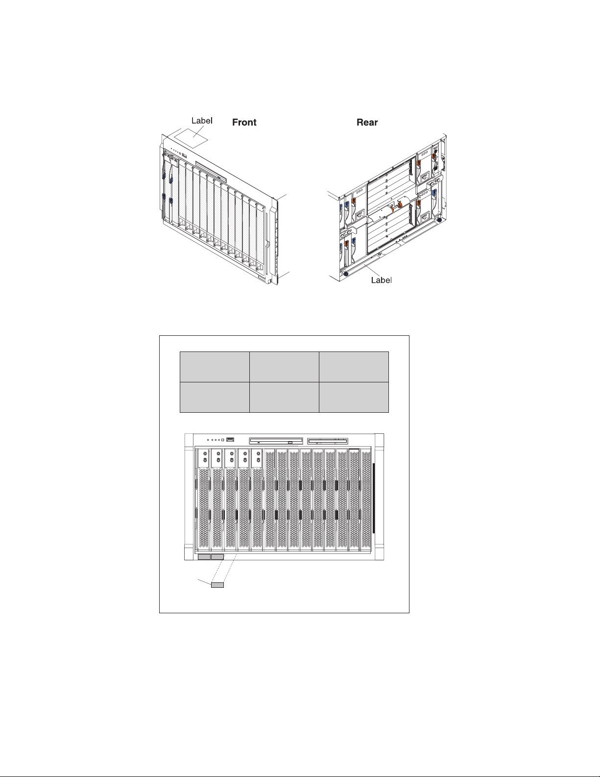
The serial number and model number are on labels on the top, front, and rear of
the chassis, as shown in the following illustration.
Note: The illustrations in this document might differ slightly from your hardware.
A set of user labels comes with each blade server. Write whatever identifying
information you want on a label, and place it on the BladeCenter bezel just below
the blade server, as shown in the following illustration.
User
label
Important: Do not place the label on the blade server itself or in any way block the
ventilation holes on the blade server.
2 BladeCenter E Type 8677 and 1881: Hardware Maintenance Manual and Troubleshooting Guide
Page 13

The IBM Documentation CD
Use the IBM Documentation CD to access the blade server documentation in PDF
format.
You can run the IBM Documentation CD on any personal computer that meets the
hardware and software requirements.
The IBM Documentation CD contains documentation for your blade server in
Portable Document Format (PDF) and includes the IBM Documentation Browser to
help you find information quickly.
Hardware and software requirements
Use this information to determine the minimum hardware and software requirements
for the blade server.
The IBM Documentation CD requires the following minimum hardware and
software:
v Microsoft Windows XP, Windows 2000, or Red Hat Enterprise Linux 5 Server
v 100 MHz microprocessor
v 32 MB of RAM
v Adobe Acrobat Reader 3.0 (or later) or xpdf, which comes with Linux operating
systems
Using the Documentation Browser
Use these instructions to start the Documentation Browser.
Use the Documentation Browser to browse the contents of the CD, read brief
descriptions of the documents, and view documents, using Adobe Acrobat Reader
or xpdf. The Documentation Browser automatically detects the regional settings in
use in your system and displays the documents in the language for that region (if
available). If a document is not available in the language for that region, the
English-language version is displayed.
Use one of the following procedures to start the Documentation Browser:
v If Autostart is enabled, insert the CD into the CD drive. The Documentation
Browser starts automatically.
v If Autostart is disabled or is not enabled for all users, use one of the following
procedures:
– If you are using a Windows operating system, insert the CD into the CD or
DVD drive and click Start → Run.IntheOpen field, type
e:\win32.bat
where e is the drive letter of the CD or DVD drive, and click OK.
– If you are using Red Hat Linux, insert the CD into the CD or DVD drive; then,
run the following command from the /mnt/cdrom directory:
sh runlinux.sh
Select your blade server from the Product menu. The Available Topics list
displays all the documents for your blade server. Some documents might be in
folders. A plus sign (+) indicates each folder or document that has additional
documents under it. Click the plus sign to display the additional documents.
Chapter 1. General information 3
Page 14

When you select a document, a description of the document is displayed under
Topic Description. To select more than one document, press and hold the Ctrl key
while you select the documents. Click View Book to view the selected document or
documents in Acrobat Reader or xpdf. If you selected more than one document, all
the selected documents are opened in Acrobat Reader or xpdf.
To search all the documents, type a word or word string in the Search field and
click Search. The documents in which the word or word string appears are listed in
order of the most occurrences. Click a document to view it, and press Crtl+F to use
the Acrobat search function, or press Alt+F to use the xpdf search function within
the document.
Click Help for detailed information about using the Documentation Browser.
Related publications
This Hardware Maintenance Manual and Troubleshooting Guide is provided in
Portable Document Format (PDF). It contains information to help you solve the
problem yourself or to provide helpful information to a service technician.
In addition to this Hardware Maintenance Manual and Troubleshooting Guide, the
following IBM BladeCenter Type 8677 Documentation is provided with the unit:
v Safety Information: This document contains translated caution and danger
statements. Each caution and danger statement that appears in the
documentation has a number that you can use to locate the corresponding
statement in your language in the Safety Information book.
v BladeCenter Type 8677 Rack Installation Instructions: This document contains
instructions for installing the BladeCenter unit in a rack.
v BladeCenter Management Module Installation Guide: This document contains
instructions for installing the management module in a BladeCenter unit and
creating the initial configuration. There is a unique Installation Guide for each
management module type.
v BladeCenter Management Module User’s Guide: This document provides general
information about the management module for your BladeCenter unit, including
information about features, how to configure the management module, and how
to get help. There is a unique User's Guide for each management module type.
v BladeCenter Management Module Command-Line Interface Reference Guide:
This document explains how to use the management-module command-line
interface to directly access BladeCenter management functions as an alternative
to using the Web-based user interface. The command-line interface also provides
access to the text-console command prompt on each blade server through a
serial over LAN (SOL) connection. There is a unique Command-Line Interface
Reference Guide for each management module type.
Additional publications might be included on the IBM BladeCenter E Type 8677
Documentation CD.
4 BladeCenter E Type 8677 and 1881: Hardware Maintenance Manual and Troubleshooting Guide
Page 15

Notices and statements used in this book
The caution and danger statements used in this book also appear in the multilingual
Safety Information book provided on the IBM BladeCenter Documentation CD. Each
caution and danger statement is numbered for easy reference to the corresponding
statements in the safety book.
The following types of notices and statements are used in this book:
v Note: These notices provide important tips, guidance, or advice.
v Important: These notices provide information or advice that might help you avoid
inconvenient or problem situations.
v Attention: These notices indicate possible damage to programs, devices, or
data. An attention notice is placed just before the instruction or situation in which
damage could occur.
v Caution: These statements indicate situations that can be potentially hazardous
to you. A caution statement is placed just before the description of a potentially
hazardous procedure step or situation.
v Danger: These statements indicate situations that can be potentially lethal or
extremely hazardous to you. A danger statement is placed just before the
description of a potentially lethal or extremely hazardous procedure step or
situation.
Features and specifications
Current BladeCenter E models do not have a diskette drive in the media tray. Older
BladeCenter E models do have a diskette drive in the media tray. A separate
features and specifications table is provided for each of these model types.
Notes:
1. For information about which types of I/O modules can be installed in which
I/O-module bays, see “I/O (switch) modules” on page 34.
2. The operating system in the blade server must provide USB support for the
blade server to recognize and use the keyboard, mouse, and optical drive. The
BladeCenter unit uses USB for internal communication with these devices.
Chapter 1. General information 5
Page 16

The following table provides a summary of the features and specifications for a
BladeCenter unit that does not have a diskette drive bay in the media tray.
Media tray (on front):
v SATA CD/DVD drive
v USB v2.0 port
v Front system LED panel
Module bays (on rear):
v Four hot-swap power-module bays
v Two hot-swap management-module
bays
v Four hot-swap I/O-module bays
v Two hot-swap blower bays
Blade-server bays (on front):
14 hot-swap blade-server bays
Redundant cooling:
Two variable-speed hot-swap blowers
Power modules:
v Minimum: Two 2000-watt or greater
hot-swap power modules
– Both power modules supply power
to all modules and to blade-server
bays 1 through 6.
– Both power modules provide
redundancy to each other.
v Maximum: Four
– Power modules 1 and 2 supply
power to all modules and to
blade-server bays 1 through 6.
– Power modules 3 and 4 supply
power to blade-server bays 7
through 14.
– Power modules 1 and 2 provide
redundancy to each other.
– Power modules 3 and 4 provide
redundancy to each other.
I/O modules:
v Minimum: One
v Maximum: Four
Management module:
v Minimum: One hot-swap advanced
management module providing the
following features:
– System-management functions for
the BladeCenter unit
– Video port (analog)
– Two USB ports for keyboard and
mouse
– Serial management connection
– 10/100 Mb Ethernet remote
management connection
v Maximum: Two hot-swap advanced
management modules: one active, one
redundant
Upgradeable microcode:
v Management-module firmware
v I/O-module firmware (some I/O module
types)
v Blade-server firmware
Security features:
v Login password for remote connection.
v Secure Socket Layer (SSL) security for
Web interface access, Secure Shell
(SSH) for remote command-line access,
and Lightweight Directory Access
Protocol (LDAP) and role-based security
for user authentication and
authorization.
Size (7 U):
v Height: 304.2 mm (12 in. or 7 U)
v Depth: 711.2 mm (28 in.)
v Width: 444 mm (17.5 in.)
v Weight:
– Fully configured with modules and
blade servers: Approximately 102 kg
(225 lb)
– Fully configured without modules and
blade servers: Approximately 38.6 kg
(85 lb)
Acoustical noise emissions:
v Without acoustic attenuation module: Sound
power, operating, and idle: 7.4 bels
v With acoustic attenuation module: Sound
power, idle, and operating: 6.9 bels
Environment:
v Air temperature:
– On:
- Altitude: 0 to 914 m (3000 ft) - 10° to
35°C (50° to 95°F)
- Altitude: 914 m to 2134 m (3000 ft to
7000 ft) - 10° to 32°C (50° to 89.6°F)
– Off: -40° to 60°C (-40° to 140°F).
v Humidity: 8% to 80%
Electrical input:
v Sine-wave input (50-60 Hz single-phase)
required
v Input voltage:
– Minimum: 200 V ac
– Maximum: 240 V ac
Heat output:
Approximate heat output in British thermal
units (Btu) per hour:
v Minimum configuration: 1365 Btu/hour (400
watts)
v Maximum configuration: Varies depending
on the type of power modules installed.
– Four 2000-watt power modules: 20 094
Btu/hour (5889 watts)
– Four 2320-watt power modules: 23 672
Btu/hour (6938 watts)
6 BladeCenter E Type 8677 and 1881: Hardware Maintenance Manual and Troubleshooting Guide
Page 17

The following table provides a summary of the features and specifications for a
BladeCenter unit that has a diskette drive bay in the media tray.
Media tray (on front):
v Diskette drive: 1.44 MB
v IDE CD or DVD
v USB v1.1 port
v Front system LED panel
Module bays (on rear):
v Four hot-swap power-module bays
v Two hot-swap management-module
bays
v Four hot-swap I/O-module bays
v Two hot-swap blower bays
Blade-server bays (on front):
14 hot-swap blade-server bays
Redundant cooling:
Two variable-speed hot-swap blowers
Power modules:
v Minimum: Two hot-swap power
modules
– Both power modules supply power
to all modules and to blade-server
bays 1 through 6.
– Both power modules provide
redundancy to each other.
v Maximum: Four
– Power modules 1 and 2 supply
power to all modules and to
blade-server bays 1 through 6.
– Power modules 3 and 4 supply
power to blade-server bays 7
through 14.
– Power modules 1 and 2 provide
redundancy to each other.
– Power modules 3 and 4 provide
redundancy to each other.
I/O modules:
v Minimum: One
v Maximum: Four
Management module:
v Minimum: One hot-swap management
module providing the following features:
– System-management functions for
the BladeCenter unit
– Video port (analog)
– Keyboard connection (PS/2 port or
USB port depending on the
management module-type)
– Mouse connection (PS/2 port or USB
port depending on the management
module type)
– Serial management connection
(advanced management module
only)
– 10/100 Mb Ethernet remote
management connection
v Maximum: Two hot-swap management
modules: one active, one redundant
Upgradeable microcode:
v Management-module firmware
v I/O-module firmware (some I/O module
types)
v Blade-server firmware
Security features:
v Login password for remote connection.
v Secure Socket Layer (SSL) security for
Web interface access, Secure Shell
(SSH) for remote command-line access,
and Lightweight Directory Access
Protocol (LDAP) and role-based security
for user authentication and
authorization.
Size (7 U):
v Height: 304.2 mm (12 in. or 7 U)
v Depth: 711.2 mm (28 in.)
v Width: 444 mm (17.5 in.)
v Weight:
– Fully configured with modules and
blade servers: Approximately 102 kg
(225 lb)
– Fully configured without modules and
blade servers: Approximately 38.6 kg
(85 lb)
Acoustical noise emissions:
v Without acoustic attenuation module: Sound
power, operating, and idle: 7.4 bels
v With acoustic attenuation module: Sound
power, idle, and operating: 6.9 bels
Environment:
v Air temperature:
– On:
- Altitude: 0 to 914 m (3000 ft) - 10° to
35°C (50° to 95°F)
- Altitude: 914 m to 2134 m (3000 ft to
7000 ft) - 10° to 32°C (50° to 89.6°F)
– Off: -40° to 60°C (-40° to 140°F).
v Humidity: 8% to 80%
Electrical input:
v Sine-wave input (50-60 Hz single-phase)
required
v Input voltage:
– Minimum: 200 V ac
– Maximum: 240 V ac
Heat output:
Approximate heat output in British thermal
units (Btu) per hour:
v Minimum configuration: 1365 Btu/hour (400
watts)
v Maximum configuration: Varies depending
on the type of power modules installed.
– Four 1200-watt power modules: 9622
Btu/hour (2820 watts)
– Four 1400-watt power modules: 11 111
Btu/hour (3256 watts)
– Four 1800-watt power modules: 13 650
Btu/hour (4000 watts)
– Four 2000-watt power modules (for use
with a Gigabit Ethernet expansion card):
18 425 Btu/hour (5400 watts)
Chapter 1. General information
7
Page 18
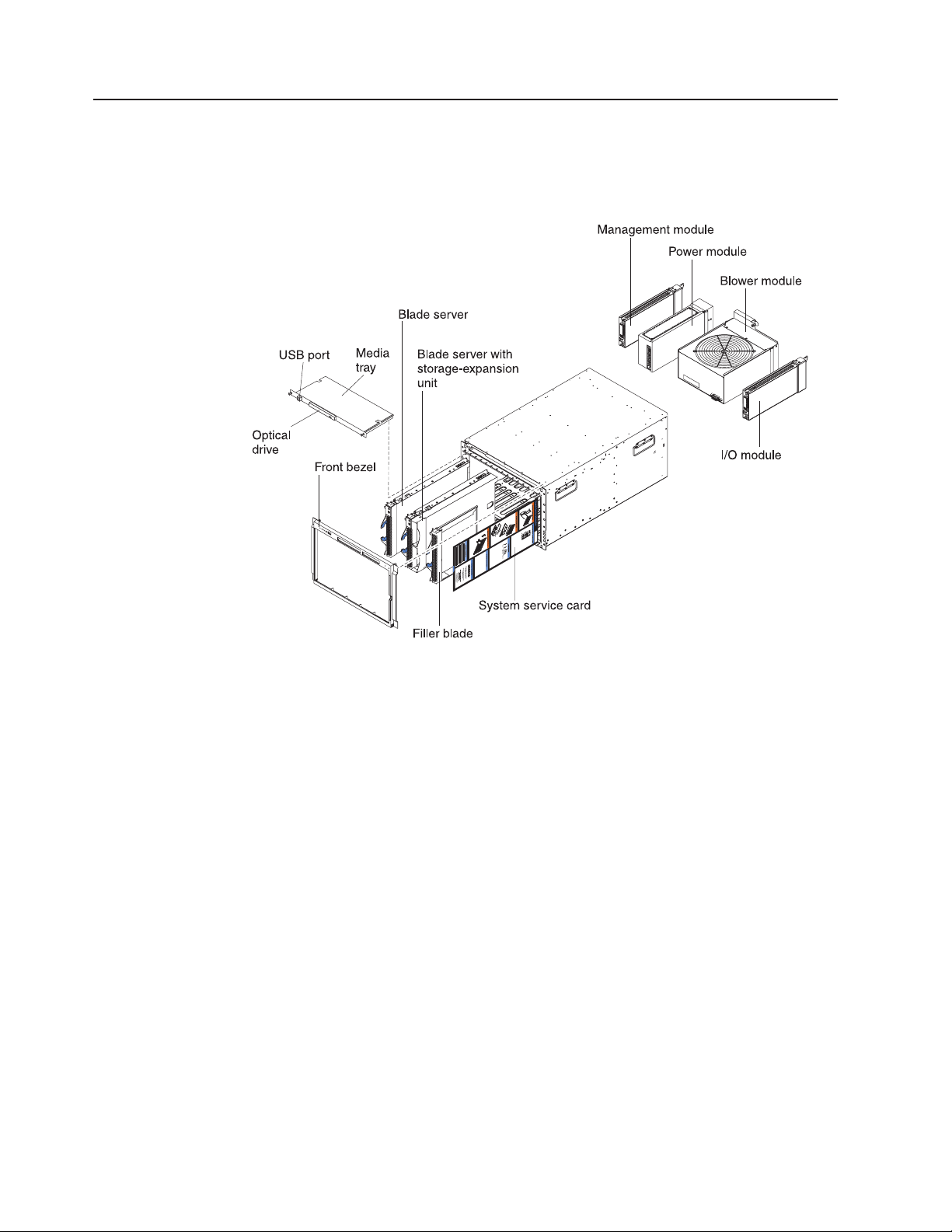
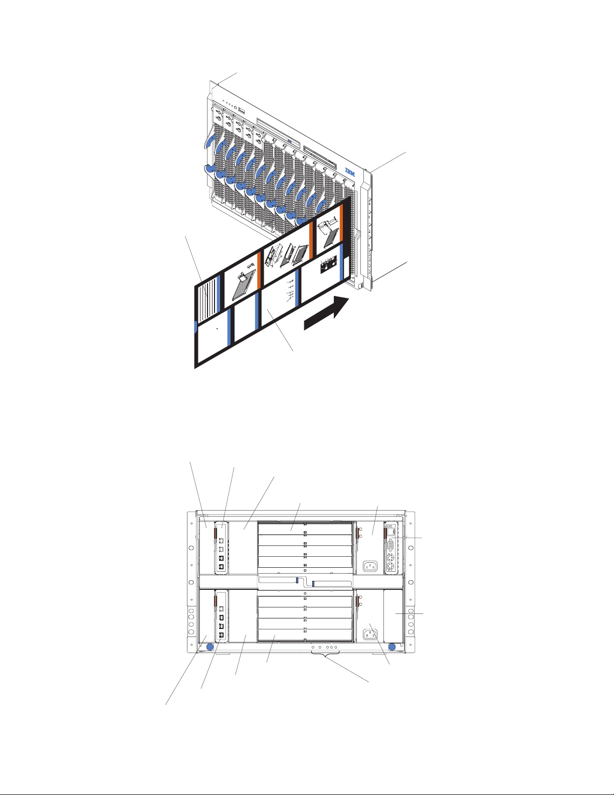
Major components of the BladeCenter Type 8677 and 1881 unit
The following illustration shows the locations of major components in your
BladeCenter unit.
Note: The illustrations in this document might differ slightly from your hardware.
Attention: To maintain proper system cooling, each module bay must contain
either a module or a filler module; each blade bay must contain either a blade
server or a filler blade.
8 BladeCenter E Type 8677 and 1881: Hardware Maintenance Manual and Troubleshooting Guide
Page 19
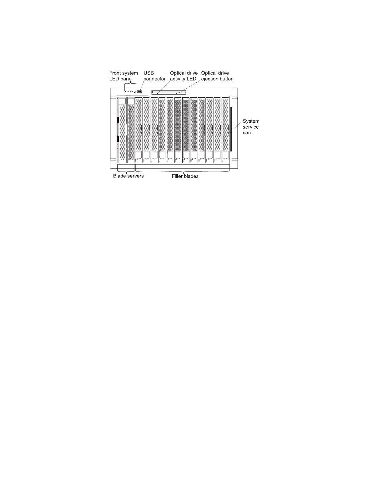
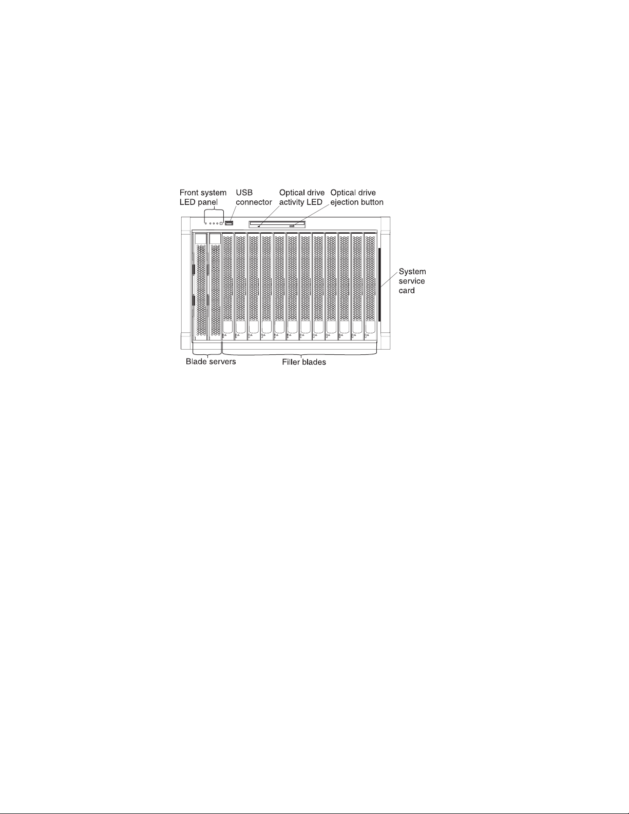
Front view
The following illustration shows the locations of components and indicators on the
front of the BladeCenter Type 8677 and 1881 unit.
See “BladeCenter components, controls, and LEDs” on page 13 for details about
these components and indicators.
Chapter 1. General information 9
Page 20
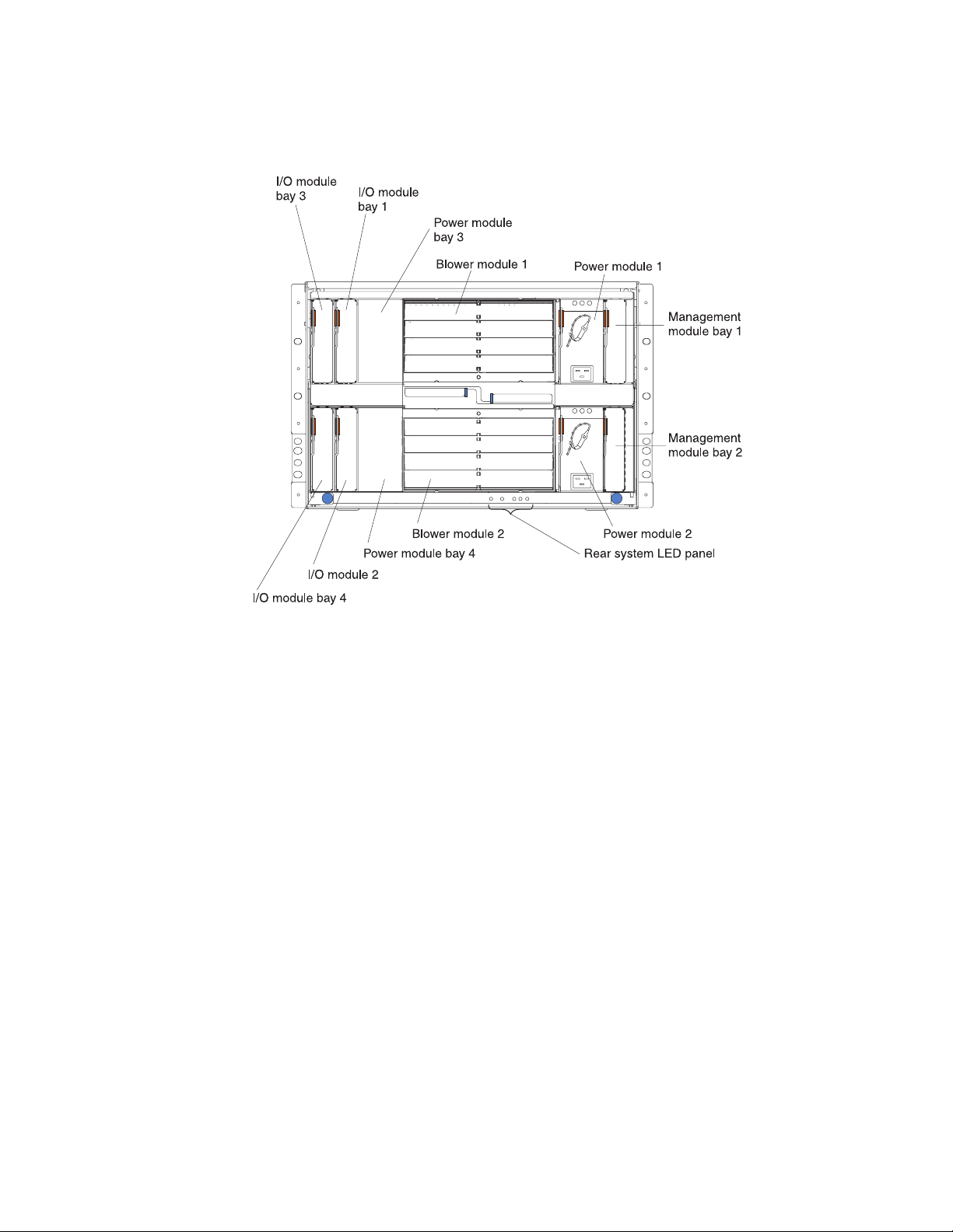
Rear view
The following illustration shows the locations of components and indicators on the
rear of the BladeCenter Type 8677 and 1881 unit.
See “BladeCenter components, controls, and LEDs” on page 13 for details about
these components and indicators.
10 BladeCenter E Type 8677 and 1881: Hardware Maintenance Manual and Troubleshooting Guide
Page 21

BladeCenter unit power, controls, and indicators
This section describes the controls and light-emitting diodes (LEDs) and how to
start and shut down the BladeCenter unit.
Notes:
1. The removable media drives, keyboard, and mouse in the BladeCenter unit are
viewed as USB devices by the blade server operating system.
2. Local media tray support can be turned off preventing the blade servers from
accessing the removable media drives.
3. Local KVM switching support can be turned off preventing the blade servers
form accessing the keyboard, video, and mouse.
Press keyboard keys in the following sequence to switch KVM control between
blade servers:
NumLock <blade server number> Enter
Where <blade server number> is the two-digit number for the blade bay in which
the blade server is installed.
You will need to press the Shift key to switch KVM control when using the 28L3644
(37L0888) keyboard. If pressing the Shift key does not switch KVM control,
complete the following steps:
1. Press and hold the Shift key.
2. Press keyboard keys in the following sequence:
NumLock <blade server number> Enter
3. Release the Shift key.
Starting the BladeCenter unit
Important: For the LEDs on each system LED panel to function correctly, be sure
to install the management module before turning on the BladeCenter unit. See
Chapter 4, “Installing options,” on page 31 for instructions for installing the
management module.
To start the BladeCenter unit, plug one end of each power cord into a power
module on the rear of the BladeCenter unit and the other end of each power cord
into a 220-volt power distribution unit (PDU) that is plugged into an appropriate
electrical outlet.
After you start the BladeCenter unit, it has dc power. The blade servers in the
BladeCenter unit are connected to dc power but are not turned on. Press the
power-control button on the front of each blade server to obtain full power for the
blade server and start its operating system (see the documentation that comes with
your blade server for information about turning on the blade server).
Note: If a power failure occurs, the BladeCenter unit restarts automatically when
power is restored.
Chapter 1. General information 11
Page 22
Shutting down the BladeCenter unit
You can shut down the BladeCenter unit by turning off the blade servers and
disconnecting the BladeCenter unit from the power source.
Complete the following steps to shut down the BladeCenter unit:
1. Refer to your blade server operating-system documentation for the proper
procedure to shut down the operating system in the blade servers; then, shut
down each operating system.
Statement 5:
CAUTION:
The power control button on the device and the power switch on the
power supply do not turn off the electrical current supplied to the device.
The device also might have more than one power cord. To remove all
electrical current from the device, ensure that all power cords are
disconnected from the power source.
2
1
2. Press the power-control button on the front of each blade server. Wait at least
30 seconds for the blade server drives to stop spinning.
3. Disconnect all power cords on the BladeCenter unit from all the power modules.
Note: After you disconnect the BladeCenter unit from power, wait at least 5
seconds before you connect the BladeCenter unit to power again.
12 BladeCenter E Type 8677 and 1881: Hardware Maintenance Manual and Troubleshooting Guide
Page 23
BladeCenter components, controls, and LEDs
This section identifies the components, controls, and LEDs on the front and rear of
your BladeCenter unit.
Note: The illustrations in this document might differ slightly from your hardware.
Front view
This section identifies the components, controls, and LEDs on the front of your
BladeCenter unit.
Front system LED panel: The LEDs on this panel provide status information for
your BladeCenter unit. See “System LED panel” on page 17 for more information.
USB port: Use this port to attach an external USB device.
Optical-drive activity LED: When this LED is lit, it indicates that the optical drive is
in use.
Optical-drive eject button: Press this button to release a CD or DVD from the
optical drive.
Diskette-drive activity LED (not shown in illustration): For media trays that have a
diskette drive, when this LED is lit, it indicates that the diskette drive is in use.
Diskette-drive eject button (not shown in illustration): For media trays that have a
diskette drive, press this button to release a diskette from the drive.
Blade control panel: This panel contains indicators and controls for the blade
server. See the documentation that comes with your blade server for information
about the blade control panel.
System service card: This card contains system service instructions and a writable
area for your use.
Chapter 1. General information 13
Page 24
Chassis Service Information
H
o
t-P
lu
g
P
r
o
c
e
s
s
o
Writeable
area
H
o
t-P
lu
g
M
e
d
ia
T
ra
H
o
t-S
w
a
p
H
a
r
d
D
is
k
D
riv
C
u
s
to
m
e
r In
fo
r
m
a
tio
n
D
h
p
o
ttp
ro
w
n
file
h
://w
lo
ttp
a
s
d
, a
w
://w
file
n
h
IB
w
d
ttp
s
.ib
M
fre
w
, h
w
://w
h
m
q
in
.ib
ttp
u
server x
.c
ts
e
w
&
n
o
m
://w
C
tly
w
m
tip
o
.c
.ib
m
a
/p
o
w
s
IB
p
s
S
m
c
, c
m
x
k
w
a
e
h
/s
M
e
tib
s
/e
r
.ib
re
.c
ttp
d
ie
e
S
u
q
ility
s
a
o
rie
s
p
m
e
e
te
://w
u
h
m
p
r
r
e
in
ve
.c
c
s
IB
o
v
o
/p
s
/s
m
u
e
o
r
tio
rG
f
M
w
o
c
s
t
r/x
e
m
e
r
to
S
/u
n
w
p
u
m
r
s
/p
id
m
v
s
.ib
e
a
s
a
e
r
e
e
g
c
/c
tio
ve
r
h
e
r
m
/w
g
ie
o
n
r h
o
u
.c
m
w
m
s
id
o
o
p
/e
e
m
e
m
p
a
s
e
t/
a
/s
e
p
g
r
e
e
a
v
r
g
e
v
e
r/
e
r
s
e
s
C
o
m
m
o
n
C
h
a
s
s
is
F
F
o
R
r M
U
s
o
r
e
In
fo
r
m
a
tio
n
y
O
p
Powe
e
ra
r-o
n
to
L
o
c
r P
a
tio
O
n
v
a
e
r-te
n
e
m
In
p
l
f
e
o
r
r
a
m
tu
a
re
tio
n
S
y
s
te
m
e
rro
r
r B
la
d
e
P
r
o
c
e
s
s
o
r B
la
C
d
D
e
O
p
e
ra
to
r P
a
n
e
l
System service card
Rear view
This section identifies the components and indicators on the rear of your
BladeCenter unit.
Switch module
bay 3
Switch module 1
Power module
bay 3
Blower module 1
Blower module 2
Power module bay 4
Power module 1
AC
DC
AC
DC
Power module 2
Rear system LED panel
Switch module 2
Switch module bay 4
14 BladeCenter E Type 8677 and 1881: Hardware Maintenance Manual and Troubleshooting Guide
Management
module
Reserved
Page 25
Rear system LED panel: The LEDs on this panel provide status information for
your BladeCenter unit. These LEDs duplicate the LEDs in the front system LED
panel, see “System LED panel” on page 17 for more information about these LEDs.
Blower module:
Blower error
LEDs
Important: If the ambient temperature is 72° F or below, the BladeCenter blowers
will run at 30% of their maximum rotational speed, increasing their speed as
required to control internal BladeCenter temperature. If ambient temperature is
above 72° F, the blowers will run at 80% of their maximum rotational speed
increasing their speed as required to control internal BladeCenter temperature.
Blower error LEDs: The amber LED on each blower is lit and stays lit when an
error has been detected in the blower. The system-error LED on the BladeCenter
system LED panels is also lit. For additional information, see “Identifying problems
using the Light Path Diagnostics feature” on page 29.
I/O (switch) module: See the documentation that comes with each I/O module for
a description of the LEDs on the I/O module.
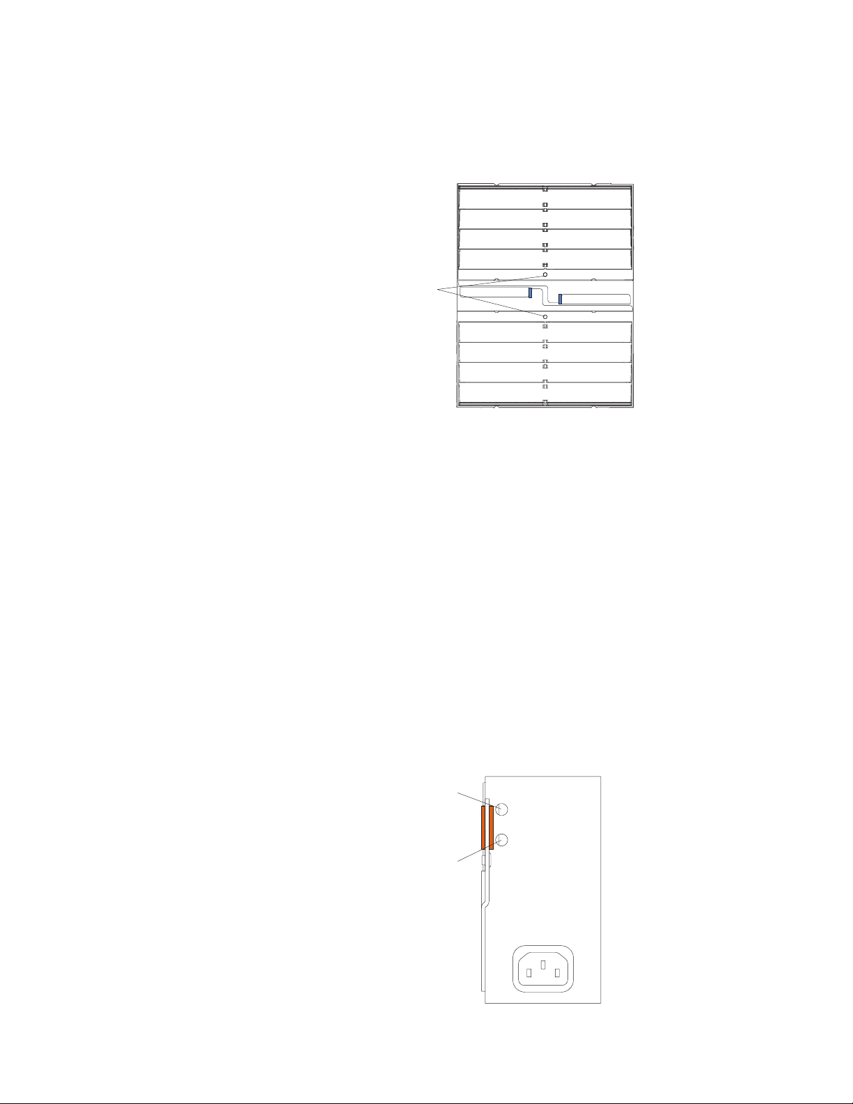
Power module: Several types of power module, with different wattage ratings, can
be used in the BladeCenter E unit.
The following illustration shows the rear view for older power modules.
Note: The illustrations might differ slightly from your hardware.
AC power
AC
DC
DC power
Chapter 1. General information 15
Page 26
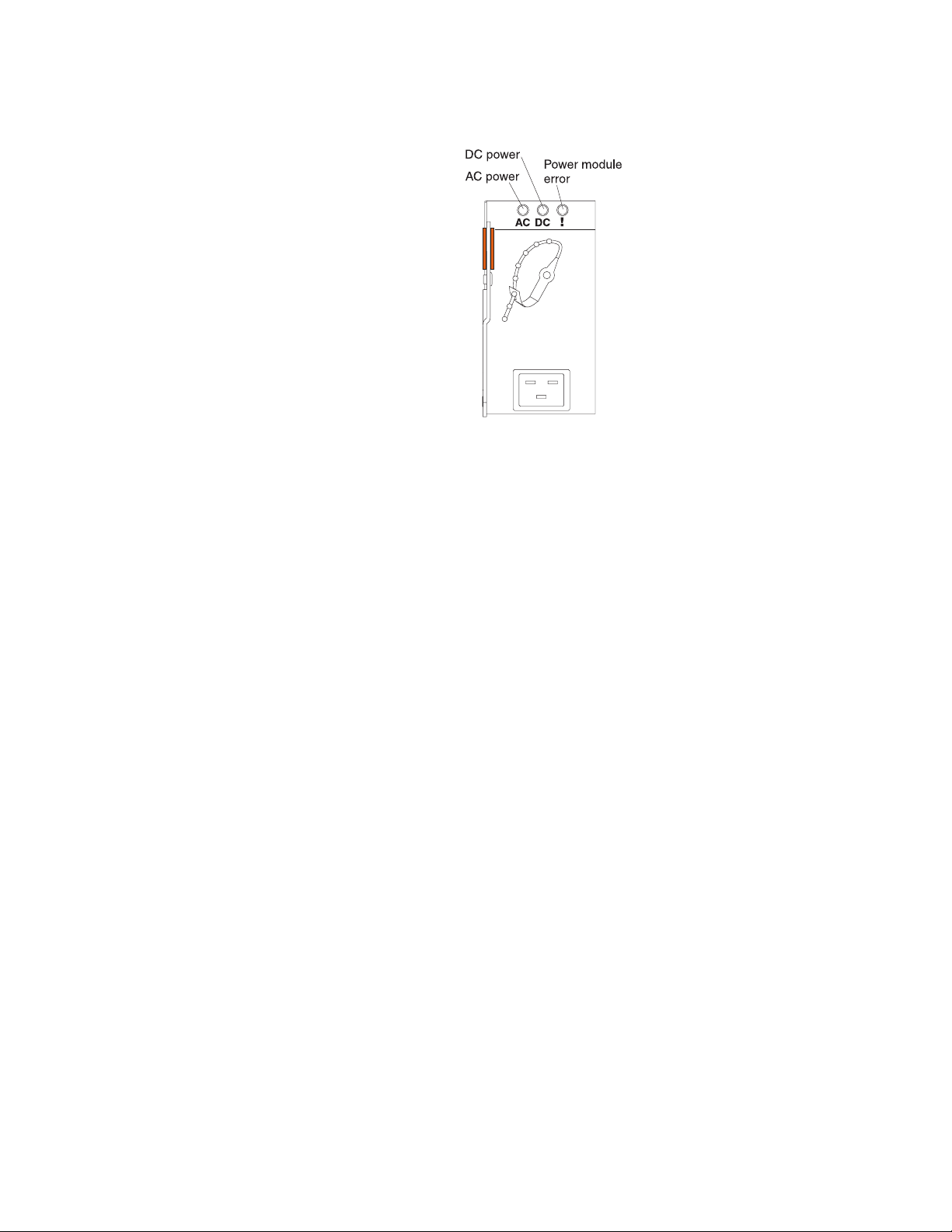
The following illustration shows the rear view for the currently available power
modules.
Power module LEDs: These LEDs indicate the condition of the power module. For
additional information, see “Identifying problems using the Light Path Diagnostics
feature” on page 29.
v AC power: When this green LED is lit, ac input to the power module is present
and within specifications. During typical operation, both the ac and dc power
LEDs are lit. For any other combination of LEDs, see “Identifying problems using
the Light Path Diagnostics feature” on page 29.
v DC power: When this green LED is lit, the dc output from the power module to
the other components and blade servers is present and within specifications.
During typical operation, both the ac and dc power LEDs are lit. For any other
combination of LEDs, see “Identifying problems using the Light Path Diagnostics
feature” on page 29.
v Power module error LED (2320-watt power modules only): When this amber
LED is lit, it indicates that an error has been detected in the power module.
When this LED is lit, the BladeCenter unit system error LED is also lit.
Management module: The type of management module that is installed in your
BladeCenter unit depends on the BladeCenter unit model and devices that are
installed.
v A BladeCenter unit that has a media tray with a diskette drive can use either a
management module or an advanced management module, depending on which
devices are installed in the BladeCenter unit.
v A BladeCenter unit that has a media tray without a diskette drive must use an
advanced management module.
v If 2320-watt power modules are installed in the BladeCenter unit, you must use
an advanced management module.
v See the documentation that comes with your BladeCenter device to determine if
a specific management module type is required to support the device.
See the documentation for your management module for additional information and
instructions.
16 BladeCenter E Type 8677 and 1881: Hardware Maintenance Manual and Troubleshooting Guide
Page 27

System LED panel
The following illustration shows the status LEDs on the system LED panels on the
front and rear of the BladeCenter unit.
Power-on
Location
Over-temperature
Information
System error
Attention: If the power-on LED is off, it does not mean there is no electrical
current present in the BladeCenter unit. The LED might be burned out. To remove
all electrical current from the BladeCenter unit, you must unplug all power cords
from all power modules.
Note: You can turn off the location LED and the information LED through the Web
interface or the IBM Director console.
Power-on: When this green LED is lit, power is present in the BladeCenter unit.
When this LED is off, the power subsystem, the ac power, or the LED has
failed, or the management module is not present or not functioning.
Location: When this blue LED is lit or flashing, it has been turned on by the
system administrator to aid in visually locating the BladeCenter unit. If a blade
server requires attention, the location LED on the blade server usually will also
be lit. After the BladeCenter unit has been located, you can have the system
administrator turn off the location LED.
Over-temperature: When this amber LED is lit, the temperature in the
BladeCenter unit exceeds the temperature limits, or a blade server has reported
an over-temperature condition. The BladeCenter unit might have already taken
corrective action, such as increasing the blower speed. This LED turns off
automatically when there is no longer an over-temperature condition.
Information: When this amber LED is lit, a noncritical event has occurred that
requires attention, such as the wrong I/O module inserted in a bay or power
demands that exceed the capacity of power modules currently installed. The
event is recorded in the event log. Check the LEDs on the BladeCenter unit and
the blade servers to isolate the component. After the situation is handled, have
the system administrator turn off the information LED.
Note: The information LED will also light if the system error log is 75% full.
System-error: When this amber LED is lit, it indicates that a system error has
occurred, such as a failed module or a system error in a blade server. An LED
on one of the components or on a blade server is also lit to further isolate the
error. (For more information, see “Identifying problems using the Light Path
Diagnostics feature” on page 29.)
Setting up the BladeCenter unit
This section briefly discusses considerations for the setup of your BladeCenter unit.
v Blade bays must be occupied at all times.
To help ensure proper cooling, performance, and system reliability, make sure
that each of the blade bays on the front of the BladeCenter unit has a blade
server, expansion unit, or filler blade installed.
Important: When replacing a blade server or installing an expansion option, do
not operate the BladeCenter unit for more than one minute without either a blade
server, an expansion option, or a filler blade installed in each blade bay.
Chapter 1. General information 17
Page 28

v Module bays must be occupied at all times.
To help ensure proper cooling, performance, and system reliability, make sure
that each of the module bays on the rear of the BladeCenter unit has a module
or filler module installed.
Important: When replacing a module, do not operate the BladeCenter unit for
more than one minute without either a module or a filler module installed in each
module bay.
v There is no power switch on the BladeCenter unit.
The BladeCenter unit does not have a power switch. Plugging the power cords
into the power modules and a 220 V ac power source (rack-mounted 220-volt
PDU) starts the BladeCenter unit (the management module, I/O modules, and
blowers start running).
Each blade server in the BladeCenter unit has an individual power-control button
behind the control-panel door on the blade front that turns on or turns off the
blade server. Be sure to shut down the operating system before turning off the
blade server, to avoid damaging the hard disk drives.
Notes:
1. The blade server power button turns on or turns off the blade server if local
power control has not been disabled through the management module.
2. The blade server power button turns on the blade server only if the green
power light on the blade server is flashing slowly. If the light flashes rapidly,
the blade server has not yet synchronized with the management module, and
the power button will have no effect.
See the IBM BladeCenter Type 8677 Installation and User’s Guide for more
information about the BladeCenter unit. See the Installation and User’s Guide for
your blade server for more information about the blade server power controls and
turning on or turning off the blade server.
v The removable media drives are detected as a Universal Serial Bus (USB)
device
The removable media drives in the BladeCenter unit are viewed as a USB
devices by the operating system in the blade server. Make sure that your
operating system provides USB support.
v Hot-swap capabilities
The front bays on the BladeCenter unit are hot-swap blade bays; the rear bays
on the BladeCenter unit are hot-swap module bays. You can add, remove, or
replace blade servers or management, I/O, power, or blower modules in
hot-swap bays without removing power from the BladeCenter unit.
Attention: To maintain proper system cooling, each unoccupied bay must
contain a filler blade and an expansion or filler module. When replacing a blade
server or installing an expansion option, do not operate the BladeCenter unit for
more than one minute without either a blade server, an expansion option, or a
filler blade installed in each blade bay or without a module or filler installed in
each rear bay.
18 BladeCenter E Type 8677 and 1881: Hardware Maintenance Manual and Troubleshooting Guide
Page 29

Connecting to the default IP address on a new BladeCenter
A newly-installed (out-of-the-box) BladeCenter unit tries to locate a DHCP server on
the network before it will default to the factory-configured static IP address in the
management module. This is the initial configuration setting. When there is no
DHCP server on the network the BladeCenter unit is connected to, it can take
several minutes before the management module uses the default (static) IP
address. When the DHCP search times out and the management module uses the
static IP address, you can change the management module configuration so that it
will not attempt to locate a DHCP server.
See the Installation Guide and User's Guide or Command-Line Interface Reference
Guide for your management module type for information about connecting to and
configuring the BladeCenter management module.
Registering and profiling the BladeCenter products
You can register and profile the BladeCenter unit and blade servers on the World
Wide Web.
v To register, go to: http://www.ibm.com/support/mysupport/
v To profile, go to: http://www.ibm.com/systems/support/
Important:
1. Do not switch control of a shared removable media drive to another blade
server until the activity lights on the drive is off, indicating that no read or write
operations are in progress. Before you remove a hot-swap blade server from
the BladeCenter unit, you must shut down the operating system and turn off the
blade server. You do not have to shut down the BladeCenter unit itself.
2. It can take approximately 20 seconds for the operating system in the
switched-to blade server to recognize the removable media drives and USB port
or the keyboard, video, and mouse.
a. The system-error LED might light, and a KVM allocation error might be
logged if the change in ownership for the removable media drives and USB
port or the keyboard, video, and mouse takes more than 8 seconds. The
system-error LED will go off after the ownership change is complete.
b. It can take up to 48 seconds after a blade server is initially turned on before
you can attempt to switch KVM control to that blade server.
Chapter 1. General information 19
Page 30

20 BladeCenter E Type 8677 and 1881: Hardware Maintenance Manual and Troubleshooting Guide
Page 31

Chapter 2. Configuring your BladeCenter unit
The BladeCenter unit automatically detects the modules and blade servers that are
installed and stores the vital product data (VPD) information. When the BladeCenter
unit is started, it automatically configures the remote-management port on the
management module, so that you can configure and manage the BladeCenter unit
and blade servers. You configure and manage the BladeCenter unit remotely
through the management module using the Web-based user interface.
Note: You can also configure the I/O modules directly through an external
I/O-module port using a Telnet interface or a Web browser. See the documentation
that comes with the I/O module for more information.
For the management module to communicate with the blade servers in the
BladeCenter unit, you will need to configure the IP addresses for the following
internal and external ports:
v The external Ethernet (remote management) port on the management module
(see the User's Guide or Command-Line Interface Reference Guide for your
management module type for instructions). The initial management-module
autoconfiguration enables the network-management station to connect to the
management module to configure the port completely and to configure the rest of
the BladeCenter unit.
v The internal Ethernet port on the management module for communication with
the I/O modules (see the User's Guide or Command-Line Interface Reference
Guide for your management module type for instructions).
v The internal Ethernet management port on each I/O module for communication
with the management module. You configure this port by configuring the IP
address for the I/O module (see the User's Guide or Command-Line Interface
Reference Guide for your management module type for instructions).
Note: Pass-thru modules have no internal Ethernet port.
To communicate with the blade servers for functions such as deploying an operating
system or application program, you also will need to configure at least one external
(in-band) port on an Ethernet switch module. See the BladeCenter Management
Module User’s Guide or the BladeCenter Management Module Command-Line
Interface Reference Guide for information about configuring external ports on I/O
modules.
Note: If a pass-thru module is installed in I/O-module bay 1 or 2 (instead of an
Ethernet switch module), you will need to configure a port on the network switch to
which the pass-thru module is connected.
Management module and advanced management modules support different types
of remote access. See the documentation for your management module type for
information and instructions.
The Web-based user interface and command-line interface communicate with the
management and configuration programs that are part of the firmware that comes
with the management module. You can use these programs to perform tasks such
as:
v Defining the login IDs and passwords
v Selecting recipients for alert notification of specific events
© Copyright IBM Corp. 2011 21
Page 32

v Monitoring the status of the BladeCenter unit and blade servers
v Controlling the BladeCenter unit and blade servers
v Accessing the I/O modules to configure them
v Changing the drive startup sequence in a blade server
v Setting the date and time
v Using a remote console for the blade servers
v Changing ownership of the keyboard, video, and mouse
v Changing ownership of the optical drive, and USB port. (The optical drive in the
BladeCenter unit is viewed as a USB device by the blade server operating
system.)
Note: The IBM Director program is a system-management tool that comes with the
BladeCenter unit. To configure the remote alert recipients for IBM Director over
LAN, the remote alert recipient must be an IBM Director-enabled server.
You also can use the management and configuration programs to view some of the
blade server configuration settings. See the User's Guide or Command-Line
Interface Reference Guide for your management module type for more information.
BladeCenter unit power requirement
The power supply modules in the BladeCenter unit must be connected to 220 V ac
power only. The BladeCenter unit comes with two power cords to connect the
BladeCenter unit to the power distribution unit (PDU).
BladeCenter power configuration
The power modules in power bays 1 and 2 provide power to blade bays 1 through
6 and to common components in the BladeCenter unit. The power modules in
power bays 3 and 4 provide power to blade bays 7 through 14. Power modules
must always be present in power bays 1 and 2.
Attention:
Non-redundant power is not supported by the BladeCenter E unit. Power modules
must always be present in power bays 1 and 2. When any blade server or option is
in blade bay 7 through 14, power modules must be present in power bays 1 and 2,
and power modules must be present in power bays 3 and 4.
If a power module fails or an ac power failure occurs, a BladeCenter unit configured
for redundant power operation will operate in a nonredundant mode, and the blower
modules will run at full speed. You must replace the failing power module or restore
ac power as soon as possible to regain redundant power operation and to reset the
blower modules to their normal operating speed.
See the IBM BladeCenter Power Supply Modules option documentation and the
BladeCenter Type 8677 Installation and User’s Guide for more information.
Firmware updates
The firmware for the management module and other BladeCenter components is
periodically updated and is available for download on the Web. Go to
http://www.ibm.com/support/ to get the latest level of firmware, such as BIOS code
and device drivers.
22 BladeCenter E Type 8677 and 1881: Hardware Maintenance Manual and Troubleshooting Guide
Page 33

Important: Some cluster solutions require specific code levels or coordinated code
updates. If the device is part of a cluster solution, verify that the latest level of code
is supported for the cluster solution before you update the code.
Note: When replacing BladeCenter components, you might have to update the
management module or other components with the latest version of firmware.
Configuring the BladeCenter unit
General configuration of the BladeCenter unit and installed components is
performed through the management module. See the BladeCenter Management
Module User’s Guide and the BladeCenter Management Module Command-Line
Interface Reference Guide for information and instructions. Some devices in the
BladeCenter unit, such as I/O modules and blade servers, might also require
additional configuration. See the documentation that comes with each device for
information and instructions.
Configuring the management module
All management modules are preconfigured with the same static IP address. You
can use the management module to assign a new static IP address. To establish
connectivity, the management module attempts to use Dynamic Host Control
Protocol (DHCP) to acquire its initial IP address for the management-module
Ethernet port. If DHCP is not installed or is enabled and fails, the management
module uses the static IP address. Use the management module to configure other
BladeCenter component settings such as user accounts, DHCP, or Wake on LAN.
See the BladeCenter Management Module User’s Guide and the BladeCenter
Management Module Command-Line Interface Reference Guide for instructions.
Communicating with the IBM Director software
Notes:
1. See the illustration on page 27 for an example of a typical network
configuration. See the IBM BladeCenter Planning and Installation Guide for
more examples of network configurations. You can obtain the planning guide
from http://www.ibm.com/systems/support/.
2. The IBM Director CD comes with the BladeCenter unit.
To communicate with the BladeCenter unit, the IBM Director software needs a
managed object (in the Group Contents pane of the IBM Director Management
Console main window) that represents the BladeCenter unit. If the BladeCenter
management module IP address is known, the network administrator can create an
IBM Director managed object for the unit. If the IP address is not known, the IBM
Director software can automatically discover the BladeCenter unit (out-of-band,
using the Ethernet port on the BladeCenter management module) and create a
managed object for the unit.
For the IBM Director software to discover the BladeCenter unit, your network must
initially provide connectivity from the IBM Director server to the BladeCenter
management-module Ethernet port. To establish connectivity, the management
module attempts to use DHCP to acquire its initial IP address for the Ethernet port.
If the DHCP request fails, the management module uses a static IP address.
Therefore, the DHCP server (if used) must be on the management LAN for your
BladeCenter unit.
Chapter 2. Configuring your BladeCenter unit 23
Page 34

Notes:
1. All management modules are preconfigured with the same static IP address.
You can use the management-module Web interface or command-line interface
to assign a new static IP address for each BladeCenter unit. If DHCP is not
used and you do not assign a new static IP address for each BladeCenter unit
before attempting to communicate with the IBM Director software, only one
BladeCenter unit at a time can be added to the network for discovery. Adding
multiple units to the network without a unique IP address assignment for each
BladeCenter unit results in IP address conflicts.
2. For I/O-module communication with the IBM Director server through the
management-module external Ethernet port, the I/O module internal network
interface and the management-module internal and external interfaces must be
on the same subnet.
Configuring I/O modules
You must install and configure at least one external (in-band) port on an Ethernet
switch module in I/O-module bay 1 to communicate with the Ethernet controllers
that are integrated in each blade server. See the BladeCenter Management Module
User’s Guide and the BladeCenter Management Module Command-Line Interface
Reference Guide for information about configuring external ports on I/O modules.
For I/O-device settings, see the documentation that comes with your I/O device.
See “I/O (switch) modules” on page 34 for information about the location and
purpose of each I/O module.
Notes:
1. If a pass-thru module is installed in I/O-module bay 1, you must configure the
network switch that the pass-thru module is connected to; see the
documentation that comes with the network switch.
2. You can set up Ethernet failover by installing an Ethernet switch module in
I/O-module bay 2.
Configuring blade servers
To achieve communication redundancy on a blade server, you must configure the
Ethernet controllers on the blade servers for failover. When failover occurs on a
blade server, the secondary Ethernet controller takes over network communications,
using the I/O module that is associated with that controller. Install a pair of Ethernet
switches in I/O-module bays 1 and 2; then, configure them and your network
infrastructure so that they can direct traffic to the same destinations. You can also
install a pass-thru module that is connected to an external Ethernet switch in either
or both of these I/O-module bays. See the documentation that comes with your
blade server and operating system for instructions.
Using IBM Director
The IBM Director program is a system-management product that comes with the
BladeCenter unit. Through the remote connection on the management module, you
can use the IBM Director software at the IBM Director console to configure the
BladeCenter unit, modify the configuration, and set up more advanced features.
Notes:
1. Some tasks, such as software distribution, require an in-band connection from
the Director server through a campus (public) LAN to an I/O module port.
2. To manage BladeCenter redundant management modules with the IBM Director
software, IBM Director version 4.1.01 or greater is required.
24 BladeCenter E Type 8677 and 1881: Hardware Maintenance Manual and Troubleshooting Guide
Page 35

The IBM Director software includes the IBM BladeCenter Deployment Wizard.
About the wizard
The BladeCenter Deployment Wizard is integrated into the IBM Director
management software. The wizard walks you through initial startup and
configuration of one or more BladeCenter units.
In addition to performing initial configuration on BladeCenter units, you can use the
built-in IBM Director tasks in the wizard to modify the configuration and to set up
more advanced features.
You can also create a reusable profile in the wizard for configuring or reconfiguring
BladeCenter units. The profile is a noninteractive script that can run as scheduled
or as part of an Event Action Plan. With this feature you can define policies to
reconfigure a BladeCenter unit on demand, responding to hardware failures or other
IBM Director events.
Specifically, you can use the BladeCenter Deployment wizard to perform the
following tasks:
v Perform all initial network configuration, including configuring IP addresses for the
v Set up the initial security profile for the BladeCenter unit, including user names,
v Optionally configure external switch module ports for multi-port link aggregation
management module and the I/O-module internal configuration ports.
passwords, enablement or disablement of management services, and so forth.
(trunking).
Starting the wizard
Start the wizard from the IBM Director Management Console on the Director server.
1. Select one or more BladeCenter units from the middle (contents) pane of the
console window.
Note: A lock icon beside a newly discovered BladeCenter unit indicates that the
Director server cannot log into the management module for that BladeCenter
unit, which can mean that the management module has not been configured
yet. You might want to select that BladeCenter unit for initial configuration
through the wizard.
2. Perform either of the following actions:
v Right-click the selected BladeCenter units (managed objects).
v Drag the wizard task from the right-most pane (under BladeCenter in the task
The wizard starts, and guides you through the login and configuration tasks
needed.
The following illustration shows the main window on the BladeCenter Deployment
wizard.
list) to any of the selected BladeCenter units (managed objects).
Chapter 2. Configuring your BladeCenter unit 25
Page 36

Using Remote Deployment Manager Version 4.1 or later
You can use the Remote Deployment Manager (RDM) Version 4.1 (or later)
program to install a supported Microsoft Windows operating system or a BIOS
update onto a blade server. Follow the instructions in the documentation that comes
with the RDM program to log into the BladeCenter system and install a supported
Microsoft Windows operating system or BIOS update.
Go to http://www-03.ibm.com/systems/management/director/about/director52/
extensions/rdm.html on the World Wide Web for updated information about the
RDM program and to download the software:
BladeCenter networking guidelines
Your networking administrator should assist in the configuration of the network
infrastructure prior to connecting the BladeCenter unit to the LAN switch or similar
network device. This section provides additional guidelines that might be useful in
setting up your system.
A BladeCenter chassis with two Ethernet switch modules and one management
module has the following internal configuration:
26 BladeCenter E Type 8677 and 1881: Hardware Maintenance Manual and Troubleshooting Guide
Page 37

1 Gbps links
1 Gbps or
100 Mbps links
Switch A
1234
MAC MAC MAC
1a 2a 3a
1b 2b 3b
Note: 2nd switch module is optional
5678910
1 Gbps links
11 121314
Mgmt
Mod
Switch B
10/100 Mbps
100 Mbps
links
Each blade server has two independent Ethernet controllers, each with its own
MAC address and a dedicated 1000-Mbps link to one of the I/O modules (Controller
1 to Switch A and Controller 2 to Switch B in this diagram). In this configuration (the
default), the blade servers share access to four external ports on each I/O module.
There is no internal data path between the two switches within the BladeCenter
chassis; an external network device is required for data packets to flow from one
internal switch to the other.
The management module has a separate internal 100-Mbps link to each switch.
These links are for internal management and control only. No data packets are
allowed to flow from application programs on the blade servers to the management
module over this path. A separate, nonswitched path (not shown) is used for
communication between the management module and a service processor on each
blade server.
A typical, preferred BladeCenter network topology is shown in the following
illustration. See the IBM BladeCenter Planning and Installation Guide for more
information and other topologies and guidelines.
Chapter 2. Configuring your BladeCenter unit 27
Page 38

1234
1234
5678910
5678910
11 121314
11 121314
Switch A
Mgmt
Mod
Switch B
Switch A
Mgmt
Mod
Multiport aggregation group
1 Gbps or 100 Mbps links
L2 Switch
10/100 Mbps
management
links
IBM Director
- Chassis management
- Application deployment
L2+ Switch
- Internal switches
Dual
external
switches
Establishment
backbone
1234
5678910
11 121314
Switch B
Switch A
Mgmt
Mod
L2+ Switch
Network administrator
- Infrastructure
management
Switch B
- Network hardware
and software
In this configuration, each BladeCenter unit contains two Ethernet switch modules
and one management module. The external ports on the switch modules are
configured for multi-port link aggregation groups, or trunks, as are the
corresponding ports on the attaching external LAN switches. Additionally, every port
in the switch module in I/O-module bay 1 (switch A in this illustration) in the
BladeCenter units is connected to the same external LAN switch and every port in
the switch module in I/O-module bay 2 (switch B in this illustration) in the
BladeCenter units is connected to the second external LAN switch.
Observe the following guidelines when creating this topology:
1. The external ports on the BladeCenter switch modules are designed for
point-to-point, full-duplex operation to a compatible LAN switch or router.
Configure a corresponding multi-port link aggregation group, or trunk, in both
the switch module and the attaching LAN switch prior to installing the cables.
The connection options are as follows, in order of preference:
v Multi-port Link Aggregation Group or Trunk, 1 Gbps (1000 Mbps) per port
v Single-uplink port, 1 Gbps
v Multi-port Link Aggregation Group or Trunk, 100 Mbps per port
2. Connect the management module 10/100 Mbps Ethernet port to a separate
Layer 2 network if possible, for the best security. If a separate network is not
available, you can attach the Ethernet ports of the management module and
switch modules to the same Layer 2 network.
3. Avoid network configurations that could lead to data loops, if possible. Loops
will be created if you connect multiple ports from the same switch module to the
same Layer 2 network device without first enabling link aggregation. If you
implement configurations that include data loops, it is essential that you enable
Spanning Tree Protocol on the I/O module external ports.
28 BladeCenter E Type 8677 and 1881: Hardware Maintenance Manual and Troubleshooting Guide
Page 39

Chapter 3. Diagnostics
This section provides basic troubleshooting information to help you resolve some
common problems that might occur with your BladeCenter unit.
If you cannot locate and correct the problem using the information in this section,
see Appendix A, “Getting help and technical assistance,” on page 85 for more
information.
Diagnostic tools overview
The following tools are available to help you identify and solve hardware-related
problems:
v Troubleshooting charts
These charts list problem symptoms and steps to correct the problems. See the
Chapter 6, “Symptom-to-FRU index,” on page 59 for more information.
v Diagnostic programs and error messages
The built-in self-test (BIST) program checks the BladeCenter unit during startup
and generates error messages if problems are found.
The system diagnostic program, Real Time Diagnostics Version 1.3, tests the
major components of your BladeCenter unit. The Real Time Diagnostics software
is available from the IBM Support Web site at http://www.ibm.com/systems/
support. It is run from the IBM Director Management Console window (under the
BladeCenter task in the Task panel).
To obtain the Real Time Diagnostics program, go to the following Web site:
http://www.ibm.com/systems/support.
1. Select Servers from the list at the left of the window.
2. Select Downloadable files from the list at the left of the window.
3. In the Downloadable files by category list, select Diagnostic.
4. Click the entry for Real Time Diagnostics and follow the instructions on that
page.
v Light Path Diagnostics feature
Use the Light Path Diagnostics feature to identify system errors quickly. On the
BladeCenter unit, the Light Path Diagnostics feature consists of the LEDs on the
front and rear of the BladeCenter unit and on the front of the modules and blade
servers.
Identifying problems using the Light Path Diagnostics feature
If the system-error LED on the system LED panel on the front or rear of the
BladeCenter unit is lit, one or more error LEDs on the BladeCenter components
also might be on. These LEDs help identify the cause of the problem.
This section provides the information to identify problems that might arise during
installation using the Light Path Diagnostics feature.
© Copyright IBM Corp. 2011 29
Page 40

To locate the actual component that caused the error, you must locate the lit error
LED on that component.
For example:
A system error has occurred, and you have noted that the BladeCenter
system-error LED is lit on the system LED panel. You then locate the module or
blade server that also has an error LED lit (see “BladeCenter unit power, controls,
and indicators” on page 11 for the location of error LEDs; see the documentation
that comes with your blade server for the location of error LEDs on the blade). If the
component is a module, replace the module. If the component is a blade server
with its system-error LED lit, follow the instructions in the documentation that comes
with the blade server to isolate and correct the problem.
30 BladeCenter E Type 8677 and 1881: Hardware Maintenance Manual and Troubleshooting Guide
Page 41
Chapter 4. Installing options
This chapter provides instructions for adding options to your BladeCenter unit.
Some option-removal instructions are provided in case you need to remove one
option to install another.
Installing the BladeCenter unit in a rack
Statement 20:
CAUTION:
To avoid personal injury, before lifting the unit, remove all the blades to
reduce the weight.
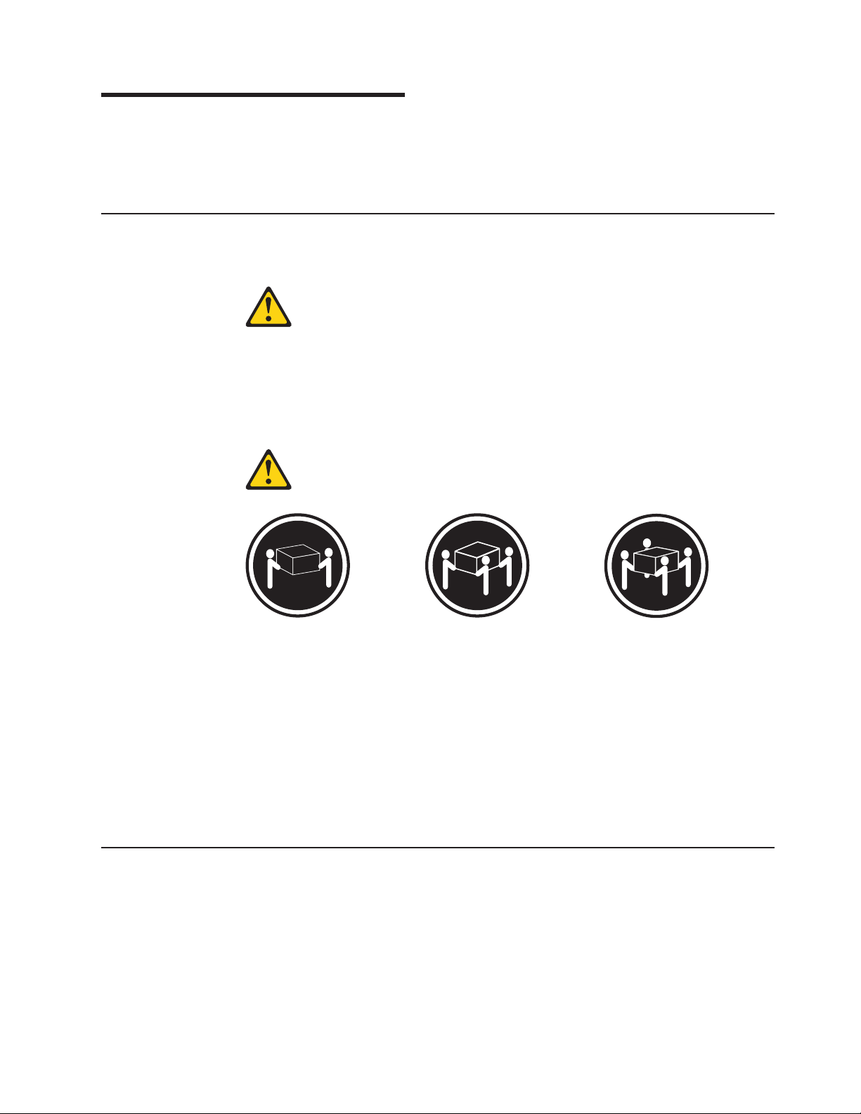
Statement 4:
≥ 18 kg (39.7 lb) ≥ 32 kg (70.5 lb) ≥ 55 kg (121.2 lb)
CAUTION:
Use safe practices when lifting.
Install the BladeCenter unit in a rack before installing any blade servers in the
BladeCenter unit. If your BladeCenter unit has blade servers already installed,
remove them first. Blade servers are installed from the front of the BladeCenter unit,
without sliding the BladeCenter unit into or out of the rack. Detailed instructions for
installing a BladeCenter unit in a rack are in the Rack Installation Instructions that
come with your BladeCenter unit.
Installation guidelines
Before you begin to install options in your BladeCenter unit, read the following
information:
v Read the “Important safety information” on page vii and the guidelines in
“Handling electrostatic discharge-sensitive devices” on page 90. This information
will help you work safely with your BladeCenter unit and options.
v The orange color on components and labels in your BladeCenter unit identifies
hot-swap components. You can install or remove hot-swap modules and, with
© Copyright IBM Corp. 2011 31
Page 42

some restrictions, hot-swap blade servers while the BladeCenter unit is running.
For complete details about installing or removing a hot-swap component, see the
detailed information in this chapter.
v The blue color on components and labels identifies touch points where you can
grip a component, move a latch, and so on.
v You do not need to disconnect the BladeCenter unit from power to install or
replace any of the hot-swap modules on the rear of the BladeCenter unit. You
need to shut down the operating system and turn off a hot-swap blade server on
the front of the BladeCenter unit before removing the blade server, but you do
not need to shut down the BladeCenter unit itself.
v For a list of supported options for your BladeCenter unit, go to
http://www.ibm.com/pc/compat/ on the World Wide Web.
System reliability considerations
To help ensure proper cooling and system reliability, make sure that:
v Each of the module bays on the rear of the BladeCenter unit has either a module
or filler module installed.
v Each of the blade bays on the front of the BladeCenter unit has either a blade
server or filler blade installed.
v Each of the drive bays in a blade server storage expansion option has either a
hot-swap drive or a filler panel installed.
v A removed hot-swap module, blade server, or drive is replaced within two
minutes of removal.
v Cables for the option modules are routed according to the illustrations and
instructions in this document.
v A failed blower is replaced as soon as possible, to restore cooling redundancy.
Handling static-sensitive devices
Attention: Static electricity can damage electronic devices and your system. To
avoid damage, keep static-sensitive devices in their static-protective packages until
you are ready to install them.
To reduce the possibility of electrostatic discharge, observe the following
precautions:
v Limit your movement. Movement can cause static electricity to build up around
you.
v Handle the device carefully, holding it by its edges or its frame.
v Do not touch solder joints, pins, or exposed printed circuitry.
v Do not leave the device where others can handle and damage it.
v While the device is still in its static-protective package, touch it to an unpainted
metal part of the BladeCenter unit or rack where the BladeCenter unit is installed
for at least 2 seconds. This drains static electricity from the package and from
your body.
v Remove the device from its package, and install it directly into the system unit
without setting the device down. If it is necessary to set down the device, place it
back into its static-protective package. Do not place the device on your system
unit or on a metal surface.
v Take additional care when handling devices during cold weather. Heating reduces
indoor humidity and increases static electricity.
32 BladeCenter E Type 8677 and 1881: Hardware Maintenance Manual and Troubleshooting Guide
Page 43

Installing and removing modules
The procedures for installing or removing a module on the BladeCenter unit are
nearly identical for all modules except the blower modules. To install or remove a
blower module, see “Replacing a blower module” on page 47. To install or remove
all other modules, follow the instructions in this section.
Every module is keyed so that it can be inserted only in an appropriate bay. You
can insert an I/O module only in an I/O-module bay, for example. In addition, most
modules must be installed in a specific sequence or under specific circumstances.
The BladeCenter modules
Your BladeCenter unit contains the following hot-swap modules: power modules, I/O
modules, management module, and blower modules. See “Rear view” on page 10
for the location of each module. These modules supply common functions to the
blade servers that are installed in the blade bays in the front of the BladeCenter
unit.
The chassis and the management module supply I/O (optical drive, USB port,
keyboard, video, and mouse) that is available to all the blade servers, selected by
any one blade server at a time. The chassis can contain up to 14 blade servers.
Attention: To help ensure proper cooling, performance, and system reliability,
make sure that each of the module bays on the rear of the BladeCenter unit has a
module or filler module installed. When replacing a module, do not operate the
BladeCenter unit for more than one minute without either a module or a filler
module installed in each module bay.
Management module
Your BladeCenter unit comes with one hot-swap management module in the
management bay. You can add a management module in management bay 2.
Note: Only one management module will be active; the second management
module, if present, provides redundancy.
The management module functions as a service processor and a
keyboard/video/mouse (KVM) multiplexor for the multiple blade servers. The
management module also configures the BladeCenter unit and modules, configuring
information such as the I/O module IP addresses. The management module
provides the following external connections: keyboard, mouse, and video for use by
a local console, and one RJ-45 connector for a 10/100 Mbps Ethernet remote
management connection. Advanced management modules also provide an RJ-45
connector for serial management connection.
The service processor in the management module communicates with the service
processor in each blade server for functions such as:
v Blade server power-on requests
v Blade server error and event reporting
v Blade server requests for keyboard, mouse, and video
v Blade server requests for removable media drives
The management module also communicates with the I/O modules, power modules,
blower modules, and blade servers to detect presence or absence and any error
conditions, sending alerts when required.
Chapter 4. Installing options 33
Page 44

I/O (switch) modules
For blade server communication with the network, your BladeCenter unit supports
from one to four hot-swap I/O modules. Table 1 on page 35 identifies the type of I/O
module you can install in each I/O-module bay. Go to the IBM Support Web site at
http://www.ibm.com/systems/support to see the list of supported I/O modules. Your
BladeCenter unit supports a minimum of one hot-swap Ethernet switch module or
pass-thru module, in I/O-module bay 1. This I/O module provides an internal
connection to Ethernet Link 1 in all the blade servers in the BladeCenter unit, up to
14 internal connections per I/O module. To provide an internal connection for
Ethernet Link 2 in each blade server, install an Ethernet switch module or pass-thru
module in I/O-module bay 2.
The BladeCenter unit also supports two additional I/O modules, for a total of four
I/O modules. The two additional I/O modules support the network interface on the
I/O expansion option installed on one or more blade servers in the BladeCenter
unit.
Note: The BladeCenter unit supports either four Ethernet switch modules or two
Ethernet switch modules and up to two fibre channel switch modules. No more than
two fibre channel switch modules can be connected to the BladeCenter unit.
If you install an I/O expansion option on any blade server, you must install a
hot-swap I/O module of the same network interface (or an optical pass-thru module)
in I/O-module bay 3 to obtain network connection 3 for the option; to provide
network connection 4 for the option, install the same type of I/O module in
I/O-module bay 4 as you installed in I/O-module bay 3. For example, if you install a
Fibre Channel I/O expansion option on a blade server, the I/O modules you install
in I/O-module bays 3 and 4 must both be Fibre Channel or both be optical
pass-thru, and all other I/O expansion options in the BladeCenter unit must also be
Fibre Channel I/O expansion options.
Notes:
1. All blade server I/O expansion options in the BladeCenter unit must use the
same type of network interface.
2. You can mix four-port 1-Gb Ethernet switch modules with other supported
Ethernet switch modules to achieve the total number of Ethernet switch modules
you need in the BladeCenter unit.
3. You can use a pass-thru module in any I/O-module bay, provided that the
controller in the blade servers or I/O expansion options is compatible with the
network switch to which the pass-thru module is connected.
34 BladeCenter E Type 8677 and 1881: Hardware Maintenance Manual and Troubleshooting Guide
Page 45

The following table summarizes the types of modules that can be used in each
I/O-module bay. See “Rear view” on page 10 for the location of the I/O-module bays
on the BladeCenter unit.
Table 1. Hot-swap I/O module types by location
Bays I/O-module function Permissible I/O module
1 and 2 Network connections 1 and 2
(Ethernet) for all blade servers in the
BladeCenter unit
3 and 4 Network connections 3 and 4 (from all
blade server I/O expansion options on
blade servers in the BladeCenter unit)
One of the following combinations:
v Two Ethernet switch modules
v Two pass-thru modules
v One Ethernet module and one
pass-thru module
One of the following combinations:
v Two Ethernet switch modules
v Two Fibre Channel switch modules
v Two pass-thru modules
v One pass-thru module and one
Ethernet switch module
v One pass-thru module and one Fibre
Channel switch module
Important:
v The modules used must support the
network interface used on the I/O
expansion options.
v You cannot combine Ethernet and
Fibre Channel switch modules in bays
3 and 4.
Notes:
1. The enumeration of the Ethernet controllers in a blade server is
operating-system dependent. You can verify the Ethernet controller designations
a blade server uses through your operating system settings.
2. The routing of an Ethernet controller to a particular I/O-module bay depends on
the type of blade server. You can verify which Ethernet controller is routed to
which I/O-module bay by using the following test:
a. Install only one Ethernet switch module or pass-thru module, in I/O-module
bay 1.
b. Make sure the ports on the switch module or pass-thru module are enabled
(see the User's Guide or Command-Line Interface Reference Guide for your
management module type for instructions).
c. Enable only one of the Ethernet controllers on the blade server. Note the
designation the blade server operating system has for the controller.
d. Ping an external computer on the network connected to the switch module.
If you can ping the external computer, the Ethernet controller you enabled is
associated with the switch module in I/O-module bay 1. The other Ethernet
controller in the blade server is associated with the switch module in I/O-module
bay 2.
3. If you have installed an I/O expansion option on a blade server, communications
from the option are routed to I/O-module bays 3 and 4. You can verify which
controller on the option is routed to which I/O-module bay by performing the test
in note 2, using a controller on the I/O expansion option and a compatible
switch module or pass-thru module in I/O-module bay 3 or 4.
Chapter 4. Installing options 35
Page 46

Power modules
Note: The IBM BladeCenter E type 8677 and 1881 chassis must be configured to
support 2320-watt power modules. See the IBM BladeCenter E 2320 Watt Power
Modules Installation Guide for specific information and instructions.
Your BladeCenter unit comes with one pair of 220-volt hot-swap power modules in
power bays 1 and 2 that provides power to all the BladeCenter modules and to
blade bays 1 through 6. The BladeCenter unit supports a second pair of power
modules in power bays 3 and 4 that provides power to blade bays 7 through 14.
Each pair of power modules is redundant. If either power module fails, the
remaining power module continues to supply power, but there is no redundancy; the
failed power module must be replaced as soon as possible.
To provide true redundant power, BladeCenter power modules 1 and 3 must
connect to a different ac power source than power modules 2 and 4. Connect
BladeCenter power modules 1 and 3 to a different PDU than power modules 2 and
4; then, connect each PDU to an ac power source (building power source or service
entrance) that is controlled by a separate circuit breaker.
The following table summarizes the application for each power module
Bays Power module function
1 and 2 Provides power to all the BladeCenter modules and to blade bays 1 through 6
3 and 4 Provides power to blade bays 7 through 14
Power modules are not needed in bays 3 and 4 until you begin installing blade
servers and options in blade bays 7 through 14.
Note: If you install a blade server that has a storage expansion unit option
attached in blade bay 6, the option will use blade bay 7; power modules will be
required in power bays 1, 2, 3 and 4.
Each active power module supplies 12 volts of power to the blade bays it services.
Important: Plug one end of each power-module power cord into the power module;
plug the other end of the power cord into a 220-volt power distribution unit (PDU).
Blower modules
Your BladeCenter unit comes with two hot-swap blowers for cooling redundancy.
The blower speeds vary depending on the ambient air temperature at the front of
the BladeCenter. If the ambient temperature is 72°F or below, the BladeCenter
blowers will run at 30% of their maximum rotational speed, increasing their speed
as required to control internal BladeCenter temperature. If the ambient temperature
is above 72°F, the blowers will run at 80% of their maximum rotational speed,
increasing their speed as required to control internal BladeCenter temperature. If a
blower fails, the remaining blower continues to cool the BladeCenter unit and blade
servers.
Important: Replace a failed blower as soon as possible, to restore cooling
redundancy.
36 BladeCenter E Type 8677 and 1881: Hardware Maintenance Manual and Troubleshooting Guide
Page 47

Installing a module
The following illustration shows how to install a power module, management
module, or I/O module in the rear of the BladeCenter unit. See “Replacing a blower
module” on page 47 for information about replacing a blower module.
Before you begin, read the documentation that comes with your option.
Statement 8:
CAUTION:
Never remove the cover on a power supply or any part that has the following
label attached.
Hazardous voltage, current, and energy levels are present inside any
component that has this label attached. There are no serviceable parts inside
these components. If you suspect a problem with one of these parts, contact
a service technician.
Complete the following steps to install a module:
Note: These instructions assume the BladeCenter unit is connected to power.
1. Read the safety information beginning on page 87 and “Installation guidelines”
on page 31 through “Handling static-sensitive devices” on page 32.
2. Remove the acoustic module option, if installed, from the rear of the
BladeCenter unit. See “Installing and removing the acoustic module option” on
page 40 for instructions.
3. Remove the filler module from the bay.
4. Ensure that the release lever on the module is in the open position
(perpendicular to the module).
5. Slide the module into the appropriate module bay until it stops.
6. Push the release lever on the front of the module closed.
Chapter 4. Installing options 37
Page 48
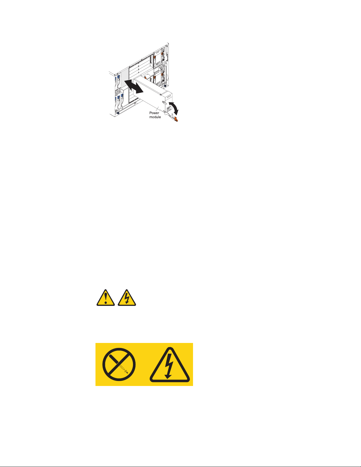
7. Attach any cables or cords required by the module. See “Input/output
connectors” on page 46 for the location of connectors on the BladeCenter unit.
Be sure to route the power cord on a power module through the strain-relief
clamp on the power module.
8. Make sure the LEDs on the module indicate that it is operating properly. Verify
that:
v The dc power LED and the ac power LED on each power module are lit and
v The OK LED on the management module is lit.
v The OK LED on each I/O module is lit.
9. If you have other modules to install, do so now; otherwise, go to step 10.
10. Replace the acoustic module option, if you removed it in step 2.
Removing a module
Complete the following steps to remove a power module, management module, or
I/O module.
Note: These instructions assume the BladeCenter unit is connected to power.
Statement 8:
that the power module error LED (2320-watt power modules only) on each
power module is not lit.
CAUTION:
Never remove the cover on a power supply or any part that has the following
label attached.
Hazardous voltage, current, and energy levels are present inside any
component that has this label attached. There are no serviceable parts inside
these components. If you suspect a problem with one of these parts, contact
a service technician.
38 BladeCenter E Type 8677 and 1881: Hardware Maintenance Manual and Troubleshooting Guide
Page 49

1. Read the safety information beginning on page 87 and “Installation guidelines”
on page 31 through “Handling static-sensitive devices” on page 32.
2. Remove the acoustic module option, if installed, from the rear of the
BladeCenter unit. See “Installing and removing the acoustic module option” on
page 40 for instructions.
Important:
a. If you are removing a functional power module, make sure before you
remove the module that both the ac power LED and the dc power LED on
the remaining power module are lit and that the power module error LED
(2320-watt power modules only) on the remaining power module is not lit;
otherwise, shut down the operating systems, and turn off all blade servers
that are supported by the power module you are removing before you
remove it. (See the documentation that comes with the blade server for
instructions for shutting down the blade server operating system and turning
off the blade server.)
b. If you are removing a management module, you might prefer to stop all
management module local and remote sessions before proceeding, to avoid
unexpected termination of sessions.
3. Disconnect any cables from the module. For a power module, disconnect the
power cord from the module.
4. Pull the release lever all the way toward the bottom of the module until it stops,
as shown in the illustration. The module moves out of the bay approximately 0.6
cm (0.25 inch).
5. Slide the module out of the bay, and set it aside. Within 1 minute, place either
another module of the same type or a filler module in the bay.
6. If you placed another module in the bay, reconnect any cables or power cords
you disconnected in step 3; then, make sure the LEDs on the module indicate
that it is operating properly. Verify that:
v The dc power LED and the ac power LED on each power module are lit and
that the power module error LED (2320-watt power modules only) on each
power module is not lit.
v The OK LED on the management module is lit.
v The OK LED on each I/O module is lit.
7. Replace the acoustic module option, if you removed it in step 2.
Chapter 4. Installing options 39
Page 50
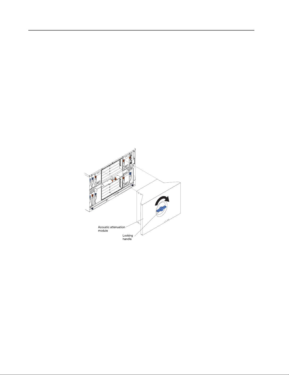
Installing and removing the acoustic module option
For server environments where noise reduction is essential, you might choose to
install the BladeCenter acoustic attenuation module option (acoustic module) on the
BladeCenter unit. The acoustic module reduces the sound level of the BladeCenter
unit to below 7.2 Bel using a T-shaped baffle. The acoustic module is installed on
the back of the BladeCenter unit, directly covering the blower modules and partially
covering the other modules. The system LED panel is replicated on the acoustic
module for visibility. Installing an acoustic module increases the length of a
BladeCenter unit and requires use of an enterprise rack.
Installing the acoustic module option
Complete the following steps to install an acoustic module option on the
BladeCenter unit:
1. Place the acoustic module over the blower modules, aligning the corners of the
acoustic module back with the guides on the chassis, and pushing the shaft into
the hole between the blower modules.
2. Rotate the acoustic module handle approximately 2 turns clockwise until it
tightens the acoustic module firmly into place.
40 BladeCenter E Type 8677 and 1881: Hardware Maintenance Manual and Troubleshooting Guide
Page 51

Removing the acoustic module option
Complete the following steps to remove an acoustic module option from the
BladeCenter unit:
1. Rotate the acoustic module handle approximately 2 turns counter-clockwise until
it stops.
2. Carefully pull the acoustic module away from the BladeCenter unit, and set it
aside.
Acoustic attenuation
module
Locking
handle
Installing and removing blade servers
Your BladeCenter unit supports up to 14 high-performance blade servers. Each
blade server is an enclosure that contains microprocessors, memory, a control chip
set, an I/O bus, Ethernet controllers, hard disk drives, customer interface controls,
and connectors for expansion options. The blade server receives its power, network
connection, and I/O devices (removable media drives, keyboard, mouse, and video
ports, USB port, remote monitoring port) from the BladeCenter unit, reducing the
server physical size and reducing the number of cables needed.
Blade server expansion options
Some blade servers contain connectors for options that add capabilities to the blade
server. You can add these options before installing the blade server in the
BladeCenter unit.
Go to http://www.ibm.com/pc/compat/ on the World Wide Web for a list of available
options for your IBM blade server.
I/O expansion option
Some blade servers have connectors for adding an I/O expansion option, such as
the IBM HS20 Fibre Channel Expansion Card. The BladeCenter unit routes network
communication signals from the I/O expansion option to I/O modules 3 and 4 on the
BladeCenter unit. The I/O expansion option is attached directly to the blade server
but does not occupy an additional blade bay.
Chapter 4. Installing options 41
Page 52

Note: If an I/O expansion option is installed on any blade server, I/O modules for
that network interface must be installed in I/O-module bays 3 and 4 on the
BladeCenter unit. See “I/O (switch) modules” on page 34 for more information.
Storage-expansion option
Some blade servers have a connector for adding a SCSI expansion unit, such as
the IBM HS20 SCSI Storage Expansion Unit. The storage expansion unit supports
up to two hot-swap SCSI hard disk drives. The expansion option is attached directly
to the blade server.
Note: The SCSI controller in the SCSI storage expansion unit supports RAID
level-1 (embedded mirroring).
Important:
1. To ensure proper cooling and system reliability, make sure that each of the
SCSI hard disk drive bays on the SCSI storage expansion unit contains either a
hot-swap SCSI hard disk drive or a filler panel.
2. Do not install a drive into IDE connector 2 on the blade server if you intend to
also install an I/O expansion option. The I/O expansion option occupies the
same area as the second IDE drive.
3. Two IDE drives can be used to implement and manage RAID level-1 under both
the Linux and Microsoft Windows 2000 operating systems. Details of the
implementation for Microsoft Windows 2000 can be found at
http://support.microsoft.com/default.aspx?scid=kb;EN-US;q302969 on the World
Wide Web.
42 BladeCenter E Type 8677 and 1881: Hardware Maintenance Manual and Troubleshooting Guide
Page 53

Installing a blade server
Complete the following steps to install a blade server in the BladeCenter unit.
Statement 21:
CAUTION:
Hazardous energy is present when the blade is connected to the power
source. Always replace the blade cover before installing the blade.
1. Read the “Important safety information” on page vii, “Installation guidelines” on
page 31, and “Handling electrostatic discharge-sensitive devices” on page 90.
2. Install any options needed, such as disk drives or memory, in the blade server.
See the documentation that comes with the blade server for instructions.
3. Select the bay for the blade server.
Notes:
a. If a blade server has an expansion option installed on it, the blade server
and expansion option require two adjacent blade bays.
b. If you install a blade server or option in bay 7 through 14, you must install
power modules in power bays 3 and 4.
4. Remove the filler blade from the bay, and store it in a safe place.
5. Ensure that the release levers on the blade server are in the open position
(perpendicular to the blade server).
6. Slide the blade server into the bay until it stops. The spring-loaded doors that
cover the bay opening move out of the way as you insert the blade server.
7. Push the release levers on the front of the blade server until they are closed.
8. Turn on the blade server by pressing the power-control button on the blade
server control panel. See the documentation that comes with the blade server
for more instructions.
9. Verify that the power LED on the blade server control panel is lit, indicating
that the blade server is receiving power.
Chapter 4. Installing options 43
Page 54

10. If desired, write identifying information on one of the user labels that come with
the blade server; then, place the label on the BladeCenter bezel just below the
blade server, as shown in the following illustration.
User
label
Important: Do not place the label on the blade server or in any way block the
ventilation holes on the blade server.
11. If you have other blade servers to install, do so now.
Important: Reinstalling a blade server into a different bay than the one from which
it was removed could have unintended consequences. Some configuration
information and update options are established according to bay number. You might
need to reconfigure the blade server.
If this is the initial installation for a blade server in the BladeCenter unit, you need to
configure the blade server with the blade server Configuration/Setup Utility program
and install the blade server operating system. See the documentation that comes
with the blade server for instructions.
44 BladeCenter E Type 8677 and 1881: Hardware Maintenance Manual and Troubleshooting Guide
Page 55
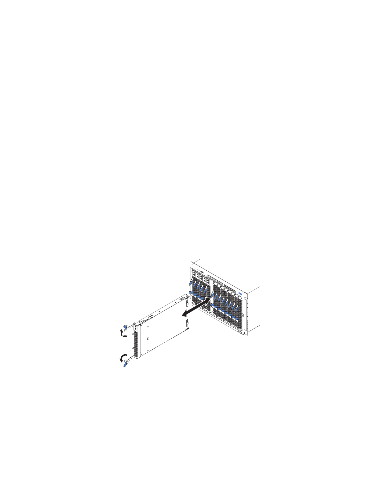
Removing a blade server
Complete the following steps to remove a blade server from the BladeCenter unit.
Attention:
v To maintain proper system cooling, do not operate the BladeCenter unit for more
than one minute without either a blade server or a filler blade installed in each
blade bay. If you fail to replace a blade server or filler blade within one minute,
system performance might be affected.
v Make note of the bay number. Some configuration information and update
options are established according to bay; if you reinstall the blade server in a
different bay than the one from which it was removed, unintended consequences
could occur.
1. Read the “Important safety information” on page vii, “Installation guidelines” on
page 31, and “Handling electrostatic discharge-sensitive devices” on page 90.
2. Shut down the blade server operating system; then, press the blade server
power-control button (behind the blade server control panel door) to turn off the
blade server.
Attention: Wait at least 30 seconds until the drives stop spinning, before
proceeding to the next step.
3. Open the two release levers as shown in the illustration. The blade server
moves out of the bay approximately 0.6 cm (0.25 inch).
4. Pull the blade server out of the bay. Spring-loaded doors move down to cover
the bay temporarily.
5. Place either a filler blade or another blade server in the bay within two minutes.
The spring-loaded doors will move out of the way as you insert the blade server
or filler blade.
Chapter 4. Installing options 45
Page 56

Completing the installation
After you connect the cables to the modules and route the cables (if necessary, see
the Rack Installation Instructions for information about routing the cables), start the
BladeCenter unit (if it is not already started), and verify that it is working properly,
as follows:
1. Start the BladeCenter unit by connecting the power-module power cords to a
220-volt power source (a 220-volt power distribution unit (PDU) that is
connected to a 220-volt ac power outlet or directly to a 220-volt ac power
outlet).
2. Make sure the LEDs on the modules indicate that they are operating properly.
Verify that:
v The dc power LED and the ac power LED on each power module are lit and
that the power module error LED (2320-watt power modules only) on each
power module is not lit.
v The OK LED on each management module is lit.
v The OK LED on each I/O module is lit.
3. Make sure the Power-on LED on each blade server is lit, either steady or
blinking.
See “BladeCenter unit power, controls, and indicators” on page 11 for information
about starting the BladeCenter unit and the location of the LEDs on the modules.
See the Installation and User’s Guide for your blade server for the location of the
LEDs on the blade servers.
Input/output connectors
Your BladeCenter has one Universal Serial Bus (USB) version 1.1 or 2.0 connector,
depending on BladeCenter unit type, on the front of the BladeCenter unit. All other
input/output connectors are provided by devices installed in the BladeCenter unit,
such as management modules or I/O modules. See the documentation for these
devices for information about the input/output connectors and their function.
Use the USB connector to connect a USB device other than a mouse or keyboard
to the BladeCenter unit. Using Plug and Play technology, USB devices are
configured automatically.
The following illustration shows a USB connector.
14
Use a USB cable to connect a device to a USB connector. If you need to connect
more USB devices than the BladeCenter unit has USB connectors, use a USB hub
to connect additional devices.
If you connect a USB keyboard that has a mouse port, the keyboard emulates a
mouse, and you cannot disable the mouse settings in the blade server
Configuration/Setup Utility program.
46 BladeCenter E Type 8677 and 1881: Hardware Maintenance Manual and Troubleshooting Guide
Page 57

Chapter 5. Service replaceable units
This chapter describes the removal of server components.
Important: The field replaceable unit (FRU) procedures are intended for trained
servicers who are familiar with IBM products. See the parts listing in Chapter 7,
“Parts listing, BladeCenter Type 8677 and 1881,” on page 79 to determine if the
component being replaced is a customer replaceable unit (CRU) or a FRU.
Note: Blade modules (I/O, management, power), servers, and blowers must be
replaced during service within two minutes.
Replacing a blower module
Your BladeCenter comes with two hot-swap blowers for cooling redundancy. The
blower speeds vary depending on the thermal load. If a blower fails, the remaining
blower continues to cool the BladeCenter and blades.
Important:
1. The failed blower module must be replaced within two minutes during service.
2. If ambient temperature is 72° F or below, the BladeCenter blowers will run at
30% of their maximum rotational speed, increasing their speed as required to
control internal BladeCenter temperature. If ambient temperature is above 72° F,
the blowers will run at 80% of their maximum rotational speed increasing their
speed as required to control internal BladeCenter temperature.
Complete the following steps to replace a blower in the BladeCenter.
1. Press the release lever on the blower handle.
2. Grasp the handle and pull the blower module out of the bay.
3. Slide another blower module into the bay, pushing it until the release lever
clicks; the release lever secures the blower module in the bay.
Release latch
Handle
© Copyright IBM Corp. 2011 47
Page 58

Media tray
This section describes removing and opening the media tray.
Removing the media tray
Complete the following steps to remove the media tray.
Note:
v Read “Installation guidelines” on page 31.
v Read the safety notices at “Safety information” on page 87.
v Read “Handling electrostatic discharge-sensitive devices” on page 90.
1. Remove the BladeCenter bezel.
a. Press the release pads at the bottom corners of the bezel.
b. Swing the bezel up and off the BladeCenter.
2. Push the tabs on the left and right sides of the tray to the left and right
respectively; then, pull the media tray out of the BladeCenter.
Reverse these instructions to reinstall the media tray.
Removing the media-tray cover
Complete the following steps to remove the media tray cover.
Note:
v Read “Installation guidelines” on page 31.
v Read the safety notices at “Safety information” on page 87.
v Read “Handling electrostatic discharge-sensitive devices” on page 90.
1. Lift at the points indicated in the illustration to lift the rear of the tray cover off
the fasteners.
2. Slide the cover toward the rear of the tray until the front tabs are clear of the
slots in the tray; then, lift the cover off the tray.
Note: The diskette drive shown in the following illustration is not present in all
BladeCenter unit models.
48 BladeCenter E Type 8677 and 1881: Hardware Maintenance Manual and Troubleshooting Guide
Page 59
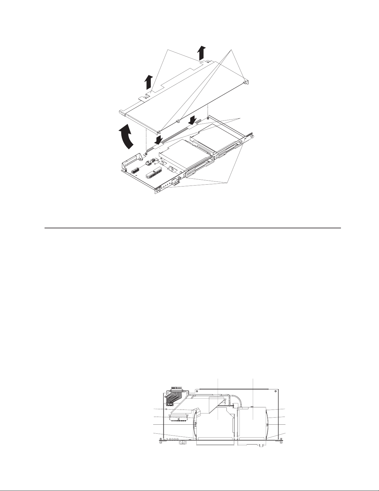
Lift points
Tabs
Pressure points
Slots
Reverse these instructions to reinstall the media tray cover. Press the rear of the
cover down onto the two fasteners to secure the cover in place.
Optical or diskette drive
Note: The diskette drive is not present in all BladeCenter unit models.
The optical drive and the diskette drive have the same securing mechanism, a
wire-retention spring. On the optical drive, the wire spring is on the left; on the
diskette drive, the wire spring is on the right.
Complete the following steps to replace the optical drive or the diskette drive.
Note:
v Read “Installation guidelines” on page 31.
v Read the safety notices at “Safety information” on page 87.
v Read “Handling electrostatic discharge-sensitive devices” on page 90.
1. Remove the media tray (see “Media tray” on page 48).
2. Remove the media-tray cover (see “Removing the media-tray cover” on page
48).
CD-ROM drive
Diskette drive
Drive guideDrive guide
Wire springWire spring
Retention hookRetention hook
Drive guideDrive guide
Chapter 5. Service replaceable units 49
Page 60

3. If you are removing the diskette drive, disconnect the cable from the rear of
the drive.
4. Slip the wire spring out from under the retention hook, and pull it away from
the drive. Set the wire spring aside.
5. Slide the drive out of the front of the media tray, and set it aside.
6. Set any jumpers or switches on the replacement drive to match the drive you
just removed.
7. Slide the replacement drive all the way into the bay on the media tray.
8. Align the holes in the side of the drive with the hole in each drive guide.
9. Push each end of the wire spring through the hole in the drive guide and into
the hole in the drive; then, push the middle of the wire spring under the
retention hook.
10. Try to move the drive, to make sure the wire spring is holding it in place. If the
drive slides forward, remove the wire spring and repeat steps 7 through 10.
11. If you replaced the diskette drive, reconnect the cable at the rear of the drive.
Installing SuSE to a SCSI drive
The SuSE Linux operating system sees the diskette drive as a SCSI device. When
you are trying to install SuSE to a SCSI hard disk drive in a blade server SCSI
storage expansion unit and the blade server is the current owner of the media tray
(optical drive, diskette drive, and USB port), the SCSI identification of the diskette
drive can cause problems. SuSE might not install properly to the SCSI hard disk
drive.
CD-ROM drive
Diskette drive
Drive guideDrive guide
Wire springWire spring
Retention hookRetention hook
Drive guideDrive guide
For a remote (network) installation, make sure the blade server is not the current
owner of the media tray before you attempt to install the SuSE Linux operating
system on the blade server.
Customer interface card and USB connector
Complete the following steps to remove the customer interface card from the media
tray.
Note:
v Read “Installation guidelines” on page 31.
v Read the safety notices at “Safety information” on page 87.
v Read “Handling electrostatic discharge-sensitive devices” on page 90.
1. Remove the media tray (see “Media tray” on page 48).
2. Remove the media tray cover (see “Removing the media-tray cover” on page
48).
50 BladeCenter E Type 8677 and 1881: Hardware Maintenance Manual and Troubleshooting Guide
Page 61

Fasteners
Customer
interface card
3. Disconnect the cables from the customer interface card.
4. Lift the two rear corners of the customer interface card to release it from the
fasteners.
5. Slide the customer interface card toward the rear of the media tray until the
USB connector is free of the opening; then, lift the board off the media tray.
6. To replace the customer interface card, reverse the previous steps. Press down
on the rear of the board to secure it to the fasteners.
CD interposer board
Note: The CD interposer board is only present in BladeCenter unit models that
have a media tray with a diskette drive.
Complete the following steps to replace the CD interposer board.
USB connector
Note:
v Read “Installation guidelines” on page 31.
v Read the safety notices at “Safety information” on page 87.
v Read “Handling electrostatic discharge-sensitive devices” on page 90.
1. Remove the media tray (see “Media tray” on page 48).
2. Remove the media-tray cover (see “Removing the media-tray cover” on page
48).
3. Remove the CD-ROM drive (see “Optical or diskette drive” on page 49.)
Interposer board
Retaining brackets
4. Remove the cables from the interposer board.
Chapter 5. Service replaceable units 51
Page 62
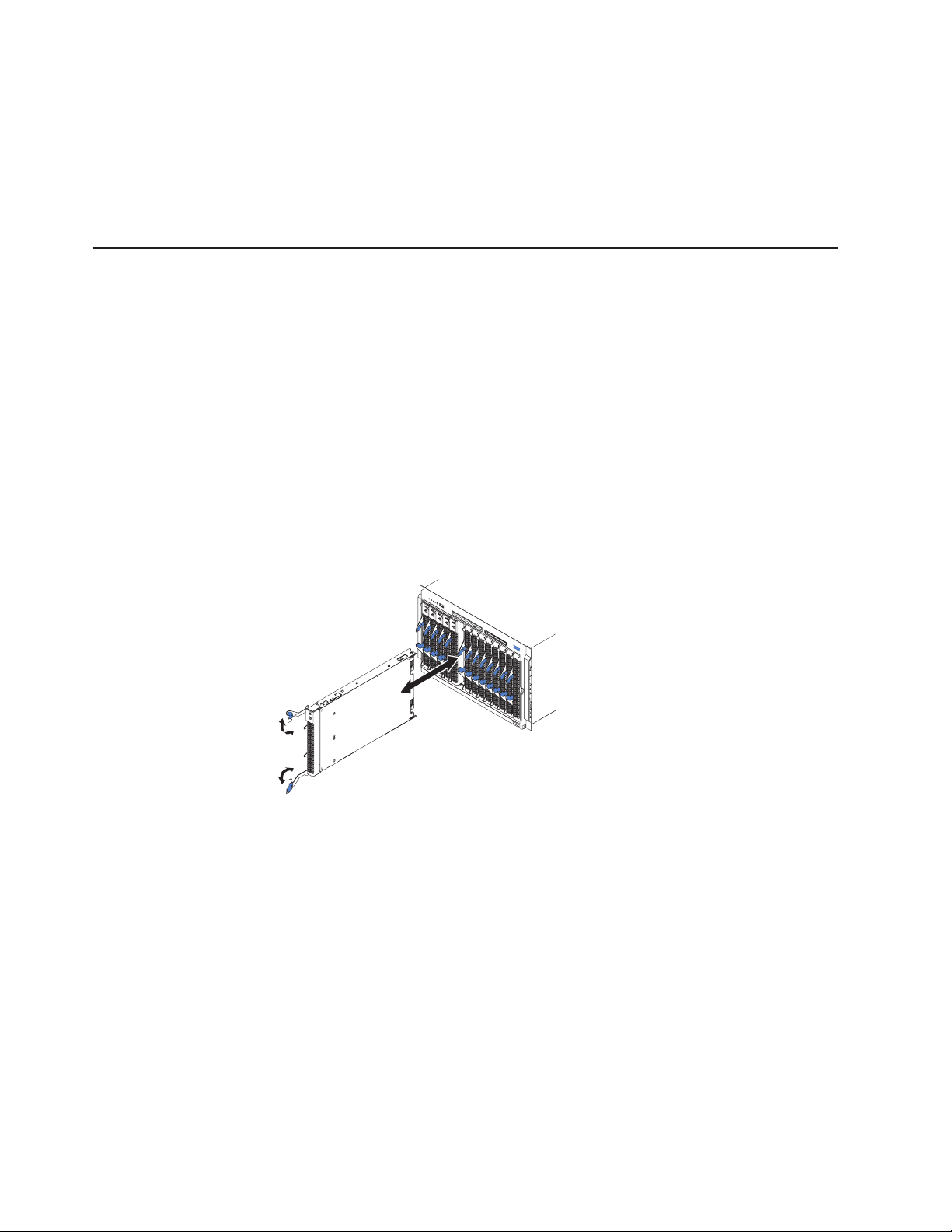
5. Lift the end of the interposer board that is closer to the customer interface card,
and slide it toward the customer interface card until the other end of the
interposer board is free of the retaining bracket.
To install the replacement CD interposer board, reverse the previous steps, making
sure to insert the tab on one end of the interposer board into the guide that is near
the diskette drive.
Switch, power, and cooling (SPC) chassis
Complete the following steps to remove the sub-chassis that contains the switch
(I/O), power, and cooling (SPC) modules.
Note:
v Read “Installation guidelines” on page 31.
v Read the safety notices at “Safety information” on page 87.
v Read “Handling electrostatic discharge-sensitive devices” on page 90.
1. Shut down the operating systems, and turn off any blades in the BladeCenter.
2. Turn off the BladeCenter and any attached devices (see “Shutting down the
BladeCenter unit” on page 12).
3. Disconnect the cables from the modules in the rear of the BladeCenter.
4. Remove the modules from the rear of the BladeCenter.
5. Disengage all the blades from the BladeCenter midplane.
a. Open the two release levers on each blade as far as they will go.
b. Pull each blade out about 2.54 cm (1 inch).
Important: If you completely remove any blades, each blade must be
reinstalled in the same bay from which it was removed.
Note: It is not necessary to release or remove any filler blades.
6. On the rear of the BladeCenter, release the shipping brackets.
52 BladeCenter E Type 8677 and 1881: Hardware Maintenance Manual and Troubleshooting Guide
Page 63
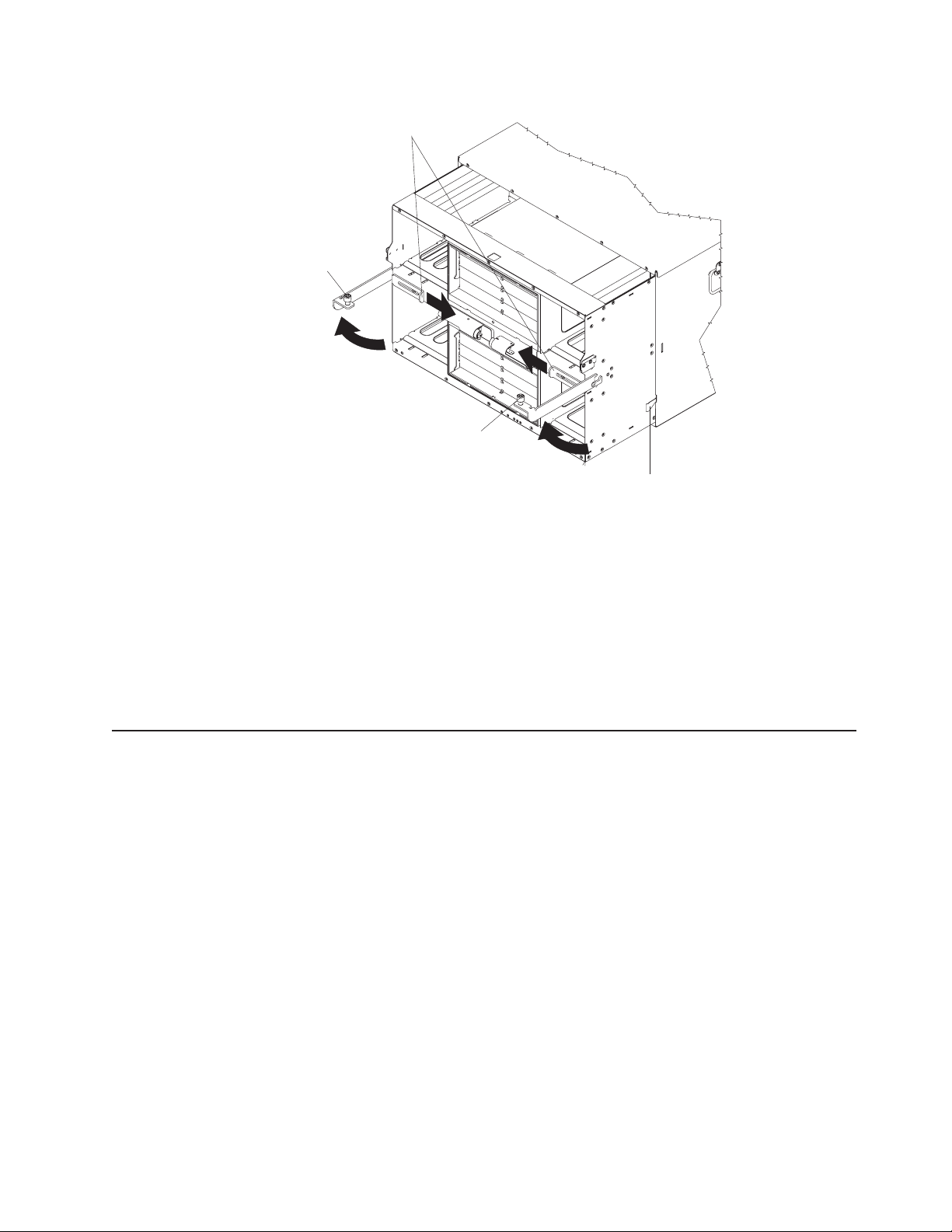
Shipping
bracket
SPC chassis
thumbscrews
SPC chassis
thumbscrews
Release
latch
a. To disengage the shipping brackets, slide the shipping brackets towards the
blowers.
7. Unscrew the captive thumbscrews at the bottom corners of the chassis, and pull
them until the SPC chassis moves out about 1.27 cm (0.5 inches).
8. Pull the SPC chassis out until it stops (about half-way out).
9. While supporting the SPC chassis with your hands, press the release levers on
the sides, and pull the SPC chassis out of the BladeCenter unit. Place the SPC
chassis on a strong, flat surface.
To reinstall the SPC chassis, reverse the previous steps.
Media-cable tray
Note: The media cable is only present in BladeCenter unit models that have a
media tray with a diskette drive.
The media-cable tray is between the media tray and the SPC chassis.
Complete the following steps to remove the media cable tray.
Note:
v Read “Installation guidelines” on page 31.
v Read the safety notices at “Safety information” on page 87.
v Read “Handling electrostatic discharge-sensitive devices” on page 90.
1. Remove the BladeCenter bezel.
2. Push the tabs on the left and right sides of the tray to the left and right
a. Press the release pads at the bottom corners of the bezel.
b. Swing the bezel up and off the BladeCenter.
respectively; then, pull the media tray out of the BladeCenter.
Chapter 5. Service replaceable units 53
Page 64
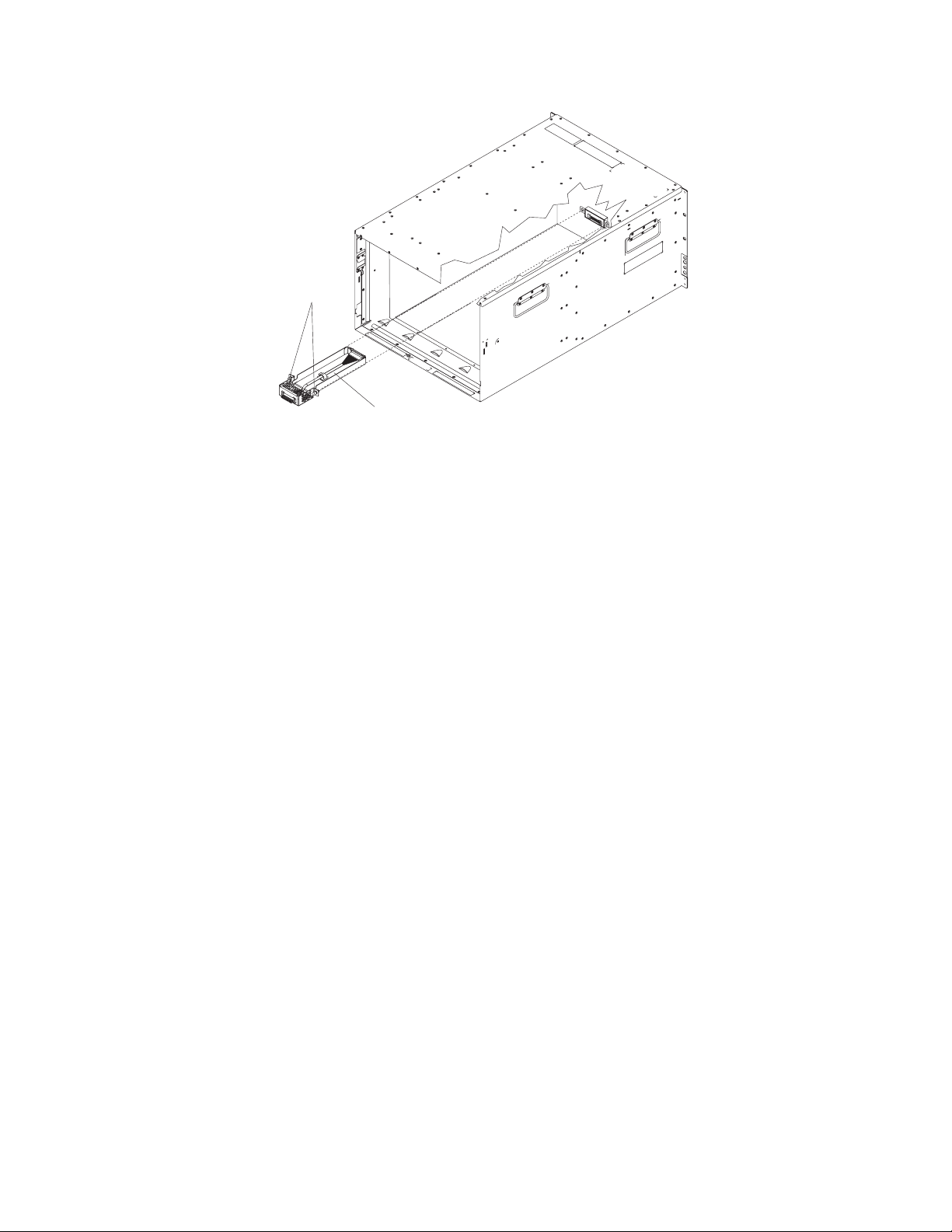
Fasteners
Media cable
tray
3. Remove the media tray cable.
To replace or reinstall the media cable tray, reverse the previous steps.
54 BladeCenter E Type 8677 and 1881: Hardware Maintenance Manual and Troubleshooting Guide
Page 65

Midplane
Complete the following steps to replace the midplane.
Note:
v Read “Installation guidelines” on page 31.
v Read the safety notices at “Safety information” on page 87.
v Read “Handling electrostatic discharge-sensitive devices” on page 90.
1. Shut down the BladeCenter, and remove the SPC chassis (see “Switch, power,
and cooling (SPC) chassis” on page 52).
2. Unplug the cable at the bottom of the midplane.
3. Unscrew the 12 fasteners that hold the midplane to the SPC chassis.
4. Pull the midplane away from the SPC chassis.
5. Install the replacement midplane by reversing the previous steps.
6. Update the vital product data (VPD) for the BladeCenter:
System LED panel
There are two system LED panels on the BladeCenter: one is on the front of the
BladeCenter; the other is on the rear.
Alignment pins
Screws
(12 places)
Midplane
a. Log into the advanced management module Web interface.
b. In the navigation pane, click Monitor → Hardware VPD.
c. Click Chassis.
d. Click Edit BladeCenter System Vital Product Data.
e. Obtain the model number and serial number on the ID label on the
BladeCenter; then, enter the information in the Type/Model and Serial
Number fields.
f. If the advanced management module is using firmware version BPET54R or
older, restart the advanced management module.
Chapter 5. Service replaceable units 55
Page 66

Front system LED panel
The front system LED panel is on the customer interface card in the media tray. To
replace the front system LED panel, replace the customer interface card. See
“Customer interface card and USB connector” on page 50 for instructions.
56 BladeCenter E Type 8677 and 1881: Hardware Maintenance Manual and Troubleshooting Guide
Page 67
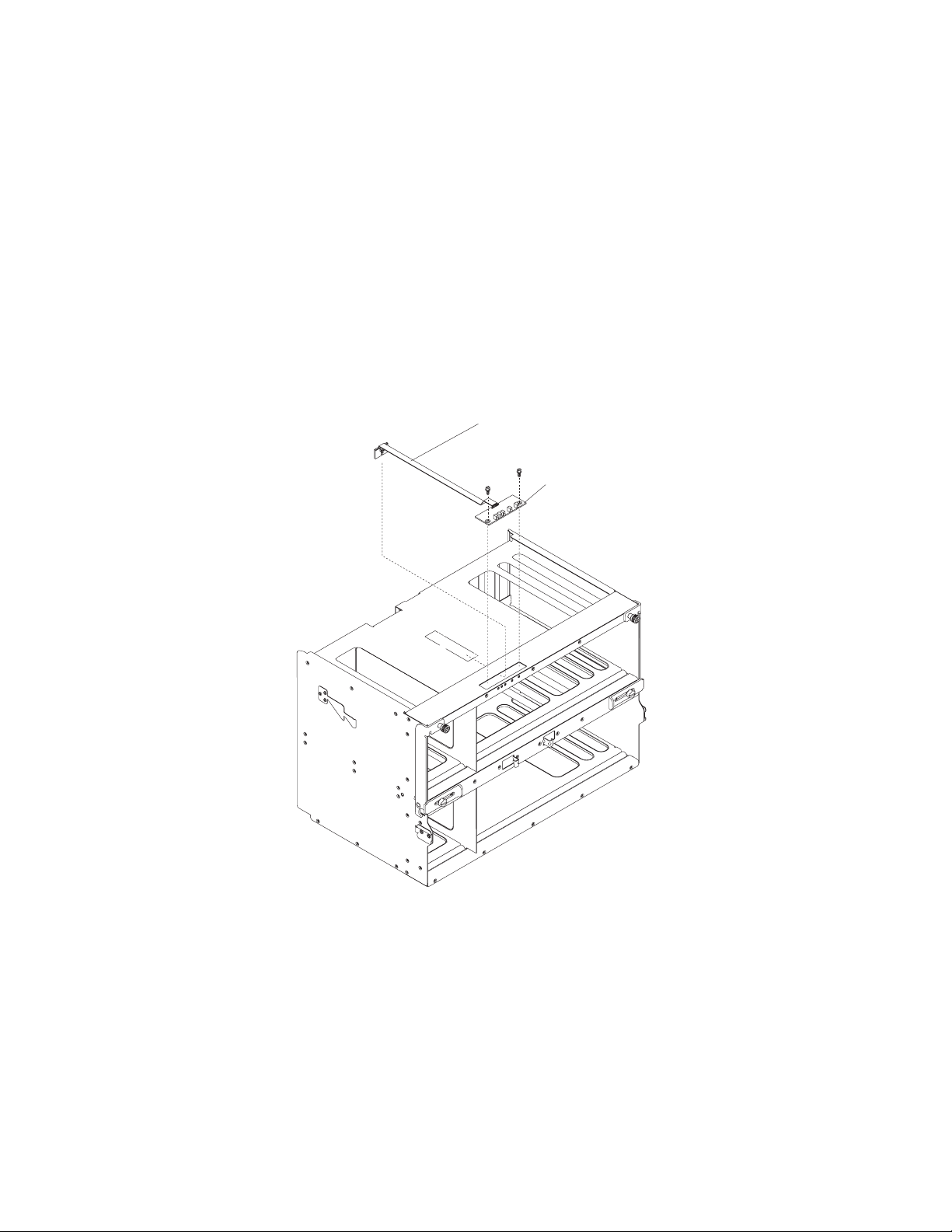
Rear system-LED panel
The rear system-LED panel is on the SPC chassis. Complete the following steps to
replace the rear system-LED panel.
Note:
v Read “Installation guidelines” on page 31.
v Read the safety notices at “Safety information” on page 87.
v Read “Handling electrostatic discharge-sensitive devices” on page 90.
1. Shut down the BladeCenter, and remove the SPC chassis (see “Switch, power,
and cooling (SPC) chassis” on page 52).
2. Turn the SPC chassis upside-down.
3. Unplug the cable at the bottom of the midplane.
4. Unscrew the two fasteners on the LED panel.
5. Remove the LED panel from the SPC chassis.
Cable
LED panel
Note: You might need to push the LED panel cable toward the panel to
leverage the panel out of the chassis opening.
6. Install the replacement rear system LED panel by reversing the previous steps.
Note: The cable of the new rear system LED panel must be adhered to the
SPC chassis. Once the panel is positioned on the SPC chassis, the release
liner that covers the adhesive on the cable must be removed for the cable to
adhere to that chassis. The cable can then be plugged to the midplane.
Chapter 5. Service replaceable units 57
Page 68

58 BladeCenter E Type 8677 and 1881: Hardware Maintenance Manual and Troubleshooting Guide
Page 69

Chapter 6. Symptom-to-FRU index
This index supports the BladeCenter Type 8677 and 1881.
Notes:
1. Check the configuration before you replace a FRU. Configuration problems can
cause false errors and symptoms.
2. For IBM devices not supported by this index, refer to the manual for that device.
3. Blade modules (I/O, management, power) and blowers must be replaced during
service within two minutes.
The symptom-to-FRU index lists symptoms, errors, and the possible causes. The
most likely cause is listed first. Use this symptom-to-FRU index to help you decide
which FRUs to have available when servicing the system.
The left-hand column of the tables in this index lists error codes or messages, and
the right-hand column lists one or more suggested actions or FRUs to replace.
Note: In tables with more than two columns, multiple columns are required to
describe the error symptoms.
Take the action (or replace the FRU) suggested first in the list of the right-hand
column, then try the server again to see if the problem has been corrected before
taking further action.
Error symptoms
Note: Try reseating a suspected component or reconnecting a cable before
replacing the component.
You can use the following information to find solutions to problems that have
definite symptoms.
Attention: If diagnostic error messages appear that are not listed in the following
tables, make sure that your BladeCenter unit has the latest level of firmware code
installed.
If you have just added a new option and your system is not working, complete the
following procedure before using the troubleshooting charts:
1. Remove the option that you just added.
2. Run the diagnostic tests to determine if your system is running correctly.
3. Reinstall the new device.
© Copyright IBM Corp. 2011 59
Page 70

Table 2. Troubleshooting charts
Device Suggested action
Blade server problem
Blade servers turn off for no
apparent reason.
Blade server does not turn off
during Red Hat Linux 7.3
shutdown.
Blade server does not turn off
during SuSE Linux 8.0
shutdown.
All blade bays must have a blade server, expansion unit, or filler blade in them. Blade
bays that do not have these items installed or have them installed improperly disturb
airflow in the BladeCenter unit with an adverse effect on BladeCenter unit cooling. If
the BladeCenter unit begins to overheat, blade server processors will begin to slow
down and will eventually turn off the system.
Issuing any of the Linux shutdown commands shuts down the operating system, but
does not turn off the blade server. The blade server shuts down to the point where a
message is displayed on the management module saying that the blade server is off,
but the blade server power-on LED remains lit.
Complete the instructions provided for Red Hat Linux in the User's Guide or the
Command-Line Interface Reference Guide for your management module type to
enable Wake On LAN for both onboard Broadcom integrated Ethernet controllers.
This will allow the blade server to restart using Wake on LAN even if the Linux
shutdown is incomplete and the blade server does not turn off.
Forcing a blade server to turn off
Complete the following steps to turn off a blade server after an incomplete Linux
shutdown:
1. Manually press the power-control button on the front of the blade server (behind
the control panel door) to turn off the blade server. Turning off the blade server in
this way is considered an improper shutdown by the Wake on LAN feature, and
the Wake on LAN feature will not restart the blade server.
2. Unlatch and slide the blade server partially out of the BladeCenter; then, reinstall
it to reset the blade server power state and re-enable its previously programmed
Wake on LAN capability.
Issuing any of the Linux shutdown commands shuts down the operating system but
does not turn off the blade server. The blade server shuts down to the point where a
message is displayed on the management module saying that the blade server is off,
but the blade server power-on LED remains lit.
A blade server running SuSE Linux 8.0 will not turn off during shutdown if ACPI is not
enabled. Complete the following steps to enable ACPI:
1. Type the following command: modprobe ospm_system
2. Type the following command to save this setting upon subsequent reboots: echo
"/sbin/modprobe ospm_system" >> /etc/init.d/boot.local
Blade server does not turn
on, the amber system-error
LED on the BladeCenter
system-LED panel is lit, the
amber blade error LED on the
blade server LED panel is lit,
and the system-error log
contains the following
message: "CRUs
MisMatched".
The problem occurs after installing the second microprocessor option or after
replacing a failed microprocessor in a two-way Blade server.
The processor with the lowest feature set and stepping level must be used as the
Bootstrap Processor (BSP). This is Microprocessor 1 in location U66. Move the
microprocessor in location U66 to location U70, and move the microprocessor in
location U70 to location U66.
60 BladeCenter E Type 8677 and 1881: Hardware Maintenance Manual and Troubleshooting Guide
Page 71

Table 2. Troubleshooting charts (continued)
Device Suggested action
CD-ROM cannot be
configured with a JS20 blade
server but works with a HSxx
blade server.
The customer interface card (FRU number 59P6629) is not compatible with the JS20
blade server and must be replaced with the latest level FRU.
Note: The customer interface card installed in the BladeCenter is listed as the
"media tray" instead of the "customer interface card" on the Hardware VPD view of
the management-module web interface. The FRU number is also printed on the
customer interface card. Replace the customer interface card with the latest level,
see Chapter 7, “Parts listing, BladeCenter Type 8677 and 1881,” on page 79for the
correct FRU number.
Some components do not
report environmental status
(temperature, voltage).
The green status dot for a component is not automatically a link to environmental
information (temperature and voltage) for the component. Only the management
module and blade servers have environmental information, and only the green dot for
those components contains a link to environmental information.
Switching KVM control
between blade servers gives
USB device error.
If a blade server is under heavy load, it can take several minutes before it
enumerates the USB devices connected to it. If control of the KVM and media tray is
switched away from the blade server before this enumeration is complete, a USB
device installation error might be displayed. Do not switch KVM control between
blade servers until the mouse and keyboard are both working on the blade server
that has control of the KVM and media tray.
“Unsafe Removal of Device”
error message appears on
blade server running
Microsoft Windows 2000.
Before switching ownership of the media tray to another blade server, safely stop the
media tray devices on the blade server that currently owns the media tray, similar to
the following:
1. Double-click the Unplug or Eject Hardware icon in the Windows taskbar at the
bottom right of the screen.
2. Select USB Floppy, and click Stop.
3. Select USB Mass Storage Device, and click Stop.
4. Click Close.
You can now safely switch ownership of the media tray to another blade server.
“Media not found” error
message and other file
system error occur on a blade
server running Linux or DOS.
Attempting to access the mounted optical drive or diskette drive (media tray) after it
has been switched to another blade server results in I/O errors, even if the media tray
has been switched back.
Note: Because the BladeCenter unit uses a USB bus to communicate with the media
tray devices, switching ownership of the media tray to another blade server is the
same as unplugging a USB device.
v If a blade server tries to access the optical drive after it has been switched to
another blade server, a “Media not found” error occurs.
v If a blade server is running a DOS environment, such as when updating firmware
on the blade server, the firmware can be interrupted or corrupted when the media
tray is switched away; you might need to call for service on the blade server.
v If a file handle was left open by switching the media tray away, the system
administrator will not be able to do a clean unmount (umount command) unless the
unmount is forced by umount command parameters (“lazy umount”).
v If the system administrator is sharing out the optical drive for multiple users, that
network share is broken.
Before switching ownership of the media tray to another blade server, ensure that the
optical drive and diskette drive are not mounted for the current blade server owner
(check for open file handles and sharing out). If a firmware update is taking place on
the blade server, do not switch the media tray to another blade server.
Chapter 6. Symptom-to-FRU index 61
Page 72

Table 2. Troubleshooting charts (continued)
Device Suggested action
Linux does not install from
the BladeCenter optical drive
or will not start afterward.
X does not start in Red Hat
7.3 when the blade server
does not own the KVM.
Neither Red Hat Linux 7.3 nor SuSE Linux version 8.0 will install locally, although
Red Hat Linux might appear to install.
v If you try to install Red Hat Linux to the blade server IDE drive, Linux does not
install.
v If you try to install Red Hat Linux to the SCSI drive on a blade server expansion
unit, Linux appears to install but the operating system will not start properly.
v If you try to install SuSE Linux, Linux does not install.
Download the latest operating system installation instructions for your operating
system from the IBM Support Web page at http://www.ibm.com/systems/support/. The
necessary workaround is described in the instructions for your operating system.
The X Window does not start in a blade server if the blade server is not the current
owner of the keyboard, video, and mouse (KVM). Because the blade server does not
own the KVM, the X Window cannot find the mouse.
Depending on the Red Hat Linux kernel version, do one of the following:
v Red Hat Linux 7.3, kernels prior to 2.4.18-17.7.x, and Red Hat Advanced
Server kernels 2.1:
Add the following line to the /etc/modules.conf file.
alias char-major-13 mousedev
v Red Hat Linux 7.3, kernel 2.4.18-17.7.x or later:
Install the 2.4.18-17.7.x or later kernel errata, available from https://rhn.redhat.com/
errata/rh73-errata.html.
62 BladeCenter E Type 8677 and 1881: Hardware Maintenance Manual and Troubleshooting Guide
Page 73

Table 2. Troubleshooting charts (continued)
Device Suggested action
Remote control does not work
with default SuSE Linux,
version 8.0, display settings.
The remote console requires a display setting of 1024x768@60Hz in the blade server
operating system. The default resolution in SuSE is 1024x768, but the default refresh
rate falls somewhere between 50Hz and 60Hz. The remote console does not work for
a blade server running SuSE with a display refresh rate other than exactly 60Hz. The
message “eServer/No video available” displays.
Other operating systems do not exhibit the problem.
Set the refresh rate in the XF86Config file to exactly 60Hz.
There are two methods.
v Method 1 (unattended network install, prevent the problem): Modify the
AutoYaST control file to specify 1024x768@60Hz.
1. Run the graphical interface to the AutoYaST control file to set the VESA video
mode to 1040x768@60Hz. The graphical interface creates the AutoYaST
control file.
2. Edit the resulting AutoYaST control file to set the value for min_vsync to 60.
During an unattended network install, the YaST program uses the AutoYaST
control file to modify the XF86Config file (/etc/X11/XF86Config); these changes will
cause XF86Config to set the display resolution to 1040x768 with a refresh rate of
60Hz.
-- OR --
v Method 2 (situation has already occurred): Modify the xF86Config file.
1. In the Monitor section of /etc/X11/XF86Config, change the value of
VertRefresh to 60, as shown in these sample lines.
Section “Monitor”
Option “CalcAlgorithm” “IteratePrecisely”
HorizSync 31-48
Identifier “Monitor[0]”
ModelName “AutoDetected”
Option “DPMS”
VendorName “AutoDetected”
VertRefresh 60
UseModes “Modes[0]”
EndSection
2. Shut down X; then, restart it.
Diskette drive problems
Chapter 6. Symptom-to-FRU index 63
Page 74

Table 2. Troubleshooting charts (continued)
Device Suggested action
Diskette drive is seen as
/dev/sdx by Red Hat Linux
7.3 and SuSE version 8.0
Diskette drive problem.
Optical drive problems
Optical drive is seen as
/dev/sr0 by SuSE.
Both Red Hat Linux and SuSE Linux see the diskette drive as /dev/sdx (where x is
the last SCSI device in the line) instead of /dev/fd0. When you try to mount the drive
as fd0, the Linux operating system does not recognize the device (“not a valid block
device”).
There are two options:
v (For SuSE Linux version 8.0)
Modify the /etc/fstab file to include the following line:
/dev/sdx /media/floppy auto noauto,user,sync 0 0
where x is the letter that was assigned to the diskette drive.
v (For Red Hat Linux 7.3)
1. Modify the /etc/fstab file to include the following line:
/dev/fdx /mnt/floppy auto noauto,user 0 0
where x is the letter that was assigned to the diskette drive.
2. Create a directory for the diskette drive under /mnt by running:
mkdir /mnt/floppy
3. Mount the diskette drive by typing:
mount /mnt/floppy
Note: When running Linux, you must unmount the diskette drive before changing
ownership of the media tray.
1. Replace the diskette drive
2. Replace the diskette drive signal/power cable
If the SuSE Linux operating system is installed remotely onto a blade server that is
not the current owner of the media tray (optical drive, diskette drive, and USB port),
SuSE sees the optical drive as /dev/sr0 instead of /dev/cdrom, establish a link
between /dev/sr0 and /dev/cdrom as follows:
1. Enter the following command:
rm /dev/cdrom; ln -s /dev/sr0 /dev/cdrom
2. Insert the following line in the /etc/fstab file:
/dev/cdrom /media/cdrom auto ro,noauto,user,exec 0 0
64 BladeCenter E Type 8677 and 1881: Hardware Maintenance Manual and Troubleshooting Guide
Page 75

Table 2. Troubleshooting charts (continued)
Device Suggested action
Optical drive is not
recognized after being
switched back to blade server
running on Windows 2000
Advanced Server with SP3
applied.
When the optical drive is owned by blade server x, is switched to another blade
server, then is switched back to blade server x, the operating system in blade server
x no longer recognizes the optical drive. This happens when you have not safely
stopped the drives before switching ownership of the optical drive, diskette drive, and
USB port (media tray).
Note: Because the BladeCenter unit uses a USB bus to communicate with the media
tray devices, switching ownership of the media tray to another blade server is the
same as unplugging a USB device. Before switching ownership of the optical drive
(media tray) to another blade server, safely stop the media tray devices on the blade
server that currently owns the media tray, as follows:
1. Double-click the Unplug or Eject Hardware icon in the Windows taskbar at the
bottom right of the screen.
2. Select USB Floppy and click Stop.
3. Select USB Mass Storage Device and click Stop.
4. Click Close.
You can now safely switch ownership of the media tray to another blade server.
Optical drive problem.
1. Replace the optical drive
2. Replace the CD interposer card
3. Replace the optical drive signal cable
4. Replace the optical drive power cable
Ethernet controller problems
Operating systems number
Ethernet controllers
differently.
Enumeration of the Ethernet controllers in a blade server is operating-system
dependent. In the blade server Configuration/Setup Utility program, the Ethernet port
designated as Planar Ethernet 1 is routed to Ethernet switch module 2 and the
Ethernet port designated as Planar Ethernet 2 is routed to Ethernet switch module 1.
Verify the designations through your operating system settings or by testing:
1. Install only one switch module, in I/O-module bay 1.
2. Enable only one of the Ethernet controllers on the blade server. Make note of the
3. Ping an external computer on the network connected to the switch module.
If you can ping the external computer, the Ethernet controller you enabled is the
upper controller in the blade server and is associated with Ethernet switch 1.
Ethernet switch module problems
First ping from Ethernet
switch module through Telnet
reports failure.
When you use the Ethernet switch module Telnet interface to request the switch
module to ping something, the first ping response reports a failure, although the other
repetitions might report success. This occurs regardless of whether the switch module
port the pinged object is connected to is internal or external, and applies to pinging
blade servers but not to pinging the management module or objects connected to its
external Ethernet port, such as the network management station. To get accurate
results, always specify multiple repetitions (>1) in the ping request, and ignore the
first ping response from that request. See the IBM 4-Port Gb Ethernet Switch Module
for BladeCenter Installation Guide for instructions on how to ping through the Telnet
interface.
designation the blade server operating system has for the controller.
Chapter 6. Symptom-to-FRU index 65
Page 76

Table 2. Troubleshooting charts (continued)
Device Suggested action
Ethernet switch-module
firmware graphics shows a
blank panel when the blade
server is present but powered
off.
Ethernet switch-module log
reports elapsed time, not time
of day.
Ethernet disconnect notice
will not appear when running
Windows 2000.
The default IP address set by
the Ethernet switch module
does not match the one
assigned by the management
module.
Updating the Ethernet switch
module configuration through
the management module
does not save the switch
NVRAM.
If the Wake-on-LAN (WOL) feature is disabled on a blade server, and the blade
server is turned off, the switch module internal port link to that blade is down. This is
not an error, but the graphic of the BladeCenter unit might show a blank panel
instead of a blade server in that bay.
Note: You can enable or disable the WOL feature on a blade server through the
management-module Web interface or through the IBM Director console. Do not rely
on the BladeCenter graphic in the Ethernet switch-module firmware Web interface to
determine the presence or absence of blade servers in the BladeCenter unit.
The timestamp on entries in the Ethernet switch module log uses elapsed time (since
last switch restart). The timestamp on entries restarts from 0 each time the switch is
restarted, although the entries do remain in order of occurrence.
If an Ethernet cable is accidentally removed from the back of the BladeCenter unit,
the small red X (disconnect notice) that normally would appear to indicate that the
cable was disconnected will not appear in the bottom right of the screen. The
disconnect notice does not appear because the blade server Ethernet controller
connects to the Ethernet switch module through integrated circuitry inside the
BladeCenter unit.
When troubleshooting Ethernet-related problems, ensure that the Ethernet cables on
the back of the BladeCenter unit are connected properly.
When troubleshooting Ethernet-related problems, ensure that the Ethernet cables on
the back of the BladeCenter unit are connected properly.
When you use the management-module Web interface to update the Ethernet switch
module configuration, the management module firmware writes its settings for the
switch module only to the management module NVRAM; it does not write its settings
for the switch module to the switch-module NVRAM.
If the switch module restarts when the management module is not able to apply the
IP address it has in NVRAM for the switch module, the switch module will use
whatever IP address it has in its own NVRAM. If the two IP addresses are not the
same, you might not be able to manage the Ethernet switch module any more.
The management module cannot apply the switch IP address from its NVRAM if:
v The management module is restarting
v The management module has failed
v The management module has been removed from the unit.
When you use the management-module Web interface to update the Ethernet switch
module configuration, the management module firmware writes its settings for the
switch module only to the management module NVRAM; it does not write its settings
for the switch module to the switch module NVRAM.
If the switch module restarts when the management module is not able to apply the
IP address it has in NVRAM for the switch module, the switch module will use
whatever IP address it has in its own NVRAM. If the two IP addresses are not the
same, you might not be able to manage the Ethernet switch module any more.
The management module cannot apply the switch IP address from its NVRAM if:
v The management module is restarting
v The management module has failed
v The management module has been removed from the unit.
Keyboard problems
66 BladeCenter E Type 8677 and 1881: Hardware Maintenance Manual and Troubleshooting Guide
Page 77

Table 2. Troubleshooting charts (continued)
Device Suggested action
The keyboard is very slow
when using an operating
system that does not have
USB drivers.
Although the keyboard attached to the BladeCenter unit is a PS/2-style keyboard,
communication with it is through a USB bus. When you are running an operating
system that does not have USB drivers, such as in the following instances, the
keyboard responds very slowly.
v Run the blade server integrated diagnostics
v Run a BIOS update diskette on a blade server
v Update the diagnostics on a blade server
v Run the Broadcom firmware CD for a blade server
The keyboard is very slow
when using an operating
system that does not have
Sometimes when switching ownership of the KVM to a blade server, the video for the
blade server appears almost immediately, but it takes up to 10 or 20 seconds for the
mouse and keyboard to be usable. No action required.
USB drivers.
Pressing F1 brings up
browser help instead of
performing BladeCenter
management functions.
Connecting to the BladeCenter management module through the Web interface does
not provide proper coverage for the F1 key. In particular, pressing F1 to access the
Configuration/Setup Utility when a blade server is started brings up browser help
instead of the Configuration/Setup Utility.
This problem is peculiar to the Sun Java browser plug-in. Use the Microsoft virtual
machine (VM) that is built in to the browser.
Remote console has
keyboard entry problems with
Sun Java plug-
When you are redirecting the server console (remote console function) of a blade
server that is running Microsoft Windows 2000 or Windows XP and using the Sun
Java plug-in (Java Virtual Machine), the remote console can have keyboard entry
problems.
Management-module problems
The management module
password cannot be reset.
Management module does
not complete changeover to
redundant module on
hardware failure.
Media tray problems
Media tray access is lost
temporarily during
management module restart.
Use the Microsoft Java Virtual Machine (JVM) or Java Runtime Environment (JRE)
on the blade server instead of using the Sun Java Virtual Machine. The Microsoft
JVM comes with the Windows XP Service Pack 1. You can obtain the Microsoft JVM
for Windows 2000 from the Microsoft corporation. If you are using the Internet
Explorer browser, version 6.0 or later, to log into the management module and use
the remote control function, you must also adjust the browser settings:
1. Click Tools → Internet Options → Advanced tab.
2. Under the Java (Sun) section, uncheck the checkbox next to ’Use Java 2 v1.4. for
<applet> (requires restart)’
If you forget the management-module password, you will not be able to access the
BladeCenter management module. The management-module password cannot be
overridden, and the management module will need to be replaced.
Replace the management module.
When the BladeCenter management module is restarted, use of the media tray
(removable media drives) is lost temporarily. If you or a failure condition initiates a
management module restart while I/O activity is taking place on the media tray, the
disruption can interrupt reads to the optical drive or lose data being written to a
diskette or USB device.
Note: You can restart the management module through the Web interface to the
management module or from a network management station such as the IBM
Director console. Some failures on the BladeCenter unit can result in the
management module restarting automatically.
Make sure there is no I/O activity on the media tray before you restart the
management module.
Chapter 6. Symptom-to-FRU index 67
Page 78

Table 2. Troubleshooting charts (continued)
Device Suggested action
Monitor problems
The monitor works when you
start the BladeCenter unit, but
goes blank when you start
some application programs in
the blade servers.
The monitor displays video
for blade server 14 during
management module restart.
The screen is blank. Verify that:
Only the cursor appears. See “Undetermined problems” on page 77.
The screen is wavy,
unreadable, rolling, distorted,
or has screen jitter.
Wrong characters appear on
the screen.
Mouse problems
Mouse function lost during
Red Hat installation.
See the IBM 4-Port Gb Ethernet Switch Module for BladeCenter Installation Guide for
instructions on how to ping through the Telnet interface.
The monitor attached to the BladeCenter management module normally shows the
video output from the blade server that is the current owner of the keyboard, video,
and mouse (KVM). When there is no actively selected video from any blade server,
the video from blade server 14 is routed to the management module. While the
management module is restarting, there is temporarily no current KVM owner. The
video from blade server 14 displays on the monitor briefly until the management
module uses its NVRAM values to reestablish ownership of the KVM and media tray
(optical drive, diskette drive, and USB port). After that, the video from the blade
server that is the current KVM owner displays on the monitor.
1. The system power cord is plugged into the BladeCenter power module and a
working 220-volt PDU or electrical outlet.
2. The monitor cables are connected properly.
3. The monitor is turned on and the brightness and contrast controls are adjusted
correctly.
4. If you have verified these items and the screen remains blank, replace:
a. Monitor
b. Management module
If the monitor self-tests show the monitor is working properly, consider the location of
the monitor. Magnetic fields around other devices (such as transformers, appliances,
fluorescent lights, and other monitors) can cause screen jitter or wavy, unreadable,
rolling, or distorted screen images. If this happens, turn off the monitor. (Moving a
color monitor while it is turned on might cause screen discoloration.) Then move the
device and the monitor at least 305 mm (12 in.) apart. Turn on the monitor.
Notes:
1. To prevent diskette drive read/write errors, be sure the distance between monitors
and diskette drives is at least 76 mm (3 in.).
2. Non-IBM monitor cables might cause unpredictable problems.
3. An enhanced monitor cable with additional shielding is available for the 9521 and
9527 monitors. For information about the enhanced monitor cable, contact your
IBM reseller or IBM marketing representative.
If the problem remains, replace the monitor.
If the wrong language is displayed, update the firmware in the management module
with the correct language. If the problem remains, replace the management module.
If, while installing Red Hat Linux 7.3 to a blade server, you or someone else selects a
different blade server as owner of the keyboard, video, and monitor (KVM), you might
lose mouse function for the installation process.
Do not switch KVM owners until the installation process begins to install the
packages (after the ’About to Install’ window).
68 BladeCenter E Type 8677 and 1881: Hardware Maintenance Manual and Troubleshooting Guide
Page 79

Table 2. Troubleshooting charts (continued)
Device Suggested action
Mouse is not detected during
SuSE installation.
The installation of the SuSE Linux version 8.0 operating system does not detect the
mouse.
You will need to select the mouse manually. Download the latest operating system
installation instructions for your operating system from the IBM Support Web page at
http://www.ibm.com/systems/support/. The steps for selecting the mouse are
described in the instructions for your operating system.
Mouse offset problems occur
when using remote console
and running X.
When you are using the remote console on a blade server that is running X Windows
in Red Hat Linux 7.3 or SuSE Linux version 8.0, you see two cursor arrows on the
screen, widely spaced, one white and one black.
Configure Linux and X Windows for accurate mouse tracking. See the online help
information in the management module configuration and management software for
instructions (Blade Tasks → Remote Control, click the circled question mark next to
Redirect Server Console, read the section titled Notes on mouse support under
Linux).
Power problems
The system does not power
on.
Verify that:
1. The power cables are properly connected to the power modules in the
BladeCenter unit.
2. The 220-volt PDU functions properly.
3. The ac and dc power LEDs on the power module are on and the power module
error LED (2320-watt power modules only) on the power module is off.
4. If you just installed an option, remove it, and restart the BladeCenter unit. If the
BladeCenter unit now turns on, you might have installed more options than the
power module supports. You might need to install a power module in power bay 3
or 4.
If the problem remains, go to “Undetermined problems” on page 77.
Option problems
An IBM option that was just
installed does not work.
Verify that:
v The option is designed for the BladeCenter unit. See the “Server Support”
flowchart for information about obtaining ServerProven
from the World Wide Web.
v You followed the installation instructions that came with the option.
v The option is installed correctly.
v You have not loosened any other installed options or cables.
If the problem remains, replace the option.
An IBM option that used to
work does not work now.
Verify that all of the option hardware and cable connections are secure. If the option
comes with its own test instructions, use those instructions to test the option. If the
problem remains, replace the option.
Service processor problems
Service processor in the
management module reports
a general monitor failure.
Disconnect the BladeCenter unit from all electrical sources, wait for 30 seconds,
reconnect the BladeCenter unit to the electrical sources, and restart the server. If a
problem remains, replace the management module.
I/O-module problems
®
compatibility information
Chapter 6. Symptom-to-FRU index 69
Page 80

Table 2. Troubleshooting charts (continued)
Device Suggested action
Updating the I/O-module
configuration through the
I/O-module does not save the
management-module
NVRAM.
If you log in to the Ethernet switch module directly (through the Ethernet
switch-module Web interface or Telnet interface instead of through the management
module Web interface) and update the I/O module configuration, saving the new
configuration saves only to the I/O-module NVRAM, not to the management-module
NVRAM. The management module will not be able to communicate with the I/O
module.
See the User's Guide or Command-Line Interface Reference Guide for your
management module type for information about how to change the New Static IP
Configuration values to match the ones in Current IP Configuration, and apply the
configuration.
70 BladeCenter E Type 8677 and 1881: Hardware Maintenance Manual and Troubleshooting Guide
Page 81

Light Path Diagnostics table
The system-error LED on the system LED panel is lit when certain system errors
occur. If the system-error LED on your BladeCenter unit is lit, use the following
table to help determine the cause of the error and the action you should take.
Table 3. Light Path Diagnostics
Lit LED Cause Action
BladeCenter system LED panel
Location A condition has occurred in this BladeCenter
unit that has caused the remote system
management to identify this BladeCenter unit
as needing attention.
Over-temperature The system temperature has exceeded a
threshold level.
Look for any information or error LEDs on the
system-LED panel, the modules, and the
blades in the this BladeCenter unit, and follow
the instructions in this table for those LEDs.
1. Check to see if a blower module has failed.
2. Make sure the room temperature is not too
3. Check to see if a blade server has a
4. Make sure there is a blade, module, or filler
If it has, replace the blower module as
soon as possible to regain redundancy.
high. (See “Features and specifications” on
page 5 for temperature information.)
temperature LED lit. If it has, see the
documentation that comes with the blade
server.
plugged in each bay.
Information A noncritical event has occurred that should be
looked at, such as the wrong I/O module
inserted in a bay, or power needs that exceed
the capacity of power modules currently
installed.
System error A critical system error has occurred, such as
non-redundancy on the power modules or a
system error in a blade.
Management module
Managementmodule error
Managementmodule Web
interface to
Ethernet switch
module does not
refresh
Power module
A critical error has occurred in the
management module.
After adding or restarting an Ethernet switch
module through the management-module Web
interface, the Web page does not refresh. You
will also be unable to connect to the Ethernet
switch module through the Telnet interface.
If the problem remains, have the system
serviced.
Check the error log for the messages. Check
the LEDs on the BladeCenter unit and the
blade servers to isolate the component.
1. Check the error log for messages.
2. Look for an error LED on the modules and
blades to locate the component.
v If the error LED is on a module, follow
the instructions for the module in this
table.
v If the error LED is on a blade, see the
documentation that comes with the
blade.
Unplug the management module and reinsert
it, then, restart the BladeCenter unit. If the
problem remains, replace the management
module.
You must wait until the Ethernet switch module
completes POST. After Ethernet switch module
POST is complete, you will be able to connect
to the Ethernet switch module.
Chapter 6. Symptom-to-FRU index 71
Page 82

Table 3. Light Path Diagnostics (continued)
Lit LED Cause Action
Power module
error
Blower module
Blower-module
error
I/O module
I/O module error A critical error has occurred in the I/O module. Replace the module.
A critical error has occurred in the power
module.
The blower has failed or is operating too
slowly.
Replace the module. If your BladeCenter unit
has a redundant module for this power module,
the BladeCenter unit continues to function
using the redundant module.
Replace the blower module as soon as
possible to regain cooling redundancy. The
BladeCenter unit continues to function. The
redundant blower module provides cooling to
the BladeCenter unit and blades.
Temperature error messages
Note: See Chapter 7, “Parts listing, BladeCenter Type 8677 and 1881,” on page 79 to determine which components
should be replaced by a field service technician.
Message Action
Power supply x temperature fault
Power supply x temperature warning
Switch x temperature fault
System over abbient temperature Ensure that the system is being properly cooled; see “System
Switch x temperature fault Ensure that the system is being properly cooled; see “System
1. Ensure that the system is being properly cooled; see “System
reliability considerations” on page 32.
2. Replace power supply x.
1. Ensure that the system is being properly cooled; see “System
reliability considerations” on page 32.
2. Replace power supply x.
1. Ensure that the system is being properly cooled; see “System
reliability considerations” on page 32.
2. Replace I/O module x.
reliability considerations” on page 32.
reliability considerations” on page 32.
Blower error messages
Note: See Chapter 7, “Parts listing, BladeCenter Type 8677 and 1881,” on page 79 to determine which components
should be replaced by a field service technician.
Message Action
Blower x outside recommended speed Replace blower x.
Blower x failure Replace blower x.
Blower x fault Replace blower x.
72 BladeCenter E Type 8677 and 1881: Hardware Maintenance Manual and Troubleshooting Guide
Page 83

Power error messages
Note: See Chapter 7, “Parts listing, BladeCenter Type 8677 and 1881,” on page 79 to determine which components
should be replaced by a field service technician.
Message Action
Power module 3 or 4 is required to
power blades 7 to 14
Power supply x fault Replace power module x.
Power supply x 12V over voltage fault Replace power module x.
Power supply x 12V over current fault
Power supply x 12V under voltage fault Replace power module x.
Power supply x 12V current fault Replace power module x.
Power supply x DC good fault Replace power module x.
Power supply x removed Reinstall power supply x.
System over recommended voltage for
+12V
System over recommended voltage for
+1.8V
System over recommended voltage for
+2.5V
System over recommended voltage for
+3.3V
System over recommended voltage for
5V
System over recommended voltage for
+5V
System under recommended voltage for
+12V
System under recommended voltage for
+1.8V
System under recommended voltage for
+2.5V
System under recommended voltage for
3.3V
System under recommended voltage for
5V
Ensure power modules 3 and 4 are installed and connected to ac
power.
1. An over current condition is typically caused by an external
load fault. Attempt to restart the faulted power module by
removing ac to the system components one at a time to isolate
the failing component.
2. Replace power module.
1. Reseat the management module.
2. Reseat the power modules.
3. Replace the power modules.
4. Replace the management module.
1. Reseat the management module.
2. Replace the management module.
1. Reseat the management module.
2. Replace the management module.
1. Reseat the management module.
2. Replace the management module.
1. Reseat the management module.
2. Replace the management module.
1. Reseat the management module.
2. Replace the management module.
1. Reseat the management module.
2. Replace the management module.
1. Reseat the management module.
2. Replace the management module.
1. Reseat the management module.
2. Replace the management module.
1. Reseat the management module.
2. Replace the management module.
1. Reseat the management module.
2. Replace the management module.
Chapter 6. Symptom-to-FRU index 73
Page 84

Note: See Chapter 7, “Parts listing, BladeCenter Type 8677 and 1881,” on page 79 to determine which components
should be replaced by a field service technician.
Message Action
System is under recommended voltage
for +5V
System running nonredundant power Ensure that power modules 1 and 2 are installed and operating
1. Reseat the management module.
2. Replace the management module.
correctly. If blade servers are installed in bay 7 or higher, ensure
that power modules 3 and 4 are installed and working correctly.
Blade server error messages
Note: See Chapter 7, “Parts listing, BladeCenter Type 8677 and 1881,” on page 79 to determine which components
should be replaced by a field service technician.
Message Action
Blade server x was installed Information only. Take action as required.
Blade server x was removed Information only. Take action as required.
Received an [xxx] alert from an
unsupported ISMP type xxxx, via the
interconnect network
Ensure that all blade servers in the blade center are supported by
the management module.
KVM error message
Note: See Chapter 7, “Parts listing, BladeCenter Type 8677 and 1881,” on page 79 to determine which components
should be replaced by a field service technician.
Message Action
Error encountered switching KVM owner,
see system error log
1. Reseat the blade server.
2. Reseat the management module.
3. Reflash the blade server H8 firmware.
4. Replace the blade server.
5. Replace the management module.
6. Replace the midplane.
I/O module error messages
Note: See Chapter 7, “Parts listing, BladeCenter Type 8677 and 1881,” on page 79 to determine which components
should be replaced by a field service technician.
Message Action
Switch fault x
Switch module x was removed Information only. Take action as required.
Switch module x was installed Information only. Take action as required.
Switch module x was powered on Information only. Take action as required.
Switch module x was powered on Information only. Take action as required.
Switch System running nonredundant
switch modules
1. Reseat I/O module x.
2. Replace I/O module x.
Information only. Take action as required.
74 BladeCenter E Type 8677 and 1881: Hardware Maintenance Manual and Troubleshooting Guide
Page 85

Note: See Chapter 7, “Parts listing, BladeCenter Type 8677 and 1881,” on page 79 to determine which components
should be replaced by a field service technician.
Message Action
Switch module%d IP configuration was
changed
ENET [X] DHCP HSTN=X, DN=X, IP @=
XXX.XXX.XXX.XXXGW @=
XXXX.XXX.XXX.XXX, SN=
XXX,XXX,XXX,XXX, DNS1@=
XXX.XXX.XXX.XXX
ENET [X] IP Cfg:HstName= XXXX, IP@=
XXX.XXX.XXX.XXX ,GW@=
XXX.XXX.XXX.XXX, NetMsk=
XXX.XXX.XXX.XXX Switch module x was
installed
LAN: Ethernet [x] interface is no longer
active
LAN: Ethernet [x] interface now longer
active
Information only. Take action as required.
Ethernet configuration information. Take action as required.
Ethernet configuration information. Take action as required.
Check cables to I/O module.
Information only. Take action as required.
Management-module error messages
Note: See Chapter 7, “Parts listing, BladeCenter Type 8677 and 1881,” on page 79 to determine which components
should be replaced by a field service technician.
Message Action
Application posted alert to ASM The alert button on the Web interface was tested. Information only.
Take action as required.
System log 75% full Information only. Take action as required.
System log full Information only. Take action as required.
Management module network
initialization complete
Remote login successful. Login ID Information only. Take action as required.
ASM reset was caused by restoring
default values
ASM reset was initiated by the user Information only. Take action as required.
Pushbutton reset activated: Ethernet
configuration reset to default values and
MM ASM reset due to watchdog timeout
ASM reset due to XXXXX, instruction
fault: XXXXXXXX YYYYYYYY ZZZZZZ
ASM reset reason unknown Information only.
Possible ASM reset occurred reason
unknown
Remote access attempt failed. Invalid
userid or password received. User is
XXX from CMD mode client at
IP@=XXX.XXX.XXX.XXX
Information only. Take action as required.
The management-module assembly was reset after restoring the
default settings. Information only. Take action as required.
1. Reseat the management module.
2. Reflash the management-module firmware.
3. Replace the management module.
1. Reseat the management module.
2. Reflash the management-module firmware.
3. Replace the management module.
Information only.
Failed attempt to log into the management module.
Chapter 6. Symptom-to-FRU index 75
Page 86

Note: See Chapter 7, “Parts listing, BladeCenter Type 8677 and 1881,” on page 79 to determine which components
should be replaced by a field service technician.
Message Action
Remote access attempt failed. Invalid
userid or password received. User is
XXX from WEB browser
IP@=XXX.XXX.XXX.XXX
DHCP [X] failure, no IP @ assigned (retry
X), rc=X
LAN: Command mode tamper triggered.
Possible break in attempt.
LAN: WEB server tamper delay
triggered. Possible break in attempt.
System log cleared. Information only. Take action as required.
Failed attempt to log into the management module.
Failed to get IP address by DHCP server. Check the DHCP server
connection and settings.
Unsuccessful attempt to access the management module in
command mode. Information only. Take action as required.
Unsuccessful attempt to access the management module in
command mode. Information only. Take action as required.
Bus error messages
Note: See Chapter 7, “Parts listing, BladeCenter Type 8677 and 1881,” on page 79 to determine which components
should be replaced by a field service technician.
Message Action
Failure reading I2C device. Check
devices on bus 1.
Failure reading I2C device. Check
devices on bus 2.
Failure reading I2C device. Check
devices on bus 3.
Failure reading I2C device. Check
devices on bus 4.
1. Reset the management module.
2. Reseat the management module.
3. Reflash the management module.
4. Replace the management module.
1. Reset the management module.
2. Reseat the management module.
3. Replace the management module.
4. Replace the midplane.
1. Reseat the power modules.
2. Reseat the management module.
3. Replace the power modules.
4. Replace the management module.
5. Replace the midplane.
1. Reseat the management module.
2. Reseat the cables connected to the front panel customer interface
card.
3. Reseat the cables connected to the rear panel customer interface
card.
4. Replace the front panel customer interface card.
5. Replace the rear panel customer interface card.
6. Replace the management module.
7. Replace the midplane.
76 BladeCenter E Type 8677 and 1881: Hardware Maintenance Manual and Troubleshooting Guide
Page 87

Note: See Chapter 7, “Parts listing, BladeCenter Type 8677 and 1881,” on page 79 to determine which components
should be replaced by a field service technician.
Message Action
Failure reading I2C device. Check
devices on bus 5.
1. Reseat the I/O modules.
2. Reseat the management module.
3. Replace the I/O modules.
4. Replace the management module.
5. Replace the midplane.
Undetermined problems
Use the information in this section if the diagnostic tests did not identify the failure,
the devices list is incorrect, or the system is inoperative.
Notes:
1. When troubleshooting a BladeCenter problem, you must determine if the
problem is actually a blade server problem.
v If the BladeCenter unit contains more then one blade server installed and
only one of the blade servers exhibits the symptom, most likely it is a blade
server problem.
v If all blade servers exhibit the same symptom, most likely it is a BladeCenter
unit problem.
2. Damaged data in CMOS can cause undetermined problems.
3. Damaged data in BIOS code can cause undetermined problems.
Check the LEDs on all the power supplies. If the LEDs indicate the power modules
are working correctly and reseating the BladeCenter components does not correct
the problem, remove or disconnect the BladeCenter components one at a time to a
minimal configuration or until you locate the problem. You do not need to remove
power from the system. Complete the following steps to remove the components.
1. Remove the acoustic attenuation models, if attached.
2. Shut down the operating system on all blade servers.
3. Turn off the blade servers; then, open the release lever on each blade server
and slide it out of the bay approximately 1 inch.
4. Disconnect power modules 2, 3, and 4 one at a time. To do this, first remove
the power cord; then, pull the release lever all the way down. Slide the power
module out of its bay approximately 1 inch.
5. Disconnect the I/O modules one at a time. To do this, remove all cables
connected to the I/O module; then, pull the release lever all the way down. Slide
the I/O module out of the bay approximately 1 inch.
Note: The minimum configuration is:
v 8677 or 1881 unit (media tray may be connected).
v power module in bay 1.
v management module.
The BladeCenter unit can be checked with the management module Web interface
at each stage as components are removed, and will work in the minimal
configuration. If the minimal configuration does not work, do the following.
1. Recheck the management-module network settings.
2. Disconnect the media tray, and slide it out of the bay approximately 1 inch.
Chapter 6. Symptom-to-FRU index 77
Page 88

Note: The front and rear panel LEDs will not function with the media tray
removed.
3. Move the power module to bay 2.
4. Remove and reconnect the power cord to the power module.
5. Replace the management module.
6. Replace the power module.
7. Replace the midplane.
Problem determination tips
Due to the variety of hardware and software combinations that can be encountered,
use the following information to assist you in problem determination. If possible,
have this information available when requesting assistance from Service Support
and Engineering functions.
v Machine type and model
v Microprocessor or hard disk upgrades
v Failure symptom
– Do diagnostics fail?
– What, when, where, single, or multiple systems?
– Is the failure repeatable?
– Has this configuration ever worked?
– If it has been working, what changes were made prior to it failing?
– Is this the original reported failure?
v Diagnostics version — type and version level
v Hardware configuration
– Print (print screen) configuration currently in use
– BIOS level
v Operating system software — type and version level
Note: To eliminate confusion, identical systems are considered identical only if
they:
1. Are the exact machine type and models
2. Have the same BIOS level
3. Have the same adapters/attachments in the same locations
4. Have the same address jumpers/terminators/cabling
5. Have the same software versions and levels
6. Have the same diagnostics code (version)
7. Have the same configuration options set in the system
8. Have the same setup for the operation system control files
Comparing the configuration and software set-up between “working” and
“non-working” systems will often lead to problem resolution.
78 BladeCenter E Type 8677 and 1881: Hardware Maintenance Manual and Troubleshooting Guide
Page 89
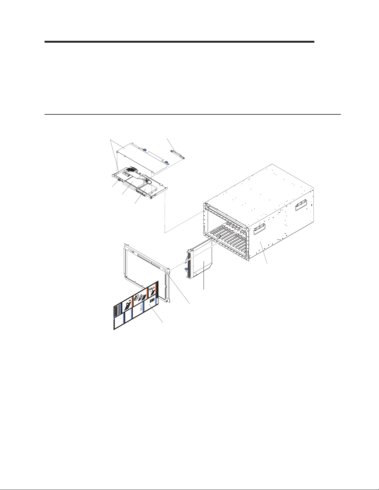
Chapter 7. Parts listing, BladeCenter Type 8677 and 1881
This parts listing supports the xSeries®Type 8677 and 1881. To check for an
updated parts listing on the Web, complete the following steps:
1. Go to http://www.ibm.com/support/
2. Under Search technical support, type 8677 or 1881 and click Search.
3. Under Document type, select Parts information and click Go.
Front view
8
9
7
6
5
1
ChassisService Information
H
o
t
P
l
u
g
P
r
o
c
e
s
s
o
r
H
B
l
o
a
t
d
P
e
l
u
g
M
e
d
i
a
P
T
r
r
o
a
c
y
e
s
s
o
r
H
o
t
S
w
a
p
H
a
r
d
D
i
s
k
D
r
i
v
e
C
s
u
s
t
o
m
e
r
I
n
f
o
r
m
C
a
t
o
i
m
o
n
m
o
n
C
h
a
s
s
i
s
F
o
F
r
R
D
h
p
o
t
M
U
r
w
t
o
p
n
f
h
i
s
:
l
l
o
o
e
/
t
/
a
t
s
w
r
p
d
,
e
w
:
a
f
/
i
n
h
/
I
w
l
w
B
e
d
t
I
s
.
M
t
w
i
f
,
n
p
b
r
e
h
w
:
h
m
f
/
q
i
n
/
.
t
u
o
w
i
server
.
t
t
b
c
s
e
p
w
r
n
o
m
:
&
C
/
t
m
w
m
l
/
o
.
y
t
w
c
i
.
m
p
/
i
a
o
x
p
w
b
s
a
I
p
s
S
B
m
c
,
m
x
k
w
a
e
h
c
t
/
M
e
t
s
s
/
r
.
r
i
.
t
d
e
i
b
i
i
e
c
e
u
t
e
b
S
o
i
s
p
a
o
r
q
l
s
p
i
m
e
i
e
t
t
:
u
m
e
e
y
n
p
h
r
/
r
e
/
ve
.
s
I
o
v
o
i
w
c
c
/
B
s
n
p
m
/
u
e
o
t
r
s
r
f
M
w
i
o
G
c
s
t
o
r
e
m
e
r
t
/
/
n
w
u
o
S
x
m
r
u
p
s
/
i
m
v
s
.
e
p
d
a
s
a
i
e
r
e
b
e
g
c
/
t
ve
i
c
r
e
r
o
m
/
h
g
i
w
o
n
e
r
o
u
.
m
w
m
h
s
c
i
o
d
o
p
/
e
m
e
e
m
a
p
s
e
t
a
/
e
/
s
g
p
r
e
e
a
v
r
g
e
v
e
r
e
/
r
s
B
l
a
C
d
D
e
O
p
e
r
a
t
o
r
P
a
n
e
l
O
p
Powe
e
r
r
a
o
n
t
L
o
o
c
r
a
t
i
P
o
O
n
v
a
e
r
n
t
e
e
m
I
n
p
l
f
e
o
r
r
a
m
t
u
a
r
t
e
i
o
n
S
y
s
t
e
m
e
r
r
o
r
4
2
3
Note: Field replaceable units (FRUs) should be serviced only by qualified field
service technicians. Customer replaceable units can be replaced by the customer.
Index System (BladeCenter Type 8677 and 1881) FRU No. CRU/FRU
1 Chassis assembly (all models) 25R8172 FRU
2 Filler blade (all models) 49P2517 CRU
2 Filler blade (models 1Xx, 2Xx, 2Gx, 3Rx 3Sx 3Tx, 3Xx, 4Sx, 4Tx) 39M3317 CRU
2 Filler blade (model 3Rx) (optional all models) 39M3264 CRU
3 Bezel assembly (all models except 3Rx, 3Sx, 3Tx, 3Xx, 4Sx, 4Tx) 49P2521 CRU
3 Bezel assembly (models 3Rx, 3Xx) 39M3200 CRU
3 Front Bezel (models 3Sx, 3Tx, 4Sx, 4Tx) 46C5450 CRU
4 BladeCenter system service label (all models except 3Rx, 3Sx, 3Tx, 4Sx,
4Tx, 3Xx)
4 BladeCenter system service label (models 3Rx, 3Xx) 39M3313 CRU
4 BladeCenter system service label (models 3Sx, 3Tx, 4Sx, 4Tx) 46C5451 CRU
© Copyright IBM Corp. 2011 79
26K9419 CRU
Page 90

Index System (BladeCenter Type 8677 and 1881) FRU No. CRU/FRU
5 Diskette drive, USB (primary) (all models except 3Sx, 3Tx, 4Sx, 4Tx) 39M0109 CRU
5 Diskette drive, USB (alternate) (all models except 3Sx, 3Tx, 4Sx, 4Tx) 39M0109 CRU
6 CD-RW/DVD-ROM, slim (primary) (models 3Rx, 3Xx) 43W4581 CRU
6 CD-RW/DVD-ROM (alternate) (models 3Rx, 3Xx) 39M3551 CRU
6 CD-RW/DVD-ROM (alternate) (models 3Rx, 3Xx) 39M3561 CRU
6 CD-ROM, 24X (primary) (all models except 3Xx, 3Rx, 3Sx, 3Tx, 3Xx,
4Sx, 4Tx)
6 CD-ROM, 24X (alternate) (all models except 3Xx, 3Rx, 3Sx, #tx, 3Xx,
4Sx, 4Tx)
6 CD-ROM, 24X (alternate) (all models except 3Xx, 3Rx, 3Sx, 3Tx, 3Xx,
4Sx, 4Tx)
6 CD-ROM, 24X (alternate) (all models except 3Rx, 3Sx, 3Tx, 3Xx, 4Sx,
4Tx)
6 Combo drive, 24/24/24/8X (alternate) (models 3Rx, 3Xx) 26K5439 CRU
6 DVD-ROM, 8X (primary) (model 3Rx) 39M3531 CRU
6 DVD-ROM, 8X (alternate) (model 3Xx) 26K5393 CRU
6 UltraSlim Enhanced SATA DVD-ROM (models 3Sx, 4Sx) (optional all
models)
6 UltraSlim Enhanced SATA Multi-Burner (models 3Sx, 4Sx) 44W3256 CRU
6 Optical Blank filler (models 3Sx, 3Tx, 4Sx, 4Ts) (optional all models) 49Y4868 CRU
7 Customer interface card (all models except 3Rx, 3Sx, 3Tx, 3Xx, 4Sx,
4Tx)
7 Customer interface card (model 3Rx, 3Sx, 3Tx, 3Xx, 4Sx, 4Tx) 26R0368 FRU
8 Media tray (all models except 3Rx, 3Sx, 3Tx, 3Xx, 4Sx, 4Tx) 49P2522 FRU
8 Media tray (models 3Rx, 3Xx) 39M3207 FRU
8 Media tray (models 3Sx, 3Tx, 4Sx, 4Tx) 46C5447 FRU
9 CD-ROM Interposer card (all models) 39R8542 CRU
39M3505 CRU
26K5423 CRU
06P5263 CRU
26K5423 CRU
44W3254 CRU
90P4703 FRU
80 BladeCenter E Type 8677 and 1881: Hardware Maintenance Manual and Troubleshooting Guide
Page 91
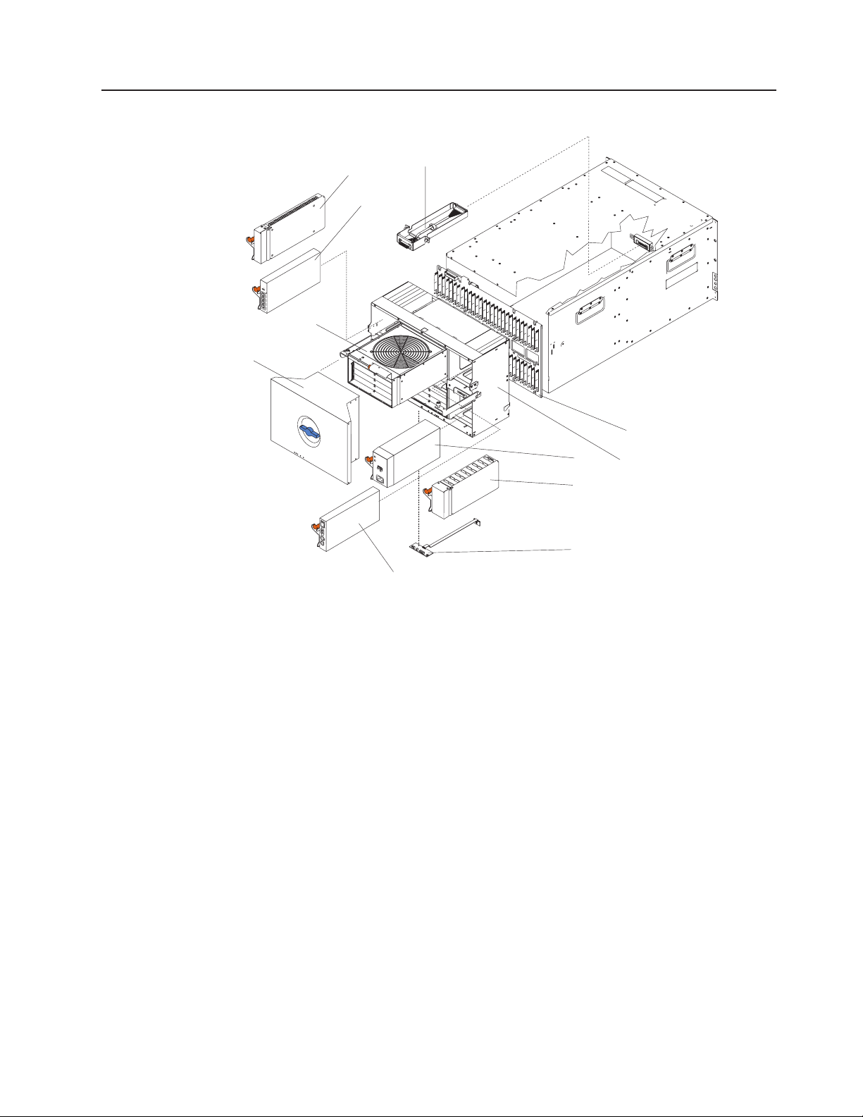
Rear view
9
11
10
O
K
L
INK
1
TX/R
X
L
IN
K
2
TX/R
X
L
IN
K
3
TX/
R
X
L
I
NK
4
TX/R
X
8
7
1
AC
D
C
23
4
OK
L
I
N
K
TX/RX
5
6
Index System (BladeCenter Type 8677 and 1881) FRU No. CRU/FRU
1 Midplane card (all models except 3Rx, 3Sx, 3Tx, 3Xx, 4Sx, 4Tx) 26K9450 FRU
1 Midplane card (models 3Sx, 3Tx, 4Sx, 4Tx) 46M0540 FRU
1 Midplane card (models 3Rx, 3Xx) 39R8563 FRU
2 SPC chassis (all models except 3Rx, 3Sx, 3Tx, 3Xx, 4Sx, 4Tx) 49P2530 FRU
2 SPC chassis (models 3Rx, 3Sx, 4Sx, 3Xx) 39M3223 FRU
2 SPC chassis (models 3Sx, 3Tx, 4Sx, 4Tx) 46C5453 FRU
3 Power supply module, 1400 watt (model 1Xx) 73P7501 CRU
3 Power supply module, 1800 watt (models 2Gx, 2Xx, CXx) 74P4401 CRU
3 Power supply module, 2000 watt (models 3Rx, 3Sx, 3Tx, 3Xx) 39Y7360 CRU
3 Power supply module, 2320 watt (model 4Sx, 4Tx) 39Y7400 CRU
4 Power supply filler (models 1Xx, 2Xx) 49P2519 CRU
4 Power supply filler (models 1Xx, 22x, 3Rx, 3Xx) 39M3262 CRU
4 Power Supply Filler (models 3Sx, 3Tx, 4Sx, 4Tx) 46C5470. CRU
5 Rear interface card (all models except 3Rx, 3Sx, 3Tx, 3Xx, 4Sx, 4Tx) 59P6602 FRU
5 Rear interface card (models 3Rx, 3Xx) 26R0361 FRU
5 Rear interface card (models 3Rx, 3Sx, 3Tx, 3Xx, 4Sx, 4Tx) 26R0368 FRU
6 Management module (all models except 3Rx, 3Sx, 3Tx, 3Xx, 4Sx, 4Tx) 39M4945 CRU
6 Advanced management module 2 (models 3Rx, 3Sx, 3Tx, 3Xx, 4Sx,
60Y0621 CRU
4Tx)
7 Acoustic attenuation module (optional all models) 39M3330 CRU
8 Blower with damper (all models) 39M3225 CRU
9 Filler module (models 1Xx, 2Gx, 2Xx) 49P2518 CRU
9 Filler module (models 3Rx, 3Sx, 3Tx, 3Xx, 4Sx, 4Tx) 39M3261 CRU
11 Media cable with bracket (models 3Rx, 3Xx) 39M3222 CRU
Chapter 7. Parts listing, BladeCenter Type 8677 and 1881 81
Page 92

Index System (BladeCenter Type 8677 and 1881) FRU No. CRU/FRU
11 Media cable with bracket (models 3Sx, 3Tx, 4Sx, 4Tx) 46C5452 CRU
1Gb 4-Port Ethernet Expansion Card (optional all models) 44W4488 CRU
6 Port Server Connectivity module (optional all models) 46M6151 CRU
10GbE 850NM Fibre SFP Plus Transceiver 44W4411 CRU
Bezel assembly, (optional all models) 43X0438 CRU
BladeCenter system board assembly (optional all models) 43W4506 CRU
Blade filer (optional all models) 26K9624 CRU
Cable, 3 m 12X -4X IB (optional all models) 44V5085 CRU
Cable, 8 m 12X -4X IB (optionl all models) 44V5086 CRU
Cable,8mOB(optional all models) 42R6157 CRU
Cable, 10 m 4X IB (optional all models) 44V5084 CRU
Cable 10 m 12X IB (optional all models) 42R6158 CRU
Cable, 4000 mm IBT (optional all models) 42R6155 CRU
Cable, 8000 mm 4X IB (optional all models) 44V5083 CRU
Cable, copper (optional) all models) 32R1848 CRU
Cable, diskette drive to CI card (model 1Xx) 49P2526 CRU
Cable, diskette drive to CI card (model 3Rx, 3Xx) 39M3220 CRU
Cable, DDR IB 4x to 4x 3.0 m 45D2238 CRU
Cable, DDR IB 4x to 4x 8.0 m 45D2239 CRU
Cable, Fibre Optic adapter (optionl all models) 39Y9223 CRU
Cable, Fibre Channel (model CXx) 02R9024 CRU
Cable, FO Adapter Duplex RECP (optional all models) 41V0573 CRU
Cable, Infiniband (optional all models) 44V5082 CRU
Cable, Nortel (optional all models) 26K6541 CRU
Cable, Nortel CX4 1.5 meter (optional all models) 32R1940 CRU
Cable, Nortel CX4 3 meter (optional all models) 32R1944 CRU
Cable, Optical Passthru OPC (optional all models) 39Y9174 CRU
Cable, Optical Passthru OPC (optional all models) 39Y9176 CRU
Cable, SDR 11 m Octopus 12x to (3) 4x's (optional all models) 45D2409 CRU
Cable, serial breakout (optional all models) 74P5186 CRU
Chassis Muffler (optional all models) 02R9004 CRU
Clip, power cord (all models) 26K6038 CRU
Connector, Nortel fibre channel (optional all models) 26R0808 CRU
Damper (all models) 42C0826 CRU
Damper (all models) 49P2532 CRU
Ethernet dongle cable (model CXx) 02R9024 CRU
Filler, front (models 1Xx, 2Xx, 2Gx, 3Rx, 3Sx, 3Tx, 3Xx, 4Sx, 4Tx) 39M3317 CRU
Filter (optional all models) 43X0439 CRU
ICPM Intelligent Copper Passthru module (optional all models) 44W4486 CRU
Insulator kit (optional all models) 39M6608 CRU
I/O card (optional all models) 32R1845 CRU
IRCL module (all models) 73P9044 CRU
Label, CRU/FRU (models 3Rx, 3Sx, 3Xx, 4Sx) 46C5472 CRU
Line cord (optional all models) 39M5393 CRU
Miscellaneous Parts Kit (all models except 3Rx, 3Sx, 3Tx, 3Xx, 4Sx,
4Tx)
v CD-ROM spring retainer (1)
v Diskette drive spring retainer (1)
v Mounting hardware assembly (1)
v Damper spring (4)
v Screw, M3.5 slotted (8)
v Label, customer write on (2)
49P2523 CRU
82 BladeCenter E Type 8677 and 1881: Hardware Maintenance Manual and Troubleshooting Guide
Page 93

Index System (BladeCenter Type 8677 and 1881) FRU No. CRU/FRU
Miscellaneous Parts Kit (all models)
26K9699 CRU
v CD-ROM spring retainer (1)
v Diskette drive spring retainer (1)
v Mounting hardware assembly (1)
v Upper damper (4)
v Lower damper (4)
v Screw, M3.5 slotted (8)
v Label, customer write on (2)
Miscellaneous Parts Kit (model 3RX)
26K9699 CRU
v Lower damper (4)
v Upper damper (4)
v Mounting hardware assembly (1)
v CD spring (1)
v Screw, M3.5 slotted (8)
v Label, customer write on (2)
Miscellaneous Parts Kit (models 3Rx, 3Xx)
39M3217 CRU
v Diskette drive spring (1)
Miscellaneous Parts Kit (models 3Sx, 3Tx, 4Sx, 4Tx)
46C5454 CRU
v Backflow Damper (1)
v Lower Damper (4)
v Upper Damper (4)
v Mounting hardware assembly (1)
v CD Spring (1)
v Rear Combo Bay (1)
v Combo (1)
v Blower Damper (1)
v Screw, M3.5 slotted (14)
Module, 3+7 port (optional all models) 32R1820 CRU
Module, 3+7 port (optional all models) 32R1821 CRU
Module, 4GB fibre channel (optional all models) 32R1836 CRU
Module, 4GB Qlogic (optional all models) 26R0888 CRU
Module, CPM (optional all models) 46C7101 CRU
Module, CPM (optional all models) 39Y9169 CRU
Module, fibre channel (model CXx) (optional all models) 59P6621 FRU
Module, optical (optional all models) 02R9082 CRU
Module, serial port (optional all models) 71P8600 CRU
PCI-E Expansion Card (optional all modes) 44W4487 CRU
Power cord (primary) (models 1Xx, 2Gx, 2Xx, 3Xx, 3Rx, 3Sx, 3Tx, 4Sx,
39M5389 CRU
4Tx, CXx, ERx, 2Gx)
PDU cord (model 1Xx) 36L8886 CRU
Power cable, interposer to CI card (model 1Xx) 49P2525 FRU
Power cable, interposer to CI card (models 3Rx, 3Xx) 39M3219 FRU
Rack Kit (model 3Rx, 3Sx, 3Tx, 4Sx, 4Tx, 3Xx)
39M3256 CRU
v Bracket, lower rack (1)
v Bracket, rear chassis (1)
v Rail, left (1)
v Rail, right (1)
v Upper shipping bracket (1)
v Rail, rack mounting hardware (1)
Rails, left and right (all models except 3Rx, 3Sx, 3Tx, 31x, 4Sx, 4Tx) 49P2610 CRU
Signal cable, interposer to CI card (model 1Xx) 49P2524 CRU
Signal cable, CI card to media (model 1Xx) 74P5227 FRU
Signal cable, CI card to media (models 3Rx, 3Xx) 39M3221 CRU
Signal cable, CI card interposer to chassis (model 3Rx, 3Xx) 39M3218 FRU
Switch, 10 port 4GB McDATA (optional all models) 32R1911 CRU
Chapter 7. Parts listing, BladeCenter Type 8677 and 1881 83
Page 94

Index System (BladeCenter Type 8677 and 1881) FRU No. CRU/FRU
Switch, 10 port Qlogic (optional all models) 32R1910 CRU
Switch, BladeCenter SAS module (optional all models) 39Y9193 CRU
Switch, Brocade (optional all models) 90P0164 CRU
Switch, CISCO Ethernet (optional all models) 13N2285 CRU
Switch, CISCO Ethernet (optional all models) 25R5391 CRU
Switch, CISCO Fibre Channel Ethernet module assembly (optional all
models)
Switch, CISCO Copper Ethernet module (optional all models) 32R1895 CRU
Switch, CISCO 4GB 20 Port Fiber Channel module (optional all models) 39Y9278 CRU
Switch, CISCO 4GB 10 Port Fiber Channel module (optional all models) 39Y9282 CRU
Switch, CISCO 4GB Shortwave SFP module (optional all models) 41Y8602 CRU
Switch, CISCO 4GB Longwave SFP module, single (optional all models) 41Y8603 CRU
Switch, Copper Passthru module (optional all models) 44X1986 CRU
Switch, Copper SFP 10GB Ethernet module (optional all models) 32R1936 CRU
Switch, Ethernet module (models 2Gx, CXx) (optional all models) 26K6482 CRU
Switch, Infiniband (optional all models) 26K6452 CRU
Switch, Infiniband card module (optional all models) 32R1903 CRU
Switch, McDATA fibre channel (optional all models) 32R1792 CRU
Switch, Nortel Ethernet 6 Pt Fiber (optional all models) 32R1870 CRU
Switch, Nortel Ethernet 6 Pt Copper (optional all models) 32R1869 CRU
Switch, Nortel Ethernet (optional all models) 32R1868 CRU
Switch, Nortel 10GB Uplink Ethernet (optional all models) 32R1785 CRU
Switch, Nortel ESM (optional all models) 26K6526 CRU
Switch, Nortel fibre channel (optional all models) 26K6529 CRU
Switch, Nortel 10GB 850NM Fiber XFP Transceiver SR assembly
(optional all models)
Switch, Nortel 10GB 1310 NM Fibre XFP Transceiver LR assembly
(optional all models)
Switch, Nortel 1/10GB Uplink Ethernet module (optional all models) 44W4407 CRU
Switch, Nortel 10 port 10 Gb switch module (optional all models) 46C7194 CRU
Switch, Optical Passthru module (optional all models) 44W3323 CRU
Switch, port, Nortel (optional all models) 39Y9131 CRU
Switch, Qlogic 6 port (optional all models) 26K6481 CRU
Tray, Fibre Channel adapter card mount (optional all models) 49P2514 CRU
32R1891 CRU
32R1883 CRU
32R1884 CRU
84 BladeCenter E Type 8677 and 1881: Hardware Maintenance Manual and Troubleshooting Guide
Page 95

Appendix A. Getting help and technical assistance
If you need help, service, or technical assistance or just want more information
about IBM products, you will find a wide variety of sources available from IBM to
assist you. This section contains information about where to go for additional
information about IBM and IBM products, what to do if you experience a problem
with your system, and whom to call for service, if it is necessary.
Before you call
Before you call, make sure that you have taken these steps to try to solve the
problem yourself:
v Check all cables to make sure that they are connected.
v Check the power switches to make sure that the system and any optional
devices are turned on.
v Use the troubleshooting information in your system documentation, and use the
diagnostic tools that come with your system. Information about diagnostic tools is
in the Problem Determination and Service Guide on the IBM Documentation CD
that comes with your system.
v Go to the IBM support Web site at http://www.ibm.com/systems/support/ to check
for technical information, hints, tips, and new device drivers or to submit a
request for information.
You can solve many problems without outside assistance by following the
troubleshooting procedures that IBM provides in the online help or in the
documentation that is provided with your IBM product. The documentation that
comes with IBM systems also describes the diagnostic tests that you can perform.
Most systems, operating systems, and programs come with documentation that
contains troubleshooting procedures and explanations of error messages and error
codes. If you suspect a software problem, see the documentation for the operating
system or program.
Using the documentation
Information about your IBM system and preinstalled software, if any, or optional
device is available in the documentation that comes with the product. That
documentation can include printed documents, online documents, readme files, and
help files. See the troubleshooting information in your system documentation for
instructions for using the diagnostic programs. The troubleshooting information or
the diagnostic programs might tell you that you need additional or updated device
drivers or other software. IBM maintains pages on the World Wide Web where you
can get the latest technical information and download device drivers and updates.
To access these pages, go to http://www.ibm.com/systems/support/ and follow the
instructions. Also, some documents are available through the IBM Publications
Center at http://www.ibm.com/shop/publications/order/.
Getting help and information from the World Wide Web
On the World Wide Web, the IBM Web site has up-to-date information about IBM
systems, optional devices, services, and support. The address for IBM System x
and xSeries information is http://www.ibm.com/systems/x/. The address for IBM
BladeCenter information is http://www.ibm.com/systems/bladecenter/. The address
for IBM IntelliStation
© Copyright IBM Corp. 2011 85
®
information is http://www.ibm.com/intellistation/.
®
Page 96

You can find service information for IBM systems and optional devices at
http://www.ibm.com/systems/support/.
Software service and support
Through IBM Support Line, you can get telephone assistance, for a fee, with usage,
configuration, and software problems with System x and xSeries servers,
BladeCenter products, IntelliStation workstations, and appliances. For information
about which products are supported by Support Line in your country or region, see
http://www.ibm.com/services/sl/products/.
For more information about Support Line and other IBM services, see
http://www.ibm.com/services/, or see http://www.ibm.com/planetwide/ for support
telephone numbers. In the U.S. and Canada, call 1-800-IBM-SERV
(1-800-426-7378).
Hardware service and support
You can receive hardware service through your IBM reseller or IBM Services. To
locate a reseller authorized by IBM to provide warranty service, go to
http://www.ibm.com/partnerworld/ and click Find a Business Partner on the right
side of the page. For IBM support telephone numbers, see http://www.ibm.com/
planetwide/. In the U.S. and Canada, call 1-800-IBM-SERV (1-800-426-7378).
In the U.S. and Canada, hardware service and support is available 24 hours a day,
7 days a week. In the U.K., these services are available Monday through Friday,
from 9 a.m. to 6 p.m.
IBM Taiwan product service
IBM Taiwan product service contact information:
IBM Taiwan Corporation
3F, No 7, Song Ren Rd.
Taipei, Taiwan
Telephone: 0800-016-888
86 BladeCenter E Type 8677 and 1881: Hardware Maintenance Manual and Troubleshooting Guide
Page 97

Appendix B. Related service information
Note: The service procedures are designed to help you isolate problems. They are
written with the assumption that you have model-specific training on all computers,
or that you are familiar with the computers, functions, terminology, and service
information provided in this manual.
Safety information
The following section contains the safety information that you need to be familiar
with before servicing an IBM computer.
General safety
Follow these rules to ensure general safety:
v Observe good housekeeping in the area of the machines during and after
maintenance.
v When lifting any heavy object:
1. Ensure you can stand safely without slipping.
2. Distribute the weight of the object equally between your feet.
3. Use a slow lifting force. Never move suddenly or twist when you attempt to
lift.
4. Lift by standing or by pushing up with your leg muscles; this action removes
the strain from the muscles in your back. Do not attempt to lift any objects
that weigh more than 16 kg (35 lb) or objects that you think are too heavy for
you.
v Do not perform any action that causes hazards to the customer, or that makes
the equipment unsafe.
v Before you start the machine, ensure that other service representatives and the
customer's personnel are not in a hazardous position.
v Place removed covers and other parts in a safe place, away from all personnel,
while you are servicing the machine.
v Keep your tool case away from walk areas so that other people will not trip over
it.
v Do not wear loose clothing that can be trapped in the moving parts of a machine.
Ensure that your sleeves are fastened or rolled up above your elbows. If your
hair is long, fasten it.
v Insert the ends of your necktie or scarf inside clothing or fasten it with a
nonconductive clip, approximately 8 centimeters (3 inches) from the end.
v Do not wear jewelry, chains, metal-frame eyeglasses, or metal fasteners for your
clothing.
Remember: Metal objects are good electrical conductors.
v Wear safety glasses when you are: hammering, drilling soldering, cutting wire,
attaching springs, using solvents, or working in any other conditions that might be
hazardous to your eyes.
v After service, reinstall all safety shields, guards, labels, and ground wires.
Replace any safety device that is worn or defective.
v Reinstall all covers correctly before returning the machine to the customer.
© Copyright IBM Corp. 2011 87
Page 98

Electrical safety
CAUTION:
Electrical current from power, telephone, and communication cables can be
hazardous. To avoid personal injury or equipment damage, disconnect the
attached power cords, telecommunication systems, networks, and modems
before you open the server covers, unless instructed otherwise in the
installation and configuration procedures.
Observe the following rules when working on electrical equipment.
Important: Use only approved tools and test equipment. Some hand tools have
handles covered with a soft material that do not insulate you when working with live
electrical currents.
Many customers have, near their equipment, rubber floor mats that contain small
conductive fibers to decrease electrostatic discharges. Do not use this type of mat
to protect yourself from electrical shock.
v Find the room emergency power-off (EPO) switch, disconnecting switch, or
electrical outlet. If an electrical accident occurs, you can then operate the switch
or unplug the power cord quickly.
v Do not work alone under hazardous conditions or near equipment that has
hazardous voltages.
v Disconnect all power before:
– Performing a mechanical inspection
– Working near power supplies
– Removing or installing main units
v Before you start to work on the machine, unplug the power cord. If you cannot
unplug it, ask the customer to power-off the wall box that supplies power to the
machine and to lock the wall box in the off position.
v If you need to work on a machine that has exposed electrical circuits, observe
the following precautions:
– Ensure that another person, familiar with the power-off controls, is near you.
Remember: Another person must be there to switch off the power, if
necessary.
– Use only one hand when working with powered-on electrical equipment; keep
the other hand in your pocket or behind your back.
Remember: There must be a complete circuit to cause electrical shock. By
observing the above rule, you may prevent a current from passing through
your body.
– When using testers, set the controls correctly and use the approved probe
leads and accessories for that tester.
– Stand on suitable rubber mats (obtained locally, if necessary) to insulate you
from grounds such as metal floor strips and machine frames.
Observe the special safety precautions when you work with very high voltages;
these instructions are in the safety sections of maintenance information. Use
extreme care when measuring high voltages.
v Regularly inspect and maintain your electrical hand tools for safe operational
condition.
88 BladeCenter E Type 8677 and 1881: Hardware Maintenance Manual and Troubleshooting Guide
Page 99

v Do not use worn or broken tools and testers.
v Never assume that power has been disconnected from a circuit. First, check that
it has been powered-off.
v Always look carefully for possible hazards in your work area. Examples of these
hazards are moist floors, nongrounded power extension cables, power surges,
and missing safety grounds.
v Do not touch live electrical circuits with the reflective surface of a plastic dental
mirror. The surface is conductive; such touching can cause personal injury and
machine damage.
v Do not service the following parts with the power on when they are removed from
their normal operating places in a machine:
– Power supply units
– Pumps
– Blowers and fans
– Motor generators and similar units. (This practice ensures correct grounding of
the units.)
v If an electrical accident occurs:
– Use caution; do not become a victim yourself.
– Switch off power.
– Send another person to get medical aid.
Safety inspection guide
The intent of this inspection guide is to assist you in identifying potentially unsafe
conditions on these products. Each machine, as it was designed and built, had
required safety items installed to protect users and service personnel from injury.
This guide addresses only those items. However, good judgment should be used to
identify potential safety hazards due to attachment of non-IBM features or options
not covered by this inspection guide.
If any unsafe conditions are present, you must determine how serious the apparent
hazard could be and whether you can continue without first correcting the problem.
Consider these conditions and the safety hazards they present:
v Electrical hazards, especially primary power (primary voltage on the frame can
cause serious or fatal electrical shock).
v Explosive hazards, such as a damaged CRT face or bulging capacitor
v Mechanical hazards, such as loose or missing hardware
The guide consists of a series of steps presented in a checklist. Begin the checks
with the power off, and the power cord disconnected.
Checklist:
1. Check exterior covers for damage (loose, broken, or sharp edges).
2. Turn off the computer. Disconnect the power cord.
Appendix B. Related service information 89
Page 100

3. Check the power cord for:
a. A third-wire ground connector in good condition. Use a meter to measure
third-wire ground continuity for 0.1 ohm or less between the external ground
pin and frame ground.
b. The power cord should be the appropriate type as specified in the parts
listings.
c. Insulation must not be frayed or worn.
4. Remove the cover.
5. Check for any obvious non-IBM alterations. Use good judgment as to the safety
of any non-IBM alterations.
6. Check inside the unit for any obvious unsafe conditions, such as metal filings,
contamination, water or other liquids, or signs of fire or smoke damage.
7. Check for worn, frayed, or pinched cables.
8. Check that the power-supply cover fasteners (screws or rivets) have not been
removed or tampered with.
Handling electrostatic discharge-sensitive devices
Any computer part containing transistors or integrated circuits (Is) should be
considered sensitive to electrostatic discharge (ESD). ESD damage can occur when
there is a difference in charge between objects. Protect against ESD damage by
equalizing the charge so that the server, the part, the work mat, and the person
handling the part are all at the same charge.
Notes:
1. Use product-specific ESD procedures when they exceed the requirements noted
here.
2. Make sure that the ESD-protective devices you use have been certified (ISO
9000) as fully effective.
When handling ESD-sensitive parts:
v Keep the parts in protective packages until they are inserted into the product.
v Avoid contact with other people.
v Wear a grounded wrist strap against your skin to eliminate static on your body.
v Prevent the part from touching your clothing. Most clothing is insulative and
retains a charge even when you are wearing a wrist strap.
v Use the black side of a grounded work mat to provide a static-free work surface.
The mat is especially useful when handling ESD-sensitive devices.
v Select a grounding system, such as those in the following list, to provide
protection that meets the specific service requirement.
Note: The use of a grounding system is desirable but not required to protect
against ESD damage.
– Attach the ESD ground clip to any frame ground, ground braid, or green-wire
ground.
– Use an ESD common ground or reference point when working on a
double-insulated or battery-operated system. You can use coax or
connector-outside shells on these systems.
– Use the round ground-prong of the ac plug on ac-operated computers.
90 BladeCenter E Type 8677 and 1881: Hardware Maintenance Manual and Troubleshooting Guide
 Loading...