

Page 1

BladeCenter T Ty pe 8720 and 8730
Hardw are Maintenance Manual an d
Troubleshooting Guide
Page 2

Page 3

BladeCenter T Ty p e 8720 and 8730
Hardw are Maintenance Manual an d
Troubleshooting Guide
Page 4

Note
Before using this information and the product it supports, be sure to read Appendix C, “Notices,” on page 157.
Sixth Edition (August 2006)
© Copyright International Business Machines Corporation 2004. All rights reserved.
US Government Users Restricted Rights – Use, duplication or disclosure restricted by GSA ADP Schedule Contract
with IBM Corp.
Page 5
About this manual
This manual contains diagnostic information, a Symptom-to-FRU index, service
information, error codes, error messages, and configuration information for the
BladeCenter
Important safety information
Be sure to read all caution and danger statements in this book before performing
any of the instructions. See “Safety information” on page 113.
Lea todas as instruções de cuidado e perigo antes de executar qualquer operação.
®
Type 8720 and 8730.
Prenez connaissance de toutes les consignes de type Attention et Danger avant de
procéder aux opérations décrites par les instructions.
Lesen Sie alle Sicherheitshinweise, bevor Sie eine Anweisung ausführen.
Accertarsi di leggere tutti gli avvisi di attenzione e di pericolo prima di effettuare
qualsiasi operazione.
© Copyright IBM Corp. 2004 iii
Page 6

Lea atentamente todas las declaraciones de precaución y peligro ante de llevar a
cabo cualquier operación.
Online support
You can download the most current diagnostic, H8 flash, and device driver files
from http://www.ibm.com/pc/support on the World Wide Web.
Support telephone numbers
View support telephone numbers at http://www.ibm.com/planetwide/ on the World
Wide Web.
iv BladeCenter T Type 8720 and 8730: Hardware Maintenance Manual and Troubleshooting Guide
Page 7

Contents
About this manual . . . . . . . . . . . . . . . . . . . . . . . iii
Important safety information . . . . . . . . . . . . . . . . . . . . iii
Online support . . . . . . . . . . . . . . . . . . . . . . . . .iv
Support telephone numbers . . . . . . . . . . . . . . . . . . . .iv
Chapter 1. General information . . . . . . . . . . . . . . . . . . .1
Related publications . . . . . . . . . . . . . . . . . . . . . . .3
Notices and statements used in this book . . . . . . . . . . . . . . .4
Features and specifications for the BladeCenter T Type 8720 unit . . . . . .5
Features and specifications for the BladeCenter T Type 8730 unit . . . . . .7
Major components of the BladeCenter T Types 8720 and 8730 unit . . . . . .9
Front view . . . . . . . . . . . . . . . . . . . . . . . . . .9
Rear view . . . . . . . . . . . . . . . . . . . . . . . . . .15
BladeCenter T unit power, controls, and indicators . . . . . . . . . . . .19
Starting the BladeCenter T unit . . . . . . . . . . . . . . . . . .19
Shutting down the BladeCenter T unit . . . . . . . . . . . . . . .21
Chapter 2. Configuring the BladeCenter T unit . . . . . . . . . . . .23
Setting up the remote connection . . . . . . . . . . . . . . . . . .25
Cabling the Ethernet port . . . . . . . . . . . . . . . . . . . .25
Management and configuration program . . . . . . . . . . . . . . .26
Setting up the management and configuration program . . . . . . . . .26
Starting the management and configuration program . . . . . . . . . .27
Setting management and configuration program options . . . . . . . . .28
Saving and restoring the configuration file . . . . . . . . . . . . . .29
Configuring an I/O module . . . . . . . . . . . . . . . . . . . . .29
What to configure . . . . . . . . . . . . . . . . . . . . . . .29
Supporting Ethernet failover . . . . . . . . . . . . . . . . . . .30
Configuring the Ethernet controllers in the blade servers . . . . . . . .30
BladeCenter T networking guidelines . . . . . . . . . . . . . . . . .31
Using Remote Deployment Manager Version 4.11 Update 3 or later . . . . .33
Using IBM Director . . . . . . . . . . . . . . . . . . . . . . .33
Communicating with the IBM Director software . . . . . . . . . . . .33
Chapter 3. Diagnostics . . . . . . . . . . . . . . . . . . . . .35
Diagnostic tools overview . . . . . . . . . . . . . . . . . . . . .35
Identifying problems using the Light Path Diagnostics feature . . . . . . . .35
Chapter 4. Setting up the BladeCenter T hardware . . . . . . . . . .37
Setting up the BladeCenter T unit . . . . . . . . . . . . . . . . . .37
Installation guidelines . . . . . . . . . . . . . . . . . . . . . .37
Preparing for system power . . . . . . . . . . . . . . . . . . .38
System reliability considerations . . . . . . . . . . . . . . . . .39
Handling static-sensitive devices . . . . . . . . . . . . . . . . .40
Preinstallation steps . . . . . . . . . . . . . . . . . . . . . . .42
Removing and installing the bezel assembly . . . . . . . . . . . . . .43
Removing the bezel assembly . . . . . . . . . . . . . . . . . .43
Installing the bezel assembly . . . . . . . . . . . . . . . . . . .44
Removing and installing the bezel air filter . . . . . . . . . . . . . . .44
Removing and installing power modules . . . . . . . . . . . . . . .46
Removing a power module . . . . . . . . . . . . . . . . . . .47
Installing a power module . . . . . . . . . . . . . . . . . . . .48
Removing and installing the media tray . . . . . . . . . . . . . . . .49
© Copyright IBM Corp. 2004 v
Page 8

Removing the media tray . . . . . . . . . . . . . . . . . . . .50
Installing the media tray . . . . . . . . . . . . . . . . . . . .50
Removing and installing management modules . . . . . . . . . . . . .51
Removing a management module . . . . . . . . . . . . . . . . .52
Installing a management module . . . . . . . . . . . . . . . . .53
Removing and installing blower modules . . . . . . . . . . . . . . .54
Removing a blower module . . . . . . . . . . . . . . . . . . .55
Installing a blower module . . . . . . . . . . . . . . . . . . . .55
Removing and installing the KVM (keyboard, video, mouse) module . . . . .56
Removing the KVM module . . . . . . . . . . . . . . . . . . .57
Installing the KVM module . . . . . . . . . . . . . . . . . . . .57
Removing and installing the LAN module . . . . . . . . . . . . . . .58
Removing the LAN module . . . . . . . . . . . . . . . . . . .59
Installing the LAN module . . . . . . . . . . . . . . . . . . . .59
Removing and installing I/O modules . . . . . . . . . . . . . . . . .60
Removing an I/O module . . . . . . . . . . . . . . . . . . . .62
Installing an I/O module . . . . . . . . . . . . . . . . . . . .62
Blade servers . . . . . . . . . . . . . . . . . . . . . . . . .63
Blade server expansion options . . . . . . . . . . . . . . . . . .63
Removing and installing a blade server or filler module . . . . . . . . .64
Completing the installation . . . . . . . . . . . . . . . . . . . . .66
Chapter 5. Service replaceable units . . . . . . . . . . . . . . . .67
DC terminal cover with fasteners . . . . . . . . . . . . . . . . . .68
AC rear panel . . . . . . . . . . . . . . . . . . . . . . . . .69
DC Rear Panel . . . . . . . . . . . . . . . . . . . . . . . . .70
Upper flex circuit assembly . . . . . . . . . . . . . . . . . . . .71
Lower flex circuit assembly . . . . . . . . . . . . . . . . . . . .72
Docking board/blower housing assembly - (dc Type 8720 and ac Type 8730) 75
Rear chassis stiffener bracket . . . . . . . . . . . . . . . . . . .77
Backplane . . . . . . . . . . . . . . . . . . . . . . . . . .79
Backplane insulator . . . . . . . . . . . . . . . . . . . . . . .81
Air damper . . . . . . . . . . . . . . . . . . . . . . . . . .82
Mechanical chassis . . . . . . . . . . . . . . . . . . . . . . .85
Chapter 6. Symptom-to-FRU index . . . . . . . . . . . . . . . . .89
Error symptoms . . . . . . . . . . . . . . . . . . . . . . . .89
Light path diagnostics LEDs . . . . . . . . . . . . . . . . . . . .98
Temperature error messages . . . . . . . . . . . . . . . . . . . 100
Blower error messages . . . . . . . . . . . . . . . . . . . . . 100
Power error messages . . . . . . . . . . . . . . . . . . . . . 100
Blade server error messages . . . . . . . . . . . . . . . . . . . 101
KVM error message . . . . . . . . . . . . . . . . . . . . . . 102
Switch error messages . . . . . . . . . . . . . . . . . . . . . 102
Management-module error messages . . . . . . . . . . . . . . . . 103
Bus error messages . . . . . . . . . . . . . . . . . . . . . . 104
Undetermined problems . . . . . . . . . . . . . . . . . . . . . 104
Problem determination tips . . . . . . . . . . . . . . . . . . . . 105
Chapter 7. Parts listing, BladeCenter T Type 8720 and 8730 . . . . . . 107
Type 8720 and 8730 - Front view . . . . . . . . . . . . . . . . . 107
Type 8720 and 8730 - Rear view . . . . . . . . . . . . . . . . . . 108
Appendix A. Getting help and technical assistance . . . . . . . . . . 111
Before you call . . . . . . . . . . . . . . . . . . . . . . . . 111
Using the documentation . . . . . . . . . . . . . . . . . . . . . 111
vi BladeCenter T Type 8720 and 8730: Hardware Maintenance Manual and Troubleshooting Guide
Page 9

Getting help and information from the World Wide Web . . . . . . . . . 111
Software service and support . . . . . . . . . . . . . . . . . . .112
Hardware service and support . . . . . . . . . . . . . . . . . . .112
Appendix B. Related service information . . . . . . . . . . . . . .113
Safety information . . . . . . . . . . . . . . . . . . . . . . .113
General safety . . . . . . . . . . . . . . . . . . . . . . . .113
Electrical safety . . . . . . . . . . . . . . . . . . . . . . .114
Safety inspection guide . . . . . . . . . . . . . . . . . . . .115
Handling electrostatic discharge-sensitive devices . . . . . . . . . .116
Grounding requirements . . . . . . . . . . . . . . . . . . . .117
Safety notices (multi-lingual translations) . . . . . . . . . . . . . .117
Appendix C. Notices . . . . . . . . . . . . . . . . . . . . . . 157
Edition notice . . . . . . . . . . . . . . . . . . . . . . . . . 157
Trademarks . . . . . . . . . . . . . . . . . . . . . . . . . . 158
Important notes . . . . . . . . . . . . . . . . . . . . . . . . 158
Product recycling and disposal . . . . . . . . . . . . . . . . . . 159
Battery return program . . . . . . . . . . . . . . . . . . . . . 159
Electronic emission notices . . . . . . . . . . . . . . . . . . . . 160
Federal Communications Commission (FCC) statement . . . . . . . . 160
Industry Canada Class A emission compliance statement . . . . . . . . 160
Australia and New Zealand Class A statement . . . . . . . . . . . . 160
United Kingdom telecommunications safety requirement . . . . . . . . 160
European Union EMC Directive conformance statement . . . . . . . . 161
Taiwanese Class A warning statement . . . . . . . . . . . . . . . 161
Chinese Class A warning statement . . . . . . . . . . . . . . . . 161
Japanese Voluntary Control Council for Interference (VCCI) statement 161
Power cords . . . . . . . . . . . . . . . . . . . . . . . . . 162
Index . . . . . . . . . . . . . . . . . . . . . . . . . . . . 165
Contents vii
Page 10

viii BladeCenter T Type 8720 and 8730: Hardware Maintenance Manual and Troubleshooting Guide
Page 11

Chapter 1. General information
®
The IBM
high-density, high-performance blade server systems developed for
telecommunications network applications and other applications requiring physical
robustness.
The BladeCenter T unit uses blade servers, switches, and other components that
are common to the IBM BladeCenter product line. This common component
strategy makes it ideal for applications in telecommunications networks that need
high levels of computing power and access to common off-the-shelf middleware
packages that are used in IT data centers. The BladeCenter T unit supports up to
eight blade servers and four I/O modules, making it ideally suited for networking
environments that require a large number of high-performance servers in a small
amount of space. The BladeCenter T unit provides common resources that are
shared by the blade servers, such as power, cooling, system management, network
connections, backplane, and I/O (CD-ROM drive and connectors for USB, network
interfaces, and – for blade servers that support the KVM function – keyboard, video,
and mouse).
Performance, ease of use, reliability (NEBS/ETSI compliance), and expansion
capabilities were key considerations during the design of the BladeCenter T system.
These design features make it possible for you to customize the system hardware
to meet your needs today, while providing flexible expansion capabilities for the
future.
BladeCenter®T Types 8720 and 8730 units are rack-mounted,
This Hardware Maintenance and Troubleshooting Guide provides information to:
v Set up and cable a BladeCenter T unit
v Start and configure a BladeCenter T unit
v Install and remove modules, options, and blades
v Replace field replaceable units
v Perform troubleshooting and servicing of the BladeCenter T unit
Packaged
with the Hardware Maintenance and Troubleshooting Guide are software
CDs that help you to configure and manage the BladeCenter T unit.
This Hardware Maintenance and Troubleshooting Guide and other publications that
provide detailed information about your BladeCenter T unit are provided in Portable
Document Format (PDF) on the IBM BladeCenter T Documentation CD.
You can register the BladeCenter T unit and blade servers on the World Wide Web.
To register, go to: http://www.ibm.com/pc/register/.
© Copyright IBM Corp. 2004 1
Page 12
Record information about your BladeCenter T unit in the following table. Yo u will
need this information when you register your BladeCenter T unit with IBM.
Product name IBM Eserver BladeCenter T
Machine type (8720 or 8730) _________________________________________
Model number _________________________________________
Serial number _________________________________________
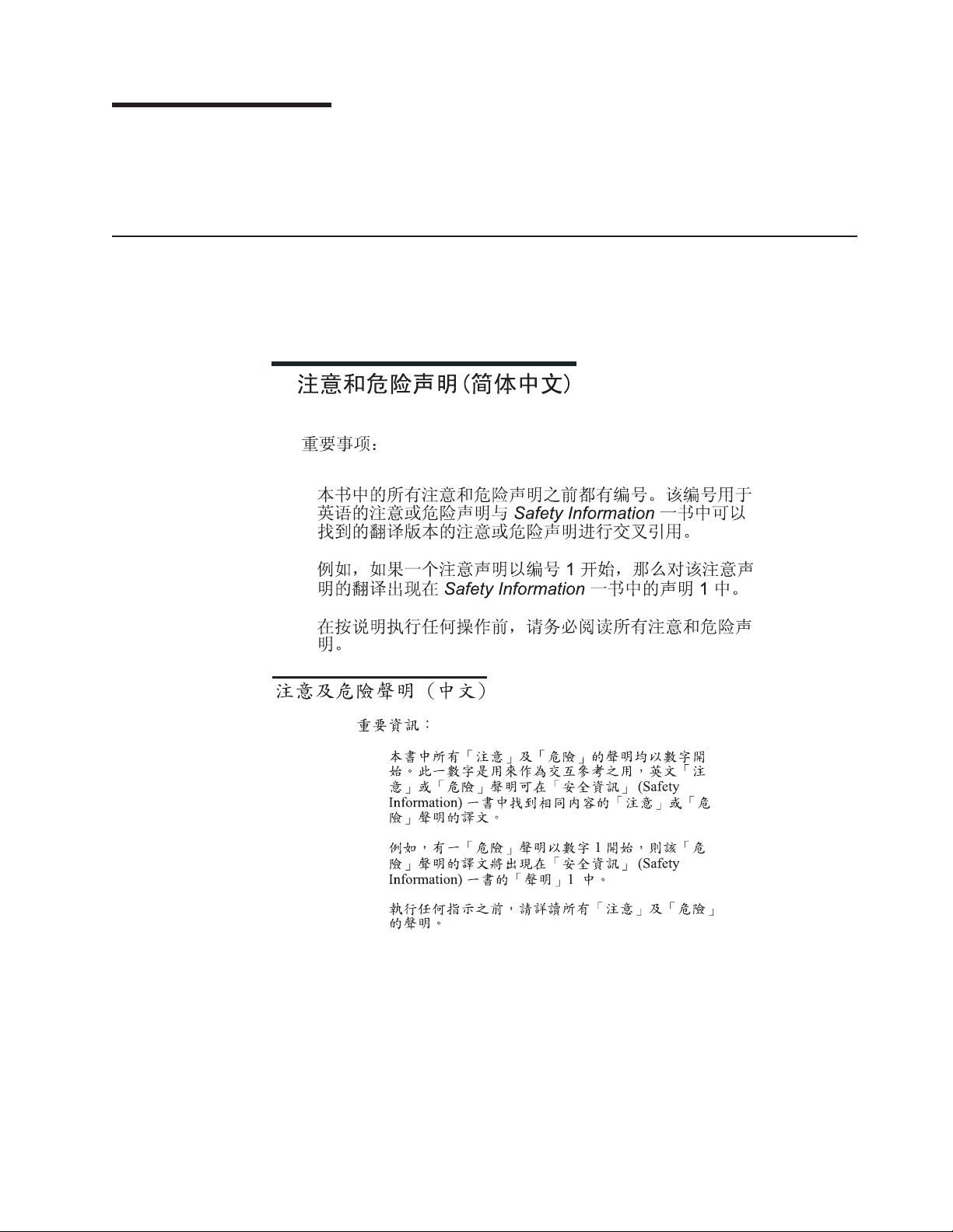
The serial number and model number are located in three places on the
BladeCenter T unit:
v To p of the BladeCenter T unit.
v Front of the bezel assembly.
v Front of the BladeCenter T unit.
labels on the top and the front of the bezel assembly of the BladeCenter T unit
The
are shown in the following illustration.
Information label
C
M
M
1
C
M
M
2
E
S
D
Serial number label
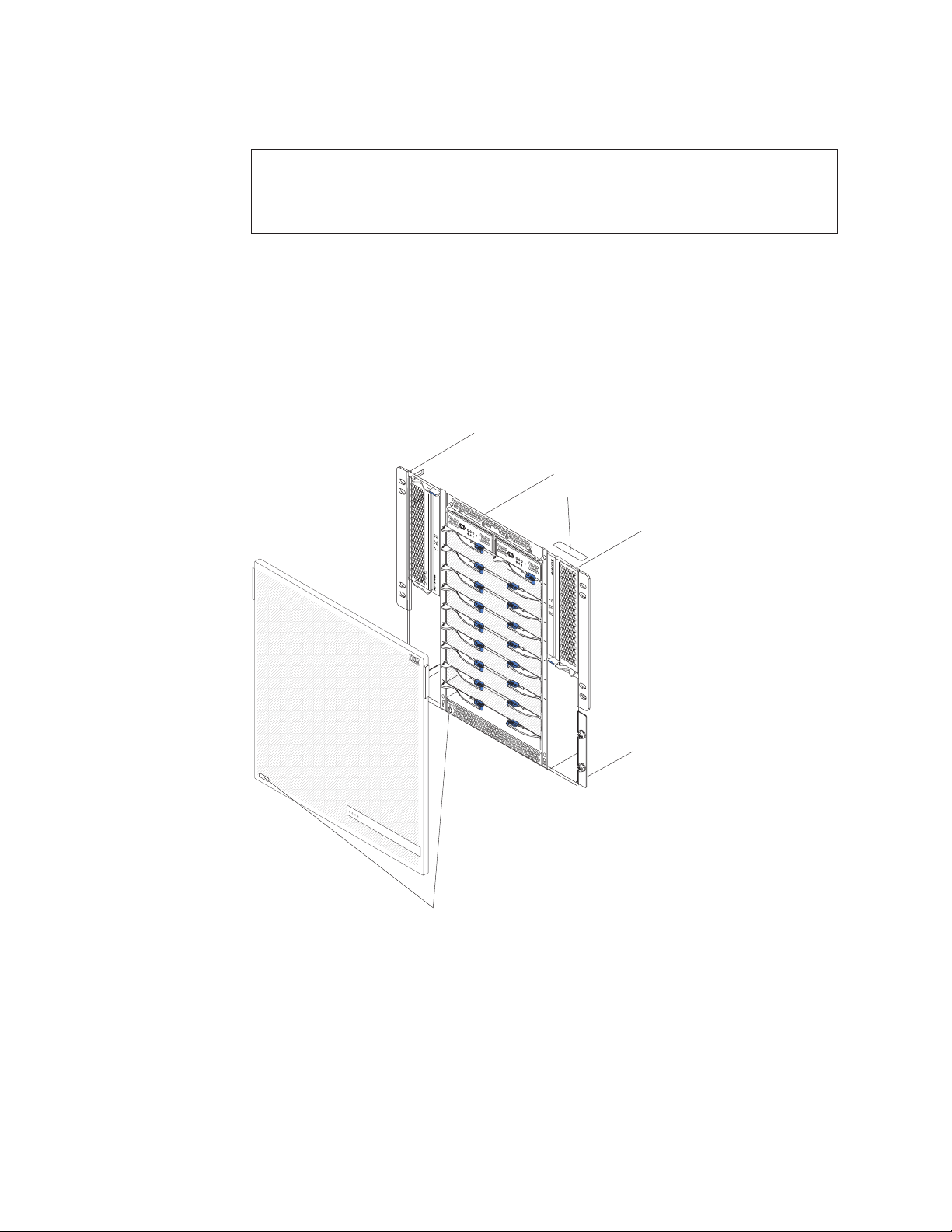
A set of user labels comes with each blade server. When you install a blade server
in the BladeCenter T unit, write identifying information on a label and place the label
on the BladeCenter T unit bezel.
The following illustration shows the placement of the label, to the side of the blade
server, on the BladeCenter T unit.
2 BladeCenter T Type 8720 and 8730: Hardware Maintenance Manual and Troubleshooting Guide
Page 13
Important: Do not place the label on the blade server itself or in any way block the
ventilation holes on the blade server.
Related publications
This Hardware Maintenance and Troubleshooting Guide is provided in Portable
Document Format (PDF). It contains information to help you solve the problem
yourself or to provide helpful information to a service technician.
In addition to this Hardware Maintenance and Troubleshooting Guide, the following
documentation is provided in PDF on the IBM BladeCenter T Documentation CD
that comes with your BladeCenter T unit:
v Safety Information: This document contains translated caution and danger
statements. Each caution and danger statement that appears in the
documentation has a number that you can use to locate the corresponding
statement in your language in the Safety Information document.
v Installation and User’s Guide This publication provides general information about
the server, including information about features, how to configure the server, and
how to get help.
v BladeCenter T rack installation instructions
These documents contain instructions for installing the BladeCenter T unit in a
4-post and 2-post rack.
CMM
1
CMM
2
User
label
Note: The BladeCenter T can also be installed in some xSeries and pSeries
racks, such as the IBM Netbay42 Enterprise Rack Model 9308. See the
installation instructions that come with those racks.
v BladeCenter T Management Module Installation Guide
This document contains instructions for installing an IBM BladeCenter T
management module option in a BladeCenter T unit and creating the initial
configuration.
v BladeCenter T Management Module User’s Guide
This document contains instructions for using the Web interface to configure the
management modules in a BladeCenter T unit.
Additional publications might be included on the IBM BladeCenter T Documentation
CD.
Chapter 1. General information 3
Page 14

Notices and statements used in this book
The caution and danger statements that appear in this book are also in the
multilingual Safety Information book, which is on the IBM BladeCenter T
Documentation CD. Each statement is numbered for reference to the corresponding
statement in the Safety Information book.
The following notices and statements are used in the documentation:
v Note: These notices provide important tips, guidance, or advice.
v Important: These notices provide information or advice that might help you avoid
inconvenient or problem situations.
v Attention: These notices indicate possible damage to programs, devices, or
data. An attention notice is placed just before the instruction or situation in which
damage could occur.
v Caution: These statements indicate situations that can be potentially hazardous
to you. A caution statement is placed just before the description of a potentially
hazardous procedure step or situation.
v Danger: These statements indicate situations that can be potentially lethal or
extremely hazardous to you. A danger statement is placed just before the
description of a potentially lethal or extremely hazardous procedure step or
situation.
4 BladeCenter T Type 8720 and 8730: Hardware Maintenance Manual and Troubleshooting Guide
Page 15

Features and specifications for the BladeCenter T Type 8720 unit
The following table provides a summary of the features and specifications of the
BladeCenter T Type 8720 unit.
Table 1. BladeCenter T Type 8720 features and specifications
Media tray (on front):
v DVD/CD-RW drive: slim IDE
v Two Universal Serial Bus (USB) v2.0
full speed ports
v System-status panel
bays (on front):
Module
v Eight hot-swap blade bays
v Four hot-swap power-module bays
v Two hot-swap management module
bays
Module bays (on rear):
v Four hot-swap I/O module bays
v Four hot-swap blower bays
v One hot-swap KVM (keyboard, video,
mouse) module
v One hot-swap LAN module
modules:
Power
v Standard: Two 1300-watt or greater
hot-swap -48 V dc (-40 to -60 V dc)
power modules
– Power modules 1 and 2 supply
power to:
- Blade bays 1 through 4
- Management modules 1 and 2
- I/O modules 1 and 2
- Media tray
- All KVM, LAN, and alarm
interfaces
- All four blower modules
Power modules 1 and 2 provide
–
redundancy to each other
Maximum: Four 1300-watt or greater
v
hot-swap -48 V dc (-40 to -60 V dc)
power modules
– Power modules 3 and 4 supply
power to:
- Blade bays 5 through 8
- I/O modules 3 and 4
– Power modules 3 and 4 provide
redundancy to each other
– Blowers are powered by all four
power modules
LAN module:
v Two 10/100 Mb Ethernet remote
management connections
v One DSUB 15P alarm connector
module:
KVM
v Video port (analog)
v PS/2 keyboard port
v PS/2 mouse port
v System-status panel
I/O modules:
v Standard: None
v Maximum: Four
– Two hot-swap 1 Gb Ethernet
four-port switch modules
– Two hot-swap switch modules of
another network-communication
standard, such as Fibre Channel
Management
module:
v Standard: One hot-swap management
module providing system-management
functions for the BladeCenter T unit
v Maximum: Two hot-swap management
modules (one active, one redundant)
Redundant
cooling:
Four variable-speed hot-swap blowers
Front bezel with changeable filter
Upgradeable microcode:
v management module firmware
v I/O-module firmware (not all I/O module
types)
v Blade server service processor firmware
(BIOS, service processor)
(8 U):
Size
v Height: 349.25 mm (13.75 in. or 8 U)
v Depth: 508 mm (20 in.) from front of
chassis to rear I/O connector plane
Maximum depth: 600 mm (23.62 in.)
including bezel, handles, and cable
bend radius.
v Width: 442 mm (17.4 in.)
v Weight:
– Fully configured with modules and
blade servers: Approx. 100.2 kg (221
lb)
– Fully configured without blade
servers: Approx. 61.7 kg (136 lb)
Security
features:
v Login password for remote connection
v Lightweight Directory Access Protocol
(LDAP) and role based security for user
authentication and authorization
v Secure Shell (SSH) for remote
command-line interface
v Secure socket layer (SSL) security for
remote Web interface access
®
Predictive Failure Analysis
(PFA)
alerts:
v Blowers
v Blade-dependent features
v Power supplies
Declared acoustical noise emission levels
for normal operations:
v Sound-power levels (upper-limit): 7.8 bels
v Sound-pressure levels (average), for four
one-meter bystander positions: 63 dBA
noise emission levels stated are the
The
declared upper limit sound-power levels, in
bels, for a random sample of machines. All
measurements made in accordance with ISO
7779 and reported in conformance with ISO
9296.
Environment:
v Air temperature:
– Altitude: -60 to 1800 m (-197 ft to 6000
ft)
- BladeCenter T on: 5° to 40°C (41° to
104°F)
- BladeCenter T on (short term): -5° to
55°C (23° to 131°F)
Altitude: 1800 m to 4000 m (6000 ft to
–
13000 ft)
- BladeCenter T on: 5° to 30°C (41° to
86°F)
- BladeCenter T on (short term): -5° to
45°C (23° to 113°F)
– System unit off: uncontrolled
Rate of temperature change: 30°C/hour
v
(54°F/hour)
v Humidity:
– BladeCenter T on: 5% to 85%
– BladeCenter T on (short term): 5% to
90% not to exceed 0.024 water/kg of dry
air
– BladeCenter T off: uncontrolled
Electrical
input:
v dc power
v Input voltage: -48 V dc (-38 V dc to -75 V
dc)
v Input current:
– Chassis: 70 amp maximum
– Single power-supply feed: 70 amp
maximum
Input connector type: Two (2) four post DC
v
terminals, rated at 70 amps each.
output:
Heat
v Input kilovolt-amperes (kVA) approx.
– Minimum configuration: 0.2 kVA
Maximum configuration: 3.7 kVA
–
v BTU output
– Ship configuration:
673 Btu/hour (197 watts)
– Full configuration:
12640 Btu/hour (3707 watts)
Chapter 1. General information 5
Page 16

Notes:
1. For details about the BladeCenter T unit port specifications, see “BladeCenter T
unit power, controls, and indicators” on page 19.
2. For information about which types of I/O modules can be installed in which
I/O-module bays, see “I/O modules” on page 19.
3. The operating system in the blade server must provide USB support for the
blade server to recognize and use the keyboard, mouse, and CD-ROM drive.
The BladeCenter T unit uses USB for internal communication with these
devices.
6 BladeCenter T Type 8720 and 8730: Hardware Maintenance Manual and Troubleshooting Guide
Page 17

Features and specifications for the BladeCenter T Type 8730 unit
The following table provides a summary of the features and specifications of the
BladeCenter T Type 8730 unit.
Table 2. BladeCenter T Type 8730 features and specifications
Media tray (on front):
v DVD/CD-RW drive: slim IDE
v Two Universal Serial Bus (USB) v2.0
full speed ports
v System-status panel
bays (on front):
Module
v Eight hot-swap blade bays
v Four hot-swap power-module bays
v Two hot-swap management module
bays
Module bays (on rear):
v Four hot-swap I/O module bays
v Four hot-swap blower bays
v One hot-swap KVM (keyboard, video,
mouse) module
v One hot-swap LAN module
modules:
Power
v Standard: Two 1300-watt or greater
220-volt (200-240 V ac) hot-swap
power modules
– Power modules 1 and 2 supply
power to:
- Blade bays 1 through 4
- Management modules 1 and 2
- I/O modules 1 and 2
- Media tray
- All KVM, LAN, and alarm
interfaces
- All four blower modules
Power modules 1 and 2 provide
–
redundancy to each other
Maximum: Four 1300-watt or greater
v
220-volt (200-240 V ac) hot-swap
power modules
– Power modules 3 and 4 supply
power to:
- Blade bays 5 through 8
- I/O modules 3 and 4
– Power modules 3 and 4 provide
redundancy to each other
– Blowers are powered by all four
power modules
LAN module:
v Two 10/100 Mb Ethernet remote
management connections
v One DSUB 15P alarm connector
module:
KVM
v Video port (analog)
v PS/2 keyboard port
v PS/2 mouse port
v System-status panel
I/O modules:
v Standard: None
v Maximum: Four
– Two hot-swap 1 Gb Ethernet
four-port switch modules
– Two hot-swap switch modules of
another network-communication
standard, such as Fibre Channel
Management
module:
v Standard: One hot-swap management
module providing system-management
functions for the BladeCenter T unit
v Maximum: Two hot-swap management
modules (one active, one redundant)
Redundant
cooling:
Four variable-speed hot-swap blowers
Front bezel with changeable filter
Upgradeable microcode:
v management module firmware
v I/O-module firmware (not all I/O module
types)
v Blade server service processor firmware
(BIOS, service processor)
(8 U):
Size
v Height: 349.25 mm (13.75 in. or 8 U)
v Depth: 508 mm (20 in.) from front of
chassis to rear I/O connector plane
Maximum depth: 600 mm (23.62 in.)
including bezel, handles, and cable
bend radius.
v Width: 442 mm (17.4 in.)
v Weight:
– Fully configured with modules and
blade servers: Approx. 100.2 kg (221
lb)
– Fully configured without blade
servers: Approx. 61.7 kg (136 lb)
Security
features:
v Login password for remote connection
v Secure Shell (SSH) for command-line
interface
v Secure socket layer (SSL) security for
remote Web management access
Predictive
Failure Analysis (PFA) alerts:
v Blowers
v Blade-dependent features
v Power supplies
Declared acoustical noise emission levels
for normal operations:
v Sound-power levels (upper-limit):7.8 bels
v Sound-pressure levels (average), for four
one-meter bystander positions: 63 dBA
noise emission levels stated are the
The
declared upper limit sound-power levels, in
bels, for a random sample of machines. All
measurements made in accordance with ISO
7779 and reported in conformance with ISO
9296.
Environment:
v Air temperature:
– BladeCenter T on: 10° to 35°C (50° to
95°F). Altitude: 0 to 914 m (2998.69 ft).
– BladeCenter T on: 10° to 32°C (50° to
89.6°F). Altitude: 914 m to 2134 m
(2998.69 ft to 7000 ft).
– BladeCenter T off: -40° to 60° C (-40° to
140°).
v Humidity:
– Server on: 8% to 80%
– Server off: 8% to 80%
Electrical
input:
v Sine-wave input (50 or 60 Hz single-phase)
required
v Input voltage:
– Minimum: 200 V ac
– Maximum: 240 V ac
Input current:
v
– Chassis: 18 amp maximum @ 208 V ac
– Single power-supply feed: 9 amp
maximum
Input connector type: Four (4) C13 inputs,
v
rated at 8 amps each
output:
Heat
v Input kilovolt-amperes (kVA) approx.
– Minimum configuration: 0.2 kVA
– Maximum configuration: 3.5 kVA
BTU output
v
– Ship configuration:
673 Btu/hour (197 watts)
– Full configuration:
11900 Btu/hour (3490 watts)
Chapter 1. General information 7
Page 18

Notes:
1. For details about the BladeCenter T unit port specifications, see “BladeCenter T
unit power, controls, and indicators” on page 19.
2. For information about which types of I/O modules can be installed in which
I/O-module bays, see “I/O modules” on page 19.
3. The operating system in the blade server must provide USB support for the
blade server to recognize and use the keyboard, mouse, and CD-ROM drive.
The BladeCenter T unit uses USB for internal communication with these
devices.
8 BladeCenter T Type 8720 and 8730: Hardware Maintenance Manual and Troubleshooting Guide
Page 19
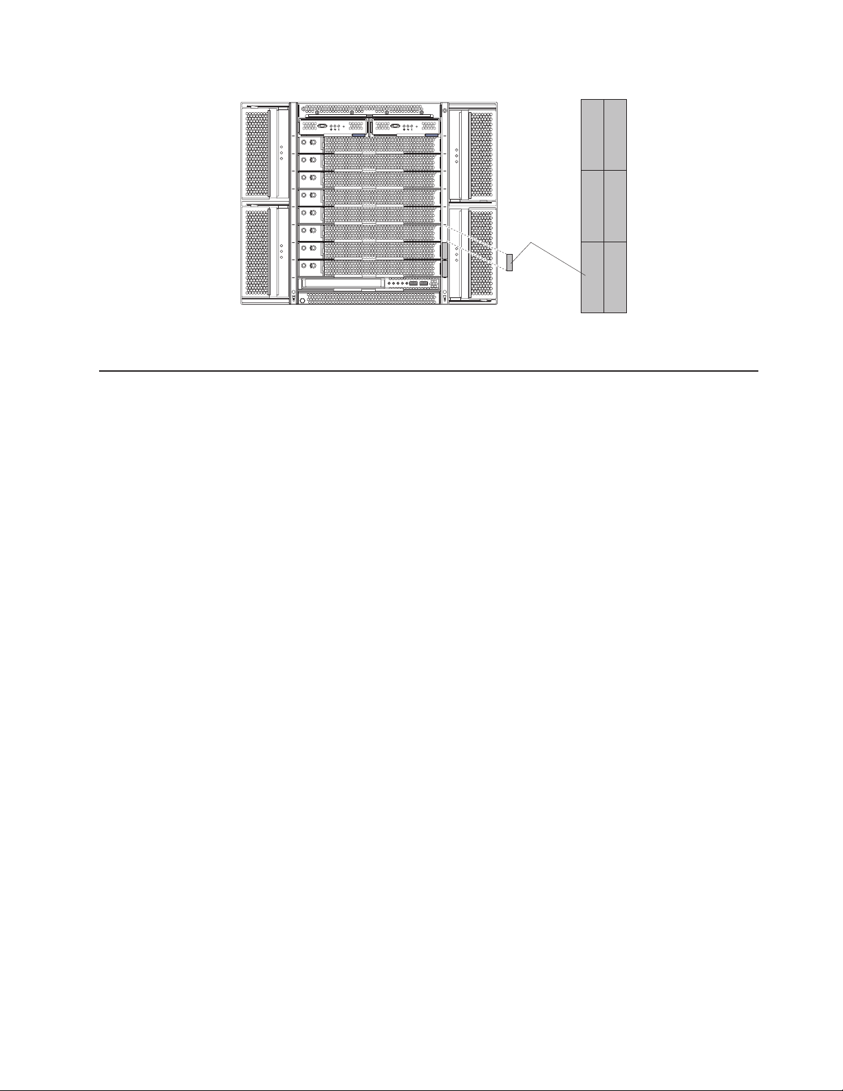
Major components of the BladeCenter T Types 8720 and 8730 unit
The following illustration shows the locations of major components in your
BladeCenter T unit.
KVM module
I/O module
Front view
LAN
module
A
C
1
3
0
0
W
O
D
C
U
T
A
I
C
N
Management module
Filler blade
Blower module
(4 units)
Power module
I
A
T
U
C
D
O
!
W
0
0
3
1
C
A
D
S
E
Blade server
!
O
D
C
U
T
A
I
C
N
N
C
Media tray
Bezel assembly
Attention: To maintain proper system cooling, each module bay must contain
either a module or a filler module; each blade bay must contain either a blade
server or a filler blade.
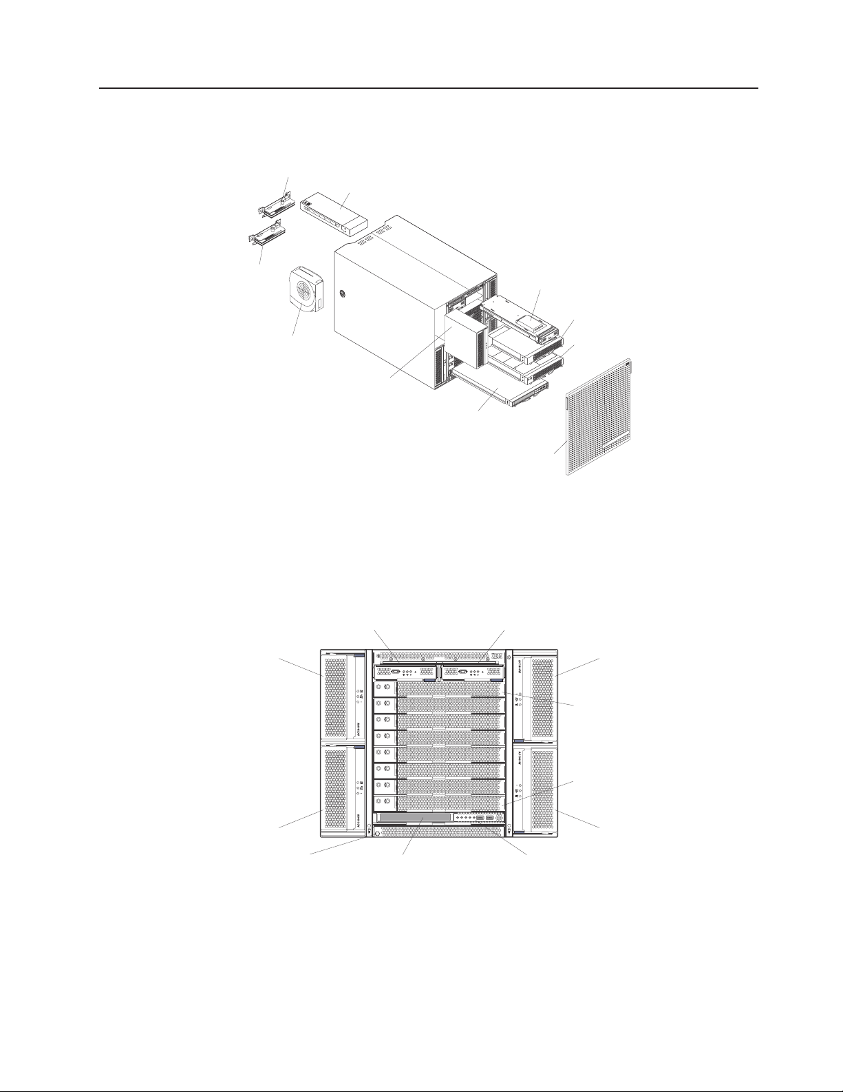
This section identifies the components, controls, and LEDs on the front of your
BladeCenter T unit.
Power module 1
Management-module bay 1
CMM
1
Management-module bay 2
Power module 2
CMM
2
Power module 3
ESD connector
Blade server 1
Blade server 8
Power module 4
Front panelMedia tray
Chapter 1. General information 9
Page 20
System service cards
These cards contain system service instructions and a writable area for your use.
The cards are located in a slot just above the management-module bays. To access
the service cards, slide out the cards as shown in the following illustration.
System service card
C
MM
1
C
M
M
2
ES
D
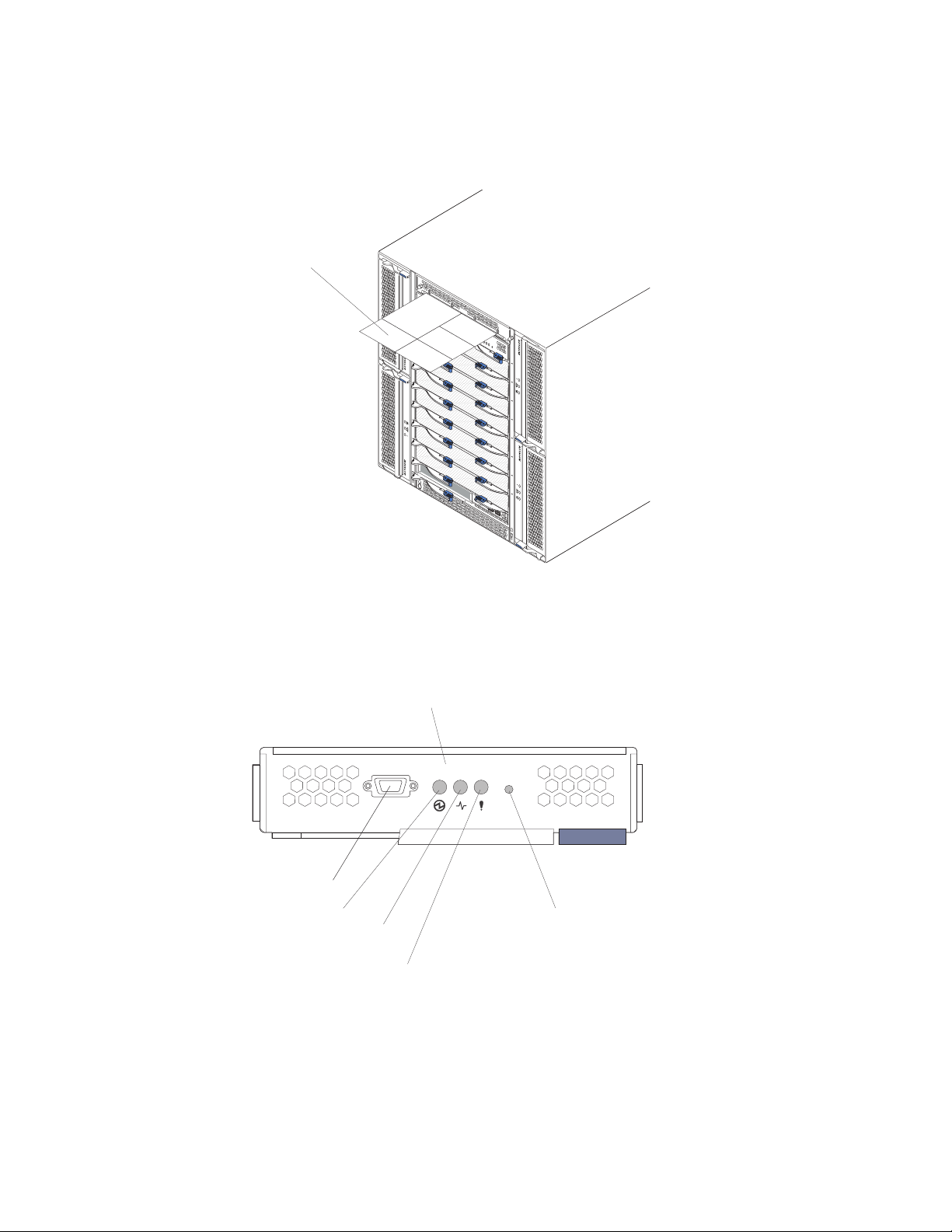
Management module controls and indicators
These management-module controls and indicators provide status information about
the management module and remote management connection. For additional
information, see the Hardware Maintenance Manual and Troubleshooting Guide on
the IBM BladeCenter T Documentation CD.
Serial port
Power LED
Active LED
Management module LEDs: These LEDs provide status information about the
management module and remote management connection.
v Power: When this green LED is lit, it indicates that the management module has
power.
v Active: When this green LED is lit, it indicates that the management module is
actively controlling the BladeCenter T unit. Only one management module
actively controls the BladeCenter T unit. If two management modules are
installed in the BladeCenter T unit, this LED is lit on only one.
Management module
Reset button
Error LED
10 BladeCenter T Type 8720 and 8730: Hardware Maintenance Manual and Troubleshooting Guide
Page 21
v Error: When this amber LED is lit, it indicates that an error has been detected
somewhere on the management module. When this LED is lit, the system error
LED (critical, major, or minor) on each of the BladeCenter T system-status panels
is also lit.
Management
module IP reset button: Do not press this button unless you intend
to erase your configured IP addresses for the management module and lose
connection with the remote management station, the switch modules, and the blade
servers. If you press this button, you will have to reconfigure the management
module settings (see the information beginning with “Setting up the remote
connection” on page 25 for instructions).
Press this recessed button to reset the IP configuration of the management module
network interfaces (Ethernet 1, Ethernet 2, gateway address, and so on) to the
factory defaults and then restart the management module.
Use a straightened paper clip to press the button.
Serial connector: Use this connection for configuring and managing the
BladeCenter components over a serial line through the command-line interface
(CLI) user-interface. This port provides access and redirection to the
serial-over-LAN (SOL) interface of any processor blade server. For example, you
can connect a laptop device to the serial connector and use a terminal-emulator
program to configure the assorted IP addresses, user accounts, and other
management settings through the CLI user-interface.
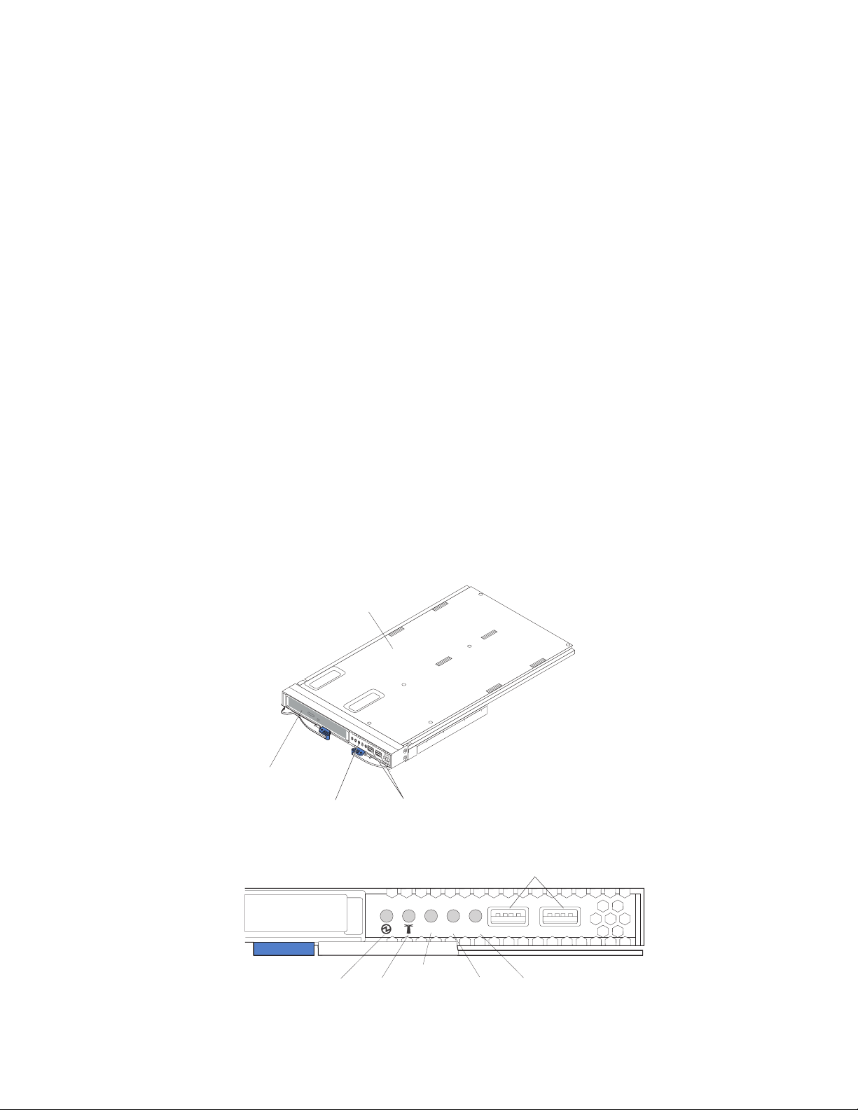
Media tray
The media tray is a hot-swap unit that is installed on the front of the BladeCenter T
unit and contains the system-status panel, I/O, and CD-ROM drive.
Media tray
CD-ROM drive
System-status panel
USB connectors
The following illustration shows the system-status LEDs on the system-status panel
on the front of the BladeCenter T unit.
Power Location
Media tray
MJR
CRT
Critical
MNR
Major Minor
USB connectors
The system-status panel on the front of the BladeCenter T system has five
system-status LEDs and two USB connectors.
Chapter 1. General information 11
Page 22

System status LEDs: The LEDs on this part of the panel provide status
information for the BladeCenter T unit.
v Power: When continuously lit, this green LED indicates the presence of power in
the BladeCenter T unit. The LED turns off when the power source is interrupted.
Attention: If the power LED is off, it does not mean electrical power is not
present in the BladeCenter T unit. The LED might be burned out. To remove all
electrical power from the BladeCenter T unit, you must disconnect all power
cords from the rear of the BladeCenter T unit.
v Location: This blue LED is for system identification. A system administrator or
servicer uses this LED to locate a specific BladeCenter T unit for service or
repair. You can turn off the location LED through the Web interface or a remote
management console.
Alarm LEDs: These LEDs provide alarm notifications for the BladeCenter T unit.
v CRT (Critical alarm, amber (default) or red): When continuously lit, this LED
indicates the presence of a critical system fault. The system comes with amber
as the default. See the BladeCenter T Management Module User’s Guide for
information on setting the color of this LED.
A critical system fault is an error or event that is unrecoverable. In this case, the
system cannot continue to operate. An example is the loss of a large section of
memory that causes the system to be incapable of operating.
v MJR (Major alarm, amber (default) or red): When continuously lit, this LED
indicates the presence of a major system fault. The system comes with amber as
the default. See the BladeCenter T Management Module User’s Guide for
information on setting the color of this LED.
A major system fault is an error or event that has a discernible impact to system
operation. In this case, the system can continue to operate but with reduced
performance. An example is the loss of one of two mirrored disks.
v MNR (Minor alarm, amber): When continuously lit, this LED indicates the
presence of a minor system fault. A minor system fault is an error or event that
has little impact to system operation. An example is a correctable ECC error.
connectors: There are two USB connectors on the front system-status panel.
USB
You can use these USB connectors to connect two USB peripheral devices without
an external hub. If more devices are required, you can connect an external hub to
any of the built-in connectors.
12 BladeCenter T Type 8720 and 8730: Hardware Maintenance Manual and Troubleshooting Guide
Page 23

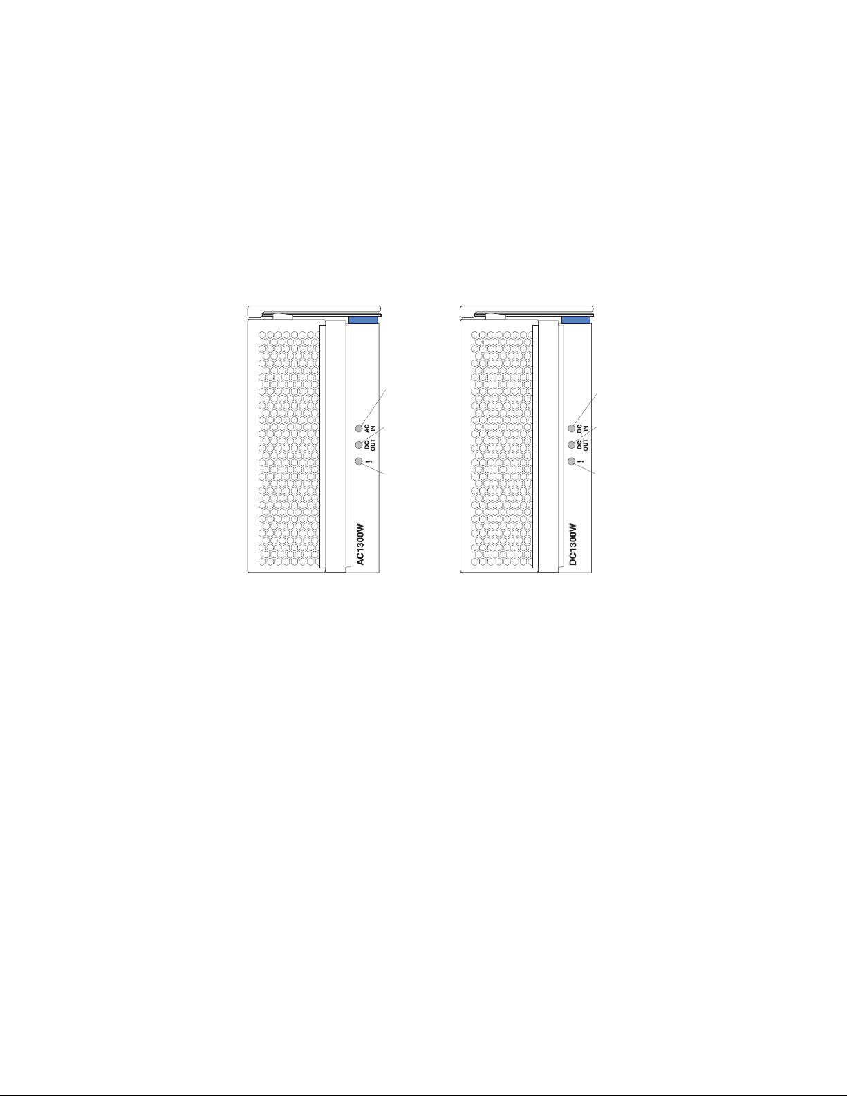
Power modules
AC power module DC power module
AC in LED
DC out LED
Error LED
DC in LED
DC out LED
Error LED
Power module LEDs: Each power module has three LEDs to indicate the status of
the power module.
v AC (or DC) in: When continuously lit, this green LED indicates that the input
power source is working. If the LED is not lit, it indicates that the input power
source is not present or is incorrect.
v DC out: When continuously lit, this green LED indicates that the output power is
present. If the LED is not lit, it indicates that the output power is not present.
v ! (Error): When continuously lit, this amber LED indicates that there is a error
condition within the power module.
Table 3. Power module LEDs
! (Error)
DC IN or AC IN DC OUT
(amber) Description and action
On On Off The power module is on and operating
correctly.
On Off Off or On* There is an output power problem. A system
error has shut down the power module.
Actions: Determine the cause of the shutdown
using the diagnostics and replace the failed
component. When the fault has been cleared,
reset the power module in one of the following
ways:
v Issue a power-module reset through the
management module.
v Remove the power module from the unit for
at least 10 seconds.
the problem remains, have the unit serviced.
If
*Error LED will operate only if a redundant
power supply is installed.
Chapter 1. General information 13
Page 24

Table 3. Power module LEDs (continued)
! (Error)
DC IN or AC IN DC OUT
(amber) Description and action
Off Off Off or On* There is an input power problem.
Possible causes:
v There is no power to the power module.
Actions: Make sure that:
1. The power is correctly connected to the
unit.
2. The power is connected to 220 v ac
(8730) or –48 v dc (8720).
3. The power source functions properly.
The power module has failed.
v
Action: Replace the power module.
the problem remains, have the unit serviced.
If
*Error LED will operate only if a redundant
power supply is installed.
On On On There is a fault condition in the power supply.
Possible causes:
v Thermal fault.
Action: Replace the power module.
v 12 v over-voltage power condition or 12 v
under-voltage power condition.
Actions: Determine the cause of shutdown
using diagnostics and replace the failed
component. When the fault has ben
cleared, reset the power module.
– Issue a power-module reset through the
management module.
– Remove the power module from the unit
for at least 10 seconds.
14 BladeCenter T Type 8720 and 8730: Hardware Maintenance Manual and Troubleshooting Guide
Page 25
Rear view
This section identifies the components and indicators on the rear of the
BladeCenter T unit.
I/O module 2 I/O module 1
KVM module
Blower module 2
Blower module 4
I/O module 4
TOP
24
BTM
D
CRT
MNR
MJR
E
TOP
2
1
BTM
ESD connector
D
Alarms
13
E
I/O module 3
LAN module
Blower module 1
Blower module 3
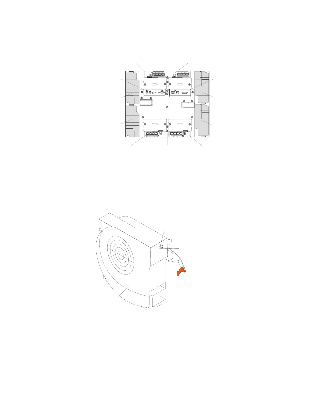
Blower modules
The blower modules are hot-swap units that are installed into the rear of the
system. The BladeCenter T unit comes with four blowers that are in a 3+1
redundancy configuration. All the cooling requirements are met if one blower fails.
All blowers contain a backflow device that prevents the system from drawing air into
the exhaust port of a failed blower. The management module in the BladeCenter T
unit controls the blower speed and detects blower failures.
Error LED
Power LED
Blower
Blower LEDs: The LEDs on each blower provide status information about the
blower.
v Power: When this green LED is lit, it indicates that the blower module has
power.
v Error: This amber LED is lit and stays lit when an error has been detected in the
blower. The system error LED on the BladeCenter system-status panels is also
lit.
Chapter 1. General information 15
Page 26
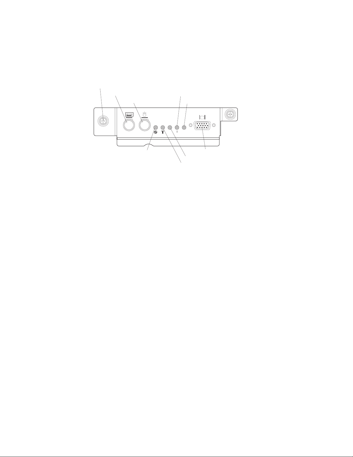
KVM (keyboard, video, mouse) module indicators and input/output connectors
The KVM module is a hot-swap module that is installed on the rear of the
BladeCenter T unit and is held in place by captive thumbscrews. This module
contains two PS/2 connectors for the keyboard and mouse, a system-status panel,
and an HD-15 video connector.
Thumbscrew
Keyboard
Mouse
Major (MJR) alarm LED
Minor (MNR) alarm LED
CRT
MNR
MJR
Power LED
Critical (CRT) alarm LED
Location LED
Video
System-status LEDs: These LEDs provide status information for the BladeCenter
T unit.
v Power: When continuously lit, this green LED indicates the presence of power in
the BladeCenter T unit. The LED turns off when the power source is interrupted.
Attention: If the power LED is off, it does not mean electrical power is not
present in the BladeCenter T unit. The LED might be burned out. To remove all
electrical power from the BladeCenter T unit, you must disconnect all power
cords from the rear of the BladeCenter T unit.
v Location: This blue LED is for system identification. A system administrator or
servicer uses this LED to locate a specific BladeCenter T unit for service or
repair. You can turn off the location LED through the Web interface or a remote
management console.
Alarm LEDs: These LEDs provide alarm notifications for the BladeCenter T unit.
v CRT (Critical alarm, amber (default) or red): When continuously lit, this LED
indicates the presence of a critical system fault. The system comes with amber
as the default. See the BladeCenter T Management Module User’s Guide for
information on setting the color of this LED.
A critical system fault is an error or event that is unrecoverable. In this case, the
system cannot continue to operate. An example is the loss of a large section of
memory that causes the system to be incapable of operating.
v MJR (Major alarm, amber (default) or red): When continuously lit, this LED
indicates the presence of a major system fault. The system comes with amber as
the default. See the BladeCenter T Management Module User’s Guide for
information on setting the color of this LED.
A major system fault is an error or event that has a discernible impact to system
operation. In this case, the system can continue to operate but with reduced
performance. An example is the loss of one of two mirrored disks.
v MNR (Minor alarm, amber): When continuously lit, this LED indicates the
presence of a minor system fault. A minor system fault is an error or event that
has little impact to system operation. An example is a correctable ECC error.
16 BladeCenter T Type 8720 and 8730: Hardware Maintenance Manual and Troubleshooting Guide
Page 27

Connectors: The KVM module has the following I/O connectors:
v Keyboard connector: The BladeCenter T KVM module contains one PS/2-style
keyboard connector.
Use this connector to connect a PS/2 keyboard to the BladeCenter T unit.
6
4
2
5
3
1
v Mouse connector: The BladeCenter T KVM module contains one PS/2-style
mouse connector.
Use this connector to connect a PS/2 mouse to the BladeCenter T unit.
6
4
2
5
3
1
v Video connector: The BladeCenter T KVM module contains one standard video
connector. The integrated video controller on each blade server is compatible
with SVGA and VGA and communicates through this video port.
Use this connector to connect a video monitor to the BladeCenter T unit.
5
1
1115
Chapter 1. General information 17
Page 28
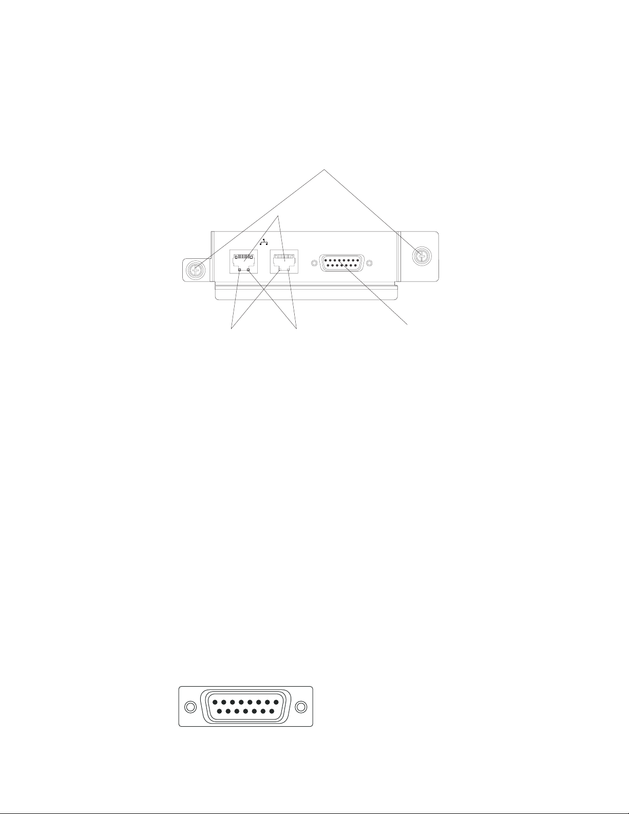
LAN-module indicators and input/output connectors
The LAN module is a hot-swap module that is installed on the rear of the
BladeCenter T unit and is held in place by captive thumbscrews. The LAN module
provides the electrical and mechanical interface to the BladeCenter T unit for the
two local area network (Ethernet) connections, as driven from each management
module, and the telco external alarms. This module contains two RJ-45 connectors
with LEDs and one DSUB 15P telco alarm connector.
Thumbscrews
Remote management
and console (Ethernet)
Ethernet link LED
2
1
Ethernet activity LED
Alarms
Alarms connector
LAN-module LEDs: These LEDs provide status information about the LAN
connection:
v Ethernet link: When this green LED is lit, there is an active connection through
the port to the network.
Ethernet activity: When this green LED is flashing, it indicates that there is
v
activity through the port over the network link.
LAN-module
connectors:
v Remote management and console (Ethernet) connectors: The LAN module
provides two Ethernet RJ-45 connectors.
The BladeCenter T LAN module contains two 10/100 Mb Ethernet connectors
that provide the remote connections, driven from each management module, to
the network management station on the network.
Use these ports for remote management and remote console.
The network management station, through these connectors, can access control
functions running in the management module, the service processor on each
blade server, or within each switch module. However, it cannot use these ports to
communicate with application programs running in the blade servers. The
network management station must direct those communications through a
network connected to the external ports in the I/O modules in the BladeCenter T
unit.
v Alarms connector: The LAN module provides one telco DB15 alarms connector
(male) for critical, major, and minor telco alarms. Each of the alarms has a relay
that enables multiple system alarm indicators to be daisy-chained together.
Table 4 on page 19 shows the pinouts for the telco alarms connector.
Alarms
18
915
18 BladeCenter T Type 8720 and 8730: Hardware Maintenance Manual and Troubleshooting Guide
Page 29

Note: The service processor, management module, or systems-management
function must monitor the alarm reset inputs to maintain the fault condition
that you set for the unit. The alarm reset inputs can be voltages in excess
of standard logic levels, so you must electrically or optically isolate them
from the monitoring logic.
Table 4. Alarms connector pinout
Pin # Description I/O Pin # Description I/O
1 Minor alarm reset + I 9 Minor alarm normally
closed
2 Minor alarm reset - I 10 Minor alarm common O
3 Major alarm reset + I 11 Major alarm normally open O
4 Major alarm reset - I 12 Major alarm normally
closed
5 Critical alarm normally
open
6 Critical alarm normally
closed
7 Critical alarm common O 15 Reserved O
8 Minor alarm normally open O
O 13 Major alarm common O
O 14 Reserved O
O
O
The electrical specifications for the alarms connector are as follows:
– Outputs
- Voltage range: 0 V dc to -100 V dc (maximum current 0.3 A at 100 V dc)
- Current range: 0 A to 1 A (maximum voltage 30 V dc at 1 A)
- Worst-case VA: 1 A at -30 V dc (30 VA maximum) indefinitely
– Inputs
- Voltage range: 0 V dc to -100 V dc (including transients)
- Differential input voltage: 3 V dc to 72 V dc
Reset input activation
–
Pulse width: 200 ms (minimum) to 300 ms
I/O modules
You can install a maximum of four I/O modules at the rear of the system (a
maximum of four Gbit Ethernet switches, or a maximum of two Gbit Ethernet
switches and two Fibre Channel switches). The minimum system configuration
requires one Gbit Ethernet switch or pass-thru module. The I/O switch modules
provide high-performance connectivity between the blade servers.
See the documentation that comes with each I/O module for a description of the
LEDs and connectors on the I/O module.
BladeCenter T unit power, controls, and indicators
This section describes the controls and light-emitting diodes (LEDs) and how to
start and shut down the BladeCenter T unit.
Starting the BladeCenter T unit
Complete the following steps to start the BladeCenter T unit:
1. Read the information in “System reliability considerations” on page 39.
Chapter 1. General information 19
Page 30
2. Reinstall the four blowers into the rear of the BladeCenter T unit if you have not
done so already. See “Removing and installing blower modules” on page 54 for
detailed instructions.
Note: The blowers will not start until the power modules are installed.
3. When the power connections are in place, you can reinstall the power modules
in the BladeCenter T unit. After you connect power to the BladeCenter T unit, all
the power-module bays receive power. To start the BladeCenter T unit, install
power modules in all four power-module bays or install power modules in
power-module bays 1 and 2 and filler modules in bays 3 and 4. See “Installing a
power module” on page 48 for detailed instructions.
AC power module DC power module
AC in LED
DC out LED
Error LED
DC in LED
DC out LED
Error LED
Make sure that the LEDs on the power modules indicate that they are operating
correctly. Make sure that the input and output power LEDs on each power
module are lit, and the error LEDs are not lit.
4. Before proceeding, make sure that the LEDs on the blower modules indicate
that they are operating correctly. Make sure that the power LED on each blower
is lit, and the error LEDs are not lit.
5. Make sure that the following BladeCenter T modules are installed correctly. See
“Media tray” on page 11 for the location of the LEDs on these modules.
v Media tray
v KVM module
v LAN module
v Management module
v I/O modules
Install the blade servers or filler modules in all of the blade server bays before
6.
you power on any of the blade servers. See “Removing and installing a blade
server or filler module” on page 64 for detailed instructions. Make sure that the
power LED on each blade server is flashing.
7. Install the bezel assembly on the front of the BladeCenter T unit by inserting the
bottom bezel hooks into the bezel slots at the bottom of the BladeCenter T unit.
Push in the bottom and the top of the bezel assembly until they both lock firmly
into place.
20 BladeCenter T Type 8720 and 8730: Hardware Maintenance Manual and Troubleshooting Guide
Page 31

Notes:
1. Within 2 minutes after power has been connected to the BladeCenter T unit, the
management module applies power to the I/O modules.
2. If a power failure occurs, the BladeCenter T unit restarts automatically when
power is restored.
3. The blade-server power button turns on or turns off the blade server if local
power control has not been disabled through the management module.
4. The blade-server power button turns on the blade server only if the green power
light on the blade server is flashing slowly. If the light flashes rapidly, the blade
server has not yet synchronized with the management module, and pressing the
power button will have no effect. See “Media tray” on page 11 for more
information about the controls and indicators on the BladeCenter T unit
modules.
the Installation and User’s Guide for your blade server on the IBM
See
Documentation CD that comes with the blade server for the location of the blade
server LEDs.
Shutting down the BladeCenter T unit
You can shut down the BladeCenter T unit by turning off the blade servers and
disconnecting the BladeCenter T unit from the power source.
Complete the following steps to shut down the BladeCenter T unit.
1. See your blade server operating-system documentation for the procedure to
shut down the operating system in the blade servers; then, shut down each
operating system.
2. Press the power-control button on the front of each blade server. Wait until the
solid green power LED on the blade server goes to a slow flash indicating that
the blade server drives have stopped spinning.
Statement 5:
CAUTION:
The power control button on the device and the power switch on the
power supply do not turn off the electrical current supplied to the device.
The device also might have more than one power cord. To remove all
electrical current from the device, ensure that all power cords are
disconnected from the power source.
1 2
Note: The BladeCenter T Type 8720 and 8730 units do not have a power
switch. The units also have more than one connection to power. To
remove all electrical current from the unit, make sure that all connections
to input power are disconnected at the power input terminals or
connectors.
3. If you have a BladeCenter T Type 8720 (dc-power) unit, disconnect the unit
from the input power at the dc power distribution panel by switching the circuit
Chapter 1. General information 21
Page 32

breakers to the Off position or removing the fuses as applicable. Make sure that
both circuits are disconnected or turned off.
If you have a BladeCenter T Type 8730 (ac-power) unit, disconnect all power
cords on the BladeCenter T unit from the ac power distribution unit (PDU).
Note: After you disconnect the BladeCenter T unit from power, wait at least 5
seconds before you connect the BladeCenter T unit to power again.
22 BladeCenter T Type 8720 and 8730: Hardware Maintenance Manual and Troubleshooting Guide
Page 33

Chapter 2. Configuring the BladeCenter T unit
The BladeCenter T unit automatically detects the modules and blade servers that
are installed and stores the vital product data (VPD). When the BladeCenter T unit
is started, the management module automatically configures the remote
management port on the management module, accessed through the LAN module
on the rear of the BladeCenter T unit, so that you can configure and manage the
BladeCenter T unit and blade servers. Yo u configure and manage the BladeCenter
T unit remotely, through the management module, using the Web-based user
interface.
Note: There are two ways to configure the switch modules; through the
management-module Web interface, or through an external switch-module
port enabled through the management module, using a Telnet interface or a
Web browser. See the documentation that comes with the switch module for
more information.
For the active management module to communicate with the I/O modules in the
BladeCenter T unit, you must configure the IP addresses for the following internal
and external ports:
v The external Ethernet (remote management) port on the management module,
accessed through the LAN module on the rear of the BladeCenter T unit (see
“Configuring the external Ethernet port” on page 28 for instructions). The initial
management module autoconfiguration enables the network management station
to connect to the management module to configure the port completely and to
configure the rest of the BladeCenter T unit.
v The internal Ethernet port on the management module for communication with
the I/O modules (see “Configuring the internal Ethernet port” on page 29 for
instructions).
v The management port on each switch module provides for communication with
the management module. You configure this port by configuring the IP address
for the switch module (see “Configuring management ports on I/O modules” on
page 29 for instructions).
Note: Some types of I/O modules, such as the pass-thru module, have no
management port.
the documentation that comes with the I/O module to determine what else you
See
must configure in the I/O module.
To communicate with the blade servers for functions such as deploying an operating
system or application program over the network, you must also configure at least
one external (in-band) port on an Ethernet switch module in I/O-module bay 1 or 2.
See “What to configure” on page 29 for information about configuring external ports
on Ethernet switch modules.
The management module supports the following Web browsers for remote access.
The Web browser that you use must be Java™-enabled, must support JavaScript
™
1.2 or later, and must have the Java Virtual Machine (JVM) 1.4.1 or later Plug-in
installed. The JVM Plug-in is available at the Java Web site at http://www.java.com/.
®
v Microsoft
Internet Explorer 5.5 (with latest Service Pack installed), or later
v Netscape Navigator 4.72, or later (version 6 is not supported)
v Mozilla version 1.3, or later
© Copyright IBM Corp. 2004 23
Page 34

For best results when using the Web browser, set the monitor to 256 colors. Use
only the video resolutions and refresh rates given in the following table. These are
the only video resolution and refresh rate combinations that are supported for all
system configurations.
Resolution Refresh rate
640 x 480 60 Hz
640 x 480 72 Hz
640 x 480 75 Hz
640 x 480 85 Hz
800 x 600 60 Hz
800 x 600 72 Hz
800 x 600 75 Hz
800 x 600 85 Hz
1024 x 768 60 Hz
1024 x 768 75 Hz
The Web interface does not support the double-byte character set (DBCS)
languages.
The Web-based user interface communicates with the management and
configuration program that is part of the firmware that comes with the management
module. You can use this program to perform the following tasks:
v Defining the login IDs and passwords.
v Selecting recipients for alert notification of specific events.
v Monitoring the status of the BladeCenter T unit and blade servers.
v Controlling the BladeCenter T unit and blade servers.
v Accessing the I/O modules to configure them.
v Changing the startup sequence in a blade server.
v Setting the date and time.
v Using a remote console for the blade servers.
v Changing ownership of the keyboard, video, and mouse.
Note: Some blade server models do not support the keyboard, video, and
mouse feature. Ownership of the keyboard, video, and mouse cannot be
transferred to those blade servers.
v Changing ownership of the CD-ROM drive and USB ports. (The CD-ROM drive
in the BladeCenter T unit is viewed as a USB device by the blade server
operating system.)
v Activating On Demand blade servers.
v Setting the active color of the critical (CRT) and major (MJR) alarm LEDs
also can use the management and configuration program to view some of the
You
blade server configuration settings. See “Management and configuration program”
on page 26 for more information.
24 BladeCenter T Type 8720 and 8730: Hardware Maintenance Manual and Troubleshooting Guide
Page 35

Setting up the remote connection
To configure and manage the BladeCenter T unit and blade servers, you must first
set up the remote connection through an Ethernet port on the LAN module. The
LAN module is on the rear of the BladeCenter T unit at the top-right side.
KVM module
Cabling the Ethernet port
You can connect to an Ethernet port directly from a personal computer (PC) using a
cross-over cable, or you can make the connection through an Ethernet switch.
The right Ethernet port on the LAN module is driven by management module 1, and
the left Ethernet port of the LAN module is driven by management module 2.
Rear of BladeCenter T type 8730 unit
TOP
D
24
BTM
E
TOP
24
D
CRT
MNR
MJR
BTM
E
TOP
D
2
1
Alarms
13
BTM
E
192.168.70.125
LAN module
TOP
D
2
1
Alarms
13
BTM
E
LAN module
RJ-45
connector
192.168.70.155
192.168.70.135
Standard
Ethernet
cables
Cross-over
Ethernet cable
Connect directly to PC
Ethernet switch
Connect through an Ethernet switch
Chapter 2. Configuring the BladeCenter T unit 25
Page 36

Complete the following steps to connect the Ethernet cable to the management
module.
1. Connect one end of a Category 5 or higher Ethernet cable to an Ethernet
connector on the LAN module. Connect the other end of an Ethernet cable to
the network.
2. Check the Ethernet LEDs to make sure that the network connection is working.
The following illustration shows the locations of the Ethernet LEDs on the LAN
module.
2
Ethernet link Ethernet activity
1
Alarms
Ethernet link LED
When this green LED is lit, there is an active connection through the
port to the network.
Ethernet activity LED
When this green LED is flashing, it indicates that there is activity
through the port over the network link.
Management and configuration program
This section provides the instructions for setting up and using the management and
configuration program in the management module.
Setting up the management and configuration program
Complete the following steps to set up the management and configuration program:
1. Connect a PC to the BladeCenter T management network.
2. At initial power-on, the management module configures the Ethernet port
connection in one of the following ways:
v If you have an accessible, active, and configured dynamic host configuration
protocol (DHCP) server on the network, the host name, IP address, gateway
address, subnet mask, and DNS server IP address are set automatically.
v If the DHCP server does not respond within 2 minutes after the port is
connected, the management module uses a default IP address of
192.168.70.125 and subnet mask of 255.255.255.0.
Either of these actions enables the Ethernet to assign a connection.
If you cannot communicate with a replacement management module through
the Web interface. Press the IP reset button on the front of the management
module to set the management module to the factory default IP addresses;
then, access the management module using the factory IP address (see
“Setting up the management and configuration program” for the factory IP
addresses) and configure the management module.
Note: If the IP configuration is assigned by the DHCP server, the network
administrator can query the MAC address of the management-module
network interface on the DHCP server to determine what IP address and
host name are assigned.
26 BladeCenter T Type 8720 and 8730: Hardware Maintenance Manual and Troubleshooting Guide
Page 37

Starting the management and configuration program
Complete the following steps to start the management and configuration program:
1. Open a Web browser. In the address or URL field, type the IP address or host
name that is defined for the management-module remote connection (see
“Setting up the management and configuration program” on page 26 for more
details).
The Enter Network Password window opens.
2. Type your user name and password. If you are logging in to the management
module for the first time, you can obtain your user name and password from
your system administrator. All login attempts are documented in the event log.
Note: The initial user ID and password for the management module are as
follows:
v User ID: USERID (all capital letters)
v Password: PASSW0RD (note the zero, not O, in PASSW0RD)
3. Follow the instructions that appear on the screen. Be sure to set the timeout
value that you want for your Web session.
BladeCenter T management and configuration window opens.
The
Note: The upper left corner of the management and configuration window shows
the location and identity of the active management module.
Chapter 2. Configuring the BladeCenter T unit 27
Page 38
Setting management and configuration program options
From the management and configuration program main menu, you can select
settings that you want to view or change.
The navigation pane (on the left side of the management module window) contains
navigational links that you use to manage the BladeCenter T unit and check the
status of the components (modules and blade servers). The following information
describes the choices that you have to configure the external Ethernet port on the
management module, the internal Ethernet port on the management module, and
the external management port on each I/O module. See the BladeCenter T
Management Module User’s Guide on the BladeCenter T Documentation CD that
comes with the BladeCenter T unit for a description of all the navigational links.
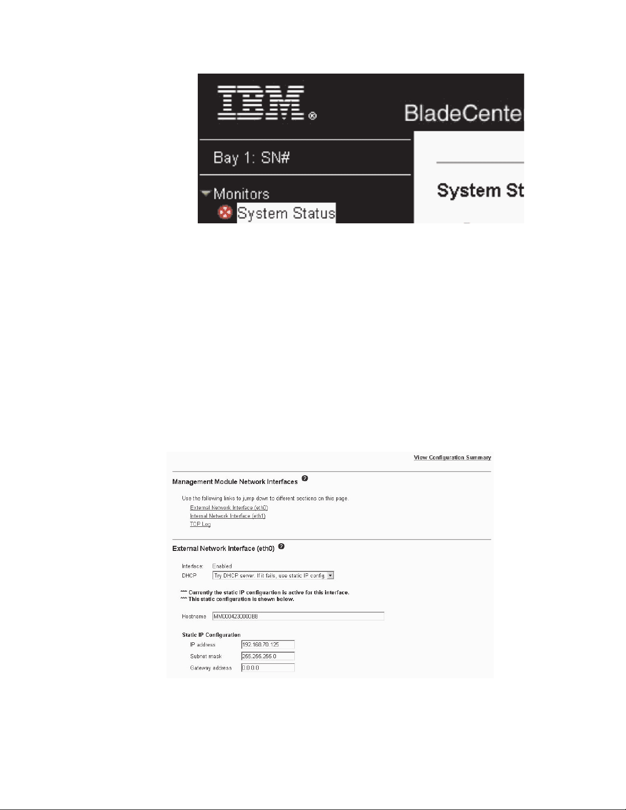
Configuring the external Ethernet port
Under MM Control, click Network Interfaces ” External Network Interface (eth0).
This is the interface for the remote management and console port.
v Set Interface to Enabled to use the Ethernet connection.
v If you plan to use redundant management modules and want both to use the
same IP address, disable DHCP and configure and use a static IP address (the
IP configuration information will be transferred to the redundant management
28 BladeCenter T Type 8720 and 8730: Hardware Maintenance Manual and Troubleshooting Guide
Page 39

module automatically when needed). Otherwise, configure the DHCP setting as
you prefer. You must configure the static IP address only if DHCP is disabled.
– IP address - The IP address for the management module. The IP address
must contain four integers from 0 through 255, separated by periods, with no
spaces or consecutive periods. The default setting is 192.168.70.125.
– Subnet mask - The subnet mask must contain four integers from 0 to 255,
separated by periods, with no spaces. The default setting is 255.255.255.0
– Gateway address - The IP address for your network gateway router. The
gateway address must contain four integers from 0 through 255, separated by
periods, with no spaces.
Configuring the internal Ethernet port
Under MM Control, click Network Interfaces ” Internal Network Interface (eth1).
This interface communicates with the network-interface I/O modules, such as the
Ethernet switch module or the Fibre Channel switch module.
v Specify the IP address to use for this interface. The IP addresses for the internal
Ethernet port (eth1) and external Ethernet port (eth0) must be on the same
subnet.
v (Optional) Configure the locally-administered MAC address for this interface; the
other fields (data rate, duplex mode, maximum transmission unit (MTU), and
burned-in MAC address) are read-only.
Configuring management ports on I/O modules
Under I/O Module Tasks, click Management; then, click the bay number that
corresponds to the I/O module that you are configuring.
v In the New Static IP address fields, specify the IP address to use for this
interface. The new static IP address must be on the same subnet as the internal
network interface (eth1).
v Click Advanced Management ” Advanced setup. Enable the external ports.
v Click Advanced Management ” Advanced setup. (Optional) Enable external
management.
Saving and restoring the configuration file
After you have configured the management module, you can save the configuration
file to a drive attached to the system running the management-module Web
interface. Then, if the configuration in the management module becomes damaged
or if the management module is replaced, you can restore the saved configuration
file to the management module. Use the management-module Web interface to
save and restore the configuration file (MM Control ” Configuration File).
Configuring an I/O module
To connect any of the blade servers to the network, you must have an Ethernet
switch module installed in I/O-module bay 1 or 2, or a pass-thru module in
I/O-module bay 1 or 2 connected to an external Ethernet switch. If you have an I/O
expansion option installed on one or more blade servers, you must have compatible
I/O modules (switch modules or other compatible modules) in I/O module bays 3 or
4. See “Removing and installing I/O modules” on page 60 for information about the
location and purpose of each I/O module.
What to configure
You must configure switch-module IP addresses and subnet masks through the
management-module Web interface to communicate with the management module
Chapter 2. Configuring the BladeCenter T unit 29
Page 40

and remote management station. This is in addition to the IP addresses that are
configured on the management module. You might also have to use the user
interface on the switch module to configure the switch external ports to operate in
the correct link aggregation (trunking) mode, or to configure any VLANs or other
special conditions.
To allow blade servers to communicate with the network, make sure that the
External ports configuration item in the management module is set to Enabled. In
the management-module Web interface, under I/O Module Tasks, click
Management ” Bay n ” Advanced Management ” Advanced Setup and enable
the item (where n is the number of the I/O bay).
To access the user interface using external ports on the switch module, make sure
that the External management over all ports configuration item is set to enabled.
See your network administrator before enabling this feature.
Because all blade servers in the BladeCenter T unit share access to the external
LAN through the switch ports, you can configure the ports on a switch module to
operate together as an aggregate link, or trunk. An aggregate link provides more
bandwidth than a single link to the attached LAN.
Notes:
1. The attaching LAN switch must have a compatible multiport trunk configuration.
2. Configure link aggregation before you attach cables between the external ports
and your LAN equipment.
Configure
the switch through the user interface on the switch module, which you
can access through the Web interface to the management module (click I/O
Module Tasks ” Management ” Advanced Management ” Start Telnet/Web
Session in the navigation pane).
Important: For a remote management station, such as a management server, to
communicate with the switch modules in the BladeCenter T unit, the management
port of the switch module must be on the same subnet as the management module.
Supporting Ethernet failover
To have the BladeCenter T unit support Ethernet failover on the blade servers, set
up the BladeCenter T unit and blade servers as follows:
1. Configure the Ethernet controllers in one or more blade servers for failover (see
the blade server documentation and the operating-system documentation for
information). When failover occurs on a blade server, the secondary Ethernet
controller takes over network communication, using the I/O module associated
with that controller.
2. Install a switch module or a pass-thru module that is connected to external
Ethernet switches in both I/O-module bays 1 and 2.
3. Configure the Ethernet switch modules and your network infrastructure so that
they can direct traffic to the same destinations.
Configuring the Ethernet controllers in the blade servers
Note: The BladeCenter T unit does not include an Ethernet switch module; this is
an optional feature that must be purchased separately. An Ethernet switch
module or a pass-thru module is connected to an external Ethernet switch
30 BladeCenter T Type 8720 and 8730: Hardware Maintenance Manual and Troubleshooting Guide
Page 41

must be installed in the BladeCenter T unit in I/O-module bay 1 or 2, or both,
before the integrated Ethernet controllers on each blade server system board
can be used.
The Ethernet controllers are integrated on each blade server system board. The
Ethernet controllers provide 1-Gbps full-duplex capability only, which enables
simultaneous transmission and reception of data to the external ports on the
Ethernet switches. You do not need to set any jumpers or configure the controller
for the blade server operating system. However, you must install a device driver on
the blade server to enable the blade server operating system to address the
Ethernet controller. For blade server device drivers and information about
configuring the Ethernet controllers, see the Ethernet software CD that comes with
your blade server.
BladeCenter T networking guidelines
Your networking administrator should assist in the configuration of the network
infrastructure before you connect the BladeCenter T unit to a LAN switch or similar
network device. This section provides additional guidelines that might be useful in
setting up your system.
A BladeCenter T unit with two Ethernet switch modules and one management
module has the internal configuration that is shown in the following illustration:
MAC
1a
1b
2a
2b
3a
3b
4a
4b
5a
5b
6a
6b
7a
7b
8a
8b
1
2
3
4
5
6
7
8
1 Gbps links
1 Gbps or
100 Mbps links
Switch A
10/100 Mbps
Mgmt
Mod
100 Mbps links
Switch B
1 Gbps links
Note: 2nd switch module is optional
Each blade server has two independent Ethernet controllers, each with its own
MAC address and a dedicated 1 Gbps link to one of the switch modules in I/O
module bays 1 and 2 (controller 1 to switch A and controller 2 to switch B in the
illustration). In this configuration (the default), the blade servers share access to
four external ports on each switch. There is no internal data path between the two
switches within the BladeCenter T unit; an external network device is required for
data packets to flow from one internal switch to the other.
The management module has a separate internal 100 Mbps link to each switch.
These links are for internal management and control only. No data packets are
allowed to flow from application programs on the blade servers to the management
module over this path. A separate, nonswitched path (not shown) is used for
communication between the management module and a service processor on each
blade server.
Chapter 2. Configuring the BladeCenter T unit 31
Page 42

A typical, preferred BladeCenter T network topology is shown in the following
illustration. See the IBM Eserver BladeCenter T Planning and Installation Guide
for more information and other topologies and guidelines.
Multiport aggregation group
1 Gbps or 100 Mbps links
MAC
1a
1
1b
2a
2
2b
3a
3
3b
4a
4
4b
5a
5
5b
6a
6
6b
7a
7
7b
8a
8
8b
Switch A
Mgmt
Mod
Switch B
L2 Switch
10/100 Mbps
management
links
IBM Director
- Chassis management
- Application deployment
MAC
1a
1
1b
2a
2
2b
3a
3
3b
4a
4
4b
5a
5
5b
6a
6
6b
7a
7
7b
8a
8
8b
MAC
1a
1
1b
2a
2
2b
3a
3
3b
4a
4
4b
5a
5
5b
6a
6
6b
7a
7
7b
8a
8
8b
Switch A
Mgmt
Mod
Switch B
Switch A
Mgmt
Mod
Switch B
L2+ Switch
Dual
external
switches
L2+ Switch
- Internal switches
Establishment
backbone
Network administrator
- Infrastructure
management
- Network hardware
and software
In this configuration, each BladeCenter T unit contains two Ethernet switch modules
and one management module. The external ports on the switch modules are
configured for multiport link aggregation groups, or trunks, as are the corresponding
ports on the attached external LAN switches. Additionally, every port in the switch
module in I/O-module bay 1 (switch A in this illustration) in the BladeCenter T units
is connected to the same external LAN switch, and every port in the switch module
in I/O-module bay 2 (switch B in this illustration) in the BladeCenter T units is
connected to another external LAN switch.
Observe the following guidelines when creating this topology:
1. The external ports on the BladeCenter T switch modules are designed for
point-to-point, full-duplex operation to a compatible LAN switch or router.
Configure a corresponding multiport link aggregation group, or trunk, in both the
switch module and the attached LAN switch before installing the cables. The
connection options are as follows, in order of preference:
v Multiport link aggregation group or trunk, 1 Gbps (1000 Mbps) per port
v Single-uplink port, 1 Gbps
v Multiport link aggregation group or trunk, 100 Mbps per port
Connect the management-module 10/100 Mbps Ethernet port to a separate
2.
layer 2 network for security. If a separate network is not available, you can
attach the Ethernet ports of the management module and switch modules to the
same layer 2 network.
32 BladeCenter T Type 8720 and 8730: Hardware Maintenance Manual and Troubleshooting Guide
Page 43

3. Avoid network configurations that could lead to data loops, if possible. Loops
will be created if you connect multiple ports from the same switch module to the
same layer 2 network device without first enabling link aggregation. If you
implement configurations that include data loops, you must enable Spanning
Tree Protocol on the switch-module external ports.
Using Remote Deployment Manager Version 4.11 Update 3 or later
You can use the Remote Deployment Manager (RDM) Version 4.11 Update 3 (or
later) program to install a supported Microsoft Windows
BIOS update onto a blade server. Follow the instructions in the documentation that
comes with the RDM program to install a supported Microsoft Windows operating
system, supported Red Hat Advanced server 2.1, or BIOS code update.
Go to the following Web site for updated information about the RDM program and
information about how to purchase the software or download an update:
http://www.ibm.com/pc/ww/eserver/xseries/systems_management/sys_migration/
rdm.html
Using IBM Director
For a complete list of operating systems that support IBM Director, see the IBM
Director compatibility document. This document is in PDF http://www.ibm.com/
servers/eserver/xseries/systems_management/sys_migration/ibmdiragent.html. This
document is updated every 6 to 8 weeks.
The IBM Director program is a systems-management product. Through the remote
connection on the management module, you can use IBM Director on a
management console to configure the BladeCenter T unit, modify the configuration,
and set up more advanced features.
Notes:
1. Some tasks, such as software distribution, require an in-band connection from
IBM Director Server through a campus (public) LAN to a switch-module port.
2. See the IBM Support Web site at http://www.ibm.com/support/ for the version of
IBM Director software that you can use to manage redundant management
modules.
®
operating system or a
Communicating with the IBM Director software
For a complete list of operating systems that support IBM Director, see the IBM
Director compatibility document. This document is in PDF at http://www.ibm.com/
servers/eserver/xseries/systems_management/sys_migration/ibmdiragent.html.
updated every 6 to 8 weeks.
Note: See the illustration on page 32 for an example of a typical network
configuration. See the IBM Eserver BladeCenter T Planning and Installation
Guide for more examples of network configurations. You can obtain the
planning guide from http://www.ibm.com/support/.
To communicate with the BladeCenter T unit, the IBM Director software needs a
managed object (in the Group Contents pane of the IBM Director Management
Console main window) that represents the BladeCenter T unit. If the BladeCenter T
management-module IP address is known, the network administrator can create an
IBM Director managed object for the unit. If the IP address is not known, the IBM
Chapter 2. Configuring the BladeCenter T unit 33
It is
Page 44

Director software can automatically discover the BladeCenter T unit (out-of-band,
using the Ethernet port on the management module) and create a managed object
for the unit.
For the IBM Director software to discover the BladeCenter T unit, your network
must initially provide connectivity from the IBM Director server to the BladeCenter T
management-module Ethernet port. To establish connectivity, the management
module attempts to use DHCP to acquire its initial IP address for the Ethernet port.
If the DHCP request fails, the management module uses a static IP address.
Therefore, the DHCP server (if used) must be on the management LAN for the
BladeCenter T unit.
Notes:
1. All management modules are preconfigured with the same static IP address.
You can use the management-module Web interface to assign a new static IP
address for each BladeCenter T unit. If DHCP is not used and you do not
assign a new static IP address for each BladeCenter T unit before attempting to
communicate with the IBM Director software, only one BladeCenter T unit at a
time can be added onto the network for discovery. Adding multiple units to the
network without a unique IP address assignment for each BladeCenter T unit
results in IP address conflicts.
2. For switch communication with the IBM Director server through the
management-module external Ethernet port, the switch-module internal network
interface and the management-module internal and external interfaces must be
on the same subnet.
34 BladeCenter T Type 8720 and 8730: Hardware Maintenance Manual and Troubleshooting Guide
Page 45

Chapter 3. Diagnostics
This section provides basic troubleshooting information to help you resolve some
common problems that might occur with your BladeCenter T unit.
If you cannot locate and correct the problem using the information in this section,
see Appendix A, “Getting help and technical assistance,” on page 111 for more
information.
Diagnostic tools overview
The following tools are available to help you identify and solve hardware-related
problems:
v Troubleshooting charts
These charts list problem symptoms and steps to correct the problems. See the
Chapter 6, “Symptom-to-FRU index,” on page 89 for more information.
v Diagnostic programs and error messages
The built-in self-test (BIST) program checks the BladeCenter T unit during startup
and generates error messages if problems are found.
The system diagnostic program, Real Time Diagnostics Version 1.3, tests the
major components of your BladeCenter T unit. The Real Time Diagnostics
software is available from the IBM Support Web site at http://www.ibm.com/pc/
support. It is run from the IBM Director Management Console window (under the
BladeCenter T task in the Task panel).
To obtain the Real Time Diagnostics program, go to the following Web site:
http://www.ibm.com/pc/support, and complete the following steps:
1. Select Servers from the list at the left of the window.
2. Select Downloadable files from the list at the left of the window.
3. In the Downloadable files by category list, select Diagnostic.
4. Click the entry for Real Time Diagnostics, and follow the instructions on that
page.
v Light Path Diagnostics feature
Use the Light Path Diagnostics feature to identify system errors quickly. On the
BladeCenter T unit, the Light Path Diagnostics feature consists of the LEDs on
the front and rear of the BladeCenter T unit and on the front of the modules and
blade servers.
Identifying problems using the Light Path Diagnostics feature
If the system-error LED on the system LED panel on the front or rear of the
BladeCenter T unit is lit, one or more error LEDs on the BladeCenter T components
also might be on. These LEDs help identify the cause of the problem.
This section provides the information to identify problems that might arise during
installation using the Light Path Diagnostics feature.
To locate the actual component that caused the error, you must locate the lit error
LED on that component.
© Copyright IBM Corp. 2004 35
Page 46

For example:
A system error has occurred, and you have noted that the BladeCenter T
system-error LED is lit on the system LED panel. You then locate the module or
blade server that also has an error LED lit (see “BladeCenter T unit power, controls,
and indicators” on page 19 for the location of error LEDs; see the documentation
that comes with your blade server for the location of error LEDs on the blade). If the
component is a module, replace the module. If the component is a blade server
with its system-error LED lit, follow the instructions in the documentation that comes
with the blade server to isolate and correct the problem.
36 BladeCenter T Type 8720 and 8730: Hardware Maintenance Manual and Troubleshooting Guide
Page 47

Chapter 4. Setting up the BladeCenter T hardware
This chapter provides instructions for setting up the BladeCenter T unit and
installing and removing modules, options, and blade servers.
Setting up the BladeCenter T unit
Statement 20:
CAUTION:
To avoid personal injury, before lifting the unit, remove all the blades to
reduce the weight.
Statement 4:
≥ 18 kg (39.7 lb) ≥ 32 kg (70.5 lb) ≥ 55 kg (121.2 lb)
CAUTION:
Use safe practices when lifting.
Install the BladeCenter T unit in a rack before installing any blade servers in the
BladeCenter T unit. If your BladeCenter unit has blade servers already installed,
remove them first. Detailed instructions for installing and cabling a BladeCenter T
unit in a rack are in the Rack Installation Instructions that come with the
BladeCenter T unit.
Installation guidelines
This section includes guidelines for:
v Preparing and making ac or dc power connections before installing the
BladeCenter T modules, options, and blade servers.
v System reliability considerations.
v Handling static-sensitive devices and the use of the electro-static discharge
(ESD) connector.
© Copyright IBM Corp. 2004 37
Page 48

Before you begin to install options in the BladeCenter T unit, read the following
information:
v Read the safety information beginning on page 113 and the guidelines in
“Handling static-sensitive devices” on page 40. This information will help you
work safely with your BladeCenter T unit and options.
v Blue on a component indicates touch points, where you can grip the component
to remove it from or install it in the server, open or close a latch, and so on.
v Orange on a component or an orange label on or near a component indicates
that the component can be hot-swapped, which means that you can remove or
install the component while the BladeCenter T unit is running. (Orange can also
indicate touch points on hot-swap components.) See the instructions for removing
or installing a specific hot-swap component for any additional procedures that
you might have to perform before you remove or install the component.
v Yo u do not need to disconnect the BladeCenter T unit from power to install or
replace any of the hot-swap modules in the BladeCenter T unit. Yo u need to shut
down the operating system and turn off a hot-swap blade server on the front of
the BladeCenter T unit before removing the blade server, but you do not need to
shut down the BladeCenter T unit itself.
v For a list of supported options for your server, go to http://www.ibm.com/pc/
compat/.
Preparing for system power
There a number of basic differences in preparing for system power between the
Type 8720 (dc power) and Type 8730 (ac power) units.
Type 8720 (dc power)
The BladeCenter T unit does not have a power switch. The BladeCenter Type 8720
(dc power) unit has two dc-power terminal connectors each powering two power
modules. The left connection (looking from the rear) supplies power to
power-module bays 2 and 4, while the connection on the right supplies power to
power-module bays 1 and 3.
Each dc terminal has four #M6 (1/4 in.) studs, one for -48 V dc, one for RETURN,
and two for connecting the safety ground wire. The following guidelines are
provided for connecting to the -48 V dc power source:
v DC wire rating of 4AWG (7x7x34/36 TC), 105C, 300V UL 10198, CSA approved
and VW1 rated.
v Ring terminal designed for M6 stud, 4AWG wire, wire size (circular Mil area) of
33100-52600, and a wire insulation diameter of 12.8mm to 13.1mm.
Note: The actual wire gauge and ring terminal will be determined by the current
draw and the length of the wire run or as specified by the customer
premises guidelines.
v A two-lug ring terminal is required by NEBS for connecting the single safety
ground wire.
Attention: Remove the power modules before installing the power connections.
Once the power connections are in place, the power modules can be re-installed in
the BladeCenter T unit.
After you connect power to the BladeCenter T unit, all the power-module bays
receive power. The blade servers in the BladeCenter T unit are connected to dc
power but are not turned on. Press the power-control button on the front of each
blade server to obtain full power for the blade server and start its operating system
38 BladeCenter T Type 8720 and 8730: Hardware Maintenance Manual and Troubleshooting Guide
Page 49

(see the documentation that comes with your blade server for information about
turning on the blade server). Make sure that you shut down the blade-server
operating system before turning off a blade server, to avoid damaging the hard disk
drives.
Notes:
1. Within two minutes after power has been connected to the BladeCenter T unit,
the management module applies power to the I/O modules.
2. If a power failure occurs, the BladeCenter T unit restarts automatically when
power is restored.
3. The blade-server power button turns on or turns off the blade server if local
power control has not been disabled through the management module.
4. The blade-server power button turns on the blade server only if the green power
light on the blade server is flashing slowly. If the light flashes rapidly, the blade
server has not yet synchronized with the management module and pressing the
power button will have no effect.
Type 8730 (ac power)
The BladeCenter T unit can support two or four power modules.
The BladeCenter T unit does not have a power switch. To start the BladeCenter T
Type 8730 (ac power) unit, connect one end of a power cord into input power
connector 1 and 2 on the rear of the BladeCenter T unit, and the other end of each
power cord into a 220-volt power distribution unit (PDU) that is connected into an
appropriate electrical outlet.
There are four IEC320 power connectors on the rear of the Type 8730 (ac power)
unit, marked 1-4 on the rear panel. Power is applied to the respective power
module according to the numbering convention on the rear panel.
v Power connector 1 supplies power to power module 1
v Power connector 2 supplies power to power module 2
v Power connector 3 supplies power to power module 3
v Power connector 4 supplies power to power module 4
System reliability considerations
To help ensure proper cooling and system reliability, make sure that:
v Each of the module bays on the front and rear of the BladeCenter T unit has
either a module or filler module installed.
v Each of the blade bays on the front of the BladeCenter T unit has either a blade
server or filler blade installed.
v Each of the drive bays in a blade server storage expansion option has either a
hot-swap drive or a filler panel installed.
v Each of the PCI slots in a blade server PCI I/O expansion option has either a
PCI adapter or a PCI filler bracket installed
v A removed hot-swap module or drive is replaced within 1 minute of removal.
v A removed hot-swap blade is replaced within 20 minutes of removal.
v A failed blower is replaced as soon as possible, to restore cooling redundancy.
Chapter 4. Setting up the BladeCenter T hardware 39
Page 50

Handling static-sensitive devices
Attention: Static electricity can damage electronic devices and your system. To
avoid damage, keep static-sensitive devices in their static-protective packages until
you are ready to install them.
Use an ESD wrist strap and the ESD connectors on the BladeCenter T unit.
Electrostatic discharge (ESD) is the release of stored static electricity that can
damage electric circuits. Static electricity is often stored in your body and
discharged when you come in contact with an object with a different potential. The
ESD wrist strap safely channels the electricity from your body to a proper ground
(the BladeCenter T unit).
Use an ESD wrist strap whenever you are working on the BladeCenter T unit,
especially when you are handling modules, options, and blade servers. To work
properly, the wrist strap must have a good contact at both ends (touching your skin
at one end and connected to the ESD connector on the front or back of the
BladeCenter T unit.)
Location of ESD connector (front of unit)
CMM
1
CMM
2
D
S
E
D
ESD connector
S
E
Location of ESD connector (rear of unit)
TOP
D
CRT
MNR
MJR
24
BTM
E
ESD connector
TOP
D
2
1
Alarms
13
BTM
E
To reduce the possibility of electrostatic discharge, observe the following
precautions:
40 BladeCenter T Type 8720 and 8730: Hardware Maintenance Manual and Troubleshooting Guide
Page 51

v Limit your movement. Movement can cause static electricity to build up around
you.
v Handle the device carefully, holding it by its edges or its frame.
v Do not touch solder joints, pins, or exposed printed circuitry.
v Do not leave the device where others can handle and damage it.
v While the device is still in its static-protective package, touch it to an unpainted
metal part of the system unit for at least 2 seconds. This drains static electricity
from the package and from your body.
v Remove the device from its package and install it directly into the system unit
without setting the device down. If it is necessary to set down the device, place it
back into its static-protective package. Do not place the device on the system
unit or on a metal surface.
v Take additional care when handling devices during cold weather. Heating reduces
indoor humidity and increases static electricity.
chapter provides instructions for installing and removing modules, options, and
This
blade servers in the BladeCenter T unit.
Each module is keyed so that it can be inserted only in an appropriate bay. For
example, you can insert an I/O module only in an I/O-module bay.
This section describes the following BladeCenter T modules and how to install and
remove them:
v Bezel assembly
v Bezel air filter
v Power module
v Media tray
v Management module
v Blower module
v KVM module
v LAN module
v I/O modules
v Blade server
the “Rear view” on page 15 and “Front view” on page 9 for the location of each
See
module. These modules supply common functions to the blade servers that are
installed in the blade bays at the front of the BladeCenter T unit.
The KVM module and media tray supply I/O (CD-ROM drive, USB ports, keyboard,
video, and mouse) that is available to all the blade servers that support those I/O
functions, selected by any one blade server at a time.
Attention: To help ensure proper cooling, performance, and system reliability,
make sure that each of the module bays on the front and rear of the BladeCenter T
unit has a module or filler module installed. When replacing components, do not
operate the BladeCenter T unit for more than the following time limits:
v 1 minute without either a module or a filler module installed in each module bay
v 20 minutes without a server blade or blade filler
Chapter 4. Setting up the BladeCenter T hardware 41
Page 52

Preinstallation steps
Before you begin, read the documentation that comes with your module or option.
Statement 8:
CAUTION:
Never remove the cover on a power supply or any part that has the following
label attached.
Hazardous voltage, current, and energy levels are present inside any
component that has this label attached. There are no serviceable parts inside
these components. If you suspect a problem with one of these parts, contact
a service technician.
Complete the following steps before you install or remove a module or option in the
BladeCenter T unit.
Note: These instructions assume the BladeCenter T unit is connected to power.
1. Read the safety information beginning on page 113 and the guidelines in
“Handling static-sensitive devices” on page 40. This information will help you
work safely with your BladeCenter T unit and options.
2. If you are installing or removing a module at the front of the BladeCenter T unit,
complete the following steps:
a. Remove the bezel assembly from the front of the BladeCenter T unit. See
“Removing the bezel assembly” on page 43 for instructions.
b. Connect an ESD wrist strap to the ESD connector at the front of the
BladeCenter T unit (see the illustration on page 40 for the location of the
ESD connector).
If you are installing or removing a module at the rear of the BladeCenter T unit,
3.
connect an ESD wrist strap to the ESD connector at the rear of the BladeCenter
T unit (see the illustration on page 40 for the location of the ESD connector).
4. Go to the instructions for the module or option you wish to install.
42 BladeCenter T Type 8720 and 8730: Hardware Maintenance Manual and Troubleshooting Guide
Page 53
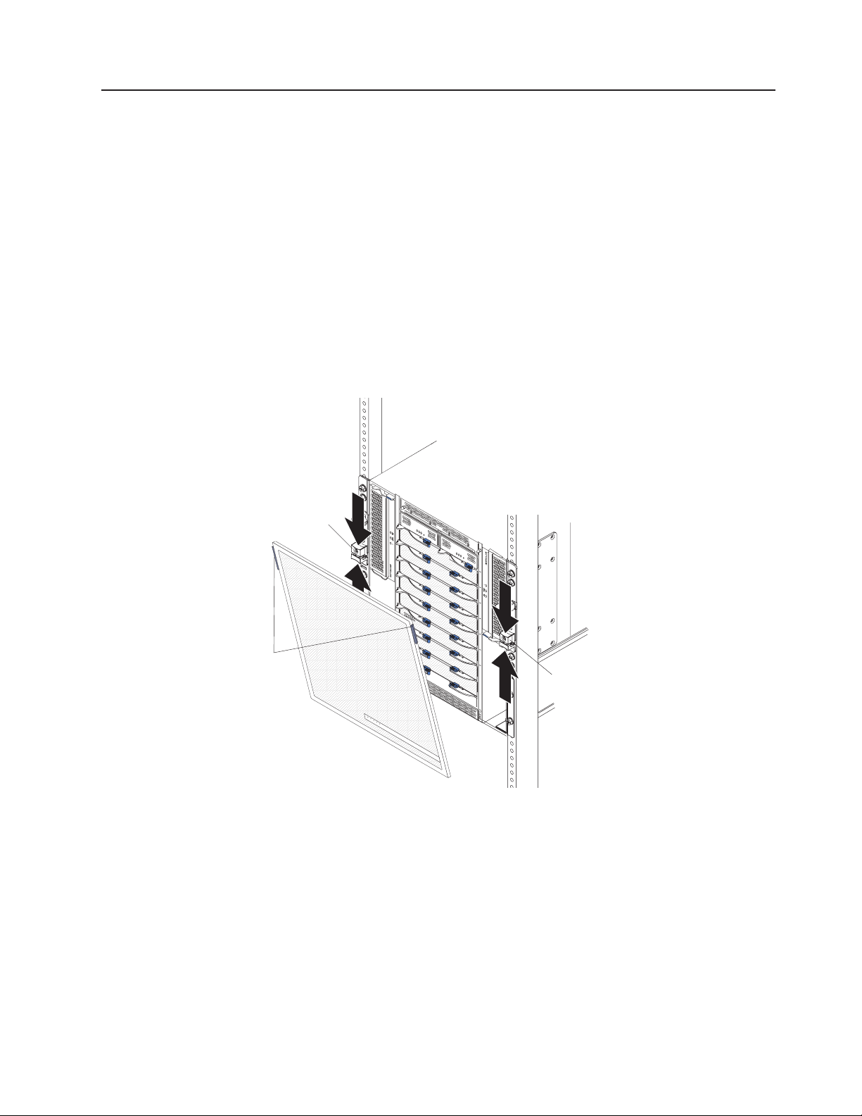
Removing and installing the bezel assembly
The BladeCenter T unit comes with a bezel assembly containing a removable and
replaceable air filter. There are software features in the management-module that
detect a clogged filter and generate system alerts based on the severity of the
airflow reduction. The typical service interval for the filter is approximately three to
six months depending on your environment. Be sure to replace the air filter when
indicated.
Important: If the BladeCenter T unit contains any blade servers with standard
(high-profile) release levers, the bezel assembly will not fit on the chassis. The
bezel assembly and air filter can be used only if all blade servers in the chassis
have low-profile release levers.
See “Removing and installing the bezel air filter” on page 44 for instructions for
removing and replacing the bezel air filter.
Bezel lock
retention latch
Bezel
touch
points
Removing the bezel assembly
Complete the following steps if you are removing the bezel assembly from the front
of the BladeCenter T unit:
1. Squeeze the upper and lower halves of the bezel lock retention latches together
to open the bezel locks on each side as shown in the illustration; then, forcefully
pull forward on the blue touch points at the top sides of the bezel.
2. Lift the bezel assembly up and out of the BladeCenter T unit. Carefully set the
bezel assembly aside in a safe location.
C
M
M
1
CM
M
2
ES
D
Bezel lock
retention latch
Chapter 4. Setting up the BladeCenter T hardware 43
Page 54

Installing the bezel assembly
Complete the following steps if you are installing the bezel assembly at the front of
the BladeCenter T unit:
1. Ensure that the bezel lock is open; then, insert the bottom bezel hooks into the
bezel slots at the bottom of the BladeCenter T unit.
2. Push in the bottom and the top of the bezel assembly until they both click firmly
into place; then, close the bezel locks by sliding the bottom half of the bezel
lock retention latch down until it stops.
Removing and installing the bezel air filter
The air filter is installed behind the front bezel of the BladeCenter T unit.
Important: If the BladeCenter T unit contains any blade servers with standard
(high-profile) release levers, the bezel assembly will not fit on the chassis. The
bezel assembly and air filter can be used only if all blade servers in the chassis
have low-profile release levers.
Note:
v Read “Installation guidelines” on page 37.
v Read “Important safety information” on page iii.
v Read “Handling static-sensitive devices” on page 40.
Bezel
Air filter
Retainer
CM
M
1
CM
M
2
ES
D
Complete the following steps to replace the front bezel air filter in the BladeCenter
T unit:
44 BladeCenter T Type 8720 and 8730: Hardware Maintenance Manual and Troubleshooting Guide
Page 55

1. Remove the bezel from the front of the BladeCenter T unit (see “Removing the
bezel assembly” on page 43 for instructions).
2. Place the bezel front-side down on a work surface.
3. Remove the air-filter retainer by pulling the retainer upwards and off the
ball-stud fasteners on the bezel.
4. Remove the old air filter from the bezel frame.
5. Remove the new air filter from its packaging.
Ball-stud clips
Air-filter retainer
LED pipes
Air-filter
LED window
Ball-studs
Bezel
LED holes
6. Align the LED window of the filter with the holes for the LEDs on the bezel and
lay the filter into the bezel frame.
7. Align the air-filter retainer over the filter with the ball-stud clips facing down and
the LED light pipe lined up with the LED holes on the bezel.
8. Gently push the air-filter retainer down until it snaps into the ball-stud fasteners
on the back of the bezel.
9. Install the bezel on the front of the system (see “Installing the bezel assembly”
on page 44 for instructions).
Chapter 4. Setting up the BladeCenter T hardware 45
Page 56

Removing and installing power modules
The BladeCenter T unit is separated into two power domains. To support devices in
power domain B, a power-supply module option (consisting of two power modules)
must be installed.
The following table summarizes the modules that are powered by each power
domain.
Power domain Power-module bays Modules powered by the power domain
A 1 and 2 I/O-module bays 1 and 2
Management-module bays 1 and 2
Media tray
Blade bays 1 through 4
B 3 and 4 Blade bays 5 through 8
I/O-module bays 3 and 4
All four blowers are required for redundant system operation. Power for all four
blowers is shared by all installed power modules. One failed blower creates a
nonredundant configuration.
If a power module fails or an input power failure occurs, BladeCenter T units that
are configured for redundant power operation will operate in a nonredundant mode.
You must replace the failing power module or restore input power as soon as
possible to regain redundant power operation.
Important:
1. The power modules must be installed in pairs in a domain and must match each
other in capacity (wattage, amperage, and so on).
2. To provide true redundant power, BladeCenter T power modules 1 and 3 must
be connected to a different input power source than power modules 2 and 4.
46 BladeCenter T Type 8720 and 8730: Hardware Maintenance Manual and Troubleshooting Guide
Page 57
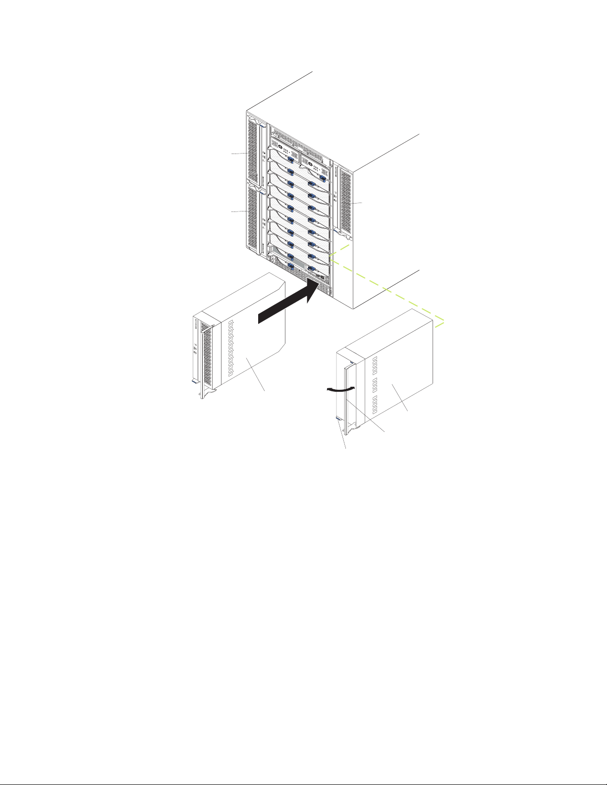
C
MM
1
Power module 1
C
M
M
2
Power module 3
Removing a power module
Complete the following steps to remove a power module or filler panel from the
front of the BladeCenter T unit. The procedure is the same for both ac-power and
dc-power modules.
ES
D
Power module 4
Power module 2
Filler module
Release handle
Release button
Attention: To help ensure proper cooling and system reliability, make sure that
you replace a removed power module or filler panel with a power module within 1
minute.
Important:
If you are removing a functional power module, make sure that both the
ac-power LED and the dc-power LED on the remaining power module
are lit; otherwise, shut down the operating systems and turn off all of
the blade servers that are supported by the power module you are
removing, before you remove it. (See the documentation that comes
with the blade server for instructions for shutting down the blade server
operating system and turning off the blade server.)
1. Press the blue release button on the front of the new power module to release
the power-module handle; then, move the power-module handle outward until it
is in the open position (90° from the closed position).
Chapter 4. Setting up the BladeCenter T hardware 47
Page 58

2. Grip the power-module handle with one hand and slowly pull the power module
out of the bay. Use your other hand to support the bottom of the power module
as you pull the power module out from the bay.
Attention: Do not carry the power module by only the power-module handle.
You must support the weight of the power module.
3. Place the power module in a safe location.
4. Within 1 minute, install either another power module or a filler module into the
selected power-module bay.
Installing a power module
Complete the following steps to install a power module at the front of the
BladeCenter T unit. The procedure is the same for both ac-power and dc-power
modules.
Attention: To help ensure proper cooling and system reliability, make sure that
you replace a removed power-module filler panel with a power module within 1
minute.
1. Note the orientation of the power module or filler you are removing; then,
remove the filler or power module from the selected power-module bay and set
it aside.
2. Press the blue release button on the front of the new power module to release
the power-module handle; then, move the power-module handle outward until it
is in the open position (90° from the closed position).
3. Grip the power-module handle with one hand and support the bottom of the
power module with the other hand.
Attention: Do not carry the power module by only the power-module handle.
You must support the weight of the power module.
4. Orient the new power module to the selected power-module bay; then, slide the
power module into the bay until it stops.
5. Push the power-module handle in until it locks into the latch next to the blue
release button.
6. Make sure the LEDs on the power module indicate that it is operating correctly.
Make sure that:
v The input power LED is lit.
v The output power LED is lit.
v The error LED is not lit.
7. If you have other modules to install at the front of the unit, do so now.
Otherwise reinstall the bezel assembly at the front of the BladeCenter T unit.
48 BladeCenter T Type 8720 and 8730: Hardware Maintenance Manual and Troubleshooting Guide
Page 59

Removing and installing the media tray
The media tray is a hot-swap unit that is installed in the front of the BladeCenter T
unit and contains the system-status panel, two USB connectors, and the CD-ROM
drive. See “Media tray” on page 11 for information about the system-status panel
controls and indicators.
Media tray
CD-ROM drive
System-status panel
USB connectors
Use the instructions in this section to remove or install the media tray at the front of
the BladeCenter T unit.
C
MM
1
C
M
M
2
E
S
D
Release latch
Media tray
Release button
Chapter 4. Setting up the BladeCenter T hardware 49
Page 60

Removing the media tray
Complete the following steps to remove the media tray in the front of the
BladeCenter T unit:
1. Open the two release levers as shown in the illustration. The media tray moves
out of the bay approximately 0.6 cm (0.25 inch).
2. Make sure that the release latches are in the open position (90° from the closed
position).
3. Grasp the media tray at the front of each side of the module and carefully pull
the module all the way out of the bay. Set it in a safe place.
4. Within 1 minute, install another media tray into the BladeCenter T unit.
Installing the media tray
Complete the following steps to install the media tray in the front of the BladeCenter
T unit:
1. Hold the media tray at the front of each side of the module and orient the media
tray to the top of the media-tray bay. Carefully position the module into the rails
in the media-tray bay.
2. Make sure that the release latches are in the open position (90° from the closed
position).
3. Slide the media tray forward into the media-tray bay until it stops.
4. Push the media tray in until you feel it lock into position.
5. Push both release latches in until they lock.
6. Make sure that the power LED is lit on the system-status panel.
7. If you have other modules to install at the front of the unit, do so now.
Otherwise, reinstall the bezel assembly at the front of the unit.
50 BladeCenter T Type 8720 and 8730: Hardware Maintenance Manual and Troubleshooting Guide
Page 61

Removing and installing management modules
The BladeCenter T unit comes with one hot-swap management module in
management-module bay 1. You can add a second management module in
management-module bay 2.
Note: Only one management module is active; the second management module, if
present, provides redundancy.
Release button
Management module
Release latch
Serial port
MAC address
The management module functions as a service processor for the multiple blade
servers. The management module configures the BladeCenter T unit and modules,
configuring information such as switch module IP addresses. The management
module also performs USB-to-PS/2 conversions for the system keyboard and
mouse and can send the VGA signal stream to a remote console for viewing. See
“Management module controls and indicators” on page 10 for information about the
controls and indicators.
The service processor in the management module communicates with the service
processor in each blade server for functions such as:
v Blade server power-on requests
v Blade server error and event reporting
v Blade server requests for keyboard, mouse, and video
v Blade server requests for CD-ROM drive and USB ports
management module also communicates with the I/O modules, power modules,
The
blower modules, and blade servers to detect presence or absence and any error
conditions, sending alerts when required.
Use the instructions in this section to remove or install a management module at
the front of the BladeCenter T unit.
Chapter 4. Setting up the BladeCenter T hardware 51
Page 62

Release latch
C
M
M
1
ES
D
Management module
C
M
M
2
Removing a management module
Notes:
1. If you are removing the only management module in the BladeCenter T unit, to
avoid unexpected termination of sessions, stop all management-module local
and remote sessions before proceeding.
2. If you are removing the only management module in the BladeCenter T unit, be
aware that as soon as you remove the module, the BladeCenter T blowers will
increase to full speed.
3. If you are replacing the only management module in the BladeCenter T unit and
the management module is functional, save the configuration file to another
medium before you proceed (in the MM Control section in the navigation pane,
click Configuration File and follow the instructions under Save MM
Configuration); you will be able to restore the saved configuration file to the
replacement management module.
4. If you have just installed a second management module in the BladeCenter T
unit, do not remove the first (primary) management module for approximately 2
minutes; the second (secondary) management module needs the time to
receive initial status information.
Complete the following steps to remove a management module or filler module from
the front of the BladeCenter T unit:
1. Press the blue release button at the front of the management module.
2. Pull the release latch all the way toward the left side of the management
module until it stops, as shown in the illustration. The module moves slightly out
of the bay.
3. Grip the management module with one hand and slowly pull the management
module out of the bay. Use your other hand to support the bottom of the
management module as you pull it out from the bay.
Important: Within 1 minute, you must place either another module of the same
type or a filler module in the bay.
52 BladeCenter T Type 8720 and 8730: Hardware Maintenance Manual and Troubleshooting Guide
Page 63

Installing a management module
Complete the following steps to install a management module in the BladeCenter T
unit:
1. If you are installing a second management module, see the IBM BladeCenter
T Management Module User’s Guide for information about
management-module redundancy.
2. If you are replacing a management module, remove the current module from
the bay (see “Removing a management module” on page 52). If you are
adding a management module, remove the filler module from the selected
management-module bay and store the filler module for future use.
Note: You will be able to apply a saved configuration file to the replacement
management module. For more information about applying a saved
configuration file, see “Saving and restoring the configuration file” on
page 29.
3. If you have not already done so, touch the static-protective package that
contains the new management module to an unpainted metal part of the
BladeCenter T unit or any unpainted surface on any other grounded rack
component for at least 2 seconds.
4. Remove the management module from its static-protective package.
5. Press the blue release button on the management module to open the release
latch. Make sure that the release latch on the management module is in the
open position (90° from the closed position).
6. Holding the management module at the front with one hand, and in the middle
with the other hand, orient the management module to the bottom of the
selected management-module bay and gently slide the management module
into the bay until it stops. Push the management module in until the release
latch starts to close.
7. Push the release latch on the front of the management module to the closed
position.
8. Make sure that the error LED on the management module is not lit, indicating
that the management module is operating correctly.
9. If this is the only management module in the BladeCenter T unit, configure the
new management module. See the IBM BladeCenter T Management Module
User’s Guide for detailed instructions. If this is the secondary management
module and you followed the instructions in the IBM BladeCenter T
Management Module User’s Guide, no configuring is necessary. The
secondary management module receives the configuration and status
information automatically from the primary management module when
necessary. However, you must apply the latest level of firmware from the IBM
Support Web site at http://www.ibm.com/support/ to ensure smooth
changeovers (see the IBM BladeCenter T Management Module User’s Guide
for more information).
Note: Do not initiate any management module changeover for approximately 2
minutes after installing the secondary management module; the
secondary management module needs the time to receive initial
configuration and status information.
10. If you have other modules to install at the front of the unit, do so now.
Otherwise reinstall the bezel assembly on the front of the BladeCenter T unit.
Chapter 4. Setting up the BladeCenter T hardware 53
Page 64

Removing and installing blower modules
The BladeCenter T unit comes with four hot-swap blowers for cooling redundancy.
The blowers are installed at the rear of the system. The blower speeds vary
depending on the ambient air temperature at the front of the BladeCenter T unit. If a
blower fails, the remaining blowers increase their speed to cool the BladeCenter T
unit and blade servers.
All flour blowers are required for redundant system operation. Power for all four
blowers is shared by all installed power modules. One failed blower creates a
nonredundant configuration.
Note: Each power module has cooling fans that are independent from the system
cooling.
Error LED
Power LED
Blower
Important: Replace a failed blower as soon as possible to restore cooling
redundancy.
Use the instructions in this section to remove or install a blower module at the rear
of the BladeCenter T unit.
Note: Blowers on the left side of the system are installed with the release lever
pointing upward, and blowers on the right side are installed with the release
lever facing downward.
54 BladeCenter T Type 8720 and 8730: Hardware Maintenance Manual and Troubleshooting Guide
Page 65

Error LED
3
1
4
2
Power LED
Release latch
(open)
Removing a blower module
Use the following instructions to remove a blower at the rear of the BladeCenter T
unit.
1. Press the release lever at the end of the release latch and pull the latch to the
open position. The blower module moves slightly out of the bay.
2. Slide the module out of the blower bay and set it aside.
3. Within 1 minute, install another blower module into the bay.
Installing a blower module
Complete the following steps to install a blower module into the rear of the
BladeCenter T unit.
1. Press the release lever at the end of the release latch and pull the latch to the
open position.
2. Insert the blower into the selected blower bay.
3. Push the blower module into the bay until it stops. The release latch moves
slightly toward the closed position.
4. Close the release latch until it locks into position.
5. Make sure that the blower power LED is lit and the blower error LED is not lit.
Chapter 4. Setting up the BladeCenter T hardware 55
Page 66

Removing and installing the KVM (keyboard, video, mouse) module
The KVM module is a hot-swap unit that is installed in the rear of the BladeCenter
T unit and is held in place by captive thumbscrews. The KVM module provides the
electrical and mechanical interface to the BladeCenter T unit for a local keyboard,
RGB VGA video monitor, and a mouse. Five LEDs on the KVM module
system-status panel are used for system status information: power, location, minor
alarm, major alarm, and critical alarm. See “KVM (keyboard, video, mouse) module
indicators and input/output connectors” on page 16 for information about the
controls and indicators.
NR
M
R
J
T
R
M
C
KVM module
Use the instructions in this section to remove or install the KVM module from the
rear of the BladeCenter T unit. The KVM module is held in place by captive
thumbscrews. You can use either your fingers or a screwdriver to install or remove
the KVM module. If you use a screwdriver, make sure that you do not overtighten
the thumbscrews.
3
1
4
2
LAN module
KVM module
56 BladeCenter T Type 8720 and 8730: Hardware Maintenance Manual and Troubleshooting Guide
Page 67

Removing the KVM module
Complete the following steps to remove the KVM module at the rear of the
BladeCenter T unit.
1. Remove the keyboard, mouse, and video cables if any are connected.
2. Fully loosen each thumbscrew counterclockwise.
3. Hold the KVM module by both thumbscrews.
4. Carefully pull the KVM module outward from the KVM module bay until you feel
it release.
5. Remove the KVM module from the bay and set it aside.
6. Within 1 minute, install a new KVM module.
Installing the KVM module
Complete the following steps to install the KVM module at the rear of the
BladeCenter T unit
1. Hold the KVM module by both thumbscrews.
CRT
MJR
MNR
Thumbscrew Thumbscrew
System-status panel
2. Position the KVM module into the rails inside the KVM-module bay.
3. Push the KVM module into the bay until you feel it stop. Make sure that it is
snug.
4. Turn each thumbscrew clockwise until it is finger tight. If you use a screwdriver,
make sure that you do not overtighten the thumbscrews.
5. Make sure that the power LED on the front of the KVM module is lit.
6. Connect any peripheral devices that you want to use at this time (for example,
keyboard, mouse, and video monitor).
Chapter 4. Setting up the BladeCenter T hardware 57
Page 68

Removing and installing the LAN module
The LAN module is a hot-swap unit that is installed in the rear of the BladeCenter T
unit and is held in place by captive thumbscrews. The LAN module provides the
electrical and mechanical interface to the BladeCenter T system for the two local
area network (Ethernet) connections, as driven from each management module,
and the telco external alarms. This module contains two RJ45 connectors with
LEDs for the management interface and one DSUB 15P male telco alarm
connector. See the “LAN-module indicators and input/output connectors” on page
18 for more information.
ms
ar
l
A
1
2
LAN module
Use the instructions in this section to remove or install the LAN module into the rear
of the BladeCenter T unit (see the illustration of the KVM and LAN modules on
page 56). The LAN module is held in place by captive thumbscrews. You can either
use your fingers or a screwdriver to install or remove the LAN module. If you use a
screwdriver, make sure that you do not overtighten the thumbscrews.
Ethernet link LED
2
Thumbscrews
Remote management
and console (Ethernet)
1
Alarms
Ethernet activity LED
Alarms connector
58 BladeCenter T Type 8720 and 8730: Hardware Maintenance Manual and Troubleshooting Guide
Page 69

Removing the LAN module
Complete the following steps to remove a LAN module from the rear of the
BladeCenter T unit:
1. Fully loosen each thumbscrew counter clockwise.
2. Grasp the LAN module by both thumbscrews.
3. Carefully pull the LAN module outward from the LAN module bay until you feel it
release from the card edge connector on the backplane.
4. Remove the LAN module from the bay and set it aside.
5. Within 1 minute, install the new LAN module.
Installing the LAN module
Complete the following steps to install a LAN module into the rear of the
BladeCenter T unit:
1. Hold the LAN module by both thumbscrews.
2. Position the LAN module into the rails inside the LAN module bay (see the
illustration of the KVM and LAN modules on page 56).
3. Push the LAN module into the bay until it stops. Make sure that it is snug.
4. Turn each thumbscrew clockwise until it is finger tight. If you use a screwdriver,
make sure that you do not overtighten the thumbscrews.
Chapter 4. Setting up the BladeCenter T hardware 59
Page 70

Removing and installing I/O modules
For blade server communication with the network, the BladeCenter T unit supports
up to four hot-swap I/O modules. Table 5 identifies the types of I/O modules that
you can install in each I/O-module bay. Go to the IBM Support Web site at
http://www.ibm.com/support/ to see the list of supported I/O modules.
The BladeCenter T unit supports a minimum of one hot-swap Ethernet switch
module or pass-thru module, in I/O-module bay 1 or 2. This I/O module provides an
internal connection to an integrated Ethernet controller in all the blade servers in the
BladeCenter T unit, up to eight internal connections per I/O module. To provide an
internal connection for the second integrated Ethernet controller in each blade
server, install an Ethernet switch module or pass-thru module in the available
I/O-module bay of the pair (I/O-module bay 1 or bay 2). The management modules
are connected to the switch module through the backplane using a transformerless
100 Mbps connection and an I2C interface.
The BladeCenter T unit supports two additional I/O modules in I/O-module bays 3
and 4. Each of these I/O modules provides an internal connection to one of the two
network-interface controllers on each of the I/O expansion options that are installed
on blade servers in the BladeCenter T unit. The I/O module must be compatible
with the network interface on each of the I/O expansion options. For example, if you
install a Fibre Channel I/O expansion card on a blade server, the I/O modules that
you install in I/O-module bays 3 and 4 must be Fibre Channel switch modules or
pass-thru modules.
Important: The switch modules in I/O module bays 3 and 4 and all blade server
interface options in the BladeCenter T unit, must use the same interface type. For
example, if you install an Ethernet interface option on a blade server, the switch
modules that you install in I/O module bays 3 and 4 must be Ethernet. All other
interface options in the BladeCenter T unit must also be Ethernet interface options.
Note: You can use a pass-thru module in any I/O-module bay, provided that the
associated controller in the blade servers or I/O expansion options is
compatible with it.
The following table summarizes the types of modules that can be used in each
I/O-module bay. See “Rear view” on page 15 for the location of the I/O-module bays
on the BladeCenter T unit.
Table 5. Hot-swap I/O module types by location for redundancy
Bays I/O-module function Permissible I/O module
1 and 2 Network connections 1 and 2
(Ethernet) for all blade servers in the
BladeCenter T unit
One of the following combinations:
v Two Ethernet switch modules
v Two pass-thru modules
v One Ethernet switch module and
one pass-thru module
60 BladeCenter T Type 8720 and 8730: Hardware Maintenance Manual and Troubleshooting Guide
Page 71

Table 5. Hot-swap I/O module types by location for redundancy (continued)
Bays I/O-module function Permissible I/O module
3 and 4 Network connections 3 and 4 (for all
I/O expansion options on blade
servers in the BladeCenter T unit)
One of the following combinations.
v Two Ethernet switch modules
v Two Fibre Channel switch modules
v Two pass-thru modules
Important:
v The modules used must support the
network interface that is used on the
blade server I/O expansion options.
v The I/O modules in bays 3 and 4
must be the same type.
Notes:
1. The enumeration of the Ethernet controllers in a blade server is
operating-system dependent. You can verify the Ethernet controller designations
that a blade server uses through your operating-system settings.
2. The routing of an Ethernet controller to a particular I/O-module bay depends on
the type of blade server. Yo u can verify which Ethernet controller is routed to
which I/O-module bay by using the following test:
a. Install only one Ethernet switch module or pass-thru module, in I/O-module
bay 1.
b. Make sure that the ports on the switch module or pass-thru module are
enabled (I/O Module Tasks ” Management ” Advanced Management in
the management module Web-based user interface).
c. Enable only one of the Ethernet controllers on the blade server. Note the
designation that the blade server operating system has for the controller.
d. Ping an external computer on the network that is connected to the switch
module or pass-thru module.
If you can ping the external computer, the Ethernet controller that you enabled
is associated with the I/O module in I/O-module bay 1. The other Ethernet
controller in the blade server is associated with the I/O module in I/O-module
bay 2.
3. If you have installed an I/O expansion option on a blade server, communications
from the option are routed to I/O-module bays 3 and 4. You can verify which
controller on the option is routed to which I/O-module bay by performing the test
in note 2, using a controller on the I/O expansion option and a compatible
switch module or pass-thru module in I/O-module bay 3 or 4.
the instructions in this section to remove or install an I/O module at the rear of
Use
the BladeCenter T unit.
Chapter 4. Setting up the BladeCenter T hardware 61
Page 72

Filler
module
Filler
module
Removing an I/O module
Use the following instructions to remove an I/O module or filler module from the
rear of the BladeCenter T unit.
1. Press the release lever at the end of the release latch and pull the latch to the
open position. The I/O module moves slightly out of the bay.
2. Slide the I/O module out of the I/O-module bay and set it aside.
3. Within 1 minute, install another I/O module or filler module into the bay.
Fibre
Channel
switch
module
Ethernet
switch
module
Release
latch
(open)
Release
latch
(open)
Installing an I/O module
Complete the following steps to install an I/O module into the rear of the
BladeCenter T unit.
1. Press the release lever at the end of the release latch and pull the latch to the
open position.
2. Insert the I/O module into the selected I/O-module bay.
3. Push the I/O module into the bay until it stops. The release latch moves slightly
toward the closed position.
4. Close the release latch until it locks into position.
62 BladeCenter T Type 8720 and 8730: Hardware Maintenance Manual and Troubleshooting Guide
Page 73

Blade servers
The BladeCenter T unit supports up to eight high-performance blade servers. Each
blade server is an enclosure that contains microprocessors, memory, a control chip
set, an I/O bus, Ethernet controllers, hard disk drives or flash drives, and
user-interface controls, and connectors for expansion options. The blade server
receives its power, network connection, and I/O devices (CD-ROM, keyboard,
mouse, and video ports, USB port, remote monitoring port) from the BladeCenter T
unit, reducing the number of cables that are required.
Blade server expansion options
Some blade servers contain connectors for options that add capabilities to the blade
server. You can add these options before installing the blade server in the
BladeCenter T unit.
Go to http://www.ibm.com/pc/compat/ for a list of available options for your IBM
blade server.
I/O expansion option
Some blade servers have connectors for adding an I/O expansion option, such as
an IBM BladeCenter Fibre Channel Expansion Card. The BladeCenter T unit routes
network communication signals from the I/O expansion option to I/O modules 3 and
4 on the BladeCenter T unit. The I/O expansion option is attached directly to the
blade server and does not occupy an additional blade bay.
Note: If an I/O expansion option is installed on any blade server, I/O modules that
are compatible with that network interface must be installed in I/O-module
bays 3 and 4 on the BladeCenter T unit. See “Removing and installing I/O
modules” on page 60 for more information.
Expansion unit option
You can install an optional BladeCenter SCSI Storage Expansion Unit or Peripheral
Card Interface (PCI) I/O Expansion Unit on your blade server.
Storage Expansion Unit option: Some blade servers have a connector for
adding an expansion unit, such as an IBM BladeCenter SCSI Storage Expansion
Unit. The storage expansion unit supports up to two hot-swap SCSI hard-disk
drives. The expansion option is attached directly to the blade server and occupies
an additional blade server bay.
PCI I/O-expansion Unit option: Some blade servers have a connector for adding
an expansion unit, such as an IBM BladeCenter PCI I/O Expansion Unit. The PCI
I/O-expansion unit supports up to two PCI-X adapters. The expansion unit is
attached directly to the blade server and occupies an additional blade server bay.
Chapter 4. Setting up the BladeCenter T hardware 63
Page 74

Removing and installing a blade server or filler module
Use the instructions in this section to remove or install a blade server at the front of
the BladeCenter T unit.
Important: Reinstalling a blade server into a different bay than the one from which
it was removed could have unintended consequences. Some configuration
information and update options are established according to bay number. Yo u might
need to reconfigure the blade server.
Attention: To maintain proper system cooling, do not operate the BladeCenter T
unit for more than 20 minutes without either a blade server or a filler blade installed
in each blade bay. If you fail to replace a blade server or filler blade within 20
minutes, system performance might be affected.
C
M
M
Blade Server
1
Release
latches
Filler blade
C
M
M
2
ES
D
64 BladeCenter T Type 8720 and 8730: Hardware Maintenance Manual and Troubleshooting Guide
Page 75

Installing a blade server
Complete the following steps to install a blade server or filler blade in the
BladeCenter T unit.
Statement 21:
CAUTION:
Hazardous energy is present when the blade is connected to the power
source. Always replace the blade cover before installing the blade.
1. Install any options that you need, such as hard disk drives or memory, in the
blade server. See the documentation that comes with the blade server for
instructions.
2. Select the bay for the blade server.
Notes:
a. If a blade server has a SCSI Storage Expansion Unit or PCI I/O-expansion
Unit installed on it, the blade server and expansion option require an
additional adjacent blade bay.
b. If you install a blade server or option in bay 5 through 8, you must install
power modules in power-module bays 3 and 4.
3. Remove the filler blade from the bay and store in a safe place.
4. Make sure that the release latches on the blade server are in the open position
(horizontal to the blade server).
5. Slide the blade server into the bay until it stops.
6. Push the release latches on the front of the blade server until they are closed.
7. Turn on the blade server by pressing the power-control button on the blade
server control panel. See the documentation that comes with the blade server
for more instructions.
8. Make sure that the power LED on the blade server control panel is lit,
indicating that the blade server is receiving power.
9. (Optional) Write identifying information on one of the user labels that come
with the blade server; then, place the label on the BladeCenter T unit to the
right of the blade server, as shown in the following illustration.
CMM
1
CMM
2
User
label
Important: Do not place the label on the blade server or in any way block the
ventilation holes on the blade server.
Chapter 4. Setting up the BladeCenter T hardware 65
Page 76

10. If you have other modules to install at the front of the unit, do so now.
Otherwise reinstall the bezel assembly on the front of the BladeCenter T unit.
Note: Reinstall the bezel assembly on the BladeCenter T unit after you have
finished installing the blades. However, if you installed an option such
as a PCI I/O Expansion Unit with PCI adapters that require cables, you
will not be able to install the bezel assembly, which contains an air filter
for the BladeCenter T unit. If you cannot install the bezel assembly, a
filter must be provided on the rack.
this is the initial installation for a blade server in the BladeCenter T unit, you must
If
configure the blade server with the blade server Configuration/Setup Utility program
and install the blade server operating system. See the documentation that comes
with the blade server for instructions.
Removing a blade server
Complete the following steps to remove a blade server from the BladeCenter T unit.
Note: If you do not shut down a blade server properly, it cannot be restarted using
the Wake on LAN feature.
1. Shut down the blade server operating system; then, press the blade server
power-control button (behind the blade server control panel door) to turn off the
blade server. Wait at least 30 seconds until the drives stop spinning, before
proceeding to the next step.
2. Open the two release latches as shown in the illustration on page 64. The blade
server moves slightly out of the bay.
3. Pull the blade server out of the bay.
4. Place either a filler blade or another blade server in the bay within 20 minutes.
Completing the installation
After you install modules and route and secure any power cords (if necessary, see
the Rack Installation Instructions for information about routing the cords), start the
BladeCenter T unit (if it is not already started) and verify that it is working correctly.
1. Make sure the LEDs on the modules indicate that they are operating correctly.
Make sure that:
v The input and output power LEDs on each power module are lit, and the fault
LEDs are not lit.
v The power LED on each management module is lit.
v The power LED on each I/O module is lit.
Make sure that the power LED on each blade server is lit, either steady or
2.
blinking.
See “BladeCenter T unit power, controls, and indicators” on page 19 for information
about starting the BladeCenter T unit and the location of the LEDs on the modules.
See the BladeCenter HS20 Installation and User’s Guide on the IBM BladeCenter T
Documentation CD for the location of the LEDs on the blade servers.
66 BladeCenter T Type 8720 and 8730: Hardware Maintenance Manual and Troubleshooting Guide
Page 77

Chapter 5. Service replaceable units
This chapter describes the removal of server components.
Important: The field replaceable unit (FRU) procedures are intended for trained
servicers who are familiar with IBM xSeries products. See the parts
listing in Chapter 7, “Parts listing, BladeCenter T Type 8720 and
8730,” on page 107 to determine if the component being replaced is a
customer replaceable unit (CRU) or a FRU.
As further guidance, the components in the BladeCenter T server have
an alphabetical stamp in the metal that identifies the order they were
assembled at the factory (for example, a, b, c, etc.).
© Copyright IBM Corp. 2004 67
Page 78

DC terminal cover with fasteners
Complete the following steps to replace the dc terminal cover on the Type 8720
unit.
Note:
v Read “Installation guidelines” on page 37.
v Read the safety notices at ″Safety information″ on page 113.
v Read “Handling static-sensitive devices” on page 40.
Shut down the system, and remove power from the system (see “Shutting down
1.
the BladeCenter T unit” on page 21).
2. Loosen the two captive fasteners on the old DC terminal cover.
DC terminal cover
Captive fasteners (2)
3. Remove the old dc terminal cover from the dc terminal.
4. Remove the new dc terminal cover from its packaging.
5. Align the new dc terminal cover so that the stamped arrow on the back is
pointing up, and position the new dc terminal cover over the mounting holes on
the dc terminal.
6. Tighten the two captive fasteners on the new dc terminal cover.
Note: Torque the captive fasteners to 8 inch-pounds.
7. Connect power to the BladeCenter T unit (see page“Starting the BladeCenter T
unit” on page 19).
8. Start up the system (see “Starting the BladeCenter T unit” on page 19).
68 BladeCenter T Type 8720 and 8730: Hardware Maintenance Manual and Troubleshooting Guide
Page 79

AC rear panel
Complete the following steps to replace the ac rear panel located at the rear of the
unit.
Note:
v Read “Installation guidelines” on page 37.
v Read the safety notices at ″Safety information″ on page 113.
v Read “Handling static-sensitive devices” on page 40.
1. Shut down the system, and remove power from the system (see “Shutting
down the BladeCenter T unit” on page 21).
2. Remove each power cord from the input power connections on the rear of the
BladeCenter T unit.
3. Remove the KVM module from the rear of the system (see “Removing the
KVM module” on page 57).
4. Remove the LAN module from the rear of the system (see “Removing the LAN
module” on page 59).
5. Using a screwdriver, fully loosen the seven captive fasteners on the old ac rear
panel.
Captive fastener (6)
6. Remove the old ac rear panel from the system.
7. Remove the new ac rear panel from its packaging.
8. Position the new ac rear panel so that it aligns with the power inlet receptacles
AC rear panel
on the system. Make sure that the ac rear panel is well seated on the system.
9. Using a screwdriver, tighten the seven captive fasteners on the new ac rear
panel. Torque the screws to 8-inch pounds.
Note: Torque the captive fasteners to 8 inch-pounds.
Chapter 5. Service replaceable units 69
Page 80

DC Rear Panel
10. If you have no other replacement procedures to perform at the rear of the
system, re-install the LAN module (see “Installing the LAN module” on page
59) and the KVM module (see “Removing and installing the KVM (keyboard,
video, mouse) module” on page 56).
11. Plug each power cord into the input power connections on the rear of the
BladeCenter T unit (see “Starting the BladeCenter T unit” on page 19).
12. Start up the system (see “Starting the BladeCenter T unit” on page 19).
Complete the following steps to replace the dc rear panel located at the rear of the
unit.
Note:
v Read “Installation guidelines” on page 37.
v Read the safety notices at ″Safety information″ on page 113.
v Read “Handling static-sensitive devices” on page 40.
1. Shut down the system, and remove power from the system (see “Shutting
down the BladeCenter T unit” on page 21).
2. Remove dc terminal covers.
3. Remove the power connections to each of the dc terminals, and safely place
the cables aside.
4. Remove the KVM module from the rear of the system (see “Removing the
KVM module” on page 57).
5. Remove the LAN module from the rear of the system (see “Removing the LAN
module” on page 59).
6. Using a screwdriver, fully loosen the three captive fasteners on the old dc rear
panel.
7. Remove the old dc rear panel from the system.
8. Remove the new dc rear panel from its packaging.
DC rear panel
70 BladeCenter T Type 8720 and 8730: Hardware Maintenance Manual and Troubleshooting Guide
Captive fasteners (3)
Page 81

9. Position the new dc rear panel so that it aligns with the dc power terminals on
the system. Make sure that the dc rear panel is well seated on the system.
10. Using a screwdriver, tighten the three captive fasteners on the new dc rear
panel.
Note: Torque the screws to 8 inch-pounds.
11. If you have no other replacement procedures to perform at the rear of the
system, re-install the LAN module (see “Installing the LAN module” on page
59) and the KVM module (see “Installing the KVM module” on page 57).
12. Connect the power cable connectors to the dc terminals of the BladeCenter T
unit (see page19).
13. Reinstall dc terminal covers.
14. Start up the system (see “Starting the BladeCenter T unit” on page 19).
Upper flex circuit assembly
Complete the following steps to replace the upper flex circuit assembly.
Note:
v Read “Installation guidelines” on page 37.
v Read the safety notices at ″Safety information″ on page 113.
v Read “Handling static-sensitive devices” on page 40.
1. Shut down the system and remove power from the system (see “Shutting
down the BladeCenter T unit” on page 21).
2. For Type 8720 systems, remove the dc terminal covers and power connections
to each of the DC terminals. For Type 8730 systems, remove each power cord
from the input power connections on the rear of the BladeCenter T unit.
3. Remove the KVM module from the rear of the system (see “Removing the
KVM module” on page 57).
4. Remove the LAN module from the rear of the system (see “Removing the LAN
module” on page 59).
5. Remove the I/O switch that is above the upper flex circuit assembly that you
are removing.
6. Using a screwdriver, fully loosen the two captive fasteners on the old upper
flex circuit assembly.
Chapter 5. Service replaceable units 71
Page 82
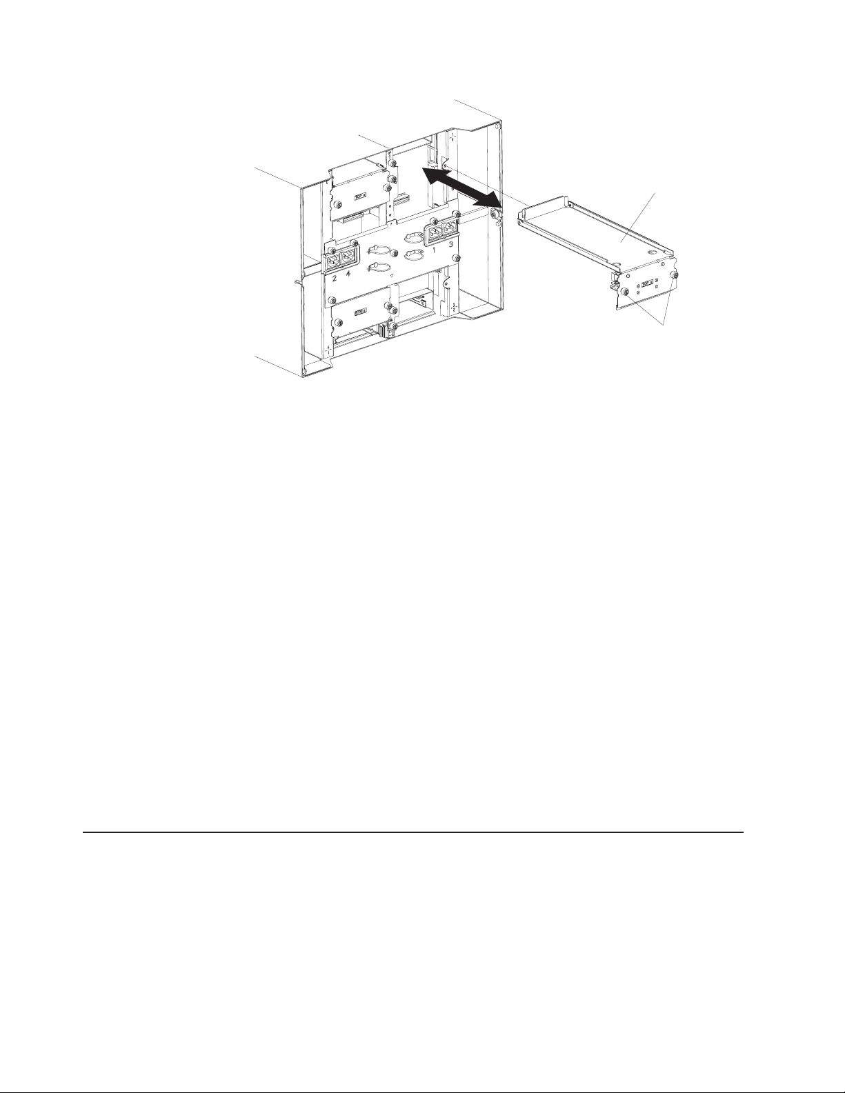
Upper flex circuit assembly
Captive fasteners
7. Carefully remove the old upper flex circuit assembly by placing your fingers
under the lower edge of the assembly and pulling the unit out of the chassis.
8. Remove the new upper flex circuit assembly from the packaging.
9. Align the assembly so that the stamped position identifier ″To p ″ is facing you.
10. Position the front end of the new upper flex circuit assembly into the assembly
bay in the chassis, making sure the leading edge rests on the lower shelf of
the bay.
CAUTION:
Be careful not to damage the EMI gaskets located on the vertical sides of
the upper flex circuit assembly bay.
11. Carefully push the assembly all the way into the bay.
12. Using a screwdriver, tighten the two captive fasteners on the new upper flex
circuit assembly.
Note: Torque the screws to 8 inch-pounds.
13. Reinstall the I/O switch that you removed.
14. If you have no other replacement procedures to perform at the rear of the
system, re-install the LAN module (see “Installing the LAN module” on page
59) and the KVM module (see “Installing the KVM module” on page 57).
15. Reconnect the power to the system (see “Starting the BladeCenter T unit” on
page 19).
16. For Type 8720 systems, reinstall dc terminal covers.
17. Start up the system (see “Starting the BladeCenter T unit” on page 19).
Lower flex circuit assembly
Complete the following steps to replace the lower flex circuit assembly.
Note:
v Read “Installation guidelines” on page 37.
v Read the safety notices at ″Safety information″ on page 113.
v Read “Handling static-sensitive devices” on page 40.
1. Shut down the system and remove power from the system (see “Shutting
down the BladeCenter T unit” on page 21).
72 BladeCenter T Type 8720 and 8730: Hardware Maintenance Manual and Troubleshooting Guide
Page 83

2. For Type 8720 systems, remove the dc terminal covers and power connections
to each of the dc terminals. For Type 8730 systems, remove each power cord
from the input power connections on the rear of the BladeCenter T unit.
3. Remove the KVM module from the rear of the system (see “Removing the
KVM module” on page 57).
4. Remove the LAN module from the rear of the system (see “Removing the LAN
module” on page 59).
5. Remove the rear panel.
6. Remove the I/O switch or filler that is below the lower flex circuit assembly that
you are removing.
7. Using a screwdriver, loosen the two captive fasteners on the old lower flex
circuit assembly.
Lower flex circuit assembly
8. Carefully remove the old lower flex circuit assembly by gripping the top edge of
Captive fasteners
the assembly and pulling the unit out of the chassis.
9. Remove the new lower flex circuit assembly from the packaging.
10. Align the assembly so that the stamped position identifier ″BTM″ is facing you,
and position the front end of the new lower flex circuit assembly into the
assembly bay in the chassis, making sure the leading edge rests against the
ceiling of the bay.
11. Carefully push the assembly all the way into the bay.
12. Using a screwdriver, tighten the two captive fasteners on the new lower flex
circuit assembly.
Note: Torque the screws to 8 inch-pounds.
13. Reinstall the I/O switch they you removed.
14. If you have no other replacement procedures to perform at the rear of the
system, re-install the LAN module (see “Installing the LAN module” on page
59) and the KVM module (see “Installing the KVM module” on page 57).
15. For Type 8720, reinstall dc terminal covers.
16. Reconnect the power to the system (see “Starting the BladeCenter T unit” on
page 19).
Chapter 5. Service replaceable units 73
Page 84

17. Start up the system (see “Starting the BladeCenter T unit” on page 19).
74 BladeCenter T Type 8720 and 8730: Hardware Maintenance Manual and Troubleshooting Guide
Page 85

Docking board/blower housing assembly - (dc Type 8720 and ac Type
8730)
Complete the following steps to replace the docking board/blower housing
assembly.
Note:
v Read “Installation guidelines” on page 37.
v Read the safety notices at ″Safety information″ on page 113.
v Read “Handling static-sensitive devices” on page 40.
1. Shut down the system, and remove power from the system (see “Shutting
down the BladeCenter T unit” on page 21).
2. For Type 8720 (dc) systems, remove the dc terminal covers and power
connections to each of the dc terminals. For Type 8730 (ac) systems, remove
each power cord from the input power connections on the rear of the
BladeCenter T unit.
3. Remove the power modules from the bays at the front of the unit on the same
side of the docking board/blower housing assembly that you are replacing.
Note: The power modules dock into the docking board on the assembly and
must be removed before you can remove the assembly.
4. At the rear of the unit, remove the two blowers from the docking board/blower
housing assembly that you are replacing (see “Removing and installing blower
modules” on page 54).
5. Remove the KVM module from the rear of the system (see “Removing the
KVM module” on page 57).
6. Remove the LAN module from the rear of the system (see “Removing the LAN
module” on page 59).
7. Remove all I/O switches and switch fillers from the rear of the unit. See
“Removing and installing I/O modules” on page 60.
8. For Type 8720, remove the dc rear panel from the rear of the unit (see “DC
Rear Panel” on page 70). For Type 8730, remove the ac rear panel from the
rear of the unit (see “AC rear panel” on page 69).
9. Remove the two upper flex circuit assemblies (see “Upper flex circuit
assembly” on page 71) and the two lower flex circuit assemblies (see “Lower
flex circuit assembly” on page 72).
10. Loosen the two captive fasteners located above and below the power inlet
receptacles.
11. Loosen the captive fastener that attaches the old docking board/blower
housing assembly to the system chassis.
Chapter 5. Service replaceable units 75
Page 86

Docking board/blower
housing assembly
(DC shown)
12. Grab the housing by the housing frame above and below the power inlet
receptacles, and carefully pull the housing out from the system chassis.
13. Remove the new docking board/blower housing assembly from its packaging.
14. Align the new assembly at the rear of the unit so that the connectors on the
assembly align with the connectors on the backplane, and carefully position
and push in the assembly until it is firmly seated in the system chassis.
15. Tighten to 8-inch pounds the two captive fasteners located above and below
the power inlet receptacles.
16. If you have no other replacement procedures to perform at the rear of the
system:
v Reinstall the two upper flex circuit assemblies (see page “Upper flex circuit
assembly” on page 71).
v Reinstall the two lower flex circuit assemblies (see “Lower flex circuit
assembly” on page 72).
v Reinstall the rear dc panel (see “DC Rear Panel” on page 70) or rear ac
panel (see “AC rear panel” on page 69).
v Reinstall the LAN module (see “Installing the LAN module” on page 59).
v Reinstall the KVM module (see page “Installing the KVM module” on page
57).
v Reinstall the I/O switches or switch fillers.
v Reinstall the two blowers (see “Installing a blower module” on page 55).
v For Type 8720 (dc) units, connect the power cables to the dc terminals and
dc terminal covers. For Type 8730 (ac) units, plug each power cord into the
input power connections on the rear of the BladeCenter T unit.
v Reinstall the power modules at the front of the unit (see “Installing a power
module” on page 48).
Start up the system (see “Starting the BladeCenter T unit” on page 19).
17.
76 BladeCenter T Type 8720 and 8730: Hardware Maintenance Manual and Troubleshooting Guide
Page 87

Rear chassis stiffener bracket
Complete the following steps to replace the rear chassis stiffner bracket.
Note:
v Read “Installation guidelines” on page 37.
v Read the safety notices at ″Safety information″ on page 113.
v Read “Handling static-sensitive devices” on page 40.
1. Shut down the system and remove power from the system (see “Shutting
down the BladeCenter T unit” on page 21).
2. For Type 8720 (dc) systems, remove the dc terminal covers and power
connections to each of the dc terminals. For Type 8730 (ac) systems, remove
each power cord from the input power connections on the rear of the
BladeCenter T unit.
3. Remove the power modules from the bays at the front of the unit.
Note: The power modules dock into the docking board on the assembly and
must be removed before you can remove the assembly.
4. Remove the KVM module from the rear of the system (see “Removing the
KVM module” on page 57).
5. Remove the LAN module from the rear of the system (see “Removing the LAN
module” on page 59).
6. Remove all I/O switches and switch fillers from the rear of the unit.
7. For a Type 8720 unit, remove the dc rear panel from the rear of the unit (see
“DC Rear Panel” on page 70). For a Type 8730 unit, remove the ac rear panel
from the rear of the unit (see “AC rear panel” on page 69).
8. Remove the two upper flex circuit assemblies (see “Upper flex circuit
assembly” on page 71) and the two lower flex circuit assemblies (see “Lower
flex circuit assembly” on page 72).
9. Loosen the four captive fasteners on the old rear chassis stiffner bracket.
Chapter 5. Service replaceable units 77
Page 88

Chassis stiffener bracket
UP
UP
Captive fastener (4)
10. Pull the old rear chassis stiffner bracket off the chassis.
11. Remove the new rear chassis stiffner bracket from its packaging.
12. Align the stiffner bracket with the ″Up″ arrow pointing upwards.
13. Position the bracket on the chassis, and tighten the four captive fasteners.
14. If you have no other replacement procedures to perform at the rear of the
system:
v Reinstall the two upper flex circuit assemblies (see page 71).
v Reinstall the two lower flex circuit assemblies (see page 72).
v For Type 8720, reinstall the rear dc panel (see “DC Rear Panel” on page
70). For Type 8730, reinstall the rear ac panel (see “AC rear panel” on page
69).
v Reinstall the LAN module (see “Installing the LAN module” on page 59).
v Reinstall the KVM module (see “Installing the KVM module” on page 57).
v Reinstall the I/O switches or switch fillers.
v For Type 8730 (ac) units, plug each power cord into the input power
connections on the rear of the BladeCenter T unit. For Type 8720 (dc) units,
connect the power cables to the dc terminals and dc terminal covers.
v Reinstall the power modules at the front of the unit (see “Installing a power
module” on page 48).
15. Start up the system (see “Starting the BladeCenter T unit” on page 19).
78 BladeCenter T Type 8720 and 8730: Hardware Maintenance Manual and Troubleshooting Guide
Page 89

Backplane
Complete the following steps to replace the backplane in your BladeCenter T unit
Note:
v Read “Installation guidelines” on page 37.
v Read the safety notices at ″Safety information″ on page 113.
v Read “Handling static-sensitive devices” on page 40.
1. Shut down the system, and remove power from the system (see “Shutting
down the BladeCenter T unit” on page 21).
2. For Type 8720 (dc) systems, remove the power connections to each of the dc
terminals. For Type 8730 (ac) systems, remove each power cord from the
input power connections on the rear of the BladeCenter T unit.
3. Remove the power modules from the bays at the front of the unit.
Note: The power modules dock into the docking board on the assembly and
must be removed before you can remove the assembly.
4. At the rear of the unit, remove all four blowers from both docking board/blower
housing assemblies (see “Removing a blower module” on page 55).
5. Remove the KVM module from the rear of the system (see “Removing the
KVM module” on page 57).
6. Remove the LAN module from the rear of the system (see “Removing the LAN
module” on page 59).
7. Remove all I/O switches and switch fillers from the rear of the unit.
8. For a Type 8720 unit, remove the dc terminal covers and the dc rear panel
from the rear of the unit (see “DC Rear Panel” on page 70). For a Type 8730
unit, remove the ac rear panel from the rear of the unit (see “AC rear panel” on
page 69).
9. Remove the two upper flex circuit assemblies (see “Upper flex circuit
assembly” on page 71) and the two lower flex circuit assemblies (see “Lower
flex circuit assembly” on page 72).
10. For each docking board/blower housing assembly, loosen the two captive
fasteners located above and below the power inlet receptacles (Type 8730) or
DC terminals (Type 8720).
11. Grab the left docking board/blower assembly housing by the frame and
carefully pull the housing out from the system chassis.
12. Grab the right docking board/blower assembly housing by the frame and
carefully pull the housing out from the system chassis
13. Loosen the four captive fasteners on the rear chassis stiffener bracket.
14. Pull the rear chassis stiffener bracket off the chassis.
Chapter 5. Service replaceable units 79
Page 90

15. Loosen and remove the six non-captive screws that mount the old backplane
to the chassis.
Backplane insulator
Backplane
Screw (6)
16. Holding the backplane at the top near the guide pins, pull the backplane out
and off of the guide pins. Set the old backplane aside.
17. Remove the new backplane from its packaging.
18. Install the new backplane.
19. Insert and tighten the six non-captive screws that mount the backplane to the
chassis.
Note: Tighten the screws to 8 inch-pounds.
20. If you have no other replacement procedures to perform at the rear of the
system:
v Reinstall the rear chassis stiffener bracket (see page78).
v Reinstall the left and right docking board/blower housing assemblies (see
page 76).
v Reinstall the two upper flex circuit assemblies (see “Upper flex circuit
assembly” on page 71).
v Reinstall the two lower flex circuit assemblies (see “Lower flex circuit
assembly” on page 72).
v For Type 8720, reinstall the rear dc panel (see “DC Rear Panel” on page
70). For Type 8730, reinstall the rear ac panel (see “AC rear panel” on page
69).
v Reinstall the LAN module (see “Installing the LAN module” on page 59).
v Reinstall the KVM module (see “Installing the KVM module” on page 57).
v Reinstall the I/O switches or switch fillers.
v Reinstall the four blowers (see “Installing a blower module” on page 55).
v For Type 8730 (ac) units, plug each power cord into the input power
connections on the rear of the BladeCenter T unit. For Type 8720 (dc) units,
connect the power cables to the dc terminals and dc terminal covers.
v Reinstall the power modules at the front of the unit (“Installing a power
module” on page 48).
Start up the system (see “Starting the BladeCenter T unit” on page 19).
21.
80 BladeCenter T Type 8720 and 8730: Hardware Maintenance Manual and Troubleshooting Guide
Page 91

Backplane insulator
Complete the following steps to replace the backplane insulator.
Note:
v Read “Installation guidelines” on page 37.
v Read the safety notices at ″Safety information″ on page 113.
v Read “Handling static-sensitive devices” on page 40.
Perform steps 1 on page 79 through 15 on page 80 in “Backplane” on page 79.
1.
When you have completed these steps, go to step 2 of this procedure.
2. Holding the backplane at the top near the guide pins, pull the backplane out and
off of the guide pins.
3. Lift the old backplane insulator out of the chassis.
Backplane insulator
Backplane
Screw (6)
4. Remove the new backplane insulator from its packaging.
Note: The backplane insulator is keyed to the screws and VHDM connectors
and installs in only one correct orientation.
5. Install the new backplane insulator over the round alignment studs in the
chassis.
6. If you have no other replacement procedures to perform at the rear of the
system:
v Reinstall the backplane (see page80).
v Reinstall the rear chassis stiffener bracket (see “Rear chassis stiffener
bracket” on page 77).
v Reinstall the left and right docking board/blower housing assemblies (see
page 76).
v Reinstall the two upper flex circuit assemblies (see page 71).
v Reinstall the two lower flex circuit assemblies (see page 72).
v For Type 8720, reinstall the rear dc panel (see “DC Rear Panel” on page 70).
For Type 8730, reinstall the rear ac panel (see “AC rear panel” on page 69).
Chapter 5. Service replaceable units 81
Page 92

Air damper
v Reinstall the LAN module (see “Installing the LAN module” on page 59).
v Reinstall the KVM module (see “Installing the KVM module” on page 57).
v Reinstall the I/O switches or switch fillers.
v Reinstall the two blowers (see “Installing a blower module” on page 55).
v For Type 8720 (dc) units, connect the power cables to the dc terminals and
dc terminal covers. For Type 8730 (ac) units, plug each power cord into the
input power connections on the rear of the BladeCenter T unit.
v Reinstall the power modules at the front of the unit (see “Installing a power
module” on page 48).
Start up the system (see “Starting the BladeCenter T unit” on page 19).
7.
Complete the following steps to replace an air damper.
Note:
v Read “Installation guidelines” on page 37.
v Read the safety notices at ″Safety information″ on page 113.
v Read “Handling static-sensitive devices” on page 40.
1. Shut down the system and remove power from the system (see “Shutting
down the BladeCenter T unit” on page 21).
2. Remove the power modules and fillers from the bays at the front of the unit
(see “Removing and installing power modules” on page 46).
3. Remove the management modules and fillers from the bays at the front of the
unit (see “Removing a management module” on page 52).
4. Remove the media tray at the front of the unit (see “Removing the media tray”
on page 50).
5. Remove the server blades and fillers from the front of the unit (see “Removing
a blade server” on page 66).
6. Remove the broken air damper from the server.
82 BladeCenter T Type 8720 and 8730: Hardware Maintenance Manual and Troubleshooting Guide
Page 93

Spring
7. Use tape to hold the air dampers above and below the empty air damper slot
in the open position. This will provide more room to install the air damper and
reduce the chance of breaking additional air dampers.
8. Turn the air damper on an angle 1 and insert the end with the pins into the
air damper slot in the side panel 2. Be sure the pins on the air damper are
behind the side panel.
9. Slide the air damper towards the rear of the chassis until it contacts the back
of the slot.
10. Use your thumb to push and hold the spring down; then, slide the air damper
all the way towards the front of the chassis 3 until it contacts the front of the
slot. Be sure the spring is behind the side panel.
Chapter 5. Service replaceable units 83
Page 94

Slight angle toward
the rear of the system
11. Hold the air damper angled slightly towards the back of the server; then, pull
the air damper towards the center of the chassis until the pins on the air
damper snap into the slots located on the back side of the air damper slot.
Rock the air damper up and down while pulling on it to help it seat.
12. Remove the tape used to hold the air dampers open in step 7 on page 83.
13. Install the power modules and fillers in the bays at the front of the unit (see
“Installing a power module” on page 48).
14. Install the management modules and fillers from the bays at the front of the
unit (see “Installing a management module” on page 53).
15. Install the media tray at the front of the unit (see “Installing the media tray” on
page 50).
16. Install the server blades and fillers from the front of the unit (see “Removing
and installing a blade server or filler module” on page 64).
17. Start up the system (see “Starting the BladeCenter T unit” on page 19).
84 BladeCenter T Type 8720 and 8730: Hardware Maintenance Manual and Troubleshooting Guide
Page 95

Mechanical chassis
Complete the following steps to replace the mechanical chassis of the BladeCenter
T system.
Note:
v Read “Installation guidelines” on page 37.
v Read the safety notices at ″Safety information″ on page 113.
v Read “Handling static-sensitive devices” on page 40.
1. Shut down the system and remove power from the system (see “Shutting
2. For Type 8720 (dc) systems, remove the dc terminal covers and power
3. Remove the power modules and fillers from the bays at the front of the unit
4. Remove the management modules and fillers from the bays at the front of the
5. Remove the media tray at the front of the unit (see “Removing the media tray”
6. Remove the server blades and fillers from the front of the unit (see “Removing
7. At the rear of the unit, remove the blowers from the docking board/blower
8. Remove all I/O switches and switch fillers from the rear of the unit.
9. Remove the KVM module from the rear of the system (see “Removing the
10. Remove the LAN module from the rear of the system (see “Removing the LAN
11. For a Type 8720 unit, remove the dc terminal covers and the dc rear panel
from the rear of the unit (see “DC Rear Panel” on page 70). For a Type 8730
unit, remove the ac rear panel from the rear of the unit (see “AC rear panel” on
page 69).
12. Remove the two upper flex circuit assemblies (see “Upper flex circuit
13. For each docking board/blower housing assembly, loosen the two captive
14. Grab the left docking board/blower assembly housing by the frame, and
15. Grab the right docking board/blower assembly housing by the frame, and
16. Loosen the four captive fasteners on the rear chassis stiffener bracket.
17. Pull the rear chassis stiffener bracket off the chassis.
18. Loosen and remove the six non-captive screws that mount the backplane to
down the BladeCenter T unit” on page 21).
connections to each of the dc terminals. For Type 8730 (ac) systems, remove
each power cord from the input power connections on the rear of the
BladeCenter T unit.
(see “Removing and installing power modules” on page 46).
unit (see “Removing a management module” on page 52).
on page 50).
a blade server” on page 66).
housing assemblies (see “Removing and installing blower modules” on page
54).
KVM module” on page 57).
module” on page 59).
assembly” on page 71) and the two lower flex circuit assemblies (see “Lower
flex circuit assembly” on page 72).
fasteners located above and below the power inlet receptacles (Type 8730) or
dc terminals (Type 8720).
carefully pull the housing out from the system chassis.
carefully pull the housing out from the system chassis
the chassis.
Chapter 5. Service replaceable units 85
Page 96

19. Holding the backplane at the top near the guide pins, pull the backplane out
and off of the guide pins.
20. Remove the backplane insulator.
21. Remove the old mechanical chassis, and set it aside.
22. Remove the new mechanical chassis from its packaging, and set it into
position to reassemble all the parts.
23. Install the backplane insulator into the new chassis.
Mechanical chassis
UP
24. Install the backplane on the chassis; then, insert and tighten the six
non-captive screws that mount the backplane to the chassis.
Note: Tighten the screws to 8 inch-pounds.
25. Install the rear chassis stiffner bracket (see page 78).
26. Install the left and right docking board/blower housing assemblies (see page
76).
27. Install the two upper flex circuit assemblies (see page 71).
28. Install the two lower flex circuit assemblies (see page 72).
29. For Type 8720, reinstall the rear dc panel (see “DC Rear Panel” on page 70).
For Type 8730, reinstall the rear ac panel (see “AC rear panel” on page 69).
30. Install the blowers at the rear of the unit (see “Installing a blower module” on
page 55).
31. Install the KVM module at the rear of the unit (see “Installing the KVM module”
on page 57).
32. Install the LAN module at the rear of the unit (see “Installing the LAN module”
on page 59).
33. Install the I/O switches at the rear of the unit.
34. Install the media tray at the front of the unit (see “Installing the media tray” on
page 50).
86 BladeCenter T Type 8720 and 8730: Hardware Maintenance Manual and Troubleshooting Guide
Page 97

35. Install the management module(s) at the front of the unit (see “Installing a
management module” on page 53).
36. Install the blade servers at the front of the unit (see “Removing and installing a
blade server or filler module” on page 64).
37. For Type 8720 (dc) units, connect the power cables to the dc terminals. For
Type 8730 (ac) units, plug each power cord into the input power connections
on the rear of the BladeCenter T unit. See “Starting the BladeCenter T unit” on
page 19).
38. Install the power modules at the front of the unit (see “Installing a power
module” on page 48).
39. Install the blade servers (see “Removing and installing a blade server or filler
module” on page 64).
40. Install the I/O modules (see “Removing and installing I/O modules” on page
60).
41. Start up the system (see “Starting the BladeCenter T unit” on page 19).
Chapter 5. Service replaceable units 87
Page 98

88 BladeCenter T Type 8720 and 8730: Hardware Maintenance Manual and Troubleshooting Guide
Page 99

Chapter 6. Symptom-to-FRU index
This index supports the Eserver BladeCenter T Type 8720 and 8730 systems.
Notes:
1. Check the configuration before you replace a FRU. Configuration problems can
cause false errors and symptoms.
2. For IBM devices not supported by this index, refer to the manual for that device.
3. A removed hot-swap module or drive must be replaced within one minute of
removal.
4. A removed hot-swap blade must be replaced within 20 minutes of removal.
The symptom-to-FRU index lists symptoms, errors, and the possible causes. The
most likely cause is listed first. Use this symptom-to-FRU index to help you decide
which FRUs to have available when servicing the system.
The left-hand column of the tables in this index lists error codes or messages, and
the right-hand column lists one or more suggested actions or FRUs to replace.
Note: In tables with more than two columns, multiple columns are required to
describe the error symptoms.
Take the action or replace the FRU suggested first in the list of the right-hand
column, then try the server again to see if the problem has been corrected before
taking further action.
Error symptoms
Note: Try reseating a suspected component or reconnecting a cable before
replacing the component.
You can use the following information to find solutions to problems that have
definite symptoms.
Attention: If diagnostic error messages appear that are not listed in the following
tables, make sure that your BladeCenter T unit has the latest level of firmware code
installed.
If you have just added a new option and your system is not working, complete the
following procedure before using the troubleshooting charts:
1. Remove the option that you just added.
2. Run the diagnostic tests to determine if your system is running correctly.
3. Reinstall the new device.
© Copyright IBM Corp. 2004 89
Page 100

Table 6. Troubleshooting charts
Device Suggested action
Blade server problem
Blade servers turn off for no
apparent reason.
All blade bays must have a blade server, expansion unit, or filler blade in them. Blade
bays that do not have these items installed or have them installed improperly disturb
airflow in the BladeCenter T unit with an adverse effect on BladeCenter T unit
cooling. If the BladeCenter T unit begins to overheat, blade server processors will
begin to slow down and will eventually turn off the system.
Blade server does not turn
on, the amber system-error
The problem occurs after installing the second microprocessor option or after
replacing a failed microprocessor in a two-way Blade server.
LED on the BladeCenter T
system-LED panel is lit, the
amber blade error LED on the
blade server LED panel is lit,
The processor with the lowest feature set and stepping level must be used as the
Bootstrap Processor (BSP). This processor must be in the Microprocessor 1 location.
Switch the processors in the Microprocessor 1 and Microprocessor 2 locations.
and the system-error log
contains the following
message: ″CRUs
MisMatched″.
Some components do not
report environmental status
(temperature, voltage).
The green status dot for a component is not automatically a link to environmental
information (temperature and voltage) for the component. Only the management
module and blade servers have environmental information, and only the green dot for
those components contains a link to environmental information.
Switching KVM control
between blade servers gives
USB device error.
If a blade server is under heavy load, it can take several minutes before it
enumerates the USB devices connected to it. If control of the KVM and media tray is
switched away from the blade server before this enumeration is complete, a USB
device installation error might be displayed. Do not switch KVM control between
blade servers until the mouse and keyboard are both working on the blade server
that has control of the KVM and media tray.
“Unsafe Removal of Device”
error message appears on
blade server running
Microsoft Windows 2000.
Before switching ownership of the media tray to another blade server, safely stop the
media tray devices on the blade server that currently owns the media tray, as follows:
1. Double-click the Unplug or Eject Hardware icon in the Windows taskbar at the
bottom right of the screen.
2. Select USB Mass Storage Device, and click Stop.
3. Click Close.
can now safely switch ownership of the media tray to another blade server.
You
90 BladeCenter T Type 8720 and 8730: Hardware Maintenance Manual and Troubleshooting Guide
 Loading...