

Page 1

IBM TS7650G Deduplication Gateway for ProtecTIER
V3.4.1
User's Guide for FSI Systems
®
IBM
GA32-2235-08
Page 2

Note
Before you use this information and the product it supports, read the information in the Safety and Environmental Notices
publication, EC M13648 PN 00MG879, and "Notices" sections of this publication.
Edition notices
This edition applies to IBM TS7650G Deduplication Gateway for ProtecTIER®and to all subsequent releases and
modifications until otherwise indicated in new editions.
© Copyright IBM Corporation 2012, 2016.
US Government Users Restricted Rights – Use, duplication or disclosure restricted by GSA ADP Schedule Contract
with IBM Corp.
Page 3

Contents
Figures .............. vii
Tables ............... ix
Homologation Statement ....... xi
About this document ........ xiii
Who should read this document ....... xiii
Terminology .............. xiii
Getting information, help, and service ..... xvi
Web sites .............. xviii
Related IBM publications ......... xix
How to send your comments ........ xix
Part 1. Preparing to work with
ProtecTIER ............. 1
Chapter 1. Introduction ........ 3
HyperFactor .............. 3
ProtecTIER Virtual Tape .......... 3
ProtecTIER File System Interface (FSI) ...... 4
ProtecTIER Manager ............ 4
Configuration .............. 4
Native replication............. 7
Chapter 2. Completing the ProtecTIER
system setup for new installations ... 9
Accessing the ProtecTIER Service menu ..... 9
Customizing the ProtecTIER server ....... 9
Configuring the application IP interfaces..... 11
Configuring static routes .......... 14
Setting the timezone ........... 17
Setting the date and time .......... 19
Managing users ............. 33
Adding user accounts .......... 33
Changing the user account password ..... 34
Changing the Support System settings ..... 35
Saving and printing data .......... 35
Refreshing ProtecTIER Manager ....... 35
Running operations in the background ..... 36
Chapter 6. Managing nodes ...... 37
Adding and removing nodes from ProtecTIER
Manager ............... 37
Adding nodes ............ 37
Adding node subnetworks ........ 38
Removing nodes............ 38
Customizing the network configuration of a node 38
Logging in and out of the ProtecTIER Manager
application .............. 40
Chapter 7. Managing repositories ... 41
Enabling replication ........... 41
Expanding repositories .......... 42
Defragmentation on a repository ....... 49
Deleting repositories ........... 49
Chapter 8. Managing and monitoring
ProtecTIER through the CLI...... 51
Understanding the syntax diagrams ...... 51
ptcli ................. 52
Creating a profile ........... 53
Processing options ............ 53
Server options ............. 54
Commands .............. 54
ProtecTIER repository commands ...... 55
ProtecTIER FSI commands ........ 56
Chapter 3. Configuring replication ... 21
Before you begin ............ 21
Accessing the ProtecTIER Service Menu ..... 21
Configuring ProtecTIER Replication Manager ... 22
Chapter 4. Installing ProtecTIER
Manager .............. 25
Prerequisites for the ProtecTIER Manager
workstation .............. 25
Installing the ProtecTIER Manager software ... 25
Uninstalling the ProtecTIER Manager software .. 28
Checking the ProtecTIER 3958 DD6 Firmware
version ................ 29
Updating the ProtecTIER 3958 DD6 Firmware ... 30
Part 2. Working with ProtecTIER FSI 69
Chapter 9. Working with ProtecTIER for
FSI ................ 71
FSI network configuration for the ProtecTIER
backup server ............. 71
Terms and abbreviations ......... 71
Bonding and teaming .......... 72
Setting up the network with ProtecTIER .... 72
Chapter 10. Working with file systems
in FSI ............... 75
Creating a file system ........... 75
Modifying properties of a file system ...... 75
Deleting a file system ........... 76
Chapter 5. Getting started with
ProtecTIER Manager ......... 33
Running the ProtecTIER Manager ....... 33
© Copyright IBM Corp. 2012, 2016 iii
Chapter 11. About CIFS ....... 77
Setting CIFS authentication ......... 77
Page 4

Defining a Workgroup.......... 78
Defining the Active directory ....... 79
User's management for CIFS workgroups .... 80
Adding a CIFS user .......... 81
Changing a user password ........ 81
Changing a user ID........... 81
Activating or deactivating CIFS user access... 82
Working with CIFS path sharing ....... 82
Creating a CIFS share on ProtecTIER ..... 82
Modifying a CIFS share on ProtecTIER .... 84
Removing a CIFS share from ProtecTIER ... 85
Connecting to a CIFS share ......... 86
Migrating between Workgroup and Active Directory
authentication ............. 86
Modifying user access to the share ..... 88
Migrating from Active Directory to Workgroup
authentication ............ 88
Chapter 12. About NFS ........ 91
Working with NFS exports ......... 91
Creating an NFS export on ProtecTIER .... 91
Modifying an NFS export on ProtecTIER ... 93
Removing an NFS export from ProtecTIER ... 94
Mounting an NFS file system on a host ..... 95
Mounting an NFS file system on Linux .... 96
Mounting an NFS file system on AIX ..... 96
Mounting an NFS file system on Solaris .... 97
Controlling replication traffic in FSI ...... 121
Suspending replication activity ...... 121
Blocking replication activity ....... 122
Stopping activities running in FSI ...... 122
Chapter 14. Monitoring ProtecTIER
FSI ................ 125
Monitoring ProtecTIER systems ....... 125
Monitoring the ProtecTIER FSI system ..... 126
Capacity .............. 127
Repository configuration ........ 128
Total utilization............ 128
Replication information ......... 128
Monitoring ProtecTIER FSI performance statistics 129
Repository statistics .......... 129
Backup statistics ........... 130
Replication statistics .......... 132
Monitoring FSI activities.......... 133
Monitoring the file system ......... 135
Viewing the space utilization of a file system
through a CIFS user .......... 136
Monitoring FSI replication policies ...... 136
Monitoring a file system.......... 137
Monitoring file system properties...... 137
Monitoring a CIFS share configuration .... 137
Monitoring an NFS export configuration ... 138
Chapter 13. Native replication
management (for FSI) ........ 99
Working with ProtecTIER Replication Manager .. 99
Managing the replication grid ........ 100
Working with repositories in a replication grid .. 101
Adding a repository to a replication grid ... 101
Removing a repository from a grid ..... 102
Updating the replication IP address of a grid
member .............. 102
Working with replication groups in FSI..... 103
Creating a Replication Group for FSI .... 103
Adding a single node repository to a replication
group ............... 104
Modifying a Replication Group for FSI .... 105
Working with replication policies in FSI .... 106
Creating replication policies for FSI ..... 106
Modifying FSI replication policies ..... 108
Deleting FSI replication policies ...... 110
Running a replication policy in FSI ..... 111
Disabling FSI replication policies ...... 112
Enabling FSI replication policies ...... 113
Creating a replication directory ...... 113
Deleting a replication directory ...... 114
Setting the weekly replication timeframe .... 115
Setting the centralized time frame ...... 116
Setting the replication rate limit ....... 116
Limiting the network interface bandwidth .... 118
Restoring backup data from a policy replication
directory ............... 119
Taking ownership of a replication destination
directory .............. 120
Cloning an FSI replication directory ..... 120
Part 3. Performance optimization,
reporting and troubleshooting... 141
Chapter 15. Optimization ...... 143
Changing the CRC setting ......... 143
Chapter 16. Reporting........ 145
Using SNMP traps ........... 145
Using the ProtecTIER Manager Configuration
menu ................ 148
Accessing the Configuration menu ..... 149
Entering registration details ....... 149
Configure SNMP Traps ......... 150
Generating a ProtecTIER service report ..... 154
Generating a service report using the ProtecTIER
Service menu ............. 156
Creating a long-term statistics report ..... 158
Creating a performance analysis report ..... 161
Understanding the ProtecTIER Performance
Analysis .............. 162
Creating a system activities statistics report ... 163
Viewing machine reported product data (MRPD) 165
Monitoring backup and deduplication activities 165
Using the analyze_sessions utility ..... 165
Chapter 17. Troubleshooting ..... 169
Common troubleshooting tasks ....... 169
Viewing the alerts and events log windows ... 172
Wizard error messages .......... 172
Checking and repairing errors........ 173
Running fsck online .......... 175
Running fsck ............ 176
iv IBM TS7650G Deduplication Gateway for ProtecTIER
®
: User's Guide for FSI Systems
Page 5

Checking and repairing with ProtecTIER
Manager .............. 177
Part 4. System recovery
procedures............ 181
Chapter 18. ProtecTIER system
recovery procedures ........ 183
Preparing to reload a node ......... 183
Recovering the configuration of a replaced server 188
Activating, analyzing and restoring ProtecTIER
Replication Manager ........... 191
Backing up the configuration files ..... 192
Activating ProtecTIER Replication Manager ... 192
Restoring the ProtecTIER Replication Manager .. 194
The File tab ............. 194
The IP Address tab .......... 195
Forcing a repository to leave a grid ...... 195
Part 5. Appendixes ........ 197
Appendix A. Remote support through
Call Home ............. 199
Electronic emission notices ......... 217
Federal Communications Commission statement 217
Industry Canada compliance statement.... 218
European Union Electromagnetic Compatibility
Directive .............. 218
Australia and New Zealand Class A Statement 218
Germany Electromagnetic compatibility
directive .............. 218
People's Republic of China Class A Electronic
Emission statement .......... 220
Taiwan Class A compliance statement .... 220
Taiwan contact information........ 220
Japan Voluntary Control Council for Interference
(VCCI) Class A Statement ........ 220
Japan Electronics and Information Technology
Industries Association (JEITA) Statement (less
than or equal to 20 A per phase) ...... 221
Korean Communications Commission (KCC)
Class A Statement ........... 221
Russia Electromagnetic Interference (EMI) Class
A Statement ............. 221
Index ............... 223
Appendix B. Worldwide time zone
codes............... 201
Accessibility............ 213
Notices .............. 215
Trademarks .............. 216
Contents v
Page 6

vi IBM TS7650G Deduplication Gateway for ProtecTIER
®
: User's Guide for FSI Systems
Page 7

Figures
1. Tape library emulation ......... 4
2. One node system ........... 5
3. Two node system ........... 6
4. Cluster setup ............ 7
5. Date, Time, Timezone & Timeserver(s)
configuration menu .......... 18
6. Sample of US time zones ........ 18
7. Manage Users dialog ......... 34
8. ProtecTIER Manager ......... 36
9. Configure IP interfaces window ...... 39
10. Repository resources dialog ....... 49
11. Authentication setup wizard ....... 78
12. Create a CIFS share window ....... 83
13. Create a CIFS share Users window..... 84
14. Create an NFS export window ...... 92
15. Adding a host user .......... 93
16. Show removed repositories window .... 101
17. Create policy source directories ..... 107
18. Create policy - Add source directory browse
window ............. 107
19. Modify policy source directories ..... 109
20. Set replication time frame window .... 115
21. Limit network interface bandwidth window 119
22. All systems view .......... 125
23. Monitoring the FSI system ....... 127
24. Nominal data size graph ........ 129
25. HyperFactor ratio over time graph .... 130
26. Utilization graph .......... 130
27. Backup read graph.......... 131
28. Marginal HyperFactor ratio graph .... 131
29. Backup write graph ......... 131
30. Incoming replication graph ....... 132
31. Outgoing replication graph ....... 133
32. Backlog replication graph ....... 133
33. Activities view in FSI ......... 134
34. Additional activities information in FSI 135
35. SNMP trap report .......... 148
36. Registration ............ 149
37. Physical space threshold alerts configuration
options ............. 151
38. Nominal space threshold alerts configuration 152
39. Set backlog threshold for repository .... 153
40. Set threshold for file system usage .... 154
41. Create service report window ...... 155
42. Create long term statistics report window 159
43. Performance analysis chart ....... 163
44. View product data (MRPD) window .... 165
45. Set trace levels window ........ 171
46. Alerts log ............. 172
47. Message area ........... 173
48. Check and recover dialog ....... 178
49. NCNR information status dialog ..... 180
50. Red Hat Linux Installation Progress Screen 186
© Copyright IBM Corp. 2012, 2016 vii
Page 8

viii IBM TS7650G Deduplication Gateway for ProtecTIER
®
: User's Guide for FSI Systems
Page 9

Tables
1. IBM Web sites for help, services, and
information ............ xvi
2. Default usernames and passwords ..... 40
3. Processing options .......... 53
4. Server options ........... 54
5. CreateRepository Command ....... 55
6. RaidConfigurations Command ...... 55
7. RepositoryStatistics Command ...... 56
8. ServerVersion Command ........ 56
9. CreateFsiFileSystem command ...... 56
10. ModifyFsiFileSystem command ...... 57
11. ListFileSystems command ........ 57
12. DeleteFsiFileSystem command ...... 58
13. DeleteFsiDirectory command....... 58
14. ListReplicationDestinationDirectoryStatistics
command ............. 58
15. AddSambaUser command ....... 59
16. ChangeSambaUserEnablement command 59
17. ChangeSambaUserId command ...... 60
18. ListSambaUsers command ....... 60
19. CreateSharedPath command ....... 60
20. ModifySharedPath command ...... 62
21. ListSharedPaths command ....... 63
22. RemoveSharedPath command ...... 63
23. CreateExportPath command ....... 63
24. ModifyExportPath command....... 64
25. ListExportPaths command ....... 65
26. RemoveExportPath command ...... 66
27. CreateFsiPolicy command ........ 66
28. ReplicationStatistics command ...... 67
29. ReplicationStatistics output parameters 67
30. CloneDirectory command ........ 68
31. Bonding methods supported by the ProtecTIER
server .............. 73
32. Combined replication rate limits ..... 117
33. Individual replication rate limits ..... 117
34. All systems view description ...... 125
35. Repository information ........ 128
36. Total utilization information ...... 128
37. File system properties......... 135
38. File system properties......... 137
39. CIFS Share configuration........ 137
40. CIFS Share details .......... 138
41. NFS Export configuration ....... 138
42. NFS Export details.......... 139
43. Performance analysis report sections .... 162
44. Recent backup session and deduplication
statistics ............. 168
© Copyright IBM Corp. 2012, 2016 ix
Page 10

x IBM TS7650G Deduplication Gateway for ProtecTIER
®
: User's Guide for FSI Systems
Page 11

Homologation Statement
Attention: This product may not be certified in your country for connection by
any means whatsoever to interfaces of public telecommunications networks.
Further certification may be required by law prior to making any such connection.
Contact an IBM representative or reseller if you have any questions.
© Copyright IBM Corp. 2012, 2016 xi
Page 12

xii IBM TS7650G Deduplication Gateway for ProtecTIER
®
: User's Guide for FSI Systems
Page 13

About this document
This document provides information for using the IBM®TS7600 ProtecTIER
Deduplication Solutions, V3.4.1.
Who should read this document
This publication is intended for storage administrators, system programmers, and
performance capacity analysts.
Terminology
IBM offers two virtualization solutions:
TS7650
When used alone, this term signifies IBM's family of virtualization
solutions that operate on the ProtecTIER platform.
TS7650G or Gateway
These are terms for IBM's virtualization solution from the TS7650 family
that does not include a disk storage repository, allowing the customer to
choose from a variety of storage options. The TS7650G consists of the
following:
Server There are five types of server that have been used in the Gateway.
The following are the currently supported servers:
3958 DD6
®
This is a higher performance server available in March
2016. The enclosure, or chassis, has space for two controller
nodes in the rear, which accommodates a cluster
configuration in a 2u platform and eliminates the external
cluster connection kit. In the front, the 3958 DD6 contains
24 SAS drive slots (only 2 of which actually contain SAS
drives). The 3958 DD6 also includes edundant power
supplies in the rear of the unit.
3958 DD5
This server, which first shipped in May 2012, is based on
the IBM System xy7143 model. When used as a server in
the TS7650G, its machine type and model are 3958 DD5.
Use this machine type and model for service purposes.
3958 DD4
This server became available in December 2010 and is
based on the IBM System x3850 X5 Type 7145-PBR. When
used as a server in the TS7650G, its machine type and
model are 3958 DD4. Use this machine type and model for
service purposes.
System console
The system console is a TS3000 System Console (TSSC). This
document uses the terms system console and TSSC interchangeably.
The TSSC is not available (and does not work with) the 3958 DD6.
Under IBM best practices, the TS7650G also contains the following:
© Copyright IBM Corp. 2012, 2016 xiii
Page 14

Disk controller
Disk expansion unit
IBM Tivoli Assist On-site (AOS)
replication
A process that transfers logical objects like cartridges from one ProtecTIER
repository to another. The replication function allows ProtecTIER
deployment to be distributed across sites. Each site has a single or
clustered ProtecTIER environment. Each ProtecTIER environment has at
least one ProtecTIER server. The ProtecTIER server that is a part of the
replication grid has one or two dedicated replication ports that are used for
replication. Replication ports are connected to the customer's WAN and are
configured on two subnets as default.
The customer must choose the disk controller for use with the
TS7650G. A list of compatible controllers is located at the IBM Tape
Systems Resource Library website in the TS7650/TS7650G ISV and
interoperability matrix document.
The customer must choose the disk expansion unit for use with the
TS7650G. A list of compatible expansion units is located at the IBM
Tape Systems Resource Library website in the TS7650/TS7650G ISV
and interoperability matrix document.
IBM Tivoli Assist On-site (AOS) is a web-based tool that enables a
remote support representative in IBM to view or control the
management node desktop. More information is located at the
Tivoli AOS website.
replication grid
A set of repositories that share a common ID and can potentially transmit
and receive logical objects through replication. A replication grid defines a
set of ProtecTIER repositories and actions between them. It is configured
by using the ProtecTIER Replication Manager. The ProtecTIER Replication
Manager is a software component installed on a ProtecTIER server or a
dedicated host. The ProtecTIER Replication Manager should be able to
recognize all of the members of the entire network that it handles on both
replication subnets. The ProtecTIER Replication Manager manages the
configuration of multiple replication grids in an organization. An agent on
every node in each ProtecTIER server interacts with the server and
maintains a table of its grid members.
Note: Customers must license the Replication features on all ProtecTIER
systems participating in the replication grid whether the system is sending
or receiving data (or both).
replication grid ID
A number from 0 to 63 that identifies a replication grid within an
organization.
replication grid member
A repository that is a member in a replication grid.
replication pairs
Two repositories within a replication grid that replicate from one to
another.
replication policy
A policy made up of rules that define a set of objects (for example, VTL
cartridges) from a source repository to be replicated to a target repository.
xiv IBM TS7650G Deduplication Gateway for ProtecTIER
®
: User's Guide for FSI Systems
Page 15

repository unique ID (RID)
A number that uniquely identifies the repository. The RID is created from
the replication grid ID and the repository internal ID in the grid.
replication timeframe
A scheduled period of time for replication to take place for all policies.
shelf A container of VTL cartridges within a ProtecTIER repository.
virtual tape library (VTL)
The ProtecTIER virtual tape library (VTL) service emulates traditional tape
libraries. By emulating tape libraries, ProtecTIER VTL allows you to switch
to disk backup without replacing your entire backup environment. Your
existing backup application can access virtual robots to move virtual
cartridges between virtual slots and drives. The backup application
perceives that the data is being stored on cartridges while ProtecTIER
actually stores data on a deduplicated disk repository.
visibility switching
The automated process that transfers the visibility of a VTL cartridge from
its master to its replica and vice versa. The visibility switching process is
triggered by moving a cartridge to the source library Import/Export (I/E)
slot. The cartridge will then disappear from the I/E slot and appear at the
destination library's I/E slot. To move the cartridge back to the source
library, the cartridge must be ejected to the shelf from the destination
library. The cartridge will then disappear from the destination library and
reappear at the source I/E slot.
ACL – Access Control List
A list of permissions attached to an object (file, directory, etc). An ACL
specifies which users are allowed to access an object and which operations
are allowed on the object.
AD – Windows Active Directory
Windows-based software that manages user and group authentication and
authorization between multiple servers.
Authentication
The process of presenting credentials (username/password) to a service
and having that service validate you.
Authorization
The process of granting access to resources on a server that is in the
network.
CIFS – Common Internet File System
The Microsoft file sharing protocol that supports remote mounts over
TCP/IP using the SAMBA server message block (SMB) protocol.
DNS – Domain name server
Used to lookup and translate host names and IP addresses.
FSI – File System Interface
This refers to the overall ProtecTIER File System Interface implementation.
When used in this document without any qualifiers it will refer to the
initial release supporting the CIFS interface.
Kerberos
A computer network authentication protocol that allows nodes
communicating over a non-secure network to prove their identity to one
another in a secure manner. When used in this document this term will
generally refer to the authentication protocol.
About this document xv
Page 16

NAS - Network attached storage
Storage that may be accessed over IP networks using a variety of different
protocols such as CIFS, NFS, and HTTP.
NFS - Networked File system
A file sharing protocol that supports remote mounts over TCP/IP.
Samba
An open source package that provides a CIFS interface on a Linux server.
When used in this document this term will generally refer to the CIFS
interface.
Stream
Once a connection has been established, the data flowing between a file
within the CIFS exported filesystem and a Windows (host) application is
referred to as a stream. Both a connection and a file can support multiple
streams according to the ProtecTIER FSI implementation.
User file system
Pertaining to the ProtecTIER file system created by the user and presented
as a CIFS share.
Getting information, help, and service
IBM provides several options for obtaining help, service, and information about
the TS7600 ProtecTIER Deduplication Solutions, V3.4.1.
If you need help, service, technical assistance, or want more information about IBM
products, a wide variety of IBM sources are available to assist you. Available
services, telephone numbers, and Web links are subject to change without notice.
Information
IBM maintains pages on the World Wide Web that contain information about its
products and services.
IBM maintains pages on the World Wide Web where you can get information
about IBM products and services and find the latest technical information. For
more information refer to Table 1.
Table 1. IBM Web sites for help, services, and information
Description Web address (URL)
IBM home page http://www.ibm.com
Directory of worldwide contacts http://www.ibm.com/planetwide
xvi IBM TS7650G Deduplication Gateway for ProtecTIER
®
: User's Guide for FSI Systems
Page 17

Table 1. IBM Web sites for help, services, and information (continued)
Description Web address (URL)
Support for IBM System Storage®and
TotalStorage products
http://www.ibm.com/support
The IBM Support Portal page displays. Do
the following:
1. In the Product Lookup field, begin
typing TS76. As you type, a list of
matching products drops down below
the input field.
2. Select your product from the drop down
list. The product you select appears
below the Search field in the Search
supports and downloads section. Items
specific to the product you selected
appear in the five areas below the Search
field. You can search for specific
information, or select one of the links in
the Downloads, Product support
content, Tools and resources, Featured
links, or Common support links.
3. To view a list of available fixes for your
product, for example, click on →
Downloads (drivers, firmware, PTFs).
Alternatively, you can use the Browse for a
product link.
1. Click Browse for a product.
2. Expand ► System Storage.
3. Expand ► Tape systems.
4. Expand ► Tape virtualization. The page
shows a list of products.
5. Select your product from the list. The
product you select appears below the
Search field in the Search supports and
downloads section.
Help and service
When you call for service, you must provide certain identifying information.
You can call 1 (800) IBM SERV (1-800-426-7378) for help and service if you are in
the U.S. or Canada. You must choose the software or hardware option when calling
for assistance.
Choose the software option if you are uncertain if the problem involves TS7650
software or TS7650 hardware. Choose the hardware option only if you are certain
the problem solely involves the TS7650 hardware.
When calling IBM for service regarding the TS7650, follow these guidelines for the
software and hardware options:
Software option
Identify the TS7650 as your product and supply your customer number as
proof of purchase. The customer number is a seven-digit numeric (0000000
About this document xvii
Page 18

Web sites
- 9999999) assigned by IBM when the PID is purchased. It is located on the
customer information worksheet or on the invoice from the software
purchase.
Note: If asked for an operating system, say "Storage".
Hardware option
Provide the serial number and appropriate four-digit Machine Type for the
hardware component that displays a problem (for example: 3958 DD4, 3958
DD5, or 3958).
Note: Cache modules and cache controllers are supported separately
within the TS7650G. If the problem is in the IBM attached storage
component, select the hardware option. Enter the appropriate Machine
Type and S/N (serial number) for the component. If the attached storage is
not IBM branded, contact the appropriate service provider for the
component.
The most up-to-date information about your product, including documentation
and the most recent downloads, can be found at the following Web sites:
v The translated publications for this product are included with the product. These
documents and product specification sheets are also available from the following
Web site:
www.ibm.com/storage/support/
v You can order publications through the IBM Publications Ordering System at the
following Web site:
www.elink.ibmlink.ibm.com/publications/servlet/pbi.wss/
v Access the IBM System Storage ProtecTIER TS7650 Customer Information Center
at:
http://publib.boulder.ibm.com/infocenter/ts7650/cust/index.jsp
v Access installation and technical support information via the Web at:
www.ibm.com/support
v The IBM Web site for Independent Software Vendor (ISV) support is:
www.ibm.com/servers/storage/tape/resource-library.html
v The IBM System Storage TS7600 Interoperability Matrix Web site can be found
at:
http://www-03.ibm.com/systems/support/storage/ssic/interoperability.wss
v For the latest information about SAN switches and directors, go to the following
Web site:
www.ibm.com/servers/storage/san
v For the latest information about IBM xSeries products, services, and support, go
to the following Web site:
www.ibm.com/eserver/xseries
v For the latest information about operating system and HBA support, clustering
support, SAN fabric support, and Storage Manager feature support, see the
DS4000®Interoperability Matrix at the following Web site:
www.ibm.com/servers/storage/disk/ds4000/interop-matrix.html
v For product firmware and software downloads, as well as associated driver
code, go to the following Web site:
xviii IBM TS7650G Deduplication Gateway for ProtecTIER
®
: User's Guide for FSI Systems
Page 19

www.ibm.com/storage/support/
v For accessibility information, go to the following Web site:
www.ibm.com/able/product_accessibility/index.html
v For the latest information about product recycling programs, go to the following
Web site:
www.ibm.com/ibm/environment/products/prp.shtml
Related IBM publications
The following documents provide information about the IBM System Storage
TS7600 with ProtecTIER gateway and appliance server(s) and recommended
additional hardware components.
TS7650G Server (x3958 DD4/DD5/DD6) publications
The following publications provide additional documentation about the TS7650G
Server:
v IBM System x3850 M2 (Type 7141, 7144), System x3950 M2 (Type 7141) User's
Guide
v IBM Safety Information
The server might have features that are not described in the documentation that
you received with the server. The documentation might be updated occasionally to
include information about those features, or technical updates might be available
to provide additional information that is not included in the server documentation.
These updates are available from the IBM Web site. Complete the following steps
to check for updated documentation and technical updates:
1. In a Web browser, navigate to http://www.ibm.com/support/publications/us/
library/.
2. Click Information Centers > Systems > xSeries>.
3. Click Product information > Servers > xSeries.
4. From the Product family list, select System x3850.
5. From the Type list, select System 7141.
6. Click Go.
7. On the Software and device drivers page, click the Documentation link.
8. On the Support for System x3850 page, click the link for the document you
want to view.
Integrated Management Module (IMM) publications
The following publications provide additional documentation about the IMM:
v Integrated Management Module User's Guide
How to send your comments
Your feedback is important to help us provide the highest quality information. If
you have any comments about this information or other documentation about the
IBM System Storage TS7650 ProtecTIER Deduplication Appliance or Gateway, you
can submit them in the following ways:
E-mail Send your comments electronically to starpubs@us.ibm.com. Be sure to
include the title, and if applicable, the location or navigation path of the
topic on which are you are commenting.
About this document xix
Page 20

Mail Download, complete, and return this Readers' Comment Form.
xx IBM TS7650G Deduplication Gateway for ProtecTIER
®
: User's Guide for FSI Systems
Page 21

Part 1. Preparing to work with ProtecTIER
This section of the guide describes the steps for completing the ProtecTIER system
setup for new installations and upgrading ProtecTIER servers.
In addition, this part describes how to install and configure the ProtecTIER
Manager software and how to manage repositories.
© Copyright IBM Corp. 2012, 2016 1
Page 22

2 IBM TS7650G Deduplication Gateway for ProtecTIER
®
: User's Guide for FSI Systems
Page 23

Chapter 1. Introduction
The TS7600 ProtecTIER Deduplication Solutions, V3.4.1 are advanced disk-based
storage systems.
ProtecTIER is a disk-based data storage system. It uses data deduplication
technology to store data to disk arrays. The ProtecTIER VTL service emulates
traditional automated tape libraries.
Before you use ProtecTIER and this document, ensure that you complete the
planning, preparation, and installation tasks. These tasks are described in the IBM
TS7650G ProtecTIER Deduplication Gateway Installation Roadmap Guide, GA32-0921
publication.
HyperFactor
This topic describes IBM data factoring technology, known as HyperFactor®.
ProtecTIER is the first virtual tape product to contain patented data deduplication
technology that IBM calls HyperFactor. This technology detects recurring data in
multiple backups. The common data is merged into a single instance store, saving
disk space needed to store multiple backups without sacrificing performance or the
availability of backups.
HyperFactor is a breakthrough on several fronts:
v It is scalable up to 1024 TB.
v The algorithm used to find the common data between backups does not affect
the backup performance of the virtual tape engine.
v Data integrity is not compromised, not even statistically.
v Merged data is stored in a format that preserves restore performance.
HyperFactor saves space by taking advantage of the fact that only a small
percentage of data actually changes from backup to backup. Incremental backups
include all files with modification dates that have changed since the last full or
incremental backup. Full backups store all the data, changed or not.
The amount of space saved depends on many factors, mostly of the backup
policies and retention periods and the variance of the data between them. The
more full backups retained on ProtecTIER, and the more intervening incremental
backups, the more overall space saved.
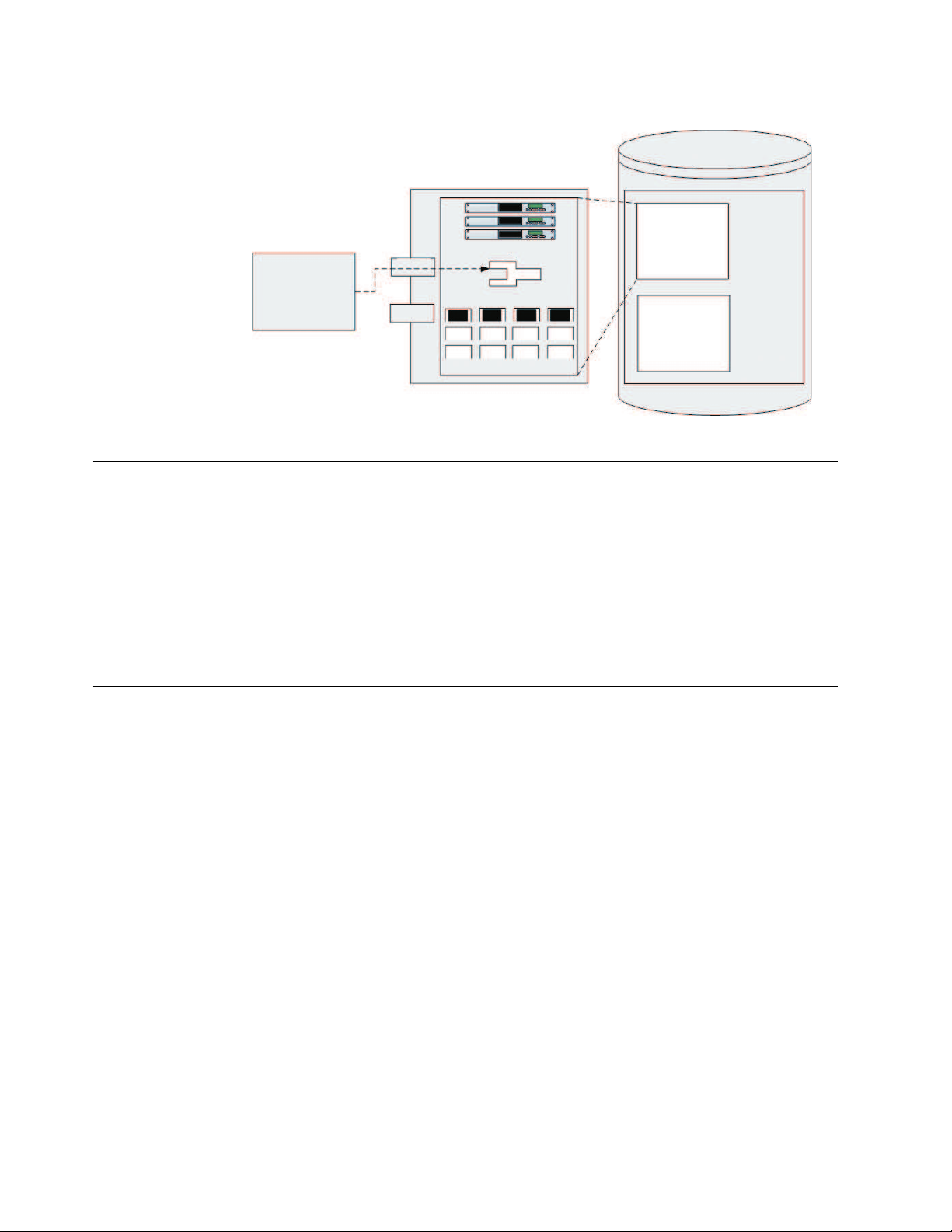
ProtecTIER Virtual Tape
The ProtecTIER Virtual Tape service acts like a traditional tape drive.
The ProtecTIER Virtual Tape (VT) service emulates traditional tape libraries.
Because ProtecTIER VT emulates tape libraries, you can switch to disk backup
without replacing your entire backup environment. Your existing backup
application can access virtual robots to move virtual cartridges between virtual
slots and drives. The backup application perceives that the data is being stored on
cartridges while ProtecTIER stores data on a deduplicated disk repository on the
storage fabric.
© Copyright IBM Corp. 2012, 2016 3
Page 24
ServerRunning
Backup Application
ProtecTIERServer
Virtual TapeDrives
Virtual
Robot
VirtualCartridgesandSlots
Port0
Port1
StorageFabric
VirtualLibrary
Repository
VirtualLibrary
ts760435
Figure 1. Tape library emulation
ProtecTIER File System Interface (FSI)
This topic provides an overview of the ProtecTIER File System Interface (FSI).
With FSI, ProtecTIER emulates a network attached storage (NAS) backup target
capable of using HyperFactor, as well as ProtecTIER Native Replication bandwidth
reduction techniques for storing and replicating deduplicated data. ProtecTIER FSI
enables backup servers running backup applications to connect over IP networks
to ProtecTIER, without the use of FC connectivity and allows customers to use
their existing tools and capabilities to integrate a ProtecTIER NAS-based backup
target into your environment.
ProtecTIER Manager
This topic provides an overview of the ProtecTIER Manager software.
The ProtecTIER Manager application can be installed on one or more workstations,
enabling you to monitor the status of nodes and clusters in your ProtecTIER
system along with the accompanying repositories and services. ProtecTIER
Manager is used to initially configure your ProtecTIER system and to change the
configuration.
Configuration
This topic provides an overview of ProtecTIER system configuration.
ProtecTIER systems can be set up with either one node or two nodes arranged in a
cluster. Each cluster operates independently, but you can manage them all from
ProtecTIER Manager.
Note: FSI only supports one node configurations, therefore cluster configurations
are only available in a VTL system set up.
Attention: To meet electromagnetic immunity requirements, shielded Ethernet
cables are required when attaching to a 1 GbE PCIe Ethernet adapter card.
4 IBM TS7650G Deduplication Gateway for ProtecTIER
®
: User's Guide for FSI Systems
Page 25
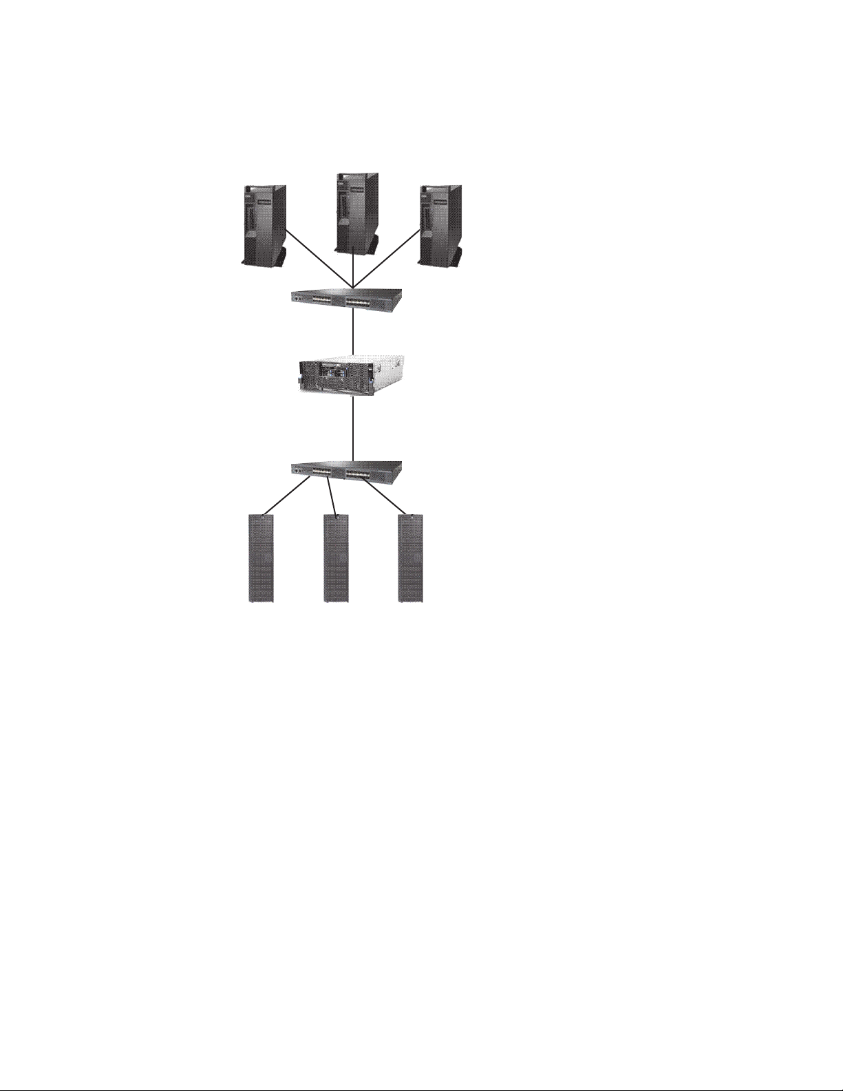
A one node system uses one server to transfer data from the backup server to the
Backup Servers
Disk Arrays
ts760432
Storage Fabric
Storage Fabric
ProtecTIER
Server (Node) 1
storage fabric, as illustrated in the following figure:
Figure 2. One node system
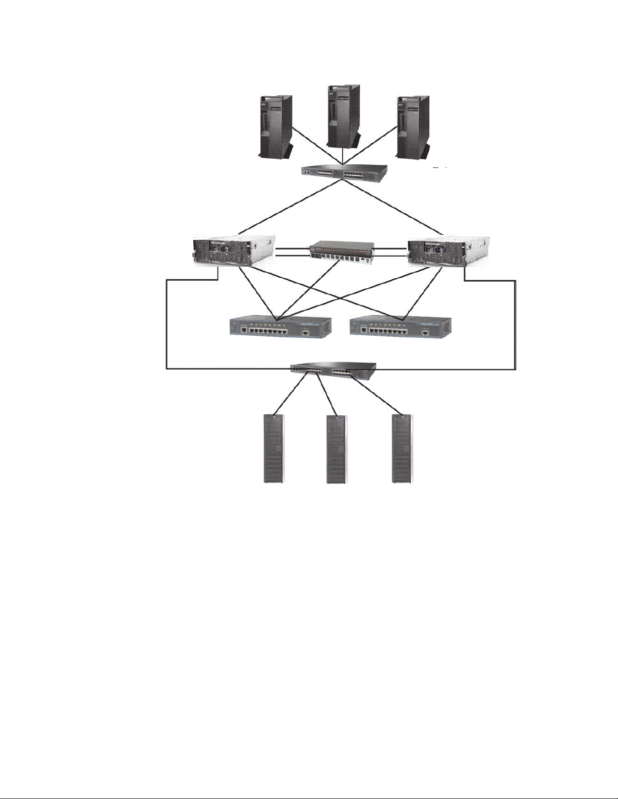
A two node system uses two servers in an active-active cluster and enables you to
build a more sophisticated system, as illustrated in the following figure:
Chapter 1. Introduction 5
Page 26
Backup Servers
Storage Fabric
ProtecTIER
Server (Node) 1
Disk Arrays
ts760433
ProtecTIER
Server (Node) 2
Storage Fabric
Cluster Internal
Network Switch 1
Cluster Internal
Network Switch 2
Figure 3. Two node system
Using a two node system provides the following benefits:
v Higher-Availability clustered configuration available to provide hardware
redundancy in the event of a node failure.
v Increased Performance if there are sufficient disk resources, the two servers can
share the backup load, and increase the performance of ProtecTIER.
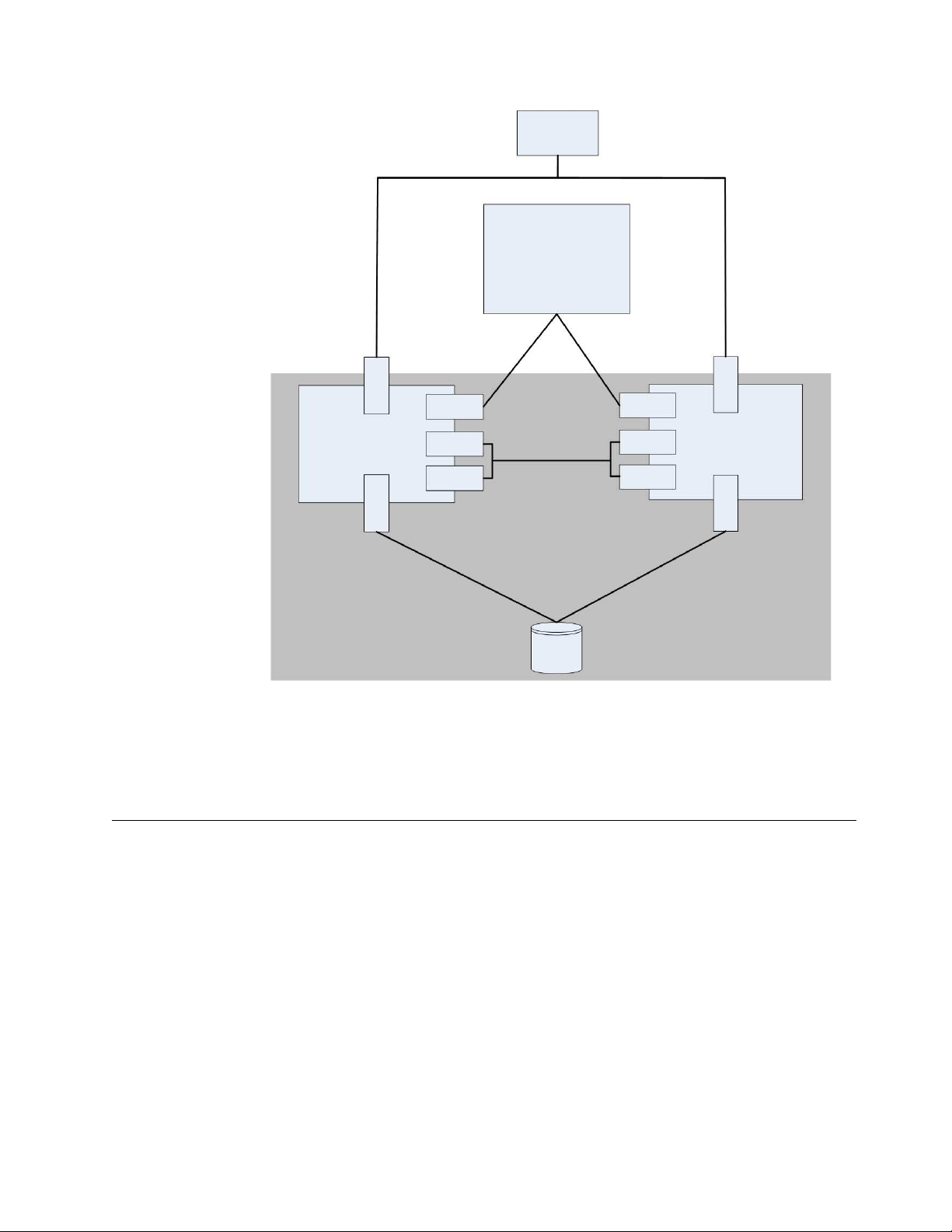
The following diagram illustrates the details of the ProtecTIER cluster setup:
6 IBM TS7650G Deduplication Gateway for ProtecTIER
®
: User's Guide for FSI Systems
Page 27
ts761000
Backup
Server
ProtecTIER Manager
Workstation
Front-End
FC Port
Front-End
FC Port
Node 1 Node 2
Eth 0
Eth 1
Eth 4
Eth 0
Eth 1
Eth 4
Bond 0 Bond 0
Network
Interfaces
(NIC)
Network
Interfaces
(NIC)
Back-End
FC Port
Back-End
FC Port
Cluster Internal
Network
Disk
Array
Figure 4. Cluster setup
Each node connects through front-end Fibre Channel ports to the backup server,
and through back-end Fibre Channel ports to disk arrays. The network interface
cards enable the nodes to connect to each other and to the ProtecTIER Manager
workstation.
Native replication
Native replication lets you replicate between repositories connected to a wide area
network (WAN) with TCP/IP protocol.
Replication enables you to set rules (depending on your required replication needs)
for replicating data objects across ProtecTIER repositories. The ProtecTIER
repositories can be different in size as well as physical layout. Since ProtecTIER
deduplicates data before storing it, only the changes are transferred to the remote
site. You define the rules for replicating data objects in replication policies on a
repository.
A replication grid is a logical set of repositories that can replicate from one to the
other. The ProtecTIER Replication Manager is a server that remotely manages the
configuration of the grid (for example, grid creation or deletion, repository
membership in the grid, and so on). In most cases, the ProtecTIER Replication
Manager resides on one of the ProtecTIER nodes.
Chapter 1. Introduction 7
Page 28

Before defining replication policies, however, you must first create connections
between the repositories. To create connections, you define replication groups.
Depending on your environment, you create replication groups in either
"many-to-one" or "many-to-many" topologies.
In a "many-to-one" topology, you create replication groups in which source
repositories can receive local backups and replicate to a single destination. The
destination repository can then act as a Disaster Recovery site for any number of
the source repositories, and still allow local backups, as well as replication, from
the active source repositories.
In a "many-to-many" topology, you create replication groups where multiple
repositories can replicate to each other. You can define a many-to-many replication
group where each repository assumes the responsibility of a destination repository
and can receive local backups, replicate data to remote repositories, and receive
replicated data from remote repositories.
8 IBM TS7650G Deduplication Gateway for ProtecTIER
®
: User's Guide for FSI Systems
Page 29

Chapter 2. Completing the ProtecTIER system setup for new installations
This chapter details the prerequisites for completing the ProtecTIER system setup
for new installations. Configuring the node is described in the IBM TS7650G
ProtecTIER Deduplication Gateway Installation Roadmap Guide, GA32-0921.
If you are upgrading the ProtecTIER system, refer to the IBM TS7650 ProtecTIER
Software Upgrade Guide, SC27-3643.
Use the ProtecTIER Service menu to complete the ProtecTIER configuration process
that was started in manufacturing. If you are working on a TS7650G, some or all of
these configurations may have already been done during the node configuration.
Note: Throughout this chapter the terms server and node are used
interchangeably, depending upon the task being performed.
Accessing the ProtecTIER Service menu
Complete this task to access the ProtecTIER Service menu.
Procedure
1. If you are in a single node configuration, connect the USB keyboard and
graphics-capable monitor to the server.
2. Verify that the server is running:
3. At the localhost Login prompt, type ptconfig and press Enter.
4. At the Password prompt, type ptconfig and press Enter.
The ProtecTIER Service Menu opens:
---------------------------------------------------------------------ProtecTIER Service Menu running on rasddx
----------------------------------------------------------------------
1) ProtecTIER Configuration (...)
2) Manage ProtecTIER services (...)
3) Health Monitoring (...)
4) Problem Alerting (...)
5) Version Information (...)
6) Generate a service report
7) Generate a system view
8) Update ProtecTIER code
9) ProtecTIER analysis (...)
E) Exit
----------------------------------------------------------------------
>>> Your choice?
5. Go on to “Customizing the ProtecTIER server”
Customizing the ProtecTIER server
Complete this task to customize the ProtecTIER server.
© Copyright IBM Corp. 2012, 2016 9
Page 30

About this task
Perform the following steps to configure the server by using the ProtecTIER
Service menu:
Procedure
1. On the server, if it is not already displayed, access the ProtecTIER Service
menu. See “Accessing the ProtecTIER Service menu” on page 9.
2. Select the ProtecTIER Configuration (...) option. Type the corresponding
number and press Enter. The ProtecTIER Configuration (...) menu appears.
-----------------------------------------------------------------------------ProtecTIER Service Menu running on rassmx
------------------------------------------------------------------------------
1) Configure ProtecTIER node
2) Recover Configuration for a replaced server
3) Configure machine serial number for a replaced server
4) Configure RAS
5) Update Time, Date, Timezone & Timeserver(s)
6) Scan storage interconnections
7) File systems Management (...)
8) Configure replication (...)
9) IP Network configuration (...)
10) Update Firmware (...)
11) Update the system’s name
12) Validate configuration
13) Single Node - code upgrade
14) OS images Management (...)
15) Replace SAS drive
B) Back
E) Exit
------------------------------------------------------------------------------
>>> Your choice?
ProtecTIER Configuration (...)
3. Select the IP Network configuration (...) option. Type the corresponding
number and press Enter. The IP Network configuration (...) menu appears.
----------------------------------------------------------------------
ProtecTIER Service Menu running on rasddx
ProtecTIER Configuration (...)
IP Network Configuration (...)
----------------------------------------------------------------------
1) Configure hostname
2) Configure ProtecTIER’s IP interfaces
3) Configure Static Routes
4) Configure Baseboard Management Controller (BMC) IP
5) Configure RAS switch
B) Back
E) Exit
----------------------------------------------------------------------
>>> Your choice?
4. Select the option Configure ProtecTIER's IP interfaces to configure external.
Type the corresponding number and press Enter.
If asked if you would like to stop the vtfd service, type yes and press Enter.
The following status message displays as the system initiates shutdown:
Stopping VTFD [/]
The shutdown process may take a few minutes to complete.
When shutdown completes, the following status message appears:
Stopping RAS [ Done ]
Stopping VTFD [ Done ]
10 IBM TS7650G Deduplication Gateway for ProtecTIER
®
: User's Guide for FSI Systems
Page 31

5. Change the server IP address, netmask, default gateway, and host name
factory-set values, to the values specific to the customer environment.
a. You are prompted, one at a time to enter the following values. At each
prompt, type the new value and then press <Enter>:
v Customer Network IP address
v Customer Network netmask
v Customer Network default gateway
v Customer Network hostname (The fully qualified hostname of the server.
For example: hostname.domain.com)
After you enter the hostname, the system automatically starts the network
configuration process. The following status messages display:
Configuring network [ Done ]
Updated network configuration successfully
update updateNetwork ended successfully
The system automatically restarts the vtfd service, and you are returned to
the command prompt.
6. Change the system name from the one assigned during manufacturing to one
specific to the customer environment. To do so:
a. From the ProtecTIER Configuration (...) menu, select the Update System
Name option. Type the number of your choice and press Enter.
b. When prompted, type the new system name of the server and press Enter.
Note: The system name that was assigned to the server in manufacturing
appears in brackets after the prompt. For example: [PORTLAND]. After you
enter the system name, the system automatically starts the Update the
System Name process. The following status message appears:
Changing system name [ Done ]
Updated system name successfully
UpdateSystemName ended successfully
End Processing Procedure Successfully
Press Enter to continue and return to the command prompt.
7. When you are finished, go on to Chapter 4, “Installing ProtecTIER Manager,”
on page 25.
Configuring the application IP interfaces
This section describes how to update the IP communication interfaces on a node.
About this task
Note: Customizing the network configuration on a node can also be done using
ProtecTIER Manager. If ProtecTIER Manager is already installed on the system, go
to “Customizing the network configuration of a node” on page 38.
ProtecTIER exposes virtual interfaces to the host, such as a media server with the
plug-in installed. In version 3.4.1, the physical Ethernet ports are assigned to one
virtual application interface. Currently, the physical ports are assigned to virtual
interface eth0 or eth1, depending on the server configuration. This assignment
option is used to group several physical interfaces into a single virtual interface,
and create a bond configuration of several physical interfaces. Each virtual
interface used must be configured with a corresponding IP address.
Chapter 2. Completing the ProtecTIER system setup for new installations 11
Page 32

Attention: Each configured IP address on the same server needs to be on a
different subnet, and each subnet needs to be on a different VLAN. If separate
subnets and VLAN’s are not used, in certain environments and networks, network
packets can move to other subnets, which can harm network performance and
potentially reduce the network's quality of service.
In addition, each virtual interface containing more than one physical interface
(configured as a bond) needs to be configured with a load balancing method. For a
server with 10 Gb interfaces, where bonding is implemented, the recommended
load balancing method is Link Aggregation Control Protocol (LACP) with L3L4.
For more information about bonding, the different load balancing methods, and
whether to configure bonds at all, refer to the IBM ProtecTIER Implementation and
Best Practices, Redbooks publication SG24-8025, available at: http://
www.redbooks.ibm.com/Redbooks.nsf/RedpieceAbstracts/sg248025.html?Open or
the IBM ProtecTIER Implementation and Best Practices, Redbooks publication
SG24-8025, available at: http://www.redbooks.ibm.com/Redbooks.nsf/
RedpieceAbstracts/sg248025.html?Open.
The following procedure describes how to perform the tasks described in the
previous paragraph.
Procedure
1. On the server, if it is not already displayed, access the ProtecTIER Service
menu. See “Accessing the ProtecTIER Service menu” on page 9.
2. Select the ProtecTIER Configuration (...) option. Type the corresponding
number and press <enter>. The ProtecTIER Configuration (...) menu is
displayed.
---------------------------------------------------------------------ProtecTIER Service Menu running on rasddx
ProtecTIER Configuration (...)
----------------------------------------------------------------------
1) Configure ProtecTIER node
2) Recover Configuration for a replaced server
3) Configure machine serial number for a replaced server
4) Configure RAS
5) Update Time, Date, Timezone & Timeserver(s)
6) Scan storage interconnections
7) File Systems Management (...)
8) Configure replication (...)
9) IP Network configuration (...)
10) Update Firmware (...)
11) Update the system’s name
12) Validate configuration
13) Single Node - code upgrade
14) OS images Management (...)
15) Replace SAS drive
B) Back
E) Exit
----------------------------------------------------------------------
>>> Your choice?
3. Select the IP Network configuration (...) option. Type the corresponding
number and press Enter. The IP Network configuration (...) menu is
displayed:
12 IBM TS7650G Deduplication Gateway for ProtecTIER
®
: User's Guide for FSI Systems
Page 33

---------------------------------------------------------------------ProtecTIER Service Menu running on rasddx
ProtecTIER Configuration (...)
IP Network Configuration (...)
----------------------------------------------------------------------
1) Configure hostname
2) Configure ProtecTIER’s IP interfaces
3) Configure Static Routes
4) Configure Baseboard Management Controller (BMC) IP
5) Configure RAS switch
B) Back
E) Exit
----------------------------------------------------------------------
>>> Your choice?
4. Select the Configure ProtecTIER’s IP interfaces option. Type the
corresponding number and press Enter.
The system displays the corresponding output. As an example:
# Interface L/B Method IP Address Netmask Devices
1 external HA 9.148.220.154 255.255.252.0 eth0
2 replic1 HA 192.168.20.1 255.255.255.0 eth3
3 replic2 HA 192.168.21.1 255.255.255.0 eth4
4 unassigned HA
Available Options:
==================
(e)edit a virtual interface
(r)re-assign a physical interface
(c)commit changes
(q)quit
Please Choose (e,r,c,q):
5. To edit the virtual interface, type e and press Enter.
The following is displayed:
Please choose the ID of the virtual interface you wish to edit:
6. Choose a virtual interface to edit and type the requested information at each
prompt. For example, type 1 and press Enter:
Available Options:
==================
(e)edit a virtual interface
(r)re-assign a physical interface
(c)commit changes
(q)quit
Please Choose (e,r,c,q): e
Please choose the ID of the virtual interface you wish to edit: 1
The system displays the available load balancing methods:
Available Load Balancing methods are:
RR, L3L4, L2L3, L2, HA
Choose a Load Balancing method [HA]: (for example: HA)
IP Address for external [9.148.220.154]: (for example: 9.148.220.154)
Netmask for external [255.255.255.0]: (for example: 255.255.255.0)
Gateway for external [9.148.220.4]: (for example: 9.148.220.4)
Hostname for external [minsk]:(for
example: minsk)
Note: For more information about the load balancing methods, refer to “FSI
network configuration for the ProtecTIER backup server” on page 71.
7. If you want to reassign a physical interface, type r <enter>.
Chapter 2. Completing the ProtecTIER system setup for new installations 13
Page 34

8. Select the device to reassign and the virtual device to assign it to from the
available virtual devices displayed.
9. When you want to commit the changes, type c and press Enter.
10. Type q and press Enter to quit.
11. The system returns you to the prompt command.
What to do next
The procedure is now complete. If the static routes have not been previously
configured, continue to “Configuring static routes.” Then continue to Changing the
system date and time .
Configuring static routes
Complete this task to configure the static routes for replication.
About this task
In this task you will provide information about your source server(s) and the target
server(s), in order to define the static routes.
For assistance with this task, refer to the information on your completed Configure
Static Route for Replication worksheet(s).
Run this procedure on the source server(s) to configure the addresses of all the
destination systems and the node on which the ProtecTIER Replication Manager is
activated. On the destination server(s), run this procedure to configure the
addresses of the source system(s).
On the ProtecTIER Replication Manager node, all the systems (source and
destination) must be configured.
Procedure
1. Access the ProtecTIER Configuration Menu. See “Accessing the ProtecTIER
Service menu” on page 9.
2. From the ProtecTIER Service Menu, select ProtecTIER Configuration (...).
Type the corresponding number and press Enter. The ProtecTIER
Configuration (...) menu is displayed.
14 IBM TS7650G Deduplication Gateway for ProtecTIER
®
: User's Guide for FSI Systems
Page 35

---------------------------------------------------------------------ProtecTIER Service Menu running on rasddx
ProtecTIER Configuration (...)
----------------------------------------------------------------------
1) Configure ProtecTIER node
2) Recover Configuration for a replaced server
3) Configure machine serial number for a replaced server
4) Configure RAS
5) Update Time, Date, Timezone & Timeserver(s)
6) Scan storage interconnections
7) File Systems Management (...)
8) Configure replication (...)
9) IP Network configuration (...)
10) Update Firmware (...)
11) Update the system’s name
12) Validate configuration
13) Single Node - code upgrade
14) OS images Management (...)
15) Replace SAS drive
B) Back
E) Exit
----------------------------------------------------------------------
>>> Your choice?
3. Select Configure replication (...). Type the corresponding number and
press Enter. The Configure replication (...) menu is displayed.
---------------------------------------------------------------------ProtecTIER Service Menu running on rasddx
ProtecTIER Configuration (...)
Configure Replication (...)
----------------------------------------------------------------------
1) Configure/Unconfigure ProtecTIER Replication Manager on this node
2) Configure Static Routes
B) Back
E) Exit
----------------------------------------------------------------------
>>> Your choice?
4. Select Configure Static routes. Type the corresponding number and press
Enter.
The message: Gathering System information [Done] displays, followed by a
summary of the information that was retrieved for the server on which you
are currently working. For example:
Target Network
ID
Address Target Netmask
1 10.11.195.0 255.255.255.0 10.11.195.1
2 10.11.197.0 255.255.255.0 10.11.197.1
Local Gateway
Address
Following the summary, the Available Options prompt displays:
Available Options:
==================
(a)dd a new record
(e)dit a record
(d)elete a record
(c)ommit changes
(q)uit
Chapter 2. Completing the ProtecTIER system setup for new installations 15
Page 36

Please Choose (a,e,d,c,q):
5. Select (a)dd a new record. Type a and press Enter.
You are prompted to enter information for the first destination (target) server
and the local network.
6. At each prompt, type the requested information and then press Enter:
Please provide the following information:
Target Network Address:
This is the starting network address of the Target (Hub) server. For example:
10.11.194.0.
Target Netmask:
This is the network netmask address of the Target (Hub) server. For example:
255.255.255.0.
Local Gateway Address:
This is the gateway IP address of the local server you are currently working
on. For example: 10.11.195.1.
A summary of the information you provided, displays. For example:
Target
ID
1 10.11.194.0 255.255.255.0 10.11.195.1
Network Address Target Netmask
Local Gateway
Address
Note: The addresses in the above summary are examples. Your actual values
will vary.
The Available Options prompt displays a second time:
Available Options:
==================
(a)dd a new record
(e)dit a record
(d)elete a record
(c)ommit changes
(q)uit
Please Choose (a,e,d,c,q):
7. Type a and press Enter.
You are prompted for the information for the second destination (target ETH2) server and the local network.
8. At each prompt, type the requested information and then press Enter:
Please provide the following information:
Target Network Address:
This is the starting network address of the Target (Hub) server. For example:
10.11.196.0.
Target Netmask:
This is the network netmask address of the Target (Hub) server. For example:
255.255.255.0.
Local Gateway Address:
This is the gateway IP address of the local server you are currently working
on. For example: 10.11.197.1
An updated summary displays:
16 IBM TS7650G Deduplication Gateway for ProtecTIER
®
: User's Guide for FSI Systems
Page 37

Target
ID
1 10.11.194.0 255.255.255.0 10.11.195.1
2 10.11.196.0 255.255.255.0 10.11.197.1
Network Address Target Netmask
Local Gateway
Address
Note: The addresses in the above summary are examples. Your actual values
will vary.
The Available Options prompt displays a third time:
Available Options:
==================
(a)dd a new record
(e)dit a record
(d)elete a record
(c)ommit changes
(q)uit
Please Choose (a,e,d,c,q):
9. Type: q <enter>
The Would you like to commit the changes performed to the routing table
now? (yes|no) message, displays.
10. Type yes and press Enter.
The Successfully committed changes! message displays.
11. Press Enter to return to the ProtecTIER Configuration Menu.
12. Quit the menu to exit. Type q and press Enter. You are returned to the login
prompt.
13. Configuration for one source server and the destination server, is now
complete. Confirm that your replication configuration was successful. To do
so, refer to the instructions in Chapter 13, “Native replication management (for
FSI),” on page 99.
14. To configure additional servers for a many-to-one configuration or
many-to-many configuration, repeat the steps in “Configuring the application
IP interfaces” on page 11, until each of your remaining servers are configured
and the connections are verified.
Setting the timezone
Use the procedures in this task to change the time zone setting to match that of
your location. You must set the timezone to ensure accurate system timekeeping.
Procedure
1. On the ProtecTIER Configuration (...) menu (see “Setting the timezone”), select
the Update Time, Date, Timezone & Timeserver(s) option. Type the
corresponding number for this selection and press Enter.
The Date, Time, Timezone & Timeserver(s) configuration menu, displays:
Chapter 2. Completing the ProtecTIER system setup for new installations 17
Page 38

-----------------------------------------------------------------------------ProtecTIER Service Menu running on rassmx
------------------------------------------------------------------------------
1. Set date & time
2. Set Timezone
3. Set Timeserver(s)
c. Commit changes and exit
q. Exit without committing changes
------------------------------------------------------------------------------
>>> Please Choose:
Date, Time, Timezone & Timeserver(s) configuration
Figure 5. Date, Time, Timezone & Timeserver(s) configuration menu
Note: To prevent selections from scrolling off the screen, consider setting the
paging to show fewer lines of information.
2. Select the Set Timezone option. Type the corresponding number and press
Enter.
3. If you are in the United States, when prompted for a country code, type: US
and press Enter.
For locations outside the United States, you must enter an international country
code. Refer to Appendix B, “Worldwide time zone codes,” on page 201 to locate
your information, then return to this task and enter the appropriate country
code in step “Setting the timezone” on page 17.
The time zones for the specified country display. A sample of the US time
zones list is shown in “Setting the timezone” on page 17:
Time zones under US:
====================
1. America/New_York
2. America/Detroit
3. America/Kentucky/Louisville
4. America/Kentucky/Monticello
5. America/Indiana/Indianapolis
6. America/Indiana/Vincennes
7. America/Indiana/Winamac
8. America/Indiana/Marengo
9. America/Indiana/Petersburg
10. America/Indiana/Vevay
11. America/Chicago
12. America/Indiana/Tell_City
13. America/Indiana/Knox
14. America/Menominee
15. America/North_Dakota/Center
16. America/North_Dakota/New_Salem
17. America/Denver
18. America/Boise
19. America/Shiprock
20. America/Phoenix
21. America/Los_Angeles
22. America/Anchorage
23. America/Juneau
24. America/Yakutat
25. America/Nome
26. America/Adak
Press <Enter>
27. Pacific/Honolulu
Please choose a timezone:
Figure 6. Sample of US time zones
18 IBM TS7650G Deduplication Gateway for ProtecTIER
®
: User's Guide for FSI Systems
Page 39

4. If the Press enter to continue prompt displays, the time zone list is too long
to display on the screen at once. Press Enter to advance the list.
5. At the Please choose a timezone: prompt, type the number that corresponds
to your timezone and press Enter to return to the Date, Time, Timezone &
Timeserver(s) configuration menu. Type: c for commit and press Enter.
The current time, date, and timezone settings display for review.
6. At the Do you wish to apply those settings? (yes|no) prompt, type: yes and
press Enter.
The following message appears: The cluster & VTFD services on all nodes
must be stopped in order to continue. Do you wish to continue? (yes|no).
Type: yes and press Enter.
A series of status messages appears as the services are stopped and restarted.
This process might take up to 10 minutes. When the service restart is complete,
the Press the ENTER key to continue... message appears.
7. Press Enter to continue and return to the ProtecTIER Configuration (...) menu.
Setting the date and time
Each server contains a battery that must be calibrated.
About this task
Use the procedures in this task to check the time and date on the server. If
necessary, change the settings to match the time and date at your location.
Important: With Version 3.3.6 and later, you must apply each change you make to
the timezone, date and time, and time server individually before proceeding to the
next task.
Procedure
1. On the ProtecTIER Configuration (...) menu, select the Update Time, Date,
Timezone & Timeserver(s) option. Type the corresponding number for this
selection and press Enter.
The Date, Time, Timezone & Timeserver(s) configuration menu, displays:
2. On the Date, Time, Timezone & Timeserver(s) configuration menu, select the
Set date & time option. Type the corresponding number and press Enter.
3. When prompted for the date:
v If the default date [displayed in brackets] is correct, press Enter.
v If the default date is incorrect, type the current date in DD/MM/YYYY
format and press Enter. For example, 09/01/2012.
4. When prompted for the time:
v If the default time [displayed in brackets] is correct, press Enter.
v If the default time is incorrect, type the current time in HH:MM:SS format
and press Enter. For example:08:32:58.
5. At the Please choose: prompt, commit your date and time settings To commit,
type: c and press Enter.
The current time, date, and timezone settings display for review.
6. At the Do you wish to apply those settings? (yes|no) prompt, type: yes and
press Enter.
Chapter 2. Completing the ProtecTIER system setup for new installations 19
Page 40

You are notified as follows: The cluster & VTFD services on all nodes must
be stopped in order to continue. Do you wish to continue? (yes|no).
Type: yes and press Enter.
A series of status messages appears as the services are stopped and restarted.
This process might take up to 10 minutes. When the service restart is complete,
the Press the ENTER key to continue... message displays.
7. Press Enter to continue and return to the ProtecTIER Configuration (...) menu.
20 IBM TS7650G Deduplication Gateway for ProtecTIER
®
: User's Guide for FSI Systems
Page 41

Chapter 3. Configuring replication
Use the applicable options on the ProtecTIER Service Menu to configure your
system for replication.
About this task
Once basic system configuration is complete, you can perform the tasks required to
configure your system for replication. To do so, you will need to complete the
pre-configuration tasks outlined in “Before you begin,” as well as “Accessing the
ProtecTIER Service Menu” through “Configuring static routes” on page 14, if
necessary.
Before you begin
This topic describes the prerequisites for configuring replication.
About this task
Replication configuration requires careful planning, decision-making, and
coordination of effort. Before you get started, it is strongly recommended that you
complete these tasks:
v Make sure that TCP ports 6520, 6530, 6540, 6550 are open in your firewall. Each
ProtecTIER server being used for replication must allow TCP access through
these ports.
v Ensure that the replication ports are on a different subnet than the external local
area network (LAN) port. Having the replication ports and the external LAN
port on the same subnet may cause replication errors.
In addition, IBM recommends that on all ProtecTIER nodes or servers involved
in Native Replication, you configure all rep1 ports on one subnet, and you
configure all rep2 ports on a different subnet.
v Identify the person (or persons) responsible for completing the planning
worksheets.
It is strongly recommended that the worksheets be filled out in advance by
someone with extensive knowledge of your organization's network and TCP/IP
configuration. This will ensure that the information is technically accurate and
readily available during replication setup.
v Identify the person (or persons) responsible for configuring the TARGET(S) and
SOURCE(S) servers for replication, depending on the replication topology you
are using.
This may or may not be the same person (or persons) who completed the
worksheets.
v If replication throughput in excess of 1GbE is required for DD6 replication,
ensure the network infrastructure accepts 10Gbase-T connections.
After completing the above tasks, return to this page and go to “Accessing the
ProtecTIER Service Menu.”
Accessing the ProtecTIER Service Menu
Complete this task to access the ProtecTIER Service menu.
© Copyright IBM Corp. 2012, 2016 21
Page 42

Procedure
1. If necessary, power-on the server and the monitor, and wait for the login
prompt to display.
2. At the login prompt, type: ptconfig and press Enter.
3. At the Password prompt, type: ptconfig and press Enter.
The ProtecTIER Service Menu displays:
---------------------------------------------------------------------ProtecTIER Service Menu running on rasddx
----------------------------------------------------------------------
1) ProtecTIER Configuration (...)
2) Manage ProtecTIER services (...)
3) Health Monitoring (...)
4) Problem Alerting (...)
5) Version Information (...)
6) Generate a service report
7) Generate a system view
8) Update ProtecTIER code
9) ProtecTIER analysis (...)
E) Exit
----------------------------------------------------------------------
>>> Your choice?
4. Go on to “Configuring ProtecTIER Replication Manager.”
Configuring ProtecTIER Replication Manager
Use this procedure to configure the ProtecTIER Replication Manager application on
the designated server in your replication grid.
About this task
You must configure the Replication Manager application on the server that
remotely manages the replication grid or grids within your organization. IBM
recommends configuring the ProtecTIER Replication Manager application on the
TARGET server at the remote (destination) site. By doing so, the Replication
Manager will remain available in a disaster recovery situation.
Note: This task may be completed at any time during the replication configuration
process. However, creation of the replication grid and verification of the replication
configuration, cannot take place until ProtecTIER Replication Manager is up and
running on the designated server.
Procedure
1. On the designated ProtecTIER Replication Manager server, if it is not already
displayed, access the ProtecTIER Service Menu. See “Accessing the ProtecTIER
Service Menu” on page 21.
2. From the ProtecTIER Service Menu, select ProtecTIER Configuration (...).
Type the corresponding number and press Enter. The ProtecTIER
Configuration (...) menu is displayed.
22 IBM TS7650G Deduplication Gateway for ProtecTIER
®
: User's Guide for FSI Systems
Page 43

---------------------------------------------------------------------ProtecTIER Service Menu running on rasddx
ProtecTIER Configuration (...)
----------------------------------------------------------------------
1) Configure ProtecTIER node
2) Recover Configuration for a replaced server
3) Configure machine serial number for a replaced server
4) Configure RAS
5) Update Time, Date, Timezone & Timeserver(s)
6) Scan storage interconnections
7) File Systems Management (...)
8) Configure replication (...)
9) IP Network configuration (...)
10) Update Firmware (...)
11) Update the system’s name
12) Validate configuration
13) Single Node - code upgrade
14) OS images Management (...)
15) Replace SAS drive
B) Back
E) Exit
----------------------------------------------------------------------
>>> Your choice?
3. Select Configure replication (...). Type the corresponding number and press
Enter. The Configure replication (...) menu is displayed.
---------------------------------------------------------------------ProtecTIER Service Menu running on rasddx
ProtecTIER Configuration (...)
Configure Replication (...)
----------------------------------------------------------------------
1) Configure/Unconfigure ProtecTIER Replication Manager on this node
2) Configure Static Routes
B) Back
E) Exit
----------------------------------------------------------------------
>>> Your choice?
4. Select Config/Unconfig ProtecTIER Replication Manager on this node. Type
the corresponding number and press Enter.
5. When the Replication Manager is currently unconfigured, do you wish to
configue it? (yes|no) prompt displays, type: yes and press Enter.
The warning below displays:
Warning: You should not configure Replication Manager on more than one
server in a grid, as doing so may cause conflicts within the grid. It is
recommended that you designate the Target server (Hub) as the
Replication Manager.
6. When the Are you sure you want to configure the ProtecTIER Replication
Manager on this node? (yes|no) prompt displays, type: yes and press Enter.
The status messages below, display:
Gathering information [ Done ]
The configurePTReplicationManager ended successfully message displays.
7. When the Press the ENTER key to continue... prompt displays, press Enter.
You are returned to the Configure replication (...) menu.
8. If the static routes have not been previously configured, continue to
“Configuring static routes” on page 14.
9. Type E and press Enter to exit.
Chapter 3. Configuring replication 23
Page 44

24 IBM TS7650G Deduplication Gateway for ProtecTIER
®
: User's Guide for FSI Systems
Page 45

Chapter 4. Installing ProtecTIER Manager
The topics in this chapter describe how to install, configure, and uninstall the
ProtecTIER Manager software.
The ProtecTIER system is managed with the ProtecTIER Manager software. It is
recommended that you install the ProtecTIER Manager software on one or more
workstations and not directly on the ProtecTIER servers.
ProtecTIER Manager enables you to:
v Configure ProtecTIER
v Monitor the status of nodes
v Manage file systems, repositories, and services
v Change the system configuration
v Manage Native Replication activities with the ProtecTIER Replication Manager
software
Prerequisites for the ProtecTIER Manager workstation
This topic describes the workstation prerequisites for installing and running the
ProtecTIER Manager.
The ProtecTIER Manager workstation must meet the following prerequisites in
order to install and run ProtecTIER Manager effectively:
v One of the following operating systems:
– Windows 7
– Windows 8, 2012
– Linux Red Hat 64 ES/AS (4, 5 and 6)
v At least 1.2 GB of available disk space
v At least 256 MB of RAM
v Workstation access to the ProtecTIER service nodes IP addresses (ports 3501 and
3503 are open on the firewall).
IBM recommends that you use the following settings to configure the monitor for
ProtecTIER Manager:
v Resolution of 1024 x 768 pixels or higher (this resolution is the minimum
supported, however, 1280 x 1024 is recommended).
v 24 bit color or higher
Note: If you are planning to run ProtecTIER Manager on a UNIX system,
configure your graphics card and X Window System. You can perform this task
either manually or by use of the Xconfigurator utility. For instructions, refer to the
appropriate Linux documentation.
Installing the ProtecTIER Manager software
Use the procedures in this chapter to install the latest version of ProtecTIER
Manager software on the ProtecTIER Manager Workstation.
© Copyright IBM Corp. 2012, 2016 25
Page 46

Important: Before starting the installation, make sure that the currently installed
ProtecTIER Manager application is closed.
The ProtecTIER Manager installer is provided on your IBM ProtecTIER Manager
DVD.
Different ProtecTIER Manager installers are used for Windows and Linux. Ensure
that the installer that you are using is correct for the operating system running on
your workstation.
v If you are installing ProtecTIER Manager on a workstation running Windows,
see “Installing on Windows.”
v If you are installing ProtecTIER Manager on a workstation running Linux, see
“Installing on Linux” on page 27.
If you are installing ProtecTIER Manager on a workstation on which an older
version of ProtecTIER Manager is already installed, uninstall the older version first.
For more information, see “Uninstalling the ProtecTIER Manager software” on
page 28.
Installing on Windows
Complete this task to install ProtecTIER Manager on a Windows system.
About this task
Perform the following steps to install ProtecTIER Manager on a Windows system:
Procedure
1. Insert the IBM ProtecTIER Manager DVD into the CD-ROM drive of the
designated ProtecTIER Manager workstation.
v If the ProtecTIER Manager installer launches and starts the installation, go on
to step 2.
v If the ProtecTIER Manager installer process does not launch automatically, do
the following:
a. On the Windows task bar, click: Start > Run. The Run dialog box opens.
b. In the Open box, type: D: (where D: is the CD-ROM drive of the server).
c. Click OK.
The contents of the IBM ProtecTIER Manager DVD displays.
d. From the list of files, locate the ProtecTIER Manager for Windows
installation file and double-click the file to start the installation.
2. Read the Introduction screen, and then click Next.
3. Read and accept the license agreement provided, and click Next.
The Red HAT Enterprise Linux License screen is displayed.
4. Read and accept the license agreement provided, and click Next.
The Choose Install Folder screen is displayed.
5. Specify the folder where the ProtecTIER Manager program files are to be
installed, and click Next.
The Choose Shortcut Folder screen is displayed.
6. Select the location where the program icons are to be created:
v In a new Program Group - Creates a program group in the Program list of
the Start menu.
26 IBM TS7650G Deduplication Gateway for ProtecTIER
®
: User's Guide for FSI Systems
Page 47

v In an existing Program Group - Adds the shortcut to an existing program
group in the Program list of the Start menu.
v In the Start Menu
v On the Desktop
v In the Quick Launch Bar
v Other - Enables you to enter a path location for the shortcut, or to browse
for a location by clicking Choose.
v Don't create icons - No shortcuts are created.
Note: When relevant, you can select Create Icons for All Users to create a
shortcut in the defined location for all user accounts on the workstation.
7. Click Next.
The Pre-Installation Summary screen displays the Install and Shortcut folder
locations and the disk space information of the target for installation.
8. Review the Summary screen, and click Install to start the installation.
The Installing ProtecTIER Manager screen is displayed.
9. When the installation is complete and ProtecTIER Manager has been
successfully installed, click Done.
The ProtecTIER Installation wizard closes and the installation process is
complete.
What to do next
Go on to the next chapter.
Installing on Linux
Complete this task to install ProtecTIER Manager on a Linux system.
About this task
Perform the following steps to install ProtecTIER Manager on Linux:
Procedure
1. Insert the IBM ProtecTIER Manager DVD into the CD-ROM drive of the
designated ProtecTIER Manager workstation.
2. Run the ProtecTIER Manager installer.
Note: This procedure presumes that the workstation has a Linux graphical
interface which is required for ProtecTIER Manager.
a. From the Linux Desktop, select and open the CD drive icon.
b. Select and open the folder for your Linux version: Linux for version 64 or
Linux32 for version 32.
c. When the folder opens, drag the InstallLinuxXX.bin file from the folder to
the Desktop. (XX=either 32 or 64, depending on the Linux folder that you
selected.)
d. Close the open windows.
e. Right-click on an open area of the Desktop, and from the menu options
displayed, select Open Terminal.
f. At the Terminal command prompt, use the following command to change
to the Desktop directory (Note: Desktop is case-sensitive. Type it using a
capital "D".):
Chapter 4. Installing ProtecTIER Manager 27
Page 48

cd Desktop
and press Enter.
g. From the Desktop directory in the Terminal window, run the ProtecTIER
Manager installer:
./InstallLinuxXX.bin
and press Enter.
(XX= either 32 or 64)
If the message: Permission Denied displays, enter the following
commands:
chmod +x InstallLinuxXX.bin
./InstallLinuxXX.bin
after typing each command press Enter.
The IBM ProtecTIER Manager wizard Introduction screen is displayed.
3. Click Next. Two separate Software License Agreement screens display.
4. Read the terms for each license agreement, select I accept both the IBM and
non-IBM terms of the License Agreement and click Next. The Choose Install
Folder screen is displayed.
5. Enter the path to the location where you want the ProtecTIER Manager
program files installed. Click Choose to browse for a location.
Note: Click Restore Default Folder to revert to the default installation path.
6. Click Next. The Choose Link Folder screen is displayed.
7. Select the location where you want the program links created::
v In your Home folder – Creates the links in the directory where the user
files are typically stored. For example: /home/bill.
v Other – Creates the links in the default location (/opt/IBM/PTManager). To
specify a different location, click Choose and select a directory on the
workstation hard disk drive.
v Don't create links – No links are created.
8. Click Next. The Pre-Installation Summary screen is displayed.
9. Click Install. The Installing ProtecTIER Manager screen is displayed and
ProtecTIER Manager is installed on your computer. When the installation is
complete, the Install Complete screen is displayed.
10. Click Done. The ProtecTIER Manager wizard closes. When the command
prompt returns in the Terminal window, type exit to close the window.
Uninstalling the ProtecTIER Manager software
This topic describes how to uninstall the ProtecTIER Manager software.
Procedure
To uninstall the ProtecTIER Manager software:
1. From the ProtecTIER Manager directory, run the ProtecTIER Manager
uninstaller. The Uninstall ProtecTIER Manager wizard Introduction screen is
displayed.
2. Click Uninstall. The Uninstalling screen is displayed and the ProtecTIER
Manager software is removed from your computer. The Uninstall Complete
screen is displayed.
28 IBM TS7650G Deduplication Gateway for ProtecTIER
®
: User's Guide for FSI Systems
Page 49

3. Click Done. The Uninstall ProtecTIER Manager wizard closes.
Checking the ProtecTIER 3958 DD6 Firmware version
Complete this task to check the 3958 DD6 Firmware version
About this task
Important: The firmware upgrade process connects to the Baseboard Management
Controller (BMC) to get firmware information. Therefore, it is mandatory to have
the BMC configured with an IP address on the same customer network segment
before continuing with the procedure.
Procedure
1. If you are updating a single node configuration, connect a USB keyboard and
graphics-capable monitor to the server.
2. If you are updating a clustered configuration, verify that both Server A and
Server B are running:
v Yes, continue to step 3
v No, power on any servers that are not running, wait for the boot cycle to
complete, and then continue to step 3
3. At the localhost Login prompt, type the user ID ptconfig and the password
ptconfig press <enter>.
The ProtecTIER System Menu displays:
------------------------------------------------------------------------------
ProtecTIER Service Menu running on rassmx
------------------------------------------------------------------------------
1) ProtecTIER Configuration (...)
2) Manage ProtecTIER services (...)
3) Health Monitoring (...)
4) Problem Alerting (...)
5) Version Information (...)
6) Generate a service report
7) Generate a system view
8) Update ProtecTIER code
9) ProtecTIER Analysis (...)
E) Exit
------------------------------------------------------------------------------
>>> Your choice?
4. Select Protectier Configuration. Type the corresponding number and press
<enter>.
The ProtecTIER Configuration (...) screen displays:
Chapter 4. Installing ProtecTIER Manager 29
Page 50

-----------------------------------------------------------------------------ProtecTIER Service Menu running on rassmx
ProtecTIER Configuration (...)
------------------------------------------------------------------------------
1) Configure ProtecTIER node
2) Recover Configuration for a replaced server
3) Configure enclosure serial number for a replaced enclosure
4) Update Time, Date, Timezone & Timeserver(s)
5) Configure replication (...)
6) IP Network configuration (...)
7) Update Firmware
8) Update the System’s name
9) Validate configuration
10) Single node - code upgrade (For Support Use ONLY)
B) Back
E) Exit
------------------------------------------------------------------------------
>>> Your choice?
5. Select Update Firmware. Type the corresponding number and press <enter>.
The Update Firmware (...) screen is displayed:
-----------------------------------------------------------------------------ProtecTIER Service Menu running on rassmx
------------------------------------------------------------------------------
1) Update Server Firmware
2) Display Firmware Version for BMC and GEM Components
3) Upgrade Firmware Version for BMC and GEM Components
ProtecTIER Configuration (...)
Update Firmware (...)
B) Back
E) Exit
------------------------------------------------------------------------------
>>> Your choice?
6. Select Display Firmware Version for BMC and GEM Components. Type the
corresponding number and press <enter>. Wait for the process to complete:
Your choice? 2
Begin Processing Procedure [Jan 31 11:36:18]
Firmware Component : Version
---------------------------------BMC : 2.0.003C
CPLD : 0.6.0004
BIOS : 0.3.0016
FLASH CONFIG : 0xAD9E52D7
DISRUPTIVE : 0x30E4C1D4
End Processing Procedure Successfully [Jan 31 11:36:18]
Updating the ProtecTIER 3958 DD6 Firmware
Complete this task to update the 3958 DD6 Firmware
About this task
Important: The firmware upgrade process connects to the Baseboard Management
Controller (BMC) to get firmware information. Therefore, it is mandatory to have
the BMC configured with an IP address on the same customer network segment
before continuing with the procedure.
30 IBM TS7650G Deduplication Gateway for ProtecTIER
®
: User's Guide for FSI Systems
Page 51

Procedure
1. If you are updating a single node configuration, connect a USB keyboard and
graphics-capable monitor to the server.
2. If you are updating a clustered configuration, verify that both Server A and
Server B are running:
v Yes, continue to step 3
v No, power on any servers that are not running, wait for the boot cycle to
complete, and then continue to step 3
3. At the Login prompt, type the user ID ptconfig and the password ptconfig
press <enter>.
The ProtecTIER System Menu displays:
-----------------------------------------------------------------------------ProtecTIER Service Menu running on rassmx
------------------------------------------------------------------------------
1) ProtecTIER Configuration (...)
2) Manage ProtecTIER services (...)
3) Health Monitoring (...)
4) Problem Alerting (...)
5) Version Information (...)
6) Generate a service report
7) Generate a system view
8) Update ProtecTIER code
9) ProtecTIER Analysis (...)
E) Exit
------------------------------------------------------------------------------
>>> Your choice?
4. Select Protectier Configuration. Type the corresponding number and press
<enter>.
The ProtecTIER Configuration (...) screen displays:
-----------------------------------------------------------------------------ProtecTIER Service Menu running on rassmx
ProtecTIER Configuration (...)
------------------------------------------------------------------------------
1) Configure ProtecTIER node
2) Recover Configuration for a replaced server
3) Configure enclosure serial number for a replaced enclosure
4) Update Time, Date, Timezone & Timeserver(s)
5) Configure replication (...)
6) IP Network configuration (...)
7) Update Firmware
8) Update the System’s name
9) Validate configuration
10) Single node - code upgrade (For Support Use ONLY)
B) Back
E) Exit
------------------------------------------------------------------------------
>>> Your choice?
5. Select Update Firmware. Type the corresponding number and press <enter>.
The Update Firmware (...) screen is displayed:
Chapter 4. Installing ProtecTIER Manager 31
Page 52

-----------------------------------------------------------------------------ProtecTIER Service Menu running on rassmx
------------------------------------------------------------------------------
1) Update Server Firmware
2) Display Firmware Version for BMC and GEM Components
3) Upgrade Firmware Version for BMC and GEM Components
B) Back
E) Exit
------------------------------------------------------------------------------
>>> Your choice?
ProtecTIER Configuration (...)
Update Firmware (...)
6. Select Upgrade Firmware Version for BMC and GEM Components. Type the
corresponding number and press <enter>. The current firmware is checked and
if an upgrade is needed, a confirmation message is displayed informing that
services will be stopped and 1 or 2 reboots are needed during the upgrade
process. Select Yes and press <enter>. Wait for the process to complete:
Your Choice? 3
BeginProcessingProcedure [Jan 30 07:47:33]
Checkcurrent Firmware Versions [ Done ]
In ordertoupdatetheNode’s firmware level, alltheserviceswill be stopped.
The firmware upgradeprocesswill requiere 1 reboot
Do youwanttocontinue? (yes|no) yes
Stoppingptrasd [ Done ]
Stoppingvtfd [ Done ]
Stoppingptcluster [ Done ]
Updating BMC firmware [ Done ]
Updating CPLD firmware [ Done ]
Updating BIOS firmware [ Done ]
Machine will be rebooted
7. Once the system is online, run the Update Firmware option again to make sure
the process completed. If firmware was upgraded successfully the following
message is displayed:
Your choice? 3
Begin Processing Procedure [Jan 31 11:25:43]
Check current Firmware Versions [ Done ]
All firmware versions are up to date.
End Processing Procedure Successfully [Jan 31 11:25:43]
32 IBM TS7650G Deduplication Gateway for ProtecTIER
®
: User's Guide for FSI Systems
Page 53

Chapter 5. Getting started with ProtecTIER Manager
Topics in this chapter provide an overview of common ProtecTIER Manager tasks.
After the ProtecTIER Manager software has been installed, familiarize yourself
with various common tasks that apply throughout the ProtecTIER Manager
application.
Running the ProtecTIER Manager
This task describes how to run the ProtecTIER Manager software on the
ProtecTIER Manager workstation.
About this task
The ProtecTIER Manager GUI can be run from either a Windows based, or a Linux
based ProtecTIER Manager workstation.
Procedure
1. Run the ProtecTIER Manager application:
v On a Windows-based ProtecTIER Manager workstation, run the ProtecTIER
Manager application:
Click Start > All Programs > IBM > ProtecTIER Manager > IBM
ProtecTIER Manager.
v On a Linux-based ProtecTIER Manager workstation:
a. Navigate to the directory where you installed ProtecTIER Manager. The
default installation directory is: /opt/IBM/PTManager.
b. Double-click the ProtecTIER Manager icon.
The ProtecTIER Manager window is displayed.
2. Go on to Chapter 6, “Managing nodes,” on page 37.
Managing users
The topics in this section describe how to manage users of the ProtecTIER Manager
system.
ProtecTIER Manager enables you to create user accounts with different permission
levels for accessing and configuring your ProtecTIER system.
Notes:
v User accounts (including the default user account) defined in the GUI are
different than user accounts used on the ProtecTIER server.
v Do not use the GUI to manage user accounts on the ProtecTIER server.
v The end-user can change passwords according to the required security policy
without affecting ProtecTIER functions.
v The GUI does not handle password policies or rotation rules.
Adding user accounts
This topic describes how to add a user account to ProtecTIER Manager.
© Copyright IBM Corp. 2012, 2016 33
Page 54

About this task
ts761288
Complete this task to add a new user account to the ProtecTIER Manager system.
Procedure
1. Log in to the ProtecTIER Manager system and choose System > Manage Users.
The Manage Users dialog is displayed:
Figure 7. Manage Users dialog
2. Click Add. The Add account dialog is displayed.
3. In the User name field, enter a username for the account.
4. In the New password field, enter a password for the account.
5. In the Verify password field, reenter the password that you entered in the New
password field.
6. In the Permission field, select a permission level (Administrator, Operator, or
User) you want to assign to the user account.
Note: Before processing, record this information in a manner that allows you to
notify the new user. Remind the new user to record the password because you
nor the system stores the passwords for later use.
7. Click Ok. The Add account dialog closes and the account is added to the
ProtecTIER Manager system.
8. Click Close to exit the Manage Users window.
Changing the user account password
This topic describes how to change the password of a user account on the
ProtecTIER Manager system.
34 IBM TS7650G Deduplication Gateway for ProtecTIER
®
: User's Guide for FSI Systems
Page 55

About this task
Complete this task to change the user password in the ProtecTIER Manager
system.
Procedure
1. Choose System > Manage Users. The Manage Users dialog is displayed.
2. Select a user account from the list and click Change password. The Change
password dialog is displayed.
3. Type the current password in the Password field.
4. Type the new password in the New password field.
5. Type the new password again in the Verify password field.
6. Click Ok. The password for the selected user account is changed.
7. Click Close to exit the Manage Users window.
Changing the Support System settings
This topic explains how to change the support system settings.
About this task
The ProtecTIER Manager installation wizard and the ProtecTIER Manager
application are fully compatible with the JAWS screen-reader software. ProtecTIER
Manager also allows you to change other accessibility settings, such as the contrast
resolution mode and color palette. Instructions for installing JAWS and the
Java-based accessibility tools, and for setting the contrast resolution mode and
color palette are available in “Accessibility” on page 213.
Saving and printing data
This task describes how to save or print the data displayed in informational
ProtecTIER Manager windows.
About this task
Follow these steps to save or print data in ProtecTIER Manager informational
windows and panes:
Procedure
1. Select Options in the upper right-hand corner of the window.
Note: The Options menu may not be available on all windows.
2. Select Save to save the information or Print to print the information. Use the
standard saving or printing procedures for your operating system.
Refreshing ProtecTIER Manager
This task describes how to refresh windows, screens, and panes in the ProtecTIER
Manager application.
Many windows, screens, and panes of ProtecTIER Manager automatically refresh
to display the most current information. However, you need to refresh some
windows manually. Because you can have multiple ProtecTIER Manager
Chapter 5. ProtecTIER Manager overview 35
Page 56

workstations on the same system, changes made on another workstation are not
automatically reflected on your workstation. To ensure that you have the most up
to date information, you should periodically refresh the ProtecTIER Manager
Navigation pane and View pane.
Figure 8. ProtecTIER Manager
Select the Refresh navigation pane button to refresh the Navigation pane.
Select the Refresh current view button to refresh the View pane.
Running operations in the background
This topic describes enabling operations to run in the background while you are
running another operation.
You can use the same instance of ProtecTIER Manager to work with multiple
ProtecTIER systems while a specific ProtecTIER Manager operation runs in the
background. You cannot, however, run multiple operations in the same ProtecTIER
system.
For instance, if you are running a Delete library operation, the wizard prompts
you to wait while the system goes offline to run the required operation. That
system will be busy until it completes, thereby not allowing further administration
of other operations.
By selecting Run in background, you return control to the user. If additional
systems are configured in ProtecTIER Manager, those systems are accessible and
can be worked on, even while the required operation is running.
36 IBM TS7650G Deduplication Gateway for ProtecTIER
®
: User's Guide for FSI Systems
Page 57

Chapter 6. Managing nodes
Topics in this chapter describe how to manage nodes on the ProtecTIER system.
The ProtecTIER system supports one-node systems.
Adding and removing nodes from ProtecTIER Manager
The topics in this section describe how to add a node, a subnetwork node, and
remove a node from the ProtecTIER system using the ProtecTIER Manager.
Note: This section provides instructions for adding and removing nodes when
using the TS7650G.
Adding a node registers the node IP address and port number with the instance of
ProtecTIER Manager at your workstation. Similarly, removing a node removes the
node registration from ProtecTIER Manager at that workstation.
Adding nodes
Complete this task to add a node to your ProtecTIER system with ProtecTIER
Manager.
About this task
Adding a node registers the node IP address and port number with the instance of
ProtecTIER Manager at your workstation.
To add a node to your ProtecTIER system:
Procedure
1. Run the ProtecTIER Manager application:
v For a Windows-based ProtecTIER Manager workstation, run the ProtecTIER
Manager application:
Click Start > All Programs > IBM > ProtecTIER Manager > IBM
ProtecTIER Manager.
v For a Linux-based ProtecTIER Manager workstation, click the icon for
ProtecTIER Manager on the Desktop or the location of the shortcut specified
during the installation.
The ProtecTIER Manager window is displayed.
2. From the Systems Management view, click the Add new node button on the
toolbar located at the top of the ProtecTIER Manager window. The Add new
node dialog box is displayed, prompting you for the IP address and Port
number of the node that you want to add.
3. Enter the IP address of the node and click Ok. The node is displayed in the
Navigation pane and the Login button is displayed in the View pane.
Note: Do not change the port number of the node unless directed to do so by
trained ProtecTIER specialist.
© Copyright IBM Corp. 2012, 2016 37
Page 58

What to do next
Go on to “Logging in and out of the ProtecTIER Manager application” on page 40.
Adding node subnetworks
This topic describes how to add a node subnetwork to your ProtecTIER system
with the ProtecTIER Manager.
About this task
In addition to adding individual nodes to ProtecTIER Manager, you can add
addresses for subnetworks to which nodes are connected. When ProtecTIER
Manager restarts, it automatically detects all nodes on the added subnetworks of
the TCP/IP network.
Procedure
1. Click on the Auto discovery tab.
2. For each subnetwork you want to add, click a Sub network check box and
enter the subnetwork address in the corresponding field.
3. Click Ok. The Preferences dialog box closes and the subnetwork address is
added to the ProtecTIER Manager. When you restart the ProtecTIER Manager,
all nodes on the defined subnetwork addresses are automatically added to the
ProtecTIER Manager.
Removing nodes
This topic describes how to remove a node from your ProtecTIER system using the
ProtecTIER Manager.
About this task
Removing a node stops the instance of ProtecTIER Manager at your workstation
from registering the node and being able to manage it. The node itself is unaffected
by removing a node in this way.
Perform the following steps to remove a node from ProtecTIER Manager:
Note: Do not log in to the node you want to remove or you will be unable to
perform this operation.
Procedure
1. From theSelect a system dropdown list in the Systems Management view,
choose the system from which you want to disconnect.
2. Select Node > Remove node. A confirmation message box is displayed to
remove the connection.
3. Click Yes. The node is removed.
Customizing the network configuration of a node
This topic describes how to use the Network Configuration window in ProtecTIER
Manager to customize the IP communication interfaces on a node.
38 IBM TS7650G Deduplication Gateway for ProtecTIER
®
: User's Guide for FSI Systems
Page 59

About this task
ts761141
The Network Configuration window lets you reassign the IP communication
interfaces to group several physical interfaces into a single virtual interface, and
create a bond configuration of several physical interfaces. The IP communication
interfaces can also be reassigned using the ProtecTIER Service menu. See
“Configuring the application IP interfaces” on page 11.
Procedure
1. From the Systems Management view, select Node > Network configuration.
The Network configuration window is displayed:
Figure 9. Configure IP interfaces window
2. Select a node from the Node to be configured field.
3. Highlight the virtual interface you wish to edit.
4. Click on the dropdown in the L/B Method column to select the load balancing
method. The available load balancing methods are displayed:
RR (Round-robin)
Outgoing traffic is spread evenly across all of the adapter ports in the bond
L2 Outgoing traffic is spread using a default transmit hash policy of layer 2
L2L3
Outgoing traffic is spread using a transmit hash policy of MAC addresses
and IP addresses of the source and the destination
L3L4
Outgoing traffic is spread using a transmit hash policy of IP addresses and
ports of the source and the destination
HA Active-backup policy: only one slave in the bond is active. A different slave
becomes active if, and only if, the active slave fails.
5. Edit the IP Address, Netmask and Gateway addresses, as desired.
6. If you want to reassign a physical interface, select an Ethernet port from the
ports available in the Assign field.
Chapter 6. Managing nodes 39
Page 60

7. If you want to unassign a port, select the port to unassign from the Unassigned
Ethernet Ports dropdown.
8. Click Ok to save the changes and exit the Network Configuration window.
Logging in and out of the ProtecTIER Manager application
Complete this task to log in to and log out of the ProtecTIER Manager application.
About this task
ProtecTIER Manager has default user accounts corresponding to three user
permission levels: Administrator, Operator, and User. The default username and
password for each of these accounts are as follows:
Table 2. Default usernames and passwords
Permission Level Default Username Default Password
Administrator ptadmin ptadmin
Operator ptoper ptoper
User ptuser ptuser
Log in to each ProtecTIER node that you want to manage with the ProtecTIER
Manager.
Procedure
1. Click the Login button. The Login dialog box is displayed.
2. Enter your username and password.
3. Click Ok. The Login dialog box closes and ProtecTIER Manager displays the
information for that node.
Results
IBM recommends that you change or replace these default user accounts. For more
information, see “Managing users” on page 33.
Note: Only one Administrator can be logged in to a ProtecTIER node at a time. To
avoid conflicts, you should log out at the end of each session by clicking the
Logout button.
If you log in with Administrator level permission while another Administrator is
already logged in, a message box is displayed with the following message:
Administrator is already logged in:
Username:
Host:
IP address:
Would you like to login anyway?
Clicking Yes forces the other Administrator to logout.
What to do next
Go on to Chapter 7, “Managing repositories,” on page 41.
40 IBM TS7650G Deduplication Gateway for ProtecTIER
®
: User's Guide for FSI Systems
Page 61

Chapter 7. Managing repositories
The topics in this chapter describe how to use the ProtecTIER Manager software to
create and manage repositories in TS7600 ProtecTIER Deduplication Solutions,
V3.4.1.
Each ProtecTIER node has one repository on which data is stored.
Use the ProtecTIER Manager software for repository management tasks, including:
v Enabling replication
v Increasing the capacity of repositories
v Creating and configuring CIFS shares in FSI systems
v Defragmenting a repository
v Reserving space on a repository
Enabling replication
Perform the following procedure on ProtecTIER Manager to enable replication on
systems that have not already been configured for replication.
Before you begin
Note: It is possible that replication has already been enabled on your system. For
example, if you performed the Increase Capacity operation with ProtecTIER v2.3
or above, replication was automatically enabled.
By default, replication is enabled on new repositories created with ProtecTIER v2.3
and above. Replication is disabled on repositories upgraded from v2.2 (and below)
versions. When you enable replication, you must assign files systems, set the
estimated factoring ratio, MD raid configuration, and disk size. The procedure
allocates metadata for replication and then you can add file systems to the
repository as needed. If more storage is required, you can select additional file
systems (if they exist) to add to the metadata.
About this task
Enabling replication on the TS7650G might require additional metadata, pending
the actual metadata deployment on the specific repository.
To enable replication:
Procedure
1. From the Systems management view, select Replication > Enable replication.
The Enable replication wizard welcome screen is displayed.
2. Click Next. The Properties dialog is displayed.
3. Select the Estimated factoring ratio, the MD raid configuration, and the Disk
size (in GB) of the metadata disks.
Note: The size of the repository cannot be changed when enabling replication.
4. Click Next. The Repository resources dialog displays the total amount of
metadata and user data (in GB) allocated for the repository.
© Copyright IBM Corp. 2012, 2016 41
Page 62

5. If more storage is required, click Advanced. The Repository resources window
is displayed with a list of available file systems (if they exist).
6. Select what file systems to use for metadata or user data. Click Ok. The
resources window closes.
7. Click Finish. The summary report is displayed and replication is enabled on
ProtecTIER Manager.
Expanding repositories
Complete the tasks in this topic to increase the capacity of a repository.
About this task
Attention: This section provides instructions for increasing the capacity of a
repository.
After the repository is created, the ProtecTIER system enables you to increase the
capacity of the repository. Much like creating the repository, expanding the
repository requires the guidance of a trained ProtecTIER specialist and use of a
wizard for planning repository expansions. You might need to expand the
repository if:
v Your factoring ratio is higher than originally expected and you are running out
of meta data space.
v Your repository needs have expanded beyond the original growth projections
and you are running out of user data space.
The increase capacity steps described in this task appear in the order in which they
should be performed:
1. Plan the expansion using ProtecTIER Manager.
2. Create new file systems or extend existing ones on the backend storage using
the ProtecTIER Service menu and verify that the devices are displayed.
3. Run the Increase Capacity wizard.
Planning an expansion
Complete this task to plan for a repository expansion.
About this task
With the guidance of a trained ProtecTIER specialist, run the Plan repository
increase wizard to determine the optimum repository size and meta data file
system arrangement for your expanded repository.
To plan a repository expansion:
Procedure
1. Choose Repository > Increase capacity planning. The Increase capacity
planning window opens.
2. In the Repository size field, select the total physical size, in TB, for the
repository.
Note: If you are expanding the repository only to increase the amount of meta
data space, increase the estimated factoring ratio value, but leave the repository
physical size value unchanged.
42 IBM TS7650G Deduplication Gateway for ProtecTIER
®
: User's Guide for FSI Systems
Page 63

3. In the Estimated factoring ratio field, enter the updated factoring ratio estimate
for the repository.
4. In the MD Raid configuration field, select a configuration option from the
drop-down list.
5. In the Disk size field, select the physical disk size, in GB, from the drop-down
list.
6. Click Ok. The Increase capacity planning dialog closes and the Repository
meta data storage requirements window is displayed listing the minimum
meta data file system expansion options that are suitable for your expansion
needs.
7. Click Options to print or save as a .csv file the information in the Repository
meta data storage requirements dialog using the standard procedures for your
operating system.
8. Click Plan again to go back to the Increase capacity planning window and
change the configuration options, or click Close. The Repository meta data
storage requirements dialog closes.
Results
The information from the Repository meta data storage dialog indicates whether
you need to create more file systems and/or expand the existing file systems for
the increased repository.
Note: If you need to expand an existing file system, refer to “Using the ProtecTIER
Service Menu to expand existing file systems.” If not, go on to “Using the
ProtecTIER Service Menu to create file systems” on page 46.
Using the ProtecTIER Service Menu to create and extend file
systems
Use the ProtecTIER Service Menu to create or extend the required file systems.
When you select a given option, an interactive dialog starts, allowing you to select
desired components and values and to confirm your final choices.
Complete these tasks to increase the physical capacity of a repository.
To extend existing file systems, go to “Expanding the repository” on page 48. To
create new file systems, go to “Using the ProtecTIER Service Menu to create file
systems” on page 46.
Using the ProtecTIER Service Menu to expand existing file
systems
Use the File Systems Management menu to extend existing file systems, based on the
output of the Plan repository increase wizard.
About this task
Note: Before continuing with this task, file systems needed for extending existing
file systems should be performed on the backend storage.
Procedure
Follow these steps to extend an existing file system for repository metadata storage
with a new unused device on a repository.
Chapter 7. Managing repositories 43
Page 64

1. Log in to Server A. Open a Secured Shell (SSH) session to the node and log in
using the user ID: ptconfig and password: ptconfig.
2. At the command line type menu and then press Enter. The ProtecTIER Service
menu displays:
----------------------------------------------------------------------
ProtecTIER Service Menu running on rasddx
----------------------------------------------------------------------
1) ProtecTIER Configuration (...)
2) Manage ProtecTIER services (...)
3) Health Monitoring (...)
4) Problem Alerting (...)
5) Version Information (...)
6) Generate a service report
7) Generate a system view
8) Update ProtecTIER code
9) ProtecTIER analysis (...)
E) Exit
----------------------------------------------------------------------
>>> Your choice?
3. Type the numeral corresponding to ProtecTIER Configuration and press Enter.
The ProtecTIER Configuration menu displays:
----------------------------------------------------------------------
ProtecTIER Service Menu running on rasddx
ProtecTIER Configuration (...)
----------------------------------------------------------------------
1) Configure ProtecTIER node
2) Recover Configuration for a replaced server
3) Configure machine serial number for a replaced server
4) Configure RAS
5) Update Time, Date, Timezone & Timeserver(s)
6) Scan storage interconnections
7) File Systems Management (...)
8) Configure replication (...)
9) IP Network configuration (...)
10) Update Firmware (...)
11) Update the system’s name
12) Validate configuration
13) Single Node - code upgrade
14) OS images Management (...)
15) Replace SAS drive
B) Back
E) Exit
----------------------------------------------------------------------
>>> Your choice?
4. Type the numeral corresponding to File Systems Management and press Enter.
The File Systems Management menu displays.
44 IBM TS7650G Deduplication Gateway for ProtecTIER
®
: User's Guide for FSI Systems
Page 65

---------------------------------------------------------------------ProtecTIER Service Menu running on rasddx
ProtecTIER Configuration (...)
File Systems Management (...)
----------------------------------------------------------------------
1) Configure file systems on all available devices
2) Create file system(s) on a single unused device
3) Extend a file system with a new unused device
4) Update /etc/fstab
5) Display configured devices
6) Display unused devices
7) Display GFS repository file systems
8) Display unused GFS file systems
9) Increase capacity completion (applicable for a second cluster node)
B) Back
E) Exit
----------------------------------------------------------------------
>>> Your choice?
Note: Complete the steps in the order they appear. Display the new volumes
created on the backend storage before expanding the file systems.
v To display the list of file systems that are already part of the repository, type
the numeral corresponding to Display GFS repository file systems and
press Enter. An example follows:
Device Size MountPoint
vg01-lv_vg01 2044.00M /mnt/vg01-lv_vg01
vg11-lv_vg11 2285196.00M /mnt/vg11-lv_vg11
vg21-lv_vg21 3430864.00M /mnt/vg21-lv_vg21
v To display the list of available new multipath devices, type the numeral
corresponding to Display unused devices and press Enter. An example
follows:
Device: Size: MountPoint
mpath0 2048.00M Unused
mpath1 2285200.00M Unused
mpath2 2287248.00M Unused
mpath3 2287248.00M Unused
v To expand an existing file system, type the numeral corresponding to Extend
a file system with a new unused device and press Enter. You must select a
file system and an unused device to which to extend it.
Note: At the prompt to stop the VTFD service, type y to continue. At the
end of the procedure, all services will be automatically restarted.
For example:
Chapter 7. Managing repositories 45
Page 66

GFS File Systems
1. vg1p1-lv_vg1p1
2. vg2p1-lv_vg2p1
Please select file system to extend:1
Display of all available devices
Device: Size: Status
1. mpath0 512000.00M Unused
2. mpath3 512000.00M Unused
Please select device:1
You have selected to extend file system ’vg1p1-lv_vg1p1’ with device ’mpath0’ having
size ’512000.00M’
Please confirm:? (yes|no) y
This will stop the VTFD service, Do you wish to continue? (yes|no) y
Stopping RAS [ Done ]
Stopping VTFD [ Done ]
Stopping RAS [ Done ]
Stopping VTFD locally [ Done ]
Stopping RAS Remotely [ Done ]
Stopping VTFD remotely [ Done ]
Stopping Remote Cluster Services [ Done ]
Creating partition [ Done ]
Creating physical volume [ Done ]
Add PV to VG [ Done ]
Extend LV [ Done ]
Extend FS [ Done ]
Starting VTFD [ Done ]
Starting RAS [ Done ]
Successful file system extension
End Processing Procedure Successfully
Press <ENTER> to continue
What to do next
If you are required to create new file systems for repository user data and
metadata storage, proceed to “Using the ProtecTIER Service Menu to create file
systems.” Otherwise, go to “Expanding the repository” on page 48.
Using the ProtecTIER Service Menu to create file systems
About this task
Use the File Systems Management menu to create file systems for repository user
data and metadata storage, based on the output of the Plan repository increase
wizard. You need to create the set of file systems only once. Even if you later
delete the repository, you can recreate the repository using the existing file
systems.
Note: Complete the steps in the order they appear. Before creating the new file
systems, display the new volumes created on the backend storage.
Procedure
Follow these steps to create file systems on a repository:
1. Log in to a ProtecTIER node server. Open a Secured Shell (SSH) session to the
node and log in using the user ID: ptconfig and password: ptconfig.
2. At the command line type menu and then press Enter. The ProtecTIER Service
Menu displays:
46 IBM TS7650G Deduplication Gateway for ProtecTIER
®
: User's Guide for FSI Systems
Page 67

----------------------------------------------------------------------
ProtecTIER Service Menu running on rasddx
----------------------------------------------------------------------
1) ProtecTIER Configuration (...)
2) Manage ProtecTIER services (...)
3) Health Monitoring (...)
4) Problem Alerting (...)
5) Version Information (...)
6) Generate a service report
7) Generate a system view
8) Update ProtecTIER code
9) ProtecTIER analysis (...)
E) Exit
----------------------------------------------------------------------
>>> Your choice?
3. Type the numeral corresponding to ProtecTIER Configuration and press Enter.
The ProtecTIER Configuration menu displays:
----------------------------------------------------------------------
ProtecTIER Service Menu running on rasddx
ProtecTIER Configuration (...)
----------------------------------------------------------------------
1) Configure ProtecTIER node
2) Recover Configuration for a replaced server
3) Configure machine serial number for a replaced server
4) Configure RAS
5) Update Time, Date, Timezone & Timeserver(s)
6) Scan storage interconnections
7) File Systems Management (...)
8) Configure replication (...)
9) IP Network configuration (...)
10) Update Firmware (...)
11) Update the system’s name
12) Validate configuration
13) Single Node - code upgrade
14) OS images Management (...)
15) Replace SAS drive
B) Back
E) Exit
----------------------------------------------------------------------
>>> Your choice?
4. Type the numeral corresponding to File Systems Management and press Enter.
The File Systems Management menu displays.
---------------------------------------------------------------------ProtecTIER Service Menu running on rasddx
ProtecTIER Configuration (...)
File Systems Management (...)
----------------------------------------------------------------------
1) Configure file systems on all available devices
2) Create file system(s) on a single unused device
3) Extend a file system with a new unused device
4) Update /etc/fstab
5) Display configured devices
6) Display unused devices
7) Display GFS repository file systems
8) Display unused GFS file systems
9) Increase capacity completion (applicable for a second cluster node)
B) Back
E) Exit
----------------------------------------------------------------------
>>> Your choice?
Chapter 7. Managing repositories 47
Page 68

5. To create file systems on new available multipath devices, type the numeral
corresponding to Configure file systems on all available devices and press
Enter. A list of all unused devices is displayed. You must confirm your choice
to continue. An example follows:
Begin Processing Procedure
Devices to be configured
Device: Size: Status
1. mpath3 2287248.00M Unused
Please confirm:? (yes|no)
6. Type y to confirm.
What to do next
If you have to add file systems to existing metadata file systems, proceed to
“Using the ProtecTIER Service Menu to expand existing file systems” on page 43.
Otherwise, go to “Expanding the repository.”
Expanding the repository
Use ProtecTIER Manager to expand the repository by incorporating the
information that is generated during the repository expansion planning process.
About this task
Note: For clustered configurations, ensure that both Server A and Server B are
powered on and running before you increase capacity on Server A. If Server B is
powered off while you increase capacity on Server A, pay attention to the state of
vtfd when you run the Increase capacity completion operation on Server B. In this
case, vtfd must be offline.
Access ProtecTIER Manager to expand the repository:
Procedure
1. In the Systems Management view, expand the drop-down list and select the
system for which you want to expand the repository.
2. Select Repository > Increase capacity. The Increase capacity wizard Welcome
screen is displayed.
3. Click Next. The Repository size properties screen is displayed.
4. In the Repository size field, enter the physical size, in terabytes, to which you
want to expand the repository.
5. In the Estimated factoring ratio field, enter the factoring ratio value that you
estimate for the expanded repository.
6. Select the MD Raid configuration from the options in the drop-down list.
7. Select the Disk size, in GB, from the options in the drop-down list.
8. Click Next. The Repository resources screen is displayed. The Allocated
metadata size and Allocated user data size field values are automatically
generated based on the values that are entered in the Repository size
properties screen.
9. From the Repository resources dialog, click Advanced. The Repository
resources window is displayed with a list of available file systems for
metadata and user data.
48 IBM TS7650G Deduplication Gateway for ProtecTIER
®
: User's Guide for FSI Systems
Page 69

ts760326
Figure 10. Repository resources dialog
10. Select file systems from the Available file systems list and click the arrows to
the left and right of the column to add available file systems to either the
metadata column or the user data column.
11. Click Ok. The Repository resources dialog closes.
12. Click Next. A summary report is displayed with the new configuration.
13. Click Finish. The Increase capacity wizard closes and the ProtecTIER system
temporarily goes offline to increase the repository capacity.
When the system comes back online, you can resume use of your ProtecTIER
system.
What to do next
Defragmentation on a repository
Defragmentation is the process to allocate fragmented space on a repository as
defragmented so that this space can be used to write new data.
Important: Contact a trained ProtecTIER specialist before performing this
operation.
A ProtecTIER repository becomes fragmented over time. The Defragmentation
control operation gathers the fragmented (i.e. free, but unusable) space together in
order to improve the speed of reading and writing new data to the repository.
Deleting repositories
Complete this task to delete a repository.
Chapter 7. Managing repositories 49
Page 70

About this task
In general, it is not necessary to delete a repository. Using ProtecTIER Manager,
follow the task to delete a repository. To recreate the repository on the existing
storage, you must reinstall the operating system and the ProtecTIER code. For
further instructions, refer to Chapter 18, “ProtecTIER system recovery procedures,”
on page 183.
For more information, contact a trained ProtecTIER specialist.
Attention: Deleting the repository results in the loss of all the data contained in
the repository.
Perform the following steps to delete a repository:
Procedure
1. Select the repository.
2. Choose Repository > Delete repository. A confirmation message box is
displayed.
3. Click Yes. The Data Loss Confirmation dialog box is displayed.
4. In the field, type data loss and click Ok. A confirmation message box is
displayed.
5. Click Yes. The ProtecTIER system temporarily goes offline to delete the
repository.
6. When the system comes back online, you can resume use of your ProtecTIER
system.
Note: Before you can recreate a repository on the existing storage, contact a
trained ProtecTIER specialist for assistance.
50 IBM TS7650G Deduplication Gateway for ProtecTIER
®
: User's Guide for FSI Systems
Page 71

Chapter 8. Managing and monitoring ProtecTIER through the CLI
This chapter describes how to query and configure the system via the command
line interface (CLI), and to receive various statistics about the ProtecTIER system.
This information can provide valuable insight to the administrator on the
performance, capacity, configuration and operation of the system, and can be
accessed by other management applications.
A CLI is provided for adminstrators who either prefer a text interface or want to
automate capture of statistical information.
Understanding the syntax diagrams
A syntax diagram uses symbols to represent the elements of a command and to
specify the rules for using these elements.
Syntax diagrams
Main path line
►► ►◄
Begins on the left with double arrowheads (>>) and ends on the right with
two arrowheads facing each other (><). If a diagram is longer than one
line, each line to be continued ends with a single arrowhead (>) and the
next line begins with a single arrowhead. Read the diagrams from
left-to-right, top-to-bottom, following the main path line.
Keyword
►► ptcli ►◄
Represents the name of a command, flag, parameter, or argument. A
keyword is not in italics. Spell a keyword exactly as it is shown in the
syntax diagram.
Required keywords
►► ./ptcli <command name> <--server options>
<processing options> <--command specific options>
Indicate the parameters or arguments you must specify for the command.
Required keywords appear on the main path line. Mutually exclusive
required keywords are stacked vertically.
Optional keywords
►►
-h -help -?
►◄
►◄
© Copyright IBM Corp. 2012, 2016 51
Page 72

Indicate the parameters or arguments you can choose to specify for the
command. Optional keywords appear below the main path line. Mutually
exclusive optional keywords are stacked vertically.
Variable
►► variable ►◄
Represents the value you need to supply for a parameter or argument,
such as a file name, user name, or password. Variables are in italics.
Special characters
- (minus) or -- (double minus)
Flags are prefixed with a - (minus) sign. Flags define the action of a
command or modify the operation of a command. You can use multiple
flags, followed by parameters, when you issue a command.
[ ] square brackets
Optional values are enclosed in square brackets.
| vertical bar
A vertical bar indicates that you have a choice between two or more
options or arguments.
For example, [ a | b ] indicates that you can choose a, b, or nothing.
Similarly, { a | b } indicates that you must choose either a or b.
ptcli
This topic describes how to use ptcli through the command-line interface (CLI) .
The ptcli is loaded during the installation of ProtecTIER software and ProtecTIER
Manager software.
Usage
When ptcli is running, the available ptcli commands are listed according to the
version of ProtecTIER that is installed. If the ptcli for version 3.4.1 is running on
older versions of ProtecTIER, several operations might not be supported.
Use ptcli to do any of the following tasks:
v Configure ProtecTIER (including configuration of a ProtecTIER repository ).
v Monitor ProtecTIER (including statistics about the ProtecTIER repository).
To run ptcli on a ProtecTIER node, move into the following directory:
/opt/dtc/ptcli.
To run ptcli on a host running ProtecTIER Manager, move into the ProtecTIER
Manager directory (in Windows, C:\Program Files\IBM\ProtecTIER Manager).
The ptcli command is issued from the command line as follows:
►► ./ptcli <command name> <--server options>
<processing options> <--command specific options>
For more information, see:
v “Processing options” on page 53
52 IBM TS7650G Deduplication Gateway for ProtecTIER
®
: User's Guide for FSI Systems
►◄
Page 73

v “Server options” on page 54
v “Commands” on page 54
Creating a profile
This topic describes how to create a profile in order to query the ProtecTIER server
through the command line interface (CLI) using ptcli.
About this task
Creating a profile is an optional task that can be completed prior to accessing the
ptcli. Creating a profile provides for the user name and password to be saved in
a file. You can always enter the user name and password manually if you choose
not to create a profile. For more information on using ptcli, see “ptcli” on page
52.
Procedure
1. Activate ptcli with -p followed by a file name with full path.
2. Once prompted, enter the desired user name and password. This step creates
the user-specified file with the user name and password that is needed for
login.
Example
Note: In the following example, \ptcli is the root directory. Keep in mind that
running the command does not create the directory path. Therefore, for the
command to work, the root directory (in this case \ptcli) must be created before
activating the command.
ptcli -p h:\ptcli\ptuser
User name: ptuser
Password:
<?xml version="1.0" encoding="UTF-8"?
<response command="createprofile" status="success"/>
Processing options
This topic describes how to use the processing options to query the ProtecTIER
server through the command line interface (CLI).
Usage
You can specify the following processing options at the beginning of the command
string:
Table 3. Processing options
Processing options Explanation
--debug <debug level> Specify the debug level to print log messages to the
console. Choices for the debug level are as follows:
v SEVERE
v WARNING
v ALL
[-h (--help)] Prints the Help message to the console and exits.
[-v (--version] Prints the version information and exits.
Chapter 8. Managing and monitoring ProtecTIER through the CLI 53
Page 74

Table 3. Processing options (continued)
Processing options Explanation
[-p (--createprofile) FILE] Creates or modifies the user profile file. This file is used
for logging into the management server.
Server options
This topic describes the server options to use when querying the ProtecTIER server
through the command line interface (CLI). Server options are used for connection
to the management server. They should appear with each query/action - except for
the arguments -h or -v.
Usage
Note: Administrator privileges are required for configuration operations.
You can specify the following server options at the beginning of the command
string:
Table 4. Server options
Server options Explanation
--ip <IP> Specify the IP address of the management server.
This field is required if you are running ptcli from a
server or PC that is not the ProtecTIER server to which
you want to connect.
[--port <PORT>] Specify the port of the management server. The default
is: 3501.
Note: This is optional.
[--loginFile <FILE>] Specify a user profile file for login.
Notes:
v This is optional.
v When specifying --loginFile, using --loginInline is
mutually exclusive.
[--loginInline <USERNAME,PASSWORD>] Specify a login using the user name and password.
Notes:
v This is optional.
v When specifying --loginInline, using --loginFile is
mutually exclusive.
[--force] Force the login if another administrator is already logged
in.
Note: This is optional.
Commands
The following tables contain lists of commands to invoke on the management
server.
For information about ProtecTIER Repository commands, see “ProtecTIER
repository commands” on page 55.
54 IBM TS7650G Deduplication Gateway for ProtecTIER
®
: User's Guide for FSI Systems
Page 75

ProtecTIER repository commands
The following tables contain lists of commands to invoke on the ProtecTIER
repository.
Table 5. CreateRepository Command
Command Explanation Command Specific Options
CreateRepository Create a repository Name Explanation
--name <NAME> Repository name
--system <NAME> System name
--size <SIZE> Repository physical
maximum size in TB
--peak <NUM> Peak throughput in MB
--ratio <NUM> Deduplication ratio
--raid <X,Y,Z> Metadata raid configuration
in the form of [X,Y,Z]
where (X = Type), (Y =
Members) and (Z = Disk
size in GB) taken from
"RaidConfiguations" output
[--metadata
<MOUNT_POINTS>]
[--userdata
<MOUNT_POINTS>]
Example:
List of GFS (global file
system) mounted file
systems used to store
ProtecTIER repository
metadata
List of GFS mounted file
systems used to store
ProtecTIER repository user
data
CreateRepository
►► ./ptcli CreateRepository --ip 9.148.220.101 --loginFile h:\ptcli\ptadmin Command Specific Options ►◄
Command Specific Options:
--name PTCLI_REP --system PTCLI_SYS --size 2 --peak 300 --ratio 13 --raid FC-10K,4+4,120 Command specific options
Command specific options:
--metadata <MOUNT_POINTS> --userdata <MOUNT_POINTS>
Table 6. RaidConfigurations Command
Command Explanation
RaidConfigurations Prints information about the supported raid
configurations
Chapter 8. Managing and monitoring ProtecTIER through the CLI 55
Page 76

Table 6. RaidConfigurations Command (continued)
Command Explanation
Example:
RaidConfigurations
►► ./ptcli RaidConfigurations --ip 9.148.220.101 --loginFile h:\ptcli\ptadmin ►◄
Table 7. RepositoryStatistics Command
Command Explanation
RepositoryStatistics Prints the repository statistics
Example:
RepositoryStatistics
►► ./ptcli RepositoryStatistics --ip 9.148.220.101 --loginFile h:\ptcli\ptadmin ►◄
Table 8. ServerVersion Command
Command Explanation
ServerVersion Prints the server version
Example:
ServerVersion
►► ./ptcli ServerVersion --ip 9.148.220.101 --loginFile h:\ptcli\ptadmin ►◄
ProtecTIER FSI commands
The following tables contain lists of commands to invoke for the file system
interface (FSI).
ptcli File system interface commands
This topic describes how to use the ProtecTIER server through the command line
interface (CLI) using FSI file system commands.
FSI related commands
Table 9. CreateFsiFileSystem command
Command Explanation Command Specific Options
CreateFsiFileSystem Create file system Name Explanation
--fsName <NAME> File system name
--size <NUM> Maximum file system size
(in GB)
56 IBM TS7650G Deduplication Gateway for ProtecTIER
®
: User's Guide for FSI Systems
Page 77

Table 9. CreateFsiFileSystem command (continued)
Command Explanation Command Specific Options
Example:
CreateFsiFileSystem
►► ./ptcli CreateFsiFileSystem --ip 9.148.220.45 --loginFile h:\ptcli\ptadmin Command Specific Options ►◄
Command Specific Options:
--fsName <NAME> --size <GB>
Table 10. ModifyFsiFileSystem command
Command Explanation Command Specific Options
ModifyFsiFileSystem Modify file system
properties. Please provide
the name of the file system
to modify, and at least one
property to be modified.
Example:
--fsName <NAME> File system name (taken
[--newName <NAME>] The new (unique) name to
[--size <NUM>] The new (unique) name to
[--hyperFactor <MODE>] The HyperFactor mode to
[--compression <TYPE>] The compression type to be
Name Explanation
from "ListFileSystems"
output).
be set for the file system.
be set for the file system.
[--size NUM] Maximum file
system size (in GB) to be
set.
be set. Valid values are
enabled, disabled, baseline.
set. Valid values are
enabled, disabled.
ModifyFsiFileSystem
►► ./ptcli ModifyFsiFileSystem --ip 9.148.220.45 --loginFile h:\ptcli\ptadmin --fsName <NAME> Command Specific Options ►◄
Command Specific Options:
[--newName] <NAME> [--size] <NUM> [--hyperFactor] <MODE> [--compression] <MODE>
Table 11. ListFileSystems command
Command Explanation Command Specific Options
ListFileSystems Prints the list of file
systems on the server.
None
Chapter 8. Managing and monitoring ProtecTIER through the CLI 57
Name Explanation
Page 78

Table 11. ListFileSystems command (continued)
Command Explanation Command Specific Options
Example:
ListFileSystems
►► ./ptcli ListFileSystems --ip 9.148.220.45 --loginFile h:\ptcli\ptadmin ►◄
Table 12. DeleteFsiFileSystem command
Command Explanation Command Specific Options
DeleteFsiFileSystem Deletes an FSI File System
on a given system.
Example:
--fsName <NAME> File system name (taken
Name Explanation
from "ListFileSystems"
output).
DeleteFsiFileSystem
►► ./ptcli DeleteFsiFileSystem --ip 9.148.220.45 Command Specific Options ►◄
Command Specific Options:
--fsName <NAME>
Table 13. DeleteFsiDirectory command
Command Explanation Command Specific Options
DeleteFsiDirectory Delete a File System
directory.
Example:
--path <PATH> The path of the directory to
--fsName <NAME> File system name (taken
Name Explanation
delete.
from "ListFileSystems"
output).
DeleteFsiDirectory
►► ./ptcli DeleteFsiDirectory --ip 9.148.220.45 --loginFile h:\ptcli\ptadmin Command Specific Options ►◄
Command Specific Options:
--path <PATH> --fsName <NAME>
Table 14. ListReplicationDestinationDirectoryStatistics command
Command Explanation Command Specific Options
ListReplicationDestination
DirectoryStatistics
Prints the list of replication
destination directory
statistics on the given file
system.
Name Explanation
--fsName <NAME> File system name (taken
from "ListFileSystems"
output).
58 IBM TS7650G Deduplication Gateway for ProtecTIER
®
: User's Guide for FSI Systems
Page 79

Table 14. ListReplicationDestinationDirectoryStatistics command (continued)
Command Explanation Command Specific Options
Example:
ListReplicationDestinationDirectoryStatistics
►► ./ptcli ListReplicationDestinationDirectoryStatistics --ip 9.148.220.45 --loginFile h:\ptcli\ptadmin --fsName <name> ►◄
CIFS related commands
Table 15. AddSambaUser command
Command Explanation Command Specific Options
AddSambaUser Add a Samba user (note
that this command may
only be used in Workgroup
authentication mode
Example:
--name <NAME> Samba usenername
--password PASSWORD Samba user password
[--uid ID] User ID
AddSambaUser
►► ./ptcli AddSambaUser --ip 9.148.220.45 --loginFile h:\ptcli\ptadmin Command Specific Options ►◄
Name Explanation
Command Specific Options:
--name <NAME> --password <PASSWORD>
[--uid] <ID>
Table 16. ChangeSambaUserEnablement command
Command Explanation Command Specific Options
ChangeSambaUserEnablement Update enablement Name Explanation
--name <NAME> Samba username (taken
from "ListSambaUsers"
output).
--enablement <STATUS> User's enablement status
(valid values are enable,
deactivate).
Example:
ChangeSambaUserEnablement
►► ./ptcli ChangeSambaUserEnablement --ip 9.148.220.45 --loginFile h:\ptcli\ptadmin Command Specific Options ►◄
Command Specific Options:
--name <NAME> --enablement <ENABLE or DEACTIVATE>
Chapter 8. Managing and monitoring ProtecTIER through the CLI 59
Page 80

Table 17. ChangeSambaUserId command
Command Explanation Command Specific Options
ChangeSambaUserId Change user ID Name Explanation
--name <NAME> Samba username (taken
from "ListSambaUsers"
output).
--uid <ID> "The new user ID to be set"
output).
Example:
ChangeSambaUserId
►► ./ptcli ChangeSambaUserId --ip 9.148.220.45 --loginFile h:\ptcli\ptadmin Command Specific Options ►◄
Command Specific Options:
--name <NAME> --uid <ID>
Table 18. ListSambaUsers command
Command Explanation Command Specific Options
ListSambaUsers Prints the list of Samba
users in the system.
Example:
None
Name Explanation
ListSambaUsers
►► ./ptcli ListSambaUsers --ip 9.148.220.45 --loginFile h:\ptcli\ptadmin --ListSambaUsers ►◄
Table 19. CreateSharedPath command
Command Explanation Command Specific Options
CreateSharedPath Create a CIFS share Name Explanation
--fsName <NAME> File system name (taken
from "ListFileSystems"
output).
--shareName <NAME> Shared path name
60 IBM TS7650G Deduplication Gateway for ProtecTIER
®
: User's Guide for FSI Systems
Page 81

Table 19. CreateSharedPath command (continued)
Command Explanation Command Specific Options
Example:
--path <PATH> Shared path
--allowedHosts <IP> Comma-delimited list of IP
addresses of the allowed
hosts, or 'all' if all hosts are
allowed
[--userReadOnly
<NAME,...,NAME]
[--userReadWrite
<NAME,...,NAME>]
[--uid ID] The user ID to use for
[--gid ID] The group ID to use for
Comma-delimited list of
user names to be set to
"Read Only" permission
(taken from
"ListSambaUsers" output).
Note that this option is
only optional if
--userReadWrite is
supplied; otherwise, it is
required.
Comma-delimited list of
user names to be set to
"Read" and "Write"
permissions (taken from
"ListSambaUsers" output).
Note that this option is
only optional if
--userReadOnly is supplied;
otherwise, it is required.
anonymous users (when
squash is enabled).
anonymous users (when
squash is enabled).
CreateSharedPath
►► ./ptcli CreateSaredPath --ip 9.148.220.45 --loginFile h:\ptcli\ptadmin Command Specific Options ►◄
Command Specific Options:
--fsName <NAME> --shareName <NAME> --path <NAME> Command Specific Options
Command Specific Options:
--allowed hosts <IP>
[--userReadOnly] <NAME> [--userReadWrite] <NAME>
►
[--gid] <ID> [--uid] <ID>
Chapter 8. Managing and monitoring ProtecTIER through the CLI 61
►
Page 82

Table 20. ModifySharedPath command
Command Explanation Command Specific Options
ModifySharedPath Modify share Name Explanation
--fsName <NAME> File system name (taken
from "ListFileSystems"
output).
--shareName <NAME> Shared path name (taken
from "ListSharedPaths"
output).
[--newShareName <NAME>] A new name for the shared
path.
[--enablement <STATUS>] Share enablement status.
Valid values are enabled,
enabled.
[--allowedHosts
<IP,...,IP>]
Comma-delimited list of IP
addresses of the allowed
hosts, or 'all' if all hosts are
allowed.
[--userReadOnly
<NAME,...,NAME>]
Comma-delimited list of
user names to be set "Read
Only" permission (taken
from "ListSambaUsers"
output).
[--userReadWrite
<NAME,...,NAME>]
Comma-delimited list of
user names to be set
"Read"mand "Write"
permissions (taken from
"ListSambaUsers" output).
Example:
ModifySharedPath
►► ./ptcli ModifySharedPath --ip 9.148.220.45 --loginFile h:\ptcli\ptadmin --fsName <NAME> Command Specific Options ►◄
Command Specific Options:
--shareName <NAME>
[--newShareName] <NAME> [--enablement] <STATUS>
► Command Specific Options
Command Specific Options:
[--allowedHosts] <IP,...,IP> [--userReadOnly] <NAME,...,NAME>
►
[--userReadWrite] <NAME,...,NAME>
►
►
62 IBM TS7650G Deduplication Gateway for ProtecTIER
®
: User's Guide for FSI Systems
Page 83

Table 21. ListSharedPaths command
Command Explanation Command Specific Options
ListSharedPaths Prints the list of shared
paths on the given file
system.
Example:
--fsName <NAME> File system name (taken
Name Explanation
from "ListFileSystems"
output).
ListSharedPaths
►► ./ptcli ListSharedPaths --ip 9.148.220.45 --loginFile h:\ptcli\ptadmin --fsName <NAME> ►◄
Table 22. RemoveSharedPath command
Command Explanation Command Specific Options
RemoveSharedPath Delete share Name Explanation
--fsName <NAME> File system name (taken
from "ListFileSystems"
output).
--shareName <NAME> Shared path name (taken
from "ListSharedPaths"
output).
Example:
RemoveSharedPath
►► ./ptcli RemoveSharedPath --ip 9.148.220.45 --loginFile h:\ptcli\ptadmin Command Specific Options ►◄
Command Specific Options:
--fsName <NAME> --shareName <NAME> --path <PATH>
NFS related commands
Table 23. CreateExportPath command
Command Explanation Command Specific Options
CreateExportPath Create an NFS export Name Explanation
--fsName <NAME> File system name (taken
from "ListFileSystems"
output).
--exportName <NAME> Export path name.
Chapter 8. Managing and monitoring ProtecTIER through the CLI 63
Page 84

Table 23. CreateExportPath command (continued)
Command Explanation Command Specific Options
Example:
--path <PATH> Export path.
[--secured STATUS] Port security: Allow only
connections from port 1024
and below. The valid values
are Yes and No.
[--uid ID] The user ID to use for
anonymous users (when
squash is enabled).
[--gid ID] The group ID to use for
anonymous users (when
squash is enabled).
--allowedHosts
(FIELD=VALUE...)...,(...)
Comma-delimited list of
allowed hosts (without
spaces). Each host is in the
form of a tuple with the
following fields: ip,
permission = r / rw,
mapping = root_squash /
no_root_squash.
Note: Linux users must
add the backslash character
(\) before special characters
such as (,) and *.
CreateExportPath
►► ./ptcli CreateExportPath --ip 9.148.220.45 --fsName <NAME> --exportName <NAME> --path <path> Command Specific Options ►◄
Command Specific Options:
--secured <STATUS> [--uid] <ID> [--gid] <ID>
Command Specific Options
Command Specific Options:
--allowedHosts <IP>
Table 24. ModifyExportPath command
Command Explanation Command Specific Options
ModifyExportPath Modify an NFS
export
--fsName <NAME> File system name (taken from
--exportName <NAME> Export path name (taken from
Name Explanation
"ListFileSystems" output).
"ListExportPaths" output).
64 IBM TS7650G Deduplication Gateway for ProtecTIER
®
: User's Guide for FSI Systems
Page 85

Table 24. ModifyExportPath command (continued)
Command Explanation Command Specific Options
--[newExportName <NAME>] A new name for the export path
[--enablement STATUS] Export the enablement status.
Valid values are enabled and
disabled.
--secured STATUS Port security status allows only
connections from port 1024 and
below. Valid values are Yes and
No.
[--uid ID] The user ID to use for anonymous
users (when squash is enabled).
[--gid ID] The group ID to use for
anonymous users (when squash is
enabled).
--allowedhosts
<(FIELD=VALUE...),...(...)>
Comma-delimited list of IP
addresses of the allowed hosts
(without spaces). Each host is in
the form of a tuple, with the
following required fields: IP,
permission = r / rw, mapping =
root_squash / no_root_squash.
Note: Linux users must add the
backslash character (\) before
special characters such as (,) and *.
Example:
ModifyExportPath
►► ./ptcli ModifyExportPath --ip 9.148.220.45 --loginFile h:\ptcli\ptadmin Command Specific Options ►
► Command Specific Options ►◄
Command Specific Options:
--fsName <NAME> --exportName <NAME>
[--newExportName] <NAME>
Command Specific Options:
--secured STATUS <Yes or No> ►
[--enablement STATUS] <Enabled or Disabled>
►
[--uid ID] <ID> [--gid ID] <ID>
Table 25. ListExportPaths command
Command Explanation Command Specific Options
ListExportPaths Print the list of export
paths on a given system.
--allowedHosts <LIST>
Name Explanation
--fsName <NAME> File system name (taken
from "ListFileSystems"
output).
Chapter 8. Managing and monitoring ProtecTIER through the CLI 65
Page 86

Table 25. ListExportPaths command (continued)
Command Explanation Command Specific Options
Example:
ListExportPaths
►► ./ptcli ListExportPaths --ip 9.148.220.45 Command Specific Options ►◄
Command Specific Options:
--fsName <NAME>
Table 26. RemoveExportPath command
Command Explanation Command Specific Options
RemoveExportPath Deletes NFS support. Name Explanation
--fsName <NAME> File system name (taken
from "ListFileSystems"
output).
--exportName <NAME> Export path name (taken
from "ListSharedPaths"
output).
Example:
RemoveExportPath
►► ./ptcli RemoveExportPath --ip 9.148.220.45 --loginFile h:\ptcli\ptadmin Command Specific Options ►◄
Command Specific Options:
--fsName <NAME> --exportName <NAME>
ptcli Replication commands
This topic describes how to use the ProtecTIER server through the command line
interface (CLI) using FSI replication commands.
Table 27. CreateFsiPolicy command
Command Explanation Command Specific Options
CreateFsiPolicy Create FSI replication
policy
--name <NAME> Policy name
--sourcePaths
<PATH,...,PATH>
--destinationPaths
<PATH,...,PATH>
Name Explanation
A comma-delimited list of
source paths, with each
path in the following
format: fsName:sourcePath
A comma-delimited list of
destination paths, with each
path in the following
format:
repositoryId:fsName:
destinationPath
66 IBM TS7650G Deduplication Gateway for ProtecTIER
®
: User's Guide for FSI Systems
Page 87

Table 27. CreateFsiPolicy command (continued)
Command Explanation Command Specific Options
Example:
CreateFsiPolicy
►► ./ptcli CreateFsiPolicy --ip 9.148.220.45 --loginFile h:\ptcli\ptadmin Command Specific Options ►◄
Command Specific Options:
--name <name> --sourcePaths <PATH,...,PATH>
--destinationPaths <PATH,...,PATH>
Table 28. ReplicationStatistics command
Command Explanation Command Specific Options
ReplicationStatistics Prints the replication
statistics history on the
local host.
Example:
--hours <NUM> The number of statistics
Name Explanation
hours included in the
output. By default, the
output should include
four chronicles (statistics
records) per hour if
uptime >= hours).
ReplicationStatistics
►► ./ptcli ReplicationStatistics --ip 9.148.220.45 --loginFile h:\ptcli\ptadmin Command Specific Options ►◄
Command Specific Options:
--hours <NUM>
Note: See Table 29 for examples of the ReplicationStatistics output parameters.
Table 29. ReplicationStatistics output parameters
Output Parameter Name Description
Backlog.avg Average backlog size during the chronicle
period
NetIncBytesPerSec.avg Physical throughput average - incoming
NetOutBytesPerSec.avg Physical throughput average - outgoing
NominalIThr.avg Nominal throughput average - incoming
NominalInThr.max Nominal throughput maximal value -
incoming
NominallOutThr.avg Nominal throughput average - outgoing
NominallOutThr.max Nominal throughput maximal value -
outgoing
nrmRunlnNAbrtActv.sum Number of aborted (manually) activities -
incoming
nrmRunlnNSuccActv.sum Number of successful activities - incoming
nrmRunOutNAbrtActv.sum Number of aborted (manually) activities -
outgoing
Chapter 8. Managing and monitoring ProtecTIER through the CLI 67
Page 88

Table 29. ReplicationStatistics output parameters (continued)
Output Parameter Name Description
nrmRunOutNSuccActv.sum Number of successful activities - outgoing
Table 30. CloneDirectory command
Command Explanation Command Specific Options
CloneDirectory Clones the contents of an
FSI directory.
--sourceFS <NAME> The file system name of the
Name Explanation
source directory (taken
from "ListFileSystems"
output).
--targetFS <NAME> The file system name of the
target directory (taken from
"ListFileSystems" output).
--sourceDir <NAME> Source directory name.
--targetDir <NAME> Target directory name.
Example:
CloneDirectory
►► ./ptcli CloneDirectory --loginInline h:\ptcli\<ID.PASSWORD> Command Specific Options ►◄
Command Specific Options:
--sourceFS <NAME> --targetFS <NAME> --sourceDir <NAME> --targetDir <NAME>
68 IBM TS7650G Deduplication Gateway for ProtecTIER
®
: User's Guide for FSI Systems
Page 89

Part 2. Working with ProtecTIER FSI
This section of the guide describes how to work with ProtecTIER for FSI.
© Copyright IBM Corp. 2012, 2016 69
Page 90

70 IBM TS7650G Deduplication Gateway for ProtecTIER
®
: User's Guide for FSI Systems
Page 91

Chapter 9. Working with ProtecTIER for FSI
This topic describes how to manage and work with ProtecTIER in a File System
Interface (FSI) environment.
ProtecTIER for FSI presents ProtecTIER as a network attached storage (NAS)
backup target capable of using the HyperFactor algorithm, as well as ProtecTIER
native replication bandwidth reduction techniques for storing and replicating
deduplicated data to make disk backup and WAN vaulting more cost effective. FSI
enables backup servers running backup applications to connect over IP networks
to ProtecTIER, without the use of Fibre Channel connectivity, allowing customers
to use their existing tools and capabilities to integrate a ProtecTIER NAS based
backup target into their environment.
ProtecTIER for FSI supports two file systems and network protocols: the NFS and
the CIFS.
NFS, or Network File System, is used mostly for Linux or Unix-based operating
systems and allows for remote access. Files in one computer can be viewed or
edited from a remote computer.
CIFS, or Common Internet File System, file sharing is Windows-based. The CIFS
protocol allows joint sharing of multiples devices such as printers, files, and even
serial ports, among various users and administrators. The CIFS protocol supports
remote mounts over TCP/IP using the samba server message block (SMB) protocol.
Note: ProtecTIER FSI support is intended for backup images produced by backup
applications, and not for primary storage deduplication.
FSI network configuration for the ProtecTIER backup server
This section provides information on FSI network configuration for the ProtecTIER
backup server and includes the scopes and objectives, definitions and acronyms,
information on bonding, and procedures for setting up the network with
ProtecTIER.
Terms and abbreviations
This topic defines terms and abbreviations that are relevant to network
configuration, in general.
Bonding
A method for grouping several physical adapters into a single virtual
adapter for the purpose of load sharing and throughput enhancement.
“Bonding” is the term typically used in Linux/Unix operating systems.
Teaming
An alternate term for bonding, typically used in Microsoft operating
systems.
Link aggregation
A method for grouping several interfaces into a single virtual interface, for
the purpose of load sharing between the interfaces.
IEEE 802.3ad
IEEE standard for Link Aggregation for LAN connectivity.
© Copyright IBM Corp. 2012, 2016 71
Page 92

Gigabit Ethernet
Ethernet that runs in a gigabit per second bandwidth.
VLAN Virtual LAN is a software-defined LAN that groups network elements in
the same broadcast domain.
Host A network element connected to the network. In ProtecTIER, the media
servers are referred to as hosts.
Bonding and teaming
This section gives the technical background of bonding and teaming.
Technical background
The connectivity is based on a mechanism called teaming (usually in Microsoft
platforms) or bonding (usually on Linux/Unix platforms) in servers, and Link
aggregation (802.3ad) or Cisco Etherchannel in LAN switches. The purpose of these
mechanisms is to achieve higher bandwidth on the connection, as close as possible
to the multiplication of the port's bandwidth, along with redundancy between the
ports.
Setting up the network with ProtecTIER
This section describes the setup procedures for the ProtecTIER server.
ProtecTIER server configuration
ProtecTIER servers have several physical network ports. The number of ports vary
based on the ProtecTIER model. Ports might be used for management, replication,
and/or file system related operations from the hosts. Each port is designated to
one of these usages by assigning the physical ports to a virtual interface on
ProtecTIER.
When DD6 is configured with 1GB cards there are 4 virtual application interfaces
available. The configuration set up consists of:
v External
v Replication1
v Replication2
v Application1
v Application2
v Application3
v Application4
When DD6 is configured with 10GB cards there are 2 virtual application interfaces
available. The configuration set up conists of:
v External
v Replication1
v Replication2
v Application1
v Application2
Each one of the virtual interfaces can be assigned one or more physical network
ports. ProtecTIER's default setup already divides the physical ports between the
virtual interfaces; however, this can be changed in specific cases where required. If
72 IBM TS7650G Deduplication Gateway for ProtecTIER
®
: User's Guide for FSI Systems
Page 93

more than one physical port is assigned to a virtual interface, it is important to
configure the bonding methodology of this interface to align with the network
environment and fulfill the desired behavior in terms of performance and
redundancy.
See “Load distribution methodology” for the bonding methodologies supported by
ProtecTIER.
Load distribution methodology
This section describes the load distribution methodology.
Table 31 lists the bonding methods supported by the ProtecTIER server.
Table 31. Bonding methods supported by the ProtecTIER server
Mode Method Description
1 (High Availability) HA High Availability is set by default. Only one
interface in this bond is active. Should one of the
interfaces fail, the other interface becomes active,
and takes over communication.
0 (Round Robin) RR Outgoing traffic is spread evenly across all of the
adapter ports in the bond
L2 Outgoing traffic is spread using a default
transmit hash policy of layer 2 (source MAC ⊕
destination MAC)%N (number of slaves)
4 (Dynamic IEEE 802.3ad,
switch-assist)
L2L3 Outgoing traffic is spread using a transmit hash
policy of MAC addresses and IP addresses of the
source and the destination
L3L4 Outgoing traffic is spread using a transmit hash
policy of IP addresses and ports of the source and
the destination
To modify the load balancing configuration, refer to “Configuring the application
IP interfaces” on page 11.
Subnetwork and VLAN separation
This section describes the recommended bonding to be used in FSI (that is,
Application1/ApplicationN).
It is very important to configure the ProtecTIER network such that each virtual
interface (IP) is on a different sub network and preferably a different VLAN in a
multi tier network infrastructure. This is important to segregate between the
backup traffic and other types of traffic for security and administrative reasons.
Selecting Bonding type and mode for FSI application interfaces
The default setting for the application interfaces is one application virtual interface
assigned to several physical network ports, depending on the model. This interface
is configured in a bond, mode 0 (Round-robin). It is recommended to change the
mode to 4 (IEEE 802.3ad) when a supporting switch is available. Note that the
switch needs to be configured for this mode, too. If there is no switch support for
IEEE 802.3ad, or the hosts are directly connected to ProtecTIER, the default mode
should not be changed.
Chapter 9. Working with ProtecTIER for FSI 73
Page 94

Using several application interfaces for backup/restore versus using
single interface
The default setting for the application interface is one application virtual interface
that assigned several physical network ports. The advantage of this configuration
is that only a single IP address is assigned to the Backup/Restore activity, and all
hosts and all shares will be mounted to the same IP. This is the simplest
configuration to setup.
The main problem with this setup is related to performance if the ProtecTIER is
using the one Gigabit ports (versus using the 10 Gigabit configurations). Although
the ports are configured to share the load on the ProtecTIER side, the hosts (even if
also configured in a bond or teaming) will not always know to load balance the
activity to get the full throughput from the ports. It mainly depends on the
network cards installed on the hosts, and their implementation of teaming. The
following is recommended:
v In a one-to-one setup (one host to one ProtecTIER), if the ProtecTIER is using 1
Gigabit ports and the performance target is beyond 125 MB/Sec, consider
changing the default setup, and define several application interfaces. Divide the
physical ports between the interfaces, and define different IP addresses and
subnetworks for each IP. In this case, note that the host must choose to mount
the shares on different IPs to benefit from it. To allow redundancy on the ports,
include at least a pair of ports for each application interface.
v In a many-to-one setup (many hosts to one ProtecTIER), if the aggregate
performance is important (versus the performance of a specific single host),
leave the default setup as is (except from the bonding type as explained before).
v If ProtecTIER is configured with 10 Gigabit ports, the throughput can be
satisfied by a single interface. Therefore, there is no need to modify the default
setup, unless there is a reason related to the system's management to expose
several IPs to the hosts.
74 IBM TS7650G Deduplication Gateway for ProtecTIER
®
: User's Guide for FSI Systems
Page 95

Chapter 10. Working with file systems in FSI
Working with file systems when using ProtecTIER for FSI involves tasks such as
creating, modifying, and deleting file systems.
Creating a file system
This topic describes how to create a file system.
About this task
When creating file systems, the overall nominal capacity of all FSI file systems
together is less than, or equal to, the nominal capacity of the repository.
Procedure
1. From the Systems Management view of ProtecTIER Manager, select Create file
system from the File system menu.
2. Type the file system name in the Name field.
3. Define the maximum size of the file system.
Note: By default, compression and hyperfactor are enabled while the SNMP
threshold is disabled.
4. Click Ok. A new file system is added to the Systems Management navigation
pane and the details are displayed in the view pane.
Modifying properties of a file system
This topic describes how to change file system attributes.
About this task
Modify the properties of a file system, such as the file system name, the maximum
size of the file system, the Hyperfactor and compression settings, and the SNMP
threshold setting:
Procedure
1. From the Systems Management view, select an existing file system under the
File System category in the navigation pane.
2. Select Modify properties from the File system menu.
3. (Optional) Type a new name in the File system name: field to change the name
of the file system.
4. (Optional) Type a new value (in GB) in the Maximum file system size: field to
change the maximum size of the file system.
Notes:
v An informational message displays the maximum file system size that can be
defined.
v It is possible that in order to modify the file system you will be required to
change the file system size. When creating the file system, the maximum file
system size is set as the configured and as the actual, but over time due to
© Copyright IBM Corp. 2012, 2016 75
Page 96

changes in the ProtecTIER dedup ratio the current file system maximum size
may decline. If this is the case, you will be required to change the maximum
file system size.
Note: An informational message displays the maximum file system size that
can be defined.
5. (Optional) Select a new setting (Enabled, Disabled, or Baseline) from the
dropdown list in the HyperFactor: field.
Note: If hyperfactor is disabled, the latest data is not used for deduplication
when hyperfactor is re-enabled.
6. (Optional) Select a new setting (Enabled or Disabled) from the dropdown list in
the Compression: field.
7. (Optional) Select the check box to enable sending an SNMP alert when the file
system usage reaches a threshold.
a. Select the threshold unit type (GB or Percent).
b. Enter the corresponding values for the upper and lower file system usage
threshold limits in the input fields.
8. When you finish setting the file system usage threshold limits, click Ok to close
the window. The new parameters are displayed in the File system view pane.
Deleting a file system
This topic describes how to delete file systems.
About this task
You can delete a file system and all of its data.
Note: Before a file system can be deleted, the user must delete all of the exports
and shares. In order to delete a share, the share must not be in use or mapped on a
host at the time of deletion.
Procedure
1. From the Systems Management view, select an existing file system under the
File System category in the navigation pane.
2. Select Delete from the File system menu. A confirm data loss window is
displayed.
3. Type data loss in the Confirm data loss window and click Ok. The file system
is deleted from the system.
76 IBM TS7650G Deduplication Gateway for ProtecTIER
®
: User's Guide for FSI Systems
Page 97

Chapter 11. About CIFS
This section describes how to configure CIFS and manage data access using
ProtecTIER Manager.
Important: ProtecTIER FSI support is intended for storing backup images
produced by backup applications and not for primary storage deduplication.
The CIFS interface to ProtecTIER for Windows Servers is supported on a single
node ProtecTIER system. CIFS can coexist with NFS on the same repository, but
not in the same directory. In addition, an 8 way many-to-many replication
topology group is supported.
Setting CIFS authentication
Use the Authentication setup wizard to set the authentication that the ProtecTIER
system uses for working with CIFS clients.
About this task
To begin managing data with CIFS, you must set the authentication to either
Workgroup or Active Directory. In a Workgroup configuration, users are added
using the Users Management wizard in ProtecTIER Manager. In an Active
Directory configuration, users are obtained from the active directory server.
Note: By default, ProtecTIER is set to a Workgroup authentication mode. The
customer is responsible for configuring the Active Directory server.
Procedure
1. From the Systems Management view of ProtecTIER Manager, select CIFS >
Authentication > Set authentication mode. The Authentication setup wizard
is displayed:
© Copyright IBM Corp. 2012, 2016 77
Page 98

ts761120
Figure 11. Authentication setup wizard
2. Select the authentication type and click Next to advance the wizard according
to the chosen authentication:
v Workgroup
Go to “Defining a Workgroup.”
v Active directory
Go to “Defining the Active directory” on page 79.
Defining a Workgroup
About this task
Continue using the Authentication setup wizard to set the parameters for
Workgroup authentication.
Procedure
1. From the Welcome page of the Authentication setup wizard, select the
Workgroup authentication type and click Next. The Properties window is
displayed.
2. Use the Properties window to assign a descriptive name for the workgroup.
Type a name in the Workgroup name: field and click Next. The Preview
window displays the Authentication type and Workgroup name.
3. Click Finish to save and exit the Authentication setup wizard.
4. After a workgroup is successfully configured, a popup window prompts the
user to assign users via the Users Management wizard. Click Yes and go on to
“User's management for CIFS workgroups” on page 80.
What to do next
Go on to “User's management for CIFS workgroups” on page 80.
78 IBM TS7650G Deduplication Gateway for ProtecTIER
®
: User's Guide for FSI Systems
Page 99

Defining the Active directory
About this task
Continue using the Authentication setup wizard to set the parameters for Active
Directory authentication.
Procedure
1. From the Welcome page of the Authentication setup wizard, click the Active
directory authentication type and click Next. A warning message displays that
the Network Time Protocol (NTP) servers are configured with primary and
secondary addresses.
These settings can be modified using the ProtecTIER Service menu. Refer to
Changing the system date and time .
Note: The system clock time can differ by no more that 5 minutes from the
clock time of the domain controller.
2. Click Ok to exit the Warning message. The Domain window is displayed.
3. Type a name for the domain in the Domain name: field. Click Next. The
Realm window is displayed.
4. The Realm allows user in one domain to access resources in another domain.
Type a name for the realm in the Realm name: field. Click Next. The Servers
window is displayed.
5. Define the server credentials of the Active Directory:
a. Type a username in the Accounts operator user name: field.
b. Assign a password in the Password: field.
6. Define the Active Directory server(s) IP addresses:
a. Type the primary IP server address in the Primary active directory server
address: field.
b. (Optional) Type the secondary IP server address in the Secondary active
directory server address: field.
Click Next. The WINS Servers window is displayed.
Note: If CIFS clients are using NetBIOS, use the WINS Servers window to
map IP addresses to the system (NetBIOS) names. This allows access to
resources by system name, instead of by IP address. Configure additional
computers in your network using the WINS Server to keep track of the names
and IP addresses.
7. (Optional) Select Configure WINS servers and enter the server addresses.
Click Next. The Users Mapping window is displayed.
8. From the Users Mapping window, select one of the following:
v RID—RID uses a deterministic algorithm mapping scheme to map User
IDs, Group IDs, and SIDs. RID is used if mappings need to be identical
across multiple servers.
If you choose RID, continue to step 9 on page 80.
v Schema Extension—Used only if your Active Directory server uses
RFC2307 or SFU schema extensions for ID mappings.
Notes:
– RFC should be used when the operating system domain to be joined is a
Windows 2003 R2 or Windows 2008 system.
Chapter 11. About CIFS 79
Page 100

– SFU should be used when the operating system domain to be joined is a
Windows 2000 or Windows 2003 with SP1 system.
If you choose Schema Extension, continue to step 11.
9. Click Next. The RID Configuration window is displayed.
10. Use the RID Configuration window to set the range mapping and the trusted
domains:
a. Enter the User ID range in the from: and to: fields.
Note: The value in the from field must be smaller than the value in the to
field.
b. Click Add in the Trusted domains pane to define and add domains and
the respective ID range. Click Ok to add the domain to the list.
Conversely, to remove domains, select the domain from the list and click
Remove.
11. Click Next. The Schema Config window is displayed.
12. Use the Schema Config window to set the range mapping and the desired
schema:
a. Enter the User ID range in the from: and to: fields.
Note: The value in the from field must be smaller than the value in the to
field.
b. In the Schema config pane, select either RFC2307 (meaning that your
network's password and NIS attributes can be resolved by the LDAP) or
SFU (achieves Active Directory integration with Linux and UNIX systems)
as the desired schema.
13. Click Next to preview the Summary report. The parameters defined for the
set authentication are displayed.
14. Click Finish to submit the settings to the server.
What to do next
Setting the authentication is now complete. If you have users defined in the Active
Directory, go on to “Creating a CIFS share on ProtecTIER” on page 82.
User's management for CIFS workgroups
Use the Users Management for Workgroups window to configure and manage
users in a CIFS workgroup.
About this task
From the Users Management for Workgroups window, you can:
v Add users
v Change user passwords
v Change user IDs
v Activate or deactivate user access to shared paths
Procedure
1. In the Systems Management view, select CIFS > Authentication > Users
management from the menu bar. The Users Management for Workgroups
window is displayed.
80 IBM TS7650G Deduplication Gateway for ProtecTIER
®
: User's Guide for FSI Systems
 Loading...