

Page 1

IBM TS2900 Tape Autoloader
Setup, Operator, and Service Guide
Machine Type 3572
IBM
GC27-2212-08
Page 2

Page 3

Important
Before using this information and the product it supports, read the information in “Notices” on page 229. To ensure
you have the latest publications, visit the web at http://www.ibm.com/storage/lto
This edition applies to the IBM TS2900 Tape Autoloader Setup, Operator, and Service Guide, GC27-2212-08, and to the
subsequent releases and modifications until otherwise indicated in new editions.
© Copyright IBM Corporation 2007, 2018.
US Government Users Restricted Rights – Use, duplication or disclosure restricted by GSA ADP Schedule Contract
with IBM Corp.
© Copyright IBM Corp. 2009, 2018
iii
Page 4

iv IBM TS2900 Tape Autoloader: Setup, Operator, and Service Guide Machine Type 3572
Page 5

Read this first
This product might not be certified in your country for connection by any means whatsoever to
interfaces of public telecommunications networks. Further certification might be required by law
before making any such connection. Contact IBM®for information.
Accessing online technical support
It is the customer's responsibility to set up this tape drive or library and to ensure that the drive and
library have the latest firmware (unless you purchase a service contract).
For online Technical Support, visit http://www.ibm.com/support/.
For latest firmware and diagnostic procedures, visit http://www.ibm.com/support/.
Note: IBM supports higher versions of the browsers if the vendors do not remove or disable functions
that the product relies upon. For browser levels higher than the versions that are certified with the
product, customer support accepts usage-related and defect-related service requests. As with operating
system and virtualization environments, if IBM support cannot re-create the issue in the lab. The client
might be asked to re-create the problem on a certified browser version to determine whether a product
defect exists. Defects are not accepted for cosmetic differences between browsers or browser versions that
do not affect the functional behavior of the product. If a problem is identified in the product, defects are
accepted. If a problem is identified with the browser, IBM might investigate potential solutions or
workarounds that the client can implement until a permanent solution becomes available.
Registering for My Notification
My Notification registration provides email notification when new firmware levels are updated and
available for download and installation. To register for My Notification:
1. Visit the web at: http://www-01.ibm.com/software/support/einfo.html.
2. Click My Notifications.
Note: Library firmware and tape drive firmware are verified and released together. When you are
updating, verify that all installed components such as tape drive and library firmware are at the latest
levels noted on the Support website. Mixing different levels of library and tape drive firmware is not
supported and might cause unpredictable results.
Sending us your comments
Your feedback is important in helping IBM provide accurate and useful information. If you have
comments or suggestions for improving this publication, send your comments by:
v Emailing IBM:
– Internet or IBMLink from US: starpubs@us.ibm.com
– IBMLink from Canada: STARPUBS at TORIBM
Include the following information in your email:
– Exact publication title
– Form number (for example, GA32–1234–02) or part number (on the back cover of the publication)
– Page number to which you are referring
v Mailing your comments:
© Copyright IBM Corp. 2009, 2018 v
Page 6

International Business Machines Corporation
Information Development
Department GZW
9000 South Rita Road
Tucson, AZ 85744-0001 USA
Contacting IBM technical support
In the US: Call 1-800-IBM_SERV (1-800-426-7378).
Note: Before you call IBM, complete all the steps in “Contacting IBM technical support” on page 139
All other Countries/Regions: Visit http://www.ibm.com and complete all the steps in “Contacting IBM
technical support” on page 139.
To open a Service Request online: Under Support & downloads, click Open a service request.
vi IBM TS2900 Tape Autoloader: Setup, Operator, and Service Guide Machine Type 3572
Page 7

Summary of changes
Revision bars (|) display next to the information that was added or changed since the previous edition
(GC27-2212-07).
8th edition
The following information is added to the GC27-2212-08 Setup, Operator, and Service Guide.
v The Acclimation section was added.
v The application changed from a Java-based to an HTML-based web user interface. All screens show the
new interface.
v Changed the method of ordering WORM Cartridges.
v Updated the list of vendors of cartridge bar code labels.
© Copyright IBM Corp. 2009, 2018 vii
Page 8

viii IBM TS2900 Tape Autoloader: Setup, Operator, and Service Guide Machine Type 3572
Page 9

Contents
Important .............. iii
Read this first ............ v
Accessing online technical support ....... v
Registering for My Notification ........ v
Sending us your comments ......... v
Contacting IBM technical support ....... vi
Summary of changes ........ vii
8th edition .............. vii
Figures .............. xiii
Tables ............... xv
Safety and environmental notices .. xvii
Safety notices ............. xvii
Possible safety hazards .......... xviii
Laser safety and compliance ........ xix
Performing the safety inspection procedure ... xix
Rack safety .............. xix
Power cords.............. xxii
Cautions and regulatory compliance statements for
NEBS ................ xxii
Preface .............. xxv
Product description.......... 1
Front panel ............... 3
Cartridge magazine ............ 4
Rear panel ............... 5
Bar code reader ............. 6
SAS host interface ............ 6
Encryption ............... 6
Supported Internet Protocols ......... 7
Simple Network Management Protocol (SNMP)
messaging ............... 7
Network Time Protocol ........... 8
Ultrium tape drives ............ 8
Media ................ 9
Logical Unit Number (LUN) scanning ...... 9
Location coordinates and element addresses .... 9
Library specifications ........... 10
Product environment ........... 11
Supported servers, operating systems, and software 12
Supported device drivers .......... 12
User interfaces ........... 13
Operator Panel ............. 13
Web User Interface ............ 16
Installation and configuration ..... 21
Verifying the shipment .......... 21
Choosing a location ........... 22
||
Acclimation .............. 22
Installing the Deskside Cover ........ 23
Installing in a rack ............ 26
Removing the accessor locking screw ...... 33
Attaching the library to a server ....... 34
Configuring the library .......... 36
Configuring your library with the Web User
Interface .............. 37
Logging in to the Web User Interface .... 38
Checking firmware level ........ 38
Configuring library settings ....... 39
Configuring network settings ...... 41
Configuring date and time settings .... 42
Configuring encryption settings ..... 44
Configuring email notifications ...... 47
Configuring trap notifications ...... 48
Managing user access ......... 50
Saving the library configuration ..... 53
Configuring your library with the Operator Panel 54
Logging in to the Operator Panel ..... 54
Configuring network settings ...... 54
Configuring library settings ....... 55
Populating the library with cartridges ..... 56
Verifying library and drive operation ...... 58
Taking the library online .......... 58
Registering for support notification ...... 59
Operations ............. 61
The Operator Panel............ 62
Monitoring the library .......... 63
Configuration settings ......... 63
Current information ......... 63
Firmware revision .......... 64
Managing the library .......... 64
Unlocking the I/O station ....... 64
Unlocking the cartridge magazine ..... 65
Moving cartridges .......... 65
Unloading the drive ......... 65
Cleaning the drive manually ...... 66
Conducting a library inventory ...... 66
Taking the library online and offline .... 66
Powering down the library ....... 67
Shipping the library ......... 67
Rebooting the drive ......... 67
Rebooting the library ......... 67
Logging out of the library ....... 68
Configuring the library ......... 68
Configuring auto cleaning ....... 68
Configuring the number of active slots ... 68
Configuring the library access mode .... 69
Configuring date and time settings .... 70
Configuring network settings ...... 71
Configuring Operator Panel settings .... 72
Configuring Web GUI Settings ...... 72
© Copyright IBM Corp. 2009, 2018 ix
Page 10

Setting the library to factory defaults .... 73
Servicing the library .......... 73
Checking the library error status ..... 73
Running library verify diagnostic procedures 73
Running drive diagnostic procedures .... 74
The Web User Interface .......... 75
Monitoring the library .......... 76
The system summary ......... 76
The library map ........... 77
Managing the library .......... 79
Moving cartridges .......... 79
Unloading the drive ......... 80
Cleaning the drive manually ...... 80
Taking the library online and offline .... 81
Conducting a library inventory ...... 81
Unlocking the cartridge magazine ..... 81
Configuring the library ......... 82
Managing user access ......... 82
|
||
Configuring physical and logical library
settings .............. 85
Configuring network settings ...... 88
Configuring encryption settings ..... 90
Configuring date and time settings .... 93
Configuring email notifications ...... 94
Configuring trap notifications ...... 95
Uploading and configuring the SSL certificate 98
Saving and restoring configuration settings .. 99
Servicing the library .......... 101
Running encryption Key Path diagnostic
procedures ............ 101
Library logs ............ 102
Downloading logs .......... 103
Resetting the library and drives ..... 103
Updating library and drive firmware ... 104
Usage statistics ........... 105
Reattaching a leader pin......... 120
Environmental and shipping specifications for tape
cartridges .............. 123
Disposing of tape cartridges ........ 124
Ordering media supplies ......... 125
Ordering bar code labels ........ 127
Troubleshooting .......... 129
How the library reports problems ...... 129
Library error message content ........ 130
Diagnosing a problem .......... 130
Isolating problems............ 133
Installation and configuration problems .... 135
Interpreting front panel LEDs ........ 136
Reseating cables ............ 137
Emailing logs ............. 137
Service procedures ......... 139
The IBM Tape Diagnostic tool (ITDT) ..... 139
Contacting IBM technical support ...... 139
Removal and replacement procedures 141
Required tools ............. 141
Replacing a defective cartridge magazine .... 141
Unlocking the cartridge magazine manually ... 141
Moving the library from a rack to a desktop ... 142
Moving the library from a desktop to a rack ... 147
Replacing the library ........... 153
Applying an RID tag to a library ....... 157
Parts list ............. 159
Features ............... 159
Customer Replaceable Units (CRUs)...... 159
Power cords and receptacles ........ 160
Media............... 107
Data cartridges ............. 108
Cartridge compatibility ......... 109
Capacity scaling ........... 109
LTO type M cartridge (M8) ........ 109
Write once, read many (WORM) cartridges ... 110
WORM media ............ 110
Data security on WORM media ...... 110
WORM media errors .......... 110
Requirements for WORM capability ..... 111
Cleaning cartridge ............ 111
Cartridge memory chip (LTO-CM) ...... 111
Bar code labels ............. 111
Guidelines for the use of bar code labels ... 113
Write-Protect switch ........... 114
Cartridge care and handling ........ 114
Provide training ........... 114
Ensure proper packaging ........ 115
Provide proper acclimation and environmental
conditions ............. 116
Perform a thorough inspection ...... 116
Handle the cartridge carefully ....... 117
Examples of cartridge problems ...... 117
Repositioning or reattaching a leader pin .... 118
Repositioning a leader pin ........ 118
Appendix A. Information for trained
IBM service personnel ....... 167
Web User Interface service login ....... 167
Connecting to the library with the Telnet service
port ................ 169
Drive or cartridge removal ......... 170
Appendix B. Error codes ...... 187
Library error codes ........... 187
Drive error codes ............ 197
Web User Interface error messages ...... 197
Trap definitions (types) .......... 200
Appendix C. TapeAlert flags ..... 201
TapeAlert flags supported by the library .... 201
TapeAlert flags supported by the Ultrium tape
drive ................ 203
Appendix D. Sense data ....... 207
Sense Key definitions........... 207
Library sense data............ 208
Tape drive sense data .......... 209
x IBM TS2900 Tape Autoloader: Setup, Operator, and Service Guide Machine Type 3572
Page 11

Appendix E. Message retrieval at the
host ............... 217
Obtaining error information from an IBM System p 217
Retrieving from a Sun system ........ 220
Retrieving from an HP-UX system ...... 220
Retrieving from an IBM System i with RISC
processor ............... 221
Appendix F. Library Configuration
Form ............... 223
Appendix G. Accessibility ...... 227
Notices .............. 229
Trademarks .............. 231
Electronic Emission Notices ........ 231
United States Federal Communications
Commission (FCC) Notice ........ 231
Canada Notice ............ 232
European Community and Morocco Notice .. 232
Australia and New Zealand Class A
Statement ............ 232
Germany Notice .......... 232
People's Republic of China Notice ..... 233
Taiwan Notice ............ 234
Taiwan Contact Information ....... 234
Japan Voluntary Control Council for Interference
(VCCI) Notice ............ 235
Japan Electronics and Information Technology
Industries Association (JEITA) Notice .... 235
Korea Notice ............ 236
Russia Notice ............ 236
Glossary ............. 237
Index ............... 255
Contents xi
Page 12

xii IBM TS2900 Tape Autoloader: Setup, Operator, and Service Guide Machine Type 3572
Page 13

Figures
1. TS2900 Tape Autoloader......... 1
2. Front panel components......... 3
3. Cartridge Magazine .......... 4
4. Cartridge magazine (top view) ...... 4
5. Rear panel components ......... 5
6. Ultrium half height tape drive ...... 8
7. Location coordinates ......... 10
8. Operator Panel components ....... 13
9. Library ready screen ......... 15
10. Password entry screen ......... 15
11. Screen elements ........... 16
12. Confirmation screen.......... 16
||
13. Login page............. 17
14. User account window ......... 18
||
15. Superuser account window ....... 19
||
||
16. Administrator account window ...... 20
17. Attaching side rails to the library chassis 24
18. Attaching the desktop feet ....... 25
19. Attaching the cover to the library chassis (side
screws) .............. 25
20. Attaching the cover to the library chassis (rear
screws) .............. 26
21. Rack mount screw locations for front vertical
rails ............... 29
22. Rack mount screw locations for rear vertical
rails ............... 29
23. Attaching the front brackets to the library
chassis .............. 30
24. Attaching the rear brackets to the rails ... 30
25. Creating the rail assemblies ....... 31
26. Installing the rail assemblies ....... 32
27. Securing the front of the library in the rack 32
28. Securing the rear of the library in the rack 33
29. The cables at the rear of the library .... 33
30. accessor locking screw ......... 34
31. Interface cable connection ........ 34
||
32. Web User Interface login screen ...... 38
33. System summary........... 39
||
34. Cartridge assignment settings ...... 39
||
||
35. Logical library mode settings ...... 40
||
36. Network settings........... 41
37. Date and time settings ......... 42
||
38. Encryption settings .......... 44
||
||
39. Encryption enabled settings ....... 45
||
40. Email notifications .......... 47
41. Trap notifications .......... 48
||
42. SNMP trap settings .......... 49
||
||
43. SNMPv3 user settings ......... 50
||
44. User access settings .......... 51
45. Add User dialog box ......... 51
||
46. Modify user ............ 52
||
||
47. Save configuration .......... 53
48. Cartridge release gate ......... 56
49. Incorrect (left) and correct (right) placement of
release gate ............ 57
50. Cartridge orientation ......... 57
51. Operator Panel top menus ....... 63
52. Configuration settings ......... 63
53. Current information.......... 63
54. Firmware revision .......... 64
55. Unlock I/O station command ...... 64
56. I/O station unlocked ......... 64
57. Unlock magazine command ....... 65
58. Move cartridge command ........ 65
59. Unload command .......... 65
60. Clean Drive command ......... 66
61. Inventory command ......... 66
62. Online/Offline command ........ 66
63. Move to Ship Position command ..... 67
64. Reboot Drive command ........ 67
65. Reboot Library command ........ 67
66. Logout command .......... 68
67. Auto Cleaning settings ......... 68
68. Active slot count settings ........ 68
69. Library access mode settings ....... 69
70. Date and time settings ......... 70
71. Network settings........... 71
72. Operator Panel settings ........ 72
73. Configuring Web GUI settings ...... 72
74. Factory default settings ........ 73
75. Error status menu .......... 73
76. Run Library Verify command ...... 73
77. Drive diagnostic procedures ....... 74
78. SAS wrap tool ........... 75
||
79. Web User Interface menu ........ 75
80. System Summary screen ........ 76
||
81. Library Map screen .......... 77
||
||
82. Move Cartridges screen ........ 79
||
83. Unload Drive screen ......... 80
84. Clean Drive screen .......... 80
||
85. Library State screen .......... 81
||
||
86. Inventory screen ........... 81
||
87. Inventory progress bar ......... 81
88. Unlock magazine .......... 81
||
89. User Access screen .......... 82
||
||
90. User access settings .......... 83
||
91. Add User dialog box ......... 83
92. Modify user ............ 84
||
93. Password Rules screen ......... 85
||
||
94. Physical library settings screen ...... 86
||
95. Network settings screen ........ 88
96. Encryption settings screen........ 90
||
97. Encryption licensed settings screen..... 91
||
||
98. Date and time settings screen ...... 93
||
99. Email notifications .......... 94
100. Trap notifications .......... 95
||
101. SNMP trap settings .......... 96
||
||
102. SNMPv3 user settings ......... 97
||
103. Certificate screen........... 98
104. New certificate ........... 99
||
105. Save/Restore configuration with cookies 100
||
106. Save configuration .......... 100
© Copyright IBM Corp. 2009, 2018 xiii
Page 14

107. Key path diagnostics screen....... 101
||
108. View Library Logs screen ....... 102
||
109. Download Logs screen ........ 103
||
110. Reset library and drive screen ...... 103
||
111. Firmware Update screen ........ 104
||
112. Usage Statistics screen ........ 105
||
113. The IBM LTO Ultrium Data Cartridge 107
114. Ultrium data and WORM tape cartridges 110
115. Sample bar code label on the LTO Ultrium 8
Tape Cartridge ........... 113
116. Setting the write-protect switch ..... 114
117. Tape cartridges in a Turtlecase ...... 115
118. Double-boxing tape cartridges for shipping 116
119. Checking for gaps in the seams of a cartridge 117
120. Leader pin in the incorrect and correct
positions ............. 119
121. Placing the dislodged leader pin into the
correct position ........... 119
122. Rewinding the tape into the cartridge 120
123. Leader Pin Reattachment Kit ...... 121
124. Attaching the leader pin attach tool to the
cartridge ............. 121
125. Winding the tape out of the cartridge 122
126. Removing the C-clip from the leader pin 122
127. Attaching the leader pin to the tape .... 123
128. Front panel LEDs .......... 136
129. Cartridge magazine lock release access hole 142
130. Insert accessor locking screw ...... 143
131. Removing cables at the rear of the library 143
132. Removing screws at the rear of the library 143
133. Removing screws at the front of the library 144
134. Removing the front brackets from the library
chassis .............. 144
135. Attaching the side rails to the library chassis 145
136. Attaching the feet .......... 145
137. Attaching the cover to the library chassis
(side screws) ............ 145
138. Attaching the cover to the library chassis
(rear screws) ............ 146
139. Removing the accessor locking screw 146
140. Insert accessor locking screw ...... 147
141. Removing screws from the rear of the library
the cover to the library chassis (rear screws) . 148
142. Removing the cover from the library chassis 148
143. Removing the feet .......... 149
144. Removing side rails from the library chassis 149
145. Attaching the front brackets to the library
chassis .............. 150
146. Attaching the rear brackets to the rails 150
147. Attaching the rear brackets to the rails 151
148. Installing the rail assemblies ...... 151
149. Securing the front of the library in the rack 152
150. Securing the rear of the library in the rack 152
151. The cables at the rear of the library .... 153
152. Removing accessor locking screw ..... 153
153. Library configuration with cookies .... 154
154. Auto saved data confirmation ...... 155
155. Overwrite confirmation dialog box .... 155
156. Save/Restore screen ......... 156
||
157. RID tag ............. 157
158. Types of power cord receptacles ..... 161
159. Login window ........... 167
||
160. Service account window ........ 168
||
161. Removing screws from the rear of the library 170
162. Removing the deskside cover ...... 171
163. Removing side rails from the library chassis 171
164. Removing screws at the rear of the library 171
165. Removing screws at the rear of the library 172
166. Library chassis cover screw locations 172
167. Library chassis cover removal ...... 173
168. Internal components ......... 174
169. Rear panel of the SAS Half Height drive 175
170. Drive housing screw locations ...... 175
171. Tape drive removal ......... 176
172. Removing the bezel and the cover from the
internal drive ........... 178
173. Rewinding tape into cartridge ...... 179
174. Drive with cover removed to reveal gear train 180
175. Leader Block Assembly (LBA) ...... 181
176. Rewinding tape into cartridge ...... 182
177. Rewinding tape into cartridge ...... 183
178. Rewinding tape into cartridge ...... 184
179. Drive with cover removed to reveal gear train 185
180. Leader Block Assembly (LBA) ...... 185
xiv IBM TS2900 Tape Autoloader: Setup, Operator, and Service Guide Machine Type 3572
Page 15

Tables
1. Class I Laser Product ......... xix
2. NEBS Compliance Statements ...... xxii
3. Data capacity and recording format ..... 2
4. Front panel component descriptions..... 3
5. Rear panel component descriptions ..... 5
6. Ultrium data cartridge compatibility with
Ultrium tape drive .......... 9
7. Physical specifications ......... 10
8. Electrical specifications......... 10
9. Environmental specifications ....... 10
10. Operational specifications ........ 11
11. Acoustical specifications ........ 11
12. Operator Panel component descriptions 13
13. Location criteria ........... 22
14. Deskside Assembly Kit......... 23
15. Rack mount assembly kit ........ 26
16. Default library configuration settings .... 36
17. Cartridge types and colors ....... 108
18. Nominal cartridge life: Load/unload cycles 109
19. LTO7 and LTO8 Cartridge Types ..... 109
20. Bar code label requirements for Ultrium tape
drives and libraries.......... 111
21. Cartridges and VOLSERs compatible with the
Ultrium Tape Drives ......... 112
22. Location of the write-protect switch .... 114
23. Environment for operating, storing, and
shipping the LTO Ultrium Tape Cartridge .. 124
24. Media supplies ........... 125
25. Authorized suppliers of custom bar code
|
||
labels1.............. 127
26. Front Panel LED indicators ....... 136
27. Optional features .......... 159
28. Customer replaceable units ....... 160
29. Power cords ............ 161
30. Menu commands and access privileges 169
31. Internal component descriptions ..... 174
32. Library error codes ......... 187
33. Drive error codes .......... 197
34. Web user error messages ........ 197
35. Trap list ............. 200
36. TapeAlert flags supported by the library 201
37. TapeAlert flags supported by the Ultrium
tape drive............. 203
38. Sense key definitions ......... 207
39. Library sense data .......... 208
40. Ultrium Tape drive sense data ...... 209
41. Ultrium Tape drive sense data - Bytes 12 and
13 ............... 210
42. Device driver types ......... 217
43. Library sense data example ....... 219
44. Drive sense data example ....... 220
45. User Accounts ........... 225
© Copyright IBM Corp. 2009, 2018 xv
Page 16

xvi IBM TS2900 Tape Autoloader: Setup, Operator, and Service Guide Machine Type 3572
Page 17
Safety and environmental notices
Safety notices and environmental notices for this product are shown and described.
Safety notices
Observe the safety notices when this product is used. These safety notices contain danger and caution
notices. These notices are sometimes accompanied by symbols that represent the severity of the safety
condition.
Most danger or caution notices contain a reference number (Dxxx or Cxxx). Use the reference number to
check the translation in the IBM Systems Safety Notices, G229-9054 manual.
The sections that follow define each type of safety notice and give examples.
Danger notice
A danger notice calls attention to a situation that is potentially lethal or extremely hazardous to people. A
lightning bolt symbol always accompanies a danger notice to represent a dangerous electrical condition.
A sample danger notice follows:
DANGER: An electrical outlet that is not correctly wired could place hazardous voltage
on metal parts of the system or the devices that attach to the system. It is the
responsibility of the customer to ensure that the outlet is correctly wired and grounded to
prevent an electrical shock. (D004)
Caution notice
A caution notice calls attention to a situation that is potentially hazardous to people because of some
existing condition, or to a potentially dangerous situation that might develop because of some unsafe
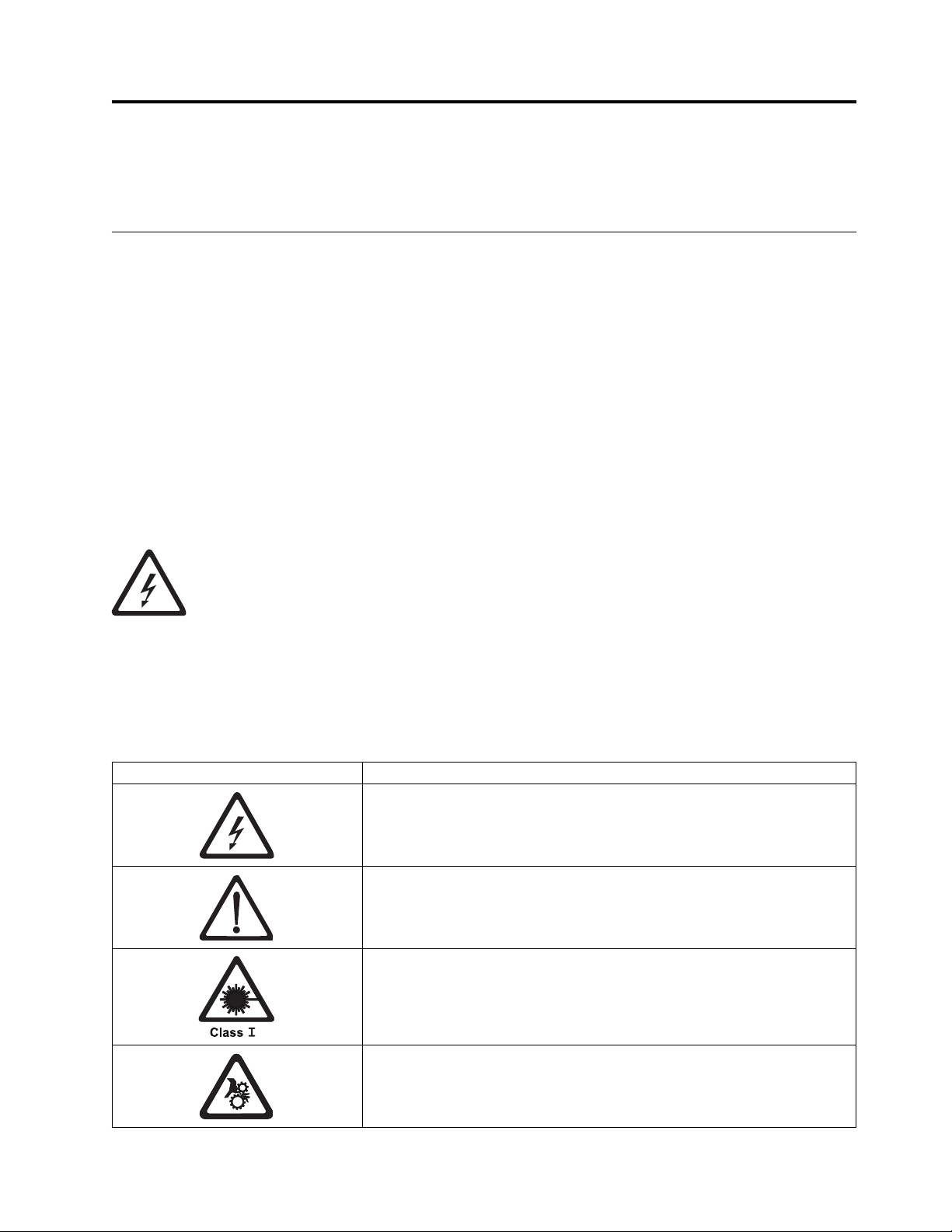
practice. A caution notice can be accompanied by one of several symbols:
If the symbol is... It means...
A hazardous electrical condition with less severity than electrical danger.
A hazardous condition that is not represented by other safety symbols.
This product contains a Class II laser. Do not stare into the beam. (C029)
Laser symbols are always accompanied by the classification of the laser as
defined by the U. S. Department of Health and Human Services (for
example, Class I, Class II).
A hazardous condition due to mechanical movement in or around the
product.
© Copyright IBM Corp. 2009, 2018 xvii
Page 18
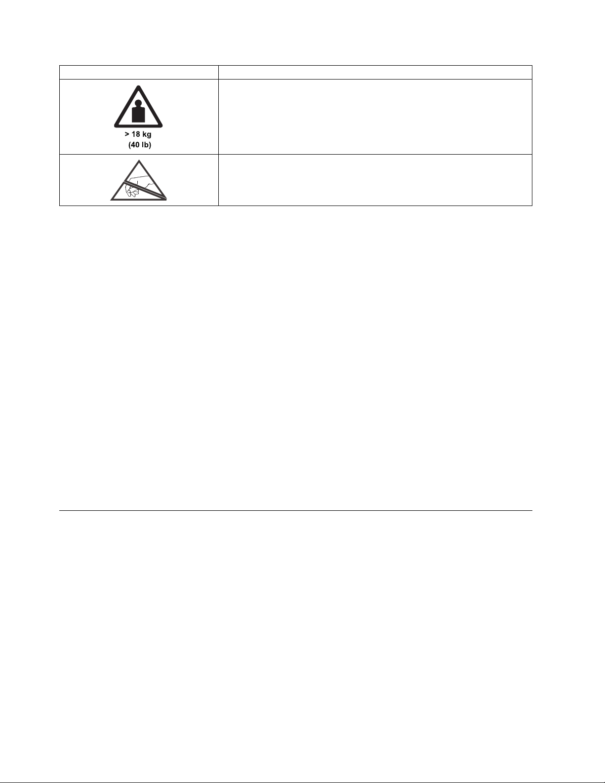
If the symbol is... It means...
This part or unit is heavy but has a weight smaller than 18 kg (39.7 lb). Use
care when lifting, removing, or installing this part or unit. (C008)
A hazardous condition due to the unit's susceptibility to electrostatic
discharge.
Sample caution notices follow:
Caution
The battery is a lithium ion battery. To avoid possible explosion, do not burn. Exchange only with
the IBM-approved part. Recycle or discard the battery as instructed by local regulations. In the
United States, IBM has a process for the collection of this battery. For information, call
1-800-426-4333. Have the IBM part number for the battery unit available when you call. (C007)
Caution
The system contains circuit cards, assemblies, or both that contain lead solder. To avoid the
release of lead (Pb) into the environment, do not burn. Discard the circuit card as instructed by
local regulations. (C014)
Caution
When the Modular Refrigeration Unit (MRU) is removed, immediately remove any oil residue
from the MRU support shelf, floor, and any other area to prevent injuries because of slips or falls.
Do not use refrigerant lines or connectors to lift, move, or remove the MRU. Use handholds as
instructed by service procedures. (C016)
Caution
Do not connect an IBM control unit directly to a public optical network. The customer must use
an extra connectivity device between an IBM control unit optical adapter (that is, fibre, ESCON,
FICON®) and an external public network. Use a device such as a patch panel, a router, or a
switch. You do not need an extra connectivity device for optical fibre connectivity that does not
pass through a public network.
Possible safety hazards
Possible safety hazards to the operation of this product are:
Electrical
An electrically charged frame can cause serious electrical shock.
Mechanical
Hazards (for example, a safety cover missing) are potentially harmful to people.
Chemical
Do not use solvents, cleaners, or other chemicals that are not approved for use on this product.
Before the library is used, repair any of the preceding problems.
xviii IBM TS2900 Tape Autoloader: Setup, Operator, and Service Guide Machine Type 3572
Page 19
Laser safety and compliance
Table 1. Class I Laser Product
The library might contain a laser assembly that complies with the performance standards set by the
US Food and Drug Administration for a Class I laser product. Class I laser products do not emit
hazardous laser radiation. The library has the necessary protective housing and scanning safeguards
to ensure that laser radiation is inaccessible during operation or is within Class I limits. External
safety agencies have reviewed the library and have obtained approvals to the latest standards as they
apply.
Performing the safety inspection procedure
Before you service the unit, complete the following safety inspection procedure.
1. Stop all activity between the host and the library’s tape drive.
2. Turn off the power to the library by switching the Power button on the rear of the tape library to the
Off position.
3. Disconnect the tape drive’s SAS cable.
4. Unplug the library’s power cord from the electrical outlet and the library’s power supply unit.
5. Check the library’s power cords for damage, such as a pinched, cut, or frayed cord.
6. Check the tape drive’s SAS cable for damage.
7. Check the cover of the library for sharp edges, damage, or alterations that expose its internal parts.
8. Check the cover of the library for proper fit. It should be in place and secure.
9. Check the product label at the rear of the library to make sure that it matches the voltage at your
outlet.
Rack safety
The following general safety information must be used for all rack-mounted devices.
DANGER
v Always lower the leveling pads on the rack cabinet.
v Always install stabilizer brackets on the rack cabinet.
v To avoid hazardous conditions because of uneven mechanical loading, always install the
heaviest devices in the bottom of the rack cabinet. Always install servers and optional
devices, starting from the bottom of the rack cabinet.
v Rack-mounted devices are not to be used as a shelf or workspace. Do not place any object
on top of rack-mounted devices.
v Each rack cabinet might have more than 1 power cord. Be sure to disconnect all power
cords in the rack cabinet before you service any device in the rack cabinet.
v Connect all devices that are installed in a rack cabinet to power devices installed in the
same rack cabinet. Do not plug a power cord from a device that is installed in one rack
cabinet into a power device that is installed in a different rack cabinet.
v An electrical outlet that is not correctly wired might place hazardous voltage on the metal
parts of the system or the devices that attach to the system. It is the responsibility of the
customer to ensure that the outlet is correctly wired and grounded to prevent an electrical
shock.
Safety and environmental notices xix
Page 20

CAUTION:
(R001)
v Do not install a unit in a rack where the internal rack ambient temperatures might exceed
the manufacturer's recommended ambient temperature for all your rack-mounted devices.
v Do not install a unit in a rack where the air flow is compromised. Ensure that air flow is
not blocked or reduced on any side, front, or back of a unit that is used for air flow
through the unit.
v Consideration must be given to the connection of the equipment to the supply circuit so
that overloading of the circuits does not compromise the supply wiring or overcurrent
protection. To provide the correct power connection to a rack, refer to the rating labels on
the equipment in the rack to determine the total power requirement of the supply circuit.
v (For sliding drawers) Do not pull out or install any drawer or feature if the rack stabilizer
brackets are not attached to the rack. Do not pull out more than 1 drawer at a time. The
rack might become unstable if you pull out more than one drawer at a time.
v (For fixed drawers) This drawer is a fixed drawer and must not be moved for servicing
unless specified by the manufacturer. Attempting to move the drawer partially or out of
the rack might cause the rack to become unstable or cause the drawer to fall out of the
rack.
xx IBM TS2900 Tape Autoloader: Setup, Operator, and Service Guide Machine Type 3572
Page 21

CAUTION:
Removing components from the upper positions in the rack cabinet improves rack stability
during relocation. Follow these general guidelines whenever you relocate a populated rack
cabinet within a room or building:
v Reduce the weight of the rack cabinet by removing equipment, starting at the top of the
rack cabinet. When possible, restore the rack cabinet to the configuration of the rack
cabinet as you received it. If this configuration is not known, you must do the following
steps.
– Remove all devices in the 32U position and above.
– Ensure that the heaviest devices are installed in the bottom of the rack cabinet.
– Ensure that there are no empty U-levels between devices that are installed in the rack
cabinet below the 32U level.
v If the rack cabinet you are relocating is part of a suite of rack cabinets, detach the rack
cabinet from the suite.
v Inspect the route that you plan to take to eliminate potential hazards.
v Verify that the route that you choose can support the weight of the loaded rack cabinet.
Refer to the documentation that comes with your rack cabinet for the weight of a loaded
rack cabinet.
v Verify that all door openings are at least 760 x 2032 mm (30 x 80 in.).
v Ensure that all devices, shelves, drawers, doors, and cables are secure.
v Ensure that the 4 leveling pads are raised to their highest position.
v Ensure that no stabilizer bracket is installed on the rack cabinet during movement.
v Do not use a ramp that is inclined at more than 10 degrees.
v When the rack cabinet is in the new location:
– Lower the 4 leveling pads.
– Install stabilizer brackets on the rack cabinet.
– If you removed any devices from the rack cabinet, repopulate the rack cabinet from the
lowest position to the highest position.
v If a long-distance relocation is required, restore the rack cabinet to the configuration of the
rack cabinet as you received it. Pack the rack cabinet in the original packaging material, or
equivalent. Also, lower the leveling pads to raise the casters off the pallet and bolt the
rack cabinet to the pallet.
(R002)
Safety and environmental notices xxi
Page 22

Power cords
For your safety, IBM provides a power cord with a grounded attachment plug to use with this IBM
product. To avoid electrical shock, always use the power cord and plug with a properly grounded outlet.
For your safety, IBM provides a power cord with a grounded attachment plug to use with this
IBM product. To avoid electrical shock, always use the power cord and plug with a properly
grounded outlet.
IBM power cords that are used in the United States and Canada are listed by Underwriter’s
Laboratories (UL) and certified by the Canadian Standards Association (CSA).
For units intended to be operated at 115 volts: Use a UL-listed and CSA-certified cord set
consisting of a minimum 18 AWG, Type SVT or SJT, three-conductor cord, a maximum of 15 feet
in length and a parallel blade, grounding-type attachment plug rated 15 amperes, 125 volts.
For units intended to be operated at 230 volts (US use): Use a UL-listed and CSA-certified cord set
consisting of a minimum 18 AWG, Type SVT or SJT, three-conductor cord, a maximum of 15 feet
in length and a tandem blade, grounding-type attachment plug rated 15 amperes, 250 volts.
For units intended to be operated at 230 volts (outside the US): Use a cord set with a
grounding-type attachment plug. The cord set must have the appropriate safety approvals for the
country in which the equipment are installed.
IBM power cords for a specific country or region are available only in that country or region.
Cautions and regulatory compliance statements for NEBS
This library is NEBS certified. This section includes the cautions and regulatory compliance statements for
the Network Equipment-Building System (NEBS) certification from the Telcordia Electromagnetic
Compatibility and Electrical Safety - Generic Criteria for Network Telecommunications Equipment (A
Module of LSSGR, FR-64; TSGR, FR-440; and NEBSFR, FR-2063) Telcordia Technologies Generic
Requirements, GR-1089-CORE, Issue 4, June 2006.
Table 2. NEBS Compliance Statements
CAUTION:
To comply with the Telcordia GR-1089-CORE standard for electromagnetic compatibility and safety, for Ethernet
RJ-45 ports, use only shielded Ethernet cables that are grounded on both ends. In a NEBS installation, all
Ethernet ports are limited to intra-building wiring.
CAUTION:
The intra-building ports of the equipment or subassembly are only suitable for connection to intra-building or
unexposed wiring or cabling. The intra-building ports of the equipment or subassembly must NOT be
metallically connected to interfaces that connect to the OSP or its wiring. These interfaces are designed for use
only as intra-building interfaces (Type 2 or Type 4 ports as described in GR-1089-CORE, Issue 4), and require
isolation from the exposed OSP cabling. The addition of primary protectors is not sufficient protection in order
to connect these interfaces metallically to OSP wiring.
An external Surge Protective Device (SPD) is not required for operating this library.
xxii IBM TS2900 Tape Autoloader: Setup, Operator, and Service Guide Machine Type 3572
Page 23

Table 2. NEBS Compliance Statements (continued)
This product can be installed in a network telecommunication facility or location where the NEC applies.
Safety and environmental notices xxiii
Page 24

xxiv IBM TS2900 Tape Autoloader: Setup, Operator, and Service Guide Machine Type 3572
Page 25

Preface
This manual contains information and instructions necessary for the setup, operation, and servicing of the
IBM TS2900 Tape Autoloader (Machine Type 3572).
Related Publications
To ensure that you have the latest publications, visit the web at http://www.ibm.com/storage/.
v IBM TS2900 Tape Autoloader Installation Quick Reference (GA76-0423) provides hardware installation
instructions.
v IBM TS2900 Tape Autoloader SCSI Reference (GC27-2211) provides information about the SCSI commands
that are supported by this library.
v IBM Tape Device Driver Installation and User’s Guide (GA32-2130) provides instructions for attaching
IBM-supported hardware to open-systems operating systems. It indicates what devices and levels of
operating systems are supported. It also gives requirements for adapters, and tells how to configure
hosts to use the device driver. All of the above are with the Ultrium family of devices.
v IBM Tape Device Driver Programming Reference (GA32-0566) supplies information to application owners
who want to integrate their open-systems applications with IBM-supported Ultrium hardware. The
reference contains information about the application programming interfaces (APIs) for each of the
various supported operating system environments.
v IBM LTO Ultrium Tape Drive SCSI Reference (GA32-0450) provides SCSI supported commands and
protocol that governs the behavior of the SCSI interface.
v IBM Tivoli®Key Lifecycle Manager V1.0 (English) publications can be downloaded from the following
website: http://www.ibm.com/software/tivoli/library.
– IBM Tivoli Key Lifecycle Manager Quick Start Guide (GI11-8738)
– IBM Tivoli Key Lifecycle Manager Installation and Configuration Guide (SC23-9977)
v IBM Security Key Lifecycle Manager Knowledge Center, located at http://www-01.ibm.com/support/
knowledgecenter/SSWPVP/welcome?lang=en, contains information to help you install, configure, and
use the IBM Security Key Lifecycle Manager.
v The IBM Publications Center: http://www.ibm.com/shop/publications/order.
The Publications Center is a worldwide central repository for IBM product publications and marketing
material with a catalog of 70,000 items. Extensive search facilities are provided. Payment options for
orders are by way of credit card (in the US) or customer number for 20 countries. Many publications
are available online in various file formats, and they can all be downloaded by all countries, free of
charge.
© Copyright IBM Corp. 2009, 2018 xxv
Page 26

xxvi IBM TS2900 Tape Autoloader: Setup, Operator, and Service Guide Machine Type 3572
Page 27

Product description
a29z0033
“Front panel” on page 3
“Cartridge magazine” on page 4
“Rear panel” on page 5
“Bar code reader” on page 6
“SAS host interface” on page 6
“Encryption” on page 6
“Supported Internet Protocols” on page 7
“Simple Network Management Protocol (SNMP) messaging” on page 7
“Network Time Protocol” on page 8
“Ultrium tape drives” on page 8
“Media” on page 9
“Logical Unit Number (LUN) scanning” on page 9
“Location coordinates and element addresses” on page 9
“Library specifications” on page 10
“Product environment” on page 11
“Supported servers, operating systems, and software” on page 12
“Supported device drivers” on page 12
Figure 1. TS2900 Tape Autoloader
The IBM TS2900 Tape Autoloader (Machine Type 3572) provides compact, high-capacity, low-cost
solutions for simple, unattended data backup. The library has a compact 1U form factor with easy access
to tape cartridges with a removable magazine. It is equipped with a SAS (Serial Attached SCSI) host
adapter attachment that has a data transfer rate of up to 6.0 Gbps (S5H and S4H) or 3.0 Gbps (S4H and
S3H). The TS2900 Tape Autoloader is an external stand-alone or rack-mountable unit that incorporates:
v IBMUltrium 8 Half Height Tape Drive (Model S8H)
v IBMUltrium 7 Half Height Tape Drive (Model S7H)
v IBMUltrium 6 Half Height Tape Drive (Model S6H)
v IBMUltrium 5 Half Height Tape Drive (Model S5H)
v IBMUltrium 4 Half Height Tape Drive (Model S4H)
v IBM Ultrium 3 Half Height Tape Drive (Model S3H)
© Copyright IBM Corp. 2009, 2018 1
Page 28

Note: The Ultrium 4 Half Height tape drive in S4H libraries that are manufactured after March 2011
support 6.0 Gb/s.
The TS2900 Tape Autoloader has a 10-position removable cartridge magazine, providing a maximum of 9
data cartridge positions, or a maximum of 8 data cartridge positions with a configurable 1-slot I/O
station. One position is reserved as the tape drive exchange position and can be accessed by the library
only. The library data storage capacity can be further increased by using hardware compression.
See Table 3 for more information on supported tape cartridges in the TS2900 Tape Autoloader. WORM for
Ultrium 3 and later is also supported.
Table 3. Data capacity and recording format
Type Native Data Capacity Recording Format
Ultrium 8 12 TB (30 TB at 2.5:1 compression) Reads and writes data on 6656 tracks,
32 tracks at a time.
Ultrium M8 9 TB (22.5 TB at 2.5:1 compression)1Reads and writes data on 3584 tracks,
32 tracks at a time.
Ultrium 7 6 TB (15 TB at 2.5:1 compression) Reads and writes data on 3584 tracks,
32 tracks at a time.
Ultrium 6 2.5 TB (6.25 TB at 2.5:1 compression) Reads and writes data on 2176 tracks,
16 tracks at a time.
Ultrium 5 1.5 TB (3 TB at 2:1 compression) Reads and writes data on 1280 tracks,
16 tracks at a time.
Ultrium 4 800 GB (1.6 TB at 2:1 compression) Reads and writes data on 896 tracks,
16 tracks at a time.
Ultrium 3 400 GB (800 GB at 2:1 compression) Reads and writes data on 704 tracks,
16 tracks at a time.
Ultrium 2 200 GB (400 GB at 2:1 compression) Reads and writes data on 512 tracks,
8 tracks at a time.
Ultrium 1 100 GB (200 GB at 2:1 compression) Reads and writes data on 384 tracks,
8 tracks at a time.
1
Library Firmware must be at 0080 or greater to support the LTO M8 media feature. Drive firmware must be at
HB82 or greater to support the LTO M8 media feature. Ensure that any IBM device drivers are at the minimum
level that is required to support the library.
2 IBM TS2900 Tape Autoloader: Setup, Operator, and Service Guide Machine Type 3572
Page 29
Front panel
3 46 65 1 2
a29z0002
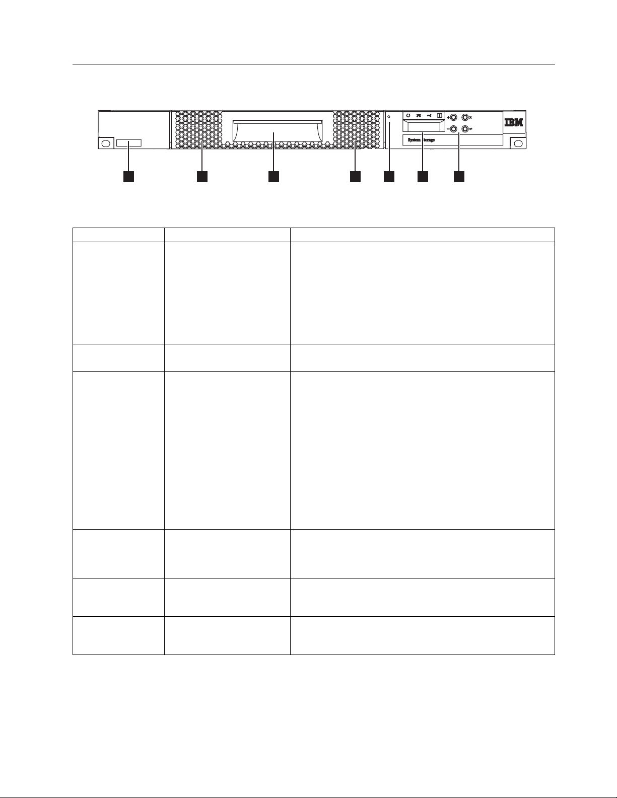
Figure 2. Front panel components
Table 4. Front panel component descriptions
Number Component Description
▌1▐ Operator Panel The Operator Panel features a monochrome 16-character LCD
graphic display that is on the front of the library. Library
operations and service functions are completed from this
screen.
The Web User Interface offers some of the same functionality
as the Operator Panel with a web browser for remote access to
the library. For information about the Operator Panel and the
Web User Interface, see “User interfaces” on page 13.
▌2▐ Control keys The control keys are located to the right of the Operator Panel
LCD display on the front of the library.
▌3▐ Cartridge magazine The tape library has a single cartridge magazine that can hold
up to 9 data cartridges, or 8 data cartridges with a 1-slot I/O
station. See Figure 3 on page 4.
Column 5/Tier 1 in the cartridge magazine can be configured
as a 1-slot I/O station. Column 5/Tier 2 in the cartridge
magazine is reserved for the exchange position and can be
accessed by the library only. The I/O station is used to import
and export cartridges without interrupting normal library
operation. Beginning with Column 4, a minimum of one
column can be reserved for cleaning cartridges. Cleaning
cartridges are used to clean the tape drive heads. For
configuration details, see “Installation and configuration” on
page 21.
▌4▐ Cartridge magazine release Emergency cartridge magazine lock release. When the I/O
station is locked, insert a large, straightened paper clip twice
or hold the paper clip in place while the cartridge magazine
slides past the I/O station lock.
▌5▐ Serial number label The machine type and serial number of the library are on the
front bezel of the library. The serial number is the number that
links the library to IBM entitlement for service.
▌6▐ Air vents These vents draw cooler air into the library enclosure and
allow warm air to escape which helps keep the library at a
normal operating temperature.
Product description 3
Page 30
Cartridge magazine
a29z0025
Column 5
Tier 2
Column 4
Tier 2
Column 3
Tier 2
Column 2
Tier 2
Column 1
Tier 2
Column 5
Tier 1
Column 4
Tier 1
Column 3
Tier 1
Column 2
Tier 1
Column 1
Tier 1
2
3
1
a29z0057
21
Figure 3. Cartridge Magazine
▌1▐ Cartridge locations as they appear in the
Library Map.
▌2▐ Cartridge magazine
▌3▐ Magazine handle
Note: These labels are for reference only and
do not display on the magazine.
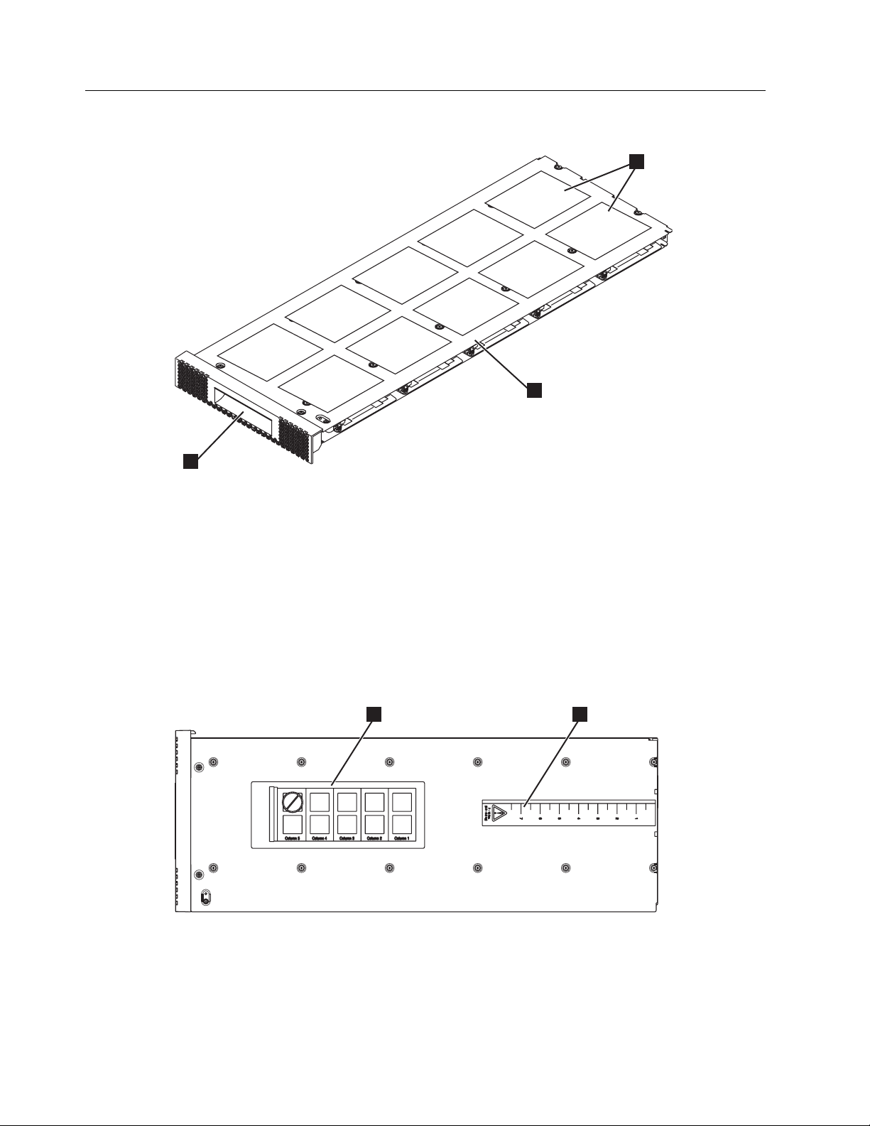
Figure 4 shows the cartridge location label ▌1▐, and ruler ▌2▐ that appear on the cartridge magazine. The
ruler provides an indication of the distance, when the magazine is opened or withdrawn, to the end of
the magazine before it clears the front edge of the library. To prevent dropping the magazine, support
both ends of the magazine before it clears the front edge of the library.
Figure 4. Cartridge magazine (top view)
4 IBM TS2900 Tape Autoloader: Setup, Operator, and Service Guide Machine Type 3572
Page 31

Rear panel
45 1 2 6
3
a29z0003
Figure 5. Rear panel components
Table 5. Rear panel component descriptions
Number Component Description
▌1▐ Power connector The library connects to a 110/220 volt ac power supply.
▌2▐ Power switch The library is powered ON when the power supply switch on the
rear panel is ON (|). The library has no independent power switch
on the front panel.
▌3▐ SAS host interface connector Serial-attached SCSI host interface cable connection. The Ultrium 3,
4, 5, 6, and 7 SAS drives use the SFF-8088 connection at the drive
end and SFF-8088 or SFF-8470 at the host adapter end.
▌4▐ Ethernet port This port is used to connect the library to a network.
▌5▐ Accessor locking screw The accessor locking screw is used to lock the accessor in place
during transportation.
Important: Remove the accessor locking screw before the library is
powered ON.
▌6▐ Air vent These vents allow air to escape from the power supply and tape
drive sled.
Product description 5
Page 32

Bar code reader
The bar code reader is a part of the library accessor. The bar code reader reads each cartridge bar code
label that identifies the types of cartridge magazines and tape drive that is installed in the library. It also
provides inventory feedback to the host application, Operator Panel, and Web User Interface. The library
stores the customized inventory data in memory. Library firmware supports a 6 or 8-character volume
serial number (VOLSER) on the bar code label on the tape cartridge.
SAS host interface
The Ultrium 3 Half Height Tape Drives and later, support the Serial Attached SCSI (SAS) interface. They
have one Mini-SAS (SFF-8088) connector, and are connected to a Mini-SAS (SFF-8088) or SAS (SFF-8470)
at the host adapter end with the appropriate cable. The SFF-8088 SAS connectors on the Ultrium 3 and
Ultrium 4 are compatible with SAS-1 cables. The SFF-8088 SAS connector on the Ultrium 5 tape drives
and later, are compatible with SAS-1 or SAS-2 cables.
A drive with a SAS (Serial Attached SCSI) interface is linked directly to controllers. SAS is a performance
improvement over traditional SCSI. SAS enables multiple devices (up to 128) of different sizes and types
to connect simultaneously with thinner and longer cables. Its full-duplex signal transmission supports 3.0
Gb/s (S3H and S4H) or 6.0 Gb/s for S4H and later. In addition, the TS2900 Tape Autoloader is
hot-plugged, if necessary. SAS drives can auto-negotiate speed.
Note: The Ultrium 4 Half Height tape drive in S4H libraries that are manufactured after March 2011
support 6.0 Gb/s.
Encryption
The LTO Ultrium 4 and later Tape Drives support host Application Managed Encryption (AME) and
Library Managed Encryption (LME) with T10 encryption methods, for SAS and Fibre Channel drives.
Data encryption is only supported by LTO Ultrium 4 Data Cartridges and later. Encryption is also
supported by library firmware version 4.0 or later.
Note: Application Managed Encryption (AME) does not require a key. Library Managed Encryption
(LME) requires a license key, which is available by purchasing Feature Code 5901.
The encryption enabled drive contains the necessary hardware and firmware to encrypt and decrypt host
tape application data. Encryption policy and encryption keys are provided by the host application or host
server. A drive digital certificate is installed at manufacturing time. Each drive receives a unique serial
number and certificate. The T10 application validates each drive instance by checking the drive’s digital
certificate.
The LTO Ultrium encryption environment is complex and requires knowledge beyond that of product
trained Service Support Representatives (SSRs). The Encryption function on tape drives, whether it's a
desktop, a stand-alone drive, or within libraries, is configured and managed by the customer. In some
instances, SSRs are required to enable encryption at a hardware level when service access or service
password-controlled access is required. Customer setup support is by Field Technical Sales Support
(FTSS), customer documentation, and software support for encryption software problems. Customer 'how
to' support is also provided by way of support line contract.
Use the encryption-capable library firmware to select None or Application Managed encryption from the
Web User Interface. If you did not previously enter a valid Transparent Encryption license key, you can
also select Library Managed Encryption. The factory default is None.
For more information, see IBM Encryption Key Manager Installation, Planning, and User’s Guide. See
“Related Publications” on page xxv.
6 IBM TS2900 Tape Autoloader: Setup, Operator, and Service Guide Machine Type 3572
Page 33

Supported Internet Protocols
The TS2900 Tape Autoloader supports the Internet protocols:
v IPv4
v IPv6
To learn more about IPv4, visit http://www.iana.org/. To learn more about IPv6, visit
http://www.ipv6.org/..
Simple Network Management Protocol (SNMP) messaging
Occasionally, the library might encounter a situation that you want to know about, such as an open
magazine or a fault that causes the library to stop. The library provides a standard TCP/IP protocol
called Simple Network Management Protocol (SNMP). SNMP can send alerts about conditions (such as
need for operator intervention) over a TCP/IP LAN network to an SNMP monitoring station. These alerts
are called SNMP traps. With the information that is supplied in each SNMP trap, the monitoring station
(together with customer-supplied software) can alert operations personnel of possible problems or
operator interventions that occur.
All of the IBM automation products support SNMP (Simple Network Management Protocol) and all of
them support SNMP read and walk capability.
The new Configuration capability of SNMP Query provides a common Management Information Base
(MIB) across all of the IBM tape libraries. This capability allows a product administrator to audit the
settings of all of their IBM tape libraries to ensure that they comply with their own policies.
SNMP traps
SNMP Traps are alerts or status messages that can be collected, monitored, and used to proactively
manage attached libraries with SNMP protocol with the SNMP monitoring stations. In summary, each
trap provides the following information.
v Product Identification such as product name, description, manufacturer, model number, firmware
level, and the URL that the trap is designated for.
v Product Status such as the severity of the trap, status (current and previous) and the time the trap
occurred.
v Library State (physical device status) such as identification and status of devices that is monitored. It
would include enclosure, power supply, controller, magazine status, drive count, cartridge slot count,
and I/O station count. Also included would be certain library statistics, and where appropriate, the
fault FSC (fault symptom code) including the severity and description of that fault.
v Drive Status such as the identification of each drive in the library, firmware level, serial number, and
other address and status information.
v Trap Definitions such as library status change, open magazine, I/O accessed, hard fault information,
requests to clean the drive, excessive retries, and returning to normal operations.
v SNMP MIBs The library's MIB contains units of information that specifically describe an aspect of the
system, such as the system name, hardware number, or communications configuration. When with
SNMP to monitor your TS2900 Tape Autoloader, make sure that the TS2900 MIB file is loaded on your
SNMP monitoring station. SNMP traps are sent to the SNMP monitoring stations that are defined for
your library (see “Configuring trap notifications” on page 48). Download the SNMP MIB file for this
library from http://www.ibm.com/storage/support.
Product description 7
Page 34

Network Time Protocol
a80hh015
NTP is an Internet standard protocol that assures accurate synchronization of computer clock times in a
network of computers. Running as a continuous background client program on a computer, NTP sends
periodic time requests to a server, obtaining server time stamps, and with them to adjust the client’s
clock.
Ultrium tape drives
The TS2900 Tape Autoloader supports the Ultrium 3 (3572-S3H) and later, half height tape drives.
The Ultrium 3 and later, half height tape drives support the Serial Attached SCSI (SAS) interface. They
have one Mini-SAS (SFF-8088) connector.
Figure 6. Ultrium half height tape drive
Speed matching
To improve system performance, the Ultrium 3 and later Tape Drives use a technique that is called speed
matching. Speed Matching dynamically adjusts the native (uncompressed) data rate to the slower data rate
of the attached server.
Channel calibration
The channel calibration feature of the Ultrium 3 and later Tape Drives customizes each read/write data
channel for optimum performance. The customization enables compensation for variations in the
recording channel transfer function, media characteristics, and read/write head characteristics.
Power management
The Ultrium 3 and later Tape Drives feature a power management function. This function controls the
drive's electronics so that part of the electronics completely turns OFF when circuit functions are not
needed for the drive's operation.
8 IBM TS2900 Tape Autoloader: Setup, Operator, and Service Guide Machine Type 3572
Page 35

Media
The TS2900 Tape Autoloader uses Ultrium tape cartridges that provide up to 12 TB native capacity (up to
30 TB with 2.5:1 hardware data compression) for Ultrium 8 tape drives.
For more information on native data capacity, see Table 3 on page 2.
Table 6. Ultrium data cartridge compatibility with Ultrium tape drive
IBM
Ultrium
Tape
Drive
LTO8 Read/
LTO7 Read/
LTO6 Read/
LTO5 Read/
LTO4 Read/
LTO3 Read/
LTO2 Read/
LTO1 Read/
1
Library Firmware must be at 0080 or greater to support the LTO M8 media feature. Drive firmware must be at
HB82 or greater to support the LTO M8 media feature. Ensure that any IBM device drivers are at the minimum
level that is required to support the library.
12 TB
Ultrium 8
Write
9 TB LTO
1
M8
Read/
Write
6 TB
Ultrium 7
Read/
Write
Write
IBM LTO Ultrium Data Cartridges
2.5 TB
Ultrium 6
Read/
Write
Write
1.5 TB
Ultrium 5
Read only
Read/
Write
Write
800 GB
Ultrium 4
Read only
Read/
Write
Write
400 GB
Ultrium 3
Read only
Read/
Write
Write
200 GB
Ultrium 2
Read only
Read/
Write
Write
100 GB
Ultrium 1
Read only
Read/
Write
Write
Note: The TS2900 Tape Autoloader supports the Ultrium 3 (3572-S3H) and laterTape Drives only.
For more information about media compatibility, see “Media” on page 107.
Logical Unit Number (LUN) scanning
The TS2900 Tape Autoloader uses a single SCSI ID and dual LUNs to control the tape drive (LUN 0) and
library accessor (LUN 1). The library requires a Host Bus adapter (HBA) that supports LUN scanning. If
it is not enabled, your host system cannot scan beyond LUN 0 and fails to detect the library. It sees only
the tape drive.
Important: Some HBAs, such as RAID controllers, do not support LUN scanning.
Location coordinates and element addresses
The TS2900 Tape Autoloader incorporates IBM’s patented high-density (HD) slot technology, which
allows multiple cartridges to be stored in a tiered architecture. The depth of a cartridge location in a
high-density slot is known as a tier. High-density slots are designed to contain multiple cartridges in
Tiers 1 and 2.
Product description 9
Page 36

Note: Each column has a spring-loaded mechanism that pushes a tape cartridge into Tier 1 when it is the
Front Rear
Reservedslot
Column4
Tier2
Column3
Tier2
Column2
Tier2
Column1
Tier2
Column5
Tier1
Column4
Tier1
Column3
Tier1
Column2
Tier1
Column1
Tier1
Drive
Accessor
Column5
Tier2
only cartridge in that column. A single cartridge in a column takes on the Tier 2 element address even
though it is physically in Tier 1.
Figure 7. Location coordinates
A storage element address is assigned to each cartridge at the time the cartridge is inserted. Storage
element addresses range from 4097 to 4105 (0x1001 to 0x1009) when the I/O station is not enabled, and
from 4097 to 4104 (0x1001 to 0x1008) when the I/O station is enabled.
Library specifications
Table 7. Physical specifications
Parameter Measurement
Front panel width (chassis/bezel) 445 mm (17.52 in.)/483 mm (19.02 in.)
Depth 850 mm (33.46 in.)
Height 44 mm (1.73 in.)
Weight (library only) 13 kg (28.66 lbs)
Table 8. Electrical specifications
Parameter Measurement
Voltage 100 - 240 Vac. (4.0 to 1.5 A)
Frequency 50 - 60 Hz
Power consumption 110 W
For more information about installation specifications, see “Installation and configuration” on page 21.
Table 9. Environmental specifications
Parameter Operating (see Note) Storage Shipping
Temperature 10 - 38 °C (50 - 100 °F) 1 - 60 °C (34 - 140 °F) -40 to 60 °C (-40 to 140 °F)
Temperature variation 10 °C/hour (maximum) 10 °C/hour (maximum) 10 °C/hour (maximum)
Relative humidity 20 - 80% 10 - 90% 10 - 90%
Wet bulb temperature 26 °C (78.8 °F) maximum 29 °C (84 °F) maximum 29 °C (84 °F) maximum
Altitude (meters) 0 - 2,500 0 - 2,500 0 - 2,500
10 IBM TS2900 Tape Autoloader: Setup, Operator, and Service Guide Machine Type 3572
Page 37

Table 9. Environmental specifications (continued)
Parameter Operating (see Note) Storage Shipping
Note: The operating environment of the library must not conflict with the media storage requirements. The library
can operate at elevated temperatures for an extended period. However, the temperature might shorten the useful
life of media that is stored in the library. If media is stored in the library for more than 10 hours, the storage
temperature requirements for media are met. It is assumed that media that is stored in the library is approximately
2 degrees above ambient temperature when the library is powered ON.
Table 10. Operational specifications
Parameter Model S8H Model S7H Model S6H Model S5H Model S4H
Maximum storage
capacity
Maximum
number of data
cartridges
Drive types Ultrium 8 Half
Sustained native
data transfer rate
Interface 6 Gb/s SAS 3 Gb/s SAS
Note: The Ultrium 4 Half Height tape drive in S4H libraries that are manufactured after March 2011 support 6.0
Gb/s and a sustained native data rate of 120 Gb/s.
108 TB (270 TB
with 2.5:1
compression)
9 (including an optional I/O Station)
Height
300 MB/s (750
MB/s with 2.5:1
compression)
54 TB (135 TB
with 2.5:1
compression)
Ultrium 7 Half
Height
300 MB/s (750
MB/s with 2.5:1
compression)
22.5 TB (56.2 TB
with 2.5:1
compression)
Ultrium 6 Half
Height
160 MB/s (400
MB/s with 2.5:1
compression)
13.5 TB (27 TB
with 2:1
compression)
Ultrium 5 Half
Height
140 MB/s (280
MB/s with 2:1
compression)
7.2 TB (14.4 TB
with 2:1
compression)
Ultrium 4 Half
Height
120 MB/s (240
MB/s with 2:1
compression)
Table 11. Acoustical specifications
Parameter Measurement
Idling acoustical noise sound power level LwAD in Bels
(1 Bel = 10 dB)
Maximum acoustical noise sound power level LwAD in
Bels (1 Bel = 10 dB)
6.6
6.8
Product environment
The TS2900 Tape Autoloader is designed to operate in a general business environment.
The library meets the acoustical requirements for general business area category 2D. Category 2D states
that the library can be installed a minimum of 4 m (13 ft.) from a permanent work station.
To allow for service access, install the library a minimum of 0.9 m (3 ft.) from all obstacles.
The library is a precision computer peripheral device. To ensure maximum longevity of your library,
locate the library away from dust, dirt, and airborne particulates, as follows:
v Keep the library away from high-traffic areas, especially if the floor is carpeted. Carpeting harbors dust
and walking on the carpet can cause the carpet fibers and the dust to become airborne.
v Keep the library out of printer and copier rooms because of toner and paper dust. Additionally, do not
store paper supplies next to the library.
v Keep the library away from moving air caused by doorways, open windows, fans, and air
conditioners.
Product description 11
Page 38

Ensure that the machine covers are always kept closed to minimize any contamination from airborne
particles.
Supported servers, operating systems, and software
The TS2900 Tape Autoloader is supported by a wide variety of servers (hosts), operating systems,
adapters, and software. The supported attachments and software can change throughout the lifecycle of
the product.
To determine the latest supported attachments:
1. Visit the web at http://www.ibm.com/storage/lto.
2. Select Storage Systems from the Product Group menu.
3. Select Tape Systems from the Product Family menu.
4. Select the appropriate link from the Product Type menu. For example, select Tape autoloaders and
libraries from the Product Type menu, then TS2900 Autoloader from the Product menu to find links
to updates.
IBM supports later versions of the browsers if the vendors do not remove or disable functions that the
product relies upon. For browser levels later than the versions that are certified with the product,
customer support accepts usage-related and defect-related service requests. As with operating system and
virtualization environments, if IBM support cannot re-create the issue in the lab, the client might be asked
to re-create the problem on a certified browser version to determine whether a product defect exists.
Defects are not accepted for cosmetic differences between browsers or browser versions that do not affect
the functional behavior of the product. If a problem is identified in the product, defects are accepted. If a
problem is identified with the browser, IBM might investigate potential solutions or workarounds that the
client can implement until a permanent solution becomes available.
Supported device drivers
Device drivers enable the drive to interact with various servers. To properly install an IBM device drive
(if required), refer to the IBM Tape Device Drivers Installation and User’s Guide. For applications that use
other device drivers, see the application’s documentation to determine which drivers to use.
IBM maintains the levels of device drivers and driver documentation for the drive on the Internet. You
can access this material at the website: http://www.ibm.com/support/fixcentral.
Note: If you do not have Internet access and you need information about device drivers, contact your
sales representative.
Note: The device driver for System i®servers is included in the OS/400®operating system.
12 IBM TS2900 Tape Autoloader: Setup, Operator, and Service Guide Machine Type 3572
Page 39

User interfaces
3 51
2 46 7 8 9
a29z0004
“Operator Panel”
“Web User Interface” on page 16
The library has a local interface, the Operator Panel, and a remote Web User Interface (UI).
The Operator Panel is on the front of the library and allows users to work locally on the library. The Web
User Interface allows users and administrators to view and perform some library functions from remote
sites.
Operator Panel
The Operator Panel is on the front bezel of the library. The Operator Panel displays library information
and menu commands that are used to run library management functions in response to the control keys
on the right of the LCD display.
Figure 8. Operator Panel components
Table 12. Operator Panel component descriptions
Number Component Description
▌1▐ LCD display 16-character LCD graphic display
▌2▐ Plus key (+) Button that is used to navigate upward (↑) through the menu items
▌3▐ Minus key (-) Button that is used to navigate downward (↓) through the menu items
▌4▐ Cancel key (X) Button that is used to cancel a user action and return to the last menu item
▌5▐ Enter key Button that is used to display a submenu or to select a user action
▌6▐ Ready/Activity LED Green LED lit when the unit is powered ON. The LED flashes when there is
any library activity or the library is offline.
▌7▐ Clean Drive LED Amber LED lit when the drive needs cleaning. The LED turns OFF after the
drive is cleaned successfully.
▌8▐ Attention LED Amber LED lit when a cartridge is incompatible with the drive, marginal, or
invalid. The LED turns OFF when the media is removed from the drive. The
▌9▐ Error LED Amber LED lit when there is an unrecoverable library or drive failure. The
© Copyright IBM Corp. 2009, 2018 13
LED might also be lit when there is a power supply problem.
corresponding error message displays on the LCD display.
Page 40

The Operator Panel operates in two basic modes:
v User Interaction mode - Mode that is employed when a user is pushing keys on the Operator Panel.
v System Driven mode - Normal mode of operation where the Operator Panel displays status in
response to commands issued from the drive's internal interface.
When an Operator Panel key is pressed and released, the Operator Panel automatically changes to User
Interaction mode. User Interaction mode continues until 3 minutes after a user stops pushing keys, or the
requested accessor action stops, whichever is longer. Then, the Operator Panel returns to System Driven
mode.
If necessary, the Operator Panel automatically changes to System Driven mode. When this change occurs,
the library remembers what the user was doing before the display mode changed.
Any operational conflict between commands that are received over the host interface or the Web User
Interface and those commands that are entered by way of the Operator Panel are avoided with a
reservation mechanism on a first-come, first-served basis. Operator Panel commands are canceled by an
Operator Panel logout or timeout.
Library firmware does not allow a user to select an impossible request. Those situations include, but are
not limited to -
v Moving a cartridge from any source to a position occupied by another cartridge
v Moving a cartridge from an empty cartridge position
v Loading a cartridge from any source to a full drive
v Unloading a cartridge from an empty drive
Any error that is detected by the library or drive controller and not recoverable through predetermined
firmware algorithms is considered unrecoverable. When an error occurs, an error code is displayed on the
Operator Panel display and the error LED is ON. The error code remains on the Operator Panel until a
key is pressed, which causes the Operator Panel to return to the Home Screen. Numeric error codes are
used for unrecoverable errors. Otherwise, text status messages are displayed.
When the library powers ON or resets, it goes through several internally controlled initialization
processes, called the Power-On-Self-Test (POST).
Front panel LEDs
All LEDs are updated during power ON and reset sequences. At power ON or software reset, all LEDs
turn ON as soon as POST allows. When initialization starts, all LEDs turn OFF and the Ready/Activity
LED flashes at a rate of approximately 2 seconds per cycle. When the mechanical initialization is
complete, the Ready/Activity LED stops flashing and turns ON.
If a library failure occurs, the Ready/Activity LED turns OFF and the Error LED turns ON. The Operator
Panel also displays an appropriate error code to help identify the failure.
The following are more operational details of LEDs:
v The Ready/Activity LED (▌6▐ in Figure 8 on page 13) turns ON any time the unit is powered ON and
functional. The Ready/Activity LED flashes whenever there is library. This LED also flashes when the
library is offline.
v The Clean Drive LED (▌7▐ in Figure 8 on page 13) turns ON when a “cleaning required” command is
issued by the drive. The LED turns OFF after a successful drive cleaning operation.
v The Attention LED (▌8▐ in Figure 8 on page 13) turns ON to indicate that a piece of media is
bad/marginal, or invalid. The LED turns OFF when all marginal and invalid cartridges are exported
from the library. The Attention LED also turns ON if Autoclean is enabled and no cleaning cartridge is
in a cleaning position.
14 IBM TS2900 Tape Autoloader: Setup, Operator, and Service Guide Machine Type 3572
Page 41

v The Error LED (▌9▐ in Figure 8 on page 13) turns ON when there is an unrecoverable drive or library
a29z0028
a29z0029
failure. An error message is displayed on the screen and the LED remains ON until the error state is
resolved.
For information, see “Interpreting front panel LEDs” on page 136.
Input modes
There are several ways to enter values in the different menu items. These values are selectable predefined
values, toggle values (for example, ON/OFF) and numerical values like network addresses.
Selecting predefined values
1. To set the predefined values, press Enter to select the menu item.
2. With the Plus and Minus keys, select one of the various predefined values for that item.
3. As soon as the Operator Panel display shows the correct value, press Enter to apply the value.
Toggling values
Toggle values are used to switch between two different states like ON and OFF.
1. After you navigate to the menu item, press Enter to select the menu item.
2. With the Plus and Minus keys, select one of the various predefined states for that item.
3. Press Enter to apply the new state.
Entering numerical values
Numerical values are needed for network addresses, password entries, and other configuration entries.
1. After you navigate to the menu item, the current value is displayed and the cursor highlights the first
digit of the value that can be changed.
2. For each digit to be changed in the value:
a. Use the Plus and Minus keys to increment or decrement the digit.
b. Press Enter to highlight the next editable digit.
3. Press Enter at the last digit to apply the complete entry. Press Cancel to cancel the whole edit process
and maintain the original value.
Logging in
At power ON or software reset, the library ready screen displays when POST initialization completes
successfully.
Figure 9. Library ready screen
To log in to the Operator Panel, press the Enter key. The password entry screen displays.
Figure 10. Password entry screen
User interfaces 15
Page 42

Press the UP and DOWN arrow keys to change the current digit. Press the Enter key to advance to the
2
1
3
a29z0032
next digit. The default password is 0000. When you are logged in, you can change the password with the
Change Login Password command. See “Configuring Operator Panel settings” on page 72.
Screen elements
Figure 11. Screen elements
The Operator Panel displays a single menu item (▌1▐ in Figure 11) on each screen. The existence of other
menu items above and below the currently displayed item is indicated by the arrows (▌2▐ in Figure 11)
on the right side of the screen.
In the Configuration menu, the current configuration setting is indicated by an asterisk (▌3▐ in Figure 11)
on the right side of the screen. For example, in Figure 11, the I/O station is enabled. When a
configuration setting is changed, the confirmation screen in Figure 12 displays. Press Enter to confirm, or
Cancel to return to the previous screen.
Figure 12. Confirmation screen
Web User Interface
You can use the Web User Interface to update the library and drive firmware, and to download error
logs, drive memory dumps, and other library data.
Before the TS2900 Tape Autoloader can be managed over a network with the Web User Interface, set up
the initial network configuration of the library with the Operator Panel. For information, see
“Configuring network settings” on page 54.
Logging in
To log in to the Web User Interface from Internet Explorer, you must enter the IP address of the library.
The IP address can be obtained with the View Settings command from the Operator Panel. For example,
http://192.168.1.1.
After the Web User Interface is started, the login window is displayed.
16 IBM TS2900 Tape Autoloader: Setup, Operator, and Service Guide Machine Type 3572
Page 43

|
|
Figure 13. Login page
|
|
The factory default account login and password for an Administrator account is
v Account: admin
v Password: secure
The account name and password are case-sensitive. After your account name and password are entered,
use your mouse to click Login or press Enter.
For information about account privileges, see “User privileges” on page 20.
Common header elements
All Web User Interface windows (except for the Login screen) contain the following common elements in
the header
v Logoff - Click to log out of the Web User Interface.
v Help - Click to read context-sensitive help for the associated page.
Menus available from the Web User Interface
Figure 14 on page 18 shows the Web User Interface window for a User account, Figure 15 on page 19
shows the window for a Superuser account, and Figure 16 on page 20 shows the window for an
Administrator account.
User interfaces 17
Page 44

|
|
Figure 14. User account window
|
|
18 IBM TS2900 Tape Autoloader: Setup, Operator, and Service Guide Machine Type 3572
Page 45

|
|
Figure 15. Superuser account window
|
|
User interfaces 19
Page 46

|
|
Figure 16. Administrator account window
|
|
For a complete description of all Web User Interface menu options, see “Operations” on page 61.
User privileges
User privilege levels are manually assigned to user accounts created within the library. Controlling access
to screens and operations within the library preserves the integrity of the library and the data that is
stored within the library.
There are three types of user privileges in the library.
v Users are allowed to monitor the library, but not complete actions that affect the physical library.
v Superusers are allowed to operate the physical and logical library, but not complete actions that affect
the library configuration.
v Administrator users are allowed access to the entire physical library and logical library, including
configuration. Only one administrator user must be assigned the login name admin.
User privileges include
v Multiple users can be logged in at one time on the Web User Interface.
v Any user can be logged in to only one interface at a time.
For a comparison of user privileges, see “User privilege comparison” on page 168.
20 IBM TS2900 Tape Autoloader: Setup, Operator, and Service Guide Machine Type 3572
Page 47

Installation and configuration
“Verifying the shipment”
“Choosing a location” on page 22
“Acclimation” on page 22
Installing Your Library “Installing the Deskside Cover” on page 23
“Installing in a rack” on page 26
“Removing the accessor locking screw” on page 33
“Attaching the library to a server” on page 34
“Configuring your library with the Web User
Interface” on page 37
“Configuring your library with the Operator
Panel” on page 54
“Populating the library with cartridges” on page 56
“Verifying library and drive operation” on page 58
“Taking the library online” on page 58
“Registering for support notification” on page 59
“Logging in to the Web User Interface” on page 38
“Checking firmware level” on page 38
“Configuring library settings” on page 39
“Configuring network settings” on page 41
“Configuring date and time settings” on page 42
“Configuring encryption settings” on page 44
“Configuring email notifications” on page 47
“Configuring trap notifications” on page 48
“Managing user access” on page 50
“Saving the library configuration” on page 53
“Logging in to the Operator Panel” on page 54
“Configuring network settings” on page 54
“Configuring library settings” on page 55
To install and configure a desktop or rack-mounted TS2900 Tape Autoloader, complete these procedures
in the order they are presented.
Verifying the shipment
Verify that the following items are included in the library shipment:
v Power cord
v IBM Translated Safety Notices
v Safety notices pointer sheet (pointing to the CD-ROM)
v Quick Reference
v Setup, Operator, and Service Guide CD-ROM
v Warranty information
v Device driver pointer sheet (pointing to the Internet)
v Quality Hotline card
v Rack mount kit or Deskside kit
© Copyright IBM Corp. 2009, 2018 21
Page 48

v SAS wrap tool
v Optional transparent LTO encryption information
The following items are required for installation and library operation:
v SAS cable
v Data cartridges
v Cleaning cartridge
v Ethernet cable
Important: If any of the contents of your shipment are damaged or missing, call the appropriate number
that is listed on the Quality Hotline card.
Choosing a location
Table 13. Location criteria
Criteria Definition
Room temperature 16 - 32 °C (60 - 90 °F)
Voltage 100 - 240 Vac. (4.0 to 1.5 A)
Note: The power switch is on the rear of the library and
must be easily accessible.
Frequency 50 - 60 Hz
Relative humidity 20 - 80% non-condensing
Air quality The library must be placed in an area with minimal
sources of particulate contamination. Avoid areas near
frequently used doors and walkways, stacks of supplies
that collect dust, printers, and smoke-filled rooms.
Excessive dust and debris can damage cartridges and the
tape drive.
Clearance
Rack requirements Standard EIA 19-inch rack: 1U space
v Back: Minimum of 15 cm (6 in.)
v Front: Minimum of 30 cm (12 in.)
v Sides: Minimum of 5 cm (2 in.)
Acclimation
|
Server and storage equipment (racks and frames) must be gradually acclimated to the surrounding
|
environment to prevent condensation.
|
When server and storage equipment (racks and frames) is shipped in a climate where the outside
|
temperature is below the dew point of the destination (indoor location), there is a possibility that water
|
condensation can form on the cooler inside and outside surfaces of the equipment when the equipment is
|
brought indoors.
|
Sufficient time must be allowed for the shipped equipment to gradually reach thermal equilibrium with
|
the indoor environment before you remove the shipping bag and energize the equipment. Follow these
|
guidelines to properly acclimate your equipment:
|
v Leave the system in the shipping bag. If the installation or staging environment allows it, leave the
|
product in the full package to minimize condensation on or within the equipment.
|
22 IBM TS2900 Tape Autoloader: Setup, Operator, and Service Guide Machine Type 3572
Page 49

v Allow the packaged product to acclimate for 24 hours.1If there are visible signs of condensation (either
a29z0034
a29z0036
a29z0037
|
external or internal to the product) after 24 hours, acclimate the system without the shipping bag for
|
an additional 12 - 24 hours or until no visible condensation remains.
|
v Acclimate the product away from perforated tiles or other direct sources of forced air convection to
|
minimize excessive condensation on or within the equipment.
|
1
Unless otherwise stated by product-specific installation instructions.
|
Note: Condensation is a normal occurrence, especially when you ship equipment in cold-weather
|
climates. All IBM®products are tested and verified to withstand condensation that is produced under
|
these circumstances. When sufficient time is provided to allow the hardware to gradually acclimate to the
|
indoor environment, there should be no issues with long-term reliability of the product.
|
Installing the Deskside Cover
A deskside cover and six desktop feet must be installed on the library chassis before the library can be
used as a desktop unit. If you intend to install the library in a rack, skip this step and proceed to
“Installing in a rack” on page 26.
Table 14 lists the parts in the deskside assembly kit. A Phillips head screwdriver (preferably with a
magnetic head) is needed to assemble the deskside kit.
Table 14. Deskside Assembly Kit
Number Part Number Quantity Description Part
▌1▐ 45E3240 6 1U desktop foot
▌2▐ 45E3798 1 Deskside cover
▌3▐ 45E3799 1
▌4▐ 45E3749 2
Bracket, 1U library right
rail
Screw, cross-recessed
binding head, M4x4 (for
securing the rear of the
cover to the library)
Installation and configuration 23
Page 50

Table 14. Deskside Assembly Kit (continued)
a29z0038
a29z0009
6
5
3
6
Number Part Number Quantity Description Part
▌5▐ 45E3801 1
▌6▐ 45E3802 12
Bracket, 1U library left
rail
Screw, cross-recessed
flat head, M3x6 (6 for
securing left and right
rails to library; 6 for
securing sides of cover
to library)
To install the deskside cover on your library:
1. Verify that your deskside kit includes all the necessary contents. See Table 14 on page 23.
2. Attach the left ▌5▐ and right ▌3▐ rails to the chassis with 3 flat-head screws ▌6▐ on each side
(Figure 17).
Figure 17. Attaching side rails to the library chassis
3. Turn the library over and attach the desktop feet ▌1▐ to the designated locations on the bottom of the
library (Figure 18 on page 25). Return the library to the upright position.
24 IBM TS2900 Tape Autoloader: Setup, Operator, and Service Guide Machine Type 3572
Page 51

a29z0013
1
1
Figure 18. Attaching the desktop feet
a29z0011
2
6
6
4. Position the deskside cover ▌2▐ in the correct orientation over the library chassis and attach the cover
to the library with 3 flat-head screws ▌6▐ on each side (Figure 19).
Figure 19. Attaching the cover to the library chassis (side screws)
5. Attach the deskside cover with the 2 large binding-head screws ▌4▐ on the rear of the library
(Figure 20 on page 26).
Installation and configuration 25
Page 52

a29z0040
a29z0041
a29z0042
a29z0012
4
Figure 20. Attaching the cover to the library chassis (rear screws)
6. Place the library in the wanted desktop location.
Important: Do not place the library on its side. Do not stack objects on top of the library.
Installing in a rack
The TS2900 Tape Autoloader can be easily installed into a standard 19-inch rack system. A standard
19-inch rack system contains multiple mounting locations that are called EIA units as defined by the
Electronics Industries Association. Each EIA unit contains three square or round holes that are used to
mount rack designed equipment. The library requires 1 EIA unit (1U) of rack space. Each unit is
separated by a small space.
Table 15 lists the parts in the rack mount assembly kit. A Phillips head screwdriver (preferably with a
magnetic head) is needed to assemble the rack mount kit.
Table 15. Rack mount assembly kit
Number Part Number Quantity Description Part
▌1▐ 45E3741 1 Left rear bracket
▌2▐ 45E3742 1 Right rear bracket
▌3▐ 45E3743 1 Left front bracket
26 IBM TS2900 Tape Autoloader: Setup, Operator, and Service Guide Machine Type 3572
Page 53

Table 15. Rack mount assembly kit (continued)
a29z0043
a29z0044
a29z0045
a29z0046
a29z0048
a29z0049
Number Part Number Quantity Description Part
▌4▐ 45E3744 1 Right front bracket
▌5▐ 45E3745 1 Left front rail
▌6▐ 45E3746 1 Right front rail
▌7▐ 45E3747 2 Rear rail
Screw,
▌8▐ 45E5909 4
cross-recessed flat
head, M3x4
Screw, flat head,
▌9▐ 45E3748 8
self lockable,
M6x10
Screw,
▌10▐ 45E3749 6
cross-recessed
binding head
Installation and configuration 27
Page 54

Table 15. Rack mount assembly kit (continued)
a29z0050
a29z0051
E
L
N
E
L
N
a29z0058
Number Part Number Quantity Description Part
Screw,
▌11▐ 45E3867 2
cross-recessed pan
head, M6x10
▌12▐ 07H6655 1
▌13▐ 39M5378 1
Hook-and-loop
fastener strap
Rack device to
PDU power cord
When you decide on a location in your rack for the library, consider that the Operator Panel has a small
LCD screen. The library must be positioned to allow for easy viewing. The rear of the library must be
free from any obstructions to allow easy access to the power switch and other rear panel components.
Note: Before you begin the rack installation of the library, read the safety information in “Rack safety” on
page xix. Also, verify that no desktop feet are attached to the bottom of the library.
To install the library in a rack:
1. Verify that your rack kit includes all the necessary contents. See Table 15 on page 26.
2. Determine the location in your rack for your library to be installed. With a pencil, mark the location
on the front vertical rails (Figure 21 on page 29) and rear vertical rails (Figure 22 on page 29) in your
rack.
28 IBM TS2900 Tape Autoloader: Setup, Operator, and Service Guide Machine Type 3572
Page 55

Figure 21. Rack mount screw locations for front vertical rails
Figure 22. Rack mount screw locations for rear vertical rails
Installation and configuration 29
Page 56

3. Attach the left ▌3▐ and right ▌4▐ (Figure 23) front brackets to the front of the library chassis with 2
a29z0017
8
3
8
4
a29z0019
5
6
10
1
2
12
flat-head screws ▌8▐ on each side. Use the bottom two screw holes on each side.
Figure 23. Attaching the front brackets to the library chassis
4. Attach the left ▌1▐ and right ▌2▐ rear brackets to the left ▌5▐ and right ▌6▐ front rails with 2
round-head screws ▌10▐ on each side (Figure 24).
Figure 24. Attaching the rear brackets to the rails
Important: Do NOT tighten these screws completely.
5. Slide in the rear rails ▌7▐ from back to front, to create the rail assemblies. Ensure that the screw holes
face outwards (Figure 25 on page 31).
30 IBM TS2900 Tape Autoloader: Setup, Operator, and Service Guide Machine Type 3572
Page 57

a29z0018
7
Figure 25. Creating the rail assemblies
6. Install the rail assemblies into the rack (Figure 26 on page 32). Ensure the 3 holes in the front of the
unit align with the 1U space marked on the vertical rails in Step 2. Secure the rails to the rack with 4
flat-head screws ▌9▐ on each side of the rack. Use both of the two screw locations on the rear of the
rack rail (Figure 22 on page 29). Use the top and middle screw locations on the front of the rack rail
(Figure 21 on page 29).
Installation and configuration 31
Page 58

a29z0020
9
9
Figure 26. Installing the rail assemblies
a29z0021
11
7. Slide the library chassis into the rack. Secure the front of the library to the rack with the large black
screws ▌11▐ in the bottom holes on each front bracket (Figure 27).
Figure 27. Securing the front of the library in the rack
8. Secure the rear of the library to the rack with a round-head screw ▌10▐ on each rear bracket (Figure 28
on page 33). Tighten the other rear bracket screws to secure the library to the rack.
32 IBM TS2900 Tape Autoloader: Setup, Operator, and Service Guide Machine Type 3572
Page 59

a29z0022
1010
Figure 28. Securing the rear of the library in the rack
a29z0023
12
9. Run the SAS cable, power cable, and Ethernet cable through the hook-and-loop fastener strap ▌12▐.
Leave enough slack to reach the corresponding connectors, then tighten the strap (Figure 29).
Figure 29. The cables at the rear of the library
Note: For information about converting and relocating the library, see “Removal and replacement
procedures” on page 141.
Removing the accessor locking screw
Important: The accessor locking screw prevents the library accessor from moving during shipment and
must be removed before the library is powered ON.
Remove the accessor locking screw, located on the rear panel of the library (▌1▐ in Figure 30 on page 34).
Installation and configuration 33
Page 60

1
Figure 30. accessor locking screw
1 2 3
Attaching the library to a server
The drive is attached to a server with the Serial Attached SCSI (SAS) interface. The Web User Interface
accesses the library with an ethernet interface.
Connecting the Host Interface cables
To connect the host interface cable to the library:
Note: It is recommended that you shut down and turn OFF the associated server before you connect the
SAS interface cable. Turn ON the associated server after the SAS interface cable is connected to the
library and server, the library is powered ON, and the library completed the initialization.
Figure 31. Interface cable connection
1. Attach an ethernet cable to the ethernet port (▌1▐ in Figure 31)
Note: On rack mount installations, run the cable through the hook-and-loop fastener strap on the
right rear bracket.
34 IBM TS2900 Tape Autoloader: Setup, Operator, and Service Guide Machine Type 3572
Page 61

2. Attach the host end of the SAS cable to the drive’s SAS connector (▌2▐ in Figure 31 on page 34). See
“SAS host interface” on page 6 for information about the type of SAS connector that is required for
attachment to the drive.
Note: On rack mount installations, run the cable through the hook-and-loop fastener strap on the
right rear bracket.
3. Attach the other end of the host SAS interface cable to the host or to an interposer if required.
4.
v Method 1: Plug the ethernet cable into your server or PC to access the Web User Interface directly.
This method modifies your server or PC network settings to match the library default settings. You
can also use the library Operator Panel to change the library network settings to match the server
or PC network settings before you use the Web User Interface to access the library. If the ethernet
connection is directly attached to a server or a PC, a crossover ethernet cable might be required.
v Method 2: Plug the ethernet cable into an ethernet switch or router to access the Web User Interface
on a LAN (local area network). The library network settings must be entered with the Operator
Panel before the Web User Interface is used to access the library.
Connecting the power cord
Note: This product can ONLY be used with an approved power cord for your specific geographic region.
Use of an unapproved power cord might result in
v Not meeting individual country-specific safety requirements
v Overheating with potential personal injury or property damage
v A fracture that results in internal contacts that are exposed, which might subject the user to a shock
hazard
To connect a power cord:
1. Plug one end of the power cord or rack PDU power cord into the power connector (▌3▐ in Figure 31
on page 34) on the rear panel of the library.
Note: On rack mount installations, run the rack PDU power cord through the hook-and-loop fastener
strap on the right rear bracket, and tighten the strap. The rack PDU power cord is a special power
cord that plugs into a rack power strip.
2. Plug the other end of the power cord into the nearest properly grounded power outlet. On rack
mount installations, plug the other end of the rack PDU power cord into the nearest rack PDU.
3. Power ON the library by toggling the power switch on the power supply to the ON (|) position.
4. Wait for the library to initialize.
During initialization, the library completes a Power ON Self Test (POST) to ensure that the library
hardware is functional. The library also tests communications with the tape drive over the internal
bus.
Note: If the Operator Panel does not initialize, check all cable connections, and ensure that the cartridge
magazine is closed and in the locked position. Ensure that the power supply switch is in the ON position.
If the Operator Panel still does not initialize, see “Troubleshooting” on page 129.
Important: To disconnect all power from the library, turn the power switch to the OFF position, then
remove the power cord from the outlet. The power switch removes power from portions of the library
and the drive, but the power supply still has ac power at its input.
Note: When the library is power-cycled, wait 10 seconds after the power is OFF before the library is
powered ON again.
Installation and configuration 35
Page 62

Configuring the library
The library can be configured with the Web User Interface or the Operator Panel. The preferred method
for configuring your library is by using the Web User Interface. See “Configuring your library with the
Operator Panel” on page 54 and “Configuring your library with the Web User Interface” on page 37.
For complete detailed information about all of the functions available on the library with the Operator
Panel and the Web User Interface, see “Operations” on page 61.
The default library configuration settings are listed in Table 16.
Table 16. Default library configuration settings
Configuration Item Default Setting
NETWORK
Ethernet link speed Auto
SSL security Disabled
IPv4 settings Enabled
DHCP (Dynamic Host Configuration Protocol) Enabled
Static IP address Disabled
IPv4 address 0.0.0.0
Subnet mask 255.255.255.0
Gateway 0.0.0.0
IPv6 settings Disabled
DHCP (Dynamic Host Configuration Protocol) Enabled
Stateless auto-configuration Enabled
Static IP address Disabled
IPv6 address 0:0:0:0:0:0:0:0
Prefix length 64
Gateway 0:0:0:0:0:0:0:0
DNS setting Disabled
DNS IP address 0.0.0.0
PHYSICAL
Library name (Blank)
Auto Cleaning Disabled
Bar code label length 8 characters
LOGICAL
Library mode Random
Loop Enabled
Auto Load Enabled
Active slots 9 + 0
ENCRYPTION (S4H and LATER ONLY)
Encryption method None
Encryption policy Encrypt All
SSL security Disabled
Primary EKM server address 0.0.0.0
36 IBM TS2900 Tape Autoloader: Setup, Operator, and Service Guide Machine Type 3572
Page 63

Table 16. Default library configuration settings (continued)
Configuration Item Default Setting
Primary EKM TCP port number 3801
Primary EKM SSL port number 443
Secondary EKM server address 0.0.0.0
Secondary EKM TCP port number 3801
Secondary EKM SSL port number 443
Advanced encryption settings (None)
DATE and TIME
NTP server Disabled
NTP server address 0.0.0.0
Time zone (GMT) +00:00
Date (MM/DD/YYYY) 01/08/2008
Auto adjustment by PC Every 1 minute
NOTIFICATIONS
SMTP (mail) settings
Mail server address 0.0.0.0
Mail event Error events enabled
SNMP (trap) settings
Community Public
Trap event Error events enabled
SNMPv3 engine ID (Set by library firmware)
Static library network settings must be entered with the Operator Panel before the library can be accessed
remotely with the Web User Interface. If your system is serviced by a Dynamic Host Configuration
Protocol (DHCP) server, the network parameters are automatically set. Once remote access is established,
you can complete the configuration of your library remotely.
If you choose to use the Operator Panel to configure your library, go to “Configuring your library with
the Operator Panel” on page 54.
Configuring your library with the Web User Interface
If you choose to use the Web User Interface to configure your library, first enter your library network
settings with the Operator Panel (see “Configuring network settings” on page 71).
To configure your library with the Web User Interface:
1. “Logging in to the Web User Interface” on page 38
2. “Checking firmware level” on page 38
3. “Configuring library settings” on page 39
4. “Configuring network settings” on page 41
5. “Configuring date and time settings” on page 42
6. “Configuring encryption settings” on page 44
7. “Configuring email notifications” on page 47
8. “Configuring trap notifications” on page 48
9. “Managing user access” on page 50
Installation and configuration 37
Page 64

10. “Saving the library configuration” on page 53
Logging in to the Web User Interface
To log in to the Web User Interface:
1. If necessary, obtain the IP address of the library on the Operator Panel.
a. From the top menu of the Operator Panel, press the Minus key to select View Current
Information, and press Enter.
b. Press the Minus key until the IP Address setting is displayed and make a note of the IP address.
c. Press the Cancel key repeatedly to log out of the Operator Panel.
2. Open Internet Explorer on your server or PC to access the Web User Interface.
3. In the browser address field, enter your library's IP address URL to start the Web User Interface
applet in the browser window. For example, http://192.168.1.1
4. On the Web User Interface login screen, enter the administrator login account name and default
password.
v Account: admin
v Password: secure
|
|
|
Figure 32. Web User Interface login screen
|
5. Click Login.
Checking firmware level
To determine the latest supported firmware level:
1. Visit the web at http://www.ibm.com/support/fixcentral.
2. Select Storage Systems from the Product Group menu.
3. Select Tape Systems from the Product Family menu.
4. Select the appropriate link from the Product Type menu. For example, select Tape autoloaders and
libraries from the Product Type menu, then TS2900 Autoloader from the Product menu to find links
to updates.
Check the current level of library firmware that is displayed in the Versions box of the System Summary
page. If an updated level of firmware is available, download and update the library firmware before
normal operation starts. See “Updating library and drive firmware” on page 104.
38 IBM TS2900 Tape Autoloader: Setup, Operator, and Service Guide Machine Type 3572
Page 65

|
|
|
Figure 33. System summary
|
Configuring library settings
Physical library settings
|
|
|
Figure 34. Cartridge assignment settings
|
To configure the library cartridge assignment settings, complete the following procedure:
1. In the Configure Library menu in the left navigation pane of the Web User Interface, click
Physical/Logical
|
2. In the Physical Settings, enter the Library settings:
|
v Library name - Enter a name for your library.
v Auto Cleaning - Automatically cleans the drive when the drive requests that cleaning and a
cleaning cartridge is present in the library. Auto cleaning can be enabled only when there is at least
one inactive position in the magazine in the library.
Installation and configuration 39
Page 66

Note: It is recommended to enable the Auto Clean function on the library. With the Auto Clean
function enabled, drive cleaning occurs automatically. The only time Auto Cleaning must be
disabled is when your Backup Application requires that it has control.
v Bar code label length - Use to choose the number of characters in the cartridge bar code that is
reported to the host computer.
3. Click Submit to enable the settings.
Logical library settings
|
|
|
Figure 35. Logical library mode settings
|
To configure the library access mode settings for the logical library:
1. In the Configure Library menu in the left navigation pane of the Web User Interface, click
|
Physical/Logical
|
2. In the Logical Settings, select the Library Mode:
|
v Random - In random mode, the library allows the server's (host's) application software to select
any data cartridge in any order.
v Sequential - In sequential mode, the library's firmware predefines the selection of the cartridges.
After initialization, the firmware causes the library to select the first available cartridge found
(counting from the lowest Column/Tier position through the highest cartridge position in your
library) for loading into the drive. See “Location coordinates and element addresses” on page 9.
|
|
|
|
|
– Loop - When Library mode is Sequential with Loop mode Enabled, the cartridge in the lowest
Column/Tier cartridge position is loaded after the cartridge in the highest Column/Tier
cartridge position is filled with data and sent back to its home position. This mode allows
endless backup operations without user interaction.
– Auto load - When Library mode is Sequential with Auto load mode Enabled, the first available
cartridge (the lowest Column/Tier cartridge position that contains a cartridge) is loaded
automatically if the library powers ON, or resets, with an empty drive. If the library powers ON
with a cartridge already in the drive, sequential mode starts from the home position of that
cartridge, unless the host issues a rewind and unload command to the drive. In which case the
next cartridge in sequence will be loaded into the drive.
To start Sequential mode if Auto load is not Enabled, use the Move Cartridge command to load the
first cartridge into the drive. The sequence starts from the home position of that cartridge.
Cartridges need not to be in contiguous slots.
To stop Sequential mode, use the Move Cartridge command to unload the drive. This command
cancels Sequential mode; the next sequential cartridge is NOT loaded.
To restart Sequential mode, use the Move Cartridge command again to load a cartridge; the loading
sequence resumes from the home position of that cartridge.
v Number of active slots - Select the number of active slots to assign in your library. Selecting the
number of active slots defines the number of storage slots, number of cleaning/inactive slots,
whether the I/O Station is enabled/disabled, and whether auto cleaning is allowed. The first digit
configures the number of active storage positions (4, 6, 8, or 9). The second digit configures Column
5, Tier 1 of the magazine as an I/O Station (0 when disabled, and 1 when enabled). The Auto
40 IBM TS2900 Tape Autoloader: Setup, Operator, and Service Guide Machine Type 3572
Page 67

Cleaning function can be enabled only if there is at least one inactive position in the magazine. If
Auto Cleaning is enabled, the inactive positions become cleaning cartridge positions.
3. Click Submit to enable the settings.
Configuring network settings
Once the network settings are entered on the Operator Panel, the current network configuration of the
|
library can be modified with the Web User Interface. The changes that are made to the network settings
|
take effect after the library is rebooted.
|
|
|
|
Figure 36. Network settings
|
To modify the network settings:
1. In the Configure Library menu in the left navigation pane of the Web User Interface, click Network.
|
2. Select the Ethernet Link speed (duplex mode).
3. In Security, select Enable SSL for Web to provide secure communications between the web browser
|
and the tape library.
|
4. Select the TCP/IP settings. To enable dual IPv4/IPv6 protocol, select both Use IPv4 and Use IPv6 and
enter parameters for both.
Installation and configuration 41
Page 68

v IPv4 settings - Select Use IPv4 to enable the IPv4 Internet Protocol. Select the corresponding button
to obtain an IP address automatically (DHCP) or use static IP address settings. When with DHCP,
use the Operator Panel to determine the library's assigned IP address. See “Configuring network
|
|
|
|
|
|
|
|
|
settings” on page 71. Enter the following parameters if Use static IP address is selected.
– IPv4 address - Sets the TCP/IPv4 address of the library on the network.
– Subnet mask - Defines and limits users within a local network.
– Gateway - Allows access outside the local network.
v IPv6 settings - Select Use IPv6 to enable the IPv6 Internet Protocol. Select the corresponding button
or check box to obtain an IP address automatically (DHCP), to obtain an IP address with stateless
auto configuration, or to use static IP address settings. Enter the following parameter if Use static
IP address is selected.
– IPv6 address - Sets the TCP/IPv6 address of the library on the network.
– Prefix length - Decimal value that indicates the number of contiguous, high-order bits
comprising the network portion of the address.
– Gateway - Allows access outside the local network.
5. In DNS settings, select Use DNS to use a domain name server. The DNS server, if entered, allows the
encryption, date and time, and notifications IP addresses to be specified with host names instead of
numerical IP addresses.
v DNS IP address - Sets the IP address of the DNS server.
6. Click Submit to enable the settings.
Note: The changes that are made to the network settings take effect after the library is rebooted.
Configuring date and time settings
|
|
|
Figure 37. Date and time settings
|
Configure the date and time settings with one of three methods: automatically with a remote NTP time
server on the network, automatically with the clock on your host computer, or manually.
Note: If you manually set your date and time, you must reset the date and time after the library is
power-cycled and after a library reset.
Note: When the library is power-cycled, wait 10 seconds after the power is OFF before the library is
powered ON again.
Once the network settings are entered on the Operator Panel, the current date and time can be modified
with the Web User Interface.
The TS2900 Tape Autoloader communicates with an NTP server with the following conditions:
v Client/server basis operation
v UDP (User Datagram Protocol) to access the NTP server
42 IBM TS2900 Tape Autoloader: Setup, Operator, and Service Guide Machine Type 3572
Page 69

v Does not use authentication keys
v Library polling is every 12 hours
To modify the date and time settings:
1. In the Configure Library menu in the left navigation pane of the Web User Interface, click Date and
|
Time.
|
2. Select the Date and Time settings.
v Select the Enable NTP Server check box to enable time and date control with a time server on the
|
|
network.
– NTP server address - Enter the IP address of the time server. IPv4 and IPv6 addresses are
supported, depending on the TCP/IP settings. Host names can be entered instead of numerical
IP addresses if Use DNS is selected in the Network settings.
|
– Time zone - Enter the time zone relative to Coordinated Universal Time (UTC).
v If the time server is disabled, enter the local time and date manually.
– Date - Enter the date with the MM/DD/YYYY format.
– Time - Enter the time with the HH:MM:SS format.
v Click Load PC date time to synchronize the library with the clock on your host computer at regular
|
|
intervals.
3. Click Submit to update the settings.
Installation and configuration 43
Page 70

Configuring encryption settings
|
|
Figure 38. Encryption settings
|
|
Note: This procedure is optional if you have the Encryption Activation Key Feature Code 5901. Only the
Ultrium 4 Tape Drive (3572-S4H) and later support encryption.
Before you can use the encryption capability of the tape drive, you must be sure that certain software and
hardware requirements are met. Refer to the IBM Security Key Lifecycle Manager Knowledge Center before
you continue to the next step.
44 IBM TS2900 Tape Autoloader: Setup, Operator, and Service Guide Machine Type 3572
Page 71

|
|
|
Figure 39. Encryption enabled settings
|
To modify the encryption settings:
1. In the Configure Library menu in the left navigation pane of the Web User Interface, click Encryption
|
2. Enter the Feature Activation Key (see Figure 38 on page 44) and click Submit to enable encryption in
your library.
3. Select the Security settings.
v Enable SSL for EKM - Select to enable secure communications between the tape library and the
EKM server.
4. Select the Encryption method settings.
v Application Managed Encryption - For encryption in operating environments that run an
application capable of generating and managing encryption policies and keys. If you select
application-managed encryption, no further configuration steps are necessary.
v System Managed Encryption - For encryption in operating environments where no application is
capable of key management runs, and encryption is set up implicitly through each instance of the
IBM device driver.
v Library Managed Encryption - For transparent encryption by the TS2900 Tape Autoloader tape
drive.
Installation and configuration 45
Page 72

Note: System Managed Encryption and Library Managed Encryption are transparent to each other. A
|
tape encrypted with System Managed Encryption might be decrypted with Library Managed
|
Encryption, and vice versa, provided both have access to the same EKM keystore.
|
5. Select the Primary EKM Server Settings (Library Managed Encryption only) - the address of the
primary encryption key manager on a server. IPv4 and IPv6 addresses are supported. Host names can
be entered instead of numerical IP addresses if the DNS server is specified.
v Address - The IP address of the primary encryption key manager.
v TCP port number - The port number of the primary encryption key manager for TCP. The default
port number is 3801.
v SSL port number - The port number of the primary encryption key manager for SSL. The default
port number is 443.
6. Select the Secondary EKM Server Settings (Library Managed Encryption only) - The address of the
secondary encryption key manager on a server. IPv4 and IPv6 addresses are supported. Host names
can be entered instead of numerical IP addresses if the DNS server is specified.
v Address - The IP address of the secondary encryption key manager.
v TCP port number - The port number of the secondary encryption key manager for TCP. The
default port number is 3801.
v SSL port number - The port number of the secondary encryption key manager for SSL. The default
port number is 443.
7. Select the Encryption policy settings (library-managed encryption only).
v Encrypt All - All tape cartridges that are loaded into the tape drive are encrypted.
v Internal Label - Selective Encryption - This option is used only for Veritas Technologies
|
NetBackup.
v Internal Label - Encrypt All - This option is used only for Veritas Technologies NetBackup.
|
8. Skip over the Advanced Encryption Settings. The purpose of these advanced encryption settings is to
allow only IBM Support personnel (under the direction of the drive development team) to provide a
solution to an unforeseen problem or to support a unique configuration. These options are not
intended for use by the customer without the guidance of IBM Technical Support.
9. Click Submit to enable the settings.
46 IBM TS2900 Tape Autoloader: Setup, Operator, and Service Guide Machine Type 3572
Page 73

Configuring email notifications
|
|
Figure 40. Email notifications
|
|
Note: This procedure is optional.
To set up email notifications of library events:
1. In the Configure Library menu in the left navigation pane of the Web User Interface, click SMTP.
|
2. Configure the Send server settings.
|
v SMTP server address - SMTP mail server address. IPv4 and IPv6 addresses are supported. Host
names can be entered instead of numerical IP addresses if the DNS server is specified in the
Network settings.
v Sender address - Mail header information.
v Subject - Mail header information.
3. Enter the email addresses to be notified when an event takes place in the Mail To fields, and click the
|
Enable check boxes to select each address.
|
4. Select the event level to report in the Mail Event settings.
|
5. Click Test to send a test email message to the enabled addresses.
6. Click Submit to enable the settings.
Installation and configuration 47
Page 74

Configuring trap notifications
|
|
Figure 41. Trap notifications
|
|
Note: This procedure is optional. SNMP notifications are not enabled unless you have selected the SNMP
Enabled check box. To disable SNMP notifications, clear the SNMP Enable check box and click Submit.
The traps that are supported by the TS2900 Tape Autoloader are listed in “Trap definitions (types)” on
page 200.
To set up trap notifications for an SNMP server:
1. In the Configure Library menu in the left navigation pane of the Web User Interface, click SNMP
|
2. Select the SNMP Enabled check box.
3. Configure the SNMP server and header settings.
v Community - SNMP community name to which the library belongs.
v Name - Unique SNMP name for the system.
48 IBM TS2900 Tape Autoloader: Setup, Operator, and Service Guide Machine Type 3572
Page 75

v Location - Physical location of the system.
v Contact - Contact person's name.
v SNMPv3 engine ID - A read-only attribute that identifies the SNMPv3 engine.
4. Enter the settings of the SNMP monitoring stations to be notified when an event takes place by
|
clicking the modify buttons in the Trap List box.
|
|
|
|
Figure 42. SNMP trap settings
|
v Validity - Select the check box to enable and clear the check box to disable.
|
v Address - IPv4 and IPv6 addresses are supported. Host names can be entered instead of numerical
IP addresses if the DNS server is specified.
v Version - Trap version v1, v2c, or v3. For v2c and v3, the Inform check box determines if an SNMP
INFORM request is sent instead of a trap event.
v Community (v1 or v2c) - SNMP community name.
v User name (v3 only) - SNMPv3 unique user name.
v Authentication (v3 only) - Authentication algorithm: disable, MD5, or SHA.
v Authentication Password - When an Authentication algorithm is enabled, an Authentication
|
|
|
|
|
|
|
|
|
|
|
Password is required. (see “Configuring Password Rules Settings” on page 52).
v Confirm - Re-enter the Authentication Password to confirm it.
v Privacy (v3 only) - Privacy service encryption and decryption algorithm: disable, DES, or AES.
When an algorithm is specified, a privacy password is required.
v Privacy password - enter a password (see “Configuring Password Rules Settings” on page 52).
v Confirm - Re-enter the Privacy password to confirm it.
5. Click Submit to save the SNMP Trap settings. Modify each trap's settings by repeating the previous
step.
6. Enter the SNMPv3 users who are allowed to access the tape library by clicking the modify buttons in
the SNMPv3 User List box.
Installation and configuration 49
Page 76

|
|
Figure 43. SNMPv3 user settings
|
|
v Validity - Select the check box to enable and clear the check box to disable.
|
v User name - SNMPv3 unique user name.
v Authentication - Authentication algorithm: disable, MD5, or SHA. When an algorithm is specified,
an authentication password is required.
v Authentication password - enter a password (see “Configuring Password Rules Settings” on page
|
|
|
|
|
|
|
52).
v Confirm - Re-enter the Authentication password to confirm it.
v Privacy - Privacy service encryption and decryption algorithm: disable, DES, or AES. When a
privacy algorithm is specified, a privacy password is required.
v Privacy password - enter a password (see “Configuring Password Rules Settings” on page 52).
v Confirm - Re-enter the Privacy password to confirm it.
7. Select the event level to report in the Trap Event box.
8. Click Test to send a test trap notification to the enabled IP addresses.
9. Click Submit to enable the settings.
Managing user access
To add, modify, or remove users that are able to access the library with the Web User Interface:
|
1. In the Configure Library menu in the left navigation pane of the Web User Interface, click User
|
Access.
|
|
50 IBM TS2900 Tape Autoloader: Setup, Operator, and Service Guide Machine Type 3572
Page 77

|
|
|
Figure 44. User access settings
|
2. To add, modify, or remove a user account, do the following:
|
v Add a user account:
|
|
a. Click Add
|
|
|
|
Figure 45. Add User dialog box
|
|
|
|
|
|
|
|
b. Enter the User Name and Password into the dialog box and assign the user's role. Re-enter
password to Confirm.
c. Select one of the following from the Role menu:
– User - User access permission allows users to monitor the library, but not to complete
functions that affect the library.
– Superuser - Superuser access permission allows users to operate the physical and logical
library, but not to change configuration settings.
Installation and configuration 51
Page 78

|
|
|
– Administrator - Administrator access permission allows users to complete tape library
functions and change configuration settings.
d. Click Submit to save the new user.
|
|
|
|
|
|
|
|
|
|
|
|
|
|
Note: A new user's Password status is set to Expired. A new user is presented with a Login
failure message and given the opportunity to create a new password.
v Modify a user account:
a. Observe the Password status of the user:
– Available: The password is available to be changed.
– Expired: The maximum password age was exceeded. The password is now invalid.
– Unchangeable: The minimum password age was not exceeded. You cannot change the
password.
– Locked: The maximum number of failed login attempts for the account was exceeded.
Note: An administrator must unlock the account by modifying the account and entering a
new password. The Password status changes to Expired.
b. Click Modify next to the User Name of the account.
|
Figure 46. Modify user
|
|
|
|
|
|
|
|
|
|
|
|
|
|
|
c. Enter and confirm a new password (see “Configuring Password Rules Settings”).
d. Select one of the following from the Role menu:
– User - User access permission allows users to monitor the library, but not to complete
functions that affect the library.
– Superuser - Superuser access permission allows users to operate the physical and logical
library, but not to change configuration settings.
– Administrator - Administrator access permission allows users to complete tape library
functions and change configuration settings.
e. Click Submit to save the modified user account.
v Remove a user account
a. Click Remove next to a User Name to delete the account from the system.
3. Enter all user IDs and passwords on the Library Configuration form in Appendix F, “Library
Configuration Form,” on page 223.
Configuring Password Rules Settings
The Password Rules box displays the rules for user passwords.
v Minimum number of characters - Choose the minimum password length. The factory default value is
8. The maximum password length is 16.
52 IBM TS2900 Tape Autoloader: Setup, Operator, and Service Guide Machine Type 3572
Page 79

v Minimum number of upper case alphabetic characters (A-Z) - Choose the minimum number of
uppercase alphabetic characters. The factory default value is 1.
v Minimum number of lower case alphabetic characters (a-z) - Choose the minimum number of
lowercase alphabetic characters. The factory default value is 1.
v Minimum number of numeric characters (0-9) - Choose the minimum number of numeric characters.
The factory default value is 1.
v Minimum number of special characters (!@#$%^&*()_+={}|[]\;':"<>?,./) - Choose the minimum
number of special characters. The factory default value is 0.
v Maximum number of identical consecutive characters - Choose the maximum number of identical
consecutive characters. The factory default value is 2. There is no limitation if 0 is selected.
v Maximum number of failed logins before password is locked - Choose the maximum number of
failed logins before the password is locked. The factory default value is 5. Possible range for this
configuration option is 0 - 10. There is no limitation if 0 is selected.
v Maximum number of days before password must be changed - Choose the maximum number of
days before the password must be changed. There is no limitation if 0 is selected.
v Minimum number of days before password can be changed - Choose the minimum number of days
before the password can be changed. A password can be changed immediately if 0 is selected.
v Number of password changes before an old password can be used again - Choose the number of
password changes that are required before a password can be used again. A password can be reused
immediately if 0 is selected.
Click Submit to save all the information.
Saving the library configuration
|
|
|
Figure 47. Save configuration
|
Note: This procedure is recommended.
Each time that you change the configuration of your library, save the configuration. This function also
maintains several library configuration profiles that can be restored to the library when wanted with the
Web User Interface.
To save a library configuration:
1. In the Configure Library menu in the left navigation pane of the Web User Interface, click
|
Save/Restore
|
2. In the Save Library Settings box, click Save to create a configuration file of your library on your
computer.
Installation and configuration 53
Page 80

Configuring your library with the Operator Panel
To configure your library with the Operator Panel, complete the following procedures:
1. “Logging in to the Operator Panel”
2. “Configuring network settings”
3. “Configuring library settings” on page 55
Logging in to the Operator Panel
In many environments, the default network settings might be sufficient to access your tape library on a
network. To change the default network settings with the Operator Panel, complete the following
procedure:
1. When the library is initialized, press Enter to move to the Password screen.
2. Enter 0000, the default password. The top menu screen displays.
3. When finished with the Operator Panel, press Cancel to return to the top menu screen.
4. When finished, press the Minus key to select Logout, and press Enter.
Configuring network settings
In many environments, the default network settings might be sufficient to access your tape library on a
network. To change the default network settings with the Operator Panel, complete the following
procedure:
1. From the top menu screen, press the Minus key to select Configuration, and press Enter.
2. Link speed (Default: Auto Negotiation)
a. Select Configure Network Settings > Configure Link Speed.
b. Select the required speed and press Enter.
c. Press Enter again to apply the setting, or Cancel to reject the setting.
The speed must be set to Set Auto Negotiation for gigabit Ethernet networks.
d. Press Cancel to backtrack through the menu hierarchy.
3. DHCP IPv4 (Default: Enabled)
a. Select Configure Network Settings > Configure DHCP > Configure DHCPIPv4.
b. Select Enable DHCP IPv4 and press Enter to enable, or press Down and select Disable DHCP
IPv4 to disable.
c. Press Enter again to apply the setting, or Cancel to reject the setting.
d. Press Cancel to backtrack through the menu hierarchy.
4. DHCP IPv6 (Default: Disabled)
a. Select Configure Network Settings > Configure DHCP > Configure DHCPIPv6.
b. Select Enable DHCP IPv6 and press Enter to enable, or press Down and select Disable DHCP
IPv6 to disable.
c. Press Enter again to apply the setting, or Cancel to reject the setting.
d. Press Cancel to backtrack through the menu hierarchy.
5. IPv4/IPv6 Address (Default: 0.0.0.0). If DHCP is disabled, set the IP address manually.
a. Select Configure Network Settings > Change IP Address.
b. Select Set IP Address IPv4 to enter the IPv4 address of the tape library. Set IP Address IPv6 to
enter the IPv6 IP address (split over 4 screens).
c. Press Enter again to apply the setting, or Cancel to reject the setting.
d. Press Cancel to backtrack through the menu hierarchy.
6. IPv4 Subnet Mask (Default: 255.255.255.0). If DHCP IPv4 is disabled, set the IPv4 subnet mask
manually.
a. Select Configure Network Settings > Change Subnet Mask > Set Subnet Mask.
b. Enter the IPv4 subnet mask.
54 IBM TS2900 Tape Autoloader: Setup, Operator, and Service Guide Machine Type 3572
Page 81

c. Press Enter again to apply the setting, or Cancel to reject the setting.
d. Press Cancel to backtrack through the menu hierarchy.
7. IPv6 Prefix Length (Default: 64). If DHCP IPv6 is disabled, set the IPv6 prefix length manually.
a. Select Configure Network Settings > Change Subnet Mask > Set Prefix Length.
b. Enter the IPv4 prefix length.
c. Press Enter again to apply the setting, or Cancel to reject the setting.
d. Press Cancel to backtrack through the menu hierarchy.
8. IPv4/IPv6 Gateway (Default: 0.0.0.0). If DHCP is disabled, set the IP address manually.
a. Select Configure Network Settings > Change Gateway.
b. Select Set Gateway Address IPv4 to enter the IPv4 gateway address or Set Gateway Address
IPv6 to enter the IPv6 gateway address (split over 4 screens).
c. Press Enter again to apply the setting, or Cancel to reject the setting.
d. Press Cancel to backtrack through the menu hierarchy.
9. Press Cancel to return to the Network Settings menu.
10. Press Cancel to return to the Configuration menu.
11. Press Cancel to return to the top menu screen.
Configuring library settings
To configure the library settings, complete the following procedure.
1. From the top menu screen, press the Minus key to select Configuration, and press Enter.
2. Select Configure Library, and press Enter.
3. Active Slots (Default: All)
a. Select Configure Library > Set Active Slots Count.
b. Select the number of active slots you would like to assign for the logical library.
c. To enable I/O station, select Active and I/O X Active + 1 I/O.
d. To disable I/O station, select Active and I/O X Active + 0 I/O.
e. Press Enter again to apply the setting, or Cancel to reject the setting.
4. Library Mode (Default: Random)
a. Select Configure Library > Configure Library Mode.
b. Select Set Random Mode or Configure Sequential Mode, and press Enter.
Random - In random mode, the library allows the server's (host's) application software to select
any data cartridge in any order.
Sequential - In sequential mode, the library's firmware predefines the selection of the cartridges.
After initialization, the firmware causes the library to select the first available cartridge found
(counting from the lowest Column/Tier position through the highest cartridge position in your
library) for loading into the drive.
v Loop - Sequential mode with loop mode ON loads the cartridge in the lowest Column/Tier
cartridge position after the cartridge in the highest Column/Tier cartridge position is filled with
data and sent back to its home position. This procedure allows endless backup operations
without user interaction.
v Autoload - Sequential mode with autoload mode ON loads the first available cartridge (the
lowest Column/Tier cartridge position that contains a cartridge) automatically if the library
powers ON, or resets, with an empty drive. If the library powers ON with a cartridge already in
the drive, sequential mode starts from the home position of that cartridge, unless the host issues
a rewind and unload command to the drive. In which case the next cartridge in sequence is
loaded into the drive.
To start sequential mode if autoload is OFF, use the Move Cartridge command to load the first
cartridge into the drive. The sequence starts from the home position of that cartridge. Cartridges
need not to be in contiguous slots.
Installation and configuration 55
Page 82

To stop sequential mode, use the Move Cartridge command to unload the drive. This command
1
cancels sequential mode; the next sequential cartridge is NOT loaded.
To restart sequential mode, use the Move Cartridge command again to load a cartridge; the
loading sequence resumes from the home position of that cartridge.
c. Press Enter again to apply the setting, or Cancel to reject the setting.
d. Press Cancel to backtrack through the menu hierarchy.
5. Date/Time - Enter the local time and date manually if you do not plan to use a network-based time
server.
a. Select Configure Library > Configure Date/Time.
b. Select Set Date or Set Time, and press Enter.
v Date - Enter the date with the MM/DD/YYYY format.
v Time - Enter the time with the HH:MM:SS format.
c. Press Cancel to backtrack through the menu hierarchy.
6. Auto Cleaning (Default: Disabled)
a. Select Cofiguration > Configure Auto Cleaning.
b. Select Enable Auto Cleaning or Disable Auto Cleaning, and press Enter. The Auto Cleaning
function is enabled only if there is at least one inactive position in the magazine in the library.
c. Press Enter again to apply the setting, or Cancel to reject the setting.
d. Press Cancel to backtrack through the menu hierarchy.
Populating the library with cartridges
The magazine is opened with the Operator Panel.
To populate the library with data and cleaning cartridges, complete the following procedure:
1. From the top menu screen on the Operator Panel, press the Minus key to select Unlock Magazine,
and press Enter, or from Web User Interface: Manage Library > Unlock Magazine.
2. Insert cartridges in the magazine.
Note: A blue release gate (▌1▐ in Figure 48) in the upper left corner of each column in the cartridge
magazine prevents each cartridge from falling out of the front of the magazine. When manually
releasing the gate with one hand, position your other hand in front of the column opening to protect
cartridges that are ejected by the internal column spring.
Figure 48. Cartridge release gate
56 IBM TS2900 Tape Autoloader: Setup, Operator, and Service Guide Machine Type 3572
Page 83

a77ug305
Figure 49. Incorrect (left) and correct (right) placement of release gate
L
TO123L4
Note: Column 5 Tier 2 is reserved as the exchange position. This position is accessible by the library
only. A locking mechanism prevents insertion of a cartridge into the reserved slot.
Each cartridge must be inserted with the indicator arrow on the leading edge of the upper surface of
the cartridge pointing towards the cartridge magazine (see Figure 50).
Note: Do not rely on the bar code label orientation, if attached, to provide an indication of the correct
cartridge orientation. The bar code label is right side up if attached correctly.
Figure 50. Cartridge orientation
The Auto Cleaning function can be enabled only if the number of active slots is less than the
maximum available slots. The active slots are always enabled starting with the lowest numerical
cartridge position number in the magazine. This position is at the drive end of the cartridge
magazine. Place cleaning cartridges in inactive cartridge positions for use by the auto cleaning
function.
Do not store data or cleaning cartridges in the I/O Station (Column 5, Tier 1) if the I/O station is
enabled.
Installation and configuration 57
Page 84

3. Put the magazine back into the library and wait for the library inventory to complete. Then, you can
proceed to the next step.
4. Press Cancel to return to the top-level menu.
Verifying library and drive operation
To verify the library is operating correctly:
1. From the top menu screen on the Operator Panel, press the Minus key to select Service, and press
Enter.
2. Press the Minus key to select Diagnostics, and press Enter.
3. Select Run Library Verify, and press Enter. Follow the on-screen instructions.
If there is a cartridge in a drive, the library moves the cartridge to its home position, or to the I/O
station if the home position is not known.
4. When prompted, insert a customer supplied scratch cartridge into the I/O station.
When the scratch cartridge is loaded, the bar code reader reads the bar code label on the cartridge
and stores it for later comparison. The cartridge is then moved to the tape drive, where the drive runs
its own write/read/verify test. When the test is done, the library tells the drive to eject the cartridge,
and then the cartridge is moved back to the I/O station. The bar code is read again and compared
with the value stored earlier.
5. When prompted, remove the cartridge from the I/O station.
The result of the test is reported on the Operator Panel.
If an error occurs, note the error code number and see Appendix B, “Error codes,” on page 187.
6. Press Cancel to return to the top-level menu.
Taking the library online
When your library is configured, you are ready to save the library configuration and take the library
online.
Note: The tape drive is always online, regardless of whether the library is online or offline.
To take the library online with the Operator Panel:
1. From the top menu screen, press the Minus key to select Commands, and press Enter.
2. Select Change Library State, and press Enter.
3. Select Set Library Online, and press Enter.
4. Press Cancel repeatedly to return to the top-level menu.
5. Press the Minus key to select Logout, and press Enter.
To take the library online with the Web User Interface:
1. Save the library configuration.
a. In the Configure Library menu in the left navigation pane of the Web User Interface, click
|
|
2. Verify the library state.
|
|
3. Click Logoff in the upper right corner of the window.
Save/Restore.
b. Click Save, and then enter a file name and select a location to save the configuration file.
a. In the Manage Library menu in the left navigation pane of the Web User Interface, click Library
State.
b. If the library is offline, click Bring Online.
c. Click Yes to confirm when prompted.
A message dialog displays when the operation is completed.
58 IBM TS2900 Tape Autoloader: Setup, Operator, and Service Guide Machine Type 3572
Page 85

Registering for support notification
Support notification registration provides email notification when new firmware levels are updated and
are available for download and installation.
To register for support notification, visit the web at: http://www-01.ibm.com/software/support/
einfo.html.
Enter your user name and password on the Appendix F, “Library Configuration Form,” on page 223.
Note: Library firmware and tape drive firmware are verified and released together. When the latest
firmware is updated, verify that all installed components such as the tape drive and library are at the
latest levels noted on the Support website. Mixing different levels of library and tape drive firmware is
not supported and might cause unpredictable results.
IBM suggests that you update library and drive firmware when new levels become available. For
instructions on updating library and drive firmware, see “Updating library and drive firmware” on page
104.
Now you are ready to use your library.
Installation and configuration 59
Page 86

60 IBM TS2900 Tape Autoloader: Setup, Operator, and Service Guide Machine Type 3572
Page 87

Operations
“The Operator Panel” on
page 62
Monitoring the Library “Configuration settings” on page 63
“Current information” on page 63
“Firmware revision” on page 64
Managing the Library “Unlocking the I/O station” on page 64
“Unlocking the cartridge magazine” on page 65
“Moving cartridges” on page 65
“Unloading the drive” on page 65
“Cleaning the drive manually” on page 66
“Conducting a library inventory” on page 66
“Taking the library online and offline” on page 66
“Powering down the library” on page 67
“Shipping the library” on page 67
“Rebooting the drive” on page 67
“Rebooting the library” on page 67
“Logging out of the library” on page 68
Configuring the Library “Configuring auto cleaning” on page 68
“Configuring the number of active slots” on page 68
“Configuring the library access mode” on page 69
“Configuring date and time settings” on page 70
“Configuring network settings” on page 71
“Configuring Operator Panel settings” on page 72
“Configuring Web GUI Settings” on page 72
“Setting the library to factory defaults” on page 73
Servicing the Library “Checking the library error status” on page 73
“Running library verify diagnostic procedures” on
page 73
“Running drive diagnostic procedures” on page 74
© Copyright IBM Corp. 2009, 2018 61
Page 88

“The Web User
Interface” on page 75
Monitoring the Library “The system summary” on page 76
“The library map” on page 77
Managing the Library “Moving cartridges” on page 79
“Unloading the drive” on page 80
“Cleaning the drive manually” on page 80
“Taking the library online and offline” on page 81
“Conducting a library inventory” on page 81
“Unlocking the cartridge magazine” on page 81
Configuring the Library “Managing user access” on page 82
“Configuring physical and logical library settings” on page
85
“Configuring network settings” on page 88
“Configuring encryption settings” on page 90
“Configuring date and time settings” on page 93
“Configuring email notifications” on page 47
“Configuring trap notifications” on page 48
“Uploading and configuring the SSL certificate” on page 98
“Saving and restoring configuration settings” on page 99
Servicing the Library “Running encryption Key Path diagnostic procedures” on
page 101
“Library logs” on page 102
“Downloading logs” on page 103
“Resetting the library and drives” on page 103
“Updating library and drive firmware” on page 104
“Usage statistics” on page 105
The Operator Panel
Figure 51 on page 63 shows the top-level menu tree structure of the Operator Panel on the front of the
TS2900 Tape Autoloader. For details on how to select commands and options, see the description in
“Operator Panel” on page 13.
62 IBM TS2900 Tape Autoloader: Setup, Operator, and Service Guide Machine Type 3572
Page 89

Top Level
Commands
Service
Configuration
Unlock I/O Station*
Unlock Magazine
Commands
Configuration
View Current Information
Service
Logout
* If enabled.
Move Cartridge
Unload
Clean Drive
Inventory
Move to Ship Position
Reboot Drive
Reboot Library
Change Library State
Configure Library
Configure Auto Cleaning
Configure Network Settings
Configure Op Panel Settings
View Settings
Set Default
View Error Status
Diagnostics
View Firmware Revision
Telnet Service Port*
* For use by technical
support personnel only.
a29z0064
Figure 51. Operator Panel top menus
Configuration
ViewSettings
ViewCurrentInformation
Monitoring the library
Configuration settings
Figure 52. Configuration settings
Use Configuration > View Settings to display a list of the library configuration settings.
The settings that are displayed include:
v Library settings
– I/O station (On/Off)
– Auto cleaning (On/Off)
– Number of cleaning slots when Auto cleaning is enabled
– Operator Panel back light setting
v Network settings
– Link speed
– IP address protocol
– IPv4 settings (IP address, subnet mask address, gateway address, DHCP)
– IPv6 settings (IP address, gateway address, prefix length, DHCP, stateless Auto configuration)
v Drive settings
– Model number
Current information
Figure 53. Current information
Use View Current Information to display the network settings information.
The settings that are displayed include:
Operations 63
Page 90

v Network settings
Service
ViewFirmwareRevision
UnlockI/OStation
a29z0024
– Worldwide node name
– IP address protocol stack
– IP address
Firmware revision
Figure 54. Firmware revision
Select Service > View Firmware Revision to display the current version of the library firmware.
Managing the library
Unlocking the I/O station
Figure 55. Unlock I/O station command
Select Unlock I/O Station to unlock the I/O station. This menu option is available only when the I/O
station is enabled in the library configuration settings.
Figure 56. I/O station unlocked
After the I/O station is closed, wait for the library to complete its inventory before you proceed with
normal library operations.
64 IBM TS2900 Tape Autoloader: Setup, Operator, and Service Guide Machine Type 3572
Page 91

Note: A blue release gate in the upper left corner of each column in the cartridge magazine prevents each
UnlockMagazine
Commands
MoveCartridge
SourceSlot
DestinationSlot
Commands
Unload
cartridge from falling out of the front of the magazine. When manually releasing the gate with one hand,
position your other hand in front of the column opening to protect cartridges that are ejected by the
internal column spring.
Unlocking the cartridge magazine
Figure 57. Unlock magazine command
Select Unlock Magazine to unlock and remove the cartridge magazine.
When the cartridge magazine is unlocked, it can be removed from the library to insert or remove data
and cleaning cartridges. When the cartridge magazine is fully inserted, the magazine locks into place.
After the magazine is closed, wait for the library to complete its inventory before you proceed with
normal library operations.
Note: A blue release gate in the upper left corner of each column in the cartridge magazine prevents each
cartridge from falling out of the front of the magazine. When manually releasing the gate with one hand,
position your other hand in front of the column opening to protect cartridges that are ejected by the
internal column spring.
Moving cartridges
Figure 58. Move cartridge command
Select Commands > Move Cartridge to move data cartridges and cleaning cartridges between the I/O
station, storage positions, and tape drive.
Specify the following parameters:
v Source Slot - Specify a source that contains a cartridge.
v Destination Slot - Specify the destination.
Press Enter to move the cartridge from the source to the destination.
Note: Cartridges cannot be moved to the accessor with this command, but can be moved from the
accessor if, for example, the library was powered OFF with a tape still held in the Picker.
Unloading the drive
Figure 59. Unload command
Select Commands > Unload to unload the cartridge from the tape head mechanism.
Operations 65
Page 92

Unload when library is in Random mode: The cartridge in the drive is unloaded from the tape head
Commands
CleanDrive
Commands
Inventory
Commands
ChangeLibraryState
SetLibraryOnline
SetLibraryOffline
mechanism, but is still retained inside the tape drive housing. The Move Cartridge command moves the
cartridge from the drive to another location. Moving a tape cartridge from a drive to another location
both unloads and moves the cartridge in a single action.
Unload when library is in Sequential mode: The cartridge in the drive is unloaded from the tape head
mechanism, and returned to the cartridge home position.
Press Enter to unload the cartridge from the tape head mechanism.
Cleaning the drive manually
Figure 60. Clean Drive command
Select Commands > Clean Drive to clean the tape drive manually with a cleaning cartridge in either a
cartridge storage position or the I/O station.
Press Enter to move the cleaning cartridge to the drive and start drive head cleaning. The cleaning
cartridge is returned to its home position when drive cleaning is finished.
Conducting a library inventory
Figure 61. Inventory command
Select Commands > Inventory to force the library to run an inventory of the cartridge magazine,
accessor, and tape drive to refresh the library map. An inventory is conducted automatically when power
is first turned ON or when the cartridge magazine is removed and reinserted.
Press Enter to conduct the inventory.
Taking the library online and offline
Figure 62. Online/Offline command
Select Commands > Change Library State to take the library online or offline.
It is sometimes necessary to take the library offline before servicing functions for the library are done.
Once these operations are finished, it is necessary to bring the library online.
Note: The tape drive is always online, even when the library is offline.
66 IBM TS2900 Tape Autoloader: Setup, Operator, and Service Guide Machine Type 3572
Page 93

Powering down the library
Commands
MovetoShipPosition
Commands
RebootDrive
Commands
RebootLibrary
Before powering OFF the library, ensure that the library is in an idle state with no mechanical movement
of the accessor, and all data operations (for example, backup operations, accessing of log files) are
complete. Then, power OFF the library with the power switch on the rear panel of the library.
Important: If you switch the library power OFF while the library is being accessed, loss of data might
occur.
Note: When power cycling the library, wait 10 seconds after the power is OFF before the library is
powered ON again.
Shipping the library
Figure 63. Move to Ship Position command
Select Commands > Move to Ship Position when the library is prepared to move to a new location. The
accessor must be placed in a parked position within the library housing. Move to Ship Position finishes
all active commands that are received from the host application, does not process any new commands,
and moves the accessor to the parked position before the power is turned OFF.
1. When Unlock Magazine is displayed, press Enter to unlock the cartridge magazine. The magazine
unlocks and the display prompts the removal of the magazine.
2. Remove all cartridges from the magazine and reinsert the magazine into the slide mechanism. The
library completes an inventory to verify no cartridges are in the magazine.
3. If the magazine is empty, the library moves the accessor to the ship position. The library can be
powered down. If the magazine is NOT empty, the library prompts to remove cartridges. After all
cartridges are removed and the magazine is replaced, start the ship position process again.
Rebooting the drive
Figure 64. Reboot Drive command
Select Commands > Reboot Drive to force the drive to reboot. You also specify whether the library will
come online or offline after it finishes rebooting.
Press Enter to reboot the drive.
Rebooting the library
Figure 65. Reboot Library command
Select Commands > Reboot Library to force the library to reboot. You also specify whether the library
will come online or offline after it finishes rebooting.
Press Enter to reboot the library.
Operations 67
Page 94

Logging out of the library
Logout
Configuration
Configure AutoCleaning
Enable AutoCleaning
Disable AutoCleaning
Configuration
ConfigureLibrary
Set ActiveSlotsCount
ActiveSlots
Figure 66. Logout command
Select Logout to log out of the library. The login screen is displayed for the next user.
Configuring the library
Configuring auto cleaning
Figure 67. Auto Cleaning settings
Select Configuration > Configure Auto Cleaning to enable or disable automatic head cleaning of the
tape drive in the library.
Note: It is recommended that the Auto Clean function is enabled on the library. With the Auto Clean
function enabled, drive cleaning occurs automatically. The only time Auto Cleaning is disabled is when
your Backup Application requires that it has control.
The drive can also be cleaned manually. For details, see “Cleaning the drive manually” on page 66.
Configuring the number of active slots
Figure 68. Active slot count settings
Select Configuration > Configure Library > Set Active Slots Count to set the number of active data
cartridge positions within the logical library.
Configure the number of active slots with the following setting:
v Active Slots - The maximum number of active slots that can be set is dependent upon the I/O station
configuration and auto cleaning setting.
The active cartridge slots always begin with the cartridge position with the lowest cartridge address
within the logical library.
68 IBM TS2900 Tape Autoloader: Setup, Operator, and Service Guide Machine Type 3572
Page 95

Configuration
ConfigureLibrary
ConfigureLibraryMode
SetRandomMode
SetSequentialMode
ConfigureLoopMode
EnableLoopMode
DisableLoopMode
Configure AutoloadMode
Enable AutoloadMode
Disable AutoloadMode
Configuring the library access mode
Figure 69. Library access mode settings
Select Configuration > Configure Library > Configure Library Mode to set the logical library access
mode.
Configure the library access mode with the following settings:
v Random Mode - In random mode, the library allows the server's (host's) application software to select
any data cartridge in any order.
v Sequential Mode - In sequential mode, the library's firmware predefines the selection of the cartridges.
After initialization, the firmware causes the library to select the first available cartridge found (counting
from the lowest Column/Tier position through the highest cartridge position in your library) for
loading into the drive.
– Loop - Sequential mode with loop mode ON loads the cartridge in the lowest Column/Tier
cartridge position after the cartridge in the highest Column/Tier cartridge position is filled with
data and sent back to its home position. This mode allows endless backup operations without user
interaction.
– Autoload - Sequential mode with autoload mode ON loads the first available cartridge (the lowest
Column/Tier cartridge position that contains a cartridge) automatically if the library powers ON, or
resets, with an empty drive. If the library powers ON with a cartridge already in the drive,
sequential mode will start from the home position of that cartridge, unless the host issues a rewind
and unload command to the drive, in which case the next cartridge in sequence will be loaded into
the drive.
To start sequential mode if autoload is OFF, use the Move Cartridge command to load the first
cartridge into the drive. The sequence starts from the home position of that cartridge. Cartridges do
not need to be in contiguous slots.
To stop sequential mode, use the Move Cartridge command to unload the drive. This mode cancels
sequential mode; the next sequential cartridge is NOT loaded.
To restart sequential mode, use the Move Cartridge command again to load a cartridge; the loading
sequence resumes from the home position of that cartridge.
Operations 69
Page 96

Configuring date and time settings
Configuration
ConfigureLibrary
ConfigureDate/Time
SetDate
Set Time
Figure 70. Date and time settings
Select Configuration > Configure Library > Configure Date/Time to set the date and time on your
library manually after a power disruption and when daylight saving time starts and ends. The date is set
in MM/DD/YYYY format, and the time is set in 24-hour HH:MM:SS format.
The current date and time is also controlled automatically with a network-based Network Time Protocol
(NTP) server. For more information, see “Configuring network settings” on page 71.
70 IBM TS2900 Tape Autoloader: Setup, Operator, and Service Guide Machine Type 3572
Page 97

Configuring network settings
Configuration
ConfigureNetworkSettings
ConfigureLinkSpeed
Set AutoNegotiation
Set10Base-T Full
Set10Base-T Half
Set100Base-T Full
Set100Base-T Half
ConfigureDHCP
ConfigureDHCP IPv4
EnableDHCP IPv4
DisableDHCP IPv4
ConfigureDHCP Ipv6
EnableDHCP IPv6
DisableDHCP Ipv6
SetIP AddressIpv4
ChangeIP Address
SetIP AddressIpv6
InputIP Address
InputIP Addressx4
ChangeSubnetMask
SetSubnetMask
SetPrefixLength
InputSubnetMask
InputPrefix
ChangeGateway
SetGateway AddressIpv4
SetGateway AddressIpv6
InputGateway
InputGatewayx4
Figure 71. Network settings
Select Configuration > Configure Network Settings to set the network settings for the library.
Note: The Internet Protocol (IPv4, IPv6, or dual IPv4/IPv6) selection is used for the TS2900 Tape
Autoloader IP address, subnet mask, gateway address, time server address, mail server address, SNMP
trap address, and EKM server addresses.
Configure the network with the following settings:
v Link Speed - Ethernet duplex mode (Auto, 10Base-T Full, 10Base-T Half, 100Base-TX Full, 100Base-TX
Half).
v DHCP - (Dynamic Host Configuration Protocol) Enable DHCP to have the library server or router
negotiate the connection with the library.
– IPv4 - Select to enable DHCP with the IPv4 protocol.
– IPv6 - Select to enable DHCP with the IPv6 protocol
v IP Address - If DHCP is disabled, set the IP address of the library manually.
– IPv4 - Select to enter the library IP address with the IPv4 protocol.
Operations 71
Page 98

– IPv6 - Select to enter four library IP addresses with the IPv6 protocol.
Configuration
ConfigureOpPanelSettings
ConfigureLCDBackLight
Enable AutoBackLight
InputCount(min)
Disable AutoBackLight
ChangeLoginPassword
NewPassword
ReenterPassword
a29z0206
Configuration
Configure WEB GUI Settings
Unlock a User Account
v Subnet Mask - If DHCP is disabled, set the IP address of the subnet mask.
– Subnet Mask - Select to enter the subnet mask address with the IPv4 protocol.
– Prefix Length - Select to enter the prefix length for the IPv6 protocol.
v Gateway - If DHCP is disabled, set the IP address of the gateway.
– IPv4 - Select to enter the gateway IP address with the IPv4 protocol.
– IPv6 - Select to enter four gateway IP addresses with the IPv6 protocol.
Configuring Operator Panel settings
Figure 72. Operator Panel settings
Select Configuration > Configure Op Panel Settings to set the preferences when with the Operator
Panel.
Configure the Operator Panel with the following settings:
v Back light - Select to enable the LCD back light when with the Operator Panel.
– Input Count - If the auto back light is enabled, specify the time duration before the back light turns
OFF. The setting uses a four-digit timer in minutes.
v Login Password - Select to change the Operator Panel four-character login password. The new
password must be reentered for confirmation before the password is changed (default: 0000).
Configuring Web GUI Settings
Figure 73. Configuring Web GUI settings
Use Configuration > Configure Web GUI Settings > Unlock a User Account to unlock a User Account.
The password of the user unlocked by Unlock a User Account is automatically changed to secure.
72 IBM TS2900 Tape Autoloader: Setup, Operator, and Service Guide Machine Type 3572
Page 99

Setting the library to factory defaults
Configuration
SetDefault
Service
ViewErrorStatus
ViewLibraryErrorStatus
ViewDriveErrorStatus
Service
Diagnostics
RunLibraryVerify
Figure 74. Factory default settings
Select Configuration > Set Default to reset the library to the factory default settings. See Table 16 on
page 36. The date and time must be reset after restoring factory default settings. See “Configuring date
and time settings” on page 70.
Important: This configuration setting deletes all current library settings, and should be used with utmost
caution.
To restore your library configuration, see “Saving and restoring configuration settings” on page 99.
Servicing the library
The Service menu on the Operator Panel gives users access to troubleshooting and maintenance
diagnostic tools.
Checking the library error status
Figure 75. Error status menu
Select Service > View Error Status to check the status of the major library components.
Select the component to view its error status:
v Library - Checks the error status of the library.
v Drive - Checks the error status of the tape drive.
If an error occurs, press Enter to display specific error information. You can check the meaning of error
codes in Appendix B, “Error codes,” on page 187.
Running library verify diagnostic procedures
Figure 76. Run Library Verify command
Select Service > Diagnostics > Run Library Verify to test the library and drive hardware,
communications, and the read or write capability of the library. Library Verify is the most critical and
most frequently used test, and is run after all maintenance procedures to ensure correct library
performance.
Operations 73
Page 100

Note: If the host application hasn't already unloaded tape cartridges in the drives, run the Library Verify
Service
Diagnostics
DriveDiagnostics
RunNormalRead/Write Test
RunPerformRead/Write Test
RunMedia Test
RunHead Test
RunSASWrap Test
diagnostic test.
To run library verification diagnostic tests:
1. Select Run Library Verify, and press Enter. Follow the on-screen instructions. If there is a cartridge in
the drive, the library moves the cartridge to its home position, or to the I/O station if the home
position is not known.
2. When prompted, insert a scratch cartridge into the I/O station.
When the scratch cartridge is loaded, an inventory is conducted and the bar code reader reads the bar
code label on the cartridge and stores it for later comparison. The scratch cartridge is then moved to
the tape drive, where the drive runs its own write/read/verify test. When the test is done, the library
tells the drive to eject the scratch cartridge, and then the cartridge is moved back to the I/O station.
The bar code is read again and compared with the value stored earlier.
3. When prompted, remove the scratch cartridge from the I/O station.
The result of the test (PASSED or error message) is reported on the Operator Panel.
4. View the Error Log to check for errors.
If an error occurs, see Appendix B, “Error codes,” on page 187 to identify and locate the problem.
Running drive diagnostic procedures
Figure 77. Drive diagnostic procedures
Select Service > Diagnostics > Drive Diagnostics to run various drive-related diagnostic tests.
To run drive diagnostic tests:
1. Select Drive Diagnostics, and press Enter. Select one of the diagnostic tests and follow the on-screen
instructions.
2. When prompted, insert a scratch (blank) cartridge into the I/O station.
v Normal R/W Test - Runs a shortened version of the Performance R/W Test. It does not include the
POST diagnostic, calibrate drive, or unique tape motion tests. It checks the motors and head by
running read/write tests on a shortened section of tape, both inbound and outbound. Takes
approximately 4 minutes (if no error occurs) to 9 minutes (if calibration is required).
v Perform R/W Test (Performance R/W Test) - Runs most of the tests that normally occur when the
library is powered ON (POST). When prompted, load a CE scratch cartridge to run the calibrate
drive, read/write, and tape motion tests. These tests calibrate the read/write channel to optimum
settings, run a long read/write test with all servo positions, and exercise all of the tape motion
functions of the drive. Takes up to 30 minutes.
v SAS Wrap Test - Runs tests on the SAS interface SCSI controller. Remove the SAS cable from the
library and insert the SAS wrap tool (see Figure 78 on page 75) into the SAS host connector. Start
the SAS wrap test. If the wrap test fails, contact your next level of support.
74 IBM TS2900 Tape Autoloader: Setup, Operator, and Service Guide Machine Type 3572
 Loading...