

Page 1
TPF
Systems
Technical Newsletter
http://www.s390.ibm.com/products/tpf/tpfhp.html
Volume 7 Number 4Fourth Quarter 2000
In this issue
What Is on Program Update Tape (PUT) 13? ...................3
TCP/IP Congress Ratifies the Balanced Budget
Amendment.......................................................................6
“We are definitely living in the age
of information overload where
TCP/IP Update ..................................................................9
TPF DECB Support ...........................................................12
TPFCS Recoup Changes, but Stays the Same ................18
Another Monumental Home Run for Sammy OSA............ 21
How Do I Find Information about ______? .......................25
The TPFDF Product Gets SET..........................................26
BookManager Hints and Tips: Searching..........................27
The Collection Connection................................................36
TPF Family Libraries Web Page----We’re Growing! ..........42
Letters, We Get Letters . . . Usually C and C++................ 43
Logical Record Caching....................................................47
Recoup - Warp Factor 9 - Engaged .................................. 53
IIOP Connect for TPF---Keeping Current .......................... 58
there is an infinite amount of
information at our disposal every
day. With the onslaught of more
and more information, it has
become crucial that we find the
information we want when we
want it and as quickly as possible.”
How Do I Find Information about ______?
Fay Casatuta, IBM TPF ID Core Team
2001 TPF Holiday Schedule ............................................. 59
Page 2

TPF Systems Technical Newsletter
Vol. 7 No. 4
Managing Editors:
Thomas Brocker
Jennifer Wirsch
Editor:
Frank DiGiandomenico
Web Suppor t:
Al Brajnikoff
The TPF Systems Technical Newsletter is a
publication of the International Business
Machines Corporation. IBM may own patents
and copyrights on the subject matter disclosed
in this newsletter. No license is implied or
intended through the publication and distribution
of this newsletter. IBM is a registered trademark
of the International Business Machines
Corporation.
© Copyright International Business Machines
Corporation 2000. All rights reserved.
Comments, Address Changes
This newsletter is provided free-of-charge
through the IBM TPF Web site. IBM reserves
the right to discontinue this service or change
any of the policies regarding this service at any
time.
To Fax your comments, use the following
number:
• +1-845-432-9788.
To send comments electronically, use the
following Internet E-mail addresses:
• jwirsch@us.ibm.com
• brocker@us.ibm.com
Letters to the Editor and Articles
Policy
Suggestions on topics and comments on articles
are welcome from our readers. Letters or articles
submitted for publication by readers may or may
not be published at the sole discretion of IBM.
Page 3

Fourth Quarter 2000
What Is on Program Update Tape (PUT) 13?
Ellen Smyth, IBM TPF ID Core Team
The following summarizes PUT 13 support:
• Use either Domain Name System (DNS) server support or the enhancements to DNS client support (APAR
PJ27268), or both, to do the following:
- Enable the TPF 4.1 system to process incoming DNS requests, thereby enabling load balancing of the
Transmission Control Protocol/Internet Protocol (TCP/IP) connections in a loosely coupled complex (referred
to as the DNS server portion)
- Customize the load balancing algorithms by using the UDNS user exit
- Enhance DNS client performance of your TPF 4.1 system by providing a cache to store information received
from remote DNS servers (referred to as the client cache portion).
• The following enhancements are included in TPF Support for VisualAge Client (APAR PJ27383):
- Macro breakpoints entered in either the TPF C Debugger for VisualAge Client or the TPF Assembler Debugger
for VisualAge Client are in effect for both C and assembler programs.
- Deferred line breakpoints for the TPF Assembler Debugger for V isualAge Client are saved between debugging
sessions so that you need to set them only once, and they are available during any debugging sessions that
follow.
- Enter/back support for the TPF Performance Trace Execution Analyzer for VisualAge Client means that
when a transaction is run through the performance analyzer, the analyzer will record information for assembler
segments as well as C and C++ programs.
- PRINT NOGEN support addresses the ability to generate assembler debugger ADATA files, which allow
macro expansions to be suppressed.
• FIFO special file support (APAR PJ27214) builds on the infrastructure provided previously with TPF Internet
server support (APARs PJ25589 and PJ25703) and open systems infrastructure (APAR PJ26188).
Enhancements to the infrastructure ease porting efforts and encourage development of new applications for
the TPF system. FIFO special file support provides the following:
- Support for FIFO special files. A FIFO special file is a file that is typically used to send data from one process
to another so that the receiving process reads the data as first-in-first-out (FIFO) format. A FIFO special file
is also known as a named pipe. This support provides a method for independent processes to communicate
with each other by using TPF file system functions such as the read and write functions.
- Enhancements to the select function to allow the use of file descriptors for named pipes.
- A syslog daemon to provide a message logging facility for all application and system processes. Internet
server applications and components use the syslog daemon for logging purposes and can also send trace
information to the syslog daemon. Messages can be logged to file or to tape. Remote syslog daemons can
also log messages to the local syslog daemon through remote sockets.
• File system tools (APAR PJ27277) enhances the file system by making it easier to port or create new applications
and scripting languages on the TPF 4.1 system. File system tools allows you to do the following:
- Activate scripts and TPF segments from the command line using the ZFILE functional message
3
Page 4

TPF Systems Technical Newsletter http://www.s390.ibm.com/products/tpf/tpfhp.html
- Pass data from the standard output (stdout) of one ZFILE functional message to another as standard input
(stdin) by using a vertical bar (|) as a pipe
- Use the expanded family of ZFILE functional messages to support Web hosting and scripting
- Emulate the execl, execp, execv, and execvp Portable Operating System Interface for Computer Environments
(POSIX) functions to process file system files with more than one level of redirection
- Preserve the meaning of special characters by using a quoting mechanism in the ZFILE functional messages.
Many of these enhancements are made possible through updates to the tpf_fork function. This function has
been enhanced as follows to allow you to specify how to pass data:
- Application-defined environment variables can now be passed to the child process.
- Data can be passed as arguments through the argv parameter to the main function of the child process.
• Infrastructure for 32-way loosely coupled processor support (AP AR PJ27387) provides structural changes needed
to support the future growth of application workload beyond the maximum of 8 loosely coupled processors. This
support includes:
- Enhancements to the internal event facility (IEF) so that application processors can track communication
responses from as many as 32 loosely coupled processors
- Changes to the communication control record structure and content so that you can add as many as 32 loosely
coupled processors to future configurations without requiring the reorganization of communication control record
structures
- Enhancements to the processor resource ownership table (PROT) and E-type loaders to accommodate additional
loosely coupled processors.
Note: PUT 13 does not remove the constraint of a maximum of 8 loosely coupled processors. Additional
functions are required to complete 32-way loosely coupled processor support.
• Integrated online pool maintenance and recoup support (APAR PJ27469) enhances the recoup, pool directory
update (PDU), pool generation, pool allocation, and pool deactivation utilities in a TPF 4.1 system environment by
doing the following:
- Eliminating most offline processing
- Eliminating recoup and pool general files
- Increasing performance and data integrity
- Allowing all phases of recoup to be run in NORM state
- Providing multiprocessor and multi-I-stream capability
- Providing online historical data
- Providing recoup and PDU fallback capability.
• The loaders enhancement for the TPF Assembler Debugger for VisualAge Client (APAR PJ27422) offers the
ability to load ADATA files used by the assembler debugger rather than using T rivial File Transfer Protocol (TFTP)
to transfer ADATA files to the online TPF 4.1 system. The loaders enhancement for the TPF Assembler Debugger
provides the following benefits:
- Eliminates the need to remember and specify the path and name of the ADATA file in the hierarchical file
system (HFS). The assembler debugger finds and uses the ADATA file that is loaded by the TPF loader.
- E-type loader (OLDR) support for ADATA files allows the assembler debugger to automatically use the correct
ADATA file for any version of a program.
4
Page 5

Fourth Quarter 2000
- Provides a foundation for changes to the assembler debugger that enable tracing in a multiple database function
(MDBF) environment by loading ADATA files to a specific subsystem.
• Logical record cache and coupling facility (CF) cache support (APAR PJ27083) further exploits CF support and
CF record lock support, which were provided on PUT 9 and PUT 11 respectively. Logical record cache support
provides the ability to maintain data consistency as well as the ability to keep track of data that resides in the local
cache and in permanent storage. The caches can be processor shared or processor unique.
• Open Systems Adapter (OSA)-Express support is now enabled on the TPF 4.1 system. An Open Systems Adapter
is integrated hardware (the OSA-Express card) that combines the functions of an IBM System/390 (S/390) I/O
channel with the functions of a network port to provide direct connectivity between IBM S/390 applications and
remote Transmission Control Protocol/Internet Protocol (TCP/IP) applications on the attached networks. OSAExpress is the third generation of OSA and provides the following enhancements:
- You can dynamically configure an OSA-Express card by using the ZOSAE functional message to manage
OSA-Express connections.
- The queued direct I/O (QDIO) protocol is used to communicate between the TPF 4.1 system and an OSAExpress card by sharing memory and eliminating the need for real I/O operations (channel programs) for data
transfer between them. The load on your I/O processor is reduced, path lengths in the TPF 4.1 system are
reduced, and throughput is increased.
- OSA-Express support enables the TPF 4.1 system to connect to high-bandwidth TCP/IP networks such as the
Gigabit Ethernet (GbE or GENET) network.
- OSA-Express support provides virtual IP address (VIPA) support to eliminate single points of failure in a TCP/
IP network.
- Movable virtual IP address (VIP A) support provides the ability to balance TCP/IP workloads across processors
in the same loosely coupled complex using the ZVIPA functional message.
• Before TPF data event control block (DECB) support (AP AR PJ27393), the TPF 4.1 system restricted the number
of entry control block (ECB) data levels (D0 - DF) that were available for use to 16 (the number of data levels
defined in the ECB). With TPF DECB support, that restriction has been removed. TPF DECB support also provides
the following:
- 8-byte file addressing in 4x4 format, which provides standard 4-byte file addresses (FARF3, F ARF4, or F ARF5)
to be stored in an 8-byte field
- New interfaces to allow TPF programs to access file records with a DECB instead of a data level in an ECB
- New macros for managing DECBs
- The ability to associate symbolic names with each DECB; this allows different components of a program to
easily pass information in core blocks attached to a DECB.
• TPF MQSeries enhancements (APARs PJ27230, PJ27231, PJ27351, and PJ27431) include the following:
- MQSeries TCP/IP support (APAR PJ27230) allows the TPF system to connect to MQSeries server platforms
that do not support the Systems Network Architecture (SNA) protocol.
- MQSeries user exit support (APAR PJ27231) adds the TPF MQSeries start queue manager user exit, CUIA,
which allows you to start your MQSeries applications immediately after the start or restart of the queue manager,
and moves other TPF MQSeries user exits from dynamic link library (DLL) CMQS to DLL CMQU, allowing you
to load CMQS without modifying the DLL.
5
Page 6

TPF Systems Technical Newsletter http://www.s390.ibm.com/products/tpf/tpfhp.html
- MQSeries slow queue sweeper and move support (APARs PJ27351 and PJ27431) creates the slow queue
sweeper mechanism and the ZMQSC MOVEMSGS functional message. The slow queue sweeper mechanism
moves messages on a queue to a TPF collection support (TPFCS) persistent collection if the number of messages
on the queue is increasing. This prevents memory resources from becoming depleted. The ZMQSC MOVEMSGS
functional message allows you to move messages from a processor unique normal local queue when that
processor is deactivated.
• The system initialization program (SIP) enhancement for the TPF Database Facility (TPFDF) (APAR PJ27328)
includes the TPFDF product in the TPF 4.1 system SIP process. This enhancement creates all the JCL that is
required to build the TPFDF product during the TPF SIP process. It is easier to install the TPFDF product because
the required segments are assembled, compiled, and link-edited as part of the TPF SIP process. Before this
enhancement, this occurred after the TPF SIP process, making any installation errors dif ficult to detect and timeconsuming to correct.
TCP/IP Congress Ratifies the Balanced Budget Amendment
Mark Gambino, IBM TPF Development
You have a TCP/IP server application that resides on all TPF processors in a loosely coupled complex, or the
application resides on a single TPF processor that has multiple network interfaces (IP addresses). The problem
becomes how to balance the workload across the different processors and interfaces. To make the situation even
more challenging, the server environment is not static, meaning TPF processors are periodically added or removed
from the complex. Processors in the complex can have different capacity, and the amount of available cycles on a
given processor can change when certain utilities are run. Another way of saying all of this is that the characteristics
of the server environment change throughout the day and the load balancing mechanisms must be able to react to
the changes. TPF provides two TCP/IP load balancing functions on PUT 13: movable virtual IP address (VIPA)
support and Domain Name System (DNS) server support.
Movable VIPA Motor Homes
TPF supports VIP As across OSA-Express connections with PUT 13 APAR PJ27333. Traditionally , VIP As are used to
eliminate single points of failure in the IP network because the physical network through which a VIP A is mapped can
change. TPF has extended the concept of a VIPA where it can be moved from one TPF processor to another in the
loosely coupled complex. This support is included in AP AR PJ27333. During a planned or unplanned outage of a TPF
processor, movable VIPAs currently owned by that processor are moved to another processor. The result is that all
movable VIPAs are always active (except, of course, in the case of a total complex outage). This is an important
concept because a given remote client always connects to the same TPF VIPA. Which TPF processor the client
connection goes to is based on which processor currently owns the VIP A. However, all that the client cares about is
whether or not a connection can be established. Because the movable VIPA is always active somewhere in the
complex, the client is able to connect to TPF.
When you move a VIPA to another TPF processor, connections to that VIPA will fail, causing remote clients to
reconnect. When they reconnect, the new connections will end up on the new TPF processor . Therefore, moving a
VIPA moves a percentage of the workload from one TPF processor to another. The following are situations where
you would want to move VIPAs:
• A TPF processor is taken out of the complex (planned or unplanned).
• A TPF processor is added to the complex.
• The workload in the complex is not balanced.
6
Page 7

Fourth Quarter 2000
A VIPA can be moved manually at any time using the ZVIPA MOVE operator command. In addition, new user exit
UVIP allows you to automatically move VIPAs that are owned by a TPF processor when that TPF processor is
deactivated. Various displays have been included to help you determine and react to unbalanced workloads. For
example, you can use the ZVIPA SUMMARY command to display the distribution of TCP/IP traffic across all the
processors in the complex and to see how busy each processor is. You can then use the ZVIPA DISPLA Y command
to identify which movable VIPAs are on the overloaded processors and use the ZVIPA MOVE command to move
some of those VIPAs to the processors that have available cycles. In the case of a planned outage on processor
TPFA, you can gradually move the VIPAs off TPFA and then deactivate that processor . When new processor TPFB
is added to the complex, you can gradually move work to TPFB by moving VIPAs to TPFB one at a time.
What Is the Matrix?
A TCP/IP client application uses the Domain Name System (DNS) to translate the host name of a server application
to the IP address of the server. The client application issues a gethostbyname() call causing the client node,
which is acting as the DNS client, to send the request to its local DNS server. If the local DNS server cannot resolve
the server host name, the local DNS server communicates with remote DNS servers in the hierarchy until the
request is resolved. The reply sent back to the client node contains the IP address of the server. In the case of a
single server node with a single network interface, there is only one possible server IP address to use. However , in
the case of a server farm, cluster, or complex, the server has multiple IP addresses. Because of this, the reply sent
to the DNS client node can contain multiple server IP addresses. If so, it is implementation-dependent how the client
node selects the IP address to use from the reply . The reply can also indicate that the local DNS server and the client
node can cache the reply information. Caching the information in the client node allows subsequent gethostbyname()
requests issued on that node for the same server host name to be resolved internally without having to go to its local
DNS server . Caching the information in the local DNS server means that the local DNS server can resolve requests
for that server host name if the request is issued by any node using this DNS server.
Assume you have 50 business partners, each with 100 clients, that connect to your server. Each business partner
has its own local DNS server. In the single server node, single network interface environment, there is only one
server IP address; therefore, allowing the 50 local DNS servers and 5000 client nodes to cache the server information
is not a problem. If, instead, you had multiple server nodes and network interfaces, load balancing becomes an
issue. If you allow the client nodes or local DNS servers of the client to select the server IP addresses, you have no
control over the load balancing. The situation becomes even worse if the server environment changes, meaning
server nodes are added and removed throughout the day. For example, assume there is a maximum of 32 server
nodes (each with only one IP address to keep things simple). If the cached information of the remote client DNS
servers includes all 32 server IP addresses, but only 16 of the server nodes are active, there is a 50% chance that
the client DNS server will select an IP address of an inactive server node. If so, depending on the client node’s
implementation, the client application could fail or it has to use trial and error until an IP address is selected that goes
to an active server node, neither of which is a desirable outcome. Rather than pass back all possible server IP
addresses, assume the server node’s DNS server is smart enough to only include active IP addresses in the DNS
reply sent back to your business partners. If the client nodes cache the fact that there are 16 active server IP
addresses and then you activate more server nodes, there is no easy way to get connections to the new server
nodes because none of the client caches know about the IP addresses of the new server nodes.
By now it should be obvious that allowing the client node or client DNS server to select the server IP address cannot
achieve load balancing in a multiple server node environment. To find out the best server IP address to use for a new
remote client connection, you need to ask the question to the server complex. This is why the DNS server function
is now part of the TPF system. PUT 13 APAR PJ27268 provides this function. If a remote client wants to start a
connection with a TPF server application, the DNS request to resolve the TPF host name will now flow into the TPF
system. The TPF DNS server application will look up the host name in the user-created TPF host name file
(/etc/host.txt) to find the IP addresses that are allowed to be used by this server application. Because the DNS
7
Page 8

TPF Systems Technical Newsletter http://www.s390.ibm.com/products/tpf/tpfhp.html
server function is now in the TPF system, it knows all the IP addresses that are active and on which processors in the
complex. The list of IP addresses from the TPF host name file is then trimmed down so that only active IP addresses
remain. One IP address is selected from this list. User exit UDNS allows you to select the IP address or you can let
the TPF DNS server select the IP address. The DNS reply sent back to the remote client contains only one server IP
address; therefore, that is the IP address the client will use to connect to TPF. The other important factor is that the
DNS reply indicates that the information is not allowed to be cached. Not allowing the client nodes or client DNS
servers to cache information forces all DNS requests for TPF host names to flow into TPF. This centralizes the load
balancing in one place (TPF) and allows you to assign new client connections to processors based on current
conditions in the server complex.
As an added bonus, APAR PJ27268 also contains enhancements to TPF DNS client support, which shipped on PUT
8 and enabled TPF client applications to issue gethostbyname() and gethostbyaddr() calls. These requests
were always sent to an external DNS server for processing. APAR PJ27268 adds DNS client cache functionality to
TPF, meaning information learned from external DNS servers in replies is cached in TPF if the reply indicates that
the information is allowed to be cached. Now, when a TPF client application requests a DNS function, TPF first looks
in its local cache to try to resolve the request. If the information is not in the cache, the request is sent to an external
DNS server. If the request cannot be resolved by an external DNS server, TPF will now look in the user-created
external host name file (/etc/hosts) to see if the request can be resolved.
Déjà Vu
If the concepts of these TCP/IP load balancing solutions sound familiar , they should. If you replace the term TCP/IP
with SNA, you would have similar load balancing concepts, just different names. For example, when an SNA LU-LU
session is started, information flows on a control session (CDRM-CDRM or CP-CP) to select the path for the LU-LU
session to use. Putting the DNS server function in TPF emulates the SNA control session concept. The TPF SNA
Advanced Peer-to-Peer Networking (APPN) and TPF TCP/IP DNS server environments are very similar in concept
now. When a remote client wants to connect to TPF, a control message is sent to TPF, TPF selects the path for the
session with a user exit allowing you to customize the path selection algorithm, the reply with the selected path is
sent to the remote client, and then the remote client starts the connection across the selected path. Movable VIPA
support for TCP/IP is similar to how generic LU works for SNA networks. In both cases, a server interface (VIPA or
LU name) can be moved from one server node to another in the complex.
Why the Votes Were Unanimous
Movable VIPA and DNS server support both have attractive features for the TPF environment:
• Solutions are based on proven concepts in other networking environments.
• All the load balancing is centralized in one place (TPF).
• No special hardware or software is required in the network or remote client nodes.
• They use standard protocols (RIP for movable VIPA and standard DNS flows for DNS server).
• Solutions are network-independent, meaning the underlying physical network can change without affecting how
the load balancing is done.
• Solutions are scalable, meaning there are no architectural limits to the number of remote client connections.
High-end TCP/IP connectivity and load balancing solutions for TPF . . . they’re here!
8
Page 9

Fourth Quarter 2000
TCP/IP Update
Dan Yee, IBM TPF Development
Program update tape (PUT) 13 contains a large number of enhancements and fixes to TPF Transmission Control
Protocol/Internet Protocol (TCP/IP) support in various areas. Some of the enhancements are addressed in other
TPF newsletter articles in this issue. This article briefly mentions those enhancements and discusses TCP/IP
enhancements and fixes that are not explained in the other articles.
DNS Server Support on APAR PJ27268
APAR PJ27268 contains Domain Name System (DNS) server support to enable you to load balance TCP/IP traffic
that comes into a TPF loosely coupled complex. The server code will only work with TCP/IP native stack support and
will not work with TCP/IP offload support.
The main features of the server code include the following:
• Support for a User Datagram Protocol (UDP) server that accepts DNS queries on port 53 through the Internet
daemon
• Support for a /etc/host.txt file that enables you to define TPF host names and IP addresses to be associated
with each host name
• Support for a UDNS user exit that enables you to customize the TCP/IP load balancing to suit your particular
loosely coupled environment.
The DNS server code also supports a new flag for the recvfrom() socket API function. The flag is called
MSG_RTN_LOCAL_IP_ADDR and returns the local socket address associated with an incoming message. This
flag is unique to the TPF environment because it enables the TPF DNS server code to run multithreaded without
using routing tables when sending responses to DNS queries; that is, the server code is able to respond to multiple
DNS query requests at the same time by creating a raw socket, binding to the local IP address returned by
recvfrom(), and sending the response on that socket for each DNS query it receives. As a result, the performance
of the TPF DNS server is enhanced because it does not have to process one DNS query at a time. See “TCP/IP
Congress Ratifies the Balanced Budget Amendment” in this issue for more information about the DNS server code.
DNS Client Support on APAR PJ27268
The majority of the code for DNS support on APAR PJ27268 will only work with TCP/IP native stack support.
However, the DNS client cache support in APAR PJ27268 will work with offload support, native stack support, or
both. As a prerequisite, you need to install A PAR PJ27083, which added logical record cache support to the system
on PUT 13. The client cache portion of the APAR applies to the DNS client code in the system that processes the
gethostbyaddr() and gethostbyname() functions. Data that is retrieved from the remote DNS server is saved
in the gethostbyaddr() cache if a gethostbyaddr() function was issued, and is saved in the gethostbyname()
cache if a gethostbyname() function was issued. As a result, host names or IP addresses that you query on a
regular basis from your TCP/IP applications are not retrieved from the remote server each time, and are obtained
from one of the two new client caches. Because TPF does not have to go to the remote server each time, the
performance of your applications is improved.
AP AR PJ27268 also contains support for a /etc/hosts file similar to a file you may use on other TCP/IP platforms,
such as UNIX. The /etc/hosts file, which is optional, must contain a list of IP addresses and host names to be
used by the gethostbyname() function to resolve a host name provided by the application. The gethostbyname()
code only searches this file if the host name cannot be resolved by either the primary or secondary remote DNS
server or if the host name cannot be retrieved from the gethostbyname() cache. Although the format of this file is
similar to /etc/hosts files you may use on other TCP/IP platforms, the host name must precede the IP address in
9
Page 10

TPF Systems Technical Newsletter http://www.s390.ibm.com/products/tpf/tpfhp.html
the file, and any aliases in the file are ignored by TPF. We chose this format so that it would be similar to the format
of the /etc/host.txt file we are now supporting for the new DNS server support contained in APAR PJ27268.
Despite the similarity in format, there are several differences in characteristics between the TPF /etc/hosts and
the /etc/host.txt file:
• Y ou can enter more than one IP address per host name in the /etc/host.txt file. You cannot enter more than
one IP address per host name in the /etc/hosts file.
• The /etc/host.txt file contains host names and IP addresses local to TPF. The /etc/hosts file contains
host names and IP addresses that are remote to TPF; for example, www.ibm.com or www.yahoo.com.
• The /etc/host.txt file is only supported if TCP/IP native stack support has been installed. The /etc/hosts
file is supported for native stack and offload environments.
OSA-Express and VIPA Support (APAR PJ27333)
TCP/IP native stack support (APAR PJ26683) enables the TPF system to directly connect to IP networks through a
channel data link control (CDLC) link with a 374x IP router. With Open Systems Adapter (OSA)-Express support in
APAR PJ27333, TPF can connect to IP networks through a Queued Direct I/O (QDIO) link with an OSA-Express
card. An OSA-Express card is a third generation OSA card that is available on IBM G5 processors and later models.
The OSA-Express card enables TPF to connect to IP networks directly without the need for front-end channelattached routers. The three features of OSA-Express that make it highly desirable in a TPF environment are as
follows:
• It connects to high-bandwidth TCP/IP networks through the Gigabit Ethernet (GbE) adapter. This adapter type is
currently the only one supported by TPF.
• It uses the QDIO link layer to communicate between the host and the OSA-Express card. Older OSA cards use
standard channel programs to exchange data between the host and the card. The QDIO link layer enables the
host and OSA-Express card to share memory , so there is no need for the channel programs to transfer the data.
As a result, throughput and performance are improved.
• The OSA-Express card can be configured by the host. Older OSA cards require the OSA/SF feature to configure
the card.
APAR PJ27333 also contains support for virtual IP addresses (VIPAs), which can be used in an OSA-Express
environment to eliminate single points of failure. In an OSA-Express environment, each OSA-Express connection
has an associated real IP address as well, but it is to your advantage to use VIPAs instead of real IP addresses in
your socket applications. One advantage to using VIPAs instead of real IP addresses is that VIPAs automatically
swing from a primary OSA-Express connection to an alternate primary OSA-Express connection if the primary
connection fails. When that swing occurs, the sockets using those VIPAs remain open. If a real IP address is used
and the associated OSA-Express connection fails, sockets using the real IP address fail as well. Another advantage
to using VIPAs instead of real IP addresses is that the ZVIPA functional message can be used to move them from
one processor to another to balance TCP/IP traffic. For more information about APAR PJ27333, see “Another
Monumental Home Run for Sammy OSA” in this issue.
Offload Support
There are a few APARs on PUT 13 relating to offload support that you need to be aware of. Customers have
experienced CTL-571, -572, or -573 system errors occurring when dump processing and Common Link Access to
Workstation (CLAW) protocol are running at the same time. Program-controlled interruptions (PCIs) from offload
devices may occur during dump processing and cause an I-stream to attempt to lock the CLAW adapter block when
another I-stream is holding the lock. Because the I-stream is still holding the lock as a result of the dump, the various
CTL-571, -572, and -573 dumps will occur in that case. As it turns out, the OSA-Express support code cannot allow
PCIs during dump processing, so the fix to prevent PCIs from being processed during dump processing has been
10
Page 11

Fourth Quarter 2000
included in the OSA-Express support APAR (PJ27333).
A few customers have run into resource problems when writing CLAW trace output to the real-time tape. DASD and
tape queues build because the CLAW trace program retrieves keypoint A from DASD and issues a TOUTC macro
instead of a TOURC macro when writing to tape. The TOUTC macro causes the program to wait before the data is
written to tape, so ECBs, SWBs, and 4-K frames may become depleted as the trace program is reentered numerous
times to write 4-K buffers to tape. APAR PJ27288 solves these problems in the following ways:
• A LODIC macro has been added to check system resources before CLAW trace data is written to tape. If there
are not enough resources, the writing of the CLAW trace data to tape is stopped.
• The TOUTC macro has been replaced by a TOURC macro, which does not require the CLAW trace program to
wait before the data is written to tape.
• Keypoint A is no longer retrieved from DASD.
If the LODIC macro determines that there are not enough resources to write the CLAW trace data to tape, error
message CLAW0082I (ZCLAW TAPE TRACE INTERNALLY INACTIVATED) will now be issued and TPF stops
writing the data to tape. If this condition occurs, the operator needs to enter the ZSYSL functional message to adjust
the shutdown values associated with the IBMHI priority class for ECBs, 4-KB frames, and SWBs. Once the operator
adjusts the shutdown values with the ZSYSL functional message, the operator can reenter ZCLA W TRACE START
TAPE to enable the CLAW trace to be written to tape again.
If you have installed INETD support or your applications contain select() API function calls, you may have noticed
that your CLAW trace output is usually filled with traces of select() API function calls that have timed out. APAR
PJ26995 is designed to reduce the amount of trace output that is produced by timed-out select() API function
calls. If you install this APAR, timed-out select() API function calls are not traced and responses for all other
select() API function calls are traced. As a result, you may notice that your CLA W trace output will be significantly
reduced after you apply this APAR.
Native Stack Support
APAR PJ27204 corrects a problem in which a channel data link control (CDLC) link cannot be activated after a
ZTTCP INACT functional message is entered. What happens is that the 3746 sends an asynchronous interrupt to
TPF after the link is deactivated indicating that it is now ready to start an exchange ID (XID). TPF responds by
sending a prenegotiation write XID that contains control vector X’22' (XID error control vector) with a sense code of
X’08010000' (resource not available). The problem is that this write XID leaves the CDLC link in an inoperable state,
so TPF cannot activate the link with a ZTTCP ACT functional message unless the 3746 is reinitialized. APAR
PJ27204 fixes the problem by ignoring the asynchronous interrupt sent by the 3746 during link deactivation so that
control vector X’22' is not sent to the 3746.
Internet Daemon Support
The ZINET functional message has been enhanced by AP AR PJ27255 to display the socket number in both decimal
and hexadecimal format. The reason for this change is that ZDTCP NETSTAT displays the socket number in
hexadecimal for sockets created by native stack support, and the ZINET functional message previously displayed
the socket number in decimal only. APAR PJ27255 adds consistency to the two messages.
APARs PJ27363 and PJ27474 correct timing problems associated with child processes created by the various
Internet daemon models. APAR PJ27363 eliminates a CTL-4 system error that occurs when the Internet daemon
attempts to address system heap storage that has been released during system cycle-down. AP AR PJ27474 corrects
a CTL-C problem that can occur when the daemon model is run and a loadset is activated or deactivated. If you have
installed APAR PJ26848 on PUT 12, you need to install both of these APARs to correct these problems.
11
Page 12
TPF Systems Technical Newsletter http://www.s390.ibm.com/products/tpf/tpfhp.html
TPF DECB Support
Michele Dalbo, IBM TPF ID Core Team, and Jason Keenaghan and Mike Wang, IBM TPF Development
What Is a DECB?
A data event control block (DECB) can logically be thought of as another data level in an entry control block (ECB).
A DECB can be used in place of an ECB data level for FIND/FILE-type I/O requests by applications. Although a
DECB does not physically reside in an ECB, it contains the same information as standard ECB data levels: a core
block reference word (CBRW), a file address reference word (F ARW), file address extension words (FAXWs), and a
detailed error indicator (SUD).
Before TPF DECB support, the TPF 4.1 system restricted the number of ECB data levels (D0–DF) that were available
for use to 16 (the number of data levels defined in the ECB). DECBs can be acquired dynamically by a single ECB
(through the use of the tpf_decb_create C++ function or the DECBC assembler macro), with no preset limit on
the number of DECBs that a single ECB can create.
How Is a DECB Different from an ECB Data Level?
An ECB data level is simply a series of doubleword reference or control fields (CBRWs, FARWs, and FAXWs) for
data blocks that can be used however the application requirements dictate. A DECB is basically the same except the
file address field in the FARW has been expanded to allow for 8-byte file addresses as compared to 4 bytes in an
ECB data level FARW. Because there is no room for that expansion in an ECB FARW without changing the entire
layout of the ECB, a DECB is the logical place for 8-byte file addresses to be stored.
In addition, using TPF DECB support instead of ECB data levels allows you to associate symbolic names with each
DECB. This feature allows different components of a program to easily pass information in core blocks attached to
a DECB. Each component only needs to know the name of the DECB where the information is located to access it.
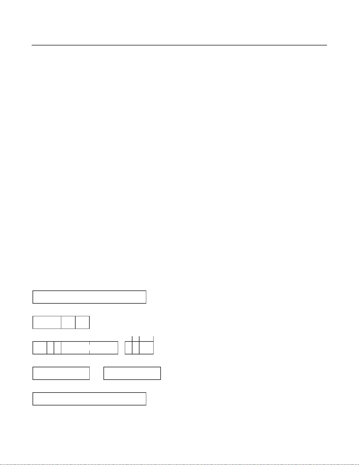
What Are the DECB Fields?
The following figure shows the DECB application area and the fields inside the DECB.
DECB Name (IDECNAM)
CBRW (IDECCRW)
Core Block Type Len
FARW (IDECFRW)
R
C
RID File Address
C
FAXW (IDECFX0) (IDECUSR)
Ext. File Address
Reserved
IDECSUD
Reserved
S
U
D
User Data
IDECDET
12
Page 13

The DECB fields are used as follows:
IDECNAM Contains the name of the DECB.
IDECCRW Corresponds to an ECB core block level.
IDECDAD (Core block)
Contains the address of a core block.
IDECCT0 (Type)
Contains the core block type indicator or X’0001' to indicate there is no core block attached.
IDECDLH (Len)
Contains the data length.
IDECFRW Corresponds to an ECB FARW.
IDECRID (RID)
Contains the record ID for a FIND/FILE request.
IDECRCC (RCC)
Contains the record code check (RCC) value for a FIND/FILE request.
IDECFA (File Address)
Contains the file address for a FIND/FILE request.
Fourth Quarter 2000
IDECSUD When the FIND/FILE request is completed, this field will be set to the SUD error value, or zero if
there is no error.
IDECDET Contains the number of core blocks currently detached from this DECB.
IDECFX0 Contains the FAXW information.
IDECUSR Contains the user data.
What Is 4x4 Format?
The IDECFA field, which contains the file address, is 8 bytes in the DECB. This allows 8-byte file addressing in 4x4
format, which provides for standard 4-byte file addresses (FARF3, FARF4, and FARF5) to be stored in an 8-byte
field. This is done by having the file address reside in the low-order 4 bytes of the field. The high-order 4 bytes of the
field contain an indicator (a fullword of zeros) that classifies it as a valid 4x4 format address. When there is file
activity, the FARW will be used for the record identification (2 bytes), record code check (1 byte), and the symbolic
file address (8 bytes); 1 byte is unused. The following example shows the layout of a 4x4 format file address:
E5 C3 00 00 07 D0 88 4000 00 00 00
IDECFA: 8-byte symbolic file address
not used: 1-byte
IDECRCC: 1-byte record code check, an unsigned character
IDECRID: 2-byte file record identification, an unsigned short integer
How Do I Create and Release DECBs?
TPF programs can dynamically create and release DECBs by using the tpf_decb_create and tpf_decb_release
C++ functions or the DECBC assembler macro. The storage, which will hold the DECB comes from the 1-MB ECB
private area (EPA). Therefore, the number of DECBs that the ECB is restricted to is limited only by the amount of
13
Page 14
TPF Systems Technical Newsletter http://www.s390.ibm.com/products/tpf/tpfhp.html
storage in the private area that is dedicated to DECBs.
When the first DECB creation request is received by the TPF system, a 4-K frame is obtained from the EPA. This
frame, which will act as a DECB frame, is attached to page 2 of the ECB at field CE2DECBPT. The DECB frame
itself contains a header section to help manage the DECBs. The remainder of the frame is then carved into the
individual DECBs themselves; therefore, a single DECB frame contains several individual DECBs (currently a single
frame can hold 31 DECBs). If more DECB creation requests are received than can fit in a single DECB frame,
another 4-K frame is obtained and forward chained to the previous DECB frame.
Individual DECBs are dispensed sequentially using a first-in-first-out (FIFO) approach. The address of the next
DECB to be dispensed is maintained in the header of the DECB frame. When dispensing the DECB, the contents
are first cleared and the DECB is marked as not holding a core block. The DECB is then marked as in-use (that is,
allocated) and the name of the DECB, if one was supplied at creation time, is assigned. Finally, the DECB frame
header is updated to indicate the address of the next DECB that will be dispensed.
When a DECB is released by the application, the DECB is simply marked as not in use. The DECB is not cleared
until it is later redistributed, nor is the DECB frame header updated to indicate the address of the next DECB to be
dispensed. Once released, this DECB will not be redistributed until all other DECBs in this frame have been dispensed
at least one time (FIFO approach). No DECB frames will be detached from the ECB until ECB exit time, even if all
DECBs are currently marked as not in use. This is done to speed processing if another DECB creation request is
received by the TPF system.
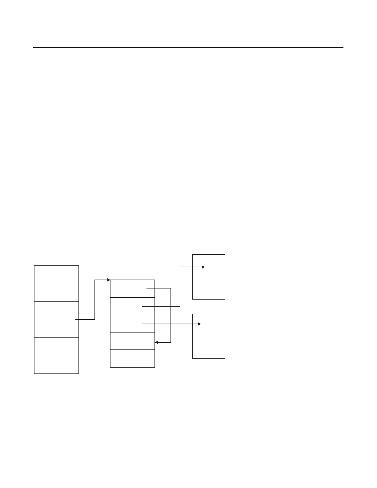
The following figure shows the relationship between DECBs and the ECB.
ECB
Core
Block
Core
Block
CE2DECBPT
DECB Frame
Available
CBRW
CBRW
How Do I Access File Records with a DECB?
All types of applications can use DECBs. Application programming interfaces (APIs) have been added or updated to
allow TPF programs to access file records with a DECB instead of an ECB data level. However , only a subset of the
existing macros and C functions that currently reference ECB data levels accept a DECB in place of an ECB data
level. Macros and C functions that use a file address will first verify that it is a valid address in 4x4 format. If the
address is not valid, a system error will occur.
14
Page 15

Fourth Quarter 2000
How Does a DECB Handle Errors?
With TPF DECB support, each DECB has a detailed error indicator byte (IDECSUD). The existing CE1SUG byte will
include any errors that occur on a DECB-related I/O operation. In addition, the IN1DUD bit in the CE1IN1 byte of the
ECB will be set to indicate that an error occurred on a DECB.
What Other Areas of TPF Will Be Affected by the Introduction of DECBs?
The following areas in the TPF system have been changed to best make use of TPF DECB support:
• The ZFECB functional message has been modified to display DECBs attached to a given ECB.
• The real-time trace (RTT) utility has been modified to save and display information about DECBs for specific
types of macros that are called by a particular ECB.
• ECB macro trace has been modified to handle DECBs as macro parameters instead of ECB data levels as well
as to correctly handle 8-byte file addresses.
• Because of the increased size of each macro trace entry, the number of macro trace entries for each ECB has
been reduced from 66 to 55 when tracing without registers, and from 25 to 23 when tracing with registers.
• System error processing has been updated to gather information about DECBs attached to an ECB when an
error occurs. Additionally, system error processing now searches for any core blocks attached to or detached
from DECBs; this will also be reported in a system dump.
• The interface to the Dump Data user exit (segment CPSU) has been updated to pass along information about
DECBs to the user if an error occurs.
• ECB exit processing has been modified to release any memory resources associated with the DECB before
stopping an ECB.
Why Must I Use the C++ Compiler Instead of the C Compiler When Using
DECBs?
When creating the new C language functions that would support DECBs and, in some cases, 8-byte file addresses
without DECBs, several different approaches were examined. The primary goal was to create functions that could
be quickly learned by experienced TPF programmers. In other words, if a new C function was going to be created to
release a core block on a DECB, it should look very similar to the existing function to release a core block on an ECB
data level (relcc).
Note: In the remainder of this article, relcc is used as an example of the functions updated for TPF DECB support.
The first approach would have been to change the existing function to accept a pointer to a DECB (TPF_DECB *) in
addition to an ECB data level (enum t_lvl). However, this would have forced all existing applications to be recoded
and recompiled to account for the additional parameter that was added. This is obviously an unacceptable solution.
A second approach would have been to create completely new functions with new names and new parameters to
handle similar functions with DECBs instead of ECB data levels. This approach becomes cumbersome to a TPF
application programmer who would have to recognize that when using ECB data levels, the correct function to call
would be relcc; however, when using DECBs, the correct function to call would be something like tpf_relcc_decb
(to follow TPF naming conventions).
The final approach, and the one that has been implemented for TPF DECB support, is to create functions with the
same name (relcc), but have the function take a pointer to a DECB instead of an ECB data level as a parameter.
15
Page 16

TPF Systems Technical Newsletter http://www.s390.ibm.com/products/tpf/tpfhp.html
The benefits of this approach include the following:
• Eliminating the need to recompile any existing applications that call the function
• Using familiar TPF function names so application programmers do not have to remember additional functions.
To enable existing TPF C functions to use DECBs instead of ECB data levels, the functions have been doubly
defined by using the C++ function overload feature. For example, in addition to the existing relcc function prototype:
#ifdef __cplusplus
extern "C"
#endif
void relcc (enum t_lvl level);
an overloaded relcc function that takes a DECB pointer as a parameter has been created:
#ifdef __cplusplus
} /* end extern "C" */
void relcc (TPF_DECB *decb);
#endif
The overloaded function uses C++ function linkage, so programs that use overloaded functions must be compiled
with the C++ compiler.
In TPF, the relcc function (which uses ECB data levels) is actually an assembler program (crelcc.asm) that resides
in the CTAL (TPF Application Library) ISO-C library. This did not change with the introduction of the overloaded
relcc function (which uses DECBs). Any calls made to relcc using ECB data levels will still go to the CT AL library;
it does not matter if the call is made from a C or C++ program.
The definition of the relcc function, which uses DECBs, is part of a C++ segment that contains what can be thought
of as bridge functions (segment ctadov.cpp). This segment has been included as part of the new CTAD (TPF
Application DLL) DLL. The underlying service routine (or stub, as it is sometimes called) is an assembler language
program. However, C++ and assembler programs cannot communicate between each other directly , but C++ programs
can communicate with C programs and C programs can communicate with assembler language programs. Therefore,
the new bridge functions have been created to span the gap between C++ and assembler programs. The following
shows an example from segment ctadov.cpp:
#pragma export(relcc(TPF_DECB *decb)) <--- This makes relcc callable by other
. DLMs and DLLs
.
.
#pragma map(tpf_relcc_decb, "@@RELCCD")
extern "C" tpf_relcc_decb (TPF_DECB *decb); <--- This is internal to this DLL
. and generates C-type linkage
.
.
void relcc (TPF_DECB *decb)
{
tpf_relcc_decb (decb); <--- Call internal C function to process relcc
request
}
The functions shown in the previous example interact in the following way: a pseudo C function called
tpf_relcc_decb has been created. The underlying service routine for this C function can then be written in
16
Page 17
Fourth Quarter 2000
assembler language, much like the service routine for relcc (enum t_lvl level) is in the CTAL library. T o avoid
recompiling or reassembling, a separate segment was added to process the DECB parameter. The segment that
processes tpf_relcc_decb is in an assembler segment (crelcd.asm), which is also a member of the CTAD DLL.
The first few instructions in segment crelcd.asm would look as follows to be correctly resolved at when the DLL is
linked:
BEGIN NAME=CRELCD,IBM=YES,VERSION=40,TPFISOC=YES
...
@@RELCCD TMSPC FRAMESIZE=NO,LWS=R6,PPANAME=tpf_relcc_decb
L R2,0(R1) GET DECB FOR RELEASE
...
...
When a TPF application wants to call the relcc function using DECBs, the TPF application must first be compiled
with the C++ compiler . This does not mean that the application has to be written as an object-oriented C++ application;
it only means that the __cplusplus declaration must be defined (which happens automatically when the segment
is a .cpp file). The second step is to ensure that the definition side-deck for the CT AD DLL is imported correctly when
linking the dynamic load module (DLM) containing the application calling the overloaded function. This enables the
correct function linkage to be generated to the relcc service routine in the CTAD DLL at run time.
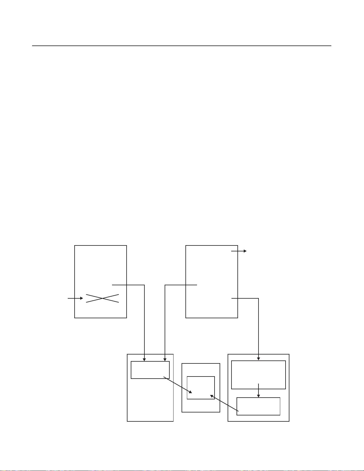
The following shows an example of how all this links together for both C and C++ programs. Notice that both
functions, in the end, call the same SVC service routine in the CCNUCL CSECT of the control program (CP):
Cannot call DECB
from C program
qzz1.c qzz2.cpp
#include <tpfapi.h>
void QZZ1
{
…
relcc (D1);
…
relcc (decb_1);
…
}
CTALLibrary CTAD DLL
crelcc.asm
#include <tpfapi.h>
void QZZ2
{
…
relcc (D2);
…
relcc (decb_2);
…
}
CCNUCL
cicr40.cpy
Includes c$decb.h
ctadov.cpp
void relcc (TPF_DECB *decb)
{
tpf_relcc_decb (decb);
}
crelcd.asm
17
Page 18

TPF Systems Technical Newsletter http://www.s390.ibm.com/products/tpf/tpfhp.html
Where Can I Find More Information about TPF DECB Support?
For more information, see the following books:
• TPF Application Programming
• TPF C/C++ Language Support User’s Guide
• TPF Concepts and Structures
• TPF Database Reference
• TPF General Macros
• TPF Library Guide
• TPF Messages
• TPF Migration Guide
• TPF Operations
• TPF Program Development Support Reference
• TPF System Generation
• TPF System Installation Support Reference
• TPF System Macros
TPFCS Recoup Changes, but Stays the Same
Daniel Jacobs, IBM TPF Development
Y ou have probably been hearing a lot about the improved online recoup deliverable on PUT 13. There were definitely
many changes made to the TPF online recoup package, but there were also some changes made to TPF collection
support (TPFCS) recoup. What are these changes? Do they affect you? How the heck do you even use TPFCS
recoup? What year was the chocolate chip cookie invented? If you’re curious about the answers to any of these
questions, read on!
TPFCS Recoup Overview
For starters, I will describe how TPFCS recoup works on your pre-PUT 13 system. Assuming that the TPFCS
database is initialized in the system, records used by TPFCS are recouped as part of TPF recoup phase 1 before the
traditional TPF recoup chain chase. Because TPFCS has no knowledge of the contents of the data stored in a
collection, the data layout must be provided to TPFCS through another means so that collections that contain
references to standard TPF files or to other collections can be recouped correctly.
So what happens during TPFCS recoup processing? Well, it is a very complicated algorithm, but I will try to explain
it as best as I can. First, TPFCS makes a list of all data stores that reside on the subsystem that recoup is running
on. Second, for each data store, recoup processes each of the TPFCS internal system collections. Third, if any of
those collections contain any embedded references (as described by a recoup index associated with those collections),
those collections are then recursively processed as well. Fourth ... wait, there is no fourth ... that’s it! OK, maybe it
wasn’t so complicated after all (it seemed a lot worse writing the code).
At this point, you might be asking yourself, “What about my user collections? How are they recouped?” Good
questions! You may have cleverly realized that any collections created by user applications will not be recouped
unless they are explicitly made known to TPFCS by establishing one or more recoup indexes. A recoup index
describes the location of PIDs and file addresses embedded within all collections associated with that recoup index.
An anchor collection, usually the data store application dictionary (named DS_USER_DICT) of the data store, refers
to user-created collections, which refer to other collections, and so on. So, in step 3 of the previously described
algorithm, when DS_USER_DICT (an internal system collection) is recouped, embedded references to user collections
will also be processed .
18
Page 19

Fourth Quarter 2000
T o summarize the important points here, (1) every user-created collection must be referred to by an anchor collection
or it will not be recouped, and (2) a recoup index must be created and associated with the anchor collection and any
other collections that contain embedded references.
Recoup Indexes
How do you manage recoup indexes? TPFCS provides APIs that allow you to write applications to create, update, or
delete recoup indexes; or if you have APAR PJ26887 from PUT 12 installed, you can use the ZBROW RECOUP
functional message to do the same thing.
A separate index should be created for each of the different collection formats in a TPFCS data store. After a recoup
index is created, you must add one or more entries to it. Recoup index entries identify the location of file addresses
or PIDs in the collection data. Note that TPFCS recoup supports only traditional TPF chained records. TPFDF
records are not supported.
There are two basic types of recoup indexes. The first type, known as a homogeneous index, is used when each of
the elements in the collections associated with this index has the same format and can be recouped the same way .
The second type, known as a heterogeneous index, is used when the elements in the collections associated with
this index cannot be recouped the same way because they have different formats. When adding entries to a
heterogeneous index, you must specify which elements have embedded file address or PID information (as well as
the displacements in those elements where the embedded references are stored). Any collection type can be
associated with either recoup index type with the exception of binary large objects (BLOBs). Because BLOBs have
a single element, special processing is required and the recoup index type indicator is ignored.
After the recoup index has been created, it can be associated with one or more collections as long as they have the
same format for embedded references. However, a single collection can only be associated with one recoup index
at a time.
TPF Database Reference gives more information about using TPFCS recoup indexes, including:
• A comparison of the APIs to the ZBROW RECOUP functional message parameters
• Details about the format of embedded references
• A sample application that sets up recoup indexes.
PUT 13 TPFCS Recoup Changes
Now that I have explained how TPFCS used to work, let me tell you what has changed with the PUT 13 recoup
enhancements (AP AR PJ27469). Most of the changes made to the TPFCS recoup code were internal and would not
normally be seen by the user. However, there were a few external changes as well.
One big change is that TPF recoup now requires TPFCS to be initialized in your TPF system (this is a one-time only
procedure). With many other TPF functions using TPFCS, such as the POSIX file system, MQSeries, and MATIP,
you probably already have TPFCS initialized. If not, you may want to read about the ZOODB INIT functional message
in TPF Operations.
Another big change was the creation of two structures that could be used by both TPF recoup as well as TPFCS
recoup. The first structure is the IBM Recoup Scheduling Control Table (IRSCT). This table is used to determine the
order that TPF groups and TPFCS data stores are processed. What this means is that TPFCS data stores are no
longer automatically processed first. Data stores are now handled like TPF record IDs, so depending on how your
GROUP macros are defined, TPFCS data stores can be processed before, after, or even while TPF groups are
processed.
19
Page 20

TPF Systems Technical Newsletter http://www.s390.ibm.com/products/tpf/tpfhp.html
The second structure is the IBM Recoup Active Root Table (IRART), which effectively replaces the TPFCS recoup
heap. There is one IRART for each processor defined in your TPF system. The IRART contains information about
each of the root units of work in progress, whether it is a TPF ordinal or a TPFCS persistent identifier (PID). This table
is used to determine timeout conditions and is also used during restart processing.
These structures are represented by TPFCS BLOBs. To initialize these structures, you are now required to enter the
ZRECP SETUP functional message once at CRAS state or above for each subsystem in your TPF system. Once
this is done, recoup can run in any state. However, if the IRSCT needs to expand because you are adding more
items to it, you will need to cycle to CRAS state or above. The ZRECP SETUP functional message also resets all
ZRECP PROFILE options to their default values.
As a result of these changes, many aspects of TPFCS recoup are now obsolete. With TPFCS recoup now using the
IRSCT and IRART, the old TPFCS recoup BLOB (also known as the TPFCS recoup heap) is no longer needed and
has been obsoleted. In fact, it will be automatically removed from your system when you enter the ZRECP SETUP
functional message.
The ZRECP TO2 functional message has also been obsoleted, although the functionality of many of its parameters
are still available:
• The ZRECP SETUP functional message replaces the SETUP parameter.
• The CSERRMAX and CSTIMEOUT parameters on the ZRECP PROFILE functional message replace the MAXERR
and TIMEOUT parameters.
• The ZRECP LEVEL functional message replaces the functionality of the MAXECB parameter.
Furthermore, pre-PUT 13 recoup allowed you to selectively recoup individual collections in test mode or production
mode. The improved online recoup package still allows you to selectively recoup individual collections in production
mode with the PID parameter on the ZRECP SEL functional message. However, the selective processing in test
mode has been changed to now allow you to recoup an individual data store instead of an individual collection by
using the SEL and DS parameters with the ZRECP RECALL functional message. This logically corresponds to being
able to selectively recoup an individual record ID and not a file address in test mode.
Other than what has already been described, very little else has changed! The segments are different and the online
message numbers have changed, but the fundamental TPFCS recoup processing remains the same. (Remember
our three-item algorithm?) Most importantly , TPFCS recoup indexes are still used the same way and existing TPFCS
recoup indexes are still valid and don’t have to be modified at all.
Odds and Ends
If you don’t have any user TPFCS data stores defined, there is very little that you need to do for recoup to protect all
file addresses in your existing TPFCS data stores. There are a few notes worth mentioning though:
• File system users should make sure they have the BKD7 descriptor loaded to their system. Without this descriptor ,
the x'FC2A' fixed file records will not be recouped and your file system will potentially become corrupted if the
recoup results are rolled in.
• MQSeries and file system users should apply A PAR PJ27409 to correct a problem where pool addresses belonging
to deleted collections were being lost.
20
Page 21

Fourth Quarter 2000
• MQSeries users should apply APAR PJ27274 to avoid some online errors while the MQSC data store is being
recouped.
• MATIP users should apply APAR PJ27688 to avoid the potential corruption of their connection definitions.
Finally , the chocolate chip cookie was invented in 1933 by Ruth W akefield. Why was this mentioned here? Because
I got very hungry while writing this article and I was thinking about chocolate chip cookies.
Another Monumental Home Run for Sammy OSA
Mark Gambino, IBM TPF Development
The history of networking technology is similar to the evolution of flight. Networks, like airplanes, keep getting faster
and faster. In the early days there were crop dusters and “puddle jumpers” with a top speed of 100 miles per hour
(provided, of course, there was a strong tailwind), and network line speeds were measured in bytes per second.
Jumping ahead to the end of the 20th century , there are supersonic aircraft capable or traveling at several times the
speed of sound, and network connections are now measured in megabytes (MB) per second. New challenges had
to be overcome as speeds increased, such as creating aircraft out of space-age composite materials that can
withstand the stresses of near warp (or is it warped) speed, and designing scalable TCP/IP stacks that can handle
the ever-increasing volume of traffic (and do so efficiently). In 1999, IBM technicians working in their secret “Area
61” facility (Poughkeepsie, New York) declassified (announced and shipped) two state-of-the-art projects:
• TCP/IP native stack support, enabling the TPF 4.1 operating system to connect to high-volume TCP/IP networks
through channel-attached routers, and doing so with exceptional performance
• OSA-Express support, enabling the S/390 host (running on IBM G5 servers or later models) to directly connect to
the latest generation and preferred high-speed IP backbone network, Gigabit Ethernet (GbE).
“Area 61” is now proud to announce that these technologies have been integrated to produce the first hypersonic
aircraft on the network: OSA-Express support for the TPF system. This support is provided by TPF APAR PJ27333
on PUT 13. You will also need OSA-Express cards at microcode level 4.08 or higher.
Who Is Sammy OSA and What Records Did He Break?
Open Systems Adapter (OSA), not to be confused with origin subarea (OSA), is integrated hardware (a card)
residing in the IBM mainframe that combines the functions of an I/O channel with a network port to provide direct
connectivity between S/390 applications and TCP/IP networks. OSA-Express is the third generation of OSA and
provides the following significant enhancements:
• OSA-Express connects to current high-bandwidth network technology , specifically GbE. Previous generations of
OSA were limited to Fast Ethernet connection speed.
• OSA-Express uses a new link layer, queued direct I/O (QDIO), to exchange information between the host and
OSA-Express card. QDIO uses a shared memory model, eliminating the need for real I/O operations (channel
programs) to transfer data between the host and the card. Previous generations of OSA used channel program
interfaces to exchange data between the host and the card. QDIO reduces the load on your I/O processor (IOP)
and improves the performance of the host.
• OSA-Express can be dynamically configured using TPF functional messages. Previous generations of OSA
required a separate feature, OSA/SF, to configure the OSA card.
These features made OSA-Express a logical choice to couple with TPF TCP/IP native stack support. Data presented
at the October 1999 TPF Users Group (TPFUG) meeting compared high-end native stack support (using IBM 3746
21
Page 22

TPF Systems Technical Newsletter http://www.s390.ibm.com/products/tpf/tpfhp.html
IP routers) to high-end offload support (using Cisco 7500 offload boxes). The results showed that we were comparing
a jet fighter to a propeller-driven plane because TPF was able to send 2.3 to 16 times more data using native stack
and do so much more efficiently using 9.5 to 17.2 times fewer CPU cycles. Each channel-attached router using
native stack support could pump up to about 1500 packets per second and a maximum of about 2.5 MB per second
into a TPF system, depending on message size. To achieve more volume, just add more routers (or channel
connections). Recent testing in lab 416 of “Area 61” compared TPF native stack support using channel-attached
routers to TPF native stack support using OSA-Express. Again, the results showed another giant leap in technology ,
from jet fighter to next-generation hypersonic propulsion aircraft. A TPF system with only one OSA-Express connection
generated over 33 000 packets per second using a mixture of 500- and 1400-byte packets, and 44 MB per second
using large (3500-byte) packets. In other words, a single OSA-Express card can handle the load of a dozen or more
channel-attached connections. This enables you to greatly reduce the cost, size, and complexity of your network at
strategic air command headquarters (where your TPF system is located).
What Do I Do If Sammy OSA Goes on the Disabled List?
A single OSA-Express card can probably handle all the TCP/IP traffic in and out of a TPF processor in your complex
today , but that does not mean you need only one card (per processor). Networks and airplanes have another thing
in common here: single points of failure can be fatal! To avoid single points of failure in the network, OSA-Express
support for TPF (AP AR PJ27333) includes virtual IP address (VIP A) support. An OSA-Express card has one network
port that connects to one GbE network through a GbE switch. TCP/IP is a connectionless architecture, meaning the
failure of any one component in the network should not cause user connections (sockets) to fail provided that
alternate paths exist. Applying this concept to TPF sockets across OSA-Express, you do not want the sockets to fail
if the card, GbE switch, or Ethernet fails. Figure 1 shows the recommended configuration for a processor in a
production TPF system.
VIPA1
TPF
VIPA2
VIPA3
OSA1PRIM OSA1BACK
OSA-Express OSA-Express
GbE Switch GbE Switch
IP Router IPRouter IP Router
Network
Figure 1. Recommended OSA-Express Configuration for TPF
In the figure, TPF is connected to two OSA-Express cards, each of which is connected to a different GbE network
through a different GbE switch. Both GbE switches are connected to a series of IP routers that connect to the
remainder of the network. One or more VIP As in TPF are mapped across one of the OSA-Express cards. TPF uses
Routing Information Protocol (RIP) to broadcast information to all the IP routers. This information, which indicates
the current path to use to reach the VIP As in TPF, is saved in the routing tables of the IP routers. In this example, the
VIP As are mapped across the OSA1PRIM connection. When a packet arrives from the network at an IP router and
22
Page 23

Fourth Quarter 2000
the final destination of the packet is one of the VIPAs in TPF, the IP router will look in its routing table to determine
the GbE switch through which to route the packet to reach the appropriate OSA-Express card, which in turn passes
the packet to TPF.
Figure 2 shows what happens if the OSA1PRIM connection fails for any reason (card, switch, or Ethernet failure).
TPF will automatically swing the VIP As to the alternate connection, which in this example is OSA1BACK. New RIP
messages are broadcast to the IP routers indicating to use a different path (through OSA1BACK) to now reach the
VIPAs. This causes the IP routers to update their routing tables with the new path information and subsequent
packets destined for VIP As in TPF will be routed using the new path. The VIPA swing operation is automatic in this
case and transparent to the end user, meaning that the sockets using the VIP As will remain active despite the failure
of a network component. To use VIPA support on TPF, your IP routers must support and have RIP version 2 enabled
on the interfaces that are used to connect to TPF (meaning the interface on the IP router that connects to the GbE
switch that, in turn, connects to the OSA-Express card).
TPF
OSA1PRIM OSA1BACK
OSA-Express OSA-Express
GbE Switch
IP Router IP Router IP Router
Network
VIPA1
VIPA2
VIPA3
GbE Switch
Figure 2. Network Failure Causes VIPAs to Swing to Alternate Commection
How Do I Use Sammy OSA in Spring Training?
An OSA-Express card can be shared by any combination of logical partitions (LPARs) in the processor (CEC). In
addition, multiple TPF test systems running under VM can each have connections to the same OSA-Express card.
While OSA-Express does not use channel programs for data transfer, it does use channel programs for connection
activation and some error reporting. Each connection between TPF and an OSA-Express card uses three symbolic
device addresses (SDAs). In the test system environment, you need to assign each TPF test ID three SDAs and a
unique set of IP addresses (including VIPAs). For planning purposes, it is important to know how much payload an
aircraft can carry and how many host connections an OSA-Express card can have. The answer of course is, “it
depends.” The formula for the maximum number of host connections to an OSA-Express card is 80 divided by the
number of LPARs that are sharing the OSA-Express card.
For example, if two LPARs are sharing the card, each LPAR can have 40 host connections. If your shop has 150
TPF developers and testers, two OSA-Express cards dedicated to the test system would give TCP/IP connectivity
to every developer and tester. The final important point to mention about test systems is that you need VM/ESA 2.4
or higher to use OSA-Express support on a TPF system that is running under VM.
23
Page 24

TPF Systems Technical Newsletter http://www.s390.ibm.com/products/tpf/tpfhp.html
I Traded to Get Sammy OSA on My Team. Now What?
Once you have decided that you want to use OSA-Express for your TPF system, there are planning steps that you
need to think about well in advance:
• Hardware:
- IBM G5 servers or later models are required
- Determine how many cards are needed and then order OSA-Express cards with GbE adapters at microcode
level 4.08 or higher
- GbE switches to connect to the OSA-Express cards
- IP routers on the other side of the GbE switches to connect to the reaminder of the network. These IP routers
must support RIP version 2 to use VIPA support on TPF.
• Software:
- TPF 4.1 with PUT 13 APAR PJ27333 applied
- VM/ESA 2.4 or later version to use OSA-Express support for TPF test systems running under VM.
• Network Administration:
- Assign IP addresses to the TPF systems, including VIPAs
- Assign IP addresses to the IP routers.
After you have completed the necessary hardware and software upgrades, and the cabling of network devices is
completed, you are ready to install and use OSA-Express support. The procedure is as follows:
1. Define the OSA-Express cards to the processor in the I/O configuration program (IOCP). Each definition includes
which LP ARs will be using (sharing) the card and the range of SDAs that can be used for connections to the card.
2. Update parameter MAXOSA in keypoint 2 (CTK2) with the maximum number of OSA-Express connections for
your TPF system. Load the updated CTK2 to TPF.
3. IPL and cycle your TPF system to NORM state.
4. Define the OSA-Express connections to TPF using the ZOSAE DEFINE and ZOSAE MODIFY functional messages.
5. Define the VIPAs to TPF using the ZOSAE ADD functional message.
6. Activate the OSA-Express connections using the ZTTCP ACT functional message.
Why Sammy OSA Will End Up in the Hall of Fame
GbE is the preferred backbone network for industrial strength (and speed) TCP/IP traf fic. Before OSA-Express, the
processor used channel-attached connections to front-end routers to connect to the backbone network. The host
communicated through the IOP, to the channel, to the router, to the GbE. Multiple channel-attached connections
were required to achieve the necessary bandwidth to feed a GbE. OSA-Express now enables the host to directly
connect to the GbE. There is an opportunity here for you to reduce the cost and complexity of the host connectivity
portion of your TCP/IP network by consolidating several channel connections into two OSA-Express connections.
While one OSA-Express connection is enough to handle the traffic by itself, you really want to have two OSAExpress connections so that there is not a single point of failure. Migrating to OSA-Express also has performance
benefits. The QDIO link layer allows the host and OSA-Express card to exchange data more efficiently by sharing
memory . The IOP is no longer used for TCP/IP data transfer , which reduces the load on your IOP and allows the IOP
to focus on other work (like tape and DASD I/O). Couple OSA-Express with TPF native stack support and you now
have unparalleled performance and scalability for TCP/IP connectivity in your TPF system. Please stow your carryon luggage and prepare for the flight of your life!
24
Page 25

TPF Systems Technical Newsletter http://www.s390.ibm.com/products/tpf/tpfhp.html
The TPFDF Product Gets SET
Tom Brocker, IBM TPF ID Core Team, and Mike DeCarlo, IBM TPFDF Development
APAR PJ27328 simplifies the method of installing the TPFDF product on your TPF 4.1 system with the system
initialization program (SIP) enhancement for TPFDF (called SET).
AP AR PJ27328 includes the TPFDF product in the TPF 4.1 SIP process by creating all the JCL required to build the
TPFDF product during the TPF 4.1 SIP process.
Without the benefit of SET, the required segments to install the TPFDF product are assembled, compiled, and linkedited after the TPF 4.1 SIP process. This two-step process is susceptible to errors that result from omitting segments,
and is time consuming and difficult to correct.
SET simplifies the installation of the TPFDF product because the required segments are assembled, compiled, and
link-edited as part of the TPF 4.1 SIP process.
Y ou should apply AP AR PJ27328 to stay current with maintenance even if you do not use SIP or the TPFDF product.
(If you do not use the TPFDF product, you will not see any changes in the SIP stage 2 output.)
To include the TPFDF product on an existing TPF 4.1 system, do the following:
1. Update the SIP stage I Deck:
a. To enable the TPF 4.1 system for the TPFDF product, set TPFDF=YES in the CONFIG macro.
b. Specify the EXPRS parameter of the GENSIP macro with the job names in the following list:
Job T ask
F2 Updates macro and SIP support libraries.
G5 Assembles RIAT.
G6 Updates data reduction.
H Assembles and link-edits the JCL for the TPFDF product.
I1 Assembles control program CSECTs.
I2 Link-edits the control program load module (CPS0).
I3 Assembles and link-edits control programs.
JA Compiles C functions for the C load module.
JB Assembles C functions and C++ load modules.
JC Assembles C++ load modules.
JD Compiles C functions for the C load module for the TPFDF product.
JE Assembles C functions for the C load module for the TPFDF product.
JF Compiles C++ functions for the C load module for the TPFDF product.
J1A Assembles GTSZ.
J3A Generates CTKX.
J4 Assembles real-time programs.
26
Page 26

J5 Assembles WTC offline components.
J6 Link-edits WTC offline components.
J7 Assembles user real-time programs.
J8 Compiles C real-time programs.
J9 Compiles user C real-time programs.
J10 Assembles real-time programs for the TPFDF product.
L2 Updates and assembles release PARS lists for the TPFDF product and TPF 4.1 system.
L5 Link-edits C load modules.
L6 Link-edits C load modules for the TPFDF product.
S Runs system allocator (SALO) and creates IPAT.
2. Run the FACE table generator (FCTBG).
a. See TPFDF Installation and Customization for RAMFIL statement updates.
b. See TPF System Generation for more information about running the FCTBG.
Fourth Quarter 2000
3. Assemble SIP Stage I to create the SIP Stage II deck.
4. Run the SIP Stage 2 deck to compile and assemble the elements of the TPFDF product.
5. Load the PARS list, PARS13, to the TPF 4.1 system.
6. IPL the TPF 4.1 system and load the pilot and macro label set (MLS) tapes.
You have completed the installation of the TPFDF product using the TPF 4.1 SIP process!
For more information about APAR PJ27328, see the following books:
• TPFDF Installation and Customization
• TPF System Generation.
BookManager Hints and Tips: Searching
Fay Casatuta, IBM TPF ID Core Team
Over the last few months we have received several inquires from you about how to use the BookManager search
facilities effectively so that you can find the information you want, when you want it, in our softcopy books. This
article introduces you to searching for information in softcopy books using BookManager READ for Windows.
For the most part, many of us are very comfortable flipping (searching) through a traditional book to perform our day-
to-day activities on the job when using the TPF family of products. It is when we venture into the world of softcopy
books that our steady footing begins to slip. To help you bridge the gap between a traditional book and a softcopy
book, let's level-set some basic concepts. BookManager READ for Windows uses the concepts of books and
bookshelves so that those of you who have primarily used traditional books in the past, and may be most comfortable
in that medium, can readily find the information you want in a softcopy book. As you would open a traditional book,
you can open a softcopy book or a bookshelf and you will find yourself in relatively familiar territory.
27
Page 27

TPF Systems Technical Newsletter http://www.s390.ibm.com/products/tpf/tpfhp.html
N
The
LL
CO ECTIO
FAQs about Collections
Daniel Jacobs, IBM TPF Development
Date: Monday, November 6
Attendees: Will Notfly (Database administrator for Wingless Airlines)
C (comment). Ree: It’s great to see all of you again! I’ve heard that there have been a couple of questions about
NN
Hi! This is Ree Porter back on assignment with the TPF collection support (TPFCS)
team. It has been a while since my last article in the second quarter of 1999, but
now I’m back by popular demand! Once again, I recently acted as a liaison at a
meeting between TPF customers and the TPF lab, seeing what kinds of questions
the customers had about TPFCS. Now I’m here to report the answers to all of you.
Note: Just like last time, the names in this article have been changed to protect the
innocent. Any correlation to actual names is strictly coincidental.
Rich Mann (System Administrator at Knight Trader Securities)
Bill Meelater (Application Programmer at Tumuch Credit Corporation)
Albert (TPFCS programmer)
Dan (TPFCS programmer)
John (TPFCS programmer)
Glenn (TPFCS all-knowing individual)
TPFCS recoup, so why don’t we start with that. Who wants to begin?
Q (question). Will: I will. First of all, I recently displayed the contents of file system #INODE record ordinal 0 and
saw a persistent identifier (PID) in there. When I displayed the contents of the file address in the PID,
I noticed that it was a Wingless record ID and not the expected TPFCS record ID of FC16. However ,
recoup did not report an error with this record. This leads me to believe that the address was not
chain chased. Is there something special that I have to do?
A (answer). Dan: That is an excellent observation. In general, unless you have your own user-created data
stores, there isn’t anything special that you need to do for recoup to work with TPFCS and TPF data
stores . . . except for one important thing. You have to make sure that the BKD7 descriptor is loaded
to your system. The BKD7 descriptor tells recoup that within the file system #INODE (x'FC2A')
records there are embedded PIDs to chase. Without this descriptor, the pools used by these embedded
collections will not be protected and could be made available for reuse, which probably explains how
your record ID got corrupted in the first place.
C. Will: That makes sense. I will have to double-check that.
Q. Rich: Does the TPFCS descriptor (BKD7) have to be in a specific ordinal slot on the BKD tape, such as at the
beginning or the end, or can it be anywhere on the BKD tape?
A. Albert: First of all, to clarify some terminology, the BKD7 descriptor is not the TPFCS descriptor. There can be
many TPFCS descriptors in a system. Actually, BKD7 is really a file system descriptor because it describes
the x'FC2A' fixed file records that the file system uses.
36
Page 28

Fourth Quarter 2000
C. Rich: OK, but getting back to the question . . .
A. Albert: Oh, right. To answer your question, no, the BKD7 descriptor does not have to be in any particular ordinal
slot. Basically, prior to PUT 13, TPFCS recoup would run first at the beginning of phase 1. As part of its
processing, it creates a TPFCS heap area that is used for keypointing purposes. This area is still available
after TPFCS recoup is completed, and remains available until the end of phase 1. Therefore, as long as
this area is still available, the BKD7 descriptor can run. This processing changes a bit with the recoup
being shipped on PUT 13, but that’s a whole different topic.
A. John: A personal preference would be to have this descriptor run toward the beginning of TPF recoup, just to
logically group the processing of TPFCS records.
Q. Rich: How does the recoup code know it’s a TPFCS descriptor?
A. Dan: For any traditional TPF file that contains embedded references to TPFCS PIDs, such as with BKD7,
there is a PID=YES parameter on the INDEX macro that indicates this. When TPF recoup encounters
this, it takes the PID and passes it to TPFCS recoup for processing.
A. Albert: If you were to have traditional file addresses embedded within TPFCS collections, a descriptor must be
coded for the record IDs that are embedded. In this case, the GROUP macro contains an IND=C and
USE=TPFCS option that indicates that the descriptor will not be chased by TPF recoup, but instead will
be handled by TPFCS recoup. More information on this is available in the TPFCS chapter in TPF Database
Reference.
Q. Dusty: OK, so if I understand this now, the BKD7 descriptor only chases the fixed file INODE records. Is there
a descriptor that chases the IBMM4 (ordinals 121 & 148) fixed files that we might be missing?
A. John: No. BKD7 is specifically used to chain chase INODEs that are used by the TPF file system, as you
described. Although there are embedded PIDs within the IBMM4 ordinals, these are actually handled
automatically by TPFCS recoup processing at the beginning of phase 1, so nothing additional needs to
be loaded to the system. TPFCS recoup will automatically recoup any collections that it creates. Users
are responsible for creating recoup indexes to describe the location of any collections that they create.
Details on this procedure are also available in the TPFCS chapter of TPF Database Reference.
C. Rich: TPF Database Reference sounds like a very handy document!
Q. Rich: How do I create and maintain these recoup indexes?
A. John: That’s easy! You have two choices. You can either write an application for this purpose using the
TO2_ APIs, such as TO2_createRecoupIndex, TO2_addRecoupIndexEntry, and
TO2_associateRecoupIndexWithPID, or you can use the ZBROW RECOUP functional message that
is provided with PUT 12.
Q. Will: Just to double-check, are there any special TPFCS recoup considerations regarding the Internet daemon
server’s usage of long-term pool?
A. Glenn: No, the Internet daemon uses the file system, which, like we have said, is covered by the BKD7 descriptor .
MQSeries definitions are automatically recouped, and MA TIP definitions are supposed to be recouped,
but you will actually need APAR PJ27688 applied for this to happen.
Q. Rich: Is a TPFCS recoup index only required for collections that have either embedded PIDs or file addresses?
If a collection does not contain embedded PIDs or file addresses, is the collection automatically protected?
A. Dan: Yes, you only need to associate a recoup index with a collection when that collection contains embedded
37
Page 29

TPF Systems Technical Newsletter http://www.s390.ibm.com/products/tpf/tpfhp.html
PIDs or file addresses. Assuming that something is pointing to a collection, the pool files that the collections
consist of will be recouped regardless of whether or not that collection contains embedded references.
The recoup index for a collection is only required if the collection will contain embedded file addresses or
PIDs that have to be recouped. The recoup index tells TPFCS how to find the embedded pointers to
other collections. It is just like the normal TPF recoup descriptors in that you would only create the
indexes if the pointed to collections could only be recouped from this collection. You wouldn’t want the
collections to be recouped multiple times because it would slow down the recoup run, but at the same
time you want to make sure that they are recouped at least once.
A. John: TPF will automatically recoup all system collections that TPFCS creates on its own, such as the application
and system dictionaries, the browser dictionary , an so on. All other collections must be referenced by a
collection that has a recoup index associated with it so that recoup knows how to find the referenced
collections.
Q. Rich: My collections do not have embedded PIDs in them. However, I store the PIDs for my collections in the
data store user dictonary (DS dict). When I delete the collections, I also delete the entry in the DS dict
containing the associated PID. Am I right that these PIDs do not have to have recoup indexes associated
with them?
A. Albert: Yes, but if you are storing PIDs in the DS dict (that is, the DS_USER_DICT collection), you do have to
create and assign a recoup index to the DS dict collection. You can decide if you want the DS dict to be
homogeneous or heterogeneous. The obvious advantage to making it homogeneous (that is, each element
has the same format) is that you can have a single entry in the recoup index associated with the DS dict,
and you don’t have to change the recoup index when you add collections to, or remove collections from,
the DS dict.
Q. Will: If we issue the ZOODB INIT functional message, does this initialize both the file system and TPFCS?
A. Albert: Yes. This functional message must be issued from CRAS state or above on the basic subsystem (BSS),
and it will do several things. First, it will initialize TPFCS by creating the TPFDB data store on the BSS.
It will then initialize the file system on the BSS by creating the IFSXBSS data store. Finally , it will initialize
the file system on any other subsystem that is also in CRAS state or above by creating a distinct IFSX
data store for that subsystem.
A. Dan: Don’t forget that you can later initialize the file system on subsystems that weren’t initialized when
TPFCS was initialized by using the ZFINT ON functional message.
C. Ree: Wow , that is a lot of good information about recoup; and don’t forget that there is a new recoup deliverable
that has shipped on PUT 13 that you can read about elsewhere in the TPF Systems T echnical Newsletter .
C. Dan: Wow, it’s almost as if I willed you to say that. Thanks!
C. Ree: Sure! OK, what is the next topic going to be?
Q. Rich: We have a couple of performance issues. We’ve done a few quick tests to see what the performance of
TPFCS would be like. Our initial results show that TPFCS performance seems to be about 15
worse than the TPF Database Facility (TPFDF). Is this to be expected or can the application be optimized
with some advice?
A. Glenn: There are two major differences in performance between TPFDF and TPFCS. The first is that TPFCS
uses commit scopes to process all database updates. On relatively small-scale systems, this causes
every collection update to be delayed approximately 10 ms. The delay is because the update most likely
does not completely fill a commit buffer, and commit processing waits that amount of time before filing
–20 times
38
Page 30

Fourth Quarter 2000
out the partial buffer and allowing the ECB to continue.
Q. Will: So can anything be done about this?
A. Glenn: The main way around this problem is for the application to open its own outer commit scope around the
updates. This causes all of the TPFCS commit scopes to be handled as nested commit scopes and to be
rolled into the outer commit scope with no time delay . When the application issues it’s commit, all of the
TPFCS updates will be filed out at that time with, at most, a single 10-ms delay. The downside of this is
that you probably don’t have enough VF A resources to hold the complete set of updates. Therefore, you
will have to break up the outer commit scope into smaller scopes. For example, you may have to open
a commit scope, do 100 updates, commit the updates, and then reopen a new commit scope to do the
next 100 updates. By doing this, you can cut out most of the time overhead involved.
Q Will: Hmm, that sounds promising. What is the other major performance difference between TPFDF and
TPFCS?
A. Glenn: There is a path length increase in TPFCS that, depending on the functions, can be from a few percentage
points to an order of magnitude. To cut down on path length overhead, the application should use a
locking cursor when more than one operation is to be performed against a single collection. Because
TPFCS doesn’t know how the application is using a collection, TPFCS will always read the collection into
malloc storage, process the request, and write the collection back to DASD unless the application has a
cursor opened against the collection. If the application uses cursors, TPFCS holds on to the collection
until the cursor is closed. This saves all the reading and writing of the collection’s control structures
between every API call. The downside is that in order to update the collection, a locking cursor is required
and this will cause the collection to be locked for the entire time the cursor is opened.
Q. Bill: Hey, could you guys sketch this out in a sample program format?
A. Albert: Sure. OK, to get the best performance, the application loop might look something like this:
while (more To Process == TRUE)
{
/* start outer commit scope */
tx_begin()
/* tell TPFCS to get a collection and hold on to it */
TO2_createReadWriteCursor()
/* do 100 (could be more or less depending on resources needed)
updates using APIs like TO2_atNewKeyPut */
/* delete the cursor & allow TPFCS to file out any updates
still in memory */
TO2_deleteCursor()
/* now commit all TPFCS updates to disk. */
tx_commit()
}
C. Ree: Great! I’m glad I brought all of these colors!
39
Page 31

TPF Systems Technical Newsletter http://www.s390.ibm.com/products/tpf/tpfhp.html
Q. Rich: We also noticed that there are a significant amount of reads to the DASD surface from various TPFCS
records, such as x'FC10', x'FC1 1', and x'FC16'. Could we set these record IDs as VF A-IMMED in a nonloosely coupled environment so that they are core resident?
A. Albert: Unfortunately, no. You cannot make them VFA candidates without causing database corruption unless
you use VFA sync and make them VFA-SIMMED. The TPFCS record IDs should be set to either VFANO (which is the default setting), or to VFA-IMMED for uniprocessor support, or to VFA-SIMMED for
loosely coupled support. They should never be set to VFA-IMMED or VFA-DLAY on loosely coupled
systems.
Q. Will: I also have some questions concerning locking. I am creating a package that will dynamically create
collections and store the PIDs for these collections in the data store dictionary (DS dict). I need to write
a “nightly maintenance” program that will loop through the entire collection and delete all entries beyond
a certain date. I noticed that there are only a limited number of TPFCS functions for the DS dict. Could
I create a locking cursor for the DS dict and use the cursor functions to search the DS dict? If not, is
there a way to do what I want to do (without of course building my own index file as a collection)?
A. Glenn: The easiest way is to use the locking cursor , as you described. The only problem with the locking cursor
is that the collection will be locked for the duration of the scan. Another way of doing it would be to create
a standard cursor on the collection and use it to locate the keys, and then do a TO2_removeKey on the
key to be deleted. This would cause the collection to be locked only during the remove request itself as
long as your application was not in a commit scope. If you are using your own commits, the collection
would then remain locked from the first remove until your application did the final commit. The problem
with this approach is that because the collection is not locked but is actually being processed using dirty
reads, every remove will cause TO2 to reaccess the collection control information, update it, and then
write it back out again. This could have an adverse af fect on performance if performance is a concern for
this operation.
C. Ree: So, to summarize, the locking cursor and a cursor remove request is the fastest but it has a lock duration
problem, whereas the standard cursor using TO2_removeKey bypasses the lock duration problem but
has a performance concern. It sounds like you will have to make the choice.
Q. Bill: I’m still a little confused about how collection locking works. Let’s say we have a large array , and we start
to update element 1000. If another application at the same time tries to update element 2000, what will
happen?
A. Albert: In this case, the request by the second application will be queued until the first application has released
its lock on the collection. This is done either by completing an atomic collection API, such as T O2_atPut(),
or by deleting a locking cursor. At this point, the second application will lock the entire collection (not just
element 2000) and process the update request.
Q. Will: I had a couple more database design questions. First, I was reading a little bit about temporary collections.
These collections always remain in core, right?
A. Glenn: W ell, actually , these collections will overflow to short-term pool if they become too large to fit in memory.
Q. Will: Secondly, are the elements in a collection all the same size, or can they be variable in length?
A. Dan: Another good question. The answer depends on the collection type. For arrays, logs, keyed logs, and
BLOBs, the collection elements all have the same logical size, which is specified when the collection is
created. In reality, the application can physically create elements that are smaller than this common,
maximum size. For all other collection types, the elements can be different sizes within the same collection,
40
Page 32

Fourth Quarter 2000
and the maximum length of an element within a particular collection is specified when the collection is
created.
C. Bill: Would you all mind if I asked a couple of application questions?
C. Ree: Go right ahead!
Q. Bill: Thanks. If we have a key bag and we do a TO2_locate using a particular key value, will T O2_next return
the next element with the same key value?
A. Dan: No. Key bags and key sets do not have a defined next or previous element, so issuing a TO2_next in
your situation could return any element, including one with a different key value. If you were to use a key
sorted bag or key sorted set, TO2_next would return another element with the same key.
Q. Bill: Is there any sample code that TPFCS can provide?
A. Albert: Why does that question sound familiar? Sure, we have sample code that we provide on request. You
should contact your IBM TPF representative.
Q. Rich: Before we end this, I had a couple of database maintenance questions. Is there a way for me to delete
a data store?
A. Glenn: It’s funny you should ask that. As we sit here during this question and answer session, there is no
supported interface for deleting a data store. There is a way to do it “under the covers”, but you should
contact the TPF Lab for more information. In addition, at this very moment, there is a programmer back
in Poughkeepsie, NY who is looking into this very issue and may be providing an interface before too
long (wink, wink).
Q. Rich: Is it safe to assume all updates to a F ARF record in the TPFCS database will have a hold on the record
before it is filed.
A. John: No, TPFCS does not hold each record when updating. Currently the control record (FC16) whose address
is in the PID is the record held. This hold pattern might change over time to allow concurrent updates.
Q. Rich: I’m getting certain errors out of TPFCS. How would I go about debugging the problem?
A. Dan: As much as we would love to explain everything to you here, there is just too much to understand in one
sitting. There is no fixed set of instructions for debugging a TPFCS problem; it really varies from problem
to problem. For starters though, you may want to consider using the ZBROW DISPLA Y functional message
to collect as much information as you can about particular collections. How about we come back next
time and discuss this in more detail?
C. Rich: That sounds good.
Q. Ree: This has been very helpful. Are any of you planning on giving any TPFCS classes?
A. Dan: Actually, a class is being put together and might even be available by the time these interviews are
published. Contact your IBM service representative for more information.
C. Ree: Well then, this concludes our second investigative report into customer questions about TPFCS. I’m sure
there will be more questions to report on, so keep an eye out for my return before too long!
41
Page 33

Fourth Quarter 2000
Letters, We Get Letters . . . Usually C and C++
Bob Kopac, Sarat Vemuri, and Dave Flaherty, IBM TPF Development
The TPF C/C++ team often receives questions from customers about C and C++ issues. These queries usually do
not result in PMRs or APARs. Instead, an explanation often clears up the customer’s problem. Sometimes we
receive the same question from different customers. Because some of these questions and answers may be of
interest to many customers, we decided to write this newsletter article based on some of these questions and
answers. You might even see one of your questions here!
Q:I need a clarification from the TPF lab regarding C++ support in TPF. Apparently someone heard at the TPF Users
Group (TPFUG) meeting in Las Vegas that the customers need PUT 12 for C++ support. What TPF PUT level
supports C++ applications?
A:TPF provided support for C++ and dynamic link libraries (DLLs) on PUT 7. Customers can write or port C++
programs for this PUT. Later TPF releases contain additional C++ features. The release you need depends on
what C++ features you require. For example, TPF implemented C++ exception handling on PUT 12. The major
releases and corresponding C++ support are as follows:
TPF PUT 7
• APAR PJ25084: support for DLLs and the C++ programming language.
TPF PUT 10
• APARs PJ26187, PJ26337, PJ26375: support for the I/O Stream Class Library. For example, this provides
support for C++ I/O, such as the cin() and cout() functions.
•APAR PJ26173: support for the STLport standard template library . STLport was tested on PUT 10. However ,
TPF does not release STLport on TPF PUTs because TPF does not own the code. Customers can download
STLport as freeware from the Internet. For a link to STLport, go to Standard Template Library on the TPF
System (STLport).
TPF PUT 12
• APAR PJ26967: support for C++ exception handling (try/catch/throw).
Q:That was a long explanation. Will all your answers be so wordy?
A:No.
Q:We have many C segments. To recompile them all is not a small effort. What optimization level do you use in TPF
development?
A:TPF uses different optimization levels during various code development stages:
OPT(0): TPF code development, unit test, and beginning of function test.
OPT(2): Remainder of function test, all of system test, and all of code release.
We discussed our methodology with OS/390 compiler designers and they agree with our approach.
Q:Why do you switch optimization levels in the middle of your development cycle? What are the benefits of optimization
level 2?
A:OPT(0) C or C++ code is easier to debug than OPT(2) code. In addition, you can compile with the TEST option
and generate many C debugger hooks in OPT(0) code. The OPT(0) assembler code closely matches the C or
C++ statements. Simple problems can be found easily during unit test and the first part of function test. However,
43
Page 34

TPF Systems Technical Newsletter http://www.s390.ibm.com/products/tpf/tpfhp.html
OPT(2) code is more efficient than OPT(0) code. The compiler generates fewer instructions and the code paths
are much shorter. For those reasons, TPF ships its objects and load modules compiled as OPT(2). We switch to
compiling with OPT(2) during function test so that we test the code extensively as OPT(2).
Q:Why do I have to test OPT(2) code? Could I just test with OPT(0) and then just recompile and ship as OPT(2)?
A:The code generated by OPT(2) is totally different than OPT(0) code. OPT(2) code might generate assembler
code that exposes a C or C++ coding problem.
Q:How can that happen?
A:Here is an example that we saw in the TPF Development Lab: A TPF program compiled as OPT(0) ran successfully ,
but the program failed when compiled as OPT(2). We discovered that the programmer forgot to initialize a variable
to zero, even though the code relied on that variable being initialized to zero. For OPT(0), the storage for the
variable happened to be in an area that, by coincidence, contained zeros. Thus, the program worked by accident.
For OPT(2), the storage for the variable was an area that had nonzeros. As a result, the program failed. It was not
an optimization problem; it was a programming problem. Compiling the code as OPT(2) happened to expose the
problem. The moral of the story: Test your code after recompiling with OPT(2).
Q:Here is a more specific question. I am writing C++ code to understand the dllqueryfn() function and I am
receiving link errors. Why?
A:For C++, you need to use the external symbol name of the function, not the function name, because the external
symbol name may be mangled. The mangled name is a representation of the function name and the parameter
types. One reason for mangling is that it helps to differentiate overloaded function names.
Overloading means that the same function name may be used by two or more functions with a different number
of parameters. For example, function tryit(arg1) is different from function tryit(arg1,arg2) and is different
from function tryit(arg1,arg2,arg3).
Here is a simple example. The following code is in a DLL:
int overloaded_function(){
int x;
x = 2;
return(x);
}
int overloaded_function(int r){
int x;
x = r;
return(x);
}
int overloaded_function(int p, int q){
int x;
x = p + q;
return(x);
}
Compiling the DLL with the XREF compiler option produces the following values in the external symbol crossreference table:
44
Page 35

Fourth Quarter 2000
E X T E R N A L S Y M B O L C R O S S R E F E R E N C E
ORIGINAL NAME EXTERNAL SYMBOL NAME
overloaded_function() overloaded_function__Fv
overloaded_function(int) overloaded_function__Fi
overloaded_function(int,int) overloaded_function__FiT1
For the corresponding dllqueryfn() functions in the following DLM, the programmer correctly used the external
symbol names instead of the original names in the external symbol cross-reference table.
#include <dll.h>
void main(){
dllhandle * handle;
int (*fptr1)();
int (*fptr2)(int);
int (*fptr3)(int,int);
fptr1 = (int (*)()) dllqueryfn(handle, "overloaded_function__Fv");
fptr2 = (int (*)(int)) dllqueryfn(handle, "overloaded_function__Fi");
fptr3 = (int (*)(int,int)) dllqueryfn(handle, "overloaded_function__FiT1");
return;
}
The following would be incorrect:
...
fptr1 = (int (*)()) dllqueryfn(handle, "overloaded_function()");
fptr2 = (int (*)(int)) dllqueryfn(handle, "overloaded_function(int)");
fptr3 = (int (*)(int,int)) dllqueryfn(handle, "overloaded_function(int,int)");
...
Q: I noticed that there are some compiler options that relate to ANSI standards. What are the benefits of these
options?
A: Although that is a question for the OS/390 C/C++ compiler development area, it is common knowledge that the
compiler is becoming more ANSI-compliant. Some compiler enhancements assume that user code conforms to
ANSI coding practices. The advantage is that the compiler can generate better optimized code. However, if your
code is not ANSI-compliant, you must override the compiler default. OS/390 provides options to override the
assumptions about ANSI-standard code.
Q: Can you give me an example of a compiler option that is based on ANSI-compliant code?
A: The ANSIALIAS/NOANSIALIAS compiler option default is ANSIALIAS. This default assumes that pointers access
objects of the same type; that is, the pointers are ANSI-compliant. Casting a pointer to point to a different object
is a common C practice, but it is not ANSI-compliant. If your code casts a pointer to point to a dif ferent object, you
must then compile your code using the NOANSIALIAS compiler option.
Q: What might happen if I compiled code that contained non-ANSI-compliant pointers, but I used the ANSIALIAS
compiler option?
A: Problems may occur. For example, compiling code that casts away a const qualifier using the ANSIALIAS
option might lead to an error at run time. We recently helped a customer troubleshoot a problem caused by the
misuse of ANSIALIAS. The customer received a CTL-3 dump. The problem was that the customer’s code had
45
Page 36

TPF Systems Technical Newsletter http://www.s390.ibm.com/products/tpf/tpfhp.html
cast a pointer to another object; but the code had been compiled with the default ANSIALIAS compiler option
instead of NOANSIALIAS. This resulted in a CTL-3 dump. The moral of the story: Use NOANSIALIAS if your code
casts a pointer to point to a different object.
Q: Can the compiler help me to know if I am violating the casting rules?
A: The OS/390 C/C++ V2R9 compiler has a new CAST suboption for the CHECKOUT compiler option. CAST is the
default for the CHECKOUT option. This suboption checks for potential violations of ANSI type-based aliasing
rules in explicit pointer type casting. When a potential violation is found, the compiler issues warning message
CBC3374W: Pointer types "&1"' and "'&2" are not compatible.
Note: OS/390 V2R9 compiler APAR PQ42300 will fix the following:
#pragma checkout(suspend) does not suppress message CBC3374W.
A workaround is to compile with CHECKOUT(NOCAST).
Q: Are there any more ANSI-compliant compiler options?
A: The OS/390 C/C++ V2R9 compiler has a new compiler option: AGGRCOPY(NOOVERLAP/OVERLAP). The
default is AGGRCOPY(NOOVERLAP), which assumes the source and destination in a structure assignment do
not overlap; that is, they are ANSI-compliant. Use AGGRCOPY(OVERLAP) when the source and destination in a
structure assignment might overlap.
Note: OS/390 V2R9 compiler APAR PQ42159 will fix the following:
The OS/390 C/C++ V2R9 compiler generates incorrect code for the switch statement when compiled with
optimization level 0 and with TEST(NOPATH).
A workaround is to compile with one of the following options:
• NOTEST
• TEST(PATH)
Note: TPF APAR PJ27522 will fix the following:
Unresolved references for lowercase memmove function occur during prelinking and linking TPF modules
compiled using AGGRCOPY(OVERLAP).
Q: I do not have the OS/390 V2R9 compiler yet. Why should I care about ANSI-compliant issues?
A: Although AGGRCOPY(OVERLAP/NOOVERLAP) is new for the OS/390 V2R9 compiler, the ANSIALIAS/
NOANSIALIAS compiler option has been around for several OS/390 compiler levels. As each new compiler
release generates more sophisticated optimized code than the previous level, these issues become more and
more important. Thus, you should understand the C/C++ compiler options.
Q: Are these all the questions you received from customers?
A: No, there have been many questions. W e have enough material for several newsletter articles. W e hope that this
is a good thing!
46
Page 37

Fourth Quarter 2000
Logical Record Caching
Sue Pavlakis, IBM TPF Development, George Leier, IBM TPF Test Core Team, and Fay Casatuta, IBM TPF ID
Core Team
Overview
Logical record cache support (AP AR PJ27083) allows applications to define and use memory caches, and provides
fast access to frequently used information through logical record caches.
Logical record caching is a set of system functions that allow an application to define and use memory caches. A
cache is a hashed structure for holding information in a temporary storage area (system heap) where a copy of the
data is saved to avoid refetching that data on every access. The data is retrieved from temporary storage instead of
its permanent residence. The cache gives the application fast access to frequently used information without always
needing to retrieve the information from an external storage device.
Logical record caches are named caches that are subsystem shared with entries that are subsystem unique and
either processor unique or processor shared. Processor unique caches hold data that is only used and updated by
one processor . The data pertains only to the processor where it resides and does not need to be kept synchronous
with the image of any other processor . A processor unique cache does not require a coupling facility (CF). Processor
shared logical record caches are discussed later in this article.
The information held in the logical record cache must also be resident on an external storage device. A cache is lost
over a processor IPL and must be reestablished by the application after an IPL occurs. There is no mechanism for
preserving the contents of a cache over an IPL.
Two areas of the TPF 4.1 system use logical record caching:
• File system support: To improve file system performance, processor unique logical record caches were created
for the directory information and the i-node information. This support was provided with A PAR PJ26713 on program
update tape (PUT) 11. With PUT 13, these caches were converted to processor shared logical record caches to
keep the updates synchronized between all processors in the complex. This support was provided with APAR
PJ27083 and is discussed later in this article.
• Domain name system (DNS) support: DNS support uses two DNS client caches, saved gethostbyaddr() responses
and saved gethostbyname() responses. With logical record caching, there is no longer a need to retrieve data
from an external DNS server on every reference. Both types of caches are processor unique caches with entries
that are timed out. This support was provided with APAR PJ27268 on PUT 13.
Today, with logical record cache support provided on PUT 13, you can use the application programming interfaces
(APIs) that are provided to do the following:
• Create a logical record cache
• Add a logical record cache entry
• Update a logical record cache entry
• Read a logical record cache entry
• Delete a logical record cache entry
• Flush a logical record cache
• Delete a logical record cache.
47
Page 38

TPF Systems Technical Newsletter http://www.s390.ibm.com/products/tpf/tpfhp.html
An explanation of each API and information about how to use it in your application program is provided later in this
article. Coding examples are also provided.
Processor Shared Logical Record Caches
Processor shared logical record caches hold data that can be used and updated by all processors in a complex so
the data must be kept synchronous between all the processors. CF support is used to keep this data synchronous
for all processors in the complex. Therefore, to make use of processor shared logical record caches, at least one CF
must be available to the complex. A discussion of how the operating system uses CF support to synchronize the
data follows.
When an application creates a processor shared logical record cache, operating system logical record cache support
creates a local cache for the processor using system heap and also creates a cache structure on a CF. When the
application creates the same processor shared logical record cache on another processor in the complex, operating
system support again creates a local cache for this other processor and connects this other processor to the existing
cache structure on the CF; that is, there is a local cache for each processor, but only one cache structure on the CF
for a given processor shared logical record cache.
When an application adds an entry to the processor shared logical record cache, operating system logical record
cache support adds the entry to the processor’s local cache and registers interest in the cache entry on the CF. An
indicator in the processor’s local cache vector is assigned to the added logical record cache entry.
When an application updates an entry in the processor shared logical record cache, operating system logical record
cache support updates the entry in the processor’s local cache and uses the CF’s cross-invalidate mechanism to
inform other processors in the complex of the change to the data. Cross-invalidate processing involves setting the
indicator in each processor’s local cache vector for the logical record cache entry to indicate that the locally cached
copy of the data is no longer valid.
When an application reads an entry in the processor shared logical record cache, operating system logical record
cache support checks the indicator in the local cache vector for the logical record cache entry to determine whether
the locally cached copy of the data is still valid. If the locally cached copy is still valid, the data is returned to the
application from the local cache. If the locally cached copy is no longer valid, a CACHE_NOT_FOUND indication is
returned to the application and the application must retrieve the data from permanent storage and add the entry to
the logical record cache again.
It is important to note that the cache structure on the CF is a directory-only cache. No data is stored in a directoryonly cache. The directory-only cache is used to maintain consistency of data in the local caches of processors.
File System Usage of Processor Shared Caches
As discussed previously in this article, file system performance was improved by using processor unique logical
record caches for the directory information and the i-node information. However, the data in these caches can be
updated by any processor in the complex. To keep the updates synchronized between all the processors in the
complex, these caches were converted to processor shared logical record caches. This support was provided with
APAR PJ27083 on PUT 13.
Logical Record Cache Attributes
A logical record cache is given a name when it is created. An entry in a logical record cache is uniquely identified by
the database ID (DBI) in the entry control block (ECB), a primary key, and optionally, a secondary key. When a
logical record cache is created, it is assigned a cache token. This cache token is used on subsequent function calls
to identify the logical record cache.
48
Page 39

Fourth Quarter 2000
Creating a Logical Record Cache
To create a logical record cache, an application uses the newCache function, passing the following as parameters:
• The name of the logical record cache being created. If the logical record cache is processor shared, all processors
in the complex must use the same name.
• A pointer to a field where the cache token for the created logical record cache will be stored.
• The maximum lengths of the primary and secondary keys.
• The maximum length of the data area for an entry in the logical record cache.
• The minimum number of unique cache entries the logical record cache will hold before it begins to reuse the least-
referenced cache entries.
• The number of seconds that a cache entry can reside in the local cache before it is cast out.
• The type of cache (processor shared or processor unique).
Adding an Entry to a Logical Record Cache
To add an entry to a logical record cache, an application uses the updateCacheEntry function, passing the following
as parameters:
• The cache token for the logical record cache
• The primary key and its length
• The secondary key and its length
• The pointer to the area that contains the entry data to be saved in the logical record cache
• The length of the passed entry data
• The number of seconds the entry can reside in the cache before it is flushed
• An indicator to change the local cache only; that is, don’t invalidate other processors.
Applications should use a serialization mechanism when adding an entry to a logical record cache.
Updating an Entry in a Logical Record Cache
To update an entry in a logical record cache, an application uses the updateCacheEntry function, passing the
following as parameters:
• The cache token for the logical record cache
• The primary key and its length
• The secondary key and its length
• The pointer to the area that contains the entry data to be saved in the logical record cache
• The length of the passed entry data
• The number of seconds the entry can reside in the cache before it is flushed
• An indicator to invalidate other processors.
Applications should use a serialization mechanism when updating an entry in a logical record cache.
49
Page 40

TPF Systems Technical Newsletter http://www.s390.ibm.com/products/tpf/tpfhp.html
Reading an Entry from a Logical Record Cache
T o read an entry from a logical record cache, an application uses the readCacheEntry function, passing the following
as parameters:
• The cache token for the logical record cache
• The primary key and its length
• The secondary key and its length
• The pointer to the area that is to be overlayed with the contents of the specified cache entry
• The length of the area to hold the contents of the specified cache entry.
Deleting an Entry from a Logical Record Cache
To delete an entry from a logical record cache, an application uses the deleteCacheEntry function, passing the
following as parameters:
• The cache token for the logical record cache
• The primary key and its length
• The secondary key and its length.
Deleting an entry from a processor shared logical record cache causes the entry to be invalidated on all other
processors in the complex.
Deleting a Logical Record Cache
To delete a logical record cache, an application uses the deleteCache function, passing the following parameter:
• The cache token for the logical record cache.
Flushing a Logical Record Cache
To flush a logical record cache, an application uses the flushCache function, passing the following parameter:
• The cache token for the logical record cache.
Coding Examples
The following code excerpt shows how to use the newCache function to create a processor shared logical record
cache that uses a secondary key for its entries in addition to a primary key.
char cache_name[CACHE_MAX_NAME_SIZE];
long primeKeyLgh=NAME_MAX; /* max lgh of path name */
long secondaryKeyLgh=sizeof(ino_t); /* INODE nbr lgh */
long cacheSize = * (long *) &ecbptr()->ebw004;
long dataLgh=sizeof(struct TPF_directory_entry);
long castOutTime = TPF_FS_CACHE_TIMEOUT ;
char typeOfCache=Cache_ProcS; /* proc shared cache */
strcpy(cache_name,TPF_FS_DIR_CACHE_NAME);
if (newCache(&cache_name,
&contrl_ptr->icontrol_dcacheToken,
primeKeyLgh,
secondaryKeyLgh,
dataLgh,
50
Page 41

Fourth Quarter 2000
cacheSize,
castOutTime,
&typeOfCache,
NULL) != CACHE_SUCCESS)
{
....error processing
}
The following code excerpt shows how to use the readCacheEntry function to attempt to read an entry from a cache.
If the entry is not found in the cache, the data is then read from the database and the entry is added to the cache
using the updateCacheEntry function. The NULL used as the next to last parameter on the updateCacheEntry
function call indicates that the entry will not be flushed from the cache. The NULL used as the last parameter on the
updateCacheEntry function call indicates that the entry is not invalidated on the other processors in the complex.
long primaryKeyLgh = strlen( tran->itran_response.itres_name );
long secondaryKeyLgh = sizeof(ino_t);
struct TPF_directory_entry tde;
long bufferSize= sizeof(struct TPF_directory_entry);
if (readCacheEntry(&contrl_ptr->icontrol_dcacheToken,
&tran->itran_response.itres_name,
&primaryKeyLgh,
&tran->itran_response.
itres_parent_inode.inode_ino,
&secondaryKeyLgh,
&bufferSize,
&tde) != CACHE_SUCCESS)
{
....read directory from the database, it was not found in cache
/* Add the directory to the directory cache. */
updateCacheEntry(&contrl_ptr->icontrol_dcacheToken,
&tran->itran_response.itres_name,
&primaryKeyLgh,
&tran->itran_response.
itres_parent_inode.inode_ino,
&secondaryKeyLgh,
&bufferSize,
&tde,
NULL,
NULL );
}
The following code excerpt shows how to use the updateCacheEntry function to update an entry in the cache after
the data has been updated on the database. The NULL used as the next to last parameter on the updateCacheEntry
function call indicates that the entry will not be flushed from the cache. The last parameter on the updateCacheEntry
function call indicates that the entry is to be invalidated on the other processors in the complex since this processor
updated the entry.
51
Page 42

TPF Systems Technical Newsletter http://www.s390.ibm.com/products/tpf/tpfhp.html
struct TPF_directory_entry new_tde =
{ TPF_FS_DIRECTORY_CURRENT_VERSION };
const long dataLength = sizeof (new_tde);
const long primaryKeyLgh = strlen( link->ilink_file_name );
const long secondaryKeyLgh = sizeof(ino_t);
const char invalidate = Cache_Invalidate;
new_tde.TPF_directory_entry_ino =
link->ilink_file_inode_ordinal;
new_tde.TPF_directory_entry_igen =
link->ilink_file_inode->inode_igen;
...update the database
updateCacheEntry(&contrl_ptr->icontrol_dcacheToken,
link->ilink_file_name,
&primaryKeyLgh,
&link->ilink_parent_inode->inode_ino,
&secondaryKeyLgh,
&dataLength,
&new_tde,
NULL,
&invalidate );
Using Processor Shared Logical Record Caches
Using processor shared logical record caches requires CF resources for TPF record locking to be established. You
are not required to use CF record locking (through the ZMCFT MIGRA TE functional message), but must set up one
or more CFs for record locking before you can enable CFs for the synchronization of processor shared logical record
caches. The following functional messages are used to establish the CF resources necessary for synchronization of
processor shared logical record caches:
• ZMCFT ADD cfname — This functional message must be entered on all processors to add the CF to each
processor.
• ZCFLK ADD cfname SIZE xxxx — This functional message is entered from one processor to add the CF to the
locking configuration for all processors.
You enable CFs to be used for synchronization of processor shared logical record caches by entering the ZCACH
CF ENABLE functional message. This functional message is entered from one processor and takes effect on all
other active processors in the complex. If an inactive processor is brought into the complex later, you must enter this
functional message again at that time.
Once this is done, applications can create and use processor shared logical record caches that will be synchronized
across multiple loosely coupled processors. Additionally, any existing processor shared logical record caches will
begin to be synchronized. Processor shared logical record caches behave like processor unique caches if CFs are
not enabled for processor shared logical record cache synchronization. Therefore, processor shared logical record
caches could be implemented with the understanding that the caches would not be synchronized. CF resources
could then be introduced at a later date to enable the caches to be synchronized.
52
Page 43

Fourth Quarter 2000
So How Are My Caches Doing ?
Logical record caches are established and used by applications as stated previously . Whether you are talking about
processor shared or processor unique caches, they can be monitored for tuning purposes by using TPF Data
Collection reports and by entering functional messages. The ZCACH DISPLAY functional message can be used to
display attributes and count fields for the processor’s local copies of the logical record caches, and the data collection
TPF Logical Record Cache Summary report can be used to check on how your logical record caches are doing.
Similarly, the ZCFCH DISPLAY functional message can be used to display attributes and counts of CF-resident
directory-only caches. The data collection Coupling Facility Caching Summary report should also be used for tuning
CF-resident directory-only caches. Information such as castouts per second can be very helpful in determining if
caching attributes need to be altered. As is always the case, tuning is very installation-specific. If you have additional
questions about cache tuning, call your IBM TPF support representative.
If you want to modify cache attributes, you can enter the ZCACH MODIFY functional message. This functional
message will establish a set of permanent override values that will be used by the TPF system whenever caches of
the names specified are created. For the new attributes to take effect for caches that already exist, these caches
must be deleted either by the application or by entering the ZCACH DELETE functional message. When these
logical record caches are re-created, the new attributes will be used.
Similarly, if you want to modify CF-resident directory-only cache structure attributes, you can enter the ZCFCH
MODIFY functional message. This functional message will establish a set of permanent override values that will be
used by the TPF system whenever CF-resident directory-only caches of the names specified are created. For new
attributes to be used on existing CF-resident directory-only cache structures, the associated processor shared
logical record caches must be deleted on all processors by the application or by the ZCACH DELETE functional
message. Deleting all the processor shared logical record caches that use the CF-resident directory-only cache
structure will force the directory-only cache structure to be created with the new attributes the next time it is created.
Creating override values through the functional messages described previously can be used to try out or phase in
new logical record cache or CF directory-only cache attributes. When the new attributes are verified, the associated
applications can be updated to use these new attributes and the overrides can be deleted through a functional
message.
Recoup - Warp Factor 9 - Engaged
Anita Cheung, Steven E. Roach, and Daniel Jacobs, IBM TPF Development, and John Thayer, IBM TPF ID Core
Team
Faster than a speeding schedule change! More powerful than a database reorganization! Able to clean large pools
in a single run! Look! Up in the sky! It’s a bird! It’s a plane! No, it’s Recoup 2000! Disguised as mild-mannered A P AR
PJ27469 on TPF PUT 13, Integrated Online Pool Maintenance and Recoup Support fights a never-ending battle
against broken chains, erroneously available and lost addresses, and processing the offline way.
Y es, it is finally here. The number one requirement from the TPF Users Group (TPFUG) Requirements List. The IBM
version of the TPFUG Task Force Pool Rewrite Project. First, a big “Thank You” to the members of the Task Force
for their contribution and effort to provide this rich functional enhancement to pool support for the TPF user community.
We especially thank representatives of Galileo and Sabre for their continued support and assistance to the IBM
team working on this project.
53
Page 44

TPF Systems Technical Newsletter http://www.s390.ibm.com/products/tpf/tpfhp.html
This will be the first of several TPF Newsletter articles that will address technical aspects of Recoup 2000. This
article concentrates on changes to the creation, loading, and scheduling of TPF descriptor records.
Creating TPF Descriptor Records
First, all of your current recoup descriptor records will have to be examined, possibly updated, and definitely
reassembled with the new GROUP and INDEX macros. This is caused by a couple of key changes. The internal
layout of the descriptor record has changed, so a reassemble must be done to place the generated data at the
correct location in the descriptor record. Next, descriptor containers have been changed to use 4-K programs rather
than 1-K data records. Finally, for record identification and scheduling purposes, all groups with USE=BASE parameters
must be identified by using a unique record ID and version number combination.
Changes in the GROUP Macro
Several parameters in the GROUP macro have become obsolete. With the inclusion of an online RCI process that
allows the elimination of duplicate data structure chases, two parameters for the MET= option have been removed
from the system. These parameters are MET=SWITCH and MET=TAPE. The new approach to this process is
explained later in this article.
Another parameter, IND=, also has a new look. Gone are the options related to fixed record unique attributes (IND=
S | T | B | M | T | ST | MST). In a TPF system, the online FACE table (FCTB) is the sole arbiter of a record type’s
unique attributes. Therefore, when a processor participating in a recoup run on a loosely coupled complex is assigned
to chase a data structure, it will identify the owners of unique records and will initiate a chase for each based on
subsystem user (SSU), processor, and/or I-stream uniqueness. This normalization of unique attribute information
should reduce complexity and errors in coding descriptors. One impact of this change is that in a loosely or tightly
coupled complex, records should be chased from the file copies of the data. The only chases that should be done
out of memory are those that are in synchronized global fields and records (each processor has exactly the same
view of the data).
The GROUP macro also has some additional parameters. The first addition is MET=DBREF. This parameter is only
valid when coding a GROUP macro with the USE=DSCR parameter . It specifies that the record being chased from
a traditional TPF database is a TPF Database Facility (TPFDF) file, which should be handled by the TPFDF software
under the control of TPF recoup.
There are now two parameters used for versioning record structures. The VER= parameter, used with the ID=
parameter, allows you to define up to 255 dif ferent versions for records that share IDs but have different file layouts.
The FVN= parameter is similarly used with the MET=DBREF parameter.
There are five new parameters on the GROUP macro that provide users some flexibility in scheduling where and
when a record structure will be chain chased by recoup. At the start of each recoup run, the TPF recoup descriptors
are examined and key information for each primary group (the ones coded with USE=BASE) is extracted and stored
in the IRSCT (IBM Recoup Scheduling Control Table). The order of chain chasing is determined by this extracted
information. The following new parameters on the GROUP macro provide the scheduling information:
IDFIRST=
Allows you to specify that this record ID/version will be scheduled for chain chase as soon as practical in the
beginning of the chain chase process.
IDNEXT=
Allows you to specify the record ID, or record ID and version, of the next primary group to be started by the
scheduling program when the current chain chase is completed.
54
Page 45

Fourth Quarter 2000
IDCOMP=
Allows you to specify that chain chasing of the selected primary group cannot begin until the chase for the primary
group with the target record ID, or record ID and version, has completed it’s chain chase activity.
CPUID=
Can be used in a loosely coupled processing complex to provide scheduling information by directing which processor
is targeted to perform the chain chase of the primary RECID/VER group. If the specified CPU is not active, the
primary processor performs the chain chase at the end of recoup phase 1.
GRP=
Allows primary groups that have related database chases to be targeted for chain chasing on the same processor.
When the RCI option is coded, recoup will first check to see if a record has already been chased. If it has, it is not
chased again. An example of this occurs in a database where multiple fixed records point to a common pool record.
Chasing the common record multiple times would extend the run time for phase 1 recoup. Chasing these record
structures on a single processor in a given order will permit the elimination of multiple chases of records.
In the following example, the PNID chase will be one of the first chases started on the prime recoup processor.
Because the GRP= parameter is used, all other prime groups that have the GRP=PR or GRP=(PR,RCI) parameter
coded will be marked as targeted for the prime processor. Because the RCI parameter is coded, each time a PR is
to be retrieved a check will be made in the pseudo directories to see if that address has already been retrieved
successfully. If so, the record will not be retrieved again and processing resumes with the next item in the PD.
TESTPNID GROUP MAC=PD1PD,ID=PD,VER=01,NBR=1,TYP=#PNDRI,TIME=210, X
MET=(FON,28,8),OFL=(N,8),IDFIRST=YES,IDNEXT=(PG,01), X
ECB=20, GRP=(PR,RCI),USE=BASE,CPUID=PRIME
INDEX ID=PR,TYP=V,FI=PD1ITM,FA=PD1FA,LI=L’PD1ITM, X
CNT=(2,PD1CT), DUPEELIM=YES
TESTPNIG GROUP MAC=PG1PG,ID=PG,VER=01,NBR=1,TYP=#PNGRI,TIME=210, X
MET=(FON,1,8),OFL=(N,8),ECB=20,GRP=(PR,RCI),USE=BASE
INDEX ID=PR,TYP=V,FI=PG1ITM,FA=PG1FA,LI=L’PG1ITM, X
CNT=(2,PG1CT), DUPEELIM=YES
When the PNID records have been processed, recoup selects the PNIG records to process because the PNID
chase had an IDNEXT=(PG,01) coded. The GRP=(PR,RCI) parameter signifies that both PNID and PNIG records
have embedded PR records.
New INDEX Macro Parameters
Like the GROUP macro, there have been several beneficial changes made to the INDEX macro. These enhancements
include an additional user exit point for code execution, the ability to navigate records with variable length items,
direct chasing of TPFDF records embedded in a traditional TPF file, reduced duplicate chain chasing of embedded
files, and specifying multiple record ID possibilities from a single location within a record. Following are the new
parameters with their explanations:
DUPEELIM=
DUPEELIM=YES is used to restrict duplicate chain chases of selected records when USE=BASE and
GRP=(grpid,RCI) are coded in the associated primary GROUP macro statement.
55
Page 46

TPF Systems Technical Newsletter http://www.s390.ibm.com/products/tpf/tpfhp.html
ACODE=
This parameter provides an additional exit point for executing user-written code after an embedded pool record is
retrieved.
TYP=S
Specifies that the file is a TPFDF file described by a DBDEF and chain chased by TPFDF recoup.
FVN=fversionnbr
This parameter is only used with TYP=S. It specifies the file version number used by the TPFDF product to identify
the file structure to be chased.
TYP=M
This parameter is used when embedded file addresses are contained in items or subitems that have a variablelength format. For example, this might be used with a file in which each logical record starts with a 2-byte size value
followed by variable length data. The 2-byte size is used to index into the next logical record.
Another approach to variable-length items is to have a pointer of a known size and location in the item referencing
the location of an embedded file address also within the item.
SI=
When using variable items, this specifies the location of the first subitem in an item or a location of a pointer to the
first subitem in an item.
ALTID=altidtbl
Ever have one of those days when a programmer approaches you with an emergency? A database has been
designed without your review or concurrence and it has already been implemented into the system. So, you must
code the descriptor immediately! As you examine the database design you find that a field in a record has been used
twice (or more) to point to several different pool records, each with its own ID, size, and layout. This could never
happen? Think about it; how many different ways are file address reference fields described in your AAA record?
Well, recoup now provides a way around this dilemma. This allows recoup to chase multiple embedded pool record
types with different IDs from a single location in the parent record. Recoup compares the found record ID against a
list of possible record IDs. If a match is found, the correct chase is then executed. If no match is found, the broken
chain is reported against the first ID on the list.
How does this work? The ALTID parameter references a label on a special index macro that is coded in the descriptor,
outside the GROUP/INDEX set that references it. This INDEX statement uses the TYP=AIDTBL parameter that
expands to an alternate ID table. Because it is a special INDEX macro, it is not reflected in the NBR= parameter on
the GROUP macro and is handled in a way similar to user exit code. The alternate ID table INDEX statement
specifies sets of record IDs, record code checks, and descriptor locations.
The following snippet of descriptor code reflects an example of how this new function is used.
*-----------------------------------------------------------JWVER0 GROUP MAC=QW0JW,ID=JW,VER=01,NBR=1,TYP=#QW0JW, X
MET=(SEQ,0,1,2),GRP=(J2,RCI),ECB=20,USE=BASE
INDEX TYP=V,FI=QW0ENT,FA=QW0FIC,LI=L'QW0ENT,CNT=(4,QW0NET),X
ALTID=BKZBALT
*-----------------------------------------------------------JU1 GROUP MAC=QU0JU,ID=D1E4,NBR=1,USE=DSCR
56
Page 47

Fourth Quarter 2000
INDEX TYP=F,ID=J2,FA=QU0J2P,DSCR=J21,DUPEELIM=YES
*-----------------------------------------------------------JVREC1 GROUP MAC=QV0JV,ID=JV,NBR=1,USE=DSCR
INDEX TYP=M,ID=J2,CNT=(4,QV0NET),FI=QV0ARR,LI=(4,QV0ITL), X
FA=QV0FAS,DSCR=J21,DUPEELIM=YES
*===================================
* ALTERNATE ID TABLE FOR JWVER0
*-----------------------------------
BKZBALT INDEX TYP=AIDTBL,(JU,,JU1),(JV,00,JVREC1),(JX,,)
In the previous example, the JW fixed record has a set of embedded items containing file addresses. These records
can be a JU, JV, or JX record. The JU record, in turn, contains a single J2 record while the JV record contains a set
of variable-length items, each with a pointer to a J2 record. Finally , the JX record contains no embedded records and
no forward chaining.
FAT=
OK, here is a trick question. Why do I need to specify the File Address Type for embedded file references? Everyone
knows a file address reference is 4 bytes, right? W ell, for one, if you were at the Fall 2000 TPFUG meeting in Tucson,
you got a peek at a new feature called Data Event Control Block (DECB) Support. A DECB permits the use of an 8byte file address reference. This sounds like a future item type of thing. Something is coming so we need to prepare
for it now, so the F A4 parameter indicates a 4-byte file address! Additionally , recoup needs to be able to identify a 32byte TPF collection support (TPFCS) persistent identifier (PID) to chase a TPFCS collection from a traditional TPF
file. This is done with the PID parameter.
Loading Recoup Descriptors
No more tapes! Descriptors will now be loaded as normal 4-K programs and then moved into a final staging area
using the ZRBKD functional message. See TPF Migration Guide: Program Update Tapes for details about this
procedure, but here is a general flow:
First, it is necessary to enter ZRBKD INIT CTL to initialize the BKD load control record.
Next, enter the ZRBKD DUMM functional message to insert dummy descriptor references in the descriptor staging
area. This functional message can also be used to change any active descriptor to a dummy descriptor.
Once all descriptors have been updated, assembled, and then loaded to the system, you are ready to move selected
descriptors to the specific online descriptor ordinal numbers by using the ZRBKD MOVE functional message.
What if you change your mind and would like to restore a previous version of a descriptor? The ZRBKD REST
functional message will handle it for you.
What if you are not sure which descriptors are active on your system? Enter the ZRBKD DISP functional message
to get the current status of all active descriptors you have loaded into the system.
If you would like to get a history of the last 10 ZRBKD functional messages that you have entered, ZRBKD HIST will
do the trick. Too many ZRBKD commands to remember? Let ZRBKD HELP remind you what the syntax is.
For more information, see TPF Migration Guide: Program Update Tapes, TPF System Macros, and TPF Operations.
Because a lot has changed for Recoup 2000, it is impossible to cover everything in one article. Stay tuned.
57
Page 48

TPF Systems Technical Newsletter http://www.s390.ibm.com/products/tpf/tpfhp.html
IIOP Connect for TPF—Keeping Current
Sue Zee Wolfsie, IBM TPF Development, and Fay Casatuta and Laura Underhill, IBM TPF ID Core Team
Last year we were excited to announce the general availability of the newest addition to the TPF family of products:
IIOP Connect for TPF. Along with that we provided a central location for information related to IIOP Connect for TPF
and also introduced a new method of delivering books through the IIOP Connect for TPF Web page. Y ou can access
the IIOP Connect for TPF Web page through the TPF Web site at:
http://www.s390.ibm.com/products/tpf/
This Web page has information for the general public and for IIOP Connect for TPF customers.
We are now very pleased to tell you about an enhancement that we made generally available this past year for the
delivery of maintenance for IIOP Connect for TPF. The maintenance is delivered through our Web page, which is
accessible by IIOP Connect for TPF customers. This Web page contains detailed instructions for downloading and
applying the maintenance as well as a date stamp to let you know the last time maintenance was posted. The
maintenance is packaged in a tar file and contains all the required files to install the latest version of IIOP Connect
for TPF. The tar file also includes the full source of any files changed to date. Maintenance is cumulative; for
example, it is not granular by APAR.
What’s different? There are no program update tapes (PUTs) for IIOP Connect for TPF. Rather than receiving
regularly scheduled PUTs, you can download maintenance as it becomes available. IBMLink or ServiceLink will not
contain the maintenance.
What’s the same? Problems are still opened and closed in IBMLink or ServiceLink, so opening, closing, notifying,
and searching for problems remains the same.
We have also made changes to how we will distribute the maintenance updates in the IIOP Connect for TPF Reference
(SH31-0188). Each time the maintenance for an APAR or a set of APARs is made available to you, an updated
version of the IIOP Connect for TPF Reference will also be available immediately so that you always have a current
copy of the book at your disposal. The book will be available immediately as a Portable Document Format (PDF) file
on our Web page.
You will need Adobe Acrobat Reader software to print and view the PDF file. This software is available for free from
the Adobe Web site at:
http://www.adobe.com/prodindex/acrobat/readstep.html
58
Page 49

© International Business Machines Corporation 2000.
IBM Corporation
TPF Systems Development
2455 South Road
Poughkeepsie, NY 12601-5400
USA
This publication was produced in the United States.
IBM may not offer the products, services or features
discussed in this document in other countries and the
information may be subject to change without notice.
Consult your local IBM business contact for
information on the products or services available in
your area.
® IBM, Advanced Peer-to-Peer Networking, APPN,
BookManager, EOCF/2, MQSeries, OS/390,
System/390, S/390, VisualAge, and VM/ESA are
registered trademarks of International Business
Machines Corporation in the United States, other
countries, or both.
™IBMLink is a trademark of International Business
Machines Corporation in the United States, other
countries, or both.
IIOP is a registered trademark of the Object
Management Group, Inc.
Windows and the Windows logo are trademarks of
Microsoft Corporation in the United States, other
countries, or both.
UNIX is a registered trademark of The Open Group in
the United States and other countries.
Other company , product, and service names may be
trademarks or service marks of others.
 Loading...