

Page 1

IBM TotalStorage Ultrium Tape Drive 3580
Models L23 and H23
Setup and Operator Guide
GA32-0460-00
Page 2

Page 3

IBM TotalStorage Ultrium Tape Drive 3580
Models L23 and H23
Setup and Operator Guide
GA32-0460-00
Page 4

Note!
Before using this information and the product it supports, read the information in “Safety and Environmental Notices” on
page ix and “Notices” on page 111.
To ensure that you have the latest publications, visit the web at http://www.ibm.com/storage/lto.
First Edition (February 2003)
This edition applies to the IBM TotalStorage Ultrium Tape Drive 3580 Models L23 and H23 Setup and Operator Guide
and to all subsequent releases and modifications until otherwise indicated in new editions.
© Copyright International Business Machines Corporation 2003. All rights reserved.
US Government Users Restricted Rights – Use, duplication or disclosure restricted by GSA ADP Schedule Contract
with IBM Corp.
Page 5

Contents
Figures ...............v
Tables ...............vii
Safety and Environmental Notices . . . ix
Danger Notice .............ix
Caution Notice .............ix
Attention Notice .............xi
Performing the Safety Inspection Procedure....xi
End of Life (EOL) Plan...........xi
Preface ..............xiii
Related Publications ...........xiv
Chapter 1. Introduction ........1
Drive Performance ............2
Supported Servers and Operating Systems ....3
Supported Device Drivers ..........3
TapeAlert Support ............4
Specifications ..............4
Chapter 2. Installing the 3580 Ultrium 2
Tape Drive..............5
Step 1. Unpacking the Tape Drive .......5
Step 2. Using the Inventory Checklist ......6
Step 3. Installing the Rackmount Kit ......6
Step 4. Inspecting the Power Cord and Outlet . . . 6
Step 5. Setting the SCSI ID..........8
Step 6. Positioning the Tape Drive .......8
Step 7. Connecting Power ..........9
Step 8. Running the Fast Read/Write Test ....9
Step 9. Installing the SCSI Host Adapter Card (if
required) ...............12
Step 10. Installing Device Drivers .......12
Step 11. Connecting the SCSI Bus Cable .....13
Step 12. Configuring the 3580 Ultrium 2 Tape Drive
to the Server ..............15
Chapter 3. Operating the 3580 Ultrium 2
Tape Drive .............17
Power Switch..............17
Unload Button .............18
Status Light ..............19
Message Display.............20
Single-Character Display ..........20
Inserting a Tape Cartridge .........20
Removing a Tape Cartridge .........21
Performing Diagnostic and Maintenance Functions 22
Updating the Drive Firmware ........22
Cleaning the Drive Head ..........22
Cleaning the 3580 Ultrium 2 Tape Drive .....23
Chapter 4. Using Ultrium Media ....25
Data Cartridge .............26
Cleaning Cartridge ............27
Bar Code Label .............28
Guidelines for Using Bar Code Labels ....29
Setting the Write-Protect Switch .......30
Handling the Cartridges ..........30
Provide Training............30
Ensure Proper Packaging .........31
Provide Proper Acclimation and Environmental
Conditions..............32
Perform a Thorough Inspection.......32
Handle the Cartridge Carefully .......33
Examples of Cartridge Problems ......34
Repositioning or Reattaching a Leader Pin ....35
Repositioning a Leader Pin ........35
Reattaching a Leader Pin .........37
Environmental and Shipping Specifications for Tape
Cartridges ...............42
Disposing of Tape Cartridges ........43
Ordering Media Supplies..........43
Ordering Bar Code Labels ........45
Chapter 5. Troubleshooting ......47
Procedure 1 ..............48
Procedure 2 ..............49
Procedure 3 ..............49
Procedure 4 ..............50
Pre-Call Checklist ............50
Replacing the Tape Drive..........52
Appendix A. Codes on the
Single-Character Display .......55
Appendix B. Performing Diagnostic and
Maintenance Functions .......59
Placing the Tape Drive in Maintenance Mode . . . 61
Performing a Diagnostic or Maintenance Function 62
Function Code 1: Run Tape Drive Diagnostics . . 62
Function Code 2: Update Tape Drive Firmware
fromFMRTape............64
Function Code 3: Create FMR Tape .....65
Function Code 4: Force a Drive Dump ....67
Function Code 5: Copy the Drive Dump to Tape
(at Beginning of Tape) ..........68
Function Code 6: Run SCSI Wrap Test ....69
Function Code 7: Run RS-422 Wrap Test ....72
Function Code 8: Unmake FMR Tape.....72
Function Code 9: Display Error Code Log . . . 73
Function Code A: Clear Error Code Log ....74
Function Code C: Insert Cartridge into Tape
Drive ...............75
Function Code E: Test Cartridge & Media . . . 75
Function Code F: Fast Read/Write Test ....77
Function Code H: Test Head........79
Function Code P: Enable Post Error Reporting. . 81
© Copyright IBM Corp. 2003 iii
Page 6

Function Code U: Disable Post Error Reporting 81
Function Code 0: Exit Maintenance Mode . . . 81
Appendix C. Manually Removing a
Tape Cartridge ...........83
Required Tools .............83
Performing the Removal ..........83
Rewinding the Tape into the Cartridge ....85
Disengaging the Leader Pin from the Leader
Block ...............87
Unloading the Cartridge from the Drive....88
Fixing a Jammed, Broken, or Detached Tape . . . 89
Removing the Internal Drive .......89
Removing the Cover of the Internal Drive . . . 93
Fixing the Problem ...........93
Removing the Cartridge from the Drive ....95
Appendix D. Installing a Tape Drive into
a Rack ...............97
Safety Considerations ...........97
Installation ..............98
Removing the Shelf from the Rack ......101
Types of Receptacles ..........107
Appendix G. Parts List .......109
Parts for 3580 Ultrium 2 Tape Drive Model L23 109
Parts for 3580 Ultrium 2 Tape Drive Model H23 110
Notices ..............111
How to Send Your Comments ........112
Trademarks ..............113
Electronic Emission Notices.........114
Federal Communications Commission (FCC)
Class A Statement ...........114
Industry Canada Class A Emission Compliance
Statement..............114
Avis de conformitéàla réglementation
d’Industrie Canada ..........114
European Union (EU) Electromagnetic
Compatibility Directive .........114
Germany Electromagnetic Compatibility
Directive ..............115
Japan VCCI Class A ITE Electronic Emission
Statement..............115
Taiwan Class A Electronic Emission Statement 115
Appendix E. TapeAlert Flags .....103
Appendix F. Power Cords ......105
Power Cable Information .........105
Glossary .............117
Index ...............125
iv
IBM 3580 Ultrium Tape Drive Setup and Operator Guide
Page 7

Figures
1. The IBM 3580 Ultrium 2 Tape Drive.....1
2. Components of the 3580 Ultrium 2 Tape Drive 7
3. Example of connecting one SCSI device to the
server ..............14
4. Example of connecting multiple SCSI devices
to the server ............15
5. Front view of the 3580 Ultrium 2 Tape Drive 17
6. Inserting a cartridge into the 3580 Ultrium 2
Tape Drive .............21
7. The IBM TotalStorage LTO Ultrium 200 GB
Data Cartridge ...........25
8. Sample bar code label on the LTO Ultrium 2
Tape Cartridge ...........29
9. Setting the write-protect switch ......30
10. Tape cartridges in a Turtlecase ......31
11. Double-boxing tape cartridges for shipping 32
12. Checking for gaps in the seams of a cartridge 33
13. Leader pin in the incorrect and correct
positions .............35
14. Placing the dislodged leader pin into the
correct position ...........36
15. Rewinding the tape into the cartridge ....36
16. Leader Pin Reattachment Kit .......37
17. Attaching the leader pin attach tool to the
cartridge .............38
18. Winding the tape out of the cartridge ....39
19. Removing the C-clip from the leader pin 39
20. Attaching the leader pin to the tape ....40
21. Flowchart for analyzing maintenance problems 47
22. Checking the setting on the SCSI address
switch ..............48
23. Components of the 3580 Ultrium 2 Tape Drive 53
24. Removing the screw from the access hole 85
25. Determining whether the tape is broken 86
26. Moving the leader pin block into the cartridge 87
27. Removing the cover from the 3580 Ultrium 2
Tape Drive .............89
28. Removing the internal drive from the 3580
Ultrium 2 Tape Drive .........90
29. Removing the bezel from the 3580 Ultrium 2
Tape Drive .............91
30. Removing the internal drive from the 3580
Ultrium 2 Tape Drive .........92
31. Removing the cover from the internal drive 93
32. Rewinding the leader pin into the tape
cartridge .............94
33. Guiding the leader pin into the tape cartridge 95
34. Installing a cage nut in the mounting rail 98
35. Attaching the shelf extender brackets ....99
36. Attaching the front of the shelf to the
mounting rails ...........100
37. Attaching the rear of the shelf to the rear
mounting rails ...........100
38. Attaching the front safety bar to the
mounting rails ...........101
39. Types of receptacles .........107
© Copyright IBM Corp. 2003 v
Page 8

vi IBM 3580 Ultrium Tape Drive Setup and Operator Guide
Page 9

Tables
1. 3580 Tape Drive Models.........2
2. Performance characteristics of the Ultrium 2
Tape Drive and the Ultrium 1 Tape Drive . . . 2
3. Specifications for the 3580 Ultrium 2 Tape Drive 4
4. Meaning of Status Light Activity .....19
5. Environment for operating, storing, and
shipping the LTO Ultrium Tape Cartridge . . 42
6. Ordering media supplies for the 3580 Ultrium
2 Tape Drive ............44
7. Authorized suppliers of custom bar code labels 45
8. Codes on the single-character display of the
3580 Ultrium 2 Tape Drive .......55
9. Diagnostic and maintenance functions of the
3580 Ultrium 2 Tape Drive .......59
10. Power cable information ........105
11. Parts for the 3580 Ultrium 2 Tape Drive
Model L23 ............109
12. Parts for the 3580 Ultrium 2 Tape Drive
Model H23 ............110
© Copyright IBM Corp. 2003 vii
Page 10

viii IBM 3580 Ultrium Tape Drive Setup and Operator Guide
Page 11
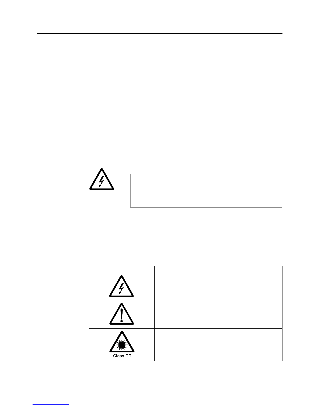
Safety and Environmental Notices
When using this product, observe the danger, caution, and attention notices
contained in this guide. The notices are accompanied by symbols that represent the
severity of the safety condition.
Danger Notice
Caution Notice
Most danger or caution notices contain a reference number (RSFTDxxx or
RSFTCxxx). Use the reference number to check the translation in IBM
®
Externally
Attached Devices Safety Information, SA26-2004.
The sections that follow define each type of safety notice and give examples.
A danger notice calls attention to a situation that is potentially lethal or extremely
hazardous to people. A lightning bolt symbol always accompanies a danger notice
to represent a dangerous electrical condition. A sample danger notice follows:
DANGER
An electrical outlet that is not correctly wired could place
hazardous voltage on metal parts of the system or the products that
attach to the system. It is the customer’s responsibility to ensure
that the outlet is correctly wired and grounded to prevent an
electrical shock. (RSFTD201)
A caution notice calls attention to a situation that is potentially hazardous to
people because of some existing condition. A caution notice can be accompanied
by one of several symbols:
If the symbol is... It means....
A hazardous electrical condition with less severity than
electrical danger.
A generally hazardous condition not represented by other
safety symbols.
A hazardous condition due to the use of a laser in the
product. Laser symbols are always accompanied by the
classification of the laser as defined by the U. S.
Department of Health and Human Services (for example,
Class I, Class II, and so forth).
© Copyright IBM Corp. 2003 ix
Page 12
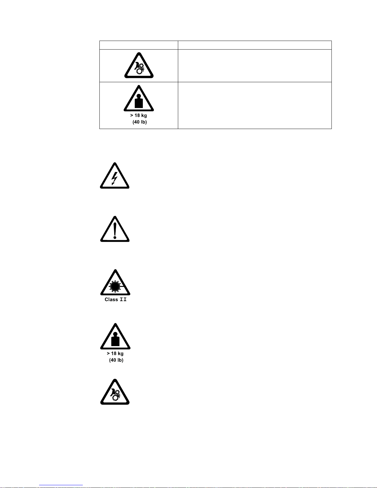
If the symbol is... It means....
A hazardous condition due to mechanical movement in or
around the product.
A hazardous condition due to the weight of the unit.
Weight symbols are accompanied by an approximation of
the product’s weight.
Sample caution notices follow:
CAUTION:
The controller card contains a lithium battery. To avoid possible
explosion, do not burn, exchange, or charge the battery. Discard the
controller card as instructed by local regulations for lithium batteries.
(RSFTC228)
CAUTION:
Do not attempt to use the handle on the module to lift the entire
device (module and enclosure) as a unit. First remove the module;
then, use two hands to lift the enclosure. (72XXC356)
CAUTION:
This product complies with the performance standards set by the U.S.
Food and Drug Administration for a Class II and IEC825 Laser
Product. Avoid prolonged staring into the laser beam.
CAUTION:
The weight of this part or unit is between 18 and 32 kilograms (39.7
and 70.5 pounds). It takes two persons to safely lift this part or unit.
(RSFTC204)
CAUTION:
This assembly contains mechanical moving parts. Use care when
servicing this assembly.
x IBM 3580 Ultrium Tape Drive Setup and Operator Guide
Page 13

Attention Notice
An attention notice indicates the possibility of damage to a program, device, or
system, or to data. An exclamation point symbol may accompany an attention
notice, but is not required. Sample attention notices follow:
Attention: If you use a power screwdriver to perform this
procedure it could destroy the tape.
Attention: Do not operate the 3580 Ultrium 2 Tape Drive in a poor air-quality
environment.
Performing the Safety Inspection Procedure
Before you service the 3580 Ultrium 2 Tape Drive, perform the following safety
inspection procedure:
1. Stop all activity on the SCSI bus.
2. Turn off the power to the tape drive.
3. Disconnect the SCSI cable and check the SCSI bus terminator for damage.
4. Unplug the tape drive’s power cord from the electrical outlet.
5. Check the tape drive’s power cord for damage, such as a pinched, cut, or
frayed cord.
6. Check the tape drive’s SCSI bus (signal) cable for damage.
7. Check the cover of the tape drive for sharp edges, damage, or alterations that
expose its internal parts.
8. Check the cover of the tape drive for proper fit. It should be in place and
secure.
9. Check the product label on the bottom of the tape drive to make sure that it
matches the voltage at your outlet.
End of Life (EOL) Plan
This box is a purchased unit. Therefore, it is the sole responsibility of the purchaser
to dispose of it in accordance with local laws and regulations at the time of
disposal.
This unit contains recyclable materials. The materials should be recycled where
facilities are available and according to local regulations. In some areas IBM may
provide a product take-back program that ensures proper handling of the product.
For more information, contact your IBM representative.
Safety and Environmental Notices xi
Page 14

xii IBM 3580 Ultrium Tape Drive Setup and Operator Guide
Page 15

Preface
This guide describes how to install and use the IBM 3580 Ultrium 2 Tape Drive
Models L23 and H23.
This guide contains the following chapters:
Chapter 1, “Introduction”, on page 1 describes the 3580 Ultrium 2 Tape Drive,
discusses supported servers, operating systems, and device drivers, and lists
hardware specifications.
Chapter 2, “Installing the 3580 Ultrium 2 Tape Drive”, on page 5 tells how to
unpack and set up the 3580 Ultrium 2 Tape Drive.
Chapter 3, “Operating the 3580 Ultrium 2 Tape Drive”, on page 17 describes the
power switch, unload button, and status light on the 3580 Ultrium 2 Tape Drive. It
explains the function of the message display and the single-character display. It
tells how to insert and remove a tape cartridge, describes methods of updating
drive firmware, and explains how to clean the tape drive. It also lists the
diagnostic and maintenance functions that the 3580 Ultrium 2 Tape Drive can
perform.
Chapter 4, “Using Ultrium Media”, on page 25 describes the types of tape
cartridges to use in the 3580 Ultrium 2 Tape Drive and defines the conditions for
storing and shipping them. It also tells how to handle the cartridges, how to set a
cartridge’s write-protect switch, and how to order additional cartridges.
Chapter 5, “Troubleshooting”, on page 47 gives tips for solving problems with the
3580 Ultrium 2 Tape Drive and includes a flowchart that analyzes when the tape
drive requires maintenance.
Appendix A, “Codes on the Single-Character Display”, on page 55 describes the
error and informational codes that appear on the single-character display of the
3580 Ultrium 2 Tape Drive.
Appendix B, “Performing Diagnostic and Maintenance Functions”, on page 59
describes the procedures that you can use to identify and correct problems with
the 3580 Ultrium 2 Tape Drive.
Appendix C, “Manually Removing a Tape Cartridge”, on page 83 gives the
procedure for removing a stuck tape cartridge from the 3580 Ultrium 2 Tape Drive.
Appendix D, “Installing a Tape Drive into a Rack”, on page 97 describes how to
install the 3580 Ultrium 2 Tape Drive into a rack.
Appendix E, “TapeAlert Flags”, on page 103 lists TapeAlert messages that are
supported by the 3580 Ultrium 2 Tape Drive and that may aid during problem
determination.
Appendix F, “Power Cords”, on page 105 provides information about the power
cords that are used in different countries or regions.
© Copyright IBM Corp. 2003 xiii
Page 16

Appendix G, “Parts List”, on page 109 lists parts and supplies that are used by the
3580 Ultrium 2 Tape Drive.
Store this guide with your server’s manuals.
Related Publications
Refer to the following publications for additional information. To ensure that you
have the latest publications, visit the web at http://www.ibm.com/storage/lto.
v IBM TotalStorage
GX35-5068, illustrates how to configure and operate the 3580 Ultrium 2 Tape
Drive.
v IBM TotalStorage LTO Ultrium Tape Drive SCSI Reference, GA32–0450, gives
information about the supported SCSI commands and protocol for the tape
drive.
v IBM Ultrium Device Drivers Installation and User’s Guide, GA32-0430, provides
instructions for attaching IBM-supported hardware to open-systems operating
systems. It indicates what devices and levels of operating systems are supported,
gives the requirements for adapter cards, and tells how to configure servers to
use the device driver with the Ultrium family of devices.
v IBM Ultrium Device Drivers Programming Reference, GC35-0483, supplies
information to application developers who want to integrate their open-systems
applications with IBM-supported Ultrium hardware. The reference contains
information about the application programming interfaces (APIs) for each of the
various supported operating-system environments. You can obtain this reference
via File Transfer Protocol (FTP) at
ftp://ftp.software.ibm.com/storage/devdrvr.
v IBM Externally Attached Devices Safety Information, SA26-2004, provides translation
of danger and caution notices.
™
Ultrium Tape Drive 3580 Models L23 and H23 Quick Reference,
xiv IBM 3580 Ultrium Tape Drive Setup and Operator Guide
Page 17
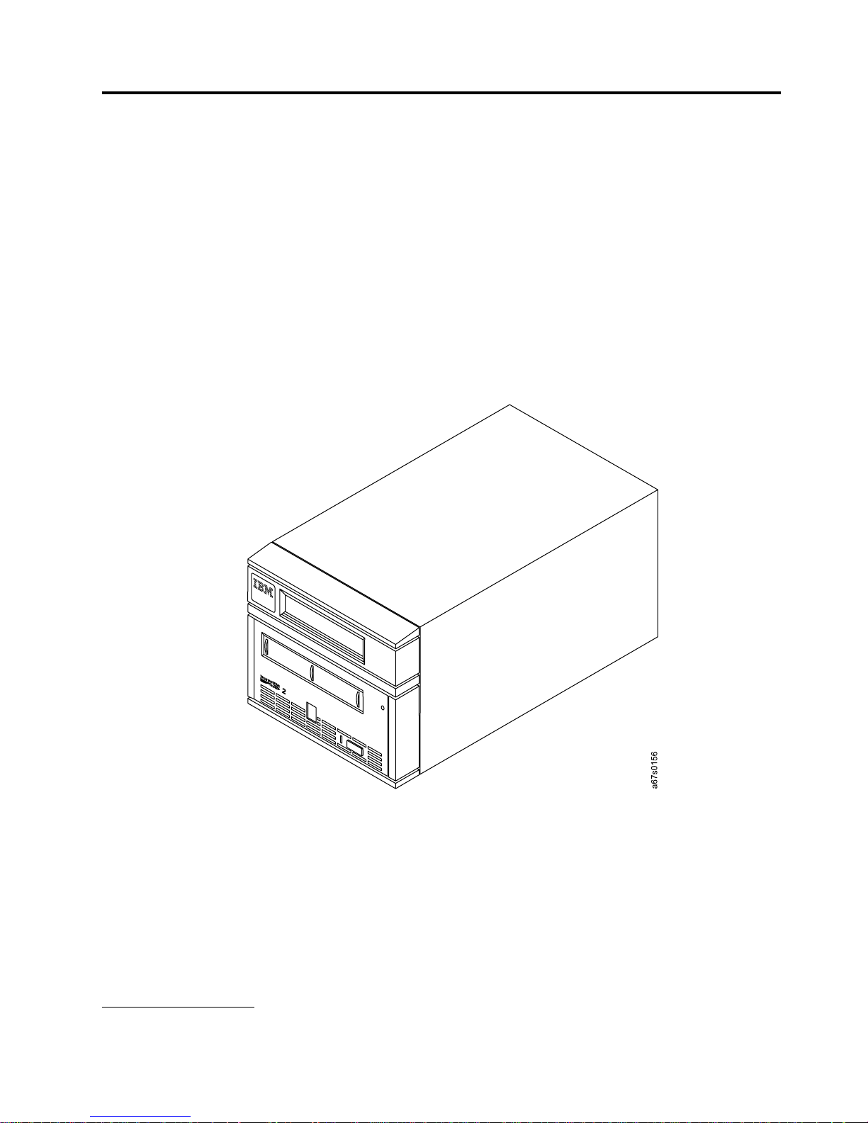
Chapter 1. Introduction
The IBM 3580 Tape Drive Models L23 and H23 are high-performance,
high-capacity data-storage devices that connect to and provide additional storage
for supported servers. Designed to perform unattended backups as well as to
retrieve and archive files, the IBM 3580 Tape Drive Models L23 and H23 feature:
v Native storage capacity of 200 GB per cartridge (400 GB at 2:1 compression)
v Native sustained data transfer rate of up to 35 MB per second (70 MB per
second at 2:1 compression)
v Burst data transfer rate of 160 MB per second for Model L23
The IBM 3580 Tape Drive Models L23 and H23 are equipped internally with the
IBM Ultrium 2 Tape Drive.
1
2
Figure 1. The IBM 3580 Ultrium 2 Tape Drive
For the remainder of this guide, the IBM 3580 Tape Drive Models L23 and H23 will
be referred to as the 3580 Ultrium 2 Tape Drive. Table 1 on page 2 lists the 3580
Tape Drive models. It lists each model’s SCSI attachment, and it shows that Models
L23 and H23 are Ultrium 2 models, while all other models are Ultrium 1 models.
1. 1 GB = one gigabyte or 1 000 000 000 bytes
2. 1 MB = one megabyte or 1 000 000 bytes
© Copyright IBM Corp. 2003 1
Page 18

Table 1. 3580 Tape Drive Models
Model SCSI Attachment Ultrium 1 or Ultrium 2
L11 LVD Ultrium 1
L13 LVD Ultrium 1
L23 LVD Ultrium 2
H11 HVD Ultrium 1
H13 HVD Ultrium 1
H23 HVD Ultrium 2
Drive Performance
If you run applications that are highly dependent on tape-processing speed, you
can take advantage of the significant performance improvements provided by the
IBM 3580 Ultrium 2 Tape Drive. Table 2 lists the performance characteristics of
both the Ultrium 2 and Ultrium 1 models.
Table 2. Performance characteristics of the Ultrium 2 Tape Drive and the Ultrium 1 Tape Drive
Performance Characteristic
Native sustained data rate 35 MB/s
Compressed data rate (at 2:1
compression)
Maximum sustained data rate (at
maximum compression)
Burst data rate for Low Voltage
Differential (LVD) SCSI drives
Burst data rate for High Voltage
Differential (HVD) SCSI drives
Nominal load-to-ready time 15 seconds 20 seconds
Nominal unload time 15 seconds 18 seconds
Average search time to first byte of
data
Note: All sustained data rates are dependent on the capabilities of the interconnect (for example, an UltraSCSI bus
is limited to less than 40MB/sec).
Ultrium 2 Tape Drive Ultrium 1 Tape Drive
(with Ultrium 2 media)
20 MB/s
(with Ultrium 1 media)
70 MB/s
(with Ultrium 2 media)
40 MB/s
(with Ultrium 1 media)
107 MB/s (Ultra160) 60 MB/s
160 MB/s (Ultra160) 80 MB/s (Ultra2)
40 MB/s (Ultra) 40 MB/s (Ultra)
49 seconds 73 seconds
Tape Drive
15 MB/s
30 MB/s
By using the built-in data-compression capability of the tape drives, you can
achieve greater data rates than the native data transfer rate. However, the actual
throughput is a function of many components, such as the host system processor,
disk data rate, block size, data compression ratio, SCSI bus capabilities, and system
or application software.
2 IBM 3580 Ultrium Tape Drive Setup and Operator Guide
Page 19

Supported Servers and Operating Systems
The 3580 Ultrium 2 Tape Drive attaches to many servers and many operating
systems. To determine the latest supported attachments, visit the web at
http://www.ibm.com/storage/lto and click on Technical Support or LTO Support.
For specific instructions about attaching the tape drive, see Chapter 2, “Installing
the 3580 Ultrium 2 Tape Drive”, on page 5.
Supported Device Drivers
IBM offers device drivers for the 3580 Ultrium 2 Tape Drive. Device drivers enable
the drive to interact with a variety of servers. To properly install an IBM device
driver (if required), refer to the IBM Ultrium Device Drivers Installation and User’s
Guide. For applications that use other device drivers, see the application’s
documentation to determine which drivers to use.
IBM maintains the latest levels of device drivers and driver documentation for the
IBM TotalStorage Ultrium 2 tape products on the Internet. You can access this
material from your browser or through the IBM FTP site by performing one of the
following procedures. (Note: If you do not have Internet access and you need
information about device drivers, contact your Marketing Representative.)
v Using a browser, type one of the following:
– http://www.ibm.com/storage/lto (select either Technical Support or LTO
Support)
– ftp://ftp.software.ibm.com/storage/devdrvr
– ftp://207.25.253.26/storage/devdrvr
v Using an IBM FTP site, enter the following specifications:
– FTP site: ftp.software.ibm.com
– IP Addr: 207.25.253.26
– Userid: anonymous
– Password: (use your current e-mail address)
– Directory: /storage/devdrvr
IBM provides PostScript- and PDF-formatted versions of its documentation in the
/storage/devdrvr/Doc directory:
v IBM_ultrium_tape_IUG.ps and IBM_ultrium_tape_IUG.pdf contain the current
version of the IBM Ultrium Device Drivers Installation and User’s Guide
v IBM_ultrium_tape_PROGREF.ps and IBM_ultrium_tape_PROGREF.pdf contain
the current version of the IBM Ultrium Device Drivers Programming Reference
Device drivers and utilities for each supported server are beneath
/storage/devdrvr/ in the following directories (the device driver for the iSeries
or AS/400®server is included in the OS/400®operating system):
®
v AIX
v HPUX
v Linux
v Solaris
v Windows
For more information about device drivers, refer to any of the preceding
directories.
™
®
Chapter 1. Introduction 3
Page 20

TapeAlert Support
The 3580 Ultrium 2 Tape Drive is compatible with TapeAlert technology, which
provides error and diagnostic information to the server. For more information, see
Appendix E, “TapeAlert Flags”, on page 103.
Specifications
The following are specifications for the 3580 Ultrium 2 Tape Drive. Specifications
for tape cartridges are given in “Environmental and Shipping Specifications for
Tape Cartridges” on page 42.
Table 3. Specifications for the 3580 Ultrium 2 Tape Drive
Specification Dimensions
Width 17.1 cm (6.74 in.)
Length 33.3 cm (13.11 in.)
Height 14.6 cm (5.75 in.)
Weight 6.59 kg (14.3 lbs)
AC line voltage 100 to 240 Vac
Line frequency 50 to 60 Hz
Line current at 100
Vac
Line current at 240
Vac
Maximum altitude 2500 m (8202 ft)
Temperature
Relative humidity 20 to 80% 10 to 90% 10 to 90%
Maximum wet bulb
temperature
Environmental
Factor
Physical Specifications
Power Specifications
1.0 A
0.5 A
Other Specifications
Environmental Specifications
Operating Storage Shipping
10 to 38°C
(50 to 100°F)
26°C
(79°F)
−40 to 60°C
(−40 to 140°F)
Noncondensing Noncondensing
−40 to 60°C
(−40 to 140°F)
4 IBM 3580 Ultrium Tape Drive Setup and Operator Guide
Page 21
Chapter 2. Installing the 3580 Ultrium 2 Tape Drive
Attention:
1. The 3580 Ultrium 2 Tape Drive Models L23 and H23 are customer setup units.
It is the customer’s responsibility to install these products.
2. The 3580 Ultrium 2 Tape Drive Models L23 and H23 are supported by
Customer Replaceable Unit (CRU), Courier, or on-site service. Warranty service
may vary by Countries/Regions. Refer to the warranty documentation to
determine the type of warranty service offered in your Countries/Regions.
As with all devices, it is recommended that you download the latest level of
firmware by visiting http://www.ibm.com/storage/lto and clicking on Technical
Support or LTO Support. Be sure to verify that you have the latest firmware
installed on your machine before you contact IBM for any necessary technical
support.
If you choose not to install this product yourself, IBM will install it for a fee. You
can purchase installation services by contacting your local IBM Service office or
your IBM Business Partner.
To install the 3580 Ultrium 2 Tape Drive, complete the following steps.
DANGER
An electrical outlet that is not correctly wired could place hazardous voltage on metal
parts of the system or the products that attach to the system. It is the customer’s
responsibility to ensure that the outlet is correctly wired and grounded to prevent an
electrical shock. (RSFTD201)
Step 1. Unpacking the Tape Drive
__ 1. Unpack the 3580 Ultrium 2 Tape Drive.
__ 2. Inspect the 3580 Ultrium 2 Tape Drive for shipping damage. If there is
damage, do not install the tape drive. Report the damage immediately by
contacting your place of purchase.
__ 3. Tilt the 3580 Ultrium 2 Tape Drive on its side and locate the label that gives
the machine type, model number and serial number of the unit (see 10 in
Figure 2 on page 7). Make a note of these numbers and store them in an
easily accessible place. Should you need to contact IBM Technical Support,
you will be asked for these numbers.
© Copyright IBM Corp. 2003 5
Page 22

Step 2. Using the Inventory Checklist
Ensure that you have received the following items:
__ 1. Power cord (for the appropriate cord for your country or region, see
Appendix F, “Power Cords”, on page 105)
__ 2. IBM LTO Ultrium Data Cartridge
__ 3. IBM TotalStorage LTO Ultrium Cleaning Cartridge
__ 4. Single-connector SCSI wrap tool
__ 5. Device driver kit that includes:
v CD that contains the device drivers, the IBM Ultrium Device Drivers
Installation and User’s Guide, and the IBM Ultrium Device Drivers
Programming Reference
__ 6. A host-to-device SCSI bus (signal) cable and a terminator
__ 7. Optional rackmount kit (if ordered)
__ 8. The IBM TotalStorage Ultrium Tape Drive 3580 Models L23 and H23 Quick
Reference, GX35–5068
__ 9. The IBM TotalStorage Ultrium Tape Drive 3580 Models L23 and H23 Setup and
Operator Guide, GA32–0460 (this guide)
__ 10. The IBM Externally Attached Devices Safety Information manual
Step 3. Installing the Rackmount Kit
If you ordered the optional rackmount kit, refer to Appendix D, “Installing a Tape
Drive into a Rack”, on page 97 for installation instructions. If you did not order the
optional rackmount kit, proceed to “Step 4. Inspecting the Power Cord and
Outlet”.
Step 4. Inspecting the Power Cord and Outlet
__ 1. Inspect the power cord plug to ensure that it matches the power receptacle.
If it does not match, see Appendix F, “Power Cords”, on page 105 to
determine the appropriate power cord.
__ 2. Ensure that the electrical outlets that you use are properly grounded and
that the circuit breaker is turned on.
6 IBM 3580 Ultrium Tape Drive Setup and Operator Guide
Page 23

1 Message display 7 Power receptacle
2 Cartridge load compartment 8 Power switch
3 Single-character display 9 SCSI address switch
4 Status light 10 Machine type, model number,
and serial number
5 Unload button 11 IBM Repair Identification Tag
Placeholder
6 External SCSI connectors
Figure 2. Components of the 3580 Ultrium 2 Tape Drive
Chapter 2. Installing 7
Page 24

Step 5. Setting the SCSI ID
The SCSI ID is a unique address that identifies the 3580 Ultrium 2 Tape Drive to
the server. To set the SCSI ID:
__ 1. Refer to the following notes and decide what ID you want to assign to the
3580 Ultrium 2 Tape Drive.
Notes:
a. The range of SCSI IDs is 0 through 15. The priority of SCSI IDs is: 7, 6, 5,
4, 3, 2, 1, 0, 15, 14, 13, 12, 11, 10, 9, 8.
b. Do not select an ID that is already in use by any device on the SCSI bus.
c. Do not select the SCSI ID of the SCSI host adapter card. The priority of
this ID is usually higher than any device on the SCSI bus. Generally, the
SCSI ID for the host adapter is set to 7.
__ 2. Locate the SCSI address switch at the rear of the 3580 Ultrium 2 Tape Drive
(see 9 in Figure 2 on page 7).
__ 3. With a small, pointed object (such as a ballpoint pen), press the + or − push
button until the ID that you want displays on the switch.
Note: If the SCSI ID is changed after installation, cycle the power (turn it off then
on again) to activate the new SCSI ID.
Step 6. Positioning the Tape Drive
Position the 3580 Ultrium 2 Tape Drive anywhere that is convenient to the server.
The only restrictions are the length of the power cord and the length of the SCSI
cable. Recommended locations are:
v Away from high-traffic areas, especially if the floor is carpeted.
v Out of computer rooms to avoid toner and paper dust. Do not store paper
supplies next to any unit.
v Away from moving air, such as doorways, open windows, fans, and air
conditioners.
v Off the floor.
v In a horizontal position.
v Where the tape cartridge can be easily inserted.
The 3580 Ultrium 2 Tape Drive should not be stacked. Do not place anything on
top of the unit. To minimize any contamination from airborne particles, ensure that
the cover is always closed.
8 IBM 3580 Ultrium Tape Drive Setup and Operator Guide
Page 25

Step 7. Connecting Power
__ 1. Ensure that the power switch on the 3580 Ultrium 2 Tape Drive is set to off
by pressing 0 on the switch (see 8 in Figure 2 on page 7).
__ 2. Plug the power cord into the 3580 Ultrium 2 Tape Drive 7, then plug the
other end into a grounded electrical outlet.
__ 3. Because the 3580 Ultrium 2 Tape Drive may not complete the Power-On Self
Test (POST) without SCSI termination, ensure that a terminator (or SCSI bus
with termination) is connected to one of the two SCSI connectors at the rear
of the unit.
Note: LVD and HVD/DIFF terminators cannot be intermixed.
__ 4. Power-on the 3580 Ultrium 2 Tape Drive by pressing | on the power switch.
The tape drive runs the POST, which checks all hardware except the drive
head. During the POST, the Single-Character Display flashes several
segmented characters. Each segmented character respresents a test
performed during the POST. When the POST finishes, the Single-Character
Display momentarily lights all 8 segments and then goes blank. At the
outset of the POST, the following message appears in the message display
for 90 seconds:
Power On Self Test
In Progress
v If the test succeeds, the following message appears in the message display
for 5 seconds:
Drive FW xxxx
Display FW xxxx
followed by:
Ultrium Tape Drive
Drive Empty
v If a failure occurs, the following message appears in the message display:
ERROR!
SELF TEST FAILURE
Step 8. Running the Fast Read/Write Test
The Fast Read/Write Test performs procedures to ensure that the drive can read
from and write to tape. The diagnostic takes approximately 5 minutes to complete
and loops continually until you halt it. To halt the diagnostic, press the unload
button. The diagnostic will continue to the end of its loop and then stop.
Attention: For this test, use only a scratch (blank) data cartridge or a cartridge
that may be overwritten. During the test, the drive overwrites the data on the
cartridge.
__ 1. Make sure that no cartridge is in the drive.
__ 2. Make sure that the following message appears on the message display (you
may need to turn the power off, then on again for the message to appear).
Chapter 2. Installing 9
Page 26

Ultrium Tape Drive
Drive Empty
__ 3. Within two seconds, press the unload button 3 times. The status light
becomes solid amber and the following message displays (indicating that the
tape drive is in maintenance mode):
Maint Mode: Select
Exit Maint Mode
Note: If a cartridge is in the tape drive, it will eject the first time that you
press the unload button and the drive will not be placed in
maintenance mode. To continue placing the drive in maintenance
mode, perform the preceding step.
__ 4. Press the unload button once per second until F appears in the
single-character display and the following message displays. (If you cycle
past the desired code, press the unload button once per second until the
code redisplays.)
Maint Mode: Select
Fast R/W Diagnostic
__ 5. Press and hold the unload button for 2 or more seconds, then release it to
select the function. Immediately after the following message displays, insert
a scratch (blank) data cartridge that is not write-protected (or the tape drive
exits maintenance mode).
Fast R/W Diagnostic
Load Scratch Tape
__ 6. After you insert the scratch data cartridge, the flashing C in the
single-character display changes to F, and one or more of the following
messages display:
Fast R/W Diagnostic
Tape Loading = = = >
Fast R/W Diagnostic
Locating = = = >
Fast R/W Diagnostic
Rewinding = = = >
followed by:
Fast R/W Diagnostic
Writing = = = >
and:
Fast R/W Diagnostic
Reading = = = >
The tape drive runs the tests.
10 IBM 3580 Ultrium Tape Drive Setup and Operator Guide
Page 27

Note: If you inserted an invalid or write-protected tape cartridge, 7 appears
in the single-character display. The 3580 Ultrium 2 Tape Drive
unloads the cartridge and exits maintenance mode.
v If no error is detected, the test will loop and begin again. To stop the
loop, press and hold the unload button for several seconds. When the
loop ends, 0 temporarily appears in the single-character display. The drive
rewinds and unloads the tape, partially ejects the cartridge, then exits
maintenance mode. The solid amber status light turns off and the
following message displays:
Passed!
Tape Unloading
followed by:
Cartridge Unloading
In Progress
then:
Ultrium Tape Drive
Drive Empty
v If an error is detected, the status light flashes amber, a message similar to
the following displays, and the tape drive posts an error code to the
single-character display.
ERROR!
Drive/Media Error
To determine the error, locate the code in Table 8 on page 55. The tape
drive unloads the tape cartridge, exits maintenance mode, and displays
the following message:
Ultrium Tape Drive
Drive Empty
Note: To reset the drive after an error occurs, cycle power (turn it off,
then on again).
__ 7. Power-off the 3580 Ultrium 2 Tape Drive.
Chapter 2. Installing 11
Page 28

Step 9. Installing the SCSI Host Adapter Card (if required)
If there are no other devices attached to your server, you may need to install a
SCSI host adapter card in the server. To determine whether your server needs an
LVD or HVD/DIFF SCSI host adapter card, examine the label between the two
SCSI connectors at the rear of the 3580 Ultrium 2 Tape Drive:
SCSI LVD/SE
v If
v If
appears on the label, your server needs an LVD SCSI host adapter card.
SCSI DIFF
appears on the label, your server needs an HVD/DIFF SCSI host adapter
card.
To install an adapter, refer to the instructions that accompany it, as well as to the
section about SCSI card installation in your server’s documentation. For a list of
supported adapters and required interposers, visit the web at
http://www.ibm.com/storage/lto.
Although the LVD hardware in the 3580 Ultrium 2 Tape Drive Model L23 is
capable of operating in the single-ended (SE) mode, SE operation is not
recommended or supported.
Step 10. Installing Device Drivers
A device driver is firmware that enables the 3580 Ultrium 2 Tape Drive to interact
with a variety of servers. Refer to “Supported Device Drivers” on page 3 for
instructions on downloading the latest device drivers (the CD contains device
drivers current at time of manufacturing). Install device drivers for the 3580
Ultrium 2 Tape Drive as follows:
Note: If you intend to use the 3580 Ultrium 2 Tape Drive with a commercial
software application, IBM recommends that you do not install any device
driver from the CD that was shipped with the tape drive, as conflicts could
occur over which driver controls the drive. Only install a device driver from
the CD if the instructions from your commercial software application tell
you to do so.
v If you intend to use the 3580 Ultrium 2 Tape Drive with an existing or new
commercial software application (such as Tivoli
®
Storage Manager, Computer
Associates ARCserve, VERITAS Backup Exec, or Legato NetWorker), refer to that
application’s installation instructions to install the device driver and configure
the 3580 Ultrium 2 Tape Drive.
v If you do not intend to use the 3580 Ultrium 2 Tape Drive with a commercial
software application, install the device driver from the CD that was shipped
with the drive. Refer to the installation instructions in the IBM Ultrium Device
Drivers Installation and User’s Guide, which is on the CD. The CD contains drivers
and installation instructions for supported operating systems.
12 IBM 3580 Ultrium Tape Drive Setup and Operator Guide
Page 29

Step 11. Connecting the SCSI Bus Cable
For maximum performance, the quantity of tape drives that you can attach to one
SCSI bus is limited, and is based on the type of bus that you have and the amount
of data compression achieved. Ultra SCSI buses have a bandwidth of 40 MB per
second; Ultra2 SCSI buses have a bandwidth of 80 MB per second; Ultra160 SCSI
buses have a bandwidth of 160 MB per second. The 3580 Ultrium 2 Tape Drive is
capable of data transfer rates of up to 35 MB per second with no compression and
70 MB per second at 2:1 compression. For these reasons, you should attach only
one 3580 Ultrium 2 Tape Drive to an Ultra SCSI bus, one or two 3580 Ultrium 2
Tape Drives to an Ultra2 SCSI bus, and one to four 3580 Ultrium 2 Tape Drives to
an Ultra160 SCSI bus.
The SCSI bus cable connects the 3580 Ultrium 2 Tape Drive to the server. You can
connect the SCSI bus cable (and the terminator) to either SCSI connector on the
3580 Ultrium 2 Tape Drive.
__ 1. Ensure that the 3580 Ultrium 2 Tape Drive is powered off and plugged into
the electrical outlet.
__ 2. If the server’s SCSI bus is in operation, stop all activity on the bus that you
are connecting to (for instructions about how to stop SCSI bus activity, see
your server’s documentation).
__ 3. Determine the maximum allowable length of your bus cable. The maximum
allowable length depends on the type of SCSI bus (LVD or HVD) that you
are using and the number of devices on the bus:
v For an LVD bus with a single device, do not use a total cabling length
that exceeds 25 m (82 ft).
v For an LVD bus with multiple devices, do not use a total cabling length
that exceeds 12 m (39 ft).
v For an HVD bus, do not use a total cabling length that exceeds 25 m (82
ft).
To determine whether your drive uses an LVD or HVD SCSI bus, see “Step
9. Installing the SCSI Host Adapter Card (if required)” on page 12.
Attention:
v Do not mix LVD and HVD SCSI host adapters, tape drives, or
terminators on the same bus, as they could become damaged.
v Data transfer protocols for tape and disk drives are very
dissimilar. For that reason, IBM strongly recommends that you
avoid running tape and disk drives on the same host adapter.
A configuration with tape and disk on a single host adapter
gives a slow and unreliable performance.
Chapter 2. Installing 13
Page 30
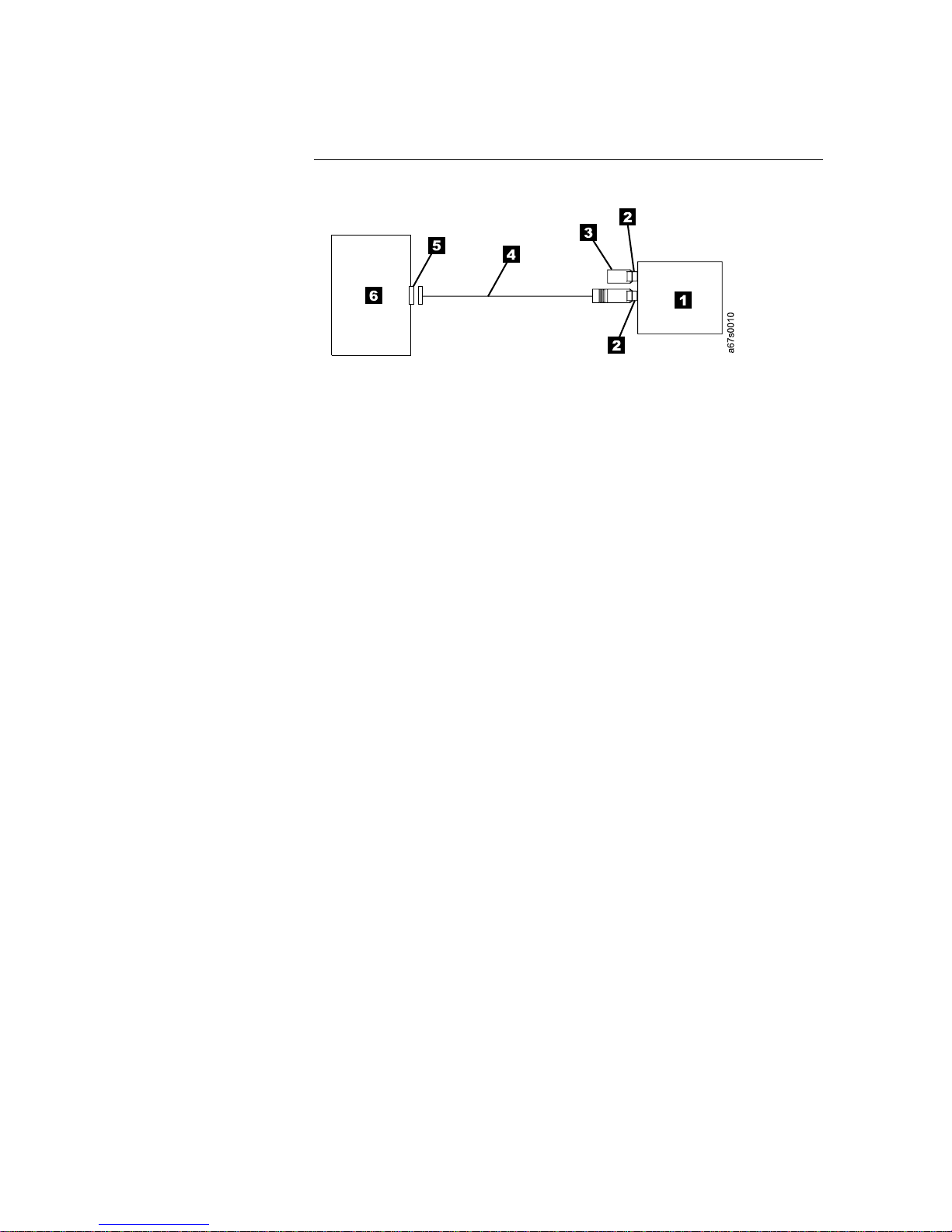
__ 4. Configure your 3580 Ultrium 2 Tape Drive similar to one of the following
examples:
v If the 3580 Ultrium 2 Tape Drive Is the Only Device On the SCSI Bus:
connect the SCSI bus cable to the server (see Figure 3).
Figure 3. Example of connecting one SCSI device to the server. The view is from the top.
1 3580 Ultrium 2 Tape Drive 5 SCSI host adapter card
2 SCSI connectors 6 Server
3 Terminator
4 SCSI bus cable
14 IBM 3580 Ultrium Tape Drive Setup and Operator Guide
Page 31

v If the 3580 Ultrium 2 Tape Drive Is One of Multiple Devices On the
SCSI Bus: connect the SCSI bus cable to the next device on the bus, and
move the terminator to the last device on the bus (see Figure 4). The
maximum allowable length of your bus cable depends on the drive
interface:
– For a drive with an LVD SCSI interface, use a cable with a total length
of 12 m (39 ft) or less.
– For a drive with an HVD/DIFF SCSI interface, use a cable with a total
length of 25 m (82 ft) or less.
To determine whether your drive uses an LVD or HVD/DIFF SCSI
interface, see “Step 9. Installing the SCSI Host Adapter Card (if required)”
on page 12.
Attention: Do not mix LVD and HVD/DIFF SCSI host adapters, tape
drives, or terminators on the same bus, as they could become damaged.
Figure 4. Example of connecting multiple SCSI devices to the server. The view is from the
top.
1 3580 Ultrium 2 Tape Drive 5 SCSI host adapter card
2 SCSI connectors 6 Server
3 Terminator 7 Another tape device
4 SCSI bus cable
Step 12. Configuring the 3580 Ultrium 2 Tape Drive to the Server
__ 1. Power-on the 3580 Ultrium 2 Tape Drive.
__ 2. To configure the 3580 Ultrium 2 Tape Drive for use, refer to the
documentation for your server and application software.
Chapter 2. Installing 15
Page 32

16 IBM 3580 Ultrium Tape Drive Setup and Operator Guide
Page 33

Chapter 3. Operating the 3580 Ultrium 2 Tape Drive
Power Switch
The power switch is a toggle switch that lets you turn the 3580 Ultrium 2 Tape
Drive on or off. The switch is located on the rear panel (see 8 in Figure 2 on
page 7). To power the tape drive on, push the power switch to | ; to power it off,
push the switch to 0. When you place the power switch in the off (0) position, the
primary electrical power within the enclosure is still active. If you do not want
electrical power to be present in the enclosure, unplug the 3580 Ultrium 2 Tape
Drive’s power cord from the receptacle at the rear of the drive (see 7 in Figure 2
on page 7).
When the 3580 Ultrium 2 Tape Drive is powered-on but idle, the status light is off
(see 2 in Figure 5); when the unit is performing a function, the status light is on.
1 Unload button 3 Message display
2 Status light 4 Single-character display
Figure 5. Front view of the 3580 Ultrium 2 Tape Drive
© Copyright IBM Corp. 2003 17
Page 34

Unload Button
The unload push button (1 in Figure 5 on page 17) enables you to perform the
following functions.
v Rewind the tape into the cartridge and eject the cartridge from the tape drive.
v Enter or exit maintenance mode, or perform diagnostic or maintenance
functions. For more information, see “Performing a Diagnostic or Maintenance
Function” on page 62.
v Perform a panic reset of the drive.
Attention: If you press the Unload button during host operation, the 3580
Ultrium 2 Tape Drive ends the command that is being processed, and unloads and
ejects the tape cartridge. Note that (depending on its location on the reel) the tape
may take as much as 20 minutes to completely rewind and eject.
18 IBM 3580 Ultrium Tape Drive Setup and Operator Guide
Page 35

Status Light
The status light (1 in Figure 5 on page 17) is a light-emitting diode (LED) that
provides information about the state of the 3580 Ultrium 2 Tape Drive. The light
can be green or amber, and (when lit) solid or flashing. Table 4 lists the conditions
of the status light and provides an explanation of what each condition means.
Table 4. Meaning of Status Light Activity
Color and Condition
of Status Light
Off The tape drive has no power or is powered off.
Green/Solid The tape drive is powered on or (if a solid C displays in the
Green/Flashing The tape drive is reading from the tape, writing to the tape,
Amber/Solid The tape drive is powering on or is in maintenance mode. For
Amber/Flashing One of the following applies:
Meaning
single-character display) needs cleaning.
rewinding the tape, locating data on the tape, loading the tape, or
unloading the tape.
The status light also flashes green if the tape drive contains a
cartridge during the power-on cycle. In this case, the drive
completes POST and slowly rewinds the tape (the process may
take approximately 13 minutes). The light stops blinking and
becomes solid when the drive completes the recovery and is ready
for a read or write operation. To eject the cartridge, press the
unload button.
information about the functions that are available when the drive
is in maintenance mode, see “Performing a Diagnostic or
Maintenance Function” on page 62.
v If the light flashes once per second, an error occurred and the
tape drive or media may require service. Note the code on the
single-character display, then go to Table 8 on page 55 to
determine the action that is required. If a solid C appears in the
single-character display, the drive needs cleaning.
v If the light flashes twice per second, the tape drive is updating
firmware. For more information, see “Updating the Drive
Firmware” on page 22.
v If the light flashes once per two seconds, the tape drive detected
an error and is performing a firmware recovery. It resets
automatically.
Chapter 3. Operating 19
Page 36

Message Display
The message display (3 in Figure 5 on page 17) is a liquid crystal display (LCD)
that provides information about the status of the 3580 Ultrium 2 Tape Drive and
any error conditions. The message display consists of two rows, with 20 characters
available in each row. During operation, the message display processor
continuously queries the drive and updates the display with status messages.
When in an idle (non-operating) state, the tape drive displays the following
message:
Ultrium Tape Drive
Drive Empty
If the message display processor loses communication with the 3580 Ultrium 2
Tape Drive, the unit displays the following message (where xxxx equals the
message that was present when the processor lost contact):
xxxx
...
Note: The preceding message may occasionally display during normal processing.
Single-Character Display
The 3580 Ultrium 2 Tape Drive features a light-emitting diode (LED) (4 in
Figure 5 on page 17) that presents a single-character code for:
v Error conditions and informational messages
v Diagnostic or maintenance functions (while in maintenance mode only)
Table 8 on page 55 lists the codes for error conditions and informational messages.
If multiple errors occur, the code with the highest priority (represented by the
lowest number) displays first. When the error is corrected, the code with the next
highest priority displays, and so on until no errors remain.
Table 9 on page 59 lists the single-character codes that represent diagnostic or
maintenance functions. To initiate a function you must be in maintenance mode.
For more information, see Appendix B, “Performing Diagnostic and Maintenance
Functions”, on page 59. While in maintenance mode, the drive may display a single
red dot at the lower-right of the single character display. This indicator is for use
by IBM Support personnel.
The single-character display is blank during normal operation of the 3580 Ultrium
2 Tape Drive.
Inserting a Tape Cartridge
To insert a tape cartridge:
1. Ensure that the 3580 Ultrium 2 Tape Drive is powered-on.
2. Ensure that the write-protect switch (1 in Figure 6 on page 21) is properly set
(see “Setting the Write-Protect Switch” on page 30).
3. Grasp the cartridge so that the write-protect switch faces you.
4. Slide the cartridge into the tape load compartment (see Figure 6 on page 21).
The cartridge loader draws the cartridge into the tape drive and the following
message appears on the message display:
20 IBM 3580 Ultrium Tape Drive Setup and Operator Guide
Page 37

Cartridge Loading In Progress
followed by: (where DC means that drive data compression is enabled)
Volume Loaded DC
Ready...
The status light flashes green, then becomes solid green. The single-character
display remains blank.
Notes:
a. If the cartridge is already in an ejected position and you want to reinsert it,
remove the cartridge then insert it again.
b. If the cartridge is already loaded and you cycle the power (turn it off, then
on), the tape will reload.
c. If you set the write-protect switch so that data cannot be written to it, the
message reads as follows (where WP equals write protect):
Volume Loaded DC WP
Ready...
Figure 6. Inserting a cartridge into the 3580 Ultrium 2 Tape Drive
Removing a Tape Cartridge
Attention: Remove any cartridge from the 3580 Ultrium 2 Tape Drive before
turning off its power. Failure to remove a cartridge may result in damage to the
cartridge or to the tape drive.
To remove a tape cartridge:
1. Ensure that the 3580 Ultrium 2 Tape Drive is powered on.
Note: In the following step, the tape may take as much as 20 minutes to
completely rewind and eject (depending on its location on the reel).
Chapter 3. Operating 21
Page 38

2. Press the unload button. The status light flashes green for approximately 30
seconds while the tape rewinds. The drive then partially ejects the cartridge,
and the status light goes out.
3. After the cartridge partially ejects, grasp the cartridge and remove it.
Performing Diagnostic and Maintenance Functions
The 3580 Ultrium 2 Tape Drive can:
v Run tape drive diagnostics
v Update tape drive firmware from a field microcode replacement (FMR) tape
v Create an FMR tape
v Force a drive dump
v Copy the drive dump to tape
v Run a SCSI wrap test
v Convert an FMR tape to a blank tape
v Display the error code log
v Clear the error code log
v Test the tape cartridge and media
v Test the read/write function
v Test the drive head
To perform the preceding diagnostic and maintenance functions, you must place
the tape drive in maintenance mode. It is recommended that you use a scratch
(blank) data cartridge for diagnostic testing. For complete instructions about
performing each operation, see Appendix B, “Performing Diagnostic and
Maintenance Functions”, on page 59.
Updating the Drive Firmware
Attention: To ensure optimum performance from the 3580 Ultrium 2 Tape Drive,
use the latest level of drive firmware. It is the customer’s responsibility to obtain
and install drive firmware.
You can update the drive firmware in the 3580 Ultrium 2 Tape Drive by:
v Obtaining the new firmware image and downloading it to the tape drive over
the SCSI interface
v Loading the firmware from a field microcode replacement (FMR) tape cartridge
To update the firmware over the SCSI bus, obtain the new firmware image and the
installation instructions by visiting the web at http://www.ibm.com/storage/lto.
For instructions about downloading firmware, see “Procedure 2” on page 49.
To update the firmware by using an FMR tape, visit the web at
http://www.ibm.com/storage/lto.
Cleaning the Drive Head
Attention: When cleaning the drive head in the 3580 Ultrium 2 Tape Drive, use
the IBM TotalStorage LTO Ultrium Cleaning Cartridge (part number 35L2086). You
may use another LTO cleaning cartridge, but it may not meet the standards of
reliability established by IBM.
22 IBM 3580 Ultrium Tape Drive Setup and Operator Guide
Page 39

Clean the drive head in the 3580 Ultrium 2 Tape Drive whenever C displays on the
single-character display and the status light is solid green. IBM does not
recommend that you clean the drive head on a periodic basis; only when C
displays.
To clean the head, insert the cleaning cartridge into the tape load compartment (see
Figure 6 on page 21). The tape drive performs the cleaning automatically. The
cleaning cycle takes less than 2 minutes. When the cleaning is finished, the drive
ejects the cartridge.
Note: If you insert a cleaning cartridge when the drive does not need to be
cleaned or if you insert a cleaning cartridge that has expired, the drive will
automatically eject the cartridge.
The IBM TotalStorage LTO Ultrium Cleaning Cartridge is valid for 50 uses.
Cleaning the 3580 Ultrium 2 Tape Drive
Clean the exterior surface of the 3580 Ultrium 2 Tape Drive with a damp towel. If
you use a liquid all-purpose cleaner, apply it to the towel. Do not spray the
enclosure.
Chapter 3. Operating 23
Page 40

24 IBM 3580 Ultrium Tape Drive Setup and Operator Guide
Page 41
Chapter 4. Using Ultrium Media
The 3580 Ultrium 2 Tape Drive automates the storage and movement of IBM LTO
Ultrium Tape Cartridges. The Ultrium Tape Drive uses the following cartridge
types:
v IBM TotalStorage LTO Ultrium 200 GB Data Cartridge (Ultrium 2)
v IBM LTO Ultrium Data Cartridge (Ultrium 1)
v IBM TotalStorage LTO Ultrium Cleaning Cartridge
v LTO Ultrium Cleaning Cartridge
The 3580 Tape Drive is compatible with the cartridges of its predecessor, the
Ultrium 1 Tape Drive. When labeled according to proper IBM bar code label
specifications (see “Bar Code Label” on page 28), the last character of the
cartridge’s volume serial number (VOLSER) indicates the generation of the media.
For example, a cartridge with a VOLSER of 000764L2 is an Ultrium 2 cartridge; a
cartridge with a VOLSER of 003995L1 is an Ultrium 1 cartridge. Cartridge
compatibility for the 3580 Tape Drive is as follows:
v Reads and writes Ultrium 2 format on Ultrium 2 cartridges
v Reads and writes Ultrium 1 format on Ultrium 1 cartridges
v Does not write Ultrium 2 format on Ultrium 1 cartridges
v Does not write Ultrium 1 format on Ultrium 2 cartridges
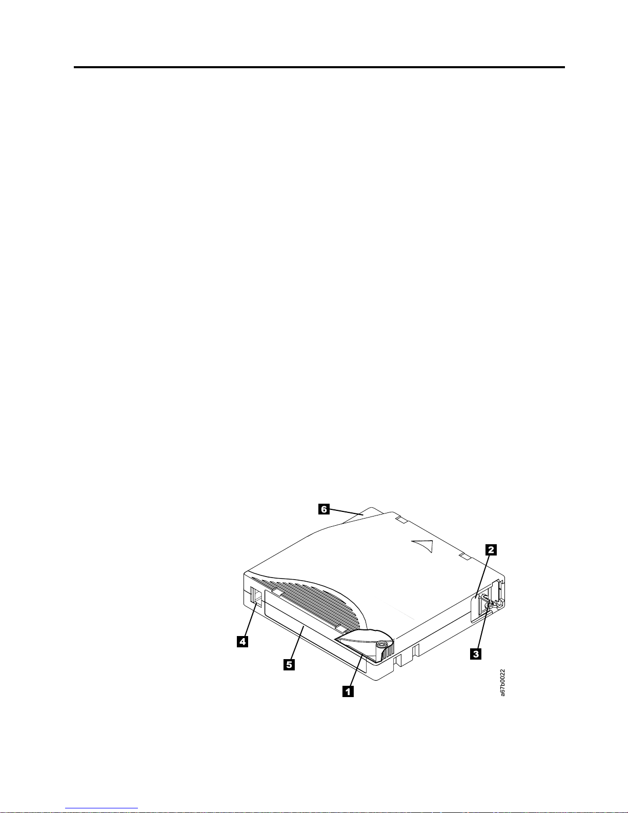
Figure 7 shows the IBM TotalStorage LTO Ultrium 200 GB Data Cartridge and its
components.
1 LTO cartridge memory 4 Write-protect switch
2 Cartridge door 5 Label area
3 Leader pin 6 Insertion guide
Figure 7. The IBM TotalStorage LTO Ultrium 200 GB Data Cartridge
© Copyright IBM Corp. 2003 25
Page 42

Data Cartridge
In addition to using LTO Ultrium 2 Tape Cartridges with up to 200 GB capacity,
the tape drive reads and writes to certified LTO Ultrium Tape Cartridges that have
capacities of 100, 50, 30, and 10 GB. If you want to control the capacity of the
cartridge (for example, if you want to limit the capacity to obtain a faster seek
time) you can do so by issuing the SCSI command SET CAPACITY. For
information about this command, refer to the IBM TotalStorage LTO Ultrium Tape
Drive SCSI Reference.
To ensure that your tape drive conforms to IBM’s specifications for reliability, use
only IBM LTO Ultrium Tape Cartridges. You may use other LTO-certified data
cartridges, but they may not meet the standards of reliability that are established
by IBM. The IBM TotalStorage LTO Ultrium 200 GB Data Cartridge cannot be
interchanged with the media used in other IBM non-LTO Ultrium tape products.
The IBM Ultrium 2 Data Cartridge is purple, and the Ultrium 1 Data Cartridge is
black. Both generations contain 1/2-inch, dual-coat, metal-particle tape. The
Ultrium 1 cartridge has a native data capacity of 100 GB (200 GB at 2:1
compression); the Ultrium 2 cartridge has a native data capacity of 200 GB (400 GB
at 2:1 compression).
When processing tape in the cartridges, the Ultrium Tape Drives use a linear,
serpentine recording format. The Ultrium 1 drive reads and writes data on 384
tracks, eight tracks at a time; the Ultrium 2 drive reads and writes data on 512
tracks, eight tracks at a time The first set of eight tracks is written from near the
beginning of the tape to near the end of the tape. The head then repositions to the
next set of eight tracks for the return pass. This process continues until all tracks
are written and the tape is full, or until all data is written.
Both generations of the IBM LTO Ultrium Data Cartridges include a Linear
Tape-Open Cartridge Memory (LTO-CM) chip (1 in Figure 7 on page 25), that
contains information about the cartridge and the tape (such as the name of the
manufacturer that created the tape), as well as statistical information about the
cartridge’s use. The LTO-CM enhances the efficiency of the cartridge. For example,
the LTO-CM stores the end-of-data location which, when you next insert a
cartridge and issue the Write command, enables the drive to quickly locate the
recording area and begin recording. The LTO-CM also aids in determining the
reliability of the cartridge by storing data about its age, how many times it has
been loaded, and how many errors it has accumulated. Whenever you unload a
tape cartridge, the tape drive writes any pertinent information to the cartridge
memory. The storage capacity of the LTO-CM is 4096 bytes.
The cartridge door 2 protects the tape from contamination when the cartridge is
out of the drive. Behind the door, the tape is attached to a leader pin 3. When
you insert the cartridge into the drive, a threading mechanism pulls the pin (and
tape) out of the cartridge, across the drive head, and onto a non-removable takeup
reel. The head can then read or write data from or to the tape.
The write-protect switch 4 prevents data from being written to the tape
cartridge. On the data cartridge, the switch is red; on the cleaning cartridge, the
switch is gray. The label area 5 provides a location for you to place a label. Affix
only a bar code label. When affixing a label, place it only in the recessed label area.
A label that extends outside of the recessed area can cause loading problems in the
internal drive or in the 3580 Ultrium 2 Tape Drive. The insertion guide 6 is a
large, notched area that prevents you from inserting the cartridge incorrectly.
26 IBM 3580 Ultrium Tape Drive Setup and Operator Guide
Page 43

You can order tape cartridges with the bar code labels included, or you can order
custom labels. To obtain tape cartridges and bar code labels, see “Ordering Media
Supplies” on page 43.
Both generations of the LTO Ultrium Data Cartridge have a nominal cartridge life
of 5000 load and unload cycles.
Cleaning Cartridge
With each 3580 Ultrium 2 Tape Drive, a specially labeled IBM LTO Ultrium
Cleaning Cartridge is supplied to clean the drive heads. The drive itself determines
when a head needs to be cleaned. It alerts you by displaying C on the
single-character display. To clean the head, insert the IBM LTO Cleaning Cartridge
into the tape load compartment (see Figure 6 on page 21). The tape drive performs
the cleaning automatically. When the cleaning is finished, the drive ejects the
cartridge.
Note: If you insert a cleaning cartridge when the drive does not need to be
To remove a cleaning cartridge, see “Removing a Tape Cartridge” on page 21.
The IBM Cleaning Cartridges are valid for 50 uses. The cartridge’s LTO-CM chip
tracks the number of times that the cartridge is used.
cleaned or if you insert a cleaning cartridge that has expired, the drive will
automatically eject the cartridge.
Chapter 4. Using Ultrium Media 27
Page 44

Bar Code Label
The 3580 Ultrium 2 Tape Drive does not require cartridge bar code labels.
However, if you use your data cartridges or cleaning cartridges in an IBM tape
library product, you may need cartridge bar code labels if your tape library
product requires them. A label contains:
v A volume serial number (VOLSER) that you can read
v A bar code that the library can read
When read by the library’s bar code reader, the bar code identifies the cartridge’s
VOLSER to the library. The bar code also tells the library whether the cartridge is a
data cartridge or cleaning cartridge. In addition, the bar code includes the
two-character media-type identifier Lx, where x equals 1 or 2. L identifies the
cartridge as an LTO cartridge. 1 indicates that the cartridge is the first generation
of its type; 2 indicates that the cartridge is the second generation of its type.
Figure 8 on page 29 shows a sample bar code label for the LTO Ultrium Tape
Cartridge.
You can order tape cartridges with the labels included, or you can order custom
labels. To order tape cartridges and bar code labels, see “Ordering Media Supplies”
on page 43. The bar code for usage in IBM tape libraries must meet predefined
specifications. They include (but are not limited to):
v Eight uppercase alphanumeric characters, where the last two characters must be
L1 or L2
v Label and printing to be non-glossy
v Nominal narrow line or space width of 0.423 mm (0.017 in.)
v Wide to narrow ratio of 2.75:1
v Minimum bar length of 11.1 mm (0.44 in.)
To determine the complete specifications of the bar code and the bar code label,
visit the web at http://www.ibm.com/storage/lto (select either Technical Support
or LTO Support), or contact your IBM Sales Representative.
When attaching a bar code label to a tape cartridge, place the label only in the
recessed label area (see 4 in Figure 7 on page 25). A label that extends outside of
the recessed area can cause loading problems in the drive.
Attention: Do not place any type of mark on the white space at either end of the
bar code. A mark in this area may prevent the library from reading the label.
28 IBM 3580 Ultrium Tape Drive Setup and Operator Guide
Page 45

Figure 8. Sample bar code label on the LTO Ultrium 2 Tape Cartridge. The volume serial
number (LTO123) and bar code are printed on the label.
Guidelines for Using Bar Code Labels
Apply the following guidelines whenever you use bar code labels:
v Use only IBM-approved bar code labels if you intend to use the cartridge in an
IBM tape library.
v Do not reuse a label or reapply a used label over an existing label.
v Before you apply a new label, remove the old label by slowly pulling it at a
right angle to the cartridge case.
v Use peel-clean labels that do not leave a residue after they are removed. If there
is glue residue on the cartridge, remove it by gently rubbing it with your finger;
do not use a sharp object, water, or a chemical to clean the label area.
v Examine the label before you apply it to the cartridge. Do not use the label if it
has voids or smears in the printed characters or bar code (a library’s inventory
operation will take much longer if the bar code label is not readable).
v Remove the label from the label sheet carefully. Do not stretch the label or cause
the edges to curl.
v Position the label within the recessed label area (see 5 in Figure 7 on page 25).
v With light finger pressure, smooth the label so that no wrinkles or bubbles exist
on its surface.
v Verify that the label is smooth and parallel, and has no roll-up or roll-over. The
label must be flat to within 0.5 mm (0.02 in.) over the length of the label and
have no folds, missing pieces, or smudges.
v Do not place other machine-readable labels on other surfaces of the cartridge.
They may interfere with the ability of the drive to load the cartridge.
Chapter 4. Using Ultrium Media 29
Page 46

Setting the Write-Protect Switch
The position of the write-protect switch on the tape cartridge (see 1 in Figure 9)
determines whether you can write to the tape:
v If the switch is set to
v If the switch is set to unlocked (black void), data can be written to the tape.
If possible, use your server’s application software to write-protect your cartridges
(rather than manually setting the write-protect switch). This allows the server’s
software to identify a cartridge that no longer contains current data and is eligible
to become a scratch (blank) data cartridge. Do not write-protect scratch (blank)
cartridges; the tape drive will not be able to write new data to them.
If you must manually set the write-protect switch, slide it left or right to the
desired position.
(solid red), data cannot be written to the tape.
Figure 9. Setting the write-protect switch
Handling the Cartridges
Incorrect handling or an incorrect environment can damage the IBM LTO Ultrium
Tape Cartridges or their magnetic tape. To avoid damage to your tape cartridges
and to ensure the continued high reliability of your IBM LTO Ultrium Tape Drives,
use the following guidelines:
Provide Training
v Post procedures that describe proper media handling in places where people
gather.
1
Attention: Do not insert a damaged tape cartridge into your
3580 Ultrium 2 Tape Drive. A damaged cartridge can interfere
with the reliability of a drive and may void the warranties of the
drive and the cartridge. Before inserting a tape cartridge, inspect
the cartridge case, cartridge door, and write-protect switch for
breaks.
A67E0026
30 IBM 3580 Ultrium Tape Drive Setup and Operator Guide
Page 47

v Ensure that anyone who handles tape has been properly trained in handling and
shipping procedures. This includes operators, users, programmers, archival
services, and shipping personnel.
v Ensure that any service or contract personnel who perform archiving are
properly trained in media-handling procedures.
v Include media-handling procedures as part of any services contract.
v Define and make personnel aware of data recovery procedures.
Ensure Proper Packaging
v When you ship a cartridge, ship it in its original or better packaging.
v Always ship or store a cartridge in a jewel case.
v Use only a recommended shipping container that securely holds the cartridge in
its jewel case during transportation. Ultrium Turtlecases (by Perm-A-Store) have
been tested and found to be satisfactory (see Figure 10). They are available at
http://www.turtlecase.com.
Figure 10. Tape cartridges in a Turtlecase
v Never ship a cartridge in a commercial shipping envelope. Always place it in a
box or package.
v If you ship the cartridge in a cardboard box or a box of a sturdy material, ensure
the following:
– Place the cartridge in polyethylene plastic wrap or bags to protect it from
dust, moisture, and other contaminants.
– Pack the cartridge snugly; do not allow it to move around.
– Double-box the cartridge (place it inside a box, then place that box inside the
shipping box) and add padding between the two boxes (see Figure 11 on
page 32).
Chapter 4. Using Ultrium Media 31
Page 48
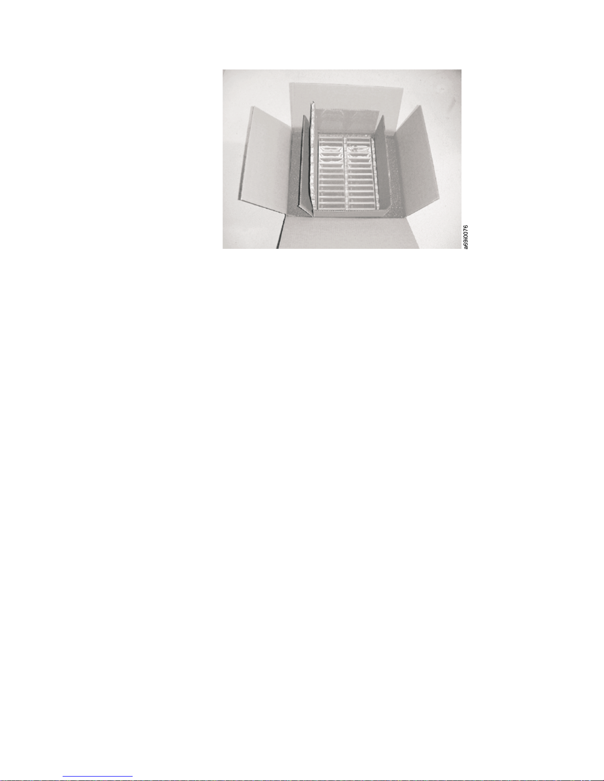
Figure 11. Double-boxing tape cartridges for shipping
Provide Proper Acclimation and Environmental Conditions
v Before you use a cartridge, let it acclimate to the normal operating environment
for 1 hour. If you see condensation on the cartridge, wait an additional hour.
v Ensure that all surfaces of a cartridge are dry before inserting it.
v Do not expose the cartridge to moisture or direct sunlight.
v Do not expose recorded or blank cartridges to stray magnetic fields of greater
than 100 oersteds (for example, terminals, motors, video equipment, X-ray
equipment, or fields that exist near high-current cables or power supplies). Such
exposure can cause the loss of recorded data or make the blank cartridge
unusable.
v Maintain the conditions that are described in “Environmental and Shipping
Specifications for Tape Cartridges” on page 42.
Perform a Thorough Inspection
After purchasing a cartridge and before using it, perform the following steps:
v Inspect the cartridge’s packaging to determine potential rough handling.
v When inspecting a cartridge, open only the cartridge door. Do not open any
other part of the cartridge case. The upper and lower parts of the case are held
together with screws; separating them destroys the usefulness of the cartridge.
v Inspect the cartridge for damage before using or storing it.
v Inspect the rear of the cartridge (the part that you load first into the tape load
compartment) and ensure that there are no gaps in the seam of the cartridge
case (see 1 in Figure 12 on page 33 and 4 in Figure 14 on page 36). If there
are gaps in the seam (see Figure 12 on page 33), the leader pin may be
dislodged. Go to “Repositioning or Reattaching a Leader Pin” on page 35.
32 IBM 3580 Ultrium Tape Drive Setup and Operator Guide
Page 49

Figure 12. Checking for gaps in the seams of a cartridge
v Check that the leader pin is properly seated (see 2 in Figure 13 on page 35).
v If you suspect that the cartridge has been mishandled but it appears useable,
copy any data onto a good cartridge immediately for possible data recovery.
Discard the mishandled cartridge.
v Review handling and shipping procedures.
Handle the Cartridge Carefully
v Do not drop the cartridge. If the cartridge drops, slide the cartridge door back
and ensure that the leader pin is properly seated in the pin-retaining spring clips
(see 2 in Figure 13 on page 35). If the leader pin has become dislodged, go to
“Repositioning or Reattaching a Leader Pin” on page 35.
v Do not handle tape that is outside the cartridge. Handling the tape can damage
the tape’s surface or edges, which may interfere with read or write reliability.
Pulling on tape that is outside the cartridge can damage the tape and the brake
mechanism in the cartridge.
v Do not stack more than six cartridges.
v Do not degauss a cartridge that you intend to reuse. Degaussing makes the tape
unusable.
Chapter 4. Using Ultrium Media 33
Page 50

Examples of Cartridge Problems
Example: Split Cartridge Case (see Figure 12 on page 33)
The cartridge’s case is damaged. There is a high possibility of media damage and
potential loss. Perform the following steps:
1. Look for cartridge mishandling.
2. Use the IBM Leader Pin Reattachment Kit (part number 08L9129) to correctly
seat the pin (see “Repositioning a Leader Pin” on page 35). Then, immediately
use data recovery procedures to minimize chances of data loss.
3. Review media-handling procedures.
Example: Improper Placement of Leader Pin (see Figure 13 on page 35)
The leader pin is misaligned. Perform the following steps:
1. Look for cartridge damage.
2. Use the IBM Leader Pin Reattachment Kit (part number 08L9129) to correctly
seat the pin (see “Repositioning a Leader Pin” on page 35). Then, immediately
use data recovery procedures to minimize chances of data loss.
34 IBM 3580 Ultrium Tape Drive Setup and Operator Guide
Page 51

Repositioning or Reattaching a Leader Pin
Attention: Use a repaired tape cartridge only to recover data
and move it to another cartridge. Continued use of a repaired
cartridge may void the warranties of the drive and the cartridge.
If the leader pin in your cartridge becomes dislodged from its pin-retaining spring
clips or detaches from the tape, you must use the IBM Leader Pin Reattachment
Kit (part number 08L9129) to reposition or reattach it. (Do not reattach the pin if
you must remove more than 7 meters (23 feet) of leader tape.) The sections that
follow describe each procedure.
Repositioning a Leader Pin
A leader pin that is improperly seated inside a cartridge can interfere with the
operation of the drive. Figure 13 shows a leader pin in the incorrect 1 and correct
2 positions.
To place the leader pin in its proper position, you will need the following tools:
v Plastic or blunt-end tweezers
v Cartridge manual rewind tool (from Leader Pin Reattachment Kit, part number
08L9129)
Figure 13. Leader pin in the incorrect and correct positions. The cartridge door is open and
the leader pin is visible inside the cartridge.
Chapter 4. Using Ultrium Media 35
Page 52
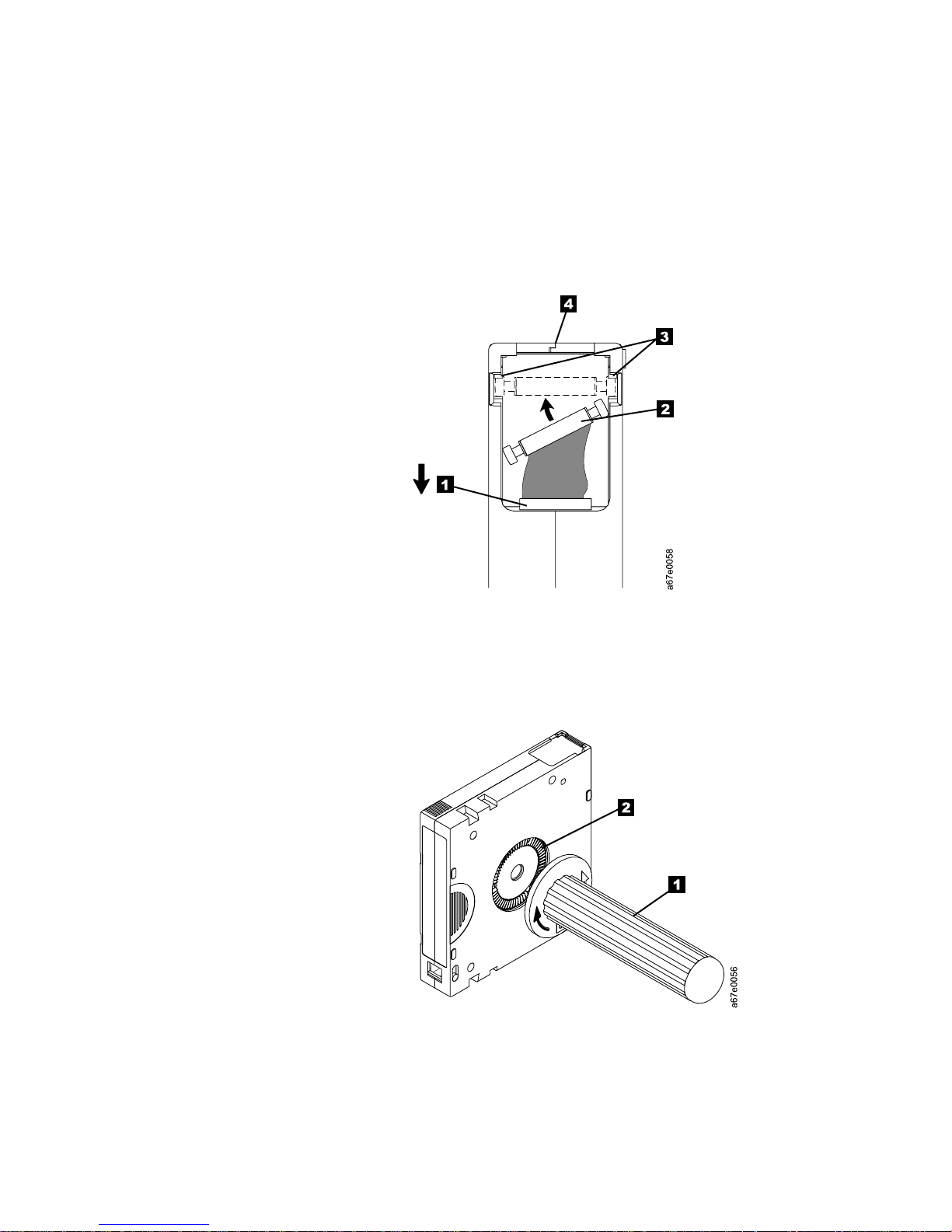
To reposition the leader pin, perform the following steps.
1. Slide open the cartridge door (1 in Figure 14) and locate the leader pin 2
(you may need to shake the cartridge gently to roll the pin toward the door).
2. With plastic or blunt-end tweezers, grasp the leader pin and position it in the
pin-retaining spring clips 3.
3. Press the leader pin gently into the clips until it snaps into place and is firmly
seated.
4. Close the cartridge door.
Figure 14. Placing the dislodged leader pin into the correct position. The cartridge door is
open to show the leader pin.
5. To rewind the tape, insert the cartridge manual rewind tool (1 in Figure 15)
into the cartridge’s hub 2 and turn it clockwise until the tape becomes taut.
Figure 15. Rewinding the tape into the cartridge
6. Remove the rewind tool by pulling it away from the cartridge.
7. If you suspect that the cartridge has been mishandled but it appears useable,
copy any data onto a good cartridge immediately for possible data recovery.
Discard the mishandled cartridge.
36 IBM 3580 Ultrium Tape Drive Setup and Operator Guide
Page 53

Reattaching a Leader Pin
The first meter of tape in a cartridge is leader tape. Once the leader tape has been
removed there is a possibility of tape breakage. After reattaching the leader pin,
transfer data from the defective tape cartridge. Do not reuse the defective tape
cartridge.
The Leader Pin Reattachment Kit contains three parts:
v Leader pin attach tool (see 1 in Figure 16). A plastic brace that holds the
cartridge door open.
v Cartridge manual rewind tool (see 2 in Figure 16). A device that fits into the
cartridge’s hub and lets you wind the tape into and out of the cartridge.
v Pin supplies (see 3 in Figure 16). Leader pins and C-clips.
Attention:
v Use only the IBM Leader Pin Reattachment Kit to reattach the leader pin to the
tape. Other methods of reattaching the pin will damage the tape, the drive, or
both.
v Use this procedure on your tape cartridge only when the leader pin detaches
from the magnetic tape and you must copy the cartridge’s data onto another
cartridge. Destroy the damaged cartridge after you copy the data. This
procedure may affect the performance of the leader pin during threading and
unloading operations.
v Touch only the end of the tape. Touching the tape in an area other than the end
can damage the tape’s surface or edges, which may interfere with read or write
reliability.
3
Figure 16. Leader Pin Reattachment Kit
1
2
A67E0042
Chapter 4. Using Ultrium Media 37
Page 54

The following procedure describes how to reattach a leader pin.
To reattach a leader pin by using the IBM Leader Pin Reattachment Kit:
1. Attach the leader pin attach tool (1 in Figure 17) to the cartridge 2 so that
the tool’s hook 3 latches into the cartridge’s door 4. Pull the tool back to
hold the door open, then slide the tool onto the cartridge. Open the tool’s
pivot arm 5.
Figure 17. Attaching the leader pin attach tool to the cartridge. To hold the cartridge door
open, hook the tool into the door and pull the tool back.
38 IBM 3580 Ultrium Tape Drive Setup and Operator Guide
Page 55

2. To find the end of the tape inside the cartridge, attach the cartridge manual
rewind tool (1 in Figure 18) to the cartridge’s hub 2 by fitting the tool’s
teeth between the teeth of the hub. Turn the tool clockwise until you see the
end of the tape inside the cartridge. Then, slowly turn the rewind tool
counterclockwise to bring the tape edge toward the cartridge door 3.
3. Continue to turn the rewind tool counterclockwise until approximately 13 cm
(5 in.) of tape hangs from the cartridge door. If necessary, grasp the tape and
pull gently to unwind it from the cartridge.
4. Remove the rewind tool by pulling it away from the cartridge. Set the tool
and the cartridge aside.
Figure 18. Winding the tape out of the cartridge. Turn the cartridge manual rewind tool
clockwise to see the end of the tape, then turn it counterclockwise to bring the tape to the
cartridge door.
5. On the leader pin (1 in Figure 19), locate the open side of the C-clip 2.
The C-clip is a small black part that secures the tape 3 to the pin.
6. Remove the C-clip from the leader pin by using your fingers to push the clip
away from the pin. Set the pin aside and discard the clip.
3
1
2
Figure 19. Removing the C-clip from the leader pin. Use your fingers to push the C-clip from
the leader pin.
A67E0036
Chapter 4. Using Ultrium Media 39
Page 56

7. Position the tape in the alignment groove of the leader pin attach tool (see 1
in Figure 20).
8. Place a new C-clip into the retention groove 2 (Figure 20) on the leader pin
attachment tool and make sure that the clip’s open side faces up.
9. Place the leader pin (from step 6 on page 39) into the cavity 3 (Figure 20) of
the leader pin attach tool.
Attention: To prevent the leader pin from rolling into the cartridge, in the
following step use care when folding the tape over the pin.
10. Fold the tape over the leader pin and hold it with your fingers (see Figure 20).
Note: Use care to ensure that the tape is centered over the leader pin. Failure
to properly center the tape on the pin will cause the repaired cartridge
to fail. When the tape is properly centered, a 0.25-mm (0.01-in.) gap
exists on both sides of the pin.
2
1
6
5
Figure 20. Attaching the leader pin to the tape
4
3
A67E0037
11. Close the pivot arm 4 of the leader pin attach tool by swinging it over the
leader pin so that the C-clip snaps onto the pin and the tape.
12. Swing the pivot arm open and trim the excess tape 5 so that it is flush with
the reattached leader pin 6.
40 IBM 3580 Ultrium Tape Drive Setup and Operator Guide
Page 57

13. Use your fingers to remove the leader pin from the cavity 3 in the leader
pin attach tool.
14. Use the cartridge manual rewind tool to wind the tape back into the cartridge
(wind the tape clockwise). Ensure that the leader pin is latched by the
pin-retaining spring clips on each end of the leader pin.
15. Remove the rewind tool.
16. Remove the leader pin attach tool by lifting its end up and away from the
cartridge.
Attention: Use a repaired tape cartridge only to recover data
and move it to another cartridge. Continued use of a repaired
cartridge may void the warranties of the drive and the cartridge.
Chapter 4. Using Ultrium Media 41
Page 58

Environmental and Shipping Specifications for Tape Cartridges
Before you use a tape cartridge, acclimate it to the operating environment for 24
hours or the time necessary to prevent condensation in the drive (the time will
vary, depending on the environmental extremes to which the cartridge was
exposed).
The best storage container for the cartridges (until they are opened) is the original
shipping container. The plastic wrapping prevents dirt from accumulating on the
cartridges and partially protects them from humidity changes.
When you ship a cartridge, place it in its jewel case or in a sealed, moisture-proof
bag to protect it from moisture, contaminants, and physical damage. Ship the
cartridge in a shipping container that has enough packing material to cushion the
cartridge and prevent it from moving within the container.
Table 5 gives the environment for operating, storing, and shipping LTO Ultrium
Tape Cartridges.
Table 5. Environment for operating, storing, and shipping the LTO Ultrium Tape Cartridge
Environmental Specifications
Environmental Factor Operating Operational Storage
Temperature
Relative humidity
(noncondensing)
Maximum wet bulb
temperature
10 to 45°C
(50 to 113°F)
10 to 80% 20 to 80% 20 to 50% 5 to 80%
26°C
(79°F)
16 to 32°C
(61 to 90°F)
26°C
(79°F)
1
Archival Storage
16 to 25°C
(61 to 77°F)
26°C
(79°F)
2
Shipping
−23 to 49°C
(−9to120°F)
26°C
(79°F)
Notes:
1. Operational storage equals less than 1 year.
2. Archival storage equals 1 to 10 years.
42 IBM 3580 Ultrium Tape Drive Setup and Operator Guide
Page 59

Disposing of Tape Cartridges
Under the current rules of the U.S. Environmental Protection Agency (EPA),
regulation 40CFR261, the LTO Ultrium Tape Cartridge is classified as
non-hazardous waste. As such, it may be disposed of in the same way as normal
office trash. These regulations are amended from time to time, and you should
review them at the time of disposal.
If your local, state, country (non-U.S.A.), or regional regulations are more
restrictive than EPA 40CFR261, you must review them before you dispose of a
cartridge. Contact your account representative for information about the materials
that are in the cartridge.
If a tape cartridge must be disposed of in a secure manner, you can erase the data
on the cartridge by using a high-energy ac degausser (use a minimum of 1200
oersted peak field over the entire space that the cartridge occupies). Degaussing
makes the cartridge unusable.
If you burn the cartridge and tape, ensure that the incineration complies with all
applicable regulations.
Ordering Media Supplies
Table 6 on page 44 lists the cartridges and media supplies that you can order for
the 3580 Ultrium 2 Tape Drive.
Chapter 4. Using Ultrium Media 43
Page 60

Table 6. Ordering media supplies for the 3580 Ultrium 2 Tape Drive
Supply Item Method of Ordering
IBM TotalStorage LTO Ultrium 200 GB Data Cartridge
(without bar code label)
Order VOLSER labels separately (see “Ordering Bar
Code Labels” on page 45).
IBM TotalStorage LTO Ultrium 200 GB Data Cartridge
(with bar code label)
Bar code labels are preapplied to cartridges.
IBM LTO Ultrium 100 GB Data Cartridge (without bar
code label)
Order VOLSER labels separately (see “Ordering Bar
Code Labels” on page 45).
IBM LTO Ultrium 100 GB Data Cartridge (with bar
code label)
Bar code labels are preapplied to cartridges.
IBM TotalStorage LTO Ultrium Cleaning Cartridge
(universal cleaning cartridge for use with Ultrium 1 and
Ultrium 2 drives; without bar code label)
Order VOLSER labels separately (see “Ordering Bar
Code Labels” on page 45).
IBM TotalStorage LTO Ultrium Cleaning Cartridge
(universal cleaning cartridge for use with Ultrium 1 and
Ultrium 2 drives; with bar code label)
Bar code labels are preapplied to cartridges.
Leader Pin Reattachment Kit Order as part number 08L9129 through an
v Order as part number 08L9870 through an
IBM-authorized distributor (for the closest distributor,
visit the web at http://www.ibm.com/storage/media).
v If you do not have Internet access, order the cartridge
from any authorized IBM Business Partner or your
IBM Sales Representative.
v Call 1-888-IBM-MEDIA.
v Order as part number 19P5887 through an
IBM-authorized distributor (for the closest distributor,
visit the web at http://www.ibm.com/storage/media).
Specify the VOLSER characters that you want.
v If you do not have Internet access, order the cartridge
from any authorized IBM Business Partner or your
IBM Sales Representative. Specify the VOLSER
characters that you want.
v Call 1-888-IBM-MEDIA. Specify the VOLSER
characters that you want.
v Order as part number 08L9120 through an
IBM-authorized distributor (for the closest distributor,
visit the web at http://www.ibm.com/storage/media).
v If you do not have Internet access, order the cartridge
from any authorized IBM Business Partner or your
IBM Sales Representative by specifying Machine Type
3589 Model 003.
v Call 1-888-IBM-MEDIA.
v Order the cartridge from any authorized IBM Business
Partner or your IBM Sales Representative by
specifying Machine Type 3589 Model 002. Specify the
VOLSER characters that you want.
v Order as part number 35L2086 through an
IBM-authorized distributor (for the closest distributor,
visit the web at http://www.ibm.com/storage/media).
v If you do not have Internet access, order the cartridge
from any authorized IBM Business Partner or your
IBM Sales Representative.
v Call 1-888-IBM-MEDIA.
v Order as part number 35L2087 through an
IBM-authorized distributor (for the closest distributor,
visit the web at http://www.ibm.com/storage/media).
v If you do not have Internet access, order the cartridge
from any authorized IBM Business Partner or your
IBM Sales Representative.
v Call 1-888-IBM-MEDIA.
IBM-authorized distributor (for the closest distributor,
visit the web at http://www.ibm.com/storage/media).
44 IBM 3580 Ultrium Tape Drive Setup and Operator Guide
Page 61

Ordering Bar Code Labels
The 3580 Ultrium 2 Tape Drive does not require cartridge bar code labels.
However, if you use your data cartridges or cleaning cartridges in an IBM tape
library product, you may need cartridge bar code labels if your tape library
product requires them. You can order these labels separately from the IBM Data
Cartridges and Cleaning Cartridges.
You can order bar code labels directly from the authorized label suppliers in
Table 7.
Table 7. Authorized suppliers of custom bar code labels
In America In Europe and Asia
EDP/Colorflex
697 South Pierce Street
Louisville, CO 80027
U. S. A.
Telephone: 800-522-3528
http://www.colorflex.com/Ai/Home.asp
Dataware
7570 Renwick
Houston, TX 77081
U. S. A.
Telephone: 800-426-4844
http://www.datawarelabels.com/
NetC
P. O. Box 320784
Fairfield, CT 06432
U. S. A.
Telephone: 203-372-6382
http://www.netcllc.com/
EDP Europe, Ltd.
43 Redhills Road
South Woodham Ferrers
Chelmsford, Essex CM3 5UL
U. K.
Telephone: 44 (0) 1245-322380
http://www.edpeurope.com/media_labelling.htm
Dataware Labels Europe
Heubergstrasse 9
D-83052 Bruckmuhl-Gotting
Germany
Telephone: 49 806-29455
http://www.datawarelabels.com/
NetC Europe Ltd
Town Farm Bungalow
North Curry
Taunton
Somerset U. K. TA3 6LX
Telephone: 44 (0) 1823 491439
http://www.netclabels.co.uk
NetC Asia Pacific Pty Ltd
Locked Bag 14
Kenthurst
NSW Australia 2156
Telephone: 61 (0) 2 9654 8272
http://www.netclabels.com.au
Chapter 4. Using Ultrium Media 45
Page 62

46 IBM 3580 Ultrium Tape Drive Setup and Operator Guide
Page 63

Chapter 5. Troubleshooting
If you encounter problems when running the 3580 Ultrium 2 Tape Drive, refer to the flowchart in
Figure 21. For explanations of codes on the single-character display, see Appendix A, “Codes on the
Single-Character Display”, on page 55. Should the drive need to be replaced, go to “Replacing the Tape
Drive” on page 52. Please review the pre-call checklist on “Pre-Call Checklist” on page 50 before calling
IBM Technical Support.
Figure 21. Flowchart for analyzing maintenance problems
© Copyright IBM Corp. 2003 47
Page 64

Procedure 1
If your server is not communicating with the 3580 Ultrium 2 Tape Drive, the
drive’s SCSI address switch may be set incorrectly:
1. Check the SCSI address switch (1 in Figure 22) to ensure that it is set to the
SCSI ID that you chose in “Step 5. Setting the SCSI ID” on page 8.
2. Make sure that the ID is not one that is used by another device or the SCSI
host adapter (note that because ID 7 is the highest priority ID on the SCSI bus,
it is usually reserved for the primary SCSI host adapter).
3. If you change a SCSI ID, power-off the 3580 Ultrium 2 Tape Drive, then power
it back on to effect the change.
Figure 22. Checking the setting on the SCSI address switch. The switch is located at the rear
of the 3580 Ultrium 2 Tape Drive.
48 IBM 3580 Ultrium Tape Drive Setup and Operator Guide
Page 65

Procedure 2
Procedure 3
If 3 or 4 appears in the single-character display, a firmware failure may have
occurred. Perform the following to capture any drive dump information and to
determine the current level of firmware that is installed on the drive:
1. Determine the current level of firmware on the 3580 Ultrium 2 Tape Drive by
watching for the message Drive FW xxxx (where xxxx is the firmware level) to
display while you power the drive off, then back on.
2. Determine the latest level of firmware available by visiting the web at
http://www.ibm.com/storage/lto. See “Updating the Drive Firmware” on
page 22 for instructions on downloading the latest firmware.
v If the firmware on your 3580 Ultrium 2 Tape Drive is outdated, download
the latest firmware from the web site (instructions for downloading are
available at the site).
v If the firmware on your 3580 Ultrium 2 Tape Drive is at the latest level,
contact IBM Technical Support for additional problem determination. If IBM
Technical Support determines that the machine should be replaced, it will
send you a replacement. To install the replacement machine, refer to
“Replacing the Tape Drive” on page 52.
If your server is not communicating with the 3580 Ultrium 2 Tape Drive, the SCSI
cable or terminator connector pins may be damaged or not seated correctly, or the
SCSI bus length may be incorrect.
1. Check whether the SCSI ID is unique. If not, select a unique SCSI ID and
reconfigure the system. The new ID is effective at the next power-on.
2. Check whether the parameters for the SCSI adapter installation are correct.
3. Ensure that a SCSI terminator is attached to each end of the bus (one
terminator is usually installed at the server).
4. Ensure that no more than two terminators are present on the bus.
5. Limit the number of devices on the bus.
6. Check that the SCSI connectors are properly seated (this includes the interposer
(if used), terminator, and cable connectors). Push the connectors into their
receptacle connectors, and (if applicable) tighten the retention screws until
firmly seated. Then, retry the operation.
7. If communication still fails, check all connector pins for damage. Remove the
interposer, terminator, and cable connectors, and inspect them for bent,
recessed, or missing pins. If necessary, replace the damaged component and
ensure that all connectors are properly seated, then retry the operation.
8. If communication still fails, check the length of the SCSI bus cable:
v If your 3580 Ultrium 2 Tape Drive uses an LVD SCSI interface and it is the
only device on the SCSI bus, ensure that the total bus length does not exceed
25 m (82 ft). If there are other devices on the bus, ensure that the total length
does not exceed 12 m (39 ft).
v If your 3580 Ultrium 2 Tape Drive uses an HVD/DIFF SCSI interface, ensure
that the total SCSI bus length does not exceed 25 m (82 ft).
9. If communication still fails, run the SCSI wrap test (see “Function Code 6: Run
SCSI Wrap Test” on page 69). If the test succeeds, the problem may be with the
cables or SCSI host adapter. Refer to your server’s documentation and exercise
a host utility to isolate the location of the problem. If the test fails, replace the
terminator and run the test again.
Chapter 5. Troubleshooting 49
Page 66

Procedure 4
If the 3580 Ultrium 2 Tape Drive fails to load or unload properly, perform the
following steps:
1. Check that the leader pin is attached and properly seated (see Figure 13 on
page 35) by opening the cartridge door and observing the pin’s placement.
2. Inspect the cartridge case, the cartridge door, and the write-protect switch for
damage.
3. Inspect the rear of the cartridge (the part that you load first into the tape load
compartment) and ensure that there are no gaps in the seam of the cartridge
case (see 1 in Figure 12 on page 33 and 4 in Figure 14 on page 36). If there
are gaps, the leader pin may be dislodged. Go to “Repositioning or Reattaching
a Leader Pin” on page 35.
4. Try loading or unloading another tape cartridge. If it fails, contact your service
representative for additional problem determination. If it is successful, discard
the cartridge that originally failed.
Notes:
1. If a damaged or mishandled cartridge is the problem, see Chapter 4, “Using
Ultrium Media”, on page 25 for proper instructions about handling media. It is
possible that your other cartridges may also be damaged.
2. If your cartridge is stuck inside the tape drive, go to Appendix C, “Manually
Removing a Tape Cartridge”, on page 83.
Pre-Call Checklist
If you have questions or problems concerning the 3580 Ultrium 2 Tape Drive,
perform the following steps before you place a call to IBM Technical Support.
Where instructions refer you to the web, visit http://www.ibm.com/storage/lto.
__ 1. Verify that the drive’s firmware is at the most recent level. To determine the
__ 2. Verify that your device drivers are at the most recent level:
__ 3. Verify whether your hardware and software configuration is supported. To
__ 4. Review “Frequently Asked Questions and ″Hints and Tips” on the web.
__ 5. Perform a general checkup of the hardware and connections:
__ 6. Run tape drive diagnostics according to “Function Code 1: Run Tape Drive
latest release of firmware, visit the web. See “Updating the Drive Firmware”
on page 22 for instructions on downloading the latest firmware.
v For IBM device drivers, visit the web.
v For the device drivers of independent software vendors (ISVs), visit the
appropriate third-party web site.
determine the latest supported attachments, visit the web.
v Ensure that you are using the correct SCSI terminator (LVD/HVD) and
that you are not mistakenly using a SCSI wrap plug (used for the
diagnostic SCSI wrap test).
v Before attaching the SCSI cables, ensure that the connector does not
contain bent or recessed pins.
v Ensure that all retention screws for the SCSI cable and terminator are
securely tightened.
Diagnostics” on page 62. The diagnostics take approximately 20 minutes to
complete. Once complete, the diagonstics loop continually until you halt
50 IBM 3580 Ultrium Tape Drive Setup and Operator Guide
Page 67

them. To halt the diagnostics, press the unload button. The diagnostics will
continue to the end of the loop and then stop. The drive then exits
maintenance mode.
Chapter 5. Troubleshooting 51
Page 68

Replacing the Tape Drive
To replace your 3580 Ultrium 2 Tape Drive, perform the following steps:
1. Remove the replacement drive from its packaging.
2. Locate the repair tag (included with the replacement drive). See 12 in
Figure 23 on page 53)
3. Write down the serial number of the failed drive on the repair tag.
4. Affix the repair tag to the replacement drive (near to, but not covering, the
serial number on the drive).
5. Place the failed drive into the packaging of the replacement drive.
6. Follow the instructions (included with the replacement drive) for returning the
failed drive to IBM.
52 IBM 3580 Ultrium Tape Drive Setup and Operator Guide
Page 69

1 Message display 7 Power receptacle
2 Cartridge load compartment 8 Power switch
3 Single-character display 9 SCSI address switch
4 Status light 10 Machine type, model number,
and serial number
5 Unload button 11 IBM Repair Identification Tag
Instructions
6 External SCSI connectors 12 IBM Repair Identification Tag
Figure 23. Components of the 3580 Ultrium 2 Tape Drive
Chapter 5. Troubleshooting 53
Page 70

54 IBM 3580 Ultrium Tape Drive Setup and Operator Guide
Page 71

Appendix A. Codes on the Single-Character Display
Errors and informational messages that pertain to the 3580 Ultrium 2 Tape Drive
are presented by the single-character display. If an error code displays, refer to
Chapter 5, “Troubleshooting”, on page 47 to troubleshoot the problem. Table 8
describes the messages and codes.
Note: The codes on the 3580 Ultrium 2 Tape Drive’s single-character display have
different meanings, depending on whether they display during normal
operation or while the tape drive is in maintenance mode. Codes that occur
during normal operations are defined in Table 8. Codes that occur while in
maintenance mode are defined in Table 9 on page 59.
Table 8. Codes on the single-character display of the 3580 Ultrium 2 Tape Drive. The display clears if you power-off
the tape drive.
Code Cause and Action
0 No error occurred and no action is required. This code displays:
v When power is cycled (turned off, then on) to the tape drive.
v When diagnostics have finished running and no error occurred.
Note: The single-character display is blank during normal operation of the tape drive.
1 Cooling problem. The tape drive detected that the recommended operating temperature was
exceeded. Perform one or more of the following actions:
v Ensure that the cooling fan is rotating and is quiet. If not, replace the 3580 Ultrium 2 Tape
Drive.
v Remove any blockage that prevents air from flowing freely through the tape drive.
v Ensure that the operating temperature and airflow is within the specified range (see
“Specifications” on page 4).
v If the operating temperature is within the specified range and the problem persists, replace the
3580 Ultrium 2 Tape Drive.
The error code clears when you power-off the tape drive or place it in maintenance mode.
2 Power problem. The tape drive detected that the externally supplied power is approaching the
specified voltage limits (the tape drive is still operating) or is outside the specified voltage limits
(the tape drive is not operating). Perform the following action:
1. Ensure that the power connector is properly seated.
2. Ensure that the proper dc voltages are being applied within the tolerances allowed (see
“Specifications” on page 4).
3. If the proper voltages are being applied but the problem persists, replace the 3580 Ultrium 2
Tape Drive.
The error code clears when you power-off the tape drive or place it in maintenance mode.
© Copyright IBM Corp. 2003 55
Page 72

Table 8. Codes on the single-character display of the 3580 Ultrium 2 Tape Drive (continued). The display clears if
you power-off the tape drive.
Code Cause and Action
3 Firmware problem. The tape drive determined that a firmware error occurred. Perform the
following action:
1. Collect a drive dump from one of the following:
Note: Do not force a new dump; the tape drive has already created one.
v Server’s SCSI interface by using a device driver utility or system tool (for instructions about
reading a drive dump from tape, visit the Web at http://www.ibm.com/storage/lto)
v Ultrium 2 Tape Drive (to copy and read a drive dump, use Function Code 5 in Table 9 on
page 59)
2. Power the tape drive off and on, then retry the operation that produced the error.
3. If the problem persists, download new firmware and retry the operation.
4. If the problem persists, send the drive dump that you collected in step 1 to your IBM Support
Center.
The error code clears when you power-off the tape drive or place it in maintenance mode.
4 Firmware or tape drive problem. The tape drive determined that a firmware or tape drive
hardware failure occurred. Perform the following action:
1. Collect a drive dump from one of the following:
Note: Do not force a new dump; one already exists.
v Server’s SCSI interface by using a device driver utility or system tool (for instructions about
reading a drive dump from tape, visit the Web at http://www.ibm.com/storage/lto)
v Ultrium 2 Tape Drive (to copy and read a drive dump, use Function Code 5 in Table 9 on
page 59)
2. Power the tape drive off and on, then retry the operation that produced the error. The error
code clears when you power-off the tape drive or place it in maintenance mode.
3. If the problem persists, download new firmware and retry the operation; if new firmware is
not available, replace the 3580 Ultrium 2 Tape Drive.
5 Tape drive hardware problem. The drive determined that a tape path or read/write error
occurred. To prevent damage to the drive or tape, the tape drive will not allow you to insert a
cartridge if the current cartridge was successfully ejected. If the problem persists, replace the 3580
Ultrium 2 Tape Drive. The error code may clear when you cycle power to the tape drive or place
it in maintenance mode.
56 IBM 3580 Ultrium Tape Drive Setup and Operator Guide
Page 73

Table 8. Codes on the single-character display of the 3580 Ultrium 2 Tape Drive (continued). The display clears if
you power-off the tape drive.
Code Cause and Action
6 Tape drive or media error. The tape drive determined that an error occurred, but it cannot isolate
the error to faulty hardware or to the tape cartridge. Perform the following action:
For Problems with Writing Data:
If the problem occurred while the tape drive was writing data to the tape, and if you know the
volume serial number (located on the cartridge label) of the tape cartridge that was loaded in the
drive when the problem occurred, retry the operation with a different cartridge:
v If the operation succeeds, the original cartridge was defective. Copy data from the defective
cartridge and discard it.
v If the operation fails and another tape drive is available, insert the cartridge into the other unit
and retry the operation.
– If the operation fails, discard the defective cartridge.
– If the operation succeeds, insert a scratch data cartridge into the first unit and run the tape
drive diagnostics (see Function Code 1 in Table 9 on page 59).
- If the diagnostics fail, replace the tape drive.
- If the diagnostics succeed, the error was temporary.
v If the operation fails and another tape drive is not available, insert a scratch data cartridge into
the unit and run the tape drive diagnostics (see Function Code 1 in Table 9 on page 59).
– If the diagnostics fail, replace the tape drive.
– If the diagnostics succeed, discard the cartridge.
If the problem occurs with multiple tape cartridges or if you do not know the tape cartridge’s
volume serial number, run the tape drive diagnostics (see Function Code 1 in Table 9 on page 59):
v If the diagnostics fail, replace the tape drive.
v If the diagnostics succeed, run the Test Head diagnostic (see Function Code H in Table 9 on
page 59).
– If the Test Head diagnostic fails, replace the tape drive.
– If the Test Head diagnostic succeeds, replace the cartridges that caused the problem.
The error code clears when you remove the tape cartridge or place the tape drive in maintenance
mode.
For Problems with Reading Data:
If the problem occurred while the tape drive was reading data from the tape, and if you know the
volume serial number of the tape cartridge, perform one of the following procedures:
v If another tape drive is available, insert the cartridge into the other unit and retry the operation:
– If the operation fails, discard the defective cartridge.
– If the operation succeeds, insert a scratch data cartridge into the first unit and run the tape
drive diagnostics (see Function Code 1 in Table 9 on page 59):
- If the diagnostics fail, replace the tape drive.
- If the diagnostics succeed, the error was temporary.
v If another tape drive is not available, insert a scratch data cartridge into the unit and run the
tape drive diagnostics (see Function Code 1 in Table 9 on page 59):
– If the diagnostics fail, replace the tape drive.
– If the diagnostics succeed, discard the cartridge.
If the problem occurs with multiple tape cartridges or if you do not know the tape cartridge’s
volume serial number, run the tape drive diagnostics (see Function Code 1 in Table 9 on page 59):
v If the diagnostics fail, replace the tape drive.
v If the diagnostics succeed, run the Test Head diagnostic (see Function Code H in Table 9 on
page 59).
– If the Test Head diagnostic fails, replace the tape drive.
– If the Test Head diagnostic succeeds, replace the cartridges that caused the problem.
The error code clears when you remove the tape cartridge or place the tape drive in maintenance
mode.
Appendix A. Codes on Single-Character Display 57
Page 74

Table 8. Codes on the single-character display of the 3580 Ultrium 2 Tape Drive (continued). The display clears if
you power-off the tape drive.
Code Cause and Action
7 A high probability of media error. The tape drive determined that an error occurred because of a
faulty tape cartridge. Try another tape cartridge. If the problem occurs with multiple tape
cartridges, use the following procedure:
Attention: When you run the Test Cartridge & Media diagnostic, data on the suspect tape is
overwritten. Use only a scratch data cartridge to run the test.
1. If possible, run the tape cartridge in a different tape drive. If the operation in the other unit
fails and 6 or 7 displays, replace the media. If the operation succeeds, run the Test Cartridge &
Media diagnostic (see Function Code E in Table 9 on page 59).
2. If the Test Cartridge & Media diagnostic fails, replace the media. If it runs successfully, clean
the drive head and run the tape drive diagnostics (see “Cleaning the Drive Head” on page 22
and Function Code 1 in Table9 on page 59).
3. If the tape drive diagnostics fail, replace the 3580 Ultrium 2 Tape Drive. If the tape drive
diagnostics run successfully, perform the operation that produced the initial media error.
The error code clears when you remove the tape cartridge or place the tape drive in maintenance
mode.
8 Tape drive or SCSI bus failure. The tape drive determined that a failure occurred in the tape
drive’s hardware or in the SCSI bus. See “Procedure 3” on page 49. The error code clears 10
seconds after the drive detected the error or when you place the drive in maintenance mode.
9 Tape drive or RS-422 error. The tape drive determined that a failure occurred in the tape drive’s
hardware or in the RS-422 connection. Replace the tape drive3580 Ultrium 2 Tape Drive. The error
code clears 10 seconds after the drive detected the error or when you place the tape drive in
maintenance mode.
o, c, b, h, E, orFNo error or message assigned. There may be a problem with the single-character display. Turn the
power off, then on and determine whether all segments on the single-character display are lit. If
so, you may have a down-level version of your 3580 Ultrium 2 Tape Drive’s firmware or this
book. Refer to the latest version of the firmware or this book.
A Tape drive hardware problem. The tape drive determined that a problem occurred which
degraded the operation of the tape drive, but it did not restrict continued use. If the problem
persists, replace the 3580 Ultrium 2 Tape Drive. The drive is usable, though the single-character
display continues to indicate an error and the status light flashes amber.
The error code may clear when you cycle power to the tape drive or place it in maintenance
mode.
B No error or message is assigned. See error code 8 in this table.
C The tape drive needs to be cleaned. Clean the tape drive. See “Cleaning the Drive Head” on
page 22.
The error code clears when you clean the tape drive or place it in maintenance mode.
D No error or message assigned. See error code 0 in this table.
58 IBM 3580 Ultrium Tape Drive Setup and Operator Guide
Page 75

Appendix B. Performing Diagnostic and Maintenance
Functions
Table 9 describes each diagnostic and maintenance function that the 3580 Ultrium 2
Tape Drive can perform, gives its function code (which appears on the
single-character display), and directs you to the instructions for performing the
function. It is recommended that you use a scratch (blank) data cartridge for
diagnostic testing.
Table 9. Diagnostic and maintenance functions of the 3580 Ultrium 2 Tape Drive
Diagnostic or Maintenance Function Function Code
Run Tape Drive Diagnostics
Causes the 3580 Ultrium 2 Tape Drive to run tests to determine
whether it can properly load and unload cartridges, and read and
write data.
Update Tape Drive Firmware from FMR Tape
Causes the 3580 Ultrium 2 Tape Drive to load updated firmware
from a field microcode replacement (FMR) tape.
Create FMR Tape
Causes the 3580 Ultrium 2 Tape Drive to copy its field microcode
replacement (FMR) data to a scratch (blank) data cartridge.
Force a Drive Dump
1 Page 62
2 Page 64
3 Page 65
4 Page 67
Location of
Instructions
Causes the 3580 Ultrium 2 Tape Drive to perform a dump of data
(also known as saving a microcode trace).
Copy the Drive Dump to Tape (at Beginning of Tape)
Causes the 3580 Ultrium 2 Tape Drive to copy data from a drive
dump (captured by using Function Code 4) to the beginning of a
scratch (blank) data cartridge.
Run SCSI Wrap Test
Causes the 3580 Ultrium 2 Tape Drive to perform a check of the
SCSI circuitry from and to the SCSI connector.
Run RS-422 Wrap Test
Not available.
Unmake FMR Tape
Causes the 3580 Ultrium 2 Tape Drive to erase the FMR data on a
scratch (blank) data cartridge and rewrite the cartridge memory on
the tape. This turns the cartridge into a valid scratch data cartridge.
Display Error Code Log
Causes the 3580 Ultrium 2 Tape Drive to display the last 10 error
codes, one at a time (the codes are ordered; the most recent is
presented first and the oldest (tenth) is presented last).
5 Page 68
6 Page 69
7 Not available
8 Page 72
9 Page 73
© Copyright IBM Corp. 2003 59
Page 76

Table 9. Diagnostic and maintenance functions of the 3580 Ultrium 2 Tape Drive (continued)
Diagnostic or Maintenance Function Function Code
Clear Error Code Log
Causes the 3580 Ultrium 2 Tape Drive to erase the contents of the
error code log.
Insert Cartridge into Tape Drive
This function cannot be selected by itself, but is a part of other
maintenance functions (such as Run Tape Drive Diagnostics and
Create FMR Tape) that require a tape cartridge to be loaded.
Test Cartridge & Media
Causes the 3580 Ultrium 2 Tape Drive to perform tests to ensure
that a suspect cartridge and its magnetic tape are acceptable.
Fast Read/Write Test
Causes the 3580 Ultrium 2 Tape Drive to perform tests to ensure
that the drive can read from and write to tape.
Test Head
Causes the 3580 Ultrium 2 Tape Drive to perform tests to ensure
that the tape drive’s head and tape-carriage mechanics are working
correctly.
Enable Post Error Reporting
A Page 74
C Page 75
E Page 75
F Page 77
H Page 79
P Page 81
Location of
Instructions
When selected, deferred-check conditions are reported to the host.
Disable Post Error Reporting
When selected, deferred-check conditions are NOT reported to the
host.
Exit Maintenance Mode
Causes the 3580 Ultrium 2 Tape Drive to become available for
reading and writing data.
U Page 81
0 Page 81
60 IBM 3580 Ultrium Tape Drive Setup and Operator Guide
Page 77

Placing the Tape Drive in Maintenance Mode
The 3580 Ultrium 2 Tape Drive must be in maintenance mode to run tape drive
diagnostics or maintenance procedures. To place the unit in maintenance mode:
1. Make sure that no cartridge is in the drive.
2. Make sure that the following message appears on the message display (you
may need to turn the power off, then on again for the message to appear):
Ultrium Tape Drive
Drive Empty
3. Within 1-second interval, press the unload button 3 times. The status light
becomes solid amber, 0 appears in the single-character display, and the
following message displays (indicating that the tape drive is in maintenance
mode):
Maint Mode: Select
Exit Maint Mode
Note: If a cartridge is in the tape drive, it will eject the first time that you press
the unload button and the drive will not be placed in maintenance
mode. To continue placing the drive in maintenance mode, perform the
preceding step.
Maintenance functions cannot be performed concurrently with read or write
operations. While in maintenance mode, the 3580 Ultrium 2 Tape Drive does not
receive SCSI commands from the server.
Appendix B. Diagnostic and Maintenance Functions 61
Page 78

Performing a Diagnostic or Maintenance Function
The sections that follow describe each diagnostic and maintenance function of the
3580 Ultrium 2 Tape Drive.
Function Code 1: Run Tape Drive Diagnostics
Function Code 1 runs tests that determine whether the 3580 Ultrium 2 Tape Drive
can properly load and unload cartridges, and read and write data. The diagnostic
takes approximately 20 minutes to complete and loops continually until you halt it.
To halt the diagnostic, press the unload button. The diagnostic will continue to the
end of its loop and then stop. The drive then exits maintenance mode.
Attention: For this test, insert only a scratch (blank) data cartridge or a
cartridge that may be overwritten. During the test, the drive overwrites the data
on the cartridge.
1. Make sure that no cartridge is in the drive.
2. Make sure that the following message appears on the message display (you
may need to turn the power off, then on again for the message to appear):
Ultrium Tape Drive
Drive Empty
3. Within two seconds, press the unload button 3 times. The status light becomes
solid amber and the following message displays (indicating that the tape drive
is in maintenance mode):
Maint Mode: Select
Exit Maint Mode
Note: If a cartridge is in the tape drive, it will eject the first time that you press
the unload button and the drive will not be placed in maintenance
mode. To continue placing the drive in maintenance mode, perform the
preceding step.
4. Press the unload button once per second until 1 appears in the single-character
display and the following message displays. (If you cycle past the desired code,
press the unload button once per second until the code redisplays.)
Maint Mode: Select
Drive R/W Diagnostic
5. Press and hold the unload button for 3 or more seconds, then release it to select
the function. Immediately after the following message displays, insert a scratch
(blank) data cartridge that is not write-protected (or the tape drive exits
maintenance mode).
Note: Due to the Power-On Self Test that is running, the message may take 90
seconds to display.
Drive R/W Diagnostic
Load Scratch Tape
After you insert the scratch data cartridge, the flashing C in the single-character
display changes to 1, and one or more of the following messages display:
62 IBM 3580 Ultrium Tape Drive Setup and Operator Guide
Page 79

Drive R/W Diagnostic
Tape Loading ===>
Drive R/W Diagnostic
Locating ===>
Drive R/W Diagnostic
Rewinding ===>
followed by:
Drive R/W Diagnostic
Writing ===>
The tape drive runs the tests.
Note: If you inserted an invalid or write-protected tape cartridge, 7 appears in
the single-character display. The tape drive unloads the cartridge and
exits maintenance mode.
v If no error is detected, the diagnostic will loop and begin again. To stop the
loop, press the unload button for one second and release. When the loop
ends, 0 temporarily appears in the single-character display. The drive
rewinds and unloads the cartridge, and then exits maintenance mode. The
solid amber status light turns off and the following message displays:
Passed!
Tape Unloading
followed by:
Ultrium Tape Drive
Drive Empty
v If an error is detected, the status light flashes amber, a message similar to the
following displays, and the drive posts an error code to the single-character
display.
ERROR!
Drive/Media Error
To determine the error, locate the code in Table 8 on page 55. The tape drive
unloads the tape cartridge, exits maintenance mode, and displays the
following message:
Ultrium Tape Drive
Drive Empty
To clear the error, turn the power off, then on again.
Appendix B. Diagnostic and Maintenance Functions 63
Page 80

Function Code 2: Update Tape Drive Firmware from FMR Tape
Attention: When updating drive firmware, do not power-off the 3580 Ultrium 2
Tape Drive until the update is complete or the firmware may be lost.
Function Code 2 loads updated drive firmware from a field microcode replacement
(FMR) tape. After the update is complete, activate the new firmware by turning the
power off, then on again.
1. Make sure that no cartridge is in the drive.
2. Make sure that the following message appears on the message display (you
may need to turn the power off, then on again for the message to appear):
Ultrium Tape Drive
Drive Empty
3. Within two seconds, press the unload button 3 times. The status light becomes
solid amber and the following message displays (indicating that the tape drive
is in maintenance mode):
Maint Mode: Select
Exit Maint Mode
Note: If a cartridge is in the tape drive, it will eject the first time that you press
the unload button and the drive will not be placed in maintenance
mode. To continue placing the drive in maintenance mode, perform the
preceding step.
4. Press the unload button once per second until 2 appears in the single-character
display and the following message displays. (If you cycle past the desired code,
press the unload button once per second until the code redisplays.)
Maint Mode: Select
Update Drive FW
5. Press and hold the unload button for 3 or more seconds, then release it to select
the function. Immediately after the following message displays, insert the FMR
tape cartridge (or the tape drive exits maintenance mode).
Update Drive FW
Load Drv FMR Tape
After you insert the FMR tape cartridge, the flashing C in the single-character
display changes to 2 and the following message displays:
Update Drive FW
Tape Loading = = = >
followed by:
Update Drive FW
Reading = = = >
The tape drive loads the updated firmware from the FMR tape into its erasable
programmable read-only memory (EPROM) area.
64 IBM 3580 Ultrium Tape Drive Setup and Operator Guide
Page 81

v If the update completes successfully, the tape drive rewinds and unloads the
FMR tape, resets itself, and is ready to use the new firmware. The following
message displays:
Update Drive FW
Completed!
followed by:
Cartridge Unloading
In Progress
The 3580 Ultrium 2 Tape Drive automatically reboots. Ignore the messages
that appear on line 2 of the message display (such as Load Drv FMR Tape)
and wait until the reboot is finished. The following message displays:
Ultrium Tape Drive
Drive Empty
v If the update fails, a message similar to the following displays and the tape
drive posts an error code to the single-character display.
ERROR!
Mcode/Drive Error
To determine the error, locate the code in Table 8 on page 55. The drive then
unloads the FMR tape, exits maintenance mode, and displays the following
message:
Ultrium Tape Drive
Drive Empty
Contact IBM Technical Support for problem determination or machine
replacement.
Function Code 3: Create FMR Tape
Function Code 3 copies the drive’s field microcode replacement (FMR) data to a
scratch data cartridge.
Attention: For this test, insert only a scratch (blank) data cartridge or a
cartridge that may be overwritten. During the test, the drive overwrites the data
on the cartridge.
1. Make sure that no cartridge is in the drive.
2. Make sure that the following message appears on the message display (you
may need to turn the power off, then on again for the message to appear):
Ultrium Tape Drive
Drive Empty
3. Within two seconds, press the unload button 3 times. The status light becomes
solid amber and the following message displays (indicating that the tape drive
is in maintenance mode):
Appendix B. Diagnostic and Maintenance Functions 65
Page 82

Maint Mode: Select
Exit Maint Mode
Note: If a cartridge is in the tape drive, it will eject the first time that you press
the unload button and the drive will not be placed in maintenance
mode. To continue placing the drive in maintenance mode, perform the
preceding step.
4. Press the unload button once per second until 3 appears in the single-character
display and the following message displays. (If you cycle past the desired code,
press the unload button once per second until the code redisplays.)
Maint Mode: Select
Create FMR Tape
5. Press and hold the unload button for 3 or more seconds, then release it to select
the function. Immediately after the following message displays, insert a scratch
(blank) data cartridge that is not write protected (or the tape drive exits
maintenance mode).
Create FMR Tape
Load Scratch Tape
After you insert the scratch data cartridge, the flashing C in the single-character
display changes to 3 and the following message displays:
Create FMR Tape
Tape Loading = = = >
followed by:
Create FMR Tape
Writing = = = >
The tape drive copies the FMR data to the scratch data cartridge.
Note: If you inserted an invalid or write-protected tape cartridge, 7 appears in
the single-character display. The tape drive unloads the cartridge and
exits maintenance mode.
v If the tape drive creates the FMR tape successfully, it rewinds and unloads
the new tape, exits maintenance mode, and is ready to use the tape. The
following message displays:
Create FMR Tape
Completed!
followed by:
Cartridge Unloading
In Progress
66 IBM 3580 Ultrium Tape Drive Setup and Operator Guide
Page 83

then:
Ultrium Tape Drive
Drive Empty
v If the tape drive fails to create the FMR tape, it displays an error code. To
determine the error, see Table 8 on page 55. The tape drive then unloads the
FMR tape, exits maintenance mode, and displays the following message:
Ultrium Tape Drive
Drive Empty
Function Code 4: Force a Drive Dump
Function Code 4 performs a dump of data collected by the drive (this process is
also known as saving a microcode trace).
1. Make sure that no cartridge is in the drive.
2. Make sure that the following message appears on the message display (you
may need to turn the power off, then on again for the message to appear):
Ultrium Tape Drive
Drive Empty
3. Within two seconds, press the unload button 3 times. The status light becomes
solid amber and the following message displays (indicating that the tape drive
is in maintenance mode):
Maint Mode: Select
Exit Maint Mode
Note: If a cartridge is in the tape drive, it will eject the first time that you press
the unload button and the drive will not be placed in maintenance
mode. To continue placing the drive in maintenance mode, perform the
preceding step.
4. Press the unload button once per second until 4 appears in the single-character
display and the following message displays. (If you cycle past the desired code,
press the unload button once per second until the code redisplays.)
Maint Mode: Select
Force Drive Dump
5. Press and hold the unload button for 3 or more seconds, then release it to select
the function. The 3580 Ultrium 2 Tape Drive performs the dump and displays
the following message:
Force Drive Dump
Completed!
The single-character display shows 0, then goes blank. The following message
displays, and the tape drive exits maintenance mode.
Ultrium Tape Drive
Drive Empty
Appendix B. Diagnostic and Maintenance Functions
67
Page 84

To access the contents of the dump, see “Function Code 5: Copy the Drive
Dump to Tape (at Beginning of Tape)”.
Note: You can also force a drive dump when the tape drive is in normal
operating mode. Simply press and hold the unload button for 10
seconds.
Function Code 5: Copy the Drive Dump to Tape (at Beginning
of Tape)
Function Code 5 copies data from a drive dump (captured in Function Code 4) to
the beginning of a scratch (blank) data cartridge.
Attention: For this test, insert only a scratch (blank) data cartridge or a
cartridge that may be overwritten. During the test, the drive overwrites the data
on the cartridge.
1. Make sure that no cartridge is in the drive.
2. Make sure that the following message appears on the message display (you
may need to turn the power off, then on again for the message to appear):
Ultrium Tape Drive
Drive Empty
3. Within two seconds, press the unload button 3 times. The status light becomes
solid amber and the following message displays (indicating that the tape drive
is in maintenance mode):
Maint Mode: Select
Exit Maint Mode
Note: If a cartridge is in the tape drive, it will eject the first time that you press
the unload button and the drive will not be placed in maintenance
mode. To continue placing the drive in maintenance mode, perform the
preceding step.
4. Press the unload button once per second until 5 appears in the single-character
display and the following message displays. (If you cycle past the desired code,
press the unload button once per second until the code redisplays.)
Maint Mode: Select
Copy Dump To Tape
5. Press and hold the unload button for 3 or more seconds, then release it to select
the function. Immediately after the following message displays, insert a scratch
(blank) data cartridge that is not write protected (or the tape drive exits
maintenance mode).
Copy Dump To Tape
Load Scratch Tape
After you insert the scratch data cartridge, the flashing C in the single-character
display changes to 5 and the following message displays:
Copy Dump to Tape
Tape Loading = = = >
68 IBM 3580 Ultrium Tape Drive Setup and Operator Guide
Page 85

followed by:
Copy Dump to Tape
Writing ===>
The tape drive writes the dump data to the tape (at the beginning of the tape).
Note: If you inserted an invalid or write-protected tape cartridge, 7 appears in
the single-character display. The tape drive unloads the cartridge and
exits maintenance mode.
v If the copy operation completes successfully, the tape drive rewinds and
unloads the tape, and exits maintenance mode. The following message
displays:
Copy Dump to Tape
Passed!
followed by:
Cartridge Unloading
In Progress
then:
Ultrium Tape Drive
Drive Empty
v If the copy operation fails, a message similar to the following displays, and
an error code appears in the single-character display.
ERROR!
Cooling Problem
To determine the error, locate the code in Table 8 on page 55. The tape drive
unloads the tape cartridge, exits maintenance mode, and displays the
following message:
Ultrium Tape Drive
Drive Empty
Function Code 6: Run SCSI Wrap Test
Function Code 6 performs a check of the SCSI circuitry from and to the SCSI
connector.
Note: This test requires that the drive be terminated by either the terminator on
the connector or at the end of the bus. Before you select this function,
disconnect the SCSI cable of the 3580 Ultrium 2 Tape Drive that is closest to
the server. Then, attach the SCSI wrap plug to that SCSI connector.
1. Make sure that no cartridge is in the drive.
2. Make sure that the following message appears on the message display (you
may need to turn the power off, then on again for the message to appear):
Appendix B. Diagnostic and Maintenance Functions 69
Page 86

Ultrium Tape Drive
Drive Empty
3. Within two seconds, press the unload button 3 times. The status light becomes
solid amber and the following message displays (indicating that the tape drive
is in maintenance mode):
Maint Mode: Select
Exit Maint Mode
Note: If a cartridge is in the tape drive, it will eject the first time that you press
the unload button and the drive will not be placed in maintenance
mode. To continue placing the drive in maintenance mode, perform the
preceding step.
4. Press the unload button once per second until 6 appears in the single-character
display and the following message displays. (If you cycle past the desired code,
press the unload button once per second until the code redisplays.)
Maint Mode: Select
SCSI Wrap [Inst Plug]
5. Make sure that the SCSI wrap plug is connected to one of the SCSI connectors
at the rear of the 3580 Ultrium 2 Tape Drive.
6. Make sure that the 3580 Ultrium 2 Tape Drive is terminated at one of its SCSI
connectors or at the SCSI bus.
7. Press and hold the unload button for 3 or more seconds, then release it to select
the function. The 3580 Ultrium 2 Tape Drive automatically starts the test (one
loop of which lasts for less than one second) and displays the following
message:
SCSI Wrap [Inst Plug]
Running!
v If no error is detected, the test will loop and begin again. To stop the loop,
press the unload button for one second and release. When the loop ends, 0
temporarily appears in the single-character display. The following message
displays:
SCSI Wrap [Inst Plug]
Passed!
The drive then exits maintenance mode and displays the following message:
Ultrium Tape Drive
Drive Empty
Disconnect the SCSI wrap plug.
v If an error is detected, the test stops, 8 appears in the single-character
display, and the following message displays:
ERROR!
Drive/SCSI Bus Error
70 IBM 3580 Ultrium Tape Drive Setup and Operator Guide
Page 87

To determine the error, locate 8 in Table 8 on page 55. To clear the error, turn
the power off, then on again.
Appendix B. Diagnostic and Maintenance Functions 71
Page 88

Function Code 7: Run RS-422 Wrap Test
This test is not available and cannot be performed.
Function Code 8: Unmake FMR Tape
Function Code 8 erases the field microcode replacement (FMR) data and rewrites
the cartridge memory on the tape. This converts the cartridge into a valid scratch
(blank) data cartridge.
1. Make sure that no cartridge is in the drive.
2. Make sure that the following message appears on the message display (you
may need to turn the power off, then on again for the message to appear):
Ultrium Tape Drive
Drive Empty
3. Within two seconds, press the unload button 3 times. The status light becomes
solid amber and the following message displays (indicating that the tape drive
is in maintenance mode):
Maint Mode: Select
Exit Maint Mode
Note: If a cartridge is in the tape drive, it will eject the first time that you press
the unload button and the drive will not be placed in maintenance
mode. To continue placing the drive in maintenance mode, perform the
preceding step.
4. Press the unload button once per second until 8 appears in the single-character
display and the following message displays. (If you cycle past the desired code,
press the unload button once per second until the code redisplays.)
Maint Mode: Select
Unmake FMR Tape
5. Press and hold the unload button for 3 or more seconds, then release it to select
the function. Immediately after the following message displays, insert the FMR
data cartridge (or the tape drive exits maintenance mode).
Unmake FMR Tape
Load Drv FMR Tape
After you insert the FMR cartridge, the flashing C in the single-character
display changes to 8 and the following message displays:
Unmake FMR Tape
Tape Loading = = = >
followed by:
Unmake FMR Tape
Writing = = = >
72 IBM 3580 Ultrium Tape Drive Setup and Operator Guide
Page 89

The tape drive erases the firmware on the tape and rewrites the header in the
cartridge memory to change the cartridge to a valid scratch (blank) data
cartridge:
v If the operation is successful, the tape drive displays 0, rewinds and unloads
the newly converted scratch data cartridge, and exits maintenance mode. The
following message displays:
Unmake FMR Tape
Completed!
followed by:
Cartridge Unloading
In Progress
then:
Ultrium Tape Drive
Drive Empty
v If the operation is not successful, an error code displays. To determine the
error, locate the code in Table 8 on page 55.
To clear the error, turn the power off, then on again.
Function Code 9: Display Error Code Log
Function Code 9 displays the last 10 error codes, one at a time (the codes are
ordered; the most recent is presented first and the oldest is presented last). If there
are no errors in the log, 0 displays on the single-character display.
1. Make sure that no cartridge is in the drive.
2. Make sure that the following message appears on the message display (you
may need to turn the power off, then on again for the message to appear):
Ultrium Tape Drive
Drive Empty
3. Within two seconds, press the unload button 3 times. The status light becomes
solid amber and the following message displays (indicating that the tape drive
is in maintenance mode):
Maint Mode: Select
Exit Maint Mode
Note: If a cartridge is in the tape drive, it will eject the first time that you press
the unload button and the drive will not be placed in maintenance
mode. To continue placing the drive in maintenance mode, perform the
preceding step.
4. Press the unload button once per second until 9 appears in the single-character
display and the following message displays. (If you cycle past the desired code,
press the unload button once per second until the code redisplays.)
Maint Mode: Select
Display Err Code Log
Appendix B. Diagnostic and Maintenance Functions
73
Page 90

5. To view the most recent error code (the errors are numbered from 0 to 9, with 0
the most recent and 9 the oldest), press and hold the unload button for 3 or
more seconds, then release it to select the function. A message similar to the
following displays:
Display Err Code Log
0. Cooling Problem
6. Press the unload button again to view successive error codes. Messages similar
to the following display:
Note: To view another error code, wait 2 seconds before pressing the unload
button again.
Display Err Code Log
1. Cooling Problem
followed by:
Display Err Code Log
2. Media Error
7. To exit this function and maintenance mode, press the unload button until the
tenth error code displays (Error 9). Let 2 to 3 seconds pass between each
depression. Press the unload button again. The tape drive exits maintenance
mode and the following message displays:
Display Err Log
Exit Maint Mode
followed by:
Ultrium Tape Drive
Drive Empty
Function Code A: Clear Error Code Log
Function Code A erases the contents of the error code log.
1. Make sure that no cartridge is in the drive.
2. Make sure that the following message appears on the message display (you
may need to turn the power off, then on again for the message to appear):
Ultrium Tape Drive
Drive Empty
3. Within two seconds, press the unload button 3 times. The status light becomes
solid amber and the following message displays (indicating that the tape drive
is in maintenance mode):
Maint Mode: Select
Exit Maint Mode
Note: If a cartridge is in the tape drive, it will eject the first time that you press
74 IBM 3580 Ultrium Tape Drive Setup and Operator Guide
the unload button and the drive will not be placed in maintenance
mode. To continue placing the drive in maintenance mode, perform the
preceding step.
Page 91
4. Press the unload button once per second until A appears in the single-character
display and the following message displays. (If you cycle past the desired code,
press the unload button once per second until the code redisplays.)
Maint Mode: Select
Clear Error Log
5. Press and hold the unload button for 3 or more seconds, then release it to select
the function. A flashes in the single-character display, followed by 0. The tape
drive erases all errors from the error code log, and displays the following
message:
Clear Error Log
Completed!
The tape drive exits maintenance mode and displays the following message:
Ultrium Tape Drive
Drive Empty
Function Code C: Insert Cartridge into Tape Drive
This function cannot be selected by itself, but is part of other maintenance
functions (such as Run Tape Drive Diagnostics and Create FMR Tape) that require
a tape cartridge to be inserted.
Function Code E: Test Cartridge & Media
Function Code E performs tests that determine whether a suspect cartridge and its
magnetic tape are acceptable. The diagnostic takes approximately 15 minutes to
complete and loops continually until you halt it. To halt the diagnostic, press the
unload button. The diagnostic will continue to the end of its loop, then stop. The
drive then exits maintenance mode.
Attention: When you perform this test, data on the suspect tape will be
overwritten.
1. Make sure that no cartridge is in the drive.
2. Make sure that the following message appears on the message display (you
may need to turn the power off, then on again for the message to appear):
Ultrium Tape Drive
Drive Empty
3. Within two seconds, press the unload button 3 times. The status light becomes
solid amber and the following message displays (indicating that the tape drive
is in maintenance mode):
Maint Mode: Select
Exit Maint Mode
Note: If a cartridge is in the tape drive, it will eject the first time that you press
the unload button and the drive will not be placed in maintenance
mode. To continue placing the drive in maintenance mode, perform the
preceding step.
Appendix B. Diagnostic and Maintenance Functions 75
Page 92

4. Press the unload button once per second until E appears in the single-character
display and the following message displays. (If you cycle past the desired code,
press the unload button once per second until the code redisplays.)
Maint Mode: Select
Test Media
5. Press and hold the unload button for 3 or more seconds, then release it to select
the function. Immediately after the following message displays, ensure that the
write-protect switch on the suspect cartridge is off, then insert the cartridge (or
the tape drive exits maintenance mode).
Test Media
Load Scratch Tape
After you insert the cartridge, the flashing C in the single-character display
changes to E and one or more of the following messages display:
Test Media
Tape Loading = = = >
Test Media
Locating ===>
Test Media
Rewinding ===>
followed by:
Test Media
Writing = = = >
and:
Test Media
Reading = = = >
The tape drive runs the tests.
v If no error is detected, the test will loop and begin again. To stop the loop,
press the unload button for one second and release. When the loop ends, 0
temporarily appears in the single-character display. The drive rewinds the
tape, unloads the cartridge, and exits maintenance mode. The following
message displays:
Test Media
Passed!
followed by:
Cartridge Unloading
In Progress
76 IBM 3580 Ultrium Tape Drive Setup and Operator Guide
Page 93

then:
Ultrium Tape Drive
Drive Empty
v If an error is detected the test stops, 6 or 7 appears in the single-character
display (another code could appear), and the following message displays:
ERROR!
Drive/Media Error
To determine the error, locate 6 or 7 in Table 8 on page 55. The drive unloads
the tape cartridge, exits maintenance mode, and displays the following
message:
Ultrium Tape Drive
Drive Empty
To clear the error, turn the power off, then on again.
Function Code F: Fast Read/Write Test
Function Code F performs tests to ensure that the drive can read from and write to
tape. The diagnostic takes approximately 5 minutes to complete and loops
continually until you halt it. To halt the diagnostic, press the unload button. The
diagnostic will continue to the end of its loop, then stop. The drive then exits
maintenance mode. The Fast Read/Write Test performs fewer tests than the Run
Tape Drive Diagnostics test (Function Code 1).
Attention: For this test, insert only a scratch (blank) data cartridge or a
cartridge that may be overwritten. During the test, the drive overwrites the data
on the cartridge.
1. Make sure that no cartridge is in the drive.
2. Make sure that the following message appears on the message display (you
may need to turn the power off, then on again for the message to appear):
Ultrium Tape Drive
Drive Empty
3. Within two seconds, press the unload button 3 times. The status light becomes
solid amber and the following message displays (indicating that the tape drive
is in maintenance mode):
Maint Mode: Select
Exit Maint Mode
Note: If a cartridge is in the tape drive, it will eject the first time that you press
the unload button and the drive will not be placed in maintenance
mode. To continue placing the drive in maintenance mode, perform the
preceding step.
4. Press the unload button once per second until F appears in the single-character
display and the following message displays. (If you cycle past the desired code,
press the unload button once per second until the code redisplays.)
Appendix B. Diagnostic and Maintenance Functions 77
Page 94
Maint Mode: Select
Fast R/W Diagnostic
5. Press and hold the unload button for 3 or more seconds, then release it to select
the function. Immediately after the following message displays, insert a scratch
(blank) data cartridge that is not write-protected (or the tape drive exits
maintenance mode).
Fast R/W Diagnostic
Load Scratch Tape
6. After you insert the scratch data cartridge, the flashing C in the single-character
display changes to F and one or more of the following messages display:
Fast R/W Diagnostic
Tape Loading = = = >
Fast R/W Diagnostic
Locating ===>
Fast R/W Diagnostic
Rewinding ===>
followed by:
Fast R/W Diagnostic
Writing = = = >
and:
Fast R/W Diagnostic
Reading = = = >
The tape drive runs the tests.
Note: If you inserted an invalid or write-protected tape cartridge, 7 appears in
the single-character display. The tape drive unloads the cartridge and
exits maintenance mode.
v If no error is detected, the test will loop and begin again. To stop the loop,
press the unload button for one second and release. When the loop ends, 0
temporarily appears in the single-character display. The drive rewinds and
unloads the tape, partially ejects the cartridge, then exits maintenance mode.
The solid amber status light turns off and the following message displays:
Passed!
Tape Unloading
followed by:
Cartridge Unloading
In Progress
78 IBM 3580 Ultrium Tape Drive Setup and Operator Guide
Page 95

then:
Ultrium Tape Drive
Drive Empty
v If an error is detected, the status light flashes amber, a message similar to the
following displays, and the tape drive posts an error code to the
single-character display.
ERROR!
Drive/Media Error
To determine the error, locate the code in Table 8 on page 55. The tape drive
unloads the cartridge, exits maintenance mode, and displays the following
message:
Ultrium Tape Drive
Drive Empty
To clear the error, turn the power off, then on again.
Function Code H: Test Head
Function Code H performs tests to ensure that the tape drive’s head and
tape-carriage mechanics work correctly. The diagnostic takes approximately 10
minutes to complete and loops continually until you halt it. To halt the diagnostic,
press the unload button. The diagnostic will continue to the end of its loop, then
stop. The drive then exits maintenance mode.
Attention: For this test, insert only a scratch (blank) data cartridge or a
cartridge that may be overwritten. During the test, the drive overwrites the data
on the cartridge.
1. Make sure that no cartridge is in the drive.
2. Make sure that the following message appears on the message display (you
may need to turn the power off, then on again for the message to appear):
Ultrium Tape Drive
Drive Empty
3. Within two seconds, press the unload button 3 times. The status light becomes
solid amber and the following message displays (indicating that the tape drive
is in maintenance mode):
Maint Mode: Select
Exit Maint Mode
Note: If a cartridge is in the tape drive, it will eject the first time that you press
the unload button and the drive will not be placed in maintenance
mode. To continue placing the drive in maintenance mode, perform the
preceding step.
Appendix B. Diagnostic and Maintenance Functions 79
Page 96

4. Press the unload button once per second until H appears in the single-character
display and the following message displays. (If you cycle past the desired code,
press the unload button once per second until the code redisplays.)
Maint Mode: Select
Test Head
5. Press and hold the unload button for 3 or more seconds, then release it to select
the function. Immediately after the following message displays, insert a scratch
(blank) data cartridge that is not write-protected (or the tape drive exits
maintenance mode).
Test Head
Load Scratch Tape
After you insert the scratch data cartridge, the flashing C in the single-character
display changes to H and one or more of the following messages display:
Test Head
Tape Loading
Test Head
Locating ===>
Test Head
Rewinding ===>
followed by:
Test Head
Writing = = = >
The tape drive runs the tests.
v If no error is detected, the test will loop and begin again. To stop the loop,
press the unload button for one second and release. When the loop ends, 0
temporarily appears in the single-character display. The drive rewinds the
tape, unloads the cartridge, and displays the following message:
Passed!
Tape Unloading
The drive then exits maintenance mode and displays the following message:
Ultrium Tape Drive
Drive Empty
v If an error is detected the test stops, 5 appears in the single-character display,
and the following message displays:
ERROR!
Drive/Media Error
80 IBM 3580 Ultrium Tape Drive Setup and Operator Guide
Page 97

To determine the error, locate 5 in Table 8 on page 55. The drive unloads the
tape cartridge, exits maintenance mode, and displays the following message:
Ultrium Tape Drive
Drive Empty
To clear the error, turn the power off, then on again.
Function Code P: Enable Post Error Reporting
When selected, deferred-check conditions are reported to the host. Therefore,
temporary errors are reported in the sense data. This selection is normally used as
a request from support personnel. This function is performed by pressing and
holding the UNLOAD button for 3 seconds while the SCD is displaying P and
when the drive is in Maintenance Mode. The SCD will change to U for 1.5 sec and
then exit maintenance mode. Default is NOT enabled.
Function Code U: Disable Post Error Reporting
When selected, turns Post Error reporting off. Deferred-check conditions
(temporary errors) are NOT reported to Host (normal mode of drive operation).
This function is performed by pressing and holding the UNLOAD button for 3
seconds while the SCD is displaying U and when the drive is in Maintenance
Mode. The SCD will change to P for 1.5 sec and then exit maintenance mode.
Default is NOT enabled.
Function Code 0: Exit Maintenance Mode
Function Code 0 makes the 3580 Ultrium 2 Tape Drive available for reading and
writing data.
1. Make sure that no cartridge is in the drive.
2. Make sure that the following message appears on the message display (you
may need to turn the power off, then on again for the message to appear):
Ultrium Tape Drive
Drive Empty
3. Within two seconds, press the unload button 3 times. The status light becomes
solid amber and the following message displays (indicating that the tape drive
is in maintenance mode):
Maint Mode: Select
Exit Maint Mode
Note: If a cartridge is in the tape drive, it will eject the first time that you press
the unload button and the drive will not be placed in maintenance
mode. To continue placing the drive in maintenance mode, perform the
preceding step.
4. Press the unload button once per second until 0 appears in the single-character
display.
5. Press and hold the unload button for 3 or more seconds to take the 3580
Ultrium 2 Tape Drive out of maintenance mode. The solid amber status light
turns off (indicating that the tape drive is no longer in maintenance mode) and
the following message displays.
Appendix B. Diagnostic and Maintenance Functions 81
Page 98

Maint Mode: Select
Exit Maint Mode
followed by:
Ultrium Tape Drive
Drive Empty
v If no error is detected, 0 temporarily appears in the single-character display,
then goes blank. The drive then exits maintenance mode.
v If an error is detected, the single-character display shows an error code but
still exits maintenance mode. To determine the error, locate the code in
Table 8 on page 55.
To clear the error, turn the power off, then on again.
The 3580 Ultrium 2 Tape Drive also exits maintenance mode automatically after it
completes a maintenance function or after 10 minutes if no action has occurred.
82 IBM 3580 Ultrium Tape Drive Setup and Operator Guide
Page 99

Appendix C. Manually Removing a Tape Cartridge
Attention:
If you are not a trained service person, do not attempt to open the drive for
repairs. Attempting a repair other than the manual removal of a tape
cartridge will void your warranty.
Perform this procedure only after you have attempted to remove the tape
cartridge by pressing the unload button (see “Removing a Tape Cartridge” on
page 21). Note that (depending on its location on the reel) the tape may take
as much as 20 minutes to completely rewind and eject.
If a tape cartridge fails to eject from the 3580 Ultrium 2 Tape Drive, you can
manually remove the cartridge. The procedure to do so, however, requires care.
Success depends on your ability to maintain constant and appropriate tension on
the tape while rewinding it into the cartridge and disengaging it from the drive’s
leader block. Apply too much tension and the tape may break; apply too little
tension and the leader pin may fall from the leader block. IBM recommends that
you read the complete instructions before starting the task, then perform the steps
slowly and carefully to avoid complications.
Required Tools
The following tools are required to manually remove a tape cartridge:
v #3 Phillips screwdriver
v 2.5-mm allen wrench
v Small-blade screwdriver or potentiometer
v Needle-nose pliers
v Flashlight (optional)
Performing the Removal
CAUTION:
This assembly contains mechanical moving parts. Use care when servicing this
assembly.
© Copyright IBM Corp. 2003 83
Page 100

Attention: Before performing this procedure, note the following:
v The procedure that follows may result in damage to your tape cartridge. If you
use this procedure, you must replace the stuck tape cartridge after removing it
and copying its data to another cartridge.
v If you use a power screwdriver to perform this procedure it could destroy the
tape.
v Never touch the head or electronic components within the 3580 Ultrium 2 Tape
Drive. Touching may cause contamination or damage by electrostatic discharge.
To manually remove a tape cartridge you must first rewind the tape into the
cartridge and disengage it from the drive’s leader block. Then you must move the
cartridge out of the drive. The sections that follow describe each operation.
84 IBM 3580 Ultrium Tape Drive Setup and Operator Guide
 Loading...