

Page 1

IBM TotalStorage SAN140M Director
Installation an d Service Manual
Service information: 2027 / 140
Read Before Using
This product contains software that is licensed under written license agreements. Your use of such software is subject to
the license agreements under which they are provided.
GC26-7664-04
Page 2

Page 3

IBM TotalStorage SAN140M Director
Installation an d Service Manual
Service information: 2027 / 140
GC26-7664-04
Page 4

Note:
Before using this information and the product it supports, read the information in the Notices section.
Fifth Edition (March 2006)
This fifth edition replaces all previous versions. This edition includes information about RoHS compliance and part
numbers.
The following paragraph does not apply to any country (or region) where such provisions are inconsistent with local
law.
INTERNATIONAL BUSINESS MACHINES CORPORATION PROVIDES THIS PUBLICATION “AS IS” WITHOUT
WARRANTY OF ANY KIND, EITHER EXPRESS OR IMPLIED, INCLUDING, BUT NOT LIMITED TO, THE IMPLIED
WARRANTIES OF MERCHANTABILITY OR FITNESS FOR A PARTICULAR PURPOSE. Some states (or regions) do
not allow disclaimer of express or implied warranties in certain transactions; therefore, this statement may not apply
to you.
Order publications through your IBM
© Copyright International Business Machines Corporation 2004, 2006. All rights reserved.
US Government Users Restricted Rights – Use, duplication or disclosure restricted by GSA ADP Schedule Contract
with IBM Corp.
®
representative or the IBM branch office serving your locality.
Page 5

Contents
Preface.............................................................................................................................xv
Chapter 1 General i nformation
Director description.............................................................................1
Field-replaceable units........................................................................4
Power/system LED assembly.....................................................6
CTP card.........................................................................................6
UPM card.......................................................................................7
XPM card........................................................................................9
SFP and XFP transceivers..........................................................10
Power supply ..............................................................................11
AC module...................................................................................11
Fan module..................................................................................12
SBAR assembly ...........................................................................12
Backplane.....................................................................................12
Error-detection, reporting, and serviceability features ................13
Element Manager status indicators.................................................14
Tools and test equipment..................................................................15
Tools supplied with the director...............................................15
Tools supplied by service personnel........................................17
Director management........................................................................18
Ordering the lift tool..........................................................................19
World Trade locations................................................................19
United States locations...............................................................20
Chapter 2 Installation tasks
© Copyright IBM Corp. 2006
Factory defaults..................................................................................23
Installation task summary ................................................................24
Task 1: Verify installation requirements .........................................26
Task 2: Unpack, inspect, and install the Ethernet hub (optional)26
Unpack and inspect the Ethernet hub .....................................27
Desktop installation....................................................................27
Rack-mount installation.............................................................29
Task 3: Unpack, inspect, and install the director...........................30
Rack-mount installation.............................................................31
Task 4: Configure director at the EFCM Basic Edition interface
(optional).............................................................................................33
iii
Page 6

Configure director identification .............................................34
Configure date and time............................................................35
Configure parameters................................................................36
Configure fabric parameters.....................................................38
Configure network information...............................................39
Configure basic port information.............................................41
Configure port BB_Credit .........................................................42
Configure port NPIV..................................................................42
Configure SNMP ........................................................................43
Enable CLI ...................................................................................44
Enable or disable host control...................................................45
Configure SSL encryption.........................................................46
Install PFE keys (optional) ........................................................47
Configure security......................................................................49
Configure interswitch links.......................................................50
Task 5: Configure director network information (optional)........51
Task 6: Configure server password and network addresses....... 55
Configure password...................................................................55
Configure private LAN addresses...........................................56
Configure public LAN addresses (optional) ..........................56
Task 7: Configure management server information.....................57
Access the management server desktop .................................57
Configure management server names ....................................58
Configure gateway and DNS server addresses .....................59
Task 8: Configure Windows operating system users....................61
Change default administrator password................................61
Add a new user...........................................................................61
Change user properties..............................................................62
Task 9: Set management server date and time ..............................63
Task 10: Configure the call-home feature (optional).....................65
Task 11: Assign user names and passwords ..................................66
Task 12: Configure the director to the management application 67
Task 13: Record or verify server restore information...................68
Task 14: Verify director-to-server communication........................69
Task 15: Configure PFE key (optional) ...........................................70
Task 16: Configure management server (optional).......................72
Task 17: Set director date and time..................................................73
Task 18: Configure the Element Manager application .................74
Configure director identification .............................................75
Configure director parameters.................................................75
Configure fabric parameters.....................................................77
Configure ports...........................................................................79
Configure SNMP ........................................................................80
iv
SAN140M Installation and Service Manual
Page 7

Configure threshold alerts.........................................................81
Enable EFCM Basic Edition and Telnet access .......................84
Configure, enable, and test e-mail notification.......................84
Configure and enable Ethernet events.....................................86
Configure, enable, and test call-home event notification......86
Configure security ......................................................................87
Configure interswitch links.......................................................88
Task 19: Back up configuration data................................................89
Task 20: Cable Fibre Channel ports .................................................91
Task 21: Configure Zoning (Optional) ............................................92
Task 22: Connect director to a fabric element (optional) ..............92
Chapter 3 Maintenance analysis procedures (MAPS)
Factory defaults..................................................................................95
Quick start...........................................................................................95
MAP 0000: Start MAP......................................................................102
MAP 0100: Power distribution analysis........................................107
MAP 0200: POST failure analysis ..................................................110
MAP 0300: Loss of server communication ...................................114
MAP 0400: FRU failure analysis.....................................................124
MAP 0500: Port failure or link incident analysis.........................128
MAP 0600: Fabric or ISL problem analysis...................................141
Chapter 4 Repair information
Factory defaults.........................................................................156
Procedural notes........................................................................156
Obtaining log information..............................................................157
SAN management logs.............................................................157
Element Manager logs..............................................................159
EFCM Basic Edition logs..........................................................162
Obtaining port diagnostic information.........................................165
Port LED diagnostics................................................................165
Element Manager application diagnostics ............................166
EFCM Basic Edition diagnostics.............................................172
Performing loopback tests ..............................................................175
Internal loopback test (Element Manager application).......175
External loopback test (Element Manager application) ......177
Internal loopback test (EFCM Basic Edition) ........................178
External loopback test (EFCM Basic Edition).......................180
Blocking and unblocking ports ......................................................181
Block or unblock a port or port card (Element Manager appli-
Contents
v
Page 8

cation).........................................................................................181
Block or unblock a port (EFCM Basic Edition).....................182
Swapping ports................................................................................183
Performing channel wrap tests (FICON) .....................................185
Collecting maintenance data..........................................................186
Collecting maintenance data (Element Management applica-
tion).............................................................................................186
Collecting maintenance data (EFCM Basic Edit ion) ...........187
Powering the director on or off......................................................188
Power-on procedure ................................................................188
Power-off procedure................................................................189
Setting the director online or offline .............................................190
Set online or offline (Element M anager application) ..........190
Set online or offline (EFCM Basic Edition) ...........................191
IML, IPL, or reset the director........................................................192
IML the director (CTP front panel)........................................192
IPL the director (Element Manager application).................193
Reset the director (CTP front panel).....................................193
Cleaning fiber-optic components..................................................194
Download and install firmware ....................................................195
Download and install firmware to director (Element Manag-
er application) ...........................................................................196
Download and install firmware to director (EFCM Basic Edi-
tion).............................................................................................198
Install or upgrade software............................................................199
Managing configuration data ........................................................202
Back up configuration (Element M anager application)...... 202
Restore configuration (Element Manager application)....... 202
Reset configuration data (Element Manager application)..203
Back up configuration (EFCM Basic Edition).......................205
Restore configuration (EFCM Basic Edition)........................206
Reset configuration data (EFCM Basic Edition)...................206
Chapter 5 Removal and replacement procedures (RRPs)
RRP: CTP card..................................................................................213
RRP: Port module card (UPM and XPM).....................................218
vi
SAN140M Installation and Service Manual
Factory defaults ........................................................................209
Procedural notes.......................................................................209
Removing and replacing FRUs...............................................210
ESD information.......................................................................210
Concurrent FRUs......................................................................212
Nonconcurrent FRU.................................................................212
Page 9

RRP: Optical transceiver (SFP and XFP).......................................223
RRP: Filler panel (UPM and XPM)................................................227
RRP: Power supply ..........................................................................229
RRP: AC module ..............................................................................232
RRP: Fan module..............................................................................235
RRP: Power/system error LED assembly ....................................239
RRP: SBAR assembly.......................................................................241
RRP: Backplane.................................................................................244
Chapter 6 Illustrated parts breakdown
RoHS Information.....................................................................251
Front-accessible FRUs......................................................................253
Rear-accessible FRUs.......................................................................255
Miscellaneous parts .........................................................................258
Power cords and receptacles ..........................................................259
Appendix A Event code tables
System events (000 through 199) ...................................................265
Power supply events (200 through 299) .......................................288
Fan module events (300 through 399) ..........................................292
CTP card events (400 through 499) ...............................................300
Port card (UPM and XPM) events (500 through 599) ................311
SBAR events (600 through 699) .....................................................323
Thermal events (800 through 899) ................................................329
Appendix B Director specifications
Physical characteristics.............................................................335
Power requirements ................................................................335
Heat dissipation .......................................................................335
Cooling airflow clearances (director chassis).....................336
Acoustical noise........................................................................336
Shipping and storage environment........................................336
Operating environment............................................................336
SANC40M equipment cabinet service clearances ......................337
Appendix C Management server and Ethernet hub
Management server description ....................................................339
Ethernet hub description.................................................................339
Appendix D Restore management server
Contents
vii
Page 10

Requirements ...................................................................................341
Restore management server procedure .......................................342
Glossary........................................................................................................................347
Notices .........................................................................................................................373
Trademarks.......................................................................................375
Electronic emission notices.............................................................375
Laser Compliance Statement ..................................................375
Federal Communications Commission (FCC) Class A State-
ment............................................................................................376
Industry Canada Class A Emission Compliance Statement ....
376
Avis de conformité à la réglementation d’Industrie Canada...
376
European Union (EU) Electromagnetic Compatibility Direc-
tive ..............................................................................................376
Germany Electromagnetic Compatibility Directive............377
People’s Republic of China Class A Electronic Emission
Statement...................................................................................378
Korean Class A Electronic Emission Statement...................378
Japan VCCI Class A ITE Electronic Emission Statement.... 378
Index...............................................................................................................................379
viii
SAN140M Installation and Service Manual
Page 11

Figures
1 Cabinet-mounted SAN140M directors and management server .............. 3
2 Director FRUs (front access) ........................................................................... 4
3 Director FRUs (rear access) ............................................................................. 5
4 UPM card LEDs and connectors .................................................................... 8
5 XPM card ........................................................................................................... 9
6 Small form-factor pluggable (SFP) transceiver .......................................... 10
7 Ten Gbps form-factor pluggable (XFP) transceiver .................................. 11
8 Torque tool and hex adapter ........................................................................ 16
9 Door key .......................................................................................................... 16
10 Loopback plug ................................................................................................ 16
11 Fiber-optic protective plug ........................................................................... 17
12 Null modem cable .......................................................................................... 17
13 Patch cable and MDI selector configuration .............................................. 28
14 Mounting bracket installation (Ethernet hub) ........................................... 29
15 AC power connections (director) ................................................................. 32
16 Identification view ......................................................................................... 35
17 Date time view ................................................................................................ 36
18 Parameters view ............................................................................................. 36
19 Fabric parameters view ................................................................................. 38
20 Netw ork view ................................................................................................. 40
21 Basic information view .................................................................................. 42
22 SNMP view ..................................................................................................... 43
23 CLI view .......................................................................................................... 45
24 O SMS view ...................................................................................................... 45
25 SSL view .......................................................................................................... 47
26 Maintenance feature installation view ........................................................ 49
27 Co nnection description dialog box .............................................................. 53
28 Identification changes dialog box ................................................................ 59
29 Internet protocol (TCP/IP) properties dialog bo x ..................................... 60
30 Add new user wizard .................................................................................... 62
31 Pro perties dialog box (General tab) ............................................................. 63
32 Date/time properties dialog box (Time Zone tab) .................................... 64
33 Date/time properties dialog box (Date & Time tab) ................................. 65
34 Add user dialog box ....................................................................................... 66
35 Address properties dialog box (IP Address page) .................................... 68
36 New feature key dialog box .......................................................................... 72
37 Co nfigure date and time dialog box ............................................................ 73
38 Configure identification dialog box ............................................................. 75
39 Co nfigure switch parameters dialog box .................................................... 76
© Copyright IBM Corp. 2006
ix
Page 12

40 Configure fabric parameters dialog box ..................................................... 77
41 Configure ports dialog box ........................................................................... 79
42 Configure SNMP dialog box ........................................................................ 81
43 New threshold alert dialog box (Screen 1) ................................................. 82
44 New threshold alert dialog box (Screen 2) ................................................. 83
45 New threshold alert dialog box (Screen 3) ................................................. 84
46 Email event notification setup dialog box .................................................. 85
47 InCD icon (unformatted CD) ........................................................................ 90
48 Daisy-chained Ethernet hubs ..................................................................... 117
49 UPM (or XPM) card diagram (front) ......................................................... 137
50 UPM (or XPM) card diagram (rear) .......................................................... 138
51 Port list view ................................................................................................. 167
52 Port properties dialog box .......................................................................... 169
53 Port technology dialog box ......................................................................... 171
54 Port list view ................................................................................................. 172
55 Port diagnostics dialog box ........................................................................ 176
56 Diagnostics view .......................................................................................... 179
57 Basic information view ................................................................................ 182
58 Swap ports dialog box ................................................................................. 184
59 Save data collection dialog box .................................................................. 186
60 System files view .......................................................................................... 187
61 Switch view ................................................................................................... 191
62 Clean fiber-optic components .................................................................... 195
63 Firmware library dialog box ....................................................................... 196
64 Firmware upgrade view .............................................................................. 198
65 InstallShield wi zard dialog box ................................................................. 200
66 Address properties dialog box ................................................................... 204
67 Backup configuration view ......................................................................... 205
68 Restore configuration view ......................................................................... 206
69 ESD grounding points ................................................................................. 211
70 CTP card removal and replacement .......................................................... 215
71 UPM (shown) or XPM card removal and replacement .......................... 220
72 SFP (shown) or XFP optical transceiver removal and replacement ..... 225
73 UPM or XPM filler panel removal and replacement ............................. 228
74 Powe r supply removal and replacement .................................................. 230
75 AC module removal and replacement ...................................................... 233
76 Fan module removal and replacement ..................................................... 237
77 Power/System error LED assembly removal and replacement ........... 240
78 SBAR ass embly removal and replacement ............................................... 242
79 Backplane removal and replacement ........................................................ 246
80 Front-accessible FRUs .................................................................................. 253
81 Rear-accessible FRUs (part 1) ..................................................................... 255
82 Rear-accessible FRUs (part 2) ..................................................................... 257
x
SAN140M Installation and Service Manual
Page 13

83 Miscell aneous parts ...................................................................................... 258
84 Power cords and receptacles ....................................................................... 259
85 24-Port Ethernet hub .................................................................................... 340
Figures
xi
Page 14

xii
SAN140M Installation and Service Manual
Page 15

Tables
1 IBM products and SAN management documentation ........................... xvi
2 Element Manager alert symbols, messages, and status ........................... 15
3 Factory-set defaults (director) ...................................................................... 23
4 Installation Task summary ........................................................................... 24
5 Operational states and symbols ................................................................... 70
6 Factory-set defaults ........................................................................................ 95
7 MAP summary ............................................................................................... 95
8 Event codes versus maintenance action ...................................................... 96
9 MAP 100 event codes ................................................................................... 107
10 MAP 200 event codes ................................................................................... 110
11 MAP 200: byte 0 FRU codes ........................................................................ 110
12 MAP 300 error messages ............................................................................. 116
13 MAP 400: Event codes ................................................................................. 124
14 MAP 500: Event codes ................................................................................. 128
15 Lin k incident messages ................................................................................ 129
16 In valid a ttachment reasons and actions .................................................... 130
17 In active port reasons and actions ............................................................... 135
18 MAP 600 event codes ................................................................................... 141
19 E_Port segmentation reasons and actions ................................................ 143
20 Po rt fence codes and actions ....................................................................... 148
21 Fabric merge failure reasons and actions ................................................. 151
22 Facto ry-set defaults ...................................................................................... 156
23 Po rt operational states ................................................................................. 165
24 Facto ry-set defaults ...................................................................................... 209
25 Co ncurrent FRUs .......................................................................................... 212
26 No nconcurrent FRU ..................................................................................... 212
27 Fro nt-accessible FRU parts list ................................................................... 254
28 Rear-accessible FRU parts list (part 1) ....................................................... 256
29 Rear-accessible FRU parts list (part 2) ....................................................... 257
30 Miscellaneous parts ...................................................................................... 258
31 Po wer cord and receptacle list ................................................................... 260
© Copyright IBM Corp. 2006
xiii
Page 16

xiv
SAN140M Installation and Service Manual
Page 17

Preface
This publication is part of a documentation suite that supports the
IBM TotalStorage SAN140M director.
Who should use this manual
This publication is intended for use by installation and service
representatives experienced with the director, storage area network
(SAN) technology , and Fibre Channel technology.
The IBM TotalStorage SAN140M director is to be installed and
serviced by qualified IBM service representatives only. The director
contains no customer-serviceable parts that require internal access to
the product during normal operation or prescribed maintenance
conditions.
Related publications
Other publications that provide additional information about the
director include:
• IBM TotalStorage Products in a SAN Environment Planning Manual,
GC26-7675.
• EFC Manager Software Release 9.0 User Manual, 620-000170.
• Element Manager User Manual, 620-000153.
• EFCM Basic Edition User Manual, 620-000240.
• SNMP Support Manual, 620-000131.
• E/OS Command Line Interface User Manual, 620-000134.
• IBM TotalStorage SANC40M Cabinet Installation andService Manual,
GC26-7746.
• IBM eServer Safety Notices, G229-9054.
© Copyright IBM Corp. 2006
xv
Page 18

IBM and McDATA publications
Some of the documentation that is applicable to IBM TotalStorage
products is provided by McDATA Corporation. The documents often
are identified by a McDATA product name that corresponds to the
IBM product name. Table 1 lists the IBM product name, the
corresponding McDATA product name, the applicable software, and
the documentation that is relevant to the product.
Table 1 IBM products and SAN management documentation
IBM TotalStorage
productname,
and machine type
and model
SAN12M-1 Switch
• 2026-E12
• 2026-12E
SAN24M-1 Switch
• 2026-224
SAN32M-1 Switch
• 2027-232
McDATA product
name
Sphereon 4300
Switch
Sphereon 4500
Switch
Sphereon 3232
Switch
Related firmware
and SAN
management
product
•E/OS
•EFCMBasic
Edition
•E/OS
•EFCM
• Element
Manager
•EFCMBasic
Edition
•E/OS
•EFCM
• Element
Manager
•EFCMBasic
Edition
Relevant documentation
•
EFCM Basic Edition User Manual
•
E/OS SNMP Support Manual
•
E/OS Command Line Interface User Manual
•
EFC Manager Software Release 9.0 User Manual,
620-000170.
•
Sphereon 4500 Switch Element Manager User Manual
(620-000175)
•
EFCM Basic Edition User Manual
•
E/OS SNMP Support Manual
•
E/OS Command Line Interface User Manual
•
EFC Manager Software Release 9.0 User Manual,
620-000170.
•
Sphereon 3032 and 3232 Fabric Switch Element Manager
User Manual
•
EFCM Basic Edition User Manual
•
E/OS SNMP Support Manual
•
E/OS Command Line Interface User Manual
(620-000173)
(620-000240)
(620-000131)
(620-000134)
(620-000240)
(620-000131)
(620-000134)
(620-000240)
(620-000131)
(620-000134)
SAN16M-2 Switch
• 2026-416
• 2026-16E
xvi
SAN140M Installation and Service Manual
Sphereon 4400
Switch
•E/OS
•EFCM
• Element
•EFCMBasic
Manager
Edition
•
EFC Manager Software Release 9.0 User Manual,
620-000170.
•
Sphereon 4400 Switch Element Manager User Manual
(620-000241)
•
EFCM Basic Edition User Manual
•
E/OS SNMP Support Manual
•
E/OS Command Line Interface User Manual
(620-000240)
(620-000131)
(620-000134)
Page 19

Table 1 IBM products and SAN management documentation (Continued)
IBM TotalStorage
product name,
and machine type
and model
SAN32M-2 Switch
• 2026-432
• 2026-32E
SAN140M director
• 2027-140
McDATA product
name
Sphereon 4700
Switch
Intrepid 6140
director
Related firmware
and SAN
management
product
•E/OS
•EFCM
• Element
Manager
•EFCMBasic
Edition
•E/OS
•EFCM
• Element
Manager
•EFCMBasic
Edition
Ordering printed manuals
Relevant documentation
•
EFC Manager Software Release 9.0 User Manual,
620-000170.
•
Sphereon 4700 Switch Element Manager User Manual
(620-000242)
•
EFCM Basic Edition User Manual
•
E/OS SNMP Support Manual
•
E/OS Command Line Interface User Manual
•
EFC Manager Software Release 9.0 User Manual,
620-000170.
•
Intrepid 6140 and 6064 Directors Element Manager User
Manual
(620-000153)
•
EFCM Basic Edition User Manual
•
E/OS SNMP Support Manual
•
E/OS Command Line Interface User Manual
(620-000240)
(620-000131)
(620-000134)
(620-000240)
(620-000131)
(620-000134)
Where to g et help
To order a printed copy of this publication, contact your IBM Branch
office or you can locate (and purchase) books online at:
http://www.elink.ibmlink.ibm.com/public/applications/publications/cgib
in/pbi.cgi?.
To contact IBM for technical support, which includes hardware
support, all product repairs, and ordering of spare parts, go to:
http://www.ibm.com/servers/storage/support/san/index.html.
You can also contact IBM within the United States at
1-800-IBMSERV (1-800-426-7378). For support outside the United
States, you can find the appropriate service number at
http://www.ibm.com/planetwide/.
Preface
xvii
Page 20

How to send your comments
Your feedback is important in helpin g us provide the most accurate
and high-quality information. If you have comments or suggestions
for improving this document, you can send us comments
electronically by using the following addresses:
• Internet: starpubs@us.ibm.com
• IBMLink™ from U.S.A.: STARPUBS at SJEVM5
• IBMLink from Canada: STARPUBS at TORIBM
• IBM Mail Exchange: USIB3VVD at IBMMAIL
You can also mail your comments by using the Reader Comment
Form in the back of this manual or direct your mail to:
International Business Machine Corporation
Information Development
Department GZW
9000 South Rita Road
Tucson, Arizona 85744-001 U.S.A
When you send information to IBM, you grant IBM a nonexclusive
right to use or distribute the information in any way it believes
appropriate without incurring any obligation to you.
xviii
SAN140M Installation and Service Manual
Page 21

Safety and environmental notices
ATTENTION ! The IBM Total Storage SAN140M director is not designed to
be installed and serviced by customers. Installationand servicing of the
director should be performed only by qualified service representatives.
Safety notices and labels
When using this product, observe the danger, caution, and attention
notices contained in this guide. The notices are accompanied by
symbols that represent the severity of the safety condition. The
danger and caution notices are listed in numerical order based on
theirIDs,whicharedisplayedinparentheses,forexample(D004),at
the end of each notice. Use this ID to locate the translations of these
danger and caution notices in the IBM eServer Safety Notices
(G229-9054) publication, which is on the CD-ROM that accompanies
this product.
The following notices andstatements are used inthis document. They
are listed below in order of increasing severity of potential hazards.
Follow the links for more detailed descriptions and examples of the
danger, caution, and attention notices in the sections that follow.
• Note: These notices provide im portant tips, guidance, or advice.
• Attention notices: These notices indicate potential damage to
programs, devices, or data.
• Caution notices: These statements indicate situations that can be
potentially hazardous to you.
• Danger notices: These statements indicate situations that can be
potentially lethal or extremely hazardous to you. Safety labels are
also attached directly to products to warn of these situations.
Danger notices A danger notice calls attention to a situation that is potentially lethal
or extremely hazardous to people. A lightning bolt symbol
accompanies a danger notice to represent a dangerous electrical
condition. Read and comply with the following danger notices before
installing or servicing this device.
Preface
xix
Page 22
DANGER
To prevent a possibleshock from touching twosurfaces with different
protective ground (earth), use one hand, when possible, to connect or
disconnect signal cables.
(D001)
DANGER
Overloading a branch circuit is potentially a fire hazard and a shock
hazard under certain conditions. To avoid these hazards, ensure that
your system electrical requirements do not exceed branch circuit
protection requirements. Refer to the information that is provided
with your device or the power rating label for electrical
specifications.
(D002)
DANGER
If the receptacle has a metal shell, do not touch the shell until you
have completed the voltage and grounding checks. Improper wiring
or grounding could place dangerous voltage on the metal shell. If any
of the conditions are not as described, STOP. Ensure the improper
voltage or impedance conditions are corrected before proceeding.
(D003)
DANGER
An electrical outlet that is not correctly wired could place hazardous
voltage on metal parts of the system or the devices that attach to the
system. It is the responsibility of the customer to ensure that the
outlet is correctly wired and grounded to prevent an electrical shock.
(D004)
A comprehensive danger notice provides instructions on how to
avoid shock hazards when servicing equipment. Unless instructed
otherwise, follow the procedures in the following danger notice.
xx
SAN140M Installation and Service Manual
Page 23

DANGER
Electrical voltage and current from power, telephone, and
communication cables are hazardous. To avoid a shock hazard:
• Do not connect or disconnect any cables or perform installation,
maintenance, or reconfiguration of this product during an
electrical storm.
• Connect all power cords to a properly wired and grounded
electrical outlet. Ensure outlet supplies proper voltage and phase
rotation according to the system rating plate.
• Connect any equipment that will be attached to this product to
properly wired outlets.
• When possible, use one hand only to connect or disconnect signal
cables.
• Never turnon anyequipment when there isevidence offire, water,
or structural damage.
• Disconnect the attached power cords, telecommunications
systems, networks, and modems before you open the device
covers, unless instructed otherwise in the installation and
configuration procedures.
• Connect and disconnect cables as described below when
installing, moving, or opening covers on this product or attached
devices.
To Disconnect:
1. Turn everything OFF (unless instructed otherwise).
2. Remove power cords from the outlet.
3. Remove signal cables from con necto rs.
4. Remove all cables from devices.
To Connect:
1. Turn everything OFF (unless instructed otherwise).
2. Attach all cables to devices.
3. Attach signal cables to connectors.
4. Attach power cords to outlet.
5. Turn device ON.
(D005)
Labels As an added precaution, safety labels are often installed directly on
products or product components to warn of potential hazards. These
Preface
xxi
Page 24
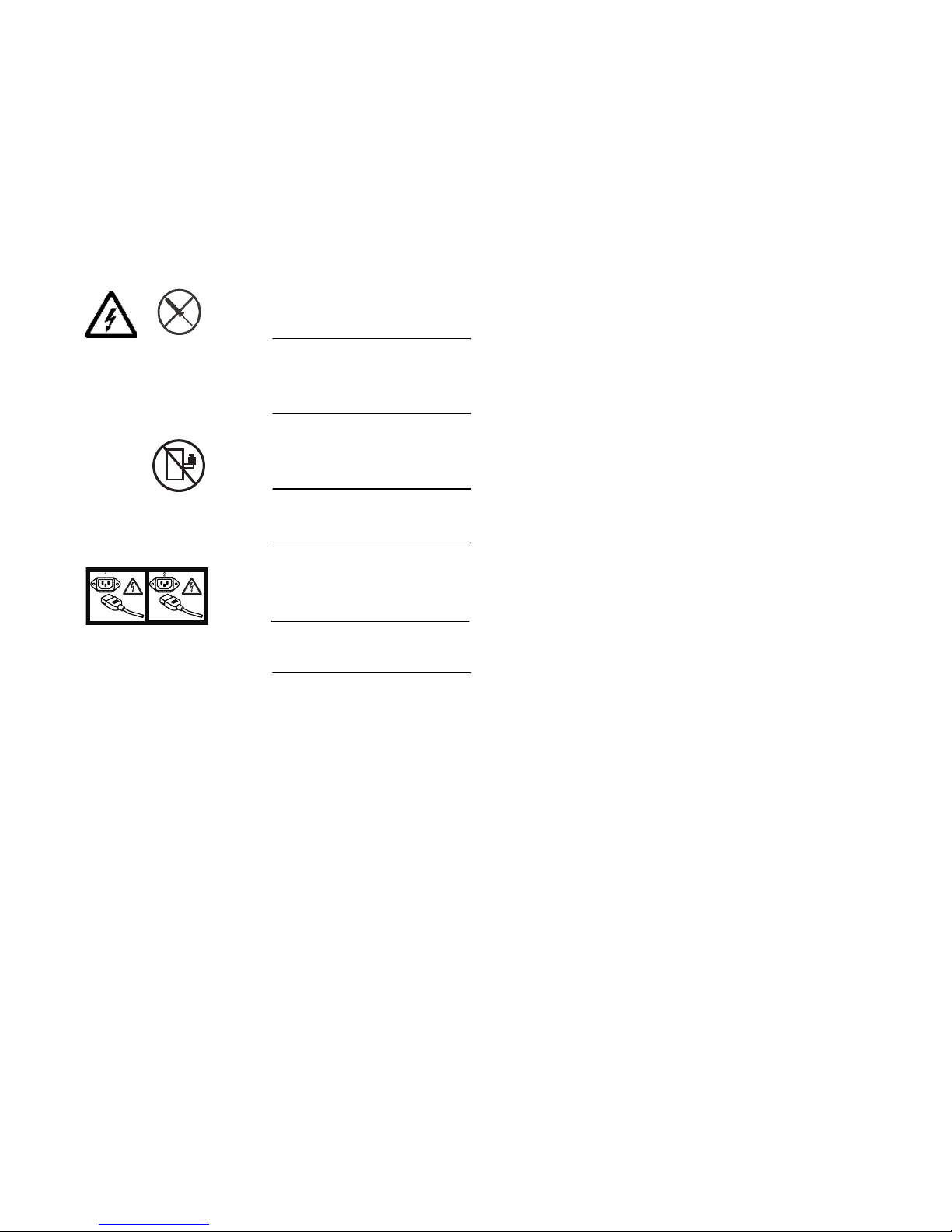
canbeeitherdangerorcautionnotices,dependinguponthelevelof
the hazard.
The actual product safety labels may differ from these sample safety
labels:
DANGER
Hazardous voltage, current, or energy levels are present inside any
component that has this label attached.
(L001)
DANGER
Rack-mounted devices are not to be used as a shelf or work space.
(L002)
DANGER
Multiple power cords
(L003)
Caution notices A caution notice calls attention to a situation that is potentially
hazardous to people because of some existing condition. A caution
notice can be accompanied by different symbols, as in the examples
below:
xxii
SAN140M Installation and Service Manual
Page 25
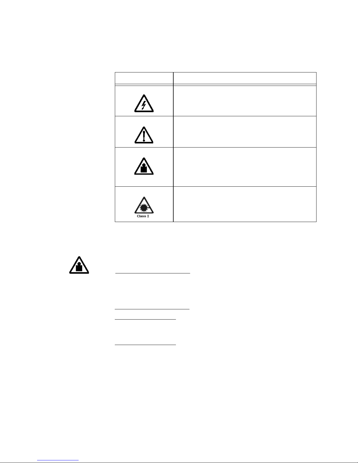
If the symbol is... It means....
A hazardous electrical condition with less severity than electrical
danger.
A generally hazardous condition not represented by other safety
symbols.
A specification of product weight that requires safe lifting
practices. The weight range of the product is listed below the
graphic, and thewording of the caution varies,depending on the
weight of the device.
>18 kg (39.7 lb)
A hazardous condition due to the use of a laser in the product.
Laser symbols are always accompanied by the classification of
the laser as defined by the U. S. Department of Health and
Human Services (forexample, Class I, Class II, and so forth).
Read and comply with the following caution notices before installing
or servicing this device.
CAUTION
The weightof this part or unitis more than 55kg (121.2 lb.). It takes
specially-trained persons and/or a lifting device to safely lift this
part or unit.
(C011)
ATTENTION ! Safe installation of the directorrequires the use of a lift tool,
PN 09P2481, and a 24-inch load plate, PN11P4369. S ee Ordering the lift tool on
page 19.
Preface
xxiii
Page 26
CAUTION
The doors and covers to the product are to be closed at all times
except for service by trained service personnel. All covers must be
replaced and doors locked at the conclusion of the service
operation.
(C013)
CAUTION
The system contains circuit cards and/or assemblies that contain
lead solder. To avoidthe release of lead (Pb) into the environment,
do not burn. Discard the circuit card as instructed by local
regulations.
(C014)
CAUTION
Ensure the building power circuit breakers are turned off BEFORE
you connect the power cord(s) to the building power.
(C023)
xxiv
CAUTION
This assembly contains mechanical moving parts. Use care when
servicing this assembly.
(C025)
CAUTION
Servicing of this product or unit is to be performed by trained
service personnel only.
(C032)
SAN140M Installation and Service Manual
Page 27

Rack-mount safety
information
Danger
Always lower the leveling pads on the rack cabinet.
Always install stabilizer brackets on the rack cabinet.
To avoid hazardous conditions due to uneven mechanical
loading, always install the heaviest devices in the bottom of the
rack cabinet. Always install servers and optional devices starting
from the bottom of the rack cabinet.
Rack-mounted devices are not to beused as a shelf or workspace.
Do not place any object on top of rack-mounted devices.
Each rack cabinet might have more than one power cord. Be sure
to disconnect all power cords in the rack cabinet before servicing
any device in the rack cabinet.
Connect all devices installed in a rack cabinet to power devices
installed in the same rack cabinet. Do not plug a power cord from
a device installed in one rack cabinet into a power device installed
in a different rack cabinet.
An electrical outlet that is not correctly wired could place
hazardous voltage on the metal parts of the system or the devices
that attach to the system. It is the responsibility of the customer to
ensure that the outlet is correctly wired and grounded to prevent
an electrical shock.
Caution
Do not install a unit in a rack where the internal rack ambient
temperatures will exceed the manufacturer’s recommended
ambient temperature for all your rack-mounted devices.
Do not install a unit in a rack where the air flow is compromised.
Ensure that air flow is not blocked or reduced on any side, front,
or back of a unit used for air flow through the unit
Consideration should be given to the connection of the
equipment to the supply circuit so that overloading of the circuits
does not compromise the supply wiring or overcurrent
protection. To provide the correct power connection to a rack,
refer to the rating labels located on the equipment in the rack to
determine the total power requirement of the supply circuit.
Preface
xxv
Page 28

(For sliding drawers.) Do not pull out or install any drawer or
feature if the rack stabilizer brackets are not attached to the rack.
Do not pull out more than one drawer at a time. The rack may
become unstable if you pull out more than one drawer at a time.
(For fixed drawers.) This drawer is a fixed drawer and should not
be moved for servicing unless specified by manufacturer.
Attempting to move the drawer partially or completely out of the
rack may cause the rack to become unstable or cause the drawer
to fall out of the rack.
(R001)
Caution
Removing components from the upper positions in the rack cabinet
improves rack stability during relocation. Follow these general
guidelines whenever you relocate a populated rack cabinet within a
room or building:
Reduce the weight of the rack cabinet by removing equipment
starting at the top of the rack cabinet. When possible, restore the
rack cabinet to the configuration of the rack cabin e t as you
received it.
If this configuration is not known, you must do the following:
• Remove all devices in the 32U position and above.
• Ensure that the heaviest devices are installed in the bottom of
the rack cabinet.
• Ensure that there are no empty U-levels between devices
installed in the rack cabinet below the 32U level.
If the rack cabinet you are relocating is part of a suite of rack
cabinets, detach the rack cabinet from the suite.
Inspect the route that you plan to take to eliminate potential
hazards.
Verify that the route that you choose can support the weight of
the loaded rack cabinet. Refer to the documentation that comes
with your rack cabinet for the weight of a loaded rack cabinet.
Verify that all door openings are at least 760 x 230 mm (30 x 80
in.).
xxvi
SAN140M Installation and Service Manual
Page 29

Ensure that all devices, shelves, drawers, doors, and cables are
secure.
Ensure that the four leveling pads are raised to their highest
position.
Ensure that there is no stabilizer bracket installed on the rack
cabinet during movement.
(R002)
Attention notices An attention notice indicates the possibility of damage to a program,
device, or system, or to data. An exclamation point symbol may
accompany an attention notice, but is not required. A sample
attention notice follows:
ATTENTION! Do not bend afibre cable to a radius lessthan 5cm (2 in.); you
candamagethecable.Tiewrapsarenotrecommendedforopticalcables
because they can be easily overtightened, causing damage to the cable.
Laser safety This equipment contains Class 1 laser products, and complies with
FDA radiation Performance Standards, 21 CFR Subchapter J and the
international laser safety standard IEC 60825.
CAUTION
This product may contain one or more of the following: CD-ROM,
DVD-ROM, DVD-RAM, or laser module, which are Class 1 laser
products. Please note the following:
• Do not removethe covers. Removing the covers of the laser
product could result in exposure to hazardous laser radiation.
There are no serviceable parts inside the device.
• Use of the controls or adjustments or performance of
procedures other than those specified herein might result in
hazardous radiation exposure.
(C026)
Preface
xxvii
Page 30

CAUTION
Data processing environments can contain equipmenttransmitting
on system links with laser modules that operate at greater than
Class 1 power levels. For this reason, never look into the end of an
optical fiber cable or open receptacle.
(C027)
Environmental notices
Use the environmental statements and warning in this section to
guide you when using this product and in properly disposing of the
product and its components.
Product recycling
and disposal
This unit must be recycled or discarded according to applicable local
and national regulations. IBM encourages owners of information
technology (IT) equipment to responsibly recycle their equipment
when it is no longer needed. IBM offers a variety of product return
programs and services in several countries to assist equipment
owners in recycling their IT products. Information on IBM product
recycling offerings can be found on IBM’s Internet site at
http://www.ibm.com/ibm/environment/products/prp.shtml
Note: This mark applies only to countries within the European Union
(EU) and Norway.
Appliances are labeled in accordance with European Directive
2002/96/EC concerning waste electrical and electronic equipment
(WEEE). The Directive determines the framework for the return and
recycling of used appliances as applicable throughout the European
Union. This label is applied to various products to indicate that the
product is not to be thrown away, but rather reclaimed upon end of
life per this Directive.
xxvii
SAN140M Installation and Service Manual
Page 31

In accordance with the European WEEE Directive, electrical and
electronic equipment (EEE) is to be collected separately and to be
reused, recycled, or recovered at end of life. Users of EEE with the
WEEE marking per Annex IV of the W EEE Directive, as shown
above, must not dispose of end of life EEE as unsorted municipal
waste, but usethe collection framework available to customers for the
return, recycling and recovery of WEEE. Customer participation is
important to minimize any potential effects of EEE on the
environment and human health due to the potential presence of
hazardous substances in EEE. For proper collection and treatment,
contact your local IBM representative.
Battery return
program
This product may contain sealed lead acid, nickel cadmium, nickel
metal hydride, lithium, or lithium ion battery. Consult your user
manual or service manual for specific battery information. The
battery must be recycled or disposed of properly. Recycling facilities
may not be available in your area. For information on disposal of
batteries outside the United States, go to
http://www.ibm.com/ibm/environment/products/batteryrecycle.s
html or contact your local waste disposal facility.
In the United States, IBM has established a return process for reuse,
recycling, or proper disposal of used IBM sealed lead acid, nickel
cadmium, nickel metal hydride, and other battery packs from IBM
Equipment. For information on proper disposal of these batteries,
contact IBM at 1-800-426-4333. Please have the IBM part number
listed on the battery available prior to your call.
Preface
xxix
Page 32

Cable warning
For Taiwan:
WARNING
Handling the cord on this product or cords associated with
accessories sold with this product, will expose you to lead, a
chemical known to the State of California to cause cancer, and birth
defects or other reproductive harm. Wash hands after handling.
xxx
SAN140M Installation and Service Manual
Page 33

Chapter 1: General information
The IBM®TotalStorage SAN140M directorprovides up to 140ports of
high-performance, dynamic Fibre Channel connectivity for switched
fabric devices in a storage area network (SAN). The director provides
a broad bandwidth (1, 2 or 10 gigabits per second), redundant
switched data paths, and long transmission distances.
This chapter presents information and features of the director and its
management, including:
• Director description.
• Field-replaceable units (FRUs).
• Error detection, reporting, and serviceability features.
• Element Manager status indicators
•Toolsandtestequipment.
• Director management.
Director description
The SAN140M director is a 140-port product that provides dynamic
switched connections between Fibre Chann el servers a nd devices in a
SAN environment. The portsoperate at 1, 2 or 10 gigabits per second
(Gbps). Directors (from one to three) can be configured to order in an
equipment cabinet, which can provide up to 420 ports in a single
cabinet.
The director provides dynamic switched connections for servers and
devices, supports mainframe andopen-systems interconnection (OSI)
computing environments, and provides data transmission and flow
control between device node ports (N_Ports) as dictated by the Fibre
Channel Physical and Signaling Interface (FC-PH 4.3). Through
interswitch links (ISLs), the director can also connect to one or more
additional directors to form a Fibre Channel multiswitch fabric.
The director can be managed through a management server running
a Java™-based SAN management application (Enterprise Fabric
Connectivity Manager (EFCM) and Element Manager applications).
© Copyright IBM Corp. 2006
1
Page 34

Multiple directors and the management server communicate on a
local area network (LAN) through one or more 10/100 Base-T
Ethernet hubs. One or more 24-port Ethernet hubs are optional and
can be ordered with the director. Up to three hubs can be
daisy-chained to provide additional Ethernet connections as more
directors (or other IBM managed products) are installed on a
customer network.
As an option, administrators or operators with a browser-capable PC
and an Internet connection can monitor and manage the director
through the EFCM Basic Edition interface. The interface manages
only a single director, and provides a graphical user interface (GUI)
that supports product configuration, statistics monitoring, and basic
operation. The EFCM Basic Edition interface is opened from a
®
standard web browser running Netscape Navigator
®
Microsoft
Internet Explorer 4.0 or higher.
4.6orhigheror
Figure 1 illustrates an equipment rack with three directors, the
management server, and an Ethernet hub.
2
SAN140M Installation and Service Manual
Page 35

1
2
3
3
H
D
D
FA
N
L
2
L1
ENTER
4
3
4
5
Figure 1 Cabinet-mounted SAN140M directors and management server
Location Description
1Ethernethub
2Director
3 Management server
4Director
5Director
Chapter 1: General information
i140M001
3
Page 36

Field-replaceable units
The director provides a modular design th at enables quick removal
and replacement of FRUs. This section describes director FRUs and
controls, connectors, and indicators associated with the FRUs.
Director FRUs accessed from the front (Figure 2)includethe:
• Universal port module (UPM) cards (2 Gbps).
•10Gbpsportmodule(XPM)cards.
• Control processor (CTP) cards.
1
2
4
3
i140M232
Figure 2 Director FRUs (front access)
Location Description
1XPMcards
2 Power and system error LEDs
3UPMcard
4CTPcards
Director FRUs accessed from the rear (Figure 3)includethe:
•Fanmodules.
4
SAN140M Installation and Service Manual
Page 37

• Universal port module (UPM) cards (2 Gbps).
• 10 Gbps port module (XPM) cards.
• Serial crossbar (SBAR) assemblies.
• Power supplies.
•ACmodules.
• Power/System Error LED Assembly (not shown).
•Backplane(notshown).
1
2
3
4
Figure 3 Director FRUs (rear access)
Location Description
1 Cooling fans
2UPMorXPMCards
3 Maintenance port
4 SBAR assemblies
5 Power supplies
6ACmodules
5
6
i140M003
Chapter 1: General information
5
Page 38

Power/system LED assembly
The bezel at the top front of the director includes an amber system
errorlight-emitting diode (LED)and a greenpower LED. These LEDs
are actuated and controlled by a Power/System LED Assembly
which is accessed from the rear of the director.
The power LED lights up when the director is powered on and
operational. If the LED turns off, a facility power source, alternating
current (AC) power cord, or director power distribution failure is
indicated.
The system error LED lights up when the director detects an event
requiring immediate operator attention, such as a FRU failure. The
LED remains illuminated as long as an event is active. The LED turns
off when the Clear System Error Light function is selected from the
Element Manager application. The LED blinks if unit beaconing is
enabled. A lit system error LED (indicating a failure) takes
precedence over unit beaconing.
CTP card
The director is delivered with two CTP cards. The active CTP card
initializes and configures the director after power on and contains the
microprocessor and associated logic that coordinate director
operation.
The CTP card provides an initial machine load (IML)buttonanda
RESET button (recessed) on the faceplate.
When the IML button is pressed, held for three seconds, and
released,the director performsan IMLthat reloadsthe firmware from
FLASH memory. This operation is not disruptive to Fibre Channel
traffic.
When the RESET button is pressed and held for three seconds, the
director performs a reset. A reset is disruptive and resets the:
• Microprocessor and functional logic for the CTP card and reloads
thefirmwarefromFLASHmemory.
• Ethernet LAN interface, causing the connection to the
management server to drop momentarily until the connection
automatically recovers.
6
SAN140M Installation and Service Manual
Page 39

• Ports, causing all Fibre Channel connections to drop momentarily
until the connections automatically recover. This causes attached
devices to log out and log back in, therefore data frames lost
during director reset must be retransmitted.
A reset should only be performed if a CTP card failure is indicated.
As a precaution, the RESET button is flush mounted to protect
against inadvertent activation.
Each CTP card also provides a 10/100 megabit per second (Mbps)
RJ-45 twisted pair connector on the faceplate that attaches to an
Ethernet local area network (LAN) to communicate with the
management server or a simple network management protocol
(SNMP) management station.
Each CTP card provides system services processor (SSP) and
embedded port (EP) subsystems. The SSP subsystem runs director
applications and the underlying operating system, communicates
with director ports, and controls the RS-232 maintenance port and
10/100 Mbps Ethernet port. The EP subsystem provides Class F and
exception frame processing, and manages frame transmission to
and from the SBAR assembly. In addition, a CTP card provides
nonvolatile memory for s toring firmware, director configuration
information, persistent operating parameters, and memory dump
files. Director firmware isupgraded concurrently (without disrupting
operation).
UPM card
The backup CTP card takes over operation if the active card fails.
Failover from a faulty card to the backup card is transparent to
attached devices.
Each card faceplate contains a green LED that illuminates if the card
is operational and active, and an amber LED that illuminates if the
card fails. Both LEDs are turned off on an operational backup card.
The amber LED blinks if FRU beaconing is enabled.
Each UPM card (Figure 4) provides four full-duplex generic ports
(G_Ports) that transmit or receive data at 2 gigabits per second
(Gbps). G_Port functionality depends on the type of cable
attachment. UPM cards use non-open fiber control (OFC) Class 1
laser transceivers that comply with Section 21 of the Code of Federal
Regulations(CFR),Subpart(J)asofthedateofmanufacture.
The card faceplate contains:
Chapter 1: General information
7
Page 40

• Four duplex LC connectors for attaching fiber-optic cables.
• An amber LED (at the top of the card) that illuminates if any port
fails or blinks if FRU beaconing is enabled.
• A bank of amber and green LEDs above the ports. One amber
LED and one green LED are associated with each port and
indicate port status as follows:
— The green LED illuminates (or blinks if there is active traffic)
and the amber LED turns off to indicate normal port
operation.
— The amber LED illuminates and the green LED turns off to
indicate a port failure.
— Both LEDs turn off to indicate a port is operational but not
communicating with an N_Port (no cable attached, loss of
light, port blocked, or link recovery in process).
— The amber LED flashes and the green LED either remains on,
turns off, or flashes to indicate a port is beaconing or running
online diagnostics.
UPM
Figure 4 UPM card LEDs and connectors
1
2
3
i140M004
8
SAN140M Installation and Service Manual
Page 41

XPM card
Location Description
1 Card LED
2 Port LEDs
3 Port connectors
Each XPM card (Figure 5) provides one full-duplex generic port
(G_Port) that transmits or receives data at 10 gigabits per second
(Gbps). The card faceplate contains:
• One duplex LC connector for attaching fiber-optic cables.
• Amber and green LEDs that indicate port status similar to the
LEDs on the UPM cards (UPM card on page 7).
1
Figure 5 XPM card
Location Description
1XPMcard
i140M229
Chapter 1: General information
9
Page 42

SFP and XFP transceivers
Singlemode or multimode fiber-optic cables attach to director ports
through2 Gbps small form-factor pluggable (SFP, Figure 6 -forUPM
cards) or 10 Gbps form-factor pluggable (XFP, Figure 7 -forXPM
cards) optic transceivers. The fiber-optic transceivers provide duplex
®
connectors and can be detached from director ports for easy
LC
replacement.
NOTE: SFPandXFPtransceiversarenotinterchangeable.
These fiber-optic transceiver types are available:
• Shortwave laser, SFP, 2.125 Gbps
•Shortwavelaser,XFP,10.520Gbps
• Longwavelaser,SFP,2.125Gbps
• Longwavelaser,XFP,10.520Gbps
Figure 6 Small form-factor pluggable (SFP) transceiver
10
SAN140M Installation and Service Manual
i256M066
Page 43

Figure 7 Ten Gbps form-factor pluggable (XFP) transceiver
Power supply
i256M152
Redundant, load-sharing power supplies step down and rectify
facility input power to provide 48-volt direct current (VDC) power to
director FRUs. The power supplies also provide overvoltage and
overcurrent protection. Either power supply can be replaced while
the director is powered on and operational.
Each power supply has a separate backplane connection to allow for
different AC power sources. The power supplies a re in put rated at
180 to 264 volts alternating current (V AC). The faceplate of each
power supply provides the following status LEDs:
• A green AC OK LED illuminates if the power supply is
operational and receiving AC power.
• A green DC OK LED illuminates if the power supply is
operational and producing DC power.
•AredFAULT LED illuminates if the power supply fails.
AC module
The AC module is located at the bottom rearof the director. Either AC
module can be replaced while the director is powered on and
operational. The module provides:
• Two single-phase, 220 VAC, power connectors.
Chapter 1: General information
11
Page 44

Fan module
SBAR assembly
• An input filter and AC system harness (internal to the FRU) that
provides the wiring to connect the AC power connectors to the
power supplies (through the backplane).
Three fan modules, each containing one system fan (three system fans
total), provide cooling for director FRUs, as well as redundancy for
continued operation if a fan fails.
A fan module can be replaced while the director is powered on and
operating, provided the module is replaced within ten minutes (after
which software powers off the director). An amber LED for each fan
module illuminates if one or more fans fail or rotate at insufficient
angular velocity.
The director is delivered with two SBAR assemblies. The active SBAR
isresponsibleforFibreChannelframetransmissionfromanydirector
port to any other director port. Connections are established without
software intervention. The assembly accepts a connection request
from a port, determines if a connection can be established, and
establishes the connection if the destination port is available. The
assembly also stores busy, source connection, and error status for
each director port.
Backplane
12
SAN140M Installation and Service Manual
The backup SBAR takes over operation if the active assembly fails,
and provides the ability to maintain connectivity and data frame
transmission without interruption. Failover tothe backup assembly is
transparent to attached devices.
Each SBARassembly consists of a card and steel carriage that mounts
flushonthebackplane.Thecarriageprovidesprotectionfortheback
of the card, distributes cooling airflow, and assists in aligning the
assembly during installation. The rear of the carriage contains a green
LED that illuminates if the assembly is operational and active, and an
amber LED that illuminates if the assembly fails. Both LEDs are
turned off on an operational backup assembly.The amber LED blinks
if FRU beaconing is enabled.
The backplane provides 48 VDCpower distributionand connections
for all logic cards. The backplane is a nonconcurrent FRU. The
director must be powered off prior to FRU removal and replacement.
Page 45

Error-detection, repor ting, and serviceability features
The director provides the following error detection, reporting, and
serviceability features:
• Light-emitting diodes (LEDs) on director FRUs and the front
bezel that provide visual indicators of hardware status or
malfunctions.
• Redundant FRUs (logic cards, power supplies, and cooling fans)
that are removed or replaced without disrupting director or Fibre
Channel link operation.
• A modular design that enables quick removal and replacement of
FRUs without the use of special tools or equipment.
• System alerts and logs that display director, Ethernet link, and
Fibre Channel link status at the management server (running a
SAN management application), client comm unicating with the
management server, or EFCM Basic Edition interface.
• Diagnostic software that performs power-on self-tests (POSTs)
and port diagnostics (internal loopback, external loopback, and
Fibre Channel (FC) wrap tests). The FC wrap test applies only
when the director isconfigured to operate in FICON management
style.
• An RS-232maintenance port at the rearof the director(port access
is password protected) that enables installation or service
personnel to change the director’s internet protocol (IP) address,
subnet mask, and gateway address; or to run diagnostics and
isolate system problems through a local or remote terminal.
The director parameters can also be changed through a Telnet
session, access for which is providedthrough a local or remotePC
with an Internet connection to the director.
• Data collection through the Element Manager application or the
EFCM Basic Edition interface to help isolate system problems.
The data includes a memory dump file and audit, hardware, and
engineering logs.
• Beaconing to assist service personnel in locating a specific port,
FRU, or director in a multiswitch environment. When port
beaconing is enabled, the amber LED associated with the port
flashes. When FRU beaconing is enabled, the amber (service
Chapter 1: General information
13
Page 46

required) LED on the FRU flashes. When unit beaconing is
enabled, the system error indicator on the front bezel fla shes.
Beaconing does not affect port, FRU, or director operation.
• An internal modem for use by support personnel to dial-in to the
management server for event notification and to perform remote
diagnostics.
• Automatic notification of significant system events (to support
personnel or administrators) through e-mail messages or the
call-home feature.
NOTE: Thecall-homefeatureisnotavailablethroughtheEFCMBasic
Edition interface.
• Concurrent port maintenance. UPM cards are added or replaced
and fiber-optic cables are attached to ports without interrupting
other ports or director operation.
• Status monitoring of redundant FRUs and alternate Fibre
Channel data paths to ensure continued director availability in
case of failover. The SAN management application queries the
status of each backup FRU. A backup FRU failure is indicated by
an illuminated amber LED.
• SNMP management using the Fibre Channel Fabric Element MIB
(Version 1.1), transmission control protocol/internet protocol
(TCP/IP) MIB-II definition (RFC 1157), or a product-specific
private enterprise MIB that runs on each director. Up to six
authorized management workstations can be configured through
the Element Manager application or EFCM Basic Edition interface
to receive unsolicited SNMP trap messages. The trap messages
indicate operational state changes and failure conditions.
• SNMP management using the Fibre Alliance MIB (Version 3.1)
that runs on the management server. Up to 12 authorized
management workstations can be configured through the SAN
management application to receive unsolicited SNMP trap
messages. The trap messages indicate operational state changes
and failure conditions.
Element Manager status indicators
In addition to the visual indicators on the director chassis, the
Element Manager application presents alert symbols and messages
14
SAN140M Installation and Service Manual
Page 47

that describe the condition of the director and its FRUs. These alert
symbols, messages, and a description are summarized in Table 2.
Table 2 Element Manager alert symbols, messages, and status
Symbol Message Description
Fully operational All components and installed ports are operational.
Redundant failure A redundant component has failed, and the backup
component has taken over.
Minor failure A failure has occurred that has decreased the
director operational capability, but has not affected
normal switching operations.
Major failure Power supplies have failed.
Loading firmware The system is busy loading new firmware, but the
system is otherwise operational.
Not operational A critical failure has occurred that prevents the
director from performing fundamental switching
operations.
Tools and test equipment
This section describes tools and test equipment that may be required
to test, service, and verify operation of the director and attached
management server. These tools are either supplied with the director
or must be supplied by service personnel.
Tools supplied with the director
The following tools are supplied with the director. Use of the tools
may be required to perform installation, test, service, or verification
tasks.
o Link time-out
oProtocol
mismatch
o Never connected
Director status is unknown. Occurs is network
connection between the management server and the
director is lost, or if a CTP card fails and there is no
operational backup, or if there is no system power.
Chapter 1: General information
15
Page 48

• Torque tool with hexagonal adapter- The torque tool with 5/32”
hexagonal adapter (Figure 8)isrequiredtoremoveandreplace
director logic cards.
ATTENTION! The torque tool supplied with the IBM TotalStorage
SAN140M director is designed to tighten director logic cards and is set to
release at a torque value of six inch-pounds. Do not use an Allen wrench or
torquetool designedfor usewith anotherIBM product.Use ofthe wrongtool
may overtighten and damage logic cards.
Figure 8 Torque tool and hex adapter
• Door key - The door key with 5/16” socket (Figure 9)maybe
required to open the front or rear door of the equipment cabinet.
A 5/16” socket wrench may be used in lieu of the door key.
i140M009
Figure 9 Door key
• Loopback plug - SFP or XFP loopback plugs (Figure 10)are
required to perform port loopback diagnostic tests. Loopback
plugs are shipped with the director, depending on the type of
port transceivers installed.
Figure 10 Loopback plug
16
SAN140M Installation and Service Manual
i140M010
i140M212
Page 49

• Fiber-optic protective plug - For safety and port transceiver
protection, fiber-optic protective plugs (Figure 11)mustbe
inserted in all director ports without fiber-optic cables attached.
The director is shipped with protective plugs installed in all ports.
i140M213
Figure 11 Fiber-optic protective plug
• Null modem cable - An asynchronous RS-232 null modem cable
(Figure 12) is required to configure director network addresses
and acquire event log information through the maintenance port.
ThecablehasnineconductorsandDB-9maleandfemale
connectors.
Figure 12 Null modem cable
Tools supplied by service personnel
The following tools are expected to be supplied by service personnel
performing director installation or maintenance actions. Use of the
tools may be required to perform one or more test, service, or
verification tasks.
• Scissors or pocket knife - A sharp cutting edge (scissors or
knife blade) may be requiredto cut the protective strapping when
unpacking replacement FRUs.
• Standard flat-tip and cross-tip (Phillips) screwdrivers -
Screwdrivers are required to remove, replace, adjust or tighten
various FRUs, chassis, or cabinet components.
i12M1015
Chapter 1: General information
17
Page 50

• T10 Torts®tool - The tool is required to rack-mount the director
or to remove, replace, adjust or tighten various chassis or cabinet
components.
• Electrostatic discharge (ESD) grounding cable with attached
wrist strap- Use of the ESD wrist strap is required when working
in and around the director card cage.
• Maintenance terminal (desktop or notebook PC) - The PC is
required to configure director network addresses and acquire
event log information through the maintenance port. The PC
must have:
— The Microsoft™ Windows™ 98, Windows 2000, Windows XP,
or Millennium Edition™ operating system installed.
— RS-232 serial communication software (such as ProComm
Plus™ or HyperTerminal) installed. HyperTerminal is
provided with Windows operating systems.
• Fiber-optic cleaningkit - The kit contains tools and instructions
to clean fiber-optic cable, connectors, loopback plugs, and
protective plugs.
Director management
The director is managed and controlled through a:
• Management serverrunning a SAN management application that
• Customer-suppliedPCplatformwithanInternetconnectionto
provides a central point of control for up to 48 directors or
managed products.
The management server is delivered with a server and client SAN
management applications (EFC Manager, and Element Manager)
installed. A customer-supplied PC or workstation (with client
applications installed) communicates with the server through a
through a corporate intranet.
the EFCM Basic Edition interface on the director. Using this
graphical user interface (GUI), operators can quickly view
director status.
The interface allows service personnel to perform configuration
tasks, view system alerts and related log information, and
monitor director status, port status, and performance. FRU status
and system alert information are highly visible.
18
SAN140M Installation and Service Manual
Page 51

• Customer-supplied PC or UNIX-based platform with the server
• Simple network management protocol (SNMP). An SNMP agent
• Command line interface (CLI). The CLI allows you to access
Ordering the lift tool
and client Element Manager application installed.
is implemented through the SAN management application that
allows administrators on SNMP management workstations to
access director management information using any standard
network management tool. Administrators can assign internet
protocol (IP) addresses and corresponding community names for
up to 12 SNMP workstations functioning as SNMP trap message
recipients. Refer to the SNMP Support Manual (620-000131).
many SAN management functions while entering commands
during a telnet session with the director. The primary purpose of
the CLI is toautomate management of a largenumber of directors
using scripts. The CLI is not an interactive interface; no checking
is done for pre-existing conditions and no prompts display to
guide users through tasks. Refer to the E/OS Command Line
Interface User Manual, 620-000134.
CAUTION
Important! The lift tool is required when you install or remove a
director.
The ordering procedures for the lift tool vary depending on your
location. You should direct questions about these procedures to your
regional specialist.
World Trade locations
The following ordering procedures are for world trade locations:
• Order the lift tool by using the parts order system, like any other
• Use the following part numbers when you order:
part.
• Lift tool (PN 09P2481)
• 24-inch load plate (PN 11P4369)
Chapter 1: General information
19
Page 52

• You do not record parts usage.
• Return the lift tool and the 24-inch load plate to the parts center
United States locations
In the United States, call UPS Logistics at 800-528-6070 to order the
lift tool and the 24-inch load plate.
NOTE: For the SSR branch and territory, the United States cannot order the
lift tool or 24-inch load plate through the parts order system. UPS Logistics
are used to ship and return the lift tool and 24-inchload plate.
Use the following part numbers when you order:
• Lift tool (PN 09P2481)
• 24-inch load plate (PN 11P4369)
This information is necessary to ensure that the lift tool is delivered
when you need it. Failure to provide this information might delay the
completion of the order request and the shipping request. It might
also result in a time and date to return the tool that is different from
what you need.
after you complete the installation or removal of the Director.
• Phone number and customer contact
• Account code: 98577
• Time and date of delivery
• Accurate destination address with zip code
• Time and date of return pickup
YoumustreturnthelifttoolatthetimethatwasscheduledwithUPS
Logistics. If you need to change the scheduled return time or date,
contact UPS Logistics.
YoumustreturnthelifttoolatthetimethatwasscheduledwithUPS
Logistics. If you need to change the scheduled return time or date,
contact UPS Logistics. You are responsiblefor ensuring that all of the
paperwork and components are packed and restored in the arbocrate
(shipping container) of the lift tool. Ensure that the lift tool is
functioning properly before you release the tool to UPS Logistics for
return. You are accountable for the lift tool until UPS Logistics picks
up the lift tool for return delivery to their parts storage facility.
20
SAN140M Installation and Service Manual
Page 53

Contactyourbranchofficetoolscoordinatororyourregionspecialist
if you have any questions or concerns.
Chapter 1: General information
21
Page 54

22
SAN140M Installation and Service Manual
Page 55

Chapter 2: Installation tasks
This chapter describes tasks to install, configure, and verify operation
of the SAN140M directorusing a storage area network (SAN)
management application or the EFCM Basic Edition interface. The
director can be installed in an equipment cabinet, in any standard
19-in equipment rack, or mounted on a table top.
Factory defaults
Table 3 lists factory-set defaults for the director.
Table 3 Factory-set defaults (director)
Item Default
EFCM Basic Edition interface user name (case sensitive) Administrator
EFCM Basic Edition interface password (case sensitive) password
Customer-level password (maintenance port access) password
Maintenance-level password (maintenance port access) level-2
IP address 10.1.1.10
Subnet mask 255.0.0.0
Gateway address 0.0.0.0
© Copyright IBM Corp. 2006
23
Page 56

Installation task summary
The service representative installation responsibilities include the
following:
• Installing the director in a rack (if the director did not arrive in a
rack)
• Connection power cords.
•Poweringupthedirector.
• Changing the IP address to the customer-requested values.
• Preparing the director for the customer or some consultant to
configure.
IBM does not install the EFCM Basic program, install the
management server, or configure the machine for use.
Table 4 summarizes the installation tasks for the director and optional
Ethernet hub. The table describes each task, states whether the task is
optional, and lists the page reference.
Table 4 Installation Task summary
Task number and description Required or optional Page
Task 1: Verify installation requirements
Task 2: Unpack, inspect, and install the Ethernet hub
(optional)
Task 3: Unpack, inspect, and install the director
Task 4: Configure director at the EFCM Basic Edition
interface (optional)
Task 5: Configure director network information (optional)
Task 6: Configure server password and network addresses
Task 7: Configure management server information
Task 8: Configure Windows operating system users
Task 9: Set management server date and time
Task 10: Configure the call-home feature (optional)
Required. 26
Optional - perform task if hub is required to connect
director and management interface.
Required. 30
Optional - perform task if director is managed through
the EFCM Basic Edition interface.
Configure if connecting multiple directors or connecting
director and management server to a public LAN.
Required if management server is used. 55
Required if management server is used. 57
Required if management server is used. 61
Required if management server is used. 63
Optional - configure if specified by customer and
telephone connection is provided.
26
33
51
65
24
SAN140M Installation and Service Manual
Page 57

Table 4 Installation Task summary (Continued)
Task number and description Required or optional Page
Task 11: Assign user names and passwords
Task 12: Configure the director to the management
application
Task 13: Record or verify server restore information
Task 14: Verify director-to-server communication
Task 15: Configure PFE ke y (optional)
Task 16: Configure management server (optional)
Task 17: Set director date and time
Task 18: Configure the Element Manager application
Task 19: Back up configuration data
Task 20: Cable Fibre Channel ports
Task 21: Configure Zoning (Optional)
Task 22: Connect director to a fabric element (optional)
Required if management server is used. 66
Required if management server is used. 67
Required if management server is used. 68
Required if management server is used. 69
Optional - configure if product feature enablement (PFE)
keyisordered.
Optional - configure for open-systems host control of
director.
Required if management server is used. 73
Required if management server is used. 74
Required if management server is used. 89
Required. 91
Optional - perform task to configure zoning. 92
Optional - perform task to connect director to a Fibre
channel fabric.
70
72
92
Chapter 2: Installation tasks
25
Page 58

Task 1: Verify installation requirements
Verify that the following requirements are met prior to director and
management interface installation. Ensure:
• A site plan and planning tasks are complete. Refer to the IBM
TotalStorage Products in a SAN Environment Planning Manual,
GC26-7675.
• Fibre Channel SAN design is complete. Refer to the IBM
TotalStorage Products in a SAN Environment Planning Manual,
GC26-7675.
• Support is available for one of the following product
management methods:
— A management server or browser-capable PC and LAN
segment connectivity to support operation of SAN
management and Element Manager applications, or
— A browser-capable PC and Internet connectivity to support
the product-resident EFCM Basic Edition interface.
• Support equipment and technical personnel are available for the
installation.
• The required number and type of fiber-optic jumper cables are
delivered and available. Ensure cables are the correct length and
have the required connectors.
• A 19-inch equipment rack and associated hardware are available.
• Remote workstations or simple network management protocol
(SNMP) workstations are available (optional). Workstations are
connected through a public or dedicated LAN segment.
Task 2: Unpack, inspect, and install the Ethernet hub (optional)
The director is managed through either:
• A 10/100 megabit per second (Mbps) LAN connection to a
management server. Connectivity may require installation of a
24-portEthernethub.Acombinationofupto48productscanbe
configured and managed on one netw ork, therefore multiple,
daisy-chained hubs may be required to provide sufficient port
connections.
26
SAN140M Installation and Service Manual
Page 59

• An Internet connection to a browser-capable PC (EFCM Basic
Edition interface). Connection of a LAN segment with multiple
products to the Internet may require installation of a 24-port
Ethernet hub.
Follow the instructions in Unpack and inspect the Ethernet hub below to
unpack, inspect, and install the Ethernet hub, but:
• If the existing Ethernet LAN segment is adequate for connectivity
andahubisnotdelivered,thistaskisnotrequired.GotoTask 3:
Unpack, inspect, and install the director on page 30.
• If the hub is delivered in an equipment cabinet, go to Task 5:
Configure director network information (optional) on page 51.
Unpack and inspect the Ethernet hub
Unpack and inspect the Ethernet hub(s).
1. Inspect shippingcontainer(s)for damage caused during transit. If
a container is damaged, ensure a representative from the freight
carrier is present when the container is opened.
2. Unpack shipping container(s) and inspect each item for damage.
Ensure the packaged items correspond to the items listed on the
enclosed bill of materials.
Desktop installation
3. If any items are damaged or missing, call the IBM Quality Hotline
toll-free at 1-800-442-6773 within the United States and Canada.
In other locations direct dial 770-858-8459.
To install and configure up to three Ethernet hubs on a desktop:
1. Remove the backing from the four adhesive rubber pads and
apply the pads to the underside of each hub. Ensure pads are
aligned with the scribed circles at each corner.
2. Position the first hub on a table or desktop. Stack the remaining
hubs on top of the first hub. Ensure the adhesive rubber pads on
the underside of a hub align with the recesses on the top of the
hub below.
3. To daisy-chain (connect) the hubs:
Chapter 2: Installation tasks
27
Page 60

a. To connect the top and middle stacked hubs, connect an RJ-45
patch cable to port 24 of the top hub, then connect the cable to
port 12 of the middle hub.
b. To connect the bottom and middle stacked hubs, connect a
second RJ-45 patch cable to port 24 ofthemiddlehub,then
connect the cable to port 12 of the bottom hub.
c. Use a pointed instrument to set the medium-dependent
interface (MDI) switch on the top and middle hubs to MDI
(in) (Figure 13, 1 and 2).SettheMDIswitchonthebottomhub
to MDIX (out) ( Figure 13, 3).
NOTE: To connecttwo hubs, follow step b and step c (middle and
bottom hub)instructions.
4. Connect a power cord to an AC power strip and the receptacle at
therearofeachhub.Useanextensioncordifrequired.
5. Connect the AC power strip to facility power. Power for each hub
switches on when the strip is connected to facility AC power.
6. Inspect the front panel of each hub. Ensure each green Power
light-emitting diode (LED) is lit.
28
1
2
3
i140M015
Figure 13 Patch cable and MDI selector configuration
SAN140M Installation and Service Manual
Page 61

Rack-mount installation
Perform the following steps to install and configure up to three
Ethernet hubs in a cabinet or 19-inch equipment rack. A pointed
instrument (pencil tip orbent paper clip), #2Phillips screwdriver,and
1/8-inch Allen wrench are required.
1. Secure one mounting bracket to each side of the first hub
(Figure 14). Use the two brackets and four pan-head Phillips
screws (8/32 x 0.5-inch) provided.
i140M016
Figure 14 Mounting bracket installation (Ethernet hub)
2. Position the hub in the equipment rack. Align screw holes in the
mounting brackets with screw holes in the rack-mount standards.
3. Secure both sides of the hub to the rack-mount standards. Use the
1/8-inch Allen wrench and four Allen-head mounting screws
(10/32 x 0.5-inch) provided.
4. Repeat step 1 through step 3 for the remaining hubs.
5. To daisy-chain (connect) the hubs:
a. To connect the top and middle stacked hubs, connect an RJ-45
patch cable to port 24 of the top hub, then connect the cable to
port 12 of the middle hub.
b. To connect the bottom and middle stacked hubs, connect a
second RJ-45 patch cable to port 24 ofthemiddlehub,then
connect the cable to port 12 of the bottom hub.
Chapter 2: Installation tasks
29
Page 62

c. Use a pointed instrument to set the medium-dependent
interface (MDI) switch on the top and middle hubs to MDI
(in) (Figure 13, 1 and 2).SettheMDIswitchonthebottomhub
to MDIX (out) ( Figure 13, 3).
NOTE: To connecttwo hubs, follow step b and step c (middle and
bottom hub)instructions.
6. Connect a power cord to a rack power strip and the receptacle at
the rear of each hub. Power for each hub switches on when the
hub (and equipment rack) are connected to facility AC power.
NOTE: Ensure each hub is connected to a separate rack power strip.
7. Inspect the front panel of each hub. Ensure each green Power
LED turns on.
Task 3: Unpack, inspect, and install the director
The following paragraphs provide instructions to unpack, inspect,
and install the director in a rack-mount configuration. If the director
is delivered in an equipment cabinet, go to Task 5: Configure director
network information (optional) on page 51.
30
CAUTION
The weightof this part orunit is more than 55kg (121.2 lb.). Ittakes
specially-trained persons and/or a lifting device to safely lift this
part or unit.
(C011)
Unpack and inspect the director.
1. Inspect theshipping containersfor damagecaused duringtransit.
If a container is damaged, ensurea representative fromthe freight
carrier is present when the container is opened.
2. Unpack the shipping containers and inspect each item for
damage. Ensure the items match the items listed on the bill of
materials (BOM).
SAN140M Installation and Service Manual
Page 63

3. If any items are damaged or missing, call the IBM Quality Hotline
Rack-mount installation
CAUTION
The weightof this part or unitis more than 55 kg(121.2 lb.). It takes
specially-trained persons and/or a lifting device to safely lift this
part or unit.
(C011)
ATTENTION ! Safe installation of the directorrequires the use of a lift tool,
PN 09P2481, and a 24-inch load plate, PN11P4369. S ee Ordering the lift tool on
page 19 for complete ordering information.
Perform the following steps to install the director in a customersupplied equipment rack. A #2 Phillips screwdriver is required.
1. Locate the rack-mount position as directed by the customer. The
toll-free at 1-800-442-6773 within the United States and Canada.
In other locations direct dial 770-858-8459.
director is 20 inches (12 U) high.
2. Verify all FRUs, including the SFP and XFP optical transceivers,
logic cards, fans, and power supplies are installed as ordered.
3. Open the rack-mount kit and inspect the contents. Refer to the
enclosed bill of materials and verify all parts are delivered.
4. Using installation instructions delivered with the rack-mount kit
and a #2 Phillips screwdriver,install the director in the equipment
cabinet.
5. Connect the U.S. AC power cords to the right (PS0) and left (PS1)
receptacles at the rear of the director (Figure 15).
DANGER
An electrical outlet that is not correctlywired could place hazardous
voltage on metal parts of the system or the devices that attach to the
system. It is the responsibility of the customer to ensure that the
outlet is correctly wired and grounded to prevent an electrical shock.
(D004)
Chapter 2: Installation tasks
31
Page 64

6. Connect the remaining ends of the AC power cords to separate
(for redundancy) rack power strips.
NOTE: The director does not have a power switch. Therefore the director
powers on when its power cords are connected to facility or rack power.
Figure 15 AC power connections (director)
7. Connect the equipment rack power cords to separate (for
redundancy) facility power sourcesthat provide single-phase, 180
to 264 VAC voltage.
i140M018
8. Power on the rack power strips.
9. Inspect the front panel of each rack-mounted Ethernet hub.
Ensure each green Power LED turns on.
10. The director powers on and performs POSTs. During POSTs:
— Amber LEDs on both CTP cards and all port cards illuminate
momentarily.
— The green LED on each CTP card (active and backup) and
each port card illuminate as the card is tested.
— Green LEDs associated with Fibre Channel ports sequentially
illuminate as the ports are tested.
11. After successful POST completion
— Bezel: POWER LED green
— Active CTP card: LED green
— Power supplies: PWR OK LEDs green
32
SAN140M Installation and Service Manual
Page 65

12. If a POST error or other malfunction occurs, go to Chapter 3,
Maintenance analysis procedures (MAPS) to isolate the problem.
13. Perform one of the following:
— If the director will be managed through the EFCM Basic
Edition interface, go to Task 4: Configure director at the EFCM
Basic Edition interface (optional).
— If the will be managed through a management or
customer-supplied server, go to Task 5: Configure director
network information (optional) on page 51.
Task 4: Configure director at the EFCM Basic Editi on interface
(optional)
Perform these procedures to configure the director from the EFCM
Basic Edition interface. A browser-capable PC with Internet or
Ethernet LAN access is required. To open the EFCM Basic Edition
interface:
1. Connect the Ethernet patch cable (supplied with the product) to
the RJ-45 connector (labelled 10/100)atthefrontpanel.
2. Connect the remainingend of the Ethernet cableto the Internetor
LAN segment as directed by the customer. If the hub installed in
Tas k 2: Unpack, inspect, and install the Ethernet hub (optional)
provides connectivity, connect the cable to any available hub port.
3. At the PC, launch the browser application (Internet Explorer or
Netscape Navigator).
4. Enter the default Internet Protocol (IP) address of the director
(10.1.1.10) as the uniform resource locator (URL). The Enter
Network Password dialog box displays.
5. Type the case-sensitive default user name (Administrator)and
password (password) and click OK.TheFirst Time Login View
displays.
6. Type customer-specified values in the User Name, New Password,
and Confirm Password fields, then click Activate.TheTopology V iew
displays with status information about each fabric element,
including the director to be configured.
7. Click Switch Details.TheHardware View displays.
Chapter 2: Installation tasks
33
Page 66

8. Selectively perform the following tasks according to customer
requirements:
• Product - includes identification, date and time, parameters,
fabric parameters, and network addresses.
• Ports - includes basic information, buffer-to-buffer credits
(BB_Credits), and N_Port identifier virtualization (NPIV).
• Management - includes SNMP trap message recipients,
command line interface (CLI), open systems management server
(OSMS), secure socket layer (SSL) encryption.
• Options - includes product feature enablement (PFE) keys.
• Security - includes SANtegrity authentication (settings, access
control list, and remote authentication dial-in user service
(RADIUS) server support), Enterprise Fabric Mode, and
SANtegrity binding (fabric, switch, and port binding).
• Interswitch links - includes OpenTrunking, preferred path, and
interswitch link (ISL) port fencing.
Configure director identification
Perform this procedure to configure the director identificatio n. The
Name, Location,andContact variables correspond respectively to the
SNMP variables sysName, sysLocation,andsysContact,andareusedby
management workstations when obtaining director data.
1. Select Switch and Identification from the Configure menu at any
view. The Identification View displays (Figure 16).
a. Type a unique director name of 24 alphanumeric characters or
less in the Name field. If installed on a public LAN, the name
should reflect the director Ethernet network domain name
system (DNS) host name.
b. Type a director description of 255 alphanumeric characters or
less in the Description field.
c. Type the director physical location (255 alphanumeric
characters or less) in the Location field.
d. Type the name of a contact person (255 alphanumeric
characters or less) in the Contact field.
2. Click OK to save and activate changes.
34
SAN140M Installation and Service Manual
Page 67

Figure 16 Identification view
3
Configure date and time
Perform this procedure to configure director date and time.
1. Select Switch and Date & Time from the Configure menu at any
2
24M11
view. The Date Time View displays (Figure 17).
a. Click Date fields that require change, and type numbers in the
following ranges:
•Month(MM): 1 through 12.
•Day(DD): 1 through 31.
•Year(YYYY): greater than 1980.
b. Click Time fields that require change, and type numbers in the
following ranges:
•Hour(HH): 0 through 23.
2. Click OK to save and activate changes.
•Minute(MM): 0 through 59.
•Second(SS): 0 through 59.
Chapter 2: Installation tasks
35
Page 68

Figure 17 Date time view
30
Configure parameters
Perform this procedure to configure director operating parameters.
1. Set the director offline (Setting the director online or offline on
2. Select Switch and Parameters from the Configure menu at any view.
24M11
page 190).
The Parameters View displays (Figure 18).
Figure 18 Parameters view
a. At the Insistent Domain ID field, check (enable) or uncheck the
36
SAN140M Installation and Service Manual
4M1134
parameter. Whenenabled, the value configured inthe Preferred
Domain ID field becomes the active domain ID when the fabric
initializes.
Page 69

b. At the Rerouting Delay field, check (enable) or uncheck the
parameter. When enabled, traffic is delayed through the fabric
by the error detect time out value (E_D_TOV). This delay
ensures Fibre Channel frames are delivered to their
destination in order.
c. At the Domain RSCN field, check (enable) or uncheck the
parameter. When enabled, attached devices can register to
receive notification when other devices change state.
d. At the Suppress RSCN on Zone Set Activations field, check
(enable) or uncheck the parameter. When enabled, RSCNs are
not transmitted when a zone set is activated.
e. Atthe Limited Fabric RSCN field, check (enable) or uncheck the
parameter. When enabled, RSCNs are not transmitted after a
director initial program load (IPL).
f. At the Zone Flexpars field, check (enable) or uncheck the
parameter. When enabled, zone FlexPars implement an
isolation feature that prevents fabric-format RSCNs from
propagating to devices in zones that are not impacted.
g. At the Preferred Domain ID field, type a value between 1
through 31. This value uniquely identifies each fabric element.
NOTE: An ISL between fabric elements with identical domain IDs
segments and prevents communication.
h. At the ISL FSPF Cost Configuration field, select Default orEqual.
to calculate fabric shortest path first (FSPF) cost.
• By Port Speed - The fastest fabric path is determined by
port (ISL) speed. FSPF cost is inversely proportional to ISL
speed.
• Ignore Port Speed - ISL speed is ignored, and the fastest
fabric path is determined by the number of hops. FSPF cost
is directly proportional to hop count.
3. Click OK to save and activate changes.
4. Set the director online (Setting the director online or offline on
page 190).
Chapter 2: Installation tasks
37
Page 70

Configure fabric parameters
3
Perform this procedure to configure fabric operating parameters.
1. Set the director offline (Setting the director online or offline on
page 190).
2. Select Switch and Fabric Parameters from the Configuremenu atany
view. The Fabric Parameters View displays (Figure 19).
Figure 19 Fabric parameters view
1
24M11
a. At the R_A_TOV field, type a value between 10 through 1200
tenths of a second (one through 120 seconds). Ten seconds
(100) is the recommended value. The R_A_TOV value must
exceed the E_D_TOV value.
b. At the E_D_TOV field, type a value between 2 through 600
tenths of a second (0.2 through 60 seconds). T wo seconds (20)
is the recommended value.
NOTE: Fabric elements must be set to the same R_A_TOV and
E_D_TOV values. An ISL between fabric elements with different
values segments and prevents communication.
c. Select from the Switch Priority drop-down list to designate the
fabric principal switch. The principal switch is assigned a
priority of 1 and controls the allocation and distribution of
domain IDs for all fabric elements (including itself). Available
selections are Default, Principal,andNever Principal.
38
SAN140M Installation and Service Manual
Page 71

Principal is the highest priority setting, Default is next, and
Never Principal is the lowest. At least one switch in a fabric
must be set as Principal or Default. If all switches are set to
Never Principal, all ISLs segment.
d. Select from the Interop Mode drop-down list to set the director
operating mode. This setting affects the mode used to manage
thedirectoranddoesnotaffectportoperation.Available
selections are:
• McDATA Fabric 1.0 - Select this option if the director is
fabric-attached only to other IBM directors or switches
operating in McDATA fabric mode.
• Open Fabric 1.0 - Select this option (default) for managing
heterogeneous fabrics and if the director is fabric-attached
to IBM directors or switches and other open-fabric
compliant switches.
NOTE: With Open Fabric 1.0 enabled,the default zone set is disabled.
3. Click OK to save and activate changes.
4. Set the director online (Setting the director online or offline on
page 190).
Configure network information
Verify the LAN installation with the network administrator.
• If one director is installed on a dedicated LAN, network
information (IP address, subnet mask, and gateway address) does
not require change.
• If multiple directors are installed or a public LAN segment is
used, network information must be changed to conform to the
LAN addressing plan.
Perform this procedure to change director network information.
1. Select Switch and Network from the Configure menu at any view.
The Network View displays (Figure 20).
Chapter 2: Installation tasks
39
Page 72

Figure 20 Network view
33
a. At the IP Address field, type the new value (default is
10.1.1.10).
b. At the Subnet Mask field, type the new value (default is
255.0.0.0).
c. At the Gateway Address field, type the new value (default is
0.0.0.0).
2. Click OK to save and activate changes. An acknowledgement
message displays, indicating the browser PC must be directed to
the new IP address.
3. Update the address resolution protocol (ARP) table for the
browser PC.
a. Close the EFCM Basic Edition interface and all browser
applications.
b. At the Windows desktop, click Start attheleftsideofthetask
bar. The Windows Workstation menu displays.
24M11
c. At the Windows Workstation menu, sequentially select the
d. Delete the director old IP address from the ARP table. At the
40
SAN140M Installation and Service Manual
Programs and Command Prompt options. A disk operating
system (DOS) window displays.
command (C:\) prompt, type arp -d xxx.xxx.xxx.xxx,where
xxx.xxx.xxx.xxx is the old IP address for the director.
Page 73

e. Click close (X) at the upper right corner of the DOS window to
close the window and return to the Windows desktop.
4. Perform a power-on reset (POR) (IML, IPL, or reset the director on
page 192).
5. At the PC, launch the browser application (Internet Explorer or
Netscape Navigator). Enter the director new IPaddressasthe
Internet URL. The Enter Network Password dialog box displays.
6. Type the case-sensitive user name and password and click OK.
The EFCM Basic Edition interface opens and the Topology View
displays with status information about each fabric element.
Configure basic port information
Perform this procedure to configure basic port information.
1. Select Ports and Basic Info from the Configure menu at any view.
The Basic Information View displays (Figure 21).
a. For each port to be configured, type a port name of 24
alphanumeric characters or less in the Name field. The port
name should characterize the device to which the port is
attached.
b. Click a check box in the Blocked column to block or unblock a
port (default is unblocked). A check mark in the box i ndicates
aportisblocked.
c. Click the check box in the FAN column to enable or disable the
fabric address notification (FAN) feature (default is enabled).
A check mark in the box indicates FAN is enabled. When the
feature is enabled, the port transmits FAN frames after loop
initialization to verify that FC-AL devices are still logged in.
d. Select from the drop-down list in theType column to configure
the port type. Available selections are fabric port (F_Port),
expansion port (E_Port), generic port (G_Port), generic mixed
port (GX_Port), and fabric mixed port (FX_Port).
e. Select from the drop-down list in the Speed column to
configure the port transmission rate. Available selections are
auto-negotiate between 1.0625 and 2.1250 gigabit per second
(Gbps) operation, and 10.520 Gbps with XPM card installed)
(Negotiate), 1.0625 Gbps operation (1Gb/sec), 2.1250 Gbps
operation (2Gb/sec), and 10.520 Gbps operation (10 Gb/sec)
with XPM card installed.
Chapter 2: Installation tasks
41
Page 74

2. Click OK to save and activate changes.
6
0
Figure 21 Basic information view
Configure port BB_Credit
11
M2
1
Configure port NPIV
Perform this procedure to configure port receive BB_Credit.
1. Setallorasubsetofuser-specifiedportsoffline(Blocking and
unblocking ports on page 181).
2. Select Ports and RX BB_Credit from the Configure menu at any
view. The RX BB_Credit Viewdisplays.
3. Perform one of the following:
— To set all offline ports to default values, click Default.
— Toset an offline port to a user-specified value, type the desired
value in the RX BB_Credit column.
4. Click OK to save and activate changes.
5. Set ports online (Blocking and unblocking ports on page 181 ).
NPIV allows multiple (up to 256) Fibre Channel addresses to be
assigned to a node (N_Port). The NPIV feature must be installed
42
SAN140M Installation and Service Manual
Page 75

Configure SNMP
3
(Install PFE keys (optional) on page 47). Perform this procedure to
configure ports for NPIV connectivity.
1. Select Ports and NPIV from the Configure menu at any view. The
NPIV View displays.
2. Click Enable to activate director NPIV operation.
3. To set a port to a user-specified value, type the desired value (1
through 256)intheLogin column.
4. Click OK to save and activate changes.
Perform this procedure to configure names, write authorizations,
addresses, and user datagram protocol (UDP) port numbers for
SNMP trap message recipients. To configure recipient workstations:
1. Select SNMP from the Configure menu at any view. The SNMP
View displays (Figure 22).
Figure 22 SNMP view
a. Click Enable to activate the installed SNMP agent.
b. Select the Fibre Alliance management information base (FA
MIB) from the FA MIB Version drop-down list. Valid selections
are FA MIB Version 3.0 or FA MIB Version 3.1.
Chapter 2: Installation tasks
24M114
43
Page 76

Enable CLI
c. Check the Enable Authentication Traps check box to enable
transmission of SNMP trap messages to recipients.
d. For each configured recipient, type a community name of 32
alphanumeric characters or less in the Name field. The name is
incorporated in SNMP trap messages to ensure against
unauthorized viewing.
e. Check the box in the Write Auth column to enable write
authorization for the trap recipient (default is disabled). When
enabled, a configured user can change sysContact, sysName,
and sysLocation SNMP variables.
f. Type the IP address or DNS host name of the trap recipient
(SNMP management workstation) in the Trap Recipient field. It
is recommended the IP address be used.
g. Type a decimal port number in the UDP Port Number field to
specify the UDP port number
2. Click OK to save and activate changes.
Perform this procedure to toggle (enable or disable) the state of the
director command line interface (CLI). To change the CLI state:
1. Select CLI from the Configure menu at any view. The CLI View
displays (Figure 23).
2. Perform one of the following:
• Click Enable to activate the CLI.
• Click Disable to deactivate the CLI.
3. Check the Use SSH check box to enable secure shell (SSH)
protocol. The protocol controls CLI access to the director and
provides software-enforced encryption.
4. Click OK to save and activate changes.
44
SAN140M Installation and Service Manual
Page 77

Figure 23 CLI view
37
Enable or disable host control
Perform this procedure to toggle (enable or disable) host control of
the director through the OSMS. To enable or disable OSMS and host
control:
1. Select OSMS from the Configure menu at any view. The OSMS
View displays (Figure 24).
2. Perform one of the following:
• Click Enable to activate OSMS.
• Click Disable to deactivate OSMS.
3. Check the Enable Host Control check box to activate host control of
the director.
4. Click OK to save and activate changes.
24M11
Figure 24 OSMS view
Chapter 2: Installation tasks
45
Page 78

Configure SSL encryption
SSL isa protocol that encryptsinternetcommunications.The protocol
uses key encryption and includes a digital certificate that enables
server authentication and SSL session initialization. To configure SSL
encryption:
1. Select SSL from the Configure menu at any view . The SSL View
displays (Figure 25).
2. With web SSL enabled, all data transmitted over an authenticated
Internet connection is encrypted. Perform one of the following:
• Click Enable to activate web SSL.
• Click Disable to deactivate web SSL.
3. Software SSL enables use of an application program interface
(API) connection. With software SSL enabled, secure and
unsecure communications are acceptable, however, unsecure
communications are directed to an encrypted API connection.
Perform one of the following:
• Click Enable to activate software SSL.
• Click Disable to deactivate software SSL.
4. To define the expiration period (in days) of the digital certificate,
type a value between 30 and 3650 in the Expires in field. The
default is 365 days. Click Generate to generate a new certificate.
5. To define a renegotiation parameter (in megabytes) for the SSL
session key, type a value between 50 and 10000 in the Renegotiate
after field. The value defines the MB of data transmitted over the
connection before triggering the regeneration of a new SSL
session key. An SSL session key (not part of the digital certificate)
is valid only during the SSL connection, and is renegotiated per
the value entered.
6. Click OK to save and activate changes.
46
SAN140M Installation and Service Manual
Page 79

Figure 25 SSL view
4M
44
Install PFE keys (optional)
The following PFE-keyed options are available:
• Element Manager application - This feature enables out-of-band
director management through an Element Manager interface.
Directors are delivered with the application enabled for a 31-day
grace period. Before grace period expiration, the application must
be reactivated through a PFE key.
• Flexport Technology - A Flexport Technology product is
delivered at a discount without all Fibre Channel ports enabled.
When additional port capacity is required, the remaining ports
are incrementally enabled through this feature.
• Full volatility - This featureensures no Fibre Channel frames are
stored after the director is powered off or fails, and a memory
dump file (that possibly includes classified data frames) is not
included as part of the data collection procedure.
11
2
• N_Port ID virtualization - This feature allows up to 256 Fibre
• OpenTrunking - This feature provides dynamic load balancing of
Channel addresses to be assigned to an N_Port.
Fibre Channel traffic across multiple ISLs.
Chapter 2: Installation tasks
47
Page 80

• Preferred path - This feature allows a user to configure a path
between multiple fabric elements (directors or fabric switches) by
configuring the source and exit ports of the origination fabric
element and the Domain _ID of the destination fabric element.
• SANtegrity authentication - This feature enhances security in
SANs by restricting access to FibreChannel elements (directors or
fabric switches).
• SANtegrity binding - This feature enhances security in SANs
with a large and mixed group of fabrics and attached devices.
Afterpurchasingafeature,obtainthePFEkeybyfollowingthe
enclosed instructions. The key is an alphanumeric string consisting of
uppercaseandlowercasecharactersthatmustbeenteredexactly,
including dashes. An example format is:
XxXx-XXxX-xxXX-xX.
Keys are encoded to work only with the serial number of the installed
director. Record the key to re-install the feature if required. If the
director fails and is replaced, obtain new PFE keys from IBM). Have
the serial numbers of the failed and replacement directors, and the
old PFE key number or transaction code.
After obtaining a PFE key, install the feature as follows:
1. Select Upgrade Options from the Configure, Maintenance,orSecurity
menus at any view. The Maintenance Feature Installation View
displays (Figure 26).
Feature status is indicated by a green check mark
(installed) or a red
(uninstalled). Flexport Technology status is indicated by the number
of installed ports. Click a feature title in the Feature panel and a
description appears in the Feature Details panel.
2. Type the key in the Feature Key field and click Update.The
interfacerefreshesandindicatestheupdatechangesintheFeature
panel.
NOTE: When OK is selected, all features are updated with new features.
3. Click OK. New PFE keys activate, the message "Feature
installation in process. Your browser connection will be
unavailable until unit restart is complete." displays, and the
director performs a non-disruptive (to Fibre Channel traffic)
firmware reset.
48
SAN140M Installation and Service Manual
Page 81

4. After the director reset, the message "Feature installation
complete. Click here to login." displays.
5. Click here to login and start a new EFCM Basic Edition session.
The Enter Network Password dialog box displays.
Figure 26 Maintenance feature installation view
Configure security
i24M1147
This section describes optional director security features configured
through Security menu selections. Theenhanced SANtegrity PFE keys
(SANtegrity authentication and SANtegrity binding) must be
installed (Install PFE keys (optional) on page 47). Features include:
• Authentication settings - The Authentication Settings View
provides pages to configure the optional SANtegrity
authentication features, including:
— User settings - Use this page to configure password-protected
administrator and operator access to the EFCM Basic Edition
and command line interfaces.
Chapter 2: Installation tasks
49
Page 82

— Software settings - Use this page to configure challenge
handshake authentication protocol (CHAP) controlled
management interface access (out-of-band and inband) to the
director.
— Device settings - Use this page to configure a CHAP secret
authentication sequence for nodes (devices) attached to the
director through E_Ports or N_ports.
— Port settings - Usethispagetooverridedirector-level
authentication settings and enable or disable device
communication on a per-port basis.
• Access controll ist - As part of SANtegrity authentication, use the
IP Access Control List View to configure a list of device IP
addresses or a range of device IP addresses that are authorized to
communicate with the director.
• RADIUS -As part of SANtegrity authentication, use the RADIUS
Server View to configure up to three remote authentication dial-in
user service (RADIUS) servers. A RADIUS server stores and
authenticates passwords and CHAP secrets.
• Enterprise Fabric Mode - Use the Enterprise Fabric Mode View to
enable or disable Enterprise Fabric Mode (EFM). Fabric binding is
activated when EFM is enabled.
• Fabric binding- Use the Fabric Binding View to lock parameters of
a fabric in accordance with the user configuration. Fabric binding
creates a membership list of element (director or switch)
Domain_IDs and worldwide names (WWNs) that can
communicate with the director.
• Switch binding - Use the Switch Binding View to create a
membership list of node (device) WWNs that can attach to the
director. The specified connection policy restricts director access
through E_Ports, F_Ports, or in general (all ports).
• Port binding - Use the Port Binding View to bind an attached
device WWN to a director Fibre Channel port.
To configure optional security features, refer to the EFCM Basic
Edition User Manual (620-000240).
Configure interswitch links
This section describes optional ISL performance features configured
through Configure menu selections. The OpenTrunking and preferred
50
SAN140M Installation and Service Manual
Page 83

path PFE keys must be installed (Install PFE keys (optional) on
page 47). Features include:
• OpenTrunking - Use the OpenTrunking View to optimize ISL
bandwidth. The feature monitors data rates (congestion and
BB_Credit starvation) through multiple ISLs and load balances
traffic (from congested to uncongested links) accordingly.
• Preferredpath-Use the PreferredPathViewto specify and
configure one or more ISL data paths between multiple fabric
elements. At each fabric e lement, a preferred path consists of a
source port, exit port, and destination Domain_ID.
• Port fencing - Use the Port Fencing View to minimize ISLs that
bounce (repeatedly attempt to establish a connection), causing
disruptive fabric rebuilds. Fencing defines a bounce threshold
that when reached, automatically blocks the disruptive E_Port.
To configure optional ISL performance features, refer to the EFCM
Basic Edition User Manual (620-000240) for instructions.
If no additional options or features are to be configured, go to Task 20:
Cable Fibre Channel ports.
Task 5: Configure director n etwork information (optional)
The director is delivered with default network addresses as follows:
• MAC address - The media access control (MAC) address is
programmed into FLASH memory on thecontrolprocessor(CTP)
card at manufacture. The MAC address is unique for each
product and should not be changed.
• IP address - The default IP address is 10.1.1.10.Ifmultiple
products are installed on the same LAN, each product (and the
management server) must have a unique IP address.
NOTE: If multiple products and the management server are delivered in
an equipment cabinet, all devices are configured with unique IP
addresses that do not require change. The addresses require change only
if multiple cabinets are LAN-connected.
• Subnet mask- The default subnetmask is 255.0.0.0.Ifthedirector
is installed on a complex public LAN with one or more routers,
theaddressmayrequirechange.
Chapter 2: Installation tasks
51
Page 84

• Gateway address - The default gateway address is 0.0.0.0.Ifthe
director is installed on a public LAN, the gateway address must
be changed to the address of the corporate intranet local router.
Verify the LAN installation with the customer. If one director is
installed on a dedicated LAN, network addresses do not require
change. Go to Task 6: Configure server password and network addresses on
page 55.
If multiple products are installed or a public LAN segment is used,
network addresses must be changed to conform to the customer LAN
addressing plan. Perform the following steps to change a product IP
address, subnet mask, or gateway address. An asynchronous RS-232
modem cable and maintenance terminal (desktop or notebook PC)
with a Windows-based operating system and RS-232 serial
communication software (such as ProComm Plus or HyperTerminal)
are required.
1. Using a Phillips screwdriver, remove the protective cap from the
9-pin maintenance port. Connect one end of the RS-232 modem
cable to the port.
2. Connect the other cable end to a 9-pin serial communication port
(COM1 or COM2) at the rear of the maintenance terminal PC.
3. Power on the maintenance terminal. At the Windows desktop,
click Start attheleftsideofthetaskbar.TheWindows Workstation
menu displays.
NOTE: The following steps describe changing n etwork addresses using
HyperTerminal serial communication software.
4. At the Windows Workstation menu, sequentially select the
Programs, Accessories, Communications,andHyperTerminal options.
The Connection Description dialog box d isplays (Figure 27).
52
SAN140M Installation and Service Manual
Page 85

Figure 27 Connection description dialog box
58
5. Type a descriptive director name in the Name field and click OK.
The Connect To dialog box displays.
6. Ensure the Connect using field displays COM1 or COM2
(depending on the port connection to the director), and click OK.
The COMn Properties dialog box displays, where n is 1 or 2.
7. Configure Port S ettings parameters:
— Bits per second - 115200.
— Data bits - 8.
— Parity - None.
— Stop bits - 1.
— Flow control - Hardware or None.
Click OK.TheNew Connection - HyperTerminal window displays.
8. At the > prompt, type the user password (default is password)
and press Enter. The password is case sensitive. The New
Connection - HyperTerminal window displays with software and
hardware version information for the director, and a C>prompt
at the bottom of the window.
4M11
9. At the C>prompt, type the ipconfig command and press the
Enter key. The New Connection - HyperTerminal window displays
with configuration information listed:
— MAC Address.
Chapter 2: Installation tasks
53
Page 86

— IP Address (default is 10.1.1.10).
— Subnet Mask (default is 255.0.0.0).
— Gateway Address (default is 0.0.0.0).
— Auto Negotiate.
— Speed.
— Duplex.
Only the IP Address, Subnet Mask,andGateway Address fields are
configurable.
10. Change the IP address, subnet mask, and gateway address as
directed by the customer. To change the addresses, type the
following at the C>prompt and press Enter.
ipconfig xxx.xxx.xxx.xxx yyy.yyy.yyy.yyy zzz.zzz.zzz.zzz
The IP address is xxx.xxx.xxx.xxx, the subnet mask is
yyy.yyy.yyy.yyy, and the gateway address is zzz.zzz.zzz.zzz,
where the octets xxx, yyy,andzzz are decimals fromzero through
255. If an address is to remain unchanged, type the current
address in the respective field.
11. Select Exit from the File pull-down menu. A HyperTerminal
message box appears.
12. Click Yes. A second message box appears. Click No to exit and
close the application.
13. Power off the maintenance terminal and disconnect the RS-232
modemcable.Replacetheprotectivecapoverthemaintenance
port.
14. Perform a POR (IML, IPL, or reset the director on page 192).
15. Connect the director to the Ethernet LAN segment or Ethernet
hub:
a. Connect one end of the Ethernet patch cable(supplied) to the
RJ-45 connector (labelled 10/100).
b. Connect the remaining end of the cable to the LAN as directed
by the customer or to any available Ethernet hub port.
16. Perform one of the following:
54
SAN140M Installation and Service Manual
Page 87

— If the director is delivered separately from the management
server, go to Task 6: Configure server password and network
addresses following.
— If the director is delivered as part of an equipment cabinet, go
to Task 6: Configure server password and network addresses on
page 55.
Task 6: Configure server password and network addresses
Verify the LAN installation. If the server is installed on a dedicated
LAN, network information does not require change. Change the
default password for the server LCD panel (if required by the
customer), then go to Task 7: Configure management server information
on page 57.
If the server or equipment cabinet is installed on a public LAN, the
default password for the server LCD panel and the following
transmission control protocol internet protocol (TCP/IP) network
information must be changed to conform to the customer LAN
addressing plan:
• IP address.
Configure password
•Subnetmask.
To configure a new LCD panel password:
1. At the management server LCD panel, press ENTER.The
Welcome!! or operational information message changes to an
Input Password 0**** message.
2. Inputthedefaultpassword(9999), and press ENTER.ALAN 1
Setting?? message appears at the LCD panel.
3. Press the down-arrow button several times until the Change
Password? option appears at the LCD panel, then press ENTER.
A New Password 0**** message appears.
4. Input a new 4-digit numeric password, then press ENTER.A
Save Change? Yes, Save!!message appears.
5. Press ENTER.AWait a moment! message appears at the LCD
panel, the LCD panel returns to the LAN 1 Setting?? message,
and the password changes.
Chapter 2: Installation tasks
55
Page 88

Configure private LAN addresses
To configure TCP/IP network information for the private LAN
connection (LAN 2):
1. At the management server LCD panel, press ENTER.The
Welcome!! or operational information message changes to an
Input Password 0**** message.
2. Inputthedefaultorchangedpassword,andpressENTER.The
LAN 1 Setting?? message appears at the LCD panel.
3. Press the down-arrow button. The LAN 2 Setting?? message
appears at the LCD panel. Press ENTER and the default IP
address of 10.1.1.1 appears.
4. Input a new IP address, then press ENTER.ASave Change? Yes,
Save!! message appears.
5. Press ENTER. The LAN 2 IP address changes and the default
subnet mask of 255.0.0.0 appears.
6. Inputanewsubnetmask,thenpressENTER.ASave Change?
Yes, Save!! message appears.
7. Press ENTER.AWait a moment! message appears at the LCD
panel, the panel returns to the LAN 1 Setting?? message, and the
LAN 2 subnet mask changes.
8. Record the private LAN IP address and subnet mask for
reference.
Configure public LAN addresses (optional)
To optionally configure TCP/IP network information for the public
LANconnection(LAN1):
1. At the management server LCD panel, press ENTER.The
Welcome!! or operational information message changes to an
Input Password 0**** message.
2. Inputthedefaultorchangedpassword,andpressENTER.The
LAN 1 Setting?? message appears at the LCD panel.
3. Press ENTER and the default IP address of 192.168.0.1.appears.
4. Input a new IP address, then press ENTER.ASave Change? Yes,
Save!! message appears.
56
SAN140M Installation and Service Manual
Page 89

5. Press ENTER. The LAN 1 IP address changes and the default
subnet mask of 255.0.0.0 appears.
6. Input a new subnet mask, then press ENTER.ASave Change?
Yes, Save!! message appears.
7. Press ENTER.AWait a moment! message appears at the LCD
panel, the panel returns to the LAN 1 Setting?? message, and the
LAN 1 subnet mask changes.
8. Record the public LAN IP address and subnet mask for reference.
Task 7: Configure management server information
Configure a server computer name and workgroup name from the
Windows operating system, using a LAN-attached PC with standard
web browser.
If required, change the server gateway addresses and domain name
system (DNS) server IP addresses to conform to the customer LAN
addressingplan. The gateway addresses arethe addresses ofthe local
router for the corporate intranet.
Access the management server desktop
To login and access the server desktop:
1. Ensure the management server and a browser-capable PC are
connected through an Ethernet LAN. At the PC, launch the
browser application (Internet Explorer or Netscape Navigator).
2. At the PC, enter the LAN 2 IP address of the server, followed by
:5800, as the Internet uniform resource locator (URL). Use the
following format:
http://xxx.xxx.xxx.xxx:5800
Where xxx.xxx.xxx.xxx is the default IP address of 10.1.1.1 or the
IP address configured while performing Task 6: Configure server
password and network addresses on page 55. TheVNC Authentication
screen displays.
3. Type the default password and click OK.TheWelcome to Windows
dialog box displays.
NOTE: The default TightVNC viewer password is password.
Chapter 2: Installation tasks
57
Page 90

4. Click the Send Ctrl-Alt-Del button at the top of the window to
log on to the server desktop. The Log On to Windows dialog box
displays.
NOTE: Do not simultaneously press the Ctrl, Alt,andDelete keys. This
action logs the user on to the browser-capable PC, not the server.
5. Type the default Windows user name and password and click OK.
The server Windows desktop opens and the EFCM Log In dialog
box displays.
NOTE: The default Windows user name is Administrator and the
default password is password.Botharecase-sensitive.
Configure management server names
To configure the management server name and workgroup name:
1. At the Windows desktop, click Start at the left side of the task bar
(bottom of the desktop), then sequentially select Settings, Control
Panel,andSystem.TheSystem Properties dialog box displays with
the General tab open by default.
2. Click the Network Identification tab. The System Properties dialog
box displays with the Network Identification tab selected.
3. Click Properties.TheIdentification Changes dialog box displays
(Figure 28).
4. At the Computer Name field, change the nameto MGMTSERVER.
Click (select) Workgroup, change the name to WORKGROUP,and
click OK.Thedialogboxcloses.
5. Record the computer and workgroup names for reference.
6. Close all dialog boxes and return to the Windows desktop.
58
SAN140M Installation and Service Manual
Page 91

Figure 28 Identification changes dialog box
6
Configure gateway and DNS server addresses
To configure gateway and DNS server IP addresses for the private
LAN connection (LAN 2) and public LAN connection (LAN 1):
1. At the Windows desktop, click Start attheleftsideofthetaskbar
(bottom of the desktop), then sequentially select Settings, Control
Panel,andNetwork and Dial-up Connections.TheNetwork and
Dial-up Connections window displays.
2. ToconfigureaddressesfortheprivateLANconnection(LAN 2),
double-click the Local Area Connection 2 icon. The Local Area
Connection 2 Status dialog box displays.
3. Click Properties.TheLocal Area Connection 2 Properties dialog box
displays.
4. In the Components checked are used by this connection field,
double-click the Internet Protocol (TCP/IP) entry. The Internet
Protocol (TCP/IP) Properties dialog box displays (Figure 29).
1
24M11
Chapter 2: Installation tasks
59
Page 92

24M11
63
Figure 29 Internet protocol (TCP/IP) properties dialog box
5. The Use the following IP address radio button is enabled and the IP
address and Subnet mask fields display network information
configured while performing Task 6: Configure server password and
network addresses on page 55.
6. At the Default gateway field, enter the gateway address obtained
from the customer.
7. Select (enable) the Use the following DNS server addresses radio
button. At the Preferred DNS server field, enter the DNS server IP
address obtained from the customer, then click OK to apply the
changes and close the dialog box.
8. Close dialog boxes as appropriate and return to the The Network
and Dial-up Connections window.
9. Record the changed gateway and DNS server addresses.
10. To optionally configure addresses for the public LAN connection
(LAN 1), double-click the Local Area Connection 1 icon and repeat
step 2 through step 9.
11. Close all dialog boxes and return to the Windows desktop.
12. Reboot the server (Access the management server desktop on
page 57).
60
SAN140M Installation and Service Manual
Page 93

Task 8: Configure Windows operating system users
Configure password access for all authorized Windows (server)
users. It is also recommended to change the default administrator
password. To configure users:
1. At the Windows desktop, click Start attheleftsideofthetaskbar
(bottom of the desktop), then sequentially select Settings, Control
Panel,andUsers and Passwords.TheUsers and Passwords dialog
box displays.
2. The Guest user name is a built-in account in the Windows
operating system and cannot be deleted. The srvacc account is for
field service users and must not be modified or deleted.
Change default administrator password
Tochange the administrator password from the default (password)to
a customer-specified password:
1. At the Users and Passwords dialog box, click Set Password.TheSet
Password dialog box displays.
2. At the New Password and Confirm New Password fields,typethe
new password. Both fields are case-sensitive.
Add a new user
3. Click OK. The default administrator password changes and the
Set Password dialog box closes.
To set up a new Windows user:
1. At the Users and Passwords dialog box, click Add.Thefirstwindow
of the Add New User wizard displays (Figure 30).
2. Type the appropriate information in the User name and Domain
fields and click Next. The second window of the Add New User
wizard displays.
3. Typethe new user passwordin the Password and Confirm password
fields and click Next. The third window of the Add New User
wizard displays.
4. Select the Standard user, Restricteduser,orOther radio button. If the
Other radio button is selected, choose the type of access from the
adjacent list box.
Chapter 2: Installation tasks
61
Page 94

5. Click Finish. New user information is added and the wizard
60
6. If no otherusers are to be added, close all dialog boxes and return
Figure 30 Add new user wizard
Change user properties
closes. Record the user information for reference.
to the Windows desktop.
M11
To change existing user properties:
1. At the Users and Passwords dialog box, highlight the user at the
Users for this computer field and click Properties.TheProperties
dialog box displays with the General tab selected (Figure 31).
2. Type the appropriate new user information in the User name, Full
name,andDescription fields, then click the Group Membership tab.
The Properties dialog box displays with the Group Membership tab
selected.
3. Based on thelevel of access to be changed, select the Standard user,
Restricted user,orOther radio button. If the Other radio button is
selected, choose the type of access from the adjacent list box.
4. Click OK. The new user information is added and the Properties
dialog box closes. Record the user information for reference.
5. If no other users will be changed, close all dialog boxes andreturn
to the Windows desktop.
62
SAN140M Installation and Service Manual
Page 95

Figure 31 Properties dialog box (General tab)
6
Task 9: Set management server date and time
SAN Management application logs are stamped with the server date
and time, and the director system clock is synchronized with the
server date and time by default. To set the server date an d time:
1. At the Windows desktop, click Start attheleftsideofthetaskbar
(bottom of the desktop), then sequentially select Settings, Control
Panel,andDate/Time.TheDate/Time Properties dialog box displays
with the Date & Time page open.
NOTE: The Time Zone field must be set before the Date & Time field.
2. Click the Time Zone tab. The Date/Time Properties dialog box
displays with the Time Zone page open (Figure 32).
2
24M11
Chapter 2: Installation tasks
63
Page 96

Figure 32 Date/time properties dialog box (Time Zone tab)
65
3. To change the time zone:
a. Selecttheappropriatetimezonefromthedrop-downlistat
the top of the dialog box.
b. If instructed by the customer, select the Automatically adjust
clock for daylight saving changes check box.
c. Click Apply. Record time zone and daylight savings
information for reference.
4. Click the Date & Time tab. The Date/Time Properties dialog box
displays with the Date & Time page open (Figure 33).
5. To change the date and time:
a. Select the month from the drop-down list under Date.
b. Click the up or down arrow adjacent to the year field and
select the desired year.
c. Click the day on the calendar to select the desired date.
4M11
d. Click in the timefield and enter the desired time, thenclick the
e. Click Apply. Record date and time information for reference.
6. Close all dialog boxes and return to the Windows desktop.
64
SAN140M Installation and Service Manual
adjacent up or down arrow and select AM or PM.
Page 97

Figure 33 Date/time properties dialog box (Date & Time tab)
6
Task 10: Configure the call-home feature (optional)
The management server has an optional call-home feature that
provides automatic dial-out through the internal modem to a service
support facility to report director problems. The problem is logged
into the support facility tracking system for resolution.
NOTE: Thesestepsarevalidonly for an initial installation. Several dialog
boxes appearing in this procedure are configured only once per installation.
To configure the call-home feature:
1. There are two jacks on the server internal modem: one for the
call-home connection (LINE), and the other for a telephone
(PHONE). Ensure a telephone cable is routed and connected to
the LINE jack at the rear of the management server.
4
24M11
2. At the Windows desktop, double-click the Call Home Configuration
3. At the Call Center Phone Number field, enter the telephone number
icon. The Call Home Configuration dialog box displays.
for IBM technical support. Include necessary information, such as
the country code, area code, or any prefix required to access a
telephone line outside the facility.
Chapter 2: Installation tasks
65
Page 98

4. At the Local Phone Number field, enter the telephone number for
access to the local server. Include necessary information such as
the country code or area code.
5. Click OK to save the configured telephone numbers and closethe
dialog box.
Task 11: Assign user names and passwords
In addition to password access for the Windows operating system,
users must be configured for SAN management application access.
To assign application user names and passwords:
1. At the Windows desktop, open the EFCM Log In dialog box .
2. Type the SAN management application default user ID and
password and select a server or IP address from the Network
Address drop-down list.
NOTE: The default user ID is Administrator andthedefaultpasswordis
password. Both are case-sensitive.
3. Click Login. The application opens and the EFCM main window
appears.
4. Select Users from the SAN menu. The EFCM Server Users dialog
box displays.
5. Click Add.TheAdd User dialog box displays (Figure 34).
Figure 34 Add user dialog box
4M1166
66
SAN140M Installation and Service Manual
Page 99

6. Enter information in fields as directed by the customer:
• Description - Type a new user name up to 16 alphanumeric
characters in length. Control characters and spaces are not
valid. The user name is case-sensitive.
• Email Address - Type one or more new user e-mail addresses.
Separate multiple addresses with a semicolon.
• User ID - Type a unique user ID for the new user.
• Secure password - Typeapasswordupto16alphanumeric
characters in length. Control characters and spaces are not
valid. The password is case-sensitive.
• Retype Password - To confirm the password, enter the
password exactly as in the Secure Password field.
7. To enable e-mail notification for the new user, select (click) the
Enable check box. An unchecked box indicates e-mail notification
is not enabled.
8. To configure event types for which e-mail notification is sent,
select (click) the Filter link. The Define Filter dialog box displays.
For instructions on defining event filters, refer to the EFC Manager
Software Release 9.0 User Manual (620-000170).
9. Click OK to accept the information. Close all dialog boxes and
return to the EFCM main window.
Task 12: Configure the director to the management application
To manage a new director, it must be identified to and discovered by
the SAN management application. To identify the director:
1. At the EFCM main window, select Setup from the Discover menu.
The Discover Setup dialog box displays.
2. Click Add.TheAddress Properties dialog box displays with the IP
Address page open by default (Figure 35).
3. Type a director description in the Description field.
4. Type the director IP address (determined by the customer) in the
IP Address field.
5. Type the director subnet mask (determined by the customer) in
the Subnet Mask field.
Chapter 2: Installation tasks
67
Page 100

6. Click OK to save the entered information and define the director
to the SAN management application. Close all dialog boxes and
return to the EFCM main window.
Figure 35 Address properties dialog box (IP Address page)
Task 13: Record or verify server restore information
i24M1167
Windows operating system configuration information must be
recorded to restore the server in case of hard drive failure (Appendix
D, Restore management server). Record or verify the following
information:
1. Verify network configuration information was recorded (during
Task 6: Configure server password and network addresses and Task 7:
Configure management server information).
a. Verify the default LCD panel password (9999) or changed
password was recorded.
b. Verify default or changed network addresses were recorded
for the private LAN connection (LAN 2):
• IP address - default is 10.1.1.1.
• Subnet mask - default is 255.0.0.0.
• Gateway address - default is blank.
• DNS server IP address - default is blank.
c. Verify default or changed network addresses were recorded
for the public LAN connection (LAN 1):
68
SAN140M Installation and Service Manual
 Loading...