

Page 1

IBM TotalStorageFAStT900
Fibre Channel Storage Server
User’ s Guide
Read Before Using
The IBM License Agreement for Machine Code is included in this book. Carefully read the agreement. By using this product
you agree to abide by the terms of this agreement and applicable copyright laws.
GC26-7534-00
Page 2

Page 3

IBM TotalStorageFAStT900
Fibre Channel Storage Server
User’ s Guide
GC26-7534-00
Page 4

Note:
Before using this information and the product it supports, be sure to read the general information under “Notices” on page 65.
First Edition (March 2003)
© Copyright International Business Machines Corporation 2001, 2003. All rights reserved.
US Government Users Restricted Rights – Use, duplication or disclosure restricted by GSA ADP Schedule Contract
with IBM Corp.
Page 5

Contents
Figures ...........................vii
Tables ............................ix
Safety ............................xi
About this document .....................xvii
Who should read this document ..................xvii
FAStT installation process overview .................xviii
FAStT documentation ......................xviii
FAStT900 Fibre Channel Storage Server library............xix
FAStT Storage Manager Version 8.3 library .............xx
FAStT related documents ....................xxi
How this book is organized ....................xxii
Notices and statements in this document ...............xxii
Getting information, help, and service ................xxii
Before you call........................xxii
Using the documentation....................xxiii
Web sites .........................xxiii
Software service and support ..................xxiii
Hardware service and support ..................xxiv
How to send your comments ...................xxiv
Chapter 1. Introduction ......................1
FAStT900 Storage Server overview ..................1
Front view ..........................1
Back view ..........................2
Fibre Channel connections .....................3
Handling fiber-optic cables .....................4
Using LC-LC Fibre Channel cables ..................4
Connecting an LC-LC Fibre Channel cable to an SFP module .......5
Removing an LC-LC Fibre Channel cable from an SFP module ......7
Using LC-SC Fibre Channel cable adapters...............8
Connecting an LC-SC cable to a device ...............9
Removing an LC-LC cable from an LC-SC cable adapter ........10
Types of interface ports ......................11
Host interface ports ......................12
Drive interface ports ......................12
Ethernet interface ports.....................14
Chapter 2. Operating the FAStT900 Storage Server ..........15
Tasks overview .........................15
Removing and replacing the front bezel to access the FAStT Storage Server
components .........................16
Turning on the power ......................17
Turning off the power ......................18
Monitoring status through software .................20
Checking the indicator lights ....................20
Storage server indicator lights ..................20
RAID controller indicator lights ..................22
Battery indicator lights .....................24
Fan and communications module indicator light ............25
Power supply indicator light ...................26
© Copyright IBM Corp. 2001, 2003 iii
Page 6

Mini-hub indicator lights.....................26
Overtemperature condition and power supply shutdown ..........31
Turning on the power after an overtemperature shutdown ........32
Turning on the power after an emergency shutdown ..........32
Checking the battery service date ..................32
Preparing to move the FAStT900 Storage Server ............33
Moving or relocating the FAStT900 Storage Server ...........34
Chapter 3. Replacing the FAStT900 Storage Server components .....37
Handling static-sensitive devices ..................37
FAStT900 Storage Server controller .................37
Servicing notes ........................38
Replacing a failed controller ...................39
Battery ............................40
Servicing notes ........................40
Replacing a failed battery ....................41
Storage server fan .......................44
Servicing notes ........................45
Replacing a failed storage server fan................45
Fan and communications module ..................47
Servicing notes ........................48
Replacing a failed fan and communications module ..........48
Power supply .........................50
Servicing notes ........................50
Replacing a failed power supply .................51
Small Form-Factor Pluggable (SFP) modules ..............53
Servicing notes ........................53
Replacing a failed SFP module ..................54
Mini hubs ...........................57
Servicing notes ........................57
Replacing a failed mini hub ...................57
Appendix. Getting information, help, and service ...........61
Getting information .......................61
Using the World Wide Web ...................61
Getting information by fax ....................61
Getting help and service .....................61
Using the documentation and diagnostic programs...........61
Calling for service .......................62
Telephone numbers ......................63
International warranty Service ...................63
Purchasing additional services ...................64
Notices ...........................65
Edition notice .........................65
Trademarks ..........................66
Important notes.........................66
Electronic emission notices ....................67
Federal Communications Commission (FCC) statement .........67
Industry Canada Class A emission compliance statement ........67
Australia and New Zealand Class A statement ............67
United Kingdom telecommunications safety requirement.........68
European Union EMC Directive conformance statement .........68
Taiwan electrical emission statement ................68
Japanese Voluntary Control Council for Interference (VCCI) statement . . . 68
Power cords ..........................68
iv IBM TotalStorageFAStT900 Fibre Channel Storage Server: User’s Guide
Page 7

IBM license agreement for Machine Code ...............70
Glossary ...........................71
Index ............................79
Contents v
Page 8

vi IBM TotalStorageFAStT900 Fibre Channel Storage Server: User’s Guide
Page 9

Figures
1. Process flow by current publications .......................xviii
2. IBM TotalStorage FAStT900 Fibre Channel Storage Server front bezel ...........2
3. IBM TotalStorage FAStT900 Fibre Channel Storage Server front view ............2
4. IBM TotalStorage FAStT900 Fibre Channel Storage Server - back view ...........3
5. Fibre Channel interface connections ........................3
6. LC-LC Fibre Channel cable ...........................5
7. Removing the fiber-optic cable protective caps ....................6
8. Inserting an LC-LC Fibre Channel cable into an SFP module ...............6
9. Inserting an LC-LC Fibre Channel cable into an installed SFP module............7
10. LC-LC Fibre Channel Cable lever and latches ....................8
11. Removing the LC-LC Fibre Channel cable ......................8
12. LC-SC Fibre Channel cable ...........................9
13. Removing the LC-SC cable adapter protective caps ..................10
14. LC-LC cable connected into the LC-SC cable adapter .................10
15. LC-LS Fibre Channel cable lever and latches ....................11
16. Removing the LC-LC Fibre Channel cable from an LC-SC Fibre Channel cable adapter.....11
17. FAStT900 Storage Server interface ports ......................12
18. Host-side mini-hub interface ports ........................12
19. Drive-side mini-hub interface ports ........................14
20. Ethernet interface ports ............................14
21. Removing the FAStT900 Storage Server bezel ....................16
22. Replacing the FAStT900 Storage Server bezel ....................17
23. Connecting the power cords and power switch locations ................18
24. Storage server indicator lights ..........................21
25. RAID controller indicator lights ..........................23
26. Battery indicator lights .............................24
27. Fan and communications module indicator light ...................25
28. Power supply indicator light ...........................26
29. Mini-hub indicator lights ............................26
30. Fan and communications and power supply fault indicators ...............31
31. Storage server fan indicator ...........................31
32. Checking the battery service date.........................33
33. Controller status indicator lights .........................38
34. Removing and replacing a failed controller CRU ...................39
35. Indicator lights on the FAStT900 Storage Server bezel .................40
36. Removing and installing a battery.........................42
37. Recording the battery support information......................43
38. Battery CRU indicator lights ...........................44
39. FAStT900 Storage Server airflow .........................45
40. Removing and installing the storage server fan ....................46
41. Storage server indicator lights ..........................47
42. Fan and communications module ports and indicator light................49
43. Removing and installing a fan and communications module ...............49
44. Power supply switch, ac power connectors, and indicator lights..............51
45. Removing and installing a power supply CRU ....................53
46. Replacing a failed SFP module .........................55
47. Unlocking the SFP module latch .........................55
48. Small Form-Factor Pluggable (SFP) Module .....................56
49. Installing an SFP module in a mini hub.......................56
50. Removing the fiber-optic cable from the SFP module .................58
51. Removing and installing a mini hub ........................59
© Copyright IBM Corp. 2001, 2003 vii
Page 10

viii IBM TotalStorageFAStT900 Fibre Channel Storage Server: User’s Guide
Page 11

Tables
1. TotalStorage FAStT900 Fibre Channel Storage Server document titles by user tasks......xix
2. TotalStorage FAStT Storage Manager Version 8.3 titles by user tasks ...........xx
3. TotalStorage FAStT related document titles by user tasks ................xxi
4. Possible combinations of EXP500 and EXP700 drive expansion units per drive loop ......13
5. Tasks overview ...............................15
6. Storage server indicator lights ..........................22
7. RAID controller indicator lights ..........................24
8. Battery indicator lights .............................25
9. Fan and communications module indicator light ...................25
10. Power supply indicator light ...........................26
11. Host-side and drive-side mini-hub indicator lights ...................27
© Copyright IBM Corp. 2001, 2003 ix
Page 12

x IBM TotalStorageFAStT900 Fibre Channel Storage Server: User’s Guide
Page 13
Safety
Before installing this product, read the Safety Information.
Antes de instalar este produto, leia as Informações de Segurança.
Pred instalací tohoto produktu si prectete prírucku bezpecnostních instrukcí.
Læs sikkerhedsforskrifterne, før du installerer dette produkt.
Lees voordat u dit product installeert eerst de veiligheidsvoorschriften.
Ennen kuin asennat tämän tuotteen, lue turvaohjeet kohdasta Safety Information.
Avant d’installer ce produit, lisez les consignes de sécurité.
Vor der Installation dieses Produkts die Sicherheitshinweise lesen.
Prima di installare questo prodotto, leggere le Informazioni sulla Sicurezza.
Les sikkerhetsinformasjonen (Safety Information) før du installerer dette produktet.
Antes de instalar este produto, leia as Informações sobre Segurança.
© Copyright IBM Corp. 2001, 2003 xi
Page 14
Antes de instalar este producto, lea la información de seguridad.
Lässäkerhetsinformationen innan du installerar den här produkten.
The following Danger notices and Caution notices are printed in English throughout
this document. For translations of these notices, see IBM Safety Information.
Statement 1:
DANGER
Electrical current from power, telephone, and communication cables is
hazardous.
To avoid a shock hazard:
v Do not connect or disconnect any cables or perform installation,
maintenance, or reconfiguration of this product during an electrical
storm.
v Connect all power cords to a properly wired and grounded electrical
outlet.
v Connect to properly wired outlets any equipment that will be attached to
this product.
v When possible, use one hand only to connect or disconnect signal
cables.
v Never turn on any equipment when there is evidence of fire, water, or
structural damage.
v Disconnect the attached power cords, telecommunications systems,
networks, and modems before you open the device covers, unless
instructed otherwise in the installation and configuration procedures.
v Connect and disconnect cables as described in the following table when
installing, moving, or opening covers on this product or attached
devices.
To Connect: To Disconnect:
1. Turn everything OFF.
2. First, attach all cables to devices.
3. Attach signal cables to connectors.
4. Attach power cords to outlet.
5. Turn device ON.
xii IBM TotalStorageFAStT900 Fibre Channel Storage Server: User’s Guide
1. Turn everything OFF.
2. First, remove power cords from outlet.
3. Remove signal cables from connectors.
4. Remove all cables from devices.
Page 15

Statement 2:
CAUTION:
When replacing the lithium battery, use only IBM Part Number 33F8354 or an
equivalent type battery recommended by the manufacturer. If your system has
a module containing a lithium battery, replace it only with the same module
type made by the same manufacturer. The battery contains lithium and can
explode if not properly used, handled, or disposed of.
Do not:
v Throw or immerse into water
v Heat to more than 100°C (212°F)
v Repair or disassemble
Dispose of the battery as required by local ordinances or regulations.
Statement 3:
CAUTION:
When laser products (such as CD-ROMs, DVD drives, fiber optic devices, or
transmitters) are installed, note the following:
v Do not remove the covers. Removing the covers of the laser product could
result in exposure to hazardous laser radiation. There are no serviceable
parts inside the device.
v Use of controls or adjustments or performance of procedures other than
those specified herein might result in hazardous radiation exposure.
Safety xiii
Page 16
DANGER
Some laser products contain an embedded Class 3A or Class 3B laser
diode. Note the following.
Laser radiation when open. Do not stare into the beam, do not view directly
with optical instruments, and avoid direct exposure to the beam.
Class 1 Laser Statement
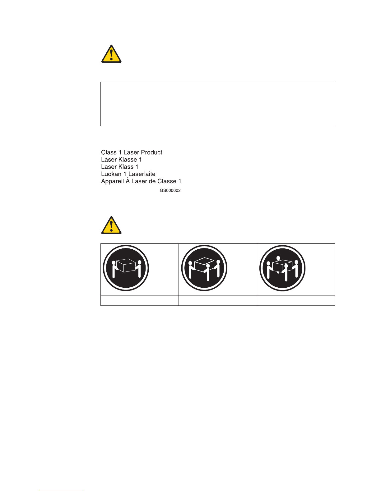
Statement 4:
≥ 18 kg (39.7 lb) ≥ 32 kg (70.5 lb) ≥ 55 kg (121.2 lb)
CAUTION:
Use safe practices when lifting.
xiv IBM TotalStorageFAStT900 Fibre Channel Storage Server: User’s Guide
Page 17

Statement 5:
CAUTION:
The power control button on the device and the power switch on the power
supply do not turn off the electrical current supplied to the device. The device
also might have more than one power cord. To remove all electrical current
from the device, ensure that all power cords are disconnected from the power
source.
2
1
Statement 8:
CAUTION:
Never remove the cover on a power supply or any part that has the following
label attached.
Hazardous voltage, current, and energy levels are present inside any
component that has this label attached. There are no serviceable parts inside
these components. If you suspect a problem with one of these parts, contact
a service technician.
Safety xv
Page 18

xvi IBM TotalStorageFAStT900 Fibre Channel Storage Server: User’s Guide
Page 19

About this document
This document provides an overview of the IBM®TotalStorage™FAStT900 Fibre
Channel Storage Server, hereafter referred to as the FAStT900 Storage Server, and
contains information about routine operations and replacement procedures for all
customer replaceable units (CRUs).
Before you use this document, install the hardware and software. For more
information, refer to the IBM TotalStorage FAStT900 Fibre Channel Storage Server
Installation Guide and the IBM FAStT Storage Manager installation guide
appropriate for your operating system. .
Who should read this document
This user’s guide is intended for system operators and service technicians who
have extensive knowledge of Fibre Channel, network technology, computer-system
operation, maintenance, and repair. Use this guide to:
v Become familiar with the components of the FAStT900 Storage Server
v Learn how to operate the FAStT900 Storage Server
v Learn how to replace failed components in the FAStT900 Storage Server
© Copyright IBM Corp. 2001, 2003 xvii
Page 20
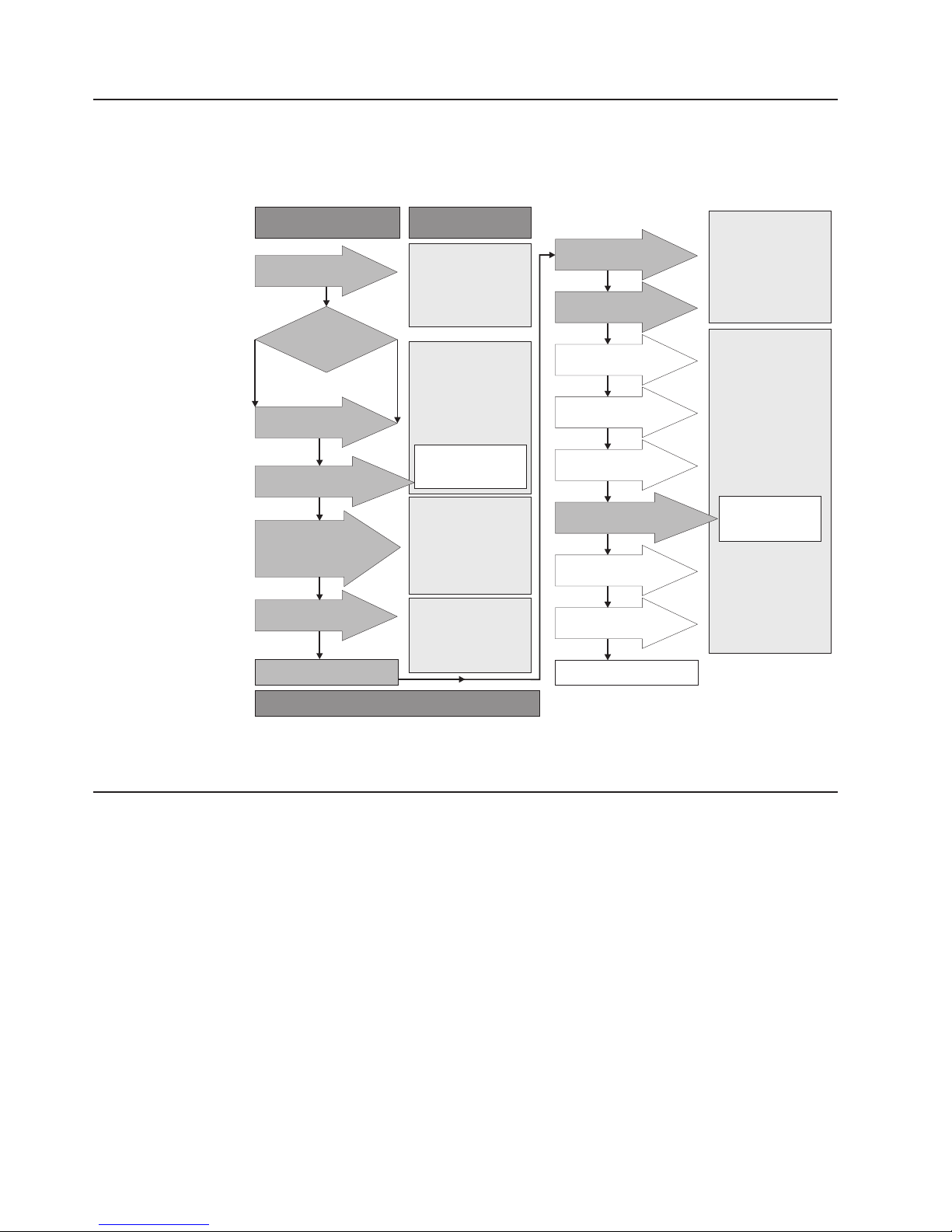
FAStT installation process overview
The following flow chart gives an overview of the installation process for the FAStT
hardware and the FAStT Storage Manager. The arrows in the flow chart indicate the
current publications that cover, in detail, each step in the installation process.
Install Process
Install Storage Server
in Rack
Determine
Management
Method
Out-of-Band
Install Management
Hardware
Make Network Connection
Install RAID Controller
Enclosure(s) / Storage
Expansion Unit(s)
Make Fibre Channel
Connections
Set Link Switch
In-Band
Publications
FAStT Storage Server
Installation Guides
FAStT SM install and
Support OS Guides
FAStT and FC-2 HBA
Install and Users Guide
* FC Planning and
Integration: User's
Guide and Service
Information
FAStT Storage Server
Installation Guides
FAStT RAID Controller
Enclosure Unit Install
and User's Guide
FAStT Storage Exp
Units Install and User's
Guides
FAStT Fibre Channel
Storage Server
Installation Guides
Fibre Channel Cable
Instructions
Connect Power and
Start Server
Verify Server
operation w / LEDs
Prepare for
Installation of SM
Software
Install and Verify SM
Client SW on Host
Install and Verify SM
Host SW on Host
Configure Storage
Hardware
Configure Storage
Subsystems on Host
Complete SM SW
Installation
Test Installation
FAStT Storage Server
Installation Guides
Fibre Channel
Hardware Maintenance
and Problem
Determination Guide
FAStT SM Install and
Support OS Guides
FAStT Storage
Server User's
Guides
FAStT Remote Mirror
Option Install ation and
User's Guide
* For pSeries Server and 6227 or 6228 HBA use only
Figure 1. Process flow by current publications
FAStT documentation
The following three tables present an overview of the FAStT900 Fibre Channel
Storage Server and the FAStT Storage Manager document libraries, as well as
related documents. Each table lists documents that are included in the libraries and
where to locate the information that you need to accomplish common tasks.
SJ001046
xviii IBM TotalStorageFAStT900 Fibre Channel Storage Server: User’s Guide
Page 21

FAStT900 Fibre Channel Storage Server library
Table 1 associates each document in the FAStT900 Fibre Channel Storage Server
library with its related common user tasks.
Table 1. TotalStorage FAStT900 Fibre Channel Storage Server document titles by user tasks
Title User Tasks
FAStT900
Installation and
Support Guide,
GC26-7530
FAStT900 Fibre
Channel Cabling
Instructions,
24P8135
FAStT900 User’s
Guide, GC26-7534
FAStT Host Adapter
Installation and
User’s Guide,
59P5712
FAStT FC2-133 Dual
Port Host Bus
Adapter Installation
and User’s Guide,
GC26-7532
FAStT FC2-133 Host
Bus Adapter
Installation and
User’s Guide,
48P9823
Fibre Channel
Planning and
Integration: User’s
Guide and Service
Information,
SC23-4329
FAStT Management
Suite Java User’s
Guide, 32P0081
Fibre Channel
Hardware
Maintenance Manual
and Problem
Determination
Guide, GC26-7528
Planning Hardware
Installation
UU U
UU
UU
UU
UU
UU U U
Software
Installation
Configuration Operation and
Administration
UUU
Diagnosis and
Maintenance
UU
U
About this document xix
Page 22

FAStT Storage Manager Version 8.3 library
Table 2 associates each document in the FAStT Storage Manager library with its
related common user tasks.
Table 2. TotalStorage FAStT Storage Manager Version 8.3 titles by user tasks
Title User Tasks
Installation and
Support Guide for
Windows
Windows 2000,
GC26-7522
Installation and
Support Guide for
Linux, GC26-7519
Installation and
Support Guide for
Novell NetWare,
GC26-7520
Installation and
Support Guide for
UNIX and AIX
Environments,
GC26-7521
FAStT Remote
Mirror Option
Installation and
User’s Guide,
48P9821
IBM FAStT Storage
Manager Script
Commands (see
product CD)
IBM FAStT Storage
Manager Version
7.10 Concepts
Guide, 25P1661
®
NT and
Planning Hardware
Installation
UUU
UUU
UUU
UUU
UUUU
UU U U U U
Software
Installation
Configuration Operation and
U
Administration
Diagnosis and
Maintenance
xx IBM TotalStorageFAStT900 Fibre Channel Storage Server: User’s Guide
Page 23

FAStT related documents
Table 3 associates each of the following documents related to FAStT operations
with its related common user tasks.
Table 3. TotalStorage FAStT related document titles by user tasks
Title User Tasks
IBM Safety
Information,
P48P9741
IBM FAStT500 RAID
Controller Enclosure
Unit Installation
Guide, 59P6244
IBM FAStT500 RAID
Controller Enclosure
Unit User’s
Reference, 48P9847
®
IBM Netfinity
Channel Cabling
Instructions,
19K0906
IBM FAStT200 and
FAStT200 HA
Storage Servers
Installation and
User’s Guide,
59P6243
IBM FAStT200 Fibre
Channel Cabling
Instructions,
21P9094
IBM TotalStorage
FAStT EXP700
Storage Expansion
Unit Installation and
User’s Guide,
32P0178
IBM FAStT EXP500
Installation and
User’s Guide,
59P5637
IBM Fibre Channel
SAN Configuration
Setup Guide,
25P2509
Fibre
Planning Hardware
Installation
UU
UU
U
UU
U
UU
UU
UUUU
Software
Installation
Configuration Operation and
Administration
U
Diagnosis and
Maintenance
About this document xxi
Page 24

How this book is organized
Chapter 1, “Introduction”, on page 1 introduces the FAStT900 Storage Server and
its primary components.
Chapter 2, “Operating the FAStT900 Storage Server”, on page 15 describes the
tasks required to operate the FAStT900 Storage Server.
Chapter 3, “Replacing the FAStT900 Storage Server components”, on page 37
describes how to service and replace components of the FAStT900 Storage Server.
“Getting information, help, and service”, on page 61 describes how to obtain help,
service, and information about IBM products.
“Notices” on page 65 provides product notices.
Notices and statements in this document
The caution and danger statements that this document uses also appear in the
multilingual Safety Information document provided with your FAStT900 Storage
Server. Each caution and danger statement is numbered for easy reference to the
corresponding statements in the safety document.
This document uses the following types of notices and statements:
v Note: These notices provide important tips, guidance, or advice.
v Important: These notices provide information or advice that might help you avoid
inconvenient or problem situations.
v Attention: These notices indicate possible damage to programs, devices, or
data. An attention notice is placed just before the instruction or situation in which
damage could occur.
v Caution: These statements indicate situations that can be potentially hazardous
to you. A caution statement is placed just before the description of a potentially
hazardous procedure step or situation.
v Danger: These statements indicate situations that can be potentially lethal or
extremely hazardous to you. A danger statement is placed just before the
description of a potentially lethal or extremely hazardous procedure step or
situation.
Getting information, help, and service
If you need help, service, or technical assistance or just want more information
about IBM and IBM products, you will find a wide variety of sources available from
IBM to assist you. This section contains information about where to go for additional
information, what to do if you experience a problem with your xSeries
IntelliStation
Before you call
Before you call, make sure that you have taken these steps to try to solve the
problem yourself:
v Check all cables to make sure that they are connected.
v Check the power switches to make sure that the system is turned on.
v Use the troubleshooting information in your system documentation, and use the
diagnostic tools that come with your system.
xxii IBM TotalStorageFAStT900 Fibre Channel Storage Server: User’s Guide
®
system, and whom to call for service, if it is necessary.
™
or
Page 25

v Go to the IBM Support Web site at http://www.ibm.com/pc/support/ to check for
technical information, hints, tips, and new device drivers.
v Use an IBM discussion forum on the IBM Web site to ask questions.
You can solve many problems without outside assistance by following the
troubleshooting procedures that IBM provides in the online help or in the
publications that are provided with your system and software. The information that
comes with your system also describes the diagnostic tests that you can perform.
Most xSeries and IntelliStation systems, operating systems, and programs come
with information that contains troubleshooting procedures and explanations of error
messages and error codes. If you suspect a software problem, see the information
for the operating system or program.
Using the documentation
Information about your IBM®xSeries or IntelliStation system and preinstalled
software, if any, is available in the documentation that comes with your system.
That documentation includes printed documents, online documents, readme files,
and help files. See the troubleshooting information in your system documentation
for instructions for using the diagnostic programs. The troubleshooting information
or the diagnostic programs might tell you that you need additional or updated
device drivers or other software. IBM maintains pages on the World Wide Web
where you can get the latest technical information and download device drivers and
updates. To access these pages, go to http://www.ibm.com/pc/support and follow
the instructions. Also, you can order publications through the IBM Publications
Ordering System at
http://www.elink.ibmlink.ibm.com/public/applications/publications/cgibin/pbi.cgi/
Web sites
On the World Wide Web, the IBM Web site has up-to-date information about IBM
xSeries and IntelliStation products, services, and support. The address for IBM
xSeries information is http://www.ibm.com/eserver/xseries/ The address for IBM
IntelliStation information is http://www.ibm.com/pc/intellistation.
You can find service information for your IBM products, including supported options,
at http://www.ibm.com/pc/support/ If you click Profile from the support page, you
can create a customized support page. The support page has many sources of
information and ways for you to solve problems, including how to:
v Diagnose problems, using the IBM Online Assistant
v Download the latest device drivers and updates for your products
v View Frequently Asked Questions (FAQ)
v View hints and tips to help you solve problems
v Participate in IBM discussion forums
v Set up e-mail notification of technical updates about your products
Software service and support
Through the IBM Support Line, for a fee, you can get telephone assistance with
usage, configuration, and software problems with xSeries servers, IntelliStation
workstations and appliances. For information about which products are supported
by Support Line in your country or region, go to
http://www.ibm.com/services/sl/products/
About this document xxiii
Page 26

For more information about Support Line and other IBM services, go to
http://www.ibm.com/services/ or go to http://www.ibm.com/planetwide/ for support
telephone numbers.
Hardware service and support
You can receive hardware service through IBM Integrated Technology Services or
through your IBM reseller, if your reseller is authorized by IBM to provide warranty
service. Go to http://www.ibm.com/planetwide/ for support telephone numbers.
In the U.S. and Canada, hardware service and support is available 24 hours a day,
7 days a week. In the U.K., these services are available Monday through Friday,
from 9 a.m. to 6 p.m.
How to send your comments
Your feedback is important to help us provide the highest quality of information. If
you have any comments about this document, you can submit them in one of the
following ways:
v E-mail
Submit your comments electronically to:
starpubs@us.ibm.com
Be sure to include the name and order number of the document and, if
applicable, the specific location of the text that you are commenting on, such as
a page number or table number.
v Mail or fax
Fill out the Readers’ Comments form (RCF) at the back of this document and
return it by mail or fax (1-800-426-6209) or give it to an IBM representative. If the
RCF has been removed, you may address your comments to:
International Business Machines Corporation
RCF Processing Department
Dept. M86/Bldg. 050-3
5600 Cottle Road
San Jose, CA 95193-0001
U.S.A.
xxiv IBM TotalStorageFAStT900 Fibre Channel Storage Server: User’s Guide
Page 27

Chapter 1. Introduction
The IBM TotalStorage FAStT900 Fibre Channel Storage Server (referred to
throughout this book as the FAStT900 Storage Server) is a high-performance unit
that provides dual, redundant array of independent disks (RAID) controllers and
Fibre Channel interfaces to both the host and drive channels.
FAStT900 Storage Server overview
The FAStT900 Storage Server (Machine type 1742, models 90U and 90X) supports
direct attachment of up to four hosts that contain two host adapters each, and is
designed to provide maximum host-side and drive-side redundancy. By using
external Fibre Channel switches in conjunction with the FAStT900 Storage Server,
you can attach up to 64 hosts with two adapters each to a FAStT900 Storage
Server.
Each FAStT900 Storage Server contains several removable components, called
customer replaceable units (CRUs), that you can access from either the front or
back of the unit. These CRUs include the battery, RAID controllers, storage server
fan, power supplies, fan and communications module, mini hubs, and Small
Form-Factor Pluggable (SFP) modules. The FAStT900 Storage Server also has a
removable front bezel.
The FAStT900 Storage Server functions with at least one external Fibre Channel
drive expansion unit containing Fibre Channel hard drives. The FAStT900 Storage
Server supports a maximum of 224 Fibre Channel hard drives when using an IBM
FAStT EXP700 drive. If the Fibre Channel drives are configured in FAStT EXP500
drive expansion units, a maximum of 220 hard drives are supported.
Front view
Attention: The FAStT900 controller units are not compatible with the FAStT700 or
FAStT500 controller units. The FAStT900 controller units are keyed to prevent them
from being mistakenly inserted in the non-supported storage server units. Do not
force fit the controller units or the backplane might be damaged.
Figure 2 on page 2 shows the bezel. The bezel is a removable front cover with
holes for viewing the status lights and for boosting air circulation.
Note: The illustrations in this document might differ slightly from your hardware.
© Copyright IBM Corp. 2001, 2003 1
Page 28
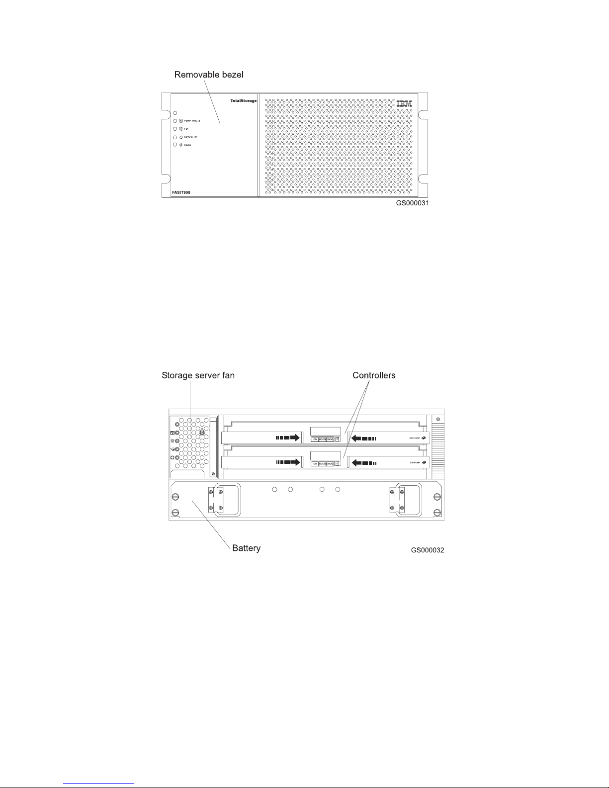
Figure 2. IBM TotalStorage FAStT900 Fibre Channel Storage Server front bezel
Figure 3 shows the following components on the FAStT900 Storage Server without
the front bezel:
v Storage server fan - A removable unit that contains two cooling fans and
indicator lights
v Battery - A removable unit that contains the cache battery for the controllers,
battery charger circuitry, and status indicator lights
v Controllers - Two removable units that each contain one RAID controller with 1
Gb cache memory and status indicator lights
Figure 3. IBM TotalStorage FAStT900 Fibre Channel Storage Server front view
Back view
Figure 4 on page 3 shows the FAStT900 Storage Server back view and the
following components:
v Host-side and drive-side mini hubs - Up to eight removable mini hubs with
indicator lights. You can insert SFP modules into the mini hubs and connect
fiber-optic host and drive interface cables to the FAStT Storage Server. (The
standard FAStT900 configuration includes two host and two drive mini hubs.)
v Power supplies - Two removable units that each contain a power supply and an
indicator light.
2 IBM TotalStorageFAStT900 Fibre Channel Storage Server: User’s Guide
Page 29
v Fan and communications module - A removable unit that contains the power
supply cooling fans, an indicator light, and Ethernet ports.
Figure 4. IBM TotalStorage FAStT900 Fibre Channel Storage Server - back view
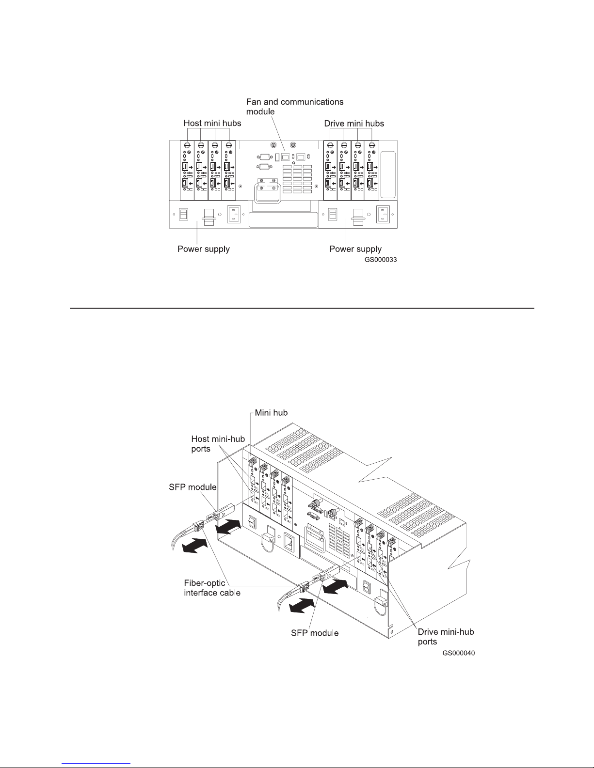
Fibre Channel connections
When fully configured, the back of the FAStT900 Storage Server can accommodate
up to four host-side and four drive-side mini hubs. Each mini hub is a single,
removable unit that provides the Fibre Channel interface between a FAStT900
Storage Server, host computers, and drives. Each mini hub has two SFP module
ports. An SFP module is inserted into a mini-hub port. Figure 5 shows the Fibre
Channel components.
Figure 5. Fibre Channel interface connections
Chapter 1. Introduction 3
Page 30

The FAStT900 Storage Server uses fiber-optic cables to connect to other Fibre
Channel devices. The fiber-optic cables that you need depend on the type of optical
connectors in the device to which you are connecting the FAStT900 Storage Server.
If the device uses SFP modules or optical interface connectors, then you must use
LC-LC Fibre Channel cables. If the device uses Gigabit Interface Converters
(GBICs) as the optical interface connector, you must use LC-LC Fibre Channel
cables and LC-SC Fibre Channel cable adapters (Part number 19K1250) to connect
to the FAStT900 Storage Server.
Handling fiber-optic cables
Before you use fiber-optic cables, read the following precautions.
Attention: To avoid damage to your fiber-optic cables, follow these guidelines:
v Do not route the cable along a folding cable-management arm.
v When attaching to a device on slide rails, leave enough slack in the cable so that
it does not bend to a radius of less than 38 mm (1.5 in.) when extended or
become pinched when retracted.
v Route the cable away from places where it can be damaged by other devices in
the rack cabinet.
v Do not use plastic cable ties in place of the provided cable straps.
v Do not overtighten the cable straps or bend the cables to a radius of less than 38
mm (1.5 in.).
v Do not put excess weight on the cable at the connection point. Be sure that the
cable is well supported.
Using LC-LC Fibre Channel cables
The LC-LC Fibre Channel cable is a fiber-optic cable that is used to connect into
one of the following devices:
v SFP module installed in a FAStT900 Storage Server mini hub
v SFP module installed in an IBM Fibre Channel switch
v SFP module installed in an IBM FAStT EXP700 drive expansion unit
v Optical interface connector on an IBM FAStT FC–2 Host Bus Adapter (part
number 19K1246), IBM FAStT single port FC2-133 Host Bus Adapter (part
number 24P0960), or dual port FC2-133 Host Bus Adapter (part number
24P8053)
Figure 6 on page 5 shows an LC-LC Fibre Channel cable.
4 IBM TotalStorageFAStT900 Fibre Channel Storage Server: User’s Guide
Page 31

Figure 6. LC-LC Fibre Channel cable
The following sections provide the procedures for properly connecting and removing
an LC-LC Fibre Channel cable.
Note: If you are connecting a FAStT900 Storage Server to a FAStT EXP500
expansion unit or to an IBM FAStT host adapter, you must also use a Fibre
Channel cable adapter. For more information about how to use the LC-SC
Fibre Channel cable adapter, see “Using LC-SC Fibre Channel cable
adapters” on page 8.
Connecting an LC-LC Fibre Channel cable to an SFP module
To connect an LC-LC Fibre Channel cable to an SFP module, complete the
following steps.
Statement 3:
CAUTION:
When laser products (such as CD-ROMs, DVD drives, fiber optic devices, or
transmitters) are installed, note the following precautions:
v Do not remove the covers. Removing the covers of the laser product could
result in exposure to hazardous laser radiation. There are no serviceable
parts inside the device.
v Use of controls or adjustments or performance of procedures other than
those specified herein might result in hazardous radiation exposure.
DANGER
Some laser products contain an embedded Class 3A or Class 3B laser
diode. Note the following precautions. Laser radiation when open. Do not
stare into the beam, do not view directly with optical instruments, and
avoid direct exposure to the beam.
1. Read the information in “Handling fiber-optic cables” on page 4.
2. If necessary, remove the protective cap from the SFP module, as shown in
Figure 48 on page 56. Save the protective cap for future use.
Chapter 1. Introduction 5
Page 32

3. Remove the two protective caps from one end of the LC-LC cable as shown in
Figure 7. Save the protective caps for future use.
Figure 7. Removing the fiber-optic cable protective caps
4. Carefully insert that same end of the LC-LC cable into an SFP module that is
installed in a FAStT900 Storage Server mini hub. The cable connector is keyed
to ensure it is inserted into the SFP module correctly. While you hold the
connector, push in the connector until it clicks into place.
Figure 8. Inserting an LC-LC Fibre Channel cable into an SFP module
6 IBM TotalStorageFAStT900 Fibre Channel Storage Server: User’s Guide
Page 33

Figure 9 shows an LC-LC Fibre Channel cable that connects into an SFP
module that is installed in a FAStT900 Storage Server mini hub.
Figure 9. Inserting an LC-LC Fibre Channel cable into an installed SFP module
5. Remove the two protective caps from the other end of the LC-LC cable, as
shown in Figure 7 on page 6. Save the protective caps for future use.
6. Connect the end of the LC-LC Fibre Channel cable to one of the following
devices:
v SFP module that is installed in an IBM Fibre Channel switch
v Optical interface connector on an IBM FAStT FC–2 Host Bus Adapter (part
number 19K1246)
v LC-SC Fibre Channel cable adapter (For information about how to use an
LC-SC cable adapter, see “Using LC-SC Fibre Channel cable adapters” on
page 8.)
Removing an LC-LC Fibre Channel cable from an SFP module
To remove an LC-LC Fibre Channel cable, perform the following steps:
Attention: To avoid damaging the LC-LC cable or SFP module, make sure you
press and hold the lever to release the latches as you remove the cable from the
SFP module.
1. On the end of the LC-LC cable that connects into the SFP module or host bus
adapter, press down and hold the lever to release the latches, as shown in
Figure 10 on page 8. Carefully pull on the connector to remove the cable from
the SFP module, (ensure that the levers are in the released position when you
remove the cable) as shown in Figure 11 on page 8. If you use the SFP module
with the pull tab, make sure you do not grasp the plastic tab when you remove
the cable.
Chapter 1. Introduction 7
Page 34

Figure 10. LC-LC Fibre Channel Cable lever and latches
Figure 11. Removing the LC-LC Fibre Channel cable
2. Replace the protective caps on the cable ends.
3. Replace the protective cap on the SFP module.
Using LC-SC Fibre Channel cable adapters
The LC-SC Fibre Channel Cable Adapter is a fiber-optic cable that you use to
connect the LC connector into one of the following devices that require SC
connectors:
v FAStT host adapter (Part number 00N6881)
v FAStT EXP500 expansion unit (Machine type 3560)
v 1 Gb Fibre Channel switch (Machine type 2109)
v 1 Fibre Channel Managed hub (Machine type 3534)
8 IBM TotalStorageFAStT900 Fibre Channel Storage Server: User’s Guide
Page 35

Figure 12 shows an LC-SC Fibre Channel cable adapter.
Figure 12. LC-SC Fibre Channel cable
The following sections provide the procedures for properly connecting and removing
an LC-SC Fiber Channel cable adapter.
Connecting an LC-SC cable to a device
To connect an LC-SC cable adapter to a device or LC-LC cable, complete the
following steps.
Statement 3:
CAUTION:
When laser products (such as CD-ROMs, DVD drives, fiber optic devices, or
transmitters) are installed, note the following precautions:
v Do not remove the covers. Removing the covers of the laser product could
result in exposure to hazardous laser radiation. There are no serviceable
parts inside the device.
v Use of controls or adjustments or performance of procedures other than
those specified herein might result in hazardous radiation exposure.
DANGER
Some laser products contain an embedded Class 3A or Class 3B laser
diode. Note the following precautions. Laser radiation when open. Do not
stare into the beam, do not view directly with optical instruments, and
avoid direct exposure to the beam.
1. Read the information in “Handling fiber-optic cables” on page 4.
Chapter 1. Introduction 9
Page 36

2. Connect an LC-LC cable to an SFP module in the FAStT900 Storage Server
mini hub. For instructions, see “Connecting an LC-LC Fibre Channel cable to an
SFP module” on page 5.
3. Remove the two protective caps from the LC connector end of the LC-SC cable,
as shown in Figure 13. Save the protective caps for future use.
Figure 13. Removing the LC-SC cable adapter protective caps
4. Carefully insert one end of an LC-LC cable into the LC connector end of the
LC-SC cable. Push in the connector until it clicks into place.
Figure 14. LC-LC cable connected into the LC-SC cable adapter
5. Connect the SC connector end of the LC-SC cable to one of the following
devices:
v Optical interface connector on an IBM FAStT Host Bus Adapter (Part number
00N6881)
v GBIC installed in a FAStT EXP500 expansion unit (Machine type 3560)
v 1 Gb Fibre Channel switch (Machine type 2109)
v 1 Gb Fibre Channel managed hub (Machine type 3534)
Removing an LC-LC cable from an LC-SC cable adapter
To remove an LC-LC cable from an LC-SC cable adapter, perform the following
steps:
10 IBM TotalStorageFAStT900 Fibre Channel Storage Server: User’s Guide
Page 37

Attention: To avoid damaging the LC-LC cable, make sure you press and hold
the lever to release the latches while you remove the cable from an LC-SC cable
adapter. Ensure that both levers on the LC-LC cable are in the released position
when you remove the cable.
1. On the end of the cable that connects into the LC connector end of the LC-SC
cable adapter, press down and hold the lever to release the latches. Figure 15
shows the location of the lever and latches.
Figure 15. LC-LS Fibre Channel cable lever and latches
2. Carefully pull on the connector to remove it. Make sure you grasp the connector
and not the cable when you remove the LC-LC cable from the LC-SC cable
adapter, as shown in Figure 16.
Figure 16. Removing the LC-LC Fibre Channel cable from an LC-SC Fibre Channel cable
adapter
3. Replace the protective caps on the cable ends.
Types of interface ports
The FAStT900 Storage Server has the following types of interface ports:
v Host mini hub
v Drive mini hub
v Ethernet
The host and drive mini-hub ports are used for data transfer between hosts or drive
enclosures and RAID controllers in the FAStT900 Storage Server. Ethernet ports
are available for storage subsystem-management. The FAStT900 Storage Server
Chapter 1. Introduction 11
Page 38

interface ports are shown in Figure 17.
Figure 17. FAStT900 Storage Server interface ports
For more information about how to connect the FAStT900 Storage Server and drive
enclosures (also referred to as expansion units) by using the host and drive
interface ports, refer to the IBM FAStT900 Fibre Channel Storage Server Installation
Guide.
Host interface ports
The FAStT900 Storage Server comes with host-side mini hubs 1 and 2 installed.
Each mini hub provides host loop connectivity and self-diagnostic features. Host
mini hubs connect to the controller in pairs. When fully configured, the FAStT900
Storage Server can accommodate four host-side mini hubs, two per controller. Mini
hubs 1 and 3 connect to the top controller (Controller A) and mini hubs 2 and 4
connect to the bottom controller (Controller B), as shown in Figure 18. To ensure
redundancy, you must connect each host to both controllers through the appropriate
mini hub.
Figure 18. Host-side mini-hub interface ports
Drive interface ports
The FAStT900 Storage Server comes with drive-side mini hubs 1 and 2 installed.
Each drive mini hub connects to Controller A and Controller B and represents a
single drive loop. The drive loops must be set up in pairs to support redundant drive
loop configurations (two data paths per drive enclosure). The maximum number of
drive expansion units can be connected per pair of redundant drive loops
depending on the IBM FAStT drive expansion unit models used. The two possible
12 IBM TotalStorageFAStT900 Fibre Channel Storage Server: User’s Guide
Page 39

drive expansion unit types are the IBM FAStT EXP500 and the IBM FAStT EXP700.
You can mix the drive expansion unit models in the same storage server or the
same pair of drive loops. However, the maximum Fibre Channel transfer speed in
the storage server drive mini hubs and the IBM FAStT EXP700 Environmental Card
units must be set at 1Gbps because the maximum FC transfer speed of the IBM
FAStT EXP500 drive expansion units is 1Gbps. See Table 4 for the possible
combinations of EXP500 and EXP700 drive expansion units per drive loop. See
Figure 19 on page 14 for a graphical depiction of the drive-side mini-hub interface
ports.
A fully configured FAStT900 Storage Server supports a maximum of 16 IBM FAStT
EXP700 drive expansion units (8 drive expansion units per drive-loop pair), or 224
drives using dual pair of redundant drive loops.
Table 4. Possible combinations of EXP500 and EXP700 drive expansion units per drive loop
# of EXP500 units # of EXP700 units Total Expansion
units
088112
178108
268104
369114
459110
549106
639102
7310112
8210108
9110104
10 0 10 100
11 0 11 11 0
Total number of
drives
Important: These large configurations are for capacity purposes and might not
provide the best performance. FAStT900 Storage Servers use only redundant
drive-loop configurations.
Chapter 1. Introduction 13
Page 40

Figure 19. Drive-side mini-hub interface ports
Ethernet interface ports
There are two Ethernet interface ports, one for each controller (Controller A and
Controller B). Use the Ethernet ports to directly manage storage subsystems.
Figure 20 shows the location of the interface ports.
Figure 20. Ethernet interface ports
14 IBM TotalStorageFAStT900 Fibre Channel Storage Server: User’s Guide
Page 41

Chapter 2. Operating the FAStT900 Storage Server
This chapter describes the tasks required to operate the FAStT900 Storage Server.
Tasks overview
Perform the tasks shown in Table 5 to maintain the FAStT900 Storage Server after
you install it.
Table 5. Tasks overview
Task Description See
Accessing the FAStT900 Storage
Server components and indicator
lights
Turning on or off the power The FAStT900 Storage Server usually
Monitoring FAStT900 Storage Server
status through software
Checking fault indicator lights for
component failures
Restoring power after a power supply
shutdown
Checking the battery service date Periodically check the battery service
To access the controller CRUs,
battery, storage server fan, and
indicator lights, remove the FAStT900
Storage Server bezel.
runs continuously. However, you might
need to turn off the power to move the
FAStT900 Storage Server or to
perform maintenance procedures.
Run the storage-management
software continuously. This software
checks the storage subsystem for
failures and displays messages that
indicate the types of failures and the
recovery procedures.
Component failures are indicated by
lights on the front and back of the
FAStT900 Storage Server and are
monitored by the
storage-management software.
Note: The indicator lights identify
problems with the FAStT900 Storage
Server components, but you might
need more information to thoroughly
diagnose and repair the unit.
Therefore, it is important to use the
storage-management software to
continuously monitor the status of the
FAStT900 Storage Server.
When the FAStT900 Storage Server
shuts down because of a power
supply overtemperature condition,
take special care restarting it.
date information. Replace the battery
whenever it fails to hold a charge or
every three years.
Note: Using the FAStT900 Storage
Server in a hot environment (above
35° Cor95° F), lowers the battery life
expectancy. Environmental conditions
that are not in the specified range are
not supported.
“Removing and replacing the front
bezel to access the FAStT Storage
Server components” on page 16
“Turning on the power” on page 17
and “Turning off the power” on
page 18
“Monitoring status through software”
on page 20
“Checking the indicator lights” on
page 20
“Overtemperature condition and power
supply shutdown” on page 31
“Checking the battery service date” on
page 32
© Copyright IBM Corp. 2001, 2003 15
Page 42

Table 5. Tasks overview (continued)
Task Description See
Preparing to move the FAStT900
Storage Server
You might need to move the
FAStT900 Storage Server to a new
location or remove the chassis from
its rack cabinet.
“Preparing to move the FAStT900
Storage Server” on page 33
Removing and replacing the front bezel to access the FAStT Storage
Server components
To access the controller blades, battery, storage server fan, and indicator lights, you
must remove the FAStT900 Storage Server bezel, as shown in Figure 21.
Attention: Pulling the cover out too far can damage the plastic hooks at the top.
To avoid damaging the hooks, place the FAStT900 Storage Server on a flat surface.
Be sure the front of the FAStT900 Storage Server extends beyond the edge
approximately 5 cm (2 in.).
1. Carefully pull the bottom of the bezel out to release the pins. Then slide the
bezel down as shown in Figure 21.
Figure 21. Removing the FAStT900 Storage Server bezel
2. To replace the bezel, slip the top edge of the bezel under the lip on the chassis,
then push the bottom of the bezel until the pins snap into the mounting holes,
as shown in Figure 22 on page 17.
16 IBM TotalStorageFAStT900 Fibre Channel Storage Server: User’s Guide
Page 43

Figure 22. Replacing the FAStT900 Storage Server bezel
Turning on the power
Important: You must turn on the drive enclosures before you turn on the FAStT900
Storage Server. The controllers might not recognize the correct configuration if you
turn on the hard disk drives after the FAStT900 Storage Server.
Always wait at least 30 seconds between the time you turn off a power switch and
the time you turn on the power.
Turn on the power to each device in the following order:
v Supporting devices
v Drive enclosures
v FAStT900 Storage Server
v Host
If you are restoring power to the FAStT900 Storage Server after an emergency
shutdown or power outage, go to “Overtemperature condition and power supply
shutdown” on page 31.
Use the following procedure to turn on the connected devices and the FAStT900
Storage Server:
1. Turn on the power to the supporting devices (for example, Ethernet switches,
Fibre Channel switches, and management stations).
2. Turn on the drive enclosure. The controllers might not recognize the correct
configuration if the drives are powered up after the storage server. For
instructions on turning on the drive enclosures, refer to the drive enclosure
documentation.
3. Turn on the power to the FAStT900 Storage Server, as follows:
Chapter 2. Operating the FAStT900 Storage Server 17
Page 44

a. Verify that all communication and power cables are plugged into the back of
the FAStT900 Storage Server and to a properly grounded ac electrical
outlet.
b. Turn on the power supply switches on the back of the FAStT900 Storage
Server (see Figure 23). You must turn on both power-supply switches to
take advantage of the redundant power supplies.
Figure 23. Connecting the power cords and power switch locations
c. Use the storage-management software and the Fault indicator lights to
check the overall status of the FAStT900 Storage Server and its
components. See “Checking the indicator lights” on page 20.
4. Depending on the type of operating system on the host server, perform either a
server power cycle, a server restart, or a rescan for hardware on the host
server.
Turning off the power
Attention: The FAStT900 Storage Server is designed to run continuously, 24
hours a day. Except in an emergency, never turn off the power even if any
FAStT900 Storage Server fault indicator lights are lit. Use the proper
troubleshooting or servicing procedure to correct the fault before you turn off the
power. This measure ensures that the FAStT900 Storage Server powers up
correctly later. Also do not power off the storage server to reset it. Use the Reset
Controller menu function in the Storage Manager Client program instead.
18 IBM TotalStorageFAStT900 Fibre Channel Storage Server: User’s Guide
Page 45

Statement 5:
CAUTION:
The power control button on the device and the power switch on the power
supply do not turn off the electrical current supplied to the device. The device
also might have more than one power cord. To remove all electrical current
from the device, ensure that all power cords are disconnected from the power
source.
2
1
Use the following procedure to turn off power to the FAStT900 Storage Server:
1. Make sure that all amber fault indicator lights on the FAStT900 Storage Server
are off. If any fault indicator lights are on, use the storage-management software
to determine the status of the system components and correct any problems
before you turn off the power. For more information, see “Monitoring status
through software” on page 20 and “Checking the indicator lights” on page 20.
2. Perform any required procedures that are indicated by the operating system
software.
3. Prepare the FAStT900 Storage Server for shutdown, as follows:
a. Stop all I/O activity to the FAStT900 Storage Server and attached drive
enclosures.
Note: If a parity check is in progress, it might take a long time for the drive
indicator lights to stop blinking.
b. Use the operating system software to disconnect the FAStT900 Storage
Server logical drives from the host before you power off the storage server.
c. Make sure that the fast write cache indicator light on each FAStT900
Storage Server front panel and all drive active indicator lights on each drive
enclosure front panel are off (not blinking).
Attention: To turn off all power to the storage server, you must turn off both
power supply switches and disconnect both power cords. Use the procedure in
step 4 for the proper shutdown sequence.
4. Turn off the power to the FAStT900 Storage Server or turn off the power to
each device using the following shutdown sequence.
a. Turn off power to the host before you turn off the power to the storage
server. If the host must stay powered on to support an existing network,
refer to the operating system documentation for information about
disconnecting the storage server logical drives from the host before the
storage server is powered off.
b. Turn off power to the storage server before you turn off power to the drive
enclosures. Turn off both power supply switches on the back of the storage
server. See Figure 23 on page 18.
Chapter 2. Operating the FAStT900 Storage Server 19
Page 46

c. Instead of turning off the power to other supporting devices ( for example,
management stations, Fibre Channel switches, or Ethernet switches),
disconnect the communications cables to the supporting devices.
Monitoring status through software
To monitor FAStT900 Storage Server status, always run the storage-management
software and check it frequently. Be sure to enable the management alerts that you
need. The storage-management software provides the best way to diagnose and
repair FAStT900 Storage Server failures. This software can help you:
v Determine the nature of a failure
v Locate a failed component
v Provide recovery procedures to repair a failure
Although the FAStT900 Storage Server has fault indicators, these lights are
summary indicators and might not identify the specific component that has failed or
needs replacing, or which type of recovery procedure you must perform. In some
cases (such as loss of redundancy in FAStT900 Storage Server drive loops), the
fault light does not come on. Only the storage-management software can detect the
failure.
Recovering from a FAStT900 Storage Server failure might require you to perform
procedures other than replacing the component. The storage-management software
gives these procedures when you are using the Recovery Guru menu.
Note: Always follow the software recovery procedures to prevent data loss.
For more information about the storage-management software, refer to the Online
help or publications that are appropriate for your operating system (see “About this
document” on page xvii for a list of publications).
Checking the indicator lights
The FAStT900 Storage Server indicator lights display the status of the FAStT900
Storage Server and its components. Green indicator lights mean normal operating
status; amber indicator lights mean a possible failure.
It is important that you check all the indicator lights on the front and back of the
FAStT900 Storage Server a few minutes after you turn on the power. After you turn
on the power, the indicator lights might blink intermittently. Wait until the FAStT900
Storage Server completes its power up before checking for faults. It can take up to
15 minutes for the battery to complete its self-test and up to 24 hours to fully
charge, particularly after an unexpected power loss of more than a few minutes.
The indicator lights for the components of the FAStT900 Storage Server are
described in the following sections.
Storage server indicator lights
The storage server has five indicator lights, as shown in Figure 24 on page 21. To
view the storage server indicator lights, you do not have to remove the FAStT900
Storage Server bezel.
20 IBM TotalStorageFAStT900 Fibre Channel Storage Server: User’s Guide
Page 47

Figure 24. Storage server indicator lights
Table 6 on page 22 describes the storage server indicator lights.
Chapter 2. Operating the FAStT900 Storage Server 21
Page 48

Table 6. Storage server indicator lights
Indicator light Color Normal
operation
Power Green On Off
Problem
indicator
Possible conditions indicated by the
problem indicator
1
v The FAStT900 Storage Server has no
power.
v The power supply cables are loose or the
switches are off.
v Both power supplies have failed, are
missing, or are not fully seated in FAStT900
Storage Server.
v The temperature of the FAStT900 Storage
Server is too high.
Power supply
fault
Amber Off On
v One of the redundant power supplies has
failed or the power supply is turned off,
disconnected, or is not fully seated in the
FAStT900 Storage Server.
v The temperature of the FAStT900 Storage
Server is too high.
v If both power supplies have failed, are
turned off, or are disconnected, all of the
indicator lights will not be off.
Storage server
fan fault
Amber Off On
v
v The storage server fan has failed.
v The fan and communications module is
missing, unplugged, or has failed.
v The storage server fan circuitry has failed.
v The temperature of the FAStT900 Storage
Server is too high.
Controller fault Amber Off On
v The RAID controller is restarting.
v The RAID controller has failed.
v One or more controller memory modules
have failed.
Fast write
cache
Green Steady or
blinking
2
Software
dependent
1
During normal operation, the indicator light is
not lit in the following conditions:
v The RAID controller cache is not enabled.
v The battery is not ready.
1
Always use the storage-management software to identify the failure.2The fast write cache indicator light is on when
there is data in the cache and blinks during a fast write operation.
RAID controller indicator lights
Each RAID controller has ten indicator lights: one power, one fault, and eight status
lights, as shown in Figure 25 on page 23.
22 IBM TotalStorageFAStT900 Fibre Channel Storage Server: User’s Guide
Page 49

Note: To view the RAID controller indicator lights, remove the FAStT900 Storage
Server bezel, as shown in Figure 21 on page 16.
Figure 25. RAID controller indicator lights
Table 7 on page 24 describes the FAStT900 RAID controller indicator lights.
Chapter 2. Operating the FAStT900 Storage Server 23
Page 50

Table 7. RAID controller indicator lights
Indicator light Color Normal
operation
Power Green On Off
Problem
indicator
Possible conditions indicated by the
problem indicator
1
v There is no power to the storage subsystem.
v The cables are loose or the switches are off.
v The power supply has failed, is missing, or
is not fully seated.
v The temperature of the FAStT900 Storage
Server is too high.
Fault
3
Amber Off On Controller failure
Heartbeat Green Blinking Not blinking No controller activity
Status (seven
lights not
including
Green All indicator lights
are off except the
heartbeat
2
Various patterns
depending on
the condition
2
If any status indicator lights are lit and the
controller is not offline, there is a memory fault
indicating that the controller CRU has failed.
3
Heartbeat)
1
Always use the storage-management software to identify the failure.2There are eight indicator lights (the Heartbeat
and seven others) the seven others are lit in various patterns, depending on the controller status.
3
If the controller is
offline, all of the indicator lights will be lit. This does not indicate failure.
Battery indicator lights
The battery has four indicator lights, as shown in Figure 26.
Note: To view the battery indicator lights, remove the FAStT900 Storage Server
bezel, as shown in Figure 21 on page 16.
Figure 26. Battery indicator lights
Table 8 on page 25 describes the battery indicator lights.
24 IBM TotalStorageFAStT900 Fibre Channel Storage Server: User’s Guide
Page 51

Table 8. Battery indicator lights
Indicator light Color Normal
operation
Fault-A or
Amber Off On
Fault-B
Full Charge-A
Green On
2
Problem
indicator
Possible conditions indicated by the
problem indicator
1
v The left or right battery bank has failed.
v The battery is either discharged or defective.
Off The left or right battery bank has failed.
or Full
Charge-B
1
Always use the storage-management software to identify the failure.2If the Full Charge-A or Full Charge-B indicator
light is blinking, the battery is in the process of charging.
Fan and communications module indicator light
The fan and communications module has one indicator light, as shown in Figure 27.
Figure 27. Fan and communications module indicator light
Table 9 describes the fan and communications module indicator light.
Table 9. Fan and communications module indicator light
Indicator light Color Normal
operation
Fan and
Amber Off On
communications fault
1
Always use the storage-management software to identify the failure.
Problem
indicator
Possible conditions indicated by the
problem indicator
1
v The fan and communications module
has failed or is installed incorrectly.
v The temperature of the FAStT900
Storage Server is too high.
Chapter 2. Operating the FAStT900 Storage Server 25
Page 52

Power supply indicator light
The power supply has one indicator light, as shown in Figure 28.
Figure 28. Power supply indicator light
Table 10 describes the power supply indicator light.
Table 10. Power supply indicator light
Indicator light Color Normal
operation
Power supply Green On Off
1
Always use the storage-management software to identify the failure.
Problem
indicator
Possible conditions indicated by the
problem indicator
v The power supply has failed or is turned
off
v The temperature of the FAStT900
Storage Server is too high.
1
Mini-hub indicator lights
There are five indicator lights on each mini hub. Figure 29 shows the host-side
indicator lights. The drive side indicator lights are the same; however, the possible
conditions indicated by the problem indicators (described in Table 11 on page 27)
might be different.
Figure 29. Mini-hub indicator lights
Table 11 on page 27 describes the indicator light status when there are Fibre
Channel connections to devices between host-side and drive-side mini hubs.
26 IBM TotalStorageFAStT900 Fibre Channel Storage Server: User’s Guide
Page 53

Table 11. Host-side and drive-side mini-hub indicator lights
Icon Indicator light Color Normal operation Problem indicator Possible
condition
indicated by the
problem indicator
None Speed Green On for 2 Gb Off
for1Gb
Not applicable Light on indicates
data transfer rate of
2Gb/s. Light off
indicates data
transfer rate of
1Gb/s.
! Fault Amber Off On Mini hub has failed.
Note: If a
host-side mini hub
is not connected to
a controller, this
fault light is always
lit.
Chapter 2. Operating the FAStT900 Storage Server 27
Page 54

Table 11. Host-side and drive-side mini-hub indicator lights (continued)
Icon Indicator light Color Normal operation Problem indicator Possible
condition
indicated by the
problem indicator
Bypass (upper
port)
Amber Off On
v Upper mini-hub
port is bypassed.
v Mini hub port or
SFP module has
failed or is loose.
v Fiber-optic
cables are
damaged.
Note: When two
functioning SFP
modules are
installed into the
mini-hub ports and
no Fibre Channel
cables are
connected to them,
the bypass
indicator light is lit.
If only one
functioning SFP
module is installed
in a host-side mini
hub port and no
Fibre Channel
cables are
connected to it, the
indicator light will
not be lit.
28 IBM TotalStorageFAStT900 Fibre Channel Storage Server: User’s Guide
However, the
drive-side mini hub
bypass indicator
light will be lit when
one SFP module is
installed in the mini
hub and the mini
hub has no Fibre
Channel cable
connection.
Page 55

Table 11. Host-side and drive-side mini-hub indicator lights (continued)
Icon Indicator light Color Normal operation Problem indicator Possible
condition
indicated by the
problem indicator
Loop good Green On Off
v The loop is not
operational, so
no devices are
connected.
v Mini hub has
failed or a faulty
device is
connected to the
mini hub.
v If no SFP
module is
installed, the
indicator will be
lit.
v If one functioning
SFP module is
installed in the
host-side mini
hub port and no
Fibre Channel
cable is
connected to it,
the loop good
indicator light will
not be lit.
If one functioning
SFP module is
installed in the
drive-side mini
hub port and no
Fibre Channel
cable is
connected to it,
the loop good
indicator light will
be lit.
v Drive enclosure
has failed
(drive-side mini
hub only).
Chapter 2. Operating the FAStT900 Storage Server 29
Page 56

Table 11. Host-side and drive-side mini-hub indicator lights (continued)
Icon Indicator light Color Normal operation Problem indicator Possible
condition
indicated by the
problem indicator
Bypass (lower
port)
Amber Off On
v Lower mini-hub
port is bypassed;
no devices are
connected.
v Mini-hub port or
SFP module has
failed or is loose.
v Fiber-optic
cables are
damaged.
Note: When two
functioning SFP
modules are
installed into the
mini hub port and
no Fibre Channel
cables are
connected to them,
the bypass
indicator light is lit.
If only one
functioning SFP
module is installed
in a host-side mini
hub port and no
Fibre Channel
cables are
connected to it, the
indicator light is not
lit.
However, the
drive-side mini hub
bypass indicator
light will be lit when
one functioning
SFP module is
installed in the mini
hub port and the
mini- hub has no
Fibre Channel
cables connected
to it.
30 IBM TotalStorageFAStT900 Fibre Channel Storage Server: User’s Guide
Page 57

Overtemperature condition and power supply shutdown
If the fan and communications module fails or is unable to maintain an internal
temperature below 70° C (158° F), one or both of the power supplies in the
FAStT900 Storage Server might shut down (see Figure 30). If both power supplies
shut down, the FAStT900 Storage Server is not operational.
Figure 30. Fan and communications and power supply fault indicators
The storage-management software causes the fan and communications module
fault indicator and storage server fan indicator to light before the temperature has
risen sufficiently to shut down the power supplies. The storage server fan indicator
light, shown in Figure 31, is lit when the FAStT900 Storage Server temperature
exceeds 45° C(113° F). The FAStT900 Storage Server shuts down if the
temperature rises to 70° C (158° F). If both power supplies shut down, the fault
indicator cannot light.
Figure 31. Storage server fan indicator
Chapter 2. Operating the FAStT900 Storage Server 31
Page 58

Turning on the power after an overtemperature shutdown
If your FAStT900 Storage Server shuts down unexpectedly and you received a
″Maximum temperature exceeded ″ alert from the storage server before it
shutdown, take the following precautions to cool it before you power on the unit:
1. Turn off the power switches to allow the FAStT900 Storage Server to cool.
2. When the room temperature is below the upper operating temperature of 35° C
(95° F), turn on the power switches.
3. Check the FAStT900 Storage Server for faults or damage. Use the
storage-management software to check the overall status of the FAStT900
Storage Server and its components. Correct any problems indicated.
Turning on the power after an emergency shutdown
Use this procedure to regain normal system operation after a power failure or
emergency shutdown:
1. Check all components and cables for damage. If there is no visible damage,
continue with Step 2; otherwise, service the system.
2. Make sure the power cords are plugged in.
3. Make sure that the circuit breaker, drive enclosures, and storage server power
switches are in the off position.
4. Turn on the circuit breakers in the rack cabinet, and turn on the power switches
on all drive enclosures attached to the FAStT900 Storage Server.
Important: You must turn on the drive enclosures before you turn on the
FAStT900 Storage Server. The controllers might not recognize the correct
configuration if the attached drives are powered up after the FAStT900 Storage
Server. For instructions on how to power up the drive enclosures, refer to the
drive enclosure documentation.
5. Turn on both power switches on the back of the FAStT900 Storage Server. For
the location of the power switches, see Figure 23 on page 18.
6. Check the status of the FAStT900 Storage Server and other devices. Make sure
all fault indicator lights are off on the front and back of the FAStT900 Storage
Server. For more information, see “Checking the indicator lights” on page 20.
7. When all the devices are powered up, check the overall system status by using
the storage-management software.
Checking the battery service date
Note: Replace the battery whenever it fails to hold a charge or every three years.
Operating the FAStT900 Storage Server in a hot environment (above 35° C
or 95° F) lowers the battery life expectancy.
To check the battery service date, perform the following steps:
1. Remove the FAStT900 Storage Server bezel, as shown in Figure 21 on
page 16.
32 IBM TotalStorageFAStT900 Fibre Channel Storage Server: User’s Guide
Page 59

2. Check the Battery Support Information label, as shown in Figure 32.
Figure 32. Checking the battery service date
The Battery Support Information label on the front of the battery has three
dates:
v Date of Manufacture - Date the battery was built at the factory
v Date of Installation - Date the battery was installed in the FAStT900 Storage
Server
v Replacement Date - Battery replacement date (see the note at the beginning
of this section)
3. Perform one of the following tasks:
v If it is time to replace the battery, install a new battery using the procedure
described in “Replacing a failed battery” on page 41.
v If it is not time to replace the battery, replace the FAStT900 Storage Server
bezel, as shown in Figure 22 on page 17.
Preparing to move the FAStT900 Storage Server
Remove each component CRU before you move the FAStT900 Storage Server to a
new location or before you remove the chassis from its rack cabinet. This
precaution helps safeguard the equipment and ensures a smoother transition to the
new environment.
If you are moving the FAStT900 Storage Server a short distance, and you have
sufficient assistance or equipment, you might be able to move the FAStT900
Storage Server without removing each component CRU. If you do not have
sufficient assistance or equipment, use the procedure in “Moving or relocating the
FAStT900 Storage Server” on page 34 to safely move the equipment to its new
location.
If you are moving the FAStT900 Storage Server a significant distance, be sure to
pack it in its original shipping container.
Chapter 2. Operating the FAStT900 Storage Server 33
Page 60

Moving or relocating the FAStT900 Storage Server
Use the following procedure to remove all component CRUs before you move or
relocate the FAStT900 Storage Server.
1. Prepare the FAStT900 Storage Server for shutdown. Refer to “Turning off the
power” on page 18.
2. Label the host Fibre Channel and interface cables and disconnect them.
Attention: Handle and install fiber-optic cables properly to avoid degraded
performance or loss of communications with devices. When working with
fiber-optic cables, do not pinch them, step on them, or locate them in aisles or
walkways. Do not bend the cables to a radius of less than 38 mm (1.5 in.).
3. Disconnect all remaining cables from the FAStT900 Storage Server and label
them so that you can correctly reconnect them later.
Attention: When you handle static-sensitive devices, take precautions to
avoid damage from static electricity. For details about handling static-sensitive
devices, see “Handling static-sensitive devices” on page 37.
4. Remove all CRUs from the FAStT900 Storage Server. For information about
removing and replacing CRUs, see Chapter 3, “Replacing the FAStT900
Storage Server components”, on page 37.
5. Remove the two screws from the inside rear of the FAStT900 Storage Server;
then, remove the two screws from the inside front of the FAStT900 Storage
Server. Save the screws for later. For detailed information, see the Rack
Mounting Instructions that come with the storage server.
Attention: Do not remove the black hex head screws. These secure the rails
that support your FAStT900 Storage Server.
Statement 4:
≥ 18 kg (39.7 lb) ≥ 32 kg (70.5 lb) ≥ 55 kg (121.2 lb)
CAUTION:
Use safe practices when lifting.
6. Slide the FAStT900 Storage Server out of the rack cabinet and set it on a
level, dry surface.
7. Perform one of the following tasks:
v If you are shipping the FAStT900 Storage Server to another location,
replace all CRUs in the FAStT900 Storage Server. Carefully pack the unit in
its original shipping container. You are finished with this procedure.
v If you are moving the FAStT900 Storage Server to another rack cabinet,
remove the support rails and power cords from the old rack cabinet and
install them in the new one.
34 IBM TotalStorageFAStT900 Fibre Channel Storage Server: User’s Guide
Page 61

8. To install the FAStT900 Storage Server into a rack cabinet in the new location,
perform the following steps:
a. Slide the FAStT900 Storage Server into the rack cabinet.
b. Insert and tighten two of the screws that you removed in Step 5 on the
inside front of the FAStT900 Storage Server.
c. Insert and tighten the remaining two screws that you removed in Step 5 on
the inside rear of the FAStT900 Storage Server.
9. Replace all CRUs in the FAStT900 Storage Server.
10. Connect the interface cables and host Fibre Channel cables that you labeled in
Step 3 on page 34.
11. Connect the remaining cables to the FAStT900 Storage Server.
12. Turn on power to the FAStT900 Storage Server. Use the procedure in “Turning
on the power” on page 17.
13. Replace the FAStT900 Storage Server bezel.
Chapter 2. Operating the FAStT900 Storage Server 35
Page 62

36 IBM TotalStorageFAStT900 Fibre Channel Storage Server: User’s Guide
Page 63

Chapter 3. Replacing the FAStT900 Storage Server
components
The FAStT900 Storage Server contains two RAID controllers, a cooling system that
contain four fans, mini hubs, SFP modules, and a power system. This chapter
includes detailed instructions on how to replace these components.
Handling static-sensitive devices
Attention: Static electricity can damage electronic devices and your system. To
avoid damage, keep static-sensitive devices in their static-protective package until
you are ready to install them.
To reduce the possibility of electrostatic discharge, observe the following
precautions:
v Limit your movement. Movement can cause static electricity to build up around
you.
v Handle the device carefully, holding it by its edges or its frame.
v Do not touch solder joints, pins, or exposed printed circuitry.
v Do not leave the device where others can handle and possibly damage the
device.
v While the device is still in its static-protective package, touch it to an unpainted
metal part of the system unit for at least two seconds. (This drains static
electricity from the package and from your body.)
v Remove the device from its package and install it directly into your system unit
without setting it down. If it is necessary to set the device down, place it in its
static-protective package. Do not place the device on your system unit cover or
on a metal table.
v Take additional care when handling devices during cold weather because heating
reduces indoor humidity and increases static electricity.
FAStT900 Storage Server controller
The FAStT900 Storage Server supports RAID technology. The FAStT900 Storage
Server contains two RAID controllers.
Each controller comes in a removable, portable unit, called a controller CRU, as
shown in Figure 34 on page 39. Each controller CRU slides into one of two
controller slots on the front of the FAStT900 Storage Server and attaches to hosts
through Fibre Channel connections. Two handles lock the controller in place. Each
controller slot has a controller slot designation that identifies the physical location of
the controller in the chassis: controller slot A (top) or controller slot B (bottom). Each
controller CRU has ten indicator lights: one power, one fault, and eight status
indicator lights, as shown in Figure 33 on page 38.
© Copyright IBM Corp. 2001, 2003 37
Page 64

Attention: If you are removing both controllers (controller A and controller B) from
the FAStT900 Storage Server, label controllers A and B with the white tape dots that
are included in the rack mounting assembly kit. To prevent data loss, the controllers
must be installed into their original location.
Servicing notes
Figure 33. Controller status indicator lights
Consider the following factors when servicing the controllers in the FAStT900
Storage Server:
v The FAStT900 Storage Server supports two controller CRUs, which attach to
hosts through Fibre Channel connections.
v You can hot swap or replace a failed controller while the FAStT900 Storage
Server is in operation as long as the host has a Fibre Channel connection to the
functioning controller and is in a “passive” or “offline” status in the
storage-management software.
v If cache mirroring is enabled in redundant controllers and one controller fails, the
second controller assumes processing functions without data loss. However,
some or all data might be lost if cache mirroring is disabled and a failure occurs
before data is written from cache memory to disk.
v If you replace the controller CRU and still experience problems, the FAStT900
Storage Server might have other defective components or connections. Check
the storage-management software for indications of other component failures.
v When a controller CRU fails, the fault light on the affected controller is lit. For
more information about indicator lights, see “RAID controller indicator lights” on
page 22.
38 IBM TotalStorageFAStT900 Fibre Channel Storage Server: User’s Guide
Page 65

v The two controllers are automatically synchronized when you replace a failed
controller. The storage-management software automatically synchronizes the
firmware between the existing controller and the new controller.
Replacing a failed controller
When instructed by the storage-management software, replace a controller CRU by
using the following procedure.
Attention: After replacing a controller, always use the storage-management
software to verify the firmware levels.
1. Remove the FAStT900 Storage Server bezel, as shown in Figure 21 on
page 16.
Attention: Removing a controller that is operating normally (not failed) can
result in data loss. Only remove a controller that:
v Has a fault indicator light that is lit
v Is marked as “Failed” (offline) through the storage-management software
2. Using Figure 34 as a guide, remove the controller that has failed.
a. Using your thumbs, squeeze the two center tabs and pull both controller
handles outward with your fingers.
b. Using both handles, pull out on the controller to remove it.
Figure 34. Removing and replacing a failed controller CRU
Attention: When you handle static-sensitive devices, take precautions to
avoid damage from static electricity. For details about handling static-sensitive
devices, see “Handling static-sensitive devices” on page 37.
3. Unpack the new controller. Using the proper handling precautions, remove the
new controller from the packing material.
Check the shipping invoice and the controller to make sure that it has the same
memory size as the controller that you just removed.
4. Using Figure 34 as a guide, install the new controller as follows:
a. Using your thumbs, squeeze the two center tabs and pull both controller
handles outward with your fingers.
Chapter 3. Replacing the FAStT900 Storage Server components 39
Page 66

b. Using the handles, slide the controller into the slot until the back edge of
both handles hooks onto the frame.
c. Close both handles and snap into place.
5. Using Figure 35 as a guide, check the controller indicator lights.
Figure 35. Indicator lights on the FAStT900 Storage Server bezel
v If the green power indicator light is on and the amber fault indicator light is
off, go to Step 8.
v If the green power indicator light remains off or the fault indicator light is on
after a few seconds, make sure that the controller CRU is locked into place. If
the fault indicator light remains on, go to Step 6.
6. Use the storage-management software to check the status of both controllers. If
applicable, perform the recovery procedures required by the software. If this
corrects the fault and the FAStT900 Storage Server is operating without error,
go to Step 8. If not, go to Step 7.
7. Reinsert the controller CRU. Then, if there are no error messages or controller
faults, go to Step 8. If there is still a problem, call for service.
8. Replace the FAStT900 Storage Server bezel, as shown in Figure 22 on
page 17.
Battery
The battery CRU contains rechargeable batteries and a battery-charger board. The
battery CRU plugs into the front of the FAStT900 Storage Server (see Figure 36 on
page 42) where it provides backup power to the cache memory in both controllers.
During a power outage, a properly charged battery CRU maintains electrical current
to the controllers for up to five days with 1 Gb cache memory installed. All data
stored in memory is preserved as long as the batteries can sustain power to the
cache memory. However, the battery does not provide power to the rest of the
system during a power outage. Therefore, the system is not able to write data to
hard disk drives without a backup power source.
Servicing notes
Consider the following factors when you service the battery in the FAStT900
Storage Server:
v The battery has a three-year life expectancy. Replace the battery every three
years or whenever it fails to hold a charge. Operating the FAStT900 Storage
Server in an unsupported environment (above 35° Cor95° F) lowers the life
expectancy of the battery.
v The service label on the battery provides a blank line for recording the date on
which the battery was last serviced (see Figure 37 on page 43). Check this label
40 IBM TotalStorageFAStT900 Fibre Channel Storage Server: User’s Guide
Page 67

to determine when to replace the battery. For information about using the
software to track battery age, refer to the IBM FAStT Storage Manager online
help.
v When a battery fails, the fault light on the battery is lit. For more information
about indicator lights, see “Battery indicator lights” on page 24.
v If you replace the battery and still experience battery problems (for example, loss
of battery power to the controllers or batteries not charging properly), the
FAStT900 Storage Server might have defective components or connections.
Check the storage-management software for indications of other component
failures.
Replacing a failed battery
When instructed by the storage-management software, replace the battery.
Attention: Because the battery CRU is a sealed unit, you must replace the entire
CRU (not just the batteries) in order to keep the battery backup system in working
order. Opening the battery CRU voids your warranty.
1. Use the storage-management software to disable caching. Caching is disabled
when the Fast write cache indicator light is off. Data in cache is unprotected if
a power outage occurs while the battery CRU is out of operation.
Attention: When you handle static-sensitive devices, take precautions to
avoid damage from static electricity. For details about handling static-sensitive
devices, see “Handling static-sensitive devices” on page 37.
Statement 8:
CAUTION:
Never remove the cover on a power supply or any part that has the
following label attached.
Hazardous voltage, current, and energy levels are present inside any
component that has this label attached. There are no serviceable parts
inside these components. If you suspect a problem with one of these
parts, contact a service technician.
2. Remove the FAStT900 Storage Server bezel, as shown in Figure 21 on
page 16.
Attention: Be careful when you remove the battery. The battery weighs
approximately 6.4 kg (14 lb).
3. Using Figure 36 on page 42 as a guide, remove the battery.
a. Loosen the four captive screws on the battery. If necessary, use a flat
blade screwdriver to loosen the screws.
b. Using both pull handles, slide out the battery about 5 cm (2 in.).
c. Using both hands, grasp the sides of the battery and pull out.
Chapter 3. Replacing the FAStT900 Storage Server components 41
Page 68

Figure 36. Removing and installing a battery
4. This product contains a sealed lead acid battery. The battery must be recycled
or disposed of properly.
Recycling facilities might not be available in all areas.
42 IBM TotalStorageFAStT900 Fibre Channel Storage Server: User’s Guide
Page 69

In the United States, IBM has established a collection process for reuse,
recycling, or proper disposal of used IBM sealed lead acid batteries. For
information on proper disposal of these batteries, please contact your IBM
representative.
For information on disposal of sealed lead acid batteries outside the United
States, contact your local waste disposal facility.
5. Prepare the new battery. Unpack the battery CRU. Save the packing material
for shipping the used battery CRU to a disposal facility.
6. Find the “Battery Support Information” label on the front of the new battery
CRU, as shown in Figure 37.
Figure 37. Recording the battery support information
Fill in the following information:
v Date of Installation - Record today’s date on the blank line
v Replacement Date - Record the expiration date (three years from today’s
date) on the blank line
7. Install the new battery.
a. Using both hands, slide the battery about 5 cm (2 in.) into the slot.
b. Using the pull handles, slowly push the battery completely into the slot.
c. Tighten the four captive screws.
8. Replace the FAStT900 Storage Server bezel, as shown in Figure 22 on
page 17.
9. Run the system for at least 24 hours to properly charge the batteries. The
battery might take up to 15 minutes to complete its self-test and up to 24 hours
to fully charge, especially after a power loss of more than a few minutes.
When properly charged, both full-charge indicator lights on the front of the
battery are lit.
Chapter 3. Replacing the FAStT900 Storage Server components 43
Page 70

10. Check the battery indicator lights, as shown in Figure 38.
Figure 38. Battery CRU indicator lights
11. After your battery has completed the self test, reset the battery installation date
Storage server fan
The storage server fan is a single, removable unit that contains two cooling fans
and temperature monitoring circuitry. The storage server fan plugs directly into a
slot on the front of the FAStT900 Storage Server, to the left of the controllers (see
Figure 40 on page 46). Five indicator lights provide overall system status
information (see Figure 41 on page 47). The dual fans in the storage server fan unit
provide a redundant cooling system to both controller CRUs. If one fan fails, the
other continues to operate, providing sufficient air circulation to prevent the
controllers from overheating until you can replace the entire storage server fan.
To prevent cooling problems, the FAStT900 Storage Server must have proper air
circulation throughout the chassis. Cooling problems include any malfunctions or
obstructions that impede air flow and cause one or more components in the
FAStT900 Storage Server to overheat. Make sure that the ambient air temperature
around the FAStT900 Storage Server is within the environmental requirements. To
boost air circulation, the FAStT900 Storage Server chassis has air vents along its
top and sides. These vents serve as air intake and exhaust passages. Always keep
vents clean and free of obstructions (Refer to the IBM FAStT900 Fibre Channel
Storage Server Installation Guide for operating specifications).
Note: If the Full Charge-A and the Full Charge-B indicator lights are blinking,
the battery is in the process of charging.
using the storage-management software. The software continues to issue
battery-related errors if the installation date is not reset.
Figure 39 on page 45 shows the FAStT900 Storage Server air flow. Make sure your
installation site allows adequate ventilation to the FAStT900 Storage Server during
operation.
44 IBM TotalStorageFAStT900 Fibre Channel Storage Server: User’s Guide
Page 71

Note: Allow at least 60 cm (2 ft) of clearance in front of and behind the FAStT900
Storage Server for proper ventilation.
Figure 39. FAStT900 Storage Server airflow
Servicing notes
Consider the following factors when you service the storage server fan:
v The storage server fan and the fan and communications module cooling system
failing simultaneously in the storage server is unlikely. Such a failure will cause
either one or both controllers to overheat. Under these circumstances, the amber
controller light on the front panel might be lit. If this occurs, shut down the
FAStT900 Storage Server immediately and let the unit cool to room temperature
and then replace the storage server fan.
v You can hot swap, or replace, the storage server fan, as long as you complete
the exchange within 15 minutes. The time limit applies to the total time that the
fan is out of the chassis. The time begins when you remove the failed storage
server fan and ends when you install the new one. This does not include the time
it takes to perform the entire procedure (for example, checking the indicator
lights).
v When a storage server fan fails, the fault light on the storage server fan is lit. For
more information about indicator lights, see “Storage server indicator lights” on
page 20.
v If you replace the storage server fan and still experience problems, the FAStT900
Storage Server might have defective components or connections. Check the
storage-management software for indications of other component failures.
v The storage server fan indicator light is also used to indicate a fan and
communications module failure. Be sure to check the storage server fan and fan
and communications module before you call for service.
Replacing a failed storage server fan
When instructed by the storage-management software, replace the storage server
fan.
1. Remove the FAStT900 Storage Server bezel, as shown in Figure 21 on
page 16.
Chapter 3. Replacing the FAStT900 Storage Server components 45
Page 72

Attention: To prevent damage to the FAStT900 Storage Server components,
do not operate the FAStT900 Storage Server without adequate ventilation to the
controllers. If it will take longer than 15 minutes to replace the storage server
fan, you must shut down the FAStT900 Storage Server to prevent it from
overheating. The time limit applies to the total time that the fan is out of the
chassis. For more information, see “Turning off the power” on page 18.
2. Remove the failed storage server fan, as shown in Figure 40.
a. Lift up the lever on the storage server fan.
b. Pull firmly on the bottom lip to remove the fan.
Figure 40. Removing and installing the storage server fan
Attention: When you handle static-sensitive devices, take precautions to
avoid damage from static electricity. For details about handling static-sensitive
devices, see “Handling static-sensitive devices” on page 37.
3. Unpack the new storage server fan.
4. Install the new storage server fan.
a. Slide the new storage server fan all the way into the slot.
b. Press down on the lever and snap the lever into place.
46 IBM TotalStorageFAStT900 Fibre Channel Storage Server: User’s Guide
Page 73

5. Using Figure 41 as a guide, check the storage server indicator lights on the fan.
Figure 41. Storage server indicator lights
v When the storage server fan is operating properly, the green power indicator
is lit and the amber fan indicator is off.
v If the amber fan indicator is lit or the green power indicator remains off, make
sure that the storage server fan is seated securely in the slot and that the
lever is snapped into place. Check the storage server fan or the fan and
communications module status.
v If the storage server fan indicator remains on, it might indicate a problem with
the new storage server fan or the fan and communications module (both
components share the same indicator light). Replace the storage server fan
with a spare, if available. Otherwise, turn off the FAStT900 Storage Server to
prevent it from overheating until you can replace the fan.
6. Replace the FAStT900 Storage Server bezel, as shown in Figure 22 on
page 17.
Fan and communications module
The fan and communications module is a single, removable unit that contains two
cooling fans and two Ethernet ports. This module plugs into a slot at the center
back of the FAStT900 Storage Server, just above the power supplies (see Figure 43
on page 49). It has two captive screws and a rectangular handle for securing and
removing the fan and communications module. The module contains dual fans that
provide a redundant cooling system to both power supplies. If one fan within the
module fails, the other continues to operate. A single fan provides sufficient air
circulation to prevent the power supplies from overheating until you can replace the
entire fan and communications module.
Chapter 3. Replacing the FAStT900 Storage Server components 47
Page 74

Servicing notes
Consider the following factors when you service the fan and communications
module:
v The fan and communications module contains two Ethernet connections used for
direct network-management.
v You can hot swap the fan and communications module as long as you complete
the exchange within 15 minutes from when you remove the failed unit until you
install the new one.
v It is unlikely that the storage server fan and the fan and communications module
cooling system will fail simultaneously. Such a failure will cause one or both
power supplies to overheat. In these circumstances, the amber power supply
indicator light on the bezel is lit and the overheated power supply automatically
shuts down (the green power indicator light on the power supply turns off). Once
the ambient air temperature cools below 70° C (158° F), the power supply
automatically turns on. Replace the failed fan and communications module. Then
check the power supply indicator lights (fault indicator light on the front and
power indicator light on the back). If the power supply fault indicator light remains
on, replace the power supply. For more information about indicator lights, see
“Fan and communications module indicator light” on page 25 and Figure 28 on
page 26.
v If you replace the fan and communications module and still experience problems,
the FAStT900 Storage Server might have defective components or connections.
Check the storage-management software for indications of other component
failures.
Replacing a failed fan and communications module
When instructed by the storage-management or diagnostic software, replace the fan
and communications module.
Attention: To prevent damage to the FAStT900 Storage Server circuitry, do not
operate the FAStT900 Storage Server without adequate ventilation to the power
supplies and mini hubs. If it will take longer than 15 minutes to replace the fan and
communications module, you must shut down the FAStT900 Storage Server to
prevent it from overheating. The time limit applies only to the total time that the fan
and communications module is out of the chassis. The time begins when you
remove the failed module and ends when you install the new one. This does not
include the time it takes you to perform this entire procedure (for example, checking
the indicator lights).
48 IBM TotalStorageFAStT900 Fibre Channel Storage Server: User’s Guide
Page 75

1. Disconnect all Ethernet interface cables from the failed fan and communications
module. The locations of the ports are shown in the following figure.
Figure 42. Fan and communications module ports and indicator light
2. Use Figure 43 as a guide and perform the following steps to remove the failed
fan and communications module from the FAStT900 Storage Server.
Figure 43. Removing and installing a fan and communications module
a. Using a flat-blade screwdriver, loosen the two captive screws on the fan and
b. Use the pull handle to slide the module out of the slot a few inches.
c. Grasp the sides of the module with both hands and remove it from the
communications module.
FAStT900 Storage Server.
Chapter 3. Replacing the FAStT900 Storage Server components 49
Page 76

Attention: When you handle static-sensitive devices, take precautions to
avoid damage from static electricity. For details about handling static-sensitive
devices, see “Handling static-sensitive devices” on page 37.
3. Unpack the new fan and communications module.
4. Install the new fan and communications module.
a. Push the new fan and communications module all the way into its chassis
slot.
b. Use a flat-blade screwdriver to tighten the two captive screws on the new
module, securing it into place.
5. Check the fan and communications indicator light. See Figure 42 on page 49 for
the location of the fan and communications indicator light.
v If the amber fault indicator light is on, make sure that the fan and
communications module is inserted all the way into the chassis and secured
in place.
v If the fault indicator light remains on, one or both fans inside the fan and
communications module might be malfunctioning. Replace the failed fan and
communications module with a spare, if available. Otherwise, shut down the
FAStT900 Storage Server until you can replace the failed fan and
communications module with a new one.
6. Reconnect the interface cables that you disconnected in Step 1 on page 49 to
the new fan and communications module.
Power supply
Servicing notes
The FAStT900 Storage Server power system consists of two power supplies. The
power supplies slide into either of the two slots on the back of the FAStT900
Storage Server. The power supplies provide power to the internal components by
converting incoming ac voltage to dc voltage. The power supplies are
interchangeable and redundant. Each power supply uses one power cord. You can
plug both power cords into a common power source or plug each cord into a
separate circuit for power redundancy. One power supply can maintain electrical
power to the FAStT900 Storage Server if the other power supply is turned off or
malfunctions.
Consider the following factors when you service the power supplies:
v Each power supply has a built-in sensor that detects the following conditions:
– Overvoltage
– Overcurrent
– Overtemperature
If any of these conditions occur, one or both power supplies enter shutdown
mode. All power remains off until one of the following events occurs:
– You cycle the power switches (turn off the power switches, wait at least 30
seconds, then turn on the power switches). For more information, see
“Overtemperature condition and power supply shutdown” on page 31.
– The power supplies automatically resume operation when the ambient air
temperature cools to below 70° C (158° F). When the power supplies
automatically resume operation, the FAStT900 Storage Server also resumes
operation.
v You can hot swap (replace) a power supply because the two power supplies
provide redundancy.
50 IBM TotalStorageFAStT900 Fibre Channel Storage Server: User’s Guide
Page 77

v Both power supplies have built-in temperature sensors designed to prevent the
power supplies from overheating. If a temperature sensor detects an ambient air
temperature greater than 70° C (158° F), the “overheated” power supply
automatically shuts down. The second power supply remains on as long as its
temperature remains below 70° C (158° F). If the second power supply
overheats, it turns off all power to the FAStT900 Storage Server.
Note: There is a serious problem if the air temperature inside the rack cabinet is
hot enough to cause the power supplies to shut down.
v The FAStT900 Storage Server is capable of power-up recovery without operator
intervention. Once the air temperature cools to below 70° C (158° F), the power
supplies automatically restart. An automatic restart resets the controllers,
attempts to restart the hard disk drives, which has no effect on the hard disk
drives if they are already running, and returns the FAStT900 Storage Server to
normal operation.
v When a power supply fails, the green power indicator light on the power supply
goes off and the amber power supply fault light is lit on the front of the FAStT900
Storage Server. For more information, see “Power supply indicator light” on
page 26 and “Storage server indicator lights” on page 20.
v If you replace the power supply CRU and still experience problems, the
FAStT900 Storage Server might have defective components or connections.
Check the storage-management software for indications of other component
failures.
Replacing a failed power supply
When instructed by the storage-management software, replace a power supply.
1. Check the power supply indicator light on the back of the FAStT900 Storage
Server, as shown in Figure 44. Be sure that the green power indicator light on
the failed power supply is off.
Figure 44. Power supply switch, ac power connectors, and indicator lights
Chapter 3. Replacing the FAStT900 Storage Server components 51
Page 78

Statement 5:
CAUTION:
The power control button on the device and the power switch on the
power supply do not turn off the electrical current supplied to the device.
The device also might have more than one power cord. To remove all
electrical current from the device, ensure that all power cords are
disconnected from the power source.
2
1
2. Turn off the power switch and unplug the power cord from the failed power
supply (see Figure 44 on page 51).
Statement 8:
CAUTION:
Never remove the cover on a power supply or any part that has the
following label attached.
Hazardous voltage, current, and energy levels are present inside any
component that has this label attached. There are no serviceable parts
inside these components. If you suspect a problem with one of these
parts, contact a service technician.
3. Using Figure 45 on page 53 as a guide, remove the failed power supply. Lift up
and pull out on the pull handle to release the power supply. Then slide the unit
out.
52 IBM TotalStorageFAStT900 Fibre Channel Storage Server: User’s Guide
Page 79

Figure 45. Removing and installing a power supply CRU
Attention: When you handle static-sensitive devices, take precautions to
avoid damage from static electricity. For details about handling static-sensitive
devices, see “Handling static-sensitive devices” on page 37.
4. Unpack the new power supply.
5. Install the new power supply, as shown in Figure 45. Using the pull handle,
push the power supply into the slot until it locks into place.
6. Plug in the power cord and turn on the power supply switch.
7. Check the new power supply and other FAStT900 Storage Server indicator
lights for faults. For more information, see “Checking the indicator lights” on
page 20.
Small Form-Factor Pluggable (SFP) modules
Small Form-Factor Pluggable (SFP) modules are used to connect mini-hub ports to
attached nodes. An SFP module slides into a mini-hub port on the back of the
FAStT900 Storage Server and then a host or drive-interface cable connects into the
SFP module. For more information, see “Fibre Channel connections” on page 3 and
“Mini hubs” on page 57.
Servicing notes
Consider the following factors when you service SFP modules:
v The SFP module housing has an integral guide key designed to prevent you from
inserting the SFP module improperly.
v Use minimal pressure when you insert the SFP module into a mini-hub port.
Forcing the SFP module into a port could cause damage to the SFP module or
the port.
v You can insert or remove the SFP module while the storage server is powered
on.
v The operational loop performance is not affected when you install or remove an
SFP module.
Chapter 3. Replacing the FAStT900 Storage Server components 53
Page 80

v You must insert the SFP module into a mini-hub port before you connect the
fiber-optic cable.
v You must remove the fiber-optic cable from the SFP module before you remove
the SFP module from the mini hub.
v Four indicator lights on a mini hub provide status information. If an SFP module
fails, the corresponding SFP port bypass indicator will be lit on the mini hub. For
more information, see “Mini-hub indicator lights” on page 26.
v If you replace the SFP module and still experience problems, the FAStT900
Storage Server might have defective components or connections. Check the
storage-management software for indications of other component failures.
Replacing a failed SFP module
When instructed by the storage-management software, complete the following steps
to replace an SFP module from the mini hub.
Statement 3:
CAUTION:
When laser products (such as CD-ROMs, DVD drives, fiber optic devices, or
transmitters) are installed, note the following precautions:
v Do not remove the covers. Removing the covers of the laser product could
result in exposure to hazardous laser radiation. There are no serviceable
parts inside the device.
v Use of controls or adjustments or performance of procedures other than
those specified herein might result in hazardous radiation exposure.
DANGER
Some laser products contain an embedded Class 3A or Class 3B laser
diode. Note the following precautions. Laser radiation when open. Do not
stare into the beam, do not view directly with optical instruments, and
avoid direct exposure to the beam.
Attention: To avoid damage to the cable or SFP module, make sure you unplug
the LC-LC Fibre Channel cable before you remove the SFP module.
1. Remove the LC-LC Fibre Channel cable from the SFP module that has failed.
For more information, see “Handling fiber-optic cables” on page 4 and
“Removing an LC-LC Fibre Channel cable from an SFP module” on page 7.
54 IBM TotalStorageFAStT900 Fibre Channel Storage Server: User’s Guide
Page 81

2. Replace the protective caps on the LC-LC Fibre Channel cables.
Figure 46. Replacing a failed SFP module
3. To remove the SFP module from the mini hub, perform the following steps:
a. Unlock the SFP module latch by pulling the plastic tab outward 10°,as
shown in Figure 47. Pull the failed SFP module from the mini hub.
b. With the SFP latch in the unlocked position, slide the SFP module out of the
mini-hub port.
Figure 47. Unlocking the SFP module latch
c. Replace the protective cap on the SFP module.
Attention: When you handle static-sensitive devices, take precautions to
avoid damage from static electricity. For details about handling static-sensitive
devices, see “Handling static-sensitive devices” on page 37.
4. Unpack the new SFP module.
5. Remove the protective cap from the SFP module, as shown in Figure 48 on
page 56.
Chapter 3. Replacing the FAStT900 Storage Server components 55
Page 82

Figure 48. Small Form-Factor Pluggable (SFP) Module
6. Insert the SFP module into the mini-hub port until it clicks into place.
Figure 49. Installing an SFP module in a mini hub
7. Reconnect the fiber-optic cables that you removed in Step 1 on page 54.
8. Check the indicator lights on the mini hub.
When the mini hub is operating properly, the green loop good light is lit and the
fault light is not lit. If the mini-hub port is in normal operation, the amber port
bypass light is not lit. If a problem is indicated, use the storage-management
software to check the FAStT900 Storage Server status. For more information,
see “Mini-hub indicator lights” on page 26.
56 IBM TotalStorageFAStT900 Fibre Channel Storage Server: User’s Guide
Page 83

Mini hubs
Servicing notes
The mini hubs are located on the back of the FAStT900 Storage Server (see
Figure 51 on page 59). A mini hub is a single, removable unit that provides the Fibre
Channel interface between a FAStT900 Storage Server and hosts or drives. The
back of the FAStT900 Storage Server can accommodate eight mini hubs: up to four
host-side and up to four drive-side mini hubs. Each mini hub has two ports. An SFP
module is installed in a mini-hub port; then, a fiber-optic interface cable is
connected into the SFP module. For more information, see “Fibre Channel
connections” on page 3 and “Small Form-Factor Pluggable (SFP) modules” on
page 53.
Consider the following factors when you service mini hubs:
v You can hot swap (replace) a failed mini hub while the FAStT900 Storage Server
is in operation.
v Four indicator lights provide status information. If a mini hub fails, the interface
fault and the bypass indicator lights on the mini hub are lit and the loop good
indicator light is off. For more information about indicator lights, see “Mini-hub
indicator lights” on page 26.
v If you replace the mini hub and the SFP modules in them and still experience
problems, the FAStT900 Storage Server might have defective components or
connections. Check the storage-management software for indications of other
component failures.
For more information, see “Fibre Channel connections” on page 3 and “Types of
interface ports” on page 11.
Replacing a failed mini hub
When instructed by the storage-management software, replace a mini hub. Use the
following procedure to replace either a failed host-side or drive-side mini hub.
Attention: To prevent possible data loss, do not remove cables from a mini hub
that has not failed.
Note: Yo u must remove the fiber-optic cable from the SFP module before you can
remove the SFP module from the mini-hub port.
1. On the mini hub that has failed, remove the fiber-optic cables from the SFP
modules, as shown in Figure 50 on page 58.
For proper handling of fiber-optic cables, see “Handling fiber-optic cables” on
page 4.
Chapter 3. Replacing the FAStT900 Storage Server components 57
Page 84

Figure 50. Removing the fiber-optic cable from the SFP module
2. Replace the protective caps on the cables.
3. Remove the SFP modules from the mini hub as follows:
a. Unlock the SFP module latch by pulling the plastic tab outward 10° and slide
the SFP module out of the mini-hub port.
b. Replace the protective cap on the SFP module.
c. Place the SFP modules into their static-protective packages.
58 IBM TotalStorageFAStT900 Fibre Channel Storage Server: User’s Guide
Page 85

4. Loosen the captive screw on the mini hub. Then grasp the screw and remove
the mini hub from the chassis, as shown in Figure 51.
Figure 51. Removing and installing a mini hub
Attention: When you handle static-sensitive devices, take precautions to
avoid damage from static electricity. For details about handling static-sensitive
devices, see “Handling static-sensitive devices” on page 37.
5. Unpack the new mini hub and slide it into the appropriate slot. Then tighten the
captive screw.
6. Install the SFP modules that you removed in Step 3a on page 55 as follows:
a. Remove the SFP modules from their static-protective packages.
b. Remove the protective caps from the SFP modules.
c. Slide the SFP modules into the mini-hub ports.
7. Replace the fiber-optic cables that you removed in Step 1 on page 57.
8. Check the indicator lights on the mini hub.
When the mini hub is operating properly, the green loop good light is lit and the
fault light is off. If the mini-hub port is active, the amber port bypass light is not
lit. For more information see “Mini-hub indicator lights” on page 26. If a problem
is indicated, use the storage-management software to check the FAStT900
Storage Server status.
Chapter 3. Replacing the FAStT900 Storage Server components 59
Page 86

60 IBM TotalStorageFAStT900 Fibre Channel Storage Server: User’s Guide
Page 87

Appendix. Getting information, help, and service
If you need help, service, or technical assistance or just want more information
about IBM products, you will find a wide variety of sources available from IBM to
assist you. This section contains information about where to go for additional
information about IBM and IBM products, what to do if you experience a problem
with your computer, and whom to call for service should it be necessary.
Getting information
Information about your IBM server product and preinstalled software, if any, is
available in the documentation that comes with your server. That documentation
includes printed books, online books, README files, and help files. In addition,
information about IBM products is available on the World Wide Web and through
the IBM Automated Fax System.
Using the World Wide Web
On the World Wide Web, the IBM Web site has up-to-date information about IBM
products and support. The address for the IBM Personal Computing home page is
http://www.ibm.com/pc/.
You can find support information for your IBM products at
http://www.ibm.com/pc/support/.
If you click Profile from the support page, you can create a customized support
page that is specific to your hardware, complete with Frequently Asked Questions,
Parts Information, Technical Hints and Tips, and Downloadable Files. In addition,
you can choose to receive e-mail notifications whenever new information becomes
available about your registered products.
You also can order publications through the IBM Publications Ordering System at
http://www.elink.ibmlink.ibm.com/public/applications/publications/cgibin/pbi.cgi.
Getting information by fax
If you have a touch-tone telephone and access to a fax machine, in the U.S. and
Canada, you can receive, by fax, marketing and technical information on many
topics, including hardware, operating systems, and local area networks (LANs).
You can call the IBM Automated Fax System 24 hours a day, 7 days a week. Follow
the recorded instructions, and the requested information will be sent to your fax
machine. In the U.S. and Canada, to access the IBM Automated Fax System, call
1-800-426-3395.
Getting help and service
If you have a problem with your server product, you will find a wide variety of
sources available to help you.
Using the documentation and diagnostic programs
Many problems can be solved without outside assistance. If you experience a
problem with your server product, the first place to start is the troubleshooting
© Copyright IBM Corp. 2001, 2003 61
Page 88

information in your IBM documentation. If you suspect a software problem, see the
documentation, including README files and online help, that comes with the
operating system or application program.
Most IBM server products come with a set of diagnostic programs that you can use
to help you identify hardware problems. See the troubleshooting information in your
IBM documentation for instructions on using the diagnostic programs.
The troubleshooting information or the diagnostic programs might tell you that you
need additional or updated device drivers or other software. IBM maintains pages
on the World Wide Web where you can get the latest technical information and
download device drivers and updates. To access these pages, go to
http://www.ibm.com/pc/support/ and follow the instructions.
Calling for service
If you have tried to correct the problem yourself and still need help, during the
warranty period, you can get help and information by telephone through the IBM
HelpCenter
v Problem determination - Trained personnel are available to assist you with
determining if you have a hardware problem and deciding what action is
necessary to fix the problem.
v IBM hardware repair - If the problem is determined to be caused by IBM
hardware under warranty, trained service personnel are available to provide the
applicable level of service.
v Engineering Change management - Occasionally, there might be changes that
are required after a product has been sold. IBM or your reseller, if authorized by
IBM, will make selected Engineering Changes (ECs) available that apply to your
hardware.
®
. The following services are available during the warranty period:
The following items are not covered:
v Replacement or use of non-IBM parts or nonwarranted IBM parts. All warranted
parts contain a 7-character identification in the format IBM FRU XXXXXXX.
v Identification of software problem sources.
v Configuration of BIOS as part of an installation or upgrade.
v Changes, modifications, or upgrades to device drivers.
v Installation and maintenance of network operating systems (NOS).
v Installation and maintenance of application programs.
Refer to your IBM Statement of Limited Warranty for a full explanation of IBM
warranty terms. Be sure to retain your proof of purchase to obtain warranty service.
In the U.S. and Canada, these services are available 24 hours a day, 7 days a
week. In the U.K., these services are available Monday through Friday, from 9:00
a.m. to 6:00 p.m.
Note: Response times vary and may exclude some holidays.
In addition, you are eligible for IBM Start Up Support for 90 days after installation.
This service provides assistance for:
v Setting up your network operating system
v Installing and configuring interface adapters
v Installing and configuring network adapters
Please have the following information ready when you call:
v Machine type and model
62 IBM TotalStorageFAStT900 Fibre Channel Storage Server: User’s Guide
Page 89

v Serial numbers of your IBM hardware products
v Description of the problem
v Exact wording of any error messages
v Hardware and software configuration information
Telephone numbers
Phone numbers are subject to change without notice. For the most up-to-date
phone numbers, go to http://www.ibm.com/pc/support/ and click Support Phone
List.
Country Telephone number
Austria Österreich 01-24 592 5901
Belgium - Dutch Belgie 02-210 9820
Belgium - French Belgique 02-210 9800
Canada Toronto only 416-383-3344
Canada Canada - all other 1-800-565-3344
Denmark Danmark 45 20 82 00
Finland Suomi 09-22 931 840
France France 02 38 55 74 50
Germany Deutschland 07032-1549 201
Ireland Ireland 01-815 9202
Italy Italia 02-7031 6101
Luxembourg Luxembourg 298-977 5063
Netherlands Nederland 020-514 5770
Norway Norge 23 05 32 40
Portugal Portugal 21-791 51 47
Spain España 91-662 49 16
Sweden Sverige 08-477 4420
Switzerland Schweiz/Suisse/Svizzera 058-333 0900
United Kingdom United Kingdom 01475-555 055
U.S.A. and Puerto Rico U.S.A. and Puerto Rico 1-800-772-2227
In all other countries or regions, contact your IBM reseller or IBM marketing
representative.
International warranty Service
If you travel with your server product or relocate it to a country where your server
machine type is sold and serviced by IBM or by IBM resellers who are authorized to
perform warranty service, International Warranty Service is available for your server
product.
Service methods and procedures vary by country, and some services might not be
available in all countries. International Warranty Service is delivered through the
method of service (such as depot, carry-in, or on-site service) that is provided in the
servicing country. Service centers in certain countries might not be able to service
all models of a particular machine type. In some countries, fees and restrictions
might apply at the time of service.
Appendix. Getting information, help, and service 63
Page 90

To determine whether your server product is eligible for International Warranty
Service and to view a list of the countries where service is available, go to
http://www.ibm.com/pc/support/, and click Warranty Lookup. Eligible IBM server
products are identified by their four-digit machine types. For more information about
International Warranty Service, see Service Announcement 601-034 at
http://www.ibm.com/. Click Support & downloads, click Announcement letters,
and click Announcements search.IntheSearch by letter number only field,
type 601-034, and click Search.
Purchasing additional services
During and after the warranty period, you can purchase additional services, such as
support for IBM and non-IBM hardware, operating systems, and application
programs; network setup and configuration; upgraded or extended hardware repair
services; and custom installations. Service availability and service name might vary
by country or region.
For more information about these services, contact your IBM marketing
representative.
64 IBM TotalStorageFAStT900 Fibre Channel Storage Server: User’s Guide
Page 91

Notices
This publication was developed for products and services offered in the U.S.A.
IBM may not offer the products, services, or features discussed in this document in
other countries. Consult your local IBM representative for information on the
products and services currently available in your area. Any reference to an IBM
product, program, or service is not intended to state or imply that only that IBM
product, program, or service may be used. Any functionally equivalent product,
program, or service that does not infringe any IBM intellectual property right may be
used instead. However, it is the user’s responsibility to evaluate and verify the
operation of any non-IBM product, program, or service.
IBM may have patents or pending patent applications covering subject matter
described in this document. The furnishing of this document does not give you any
license to these patents. You can send license inquiries, in writing, to:
IBM Director of Licensing
IBM Corporation
North Castle Drive
Armonk, NY 10504-1785
U.S.A.
INTERNATIONAL BUSINESS MACHINES CORPORATION PROVIDES THIS
PUBLICATION “AS IS” WITHOUT WARRANTY OF ANY KIND, EITHER EXPRESS
OR IMPLIED, INCLUDING, BUT NOT LIMITED TO, THE IMPLIED WARRANTIES
OF NON-INFRINGEMENT, MERCHANTABILITY OR FITNESS FOR A
PARTICULAR PURPOSE. Some states do not allow disclaimer of express or
implied warranties in certain transactions, therefore, this statement may not apply to
you.
Edition notice
This information could include technical inaccuracies or typographical errors.
Changes are periodically made to the information herein; these changes will be
incorporated in new editions of the publication. IBM may make improvements and/or
changes in the product(s) and/or the program(s) described in this publication at any
time without notice.
Any references in this publication to non-IBM Web sites are provided for
convenience only and do not in any manner serve as an endorsement of those
Web sites. The materials at those Web sites are not part of the materials for this
IBM product, and use of those Web sites is at your own risk.
IBM may use or distribute any of the information you supply in any way it believes
appropriate without incurring any obligation to you.
© COPYRIGHT INTERNATIONAL BUSINESS MACHINES CORPORATION, 2001.
All rights reserved.
Note to U.S. Government Users — Documentation related to restricted rights —
Use, duplication or disclosure is subject to restrictions set forth in GSA ADP
Schedule Contract with IBM Corp.
© Copyright IBM Corp. 2001, 2003 65
Page 92

Trademarks
The following terms are trademarks of International Business Machines Corporation
in the United States, other countries, or both:
IBM
HelpCenter
e-business logo
ServerProven
TotalStorage
Intel, Celeron, MMX, LANDesk, Pentium, Pentium II Xeon, and Pentium III Xeon are
trademarks of Intel Corporation in the United States, other countries, or both.
Microsoft, Windows, and Windows NT are trademarks of Microsoft Corporation in
the United States, other countries, or both.
UNIX is a registered trademark of The Open Group in the United States and other
countries.
Java and all Java-based trademarks and logos are trademarks or registered
trademarks of Sun Microsystems, Inc. in the United States, other countries, or both.
Important notes
Linux is a registered trademark of Linus Torvalds.
Other company, product, or service names may be the trademarks or service marks
of others.
Processor speeds indicate the internal clock speed of the microprocessor; other
factors also affect application performance.
CD-ROM drive speeds list the variable read rate. Actual speeds vary and are often
less than the maximum possible.
When referring to processor storage, real and virtual storage, or channel volume,
KB stands for approximately 1000 bytes, MB stands for approximately 1000000
bytes, and GB stands for approximately 1000000000 bytes.
When referring to hard disk drive capacity or communications volume, MB stands
for 1 000 000 bytes, and GB stands for 1 000 000 000 bytes. Total user-accessible
capacity may vary depending on operating environments.
Maximum internal hard disk drive capacities assume the replacement of any
standard hard disk drives and population of all hard disk drive bays with the largest
currently supported drives available from IBM.
Maximum memory may require replacement of the standard memory with an
optional memory module.
66 IBM TotalStorageFAStT900 Fibre Channel Storage Server: User’s Guide
Page 93

IBM makes no representation or warranties regarding non-IBM products and
services that are ServerProven®, including but not limited to the implied warranties
of merchantability and fitness for a particular purpose. These products are offered
and warranted solely by third parties.
Unless otherwise stated, IBM makes no representations or warranties with respect
to non-IBM products. Support (if any) for the non-IBM products is provided by the
third party, not IBM.
Some software may differ from its retail version (if available), and may not include
user manuals or all program functionality.
Electronic emission notices
Federal Communications Commission (FCC) statement
Note: This equipment has been tested and found to comply with the limits for a
Class A digital device, pursuant to Part 15 of the FCC Rules. These limits are
designed to provide reasonable protection against harmful interference when the
equipment is operated in a commercial environment. This equipment generates,
uses, and can radiate radio frequency energy and, if not installed and used in
accordance with the instruction manual, may cause harmful interference to radio
communications. Operation of this equipment in a residential area is likely to cause
harmful interference, in which case the user will be required to correct the
interference at his own expense.
Properly shielded and grounded cables and connectors must be used in order to
meet FCC emission limits. Properly shielded and grounded cables and connectors
must be used in order to meet FCC emission limits. IBM is not responsible for any
radio or television interference caused by using other than recommended cables
and connectors or by using other than recommended cables and connectors or by
unauthorized changes or modifications to this equipment. Unauthorized changes or
modifications could void the user’s authority to operate the equipment.
This device complies with Part 15 of the FCC Rules. Operation is subject to the
following two conditions: (1) this device may not cause harmful interference, and (2)
this device must accept any interference received, including interference that may
cause undesired operation.
Industry Canada Class A emission compliance statement
This Class A digital apparatus complies with Canadian ICES-003.
Avis de conformitéàla réglementation d’Industrie Canada
Cet appareil numérique de la classe A est conforme à la norme NMB-003 du
Canada.
Australia and New Zealand Class A statement
Attention: This is a Class A product. In a domestic environment this product may
cause radio interference in which case the user may be required to take adequate
measures.
Notices 67
Page 94

United Kingdom telecommunications safety requirement
Notice to Customers
This apparatus is approved under approval number NS/G/1234/J/100003 for indirect
connection to public telecommunication systems in the United Kingdom.
European Union EMC Directive conformance statement
This product is in conformity with the protection requirements of EU Council
Directive 89/336/EEC on the approximation of the laws of the Member States
relating to electromagnetic compatibility. IBM cannot accept responsibility for any
failure to satisfy the protection requirements resulting from a nonrecommended
modification of the product, including the fitting of non-IBM option cards.
This product has been tested and found to comply with the limits for Class A
Information Technology Equipment according to CISPR 22/European Standard EN
55022. The Limits for Class A equipment were derived for commercial and industrial
environments to provide reasonable protection against interference with licensed
communication equipment.
Attention: This is a Class A product. In a domestic environment this product may
cause radio interference in which case the user may be required to take adequate
measures.
Taiwan electrical emission statement
Japanese Voluntary Control Council for Interference (VCCI) statement
Power cords
For your safety, IBM provides a power cord with a grounded attachment plug to use
with this IBM product. To avoid electrical shock, always use the power cord and
plug with a properly grounded outlet.
68 IBM TotalStorageFAStT900 Fibre Channel Storage Server: User’s Guide
Page 95

IBM power cords used in the United States and Canada are listed by Underwriter’s
Laboratories (UL) and certified by the Canadian Standards Association (CSA).
For units intended to be operated at 115 volts: Use a UL-listed and CSA-certified
cord set consisting of a minimum 18 AWG, Type SVT or SJT, three-conductor cord,
a maximum of 15 feet in length and a parallel blade, grounding-type attachment
plug rated 15 amperes, 125 volts.
For units intended to be operated at 230 volts (U.S. use): Use a UL-listed and
CSA-certified cord set consisting of a minimum 18 AWG, Type SVT or SJT,
three-conductor cord, a maximum of 15 feet in length and a tandem blade,
grounding-type attachment plug rated 15 amperes, 250 volts.
For units intended to be operated at 230 volts (outside the U.S.): Use a cord set
with a grounding-type attachment plug. The cord set should have the appropriate
safety approvals for the country in which the equipment will be installed.
IBM power cords for a specific country or region are usually available only in that
country or region.
IBM power cord part
number
13F9940 Argentina, Australia, China (PRC), New Zealand, Papua New
13F9979 Afghanistan, Algeria, Andorra, Angola, Austria, Belgium, Benin,
13F9997 Denmark
14F0015 Bangladesh, Burma, Pakistan, South Africa, Sri Lanka
14F0033 Antigua, Bahrain, Brunei, Channel Islands, China (Hong Kong
14F0051 Liechtenstein, Switzerland
14F0069 Chile, Ethiopia, Italy, Libya, Somalia
14F0087 Israel
1838574 Thailand
6952301 Bahamas, Barbados, Bermuda, Bolivia, Brazil, Canada, Cayman
Used in these countries and regions
Guinea, Paraguay, Uruguay, Western Samoa
Bulgaria, Burkina Faso, Burundi, Cameroon, Central African Rep.,
Chad, China (Macau S.A.R.), Czech Republic, Egypt, Finland,
France, French Guiana, Germany, Greece, Guinea, Hungary,
Iceland, Indonesia, Iran, Ivory Coast, Jordan, Lebanon,
Luxembourg, Malagasy, Mali, Martinique, Mauritania, Mauritius,
Monaco, Morocco, Mozambique, Netherlands, New Caledonia,
Niger, Norway, Poland, Portugal, Romania, Senegal, Slovakia,
Spain, Sudan, Sweden, Syria, Togo, Tunisia, Turkey, former
USSR, Vietnam, former Yugoslavia, Zaire, Zimbabwe
S.A.R.), Cyprus, Dubai, Fiji, Ghana, India, Iraq, Ireland, Kenya,
Kuwait, Malawi, Malaysia, Malta, Nepal, Nigeria, Polynesia, Qatar,
Sierra Leone, Singapore, Tanzania, Uganda, United Kingdom,
Yemen, Zambia
Islands, Colombia, Costa Rica, Dominican Republic, Ecuador, El
Salvador, Guatemala, Guyana, Haiti, Honduras, Jamaica, Japan,
Korea (South), Liberia, Mexico, Netherlands Antilles, Nicaragua,
Panama, Peru, Philippines, Saudi Arabia, Suriname, Taiwan,
Trinidad (West Indies), United States of America, Venezuela
Notices 69
Page 96

IBM license agreement for Machine Code
Regardless of how you acquire (electronically, preloaded, on media or otherwise)
BIOS, Utilities, Diagnostics, Device Drivers, firmware, or Microcode (collectively
called “Machine Code”), you accept the terms of this Agreement by your initial use
of a Machine or Machine Code. The term “Machine” means an IBM Machine, its
features, conversions, upgrades, elements or accessories, or any combination of
them. Acceptance of these license terms authorizes you to use Machine Code with
the specific product for which it is provided.
International Business Machines Corporation or one of its subsidiaries (“IBM”), or an
IBM supplier, owns copyrights in Machine Code.
IBM grants you a nonexclusive license to use Machine Code only in conjunction
with a Machine. As the rightful possessor of a Machine, you may make a
reasonable number of copies of Machine Code as necessary for backup,
configuration, and restoration of the Machine. You must reproduce the copyright
notice and any other legend of ownership on each copy of Machine Code you
make.
You may transfer possession of Machine Code and its media to another party only
with the transfer of the Machine on which the Machine Code is used. If you do so,
you must give the other party a copy of these terms and provide all user
documentation to that party. When you do so, you must destroy all your copies of
Machine Code.
Your license for Machine Code terminates when you no longer rightfully possess the
Machine.
No other rights under this license are granted.
You may not, for example, do any of the following:
1. Otherwise copy, display, transfer, adapt, modify, or distribute in any form,
Machine Code, except as IBM may authorize in a Machine’s user
documentation.
2. Reverse assemble, reverse compile, or otherwise translate the Machine Code,
unless expressly permitted by applicable law without the possibility of
contractual waiver;
3. Sublicense or assign the license for the Machine Code; or
4. Lease the Machine Code or any copy of it.
The terms of IBM’s Machine warranty, which is incorporated into this Agreement by
reference, apply to Machine Code. Please refer to that warranty for any questions
or claims regarding performance or liability for Machine Code.
70 IBM TotalStorageFAStT900 Fibre Channel Storage Server: User’s Guide
Page 97

Glossary
This glossary provides definitions for the
terminology used for the IBM TotalStorage FAStT.
This glossary also provides definitions for the
terminology used for the IBM TotalStorage FAStT
Storage Manager.
This glossary defines technical terms and
abbreviations used in this document. If you do not
find the term you are looking for, see the IBM
Glossary of Computing Terms located at
www.ibm.com/networking/nsg/nsgmain.htm
This glossary also includes terms and definitions
from:
v Information Technology Vocabulary by
Subcommittee 1, Joint Technical Committee 1,
of the International Organization for
Standardization and the International
Electrotechnical Commission (ISO/IEC
JTC1/SC1). Definitions are identified by the
symbol (I) after the definition; definitions taken
from draft international standards, committee
drafts, and working papers by ISO/IEC
JTC1/SC1 are identified by the symbol (T) after
the definition, indicating that final agreement
has not yet been reached among the
participating National Bodies of SC1.
v IBM Glossary of Computing Terms. New York:
McGraw-Hill, 1994.
The following cross-reference conventions are
used in this glossary:
See Refers you to (a) a term that is the
expanded form of an abbreviation or
acronym, or (b) a synonym or more
preferred term.
See also
Refers you to a related term.
This glossary includes terms for the IBM FAStT
Storage Manager Version 8.30 for Microsoft
Windows NT and Windows 2000 environments. A
glossary also exists in the Help section of the
Storage Manager Enterprise Management window
and the Storage Subsystem Management window.
This glossary also includes terms and definitions
from: IBM Glossary of Computing Terms, available
online at the following Web site:
www.ibm.com/ibm/terminology/
The following cross-reference convention is used
in this glossary:
See Refers you to (a) a term that is the
expanded form of an abbreviation or an
acronym, or (b) a synonym or more
preferred term.
See also
Refers you to a related term.
Abstract Windowing Toolkit (AWT). A Java graphical
user interface (GUI).
accelerated graphics port (AGP). A bus specification
that gives low-cost 3D graphics cards faster access to
main memory on personal computers than the usual
PCI bus. AGP reduces the overall cost of creating
high-end graphics subsystems by using existing system
memory.
access volume. A special logical drive that allows the
host-agent to communicate with the controllers in the
storage subsystem.
adapter. A printed circuit assembly that transmits user
data (I/Os) between the internal bus of the host system
and the external Fibre Channel link and vice versa. Also
called an I/O adapter, host adapter, or FC adapter.
advanced technology (AT) bus architecture. A bus
standard for IBM compatibles. It extends the XT bus
architecture to 16 bits and also allows for bus
mastering, although only the first 16 MB of main
memory are available for direct access.
agent. A server program that receives virtual
connections from the network manager (the client
program) in an SNMP-TCP/IP network-managing
environment.
AGP. See accelerated graphics port.
AL_PA. See arbitrated loop physical address.
arbitrated loop. A shared 100 MBps Fibre Channel
transport structured as a loop and supporting up to 126
devices and one fabric attachment. A port must
successfully arbitrate before a circuit can be
established.
arbitrated loop physical address (AL_PA). One of
three existing Fibre Channel topologies, in which two to
126 ports are interconnected serially in a single loop
circuit. Access to the FC-AL is controlled by an
arbitration scheme. The FC-AL topology supports all
classes of service and guarantees in-order delivery of
FC frames when the originator and responder are on
© Copyright IBM Corp. 2001, 2003 71
Page 98

the same FC-AL. The default topology for the disk array
is arbitrated loop. An arbitrated loop is sometimes
referred to as Stealth Mode.
PCs. CGA displays 80 x 25 or 40 x 25 text in 16 colors,
640 x 200 pixel graphics in two colors or 320 x 200
pixel graphics in four colors.
auto volume transfer/auto disk transfer (AVT/ADT).
A function that provides automatic failover in case of
controller failure on a storage subsystem.
AVT/ADT. See auto volume transfer/auto disk transfer.
AWT. See Abstract Windowing Toolkit.
basic input/output system (BIOS). Code that controls
basic hardware operations, such as interactions with
diskette drives, hard disk drives, and the keyboard.
BIOS. See basic input/output system.
BOOTP. See bootstrap protocol.
bootstrap protocol (BOOTP). A Transmission Control
Protocol/Internet Protocol (TCP/IP) protocol that a
diskless workstation or network computer use to obtain
its IP address and other network information such as
server address and default gateway.
bridge. A SAN device that provides physical and
transport conversion, such as Fibre Channel to SCSI
bridge.
bridge group. A bridge and the collection of devices
connected to it. Bridge Groups are discovered by the
SANavigator tool and displayed with a gray background
on the Physical and Data Path Maps.
broadcast. A method of sending an SNMP request for
information to all the devices on a subnet that use a
single special request. Because of its efficiency, the
SANavigator tool sets its default method of discovery to
broadcast. However, a network administrator might
disable this method on the network router.
cathode ray tube (CRT). An electrical device for
displaying images by exciting phosphor dots with a
scanned electron beam. CRTs are found in computer
VDUs and monitors, televisions, and oscilloscopes.
CDPD. See cellular digital packet data.
cellular digital packet data (CDPD). A wireless
standard that provides two-way, 19.2 kps packet data
transmission over existing cellular telephone channels.
command. Any selection on a dialog box or elsewhere
in the user interface that causes the SANavigator tool to
perform a task.
community strings. The name of a community
contained in each SNMP message. SNMP has no
standard mechanisms for verifying that a message was
sent by a member of the community, keeping the
contents of a message private, or for determining if a
message has been changed or replayed.
CRC. See cyclic redundancy check.
CRT. See cathode ray tube.
cyclic redundancy check (CRC). (1) 1) A redundancy
check in which the check key is generated by a cyclic
algorithm. (2) 2) An error detection technique performed
at both the sending and receiving stations.
dac. See disk array controller.
dar. See disk array router.
DASD. See Direct-Access Storage Device.
device type. Identifier used to place devices in the
physical map, such as the switch, hub, storage.
direct access storage device (DASD). IBM
mainframe terminology for a data storage device by
which information can be accessed directly, instead of
by-passing sequentially through all storage areas. For
example, a disk drive is a DASD, in contrast with a tape
drive, which stores data as a linear sequence.
direct memory access (DMA). The transfer of data
between memory and an input/output (I/O) device
without processor intervention.
disk array controller (dac). A disk array controller
device that represents the two controllers of an array.
See also disk array controller.
disk array router (dar). A disk array router that
represents an entire array, including current and
deferred paths to all logical unit numbers (LUNs) (hdisks
on AIX). See also disk array controller.
CGA. See color graphics adapter.
client. A computer system or process that requests a
service of another computer system or process that is
typically referred to as a server. Multiple clients can
share access to a common server.
color graphics adapter (CGA). An early, now
obsolete, IBM video display standard for use on IBM
72 IBM TotalStorageFAStT900 Fibre Channel Storage Server: User’s Guide
DMA. See direct memory access.
domain. The most significant byte in the N_Port
Identifier for the FC device. It is not used in the
FC-SCSI hardware path ID. It is required to be the
same for all SCSI targets logically connected to an FC
adapter.
DRAM. See dynamic random access memory.
Page 99

dynamic random access memory (DRAM). A
storage in which the cells require repetitive application
of control signals to retain stored data.
E_Port. An expansion port that connects the switches
for two fabrics (also used for McData ES-1000 B ports).
ECC. See error correction coding.
EEPROM. See Electrically Erasable Programmable
Read-Only Memory.
EGA. See enhanced graphics adapter.
electrically eErasable programmable read-only
memory (EEPROM). A type of non-volatile storage
device that can be erased with an electrical signal.
Writing to EEPROM takes much longer than reading. It
also can only be reprogrammed a limited number of
times before it wears out. Therefore, it is appropriate for
storing small amounts of data that are changed
infrequently.
electrostatic discharge (ESD). The flow of current
that results when objects that have a static charge
come into close enough proximity to discharge.
enhanced graphics adapter (EGA). An IBM video
display standard that provides text and graphics with a
resolution of 640 x 350 pixels of 16 colors. It emulates
the Color/Graphics Adapter (CGA) and the Monochrome
Display Adapter (MDA) and was superseded by the
Video Graphics Display (VGA).
enhanced small disk interface (ESDI). A hard disk
controller standard that allows disks to communicate
with computers at high speeds. ESDI drives typically
transfer data at about 10 megabits per second, although
they are capable of doubling that speed.
error correction coding (ECC). A method for
encoding data so that transmission errors can be
detected and corrected by examination of the data on
the receiving end. Most ECCs are characterized by the
maximum number of errors they can detect and correct.
error detection coding. A method for encoding data
so that errors that occur during storage or transmission
can be detected. Most error detection codes are
characterized by the maximum number of errors they
can detect. The simplest form of error detection is by
using a single added parity bit or a cyclic redundancy
check. Adding multiple parity bits can detect not only
that an error has occurred, but also which bits have
been inverted, thereby indicating which bits should be
re-inverted to restore the original data.
design introduced in 1990. XGA, used mostly on
workstation-level systems, supports a resolution of 1024
x 768 pixels with a palette of 256 colors, or 640 x 480
with high color (16 bits per pixel). XGA-2 added 1024 x
768 support for high color and higher refresh rates,
improved performance, and supports 1360 x 1024 in 16
colors.
F_Port. A port that supports an N_Port on a Fibre
Channel switch.
fabric group. A collection of interconnected SAN
devices discovered by the SANavigator tool and
displayed with a blue background on the Physical and
Data Path Maps.
Fibre Channel. A bi-directional, full-duplex,
point-to-point, serial data channel structured for high
performance capability. Physically, Fibre Channel
interconnects devices, such as host systems and
servers, FC hubs and disk arrays, through ports, called
N_Ports, in one of three topologies: a point-to-point link,
an arbitrated loop, or a cross point switched network,
which is called a fabric. FC can interconnect two
devices in a point-to-point topology, from two to 126
devices in an arbitrated loop. FC is a generalized
transport mechanism that can transport any existing
protocol, such as SCSI, in FC frames.
Fibre Channel Protocol for SCSI (FCP). A high-level
Fibre Channel mapping layer (FC-4) that uses
lower-level Fibre Channel (FC-PH) services to transmit
SCSI command, data, and status information between a
SCSI initiator and a SCSI target across the FC link by
using FC frame and sequence formats.
field replaceable unit (FRU). An assembly that is
replaced in its entirety when any one of its components
fails. In some cases, a FRU might contain other field
replaceable units.
FRU. See field replaceable unit.
general purpose interface bus (GPIB). An 8-bit
parallel bus developed for the exchange of information
between computers and industrial automation
equipment.
GPIB. See general purpose interface bus..
graphical user interface (GUI). A type of computer
interface that presents a visual metaphor of a real-world
scene, often of a desktop, by combining high-resolution
graphics, pointing devices, menu bars and other menus,
overlapping windows, icons, and the object-action
relationship.
ESD. See electrostatic discharge.
ESDI. See enhanced small disk interface.
eXtended graphics array (XGA). An IBM advanced
standard for graphics controller and display mode
GUI. See graphical user interface.
HBA. See host bus adapter.
hdisk. An AIX term representing a logical unit number
(LUN) on an array.
Glossary 73
Page 100

host. A system that is directly attached to the storage
subsystem through a fibre-channel I/O path. This
system is used to serve data (typically in the form of
files) from the storage subsystem. A system can be both
a storage management station and a host
simultaneously.
host bus adapter (HBA). An interface between the
Fibre Channel network and a workstation or server.
normal instruction execution temporarily and start
executing an interrupt handler routine. Some processors
have several interrupt request inputs that allow different
priority interrupts.
Internet Protocol address. The unique 32-bit address
that specifies the location of each device or workstation
on the Internet. For example, 9.67.97.103 is an IP
address.
host computer. See host.
host group. The collection of HBAs and NASs in a
fabric discovered by the SANavigator tool and displayed
with a yellow background on the Physical and Data
Path Maps.
hub. In a network, a point at which circuits are either
connected or switched. For example, in a star network,
the hub is the central node; in a star/ring network, it is
the location of wiring concentrators.
IC. See integrated circuit.
IDE. See integrated drive electronics.
In-band. Transmission of management protocol over
the Fibre Channel transport.
Industry Standard Architecture (ISA). A bus
standard for IBM compatibles that allows components to
be added as cards plugged into standard expansion
slots. ISA was originally introduced in the IBM PC/XT
with an 8-bit data path. It was later expanded to permit
a 16-bit data path when IBM introduced the PC/AT.
initial program load (IPL). The part of the boot
sequence during which a computer system copies the
operating system kernel into main memory and runs it.
integrated circuit (IC). Also known as a chip.A
microelectronic semiconductor device that consists of
many interconnected transistors and other components.
ICs are constructed on a small rectangle cut from a
silicon crystal or other semiconductor material. The
small size of these circuits allows high speed, low
power dissipation, and reduced manufacturing cost
compared with board-level integration.
integrated drive electronics (IDE). Also known as an
Advanced Technology Attachment Interface (ATA). A
disk drive interface based on the 16-bit IBM PC ISA in
which the controller electronics reside on the drive itself,
eliminating the need for a separate adapter card.
integrated services digital network (ISDN). A digital
end-to-end telecommunication network that supports
multiple services including, but not limited to, voice and
data. ISDNs are used in public and private network
architectures.
interrupt request (IRQ). A type of input found on
many processors that causes the processor to suspend
IP address. See Internet Protocol address.
IPL. See initial program Load.
IRQ. See interrupt request.
ISA. See Industry Standard Architecture.
ISDN. See Integrated Services Digital Network.
isolated group. A collection of isolated devices not
connected to the SAN but discovered by the
SANavigator tool. The Isolated Group displays with a
gray background near the bottom of the Physical and
Data Path Maps.
Java Runtime Environment (JRE). A subset of the
Java Development Kit (JDK) for end users and
developers who want to redistribute the Java Runtime
Environment (JRE). The JRE consists of the Java virtual
machine, the Java Core Classes, and supporting files.
JRE. See Java Runtime Environment.
label. A discovered or user entered property value that
is displayed underneath each device in the Physical and
Data Path Maps.
LAN. See local area network.
LBA. See logical block addressing.
local area network (LAN). A computer network
located on a user’s premises within a limited geographic
area.
logical block addressing (LBA). A hard disk sector
addressing scheme in which the addressing conversion
is performed by the hard disk firmware. LBA is used on
all SCSI hard disks and on ATA-2 conforming IDE hard
disks.
logical unit number (LUN). An identifier used on a
small computer systems interface (SCSI) bus to
distinguish among up to eight devices (logical units) with
the same SCSI ID.
loop address. The unique ID of a node in Fibre
Channel loop topology sometimes referred to as a Loop
ID.
loop group. A collection of SAN devices that are
interconnected serially in a single loop circuit. Loop
74 IBM TotalStorageFAStT900 Fibre Channel Storage Server: User’s Guide
 Loading...