

Page 1

T85A.book Page 1 Saturday, October 10, 1998 3:53 PM
These user’s setup instructions cover typical user environments. The on-screen
messages may differ depending on the level of your hardware and software. In some
cases you may need to vary the setup procedures.
For more information, refer to your computer or operating system manuals or consult
your system administrator or dealer.
Ces instructions de configuration d’exploitation s’appliquent aux environnements
d’utilisation types. Les messages affichés à l’écran peuvent varier en fonction du niveau
de votre matériel et de vos logiciels informatiques. Dans certains cas, vous pouvez être
amenés à changer de procédures de configuration.
Pour de plus amples informations à ce sujet, veuillez vous reporter aux manuels de votre
ordinateur et de votre système d’exploitation, ou consultez l’administrateur de votre
système ou votre revendeur.
Diese Einstellungsanweisungen durch den Benutzer gelten für typische
Betriebsumgebungen. Die Bildschirmmeldungen können je nach Art der verwendeten
Hardware und Software auch anders lauten. In einigen Fällen müssen die
Einstellungsschritte unter Umständen abgeändert werden.
Weitere Informationen finden Sie im Computer- oder Betriebssystemhandbuch, oder
wenden Sie sich an Ihren Systemadministrator oder Fachhändler.
En estas instrucciones de configuración se describen entornos de usuarios típicos. Los
mensajes en pantalla, pueden diferir según sea el nivel del hardware y del software. En
algunos casos, necesitará seguir otros procedimientos para la configuración.
Para obtener más información, puede consultar los manuales del ordenador o del sistema
operativo o ponerse en contacto con el administrador del sistema o con el distribuidor.
Queste istruzioni di configurazione per l’utente coprono gli ambienti operativi comuni. I
messaggi che appaiono sul video possono differire a seconda dell’hardware e del
software utilizzati. In alcuni casi potrebbe essere necessario variare le procedure di
configurazione.
Per ulteriori informazioni, fare riferimento ai manuali del computer o del sistema
operativo, o consultare il proprio amministratore di sistema o il concessionario.
Page 2
T85A.book Page c Saturday, October 10, 1998 3:53 PM
DANGER
To avoid shock hazard:
• Do not remove the covers.
• Do not operate this product unless the stand is attached.
• Do not connect or disconnect this product during an electrical storm.
• The power cord plug must be connected to a properly wired and grounded power outlet.
• Any equipment to which this product will be attached must also be connected to properly wired
and grounded power outlets.
• To isolate the monitor from the electrical supply, you must remove the plug from the power
outlet. The power outlet should be easily accessible.
DANGER
Pour éviter les risques d’électrocution :
• Ne retirez pas les capots du moniteur.
• N’utilisez pas ce produit si le socle n’est pas fixé.
• Ne connectez, ni ne déconnectez ce produit pendant un orage.
• Le câble d’alimentation doit être connecté à une prise électrique correctement mise à la terre
et en bon état de marche.
• Tout équipement auquel ce produit est relié doit être également connecté à une prise
correctement mise à la terre et en bon état de marche.
• Pour isoler le moniteur de la source d’alimentation électrique, vous devez le débrancher de la
prise électrique. Cette prise doit être facile d’accès
GEFAHRENHINWEIS
Um die Gefahr eines elektrischen Schlags zu vermeiden, folgendes beachten:
• Unter keinen Umständen die Abdeckungen abnehmen.
• Das Produkt nicht in Betrieb nehmen, wenn der Sockel nicht montiert ist.
• Das Gerät nicht während eines Gewitters an eine Steckdose anschließen oder von ihr trennen.
• Das Netzkabel ist an eine ordnungsgemäß verdrahtete und geerdete Steckdose
anzuschließen.
• Jedes Gerät, mit dem dieses Produkt verbunden wird, muß ebenfalls an eine ordnungsgemäß
verdrahtete und geerdete Steckdose angeschlossen werden.
• Um den Monitor von der Stromversorgung zu trennen, muß der Stecker aus der Steckdose
gezogen werden. Die Steckdose sollte leicht zugänglich sein.
Page 3

T85A.book Page d Saturday, October 10, 1998 3:53 PM
GEVAAR
Ga als volgt te werk om het gevaar van een elektrische schok te voorkomen:
• Verwijder in geen enkel geval de kap.
• Stel dit produkt alleen in werking als de voet is bevestigd.
• Sluit dit apparaat niet aan op, of verbreek de aansluiting van dit apparaat niet van een
contactdoos tijdens onweer.
• Het netsnoer moet worden aangesloten op een geaarde contactdoos met correcte bedrading.
• Ook alle apparatuur waarop dit produkt wordt aangesloten moet zijn aangesloten op een
contactdoos met correcte bedrading.
• Om het beeldscherm te ontkoppelen van de netvoeding, dient u de stekker uit de contactdoos
te trekken. De contactdoos dient goed toegankelijk te zijn.
PELIGRO
Para evitar riesgos de descargas eléctricas:
• No retire bajo ningún concepto las cubiertas.
• No maneje el monitor sin antes acoplar el soporte.
• No conecte ni desconecte el equipo de una toma de alimentación durante una tormenta
eléctrica.
• El cable de alimentación debe estar conectado a un enchufe debidamente cableado y con
toma de tierra.
• Cualquier equipo al que se vaya a conectar este producto también debe estar conectado a
tomas de alimentación cableadas y conectadas a tierra correctamente.
• Para aislar el monitor del suministro eléctrico, debe retirar el enchufe de la toma de
alimentación. Esta toma deberá ser de fácil acceso.
PERICOLO
Per evitare il rischio di scariche elettriche:
• Non rimuovere nessuna parte del telaio.
• Non accendere il prodotto se il piedistallo non è stato montato.
• Non collegare o scollegare il prodotto nel corso di un temporale.
• La spina del cavo di alimentazione deve essere collegata ad una presa di corrente con messa
a terra, installata in maniera appropriata.
• Le apparecchiature a cui il prodotto viene attaccato devono essere collegate a prese di
corrente con messa a terra, installate in maniera appropriata.
• Per isolare il monitor dalla corrente elettrica, staccare la spina dalla presa di alimentazione, che
deve essere facilmente accessibile.
Page 4
T85A.book Page e Saturday, October 10, 1998 3:53 PM
PERIGO
Para evitar o perigo de choques eléctricos:
• Não retire as coberturas.
• Não utilize este produto antes de montar a base.
• Não ligue nem desligue este produto durante uma tempestade eléctrica.
• O cabo de alimentação deve ser ligado a uma tomada eléctrica devidamente ligada à terra.
• Qualquer equipamento ligado a este produto deve estar ligado a tomadas eléctricas
devidamente ligadas à terra.
• Para isolar o monitor da fonte de alimentação, retire a ficha do cabo de alimentação da tomada
eléctrica. A tomada eléctrica deve ser de fácil acesso.
FARE
Sådan undgår du elektrisk stød:
• Kabinettet må under ingen omstændigheder fjernes.
• Undgå at anvende dette produkt, uden at vippe/drejefoden er monteret.
• Undgå at tilslutte eller frakoble dette produkt i tordenvejr.
• Netledningen skal være tilsluttet en korrekt jordet stikkontakt med korrekt ledningsføring.
• Alt udstyr, som tilsluttes dette produkt, skal også være tilsluttet korrekt jordede stikkontakter
med korrekt ledningsføring.
• For at isolere skærmen fra strømforsyningen, skal stikket tages ud af stikkontakten.
Stikkontakten b ør være let tilgængelig.
FARE
Slik unngår du fare for elektrisk støt:
• Ikke ta av dekslene.
• Ikke bruk produktet dersom sokkelen ikke er
montert.
• Ikke koble produktet til eller fra under tordenvær.
• Pluggen på strømledningen må kobles til korrekt montert og jordet strømuttak.
• Utstyr som dette produktet eventuelt blir koblet til, må også kobles til korrekt montert og jordet
strømuttak.
• For å isolere skjermen fra strømkilden må du ta ut pluggen fra strømuttaket. Strømuttaket bør
være lett tilgjengelig.
VARNING - LIVSFARA
För att undvika risk för elektriska stötar måste du tänka på följande:
• Ta inte bort några skyddskåpor.
• Använd inte den här produkten innan du har satt fast stativet.
• Anslut inte produkten till ett eluttag under åskväder. Koppla inte heller ur produkten från ett
eluttag under åskväder.
• Strömkabeln måste anslutas till ett felfritt och jordat uttag.
• All utrustning som den här produkten kopplas till måste också anslutas till felfria och jordade
uttag.
• För att bryta strömmen till bildskärmen måste du dra ut kontakten. Vägguttaget bör vara lätt att
komma åt.
Page 5

T85A.book Page f Saturday, October 10, 1998 3:53 PM
VAARA
Sähköiskun vaaran välttämiseksi:
• Älä avaa laitteen kansia missään tilanteessa.
• Älä käytä laitetta, ellei jalustaa ole kiinnitetty.
• Älä kytke laitetta pistorasiaan tai irrota sitä pistorasiasta ukonilman aikana.
• Virtajohto on kytkettävä asianmukaisesti johdotettuun ja maadoitettuun pistorasiaan.
• Kaikki muutkin laitteet, joihin tämä tuote on liitetty, on kytkettävä asianmukaisesti
johdotettuihin pistorasioihin.
• Kun haluat erottaa näyttimen sähköverkosta, sinun pitää irrottaa sen verkkojohto pistorasiasta.
Pistorasian pitäisi olla mahdollisimman lähellä näytintä ja vaivattomasti käsillä.
KIN∆∆YNOΣΣ
Гйб фзн брпцхгЮ кйндэнпх злекфспрлзоЯбт:
• Мзн бцбйсеЯфе фб кблэммбфб.
• Мз иЭфефе фп рспъьн бхфь уе лейфпхсгЯб чщсЯт нб еЯнбй уфесещмЭнз з вЬуз фпх.
• Мз ухндЭефе Ю брпухндЭефе фп рспъьн бхфь кбфЬ фз дйЬскейб злекфспиэеллбт.
• Фп цйт фпх кблщдЯпх сехмбфплЮрфз рсЭрей нб ухндеиеЯ уе мйб рсЯжб ме ущуфЮ
кблщдЯщуз кбй геЯщуз.
• КЬие ухукехЮ уфзн прпЯб ухндеиеЯ бхфь фп рспъьн рсЭрей ерЯузт нб ухндеиеЯ уе рсЯжб
ме ущуфЮ кблщдЯщуз кбй геЯщуз.
• Гйб нб брпмпнюуефе фзн пиьнз брь фзн рбспчЮ сеэмбфпт, рсЭрей нб бцбйсЭуефе фп цйт
брь фзн рсЯжб. З рсЯжб рсЭрей нб еЯнбй уе узмеЯп еэкплб рспувЬуймп.
TEHLIKE
Elektrik çarpmasý tehlikesinden kaçýnmak için:
• Kapaklarý çýkarmayýnýz.
• Bu cihazý kaidesine takýlý durumda deðilken çalýþtýrmayýnýz.
• Bu cihazý elektriksel fýrtýna sýrasýnda prize takmayýnýz veya prizden çýkarmayýnýz.
• Elektrik kablosunun fiþi, elektrik ve toprak baðlantýlarý usulüne uygun olarak yapýlmýþ bir prize
takýlmalýdýr.
• Bu cihazýn baðlanacaðý diðer tüm cihazlar da elektrik ve toprak baðlantýlarý usulüne uygun
olarak yapýlmýþ prize takýlmýþ olmalýdýr.
• Monitörün elektrikle baðlantýsýný kesmek için fiþini prizden çekmeniz gereklidir. Priz, kolayca
eriþilebilecek bir yerde olmalýdýr.
Page 6
T85A.book Page 1 Saturday, October 10, 1998 3:53 PM
ENGLISHFRANÇAISESPAÑOLITALIANOJAPANESECOMPL & WARR
English
DEUTSCH
Page 7

T85A.book Page 2 Saturday, October 10, 1998 3:53 PM
First Edition (Nov/1998)
This publication could contain technical inaccuracies or typographical errors. Changes are made periodically to the information
herein; these changes will be made in later editions. IBM may make improvements and/or changes in the product(s) and/or
program(s) at any time.
It is possible that this publication may contain reference to, or information about, IBM products (machines and programs),
programming, or services that are not announced in your country.
Requests for copies of this publication and for technical information about IBM products should be made to your IBM Authorized
Dealer or IBM Retailer.
No part of this publication may be reproduced or distributed in any form or by any means without prior permission in writing from the
International Business Machines Corporation.
© Copyright International Business Machines Corporation 1998. All rights reserved.
Notices
References in this publication to IBM products, programs, or services do not imply that IBM intends to make these available in all
countries in which IBM operates. Any reference to an IBM product, program or service is not intended to state or imply that only
IBM’s product, program, or service may be used. Any functionally equivalent product, program, or service that does not infringe any
of IBM’s intellectual property rights or other legally protectable rights may be used instead of the IBM product, program, or service.
Evaluation and verification of operation in conjunction with other products, programs, or services, except those expressly
designated by IBM, are the user’s responsibility.
IBM may have patents or pending patent applications covering subject matter in this document. The furnishing of this document
does not give you any license to these patents.
Trademarks
The following terms, used in this publication, are trademarks or service marks of the IBM Corporation in the United States or other
countries:
IBM HelpCenter
ENERGY STAR is a U.S. registered mark.
Page 8
T85A.book Page 1 Saturday, October 10, 1998 3:53 PM
Contents
Setup . . . . . . . . . . . . . . . . . . . . . . . . . . . . . . . . . . . . . . . . . . . . . . . . . . . . . . . . . . . . . 2
Hardware Requirements . . . . . . . . . . . . . . . . . . . . . . . . . . . . . . . . . . . . . . . . . . 2
Workplace Preparation . . . . . . . . . . . . . . . . . . . . . . . . . . . . . . . . . . . . . . . . . . . 2
Working Practices . . . . . . . . . . . . . . . . . . . . . . . . . . . . . . . . . . . . . . . . . . . . . . . 2
Handling Instructions . . . . . . . . . . . . . . . . . . . . . . . . . . . . . . . . . . . . . . . . . . . . . 3
Connecting your Monitor . . . . . . . . . . . . . . . . . . . . . . . . . . . . . . . . . . . . . . . . . . 4
Switching on your Monitor . . . . . . . . . . . . . . . . . . . . . . . . . . . . . . . . . . . . . . . . . 4
Adjusting the Monitor Position . . . . . . . . . . . . . . . . . . . . . . . . . . . . . . . . . . . . . . 5
Caring for your Monitor . . . . . . . . . . . . . . . . . . . . . . . . . . . . . . . . . . . . . . . . . . . 5
Configuring your Monitor . . . . . . . . . . . . . . . . . . . . . . . . . . . . . . . . . . . . . . . . . . . . 6
Automatic Setup . . . . . . . . . . . . . . . . . . . . . . . . . . . . . . . . . . . . . . . . . . . . . . . . 6
Setup Diskette for Windows 95 or Windows 98 . . . . . . . . . . . . . . . . . . . . . . . . 6
Auto Setup for the PC . . . . . . . . . . . . . . . . . . . . . . . . . . . . . . . . . . . . . . . . . . . . . . . 7
Auto Setup for DOS . . . . . . . . . . . . . . . . . . . . . . . . . . . . . . . . . . . . . . . . . . . . . 8
Auto Setup for Windows 3.1, Windows 95, Windows 98 or Windows NT . . . . . 9
Auto Setup OS/2 . . . . . . . . . . . . . . . . . . . . . . . . . . . . . . . . . . . . . . . . . . . . . . . 11
ENGLISHFRANÇAISESPAÑOLITALIANOJAPANESECOMPL & WARR
DEUTSCH
Manual Setup . . . . . . . . . . . . . . . . . . . . . . . . . . . . . . . . . . . . . . . . . . . . . . . . . . . . . 13
Adjusting Your LCD Monitor . . . . . . . . . . . . . . . . . . . . . . . . . . . . . . . . . . . . . . . . 14
User controls . . . . . . . . . . . . . . . . . . . . . . . . . . . . . . . . . . . . . . . . . . . . . . . . . . 14
On-screen display (OSD) controls . . . . . . . . . . . . . . . . . . . . . . . . . . . . . . . . . 16
Further Information . . . . . . . . . . . . . . . . . . . . . . . . . . . . . . . . . . . . . . . . . . . . . . . . 19
Display modes . . . . . . . . . . . . . . . . . . . . . . . . . . . . . . . . . . . . . . . . . . . . . . . . . 19
Power Management . . . . . . . . . . . . . . . . . . . . . . . . . . . . . . . . . . . . . . . . . . . . 21
Troubleshooting . . . . . . . . . . . . . . . . . . . . . . . . . . . . . . . . . . . . . . . . . . . . . . . . . . 22
Further Help . . . . . . . . . . . . . . . . . . . . . . . . . . . . . . . . . . . . . . . . . . . . . . . . . . 24
Specifications . . . . . . . . . . . . . . . . . . . . . . . . . . . . . . . . . . . . . . . . . . . . . . . . . . . . 27
Compliances . . . . . . . . . . . . . . . . . . . . . . . . . . . . . . . . . . . . . . . . . . . . . . . . . . . . . . . I
Warranty . . . . . . . . . . . . . . . . . . . . . . . . . . . . . . . . . . . . . . . . . . . . . . . . . . . . . . . . . .IV
1
Page 9
Setup
Hardware Requirements
This monitor requires a computer with a suitable on-board video sub-system
or Video Adapter card that can support SXGA 1280 x 1024, XGA 1024 × 768,
SVGA 800 x 600, or VGA 640 x 480 at 60 Hz.
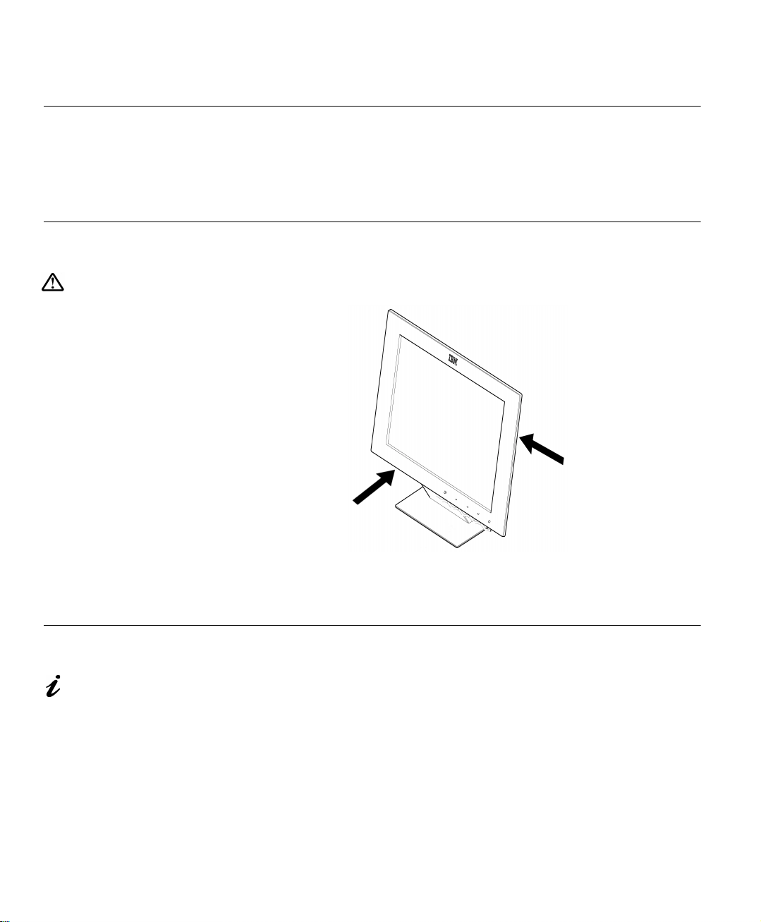
Handling Instructions
Do not support the monitor
within the screen area. The
Liquid Crystal Display is glass
and can be damaged by rough
handling or excessive pressure.
1. Lift the monitor by placing both hands under the lower part of the cover.
2. Before using your monitor for the first time, remove the clear protective
Workplace Preparation
This section gives advice
on what you should
consider before you set up your
monitor.
Height
The monitor should be positioned so that the top of the screen is slightly
below your eye level when you sit at your workstation.
film from the front of the screen.
Orientation
Choose a position that gives the least reflection from lights and windows,
usually at a right angle to any windows. The monitor should be positioned
directly in front of you so that you do not have to twist your body to use it. Tilt
the monitor to a comfortable viewing angle.
2
Page 10

Working Practices
ENGLISHFRANÇAISESPAÑOLITALIANOJAPANESECOMPL & WARR
This section gives
advice on how you can
work comfortably and reduce
fatigue.
Rest
Take regular breaks. Vary your posture, stand up and stretch occasionally as
prolonged use of computer workstations can be tiring.
Back
Adjust the height and angle of the chairback to support your lower back. Sit
well back in your chair.
Hands
DEUTSCH
Adjust the seat height so that your forearms are approximately horizontal and
your wrists are straight when using the keyboard. Your upper arms should be
relaxed with your elbows near your body.
Use a light touch on the keyboard, keeping your hands and fingers relaxed.
Allow a space in front of the keyboard to rest your wrists when not typing.
Consider using a wristpad.
Eyesight
Working with monitors, in common with any prolonged close work, can be
visually demanding. Look away from the screen periodically and have your
eyesight checked regularly.
Screen settings
Set the screen brightness and contrast to a comfortable level. You may have
to adjust this as the lighting changes during the day. Many application
programs let you select color combinations which can help you to view in
comfort. See the Us er con trols section starting on page 14 for more
information.
3
Page 11
Connecting your Monitor
Be sure to read the
‘Safety Information’
the front of this User Guide
before carrying out this
procedure.
The AC adapter and
D-SUB signal cable are
connected to your monitor. If
you wish to change these or to fit
a different stand, see
on page 24.
Help
at
Further
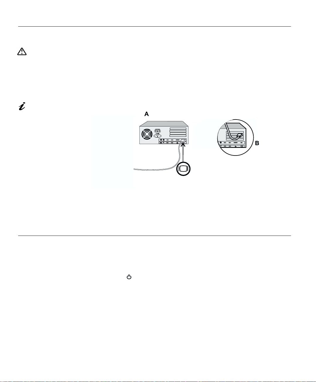
1. Turn off your PC and all attached devices.
2. Connect the signal cable (D-SUB type) to the video port on the back of
your computer. This port might be directly attached to your computer
(figure A), or it might be part of a video adapter card (figure B). The
video port on your computer or video adapter card may be colored blue
to match the blue connector on your monitor’s video cable.
If you are using a workstation, you may need to use a 13W3 cable. Refer
to Installing a 13W3 Cable on page 26 for instructions.
3. Connect the power cord to the power adapter first, then insert the plug
into a properly grounded electrical outlet.
Switching on your Monitor
1. Switch on the power source and your computer.
2. Switch on your monitor by pushing and releasing the power switch
marked .
To switch off your monitor, push and release the power switch again.
(
3. If you are using your monitor with a workstation, use the monitor’s OSD
to choose the 13W3 input source. (See INPUT SELECTION on page
18.)
4. Run
Monitor section on page 6.
4
A
UTO SETUP
)
by following the instructions in the Configuring your
Page 12

Adjusting the Monitor Positi on
Viewing Angle
You can tilt the screen backward and forward as shown below.
Caring for your Monitor
Be sure to turn off the power before you perform any maintenance on the
monitor. Clean your monitor as follows:
ENGLISHFRANÇAISESPAÑOLITALIANOJAPANESECOMPL & WARR
DEUTSCH
• Gently wipe the covers and the screen with a soft cloth.
• Remove finger marks and grease with a damp cloth and mild detergent;
do not use solvents or abrasives.
• Never use flammable cleaning material to clean your IBM monitor or any
other electrical apparatus.
5
Page 13

Configuring your Monitor
Automatic Setup
The Setup Utility included
on the setup diskette is for
displaying dot patterns. They do
not replace or modify the display
driver.
When you first use your monitor you must perform Automatic Setup (
S
ETUP
). This procedure sets up your monitor to process the video signals from
your computer without image discoloration or smearing. After you perform
A
UTO SETUP
, the settings are stored and used each time you turn on the
monitor.
The Automatic Setup
instructions require the
monitor to be warmed up for 15
minutes. This is not required for
normal operation.
Setup Diskette for Windows 95 or Windows 98
This section must be
completed before
continuing with the
Windows 95 or Windows 98
Auto Setup for the PC on
page 7.
To use the Plug and Play feature in Windows 95 or Windows 98, files should
be loaded from the IBM Color LCD Monitor Installation diskette as follows:
1. Turn off the computer and all attached devices.
2. Ensure that the monitor is connected correctly.
3. Turn on the monitor and then the system unit. Allow the system to boot
into Windows 95 or Windows 98.
Your computer’s Plug and Play code may warn you that your system
hardware has changed. This probably means that it has detected your
new monitor for the first time.
D
4. Open the
C
ONTROL PANEL
5. Select the
6. Select the
7. Select the
ISPLAY PROPERTIES
window by clicking on
and then double clicking on the
S
ETTINGS
C
HANGE DISPLAY TYPE
C
HANGE MONITOR TYPE
tab.
button.
button.
8. Insert the Setup diskette into drive A: and select the
D
ISPLAY
S
TART
icon.
H
AVE DISK
S
,
A
UTO
ETTINGS
button.
,
On LCD monitors, unlike
CRTs, a faster refresh rate
does not improve display
quality. IBM recommends using
either 1280 x 1024 at a refresh
rate of 60Hz or 640 x 480 at a
refresh rate of 60Hz.
6
9. Select OK.
10. Choose
IBM T85A
monitor and select OK. The files will be copied from
the diskette to your hard drive.
11. Close all open windows and remove the diskette.
12. Reboot the system.
The system will automatically select the maximum refresh rate and
corresponding Color Matching Profiles.
Page 14

Auto Setup for the PC
ENGLISHFRANÇAISESPAÑOLITALIANOJAPANESECOMPL & WARR
Before carrying out
this section, it is very
important that The Setup
Diskette for Windows 95 or
Windows 98 has been run.
(see page 6)
If your PC does not run
with the setup diskettes
shipped with the monitor, refer
to
Manual Setup
on page 13
Locate the operating system installed on your PC in the table below and
A
follow the appropriate instructions. You may choose to run
UTO SETUP
for
each operating system that you use. This means that if you sometimes use
your monitor while running any version of Windows and sometimes also use it
A
from within DOS (not a DOS window), you must run
A
Windows and DOS. You may run versions of
Operating System Corresponding Auto Setup procedure
DOS
Windows 3.1
Windows 95
Windows 98
Window NT
Operating System/2 (OS/2)
A
Before you begin
UTO SETUP
for your PC:
Auto Setup for DOS
Auto Setup for Windows 3.1 , Windows 95,
Windows 98 or Windows NT
Auto Setup OS/2
UTO SETUP
UTO SETUP
in any order.
for both
on page 8
on page 9
on page 11
1. Make a backup copy of the setup diskettes supplied with the monitor.
2. Make sure the PC’s video mode is set in the range of the supported
screen resolution shown in the table on page 20.
DEUTSCH
A
UTO SETUP
The
only applies to the current
screen mode. When a new
mode is selected, repeat this
section to reset the monitor
process
You should perform
A
UTO SETUP
for each screen mode you use.
7
Page 15

Auto Setup for DOS
If the monitor is in standby
mode (STANDBY ON), it
may automatically turn off while
you are waiting for it to warm up.
If this happens, switch off the
monitor and switch it on again
after a few seconds.
If your system goes into standby
mode again, reboot your system
and change the system Bios
Setup Utility to DISABLE Power
Saving. Refer to your system
manual.
If you are using PC-DOS/
V, change to U.S. mode by
typing
‘CHEV US’
ENTER at the command
prompt.
You must use DOS or
OS.2 DOS Full Screen
(not under Windows or
OS/2 DOS window, OS/2
window, or OS/2 full screen )
when you run DOS Auto
Setup.
The size and diversity of
the dot pattern varies with
the screen resolution.
If the screen flickers,
repeat the setup several
times until the flicker is
minimised, or adjust it manually
by following
on page 13.
and pressing
Manual Setup
1. Turn on the monitor first; then the PC. If the message CHECK SIGNAL CABLE is displayed, or if nothing is
displayed check:
• that the video interface cable is connected properly
• the correct video adapter card is installed
• the correct supported display mode is selected for your PC.
2. Wait approximately 15 minutes, until the monitor warms up.
3. Insert the diskette labelled ‘IBM Monitor Installation Disk’ into the diskette drive.
4. Display the command prompt screen of the DOS full-screen display.
5. At the command prompt, type
6. Type
‘TESTPATD’
and press ENTER.
‘A:’
and press ENTER.
7. Select from the screen the number for the color or text mode you want to setup.
8. Select from the screen the number for the video mode you want to setup.
You may repeat this process for as many of the color and video modes
as you need.
9. When the dot pattern appears, press the OSD Enter button at the
bottom of the monitor to display the initial OSD menu.
10. Use an Arrow button (
- or +
) to select the IMAGE LOCK icon
then press the OSD Enter button to access the function.
11. Using an Arrow button (
- or +
OSD Enter button . This activates the
), select
AUTOMATIC
A
UTO SETUP
and press the
procedure, which
will optimize the display settings with the provided dot-patterns.
The screen will dim, blink on and off several times and you may notice
small changes to the test pattern.
12. When finished, the OSD main menu returns. Press the Exit button to exit from the OSD.
13. Press the ESCAPE key to exit the test pattern program.
14. Type
If you use other operating systems, perform the appropriate
those systems, also: see
dows 98 or Windows NT
8
‘Exit’
at the command prompt to return to Windows.
Auto Setup for Windows 3.1, Windows 95, Win-
on page 9 and
Auto Setup OS/2
A
UTO SETUP
on page 11.
for
Page 16

Auto Setup for Windows 3.1, Windows 95, Windows 98 or Windows NT
ENGLISHFRANÇAISESPAÑOLITALIANOJAPANESECOMPL & WARR
If the monitor is in standby
mode (STANDBY ON), it
may automatically turn off while
you are waiting for it to warm up.
You can disable the Windows
energy saving feature by
TART
clicking on the S
selecting S
ANEL
P
Make sure that the E
SAVING FEATURES OF MONITOR
check boxes are either empty, or
that the features are set to at
least 20 minutes.
Your system may also have its
Power Saving utility enabled
through the Bios Setup Utility.
Refer to your system manual for
directions on disabling that bios
option.
, D
ETTINGS
ISPLAY
button and
ONTROL
, C
CREEN SAVER
, S
NERGY
1. Turn on the monitor first; then the PC. If the message CHECK SIGNAL CABLE is displayed, or if nothing is
displayed check:
• that the video interface cable is connected properly.
• the correct video adapter card is installed.
• the correct supported display mode is selected for your PC.
.
2. Wait approximately 15 minutes, until the monitor warms up.
3. Drag the icon bar and tool bar , if they are display ed, to the bottom of the screen.
4. Insert the diskette labelled ‘IBM Monitor Installation Disk’ into the diskette drive.
5. Check the operating system installed on your PC and follow the instructions from the table below.
Operating
System
Windows 3.1
Windows NT 3.5
Windows 95
Windows 98
Windows NT 4.0
Step1 Step2 Step3 Step4
Open
P
ROGRAM
M
ANGER
Select
F
ILE
Select
R
UN
‘
A:\TESTPAT
and press
Select
S
TART
Select R
UN
ENTER
Type
DEUTSCH
’
The size and diversity of
the dot pattern varies with
the screen resolution.
Position the mouse pointer
at the bottom center of the
screen. This allows
S
ETUP
to run properly
A
UTO
6. When the test pattern appears, press the OSD Enter button at the
bottom of the monitor to display the initial OSD menu.
7. Use an Arrow button ( -
press the OSD Enter button to access the function.
8. Using an Arrow button (
Enter button . This activates the
or
+ ) to select the
- or +
), select
A
UTO SETUP
IMAGE LOCK
AUTOMA TIC
and press the OSD
procedure, which will
icon and
optimize the display settings with the provided test pattern.
The screen will dim, blink on and off several times, and you may notice
small changes to the test pattern.
(To abor t the
A
UTO SETUP
function, press the
E
SC
key.)
9. When finished, the OSD main menu returns. Press the Exit button once to exit from the OSD.
9
Page 17

E
10. Press the
SC
key to return to Windows.
You have completed the monitor setup for Windows. If you use other operat-
A
ing systems, perform the appropriate
Auto Setup OS/2
on page 11 and
UTO SETUP
for those systems, also: see
Auto Setup for DOS
on page 8.
10
Page 18

Auto Setup OS/2
ENGLISHFRANÇAISESPAÑOLITALIANOJAPANESECOMPL & WARR
If the monitor is in standby
mode (STANDBY ON), it
may automatically turn off while
you are waiting for it to warm up.
1. Turn on the monitor first; then the PC. If the message CHECK SIGNAL CABLE is displayed, or if nothing is
displayed check:
• that the video interface cable is connected properly.
• the correct video adapter card is installed.
• the correct supported display mode is selected for your PC.
2. Wait approximately 15 minutes, until the monitor warms up.
3. Insert the diskette labelled ‘IBM Monitor Installation Disk’ into the diskette drive.
OS/2 S
4. Select
1280 X 1024 X 256
5. Select
6. Close
S
YSTEM
S
CREEN REFRESH
YSTEMS
7. At the OS/2 command prompt, select the
8. Press mouse button 2 and select
S
YSTEMS SETUP
,
S
,
YSTEM
.
60H
of
Z
.
and restart your system.
S
ETTINGS
. Select
OS/2 F
P
ROPERTIES
or
S
CREEN RESOLUTION
ULL SCREEN
command.
(depending on
your OS/2 version).
9. Select
S
ESSION
and then choose
WIN-OS/2 F
ULL SCREEN
.
10. Open the OS/2 full-screen window.
11. At the command prompt type A: and press ENTER.
DEUTSCH
The size and diversity of
the dot pattern varies with
the screen resolution.
Position the mouse pointer
at the bottom center of the
screen. This allows
S
ETUP
to run properly.
A
UTO
12. Type
TESTPATS
and press ENTER.
13. When the dot pattern appears, press the OSD Enter button to display the initial OSD menu.
14. Use an Arrow button (
press the OSD Enter button to access the function.
- or +
15. Using an Arrow button (
Enter button . This activates the
) to select the I
- or +
), select
A
UTO SETUP
MAGE LOCK
AUTOMA TIC
and press the OSD
procedure, which will
icon and
optimize the display settings with the provided test pattern.
The screen will dim, blink on and off several times, and you may notice
small changes to the test pattern.
(To abor t the
A
UTO SETUP
function, press the
ESCAPE
key.)
11
Page 19

If the screen flickers,
repeat the setup several
times until the flicker is
minimised, or adjust it manually
by following
on page 13.
Manual Setup
16. When finished, the OSD main menu returns. Press the Exit button to exit from the OSD.
17. Press the ESCAPE key to return to the OS/2 Window.
You have completed the monitor setup for OS/2. If you use other operating
A
systems, perform the appropriate
UTO SETUP
for those systems, also: see
Auto Setup for Windows 3.1, Windows 95, Windows 98 or Windows NT
on page 9 and
Auto Setup for DOS
on page 8.
12
Page 20

Manual Setup
Normally, you can complete the setup procedure using
if your screen image is still distorted after you perform
diskette does not run on your system, perform
A
M
ANUAL SETUP
A
UTO SETUP
UTO SETUP
.
ENGLISHFRANÇAISESPAÑOLITALIANOJAPANESECOMPL & WARR
, however,
or the setup
If the monitor is in standby
mode (STANDBY ON), it
might automatically turn off
while you are waiting for it to
warm up.
To disable the Windows energy
saving feature by clicking on the
TART
button and selecting
S
ETTINGS
S
ISPLAY
D
sure that the E
FEATURES OF MONITOR
boxes are either empty, or that
the features are set to at least 20
minutes.
Your system may also have its
Power Saving utility enabled
through the Bios Setup Utility.
Refer to your system manual for
directions on disabling that bios
option.
ONTROL PANEL
, C
CREEN SAVER
, S
NERGY SAVING
,
. Make
check
1. Have your computer and monitor turned on for at least 15 minutes until
the monitor and video adapter have warmed up.
2. You may wish to start the program you most often use so that you can
adjust for a “typical” screen.
3. Press the OSD Enter button at the bottom of the monitor to display the initial OSD menu.
4. Use an Arrow button (
- or +
) to select the IMAGE LOCK icon and
press the OSD Enter button to access the function.
5. Using an Arrow button (
press once to select
- or +
COARSE
indicators become illuminated (see page 17
), select
. Left and right arrow adjustment
MANUAL
).
, press and then
6. Use the Arrow buttons to correct (as much as possible) for noise in the
video signal then press to save the changes.
7. Use an Arrow button to select
FINE
and press the button.
8. Use the Arrow buttons again to tune the image to your liking.
9. When finished, press the Exit button four times to exit from the OSD .
You have completed the monitor setup.
DEUTSCH
13
Page 21

9519A-E2.fm Page 14 Friday, November 27, 1998 3:13 PM
Adjusting Your LCD Monitor
User controls
User control features
Icon Control Description
26'LQDFWLYH 6ZLWFKHVWKHYLGHRLQSXWVRXUFH
Exit
26'DFWLYH ([LWVIURPPHQXVDQGVXEPHQXV
([LWVWKH26'
The image is already
optimized for many display
modes, however the user
controls can be used to adjust
the image to your liking.
The settings are saved
after adjustment and when
exiting the OSD and will be
effective thereafter.
14
'LVSOD\VWKH26'PDLQPHQX
Left Arrow
Right Arrow
OSD Enter
Power Switch 6ZLWFKHVWKHPRQLWRURQDQGRII
0RYHVWKHFXUVRUWRKLJKOLJKWLFRQVDQGRWKHU
RSWLRQV
'LVSOD\VWKH26'PDLQPHQX
0RYHVWKHFXUVRUWRKLJKOLJKWLFRQVDQGRWKHU
RSWLRQV
'LVSOD\VWKH26'PDLQPHQX
(QWHUVPHQXVDQGVXEPHQXVDQGVHOHFWVWKH
KLJKOLJKWHGRSWLRQ
Operation
• Press an Arrow button or the OSD Enter button to display the main OSD
menu.
• Use the Arrow buttons to move among the icons . Select an icon and press
OSD Enter to access that function. If there is a sub-menu, you can move
between options using the Arrow buttons, then press OSD Enter to select
that function. Use the Arrow buttons to make adjustments.
• Press the Exit button to move backwards through the sub-menus and exit
from the OSD.
Note: After making adjustments, the Power indicator LED will briefly
turn amber to indicate that the new value has been saved.
Page 22

OSD Lock / Unlock
This feature allows you to secure the current control settings, while allowing
the user to adjust Brightness and Contrast, so that they cannot be
inadvertently changed. You can unlock the OSD controls at any time by using
the same procedure.
Push and hold the button for 10 seconds to Lock or to Unlock. When locked, a
“CONTROLS LOCKED” message will be displayed.
ENGLISHFRANÇAISESPAÑOLITALIANOJAPANESECOMPL & WARR
DEUTSCH
15
Page 23

On-screen display (OSD) controls
The settings adjustable with the user controls are viewed through the OnScreen Display (OSD). Press any of the OSD buttons to activate the OSD.
The LCD monitor needs
time to become thermally
stable the first time you turn it on
each day. Thus, to achieve more
accurate adjustments for
parameters, allow the LCD
monitor to warm up (be On) for
at least 15 minutes before
making any screen adjustments.
OSD Icon Description Sub-menu(s)
BRIGHTNESS
Initial appearance of OSD
MAIN MENU
i
BRIGHTNESS
OSD functions
Controls and
Adjustments
Adjusts brightness
16
CONTRAST
IMAGE LOCK
Adjusts contrast
The image lock function is used to
adjust the level of noise in the video
signal which causes horizontal lines or
areas on the screen where the image
appears to be unstable and jitters or
shimmers. This can be done
automatically or manually.
AUTOMATIC
Automatic adju sts the
monitor.
Page 24

OSD Icon Description Sub-menu(s)
Controls and
Adjustments
ENGLISHFRANÇAISESPAÑOLITALIANOJAPANESECOMPL & WARR
IMAGE LOCK
(continued)
COLOR
Select the preset Color mode you find
most comfortable and then fine tune
the colors using the User submenu, if
necessary.
MANUAL -
• Fine
• Coarse
PRESET 1
USER
• Red
• Green
• Blue
Use the Arrow buttons to
adjust away the
interference. If
satisfactory results are
not obtained using the
Fine adjustment, use the
Coarse adjustment and
then use Fine again.
This function may
change the width of the
display image. Use the
H-Position function to
center the display image
on the screen.
- (Cool White)
(Normal White)
2 -
- (Warm White)
3
Increases or decreases
redness
Increases or decreases
greenness
Increases or decreases
blueness
DEUTSCH
RESET
H-POSITION
V-POSITION
DISPLAY
SIZE
Resets the Brightness, Contrast, Image
Lock Fine and Coarse, Color, H-P osition,
V-Position, and Display Size settings .
Moves the screen left and right.
Moves the screen down and up.
If your computer or video board
supplies a signal rate and
addressability lower than 1280 x 1024,
this LCD monitor provides a scaling
processor that can expand the
addressability up to 1280 x 1024.
EXPANDED
NORMAL
- Does not make the
NO
adjustment
- Resets the
YES
settings
Image enlarged to fill
1 -
the entire screen.
Image enlarged to fill
2 -
the width of the screen
only.
Image at normal size.
17
Page 25

OSD Icon Description Sub-menu(s)
Controls and
Adjustments
IMAGE EFFECT
LANGUAGE
OSD MENU
POSITION
INPUT
SELECTION
i
INFORMAT ION
Select this icon to optimize the display
for the type of software you are using.
Scaling smooths an image which may
help the eye to see more detail.
Filtering sharpens text by adding a
fine, contrasting line around each
character so that it is easier to
recognize.
The language chosen affects only the
language of the OSD. It has no effect
on any software running on the
computer.
Changes the position of the OSD on
the screen.
This monitor can accept video signals
through two different connectors.
Most desktop computers use a D-SUB
connector. Most workstations use a
13W3 connector.
Shows information about the
addressability and the horizontal and
vertical frequencies available. The
current setting for the images received
from the computer or video board is
displayed along the bottom of both
submenus.
SCALING ON
OFF
FILTER ON
H-POSITION
V-POSITION
USER MODES
PRESET
MODES
OFF
Select one of the five
languages to use for the
OSD.
1
2
Lists all modes which
you have defined by
making changes using
the OSD controls
Lists all modes that have
been defined during
manufacture
- Turns Scaling on.
- Turns Sc aling off.
- Turns Filtering on.
- Turns Filter ing off.
- selects D-SUB
- selects 13 W 3
18
Page 26

Display modes
Further Information
The display mode the monitor uses is controlled by the computer. Therefore,
you should refer to your computer documentation for details on how to
change display modes.
The image size, position and shape may change when the display mode
A
changes. This is normal and the image can be readjusted using
and the monitor controls.
Unlike CRT monitors, which require a high refresh rate to minimize flicker,
TFT technology is inherent ly flicker-free. If possible, configure your computer
for 1280 x 1024 addressability at 60Hz vertical refresh rate.
For the display modes listed on page 20, the screen image has been
optimized during manufacture.
UTO SETUP
ENGLISHFRANÇAISESPAÑOLITALIANOJAPANESECOMPL & WARR
DEUTSCH
19
Page 27

Factory Set Display Modes
If your computer has
previously been used with a
CRT monitor and is currently
configured to a display mode
outside the range that the Flat
Panel monitor can display, you may
need to re-attach the CRT monitor
temporarily until you have reconfigured the computer,
preferably to 1280 x 1024 at 60Hz.
Addressability Refresh Rate
Horizontal
Frequency
640 × 350 70 Hz 31.5 kHz 640 × 480 75 Hz 37.5 kHz 640 × 480 72 Hz 37.8 kHz 640 × 480 66 Hz 35.0 kHz 640 × 480 60 Hz 31.5 kHz 720 × 400 70 Hz 31.4 kHz 800 × 600 56 Hz 35.1 kHz 800 × 600 60 Hz 37.8 kHz 800 × 600 72 Hz 48.0 kHz 800 × 600 75 Hz 46.8 kHz
832 × 624 75 Hz 49.7 kHz 1024 × 768 60 Hz 48.8 kHz 1024 × 768 70 Hz 56.5 kHz 1024 × 768 75 Hz 60.0 kHz
20
1152 x 864 75 Hz 67.5 k Hz 1152 × 870 75 Hz 68.7 kHz 1152 x 900 66 Hz 61.8 k Hz
1280 × 1024 75 Hz 79.9 kHz
1280 × 1024† 60 Hz 63.9 kHz
1280 × 1024 72 Hz 78.1 kHz 1280 × 1024 76 Hz 81.1 kHz
† Recommended
Page 28

Power Management
To benefit from power management, the monitor must be used in conjunction
with a computer that implements the Video Electronics Standards
Association (VESA) Display Power Management Signalling (DPMS)
Standard.
The power management feature is invoked when the computer recognizes
that you have not used your mouse or keyboard for a user-definable period.
There are several states as described in the table below.
E
As an
E
NERGY STAR
NERGY STAR
®
®
Partner, IBM has determined that this product meets the
guidelines for energy efficiency.
IBM recommends that you switch off your monitor at the end of each working
day, or whenever you expect to leave it unused for long periods during the
day.
ENGLISHFRANÇAISESPAÑOLITALIANOJAPANESECOMPL & WARR
DEUTSCH
State
On
DPMS
Standby
DPMS
Suspend
DPMS Off
Power
Indicator
Steady green Normal
Steady amber Blank
Flashing
amber
(0.5 sec.
interval)
Flashing
amber
(1 sec.
interval)
Screen
Blank
Blank
Restoring
Operation
Press a key or
move the mouse.
Press a key or
move the mouse. ‡
Press a key or
move the mouse. ‡
‡ There may be a slight delay before the picture reappears.
Compliance
E
NERGY STAR
and NUTEK
E
NERGY STAR
and NUTEK
E
NERGY STAR
and NUTEK
®
®
®
21
Page 29

Troubleshooting
If you have a problem setting up or using your monitor, you may be able to
solve it yourself. Before calling your retailer or IBM, try the suggested actions
that are appropriate to your problem.
For image problems, you
may want to run
S
ETUP
again before consulting to
this section. In most cases,
S
ETUP
can fix the problems. See
A
UTO
Auto Setup for the PC
page 7 for details.
A
UTO
on
Problem
Screen is blank
and power
indicator is off
Screen is blank
and power
indicator is
steady green
Screen is blank
and power
indicator is
steady amber
Possible
Cause
No power to
monitor
Brightness
and Contrast
may be too
low
The monitor is
in the Power
Management
Standby state
Suggested Action Reference
Ensure that the electrical
outlet and the monitor are
both switched on.
Check that the power cord
is firmly plugged into the
electrical outlet and the
power supply unit.
If the power cord plug has
a removable fuse, replace
it.
Try another power cord.
Try another elect r ic al
outlet.
Connecting
your Monitor
section on
page 4
User
Adjust brightness and
contrast.
Press any key on the
keyboard or move the
mouse to restore
operation.
Check the Power
Management software on
your computer
controls
section on
page 14
Power
Management
section on
page 21
22
Page 30

Problem
Screen is blank
and power
indicator is
Flashing green
every 0.5
second
Possible
Cause
The monitor is
not receiving
a video signal
Display mode
of the
computer is
outside the
range of the
monitor
Suggested Action Reference
Check that the signal cable
is firmly connected to the
computer.
Check that no pins are
bent in the signal cable
connector.
Reconfigure the computer
to use a supported display
mode.
Connecting
your Monitor
section on
page 4
Further
Information
section on
page 19
ENGLISHFRANÇAISESPAÑOLITALIANOJAPANESECOMPL & WARR
DEUTSCH
Screen is blank
and power
indicator is
flashing amber
every 0.5 or 1
second
Image appears
to be smeared
Image appears
to be
discolored
A few dots are
missing,
discolored , or
inappropriately
lighted.
Press any key on the
The monitor is
in the Power
Management
Suspend or
Off state
There are
noises in the
video signal
The Color
setting may
be incorrect
The LCD contains over 2,300,000 thin-film
transistors (TFTs). A small number of
missing, discolored, or lighted dots may be
present on the screen, which is an intrinsic
characteristic of the TFT LCD technology
and is not an L CD defect.
keyboard or move the
mouse to restore
operation.
Check the Power
Management software on
your computer.
IMAGE LOCK
Select
in the OSD. Then select
MANUAL
COARSE
Adjust the Color settings.
to adjust
settings.
menu
FINE/
Power
Management
section on
page 21
User
controls
section on
page 14
User
controls
section on
page 14
23
Page 31

Further Help
If you are unable to correct the problem yourself, you may seek further help
as follows:
Call the IBM HELPCENTER.
In the US call 1-800-772-2227
In Canada call 1-800-565-3344
In other countries contact your dealer or retailer.
If possible, stay by your
computer. Your Technical
Support Representative may
wish to go through the problem
with you during the call.
More help, late-breaking
news and details of the
latest accessories for these
products may be found on the
worldwide web at:
http://www.pc.ibm.com/us/
accessories
Information about the Video
Electronics Standards
Association can be found on the
worldwide web at:
http://www.vesa.org
Before calling, please have available as much of the following information as
possible:
1. Model and serial number from the label on your monitor.
2. Purchase receipt.
3. Description of problem.
4. Computer type and model.
5. System configuration (hardware fitted, etc.).
6. System BIOS version number.
7. Operating System and version number.
8. Display driver version number.
9. Video Adapter Type.
Removing the stand and cables
Alternative stands for your IBM Flat Panel Monitor may be available from
specialist suppliers.
This product is equipped with mounting facilities that conform to the VESA
Flat Panel Monitor Physical Mounting Interface Standard (FPMPMI).
This product is shipped with the signal cable and the power cord attached to
the monitor. If you want to use other cables for reasons such as having the
monitor wall-mounted, follow the instructions below:
1. Disconnect the power cord from the wall outlet.
24
Page 32

2. Carefully insert the head of a flathead (–) screwdriver into the slo t visib le
along either side of the cable cover (a) and pry it off.
a
ENGLISHFRANÇAISESPAÑOLITALIANOJAPANESECOMPL & WARR
d
b
c
3. Squeeze the sides of the hinge cover (b) and pull it off.
4. Gently lift the stand cover (c) along the top and then slide it backwards and off the stand.
5. Remove the signal cable and the power cord from the monitor by
disconnecting the corresponding adapters. Carefully cut the plastic tie to
free the power cord and remove the screw holding the power cord
clamp.
6. Lay the monitor facedown on a cushion and remove the six screws
holding the hinge mechanism on the monitor. Lift off the hinge and base
assembly.
7. Insert the head of a flathead (–) screwdriver in the slot of one of the two
VESA caps (d) and pry the cap off. Repeat the procedure on the other
VESA cap.
DEUTSCH
8. If you are installing an arm or wall-mounting device, follow the directions
included with the device. If you are just changing your cables, continue
with Step 9.
9. Connect the signal cable and the power cord, then refit the power cord
clamp in its original screwpost.
10. Slide the stand cover back on the stand.
25
Page 33

11. Put the hinge cover back on, making sure that the straight side is at the top.
12. Insert the three tabs at the top of the cable cover into the slots in the
back of the monitor and push the cover into place.
To obtain the correct cables and/or to get further instructions on installing
them, call the IBM HELPCENTER at the above numbers or contact your
dealer, retailer, or other IBM authorized Servicer.
Installing a 13W3 Cable
13W3 cables are most often used with workstations. To install a 13W3 cable
follows steps 1 through 4 starting on page 24(
Removing the sta nd and cables
then continue with the steps below:
5. Remove the D-SUB signal cable, if you will not be using it.
6. Connect the 13W3 signal cable to the 13W3 connector on the back of the monitor.
7. Slide the stand cover back on the stand.
8. Put the hinge cover back on, making sure that the straight side is at the top.
9. Insert the three tabs at the top of the cable cover into the slots in the
back of the monitor and push the cover into place.
),
26
Page 34

Specifications
This color monitor (Type-model 9519-Axx) uses a 18.1-inch TFT LCD.
ENGLISHFRANÇAISESPAÑOLITALIANOJAPANESECOMPL & WARR
Power consumption figures
are for the monitor and the
power supply combined.
Dimensions Width:
Depth:
Height:
Weight Unpackaged 19.8 lb. (9.0 Kg)
Tilt / Swivel Tilt:
Swivel:
Image Viewable Image Size:
Maximum Height:
Maximum Width:
Pixel Pitch:
Power Input Supply Voltage:
Max Supply Current:
Power Consumption Normal Operation:
DPMS Stand-by:
DPMS Suspend:
DPMS off:
Video Input Input Signal:
Horiz. Addressability:
Vert. Addressability:
Clock Frequency:
Communications VESA DDC: 2 B
462 mm
224 mm
459 mm
– 4° / + 41°
– 230° / + 90°
18.1” (459.7 mm)
287 mm
359 mm
0.281 mm (H) × 0.281 mm (V)
90 - 260 Vac
60/50 ± 3 Hz
1.5 A at 120 Vac
< 48 W
< 5 W
< 5 W
< 5 W
Analog Direct Drive
75 ohm 0.7 V
1280 pixels (max)
1024 lines (max)
135 MHz
DEUTSCH
Supported Display
Modes
Environment Temperature:
Standard modes:
between
Horiz. Frequency:
Vert. Frequency:
Operating:
Storage:
Shipping:
Humidity:
Operating:
Storage:
Shipping:
IBM, VESA, HP, Sun, Mac
30 kHz - 82 kHz
56 Hz - 75 Hz
See
Factory Set Display Modes
page 20
See
Display Mode Ranges
page 28
10 to 35° C
- 20 to 60° C
- 20 to 60° C
10 to 80%
5 to 95%
5 to 95%
on
on
27
Page 35

Display Mode Ranges
Refresh Rate /
Addressability
640 x 350 70 Hz 31.5 kHz
640 x 480, VGA 60 / 59 - 61 Hz 31.5 / 30.5 - 35.0 kHz
640 x 460 66 Hz 35.0 kHz 640 x 480, VGA 72 / 71 - 73 Hz 37.9 / 36.5 - 39.9 kHz 640 x 480, VGA 75 / 74 - 76 Hz 37.5 / 36.8 - 43.0 kHz
720 x 400 70 Hz 31.5 kHz
800 x 600 56 Hz 35.2 kHz
800 x 600, SVGA 60 / 59 - 61 Hz 37.9 /37.5 - 43.0 kHz 800 x 600, SVGA 72 / 71 - 73 Hz 48.1 / 45.2 - 51.0 kHz 800 x 600, SVGA 75 / 74 - 76 Hz 46.9 / 46.0 - 51.0 kHz
832 x 624 75 Hz 49.7 kHz
1024 x 768, XGA 60 / 59 - 61 Hz 48.4 / 47.8 - 53.0 kHz 1024 x 768, XGA 70 / 69 - 71 Hz 56.5 / 56.0 - 61.0 kHz 1024 x 768, XGA 75 / 74 - 76 Hz 60.0 / 59.5 - 61.0 kHz
Range
(±1 Hz)
Horizontal Frequency /
Range
(±500 Hz)
28
1152 x 864, VESA 75 Hz 67.5 kHz
1152 x 870 75 Hz 68.7 kHz
1152 x 900, Sun 66 Hz 61.8 kHz
1280 x 1024, SXGA 60 / 59 - 61 Hz 64.0 / 61.5 - 66.0 kHz
1280 x 1024, HP 72 Hz 78.1 kHz
1280 x 1024, SXGA 75 / 74 - 76 Hz 80.0 / 78.0 - 82.0 kHz
1280 x 1024, Sun 76 Hz 81.1 kHz
Page 36

T85Acomp.book Page I Monday, November 16, 1998 8:00 PM
Federal
Communications
Commission (FCC)
Statement
Compliances
This equipment has been tested and found to comply with the limits for a Class B digital device,
pursuant to Part 15 of the FCC Rules. These limits are designed to provide reasonable protection
against harmful interference in a residential installation. This equipment generates, uses, and
can radiate radio frequency energy and, if not installed and used in accordance with the
instructions, may cause harmful interference to radio communications. However, there is no
guarantee that interference will not occur in a particular installation. If this equipment does cause
harmful interference to radio or television reception, which can be determined by turning the
equipment off and on, the user is encouraged to try to correct the interference by one or more of
the following measures:
• Reorient or relocate the receiving antenna.
• Increase the separation between the equipment and receiver.
• Connect the equipment into an outlet on a circuit different from that to which the receiver is
connected.
• Consult an IBM authorized dealer or service representative for help.
Properly shielded and grounded cables and connectors must be used in order to meet FCC
emission limits. Proper cables and connector s are available from IBM auth oriz ed de ale rs. IBM is
not responsible for an y r adio or television interference caused by using other than recommended
cables and connectors or by unauthorized changes or modifications to this equipment.
Unauthorized changes or modifications could void the user’s authority to operate the equipment.
(1*/,6+)5$1d$,6(63$f2/,7$/,$12-$3$1(6(&203/:$55
'(876&+
Power Cords
Declaration of Conformity
Trade Name:
Model No.:
Responsible Party:
Address:
Telephone:
Fax:
This device complies with Part 15 of the FCC Rules. Operation is subject to the f ollowing two conditions:
(1) this device may not cause harmful interference, and (2) this device must accept any interference
received, including interference that may cause undesired operation.
For your safety, IBM provides a power cord with a grounded attachment plug to use with this IBM
product. To avoid electrical shock, always u se the p ower cord and plug with a properly grounded
power outlet.
IBM power cords used in the United States and Canada are listed by the Underwriters
Laboratories (UL) and certified by the Canadian Standards Association (CSA).
For units intended to be operated at 115 volts: Use a UL listed and CSA certified cord set
consisting of a minimum 18 AWG, type SVT or SJT, three conductor cord, a maximum of 4.5
meters (15 feet) in length and a parallel blade, grounding type attachment plug rated 15
amperes, 125 volts.
IBM Corporation
9519-AW*, 9519-AG*
Samsung Electronics Co., Ltd.
QA Lab of Samsung America
85 West Tasman Drive
San Jose, CA 95134 USA
408-554-5124
408-554-5191
I
Page 37

T85Acomp.book Page II Monday, November 16, 1998 8:00 PM
For units intended to be operated at 230 volts (U.S. use): Use a UL listed and CSA certified cord
set consisting of a minimum 18 AWG, type SVT or SJT, three conductor cord, a maximum of 4.5
meters (15 feet) in length and a tandem blade, grounding type attachment plug rated 15 amperes
250 volts.
For units intended to be operated at 230 volts (outside the U.S.): Use a cord set with a grounding
type attachment plug rated 13 amperes (minimum), 250 volts. The cord set should be marked
<HAR> and have the appropriate safety approvals for the country in which the equipment will be
installed.
MPRII
Hinweise
NERGY STAR
As an E
NERGY STAR
E
This monitor complies with TCO’95 guidelines.
This product complies with Swedish National Council for Metrology (MPR) standards issued in
December 1990 (MPRII) for very low frequency (VLF) and extremely low frequency (ELF).
Gemäß der Amtsblätter des BMPT Nm. 61/1991 und 6/1992 wird der Betreiber darauf
aufmerksam gemächt, daß die von ihm mit diesem Gerät zusammengestellte Anlage auch den
technicschen Bestimmungen dieser Amtsblätter genügen muß.
Aus ergonomischen Gründen wird empfohlen, die Grundfarbe Blau nicht auf dunklem
Untergrund zu verwenden (schlechte Erkennbarkeit,Augenbelastung bei zu geringem
Zeichenkontrast).
Aus ergonomischen Gründen sollten nur Darstellungen auf dunklem Hintergrund bei
Vertikalfrequenzen ab 60 Hz (ohne Zeilensprung) benutzt werden.
Die Konvergenz des Bildes kann sich auf Grund des Magnetfeldes am Ort der Aufstellung aus
der krrekten Grundeinstellung verändern. Zur Korrektur empfiehlt es sich deshalb, die Regler an
der Frontseite für H STAT und V STAT so einzustellun, daß die getrennt sichbaren Farblinien für
Rot. Grün und Blau bei z.B. der Darstellung eines Buchstabens zur Deckung (Konvergenz)
gelangen. Siehe hierzu auch die Erklärungen zu H STAT und V STAT.
®
Partner, IBM Corporation has determined that this product meets the
guidelines for energy efficiency.
Industry Canada
Compliance
Statement
II
This Class B digital apparatus meets the requirements of the Canadian Interference-Causing
Equipment Regulations.
Cet appareil numérique de la classe B respecte toutes les exigences du Règlement sur le
matériel brouilleur du Canada.
Page 38

T85Acomp.book Page III Monday, November 16, 1998 8:00 PM
NOM
European Union
(EU) Statement
IBM de México, S.A.
IBM 9513-Axx TFT LCD Color Monitorr
Planta de Manufactura
416, Maetan-3Dong, Paldal-Gu
Suwon City, Kyungki-Do, Korea
442-742
Hecho en Korea
NOM - 018
Consumo de Corriente1.5 A
Frecuencia de Operacion50/60 Hz
Rension de Alimentacion100-240 V
This product has been tested and found to comply with the limits for Class B Information
Technology Equipment according to CISPR 22 / European Standard EN 55022. The limits for
Class B equipment were derived for typical residential environments to provide reasonable
protection against interference with licensed communication devices.
Properly shielded and grounded cables and connectors must be used in order to reduce the
potential for causing interference to radio and TV communications and to other electrical or
electronic equipment. Such cables and connectors are available from IBM authorised dealers.
In accordance with EN 50082-1 1992, Performance Criterion A:, it should be noted that in the
presence of certain electromagnetic field s, some screen jitter may be observed.
(1*/,6+)5$1d$,6(63$f2/,7$/,$12-$3$1(6(&203/:$55
'(876&+
III
Page 39

T85Acomp.book Page IV Monday, November 16, 1998 8:00 PM
Warranty
For European warr anty terms and conditions, re fer to the enclosed IBM Warranty statement, Part
Number 72H9623.
Statement of
Limited Warranty
The warranties provided by IBM in this Statement of Limited Warranty apply only to Machines
you originally purchase for your use, and not for resale, from IBM or your reseller. The term
“Machine” means an IBM machine, its features, conversions, upgrades, elements, or
accessories, or any combination of them. Unless IBM specifies otherwise, the following
warranties apply only in the country where you acquire the Machine. If you have any questions,
contact IBM or your reseller.
Machine: IBM 9519 LCD Color Monitors
Warranty Period*: 3 years, including backlight
• Contact your place of purchase for warranty service information
Production Status
Each Machine is manufactured from new parts, or new and serviceable used parts (which
perform like new parts). In some cases, the Machine may not be new and may have been
previously installed. Regardless of the Machine’s production status, IBM’s warranty terms apply.
The IBM Warranty
IBM warrants that each Machine 1) is free from defects in materials and workmanship and 2)
conforms to IBM’s Official Published Specifications. The warranty period for a Machine is a
specified, fixed period commencing on its Date of Installation. The date on your receipt is the
Date of Installation, unless IBM or your reseller informs you otherwise.
During the warranty period IBM or your reseller, if authorized by IBM, will provide warranty
service under the type of service designated for the Machine and will manage and install
engineering changes that apply to the Machine.
IV
For IBM or your reselle r to pro vid e w a rr anty service f or a feature, conversion, or upgrade, IBM or
your reseller may require that the Machine on which it is installed be 1) for certain Machines, the
designated, serial-numbered Machine and 2) at an engineering-change level compatible with the
feature, conversion, or upgrade . Many of these transactions inv olve the remov al of parts and their
return to IBM. You represent that all removed parts are genuine and unaltered. A part that
replaces a removed part will assume the warranty service status of the replaced part.
If a Machine does not function as warranted during the warranty period, IBM or your reseller will
repair it or replace it with one that is at least functionally equivalent, without charge. The
replacement may not be new , bu t will be in good working order. If IBM or your reseller is unable to
repair or replace the Machine, you may return it to your place of purchase and your money will be
refunded.
Page 40

T85Acomp.book Page V Monday, November 16, 1998 8:00 PM
If you transfer a Machine to another user, warranty service is available to that user for the
remainder of the warranty period. You should give your proof of purchase and this Statement to
that user. Howev er, for Machines which have a life-time warranty, this warranty is not transferable.
Warranty Service
To obtain warranty service for the Machine, you should contact your reseller or call IBM. In the
United States, call IBM at 1-800-772-2227. In Canada, call IBM at 1-800-565-3344. You may be
required to present proof of purchase.
IBM or your reseller will provide certain types of repair and exchange service, either at your
location or at IBM’s or your reseller’s service center, to restore a Machine to good working order.
When a type of service involv es the exchange of a Machine or part, the item IBM or your reseller
replaces becomes its property and the replacement becomes yours. You represent that all
removed items are genuine and unaltered. The replacement may not be new, but will be in good
working order and at least functionally equivalent to the item replaced. The replacement
assumes the warranty service status of the replaced ite m. Befo re IBM or y our reseller excha nges
a Machine or part, you agree to remove all features, parts, options, alterations, and attachments
not under warranty service. You also agree to ensure that the Machine is free of any legal
obligations or restrictions that prevent its exchange.
You agree to:
• obtain authorization from the owner to have IBM or your reseller service a Machine that you
do not own; and where applicable, before service is provided :
• follow the problem determination, problem analysis, and service request procedu res that IBM
or your reseller provide,
• secure all programs, data, and funds contained in a Machine, and
• inform IBM or your reseller of changes in a Machine’s location.
IBM is responsible for loss of, or damage to , y our Machine while it is 1) in IBM’ s possession or 2)
in transit in those cases where IBM is responsible for the transportation charges.
(1*/,6+)5$1d$,6(63$f2/,7$/,$12-$3$1(6(&203/:$55
'(876&+
Extent of Warranty
IBM does not warrant uninterrupted or error-free operation of a Machine.
Misuse, accident, modification, unsuitable physical or operating environment, improper
maintenance by you, or f ailure caused b y a product f or which IBM i s not responsib le ma y v oid the
warranties.
THESE WARRANTIES REPLACE ALL OTHER WARRANTIES, EXPRESS OR IMPLIED,
INCLUDING, BUT NOT LIMITED TO, THE IMPLIED WARRANTIES OF MERCHANTABILITY
AND FITNESS FOR A PARTICULAR PURPOSE. HOWEVER, SOME LAWS DO NOT ALLOW
THE EXCLUSION OF IMPLIED WARRANTIES . iF TH ESE LAWS APPL Y, THEN ALL EXPRESS
AND IMPLIED WARRANTIES ARE LIMITED IN DURATION TO THE WARRANTY PERIOD. NO
WARRANTIES APPLY AFTER THAT PERIOD.
In Canada, warranties include both warranties and conditions.
Some jurisdictions do not allow limitations on how long an implied warranty lasts, so the above
limitation may not apply to you.
V
Page 41

T85Acomp.book Page VI Monday, November 16, 1998 8:00 PM
For European warranty terms and conditions refer to enclosed IBM warranty statement Part
Number 72H9623.
Référez-vous à la garantie IBM N° de référence 72H9623 pour les condtions de garantie
européennes.
Die europäischen Garantiebedingungen finden Sie in der beigefügten IBMGewährleistungserklärung, Teilenummer 72H9623.
Los términos y condiciones de las garantías en Europa se recogen en la declaración de garantía
adjunta del número de pieza IBM 72H9623.
Per le condizioni e i termini de garanzia relativi ai paesi europei, consultare l’apposita
dichiarazione IBM (numero di matricola 72H9623).
VI
Page 42

T85Acomp.book Page I Monday, November 16, 1998 8:00 PM
Service Information
The following parts are for use by IBM service, or IBM authorised dealers, to support
the customer warranty. Parts are for service use only
T85A Model Type 9519
21L4364 9519-AW1 Monitor - Pearl White
21L4365 9519-AG1 Monitor - Stealth Black
21L4403 Power Supply
21L4505 Video I/F Cable (White)
21L4507 Video I/F Cable (Black)
.
(1*/,6+)5$1d$,6(63$f2/,7$/,$12-$3$1(6(&203/:$55
'(876&+
 Loading...