

Page 1
T54A-E.book Page 1 Saturday, February 19, 2000 12:05 PM
ENGLISHFRANÇAISESPAÑOLITALIANOJAPANESECOMPL & WARR
English
DEUTSCH
Page 2

T54A-E.book Page 2 Saturday, February 19, 2000 12:05 PM
First Edition (Mar/2001)
This publication could contain technical inaccuracies or typographical errors. Changes are made periodically to the information
herein; these changes will be made in later editions. IBM may make improvements and/or changes in the product(s) and/or
program(s) at any time.
It is possible that this publication may contain reference to, or information about, IBM products (machines and programs),
programming, or services that are not announced in your country.
Requests for copies of this publication and for technical information about IBM products should be made to your IBM Authorized
Dealer or IBM Retailer.
No part of this publication may be reproduced or distributed in any form or by any means without prior permission in writing from the
International Business Machines Corporation.
© Copyright International Business Machines Corporation 2000. All rights reserved.
Notices
References in this publication to IBM products, programs, or services do not imply that IBM intends to make these available in all
countries in which IBM operates. Any reference to an IBM product, program or service is not intended to state or imply that only
IBM’s product, program, or service may be used. Any functionally equivalent product, program, or service that does not infringe any
of IBM’s intellectual property rights or other legally protectable rights may be used instead of the IBM product, program, or service.
Evaluation and verification of operation in conjunction with other products, programs, or services, except those expressly
designated by IBM, are the user’s responsibility.
IBM may have patents or pending patent applications covering subject matter in this document. The furnishing of this document
does not give you any license to these patents.
Trademarks
The following terms, used in this publication, are trademarks or service marks of the IBM Corporation in the United States or other
countries:
IBMHelpCenter
NERGY STAR
E
is a U.S. registered mark.
Page 3

T54A-E.book Page 1 Saturday, February 19, 2000 12:05 PM
Contents
Setup . . . . . . . . . . . . . . . . . . . . . . . . . . . . . . . . . . . . . . . . . . . . . . . . . . . . . . . . . . . . . 2
Hardware Requirements . . . . . . . . . . . . . . . . . . . . . . . . . . . . . . . . . . . . . . . . . . 2
Handling Instructions . . . . . . . . . . . . . . . . . . . . . . . . . . . . . . . . . . . . . . . . . . . . . 2
Workplace Preparation . . . . . . . . . . . . . . . . . . . . . . . . . . . . . . . . . . . . . . . . . . . 2
Adjusting the Monitor Position . . . . . . . . . . . . . . . . . . . . . . . . . . . . . . . . . . . . . . 3
Working Practices . . . . . . . . . . . . . . . . . . . . . . . . . . . . . . . . . . . . . . . . . . . . . . . 3
Connecting your Monitor . . . . . . . . . . . . . . . . . . . . . . . . . . . . . . . . . . . . . . . . . . 5
Switching on your Monitor . . . . . . . . . . . . . . . . . . . . . . . . . . . . . . . . . . . . . . . . . 5
Configuring your Monitor . . . . . . . . . . . . . . . . . . . . . . . . . . . . . . . . . . . . . . . . . . . . 6
Setup Diskette for Windows 95, Windows 98 . . . . . . . . . . . . . . . . . . . . . . . . . . 6
Setup Diskette for Windows 2000 . . . . . . . . . . . . . . . . . . . . . . . . . . . . . . . . . . 7
Auto Setup . . . . . . . . . . . . . . . . . . . . . . . . . . . . . . . . . . . . . . . . . . . . . . . . 8
Auto Setup for DOS . . . . . . . . . . . . . . . . . . . . . . . . . . . . . . . . . . . . . . . . . . . . . 9
Auto Setup for Windows 3.1, Windows 95,
Windows 98, Windows NT, or Windows 2000 . . . . . . . . . . . . . . . . . . . . . . . . . 10
ENGLISHFRANÇAISESPAÑOLITALIANOJAPANESECOMPL & WARR
DEUTSCH
Manual Setup . . . . . . . . . . . . . . . . . . . . . . . . . . . . . . . . . . . . . . . . . . . . . . . . . . . . . 12
Adjusting Your LCD Monitor . . . . . . . . . . . . . . . . . . . . . . . . . . . . . . . . . . . . . . . . 13
User controls . . . . . . . . . . . . . . . . . . . . . . . . . . . . . . . . . . . . . . . . . . . . . . . . . . 13
On-screen display (OSD) controls . . . . . . . . . . . . . . . . . . . . . . . . . . . . . . . . . 15
Further Information . . . . . . . . . . . . . . . . . . . . . . . . . . . . . . . . . . . . . . . . . . . . . . . . 18
Display modes . . . . . . . . . . . . . . . . . . . . . . . . . . . . . . . . . . . . . . . . . . . . . . . . . 19
Power Management . . . . . . . . . . . . . . . . . . . . . . . . . . . . . . . . . . . . . . . . . . . . 19
Product Disposal . . . . . . . . . . . . . . . . . . . . . . . . . . . . . . . . . . . . . . . . . . . . . . . 19
Troubleshooting . . . . . . . . . . . . . . . . . . . . . . . . . . . . . . . . . . . . . . . . . . . . . . . . . . 20
Further Help . . . . . . . . . . . . . . . . . . . . . . . . . . . . . . . . . . . . . . . . . . . . . . . . . . 22
Specifications . . . . . . . . . . . . . . . . . . . . . . . . . . . . . . . . . . . . . . . . . . . . . . . . . . . . 25
Warranty Statements . . . . . . . . . . . . . . . . . . . . . . . . . . . . . . . . . . . . . . . . . . . . . . . 26
Appendices (Compliances and Warranty)
1
Page 4
y
g
y
g y
y
y
y
y
y
g
T54A-E.book Page 2 Saturday, February 19, 2000 12:05 PM
Setup
Hardware Requirements
This monitor requires a computer with a suitable on-board sub-system or
Video Adapter card that can support XGA 1024 × 768, SVGA 800 x 600, or
VGA 640 x 480 at 60 Hz.
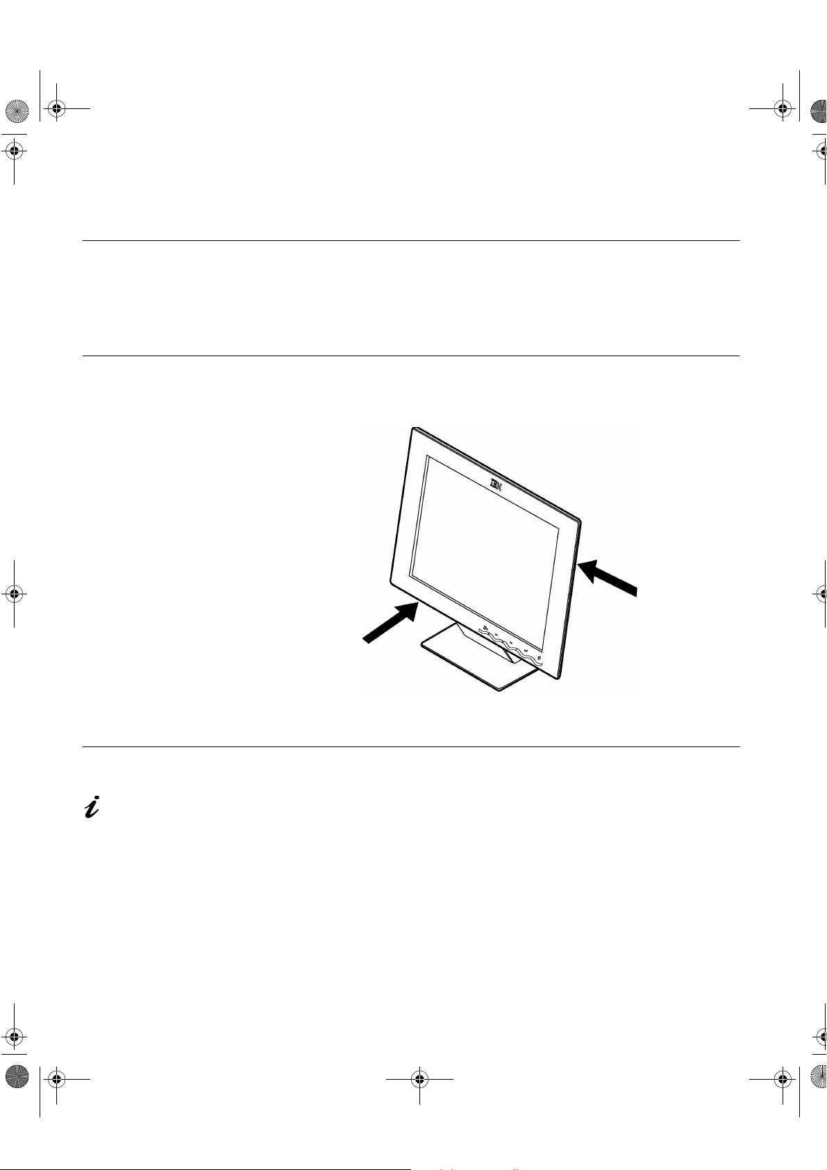
Handling Instructions
Do not support the monitor
within the screen area. The
Liquid Cr
lass and can be damaged
rough handling or
b
excessive pressure.
stal Display is
1. Lift the monitor by placing your hands where indicated below.
2. Before usin
Workplace Preparation
This section gives advice
on what
consider before
monitor.
ou should
ou set up your
Height
The monitor should be positioned so that the top of the screen is slightly
below
our monitor for the first time, remove the clear protective
film from the front of the screen.
our eye level when you sit at your workstation.
Orientation
Choose a position that gives the least reflection from lights and windows,
usuall
directl
the monitor to a comfortable viewin
2
at a right angle to any windows. The monitor should be positioned
in front of you so that you do not have to twist your body to use it. Tilt
angle.
Page 5
y
y
g
g
y
y
g
y
g
T54A-E.book Page 3 Saturday, February 19, 2000 12:05 PM
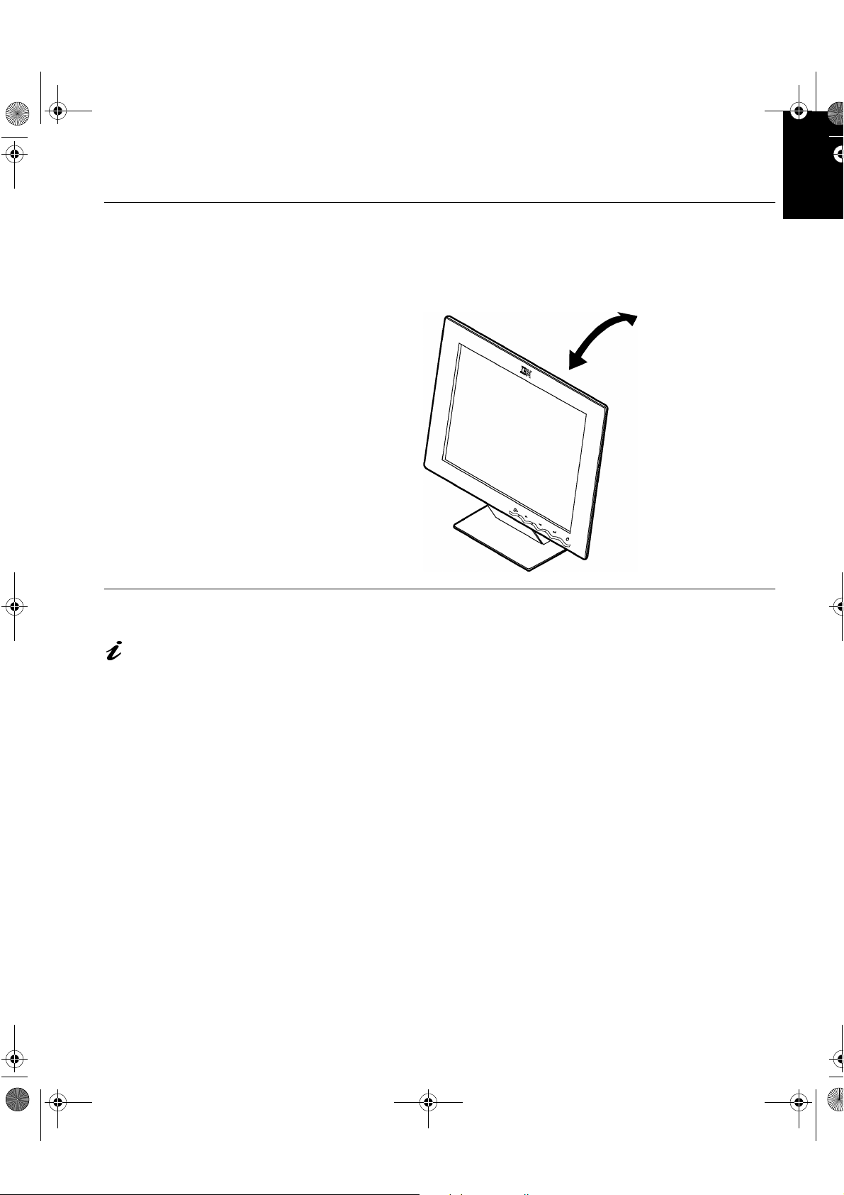
Adjusting the Monitor Position
Viewing Angle
You can tilt the screen backward and forward as shown below.
ENGLISHFRANÇAISESPAÑOLITALIANOJAPANESECOMPL & WARR
DEUTSCH
Working Practices
This section gives
advice on how
work comfortabl
ue.
fati
ou can
and reduce
Rest
Tak e regular breaks. Vary your posture, stand up and stretch occasionally as
prolon
ed use of computer workstations can be tiring.
Back
You should sit back in your chair and use the backrest.
Hands
Adjust the seat height so that your forearms are approximately horizontal and
our wrists are straight when using the keyboard. Your upper arms should be
relaxed with
Use a li
Allow a space in front of the ke
Consider usin
our elbows near your body.
ht touch on the keyboard, keeping your hands and fingers relaxed.
board to rest your wrists when not typing.
a wristpad.
3
Page 6
y
y
g
g
T54A-E.book Page 4 Saturday, February 19, 2000 12:05 PM
Eyesight
Working with monitors, in common with any prolonged close work, can be
visuall
e
demanding. Look away from the screen periodically and have your
esight checked regularly.
Screen settings
Set the screen brightness and contrast to a comfortable level. You may have
to adjust this as the li
rams let you select color combinations which can help you to view in
pro
comfort. See the
hting changes during the day. Many application
User controls
section on page 13 for more information.
4
Page 7
ying
g
g
g
y
y
y
g
g
y g
y
y
T54A-E.book Page 5 Saturday, February 19, 2000 12:05 PM
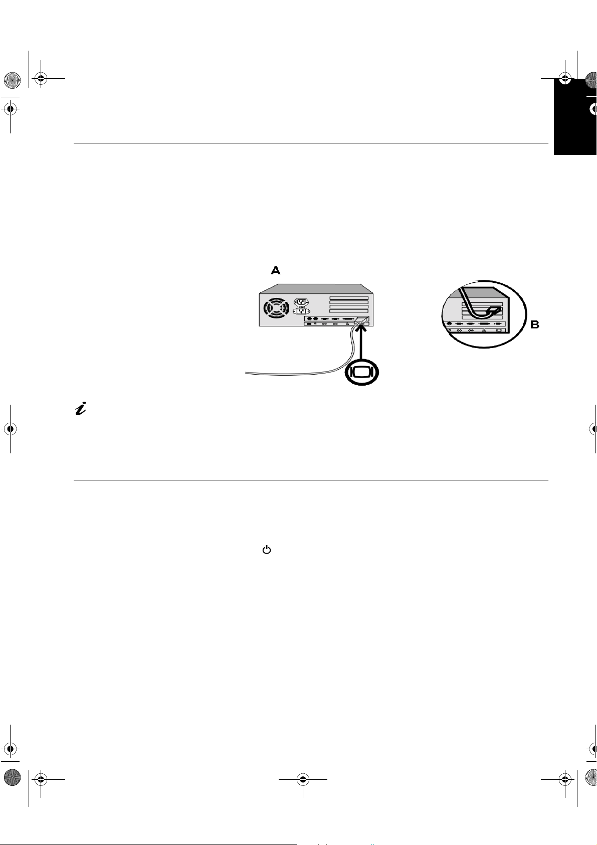
Connecting your Monitor
ENGLISHFRANÇAISESPAÑOLITALIANOJAPANESECOMPL & WARR
Be sure to read the ‘Safety
Information’ at the front of
this User Guide before
out this procedure.
carr
The AC adapter and signal
cable are connected to
our monitor. If you wish to
e these or to fit a different
chan
stand, see Further Help on
e 22.
pa
1. Turn off your PC and all attached devices.
2. Connect the si
This port mi
ht be part of a video adapter card (figure B). The video port on your
mi
computer or video adapter card ma
connector on
nal cable to the video port on the back of your computer.
ht be directly attached to your computer (figure A), or it
be colored blue to match the blue
our monitor’s video cable.
3. Connect the power cord to the power adapter first, then insert the plug
into a properl
rounded electrical outlet.
DEUTSCH
Switching on your Monitor
1. Switch on the power source and your computer.
2. Switch on
marked .
To switch off
3. Turn on the monitor and then the computer.
4. Run
Monitor
our monitor by pushing and releasing the power switch
our monitor, push and release the power switch again.
A
UTO SETUP
by following the instructions in the
section on page 6.
Configuring your
5
Page 8

g
g
y
y
g
g
y
g
g
y
g
g
y
y
y
y
g
T54A-E.book Page 6 Saturday, February 19, 2000 12:05 PM
Configuring your Monitor
Setup Diskette for Windows95 or Windows 98
This section must be
completed before
continuin
Windows 95 or Windows 98
Auto Setup on Pa
refresh rate does not
improve displa
IBM recommends usin
1024 x 768 at a refresh
rate of 60Hz.
with the
e 10.
On LCD monitors,
unlike CRTs, a faster
quality.
To use the Plug and Play feature in Windows 95 or Windows 98, files should
be loaded from the IBM Flat Panel Monitor Installation diskette:
1. Turn off the computer and all attached devices.
2. Ensure that the monitor is connected correctl
3. Turn on the monitor and then the s
stem unit. Allow the system to boot
.
into Windows 95 or Windows 98.
Your computer’s Plu
hardware has chan
and Play code may warn you that your system
ed. This probably means that it has detected your
new monitor for the first time.
4. Open the
C
ONTROL PANEL
5. Select the
D
ISPLAY PROPERTIES
and then double clicking on the
S
ETTINGS
tab.
window by clicking on
D
ISPLAY
S
TART
icon.
• In case of Windows 95:
6. -1. Select the Change Display Type button.
2. Select the Chan
e Monitor Type button.
• In case of Windows 98:
6. -1. Select the ADVANCED BUTTON.
2. Select the MONITOR tab.
3. Open the UPGRADE DEVICE WIZARD windows b
Chan
e button and then select the NEXT button.
If the UPGRADE DEVICE WIZARD is open
clicking on
o step 6-3. if not
continue to step 4.
4. Select the “Displa
a list of the known drivers for this device so that
I can choose a specific driver” and then select the NEXT button.
,
S
ETTINGS
,
7. Insert the Setup diskette into drive A: and select the
8. Select
9. Choose
the diskette to
.
OK
IBM T540
monitor and select OK. The files will be copied from
our hard drive.
H
AVE DISK
button.
10. Close all open windows and remove the diskette.
11. Reboot the s
The s
stem will automatically select the maximum refresh rate and
correspondin
6
stem.
Color Matching Profiles.
Page 9
g
y
y
y
y
y
g
y
y
y
y
g
T54A-E.book Page 7 Saturday, February 19, 2000 12:05 PM
Setup Diskette for Windows 2000
ENGLISHFRANÇAISESPAÑOLITALIANOJAPANESECOMPL & WARR
This section must be
completed before
continuin
Windows 2000
for
does not improve displa
qualit
1024 x 768 at a refresh
rate of 60Hz.
with the
confguring
our monitor on page 10.
On LCD monitors, unlike
CRTs, a faster refresh rate
. IBM recommends using
To use the Plug and Play feature in Windows 2000, files should be loaded
from the IBM Flat Panel Monitor Installation diskette.
1. Turn off the computer and all attached devices.
2. Ensure that the monitor is connected correctl
3. Turn on the monitor and then the s
stem unit. Allow the system to boot
.
into Windows 2000.
4. Open the
C
ONTROL PANEL
5. Select the
6. Select the
7. Select the
8. Select the
9. Select the Driver
10. Open theUp
D
ISPLAY PROPERTIES
and then double clicking on the
ONITOR
tab.
tab.
button.
tab.
S
ETTINGS
A
DVANCED
M
P
ROPERTIFS
rade Device Driver Wizard window by clicking on UPDATE
window by clicking on
button.
D
ISPLAY
S
TART
icon.
,
S
ETTINGS
,
DEUTSCH
DRIVER and then select the NEXT button.
11. select the “Displa
a list of the known dirvers for this device so that lcan
choose a specifc driver” and then sefect the NEXT button.
12. Inset the Setup diskette into drive A: and select the HAVE DISK button.
13. select OK.
14. Choose
the diskette to
IBM T540
monitor and select OK. The files will be copied from
our hard drive.
15. Close all open windows and remove the diskette.
16. Reboot the s
The s
stem will automatically select the maximum refresh rate and
correspondin
stem.
Color Matching Profiles.
7
Page 10

y
g
y
ying
y
y
y
y
y
g
g
y
y
g sy
y
y
y
g
y
y
g
y
g
g
y
T54A-E.book Page 8 Saturday, February 19, 2000 12:05 PM
Auto Setup
Auto Setup
Before carrying out this
section, it is ver
important that The Setup
Diskette for Windows 95 or
Windows 98 has been run.
(see pa
diskette is for displa
patterns. The
or modif
The Auto Setup instructions
This is not required for normal
operation.
B
direct access to the auto set-
up controls.
e6)
The Setup Utilit
included on the setup
the display dirver.
require the monitor to be
warmed up for 15 minutes.
pressing the
Å
and
simultaneousl
do
do not replace
Æ
keys
allows
When you first use your monitor you must perform Auto Setup. This
procedure sets up
computer without ima
Setup, the settin
In order to optimise the displa
Monitor Installation Diskette. Operation of the utilit
operatin
stem on your PC from the table below and follow the appropriate
s
stem on your PC. For correct operation locate the operating
instructions. You ma
ou use. This means that if you sometimes use your monitor while
that
runnin
any version of Windows and sometimes also use it from within DOS
(not a DOS window),
You ma
run versions of
Operating System Corresponding Auto Setup procedure
DOS
Windows 3.1
Windows 95
our monitor to process the video signals from your
e discoloration or smearing. After you perform Auto
s are stored and used each time you turn on the monitor.
ed image a set-up utility is provided on the IBM
is dependent on the
choose to run
ou must run
A
UTO SETUP
A
UTO SETUP
A
UTO SETUP
in any order.
Auto Setup for DOS
for each operating system
for both Windows and DOS.
on page 9
Auto Setup for Windows 3.1, Windows 95,
Windows 98
Window 2000
Windows 98, Windows 2000 or Windows
NT
on page 10
If your PC does not run
with the setup diskettes
shipped with the monitor, refer
to Manual Setup on pa
A
The
UTO SETUP
applies to the current
onl
screen mode. When a new
mode is selected, repeat this
section to reset the monitor
8
e 12
process
Window NT
Before you begin
A
UTO SETUP
1. Make a backup cop
for your PC:
of the setup diskettes supplied with the monitor.
2. Make sure the PC’s video mode is set in the ran
screen resolution shown in the table on pa
You should perform
A
UTO SETUP
for each screen mode you use.
e18.
e of the supported
Page 11

y
y
g
g
y
y
y
g
y
y
y
y
y
y
y
y
y
y
y
g
g
y
y
y
y
y
y
g
T54A-E.book Page 9 Saturday, February 19, 2000 12:05 PM
Auto Setup for DOS
ENGLISHFRANÇAISESPAÑOLITALIANOJAPANESECOMPL & WARR
If the monitor is in standby
mode (STANDBY ON), it
ma
automatically turn off while
ou are waiting for it to warm up.
If this happens, switch off the
monitor and switch it on a
after a few seconds.
If you are using PC-DOS/
V, chan
ping ‘CHEV US’ and pressing
t
ENTER at the command
prompt.
You must use DOS when
ou run DOS Auto Setup.
The size and diversity of
the dot pattern varies with
the screen resolution.
If the screen flickers,
repeat the setup several
times until the flicker is
minimised, or adjust it manuall
following Manual Setup on
b
e 12.
pa
e t o U.S . mo de by
ain
1. Turn on the monitor first; then the PC.
If the messa
displa
• that the video interface cable is connected properl
e CHECK SIGNAL CABLE is displayed, or if nothing is
ed check:
.
• the correct video adapter card is installed.
• the correct supported displa
mode is selected for your PC.
2. Wait approximately 15 minutes, until the monitor warms up.
3. Insert the diskette labelled ‘IBM Flat Panel Monitor Installation Diskette
into the diskette drive.
4. Display the command prompt screen of the DOS full-screen display.
5. At the command prompt, t
6. T
pe ‘TESTPATD’ and press ENTER.
7. Select from the screen the number for the color or text mode
pe ‘A:’ and press ENTER.
ou want to
setup.
8. Select from the screen the number for the video mode
ou want to
setup.
You ma
as
repeat this process for as many of the color and video modes
ou need.
9. When the dot pattern appears, press the OSD Enter button at the
bottom of the monitor to displa
the initial OSD menu.
10. Use an Arrow button ( or ) to select the IMAGE LOCK icon
then press the OSD Enter button to access the function.
11. Usin
an Arrow button ( or ), select
OSD Enter button . This activates the
will optimize the displa
settings with the provided dot-patterns.
The screen will3d off several times and
AUTOMATIC
A
UTO SETUP
ou may notice small changes to
and press the
procedure, which
the test pattern.
DEUTSCH
12. When finished, the OSD main menu returns. Press the Exit button
to exit from the OSD.
13. Press the ESCAPE ke
14. T
If
those s
pe ‘Exit’ at the command prompt to return to Windows.
ou use other operating systems, perform the appropriate
stems, also: see
to exit the test pattern program.
A
UTO SETUP
for
Auto Setup for Windows 3.1, Windows 95, Windows 98, Windows NT or
Windows 2000 on pa
e 10.
9
Page 12

y
y
g
y
y
y
y
g
y
y
g
y
y
g
y
T54A-E.book Page 10 Saturday, February 19, 2000 12:05 PM
Auto Setup for Windows 3.1, Windows 95, Windows 98, Windows NT
or Windows 2000
If the monitor is in standby
mode (STANDBY ON), it
automatically turn off while
ma
ou are waiting for it to warm up.
The size and diversity of
the dot pattern varies with
the screen resolution.
1. Turn on the monitor first; then the PC.
If the messa
displa
• that the video interface cable is connected properl
e CHECK SIGNAL CABLE is displayed, or if nothing is
ed check:
.
• the correct video adapter card is installed.
• the correct supported displa
2. Wait approximatel
3. Dra
the icon bar and tool bar, if they are displayed, to the bottom of the
15 minutes, until the monitor warms up.
mode is selected for your PC.
screen.
4. Insert the diskette labelled ‘IBM Flat Panel Monitor Installation Disk’ into
the diskette drive.
5. Check the operating system installed on your PC and follow the
instructions from the table below.
Operating
stem
S
Windows 3.1
Windows NT 3.5
Windows 95
Windows 98
Windows NT 4.0
Step1 Step2 Step3 Step4
Open
P
ROGRAM
M
ANGER
Select
S
TART
Select
F
ILE
Select R
Select
R
UN
UN
Type
‘A:\TESTPAT’
and press
ENTER
Position the mouse pointer
at the bottom center of the
screen. This allows
S
to run properl
ETUP
10
A
UTO
6. When the test pattern appears, press the OSD Enter button at the
bottom of the monitor to displa
7. Use an Arrow button ( or ) to select the
and press the OSD Enter button to access the function.
8. Usin
an Arrow button ( or ), select
OSD Enter button . This activates the
will optimize the displa
settings with the provided test pattern.
The screen will dim, blink on and off several times, and
small chan
To abort the
es to the test pattern.
A
UTO SETUP
function, press the
the initial OSD menu.
IMAGE LOCK
AUTOMATIC
A
UTO SETUP
key.
E
SC
icon
and press the
procedure, which
ou may notice
9. When finished, the OSD main menu returns. Press the Exit button
once to exit from the OSD.
10. Press the
key to return to Windows.
E
SC
Page 13

g sy
g
T54A-E.book Page 11 Saturday, February 19, 2000 12:05 PM
You have completed the monitor setup for Windows. If you use other operatin
stems, perform the appropriate
Auto Setup for DOS on pa
e 9.
A
UTO SETUP
for those systems, also: see
ENGLISHFRANÇAISESPAÑOLITALIANOJAPANESECOMPL & WARR
DEUTSCH
11
Page 14

y
y
g
y
y
y
g
g
y
g
g
g
T54A-E.book Page 12 Saturday, February 19, 2000 12:05 PM
Manual Setup
If the monitor is in standby
mode (STANDBY ON), it
ht automatically turn off
mi
ou are waiting for it to
while
warm up.
Normally, you can complete the setup procedure using
if
our screen image is still distorted after you perform
setup diskette does not run on
our system, perform
M
A
UTO SETUP
A
UTO SETUP
ANUAL SETUP
, however,
or the
.
1. Have your monitor turned on for about 15 minutes, until the monitor
warms up.
2. Displa
the image you most frequently use on the screen.
3. Press the OSD Enter button at the bottom of the monitor to displa
the initial OSD menu.
4. Use an Arrow button ( or ) to select the IMAGE LOCK icon
and press the OSD Enter button to access the function.
5. Usin
an Arrow button ( or ), select
press once to select
COARSE
indicators become illuminated (see pa
6. Use the Arrow buttons to manuall
possible) for noise in the video si
chan
es.
7. Use an Arrow button to select
8. Use the Arrow buttons a
FINE
ain to tune the image to your liking.
MANUAL
. Left and right arrow adjustment
e16).
adjust to correct (as much as
nal then press to save the
and press the button.
, press and then
9. When finished, press the Exit button four times to exit from the
OSD.
12
You have completed the monitor setup.
Page 15

y
g
g
y
g
y
y
g
g
y
g
y
g
T54A-E.book Page 13 Saturday, February 19, 2000 12:05 PM
Adjusting Your LCD Monitor
User controls
User control features
Icon Control Description
Displa
Exit
Left Arrow
Exits from menus and sub-menus
Exits the OSD
Displa
Moves the cursor to hi
options
ENGLISHFRANÇAISESPAÑOLITALIANOJAPANESECOMPL & WARR
DEUTSCH
s the OSD main menu
s the OSD main menu
hlight icons and other
The image is already
optimized for man
modes, however the user
controls can be used to adjust
the ima
e to your liking.
display
Displa
s the OSD main menu
ht Arrow
Ri
OSD Enter
Power Switch Switches the monitor on and off
Moves the cursor to hi
options
Displa
s the OSD main menu
Enters menus and sub-menus and selects the
hlighted option
hi
hlight icons and other
Operation
• Press any of the OSD control buttons to display the main OSD menu.
• Use the Arrow buttons to move amon
OSD Enter to access that function. If there is a sub-menu,
between options usin
the Arrow buttons, then press OSD Enter to select
that function. Use the Arrow buttons to make adjustments.
the icons. Select an icon and press
ou can move
13
Page 16

g
g
g
y
g
T54A-E.book Page 14 Saturday, February 19, 2000 12:05 PM
The settings are saved
after adjustment and when
the OSD and will be
exitin
effective thereafter.
• Press the Exit button to move backwards through the sub-menus and exit
from the OSD.
Note: After makin
adjustments, the Power indicator LED will briefly
turn amber to indicate that the new value has been saved.
OSD Lock / Unlock
This feature allows you to secure the current control settings, while allowing
the user to adjust Bri
inadvertentl
changed. You can unlock the OSD controls at any time by using
the same procedure.
Push and hold the OSD Enter button for 10 seconds to Lock or to Unlock.
When locked, a “LOCKED” messa
htness and Contrast, so that they cannot be
e will be displayed.
14
Page 17

y
y
y
y
g
j
j
j
g
j
g
g
j
y
j
T54A-E.book Page 15 Saturday, February 19, 2000 12:05 PM
On-screen display (OSD) controls
The settings adjustable with the user controls are viewed through the OnScreen Displa
ENGLISHFRANÇAISESPAÑOLITALIANOJAPANESECOMPL & WARR
(OSD). Press any of the OSD buttons to activate the OSD.
The LCD monitor needs
time to become thermall
stable the first time
each da
accurate adjustments for
parameters, allow the LCD
monitor to warm up (be On) for
at least 15 minutes before
makin
. Thus, to achieve more
any screen adjustments.
ou tur n it on
OSD Icon Description Sub-menu(s)
BRIGHTNESS
Initial appearance of OSD
OSD functions
Ad
usts brightness
Controls and
ustments
Ad
DEUTSCH
CONTRAST
IMAGE LOCK
usts contrast
Ad
The ima
ad
si
areas on the screen where the ima
appears to be unstable and
shimmers. This can be done
automaticall
e lock function is used to
ust the level of noise in the video
nal which causes horizontal lines or
itters or
or manually.
e
Automatic
Automatic ad
ustment
15
Page 18

y
y
g
g
y
g
y
g
y
g
y
g
y
g
j
T54A-E.book Page 16 Saturday, February 19, 2000 12:05 PM
OSD Icon Description Sub-menu(s)
Manual -
IMAGE LOCK
(continued)
IMAGE
POSITION
Moves the screen left and ri
and down.
ht or up
• Fine
• Coarse
H-Position
V-Position
Controls and
ustments
Ad
Use the Arrow buttons to
adjust awa
interference. If
satisfactor
not obtained usin
Fine adjustment, use the
Coarse adjustment and
then use Fine a
This function ma
chan
displa
H-Position function on
the Ima
menu to center the
displa
screen.
the
results are
the
ain.
e the width of the
image. Use the
e Position
image on the
16
COLOR
Select the Color Mode
comfortable and then fine tune the
colors usin
menu, if necessar
the User Color Mode
ou find most
.
Color Mode Mode 1
User Mode -
• Red
• Green
• Blue Increases or decreases
(Cool White)
Mode 2
(Normal White)
Mode 3
(Warm White)
Increases or decreases
redness
Increases or decreases
reenness
blueness
Page 19

g
g
g
y
g
y
y
g
guag
guag
y
guag
g
j
T54A-E.book Page 17 Saturday, February 19, 2000 12:05 PM
OSD Icon Description Sub-menu(s)
htness, Contrast and
s.
e position settings
and the horizontal and
es
e chosen affects only the
e of the OSD. It has no effect
Color Reset NO
Geometr
Reset
H-Position
RESET
INFORMATION
LANGUAGE
Resets the Bri
Color settin
Resets the Ima
Shows information about the
addressabilit
vertical frequencies of the ima
received from the computer or video
board.
The lan
lan
software running on the
on an
computer.
es the position of the OSD on
Chan
the screen.
Controls and
ustments
Ad
- Does not make the
adjustment
- Resets the color
YES
- Does not make the
NO
adjustment
- Resets the
YES
eometr
ENGLISHFRANÇAISESPAÑOLITALIANOJAPANESECOMPL & WARR
DEUTSCH
Select one of the five
es to use for the
lan
OSD.
OSD MENU
POSITION
V-Position
17
Page 20

y
g
g
g
g
gy
y
y
g
y
y
T54A-E.book Page 18 Saturday, February 19, 2000 12:05 PM
Display modes
The display mode the monitor uses is controlled by the computer. Therefore,
ou should refer to your computer documentation for details on how to
e display modes.
chan
Further Information
The ima
chan
e size, position and shape may change when the display mode
es. This is normal and the image can be readjusted using
and the monitor controls.
Unlike CRT monitors, which require a hi
TFT technolo
for 1024 × 768 addressabilit
For the displa
manufacture.
durin
is inherently flicker-free. If possible, configure your computer
at 60Hz vertical refresh rate.
modes listed below, the screen image has been optimized
h refresh rate to minimize flicker,
Factory Set Display Modes
Addressabilit
640 × 350 70 Hz 31.5 kHz
640 × 480 60 Hz 31.5 kHz
640 × 480 72 Hz 37.9 kHz
640 × 480 75 Hz 37.5 kHz
720 × 400 70 Hz 31.5 kHz
800 × 600 75 Hz 46.9 kHz
800 × 600 72 Hz 48.1 kHz
Refresh Rate Horizontal Frequenc
A
UTO SETUP
800 × 600 60 Hz 37.9 kHz
800 × 600 56 Hz 35.2 kHz
832 × 624 75 Hz 49.7 kHz
1024 × 768† 60 Hz 48.4 kHz
1024 × 768 70 Hz 56.5 kHz
1024 × 768 75 Hz 60.0 kHz
† Recommended
‘Note: VESA timings are as detailed in the VESA “Display Monitor Timing
Specification”. Version 1.0, Revision 0.8, dated 09/17/98.’
18
Page 21

y
y
y
g
y, y
y
y
y
y
y
g
y
y
y
y
y
y
g
y g
y
y
g
y
g
y
T54A-E.book Page 19 Saturday, February 19, 2000 12:05 PM
Power Management
ENGLISHFRANÇAISESPAÑOLITALIANOJAPANESECOMPL & WARR
If your computer has
previousl
with a CRT monitor and is
currentl
mode outside the
displa
e that the Flat Panel
ran
monitor can displa
need to re-attach the
ma
CRT monitor temporaril
ou have re-configured
until
the computer, preferabl
1024 x 768 at 60Hz.
been used
configured to a
ou
to
To benefit from power management, the monitor must be used in conjunction
with a computer that implements the Video Electronics Standards Association
(VESA) Displa
The power mana
ou have not used your mouse or keyboard for a user-definable period.
that
Power Management Signalling (DPMS) Standard.
ement feature is invoked when the computer recognizes
There are several states as described in the table below.
As an
E
NERGY STAR
E
NERGY STAR
IBM recommends that
, or whenever you expect to leave it unused for long periods during the
da
da
.
State
On Stead
DPMS
Standb
®
®
Partner, IBM has determined that this product meets the
guidelines for energy efficiency.
ou switch off your monitor at the end of each working
Power
Indicator
reen Normal
Steady amber Blank
Screen
Restorin
Operation
Press a ke
or
move the mouse.
Compliance
E
NERGY STAR
and NUTEK
®
DEUTSCH
Product Disposal
DPMS
Suspend
Flashin
amber
(0.5 sec.
Blank
Press a ke
or
move the mouse. ‡
E
NERGY STAR
and NUTEK
®
interval)
Blank
Press a ke
or
move the mouse. ‡
E
NERGY STAR
and NUTEK
®
DPMS Off
Flashin
amber
(1 sec.
interval)
‡ There ma
be a slight delay before the picture reappears.
The fluorescent lamp in the liquid crystal display contains mercury. Dispose of
it as required b
local ordinances and regulations.
19
Page 22

y
y
gg
y
y
y
g
y g
g
y
g
y
g
y
y
g
y
g
g
T54A-E.book Page 20 Saturday, February 19, 2000 12:05 PM
If you have a problem setting up or using your monitor, you may be able to
solve it
ourself. Before calling your retailer or IBM, try the suggested actions
that are appropriate to
Troubleshooting
our problem.
Problem
Screen is blank
and power
indicator is off
Screen is blank
and power
indicator is
stead
Screen is blank
and power
indicator is
stead
reen
amber
Possible
Cause
No power to
monitor
htness
Bri
and Contrast
be too
ma
low
The monitor is
in the Power
ement
Mana
Standb
state
ested Action Reference
Su
Ensure that the
electrical outlet and the
monitor are both switched
on.
Check that the power
cord is firml
the electrical outlet and the
power suppl
If the power cord plug
has a removable fuse,
replace it.
Try another power
cord.
Try another electrical
outlet.
Adjust brightness and
contrast.
Press any key on the
ke
board or move the
mouse to restore
operation.
Check the Power
Mana
our computer
plugged into
unit.
ement software on
Connecting
our Monitor
section on
e 5
pa
User
controls
section on
pa
e 13
Power
Mana
section on
pa
ement
e 19
20
Page 23

g g
y
g
g
y
g
y
g
g
g
g
y
g
y
g
y
g
g
g
g
g
g
g
g
g
g
g
y
g
g
gy
gg
y
g
g
T54A-E.book Page 21 Saturday, February 19, 2000 12:05 PM
For image problems, you
want to run AUTO
ma
Setup a
to this section. In most cases,
AUTO SETUP can fix the
problems. See Auto Setup on
pa
ain before consulting
e 8 for details.
Problem
Screen is blank
and power
indicator is
Flashin
ever
second
Screen is blank
and power
indicator is
flashin
ever
second
Ima
to be smeared
Ima
to be
discolored
reen
0.5
amber
0.5 or 1
e appears
e appears
Possible
Cause
The monitor is
not receivin
a video si
Display mode
of the
computer is
outside the
ran
monitor
The monitor is
in the Power
Mana
Suspend or
Off state
There are
noises in the
video si
The Color
settin
be incorrect
nal
e of the
ement
nal
may
ested Action Reference
Su
Check that the signal
cable is firml
the computer.
Check that no pins are
bent in the si
connector.
Reconfigure the
computer to use a
supported display mode.
Press any key on the
ke
board or move the
mouse to restore
operation.
Check the Power
Mana
our computer.
Select IMAGE LOCK
menu in the OSD. Then
select MANUAL to adjust
FINE/COARSE settin
Adjust the Color
settin
connected to
nal cable
ement software on
s.
ENGLISHFRANÇAISESPAÑOLITALIANOJAPANESECOMPL & WARR
Connecting
our Monitor
section on
e 5
pa
Further
Information
section on
e 18
pa
DEUTSCH
Power
e 19
ement
Mana
section on
pa
User
controls
section on
s.
pa
e 13
User
controls
section on
pa
e 13
A few dots are
missin
discolored, or
inappropriatel
li
,
hted.
The LCD contains over 2,300,000 thin-
film transistors (TFTs). A small number of
missin
present on the screen, which is an intrinsic
characteristic of the TFT LCD technolo
and is not an LCD defect.
, discolored, or lighted dots may be
21
Page 24

y
y
g
y
y
y
y
y
g Sy
y
y
y
g
g
y
g
y
T54A-E.book Page 22 Saturday, February 19, 2000 12:05 PM
Further Help
If you are unable to correct the problem yourself, you may seek further help
as follows:
Call the IBM HELPCENTER.
In the US call 1-800-772-2227
In Canada call 1-800-565-3344
If possible, stay by your
computer. Your Technical
Support Representative ma
wish to
with
latest accessories for these
products ma
worldwide web at:
http://www.pc.ibm.com/us/
accessories
Information about the Video
Electronics Standards
Association can be found on the
worldwide web at:
http://www.vesa.or
o through the problem
ou during the call.
More help, late-breaking
news and details of the
be found on the
In other countries contact
our dealer, retailer, or other IBM authorized
Servicer.
Before calling, please have available as much of the following information as
possible:
1. Model and serial number from the label on
our monitor.
2. Purchase receipt.
3. Description of problem.
4. Computer t
5. S
6. S
stem configuration (hardware fitted, etc.).
stem BIOS version number.
7. Operatin
8. Displa
9. Video Adapter T
pe and model.
stem and version number.
driver version number.
pe.
Removing the stand and cables
Alternative stands for your IBM Flat Panel Monitor may be available from
specialist suppliers.
This product is equipped with mountin
Flat Panel Monitor Ph
sical Mounting Interface Standard (FPMPMI).
This product is shipped with the si
the monitor. If
ou want to use other cables for reasons such as having the
monitor wall-mounted, follow the instructions below:
1. Disconnect the power cord from the wall outlet.
facilities that conform to the VESA
nal cable and the power cord attached to
22
Page 25

g
g
y
g
g
g
y
g
y
y
y
g
g
g
g
y
T54A-E.book Page 23 Saturday, February 19, 2000 12:05 PM
2. Carefully insert the head of a flathead (–) screwdriver into the slot visible
either side of the cable cover (a) and pry it off.
alon
a
b
c
3. Squeeze the sides of the hin
4. Gentl
lift the stand cover (c) along the top and then slide it backwards
e cover (b) and pull it off.
and off the stand.
5. Remove the si
disconnectin
free the power cord and remove the screw holdin
nal cable and the power cord from the monitor by
the corresponding adapters. Carefully cut the plastic tie to
the power cord
clamp.
6. La
7. If
the monitor facedown on a cushion and remove the six screws
holdin
assembl
the hinge mechanism on the monitor. Lift off the hinge and base
.
ou are installing an arm or wall-mounting device, follow the directions
included with the device. If
ou are just changing your cables, continue
with Step 8.
8. Connect the si
clamp in its ori
nal cable and the power cord, then refit the power cord
inal screwpost.
9. Slide the stand cover back on the stand.
10. Put the hin
e cover back on, making sure that the straight side is at the
top.
11. Insert the three tabs at the top of the cable cover into the slots in the
back of the monitor and push the cover into place.
To obtain the correct cables and/or to
them, call the IBM HELPCENTER at the above numbers or contact
et further instructions on installing
our
dealer, retailer, or other IBM authorized Servicer.
ENGLISHFRANÇAISESPAÑOLITALIANOJAPANESECOMPL & WARR
DEUTSCH
23
Page 26

g
g
g
g
g
g
g
y
y
y
g
y
y
y
g
y
g
g
g
y
g
g
g
g
y
T54A-E.book Page 24 Saturday, February 19, 2000 12:05 PM
Specifications
This color monitor (Type-model 9511-Axx) uses a 15-inch TFT LCD
Power consumption
ures are for the monitor
fi
and the power suppl
combined.
Dimensions Width:
Depth:
ht:
Hei
ht Unpackaged:
Wei
ed:
packa
Tilt Forward Tilt:
Backward tilt:
e Viewable Image Size:
Ima
Maximum Hei
Maximum Width:
Pixel Pitch:
Power Input Suppl
Max Suppl
Power Consumption Normal Operation:
Video Input Input Si
DPMS Stand-b
DPMS Suspend:
DPMS off:
Horiz. Addressabilit
Vert. Addressabilit
Clock Frequenc
ht:
Voltage:
Current:
:
nal:
:
:
:
401 mm
202 mm
371 mm
11.2 lb. (5.1 K
13.9 lb. (6.3 K
– 4°
+ 41°
15.0” (381 mm)
228.1 mm
304.1 mm
0.297 mm (H) × 0.297 mm (V)
90 - 260 Vac
60/50 ± 3 Hz
1.0 A at 120 Vac
< 30 W
< 3 W
< 3 W
< 3 W
Analo
75 ohm 0.7 V
1024 pixels (max)
768 lines (max)
80 MHz
)
)
Direct Drive
24
Communications VESA DDC: 2 B
Supported Displa
Modes
Environment Temperature:
VESA Standard 12 modes See page 18
Macintosh 1 mode
Operatin
Stora
Shippin
Humidit
Operatin
Stora
Shippin
:
e:
:
:
:
e:
:
10 to 35° C
- 20 to 60° C
- 20 to 60° C
10 to 80%
5 to 95%
5 to 95%
Page 27

y
y
y
T54A-E.book Page 25 Saturday, February 19, 2000 12:05 PM
Warranty Statements
Your Installation Diskette includes translation of IBM’s Statement of
Warrant
Arabic
Brazilian portuguese
Bulgarian
Chinese
Croatian
Czech
Danish
Dutch
English
Finnish
French
German
Greek
Hebrew
Hungarian
Italian
Japanese
Korean
Norwegian
Polish
Portuguese
Russian
S
Slovenian
in following languages:
(Except Turki
lovakian
Worldwide Statement of Warrant
e, U.S., Puerto Rico and Canada):
Z1255697.ara.html
Z1255697.bra.html
Z1255697.bul.html
Z1255697.chi.html
Z1255697.cro.html
Z1255697.cze.html
Z1255697.dan.html
Z1255697.dut.html
Z1255697.eng.html
Z1255697.fin.html
Z1255697.fre.html
Z1255697.ger.html
Z1255697.gre.html
Z1255697.heb.html
Z1255697.hun.html
Z1255697.ita.html
Z1255697.jap.html
Z1255697.kor.html
Z1255697.nor.html
Z1255697.pol.html
Z1255697.por.html
Z1255697.rus.html
Z1255697.sla.html
Z1255697.sle.html
ENGLISHFRANÇAISESPAÑOLITALIANOJAPANESECOMPL & WARR
DEUTSCH
25
Page 28

T54A-E.book Page 26 Saturday, February 19, 2000 12:05 PM
Spanish
Swedish
Taiwanese
Z1255697.spa.html
Z1255697.swe.html
Z1255697.tai.html
Turkiye Statement of Warranty:
Turkish
English
Z1255698.tur.html
Z1255698.eng.html
United States, Puerto Rico and Candada Statement of Limited Warranty:
English
French Canadian
Z1254753.eng.html
Z1254753.fca.html
26
 Loading...