

Page 1

IBMTotalStorageLTOUltrium2TapeDrive
Models T400 and T400F
Setu p, Operato r, and Se rvi ce Gui de
GA32-0455-00
Page 2

Page 3

IBMTotalStorageLTOUltrium2TapeDrive
Models T400 and T400F
Setu p, Operato r, and Se rvi ce Gui de
GA32-0455-00
Page 4

Note
Before using this guide and the product it supports, read the information in “Safety and Environmental Notices” on page vii
and “Notices” on page 101.
First Edition (November 2002)
This edition applies to the IBM TotalStorage LTO Ultrium 2 Tape Drive Models T400 and T400F Setup, Operator, and
Service Guide and to all subsequent releases and modifications until otherwise indicated in new editions.
© Copyright International Business Machines Corporation 2002. All rights reserved.
US Government Users Restricted Rights – Use, duplication or disclosure restricted by GSA ADP Schedule Contract
with IBM Corp.
Page 5

Contents
Safety and Environmental Notices .................vii
Danger Notice .........................vii
Caution Notice .........................vii
Attention Notice ........................viii
Laser Safety and Compliance ...................viii
Preface ............................ix
Intended Audience ........................ix
Related Publications .......................ix
IBM Ultrium Publications.....................ix
IBM Fibre Channel Publications ..................ix
Other Publications .......................ix
Chapter 1. Introduction ......................1
Cartridge Compatibility ......................2
Speed Matching and Channel Calibration ...............2
Sleep Mode ..........................2
Supported Servers and Operating Systems ...............3
SCSI Attachment ........................4
Physical Characteristics of the SCSI Interface .............4
Speed ...........................4
Address Assignments ......................5
Installing, Removing, or Resetting a Drive on an Active SCSI Bus .....5
Fibre Channel Attachment .....................6
Supported Topologies ......................6
Speed ...........................7
Address Assignments ......................7
World Wide Names .......................8
Physical Characteristics of the Fibre Channel Interface .........8
Installing, Removing, or Resetting a Drive on an Active Fibre Channel ....8
Supported Device Drivers .....................9
Chapter 2. Specifications ....................11
Chapter 3. Installing the Tape Drive ................13
Rear View of the SCSI Drive ....................14
Rear View of the Fibre Channel Drive ................15
Step 1. Unpack the Drive .....................16
Step 2. Remove Power from the Enclosure ..............16
Step 3. Set the SCSI ID or Arbitrated Loop Physical Address ........17
Setting the SCSI ID (SCSI Drive Only) ...............17
Setting the Arbitrated Loop Physical Address (Fibre Channel Drive Only) 19
Step 4. Change the Link Services of the Drive (optional) .........24
Step 5. Mount the Tape Drive into the Enclosure ............26
Step 6. Connect and Test Power to the Tape Drive............27
Step 7. Connect the Internal SCSI or Fibre Channel Cable.........27
Step 8. Connect the Internal LDI Cable (optional) ............28
Step 9. Run Drive Diagnostics ...................28
Step 10. Install the Device Drivers..................28
Step 11. Connect the External SCSI or Fibre Channel Interface to the Server 28
Connect the External SCSI Interface to the Server ...........28
Connect the External Fibre Channel Interface to the Server .......29
Step 12. Connect the External LDI Interface to the Server (optional) .....29
© Copyright IBM Corp. 2002 iii
Page 6

Step 13. Configure the Tape Drive to the Server, Switch, or Hub.......29
Chapter 4. Operating the Tape Drive ................31
Status Light ..........................32
Unload Button .........................33
Single-Character Display .....................33
Single Red Dot ........................33
Inserting a Tape Cartridge .....................34
Removing a Tape Cartridge ....................35
Cleaning the Drive Head .....................35
Selecting a Diagnostic or Maintenance Function.............36
Exiting Maintenance Mode ....................45
Updating the Firmware ......................45
Updating Firmware through the SCSI or Fibre Channel Interface .....45
Updating Firmware through the Library/Drive Interface .........45
Updating the Firmware with an FMR Tape Cartridge ..........46
Chapter 5. Using the Media....................47
Data Cartridge .........................48
Cleaning Cartridges .......................49
Setting the Write-Protect Switch ..................50
Handling the Cartridges......................50
Provide Training .......................51
Ensure Proper Packaging ....................51
Provide Proper Acclimation and Environmental Conditions ........52
Perform a Thorough Inspection ..................52
Handle the Cartridge Carefully ..................53
Examples of Cartridge Problems .................54
Repositioning or Reattaching a Leader Pin...............55
Repositioning a Leader Pin ...................55
Reattaching a Leader Pin ....................57
Environmental and Shipping Specifications for Tape Cartridges .......62
Disposing of Tape Cartridges....................63
Ordering Media Supplies .....................63
Ordering Custom Bar Code Labels ................64
Chapter 6. Resolving Problems ..................65
Methods of Receiving Errors and Messages ..............66
Descriptions and Corrective Actions for Errors and Messages.......67
Using Sense Data.......................71
Obtaining a Drive Dump ....................75
Viewing the Drive Error Log ...................76
Resolving Problems Reported by the Server ..............77
Fixing SCSI Bus Errors .....................77
Fixing Fibre Channel Errors ...................79
Resolving Media-Related Problems .................82
Chapter 7. Servicing the Tape Drive ................83
Removing a SCSI Tape Drive from an Enclosure ............83
Removing a Fibre Channel Tape Drive from an Enclosure .........84
Manually Removing a Tape Cartridge.................85
Removing the Cartridge ....................85
Fixing an Internal Jam .....................88
Appendix A. Tools and Supplies ..................95
iv IBM TotalStorage LTO Ultrium 2 Tape Drive
Page 7

Appendix B. TapeAlert Flags ...................97
TapeAlert Flags Supported by the Drive ................97
Notices ...........................101
Trademarks..........................101
Electronic Emission Notices....................102
Special Considerations for Electromagnetic Compatibility ........102
IBM TotalStorage LTO Ultrium 2 Tape Drive Models T400 and T400F . . . 102
Getting Help .........................104
Warranty...........................104
Glossary ..........................105
Index ............................117
Contents v
Page 8

vi IBM TotalStorage LTO Ultrium 2 Tape Drive
Page 9
Safety and Environmental Notices
When using this product, observe the danger, caution, and attention notices that are
contained in this guide. Symbols that represent the severity of the safety condition
accompany the notices.
The sections that follow define each type of safety notice and give examples.
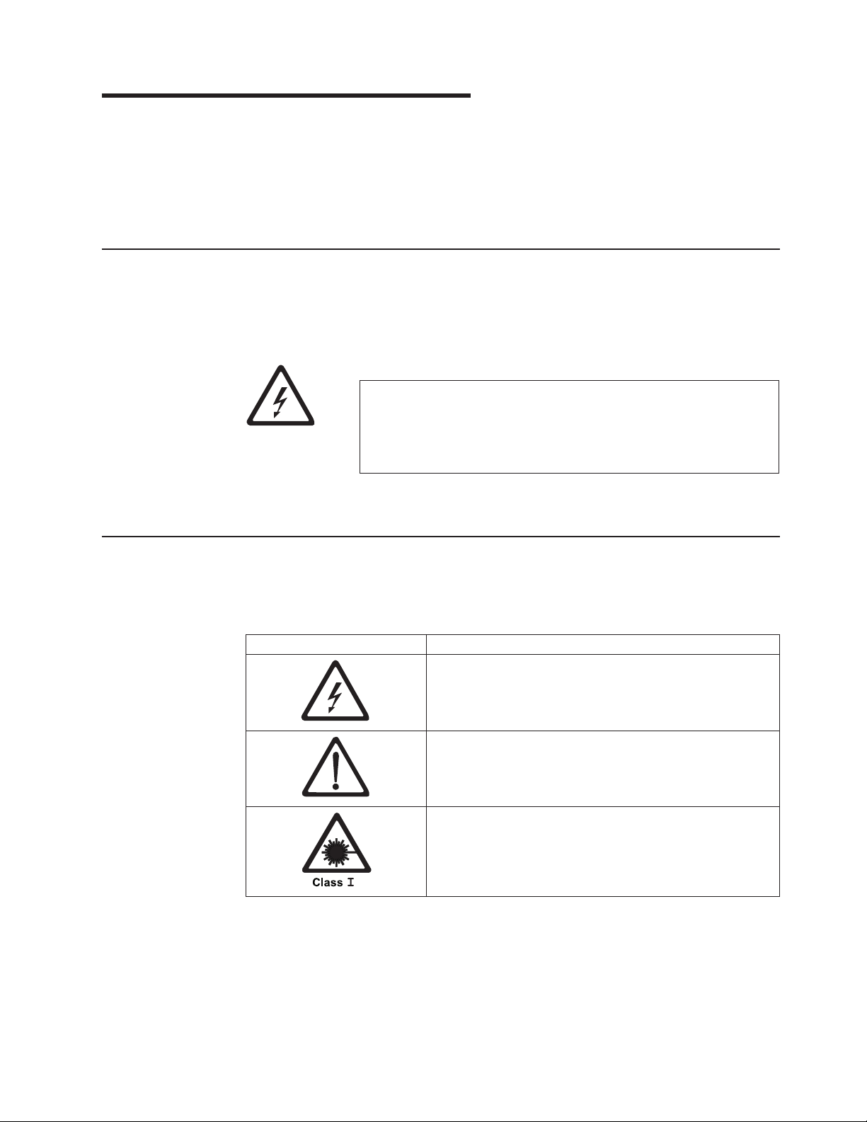
Danger Notice
A danger notice calls attention to a situation that is potentially lethal or extremely
hazardous to people. A lightning bolt symbol always accompanies a danger notice
to represent a dangerous electrical condition. A sample danger notice follows:
DANGER
An electrical outlet that is not correctly wired could place
hazardous voltage on metal parts of the system or the products
that attach to the system. It is the customer’s responsibility to
ensure that the outlet is correctly wired and grounded to prevent
an electrical shock.
Caution Notice
A caution notice calls attention to a situation that is potentially hazardous to people
because of some existing condition. One of several symbols can accompany a
caution notice:
If the symbol is... It means....
A hazardous electrical condition with less severity than an
electrical danger.
A generally hazardous condition not represented by other
safety symbols.
A hazardous condition due to the use of a laser in the
product. Laser symbols are always accompanied by the
classification of the laser as defined by the U. S.
Department of Health and Human Services (for example,
Class I, Class II, and so forth).
© Copyright IBM Corp. 2002 vii
Page 10
Attention Notice
Sample caution notices follow:
CAUTION:
The controller card contains a lithium battery. To avoid possible
explosion, do not burn, exchange, or charge the battery. Discard the
controller card as instructed by local regulations for lithium
batteries.
CAUTION:
Do not attempt to use the handle on the module to lift the entire
device (module and enclosure) as a unit. First remove the module;
then, use two hands to lift the enclosure.
An attention notice indicates the possibility of damage to a program, device, or
system (server), or to data. An exclamation point symbol may accompany an
attention notice, but is not required. Sample attention notices follow:
Attention: If you use a power screwdriver to perform this
procedure it could destroy the tape.
Attention: Do not operate the Ultrium 2 Tape Drive in a poor air quality
environment.
Laser Safety and Compliance
These products contain components that comply with performance standards that
are set by the U.S. Food and Drug Administration (Part 21CFR, 1040.10/11). This
means that these products belong to a class of laser products that do not emit
hazardous laser radiation. This classification was accomplished by providing the
necessary protective housing and scanning safeguards to ensure that laser
radiation is inaccessible during operation or is within Class I limits. External safety
agencies have reviewed these products and have obtained approvals to the latest
standards as they apply to this product type.
viii IBM TotalStorage LTO Ultrium 2 Tape Drive
Page 11

Preface
Intended Audience
This book is intended primarily for integrators who install the IBM TotalStorage
Linear Tape-Open (LTO) Ultrium 2 Tape Drive into an enclosure (such as a desktop
unit, tape autoloader, or tape library). During operation of the enclosure, portions of
the book may also be used by end users.
Related Publications
Refer to the following publications for additional information about the Ultrium 2
Tape Drive. To ensure that you have the latest publications, visit the web at
http://www.ibm.com/storage/lto.
IBM Ultrium Publications
v IBM TotalStorage LTO Ultrium Tape Drive SCSI Reference, GA32-0450, provides
the supported SCSI commands and protocol that govern the behavior of the
SCSI interface for all models of the IBM Ultrium Tape Drive.
v IBM TotalStorage LTO Ultrium 2 Tape Drive Quick Setup Guide, GX35-5066,
illustrates how to configure and operate the IBM TotalStorage LTO Ultrium 2 Tape
Drive.
v IBM Ultrium Device Drivers Installation and User’s Guide, GA32-0430, provides
instructions for attaching IBM-supported hardware to Open Systems operating
systems. It indicates what devices and levels of operating systems are
supported, gives the requirements for adapter cards, and tells how to configure
servers to use the device driver with the Ultrium family of devices.
v IBM Ultrium Device Drivers Programming Reference, GC35-0483, supplies
information to application owners who want to integrate their Open Systems
applications with IBM-supported Ultrium hardware. The reference contains
information about the application programming interfaces (APIs) for each of the
various supported operating-system environments.
™
IBM Fibre Channel Publications
v Fibre Channel Storage Hub IBM 2103 Model H07 Installation, Service, and
User’s Guide, SC26-7288
v IBM SAN Fibre Channel Switch 2109 Model S08 User’s Guide, SC26-7349
v IBM SAN Fibre Channel Switch 2109 Model S08 Installation and Service Guide,
SC26-7350
v IBM SAN Fibre Channel Switch 2109 Model S16 User’s Guide, SC26-7351
v IBM SAN Fibre Channel Switch 2109 Model S16 Installation and Service Guide,
SC26-7352
Other Publications
v IBM Storage Area Network Gateway Module Setup, Operator, and Service Guide,
GA32-0436, describes the interface between devices and a storage area network
or Fibre Channel server. The guide gives instructions for installation and
operation of the unit, as well maintenance analysis procedures and a SCSI
command reference.
v IBM Library/Drive Interface Specification, Revision 4.1, August 29, 2002,
available from your OEM Sales Representative.
© Copyright IBM Corp. 2002 ix
Page 12

x IBM TotalStorage LTO Ultrium 2 Tape Drive
Page 13
Chapter 1. Introduction
The IBM TotalStorage Linear Tape-Open (LTO) Ultrium 2 Tape Drive is a
high-performance, high-capacity data-storage device that is designed to backup and
restore Open Systems applications. The drive can be integrated into an enclosure,
such as a desktop unit, tape autoloader, or tape library. The Ultrium 2 Tape Drive
(called Generation 2) is the second-generation tape drive in the Ultrium series of
products. It is available as Model T400 with a Small Computer Systems Interface
(SCSI) or as Model T400F with a Fibre Channel interface.
The Ultrium 2 Tape Drive offers the following features:
v Native storage capacity of up to 200 GB per cartridge (400 GB assuming 2:1
LTO Data Compression)
v Native sustained data transfer rate of 35 MB per second (70 MB assuming 2:1
LTO Data Compression)
Table 1 gives additional features for each model of the drive.
Table 1. Features of the IBM TotalStorage LTO Ultrium 2 Tape Drive
SCSI Interface
Ultra160 Low Voltage Differential (LVD)
Small Computer Systems Interface
68-pin, D-shell connector (for SCSI signals,
SCSI ID selection, and power connection)
Burst data transfer rate of 160 MB per
second
Model T400
Model T400F
Fibre Channel Interface
SCSI protocol carried on a 2-Gb Fibre
Channel interface that supports switched
fabric, arbitrated loop, and point-to-point
topologies
LC-duplex, short-wave connector for
attachment to Storage Area Network (SAN)
components
Burst data transfer rate of 200 MB per
second
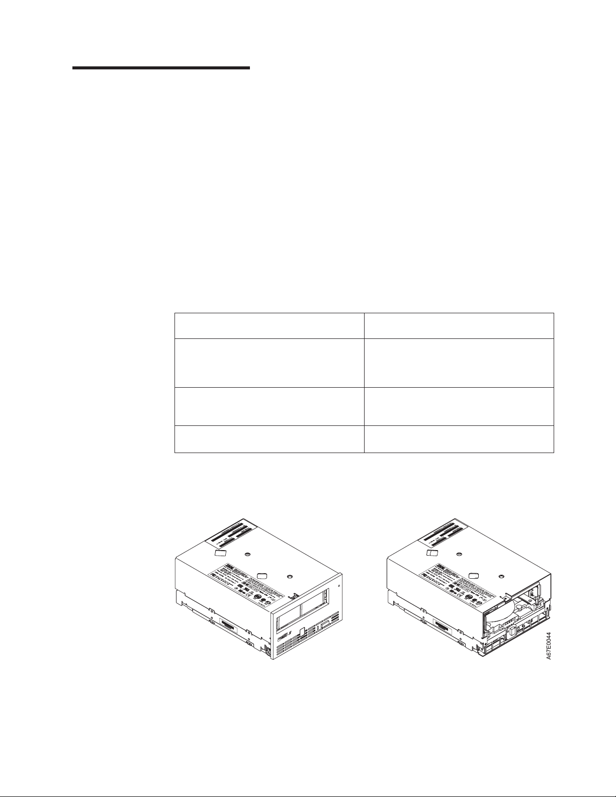
Figure 1 shows a front view of the IBM TotalStorage LTO Ultrium 2 Tape Drive with
and without a bezel.
Figure 1. View of the IBM TotalStorage LTO Ultrium 2 Tape Drive with and without the bezel
© Copyright IBM Corp. 2002 1
Page 14

Cartridge Compatibility
The Ultrium 2 Tape Drive (Generation 2) uses the IBM TotalStorage LTO Ultrium
200 GB Data Cartridge and is compatible with the cartridges of its predecessor, the
IBM Ultrium Internal Tape Drive (called Generation 1). The Ultrium 2 Tape Drive
performs the following functions:
v Reads and writes Generation 2 cartridges to Generation 2 format
v Reads and writes Generation 1 cartridges to Generation 1 format
v Does not write Generation 2 cartridges to Generation 1 format
v Does not write Generation 1 cartridges to Generation 2 format
The Ultrium 2 Tape Drive reads tapes that have been written by other licensed
Ultrium 2 drives. It also writes to tapes that can be read by other licensed Ultrium 2
drives.
In addition to using the IBM TotalStorage LTO Ultrium Data Cartridge with up to 200
GB capacity, the Ultrium 2 Tape Drive also offers read/write capability for certified
LTO Ultrium tape cartridges.
Speed Matching and Channel Calibration
To improve system performance, the Ultrium 2 Tape Drive uses a technique called
speed matching to dynamically adjust its native (uncompressed) data rate to the
slower data rate of a server. With speed matching, the drive operates at one of five
speeds when reading or writing the Generation 2 cartridge format to achieve a
native data rate of 17.5, 21.9, 26.25, 30.63, or 35 MB per second (MB/s). If the
server’s net (compressed) data rate is between two of the preceding native data
rates, the drive calculates which of the two data rates at which to operate. (For
example, if the server transfers data at 60 MB/s on the host bus, at 2:1
compression its net data rate is 30 MB/s. The drive will then dynamically choose to
operate at a native data rate of 26.25 or 30.63 MB/s, whichever enables it to
successfully receive the greatest amount of compressed data over the network.)
Speed matching dramatically reduces backhitch, the condition that occurs when a
tape stops, reverses, and restarts motion. A backhitch is usually the result of a
mismatch between the data rates of the server and the drive.
System performance is further optimized by a feature called channel calibration,in
which the drive automatically customizes each read/write data channel to
compensate for variations in such things as the recording channel’s transfer
function, the media, and characteristics of the drive head.
Sleep Mode
To conserve energy when circuit functions are not needed for drive operation, the
Ultrium 2 Tape Drive features a power-management function that causes the drive’s
electronics to enter a low-power mode known as sleep mode. To enter sleep mode,
the drive must be inactive for a minimum of 15 minutes; to exit, the drive must
receive a command across the SCSI or Fibre Channel interface, a command across
the Library/Drive Interface (LDI or RS-422 interface), or a load or unload request.
When in sleep mode, the drive’s response time to commands that do not require
media motion increases by up to 10 microseconds. Commands that require media
motion may be delayed an additional 100 milliseconds because the tape must be
retensioned.
2 IBM TotalStorage LTO Ultrium 2 Tape Drive
Page 15

Supported Servers and Operating Systems
The Ultrium 2 Tape Drive attaches to the servers and operating systems shown in
Table 2. Any attachment can include (but is not limited to) these servers and
operating systems. To determine the latest supported attachments, visit the web at
http://www.ibm.com/storage/lto. For specific instructions about attaching the tape
drive, see Chapter 3, “Installing the Tape Drive” on page 13.
Table 2. Supported servers and operating systems for SCSI and Fibre Channel attachment
Supported Servers Supported Operating Systems
®
IBM AS/400
IBM RS/6000®, RS/6000 SP™,orEserver
pSeries
or ERserver iSeries
™
IBM Eserver zSeries™800 or 900 Linux
Hewlett-Packard HP-UX
Sun Microsystems Solaris
32-bit, Intel-compatible servers Microsoft
64-bit, Intel Itanium servers Red Hat Linux
Supported SAN Components for Fibre Channel Attachment
Visit the web at: http://www.storage.ibm.com/hardsoft/tape/supserver/support.html
™
OS/400
AIX
®
®
®
Windows®2000 or Windows NT
Red Hat Linux
®
Chapter 1. Introduction 3
Page 16

SCSI Attachment
To communicate with a server, the IBM TotalStorage LTO Ultrium 2 Tape Drive uses
the Ultra160 LVD SCSI interface.
Physical Characteristics of the SCSI Interface
The Ultrium 2 Tape Drive contains a high-density, 68-pin, D-shell receptacle
connector (HD68) for attachment to the server. The HD68 connector includes the
connectors for the SCSI signal, the SCSI ID, and the drive’s power. The drive
supports LVD SCSI cables with HD68 connectors.
For a list of available cables, see Appendix A, “Tools and Supplies” on page 95.
Speed
The Ultra160 LVD SCSI interface is backward compatible with older SCSI
technology and is capable of data transmission at 160 MB/s. Ultra160 SCSI uses
the three management features of the Ultra3 SCSI standard that specifically affect
data transfer rate:
v Double transition clocking - a data-transfer technique that enables data rates
to double without increasing clock speed
v Domain validation - a procedure that detects and adjusts SCSI configuration
issues that might prevent interoperation between SCSI devices
v Cyclic redundancy check (CRC) - an error-checking technique
Because the cables, connectors, and terminators are the same for the Ultra160 and
Ultra2 SCSI interfaces, devices with those interfaces can be mixed on the same
bus and each device can operate at its fully rated speed.
4 IBM TotalStorage LTO Ultrium 2 Tape Drive
Page 17

Address Assignments
Each device on a SCSI bus must have a SCSI identifier (ID) that identifies it to the
server. When you install the Ultrium 2 Tape Drive, you can specify its SCSI ID in
one of three ways:
v By attaching jumpers to the SCSI ID connector
v By using your enclosure’s SCSI ID switch
v If you are installing the drive into a tape library, by setting the SCSI ID through
the LDI or RS-422 interface
For more information, see “Setting the SCSI ID (SCSI Drive Only)” on page 17.
Installing, Removing, or Resetting a Drive on an Active SCSI Bus
You can attach an Ultrium 2 Tape Drive to an active SCSI bus. However, the
preferred and safest method of adding, removing, or resetting a drive is to power-off
the system.
When adding, removing, or resetting a drive on an active SCSI bus, perform the
following steps:
1. Quiesce the drive. The drive to be added, removed, or reset must not be
involved in any bus activity.
2. Disconnect power to the drive.
3. Connect or disconnect the SCSI bus cables to or from the drive’s SCSI
connector. Ensure that the SCSI bus remains intact from the server (initiator) to
the terminator throughout the connection or disconnection process.
Note: Changing or moving the terminator disrupts the continuity of the SCSI
bus and interrupts any process on the bus.
Chapter 1. Introduction 5
Page 18

Fibre Channel Attachment
To communicate with a server, the Ultrium 2 Tape Drive has one Fibre Channel
interface (also called a port). In accordance with the standards of the American
National Standards Institute (ANSI), the port runs Fibre Channel Protocol (which
includes SCSI commands on the Fibre Channel) with ANSI-defined Fibre Channel
Tape Support. The method by which the drive and server communicate is
determined by the type of topology in which they reside and the type of connection
that you choose.
Supported Topologies
The Ultrium 2 Tape Drive can be attached in a two-node configuration, either
directly to a switch as a public device (switched fabric) or directly to a host bus
adapter (HBA) as a private device. It can do so in a Point-to-Point topology (through
an N_port or F_port) or Arbitrated Loop topology (through an L_port or FL_port).
Unless you set the drive to force an explicit configuration (by using the FC
configuration/status connector; see “Step 4. Change the Link Services of the Drive
(optional)” on page 24), the Ultrium 2 Tape Drive automatically configures to an
L_port or an N_port when it boots. The type of port to which it configures depends
on whether the drive recognizes the connection as a loop or a point-to-point
connection:
v An L_port supports a Fibre Channel Arbitrated Loop connection to an NL_port or
FL_port.
v An N_port supports direct connection to another N_port or to an F_port (for
example, a director-class switch) in a point-to-point topology.
Attention: A Class I laser assembly, in the optical transceiver, is
mounted on the Ultrium Fibre Channel electronics card. This laser
assembly is registered with the Department of Health and Human
Services and is in compliance with IEC825.
Regardless of the port to which you connect the drive, it automatically configures to
a public device (through an F_port or FL_port to a switch) or to a private device
(through an N_port or L_port by using direct attachment to a server).
Table 3 lists the topologies in which the Ultrium 2 Tape Drive can operate, the Fibre
Channel server connections that are available, and the port (NL, N, FL, or F)
through which communication must occur.
Table 3. Choosing the port for your topology and Fibre Channel connection
Type of Topology
Fibre Channel-Arbitrated
Loop
(can be Two-Node Arbitrated
Loop or Two-Node Switched
Fabric Loop; is limited to two
nodes)
Point-to-Point
(two nodes)
6 IBM TotalStorage LTO Ultrium 2 Tape Drive
Type of Fibre Channel Connection to Server
Direct Connection
(Private)
L_Port FL_Port
N_Port F_Port
Switched Fabric
(Public)
Page 19

Speed
The Ultrium 2 Tape Drive’s Fibre Channel interface facilitates data at 2 Gb/s (200
MB/s). It automatically negotiates to a rate of 1 Gb/s (100 MB/s) if the system or
switch to which it connects does not support the 2-Gb rate (if this is the case, you
may experience performance degradation). You can force the drive to an explicit
speed by placing jumpers on the Fibre Channel (FC) configuration/status connector.
For more information, see “Step 4. Change the Link Services of the Drive (optional)”
on page 24.
Address Assignments
Each device on a Fibre Channel loop must have a Loop Identifier (LID) and a
corresponding Arbitrated Loop Physical Address (AL_PA) to communicate with other
devices in the topology. The AL_PA identifies the device on the loop. (LIDs and their
corresponding AL_PAs are listed in Table 5 on page 21 and Table 6 on page 22.)
You can set an AL_PA by using one of two methods known as soft addressing or
hard addressing.
Soft addressing allows the drive to dynamically arbitrate the AL_PA with other Fibre
Channel devices on the loop. Hard addressing allows you to choose the LID, which
determines the corresponding AL_PA. The higher the AL_PA, the lower the priority
of the device.
Generally, servers (initiators) require that devices use hard addressing; they do not
support soft addressing. When setting addresses, assign the lowest AL_PA (and
thus the highest priority) to the server; assign the highest AL_PA (and thus the
lowest priority) to the drive.
To set soft or hard addressing, you must place jumpers on designated pins in the
drive’s LID/status connector (see (2 in Figure 3 on page 15). The pin configuration
for soft and hard addressing is defined in “Setting the Arbitrated Loop Physical
Address (Fibre Channel Drive Only)” on page 19.
Chapter 1. Introduction 7
Page 20

World Wide Names
Each Ultrium 2 Tape Drive has an 8-byte World Wide Node Name and an 8-byte
World Wide Port Name that is assigned by IBM Manufacturing. The World Wide
Node Name identifies the drive’s SCSI logical unit; the World Wide Port Name
identifies the physical port on the drive. An enclosure queries the World Wide
Names through the LDI or RS-422 interface; a server queries the Names through
the Fibre Channel interface. The Ultrium 2 Tape Drive reports the World Wide
Names to switches. You can use the World Wide Node Name or Wide Node Port
Name to uniquely identify the drive on a SAN.
When your Ultrium 2 Tape Drive is installed in a tape library, you can change the
World Wide Node Name and World Wide Port Name through the LDI or RS-422
interface. For instructions, refer to the documentation for your tape library.
Physical Characteristics of the Fibre Channel Interface
The Ultrium 2 Tape Drive attaches to Open Systems servers by using short-wave,
multimode fiber optic cables. All cables feature LC-duplex connectors and are
designated as 50/125 (50 refers to the diameter of the optical fiber and 125 refers
to the diameter of the cable; both are measured in micrometers).
For a list of available cables, see Appendix A, “Tools and Supplies” on page 95.
Installing, Removing, or Resetting a Drive on an Active Fibre Channel
A Fibre Channel network supports dynamic drive attachment. When adding,
removing, or resetting a drive on an active server or SAN, perform the following
steps:
1. Quiesce the drive. The drive to be added, removed, or reset must not be
involved in activity.
2. Connect or disconnect the Fibre Channel cables to or from the drive.
8 IBM TotalStorage LTO Ultrium 2 Tape Drive
Page 21

Supported Device Drivers
IBM offers device drivers for the Ultrium 2 Tape Drive. Device drivers enable the
drive to interact with a variety of servers. To properly install an IBM device driver (if
required), refer to the IBM Ultrium Device Drivers Installation and User’s Guide. For
applications that use other device drivers, see the application’s documentation to
determine which drivers to use.
IBM maintains the latest levels of device drivers and driver documentation for the
IBM TotalStorage LTO Ultrium 2 Tape Drive on the Internet. You can access this
material from your browser or through the IBM FTP site by performing one of the
following procedures. (Note: If you do not have Internet access and you need
information about device drivers, contact your Marketing Representative.)
v Using a browser, type one of the following:
– http://www.ibm.com/storage
– ftp://ftp.software.ibm.com/storage/devdrvr
– ftp://207.25.253.26/storage/devdrvr
v Using an IBM FTP site, enter the following specifications:
– FTP site: ftp.software.ibm.com
– IP Addr: 207.25.253.26
– Userid: anonymous
– Password: (use your current e-mail address)
– Directory: /storage/devdrvr
IBM provides PostScript- and PDF-formatted versions of its documentation in the
/storage/devdrvr/doc directory:
v IBM_ultrium_tape_IUG.ps and IBM_ultrium_tape_IUG.pdf contain the current
version of the IBM Ultrium Device Drivers Installation and User’s Guide
v IBM_ultrium_tape_PROGREF.ps and IBM_ultrium_tape_PROGREF.pdf contain
the current version of the IBM Ultrium Device Drivers Programming Reference
Device drivers and utilities for each supported server are beneath /storage/devdrvr/
in the following directories (the device driver for the iSeries or AS/400 server is
included in the OS/400 operating system):
v AIX
v HPUX
v Linux
v Solaris
v Tru64
v WinNT
v Win2000
For more information about device drivers, refer to any of the preceding directories.
Chapter 1. Introduction 9
Page 22

10 IBM TotalStorage LTO Ultrium 2 Tape Drive
Page 23

Chapter 2. Specifications
Table 4 gives the physical, power, and environmental specifications for the IBM
TotalStorage LTO Ultrium 2 Tape Drive. Specifications for tape cartridges are given
in “Environmental and Shipping Specifications for Tape Cartridges” on page 62.
Table 4. Specifications for the IBM TotalStorage LTO Ultrium 2 Tape Drive
Specification Measurement
Physical Specifications
Width 146.0 mm (5.75 in.) without bezel
148.3 mm (5.84 in.) with bezel
Length 205.5 mm (8.09 in.) without bezel
210.5 mm (8.29 in.) with bezel
Height 82.5 mm (3.25 in.) without bezel
84.8 mm (3.34 in.) with bezel
Weight (without a cartridge) 3 kg (6 lb 10 oz)
Power Specifications
Drive with Ultra160 SCSI Interface Drive with Fibre Channel Interface
Tolerance (see Note 1) + 5 Vdc and + 12 Vdc (±10%) + 5 Vdc and + 12 Vdc (±10%)
Power supply current for 5
Vdc (see Note 2)
Power supply current for 12
Vdc (see Note 2)
Power supply peak for 5
Vdc (the instantaneous
power by the power supply)
Power supply peak for 12
Vdc (the instantaneous
power by the power supply)
Power usage for typical idle
mode with no cartridge
Power usage for typical idle
mode with a cartridge
loaded
Power usage for reading
and writing at 6.22 m/s
Power usage for sleep
mode with no cartridge
Power usage for sleep
mode with a cartridge
loaded
Maximum altitude 3048 m (10,000 ft) for operating and storage
Extraction force 250 to 750 gms-force
1.3 A minimum 1.9 A minimum
3.1 A maximum 3.7 A maximum
0.2 A minimum 0.2 A minimum
1.1 A maximum 1.1 A maximum
3.3 A for 100 ms
15.5 W
4.1 A for 2 ms
49.2 W
10.9 W 13.9 W
12.7 W 15.7 W
29 W 32 W
9.0 W 12.0 W
10.8 W 13.8 W
Other Specifications (for both interface types)
12192 m (40,000 ft) for shipping
3.9 A for 100 ms
19.5 W
4.1 A for 2 ms
49.2 W
© Copyright IBM Corp. 2002 11
Page 24

Table 4. Specifications for the IBM TotalStorage LTO Ultrium 2 Tape Drive (continued)
Environmental Specifications (for both interface types)
Environmental Factor
Drive temperature
Relative humidity
(noncondensing)
Wet bulb temperature
Notes:
1. Measured at the drive’s power connector.
2. The + 5 Vdc and + 12 Vdc maximum currents do not occur simultaneously. The Ultrium 2 Tape Drive monitors
voltage and reports problems to the server.
3. Measured in front of the bezel, near the air intake area (refer to Figure 4 on page 16).
Operating
(see Note 3)
10 to 40°C
(50 to 104°F)
20 to 80% 10 to 90% 10 to 90%
26°C
(78.8°F)
Storage Shipping
1to60°C
(33.8 to 140°F)
26°C
(78.8°F)
−40 to 60°C
(−40 to 140°F)
26°C
(78.8°F)
12 IBM TotalStorage LTO Ultrium 2 Tape Drive
Page 25

Chapter 3. Installing the Tape Drive
Attention:
To avoid static electricity damage when you handle the IBM TotalStorage LTO
Ultrium 2 Tape Drive, use the following precautions:
v Limit your movement. Movement can cause static electricity to build around
you.
v Always handle the Ultrium 2 Tape Drive carefully. Never touch exposed
circuitry.
v Prevent others from touching the Ultrium 2 Tape Drive.
v Before you unpack and install the Ultrium 2 Tape Drive into an enclosure,
touch its static-protective packaging to an unpainted metal surface on the
enclosure for at least 2 seconds. This reduces static electricity in the
packaging and your body.
v When possible, remove the Ultrium 2 Tape Drive from its static-protective
packaging and install it directly into an enclosure without setting it down.
When this is not possible, place the tape drive’s packaging on a smooth,
level surface and place the tape drive on the packaging.
v Do not place the Ultrium 2 Tape Drive on the cover of the enclosure or on
any other metal surface.
The steps that follow describe how to install the Ultrium 2 Tape Drive into an
enclosure.
Note: Depending on the type of enclosure, installation procedures may vary. Before
starting this installation, read these instructions and compare them to the
drive installation instructions for your enclosure.
When installing the Ultrium 2 Tape Drive into an enclosure, refer to “Rear View of
the SCSI Drive” on page 14 or “Rear View of the Fibre Channel Drive” on page 15.
© Copyright IBM Corp. 2002 13
Page 26
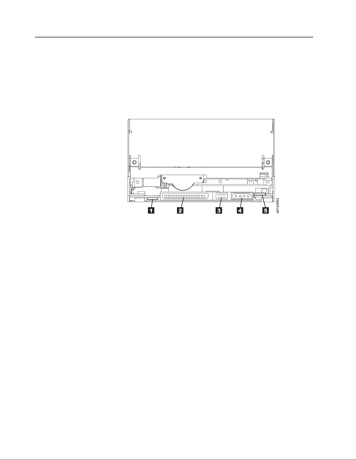
Rear View of the SCSI Drive
1 Feature switches
2 SCSI connector
3 SCSI ID connector
4 Power connector
5 Library/Drive Interface (LDI or RS-422 interface) connector
Figure 2. Rear view of the IBM TotalStorage LTO Ultrium 2 Tape Drive Model T400 (SCSI
drive)
14 IBM TotalStorage LTO Ultrium 2 Tape Drive
Page 27
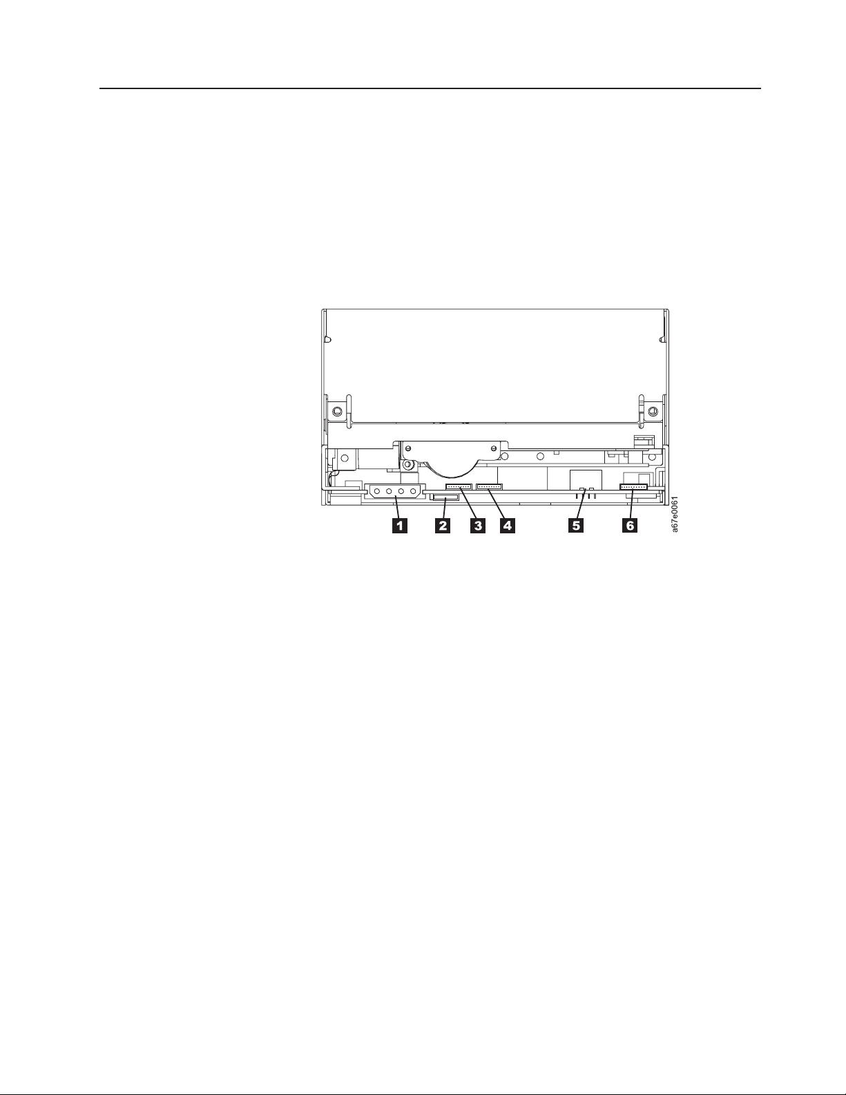
Rear View of the Fibre Channel Drive
1 Power connector
2 Feature switches
3 Loop identifier (LID)/status connector
4 Fibre Channel (FC) configuration/status connector
5 Fibre Channel connector
6 Library/Drive Interface (LDI or RS-422 interface) connector
Figure 3. Rear view of the IBM TotalStorage LTO Ultrium 2 Tape Drive Model T400F (Fibre
Channel drive)
Chapter 3. Installing 15
Page 28
Step 1. Unpack the Drive
Unpack the Ultrium 2 Tape Drive and store the packaging. You may need the
packaging if you return the unit for service.
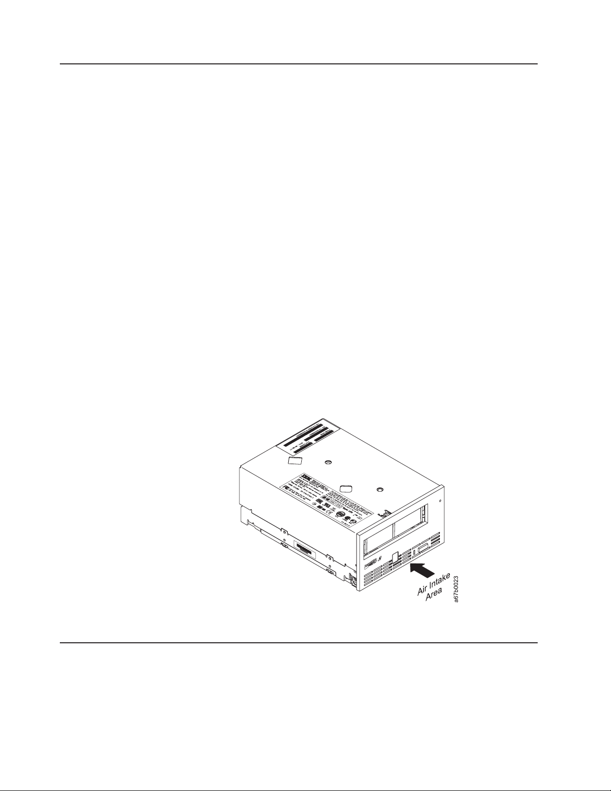
Attention::
Acclimation time is required if the temperature of the drive when unpacked is
different than the temperature of its operating environment (measured at the front of
the bezel near the air intake area; see Figure 4). The recommended acclimation
time is 4 hours after the drive has been unpacked or 1 hour after any condensation
that you can see has evaporated, whichever is greater. When acclimatizing the
drive, apply the following measures:
v If the drive is colder than its operating environment and the air contains sufficient
humidity, condensation may occur in the drive and damage it. When the drive
has warmed to the operating temperature range (greater than 10°Cor50°F) and
no danger of condensation is present (the air is dry), warm the drive more quickly
by powering it on for 30 minutes. Use a diagnostic tape to test the drive before
inserting a tape that contains data.
v If the drive is hotter than its operating environment, the tape can stick to the drive
head. When the drive has cooled to the operating temperature range (less than
40°Cor104°F), cool the drive more quickly by applying airflow for 30 minutes.
Power-on the drive and use a diagnostic tape to test it before inserting a tape
that contains data.
If you are uncertain about whether the temperature of the drive is within the
recommended operating range or the humidity is sufficient to cause condensation,
acclimate the drive for the full 4 hours.
Figure 4. Measuring the temperature of the operating environment. The temperature is
measured at the front of the bezel, near the air intake area.
Step 2. Remove Power from the Enclosure
__ 1. Power-off the enclosure (or the unit that provides power to the drive)
__ 2. Disconnect the power cord from both the electrical outlet and the enclosure.
16 IBM TotalStorage LTO Ultrium 2 Tape Drive
Page 29

Step 3. Set the SCSI ID or Arbitrated Loop Physical Address
Perform one of the following steps:
v If you are installing an Ultrium 2 Tape Drive that uses a SCSI interface (Model
T400), you must set the drive’s SCSI ID. For instructions, go to “Setting the SCSI
ID (SCSI Drive Only)” on this page.
v If you are installing an Ultrium 2 Tape Drive that uses a Fibre Channel interface
(Model T400F), you must set the drive’s Arbitrated Loop Physical Address
(AL_PA). For instructions, go to “Setting the Arbitrated Loop Physical Address
(Fibre Channel Drive Only)” on page 19.
Setting the SCSI ID (SCSI Drive Only)
You can set the SCSI ID in one of three ways:
v By placing jumpers on the SCSI ID connector
v By using a SCSI ID switch that is connected to the SCSI ID connector
v By issuing a command from the library to set the SCSI ID through the drive’s LDI
interface
The sections that follow describe each method of setting the SCSI ID.
Setting the SCSI ID with Jumpers
You can set the SCSI ID on the Ultrium 2 Tape Drive by installing 2-mm jumpers on
the drive’s SCSI ID connector (see 3 in Figure 2 on page 14). Your tape drive
may come set to a default SCSI configuration, with jumpers already installed. To
change the default SCSI configuration, contact your sales or or technical support
representative. You can change the SCSI ID by rearranging, adding, or removing
jumpers.
To set the SCSI ID:
__ 1. Locate the SCSI ID connector (see 3 in Figure 2 on page 14).
__ 2. Before attaching the SCSI bus cable to the server, decide the SCSI ID
number that you want. Make sure that the ID is not being used by another
device.
__ 3. Referring to Figure 5 on page 18, find the ID number that you chose then
place jumpers on the connector pins as shown (use a pair of needle-nose
pliers to connect the jumpers to the pins that are shaded).
Note: If you set the SCSI ID to 15, the drive will not necessarily be set to
that ID; instead, the drive will expect to receive the SCSI ID through a
command over its LDI interface.
Chapter 3. Installing 17
Page 30

Figure 5. SCSI ID settings on the SCSI ID connector
Setting the SCSI ID with a SCSI ID Switch
If your enclosure uses a SCSI ID switch (rather than jumpers), connect the switch
to the drive’s SCSI ID connector (see 3 in Figure 2 on page 14). If any jumpers
are pre-installed, be sure to remove them before connecting the switch. The SCSI
ID switch must be compatible with the drive’s SCSI ID connector and must make an
electrical connection between the same pins as the jumpers to achieve the same
corresponding SCSI ID.
Setting the SCSI ID Through the LDI Interface
If you are installing the Ultrium 2 Tape Drive into a tape library, you can issue a
command from the library to set the drive’s SCSI ID through the LDI interface.
Make sure that the SCSI ID is set to 15 (see Figure 5). When configured to accept
its SCSI ID through the LDI interface, the drive does not respond to SCSI
commands until it receives a Set Configuration command through the interface.
Supplying TERMPOWER (SCSI Drive Only)
To supply TERMPOWER to the bus, locate one of the five jumpers shipped with the
Ultrium 2 Tape Drive and place it on the SCSI ID connector as shown in the
following figure. Place the jumper on the pins that are shaded.
Note that you must provide SCSI termination externally to the Ultrium 2 Tape Drive.
18 IBM TotalStorage LTO Ultrium 2 Tape Drive
A67E0049
Page 31

Setting the Arbitrated Loop Physical Address (Fibre Channel Drive Only)
Each device on a Fibre Channel loop must have an Arbitrated Loop Physical
Address (AL_PA) to communicate. The AL_PA identifies the device on the loop. To
set the Ultrium 2 Tape Drive’s AL_PA, you must place jumpers on specific pins in
the drive’s loop identifier (LID)/status connector. The placement of the jumpers
indicates whether you want to choose the LID yourself (each LID corresponds to a
specific AL_PA) or whether you want the drive to choose the AL_PA by arbitrating it
with other devices on the loop. Valid LIDs and their corresponding AL_PAs are
provided in this section.
Note: A Loop ID is part of a contiguous range of values; valid AL_PA values are
not in a contiguous range.
In addition to establishing the AL_PA, by moving Feature Switch 3 on the drive to
ON or off you can set the drive so that it provides one of the following functions:
v Status about the Fibre Channel loop (through the use of external indicators in an
enclosure)
v Additional LIDs
The sections that follow describe how to select the AL_PA. They also describe how
to set Feature Switch 3 so that the drive gives status about the loop or provides
additional LIDs.
Chapter 3. Installing 19
Page 32

Setting the Loop ID to Provide Status About the Loop
If Feature Switch 3 on the Ultrium 2 Tape Drive is set to OFF (see 1 in Figure 6),
the LID/status connector 2 has the following definition:
v Pins 1, 2, 3, 4, 7, and 8 are inputs and are used to set the LID.
v Pins 5 and 6 are used as outputs:
– Pin 5 has three states: off (ground), on (3.3 V), and alternating (between off
and on). Pin 5 will be off if the drive does not detect light on the Fibre
Channel connector, if (while communicating as an L_port) the drive does not
complete the Loop Initialization Protocol (LIP), or if (while communicating as
an N_port) the drive does not complete logging in to the host or switch. Pin 5
will be on if the drive detects light, successfully completes the LIP process, or
logs in to another port. After the drive has completed the LIP process, the pin
will be alternating when the drive is receiving SCSI commands, and the pin
will be on when the drive is not receiving SCSI commands.
– Pin 6 indicates that the drive detects light. If pin 6 is on but pin 5 is off, this
could indicate communication problems across the fiber cable.
– If the drive is installed in an enclosure, pins 5 and 6 may be used to support
external indicators, such as light-emitting diodes (LEDs), on the enclosure.
Note: If indicators are used on an enclosure, the drive does not report error
codes 8 and F (Fibre Channel problems) to the single-character
display. Instead, pins 5 and 6 signal to the indicators that there is a
problem.
v Pin 9 is ground.
Figure 6. Setting the Loop ID and the AL_PA. The feature switches are located on the bottom
of the drive.
To set the AL_PA:
__ 1. Determine an unused AL_PA for the drive and refer to Table 5 on page 21 for
its corresponding LID.
__ 2. Locate the LID/status connector on the drive (see 2 in Figure 6).
__ 3. Place jumpers on pins 1, 2, 3, 4, 7, and 8 as shown in Table 5 on page 21.
By using hard addressing, you can specify one of 62 valid AL_PAs for the
drive. If you place jumpers on the four top and bottom pins on the right (a
total of eight pins), the drive gets the AL_PA from a field in its vital product
data (VPD). (A tape library can set the AL_PA in the VPD through the LDI
interface.) If you do not place jumpers on any pins, the drive uses soft
addressing to determine the AL_PA.
20 IBM TotalStorage LTO Ultrium 2 Tape Drive
Page 33

Table 5. ID Settings that provide status about the loop. The table lists the AL_PAs, corresponding LIDs, and
definitions of the jumpers on the connector pins. Feature Switch 3 must be set to OFF.
Pin
AL_PA LID
use soft
addressing
E8 1 -----G B1 21 G----G
E4 2 ----G- AE 22 G---GE2 3 ----GG AD 23 G---GG
E1 4 ---G-- AC 24 G--G--
E0 5 ---G-G AB 25 G--G-G
DC 6 ---GG- AA 26 G--GGDA 7 - - - G G G A9 27 G - - G G G
D9 8 - - G - - - A7 28 G - G - - D6 9 - -G- -G A6 29 G-G- -G
D5 A - -G-G- A5 2A G-G-GD4 B - -G-GG A3 2B G-G-GG
D3 C - -GG- - 9F 2C G-GG- D2 D - -GG-G 9E 2D G-GG-G
D1 E - - GGG - 9D 2E G - GGG CE F - - GGGG 9B 2F G - GGGG
CD 10 -G---- 98 30 GG---CC 11 -G---G 97 31 GG---G
CB 12 - G - - G - 90 32 G G - - G CA 13 - G - - G G 8F 33 G G - - G G
C9 14 - G - G - - 88 34 G G - G - C7 15 -G-G-G 84 35 GG-G-G
C6 16 - G - G G - 82 36 G G - G G C5 17 - G - G G G 81 37 G G - G G G
C3 18 - G G - - - 80 38 G G G - - BC 19 - G G - - G 7C 39 G G G - - G
BA 1A - G G - G - 7A 3A G G G - G -
B9 1B - G G - G G 79 3B G G G - G G
B6 1C - GGG - - 76 3C GGGG - -
B5 1D - GGG - G 75 3D GGGG - G
B4 1E - GGGG - 74 3E GGGGG -
B3 1F - GGGGG
0 ------ B2 20 G-----
(see Notes)
123478 123478
AL_PA LID
use AL_PA
from VPD
3F GGGGGG
Pin
(see Notes)
Notes:
1. G means that the pin is jumpered to ground.
2. - means that the pin is not jumpered.
Chapter 3. Installing
21
Page 34

Setting the Loop ID to Provide Additional Loop IDs
If Feature Switch 3 on the Ultrium 2 Tape Drive is set to ON (see 1 in Figure 6 on
page 20), the LID/status connector 2 has the following definition:
v Pins 1 through 7 are used to set the LID.
v Pin 8 overrides pins 1 through 7. If you place a jumper on pin 8, the drive uses
its vital product data (VPD) to set the AL_PA. A tape library can set the AL_PA in
VPD through the LDI interface.
v Pin 9 is ground.
Note: Feature Switch 3 does not support LEDs on an enclosure. Therefore, when
Feature Switch 3 is set to ON, the drive can report Fibre Channel problems
(error codes 8 and F) on the single-character display, but not by using the
enclosure’s external indicators.
To set the AL_PA:
__ 1. Determine an unused AL_PA address for the drive and refer to Table 6 for its
corresponding LID.
__ 2. Locate the LID/status connector on the drive (see 2 in Figure 6 on
page 20).
__ 3. Place jumpers on pins 1 through 7 as shown in Table 6 or on pin 8.
Table 6. ID settings that provide additional Loop IDs. The table lists the AL_PAs, corresponding LIDs, and definitions
of the jumpers on the connector pins. Feature Switch 3 must be set to ON.
Pin
AL_PA LID
1234567 1234567
EF 0 ------- B1 21 -G----G
E8 1 ------G AE 22 -G---GE4 2 -----G- AD 23 -G---GG
E2 3 -----GG AC 24 -G--G-E1 4 ----G-- AB 25 -G--G-G
E0 5 ----G-G AA 26 -G--GGDC 6 ----GG- A9 27 -G--GGG
DA 7 ----GGG A7 28 -G-G--D9 8 ---G--- A6 29 -G-G--G
D6 9 - - -G- -G A5 2A -G-G-GD5 A - - - G - G - A3 2B - G - G - G G
D4 B - - - G - G G 9F 2C - G - G G - D3 C - - - G G - - 9E 2D - G - G G - G
D2 D - - - G G - G 9D 2E - G - G G G D1 E - - - GGG - 9B 2F - G - GGGG
CE F - - - GGGG 98 30 - GG ---CD 10 --G---- 97 31 -GG---G
CC 11 --G---G 90 32 -GG--GCB 12 - - G - - G - 8F 33 - G G - - G G
CA 13 - - G - - G G 88 34 - G G - G - C9 14 - - G - G - - 84 35 - G G - G - G
C7 15 - -G-G-G 82 36 -GG-GGC6 16 - - G - GG - 81 37 - GG - GGG
(see Notes)
AL_PA LID
Pin
(see Notes)
22 IBM TotalStorage LTO Ultrium 2 Tape Drive
Page 35

Table 6. ID settings that provide additional Loop IDs (continued). The table lists the AL_PAs, corresponding LIDs,
and definitions of the jumpers on the connector pins. Feature Switch 3 must be set to ON.
Pin
AL_PA LID
1234567 1234567
C5 17 - - G - G G G 80 38 - G G G - - C3 18 - - G G - - - 7C 39 - G G G - - G
BC 19 - - GG - - G 7A 3A - GGG - G BA 1A - - GG - G - 79 3B - GGG - GG
B9 1B - - GG - GG 76 3C - GGGG - B6 1C - - GGG - - 75 3D - GGGG - G
B5 1D - - GGG - G 74 3E - GGGGG B4 1E - - GGGG - 73 3F - GGGGGG
B3 1F - - GGGGG 72 40 G -----B2 20 -G----- 71 41 G-----G
6E 42 G----G- 39 61 GG----G
6D 43 G----GG 36 62 GG---G6C 44 G----G- 35 63 GG---GG
6B 45 G- - -G-G 34 64 GG- -G- 6A 46 G - - - G G - 33 65 G G - - G - G
69 47 G - - - G G G 32 66 G G - - G G 67 48 G - - G - - - 31 67 G G - - G G G
66 49 G- -G- -G 2E 68 GG-G- - 65 4A G- -G-G- 2D 69 GG-G- -G
63 4B G- -G-GG 2C 6A GG-G-G5C 4C G- -GG- - 2B 6B GG-G-GG
5A 4D G- -GG-G 2A 6C GG-GG- 59 4E G - - GGG - 29 6D GG - GG - G
56 4F G - - GGGG 27 6E GG - GGG 55 50 G-G---- 26 6F GG-GGGG
54 51 G-G---G 25 70 GGG---53 52 G - G - - G - 23 71 G G G - - - G
52 53 G-G- -GG 1F 72 GGG- -G51 54 G-G-G- - 1E 73 GGG- -GG
4E 55 G-G-G-G 1D 74 GGG-G- 4D 56 G - G - GG - 1B 75 GGG - G - G
4C 57 G - G - G G G 18 76 G G G - G G 4B 58 G - G G - - - 17 77 G G G - G G G
4A 59 G - GG - - G 10 78 GGGG - - 49 5A G - GG - G - 0F 79 GGGG - - G
47 5B G - GG - GG 08 7A GGGG - G 46 5C G - GGG - - 04 7B GGGG - GG
45 5D G - GGG - G 02 7C GGGGG - 43 5E G - GGGG - 01 7D GGGGG - G
(see Notes)
AL_PA LID
Pin
(see Notes)
Chapter 3. Installing
23
Page 36

Table 6. ID settings that provide additional Loop IDs (continued). The table lists the AL_PAs, corresponding LIDs,
and definitions of the jumpers on the connector pins. Feature Switch 3 must be set to ON.
Pin
AL_PA LID
1234567 1234567
3C 5F G - GGGGG SA 7E GGGGGG 3A 60 GG----- SA 7F GGGGGGG
Notes:
1. G means that the pin is jumpered to ground.
2. - means that the pin is not jumpered.
3. SA means soft addressing.
(see Notes)
AL_PA LID
Pin
(see Notes)
Step 4. Change the Link Services of the Drive (optional)
You can optionally change the link services (for example, the speed and type of
topology) of your Fibre Channel drive. If you choose not to alter the link services,
the drive defaults to a negotiated speed and operation in an FC-AL topology with a
direct connection to the server.
In the following procedure, note that:
v Pin 5 is disconnected and is not represented in Table 7.
v Pin 9 is ground.
To change the type of topology and the speed of the Fibre Channel drive:
__ 1. Determine the type of topology in which you want to operate the Ultrium 2
Tape Drive and refer to Table 7 for its corresponding pin configuration.
__ 2. Determine the speed at which you want the Ultrium 2 Tape Drive to operate
and refer to Table 7 for its corresponding pin configuration.
__ 3. Locate the Fibre Channel (FC) configuration/status connector on the drive
(see 1 in Figure 7 on page 25).
__ 4. Place jumpers on the pins that you identified in steps 1 and 2.
Table 7. Topology and speed settings for the Ultrium 2 Tape Drive
Fibre Channel
Characteristic
Drive uses VPD values that
can be updated by the LDI
or RS-422 (the default
value is Negotiated)
2 Gb (200 MB/s) - G X X X
1 Gb (100 MB/s) G - X X X
Negotiated (the drive
automatically negotiates to
the highest common speed)
Drive uses VPD values that
can be updated by the LDI
or RS-422 (the default
value is the NL_port)
12345through 8
Speed Selection
--XX X
GGX X X
Topology Selection
XX - - X
Pin
24 IBM TotalStorage LTO Ultrium 2 Tape Drive
Page 37

Table 7. Topology and speed settings for the Ultrium 2 Tape Drive (continued)
Fibre Channel
Characteristic
12345through 8
Pin
L_Port X X - G X
N_Port X X G - X
NL_Port (the drive
XXGG X
automatically selects and
configures the topology)
Notes:
1. G means that the pin is jumpered to ground.
2. - means that the pin is not jumpered.
3. X means that the setting of the pin does not matter.
Figure 7. Location of the Fibre Channel (FC) configuration/status connector. The view is from
the rear of the drive.
Chapter 3. Installing 25
Page 38

Step 5. Mount the Tape Drive into the Enclosure
The Ultrium 2 Tape Drive may be shipped with or without a front bezel (see 1 in
Figure 8).
To mount the Ultrium 2 Tape Drive into an enclosure:
__ 1. Remove the cover of your enclosure (refer to the instructions in the
enclosure’s documentation).
__ 2. Place the drive into the enclosure so that its tape load compartment faces
the tape load compartment of the enclosure.
__ 3. Insert two 6-32 screws into the mounting holes 2 on the side brackets of
the chassis.
Attention: When inserted into the Ultrium 2 Tape Drive, the length of the
mounting screws must not exceed 3.5 mm (0.14 in.) inside the chassis. If the length
exceeds this measurement, the tape drive may become damaged.
Figure 8. Mounting holes on Ultrium 2 Tape Drive. The holes are located on both sides of the
drive. The tape drive is shown with a front bezel.
26 IBM TotalStorage LTO Ultrium 2 Tape Drive
Page 39

Step 6. Connect and Test Power to the Tape Drive
The Ultrium 2 Tape Drive does not contain its own power source; it must be
powered externally.
To connect and test power to the Ultrium 2 Tape Drive:
__ 1. Ensure that the enclosure (or unit that supplies power to the drive) is
powered off.
__ 2. Ensure that the power cord is disconnected from both the enclosure and the
power outlet.
__ 3. Connect the enclosure’s internal power cable to the power connector on the
drive (if you are using a SCSI drive, see 4 in Figure 2 on page 14; if you
are using Fibre Channel drive, see 1 in Figure 3 on page 15). Ensure that
the connector is properly connected.
__ 4. Connect the power cord to the enclosure and to the electrical outlet.
__ 5. Review the location of the single-character display and the status light on
page 31 (if your drive does not have a bezel, note that the bulb of the status
light is recessed and the light is not visible until lit). To ensure that the drive
is receiving power, watch for the following while turning on the power to the
enclosure:
v The single-character display presents a series of random characters, then
becomes blank (not lit).
Note: If the single-character display does not come on, the drive
may not be getting power.
v The status light briefly becomes solid amber, then becomes solid green.
__ 6. Power-off the enclosure.
__ 7. Disconnect the power cord from both the enclosure and the electrical outlet.
Step 7. Connect the Internal SCSI or Fibre Channel Cable
__ 1. Perform one of the following procedures:
v If you are using a SCSI drive (Model T400), connect the enclosure’s
internal SCSI cable to the SCSI connector on the drive (see 2 in
Figure 2 on page 14).
v If you are using a Fibre Channel drive (Model T400F), connect the
enclosure’s internal Fibre Channel cable to the Fibre Channel connector
on the drive (see 5 in Figure 3 on page 15).
__ 2. Ensure that the connector is properly connected.
Chapter 3. Installing 27
Page 40

Step 8. Connect the Internal LDI Cable (optional)
Note: Use this step only if you are installing the Ultrium 2 Tape Drive into a library
control system. The drive uses the Library/Drive Interface (LDI) to
communicate with a tape library.
Connect the enclosure’s internal LDI cable to the LDI connector on the drive (see
5 in Figure 2 on page 14 or 6 in Figure 3 on page 15).
Step 9. Run Drive Diagnostics
__ 1. Replace the cover on the enclosure.
__ 2. Connect the power cord to both the enclosure and the electrical outlet, then
power-on the enclosure.
__ 3. Run one or more of the following tape drive diagnostics. If an error code
appears on the single-character display, go to Table 15 on page 67.
v Function Code 1 - Run Tape Drive Diagnostics (see page 36).
v Function Code 6 - Run Wrap Test (for a SCSI drive, see page 39; for a
Fibre Channel drive, see page 40).
v Function Code 7 - Run LDI Wrap Test (see page 41).
__ 4. Power-off the enclosure, then disconnect the power cord from both the
enclosure and the electrical outlet.
Step 10. Install the Device Drivers
For information about installing device drivers, refer to the documentation for your
enclosure.
Step 11. Connect the External SCSI or Fibre Channel Interface to the Server
Perform one of the following steps:
v If you are using a SCSI drive (Model T400), connect the enclosure’s external
SCSI cable to the SCSI connector on the server. For instructions, go to “Connect
the External SCSI Interface to the Server” on this page.
v If you are using a Fibre Channel drive (Model T400F), connect the enclosure’s
external Fibre Channel cable to the Fibre Channel connector on the server. For
instructions, go to “Connect the External Fibre Channel Interface to the Server”
on page 29.
Connect the External SCSI Interface to the Server
To connect the enclosure to the SCSI bus:
__ 1. Connect an external SCSI bus cable to both the enclosure and the server
(for the location of the connectors, refer to the documentation for your
enclosure and server).
__ 2. Run the appropriate SCSI attachment verification procedure from your server
(for instructions, refer to the IBM Ultrium Device Drivers Installation and
User’s Guide). If a SCSI error occurs, refer to “Using Sense Data” on
page 71.
28 IBM TotalStorage LTO Ultrium 2 Tape Drive
Page 41

If you want to power a device on or off while it is connected to the same SCSI bus
as an Ultrium 2 Tape Drive, you can do so if, during the power-on cycle, you
quiesce all devices (including the Ultrium 2 Tape Drive) on the bus.
Connect the External Fibre Channel Interface to the Server
To connect the enclosure to the Fibre Channel interface:
__ 1. Connect an external fiber cable to both the enclosure and the appropriate
attachment (server, switch, or hub). For the location of the connectors and
for information about attaching the fiber cable, refer to the documentation for
your enclosure and for your server, switch, or hub.
Note: A drive with a Fibre Channel interface can be ordered with several
lengths of fiber cabling, up to 61 m (200 ft). For ordering information,
see Table 16 on page 95.
__ 2. Run the appropriate Fibre Channel attachment verification procedure from
your server (for instructions, refer to the IBM Ultrium Device Drivers
Installation and User’s Guide). If a SCSI error occurs, refer to “Using Sense
Data” on page 71.
Step 12. Connect the External LDI Interface to the Server (optional)
Use this step only if your enclosure requires an LDI interface.
To perform a checkout of the Ultrium 2 Tape Drive, connect the enclosure’s external
LDI cable to the server (for the location of the external LDI connector, refer to the
documentation for the enclosure).
Step 13. Configure the Tape Drive to the Server, Switch, or Hub
To configure the SCSI tape drive (Model T400) to the server, or to configure the
Fibre Channel drive (Model T400F) to a server, switch, or hub, refer to the
documentation for that server, switch, or hub.
Chapter 3. Installing 29
Page 42

30 IBM TotalStorage LTO Ultrium 2 Tape Drive
Page 43

Chapter 4. Operating the Tape Drive
When operating the Ultrium 2 Tape Drive, refer to Figure 9 which shows the front of
the unit.
1 Status light
2 Unload button
3 Single-character display
4 Single red dot
Figure 9. Front view of the IBM TotalStorage LTO Ultrium 2 Tape Drive
© Copyright IBM Corp. 2002 31
Page 44

Status Light
The status light (1 in Figure 9 on page 31) is a light-emitting diode (LED) that
provides information about the state of the Ultrium 2 Tape Drive. The light can be
green or amber, and (when lit) solid or flashing. Table 8 lists the conditions of the
status light and provides an explanation of what each condition means.
Table 8. Meaning of Status Light Activity
Color and Condition
of Status Light
Off The tape drive has no power or is powered off.
Green/Solid The tape drive is powered on and is idle.
Green/Flashing The tape drive is reading from the tape, writing to the tape,
Amber/Solid The tape drive is powering on, is resetting, or is in maintenance
Amber/Flashing One of the following applies:
Meaning
rewinding the tape, locating data on the tape, loading the tape, or
unloading the tape.
The status light also flashes green if the tape drive contains a
cartridge during the power-on cycle. In this case, the drive
completes POST and slowly rewinds the tape (the process may
take approximately 13 minutes). The light stops blinking and
becomes solid when the drive completes the recovery and is ready
for a read or write operation. To eject the cartridge, press the
unload button.
mode. For information about the functions that are available when
the drive is in maintenance mode, see “Selecting a Diagnostic or
Maintenance Function” on page 36.
v If the light flashes once per second, an error occurred and the
tape drive or media may require service. Note the code on the
single-character display, then go to Table 15 on page 67 to
determine the action that is required. If a solid C appears in the
single-character display, the drive needs cleaning.
v If the light flashes twice per second, the tape drive is updating
firmware. For more information, see “Updating the Firmware” on
page 45.
v If the light flashes once per second, the tape drive is updating
firmware. For more information, see “Updating the Firmware” on
page 45.
v If the light flashes twice per second, the tape drive detected an
error and is performing a firmware recovery. It resets
automatically.
32 IBM TotalStorage LTO Ultrium 2 Tape Drive
Page 45

Unload Button
The unload button (2 in Figure 9 on page 31) enables you to perform the following
functions:
v Rewind the tape into the cartridge and eject the cartridge from the tape drive. For
more information, see “Removing a Tape Cartridge” on page 35.
v Enter or exit maintenance mode, or perform diagnostic or maintenance functions.
For more information, see “Selecting a Diagnostic or Maintenance Function” on
page 36.
v Perform a panic reset of the drive. Attention: If the tape drive detected a
permanent error and displayed an error code, it automatically forces a drive
dump (also known as a save of the firmware trace). If you perform a panic reset
of the drive, the existing dump will be overwritten and lost. To perform a panic
reset, press and hold the unload button on the drive for 10 seconds. The drive
forces a dump and overwrites the existing dump. The drive then reboots to allow
communication.
Single-Character Display
The Ultrium 2 Tape Drive features an LED (3 in Figure 9 on page 31) that
presents a single-character code for:
v Diagnostic or maintenance functions
v Error conditions and informational messages
Single Red Dot
Table 9 on page 36 lists each single-character code that is used for diagnostic or
maintenance functions. Table 15 on page 67 lists the codes for error conditions and
informational messages. If multiple errors occur, the code with the highest priority
(represented by the lowest number) displays first. When the error is corrected, the
code with the next highest priority displays, and so on until no errors remain.
The single-character display is blank during normal operation. However, if a drive
dump is present while the drive is in maintenance mode, a single red dot illuminates
on the display. To copy the dump to tape, see Function Code 5 in Table 9 on
page 36.
The red dot turns off when you obtain the dump (by using an FMR tape a SCSI
command, or a library command). If no dump is present while the drive is in
maintenance mode, the single red dot does not illuminate.
Chapter 4. Operating 33
Page 46

Inserting a Tape Cartridge
To insert a tape cartridge:
1. Ensure that the Ultrium 2 Tape Drive is powered-on.
2. Ensure that the write-protect switch is properly set (see “Setting the
Write-Protect Switch” on page 50).
3. Grasp the cartridge so that the write-protect switch faces you (see 1 in
Figure 10).
4. Slide the cartridge into the tape load compartment.
Notes:
a. If the cartridge is already in an ejected position and you want to reinsert it,
remove the cartridge then insert it again.
b. If the cartridge is already loaded and you cycle the power (turn it off, then
on), the tape will reload.
Figure 10. Inserting a cartridge into the Ultrium 2 Tape Drive
34 IBM TotalStorage LTO Ultrium 2 Tape Drive
Page 47

Removing a Tape Cartridge
To remove a tape cartridge:
1. Ensure that the Ultrium 2 Tape Drive is powered-on.
2. Press the unload button. The drive rewinds the tape and partially ejects the
cartridge. The status light flashes green while the tape rewinds, then goes out
before the cartridge partially ejects.
3. After the cartridge partially ejects, grasp the cartridge and remove it.
If you are unable to remove the cartridge, see “Manually Removing a Tape
Cartridge” on page 85. Whenever you unload a tape cartridge, the tape drive writes
any pertinent information to the cartridge memory.
Cleaning the Drive Head
Attention: To clean the drive head, use the IBM LTO Ultrium Cleaning Cartridge,
the IBM TotalStorage Cleaning Cartridge (Ultrium LTO 2), or an IBM-approved
cleaning cartridge.
Clean the drive head whenever C displays on the single-character display and the
status light is flashing amber. To clean the head, insert the cleaning cartridge into
the tape load compartment (see Figure 10 on page 34). The drive performs the
cleaning automatically. When the cleaning is finished, the drive ejects the cartridge.
The IBM TotalStorage Cleaning Cartridge (Ultrium LTO 2), the IBM LTO Ultrium
Cleaning Cartridge, and most universal cleaning cartridges are generally valid for 50
cleanings.
Chapter 4. Operating 35
Page 48

Selecting a Diagnostic or Maintenance Function
The Ultrium 2 Tape Drive can run diagnostics, test write and read functions, test a
suspect tape cartridge, update its own firmware, and perform other diagnostic and
maintenance functions. The drive must be in maintenance mode to perform these
functions. To place the drive in maintenance mode and select a diagnostic or
maintenance function, see Table 9.
Attention: Maintenance functions cannot be performed concurrently with read or
write operations. While in maintenance mode, the tape drive does not accept SCSI
or Fibre Channel commands from the server. The tape drive does accept LDI or
RS-422 commands.
Table 9. Diagnostic and maintenance functions
Function Code 1 - Run SCSI or Fibre Channel Tape Drive Diagnostics
Causes the tape drive to run self tests.
Attention: Insert only a scratch data cartridge for this test. Data on the cartridge will be overwritten.
1. Make sure that no cartridge is in the drive.
2. Within a 1.5-second interval, press the unload button three times. The status light becomes solid amber, which
means that the drive is in maintenance mode.
3. Press the unload button once per 1.5 seconds until 1 appears in the single-character display. If you cycle past 1,
continue to press the unload button until it redisplays.
4. To select the function, press and hold the unload button for 3 seconds. After you select the function, 1 flashes,
the drive runs diagnostics for approximately 90 seconds, then C flashes. When C flashes, the drive is waiting for a
cartridge.
5. Within 60 seconds, insert a scratch data cartridge (or the tape drive exits maintenance mode). After you insert the
cartridge, 1 flashes:
v If the diagnostic completes successfully, it begins again and runs for a maximum of 10 times. Each loop takes
approximately 20 minutes to run. After the tenth loop, the diagnostic stops and automatically exits maintenance
mode. To halt the diagnostic, press the unload button within the first 20 minutes of the test (or the diagnostic
will run another 20 minutes). The drive acknowledges the request by slowing the length of time that the
currently displayed character flashes on the single-character display (from twice per second to once per
second). The diagnostic continues to the end of its loop and then stops. The tape drive then displays 0,
rewinds and unloads the cartridge, and exits maintenance mode.
v If the diagnostics fail, the status light flashes amber and an error code displays. The tape drive unloads the
tape cartridge and exits maintenance mode. To resolve the error, locate the code in Table 15 on page 67.
36 IBM TotalStorage LTO Ultrium 2 Tape Drive
Page 49

Table 9. Diagnostic and maintenance functions (continued)
Function Code 2 - Update Tape Drive Firmware from FMR Tape
Causes the tape drive to load updated firmware from a field microcode replacement (FMR) tape.
Attention: Do not power-off the tape drive while loading code.
1. Make sure that no cartridge is in the drive.
2. Within a 1.5-second interval, press the unload button three times. The status light becomes solid amber, which
means that the drive is in maintenance mode.
3. Press the unload button once per 1.5 seconds until 2 appears in the single-character display. If you cycle past 2,
continue to press the unload button until it redisplays.
4. To select the function, press and hold the unload button for 3 seconds. After you select the function, C flashes.
When C flashes, the drive is waiting for a cartridge. Within 60 seconds, insert the FMR tape cartridge (or the tape
drive exits maintenance mode). After you insert the cartridge, 2 flashes and the tape drive loads the updated
firmware from the FMR tape cartridge into its erasable programmable read-only memory (EPROM) area:
v If the update completes successfully, the tape drive displays 0, rewinds and unloads the FMR tape, resets
itself, and is ready to use the new firmware.
v If the update fails, the tape drive posts an error code to the single-character display (to resolve the error, see
Table 15 on page 67). The drive then unloads the FMR tape and exits maintenance mode.
Function Code 3 - Create FMR Tape
Causes the tape drive to copy its field microcode replacement (FMR) data to a scratch data cartridge.
Attention: If you select this function, the tape drive will overwrite existing data on the scratch data cartridge.
1. Make sure that no cartridge is in the drive.
2. Within a 1.5-second interval, press the unload button three times. The status light becomes solid amber, which
means that the drive is in maintenance mode.
3. Press the unload button once per 1.5 seconds until 3 appears in the single-character display. If you cycle past 3,
continue to press the unload button until it redisplays.
4. To select the function, press and hold the unload button for 3 seconds. After you select the function, C flashes.
When C flashes, the drive is waiting for a cartridge. Within 60 seconds, insert a scratch data cartridge that is not
write protected (or the tape drive exits maintenance mode). After you insert the cartridge, 3 flashes and the tape
drive copies the FMR data to the scratch data cartridge:
v If the tape drive creates the FMR tape successfully, it displays 0, rewinds and unloads the new FMR tape, and
exits maintenance mode.
v If the tape drive fails to create the FMR tape, it displays 7, unloads the FMR tape, and exits maintenance
mode.
Chapter 4. Operating 37
Page 50

Table 9. Diagnostic and maintenance functions (continued)
Function Code 4 - Force a Drive Dump
Causes the tape drive to perform a collection (or dump) of data. (A drive dump is also known as a save of the
firmware trace.) The dump (firmware trace) can only be analyzed by IBM.
Note: When an error code displays, a red dot also displays to remind you that a dump already exists. If you perform
Function Code 4, it will overwrite the dump and cause the error information to be lost.
1. Make sure that no cartridge is in the drive.
2. Within a 1.5-second interval, press the unload button three times. The status light becomes solid amber, which
means that the drive is in maintenance mode.
3. Press the unload button once per 1.5 seconds until 4 appears in the single-character display. If you cycle past 4,
continue to press the unload button until it redisplays.
4. To select the function, press and hold the unload button for 3 seconds. After you select the function, 4 displays,
followed by 0. The single-character display then goes blank, and the tape drive exits maintenance mode.
An illuminated red dot on the single-character display indicates that a drive dump has been created. To retrieve the
dump from the drive, see Function Code 5 on page 38.
You can also perform this operation when the tape drive is in normal operating mode. Simply press and hold the
unload button for 10 seconds.
Function Code 5 - Copy the Drive Dump to Tape (at Beginning of Tape)
Causes the tape drive to copy data from a drive dump (captured with Function Code 4) to the beginning of a scratch
data cartridge. An illuminated red dot on the single-character display indicates that a drive dump has been created.
1. Make sure that no cartridge is in the drive.
2. Within a 1.5-second interval, press the unload button three times. The status light becomes solid amber, which
means that the drive is in maintenance mode.
3. Press the unload button once per 1.5 seconds until 5 appears in the single-character display. If you cycle past 5,
continue to press the unload button until it redisplays.
4. To select the function, press and hold the unload button for 3 seconds. After you select the function, C flashes.
When C flashes, the drive is waiting for a cartridge. Within 60 seconds, insert a scratch data cartridge that is not
write-protected (or the tape drive exits maintenance mode). After you insert the cartridge, 5 flashes and the tape
drive writes the dump data to the tape (at the beginning of the tape). When the function is complete, 0 displays,
the drive rewinds and unloads the tape, and exits maintenance mode.
From the server, issue the SCSI READ command to read the dump from the tape to a file or electronic image.
For information about where to send the electronic image, contact your OEM Product Application Engineer (PAE).
38 IBM TotalStorage LTO Ultrium 2 Tape Drive
Page 51

Table 9. Diagnostic and maintenance functions (continued)
Function Code 6 - Run SCSI or Fibre Channel Wrap Test
Causes the drive to perform one of the following:
v A check of the SCSI circuitry from and to the SCSI connector
v A check of the Fibre Channel circuitry from and to the Fibre Channel connector or fiber cable
To run the test, determine whether your drive uses a SCSI or Fibre Channel interface, then choose one of the
following procedures.
Running a SCSI Wrap Test
This test evaluates the SCSI circuitry. A SCSI LVD wrap plug, a SCSI LVD terminator, and a Y-cable are required for
this procedure.
Note: You can terminate the Generation 1 drive internally while running the SCSI wrap test. Internal termination is
not built into the Generation 2 drive, therefore you must run the SCSI wrap test by using a Y-cable and external
termination.
Before you select this function, you must configure the drive to supply term power, terminate the SCSI bus, and
attach the SCSI wrap plug. Configure the drive to supply term power by placing a jumper on pin 6 of the drive’s SCSI
ID connector (as shown by the shaded area in the figure below).
A67E0049
Connect a Y-cable to the drive’s SCSI connector. Place a terminator on one end of the Y-cable and the wrap plug on
the other end.
1. Ensure that the drive does not contain a cartridge.
2. Within a 1.5-second interval, press the unload button three times. The status light becomes solid amber, which
means that the drive is in maintenance mode.
3. Press the unload button once per 1.5 seconds until 6 appears in the single-character display. If you cycle past 6,
continue to press the unload button until it redisplays.
4. To select the function, press and hold the unload button for 3 seconds. After you select the function, the tape
drive automatically starts the test:
v If the test is successful, it loops and begins again. To halt the test, press the unload button. The drive
acknowledges the request by slowing the length of time that the currently displayed character flashes on the
single-character display (from twice per second to once per second). The test continues to the end of its loop,
then stops. 0 displays and the drive exits maintenance mode. To continue to isolate the problem, go to “Fixing
SCSI Bus Errors” on page 77 and locate the steps to take after you run the SCSI wrap test.
v If the test fails, 8 displays, the test stops, and the tape drive exits maintenance mode. To resolve the error,
replace the tape drive (see “Removing a SCSI Tape Drive from an Enclosure” on page 83).
Chapter 4. Operating 39
Page 52

Table 9. Diagnostic and maintenance functions (continued)
Running a Fibre Channel Wrap Test
This test evaluates the Fibre Channel circuitry at the drive’s Fibre Channel connector, then at the fiber cable. A Fibre
Channel wrap plug is required for this procedure. To run the wrap test through the fiber cable, a duplex adapter is
required.
All cables and wrap plugs are hot-pluggable (that is, they can be removed from or added to the drive while the drive
or its enclosure is powered-on). Do not bend the fiber cable more than a radius of 50.8 mm (2 in.) or the optical fiber
may break.
1. Take all devices on the Fibre Channel offline (for instructions, refer to your server’s documentation).
2. Make sure that no cartridge is in the drive.
3. Disconnect the fiber cable from the drive and replace it with the Fibre Channel wrap plug. (When you disconnect
the cable, the connection to the Fibre Channel loop may break, but will be restored at the end of the procedure
when you reconnect the cable. For other devices on the loop, operations may temporarily be disrupted.)
Attention: Do not run the wrap test while the drive is connected to a Fibre Channel loop. This could disturb
the Fibre Channel loop and cause performance or I/O problems.
4. Within a 1.5-second interval, press the unload button three times. The status light becomes solid amber, which
means that the drive is in maintenance mode.
Note: If a cartridge is in the drive, it will eject the first time that you press the unload button and the drive will
not be placed in maintenance mode. To continue placing the drive in maintenance mode, remove the cartridge
and repeat this step.
5. Press the unload button once per 1.5 seconds until 6 appears in the single-character display.
Note: If you cycle past 6, press the unload button once per second until it redisplays.
Testing the Circuitry at the Drive’s Fibre Channel Connector
6. To select the function, press and hold the unload button for 3 seconds. After you select the function, the tape
drive automatically starts the test:
v If the test is successful, the circuitry at the drive’s Fibre Channel connector is working properly. The test loops
and begins again. Press the unload button. 0 displays and the tape drive exits maintenance mode. Continue
to step 7 to test the fiber cable.
v If the test fails, an error code displays and the status light flashes amber. The test stops and the drive exits
maintenance mode. To resolve the error, locate the code in Table 15 on page 67.
7. Disconnect the Fibre Channel wrap plug from the drive.
Testing the Circuitry at the Fiber Cable
8. Connect the duplex adapter, then the Fibre Channel wrap plug to the end of the fiber cable.
Note: The Fibre Channel wrap test can only be run on cable lengths up to 250 meters (820 ft).
9. Within a 1.5-second interval, press the unload button three times. The status light becomes solid amber, which
means that the drive is in maintenance mode.
Note: If a cartridge is in the drive, it will eject the first time that you press the unload button and the drive will
not be placed in maintenance mode. To continue placing the drive in maintenance mode, remove the cartridge
and repeat this step.
10. Press the unload button once per 1.5 seconds until 6 appears in the single-character display.
Note: If you cycle past 6, press the unload button once per second until it redisplays.
11. To select the function, press and hold the unload button for 3 seconds. After you select the function, the tape
drive automatically starts the test:
v If the test is successful, the drive and the cable are working properly. The problem is at the server. To resolve
the error, refer to the service guide for the server.
v If the test fails, replace the fiber cable.
12. Remove the Fibre Channel wrap plug and the duplex adapter, and reconnect the fiber cable.
40 IBM TotalStorage LTO Ultrium 2 Tape Drive
Page 53

Table 9. Diagnostic and maintenance functions (continued)
Function Code 7 - Run LDI or RS-422 Wrap Test
Causes the tape drive to perform a check of the circuitry from and to the LDI or RS-422 connector.
Before you select this function, attach an LDI or RS-422 wrap plug to the tape drive’s LDI or RS-422 connector (in
place of the LDI or RS-422 cable).
1. Make sure that no cartridge is in the drive.
2. Within a 1.5-second interval, press the unload button three times. The status light becomes solid amber, which
means that the drive is in maintenance mode.
3. Press the unload button once per 1.5 seconds until 7 appears in the single-character display. If you cycle past 7,
continue to press the unload button until it redisplays.
4. To select the function, press and hold the unload button for 3 seconds. After you select the function, 7 flashes
and the tape drive automatically starts the test:
v If the test is successful, it loops and begins again. To halt the test, press the unload button. The test continues
to the end of its loop and then stops. The tape drive then displays 0 and exits maintenance mode.
v If the test fails, 9 displays, the test stops, and the tape drive exits maintenance mode. To resolve the error,
locate 9 in Table 15 on page 67.
Function Code 8 - Convert FMR Tape to Scratch Tape
Causes the tape drive to erase the field microcode replacement (FMR) data on a scratch data cartridge and rewrite
the cartridge memory on the tape. This turns the cartridge into a valid scratch data cartridge.
1. Make sure that no cartridge is in the drive.
2. Within a 1.5-second interval, press the unload button three times. The status light becomes solid amber, which
means that the drive is in maintenance mode.
3. Press the unload button once per 1.5 seconds until 8 appears in the single-character display. If you cycle past 8,
continue to press the unload button until it redisplays.
4. To select the function, press and hold the unload button for 3 seconds. After you select the function, C flashes.
When C flashes, the drive is waiting for a cartridge. Within 60 seconds, insert the FMR cartridge (or the tape drive
exits maintenance mode). After you insert the cartridge, 8 flashes, the tape drive erases the firmware on the tape,
then rewrites the header in the cartridge memory to change the cartridge to a valid scratch data cartridge:
v If the operation is successful, the tape drive displays 0, rewinds and ejects the newly converted scratch data
cartridge, and exits maintenance mode.
v If the operation is not successful, an error code displays. To resolve the error, locate the code in Table 15 on
page 67.
Chapter 4. Operating 41
Page 54

Table 9. Diagnostic and maintenance functions (continued)
Function Code 9 - Display Error Code Log
Causes the tape drive to display the last 10 error codes, one at a time (the codes are ordered; the most recent is
presented first and the oldest (tenth) is presented last).
1. Make sure that no cartridge is in the drive.
2. Within a 1.5-second interval, press the unload button three times. The status light becomes solid amber, which
means that the drive is in maintenance mode.
3. Press the unload button once per 1.5 seconds until 9 appears in the single-character display. If you cycle past 9,
continue to press the unload button until it redisplays.
4. To select the function, press and hold the unload button for 3 seconds. After you select the function, press the
unload button to view the most recent error code. Press the unload button again to view successive error codes.
If you press the unload button for 3 seconds after the tenth error code displays, 0 displays (if there are no errors
in the log) and the drive exits maintenance mode.
Function Code A - Clear Error Code Log
Causes the tape drive to erase the contents of the error code log.
1. Make sure that no cartridge is in the drive.
2. Within a 1.5-second interval, press the unload button three times. The status light becomes solid amber, which
means that the drive is in maintenance mode.
3. Press the unload button once per 1.5 seconds until A appears in the single-character display. If you cycle past A,
continue to press the unload button until it redisplays.
4. To select the function, press and hold the unload button for 3 seconds. After you select the function, the tape
drive erases all errors from the error code log, displays 0, then exits maintenance mode.
Function Code C - Insert Cartridge into Tape Drive
This function cannot be selected by itself. It relates to other maintenance functions (such as Run Tape Drive
Diagnostics or Create FMR Tape) that require an FMR tape cartridge or scratch tape cartridge that is not write
protected.
42 IBM TotalStorage LTO Ultrium 2 Tape Drive
Page 55

Table 9. Diagnostic and maintenance functions (continued)
Function CodeE-TestCartridge & Media
Causes the tape drive to perform a Write/Read test (on the edge bands) to ensure that a suspect cartridge and its
magnetic tape are acceptable. The tape drive takes approximately 10 minutes to run the test.
Attention: Data on the suspect tape will be overwritten.
1. Make sure that no cartridge is in the drive.
2. Within a 1.5-second interval, press the unload button three times. The status light becomes solid amber, which
means that the drive is in maintenance mode.
3. Press the unload button once per 1.5 seconds until E appears in the single-character display. If you cycle past E,
continue to press the unload button until it redisplays.
4. To select the function, press and hold the unload button for 3 seconds. After you select the function, C flashes.
When C flashes, the drive is waiting for a cartridge. Within 60 seconds, insert the suspect data cartridge (or the
tape drive exits maintenance mode). After you insert the cartridge, E flashes and the test begins:
v If no error is detected, the test begins again and runs for a maximum of 10 times. After the tenth loop, the test
stops and the drive automatically exits maintenance mode. To halt the test, press the unload button. The drive
acknowledges the request by slowing the length of time that the currently displayed character flashes on the
single-character display (from twice per second to once per second). The test continues to the end of its loop
and then stops. The tape drive then rewinds and unloads the cartridge, displays 0, and exits maintenance
mode.
v If an error is detected, the tape drive displays 7, unloads the tape cartridge, and exits maintenance mode. To
resolve the error, locate 7 in Table 15 on page 67.
Function Code F - Fast Read/Write Test
Causes the tape drive to perform tests to ensure that the drive can read from and write to tape. This diagnostic
performs fewer tests than the Run Tape Drive Diagnostics test (Function Code 1). The tape drive takes approximately
three minutes to run the test. The Fast Read/Write Test is not as comprehensive a test and is not recommended for
isolating errors between the drive and the media.
Attention: Data on the suspect tape will be overwritten.
1. Make sure that no cartridge is in the drive.
2. Within a 1.5-second interval, press the unload button three times. The status light becomes solid amber, which
means that the drive is in maintenance mode.
3. Press the unload button once per 1.5 seconds until F appears in the single-character display. If you cycle past F,
continue to press the unload button until it redisplays.
4. To select the function, press and hold the unload button for 3 seconds. After you select the function, C flashes.
When C flashes, the drive is waiting for a cartridge. Within 60 seconds, insert the suspect data cartridge (or the
tape drive exits maintenance mode). After you insert the cartridge, F flashes and the test begins.
v If no error is detected, the test begins again and runs for a maximum of 10 times. Each loop takes
approximately 3 minutes to run. After the tenth loop, the test stops and the drive automatically exits
maintenance mode. To halt the test, press the unload button. The drive acknowledges the request by slowing
the length of time that the currently displayed character flashes on the single-character display (from twice per
second to once per second). The test continues to the end of its loop and then stops. The tape drive then
rewinds and unloads the cartridge, displays 0, and exits maintenance mode.
v If an error is detected, the tape drive displays an error code, unloads the tape cartridge, and exits maintenance
mode. To resolve the error, locate the code in Table 15 on page 67.
Chapter 4. Operating 43
Page 56

Table 9. Diagnostic and maintenance functions (continued)
Function CodeH-TestHead
Causes the tape drive to perform the Head Resistance Measurements test and a Write/Read test (on the center of
the tape). The drive runs these tests to ensure that the tape drive’s head and tape-carriage mechanics are working
correctly. The tape drive takes approximately 10 minutes to run the test.
1. Make sure that no cartridge is in the drive.
2. Within a 1.5-second interval, press the unload button three times. The status light becomes solid amber, which
means that the drive is in maintenance mode.
3. Press the unload button once per 1.5 seconds until H appears in the single-character display. If you cycle past H,
continue to press the unload button until it redisplays.
4. To select the function, press and hold the unload button for 3 seconds. After you select the function, C flashes.
When C flashes, the drive is waiting for a cartridge. Within 60 seconds, insert a scratch data cartridge (or the tape
drive exits maintenance mode). After you insert the cartridge, H flashes and the test begins:
v If no error is detected, the test begins again and runs for a maximum of 10 times. Each loop takes
approximately 10 minutes to run. After the tenth loop, the test stops and the drive automatically exits
maintenance mode. To halt the test, press the unload button. The drive acknowledges the request by slowing
the length of time that the currently displayed character flashes on the single-character display (from twice per
second to once per second). The test continues to the end of its loop and then stops. The tape drive then
rewinds and unloads the cartridge, displays 0, and exits maintenance mode.
v If an error is detected, the tape drive displays 5, unloads the tape cartridge, and exits maintenance mode. To
resolve the error, locate 5 in Table 15 on page 67.
Function Code L - Reserved for Future Use
Reserved for future use.
Function Code P or U - Enable or Disable Post Error Reporting
Used by support personnel during error detection, this function is an alternate method of setting or preventing the
post error (PER) bit in the SCSI Read-Write Error Recovery Page. For more information, refer to the MODE SENSE
command in the IBM TotalStorage LTO Ultrium Tape Drive SCSI Reference.
1. Make sure that no cartridge is in the drive.
2. Within a 1.5-second interval, press the unload button three times. The status light becomes solid amber, which
means that the drive is in maintenance mode.
3. Perform one of the following:
v To enable post error reporting, press the unload button once per 1.5 seconds until U appears in the
single-character display. If you cycle past U, continue to press the unload button until it redisplays.
v To disable post error reporting, press the unload button once per 1.5 seconds until P appears in the
single-character display. If you cycle past P, continue to press the unload button until it redisplays.
4. To select the function, press and hold the unload button for 3 seconds. After you select the function, the drive
displays one of the following:
v P to indicate that post error reporting is enabled.
v U to indicate that post error reporting is disabled.
44 IBM TotalStorage LTO Ultrium 2 Tape Drive
Page 57

Exiting Maintenance Mode
To manually exit maintenance mode, press the unload button once per second until
0 appears on the single-character display. Press and hold the unload button for 3
seconds. The drive exits maintenance mode (the solid amber status light becomes
solid green, then turns off).
You can also exit maintenance mode by pressing the unload button during any
maintenance or diagnostic function.
Updating the Firmware
Attention: When updating firmware, do not power-off the tape drive until the
update is complete, or the firmware may be lost.
Periodically check for updated levels of drive firmware by visiting the web at
http://www.ibm.com/storage/lto. You can update your drive’s firmware by:
v Obtaining the new firmware image and downloading it to the drive through the
SCSI or Fibre Channel interface
v Obtaining the new firmware image and downloading it to the drive through the
LDI or RS-422 interface
v Loading the firmware from a field microcode replacement (FMR) tape cartridge
For instructions about how to obtain a new firmware image or FMR tape, visit the
preceding web site. To update the firmware, refer to the following sections.
Updating Firmware through the SCSI or Fibre Channel Interface
Attention: SCSI drives and Fibre Channel drives require different firmware
images.
When you update the tape drive’s firmware by using the SCSI or Fibre Channel
interface, the procedure varies, depending on whether your server uses an IBM
tape device driver or a non-IBM tape device driver (such as a driver from Sun,
Hewlett-Packard, or Microsoft).
For instructions about updating firmware from a server that uses an IBM tape
device driver, refer to the IBM Ultrium Device Drivers Installation and User’s Guide.
To update firmware from a server that uses a non-IBM tape device driver, refer to
the documentation for that device driver.
Updating Firmware through the Library/Drive Interface
The Ultrium 2 Tape Drive includes a firmware update feature that allows a tape
library to download firmware to the drive by using the Library/Drive Interface (LDI)
while the drive performs normal host operations on logical unit number (LUN) 0 of
the SCSI Protocol Interface. The update typically takes 63 seconds and a maximum
of 140 seconds. To activate the new firmware, cycle power to the drive, or unload
the drive and issue a Power-on Reset command. The command may be received
by the SCSI interface or the LDI (RS-422) interface.
Note: If a Power-on Reset command is received while a cartridge is loaded in the
drive, the drive will respond with a Check Condition. It will not activate the
new code level until you cycle power, or until you receive a Power-on Reset
command when the drive does not contain a cartridge.
Chapter 4. Operating 45
Page 58

Updating the Firmware with an FMR Tape Cartridge
Attention: SCSI drives and Fibre Channel drives require different firmware
images.
To update the Ultrium 2 Tape Drive’s firmware from an FMR tape cartridge:
1. Ensure that the tape drive is unloaded.
2. Place the drive in maintenance mode by pressing the unload button three times
within a 1.5-second interval. The status light becomes solid amber, which
means that the drive is in maintenance mode.
3. Press the unload button once per 1.5 seconds until 2 displays, then press and
hold the button for 3 seconds. When C flashes, the drive is waiting for a
cartridge.
4. Insert the FMR tape cartridge. 2 flashes, the drive loads the updated firmware
from the cartridge, and the status light flashes amber. When the update
completes successfully, 0 displays and the cartridge automatically ejects.
The drive resets itself and automatically activates the new firmware.
If the update fails, an error code displays. To resolve the error, locate the code in
Table 15 on page 67.
46 IBM TotalStorage LTO Ultrium 2 Tape Drive
Page 59

Chapter 5. Using the Media
The IBM TotalStorage LTO Ultrium 2 Tape Drive uses the following cartridge types:
v IBM TotalStorage LTO Ultrium 200 GB Data Cartridge (Generation 2)
v IBM LTO Ultrium Cleaning Cartridge
v IBM TotalStorage Cleaning Cartridge (Ultrium LTO 2)
The Ultrium 2 Tape Drive (Generation 2) is compatible with the cartridges of its
predecessor, the IBM Ultrium Internal Tape Drive (Generation 1). Cartridge
compatibility for the Ultrium 2 Tape Drive is as follows:
v Reads and writes Generation 2 cartridges to Generation 2 format
v Reads and writes Generation 1 cartridges to Generation 1 format
v Does not write Generation 2 cartridges to Generation 1 format
v Does not write Generation 1 cartridges to Generation 2 format
Figure 11 shows the IBM TotalStorage LTO Ultrium 200 GB Data Cartridge and its
components.
1 LTO cartridge memory 4 Write-protect switch
2 Cartridge door 5 Label area
3 Leader pin 6 Insertion guide
Figure 11. The IBM TotalStorage LTO Ultrium 200 GB Data Cartridge
© Copyright IBM Corp. 2002 47
Page 60

Data Cartridge
In addition to using LTO Ultrium 2 Tape Cartridges with up to 200 GB capacity, the
tape drive reads and writes to certified LTO Ultrium Tape Cartridges that have
capacities of 100, 50, 30, and 10 GB. If you want to control the capacity of the
cartridge (for example, if you want to limit the capacity to obtain a faster seek time)
you can do so by issuing the SCSI command SET CAPACITY. For information
about this command, refer to the IBM TotalStorage LTO Ultrium Tape Drive SCSI
Reference.
To ensure that your tape drive conforms to IBM’s specifications for reliability, use
only IBM TotalStorage LTO Ultrium Tape Cartridges. You may use other
LTO-certified data cartridges, but they may not meet the standards of reliability that
are established by IBM. The IBM TotalStorage LTO Ultrium 200 GB Data Cartridge
cannot be interchanged with the media used in other IBM non-LTO Ultrium tape
products.
The IBM TotalStorage LTO Ultrium 200 GB Data Cartridge contains 1/2-inch,
dual-coat, metal-particle tape that has a native data capacity of 200 GB (400 GB at
2:1 compression). When processing the tape, the IBM TotalStorage LTO Ultrium 2
Tape Drive uses a linear, serpentine recording format, and reads and writes data on
512 tracks, eight tracks at a time. The first set of eight tracks is written from near
the beginning of the tape to near the end of the tape. The head then repositions to
the next set of eight tracks for the return pass. This process continues until all
tracks are written and the tape is full, or until all data is written.
The IBM TotalStorage LTO Ultrium 200 GB Data Cartridge includes a Linear
Tape-Open Cartridge Memory (LTO-CM) chip (1 in Figure 11 on page 47), that
contains information about the cartridge and the tape (such as the name of the
manufacturer that created the tape), as well as statistical information about the
cartridge’s use. Whenever you unload a tape cartridge, the tape drive writes any
pertinent information to the cartridge memory. The storage capacity of the LTO-CM
is 4096 bytes.
The cartridge door 2 protects the tape from contamination when the cartridge is
out of the drive. Behind the door, the tape is attached to a leader pin 3. When
you insert the cartridge into the drive, a threading mechanism pulls the pin (and
tape) out of the cartridge, across the drive head, and onto a non-removable takeup
reel. The head can then read or write data from or to the tape.
The write-protect switch 4 prevents data from being written to the tape cartridge.
The label area 5 provides a location for you to place a label. Affix only a bar code
label. When affixing a label, place it only in the recessed label area. A label that
extends outside of the recessed area can cause loading problems in the drive. The
insertion guide 6 is a large, notched area that prevents you from inserting the
cartridge incorrectly.
You can order tape cartridges with the bar code labels included, or you can order
custom labels. To obtain tape cartridges and bar code labels, see “Ordering Media
Supplies” on page 63.
The IBM TotalStorage LTO Ultrium 200 GB Data Cartridge has a nominal cartridge
life of 5000 load and unload cycles. The Generation 2 cartridge is purple; the
Generation 1 cartridge is black.
48 IBM TotalStorage LTO Ultrium 2 Tape Drive
Page 61

Cleaning Cartridges
The Ultrium 2 Tape Drive is compatible with the IBM LTO Ultrium Cleaning
Cartridge (part number 08L9124) and the IBM TotalStorage Cleaning Cartridge
(Ultrium LTO 2) (part number 35L2086).
The IBM TotalStorage Cleaning Cartridge functions with Ultrium-format tape drives
that are produced by compliance-verified manufacturers. The cartridge lets you buy
and use a single cleaning cartridge for all of your tape drives, rather than spend
time and money to support several different cleaning cartridges.
The IBM TotalStorage Cleaning Cartridge (Ultrium LTO 2) is downward-compatible
with the Ultrium Internal Tape Drive (Generation 1). To enable your Generation 1
drive to use the cartridge, simply download and install the latest drive firmware (for
instructions, see “Updating the Firmware” on page 45).
The drive itself determines when a head needs to be cleaned. It alerts you by
displaying C on the single-character display and causing the status light to become
flashing amber. To clean the head, insert the cleaning cartridge into the tape load
compartment (see Figure 10 on page 34). The tape drive performs the cleaning
automatically. When the cleaning is finished, the drive ejects the cartridge.
To remove a cleaning cartridge, see “Unload Button” on page 33. The IBM
TotalStorage Cleaning Cartridge (Ultrium LTO 2) and the IBM LTO Ultrium Cleaning
Cartridge are valid for 50 uses (the cartridge’s LTO-CM chip tracks the number of
times that the cartridge is used).
Chapter 5. Using the Media 49
Page 62

Setting the Write-Protect Switch
The position of the write-protect switch on the tape cartridge (see 1 in Figure 12)
determines whether you can write to the tape:
v If the switch is set to
v If the switch is set to unlocked (black void), data can be written to the tape.
To set the switch, slide it left or right to the desired position.
Figure 12. Setting the write-protect switch
Handling the Cartridges
(solid red), data cannot be written to the tape.
1
A67E0026
Attention: Do not insert a damaged tape cartridge into your
Ultrium 2 Tape Drive. A damaged cartridge can interfere with the
reliability of the drive and may void the warranties of the drive and
the cartridge. Before inserting a tape cartridge, inspect the
cartridge case, cartridge door, and write-protect switch for breaks.
If you need to recover data from a damaged cartridge, contact
your OEM Product Application Engineer (PAE).
Incorrect handling or an incorrect environment can damage the LTO Ultrium Tape
Cartridge or its magnetic tape. To avoid damage to your tape cartridges and to
ensure the continued high reliability of your IBM TotalStorage LTO Ultrium 2 Tape
Drive, use the following guidelines.
50 IBM TotalStorage LTO Ultrium 2 Tape Drive
Page 63

Provide Training
v Post procedures that describe proper media handling in places where people
gather.
v Ensure that anyone who handles tape has been properly trained in handling and
shipping procedures. This includes operators, users, programmers, archival
services, and shipping personnel.
v Ensure that any service or contract personnel who perform archiving are properly
trained in media-handling procedures.
v Include media-handling procedures as part of any services contract.
v Define and make personnel aware of data recovery procedures.
Ensure Proper Packaging
v When you ship a cartridge, ship it in its original or better packaging.
v Always ship or store a cartridge in a jewel case.
v Use only a recommended shipping container that securely holds the cartridge in
its jewel case during transportation. Ultrium Turtlecases (by Perm-A-Store) have
been tested and found to be satisfactory (see Figure 13). They are available at
www.turtlecase.com.
Figure 13. Tape cartridges in a Turtlecase
v Never ship a cartridge in a commercial shipping envelope. Always place it in a
box or package.
v If you ship the cartridge in a cardboard box or a box of a sturdy material, ensure
the following:
– Place the cartridge in polyethylene plastic wrap or bags to protect it from dust,
moisture, and other contaminants.
– Pack the cartridge snugly; do not allow it to move around.
– Double-box the cartridge (place it inside a box, then place that box inside the
shipping box) and add padding between the two boxes (see Figure 14 on
page 52).
Chapter 5. Using the Media 51
Page 64

Figure 14. Double-boxing tape cartridges for shipping
Provide Proper Acclimation and Environmental Conditions
v Before you use a cartridge, let it acclimate to the normal operating environment
for 1 hour. If you see condensation on the cartridge, wait an additional hour.
v Ensure that all surfaces of a cartridge are dry before inserting it.
v Do not expose the cartridge to moisture or direct sunlight.
v Do not expose recorded or blank cartridges to stray magnetic fields of greater
than 100 oersteds (for example, terminals, motors, video equipment, X-ray
equipment, or fields that exist near high-current cables or power supplies). Such
exposure can cause the loss of recorded data or make the blank cartridge
unusable.
v Maintain the conditions that are described in “Environmental and Shipping
Specifications for Tape Cartridges” on page 62.
Perform a Thorough Inspection
After purchasing a cartridge and before using it, perform the following steps:
v Inspect the cartridge’s packaging to determine potential rough handling.
v When inspecting a cartridge, open only the cartridge door. Do not open any other
part of the cartridge case. The upper and lower parts of the case are held
together with screws; separating them destroys the usefulness of the cartridge.
v Inspect the cartridge for damage before using or storing it.
v Inspect the rear of the cartridge (the part that you load first into the tape load
compartment) and ensure that there are no gaps in the seam of the cartridge
case (see 4 in Figure 17 on page 56). If there are gaps in the seam (see
Figure 15 on page 53), the leader pin may be dislodged. Go to “Repositioning or
Reattaching a Leader Pin” on page 55.
52 IBM TotalStorage LTO Ultrium 2 Tape Drive
Page 65

Figure 15. Checking for gaps in the seams of a cartridge
v Check that the leader pin is properly seated.
v If you suspect that the cartridge has been mishandled but it appears useable,
copy any data onto a good cartridge immediately for possible data recovery.
Discard the mishandled cartridge.
v If you must recover data from a damaged cartridge, contact your service
representative.
v Review handling and shipping procedures.
Handle the Cartridge Carefully
v Do not drop the cartridge. If the cartridge drops, slide the cartridge door back and
ensure that the leader pin is properly seated in the pin-retaining spring clips (see
2 in Figure 16 on page 55). If the leader pin has become dislodged, go to
“Repositioning or Reattaching a Leader Pin” on page 55.
v Do not handle tape that is outside the cartridge. Handling the tape can damage
the tape’s surface or edges, which may interfere with read or write reliability.
Pulling on tape that is outside the cartridge can damage the tape and the brake
mechanism in the cartridge.
v Do not stack more than six cartridges.
v Do not degauss a cartridge that you intend to reuse. Degaussing makes the tape
unusable.
Chapter 5. Using the Media 53
Page 66

Examples of Cartridge Problems
Example: Improper Placement of Leader Pin
The leader pin is misaligned. Perform the following steps:
1. Look for cartridge damage.
2. Use the IBM Leader Pin Reattachment Kit (part number 08L9129) to correctly
seat the pin (see “Repositioning a Leader Pin” on page 55). Then, immediately
use data recovery procedures to minimize chances of data loss.
Example: Split Cartridge Case
The cartridge’s case is damaged. There is a high possibility of media damage and
potential loss. Perform the following steps:
1. Look for cartridge mishandling.
2. Use the IBM Leader Pin Reattachment Kit (part number 08L9129) to correctly
seat the pin (see “Repositioning a Leader Pin” on page 55). Then, immediately
use data recovery procedures to minimize chances of data loss.
3. Review media-handling procedures.
54 IBM TotalStorage LTO Ultrium 2 Tape Drive
Page 67

Repositioning or Reattaching a Leader Pin
Attention: Use a repaired tape cartridge only to recover data
and move it to another cartridge. Continued use of a repaired
cartridge may void the warranties of the drive and the cartridge.
If the leader pin in your cartridge becomes dislodged from its pin-retaining spring
clips or detaches from the tape, you must use the IBM Leader Pin Reattachment Kit
(part number 08L9129) to reposition or reattach it. (Do not reattach the pin if you
must remove more than 7 meters (23 feet) of leader tape.) The sections that follow
describe each procedure.
Repositioning a Leader Pin
A leader pin that is improperly seated inside a cartridge can interfere with the
operation of the drive. Figure 16 shows a leader pin in the incorrect 1 and correct
2 positions.
To place the leader pin in its proper position, you will need the following tools:
v Plastic or blunt-end tweezers
v Cartridge manual rewind tool (from Leader Pin Reattachment Kit, part number
08L9129)
Figure 16. Leader pin in the incorrect and correct positions. The cartridge door is open and
the leader pin is visible inside the cartridge.
Chapter 5. Using the Media 55
Page 68

To reposition the leader pin, perform the following steps.
1. Slide open the cartridge door (1 in Figure 17) and locate the leader pin 2
(you may need to shake the cartridge gently to roll the pin toward the door).
2. With plastic or blunt-end tweezers, grasp the leader pin and position it in the
pin-retaining spring clips 3.
3. Press the leader pin gently into the clips until it snaps into place and is firmly
seated. Ensure that there are no gaps in the seam of the cartridge 4.
Attention: If gaps exist, do not continue with this procedure and do not use
the cartridge. Instead, contact your OEM Product Application Engineer (PAE).
4. Close the cartridge door.
Figure 17. Placing the dislodged leader pin into the correct position. The cartridge door is
open to show the leader pin.
5. To rewind the tape, insert the cartridge manual rewind tool (1 in Figure 18)
into the cartridge’s hub 2 and turn it clockwise until the tape becomes taut.
Figure 18. Rewinding the tape into the cartridge
6. Remove the rewind tool by pulling it away from the cartridge.
56 IBM TotalStorage LTO Ultrium 2 Tape Drive
Page 69
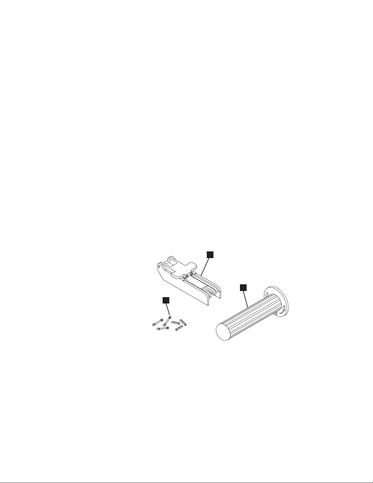
Reattaching a Leader Pin
The first meter of tape in a cartridge is leader tape. Once the leader tape has been
removed there is a possibility of tape breakage. After reattaching the leader pin,
transfer data from the defective tape cartridge. Do not reuse the defective tape
cartridge.
The Leader Pin Reattachment Kit contains three parts:
v Leader pin attach tool (see 1 in Figure 19). A plastic brace that holds the
cartridge door open.
v Cartridge manual rewind tool (see 2 in Figure 19). A device that fits into the
cartridge’s hub and lets you wind the tape into and out of the cartridge.
v Pin supplies (see 3 in Figure 19). Leader pins and C-clips.
Attention:
v Use only the IBM Leader Pin Reattachment Kit to reattach the leader pin to the
tape. Other methods of reattaching the pin will damage the tape, the drive, or
both.
v Use this procedure on your tape cartridge only when the leader pin detaches
from the magnetic tape and you must copy the cartridge’s data onto another
cartridge. Destroy the damaged cartridge after you copy the data. This procedure
may affect the performance of the leader pin during threading and unloading
operations.
v Touch only the end of the tape. Touching the tape in an area other than the end
can damage the tape’s surface or edges, which may interfere with read or write
reliability.
3
Figure 19. Leader Pin Reattachment Kit
1
2
A67E0042
Chapter 5. Using the Media 57
Page 70

The following procedure describes how to reattach a leader pin.
To reattach a leader pin by using the IBM Leader Pin Reattachment Kit:
1. Attach the leader pin attach tool (1 in Figure 20) to the cartridge 2 so that
the tool’s hook 3 latches into the cartridge’s door 4. Pull the tool back to
hold the door open, then slide the tool onto the cartridge. Open the tool’s pivot
arm 5.
Figure 20. Attaching the leader pin attach tool to the cartridge. To hold the cartridge door
open, hook the tool into the door and pull the tool back.
58 IBM TotalStorage LTO Ultrium 2 Tape Drive
Page 71

2. To find the end of the tape inside the cartridge, attach the cartridge manual
rewind tool (1 in Figure 21) to the cartridge’s hub 2 by fitting the tool’s
teeth between the teeth of the hub. Turn the tool clockwise until you see the
end of the tape inside the cartridge. Then, slowly turn the rewind tool
counterclockwise to bring the tape edge toward the cartridge door 3.
3. Continue to turn the rewind tool counterclockwise until approximately 12.7 cm
(5 in.) of tape hangs from the cartridge door. If necessary, grasp the tape and
pull gently to unwind it from the cartridge.
4. Remove the rewind tool by pulling it away from the cartridge. Set the tool and
the cartridge aside.
Figure 21. Winding the tape out of the cartridge. Turn the cartridge manual rewind tool
clockwise to see the end of the tape, then turn it counterclockwise to bring the tape to the
cartridge door.
5. On the leader pin (1 in Figure 22), locate the open side of the C-clip 2.
The C-clip is a small black part that secures the tape 3 to the pin.
6. Remove the C-clip from the leader pin by using your fingers to push the clip
away from the pin. Set the pin aside and discard the clip.
3
1
2
Figure 22. Removing the C-clip from the leader pin. Use your fingers to push the C-clip from
the leader pin.
A67E0036
Chapter 5. Using the Media 59
Page 72

7. Position the tape in the alignment groove of the leader pin attach tool (see 1
in Figure 23).
8. Place a new C-clip into the retention groove 2 (Figure 23) on the leader pin
attachment tool and make sure that the clip’s open side faces up.
9. Place the leader pin (from step 6 on page 59) into the cavity 3 (Figure 23) of
the leader pin attach tool.
Attention: To prevent the leader pin from rolling into the cartridge, in the following
step use care when folding the tape over the pin.
10. Fold the tape over the leader pin and hold it with your fingers (see Figure 23).
Note: Use care to ensure that the tape is centered over the leader pin. Failure
to properly center the tape on the pin will cause the repaired cartridge
to fail. When the tape is properly centered, a 0.25-mm (0.01-in.) gap
exists on both sides of the pin.
2
1
6
5
Figure 23. Attaching the leader pin to the tape
4
3
A67E0037
11. Close the pivot arm 4 of the leader pin attach tool by swinging it over the
leader pin so that the C-clip snaps onto the pin and the tape.
12. Swing the pivot arm open and trim the excess tape 5 so that it is flush with
the reattached leader pin 6.
60 IBM TotalStorage LTO Ultrium 2 Tape Drive
Page 73

13. Use your fingers to remove the leader pin from the cavity 3 in the leader pin
attach tool.
14. Use the cartridge manual rewind tool to wind the tape back into the cartridge
(wind the tape clockwise). Ensure that the leader pin is latched by the
pin-retaining spring clips on each end of the leader pin.
15. Remove the rewind tool.
16. Remove the leader pin attach tool by lifting its end up and away from the
cartridge.
Attention: Use a repaired tape cartridge only to recover data
and move it to another cartridge. Continued use of a repaired
cartridge may void the warranties of the drive and the cartridge.
Chapter 5. Using the Media 61
Page 74

Environmental and Shipping Specifications for Tape Cartridges
Before you use a tape cartridge, acclimate it to the operating environment for 24
hours or the time necessary to prevent condensation in the drive (the time will vary,
depending on the environmental extremes to which the drive was exposed).
The best storage container for the cartridges (until they are opened) is the original
shipping container. The plastic wrapping prevents dirt from accumulating on the
cartridges and partially protects them from humidity changes.
When you ship a cartridge, place it in its jewel case or in a sealed, moisture-proof
bag to protect it from moisture, contaminants, and physical damage. Ship the
cartridge in a shipping container that has enough packing material to cushion the
cartridge and prevent it from moving within the container.
Table 10 gives the environment for operating, storing, and shipping LTO Ultrium
Tape Cartridges.
Table 10. Environment for operating, storing, and shipping the LTO Ultrium Tape Cartridge
Environmental Specifications
Environmental
Factor
Temperature
Relative humidity
(noncondensing)
Wet bulb temperature
Operating
10 to 45°C
(50 to 113°F)
10 to 80% 20 to 80% 20 to 50% 5 to 80%
26°C
(79°F)
Operational
Storage
16 to 32°C
(61 to 90°F)
1
26°C
(79°F)
Archival Storage
16 to 25°C
(61 to 77°F)
26°C
(79°F)
2
Shipping
−23 to 49°C
(−9to120°F)
26°C
(79°F)
Notes:
1. Operational storage equals less than 1 year.
2. Archival storage equals 1 to 10 years.
62 IBM TotalStorage LTO Ultrium 2 Tape Drive
Page 75

Disposing of Tape Cartridges
Under the current rules of the U.S. Environmental Protection Agency (EPA),
regulation 40CFR261, the LTO Ultrium Tape Cartridge is classified as
non-hazardous waste. As such, it may be disposed of in the same way as normal
office trash. These regulations are amended from time to time, and you should
review them at the time of disposal.
If your local, state, country (non-U.S.A.), or regional regulations are more restrictive
than EPA 40CFR261, you must review them before you dispose of a cartridge.
Contact your account representative for information about the materials that are in
the cartridge.
If a tape cartridge must be disposed of in a secure manner, you can erase the data
on the cartridge by using a high-energy AC degausser (use a minimum of 1200
oersted peak field over the entire space that the cartridge occupies). Degaussing
makes the cartridge unusable.
If you burn the cartridge and tape, ensure that the incineration complies with all
applicable regulations.
Ordering Media Supplies
Table 11 lists the cartridges and media supplies that you can order for the IBM
TotalStorage LTO Ultrium 2 Tape Drive. To order media supplies, visit the web at
http://www.ibm.com/storage/lto.
Table 11. Media supplies for the IBM TotalStorage LTO Ultrium 2 Tape Drive
IBM Part Number Product Description
08L9870
19P5897
08L9124
35L2086 IBM TotalStorage Cleaning Cartridge (Ultrium LTO 2)
08L9267
IBM TotalStorage LTO Ultrium 200 GB Data Cartridge (includes only
human-writable labels)
IBM TotalStorage LTO Ultrium 200 GB Data Cartridge Bar Code
Labels, sheet of 20, black and white
IBM LTO Ultrium Cleaning Cartridge (includes only human-writable
labels)
IBM LTO Ultrium Cleaning Cartridge Bar Code Labels, sheet of 20,
black and white
Chapter 5. Using the Media 63
Page 76

Ordering Custom Bar Code Labels
If custom bar code labels are required for your data or cleaning cartridges, order
them directly from the authorized label suppliers in Table 12.
Table 12. Authorized suppliers of custom bar code labels
In America In Europe and Asia
EDP/Colorflex
697 South Pierce Street
Louisville, CO 80027
U. S. A.
Telephone: 800-522-3528
http://www.colorflex.com/Ai/Home.asp
Dataware (LTO 2 only)
7570 Renwick
Houston, TX 77081
U. S. A.
Telephone: 800-426-4844
http://www.datawarelabels.com/
NetC
P. O. Box 320784
Fairfield, CT 06432
U. S. A.
Telephone: 203-372-6382
http://www.netcllc.com/
EDP Europe, Ltd.
43 Redhills Road
South Woodham Ferrers
Chelmsford, Essex CM3 5UL
U. K.
Telephone: 44 (0) 1245-322380
http://www.edpeurope.com/media_labelling.htm
Dataware Labels Europe
Heubergstrasse 9
D-83052 Bruckmuhl-Gotting
Germany
Telephone: 49 806-29455
http://www.datawarelabels.com/
NetC Europe Ltd
Town Farm Bungalow
North Curry
Taunton
Somerset U. K. TA3 6LX
Telephone: 44 (0) 1823 491439
http://www.netclabels.co.uk
NetC Asia Pacific Pty Ltd
Locked Bag 14
Kenthurst
NSW Australia 2156
Telephone: 61 (0) 2 9654 8272
http://www.netclabels.com.au
64 IBM TotalStorage LTO Ultrium 2 Tape Drive
Page 77

Chapter 6. Resolving Problems
If you encounter problems when running the IBM TotalStorage LTO Ultrium 2 Tape
Drive, refer to Table 13. If the problem is not identified in Table 13, refer to “Methods
of Receiving Errors and Messages” on page 66. The color and condition of the
status light may also indicate a problem. For more information, see “Status Light” on
page 32.
Table 13. Troubleshooting tips for the IBM TotalStorage LTO Ultrium 2 Tape Drive
If the problem is this.... Do this....
A code displays on the
single-character display and the status
light flashes amber.
The status light or single-character
display never turns on.
The tape drive will not load a tape
cartridge.
The tape drive will not unload the tape
cartridge.
The server received TapeAlert flags. See Appendix B, “TapeAlert Flags” on page 97.
The server reported SCSI problems
(such as selection or command
time-outs, or parity errors).
The server reported Fibre Channel
problems.
The Fibre Channel drive indicates no
Fibre Channel light, or has light but
cannot communicate.
The library reported an LDI or RS-422
communication problem with the drive.
Codes display on the single-character
display, but the status light does not
turn on.
The tape drive detected an error or is directing you to an informational
message. See Table 15 on page 67.
The tape drive has no power. Check the power at the power source. Connect
power to the tape drive (see “Step 6. Connect and Test Power to the Tape
Drive” on page 27). If the problem persists, replace the tape drive.
One of the following has occurred:
v A tape cartridge is already inserted. To remove the cartridge, press the
unload button. If the cartridge does not eject, turn off the power to the
tape drive, then turn it back on. After the status light becomes solid green,
press the unload button to eject the cartridge.
v The tape cartridge was inserted incorrectly. To properly insert a cartridge,
see “Inserting a Tape Cartridge” on page 34.
v The tape cartridge may be defective. Insert another tape cartridge. If the
problem exists for multiple cartridges, the tape drive is defective. Replace
the tape drive (see “Removing a SCSI Tape Drive from an Enclosure” on
page 83 or “Removing a Fibre Channel Tape Drive from an Enclosure” on
page 84).
v The tape drive has no power. Connect power to the tape drive (see “Step
6. Connect and Test Power to the Tape Drive” on page 27).
The tape cartridge is stuck or is broken. Press the unload button. If the
cartridge does not eject, turn off the power to the tape drive, then turn it back
on (note that the mid-tape recovery could take up to 5 minutes to complete).
If the cartridge still does not eject, manually remove it (see “Manually
Removing a Tape Cartridge” on page 85).
See “Fixing SCSI Bus Errors” on page 77.
See “Fixing Fibre Channel Errors” on page 79.
See “Fixing Fibre Channel Errors” on page 79.
The LDI or RS-422 circuitry may be defective. Run the LDI or RS-422 wrap
test (Function Code 7 in Table 9 on page 36). If the test runs successfully but
the problem persists, refer to your library’s service documentation.
The tape drive is defective. Replace the tape drive (see “Removing a SCSI
Tape Drive from an Enclosure” on page 83 or “Removing a Fibre Channel
Tape Drive from an Enclosure” on page 84).
© Copyright IBM Corp. 2002 65
Page 78

Table 13. Troubleshooting tips for the IBM TotalStorage LTO Ultrium 2 Tape Drive (continued)
If the problem is this.... Do this....
The tape drive does not respond to
server commands.
Press and hold the unload button on the drive for 10 seconds to force a drive
dump. The drive will save the dump and then reboot to allow communication
to the drive to occur. Do not cycle power, as this will erase the contents of
the dump.
Methods of Receiving Errors and Messages
Use Table 14 as a guide for identifying error codes and message codes reported by
the Ultrium 2 Tape Drive, its enclosure (if applicable), or the server.
Note: The codes on the single-character display have different meanings,
depending on whether they display during normal operations or while the
drive is in maintenance mode. Codes that occur during normal operations
are defined in Table 15 on page 67. Codes that occur while in maintenance
mode are defined in Table 9 on page 36.
Table 14. Methods of receiving errors and messages for the IBM TotalStorage LTO Ultrium 2 Tape Drive
If the error or message was
presented by....
The enclosure’s display (if the tape
drive is enclosed in a library or
autoloader)
The tape drive’s single-character
display and the status light flashes
amber
The tape drive’s single-character
display and the status light is solid
amber
SCSI log sense data (such as
TapeAlert flags), SCSI drive sense
data, or Fibre Channel autosense data
at the server console
Drive sense data sent to a library (if
the tape drive is enclosed in a library)
The tape drive’s error log See Table 15 on page 67 and “Viewing the Drive Error Log” on page 76.
Do this....
Refer to the documentation for the enclosure.
See Table 15 on page 67. To determine the meaning of status light activity,
see “Status Light” on page 32.
See Table 9 on page 36. To determine the meaning of status light activity,
see “Status Light” on page 32.
See Appendix B, “TapeAlert Flags” on page 97, Table 15 on page 67, or
“Using Sense Data” on page 71.
Refer to your library’s documentation, then see Table 15 on page 67.
66 IBM TotalStorage LTO Ultrium 2 Tape Drive
Page 79

Descriptions and Corrective Actions for Errors and Messages
Table 15 gives descriptions of the errors and messages that pertain to the Ultrium 2
Tape Drive, and tells what to do when you receive them.
Attention: If the tape drive detects a permanent error and displays an error code
other than 0, it automatically performs a drive dump. If you force a drive dump, the
existing dump will be overwritten and data will be lost. After you force a drive dump,
do not turn off the power to the tape drive or you may lose the dump data.
Table 15. Codes for error conditions and informational messages for the IBM TotalStorage LTO Ultrium 2 Tape
Drive. The single-character display clears if you power-off the drive.
Code Cause and Action
0 No error occurred and no action is required. This code displays:
v When power is cycled (turned off, then on) to the tape drive.
v When diagnostics have finished running and no error occurred.
Note: The single-character display is blank during normal operation of the tape drive.
1 Cooling problem. The tape drive detected that the recommended operating temperature was
exceeded. Perform the following action:
1. If a fan is present in the enclosure, ensure that it is rotating and is quiet. If not, replace the fan
(for instructions about replacing the fan, see your enclosure’s documentation).
2. Remove any blockage that prevents air from flowing freely through the tape drive.
3. Ensure that the operating temperature and airflow is within the specified range (see Chapter 2,
“Specifications” on page 11).
4. If the operating temperature is within the specified range and the problem persists, replace the
tape drive.
The error code clears when you power-off the tape drive or place it in maintenance mode.
2 Power problem. The tape drive detected that the externally supplied power is either approaching
the specified voltage limits (the drive is still operating) or is outside the specified voltage limits (the
drive is not operating). Perform the following action:
1. Ensure that the power connector is properly seated.
2. Ensure that the proper dc voltages are being applied within the tolerances allowed (see
Chapter 2, “Specifications” on page 11).
3. If the proper voltages are being applied but the problem persists, replace the tape drive.
The error code clears when you power-off the tape drive or place it in maintenance mode.
Chapter 6. Resolving Problems 67
Page 80

Table 15. Codes for error conditions and informational messages for the IBM TotalStorage LTO Ultrium 2 Tape
Drive (continued). The single-character display clears if you power-off the drive.
Code Cause and Action
3 Firmware problem. The tape drive determined that a firmware error occurred. Perform the following
action:
1. Collect a drive dump from one of the following:
Note: Do not force a new dump; the tape drive has already created one.
v Server’s SCSI or Fibre Channel interface by using a device driver utility or system tool. To
obtain a dump, determine whether your server is installed with a utility that can read files
from the server’s memory. If it is, use that utility to obtain the dump. For information about
using IBM’s utility programs to obtain drive dumps, see the IBM Ultrium Device Drivers
Installation and User’s Guide. To determine where to send a file that contains a drive dump
to be analyzed, contact your OEM Product Application Engineer (PAE).
v Enclosure (refer to the procedures for reading a drive dump in your enclosure’s
documentation)
v Ultrium 2 Tape Drive (to read a drive dump, use Function Code 5 in Table 9 on page 36)
2. Power the tape drive off and on, then retry the operation that produced the error.
3. If the problem persists, download new firmware and retry the operation.
4. If the problem persists, send the drive dump that you collected in step 1 to your OEM Product
Application Engineer (PAE).
The error code clears when you power-off the tape drive or place it in maintenance mode.
4 Firmware or tape drive problem. The tape drive determined that a firmware or tape drive hardware
failure occurred. Perform the following action:
1. Collect a drive dump from one of the following:
Note: Do not force a new dump; one already exists.
v Server’s SCSI or Fibre Channel interface by using a device driver utility or system tool. To
obtain a dump, determine whether your server is installed with a utility that can read files
from the server’s memory. If it is, use that utility to obtain the dump. For information about
using IBM’s utility programs to obtain drive dumps, see the IBM Ultrium Device Drivers
Installation and User’s Guide. To determine where to send a file that contains a drive dump
to be analyzed, contact your OEM Product Application Engineer (PAE).
v Enclosure (refer to the procedures for reading a drive dump in your enclosure’s
documentation)
v Ultrium 2 Tape Drive (to read a drive dump, use Function Code 5 in Table 9 on page 36)
2. Power the tape drive off and on, then retry the operation that produced the error. The error
code clears when you power-off the tape drive or place it in maintenance mode.
3. If the problem persists, download new firmware and retry the operation; if new firmware is not
available, replace the tape drive.
5 Tape drive hardware problem. The drive determined that a tape path or read/write error occurred.
To prevent damage to the drive or tape, the drive will not allow you to insert a cartridge if the
current cartridge was successfully ejected. The error code may clear when you cycle power to the
tape drive or place it in maintenance mode. If the problem persists, replace the tape drive.
68 IBM TotalStorage LTO Ultrium 2 Tape Drive
Page 81

Table 15. Codes for error conditions and informational messages for the IBM TotalStorage LTO Ultrium 2 Tape
Drive (continued). The single-character display clears if you power-off the drive.
Code Cause and Action
6 Tape drive or media error. The drive determined that an error occurred, but it cannot isolate the
error to faulty hardware or to the tape cartridge. Perform the following action:
For Problems with Writing Data:
If the problem occurred while the drive was writing data to the tape, and if you know the volume
serial number (located on the cartridge label) of the tape cartridge loaded in the drive when the
problem occurred, retry the operation with a different cartridge:
v If the operation succeeds, the original cartridge was defective. Copy data from the defective
cartridge and discard it.
v If the operation fails and another drive is available, insert the cartridge into the other drive and
retry the operation.
– If the operation fails, discard the defective cartridge.
– If the operation succeeds, insert a scratch cartridge into the first drive and run the tape drive
diagnostics (see Function Code 1 in Table 9 on page 36).
- If the diagnostics fail, replace the drive.
- If the diagnostics succeed, the error was temporary.
v If the operation fails and another drive is not available, insert a scratch cartridge into the drive
and run the tape drive diagnostics (see Function Code 1 in Table 9 on page 36).
– If the diagnostics fail, replace the drive.
– If the diagnostics succeed, discard the cartridge.
If the problem occurs with multiple tape cartridges or if you do not know the tape cartridge’s
volume serial number, run the tape drive diagnostics (see Function Code 1 in Table 9 on page 36):
v If the diagnostics fail, replace the tape drive.
v If the diagnostics succeed, run the Test Head diagnostic (see Function Code H in Table 9 on
page 36).
– If the Test Head diagnostic fails, replace the tape drive.
– If the Test Head diagnostic succeeds, replace the cartridges that caused the problem.
The error code clears when you remove the tape cartridge or place the drive in maintenance mode.
For Problems with Reading Data:
If the problem occurred while the drive was reading data from the tape, and if you know the volume
serial number of the tape cartridge, perform one of the following procedures:
v If another drive is available, insert the cartridge into the other drive and retry the operation:
– If the operation fails, discard the defective cartridge.
– If the operation succeeds, insert a scratch cartridge into the first drive and run the tape drive
diagnostics (see Function Code 1 in Table 9 on page 36):
- If the diagnostics fail, replace the drive.
- If the diagnostics succeed, the error was temporary.
v If another drive is not available, insert a scratch cartridge into the drive and run the tape drive
diagnostics (see Function Code 1 in Table 9 on page 36):
– If the diagnostics fail, replace the drive.
– If the diagnostics succeed, discard the cartridge.
If the problem occurs with multiple tape cartridges or if you do not know the tape cartridge’s
volume serial number, run the tape drive diagnostics (see Function Code 1 in Table 9 on page 36):
v If the diagnostics fail, replace the tape drive.
v If the diagnostics succeed, run the Test Head diagnostic (see Function Code H in Table 9 on
page 36).
– If the Test Head diagnostic fails, replace the tape drive.
– If the Test Head diagnostic succeeds, replace the cartridges that caused the problem.
The error code clears when you remove the tape cartridge or place the drive in maintenance mode.
Chapter 6. Resolving Problems 69
Page 82

Table 15. Codes for error conditions and informational messages for the IBM TotalStorage LTO Ultrium 2 Tape
Drive (continued). The single-character display clears if you power-off the drive.
Code Cause and Action
7 A high probability of media error. The tape drive determined that an error occurred because of a
faulty tape cartridge. Try another tape cartridge. If the problem occurs with multiple tape cartridges,
see “Resolving Media-Related Problems” on page 82.
The error code clears when you remove the tape cartridge or place the drive in maintenance mode.
8 For SCSI drive:
Tape drive or SCSI bus failure. The tape drive determined that a failure occurred in the tape drive’s
hardware or in the SCSI bus. See “Fixing SCSI Bus Errors” on page 77. The error code clears 10
seconds after the drive detected the error or when you place the drive in maintenance mode.
For Fibre Channel drive:
Tape drive or Fibre Channel failure. The tape drive determined that a failure occurred in the tape
drive’s hardware or in the Fibre Channel. It detects light through the fiber cable but cannot perform
data communication properly. The length of the cable between the devices may exceed 500 m
(1640 ft). See “Fixing Fibre Channel Errors” on page 79. The error code clears when the drive
detects light and can communicate, or when you place the drive in maintenance mode.
9 Tape drive or LDI (RS-422) error. The tape drive determined that a failure occurred in the tape
drive hardware or in the LDI (RS-422) connection. Run the LDI or RS-422 wrap test (see Function
Code 7 in Table 9 on page 36):
v If the diagnostic fails, replace the tape drive.
v If the diagnostic runs successfully, the problem is with the enclosure or the cable to the
enclosure. Refer to your enclosure’s documentation.
The error code clears when you place the drive in maintenance mode.
o, c, b, or h No error or message assigned. There may be a problem with the single-character display. Turn the
power off, then on and determine whether all segments on the single-character display are lit. If so,
you may have a down-level version of both your enclosure’s firmware and documentation (the
documentation may not describe all of the available error codes). Refer to the latest version of the
firmware or documentation.
A Tape drive hardware problem. The tape drive determined that a problem occurred which degraded
the operation of the tape drive, but it did not restrict continued use. If the problem persists, replace
the tape drive. The drive is usable, though the single-character display continues to indicate an
error and the status light flashes amber.
The error code may clear when you cycle power to the tape drive or place it in maintenance mode.
B No error or message is assigned. See error code 8 in this table.
C The tape drive needs to be cleaned. Clean the tape drive. See “Cleaning the Drive Head” on
page 35.
The error code clears when you clean the tape drive or place it in maintenance mode.
d Fibre Channel AL_PA conflict. More than one device has the same address. Each device must
have its own unique AL_PA address. See “Setting the Arbitrated Loop Physical Address (Fibre
Channel Drive Only)” on page 19.
D No error or message assigned. See error code 0 in this table.
E Informational message. The tape drive’s Fibre Channel port has been placed offline by another
device or by an operator. This code is set when the Offline command is received from another
device on the Fibre Channel interface. Determine why the device at the other end of the Fibre
Channel (the server, switch, or other device) placed the drive offline.
The drive is placed online when it receives the Online command from the Fibre Channel interface.
After a reset, the drive comes online.
70 IBM TotalStorage LTO Ultrium 2 Tape Drive
Page 83

Table 15. Codes for error conditions and informational messages for the IBM TotalStorage LTO Ultrium 2 Tape
Drive (continued). The single-character display clears if you power-off the drive.
Code Cause and Action
F The tape drive determined that no light is being received over the Fibre Channel. See “Fixing Fibre
Channel Errors” on page 79.
The error code clears when the drive detects light or when you place the drive in maintenance
mode.
Using Sense Data
When a tape drive encounters an error, it makes sense data available. You can use
IBM device drivers to examine the sense data and determine errors. Instructions for
downloading, installing, and properly configuring the IBM device drivers are
available in the IBM Ultrium Device Drivers Installation and User’s Guide. The IBM
device drivers may conflict with some commercial software applications unless
properly configured. To avoid conflicts on Windows operating systems, refer to your
device driver’s procedures for setting the driver to manual startup mode. For
applications that use Open Systems device drivers that are provided by IBM (for
example, AIX, Linux, Sun Solaris, HP-UX, Windows/NT, and Windows 2000), the
IBM Ultrium Device Drivers Installation and User’s Guide contains information about
how to obtain sense data after an error has occurred.
If your application uses other device drivers, see the appropriate documentation for
those drivers to obtain the sense data.
Raw sense data (as returned from the Ultrium 2 Tape Drive) is documented in the
IBM TotalStorage LTO Ultrium Tape Drive SCSI Reference.
In addition to device drivers, other methods exist for obtaining sense data and error
information. The sections that follow describe alternatives for gathering such
information from the IBM AS/400, Eserver iSeries, RS/6000, and Eserver
pSeries servers.
Obtaining Error Information from the AS/400 or iSeries with RISC Processor
For OS/400, sense data is provided by the System Service Tools application. To
obtain error information from the AS/400 or iSeries by using the tool:
1. On the command entry line of the AS/400 Main Menu, type STRSST (Start
System Service Tools) and press Enter.
2. Select Start a service tool.
3. Select Product activity log.
4. Select Analyze log.
5. On the Select System Data menu, select the Magnetic media option then
specify the time period for searching the error log.
6. On the Select Analysis Report Options menu, specify a Device selection of 3580
and press Enter. Leave all other options at their default values.
7. On the Log Analysis Report menu, select the Display report option to display the
desired error log. Figure 24 on page 72 shows a sample error log.
Chapter 6. Resolving Problems 71
Page 84

Display Detail Report for Resource
Name Type Model Number Name
TAP07 3580 002 00-00000 TAP07
LogID .........: 00452B54 Sequence......: 4732468
Date ..........: 08/14/02 Time........: 09:50:21
Reference code .....: 9210 Secondary code...: 00000000
Table ID ........: 63A00001 IPL source/state..: B/3
Class..........: Permanent
System Ref Code.....: 63A09210
Illegal or unsupported tape unit response
Press Enter to continue.
F3=Exit F4=Additional Information F6=Hexadecimal report
F9=Address Information F10=Previous detail report F12=Cancel
Serial Resource
Figure 24. Example of an error log from the AS/400 or IBM Eserver iSeries
8. Press F4 to view the sense data (see the example in Figure 25).
Display Additional Information for Resource
Name Type Model Number Name
TAP07 3580 002 00-00000 TAP07
SENSE DATA FOLLOWS.....:
DATA OFFSET 0123 4567 89AB CDEF
00000000 70000500 0000001C 00000000 240000C0
00000010 00020000 00000000 00000000 00000000
00000020 058B0000
Serial Resource
Figure 25. Example of sense data from the AS/400 or IBM Eserver iSeries
Obtaining Error Information from the RS/6000 or pSeries
The AIX®Tape and Media Changer Device Driver for the IBM RS/6000 or IBM
Eserver pSeries provides logging to the system error log for a variety of errors.
You can view the error log by issuing the AIX errpt command. Figure 26 on
page 73 displays a sample drive error log; Figure 27 on page 74 displays a sample
SCSI bus error log.
To view the error log:
1. At the AIX command line, type errpt -a |pg to display a detailed report.
2. Press Enter to scroll through the error log.
3. Type q to quit the error log at any time.
72 IBM TotalStorage LTO Ultrium 2 Tape Drive
Page 85

Example of a Drive Error Log:
In the SENSE DATA area of Figure 26, entries in bold are defined as follows:
Hexadecimal Code Description
01 SCSI Command
0000, 0200, 0000 Command parameters
70 Byte 0 of SCSI sense data
03 Sense key
5200 ASC/ASCQ (Additional Sense Code/Additional Sense Code
20B0 FSC (Fault Symptom Code)
058A Relative LPOS
02 SCSI ID
LABEL: TAPE_ERR1
IDENTIFIER: 4865FA9B
Date/Time: Wed Oct 11 11:39:43
Sequence Number: 25264
Machine ID: 000D090D4C00
Node ID: tsm
Class: H
Type: PERM
Resource Name: rmt2
Resource Class: tape
Resource Type: LTO
Location: 40-60-00-2,0
VPD:
Manufacturer................IBM
Machine Type and Model......ULT3580-TD2
Serial Number...............1300015078
Device Specific.(FW)........0B70 (Firmware Level)
Description
TAPE OPERATION ERROR
Qualifier)
Probable Causes
TAPE
User Causes
MEDIA DEFECTIVE
DIRTY READ/WRITE HEAD
Recommended Actions
FOR REMOVABLE MEDIA, CHANGE MEDIA AND RETRY
PERFORM PROBLEM DETERMINATION PROCEDURES
Detail Data
SENSE DATA
0602 0000 0100 0000 0200 0000 0000 0000 0000 0000 7000 0300 0000 001C 0000 0000
5200 0700 20B0 0000 0000 0000 0000 0000 0000 0000 058A 0200 0000 0000 0000 0000
0000 0000 0000 0000 0000 0000 0000 0000 0000 0000 0000 0000 0000 0000 0000 0000
0000 0000 0000 0000 0000 0000 0000 0000 0000 0000 0000 0000 0000 0000 0000 0000
0000 0000 0000 0000 0000 0000 0000 0000 0000 0000 0000 0000 0000 0000
Figure 26. Example of an AIX ERRPT Drive Error Log
Chapter 6. Resolving Problems 73
Page 86

Example of a SCSI Bus Error:
LABEL: SCSI_ERR10
IDENTIFIER: 0BA49C99
Date/Time: Wed Oct 18 09:55:32
Sequence Number: 16140
Machine Id: 00003ABF4C00
Node Id: ofgtsm
Class: H
Type: TEMP
Resource Name: scsi3
Resource Class: adapter
Resource Type: sym896
Location: 40-59
VPD:
Product Specific.( ).......DUAL CHANNEL PCI TO ULTRA2 SCSI
Part Number.................03N3606
EC Level....................F71335
Manufacture ID..............A16592
Serial Number...............0749
Description
SCSI BUS ERROR
Probable Causes
CABLE
CABLE TERMINATOR
DEVICE
ADAPTER
ADAPTER
Failure Causes
CABLE LOOSE OR DEFECTIVE
DEVICE
ADAPTER
Recommended Actions
PERFORM PROBLEM DETERMINATION PROCEDURES
CHECK CABLE AND ITS CONNECTIONS
Detail Data
SENSE DATA
0001 0017 0000 0000 0000 0091 0000 0000 0000 0000 0000 0000 0000 0000 0000 0000
0000 0000 0000 4304 0000 0000 0000 0000 2000 0003 0203 6760 9808 0000 F7FB E1B8
0000 0015 000B 0210 0678 C800 0000 8200 8277 1B20 00A2 ED00 0000 0002 FFFF FFFF
00FF 0000 111F F000 F3DF F110
Figure 27. Example of an error that suggests a SCSI bus problem
74 IBM TotalStorage LTO Ultrium 2 Tape Drive
Page 87

Obtaining a Drive Dump
You can obtain a drive dump by selecting a function code on the IBM TotalStorage
LTO Ultrium 2 Tape Drive or by using a device driver utility (or a system tool) on the
server. The sections that follow describe each method.
Using the Drive to Obtain a Dump
To obtain a drive dump directly from the IBM TotalStorage LTO Ultrium 2 Tape
Drive:
1. Make sure that no cartridge is in the drive.
2. Within a 1.5-second interval, press the unload button three times. The status
light becomes solid amber, which means that the drive is in maintenance mode.
3. Press the unload button once per 1.5 seconds until 5 appears in the
single-character display.
4. To select the function, press and hold the unload button for 3 seconds. After you
release the button, C flashes. Within 60 seconds, insert a scratch data cartridge
that is not write-protected. After you insert the cartridge, 5 flashes and the drive
writes the dump data to the scratch tape. When the function is complete, the
drive rewinds and unloads the tape.
5. Insert the tape into a drive.
6. From the server, issue the SCSI READ command to read the dump from the
tape to a file or electronic image (you may need to issue the command several
times to read the complete dump).
7. To determine where to send the file for analysis, contact your OEM Product
Application Engineer (PAE).
Using a Device Driver Utility to Obtain a Dump
To obtain a drive dump by using a device driver utility, determine whether your
server is installed with a utility that can read files from the server’s memory. If it is,
use that utility to obtain the drive dump.
For information about using IBM’s utility programs to obtain drive dumps, see the
IBM Ultrium Device Drivers Installation and User’s Guide.
To determine where to send a file that contains a drive dump to be analyzed,
contact your OEM Product Application Engineer (PAE).
Chapter 6. Resolving Problems 75
Page 88

Viewing the Drive Error Log
The Ultrium 2 Tape Drive keeps an error log that you can use to identify and correct
errors. The log contains the 10 most recent error codes, which appear (one at a
time) on the single-character display.
To view the drive error log:
1. Make sure that no cartridge is in the drive.
2. Within a 1.5-second interval press the unload button three times. The status
light becomes solid amber, which means that the drive is in maintenance mode.
3. Press the unload button once per 1.5 seconds until 9 appears in the
single-character display.
4. Press and hold the unload button for 3 seconds to view the most recent error
code.
5. Refer to Table 15 on page 67 to determine the meaning of the code and the
action to take.
6. Press the unload button to view the next error code. (The codes are ordered;
the most recent is presented first and the oldest (tenth) is presented last.)
7. Continue to press the unload button until the 10 error codes have been
displayed. After you display the tenth error code, the drive automatically exits
maintenance mode.
To redisplay the error codes, repeat steps 1 through 7.
76 IBM TotalStorage LTO Ultrium 2 Tape Drive
Page 89

Resolving Problems Reported by the Server
The procedure for fixing SCSI bus or Fibre Channel errors varies, depending on
whether the error is consistent or intermittent, and whether your configuration
contains single or multiple Ultrium 2 Tape Drives. The sections that follow describe
how to fix each type of error.
Fixing SCSI Bus Errors
Note: If you are using a Storage Area Network (SAN) Data Gateway to convert a
drive with a SCSI interface to a Fibre Channel interface, ensure that the
problem is occurring between the SAN Data Gateway and the drive by
running the SCSI wrap test on the drive and running the SCSI loopback test
on the SAN Data Gateway. (To run the SCSI wrap test, see Function Code 6
in Table 9 on page 36; to run the SCSI loopback test, refer to the section
about that test in the IBM Storage Area Network Gateway Module Setup,
Operator, and Service Guide.) If you are using a Fibre Channel drive and are
having problems, see “Fixing Fibre Channel Errors” on page 79.
Fixing a Consistent Error with a Single Drive on a SCSI Bus
1. Ensure that the power is on to the Ultrium 2 Tape Drive.
2. Ensure that the tape drive’s SCSI address is the same as the SCSI address
assigned by the server.
3. Run the SCSI wrap test (see Function Code 6 in Table 9 on page 36).
v If the test runs successfully, replace the SCSI terminator first, then the SCSI
cable and the interposer (if installed). Repeat the operation that caused the
error. If you replaced the SCSI terminator or SCSI cable and the problem
persists, the fault is with the server’s hardware or software. To isolate the
cause of the failure, refer to the server’s service documentation.
v If the test fails, replace the tape drive (see “Removing a SCSI Tape Drive
from an Enclosure” on page 83).
Fixing a Consistent Error with Multiple Drives on a SCSI Bus
When a consistent error occurs in a configuration that has multiple tape drives on
the SCSI bus, you must determine if the problem exists with more than one tape
drive. If the problem is with all of the devices on the SCSI bus, the bus is stuck in a
SCSI phase and cannot change to another phase or the SCSI cable from the server
to the first device is defective.
1. Ensure that the SCSI cable from the server to the first device is connected.
2. Disconnect all but the first tape drive on the SCSI bus. Move the terminator to
the first SCSI device.
3. Run a device driver utility (such as IBM’s ntutil or tapeutil) to determine whether
the error will occur.
v If the error occurs, run the SCSI wrap test on the first tape drive (see
Function Code 6 in Table 9 on page 36).
– If the test runs successfully, replace the SCSI terminator first, then the
SCSI cable and the interposer (if installed) to the first tape drive. Repeat
the operation that caused the error. If you replaced the SCSI terminator or
SCSI cable and the problem persists, the fault is with the server’s
hardware or software. To isolate the cause of the failure, refer to the
server’s service documentation.
– If the test fails, replace the tape drive (see “Removing a SCSI Tape Drive
from an Enclosure” on page 83).
Chapter 6. Resolving Problems 77
Page 90

v If the error does not occur, connect one tape drive at a time back to the bus
and repeat step 3 for each tape drive until you can identify which drive is
defective.
Note: Ensure that the SCSI terminator is always on the last tape drive on the
SCSI bus.
4. Determine if the problem is with only one tape drive or with two or more tape
drives.
v If the problem is with only one tape drive, run the SCSI wrap test on that tape
drive (see Function Code 6 in Table 9 on page 36).
– If the test runs successfully, replace the SCSI terminator first, then the
SCSI cable to that tape drive and interposer (if installed).
– If the test fails, replace the tape drive (see “Removing a SCSI Tape Drive
from an Enclosure” on page 83).
v If the problem is with two or more tape drives, locate the first tape drive that
has the error and replace the SCSI cable that connects the tape drive and
the interposer (if installed).
Fixing an Intermittent Error with a Single Drive on a SCSI Bus
1. Replace the SCSI terminator on the tape drive.
2. Run the operation that caused the error. If the problem persists, the problem
may be with the cable.
3. Isolate which cable is causing the problem by replacing one cable at a time and
running the operation that caused the error after each replacement. If the
problem persists after all cables have been replaced, the problem may be with
the Ultrium 2 Tape Drive.
4. Replace the tape drive (see “Removing a SCSI Tape Drive from an Enclosure”
on page 83). If the problem persists, the problem is with your server. Consult
your server’s documentation.
Fixing an Intermittent Error with Multiples Drives on a SCSI Bus
Refer to the server’s error logs to determine which tape drive is the source of the
problem:
v If only one tape drive is reporting a SCSI failure, replace that tape drive (see
“Removing a SCSI Tape Drive from an Enclosure” on page 83).
v If multiple tape drives are reporting SCSI failures, the problem may be with the
terminator or the SCSI cables:
– Replace the terminator and run the operation that caused the error. If the
problem persists, the problem may be with the cables.
– Isolate which cable is causing the problem by replacing one cable at a time
and run the operation that caused the error after each replacement.
78 IBM TotalStorage LTO Ultrium 2 Tape Drive
Page 91

Fixing Fibre Channel Errors
If you are connected to a Fibre Channel Storage Area Network (SAN) by using a
SAN Data Gateway, use the IBM Storage Area Network Gateway Module Setup,
Operator, and Service Guide to determine whether the problem is occurring
between the drive and the SAN Data Gateway. If you are using a SCSI drive and
are having SCSI problems, see “Fixing SCSI Bus Errors” on page 77.
Starting Problem Determination
Before starting the problem determination, perform the following steps:
1. Determine the type of Fibre Channel topology that you are using (see page 6).
Ensure that the drive and the port to which it is attached are configured in
compatible topologies.
2. Using this guide or the service guides of associated switch, hub, or fiber
products, try to determine where the problem exists (whether in the drive, cable,
or the device to which the drive and cable attach).
3. Ensure that the configuration and software levels are supported (see “Fibre
Channel Attachment” on page 6).
4. Ensure that the Fibre Channel cables are installed correctly. Refer to the
appropriate steps in Chapter 3, “Installing the Tape Drive” on page 13.
5. Go to one of the following procedures:
v “Fixing a Consistent Error with a Single Drive on a Fibre Channel Loop”
v “Fixing a Consistent Error with Multiple Drives on a Fibre Channel Loop” on
page 80
v “Fixing a Consistent Error in a Point-to-Point Topology” on page 80
v “Fixing Intermittent Fibre Channel Errors” on page 81
Fixing a Consistent Error with a Single Drive on a Fibre Channel Loop
1. Ensure that the tape drive is powered on.
2. Verify that the tape drive’s serial number is the same as the drive serial number
that the server program is using.
3. Ensure that the drive’s Fibre Channel AL_PA is set correctly, that it is on the
loop, and that it is not being used by another device (see “Setting the Arbitrated
Loop Physical Address (Fibre Channel Drive Only)” on page 19). The tape drive
must be able to detect light and communicate with the server.
4. Run the Fibre Channel wrap test at the drive’s Fibre Channel connector (see
Function Code 6 in Table 9 on page 36).
v If the test fails, replace the tape drive.
v If the test is successful, go to step 5.
5. Run the Fibre Channel wrap test at the end of the fiber cable (see Function
Code 6 in Table 9 on page 36).
v If the test fails, replace the fiber cable.
v If the test is successful, go to step 6.
6. Check the Fibre Channel cable connection at the server.
7. Using a device driver utility such as ntutil or tapeutil, verify that the drive is
properly configured and available at the server.
8. If the problem persists, the fault may be with the server’s hardware or software.
Refer to your server’s service manual.
Chapter 6. Resolving Problems 79
Page 92

9. When the problem is corrected (or determined to be a server problem), restore
all of the fiber cables to their correct position.
Fixing a Consistent Error with Multiple Drives on a Fibre Channel Loop
Use the following procedure to determine if all of the drives on the Fibre Channel
have the problem:
1. Use a device driver utility (such as ntutil or tapeutil) to verify that the drive is
available and properly configured at the server.
2. Determine the type of Fibre Channel topology that you are using (see page 6).
3. Using this guide or the service guides of associated switch, hub, or fiber
products, try to isolate which part of the Fibre Channel Storage Area Network
(SAN) is experiencing problems.
4. Perform one of the following:
v If the problem exists on a small number of drives, go to “Fixing a Consistent
Error with a Single Drive on a Fibre Channel Loop” on page 79.
v If the problem exists with a large number of drives, perform the following
steps:
a. Disconnect all except one failing drive on the Fibre Channel.
b. Run the Fibre Channel wrap test to determine if a failure occurs on that
drive (see Function Code 6 in Table 9 on page 36). If it does, perform the
procedure in “Fixing a Consistent Error with a Single Drive on a Fibre
Channel Loop” on page 79.
c. Continue to connect one drive at a time to the Fibre Channel loop.
5. When the problem is corrected, restore all of the Fibre Channel cables to their
correct position.
Fixing a Consistent Error in a Point-to-Point Topology
1. Ensure that the tape drive is powered on.
2. Verify that the tape drive’s serial number is the same as the drive serial number
that the server program is using.
3. Ensure that the drive is connected to the host or switch. The drive must be able
to detect light and communicate with the server.
4. Run the Fibre Channel wrap test at the drive’s Fibre Channel connector (see
Function Code 6 in Table 9 on page 36).
v If the test fails, replace the tape drive.
v If the test is successful, go to step 5.
5. Run the Fibre Channel wrap test at the end of the fiber cable (see Function
Code 6 in Table 9 on page 36).
v If the test fails, replace the fiber cable.
v If the test is successful, go to step 6.
6. Check the Fibre Channel cable connection at the server.
7. Using a device driver utility such as ntutil or tapeutil, verify that the drive is
properly configured and available at the server.
8. If the problem persists, the fault may be with the server’s hardware or software.
Refer to your server’s service manual.
9. When the problem is corrected (or determined to be a server problem), restore
all of the fiber cables to their correct position.
80 IBM TotalStorage LTO Ultrium 2 Tape Drive
Page 93

Fixing Intermittent Fibre Channel Errors
1. Determine the type of Fibre Channel topology that you are using (see page 6).
2. Ensure that the configuration and software levels are supported (see “Fibre
Channel Attachment” on page 6).
3. Check that each Fibre Channel cable does not exceed 500 m (1640 ft).
4. Ensure that all Fibre Channel cables are installed correctly. Refer to the
appropriate steps in Chapter 3, “Installing the Tape Drive” on page 13.
5. Using this guide or the service guides of associated switch, hub, or fiber
products, determine that a problem exists between the drive, drive cable, and
the device to which they attach. Try to isolate which part of the Storage Area
Network (SAN) is experiencing problems.
6. Using this guide or the service guides of associated switch, hub, or fiber
products, verify that the SAN configurations are correct (such as switch zoning
for drive sharing).
7. Obtain all errors reported by the drive to the server (see “Using Sense Data” on
page 71), then contact your OEM Product Application Engineer (PAE) for error
analysis.
Chapter 6. Resolving Problems 81
Page 94

Resolving Media-Related Problems
To resolve problems that are related to media, the Ultrium 2 Tape Drive’s firmware
includes:
v Test Cartridge & Media diagnostic that verifies whether a suspect cartridge and
its magnetic tape are acceptable for use.
v Statistical Analysis and Reporting System (SARS) to assist in isolating failures
between media and hardware. To determine the cause of failure, SARS uses the
cartridge performance history that is saved in the cartridge memory (CM) and the
drive performance history that is kept in the drive’s flash erasable programmable
read-only memory (EPROM). Any failures that SARS detects are reported as
TapeAlert flags on the server (see Appendix B, “TapeAlert Flags” on page 97).
Attention: If you insert the IBM LTO Ultrium Data Cartridge into another
manufacturer’s tape drive, the SARS data in the cartridge memory may become
lost or invalid.
If you encounter a media-related problem, use the following procedure:
Attention: When you run the Test Cartridge & Media diagnostic, data on the
suspect tape is overwritten. Use only a scratch data cartridge to run the test.
1. If possible, run the tape cartridge in a different tape drive. If the operation in the
other tape drive fails and 6 or 7 displays, replace the media. If the operation
succeeds, run the Test Cartridge & Media diagnostic (see Function Code E in
Table 9 on page 36).
2. If the Test Cartridge & Media diagnostic fails, replace the media. If it runs
successfully, clean the tape drive and run the tape drive diagnostics (see
“Cleaning the Drive Head” on page 35 and Function Code 1 in Table 9 on
page 36).
3. If the tape drive diagnostics fail, replace the tape drive. If the tape drive
diagnostics run successfully, perform the operation that produced the initial
media error.
82 IBM TotalStorage LTO Ultrium 2 Tape Drive
Page 95

Chapter 7. Servicing the Tape Drive
Removing a SCSI Tape Drive from an Enclosure
To remove an IBM TotalStorage LTO Ultrium 2 Tape Drive Model T400 from an
enclosure, perform the following steps:
1. Ensure that the tape drive does not contain a tape cartridge.
2. Deconfigure the drive from the server (for instructions, see your server’s
documentation).
3. Turn off the power to the enclosure. Disconnect the power cable from the
enclosure and the electrical outlet.
4. Remove the cover of the enclosure.
5. Disconnect the internal power cable from the power connector (see 4 in
Figure 28).
6. If connected, disconnect the internal LDI (RS-422) cable from the LDI (RS-422)
connector 5.
7. Disconnect the internal SCSI cable from the SCSI connector 2.
8. Perform one of the following procedures on the SCSI ID connector 3:
v If your enclosure uses an internal SCSI ID switch, disconnect it from the
SCSI ID connector.
v If your enclosure uses jumpers to set the SCSI ID, do not remove them from
the connector.
9. Remove the mounting screws from the side brackets of the chassis (see 2 in
Figure 8 on page 26).
10. Remove the tape drive from the enclosure.
11. To reassemble, reverse these steps.
Figure 28. Rear view of the IBM TotalStorage LTO Ultrium 2 Tape Drive Model T400 (SCSI
drive)
© Copyright IBM Corp. 2002 83
Page 96

Removing a Fibre Channel Tape Drive from an Enclosure
To remove an IBM TotalStorage LTO Ultrium 2 Tape Drive Model T400F from an
enclosure, perform the following steps:
1. Ensure that the tape drive does not contain a tape cartridge.
2. Deconfigure the drive from the server, switch, or hub (for instructions, see the
documentation for these devices).
3. Turn off the power to the enclosure. Disconnect the power cable from the
enclosure and the electrical outlet.
4. Disconnect the internal power cable from the power connector (see 1 in
Figure 29).
5. If connected, disconnect the internal LDI (RS-422) cable from the LDI (RS-422)
connector 6.
6. Disconnect the internal fiber cable from the Fibre Channel connector 5.
7. Disconnect the LID/status connector 3.
8. Disconnect the FC configuration/status connector 4.
9. Remove the mounting screws from the side brackets of the chassis (see 2 in
Figure 8 on page 26).
10. Remove the tape drive from the enclosure.
11. To reassemble, reverse these steps.
Figure 29. Rear view of the IBM TotalStorage LTO Ultrium 2 Tape Drive Model T400F (Fibre
Channel drive)
84 IBM TotalStorage LTO Ultrium 2 Tape Drive
Page 97

Manually Removing a Tape Cartridge
If problem-determination procedures identify the Ultrium 2 Tape Drive as the source
of a problem, you can optionally perform one of the following:
v Replace the entire unit. For more information, contact your OEM Product
Application Engineer (PAE).
v Manually remove the cartridge (see “Removing the Cartridge”).
v If you are unable to manually remove the cartridge, contact trained service
personnel for assistance. Refer the service personnel to the instructions in
“Fixing an Internal Jam” on page 88.
Attention:
If you are not a trained service person, do not attempt to open the drive
for repairs. Attempting a repair other than the manual removal of a tape
cartridge will void your warranty.
Removing the Cartridge
If a tape cartridge fails to eject from the Ultrium 2 Tape Drive, you can manually
remove the cartridge. The following tools are required for the procedure:
v 2.5-mm allen wrench
v Small-blade screwdriver or potentiometer-setting tool
v 2-mm hex wrench
v #3 Phillips screwdriver
v Needle-nose pliers
v Flashlight (optional)
Attention: Before performing this procedure, note the following:
v Ensure that you have attempted all normal methods of removing the tape
cartridge from the drive. Refer to “Removing a Tape Cartridge” on page 35 and
the troubleshooting tips in Table 13 on page 65.
v This procedure may damage the stuck tape cartridge. If you use this procedure,
copy the data from the stuck cartridge to another cartridge. If you choose to
reuse the stuck cartridge, refer to the instructions in “Repositioning or
Reattaching a Leader Pin” on page 55. If you believe the cartridge has been
damaged, replace it.
v Do not use a power screwdriver to perform this procedure because it can destroy
the tape.
v Never touch the head or electronic components within the drive. Touching may
cause contamination or damage by electrostatic discharge.
Chapter 7. Servicing 85
Page 98

To manually remove a tape cartridge, perform the following steps:
1. Place the drive so that the front faces you, then tilt it on its left side (see
Figure 30).
2. Locate the access hole at the bottom of the unit (see 1 in Figure 30).
3. Insert a 2.5-mm allen wrench into the access hole and position the wrench so
that it is seated in the screw of the supply reel motor.
4. Push open the door of the tape load compartment and locate the flag 2 on
the drive’s takeup reel.
Figure 30. Determining whether the tape is broken
Attention: In the following step, rotate the allen wrench clockwise, not
counterclockwise. A counterclockwise motion may damage the tape.
5. To determine whether the tape is broken, watch the flag 2 on the drive’s
takeup reel while you rotate the allen wrench 1 clockwise (do not let the
wrench move counterclockwise):
v If you feel resistance to the allen wrench while attempting to turn the supply
reel motor screw clockwise, go to step 7 on page 87.
v If the takeup reel turns when you rotate the supply reel motor screw
clockwise with the allen wrench, the tape is not broken. Go to step 6 on
page 87.
v If the takeup reel does not turn when you rotate the supply reel motor screw
clockwise with the allen wrench and if supply reel motor screw rotates freely,
the tape is broken. You must determine the location of the leader block. To
do so, insert a small-blade screwdriver or potentiometer-setting tool into the
access hole for the loader motor gear 3. Rotate the screwdriver
counterclockwise. You may have to rotate for a lengthy period:
– If the cartridge moves up, the tape is completely in the cartridge and the
leader block is in the home position. Continue rotating the screwdriver
until the cartridge ejects. Remove the cartridge.
– If you feel resistance and the cartridge does not move up, the leader
block is not in the home position. Go to “Fixing an Internal Jam” on
page 88.
86 IBM TotalStorage LTO Ultrium 2 Tape Drive
Page 99

6. Continue to rotate the allen wrench until you feel resistance. The tape has
been rewound as far as it can go without unthreading.
Note: The number of required rotations depends on where the beginning of
the tape is on the cartridge’s takeup reel. You may have to rotate the
allen wrench for a lengthy period.
7. With the allen wrench still inserted into the bottom access hole, insert a
small-blade screwdriver or potentiometer-setting tool into the access hole for
the loader motor gear 3.
8. While keeping torque on the supply reel motor screw and rotating the allen
wrench 1 clockwise, rotate the loader motor gear with the small-blade
screwdriver 3 counterclockwise (see arrow). As you rotate the screwdriver,
the allen wrench moves slightly.
9. With the small-blade screwdriver, continue to rotate the loader motor gear in
the unload direction (counterclockwise):
v If you feel no resistance to the allen wrench and the cartridge slowly moves
up and out of the tape load compartment to the fully ejected position, the
procedure was successful. Remove the small-blade screwdriver and go to
step 10.
v If you feel resistance to the allen wrench and the cartridge does not move,
the loader mechanism is jammed or the leader block is not at the home
position. Remove the small-blade screwdriver and go to “Fixing an Internal
Jam” on page 88.
10. Remove the tape cartridge.
11. To ensure that the drive operates properly, refer to page 36 and select
Function Code 1 - Run Tape Drive Diagnostics.
After you remove the stuck tape cartridge, copy the data on the tape to another
tape. Then, if appropriate, return the stuck tape cartridge in its original packaging or
in the packaging from its replacement to your reseller. If the leader pin detached
from the tape in the cartridge, go to “Repositioning or Reattaching a Leader Pin” on
page 55.
Chapter 7. Servicing 87
Page 100

Fixing an Internal Jam
Attention:
This procedure must be performed only by trained service personnel.
If problem-determination procedures identify the Ultrium 2 Tape Drive as
the source of a problem, replace the entire unit. If you are not a trained
service person, do not attempt to open the drive for repairs. Attempting a
repair other than the manual removal of a tape cartridge will void your
warranty.
Before performing this procedure, ensure that you have completed the steps
that begin on page 86. Do not attempt this procedure until you have completed
these steps.
If you have reached this point, the tape is broken or the leader pin dropped (or
looked like it dropped) from the leader block. To fix these conditions, perform the
following procedure.
1. If the drive is mounted in an enclosure, perform the procedure to remove it
(see “Removing a SCSI Tape Drive from an Enclosure” on page 83 or
“Removing a Fibre Channel Tape Drive from an Enclosure” on page 84).
2. Place the drive on a nonslip surface.
3. Remove the cover of the drive by performing the following steps:
a. Use an appropriate tool to remove the three screws and washers (see 1
in Figure 31 on page 89) that secure the bezel 2. Remove the bezel.
b. Use a screwdriver to remove the four cover-mounting screws and washers
3.
c. Remove the cover by lifting it up. Set the cover aside.
88 IBM TotalStorage LTO Ultrium 2 Tape Drive
 Loading...