

Page 1

IBM System x3950 Ty pe 8878
System x3950 E Type 8879
and
Problem Dete rminatio n and Service Guid e
Page 2

Page 3

IBM System x3950 Ty pe 8878
System x3950 E Type 8879
and
Problem Dete rminatio n and Service Guid e
Page 4

Note: Before using this information and the product it supports, read the general information in Appendix B, “Notices,” on page
163.
The most recent version of this document is available at http://www.ibm.com/servers/eserver/support/xseries/index.html.
15th Edition (July 2007)
© Copyright International Business Machines Corporation 2007. All rights reserved.
US Government Users Restricted Rights – Use, duplication or disclosure restricted by GSA ADP Schedule Contract
with IBM Corp.
Page 5

Contents
Safety . . . . . . . . . . . . . . . . . . . . . . . . . . . . vii
Guidelines for trained service technicians . . . . . . . . . . . . . . . viii
Inspecting for unsafe conditions . . . . . . . . . . . . . . . . . viii
Guidelines for servicing electrical equipment . . . . . . . . . . . . . viii
Safety statements . . . . . . . . . . . . . . . . . . . . . . . .x
Chapter 1. Introduction . . . . . . . . . . . . . . . . . . . . . .1
Related documentation . . . . . . . . . . . . . . . . . . . . . .1
Notices and statements in this document . . . . . . . . . . . . . . . .2
Features and specifications . . . . . . . . . . . . . . . . . . . . .3
Server controls, LEDs, and connectors . . . . . . . . . . . . . . . .4
Front view . . . . . . . . . . . . . . . . . . . . . . . . . .4
Rear view . . . . . . . . . . . . . . . . . . . . . . . . . .6
Internal LEDs, connectors, and jumpers . . . . . . . . . . . . . . . .8
I/O board internal connectors and jumpers . . . . . . . . . . . . . .8
Memory-card connectors . . . . . . . . . . . . . . . . . . . . .9
Memory-card LEDs . . . . . . . . . . . . . . . . . . . . . . .9
Microprocessor-board connectors and LEDs . . . . . . . . . . . . .10
PCI-X board connectors . . . . . . . . . . . . . . . . . . . .10
PCI-X board LEDs . . . . . . . . . . . . . . . . . . . . . .11
SAS-backplane connectors . . . . . . . . . . . . . . . . . . .11
Chapter 2. Configuration information and instructions . . . . . . . . .13
Updating the firmware . . . . . . . . . . . . . . . . . . . . . .13
Configuring the server . . . . . . . . . . . . . . . . . . . . . .13
Using the ServerGuide Setup and Installation CD . . . . . . . . . . .13
Using the UpdateXpress program . . . . . . . . . . . . . . . . .14
Using the Configuration/Setup Utility program . . . . . . . . . . . .14
Installing and using the baseboard management controller utility programs 20
Using the SAS/SATA Configuration Utility program . . . . . . . . . . .20
Configuring the Ethernet controller . . . . . . . . . . . . . . . . .20
Using the PXE boot agent utility program . . . . . . . . . . . . . .21
Using the ServeRAID configuration programs . . . . . . . . . . . . .21
Using the Scalable Partition Web Interface . . . . . . . . . . . . . .21
Chapter 3. Parts listing, Type 8878 and 8879 . . . . . . . . . . . . .23
Server replaceable units . . . . . . . . . . . . . . . . . . . . .25
Power cords . . . . . . . . . . . . . . . . . . . . . . . . . .27
Chapter 4. Removing and replacing server components . . . . . . . .31
Installation guidelines . . . . . . . . . . . . . . . . . . . . . .31
System reliability guidelines . . . . . . . . . . . . . . . . . . .32
Working inside the server with the power on . . . . . . . . . . . . .33
Handling static-sensitive devices . . . . . . . . . . . . . . . . .33
Returning a device or component . . . . . . . . . . . . . . . . .33
Connecting the cables . . . . . . . . . . . . . . . . . . . . . .34
Removing and replacing Tier 1 CRUs . . . . . . . . . . . . . . . .35
Adapter . . . . . . . . . . . . . . . . . . . . . . . . . .35
DVD drive . . . . . . . . . . . . . . . . . . . . . . . . . .36
Hot-swap fan . . . . . . . . . . . . . . . . . . . . . . . .37
Hot-swap power supply . . . . . . . . . . . . . . . . . . . . .38
Memory card and memory module (DIMM) . . . . . . . . . . . . .40
Remote Supervisor Adapter II SlimLine . . . . . . . . . . . . . . .43
© Copyright IBM Corp. 2007 iii
Page 6

ServeRAID-8i adapter . . . . . . . . . . . . . . . . . . . . .44
To p cover and bezel . . . . . . . . . . . . . . . . . . . . . .45
Removing and replacing Tier 2 CRUs . . . . . . . . . . . . . . . .46
Battery . . . . . . . . . . . . . . . . . . . . . . . . . . .46
I/O board . . . . . . . . . . . . . . . . . . . . . . . . . .47
Operator information panel assembly . . . . . . . . . . . . . . . .49
PCI-X adapter guide . . . . . . . . . . . . . . . . . . . . . .50
Power-supply structure . . . . . . . . . . . . . . . . . . . . .51
SAS backplane . . . . . . . . . . . . . . . . . . . . . . . .52
Removing and replacing FRUs . . . . . . . . . . . . . . . . . . .53
Front-panel assembly . . . . . . . . . . . . . . . . . . . . .53
Microprocessor tray and microprocessor . . . . . . . . . . . . . .54
PCI-X board assembly . . . . . . . . . . . . . . . . . . . . .59
PCI-X switch card assembly . . . . . . . . . . . . . . . . . . .60
Power backplane . . . . . . . . . . . . . . . . . . . . . . .61
Scalability cartridge assembly . . . . . . . . . . . . . . . . . .63
Chapter 5. Diagnostics . . . . . . . . . . . . . . . . . . . . .65
Diagnostic tools . . . . . . . . . . . . . . . . . . . . . . . .65
POST . . . . . . . . . . . . . . . . . . . . . . . . . . . .65
POST beep codes . . . . . . . . . . . . . . . . . . . . . .66
Error logs . . . . . . . . . . . . . . . . . . . . . . . . . .71
POST error codes . . . . . . . . . . . . . . . . . . . . . . .73
Checkout procedure . . . . . . . . . . . . . . . . . . . . . . .87
About the checkout procedure . . . . . . . . . . . . . . . . . .87
Performing the checkout procedure . . . . . . . . . . . . . . . .88
Checkpoint codes (trained service technicians only) . . . . . . . . . . .88
Troubleshooting tables . . . . . . . . . . . . . . . . . . . . . .89
CD or DVD drive problems . . . . . . . . . . . . . . . . . . .89
General problems . . . . . . . . . . . . . . . . . . . . . . .90
Hard disk drive problems . . . . . . . . . . . . . . . . . . . .90
Intermittent problems . . . . . . . . . . . . . . . . . . . . . .91
Keyboard, mouse, or pointing-device problems . . . . . . . . . . . .91
USB keyboard, mouse, or pointing-device problems . . . . . . . . . .92
Memory problems . . . . . . . . . . . . . . . . . . . . . . .94
Microprocessor problems . . . . . . . . . . . . . . . . . . . .95
Monitor problems . . . . . . . . . . . . . . . . . . . . . . .96
Optional-device problems . . . . . . . . . . . . . . . . . . . .98
Power problems . . . . . . . . . . . . . . . . . . . . . . .99
Serial port problems . . . . . . . . . . . . . . . . . . . . . 100
ServerGuide problems . . . . . . . . . . . . . . . . . . . . . 101
Software problems . . . . . . . . . . . . . . . . . . . . . . 101
Universal Serial Bus (USB) port problems . . . . . . . . . . . . . 102
Video problems . . . . . . . . . . . . . . . . . . . . . . . 102
Light path diagnostics . . . . . . . . . . . . . . . . . . . . . . 102
Remind button . . . . . . . . . . . . . . . . . . . . . . . 104
Light path diagnostic LEDs . . . . . . . . . . . . . . . . . . . 105
Power-supply LEDs . . . . . . . . . . . . . . . . . . . . . . .110
Diagnostic programs, messages, and error codes . . . . . . . . . . . .112
Running the diagnostic programs . . . . . . . . . . . . . . . . .112
Diagnostic text messages . . . . . . . . . . . . . . . . . . .113
Viewing the test log . . . . . . . . . . . . . . . . . . . . . .113
Diagnostic error codes . . . . . . . . . . . . . . . . . . . . .113
Real Time Diagnostics . . . . . . . . . . . . . . . . . . . . . . 130
Recovering from a BIOS update failure . . . . . . . . . . . . . . . 130
System-error log messages . . . . . . . . . . . . . . . . . . . . 132
iv IBM System x3950 Type 8878 and System x3950 E Type 8879: Problem Determination and Service Guide
Page 7

POST and SMI error messages . . . . . . . . . . . . . . . . . . 144
Solving SCSI problems . . . . . . . . . . . . . . . . . . . . . 156
Solving power problems . . . . . . . . . . . . . . . . . . . . . 157
Solving Ethernet controller problems . . . . . . . . . . . . . . . . 157
Solving undetermined problems . . . . . . . . . . . . . . . . . . 158
Calling IBM for service . . . . . . . . . . . . . . . . . . . . . 159
Appendix A. Getting help and technical assistance . . . . . . . . . . 161
Before you call . . . . . . . . . . . . . . . . . . . . . . . . 161
Using the documentation . . . . . . . . . . . . . . . . . . . . . 161
Getting help and information from the World Wide Web . . . . . . . . . 162
Software service and support . . . . . . . . . . . . . . . . . . . 162
Hardware service and support . . . . . . . . . . . . . . . . . . . 162
IBM Taiwan product service . . . . . . . . . . . . . . . . . . . . 162
Appendix B. Notices . . . . . . . . . . . . . . . . . . . . . . 163
Trademarks . . . . . . . . . . . . . . . . . . . . . . . . . . 163
Important notes . . . . . . . . . . . . . . . . . . . . . . . . 164
Product recycling and disposal . . . . . . . . . . . . . . . . . . 165
Battery return program . . . . . . . . . . . . . . . . . . . . . 166
Electronic emission notices . . . . . . . . . . . . . . . . . . . . 167
Federal Communications Commission (FCC) statement . . . . . . . . 167
Industry Canada Class A emission compliance statement . . . . . . . . 167
Australia and New Zealand Class A statement . . . . . . . . . . . . 167
United Kingdom telecommunications safety requirement . . . . . . . . 167
European Union EMC Directive conformance statement . . . . . . . . 168
Taiwanese Class A warning statement . . . . . . . . . . . . . . . 168
Chinese Class A warning statement . . . . . . . . . . . . . . . . 168
Japanese Voluntary Control Council for Interference (VCCI) statement 169
Index . . . . . . . . . . . . . . . . . . . . . . . . . . . . 171
Contents v
Page 8

vi IBM System x3950 Type 8878 and System x3950 E Type 8879: Problem Determination and Service Guide
Page 9

Safety
Before installing this product, read the Safety Information.
Antes de instalar este produto, leia as Informações de Segurança.
Pred instalací tohoto produktu si prectete prírucku bezpecnostních instrukcí.
Læs sikkerhedsforskrifterne, før du installerer dette produkt.
Lees voordat u dit product installeert eerst de veiligheidsvoorschriften.
Ennen kuin asennat tämän tuotteen, lue turvaohjeet kohdasta Safety Information.
Avant d’installer ce produit, lisez les consignes de sécurité.
Vor der Installation dieses Produkts die Sicherheitshinweise lesen.
Prima di installare questo prodotto, leggere le Informazioni sulla Sicurezza.
Les sikkerhetsinformasjonen (Safety Information) før du installerer dette produktet.
Antes de instalar este produto, leia as Informações sobre Segurança.
Antes de instalar este producto, lea la información de seguridad.
Läs säkerhetsinformationen innan du installerar den här produkten.
© Copyright IBM Corp. 2007 vii
Page 10

Guidelines for trained service technicians
This section contains information for trained service technicians.
Inspecting for unsafe conditions
Use the information in this section to help you identify potential unsafe conditions in
an IBM product that you are working on. Each IBM product, as it was designed and
manufactured, has required safety items to protect users and service technicians
from injury. The information in this section addresses only those items. Use good
judgment to identify potential unsafe conditions that might be caused by non-IBM
alterations or attachment of non-IBM features or options that are not addressed in
this section. If you identify an unsafe condition, you must determine how serious the
hazard is and whether you must correct the problem before you work on the
product.
Consider the following conditions and the safety hazards that they present:
v Electrical hazards, especially primary power. Primary voltage on the frame can
cause serious or fatal electrical shock.
v Explosive hazards, such as a damaged CRT face or a bulging capacitor.
v Mechanical hazards, such as loose or missing hardware.
inspect the product for potential unsafe conditions, complete the following steps:
To
1. Make sure that the power is off and the power cord is disconnected.
2. Make sure that the exterior cover is not damaged, loose, or broken, and
observe any sharp edges.
3. Check the power cord:
v Make sure that the third-wire ground connector is in good condition. Use a
meter to measure third-wire ground continuity for 0.1 ohm or less between
the external ground pin and the frame ground.
v Make sure that the power cord is the correct type, as specified in “Power
cords” on page 27.
v Make sure that the insulation is not frayed or worn.
Remove the cover.
4.
5. Check for any obvious non-IBM alterations. Use good judgment as to the safety
of any non-IBM alterations.
6. Check inside the server for any obvious unsafe conditions, such as metal filings,
contamination, water or other liquid, or signs of fire or smoke damage.
7. Check for worn, frayed, or pinched cables.
8. Make sure that the power-supply cover fasteners (screws or rivets) have not
been removed or tampered with.
Guidelines for servicing electrical equipment
Observe the following guidelines when servicing electrical equipment:
v Check the area for electrical hazards such as moist floors, nongrounded power
extension cords, power surges, and missing safety grounds.
v Use only approved tools and test equipment. Some hand tools have handles that
are covered with a soft material that does not provide insulation from live
electrical currents.
v Regularly inspect and maintain your electrical hand tools for safe operational
condition. Do not use worn or broken tools or testers.
viii IBM System x3950 Type 8878 and System x3950 E Type 8879: Problem Determination and Service Guide
Page 11

v Do not touch the reflective surface of a dental mirror to a live electrical circuit.
The surface is conductive and can cause personal injury or equipment damage if
it touches a live electrical circuit.
v Some rubber floor mats contain small conductive fibers to decrease electrostatic
discharge. Do not use this type of mat to protect yourself from electrical shock.
v Do not work alone under hazardous conditions or near equipment that has
hazardous voltages.
v Locate the emergency power-off (EPO) switch, disconnecting switch, or electrical
outlet so that you can turn off the power quickly in the event of an electrical
accident.
v Disconnect all power before you perform a mechanical inspection, work near
power supplies, or remove or install main units.
v Before you work on the equipment, disconnect the power cord. If you cannot
disconnect the power cord, have the customer power-off the wall box that
supplies power to the equipment and lock the wall box in the off position.
v Never assume that power has been disconnected from a circuit. Check it to
make sure that it has been disconnected.
v If you have to work on equipment that has exposed electrical circuits, observe
the following precautions:
– Make sure that another person who is familiar with the power-off controls is
near you and is available to turn off the power if necessary.
– When you are working with powered-on electrical equipment, use only one
hand. Keep the other hand in your pocket or behind your back to avoid
creating a complete circuit that could cause an electrical shock.
– When using a tester, set the controls correctly and use the approved probe
leads and accessories for that tester.
– Stand on a suitable rubber mat to insulate you from grounds such as metal
floor strips and equipment frames.
Use extreme care when measuring high voltages.
v
v To ensure proper grounding of components such as power supplies, pumps,
blowers, fans, and motor generators, do not service these components outside of
their normal operating locations.
v If an electrical accident occurs, use caution, turn off the power, and send another
person to get medical aid.
Safety ix
Page 12

Safety statements
Important:
Each caution and danger statement in this documentation begins with a number.
This number is used to cross reference an English-language caution or danger
statement with translated versions of the caution or danger statement in the Safety
Information document.
For example, if a caution statement begins with a number 1, translations for that
caution statement appear in the Safety Information document under statement 1.
Be sure to read all caution and danger statements in this documentation before
performing the instructions. Read any additional safety information that comes with
your server or optional device before you install the device.
x IBM System x3950 Type 8878 and System x3950 E Type 8879: Problem Determination and Service Guide
Page 13

Statement 1:
DANGER
Electrical
current from power, telephone, and communication cables is
hazardous.
To avoid a shock hazard:
v Do not connect or disconnect any cables or perform installation,
maintenance, or reconfiguration of this product during an electrical
storm.
v Connect all power cords to a properly wired and grounded electrical
outlet.
v Connect to properly wired outlets any equipment that will be attached to
this product.
v When possible, use one hand only to connect or disconnect signal
cables.
v Never turn on any equipment when there is evidence of fire, water, or
structural damage.
v Disconnect the attached power cords, telecommunications systems,
networks, and modems before you open the device covers, unless
instructed otherwise in the installation and configuration procedures.
v Connect and disconnect cables as described in the following table when
installing, moving, or opening covers on this product or attached
devices.
To Connect: To Disconnect:
1. Turn everything OFF.
2. First, attach all cables to devices.
3. Attach signal cables to connectors.
4. Attach power cords to outlet.
1. Turn everything OFF.
2. First, remove power cords from outlet.
3. Remove signal cables from connectors.
4. Remove all cables from devices.
5. Turn device ON.
Safety xi
Page 14

Statement 2:
CAUTION:
When replacing the lithium battery, use only IBM Part Number 33F8354 or an
equivalent type battery recommended by the manufacturer. If your system has
a module containing a lithium battery, replace it only with the same module
type made by the same manufacturer. The battery contains lithium and can
explode if not properly used, handled, or disposed of.
Do not:
v Throw or immerse into water
v Heat to more than 100°C (212°F)
v Repair or disassemble
Dispose
Statement 3:
of the battery as required by local ordinances or regulations.
CAUTION:
When laser products (such as CD-ROMs, DVD drives, fiber optic devices, or
transmitters) are installed, note the following:
v Do not remove the covers. Removing the covers of the laser product could
result in exposure to hazardous laser radiation. There are no serviceable
parts inside the device.
v Use of controls or adjustments or performance of procedures other than
those specified herein might result in hazardous radiation exposure.
DANGER
laser products contain an embedded Class 3A or Class 3B laser
Some
diode. Note the following.
Laser radiation when open. Do not stare into the beam, do not view directly
with optical instruments, and avoid direct exposure to the beam.
xii IBM System x3950 Type 8878 and System x3950 E Type 8879: Problem Determination and Service Guide
Page 15

Statement 4:
≥ 18 kg (39.7 lb) ≥ 32 kg (70.5 lb) ≥ 55 kg (121.2 lb)
CAUTION:
Use safe practices when lifting.
Statement 5:
CAUTION:
The power control button on the device and the power switch on the power
supply do not turn off the electrical current supplied to the device. The device
also might have more than one power cord. To remove all electrical current
from the device, ensure that all power cords are disconnected from the power
source.
2
1
Safety xiii
Page 16

Statement 8:
CAUTION:
Never remove the cover on a power supply or any part that has the following
label attached.
Hazardous voltage, current, and energy levels are present inside any
component that has this label attached. There are no serviceable parts inside
these components. If you suspect a problem with one of these parts, contact
a service technician.
Statement 26:
CAUTION:
Do not place any object weighing more than 82 kg (180 lb) on top of
rack-mounted devices.
>82 kg (180 lb)
xiv IBM System x3950 Type 8878 and System x3950 E Type 8879: Problem Determination and Service Guide
Page 17

Chapter 1. Introduction
This Problem Determination and Service Guide contains information to help you
solve problems that might occur in your IBM® System x3950 Type 8878 and System
x3950 E Type 8879 server. It describes the diagnostic tools that come with the
server, error codes and suggested actions, and instructions for replacing failing
components.
Replaceable components are of three types:
v Tier 1 customer replaceable unit (CRU): Replacement of Tier 1 CRUs is your
responsibility. If IBM installs a Tier 1 CRU at your request, you will be charged for
the installation.
v Tier 2 customer replaceable unit: Yo u may install a Tier 2 CRU yourself or
request IBM to install it, at no additional charge, under the type of warranty
service that is designated for your server.
v Field replaceable unit (FRU): FRUs must be installed only by trained service
technicians.
information about the terms of the warranty and getting service and assistance,
For
see the Warranty and Support Information document.
Related documentation
In addition to this document, the following documentation also comes with the
server:
v Installation Guide
This printed document contains instructions for setting up the server and basic
instructions for installing some optional devices.
v User’s Guide
This document is in Portable Document Format (PDF) on the IBM System x
Documentation CD. It provides general information about the server, including
information about features, and how to configure the server. It also contains
detailed instructions for installing, removing, and connecting optional devices that
the server supports.
v Rack Installation Instructions
This printed document contains instructions for installing the server in a rack.
v Safety Information
This document is in PDF on the IBM System x Documentation CD. It contains
translated caution and danger statements. Each caution and danger statement
that appears in the documentation has a number that you can use to locate the
corresponding statement in your language in the Safety Information document.
v Warranty and Support Information
This document is in PDF on the IBM System x Documentation CD. It contains
information about the terms of the warranty and getting service and assistance.
™
Depending
IBM System x Documentation CD.
The System x and xSeries® Tools Center is an online information center that
contains information about tools for updating, managing, and deploying firmware,
© Copyright IBM Corp. 2007 1
on the server model, additional documentation might be included on the
Page 18

device drivers, and operating systems. The System x and xSeries Tools Center is at
http://publib.boulder.ibm.com/infocenter/toolsctr/v1r0/index.jsp.
The server might have features that are not described in the documentation that
comes with the server. The documentation might be updated occasionally to include
information about those features, or technical updates might be available to provide
additional information that is not included in the server documentation. These
updates are available from the IBM Web site. To check for updated documentation
and technical updates, complete the following steps.
Note: Changes are made periodically to the IBM Web site. The actual procedure
might vary slightly from what is described in this document.
1. Go to http://www.ibm.com/servers/eserver/support/xseries/index.html
2. From the Hardware list, select System x3950 or System x3950 E and click
Go.
3. Click the Install and use tab.
4. Click Product documentation.
Notices and statements in this document
The caution and danger statements that appear in this document are also in the
multilingual Safety Information document, which is on the IBM System x
Documentation CD. Each statement is numbered for reference to the corresponding
statement in the Safety Information document.
The following notices and statements are used in this document:
v Note: These notices provide important tips, guidance, or advice.
v Important: These notices provide information or advice that might help you avoid
inconvenient or problem situations.
v Attention: These notices indicate potential damage to programs, devices, or
data. An attention notice is placed just before the instruction or situation in which
damage could occur.
v Caution: These statements indicate situations that can be potentially hazardous
to you. A caution statement is placed just before the description of a potentially
hazardous procedure step or situation.
v Danger: These statements indicate situations that can be potentially lethal or
extremely hazardous to you. A danger statement is placed just before the
description of a potentially lethal or extremely hazardous procedure step or
situation.
2 IBM System x3950 Type 8878 and System x3950 E Type 8879: Problem Determination and Service Guide
Page 19

Features and specifications
The following information is a summary of the features and specifications of the
server. Depending on the server model, some features might not be available, or
some specifications might not apply.
Table 1. Features and specifications
Microprocessor (not standard on
System x3950 E models):
v Intel® Xeon™ MP
v 1 MB (minimum) Level-2 cache
v 4 MB or 8 MB Level-3 cache
v 667 MHz front-side bus (FSB)
v Support for up to four microprocessors
Use the Configuration/Setup Utility
Note:
program to determine the type and speed
of the microprocessors.
Memory (not standard on System x3950
E models):
v Minimum: 2 GB depending on server
model, expandable to 64 GB
v Type: 333 MHz, registered, ECC,
PC2-3200 double data rate (DDR) II,
SDRAM
v Sizes: 1 GB, 2 GB, or 4 GB in pairs
v Connectors: Two-way interleaved, four
dual inline memory module (DIMM)
connectors per memory card
v Maximum: Four memory cards, each
card containing two pairs of PC2-3200
DDRII DIMMs
Drives:
v Slim DVD-ROM: IDE
v Serial Attached SCSI (SAS) hard disk
drives
Expansion
bays:
v Six SAS, 2.5-inch bays
v One 12.7-mm removable-media drive
bay (DVD drive installed, standard on
some models only)
Expansion
slots:
Six PCI-X 2.0 hot-plug 266 MHz/64-bit
slots
Upgradeable microcode:
System BIOS, diagnostics, service
processor, BMC, and SAS microcode
Power supply:
v Standard: Two dual-rated power
supplies
– 1300 watts at 220 V ac input
– 650 watts at 11 0 V ac input
v Hot-swappable at 220 V ac only
Size:
v 3U
v Height: 128.35 mm (5.05 in.)
v Depth: 715 mm (28.15 in.)
v Width: 440 mm (17.32 in.)
v Weight: approximately 38.5 kg (85 lb)
when fully configured or 31.75 kg (70
lb) minimum
Integrated
v Baseboard management controller
v IBM EXA-32 Chipset with integrated
memory and I/O controller
v Service processor support for Remote
Supervisor Adapter II SlimLine
v Light path diagnostics
v Three Universal Serial Bus (USB) ports
(2.0)
– Two on rear of server
– One on front of server
Broadcom 5704C dual 10/100/1000
v
Gigabit Ethernet controllers
v ATI 7000-M video
– 16 MB video memory
– SVGA compatible
v Mouse connector
v Keyboard connector
v Serial connector
v SMP Expansion Ports
Acoustical
v Sound power, idle: 6.6 bel declared
v Sound power, operating: 6.6 bel
declared
functions:
noise emissions:
Environment:
v Air temperature:
– Server on:
- 10° to 35°C (50° to 95°F); altitude:
0 to 914 m (3000 ft). If the server
has a dual-core microprocessor, at
maximum power reduce the 35°C
by 1°C per 300 m above sea level,
or the microprocessor might throttle
to remain within the internal thermal
specifications.
- 10 to 32°C (50° to 90°F); altitude:
914 m to 2133 m (7000 ft).
Server off: 10° to 43°C (50.0° to
–
109.4°F); maximum altitude: 2133 m
(6998.0 ft)
v Humidity:
– Server on: 8% to 80%
– Server off: 8% to 80%
output:
Heat
Approximate heat output in British thermal
units (Btu) per hour:
v Minimum configuration: 1364 Btu (400
watts) per hour
v Maximum configuration: 5780 Btu (1700
watts) per hour
Electrical
input:
v Sine-wave input (50-60 Hz) required
v Input voltage low range:
– Minimum: 100 V ac
– Maximum: 127 V ac
v Input voltage high range:
– Minimum: 200 V ac
– Maximum: 240 V ac
Approximate input kilovolt-amperes (kVA):
v
– Minimum: 0.40 kVA
– Maximum: 1.6 kVA
Scalability
support:
Maximum configuration:
v Eight nodes
v 32-way operation
v 128 DIMMs
v 48 SAS hard disk drives
v 48 PCI-X adapters
Chapter 1. Introduction 3
Page 20

Server controls, LEDs, and connectors
This section describes the controls, light-emitting diodes (LEDs), and connectors on
the front and rear of the server.
Front view
The following illustration shows the controls, LEDs, and connectors on the front of
the server.
Note: The illustrations in this document show the System x3950 server, unless
otherwise noted.
Hard disk drive
status LED
Hard disk drive
activity LED
Electrostatic-discharge
connector
Operator information
panel
DVD-eject button
DVD drive activity LED
Hard disk drive status LED: If a ServeRAID-8i adapter is installed, when this LED
is lit it indicates that the associated hard disk drive has failed. If the LED flashes
slowly (one flash per second), the drive is being rebuilt. If the LED flashes rapidly
(three flashes per second), the controller is identifying the drive.
Hard disk drive activity LED: On some server models, each hot-swap hard disk
drive has an activity LED. When this LED is flashing, it indicates that the drive is in
use.
Operator information panel: This panel contains controls and LEDs. The following
illustration shows the controls and LEDs on the operator information panel.
Power-control button
USB connector
Power-on LED
Hard disk drive activity LED
Locator LED
Information LED
Release latch
System-error LED
The following controls, connectors, and LEDs are on the operator information panel:
v USB connector: Connect a USB device to this connector.
v Power-control button: Press this button to turn the server on and off manually.
A power-control-button shield comes with the server.
v Information LED: When this LED is lit, it indicates that there is a suboptimal
condition in the server and that light path diagnostics will light an additional LED
to help isolate the condition. If the LOG LED on the light path diagnostics panel
4 IBM System x3950 Type 8878 and System x3950 E Type 8879: Problem Determination and Service Guide
Page 21

is lit, information is available in the baseboard management controller (BMC) log
or in the system-event log about the condition. The condition might be that the
BMC log is full or almost full.
This LED and LEDs on the light path diagnostics panel remain lit until you
resolve the condition. If the only condition is that the BMC log is full or almost
full, clear the BMC log or the system-event log through the Configuration/Setup
Utility program to turn off the lit LEDs. See “Using the Configuration/Setup Utility
program” on page 14 for information about clearing the logs. Clear the logs after
you have resolved all conditions.
v Release latch: Slide this latch to the left to access the light path diagnostics
panel.
v System-error LED: When this LED is lit, it indicates that a system error has
occurred. An LED on the light path diagnostics panel is also lit to help isolate the
error.
v Locator LED: When this LED is lit, it has been lit remotely by the system
administrator to aid in visually locating the server.
In multi-node configurations, when this LED flashes during startup, it indicates
that the server is the primary node. When this LED is lit during startup, it
indicates that the server is a secondary node.
v Hard disk drive activity LED: When this LED is flashing, it indicates that a SAS
hard disk drive is in use.
v Power-on LED: When this LED is lit and not flashing, it indicates that the server
is turned on. When this LED is flashing, it indicates that the server is turned off
and still connected to an ac power source. When this LED is off, it indicates that
ac power is not present, or the power supply or the LED itself has failed.
Note: If this LED is off, it does not mean that there is no electrical power in the
server. The LED might be burned out. To remove all electrical power from the
server, you must disconnect the power cords from the electrical outlets.
Electrostatic-discharge
connector: Connect an electrostatic-discharge wrist strap
to this connector.
DVD drive activity LED: (Standard on some models only) When this LED is lit, it
indicates that the DVD drive is in use.
DVD-eject button: (Standard on some models only) Press this button to release a
CD or DVD from the DVD drive.
Chapter 1. Introduction 5
Page 22

Rear view
The following illustration shows the connectors and LEDs on the rear of the server.
Video connector: Connect a monitor to this connector.
USB 1 connector: Connect a USB device to this connector.
SP Ethernet 10/100 connector: Use this connector to connect the service
processor to a network.
SP Ethernet 10/100 activity LED: This LED is on the SP Ethernet 10/100
connector. When this LED is lit, it indicates that there is activity between the server
and the network.
SP Ethernet 10/100 link LED: This LED is on the SP Ethernet 10/100 connector.
When this LED is lit, it indicates that there is an active connection on the Ethernet
port.
USB 2 connector: Connect a USB device to this connector.
System serial connector: Connect a 9-pin serial device to this connector.
SP Serial connector: Connect a 9-pin serial device to this connector.
Mouse connector: Connect a mouse or other device to this connector.
Keyboard connector: Connect a keyboard to this connector.
Remote Supervisor Adapter II SlimLine error LED: This LED is on the I/O board
and is visible on the rear of the server. When this LED is lit, it indicates that there is
a problem with the IBM Remote Supervisor Adapter II SlimLine.
IXA RS485 connector: Use this connector to connect to an iSeries server when an
Integrated xSeries Adapter (IXA) is installed.
6 IBM System x3950 Type 8878 and System x3950 E Type 8879: Problem Determination and Service Guide
Page 23

The optional Integrated xSeries Adapter (IXA) cab be installed only in slot 2. You
must move jumpers J35 and J40 on the IXA. For details about installing the IXA,
see the documentation that comes with the adapter.
I/O board error LED: This LED is on the I/O board and is visible on the rear of the
server. When this LED is lit, it indicates that there is a problem with the I/O board.
Gigabit Ethernet 2 activity LED: This LED is on the Gigabit Ethernet 2 connector.
When this LED flashes, it indicates that there is activity between the server and the
network.
Gigabit Ethernet 2 connector: Use this connector to connect the server to a
network.
Gigabit Ethernet 2 link LED: This LED is on the Gigabit Ethernet 2 connector.
When this LED is lit, it indicates that there is an active connection on the Ethernet
port.
Gigabit Ethernet 1 activity LED: This LED is on the Gigabit Ethernet 1 connector.
When this LED flashes, it indicates that there is activity between the server and the
network.
Gigabit Ethernet 1 connector: Use this connector to connect the server to a
network.
Gigabit Ethernet 1 link LED: This LED is on the Gigabit Ethernet 1 connector.
When this LED is lit, it indicates that there is an active connection on the Ethernet
port.
Power-supply connector: Connect the power cord to this connector.
SMP Expansion Port 1 link LED: When this LED is lit, it indicates that there is an
active connection on SMP Expansion Port 1.
SMP Expansion Port 1 connector: Use this connector to connect the server to
other servers to form multi-node configurations.
SMP Expansion Port 2 connector: Use this connector to connect the server to
other servers to form multi-node configurations.
SMP Expansion Port 2 link LED: When this LED is lit, it indicates that there is an
active connection on SMP Expansion Port 2.
SMP Expansion Port 3 connector: Use this connector to connect the server to
other servers to form multi-node configurations.
SMP Expansion Port 3 link LED: When this LED is lit, it indicates that there is an
active connection on SMP Expansion Port 3.
Chapter 1. Introduction 7
Page 24

Internal LEDs, connectors, and jumpers
The following illustrations show the connectors, LEDs, and jumpers on the internal
boards. The illustrations might differ slightly from your hardware.
I/O board internal connectors and jumpers
The following illustration shows the internal connectors and jumpers on the I/O
board.
The following table describes the function of each three-pin jumper block.
Table 2. I/O board jumper blocks
Jumper name Description
Force power on (J2) The default position is pins 1 and 2. Change the position of this
jumper to pins 2 and 3 to force the server to start up when you
connect the server to ac power.
Power-on password (J9) The default position is pins 1 and 2. Change the position of this
jumper to pins 2 and 3 to bypass the power-on password check.
Changing the position of this jumper does not affect the
administrator password check if an administrator password is set. If
the administrator password is lost, the operator information panel
must be replaced.
Boot recovery (J14) The default position is pins 1 and 2 (use the primary page during
startup). Move the jumper to pins 2 and 3 to use the secondary
page during startup.
Wake on LAN® bypass (J15) The default position is pins 1 and 2. Move the jumper to pins 2 and
3 to prevent a Wake on LAN packet from waking the system when
the system is in the powered-off state.
8 IBM System x3950 Type 8878 and System x3950 E Type 8879: Problem Determination and Service Guide
Page 25

Memory-card connectors
The following illustration shows the connectors on the memory card.
Memory-card LEDs
The following illustration shows the LEDs on the memory card.
Light path diagnostics button
Light path diagnostics button power LED
DIMM 1
DIMM 2
DIMM 3
DIMM 4
Memory card error LED
To p view of the memory card
Memory Port Power
Error
Memory Hot-Swap Enabled
DIMM 1 error LED
DIMM 2 error LED
DIMM 3 error LED
DIMM 4 error LED
Chapter 1. Introduction 9
Page 26

Microprocessor-board connectors and LEDs
The following illustration shows the connectors and LEDs on the microprocessor
board.
Light path diagnostics
button
Fan 6
Fan 2
Memory
card 1
Fan 7
Fan 3
Memory
card 2
Memory
card 3
Fan 8
Fan 5
Fan 1
Microprocessor 1
socket
Microprocessor 2
socket
Microprocessor 1
error LED
PCI-X board connectors
The following illustration shows the connectors on the PCI-X board.
PCI slot 1
266 MHz 64-bit
PCI-X slot 2
266 MHz 64-bit
PCI-X slot 3
266 MHz 64-bit
PCI-X slot 4
266 MHz 64-bit
PCI-X slot 5
266 MHz 64-bit
PCI-X slot 6
266 MHz 64-bit
11 22
Microprocessor 2
error LED
44
33
Microprocessor 3 error LED
Microprocessor 3 socket
Microprocessor 4 error LED
Microprocessor 4 socket
Attention LED
Power LED
ServeRAID-8i
Active PCI cable
I/O board
Memory
card 4
Microprocessor card
error LED
Fan 4
Microprocessor 3
VRM connector
Microprocessor 4
VRM connector
VRM 4 error LED
VRM 3 error LED
10 IBM System x3950 Type 8878 and System x3950 E Type 8879: Problem Determination and Service Guide
SAS internal power
cable connector
Page 27

PCI-X board LEDs
The following illustration shows the LEDs on the PCI-X board.
PCI power LEDs
Power good LED
PCI attention LEDs
SAS-backplane connectors
The following illustration shows the connectors on the SAS backplane.
Front of SAS backplane
Back of SAS backplane
SAS hard disk drive connectors
2
SAS signal cable 2SAS signal cable 1 SAS power
Chapter 1. Introduction 11
Page 28

12 IBM System x3950 Type 8878 and System x3950 E Type 8879: Problem Determination and Service Guide
Page 29

Chapter 2. Configuration information and instructions
This chapter provides information about updating the firmware and using the
configuration utilities.
Updating the firmware
The firmware in the server is periodically updated and is available for download on
the Web. Go to http://www.ibm.com/servers/eserver/support/xseries/index.html to
check for the latest level of firmware, such as BIOS code, vital product data (VPD)
code, device drivers, and service processor firmware.
When you replace a device in the server, you might have to either update the
server with the latest version of the firmware that is stored in memory on the device
or restore the pre-existing firmware from a diskette or CD image.
v BIOS code and the diagnostics programs are stored in ROM on the
microprocessor board.
v BMC firmware is stored in ROM on the baseboard management controller on the
microprocessor board.
v Ethernet firmware is stored in ROM on the Ethernet controller on the PCI-X
board.
v ServeRAID firmware is stored in ROM on the ServeRAID adapter.
v SAS firmware is stored in ROM on the SAS controller on the I/O board.
v Major components contain vital product data (VPD) code. You can select to
update the VPD code during the BIOS code update procedure.
Configuring the server
The ServerGuide™ Setup and Installation CD provides software setup tools and
installation tools that are specifically designed for your IBM server. Use this CD
during the initial installation of the server to configure basic hardware features and
to simplify the operating-system installation.
In addition to the ServerGuide Setup and Installation CD, you can use the following
configuration programs to customize the server hardware:
v UpdateXpress program
v Configuration/Setup Utility program
v Baseboard management controller utility programs
v Preboot Execution Environment (PXE) boot agent utility program
v SAS/SATA Configuration Utility program
v ServeRAID Manager
v Scalable Partition Web Interface
section contains basic information about these programs. For detailed
This
information about these programs, see “Configuring the server” in the User’s Guide
on the IBM System x Documentation CD.
Using the ServerGuide Setup and Installation CD
The ServerGuide Setup and Installation CD provides programs to detect the server
model and installed hardware options, configure the server hardware, provide
device drivers, and help you install the operating system. For information about the
© Copyright IBM Corp. 2007 13
Page 30

supported operating-system versions, see the label on the CD. If the ServerGuide
Setup and Installation CD did not come with your server, you can download the
latest version from http://www.ibm.com/pc/qtechinfo/MIGR-4ZKPPT.html.
To start the ServerGuide Setup and Installation CD, complete the following steps:
1. Insert the CD, and restart the server.
2. Follow the instructions on the screen to:
a. Select your language.
b. Select your keyboard layout and country.
c. View the overview to learn about ServerGuide features.
d. View the readme file to review installation tips about your operating system
and adapter.
e. Start the setup and hardware configuration programs.
f. Start the operating-system installation. You will need your operating-system
CD.
Using the UpdateXpress program
The UpdateXpress program is available for most IBM System x and xSeries servers
and server options. It detects supported and installed device drivers and firmware in
your server and installs available updates. You can download the UpdateXpress
program from the Web at no additional cost, or you can purchase it on a CD. To
download the program or purchase the CD, go to http://www.ibm.com/servers/
eserver/xseries/systems_management/ibm_director/
extensions/xpress.html.
Using the Configuration/Setup Utility program
Use the Configuration/Setup Utility program to:
v View configuration information
v View and change assignments for devices and I/O ports
v Set the date and time
v Set and change passwords
v Set the startup characteristics of the server and the order of startup devices
v Set and change settings for advanced hardware features
v View and clear error logs
v Change interrupt request (IRQ) settings
v Enable USB legacy keyboard and mouse support
v Resolve configuration conflicts
to http://www.ibm.com/servers/eserver/support/xseries/index.html to check for
Go
the latest version of the BIOS code.
Starting the Configuration/Setup Utility program
To start the Configuration/Setup Utility program, complete the following steps:
1. Turn on the server.
2. When the prompt Press F1 for Configuration/Setup appears, press F1. If you
have set both a power-on password and an administrator password, you must
type the administrator password to access the full Configuration/Setup Utility
menu. If you do not type the administrator password, a limited
Configuration/Setup Utility menu is available.
3. Select settings to view or change.
14 IBM System x3950 Type 8878 and System x3950 E Type 8879: Problem Determination and Service Guide
Page 31

Configuration/Setup Utility menu choices
The following choices are on the Configuration/Setup Utility main menu. Depending
on the version of the BIOS code in the server, some menu choices might differ
slightly from these descriptions.
v System Summary
Select this choice to view configuration information, including the type, speed,
and cache sizes of the microprocessors, type and speed of installed USB
devices, and the amount of installed memory. When you make configuration
changes through other options in the Configuration/Setup Utility program, the
changes are reflected in the system summary; you cannot change settings
directly in the system summary.
This choice is on the full and limited Configuration/Setup Utility menu.
v System Information
Select this choice to view information about the server. When you make changes
through other options in the Configuration/Setup Utility program, some of those
changes are reflected in the system information; you cannot change settings
directly in the system information.
This choice is on the full Configuration/Setup Utility menu only.
– Product Data
Select this choice to view the machine type and model of the server, the serial
number, the revision level or issue date of the BIOS and diagnostics code
stored in electrically erasable programmable ROM (EEPROM), and the
revision level of the firmware on the Remote Supervisor Adapter II SlimLine.
– System Card Data
Select this choice to view VPD for some server components.
Devices and I/O Ports
v
Select this choice to view or change assignments for devices and input/output
(I/O) ports.
Select this choice to enable or disable integrated SAS and Ethernet controllers
and all standard ports (such as serial and parallel). Enable is the default setting
for all controllers. If you disable a device, it cannot be configured, and the
operating system will not be able to detect it (this is equivalent to disconnecting
the device). If you disable the integrated Ethernet controller and no Ethernet
adapter is installed, the server will have no Ethernet capability. If you disable the
integrated USB controller, the server will have no USB capability; to maintain
USB capability, make sure that Enabled is selected for the USB Host Controller
and USB BIOS Legacy Support options.
Note: If the USB host controller is disabled, the Remote Supervisor Adapter II
SlimLine remote keyboard, remote mouse, remote disk, OS watchdog, and
in-band management functions are also disabled.
This choice is on the full Configuration/Setup Utility menu only.
v Date and Time
Select this choice to set the date and time in the server, in 24-hour format
(hour:minute:second).
This choice is on the full Configuration/Setup Utility menu only.
v System Security
Select this choice to set passwords. See “Passwords” on page 18 for more
information about passwords. Yo u can also enable the chassis-intrusion detector
to alert you each time the server cover is removed.
This choice is on the full Configuration/Setup Utility menu only.
Chapter 2. Configuration information and instructions 15
Page 32

– Power-on Password
Select this choice to set or change a power-on password. See “Power-on
password” on page 18 for more information.
– Administrator Password
Attention: If you set an administrator password and then forget it, there is
no way to change, override, or remove it. You must replace the I/O board.
Select this choice to set or change an administrator password. An
administrator password is intended to be used by a system administrator; it
limits access to the full Configuration/Setup Utility menu. If an administrator
password is set, the full Configuration/Setup Utility menu is available only if
you type the administrator password at the password prompt. See
“Administrator password” on page 19 for more information.
This choice is on the Configuration/Setup Utility menu only if an IBM Remote
Supervisor Adapter II SlimLine is installed.
v Start Options
Select this choice to view or change the start options. Changes in the start
options take effect when you restart the server.
You can specify whether the server starts with the keyboard number lock on or
off. You can enable the server to run without a diskette drive, monitor, or
keyboard.
The startup sequence specifies the order in which the server checks devices to
find a boot record. The server starts from the first boot record that it finds. If the
server has Wake on LAN hardware and software and the operating system
supports Wake on LAN functions, you can specify a startup sequence for the
Wake on LAN functions.
If you enable the boot fail count, the BIOS default settings will be restored after
three consecutive failures to find a boot record.
You can enable a virus-detection test that checks for changes in the boot record
when the server starts.
You can enable the use of a USB keyboard in a DOS or System Setup
environment. If a PS/2 keyboard is detected, the USB legacy operation will be
disabled.
This choice is on the full Configuration/Setup Utility menu only.
v Advanced Setup
Select this choice to change settings for advanced hardware features.
Important: The server might malfunction if these options are incorrectly
configured. Follow the instructions on the screen carefully.
This choice is on the full Configuration/Setup Utility menu only.
– System Partition Visibility
Select this choice to specify whether the system partition is visible or hidden.
– Memory Settings
Select this choice to manually enable a pair of memory connectors. If a
memory error is detected during POST or memory configuration, the server
automatically disables the failing pair of memory connectors and continues
operating with reduced memory. After the problem is corrected, you must
manually enable memory connectors. Use the arrow keys to highlight the pair
of memory connectors that you want to enable, and use the arrow keys to
select Enable.
- Memory hole remapping above 64 GB
16 IBM System x3950 Type 8878 and System x3950 E Type 8879: Problem Determination and Service Guide
Page 33

Select Disable to prevent memory gap remapping above 64 GB. Enable is
the default setting. Memory gap remapping above 64 GB occurs when 64
GB of system memory is installed. The memory gap created for use by I/O
devices is reclaimed above 64 GB.
CPU Options
–
Select this choice to enable or disable the Hyper-Threading Technology and to
select the clustering technology settings.
– PCI Slot/Device Information
Select this choice to view system resources that are used by installed
PCI/PCI-X devices. PCI/PCI-X devices are usually configured automatically.
This information is saved when you exit. The Save Settings, Restore
Settings, and Load Default Settings choices on the Configuration/Setup
Utility main menu do not save the PCI Slot/Device Information settings.
This selection is only available when a Remote Supervisor II Adapter SlimLine
is installed in the server.
– RSA II Settings
Select this choice to view and change Remote Supervisor Adapter II SlimLine
settings. Select Save Values and Reboot RSA II to save the changes you
have made in the settings and restart the Remote Supervisor Adapter II
SlimLine.
– Baseboard management controller (BMC) settings
Select this choice to view information and to change baseboard management
controller (BMC) settings.
- BMC firmware Ver
This is a nonselectable menu item that displays the BMC firmware version.
- BMC POST Watchdog
Enable or disable the BMC POST watchdog. Disable is the default setting.
- BMC POST Watchdog Timeout
Set the BMC POST watchdog timeout value. 5 minutes is the default
setting.
- System BMC Serial Port Sharing
Enable or disable the system BMC serial port sharing. Enable is the default
setting.
- BMC Serial Port Access Mode
Share or disable the BMC serial port access mode. Shared is the default
setting.
- Reboot system on NMI
If you enable this option, the server automatically restarts 60 seconds after
the service processor issues a nonmaskable interrupt (NMI) to the server. If
you disable this option, the server does not restart. Enable is the default
setting.
- BMC Network Configuration
Select this choice to view the BMC Network Configuration information.
- BMC System Event Log
Select this choice to view the BMC system event log, which contains all
system error and warning messages that have been generated. Use the
arrow keys to move between pages in the log. If an optional IBM Remote
Supervisor Adapter II SlimLine is installed, the full text of the error
messages is displayed; otherwise, the log contains only numeric error
codes. Run the diagnostic program to get more information about error
Chapter 2. Configuration information and instructions 17
Page 34

codes that occur. See the Problem Determination and Service Guide on the
IBM System x Documentation CD for instructions. Select Clear error logs
to clear the BMC system event log.
v Error Logs
Select this choice to view or clear error logs.
This choice is available on the full Configuration/Setup Utility menu only.
– POST Error Log
Select this choice to view the three most recent error codes and messages
that were generated during POST. Select Clear error logs to clear the POST
error log.
Save Settings
v
Select this choice to save the changes that you have made in the settings.
v Restore Settings
Select this choice to cancel the changes that you have made in the settings and
restore the previous settings.
v Load Default Settings
Select this choice to cancel the changes you have made in the settings and
restore the factory settings.
v Exit Setup
Select this choice to exit from the Configuration/Setup Utility program. If you have
not saved the changes you have made in the settings, you are asked whether
you want to save the changes or exit without saving them.
Passwords
From the System Security choice, you can set, change, and delete a power-on
password and an administrator password. The System Security choice is on the
full Configuration/Setup menu only.
If you set only a power-on password, you must type the power-on password to
complete the system startup, and you have access to the full Configuration/Setup
Utility menu.
An administrator password is intended to be used by a system administrator; it
limits access to the full Configuration/Setup Utility menu. If you set only an
administrator password, you do not have to type a password to complete the
system startup, but you must type the administrator password to access the
Configuration/Setup Utility menu.
If you set a power-on password for a user and an administrator password for a
system administrator, you can type either password to complete the system startup.
A system administrator who types the administrator password has access to the full
Configuration/Setup Utility menu; the system administrator can give the user
authority to set, change, and delete the power-on password. A user who types the
power-on password has access to only the limited Configuration/Setup Utility menu;
the user can set, change, and delete the power-on password, if the system
administrator has given the user that authority.
Power-on password: If a power-on password is set, when you turn on the server,
the system startup will not be completed until you type the power-on password. Yo u
can use any combination of up to seven characters (A–Z, a–z, and 0–9) for the
password.
18 IBM System x3950 Type 8878 and System x3950 E Type 8879: Problem Determination and Service Guide
Page 35
If a power-on password is set, you can enable the Unattended Start mode, in which
the keyboard and mouse remain locked but the operating system can start. You can
unlock the keyboard and mouse by typing the power-on password.
If you forget the power-on password, you can regain access to the server in any of
the following ways:
v If an administrator password is set, type the administrator password at the
password prompt. Start the Configuration/Setup Utility program and reset the
power-on password.
v Remove the battery from the server and then reinstall it. For instructions on
removing the battery, see “Battery” on page 46.
v Change the position of the power-on password override jumper on the I/O board
to bypass the power-on password check.
Attention: Before changing any switch settings or moving any jumpers, turn off
the server; then, disconnect all power cords and external cables. See “Safety” on
page vii. Do not change settings or move jumpers on any system-board switch or
jumper blocks that are not shown in this document.
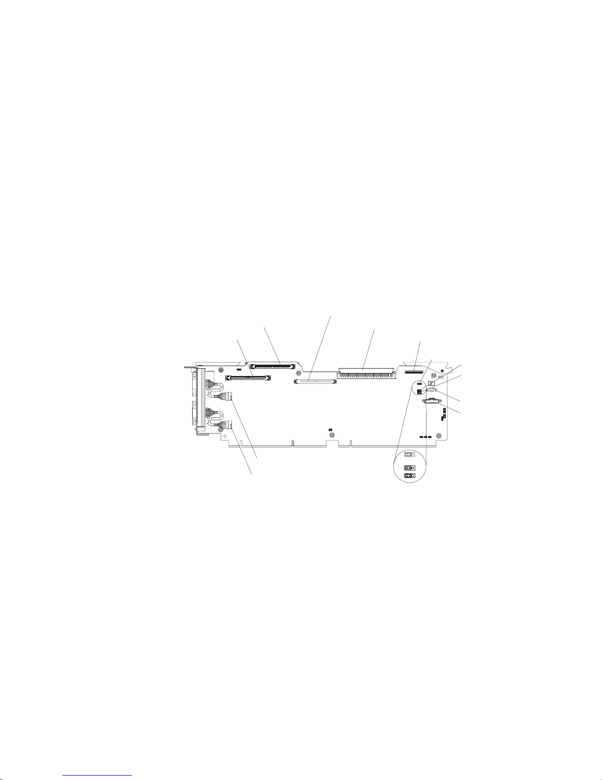
The following illustration shows the location of the power-on password override,
boot recovery, and Wake on LAN bypass jumpers.
SAS 1
SAS 2
Remote Supervisor Adapter II SlimLine
Media backplane
Light path diagnostic
Power-on password
override
Boot recovery
Wake-on-LAN
bypass
Front USB
Battery
System serial (COM 1)
SP serial (COM 2)
123
123
123
Default jumper
position
While the server is turned off, move the power-on password jumper from pins 1
and 2 to pins 2 and 3. Yo u can then start the Configuration/Setup Utility program
and reset the power-on password. After you reset the password, turn off the
server again and move the jumper back to pins 1 and 2.
The power-on password override switch does not affect the administrator
password.
Administrator
password: If an administrator password is set, you must type the
administrator password for access to the full Configuration/Setup Utility menu. You
can use any combination of up to seven characters (A–Z, a–z, and 0–9) for the
password. The Administrator Password choice is on the Configuration/Setup
Utility menu only if an optional IBM Remote Supervisor Adapter II SlimLine is
installed.
Attention: If you set an administrator password and then forget it, there is no way
to change, override, or remove it. You must replace the I/O board.
Chapter 2. Configuration information and instructions 19
Page 36

Installing and using the baseboard management controller utility
programs
The baseboard management controller provides environmental monitoring for the
server. If environmental conditions exceed thresholds or if system components fail,
the baseboard management controller lights LEDs to help you diagnose the
problem and also records the error in the BMC system event log.
Also use the baseboard management controller to establish a Serial over LAN
(SOL) connection to manage servers from a remote location. Yo u can remotely view
and change the BIOS settings, restart the server, identify the server, and perform
other management functions. Any standard Telnet client application can access the
SOL connection.
Use the baseboard management controller firmware update utility program to
download a baseboard management controller firmware update. The firmware
update utility program updates the baseboard management controller firmware only
and does not affect any device drivers.
To download the utility program, go to http://www.ibm.com/servers/eserver/support/
xseries/index.html; then, copy the Flash.exe file to a firmware update diskette.
Notes:
1. The server Ethernet ports are set to DHCP by default. The BMC MAC address
can be found on a tag on the front of the server. Once you have deployed the
server, remove the BMC MAC address tag so that it does not impede airflow
through the front of the server.
2. To ensure proper server operation, be sure to update the server baseboard
management controller firmware before updating the BIOS code.
Using the SAS/SATA Configuration Utility program
Use the SAS/SATA Configuration Utility program to view or change SAS controller
settings.
To start the SAS/SATA Configuration Utility program, complete the following steps:
1. Turn on the server.
2. When the message Press <CTRL><A> for Adaptec SAS/SATA Configuration
Utility appears, press Ctrl+A. If an administrator password has been set, you
are prompted to type the password.
3. Follow the instructions on the screen to configure the controller settings.
to http://www.ibm.com/servers/eserver/support/xseries/index.html to check for
Go
the latest version of the SAS firmware.
Configuring the Ethernet controller
The Ethernet controller is integrated on the system board. It provides an interface
for connecting to a 10-Mbps, 100-Mbps, or 1-Gbps network and provides full-duplex
(FDX) capability, which enables simultaneous transmission and reception of data on
the network. If the Ethernet ports in the server support auto-negotiation, the
controller detects the data-transfer rate (10BASE-T, 100BASE-TX, or 1000BASE-T)
and duplex mode (full-duplex or half-duplex) of the network and automatically
operates at that rate and mode.
20 IBM System x3950 Type 8878 and System x3950 E Type 8879: Problem Determination and Service Guide
Page 37

You do not have to set any jumpers or configure the controller. However, you must
install a device driver to enable the operating system to address the controller. For
device drivers and information about configuring the Ethernet controller, see the
Broadcom NetXtreme Gigabit Ethernet Software CD that comes with the server. For
updated information about configuring the controller, go to http://www.ibm.com/
servers/eserver/support/xseries/index.html.
Using the PXE boot agent utility program
Use the Preboot Execution Environment (PXE) boot agent utility program to enable
or disable operating-system wake-up support.
Note: The server does not support changing the network boot protocol or
specifying the startup order of devices through the PXE boot agent utility program.
To start the PXE boot agent utility program, complete the following steps:
1. Turn on the server.
2. When the Initializing Intel (R) Boot Agent Version X.X.XX PXE 2.0 Build
XXX (WfM 2.0) prompt appears, press Ctrl+S. You have 2 seconds (by default)
to press Ctrl+S after the prompt appears. If the prompt does not appear, use the
Configuration/Setup Utility program to enable the Ethernet PXE/DHCP option.
3. To select a choice from the menu, use the arrow keys and press Enter.
4. To change the settings of the selected items, follow the instructions on the
screen.
Using the ServeRAID configuration programs
A ServeRAID controller enables you to configure multiple physical hard disk drives
to operate as logical drives in a disk array. The controller comes with a CD that
contains the ServeRAID Manager program and the ServeRAID Mini-Configuration
program, which you can use to configure the ServeRAID controller. For information
about these programs, see the documentation that comes with the ServeRAID
controller and the User’s Guide on the IBM System x Documentation CD. If the
server comes with an operating system installed, such as Microsoft Windows 2000
Datacenter Server, see the software documentation that comes with the server for
configuration information.
Using the Scalable Partition Web Interface
The Scalable Partition Web Interface is an extension of the Remote Supervisor
Adapter II Web Interface and is used to create, delete, control, and view scalable
partitions. The Scalable Partition Web Interface is in the Remote Supervisor Adapter
II SlimLine integrated service processor.
To start the Scalable Partition Web Interface, complete the following steps:
1. Make sure that the service processor on each node is configured and
connected to a separate hub or switch and separate network for the multi-node
configuration. See the Remote Supervisor Adapter II SlimLine and Remote
Supervisor Adapter II User’s Guide for more information.
2. Connect the SMP Expansion cables to the nodes. See the User ’s Guide on the
IBM System x Documentation CD.
3. Connect all nodes to an ac power source and make sure that they are not
running an operating system.
Chapter 2. Configuration information and instructions 21
Page 38

4. Log in to the Remote Supervisor Adapter II Web Interface from the primary
node. See the Remote Supervisor Adapter II SlimLine and Remote Supervisor
Adapter II User’s Guide for more information.
22 IBM System x3950 Type 8878 and System x3950 E Type 8879: Problem Determination and Service Guide
Page 39

Chapter 3. Parts listing, Type 8878 and 8879
The following replaceable components are available for the System x3950 Type
8878 and System x3950 E Type 8879 except as specified otherwise in Table 3 on
page 25. To check for an updated parts listing on the Web, complete the following
steps:
1. Go to http://www.ibm.com/servers/eserver/support/xseries/index.html.
2. From the Hardware list, select System x3950 or System x3950 E and click
Go.
3. Click the Install and use tab.
4. Under Technical resources, click Parts information.
© Copyright IBM Corp. 2007 23
Page 40
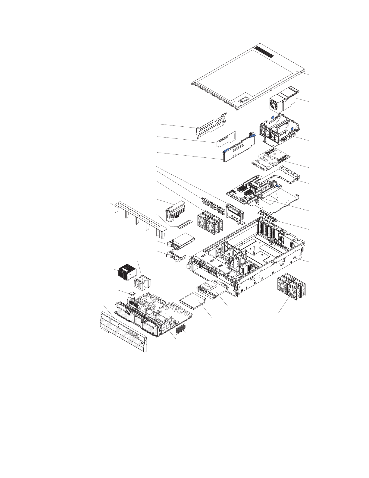
28
1
2
14
20
16
15
FRONT
17
27
26
25
24
23
22
21
19
18
3
4
5
6
7
8
10
9
11
24 IBM System x3950 Type 8878 and System x3950 E Type 8879: Problem Determination and Service Guide
12
13
Page 41

Server replaceable units
Notes:
1. Field replaceable units (FRUs) must be serviced only by trained service
technicians.
2. Customer replaceable units (CRUs) can be replaced by the customer. Tier 1
CRUs and Tier 2 CRUs are described in the IBM “Statement of Limited
Warranty” (at “Part 3 - Warranty Information”), which is in the Warranty and
Support Information document on the IBM System x Documentation CD.
Table 3. Parts listing, Type 8878 and 8879
CRU No.
Index Description
(Tier 1)
1 To p cover (all models) 26K8947
2 Power supply, 1300 W (all models) 24R2723
3 Power supply structure (all models) 26K8950
4 Power backplane (all models) 41Y3188
5 Scalability cartridge assembly (all models) 25K9606
6 PCI board assembly (all models) 42C7558
7 PCI switch card assembly (all models) 39M2699
8 Chassis assembly (all models) 42D3935
9 Fan (92 mm) (all models) 39M2694
10 Carrier, LP/media (all models) 42D3936
11 CD drive, 8/24X (primary) (all models) 39M3533
11 CD drive, 8/24X (alternate) (all models) 39M3541
11 CD drive, 8/24X (alternate) (all models) 39M3563
11 CD drive, 24X (optional) 26K5427
11 CD drive, 24X (optional) 39M3559
11 CD drive, 127MM (optional) 39M3529
11 CD drive, 127MM (optional) 39M3567
11 CD-RW drive, 14X (optional) 39M3503
11 DVD drive (optional) 42C0955
12 Microprocessor VRM, 10.2 (optional) 39Y7256
13 Microprocessor tray (all models) 40K2478
14 x3950 bezel (all models) 42C2615
14 x3950 E bezel (all models) 42C2616
15 Microprocessor, 2.5 GHZ 42D3357
15 Microprocessor, 3.0 GHZ 42D3359
15 Microprocessor, 3.16 GHZ 42D3361
15 Microprocessor, 3.33 GHZ 42D3363
15 Microprocessor, 3.5 GHZ 43V9473
16 Heat sink (all models) 26K8805
17 Microprocessor baffle (all models) 26K9020
18 Hard disk drive filler (all models) 26K8680
CRU No.
(Tier 2) FRU No.
Chapter 3. Parts listing, Type 8878 and 8879 25
Page 42

Table 3. Parts listing, Type 8878 and 8879 (continued)
CRU No.
Index Description
(Tier 1)
19 Hard disk drive, 36 GB (optional) 39R7364
19 Hard disk drive, 73 GB (optional) 39R7366
20 Air baffle (all models) 01R1479
21 Memory, 1 GB PC3200 ECC (models 1Rx, 2Rx, 3Rx) 39M5808
21 Memory, 2 GB PC3200 ECC (model 4Rx) 39M5811
21 Memory, 4 GB PC3200 ECC (optional) 30R5146
22 Memory card (all models) 41Y3153
23 Fan (80 mm) (all models) 39M2693
24 SAS hard disk drive backplane (all models) 41Y3161
25 PCI adapter guide assembly (all models) 26K8951
26 I/O board (all models) 41Y3152
27 RSA 2 adapter (standard models 2Rx, 3Rx, 4Rx) (optional
13N0833
model 1Rx)
28 PCI divider (all models) 03K9050
Alcohol wipe, Canada 41Y8746
Alcohol wipe, Brazil/Mexico 41Y8747
Alcohol wipe, Taiwan/Japan 41Y8748
Alcohol wipe, China/Malaysia 41Y8749
Alcohol wipe, Australia/UK 41Y8750
Alcohol wipe, Korea 41Y8751
Alcohol wipe, Hungary 41Y8753
Alcohol wipe, Latin America 41Y8754
Alcohol wipe, China 41Y8757
Alcohol wipe, Hong Kong 41Y8758
Alcohol wipe, India 41Y8759
Alcohol wipe, Singapore 41Y8760
Alcohol wipe, other countries 41Y8752
Battery, 3.0 volt (all models) 33F8354
Cable, active PCI (all models) 39M2509
Cable, CD/DVD signal (all models) 25K9626
Cable management arm (all models) 40K6556
Cable, SAS power (all models) 42C2618
Cable, SAS signal (all models) 25K9610
Cable, serial (all models) 39M2641
Cable, USB (all models) 25K9618
DVD/CD bay filler (type 8879 all models only) 26K8938
EIA mounting bracket (all models) 26K8948
Kit, shipping bracket (all models) 40K6592
Lift handle kit (all models) 39M2696
CRU No.
(Tier 2) FRU No.
26 IBM System x3950 Type 8878 and System x3950 E Type 8879: Problem Determination and Service Guide
Page 43

Table 3. Parts listing, Type 8878 and 8879 (continued)
Index Description
Line cord (all models) 39M5377
Retention module (all models) 26K8836
Scalability connector filler (all models) 26K8943
ServeRAID-8i card (standard type 8878 model 2Rx, 3Rx,
4Rx) (optional type 8878 model 1Rx and type 8879 model
1Rx)
ServeRAID-8i battery pack (standard type 8878 model
2Rx, 3Rx, 4Rx) (optional type 8878 model 1Rx and type
8879 model 1Rx)
Slide kit (all models) 40K6591
System service label (all models) 42D3932
Thermal grease (all models) 41Y8755
Power cords
For your safety, IBM provides a power cord with a grounded attachment plug to use
with this IBM product. To avoid electrical shock, always use the power cord and
plug with a properly grounded outlet.
CRU No.
(Tier 1)
CRU No.
(Tier 2) FRU No.
39R8731
25R8118
IBM power cords used in the United States and Canada are listed by Underwriter’s
Laboratories (UL) and certified by the Canadian Standards Association (CSA).
For units intended to be operated at 11 5 volts: Use a UL-listed and CSA-certified
cord set consisting of a minimum 18 AWG, Type SVT or SJT, three-conductor cord,
a maximum of 15 feet in length and a parallel blade, grounding-type attachment
plug rated 15 amperes, 125 volts.
For units intended to be operated at 230 volts (U.S. use): Use a UL-listed and
CSA-certified cord set consisting of a minimum 18 AWG, Type SVT or SJT,
three-conductor cord, a maximum of 15 feet in length and a tandem blade,
grounding-type attachment plug rated 15 amperes, 250 volts.
For units intended to be operated at 230 volts (outside the U.S.): Use a cord set
with a grounding-type attachment plug. The cord set should have the appropriate
safety approvals for the country in which the equipment will be installed.
IBM power cords for a specific country or region are usually available only in that
country or region.
IBM power cord part
number Used in these countries and regions
02K0546 China
13F9940 Australia, Fiji, Kiribati, Nauru, New Zealand, Papua New Guinea
Chapter 3. Parts listing, Type 8878 and 8879 27
Page 44
IBM power cord part
number Used in these countries and regions
13F9979 Afghanistan, Albania, Algeria, Andorra, Angola, Armenia, Austria,
Azerbaijan, Belarus, Belgium, Benin, Bosnia and Herzegovina,
Bulgaria, Burkina Faso, Burundi, Cambodia, Cameroon, Cape
Verde, Central African Republic, Chad, Comoros, Congo
(Democratic Republic of), Congo (Republic of), Cote D’Ivoire
(Ivory Coast), Croatia (Republic of), Czech Republic, Dahomey,
Djibouti, Egypt, Equatorial Guinea, Eritrea, Estonia, Ethiopia,
Finland, France, French Guyana, French Polynesia, Germany,
Greece, Guadeloupe, Guinea, Guinea Bissau, Hungary, Iceland,
Indonesia, Iran, Kazakhstan, Kyrgyzstan, Laos (People’s
Democratic Republic of), Latvia, Lebanon, Lithuania, Luxembourg,
Macedonia (former Yugoslav Republic of), Madagascar, Mali,
Martinique, Mauritania, Mauritius, Mayotte, Moldova (Republic of),
Monaco, Mongolia, Morocco, Mozambique, Netherlands, New
Caledonia, Niger, Norway, Poland, Portugal, Reunion, Romania,
Russian Federation, Rwanda, Sao Tome and Principe, Saudi
Arabia, Senegal, Serbia, Slovakia, Slovenia (Republic of),
Somalia, Spain, Suriname, Sweden, Syrian Arab Republic,
Tajikistan, Tahiti, Togo, Tunisia, Turkey, Turkmenistan, Ukraine,
Upper Volta, Uzbekistan, Vanuatu, Vietnam, Wallis and Futuna,
Yugoslavia (Federal Republic of), Zaire
13F9997 Denmark
14F0015 Bangladesh, Lesotho, Macao, Maldives, Namibia, Nepal,
Pakistan, Samoa, South Africa, Sri Lanka, Swaziland, Uganda
14F0033 Abu Dhabi, Bahrain, Botswana, Brunei Darussalam, Channel
Islands, China (Hong Kong S.A.R.), Cyprus, Dominica, Gambia,
Ghana, Grenada, Iraq, Ireland, Jordan, Kenya, Kuwait, Liberia,
Malawi, Malaysia, Malta, Myanmar (Burma), Nigeria, Oman,
Polynesia, Qatar, Saint Kitts and Nevis, Saint Lucia, Saint Vincent
and the Grenadines, Seychelles, Sierra Leone, Singapore, Sudan,
Tanzania (United Republic of), Trinidad and Tobago, United Arab
Emirates (Dubai), United Kingdom, Yemen, Zambia, Zimbabwe
14F0051 Liechtenstein, Switzerland
14F0069 Chile, Italy, Libyan Arab Jamahiriya
14F0087 Israel
1838574 Antigua and Barbuda, Aruba, Bahamas, Barbados, Belize,
Bermuda, Bolivia, Brazil, Caicos Islands, Canada, Cayman
Islands, Costa Rica, Colombia, Cuba, Dominican Republic,
Ecuador, El Salvador, Guam, Guatemala, Haiti, Honduras,
Jamaica, Japan, Mexico, Micronesia (Federal States of),
Netherlands Antilles, Nicaragua, Panama, Peru, Philippines,
Taiwan, United States of America, Venezuela
24P6858 Korea (Democratic People’s Republic of), Korea (Republic of)
34G0232 Japan
36L8880 Argentina, Paraguay, Uruguay
49P2078 India
49P2110 Brazil
28 IBM System x3950 Type 8878 and System x3950 E Type 8879: Problem Determination and Service Guide
Page 45

IBM power cord part
number Used in these countries and regions
6952300 Antigua and Barbuda, Aruba, Bahamas, Barbados, Belize,
Bermuda, Bolivia, Caicos Islands, Canada, Cayman Islands,
Colombia, Costa Rica, Cuba, Dominican Republic, Ecuador, El
Salvador, Guam, Guatemala, Haiti, Honduras, Jamaica, Mexico,
Micronesia (Federal States of), Netherlands Antilles, Nicaragua,
Panama, Peru, Philippines, Saudi Arabia, Thailand, Taiwan,
United States of America, Venezuela
Chapter 3. Parts listing, Type 8878 and 8879 29
Page 46

30 IBM System x3950 Type 8878 and System x3950 E Type 8879: Problem Determination and Service Guide
Page 47

Chapter 4. Removing and replacing server components
Replaceable components are of three types:
v Tier 1 customer replaceable unit (CRU): Replacement of Tier 1 CRUs is your
responsibility. If IBM installs a Tier 1 CRU at your request, you will be charged for
the installation.
v Tier 2 customer replaceable unit: Yo u may install a Tier 2 CRU yourself or
request IBM to install it, at no additional charge, under the type of warranty
service that is designated for your server.
v Field replaceable unit (FRU): FRUs must be installed only by trained service
technicians.
Chapter 3, “Parts listing, Type 8878 and 8879,” on page 23 to determine
See
whether a component is a Tier 1 CRU, Tier 2 CRU, or FRU.
For information about the terms of the warranty and getting service and assistance,
see the Warranty and Support Information document.
Installation guidelines
Before you install options, read the following information:
v Read the safety information that begins on page vii, “Working inside the server
with the power on” on page 33, and the guidelines in “Handling static-sensitive
devices” on page 33. This information will help you work safely.
v When you install your new server, take the opportunity to download and apply
the most recent firmware updates. This step will help to ensure that any known
issues are addressed and that your server is ready to function at maximum levels
of performance. To download firmware updates for your server, go to
http://www.ibm.com/servers/eserver/support/xseries/index.html, select System
x3950 or System x3950 E from the Hardware list, click Go, and then click the
Download tab. For additional information about tools for updating, managing,
and deploying firmware, see the System x and xSeries Tools Center at
http://publib.boulder.ibm.com/infocenter/toolsctr/v1r0/index.jsp.
v Before you install optional hardware devices, make sure that the server is
working correctly. Start the server, and make sure that the operating system
starts, if an operating system is installed, or that a 19990305 error code is
displayed, indicating that an operating system was not found but the server is
otherwise working correctly. If the server is not working correctly, see Chapter 5,
“Diagnostics,” on page 65 for diagnostic information.
v Observe good housekeeping in the area where you are working. Place removed
covers and other parts in a safe place.
v If you must start the server while the cover is removed, make sure that no one is
near the server and that no tools or other objects have been left inside the
server.
v Do not attempt to lift an object that you think is too heavy for you. If you have to
lift a heavy object, observe the following precautions:
– Make sure that you can stand safely without slipping.
– Distribute the weight of the object equally between your feet.
– Use a slow lifting force. Never move suddenly or twist when you lift a heavy
object.
© Copyright IBM Corp. 2007 31
Page 48

– To avoid straining the muscles in your back, lift by standing or by pushing up
with your leg muscles.
Make sure that you have an adequate number of properly grounded electrical
v
outlets for the server, monitor, and other devices.
v Back up all important data before you make changes to disk drives.
v Have a small flat-blade screwdriver available.
v You do not have to turn off the server to install or replace hot-swap power
supplies, hot-swap fans, hot-plug adapters, or hot-plug Universal Serial Bus
(USB) devices. However, you must turn off the server before you perform any
steps that involve removing or installing adapter cables.
v Blue on a component indicates touch points, where you can grip the component
to remove it from or install it in the server, open or close a latch, and so on.
v Orange on a component or an orange label on or near a component indicates
that the component can be hot-swapped, which means that if the server and
operating system support hot-swap capability, you can remove or install the
component while the server is running. (Orange can also indicate touch points on
hot-swap components.) See the instructions for removing or installing a specific
hot-swap component for any additional procedures that you might have to
perform before you remove or install the component.
v When you are finished working on the server, reinstall all safety shields, guards,
labels, and ground wires.
v For a list of supported optional devices for the server, see http://www.ibm.com/
servers/eserver/serverproven/compat/us/.
System reliability guidelines
To help ensure proper cooling and system reliability, make sure that:
v Each of the drive bays has a drive or a filler panel installed in it.
v If the server has redundant power, each of the power-supply bays has a power
supply installed in it.
v There is adequate space around the server to allow the server cooling system to
work properly. Leave approximately 50 mm (2 in.) of open space around the front
and rear of the server. Do not place objects in front of the fans. For proper
cooling and airflow, replace the server cover before turning on the server.
Operating the server for extended periods of time (more than 30 minutes) with
the server cover removed might damage server components.
v You have followed the cabling instructions that come with optional adapters.
v You have replaced a failed fan within 48 hours.
v You have replaced a hot-swap drive within 2 minutes of removal.
v You do not run the server without the air baffle installed. Operating the server
without the air baffle might cause the microprocessor or microprocessors to
overheat.
v Microprocessor sockets 2, 3, and 4 each always contain either a microprocessor
baffle or a microprocessor and heat sink.
v For redundant and hot-swappable operation, the power supplies are connected to
200-240 V ac.
32 IBM System x3950 Type 8878 and System x3950 E Type 8879: Problem Determination and Service Guide
Page 49

Working inside the server with the power on
Attention: Static electricity that is released to internal server components when
the server is powered-on might cause the server to halt, which could result in the
loss of data. To avoid this potential problem, always use an electrostatic-discharge
wrist strap or other grounding system when working inside the server with the
power on.
The server supports hot-swap devices and is designed to operate safely while it is
turned on and the cover is removed. Follow these guidelines when you work inside
a server that is turned on:
v Avoid wearing loose-fitting clothing on your forearms. Button long-sleeved shirts
before working inside the server; do not wear cuff links while you are working
inside the server.
v Do not allow your necktie or scarf to hang inside the server.
v Remove jewelry, such as bracelets, necklaces, rings, and loose-fitting wrist
watches.
v Remove items from your shirt pocket, such as pens and pencils, that could fall
into the server as you lean over it.
v Avoid dropping any metallic objects, such as paper clips, hairpins, and screws,
into the server.
Handling static-sensitive devices
Attention: Static electricity can damage the server and other electronic devices.
To avoid damage, keep static-sensitive devices in their static-protective packages
until you are ready to install them.
To reduce the possibility of damage from electrostatic discharge, observe the
following precautions:
v Limit your movement. Movement can cause static electricity to build up around
you.
v The use of a grounding system is recommended. For example, wear an
electrostatic-discharge wrist strap, if one is available. Always use an
electrostatic-discharge wrist strap or other grounding system when working inside
the server with the power on.
v Handle the device carefully, holding it by its edges or its frame.
v Do not touch solder joints, pins, or exposed circuitry.
v Do not leave the device where others can handle and damage it.
v While the device is still in its static-protective package, touch it to an unpainted
metal part on the outside of the server for at least 2 seconds. This drains static
electricity from the package and from your body.
v Remove the device from its package and install it directly into the server without
setting down the device. If it is necessary to set down the device, put it back into
its static-protective package. Do not place the device on the server cover or on a
metal surface.
v Take additional care when handling devices during cold weather. Heating reduces
indoor humidity and increases static electricity.
Returning a device or component
If you are instructed to return a device or component, follow all packaging
instructions, and use any packaging materials for shipping that are supplied to you.
Chapter 4. Removing and replacing server components 33
Page 50
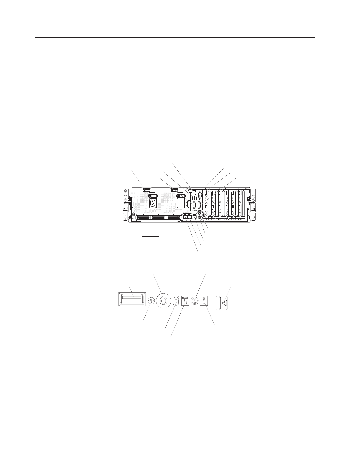
Connecting the cables
You must turn off the server before connecting any cables to or disconnecting any
cables from the server.
See the documentation that comes with optional devices for additional cabling
instructions. It might be easier for you to route cables before you install certain
options.
For details about the location and function of the input and output connectors, see
“Server controls, LEDs, and connectors” on page 4.
The following illustrations show the locations of the input and output connectors on
the server. Detailed cabling instructions are in the Rack Installation Instructions that
come with the server.
Rear view
Power-supply
SP Ethernet 10/100
USB 1
Video
USB 2
System serial
SP serial
SMP expansion port 1
SMP expansion port 2
SMP expansion port 3
Front view
Power-control button
USB connector
Power-on LED
Hard disk drive activity LED
Mouse
Keyboard
IXA RS 485
Gigabit Ethernet 2
Gigabit Ethernet 1
Information LED
Release latch
System-error LED
Locator LED
34 IBM System x3950 Type 8878 and System x3950 E Type 8879: Problem Determination and Service Guide
Page 51

Removing and replacing Tier 1 CRUs
Replacement of Tier 1 CRUs is your responsibility. If IBM installs a Tier 1 CRU at
your request, you will be charged for the installation.
The illustrations in this document might differ slightly from your hardware.
Adapter
To remove a PCI or PCI-X adapter, complete the following steps:
PCI-X retaining
bar
PCI-X
divider
Powe r
LED
(green)
Attention
LED
(yellow)
Ta b
Adapter
retention
latch
AC
DC
1. Read the safety information that begins on page vii and “Installation guidelines”
on page 31.
2. If the adapter is not hot-pluggable, turn off the server and peripheral devices,
and disconnect the power cords and all external cables necessary to remove or
install the adapter.
3. Remove the top cover (see “Top cover and bezel” on page 45).
4. Disconnect any cables from the adapter.
5. Open the blue PCI-X retaining bar by lifting the front edge.
6. Push the orange adapter retention latch toward the rear of the server and open
the tab. The power LED for the slot turns off.
7. Carefully grasp the adapter by its top edge or upper corners, and pull the
adapter from the server.
8. If you are instructed to return the adapter, follow all packaging instructions, and
use any packaging materials for shipping that are supplied to you.
To install the replacement PCI or PCI-X adapter, complete the following steps:
Chapter 4. Removing and replacing server components 35
Page 52

DVD drive
1. See the documentation that comes with the adapter for instructions on setting
jumpers or switches and for cabling.
Note: Route adapter cables before you install the adapter.
2. Carefully grasp the adapter by its top edge or upper corners, and align it with
the connector on the PCI-X board.
3. If necessary, remove the adapter guide before installing a full-length adapter.
4. Press the adapter firmly into the adapter connector.
5. Push down on the blue PCI-X retaining bar to stabilize the adapter.
6. Close the tab; then, push down on the orange adapter retention latch until it
clicks into place, securing the adapter.
7. Connect any required cables to the adapter.
8. Install the top cover (see “Top cover and bezel” on page 45).
9. Slide the server into the rack.
10. Connect the cables and power cords (see “Connecting the cables” on page 34
for cabling instructions).
11. Turn on all attached devices and the server.
To remove the DVD drive, complete the following steps:
Retention latch
1. Read the safety information that begins on page vii and “Installation guidelines”
on page 31.
2. Turn off the server and peripheral devices, and disconnect the power cords and
all external cables necessary to replace the device.
3. Remove the top cover and bezel (see “Top cover and bezel” on page 45).
4. Pull the blue retention latch forward and pull the DVD drive out of the server.
5. If you are instructed to return the DVD drive, follow all packaging instructions,
and use any packaging materials for shipping that are supplied to you.
To install the replacement DVD drive, compete the following steps:
1. Slide the DVD drive into the server to engage the drive.
2. Install the top cover and bezel (see “Top cover and bezel” on page 45).
3. Slide the server into the rack.
36 IBM System x3950 Type 8878 and System x3950 E Type 8879: Problem Determination and Service Guide
Page 53
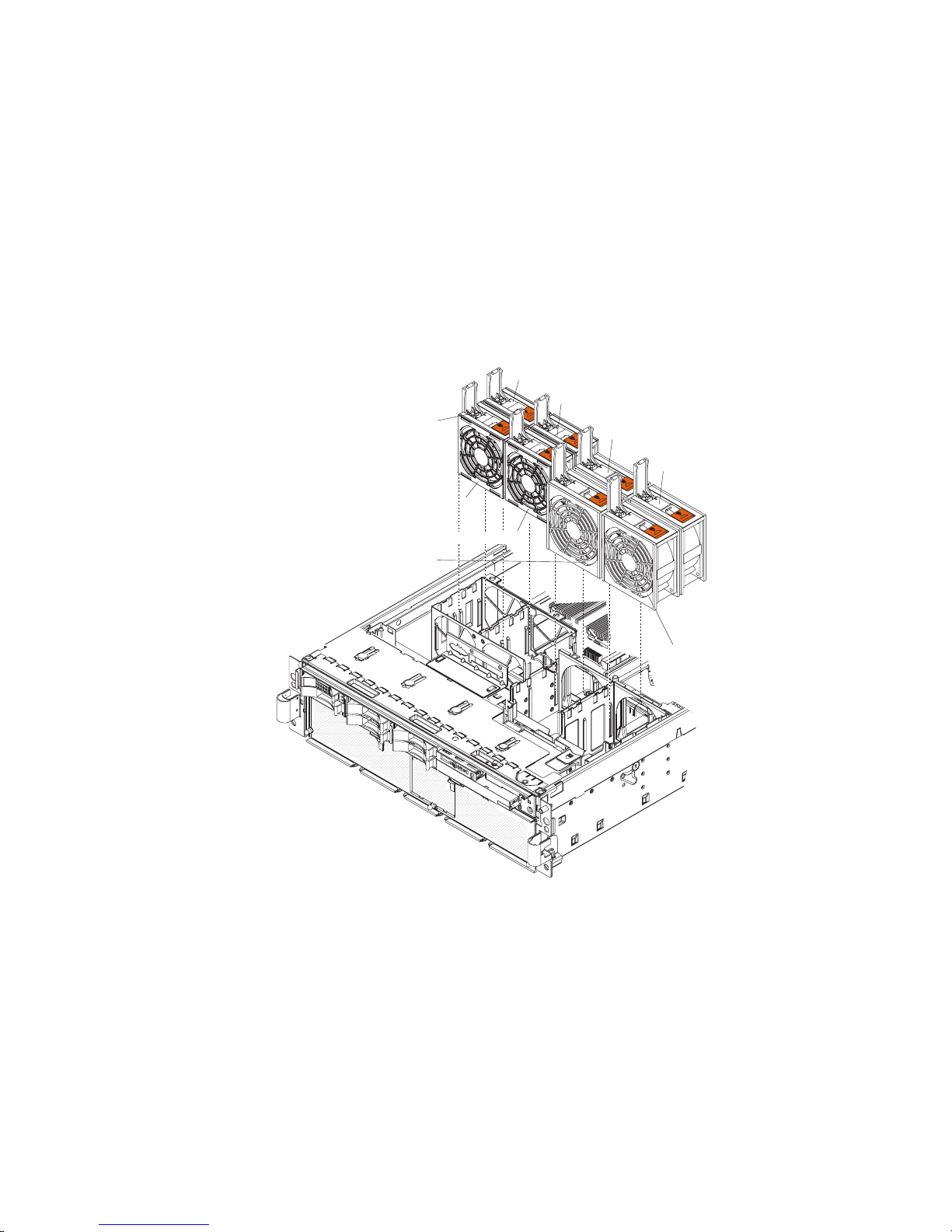
Hot-swap fan
4. Connect the cables and power cords (see “Connecting the cables” on page 34
for cabling instructions).
5. Turn on all attached devices and the server.
The server comes with 80-mm hot-swap fans in front of the PCI-X slots and 92-mm
hot-swap fans in front of the memory cards. The following removal and installation
procedures apply to either size fan. When a fan fails or is removed, the other fans
in the server speed up to maintain a safe operating temperature in the server until
the fan is reinstalled or replaced. When the fan is installed correctly the fans will
slow down.
To remove a hot-swap fan, complete the following steps:
Fan error
LED
Hot-swap fan 1
Hot-swap fan 5
Hot-swap fan 6
Hot-swap fan 7
Hot-swap fan 8
Hot-swap fan 2
Hot-swap fan 3
Hot-swap fan 4
1. Read the safety information that begins on page vii and “Installation guidelines”
on page 31.
2. Remove the top cover (see “Top cover and bezel” on page 45).
Attention: To ensure proper cooling and airflow, do not operate the server for
more than 2 minutes with the top cover removed.
3. Open the fan-locking handle by sliding the orange release latch in the direction
of the arrow.
4. Pull upward on the free end of the handle to lift the fan out of the server.
5. If you are instructed to return the fan, follow all packaging instructions, and use
any packaging materials for shipping that are supplied to you.
To install the replacement hot-swap fan, complete the following steps:
Chapter 4. Removing and replacing server components 37
Page 54

1. Open the fan-locking handle on the replacement fan.
2. Lower the fan into the socket, and close the handle to the locked position.
3. Install the top cover (see “Top cover and bezel” on page 45).
4. Slide the server into the rack.
Hot-swap power supply
When you remove or install a hot-swap power supply, observe the following
precautions.
Statement 8:
CAUTION:
Never remove the cover on a power supply or any part that has the following
label attached.
Hazardous voltage, current, and energy levels are present inside any
component that has this label attached. There are no serviceable parts inside
these components. If you suspect a problem with one of these parts, contact
a service technician.
To remove the hot-swap power supply, complete the following steps:
38 IBM System x3950 Type 8878 and System x3950 E Type 8879: Problem Determination and Service Guide
Page 55

AC
DC
Locking latch
Locking handle
(open)
AC
DC
Power supply 2 (PS2)
Power supply 1 (PS1)
AC power
LED (green)
AC
DC power
LED (green)
DC
1. Read the safety information that begins on page vii and “Installation guidelines”
on page 31.
2. Remove the top cover (see “Top cover and bezel” on page 45).
Attention: To ensure proper cooling and airflow, do not operate the server for
more than 2 minutes with the top cover removed.
3. Disconnect the power cord from the connector on the back of the power supply.
4. Press the orange locking latch on the power-supply handle and raise the
power-supply handle to the open position.
5. Lift the power supply out of the bay.
6. If you are instructed to return the hot-swap power supply, follow all packaging
instructions, and use any packaging materials for shipping that are supplied to
you.
To install the replacement hot-swap power supply, complete the following steps:
1. Raise the handle on the power supply to the open position.
2. Place the power supply into the bay and fully close the locking handle.
3. Connect one end of the power cord for the new power supply into the connector
on the back of the power supply, and connect the other end of the power cord
into a properly grounded electrical outlet.
4. Make sure that the ac power LED on the top of the power supply is lit,
indicating that the power supply is operating correctly. If the server is turned on,
make sure that the dc power LED on the top of the power supply is lit also.
5. Install the top cover (see “Top cover and bezel” on page 45).
Chapter 4. Removing and replacing server components 39
Page 56

6. Slide the server into the rack.
AC
DC
Memory card and memory module (DIMM)
The server supports 333 MHz, 1.8V, 240 pin, PC2-3200 single-ranked double
data-rate (DDR) II, registered synchronous dynamic random-access memory
(SDRAM) with error correcting code (ECC) DIMMs. These DIMMs must be
compatible with the latest PC2-3200 SDRAM Registered DIMM specifications. For a
list of the supported options for the server, see http://www.ibm.com/servers/eserver/
serverproven/compat/us/.
Removing and replacing a memory card
At least one memory card with one pair of DIMMs must be installed for the server
to operate correctly.
To remove the memory card, complete the following steps:
1. Read the safety information that begins on page vii and “Installation guidelines”
on page 31.
2. Remove the top cover (see “Top cover and bezel” on page 45).
Attention: To ensure proper cooling and airflow, do not operate the server for
more than 2 minutes with the top cover removed.
3. Open the locking levers on the edge of the memory card; then, lift the memory
card out of the server.
4. If you are instructed to return the memory card, follow all packaging instructions,
and use any packaging materials for shipping that are supplied to you.
40 IBM System x3950 Type 8878 and System x3950 E Type 8879: Problem Determination and Service Guide
Page 57

To install the replacement memory card, complete the following steps:
1. Insert the memory card into the memory card connector.
2. Press the memory card into the connector and close the locking levers.
3. Install the top cover (see “Top cover and bezel” on page 45).
4. Slide the server into the rack.
Removing and replacing a DIMM
DIMMs must be installed in pairs of the same type and speed. To use the memory
mirroring feature, all the DIMMs that are installed in the server must be of the same
type and speed, and the operating system must support memory mirroring.
To remove a DIMM, complete the following steps:
DIMM
Retaining
clip
1. Read the safety information that begins on page vii and “Installation guidelines”
on page 31.
2. If you are removing a non-hot-swap DIMM, turn off the server and peripheral
devices, and disconnect the power cords and all external cables necessary to
replace the device.
3. Remove the top cover (see “Top cover and bezel” on page 45).
Attention: To ensure proper cooling and airflow, do not operate the server for
more than 2 minutes with the top cover removed.
4. Remove the memory card (see “Removing and replacing a memory card” on
page 40).
5. Place the memory card on a flat surface with the DIMM connectors facing up.
Attention: To avoid breaking the DIMM retaining clips or damaging the DIMM
connectors, open and close the clips gently.
6. Open the retaining clip on each end of the DIMM connector and remove the
DIMM from the connector.
Chapter 4. Removing and replacing server components 41
Page 58

DIMM
Retaining
clip
7. If you are instructed to return the DIMM, follow all packaging instructions, and
use any packaging materials for shipping that are supplied to you.
To install the replacement DIMM, complete the following steps:
1. Open the retaining clip on each end of the DIMM connector.
2. Touch the static-protective package that contains the DIMM to any unpainted
metal surface on the server. Then, remove the DIMM from the package.
3. Turn the DIMM so that the DIMM keys align correctly with the slot.
DIMM
4. Insert the DIMM into the connector by aligning the edges of the DIMM with the
slots at the ends of the DIMM connector. Firmly press one end of the DIMM into
the connector; then, press the other end into the connector. The retaining clips
snap into the locked position when the DIMM is seated in the connector. If there
is a gap between the DIMM and the retaining clips, the DIMM has not been
correctly inserted; open the retaining clips, remove the DIMM, and then reinsert
it.
42 IBM System x3950 Type 8878 and System x3950 E Type 8879: Problem Determination and Service Guide
Retaining
clip
Page 59

5. Replace the memory card (see “Removing and replacing a memory card” on
page 40).
6. Install the top cover (see “Top cover and bezel” on page 45).
7. Slide the server into the rack.
8. Connect the cables and power cords (see “Connecting the cables” on page 34
for cabling instructions).
9. If you turned off the server to replace the DIMM, turn on all attached devices
and the server.
Remote Supervisor Adapter II SlimLine
The Remote Supervisor Adapter II SlimLine must be installed in its dedicated
connector on the I/O board.
To remove the Remote Supervisor Adapter II SlimLine, complete the following
steps:
Front standoff
Remote Supervisor Adapter II SlimLine connector
I/O board
Rear standoff
Remote Supervisor Adapter II SlimLine
1. Read the safety information that begins on page vii and “Installation guidelines”
on page 31.
2. Turn off the server and peripheral devices, and disconnect the power cords and
all external cables necessary to replace the device.
3. Remove the top cover (see “Top cover and bezel” on page 45).
4. Release the retention latch on the rear standoff and pull the adapter from the
I/O board.
5. If you are instructed to return the Remote Supervisor Adapter II SlimLine, follow
all packaging instructions, and use any packaging materials for shipping that are
supplied to you.
To install the replacement Remote Supervisor Adapter II SlimLine, complete the
following steps:
1. Insert the rear of the adapter into the rear standoff; then, rotate the front of the
adapter into the front standoff.
2. Press the Remote Supervisor Adapter II SlimLine firmly into the connector.
3. Install the top cover (see “Top cover and bezel” on page 45).
Chapter 4. Removing and replacing server components 43
Page 60
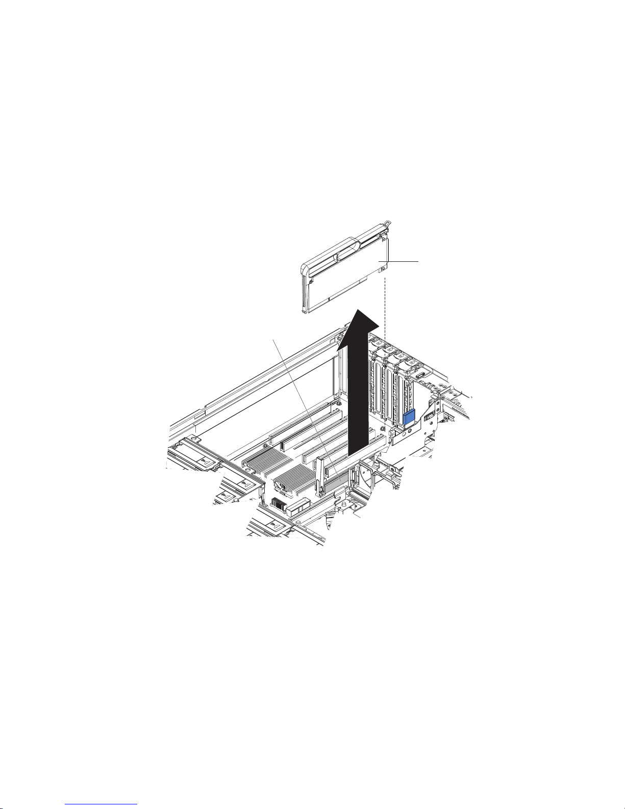
4. Slide the server into the rack.
AC
DC
5. Connect the cables and power cords (see “Connecting the cables” on page 34
for cabling instructions).
6. Turn on all attached devices and the server.
ServeRAID-8i adapter
The ServeRAID-8i adapter can be installed only in its dedicated connector on the
PCI-X board. The ServeRAID-8i adapter is not cabled to the server and no
rerouting of the SAS cables is required.
To remove the ServeRAID-8i adapter, complete the following steps:
ServeRAID-8i adapter
ServeRAID-8i
slot
1. Read the safety information that begins on page vii and “Installation guidelines”
on page 31.
2. Turn off the server and peripheral devices, and disconnect the power cords and
all external cables necessary to replace the device.
3. Remove the top cover (see “Top cover and bezel” on page 45).
4. Grasp the adapter by the plastic handle and pull the adapter from the server.
5. If you are instructed to return the ServeRAID-8i adapter, follow all packaging
instructions, and use any packaging materials for shipping that are supplied to
you.
To install the replacement ServeRAID-8i adapter, complete the following steps:
1. Touch the static-protective package that contains the adapter to any unpainted
surface on the outside of the server; then, grasp the adapter by the plastic
handle and remove it from the package.
44 IBM System x3950 Type 8878 and System x3950 E Type 8879: Problem Determination and Service Guide
Page 61
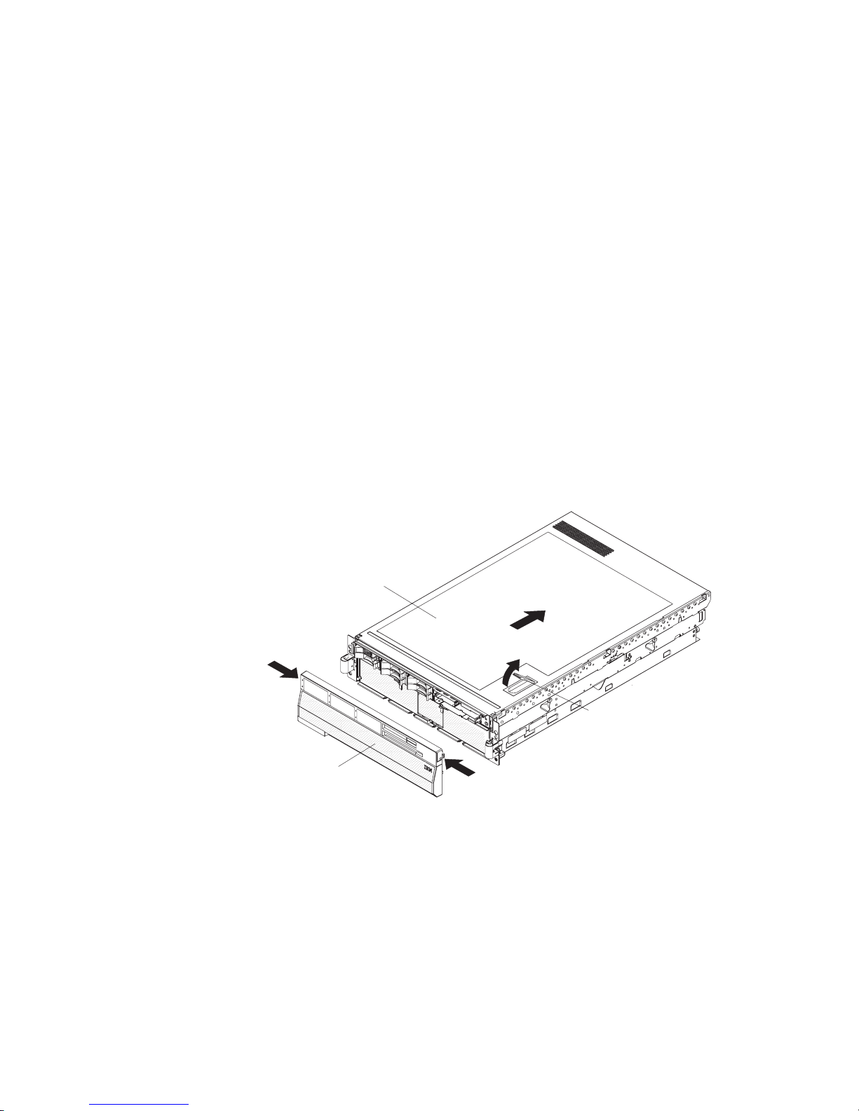
Attention: Incomplete insertion might cause damage to the server or the
ServeRAID-8i adapter.
2. Position the ServeRAID-8i adapter so that the metal locking clasp is at the rear
of the server; then, press the ServeRAID-8i adapter firmly into the connector.
3. Install the top cover (see “Top cover and bezel”).
4. Slide the server into the rack.
5. Connect the cables and power cords (see “Connecting the cables” on page 34
for cabling instructions).
6. Turn on all attached devices and the server.
Top cover and bezel
Attention: Operating the server for more than 2 minutes with the top cover
removed might damage server components. For proper cooling and airflow, replace
the top cover before turning on the server.
To remove the top cover and bezel, complete the following steps:
1. Read the safety information that begins on page “Safety” on page vii and
“Installation guidelines” on page 31.
2. If you are installing or replacing a non-hot-swap component, turn off the server
and all peripheral devices, and disconnect the power cords and all external
cables.
3. Slide the server out of the rack until the slide rails lock into place.
Top cover
Cover release
latch
Bezel
4. Lift the cover-release latch. The cover slides to the rear approximately 13 mm
(0.5 inch). Lift the cover off the server.
5. Press on the bezel retention tabs at the top edge of the bezel, and pull the top
of the bezel slightly away from the server.
6. Lift the bezel up to release the tabs at the bottom edge of the bezel.
7. If you are instructed to return the cover and bezel, follow all packaging
instructions, and use any packaging materials for shipping that are supplied to
you.
To install the top cover and bezel, complete the following steps:
1. Make sure that all internal cables are correctly routed.
Chapter 4. Removing and replacing server components 45
Page 62

2. Set the cover on top of the server so that approximately 13 mm (0.5 inch)
extends from the rear.
3. Make sure that the cover-release latch is up.
4. Slide the top cover forward and into position, pressing the release latch closed.
5. Slide the server into the rack.
6. To install the bezel, tilt the bezel and align the metal studs with the latches;
then, straighten the bezel and snap it into place.
Removing and replacing Tier 2 CRUs
You may install a Tier 2 CRU yourself or request IBM to install it, at no additional
charge, under the type of warranty service that is designated for your server.
The illustrations in this document might differ slightly from your hardware.
Battery
The following notes describe information that you must consider when replacing the
battery in the server.
v When replacing the battery, you must replace it with a lithium battery of the same
type from the same manufacturer.
v To order replacement batteries, call 1-800-772-2227 within the United States, and
1-800-465-7999 or 1-800-465-6666 within Canada. Outside the U.S. and
Canada, call your IBM marketing representative or authorized reseller.
v After you replace the battery, you must reconfigure the server and reset the
system date and time.
v To avoid possible danger, read and follow the following safety statement.
Statement 2:
CAUTION:
When replacing the lithium battery, use only IBM Part Number 33F8354 or an
equivalent type battery recommended by the manufacturer. If your system has
a module containing a lithium battery, replace it only with the same module
type made by the same manufacturer. The battery contains lithium and can
explode if not properly used, handled, or disposed of.
Do not:
v Throw or immerse into water
v Heat to more than 100°C (212°F)
v Repair or disassemble
Dispose
To remove the battery, complete the following steps:
of the battery as required by local ordinances or regulations.
1. Read the safety information that begins on page vii and “Installation guidelines”
on page 31.
2. Turn off the server and peripheral devices, and disconnect the power cords and
all external cables necessary to replace the device.
46 IBM System x3950 Type 8878 and System x3950 E Type 8879: Problem Determination and Service Guide
Page 63

3. Remove the top cover (see “Top cover and bezel” on page 45).
4. Remove the 2 SAS signal cables from the I/O board.
5. Remove the battery:
a. Use one finger to press the top of the battery clip away from the battery.
b. Lift and remove the battery from the socket.
6. Dispose of the battery as required by local ordinances or regulations. See
“Battery return program” on page 166 for information about disposing of the
battery).
install the replacement battery, complete the following steps:
To
1. Follow any special handling and installation instructions that come with the
replacement battery.
2. Insert the replacement battery:
a. Position the battery so that the positive (+) symbol is facing away from you.
b. Use one finger to press the top of the battery clip away from the battery.
c. Press the battery into the socket until it clicks into place. Make sure that the
battery clip holds the battery securely.
3. Reconnect the 2 SAS signal cables to the I/O board.
4. Install the top cover (see “Top cover and bezel” on page 45).
5. Slide the server into the rack.
6. Reconnect the external cables; then, reconnect the power cords and turn on the
peripheral devices and the server.
Note: You must wait approximately 20 seconds after you connect the power
cord of the server to an electrical outlet before the power-control button
becomes active.
7. Start the Configuration/Setup Utility program and reset the configuration.
v Set the system date and time.
v Set the power-on password.
v Reconfigure the server.
“Using the Configuration/Setup Utility program” on page 14 for details.
See
I/O board
When replacing the I/O board, you must either update the server with the latest
SAS firmware or restore the pre-existing firmware from a diskette or CD image.
Chapter 4. Removing and replacing server components 47
Page 64
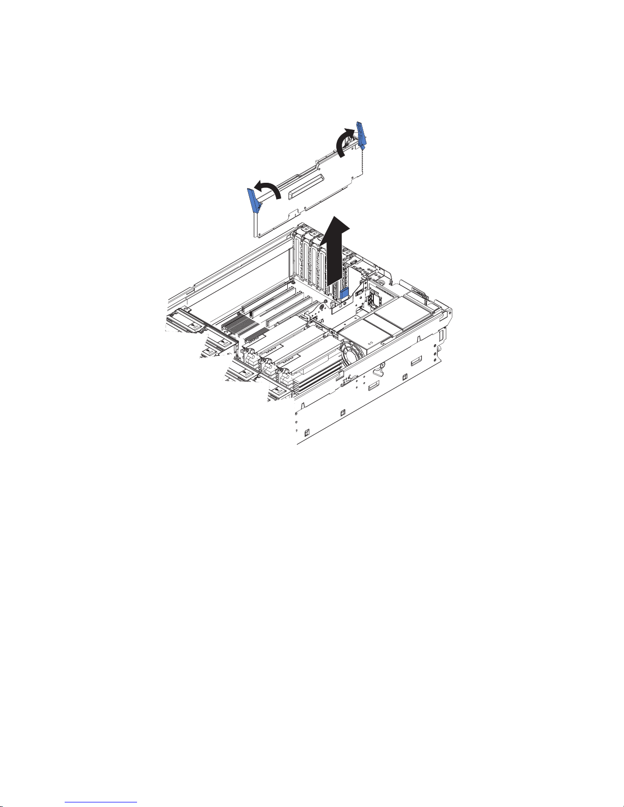
The I/O board contains three-pin jumper blocks. See “I/O board internal connectors
AC
D
C
and jumpers” on page 8 for the location and description of each jumper block.
To remove the I/O board, complete the following steps:
1. Read the safety information that begins on page vii and “Installation guidelines”
on page 31.
2. Turn off the server and peripheral devices, and disconnect the power cords and
all external cables necessary to replace the device.
3. Remove the top cover (see “Top cover and bezel” on page 45).
4. Open the release latches on both ends of the I/O board and pull the board from
the server slightly.
5. Note where each cable is connected, and then disconnect all cables from the
I/O board and remove the assembly from the server.
6. If you are instructed to return the I/O board, follow all packaging instructions,
and use any packaging materials for shipping that are supplied to you.
To install the replacement I/O board, complete the following steps:
1. Connect all cables to the internal connectors on the I/O board.
2. Align the board with the card guides and insert the board in the connector.
3. Close the release latches to seat the board in the connector.
4. Install the top cover (see “Top cover and bezel” on page 45).
5. Slide the server into the rack.
6. Connect the cables and power cords (see “Connecting the cables” on page 34
for cabling instructions).
48 IBM System x3950 Type 8878 and System x3950 E Type 8879: Problem Determination and Service Guide
Page 65

7. Turn on all attached devices and the server.
Operator information panel assembly
To remove the operator information panel assembly, complete the following steps:
Release lever
Retention clip
Retention clips
Release button
1. Read the safety information that begins on page vii and “Installation guidelines”
on page 31.
2. Turn off the server and peripheral devices, and disconnect the power cords and
all external cables necessary to replace the device.
3. Remove the top cover and bezel (see “Top cover and bezel” on page 45).
4. Note where the light path diagnostics ribbon cable and front USB cable are
connected, and then disconnect both cables from the I/O board.
5. Press the blue release button above the front-panel assembly and pull the
assembly out of the server approximately 25 mm (one inch).
6. Press the blue release lever on the operator information panel assembly to the
left and gently pull the information panel assembly out of the front-panel
assembly until it stops.
7. Press the retention clips on each side of the information panel assembly and
continue pulling the information panel assembly out of the front-panel assembly
until it stops.
8. Press the retention clip on the right side of the information panel assembly and
pull the information panel assembly out of the front-panel assembly.
9. If you are instructed to return the operator information panel assembly, follow all
packaging instructions, and use any packaging materials for shipping that are
supplied to you.
To install the replacement operator information panel assembly, complete the
following steps:
1. Guide the light path diagnostics ribbon cable and front USB cable through the
front-panel assembly first, and insert the information panel assembly into the
front-panel assembly until the blue release lever on the front engages.
Chapter 4. Removing and replacing server components 49
Page 66

2. Connect the light path diagnostics ribbon cable and front USB cable to the I/O
board.
3. Slide the front-panel assembly into the server until the blue tab on the chassis
engages.
4. Install the top cover and bezel (see “Top cover and bezel” on page 45).
5. Slide the server into the rack.
6. Connect the cables and power cords (see “Connecting the cables” on page 34
for cabling instructions).
7. Turn on all attached devices and the server.
PCI-X adapter guide
To remove the PCI-X adapter guide, complete the following steps.
Quarter-turn
fasteners
Latch mechanism
1. Read the safety information that begins on page vii and “Installation guidelines”
on page 31.
2. Turn off the server and peripheral devices, and disconnect the power cords and
all external cables necessary to replace the device.
3. Remove the top cover (see “Top cover and bezel” on page 45).
4. Lift the latch mechanism.
5. Remove all adapters and adapter dividers, and place the adapters on a
static-protective surface.
Note: You might find it helpful to note where each adapter is installed before
removing the adapters.
6. Disconnect one end of all cables that pass through the PCI-X adapter guide;
then, remove the cables from the routing feature of the guide and fold the
cables out of the way.
Note: You might find it helpful to note where each cable is connected before
disconnecting the cables.
7. Turn the blue quarter-turn fasteners to release the PCI-X adapter guide.
8. Lift the guide out of the server.
50 IBM System x3950 Type 8878 and System x3950 E Type 8879: Problem Determination and Service Guide
Page 67

9. If you are instructed to return the PCI-X adapter guide, follow all packaging
instructions, and use any packaging materials for shipping that are supplied to
you.
To install the replacement PCI-X adapter guide, complete the following steps:
1. Align the two tabs on the PCI-X adapter guide with the two slots on the
chassis.
2. Set the guide firmly into place and turn the quarter-turn fasteners to secure the
guide.
3. Reconnect the cables that pass through the PCI-X adapter guide and route the
cables through the routing feature of the guide.
4. Install the adapters and dividers.
5. When replacing the dividers, make sure that the tabs on the bottom of the
dividers rest in the holes in the bottom of the metal section of the guide and
the tabs on the top of the dividers engage the plastic retainer section of the
guide.
6. Lower the latch mechanism.
7. Install the top cover (see “Top cover and bezel” on page 45).
8. Slide the server into the rack.
9. Connect the cables and power cords (see “Connecting the cables” on page 34
for cabling instructions).
10. Turn on all attached devices and the server.
Power-supply structure
To remove the power-supply structure, complete the following steps:
1. Read the safety information that begins on page vii and “Installation guidelines”
on page 31.
2. Turn off the server and peripheral devices, and disconnect the power cords and
all external cables necessary to replace the device.
3. Remove the top cover (see “Top cover and bezel” on page 45).
4. Remove the memory cards (see “Removing and replacing a memory card” on
page 40).
Latches
Alignment tabs
Handle
Alignment pins
Chapter 4. Removing and replacing server components 51
Page 68

5. Remove the power supplies (see “Hot-swap power supply” on page 38).
6. Pull the two blue latches on the power-supply structure toward the front of the
server; the structure will disengage from the chassis.
7. Grasp the handle in the middle of the structure and rotate the structure up,
allowing the structure to pivot at the chassis front.
8. Lift the structure out of the server, and make sure that the alignment tabs clear
the chassis.
9. If you are instructed to return the power-supply structure, follow all packaging
instructions, and use any packaging materials for shipping that are supplied to
you.
To install the replacement power-supply structure, complete the following steps.
Attention: Do not allow any cables to be pinched or caught on metal protrusions.
1. Align the tabs on the power-supply structure with the notches on the rear of the
chassis; then, gently lower the structure into the server. Make sure that the
structure is firmly seated in the chassis.
2. Push the two blue latches of the power-supply structure toward the rear of the
server until they lock the structure into position.
3. Replace the power supplies.
4. Replace the memory cards.
5. Install the top cover (see “Top cover and bezel” on page 45).
6. Slide the server into the rack.
7. Connect the cables and power cords (see “Connecting the cables” on page 34
for cabling instructions).
8. Turn on all attached devices and the server.
SAS backplane
To remove the Serial Attached SCSI (SAS) backplane, complete the following steps:
Release tabs
SAS connectors
Guide channels
52 IBM System x3950 Type 8878 and System x3950 E Type 8879: Problem Determination and Service Guide
Page 69

1. Read the safety information that begins on page vii and “Installation guidelines”
on page 31.
2. Turn off the server and peripheral devices, and disconnect the power cords and
all external cables necessary to replace the device.
3. Remove the top cover (see “Top cover and bezel” on page 45).
4. Pull the hard disk drives out of the server slightly to disengage them from the
SAS backplane.
5. Note where the SAS cables are connected, and then disconnect the two SAS
cables from the SAS backplane.
6. Squeeze the two blue release tabs.
7. Lift the SAS backplane out of the server slightly; then, disconnect the power
cable and remove the backplane.
8. If you are instructed to return the SAS backplane, follow all packaging
instructions, and use any packaging materials for shipping that are supplied to
you.
To install the replacement SAS backplane, complete the following steps:
1. Connect the power cable to the replacement backplane.
2. Slide the backplane into the card guides.
3. Align the slots in the backplane with the guide tabs; then, press firmly until the
blue tabs secure the backplane.
4. Reconnect the SAS cables to the backplane.
5. Install the top cover (see “Top cover and bezel” on page 45).
6. Slide the server into the rack.
7. Replace the hard disk drives.
8. Connect the cables and power cords (see “Connecting the cables” on page 34
for cabling instructions).
9. Turn on all attached devices and the server.
Removing and replacing FRUs
FRUs must be installed only by trained service technicians.
Front-panel assembly
To remove the front-panel assembly, complete the following steps:
Release
button
Chapter 4. Removing and replacing server components 53
Page 70

1. Read the safety information that begins on page vii and “Installation guidelines”
on page 31.
2. Turn off the server and peripheral devices, and disconnect the power cords and
all external cables necessary to replace the device.
3. Remove the top cover and bezel (see “Top cover and bezel” on page 45).
4. Remove the DVD drive power and signal cables from the media-interposer card.
5. Note where the light path diagnostics ribbon cable and the USB cable are
connected, and then disconnect the light path diagnostics ribbon cable and the
USB cable from the I/O board.
6. Press the blue release button on the chassis above the front-panel assembly
and pull the assembly out of the server.
7. If you are instructed to return the front-panel assembly, follow all packaging
instructions, and use any packaging materials for shipping that are supplied to
you.
To remove the operator information panel from the front panel assembly, see
Note:
“Operator information panel assembly” on page 49.
To install the replacement front-panel assembly, complete the following steps:
1. Guide the light path diagnostics ribbon cable through first, and insert the
assembly into the server through the front.
2. Connect the DVD drive power cable and signal cable.
3. Connect the light path diagnostics ribbon cable and the USB cable to the I/O
board.
4. Install the top cover and bezel (see “Top cover and bezel” on page 45).
5. Slide the server into the rack.
6. Connect the cables and power cords (see “Connecting the cables” on page 34
for cabling instructions).
7. Turn on all attached devices and the server.
Microprocessor tray and microprocessor
The following notes describe information that you must consider when replacing a
microprocessor:
v When the microprocessor tray is replaced, the BMC MAC address changes to a
default value.
v The voltage regulators for microprocessors 1 and 2 are integrated on the
microprocessor board; the VRMs for microprocessors 3 and 4 come with the
microprocessor options and must be installed on the microprocessor board.
v When installing additional microprocessors, populate the microprocessor
connectors in numeric order, starting with connector 2.
v A dual-core upgrade option is available to enable the server to support dual-core
microprocessors.
Important: The following minimum code levels must be installed for the server
to support the dual-core upgrade:
Basic input/output system (BIOS) code level ZUJT53A
Remote Supervisor Adapter II (RSA2) firmware level ZUEP37B
Baseboard management controller (BMC) code level Z2BT05D
Complex programmable logic device (CPLD) firmware level HEUD18A
Diagnostic program (Diags) code level ZUYT26A
54 IBM System x3950 Type 8878 and System x3950 E Type 8879: Problem Determination and Service Guide
Page 71

The server model number will change when you install this upgrade. A new label
comes with the option kit for you to place over the existing label on the server.
The following table lists the kit server model numbers before and after the
dual-core upgrade is installed.
Table 4.
Model numbers before the dual-core
upgrade is installed
Model numbers after the dual-core
upgrade is installed
5Ax, 5Bx, 5Dx, 5Ex, 5Rx ZZZ, PPP
6Ax, 6Bx, 6Dx, 6Ex, 6Rx 333, QQQ
Removing and installing a microprocessor
To remove the microprocessor tray and a microprocessor, complete the following
steps:
Air baffle
Heat sink
FRONT
Microprocessor
Microprocessor
baffle
FRONT
FRONT
FRONT
1. Read the safety information that begins on page vii and “Installation guidelines”
VRM 4
on page 31.
2. Turn off the server and peripheral devices, and disconnect the power cords
and all external cables necessary to replace the device.
3. Remove the top cover and bezel (see “Top cover and bezel” on page 45).
4. Remove all fans (see “Hot-swap fan” on page 37).
5. Remove the memory cards (see “Removing and replacing a memory card” on
page 40).
Chapter 4. Removing and replacing server components 55
Page 72
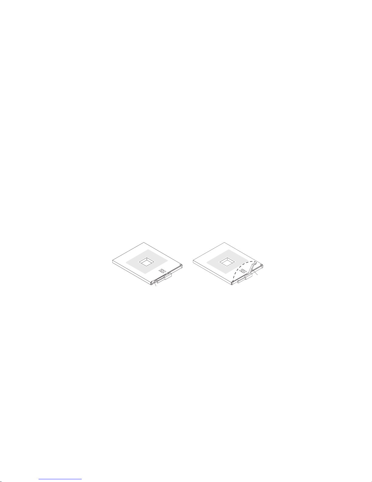
6. Lift the microprocessor-tray release latch.
7. Open the microprocessor-tray levers.
Attention: The microprocessor tray is heavy. Pull the tray partially out of the
server, and then reposition your hands to grasp the body of the tray, before
pulling out the tray the rest of the way.
8. Remove the microprocessor tray.
9. Press in on the release latches on each side of the tray; then, pull the tray out
the rest of the way.
10. Lift the air baffle out of the microprocessor tray.
11. Open the heat sink-release lever and remove the heat sink.
Note: The thermal adhesive material securing the heat sink to the
microprocessor might have formed a strong bond. Gently rotate the heat sink
back and forth to help break this bond. When the heat sink moves back and
forth easily, the bond is broken.
12. Open the microprocessor-release lever and remove the microprocessor from
the microprocessor socket.
13. If you are instructed to return the microprocessor tray and microprocessor,
follow all packaging instructions, and use any packaging materials for shipping
that are supplied to you.
To install the replacement microprocessor tray and microprocessor, complete the
following steps:
1. Lift the microprocessor-release lever to the fully open position (approximately
135° angle).
Lever fully
Lever closed
open
Attention: To avoid bending the pins on the microprocessor, do not use
excessive force when pressing it into the socket.
2. Position the microprocessor over the microprocessor socket as shown in the
following illustration. Carefully press the microprocessor into the socket.
56 IBM System x3950 Type 8878 and System x3950 E Type 8879: Problem Determination and Service Guide
Page 73

Microprocessor
Microprocessor
orientation indicator
Microprocessor
connector
Microprocessorrelease lever
3. Close the microprocessor-release lever to secure the microprocessor.
4. Make sure that the heat-sink retaining clip is open.
5. If you are installing a new heat sink, remove the cover from the bottom of the
heat sink. If you are reinstalling a heat sink that was previously removed, go to
“Thermal grease” on page 58 for instructions on replacing the contaminated or
missing thermal grease; then, return here and continue step 6.
6. If necessary, remove the cover from the bottom of the heat sink.
7. Position the heat sink above the microprocessor, making sure that the word
“Front” is closest to the front of the server; then, press the heat sink into place
and close the heat-sink release lever.
Note: If you are installing an additional microprocessor in microprocessor
socket 3 or 4, you must also install a VRM.
8. If necessary, install a VRM in the connector.
a. Open the retaining clips on each end of the VRM connector.
b. Turn the VRM so the keys align with the slot.
c. Insert the VRM into the connector by aligning the edges of the VRM with
the slots at the end of the VRM connector. Firmly press the VRM straight
down into the connector by applying pressure on both ends of the VRM
simultaneously. The retaining clips snap into the locked position when the
VRM is seated in the connector.
9. Install the air baffle in the microprocessor tray.
10. Install the microprocessor tray in the server:
a. Make sure that the microprocessor-tray release latch is open; then, push
the microprocessor tray into the server.
b. Close the tray levers and make sure they are securely latched.
c. Close the microprocessor-tray release latch.
d. Reinstall the fans and memory cards in the server.
Install the top cover and bezel (see “Top cover and bezel” on page 45).
11.
12. Slide the server into the rack.
13. Connect the cables and power cords (see “Connecting the cables” on page 34
for cabling instructions).
14. Turn on all attached devices and the server.
Chapter 4. Removing and replacing server components 57
Page 74

Thermal grease
The thermal grease must be replaced whenever the heat sink has been removed
from the top of the microprocessor and is going to be reused or when debris is
found in the grease.
To replace damaged or contaminated thermal grease on the microprocessor and
heat sink, complete the following steps:
1. Place the heat sink on a clean work surface.
2. Remove the cleaning pad from its package and unfold it completely.
3. Use the cleaning pad to wipe the thermal grease from the bottom of the heat
sink.
Note: Make sure that all of the thermal grease is removed.
4. Use a clean area of the cleaning pad to wipe the thermal grease from the
microprocessor; then, dispose of the cleaning pad after all of the thermal grease
is removed.
Microprocessor
0.01 mL of
thermal grease
5. Use the thermal-grease syringe to place 16 uniformly spaced dots of 0.01 mL
each on the top of the microprocessor.
Note: 0.01mL is one tick mark on the syringe. If the grease is properly applied,
approximately half (0.22 mL) of the grease will remain in the syringe.
6. Install the heat sink onto the microprocessor as described in “Removing and
installing a microprocessor” on page 55.
58 IBM System x3950 Type 8878 and System x3950 E Type 8879: Problem Determination and Service Guide
Page 75

PCI-X board assembly
To remove the PCI-X board assembly, complete the following steps:
AC
D
C
Handle
Retainer
screws
1. Read the safety information that begins on page vii and “Installation guidelines”
on page 31.
2. Turn off the server and peripheral devices, and disconnect the power cords
and all external cables necessary to replace the device.
3. Remove the top cover and bezel (see “Top cover and bezel” on page 45).
4. Remove the power supplies and power-structure assembly (see “Power-supply
structure” on page 51).
5. Remove the I/O board (see “I/O board” on page 47).
6. Remove all adapters and adapter dividers, and place the adapters on a
static-protective surface.
Note: You might find it helpful to note where each adapter is installed before
removing the adapters.
7. Remove the card guide (see “PCI-X adapter guide” on page 50).
8. Disconnect the PCI-X switch card cable from the PCI-X board (see “PCI-X
switch card assembly” on page 60).
9. Disconnect the SAS backplane power cable from the PCI-X board (see “SAS
backplane” on page 52).
10. Remove all fans (see “Hot-swap fan” on page 37).
11. Remove the memory cards (see “Removing and replacing a memory card” on
page 40).
12. Lift the microprocessor-tray release latch, open the microprocessor-tray levers,
and pull the microprocessor tray out of the server slightly (see “Removing and
installing a microprocessor” on page 55).
13. Remove the power backplane (see “Power backplane” on page 61).
14. Loosen the blue retainer screws on the rear of the server.
Chapter 4. Removing and replacing server components 59
Page 76
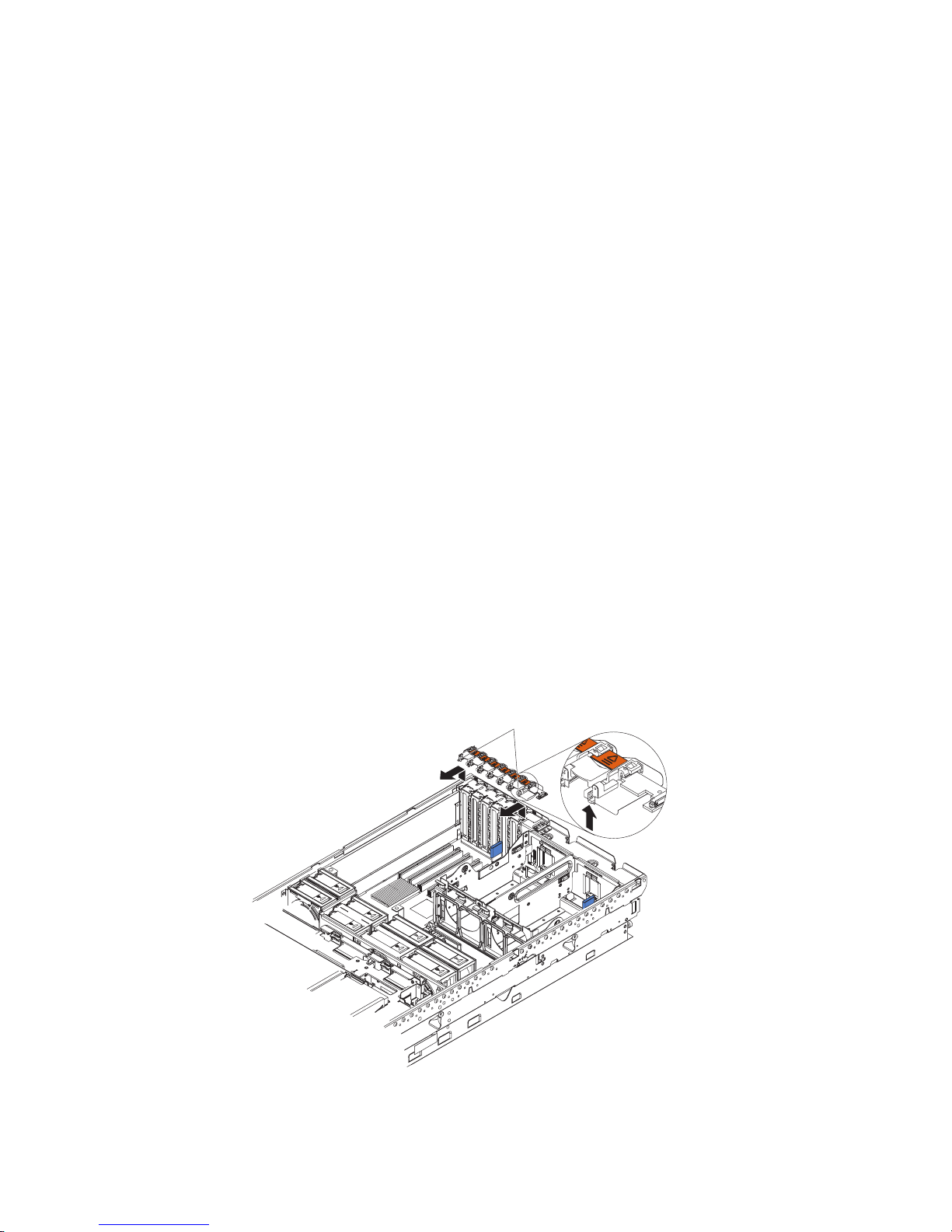
15. Slide the PCI-X board assembly toward the front of the server and grasp the
blue handle to pull the assembly out of the server.
16. If you are instructed to return the PCI-X board assembly, follow all packaging
instructions, and use any packaging materials for shipping that are supplied to
you.
To install the replacement PCI-X board assembly, complete the following steps:
1. Grasp the blue handle on the PCI-X board assembly and place the assembly
in the chassis. Slide the assembly toward the rear of the chassis and align it
with the blue retainer screws.
2. Tighten the retainer screws to secure the assembly.
3. Install the power backplane.
4. Slide the microprocessor-tray assembly back into the server.
5. Install the memory cards.
6. Install all fans.
7. Connect the SAS backplane power cable to the connector on the PCI-X board.
8. Connect the PCI-X switch card cable to the connector on the PCI-X board.
9. Install the PCI-X adapter guide and the adapter dividers.
10. Install the I/O board.
11. Install the power supplies and the power-structure assembly.
12. Install the top cover and bezel (see “Top cover and bezel” on page 45).
13. Slide the server into the rack.
14. Connect the cables and power cords (see “Connecting the cables” on page 34
for cabling instructions).
15. Turn on all attached devices and the server.
PCI-X switch card assembly
To remove the PCI-X switch-card assembly, complete the following steps:
1. Read the safety information that begins on page vii and “Installation guidelines”
on page 31.
Release latches
60 IBM System x3950 Type 8878 and System x3950 E Type 8879: Problem Determination and Service Guide
Page 77

2. Turn off the server and peripheral devices, and disconnect the power cords and
all external cables necessary to replace the device.
3. Remove the top cover (see “Top cover and bezel” on page 45).
4. Remove all adapters and place the adapters on a static-protective surface.
Note: You might find it helpful to note where each adapter is installed before
removing the adapters.
5. Disconnect the PCI-X switch card ribbon cable from the card.
6. Lift the release latches and slide the card away from the chassis; then, remove
the card from the server.
7. If you are instructed to return the PCI-X switch-card assembly, follow all
packaging instructions, and use any packaging materials for shipping that are
supplied to you.
To install the replacement PCI-X switch-card assembly, complete the following
steps:
1. Lower the card into place so that the lips on the bottom of the EMI shielding
material fit into the chassis, and slide the card into place until the two release
latches snap securely.
2. Connect the ribbon cable to the PCI-X switch-card assembly.
3. Install the adapters.
4. Install the top cover (see “Top cover and bezel” on page 45).
5. Slide the server into the rack.
6. Connect the cables and power cords (see “Connecting the cables” on page 34
for cabling instructions).
7. Turn on all attached devices and the server.
Power backplane
To remove the power backplane, complete the following steps:
1. Read the safety information that begins on page vii and “Installation guidelines”
on page 31.
Chapter 4. Removing and replacing server components 61
Page 78

2. Turn off the server and peripheral devices, and disconnect the power cords and
all external cables necessary to replace the device.
3. Remove the top cover and bezel (see “Top cover and bezel” on page 45).
4. Remove all fans (see “Hot-swap fan” on page 37).
5. Remove the memory cards (see “Removing and replacing a memory card” on
page 40).
6. Lift the microprocessor-tray release latch, open the microprocessor-tray levers,
and pull the microprocessor tray out of the server slightly (see “Removing and
installing a microprocessor” on page 55).
7. Remove the power supplies and the power-supply structure (see “Power-supply
structure” on page 51).
8. Remove the screws that secure the power backplane to the chassis and lift the
power backplane out of the server.
9. If you are instructed to return the power backplane, follow all packaging
instructions, and use any packaging materials for shipping that are supplied to
you.
To install the replacement power backplane, complete the following steps:
1. Align the power backplane in the server and secure the power backplane with
screws.
2. Install the power-supply structure and the power supplies.
3. Slide the microprocessor tray in the server and close the microprocessor-tray
levers.
4. Install the memory cards.
5. Install the fans.
6. Install the top cover and bezel (see “Top cover and bezel” on page 45).
7. Slide the server into the rack.
8. Connect the cables and power cords (see “Connecting the cables” on page 34
for cabling instructions).
9. Turn on all attached devices and the server.
62 IBM System x3950 Type 8878 and System x3950 E Type 8879: Problem Determination and Service Guide
Page 79

Scalability cartridge assembly
To remove the scalability cartridge assembly, complete the following steps:
Scalability cartridge assembly
Retention latch
1. Read the safety information that begins on page vii and “Installation guidelines”
on page 31.
2. Turn off the server and peripheral devices, and disconnect the power cords
and all external cables necessary to replace the device.
3. Remove the top cover and bezel (see “Top cover and bezel” on page 45).
4. Remove all fans (see “Hot-swap fan” on page 37).
5. Remove the memory cards (see “Removing and replacing a memory card” on
page 40).
6. Lift the microprocessor-tray release latch, open the microprocessor-tray levers,
and pull the microprocessor tray out of the server slightly (see “Removing and
installing a microprocessor” on page 55).
7. Remove the power supplies and the power-supply structure (see
“Power-supply structure” on page 51).
8. Move the retention latch away from the scalability cartridge assembly, grasp
the blue handle, and lift the assembly out of the server, allowing the structure
to pivot at the chassis rear.
9. Move the assembly away from the chassis rear as you lift the assembly from
the server.
10. If you are instructed to return the scalability cartridge assembly, follow all
packaging instructions, and use any packaging materials for shipping that are
supplied to you.
To install the replacement scalability cartridge assembly, complete the following
steps:
1. Insert the scalability cartridge assembly into the chassis rear and pivot the
assembly into place. Make sure the retention latch securely holds the assembly
in place.
2. Install the power-supply structure and the power supplies.
Chapter 4. Removing and replacing server components 63
Page 80

3. Slide the microprocessor tray in the server, close the microprocessor-tray levers,
and close the microprocessor-tray release latch.
4. Install the memory cards.
5. Install the fans.
6. Install the top cover and bezel (see “Top cover and bezel” on page 45).
7. Slide the server into the rack.
8. Connect the cables and power cords (see “Connecting the cables” on page 34
for cabling instructions).
9. Turn on all attached devices and the server.
64 IBM System x3950 Type 8878 and System x3950 E Type 8879: Problem Determination and Service Guide
Page 81

Chapter 5. Diagnostics
This chapter describes the diagnostic tools that are available to help you solve
problems that might occur in the server.
If you cannot locate and correct the problem using the information in this chapter,
see Appendix A, “Getting help and technical assistance,” on page 161 for more
information.
Diagnostic tools
The following tools are available to help you diagnose and solve hardware-related
problems:
v POST beep codes, error messages, and error logs
The power-on self-test (POST) generates beep codes and messages to indicate
successful test completion or the detection of a problem. See “POST” for more
information.
v Troubleshooting tables
These tables list problem symptoms and actions to correct the problems. See
“Troubleshooting tables” on page 89.
v Light path diagnostics
Use light path diagnostics to diagnose system errors quickly. See “Light path
diagnostics” on page 102 for more information.
v Diagnostic programs, messages, and error messages
The diagnostic programs are the primary method of testing the major
components of the server. The diagnostic programs are in read-only memory on
the server. See “Diagnostic programs, messages, and error codes” on page 112
for more information.
v Real Time Diagnostics
Real Time Diagnostics can help you diagnose problems in certain devices while
the operating system is running, to prevent or minimize server downtime. See
“Real Time Diagnostics” on page 130 for more information.
POST
When you turn on the server, it performs a series of tests to check the operation of
the server components and some optional devices in the server. This series of tests
is called the power-on self-test, or POST.
If a power-on password is set, you must type the password and press Enter, when
prompted, for POST to run.
If POST is completed without detecting any problems, a single beep sounds, and
the server startup is completed.
If POST detects a problem, more than one beep might sound, or an error message
is displayed. See “Beep code descriptions” on page 66 and “POST error codes” on
page 73 for more information.
© Copyright IBM Corp. 2007 65
Page 82

POST beep codes
A beep code is a combination of short or long beeps or series of short beeps that
are separated by pauses. For example, a “1-2-3” beep code is one short beep, a
pause, two short beeps, and pause, and three short beeps. A beep code other than
one beep indicates that POST has detected a problem. To determine the meaning
of a beep code, see “Beep code descriptions.” If no beep code sounds, see
“No-beep symptoms” on page 70.
Beep code descriptions
The following table describes the beep codes and suggested actions to correct the
detected problems.
A single problem might cause more than one error message. When this occurs,
correct the cause of the first error message. The other error messages usually will
not occur the next time POST runs.
Exception: If there are multiple error codes or light path diagnostics LEDs that
indicate a microprocessor error, the error might be in a microprocessor or in a
microprocessor socket. See “Microprocessor problems” on page 95 for information
about diagnosing microprocessor problems.
v Follow the suggested actions in the order in which they are listed in the Action column until the problem
is solved.
v See Chapter 3, “Parts listing, Type 8878 and 8879,” on page 23 to determine which components are
customer replaceable units (CRU) and which components are field replaceable units (FRU).
v If an action step is preceded by “(Trained service technician only),” that step must be performed only by a
trained service technician.
Beep code Description Action
1-1-3 CMOS write/read test failed.
1-1-4 BIOS ROM checksum failed.
1-2-1 Programmable interval timer failed.
1-2-2 DMA initialization failed.
1-2-3 DMA page register write/read failed.
1-2-4 RAM refresh verification failed.
1. Reseat the following components:
a. Battery
b. I/O board
Replace the components listed in step 1
2.
one at a time, in the order shown, restarting
the server each time.
1. Reseat the microprocessor tray.
2. (Trained service technician only) Replace
the microprocessor tray.
1. Reseat the I/O board.
2. Replace the I/O board.
1. Reseat the I/O board.
2. Replace the I/O board.
1. Reseat the I/O board.
2. Replace the I/O board.
1. Reseat the following components:
a. DIMM
b. Memory card
Replace the components listed in step 1
2.
one at a time, in the order shown, restarting
the server each time.
66 IBM System x3950 Type 8878 and System x3950 E Type 8879: Problem Determination and Service Guide
Page 83

v Follow the suggested actions in the order in which they are listed in the Action column until the problem
is solved.
v See Chapter 3, “Parts listing, Type 8878 and 8879,” on page 23 to determine which components are
customer replaceable units (CRU) and which components are field replaceable units (FRU).
v If an action step is preceded by “(Trained service technician only),” that step must be performed only by a
trained service technician.
Beep code Description Action
1-3-1 1st 64K RAM test failed.
1. Reseat the following components:
a. DIMM
b. Memory card
Replace the components listed in step 1
2.
one at a time, in the order shown, restarting
the server each time.
2-1-1 Secondary DMA register failed.
1. Reseat the I/O board.
2. Replace the I/O board.
2-1-2 Primary DMA register failed.
1. Reseat the I/O board.
2. Replace the I/O board.
2-1-3 Primary interrupt mask register failed.
1. Reseat the I/O board.
2. Replace the I/O board.
2-1-4 Secondary interrupt mask register failed.
1. Reseat the I/O board.
2. Replace the I/O board.
2-2-2 Keyboard controller failed.
1. Reseat the I/O board.
2. Replace the I/O board.
3-1-1 Timer tick interrupt failed.
1. Reseat the I/O board.
2. Replace the I/O board.
3-1-2 Interval timer channel 2 failed.
1. Reseat the I/O board.
2. Replace the I/O board.
3-1-4 Time-of-day clock failed.
1. Reseat the following components:
a. Battery
b. I/O board
Replace the components listed in step 1
2.
one at a time, in the order shown, restarting
the server each time.
Chapter 5. Diagnostics 67
Page 84

v Follow the suggested actions in the order in which they are listed in the Action column until the problem
is solved.
v See Chapter 3, “Parts listing, Type 8878 and 8879,” on page 23 to determine which components are
customer replaceable units (CRU) and which components are field replaceable units (FRU).
v If an action step is preceded by “(Trained service technician only),” that step must be performed only by a
trained service technician.
Beep code Description Action
3-3-2 Critical SMBUS error occurred.
1. Disconnect power cord, wait 30 seconds,
and retry.
2. Reseat the following components:
a. DIMM
b. Memory card
c. Microprocessor tray
d. I/O board
Replace the following components one at a
3.
time, in the order shown, restarting the
server each time.
a. DIMM
b. Memory card
c. (Trained service technician only)
Microprocessor tray
d. I/O board
3-3-3 No operational memory in system. Note: Make sure you re-enable the memory in
the Configuration/Setup Utility program. See,
“Memory problems” on page 94
1. Make sure that all memory cards contain
the correct number of DIMMs; install or
reseat DIMMS; then, restart the server.
2. Reseat the following components:
a. DIMM
b. Memory card
c. Microprocessor tray
Replace the following components one at a
3.
time, in the order shown, restarting the
server each time.
a. DIMM
b. Memory card
c. (Trained service technician only)
Microprocessor tray
Two short beeps Information only, configuration has
changed.
1. Run the Configuration/Setup Utility program.
2. Run the diagnostic programs.
68 IBM System x3950 Type 8878 and System x3950 E Type 8879: Problem Determination and Service Guide
Page 85

v Follow the suggested actions in the order in which they are listed in the Action column until the problem
is solved.
v See Chapter 3, “Parts listing, Type 8878 and 8879,” on page 23 to determine which components are
customer replaceable units (CRU) and which components are field replaceable units (FRU).
v If an action step is preceded by “(Trained service technician only),” that step must be performed only by a
trained service technician.
Beep code Description Action
Three short beeps Memory error. Note: Make sure you re-enable the memory in
the Configuration/Setup Utility program. See,
“Memory problems” on page 94
1. Reseat the following components:
a. DIMM
b. Memory card
c. Microprocessor tray
Replace the following components one at a
2.
time, in the order shown, restarting the
server each time.
a. DIMM
b. Memory card
c. (Trained service technician only)
Microprocessor tray
One continuous beep Microprocessor error.
1. Reseat the following components:
a. (Trained service technician only)
Microprocessor
b. (Trained service technician only)
Optional microprocessor
c. Microprocessor tray
Replace the following components one at a
2.
time, in the order shown, restarting the
server each time.
a. (Trained service technician only)
Microprocessor
b. (Trained service technician only)
Optional microprocessor
c. (Trained service technician only)
Microprocessor tray
Repeating short beeps Keyboard error.
1. Reseat the following components:
a. Keyboard
b. I/O board
Replace the components listed in step 1
2.
one at a time, in the order shown, restarting
the server each time.
Repeating long beeps Memory error. Reseat the DIMMs.
Chapter 5. Diagnostics 69
Page 86

v Follow the suggested actions in the order in which they are listed in the Action column until the problem
is solved.
v See Chapter 3, “Parts listing, Type 8878 and 8879,” on page 23 to determine which components are
customer replaceable units (CRU) and which components are field replaceable units (FRU).
v If an action step is preceded by “(Trained service technician only),” that step must be performed only by a
trained service technician.
Beep code Description Action
One long and one short
beep
Card error.
1. Reseat the following components:
a. Microprocessor tray
b. I/O board
Replace the following components one at a
2.
time, in the order shown, restarting the
server each time.
a. (Trained service technician only)
Microprocessor tray
b. I/O board
One long and two short
beeps
Card error.
1. Reseat the following components:
a. Microprocessor tray
b. I/O board
Replace the following components one at a
2.
time, in the order shown, restarting the
server each time.
a. (Trained service technician only)
Microprocessor tray
b. I/O board
Two long and two short
beeps
Card error.
1. Reseat the following components:
a. Microprocessor tray
b. I/O board
Replace the following components one at a
2.
time, in the order shown, restarting the
server each time.
a. (Trained service technician only)
Microprocessor tray
b. I/O board
No-beep symptoms
v Follow the suggested actions in the order in which they are listed in the Action column until the problem
is solved.
v See Chapter 3, “Parts listing, Type 8878 and 8879,” on page 23 to determine which components are
customer replaceable units (CRU) and which components are field replaceable units (FRU).
v If an action step is preceded by “(Trained service technician only)”, that step must be performed only by a
trained service technician.
No-beep symptom Description Action
No beeps occur, and the
system operates
correctly.
70 IBM System x3950 Type 8878 and System x3950 E Type 8879: Problem Determination and Service Guide
1. (Trained service technician only) Reseat the
operator information panel.
2. (Trained service technician only) Replace
the operator information panel.
Page 87

v Follow the suggested actions in the order in which they are listed in the Action column until the problem
is solved.
v See Chapter 3, “Parts listing, Type 8878 and 8879,” on page 23 to determine which components are
customer replaceable units (CRU) and which components are field replaceable units (FRU).
v If an action step is preceded by “(Trained service technician only)”, that step must be performed only by a
trained service technician.
No-beep symptom Description Action
No beeps occur after
successful completion of
POST.
The power-on status is Disabled.
1. Run the Configuration/Setup Utility program
and select Start Options; then, set
Power-On Status to Enable.
2. (Trained service technician only) Reseat the
operator information panel.
3. (Trained service technician only) Replace
the operator information panel.
No beeps occur, and
there is no video.
See “Solving undetermined problems” on page
158.
Error logs
The POST error log contains the three most recent error codes and messages that
were generated during POST. The BMC log and the system-error log contain
messages that were generated during POST and all system status messages from
the service processor.
The following illustration shows an example of a BMC log entry.
BMC System Event Log
---------------------------------------------------------Get Next Entry
Get Previous Entry
Clear BMC SEL
Entry Number= 00005 / 00011
Record ID= 0005
Record Type= 02
Timestamp= 2005/01/25 16:15:17
Entry Details: Generator ID= 0020
Sensor Type= 04
Assertion Event
Fan
Threshold
Lower Non-critical - going high
Sensor Number= 40
Event Direction/Type= 01
Event Data= 52 00 1A
The BMC log is limited in size. When the log is full, new entries will not overwrite
existing entries; therefore, you must periodically clear the BMC log through the
Configuration/Setup Utility program (the menu choices are described in the User’s
Guide). When you are troubleshooting an error, be sure to clear the BMC log so
that you can find current errors more easily.
Entries that are written to the BMC log during the early phase of POST show an
incorrect date and time as the default time stamp; however, the date and time are
corrected as POST continues.
Chapter 5. Diagnostics 71
Page 88

Each BMC log entry appears on its own page. To display all the data for an entry,
use the Up Arrow (—) and Down Arrow (–) keys or the Page Up and Page Down
keys. To move from one entry to the next, select Get Next Entry or Get Previous
Entry.
The log indicates an assertion event when an event has occurred. It indicates a
deassertion event when the event is no longer occurring.
Some of the error codes and messages in the BMC log are abbreviated.
If you view the BMC log through the Web interface of the optional Remote
Supervisor Adapter II SlimLine, the messages can be translated.
You can view the contents of the POST error log, the BMC log, and the
system-error log from the Configuration/Setup Utility program. Yo u can view the
contents of the BMC log also from the diagnostic programs.
When you are troubleshooting PCI-X slots, note that the error logs report the PCI-X
buses numerically. The numerical assignments vary depending on the configuration.
You can check the assignments by running the Configuration/Setup Utility program
(see the User’s Guide for more information).
Viewing error logs from the Configuration/Setup Utility program
For complete information about using the Configuration/Setup Utility program, see
the User’s Guide.
To view the error logs, complete the following steps:
1. Turn on the server.
2. When the prompt Press F1 for Configuration/Setup appears, press F1. If you
have set both a power-on password and an administrator password, you must
type the administrator password to view the error logs.
3. Use one of the following procedures:
v To view the POST error log, select Error Logs, and then select POST Error
Log.
v To view the BMC log, select Advanced Settings, select Baseboard
Management Controller (BMC) settings, and then select BMC System
Event Log.
v To view the system-error log (available only if an optional Remote Supervisor
Adapter II SlimLine is installed), select Event/Error Logs, and then select
System Event/Error Log.
Viewing the BMC log from the diagnostic programs
The BMC log contains the same information whether it is viewed from the
Configuration/Setup Utility program or from the diagnostic programs.
For information about using the diagnostic programs, see “Running the diagnostic
programs” on page 112.
To view the BMC log, complete the following steps:
1. If the server is running, turn off the server and all attached devices.
2. Turn on all attached devices; then, turn on the server.
3. When the prompt F2 for Diagnostics appears, press F2. If you have set both a
power-on password and an administrator password, you must type the
administrator password to run the diagnostic programs.
72 IBM System x3950 Type 8878 and System x3950 E Type 8879: Problem Determination and Service Guide
Page 89

4. From the top of the screen, select Hardware Info.
5. From the list, select BMC Log.
POST error codes
The following table describes the POST error codes and suggested actions to
correct the detected problems.
v Follow the suggested actions in the order in which they are listed in the Action column until the problem
is solved.
v See Chapter 3, “Parts listing, Type 8878 and 8879,” on page 23 to determine which components are
customer replaceable units (CRU) and which components are field replaceable units (FRU).
v If an action step is preceded by “(Trained service technician only),” that step must be performed only by a
trained service technician.
Error code Description Action
062 Three consecutive boot failures using the
default configuration.
101, 102 Tick timer internal interrupt, internal timer
channel 2.
114 Adapter read-only memory (ROM) error.
151 Real-time clock error.
161 Real-time clock battery error.
1. Flash the system firmware to the latest level (see
“Updating the firmware” on page 13).
2. Reseat the I/O board.
3. Replace the I/O board.
1. Reseat the I/O board.
2. Replace the I/O board.
1. Remove all adapters and reinstall them one at a
time, restarting the server each time, to identify
the failing adapter; then, replace the failing
adapter.
2. Reseat the microprocessor tray.
3. Reseat the I/O board.
4. (Trained service technician only) Replace the
microprocessor tray.
5. Replace the I/O board.
1. Reseat the following components:
a. Battery
b. I/O board
Replace the components listed in step 1 one at a
2.
time, in the order shown, restarting the server
each time.
1. Reseat the following components:
a. Battery
b. I/O board
Replace the components listed in step 1 one at a
2.
time, in the order shown, restarting the server
each time.
Chapter 5. Diagnostics 73
Page 90

v Follow the suggested actions in the order in which they are listed in the Action column until the problem
is solved.
v See Chapter 3, “Parts listing, Type 8878 and 8879,” on page 23 to determine which components are
customer replaceable units (CRU) and which components are field replaceable units (FRU).
v If an action step is preceded by “(Trained service technician only),” that step must be performed only by a
trained service technician.
Error code Description Action
162 Device configuration error.
1. Run the Configuration/Setup Utility program,
select Load Default Settings, and save the
settings.
2. Reseat the following components:
a. Battery
b. Failing device
c. I/O board
Remove the battery for 60 minutes; then, reinstall
3.
the battery and restart the server.
4. Replace the components listed in step 2 one at a
time, in the order shown, restarting the server
each time.
163 Real-time clock error.
1. Run the Configuration/Setup Utility program,
select Load Default Settings, make sure that the
date and time are correct, and save the settings.
2. Reseat the following components:
a. Battery
b. I/O board
Replace the components listed in step 2 one at a
3.
time, in the order shown, restarting the server
each time.
175 Bad EEPROM CRC#1.
1. Restart the server.
2. Update the BMC firmware (see “Updating the
firmware” on page 13).
3. Reseat the microprocessor tray.
4. (Trained service technician only) Replace the
microprocessor tray.
178 System VPD not available.
1. Restart the server.
2. Update the BMC firmware (see “Updating the
firmware” on page 13).
3. Reseat the microprocessor tray.
4. (Trained service technician only) Replace the
microprocessor tray.
74 IBM System x3950 Type 8878 and System x3950 E Type 8879: Problem Determination and Service Guide
Page 91

v Follow the suggested actions in the order in which they are listed in the Action column until the problem
is solved.
v See Chapter 3, “Parts listing, Type 8878 and 8879,” on page 23 to determine which components are
customer replaceable units (CRU) and which components are field replaceable units (FRU).
v If an action step is preceded by “(Trained service technician only),” that step must be performed only by a
trained service technician.
Error code Description Action
184 Power-on password damaged.
1. Run the Configuration/Setup Utility program,
select Load Default Settings, and save the
settings.
2. Reseat the following components:
a. Battery
b. I/O board
Remove the battery for 60 minutes; then, reinstall
3.
the battery and restart the server.
4. Replace the components listed in step 2 one at a
time, in the order shown, restarting the server
each time.
187 VPD serial number not set.
1. Set the serial number by updating the BIOS code
level (see “Updating the firmware” on page 13).
2. Reseat the following components:
a. I/O board
b. Optional Remote Supervisor Adapter II
SlimLine
Replace the components listed in step 2 one at a
3.
time, in the order shown, restarting the server
each time.
188 Bad EEPROM CRC #2.
1. Restart the server.
2. Update the BMC firmware (see “Updating the
firmware” on page 13).
3. Reseat the microprocessor tray.
4. (Trained service technician only) Replace the
microprocessor tray.
189 An attempt was made to access the server
with an incorrect password.
Restart the server and enter the administrator
password; then, run the Configuration/Setup Utility
program and change the power-on password.
289 A DIMM has been disabled by the user or
by the system.
Note: Make sure you re-enable the memory in the
Configuration/Setup Utility program. See, “Memory
problems” on page 94.
1. If the DIMM was disabled by the user, run the
Configuration/Setup Utility program and enable
the DIMM.
2. Make sure that the DIMM is installed correctly
(see “Memory card and memory module (DIMM)”
on page 40).
3. Reseat the DIMM.
4. Replace the DIMM.
Chapter 5. Diagnostics 75
Page 92

v Follow the suggested actions in the order in which they are listed in the Action column until the problem
is solved.
v See Chapter 3, “Parts listing, Type 8878 and 8879,” on page 23 to determine which components are
customer replaceable units (CRU) and which components are field replaceable units (FRU).
v If an action step is preceded by “(Trained service technician only),” that step must be performed only by a
trained service technician.
Error code Description Action
301 Keyboard or keyboard controller error.
1. If you have installed a USB keyboard, run the
Configuration/Setup Utility program and enable
keyboardless operation to prevent the POST error
message 301 from being displayed during startup.
2. Reseat the following components:
a. Keyboard
b. I/O board
Replace the components listed in step 2 one at a
3.
time, in the order shown, restarting the server
each time.
303 Keyboard controller error.
1. Reseat the following components:
a. I/O board
b. Keyboard
Replace the components listed in step 1 one at a
2.
time, in the order shown, restarting the server
each time.
1600 The baseboard management controller
failed BIST (built-in self-test).
1. Update the BMC firmware (see “Updating the
firmware” on page 13).
2. Reseat the following components:
a. Microprocessor tray
b. I/O board
c. PCI or PCI-X adapters
(Trained service technician only) Replace the
3.
microprocessor tray.
1601 Systems-management adapter
communication error.
1. Make sure that the Remote Supervisor Adapter II
SlimLine is installed correctly.
2. Update the Remote Supervisor Adapter II
SlimLine firmware (see “Updating the firmware”
on page 13).
3. Update the BMC firmware (see “Updating the
firmware” on page 13).
4. Reseat the following components:
a. Microprocessor tray
b. I/O board
c. Adapter
(Trained service technician only) Replace the
5.
microprocessor tray.
76 IBM System x3950 Type 8878 and System x3950 E Type 8879: Problem Determination and Service Guide
Page 93

v Follow the suggested actions in the order in which they are listed in the Action column until the problem
is solved.
v See Chapter 3, “Parts listing, Type 8878 and 8879,” on page 23 to determine which components are
customer replaceable units (CRU) and which components are field replaceable units (FRU).
v If an action step is preceded by “(Trained service technician only),” that step must be performed only by a
trained service technician.
Error code Description Action
1602 Systems-management adapter
communication error.
1. Make sure that the Remote Supervisor Adapter II
SlimLine is installed correctly.
2. Update the Remote Supervisor Adapter II
SlimLine firmware (see “Updating the firmware”
on page 13).
3. Update the BMC firmware (see “Updating the
firmware” on page 13).
4. Reseat the following components:
a. Microprocessor tray
b. I/O board
c. (Trained service technician only) PCI-X board
Replace the Remote Supervisor Adapter II
5.
SlimLine.
6. (Trained service technician only) Replace the
microprocessor tray.
1762 Fixed disk configuration error.
1. Run the Configuration/Setup Utility program and
load the defaults.
2. Reseat the following components:
a. SAS cables
b. SAS hard disk drive
c. I/O board
Replace the components listed in step 2 one at a
3.
time, in the order shown, restarting the server
each time.
178x Fixed disk error.
1. Reseat the hard disk drive cables.
2. Replace the hard disk drive cables.
3. Run the hard disk drive diagnostic tests.
4. Reseat the following components:
a. Optional ServeRAID™-8i adapter.
b. Hard disk drive.
c. I/O board.
Replace the components listed in step 4 one at a
5.
time, in the order shown, restarting the server
each time.
1800 Unavailable PCI hardware interrupt.
1. Run the Configuration/Setup Utility program and
adjust the adapter settings.
2. Remove each adapter one at a time, restarting
the server each time, until the problem is isolated.
Chapter 5. Diagnostics 77
Page 94

v Follow the suggested actions in the order in which they are listed in the Action column until the problem
is solved.
v See Chapter 3, “Parts listing, Type 8878 and 8879,” on page 23 to determine which components are
customer replaceable units (CRU) and which components are field replaceable units (FRU).
v If an action step is preceded by “(Trained service technician only),” that step must be performed only by a
trained service technician.
Error code Description Action
1962 A drive does not contain a valid boot sector.
1. Make sure that a bootable operating system is
installed.
2. Run the hard disk drive diagnostic tests.
3. Reseat the following components:
a. SAS drive
b. SAS hard disk drive backplane cable
c. I/O board
Replace the components listed in step 3 one at a
4.
time, in the order shown, restarting the server
each time.
5962 IDE CD or DVD drive configuration error.
1. Run the Configuration/Setup Utility program and
load the default settings (see “Configuration/Setup
Utility menu choices” on page 15).
2. Reseat the following components:
a. CD or DVD drive cable
b. CD or DVD drive
c. I/O board
Replace the components listed in step 2 one at a
3.
time, in the order shown, restarting the server
each time.
8603 Pointing-device error.
1. Reseat the following components:
a. Pointing device
b. I/O board
Replace the components listed in step 1 one at a
2.
time, in the order shown, restarting the server
each time.
0001295 ECC circuit check.
1. Reseat the following components:
a. DIMM
b. Memory card
Replace the components in step 1 one at a time,
2.
in the order shown, restarting the server each
time.
78 IBM System x3950 Type 8878 and System x3950 E Type 8879: Problem Determination and Service Guide
Page 95

v Follow the suggested actions in the order in which they are listed in the Action column until the problem
is solved.
v See Chapter 3, “Parts listing, Type 8878 and 8879,” on page 23 to determine which components are
customer replaceable units (CRU) and which components are field replaceable units (FRU).
v If an action step is preceded by “(Trained service technician only),” that step must be performed only by a
trained service technician.
Error code Description Action
00012000 Processor machine check error.
1. Reseat the following components:
a. (Trained service technician only)
Microprocessor
b. Microprocessor tray
Replace the following components one at a time,
2.
in the order shown, restarting the server each
time.
a. (Trained service technician only)
Microprocessor
b. (Trained service technician only)
Microprocessor tray
00019501 Processor 1 is not functioning; check
processor LEDs.
1. Reseat the following components:
a. Microprocessor tray
b. (Trained service technician only)
Microprocessor 1
Replace the following components one at a time,
2.
in the order shown, restarting the server each
time.
a. (Trained service technician only)
Microprocessor 1
b. (Trained service technician only)
Microprocessor tray
00019502 Processor 2 is not functioning; check
processor LEDs.
1. Reseat the following components:
a. Microprocessor tray
b. (Trained service technician only)
Microprocessor 2
Replace the following components one at a time,
2.
in the order shown, restarting the server each
time.
a. (Trained service technician only)
Microprocessor 2
b. (Trained service technician only)
Microprocessor tray
Chapter 5. Diagnostics 79
Page 96

v Follow the suggested actions in the order in which they are listed in the Action column until the problem
is solved.
v See Chapter 3, “Parts listing, Type 8878 and 8879,” on page 23 to determine which components are
customer replaceable units (CRU) and which components are field replaceable units (FRU).
v If an action step is preceded by “(Trained service technician only),” that step must be performed only by a
trained service technician.
Error code Description Action
00019503 Processor 3 is not functioning; check VRM
and processor LEDs.
1. Reseat the following components:
a. Microprocessor tray
b. VRM 3
c. (Trained service technician only)
Microprocessor 3
Replace the following components one at a time,
2.
in the order shown, restarting the server each
time.
a. VRM 3
b. (Trained service technician only)
Microprocessor 3
c. (Trained service technician only)
Microprocessor tray
00019504 Processor 4 is not functioning; check VRM
and processor LEDs.
1. Reseat the following components:
a. Microprocessor tray
b. VRM 4
c. (Trained service technician only)
Microprocessor 4
Replace the following components one at a time,
2.
in the order shown, restarting the server each
time.
a. VRM 4
b. (Trained service technician only)
Microprocessor 4
c. (Trained service technician only)
Microprocessor tray
00019701 Processor 1 failed BIST.
1. Reseat the following components:
a. (Trained service technician only)
Microprocessor 1
b. Microprocessor tray
Replace the following components one at a time,
2.
in the order shown, restarting the server each
time.
a. (Trained service technician only)
Microprocessor 1
b. (Trained service technician only)
Microprocessor tray
80 IBM System x3950 Type 8878 and System x3950 E Type 8879: Problem Determination and Service Guide
Page 97

v Follow the suggested actions in the order in which they are listed in the Action column until the problem
is solved.
v See Chapter 3, “Parts listing, Type 8878 and 8879,” on page 23 to determine which components are
customer replaceable units (CRU) and which components are field replaceable units (FRU).
v If an action step is preceded by “(Trained service technician only),” that step must be performed only by a
trained service technician.
Error code Description Action
00019702 Processor 2 failed BIST.
1. Reseat the following components:
a. (Trained service technician only)
Microprocessor 2
b. Microprocessor tray
Replace the following components one at a time,
2.
in the order shown, restarting the server each
time.
a. (Trained service technician only)
Microprocessor 2
b. (Trained service technician only)
Microprocessor tray
00019703 Processor 3 failed BIST.
1. Reseat the following components:
a. (Trained service technician only)
Microprocessor 3
b. VRM3
c. Microprocessor tray
Replace the following components one at a time,
2.
in the order shown, restarting the server each
time.
a. (Trained service technician only)
Microprocessor 3
b. VRM3
c. (Trained service technician only)
Microprocessor tray
00019704 Processor 4 failed BIST.
1. Reseat the following components:
a. (Trained service technician only)
Microprocessor 4
b. VRM4
c. Microprocessor tray
Replace the following components one at a time,
2.
in the order shown, restarting the server each
time.
a. (Trained service technician only)
Microprocessor 4
b. VRM4
c. (Trained service technician only)
Microprocessor tray
Chapter 5. Diagnostics 81
Page 98

v Follow the suggested actions in the order in which they are listed in the Action column until the problem
is solved.
v See Chapter 3, “Parts listing, Type 8878 and 8879,” on page 23 to determine which components are
customer replaceable units (CRU) and which components are field replaceable units (FRU).
v If an action step is preceded by “(Trained service technician only),” that step must be performed only by a
trained service technician.
Error code Description Action
00180100 A PCI adapter has requested memory
resources that are not available.
1. Change the order of the adapters in the PCI-X
slots. Make sure that the boot device is
positioned early in the scan order (see the User’s
Guide for information about the scan order).
2. Make sure that the settings for the adapter and all
other adapters in the Configuration/Setup Utility
program are correct. If the memory resource
settings are not correct, change them.
3. If all memory resources are being used, remove
an adapter to make memory available to the
adapter. Disabling the BIOS on the adapter
should correct the error. See the documentation
that comes with the adapter.
00180200 No more I/O space is available for a PCI
adapter.
1. If the error code indicates a particular PCI or
PCI-X slot or device, remove that device.
2. If the error continues, reseat the following
components:
a. Each adapter
b. (Trained service technician only) PCI-X board
Replace the components listed in step 2 one at a
3.
time, in the order shown, restarting the server
each time.
00180300 No more memory (above 1 MB for a PCI
adapter).
1. If the error code indicates a particular PCI or
PCI-X slot or device, remove that device.
2. Reseat the following components:
a. Each adapter
b. (Trained service technician only) PCI-X board
Replace the components listed in step 2 one at a
3.
time, in the order shown, restarting the server
each time.
00180400 No more memory (below 1 MB for a PCI
adapter).
1. Reseat the following components:
a. Each adapter
b. (Trained service technician only) PCI-X board
Replace the components listed in step 1 one at a
2.
time, in the order shown, restarting the server
each time.
00180500 PCI option ROM checksum error.
1. Remove the failing adapter.
2. Reseat the following components:
a. Each adapter
b. (Trained service technician only) PCI-X board
Replace the components listed in step 2 one at a
3.
time, in the order shown, restarting the server
each time.
82 IBM System x3950 Type 8878 and System x3950 E Type 8879: Problem Determination and Service Guide
Page 99

v Follow the suggested actions in the order in which they are listed in the Action column until the problem
is solved.
v See Chapter 3, “Parts listing, Type 8878 and 8879,” on page 23 to determine which components are
customer replaceable units (CRU) and which components are field replaceable units (FRU).
v If an action step is preceded by “(Trained service technician only),” that step must be performed only by a
trained service technician.
Error code Description Action
00180600 PCI built-in self-test failure.
1. If the error code indicates a particular PCI or
PCI-X slot or device, remove that device.
Note: Slot 0 indicates the I/O board.
2. Reseat the following components:
a. Each adapter
b. (Trained service technician only, if the
specified board is a FRU) The board that is
indicated in the error code. (See Chapter 3,
“Parts listing, Type 8878 and 8879,” on page
23, to determine CRU or FRU status.)
Replace the components listed in step 2 one at a
3.
time, in the order shown above, restarting the
server each time.
00180700,
00180800
General PCI error.
1. Make sure that no devices have been disabled in
the Configuration/Setup Utility program.
2. Reseat the following components:
a. Failing adapter
Note: If an error LED is lit on the PCI-X
board or on an adapter, reseat that adapter
first; if no LEDs are lit, reseat each adapter
one at a time, restarting the server each time,
to isolate the failing adapter.
b. (Trained service technician only) PCI-X board
Replace the components listed in step 2 one at a
3.
time, in the order shown, restarting the server
each time.
00181000 PCI error.
1. Remove the adapters from the PCI or PCI-X
slots.
2. Reseat the following components:
a. Failing adapter
Note: If an error LED is lit on the PCI-X
board or on an adapter, reseat that adapter
first; if no LEDs are lit, reseat each adapter
one at a time, restarting the server each time,
to isolate the failing adapter.
b. (Trained service technician only) PCI-X board
Replace the components listed in step 2 one at a
3.
time, in the order shown, restarting the server
each time.
Chapter 5. Diagnostics 83
Page 100

v Follow the suggested actions in the order in which they are listed in the Action column until the problem
is solved.
v See Chapter 3, “Parts listing, Type 8878 and 8879,” on page 23 to determine which components are
customer replaceable units (CRU) and which components are field replaceable units (FRU).
v If an action step is preceded by “(Trained service technician only),” that step must be performed only by a
trained service technician.
Error code Description Action
01295085 ECC checking hardware test error.
1. Reseat the following components:
a. (Trained service technician only)
Microprocessor
b. DIMM
c. Microprocessor tray
Replace the following components one at a time,
2.
in the order shown, restarting the server each
time.
a. (Trained service technician only)
Microprocessor
b. DIMM
c. (Trained service technician only)
Microprocessor tray
01298001 No update data for processor 1.
1. Make sure that all microprocessors have the
same cache size (see “Configuration/Setup Utility
menu choices” on page 15).
2. Update the BIOS code again (see “Updating the
firmware” on page 13).
3. (Trained service technician only) Reseat
microprocessor 1.
4. (Trained service technician only) Replace
microprocessor 1.
01298002 No update data for processor 2.
1. Make sure that all microprocessors have the
same cache size (see “Configuration/Setup Utility
menu choices” on page 15).
2. Update the BIOS code again (see “Updating the
firmware” on page 13).
3. (Trained service technician only) Reseat
microprocessor 2.
4. (Trained service technician only) Replace
microprocessor 2.
01298004 No update data for processor 3.
1. Make sure that all microprocessors have the
same cache size (see “Configuration/Setup Utility
menu choices” on page 15).
2. Update the BIOS code again (see “Updating the
firmware” on page 13).
3. (Trained service technician only) Reseat
microprocessor 3.
4. (Trained service technician only) Replace
microprocessor 3.
84 IBM System x3950 Type 8878 and System x3950 E Type 8879: Problem Determination and Service Guide
 Loading...