

IBM System x3850 X5, BladeCenter HX5, System x3950 X5, System x3690 X5 Implementation Manual
Page 1

Front cover
Click here to check for updates
IBM eX5
Implementation Guide
Covers the IBM System x3950 X5, x3850 X5,
x3690 X5, and the IBM BladeCenter HX5
Details technical information
about each server and option
Describes how to implement
two-node configurations
David Watts
Aaron Belisle
Duncan Furniss
Scott Haddow
Michael Hurman
Jeneea Jervay
Eric Kern
Cynthia Knight
Miroslav Peic
Tom Sorcic
Evans Tanurdin
ibm.com/redbooks
Page 2

Page 3

International Technical Support Organization
IBM eX5 Implementation Guide
May 2011
SG24-7909-00
Page 4

Note: Before using this information and the product it supports, read the information in “Notices” on
page xi.
First Edition (May 2011)
This edition applies to the following servers:
IBM System x3850 X5, machine type 7145
IBM System x3950 X5, machine type 7145
IBM System x3690 X5, machine type 7148
IBM BladeCenter HX5, machine type 7872
© Copyright International Business Machines Corporation 2011. All rights reserved.
Note to U.S. Government Users Restricted Rights -- Use, duplication or disclosure restricted by GSA ADP Schedule
Contract with IBM Corp.
Page 5

Contents
Notices . . . . . . . . . . . . . . . . . . . . . . . . . . . . . . . . . . . . . . . . . . . . . . . . . . . . . . . . . . . . . . . . . xi
Trademarks . . . . . . . . . . . . . . . . . . . . . . . . . . . . . . . . . . . . . . . . . . . . . . . . . . . . . . . . . . . . . . xii
Preface . . . . . . . . . . . . . . . . . . . . . . . . . . . . . . . . . . . . . . . . . . . . . . . . . . . . . . . . . . . . . . . . xiii
The team who wrote this book . . . . . . . . . . . . . . . . . . . . . . . . . . . . . . . . . . . . . . . . . . . . . . . xiii
Now you can become a published author, too! . . . . . . . . . . . . . . . . . . . . . . . . . . . . . . . . . . xvi
Comments welcome. . . . . . . . . . . . . . . . . . . . . . . . . . . . . . . . . . . . . . . . . . . . . . . . . . . . . . . xvii
Stay connected to IBM Redbooks . . . . . . . . . . . . . . . . . . . . . . . . . . . . . . . . . . . . . . . . . . . . xvii
Chapter 1. Introduction. . . . . . . . . . . . . . . . . . . . . . . . . . . . . . . . . . . . . . . . . . . . . . . . . . . . 1
1.1 eX5 systems . . . . . . . . . . . . . . . . . . . . . . . . . . . . . . . . . . . . . . . . . . . . . . . . . . . . . . . . . . 2
1.2 Model summary. . . . . . . . . . . . . . . . . . . . . . . . . . . . . . . . . . . . . . . . . . . . . . . . . . . . . . . . 3
1.2.1 IBM System x3850 X5 models . . . . . . . . . . . . . . . . . . . . . . . . . . . . . . . . . . . . . . . . 3
1.2.2 Workload-optimized x3950 X5 models . . . . . . . . . . . . . . . . . . . . . . . . . . . . . . . . . . 3
1.2.3 x3850 X5 models with MAX5 . . . . . . . . . . . . . . . . . . . . . . . . . . . . . . . . . . . . . . . . . 4
1.2.4 Base x3690 X5 models . . . . . . . . . . . . . . . . . . . . . . . . . . . . . . . . . . . . . . . . . . . . . . 4
1.2.5 Workload-optimized x3690 X5 models . . . . . . . . . . . . . . . . . . . . . . . . . . . . . . . . . . 5
1.2.6 BladeCenter HX5 models . . . . . . . . . . . . . . . . . . . . . . . . . . . . . . . . . . . . . . . . . . . . 6
1.3 Positioning. . . . . . . . . . . . . . . . . . . . . . . . . . . . . . . . . . . . . . . . . . . . . . . . . . . . . . . . . . . . 7
1.3.1 IBM System x3850 X5 and x3950 X5 . . . . . . . . . . . . . . . . . . . . . . . . . . . . . . . . . . . 8
1.3.2 IBM System x3690 X5 . . . . . . . . . . . . . . . . . . . . . . . . . . . . . . . . . . . . . . . . . . . . . . 9
1.3.3 IBM BladeCenter HX5. . . . . . . . . . . . . . . . . . . . . . . . . . . . . . . . . . . . . . . . . . . . . . . 9
1.4 Energy efficiency . . . . . . . . . . . . . . . . . . . . . . . . . . . . . . . . . . . . . . . . . . . . . . . . . . . . . . 10
1.5 Services offerings . . . . . . . . . . . . . . . . . . . . . . . . . . . . . . . . . . . . . . . . . . . . . . . . . . . . . 11
1.6 What this book contains . . . . . . . . . . . . . . . . . . . . . . . . . . . . . . . . . . . . . . . . . . . . . . . . 11
Part 1. Product overview . . . . . . . . . . . . . . . . . . . . . . . . . . . . . . . . . . . . . . . . . . . . . . . . . . . . . . . . . . . . . . 13
Chapter 2. IBM eX5 technology . . . . . . . . . . . . . . . . . . . . . . . . . . . . . . . . . . . . . . . . . . . . 15
2.1 eX5 chip set . . . . . . . . . . . . . . . . . . . . . . . . . . . . . . . . . . . . . . . . . . . . . . . . . . . . . . . . . 16
2.2 Intel Xeon 6500 and 7500 family processors . . . . . . . . . . . . . . . . . . . . . . . . . . . . . . . . 16
2.2.1 Intel Virtualization Technology . . . . . . . . . . . . . . . . . . . . . . . . . . . . . . . . . . . . . . . 17
2.2.2 Hyper-Threading Technology . . . . . . . . . . . . . . . . . . . . . . . . . . . . . . . . . . . . . . . . 17
2.2.3 Turbo Boost Technology . . . . . . . . . . . . . . . . . . . . . . . . . . . . . . . . . . . . . . . . . . . . 18
2.2.4 QuickPath Interconnect (QPI) . . . . . . . . . . . . . . . . . . . . . . . . . . . . . . . . . . . . . . . . 18
2.2.5 Processor performance in a green world . . . . . . . . . . . . . . . . . . . . . . . . . . . . . . . 21
2.3 Memory . . . . . . . . . . . . . . . . . . . . . . . . . . . . . . . . . . . . . . . . . . . . . . . . . . . . . . . . . . . . . 22
2.3.1 Memory speed . . . . . . . . . . . . . . . . . . . . . . . . . . . . . . . . . . . . . . . . . . . . . . . . . . . 22
2.3.2 Memory DIMM placement. . . . . . . . . . . . . . . . . . . . . . . . . . . . . . . . . . . . . . . . . . . 23
2.3.3 Memory ranking . . . . . . . . . . . . . . . . . . . . . . . . . . . . . . . . . . . . . . . . . . . . . . . . . . 24
2.3.4 Nonuniform memory architecture (NUMA) . . . . . . . . . . . . . . . . . . . . . . . . . . . . . . 26
2.3.5 Hemisphere Mode. . . . . . . . . . . . . . . . . . . . . . . . . . . . . . . . . . . . . . . . . . . . . . . . . 26
2.3.6 Reliability, availability, and serviceability (RAS) features . . . . . . . . . . . . . . . . . . . 28
2.3.7 I/O hubs . . . . . . . . . . . . . . . . . . . . . . . . . . . . . . . . . . . . . . . . . . . . . . . . . . . . . . . . 30
2.4 MAX5 . . . . . . . . . . . . . . . . . . . . . . . . . . . . . . . . . . . . . . . . . . . . . . . . . . . . . . . . . . . . . . 31
2.5 Scalability . . . . . . . . . . . . . . . . . . . . . . . . . . . . . . . . . . . . . . . . . . . . . . . . . . . . . . . . . . . 33
2.6 Partitioning . . . . . . . . . . . . . . . . . . . . . . . . . . . . . . . . . . . . . . . . . . . . . . . . . . . . . . . . . . 34
2.7 UEFI system settings . . . . . . . . . . . . . . . . . . . . . . . . . . . . . . . . . . . . . . . . . . . . . . . . . . 36
2.7.1 System power operating modes . . . . . . . . . . . . . . . . . . . . . . . . . . . . . . . . . . . . . . 38
© Copyright IBM Corp. 2011. All rights reserved. iii
Page 6

2.7.2 System power settings . . . . . . . . . . . . . . . . . . . . . . . . . . . . . . . . . . . . . . . . . . . . . 42
2.7.3 Performance-related individual system settings . . . . . . . . . . . . . . . . . . . . . . . . . . 43
2.8 IBM eXFlash . . . . . . . . . . . . . . . . . . . . . . . . . . . . . . . . . . . . . . . . . . . . . . . . . . . . . . . . . 47
2.8.1 IBM eXFlash price-performance . . . . . . . . . . . . . . . . . . . . . . . . . . . . . . . . . . . . . . 49
2.9 Integrated virtualization . . . . . . . . . . . . . . . . . . . . . . . . . . . . . . . . . . . . . . . . . . . . . . . . . 50
2.9.1 VMware ESXi . . . . . . . . . . . . . . . . . . . . . . . . . . . . . . . . . . . . . . . . . . . . . . . . . . . . 50
2.9.2 Red Hat RHEV-H (KVM) . . . . . . . . . . . . . . . . . . . . . . . . . . . . . . . . . . . . . . . . . . . . 50
2.9.3 Windows 2008 R2 Hyper-V. . . . . . . . . . . . . . . . . . . . . . . . . . . . . . . . . . . . . . . . . . 51
2.10 Changes in technology demand changes in implementation . . . . . . . . . . . . . . . . . . . 51
2.10.1 Using swap files . . . . . . . . . . . . . . . . . . . . . . . . . . . . . . . . . . . . . . . . . . . . . . . . . 51
2.10.2 SSD drives and battery backup cache on RAID controllers . . . . . . . . . . . . . . . . 52
2.10.3 Increased resources for virtualization . . . . . . . . . . . . . . . . . . . . . . . . . . . . . . . . . 52
2.10.4 Virtualized Memcached distributed memory caching . . . . . . . . . . . . . . . . . . . . . 52
Chapter 3. IBM System x3850 X5 and x3950 X5. . . . . . . . . . . . . . . . . . . . . . . . . . . . . . . 55
3.1 Product features . . . . . . . . . . . . . . . . . . . . . . . . . . . . . . . . . . . . . . . . . . . . . . . . . . . . . . 56
3.1.1 IBM System x3850 X5 product features . . . . . . . . . . . . . . . . . . . . . . . . . . . . . . . . 56
3.1.2 IBM System x3950 X5 product features . . . . . . . . . . . . . . . . . . . . . . . . . . . . . . . . 59
3.1.3 IBM MAX5 memory expansion unit. . . . . . . . . . . . . . . . . . . . . . . . . . . . . . . . . . . . 59
3.1.4 Comparing the x3850 X5 to the x3850 M2 . . . . . . . . . . . . . . . . . . . . . . . . . . . . . . 61
3.2 Target workloads. . . . . . . . . . . . . . . . . . . . . . . . . . . . . . . . . . . . . . . . . . . . . . . . . . . . . . 63
3.3 Models. . . . . . . . . . . . . . . . . . . . . . . . . . . . . . . . . . . . . . . . . . . . . . . . . . . . . . . . . . . . . . 64
3.4 System architecture . . . . . . . . . . . . . . . . . . . . . . . . . . . . . . . . . . . . . . . . . . . . . . . . . . . 66
3.4.1 System board . . . . . . . . . . . . . . . . . . . . . . . . . . . . . . . . . . . . . . . . . . . . . . . . . . . . 66
3.4.2 QPI Wrap Card . . . . . . . . . . . . . . . . . . . . . . . . . . . . . . . . . . . . . . . . . . . . . . . . . . . 66
3.5 MAX5 . . . . . . . . . . . . . . . . . . . . . . . . . . . . . . . . . . . . . . . . . . . . . . . . . . . . . . . . . . . . . . 68
3.6 Scalability . . . . . . . . . . . . . . . . . . . . . . . . . . . . . . . . . . . . . . . . . . . . . . . . . . . . . . . . . . . 70
3.6.1 Memory scalability with MAX5 . . . . . . . . . . . . . . . . . . . . . . . . . . . . . . . . . . . . . . . 71
3.6.2 Two-node scalability . . . . . . . . . . . . . . . . . . . . . . . . . . . . . . . . . . . . . . . . . . . . . . . 71
3.7 Processor options . . . . . . . . . . . . . . . . . . . . . . . . . . . . . . . . . . . . . . . . . . . . . . . . . . . . . 74
3.8 Memory . . . . . . . . . . . . . . . . . . . . . . . . . . . . . . . . . . . . . . . . . . . . . . . . . . . . . . . . . . . . . 76
3.8.1 Memory cards and DIMMs . . . . . . . . . . . . . . . . . . . . . . . . . . . . . . . . . . . . . . . . . . 76
3.8.2 DIMM population sequence . . . . . . . . . . . . . . . . . . . . . . . . . . . . . . . . . . . . . . . . . 79
3.8.3 Maximizing memory performance. . . . . . . . . . . . . . . . . . . . . . . . . . . . . . . . . . . . . 84
3.8.4 Memory mirroring . . . . . . . . . . . . . . . . . . . . . . . . . . . . . . . . . . . . . . . . . . . . . . . . . 87
3.8.5 Memory sparing . . . . . . . . . . . . . . . . . . . . . . . . . . . . . . . . . . . . . . . . . . . . . . . . . . 89
3.8.6 Effect on performance by using mirroring or sparing . . . . . . . . . . . . . . . . . . . . . . 89
3.9 Storage . . . . . . . . . . . . . . . . . . . . . . . . . . . . . . . . . . . . . . . . . . . . . . . . . . . . . . . . . . . . . 90
3.9.1 Internal disks . . . . . . . . . . . . . . . . . . . . . . . . . . . . . . . . . . . . . . . . . . . . . . . . . . . . . 90
3.9.2 SAS and SSD 2.5-inch disk support . . . . . . . . . . . . . . . . . . . . . . . . . . . . . . . . . . . 91
3.9.3 IBM eXFlash and 1.8-inch SSD support . . . . . . . . . . . . . . . . . . . . . . . . . . . . . . . . 93
3.9.4 SAS and SSD controllers . . . . . . . . . . . . . . . . . . . . . . . . . . . . . . . . . . . . . . . . . . . 96
3.9.5 Dedicated controller slot . . . . . . . . . . . . . . . . . . . . . . . . . . . . . . . . . . . . . . . . . . . 100
3.9.6 External storage connectivity . . . . . . . . . . . . . . . . . . . . . . . . . . . . . . . . . . . . . . . 101
3.10 Optical drives . . . . . . . . . . . . . . . . . . . . . . . . . . . . . . . . . . . . . . . . . . . . . . . . . . . . . . 102
3.11 PCIe slots . . . . . . . . . . . . . . . . . . . . . . . . . . . . . . . . . . . . . . . . . . . . . . . . . . . . . . . . . 103
3.12 I/O cards . . . . . . . . . . . . . . . . . . . . . . . . . . . . . . . . . . . . . . . . . . . . . . . . . . . . . . . . . . 104
3.12.1 Standard Emulex 10Gb Ethernet Adapter . . . . . . . . . . . . . . . . . . . . . . . . . . . . 104
3.12.2 Optional adapters . . . . . . . . . . . . . . . . . . . . . . . . . . . . . . . . . . . . . . . . . . . . . . . 107
3.13 Standard onboard features . . . . . . . . . . . . . . . . . . . . . . . . . . . . . . . . . . . . . . . . . . . . 109
3.13.1 Onboard Ethernet . . . . . . . . . . . . . . . . . . . . . . . . . . . . . . . . . . . . . . . . . . . . . . . 109
3.13.2 Environmental data . . . . . . . . . . . . . . . . . . . . . . . . . . . . . . . . . . . . . . . . . . . . . . 109
3.13.3 Integrated Management Module (IMM). . . . . . . . . . . . . . . . . . . . . . . . . . . . . . . 110
iv IBM eX5 Implementation Guide
Page 7

3.13.4 UEFI . . . . . . . . . . . . . . . . . . . . . . . . . . . . . . . . . . . . . . . . . . . . . . . . . . . . . . . . . 110
3.13.5 Integrated Trusted Platform Module (TPM). . . . . . . . . . . . . . . . . . . . . . . . . . . . 111
3.13.6 Light path diagnostics . . . . . . . . . . . . . . . . . . . . . . . . . . . . . . . . . . . . . . . . . . . . 111
3.14 Power supplies and fans of the x3850 X5 and MAX5 . . . . . . . . . . . . . . . . . . . . . . . . 112
3.14.1 x3850 X5 power supplies and fans . . . . . . . . . . . . . . . . . . . . . . . . . . . . . . . . . . 112
3.14.2 MAX5 power supplies and fans . . . . . . . . . . . . . . . . . . . . . . . . . . . . . . . . . . . . 113
3.15 Integrated virtualization . . . . . . . . . . . . . . . . . . . . . . . . . . . . . . . . . . . . . . . . . . . . . . . 114
3.16 Operating system support . . . . . . . . . . . . . . . . . . . . . . . . . . . . . . . . . . . . . . . . . . . . . 114
3.17 Rack considerations . . . . . . . . . . . . . . . . . . . . . . . . . . . . . . . . . . . . . . . . . . . . . . . . . 115
Chapter 4. IBM System x3690 X5. . . . . . . . . . . . . . . . . . . . . . . . . . . . . . . . . . . . . . . . . . 117
4.1 Product features . . . . . . . . . . . . . . . . . . . . . . . . . . . . . . . . . . . . . . . . . . . . . . . . . . . . . 118
4.1.1 System components . . . . . . . . . . . . . . . . . . . . . . . . . . . . . . . . . . . . . . . . . . . . . . 119
4.1.2 IBM MAX5 memory expansion unit. . . . . . . . . . . . . . . . . . . . . . . . . . . . . . . . . . . 121
4.2 Target workloads. . . . . . . . . . . . . . . . . . . . . . . . . . . . . . . . . . . . . . . . . . . . . . . . . . . . . 123
4.3 Models. . . . . . . . . . . . . . . . . . . . . . . . . . . . . . . . . . . . . . . . . . . . . . . . . . . . . . . . . . . . . 124
4.4 System architecture . . . . . . . . . . . . . . . . . . . . . . . . . . . . . . . . . . . . . . . . . . . . . . . . . . 126
4.5 MAX5 . . . . . . . . . . . . . . . . . . . . . . . . . . . . . . . . . . . . . . . . . . . . . . . . . . . . . . . . . . . . . 127
4.6 Scalability . . . . . . . . . . . . . . . . . . . . . . . . . . . . . . . . . . . . . . . . . . . . . . . . . . . . . . . . . . 128
4.7 Processor options . . . . . . . . . . . . . . . . . . . . . . . . . . . . . . . . . . . . . . . . . . . . . . . . . . . . 130
4.8 Memory . . . . . . . . . . . . . . . . . . . . . . . . . . . . . . . . . . . . . . . . . . . . . . . . . . . . . . . . . . . . 131
4.8.1 Memory DIMM options . . . . . . . . . . . . . . . . . . . . . . . . . . . . . . . . . . . . . . . . . . . . 133
4.8.2 x3690 X5 memory population order . . . . . . . . . . . . . . . . . . . . . . . . . . . . . . . . . . 133
4.8.3 MAX5 memory . . . . . . . . . . . . . . . . . . . . . . . . . . . . . . . . . . . . . . . . . . . . . . . . . . 136
4.8.4 Memory balance . . . . . . . . . . . . . . . . . . . . . . . . . . . . . . . . . . . . . . . . . . . . . . . . . 139
4.8.5 Mixing DIMMs and the performance effect . . . . . . . . . . . . . . . . . . . . . . . . . . . . . 140
4.8.6 Memory mirroring . . . . . . . . . . . . . . . . . . . . . . . . . . . . . . . . . . . . . . . . . . . . . . . . 141
4.8.7 Memory sparing . . . . . . . . . . . . . . . . . . . . . . . . . . . . . . . . . . . . . . . . . . . . . . . . . 143
4.8.8 Effect on performance of using mirroring or sparing. . . . . . . . . . . . . . . . . . . . . . 144
4.9 Storage . . . . . . . . . . . . . . . . . . . . . . . . . . . . . . . . . . . . . . . . . . . . . . . . . . . . . . . . . . . . 145
4.9.1 2.5-inch SAS drive support . . . . . . . . . . . . . . . . . . . . . . . . . . . . . . . . . . . . . . . . . 145
4.9.2 IBM eXFlash and SSD disk support . . . . . . . . . . . . . . . . . . . . . . . . . . . . . . . . . . 149
4.9.3 SAS and SSD controller summary . . . . . . . . . . . . . . . . . . . . . . . . . . . . . . . . . . . 152
4.9.4 Battery backup placement . . . . . . . . . . . . . . . . . . . . . . . . . . . . . . . . . . . . . . . . . 155
4.9.5 ServeRAID Expansion Adapter. . . . . . . . . . . . . . . . . . . . . . . . . . . . . . . . . . . . . . 157
4.9.6 Drive combinations . . . . . . . . . . . . . . . . . . . . . . . . . . . . . . . . . . . . . . . . . . . . . . . 158
4.9.7 External SAS storage . . . . . . . . . . . . . . . . . . . . . . . . . . . . . . . . . . . . . . . . . . . . . 162
4.9.8 Optical drives . . . . . . . . . . . . . . . . . . . . . . . . . . . . . . . . . . . . . . . . . . . . . . . . . . . 163
4.10 PCIe slots . . . . . . . . . . . . . . . . . . . . . . . . . . . . . . . . . . . . . . . . . . . . . . . . . . . . . . . . . 164
4.10.1 Riser 1. . . . . . . . . . . . . . . . . . . . . . . . . . . . . . . . . . . . . . . . . . . . . . . . . . . . . . . . 165
4.10.2 Riser 2. . . . . . . . . . . . . . . . . . . . . . . . . . . . . . . . . . . . . . . . . . . . . . . . . . . . . . . . 165
4.10.3 Emulex 10Gb Ethernet Adapter . . . . . . . . . . . . . . . . . . . . . . . . . . . . . . . . . . . . 166
4.10.4 I/O adapters . . . . . . . . . . . . . . . . . . . . . . . . . . . . . . . . . . . . . . . . . . . . . . . . . . . 168
4.11 Standard features . . . . . . . . . . . . . . . . . . . . . . . . . . . . . . . . . . . . . . . . . . . . . . . . . . . 169
4.11.1 Integrated management module . . . . . . . . . . . . . . . . . . . . . . . . . . . . . . . . . . . . 169
4.11.2 Ethernet subsystem . . . . . . . . . . . . . . . . . . . . . . . . . . . . . . . . . . . . . . . . . . . . . 170
4.11.3 USB subsystem . . . . . . . . . . . . . . . . . . . . . . . . . . . . . . . . . . . . . . . . . . . . . . . . 170
4.11.4 Integrated Trusted Platform Module . . . . . . . . . . . . . . . . . . . . . . . . . . . . . . . . . 170
4.11.5 Light path diagnostics . . . . . . . . . . . . . . . . . . . . . . . . . . . . . . . . . . . . . . . . . . . . 170
4.11.6 Cooling . . . . . . . . . . . . . . . . . . . . . . . . . . . . . . . . . . . . . . . . . . . . . . . . . . . . . . . 171
4.12 Power supplies . . . . . . . . . . . . . . . . . . . . . . . . . . . . . . . . . . . . . . . . . . . . . . . . . . . . . 173
4.12.1 x3690 X5 power subsystem . . . . . . . . . . . . . . . . . . . . . . . . . . . . . . . . . . . . . . . 173
4.12.2 MAX5 power subsystem . . . . . . . . . . . . . . . . . . . . . . . . . . . . . . . . . . . . . . . . . . 174
Contents v
Page 8

4.13 Integrated virtualization . . . . . . . . . . . . . . . . . . . . . . . . . . . . . . . . . . . . . . . . . . . . . . . 174
4.14 Supported operating systems . . . . . . . . . . . . . . . . . . . . . . . . . . . . . . . . . . . . . . . . . . 175
4.15 Rack mounting . . . . . . . . . . . . . . . . . . . . . . . . . . . . . . . . . . . . . . . . . . . . . . . . . . . . . 176
Chapter 5. IBM BladeCenter HX5. . . . . . . . . . . . . . . . . . . . . . . . . . . . . . . . . . . . . . . . . . 177
5.1 Introduction . . . . . . . . . . . . . . . . . . . . . . . . . . . . . . . . . . . . . . . . . . . . . . . . . . . . . . . . . 178
5.1.1 Comparison to the HS22 and HS22V . . . . . . . . . . . . . . . . . . . . . . . . . . . . . . . . . 180
5.2 Target workloads. . . . . . . . . . . . . . . . . . . . . . . . . . . . . . . . . . . . . . . . . . . . . . . . . . . . . 181
5.3 Chassis support . . . . . . . . . . . . . . . . . . . . . . . . . . . . . . . . . . . . . . . . . . . . . . . . . . . . . 182
5.4 Models. . . . . . . . . . . . . . . . . . . . . . . . . . . . . . . . . . . . . . . . . . . . . . . . . . . . . . . . . . . . . 183
5.5 System architecture . . . . . . . . . . . . . . . . . . . . . . . . . . . . . . . . . . . . . . . . . . . . . . . . . . 184
5.6 Speed Burst Card . . . . . . . . . . . . . . . . . . . . . . . . . . . . . . . . . . . . . . . . . . . . . . . . . . . . 185
5.7 IBM MAX5 for BladeCenter . . . . . . . . . . . . . . . . . . . . . . . . . . . . . . . . . . . . . . . . . . . . . 186
5.8 Scalability . . . . . . . . . . . . . . . . . . . . . . . . . . . . . . . . . . . . . . . . . . . . . . . . . . . . . . . . . . 188
5.8.1 Single HX5 configuration . . . . . . . . . . . . . . . . . . . . . . . . . . . . . . . . . . . . . . . . . . 188
5.8.2 Double-wide HX5 configuration. . . . . . . . . . . . . . . . . . . . . . . . . . . . . . . . . . . . . . 188
5.8.3 HX5 with MAX5 . . . . . . . . . . . . . . . . . . . . . . . . . . . . . . . . . . . . . . . . . . . . . . . . . . 190
5.9 Processor options . . . . . . . . . . . . . . . . . . . . . . . . . . . . . . . . . . . . . . . . . . . . . . . . . . . . 192
5.10 Memory . . . . . . . . . . . . . . . . . . . . . . . . . . . . . . . . . . . . . . . . . . . . . . . . . . . . . . . . . . . 194
5.10.1 Memory options . . . . . . . . . . . . . . . . . . . . . . . . . . . . . . . . . . . . . . . . . . . . . . . . 194
5.10.2 DIMM population order . . . . . . . . . . . . . . . . . . . . . . . . . . . . . . . . . . . . . . . . . . . 196
5.10.3 Memory balance . . . . . . . . . . . . . . . . . . . . . . . . . . . . . . . . . . . . . . . . . . . . . . . . 199
5.10.4 Memory mirroring . . . . . . . . . . . . . . . . . . . . . . . . . . . . . . . . . . . . . . . . . . . . . . . 200
5.10.5 Memory sparing . . . . . . . . . . . . . . . . . . . . . . . . . . . . . . . . . . . . . . . . . . . . . . . . 202
5.11 Storage . . . . . . . . . . . . . . . . . . . . . . . . . . . . . . . . . . . . . . . . . . . . . . . . . . . . . . . . . . . 203
5.11.1 Solid-state drives (SSDs) . . . . . . . . . . . . . . . . . . . . . . . . . . . . . . . . . . . . . . . . . 204
5.11.2 LSI configuration utility . . . . . . . . . . . . . . . . . . . . . . . . . . . . . . . . . . . . . . . . . . . 205
5.11.3 Determining which SSD RAID configuration to choose . . . . . . . . . . . . . . . . . . 207
5.11.4 Connecting to external SAS storage devices . . . . . . . . . . . . . . . . . . . . . . . . . . 207
5.12 BladeCenter PCI Express Gen 2 Expansion Blade . . . . . . . . . . . . . . . . . . . . . . . . . 208
5.13 I/O expansion cards . . . . . . . . . . . . . . . . . . . . . . . . . . . . . . . . . . . . . . . . . . . . . . . . . 209
5.13.1 CIOv . . . . . . . . . . . . . . . . . . . . . . . . . . . . . . . . . . . . . . . . . . . . . . . . . . . . . . . . . 209
5.13.2 CFFh . . . . . . . . . . . . . . . . . . . . . . . . . . . . . . . . . . . . . . . . . . . . . . . . . . . . . . . . . 210
5.14 Standard onboard features . . . . . . . . . . . . . . . . . . . . . . . . . . . . . . . . . . . . . . . . . . . . 212
5.14.1 UEFI . . . . . . . . . . . . . . . . . . . . . . . . . . . . . . . . . . . . . . . . . . . . . . . . . . . . . . . . . 212
5.14.2 Onboard network adapters . . . . . . . . . . . . . . . . . . . . . . . . . . . . . . . . . . . . . . . . 212
5.14.3 Integrated Management Module (IMM). . . . . . . . . . . . . . . . . . . . . . . . . . . . . . . 213
5.14.4 Video controller . . . . . . . . . . . . . . . . . . . . . . . . . . . . . . . . . . . . . . . . . . . . . . . . . 213
5.14.5 Trusted Platform Module (TPM) . . . . . . . . . . . . . . . . . . . . . . . . . . . . . . . . . . . . 213
5.15 Integrated virtualization . . . . . . . . . . . . . . . . . . . . . . . . . . . . . . . . . . . . . . . . . . . . . . . 214
5.16 Partitioning capabilities . . . . . . . . . . . . . . . . . . . . . . . . . . . . . . . . . . . . . . . . . . . . . . . 214
5.17 Operating system support . . . . . . . . . . . . . . . . . . . . . . . . . . . . . . . . . . . . . . . . . . . . . 215
Part 2. Implementing scalability . . . . . . . . . . . . . . . . . . . . . . . . . . . . . . . . . . . . . . . . . . . . . . . . . . . . . . . 217
Chapter 6. IBM System x3850 X5 and x3950 X5. . . . . . . . . . . . . . . . . . . . . . . . . . . . . . 219
6.1 Before you apply power for the first time after shipping . . . . . . . . . . . . . . . . . . . . . . . 220
6.1.1 Verify that the components are securely installed. . . . . . . . . . . . . . . . . . . . . . . . 220
6.1.2 Clear CMOS memory . . . . . . . . . . . . . . . . . . . . . . . . . . . . . . . . . . . . . . . . . . . . . 220
6.1.3 Verify that the server completes POST before adding options . . . . . . . . . . . . . . 221
6.2 Processor considerations . . . . . . . . . . . . . . . . . . . . . . . . . . . . . . . . . . . . . . . . . . . . . . 221
6.2.1 Minimum processors required. . . . . . . . . . . . . . . . . . . . . . . . . . . . . . . . . . . . . . . 222
6.2.2 Processor operating characteristics . . . . . . . . . . . . . . . . . . . . . . . . . . . . . . . . . . 222
6.2.3 Processor installation order. . . . . . . . . . . . . . . . . . . . . . . . . . . . . . . . . . . . . . . . . 224
vi IBM eX5 Implementation Guide
Page 9

6.2.4 Processor installation tool . . . . . . . . . . . . . . . . . . . . . . . . . . . . . . . . . . . . . . . . . . 224
6.3 Local memory configuration . . . . . . . . . . . . . . . . . . . . . . . . . . . . . . . . . . . . . . . . . . . . 225
6.3.1 Testing the memory DIMMs . . . . . . . . . . . . . . . . . . . . . . . . . . . . . . . . . . . . . . . . 226
6.3.2 Memory fault tolerance . . . . . . . . . . . . . . . . . . . . . . . . . . . . . . . . . . . . . . . . . . . . 229
6.4 Attaching the MAX5 memory expansion unit . . . . . . . . . . . . . . . . . . . . . . . . . . . . . . . 230
6.4.1 Before you attach the MAX5 . . . . . . . . . . . . . . . . . . . . . . . . . . . . . . . . . . . . . . . . 230
6.4.2 Installing in a rack . . . . . . . . . . . . . . . . . . . . . . . . . . . . . . . . . . . . . . . . . . . . . . . . 231
6.4.3 MAX5 cables . . . . . . . . . . . . . . . . . . . . . . . . . . . . . . . . . . . . . . . . . . . . . . . . . . . . 231
6.4.4 Accessing the DIMMs in the MAX5. . . . . . . . . . . . . . . . . . . . . . . . . . . . . . . . . . . 233
6.5 Forming a 2-node x3850 X5 complex . . . . . . . . . . . . . . . . . . . . . . . . . . . . . . . . . . . . . 235
6.5.1 Firmware requirements . . . . . . . . . . . . . . . . . . . . . . . . . . . . . . . . . . . . . . . . . . . . 235
6.5.2 Processor requirements . . . . . . . . . . . . . . . . . . . . . . . . . . . . . . . . . . . . . . . . . . . 236
6.5.3 Memory requirements . . . . . . . . . . . . . . . . . . . . . . . . . . . . . . . . . . . . . . . . . . . . . 236
6.5.4 Cabling the servers together. . . . . . . . . . . . . . . . . . . . . . . . . . . . . . . . . . . . . . . . 236
6.6 PCIe adapters and riser card options . . . . . . . . . . . . . . . . . . . . . . . . . . . . . . . . . . . . . 238
6.6.1 Generation 2 and Generation 1 PCIe adapters . . . . . . . . . . . . . . . . . . . . . . . . . 239
6.6.2 PCIe adapters: Slot selection . . . . . . . . . . . . . . . . . . . . . . . . . . . . . . . . . . . . . . . 244
6.6.3 Cleaning up the boot sequence . . . . . . . . . . . . . . . . . . . . . . . . . . . . . . . . . . . . . 245
6.7 Power supply considerations . . . . . . . . . . . . . . . . . . . . . . . . . . . . . . . . . . . . . . . . . . . 249
6.8 Using the Integrated Management Module . . . . . . . . . . . . . . . . . . . . . . . . . . . . . . . . . 250
6.8.1 IMM network access . . . . . . . . . . . . . . . . . . . . . . . . . . . . . . . . . . . . . . . . . . . . . . 251
6.8.2 Configuring the IMM network interface . . . . . . . . . . . . . . . . . . . . . . . . . . . . . . . . 251
6.8.3 IMM communications troubleshooting. . . . . . . . . . . . . . . . . . . . . . . . . . . . . . . . . 253
6.8.4 IMM functions to help you perform problem determination. . . . . . . . . . . . . . . . . 253
6.9 UEFI settings. . . . . . . . . . . . . . . . . . . . . . . . . . . . . . . . . . . . . . . . . . . . . . . . . . . . . . . . 259
6.9.1 Settings needed for 1-node, 2-node, and MAX5 configurations . . . . . . . . . . . . . 261
6.9.2 UEFI performance tuning . . . . . . . . . . . . . . . . . . . . . . . . . . . . . . . . . . . . . . . . . . 262
6.10 Installing an OS. . . . . . . . . . . . . . . . . . . . . . . . . . . . . . . . . . . . . . . . . . . . . . . . . . . . . 263
6.10.1 Installing without a local optical drive . . . . . . . . . . . . . . . . . . . . . . . . . . . . . . . . 263
6.10.2 Use of embedded VMware ESXi. . . . . . . . . . . . . . . . . . . . . . . . . . . . . . . . . . . . 271
6.10.3 Installing the ESX 4.1 or ESXi 4.1 Installable onto x3850 X5 . . . . . . . . . . . . . . 275
6.10.4 OS installation tips and instructions on the web . . . . . . . . . . . . . . . . . . . . . . . . 288
6.10.5 Downloads and fixes for x3850 X5 and MAX5 . . . . . . . . . . . . . . . . . . . . . . . . . 293
6.10.6 SAN storage reference and considerations . . . . . . . . . . . . . . . . . . . . . . . . . . . 294
6.11 Failure detection and recovery . . . . . . . . . . . . . . . . . . . . . . . . . . . . . . . . . . . . . . . . . 297
6.11.1 What happens when a node fails or the MAX5 fails . . . . . . . . . . . . . . . . . . . . . 297
6.11.2 Reinserting the QPI wrap cards for extended outages . . . . . . . . . . . . . . . . . . . 297
6.11.3 Tools to aid hardware troubleshooting for x3850 X5. . . . . . . . . . . . . . . . . . . . . 297
6.11.4 Recovery process . . . . . . . . . . . . . . . . . . . . . . . . . . . . . . . . . . . . . . . . . . . . . . . 299
Chapter 7. IBM System x3690 X5. . . . . . . . . . . . . . . . . . . . . . . . . . . . . . . . . . . . . . . . . . 301
7.1 Before you apply power for the first time after shipping . . . . . . . . . . . . . . . . . . . . . . . 302
7.1.1 Verify that the components are securely installed. . . . . . . . . . . . . . . . . . . . . . . . 302
7.1.2 Clear CMOS memory . . . . . . . . . . . . . . . . . . . . . . . . . . . . . . . . . . . . . . . . . . . . . 302
7.1.3 Verify that the server will complete POST before adding options . . . . . . . . . . . . 304
7.2 Processor considerations . . . . . . . . . . . . . . . . . . . . . . . . . . . . . . . . . . . . . . . . . . . . . . 304
7.2.1 Minimum processors required. . . . . . . . . . . . . . . . . . . . . . . . . . . . . . . . . . . . . . . 304
7.2.2 Processor operating characteristics . . . . . . . . . . . . . . . . . . . . . . . . . . . . . . . . . . 305
7.3 Memory considerations . . . . . . . . . . . . . . . . . . . . . . . . . . . . . . . . . . . . . . . . . . . . . . . . 306
7.3.1 Local memory installation considerations . . . . . . . . . . . . . . . . . . . . . . . . . . . . . . 306
7.3.2 Testing the memory DIMMs . . . . . . . . . . . . . . . . . . . . . . . . . . . . . . . . . . . . . . . . 307
7.3.3 Memory fault tolerance . . . . . . . . . . . . . . . . . . . . . . . . . . . . . . . . . . . . . . . . . . . . 310
7.4 MAX5 considerations . . . . . . . . . . . . . . . . . . . . . . . . . . . . . . . . . . . . . . . . . . . . . . . . . 311
Contents vii
Page 10

7.4.1 Before you attach the MAX5 . . . . . . . . . . . . . . . . . . . . . . . . . . . . . . . . . . . . . . . . 311
7.4.2 Installing in a rack . . . . . . . . . . . . . . . . . . . . . . . . . . . . . . . . . . . . . . . . . . . . . . . . 312
7.4.3 MAX5 cables . . . . . . . . . . . . . . . . . . . . . . . . . . . . . . . . . . . . . . . . . . . . . . . . . . . . 312
7.4.4 Accessing the DIMMs in the MAX5. . . . . . . . . . . . . . . . . . . . . . . . . . . . . . . . . . . 314
7.5 PCIe adapters and riser card options . . . . . . . . . . . . . . . . . . . . . . . . . . . . . . . . . . . . . 316
7.5.1 Generation 2 and Generation 1 PCIe adapters . . . . . . . . . . . . . . . . . . . . . . . . . 316
7.5.2 PCIe adapters: Slot selection . . . . . . . . . . . . . . . . . . . . . . . . . . . . . . . . . . . . . . . 321
7.5.3 Cleaning up the boot sequence . . . . . . . . . . . . . . . . . . . . . . . . . . . . . . . . . . . . . 322
7.6 Power supply considerations . . . . . . . . . . . . . . . . . . . . . . . . . . . . . . . . . . . . . . . . . . . 326
7.7 Using the Integrated Management Module . . . . . . . . . . . . . . . . . . . . . . . . . . . . . . . . . 327
7.7.1 IMM network access . . . . . . . . . . . . . . . . . . . . . . . . . . . . . . . . . . . . . . . . . . . . . . 328
7.7.2 Configuring the IMM network interface . . . . . . . . . . . . . . . . . . . . . . . . . . . . . . . . 328
7.7.3 IMM communications troubleshooting. . . . . . . . . . . . . . . . . . . . . . . . . . . . . . . . . 330
7.7.4 IMM functions to help you perform problem determination. . . . . . . . . . . . . . . . . 331
7.8 UEFI settings. . . . . . . . . . . . . . . . . . . . . . . . . . . . . . . . . . . . . . . . . . . . . . . . . . . . . . . . 337
7.8.1 Scaled system settings . . . . . . . . . . . . . . . . . . . . . . . . . . . . . . . . . . . . . . . . . . . . 338
7.8.2 Operating system-specific settings . . . . . . . . . . . . . . . . . . . . . . . . . . . . . . . . . . . 339
7.8.3 Power and performance system settings . . . . . . . . . . . . . . . . . . . . . . . . . . . . . . 340
7.8.4 Optimizing boot options . . . . . . . . . . . . . . . . . . . . . . . . . . . . . . . . . . . . . . . . . . . 343
7.9 Operating system installation . . . . . . . . . . . . . . . . . . . . . . . . . . . . . . . . . . . . . . . . . . . 346
7.9.1 Installation media . . . . . . . . . . . . . . . . . . . . . . . . . . . . . . . . . . . . . . . . . . . . . . . . 346
7.9.2 Integrated virtualization hypervisor . . . . . . . . . . . . . . . . . . . . . . . . . . . . . . . . . . . 355
7.9.3 Windows Server 2008 R2 . . . . . . . . . . . . . . . . . . . . . . . . . . . . . . . . . . . . . . . . . . 356
7.9.4 Red Hat Enterprise Linux 6 and SUSE Linux Enterprise Server 11 . . . . . . . . . . 358
7.9.5 VMware vSphere ESXi 4.1 . . . . . . . . . . . . . . . . . . . . . . . . . . . . . . . . . . . . . . . . . 358
7.9.6 VMware vSphere ESX 4.1 . . . . . . . . . . . . . . . . . . . . . . . . . . . . . . . . . . . . . . . . . 362
7.9.7 Downloads and fixes for the x3690 X5 and MAX5 . . . . . . . . . . . . . . . . . . . . . . . 365
7.9.8 SAN storage reference and considerations . . . . . . . . . . . . . . . . . . . . . . . . . . . . 367
7.10 Failure detection and recovery . . . . . . . . . . . . . . . . . . . . . . . . . . . . . . . . . . . . . . . . . 369
7.10.1 System alerts . . . . . . . . . . . . . . . . . . . . . . . . . . . . . . . . . . . . . . . . . . . . . . . . . . 369
7.10.2 System recovery . . . . . . . . . . . . . . . . . . . . . . . . . . . . . . . . . . . . . . . . . . . . . . . . 371
Chapter 8. IBM BladeCenter HX5. . . . . . . . . . . . . . . . . . . . . . . . . . . . . . . . . . . . . . . . . . 373
8.1 Before you apply power for the first time after shipping . . . . . . . . . . . . . . . . . . . . . . . 374
8.1.1 Verifying that the components are securely installed . . . . . . . . . . . . . . . . . . . . . 374
8.1.2 Clearing CMOS memory. . . . . . . . . . . . . . . . . . . . . . . . . . . . . . . . . . . . . . . . . . . 375
8.1.3 Verifying the server boots before adding options . . . . . . . . . . . . . . . . . . . . . . . . 376
8.2 Planning to scale: Prerequisites . . . . . . . . . . . . . . . . . . . . . . . . . . . . . . . . . . . . . . . . . 377
8.2.1 Processors supported and requirements to scale. . . . . . . . . . . . . . . . . . . . . . . . 377
8.2.2 Minimum memory requirement . . . . . . . . . . . . . . . . . . . . . . . . . . . . . . . . . . . . . . 377
8.2.3 Required firmware of each blade and the AMM . . . . . . . . . . . . . . . . . . . . . . . . . 379
8.3 Recommendations . . . . . . . . . . . . . . . . . . . . . . . . . . . . . . . . . . . . . . . . . . . . . . . . . . . 382
8.3.1 Power sharing cap . . . . . . . . . . . . . . . . . . . . . . . . . . . . . . . . . . . . . . . . . . . . . . . 382
8.3.2 BladeCenter H considerations . . . . . . . . . . . . . . . . . . . . . . . . . . . . . . . . . . . . . . 383
8.4 Local storage considerations and array setup . . . . . . . . . . . . . . . . . . . . . . . . . . . . . . 385
8.4.1 Launching the LSI Setup Utility. . . . . . . . . . . . . . . . . . . . . . . . . . . . . . . . . . . . . . 386
8.4.2 Creating a RAID-1 mirror using the LSI Setup Utility . . . . . . . . . . . . . . . . . . . . . 389
8.4.3 Using IBM ServerGuide to configure the LSI controller . . . . . . . . . . . . . . . . . . . 392
8.4.4 Speed Burst Card reinstallation . . . . . . . . . . . . . . . . . . . . . . . . . . . . . . . . . . . . . 394
8.5 UEFI settings. . . . . . . . . . . . . . . . . . . . . . . . . . . . . . . . . . . . . . . . . . . . . . . . . . . . . . . . 396
8.5.1 UEFI performance tuning . . . . . . . . . . . . . . . . . . . . . . . . . . . . . . . . . . . . . . . . . . 397
8.5.2 Start-up parameters . . . . . . . . . . . . . . . . . . . . . . . . . . . . . . . . . . . . . . . . . . . . . . 398
8.5.3 HX5 single-node UEFI settings. . . . . . . . . . . . . . . . . . . . . . . . . . . . . . . . . . . . . . 400
viii IBM eX5 Implementation Guide
Page 11

8.5.4 HX5 2-node UEFI settings . . . . . . . . . . . . . . . . . . . . . . . . . . . . . . . . . . . . . . . . . 401
8.5.5 HX5 with MAX5 attached . . . . . . . . . . . . . . . . . . . . . . . . . . . . . . . . . . . . . . . . . . 401
8.5.6 Operating system-specific settings in UEFI . . . . . . . . . . . . . . . . . . . . . . . . . . . . 402
8.6 Creating an HX5 scalable complex . . . . . . . . . . . . . . . . . . . . . . . . . . . . . . . . . . . . . . . 402
8.6.1 Troubleshooting HX5 problems. . . . . . . . . . . . . . . . . . . . . . . . . . . . . . . . . . . . . . 406
8.7 Operating system installation . . . . . . . . . . . . . . . . . . . . . . . . . . . . . . . . . . . . . . . . . . . 407
8.7.1 Operating system installation media . . . . . . . . . . . . . . . . . . . . . . . . . . . . . . . . . . 407
8.7.2 VMware ESXi on a USB key. . . . . . . . . . . . . . . . . . . . . . . . . . . . . . . . . . . . . . . . 415
8.7.3 Installing ESX 4.1 or ESXi 4.1 Installable onto HX5 . . . . . . . . . . . . . . . . . . . . . . 421
8.7.4 Windows installation tips and settings. . . . . . . . . . . . . . . . . . . . . . . . . . . . . . . . . 434
8.7.5 Red Hat Enterprise Linux installation tips and settings . . . . . . . . . . . . . . . . . . . . 436
8.7.6 SUSE Linux Enterprise Server installation tips and settings. . . . . . . . . . . . . . . . 437
8.7.7 Downloads and fixes for HX5 and MAX5 . . . . . . . . . . . . . . . . . . . . . . . . . . . . . . 438
8.7.8 SAN storage reference and considerations . . . . . . . . . . . . . . . . . . . . . . . . . . . . 440
8.8 Failure detection and recovery . . . . . . . . . . . . . . . . . . . . . . . . . . . . . . . . . . . . . . . . . . 442
8.8.1 Tools to aid hardware troubleshooting for the HX5. . . . . . . . . . . . . . . . . . . . . . . 443
8.8.2 Reinserting the Speed Burst card for extended outages . . . . . . . . . . . . . . . . . . 444
8.8.3 Effects of power loss on HX5 2-node or MAX5 configurations . . . . . . . . . . . . . . 444
Chapter 9. Management . . . . . . . . . . . . . . . . . . . . . . . . . . . . . . . . . . . . . . . . . . . . . . . . . 447
9.1 Introduction . . . . . . . . . . . . . . . . . . . . . . . . . . . . . . . . . . . . . . . . . . . . . . . . . . . . . . . . . 448
9.2 Integrated Management Module (IMM). . . . . . . . . . . . . . . . . . . . . . . . . . . . . . . . . . . . 449
9.2.1 IMM out-of-band configuration . . . . . . . . . . . . . . . . . . . . . . . . . . . . . . . . . . . . . . 449
9.2.2 IMM in-band configuration . . . . . . . . . . . . . . . . . . . . . . . . . . . . . . . . . . . . . . . . . 453
9.2.3 Updating firmware using the IMM . . . . . . . . . . . . . . . . . . . . . . . . . . . . . . . . . . . . 454
9.3 Advanced Management Module (AMM) . . . . . . . . . . . . . . . . . . . . . . . . . . . . . . . . . . . 454
9.3.1 Accessing the Advanced Management Module . . . . . . . . . . . . . . . . . . . . . . . . . 456
9.3.2 Service Advisor . . . . . . . . . . . . . . . . . . . . . . . . . . . . . . . . . . . . . . . . . . . . . . . . . . 458
9.3.3 Updating firmware using the AMM . . . . . . . . . . . . . . . . . . . . . . . . . . . . . . . . . . . 461
9.4 Remote control . . . . . . . . . . . . . . . . . . . . . . . . . . . . . . . . . . . . . . . . . . . . . . . . . . . . . . 462
9.4.1 Accessing the Remote Control feature on the x3690 X5 and the x3850 X5. . . . 462
9.4.2 Accessing the Remote Control feature for the HX5 . . . . . . . . . . . . . . . . . . . . . . 465
9.5 IBM Systems Director 6.2 . . . . . . . . . . . . . . . . . . . . . . . . . . . . . . . . . . . . . . . . . . . . . . 467
9.5.1 Discovering the IMM of a single-node x3690 X5 or x3850 X5 out-of-band via IBM
Systems Director . . . . . . . . . . . . . . . . . . . . . . . . . . . . . . . . . . . . . . . . . . . . . . . . 468
9.5.2 Discovering a 2-node x3850 X5 via IBM Systems Director 6.2.x . . . . . . . . . . . . 472
9.5.3 Discovering a single-node HX5 via IBM Systems Director . . . . . . . . . . . . . . . . . 477
9.5.4 Discovering a 2-node HX5 via IBM Systems Director 6.2.x . . . . . . . . . . . . . . . . 478
9.5.5 Service and Support Manager . . . . . . . . . . . . . . . . . . . . . . . . . . . . . . . . . . . . . . 481
9.5.6 Performing tasks against a 2-node system . . . . . . . . . . . . . . . . . . . . . . . . . . . . . 488
9.6 IBM Electronic Services . . . . . . . . . . . . . . . . . . . . . . . . . . . . . . . . . . . . . . . . . . . . . . . 493
9.7 Advanced Settings Utility (ASU) . . . . . . . . . . . . . . . . . . . . . . . . . . . . . . . . . . . . . . . . . 495
9.7.1 Using ASU to configure settings in IMM-based servers . . . . . . . . . . . . . . . . . . . 495
9.7.2 Common problems . . . . . . . . . . . . . . . . . . . . . . . . . . . . . . . . . . . . . . . . . . . . . . . 498
9.7.3 Command examples . . . . . . . . . . . . . . . . . . . . . . . . . . . . . . . . . . . . . . . . . . . . . . 499
9.8 IBM ServerGuide. . . . . . . . . . . . . . . . . . . . . . . . . . . . . . . . . . . . . . . . . . . . . . . . . . . . . 501
9.9 IBM ServerGuide Scripting Toolkit . . . . . . . . . . . . . . . . . . . . . . . . . . . . . . . . . . . . . . . 507
9.10 Firmware update tools and methods. . . . . . . . . . . . . . . . . . . . . . . . . . . . . . . . . . . . . 509
9.10.1 Configuring UEFI . . . . . . . . . . . . . . . . . . . . . . . . . . . . . . . . . . . . . . . . . . . . . . . 509
9.10.2 Requirements for updating scalable systems . . . . . . . . . . . . . . . . . . . . . . . . . . 510
9.10.3 IBM Systems Director . . . . . . . . . . . . . . . . . . . . . . . . . . . . . . . . . . . . . . . . . . . . 511
9.11 UpdateXpress System Pack Installer . . . . . . . . . . . . . . . . . . . . . . . . . . . . . . . . . . . . 511
9.12 Bootable Media Creator . . . . . . . . . . . . . . . . . . . . . . . . . . . . . . . . . . . . . . . . . . . . . . 514
Contents ix
Page 12

9.13 MegaRAID Storage Manager . . . . . . . . . . . . . . . . . . . . . . . . . . . . . . . . . . . . . . . . . . 521
9.13.1 Installation . . . . . . . . . . . . . . . . . . . . . . . . . . . . . . . . . . . . . . . . . . . . . . . . . . . . . 521
9.13.2 Drive states . . . . . . . . . . . . . . . . . . . . . . . . . . . . . . . . . . . . . . . . . . . . . . . . . . . . 522
9.13.3 Virtual drive states . . . . . . . . . . . . . . . . . . . . . . . . . . . . . . . . . . . . . . . . . . . . . . 523
9.13.4 MegaCLI utility for storage management . . . . . . . . . . . . . . . . . . . . . . . . . . . . . 523
9.14 Serial over LAN . . . . . . . . . . . . . . . . . . . . . . . . . . . . . . . . . . . . . . . . . . . . . . . . . . . . . 525
9.14.1 Enabling SoL in UEFI . . . . . . . . . . . . . . . . . . . . . . . . . . . . . . . . . . . . . . . . . . . . 526
9.14.2 BladeCenter requirements . . . . . . . . . . . . . . . . . . . . . . . . . . . . . . . . . . . . . . . . 527
9.14.3 Enabling SoL in the operating system . . . . . . . . . . . . . . . . . . . . . . . . . . . . . . . 529
9.14.4 How to start a SoL connection . . . . . . . . . . . . . . . . . . . . . . . . . . . . . . . . . . . . . 533
Abbreviations and acronyms . . . . . . . . . . . . . . . . . . . . . . . . . . . . . . . . . . . . . . . . . . . . . 537
Related publications . . . . . . . . . . . . . . . . . . . . . . . . . . . . . . . . . . . . . . . . . . . . . . . . . . . . 541
IBM Redbooks publications . . . . . . . . . . . . . . . . . . . . . . . . . . . . . . . . . . . . . . . . . . . . . . . . 541
Other publications . . . . . . . . . . . . . . . . . . . . . . . . . . . . . . . . . . . . . . . . . . . . . . . . . . . . . . . 542
Online resources . . . . . . . . . . . . . . . . . . . . . . . . . . . . . . . . . . . . . . . . . . . . . . . . . . . . . . . . 543
Help from IBM . . . . . . . . . . . . . . . . . . . . . . . . . . . . . . . . . . . . . . . . . . . . . . . . . . . . . . . . . . 543
Index . . . . . . . . . . . . . . . . . . . . . . . . . . . . . . . . . . . . . . . . . . . . . . . . . . . . . . . . . . . . . . . . . 545
x IBM eX5 Implementation Guide
Page 13

Notices
This information was developed for products and services offered in the U.S.A.
IBM may not offer the products, services, or features discussed in this document in other countries. Consult
your local IBM representative for information on the products and services currently available in your area. Any
reference to an IBM product, program, or service is not intended to state or imply that only that IBM product,
program, or service may be used. Any functionally equivalent product, program, or service that does not
infringe any IBM intellectual property right may be used instead. However, it is the user's responsibility to
evaluate and verify the operation of any non-IBM product, program, or service.
IBM may have patents or pending patent applications covering subject matter described in this document. The
furnishing of this document does not give you any license to these patents. You can send license inquiries, in
writing, to:
IBM Director of Licensing, IBM Corporation, North Castle Drive, Armonk, NY 10504-1785 U.S.A.
The following paragraph does not apply to the United Kingdom or any other country where such
provisions are inconsistent with local law: INTERNATIONAL BUSINESS MACHINES CORPORATION
PROVIDES THIS PUBLICATION "AS IS" WITHOUT WARRANTY OF ANY KIND, EITHER EXPRESS OR
IMPLIED, INCLUDING, BUT NOT LIMITED TO, THE IMPLIED WARRANTIES OF NON-INFRINGEMENT,
MERCHANTABILITY OR FITNESS FOR A PARTICULAR PURPOSE. Some states do not allow disclaimer of
express or implied warranties in certain transactions, therefore, this statement may not apply to you.
This information could include technical inaccuracies or typographical errors. Changes are periodically made
to the information herein; these changes will be incorporated in new editions of the publication. IBM may make
improvements and/or changes in the product(s) and/or the program(s) described in this publication at any time
without notice.
Any references in this information to non-IBM websites are provided for convenience only and do not in any
manner serve as an endorsement of those websites. The materials at those websites are not part of the
materials for this IBM product and use of those websites is at your own risk.
IBM may use or distribute any of the information you supply in any way it believes appropriate without incurring
any obligation to you.
Information concerning non-IBM products was obtained from the suppliers of those products, their published
announcements or other publicly available sources. IBM has not tested those products and cannot confirm the
accuracy of performance, compatibility or any other claims related to non-IBM products. Questions on the
capabilities of non-IBM products should be addressed to the suppliers of those products.
This information contains examples of data and reports used in daily business operations. To illustrate them
as completely as possible, the examples include the names of individuals, companies, brands, and products.
All of these names are fictitious and any similarity to the names and addresses used by an actual business
enterprise is entirely coincidental.
COPYRIGHT LICENSE:
This information contains sample application programs in source language, which illustrate programming
techniques on various operating platforms. You may copy, modify, and distribute these sample programs in
any form without payment to IBM, for the purposes of developing, using, marketing or distributing application
programs conforming to the application programming interface for the operating platform for which the sample
programs are written. These examples have not been thoroughly tested under all conditions. IBM, therefore,
cannot guarantee or imply reliability, serviceability, or function of these programs.
© Copyright IBM Corp. 2011. All rights reserved. xi
Page 14

Trademarks
IBM, the IBM logo, and ibm.com are trademarks or registered trademarks of International Business Machines
Corporation in the United States, other countries, or both. These and other IBM trademarked terms are
marked on their first occurrence in this information with the appropriate symbol (® or ™), indicating US
registered or common law trademarks owned by IBM at the time this information was published. Such
trademarks may also be registered or common law trademarks in other countries. A current list of IBM
trademarks is available on the Web at http://www.ibm.com/legal/copytrade.shtml
The following terms are trademarks of the International Business Machines Corporation in the United States,
other countries, or both:
AIX®
BladeCenter®
Calibrated Vectored Cooling™
DS4000®
Dynamic Infrastructure®
Electronic Service Agent™
eServer™
IBM Systems Director Active Energy
Manager™
IBM®
iDataPlex™
Netfinity®
PowerPC®
POWER®
Redbooks®
Redpaper™
Redbooks (logo) ®
RETAIN®
ServerProven®
Smarter Planet™
System Storage®
System x®
System z®
Tivoli®
X-Architecture®
XIV®
xSeries®
The following terms are trademarks of other companies:
Java, and all Java-based trademarks are trademarks of Sun Microsystems, Inc. in the United States, other
countries, or both.
Microsoft, Windows, and the Windows logo are trademarks of Microsoft Corporation in the United States,
other countries, or both.
Intel Xeon, Intel, Itanium, Intel logo, Intel Inside logo, and Intel Centrino logo are trademarks or registered
trademarks of Intel Corporation or its subsidiaries in the United States and other countries.
Linux is a trademark of Linus Torvalds in the United States, other countries, or both.
Other company, product, or service names may be trademarks or service marks of others.
xii IBM eX5 Implementation Guide
Page 15

Preface
High-end workloads drive ever-increasing and ever-changing constraints. In addition to
requiring greater memory capacity, these workloads challenge you to do more with less and
to find new ways to simplify deployment and ownership. And although higher system
availability and comprehensive systems management have always been critical, they have
become even more important in recent years.
Difficult challenges, such as these, create new opportunities for innovation. The IBM® eX5
portfolio delivers this innovation. This family of high-end computing introduces the fifth
generation of IBM X-Architecture® technology. The family includes the IBM System x3850
X5, x3690 X5, and the IBM BladeCenter® HX5. These servers are the culmination of more
than a decade of x86 innovation and firsts that have changed the expectations of the industry.
With this latest generation, eX5 is again leading the way as the shift toward virtualization,
platform management, and energy efficiency accelerates.
This book is divided into two parts. In the first part, we provide detailed technical information
about the servers in the eX5 portfolio. This information is most useful in designing,
configuring, and planning to order a server solution. In the second part of the book, we
provide detailed configuration and setup information to get your servers operational. We focus
particularly on setting up MAX5 configurations of all three eX5 servers as well as 2-node
configurations of the x3850 X5 and HX5.
This book is aimed at clients, IBM Business Partners, and IBM employees that want to
understand the features and capabilities of the IBM eX5 portfolio of servers and want to learn
how to install and configure the servers for use in production.
The team who wrote this book
This book was produced by a team of specialists from around the world working at the
International Technical Support Organization, Raleigh Center.
David Watts is a Consulting IT Specialist at the IBM ITSO Center in Raleigh. He manages
residencies and produces IBM Redbooks® publications for hardware and software topics that
are related to IBM System x® and IBM BladeCenter servers, and associated client platforms.
He has authored over 80 books, papers, and web documents. He holds a Bachelor of
Engineering degree from the University of Queensland (Australia) and has worked for IBM
both in the US and Australia since 1989. David is an IBM Certified IT Specialist and a
member of the IT Specialist Certification Review Board.
Aaron Belisle is a BladeCenter and System x Technical Support Specialist for IBM in Atlanta,
Georgia. He has 12 years of experience working with servers and has worked at IBM for
seven years. His areas of expertise include IBM BladeCenter, System x, and BladeCenter
Fibre Channel fabrics.
Duncan Furniss is a Senior IT Specialist for IBM in Canada. He currently provides technical
sales support for System x, BladeCenter, and IBM System Storage® products. He has
co-authored six previous IBM Redbooks publications, the most recent being Implementing an
IBM System x iDataPlex Solution, SG24-7629. He has helped clients design and implement
x86 server solutions from the beginning of the IBM Enterprise X-Architecture initiative. He is
an IBM Regional Designated Specialist for Linux®, High Performance Compute Clusters, and
© Copyright IBM Corp. 2011. All rights reserved. xiii
Page 16

Rack, Power and Cooling. He is an IBM Certified IT Specialist and member of the IT
Specialist Certification Review Board.
Scott Haddow is a Presales Technical Support Specialist for IBM in the UK. He has 12 years
of experience working with servers and storage. He has worked at IBM for six years, his
experience spanning IBM Netfinity®, xSeries®, and now the System x brand. His areas of
expertise include Fibre Channel fabrics.
Michael Hurman is a Senior IT Specialist for IBM STG Lab Services in South Africa. He has
more than 12 years of international experience in IT and has co-authored previous IBM
Redbooks publications including Implementing the IBM BladeCenter S Chassis, SG24-7682.
His areas of expertise include assisting clients to design and implement System x,
BladeCenter, IBM Systems Director, midrange storage and storage area networks
(SAN_-based solutions. He started his career at IBM in 2006.
Jeneea Jervay (JJ) was a Technical Support Management Specialist in Raleigh at the time of
writing this publication. She provided presales technical support to IBM Business Partners,
clients, IBM Advanced Technical Support specialists, and IBM Field Technical Sales Support
Specialists globally for the BladeCenter portfolio. She authored the IBM BladeCenter
Interoperability Guide from 2007 to early 2010. She is a PMI Certified Project Manager and
former System x and BladeCenter Top Gun instructor. She was the lead for the System x and
BladeCenter Demand Acceleration Units (DAU) program. Previously, she was a member of
the Americas System x and BladeCenter Brand team and the Sales Solution Center, which
focused exclusively on IBM Business Partners. She started her career at IBM in 1995.
Eric Kern is a Senior Managing Consultant for IBM STG Lab Services. He currently provides
technical consulting services for System x, BladeCenter, System Storage, and Systems
Software. Since 2007, he has helped clients design and implement x86 server and systems
management software solutions. Prior to joining Lab Services, he developed software for the
BladeCenter’s Advanced Management Module and for the Remote Supervisor Adapter II. He
is a VMware Certified Professional and a Red Hat Certified Technician.
Cynthia Knight is an IBM Hardware Design Engineer in Raleigh and has worked for IBM for
11 years. She is currently a member of the IBM eX5 design team. Previous designs include
the Ethernet add-in cards for the IBM Network Processor Reference Platform and the
Chassis Management Module for BladeCenter T. She was also the lead designer for the IBM
BladeCenter PCI Expansion Units.
Miroslav Peic is a System x Support Specialist in IBM Austria. He has a graduate degree in
applied computer science and has many industry certifications, including the Microsoft®
Certified Systems Administrator 2003. He trains other IBM professionals and provides
technical support to them, as well as to IBM Business Partners and clients. He has 10 years
experience in IT and has worked at IBM since 2008.
Tom Sorcic is an IT specialist and technical trainer for BladeCenter and System x support.
He is part of Global Technology Enterprise Services at the Intel® Smart Center in Atlanta,
Georgia, where he started working for IBM in 2001. He has 37 years of international
experience with IT in banking, manufacturing, and technical support. An author of hundreds
of web pages, he continues his original role as core team member for the Global System x
Skills Exchange (GLOSSE) website, assisting in the site design and providing technical
content on a wide variety of topics since 2008. He is a subject matter expert in all forms of
IBM ServeRAID hardware, Ethernet networking, storage area networks, and Microsoft high
availability clusters.
xiv IBM eX5 Implementation Guide
Page 17

Evans Tanurdin is an IT Specialist at IBM Global Technology Services in Indonesia. He
provides technical support and services on the IBM System x, BladeCenter, and System
Storage product lines. His technology focus areas include the design, operation, and
maintenance services of enterprise x86 server infrastructure. Other significant experiences
include application development, system analysis, and database design. Evans holds a
degree in Nuclear Engineering from Gadjah Mada University (Indonesia), and certifications
from Microsoft, Red Hat, and Juniper.
The authors of this book were divided into two teams, Part 1 of the book is based on the IBM
Redpaper™ IBM eX5 Portfolio Overview: IBM System x3850 X5, x3950 X5, x3690 X5, and
BladeCenter HX5, REDP-4650, and written by one team of subject matter experts.
The team that wrote Part 1 (left to right): David, Duncan, JJ, Scott, Cynthia, and Eric
Part 2 of the book was written by a second team of subject matter experts. This team also
provided updates to the first part of the book.
The team that wrote Part 2 (left to right): David, Evans, Aaron, Miro, Tom, and Mike
Thanks to the following people for their contributions to this project:
From IBM Marketing:
Mark Chapman
Michelle Gottschalk
Harsh Kachhy
Preface xv
Page 18

Richard Mancini
Tim Martin
Kevin Powell
Heather Richardson
David Tareen
From IBM Development:
Justin Bandholz
Ralph Begun
Jon Bitner
Charles Clifton
Candice Coletrane-Pagan
David Drez
Royce Espy
Dustin Fredrickson
Larry Grasso
Dan Kelaher
Randy Kolvick
Chris LeBlanc
Mike Schiskey
Greg Sellman
Mehul Shah
Matthew Trzyna
Matt Weber
From the IBM Redbooks organization:
Mary Comianos
Linda Robinson
Stephen Smith
From other IBM employees throughout the world:
Randall Davis, IBM Australia
John Encizo, IBM U.S.
Shannon Meier, IBM U.S.
Keith Ott, IBM U.S.
Andrew Spurgeon, IBM New Zealand
Xiao Jun Wu, IBM China
Now you can become a published author, too!
Here’s an opportunity to spotlight your skills, grow your career, and become a published
author—all at the same time! Join an ITSO residency project and help write a book in your
area of expertise, while honing your experience using leading-edge technologies. Your efforts
will help to increase product acceptance and client satisfaction, as you expand your network
of technical contacts and relationships. Residencies run from two to six weeks in length, and
you can participate either in person or as a remote resident working from your home base.
Find out more about the residency program, browse the residency index, and apply online at:
ibm.com/redbooks/residencies.html
xvi IBM eX5 Implementation Guide
Page 19

Comments welcome
Your comments are important to us!
We want our books to be as helpful as possible. Send us your comments about this book or
other IBM Redbooks publications in one of the following ways:
Use the online Contact us review Redbooks form found at:
ibm.com/redbooks
Send your comments in an email to:
redbooks@us.ibm.com
Mail your comments to:
IBM Corporation, International Technical Support Organization
Dept. HYTD Mail Station P099
2455 South Road
Poughkeepsie, NY 12601-5400
Stay connected to IBM Redbooks
Find us on Facebook:
http://www.facebook.com/IBMRedbooks
Follow us on Twitter:
http://twitter.com/ibmredbooks
Look for us on LinkedIn:
http://www.linkedin.com/groups?home=&gid=2130806
Explore new Redbooks publications, residencies, and workshops with the IBM Redbooks
weekly newsletter:
https://www.redbooks.ibm.com/Redbooks.nsf/subscribe?OpenForm
Stay current on recent Redbooks publications with RSS Feeds:
http://www.redbooks.ibm.com/rss.html
Preface xvii
Page 20

xviii IBM eX5 Implementation Guide
Page 21

Chapter 1. Introduction
1
The IBM eX5 product portfolio represents the fifth generation of servers built upon Enterprise
X-Architecture. Enterprise X-Architecture is the culmination of bringing generations of IBM
technology and innovation derived from our experience in high-end enterprise servers. Now
with eX5, IBM scalable systems technology for Intel processor-based servers has also been
delivered to blades. These servers can be expanded on demand and configured by using a
building block approach that optimizes system design servers for your workload
requirements.
As a part of the IBM Smarter Planet™ initiative, our Dynamic Infrastructure® charter guides
us to provide servers that improve service, reduce cost, and manage risk. These servers
scale to more CPU cores, memory, and I/O than previous systems, enabling them to handle
greater workloads than the systems they supersede. Power efficiency and machine density
are optimized, making them affordable to own and operate.
The ability to increase the memory capacity independently of the processors means that
these systems can be highly utilized, yielding the best return from your application
investment. These systems allow your enterprise to grow in processing, I/O, and memory
dimensions, so that you can provision what you need now, and expand the system to meet
future requirements. System redundancy and availability technologies are more advanced
than the technologies that were previously available in the x86 systems.
This chapter contains the following topics:
1.1, “eX5 systems” on page 2
1.2, “Model summary” on page 3
1.3, “Positioning” on page 7
1.4, “Energy efficiency” on page 10
1.5, “Services offerings” on page 11
1.6, “What this book contains” on page 11
© Copyright IBM Corp. 2011. All rights reserved. 1
Page 22

1.1 eX5 systems
The four systems in the eX5 family are the x3850 X5, x3950 X5, x3690 X5, and the HX5
blade. The eX5 technology is primarily designed around three major workloads: database
servers, server consolidation using virtualization services, and Enterprise Resource Planning
(application and database) servers. Each system can scale with additional memory by adding
an IBM MAX5 memory expansion unit to the server, and the x3850 X5, x3950 X5, and HX5
can also be scaled by connecting two systems to form a 2-node scale.
Figure 1-1 shows the IBM eX5 family.
Figure 1-1 eX5 family (top to bottom): BladeCenter HX5 (2-node), System x3690 X5, and System
x3850 X5 (the System x3950 X5 looks the same as the x3850 X5)
The IBM System x3850 X5 and x3950 X5 are 4U highly rack-optimized servers. The
x3850 X5 and the workload-optimized x3950 X5 are the new flagship servers of the IBM x86
server family. These systems are designed for maximum utilization, reliability, and
performance for computer-intensive and memory-intensive workloads.
The IBM System x3690 X5 is a new 2U rack-optimized server. This machine brings new
features and performance to the middle tier, as well as a memory scalability option with
MAX5.
The IBM BladeCenter HX5 is a single-wide (30 mm) blade server that follows the same
design as all previous IBM blades. The HX5 brings unprecedented levels of capacity to
high-density environments. The HX5 is expandable to form either a 2-node system with four
processors, or a single-node system with the MAX5 memory expansion blade.
When compared to other machines in the System x portfolio, these systems represent the
upper end of the spectrum, are suited for the most demanding x86 tasks, and can handle jobs
which previously might have been run on other platforms. To assist with selecting the ideal
system for a given workload, we have designed workload-specific models for virtualization
and database needs.
2 IBM eX5 Implementation Guide
Page 23

1.2 Model summary
This section summarizes the models that are available for each of the eX5 systems.
1.2.1 IBM System x3850 X5 models
Table 1-1 lists the standard x3850 X5 models.
Table 1-1 Base models of the x3850 X5: Four socket-scalable server
BR10i std
10Gb Ethernet
b
Drive bays
Power supplies
(std/max)
(std/max)
standard
Standard
Memory
Intel Xeon® processors
a
Model
7145-ARx E7520 4C 1.86 GHz, 18 MB L3, 95W
7145-1Rx E7520 4C 1.86 GHz, 18 MB L3, 95W
7145-2Rx E7530 6C 1.86 GHz,12 MB L3, 105W
7145-3Rx E7540 6C 2.0 GHz, 18 MB L3, 105W 1066 MHz 4x 4 GB 2/8
7145-4Rx X7550 8C 2.0 GHz, 18 MB L3, 130W 1066 MHz 4x 4 GB 2/8
7145-5Rx X7560 8C 2.27 GHz, 24 MB L3, 130W 1066 MHz 4x 4 GB 2/8
a. The x character in the seventh position of the machine model denotes the region-specific character.
For example, U indicates US, and G indicates EMEA.
b. Emulex 10Gb Ethernet Adapter is installed in PCIe slot 7.
c. Any model using the E7520 or E7530 CPU cannot scale beyond single-node 4-way, even with the addition of MAX5.
(two standard; maximum of four)
speed
(MHz)
c
800 MHz 2x 2 GB 1/8 No No 1/2 None
c
800 MHz 4x 4 GB 2/8 Ye s Yes 2 / 2 4x 2.5”/8
c
978 MHz 4x 4 GB 2/8 Ye s Yes 2 / 2 4x 2.5”/8
memory
(MAX5 is
optional)
Memory cards
(std/max)
ServeRAID
Ye s Ye s 2 / 2 4x 2.5”/8
Ye s Ye s 2 / 2 4x 2.5”/8
Ye s Ye s 2 / 2 4x 2.5”/8
1.2.2 Workload-optimized x3950 X5 models
Table 1-2 on page 4 lists the workload-optimized models of the x3950 X5 that have been
announced. The MAX5 is optional on these models. (In the table,
maximum.)
std is standard, and max is
Model 5Dx
Model 5Dx is designed for database applications and uses solid-state drives (SSDs) for the
best I/O performance. Backplane connections for eight 1.8-inch SSDs are standard and there
is space for an additional eight SSDs. The SSDs themselves must be ordered separately.
Because no SAS controllers are standard, you can select from the available cards as
described in 3.9, “Storage” on page 90.
Model 4Dx
Model 4Dx is designed for virtualization and is fully populated with 4 GB memory dual inline
memory modules (DIMMs), including in an attached MAX5 memory expansion unit, a total of
384 GB of memory. Backplane connections for four 2.5-inch serial-attached SCSI (SAS) hard
disk drives (HDDs) are standard; however, the SAS HDDs themselves must be ordered
separately. A ServeRAID BR10i SAS controller is standard in this model.
Chapter 1. Introduction 3
Page 24

Table 1-2 Models of the x3950 X5: Workload-optimized models
Intel Xeon
processors
(two standard,
a
Model
Database workload-optimized models
7145-5Dx
Virtualization workload-optimized models
7145-4Dx
a. The x character in the seventh position of the machine model denotes the region-specific character.
For example, U indicates US, and G indicates EMEA.
b. Emulex 10Gb Ethernet Adapter is installed in PCIe slot 7.
c. Includes, as standard, one 8-bay eXFlash SSD backplane; one additional eXFlash backplane is optional.
maximum of four)
X7560 8C 2.27 GHz,
24 MB L3, 130W
4x X7550 8C 2.0 GHz,
18 MB L3, 130W
Memory
speed MAX5
1066
MHz
1066
MHz
Opt Server: 8x 4GB 4/8 No
Std
Standard
memory
Server: 64x 4GB
MAX5: 32x 4GB
Memory cards
(std/max)
ServeRAID
8/8 Ye s Ye s 2/2 4x 2.5”/8
b
BR10i std
10Gb Ethernet
standard
Ye s 2 / 2 8x 1.8”/16
1.2.3 x3850 X5 models with MAX5
Table 1-3 lists the models that are standard with the 1U MAX5 memory expansion unit.
Table 1-3 Models of the x3850 X5 with the MAX5 standard
Drive bays
(std/max)
Power supplies
(std/max)
c
Standard
Memory
Intel Xeon processors
a
Model
7145-2Sx
7145-4Sx
7145-5Sx
a. The x character in the seventh position of the machine model denotes the region-specific character.
For example, U indicates US, and G indicates EMEA.
b. Emulex 10Gb Ethernet Adapter is installed in PCIe slot 7.
c. Any model using the E7520 or E7530 CPU cannot scale beyond single-node 4-way, even with the addition of
MAX5.
(four standard and max)
4x E7530 6C 1.86 GHz,
12 MB L3, 105W
4x X7550 8C 2.0 GHz,
18 MB L3, 130W
4x X7560 8C 2.27 GHz,
24 MB L3, 130W
c
speed
(MHz)
978 MHz
1066 MHz
1066 MHz
memory
(MAX5 is
standard)
Server: 8x 4 GB
MAX5: 2x 4 GB
Server: 8x 4 GB
MAX5: 2x 4 GB
Server: 8x 4 GB
MAX5: 2x 4 GB
Memory cards
4/8
4/8
4/8
(std/max)
ServeRAID
Ye s Ye s 2 / 2 4x 2.5”/8
Ye s Ye s 2 / 2 4x 2.5”/8
Ye s Ye s 2 / 2 4x 2.5”/8
b
BR10i std
10Gb Ethernet
standard
Power supplies
(std/max)
1.2.4 Base x3690 X5 models
Table 1-4 on page 5 provides the standard models of the x3690 X5. The MAX5 memory
expansion unit is standard on specific models as indicated.
Drive bays
(std/max)
4 IBM eX5 Implementation Guide
Page 25

Table 1-4 x3690 X5 models
Intel Xeon
processors
Model
(two maximum)
Memory
speed MAX5
Standard
memory
b
Power
a
Memory tray
ServeRAID
M1015 standard
10Gb Ethernet
supplies
std/max
standard
Drive
bays
std/max
7148-ARx
7148-1Rx
7148-2Rx
7148-3Rx
7148-3Gx
7148-4Rx
7148-3Sx
7148-4Sx
a. Up to 64 DIMM sockets: Each server has 16 DIMM sockets standard or 32 sockets with the addition of the internal
memory tray (mezzanine). With the addition of the MAX5 memory expansion unit, 64 DIMM sockets in total are
available.
b. Emulex 10Gb Ethernet Adapter.
1x E7520 4C,
1.86 GHz, 95W
1x E7520 4C,
1.86 GHz, 95W
1x E6540 6C,
2.00 GHz, 105W
1x X6550 8C,
2.00 GHz, 130W
1x X6550 8C,
2.00 GHz, 130W
1x X7560 8C,
2.26 GHz, 130W
1x X7550 8C,
2.00GHz, 130W
1x X7560 8C,
2.26GHz, 130W
800 MHz Opt Server: 2x 4GB Opt Opt Opt 1/4 None
800 MHz Opt Server: 2x 4GB Opt
1066 MHz Opt Server: 2x 4GB Opt
1066 MHz Opt Server: 2x 4GB Opt
1066 MHz Opt Server: 2x 4GB Opt
1066 MHz Opt Server: 2x 4GB Opt
1066 MHz
1066 MHz
Std
Std
Server: 2x 4GB
MAX5: 2x 4GB
Server: 2x 4GB
MAX5: 2x 4GB
Std Opt 1/4 4x 2.5”/16
Std Opt 1/4 4x 2.5”/16
Std Opt 1/4 4x 2.5”/16
Std Std 1/4 4x 2.5”/16
Std Opt 1/4 4x 2.5”/16
Opt Std Opt
Opt Std Opt
Server: 2/4
MAX5: 1/2
Server: 2/4
MAX5: 1/2
4x 2.5”/16
4x 2.5”/16
1.2.5 Workload-optimized x3690 X5 models
Table 1-5 on page 6 lists the workload-optimized models.
Model 3Dx is designed for database applications and uses SSDs for the best I/O
performance. Backplane connections for sixteen 1.8-inch solid-state drives are standard and
there is space for an additional 16 solid-state drives. You must order the SSDs separately. No
SAS controllers are standard, which lets you select from the available cards, as described in
4.9, “Storage” on page 145. The MAX5 is optional on this model.
Model 2Dx is designed for virtualization applications and includes VMware ESXi 4.1 on an
integrated USB memory key. The server is fully populated with 4 GB memory DIMMs,
including those in an attached MAX5 memory expansion unit, for a total of 256 GB of
memory. Backplane connections for four 2.5-inch SAS drives are standard and there is space
for an additional twelve 2.5-inch disk drives. You must order the drives separately. See 4.9,
“Storage” on page 145.
Chapter 1. Introduction 5
Page 26

Table 1-5 x3690 X5 workload-optimized models
Intel Xeon
Model
processors
(two maximum)
Memory
speed MAX5
Database workload-optimized models
Standard
memory
b
Power
a
Memory tray
ServeRAID
M1015 std
supplies
std/max
10Gb Eth
standard
Drive
bays
std/max
7148-3Dx
2x X6550 8C,
2.00 GHz, 130W
1066 MHz Opt Server: 4x 4 GB
Std Opt Opt Server: 4/4 16x 1.8”/32
Virtualization workload-optimized models
7148-2Dx
2x E6540 6C,
2.00 GHz, 105W
1066 MHz Std
Server: 32x 4GB
MAX5: 32x 4GB
Std Opt Std
Server: 4/4
MAX5: 2/2
4x 2.5”/16
a. Up to 64 DIMM sockets: Each server has 16 DIMM sockets standard or 32 sockets with the addition of the internal
memory tray (mezzanine). With the addition of the MAX5 memory expansion unit, a total of 64 DIMM sockets are
available.
b. Emulex 10Gb Ethernet Adapter.
1.2.6 BladeCenter HX5 models
Table 1-6 shows the base models of the BladeCenter HX5, with and without the MAX5
memory expansion blade. In the table,
Table 1-6 Models of the HX5
a
Model
7872-42x 1x E7520 4C/2 1.86 GHz 95W 800 MHz 800 MHz Opt Yes Opt 2x 4 GB
7872-82x 1x L7555 8C/2 1.86 GHz 95W 978 MHz 978 MHz Opt
Intel Xeon
model and
cores/max
Clock
speed
TDP HX5 max
memory
speed
Opt indicates optional and Std indicates standard.
MAX5
memory
speed
MAX5 Scalable
to four
socket
Yes Opt 2x 4 GB
10
GbE
card
b
Standard
memory
c
7872-61x 1x E7530 6C/2 1.86 GHz 105W 978 MHz 978 MHz Opt
7872-64x 1x E7540 6C/2 2.00 GHz 105W 978 MHz 1066 MHz Opt
7872-65x 1x E7540 6C/2 2.00 GHz 105W 978 MHz 1066 MHz Opt
7872-63x 2x E6540 6C/2 2.00 GHz 105W 978 MHz 1066 MHz
7872-6Dx 2x E6540 6C/2 2.00 GHz 105W 978 MHz 1066 MHz
7872-83x 2x X6550 8C/2 2.00 GHz 130W 978 MHz 1066 MHz
7872-84x 2x X7560 8C/2 2.26 GHz 130W 978 MHz 1066 MHz
7872-86x 1x X7560 8C/2 2.26 GHz 130W 978 MHz 1066 MHz Opt
Std No Opt
Std No Std
Std No Opt
Std No Opt
Yes Opt 2x 4 GB
Yes Opt 2x 4 GB
Ye s Std 2x 4 GB
HX5: 4x 4GB
MAX5: None
HX5: 4x 4GB
MAX5: None
HX5: 4x 4GB
MAX5: None
HX5: 4x 4GB
MAX5: None
Ye s Std 2x 4 GB
a. This column lists worldwide, generally available variant (GAV) model numbers. They are not orderable as listed and
must be modified by country. The US GAV model numbers use the following nomenclature: xxU. For example, the
US orderable part number for 7870-A2x is 7870-A2U. See the product-specific official IBM announcement letter for
other country-specific GAV model numbers.
b. Emulex Virtual Fabric Adapter Expansion Card (CFFh)
c. The HX5 has 16 DIMM sockets and can hold 128 GB using 8 GB memory DIMMs. The MAX5 has 24 DIMM sockets
and can hold 192 GB using 8 GB memory DIMMs. A 1-node HX5 + MAX5 supports 320 GB total using 8 GB DIMMs.
6 IBM eX5 Implementation Guide
Page 27

Also available is a virtualization workload-optimized model of these HX5s. This is a
pre-configured, pre-tested model targeted at large-scale consolidation. Table 1-7 shows the
model.
Table 1-7 Workload-optimized models of the HX5
Model Intel Xeon
model and
cores/max
Virtualization workload-optimized models (includes VMware ESXi 4.1 on a USB memory key)
7872-68x 2x E6540 6C/2 2.00 GHz 105 W 978 MHz Std No Std
a. Memory speed of the HX5 is dependent on the processor installed; however, the memory speed of the MAX5 is
up to 1066 MHz irrespective of the processor installed in the attached HX5.
b. Emulex Virtual Fabric Adapter Expansion Card (CFFh).
c. HX5 has 16 DIMM sockets and can hold 128 GB using 8 GB memory DIMMs. MAX5 has 24 DIMM sockets and
can hold 192 GB using 8 GB memory DIMMs. A 1-node HX5 + MAX5 supports 320 GB total using 8 GB DIMMs.
Clock
speed
TDP HX5 max
memory
a
speed
MAX5 Scalable
to four
socket
10GbE
b
card
Standard
memory
(max 320 GB)
160 GB
HX5: 16x 4GB
MAX5: 24x 4GB
Model 7872-68x is a virtualization-optimized model and includes the following features in
addition to standard HX5 and MAX5 features:
Forty DIMM sockets, all containing 4 GB memory DIMMs for a total of 160 GB of available
memory.
VMware ESXi 4.1 on a USB memory key is installed internally in the server. See 5.15,
“Integrated virtualization” on page 214 for details.
Emulex Virtual Fabric Adapter Expansion Card (CFFh).
c
1.3 Positioning
Table 1-8 gives an overview of the features of the systems that are described in this book.
Table 1-8 Maximum configurations for the eX5 systems
Maximum configurations x3850 X5/x3950 X5 x3690 X5 HX5
Processors 1-node 4 2 2
2-node 8 Not available 4
Memory 1-node 1024 GB (64 DIMMs)
1-node with MAX5 1536 GB (96 DIMMs)
2-node 2048 GB (128 DIMMs
Disk drives
(non-SSD)
SSDs 1-node 16 24 2
Standard 1 Gb
Ethernet interfaces
c
1-node 8 16 Not available
2-node 16 Not available Not available
2-node 32 Not available 4
1-node 2
2-node 4 Not available 4
d
a
512 GB (32 DIMMs)
a
1024 GB (64 DIMMs)b320 GB (40 DIMMs)
a
Not available 256 GB (32 DIMMs)
22
b
128 GB (16 DIMMs)
Chapter 1. Introduction 7
Page 28

Maximum configurations x3850 X5/x3950 X5 x3690 X5 HX5
Standard
10 Gb Ethernet
interface
a. Requires full processors in order to install and use all memory.
b. Requires that the memory mezzanine board is installed along with processor 2.
c. For the x3690 X5 and x3850 X5, additional backplanes might be needed to support these numbers of drives.
d. Depends on the model. See Table 3-2 on page 64 for the IBM System x3850 X5.
1-node 2 2 0
2-node 4 Not available 0
1.3.1 IBM System x3850 X5 and x3950 X5
The System x3850 X5 and the workload-optimized x3950 X5 are the logical successors to the
x3850 M2 and x3950 M2. The x3850 X5 and x3950 X5 both support up to four processors
and 1.024 TB (terabyte) of RAM in a single-node environment.
The x3850/x3950 X5 with the MAX5 memory expansion unit attached, as shown in
Figure 1-2, can add up to an additional 512 GB of RAM for a total of 1.5 TB of memory.
Figure 1-2 IBM System x3850/x3950 X5 with the MAX5 memory expansion unit attached
Two x3850/x3950 X5 servers can be connected for a single system image with a max of eight
processors and 2 TB of RAM.
Table 1-9 compares the number of processor sockets, cores, and memory capacity of the eX4
and eX5 systems.
Table 1-9 Comparing the x3850 M2 and x3950 M2 with the eX5 servers
Previous generation servers (eX4)
x3850 M2 4 24 256 GB
x3950 M2 4 24 256 GB
8 IBM eX5 Implementation Guide
Processor sockets Processor cores Maximum memory
Page 29

x3950 M2 2-node 8 48 512 GB
Next generation server (eX5)
x3850/x3950 X5 4 32 1024 GB
x3850/x3950 X5 2-node 8 64 2048 GB
x3850/x3950 X5 with MAX5 4 32 1536 GB
1.3.2 IBM System x3690 X5
The x3690 X5, as shown on Figure 1-3, is a 2-processor server that exceeds the capabilities
of the current mid-tier server, the x3650 M3. You can configure the x3690 X5 with processors
that have more cores and more cache than the x3650 M3. You can configure the x3690 X5
with up to 512 GB of RAM, whereas the x3650 M3 has a maximum memory capacity of
144 GB.
Processor sockets Processor cores Maximum memory
Figure 1-3 x3690 X5
Table 1-10 compares the processing and memory capacities.
Table 1-10 x3650 M3 compared to x3690 X5
Previous generation server
x3650 M3 2 12 144 GB
Next generation server (eX5)
x3690 X5 2 16 512 GB
x3690 with MAX5 2 16 1024 GB
a. You must install two processors and the memory mezzazine to use the full memory capacity.
1.3.3 IBM BladeCenter HX5
The IBM Blade Center HX5, as shown in Figure 1-4 on page 10 with the second node
attached, is a blade that exceeds the capabilities of the previous system HS22. The HS22V
has more memory in a single-wide blade, but the HX5 can be scaled by adding another HX5
or by adding a MAX5 memory expansion blade.
Processor sockets Processor cores Maximum memory
a
a
Chapter 1. Introduction 9
Page 30

Figure 1-4 Blade HX 5 dual scaled
Table 1-11 compares these blades.
Table 1-11 HS22, HS22V, and HX5 compared
Comparative servers
HS22 (30 mm) 2 12 192 GB
HS22V (30 mm) 2 12 288 GB
Next generation server (eX5)
HX5 (30 mm) 2 16 128 GB
HX5 2-node (60 mm) 4 32 256 GB
HX5 with MAX5 2 16 320 GB
1.4 Energy efficiency
We put extensive engineering effort into keeping your energy bills low - from high-efficiency
power supplies and fans to lower-draw processors, memory, and SSDs. We strive to reduce
the power consumed by the systems to the extent that we include altimeters, which are
capable of measuring the density of the atmosphere in the servers and then adjusting the fan
speeds accordingly for optimal cooling efficiency.
Processor sockets Processor cores Maximum memory
Technologies, such as these altimeters, along with the Intel Xeon 7500/6500 series
processors that intelligently adjust their voltage and frequency, help take costs out of IT:
95W 8-core processors use 27% less energy than 130W processors.
1.5V DDR3 DIMMs consume 10-15% less energy than the DDR2 DIMMs that were used
in older servers.
SSDs consume up to 80% less energy than 2.5-inch HDDs and up to 88% less energy
than 3.5-inch HDDs.
10 IBM eX5 Implementation Guide
Page 31

Dynamic fan speeds: In the event of a fan failure, the other fans run faster to compensate
until the failing fan is replaced. Regular fans must run faster at all times, just in case,
thereby wasting power.
Although these systems provide incremental gains at the individual server level, the eX5
systems can have an even greater green effect in your data center. The gain in computational
power and memory capacity allows for application performance, application consolidation,
and server virtualization at greater degrees than previously available in x86 servers.
1.5 Services offerings
The eX5 systems fit into the services offerings that are already available from IBM Global
Technology Services for System x and BladeCenter. More information about these services is
available at the following website:
http://www.ibm.com/systems/services/gts/systemxbcis.html
In addition to the existing offerings for asset management, information infrastructure, service
management, security, virtualization and consolidation, and business and collaborative
solutions; IBM Systems Lab Services and Training has six offerings specifically for eX5:
Virtualization Enablement
Database Enablement
Enterprise Application Enablement
Migration Study
Virtualization Health Check
Rapid! Migration Tool
IBM Systems Lab Services and Training consists of highly skilled consultants that are
dedicated to help you accelerate the adoption of new products and technologies. The
consultants use their relationships with the IBM development labs to build deep technical
skills and use the expertise of our developers to help you maximize the performance of your
IBM systems. The services offerings are designed around having the flexibility to be
customized to meet your needs.
For more information, send email to this address:
mailto:stgls@us.ibm.com
Also, more information is available at the following website:
http://www.ibm.com/systems/services/labservices
1.6 What this book contains
In this book, readers get a general understanding of eX5 technology, what sets it apart from
previous models, and the architecture that makes up this product line. This book is broken
down into two main parts:
Part One gives an in-depth look at specific components, such as memory, processors,
storage, and a general breakdown for each model.
Part Two describes implementing the servers, in particular the 2-node and MAX5
configurations. We also describe systems management, firmware update tools, and
methods for performing system firmware updates. We also describe the detection of the
most common failures and recovery scenarios for each situation.
Chapter 1. Introduction 11
Page 32

12 IBM eX5 Implementation Guide
Page 33

Part 1 Product overview
Part 1
In this first part of the book, we provide detailed technical information about the servers in the
eX5 portfolio. This information is most useful in designing, configuring, and planning to order
a server solution.
This part consists of the following chapters:
Chapter 2, “IBM eX5 technology” on page 15
Chapter 3, “IBM System x3850 X5 and x3950 X5” on page 55
Chapter 4, “IBM System x3690 X5” on page 117
Chapter 5, “IBM BladeCenter HX5” on page 177
© Copyright IBM Corp. 2011. All rights reserved. 13
Page 34

14 IBM eX5 Implementation Guide
Page 35

Chapter 2. IBM eX5 technology
2
This chapter describes the technology that IBM brings to the IBM eX5 portfolio of servers.
The chapter describes the fifth generation of IBM Enterprise X-Architecture (EXA) chip sets,
called
eX5. This chip set is the enabling technology for IBM to expand the memory subsystem
independently of the remainder of the x86 system. Next, we describe the latest Intel Xeon
6500 and 7500 family of processors and give the features that are currently available. We
then describe the current memory features, MAX5 memory expansion line, IBM exclusive
system scaling and partitioning capabilities, and eXFlash. eXFlash can dramatically increase
system disk I/O by using internal solid-state storage instead of traditional disk-based storage.
We also describe integrated virtualization and implementation guidelines for installing a new
server.
This chapter contains the following topics:
2.1, “eX5 chip set” on page 16
2.2, “Intel Xeon 6500 and 7500 family processors” on page 16
2.3, “Memory” on page 22
2.4, “MAX5” on page 31
2.5, “Scalability” on page 33
2.6, “Partitioning” on page 34
2.7, “UEFI system settings” on page 36
2.8, “IBM eXFlash” on page 47
2.9, “Integrated virtualization” on page 50
2.10, “Changes in technology demand changes in implementation” on page 51
© Copyright IBM Corp. 2011. All rights reserved. 15
Page 36

2.1 eX5 chip set
The members of the eX5 server family are defined by their ability to use IBM fifth-generation
chip sets for Intel x86 server processors. IBM engineering, under the banner of Enterprise
X-Architecture (EXA), brings advanced system features to the Intel server marketplace.
Previous generations of EXA chip sets powered System x servers from IBM with scalability
and performance beyond what was available with the chip sets from Intel.
The Intel QuickPath Interconnect (QPI) specification includes definitions for the following
items:
Processor-to-processor communications
Processor-to-I/O hub communications
Connections from processors to chip sets, such as eX5, referred to as
To fully utilize the increased computational ability of the new generation of Intel processors,
eX5 provides additional memory capacity and additional scalable memory interconnects
(SMIs), increasing bandwidth to memory. eX5 also provides these additional reliability,
availability, and serviceability (RAS) capabilities for memory: Chipkill, Memory ProteXion, and
Full Array Memory Mirroring.
QPI uses a source snoop protocol. This technique means that a CPU, even if it knows
another processor has a cache line it wants (the cache line address is in the snoop filter, and
it is in the shared state), must request a copy of the cache line and wait for the result to be
returned from the source. The eX5 snoop filter contains the contents of the cache lines and
can return them immediately. For more information about the source snoop protocol, see
2.2.4, “QuickPath Interconnect (QPI)” on page 18.
node controllers
Memory that is directly controlled by a processor can be accessed faster than through the
eX5 chip set, but because the eX5 chip set is connected to all processors, it provides less
delay than accesses to memory controlled by another processor in the system.
2.2 Intel Xeon 6500 and 7500 family processors
The IBM eX5 servers use the Intel Xeon 6500 and Xeon 7500 family of processors to
maximize performance. These processors are the latest in a long line of high-performance
processors:
The Xeon 6500 family is used in the x3690 X5 and BladeCenter HX5. These processors
are only scalable to up to two processors. This processor does not support the ability to
scale to multiple nodes; however, certain models support MAX5.
The Xeon 7500 is the latest Intel scalable processor and can be used to scale to two or
more processors. When used in the IBM x3850 and x3950 X5, these servers can scale up
to eight processors. With the HX5 blade server, scaling up to two nodes with four
processors is supported.
Table 2-1 on page 17 compares the Intel Xeon 6500 and 7500 with the Intel Xeon 5500 and
5600 processors that are available in other IBM servers.
16 IBM eX5 Implementation Guide
Page 37

Table 2-1 Two-socket, 2-socket scalable, and 4-socket scalable Intel processors minimum configuration
Xeon 5500 Xeon 5600 Xeon 6500 Xeon 7500
Used in x3400 M2
x3500 M2
x3550 M2
x3650 M2
HS22
HS22V
Intel development name Nehalem-EP Westmere-EP Nehalem-EX Nehalem-EX
Maximum processors per server 22 2HX5: 2
CPU cores per processor 2 or 4 4 or 6 4, 6, or 8 4, 6, or 8
Last level cache (MB) 4 or 8 MB 8 or 12 MB 12 or 18 MB 18 or 24 MB
a
Memory DIMMs per processor (maximum)
a. Requires that the memory mezzanine board is installed along with processor two on x3690 X5
99 16
x3400 M3
x3500 M3
x3550 M3
x3650 M3
HS22
HS22V
x3690 X5
HX5
a
x3850 X5
x3950 X5
HX5
x3850 X5: 4
16
For more information about processor options and the installation order of the processors,
see the following links:
IBM System x3850 X5: 3.7, “Processor options” on page 74
IBM System x3690 X5: 4.7, “Processor options” on page 130
IBM BladeCenter HX5: 5.9, “Processor options” on page 192
2.2.1 Intel Virtualization Technology
Intel Virtualization Technology (Intel VT) is a suite of processor hardware enhancements that
assists virtualization software to deliver more efficient virtualization solutions and greater
capabilities, including 64-bit guest OS support.
Intel VT Flex Priority optimizes virtualization software efficiency by improving interrupt
handling.
Intel VT Flex migration enables the Xeon 7500 series to be added to the existing virtualization
pool with single, 2, 4, or 8-socket servers.
For more information about Intel Virtual Technology, go to the following website:
http://www.intel.com/technology/virtualization/
2.2.2 Hyper-Threading Technology
Intel Hyper-Threading Technology enables a single physical processor to execute two
separate code streams (threads) concurrently. To the operating system, a processor core with
Hyper-Threading is seen as two logical processors, each of which has its own architectural
state, that is, its own data, segment, and control registers and its own advanced
programmable interrupt controller (APIC).
Each logical processor can be individually halted, interrupted, or directed to execute a
specified thread, independently from the other logical processor on the chip. The logical
processors share the execution resources of the processor core, which include the execution
engine, the caches, the system interface, and the firmware.
Chapter 2. IBM eX5 technology 17
Page 38

Hyper-Threading Technology is designed to improve server performance by exploiting the
multi-threading capability of operating systems and server applications in such a way as to
increase the use of the on-chip execution resources available on these processors.
Applications types that make the best use of Hyper-Threading are virtualization, databases,
email, Java™, and web servers.
For more information about Hyper-Threading Technology, go to the following website:
http://www.intel.com/technology/platform-technology/hyper-threading/
2.2.3 Turbo Boost Technology
Intel Turbo Boost Technology dynamically turns off unused processor cores and increases the
clock speed of the cores in use. For example, with six cores active, a 2.26 GHz 8-core
processor can run the cores at 2.53 GHz. With only three or four cores active, the same
processor can run those cores at 2.67 GHz. When the cores are needed again, they are
dynamically turned back on and the processor frequency is adjusted accordingly.
Turbo Boost Technology is available on a per-processor number basis for the eX5 systems.
For ACPI-aware operating systems, no changes are required to take advantage of it. Turbo
Boost Technology can be engaged with any number of cores enabled and active, resulting in
increased performance of both multi-threaded and single-threaded workloads.
Frequency steps are in 133 MHz increments, and they depend on the number of active cores.
For the 8-core processors, the number of frequency increments is expressed as four numbers
separated by slashes: the first two for when seven or eight cores are active, the next for when
five or six cores are active, the next for when three or four cores are active, and the last for
when one or two cores are active, for example, 1/2/4/5 or 0/1/3/5.
When temperature, power, or current exceeds factory-configured limits and the processor is
running above the base operating frequency, the processor automatically steps the core
frequency back down to reduce temperature, power, and current. The processor then
monitors temperature, power, and current and re-evaluates. At any given time, all active cores
run at the same frequency.
For more information about Turbo Boost Technology, go to the following website:
http://www.intel.com/technology/turboboost/
2.2.4 QuickPath Interconnect (QPI)
Early Intel Xeon multiprocessor systems used a shared front-side bus, over which all
processors connect to a core chip set, and which provides access to the memory and I/O
subsystems, as shown in Figure 2-1 on page 19. Servers that implemented this design
include the IBM eServer™ xSeries 440 and the xSeries 445.
18 IBM eX5 Implementation Guide
Page 39

Figure 2-1 Shared front-side bus, in the IBM x360 and x440; with snoop filter in the x365 and x445
Memory I/O
Processor ProcessorProcessor Processor
Core Chip set
Memory I/O
Processor ProcessorProcessor Processor
Core Chip set
The front-side bus carries all reads and writes to the I/O devices, and all reads and writes to
memory. Also, before a processor can use the contents of its own cache, it must know
whether another processor has the same data stored in its cache. This process is described
as
snooping the other processor’s caches, and it puts a lot of traffic on the front-side bus.
To reduce the amount of cache snooping on the front-side bus, the core chip set can include a
snoop filter, which is also referred to as a cache coherency filter. This filter is a table that
keeps track of the starting memory locations of the 64-byte chunks of data that are read into
cache, called
exclusive, shared, or invalid (MESI).
The next step in the evolution was to divide the load between a pair of front-side buses, as
shown in Figure 2-2. Servers that implemented this design include the IBM System x3850
and x3950 (the
cache lines, or the actual cache line itself, and one of four states: modified,
M1 version).
Figure 2-2 Dual independent buses, as in the x366 and x460 (later called the x3850 and x3950)
This approach had the effect of reducing congestion on each front-side bus, when used with a
snoop filter. It was followed by independent processor buses, shown in Figure 2-3 on
page 20. Servers implementing this design included the IBM System x3850 M2 and x3950
M2.
Chapter 2. IBM eX5 technology 19
Page 40

Figure 2-3 Independent processor buses, as in the x3850 M2 and x3950 M2
Memory I/O
Processor ProcessorProcessor Processor
Core Chip set
I/O Hub
Processor Processor
Processor Processor
I/O Hub
Memory
I/O
I/O
Memory
Memory Memory
Instead of a parallel bus connecting the processors to a core chip set, which functions as both
a memory and I/O controller, the Xeon 6500 and 7500 family processors implemented in IBM
eX5 servers include a separate memory controller to each processor. Processor-to-processor
communications are carried over shared-clock, or
over
non-coherent QPI links through I/O hubs. Figure 2-4 shows this information.
coherent QPI links, and I/O is transported
Figure 2-4 Figure 2-4 QPI, as used in the eX5 portfolio
In previous designs, the entire range of memory was accessible through the core chip set by
each processor, a shared memory architecture. This design creates a non-uniform memory
access (NUMA) system, in which part of the memory is directly connected to the processor
where a given thread is running, and the rest must be accessed over a QPI link through
another processor. Similarly, I/O can be local to a processor, or remote through another
processor.
For QPI use, Intel has modified the MESI cache coherence protocol to include a forwarding
state, so when a processor asks to copy a shared cache line, only one other processor
responds.
For more information about QPI, go to the following website:
http://www.intel.com/technology/quickpath/
20 IBM eX5 Implementation Guide
Page 41
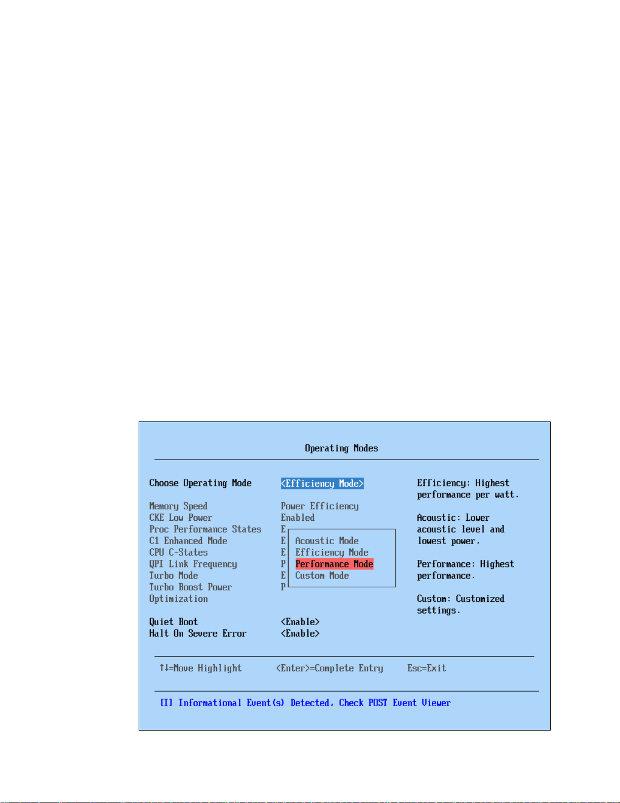
2.2.5 Processor performance in a green world
All eX5 servers from the factory are designed to use power in the most efficient means
possible. Controlling how much power the server is going to use is managed by controlling the
core frequency and power applied to the processors, controlling the frequency and power
applied to the memory, and by reducing fan speeds to fit the cooling needs of the server. For
most server configurations, these functions are ideal to provide the best performance
possible without wasting energy during off-peak usage.
Servers that are used in virtualized clusters of host computers often have the same attempts
being made to manage power consumption at the operating system level. In this environment,
the operating system makes decisions about moving and balancing virtual servers across an
array of host servers. The operating system, running on multiple hosts, reports to a single
cluster controller about the resources that remain on the host and the resource demands of
any virtual servers running on that host. The cluster controller makes decisions to move
virtual servers from one host to another host to completely power down hosts that are no
longer needed during off-peak hours.
It is a common occurrence to have virtual servers moving back and forth across the same set
of host servers, because the host servers are themselves changing their own processor
performance to save power. The result is an inefficient system that is both slow to respond
and actually consumes more power.
The solution for virtual server clusters is to turn off the power management features of the
host servers. The process to change the hardware-controlled power management in the
F1-Setup, offered during power-on self test (POST), is to select System Settings
Operating Modes Choose Operating Mode. Figure 2-5 shows the available options and
the selection to choose to configure the server for Performance Mode.
Figure 2-5 Setup (F1) System Settings Operating Modes to set Performance Mode
Chapter 2. IBM eX5 technology 21
Page 42

2.3 Memory
In this section, we describe the major features of the memory subsystem in eX5 systems. We
describe the following topics in this section:
2.3.1, “Memory speed” on page 22
2.3.2, “Memory DIMM placement” on page 23
2.3.3, “Memory ranking” on page 24
2.3.4, “Nonuniform memory architecture (NUMA)” on page 26
2.3.5, “Hemisphere Mode” on page 26
2.3.6, “Reliability, availability, and serviceability (RAS) features” on page 28
2.3.7, “I/O hubs” on page 30
2.3.1 Memory speed
As with Intel Xeon 5500 processor (Nehalem-EP), the speed at which the memory that is
connected to the Xeon 7500 and 6500 processors (Nehalem-EX) runs depends on the
capabilities of the specific processor. With Nehalem-EX, the scalable memory interconnect
(SMI) link runs from the memory controller integrated in the processor to the memory buffers
on the memory cards.
The SMI link speed is derived from the QPI link speed:
6.4 gigatransfers per second (GT/s) QPI link speed capable of running memory speeds up
to 1066 MHz
5.86 GT/s QPI link speed capable of running memory speeds up to 978 MHz
4.8 GT/s QPI link speed capable of running memory speeds up to 800 MHz
Gigatransfers: Gigatransfers per second (GT/s) or 1,000,000,000 transfers per second is
a way to measure bandwidth. The actual data that is transferred depends on the width of
the connection (that is, the transaction size). To translate a given value of GT/s to a
theoretical maximum throughput, multiply the transaction size by the GT/s value. In most
circumstances, the transaction size is the width of the bus in bits. For example, the SMI
links are 13 bits to the processor and 10 bits from the processor.
Because the memory controller is on the CPU, the memory slots for a CPU can only be used
if a CPU is in that slot. If a CPU fails when the system reboots, it is brought back online
without the failed CPU and without the memory associated with that CPU slot.
QPI bus speeds are listed in the processor offerings of each system, which equates to the
SMI bus speed. The QPI speed is listed as x4.8 or similar, as shown in the following example:
2x 4 Core 1.86GHz,18MB x4.8 95W (4x4GB), 2 Mem Cards
2x 8 Core 2.27GHz,24MB x6.4 130W (4x4GB), 2 Mem Cards
The value x4.8 corresponds to an SMI link speed of 4.8 GT/s, which corresponds to a
memory bus speed of 800 MHz. The value x6.4 corresponds to an SMI link speed of
6.4 GT/s, which corresponds to a memory bus speed of 1066 MHz.
The processor controls the maximum speed of the memory bus. Even if the memory dual
inline memory modules (DIMMs) are rated at 1066 MHz, if the processor supports only 800
MHz, the memory bus speed is 800 MHz.
22 IBM eX5 Implementation Guide
Page 43

What about 1333 MHz? The maximum memory speed that is supported by Xeon 7500
and 6500 processors is 1066 MHz (1333 MHz is not supported). Although the 1333 MHz
DIMMs are still supported, they can operate at a maximum speed of 1066 MHz.
Memory performance test on various memory speeds
Based on benchmarks using an IBM internal load generator run on an x3850 X5 system
configured with four X7560 processors and 64x 4 GB quad-rank DIMMs, the following results
were observed:
Peak throughput per processor observed at 1066 MHz: 27.1 gigabytes per second (GBps)
Peak throughput per processor observed at 978 MHz: 25.6 GBps
Peak throughput per processor observed at 800 MHz: 23.0 GBps
Stated another way, an 11% throughput increase exists when frequency is increased from
800 MHz to 978 MHz; a 6% throughput increase exists when frequency is increased from
978 MHz to 1066 MHz.
Key points regarding these benchmark results:
Use these results only as a guide to the relative performance between the various
memory speeds, not the absolute speeds.
The benchmarking tool that is used accesses only local memory, and there were no
remote memory accesses.
Given the nature of the benchmarking tool, these results might not be achievable in a
production environment.
2.3.2 Memory DIMM placement
The eX5 servers support a variety of ways to install memory DIMMs, which we describe in
detail in later chapters. However, it is important to understand that because of the layout of
the SMI links, memory buffers, and memory channels, you must install the DIMMs in the
correct locations to maximize performance.
Figure 2-6 on page 24 shows eight possible memory configurations for the two memory cards
and 16 DIMMs connected to each processor socket in an x3850 X5. Similar configurations
apply to the x3690 X5 and HX5. Each configuration has a relative performance score. The
following key information from this chart is important:
The best performance is achieved by populating all memory DIMMs in the server
(configuration 1 in Figure 2-6 on page 24).
Populating only one memory card per socket can result in approximately a 50%
performance degradation (compare configuration 1 with 5).
Memory performance is better if you install DIMMs on all memory channels than if you
leave any memory channels empty (compare configuration 2 with 3).
Two DIMMs per channel result in better performance that one DIMM per channel
(compare configuration 1 with 2, and compare 5 with 6).
Chapter 2. IBM eX5 technology 23
Page 44
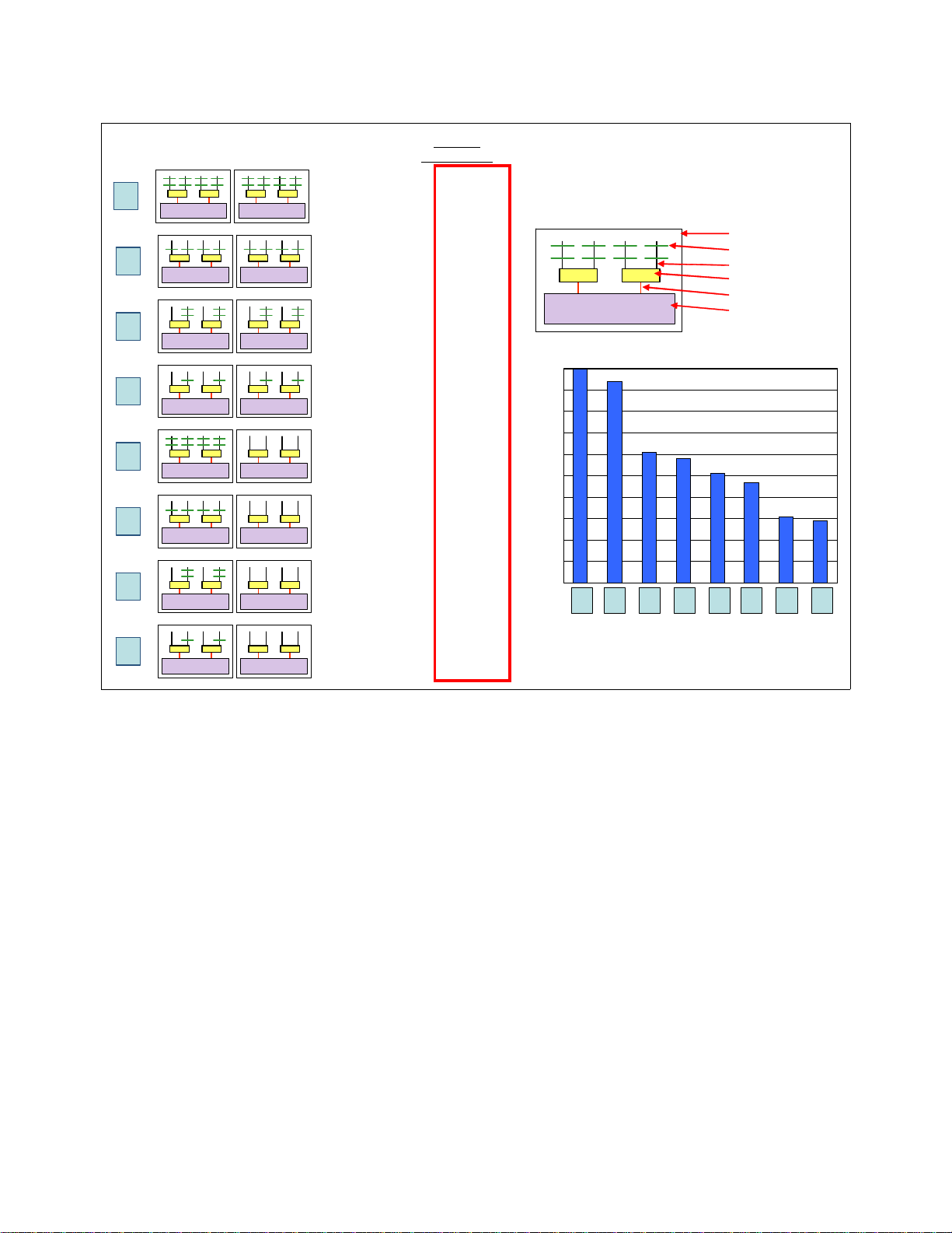
1
Each processor:
2 memory co ntrol l ers
2 DIMMs per channel
8 DIMMs per MC
Mem Ctrl 1 Mem Ctrl 2
1.0
2
Mem Ctrl 1 Mem Ctrl 2
Each processor:
2 memory controllers
1 DIMM per channel
4 DIMMs per MC
0.94
Mem Ctrl 1
Memory card
DIMMs
Channel
Memory buffer
SMI link
Memory controller
3
Mem Ctrl 1 Mem Ctrl 2
Each processor:
2 memory controllers
2 DIMMs per channel
4 DIMMs per MC
0.61
Relative
performance
4
Mem Ctrl 1 Mem Ctrl 2
Each processor:
2 memory controllers
1 DIMM per channel
2 DIMMs per MC
0.58
5
Mem Ctrl 1 Mem Ctrl 2
Each processor:
1 memory controller
2 DIMMs per channel
8 DIMMs per MC
0.51
6
Mem Ctrl 1 Mem Ctrl 2
Each processor:
1 memory controller
1 DIMM per channel
4 DIMMs per MC
0.47
7
Mem Ctrl 1 Mem Ctrl 2
Each processor:
1 memory controller
2 DIMMs per channel
4 DIMMs per MC
0.31
8
Mem Ctrl 1 Mem Ctrl 2
Each processor:
1 memory controller
1 DIMM per channel
2 DIMMs per MC
0.29
1
0.94
0.61
0.51
0.47
0.31
0.29
0.58
0
0.1
0.2
0.3
0.4
0.5
0.6
0.7
0.8
0.9
1
12345678
Configuration
Relat ive memor y pe r formance
Memory configurations
Figure 2-6 Relative memory performance based on DIMM placement (one processor and two memory cards shown)
2.3.3 Memory ranking
The underlying speed of the memory as measured in MHz is not sensitive to memory
population. (In Intel Xeon 5500 processor-based systems, such as the x3650 M2, if rules
regarding optimal memory population are not followed, the system BIOS clocks the memory
subsystem down to a slower speed. This situation is not the case with the x3850 X5.)
Unlike Intel 5500 processor-based systems, more ranks are
x3850 X5. Therefore, quad-rank memory is better than dual-rank memory, and dual-rank
memory is better than single-rank memory. Again, the frequency of the memory as measured
in MHz does not change depending on the number of ranks used. (Intel 5500-based systems,
such as the x3650 M2, are sensitive to the number of ranks installed. Quad-rank memory in
those systems always triggers a stepping down of memory speed as enforced by the BIOS,
which is not the case with the eX5 series.)
Performance test between ranks
With the Xeon 7500 and 6500 processors, having more ranks gives better performance. The
better performance is the result of the addressing scheme. The addressing scheme can
better for performance in the
24 IBM eX5 Implementation Guide
Page 45
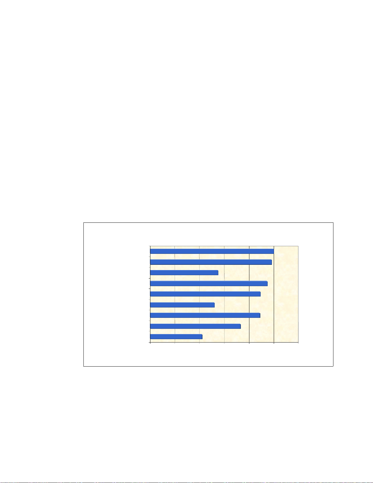
extend the pages across ranks, thereby making the pages effectively larger and therefore
Relative STREAM Triad Throughput
by DIMM population per processor
100
98
55
95
89
52
89
73
42
0 20406080100120
16x 4GB (4R)
8x 4GB (4R)
4x 4GB (4R)
16x 2GB (2R)
8x 2GB (2R)
4x 2GB (2R)
16x 1GB (1R)
8x 1GB (1R)
4x 1GB (1R)
Relative Memory Throughput
creating more page-hit cycles.
We used three types of memory DIMMs for this analysis:
Four GB 4Rx8 (four ranks using x8 DRAM technology)
Two GB 2Rx8 (two ranks)
One GB 1Rx8 (one rank)
We used the following memory configurations:
Fully populated memory:
– Two DIMMs on each memory channel
– Eight DIMMs per memory card
Half-populated memory:
– One DIMM on each memory channel
– Four DIMMs per memory card (slots 1, 3, 6, and 8; see Figure 3-16 on page 76)
Quarter-populated memory:
– One DIMM on just half of the memory channels
– Two DIMMs per memory card
Although several benchmarks were conducted, this section focuses on the results gathered
using the industry-standard STREAM benchmark, as shown in Figure 2-7.
Figure 2-7 Comparing the performance of memory DIMM configurations using STREAM
Taking the top performance result of 16x 4 GB quad-rank DIMMs as the baseline, we see how
the performance drops to 95% of the top performance with 16x 2 GB dual-rank DIMMs, and
89% of the top performance with 16x 1 GB single-rank DIMMs.
You can see similar effects across the three configurations based on eight DIMMs per
processor and four DIMMs per processor. These results also emphasize the same effect that
is shown in 3.8.3, “Maximizing memory performance” on page 84 for the x3850 X5, where
performance drops away dramatically when all eight memory channels per CPU are not used.
Chapter 2. IBM eX5 technology 25
Page 46

Tip: Additional ranks increase the memory bus loading, which is why on Xeon 5500
(Nehalem EP) platforms, the opposite effect can occur: memory slows down if too many
rank loads are attached. The use of scalable memory buffers in the x3850 X5 with Xeon
7500/6500 processors avoids this slowdown.
2.3.4 Nonuniform memory architecture (NUMA)
Nonuniform memory architecture (NUMA) is an important consideration when configuring
memory, because a processor can access its own local memory faster than non-local
memory. Not all configurations use 64 DIMMs spread across 32 channels. Certain
configurations might have a more modest capacity and performance requirement. For these
configurations, another principle to consider when configuring memory is that of
balanced configuration has all of the memory cards configured with the same
memory, even if the quantity and size of the DIMMs differ from card to card. This principle
helps to keep remote memory access to a minimum. DIMMs must always be installed in
matched pairs.
A server with a NUMA, such as the servers in the eX5 family, has local and remote memory.
For a given thread running in a processor core,
directly connected to that particular processor.
not connected to the processor where the thread is running currently.
Remote memory is attached to another processor in the system and must be accessed
through a QPI link. However, using remote memory adds latency. The more such latencies
add up in a server, the more performance can degrade. Starting with a memory configuration
where each CPU has the same local RAM capacity is a logical step toward keeping remote
memory accesses to a minimum.
local memory refers to the DIMMs that are
Remote memory refers to the DIMMs that are
balance. A
amount of
For more information about NUMA installation options, see the following sections:
IBM System x3850 X5: 3.8.2, “DIMM population sequence” on page 79
IBM System x3690 X5: “Two processors with memory mezzanine installed” on page 135
IBM BladeCenter HX5: 5.10.2, “DIMM population order” on page 196
2.3.5 Hemisphere Mode
Hemisphere Mode is an important performance optimization of the Xeon 6500 and 7500
processors. Hemisphere Mode is automatically enabled by the system if the memory
configuration allows it. This mode interleaves memory requests between the two memory
controllers within each processor, enabling reduced latency and increased throughput. It also
allows the processor to optimize its internal buffers to maximize memory throughput.
Two-node configurations: A memory configuration that enables Hemisphere Mode is
required for 2-node configurations on x3850 X5.
Hemisphere Mode is a global parameter that is set at the system level. This setting means
that if even one processor’s memory is incorrectly configured, the entire system can lose the
performance benefits of this optimization. Stated another way, either all processors in the
system use Hemisphere Mode, or all do not.
Hemisphere Mode is enabled only when the memory configuration behind each memory
controller on a processor is identical. Because the Xeon 7500 memory population rules
dictate that a minimum of two DIMMs are installed on each memory controller at a time (one
26 IBM eX5 Implementation Guide
Page 47

on each of the attached memory buffers), DIMMs must be installed in quantities of four per
Intel Xeon 7500 processor
DIMM
DIMM
DIMM
DIMM
DIMM
DIMM
DIMM
DIMM
DIMM
DIMM
DIMM
DIMM
DIMM
DIMM
DIMM
DIMM
DIMM
DIMM
DIMMDIMM
Buffer Buffer Buffer Buffer
Memory
controller
Memory
controller
processor to enable Hemisphere Mode.
In addition, because eight DIMMs per processor are required for using all memory channels,
eight DIMMs per processor need to be installed at a time for optimized memory performance.
Failure to populate all eight channels on a processor can result in a performance reduction of
approximately 50%.
Hemisphere Mode does not require that the memory configuration of each CPU is identical.
For example, Hemisphere Mode is still enabled if CPU 0 is configured with 8x 4 GB DIMMs,
and processor 1 is configured with 8x 2 GB DIMMs. Depending on the application
characteristics, however, an unbalanced memory configuration can cause reduced
performance because it forces a larger number of remote memory requests over the
inter-CPU QPI links to the processors with more memory.
We summarize these points:
There are two memory buffers per memory channel, two channels per memory controller,
and two controllers per processor. Each memory channel must contain
at least one DIMM
to enable Hemisphere Mode.
Within a processor, both memory controllers need to contain identical DIMM
configurations to enable Hemisphere Mode. Therefore, for best results, install at least
eight DIMMs per processor.
Industry-standard tests run on one Xeon 7500 processor with various memory configurations
have shown that there are performance implications if Hemisphere Mode is not enabled. For
example, for a configuration with eight DIMMs installed and spread across both memory
controllers in a processor and all memory buffers (see Figure 2-8), there is a drop in
performance of 16% if Hemisphere Mode is not enabled.
Figure 2-8 Example memory configuration
For more information about Hemisphere Mode installation options, see the following sections:
IBM System x3850 X5: 3.8.2, “DIMM population sequence” on page 79
IBM System x3690 X5: “Two processors with memory mezzanine installed” on page 135
IBM BladeCenter HX5: 5.10.2, “DIMM population order” on page 196
Chapter 2. IBM eX5 technology 27
Page 48

2.3.6 Reliability, availability, and serviceability (RAS) features
In addition to Hemisphere Mode, DIMM balance and memory size, memory performance is
also affected by the various memory reliability, availability, and serviceability (RAS) features
that can be enabled from the Unified Extensible Firmware Interface (UEFI) shell. These
settings can increase the reliability of the system; however, there are performance trade-offs
when these features are enabled.
The available memory RAS settings are normal, mirroring, and sparing. On the X5 platforms,
you can access these settings under the Memory option menu in System Settings.
This section is not meant to provide a comprehensive overview of the memory RAS features
that are available in the Xeon 7500 processor, but rather it provides a brief introduction to
each mode and its corresponding performance effects. For more information about memory
RAS features and platform-specific requirements, see the following sections:
System x3850 X5: 6.9, “UEFI settings” on page 259
System x3690 X5: 7.8, “UEFI settings” on page 337
BladeCenter HX5: 8.5, “UEFI settings” on page 396
The following sections provide a brief description of each memory RAS setting.
Memory mirroring
To further improve memory reliability and availability beyond error checking and correcting
(ECC) and Chipkill, the chip set can mirror memory data to two memory ports. To successfully
enable mirroring, you must have both memory cards per processor installed, and populate the
same amount of memory in both memory cards. Partial mirroring (mirroring of part but not all
of the installed memory) is not supported.
Memory mirroring, or
with a redundant copy of all code and data addressable in the configured memory map.
Memory mirroring works within the chip set by writing data to two memory ports on every
memory-write cycle. Two copies of the data are kept, similar to the way RAID-1 writes to disk.
Reads are interleaved between memory ports. The system automatically uses the most
reliable memory port as determined by error logging and monitoring.
If errors occur, only the alternate memory port is used, until bad memory is replaced.
Because a redundant copy is kept, mirroring results in having only half the installed memory
available to the operating system. FAMM does not support asymmetrical memory
configurations and requires that each port is populated in identical fashion. For example, you
must install 2 GB of identical memory equally and symmetrically across the two memory ports
to achieve 1 GB of mirrored memory.
FAMM enables other enhanced memory features, such as Unrecoverable Error (UE)
recovery, and is required for support of memory hot replace.
Memory mirroring is independent of the operating system.
For more information about system-specific memory mirroring installation options, see the
following sections:
x3850 X5: 3.8.4, “Memory mirroring” on page 87
x3690 X5: 4.8.6, “Memory mirroring” on page 141
BladeCenter HX5: 5.10.4, “Memory mirroring” on page 200
full array memory mirroring (FAMM) redundancy, provides the user
28 IBM eX5 Implementation Guide
Page 49

Memory sparing
Sparing provides a degree of redundancy in the memory subsystem, but not to the extent of
mirroring. In contrast to mirroring, sparing leaves more memory for the operating system. In
sparing mode, the trigger for failover is a preset threshold of correctable errors. Depending on
the type of sparing (DIMM or rank), when this threshold is reached, the content is copied to its
spare. The failed DIMM or rank is then taken offline, with the spare counterpart activated for
use. There are two sparing options:
DIMM sparing
Two unused DIMMs are spared per memory card. These DIMMs must have the same rank
and capacity as the largest DIMMs that we are sparing. The size of the two unused DIMMs
for sparing is subtracted from the usable capacity that is presented to the operating
system. DIMM sparing is applied on all memory cards in the system.
Rank sparing
Two ranks per memory card are configured as spares. The ranks have to be as large as
the rank relative to the highest capacity DIMM that we are sparing. The size of the two
unused ranks for sparing is subtracted from the usable capacity that is presented to the
operating system. Rank sparing is applied on all memory cards in the system.
You configure these options by using the UEFI during start-up.
For more information about system-specific memory sparing installation options, see the
following sections:
IBM System x3850 X5: 3.8.5, “Memory sparing” on page 89
IBM System x3690 X5: 4.8.7, “Memory sparing” on page 143
IBM BladeCenter HX5: 5.10.5, “Memory sparing” on page 202
Chipkill
Chipkill memory technology, an advanced form of error checking and correcting (ECC) from
IBM, is available for the eX5 blade. Chipkill protects the memory in the system from any single
memory chip failure. It also protects against multi-bit errors from any portion of a single
memory chip.
Redundant bit steering
Redundant bit steering (RBS) provides the equivalent of a hot-spare drive in a RAID array. It
is based in the memory controller, and it senses when a chip on a DIMM has failed and when
to route the data around the failed chip.
The eX5 servers do not currently support redundant bit steering, because the integrated
memory controller of the Intel Xeon 6500 and 7500 processors do not support the feature.
However, the MAX5 memory expansion unit supports RBS but only when x4 memory DIMMs
are used. The x8 DIMMs do not support RBS.
RBS is automatically enabled in the MAX5 memory port, if all DIMMs installed to that memory
port are x4 DIMMs.
RBS uses the ECC coding scheme that provides Chipkill coverage for x4 DRAMs. This
coding scheme leaves the equivalent of one x4 DRAM spare in every pair of DIMMs. In the
event that a chip failure on the DIMM is detected by memory scrubbing, the memory controller
can reroute data around that failed chip through these spare bits. DIMMs using x8 DRAM
technology use a separate ECC coding scheme that does not leave spare bits, which is why
RBS is not available on x8 DIMMs.
Chapter 2. IBM eX5 technology 29
Page 50

RBS operates automatically without issuing a Predictive Failure Analysis (PFA) or light path
diagnostics alert to the administrator, although an event is logged to the service processor
log. After the second DIMM failure, PFA and light path diagnostics alerts occur on that DIMM
normally.
Lock step
IBM eX5 memory operates in lock step mode. Lock step is a memory protection feature that
involves the pairing of two memory DIMMs. The paired DIMMs can perform the same
operations and the results are compared. If any discrepancies exist between the results, a
memory error is signaled. Lock step mode gives a maximum of 64 GB of usable memory with
one CPU installed, and 128 GB of usable memory with two CPUs installed (using 8 GB
DIMMs).
Memory must be installed in pairs of two identical DIMMs per processor. Although the size of
the DIMM pairs installed can differ, the pairs must be of the same speed.
Machine Check Architecture (MCA)
MCA is a RAS feature that has previously only been available for other processor
architectures, such as Intel Itanium®, IBM POWER®, and other reduced instruction set
computing (RISC) processors, and mainframes. Implementation of the MCA requires
hardware support, firmware support, such as the UEFI, and operating system support.
The MCA enables system-error handling that otherwise requires stopping the operating
system. For example, if a memory location in a DIMM no longer functions properly and it
cannot be recovered by the DIMM or memory controller logic, MCA logs the failure and
prevents that memory location from being used. If the memory location was in use by a thread
at the time, the process that owns the thread is terminated.
Microsoft, Novell, Red Hat, VMware, and other operating system vendors have announced
support for the Intel MCA on the Xeon processors.
Scalable memory buffers
Unlike the Xeon 5500 and 5600 series, which use unbuffered memory channels, the Xeon
6500 and 7500 processors use scalable memory buffers in the systems design. This
approach reflects the various workloads for which these processors were intended. The 6500
and 7500 family processors are designed for workloads requiring more memory, such as
virtualization and databases. The use of scalable memory buffers allows more memory per
processor, and prevents memory bandwidth reductions when more memory is added per
processor.
2.3.7 I/O hubs
The connection to I/O devices (such as keyboard, mouse, and USB) and to I/O adapters
(such as hard disk drive controllers, Ethernet network interfaces, and Fibre Channel host bus
adapters) is handled by I/O hubs, which then connect to the processors through QPI links.
Figure 2-4 on page 20 shows the I/O hub connectivity. Connections to the I/O devices are
fault tolerant, because data can be routed over either of the two QPI links to each I/O hub. For
optimal system performance in the four processor systems (with two I/O hubs), balance the
high-throughput adapters across the I/O hubs.
30 IBM eX5 Implementation Guide
Page 51

2.4 MAX5
For more information regarding each of the eX5 systems and the available I/O adapters, see
the following sections:
IBM System x3850 X5: 3.12, “I/O cards” on page 104.
IBM System x3690 X5: 4.10.4, “I/O adapters” on page 168.
IBM BladeCenter HX5: 5.13, “I/O expansion cards” on page 209.
Memory Access for eX5 (MAX5) is the name give to the memory and scalability subsystem
that can be added to eX5 servers. In the Intel QPI specification, the MAX5 is a node
controller. MAX5 for the rack-mounted systems (x3850 X5, x3950 X5, and x3690 X5) is in the
form of a 1U device that attaches beneath the server. For the BladeCenter HX5, MAX5 is
implemented in the form of an expansion blade that adds 30 mm to the width of the blade (the
width of one extra blade bay). Figure 2-9 shows the HX5 with the MAX5 attached.
Figure 2-9 Single-node HX5 and MAX5
Chapter 2. IBM eX5 technology 31
Page 52

Figure 2-10 shows the x3850 X5 with the MAX5 attached.
Figure 2-10 IBM System x3850 X5 with MAX5 (the MAX5 is the 1U unit beneath the main system)
Figure 2-11 shows the MAX5 removed from the housing.
Figure 2-11 IBM MAX5 for the x3850 X5 and x3690 X5
MAX5 connects to these systems through QPI links and provides the EXA scalability
interfaces. The eX5 chip set, which is described in 2.1, “eX5 chip set” on page 16, is
contained in the MAX5 units.
32 IBM eX5 Implementation Guide
Page 53

Table 2-2 through Table 2-4 show the memory capacity and bandwidth increases that are
Memory scaling System scaling
Server
MAX5
QPI Scaling
Server
QPI Scaling
Server
possible with MAX5 for the HX5, x3690 X5, and x3850 X5.
Table 2-2 HX5 compared to HX5 with MAX5
HX5 HX5 with MAX5
Memory bandwidth 16 DDR3 channels at 978 MHz 16 DDR3 channels at 978 MHz
+ 12 DDR3 channels at 1066 MHz
Memory capacity 128 GB using 8 GB DIMMs 320 GB using 8 GB DIMMs
Table 2-3 x3690 X5 compared to x3690 X5 with MAX5
x3690 X5 x3690 with MAX5
Memory bandwidth 32 DDR3 channels at 1066 MHz
Memory capacity 512 GB using 16 GB DIMMs 1 TB using 16 GB DIMMs
a. Must install optional mezzanine board
Table 2-4 x3850 X5 compared to x3850 X5 with MAX5
x3850 X5 x3850 X5 with MAX5
Memory bandwidth 32 DDR3 channels at 1066 MHz 48 DDR3 channels at 1066 MHz
Memory capacity 1 TB using 16 GB DIMMs 1.5 TB using 16 GB DIMMs
a
64 DDR3 channels at 1066 MHz
For more information about system-specific MAX5 installation options, see the following
sections:
IBM System x3850 X5: “MAX5 memory” on page 79
IBM System x3690 X5: 4.8.3, “MAX5 memory” on page 136
IBM BladeCenter HX5: “MAX5 memory population order” on page 198
2.5 Scalability
The architecture of the eX5 servers permits system scaling of up to two nodes on HX5 and
x3850 X5. The architecture also supports memory scaling. Figure 2-12 shows these types of
scaling.
Figure 2-12 Types of scaling with eX5 systems
The x3850 X5 and HX5 both support 2-node system scaling or memory scaling. The
x3690 X5 supports memory scaling only.
Chapter 2. IBM eX5 technology 33
Page 54

As shown in Figure 2-12 on page 33, the following scalability is possible:
HX5
2-node system
4 processors
32 DIMM slots
Two
independent
HX5 systems
Memory scaling: A MAX5 unit can attach to an eX5 server through QPI link cables. This
method provides the server with additional memory DIMM slots. We refer to this
combination as a
System scaling: Two servers can connect to form a single system image. The connections
are formed by using QPI link cables. The x3850 X5 and HX5 support this type of scaling.
For more information about system-specific scaling options, see the following sections:
IBM System x3850 X5: 3.6, “Scalability” on page 70
IBM System x3690 X5: 4.6, “Scalability” on page 128
BladeCenter HX5: 5.8, “Scalability” on page 188
2.6 Partitioning
You can operate the HX5 scaled system as two independent systems or as a single system,
without removing the blade and taking off the side-scale connector. This capability is called
partitioning and is referred to as IBM FlexNode technology. You partition by using the
Advanced Management Module (AMM) in the IBM BladeCenter chassis for the HX5.
Figure 2-13 depicts an HX5 system that is scaled to two nodes and an HX5 system that is
partitioned into two independent servers.
memory-enhanced system. All eX5 systems support this scaling.
34 IBM eX5 Implementation Guide
Figure 2-13 HX5 scaling and partitioning
x3690 X5 and x3850 X5: The x3690 X5 and x3850 X5 do not support partitioning.
Figure 2-14 on page 35 and Figure 2-15 on page 35 show the scalable complex configuration
options for stand-alone mode through the Advanced Management Module of the BladeCenter
chassis.
Page 55

Figure 2-14 Shows option for putting a partition into stand-alone mode
Figure 2-15 HX5 partition in stand-alone mode
The AMM can be accessed remotely, so partitioning can be done without physically touching
the systems. Partitioning can allow you to qualify two system types with little additional work,
and it allows you more flexibility in system types for better workload optimization.
The HX5 blade, when scaled as a 2-node (4-socket) system, supports FlexNode partitioning
as standard.
Before a 2-node HX5 solution can be used, you must create a partition. When the scalability
card is added, the two blades still act as single nodes until a partition is made.
For more information about creating a scalable complex, see 8.6, “Creating an HX5 scalable
complex” on page 402.
Chapter 2. IBM eX5 technology 35
Page 56

2.7 UEFI system settings
The Unified Extensible Firmware Interface (UEFI) is a pre-boot environment that provides an
interface between server firmware and operating system. It replaces BIOS as the software
that manages the interface between server firmware, operating system, and hardware
initialization, and eliminates the 16-bit, real-mode limitation that BIOS had.
Obtain more information about UEFI at the following website:
http://www.uefi.org/home/
Many of the advanced technology options that are available in the eX5 systems are controlled
in the UEFI system settings. They affect processor and memory subsystem performance with
regard to the power consumption.
Access the UEFI page by pressing F1 during the system initialization process, as shown in
Figure 2-16.
Figure 2-16 UEFI panel on system start-up
Figure 2-17 on page 37 shows the UEFI System Configuration and Boot Management
window.
36 IBM eX5 Implementation Guide
Page 57

Figure 2-17 UEFI settings main panel
Choose System Settings to access the system settings options that we will describe here, as
shown in Figure 2-18 on page 38.
Chapter 2. IBM eX5 technology 37
Page 58

Figure 2-18 UEFI System Settings panel
For more information about system-specific UEFI options, see the following sections:
IBM System x3850 X5: 6.9, “UEFI settings” on page 259
IBM System x3690 X5: 7.8, “UEFI settings” on page 337
IBM BladeCenter HX5: 8.5, “UEFI settings” on page 396
2.7.1 System power operating modes
IBM eX5 servers are designed to provide optimal performance with reasonable power
consumption, which depends on the operating frequency and voltage of the processors and
memory subsystem. The operating frequency and voltage of the processors and memory
subsystem affect the system fan speed that adjusts to the current cooling requirement of the
server.
In most operating conditions, the default settings are ideal to provide the best performance
possible without wasting energy during off-peak usage. However, for certain workloads, it
might be appropriate to change these settings to meet specific power to performance
requirements.
The UEFI provides several predefined setups for commonly desired operation conditions.
This section describes the conditions for which these setups can be configured.
These predefined values are referred to as
line of eX5 servers. Access the menu in UEFI by selecting System Settings Operating
Modes Choose Operating Mode. You see the four operating modes from which to
choose, as shown in Figure 2-19 on page 39. When a mode is chosen, the affected settings
change to the shown predetermined values.
We describe these modes in the following sections.
38 IBM eX5 Implementation Guide
operating modes and are similar across the entire
Page 59
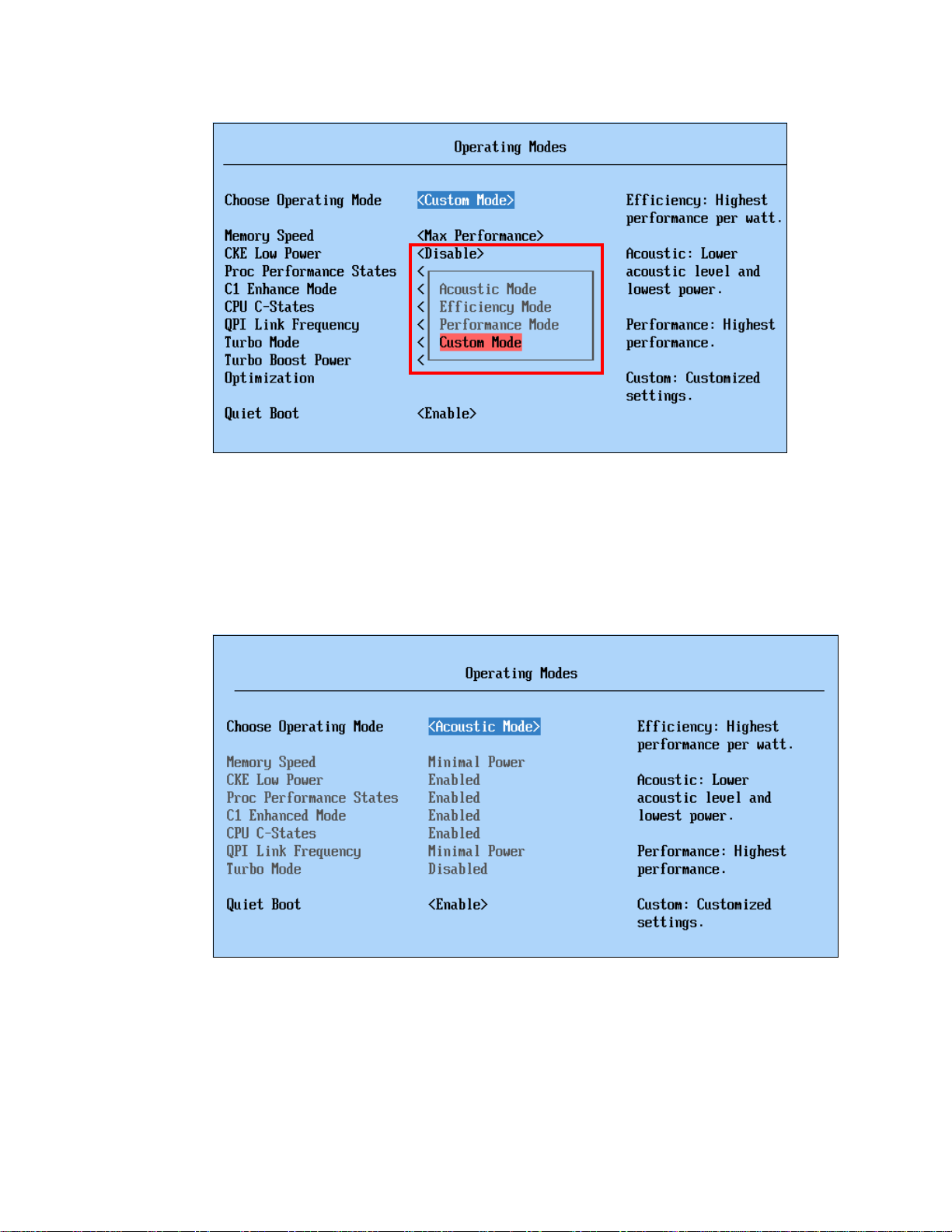
Figure 2-19 Operating modes in UEFI
Acoustic Mode
Figure 2-20 shows the Acoustic Mode predetermined values. They emphasize power-saving
server operation for generating less heat and noise. In turn, the system is able to lower the fan
speed of the power supplies and the blowers by setting the processors, QPI link, and memory
subsystem to a lower working frequency. Acoustic Mode provides lower system acoustics,
less heat, and the lowest power consumption at the expense of performance.
Figure 2-20 Acoustic Mode predetermined values
Efficiency Mode
Figure 2-21 on page 40 shows the Efficiency Mode predetermined values. This operating
mode provides the best balance between server performance and power consumption. In
short, Efficiency Mode gives the highest performance per watt ratio.
Chapter 2. IBM eX5 technology 39
Page 60

Figure 2-21 Efficiency Mode predetermined values
Performance Mode
Figure 2-22 shows the Performance Mode predetermined values. The server is set to use the
maximum performance limits within UEFI. These values include turning off several power
management features of the processor to provide the maximum performance from the
processors and memory subsystem. Performance Mode provides the best system
performance at the expense of power efficiency.
Figure 2-22 Performance Mode predetermined values
Performance Mode is also a good choice when the server runs virtualization workloads.
Servers that are used as physical hosts in virtualization clusters often have similar power
consumption management at the operating system level. In this environment, the operating
system makes decisions about moving and balancing virtual servers across an array of
physical host servers. Each virtualized guest operating system reports to a single cluster
controller about the resources usage and demand on that physical server. The cluster
40 IBM eX5 Implementation Guide
Page 61

controller makes decisions to move virtual servers between physical hosts to cater to each
guest OS resource requirement and, when possible, shuts down unneeded physical hosts to
save power.
Aggressive power management at the hardware level can interfere with the OS-level power
management, resulting in a common occurrence where virtual servers move back and forth
across the same set of physical host servers. This situation results in an inefficient
virtualization environment that responds slowly and consumes more power than necessary.
Running the server in Performance Mode prevents this occurrence, in most cases.
Custom Mode
The default value that is set in new eX5 systems is Custom Mode, as shown in Figure 2-23. It
is the recommended factory default setting. The values are set to provide optimal
performance with reasonable power consumption. However, this mode allows the user to
individually set the power-related and performance-related options.
See 2.7.3, “Performance-related individual system settings” on page 43 for a description of
individual settings.
Figure 2-23 Custom Mode factory default values
Table 2-5 shows comparisons of the available operating modes of IBM eX5 servers. Using the
Custom Mode, it is possible to run the system using properties that are in-between the
predetermined operating modes.
Table 2-5 Operating modes comparison
Settings Efficiency Acoustics Performance Custom (Default)
Memory Speed Power Efficiency Minimal Power Max Performance Max Performance
CKE Low Power Enabled Enabled Disabled Disable
Proc Performance States Enabled Enabled Enabled Enable
C1 Enhanced Mode Enabled Enabled Disabled Enable
CPU C-States Enabled Enabled Disabled Enable
Chapter 2. IBM eX5 technology 41
Page 62

Settings Efficiency Acoustics Performance Custom (Default)
QPI Link Frequency Power Efficiency Minimal Power Max Performance Max Performance
Turbo Mode Enabled Disabled Enabled Enable
Turbo Boost Power Optimization Power Optimized - Traditional Power Optimized
Additional Settings
In addition to the Operating Mode selection, the UEFI settings under Operating Modes
include these additional settings:
Quiet Boot (Default:
This mode enables system booting with less information displayed.
Enable)
Halt On Severe Error (Default:
This mode enables system boot halt when a severe error event is logged.
2.7.2 System power settings
Power settings include basic power-related configuration options:
IBM Systems Director Active Energy Manager™ (Default: Capping Enabled)
The Active Energy Manager option enables the server to use the power capping feature of
Active Energy Manager, an extension of IBM Systems Director.
Active Energy Manager measures, monitors, and manages the energy and thermal
components of IBM systems, enabling a cross-platform management solution and
simplifying the energy management of IBM servers, storage, and networking equipment.
In addition, Active Energy Manager extends the scope of energy management to include
non-IBM systems, facility providers, facility management applications, protocol data units
(PDUs), and equipment supporting the IPv6 protocol. With Active Energy Manager, you
can accurately understand the effect of the power and cooling infrastructure on servers,
storage, and networking equipment. One of its features is to set caps for how much power
the server can draw.
Learn more about IBM Systems Director Active Energy Manager at the following website:
http://www.ibm.com/systems/software/director/aem/
Power Restore Policy (Default:
This option defines system behavior after a power loss.
Disable, only available in System x3690 X5)
Restore)
Figure 2-24 on page 43 shows the available options in the UEFI system Power settings.
42 IBM eX5 Implementation Guide
Page 63

Figure 2-24 UEFI Power settings window
2.7.3 Performance-related individual system settings
The UEFI default settings are configured to provide optimal performance with reasonable
power consumption. Other operating modes are also available to meet various power and
performance requirements. However, individual system settings enable users to fine-tune the
desired characteristics of the IBM eX5 servers.
This section describes the UEFI settings that are related to system performance. Remember
that, in most cases, increasing system performance increases the power consumption of the
system.
Processors
Processor settings control the various performance and power features that are available on
the installed Xeon processor.
Figure 2-25 on page 44 shows the UEFI Processor system settings window with the default
values.
Chapter 2. IBM eX5 technology 43
Page 64

Figure 2-25 UEFI Processor system settings panel
The following processor feature options are available:
Turbo Mode (Default:
This mode enables the processor to increase its clock speed dynamically as long as the
CPU does not exceed the
2.2.3, “Turbo Boost Technology” on page 18 for more information.
Turbo Boost Power Optimization (Default:
This option specifies which algorithm to use when determining whether to overclock the
processor cores in Turbo Mode:
–
Power Optimized provides reasonable Turbo Mode in relation to power consumption.
Turbo Mode does not engage unless additional performance has been requested by
the operating system for a period of 2 seconds.
–
Traditional provides a more aggressive Turbo Mode operation.
Turbo Mode engages as more performance is requested by the operating system.
Processor Performance States (Default:
This option enables Intel Enhanced SpeedStep Technology that controls dynamic
processor frequency and voltage changes, depending on operation.
Enable)
Thermal Design Power (TDP) for which it was designed. See
Power Optimized)
Enable)
CPU C-States (Default:
This option enables dynamic processor frequency and voltage changes in the idle state,
providing potentially better power savings.
C1 Enhanced Mode (Default:
This option enables processor cores to enter an enhanced halt state to lower the voltage
requirement, and it provides better power savings.
44 IBM eX5 Implementation Guide
Enable)
Enable)
Page 65

Hyper-Threading (Default:
This option enables logical multithreading in the processor, so that the operating system
can execute two threads simultaneously for each physical core.
Enable)
Execute Disable Bit (Default:
This option enables the processor to disable the execution of certain memory areas,
therefore preventing buffer overflow attacks.
Intel Virtualization Technology (Default:
This option enables the processor hardware acceleration feature for virtualization.
Processor Data Prefetch (Default:
This option enables the memory data access prediction feature to be stored in the
processor cache.
Cores in CPU Package (Default:
This option sets the number of processor cores to be activated.
QPI Link Frequency (Default:
This option sets the operating frequency of the processor’s QPI link:
– Minimal Power provides less performance for better power savings.
The QPI link operates at the lowest frequency, which, in the eX5 systems, is 4.8 GT/s.
– Power Efficiency provides best performance per watt ratio.
The QPI link operates 1 step under the rated frequency, that is, 5.86 GT/s for
processors rated at 6.4 GT/s.
–
Max Performance provides the best system performance.
Enable)
Enable)
Enable)
All)
Max Performance)
The QPI link operates at the rated frequency, that is, 6.4 GT/s for processors rated at
6.4 GT/s.
Memory
The Memory settings window provides the available memory operation options, as shown in
Figure 2-26 on page 46.
Chapter 2. IBM eX5 technology 45
Page 66

Figure 2-26 UEFI Memory system settings panel
The following memory feature options are available:
Memory Spare Mode (Default:
This option enables memory sparing mode, as described in “Memory sparing” on page 29.
Memory Mirror Mode (Default:
This option enables memory mirroring mode, as described in “Memory mirroring” on
page 28.
Memory Mirror Mode: Memory Mirror Mode cannot be used in conjunction with
Memory Spare Mode.
Memory Speed (Default:
This option sets the operating frequency of the installed DIMMs:
– Minimal Power provides less performance for better power savings.
The memory operates at the lowest supported frequency, which, in the eX5 systems, is
800 MHz.
– Power Efficiency provides the best performance per watt ratio.
The memory operates one step under the rated frequency, that is, 977 MHz for DIMMs
that are rated at 1066 MHz or higher.
–
Max Performance provides the best system performance.
The memory operates at the rated frequency, that is, 1066 MHz for DIMMs rated at
1066 MHz or higher.
Disable)
Non-Mirrored)
Max Performance)
Tip: Although memory DIMMs rated at 1333MHz are supported on eX5 servers, the
currently supported maximum memory operating frequency is 1066 MHz.
46 IBM eX5 Implementation Guide
Page 67

CKE Low Power (Default:
This option enables the memory to enter a low-power state for power savings by reducing
the signal frequency.
Disable)
Patrol Scrub (Default:
This option enables scheduled background memory scrubbing before any error is
reported, as opposed to default demand scrubbing on an error event. This option provides
better memory subsystem resiliency at the expense of a small performance loss.
Memory Data Scrambling (Default:
This option enables a memory data scrambling feature to further minimize bit-data errors.
Spread Spectrum (Default:
This option enables the memory spread spectrum feature to minimize electromagnetic
signal interference in the system.
Page Policy (Default:
This option determines the Page Manager Policy in evaluating memory access:
–
Closed: Memory pages are closed immediately after each transaction.
– Open: Memory pages are left open for a finite time after each transaction for possible
recurring access.
– Adaptive: Use Adaptive Page Policy to decide the memory page state.
– Multi-CAS Widget: The widget allows multiple consecutive column address strobes
(CAS) to the same memory ranks and banks in the Open Page Policy.
Mapper Policy (Default:
This option determines how memory pages are mapped to the DIMM subsystem.
–
Closed: Memory is mapped closed to prevent DIMMs from being excessively
addressed.
Disable)
Disable)
Enable)
Closed)
Closed)
– Open: Memory is mapped open to decrease latency.
Scheduler Policy (Default:
This option determines the scheduling mode optimization based on memory operation:
– Static Trade Off: Equal trade-off between read/write operation latency
– Static Read Primary: Minimize read latency and consider reads as primary operation
– Static Write Primary: Minimize write latency and consider writes as primary operation
–
Adaptive: Memory scheduling adaptive to system operation
MAX5 Memory Scaling Affinity (Default:
–The
installed processors.
– The Pooled option presents the additional memory in the MAX5 as a pool of memory
that is not assigned to any particular processor.
2.8 IBM eXFlash
IBM eXFlash is the name given to the eight 1.8-inch solid-state drives (SSDs), the
backplanes, SSD hot-swap carriers, and indicator lights that are available for the x3690 X5,
x3850 X5, and x3950 X5.
Adaptive)
Non-Pooled)
Non-Pooled option splits the memory in the MAX5 and assigns it to each of the
Chapter 2. IBM eX5 technology 47
Page 68

Each eXFlash can replace four 2.5-inch serial-attached SCSIs (SAS) or (SSDs). You can
install the following number of eXFlash units:
The x3850 X5 can have either of the following configurations:
– Up to four SAS or Serial Advanced Technology Attachment (SATA) drives, plus the
eight SSDs in one eXFlash unit
– Sixteen SSDs in two eXFlash units
The x3950 X5 database-optimized models have one eXFlash unit standard with space for
eight SSDs, and a second eXFlash is optional.
The x3690 X5 can have up to 24 SSDs in three eXFlash units.
Spinning disks, although an excellent choice for cost per megabyte, are not always the best
choice when considered for their cost per I/O operation per second (IOPS).
In a production environment where the tier-one capacity requirement can be met by IBM
eXFlash, the total cost per IOPS can be lower than any solution requiring attachment to
external storage. Host bus adapters (HBAs), switches, controller shelves, disk shelves,
cabling, and the actual disks all carry a cost. They might even require an upgrade to the
machine room infrastructure, for example, a new rack or racks, additional power lines, or
perhaps additional cooling infrastructure.
Also, remember that the storage acquisition cost is only a part of the total cost of ownership
(TCO). TCO takes the ongoing cost of management, power, and cooling for the additional
storage infrastructure detailed previously. SSDs use only a fraction of the power, generate
only a fraction of the heat that spinning disks generate, and, because they fit in the chassis,
are managed by the server administrator.
IBM eXFlash is optimized for a heavy mix of read and write operations, such as transaction
processing, media streaming, surveillance, file copy, logging, backup and recovery, and
business intelligence. In addition to its superior performance, eXFlash offers superior uptime
with three times the reliability of mechanical disk drives. SSDs have no moving parts to fail.
They use Enterprise Wear-Leveling to extend their use even longer. All operating systems
that are listed in ServerProven® for each machine are supported for use with eXFlash.
The eXFlash SSD backplane uses two long SAS cables, which are included with the
backplane option. If two eXFlash backplanes are installed, four cables are required. You can
connect the eXFlash backplane to the dedicated RAID slot if desired.
In a system that has two eXFlash backplanes installed, two controllers are required in PCIe
slots 1 - 4 to control the drives; however, up to four controllers can be used. In environments
where RAID protection is required, use two RAID controllers per backplane to ensure that
peak IOPS can be reached. Although use of a single RAID controller results in a functioning
solution, peak IOPS can be reduced by a factor of approximately 50%. Remember that each
RAID controller controls only its own disks. With four B5015 controllers, each controller
controls four disks. The effect of RAID-5 is that four disks (one per array) are used for parity.
You can use both RAID and non-RAID controllers. The IBM 6Gb SSD Host Bus Adapter
(HBA) is optimized for read-intensive environments, and you can achieve maximum
performance with only a single 6Gb SSD HBA. RAID controllers are a better choice for
environments with a mix of read and write activity.
The eXFlash units can connect to the same types of ServeRAID disk controllers as the SAS
and SATA disks. For higher performance, connect them to the IBM 6Gb SAS HBA or the
ServeRAID B5015 SSD Controller.
48 IBM eX5 Implementation Guide
Page 69

In addition to using less power than rotating magnetic media, the SSDs are more reliable, and
Status lights
Solid state drives (SSDs)
they can service many more IOPS. These attributes make them well suited to I/O intensive
applications, such as complex queries of databases.
Figure 2-27 shows an eXFlash unit, with the status lights assembly on the left side.
2.8.1 IBM eXFlash price-performance
Figure 2-27 x3850 X5 with one eXFlash
For more information about system-specific memory eXFlash options, see the following
sections:
IBM System x3850 X5: 3.9.3, “IBM eXFlash and 1.8-inch SSD support” on page 93
IBM System x3690 X5: 4.9.2, “IBM eXFlash and SSD disk support” on page 149.
The information in this section gives an idea of the relative performance of spinning disks
when compared with the SSDs in IBM eXFlash. This section does not guarantee that these
data rates are achievable in a production environment because of the number of variables
involved. However, in most circumstances, we expect the scale of the performance differential
between these two product types to remain constant.
If we take a 146 GB, 15K RPM 2.5-inch disk drive as a baseline and assume that it can
perform 300 IOPS, we can also state that eight disks can provide 2400 IOPS. At a current US
list price per drive of USD579 (multiplied by eight = USD4,632), that works out to USD1.93
per IOP and USD4 per GB.
I/O operations per second (IOPS): IOPS is used predominantly as a measure for
database performance. Workloads measured in IOPS are typically sized by taking the
realistically achievable IOPS of a single disk and multiplying the number of disks until the
anticipated (or measured) IOPS in the target environment is reached. Additional factors,
such as the RAID level, number of HBAs, and storage ports can also affect the
performance. The key point is that IOPS-driven environments traditionally require
significant disk. When sizing, exceeding the requested capacity to reach the required
number of IOPS is often necessary.
Chapter 2. IBM eX5 technology 49
Page 70

Under similar optimized benchmarking conditions, eight of the 50 GB, 1.8-inch SSDs are able
to sustain 48,000 read IOPS and, in a separate benchmark, 16,000 write IOPS. The cost of
USD12,000 for the SSDs works out at approximately USD0.25 per IOP and USD60 per
gigabyte.
Additional spinning disks create additional costs in terms of shelves, rack space, and power
and cooling, none of which are applicable for the SSDs, driving their total TCO down even
further. The initial cost per GB is higher for the SSDs, but view it in the context of TCO over
time.
For more information regarding each of the eX5 systems, see the following sections:
3.9, “Storage” on page 90
5.11, “Storage” on page 203
2.9 Integrated virtualization
This section contains a list of virtualization options that are optional within the eX5 series.
2.9.1 VMware ESXi
ESXi is an embedded version of VMware ESX. The footprint of ESXi is small (approximately
32 MB) because it does not use the Linux-based Service Console. Instead, it uses
management tools, such Virtual Center, Remote Command-Line Interface (CLI), and
Common Information Model (CIM) for standards-based and agentless hardware monitoring.
VMware ESXi includes full VMware File System (VMFS) support across Fibre Channel and
iSCSI SAN, and network-attached storage (NAS). It supports 4-way Virtual Symmetrical
Multiprocessor Systems (SMP) (VSMP). ESXi 4.0 supports 64 CPU threads, for example,
eight x 8-core CPUs, and can address 1 TB of RAM.
The VMware ESXi 4.0 and 4.1 embedded virtualization keys for the x3850 X5, x3690 X5, and
HX5 are orderable, as listed in Table 2-6.
Table 2-6 VMware ESXi 4.x memory key
Part number Feature code Description
41Y8278 1776 IBM USB Memory Key for VMware ESXi 4.0
41Y8287 2420 IBM USB Memory Key for VMware ESXi 4.1 with MAX5
2.9.2 Red Hat RHEV-H (KVM)
The Kernel-based Virtualization Machine (KVM hypervisor) that is supported with Red Hat
Enterprise Linux (RHEL) 5.4 and later is available on the x3850 X5. RHEL-H (KVM) is
standard with the purchase of RHEL 5.4 and later. All hardware components that have been
tested with RHEL 5.x are also supported running RHEL 5.4 (and later), and they are
supported to run RHEV-H (KVM). IBM Support Line and Remote Technical Support (RTS) for
Linux support RHEV-H (KVM).
50 IBM eX5 Implementation Guide
Page 71

RHEV-H (KVM) supports 96 CPU threads (an 8-core processor with Hyper-Threading
enabled has 16 threads) and can address 1 TB RAM.
KVM includes the following features:
Advanced memory management support
Robust and scalable Linux virtual memory manager
Support for large memory systems with greater than 1 TB RAM
Support for nonuniform memory access (NUMA)
Transparent memory page sharing
Memory overcommit
KVM also provides the following advanced features:
Live migration
Snapshots
Memory Page sharing
SELinux for high security and isolation
Thin provisioning
Storage overlays
2.9.3 Windows 2008 R2 Hyper-V
Windows® 2008 R2 Hyper-V is also supported to run on the eX5 servers. You can confirm
Hyper-V support in ServerProven.
2.10 Changes in technology demand changes in implementation
This section introduces new implementation concepts that are now available due to the new
technology that has been made available in the IBM eX5 servers.
2.10.1 Using swap files
With the introduction of large amounts of addressable memory, when using an UEFI-aware
64-bit operating system, the question that comes to mind with a non-virtualized operating
system is, “Do I continue to use a swap file to increase the amount of usable memory that an
operating system can use?” The answer is no.
Using a swap file introduces memory page swaps that take milliseconds to perform as
opposed to possible remote memory access on a MAX5 that will take nanoseconds to
perform. Not using a swap file improves the performance of the single 64-bit operating
system.
Note, however, that when using SSD drives as your primary storage for the operating system,
remember that it is better to not have an active swap file on this type of storage. SSD drives
are designed to support a large but finite number of write operations to any single 4k storage
cell on the drive (to the order of 1 million write operations). After that limit has been reached,
the storage cell is no longer usable. As storage cells begin to die, the drive automatically
maps around them, but when enough cells fail, the drive first reports a Predictive Failure
Analysis (PFA) and then eventually fails. Therefore, you must be careful determining how
dynamic the data is that is being stored on SSD storage. Memory swap file space must never
Chapter 2. IBM eX5 technology 51
Page 72

be assigned to SSD storage. When you must use memory swap files, assign the swap file
space to conventional SAS or SATA hard drives.
2.10.2 SSD drives and battery backup cache on RAID controllers
When using conventional SAS or SATA hard drives on a ServeRAID controller, it is common
practice to enable writeback cache for the logical drive to prevent data corruption if a loss of
power occurs.
With SATA SSD drives, writes to the drives are immediately stored in the memory of the SSD
drive. The potential for loss of data is dramatically reduced. Writing to writeback cache first
and then to the SSD drives actually increases the latency time for writing the data to the SSD
device.
Today’s SSD optimized controllers have neither read nor writeback cache. If you are in a solid
SSD environment, the best practice is to not install a RAID battery and to not enable cache.
When your storage uses a mixed media environment, the best practice is to use a
ServeRAID-5xxx controller with the IBM ServeRAID 5000 Performance Accelerator Key.
We describe this topic in detail in the following sections:
IBM System x3690 X5: 4.9.1, “2.5-inch SAS drive support” on page 145
IBM System x3850 X5: “ServeRAID M5000 Series Performance Accelerator Key” on
page 95
2.10.3 Increased resources for virtualization
The huge jump in processing capacity and memory allows for the consolidation of services,
while still maintaining fault tolerance using scalable clustered host solutions. As your servers
approach peak demand, additional hosts can be automatically powered on and activated to
spread the computing demand to additional virtual servers as demand increases. As the peak
demand subsides, the same environment can automatically consolidate virtual servers to a
smaller group of active hosts, saving power while still maintaining true fault tolerance.
By using larger servers with built-in redundancy for power, fans, storage access, and network
access, it is now possible to combine the functional requirements of a dozen or more servers
into a dual-hosted virtual server environment that can withstand the possible failure of a
complete host. As demand increases, the number of hosts can be increased to maintain the
same virtual servers, with no noticeable changes or programming costs to allow the same
virtual server to function in the new array of hosts.
With this capability, the server becomes an intelligent switch in the network. Instead of trying
to balance network traffic through various network adapters on various servers, you can now
create a virtual network switch inside a cluster of host servers to which the virtual servers
logically attach. All of the physical network ports of the server, provided that they are the
same type of link, can be aggregated into a single IEEE 802.3ad load balance link to
maximize link utilization between the server and the external network switch. Two scaled
x3850 X5s running in a clustered virtualized environment can replace an entire 42U rack of
conventional 1U servers, and their associated top rack network and SAN switch.
2.10.4 Virtualized Memcached distributed memory caching
Many web content providers and light provisioning providers use servers designed for speed,
and not fault tolerance, to store the results from database or API calls so that clients can be
redirected from the main database server to a MemCached device for all future pages within
52 IBM eX5 Implementation Guide
Page 73

the original database lookup. This capability allows the database or web content server to
off-load the processing time that is needed to maintain those client sessions. You can define
the same physical servers as virtual servers with access to a collection of SSD drives. The
number of virtual servers can be dynamically adjusted to fit the demands of the database or
web content server.
Chapter 2. IBM eX5 technology 53
Page 74

54 IBM eX5 Implementation Guide
Page 75

Chapter 3. IBM System x3850 X5 and x3950 X5
3
In this chapter, we introduce the IBM System x3850 X5 and the IBM System x3950 X5. The
x3850 X5 and x3950 X5 are the follow-on products to the eX4-based x3850 M2, and like their
predecessor, are 4-socket systems. The x3950 X5 models are optimized for specific
workloads, such as virtualization and database workloads.
The MAX5 memory expansion unit is a 1U device, which you connect to the x3850 X5 or
x3950 X5, and provides the server with an additional 32 DIMM sockets. It is ideal for
applications that can take advantage of as much memory as is available.
This chapter contains the following topics:
3.1, “Product features” on page 56
3.2, “Target workloads” on page 63
3.3, “Models” on page 64
3.4, “System architecture” on page 66
3.5, “MAX5” on page 68
3.6, “Scalability” on page 70
3.7, “Processor options” on page 74
3.8, “Memory” on page 76
3.9, “Storage” on page 90
3.10, “Optical drives” on page 102
3.11, “PCIe slots” on page 103
3.12, “I/O cards” on page 104
3.13, “Standard onboard features” on page 109
3.14, “Power supplies and fans of the x3850 X5 and MAX5” on page 112
3.15, “Integrated virtualization” on page 114
3.16, “Operating system support” on page 114
3.17, “Rack considerations” on page 115
© Copyright IBM Corp. 2011. All rights reserved. 55
Page 76

3.1 Product features
The IBM System x3850 X5 and x3950 X5 servers address the following requirements that
many IBM enterprise clients need:
The ability to have increased performance on a smaller IT budget
The ability to increase database and virtualization performance without having to add
more CPUs, especially when software is licensed on a per-socket basis
The ability to add memory capacity on top of existing processing power, so that the overall
performance goes up while software licensing costs remain static
The flexibility to achieve the desired memory capacity with larger capacity single DIMMs
The ability to pay for the system they need today, with the capability to grow both memory
capacity and processing power when necessary in the future
The base building blocks of the solution are the x3850 X5 server and the MAX5 memory
expansion drawer. The x3850 X5 is a 4U system with four processor sockets and up to 64
DIMM sockets. The MAX5 memory expansion drawer is a 1U device that adds 32 DIMM
sockets to the server.
The x3950 X5 is the name for the preconfigured IBM models, for specific workloads. The
announced x3950 X5 models are optimized for database applications. Future x3950 X5
models will include models that are optimized for virtualization.
Referring to the models: Throughout this chapter, where a feature is not unique to either
the x3850 X5 or the x3950 X5 but is common to both models, the term
3.1.1 IBM System x3850 X5 product features
IBM System x3850 X5, machine type 7145, is the follow-on product to the IBM System x3850
M2 and x3950 M2. It is a 4U 4-socket Intel 7500-based (Nehalem-EX) platform with 64 DIMM
sockets. It can be scaled up to eight processor sockets depending on model and 128 DIMM
sockets by connecting a second server to form a single system image and maximize
performance, reliability, and scalability.
The x3850 X5 is targeted at enterprise clients looking for increased consolidation
opportunities with expanded memory capacity.
See Table 3-1 on page 62 for a comparison of eX4 x3850 M2 and eX5 x3850 X5.
The x3850 X5 offers the following key features:
Four Xeon 7500 series CPUs (4 core, 6 core, and 8 core)
Scalable to eight sockets by connecting two x3850 X5 servers
64 DDR3 DIMM sockets
Up to eight memory cards can be installed, each with eight DIMM slots
Seven PCIe 2.0 slots (one slot contains the Emulex 10Gb Ethernet dual-port adapter)
Up to eight 2.5-inch hard disk drives (HDDs) or sixteen 1.8-inch solid-state drives (SSDs)
RAID-0 and RAID-1 standard; optional RAID-5 and 50, RAID-6 and 60, and encryption
Two 1 Gb Ethernet ports
One Emulex 10Gb Ethernet dual-port adapter (standard on all models, except ARx)
Internal USB for embedded hypervisor (VMware and Linux hypervisors)
Integrated management module
x3850 X5 is used.
56 IBM eX5 Implementation Guide
Page 77

The x3850 X5 has the following physical specifications:
Width: 440 mm (17.3 in.)
Depth: 712 mm (28.0 in.)
Height: 173 mm (6.8 in.) or 4 rack units (4U)
Minimum configuration: 35.4 kg (78 lb.)
Maximum configuration: 49.9 kg (110 lb.)
Figure 3-1 shows the x3850 X5.
Figure 3-1 Front view of the x3850 X5 showing eight 2.5-inch SAS drives
In Figure 3-1, two serial-attached SCSI (SAS) backplanes have been installed (at the right of
the server). Each backplane supports four 2.5-inch SAS disks (eight disks in total).
Notice the orange colored bar on each disk drive. This bar denotes that the disks are
hot-swappable. The color coding used throughout the system is orange for hot-swap and blue
for non-hot-swap. Changing a hot-swappable component requires no downtime; changing a
non-hot-swappable component requires that the server is powered off before removing that
component.
Figure 3-2 on page 58 shows the major components inside the server and on the front panel
of the server.
Chapter 3. IBM System x3850 X5 and x3950 X5 57
Page 78

Figure 3-2 x3850 X5 internals
Two 1975W rear-access
hot-swap, redundant
power supplies
Four Intel Xeon CPUs
Eight memory cards for
64 DIMMs total –
eight 1066MHz DDR3
DIMMs per card
Six available
PCIe 2.0 slots
Two 60mm hot-swap fans
Eight SAS 2.5” drives or
two eXFlash SSD units
Two 120mm
hot-swap fa ns
Two front
USB ports
Light path
diagnostics
DVD drive
Dual-port 10Gb
Ethernet Adapter
(PCIe slot 7)
Additional slot for internal
RAID controller
QPI ports 1 & 2
(behind cover)
QPI ports 3 & 4
(behind cover)
Gigabit
Ethernet ports
Serial port
Video port
Four USB
ports
Systems
management
port
10 Gigabit Ethernet ports
(standard on most models)
Power supplies (redundant at
220V power)
Six available PCIe slots
Figure 3-3 shows the connectors at the back of the server.
Figure 3-3 Rear of the x3850 X5
58 IBM eX5 Implementation Guide
Page 79

3.1.2 IBM System x3950 X5 product features
For certain enterprise workloads, IBM offers preconfigured models under the product name
x3950 X5. These models do not differ from standard x3850 X5 models in terms of the
machine type or the options used to configure them, but because they are configured with
components that make them optimized for specific workloads, they are differentiated by this
naming convention.
No model of x3850 X5 or x3950 X5 requires a scalability key for 8-socket operation (as was
the case with the x3950 M2). Also, because the x3850 X5 and x3950 X5 use the same
machine type, they can be scaled together into an 8-socket solution, assuming that each
model uses four identical CPUs and that memory is set as a valid Hemisphere configuration.
For more information about Hemisphere Mode, see 2.3.5, “Hemisphere Mode” on page 26.
The IBM x3950 X5 is optimized for database workloads and virtualization workloads.
Virtualization-optimized models of the x3950 X5 include a MAX5 as standard.
Database-optimized models include eXFlash as standard. See 3.3, “Models” on page 64 for
more information.
3.1.3 IBM MAX5 memory expansion unit
The IBM MAX5 for System x (MAX5) memory expansion unit has 32 DDR3 dual inline
memory module (DIMM) sockets, one or two 675-watt power supplies, and five 40 mm
hot-swap speed-controlled fans. It provides added memory and multinode scaling support for
the x3850 X5 server.
The MAX5 expansion module is based on eX5, the next generation of Enterprise
X-Architecture. The MAX5 expansion module is designed for performance, expandability, and
scalability. Its fans and power supplies use hot-swap technology for easy replacement without
requiring the expansion module to be turned off.
Figure 3-4 shows the x3850 X5 with the attached MAX5.
Figure 3-4 x3850 X5 with the attached MAX5 memory expansion unit
Chapter 3. IBM System x3850 X5 and x3950 X5 59
Page 80

The MAX5 has the following specifications:
IBM EXA5 chip set.
Intel memory controller with eight memory ports (four DIMMs on each port).
Intel QuickPath Interconnect (QPI) architecture technology to connect the MAX5 to the
x3850 X5. Four QPI links operate at up to 6.4 gigatransfers per second (GT/s).
Scalability:
– Connects to an x3850 X5 server using QPI cables.
Memory DIMMs:
– Minimum: 2 DIMMs, 4 GB.
– Maximum: 32 DIMM connectors (up to 512 GB of memory using 16 GB DIMMs).
– Type of DIMMs: PC3-10600, 1067 MHz, ECC, and DDR3 registered SDRAM DIMMs.
– Supports 2 GB, 4 GB, 8 GB, and 16 GB DIMMs.
All DIMM sockets in the MAX5 are accessible regardless of the number of processors
installed on the host system.
Five hot-swap 40 mm fans.
Power supply:
– Hot-swap power supplies with built-in fans for redundancy support.
– 675-watt (110 - 220 V ac auto-sensing).
– One power supply standard, two maximum (second power supply is for redundancy).
Light path diagnostics LEDs:
–Board LED
– Configuration LED
– Fan LEDs
– Link LED (for QPI and EXA5 links)
– Locate LED
– Memory LEDs
– Power-on LED
– Power supply LEDs
Physical specifications:
– Width: 483 mm (19.0 in.)
– Depth: 724 mm (28.5 in.)
– Height: 44 mm (1.73 in.) (1U rack unit)
– Basic configuration: 12.8 kg (28.2 lb.)
– Maximum configuration: 15.4 kg (33.9 lb.)
With the addition of the MAX5 memory expansion unit, the x3850 X5 gains an additional
32 DIMM sockets for a total of 96 DIMM sockets. Using 16 GB DIMMs means that a total of
1.5 TB of RAM can be installed.
All DIMM sockets in the MAX5 are accessible, regardless of the number of processors
installed on the host system.
Figure 3-5 on page 61 shows the ports at the rear of the MAX5 memory expansion unit. The
QPI ports on the MAX5 are used to connect to a single x3850 X5. The EXA ports are
reserved for future use.
60 IBM eX5 Implementation Guide
Page 81

Figure 3-5 MAX5 connectors and LEDs
Power-on
LED
Locate
LED
System
error
LED
AC LED (green)
DC LED (green)
Power supply
fault (error) LED
QPI
port 1
Power
connectors
EXA port 1
LEDlink
EXA port 2
LEDlink
EXA port 3
LEDlink
EXA
port 1
EXA
port 2
EXA
port 3
QPI
port 2
QPI
port 3
QPI
port 4
32 DIMM socketsIntel Scalable
Memory buffers
Five hot-swap
fans
MAX5 slides
out from the
front
IBM EXA chip
Power supply
connectors
Figure 3-6 shows the internals of the MAX5 including the IBM EXA chip, which acts as the
interface to the QPI links from the x3850 X5.
Figure 3-6 MAX5 memory expansion unit internals
For an in-depth look at the MAX5 offering, see 3.5, “MAX5” on page 68.
3.1.4 Comparing the x3850 X5 to the x3850 M2
Table 3-1 on page 62 shows a high-level comparison between the eX4-based x3850 M2 and
the eX5-based x3850 X5.
Chapter 3. IBM System x3850 X5 and x3950 X5 61
Page 82

Table 3-1 Comparison of the x3850 M2 to the x3850 X5
Subsystem x3850 X5 x3850 M2
CPU card No Voltage Regulator Modules (VRMs),
4 Voltage Regulator Down (VRDs)
Top access to CPUs and CPU card
Memory Eight memory cards
DDR3 PC3-10600 running at up to 1066
MHz (processor dependent)
Eight DIMMs per memory card
64 DIMMs per chassis, maximum
With the MAX5, 96 DIMMs per chassis
PCIe subsystem Intel 7500 “Boxboro” chip set
All slots PCIe 2.0
Seven slots total at 5 Gb, 5 GHz,
500 MBps per lane
Slot 1 PCIe x16, Slot2 x4 (x8
mechanical), Slots 3 - 7 x8
All slots non-hot-swap
SAS controller Standard ServeRAID BR10i with
RAID 0 and 1 (most models)
Optional ServeRAID M5015 with
RAID 0, 1, and 5
Upgrade to RAID-6 and encryption
No external SAS port
Ethernet controller BCM 5709 dual-port Gigabit Ethernet,
PCIe 2.0 x4
Dual-port Emulex 10Gb Ethernet adapter
in PCIe slot 7 on all models except ARx
No Voltage Regulator Down (VRDs),
4 Voltage Regulator Modules (VRMs)
Top access to CPU/VRM and CPU card
Four memory cards
DDR2 PC2-5300 running at 533 MHz
Eight DIMMs per memory card
32 DIMMs per chassis, maximum
IBM CalIOC2 2.0 chip set
All slots PCIe 1.1
Seven slots total at 2.5 GHz, 2.5 Gb,
250 MBps per lane
Slot 1 x16, slot 2 x8 (x4), slots 3 - 7 x8
Slots 6 - 7 are hot-swap
LSI Logic 1078 with RAID-1
Upgrade key for RAID-5
SAS 4x external port for EXP3000 attach
BCM 5709 dual-port Gigabit Ethernet
PCIe 1.1 x4
Video controller Matrox G200 in IMM
16 MB VRAM
Service processor Maxim VSC452 Integrated BMC (IMM)
Remote presence feature is standard
Disk drive support Eight 2.5-inch internal drive bays or 16
1.8-inch solid-state drive bays
Support for SATA and SSD
USB, SuperIO design ICH10 chip set
USB: Six external ports, two internal
No SuperIO
No PS/2 keyboard/mouse connectors
No diskette drive controller
Optional optical drive
Fans 2x 120 mm
2x 60 mm
2x 120 mm in power supplies
Power supply units 1975 W hot-swap, full redundancy high
voltage, 875 W low voltage
Rear access
Two power supplies standard; two
maximum (most models)
a
a. Configuration restrictions at 110 V
ATI RN50 on Remote Supervisor Adapter
(RSA2)
16 MB VRAM
RSA2 standard
Remote presence feature is optional
Four 2.5-inch internal drive bays
ICH7 chip set
USB: Five external ports, one internal
No SuperIO
No PS/2 keyboard/mouse connectors
No diskette drive controller
4x 120 mm
2x 92 mm
2x 80 mm in power supplies
1440 W hot-swap, full redundancy high
voltage, 720 W low voltage
Rear access
Two power supplies standard; two
maximum
62 IBM eX5 Implementation Guide
Page 83

3.2 Target workloads
This solution includes the following target workloads:
Virtualization
The following features address this workload:
– Integrated USB key: All x3850 X5 models support the addition of an internal USB key
that is preloaded with VMware ESXi 4.0 or ESXi 4.1 and that allows clients to set up
and run a virtualized environment simply and quickly.
– MAX5 expansion drawer: The average consolidated workload benefits from increased
memory capacity per socket.
As a general guideline, virtualization is a workload that is memory-intensive and
I/O-intensive. A single-node x3850 X5 with MAX5 has a total of 96 available DIMM
slots. The Intel 7500 series 8-core processors are an ideal choice for a VMware
environment because the software is licensed by socket. The more cores per CPU, the
more performance you get for the same single socket license.
VMware ESXi support: If you use a MAX5 unit, you must use VMware ESXi 4.1 or
later. VMware ESXi 4.0 does not have support for MAX5.
For more information, see the following website:
http://www.vmware.com/resources/compatibility/detail.php?device_cat=serve
r&device_id=5317&release_id=144#notes
– Virtualization optimized models: One virtualization workload-optimized model of the
x3950 X5 is announced. See 3.3, “Models” on page 64 for more information.
– Processor support: The Intel 7500 series processors support VT FlexMigration Assist
and VMware Enhanced VMotion.
Database
Database workloads require powerful CPUs and disk subsystems that are configured to
deliver high I/O per second (IOPS) from sheer memory capacity (although the importance
of sufficient low-latency, high-throughput memory must not be underestimated). IBM
predefined database models use 8-core CPUs and use the power of eXFlash (high-IOPS
SSDs). For more information about eXFlash, see 3.9.3, “IBM eXFlash and 1.8-inch SSD
support” on page 93.
Compute-intensive
The x3850 X5 supports Windows HPC Server 2008 R2, an operating system designed for
high-end applications that require high-performance computing (HPC) clusters. Features
include a new high-speed NetworkDirect Remote Direct Memory Access (RDMA), highly
efficient and scalable cluster management tools, a service-oriented architecture (SOA) job
scheduler, and cluster interoperability through standards, such as the High Performance
Computing Basic Profile (HPCBP) specification, which is produced by the Open Grid
Forum (OGF).
For the workload-specific model details, see 3 3.3, “Models” on page 64.
Chapter 3. IBM System x3850 X5 and x3950 X5 63
Page 84
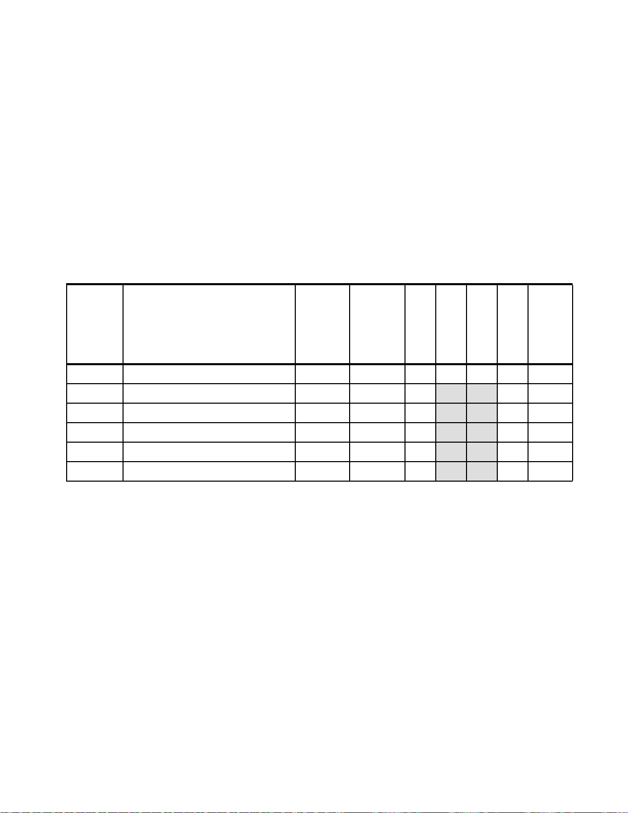
3.3 Models
This section lists the currently available models. The x3850 X5 and x3950 X5 (both models
are machine type 7145) have a three-year warranty.
For information about the recent models, consult tools, such as the Configurations and
Options Guide (COG) or Standalone Solutions Configuration Tool (SSCT). These tools are
available at the Configuration tools website:
http://www.ibm.com/systems/x/hardware/configtools.html
x3850 X5 base models without MAX5
Table 3-2 lists the base models of the x3850 X5 that do not include the MAX5 memory
expansion unit as a standard. The MAX5 is optional. In the table,
maximum, and
Table 3-2 Base models of the x3850 X5: Four-socket scalable server
C is core (such as 4C is 4-core).
std is standard, max is
Standard
Memory
Intel Xeon processors
a
Model
7145-ARx E7520 4C 1.86 GHz, 18 MB L3, 95W
7145-1Rx E7520 4C 1.86 GHz, 18 MB L3, 95W
7145-2Rx E7530 6C 1.86 GHz, 12 MB L3, 105W
7145-3Rx E7540 6C 2.0 GHz, 18 MB L3, 105W 1066 MHz 4x 4 GB 2/8
7145-4Rx X7550 8C 2.0 GHz, 18 MB L3, 130W 1066 MHz 4x 4 GB 2/8
7145-5Rx X7560 8C 2.26 GHz, 24 MB L3, 130W 1066 MHz 4x 4 GB 2/8
a. The x character in the seventh position of the machine model denotes the region-specific character.
For example, U indicates US, and G indicates EMEA.
b. The Emulex 10Gb Ethernet Adapter is installed in PCIe slot 7.
c. Any model using the E7520 or E7530 CPU cannot scale beyond single node 4-way.
(two standard; maximum of four)
speed
(MHz)
c
800 MHz 2x 2 GB 1/8 No No 1/2 None
c
800 MHz 4x 4 GB 2/8 Ye s Ye s 2 / 2 None
c
978 MHz 4x 4 GB 2/8 Ye s Ye s 2 / 2 None
memory
(MAX5 is
optional)
Memory cards
(std/max)
ServeRAID
BR10i std
Ye s Ye s 2 / 2 None
Ye s Ye s 2 / 2 None
Ye s Ye s 2 / 2 None
Workload-optimized x3950 X5 models
Table 3-3 on page 65 lists the workload-optimized models of the x3950 X5 that have been
announced. The MAX5 is optional on these models. (In the table,
maximum.)
std is standard, and max is
b
Drive
bays
10Gb Ethernet
standard
Power supplies
(std/max)
(std)
Model 5Dx
Model 5Dx is designed for database applications and uses SSDs for the best I/O
performance. Backplane connections for eight 1.8-inch SSDs are standard and there is space
for an additional eight SSDs. You must order the SSDs separately. Because no SAS
controllers are standard, you can select from the available cards that are described in 3.9,
“Storage” on page 90.
Model 4Dx
Model 4Dx is designed for virtualization and is fully populated with 4 GB memory DIMMs,
including in an attached MAX5 memory expansion unit, for a total of 384 GB of memory.
64 IBM eX5 Implementation Guide
Page 85

Backplane connections for four 2.5-inch SAS HDDs are standard; however, you must order
the SAS HDDs separately. A ServeRAID BR10i SAS controller is standard in this model.
Table 3-3 Models of the x3950 X5: Workload-optimized models
Intel Xeon
processors
Model
(two standard,
a
maximum of four)
Memory
speed MAX5
Standard
memory
Memory cards
(std/max)
ServeRAID
BR10i std
Database workload-optimized models
7145-5Dx
X7560 8C 2.27 GHz,
24 MB L3, 130W
1066
MHz
Opt Server: 8x 4GB 4/8 No Ye s 2 / 2 None
Virtualization workload optimized models
7145-4Dx
4x X7550 8C 2.0 GHz,
18 MB L3, 130W
1066
MHz
Std
Server: 64x 4GB
MAX5: 32x 4GB
8/8 Ye s Ye s 2/2 None
a. The x character in the seventh position of the machine model denotes the region-specific character.
For example, U indicates US, and G indicates EMEA.
b. The Emulex 10Gb Ethernet Adapter is installed in PCIe slot 7.
x3850 X5 models with MAX5
Table 3-4 lists the models that are standard with the 1U MAX5 memory expansion unit.
Table 3-4 Models of the x3850 X5 with the MAX5 standard
Model
Intel Xeon processors
a
(four standard and max)
Memory
speed
(MHz)
Standard
memory
(MAX5 is
standard)
Memory cards
(std/max)
ServeRAID
BR10i std
b
10Gb Ethernet
b
10Gb Ethernet
standard
Power supplies
standard
Power supplies
(std/max)
Drive bays
(std/max)
(std/max)
Drive bays
(std/max)
7145-2Sx
7145-4Sx
7145-5Sx
4x E7530 6C 1.86 GHz,
12 MB L3, 105W
c
4x X7550 8C 2.0 GHz,
18 MB L3, 130W
4x X7560 8C 2.27 GHz,
24 MB L3, 130W
978 MHz
1066 MHz
1066 MHz
Server: 8x 4 GB
MAX5: 2x 4 GB
Server: 8x 4 GB
MAX5: 2x 4 GB
Server: 8x 4 GB
MAX5: 2x 4 GB
4/8
4/8
4/8
Ye s Ye s 2 / 2 None
Ye s Ye s 2 / 2 None
Ye s Ye s 2 / 2 None
a. The x character in the seventh position of the machine model denotes the region-specific character.
For example, U indicates US, and G indicates EMEA.
b. The Emulex 10Gb Ethernet Adapter is installed in PCIe slot 7.
c. Any model using the E7520 or E7530 CPU cannot scale beyond single node 4-way.
Chapter 3. IBM System x3850 X5 and x3950 X5 65
Page 86

3.4 System architecture
SMI
links
MB 2
MB 1
MB 2
MB 1
MB 2
MB 1
MB 2
MB 1
Memory card 5Memory card 6
Memory card 1
Memory card 2
QPI
links
Intel
Xeon
CPU 3
Intel
Xeon
CPU 1
MB 2
MB 1
MB 2
MB 1
MB 2
MB 1
MB 2
MB 1
Memory card 7Memory card 8
Memory card 3
Memory card 4
QPI
ports
Intel
Xeon
CPU 4
Intel
Xeon
CPU 2
Intel
I/O Hub
QPI
links
Slot 1: x16 FL
Slot 2: x4 FL*
Slot 3: x8 FL
Slot 4: x8 FL
Slot 5: x8 HL
Slot 6: x8 HL
Slot 7: x8 HL†
Intel
I/O Hub
† Slot 7 keyed for the
10Gb Ethernet adapter
Intel
Southbridge
Dual Gb
Ethernet
x4
DVD, USB,
IMM, LP
SAS
x8
* x8 mechanical
QPI QPI
QPI QPI
QPI
ports
This section explains the system board architecture and the use of the QPI wrap card.
3.4.1 System board
Figure 3-7 shows the system board layout of a single-node 4-way system.
Figure 3-7 Block diagram for single-node x3850 X5
3.4.2 QPI Wrap Card
66 IBM eX5 Implementation Guide
In Figure 3-7, the dotted lines indicate where the QPI Wrap Cards are installed in a
4-processor configuration. These wrap cards complete the full QPI mesh to allow all four
processors to connect to each other. The QPI Wrap Cards are not needed in 2-processor
configurations and are removed when a MAX5 is connected.
Figure 3-12 on page 70 is a block diagram of the x3850 X5 connected to a MAX5.
In the x3850 X5, QPI links are used for interprocessor communication, both in a single-node
system and in a 2-node system. They are also used to connect the system to a MAX5
memory expansion drawer. In a single-node x3850 X5, the QPI links connect in a full mesh
between all CPUs. To complete this mesh, the QPI Wrap Card is used.
Page 87

Tip: The QPI Wrap Cards are only for single-node configurations with three or four
QPI
ports
QPI QPI
QPI QPI
QPI
ports
SMI
links
QPI
links
Intel
Xeon
CPU 3
Intel
Xeon
CPU 1
External
QPI ports
Intel
Xeon
CPU 4
Intel
Xeon
CPU 2
QPI Wrap Card
connection
External
QPI ports
QPI Wrap Card
connection
processors installed. They are
not necessary for any of the following items:
Single-node configurations with two processors
Configurations with MAX5 memory expansion units
Two-node configurations
Figure 3-8 shows the QPI Wrap Card.
Figure 3-8 QPI Wrap Card
For single-node systems with three or four processors installed, but without the MAX5
memory expansion unit connected, install two QPI Wrap Cards. Figure 3-9 shows a diagram
of how the QPI Wrap Cards are used to complete the QPI mesh. Although the QPI Wrap
Cards are not mandatory, they provide a performance boost by ensuring that all CPUs are
only one
hop away from each other, as shown in Figure 3-9.
Figure 3-9 Location of QPI Wrap Cards
Chapter 3. IBM System x3850 X5 and x3950 X5 67
Page 88

The QPI Wrap Cards are not included with standard server models and must be ordered
QPI bays (remove
the blanks first)
separately. See Table 3-5.
Table 3-5 Ordering information for the QPI Wrap Card
Part number Feature code Description
49Y4379 Not applicable IBM x3850 X5 and x3950 X5 QPI Wrap Card Kit (quantity 2)
Tips:
Part number 49Y4379 includes two QPI Wrap Cards. You order only one of these parts
per server.
QPI Wrap Cards cannot be ordered individually.
The QPI Wrap Cards are installed in the QPI bays at the back of the server, as shown in
Figure 3-10.
QPI Wrap Cards are not needed in a 2-node configuration and not needed in a MAX5
configuration. When the QPI Wrap Cards are installed, no external QPI ports are available.
If you later want to attach a MAX5 expansion unit or connect a second node, you must first
remove the QPI Wrap Cards.
Figure 3-10 Rear of the x3850 X5
3.5 MAX5
As introduced in 3.1.3, “IBM MAX5 memory expansion unit” on page 59, the MAX5 memory
expansion drawer is available for both the x3850 X5 and the x3950 X5. Models of the x3850
X5 and x3950 X5 are available that include the MAX5, as described in 3.3, “Models” on
68 IBM eX5 Implementation Guide
Page 89
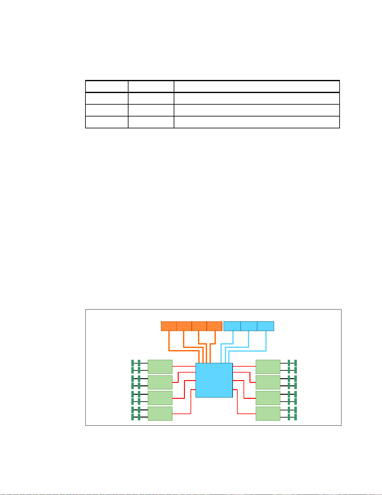
page 64, Also, you can order the MAX5 separately, as listed in Table 3-6. When ordering a
SMI
links
DDR3 DIMMs
(Two DIMMsper channel)
Memory
buffer
Memory
buffer
Memory
buffer
Memory
buffer
SMI
links
Memory
buffer
Memory
buffer
Memory
buffer
Memory
buffer
DDR3 DIMMs
(Two DIMMsper channel)
External connectors
QPI QPIQPI QPI EXA EXA EXA
IBM EXA
chip
QPI QPI
MAX5, remember to order the cable kit as well. For power supply fault redundancy, order the
optional power supply.
Table 3-6 Ordering information for the IBM MAX5 for System x
Part number Feature code Description
59Y6265 4199 IBM MAX5 for System x
60Y0332 4782 IBM 675W HE Redundant Power Supply
59Y6267 4192 IBM MAX5 to x3850 X5 Cable Kit
The eX5 chip set in the MAX5 is an IBM unique design that attaches to the QPI links as a
node controller, giving it direct access to all CPU bus transactions. It increases the number of
DIMMs supported in a system by a total of 32, and it also adds another 16 channels of
memory bandwidth, boosting overall throughput. Therefore, the MAX5 adds additional
memory and performance.
The eX5 chip connects directly through QPI links to all of the CPUs in the x3850 X5, and it
maintains a directory of each
CPU’s last-level cache. Therefore, when a CPU requests
content stored in the cache of another CPU, the MAX5 not only has that same data stored in
its own cache, it is able to return the acknowledgement of the snoop
and the data to the
requesting CPU in the same transaction. For more information about QPI links and snooping,
see 2.2.4, “QuickPath Interconnect (QPI)” on page 18.
The MAX5 also has EXA scalability ports used in an EXA-scaled configuration (that is, a
2-node and MAX5 configuration). These ports are reserved for future use.
In summary, the MAX5 offers the following major features:
Adds 32 DIMM slots to either the x3850 X5 or the x3690 X5
Adds 16 channels of memory bandwidth
Improves snoop latencies
Figure 3-11 shows a diagram of the MAX5.
Figure 3-11 MAX5 block diagram
Chapter 3. IBM System x3850 X5 and x3950 X5 69
Page 90

The MAX5 is connected to the x3850 X5 using four cables, connecting the QPI ports on the
SMI
links
QPI
links
Intel
Xeon
CPU 3
Intel
Xeon
CPU 1
Intel
Xeon
CPU 4
Intel
Xeon
CPU 2
External
QPI cables
System x3850 X5 MAX5
QPIQPI
QPI QPI
EXA
QPI QPIQPI EXA EXA EXAQPI
QPI
server to the four QPI ports on the MAX5. Figure 3-12 shows architecturally how a
single-node x3850 X5 connects to a MAX5.
Figure 3-12 The x3850 X5: Connectivity of the system unit with the MAX5
Tip: As shown in Figure 3-12 on page 70, you maximize performance when you have four
processors installed, because you then have four active QPI links to the MAX5. However,
configurations of two and three processors are still supported. If only two processors are
required, consider the use of the x3690 X5.
We describe the connectivity of the MAX5 to the x3850 X5 in 3.6, “Scalability” on page 70.
For memory configuration information, see 3.8.4, “Memory mirroring” on page 87. For
information about power and fans, see 3.14, “Power supplies and fans of the x3850 X5 and
MAX5” on page 112.
3.6 Scalability
In this section, we describe how to expand the x3850 X5 to increase the number of
processors and the number of memory DIMMs.
The x3850 X5 currently supports the following scalable configurations:
A single x3850 X5 server with four processor sockets. This configuration is sometimes
A single x3850 X5 server with a single MAX5 memory expansion unit attached. This
configuration is sometimes referred to as a
referred to as a
single-node server.
memory-expanded server.
70 IBM eX5 Implementation Guide
Page 91

Two x3850 X5 servers connected to form a single image 8-socket server. This
Rack rear
configuration is sometimes referred to as a
MAX5: The configuration of two nodes with MAX5 is not supported.
3.6.1 Memory scalability with MAX5
The MAX5 memory expansion unit permits the x3850 X5 to scale to an additional 32 DDR3
DIMM sockets.
Connecting the single-node x3850 X5 with the MAX5 memory expansion unit uses four QPI
cables, part number 59Y6267, as listed in Table 3-7. Figure 3-13 shows the connectivity.
Tip: As shown in Figure 3-12 on page 70, you maximize performance when you have four
processors installed because you have four active QPI links to the MAX5. However,
configurations of two and three processors are still supported.
2-node server.
Figure 3-13 Connecting the MAX5 to a single-node x3850 X5
Connecting the MAX5 to a single-node x3850 X5 requires one IBM MAX5 to x3850 X5 Cable
Kit, which consists of four QPI cables. See Table 3-7.
Table 3-7 Ordering information for the IBM MAX5 to x3850 X5 Cable Kit
Part number Feature code Description
59Y6267 4192 IBM MAX5 to x3850 X5 Cable Kit (quantity 4 cables)
3.6.2 Two-node scalability
The 2-node configuration also uses native Intel QPI scaling to create an 8-socket
configuration. The two servers are physically connected to each other with a set of external
QPI cables. The cables are connected to the server through the QPI bays, which are shown in
Figure 3-7 on page 66. Figure 3-14 on page 72 shows the cable routing.
Chapter 3. IBM System x3850 X5 and x3950 X5 71
Page 92

Figure 3-14 Cabling diagram for two node x3850 X5
Rack rear
Connecting the two x3850 X5 servers to form a 2-node system requires one IBM x3850 X5
and x3950 X5 QPI Scalability Kit, which consists of four QPI cables. See Table 3-8.
Table 3-8 Ordering information for the IBM x3850 X5 and x3950 X5 QPI Scalability Kit
Part number Feature code Description
46M0072 5103 IBM x3850 X5 and x3950 X5 QPI Scalability Kit (quantity 4 cables)
No QPI ports are visible on the rear of the server. The QPI scalability cables have long rigid
connectors, allowing them to be inserted into the QPI bay until they connect to the QPI ports,
which are located a few inches inside on the planar. Completing the QPI scaling of two x3850
X5 servers into a 2-node complex does not require any other option.
Intel E7520 and E7530: The Intel E7520 and E7530 processors cannot be used to scale
to an 8-way 2-node complex. They support a maximum of four processors. At the time of
this writing, the following models use those processors:
7145-ARx
7145-1Rx
7145-2Rx
7145-2Sx
Figure 3-15 on page 73 shows the QPI links that are used to connect two x3850 X5 servers to
each other. Both nodes must have four processors each, and all processors must be identical.
72 IBM eX5 Implementation Guide
Page 93

Figure 3-15 QPI links for a 2-node x3850 X5
1
24
3 3
42
1
QPI Links
QPI-based scaling is managed primarily through the Unified Extensible Firmware Interface
(UEFI) firmware of the x3850 X5.
For the 2-node x3850 X5 scaled through the QPI ports, when those cables are connected, the
two nodes act as one system until the cables are physically disconnected.
Firmware levels: It is important to ensure that both of the x3850 X5 servers have the
identical UEFI, integrated management module (IMM), and Field-Programmable Gate
Array (FPGA) levels before scaling. If they are not at the same levels, unexpected issues
occur and the server might not boot. See 9.10, “Firmware update tools and methods” on
page 509 for ways to check and update the firmware.
Partitioning: The x3850 X5 currently does not support partitioning.
Chapter 3. IBM System x3850 X5 and x3950 X5 73
Page 94

3.7 Processor options
The x3850 X5 is supported with two, three, or four processors. Table 3-9 shows the option
part numbers for the supported processors. In a 2-node system, you must have eight
processors, which must all be identical. For a list of the processor options available in this
solution, see 2.2, “Intel Xeon 6500 and 7500 family processors” on page 16.
Table 3-9 Available processor options for the x3850 X5
Part
number
Feature
code
Intel Xeon
model
Speed Cores L3 cache GT/s/
Memory speed
a
Power
(watts)
HT
b
TB
c
49Y4300 4513 X7560 2.26 GHz 8 24 MB x6.4/1066 MHz 130 W
49Y4302 4517 X7550 2.00 GHz 8 18 MB x6.4/1066 MHz 130 W
59Y6103 4527 X7542 2.66 GHz 6 18 MB x5.86/978 MHz 130 W No
49Y4304 4521 E7540 2.00 GHz 6 18 MB x6.4/1066 MHz 105 W
49Y4305 4523 E7530
49Y4306 4525 E7520
49Y4301 4515 L7555 1.86 GHz 8 24 MB x5.86/978 MHz 95 W
49Y4303 4519 L7545 1.86 GHz 6 18 MB x5.86/978 MHz 95 W
a. GT/s is gigatransfers per second. For an explanation, see 2.3.1, “Memory speed” on page 22.
b. Intel Hyper-Threading Technology. For an explanation, see 2.2.2, “Hyper-Threading Technology” on page 17.
c. Intel Turbo Boost Technology. For an explanation, see 2.2.3, “Turbo Boost Technology” on page 18.
d. Scalable to a 4-socket maximum, and therefore, it cannot be used in a 2-node x3850 X5 complex that is scaled
with native QPI cables.
d
d
1.86 GHz 6 12 MB x5.86/978 MHz 105 W
1.86 GHz 4 18 MB x4.8/800 MHz 95 W Ye s N o
Ye s Ye s
Ye s Ye s
Ye s Ye s
Ye s Ye s
Ye s Ye s
Ye s Ye s
With the exception of the E7520, all processors listed in Table 3-9 support Intel Turbo Boost
Technology. When a processor operates below its thermal and electrical limits, Turbo Boost
dynamically increases the clock frequency of the processor by 133 MHz on short and regular
intervals until an upper limit is reached. See 2.2.3, “Turbo Boost Technology” on page 18 for
more information.
With the exception of the X7542, all of the processors that are shown in Table 3-9 support
Intel Hyper-Threading Technology, which is an Intel technology that can improve the
parallelization of workloads. When Hyper-Threading is engaged in the BIOS, for each
processor core that is physically present, the operating system addresses two. For more
information, see 2.2.2, “Hyper-Threading Technology” on page 17.
Ye s
All processor options include the heat-sink and CPU installation tool. This tool is extremely
important due to the high possibility of bending pins on the processor socket when using the
incorrect procedure.
The x3850 X5 includes at least two CPUs as standard. Two CPUs are required to access all
seven of the PCIe slots (shown in Figure 3-7 on page 66):
Either CPU 1 or CPU 2 is required for the operation of PCIe slots 5-7.
Either CPU 3 or CPU 4 is required for the operation of PCIe Slots 1-4.
All CPUs are also required to access all memory cards on the x3850 X5 but they are not
required to access memory on the MAX5, as explained in 3.8, “Memory” on page 76.
74 IBM eX5 Implementation Guide
Page 95

Use these population guidelines:
Each CPU requires a minimum of two DIMMs to operate.
All processors must be identical.
Only configurations of two, three, or four processors are supported.
The number of installed processors dictates what memory cards can be used:
– Two installed processors enable four memory cards.
– Three installed processors enable six memory cards.
– Four installed processors enable all eight memory cards.
A processor must be installed in socket 1 or 2 for the system to successfully boot.
A processor is required in socket 3 or 4 to use PCIe slots 1 - 4. See Figure 3-7 on page 66.
When installing three or four processors, use a QPI Wrap Card Kit (part number 49Y4379)
to improve performance. The kit contains two wrap cards. See 3.4.2, “QPI Wrap Card” on
page 66.
When using a MAX5 memory expansion unit, as shown in Figure 3-12 on page 70, you
maximize performance when you have four installed processors because there are four
active QPI links to the MAX5. However, configurations of two and three processors are still
supported.
Consider the X7542 processor for CPU frequency-dependent workloads because it has
the highest core frequency of the available processor models.
If high processing capacity is not required for your application but high memory bandwidth
is required, consider using four processors with fewer cores or a lower core frequency
rather than two processors with more cores or a higher core frequency. Having four
processors enables all memory channels and maximizes memory bandwidth. We
describe this situation in 3.8, “Memory” on page 76.
Chapter 3. IBM System x3850 X5 and x3950 X5 75
Page 96

3.8 Memory
Two scalable
memory buffers
DIMM 8
DIMM 1
Memory is installed in the x3850 X5 in memory cards. Up to eight memory cards can be
installed in the server, and each card holds eight DIMMs. Therefore, the x3850 X5 supports
up to 64 DIMMs.
This section includes the following topics:
3.8.1, “Memory cards and DIMMs” on page 76
3.8.2, “DIMM population sequence” on page 79
3.8.3, “Maximizing memory performance” on page 84
3.8.4, “Memory mirroring” on page 87
3.8.5, “Memory sparing” on page 89
3.8.6, “Effect on performance by using mirroring or sparing” on page 89
3.8.1 Memory cards and DIMMs
This section describes the available memory options for the x3850 X5 and the MAX5.
Memory cards for the x3850 X5
The x3850 X5, like its predecessor the x3850 M2, uses memory cards to which the memory
DIMMs are attached, as shown in Figure 3-16.
Figure 3-16 x3850 x5 memory card
76 IBM eX5 Implementation Guide
Page 97

Standard models contain two or more memory cards. You can configure additional cards, as
Memory cards 1 - 8
Processors 1 - 4
listed in Table 3-10.
Table 3-10 IBM System x3850 X5 and x3950 X5 memory card
Part number Feature code Description
46M0071 5102 IBM x3850 X5 and x3950 X5 Memory Expansion Card
The memory cards are installed in the server, as shown in Figure 3-17. Each processor is
electrically connected to two memory cards as shown (for example, processor 1 is connected
to memory cards 1 and 2).
Figure 3-17 Memory card and processor enumeration
Chapter 3. IBM System x3850 X5 and x3950 X5 77
Page 98

DIMMs for the x3850 X5
Table 3-11 shows the available DIMMs that are supported in the x3850 X5 server. The table
also indicates the DIMM options that are also supported in the MAX5. When used in the
MAX5, the DIMMs have separate feature codes, which are shown as -
Table 3-11 x3850 X5 supported DIMMs
fc.
Part
number
44T1592 1712 2 GB (1x 2GB) 1Rx8, 2 Gb PC3-10600R DDR3-1333 Yes (fc 2429) 1333 MHz
44T1599 1713 4 GB (1x 4GB), 2Rx8, 2 Gb PC3-10600R DDR3-1333
46C7448 1701 4 GB (1x 4GB), 4Rx8, 1 Gb PC3-8500 DDR3-1066 No 1066 MHz Quad x8
46C7482 1706 8 GB (1x 8GB), 4Rx8, 2 Gb PC3-8500 DDR3-1066 Yes (fc 2432) 1066 MHz Quad x8
46C7483 1707 16 GB (1x 16GB), 4Rx4, 2 Gb PC3-8500 DDR3-1066
a. Memory speed is also controlled by the memory bus speed as specified by the processor model selected. The actual
memory bus speed is the lower of both the processor memory bus speed and the DIMM memory bus speed.
b. Although 1333 MHz memory DIMMs are supported in the x3850 X5, the memory DIMMs run at a maximum speed of
1066 MHz.
c. The 16 GB memory option is supported in the MAX5 only when it is the only type of memory that is used in the MAX5.
No other memory options can be used in the MAX5 if this option is installed in the MAX5. This DIMM also supports
redundant bit steering (RBS) when used in the MAX5, as described in “Redundant bit steering” on page 29.
x3850 X5
feature
code
Memory Supported
in MAX5
Yes (fc 2431) 1333 MHz Dual x8
Ye sc (fc 2433)
Memory
a
speed
1066 MHz Quad x4
b
Ranks
Single x8
Guidelines:
Memory options must be installed in matched pairs. Single options cannot be installed,
so the options that are shown in Table 3-11 need to be ordered in quantities of two.
You can achieve additional performance by enabling Hemisphere Mode, which is
described in “Hemisphere Mode” on page 26. This mode requires that the memory
options are installed in matched quads.
The maximum memory speed that is supported by Xeon 7500 and 6500 (Nehalem-EX)
processors is 1066 MHz (1,333 MHz speed is not supported). Although the 1333 MHz
DIMMs are still supported in the x3850 X5, they can operate at a speed of at most
1066 MHz.
As with Intel Xeon 5500 processor (Nehalem-EP), the speed at which the memory that is
connected to the Xeon 7500 and 6500 processors (Nehalem-EX) runs depends on the
capabilities of the specific processor. With Nehalem-EX, the scalable memory interconnect
(SMI) link runs from the memory controller that is integrated in the processor to the memory
buffers on the memory cards.
The SMI link speed is derived from the processor QPI link speed:
6.4 GT/s QPI link speed capable of running memory speeds up to 1066 MHz
5.86 GT/s QPI link speed capable of running memory speeds up to 978 MHz
4.8 GT/s QPI link speed capable of running memory speeds up to 800 MHz
To see more information about how memory speed is calculated with QPI, see 2.3.1,
“Memory speed” on page 22.
78 IBM eX5 Implementation Guide
Page 99

MAX5 memory
The MAX5 memory expansion unit has 32 DIMM sockets and is designed to augment the
installed memory in the attached x3850 X5 server. Table 3-12 shows the available memory
options that are supported in the MAX5 memory expansion unit. These options are a subset
of the options that are supported in the x3850 X5 because the MAX5 requires that all DIMMs
use identical DRAM technology: either 2 Gb x8 or 2 Gb x4 (but not both at the same time).
x3850 X5 memory options: The memory options listed here are also supported in the
x3850 X5, but under other feature codes for configure-to-order (CTO) clients. Additional
memory options are also supported in the x3850 X5 server but not in the MAX5; these
options are listed in Table 3-11 on page 78.
Table 3-12 DIMMs supported in the MAX5
Part
number
44T1592 2429 2 GB (1x 2GB) 1Rx8, 2Gbit PC3-10600R DDR3-1333
44T1599 2431 4 GB (1x 4GB), 2Rx8, 2Gbit PC3-10600R DDR3-1333
46C7482 2432 8 GB (1x 8GB), 4Rx8, 2Gbit PC3-8500 DDR3-1066
46C7483 2433 16 GB (1x 16GB), 4Rx4, 2Gbit PC3-8500 DDR3-1066
a. Memory speed is also controlled by the memory bus speed, as specified by the selected processor model. The
actual memory bus speed is the lower of both the processor memory bus speed and the DIMM memory bus speed.
b. Although 1333 MHz memory DIMMs are supported in the x3690 X5, the memory DIMMs run at a maximum speed
of 1066 MHz.
c. The 16 GB memory option is supported in the MAX5 only when it is the only type of memory used in the MAX5.
No other memory options can be used in the MAX5 if this option is installed in the MAX5.
d. This DIMM supports redundant bit steering (RBS), as described in “Redundant bit steering” on page 29.
MAX5
feature
code
Memory Supporte
d
in MAX5
Yes 1333 MHz
Yes 1333 MHz Dual x8
Yes 1066 MHz Quad x8
d
Ye sc
Memory
a
speed
1066 MHz Quad x4
b
Ranks
Single x8
Use of the 16 GB memory option: The 16 GB memory option, 46C7483, is supported in
the MAX5 only when it is the only type of memory that is used in the MAX5. No other
memory options can be used in the MAX5 if this option is installed in the MAX5.
Redundant bit steering: Redundant bit steering (RBS) is not supported on the x3850 X5
itself, because the integrated memory controller of the Intel Xeon 7500 processors does
not support the feature. See “Redundant bit steering” on page 29 for details.
The MAX5 memory expansion unit support RBS, but only with x4 memory and not x8
memory. As shown in Table 3-12, the 16 GB DIMM, part 46C7483, uses x4 DRAM
technology. RBS is automatically enabled in the MAX5 memory port, if all DIMMs installed
to that memory port are x4 DIMMs.
3.8.2 DIMM population sequence
This section describes the order in which to install the memory DIMMs in the x3850 X5 and
MAX5.
Chapter 3. IBM System x3850 X5 and x3950 X5 79
Page 100

Installing DIMMs in the x3850 X5 and MAX5 in the correct order is essential for system
performance. See “Mixed DIMMs and the effect on performance” on page 86 for performance
effects when this guideline is not followed.
Tip: The tables in this section list only memory configurations that are considered the best
practices in obtaining the optimal memory and processor performance.
For a full list of supported memory configurations, see the IBM System x3850 X5
Installation and User’s Guide or the IBM System x3850 X5 Problem Determination and
Service Guide. We list the download links to these documents in “Related publications” on
page 541.
x3850 X5 single-node and 2-node configurations
Table 3-13 is the same if you use a single-node configuration or if you use a 2-node
configuration. In a 2-node configuration, you install in the same order twice, once for each
server.
Table 3-13 shows the NUMA-compliant memory installation sequence for two processors.
Table 3-13 NUMA-compliant DIMM installation (two processors): x3850 X5
Processor 1 Processor 4
a
Card 1 Card 2 Card 7 Card 8
Number of DIMMs
Hemisphere Mode
DIMM 1 and 8
DIMM 3 and 6
DIMM 2 and 7
DIMM 4 and 5
DIMM 1 and 8
DIMM 3 and 6
DIMM 2 and 7
DIMM 4 and 5
DIMM 1 and 8
DIMM 3 and 6
DIMM 2 and 7
DIMM 4 and 5
DIMM 1 and 8
DIMM 3 and 6
DIMM 2 and 7
DIMM 4 and 5
4Nx x
Y x x x x
8
12 N
16
20 N
24
28 N
32
a. For more information about Hemisphere Mode and its importance, see 2.3.5,
x x x x x x
Y x x x x x x x x
x x x x x x x x x x
Y x x x x x x x x x x x x
x x x x x x x x x x x x x x
Y x x x x x x x x x x x x x x x x
“Hemisphere Mode” on page 26.
Table 3-14 on page 81 shows the NUMA-compliant memory installation sequence for three
processors.
80 IBM eX5 Implementation Guide
 Loading...