

IBM System x3650 Type 7979, System x3650 Type 1914 Problem Determination And Service Manual
Page 1

IBM System x3650 Ty pe 7979 and 1914
Problem Dete rminatio n and Service Guid e
Page 2

Page 3

IBM System x3650 Ty pe 7979 and 1914
Problem Dete rminatio n and Service Guid e
Page 4

Note: Before using this information and the product it supports, read the general information in Appendix B, “Notices,” on page
165.
Seventh Edition (November 2006)
© Copyright International Business Machines Corporation 2006. All rights reserved.
US Government Users Restricted Rights – Use, duplication or disclosure restricted by GSA ADP Schedule Contract
with IBM Corp.
Page 5

Contents
Safety . . . . . . . . . . . . . . . . . . . . . . . . . . . . vii
Guidelines for trained service technicians . . . . . . . . . . . . . . . viii
Inspecting for unsafe conditions . . . . . . . . . . . . . . . . . viii
Guidelines for servicing electrical equipment . . . . . . . . . . . . . viii
Safety statements . . . . . . . . . . . . . . . . . . . . . . . .x
Chapter 1. Introduction . . . . . . . . . . . . . . . . . . . . . .1
Related documentation . . . . . . . . . . . . . . . . . . . . . .1
Notices and statements in this document . . . . . . . . . . . . . . . .2
Features and specifications . . . . . . . . . . . . . . . . . . . . .3
Server controls, LEDs, and connectors . . . . . . . . . . . . . . . .5
Front view . . . . . . . . . . . . . . . . . . . . . . . . . .5
Rear view . . . . . . . . . . . . . . . . . . . . . . . . . .7
Internal connectors, LEDs, and jumpers . . . . . . . . . . . . . . . .8
System-board option connectors . . . . . . . . . . . . . . . . . .9
PCI riser-card option connectors . . . . . . . . . . . . . . . . .10
Power-backplane-board connectors . . . . . . . . . . . . . . . .10
System-board internal cable connectors . . . . . . . . . . . . . . .11
System-board external connectors . . . . . . . . . . . . . . . . .12
System-board switches and jumpers . . . . . . . . . . . . . . . .13
System-board LEDs . . . . . . . . . . . . . . . . . . . . . .15
Riser-card assembly LEDs . . . . . . . . . . . . . . . . . . .16
Chapter 2. Diagnostics . . . . . . . . . . . . . . . . . . . . .17
Diagnostic tools . . . . . . . . . . . . . . . . . . . . . . . .17
POST . . . . . . . . . . . . . . . . . . . . . . . . . . . .17
POST beep codes . . . . . . . . . . . . . . . . . . . . . .17
Error logs . . . . . . . . . . . . . . . . . . . . . . . . . .26
POST error codes . . . . . . . . . . . . . . . . . . . . . . .28
Checkout procedure . . . . . . . . . . . . . . . . . . . . . . .34
About the checkout procedure . . . . . . . . . . . . . . . . . .34
Performing the checkout procedure . . . . . . . . . . . . . . . .35
Troubleshooting tables . . . . . . . . . . . . . . . . . . . . . .36
CD or DVD drive problems . . . . . . . . . . . . . . . . . . .36
General problems . . . . . . . . . . . . . . . . . . . . . . .37
Hard disk drive problems . . . . . . . . . . . . . . . . . . . .37
Intermittent problems . . . . . . . . . . . . . . . . . . . . . .38
USB keyboard, mouse, or pointing-device problems . . . . . . . . . .39
Memory problems . . . . . . . . . . . . . . . . . . . . . . .40
Microprocessor problems . . . . . . . . . . . . . . . . . . . .41
Monitor problems . . . . . . . . . . . . . . . . . . . . . . .41
Optional-device problems . . . . . . . . . . . . . . . . . . . .44
Power problems . . . . . . . . . . . . . . . . . . . . . . .45
Serial port problems . . . . . . . . . . . . . . . . . . . . . .47
ServerGuide problems . . . . . . . . . . . . . . . . . . . . .48
Software problems . . . . . . . . . . . . . . . . . . . . . .48
Universal Serial Bus (USB) port problems . . . . . . . . . . . . . .49
Video problems . . . . . . . . . . . . . . . . . . . . . . . .49
Light path diagnostics . . . . . . . . . . . . . . . . . . . . . .49
Remind button . . . . . . . . . . . . . . . . . . . . . . . .51
Light path diagnostics LEDs . . . . . . . . . . . . . . . . . . .52
Power-supply LEDs . . . . . . . . . . . . . . . . . . . . . . .53
Diagnostic programs, messages, and error codes . . . . . . . . . . . .54
© Copyright IBM Corp. 2006 iii
Page 6

Running the diagnostic programs . . . . . . . . . . . . . . . . .55
Diagnostic text messages . . . . . . . . . . . . . . . . . . . .56
Viewing the test log . . . . . . . . . . . . . . . . . . . . . .56
Diagnostic error codes . . . . . . . . . . . . . . . . . . . . .56
Recovering the BIOS code . . . . . . . . . . . . . . . . . . . .65
System event/error log messages . . . . . . . . . . . . . . . . . .68
Solving power problems . . . . . . . . . . . . . . . . . . . . .74
Solving Ethernet controller problems . . . . . . . . . . . . . . . . .75
Solving undetermined problems . . . . . . . . . . . . . . . . . . .76
Problem determination tips . . . . . . . . . . . . . . . . . . . .77
Calling IBM for service . . . . . . . . . . . . . . . . . . . . . .78
Chapter 3. Parts listing, Type 7979 and 1914 server . . . . . . . . . .79
Replaceable server components . . . . . . . . . . . . . . . . . .79
View 1 . . . . . . . . . . . . . . . . . . . . . . . . . . .80
View 2 . . . . . . . . . . . . . . . . . . . . . . . . . . .82
Power cords . . . . . . . . . . . . . . . . . . . . . . . . . .84
Chapter 4. Removing and replacing server components . . . . . . . .87
Installation guidelines . . . . . . . . . . . . . . . . . . . . . .87
System reliability guidelines . . . . . . . . . . . . . . . . . . .88
Working inside the server with the power on . . . . . . . . . . . . .88
Handling static-sensitive devices . . . . . . . . . . . . . . . . .89
Returning a device or component . . . . . . . . . . . . . . . . .89
Removing and replacing Tier 1 CRUs . . . . . . . . . . . . . . . .90
Removing the cover . . . . . . . . . . . . . . . . . . . . . .90
Installing the cover . . . . . . . . . . . . . . . . . . . . . .91
Removing the microprocessor air baffle . . . . . . . . . . . . . . .91
Installing the microprocessor air baffle . . . . . . . . . . . . . . .92
Removing the DIMM air baffle . . . . . . . . . . . . . . . . . .92
Removing the fan-bracket assembly . . . . . . . . . . . . . . . .93
Installing the fan-bracket assembly . . . . . . . . . . . . . . . .95
Installing the DIMM air baffle . . . . . . . . . . . . . . . . . . .96
Removing the riser-card assembly . . . . . . . . . . . . . . . . .96
Installing the riser-card assembly . . . . . . . . . . . . . . . . .98
Removing an adapter . . . . . . . . . . . . . . . . . . . . .98
Installing an adapter . . . . . . . . . . . . . . . . . . . . . .99
Removing a Remote Supervisor Adapter II SlimLine . . . . . . . . . . 101
Installing a Remote Supervisor Adapter II SlimLine . . . . . . . . . . 102
Removing the ServeRAID SAS controller . . . . . . . . . . . . . . 102
Installing a ServeRAID SAS controller . . . . . . . . . . . . . . . 103
Removing a hard disk drive . . . . . . . . . . . . . . . . . . . 105
Installing a hard disk drive . . . . . . . . . . . . . . . . . . . 105
Removing a CD-RW/DVD drive . . . . . . . . . . . . . . . . . 107
Installing a CD-RW/DVD drive . . . . . . . . . . . . . . . . . . 108
Removing an optional tape drive . . . . . . . . . . . . . . . . . 108
Installing an optional tape drive . . . . . . . . . . . . . . . . . 109
Removing a memory module (DIMM) . . . . . . . . . . . . . . .114
Installing a memory module . . . . . . . . . . . . . . . . . . .114
Removing a hot-swap fan . . . . . . . . . . . . . . . . . . .116
Installing a hot-swap fan . . . . . . . . . . . . . . . . . . . .117
Removing a hot-swap power supply . . . . . . . . . . . . . . . .118
Installing a hot-swap power supply . . . . . . . . . . . . . . . .119
Removing the battery . . . . . . . . . . . . . . . . . . . . . 121
Installing the battery . . . . . . . . . . . . . . . . . . . . . 122
Removing and replacing Tier 2 CRUs . . . . . . . . . . . . . . . . 124
iv IBM System x3650 Type 7979 and 1914: Problem Determination and Service Guide
Page 7

Removing the operator information panel assembly . . . . . . . . . . 124
Installing the operator information panel assembly . . . . . . . . . . 125
Removing the power backplane . . . . . . . . . . . . . . . . . 126
Installing the power backplane . . . . . . . . . . . . . . . . . . 127
Removing the CD/DVD media backplane . . . . . . . . . . . . . . 128
Installing the CD/DVD media backplane . . . . . . . . . . . . . . 129
Installing and removing the hard disk drive backplane . . . . . . . . . 129
Removing and replacing FRUs . . . . . . . . . . . . . . . . . . 134
Removing a microprocessor . . . . . . . . . . . . . . . . . . 134
Installing a microprocessor . . . . . . . . . . . . . . . . . . . 135
Removing a heat-sink retention module . . . . . . . . . . . . . . 138
Installing a heat-sink retention module . . . . . . . . . . . . . . . 139
Removing the system board and shuttle . . . . . . . . . . . . . . 140
Installing the system board and shuttle . . . . . . . . . . . . . . 141
Removing the 3.5-inch center bracket . . . . . . . . . . . . . . . 143
Installing the 3.5-inch center bracket . . . . . . . . . . . . . . . 143
Chapter 5. Configuration information and instructions . . . . . . . . 145
Updating the firmware . . . . . . . . . . . . . . . . . . . . . . 145
Configuring the server . . . . . . . . . . . . . . . . . . . . . . 145
Using the ServerGuide Setup and Installation CD . . . . . . . . . . . 145
Using the Configuration/Setup Utility program . . . . . . . . . . . . 146
Using the ServeRAID configuration programs . . . . . . . . . . . . 146
Using the RAID configuration programs . . . . . . . . . . . . . . 147
Using the baseboard management controller . . . . . . . . . . . . 149
Appendix A. Getting help and technical assistance . . . . . . . . . . 163
Before you call . . . . . . . . . . . . . . . . . . . . . . . . 163
Using the documentation . . . . . . . . . . . . . . . . . . . . . 163
Getting help and information from the World Wide Web . . . . . . . . . 164
Software service and support . . . . . . . . . . . . . . . . . . . 164
Hardware service and support . . . . . . . . . . . . . . . . . . . 164
Appendix B. Notices . . . . . . . . . . . . . . . . . . . . . . 165
Edition notice . . . . . . . . . . . . . . . . . . . . . . . . . 165
Trademarks . . . . . . . . . . . . . . . . . . . . . . . . . . 166
Important notes . . . . . . . . . . . . . . . . . . . . . . . . 166
Product recycling and disposal . . . . . . . . . . . . . . . . . . 167
Battery return program . . . . . . . . . . . . . . . . . . . . . 168
Electronic emission notices . . . . . . . . . . . . . . . . . . . . 169
Federal Communications Commission (FCC) statement . . . . . . . . 169
Industry Canada Class A emission compliance statement . . . . . . . . 169
Australia and New Zealand Class A statement . . . . . . . . . . . . 169
United Kingdom telecommunications safety requirement . . . . . . . . 169
European Union EMC Directive conformance statement . . . . . . . . 169
Taiwanese Class A warning statement . . . . . . . . . . . . . . . 170
Chinese Class A warning statement . . . . . . . . . . . . . . . . 170
Japanese Voluntary Control Council for Interference (VCCI) statement 170
Index . . . . . . . . . . . . . . . . . . . . . . . . . . . . 171
Contents v
Page 8

vi IBM System x3650 Type 7979 and 1914: Problem Determination and Service Guide
Page 9
Safety
Before installing this product, read the Safety Information.
Antes de instalar este produto, leia as Informações de Segurança.
Pred instalací tohoto produktu si prectete prírucku bezpecnostních instrukcí.
Læs sikkerhedsforskrifterne, før du installerer dette produkt.
Lees voordat u dit product installeert eerst de veiligheidsvoorschriften.
Ennen kuin asennat tämän tuotteen, lue turvaohjeet kohdasta Safety Information.
Avant d’installer ce produit, lisez les consignes de sécurité.
Vor der Installation dieses Produkts die Sicherheitshinweise lesen.
Prima di installare questo prodotto, leggere le Informazioni sulla Sicurezza.
Les sikkerhetsinformasjonen (Safety Information) før du installerer dette produktet.
Antes de instalar este produto, leia as Informações sobre Segurança.
Antes de instalar este producto, lea la información de seguridad.
Läs säkerhetsinformationen innan du installerar den här produkten.
© Copyright IBM Corp. 2006 vii
Page 10

Guidelines for trained service technicians
This section contains information for trained service technicians.
Inspecting for unsafe conditions
Use the information in this section to help you identify potential unsafe conditions in
an IBM product that you are working on. Each IBM product, as it was designed and
manufactured, has required safety items to protect users and service technicians
from injury. The information in this section addresses only those items. Use good
judgment to identify potential unsafe conditions that might be caused by non-IBM
alterations or attachment of non-IBM features or options that are not addressed in
this section. If you identify an unsafe condition, you must determine how serious the
hazard is and whether you must correct the problem before you work on the
product.
Consider the following conditions and the safety hazards that they present:
v Electrical hazards, especially primary power. Primary voltage on the frame can
cause serious or fatal electrical shock.
v Explosive hazards, such as a damaged CRT face or a bulging capacitor.
v Mechanical hazards, such as loose or missing hardware.
inspect the product for potential unsafe conditions, complete the following steps:
To
1. Make sure that the power is off and the power cord is disconnected.
2. Make sure that the exterior cover is not damaged, loose, or broken, and
observe any sharp edges.
3. Check the power cord:
v Make sure that the third-wire ground connector is in good condition. Use a
meter to measure third-wire ground continuity for 0.1 ohm or less between
the external ground pin and the frame ground.
v Make sure that the power cord is the correct type, as specified in “Power
cords” on page 84.
v Make sure that the insulation is not frayed or worn.
Remove the cover.
4.
5. Check for any obvious non-IBM alterations. Use good judgment as to the safety
of any non-IBM alterations.
6. Check inside the server for any obvious unsafe conditions, such as metal filings,
contamination, water or other liquid, or signs of fire or smoke damage.
7. Check for worn, frayed, or pinched cables.
8. Make sure that the power-supply cover fasteners (screws or rivets) have not
been removed or tampered with.
Guidelines for servicing electrical equipment
Observe the following guidelines when servicing electrical equipment:
v Check the area for electrical hazards such as moist floors, nongrounded power
extension cords, power surges, and missing safety grounds.
v Use only approved tools and test equipment. Some hand tools have handles that
are covered with a soft material that does not provide insulation from live
electrical currents.
v Regularly inspect and maintain your electrical hand tools for safe operational
condition. Do not use worn or broken tools or testers.
viii IBM System x3650 Type 7979 and 1914: Problem Determination and Service Guide
Page 11

v Do not touch the reflective surface of a dental mirror to a live electrical circuit.
The surface is conductive and can cause personal injury or equipment damage if
it touches a live electrical circuit.
v Some rubber floor mats contain small conductive fibers to decrease electrostatic
discharge. Do not use this type of mat to protect yourself from electrical shock.
v Do not work alone under hazardous conditions or near equipment that has
hazardous voltages.
v Locate the emergency power-off (EPO) switch, disconnecting switch, or electrical
outlet so that you can turn off the power quickly in the event of an electrical
accident.
v Disconnect all power before you perform a mechanical inspection, work near
power supplies, or remove or install main units.
v Before you work on the equipment, disconnect the power cord. If you cannot
disconnect the power cord, have the customer power-off the wall box that
supplies power to the equipment and lock the wall box in the off position.
v Never assume that power has been disconnected from a circuit. Check it to
make sure that it has been disconnected.
v If you have to work on equipment that has exposed electrical circuits, observe
the following precautions:
– Make sure that another person who is familiar with the power-off controls is
near you and is available to turn off the power if necessary.
– When you are working with powered-on electrical equipment, use only one
hand. Keep the other hand in your pocket or behind your back to avoid
creating a complete circuit that could cause an electrical shock.
– When using a tester, set the controls correctly and use the approved probe
leads and accessories for that tester.
– Stand on a suitable rubber mat to insulate you from grounds such as metal
floor strips and equipment frames.
Use extreme care when measuring high voltages.
v
v To ensure proper grounding of components such as power supplies, pumps,
blowers, fans, and motor generators, do not service these components outside of
their normal operating locations.
v If an electrical accident occurs, use caution, turn off the power, and send another
person to get medical aid.
Safety ix
Page 12

Safety statements
Important:
Each caution and danger statement in this documentation begins with a number.
This number is used to cross reference an English-language caution or danger
statement with translated versions of the caution or danger statement in the Safety
Information document.
For example, if a caution statement begins with a number 1, translations for that
caution statement appear in the Safety Information document under statement 1.
Be sure to read all caution and danger statements in this documentation before
performing the instructions. Read any additional safety information that comes with
your server or optional device before you install the device.
x IBM System x3650 Type 7979 and 1914: Problem Determination and Service Guide
Page 13

Statement 1:
DANGER
Electrical
current from power, telephone, and communication cables is
hazardous.
To avoid a shock hazard:
v Do not connect or disconnect any cables or perform installation,
maintenance, or reconfiguration of this product during an electrical
storm.
v Connect all power cords to a properly wired and grounded electrical
outlet.
v Connect to properly wired outlets any equipment that will be attached to
this product.
v When possible, use one hand only to connect or disconnect signal
cables.
v Never turn on any equipment when there is evidence of fire, water, or
structural damage.
v Disconnect the attached power cords, telecommunications systems,
networks, and modems before you open the device covers, unless
instructed otherwise in the installation and configuration procedures.
v Connect and disconnect cables as described in the following table when
installing, moving, or opening covers on this product or attached
devices.
To Connect: To Disconnect:
1. Turn everything OFF.
2. First, attach all cables to devices.
3. Attach signal cables to connectors.
4. Attach power cords to outlet.
1. Turn everything OFF.
2. First, remove power cords from outlet.
3. Remove signal cables from connectors.
4. Remove all cables from devices.
5. Turn device ON.
Safety xi
Page 14

Statement 2:
CAUTION:
When replacing the lithium battery, use only IBM Part Number 33F8354 or an
equivalent type battery recommended by the manufacturer. If your system has
a module containing a lithium battery, replace it only with the same module
type made by the same manufacturer. The battery contains lithium and can
explode if not properly used, handled, or disposed of.
Do not:
v Throw or immerse into water
v Heat to more than 100°C (212°F)
v Repair or disassemble
Dispose
of the battery as required by local ordinances or regulations.
xii IBM System x3650 Type 7979 and 1914: Problem Determination and Service Guide
Page 15
Statement 3:
CAUTION:
When laser products (such as CD-ROMs, DVD drives, fiber optic devices, or
transmitters) are installed, note the following:
v Do not remove the covers. Removing the covers of the laser product could
result in exposure to hazardous laser radiation. There are no serviceable
parts inside the device.
v Use of controls or adjustments or performance of procedures other than
those specified herein might result in hazardous radiation exposure.
DANGER
laser products contain an embedded Class 3A or Class 3B laser
Some
diode. Note the following.
Laser radiation when open. Do not stare into the beam, do not view directly
with optical instruments, and avoid direct exposure to the beam.
Class 1 Laser Product
Laser Klasse 1
Laser Klass 1
Luokan 1 Laserlaite
Appareil A Laser de Classe 1
`
Safety xiii
Page 16

Statement 4:
≥ 18 kg (39.7 lb) ≥ 32 kg (70.5 lb) ≥ 55 kg (121.2 lb)
CAUTION:
Use safe practices when lifting.
Statement 5:
CAUTION:
The power control button on the device and the power switch on the power
supply do not turn off the electrical current supplied to the device. The device
also might have more than one power cord. To remove all electrical current
from the device, ensure that all power cords are disconnected from the power
source.
2
1
xiv IBM System x3650 Type 7979 and 1914: Problem Determination and Service Guide
Page 17
Statement 8:
CAUTION:
Never remove the cover on a power supply or any part that has the following
label attached.
Hazardous voltage, current, and energy levels are present inside any
component that has this label attached. There are no serviceable parts inside
these components. If you suspect a problem with one of these parts, contact
a service technician.
Statement 26:
CAUTION:
Do not place any object on top of rack-mounted devices.
Attention: This server is suitable for use on an IT power distribution system,
whose maximum phase to phase voltage is 240 V under any distribution fault
condition.
WARNING: Handling the cord on this product or cords associated with accessories
sold with this product, will expose you to lead, a chemical known to the State of
California to cause cancer, and birth defects or other reproductive harm. Wash
hands after handling.
ADVERTENCIA: El contacto con el cable de este producto o con cables de
accesorios que se venden junto con este producto, pueden exponerle al plomo, un
elemento químico que en el estado de California de los Estados Unidos está
considerado como un causante de cancer y de defectos congénitos, además de
otros riesgos reproductivos. Lávese las manos después de usar el producto.
Safety xv
Page 18

xvi IBM System x3650 Type 7979 and 1914: Problem Determination and Service Guide
Page 19
Chapter 1. Introduction
This Problem Determination and Service Guide contains information to help you
solve problems that might occur in your IBM
®
System x3650 Type 7979 and 1914
server. It describes the diagnostic tools that come with the server, error codes and
suggested actions, and instructions for replacing failing components.
Attention: The most recent version of this document is available at
http://www.ibm.com/servers/eserver/support/xseries/index.html.
Replaceable components are of three types:
v Tier 1 customer replaceable unit (CRU): Replacement of Tier 1 CRUs is your
responsibility. If IBM installs a Tier 1 CRU at your request, you will be charged for
the installation.
v Tier 2 customer replaceable unit: You may install a Tier 2 CRU yourself or
request IBM to install it, at no additional charge, under the type of warranty
service that is designated for your server.
v Field replaceable unit (FRU): FRUs must be installed only by trained service
technicians.
For information about the terms of the warranty and getting service and assistance,
see the Warranty and Support Information document.
The server has two model styles, which are based on the size and number of hard
disk drive bays:
v The 3.5-inch models have six 3.5-inch hot-swap hard disk drive bays. Install only
3.5-inch drives in these models. If you intend to install a tape drive option, the
tape drive will occupy two of the six 3.5-inch drive bays.
v The 2.5-inch models have eight 2.5-inch hot-swap hard disk drive bays and one
3.5-inch tape drive bay. Install only 2.5-inch hard disk drives and an optional
3.5-inch tape drive in these models.
Throughout this documentation, the terms 2.5-inch models and 3.5-inch models are
used to distinguish between the server styles.
Related documentation
In addition to this document, the following documentation also comes with the
server:
v Installation Guide
This printed document contains instructions for setting up the server and basic
instructions for installing some options.
© Copyright IBM Corp. 2006 1
Page 20

v User’s Guide
This document is in Portable Document Format (PDF) on the IBM System x
Documentation CD. It provides general information about the server, including
information about features, and how to configure the server. It also contains
detailed instructions for installing, removing, and connecting optional devices that
the server supports.
v Rack Installation Instructions
This printed document contains instructions for installing the server in a rack.
v Safety Information
This document is in PDF on the IBM System x Documentation CD. It contains
translated caution and danger statements. Each caution and danger statement
that appears in the documentation has a number that you can use to locate the
corresponding statement in your language in the Safety Information document.
v Warranty and Support Information
This document is in PDF on the System x Documentation CD. It contains
information about the terms of the warranty and getting service and assistance.
Depending
on the server model, additional documentation might be included on the
IBM System x Documentation CD.
The System x and xSeries Tools Center is an online information center that
contains information about tools for updating, managing, and deploying firmware,
device drivers, and operating systems. The System x and xSeries Tools Center is at
http://publib.boulder.ibm.com/infocenter/toolsctr/v1r0/index.jsp.
The server might have features that are not described in the documentation that
you received with the server. The documentation might be updated occasionally to
include information about those features, or technical updates might be available to
provide additional information that is not included in the server documentation.
These updates are available from the IBM Web site. To check for updated
documentation and technical updates, complete the following steps.
Note: Changes are made periodically to the IBM Web site. The actual procedure
might vary slightly from what is described in this document.
1. Go to http://www.ibm.com/servers/eserver/support/xseries/index.html.
2. From the Hardware list, select System x3650 and click Go.
3. Click the Install and use tab.
4. Click Product documentation.
Notices and statements in this document
The caution and danger statements that appear in this document are also in the
multilingual Safety Information document, which is on the IBM System x
Documentation CD. Each statement is numbered for reference to the corresponding
statement in the Safety Information document.
The following notices and statements are used in this document:
v Note: These notices provide important tips, guidance, or advice.
v Important: These notices provide information or advice that might help you avoid
inconvenient or problem situations.
2 IBM System x3650 Type 7979 and 1914: Problem Determination and Service Guide
Page 21

v Attention: These notices indicate potential damage to programs, devices, or
data. An attention notice is placed just before the instruction or situation in which
damage could occur.
v Caution: These statements indicate situations that can be potentially hazardous
to you. A caution statement is placed just before the description of a potentially
hazardous procedure step or situation.
v Danger: These statements indicate situations that can be potentially lethal or
extremely hazardous to you. A danger statement is placed just before the
description of a potentially lethal or extremely hazardous procedure step or
situation.
Features and specifications
The following information is a summary of the features and specifications of the
server. Depending on the server model, some features might not be available, or
some specifications might not apply.
Racks are marked in vertical increments of 4.45 cm (1.75 inches). Each increment
is referred to as a unit, or “U.” A 1-U-high device is 1.75 inches tall.
Notes:
1. Power consumption and heat output vary depending on the number and type of
optional features installed and the power-management optional features in use.
2. The sound levels were measured in controlled acoustical environments
according to the procedures specified by the American National Standards
Institute (ANSI) S12.10 and ISO 7779 and are reported in accordance with ISO
9296. Actual sound-pressure levels in a given location might exceed the
average values stated because of room reflections and other nearby noise
sources. The declared sound-power levels indicate an upper limit, below which
a large number of computers will operate.
Chapter 1. Introduction 3
Page 22

Table 1. Features and specifications
Microprocessor:
®
™
v Intel
Xeon
FC-LGA 771
dual-core with 4096 KB (minimum)
Level-2 cache
v Support for up to two
microprocessors
v Support for Intel Extended Memory
64 Technology (EM64T)
Note:
v Use the Configuration/Setup Utility
program to determine the type and
speed of the microprocessors.
v For a list of supported
microprocessors, see
http://www.ibm.com/servers/eserver/
serverproven/compat/us/
Memory:
v Twelve DIMM connectors
v Minimum: 1 GB
v Maximum: 48 GB
v Type: Fully Buffered DIMM (FBD)
PC2-5300 DIMMs only
v Sizes: 512 MB, 1 GB, 2 GB, or
4 GB (when available), in pairs
™
supported
v Chipkill
Drives:
CD/DVD: IDE 24x CD-RW/ 8x DVD
combination
Expansion bays:
v Hot-swap hard disk drive bays:
SAS only. Number and size depend
on the server model. One of the
following configurations:
– Six 3.5-inch drive bays (optional
tape drive requires two of these
bays)
– Eight 2.5-inch drive bays and
one tape drive bay
v
One 5.25-inch Ultrabay Enhanced
bay (CD-RW/DVD drive installed)
Expansion
slots:
v Two PCI Express x8 slots (x4
lanes) on system board (low profile)
v Support for either of the following
optional riser cards:
– Riser card with two PCI Express
x8 slots (x8 lanes) (standard)
– Riser card with two 133
MHz/64-bit PCI-X slots
Hot-swap
fans:
v Standard: Five
v Maximum: Te n - provide redundant
cooling
Hot-swap power supplies:
835 watts (100-240 V ac)
v Minimum: One
v Maximum: Two - provide
redundant power
(2 U):
Size
v Height: 85.4 mm (3.36 in.)
v Depth: 705 mm (27.8 in.)
v Width: 443.6 mm (17.5 in.)
v Weight: approximately 21.09 kg
(46.5 lb) to 29.03 kg (64 lb)
depending upon configuration
Integrated
functions:
v Baseboard management controller
v Two Broadcom 10/100/1000
Ethernet controllers with Wake on
®
LAN
support and TCP/IP Offload
Engine (TOE) support
v One RAID controller, active only
when a ServeRAID 8k or 8k-l SAS
controller is installed
v One serial port
v One serial-attached SCSI (SAS)
controller
v Seven Universal Serial Bus (USB)
ports (two on front and four on
rear of server, plus one internal),
v2.0 supporting v1.1
v Two video ports (one on front and
one on rear of server)
v One internal serial ATA ( SATA)
connector for tape
v Support for Remote Supervisor
Adapter II SlimLine
Note:
In messages and
documentation, the term service
processor refers to the baseboard
management controller or the
optional Remote Supervisor Adapter
II SlimLine.
Video controller:
v ATI RN50 video on system board
v Compatible with SVGA and VGA
v 16 MB DDR video memory
ServeRAID
SAS controller:
v ServeRAID™-8k-l SAS Controller
that supports RAID levels 0, 1, 10
(standard)
v Upgradeable to ServeRAID-8k
SAS Controller, 256 MB with
battery backup, that supports
RAID levels 0, 1, 1E, 5, 6, and 10
Environment:
v Air temperature:
– Server on: 10° to 35°C (50.0° to
95.0°F); altitude: 0 to 914.4 m
(3000 ft). Decrease system
temperature by 0.75°C for every
1000-foot increase in altitude.
– Server off: 10° to 43°C (50.0° to
109.4°F); maximum altitude: 2133
m (7000 ft)
– Shipment: -40° to +60°C (-40° to
140°F); maximum altitude: 2133
m (7000 ft)
v
Humidity:
– Server on/off: 8% to 80%
– Shipment: 5% to 100%
Acoustical
noise emissions:
v Declared sound power, idle: 6.8 bel
v Declared sound power, operating:
6.8 bel
Heat
output:
Approximate heat output in British
thermal units (Btu) per hour:
v Minimum configuration: 1230 Btu per
hour (360 watts)
v Maximum configuration: 3390 Btu
per hour (835 watts)
Electrical
input:
v Sine-wave input (50-60 Hz) required
v Input voltage range automatically
selected
v Input voltage low range:
– Minimum: 100 V ac
– Maximum: 127 V ac
v
Input voltage high range:
– Minimum: 200 V ac
– Maximum: 240 V ac
v
Input kilovolt-amperes (kVA)
approximately:
– Minimum: 0.29 kVA
– Maximum: 1.00 kVA
4 IBM System x3650 Type 7979 and 1914: Problem Determination and Service Guide
Page 23
Server controls, LEDs, and connectors
This section describes the controls, light-emitting diodes (LEDs), and connectors.
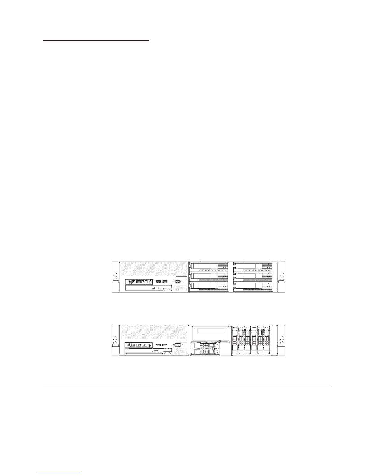
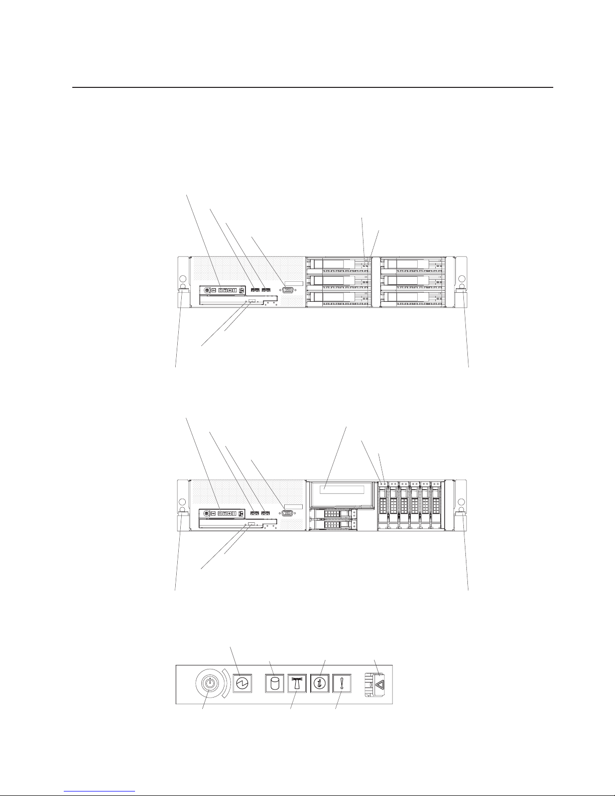
Front view
The following illustration shows the controls, light-emitting diodes (LEDs), and
connectors on the front of the 3.5-inch model server.
Operator information panel
USB 5 connector
USB 6 connector
Video connector
Hard disk drive activity LED (green)
Hard disk drive status LED (amber)
CD/DVD eject button
CD/DVD drive activity LED
Rack release latch Rack release latch
The following illustration shows the controls, light-emitting diodes (LEDs), and
connectors on the front of the 2.5-inch model server.
Operator information panel
USB 5 connector
USB 6 connector
Video connector
Tape drive bay
Hard disk drive activity LED (green)
Hard disk drive status LED (amber)
CD/DVD eject button
CD/DVD drive activity LED
Rack release latch Rack release latch
Operator information panel: This panel contains controls, LEDs, and connectors.
The following illustration shows the controls, LEDs, and connectors on the operator
information panel.
Power-on
LED
Hard disk drive
activity LED
Information
LED
Release
latch
Power-control
button
System
locator
LED
System-error
LED
Chapter 1. Introduction 5
Page 24

The following controls, LEDs, and connectors are on the operator information panel:
v Power-control button: Press this button to turn the server on and off manually.
A power-control-button shield comes installed on the server to prevent the server
from being turned off accidentally.
v Power-on LED: When this LED is lit and not flashing, it indicates that the server
is turned on. When this LED is flashing, it indicates that the server is turned off
and still connected to an ac power source. When this LED is off, it indicates that
ac power is not present, or the power supply or the LED itself has failed.
Note: If this LED is off, it does not mean that there is no electrical power in the
server. The LED might be burned out. To remove all electrical power from the
server, you must disconnect the power cord from the electrical outlet.
v Hard disk drive activity LED: When this LED is flashing, it indicates that a hard
disk drive is in use.
v System-locator LED: Use this LED to visually locate the server among other
servers. Yo u can use IBM Director to light this LED remotely.
v Information LED: When this LED is lit, it indicates that a noncritical event has
occurred. An LED on the light path diagnostics panel is also lit to help isolate the
error.
v System-error LED: When this LED is lit, it indicates that a system error has
occurred. An LED on the light path diagnostics panel is also lit to help isolate the
error.
v Release latch: Slide this latch to the left to access the light path diagnostics
panel, which is behind the operator information panel.
connectors: Connect a USB device, such as USB mouse, keyboard, or other
USB
USB device, to either of these connectors.
Video connector: Connect a monitor to this connector. The video connectors on
the front and rear of the server can be used simultaneously.
Hard disk drive activity LED: Each hot-swap hard disk drive has an activity LED.
When this LED is flashing, it indicates that the drive is in use.
Hard disk drive status LED: Each hot-swap hard disk drive has a status LED.
When this LED is lit, it indicates that the drive has failed. When this LED is flashing
slowly (one flash per second), it indicates that the drive is being rebuilt as part of a
RAID configuration. When the LED is flashing rapidly (three flashes per second), it
indicates that the controller is identifying the drive.
CD/DVD-eject button: Press this button to release a CD or DVD from the
CD-RW/DVD drive.
CD/DVD drive activity LED: When this LED is lit, it indicates that the CD-RW/DVD
drive is in use.
Rack release latches: Press these latches to release the server from the rack.
6 IBM System x3650 Type 7979 and 1914: Problem Determination and Service Guide
Page 25
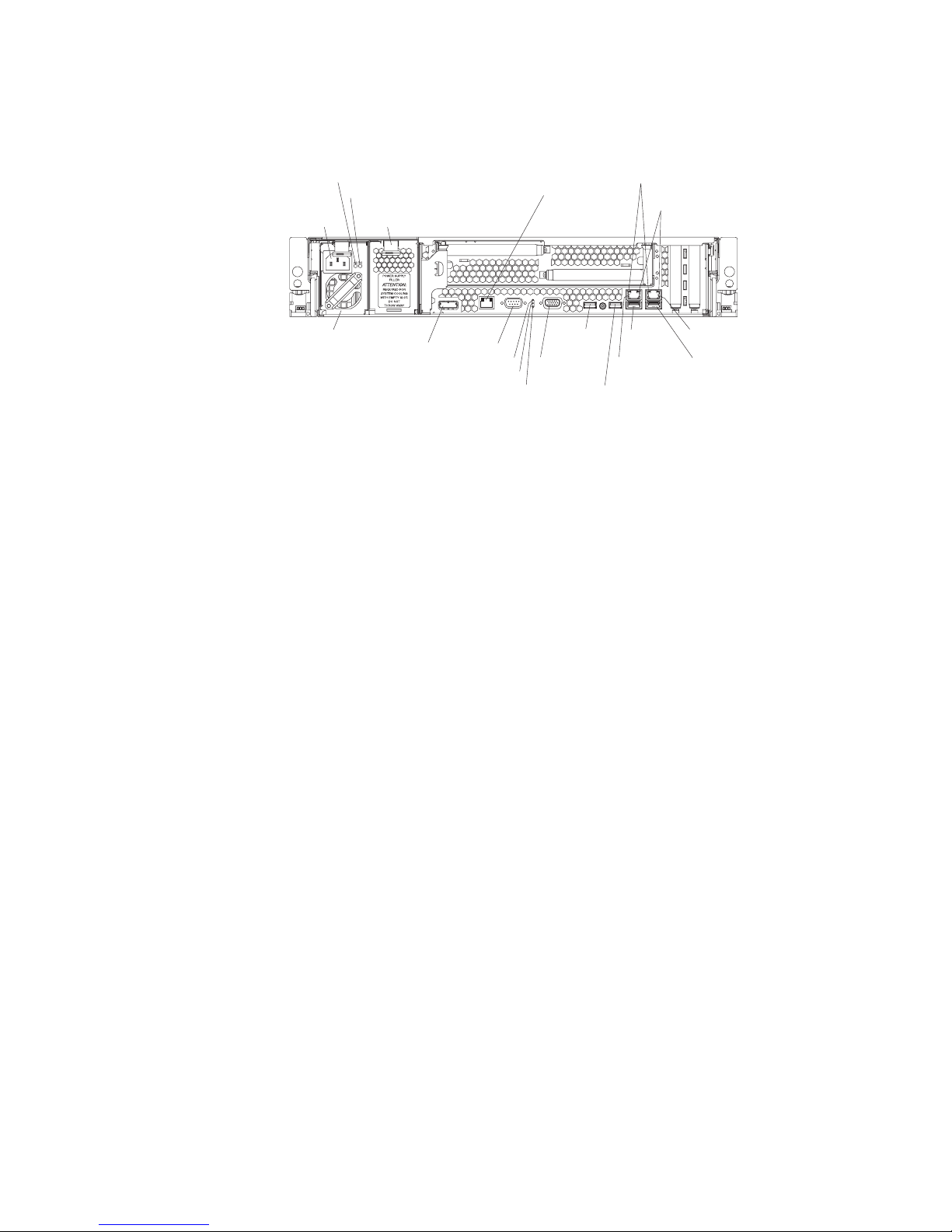
Rear view
The following illustration shows the connectors and LEDs on the rear of the server.
Power-cord
connector
Powe r
supply 1
AC power LED
DC power LED
Power-supply
filler panel
SAS
connector
S-
ystems management
Ethernet connector
Serial
connector
Power-on LED
System-locator LED
System-error LED
USB 1
connector
Video
connector
USB 2
connector
Ethernet
activity LEDs
Ethernet
link LEDs
USB 3
connector
Ethernet 2
connector
Ethernet 1
connector
USB 4
connector
Power-cord connector: Connect the power cord to this connector.
AC power LED: Each hot-swap power supply has an ac power LED and a dc
power LED. When the ac power LED is lit, it indicates that sufficient power is
coming into the power supply through the power cord. During typical operation, both
the ac and dc power LEDs are lit. For any other combination of LEDs, see
“Power-supply LEDs” on page 53.
DC power LED: Each hot-swap power supply has a dc power LED and an ac
power LED. When the dc power LED is lit, it indicates that the power supply is
supplying adequate DC power to the system. During typical operation, both the ac
and dc power LEDs are lit. For any other combination of LEDs, see “Power-supply
LEDs” on page 53.
Systems-management Ethernet connector: Use this connector to connect the
server to a network for systems-management information control. This connector is
active only if you have installed a Remote Supervisor Adapter II SlimLine, and it is
used only by the Remote Supervisor Adapter II SlimLine.
Ethernet activity LEDs: When these LEDs are lit, they indicate that the server is
transmitting to or receiving signals from the Ethernet LAN that is connected to the
Ethernet port.
Ethernet link LEDs: When these LEDs are lit, they indicate that there is an active
link connection on the 10BASE-T, 100BASE-TX, or 1000BASE-TX interface for the
Ethernet port.
Ethernet connectors: Use either of these connectors to connect the server to a
network.
USB connectors: Connect a USB device, such as USB mouse, keyboard, or other
USB device, to any of these connectors.
Video connector: Connect a monitor to this connector. The video connectors on
the front and rear of the server can be used simultaneously.
System-error LED: When this LED is lit, it indicates that a system error has
occurred. An LED on the light path diagnostics panel is also lit to help isolate the
error.
Chapter 1. Introduction 7
Page 26

System-locator LED: Use this LED to visually locate the server among other
servers. Yo u can use IBM Director to light this LED remotely.
Power-on LED: When this LED is lit and not flashing, it indicates that the server is
turned on. When this LED is flashing, it indicates that the server is turned off and
still connected to an ac power source. When this LED is off, it indicates that ac
power is not present, or the power supply or the LED itself has failed.
Serial connector: Connect a 9-pin serial device to this connector. The serial port is
shared with the baseboard management controller (BMC). The BMC can take
control of the shared serial port to perform text console redirection and to redirect
serial traffic, using Serial over LAN (SOL).
SAS connector: Connect a serial-attached SCSI (SAS) device to this connector.
Internal connectors, LEDs, and jumpers
The illustrations in this section show the LEDs, connectors, and jumpers on the
internal boards. The illustrations might differ slightly from your hardware.
8 IBM System x3650 Type 7979 and 1914: Problem Determination and Service Guide
Page 27
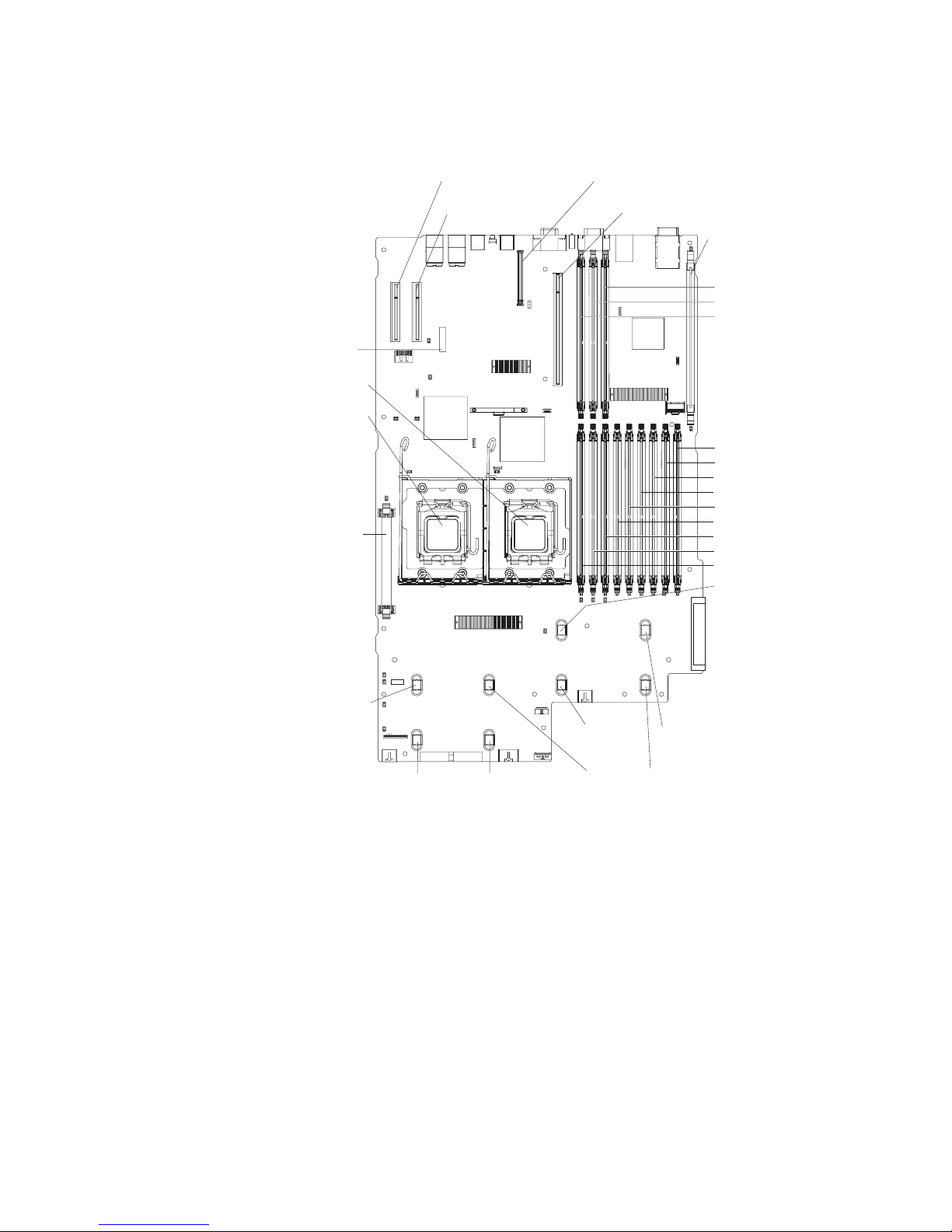
System-board option connectors
The following illustration shows the connectors on the system board for
user-installable options.
Battery
connector
Microprocessor 1
connector
Microprocessor 2
connector
Voltage regulator
module connector
PCI Express slot 4
connector
PCI Express slot 3
connector
Remote Supervisor Adapter II
SlimLine connector
PCI riser card connector
ServeRAID SAS connector
DIMM 12 connector
DIMM 11 connector
DIMM 10 connector
DIMM 9 connector
DIMM 8 connector
DIMM 7 connector
DIMM 6 connector
DIMM 5 connector
DIMM 4 connector
DIMM 3 connector
DIMM 2 connector
DIMM 1 connector
Fan 8
connector
Fan 3
connector
Fan 9
connector
Fan 6
connector
Fan 1
connector
Fan 2
connector
Fan 5
connector
Fan 4
connector
Note: The connectors for fans 7 and 10 are on the power backplane. See
“Power-backplane-board connectors” on page 10.
Chapter 1. Introduction 9
Page 28

PCI riser-card option connectors
The following illustration shows the connectors on the PCI riser card for
user-installable PCI adapters.
Note: For clarity, in the following illustration the PCI riser-card assembly is inverted.
Power-backplane-board connectors
The following illustration shows the internal connectors on the power-backplane
board.
PCI adapter
connectors
System-board
connector
Fan 10 connector
Hard disk drive
power connector
Fan 7 connector
10 IBM System x3650 Type 7979 and 1914: Problem Determination and Service Guide
Page 29

System-board internal cable connectors
The following illustration shows the internal connectors on the system board.
IPMB connector
SATA tape drive
signal (J102)
Hard disk drive
backplane
signal (J92)
Operator panel (J50)
CD/DVD power (J12)
CD/DVD signal (J37)
Power backplane
(J72)
Tape drive power
(J100)
Front USB (J80)
Front video (J51)
Internal
USB (J82)
Chapter 1. Introduction 11
Page 30
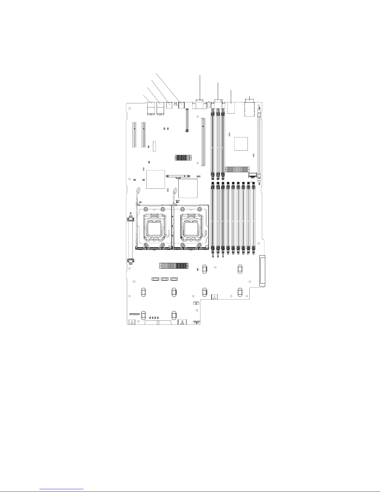
System-board external connectors
The following illustration shows the external input/output connectors on the system
board.
Ethernet 2 / USB 3
Ethernet 1 / USB 4
USB 1
USB 2
Video
Serial
Systems-management Ethernet
SAS
12 IBM System x3650 Type 7979 and 1914: Problem Determination and Service Guide
Page 31

System-board switches and jumpers
The following illustration shows the switches and jumpers on the system board.
Any switches or jumpers on the system board that are not shown in the illustration
are reserved. See “Recovering the BIOS code” on page 65 for information about
the boot block recovery jumper.
Boot block
recovery jumper
(J42)
Switch block
(SW2)
Table 2 on page 14 describes the function of each switch on switch block 2.
Chapter 1. Introduction 13
Page 32

Table 2. Switches 1 - 8
Switch
number Default value
Switch
description
8 Off Reserved.
7 Off Remote Supervisor Adapter II SlimLine BIST. When this switch is toggled to On, it
causes the Remote Supervisor Adapter II SlimLine to execute the Built In Self Test
(BIST).
6 Off Power-on override. When this switch is toggled to On, it forces the power on,
overriding the power-on button.
5 Off Power-on password override. Changing the position of this switch bypasses the
power-on password check the next time the server is turned on and starts the
Configuration/Setup Utility program so that you can change or delete the power-on
password. You do not have to move the switch back to the default position after the
password is overridden.
Changing the position of this switch does not affect the administrator password check
if an administrator password is set.
See the User’s Guide on the IBM System x Documentation CD for additional
information about the power-on password.
4 Off Force BMC update. When this switch is toggled to On, it causes an update of BMC
firmware from the diskette drive.
3 Off Force BMC reset. When this switch is toggled to On, it forces the BMC to reset.
2 Off Reserved.
1 Off Clear CMOS. When this switch is toggled to On, it clears the CMOS data, which
clears the power-on password.
Notes:
1. Before you change any switch settings or move any jumpers, turn off the server;
then, disconnect all power cords and external cables. (Review the information in
“Safety” on page vii, “Installation guidelines” on page 87, and “Handling
static-sensitive devices” on page 89.)
2. Any system-board switch or jumper blocks that are not shown in the illustrations
in this document are reserved.
14 IBM System x3650 Type 7979 and 1914: Problem Determination and Service Guide
Page 33

System-board LEDs
The following illustration shows the light-emitting diodes (LEDs) on the system
board.
Remote Supervisor
Adapter II SlimLine
error LED
Microprocessor 1
error LED
Microprocessor 2
error LED
3 v battery
error LED
PCI slot 3
error LED
PCI slot 4
error LED
VRM
error LED
Riser-card-missing
error LED
RAID error LED
DIMM 1 error LED
DIMM 2 error LED
DIMM 3 error LED
DIMM 4 error LED
DIMM 5 error LED
DIMM 6 error LED
DIMM 7 error LED
DIMM 8 error LED
DIMM 9 error LED
Power channel B
error LED
Power channel A
DIMM 12 error LED
DIMM 11 error LED
DIMM 10 error LED
BMC heartbeat LED
error LED
Power channel D
error LED
Power channel C
error LED
Table 3. System-board LEDs
LED Description
Error LEDs The associated component has failed.
BMC heartbeat LED This LED flashes to indicate that the BMC (baseboard
management controller) is functioning normally.
12-volt power (A, B, C, D)
LEDs
If any of these LEDs is lit, there is a failure in the associated
system board power channel (see “Power problems” on page
45).
Chapter 1. Introduction 15
Page 34

Riser-card assembly LEDs
The following illustration shows the light-emitting diodes (LEDs) on the riser-card
assembly.
PCI Slot 2 error LED
PCI Slot 1 error LED
16 IBM System x3650 Type 7979 and 1914: Problem Determination and Service Guide
Page 35

Chapter 2. Diagnostics
This chapter describes the diagnostic tools that are available to help you solve
problems that might occur in the server.
If you cannot locate and correct the problem using the information in this chapter,
see Appendix A, “Getting help and technical assistance,” on page 163 for more
information.
Diagnostic tools
The following tools are available to help you diagnose and solve hardware-related
problems:
v POST beep codes, error messages, and error logs
The power-on self-test (POST) generates beep codes and messages to indicate
successful test completion or the detection of a problem. See “POST” for more
information.
v Troubleshooting tables
These tables list problem symptoms and actions to correct the problems. See
“Troubleshooting tables” on page 36.
v Light path diagnostics
Use the light path diagnostics to diagnose system errors quickly. See “Light path
diagnostics” on page 49 for more information.
v Diagnostic programs, messages, and error codes
The diagnostic programs are the primary method of testing the major
components of the server. The diagnostic programs are in read-only memory on
the server. See “Diagnostic programs, messages, and error codes” on page 54
for more information.
POST
When you turn on the server, it performs a series of tests to check the operation of
the server components and some optional devices in the server. This series of tests
is called the power-on self-test, or POST.
If a power-on password is set, you must type the password and press Enter, when
prompted, for POST to run.
If POST is completed without detecting any problems, a single beep sounds, and
the server startup is completed.
If POST detects a problem, more than one beep might sound, or an error message
is displayed. See “POST beep codes” and “POST error codes” on page 28 for more
information.
POST beep codes
A beep code is a combination of short or long beeps or series of short beeps that
are separated by pauses. For example, a “1-2-3” beep code is one short beep, a
pause, two short beeps, a pause, and three short beeps. A beep code other than
one beep indicates that POST has detected a problem. To determine the meaning
of a beep code, see “Beep code descriptions” on page 18. If no beep code sounds,
see “No-beep symptoms” on page 24.
© Copyright IBM Corp. 2006 17
Page 36

Beep code descriptions
The following table describes the beep codes and suggested actions to correct the
detected problems.
A single problem might cause more than one error message. When this occurs,
correct the cause of the first error message. The other error messages usually will
not occur the next time POST runs.
Exception: If there are multiple error codes or light path diagnostics LEDs that
indicate a microprocessor error, the error might be in the microprocessor or in the
microprocessor socket. See “Microprocessor problems” on page 41 for information
about diagnosing microprocessor problems.
v Follow the suggested actions in the order in which they are listed in the Action column until the problem
is solved.
v See Chapter 3, “Parts listing, Type 7979 and 1914 server,” on page 79 to determine which components are
customer replaceable units (CRU) and which components are field replaceable units (FRU).
v If an action step is preceded by “(Trained service technician only),” that step must be performed only by a
trained service technician.
Beep code Description Action
1-1-2 Microprocessor register test failed.
1-1-3 CMOS write/read test failed.
1-1-4 BIOS EEPROM checksum failed.
1-2-1 Programmable interval timer failed. (Trained service technician only) Replace the
1-2-2 DMA initialization failed. (Trained service technician only) Replace the
1. Reseat the following components, one at a
time, in the order shown, restarting the
server each time:
v (Trained service technician only)
Microprocessor 2 (if installed)
v (Trained service technician only)
Microprocessor 1
Replace the following components, one at
2.
a time, in the order shown, restarting the
server each time:
v (Trained service technician only)
Microprocessor 2 (if installed)
v (Trained service technician only)
Microprocessor 1
v (Trained service technician only) System
board
1. Reseat the battery.
2. Replace the following components one at
a time, in the order shown, restarting the
server each time:
a. Battery
b. (Trained service technician only)
System board
1. Recover the BIOS code (see “Recovering
the BIOS code” on page 65).
2. (Trained service technician only) Replace
the system board.
system board.
system board.
18 IBM System x3650 Type 7979 and 1914: Problem Determination and Service Guide
Page 37

v Follow the suggested actions in the order in which they are listed in the Action column until the problem
is solved.
v See Chapter 3, “Parts listing, Type 7979 and 1914 server,” on page 79 to determine which components are
customer replaceable units (CRU) and which components are field replaceable units (FRU).
v If an action step is preceded by “(Trained service technician only),” that step must be performed only by a
trained service technician.
Beep code Description Action
1-2-3 DMA page register write/read failed. (Trained service technician only) Replace the
system board.
1-2-4 RAM refresh verification failed.
1. Reseat the DIMMs.
2. Replace the following components, one at
a time, in the order shown, restarting the
server each time:
a. DIMMs
b. (Trained service technician only)
System board
1-3-1 1st 64K RAM test failed.
1. Reseat the DIMMs.
2. Replace the following components, one at
a time, in the order shown, restarting the
server each time:
a. DIMMs
b. (Trained service technician only)
System board
2-1-1 Secondary DMA register failed. (Trained service technician only) Replace the
system board.
2-1-2 Primary DMA register failed. (Trained service technician only) Replace the
system board.
2-1-3 Primary interrupt mask register failed. (Trained service technician only) Replace the
system board.
2-1-4 Secondary interrupt mask register failed. (Trained service technician only) Replace the
system board.
2-2-1 Interrupt vector loading failed. (Trained service technician only) Replace the
system board.
2-2-2 Keyboard controller failed. Replace the following components, one at a
time, in the order shown, restarting the server
each time:
1. Keyboard
2. (Trained service technician only) System
board
2-2-3 CMOS power failure and checksum
checks failed.
1. Reseat the battery.
2. Replace the following components, one at
a time, in the order shown, restarting the
server each time:
a. Battery
b. (Trained service technician only)
System board
Chapter 2. Diagnostics 19
Page 38

v Follow the suggested actions in the order in which they are listed in the Action column until the problem
is solved.
v See Chapter 3, “Parts listing, Type 7979 and 1914 server,” on page 79 to determine which components are
customer replaceable units (CRU) and which components are field replaceable units (FRU).
v If an action step is preceded by “(Trained service technician only),” that step must be performed only by a
trained service technician.
Beep code Description Action
2-2-4 CMOS configuration information validation
failed.
1. Reseat the battery.
2. Replace the following components, one at
a time, in the order shown, restarting the
server each time:
a. Battery
b. (Trained service technician only)
System board
2-3-1 Screen initialization failed. (Trained service technician only) Replace the
system board.
2-3-2 Screen memory failed. (Trained service technician only) Replace the
system board.
2-3-3 Screen retrace failed. (Trained service technician only) Replace the
system board.
2-3-4 Search for video ROM failed. (Trained service technician only) Replace the
system board.
2-4-1 Video failed; screen believed operable. (Trained service technician only) Replace the
system board.
3-1-1 Timer tick interrupt failed. (Trained service technician only) Replace the
system board.
3-1-2 Interval timer channel 2 failed. (Trained service technician only) Replace the
system board.
3-1-3 RAM test failed above address OFFFFH
1. Reseat the battery.
2. Replace the following components, one at
a time, in the order shown, restarting the
server each time:
a. Battery
b. (Trained service technician only)
System board
3-1-4 Time-of-day clock failed.
1. Reseat the battery.
2. Replace the following components one at
a time, in the order shown, restarting the
server each time:
a. Battery
b. (Trained service technician only)
System board
3-2-1 Serial port failed. (Trained service technician only) Replace the
system board.
3-2-2 Parallel port failed. (Trained service technician only) Replace the
system board.
20 IBM System x3650 Type 7979 and 1914: Problem Determination and Service Guide
Page 39

v Follow the suggested actions in the order in which they are listed in the Action column until the problem
is solved.
v See Chapter 3, “Parts listing, Type 7979 and 1914 server,” on page 79 to determine which components are
customer replaceable units (CRU) and which components are field replaceable units (FRU).
v If an action step is preceded by “(Trained service technician only),” that step must be performed only by a
trained service technician.
Beep code Description Action
3-2-3 Math coprocessor test failed.
1. (Trained service technician only) Reseat
the microprocessors.
2. Replace the following components, one at
a time, in the order shown, restarting the
server each time:
v (Trained service technician only)
Microprocessors
v (Trained service technician only) System
board
3-2-4 Failure comparing CMOS memory size
against actual.
1. Reseat the following components, one at a
time, in the order shown:
a. DIMMs
b. Battery
Replace the components listed in step 1,
2.
one at a time, in the order shown.
3-3-1 Memory size mismatch occurred.
1. Reseat the following components, one at a
time, in the order shown:
a. DIMMs
b. Battery
Replace the components listed in step 1,
2.
one at a time, in the order shown.
3-3-2 Critical SMBUS error occurred.
1. Disconnect the server power cord from the
outlet and wait 30 seconds; then,
reconnect the power cord and restart the
server.
2. Reseat the following components, one at a
time, in the order shown:
a. DIMMs
b. Hard disk drive backplane
c. Power supply
Replace the following components, one at
3.
a time, in the order shown, restarting the
server each time:
a. DIMMs
b. Hard disk drive backplane
c. Power supply
d. (Trained service technician only)
System board
Chapter 2. Diagnostics 21
Page 40

v Follow the suggested actions in the order in which they are listed in the Action column until the problem
is solved.
v See Chapter 3, “Parts listing, Type 7979 and 1914 server,” on page 79 to determine which components are
customer replaceable units (CRU) and which components are field replaceable units (FRU).
v If an action step is preceded by “(Trained service technician only),” that step must be performed only by a
trained service technician.
Beep code Description Action
3-3-3 No operational memory in system.
1. Make sure that the server contains the
correct number of DIMMs, in the correct
order; install or reseat the DIMMS; then,
restart the server three times.
Important: Yo u must restart the server
three times to reset the configuration
settings to the default configuration (the
memory connector or bank of connectors
enabled).
2. Replace the following components one at
a time, in the order shown, restarting the
server each time:
a. DIMMs
b. (Trained service technician only)
System board
4-4-4 Optional system management adapter not
installed in Remote Supervisor Adapter II
SlimLine connector or not functioning
correctly.
1. Make sure that the Remote Supervisor
Adapter II SlimLine is installed in the
Remote Supervisor Adapter II SlimLine
connector.
2. Reseat the Remote Supervisor Adapter II
SlimLine.
3. Replace the following components one at
a time, in the order shown, restarting the
server each time:
v Remote Supervisor Adapter II SlimLine
v (Trained service technician only) System
board
Two short beeps Information only, the configuration has
changed
1. Run the diagnostics programs to verify that
all components are working.
2. Run the Configuration/Setup Utility
program, save the configuration, and
restart the server.
Three short beeps Possible memory prloblem.
1. Reseat the DIMMs.
2. Replace the following components, one at
a time, in the order shown:
a. DIMMs
b. (Trained service technician only)
System board
22 IBM System x3650 Type 7979 and 1914: Problem Determination and Service Guide
Page 41

v Follow the suggested actions in the order in which they are listed in the Action column until the problem
is solved.
v See Chapter 3, “Parts listing, Type 7979 and 1914 server,” on page 79 to determine which components are
customer replaceable units (CRU) and which components are field replaceable units (FRU).
v If an action step is preceded by “(Trained service technician only),” that step must be performed only by a
trained service technician.
Beep code Description Action
One continuous beep Possible microprocessor problem.
1. Reseat the following components, one at a
time, in the order shown, restarting the
server each time:
v (Trained service technician only)
Microprocessor 1
v (Trained service technician only)
Microprocessor 2 (if installed)
Replace the following components, one at
2.
a time, in the order shown, restarting the
server each time:
v (Trained service technician only)
Microprocessor 1
v (Trained service technician only)
Microprocessor 2 (if installed)
v (Trained service technician only) System
board
Repeating short beeps Possible keyboard problem.
1. Reseat the keyboard cable.
2. Replace the following components, one at
a time, in the order shown, restarting the
server each time:
v Keyboard
v (Trained service technician only) System
board
One long and one short
beep
Possible video controller problem.
1. Reseat the optional video adapter (if
installed).
2. Replace the following components, one at
a time, in the order shown, restarting the
server each time:
v Video adapter (if installed)
v (Trained service technician only) System
board
One long and two short
beeps
Possible video controller problem.
1. Reseat the optional video adapter (if
installed).
2. Replace the following components, one at
a time, in the order shown, restarting the
server each time:
v Video adapter (if installed)
v (Trained service technician only) System
board
Chapter 2. Diagnostics 23
Page 42

v Follow the suggested actions in the order in which they are listed in the Action column until the problem
is solved.
v See Chapter 3, “Parts listing, Type 7979 and 1914 server,” on page 79 to determine which components are
customer replaceable units (CRU) and which components are field replaceable units (FRU).
v If an action step is preceded by “(Trained service technician only),” that step must be performed only by a
trained service technician.
Beep code Description Action
One long and three short
beeps
Problem with the monitor or video
controller.
1. Reseat the following components, one at a
time, in the order shown, restarting the
server each time:
a. Monitor cable
b. Optional video adapter (if installed).
Replace the following components, one at
2.
a time, in the order shown, restarting the
server each time:
a. Monitor
b. Optional video adapter (if installed)
c. (Trained service technician only)
System board
Two long and two short
beeps
Problem with the optional video adapter.
1. Reseat the optional video adapter.
2. Replace the optional video adapter.
No-beep symptoms
The following table describes situations in which no beep code sounds when POST
is completed.
v Follow the suggested actions in the order in which they are listed in the Action column until the problem
is solved.
v See Chapter 3, “Parts listing, Type 7979 and 1914 server,” on page 79 to determine which components are
customer replaceable units (CRU) and which components are field replaceable units (FRU).
v If an action step is preceded by “(Trained service technician only),” that step must be performed only by a
trained service technician.
No-beep symptom Description Action
No beeps occur, and the
server operates correctly.
Possible problem with the operator
information panel.
1. Check the operator information panel cable
for damage.
2. Reseat the operator information panel
cable.
3. Replace the following components, one at a
time, in the order shown, restarting the
server each time:
a. (Trained service technician only)
Operator information panel
b. (Trained service technician only) System
board
24 IBM System x3650 Type 7979 and 1914: Problem Determination and Service Guide
Page 43

v Follow the suggested actions in the order in which they are listed in the Action column until the problem
is solved.
v See Chapter 3, “Parts listing, Type 7979 and 1914 server,” on page 79 to determine which components are
customer replaceable units (CRU) and which components are field replaceable units (FRU).
v If an action step is preceded by “(Trained service technician only),” that step must be performed only by a
trained service technician.
No-beep symptom Description Action
No beeps occur after
successful completion of
POST.
The power-on status is Disabled.
1. Run the Configuration/Setup Utility program
and select Start Options; then, set
Power-On Status to Enable.
2. Check the operator information panel cable
for damage.
3. Reseat the operator information panel
cable.
4. (Trained service technician only) Replace
the system board
No beeps occur, and
there is no video.
No beep occurs, and the
power-supply ac LED is
off
Unknown problem. See “Solving undetermined problems” on page
76.
Possible power problem.
1. Make sure that the ac power cord is
connected to the power supply and to an ac
outlet.
2. Reseat the power supplies.
3. If two power supplies are installed, swap
them to determine whether one is defective.
4. Disconnect the cable from the hard disk
drive backplane power connector (J13) on
the power backplane. If the ac power LED
comes on, see “Solving undetermined
problems” on page 76.
No beep occurs, the
Possible power problem. See “Power-supply LEDs” on page 53.
server does not start,
and the power-supply ac
LED is lit.
Chapter 2. Diagnostics 25
Page 44

Error logs
The POST error log contains the three most recent error codes and messages that
were generated during POST. The BMC system event log contains monitored
events, such as a threshold that is reached or a device that fails. The system
event/error log, which is available only when an optional Remote Supervisor
Adapter II SlimLine is installed, contains messages that were generated during
POST and all system status messages from the service processor.
The following illustration shows an example of a BMC system event log entry.
BMC System Event Log
---------------------------------------------------------Get Next Entry
Get Previous Entry
Clear BMC SEL
Entry Number= 00005 / 00011
Record ID= 0005
Record Type= 02
Timestamp= 2005/01/25 16:15:17
Entry Details: Generator ID= 0020
Sensor Type= 04
Assertion Event
Fan
Threshold
Lower Non-critical - going high
Sensor Number= 40
Event Direction/Type= 01
Event Data= 52 00 1A
The BMC system event log is limited in size. When the log is full, new entries will
not overwrite existing entries; therefore, you must periodically clear the BMC system
event log through the Configuration/Setup Utility program (the menu choices are
described in the User’s Guide). When you are troubleshooting an error, be sure to
clear the BMC system event log so that you can find current errors more easily.
Entries that are written to the BMC system event log during the early phase of
POST show an incorrect date and time as the default time stamp; however, the
date and time are corrected as POST continues.
Each system event/error log entry appears on its own page. To move from one
entry to the next, use the up-arrow and down-arrow keys.
If you view the BMC system event log through the Web interface of the optional
Remote Supervisor Adapter II SlimLine, the messages can be translated.
You can view the contents of the POST error log, the BMC system event log, and
the system event/error log from the Configuration/Setup Utility program. You can
view the contents of the BMC system event log also from the diagnostic programs.
When you are troubleshooting PCI slots, note that the error logs report the PCI
buses numerically. The numerical assignments vary depending on the configuration.
You can check the assignments by running the Configuration/Setup Utility program
(see the User’s Guide for more information).
26 IBM System x3650 Type 7979 and 1914: Problem Determination and Service Guide
Page 45

Viewing error logs from the Configuration/Setup Utility program
For complete information about using the Configuration/Setup Utility program, see
the User’s Guide.
To view the error logs, complete the following steps:
1. Turn on the server.
2. When the prompt Press F1 for Configuration/Setup appears, press F1. If you
have set both a power-on password and an administrator password, you must
type the administrator password to view the error logs.
3. Use one of the following procedures:
v To view the POST error log, select Event/Error Logs, and then select POST
Error Log.
v To view the BMC system event log, select Advanced Setup --> Baseboard
Management Controller (BMC) Setting --> System Event Log.
v To view the combined system event/error log and POST error log, select
Event/Error logs, and then select System Event/Error Log.
Viewing the BMC system event log from the diagnostic programs
The BMC system event log contains the same information, whether it is viewed
from the Configuration/Setup Utility program or from the diagnostic programs.
For information about using the diagnostic programs, see “Running the diagnostic
programs” on page 55.
To view the BMC system event log, complete the following steps:
1. If the server is running, turn off the server and all attached devices.
2. Turn on all attached devices; then, turn on the server.
3. When the prompt F2 for Diagnostics appears, press F2. If you have set both a
power-on password and an administrator password, you must type the
administrator password to run the diagnostic programs.
4. From the top of the screen, select Hardware Info.
5. From the list, select BMC Log.
Clearing the error logs
For complete information about using the Configuration/Setup Utility program, see
the User’s Guide.
To clear the error logs, complete the following steps:
1. Turn on the server.
2. When the prompt Press F1 for Configuration/Setup appears, press F1. If you
have set both a power-on password and an administrator password, you must
type the administrator password to view the error logs.
3. Use one of the following procedures:
v To clear the BMC system event log, select Advanced Setup --> Baseboard
Management Controller (BMC) Setting--> BMC System Event Log. Select
Clear BMC SEL.
v To clear the system event/error log, if one is present, or the POST error log,
select Event/Error Logs, and then select Post Error Log or System
Event/Error Log. When any log entry is displayed, press Enter (Clear xxxx
log is highlighted on each entry page, where xxxx is the name of the log that
you are viewing).
Chapter 2. Diagnostics 27
Page 46

Note: The POST error log is automatically cleared with each system restart.
POST error codes
The following table describes the POST error codes and suggested actions to
correct the detected problems.
v Follow the suggested actions in the order in which they are listed in the Action column until the problem
is solved.
v See Chapter 3, “Parts listing, Type 7979 and 1914 server,” on page 79 to determine which components are
customer replaceable units (CRU) and which components are field replaceable units (FRU).
v If an action step is preceded by “(Trained service technician only),” that step must be performed only by a
trained service technician.
Error code Description Action
062 Three consecutive boot failures using the
default configuration.
101, 102 System and processor error. (Trained service technician only) Replace the system
106 System and processor error. (Trained service technician only) Replace the system
151 Real-time clock error.
161 Real-time clock battery error.
1. Run the Configuration/Setup Utility program, save
the configuration, and restart the server.
2. Update the system firmware to the latest level
(see “Updating the firmware” on page 145).
3. Reseat the following components, one at a time,
in the order shown, restarting the server each
time:
a. Battery
b. (Trained service technician only)
Microprocessor
Replace the following components one at a time,
4.
in the order shown, restarting the server each
time:
a. Battery
b. (Trained service technician only)
Microprocessor
c. (Trained service technician only) System
board
board.
board.
1. Reseat the battery.
2. Replace the following components one at a time,
in the order shown, restarting the server each
time:
a. Battery
b. (Trained service technician only) System
board
1. Reseat the battery.
2. Replace the following components one at a time,
in the order shown, restarting the server each
time:
a. Battery
b. (Trained service technician only) System
board
28 IBM System x3650 Type 7979 and 1914: Problem Determination and Service Guide
Page 47

v Follow the suggested actions in the order in which they are listed in the Action column until the problem
is solved.
v See Chapter 3, “Parts listing, Type 7979 and 1914 server,” on page 79 to determine which components are
customer replaceable units (CRU) and which components are field replaceable units (FRU).
v If an action step is preceded by “(Trained service technician only),” that step must be performed only by a
trained service technician.
Error code Description Action
162 Device configuration error.
1. Run the Configuration/Setup Utility program,
select Load Default Settings, and save the
settings.
2. Reseat the following components, one at a time,
in the order shown, restarting the server each
time:
a. Battery
b. Failing device (if the device is a FRU, then it
must be reseated by a trained service
technician only)
Replace the following components one at a time,
3.
in the order shown, restarting the server each
time:
a. Battery
b. Failing device (if the device is a FRU, then it
must be replaced by a trained service
technician only)
c. (Trained service technician only) System
board
163 Real-time clock error. (time of day not set)
1. Run the Configuration/Setup Utility program,
select Load Default Settings, make sure that the
date and time are correct, and save the settings.
2. Reseat the battery.
3. Replace the following components one at a time,
in the order shown, restarting the server each
time:
a. Battery
b. (Trained service technician only) System
board
175 Service processor code on optional service
processor adapter corrupted or not loaded.
1. Update the firmware on the optional Remote
Supervisor Adapter II SlimLine (see “Updating the
firmware” on page 145).
2. Replace the optional Remote Supervisor Adapter
II SlimLine.
184 Power-on password damaged.
1. Restart the server and enter the administrator
password; then, run the Configuration/Setup
Utility program, select Load Default Settings,
and save the settings.
2. Reseat the battery.
3. Replace the following components one at a time,
in the order shown, restarting the server each
time:
a. Battery
b. (Trained service technician only) System
board
Chapter 2. Diagnostics 29
Page 48

v Follow the suggested actions in the order in which they are listed in the Action column until the problem
is solved.
v See Chapter 3, “Parts listing, Type 7979 and 1914 server,” on page 79 to determine which components are
customer replaceable units (CRU) and which components are field replaceable units (FRU).
v If an action step is preceded by “(Trained service technician only),” that step must be performed only by a
trained service technician.
Error code Description Action
187 VPD serial number not set.
1. Run the Configuration/Setup Utility program, set
the serial number, and save the configuration.
2. (Trained service technician only) Replace the
system board.
189 An attempt was made to access the server
with an incorrect password.
Restart the server and enter the administrator
password; then, run the Configuration/Setup Utility
program and change the power-on password.
289 A DIMM has been disabled by the user or
by the system.
1. If the DIMM was disabled by the user, run the
Configuration/Setup Utility program and enable
the DIMM.
2. Make sure that the DIMM is installed correctly
(see “Installing a memory module” on page 114).
3. Reseat the DIMM.
4. Replace the DIMM.
301 Keyboard or keyboard controller error.
1. Reseat the keyboard cable in the USB connector.
2. Move the keyboard cable to a different USB
connector.
3. Replace the following components one at a time,
in the order shown, restarting the server each
time:
a. Keyboard
b. (Only if the problem occurred with a front USB
connector) Internal USB cable.
c. (Trained service technician only) System
board
303 Keyboard controller error.
1. Reseat the keyboard cable in the USB connector.
2. Replace the following components one at a time,
in the order shown, restarting the server each
time:
a. Keyboard
b. (Trained service technician only) System
board
1600 Service processor not functioning.
1. Reseat the optional Remote Supervisor Adapter II
SlimLine.
2. Replace the optional Remote Supervisor Adapter
II SlimLine.
30 IBM System x3650 Type 7979 and 1914: Problem Determination and Service Guide
Page 49

v Follow the suggested actions in the order in which they are listed in the Action column until the problem
is solved.
v See Chapter 3, “Parts listing, Type 7979 and 1914 server,” on page 79 to determine which components are
customer replaceable units (CRU) and which components are field replaceable units (FRU).
v If an action step is preceded by “(Trained service technician only),” that step must be performed only by a
trained service technician.
Error code Description Action
178x Fixed disk error.
Note: x is the drive that has the error
1. Run the hard disk drive diagnostics tests on drive
x.
2. Reseat the following components:
a. Hard disk drive
b. Cable from the system board to the backplane
Replace the following components one at a time,
3.
in the order shown, restarting the server each
time:
a. Hard disk drive
b. Cable from the system board to the backplane
c. Hard disk drive backplane
d. (Trained service technician only) System
board
1800 Unavailable PCI hardware interrupt.
1. Run the Configuration/Setup Utility program and
adjust the adapter settings.
2. Remove each adapter one at a time, restarting
the server each time, until the problem is isolated.
1801 An adapter has requested memory
resources that are not available
Note: The server can allocate only 128 KB
of option load space (option ROM space);
error code 1801 occurs if the load space
required by an option ROM when loading
exceeds the available (remaining) load
space. Changing the option load order can
cause an option ROM that requires more
load space to load sooner, when more load
space is available; the other option ROMs
might still fit in the remaining load space.
With some options, some or all of the load
space used is released after the ROM code
loads and initializes the option.
1. If possible, rearrange the order of the adapters in
the PCI slots, to change the load order of the
option ROM code.
2. Run the Configuration/Setup Utility program,
select Startup Options, and change the boot
sequence, to change the load order of the option
ROM code.
3. Run the Configuration/Setup Utility program and
disable some other resources, if their functions
are not being used, to make more space
available.
v Select Startup Options then Planar Ethernet
(PXE/DHCP) to disable the onboard Ethernet
controller option ROM.
v Select Advanced Functions, then PCI Bus
Control, then PCI ROM Control Execution to
disable the option ROM of adapters in the PCI
slots.
v Select Devices and I/O Ports to disable any of
the onboard devices.
If the problem remains, replace the following
4.
components one at a time, in the order shown,
restarting the server each time:
a. Each adapter
b. (Trained service technician only) System
board
Chapter 2. Diagnostics 31
Page 50

v Follow the suggested actions in the order in which they are listed in the Action column until the problem
is solved.
v See Chapter 3, “Parts listing, Type 7979 and 1914 server,” on page 79 to determine which components are
customer replaceable units (CRU) and which components are field replaceable units (FRU).
v If an action step is preceded by “(Trained service technician only),” that step must be performed only by a
trained service technician.
Error code Description Action
1805 PCI option ROM checksum error.
1. Remove the failing adapter.
2. Reseat each adapter (all PCI slots).
3. Reseat the riser card.
4. Replace the following components one at a time,
in the order shown, restarting the server each
time:
a. Each adapter
b. Riser card
c. (Trained service technician only) System
board
1810 PCI error.
1. Reseat all adapters.
2. Reseat the riser card.
3. Remove both adapters from the riser card.
4. Replace the following components one at a time,
in the order shown, restarting the server each
time:
a. Riser card
b. (Trained service technician only) System
board
1962 A hard disk drive does not contain a valid
boot sector.
1. Make sure that a startable operating system is
installed.
2. Run the hard disk drive diagnostic tests.
3. Reseat the following components:
a. Hard disk drive
b. Hard disk drive backplane cable
Replace the following components one at a time,
4.
in the order shown, restarting the server each
time:
a. Cable from hard disk drive backplane to
system board
b. Hard disk drive
c. Hard disk drive backplane
d. (Trained service technician only) System
board
8603 Pointing-device error.
1. Reseat the pointing device.
2. Replace the following components one at a time,
in the order shown, restarting the server each
time:
a. Pointing device
b. (Trained service technician only) System
board
32 IBM System x3650 Type 7979 and 1914: Problem Determination and Service Guide
Page 51

v Follow the suggested actions in the order in which they are listed in the Action column until the problem
is solved.
v See Chapter 3, “Parts listing, Type 7979 and 1914 server,” on page 79 to determine which components are
customer replaceable units (CRU) and which components are field replaceable units (FRU).
v If an action step is preceded by “(Trained service technician only),” that step must be performed only by a
trained service technician.
Error code Description Action
00012000 Processor machine check error.
1. (Trained service technician only) Reseat the
microprocessor.
2. Replace the following components one at a time,
in the order shown, restarting the server each
time:
a. (Trained service technician only)
Microprocessor
b. (Trained service technician only) System
board
00019701 Processor 1 failed BIST.
1. (Trained service technician only) Reseat the
microprocessor.
2. Replace the following components one at a time,
in the order shown, restarting the server each
time:
a. (Trained service technician only)
Microprocessor
b. (Trained service technician only) System
board
01298001 No update data for processor 1.
1. Update the BIOS code again.
2. (Trained service technician only) Replace the
microprocessor.
01298101 Bad update data for processor 1.
1. Update the BIOS code again.
2. (Trained service technician only) Replace the
microprocessor.
I9990301 Hard disk drive boot sector error.
1. Reseat the following components:
a. Hard disk drive
b. Hard disk drive backplane cable
Replace the following components one at a time,
2.
in the order shown, restarting the server each
time:
a. Hard disk drive backplane cable
b. Hard disk drive
c. Hard disk drive backplane
d. (Trained service technician only) System
board
I9990305 Operating system not found. Run the Configuration/Setup Utility program to make
sure that a bootable operating system is installed on
one or more devices that are listed in the boot order.
I9990650 AC power has been restored.
1. Check the power cables.
2. Check for interruption of the power supply.
Chapter 2. Diagnostics 33
Page 52

Checkout procedure
The checkout procedure is the sequence of tasks that you should follow to
diagnose a problem in the server.
About the checkout procedure
Before performing the checkout procedure for diagnosing hardware problems,
review the following information:
v Read the safety information that begins on page vii.
v The diagnostic programs provide the primary methods of testing the major
components of the server, such as the system board, Ethernet controller,
keyboard, mouse (pointing device), serial ports, and hard disk drives. Yo u can
also use them to test some external devices. If you are not sure whether a
problem is caused by the hardware or by the software, you can use the
diagnostic programs to confirm that the hardware is working correctly.
v When you run the diagnostic programs, a single problem might cause more than
one error message. When this happens, correct the cause of the first error
message. The other error messages usually will not occur the next time you run
the diagnostic programs.
Exception: If there are multiple error codes or LEDs that indicate a
microprocessor error, the error might be in the microprocessor or in the
microprocessor socket. See “Microprocessor problems” on page 41 for
information about diagnosing microprocessor problems.
v Before running the diagnostic programs, you must determine whether the failing
server is part of a shared hard disk drive cluster (two or more servers sharing
external storage devices). If it is part of a cluster, you can run all diagnostic
programs except the ones that test the storage unit (that is, a hard disk drive in
the storage unit) or the storage adapter that is attached to the storage unit. The
failing server might be part of a cluster if any of the following conditions is true:
– You have identified the failing server as part of a cluster (two or more servers
sharing external storage devices).
– One or more external storage units are attached to the failing server and at
least one of the attached storage units is also attached to another server or
unidentifiable device.
– One or more servers are located near the failing server.
Important:
at a time. Do not run any suite of tests, such as “quick” or “normal” tests,
because this might enable the hard disk drive diagnostic tests.
v If the server is halted and a POST error code is displayed, see “Error logs” on
page 26. If the server is halted and no error message is displayed, see
“Troubleshooting tables” on page 36 and “Solving undetermined problems” on
page 76.
v For information about power-supply problems, see “Solving power problems” on
page 74.
v For intermittent problems, check the error log; see “Error logs” on page 26 and
“Diagnostic programs, messages, and error codes” on page 54.
34 IBM System x3650 Type 7979 and 1914: Problem Determination and Service Guide
If the server is part of a shared hard disk drive cluster, run one test
Page 53

Performing the checkout procedure
To perform the checkout procedure, complete the following steps:
1. Is the server part of a cluster?
v No: Go to step 2.
v Yes: Shut down all failing servers that are related to the cluster. Go to step 2.
Complete the following steps:
2.
a. Check the power supply LEDs, see “Power-supply LEDs” on page 53.
b. Turn off the server and all external devices.
c. Check all internal and external devices for compatibility at
http://www.ibm.com/servers/eserver/serverproven/compat/us/.
d. Make sure the server is cabled correctly.
e. Check all cables and power cords.
f. Set all display controls to the middle positions.
g. Turn on all external devices.
h. Turn on the server. If the server does not start, see “Troubleshooting tables”
on page 36.
i. Check the system-error LED on the operator information panel. If it is
flashing, check the LEDs on the system board (see “System-board LEDs” on
page 15).
j. Check for the following results:
v Successful completion of POST (see “POST” on page 17 for more
information)
v Successful completion of startup
Did more than one beep sound?
3.
Note: A single beep indicates successful completion of POST and is not an
error.
v No: (No beeps sounded) Find the failure symptom in “Troubleshooting tables”
on page 36; if necessary, run the diagnostic programs (see “Running the
diagnostic programs” on page 55).
– If you receive an error, see “Diagnostic error codes” on page 56.
– If the diagnostic programs were completed successfully and you still
suspect a problem, see “Solving undetermined problems” on page 76.
Yes: Find the beep code in “POST beep codes” on page 17; if necessary,
v
see “Solving undetermined problems” on page 76.
Chapter 2. Diagnostics 35
Page 54

Troubleshooting tables
Use the troubleshooting tables to find solutions to problems that have identifiable
symptoms.
If you cannot find the problem in these tables, see “Running the diagnostic
programs” on page 55 for information about testing the server.
If you have just added new software or a new optional device and the server is not
working, complete the following steps before using the troubleshooting tables:
1. Check the system-error LED on the operator information panel; if it is lit, check
the LEDs on the system board (see “System-board LEDs” on page 15).
2. Remove the software or device that you just added.
3. Run the diagnostic tests to determine whether the server is running correctly.
4. Reinstall the new software or new device.
CD or DVD drive problems
v Follow the suggested actions in the order in which they are listed in the Action column until the problem
is solved.
v See Chapter 3, “Parts listing, Type 7979 and 1914 server,” on page 79 to determine which components are
customer replaceable units (CRU) and which components are field replaceable units (FRU).
v If an action step is preceded by “(Trained service technician only),” that step must be performed only by a
trained service technician.
Symptom Action
The CD-RW/DVD drive is not
recognized.
The CD-RW/DVD is not working
correctly.
1. Make sure that:
v The IDE channel to which the CD-RW/DVD drive is attached (primary) is
enabled in the Configuration/Setup Utility program.
v All cables and jumpers are installed correctly.
v The signal cable and connector are not damaged and the connector pins are
not bent.
v All damaged parts are repaired or replaced.
v The correct device driver is installed for the CD-RW/DVD drive.
Run the CD-RW/DVD drive diagnostic programs.
2.
3. Reseat the following components:
a. CD-RW/DVD drive
b. IDE/Ultrabay Enhanced (UBE) interposer card cable
Replace the components listed in step 3 one at a time, in the order shown,
4.
restarting the server each time.
1. Clean the CD or DVD.
2. Run the CD-RW/DVD drive diagnostic programs.
3. Check the connector and signal cable for bent pins or damage.
4. Replace any damaged parts.
5. Reseat the CD-RW/DVD drive.
6. Replace the CD-RW/DVD drive.
36 IBM System x3650 Type 7979 and 1914: Problem Determination and Service Guide
Page 55

v Follow the suggested actions in the order in which they are listed in the Action column until the problem
is solved.
v See Chapter 3, “Parts listing, Type 7979 and 1914 server,” on page 79 to determine which components are
customer replaceable units (CRU) and which components are field replaceable units (FRU).
v If an action step is preceded by “(Trained service technician only),” that step must be performed only by a
trained service technician.
Symptom Action
The CD-RW/DVD drive tray is
not working.
1. Make sure that the server is turned on.
2. Insert the end of a straightened paper clip into the manual tray-release
opening.
3. Reseat the CD-RW/DVD drive.
4. Replace the CD-RW/DVD drive.
General problems
v Follow the suggested actions in the order in which they are listed in the Action column until the problem
is solved.
v See Chapter 3, “Parts listing, Type 7979 and 1914 server,” on page 79 to determine which components are
customer replaceable units (CRU) and which components are field replaceable units (FRU).
v If an action step is preceded by “(Trained service technician only),” that step must be performed only by a
trained service technician.
Symptom Action
A cover lock is broken, an LED
is not working, or a similar
problem has occurred.
If the part is a CRU, replace it. If the part is a FRU, the part must be replaced by a
trained service technician.
Hard disk drive problems
v Follow the suggested actions in the order in which they are listed in the Action column until the problem
is solved.
v See Chapter 3, “Parts listing, Type 7979 and 1914 server,” on page 79 to determine which components are
customer replaceable units (CRU) and which components are field replaceable units (FRU).
v If an action step is preceded by “(Trained service technician only),” that step must be performed only by a
trained service technician.
Symptom Action
Not all drives are recognized by
the hard disk drive diagnostic
test (the Fixed Disk test).
The server stops responding
during the hard disk drive
diagnostic test.
A hard disk drive was not
detected while the operating
system was being started.
A hard disk drive passes the
diagnostic Fixed Disk Test, but
the problem remains.
Remove the drive that is indicated by the diagnostic tests; then, run the hard disk
drive diagnostic test again. If the remaining drives are recognized, replace the drive
that you removed with a new one.
Remove the hard disk drive that was being tested when the server stopped
responding, and run the diagnostic test again. If the hard disk drive diagnostic test
runs successfully, replace the drive that you removed with a new one.
Reseat all hard disk drives and cables; then, run the hard disk drive diagnostic
tests again.
Run the diagnostic SCSI Attached Disk Test.
Chapter 2. Diagnostics 37
Page 56

Intermittent problems
v Follow the suggested actions in the order in which they are listed in the Action column until the problem
is solved.
v See Chapter 3, “Parts listing, Type 7979 and 1914 server,” on page 79 to determine which components are
customer replaceable units (CRU) and which components are field replaceable units (FRU).
v If an action step is preceded by “(Trained service technician only),” that step must be performed only by a
trained service technician.
Symptom Action
A problem occurs only
occasionally and is difficult to
diagnose.
The server resets (restarts)
occasionally.
1. Make sure that:
v All cables and cords are connected securely to the rear of the server and
attached devices.
v When the server is turned on, air is flowing from the fan grille. If there is no
airflow, the fan is not working. This can cause the server to overheat and
shut down.
Check the system event/error log or BMC system event log (see “Error logs” on
2.
page 26).
3. See “Solving undetermined problems” on page 76.
1. If the reset occurs during POST and the POST watchdog timer is enabled (click
Advanced Setup --> Baseboard Management Controller (BMC) Setting -->
BMC Post Watchdog in the Configuration/Setup Utility program to see the
POST watchdog setting), make sure that sufficient time is allowed in the
watchdog timeout value (BMC POST Watchdog Timeout). See the User’s
Guide for information about the settings in the Configuration/Setup Utility
program.
If the server continues to reset during POST, see “POST” on page 17 and
“Diagnostic programs, messages, and error codes” on page 54.
2. If the reset occurs after the operating system starts, disable any automatic
server restart (ASR) utilities, such as the IBM Automatic Server Restart IPMI
Application for Windows, or ASR devices that may be installed.
Note: ASR utilities operate as operating-system utilities and are related to the
IPMI device driver.
If the reset continues to occur after the operating system starts, the operating
system might have a problem; see “Software problems” on page 48.
3. If neither condition applies, check the system event/error log or BMC system
event log (see “Error logs” on page 26).
38 IBM System x3650 Type 7979 and 1914: Problem Determination and Service Guide
Page 57

USB keyboard, mouse, or pointing-device problems
v Follow the suggested actions in the order in which they are listed in the Action column until the problem
is solved.
v See Chapter 3, “Parts listing, Type 7979 and 1914 server,” on page 79 to determine which components are
customer replaceable units (CRU) and which components are field replaceable units (FRU).
v If an action step is preceded by “(Trained service technician only),” that step must be performed only by a
trained service technician.
Symptom Action
All or some keys on the
keyboard do not work.
The USB mouse or USB
pointing device does not work.
1. If you have installed a USB keyboard, run the Configuration/Setup Utility
program and enable keyboardless operation to prevent the POST error
message 301 from being displayed during startup.
2. Check the IBM Server Proven WEB sight for keyboard compatiblity. See,
http://www.ibm.com/servers/eserver/serverproven/compat/us/.
3. Make sure that:
v The keyboard cable is securely connected.
v The server and the monitor are turned on.
Move the keyboard cable to a different USB connector.
4.
5. Replace the following components one at a time, in the order shown, restarting
the server each time:
a. Keyboard
b. (Only if the problem occurred with a front USB connector) Internal USB
cable.
c. (Trained service technician only) System board
1. Make sure that:
v The mouse is compatible with the server. See, http://www.ibm.com/servers/
eserver/serverproven/compat/us/
v The mouse or pointing-device USB cable is securely connected to the
server, and the device drivers are installed correctly.
v The server and the monitor are turned on.
If a USB hub is in use, disconnect the USB device from the hub and connect it
2.
directly to the server.
3. Move the mouse or pointing device cable to another USB connector.
4. Replace the following components one at a time, in the order shown, restarting
the server each time:
a. Mouse or pointing device
b. (Only if the problem occurred with a front USB connector) Internal USB
cable.
c. (Trained service technician only) System board
Chapter 2. Diagnostics 39
Page 58

Memory problems
v Follow the suggested actions in the order in which they are listed in the Action column until the problem
is solved.
v See Chapter 3, “Parts listing, Type 7979 and 1914 server,” on page 79 to determine which components are
customer replaceable units (CRU) and which components are field replaceable units (FRU).
v If an action step is preceded by “(Trained service technician only),” that step must be performed only by a
trained service technician.
Symptom Action
The amount of system memory
that is displayed is less than the
amount of installed physical
memory.
Multiple rows of DIMMs in a
branch are identified as failing.
1. Make sure that:
v No error LEDs are lit on the operator information panel.
v Memory mirroring or memory sparing does not account for the discrepancy.
v The memory modules are seated correctly.
v You have installed the correct type of memory (see “Installing a memory
module” on page 114).
v If you changed the memory, you updated the memory configuration in the
Configuration/Setup Utility program.
v All banks of memory are enabled. The server might have automatically
disabled a memory bank when it detected a problem, or a memory bank
might have been manually disabled.
Check the POST error log for error message 289:
2.
v If a DIMM was disabled by a system-management interrupt (SMI), replace
the DIMM.
v If a DIMM was disabled by the user or by POST, run the Configuration/Setup
Utility program and enable the DIMM.
Run memory diagnostics (see “Running the diagnostic programs” on page 55).
3.
4. Make sure that there is no memory mismatch when the server is at the
minimum memory configuration (two 512 MB DIMMs).
5. Add one pair of DIMMs at a time, making sure that the DIMMs in each pair are
matching. Install the DIMMs in the sequence described in “Installing a memory
module” on page 114.
6. Reseat the DIMMs.
7. Replace the following components one at a time, in the order shown, restarting
the server each time:
a. DIMMs
b. (Trained service technician only) System board
1. Reseat the DIMMs; then, restart the server.
2. Replace the lowest-numbered DIMM pair of those that are identified; then,
restart the server. Repeat as necessary.
3. (Trained service technician only) Replace the system board.
40 IBM System x3650 Type 7979 and 1914: Problem Determination and Service Guide
Page 59

Microprocessor problems
v Follow the suggested actions in the order in which they are listed in the Action column until the problem
is solved.
v See Chapter 3, “Parts listing, Type 7979 and 1914 server,” on page 79 to determine which components are
customer replaceable units (CRU) and which components are field replaceable units (FRU).
v If an action step is preceded by “(Trained service technician only),” that step must be performed only by a
trained service technician.
Symptom Action
The server emits a continuous
beep during POST, indicating
that the microprocessor is not
working correctly.
1. Correct any errors that are indicated by the LEDs (see “Light path diagnostics
LEDs” on page 52).
2. Make sure that the server supports all the microprocessors and that the
microprocessors match in speed and cache size.
3. (Trained service technician only) Make sure that microprocessor 1 is seated
correctly.
4. Reseat the following components:
a. (Trained service technician only) Microprocessors
b. VRM, if microprocessor 2 is installed
(Trained service technician only) Replace the microprocessors.
5.
Monitor problems
Some IBM monitors have their own self-tests. If you suspect a problem with your
monitor, see the documentation that comes with the monitor for instructions for
testing and adjusting the monitor. If you cannot diagnose the problem, call for
service.
v Follow the suggested actions in the order in which they are listed in the Action column until the problem
is solved.
v See Chapter 3, “Parts listing, Type 7979 and 1914 server,” on page 79 to determine which components are
customer replaceable units (CRU) and which components are field replaceable units (FRU).
v If an action step is preceded by “(Trained service technician only),” that step must be performed only by a
trained service technician.
Symptom Action
Testing the monitor.
1. Make sure that the monitor cables are firmly connected.
2. Try using the other video port.
3. Try using a different monitor on the server, or try testing the monitor on a
different server.
4. Run the diagnostic programs (see “Running the diagnostic programs” on page
55). If the monitor passes the diagnostic programs, the problem might be a
video device driver.
5. Reseat the Remote Supervisor Adapter II SlimLine (if one is present).
6. Replace the following components one at a time, in the order shown, restarting
the server each time:
a. Remote Supervisor Adapter II SlimLine (if one is present)
b. (Trained service technician only) System board
Chapter 2. Diagnostics 41
Page 60

v Follow the suggested actions in the order in which they are listed in the Action column until the problem
is solved.
v See Chapter 3, “Parts listing, Type 7979 and 1914 server,” on page 79 to determine which components are
customer replaceable units (CRU) and which components are field replaceable units (FRU).
v If an action step is preceded by “(Trained service technician only),” that step must be performed only by a
trained service technician.
Symptom Action
The screen is blank.
1. If the server is attached to a KVM switch, bypass the KVM switch to eliminate it
as a possible cause of the problem: connect the monitor cable directly to the
correct connector on the rear of the server.
2. Make sure that:
v The server is turned on. If there is no power to the server, see “Power
problems” on page 45.
v The monitor cables are connected correctly.
v The monitor is turned on and the brightness and contrast controls are
adjusted correctly.
v No beep codes sound when the server is turned on.
Important:
In some memory configurations, the 3-3-3 beep code might sound
during POST, followed by a blank monitor screen. If this occurs and the Boot
Fail Count option in the Start Options of the Configuration/Setup Utility
program is enabled, you must restart the server three times to reset the
configuration settings to the default configuration (the memory connector or
bank of connectors enabled).
3. Make sure that the correct server is controlling the monitor, if applicable.
4. Make sure that damaged BIOS code is not affecting the video; see “Recovering
the BIOS code” on page 65 for information about recovering from a BIOS
failure.
5. See “Solving undetermined problems” on page 76 for information about solving
undetermined problems.
The monitor works when you
turn on the server, but the
screen goes blank when you
start some application
programs.
1. Make sure that:
v The application program is not setting a display mode that is higher than the
capability of the monitor.
v You installed the necessary device drivers for the application.
Run video diagnostics (see “Running the diagnostic programs” on page 55).
2.
v If the server passes the video diagnostics, the video is good; see “Solving
undetermined problems” on page 76 for information about solving
undetermined problems.
42 IBM System x3650 Type 7979 and 1914: Problem Determination and Service Guide
Page 61

v Follow the suggested actions in the order in which they are listed in the Action column until the problem
is solved.
v See Chapter 3, “Parts listing, Type 7979 and 1914 server,” on page 79 to determine which components are
customer replaceable units (CRU) and which components are field replaceable units (FRU).
v If an action step is preceded by “(Trained service technician only),” that step must be performed only by a
trained service technician.
Symptom Action
The monitor has screen jitter, or
the screen image is wavy,
unreadable, rolling, or distorted.
1. If the monitor self-tests show that the monitor is working correctly, consider the
location of the monitor. Magnetic fields around other devices (such as
transformers, appliances, fluorescent lights, and other monitors) can cause
screen jitter or wavy, unreadable, rolling, or distorted screen images. If this
happens, turn off the monitor.
Attention: Moving a color monitor while it is turned on might cause screen
discoloration.
Move the device and the monitor at least 305 mm (12 in.) apart, and turn on
the monitor.
Notes:
a. To prevent diskette drive read/write errors, make sure that the distance
between the monitor and any external diskette drive is at least 76 mm (3
in.).
b. Non-IBM monitor cables might cause unpredictable problems.
Reseat the following components:
2.
a. Monitor cable
b. Remote Supervisor Adapter II SlimLine (if one is present)
Replace the following components one at a time, in the order shown, restarting
3.
the server each time:
a. Monitor cable
b. Monitor
c. Remote Supervisor Adapter II SlimLine (if one is present)
d. (Trained service technician only) System board
Wrong characters appear on the
screen.
1. If the wrong language is displayed, update the BIOS code with the correct
language.
2. Reseat the monitor cable.
3. Replace the following components one at a time, in the order shown, restarting
the server each time:
a. Monitor
b. (Trained service technician only) System board
Chapter 2. Diagnostics 43
Page 62

Optional-device problems
v Follow the suggested actions in the order in which they are listed in the Action column until the problem
is solved.
v See Chapter 3, “Parts listing, Type 7979 and 1914 server,” on page 79 to determine which components are
customer replaceable units (CRU) and which components are field replaceable units (FRU).
v If an action step is preceded by “(Trained service technician only),” that step must be performed only by a
trained service technician.
Symptom Action
An IBM optional device that was
just installed does not work.
An IBM optional device that
used to work does not work
now.
1. Make sure that:
v The device is designed for the server (see http://www.ibm.com/servers/
eserver/serverproven/compat/us/).
v You followed the installation instructions that came with the device and the
device is installed correctly.
v You have not loosened any other installed devices or cables.
v You updated the configuration information in the Configuration/Setup Utility
program. Whenever memory or any other device is changed, you must
update the configuration.
Reseat the device that you just installed.
2.
3. Replace the device that you just installed.
1. Make sure that all of the hardware and cable connections for the device are
secure.
2. If the device comes with test instructions, use those instructions to test the
device.
3. Reseat the failing device.
4. Follow the instructions for device maintenance, such as keeping the heads
clean, and troubleshooting in the documentation that comes with the device.
5. Replace the failing device.
44 IBM System x3650 Type 7979 and 1914: Problem Determination and Service Guide
Page 63

Power problems
v Follow the suggested actions in the order in which they are listed in the Action column until the problem
is solved.
v See Chapter 3, “Parts listing, Type 7979 and 1914 server,” on page 79 to determine which components are
customer replaceable units (CRU) and which components are field replaceable units (FRU).
v If an action step is preceded by “(Trained service technician only),” that step must be performed only by a
trained service technician.
Symptom Action
The power-control button does
not work, and the reset button
does not work (the server does
not start).
Note: The power-control button
will not function until 20
seconds after the server has
been connected to ac power.
The OVER SPEC LED on the
light path diagnostics panel is
lit, and the power channel A
LED on the system board is lit.
1. Make sure that:
v The power cords are correctly connected to the server and to a working
electrical outlet.
v The type of memory that is installed is correct.
v The LEDs on the power supply do not indicate a problem (see
“Power-supply LEDs” on page 53).
v The microprocessors are installed in the correct sequence.
Make sure that the power-control button and the reset button are working
2.
correctly:
a. Disconnect the server power cords.
b. Reconnect the power cords.
c. Reseat the operator information panel cable.
d. Press the power-control button to restart the server. If the button does not
work, replace the operator information panel assembly.
e. Press the reset button to restart the server. If the button does not work,
replace the operator information panel assembly.
If you just installed an optional device, remove it, and restart the server. If the
3.
server now turns on, you might have installed more devices than the power
supply supports.
4. Reseat the power backplane and restart the server.
5. Replace the power backplane and restart the server.
6. Replace the following components one at a time, in the order shown, restarting
the server each time:
a. Hot-swap power supplies
b. (Trained service technician only) System board
See “Solving power problems” on page 74.
7.
8. See “Solving undetermined problems” on page 76.
1. Remove the following components:
v (Trained service technician only) Microprocessor 1
v Fans 4, 6, 8, and 9
Restart the server. If the OVER SPEC and power channel LEDs are still lit, see
2.
the actions for +12 v critical overvoltage fault in “System event/error log
messages” on page 68.
3. Reinstall the components listed in step 1, one at a time, in the order shown,
restarting the server each time. If the power channel A LED is lit, the
component that you just reinstalled is defective. Replace the defective
component.
Chapter 2. Diagnostics 45
Page 64

v Follow the suggested actions in the order in which they are listed in the Action column until the problem
is solved.
v See Chapter 3, “Parts listing, Type 7979 and 1914 server,” on page 79 to determine which components are
customer replaceable units (CRU) and which components are field replaceable units (FRU).
v If an action step is preceded by “(Trained service technician only),” that step must be performed only by a
trained service technician.
Symptom Action
The OVER SPEC LED on the
light path diagnostics panel is
lit, and the power channel B
LED on the system board is lit.
1. Remove the following components:
v IDE CD/DVD cable
v Fans 1, 2, 3 and 5
v (Trained service technician only) Microprocessor 2 and the VRM, together
Restart the server. If the OVER SPEC and power channel LEDs are still lit, see
2.
the actions for +12 v critical overvoltage fault in “System event/error log
messages” on page 68.
3. Test the IDE CD/DVD cable and drive:
a. Reinstall the IDE CD/DVD cable; then, restart the server.
b. If the OVER SPEC and power channel LEDs are still off, replace the
CD-RW/DVD drive.
Reinstall the remaining components listed in step 1, one at a time, in the order
4.
shown, restarting the server each time. If the power channel B LED is lit, the
component that you just reinstalled is defective. Replace the defective
component.
The OVER SPEC LED on the
light path diagnostics panel is
lit, and the power channel C
LED on the system board is lit.
1. Remove the following components:
v Tape drive power cable
v DIMMs
v ServeRAID SAS controller
Restart the server. If the OVER SPEC and power channel LEDs are still lit, see
2.
the actions for +12 v critical overvoltage fault in “System event/error log
messages” on page 68.
3. Test the tape drive and cable:
a. Reinstall the tape drive power cable; then, restart the server.
b. If the OVER SPEC and power channel LEDs are still off, replace the tape
drive.
Restart the server. If the OVER SPEC and power channel LEDs are off,
4.
reinstall the DIMMs, one pair at a time, restarting the server each time. If the
power channel C LED is lit, the pair of DIMMs that you just reinstalled is
defective. Replace the defective DIMMs.
5. Reinstall the ServeRAID SAS controller and restart the server. If the OVER
SPEC and power channel LEDs are off, replace the ServeRAID SAS controller.
The OVER SPEC LED on the
light path diagnostics panel is
lit, and the power channel D
LED on the system board is lit.
1. Remove all PCI adapters (the low-profile PCI Express adapters in PCI slots 3
and 4, and the adapters on the PCI riser card in PCI slots 1 and 2).
2. Restart the server. If the OVER SPEC and power channel LEDs are still lit, see
the actions for +12 v critical overvoltage fault in “System event/error log
messages” on page 68.
3. Reinstall the adapters, one at a time, restarting the server each time. If the
power channel D LED is lit, the adapter that you just reinstalled is defective.
Replace the defective adapter.
46 IBM System x3650 Type 7979 and 1914: Problem Determination and Service Guide
Page 65

v Follow the suggested actions in the order in which they are listed in the Action column until the problem
is solved.
v See Chapter 3, “Parts listing, Type 7979 and 1914 server,” on page 79 to determine which components are
customer replaceable units (CRU) and which components are field replaceable units (FRU).
v If an action step is preceded by “(Trained service technician only),” that step must be performed only by a
trained service technician.
Symptom Action
The server does not turn off.
1. Turn off the server by pressing the power-control button for 5 seconds.
2. Restart the server.
3. If the server fails POST and the power-control button does not work, disconnect
the ac power cord for 20 seconds; then, reconnect the ac power cord and
restart the server.
4. If the problem remains, suspect the system board.
The server unexpectedly shuts
See “Solving undetermined problems” on page 76.
down, and the LEDs on the
operator information panel are
not lit.
Serial port problems
v Follow the suggested actions in the order in which they are listed in the Action column until the problem
is solved.
v See Chapter 3, “Parts listing, Type 7979 and 1914 server,” on page 79 to determine which components are
customer replaceable units (CRU) and which components are field replaceable units (FRU).
v If an action step is preceded by “(Trained service technician only),” that step must be performed only by a
trained service technician.
Symptom Action
The number of serial ports that
are identified by the operating
system is less than the number
of installed serial ports.
1. Make sure that:
v Each port is assigned a unique address in the Configuration/Setup Utility
program and none of the serial ports is disabled.
v The serial-port adapter (if one is present) is seated correctly.
Reseat the serial port adapter, if one is present.
2.
3. Replace the serial port adapter, if one is present.
A serial device does not work.
1. Make sure that:
v The device is compatible with the server.
v The serial port is enabled and is assigned a unique address.
v The device is connected to the correct connector (see “Rear view” on page
7).
Reseat the following components:
2.
a. Failing serial device
b. Serial cable
c. Remote Supervisor Adapter II SlimLine (if one is present)
Replace the following components one at a time, in the order shown, restarting
3.
the server each time:
a. Failing serial device
b. Serial cable
c. Remote Supervisor Adapter II (if one is present)
d. (Trained service technician only) System board
Chapter 2. Diagnostics 47
Page 66

ServerGuide problems
v Follow the suggested actions in the order in which they are listed in the Action column until the problem
is solved.
v See Chapter 3, “Parts listing, Type 7979 and 1914 server,” on page 79 to determine which components are
customer replaceable units (CRU) and which components are field replaceable units (FRU).
v If an action step is preceded by “(Trained service technician only),” that step must be performed only by a
trained service technician.
Symptom Action
™
TheServerGuide
Installation CD will not start.
The ServeRAID program cannot
view all installed drives, or the
operating system cannot be
installed.
The operating-system
installation program
continuously loops.
The ServerGuide program will
not start the operating-system
CD.
The operating system cannot be
installed; the option is not
available.
Setup and
1. Make sure that the server supports the ServerGuide program and has a
startable (bootable) CD or DVD drive.
2. If the startup (boot) sequence settings have been changed, make sure that the
CD or DVD drive is first in the startup sequence.
3. If more than one CD or DVD drive is installed, make sure that only one drive is
set as the primary drive. Start the CD from the primary drive.
1. Make sure that there are no duplicate IRQ assignments.
2. Make sure that the hard disk drive is connected correctly.
3. Make sure that the hard disk drive cables are securely connected.
Make more space available on the hard disk.
Make sure that the operating-system CD is supported by the ServerGuide program.
See the ServerGuide Setup and Installation CD label for a list of supported
operating-system versions.
Make sure that the server supports the operating system. If it does, no logical drive
is defined (RAID servers). Run the ServerGuide program and make sure that setup
is complete.
Software problems
v Follow the suggested actions in the order in which they are listed in the Action column until the problem
is solved.
v See Chapter 3, “Parts listing, Type 7979 and 1914 server,” on page 79 to determine which components are
customer replaceable units (CRU) and which components are field replaceable units (FRU).
v If an action step is preceded by “(Trained service technician only),” that step must be performed only by a
trained service technician.
Symptom Action
You suspect a software
problem.
1. To determine whether the problem is caused by the software, make sure that:
v The server has the minimum memory that is needed to use the software. For
memory requirements, see the information that comes with the software. If
you have just installed an adapter or memory, the server might have a
memory-address conflict.
v The software is designed to operate on the server.
v Other software works on the server.
v The software works on another server.
If you received any error messages when using the software, see the
2.
information that comes with the software for a description of the messages and
suggested solutions to the problem.
3. Contact your place of purchase of the software.
48 IBM System x3650 Type 7979 and 1914: Problem Determination and Service Guide
Page 67

Universal Serial Bus (USB) port problems
v Follow the suggested actions in the order in which they are listed in the Action column until the problem
is solved.
v See Chapter 3, “Parts listing, Type 7979 and 1914 server,” on page 79 to determine which components are
customer replaceable units (CRU) and which components are field replaceable units (FRU).
v If an action step is preceded by “(Trained service technician only),” that step must be performed only by a
trained service technician.
Symptom Action
A USB device does not work.
1. Make sure that:
v The correct USB device driver is installed.
v The operating system supports USB devices.
Make sure that the USB configuration options are set correctly in the
2.
Configuration/Setup Utility program menu (see the User’s Guide for more
information).
3. If you are using a USB hub, disconnect the USB device from the hub and
connect it directly to the server.
4. Move the device cable to a different USB connector.
Video problems
See “Monitor problems” on page 41.
Light path diagnostics
Light path diagnostics is a system of LEDs on various external and internal
components of the server. When an error occurs, LEDs are lit throughout the
server. By viewing the LEDs in a particular order, you can often identify the source
of the error.
When LEDs are lit to indicate an error, they remain lit when the server is turned off,
provided that the server is still connected to power and the power supply is
operating correctly.
Before working inside the server to view light path diagnostics LEDs, read the
safety information that begins on page vii and “Handling static-sensitive devices” on
page 89.
If an error occurs, view the light path diagnostics LEDs in the following order:
1. Look at the operator information panel on the front of the server.
v If the information LED is lit, it indicates that information about a suboptimal
condition in the server is available in the BMC system event log or in the
system event/error log.
v If the system-error LED is lit, it indicates that an error has occurred; go to
step 2 on page 50.
The following illustration shows the operator information panel.
Chapter 2. Diagnostics 49
Page 68

Power-on
LED
Power-control
button
Hard disk drive
activity LED
System
locator
Information
LED
System-error
LED
Release
latch
LED
2. To view the light path diagnostics panel, slide the latch to the left on the front of
the operator information panel and pull the panel forward. This reveals the light
path diagnostics panel. Lit LEDs on this panel indicate the type of error that has
occurred.
The following illustration shows the light path diagnostics panel.
OVER SPEC
REMIND
Light Path
Diagnostics
PS1SPPS2
VRM
CPU
MEM
NMI
DASD
FAN
TEMP
CNFG
S ERR
RAID
BRD
PCI
Note any LEDs that are lit, and then push the light path diagnostics panel back
into the server.
Look at the system service label on the top of the server, which gives an
overview of internal components that correspond to the LEDs on the light path
diagnostics panel. This information and the information in “Light path diagnostics
LEDs” on page 52 can often provide enough information to diagnose the error.
3. Remove the server cover and look inside the server for lit LEDs. A lit LED on or
beside a component identifies the component that is causing the error.
The following illustration shows the LEDs on the system board.
50 IBM System x3650 Type 7979 and 1914: Problem Determination and Service Guide
Page 69

Riser-card-missing
error LED
3 v battery
error LED
Remote Supervisor
Adapter II SlimLine
error LED
PCI slot 3
error LED
PCI slot 4
error LED
Microprocessor 1
error LED
Microprocessor 2
error LED
VRM
error LED
RAID error LED
DIMM 1 error LED
DIMM 2 error LED
DIMM 3 error LED
DIMM 4 error LED
DIMM 5 error LED
DIMM 6 error LED
DIMM 7 error LED
DIMM 8 error LED
DIMM 9 error LED
Power channel B
error LED
Power channel A
DIMM 12 error LED
DIMM 11 error LED
DIMM 10 error LED
BMC heartbeat LED
error LED
Power channel D
error LED
Power channel C
error LED
Power channel error LEDs indicate an overcurrent condition. Table 4 on page 75
identifies the components associated with each power channel, and the order in
which to troubleshoot the components.
The following illustration shows the LEDs on the riser card.
PCI Slot 2 error LED
Remind button
You can use the remind button on the light path diagnostics panel to put the
system-error LED on the operator information panel into Remind mode. When you
PCI Slot 1 error LED
Chapter 2. Diagnostics 51
Page 70

press the remind button, you acknowledge the error but indicate that you will not
take immediate action. The system-error LED flashes while it is in Remind mode
and stays in Remind mode until one of the following conditions occurs:
v All known errors are corrected.
v The server is restarted.
v A new error occurs, causing the system-error LED to be lit again.
Light path diagnostics LEDs
The following table describes the LEDs on the light path diagnostics panel and
suggested actions to correct the detected problems.
Note: Check the system event/error log and BMC system event log for additional
information before replacing a FRU.
LED Problem Action
None, but
the
System
Error LED
is lit.
OVER
SPEC
PS 1 The power supply in bay 1 has failed. Make sure that the power supply is correctly seated. If the
PS 2 The power supply in bay 2 has failed. Make sure that the power supply is correctly seated. If the
CPU A microprocessor has failed. Make sure that the failing microprocessor, which is indicated by
An error has occurred and cannot be
diagnosed, or the Advanced System
Management (ASM) processor on the
Remote Supervisor Adapter II SlimLine
has failed. The error is not represented
by a light path diagnostics LED.
The power supplies are using more
power than their maximum rating.
Check the system error log for information about the error.
Replace the failing power supply, or remove optional devices
from the server.
problem remains, replace the failed power supply.
problem remains, replace the failed power supply.
a lit LED on the system board, is installed correctly. See
“Installing a microprocessor” on page 135 for information about
installing a microprocessor.
If the problem remains, replace the microprocessor (trained
service technician only).
VRM An error occurred on the
microprocessor voltage regulator
Replace the VRM. If the problem remains, replace the system
board (trained service technician only).
module (VRM).
CNFG A hardware configuration error has
occurred.
Check the microprocessors just installed to be sure that they
are compatible with each other and with the VRM (see the
microprocessor section of the User’s Guide for compatiblity
requirements). Replace an incompatible microprocessor.
Check the system error logs for information about the error.
Replace any components indicated.
MEM When this LED is lit, a memory error
has occurred.
Replace the failing DIMM, which is indicated by the lit LED on
the system board.
NMI A machine check error has occurred. Check the system error log for information about the error.
S ERR Reserved.
52 IBM System x3650 Type 7979 and 1914: Problem Determination and Service Guide
Page 71

LED Problem Action
SP The service processor has failed. Remove ac power from the server; then, reconnect the server
to ac power and restart the server.
Update the firmware on the BMC.
If a Remote Supervisor Adapter II SlimLine is installed, update
the firmware; if the problem remains, replace the adapter.
If the problem remains, replace the system board (trained
service technician only).
DASD A hard disk drive error has occurred. Check the LEDs on the hard disk drives and replace the
indicated drive.
If the problem remains, replace the hard disk drive backplane.
RAID A RAID controller error has occurred. Check the system error log for information about the error.
FAN A fan has failed, is operating too slowly,
or has been removed. The TEMP LED
Replace the failing fan, which is indicated by a lit LED on the
fan body.
might also be lit.
TEMP The system temperature has exceeded
a threshold level. A failing fan can
cause the TEMP LED to be lit.
v Determine whether a fan has failed. If it has, replace it.
v Make sure that the room temperature is not too high. See
“Features and specifications” on page 3 for temperature
information.
v Make sure that the air vents are not blocked.
BRD An error has occurred on the system
board.
v Check the LEDs on the system board to identify the
component that is causing the error.
v Check the system error log for information about the error.
PCI An error has occurred on a PCI bus or
on the system board. An additional LED
will be lit next to a failing PCI slot.
v Check the LEDs on the PCI slots to identify the component
that is causing the error.
v Check the system error log for information about the error.
v If you cannot isolate the failing adapter through the LEDs
and the information in the system error log, remove one
adapter at a time from the failing PCI bus, and restart the
server after each adapter is removed.
Power-supply LEDs
The following minimum configuration is required for the DC LED on the power
supply to be lit:
v Power supply
v Power backplane
v Power cord
The following minimum configuration is required for the server to start:
v One microprocessor
v Two 512 MB DIMMs on the system board
v One power supply
v Power backplane
v Power cord
If
the problem remains, replace the following components, in
the order shown, restarting the server each time:
v PCI riser card
v (Trained service technician only) System board
Chapter 2. Diagnostics 53
Page 72

The following illustration shows the locations of the power-supply LEDs.
AC power LED
DC power LED
The following table describes the problems that are indicated by various
combinations of the power-supply LEDs and the power-on LED on the operator
information panel and suggested actions to correct the detected problems.
v Follow the suggested actions in the order in which they are listed in the Action column until the problem
is solved.
v See Chapter 3, “Parts listing, Type 7979 and 1914 server,” on page 79 to determine which components are
customer replaceable units (CRU) and which components are field replaceable units (FRU).
v If an action step is preceded by “(Trained service technician only),” that step must be performed only by a
trained service technician.
Power-supply
LEDs
Off Off Off No power to the
Lit Off Off DC source power
Lit Lit Off Standby power
Lit Lit Lit The power is good. No action is necessary.
Operator
information
panel
power-on
LED
Description Action AC DC
server, or a problem
with the ac power
source.
problem.
problem.
1. Check the ac power to the server.
2. Make sure that the power cord is connected to a
functioning power source.
3. Remove one power supply at a time.
1. Remove one power supply at a time.
2. View the system error logs (see “Error logs” on page
26).
1. View the system error logs (see “Error logs” on page
26).
2. Remove one power supply at a time.
3. Replace the power backplane.
Diagnostic programs, messages, and error codes
The diagnostic programs are the primary method of testing the major components
of the server. As you run the diagnostic programs, text messages and error codes
are displayed on the screen and are saved in the test log. A diagnostic text
message or error code indicates that a problem has been detected; to determine
what action you should take as a result of a message or error code, see the table in
“Diagnostic error codes” on page 56.
54 IBM System x3650 Type 7979 and 1914: Problem Determination and Service Guide
Page 73

Running the diagnostic programs
To run the diagnostic programs, complete the following steps:
1. If the server is running, turn off the server and all attached devices.
2. Turn on all attached devices; then, turn on the server.
3. When the prompt F2 for Diagnostics appears, press F2. If you have set both a
power-on password and an administrator password, you must type the
administrator password to run the diagnostic programs.
4. From the top of the screen, select either Extended or Basic.
5. From the diagnostic programs screen, select the test that you want to run, and
follow the instructions on the screen.
When you are diagnosing hard disk drives, select SCSI Attached Disk Test for
the most thorough test. Select Fixed Disk Test for any of the following
situations:
v You want to run a faster test.
v The server contains RAID arrays.
v The server contains SATA or IDE hard disk drives.
For help with the diagnostic programs, press F1. You also can press F1 from within
a help screen to obtain online documentation from which you can select different
categories. To exit from the help information, press Esc.
To determine what action you should take as a result of a diagnostic text message
or error code, see the table in “Diagnostic error codes” on page 56.
If the diagnostic programs do not detect any hardware errors but the problem
remains during normal server operations, a software error might be the cause. If
you suspect a software problem, see the information that comes with your software.
A single problem might cause more than one error message. When this happens,
correct the cause of the first error message. The other error messages usually will
not occur the next time you run the diagnostic programs.
Exception: If there are multiple error codes or diagnostics LEDs that indicate a
microprocessor error, the error might be in a microprocessor or in a microprocessor
socket. See “Microprocessor problems” on page 41 for information about diagnosing
microprocessor problems.
If the server stops during testing and you cannot continue, restart the server and try
running the diagnostic programs again. If the problem remains, replace the
component that was being tested when the server stopped.
The keyboard and mouse (pointing device) tests assume that a keyboard and
mouse are attached to the server. If no mouse is attached to the server, you cannot
use the Next Cat and Prev Cat buttons to select categories. All other
mouse-selectable functions are available through function keys. Yo u can use the
regular keyboard test to test a USB keyboard, and you can use the regular mouse
test to test a USB mouse.
To view server configuration information (such as system configuration, memory
contents, interrupt request (IRQ) use, direct memory access (DMA) use, device
drivers, and so on), select Hardware Info from the top of the screen.
Chapter 2. Diagnostics 55
Page 74

Diagnostic text messages
Diagnostic text messages are displayed while the tests are running. A diagnostic
text message contains one of the following results:
Passed: The test was completed without any errors.
Failed: The test detected an error.
User Aborted: You stopped the test before it was completed.
Not Applicable: You attempted to test a device that is not present in the server.
Aborted: The test could not proceed because of the server configuration.
Warning: The test could not be run. There was no failure of the hardware that was
being tested, but there might be a hardware failure elsewhere, or another problem
prevented the test from running; for example, there might be a configuration
problem, or the hardware might be missing or is not being recognized.
The result is followed by an error code or other additional information about the
error.
Viewing the test log
To view the test log when the tests are completed, select Utility from the top of the
screen and then select View Test Log. The test-log data is maintained only while
you are running the diagnostic programs. When you exit from the diagnostic
programs, the test log is cleared.
To save the test log to a file on a diskette or to the hard disk, click Save Log on the
diagnostic programs screen and specify a location and name for the saved log file.
Notes:
1. To create and use a diskette, you must add an optional external diskette drive to
the server before initiating the diagnostic programs.
2. To save the test log to a diskette, you must use a diskette that you have
formatted yourself; this function does not work with preformatted diskettes. If the
diskette has sufficient space for the test log, the diskette can contain other data.
Diagnostic error codes
The following table describes the error codes that the diagnostic programs might
generate and suggested actions to correct the detected problems.
If the diagnostic programs generate error codes that are not listed in the table,
make sure that the latest levels of BIOS, Remote Supervisor Adapter II SlimLine,
and ServeRAID code are installed.
In the error codes, x can be any numeral or letter. However, if the three-digit
number in the central position of the code is 000, 195, or 197, do not replace a
CRU or FRU. These numbers appearing in the central position of the code have the
following meanings:
000 The server passed the test. Do not replace a CRU or FRU.
195 The Esc key was pressed to end the test. Do not replace a CRU or FRU.
197 This is a warning error, but it does not indicate a hardware failure; do not
56 IBM System x3650 Type 7979 and 1914: Problem Determination and Service Guide
Page 75

replace a CRU or FRU. Take the action that is indicated in the Action
column but do not replace a CRU or a FRU. See the description of
Warning in “Diagnostic text messages” on page 56 for more information.
v Follow the suggested actions in the order in which they are listed in the Action column until the problem
is solved.
v See Chapter 3, “Parts listing, Type 7979 and 1914 server,” on page 79 to determine which components are
customer replaceable units (CRU) and which components are field replaceable units (FRU).
v If an action step is preceded by “(Trained service technician only),” that step must be performed only by a
trained service technician.
Error code Description Action
001-xxx-000 Failed core tests. (Trained service technician only) Replace the system
board.
001-xxx-001 Failed core tests. (Trained service technician only) Replace the system
board.
001-250-001 Failed system board ECC. (Trained service technician only) Replace the system
board.
005-xxx-000 Failed video test.
011-xxx-000 Failed COM1 serial port test.
014-xxx-000 Failed parallel port test. (Trained service technician only) Replace the system
015-xxx-001 USB interface not found, board damaged. (Trained service technician only) Replace the system
015-xxx-015 Failed USB external loopback test.
015-xxx-198 USB device connected during USB test.
1. Reseat the optional video adapter, if one is
installed.
2. (Trained service technician only) Replace the
system board.
1. Check the loopback plug that is connected to the
externalized serial port; reseat or replace it if
necessary.
2. Check the cable from the externalized serial port
to the system board; reseat the cable if
necessary.
3. (Trained service technician only) Replace the
system board.
board.
board.
1. Make sure that the port is not disabled.
2. Check the loopback plug that is connected to the
externalized USB port; reseat or replace it if
necessary.
3. Check the cable from the externalized USB port
to the system board; reseat the cable if
necessary.
4. Run the USB external loopback test again.
5. (Trained service technician only) Replace the
system board.
1. Remove USB devices from the external USB
ports.
2. Run the USB external loopback test again.
3. (Trained service technician only) Replace the
system board.
Chapter 2. Diagnostics 57
Page 76

v Follow the suggested actions in the order in which they are listed in the Action column until the problem
is solved.
v See Chapter 3, “Parts listing, Type 7979 and 1914 server,” on page 79 to determine which components are
customer replaceable units (CRU) and which components are field replaceable units (FRU).
v If an action step is preceded by “(Trained service technician only),” that step must be performed only by a
trained service technician.
Error code Description Action
020-xxx-000 Failed PCI Interface test.
1. Reseat the riser-card assembly and the adapters
in the low-profile PCI slots.
2. Replace the following components one at a time,
in the order shown, restarting the server each
time:
a. Riser-card assembly
b. (Trained service technician only) System
board
030-xxx-099 Failed internal SCSI interface test. (Trained service technician only) Replace the system
board.
035-285-001 Adapter Communication Error.
1. Update the ServeRAID SAS controller firmware.
2. Reseat the ServeRAID SAS controller.
3. Replace the ServeRAID SAS controller.
035-286-001 Adapter CPU Test Error.
1. Update the ServeRAID SAS controller firmware.
2. Reseat the ServeRAID SAS controller.
3. Replace the ServeRAID SAS controller.
035-287-001 Adapter Local RAM Test Error.
1. Update the ServeRAID SAS controller firmware.
2. Reseat the ServeRAID SAS controller.
3. Replace the ServeRAID SAS controller.
035-288-001 Adapter NVSRAM Test Error.
1. Update the ServeRAID SAS controller firmware.
2. Reseat the ServeRAID SAS controller.
3. Replace the ServeRAID SAS controller.
035-289-001 Adapter Cache Test Error.
1. Update the ServeRAID SAS controller firmware.
2. Reseat the ServeRAID SAS controller.
3. Replace the ServeRAID SAS controller.
035-292-001 Adapter Parameter Set Error.
1. Update the ServeRAID SAS controller firmware.
2. Reseat the ServeRAID SAS controller.
3. Replace the ServeRAID SAS controller.
035-230-001 Battery Low. Replace the battery module on the ServeRAID SAS
controller.
035-231-001 Abnormal Battery Temperature. Replace the battery module on the ServeRAID SAS
controller.
035-231-001 Battery Status Unknown. Replace the battery module on the ServeRAID SAS
controller.
58 IBM System x3650 Type 7979 and 1914: Problem Determination and Service Guide
Page 77

v Follow the suggested actions in the order in which they are listed in the Action column until the problem
is solved.
v See Chapter 3, “Parts listing, Type 7979 and 1914 server,” on page 79 to determine which components are
customer replaceable units (CRU) and which components are field replaceable units (FRU).
v If an action step is preceded by “(Trained service technician only),” that step must be performed only by a
trained service technician.
Error code Description Action
089-xxx-00n Failed microprocessor test.
Note: n = APIC ID for failing
microprocessor
v 0, 1, 2, 3 = microprocessor 1
v 4, 5,6, 7 = microprocessor 2
1. Make sure that the BIOS code is at the latest
level.
2. (Trained service technician only) Reseat the
microprocessor.
3. (Trained service technician only) Replace the
microprocessor.
APIC numbers are hyperthreads.
Odd
166-051-000 System Management: Failed.
Unable to communicate with Remote
Supervisor Adapter II SlimLine.
1. Update the firmware (BIOS, service processor,
diagnostics) to the latest levels.
2. Run the diagnostic test again.
3. Correct other error conditions (including failed
systems-management tests and items that are
logged in Remote Supervisor Adapter II SlimLine
system event/error log) and run the test again.
4. Disconnect all power cords and external cables
from the server, wait 30 seconds, reconnect the
power cords and cables, and run the test again.
5. Reseat the Remote Supervisor Adapter II
SlimLine.
6. Replace the Remote Supervisor Adapter II
SlimLine.
166-060-000 System Management: Failed.
Unable to communicate with Remote
Supervisor Adapter II SlimLine.
1. Update the firmware (BIOS, service processor,
diagnostics) to the latest levels.
2. Run the diagnostic test again.
3. Correct other error conditions (including failed
systems-management tests and items that are
logged in Remote Supervisor Adapter II SlimLine
system event/error log) and run the test again.
4. Disconnect all power cords and external cables
from the server, wait 30 seconds, reconnect the
power cords and cables, and run the test again.
5. Reseat the Remote Supervisor Adapter II
SlimLine.
6. Replace the Remote Supervisor Adapter II
SlimLine.
Chapter 2. Diagnostics 59
Page 78

v Follow the suggested actions in the order in which they are listed in the Action column until the problem
is solved.
v See Chapter 3, “Parts listing, Type 7979 and 1914 server,” on page 79 to determine which components are
customer replaceable units (CRU) and which components are field replaceable units (FRU).
v If an action step is preceded by “(Trained service technician only),” that step must be performed only by a
trained service technician.
Error code Description Action
166-070-000 System Management: Failed.
Unable to communicate with Remote
Supervisor Adapter II SlimLine.
1. Update the firmware (BIOS, service processor,
diagnostics) to the latest levels.
2. Run the diagnostic test again.
3. Correct other error conditions (including failed
systems-management tests and items that are
logged in Remote Supervisor Adapter II SlimLine
system event/error log) and run the test again.
4. Disconnect all power cords and external cables
from the server, wait 30 seconds, reconnect the
power cords and cables, and run the test again.
5. Reseat the Remote Supervisor Adapter II
SlimLine.
6. Replace the Remote Supervisor Adapter II
SlimLine.
166-198-000 System Management: Aborted.
1. Run the diagnostic test again.
2. Correct other error conditions (including failed
system management tests and items logged in
the BMC error log and the system event/error log)
and retry the test.
3. Disconnect all server and option power cords
from the server, wait 30 seconds, reconnect the
power cords, and retry the test.
4. Replace the Remote Supervisor Adapter II
SlimLine, if installed.
5. (Trained service technician only) Replace the
system board.
166-250-000 System Management: Failed.
I2C cable is disconnected.
1. Reconnect the I2C ribbon cable between the
operator information panel assembly and the
system board.
2. (Trained service technician only) Replace the
system board.
166-260-000 System Management: Failed.
Remote Supervisor Adapter II SlimLine
restart error.
1. Disconnect all power cords and external cables
from the server, wait 30 seconds, reconnect the
power cords and cables, and run the test again.
2. Reseat the Remote Supervisor Adapter II
SlimLine.
3. Replace the Remote Supervisor Adapter II
SlimLine.
60 IBM System x3650 Type 7979 and 1914: Problem Determination and Service Guide
Page 79

v Follow the suggested actions in the order in which they are listed in the Action column until the problem
is solved.
v See Chapter 3, “Parts listing, Type 7979 and 1914 server,” on page 79 to determine which components are
customer replaceable units (CRU) and which components are field replaceable units (FRU).
v If an action step is preceded by “(Trained service technician only),” that step must be performed only by a
trained service technician.
Error code Description Action
166-342-000 System Management: Failed.
Remote Supervisor Adapter II SlimLine BIST
indicates failed tests.
1. Update the firmware for BIOS and the Remote
Supervisor Adapter II SlimLine to the latest levels.
2. Disconnect all power cords and external cables
from the server, wait 30 seconds, reconnect the
power cords and cables, and run the test again.
3. Reseat the Remote Supervisor Adapter II
SlimLine.
4. Replace the Remote Supervisor Adapter II
SlimLine.
166-400-000 System Management: Failed.
BMC self-test failed.
1. Update the BMC firmware to the latest level.
2. (Trained service technician only) Replace the
system board.
166-404-001 System Management: Failed.
BMC indicates failure in I2C bus test.
1. Disconnect all power cords and external cables
from the server, wait 30 seconds, reconnect the
power cords and cables, and run the test again.
2. Update the BMC firmware to the latest level.
3. Reseat the power backplane.
4. Replace the following components one at a time,
in the order shown, restarting the server each
time:
a. Power backplane
b. (Trained service technician only) System
board
166-406-001 System Management: Failed.
BMC indicates failure in I2C bus test.
1. Disconnect all power cords and external cables
from the server, wait 30 seconds, reconnect the
power cords and cables, and retry the test.
2. Update the BMC firmware to the latest level.
3. Reseat the following components:
a. Hard disk drive signal cable
b. Hard disk drive backplane
Replace the following components one at a time,
4.
in the order shown, restarting the server each
time:
a. Hard disk drive backplane
b. (Trained service technician only) System
board
Chapter 2. Diagnostics 61
Page 80

v Follow the suggested actions in the order in which they are listed in the Action column until the problem
is solved.
v See Chapter 3, “Parts listing, Type 7979 and 1914 server,” on page 79 to determine which components are
customer replaceable units (CRU) and which components are field replaceable units (FRU).
v If an action step is preceded by “(Trained service technician only),” that step must be performed only by a
trained service technician.
Error code Description Action
166-407-001 System Management: Failed.
BMC indicates failure in I2C bus test.
1. Disconnect all power cords and external cables
from the server, wait 30 seconds, reconnect the
power cords and cables, and retry the test.
2. Update the BMC firmware to the latest level.
3. Reseat the operator information panel cable.
4. Replace the following components one at a time,
in the order shown, restarting the server each
time:
a. Operator information panel assembly
b. (Trained service technician only) System
board
166-nnn-001 System Management: Failed.
Note: nnn indicates the failure type.
v 300 to 320: Self-test failure
v 400 to 420 (excluding 412, 414, and 415):
I2C bus test failure
1. Disconnect all power cords and external cables
from the server, wait 30 seconds, reconnect the
power cords and cables, and retry the test.
2. Update the BMC firmware to the latest level.
3. (Trained service technician only) Replace the
system board.
166-412-001 System Management: Failed.
I2C bus failure.
1. Disconnect all power cords and external cables
from the server, wait 30 seconds, reconnect the
power cords and cables, and retry the test.
2. Update the BMC firmware to the latest level.
3. Reseat the power backplane.
4. Replace the following components one at a time,
in the order shown, restarting the server each
time:
a. Power backplane
b. (Trained service technician only) System
board
166-414-001 System Management: Failed.
I2C bus failure.
1. Disconnect all power cords and external cables
from the server, wait 30 seconds, reconnect the
power cords and cables, and retry the test.
2. Update the BMC firmware to the latest level.
3. Reseat the hard disk drive signal cable.
4. Replace the following components one at a time,
in the order shown, restarting the server each
time:
a. Hard disk drive backplane
b. (Trained service technician only) System
board
62 IBM System x3650 Type 7979 and 1914: Problem Determination and Service Guide
Page 81

v Follow the suggested actions in the order in which they are listed in the Action column until the problem
is solved.
v See Chapter 3, “Parts listing, Type 7979 and 1914 server,” on page 79 to determine which components are
customer replaceable units (CRU) and which components are field replaceable units (FRU).
v If an action step is preceded by “(Trained service technician only),” that step must be performed only by a
trained service technician.
Error code Description Action
166-415-001 System Management: Failed.
I2C bus failure.
1. Disconnect all power cords and external cables
from the server, wait 30 seconds, reconnect the
power cords and cables, and retry the test.
2. Update the BMC firmware to the latest level.
3. Reseat the operator information panel cable.
4. Replace the following components one at a time,
in the order shown, restarting the server each
time:
a. Operator information panel assembly
b. (Trained service technician only) System
board
180-xxx-000 Diagnostics LED failure. Run diagnostics panel LED test for the failing LED.
180-xxx-001 Failed front LED panel test.
1. Reseat the operator information panel cable.
2. Replace the following components one at a time,
in the order shown, restarting the server each
time:
a. Operator information panel assembly
b. (Trained service technician only) System
board
180-xxx-002 Failed diagnostics LED panel test. Note: The light path diagnostics panel is part of the
operator information panel assembly.
1. Reseat the operator information panel cable.
2. Replace the following components one at a time,
in the order shown, restarting the server each
time:
a. Operator information panel assembly
b. (Trained service technician only) System
board
180-361-003 Failed fan LED test.
1. Reseat the fans.
2. Replace the following components one at a time,
in the order shown, restarting the server each
time:
a. Fans
b. (Trained service technician only) System
board
180-xxx-003 Failed system board LED test. (Trained service technician only) Replace the system
board.
Chapter 2. Diagnostics 63
Page 82

v Follow the suggested actions in the order in which they are listed in the Action column until the problem
is solved.
v See Chapter 3, “Parts listing, Type 7979 and 1914 server,” on page 79 to determine which components are
customer replaceable units (CRU) and which components are field replaceable units (FRU).
v If an action step is preceded by “(Trained service technician only),” that step must be performed only by a
trained service technician.
Error code Description Action
180-xxx-005 Failed hard disk drive backplane LED test.
1. Reseat the following components:
a. Hard disk drive backplane cable.
b. Hard disk drive backplane.
Replace the following components one at a time,
2.
in the order shown, restarting the server each
time:
a. Hard disk drive backplane
b. (Trained service technician only) System
board
201-xxx-0nn Failed memory test.
Note: nn = slot number of failing DIMM.
Replace the following components one at a time, in
the order shown, restarting the server each time:
1. DIMM identified by nn
2. (Trained service technician only) System board
201-xxx-n99 Multiple DIMM failure.
Note: n = the number of the failing pair
(see Table 7 on page 114 and the illustration
following).
1. See the error text to identify the failing DIMMs.
2. Replace the following components one at a time,
in the order shown, restarting the server each
time:
a. DIMMs in pair n
b. (Trained service technician only) System
board
202-xxx-00n Failed system cache test.
Note: n = APIC ID for failing
microprocessor.
v 0, 1, 2, 3 = microprocessor 1
v 4, 5, 6, 7 = microprocessor 2
APIC numbers are hyperthreads.
Odd
1. Make sure that the BIOS code is at the latest
level.
2. Reseat the following components:
a. (If n = 4, 5, 6, or 7) VRM
b. (Trained service technician only) The
indicated microprocessor.
Replace the following components, one at a time,
3.
in the order shown, restarting the server each
time:
a. (If n = 4, 5, 6, or 7) VRM
b. (Trained service technician only) The
indicated microprocessor.
215-xxx-000 Failed CD-RW/DVD drive test.
1. Run the test again with a different CD-RW/DVD
drive.
2. Reseat the following components:
a. CD-RW/DVD drive
b. Operator information panel assembly
3.
Replace the following components one at a time,
in the order shown, restarting the server each
time:
a. CD-RW/DVD drive
b. CD/DVD media backplane
64 IBM System x3650 Type 7979 and 1914: Problem Determination and Service Guide
Page 83

v Follow the suggested actions in the order in which they are listed in the Action column until the problem
is solved.
v See Chapter 3, “Parts listing, Type 7979 and 1914 server,” on page 79 to determine which components are
customer replaceable units (CRU) and which components are field replaceable units (FRU).
v If an action step is preceded by “(Trained service technician only),” that step must be performed only by a
trained service technician.
Error code Description Action
217-198-xxx Could not establish drive parameters.
1. Reseat the hard disk drive signal cable.
2. Reseat the hard disk drive.
3. Replace the following components in the order
shown, restarting the server each time:
a. Hard disk drive
b. Hard disk drive signal cable
c. Hard disk drive backplane
217-xxx-00n Failed fixed disk test.
Note: n is the number of the failed drive.
The hard disk drive numbers are on the
1. Reseat the hard disk drive indicated by n.
2. Replace the hard disk drive indicated by n.
server front.
301-xxx-000 Failed keyboard test.
Note: After installing a USB keyboard, you
might have to use the Configuration/Setup
Utility program to enable keyboardless
operation and prevent the POST error
message 301 from being displayed during
startup.
1. Reseat the keyboard cable.
2. Replace the following components one at a time,
in the order shown, restarting the server each
time:
a. Keyboard
b. (Trained service technician only) System
board
405-xxx-000 Failed Ethernet test on Ethernet controller.
1. Run the Configuration/Setup Utility program and
make sure that Ethernet is not disabled and that
the BIOS code is at the latest level.
2. (Trained service technician only) Replace the
system board.
405-xxx-00n Failed Ethernet test on adapter in PCI slot
n.
1. Reseat the Ethernet adapter in slot n.
2. Replace the Ethernet adapter in slot n.
3. (Trained service technician only) Replace the
system board.
415-xx-000 Failed modem test.
1. Reseat the modem cable.
Note: Make sure that the modem is present and
attached to the server.
2. Replace the following components one at a time,
in the order shown, restarting the server each
time:
a. Modem
b. (Trained service technician only) System
board
Recovering the BIOS code
If the BIOS code has become damaged, such as from a power failure during an
update, you can recover the BIOS code using the boot block jumper and a BIOS
recovery diskette.
Chapter 2. Diagnostics 65
Page 84

Notes:
1. You can obtain a BIOS recovery diskette from one of the following sources:
v Download the BIOS code update from the World Wide Web and use it to
make a recovery diskette.
v Contact your IBM service representative.
To create and use a diskette, you must add an optional external diskette drive to
2.
the server.
To download the BIOS code update from the World Wide Web, complete the
following steps:
1. Go to http://www.ibm.com/servers/eserver/support/xseries/index.html.
2. Select System x3650 from the Hardware list,.
3. Click the Download tab.
4. Download the latest BIOS code update.
5. Create the BIOS recovery diskette, following the instructions that come with the
update file that you downloaded.
flash memory of the server consists of a primary page and a backup page. The
The
backup page is a protected area that cannot be overwritten. The recovery boot
block is a section of code in this protected area that enables the server to start up
and to read a recovery diskette. The recovery utility recovers the system BIOS code
from the BIOS recovery files on the diskette.
To recover the BIOS code and restore the server operation to the primary page,
complete the following steps:
1. Turn off the server, and disconnect all power cords and external cables.
2. Remove the server cover. See “Removing the cover” on page 90 for more
information.
66 IBM System x3650 Type 7979 and 1914: Problem Determination and Service Guide
Page 85

3. Locate the boot block recovery jumper block (J42) on the system board.
Boot block
recovery jumper
(J42)
Switch block
(SW2)
4. Move the jumper from pins 1 and 2 to pins 2 and 3 to enable the BIOS
recovery mode.
5. Insert the BIOS recovery diskette into the diskette drive.
6. Reinstall the server cover; then, reconnect all power cords.
7. Restart the server. The power-on self test (POST) starts.
8. Select 1 - Update POST/BIOS from the menu that contains various flash
update options.
9. When you are asked whether you want to save the current code to a diskette,
press N.
10. When you are asked to choose a language, select a language (from 0 to 7)
and press Enter.
11. Remove the BIOS recovery diskette from the diskette drive.
12. Turn off the server, and disconnect all power cords and external cables; then,
remove the server cover.
13. Remove the jumper from the boot block recovery jumper block, or move it to
pins 1 and 2, to return to normal startup mode.
14. Reconnect all external cables and power cords, and turn on the peripheral
devices; then, reinstall the server cover.
15. Restart the server.
Chapter 2. Diagnostics 67
Page 86

System event/error log messages
A system event/error log is generated only if a Remote Supervisor Adapter II
SlimLine is installed. The system event/error log can contain messages of three
types:
Information Information messages do not require action; they record significant
system-level events, such as when the server is started.
Warning Warning messages do not require immediate action; they indicate
possible problems, such as when the recommended maximum
ambient temperature is exceeded.
Error Error messages might require action; they indicate system errors,
such as when a fan is not detected.
Each message contains date and time information, and it indicates the source of
the message (POST/BIOS or the service processor).
Note: The BMC system event log, which you can view through the
Configuration/Setup Utility program, also contains many information, warning, and
error messages.
In the following example, the system event/error log message indicates that the
server was turned on at the recorded time.
- - - - - - - - - - - - - - - - - - - - Date/Time: 2002/05/07 15:52:03
DMI Type:
Source: SERVPROC
Error Code: System Complex Powered Up
Error Code:
Error Data:
Error Data:
- - - - - - - - - - - - - - - - - - - - -
The following table describes the possible system event/error log messages and
suggested actions to correct the detected problems.
68 IBM System x3650 Type 7979 and 1914: Problem Determination and Service Guide
Page 87

v Follow the suggested actions in the order in which they are listed in the Action column until the problem
is solved.
v See Chapter 3, “Parts listing, Type 7979 and 1914 server,” on page 79 to determine which components are
customer replaceable units (CRU) and which components are field replaceable units (FRU).
v If an action step is preceded by “(Trained service technician only),” that step must be performed only by a
trained service technician.
System event/error log message Action
+12v critical over voltage fault
1. If the OVER SPEC LED on the light path diagnostics panel is
lit, or any of the four power channel error LEDs (A, B, C, or D)
on the system board are lit, see the entries about
power-channel error LEDs in “Power problems” on page 45.
(See “Internal connectors, LEDs, and jumpers” on page 8 for
the location of the power channel error LEDs.)
2. If the actions in “Power problems” on page 45 do not identify a
defective component, complete the following steps:
a. Remove the power supplies. Replace the power supplies
one at a time, restarting the server each time, to isolate a
failing power supply.
b. If the server fails to start, replace the power backplane.
Restart the server.
c. If the server fails to start, (trained service technician only)
replace the system board.
+12v critical under voltage fault
1. If the OVER SPEC LED on the light path diagnostics panel is
lit, or any of the four power channel error LEDs (A, B, C, or D)
on the system board are lit, see the entries about
power-channel error LEDs in “Power problems” on page 45.
(See “Internal connectors, LEDs, and jumpers” on page 8 for
the location of the power channel error LEDs.)
2. If the actions in “Power problems” on page 45 do not identify a
defective component, complete the following steps:
a. Remove the power supplies. Replace the power supplies
one at a time, restarting the server each time, to isolate a
failing power supply.
b. If the server fails to start, replace the power backplane.
Restart the server.
c. If the server fails to start, (trained service technician only)
replace the system board.
12v planar fault
1. If the OVER SPEC LED on the light path diagnostics panel is
lit, or any of the four power channel error LEDs (A, B, C, or D)
on the system board are lit, see the entries about
power-channel error LEDs in “Power problems” on page 45.
(See “Internal connectors, LEDs, and jumpers” on page 8 for
the location of the power channel error LEDs.)
2. If the actions in “Power problems” on page 45 do not identify a
defective component, complete the following steps:
a. Remove the power supplies. Replace the power supplies
one at a time, restarting the server each time, to isolate a
failing power supply.
b. If the server fails to start, replace the power backplane.
Restart the server.
c. If the server fails to start, (trained service technician only)
replace the system board.
Chapter 2. Diagnostics 69
Page 88

v Follow the suggested actions in the order in which they are listed in the Action column until the problem
is solved.
v See Chapter 3, “Parts listing, Type 7979 and 1914 server,” on page 79 to determine which components are
customer replaceable units (CRU) and which components are field replaceable units (FRU).
v If an action step is preceded by “(Trained service technician only),” that step must be performed only by a
trained service technician.
System event/error log message Action
+5v critical over voltage fault
1. Remove the following devices, which are powered by 5 volts:
v All PCI adapters
v USB devices
v CD-RW/DVD drive
v Tape drive, if one is installed
v Hard disk drive backplane
Reinstall each I/O device removed in step 1, one at a time,
2.
restarting the server each time, to isolate a defective device.
Replace any defective device.
3. If the error continues, replace the power backplane. Restart the
server.
4. If the error continues, (trained service technician only) replace
the system board.
+5v critical under voltage fault
1. Remove the following devices, which are powered by 5 volts:
v All PCI adapters
v USB devices
v CD-RW/DVD drive
v Tape drive, if one is installed
v Hard disk drive backplane
Reinstall each I/O device removed in step 1, one at a time,
2.
restarting the server each time, to isolate a defective device.
Replace any defective device.
3. If the error continues, replace the power backplane. Restart the
server.
4. If the error continues, (trained service technician only) replace
the system board.
5V fault
1. Remove the following devices, which are powered by 5 volts:
v All PCI adapters
v USB devices
v CD-RW/DVD drive
v Tape drive, if one is installed
v Hard disk drive backplane
Reinstall each I/O device removed in step 1, one at a time,
2.
restarting the server each time, to isolate a defective device.
Replace any defective device.
3. If the error continues, replace the power backplane. Restart the
server.
4. If the error continues, (trained service technician only) replace
the system board.
+2.5v critical over voltage fault Information only
+2.5v critical under voltage fault Information only
+1.8v critical over voltage fault Information only
70 IBM System x3650 Type 7979 and 1914: Problem Determination and Service Guide
Page 89

v Follow the suggested actions in the order in which they are listed in the Action column until the problem
is solved.
v See Chapter 3, “Parts listing, Type 7979 and 1914 server,” on page 79 to determine which components are
customer replaceable units (CRU) and which components are field replaceable units (FRU).
v If an action step is preceded by “(Trained service technician only),” that step must be performed only by a
trained service technician.
System event/error log message Action
+1.8v critical under voltage fault Information only
The system real time clock battery is no longer
Replace the battery.
reliable.
+3.3v critical over voltage fault
1. Remove all PCI adapters.
2. Reinstall each PCI adapter, one at a time, restarting the server
each time, to isolate a defective adapter. Replace any defective
adapter.
3. If the error continues, (trained service technician only) replace
the system board.
+3.3v critical under voltage fault
1. Remove all PCI adapters.
2. Reinstall each PCI adapter, one at a time, restarting the server
each time, to isolate a defective adapter. Replace any defective
adapter.
3. If the error continues, (trained service technician only) replace
the system board.
3.3V Bus Fault
1. Remove all PCI adapters.
2. Reinstall each PCI adapter, one at a time, restarting the server
each time, to isolate a defective adapter. Replace any defective
adapter.
3. If the error continues, (trained service technician only) replace
the system board.
Power Good Fault
1. Reseat the power supplies.
2. If the error continues, replace the power backplane.
VRM 1 Power Good Fault
1. (Trained service technician only) Reseat microprocessor 1.
2. (Trained service technician only) Replace microprocessor 1.
3. (Trained service technician only) Replace the system board.
VRM 2 Power Good Fault
1. Reseat the VRM.
2. (Trained service technician only) Reseat microprocessor 2.
3. Replace the VRM.
4. (Trained service technician only) Replace microprocessor 2.
5. (Trained service technician only) Replace the system board.
VRM 2 is present Information only
VRM 2 is not present If microprocessor 2 is installed, install or replace the VRM.
Memory Area non-critical over temperature
warning
1. Make sure that the fans are operating and are not obstructed.
2. Make sure that the air baffles are in place and correctly
installed.
3. Make sure that the server cover is installed and fully closed.
Chapter 2. Diagnostics 71
Page 90

v Follow the suggested actions in the order in which they are listed in the Action column until the problem
is solved.
v See Chapter 3, “Parts listing, Type 7979 and 1914 server,” on page 79 to determine which components are
customer replaceable units (CRU) and which components are field replaceable units (FRU).
v If an action step is preceded by “(Trained service technician only),” that step must be performed only by a
trained service technician.
System event/error log message Action
Memory Area non-recoverable over temperature
fault
1. Make sure that the fans are operating and are not obstructed.
2. Make sure that the air baffles are in place and correctly
installed.
3. Make sure that the server cover is installed and fully closed.
4. (Trained service technician only) Replace the system board.
Fan n Failure
n
= the fan number
1. Make sure that the connector on the fan is not damaged.
2. Make sure that the fan connector on the system board is not
damaged.
3. Make sure that the fan is fully installed (press down on the
fan).
4. Reseat fan n.
5. Replace fan n.
Fan n Fault
n
= the fan number
1. Make sure that the connector on the fan is not damaged.
2. Make sure that the fan connector on the system board is not
damaged.
3. Make sure that the fan is fully installed (press down on the
fan).
4. Reseat fan n.
5. Replace fan n.
Hard Drive n Fault
n
= the hard disk drive number
Hard drive n removal detected.
n
= the hard disk drive number
Power supply n removed
n
= the power supply number
1. Reseat hard disk drive n.
2. Replace hard disk drive n.
Reseat hard disk drive n.
1. Reseat power supply n.
2. Replace power supply n.
3. Replace the power backplane.
Power supply n fault
n
= the power supply number
1. If the server power-on LED is lit, perform the following steps:
a. Reduce the server to the minimum configuration (see
“Solving undetermined problems” on page 76 for a
description of the miniimum configuration).
b. Reinstall the components you removed, one at a time,
restarting the server each time.
c. If the error reoccurs, the component you just reinstalled is
defective; replace the defective component.
Reseat the following components:
2.
a. Power supply n
b. Power backplane
Replace the components listed in step 2, one at a time, in the
3.
order shown, restarting the server each time.
72 IBM System x3650 Type 7979 and 1914: Problem Determination and Service Guide
Page 91

v Follow the suggested actions in the order in which they are listed in the Action column until the problem
is solved.
v See Chapter 3, “Parts listing, Type 7979 and 1914 server,” on page 79 to determine which components are
customer replaceable units (CRU) and which components are field replaceable units (FRU).
v If an action step is preceded by “(Trained service technician only),” that step must be performed only by a
trained service technician.
System event/error log message Action
Power supply n AC power removed
n
= the power supply number
1. Make sure that the power cords are correctly connected to the
server and to a working electrical outlet.
2. Replace power supply n.
3. Replace the power backplane.
Power supply n fan fault
n
= the power supply number
1. Make sure that there are no obstructions, such as bundled
cables, to the airflow on the power-supply fan.
2. Replace power supply n.
Power supply current exceeded max spec value
1. Make sure that two power supplies are installed, and that the
ac power cords are correctly connected to the power supplies
and to a working electrical outlet.
2. Replace the power backplane.
Front panel NMI
1. If the MEM LED on the light path diagnostics panel is lit,
complete the following steps:
a. Check the other system logs for related entries and actions.
b. Reinstall the server device drivers.
c. Reinstall the operating system.
If the error LED for PCI slot 1 or PCI slot 2 on the riser card is
2.
lit, complete the following steps:
a. Remove the adapter from the PCI slot that has the lit error
LED.
b. If the error continues, replace the riser-card assembly.
c. (Trained service technician only) If the error continues,
replace the system board.
If the error LED for PCI slot 3 or PCI slot 4 on the system
3.
board is lit, complete the following steps:
a. Remove the adapter from the PCI slot that has the lit error
LED.
b. (Trained service technician only) If the error continues,
replace the system board.
Remove all PCI adapters from the server. (Trained service
4.
technician only) If the error continues, replace the system
board.
Software NMI Information only
CPU n IERR detected, the system has been
restarted
n
= the microprocessor number
1. Make sure that you have installed the latest levels of firmware
and device drivers for all adapters and standard devices, such
as Ethernet, SCSI, or SAS.
2. Run the diagnostics programs for the hard disk drives and
other I/O devices.
3. (Trained service technician only) Replace microprocessor n.
CPU n IERR, the CPU has been disabled
n
= the microprocessor number
1. (Trained service technician only) Reseat microprocessor n.
2. (Trained service technician only) Replace microprocessor n.
3. (Trained service technician only) Replace the system board.
Chapter 2. Diagnostics 73
Page 92

v Follow the suggested actions in the order in which they are listed in the Action column until the problem
is solved.
v See Chapter 3, “Parts listing, Type 7979 and 1914 server,” on page 79 to determine which components are
customer replaceable units (CRU) and which components are field replaceable units (FRU).
v If an action step is preceded by “(Trained service technician only),” that step must be performed only by a
trained service technician.
System event/error log message Action
CPU n over temperature
n
= the microprocessor number
1. Make sure that the fans are operating, that there are no
obstructions to the airflow, that the air baffles are in place and
correctly installed, and that the server cover is installed and
completely closed.
2. Make sure that the heat sink for microprocessor n is installed
correctly.
3. (Trained service technician only) Replace microprocessor n.
CPU removal detected Information only. Take action as appropriate.
CPU n non-critical over temperature warning
n
= the microprocessor number
1. Make sure that the fans are operating, that there are no
obstructions to the airflow, that the air baffles are in place and
correctly installed, and that the server cover is installed and
completely closed.
2. Make sure that the heat sink for microprocessor n is installed
correctly.
CPU n non-recoverable over temperature fault
1. Make sure that the fans are operating, that there are no
obstructions to the airflow, that the air baffles are in place and
correctly installed, and that the server cover is installed and
completely closed.
2. Make sure that the heat sink for microprocessor n is installed
correctly.
3. (Trained service technician only) Replace microprocessor n
4. (Trained service technician only) Replace the system board.
VRD 1 critical over voltage fault
1. (Trained service technician only) Reseat microprocessor 1.
2. (Trained service technician only) Replace the system board.
VRD 1 critical under voltage fault
1. (Trained service technician only) Reseat microprocessor 1.
2. (Trained service technician only) Replace the system board.
VRD 2 critical over voltage fault
VRD 2 = VRM
1. Reseat the VRM.
2. (Trained service technician only) Reseat microprocessor 2.
3. (Trained service technician only) Replace the system board.
VRD 2 critical under voltage fault
VRD
2 = VRM
1. Reseat the VRM.
2. (Trained service technician only) Reseat microprocessor 2.
3. (Trained service technician only) Replace the system board.
Processor VTT Power Fault.
1. (Trained service technician only) Reseat microprocessor 1.
2. (Trained service technician only) Replace the system board.
Solving power problems
Power problems can be difficult to solve. For example, a short circuit can exist
anywhere on any of the power distribution buses. Usually, a short circuit will cause
the power subsystem to shut down because of an overcurrent condition. To
diagnose a power problem, use the following general procedure:
74 IBM System x3650 Type 7979 and 1914: Problem Determination and Service Guide
Page 93

1. Turn off the server and disconnect all ac power cords.
2. Check for loose cables in the power subsystem. Also check for short circuits, for
example, if a loose screw is causing a short circuit on a circuit board.
3. If a power-channel error LED on the system board is lit, perform the following
steps; otherwise, go to step 4. See “System-board LEDs” on page 15 for the
location of the power-channel error LEDs. Table 4 identifies the components
associated with each power channel, and the order in which to troubleshoot the
components.
a. Disconnect the cables and power cords to all internal and external devices.
Leave the power-supply cords connected.
b. Remove each component that is associated with the LED, one at a time, in
the sequence indicated in Table 4, restarting the server each time, until the
cause of the overcurrent condition is identified.
Important: Only a trained service technician should remove or replace a
FRU, such as a microprocessor or the system board. See Chapter 3, “Parts
listing, Type 7979 and 1914 server,” on page 79 to determine whether a
component is a FRU.
Table 4. Components associated with power-channel error LEDs
Power-channel
error LED Components
A Fan 4, fan 6, fan 8, fan 9, microprocessor 1, system board
(integrated voltage regulator)
B Fan 1, fan 2, fan 3, fan 5, VRM, IDE CD/DVD cable, IDE
CD/DVD media backplane, microprocessor 2, system board
C ServeRAID SAS controller (8k or 8k-l), DIMMs, tape power
(connector J100), system board
D Low-profile PCI Express adapter (PCI slots 3 and 4), adapter on
PCI riser card (PCI slots 1 and 2), system board
c. Replace the identified component.
Remove the adapters and disconnect the cables and power cords to all internal
4.
and external devices until the server is at the minimum configuration that is
required for the server to start (see “Solving undetermined problems” on page
76 for the minimum configuration).
5. Reconnect all ac power cords and turn on the server. If the server starts
successfully, replace the adapters and devices one at a time until the problem is
isolated.
If the server does not start from the minimum configuration, replace the components
in the minimum configuration one at a time until the problem is isolated.
Solving Ethernet controller problems
The method that you use to test the Ethernet controller depends on which operating
system you are using. See the operating-system documentation for information
about Ethernet controllers, and see the Ethernet controller device-driver readme file.
Try the following procedures:
v Make sure that the correct device drivers, which come with the server, are
installed and that they are at the latest level.
v Make sure that the Ethernet cable is installed correctly.
Chapter 2. Diagnostics 75
Page 94

– The cable must be securely attached at all connections. If the cable is
attached but the problem remains, try a different cable.
– You must use Category 5 cabling.
Determine whether the hub supports auto-negotiation. If it does not, try
v
configuring the integrated Ethernet controller manually to match the speed and
duplex mode of the hub.
v Check the Ethernet controller LEDs on the rear panel of the server. These LEDs
indicate whether there is a problem with the connector, cable, or hub.
– The Ethernet link status LED is lit when the Ethernet controller receives a link
pulse from the hub. If the LED is off, there might be a defective connector or
cable or a problem with the hub.
– The Ethernet transmit/receive activity LED is lit when the Ethernet controller
sends or receives data over the Ethernet network. If the Ethernet
transmit/receive activity light is off, make sure that the hub and network are
operating and that the correct device drivers are installed.
Check the Ethernet activity LED on the rear of the server. The Ethernet activity
v
LED is lit when data is active on the Ethernet network. If the Ethernet activity
LED is off, make sure that the hub and network are operating and that the
correct device drivers are installed.
v Check for operating-system-specific causes of the problem.
v Make sure that the device drivers on the client and server are using the same
protocol.
If
the Ethernet controller still cannot connect to the network but the hardware
appears to be working, the network administrator must investigate other possible
causes of the error.
Solving undetermined problems
If the diagnostic tests did not diagnose the failure or if the server is inoperative, use
the information in this section.
If you suspect that a software problem is causing failures (continuous or
intermittent), see “Software problems” on page 48.
Damaged data in CMOS memory or damaged BIOS code can cause undetermined
problems. To reset the CMOS data, use the CMOS jumper to clear the CMOS
memory and override the power-on password; see “System-board switches and
jumpers” on page 13. If you suspect that the BIOS code is damaged, see
“Recovering the BIOS code” on page 65.
Check the LEDs on all the power supplies (see “Power-supply LEDs” on page 53).
If the LEDs indicate that the power supplies are working correctly, complete the
following steps:
1. Turn off the server.
2. Make sure that the server is cabled correctly.
3. Remove or disconnect the following devices, one at a time, until you find the
failure. Turn on the server and reconfigure it each time.
v Any external devices.
v Surge-suppressor device (on the server).
v Modem, printer, mouse, and non-IBM devices.
v Each adapter.
v Hard disk drives.
v Memory modules. The minimum configuration requirement is 1 GB (two 512
MB DIMM, in DIMM slots 1 and 4).
v Service processor (Remote Supervisor Adapter II SlimLine).
76 IBM System x3650 Type 7979 and 1914: Problem Determination and Service Guide
Page 95

The following minimum configuration is required for the server to start:
v One microprocessor
v Two 512 MB DIMMs
v One power supply
v Power backplane
v Power cord
v ServeRAID SAS controller
4.
Turn on the server. If the problem remains, suspect the following components in
the following order:
a. Power backplane
b. System board
the problem is solved when you remove an adapter from the server but the
If
problem recurs when you reinstall the same adapter, suspect the adapter; if the
problem recurs when you replace the adapter with a different one, suspect the riser
card.
If you suspect a networking problem and the server passes all the system tests,
suspect a network cabling problem that is external to the server.
Problem determination tips
Due to the variety of hardware and software combinations that can be encountered,
use the following information to assist you in problem determination. If possible,
have this information available when requesting assistance from Service Support
and Engineering functions.
v Machine type and model
v Microprocessor or hard disk upgrades
v Failure symptom
– Do diagnostics fail?
– What, when, where, single, or multiple systems?
– Is the failure repeatable?
– Has this configuration ever worked?
– If it has been working, what changes were made prior to it failing?
– Is this the original reported failure?
v
Diagnostics version
– Type and version level
Hardware configuration
v
– Print (print screen) configuration currently in use
– BIOS level
Operating system software
v
– Type and version level
Note: To eliminate confusion, identical systems are considered identical only if
they:
1. Are the exact machine type and models
2. Have the same BIOS level
3. Have the same adapters/attachments in the same locations
4. Have the same address jumpers/terminators/cabling
5. Have the same software versions and levels
Chapter 2. Diagnostics 77
Page 96

6. Have the same diagnostics code (version)
7. Have the same configuration options set in the system
8. Have the same setup for the operation system control files
Comparing
“non-working” systems will often lead to problem resolution.
Calling IBM for service
See Appendix A, “Getting help and technical assistance,” on page 163 for
information about calling IBM for service.
When you call for service, have as much of the following information available as
possible:
v Machine type and model
v Microprocessor and hard disk drive upgrades
v Failure symptoms
– Does the server fail the diagnostic programs? If so, what are the error codes?
– What occurs? When? Where?
– Is the failure repeatable?
– Has the current server configuration ever worked?
– What changes, if any, were made before it failed?
– Is this the original reported failure, or has this failure been reported before?
Diagnostic program type and version level
v
v Hardware configuration (print screen of the system summary)
v BIOS code level
v Operating-system type and version level
the configuration and software set-up between “working” and
can solve some problems by comparing the configuration and software setups
You
between working and nonworking servers. When you compare servers to each
other for diagnostic purposes, consider them identical only if all the following factors
are exactly the same in all the servers:
v Machine type and model
v BIOS level
v Memory amount, type, and configuration
v Adapters and attachments, in the same locations
v Address jumpers, terminators, and cabling
v Software versions and levels
v Diagnostic program type and version level
v Configuration option settings
v Operating-system control-file setup
78 IBM System x3650 Type 7979 and 1914: Problem Determination and Service Guide
Page 97

Chapter 3. Parts listing, Type 7979 and 1914 server
The components in this chapter are available for the Series x3650 Type 7979 and
1914 server except as specified otherwise in “Replaceable server components.” To
check for an updated parts listing on the Web, complete the following steps:
1. Go to http://www.ibm.com/servers/eserver/support/xseries/index.html.
2. From the Hardware list, select System x3650 and click Go.
3. Click the Install and use tab.
4. Click Product documentation.
for Parts Information.
Look
Replaceable server components
Replaceable components are of three types:
v Tier 1 customer replaceable unit (CRU): Replacement of Tier 1 CRUs is your
responsibility. If IBM installs a Tier 1 CRU at your request, you will be charged for
the installation.
v Tier 2 customer replaceable unit: You may install a Tier 2 CRU yourself or
request IBM to install it, at no additional charge, under the type of warranty
service that is designated for your server.
v Field replaceable unit (FRU): FRUs must be installed only by trained service
technicians.
information about the terms of the warranty and getting service and assistance,
For
see the Warranty and Support Information document.
© Copyright IBM Corp. 2006 79
Page 98

View 1
10
11
14
13
12
15
20
1
19
18
3
17
2
16
9
8
5
4
6
7
Table 5. View 1 parts listing, Type
CRU part
number
Index Description
(Tier 1)
1 Cover 41Y8725
2 Power supply, 835 W 24R2731
3 Filler panel, power supply bay 24R2735
4 Power backplane 24R2733
5 Cage with backplane, 2.5-inch drive (models 2Ax, 3Ax,
4Ax, 5Ax, 6Ax, 7Ax, GSx, HSx)
6 Hard disk drive, 2.5-inch, HS (varies) varies
7 Filler panel, 2.5-inch hard disk drive bay (models 2Ax,
26K8680
3Ax, 4Ax, 5Ax, 6Ax, 7Ax, GSx, HSx)
80 IBM System x3650 Type 7979 and 1914: Problem Determination and Service Guide
CRU part
number
(Tier 2)
40K6552
FRU part
number
Page 99

Table 5. View 1 parts listing, Type (continued)
CRU part
number
Index Description
(Tier 1)
8 Center bracket, 3.5-inch drive cage (models 21x, 31x,
41x, 51x, 61x, 71x, A1x, C1x, G5x, H5x)
9 Hard disk drive, 3.5-inch, HS varies
10 Filler panel, 3.5-inch hard disk drive bay (models 21x,
39M4375
31x, 41x, 51x, 61x, 71x, A1x, C1x, G5x, H5x)
11 CD-RW/DVD drive, 24/8X, HLDS 39M3541
11 CD-RW/DVD drive, 24/8X, Teac 39M3563
11 CD-RW/DVD drive, 8/24X 39M3533
12 Operator information panel assembly 41Y8736
13 Tape drive varies
14 Tape drive space filler varies
15 Filler panel, tape drive bay (models 2Ax, 3Ax, 4Ax, 5Ax,
41Y8739
6Ax, 7Ax, GSx, HSx)
16 CD/DVD media backplane 41Y8735
17 Microprocessor air baffle part of
41Y8727
18 Backplane, 3.5-inch hard disk drive (models 21x, 31x,
41x, 51x, 61x, 71x, A1x, C1x, G5x, H5x)
19 Fan bracket 41Y8726
20 Fan (60 mm) 41Y8729
3.5 inch tape carrier 41Y8823
System service label 41Y8737
CRU/FRU label 41Y8738
Rack power cable 39M5377
Brackets, EIA 40K6497
Air baffles kit 41Y8727
Battery, 3.0 volt 33F8354
Cable, CD/DVD signal 39M6765
Cable, CD/DVD power 39M6757
Cable, 2.5-inch hard disk drive power (models 2Ax, 3Ax,
4Ax, 5Ax, 6Ax, 7Ax, GSx, HSx)
Cable, 3.5-inch hard disk drive power (models 21x, 31x,
41x, 51x, 61x, 71x, A1x, C1x, G5x, H5x)
Cable, front video 39M6761
Cable, front USB 39M6763
Cable, hard disk drive signal 42C2378
Cable, USB signal (option) 39M6781
Cable, USB power 39M6797
Cable, SATA tape power 40K6558
Chassis assembly 41Y8724
Kit, misc. 41Y8730
CRU part
number
(Tier 2)
41Y8732
26K8068
39M6759
FRU part
number
41Y8733
Chapter 3. Parts listing, Type 7979 and 1914 server 81
Page 100

Table 5. View 1 parts listing, Type (continued)
Index Description
Cable management arm kit 40K6556
Slide kit, toolless 40K6591
Slide shipping brackets 40K6592
Slide kit, screw-in 41Y8731
Tape kit 40K6449
DVD drive retention clip part of
DVD drive filler (optional) 41Y8740
View 2
CRU part
number
(Tier 1)
CRU part
number
(Tier 2)
FRU part
number
41Y8730
1
2
3
4
5
6
10
9
8
Table 6. View 2 parts listing, Type
13
12
11
7
CRU part
number
Index Description
(Tier 1)
1 PCI Express riser card assembly 39Y6788
1 PCI-X riser card assembly 43W5861
2 Full-length adapter varies
3 DIMMs air baffle part of
41Y8727
CRU part
number
(Tier 2)
FRU part
number
82 IBM System x3650 Type 7979 and 1914: Problem Determination and Service Guide
 Loading...