

Page 1

System x3455 Ty pes 7984 and 7986
User’ s Gui de
Page 2

Page 3

System x3455 Ty pes 7984 and 7986
User’ s Gui de
Page 4

Note: Before using this information and the product it supports, read the general information in Appendix B, “Notices,” on page 85.
First Edition (September 2006)
© Copyright International Business Machines Corporation 2006. All rights reserved.
US Government Users Restricted Rights – Use, duplication or disclosure restricted by GSA ADP Schedule Contract
with IBM Corp.
Page 5

Contents
Safety . . . . . . . . . . . . . . . . . . . . . . . . . . . .v
Chapter 1. The System x3455 Types 7984 and 7986 server . . . . . . . .1
Related documentation . . . . . . . . . . . . . . . . . . . . . .1
Notices and statements in this document . . . . . . . . . . . . . . . .2
Features and specifications . . . . . . . . . . . . . . . . . . . . .3
What your server offers . . . . . . . . . . . . . . . . . . . . . .4
Reliability, availability, and serviceability . . . . . . . . . . . . . . . .5
IBM Director . . . . . . . . . . . . . . . . . . . . . . . . . .7
The UpdateXpress program . . . . . . . . . . . . . . . . . . . .7
Server controls, LEDs, and power . . . . . . . . . . . . . . . . . .8
Front view . . . . . . . . . . . . . . . . . . . . . . . . . .8
Rear view . . . . . . . . . . . . . . . . . . . . . . . . . .10
Server power features . . . . . . . . . . . . . . . . . . . . .11
Turning on the server . . . . . . . . . . . . . . . . . . . .11
Turning off the server . . . . . . . . . . . . . . . . . . . .11
Chapter 2. Installing optional devices . . . . . . . . . . . . . . . .13
Server components . . . . . . . . . . . . . . . . . . . . . . .14
System-board internal connectors . . . . . . . . . . . . . . . . .15
Operator information panel controls and internal connectors . . . . . . .16
System-board switches and jumpers . . . . . . . . . . . . . . . .17
System-board external connectors . . . . . . . . . . . . . . . . .18
System-board LEDs . . . . . . . . . . . . . . . . . . . . . .19
System-board optional-device connectors . . . . . . . . . . . . . .20
Installation guidelines . . . . . . . . . . . . . . . . . . . . . .21
System reliability guidelines . . . . . . . . . . . . . . . . . . .22
Handling static-sensitive devices . . . . . . . . . . . . . . . . .22
Removing the cover . . . . . . . . . . . . . . . . . . . . . . .23
Removing an air baffle . . . . . . . . . . . . . . . . . . . . . .24
Installing an adapter . . . . . . . . . . . . . . . . . . . . . . .25
Removing a riser card . . . . . . . . . . . . . . . . . . . . . .28
Installing a drive in the rear hard disk drive cage . . . . . . . . . . . .30
Removing the rear hard disk drive cage assembly . . . . . . . . . . .30
Installing the drive . . . . . . . . . . . . . . . . . . . . . . .31
Installing the rear hard disk drive cage assembly . . . . . . . . . . .32
Removing the CD or DVD drive . . . . . . . . . . . . . . . . . . .33
Replacing the front hard disk drive . . . . . . . . . . . . . . . . . .36
Installing a CD or DVD drive . . . . . . . . . . . . . . . . . . . .39
Installing a memory module . . . . . . . . . . . . . . . . . . . .43
Installing an additional microprocessor . . . . . . . . . . . . . . . .47
Completing the installation . . . . . . . . . . . . . . . . . . . . .51
Connecting the cables . . . . . . . . . . . . . . . . . . . . .53
Updating the server configuration . . . . . . . . . . . . . . . . .55
Chapter 3. Configuring the server . . . . . . . . . . . . . . . . .57
Using the Configuration/Setup Utility program . . . . . . . . . . . . .58
Starting the Configuration/Setup Utility program . . . . . . . . . . . .58
Configuration/Setup Utility menu choices . . . . . . . . . . . . . .58
Passwords . . . . . . . . . . . . . . . . . . . . . . . . .61
Power-on password . . . . . . . . . . . . . . . . . . . . .62
Administrator password . . . . . . . . . . . . . . . . . . . .62
Resetting passwords . . . . . . . . . . . . . . . . . . . . .62
© Copyright IBM Corp. 2006 iii
Page 6

Updating the BIOS code . . . . . . . . . . . . . . . . . . . . .64
Using the ServerGuide Setup and Installation CD . . . . . . . . . . . .64
ServerGuide features . . . . . . . . . . . . . . . . . . . . .65
Setup and configuration overview . . . . . . . . . . . . . . . . .65
Typical operating-system installation . . . . . . . . . . . . . . . .65
Installing your operating system without using ServerGuide . . . . . . . .66
Using the baseboard management controller . . . . . . . . . . . . . .66
Installing the SMBridge management utility program . . . . . . . . . .67
Enabling and configuring SOL through the SMBridge management utility
program . . . . . . . . . . . . . . . . . . . . . . . . .68
BIOS update and configuration . . . . . . . . . . . . . . . . .68
Linux configuration . . . . . . . . . . . . . . . . . . . . .69
Microsoft Windows 2003 Standard Edition configuration . . . . . . . .76
Using the baseboard management controller utility programs . . . . . . . .77
Using the baseboard management controller setup utility program . . . . .77
Using the baseboard management controller configuration utility program 77
Using the baseboard management controller firmware update utility program 78
Using the baseboard management controller SDR/FRU update utility program 78
Using the baseboard management controller management utility program 79
Using the SMBridge management utility program . . . . . . . . . . .79
Using the Boot Menu program . . . . . . . . . . . . . . . . . . .80
Configuring the Gigabit Ethernet controllers . . . . . . . . . . . . . .81
Updating IBM Director . . . . . . . . . . . . . . . . . . . . . .82
Appendix A. Getting help and technical assistance . . . . . . . . . .83
Before you call . . . . . . . . . . . . . . . . . . . . . . . . .83
Using the documentation . . . . . . . . . . . . . . . . . . . . .83
Getting help and information from the World Wide Web . . . . . . . . . .84
Software service and support . . . . . . . . . . . . . . . . . . .84
Hardware service and support . . . . . . . . . . . . . . . . . . .84
IBM Taiwan product service . . . . . . . . . . . . . . . . . . . .84
Appendix B. Notices . . . . . . . . . . . . . . . . . . . . . .85
Trademarks . . . . . . . . . . . . . . . . . . . . . . . . . .85
Important notes . . . . . . . . . . . . . . . . . . . . . . . . .86
Product recycling and disposal . . . . . . . . . . . . . . . . . . .87
Battery return program . . . . . . . . . . . . . . . . . . . . . .88
Electronic emission notices . . . . . . . . . . . . . . . . . . . .89
Federal Communications Commission (FCC) statement . . . . . . . . .89
Industry Canada Class A emission compliance statement . . . . . . . .89
Australia and New Zealand Class A statement . . . . . . . . . . . .89
United Kingdom telecommunications safety requirement . . . . . . . . .89
European Union EMC Directive conformance statement . . . . . . . . .90
Taiwanese Class A warning statement . . . . . . . . . . . . . . .90
Chinese Class A warning statement . . . . . . . . . . . . . . . .90
Japanese Voluntary Control Council for Interference (VCCI) statement . . .90
Index . . . . . . . . . . . . . . . . . . . . . . . . . . . .91
iv System x3455 Types 7984 and 7986: User’s Guide
Page 7

Safety
Before installing this product, read the Safety Information.
Antes de instalar este produto, leia as Informações de Segurança.
Pred instalací tohoto produktu si prectete prírucku bezpecnostních instrukcí.
Læs sikkerhedsforskrifterne, før du installerer dette produkt.
Lees voordat u dit product installeert eerst de veiligheidsvoorschriften.
Ennen kuin asennat tämän tuotteen, lue turvaohjeet kohdasta Safety Information.
Avant d’installer ce produit, lisez les consignes de sécurité.
Vor der Installation dieses Produkts die Sicherheitshinweise lesen.
Prima di installare questo prodotto, leggere le Informazioni sulla Sicurezza.
Les sikkerhetsinformasjonen (Safety Information) før du installerer dette produktet.
Antes de instalar este produto, leia as Informações sobre Segurança.
© Copyright IBM Corp. 2006 v
Page 8

Antes de instalar este producto, lea la información de seguridad.
Läs säkerhetsinformationen innan du installerar den här produkten.
Important:
All caution and danger statements in this documentation begin with a
number. This number is used to cross reference an English caution or
danger statement with translated versions of the caution or danger
statement in the IBM Safety Information book.
For example, if a caution statement begins with a number 1,
translations for that caution statement appear in the IBM Safety
Information book under statement 1.
Be sure to read all caution and danger statements in this
documentation before performing the instructions. Read any additional
safety information that comes with your server or optional device before
you install the device.
vi System x3455 Types 7984 and 7986: User’s Guide
Page 9

Statement 1:
DANGER
Electrical
current from power, telephone, and communication cables is
hazardous.
To avoid a shock hazard:
v Do not connect or disconnect any cables or perform installation,
maintenance, or reconfiguration of this product during an electrical
storm.
v Connect all power cords to a properly wired and grounded electrical
outlet.
v Connect to properly wired outlets any equipment that will be attached to
this product.
v When possible, use one hand only to connect or disconnect signal
cables.
v Never turn on any equipment when there is evidence of fire, water, or
structural damage.
v Disconnect the attached power cords, telecommunications systems,
networks, and modems before you open the device covers, unless
instructed otherwise in the installation and configuration procedures.
v Connect and disconnect cables as described in the following table when
installing, moving, or opening covers on this product or attached
devices.
To Connect: To Disconnect:
1. Turn everything OFF.
2. First, attach all cables to devices.
3. Attach signal cables to connectors.
4. Attach power cords to outlet.
1. Turn everything OFF.
2. First, remove power cords from outlet.
3. Remove signal cables from connectors.
4. Remove all cables from devices.
5. Turn device ON.
Safety vii
Page 10

Statement 2:
CAUTION:
When replacing the lithium battery, use only IBM Part Number 33F8354 or an
equivalent type battery recommended by the manufacturer. If your system has
a module containing a lithium battery, replace it only with the same module
type made by the same manufacturer. The battery contains lithium and can
explode if not properly used, handled, or disposed of.
Do not:
v Throw or immerse into water
v Heat to more than 100°C (212°F)
v Repair or disassemble
Dispose
of the battery as required by local ordinances or regulations.
viii System x3455 Types 7984 and 7986: User’s Guide
Page 11

Statement 3:
CAUTION:
When laser products (such as CD-ROMs, DVD drives, fiber optic devices, or
transmitters) are installed, note the following:
v Do not remove the covers. Removing the covers of the laser product could
result in exposure to hazardous laser radiation. There are no serviceable
parts inside the device.
v Use of controls or adjustments or performance of procedures other than
those specified herein might result in hazardous radiation exposure.
DANGER
laser products contain an embedded Class 3A or Class 3B laser
Some
diode. Note the following.
Laser radiation when open. Do not stare into the beam, do not view directly
with optical instruments, and avoid direct exposure to the beam.
Class 1 Laser Product
Laser Klasse 1
Laser Klass 1
Luokan 1 Laserlaite
Appareil A Laser de Classe 1
`
Safety ix
Page 12

Statement 4:
≥ 18 kg (39.7 lb) ≥ 32 kg (70.5 lb) ≥ 55 kg (121.2 lb)
CAUTION:
Use safe practices when lifting.
Statement 5:
CAUTION:
The power control button on the device and the power switch on the power
supply do not turn off the electrical current supplied to the device. The device
also might have more than one power cord. To remove all electrical current
from the device, ensure that all power cords are disconnected from the power
source.
2
1
x System x3455 Types 7984 and 7986: User’s Guide
Page 13

Statement 8:
CAUTION:
Never remove the cover on a power supply or any part that has the following
label attached.
Hazardous voltage, current, and energy levels are present inside any
component that has this label attached. There are no serviceable parts inside
these components. If you suspect a problem with one of these parts, contact
a service technician.
Statement 26:
CAUTION:
Do not place any object on top of rack-mounted devices.
Statement 27:
CAUTION:
Hazardous moving parts are nearby.
Safety xi
Page 14

Statement 28:
CAUTION:
The battery is a lithium ion battery. To avoid possible explosion, do not burn
the battery. Exchange it only with the IBM-approved part. Recycle or discard
the battery as instructed by local regulations. In the United States, IBM has a
process for collection of this battery. For information, call 1-800-426-4333.
Have the IBM part number for the battery unit available when you call.
xii System x3455 Types 7984 and 7986: User’s Guide
Page 15

Chapter 1. The System x3455 Types 7984 and 7986 server
®
The IBM
System x3455 Types 7984 and 7986 server is a 1-U-high
server for high-volume network transaction processing. This high-performance,
symmetric multiprocessing (SMP) server is ideally suited for networking
environments that require superior microprocessor performance, input/output (I/O)
flexibility, and high manageability.
Performance, reliability, and rack space efficiency were key considerations in the
design of the server. These design features make it possible for you to customize
the system hardware to meet your needs today and provide flexible expansion
capabilities for the future.
The server comes with a limited warranty. For information about the terms of the
warranty and getting service and assistance, see the Warranty and Support
Information document.
You can obtain up-to-date information about the server at http://www.ibm.com/
systems/x/. You can obtain information about other IBM server products at
http://www.ibm.com/servers/eserver/support/xseries/index.html.
1
rack model
Related documentation
This User’s Guide contains general information about the server, including how to
install supported optional devices and how to configure the server. The following
documentation also comes with the server:
v Installation Guide
This printed document contains instructions for setting up the server and basic
instructions for installing some optional devices.
v Warranty and Support Information
This document is in Portable Document Format (PDF) on the IBM System x
Documentation CD. It contains information about the terms of the warranty and
getting service and assistance.
v Safety Information
This document is in PDF on the IBM System x Documentation CD. It contains
translated caution and danger statements. Each caution and danger statement
that appears in the documentation has a number that you can use to locate the
corresponding statement in your language in the Safety Information document.
v Rack Installation Instructions
This printed document contains instructions for installing the server in a rack.
v Problem Determination and Service Guide
This document is in PDF on the IBM System x Documentation CD. It contains
information to help you solve problems yourself, and it contains information for
service technicians.
Depending
IBM System x Documentation CD.
1. Racks are marked in vertical increments of 1.75 inches each. Each increment is referred to as a unit, or a “U”. A 1-U-high device
is 1.75 inches tall.
© Copyright IBM Corp. 2006 1
on the server model, additional documentation might be included on the
Page 16

®
The System x and xSeries
Tools Center is an online information center that
contains information about tools for updating, managing, and deploying firmware,
device drivers, and operating systems. The System x and xSeries Tools Center is at
http://publib.boulder.ibm.com/infocenter/toolsctr/v1r0/index.jsp.
If firmware and documentation updates are available, you can download them from
the IBM Web site. The server might have features that are not described in the
documentation that comes with the server, and the documentation might be updated
occasionally to include information about those features, or technical updates might
be available to provide additional information that is not included in the server
documentation. To check for updates, go to http://www.ibm.com/servers/eserver/
support/xseries/index.html,
select System x3455 from the Hardware list, click Go,
and then click the Download tab. For firmware updates, click the Download tab.
For documentation updates, click the Install and use tab, and click Product
documentation.
Note: Changes are made periodically to the IBM Web site. Procedures for locating
firmware and documentation might vary slightly from what is described in this
document.
Notices and statements in this document
The caution and danger statements in this document are also in the multilingual
Safety Information document, which is on the IBM System x Documentation CD.
Each statement is numbered for reference to the corresponding statement in the
Safety Information document.
The following notices and statements are used in this document:
v Note: These notices provide important tips, guidance, or advice.
v Important: These notices provide information or advice that might help you avoid
inconvenient or problem situations.
v Attention: These notices indicate potential damage to programs, devices, or
data. An attention notice is placed just before the instruction or situation in which
damage could occur.
v Caution: These statements indicate situations that can be potentially hazardous
to you. A caution statement is placed just before the description of a potentially
hazardous procedure step or situation.
v Danger: These statements indicate situations that can be potentially lethal or
extremely hazardous to you. A danger statement is placed just before the
description of a potentially lethal or extremely hazardous procedure step or
situation.
2 System x3455 Types 7984 and 7986: User’s Guide
Page 17

Features and specifications
The following information is a summary of the features and specifications of the
server. Depending on the server model, some features might not be available, or
some specifications might not apply.
Use the Configuration/Setup Utility program to determine the type and speed of the
microprocessors.
Racks are marked in vertical increments of 1.75 inches. Each increment is referred
to as a unit, or “U.” A 1-U-high device is 1.75 inches tall.
Table 1. Features and specifications
Microprocessors:
v Up to two dual-core AMD
Opteron
™
processors (one
standard on all models)
v 1 MB Level-2 cache per core
Use the Configuration/Setup
Note:
Utility program to determine the
speed of the microprocessors.
Memory:
v Minimum: 1024 MB
v Maximum: 48 GB
v Type: PC2-5300 error-correcting
code (ECC), double-data-rate 2
(DDR2) SDRAM, registered
DIMMs with Chipkill
™
memory
protection
v Sizes: 512 MB, 1 GB, 2 GB, or 4
GB DIMMs in pairs
Note: Chipkill memory protection
is not supported on 512 MB
DIMMs.
v Six interleaved slots with the
standard microprocessor
v Six additional interleaved slots
with an optional microprocessor
v Standard: One pair of matching
DIMMs
Drives:
v CD-RW/DVD: Ultrabay Enhanced
IDE (standard only on some
models)
v Non-hot-swap hard disk drives:
– One standard
– Slim-high 3.5-inch drives
– Serial Advanced Technology
– Serial Attached SCSI (SAS)
– Maximum: Two SATA or two
Expansion
v Two, used in either of the following
configurations:
– One full-height, half-length
– One full-height, half-length PCI
Each riser card supports one
v
adapter
v Server supports a maximum of two
adapters
Attachment (S ATA)
Note: Drive capacity and
speed vary with model.
drives are supported if an
optional SAS adapter is
installed.
SAS drives
slots:
Hyper Transport (HTX) riser
card and one half-length PCI
Express x16 riser card
Express x8 and one half-length
PCI Express x16 riser card
Video controller:
v AT I RN50b video controller on the
system board
v Compatible with SVGA
v 16 MB DDR1 video memory
Power
supply:
One 650 watt (115 - 230 V ac)
Cooling:
v Three nonredundant,
non-hot-swappable fans with
system-board connectors
v Two air baffles on the system board
v Two fans built into the power supply
Size:
v Height: 43 mm (1.7 in.)
v Depth:
– 660.5 mm (26.0 in.) with bezel
– 643.5 mm (25.3 in.) without bezel
v
Width: 440 mm (17.3 in.)
v Weight: approximately 11.9 kg (26.2
lb) when fully configured
Integrated
functions:
v Baseboard management controller
v One SATA controller
v Two Broadcom 10/100/1000 Ethernet
controllers (dual-port design) with
Wake on LAN
®
support
v Six Universal Serial Bus (USB) ports
– Two on the front of the server
– Four on the rear of the server
v
One serial port
v One video port
Chapter 1. The System x3455 Types 7984 and 7986 server 3
Page 18

Table 1. Features and specifications (continued)
Acoustical noise emissions:
Heat output:
v Declared sound power, idling: 6.5
bels
v Declared sound power, operating:
6.5 bels
Environment:
v Air temperature:
– Server on: 10° to 35°C (50.0°
to 95.0°F). Altitude: 0 to 914 m
(2998.7 ft)
– Server on: 10° to 32°C (50.0°
to 89.6°F). Altitude: 914 m
(2998.7 ft) to 2133 m (6998.0
ft)
– Server off: 10° to 43°C (50.0°
to 109.4°F). Maximum altitude:
2133 m (6998.0 ft)
Humidity:
v
– Server on: 8% to 80%
– Server off: 8% to 80%
Airflow rates:
v
– Minimum: 34 CFM
– Maximum: 74 CFM
Approximate heat output in British
thermal units (Btu) per hour for dual
multiprocessor configurations:
v Minimum configuration: 430 Btu
(126 watts)
v Maximum configuration: 1707 Btu
(500 watts)
Electrical
v Sine-wave input (50-60 Hz)
required
v Input voltage low range:
– Minimum: 100 V ac
– Maximum: 127 V ac
Input voltage high range:
v
– Minimum: 200 V ac
– Maximum: 240 V ac
Input kilovolt-amperes (kVA),
v
approximately:
– Minimum: 0.126 kVA
– Maximum: 0.500 kVA
input:
Notes:
1. Power consumption and heat output
vary depending on the number and
type of optional features installed
and the power-management
optional features in use.
2. These levels were measured in
controlled acoustical environments
according to the procedures
specified by the American National
Standards Institute (ANSI) S12.10
and ISO 7779 and are reported in
accordance with ISO 9296. Actual
sound-pressure levels in a given
location might exceed the average
values stated because of room
reflections and other nearby noise
sources. The declared sound-power
levels indicate an upper limit, below
which a large number of computers
will operate.
What your server offers
The server uses the following features and technologies:
v Baseboard management controller
The baseboard management controller (BMC) provides basic environmental
monitoring functions. If an environmental condition exceeds a threshold or if a
system component fails, the baseboard management controller lights LEDs to
help you diagnose the problem and records the error in the error log. The
baseboard management controller also provides remote server management
capabilities through the SMBridge management utility program.
Note: The System x3455 Types 7984 and 7986 server does not support the
optional Remote Supervisor Adapter II SlimLine (systems-management
adapter).
v IBM Enhanced Diagnostics CD
Your server comes with an IBM Enhanced Diagnostics CD, which you can use to
diagnose problems.
v IBM Director
IBM Director is a workgroup-hardware-management tool that you can use to
centrally manage System x and xSeries servers. For more information, see the
IBM Director documentation on the IBM Director CD.
v IBM ServerGuide Setup and Installation CD
The ServerGuide Setup and Installation CD that comes with the server provides
programs to help you set up the server and install a Microsoft
operating system. The ServerGuide
devices and provides the correct configuration programs and device drivers. For
more information about the ServerGuide Setup and Installation CD, see “Using
the ServerGuide Setup and Installation CD” on page 64.
®
™
program detects installed optional hardware
Windows
®
4 System x3455 Types 7984 and 7986: User’s Guide
Page 19

v Integrated network support
The server comes with two integrated Broadcom Gigabit Ethernet controllers,
which support connection to a 10 Mbps, 100 Mbps, or 1 Gbps network. For more
information, see “Configuring the Gigabit Ethernet controllers” on page 81.
v Large system-memory capacity
The memory bus in the server is enabled for up to 48 GB of system memory.
The memory controller supports error-correcting code (ECC) for up to 12
industry-standard PC2-5300, 1.8 V, 184-pin, 8-byte, registered, double-data-rate
2 (DDR2) synchronous dynamic random-access memory (SDRAM) dual inline
memory modules (DIMMs). The server supports 512 MB (type x8) DIMMs and
the following sizes of type x4 DIMMs: 1 GB, 2 GB, and 4 GB.
The memory controller also provides Chipkill memory protection if all DIMMs are
of the type x4. Chipkill memory protection is a technology that protects the
system from a single chip failure on a DIMM.
Note: Chipkill memory protection is not supported on 512 MB DIMMs.
In addition, the memory controller contains built-in technology that improves
memory-to-microprocessor processing performance.
v Online-spare memory
Online-spare memory disables a failed pair of DIMMs from the system
configuration and activates an online-spare DIMM pair to replace the failed pair.
v Symmetric multiprocessing (SMP)
The server supports up to two AMD Opteron microprocessors. If the server
comes with only one microprocessor, you can install an additional microprocessor
to enhance performance and provide SMP capability.
v Systems-management capabilities
The server comes with features that a network administrator or file server can
use to remotely manage and control the server.
Reliability, availability, and serviceability
Three important server design features are reliability, availability, and serviceability
(RAS). The RAS features help to ensure the integrity of the data that is stored in
the server, the availability of the server when you need it, and the ease with which
you can diagnose and correct problems.
The server has the following RAS features:
v Advanced Configuration and Power Interface (ACPI)
v Automatic restart after a power failure
v Basic input/output system (BIOS) code boot-block recovery
v Chipkill memory protection
v Cooling fans with speed control
2
v Customer support center 24 hours per day, 7 days a week
v Cyclic redundancy check (CRC)
v Diagnostic CD
v Diagnostic LEDs on the system board
v Diagnostic support of Ethernet adapters
2. Service availability will vary by country. Response time will vary depending on the number and nature of incoming calls.
Chapter 1. The System x3455 Types 7984 and 7986 server 5
Page 20

v Double-data-rate 2 synchronous dynamic RAM (DDR2 SDRAM) with serial
presence detect (SPD)
v Error-correcting code (ECC) memory
v Error codes and messages
v Failover Ethernet support
v Hot-spare memory support
v Integrated baseboard management controller subsystem
v Menu-driven setup, system configuration, and diagnostic programs
v Microprocessor:
– Built-in self-test (BIST)
– Internal error signal monitoring
– Internal thermal trip signal monitoring
– Configuration checking
– Voltage regulator device (VRD) failure identification through error LEDs
Memory ECC/parity test
v
v Memory downsizing
v Monitoring support for temperatures, voltages, and fan speed
v Nonmaskable interrupt (NMI) switch
v Peripheral component interconnect (PCI), PCI Express (PCIe), and PCI-X bus
parity
v Power-on self-test (POST)
v Positive field replaceable unit (FRU) identification (error LEDs) for defective
DIMMs, microprocessors, hard disk drives, power supply, and fans
®
v Predictive Failure Analysis
(PFA) feature on DIMMs, microprocessors, hard disk
drives, voltage regulators, power supply, and fans
v Read-only memory (ROM) checksums
v Redundant network interface card (NIC) support
v Remote system problem-analysis support
v Status LEDs on the system board
v System error logging
v Upgradeable BIOS code, baseboard management controller firmware, flash-ROM
resident code, and diagnostics
v Vital product data (VPD), including serial-number information and replacement
part numbers, on the system board, power supply, and hard disk drive backplane
v Wake on LAN capability
6 System x3455 Types 7984 and 7986: User’s Guide
Page 21

IBM Director
With IBM Director, a network administrator can perform the following tasks:
v View the hardware configuration of remote systems, in detail
v Centrally manage individual or large groups of IBM and non-IBM servers,
desktop computers, workstations, and notebook computers on a variety of
platforms
Director provides a comprehensive entry-level workgroup hardware manager. It
IBM
includes the following key features:
v Advanced self-management capabilities for maximum system availability.
v Multiple operating-system platform support, including Microsoft 2000 Server,
Windows Server 2003, Windows XP Professional, AIX®, i5/OS™, Windows XP
Professional, Red Hat
®
Linux®, SUSE LINUX, VMware, and Novell NetWare. For
a complete list of operating systems that support IBM Director, see the IBM
Director Compatibility Document. This document is in Portable Document Format
(PDF) at http://www.ibm.com/servers/eserver/xseries/
systems_management/sys_migration/ibmdiragent.html. It is updated every 6 to 8
weeks.
v Support for IBM and non-IBM servers, desktop computers, workstations, and
notebook computers.
v Support for systems-management industry standards.
v Integration into leading workgroup and enterprise systems-management
environments.
v Ease of use, training, and setup.
Director also provides an extensible platform that supports advanced server
IBM
tools that are designed to reduce the total cost of managing and supporting
networked systems. By deploying IBM Director, you can achieve reductions in
ownership costs through the following benefits:
v Reduced downtime
v Increased productivity of IT personnel and users
v Reduced service and support costs
more information about IBM Director, see the IBM Director CD that comes with
For
the server, the IBM Director documentation on the CD, and the IBM xSeries
Systems Management Web page at http://www.ibm.com/servers/eserver/xseries/
systems_management/xseries_sm.html, which presents an overview of IBM
Systems Management and IBM Director.
The UpdateXpress program
The UpdateXpress program is available for most System x and xSeries servers and
optional devices. It detects supported and installed device drivers and firmware in
the server and installs available updates. Yo u can download the UpdateXpress
program from the Web at no additional cost, or you can purchase it on a CD. To
download the program or purchase the CD, go to http://www.ibm.com/servers/
eserver/xseries/systems_management/ibm_director/extensions/xpress.html.
Additional information about UpdateXpress is available from the System x and
xSeries Tools Center at http://publib.boulder.ibm.com/infocenter/toolsctr/v1r0/
index.jsp.
Chapter 1. The System x3455 Types 7984 and 7986 server 7
Page 22

Server controls, LEDs, and power
This section describes the controls and light-emitting diodes (LEDs) and how to turn
the server on and off.
Front view
The following illustration shows the controls, LEDs, and connectors on the front of
the server. Except for the CD or DVD drive activity LED, the CD-eject or DVD-eject
button, and the rack release latches, these controls, LEDs, and connectors are on
the operator information panel.
CD-eject or DVD-eject button
Hard disk drive activity LED
Power-on LED
Reset button
Power-control button
System locator LED
System-error LED
USB port connectors (2)
Rack release latchRack release latch
CD or DVD drive activity LED
CD or DVD drive activity LED: When this LED is lit, it indicates that the CD drive
or DVD drive is in use.
CD-eject or DVD-eject button: Press this button to release a CD from the CD
drive or a DVD from the DVD drive.
Rack release latches: Each side of the front of the server has a rack release latch.
Press these latches to remove the server from the rack.
Operator information panel: This panel contains controls, LEDs, and connectors.
The following illustration shows the operator information panel.
Hard disk drive activity LED (green)
Power-on LED (green)
Power-control button
Power-control button shield
The following controls, LEDs, and connectors are on the operator information panel:
v Power-control button: Press this button to turn the server on and off manually.
You might have to use a pen or the end of a straightened paper clip to press the
button.
A power-control-button shield comes with the server. You can install it to prevent
the server from being turned off accidentally.
8 System x3455 Types 7984 and 7986: User’s Guide
Reset button
Locator LED (blue)
System-error LED (amber)
USB connectors (2)
Page 23

v Reset button: Press this button to reset the server and run the power-on
self-test (POST). You might have to use a pen or the end of a straightened paper
clip to press the button.
v Power-on LED: When this LED is lit and not flashing, it indicates that the server
is turned on. When this LED is flashing, it indicates that the server is turned off
and still connected to an ac power source. When this LED is off, it indicates that
ac power is not present, or the power supply or the LED itself has failed.
Notes:
1. If this LED is off, it does not mean that there is no electrical power in the
server. The LED might be defective, or has failed. To remove all electrical
power from the server, you must disconnect the power cord from the
electrical outlet.
2. The ac power and dc power LEDs are on the power supply and can be
viewed from the rear of the server. For additional information, see “Rear view”
on page 10.
Hard disk drive activity LED: When this LED is lit, it indicates that either of the
v
hard disk drives is in use.
v System locator LED: This LED can be lit remotely by the system administrator
to aid in visually locating the server. If the server supports IBM Director, you can
use IBM Director to light this LED remotely. A system locator LED is also on the
rear of the server.
v System-error LED (!): When this LED is lit, it indicates that a system error has
occurred. An LED near the failing component on the system board also might be
lit to help isolate the error.
v USB connectors: Connect a USB device to either of these connectors.
Notes:
1. If you want to attach a keyboard or mouse to this server, you must use a USB
keyboard or a USB mouse. For detailed information about the USB keyboard
and how to connect it to your server, see the documentation that comes with the
USB keyboard.
2. The server supports keyboardless operation. If a USB keyboard is not
connected to the server, when the server is turned on or restarted, error
message 301 will be displayed during POST. No action is required. POST will
continue within 1 minute.
3. If you want to attach a diskette drive to this server, you must use an external
USB diskette drive.
Chapter 1. The System x3455 Types 7984 and 7986 server 9
Page 24

Rear view
The following illustration shows the connectors, switches, and LEDs on the rear of
the server.
Link LED
LAN activity LED
Video
connector
NMI switch
Ethernet
connectors
(2)
Power-cord
connector
USB connectors (4)
AC power LED
DC power LED
Serial connector
System locator LED
Link LEDs (Ethernet): These LEDs are on the dual Ethernet connector. When
either LED is lit, it indicates that there is an active link between the server and the
network device that is connected to the left or right connector.
Video connector: Connect a monitor to this connector.
NMI switch: This switch is reserved for use by service technicians only.
Power-cord connector: Connect the power cord to this connector.
AC power LED: The power supply has an ac power LED and a dc power LED.
When the ac power LED is lit, it indicates that sufficient power is coming into the
power supply through the power cord. During typical operation, both the ac and dc
power LEDs are lit. For additional information about the ac power and dc power
LEDs, see the Problem Determination and Service Guide on the IBM System x
Documentation CD.
DC power LED: The power supply has a dc power LED and an ac power LED.
When the dc power LED is lit, it indicates that the power supply is supplying
adequate dc power to the system. During typical operation, both the ac and dc
power LEDs are lit. For additional information about the ac power and dc power
LEDs, see the Problem Determination and Service Guide on the IBM System x
Documentation CD.
Serial connector: Connect a 9-pin serial device to this connector.
System locator LED: This LED can be lit remotely by the system administrator to
aid in visually locating the server. If the server supports IBM Director, you can use
IBM Director to light this LED remotely. A system locator LED is also on the front of
the server.
USB connectors: Connect a USB device to any of these four connectors.
Gigabit Ethernet 1 (LAN 1) connector: Use this connector to connect the server
to a network.
Gigabit Ethernet 2 (LAN 2) connector: Use this connector to connect the server
to a network.
10 System x3455 Types 7984 and 7986: User’s Guide
Page 25

LAN activity LEDs (Ethernet): These green LEDs are on the dual Ethernet
connector. When either LED flashes, it indicates that data is being transmitted or
received between the server and the local area network (LAN) device that is
connected to the left or right connector. The flashing frequency is proportional to the
amount of traffic on the network link.
Server power features
When the server is connected to an ac power source but is not turned on, the
operating system does not run, and all core logic except for the baseboard
management controller is shut down; however, the server can respond to requests,
such as a remote request to turn on the server. The power-on LED flashes to
indicate that the server is connected to ac power but not turned on.
Turning on the server
Approximately 20 seconds after the server is connected to ac power, the
power-control button becomes active, and one or more fans might start running to
provide cooling while the server is connected to power. You can turn on and start
the operating system by pressing the power-control button.
The server can also be turned on in any of the following ways:
v If a power failure occurs while the server is turned on, the server will restart
automatically when power is restored.
v If your operating system supports the Wake on LAN feature, the Wake on LAN
feature can turn on the server.
Turning off the server
When you turn off the server and leave it connected to ac power, the server can
respond to requests, such as a remote request to turn on the server. While the
server remains connected to ac power, one or more fans might continue to run. To
remove all power from the server, you must disconnect it from the power source.
Some operating systems require an orderly shutdown before you turn off the server.
See your operating-system documentation for information about shutting down the
operating system.
Statement 5:
CAUTION:
The power control button on the device and the power switch on the power
supply do not turn off the electrical current supplied to the device. The device
also might have more than one power cord. To remove all electrical current
from the device, ensure that all power cords are disconnected from the power
source.
2
1
Chapter 1. The System x3455 Types 7984 and 7986 server 11
Page 26

The server can be turned off in any of the following ways:
v Yo u can turn off the server from the operating system, if your operating system
supports this feature. After an orderly shutdown of the operating system, the
server will be turned off automatically.
v Yo u can press the power-control button to start an orderly shutdown of the
operating system and turn off the server, if your operating system supports this
feature.
v If the operating system stops functioning, you can press and hold the
power-control button for more than 4 seconds to turn off the server.
v The baseboard management controller can turn off the server as an automatic
response to a critical system failure.
v Yo u can turn off the server through a request from the baseboard management
controller.
12 System x3455 Types 7984 and 7986: User’s Guide
Page 27

Chapter 2. Installing optional devices
This chapter provides detailed instructions for installing optional hardware devices in
the server.
© Copyright IBM Corp. 2006 13
Page 28

Server components
The following illustration shows the major components in the server. The
illustrations in this document might differ slightly from your hardware.
Microprocessor heat sink
Air baffle for microprocessor 2
Rear hard disk drive
cage assembly
Fans
CD or DVD drive
backplane
Cover
PCI Express
x16 riser-card
PCI Express
x8 riser-card
HTX
riser card
Dual inline memory
module (DIMM)
Microprocessor
Air baffle for microprocessor 1
Power supply
PCI Express x16
riser-card connector
System
board
Front hard disk drive
cage assembly
Hard disk drive
(SAS or SATA)
Operator
information
panel
CD or DVD
drive
PCI Express
x8 riser-card
connector
HTX riser-card
connector
DIMM connectors
Microprocessor sockets
14 System x3455 Types 7984 and 7986: User’s Guide
Page 29

System-board internal connectors
The following illustration shows the internal connectors on the system board.
PCI Express x16 riser card
Operator information panel
USB (2) (front)
SATA hard disk
drive 2
SATA hard disk
drive 1
CD or DVD drive
Battery
PCI Express x8
riser card
HTX riser card
Powe r
Fan 1 Fan 2
Fan 3
Chapter 2. Installing optional devices 15
Page 30

Operator information panel controls and internal connectors
The following illustration shows the controls and internal connectors on the operator
information panel.
When the server is turned off, you can light the system-board error LEDs for up to
30 seconds to indicate detected faults by pressing the light-path button.
Signal cable connector
Light-path button
USB cable connector
16 System x3455 Types 7984 and 7986: User’s Guide
Page 31

System-board switches and jumpers
The following illustration shows the switches and jumpers on the system board.
NMI switch (SW1)
Power-on password
jumper (J52)
Force power-on
jumper (J37)
BMC update
jumper (J34)
Wake on LAN
bypass jumper (J48)
Boot block recovery
jumper (J51)
BMC reset
jumper (J36)
Chapter 2. Installing optional devices 17
Page 32

System-board external connectors
The following illustration shows the external input/output connectors on the system
board.
Serial
3
USB (4)
4
56
Video
Ethernet 2
Ethernet 1
18 System x3455 Types 7984 and 7986: User’s Guide
Page 33

System-board LEDs
The following illustration shows the light-emitting diodes (LEDs) on the system
board.
DIMM 7 error LED
DIMM 8 error LED
DIMM 9 error LED
DIMM 10 error LED
DIMM 11 error LED
DIMM 12 error LED
BMC heartbeat
LED
Battery error LED
Slot 1 error LED
Light-path power LED
Microprocessor 2
error LED
Microprocessor 2
VRD error LED
Fan 1 error LED
DIMM 1 error LED
DIMM 2 error LED
DIMM 3 error LED
DIMM 4 error LED
DIMM 5 error LED
DIMM 6 error LED
Fan 2 error LED
Slot 2 error LED
Microprocessor 1
error LED
Microprocessor 1
VRD error LED
Fan 3 error LED
Chapter 2. Installing optional devices 19
Page 34

System-board optional-device connectors
The following illustration shows the connectors on the system board for
user-installable optional devices.
Microprocessor 2
DIMMs
Microprocessor 1
20 System x3455 Types 7984 and 7986: User’s Guide
DIMMs
Page 35

Installation guidelines
Before you install optional devices, read the following information:
v Read the safety information that begins on page v and the guidelines in
“Handling static-sensitive devices” on page 22. This information will help you
work safely.
v When you install your new server, take the opportunity to download and apply
the most recent firmware updates. This step will help to ensure that any known
issues are addressed and that your server is ready to function at maximum levels
of performance. To download firmware updates for your server, go to
http://www.ibm.com/servers/eserver/support/xseries/index.html, select System
x3455 from the Hardware list, click Go, and then click the Download tab. For
additional information about tools for updating, managing, and deploying
firmware, see the System x and xSeries Tools Center at http://
publib.boulder.ibm.com/infocenter/toolsctr/v1r0/index.jsp.
v Before you install optional hardware devices, make sure that the server is
working correctly. Start the server, and make sure that the operating system
starts, if an operating system is installed, or that a 1962 error code is displayed,
indicating that an operating system was not found but the server is otherwise
working correctly. If the server is not working correctly, see the Problem
Determination and Service Guide on the IBM System x Documentation CD for
diagnostic information.
v Observe good housekeeping in the area where you are working. Place removed
covers and other parts in a safe place.
v Make sure that no tools or other objects have been left inside the server.
v Do not attempt to lift an object that you think is too heavy for you. If you have to
lift a heavy object, observe the following precautions:
– Make sure that you can stand safely without slipping.
– Distribute the weight of the object equally between your feet.
– Use a slow lifting force. Never move suddenly or twist when you lift a heavy
object.
– To avoid straining the muscles in your back, lift by standing or by pushing up
with your leg muscles.
Make sure that you have an adequate number of properly grounded electrical
v
outlets for the server, monitor, and other devices.
v Back up all important data before you make changes to disk drives.
v Have a small flat-blade screwdriver available.
v Yo u do not have to turn off the server to install or replace hot-plug Universal
Serial Bus (USB) devices. However, you must turn off the server before you
perform any steps that involve removing or installing adapter cables.
v Blue on a component indicates touch points, where you can grip the component
to remove it from or install it in the server, open or close a latch, and so on.
v When you are finished working on the server, reinstall all safety shields, guards,
labels, and ground wires.
v For a list of supported optional devices for the server, see http://www.ibm.com/
servers/eserver/serverproven/compat/us/.
Chapter 2. Installing optional devices 21
Page 36

System reliability guidelines
To help ensure proper cooling and system reliability, make sure that the following
requirements are met:
v The CD or DVD drive bay has a drive or a filler panel and electromagnetic
compatibility (EMC) shield installed in it.
v There is adequate space around the server to allow the server cooling system to
work properly. Leave approximately 50 mm (2.0 in.) of open space around the
left and right sides of the server. Leave approximately 166 mm (6.54 in.) of open
space around the rear of the server. Do not place objects in front of the fans or
air baffles. For proper cooling and airflow, replace the server cover before you
turn on the server. Operating the server for extended periods of time with the
server cover removed might damage server components.
v Yo u have followed the cabling instructions that come with optional adapters.
v All fans are operating correctly.
v Yo u do not operate the server without the air baffles installed. Operating the
server without the air baffles might cause the microprocessors or other
components to overheat.
v Microprocessor socket 1 always contains a microprocessor and heat sink.
Important: The server will not start if microprocessor socket 1 is empty.
v Microprocessor socket 2 always contains either a microprocessor baffle or a
microprocessor and heat sink.
v No dual inline memory modules (DIMMs) are installed in connectors 7 through 12
if microprocessor socket 2 (system-board identifier CPU2) is empty. The server
does not support this configuration.
v Each installed adapter is of the same type (PCI Express or Hyper Transport) as
the riser-card assembly in which it is installed. Operating the server with an
unsupported adapter in a connector on the riser-card assembly might cause
unpredictable results. For a list of supported adapters for the server, see
http://www.ibm.com/servers/eserver/serverproven/compat/us/.
v Yo u do not install a graphics adapter. Operating the server with an unsupported
graphics adapter might cause unpredictable results.
Handling static-sensitive devices
Attention: Static electricity can damage the server and other electronic devices.
To avoid damage, keep static-sensitive devices in their static-protective packages
until you are ready to install them.
To reduce the possibility of damage from electrostatic discharge, observe the
following precautions:
v Limit your movement. Movement can cause static electricity to build up around
you.
v The use of a grounding system is recommended. For example, wear an
electrostatic-discharge wrist strap, if one is available.
v Handle the device carefully, holding it by its edges or its frame.
v Do not touch solder joints, pins, or exposed circuitry.
v Do not leave the device where others can handle and damage it.
22 System x3455 Types 7984 and 7986: User’s Guide
Page 37

v While the device is still in its static-protective package, touch it to an unpainted
metal surface on the outside of the server for at least 2 seconds. This drains
static electricity from the package and from your body.
v Remove the device from its package and install it directly into the server without
setting down the device. If it is necessary to set down the device, put it back into
its static-protective package. Do not place the device on the server cover or on a
metal surface.
v Take additional care when handling devices during cold weather. Heating reduces
indoor humidity and increases static electricity.
Removing the cover
Important: Before you install optional hardware, make sure that the server is
Attention:
v For proper cooling and airflow, replace the cover before you turn on the server.
Operating the server for extended periods of time with the cover removed might
damage server components.
v Do not remove the server cover with the power on.
working correctly. Start the server, and make sure that the operating
system starts, if an operating system is installed, or that a 1962 error
code is displayed, indicating that an operating system was not found
but the server is otherwise working correctly. If the server is not working
correctly, see the “Solving problems” chapter in the Installation Guide
for diagnostic information.
remove the cover (with the server out of the rack), complete the following steps.
To
1. Read the safety information that begins on page v and “Installation guidelines”
on page 21.
2. Turn off the server and all attached peripheral devices. Disconnect all power
cords; then, disconnect all external signal cables from the server.
Chapter 2. Installing optional devices 23
Page 38

3. Remove the cover from the server:
Captive screw
a. Loosen the captive screw on the back of the cover.
b. Disengage the tabs on the sides of the cover from the matching slots on the
sides of the chassis.
c. Slide the cover toward the rear of the server, and lift the cover off the server.
Removing an air baffle
The server contains two air baffles, one customized for each microprocessor. These
air baffles direct air to cool components inside the server. You might have to
remove these air baffles to access certain components or connectors on the system
board, such as microprocessors.
Attention: For proper cooling and airflow, replace the air baffles before turning on
the server. Operating the server with the air baffles removed might damage server
components.
To remove an air baffle, complete the following steps.
24 System x3455 Types 7984 and 7986: User’s Guide
Alignment pins
Page 39

Alignment pins
1. Read the safety information that begins on page v and “Installation guidelines”
on page 21.
2. Turn off the server and all attached peripheral devices. Disconnect all power
cords; then, disconnect all external signal cables from the server.
3. Remove the server from the rack; then, remove the server cover (see
“Removing the cover” on page 23).
4. Lift the air baffle up, and out of the server. Store the air baffle in a safe place,
and keep it available for later reinstallation.
If you have other devices to install or remove, do so now.
Installing an adapter
The following notes describe the types of adapters and riser cards that the server
supports and other information that you must consider when you install an adapter:
v Read the documentation that comes with your operating system.
v Locate the documentation that comes with the adapter and follow those
instructions in addition to the instructions in this section. If you must change the
switch settings or jumper settings on the adapter, follow the instructions that
come with the adapter.
v The server has one PCI Express (PCIe) x16 riser-card connector, one PCIe x8
riser-card connector, and one Hyper Transport (HTX) riser-card connector. These
connectors support half-length riser cards.
v All PCIe devices in the server must conform to the PCIe based specification,
revision 1.1 compliant requirements.
v If you plan to install an adapter in the server, you must install the adapter on a
riser card that the server supports. The server supports a maximum of two riser
cards and two adapters.
– Yo u can install a PCIe x16 riser card in its designated connector in the server.
In addition, you can install either a PCIe x8 riser card or an HTX riser card in
its designated connector in the server.
– Yo u can install a half-length adapter on the PCIe x16 riser card. In addition,
you can install a half-length adapter on either the PCIe x8 riser card or the
HTX riser card. The server does not support both a PCIe x8 adapter and an
HTX adapter in the same configuration.
Chapter 2. Installing optional devices 25
Page 40

v The server is designed specifically for PCIe x16, PCIe x8, and HTX adapter
support. The server supports the following adapter configurations:
– The PCIe x16 riser card supports PCIe x16, x8, x4, and x1 adapters.
– The PCIe x8 riser card supports PCIe x8, x4, and x1 adapters.
– The HTX riser card supports only HTX adapters.
Important: For the most current list of supported adapters, see
http://www.ibm.com/servers/eserver/serverproven/compat/us/.
v The server does not support the following types of adapters:
– 5.0-V-only adapters
– PCI adapters
– PCI-X adapters
– The optional IBM Remote Supervisor Adapter II SlimLine
(systems-management adapter)
v The integrated video controller is on the PCI bus. The integrated Ethernet
controllers are on the PCI-X 100 MHz bus. The integrated SATA controller is on
the SATA bus. The PCIe x16 riser-card slot is on the PCIe x16 bus. The PCIe x8
riser-card slot is on the PCIe x8 bus. The HTX riser-card slot is on the HTX bus.
v The server scans PCIe and HTX slots to assign system resources. By default,
the server starts (boots) devices in the following order: PCIe, PCI-X, and PCI
devices; HTX devices; then, IDE and SATA devices.
Note: To change the boot precedence for PCIe, PCI-X, PCI, and HTX devices,
you must disable the devices through the Configuration/Setup Utility
program. Start the Configuration/Setup Utility program and select Startup
from the main menu. Then, select Startup Sequence and use the arrow
keys to specify the startup order. For more information, see For more
information, see Chapter 3, “Configuring the server,” on page 57.
install an adapter and its corresponding riser-card assembly, complete the
To
following steps.
1. Read the safety information that begins on page v and “Installation guidelines”
on page 21.
2. Turn off the server and all attached peripheral devices. Disconnect all power
cords; then, disconnect all external signal cables from the server.
3. Remove the server from the rack; then, remove the server cover (see
“Removing the cover” on page 23).
4. If you have not already done so, determine the type of adapter (PCIe x16,
PCIe x8, or HTX) that you want to install. For the locations of the riser-card
slots on the system board, see “Server components” on page 14.
Attention: For correct server operation, each installed adapter must be of
the same type (PCIe or HTX) as the riser-card assembly in which it is installed.
5. According to the type of adapter that you are installing, select the correct
riser-card adapter connector (PCIe x16, PCIe x8, or HTX) in which to install
the adapter.
6. Route the adapter cables, if any, before you install the adapter in the riser-card
assembly.
Attention: When you handle static-sensitive devices, take precautions to
avoid damage from static electricity. For information about handling these
devices, see “Handling static-sensitive devices” on page 22.
7. Touch the static-protective package that contains the adapter to any unpainted
metal surface on the server. Then, remove the adapter from the package.
26 System x3455 Types 7984 and 7986: User’s Guide
Page 41

8. Set any jumpers or switches on the adapter as directed by the adapter
manufacturer.
Attention: When you install an adapter, make sure that the adapter is
correctly seated in the connector before you turn on the server. Improperly
seated adapters might cause damage to the system board, the riser card, or
the adapter.
9. Place the adapter on a flat, static-protective surface.
10. Touch the static-protective package that contains the corresponding riser-card
assembly to any unpainted metal surface on the server. Then, remove the
riser-card assembly from the package.
11. Place the riser-card assembly on a flat, static-protective surface.
Blank cover
Adapter
12. Grasp the adapter by its top edge or upper corners; then, align the edge
connector on the adapter with the connector on the riser-card assembly. Press
the adapter firmly into the riser-card assembly connector so that the adapter
edge connector seats fully. This secures the adapter in the connector.
Adapter
13. Install the riser-card assembly in the server. Carefully align the riser-card
assembly with the guides at the rear of the server, and the riser-card connector
on the system board; then, press down on the assembly. Make sure that the
riser-card assembly is fully seated in the riser-card connector.
14. Connect any internal cables to the adapter. See the instructions that come with
the adapter for details.
Chapter 2. Installing optional devices 27
Page 42

Attention: Make sure that the cables do not block the flow of air from the
fans or air baffles.
15. Perform any configuration tasks that are required for the adapter.
See the documentation that comes with the adapter for information about
installing the adapter firmware and configuring the adapter. After you initially
configure the adapter, create a backup copy of the configuration so that if you
have to replace the adapter in the future, you can restore the configuration and
resume normal operation more quickly.
If you have other devices to install or remove, do so now. Otherwise, go to
“Completing the installation” on page 51.
Removing a riser card
The server supports PCIe x16, PCIe x8, and HTX adapters and riser cards.
However, the server does not support both an HTX adapter and a PCIe x8 adapter
in the same configuration. If one of the supported types of adapters is installed and
you decide to remove it so that you can change your server configuration, you must
first remove the corresponding riser-card assembly. The instructions in this section
apply to all of the supported types of adapters and riser-card assemblies.
To remove a riser-card assembly, complete the following steps.
1. Read the safety information that begins on page v and “Installation guidelines”
on page 21.
2. Turn off the server and all attached peripheral devices. Disconnect all power
cords; then, disconnect all external signal cables from the server.
3. Remove the server from the rack; then, remove the server cover (see
“Removing the cover” on page 23).
4. If you have not already done so, determine the type of riser-card assembly
(PCIe x16, PCIe x8, or HTX) that you want to remove. For the locations of the
riser-card slots on the system board, see “Server components” on page 14.
Attention: Before you remove a riser-card assembly that contains an adapter,
make sure that you have selected the correct riser-card assembly. Removing
the wrong riser-card assembly might cause unpredictable results, if it contains
an adapter that has already been installed and configured.
5. Disconnect any cables from the adapter.
28 System x3455 Types 7984 and 7986: User’s Guide
Page 43

6. Grasp the riser-card assembly at the rear edge and lift straight up to remove it
from the server.
Adapter
7. Place the riser-card assembly on a flat, static-protective surface.
8. If you plan to replace the adapter, carefully grasp the adapter by its top edge or
upper corners, and pull the adapter from the slot on the riser-card assembly.
Store the adapter in a static-protective environment for future use. Install a
replacement adapter as described in “Installing an adapter” on page 25.
Blank cover
Adapter
If you do not plan to replace the adapter, store the riser-card assembly in a
static-protective environment for future use.
If you have other devices to install or remove, do so now. Otherwise, go to
“Completing the installation” on page 51.
Chapter 2. Installing optional devices 29
Page 44

Installing a drive in the rear hard disk drive cage
The following notes describe the types of hard disk drives that the server supports
and other information that you must consider when you install a hard disk drive:
v The server supports two 25.4 mm (1-inch), slim, 3.5-inch non-hot-swap hard disk
drives.
v The server does not support hot-swap hard disk drives.
v The server comes with a front hard disk drive cage and a rear hard disk drive
cage. In the standard configuration, the server comes with a hard disk drive in
the front drive cage. Yo u can install an additional hard disk drive in the rear drive
cage. The rear drive cage is adjacent to the power supply.
v A non-hot-swap hard disk drive does not require a backplane or tray, and it does
not have indicator LEDs. However, you must install the drive in either the front or
rear drive cage that comes with the server.
v The front hard disk drive cage is under the CD or DVD drive assembly.
Therefore, you must remove the CD or DVD drive assembly to access the front
hard disk drive cage. If you decide to replace the hard disk drive in the front drive
cage, follow the instructions in “Replacing the front hard disk drive” on page 36.
v Yo u can install either two SAS hard disk drives or two S ATA hard disk drives in
the server. The server does not support combining SAS and S ATA drives in the
same configuration. Operating the server with an unsupported hard disk drive
configuration might cause unpredictable results. For a list of supported drives for
the server, see http://www.ibm.com/servers/eserver/serverproven/compat/us/.
v If you install only one hard disk drive, for faster startup, install it in the primary
startup device location; that is, the front drive cage. If you install a second hard
disk drive, install it in the rear drive cage.
v Yo u do not have to set any jumpers or switches on the hard disk drives before
you install the drives in the server.
Removing the rear hard disk drive cage assembly
Before you can install a hard disk drive in the rear hard disk drive cage or remove a
drive from this drive cage, you must first remove this drive cage from the server.
To remove the rear hard disk drive cage assembly, complete the following steps.
Rear hard disk
drive cage
Retention latch
30 System x3455 Types 7984 and 7986: User’s Guide
Page 45

1. Read the safety information that begins on page v and “Installation guidelines”
2. Turn off the server and all attached peripheral devices. Disconnect all power
3. Remove the server from the rack; then, remove the server cover (see
4. Open the drive-cage assembly retention latch; then, release the drive-cage
5. If a hard disk drive is installed, disconnect the power and signal cables from the
6. Lift the drive cage assembly out of the server.
7. Continue with “Installing the drive.”
Installing the drive
Before you install a non-hot-swap hard disk drive, read the following information:
v See the documentation that comes with the drive for cabling instructions.
v Route the cable before you install the drive. Do not block the airflow from the
fans.
on page 21.
cords; then, disconnect all external signal cables from the server.
“Removing the cover” on page 23).
assembly by sliding it slightly toward the front of the server.
drive. Note the cable locations for later use when you install a replacement hard
disk drive.
To install a drive in the rear hard disk drive cage, complete the following steps.
Rear hard disk
drive cage
Hard disk drive
1. Touch the static-protective package that contains the new drive to any unpainted
metal surface on the outside of the server; then, remove the drive from the
package.
2. Mount the drive in the rear hard disk drive cage, using the four mounting screws
that come with the drive kit option.
3. Connect the signal and power cables to the rear of the drive. The signal cable
for the drive in the rear hard disk drive cage is labeled “HDD2”. Keep the cables
clear of the airflow paths of the fans and air baffles.
4. Continue with “Installing the rear hard disk drive cage assembly” on page 32.
Chapter 2. Installing optional devices 31
Page 46

Installing the rear hard disk drive cage assembly
Reinstall the rear hard disk drive cage in the server if you have performed one of
the following actions:
v Yo u have installed a hard disk drive in this drive cage
v Yo u have removed a drive from this drive cage, but do not plan to install a
replacement drive
install the rear hard disk drive cage assembly, complete the following steps.
To
Rear hard disk
drive cage
Retention latch
1. Insert the drive-cage assembly into the server; then, slide the drive-cage
assembly toward the rear of the server until it seats securely.
2. Close the drive-cage assembly retention latch.
If you have other devices to install or remove, do so now. Otherwise, go to
“Completing the installation” on page 51.
32 System x3455 Types 7984 and 7986: User’s Guide
Page 47

Removing the CD or DVD drive
Before you can perform any of the following tasks, you must remove the CD or
DVD drive assembly from the server:
v Access the front hard disk drive cage so that you can remove or replace the
drive in this drive cage
v Replace the CD or DVD drive with another drive
remove the CD or DVD drive, complete the following steps.
To
Drive release
button
CD or DVD drive
1. If you are replacing a removed CD or DVD drive with a new drive, make sure
that:
v Yo u have all the cables and other equipment that is specified in the
documentation that comes with the new drive.
v Yo u have checked the instructions that come with the new drive to determine
whether you must set any switches or jumpers on the drive.
v Yo u have removed the drive mounting clip on the side of the old drive and
have it available for installation on the new drive.
Chapter 2. Installing optional devices 33
Page 48

Note: If you are installing or removing a drive that contains a laser, observe the
following safety precaution.
Statement 3:
CAUTION:
When laser products (such as CD-ROMs, DVD drives, fiber optic devices,
or transmitters) are installed, note the following:
v Do not remove the covers. Removing the covers of the laser product
could result in exposure to hazardous laser radiation. There are no
serviceable parts inside the device.
v Use of controls or adjustments or performance of procedures other
than those specified herein might result in hazardous radiation
exposure.
DANGER
laser products contain an embedded Class 3A or Class 3B laser
Some
diode. Note the following.
Laser radiation when open. Do not stare into the beam, do not view
directly with optical instruments, and avoid direct exposure to the
beam.
Class 1 Laser Product
Laser Klasse 1
Laser Klass 1
Luokan 1 Laserlaite
Appareil A Laser de Classe 1
`
34 System x3455 Types 7984 and 7986: User’s Guide
Page 49

2. Read the safety information that begins on page v and “Installation guidelines”
on page 21.
3. Turn off the server and peripheral devices, and disconnect the power cords and
all external cables.
4. Remove the server cover (see “Removing the cover” on page 23).
Drive release
button
CD or DVD drive
5. Press and hold the release button as you push the drive from the rear to slide it
out of the bay.
If you plan to reinstall the drive, place the drive on a flat, static-protective
surface. Do not remove the drive mounting clip. Keep the drive available for
reinstallation.
Chapter 2. Installing optional devices 35
Page 50

6. If you are replacing the removed drive with a new drive, slide the drive mounting
clip to remove it from the drive. Place the drive mounting clip on a flat,
static-protective surface. Keep the drive mounting clip available for attachment
to the new drive.
If you have other devices to install or remove, do so now. Otherwise, go to
“Completing the installation” on page 51.
Replacing the front hard disk drive
CD or DVD drive
Drive
retention clip
Slide the clip into
place against the drive
Locate the documentation that comes with the hard disk drive and follow those
instructions in addition to the instructions in this section. Also, review the
considerations at the beginning of “Installing a drive in the rear hard disk drive
cage” on page 30 for additional information.
If a CD or DVD drive is installed, the front hard disk drive cage is under the CD or
DVD drive assembly. Therefore, you must remove the CD or DVD drive assembly to
access the front hard disk drive cage.
Before you install a non-hot-swap hard disk drive, read the following information:
v See the documentation that comes with the drive for any cabling instructions.
v Route the cable before you install the drive. Do not block the airflow from the
fans or air baffles.
36 System x3455 Types 7984 and 7986: User’s Guide
Page 51

To replace the front hard disk drive, complete the following steps.
Hard disk drive
tray assembly
Hard disk drive
1. Read the safety information that begins on page v and “Installation guidelines”
on page 21.
2. Turn off the server and all attached peripheral devices. Disconnect all power
cords; then, disconnect all external signal cables from the server.
3. Remove the server from the rack; then, remove the server cover (see
“Removing the cover” on page 23).
4. If a CD or DVD drive is installed, remove it from the server (see “Removing the
CD or DVD drive” on page 33).
Chapter 2. Installing optional devices 37
Page 52

5. Disconnect the power and signal cables from the CD or DVD drive backplane.
Retention latch
Hard disk drive
tray assembly
6. Open the drive-cage assembly retention latch; then, release the drive-cage
assembly by sliding it slightly toward the rear of the server.
7. Disconnect the power and signal cables from the hard disk drive. Note the
cable locations for later use when you install the replacement hard disk drive.
8. Lift the drive-cage assembly out of the server.
9. Place the drive-cage assembly on a flat, static-protective surface.
10. Remove the four hard disk drive mounting screws from the sides of the drive
cage and slide the drive out of the cage.
11. Touch the static-protective package that contains the replacement drive to any
unpainted metal surface on the outside of the server; then, remove the drive
from the package.
12. Mount the drive in the front hard disk drive cage, using the four mounting
screws that come with the drive kit option.
13. Connect the signal and power cables to the rear of the drive. The signal cable
for the drive in the front hard disk drive cage is labeled “HDD1”. Keep the
cables clear of the airflow paths of the fans and air baffles.
14. Insert the drive-cage assembly into the server; then, slide the drive-cage
assembly forward until it seats securely.
15. Close the drive-cage assembly retention latch.
16. Reinstall the CD or DVD drive in the server (see “Installing a CD or DVD drive”
on page 39).
you have other devices to install or remove, do so now. Otherwise, go to
If
“Completing the installation” on page 51.
38 System x3455 Types 7984 and 7986: User’s Guide
Page 53

Installing a CD or DVD drive
The following notes describe the types of CD and DVD drives that the server
supports and other information that you must consider when you install a CD or
DVD drive:
v The server supports one CD or DVD drive.
v The server supports the following types of Ultrabay Enhanced integrated drive
electronics (IDE) drives:
– CD-RW/DVD-ROM combo
– CD-RW
– DVD-ROM
Operating the server with an unsupported CD or DVD drive configuration might
v
cause unpredictable results. For a list of supported drives for the server, see
http://www.ibm.com/servers/eserver/serverproven/compat/us/.
v If a CD or DVD drive is installed in the server and you have to remove the front
hard disk drive cage from the server, you must first remove the CD or DVD drive.
Therefore, after you have finished reinstalling the front hard disk drive cage in the
server, reinstall or replace the CD or DVD drive in the server, if you plan to use a
CD or DVD drive.
install or replace a CD or DVD drive, complete the following steps.
To
1. If you are replacing a removed CD or DVD drive with a new drive, make sure
that:
v Yo u have all the cables and other equipment that is specified in the
documentation that comes with the new drive.
v Yo u have checked the instructions that come with the new drive to determine
whether you must set any switches or jumpers on the drive.
v Yo u have removed the drive mounting clip on the side of the old drive and
have it available for installation on the new drive.
Chapter 2. Installing optional devices 39
Page 54

Note: If you are installing or removing a drive that contains a laser, observe the
following safety precaution.
Statement 3:
CAUTION:
When laser products (such as CD-ROMs, DVD drives, fiber optic devices,
or transmitters) are installed, note the following:
v Do not remove the covers. Removing the covers of the laser product
could result in exposure to hazardous laser radiation. There are no
serviceable parts inside the device.
v Use of controls or adjustments or performance of procedures other
than those specified herein might result in hazardous radiation
exposure.
DANGER
laser products contain an embedded Class 3A or Class 3B laser
Some
diode. Note the following.
Laser radiation when open. Do not stare into the beam, do not view
directly with optical instruments, and avoid direct exposure to the
beam.
Class 1 Laser Product
Laser Klasse 1
Laser Klass 1
Luokan 1 Laserlaite
Appareil A Laser de Classe 1
`
40 System x3455 Types 7984 and 7986: User’s Guide
Page 55

2. Read the safety information that begins on page v and “Installation guidelines”
on page 21.
3. Turn off the server and peripheral devices, and disconnect the power cords and
all external cables.
4. Remove the server cover (see “Removing the cover” on page 23).
5. Follow the instructions that come with the drive to set any jumpers or switches.
6. If you are reinstalling a drive that you removed and that is still attached to the
drive mounting clip, continue with the next step.
If you are replacing the removed drive with a new drive, or if you have removed
the drive mounting clip from the drive that are reinstalling, you must attach a
drive mounting clip to the drive before you can install the drive in the server.
Detach the drive mounting clip that comes attached to the side of the drive
cage, as shown in the following illustration.
Note: If you are reinstalling a drive, you can reattach the drive mounting clip
that you removed, or you can store the clip for later use.
Drive mounting
clip
Drive mounting clip
Press here to release
Hard disk drive
tray assembly
Hard disk drive
tray assembly
Chapter 2. Installing optional devices 41
Page 56

Then, slide the drive mounting clip to attach it to the side of the drive.
CD or DVD drive
Drive
retention clip
Slide the clip into
place against the drive
7. Slide the drive into the server until the drive clicks into place.
Drive release
button
CD or DVD drive
If you have other devices to install or remove, do so now. Otherwise, go to
“Completing the installation” on page 51.
42 System x3455 Types 7984 and 7986: User’s Guide
Page 57

Installing a memory module
The following notes describe the types of dual inline memory modules (DIMMs) that
the server supports and other information that you must consider when you install
DIMMs:
v The server uses interleaved DIMMs, which you must add, remove, or replace in
pairs. Both DIMMs in a pair must have the same size, type, speed, and
technology. The server comes with one pair of DIMMs that are installed in DIMM
connectors 1 and 2 on the system board.
v Yo u can increase the amount of memory in the server by replacing the installed
DIMMs with higher-capacity DIMMs or by installing additional pairs of DIMMs.
v To optimize system performance in a single-microprocessor or
dual-microprocessor configuration, install DIMMs in the following sequence. Do
not install DIMMs in connectors 7 through 12 if microprocessor socket 2
(system-board identifier CPU2) is empty.
DIMMs
Microprocessor 2
Microprocessor 1
DIMMs
Chapter 2. Installing optional devices 43
Page 58

Table 2. DIMM installation sequence
Number of DIMMs
installed
DIMM connector population
with one microprocessor
installed
DIMM connector population
with two microprocessors
installed
2 1, 2 1, 2
4 1, 2, 3, 4 1, 2, 7, 8
6 1, 2, 3, 4, 5, 6 1, 2, 3, 4, 7, 8
8 Not supported 1, 2, 3, 4, 7, 8, 9, 10
10 Not supported 1, 2, 3, 4, 5, 6, 7, 8, 9, 10
12 Not supported 1, 2, 3, 4, 5, 6, 7, 8, 9, 10, 11, 12
v The server supports 512 MB (type x8) DIMMs and the following sizes of type x4
DIMMs: 1 GB, 2 GB, and 4 GB. The memory can be expanded to a maximum of
48 GB, using twelve 4 GB DIMMs. For a list of memory modules that the server
supports, see the ServerProven
®
list at http://www.ibm.com/servers/eserver/
serverproven/compat/us/.
The memory controller also provides Chipkill memory protection if all DIMMs are
of the type x4. Chipkill memory protection is a technology that protects the
system from a single chip failure on a DIMM.
Note: Chipkill memory protection is not supported on 512 MB DIMMs.
v The server supports online-spare memory. For additional information, see “What
your server offers” on page 4.
v The server does not support memory mirroring.
v When you restart the server after you add or remove DIMMs, the server displays
a message indicating that the memory configuration has changed.
v The amount of usable memory will be reduced, depending on the system
configuration. A certain amount of memory must be reserved for system
resources. To view the total amount of installed memory and the amount of
configured memory, run the Configuration/Setup Utility program and select
System Summary from the menu. For additional information, see Chapter 3,
“Configuring the server,” on page 57.
44 System x3455 Types 7984 and 7986: User’s Guide
Page 59
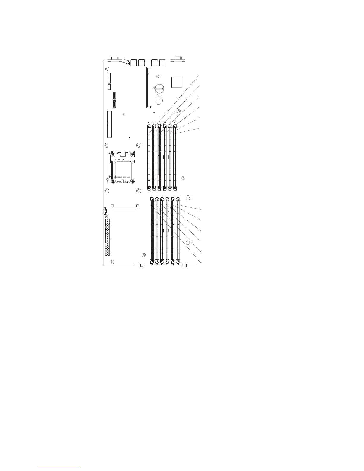
The following illustration shows the DIMM connectors on the system board.
DIMM 12
DIMM 11
DIMM 10
DIMM 9
DIMM 8
DIMM 7
DIMM 6
DIMM 5
DIMM 4
DIMM 3
DIMM 2
DIMM 1
To install a DIMM, complete the following steps.
1. Read the safety information that begins on page v and “Installation guidelines”
on page 21.
2. Turn off the server and peripheral devices, and disconnect the power cords and
all external cables.
3. Remove the server from the rack; then, remove the server cover (see
“Removing the cover” on page 23).
4. According to your server configuration, select the applicable DIMM installation
sequence from Table 2 on page 44.
Attention: To avoid breaking the retaining clips or damaging the DIMM
connectors, open and close the clips gently.
5. Open the retaining clip on each end of the DIMM connector.
6. Touch the static-protective package that contains the DIMM to any unpainted
metal surface on the server. Then, remove the DIMM from the package.
Chapter 2. Installing optional devices 45
Page 60

7. Turn the DIMM so that the DIMM keys align correctly with the connector.
8. Insert the DIMM into the connector by aligning the edges of the DIMM with the
slots at the ends of the DIMM connector. Firmly press the DIMM straight down
into the connector by applying pressure on both ends of the DIMM
simultaneously. The retaining clips snap into the locked position when the DIMM
is firmly seated in the connector. If there is a gap between the DIMM and the
retaining clips, the DIMM has not been correctly inserted; open the retaining
clips, remove the DIMM, and then reinsert it.
9. Repeat step 5 on page 45 through step 8 for the second DIMM in the pair that
you selected from Table 2 on page 44. DIMMs must be installed in pairs.
Important: When you restart the server after you have installed DIMMs, the 162
code will be displayed to indicate that the server memory configuration has
changed. You must run the Configuration/Setup Utility program to configure the
DIMMs. For additional information, see “Using the Configuration/Setup Utility
program” on page 58.
If you have other devices to install or remove, do so now. Otherwise, go to
“Completing the installation” on page 51.
46 System x3455 Types 7984 and 7986: User’s Guide
Page 61

Installing an additional microprocessor
The following notes describe the type of microprocessor that your server supports
and other information that you must consider when you install a microprocessor:
v For a list of microprocessors that the server supports, see the ServerProven list
at http://www.ibm.com/servers/eserver/serverproven/compat/us/.
v The server comes with one microprocessor. The server supports a maximum of
two microprocessors. The following illustration shows the two microprocessor
sockets on the system board.
Microprocessor 2
socket (CPU2)
Microprocessor 1
socket (CPU1)
v If only one microprocessor is installed, make sure that it is installed in
microprocessor socket 1 (system-board identifier CPU1). Microprocessor 1
supports both the startup and application processes.
v If you install a second microprocessor in the server, the server operates as a
symmetric multiprocessing (SMP) server, and operating-system application
programs can distribute the processing load between the microprocessors. This
enhances performance for database and point-of-sale applications, integrated
manufacturing solutions, and other applications. Microprocessor 2 is installed in
socket 2 (system-board identifier CPU2).
v Read the documentation that comes with the microprocessor to determine
whether you must update the BIOS code in the server. To download the most
current level of BIOS code for your server, go to http://www.ibm.com/servers/
eserver/support/xseries/index.html and follow the instructions.
Chapter 2. Installing optional devices 47
Page 62

v To use SMP, obtain an SMP-capable operating system. For a list of supported
operating systems, see http://www.ibm.com/servers/eserver/serverproven/compat/
us/.
Attention: To avoid damage and to ensure proper server operation, review the
following information before you install a microprocessor:
v The server will not start if microprocessor socket 1 (system-board identifier
CPU1) is empty.
v If two microprocessors are installed in the server, make sure that both
microprocessors are the same type, have the same cache size, and have the
same clock speed.
v Do not install DIMMs in connectors 7 through 12 if microprocessor socket 2
(system-board identifier CPU2) is empty. The server does not support this
configuration.
v When you handle static-sensitive devices, take precautions to avoid damage
from static electricity. For information about handling these devices, see
“Handling static-sensitive devices” on page 22.
v Avoid touching the components and gold-pad connectors on the microprocessor.
Make sure that the microprocessor is completely and correctly seated in the
socket. Incomplete insertion might cause damage to the system board or to the
microprocessor.
v Do not touch the thermal grease on the bottom of the heat sink or set down the
heat sink after the plastic cover is removed. Touching the thermal grease will
contaminate it. This damages its heat-conducting capability and exposes the new
microprocessor to overheating.
To install an additional microprocessor, complete the following steps.
1. Read the safety information that begins on page v and “Installation guidelines”
on page 21.
2. Turn off the server and all attached peripheral devices. Disconnect all power
cords; then, disconnect all external signal cables from the server.
3. Remove the server from the rack; then, remove the server cover (see
“Removing the cover” on page 23).
4. Remove the air baffle for microprocessor 2 (see “Removing an air baffle” on
page 24).
5. Locate the microprocessor 2 socket (identifier CPU2) on the system board.
48 System x3455 Types 7984 and 7986: User’s Guide
Page 63

6. Remove the dust cover from the surface of the microprocessor 2 socket.
a. Press down and out on the release lever on the microprocessor socket. Lift
up the release lever until it stops in the fully-open position (approximately
135° angle) and the top edge of the release lever has moved away from
the microprocessor socket.
Microprocessor
bracket frame
Microprocessor
release lever
Microprocessor socket
Microprocessor
dust cover
b. Lift the hinged microprocessor bracket frame into the open position.
Remove the protective cover from the bracket frame. Store the dust cover
in a safe place.
7. Install the microprocessor:
a. Touch the static-protective package that contains the new microprocessor
to any unpainted metal surface on the outside of the server; then, remove
the microprocessor from the package.
b. Align the microprocessor with the socket, as shown in the following
illustration (note the alignment marks and the position of the notches);
then, carefully place the microprocessor on the socket and close the
microprocessor bracket frame.
Attention: Do not use excessive force when you insert the
microprocessor into the socket.
Note: The microprocessor fits only one way on the socket.
Microprocessor
Alignment marks
Microprocessor
release lever
Microprocessor socket
Chapter 2. Installing optional devices 49
Page 64

8. Carefully close the release lever to secure the microprocessor in the socket.
Note: A new heat sink comes in a kit with a microprocessor.
Heat sink
9. Install the heat sink.
Captive screws
Microprocessor
socket
a. Remove the heat sink from its package and remove the cover from the
bottom of the heat sink.
b. Make sure that the thermal material is still on the bottom of the heat sink,
and position the heat sink on top of the microprocessor.
c. Align the captive screws on the heat sink with the holes that surround the
microprocessor socket.
d. Press firmly on the captive screws and tighten them, alternating among the
screws on opposite sides of the heat sink until they are tight. Do not
overtighten the screws by using excessive force.
10. Reinstall the air baffle for microprocessor 2 (see step1 on page 51).
you have other devices to install or remove, do so now. Otherwise, go to
If
“Completing the installation” on page 51.
50 System x3455 Types 7984 and 7986: User’s Guide
Page 65

Completing the installation
Attention: For proper cooling and airflow, replace the air baffles before you turn
on the server. Operating the server with the air baffles removed might damage
server components.
To complete the installation, complete the following steps:
1. If you have not already done so, reinstall the two air baffles, if you removed
them. Repeat the following procedure for each air baffle:
Put the air baffle into place from the top of the server, and align the holes near
the front of the air baffle with the pins in the server. Make sure that the pins on
the rear of the air baffle are seated in the system board.
Alignment pins
Alignment pins
Chapter 2. Installing optional devices 51
Page 66

2. Position the internal cables so that they do not interfere with the cover
installation.
3. Reinstall the cover on the server.
Captive screw
a. Position the cover on top of the server.
b. Align the tabs on the sides of the cover with the matching slots on the sides
of the chassis; then, slide the tabs into the slots.
Important: Before you slide the cover forward, make sure that all the tabs
on the cover engage the chassis correctly. If all the tabs do not
engage the chassis correctly, it will be very difficult to remove
the cover later.
c. Slide the cover toward the front of the server.
d. Secure the cover to the server by tightening the captive screw on the back
of the cover.
Install the server in the rack. For details, see the Rack Installation Instructions
4.
that come with the server.
Note: Depending on the optional devices that you installed, after you cable the
server, you might have to run the Configuration/Setup Utility program to
update the server configuration. For more information, see “Updating the
server configuration” on page 55 and Chapter 3, “Configuring the server,”
on page 57.
5. To attach peripheral devices and connect the power cord, continue with
“Connecting the cables” on page 53.
52 System x3455 Types 7984 and 7986: User’s Guide
Page 67

Connecting the cables
This section provides basic information about attaching peripheral devices, such as
a keyboard and pointing device, to the server.
Cable identifiers are printed on the cables that come with the server and optional
devices. Use these identifiers to connect the cables to the correct connectors, such
as the identifiers in the following examples:
v The signal cable identifier for the CD or DVD in the CD or DVD drive is “ODD”,
for optical disk drive.
v The signal cable identifier for the drive in the front hard disk drive cage is
“HDD1”.
v The signal cable identifier for the drive in the rear hard disk drive cage is
“HDD2”.
might be easier for you to route cables before you connect the devices to the
It
server. For detailed information about external devices and how to connect them to
the server, see the documentation that comes with these devices. For the location
of external ports and connectors on the server, see “Server components” on page
14.
There are release levers on the Ethernet connectors. To disconnect a cable from
one of these connectors, push down on the lever to release the cable.
Ethernet cable
release lever
Ethernet cable
Chapter 2. Installing optional devices 53
Page 68

To attach non-USB devices to the server, use the cables that come with the devices
and connect the cables to the applicable connectors on the server (see “Server
components” on page 14).
To attach a USB device to the server, use the cable that comes with the device and
connect the cable to:
v One of the two USB connectors on the front of the server (see “Front view” on
page 8), or
v One of the four USB connectors on the rear of the server (see “Rear view” on
page 10)
Important:
v If you want to attach a keyboard or mouse to this server, you must use a USB
keyboard or a USB mouse. For detailed information about the USB keyboard and
how to connect it to the server, see the documentation that comes with the USB
keyboard.
v The server supports keyboardless operation. If a USB keyboard is not connected
to the server, when the server is turned on or restarted, error message 301 will
appear during POST. No action is required. POST will continue within 1 minute.
v If you want to attach a diskette drive to this server, you must use an external
USB diskette drive.
Depending
on the optional devices that you installed, after you cable the server, you
might have to run the Configuration/Setup Utility program to update the server
configuration. For more information, see “Updating the server configuration” on
page 55 and Chapter 3, “Configuring the server,” on page 57.
54 System x3455 Types 7984 and 7986: User’s Guide
Page 69

Updating the server configuration
When you start the server for the first time after you add or remove a device, you
might receive a message indicating that the configuration has changed. The
Configuration/Setup Utility program automatically starts so that you can save the
new configuration information. For more information, see Chapter 3, “Configuring
the server,” on page 57.
Some optional devices have device drivers that you need to install. See the
documentation that comes with the option for information about installing any
required device drivers.
The server comes with at least one microprocessor installed on the system board. If
more than one microprocessor is installed, the server can operate as an SMP
server. Yo u might have to upgrade the operating system to support SMP. For more
information, see “Using the ServerGuide Setup and Installation CD” on page 64 and
the operating-system documentation.
If you have installed an adapter to manage the server remotely, see the
documentation that comes with the adapter for information about setting up,
configuring, and using the adapter.
To configure the integrated Gigabit Ethernet controllers, Chapter 3, “Configuring the
server,” on page 57.
Chapter 2. Installing optional devices 55
Page 70

56 System x3455 Types 7984 and 7986: User’s Guide
Page 71

Chapter 3. Configuring the server
The following configuration programs come with the server:
v Configuration/Setup Utility program
The Configuration/Setup Utility program is part of the basic input/output system
(BIOS). Use it to configure serial port assignments, change interrupt request
(IRQ) settings, change the startup-device sequence, set the date and time, and
set passwords. For information about using this program, see “Using the
Configuration/Setup Utility program” on page 58.
Note: In a multi-node configuration, some choices or settings are defined
through the primary server, and others must be defined on the individual
(secondary) servers. Before you create a scalable partition, make sure
that choices and settings on the secondary servers are correct.
v IBM ServerGuide Setup and Installation CD
The ServerGuide program provides software-setup tools and installation tools
that are designed for the server. Use this CD during the installation of the server
to configure basic hardware features, and to simplify the installation of your
operating system. For information about using this CD, see “Using the
ServerGuide Setup and Installation CD” on page 64.
v Ethernet controller configuration
For information about configuring the Ethernet controllers, see “Configuring the
Gigabit Ethernet controllers” on page 81.
v Baseboard management controller utility programs
Use these programs to configure the baseboard management controller, to
update the firmware and sensor data record/field replaceable unit (SDR/FRU)
data, and to remotely manage a network. For information about using these
programs, see “Using the baseboard management controller utility programs” on
page 77.
v Boot Menu program
The Boot Menu program is part of the BIOS. Use it to override the startup
sequence that is set in the Configuration/Setup Utility program and temporarily
assign a device to be first in the startup sequence. For information about using
this program, see “Using the Boot Menu program” on page 80.
v IBM Director
IBM Director is a workgroup-hardware-management tool that you can use to
centrally manage System x and xSeries servers. If you plan to use IBM Director
to manage the server, you must check for the latest applicable IBM Director
updates and interim fixes. For information about updating IBM Director, see
“Updating IBM Director” on page 82. For more information about IBM Director,
see the IBM Director documentation on the IBM Director CD that comes with the
server.
you have installed an optional SAS redundant array of independent disks (RAID)
If
adapter that the server supports, the adapter comes with RAID configuration
programs that you can use. To configure the adapter and the hard disk drives that
are connected to it, follow the instructions in the documentation that comes with the
RAID configuration programs. For a list of supported adapters for the server, see
http://www.ibm.com/servers/eserver/serverproven/compat/us/.
© Copyright IBM Corp. 2006 57
Page 72

Using the Configuration/Setup Utility program
Use the Configuration/Setup Utility program to perform the following tasks:
v View configuration information
v View and change assignments for devices and I/O ports
v Set the date and time
v Set and change passwords
v Set and change the startup characteristics of the server and the order of startup
devices (startup-drive sequence)
v Set and change settings for advanced hardware features
v View, set, and change settings for baseboard management controller features
v View and clear error logs
v Change interrupt request (IRQ) settings
v Resolve configuration conflicts
Starting the Configuration/Setup Utility program
To start the Configuration/Setup Utility program, complete the following steps.
1. Turn on the server.
2. When the prompt Press F1 for Configuration/Setup is displayed, press F1. If
you have set both a power-on password and an administrator password, you
must type the administrator password to access the full Configuration/Setup
Utility menu. If you do not type the administrator password, a limited
Configuration/Setup Utility menu is available.
3. Select settings to view or change.
Configuration/Setup Utility menu choices
The following choices are on the Configuration/Setup Utility main menu. Depending
on the version of the BIOS code, some menu choices might differ slightly from
these descriptions.
v System Summary
Select this choice to view configuration information, including the type, speed,
and cache sizes of the microprocessors and the amount of installed memory.
When you make configuration changes through other choices in the
Configuration/Setup Utility program, the changes are reflected in the system
summary; you cannot change settings directly in the system summary.
This choice is on the full and limited Configuration/Setup Utility menu.
v System Information
Select this choice to view information about the server, such as the machine type
and model identifier of your server, the serial number, and the revision level or
issue date of the BIOS code that is stored in electrically erasable programmable
ROM (EEPROM).
When you make changes through other choices in the Configuration/Setup Utility
program, some of those changes are reflected in the system information; you
cannot change settings directly in the system information.
This choice is on the full Configuration/Setup Utility menu only.
v Devices and I/O Ports
Select this choice to view or change assignments for devices and input/output
(I/O) ports.
58 System x3455 Types 7984 and 7986: User’s Guide
Page 73

You can enable or disable integrated Ethernet and other controllers and all
standard ports (such as serial). Enable is the default setting for all controllers. If
you disable a device, it cannot be configured, and the operating system will not
be able to detect it (this is equivalent to disconnecting the device). If you disable
the integrated SATA controller, the server will have no SATA capability. If you
disable the integrated video controller, the server will have no video capability. If
you disable the integrated Ethernet controller and no Ethernet adapter is
installed, the server will have no Ethernet capability.
This choice is on the full Configuration/Setup Utility menu only.
– Remote Console Redirection
Select this choice to view and change the settings for the serial connection
that is used to redirect the local keyboard-video-mouse console to a remote
console.
To redirect the local keyboard-video-mouse console to a remote serial port,
you must set the Remote Console Serial Port value to Enabled. The default
value is Disabled.
– System MAC Addresses
Select this choice to view the media-access control (MAC) addresses of the
two integrated Ethernet controllers. Yo u cannot change these values.
Date and Time
v
Select this choice to set the date and time in the server, in 24-hour format
(hour:minute:second).
This choice is on the full Configuration/Setup Utility menu only.
v System Security
Select this choice to set passwords. See “Passwords” on page 61 for more
information.
This choice is on the full Configuration/Setup Utility menu only.
– Power-on password
Select this choice to set or change a power-on password. See “Power-on
password” on page 62 for more information.
– Administrator Password
Select this choice to set or change an administrator password. An
administrator password is intended to be used by a system administrator; it
limits access to the full Configuration/Setup Utility menu. If an administrator
password is set, the full Configuration/Setup Utility menu is available only if
you type the administrator password at the password prompt. See
“Administrator password” on page 62 for more information.
Startup Option
v
Select this choice to view or change the start options. Changes in the start
options take effect when you restart the server.
This choice is on the full Configuration/Setup Utility menu only.
You can specify whether the server starts with the keyboard number lock on or
off. The POST screens show the memory count, detected devices, and any
errors encountered.
You can enable or disable legacy USB support. (Legacy USB support enables a
non-USB-aware operating system such as DOS or UNIX
®
to recognize the USB
keyboard and mouse.)
The startup sequence specifies the order in which the server checks devices to
find a boot record. The server starts from the first boot record that it finds.
Chapter 3. Configuring the server 59
Page 74

Through the Startup Sequence Options menu, you can select up to eight Wake
on LAN startup devices in addition to a maximum of eight other startup devices.
You can specify a startup sequence for the Wake on LAN functions if all of the
following requirements are met:
– The server has Wake on LAN hardware and software.
– The operating system supports Wake on LAN functions.
– Yo u have enabled the Wake on Lan choice on the Startup Sequence
Options menu.
– Yo u have enabled the Planar Ethernet choice on the Startup Sequence
Options menu.
For additional information about Wake on LAN functions, see the
Note:
documentation that comes with the operating system, and the Wake on
LAN hardware and software. For additional information about using the
Preboot Execution Environment (PXE) boot agent functions to enable or
disable operating-system wake-up support, see the Broadcom NetXtreme
Gigabit Ethernet Software CD that comes with the server.
If you enable the boot fail count, the BIOS default settings will be restored after
three consecutive failures to find a boot record.
You also can specify that the integrated SATA controller or other devices have
boot priority.
If you plan to use the Boot Menu program, you must first enable the F12 prompt
so that the Boot Menu can be displayed on your monitor. To do this, you must
enable the F12 Boot Menu Prompt menu choice.
v Advanced Setup
Select this choice to view and change settings for advanced hardware features
and to view the system event log information, such as the record, event type,
and timestamp.
Important: The server might malfunction if these settings are incorrectly
configured. Follow the instructions on the screen carefully.
This choice is on the full Configuration/Setup Utility menu only.
– Memory Settings
Select this choice to view the settings for the DIMMs. The only valid
configuration change is to Enable the DIMMs.
– CPU Options
Select this choice to view, set, and change other memory configuration
values. Some of the values on these menus cannot be changed manually;
however, they will change automatically when related configuration values are
changed manually. For example, if you change the value of ECC Mode on the
ECC Options menu, the values of DRAM ECC Scrub Control and ECC
Scrub Redirection also change automatically.
- Memory Controller Options
Select this choice to view and change memory controller configuration
values.
- ECC Options
Select this choice to view and change ECC memory configuration values.
PCI Bus Control
–
From this menu, select the PCI Interrupt Routing choice to view and change
the interrupt request (IRQ) settings for the integrated controllers and other
devices.
60 System x3455 Types 7984 and 7986: User’s Guide
Page 75

– Baseboard Management Controller (BMC) Settings
Select this choice to view and change the settings for the baseboard
management controller (BMC).
You can view the firmware levels of the baseboard management controller,
change the setting for the COM port that the baseboard management
controller uses, enable or disable the POST watchdog and OS Loader
watchdog, and view the BMC network configuration values, system event log,
and BMC error log.
v Error Logs
Select this choice to view or clear the system event/error logs.
Select the System Event/Error Log choice to view the system event/error log,
which contains the full text of the error messages that have been generated. Use
the arrow keys to move among the pages in the event/error log.
Select Clear error logs to clear the system event/error log.
Run the diagnostic program on the server to get more information about any
error codes that might occur. For instructions, see the Problem Determination
and Service Guide on the IBM System x Documentation CD.
v Save Settings
Select this choice to save the changes that you have made in the settings.
v Restore Settings
Select this choice to cancel the changes that you have made in the settings and
restore the previous settings.
v Load Default Settings
Select this choice to cancel the changes that you have made in the settings and
restore the factory settings.
v Exit Setup
Select this choice to exit from the Configuration/Setup Utility program. If you have
not saved the changes that you have made in the settings, you are asked
whether you want to save the changes or exit without saving them.
Passwords
From the System Security choice, you can set, change, and delete a power-on
password and an administrator password. The System Security choice is on the
full Configuration/Setup menu only.
If you set only a power-on password, you must type the power-on password to
complete the system startup, and you have access to the full Configuration/Setup
Utility menu.
An administrator password is intended to be used by a system administrator; it
limits access to the full Configuration/Setup Utility menu. If you set only an
administrator password, you do not have to type a password to complete the
system startup, but you must type the administrator password to access the
Configuration/Setup Utility menu.
If you set a power-on password for a user and an administrator password for a
system administrator, you can type either password to complete the system startup.
A system administrator who types the administrator password has access to the full
Configuration/Setup Utility menu; the system administrator can give the user
authority to set, change, and delete the power-on password. A user who types the
power-on password has access to only the limited Configuration/Setup Utility menu;
Chapter 3. Configuring the server 61
Page 76

the user can set, change, and delete the power-on password, if the system
administrator has given the user that authority.
Power-on password
If a power-on password is set, when you turn on the server, the system startup will
not be completed until you type the power-on password. You can use any
combination of up to seven characters (A – Z, a – z, and 0 – 9) for the password.
If a power-on password is set, you can enable the Unattended Start mode, in which
the keyboard and mouse remain locked but the operating system can start. You can
unlock the keyboard and mouse by typing the power-on password.
If you forget the power-on password, you can regain access to the server in any of
the following ways:
v If an administrator password is set, type the administrator password at the
password prompt (see “Administrator password”). Start the Configuration/Setup
Utility program and reset the power-on password.
v Change the position of the power-on password override jumper (J52) on the
system board to bypass the power-on password check.
v Remove the server battery and then reinstall it.
you regain access to the server, you can reset the power-on password. See
After
“Resetting passwords” for additional information.
Administrator password
If an administrator password is set, you must type the administrator password for
access to the full Configuration/Setup Utility menu. You can use any combination of
up to seven characters ((A – Z, a – z, and 0 – 9) for the password.
If you forget the administrator password, you can reset it. See “Resetting
passwords” for additional information.
Resetting passwords
If you forget the power-on password or the administrator password, you can reset
the password after you perform one of the following actions:
v Yo u can change the position of the power-on password override jumper (J52) on
the system board to bypass the power-on password check. This enables you to
reset the passwords without clearing all of the current system configuration
values.
v Yo u can remove the server battery and then reinstall it. This clears the current
system configuration values and resets them to their default values. For
instructions for removing and installing the battery, see the Problem
Determination and Service Guide on the IBM System x Documentation CD. After
you reinstall the battery, you must access the Configuration/Setup Utility program,
reset the system date and time, and reset all other configuration values where
necessary.
power-on password override jumper (J52) location is shown in the following
The
illustration.
62 System x3455 Types 7984 and 7986: User’s Guide
Page 77

NMI switch (SW1)
Power-on password
jumper (J52)
Force power-on
jumper (J37)
BMC update
jumper (J34)
Wake on LAN
bypass jumper (J48)
Boot block recovery
jumper (J51)
BMC reset
jumper (J36)
Attention: Before you change any switch settings or move any jumpers, turn off
the server; then, disconnect all power cords and external cables. See the safety
information that begins on page v. Do not change settings or move jumpers on any
system-board switch or jumper blocks that are not shown in this document.
To change the position of the power-on password jumper, complete the following
steps.
1. Review the safety information that begins on page v.
2. Turn off the server and peripheral devices and disconnect all power cords and
external cables; then, remove the cover (see “Removing the cover” on page 23).
3. Move the jumper on J52 from pins 1 and 2 (the default) to pins 2 and 3 to
bypass the power-on password check.
4. Replace the cover, connect the server to a monitor, and then connect it to a
power source.
5. Turn on the server and wait until POST is completed.
6. Turn off the server and disconnect all power cords and external cables; then,
remove the cover.
7. Move the jumper on J52 from pins 2 and 3 to pins 1 and 2.
8. Replace the cover, connect the server to a USB keyboard, monitor, USB mouse,
and peripheral devices; then, connect the server to a power source.
Chapter 3. Configuring the server 63
Page 78

To reset the power-on and administrator passwords, complete the following steps.
1. Turn on the server.
2. When the prompt Press F1 for Configuration/Setup is displayed, press F1.
3. Select System Security from the main menu.
4. Follow the instructions on the menu to reset each password.
Updating the BIOS code
Important: For correct server operation, be sure to update the baseboard
The most current level of BIOS code is available at http://www.ibm.com/servers/
eserver/support/xseries/index.html.
latest baseboard management controller firmware level, you can update the BIOS
code through one of the following methods:
v Downloading the latest BIOS code from this IBM Web site, creating an update
CD or diskette, and using the CD drive or an external USB diskette drive to
install the BIOS code.
v Installing an update package for the Linux or Microsoft Windows operating
system, if it is available.
management controller firmware before you update the BIOS code. For
more information, see “Using the baseboard management controller
utility programs” on page 77.
After you make sure that the server has the
Using the ServerGuide Setup and Installation CD
The ServerGuide Setup and Installation CD contains a setup and installation
program that is designed for your server. The ServerGuide program detects the
server model and optional hardware devices that are installed and uses that
information during setup to configure the hardware. The ServerGuide program
simplifies operating-system installations by providing updated device drivers and, in
some cases, installing them automatically.
If you are installing a Linux operating system, you can use ServerGuide to set up
and configure the hardware; then, install a Linux operating system, using the
procedure in “Installing your operating system without using ServerGuide” on page
66.
If a later version of the ServerGuide program is available, you can download a free
image of the ServerGuide Setup and Installation CD, or you can purchase the CD.
To download the image, go to the IBM ServerGuide Web page at
http://www.ibm.com/pc/qtechinfo/MIGR-4ZKPPT.html. To purchase the latest
ServerGuide Setup and Installation CD, go to the ServerGuide fulfillment Web site
at http://www.ibm.com/servers/eserver/xseries/systems_management/sys_migration/
serverguide/sub.html.
The ServerGuide program has the following features:
v An easy-to-use interface
v Diskette-free setup, and configuration programs that are based on detected
hardware
v Device drivers that are provided for the server model and detected hardware
v Operating-system partition size and file-system type that are selectable during
setup
64 System x3455 Types 7984 and 7986: User’s Guide
Page 79

ServerGuide features
Features and functions can vary slightly with different versions of the ServerGuide
program. To learn more about the version that you have, start the ServerGuide
Setup and Installation CD and view the online overview. Not all features are
supported on all server models.
The ServerGuide program requires a supported IBM server with an enabled
startable (bootable) CD drive. In addition to the ServerGuide Setup and Installation
CD, you must have your operating-system CD to install the operating system.
The ServerGuide program performs the following tasks:
v Sets system date and time
v Checks the microcode (firmware) levels of an adapter and determines whether a
later level is available from the CD
v Detects installed optional hardware devices and provides updated device drivers
for most adapters and devices
v Provides diskette-free installation for supported Windows operating systems
v Includes an online readme file with links to tips for hardware and
operating-system installation
Setup and configuration overview
When you use the ServerGuide Setup and Installation CD, you do not need setup
diskettes. You can use the CD to configure any supported IBM server model. The
setup program provides a list of tasks that are required to set up your server model.
Note: Features and functions can vary slightly with different versions of the
ServerGuide program.
When you start the ServerGuide Setup and Installation CD, the program prompts
you to complete the following tasks:
v Select your language.
v Select your keyboard layout and country.
v View the overview to learn about ServerGuide features.
v View the readme file to review installation tips for your operating system and
adapter.
v Start the operating-system installation. You will need your operating-system CD.
Typical operating-system installation
The ServerGuide program can reduce the time it takes to install an operating
system. It provides the device drivers that are required for your hardware and for
the operating system that you are installing. This section describes a typical
ServerGuide operating-system installation.
Note: Features and functions can vary slightly with different versions of the
ServerGuide program.
1. After you have completed the setup process, the operating-system installation
program starts. (You will need your operating-system CD to complete the
installation.)
2. The ServerGuide program stores information about the server model, baseboard
management controller, hard disk drive controllers, and network adapters. Then,
the program checks the CD for newer device drivers. This information is stored
and then passed to the operating-system installation program.
Chapter 3. Configuring the server 65
Page 80

3. The ServerGuide program presents operating-system partition options that are
based on your operating-system selection and the installed hard disk drives.
4. The ServerGuide program prompts you to insert your operating-system CD and
restart the server. At this point, the installation program for the operating system
takes control to complete the installation.
Installing your operating system without using ServerGuide
If you have already configured the server hardware and you are not using the
ServerGuide program to install your operating system, complete the following steps
to download the latest operating-system installation instructions from the IBM Web
site.
Note: Changes are made periodically to the IBM Web site. The actual procedure
might vary slightly from what is described in this document.
1. Go to http://www.ibm.com/servers/eserver/support/xseries/index.html.
2. From the Hardware list, select System x3455 and click Go.
3. Click the Install and use tab.
4. Click Product documentation.
5. Select the installation instructions for your operating system.
Using the baseboard management controller
The baseboard management controller provides basic environmental monitoring
functions for the server. If an environmental condition exceeds a threshold or if a
system component fails, the baseboard management controller lights LEDs to help
you diagnose the problem and also records the error in the BMC system event log.
The baseboard management controller also provides the following remote server
management capabilities through the Avocent SMBridge management utility
program:
v Command-line interface (IPMI Shell)
The command-line interface provides direct access to server management
functions through the Intelligent Platform Management Interface (IPMI) protocol.
Use the command-line interface to issue commands to control the server power,
view system information, and identify the server. You can also save one or more
commands as a text file and run the file as a script.
v Serial over LAN
Establish a Serial over LAN (SOL) connection to manage servers from a remote
location. You can remotely view and change the BIOS settings, restart the server,
identify the server, and perform other management functions. Any standard Telnet
client application can access the SOL connection.
Before you can perform remote management activities through an SOL
connection, you must install the SMBridge management utility program on the
server, and then enable and configure the server for SOL functions through the
SMBridge management utility program. This enables you to use the SMBridge
management utility program to remotely manage and configure a network. For
instructions and additional information, see “Installing the SMBridge management
utility program” on page 67 and “Enabling and configuring SOL through the
SMBridge management utility program” on page 68.
Important:
protocol) by default. To find your BMC on an existing network, you will need to
66 System x3455 Types 7984 and 7986: User’s Guide
The server Ethernet ports are set to DHCP (dynamic host configuration
Page 81

identify the server by the default host name. The default host name for each server
is the last 8 characters of the BMC MAC address. The BMC MAC address can be
found in the Configuration/Setup Utility program, on a label on the system board,
and on a tag hanging from the front of the server. Once you have deployed your
server, make sure that you remove the BMC MAC address tag from the front of the
server so that it does not impede airflow through the front of the server.
The baseboard management controller comes with several utility programs that you
can use to configure the baseboard management controller, download firmware
updates and SDR/FRU updates, and remotely manage a network. For additional
information about using these programs, see “Using the baseboard management
controller utility programs” on page 77.
Installing the SMBridge management utility program
Important: To obtain maximum benefit from the Avocent SMBridge management
utility program, install and load the program before problems occur.
To install the SMBridge management utility program on a server running a Microsoft
Windows operating system, complete the following steps:
1. Go to http://www.ibm.com/servers/eserver/support/xseries/index.html and
download the utility program and create the BMC Management Utility CD.
2. Insert the BMC Management Utility CD into the CD-RW/DVD drive. The
InstallShield wizard starts, and a window similar to that shown in the following
illustration opens.
3. Follow the prompts to complete the installation.
The installation program prompts you for a transmission control protocol/Internet
protocol (TCP/IP) port number and an IP address. Specify an IP address, if you
want to limit the connection requests that will be accepted by the utility program.
To accept connections from any server, type INADDR_ANY as the IP address. Also
specify the port number that the utility program will use. These values will be
recorded in the smbridge.cfg file for the automatic startup of the utility program.
Chapter 3. Configuring the server 67
Page 82

To install the SMBridge management utility program on a server running a Linux
operating system, complete the following steps. Yo u must be logged in as a root
user to perform these procedures.
1. Go to http://www.ibm.com/servers/eserver/support/xseries/index.html. Download
the utility program and create the Avocent BMC Management Utility CD.
2. Insert the Avocent BMC Management Utility CD into the drive.
3. Type mount/mnt/cdrom.
4. Locate the directory where the installation RPM package is located and type
cd/mnt/cdrom.
5. Type the following command to run the RPM package and start the installation:
rpm -ivh smbridge-2.0-xx.rpm
where xx is the release level being installed.
6. Follow the prompts to complete the installation. When the installation is
complete, the utility copies files to the following directories:
/etc/init.d/SMBridge
/etc/smbridge.cfg
/usr/sbin/smbridged
/var/log/smbridge/LICENSE
utility starts automatically when the server is started. You can also locate the
The
/ect/init.d directory to start the utility and use the following commands to manage
the utility:
smbridge status
smbridge start
smbridge stop
smbridge restart
For more information about the SMBridge management utility program, see
Note:
“Using the SMBridge management utility program” on page 79.
Enabling and configuring SOL through the SMBridge management
utility program
To enable and configure the server for SOL through the Avocent SMBridge
management utility program, you must perform the following tasks:
1. Update and configure the BIOS code
2. Update and configure the baseboard management controller (BMC) firmware
3. Update and configure the Ethernet controller firmware
4. Enable the operating system for an SOL connection
BIOS update and configuration
To update and configure the BIOS code to enable SOL, complete the following
steps:
1. Update the BIOS code:
a. Download the latest version of the BIOS code from http://www.ibm.com/
servers/eserver/support/xseries/index.html.
b. Update the BIOS code, following the instructions that come with the update
file that you downloaded.
Update the BMC firmware:
2.
a. Download the latest version of the BMC firmware from http://www.ibm.com/
servers/eserver/support/xseries/index.html.
68 System x3455 Types 7984 and 7986: User’s Guide
Page 83

b. Update the BMC firmware, following the instructions that come with the
update file that you downloaded.
Configure the BIOS settings:
3.
a. When you are prompted to start the Configuration/Setup Utility program,
restart the server and press F1.
b. Select Devices and I/O Ports; then, make sure that the values are set as
follows:
Serial Port A: Port 3F8, IRQ4
c. Select Remote Console Redirection; then, make sure that the values are
set as follows:
v Remote Console Serial Port: Enabled
v Baud Rate: 19.2K
v Console Type: vt100 8bit
v Flow Control: None
v Console connection: Direct
v Continue C.R. after POST: On
Press Esc twice to exit the Remote Console Redirection and Devices and
d.
I/O Ports sections of the Configuration/Setup Utility program.
e. Select Advanced Setup; then, select Baseboard Management Controller
(BMC) Settings.
f. Set BMC Serial Port Access Mode to Dedicated.
g. Press Esc twice to exit the Baseboard Management Controller (BMC)
Settings and Advanced Setup sections of the Configuration/Setup Utility
program.
h. Select Save Settings; then, press Enter.
i. Press Enter to confirm.
j. Select Exit Setup; then, press Enter.
k. Make sure that Yes, exit the Setup Utility is selected; then, press Enter.
Linux configuration
For SOL operation on the server, you must configure the Linux operating system to
expose the Linux initialization (booting) process. This enables users to log in to the
Linux console through an SOL session and directs Linux output to the serial
console. See the documentation for your specific Linux operating-system type for
information and instructions.
Use one of the following procedures to enable SOL sessions for your Linux
operating system. You must be logged in as a root user to perform these
procedures.
Chapter 3. Configuring the server 69
Page 84

Red Hat Enterprise Linux ES 4 configuration:
Note: This procedure is based on a default installation of Red Hat Enterprise Linux
ES 4. The file names, structures, and commands might be different for other
versions of Red Hat Linux.
To configure the general Linux parameters for SOL operation when you are using
the Red Hat Enterprise Linux ES 4 operating system, complete the following steps.
Note: Hardware flow control prevents character loss during communication over a
serial connection. You must enable it when you are using a Linux operating
system.
1. Add the following line to the end of the # Run gettys in standard runlevels
section of the /etc/inittab file. This enables hardware flow control and enables
users to log in through the SOL console.
7:2345:respawn:/sbin/agetty -h -L ttyS0 19200 vt102
2. Add the following line at the bottom of the /etc/securetty file to enable a user to
log in as the root user through the SOL console:
ttyS0
LILO configuration: If you are using LILO, complete the following steps:
1. Modify the /etc/lilo.conf file:
a. Add the following text to the end of the first default=linux line
-Monitor
b. Comment out the map=/boot/map line by adding a # at the beginning of this
line.
c. Comment out the message=/boot/message line by adding a # at the beginning
of this line.
d. Add the following line before the first image= line:
# This will allow you to only Monitor the OS boot via SOL
e. Add the following text to the end of the first label=linux line:
-Monitor
f. Add the following line to the first image= section. This enables SOL.
append="console=ttyS0,19200n8 console=tty1"
g. Add the following lines between the two image= sections:
# This will allow you to Interact with the OS boot via SOL
image=/boot/vmlinuz-2.4.9-e.12smp
label=linux-Interact
initrd=/boot/initrd-2.4.9-e.12smp.img
read-only
root=/dev/hda6
append="console=tty1 console=ttyS0,19200n8 "
70 System x3455 Types 7984 and 7986: User’s Guide
Page 85

The following examples show the original content of the /etc/lilo.conf file and the
content of this file after modification.
Original /etc/lilo.conf contents
prompt
timeout=50
default=linux
boot=/dev/hda
map=/boot/map
install=/boot/boot.b
message=/boot/message
linear
image=/boot/vmlinuz-2.4.9-e.12smp
label=linux
initrd=/boot/initrd-2.4.9-e.12smp.img
read-only
root=/dev/hda6
image=/boot/vmlinuz-2.4.9-e.12
label=linux-up
initrd=/boot/initrd-2.4.9-e.12.img
read-only
root=/dev/hda6
Chapter 3. Configuring the server 71
Page 86

Modified /etc/lilo.conf contents
prompt
timeout=50
default=linux-Monitor
boot=/dev/hda
#map=/boot/map
install=/boot/boot.b
#message=/boot/message
linear
# This will allow you to only Monitor the OS boot via SOL
image=/boot/vmlinuz-2.4.9-e.12smp
label=linux-Monitor
initrd=/boot/initrd-2.4.9-e.12smp.img
read-only
root=/dev/hda6
append="console=ttyS0,19200n8 console=tty1"
# This will allow you to Interact with the OS boot via SOL
image=/boot/vmlinuz-2.4.9-e.12smp
label=linux-Interact
initrd=/boot/initrd-2.4.9-e.12smp.img
read-only
root=/dev/hda6
append="console=tty1 console=ttyS0,19200n8 "
image=/boot/vmlinuz-2.4.9-e.12
label=linux-up
initrd=/boot/initrd-2.4.9-e.12.img
read-only
root=/dev/hda6
2. Run the lilo command to store and activate the LILO configuration.
When the Linux operating system starts, a LILO boot prompt is displayed instead of
the graphical user interface. Press Ta b at this prompt to install all of the boot
options that are listed. To load the operating system in interactive mode, type
linux-Interact and then press Enter.
GRUB configuration: If you are using GRUB, complete the following steps to
modify the /boot/grub/grub.conf file:
1. Comment out the splashimage= line by adding a # at the beginning of this line.
2. Add the following line before the first title= line:
# This will allow you to only Monitor the OS boot via SOL
3. Append the following text to the first title= line:
SOL Monitor
4. Append the following text to the kernel/ line of the first title= section:
console=ttyS0,19200 console=tty1
5. Add the following five lines between the two title= sections:
# This will allow you to Interact with the OS boot via SOL
title Red Hat Linux (2.4.9-e.12smp) SOL Interactive
root (hd0,0)
72 System x3455 Types 7984 and 7986: User’s Guide
Page 87

kernel /vmlinuz-2.4.9-e.12smp ro root=/dev/hda6 console=tty1
console=ttyS0,19200
initrd /initrd-2.4.9-e.12smp.img
Note: The entry that begins with kernel /vmlinuz is shown with a line break after
console=tty1. In your file, the entire entry must all be on one line.
The following examples show the original content of the /boot/grub/grub.conf file
and the content of this file after modification.
Original /boot/grub/grub.conf contents
#grub.conf generated by anaconda
#
# Note that you do not have to rerun grub after making changes to this file
# NOTICE: You have a /boot partition. This means that
# all kernel and initrd paths are relative to /boot/, eg.
# root (hd0,0)
# kernel /vmlinuz-version ro root=/dev/hda6
# initrd /initrd-version.img
#boot=/dev/hda
default=0
timeout=10
splashimage=(hd0,0)/grub/splash.xpm.gz
title Red Hat Enterprise Linux ES (2.4.9-e.12smp)
root (hd0,0)
kernel /vmlinuz-2.4.9-e.12smp ro root=/dev/hda6
initrd /initrd-2.4.9-e.12smp.img
title Red Hat Enterprise Linux ES-up (2.4.9-e.12)
root (hd0,0)
kernel /vmlinuz-2.4.9-e.12 ro root=/dev/hda6
initrd /initrd-2.4.9-e.12.img
Chapter 3. Configuring the server 73
Page 88

Modified /boot/grub/grub.conf contents
#grub.conf generated by anaconda
#
# Note that you do not have to rerun grub after making changes to this file
# NOTICE: You have a /boot partition. This means that
# all kernel and initrd paths are relative to /boot/, eg.
# root (hd0,0)
# kernel /vmlinuz-version ro root=/dev/hda6
# initrd /initrd-version.img
#boot=/dev/hda
default=0
timeout=10
# splashimage=(hd0,0)/grub/splash.xpm.gz
# This will allow you to only Monitor the OS boot via SOL
title Red Hat Enterprise Linux ES (2.4.9-e.12smp) SOL Monitor
root (hd0,0)
kernel /vmlinuz-2.4.9-e.12smp ro root=/dev/hda6 console=ttyS0,19200 console=tty1
initrd /initrd-2.4.9-e.12smp.img
# This will allow you to Interact with the OS boot via SOL
title Red Hat Linux (2.4.9-e.12smp) SOL Interactive
root (hd0,0)
kernel /vmlinuz-2.4.9-e.12smp ro root=/dev/hda6 console=tty1 console=ttyS0,19200
initrd /initrd-2.4.9-e.12smp.img
title Red Hat Enterprise Linux ES-up (2.4.9-e.12)
root (hd0,0)
kernel /vmlinuz-2.4.9-e.12 ro root=/dev/hda6
initrd /initrd-2.4.9-e.12.img
You must restart the Linux operating system after you complete these procedures
for the changes to take effect and to enable SOL.
SUSE SLES 9.0 configuration:
Note: This procedure is based on a default installation of SUSE LINUX Enterprise
Server (SLES) 9.0. The file names, structures, and commands might be
different for other versions of SUSE Linux.
To configure the general Linux parameters for SOL operation when using the SLES
9.0 operating system, complete the following steps.
Note: Hardware flow control prevents character loss during communication over a
serial connection. You must enable it when using a Linux operating system.
1. Add the following line to the end of the # getty-programs for the normal
runlevels section of the /etc/inittab file. This enables hardware flow control and
enables users to log in through the SOL console.
7:2345:respawn:/sbin/agetty -h -L ttyS0 19200 vt102
2. Add the following line after the tty6 line at the bottom of the /etc/securetty file to
enable a user to log in as the root user through the SOL console:
ttyS0
74 System x3455 Types 7984 and 7986: User’s Guide
Page 89

3. Complete the following steps to modify the /boot/grub/menu.lst file:
a. Comment out the gfxmenu line by adding a # in front of the word gfxmenu.
b. Add the following line before the first title line:
# This will allow you to only Monitor the OS boot via SOL
c. Append the following text to the first title line:
SOL Monitor
d. Append the following text to the kernel line of the first title section:
console=ttyS0,19200 console=tty0
e. Add the following four lines between the first two title sections:
# This will allow you to Interact with the OS boot via SOL
title linux SOL Interactive
kernel (hd0,1)/boot/vmlinuz root=/dev/hda2 acpi=oldboot vga=791
console=tty1 console=ttyS0,19200
initrd (hd0,1)/boot/initrd
The following examples show the original content of the /boot/grub/menu.lst
file and the content of this file after modification.
Original /boot/grub/menu.lst contents Notes
gfxmanu (hd0,1)/boot/message
color white/blue black/light-gray
default 0
timeout 8
title linux
kernel (hd0,1)/boot/vmlinuz root=/dev/hda2 acpi=oldboot vga=791 1
initrd (hd0,1)/boot/initrd
title floppy
root
chainloader +1
title failsafe
kernal (hd0,1)/boot/vmlinuz.shipped root=/dev/hda2 ide=nodma apm=off vga=normal nosmp 1
disableapic maxcpus=0 3
initrd (hd0,1)/boot/initrd.shipped
Note 1: The kernel line is shown with a line break. In your file, the entire entry must all be on one line.
Modified /boot/grub/menu.lst contents Notes
#gfxmanu (hd0,1)/boot/message
color white/blue black/light-gray
default 0
timeout 8
# This will allow you to only Monitor the OS boot via SOL
title linux SOL Monitor
kernel (hd0,1)/boot/vmlinuz root=/dev/hda2 acpi=oldboot vga=791 console=ttyS0,19200 1
console=tty1
initrd (hd0,1)/boot/initrd
# This will allow you to Interact with the OS boot via SOL
title linux SOL Interactive
kernel (hd0,1)/boot/vmlinuz root=/dev/hda2 acpi=oldboot vga=791 console=tty1 console=ttyS0,19200
initrd (hd0,1)/boot/initrd
Chapter 3. Configuring the server 75
Page 90

Modified /boot/grub/menu.lst contents Notes
title floppy
root
chainloader +1
title failsafe
kernel (hd0,1)/boot/vmlinuz.shipped root=/dev/hda2 ide=nodma apm=off vga=normal nosmp 1
disableapic maxcpus=0 3
initrd (hd0,1)/boot/initrd.shipped
Note 1: The kernel line is shown with a line break. In your file, the entire entry must all be on one line.
You must restart the Linux operating system after you complete these procedures
for the changes to take effect and to enable SOL.
Microsoft Windows 2003 Standard Edition configuration
Note: This procedure is based on a default installation of the Microsoft Windows
2003 operating system.
To configure the Microsoft Windows 2003 operating system for SOL operation,
complete the following steps. Yo u must be logged in as a user with administrator
access to perform this procedure.
1. Complete the following steps to determine which boot entry ID to modify:
a. Type bootcfg at a Windows command prompt; then, press Enter to display
the current boot options for your server.
b. In the Boot Entries section, locate the boot entry ID for the section with an
OS friendly name of Windows Server 2003, Standard. Write down the boot
entry ID for use in the next step.
To enable the Microsoft Windows Emergency Management System (EMS), at a
2.
Windows command prompt, type
bootcfg /EMS ON /PORT COM1 /BAUD 19200 /ID boot_id
where boot_id is the boot entry ID from step 1b; then, press Enter.
3. Complete the following steps to verify that the EMS console is redirected to the
COM1 serial port:
a. Type bootcfg at a Windows command prompt; then, press Enter to display
the current boot options for your server.
b. Verify the following changes to the bootcfg settings:
v In the Boot Loader Settings section, make sure that redirect is set to
COM1 and that redirectbaudrate is set to 19200.
v In the Boot Entries section, make sure that the OS Load Options: line
has /redirect appended to the end of it.
You must restart the Windows 2003 operating system after you complete this
procedure for the changes to take effect and to enable SOL.
76 System x3455 Types 7984 and 7986: User’s Guide
Page 91

Using the baseboard management controller utility programs
Use the baseboard management controller utility programs to configure the
baseboard management controller, download firmware updates and SDR/FRU
updates, and remotely manage a network.
Note: If the server does not start from the CD-RW/DVD drive or the external USB
diskette drive, use the Configuration/Setup Utility program to configure the
CD-RW/DVD drive or the external USB diskette drive as a startup device.
(For information about the Configuration/Setup Utility program, see “Using
the Configuration/Setup Utility program” on page 58.)
Using the baseboard management controller setup utility program
Use the baseboard management controller setup utility program to view or change
baseboard management controller information, user management, LAN
configuration, and LAN alert settings. To download the program, go to
http://www.ibm.com/servers/eserver/support/xseries/index.html, select System
x3455 from the Hardware list, and click Go. Click the Download tab, and search
for BMC software; then, copy the files bmc.exe and Init.ini to a setup utility CD or
diskette.
To start the baseboard management controller setup utility program, complete the
following steps.
1. Turn on the server.
2. If you are using a CD, insert the setup utility CD into the CD-RW/DVD drive.
If you are using a diskette, insert the setup utility diskette into the external USB
diskette drive.
3. From a command line, type bmc and press Enter.
the program to interface with the baseboard management controller, the
For
parameters in the Intf.ini file must be set correctly. To modify the Intf.ini file, use the
baseboard management controller setup utility program or a text editor.
Using the baseboard management controller configuration utility
program
Use the baseboard management controller configuration utility program to view or
change the baseboard management controller configuration settings and to save
the configuration to a file for use on multiple servers.
To download the program, go to http://www.ibm.com/servers/eserver/support/
xseries/index.html, select System x3455 from the Hardware list, and click Go. Click
the Download tab, and search for BMC software; then copy the file bmc_cfg.exe to
a configuration utility CD or diskette.
To start the baseboard management controller configuration utility program,
complete the following steps.
1. Turn on the server.
2. If you are using a CD, insert the configuration utility CD into the CD-RW/DVD
drive.
If you are using a diskette, insert the configuration utility diskette into the
external USB diskette drive.
3. From a command line, type bmc_cfg and press Enter.
Chapter 3. Configuring the server 77
Page 92

4. Follow the instructions on the screen.
the program to interface with the baseboard management controller, the
For
parameters in the Intf.ini file must be set correctly. To modify the Intf.ini file, use the
baseboard management controller setup utility program or a text editor.
Using the baseboard management controller firmware update utility
program
Use the baseboard management controller firmware update utility program to
download a baseboard management controller firmware update. This program
updates the baseboard management controller firmware only and does not affect
any device drivers.
Important: To ensure proper server operation, be sure to update the baseboard
management controller firmware before you update the BIOS code.
To download the program, go to http://www.ibm.com/servers/eserver/support/
xseries/index.html,
the Download tab, and search for BMC software; then, copy the file Flash.exe to a
firmware update CD or diskette.
To update the firmware, use one of the following procedures:
v If the Linux or Windows operating-system update package is available from the
World Wide Web and you have obtained it, follow the instructions that come with
the package.
v If you are using a CD or diskette, complete the following steps.
1. Turn on the server.
2. If you are using a CD, insert the firmware update CD into the CD-RW/DVD
drive.
If you are using a diskette, insert the firmware update diskette into the
external USB diskette drive.
3. From a command line, type flash -? and press Enter.
select System x3455 from the Hardware list, and click Go. Click
the program to interface with the baseboard management controller, the
For
parameters in the Intf.ini file must be set correctly. To modify the Intf.ini file, use the
baseboard management controller setup utility program or a text editor.
Using the baseboard management controller SDR/FRU update utility
program
Use the baseboard management controller SDR/FRU update utility program to
download an SDR/FRU update.
To download the program, go to http://www.ibm.com/servers/eserver/support/
xseries/index.html, select System x3455 from the Hardware list, and click Go. Click
the Download tab, and search for BMC software; then, copy the file fsloader.exe to
an SDR/FRU update CD or diskette.
To start the baseboard management controller SDR/FRU update utility program,
complete the following steps.
1. Turn on the server.
2. If you are using a CD, insert the SDR/FRU update CD into the CD-RW/DVD
drive.
78 System x3455 Types 7984 and 7986: User’s Guide
Page 93

If you are using a diskette, insert the SDR/FRU update diskette into the external
USB diskette drive.
3. From a command line, type fsloader -? and press Enter.
Using the baseboard management controller management utility
program
Use the baseboard management controller management utility program to remotely
manage and configure a server network. The following features are available from
the program:
v IPMI (Intelligent Platform Management Interface) Shell
Use this feature to remotely perform power-management and system
identification control functions over a LAN or serial port interface from a
command-line interface. Use this feature also to remotely view the event log.
v Serial over LAN Proxy
Use this feature to remotely perform control and management functions over a
Serial over LAN network. Use this feature also to remotely view and change the
BIOS settings.
download the utility program and create the baseboard management controller
To
management utility CD, go to http://www.ibm.com/servers/eserver/support/xseries/
index.html, select System x3455 from the Hardware list, and click Go. Click the
Download tab, and search for BMC software. The CD provides information about
installing and using the program.
Using the SMBridge management utility program
Use the Avocent SMBridge management utility program to remotely manage and
configure a network. The utility program provides the following remote management
capabilities:
v CLI (command-line interface) mode
Use CLI mode to remotely perform power-management and system identification
control functions over a LAN or serial port interface from a command-line
interface. Use CLI mode also to remotely view the BMC system event log.
Use the following commands in CLI mode:
– identify
Control the system-locator LED on the front of the server.
– power
Turn the server on and off remotely.
– sel
Perform operations with the BMC system event log.
– sysinfo
Display general system information that is related to the server and the
baseboard management controller.
Chapter 3. Configuring the server 79
Page 94

v Serial over LAN
Use the Serial over LAN capability to remotely perform control and management
functions over a Serial over LAN (SOL) network. You can also use SOL to
remotely view and change the server BIOS settings.
At a command prompt, type telnet localhost 623 to access the SOL network.
Type help at the smbridge> prompt for more information.
Use the following commands in an SOL session:
– connect
Connect to the LAN. Type connect -ip ip_address -u username -p
password.
– identify
Control the system-locator LED on the front of the server.
– power
Turn the server on and off remotely.
– reboot
Force the server to restart.
– sel get
Display the BMC system event log.
– sol
Configure the SOL function.
– sysinfo
Display system information that is related to the server and the globally
unique identifier (GUID).
Using the Boot Menu program
The Boot Menu program is a built-in configuration program that you can use to
temporarily redefine the first startup device without changing settings in the
Configuration/Setup Utility program.
To use the Boot Menu program, complete the following steps.
1. Turn off the server.
2. Restart the server.
3. Press F12.
4. Select the startup device.
next time the server is started, it returns to the startup sequence that is set in
The
the Configuration/Setup Utility program.
80 System x3455 Types 7984 and 7986: User’s Guide
Page 95

Configuring the Gigabit Ethernet controllers
The two Ethernet controllers are integrated on the system board. They provide an
interface for connecting to a 10 Mbps, 100 Mbps, or 1 Gbps network and provide
full-duplex (FDX) capability, which enables simultaneous transmission and reception
of data on the network. If the Ethernet ports in the server support auto-negotiation,
the controllers detect the data-transfer rate (10BASE-T, 100BASE-TX, or
1000BASE-T) and duplex mode (full-duplex or half-duplex) of the network and
automatically operate at that rate and mode.
You do not have to set any jumpers or configure the controllers. However, you must
install a device driver to enable the operating system to address the controllers. For
device drivers and information about configuring the Ethernet controllers, see the
Broadcom NetXtreme Gigabit Ethernet Software CD that comes with the server. To
find updated information about configuring the controllers, complete the following
steps.
Note: Changes are made periodically to the IBM Web site. The actual procedure
might vary slightly from what is described in this document.
1. Go to http://www.ibm.com/servers/eserver/support/xseries/index.html.
2. From the Hardware list, select System x3455 and click Go.
3. Click the Install and use tab.
4. Click Product documentation.
To use the Wake on LAN features that are on the configuration menu, your
Note:
server must contain Wake on LAN hardware and software, and your
operating system must support Wake on LAN functions.
The Ethernet controllers support optional modes, such as teaming, priority packets,
load balancing, fault tolerance, and virtual LANs, which provide higher performance,
security, and throughput for the server. These modes apply to the integrated
Ethernet controllers and to the controllers on supported Ethernet adapters.
Chapter 3. Configuring the server 81
Page 96

Updating IBM Director
If you plan to use IBM Director to manage the server, you must check for the latest
applicable IBM Director updates and interim fixes.
To install the IBM Director updates and any other applicable updates and interim
fixes, complete the following steps.
Note: Changes are made periodically to the IBM Web site. The actual procedure
might vary slightly from what is described in this document.
1. Check for the latest version of IBM Director:
a. Go to http://www.ibm.com/servers/eserver/xseries/systems_management/
xseries_sm/dwnl.html.
b. If the drop-down list shows a newer version of IBM Director than what
comes with the server, follow the instructions on the Web page to download
the latest version.
2. Install IBM Director.
3. Download and install any applicable updates or interim fixes for the server:
a. Go to http://www.ibm.com/servers/eserver/support/xseries/index.html.
b. From the Hardware list, select System x3455 and click Go.
c. Click the Download tab.
d. Select any applicable update or interim fix that you want to download.
e. Click the link for the executable (.exe) file to download the file, and follow
the instructions in the readme file to install the update or interim fix.
82 System x3455 Types 7984 and 7986: User’s Guide
Page 97

Appendix A. Getting help and technical assistance
If you need help, service, or technical assistance or just want more information
about IBM products, you will find a wide variety of sources available from IBM to
assist you. This appendix contains information about where to go for additional
information about IBM and IBM products, what to do if you experience a problem
with your system or optional device, and whom to call for service, if it is necessary.
Before you call
Before you call, make sure that you have taken these steps to try to solve the
problem yourself:
v Check all cables to make sure that they are connected.
v Check the power switches to make sure that the system and any optional
devices are turned on.
v Use the troubleshooting information in your system documentation, and use the
diagnostic tools that come with your system. Information about diagnostic tools is
in the Hardware Maintenance Manual and Troubleshooting Guide or Problem
Determination and Service Guide on the IBM Documentation CD that comes with
your system.
Note: For some IntelliStation
Troubleshooting Guide is available only from the IBM support Web site.
v Go to the IBM support Web site at http://www.ibm.com/servers/eserver/support/
xseries/index.html to check for technical information, hints, tips, and new device
drivers or to submit a request for information.
can solve many problems without outside assistance by following the
You
troubleshooting procedures that IBM provides in the online help or in the
documentation that is provided with your IBM product. The documentation that
comes with IBM systems also describes the diagnostic tests that you can perform.
Most systems, operating systems, and programs come with documentation that
contains troubleshooting procedures and explanations of error messages and error
codes. If you suspect a software problem, see the documentation for the operating
system or program.
Using the documentation
Information about your IBM system and preinstalled software, if any, or optional
device is available in the documentation that comes with the product. That
documentation can include printed documents, online documents, readme files, and
help files. See the troubleshooting information in your system documentation for
instructions for using the diagnostic programs. The troubleshooting information or
the diagnostic programs might tell you that you need additional or updated device
drivers or other software. IBM maintains pages on the World Wide Web where you
can get the latest technical information and download device drivers and updates.
To access these pages, go to http://www.ibm.com/servers/eserver/support/xseries/
index.html
the IBM Publications Center at http://www.ibm.com/shop/publications/order/.
and follow the instructions. Also, some documents are available through
®
models, the Hardware Maintenance Manual and
© Copyright IBM Corp. 2006 83
Page 98

Getting help and information from the World Wide Web
On the World Wide Web, the IBM Web site has up-to-date information about IBM
systems, optional devices, services, and support. The address for IBM System x
and xSeries information is http://www.ibm.com/systems/x/. The address for IBM
IntelliStation information is http://www.ibm.com/intellistation/.
You can find service information for IBM systems and optional devices at
http://www.ibm.com/servers/eserver/support/xseries/index.html.
Software service and support
Through IBM Support Line, you can get telephone assistance, for a fee, with usage,
configuration, and software problems with System x and xSeries servers,
BladeCenter
about which products are supported by Support Line in your country or region, see
http://www.ibm.com/services/sl/products/.
For more information about Support Line and other IBM services, see
http://www.ibm.com/services/, or see http://www.ibm.com/planetwide/ for support
telephone numbers. In the U.S. and Canada, call 1-800-IBM-SERV
(1-800-426-7378).
®
products, IntelliStation workstations, and appliances. For information
Hardware service and support
Important: When you call for service, you will be asked to provide the four-digit
machine type of your system, which is 7984 or 7986.
You can receive hardware service through IBM Services or through your IBM
reseller, if your reseller is authorized by IBM to provide warranty service. See
http://www.ibm.com/planetwide/ for support telephone numbers, or in the U.S. and
Canada, call 1-800-IBM-SERV (1-800-426-7378).
In the U.S. and Canada, hardware service and support is available 24 hours a day,
7 days a week. In the U.K., these services are available Monday through Friday,
from 9 a.m. to 6 p.m.
IBM Taiwan product service
IBM Taiwan product service contact information:
IBM Taiwan Corporation
3F, No 7, Song Ren Rd.
Taipei, Taiwan
Telephone: 0800-016-888
84 System x3455 Types 7984 and 7986: User’s Guide
Page 99

Appendix B. Notices
This information was developed for products and services offered in the U.S.A.
IBM may not offer the products, services, or features discussed in this document in
other countries. Consult your local IBM representative for information on the
products and services currently available in your area. Any reference to an IBM
product, program, or service is not intended to state or imply that only that IBM
product, program, or service may be used. Any functionally equivalent product,
program, or service that does not infringe any IBM intellectual property right may be
used instead. However, it is the user’s responsibility to evaluate and verify the
operation of any non-IBM product, program, or service.
IBM may have patents or pending patent applications covering subject matter
described in this document. The furnishing of this document does not give you any
license to these patents. Yo u can send license inquiries, in writing, to:
IBM Director of Licensing
IBM Corporation
North Castle Drive
Armonk, NY 10504-1785
U.S.A.
Trademarks
INTERNATIONAL
BUSINESS MACHINES CORPORATION PROVIDES THIS
PUBLICATION “AS IS” WITHOUT WARRANTY OF ANY KIND, EITHER EXPRESS
OR IMPLIED, INCLUDING, BUT NOT LIMITED TO, THE IMPLIED WARRANTIES
OF NON-INFRINGEMENT, MERCHANTABILITY OR FITNESS FOR A
PARTICULAR PURPOSE. Some states do not allow disclaimer of express or
implied warranties in certain transactions, therefore, this statement may not apply to
you.
This information could include technical inaccuracies or typographical errors.
Changes are periodically made to the information herein; these changes will be
incorporated in new editions of the publication. IBM may make improvements and/or
changes in the product(s) and/or the program(s) described in this publication at any
time without notice.
Any references in this information to non-IBM Web sites are provided for
convenience only and do not in any manner serve as an endorsement of those
Web sites. The materials at those Web sites are not part of the materials for this
IBM product, and use of those Web sites is at your own risk.
IBM may use or distribute any of the information you supply in any way it believes
appropriate without incurring any obligation to you.
The following terms are trademarks of International Business Machines Corporation
in the United States, other countries, or both:
Active Memory IBM TechConnect
Active PCI IBM (logo) Tivoli
Active PCI-X IntelliStation Tivoli Enterprise
AIX NetBAY Update Connector
Alert on LAN Netfinity Wake on LAN
© Copyright IBM Corp. 2006 85
Page 100

BladeCenter Predictive Failure Analysis XA-32
Chipkill ServeRAID XA-64
e-business logo ServerGuide X-Architecture
Eserver ServerProven XpandOnDemand
FlashCopy System x xSeries
i5/OS
Intel, Intel Xeon, Itanium, and Pentium are trademarks or registered trademarks of
Intel Corporation or its subsidiaries in the United States and other countries.
Microsoft, Windows, and Windows NT are trademarks of Microsoft Corporation in
the United States, other countries, or both.
UNIX is a registered trademark of The Open Group in the United States and other
countries.
Java and all Java-based trademarks and logos are trademarks of Sun
Microsystems, Inc. in the United States, other countries, or both.
Adaptec and HostRAID are trademarks of Adaptec, Inc., in the United States, other
countries, or both.
Important notes
Linux is a trademark of Linus Torvalds in the United States, other countries, or both.
Red Hat, the Red Hat “Shadow Man” logo, and all Red Hat-based trademarks and
logos are trademarks or registered trademarks of Red Hat, Inc., in the United States
and other countries.
Other company, product, or service names may be trademarks or service marks of
others.
Processor speeds indicate the internal clock speed of the microprocessor; other
factors also affect application performance.
CD drive speeds list the variable read rate. Actual speeds vary and are often less
than the maximum possible.
When referring to processor storage, real and virtual storage, or channel volume,
KB stands for approximately 1000 bytes, MB stands for approximately 1 000 000
bytes, and GB stands for approximately 1 000 000 000 bytes.
When referring to hard disk drive capacity or communications volume, MB stands
for 1 000 000 bytes, and GB stands for 1 000 000 000 bytes. Total user-accessible
capacity may vary depending on operating environments.
Maximum internal hard disk drive capacities assume the replacement of any
standard hard disk drives and population of all hard disk drive bays with the largest
currently supported drives available from IBM.
Maximum memory may require replacement of the standard memory with an
optional memory module.
86 System x3455 Types 7984 and 7986: User’s Guide
 Loading...