

IBM System x3250 4364, System x3250 4365, System x32504366 Problem Determination And Service Manual
Page 1

IBM System x3250 Types 4364, 4365, and 4366
Problem Determination and Service Guide
Page 2

Page 3

IBM System x3250 Types 4364, 4365, and 4366
Problem Determination and Service Guide
Page 4

Note: Before using this information and the product it supports, read the general information in
Appendix B, “Notices,” on page 119, and the Warranty and Support Information document on the IBM
System x Documentation CD..
The most recent version of this document is available at http://www.ibm.com/support/.
Eighth Edition (November 2009)
© Copyright International Business Machines Corporation 2007.
US Government Users Restricted Rights – Use, duplication or disclosure restricted by GSA ADP Schedule Contract
with IBM Corp.
Page 5

Contents
Safety ............................vii
Guidelines for trained service technicians ...............viii
Inspecting for unsafe conditions .................viii
Guidelines for servicing electrical equipment .............viii
Safety statements ........................x
Chapter 1. Introduction ......................1
Related documentation ......................1
Notices and statements in this document ................2
Features and specifications .....................3
Server controls, LEDs, and connectors ................4
Front view ..........................4
Rear view ..........................5
Internal LEDs, connectors, and jumpers ................5
System-board internal connectors .................6
System-board switches and jumpers ................7
System-board external connectors .................8
System-board LEDs ......................9
System-board optional device connectors ..............10
Chapter 2. Configuration information and instructions .........11
Updating the firmware ......................11
Configuring the server ......................11
Using the ServerGuide Setup and Installation CD ...........11
Using the Configuration/Setup Utility program ............12
Using the LSI Logic Configuration Utility program ...........12
Configuring the Ethernet controller .................13
Updating the DMI/SMBIOS data ..................14
Chapter 3. Parts listing, Type 4364, 4365, or 4366 server ........15
Replaceable server components ..................16
Product recovery CDs ......................19
Power cords ..........................22
Chapter 4. Removing and replacing server components ........25
Installation guidelines ......................25
System reliability guidelines ...................26
Working inside the server with the power on .............26
Handling static-sensitive devices .................26
Returning a device or component .................27
Removing and replacing Tier 1 CRUs ................28
Removing the cover ......................28
Installing the cover ......................29
Removing an adapter .....................30
Installing an adapter ......................31
Removing a Remote Supervisor Adapter II SlimLine ..........33
Installing a Remote Supervisor Adapter II SlimLine...........33
Hard disk drive ........................34
Removing a CD or CD/DVD combination drive ............38
Installing a CD or CD/DVD combination drive.............39
Removing a memory module (DIMM)................40
Installing a memory module (DIMM) ................40
Removing a fan .......................41
© Copyright IBM Corp. 2007 iii
Page 6

Installing a fan ........................42
Removing and replacing Tier 2 CRUs ................43
Removing the battery .....................43
Installing the battery ......................43
Removing the operator information panel assembly ..........45
Installing the operator information panel assembly ...........45
Removing the power supply ...................46
Installing the power supply ...................47
Removing the riser-card assembly .................49
Installing the riser-card assembly .................49
Removing the backplane or back plate (3.5-inch drives) .........50
Installing the backplane or back plate (3.5-inch drives) .........51
Removing the SAS backplane (2.5-inch drives) ............53
Installing the SAS backplane (2.5-inch drives) ............53
Removing the SAS/SATA controller (hot-swap models) .........54
Installing the SAS/SATA controller (hot-swap models)..........55
Removing a SATA RAID back plate ................56
Installing a SATA RAID back plate .................56
Removing a drive cage .....................58
Installing a drive cage .....................59
Removing and replacing FRUs ...................59
Microprocessor ........................59
Removing the system board ...................64
Installing the system board ...................65
Chapter 5. Diagnostics .....................67
Diagnostic tools ........................67
POST ............................67
POST beep codes ......................67
Error logs ..........................70
POST error codes .......................71
Checkout procedure .......................78
About the checkout procedure ..................78
Performing the checkout procedure ................79
Troubleshooting tables ......................81
CD or DVD drive problems ...................81
General problems .......................82
Hard disk drive problems ....................82
Intermittent problems......................83
Keyboard, mouse, or pointing-device problems ............84
Memory problems .......................85
Microprocessor problems ....................85
Monitor problems .......................85
Optional-device problems ....................88
Power problems .......................89
Serial port problems ......................90
ServerGuide problems .....................90
Software problems ......................91
Universal Serial Bus (USB) port problems ..............92
Video problems........................92
System-board LEDs .......................92
Diagnostic programs, messages, and error codes ............94
Running the diagnostic programs .................94
Diagnostic text messages ....................95
Viewing the test log ......................95
Diagnostic error codes .....................96
iv IBM System x3250 Types 4364, 4365, and 4366: Problem Determination and Service Guide
Page 7

Recovering from BIOS update failure ................103
System-event/error log messages .................104
Solving power problems .....................112
Solving Ethernet controller problems ................112
Solving undetermined problems ..................114
Problem determination tips ....................114
Calling IBM for service......................115
Appendix A. Getting help and technical assistance ..........117
Before you call ........................117
Using the documentation .....................117
Getting help and information from the World Wide Web .........118
Software service and support ...................118
Hardware service and support ...................118
IBM Taiwan product service ....................118
Appendix B. Notices ......................119
Trademarks..........................119
Important notes ........................120
Product recycling and disposal ..................121
Battery return program .....................122
Electronic emission notices ....................123
Federal Communications Commission (FCC) statement ........123
Industry Canada Class A emission compliance statement ........124
Australia and New Zealand Class A statement ............124
United Kingdom telecommunications safety requirement ........124
European Union EMC Directive conformance statement ........124
Taiwanese Class A warning statement ...............125
Chinese Class A warning statement ................125
Japanese Voluntary Control Council for Interference (VCCI) statement 125
Index ............................127
Contents v
Page 8

vi IBM System x3250 Types 4364, 4365, and 4366: Problem Determination and Service Guide
Page 9

Safety
Before installing this product, read the Safety Information.
Antes de instalar este produto, leia as Informações de Segurança.
Pred instalací tohoto produktu si prectete prírucku bezpecnostních instrukcí.
Læs sikkerhedsforskrifterne, før du installerer dette produkt.
Lees voordat u dit product installeert eerst de veiligheidsvoorschriften.
Ennen kuin asennat tämän tuotteen, lue turvaohjeet kohdasta Safety Information.
Avant d’installer ce produit, lisez les consignes de sécurité.
Vor der Installation dieses Produkts die Sicherheitshinweise lesen.
Prima di installare questo prodotto, leggere le Informazioni sulla Sicurezza.
Les sikkerhetsinformasjonen (Safety Information) før du installerer dette produktet.
Antes de instalar este produto, leia as Informações sobre Segurança.
Antes de instalar este producto, lea la información de seguridad.
Läs säkerhetsinformationen innan du installerar den här produkten.
© Copyright IBM Corp. 2007 vii
Page 10

Guidelines for trained service technicians
This section contains information for trained service technicians.
Inspecting for unsafe conditions
Use the information in this section to help you identify potential unsafe conditions in
an IBM product that you are working on. Each IBM product, as it was designed and
manufactured, has required safety items to protect users and service technicians
from injury. The information in this section addresses only those items. Use good
judgment to identify potential unsafe conditions that might be caused by non-IBM
alterations or attachment of non-IBM features or optional devices that are not
addressed in this section. If you identify an unsafe condition, you must determine
how serious the hazard is and whether you must correct the problem before you
work on the product.
Consider the following conditions and the safety hazards that they present:
v Electrical hazards, especially primary power. Primary voltage on the frame can
cause serious or fatal electrical shock.
v Explosive hazards, such as a damaged CRT face or a bulging capacitor.
v Mechanical hazards, such as loose or missing hardware.
To inspect the product for potential unsafe conditions, complete the following steps:
1. Make sure that the power is off and the power cord is disconnected.
2. Make sure that the exterior cover is not damaged, loose, or broken, and
observe any sharp edges.
3. Check the power cord:
v Make sure that the third-wire ground connector is in good condition. Use a
meter to measure third-wire ground continuity for 0.1 ohm or less between
the external ground pin and the frame ground.
v Make sure that the power cord is the correct type, as specified in “Power
cords” on page 22.
v Make sure that the insulation is not frayed or worn.
4. Remove the cover.
5. Check for any obvious non-IBM alterations. Use good judgment as to the safety
of any non-IBM alterations.
6. Check inside the server for any obvious unsafe conditions, such as metal filings,
contamination, water or other liquid, or signs of fire or smoke damage.
7. Check for worn, frayed, or pinched cables.
8. Make sure that the power-supply cover fasteners (screws or rivets) have not
been removed or tampered with.
Guidelines for servicing electrical equipment
Observe the following guidelines when you service electrical equipment:
v Check the area for electrical hazards such as moist floors, nongrounded power
extension cords, and missing safety grounds.
v Use only approved tools and test equipment. Some hand tools have handles that
are covered with a soft material that does not provide insulation from live
electrical currents.
v Regularly inspect and maintain your electrical hand tools for safe operational
condition. Do not use worn or broken tools or testers.
viii IBM System x3250 Types 4364, 4365, and 4366: Problem Determination and Service Guide
Page 11

v Do not touch the reflective surface of a dental mirror to a live electrical circuit.
The surface is conductive and can cause personal injury or equipment damage if
it touches a live electrical circuit.
v Some rubber floor mats contain small conductive fibers to decrease electrostatic
discharge. Do not use this type of mat to protect yourself from electrical shock.
v Do not work alone under hazardous conditions or near equipment that has
hazardous voltages.
v Locate the emergency power-off (EPO) switch, disconnecting switch, or electrical
outlet so that you can turn off the power quickly in the event of an electrical
accident.
v Disconnect all power before you perform a mechanical inspection, work near
power supplies, or remove or install main units.
v Before you work on the equipment, disconnect the power cord. If you cannot
disconnect the power cord, have the customer power-off the wall box that
supplies power to the equipment and lock the wall box in the off position.
v Never assume that power has been disconnected from a circuit. Check it to
make sure that it has been disconnected.
v If you have to work on equipment that has exposed electrical circuits, observe
the following precautions:
– Make sure that another person who is familiar with the power-off controls is
near you and is available to turn off the power if necessary.
– When you are working with powered-on electrical equipment, use only one
hand. Keep the other hand in your pocket or behind your back to avoid
creating a complete circuit that could cause an electrical shock.
– When you use a tester, set the controls correctly and use the approved probe
leads and accessories for that tester.
– Stand on a suitable rubber mat to insulate you from grounds such as metal
floor strips and equipment frames.
v Use extreme care when you measure high voltages.
v To ensure proper grounding of components such as power supplies, pumps,
blowers, fans, and motor generators, do not service these components outside of
their normal operating locations.
v If an electrical accident occurs, use caution, turn off the power, and send another
person to get medical aid.
Safety ix
Page 12

Safety statements
Important:
Each caution and danger statement in this document is labeled with a number. This
number is used to cross reference an English-language caution or danger
statement with translated versions of the caution or danger statement in the Safety
Information document.
For example, if a caution statement is labeled “Statement 1”, translations for that
caution statement are in the Safety Information document under “Statement 1”.
Be sure to read all caution and danger statements in this document before you
perform the procedures. Read any additional safety information that comes with the
server or optional device before you install the device.
x IBM System x3250 Types 4364, 4365, and 4366: Problem Determination and Service Guide
Page 13

Statement 1:
DANGER
Electrical current from power, telephone, and communication cables is
hazardous.
To avoid a shock hazard:
v Do not connect or disconnect any cables or perform installation,
maintenance, or reconfiguration of this product during an electrical
storm.
v Connect all power cords to a properly wired and grounded electrical
outlet.
v Connect to properly wired outlets any equipment that will be attached to
this product.
v When possible, use one hand only to connect or disconnect signal
cables.
v Never turn on any equipment when there is evidence of fire, water, or
structural damage.
v Disconnect the attached power cords, telecommunications systems,
networks, and modems before you open the device covers, unless
instructed otherwise in the installation and configuration procedures.
v Connect and disconnect cables as described in the following table when
installing, moving, or opening covers on this product or attached
devices.
To Connect: To Disconnect:
1. Turn everything OFF.
2. First, attach all cables to devices.
3. Attach signal cables to connectors.
4. Attach power cords to outlet.
5. Turn device ON.
1. Turn everything OFF.
2. First, remove power cords from outlet.
3. Remove signal cables from connectors.
4. Remove all cables from devices.
Safety xi
Page 14

Statement 2:
CAUTION:
When replacing the lithium battery, use only IBM Part Number 33F8354 or an
equivalent type battery recommended by the manufacturer. If your system has
a module containing a lithium battery, replace it only with the same module
type made by the same manufacturer. The battery contains lithium and can
explode if not properly used, handled, or disposed of.
Do not:
v Throw or immerse into water
v Heat to more than 100°C (212°F)
v Repair or disassemble
Dispose of the battery as required by local ordinances or regulations.
xii IBM System x3250 Types 4364, 4365, and 4366: Problem Determination and Service Guide
Page 15

Statement 3:
CAUTION:
When laser products (such as CD-ROMs, DVD drives, fiber optic devices, or
transmitters) are installed, note the following:
v Do not remove the covers. Removing the covers of the laser product could
result in exposure to hazardous laser radiation. There are no serviceable
parts inside the device.
v Use of controls or adjustments or performance of procedures other than
those specified herein might result in hazardous radiation exposure.
DANGER
Some laser products contain an embedded Class 3A or Class 3B laser
diode. Note the following.
Laser radiation when open. Do not stare into the beam, do not view directly
with optical instruments, and avoid direct exposure to the beam.
Class 1 Laser Product
Laser Klasse 1
Laser Klass 1
Luokan 1 Laserlaite
Appareil A Laser de Classe 1
`
Safety xiii
Page 16

Statement 4:
≥ 18 kg (39.7 lb) ≥ 32 kg (70.5 lb) ≥ 55 kg (121.2 lb)
CAUTION:
Use safe practices when lifting.
Statement 5:
CAUTION:
The power control button on the device and the power switch on the power
supply do not turn off the electrical current supplied to the device. The device
also might have more than one power cord. To remove all electrical current
from the device, ensure that all power cords are disconnected from the power
source.
2
1
xiv IBM System x3250 Types 4364, 4365, and 4366: Problem Determination and Service Guide
Page 17

Statement 8:
CAUTION:
Never remove the cover on a power supply or any part that has the following
label attached.
Hazardous voltage, current, and energy levels are present inside any
component that has this label attached. There are no serviceable parts inside
these components. If you suspect a problem with one of these parts, contact
a service technician.
Statement 26:
CAUTION:
Do not place any object on top of rack-mounted devices.
This server is suitable for use on an IT power-distribution system whose maximum
phase-to-phase voltage is 240 V under any distribution fault condition.
Safety xv
Page 18

xvi IBM System x3250 Types 4364, 4365, and 4366: Problem Determination and Service Guide
Page 19

Chapter 1. Introduction
This Problem Determination and Service Guide contains information to help you
solve problems that might occur in your IBM
4366 server. It describes the diagnostic tools that come with the server, error codes
and suggested actions, and instructions for replacing failing components.
Replaceable components are of three types:
v Tier 1 customer replaceable unit (CRU): Replacement of Tier 1 CRUs is your
responsibility. If IBM installs a Tier 1 CRU at your request, you will be charged for
the installation.
v Tier 2 customer replaceable unit: You may install a Tier 2 CRU yourself or
request IBM to install it, at no additional charge, under the type of warranty
service that is designated for your server.
v Field replaceable unit (FRU): FRUs must be installed only by trained service
technicians.
For information about the terms of the warranty and getting service and assistance,
see the Warranty and Support Information document.
Related documentation
In addition to this document, the following documentation also comes with the
server:
v Installation Guide
This printed document contains instructions for setting up the server and basic
instructions for installing some optional devices.
v User’s Guide
This document is in Portable Document Format (PDF) on the IBM System x
Documentation CD. It provides general information about the server, including
information about features, and how to configure the server. It also contains
detailed instructions for installing, removing, and connecting optional devices that
the server supports.
v Rack Installation Instructions
This printed document contains instructions for installing the server in a rack.
v Safety Information
This document is in PDF on the IBM System x Documentation CD. It contains
translated caution and danger statements. Each caution and danger statement
that appears in the documentation has a number that you can use to locate the
corresponding statement in your language in the Safety Information document.
v Warranty and Support Information
This document is in PDF on the System x Documentation CD. It contains
information about the terms of the warranty and getting service and assistance.
®
System x3250 Type 4364, 4365, or
®
Depending on the server model, additional documentation might be included on the
IBM System x Documentation CD.
The System x and xSeries
contains information about tools for updating, managing, and deploying firmware,
device drivers, and operating systems. The System x and xSeries Tools Center is at
http://publib.boulder.ibm.com/infocenter/toolsctr/v1r0/index.jsp.
© Copyright IBM Corp. 2007 1
®
Tools Center is an online information center that
Page 20

The server might have features that are not described in the documentation that
comes with the server. The documentation might be updated occasionally to include
information about those features, or technical updates might be available to provide
additional information that is not included in the server documentation. These
updates are available from the IBM Web site. To check for updated documentation
and technical updates, complete the following steps.
Note: Changes are made periodically to the IBM Web site. The actual procedure
might vary slightly from what is described in this document.
1. Go to http://www.ibm.com/servers/eserver/support/xseries/index.html.
2. From the Hardware list, select System x3250 and click Go.
3. Click the Install and use tab.
4. Click Product documentation.
Notices and statements in this document
The caution and danger statements in this document are also in the multilingual
Safety Information document, which is on the IBM System x Documentation CD.
Each statement is numbered for reference to the corresponding statement in the
Safety Information document.
The following notices and statements are used in this document:
v Note: These notices provide important tips, guidance, or advice.
v Important: These notices provide information or advice that might help you avoid
inconvenient or problem situations.
v Attention: These notices indicate potential damage to programs, devices, or
data. An attention notice is placed just before the instruction or situation in which
damage could occur.
v Caution: These statements indicate situations that can be potentially hazardous
to you. A caution statement is placed just before the description of a potentially
hazardous procedure step or situation.
v Danger: These statements indicate situations that can be potentially lethal or
extremely hazardous to you. A danger statement is placed just before the
description of a potentially lethal or extremely hazardous procedure step or
situation.
2 IBM System x3250 Types 4364, 4365, and 4366: Problem Determination and Service Guide
Page 21

Features and specifications
The following information is a summary of the features and specifications of the
server. Depending on the server model, some features might not be available, or
some specifications might not apply.
Racks are marked in vertical increments of 4.45 cm (1.75 inches). Each increment
is referred to as a unit, or “U.” A 1-U-high device is 1.75 inches tall.
Table 1. Features and specifications
Microprocessor:
One Intel
series, Pentium
®
LGA 775 Xeon 3000
®
D, or Celeron D,
depending on the server model
Note: Use the Configuration/Setup
Utility program to determine the size
of the L2 cache, speed of the
microprocessor, and speed of the
front-side bus.
Memory:
v Minimum: One or two 512 MB
DIMMs, depending on the server
model
v Maximum: 8 GB
v Type: PC2-5300, 667 MHz, ECC,
DDR II unbuffered SDRAM DIMMs
only
v Slots: Four dual inline
v Supports 512 MB, 1 GB, and 2 GB
DIMMs
Drives:
Ultrabay Enhanced: CD or CD/DVD
Expansion bays:
One of the following configurations:
v Two 3.5-inch slim-high bays for
hard disk drives.
– Hot-swap models: Supports
maximum of two serial-attached
SCSI (SAS) drives or two serial
ATA (SATA) drives.
– Simple-swap models: Supports
maximum of two SATA drives
v Four 2.5-inch small form-factor
(SFF) hot-swap bays for hard disk
drives. Supports a maximum of four
2.5-inch SAS drives.
Expansion slots:
Two PCI Express x8 slots, one
low-profile and one 3/4-length full
height
Video controller:
v ATI ES1000 video on system board
v 16 MB DDR video memory
Power supply:
351 watt (110 or 220 V ac
auto-sensing)
Size:
v Height: 43 mm (1.75 inches, 1 U)
v Depth: 559 mm (22 inches)
v Width: 440 mm (17.32 inches)
v Maximum weight: 12.7 kg (28 lb)
depending on your configuration
Integrated functions:
v Two Broadcom NetXtreme
Ethernet controllers on the system
board with Wake on LAN support
v Serial port
v Four USB ports (two on front and
two on rear of server)
v Keyboard port
v Mouse port
v Systems-management port if an
optional Remote Supervisor
Adapter II SlimLine is installed
Hard disk controllers:
v Serial ATA (SATA) controller
(simple-swap SATA models)
v Serial-attached SCSI (SAS)
controller with integrated RAID
(hot-swap SAS/SATA models)
Environment:
v Air temperature:
– Server on: 10° to 35°C (50.0°
– Server on: 10° to 32°C (50.0°
– Server off: 10° to 43°C (50.0°
– Shipping: -40° to 60°C
v Humidity:
– Server on: 8% to 80%
– Server off: 8% to 80%
™
GB
to 95.0°F); altitude: 0 to 914.4
m (3000 ft)
to 89.6°F); altitude: 914.4 m
(3000 ft) to 2133 m (6998.0 ft)
to 109.4°F); maximum altitude:
2133 m (6998.0 ft)
(-40° to 140°F); maximum
altitude: 2133 m (6998.0 ft)
Acoustical noise emissions:
v Sound power, idling: 6.5 bel
maximum
v Sound power, operating: 6.5 bel
maximum
Heat output:
Approximate heat output in British
thermal units (Btu) per hour:
v Minimum configuration: 341 Btu per
hour (100 watts)
v Maximum configuration: 1024 Btu
per hour (300 watts)
Electrical input:
v Sine-wave input (47 - 63 Hz)
required
v Input voltage low range:
– Minimum: 100 V ac
– Maximum: 127 V ac
v Input voltage high range:
– Minimum: 200 V ac
– Maximum: 240 V ac
v Approximate input kilovolt-amperes
(kVA):
– Minimum: 0.102 kVA
– Maximum: 0.55 kVA
Notes:
1. Power consumption and heat
output vary depending on the
number and type of optional
features that are installed and the
power-management optional
features that are in use.
2. These levels were measured in
controlled acoustical environments
according to the procedures that
are specified by the American
National Standards Institute (ANSI)
S12.10 and ISO 7779 and are
reported in accordance with ISO
9296. Actual sound-pressure levels
in a given location might exceed
the average stated values because
of room reflections and other
nearby noise sources. The declared
sound-power levels indicate an
upper limit, below which a large
number of computers will operate.
Chapter 1. Introduction 3
Page 22

Server controls, LEDs, and connectors
This section describes the controls, light-emitting diodes (LEDs), and connectors on
the front and rear of the server.
Front view
The following illustration shows the controls, light-emitting diodes (LEDs), and
connectors on the front of the server.
Hard disk drive activity LED
Locator LED
Reset button
Power-control button
Power-on LED
Power-on LED: When this LED is lit and not flashing, it indicates that the server is
turned on. When this LED is flashing, it indicates that the server is turned off and
still connected to an ac power source. When this LED is off, it indicates that ac
power is not present, or the power supply or the LED itself has failed.
System-error LED
USB 1 connector
USB 2 connector
CD-eject button
CD drive activity LED
Note: If this LED is off, it does not mean that there is no electrical power in the
server. The LED might be burned out. To remove all electrical power from the
server, you must disconnect the power cord from the electrical outlet.
Power-control button: Press this button to turn the server on and off manually. A
power-control-button shield comes installed around the button to prevent the server
from being turned off accidentally. You can remove this disk-shaped shield if you
prefer.
Reset button: Press this button to reset the server and run the power-on self-test
(POST). You might have to use a pen or the end of a straightened paper clip to
press the button.
Hard disk drive activity LED: When this LED is flashing, it indicates that a hard
disk drive is in use.
Locator LED: This LED can be lit remotely by the system administrator to aid in
visually locating the server. You can use IBM Director to light this LED remotely.
System-error LED: When this LED is lit, it indicates that a system error has
occurred. An LED on the system board might also be lit to help isolate the error.
See Chapter 5, “Diagnostics,” on page 67 for additional information.
USB connectors: Connect a USB device to either of these connectors.
CD-eject button: Press this button to release a CD from the CD drive.
CD drive activity LED: When this LED is lit, it indicates that the CD drive is in use.
4 IBM System x3250 Types 4364, 4365, and 4366: Problem Determination and Service Guide
Page 23

Rear view
The following illustration shows the LEDs on the rear of the server.
Ethernet 1 transmit / receive
activity LED
Ethernet 1 speed LED
Ethernet 2 speed LED
Ethernet 2 transmit / receive
activity LED
Ethernet transmit/receive activity LED: This LED is on each Ethernet connector.
When this LED is lit, it indicates that there is activity between the server and the
network.
Ethernet speed LED: This LED is on each Ethernet connector. When this LED is
lit, it indicates that the Ethernet network speed is 1 Gbps. When this LED is off, it
indicates that the Ethernet network speed is 10 Mbps or 100 Mbps.
The following illustration shows the connectors on the rear of the server.
Mouse connector
Systems-management
connector
Power-cord connector
USB 3 connector
USB 4 connector
Keyboard connector
Serial connector
Video connector
Ethernet 2 connector
Ethernet 1 connector
Power-cord connector: Connect the power cord to this connector.
Keyboard connector: Connect a PS/2 keyboard to this connector.
Mouse connector: Connect a mouse or other PS/2 device to this connector.
Serial connector: Connect a 9-pin serial device to this connector.
Video connector: Connect a monitor to this connector.
Ethernet connector: Use either of these connectors to connect the server to a
network.
USB connector: Connect a USB device to either of these connectors.
Systems-management connector: Connect the server to a network for
systems-management information control. This connector is active only if you have
installed a Remote Supervisor Adapter II SlimLine, and it is used only by the
Remote Supervisor Adapter II SlimLine.
Internal LEDs, connectors, and jumpers
The following illustrations show the connectors, LEDs, and jumpers on the internal
boards. The illustrations might differ slightly from your hardware.
Chapter 1. Introduction 5
Page 24

System-board internal connectors
The following illustration shows the internal connectors on the system board.
Fan 3 connector
Fan 2 connector
Fan 1 connector
IDE connector
Important: Use only a supported IBM SAS/SATA controller in the SAS/SATA
controller card connector. For a list of supported optional devices for the server, see
http://www.ibm.com/servers/eserver/serverproven/compat/us/
Microprocessor connection
Wake on LAN connector
SATA 2 connector
SATA 0 connector
Power connector
SAS/SATA controller
card connector
Front USB connector
Operator information
panel connector
Hot-swap SAS/SATA
backplane power
connector
SAS signal connector
(some models)
Power connector
Fan 5 connector
Fan 4 connector
6 IBM System x3250 Types 4364, 4365, and 4366: Problem Determination and Service Guide
Page 25

System-board switches and jumpers
The following illustration shows the switches and jumpers on the system board.
NMI switch
Clear CMOS jumper
Boot block
recovery jumper
The following illustration identifies the pins on a jumper and shows the location of
pin 1.
3
2
Pin 1 mark
Table 2. Switch and jumper settings
Component Settings
CMOS jumper (JP3)
Boot block jumper (JP4)
NMI (non-maskable
interrupt) switch (SW1)
1
v Pins 1 and 2: Keep CMOS data (default)
v Pins 2 and 3: Clear the CMOS data, which clears the
power-on password and administrator password
v Pins 1 and 2: Normal (default)
v Pins 2 and 3: Recover boot block
v Normal (default): No NMI issued
v The NMI button that is on the rear of server, connected to
this switch, has been pressed: NMI issued
Chapter 1. Introduction 7
Page 26

System-board external connectors
The following illustration shows the external connectors on the system board.
Keyboard/mouse
connector
Serial connector
Video connector
Ethernet 2 connector
Ethernet 1 connector
USB 4 connector
USB 3 connector
Systemsmanagement
connector
8 IBM System x3250 Types 4364, 4365, and 4366: Problem Determination and Service Guide
Page 27

System-board LEDs
The following illustration shows the light-emitting diodes (LEDs) on the system
board.
DIMM 4
error LED
DIMM 3
error LED
DIMM 2
error LED
DIMM 1
error LED
Voltage
regulator
error LED
Fan 3
error LED
Fan 2
error LED
Fan 1
error LED
Fan 5 error LED
Fan 4 error LED
Standby
power
LED
Baseboard
management
controller
heartbeat
LED
Table 3. System-board LEDs
LED Description
Error LEDs When one of these LEDs is lit, it indicates that the associated
component has failed.
Baseboard management
controller heartbeat LED
This LED flashes to indicate that the mini-BMC is functioning
normally.
Standby power LED When this LED is lit, it indicates that the server is connected
to ac power.
Chapter 1. Introduction 9
Page 28

System-board optional device connectors
The following illustration shows the connectors for user-installable optional devices.
Riser-card
connector
DIMM 1
connector
DIMM 2
connector
DIMM 3
connector
DIMM 4
connector
The following illustration shows the location of the PCI Express slots on the
riser-card assembly.
PCI Express x8 slot 1
Remote Supervisor
Adapter II SlimLine
connector
Other
systems-management
adapter connector
Battery connector
SAS/SATA controller
connector
PCI Express x8 slot 2
10 IBM System x3250 Types 4364, 4365, and 4366: Problem Determination and Service Guide
Page 29

Chapter 2. Configuration information and instructions
This chapter provides information about updating the firmware and using the
configuration utilities.
Updating the firmware
The firmware for the server is periodically updated and is available for download on
the Web. Go to http://www.ibm.com/servers/eserver/support/xseries/index.html to
check for the latest level of firmware, such as BIOS code, vital product data (VPD)
code, device drivers, and service processor firmware. Download the latest firmware
for the server; then, install the firmware, using the instructions that are included with
the downloaded file.
When you replace a device in the server, you might have to either update the
server with the latest version of the firmware that is stored in memory on the device
or restore the pre-existing firmware from a diskette or CD image.
v BIOS code is stored in ROM on the system board.
v BMC firmware is stored in ROM on the mini-baseboard management controller
on the system board.
v Ethernet firmware is stored in ROM on the Ethernet controller.
v ServeRAID firmware is stored in ROM on the ServeRAID adapter.
v SATA firmware (simple-swap models) is stored in ROM on the integrated SATA
controller.
v SAS/SATA firmware (hot-swap models) is stored in ROM on the SAS/SATA
controller on the system board.
Configuring the server
The ServerGuide Setup and Installation CD provides software setup tools and
installation tools that are specifically designed for your IBM server. Use this CD
during the initial installation of the server to configure basic hardware features and
to simplify the operating-system installation.
In addition to the ServerGuide Setup and Installation CD, you can use the following
configuration programs to customize the server hardware:
v Configuration/Setup Utility program
v LSI Logic Configuration Utility program
v Baseboard management controller SMBridge management utility program
For more information about these programs, see “Configuring the server” in the
User’s Guide on the IBM System x Documentation CD.
Using the ServerGuide Setup and Installation CD
The ServerGuide Setup and Installation CD provides programs to detect the server
model and installed optional hardware devices, configure the server hardware,
provide device drivers, and help you install the operating system. For information
about the supported operating-system versions, see the label on the CD. If the
ServerGuide Setup and Installation CD did not come with the server, you can
download the latest version from http://www.ibm.com/pc/qtechinfo/MIGR4ZKPPT.html.
© Copyright IBM Corp. 2007 11
Page 30

To start the ServerGuide Setup and Installation CD, complete the following steps:
1. Insert the CD, and restart the server. If the CD does not start, see “ServerGuide
problems” on page 90.
2. Follow the instructions on the screen to:
a. Select your language.
b. Select your keyboard layout and country.
c. View the overview to learn about ServerGuide features.
d. View the readme file to review installation tips about your operating system
and adapter.
e. Start the setup and hardware configuration programs.
f. Start the operating-system installation. You will need your operating-system
CD.
Using the Configuration/Setup Utility program
The Configuration/Setup Utility program is part of the BIOS. You can use it to
perform the following tasks:
v View configuration information
v View and change assignments for devices and I/O ports
v Set the date and time
v Set and change passwords
v Set and change the startup characteristics of the server and the order of startup
devices (startup-drive sequence)
v Set and change settings for advanced hardware features
v View and clear the error logs
v Change interrupt request (IRQ) settings
v Enable USB keyboard and mouse support
v Resolve configuration conflicts
Go to http://www.ibm.com/servers/eserver/support/xseries/index.html to check for
the latest version of the BIOS code.
Starting the Configuration/Setup Utility program
To start the Configuration/Setup Utility program, complete the following steps:
1. Turn on the server.
2. When the message Press F1 for Configuration/Setup is displayed, press F1.
If an administrator password has been set, you must type the administrator
password to access the full Configuration/Setup Utility menu.
3. Follow the instructions on the screen.
See the User’s Guide on the IBM System x Documentation CD for more detailed
information about the Configuration/Setup Utility program.
Using the LSI Logic Configuration Utility program
Use the LSI Logic Configuration Utility program to configure hot-swap hard disk
drives that are connected to the SAS/SATA controller.
Important: If the server is a simple-swap SATA model and you have installed an
optional SATA RAID Kit, you can use the LSI Logic Configuration Utility program to
configure the simple-swap SATA hard disk drives.
12 IBM System x3250 Types 4364, 4365, and 4366: Problem Determination and Service Guide
Page 31

v If the server is a simple-swap SATA model and you have installed an optional
SATA RAID Kit, you can use the LSI Logic Configuration Utility program to
configure the simple-swap SATA hard disk drives.
v If you install an optional RAID controller in the server, such as the ServeRAID 8s
controller, use the configuration software that comes with the adapter to configure
the hard disk drives.
Starting the LSI Logic Configuration Utility program
To start the LSI Logic Configuration Utility program, complete the following steps:
1. Turn on the server.
2. When the prompt Press CTRL-C to start LSI Logic Configuration Utility...
is displayed, press Ctrl+C. If you have set an administrator password, you are
prompted to type the password.
3. Use the arrow keys to select the adapter (SAS controller) for which you want to
change settings. Use the Help function to see instructions and available actions
for this screen. If you select SAS Topology or Advanced Adapter Properties,
additional screens are displayed.
4. To change the settings of the selected items, follow the instructions on the
screen.
5. Press Enter to save your changes.
Configuring the controller and devices
You can view and change settings for the following items for the selected adapter
(controller):
Boot Support
Specify the type of boot support that will be in effect (disabled, BIOS only,
OS only, or both BIOS and OS)
RAID Properties
Create a RAID array from the choices that are displayed
SAS Topology
View information about the devices attached to the selected SAS controller.
Format and verify an attached device.
Advanced Adapter Properties
View the SAS properties and change the following items for the selected
adapter:
v Global properties
v Cylinder head sector (CHS) mapping
v Link error settings
v Advanced device properties, such as I/O timeouts and LUNs to scan
v Spinup properties
v PHY properties
Configuring the Ethernet controller
The Ethernet controllers are integrated on the system board. They provide an
interface for connecting to a 10 Mbps, 100 Mbps, or 1 Gbps network and provide
full-duplex (FDX) capability, which enables simultaneous transmission and reception
of data on the network. If the Ethernet ports in the server support auto-negotiation,
the controllers detect the data-transfer rate (10BASE-T, 100BASE-TX, or
1000BASE-T) and duplex mode (full-duplex or half-duplex) of the network and
automatically operate at that rate and mode.
Chapter 2. Configuration information and instructions 13
Page 32

You do not have to set any jumpers or configure the controllers. However, you must
install a device driver to enable the operating system to address the controllers. For
device drivers and information about configuring the Ethernet controllers, see the
Broadcom NetXtreme Gigabit Ethernet Software CD that comes with the server. To
find updated information about configuring the controller, complete the following
steps:
Note: Changes are made periodically to the IBM Web site. The actual procedure
might vary slightly from what is described in this document.
1. Go to http://www.ibm.com/servers/eserver/support/xseries/index.html.
2. From the Hardware list, select System x3250 and click Go.
3. Click the Install and use tab.
4. Click Product documentation.
Updating the DMI/SMBIOS data
The Desktop Management Interface (DMI) must be updated when the system board
is replaced. To update the DMI, complete the following steps:
1. Copy the DMI/SMBIOS utility (flash2.exe) from the BIOS flash diskette to a DOS
bootable diskette (see “Updating the firmware” on page 11 for information about
downloading and using firmware).
2. Insert the diskette into a diskette drive that is connected to the server.
3. Restart the server from the diskette.
4. At the a:\ prompt, type flash2.exe, and press Enter.
5. To change the machine type and model number, type mtm xxxxyyy where xxxx
is the model type and yyy is the model number; then, press Enter.
6. To change the serial number, type sn zzzzzzz where zzzzzzz is the serial
number; then, press Enter.
7. To change the asset tag, type asset aaaaaaaaaaaaaaaaaaaaaaaaaaaaaaaaa
where aaaaaaaaaaaaaaaaaaaaaaaaaaaaaaaaa is the asset tag number; then,
press Enter.
8. Restart the server.
14 IBM System x3250 Types 4364, 4365, and 4366: Problem Determination and Service Guide
Page 33

Chapter 3. Parts listing, Type 4364, 4365, or 4366 server
The following replaceable components are available for the System x3250 Type
4364, 4365, and Type 4366 servers. To check for an updated parts listing on the
Web, complete the following steps:
1. Go to http://www.ibm.com/servers/eserver/support/xseries/index.html.
2. From the Hardware list, select System x3250 and click Go.
3. Click the Install and use tab.
4. Under Technical resources, click Parts information.
1
2
3
4
29
21
22
16
14
23
24
20
25
26
28
27
19
18
17
16
15
14
5
6
7
8
9
10
11
12
13
© Copyright IBM Corp. 2007 15
Page 34

Replaceable server components
Replaceable components are of three types:
v Tier 1 customer replaceable unit (CRU): Replacement of Tier 1 CRUs is your
responsibility. If IBM installs a Tier 1 CRU at your request, you will be charged for
the installation.
v Tier 2 customer replaceable unit: You may install a Tier 2 CRU yourself or
request IBM to install it, at no additional charge, under the type of warranty
service that is designated for your server.
v Field replaceable unit (FRU): FRUs must be installed only by trained service
technicians.
For information about the terms of the warranty and getting service and assistance,
see the Warranty and Support Information document.
/
Table 4. Parts listing, Type 4364, 4365, and 4366
CRU part
number
Index Description
1 Cover 42C1284
2 Low-profile adapter varies
3 Riser card 42C1278
4 3/4-length adapter varies
5 SAS/SATA controller card (daughter card) (hot-swap
models) (models 44x, 4Dx, 52x, 54x, 5Bx, 5Dx, 62x, 64x,
6Bx, 6Dx, 72x, 7Bx, 82x, 8Bx, 92x 9Bx)
6 System board assembly 43W0291
7 SAS/SATA backplane, 3.5-inch drives (hot-swap models)
(models 44x, 4Dx, 52x, 62x, 72x, 82x, 92x 5Bx, 6Bx, 7Bx,
8Bx, 9Bx
8 SATA simple-swap hard disk drive back plate, 3.5-inch
drives (models 12x, 1Bx, 21x, 22x, 2Ax, 2Bx, 32x 3Bx,
42x, 4Bx)
9 Power supply, 351 W 39Y7289
10 SAS/SATA backplane, 2.5-inch drives (hot-swap models)
(models 54x, 64x 5Dx, 6Dx)
11 Drive cage, 2.5-inch (models 54x, 64x, 5Dx, 6Dx) 42C1287
12 Hard disk drive, 2.5-inch, 36 GB, 10K, HS SAS (optional) 39R7364
12 Hard disk drive, 2.5-inch, 73 GB, 10K, HS SAS (optional) 39R7366
13 Hot-swap SAS filler panel, 2.5-inch (models 54x, 64x,
5Dx, 6Dx)
14 Fan (40 mm) 39M4322
15 Drive cage, 3.5-inch (models 12x, 1Bx, 21x, 22x, 2Ax,
2Bx, 32x, 3Bx, 42x, 44x, 4Bx, 4Dx, 52x, 5Bx, 62x, 6Bx,
72x, 7Bx 82x, 8Bx, 92x, 9Bx)
16 Bracket ear 39M4351
17 Hard disk drive, 3.5-inch, 73 GB, 10K, HS SAS (optional) 39R7340
(Tier 1)
26K8680
CRU part
number
(Tier 2)
42C1279
46C7919
39M4347
39Y9541
42C1286
FRU part
number
16 IBM System x3250 Types 4364, 4365, and 4366: Problem Determination and Service Guide
Page 35

Table 4. Parts listing, Type 4364, 4365, and 4366 (continued)
Index Description
17 Hard disk drive, 3.5-inch, 146 GB, 10K, HS SAS (optional) 39R7342
17 Hard disk drive, 3.5-inch, 300 GB, 10K, HS SAS (optional) 39R7344
17 Hard disk drive, 3.5-inch, 36 GB, 15K, HS SAS (optional) 39R7346
17 Hard disk drive, 3.5-inch, 73 GB, 15K, HS SAS (optional) 39R7348
17 Hard disk drive, 3.5-inch, 146 GB, 15K, HS SAS (optional) 39R7350
17 Hard disk drive, 3.5-inch, 80 GB, HS SATA (optional) 39M4521
17 Hard disk drive, 3.5-inch, 160 GB, HS SATA (optional) 39M4525
17 Hard disk drive, 3.5-inch, 250 GB, HS SATA (optional) 39M4529
17 Hard disk drive, 3.5-inch, 500 GB, HS SATA (optional) 39M4533
18 Hard disk drive, 3.5-inch, 80 GB, SS SATA (optional) 39M4503
18 Hard disk drive, 3.5-inch, 160 GB, SS SATA (optional) 39M4507
18 Hard disk drive, 3.5-inch, 250 GB, SS SATA (optional) 39M4511
18 Hard disk drive, 3.5-inch, 500 GB, SS SATA (optional) 39M4517
19 Simple-swap filler panel (SATA only), 3.5-inch (models
12x, 1Bx, 21x, 22x, 2Ax, 2Bx, 32x 3Bx, 42x, 4Bx)
20 Front bezel 42C1283
21 Hot-swap filler panel (SAS/SATA), 3.5-inch (models 44x,
4Dx, 52x, 5Bx, 62x,6Bx, 72x, 82x, 8Bx, 92x 9Bx)
22 CD/DVD drive, 24X (models 12x, 22x, 42x, 44x, 52x, 54x,
62x, 64x, 72x, 82x, 92x)
CD/DVD drive, 24X (models 12x, 22x, 42x, 44x, 52x, 54x,
62x, 64x, 72x, 82x, 92x)
CD/DVD drive, 24X (models 12x, 22x, 42x, 44x, 52x, 54x,
62x, 64x, 72x, 82x, 92x)
CD-RW/DVD drive, 24X (models 1Bx, 2Bx, 4Bx, 4Dx,
5Bx, 5Dx, 6Bx, 6Dx, 7Bx, 8Bx, 9Bx)
CD-RW/DVD drive, 24X (models 1Bx, 2Bx, 4Bx, 4Dx,
5Bx, 5Dx, 6Bx, 6Dx, 7Bx, 8Bx. 9Bx)
DVD drive, 24X (optrional) 39M3529
DVD drive, 24X (optional) 42C0955
Operator information panel assembly 42C1513
CD/DVD interface board 39M4354
Air baffle 39M6296
Microprocessor 1.8 GHz /800 Mhz 1M (models 32x, 3Bx) 44E3957
Microprocessor, 1.86 GHz 2M dual core (models 42x, 44x,
4Bx, 4Dx)
Microprocessor, 2.13 GHz 2M dual core (models 52x, 54x,
5Bx, 5Dx)
Microprocessor quad-core 2.13 GHz /1066 Mhz 2x4M
(models 82x, 8Bx)
Microprocessor, 2.4 GHz 4M dual core (models 62x, 64x,
6Bx, 6Dx)
CRU part
number
(Tier 1)
39M4343
39M4375
39M3559
26K5427
39M3503
39M3541
39M3563
CRU part
number
(Tier 2)
FRU part
number
42C1141
42C1143
43W4808
42C1145
Chapter 3. Parts listing, Type 4364, 4365, or 4366 server 17
Page 36

Table 4. Parts listing, Type 4364, 4365, and 4366 (continued)
Index Description
Microprocessor, 2.4 GHz quad core 105 W (models 92x,
9Bx)
Microprocessor 2.66 GHz /1066 Mhz 4M dual core
(models 72x, 7Bx)
Microprocessor, 2.93 GHz 256K (models 12x, 1Bx) 42C1147
Microprocessor 3.0 GHz /800 Mhz 4M dual core (models
21x, 2Ax)
Microprocessor, 3.4 GHz 4M (models 22x 2Bx) 42C1274
Heat-sink-assembly retention module 39M4360
Heat-sink assembly 39M4356
Memory, 512 MB PC2-5300 ECC (models 12x, 1Bx, 21x,
22x, 2Ax, 2Bx, 32x, 3Bx, 42x, 44x, 4Bx, 4Dx, 52x, 54x,
5Bx, 5Dx, 62x, 64x, 6Bx, 6Dx, 72x, 7Bx, 82x, 8Bx, 92x,
9Bx)
Memory, 1 GB PC2-5300 ECC (optional) 41Y2728
Memory, 2 GB PC2-5300 ECC (optional) 41Y2854
CRU part
number
(Tier 1)
41Y2725
CRU part
number
(Tier 2)
FRU part
number
43W4809
43W4807
43W4806
Alcohol wipe 59P4739
Back plate, SS SATA RAID (optional) 42C1527
Battery, 3.0 volt 33F8354
Battery pack, 8i SAS controller (optional) 25R8118
Cable, backplane, hot-swap SAS (models 44x, 4Dx, 52x,
5Bx, 62x, 6Bx, 72x, 7Bx, 82x, 8Bx, 92x 9Bx)
Cable, SAS to SATA (optional) 42C1267
Cable, backplane, hot-swap power (models 44x, 4Dx, 52x,
54x, 5Bx, 5Dx, 62x, 64x, 6Bx, 6Dx, 72x, 7Bx, 82x, 8Bx,
92x, 9Bx)
Cable, SATA (simple-swap models) (models 12x, 1Bx,
22x, 21x, 2Ax, 2Bx, 32x 3Bx, 42x, 4Bx)
Cable, operator information panel 39M6266
Cable, IDE, for CD/DVD interface card 39M6267
Cable, SAS signal, 58 cm (models 54x, 64x 5Dx, 6Dx) 41Y3884
Cable, SAS signal, .61 m (optional) 43W4473
Chassis assembly 42C1285
IBM Ultra 320 SCSI PCIe controller (optional) 43W4325
Kit, misc. (models 12x, 1Bx, 21x, 22x, 2Ax, 2Bx, 32x, 3Bx,
42x, 44x, 4Bx, 4Dx, 52x, 5Bx, 62x, 6Bx, 72x, 7Bx 82x,
8Bx, 92x, 9Bx)
Kit, misc. 2 39R8177
Kit, rail, 1U, toolless 24P1121
Kit, rail, 2-post (optional) 42C1069
Label, CRU/FRU 42C1281
42C1510
42C1509
39M6276
39M4374
18 IBM System x3250 Types 4364, 4365, and 4366: Problem Determination and Service Guide
Page 37

Table 4. Parts listing, Type 4364, 4365, and 4366 (continued)
Index Description
Label, hard disk drive installation 42C1282
Label, system service 42C1280
ServeRAID-8s SAS/SATA controller (optional) 46M0839
Rack power cord 39M5377
Product recovery CDs
Table 5 describes the product recovery CD CRUs.
Table 5. Product recovery CDs
Description CRU part number
®
Microsoft
w/SP2, 1-4 Processors, English
Microsoft Windows 2003 Server Standard 32b Edition R2
w/SP2, 1-4 Processors, French
Microsoft Windows 2003 Server Standard 32b Edition R2
w/SP2, 1-4 Processors, Italian
Microsoft Windows 2003 Server Standard 32b Edition R2
w/SP2, 1-4 Processors, German
Microsoft Windows 2003 Server Standard 32b Edition R2
w/SP2, 1-4 Processors, Spanish
Microsoft Windows 2003 Server Standard 32b Edition R2
w/SP2, 1-4 Processors, Traditional Chinese
Microsoft Windows 2003 Server Standard 32b Edition R2
w/SP2, 1-4 Processors, Simplified Chinese
Microsoft Windows 2003 Server Standard 32b Edition R2
w/SP2, 1-4 Processors, Japanese
Microsoft Windows 2003 Server Standard 32b Edition R2
w/SP2, 1-4 Processors, Korean
Microsoft Windows 2003 Server Standard 64b Edition R2
w/SP2, 1-4 Processors, English
Microsoft Windows 2003 Server Standard 64b Edition R2
w/SP2, 1-4 Processors, Japanese
Microsoft Windows 2003 Server Enterprise 32b Edition R2
w/SP2, 1-2 Processors, English
Microsoft Windows 2003 Server Enterprise 32b Edition R2
w/SP2, 1-2 Processors, French
Microsoft Windows 2003 Server Enterprise 32b Edition R2
w/SP2, 1-2 Processors, German
Microsoft Windows 2003 Server Enterprise 32b Edition R2
w/SP2, 1-2 Processors, Spanish
Microsoft Windows 2003 Server Enterprise 32b Edition R2
w/SP2, 1-2 Processors, Simplified Chinese
Microsoft Windows 2003 Server Enterprise 32b Edition R2
w/SP2, 1-2 Processors, Traditional Chinese
Windows®2003 Server Standard 32b Edition R2
CRU part
number
(Tier 1)
CRU part
number
(Tier 2)
44W4046
44W4047
44W4048
44W4049
44W4050
44W4051
44W4053
44W4052
44W4054
44W4055
44W4056
44W4057
44W4058
44W4059
44W4060
44W4061
44W4062
FRU part
number
Chapter 3. Parts listing, Type 4364, 4365, or 4366 server 19
Page 38

Table 5. Product recovery CDs (continued)
Description CRU part number
Microsoft Windows 2003 Server Enterprise 32b Edition R2
w/SP2, 1-2 Processors, Japanese
Microsoft Windows 2003 Server Enterprise 32b Edition R2
w/SP2, 1-2 Processors, Korean
Microsoft Windows 2003 Server Enterprise 32b Edition R2
w/SP2, 1-2 Processors, Italian
Microsoft Windows 2003 Server Enterprise 32b Edition R2
w/SP2, 1-8 Processors, English
Microsoft Windows 2003 Server Enterprise 32b Edition R2
w/SP2, 1-8 Processors, French
Microsoft Windows 2003 Server Enterprise 32b Edition R2
w/SP2, 1-8 Processors, Italian
Microsoft Windows 2003 Server Enterprise 32b Edition R2
w/SP2, 1-8 Processors, German
Microsoft Windows 2003 Server Enterprise 32b Edition R2
w/SP2, 1-8 Processors, Spanish
Microsoft Windows 2003 Server Enterprise 32b Edition R2
w/SP2, 1-8 Processors, Simplified Chinese
Microsoft Windows 2003 Server Enterprise 32b Edition R2
w/SP2, 1-8 Processors, Traditional Chinese
Microsoft Windows 2003 Server Enterprise 32b Edition R2
w/SP2, 1-8 Processors, Japanese
Microsoft Windows 2003 Server Enterprise 32b Edition R2
w/SP2, 1-8 Processors, Korean
Microsoft Windows 2003 Server Enterprise 64b Edition R2
w/SP2, 1-2 Processors, English
Microsoft Windows 2003 Server Enterprise 64b Edition R2
w/SP2, 1-2 Processors, Japanese
Microsoft Windows 2003 Server Enterprise 64b Edition R2
w/SP2, 1-8 Processors, English
Microsoft Windows 2003 Server Enterprise 64b Edition R2
w/SP2, 1-8 Processors, Japanese
Microsoft Windows 2008 Datacenter 32b/64b, Multilingual 49Y0222
Microsoft Windows 2008 Datacenter 32b/64b, Simplified
Chinese
Microsoft Windows 2008 Datacenter 32b/64b, Traditional
Chinese
Microsoft Windows 2008 Server Standard Edition 32b/64b, 1-4
Processors, Multilingual
Microsoft Windows 2008 Server Standard Edition 32b/64b, 1-4
Processors, Simplified Chinese
Microsoft Windows 2008 Server Standard Edition 32b/64b, 1-4
Processors, Traditional Chinese
Microsoft Windows 2008 Enterprise Edition 32b/64b, 1-8
Processor, Multilingual
Microsoft Windows 2008 Enterprise Edition 32b/64b, 1-8
Processor, Simplified Chinese
44W4063
44W4064
44W4078
44W4065
44W4066
44W4067
44W4068
44W4069
44W4070
44W4071
44W4072
44W4073
44W4074
44W4075
44W4076
44W4077
49Y0223
49Y0224
49Y0892
49Y0893
49Y0894
49Y0895
49Y0896
20 IBM System x3250 Types 4364, 4365, and 4366: Problem Determination and Service Guide
Page 39

Table 5. Product recovery CDs (continued)
Description CRU part number
Microsoft Windows 2008 Enterprise Edition 32b/64b, 1-8
49Y0897
Processor, Traditional Chinese
Microsoft Windows 2008 Server HPC ROK 1–4 Processor,
68Y9455
English
Microsoft Windows 2008 Server HPC ROK 1–4 Processor,
68Y9456
Japanese
Microsoft Windows 2008 Server HPC ROK 1–4 Processor,
68Y9457
Simplified Chinese
Chapter 3. Parts listing, Type 4364, 4365, or 4366 server 21
Page 40

Power cords
For your safety, IBM provides a power cord with a grounded attachment plug to use
with this IBM product. To avoid electrical shock, always use the power cord and
plug with a properly grounded outlet.
IBM power cords used in the United States and Canada are listed by Underwriter’s
Laboratories (UL) and certified by the Canadian Standards Association (CSA).
For units intended to be operated at 115 volts: Use a UL-listed and CSA-certified
cord set consisting of a minimum 18 AWG, Type SVT or SJT, three-conductor cord,
a maximum of 15 feet in length and a parallel blade, grounding-type attachment
plug rated 15 amperes, 125 volts.
For units intended to be operated at 230 volts (U.S. use): Use a UL-listed and
CSA-certified cord set consisting of a minimum 18 AWG, Type SVT or SJT,
three-conductor cord, a maximum of 15 feet in length and a tandem blade,
grounding-type attachment plug rated 15 amperes, 250 volts.
For units intended to be operated at 230 volts (outside the U.S.): Use a cord set
with a grounding-type attachment plug. The cord set should have the appropriate
safety approvals for the country in which the equipment will be installed.
IBM power cords for a specific country or region are usually available only in that
country or region.
IBM power cord part
number Used in these countries and regions
39M5206 China
39M5102 Australia, Fiji, Kiribati, Nauru, New Zealand, Papua New Guinea
39M5123 Afghanistan, Albania, Algeria, Andorra, Angola, Armenia, Austria,
Azerbaijan, Belarus, Belgium, Benin, Bosnia and Herzegovina,
Bulgaria, Burkina Faso, Burundi, Cambodia, Cameroon, Cape
Verde, Central African Republic, Chad, Comoros, Congo
(Democratic Republic of), Congo (Republic of), Cote D’Ivoire
(Ivory Coast), Croatia (Republic of), Czech Republic, Dahomey,
Djibouti, Egypt, Equatorial Guinea, Eritrea, Estonia, Ethiopia,
Finland, France, French Guyana, French Polynesia, Germany,
Greece, Guadeloupe, Guinea, Guinea Bissau, Hungary, Iceland,
Indonesia, Iran, Kazakhstan, Kyrgyzstan, Laos (People’s
Democratic Republic of), Latvia, Lebanon, Lithuania, Luxembourg,
Macedonia (former Yugoslav Republic of), Madagascar, Mali,
Martinique, Mauritania, Mauritius, Mayotte, Moldova (Republic of),
Monaco, Mongolia, Morocco, Mozambique, Netherlands, New
Caledonia, Niger, Norway, Poland, Portugal, Reunion, Romania,
Russian Federation, Rwanda, Sao Tome and Principe, Saudi
Arabia, Senegal, Serbia, Slovakia, Slovenia (Republic of),
Somalia, Spain, Suriname, Sweden, Syrian Arab Republic,
Tajikistan, Tahiti, Togo, Tunisia, Turkey, Turkmenistan, Ukraine,
Upper Volta, Uzbekistan, Vanuatu, Vietnam, Wallis and Futuna,
Yugoslavia (Federal Republic of), Zaire
39M5130 Denmark
39M5144 Bangladesh, Lesotho, Macao, Maldives, Namibia, Nepal,
Pakistan, Samoa, South Africa, Sri Lanka, Swaziland, Uganda
22 IBM System x3250 Types 4364, 4365, and 4366: Problem Determination and Service Guide
Page 41

IBM power cord part
number Used in these countries and regions
39M5151 Abu Dhabi, Bahrain, Botswana, Brunei Darussalam, Channel
Islands, China (Hong Kong S.A.R.), Cyprus, Dominica, Gambia,
Ghana, Grenada, Iraq, Ireland, Jordan, Kenya, Kuwait, Liberia,
Malawi, Malaysia, Malta, Myanmar (Burma), Nigeria, Oman,
Polynesia, Qatar, Saint Kitts and Nevis, Saint Lucia, Saint Vincent
and the Grenadines, Seychelles, Sierra Leone, Singapore, Sudan,
Tanzania (United Republic of), Trinidad and Tobago, United Arab
Emirates (Dubai), United Kingdom, Yemen, Zambia, Zimbabwe
39M5158 Liechtenstein, Switzerland
39M5165 Chile, Italy, Libyan Arab Jamahiriya
39M5172 Israel
39M5095 220 - 240 V
Antigua and Barbuda, Aruba, Bahamas, Barbados, Belize,
Bermuda, Bolivia, Brazil, Caicos Islands, Canada, Cayman
Islands, Colombia, Costa Rica, Cuba, Dominican Republic,
Ecuador, El Salvador, Guam, Guatemala, Haiti, Honduras,
Jamaica, Japan, Mexico, Micronesia (Federal States of),
Netherlands Antilles, Nicaragua, Panama, Peru, Philippines,
Taiwan, United States of America, Venezuela
39M5081 110 - 120 V
Antigua and Barbuda, Aruba, Bahamas, Barbados, Belize,
Bermuda, Bolivia, Caicos Islands, Canada, Cayman Islands,
Colombia, Costa Rica, Cuba, Dominican Republic, Ecuador, El
Salvador, Guam, Guatemala, Haiti, Honduras, Jamaica, Mexico,
Micronesia (Federal States of), Netherlands Antilles, Nicaragua,
Panama, Peru, Philippines, Saudi Arabia, Thailand, Taiwan,
United States of America, Venezuela
39M5219 Korea (Democratic People’s Republic of), Korea (Republic of)
39M5199 Japan
39M5068 Argentina, Paraguay, Uruguay
39M5226 India
39M5233 Brazil
Chapter 3. Parts listing, Type 4364, 4365, or 4366 server 23
Page 42

24 IBM System x3250 Types 4364, 4365, and 4366: Problem Determination and Service Guide
Page 43

Chapter 4. Removing and replacing server components
Replaceable components are of three types:
v Tier 1 customer replaceable unit (CRU): Replacement of Tier 1 CRUs is your
responsibility. If IBM installs a Tier 1 CRU at your request, you will be charged for
the installation.
v Tier 2 customer replaceable unit: You may install a Tier 2 CRU yourself or
request IBM to install it, at no additional charge, under the type of warranty
service that is designated for your server.
v Field replaceable unit (FRU): FRUs must be installed only by trained service
technicians.
See Chapter 3, “Parts listing, Type 4364, 4365, or 4366 server,” on page 15 to
determine whether a component is a Tier 1 CRU, Tier 2 CRU, or FRU.
For information about the terms of the warranty and getting service and assistance,
see the Warranty and Support Information document.
Installation guidelines
Before you remove or replace a component, read the following information:
v Read the safety information that begins on page vii, and the guidelines in
“Handling static-sensitive devices” on page 26. This information will help you
work safely.
v Before you install optional hardware devices, make sure that the server is
working correctly. Start the server, and make sure that the operating system
starts, if an operating system is installed, or that a 19990305 error code is
displayed, indicating that an operating system was not found but the server is
otherwise working correctly. If the server is not working correctly, see Chapter 5,
“Diagnostics,” on page 67 for diagnostic information.
v Observe good housekeeping in the area where you are working. Place removed
covers and other parts in a safe place.
v If you must start the server while the cover is removed, make sure that no one is
near the server and that no other objects have been left inside the server.
v Do not attempt to lift an object that you think is too heavy for you. If you have to
lift a heavy object, observe the following precautions:
– Make sure that you stand safely without slipping.
– Distribute the weight of the object equally between your feet.
– Use a slow lifting force. Never move suddenly or twist when you lift a heavy
object.
– To avoid straining the muscles in your back, lift by standing or by pushing up
with your leg muscles
v Make sure that you have an adequate number of properly grounded electrical
outlets for the server, monitor, and other devices.
v Back up all important data before you make changes to disk drives.
v Have a small flat-blade screwdriver available.
v You do not have to turn off the server to install or replace hot-plug Universal
Serial Bus (USB) devices.
v Blue on a component indicates touch points, where you can grip the component
to remove it from or install it in the server, open or close a latch, and so on.
© Copyright IBM Corp. 2007 25
Page 44

v Orange on a component or an orange label on or near a component indicates
that the component can be hot-swapped, which means that if the server and
operating system support hot-swap capability, you can remove or install the
component while the server is running. (Orange can also indicate touch points on
hot-swap components.) See the instructions for removing or installing a specific
hot-swap component for any additional procedures that you might have to
perform before you remove or install the component.
v When you are finished working on the server, reinstall all safety shields, guards,
labels, and ground wires.
v For a list of supported optional devices for the server, see http://www.ibm.com/
servers/eserver/serverproven/compat/us/.
System reliability guidelines
To help ensure proper cooling and system reliability, make sure that:
v Each of the drive bays has a drive or a filler panel and electromagnetic
compatibility (EMC) shield installed in it.
v There is adequate space around the server to allow the server cooling system to
work properly. Leave approximately 50 mm (2 in.) of open space around the front
and rear of the server. Do not place objects in front of the fans. For proper
cooling and airflow, replace the server cover before you turn on the server.
Operating the server for extended periods of time (more than 30 minutes) with
the server cover removed might damage server components.
v You have followed the cabling instructions that come with optional adapters.
v You have replaced a failed fan as soon as possible.
v You have replaced a hot-swap drive within 2 minutes of removal.
Working inside the server with the power on
Attention: Static electricity that is released to internal server components when
the server is powered-on might cause the server to halt, which might result in the
loss of data. To avoid this potential problem, always use an electrostatic-discharge
wrist strap or other grounding system when you work inside the server with the
power on.
You might have to have the server turned on while the cover is off, to look at
system-board LEDs or to test a replacement power supply. Follow these guidelines
when you work inside a server that is turned on:
v Avoid wearing loose-fitting clothing on your forearms. Button long-sleeved shirts
before working inside the server; do not wear cuff links while you are working
inside the server.
v Do not allow your necktie or scarf to hang inside the server.
v Remove jewelry, such as bracelets, necklaces, rings, and loose-fitting wrist
watches.
v Remove items from your shirt pocket, such as pens and pencils, that could fall
into the server as you lean over it.
v Avoid dropping any metallic objects, such as paper clips, hairpins, and screws,
into the server.
Handling static-sensitive devices
Attention: Static electricity can damage the server and other electronic devices.
To avoid damage, keep static-sensitive devices in their static-protective packages
until you are ready to install them.
26 IBM System x3250 Types 4364, 4365, and 4366: Problem Determination and Service Guide
Page 45

To reduce the possibility of damage from electrostatic discharge, observe the
following precautions:
v Limit your movement. Movement can cause static electricity to build up around
you.
v The use of a grounding system is recommended. For example, wear an
electrostatic-discharge wrist strap, if one is available. Always use an
electrostatic-discharge wrist strap or other grounding system when working inside
the server with the power on.
v Handle the device carefully, holding it by its edges or its frame.
v Do not touch solder joints, pins, or exposed circuitry.
v Do not leave the device where others can handle and damage it.
v While the device is still in its static-protective package, touch it to an unpainted
metal part on the outside of the server for at least 2 seconds. This drains static
electricity from the package and from your body.
v Remove the device from its package and install it directly into the server without
setting down the device. If it is necessary to set down the device, put it back into
its static-protective package. Do not place the device on the server cover or on a
metal surface.
v Take additional care when you handle devices during cold weather. Heating
reduces indoor humidity and increases static electricity.
Returning a device or component
If you are instructed to return a device or component, follow all packaging
instructions, and use any packaging materials for shipping that are supplied to you.
Chapter 4. Removing and replacing server components 27
Page 46
Removing and replacing Tier 1 CRUs
Replacement of Tier 1 CRUs is your responsibility. If IBM installs a Tier 1 CRU at
your request, you will be charged for the installation.
The illustrations in this document might differ slightly from your hardware.
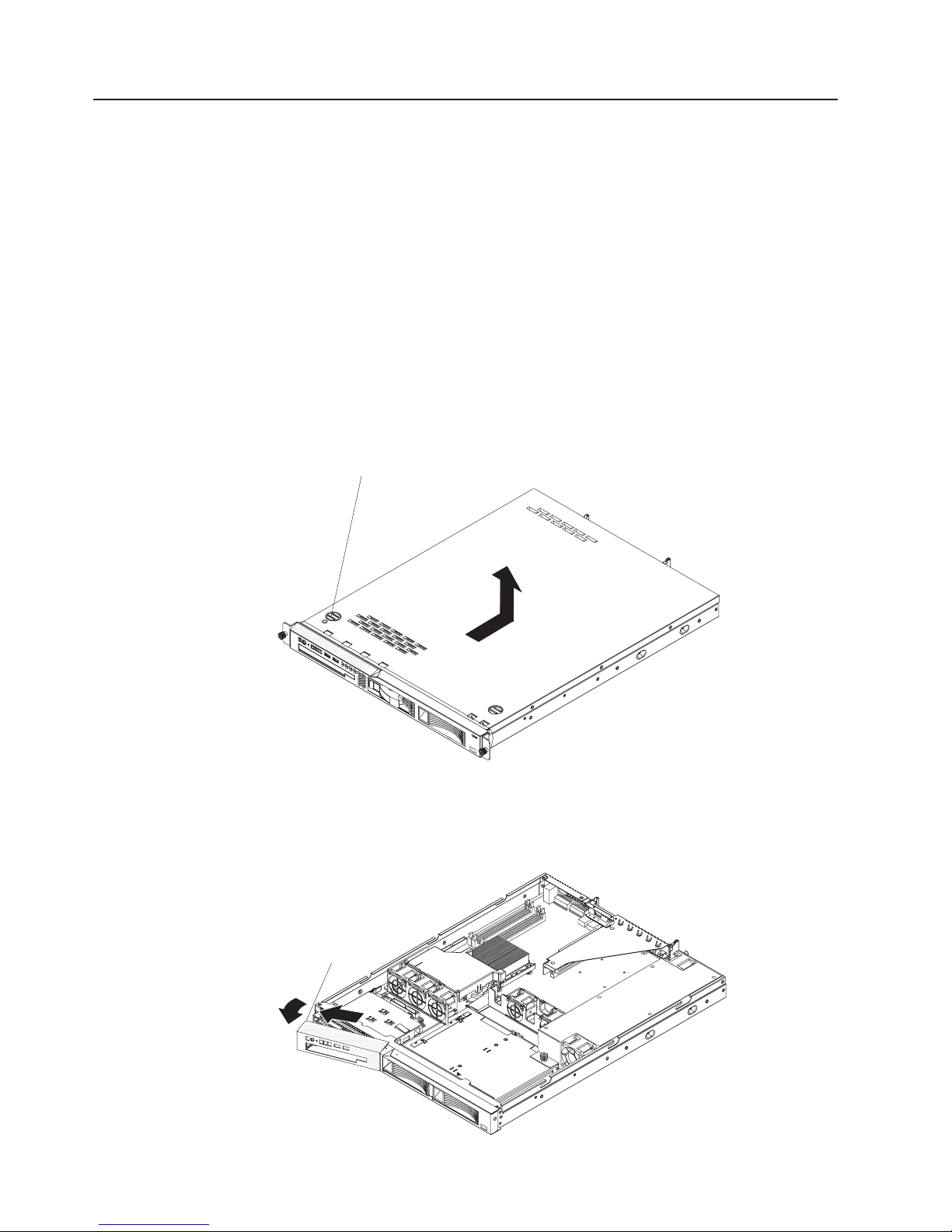
Removing the cover
Attention: Operating the server for more than 2 minutes with the cover removed
might damage server components. For proper cooling and airflow, replace the cover
before you turn on the server.
To remove the cover, complete the following steps:
1. Read the safety information that begins on page vii and “Installation guidelines”
on page 25.
2. Turn off the server and all peripheral devices, and disconnect the power cords
and all external cables.
3. Slide the server out of the rack and place it on a flat, static-protective surface.
Cover-release
button
4. Press the cover-release button.
5. Slide the cover back approximately 1.27 cm (0.5 inches); then, lift it off the
server.
6. If you are instructed to remove the bezel, complete the following steps.
28 IBM System x3250 Types 4364, 4365, and 4366: Problem Determination and Service Guide
Release
latch
Page 47
a. From inside the server, press the bezel release latch toward the left side of
b. Pivot the bezel forward and pull it away from the server.
7. If you are instructed to return the cover and bezel, follow all packaging
instructions, and use any packaging materials for shipping that are supplied to
you.
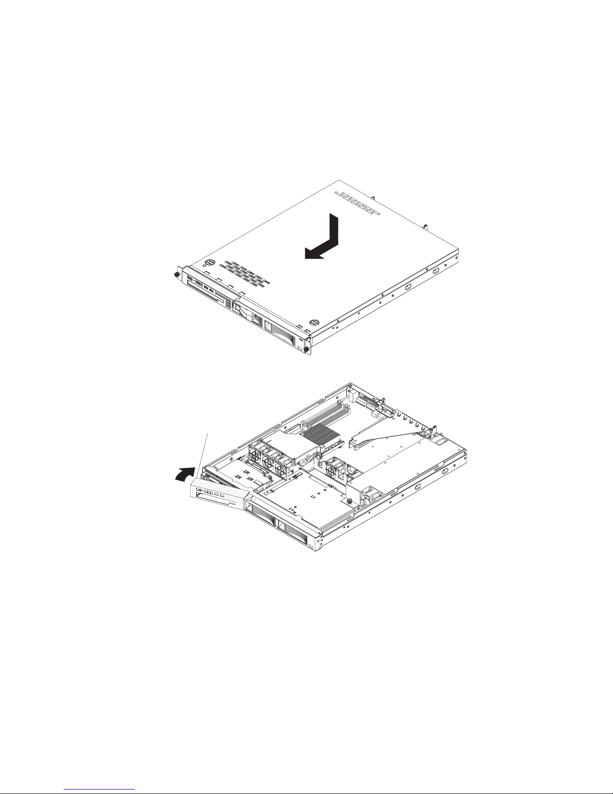
Installing the cover
the server.
To install the cover and bezel, complete the following steps.
Release
latch
1. To install the left bezel, if you removed it, insert the tab at the right end of the
bezel into the front of the chassis and pivot the bezel until it snaps into place.
2. Make sure that all internal cables are correctly routed.
3. Set the cover on top of the server so that approximately 13 mm (0.5 inch)
extends from the rear.
4. Slide the cover forward and into position.
5. Slide the server into the rack.
Chapter 4. Removing and replacing server components 29
Page 48

Removing an adapter
To remove a PCI Express adapter, complete the following steps.
Expansion-slot
bracket
Adapter
Adapter support
bracket
Expansion slot 1
Riser-card
assembly
Expansion slot 2
1. Read the safety information that begins on page vii and “Installation guidelines”
on page 25.
2. Turn off the server and peripheral devices, and disconnect the power cords and
all external cables.
3. Remove the server from the rack; then, remove the cover (see “Removing the
cover” on page 28).
4. Disconnect any cables from the adapter.
5. Grasp the riser-card assembly at the rear edge and lift to remove it from the
server.
Riser-card
assembly
30 IBM System x3250 Types 4364, 4365, and 4366: Problem Determination and Service Guide
Page 49

6. Place the riser-card assembly on a flat, static-protective surface.
7. Carefully grasp the adapter by its top edge or upper corners, and pull the
adapter from the riser-card assembly.
8. If you are instructed to return the adapter, follow all packaging instructions, and
use any packaging materials for shipping that are supplied to you.
Installing an adapter
Note: Because of mechanical interference, when the Remote Supervisor Adapter II
SlimLine is installed you cannot install an adapter in expansion slot 1.
Expansion-slot
bracket
Adapter
Adapter support
bracket
Expansion slot 1
Riser-card
assembly
Expansion slot 2
To install a replacement adapter, complete the following steps:
1. See the documentation that comes with the adapter for instructions for setting
jumpers or switches and for cabling.
2. Touch the static-protective package that contains the adapter to any unpainted
metal surface on the server. Then, remove the adapter from the
static-protective package. Avoid touching the components and gold-edge
connectors on the adapter.
3. Place the adapter, component side up, on a flat, static-protective surface and
set any jumpers or switches as described by the adapter manufacturer, if
necessary.
4. To install the adapter in the riser-card assembly, carefully grasp the adapter by
its top edge or upper corners, and align it with the expansion slot; then, press
the adapter firmly into the expansion slot.
5. Follow the cabling instructions, if any, that come with the adapter.
6. Carefully align the riser-card assembly with the guides on the rear of the
server and with the riser-card connectors on the system board; then, press
down on the assembly. Make sure that the riser-card assembly is fully seated
in the riser-card connector on the system board.
Chapter 4. Removing and replacing server components 31
Page 50

7. If you are installing a ServeRAID 8s controller in a server with 2.5-inch drives,
make sure that the ServeRAID 8s signal cable is routed as shown in the
following illustration and connected to the hard disk drive backplane.
If you are installing a ServeRAID 8s controller in a server with 3.5-inch drives,
make sure the ServeRAID 8s signal cable is routed as shown in the following
illustration and connected to the hard disk drive backplane.
8. Install the cover (see “Installing the cover” on page 29).
9. Slide the server into the rack.
10. Connect the cables and power cords.
32 IBM System x3250 Types 4364, 4365, and 4366: Problem Determination and Service Guide
Page 51

11. Turn on all attached devices and the server.
Removing a Remote Supervisor Adapter II SlimLine
To remove a Remote Supervisor Adapter II SlimLine from the server, complete the
following steps:
1. Read the safety information that begins on page vii and “Installation guidelines”
on page 25.
2. Turn off the server and peripheral devices and disconnect all power cords and
external cables; then, remove the cover.
3. Grasp the riser-card assembly at the rear edge and lift to remove it from the
server. Set the riser-card assembly aside on a flat, static-protective surface.
Remote Supervisor Adapter II SlimLine
Mounting bracket
retention latch
Mounting bracket
Mounting bracket
Rear of system
4. Spread the mounting bracket retention latches as you lift the Remote Supervisor
Adapter II SlimLine, to disconnect it from the system board; then, lift it out of the
server.
Installing a Remote Supervisor Adapter II SlimLine
See the illustration in “System-board optional device connectors” on page 10 for the
location of the dedicated connector for the Remote Supervisor Adapter II SlimLine.
After the Remote Supervisor Adapter II SlimLine is installed, the
systems-management port on the rear of the server is active.
Notes:
1. When you start the server for the first time after you install a Remote Supervisor
Adapter II SlimLine, the startup process will take several minutes longer than a
typical startup.
2. Earlier versions of the Remote Supervisor Adapter II SlimLine might not work in
this server. See http://www.ibm.com/servers/eserver/serverproven/compat/us/ for
the supported Remote Supervisor Adapter II SlimLine.
Chapter 4. Removing and replacing server components 33
Page 52

To install a Remote Supervisor Adapter II SlimLine, complete the following steps.
Remote Supervisor Adapter II SlimLine
Mounting bracket
Mounting bracket
retention latch
Mounting bracket
Remote Supervisor
Adapter II Slimline connector
Rear of system
1. Put the protective plastic cover on the Remote Supervisor Adapter II SlimLine.
2. Turn the Remote Supervisor Adapter II SlimLine so that the keys on the
connector align correctly with the connector on the system board.
3. At a downward angle, insert the free end of the adapter under the tab on the
mounting bracket, aligning the holes in the adapter with the posts on the
mounting bracket. Rotate the rear of the adapter into the rear mounting
bracket, aligning the holes in the adapter with the posts on the rear mounting
bracket.
4. Press the Remote Supervisor Adapter II SlimLine firmly into the connector and
make sure that all tabs on both mounting brackets secure the adapter in place.
Attention: Incomplete insertion might cause damage to the server or the
adapter.
5. Carefully align the riser-card assembly with the guides on the rear of the
server and with the riser-card connectors on the system board; then, press
down on the assembly. Make sure that the riser-card assembly is fully seated
in the riser-card connectors on the system board.
6. Install the cover (see “Installing the cover” on page 29).
7. Slide the server into the rack.
8. Connect the cables and power cords.
9. Turn on all attached devices and the server.
10. See the documentation that comes with the Remote Supervisor Adapter II
SlimLine for information about installing the firmware and configuring the
adapter. If you have a backup copy of the configuration, restore the
configuration.
Hard disk drive
Locate the documentation that comes with the hard disk drive and follow those
instructions in addition to the instructions in this section.
Attention: To avoid damage to the hard disk drive connectors, make sure that the
server cover is in place and fully closed whenever you install or remove a hard disk
drive.
34 IBM System x3250 Types 4364, 4365, and 4366: Problem Determination and Service Guide
Page 53
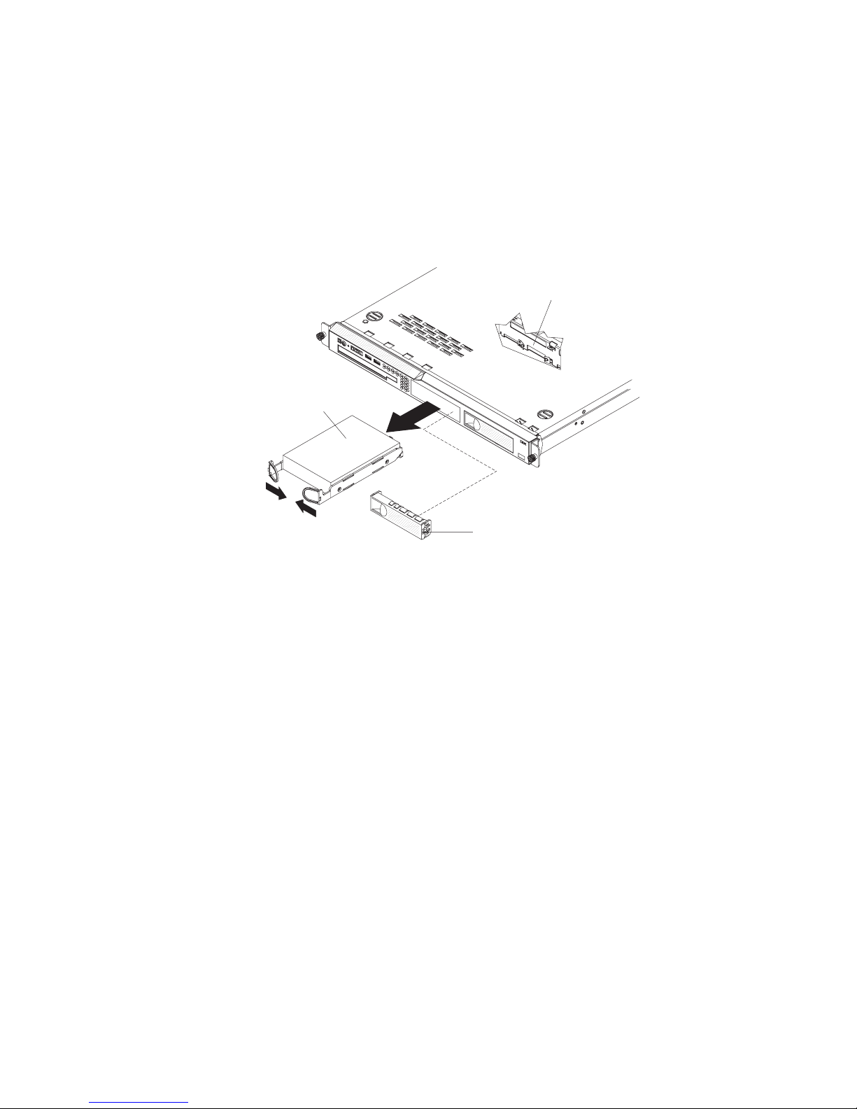
Note: If a RAID controller or adapter is installed, you might have to reconfigure the
disk arrays after you install or remove hard disk drives. See the documentation that
comes with the adapter for more information.
Removing a simple-swap Serial ATA hard disk drive
Attention: Simple-swap hard disk drives are not hot-swappable. Disconnect all
power from the server before you remove or install a simple-swap hard disk drive.
To remove a simple-swap SATA drive from the bay, complete the following steps.
SATA hard disk
drive back plate
Hard disk
drive assembly
Filler panel
1. Read the safety information that begins on page vii and “Installation guidelines”
on page 25.
2. Make sure that the server cover is in place and fully closed.
3. Turn off the server and peripheral devices, and disconnect the power cord and
all external cables.
4. Remove the filler panel from the bay.
5. Pull the loops of the drive tray toward each other and pull the tray out of the
bay.
Installing a simple-swap Serial ATA hard disk drive
Attention: Simple-swap hard disk drives are not hot-swappable. Disconnect all
power from the server before you remove or install a simple-swap hard disk drive.
To install a simple-swap Serial ATA hard disk drive, complete the following steps.
Chapter 4. Removing and replacing server components 35
Page 54

Note: If you have only one hard disk drive, install it in the left drive bay.
SATA hard disk
drive back plate
Hard disk
drive assembly
Filler panel
Attention: To avoid damage to the hard disk drive connectors, make sure that the
server cover is in place and fully closed whenever you install or remove a hard disk
drive.
1. Read the safety information that begins on page vii and “Installation guidelines”
on page 25.
2. Make sure that the server cover is in place and fully closed.
3. Turn off the server and peripheral devices, and disconnect the power cord and
all external cables.
4. Remove the filler panel from the bay.
5. Pull the loops of the drive tray toward each other, and slide the drive into the
server until the drive connects to the back plate.
6. Release the loops of the drive tray.
7. Insert the filler panel into the bay to cover the drive.
8. Slide the server into the rack.
9. Connect the cables and power cords.
10. Turn on all attached devices and the server.
Removing a hot-swap hard disk drive
The 3.5-inch drive hot-swap server models support either two SAS 3.5-inch hard
disk drives or two SATA 3.5-inch hard disk drives. The 2.5-inch drive hot-swap
server models support four 2.5-inch SAS hard disk drives.
The removal and installation procedures are the same for any of these drives. The
illustrations in this procedure show 3.5-inch SAS drives.
36 IBM System x3250 Types 4364, 4365, and 4366: Problem Determination and Service Guide
2.5-inch drives
Page 55

To remove a hot-swap hard disk drive, complete the following steps.
Drive-tray assembly
Drive handle
(in open position)
Attention: To avoid damage to the hard disk drive connectors, make sure that the
server cover is in place and fully closed whenever you install or remove a hard disk
drive.
1. Move the handle on the drive to the open position (perpendicular to the drive).
2. Pull the hot-swap drive assembly from the bay
Installing a hot-swap hard disk drive
To install a hot-swap hard disk drive, complete the following steps.
Note: If you have only one hard disk drive, install it in the left or upper-left drive
bay.
Chapter 4. Removing and replacing server components 37
Page 56

Attention: To avoid damage to the hard disk drive connectors, make sure that the
server cover is in place and fully closed whenever you install or remove a hard disk
drive.
1. Read the safety information that begins on page vii and “Installation guidelines”
on page 25.
2. Make sure that the server cover is in place and fully closed.
Attention: To maintain proper system cooling, do not operate the server for
more than 10 minutes without either a drive or filler panel installed in each bay.
3. Install the hard disk drive in the hot-swap bay:
a. Make sure that the tray handle is open (that is, perpendicular to the front of
the drive).
b. Align the drive assembly with the guide rails in the bay.
c. Gently push the drive assembly into the bay until the drive stops.
d. Push the tray handle to the closed (locked) position.
e. Check the hard disk drive status LED to make sure that the hard disk drive
is operating correctly. If the amber hard disk drive status LED for a drive is
lit continuously, that drive is faulty and must be replaced. If the green hard
disk drive activity LED is flashing, the drive is being accessed.
Removing a CD or CD/DVD combination drive
To remove the CD or CD/DVD combination drive, complete the following steps.
1. Read the safety information that begins on page vii and “Installation guidelines”
on page 25.
2. Turn off the server and peripheral devices, and disconnect the power cords and
all external cables. Remove the cover (see “Removing the cover” on page 28).
3. Press the release tab (the rear of the drive-retention clip) toward the drive to
release the clip; then, while you press the tab, pull the drive out of the bay.
Note: You might have to push the right-rear corner of the drive toward the front
of the server to move the drive initially.
38 IBM System x3250 Types 4364, 4365, and 4366: Problem Determination and Service Guide
Page 57

4. Remove the retention clip from the drive and save for future use.
5. If you are instructed to return the CD or CD/DVD drive, follow all packaging
instructions, and use any packaging materials for shipping that are supplied to
you.
Installing a CD or CD/DVD combination drive
To install the replacement CD or CD/DVD combination drive, complete the following
steps:
1. Read the safety information that begins on page vii and “Installation guidelines”
on page 25.
2. Turn off the server and peripheral devices, and disconnect the power cords and
all external cables. Remove the cover (see “Removing the cover” on page 28).
3. Follow the instructions that come with the drive to set any jumpers or switches.
4. Attach the drive-retention clip that you removed in “Removing a CD or CD/DVD
combination drive” on page 38 to the side of the drive.
5. Slide the drive into the CD/DVD drive bay until the drive clicks into place.
6. Replace the cover (see “Installing the cover” on page 29).
7. Slide the server into the rack.
8. Connect the cables and power cords.
9. Turn on all attached devices and the server.
Chapter 4. Removing and replacing server components 39
Page 58
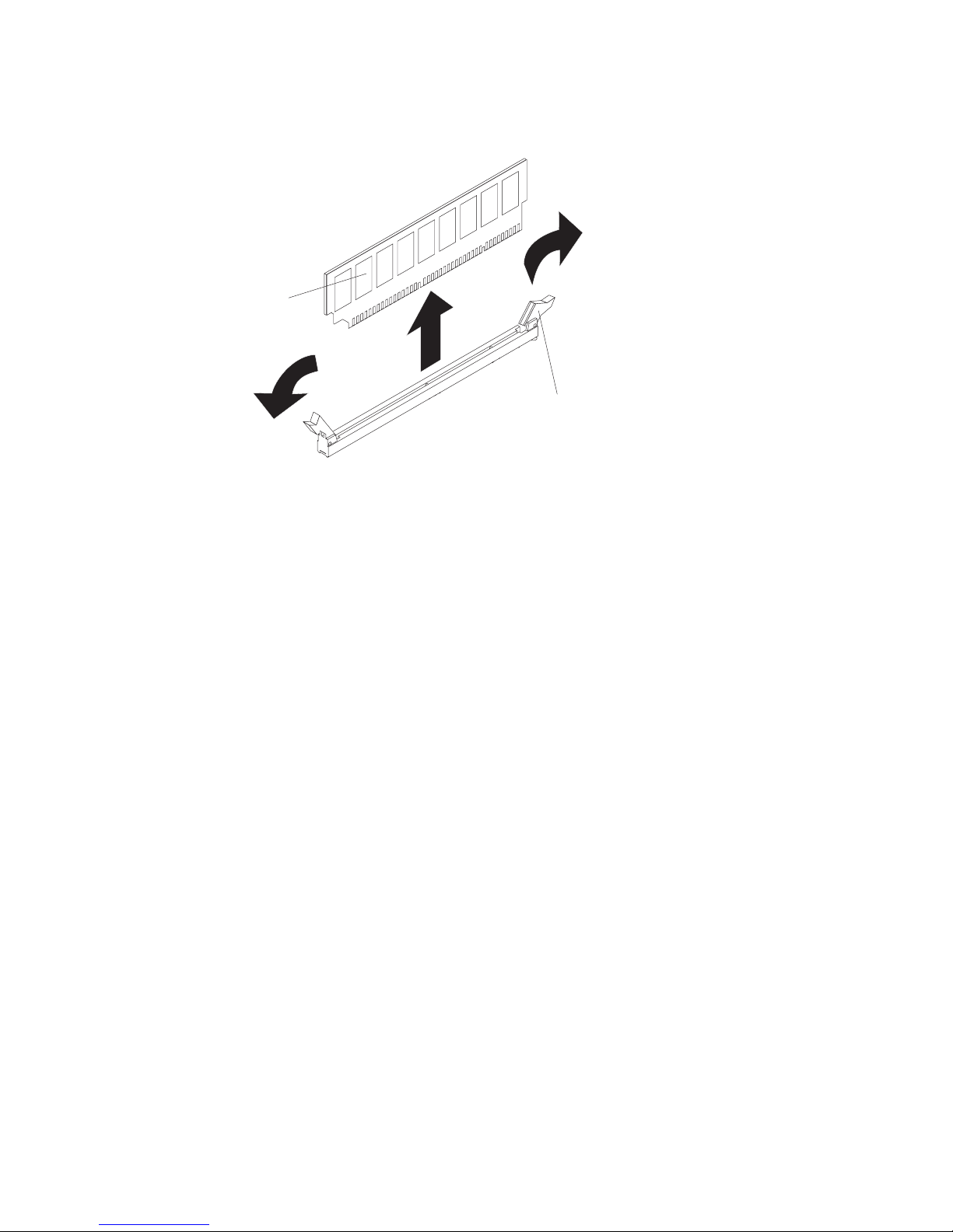
Removing a memory module (DIMM)
To remove a DIMM, complete the following steps.
DIMM
1. Read the safety information that begins on page vii and “Installation guidelines”
on page 25.
2. Turn off the server and peripheral devices, and disconnect the power cord and
all external cables.
3. Remove the cover (see “Removing the cover” on page 28).
Attention: To ensure proper cooling and airflow, do not operate the server for
more than 2 minutes with the cover removed.
4. Open the retaining clip on each end of the DIMM connector and remove the
DIMM from the connector.
5. If you are instructed to return the DIMM, follow all packaging instructions, and
use any packaging materials for shipping that are supplied to you.
Retaining
clip
Installing a memory module (DIMM)
The following notes describe information that you must consider when you install
DIMMs:
v The server comes with one 512 MB DIMM installed in DIMM connector 1. Some
models come with a second 512 MB DIMM installed in DIMM connector 3. If only
one DIMM is installed, when you install an additional DIMM, you must install it in
DIMM connector 3, and it must be the same size, speed, type, and technology as
the DIMM that is installed in DIMM connector 1. You can mix compatible DIMMs
from various manufacturers. The third and fourth DIMMs must be installed as a
pair, in DIMM connectors 2 and 4.
v If you install a pair of DIMMs in DIMM connectors 2 and 4, they do not have to
be the same size, speed, type, and technology as the DIMMs that are installed in
DIMM connectors 1 and 3. However, the size, speed, type, and technology of the
DIMMs that you install in DIMM connectors 2 and 4 must match each other.
v If you install a pair of 2 GB DIMMs and a pair of other-size DIMMs, the 2 GB
DIMMs must be installed as the first pair (in DIMM connectors 1 and 3).
To install the replacement DIMM, complete the following steps.
Attention: To avoid breaking the retaining clips or damaging the DIMM
connectors, open and close the clips gently.
40 IBM System x3250 Types 4364, 4365, and 4366: Problem Determination and Service Guide
Page 59
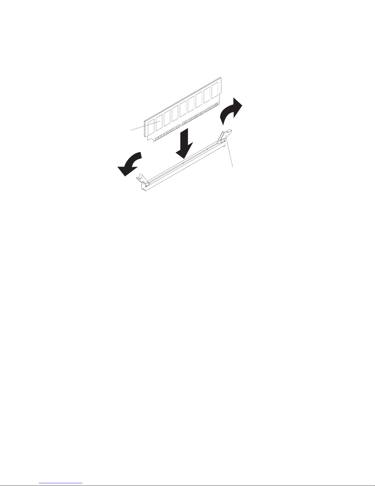
1. Open the retaining clip on each end of the DIMM connector.
2. Touch the static-protective package that contains the DIMM to any unpainted
metal surface on the server. Then, remove the DIMM from the package.
3. Turn the DIMM so that the DIMM keys align correctly with the slot.
DIMM
Retaining
clip
4. Insert the DIMM into the connector by aligning the edges of the DIMM with the
slots at the ends of the DIMM connector. Firmly press the DIMM straight down
into the connector by applying pressure on both ends of the DIMM
simultaneously. The retaining clips snap into the locked position when the DIMM
is seated in the connector. If there is a gap between the DIMM and the retaining
clips, the DIMM has not been correctly inserted; open the retaining clips,
remove the DIMM, and then reinsert it.
5. Install the cover (see “Installing the cover” on page 29).
6. Slide the server into the rack.
7. If you disconnected any cables or power cords to replace the DIMM, connect
the cables and power cords.
8. Turn on all attached devices and the server.
Removing a fan
The server comes with five replaceable fans.
To remove any of the five replaceable fans, complete the following steps:
1. Read the safety information that begins on page vii and “Installation guidelines”
on page 25.
2. Turn off the server and all peripheral devices, and disconnect the power cords
and all external cables.
3. Remove the server from the rack and remove the cover (see “Removing the
cover” on page 28).
4. Reconnect the power cord; then, turn on the server.
Attention: For proper cooling and airflow, replace the cover before you turn
on the server. Operating the server for extended periods of time (more than 30
minutes) with the cover removed might damage server components.
5. Determine which fan to replace by checking the LEDs on the system board (see
“System-board LEDs” on page 9); a lit LED indicates the fan to replace.
6. Turn off the server; then, disconnect the power cord again.
Chapter 4. Removing and replacing server components 41
Page 60
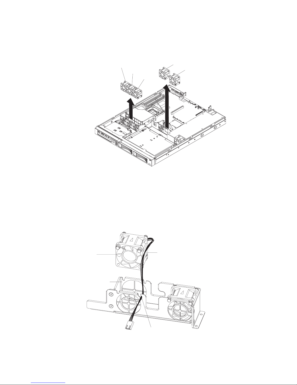
7. Remove the failed fan from the server:
a. Disconnect the fan cable from the system board.
b. Grasp the top of the fan with your index finger and thumb and lift the fan out
of the server.
Installing a fan
Fan 1
Fan 2
Fan 3
Fan 4
Fan 5
8. If you are instructed to return the fan, follow all packaging instructions, and use
any packaging materials for shipping that are supplied to you.
To install the replacement fan, complete the following steps:
1. Position the replacement fan so that the airflow arrow on the side of the fan
points toward the rear of the server.
Note: Correct airflow is from the front to the rear of the server.
Fan
Fan bracket
Fan bracket
cable channel
Fan bracket
cable slot
2. Install the replacement fan in the bracket:
a. Make sure that the fan cable sits in the channel on the side of the fan.
42 IBM System x3250 Types 4364, 4365, and 4366: Problem Determination and Service Guide
Page 61
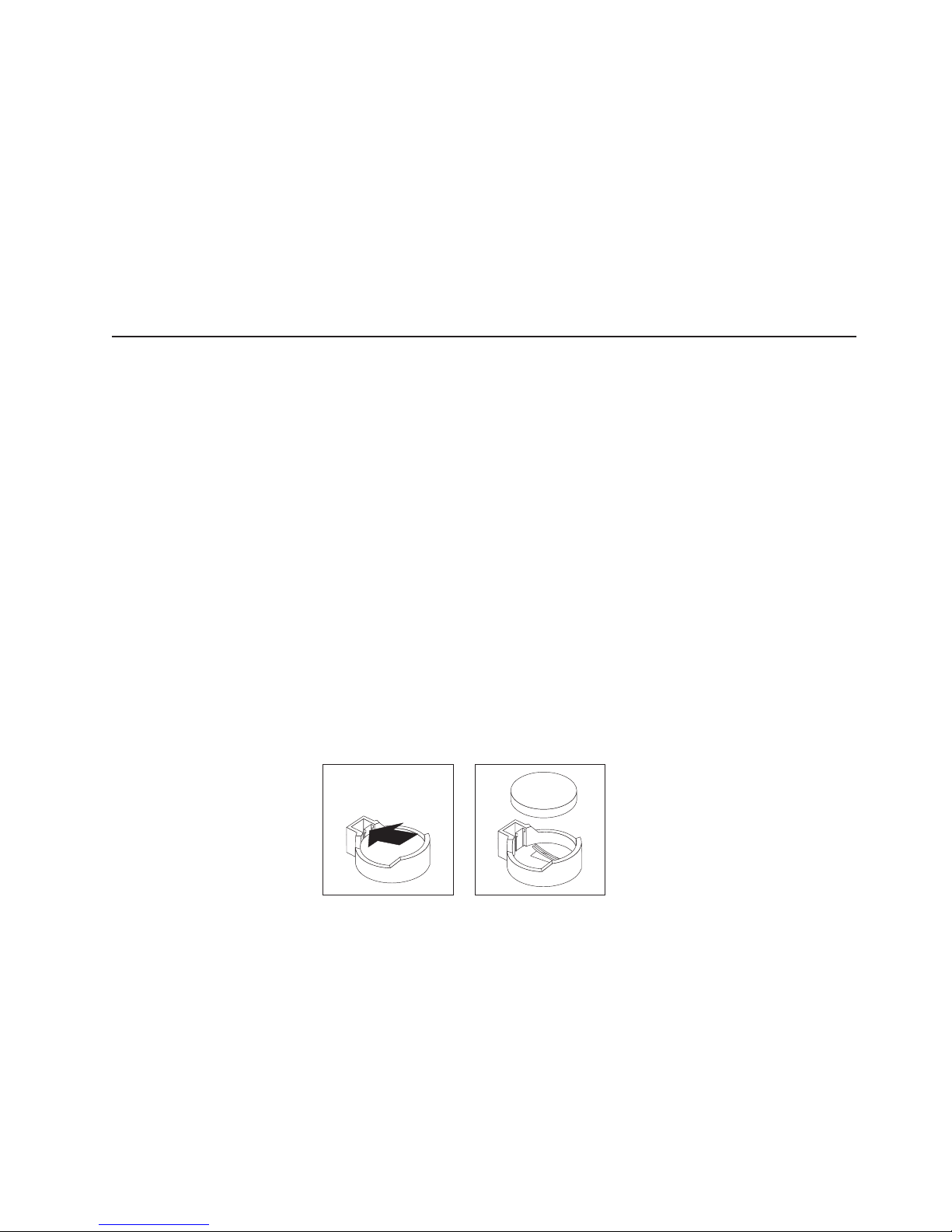
b. In the location from which you removed the failed fan, route the fan cable
into its slot in the fan bracket top.
c. Insert the fan into the bracket.
d. Make sure that each of the blue soft tabs on the fan is fully seated in its slot
in the fan bracket.
3. Connect the replacement fan cable to the system board.
4. Install the cover (see “Installing the cover” on page 29).
5. Slide the server into the rack.
6. Reconnect all external cables and the power cord.
7. Turn on all attached devices and the server.
Removing and replacing Tier 2 CRUs
You may install a Tier 2 CRU yourself or request IBM to install it, at no additional
charge, under the type of warranty service that is designated for your server.
The illustrations in this document might differ slightly from your hardware.
Removing the battery
To remove the battery, complete the following steps:
1. Read the safety information that begins on page vii and “Installation guidelines”
on page 25.
2. Turn off the server and peripheral devices, and disconnect the power cords and
all external cables necessary to replace the device.
3. Remove the cover (see “Removing the cover” on page 28).
4. If necessary, lift the riser-card assembly out of the way (see “Removing the
riser-card assembly” on page 49).
5. Remove the battery:
a. Use a fingernail to press the top of the battery clip away from the battery.
The battery pops up when released.
b. Use your thumb and index finger to lift the battery from the socket.
6. Dispose of the battery as required by local ordinances or regulations. See
“Battery return program” on page 122 for more information.
Installing the battery
The following notes describe information that you must consider when you replace
the battery in the server.
v When replacing the battery, you must replace it with a lithium battery of the same
type from the same manufacturer.
v To order replacement batteries, call 1-800-426-7378 within the United States, and
1-800-465-7999 or 1-800-465-6666 within Canada. Outside the U.S. and
Canada, call your IBM marketing representative or authorized reseller.
Chapter 4. Removing and replacing server components 43
Page 62
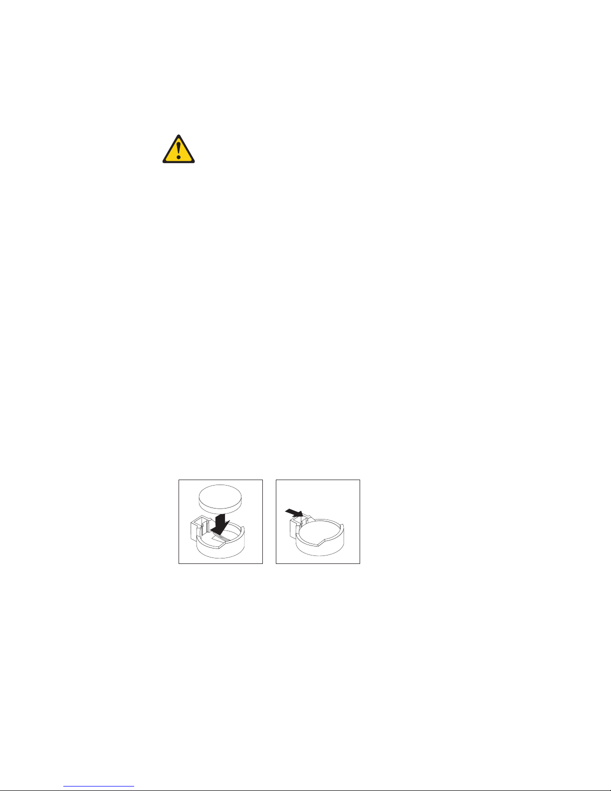
v After you replace the battery, you must reconfigure the server and reset the
system date and time.
v To avoid possible danger, read and follow the following safety statement.
Statement 2:
CAUTION:
When replacing the lithium battery, use only IBM Part Number 33F8354 or an
equivalent type battery recommended by the manufacturer. If your system has
a module containing a lithium battery, replace it only with the same module
type made by the same manufacturer. The battery contains lithium and can
explode if not properly used, handled, or disposed of.
Do not:
v Throw or immerse into water
v Heat to more than 100°C (212°F)
v Repair or disassemble
Dispose of the battery as required by local ordinances or regulations.
To install the replacement battery, complete the following steps:
1. Follow any special handling and installation instructions that come with the
replacement battery.
2. Insert the new battery:
a. Tilt the battery so that you can insert it into the socket on the side opposite
the battery clip.
b. Press the battery down into the socket until it clicks into place. Make sure
that the battery clip holds the battery securely.
3. Make sure that the riser-card assembly is fully seated in the connectors on the
system board.
4. Install the cover (see “Installing the cover” on page 29).
5. Slide the server into the rack.
6. Reconnect the external cables; then, reconnect the power cords and turn on the
peripheral devices and the server.
Note: You must wait approximately 20 seconds after you connect the power
cord of the server to an electrical outlet before the power-control button
becomes active.
7. Start the Configuration/Setup Utility program and reset the configuration.
v Set the system date and time.
44 IBM System x3250 Types 4364, 4365, and 4366: Problem Determination and Service Guide
Page 63
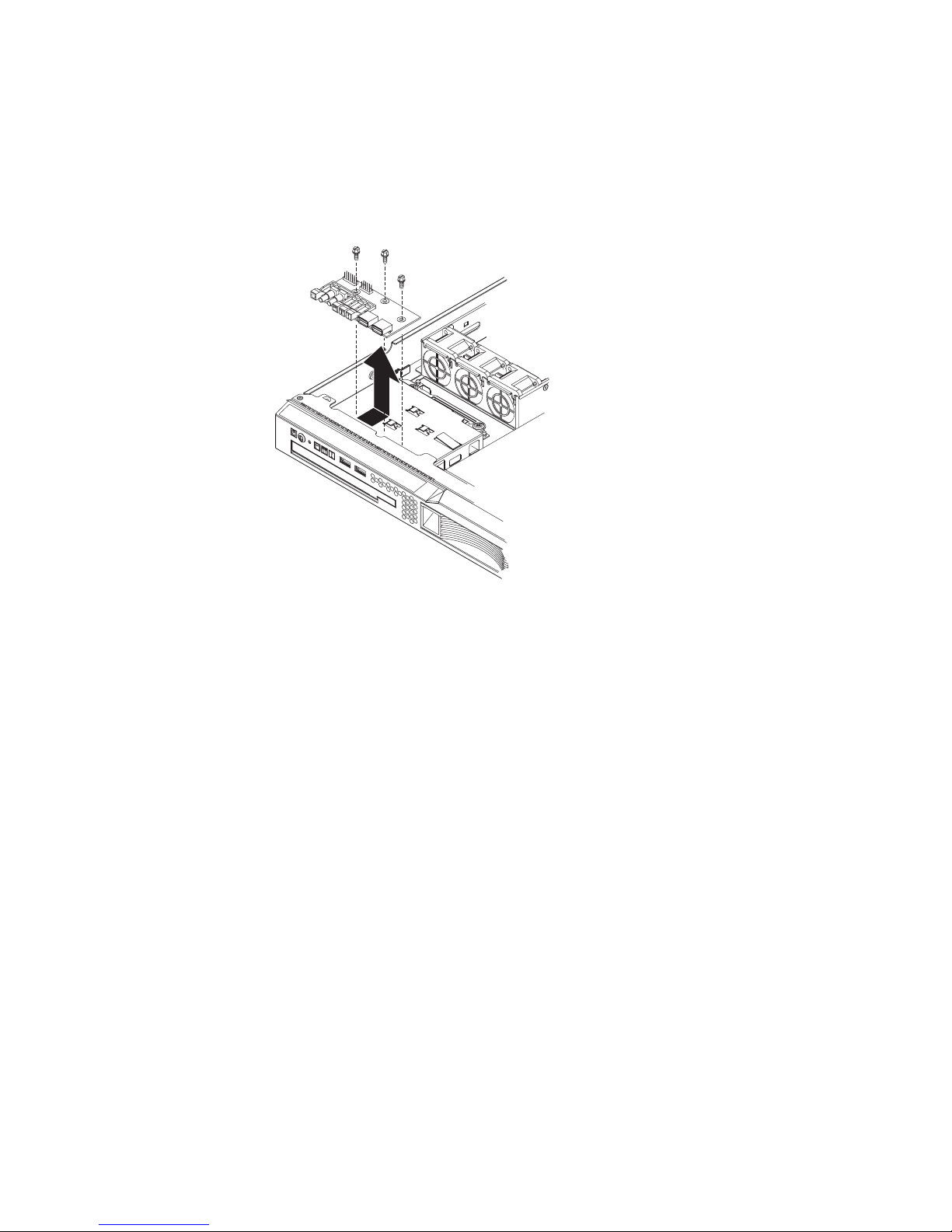
v Set the power-on password.
v Reconfigure the server.
See “Using the Configuration/Setup Utility program” on page 12 for details.
Removing the operator information panel assembly
To remove the operator information panel assembly, complete the following steps.
1. Read the safety information that begins on page vii and “Installation guidelines”
on page 25.
2. Turn off the server and peripheral devices, and disconnect the power cords and
all external cables necessary to replace the device.
3. Remove the server from the rack and remove the cover (see “Removing the
cover” on page 28).
4. Disconnect both cables from the operator information panel board.
5. Remove the screws that secure the operator information panel assembly to the
CD/DVD bay housing.
6. Lift the operator information panel assembly out of the server.
7. If you are instructed to return the operator information panel assembly, follow all
packaging instructions, and use any packaging materials for shipping that are
supplied to you.
Installing the operator information panel assembly
To install the replacement operator information panel assembly, complete the
following steps:
1. Guide the operator information panel assembly into position on top of the
CD/DVD bay housing. Make sure that the LEDs and the USB connectors are
aligned with the openings in the bezel and that the holes in the board align with
the screw holes in the top of the bay housing.
2. Use the screws that you removed in step 5 of “Removing the operator
information panel assembly” to secure the operator information panel assembly
onto the top of the CD/DVD bay housing.
3. Connect the light panel cable and front USB cable to the operator information
panel board.
Chapter 4. Removing and replacing server components 45
Page 64

4. Install the cover (see “Installing the cover” on page 29).
5. Slide the server into the rack.
6. Connect the cables and power cords.
7. Turn on all attached devices and the server.
Removing the power supply
When you remove or install the power supply, observe the following precautions.
Statement 8:
CAUTION:
Never remove the cover on a power supply or any part that has the following
label attached.
Hazardous voltage, current, and energy levels are present inside any
component that has this label attached. There are no serviceable parts inside
these components. If you suspect a problem with one of these parts, contact
a service technician.
To remove the power supply, complete the following steps.
Air deflector
Captive screw
Power supply
Rear screw
1. Read the safety information that begins on page vii and “Installation guidelines”
on page 25.
2. Disconnect the ac power cord from the connector on the power supply.
Disconnect all external cables from the server.
46 IBM System x3250 Types 4364, 4365, and 4366: Problem Determination and Service Guide
Page 65

3. Remove the server from the rack and remove the cover (see “Removing the
cover” on page 28).
Attention: To ensure proper cooling and airflow, do not operate the server
for more than 2 minutes with the cover removed.
4. Rotate (lift) the air deflector out of the way.
5. If the server is a 3.5-inch drive model, remove the hard disk drive back plate or
backplane (see “Removing the backplane or back plate (3.5-inch drives)” on
page 50).
6. Disconnect the power-supply cables from the connector on the system board
and from all devices; then, disengage the cables from any retention-clips that
secure them to the chassis.
Note: Note the routing of all power-supply cables; you will route the
power-supply cables the same way when you install the power supply.
7. Remove the rear screw, which holds the power supply to the rear of the
chassis.
8. Loosen the captive thumbscrew at the rear of the power supply that secures
the power supply to the chassis bottom.
9. Lift the power supply out of the bay.
10. If you are instructed to return the power supply, follow all packaging
instructions, and use any packaging materials for shipping that are supplied to
you.
Installing the power supply
To install the replacement power supply, complete the following steps:
1. Read the safety information in “Working inside the server with the power on”
on page 26.
2. Place the new power supply into the bay.
3. Tighten the captive thumbscrew at the rear of the power supply to secure the
power supply to the chassis bottom.
4. Replace the rear screw, which holds the power supply to the rear of the
chassis (see the illustration on page 46).
5. Make sure that the air deflector is in the open position.
6. Connect the internal power-supply cable from the power supply to the power
connector (CN20) on the system board (see “System-board internal
connectors” on page 6).
7. Route the other internal power-supply cable, securing it under the
retention-clips on the chassis; then, reconnect the cable to the CD/DVD
interface card.
Chapter 4. Removing and replacing server components 47
Page 66

Cable path
8. If the server is a 3.5-inch drive model, replace the hard disk drive back plate or
backplane and reconnect all cables (see “Installing the backplane or back plate
(3.5-inch drives)” on page 51).
9. Rotate the air deflector into place, making sure that no cables are pinched
beneath it, and press it down firmly.
10. Test the power supply:
a. Connect one end of the ac power cord for the new power supply into the
connector on the back of the power supply, and connect the other end of
the power cord into a properly grounded electrical outlet.
b. Make sure that the standby power LED on the system board is lit (see
“System-board LEDs” on page 9); if the standby power LED is not lit,
discontinue this procedure and obtain a new power supply.
c. Press the power-control button. Make sure that the power-on LED on the
front of the server is lit.
If the server starts, proceed to step 11. If the server does not start, disconnect
the ac power cord and call for service.
11. Turn off the server and disconnect the ac power cord.
12. Install the cover (see “Installing the cover” on page 29).
13. Slide the server into the rack.
14. Reconnect the ac power cord into the connector on the back of the power
supply.
15. Connect all external cables that you disconnected in step 2 on page 46.
16. Connect the other end of the ac power cord into a properly grounded electrical
outlet.
17. Press the power-control button.
18. Make sure that the power-on LED on the front of the server is lit.
48 IBM System x3250 Types 4364, 4365, and 4366: Problem Determination and Service Guide
Page 67

Removing the riser-card assembly
Riser-card
assembly
To remove the riser-card assembly, complete the following steps:
1. Read the safety information that begins on page vii and “Installation guidelines”
on page 25.
2. Turn off the server and peripheral devices, and disconnect the power cord and
all external cables.
3. Remove the server from the rack and place it on a flat, static-protective surface.
4. Remove the cover (see “Removing the cover” on page 28).
5. Disconnect any cables from the adapters in the riser-card assembly.
6. Grasp the riser-card assembly at the rear edge and lift to remove it from the
server. Place the riser-card assembly on a flat, static-protective surface.
7. If you are instructed to return the riser-card assembly, follow all packaging
instructions, and use any packaging materials for shipping that are supplied to
you.
Installing the riser-card assembly
The server comes with one riser-card assembly that contains two PCI Express
connectors.
Chapter 4. Removing and replacing server components 49
Page 68

Riser-card
assembly
To install the riser-card assembly, complete the following steps:
1. Install the adapters in the riser-card assembly.
Note: Because of mechanical interference, if you have installed a Remote
Supervisor Adapter II SlimLine in the server, you cannot install an adapter in
expansion slot 1 on the riser-card assembly.
2. Reconnect any adapter cables that you disconnected when you removed the
riser-card assembly.
3. Carefully align the riser-card assembly with the guides on the rear of the server
and with the riser-card connectors on the system board; then, press down on
the assembly. Make sure that the riser-card assembly is fully seated in the
riser-card connectors on the system board.
4. Install the cover (see “Installing the cover” on page 29).
5. Slide the server into the rack.
6. Connect the cables and power cords.
7. Turn on all attached devices and the server.
Removing the backplane or back plate (3.5-inch drives)
To remove the Serial Attached SCSI (SAS) backplane, which is also referred to as
the hot-swap SAS/SATA backplane, or to remove the simple-swap SATA back plate,
complete the following steps.
50 IBM System x3250 Types 4364, 4365, and 4366: Problem Determination and Service Guide
Page 69

Note: The following illustration shows removing the hot-swap SAS/SATA backplane.
Connectors
Air deflector
Guide channel
1. Read the safety information that begins on page vii and “Installation guidelines”
on page 25.
2. Turn off the server and peripheral devices, and disconnect the power cords and
all external cables necessary to replace the device.
3. Remove the server from the rack and place it on a flat, static-protective surface.
4. Pull the hard disk drives out of the server slightly to disengage them from the
backplane or back plate.
5. Remove the cover (see “Removing the cover” on page 28).
6. Disconnect the backplane or back plate cables:
v If the server is a hot-swap model, or you have installed an optional SATA
RAID kit, disconnect the SAS/SATA controller cable from the backplane or
back plate.
v If the server is a simple-swap model, disconnect the SATA cables from the
system board.
7. Rotate (lift) the air deflector out of the way.
8. Lift the backplane or back plate out of the server slightly; then, disconnect the
power cable and remove the backplane or back plate.
9. If you are instructed to return the backplane or back plate, follow all packaging
instructions, and use any packaging materials for shipping that are supplied to
you.
Installing the backplane or back plate (3.5-inch drives)
To install the replacement 3.5-inch hot-swap drives backplane or simple-swap SATA
drives back plate, complete the following steps.
Note: The following illustration shows installing the hot-swap SAS/SATA backplane.
Chapter 4. Removing and replacing server components 51
Page 70
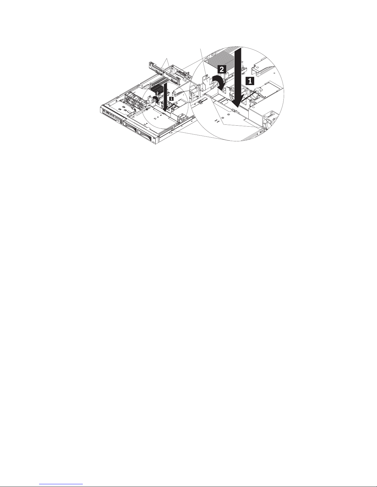
Air deflector
Connectors
Guide
channel
1. Make sure that the air deflector is in the open position.
2. Connect the power cable to the replacement backplane or back plate.
3. Slide the backplane or back plate into the card guides, making sure that any
nearby wires or cables are not trapped or pinched.
4. Press firmly until the backplane or back plate is fully seated.
5. Rotate the air deflector into place, making sure that no cables are pinched
beneath it, and press it down firmly.
6. Reconnect the backplane or back plate cables.
v If the server is a hot-swap model, reconnect the SAS/SATA controller cable
to the backplane.
v If the server is a simple-swap model, reconnect the SATA cables to the
system board. See “System-board internal connectors” on page 6 for the
location of the SATA connectors on the system board.
Note: Make sure that the cable drive number on the back plate matches
the connector number on the system board.
7. Install the cover (see “Installing the cover” on page 29).
8. Replace the hard disk drives.
9. Slide the server into the rack.
10. Connect the cables and power cords.
11. Turn on all attached devices and the server.
52 IBM System x3250 Types 4364, 4365, and 4366: Problem Determination and Service Guide
Page 71

Removing the SAS backplane (2.5-inch drives)
Connectors
Latch
Latch
Air deflector
To remove the 2.5-inch drives backplane, complete the following steps:
1. Read the safety information that begins on page vii and “Installation guidelines”
on page 25.
2. Turn off the server and peripheral devices, and disconnect the power cords and
all external cables that are necessary to replace the device.
3. Remove the server from the rack and place it on a flat, static-protective surface.
4. Pull the hard disk drives out of the server slightly to disengage them from the
backplane.
5. Remove the cover (see “Removing the cover” on page 28).
6. Disconnect the backplane cables:
v Disconnect the SAS/SATA controller cable from the backplane.
v Disconnect the power cable from the backplane.
7. Press the backplane latches toward each other; then, while you press the
latches, lift the backplane out of the server.
8. If you are instructed to return the backplane or back plate, follow all packaging
instructions, and use any packaging materials for shipping that are supplied to
you.
Installing the SAS backplane (2.5-inch drives)
To install the replacement 2.5-inch hot-swap drives backplane, complete the
following steps.
Chapter 4. Removing and replacing server components 53
Page 72

Connectors
Air deflector
1. Make sure that the 2.5-inch drive cage is fully installed in the server (see
“Installing a drive cage” on page 59).
2. Connect the power cable to the replacement backplane.
3. Slide the backplane into the card guides, making sure that any nearby wires or
cables are not trapped or pinched.
4. Press firmly until the backplane is fully seated and clicks into place.
5. Reconnect the backplane cables.
6. Install the cover (see “Installing the cover” on page 29).
7. Replace the hard disk drives.
8. Slide the server into the rack.
9. Connect the cables and power cords.
10. Turn on all attached devices and the server.
Removing the SAS/SATA controller (hot-swap models)
Support posts
54 IBM System x3250 Types 4364, 4365, and 4366: Problem Determination and Service Guide
SAS/SATA controller card
Page 73

To remove the SAS/SATA controller from the system board, complete the following
steps:
1. Read the safety information that begins on page vii and “Installation guidelines”
on page 25.
2. Turn off the server and peripheral devices, and disconnect the power cords and
all external cables.
3. Remove the server from the rack; then, remove the cover (see “Removing the
cover” on page 28).
4. Disconnect the cable from the SAS/SATA controller.
5. Grasp the edges of the SAS/SATA controller.
6. Pinch the top of each of the two plastic alignment pins while you gently lift the
controller, until the alignment pins release the controller.
7. Gently pull the controller toward the front of the server slightly; then, lift the
controller off the system board.
8. If you are instructed to return the SAS/SATA controller, follow all packaging
instructions, and use any packaging materials for shipping that are supplied to
you.
Installing the SAS/SATA controller (hot-swap models)
SAS/SATA
controller card
Notch
Ta b
To replace the SAS/SATA controller on the system board, complete the following
steps:
1. Grasp the edges of the SAS/SATA controller.
2. Gently insert the controller card into the SAS/SATA controller card connector
on the system board (see the illustration on page 6 for the location of the
connector) while you align the holes in the card with the two plastic alignment
pins on the system board.
3. Press the controller card firmly onto the alignment pins until the card clicks into
place. Make sure that the top of each alignment pin has expanded to hold the
controller card securely in place.
4. Push the controller card toward the rear of the server, fully into the connector,
until the side tabs on the connector rest in the side notches of the controller
card.
5. Connect the cable from the hard disk drive backplane to the SAS/SATA
controller.
6. Install the riser-card assembly (see “Installing the riser-card assembly” on page
49).
Chapter 4. Removing and replacing server components 55
Page 74
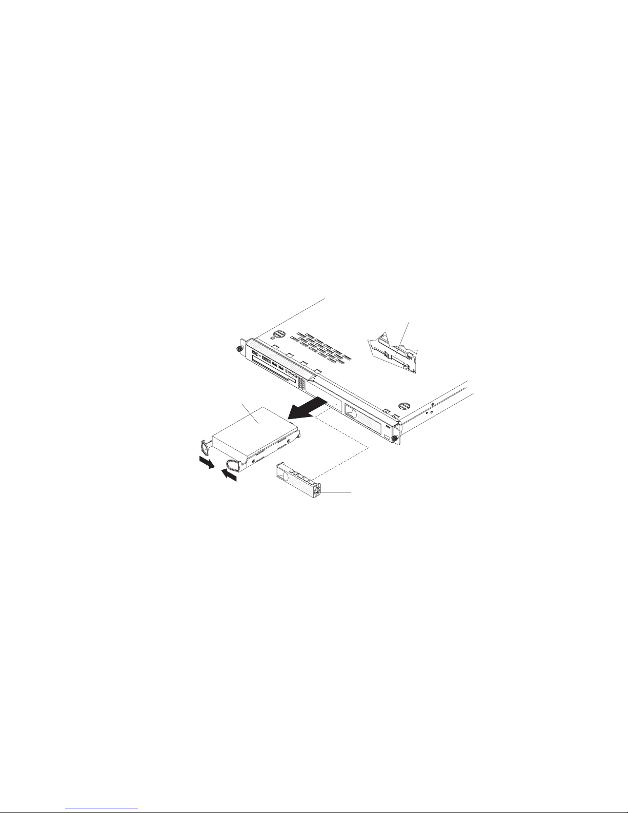
7. Install the cover (see “Installing the cover” on page 29).
8. Slide the server into the rack.
9. Connect the cables and power cords.
10. Turn on all attached devices and the server.
Removing a SATA RAID back plate
If a SATA RAID kit was installed in the server, the cables in the SATA back plate
attach to a SAS/SATA controller.
To remove the SATA RAID back plate, complete the following steps:
1. Read the safety information that begins on page vii and “Installation guidelines”
on page 25.
2. Turn off the server and peripheral devices, and disconnect the power cord and
all external cables.
3. Remove the server from the rack and place it on a flat, static-protective surface.
4. Remove the cover (see “Removing the cover” on page 28).
SATA hard disk
drive back plate
Hard disk
drive assembly
5. Pull the hard disk drives out of the server slightly to disengage them from the
backplane or remove the drives completely (see “Removing a simple-swap
Serial ATA hard disk drive” on page 35).
6. Disconnect the SAS signal cable from the SAS/SATA controller.
7. Remove the SATA RAID back plate from the server:
a. Rotate (lift) the air deflector out of the way.
b. Lift the back plate out of the server slightly; then, disconnect the power
cables and remove the back plate.
Installing a SATA RAID back plate
If a SATA RAID kit was installed in the server, the cables in the SATA back plate
attach to a SAS/SATA controller.
Filler panel
56 IBM System x3250 Types 4364, 4365, and 4366: Problem Determination and Service Guide
Page 75
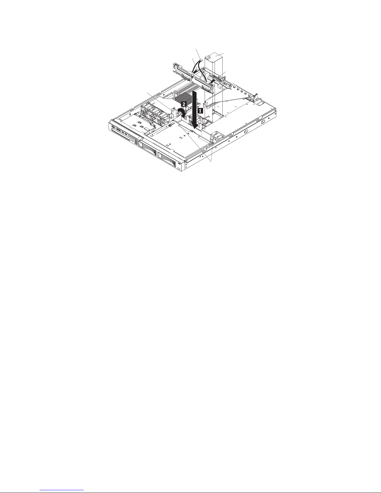
SAS signal cable
Power cable
Air deflector
SAS/SATA controller
Power cable
Guide channel
To install the SATA RAID back plate, complete the following steps:
1. Install the back plate:
a. Make sure that the air deflector is in the open position.
b. Connect the power supply cables to the power cables on the SATA RAID kit
back plate.
c. Slide the back plate into the card guides, making sure that any nearby wires
or cables are not trapped or pinched.
d. Press firmly until the back plate is fully seated.
e. Rotate the air deflector into place, making certain that no cables are pinched
beneath it, and press it down firmly.
f. Connect the back plate cable to the signal connector on the SAS/SATA
controller.
2. Connect the cable from the back plate to the signal connector on the SAS/SATA
controller.
3. Install the cover (see “Installing the cover” on page 29).
4. Insert the hard disk drives that you removed in “Removing a SATA RAID back
plate” on page 56 fully into the bays (see “Installing a simple-swap Serial ATA
hard disk drive” on page 35 ).
5. Slide the server into the rack.
6. Connect the cables and power cords.
7. Turn on all attached devices and the server.
Chapter 4. Removing and replacing server components 57
Page 76

Removing a drive cage
To remove a drive cage, complete the following steps.
1. Read the safety information that begins on page vii and “Installation guidelines”
on page 25.
2. Turn off the server and peripheral devices, and disconnect the power cord and
all external cables.
3. Remove the hard disk drives from the cage.
4. Remove the cover (see “Removing the cover” on page 28).
Attention: To ensure proper cooling and airflow, do not operate the server for
more than 2 minutes with the cover removed.
5. Remove the hard disk drive backplane or back plate:
v 2.5-inch drive models: Remove the hard disk drive backplane from the
cage. See “Removing the SAS backplane (2.5-inch drives)” on page 53 for
instructions.
v 3.5-inch drive models: You might find it easier to remove the cage if you
remove the hard disk drive backplane or back plate first. See “Removing the
backplane or back plate (3.5-inch drives)” on page 50 for instructions.
6. Remove the screws that hold the drive cage in place.
7. Slide the drive cage forward and remove it from the server.
8. If you are instructed to return the drive cage, follow all packaging instructions,
and use any packaging materials for shipping that are supplied to you.
58 IBM System x3250 Types 4364, 4365, and 4366: Problem Determination and Service Guide
Page 77
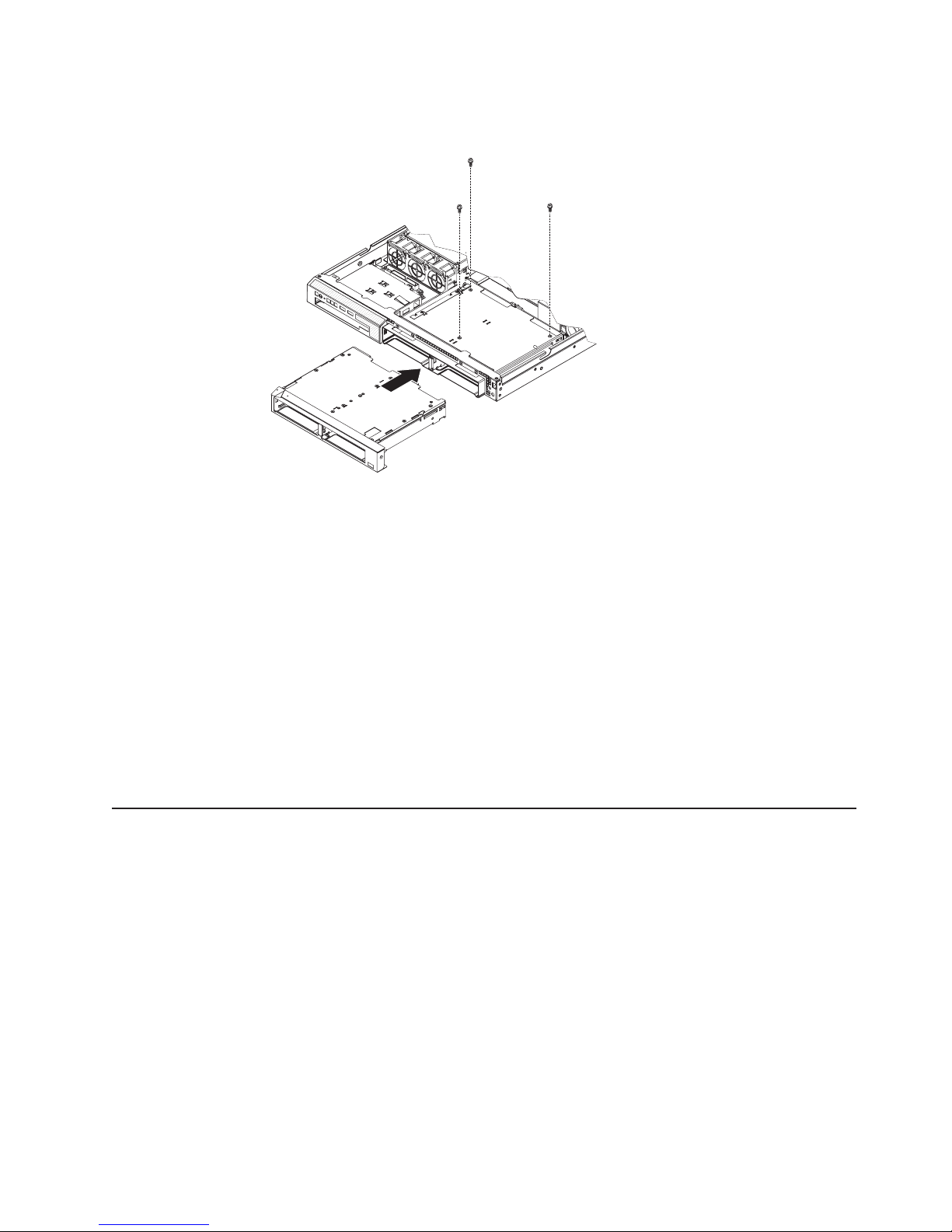
Installing a drive cage
To install a drive cage, complete the following steps.
1. If the server is a 2.5-inch drive model, make sure that the 2.5-inch backplane
is removed from the drive cage. (See “Removing the SAS backplane (2.5-inch
drives)” on page 53 for instructions.)
2. Line up the drive cage with the drive bays on the front of the server.
3. Push the drive cage into the server until it stops.
4. Align the holes in the top of the drive cage with the holes in the top of the
chassis; then, insert the screws that secure the drive cage to the chassis.
5. If the server is a 2.5-inch drive model, install the SAS backplane. (See
“Installing the SAS backplane (2.5-inch drives)” on page 53 for instructions.)
6. Install the cover (see “Installing the cover” on page 29).
7. Install the hard disk drives.
8. Install the server in the rack.
9. Connect the cables and power cords.
10. Turn on all attached devices and the server.
Removing and replacing FRUs
FRUs must be installed only by trained service technicians.
The illustrations in this document might differ slightly from the hardware.
Microprocessor
The following notes describe the type of microprocessor that the server supports
and other information that you must consider when you install a microprocessor:
v The server supports one Intel land grid array (LGA) 775-land dual-core
microprocessor. The type, speed, and L2 cache of the microprocessor depends
on the server model.
v Read the documentation that comes with the microprocessor to determine
whether you have to update the BIOS code. To download the most current level
of BIOS code, go to http://www.ibm.com/servers/eserver/support/xseries/
index.html.
v The microprocessor uses an integrated voltage regulator on the system board.
Chapter 4. Removing and replacing server components 59
Page 78
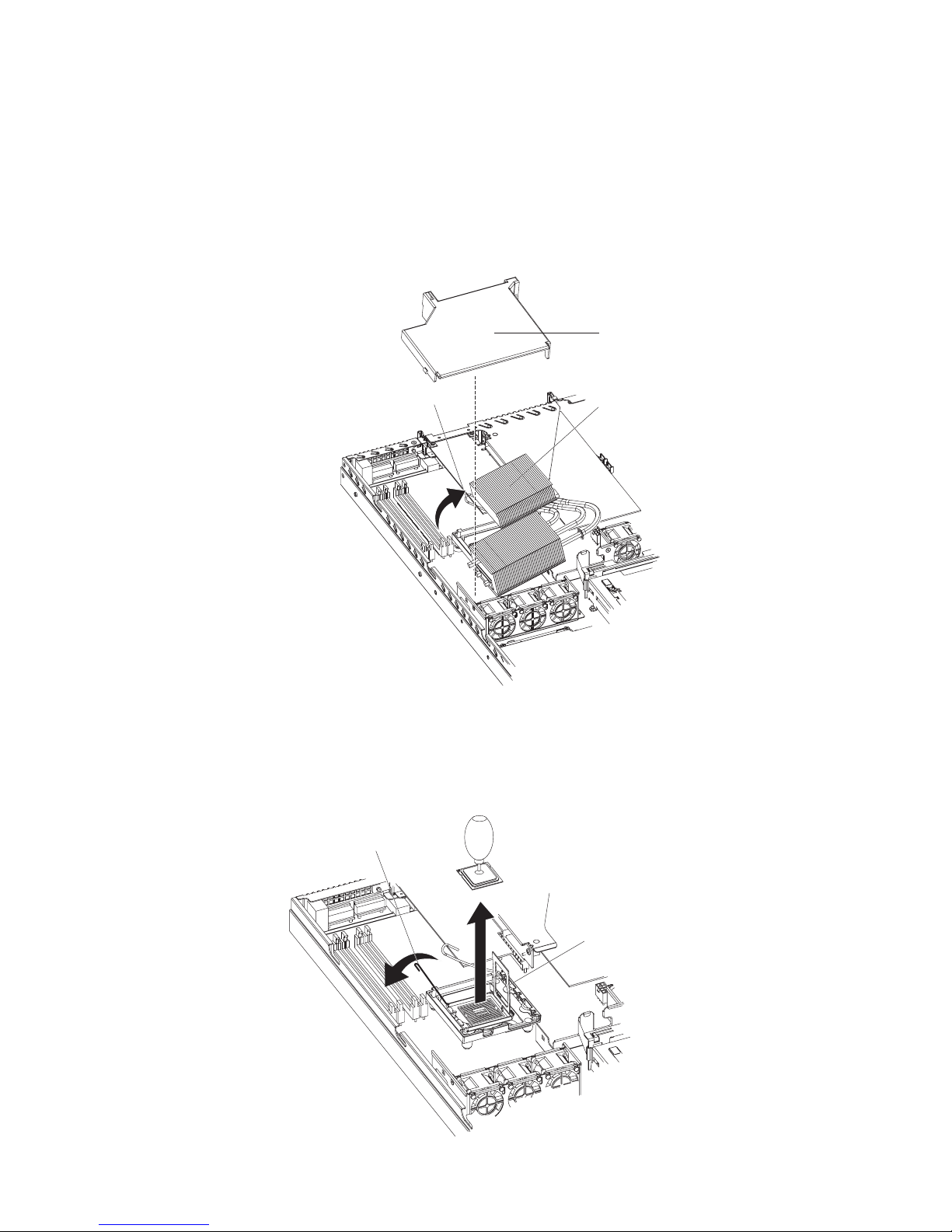
Removing the microprocessor
To remove the microprocessor, complete the following steps.
1. Read the safety information that begins on page vii and “Installation guidelines”
on page 25.
2. Turn off the server and peripheral devices, and disconnect the power cords
and all external cables necessary to replace the device.
3. Remove the server from the rack; then, remove the cover (see “Removing the
cover” on page 28).
Air baffle
Heat-exchanger-assembly
release latch
Heat-exchanger
assembly
4. Remove the air baffle.
5. Open the heat-exchanger-assembly release latch to the fully open position.
6. Lift the side of the heat-exchanger assembly that is closer to the middle of the
server, slide it toward the middle of the server slightly, and lift the entire
assembly out of the server.
Microprocessor
release latch
60 IBM System x3250 Types 4364, 4365, and 4366: Problem Determination and Service Guide
Microprocessor
bracket frame
Page 79
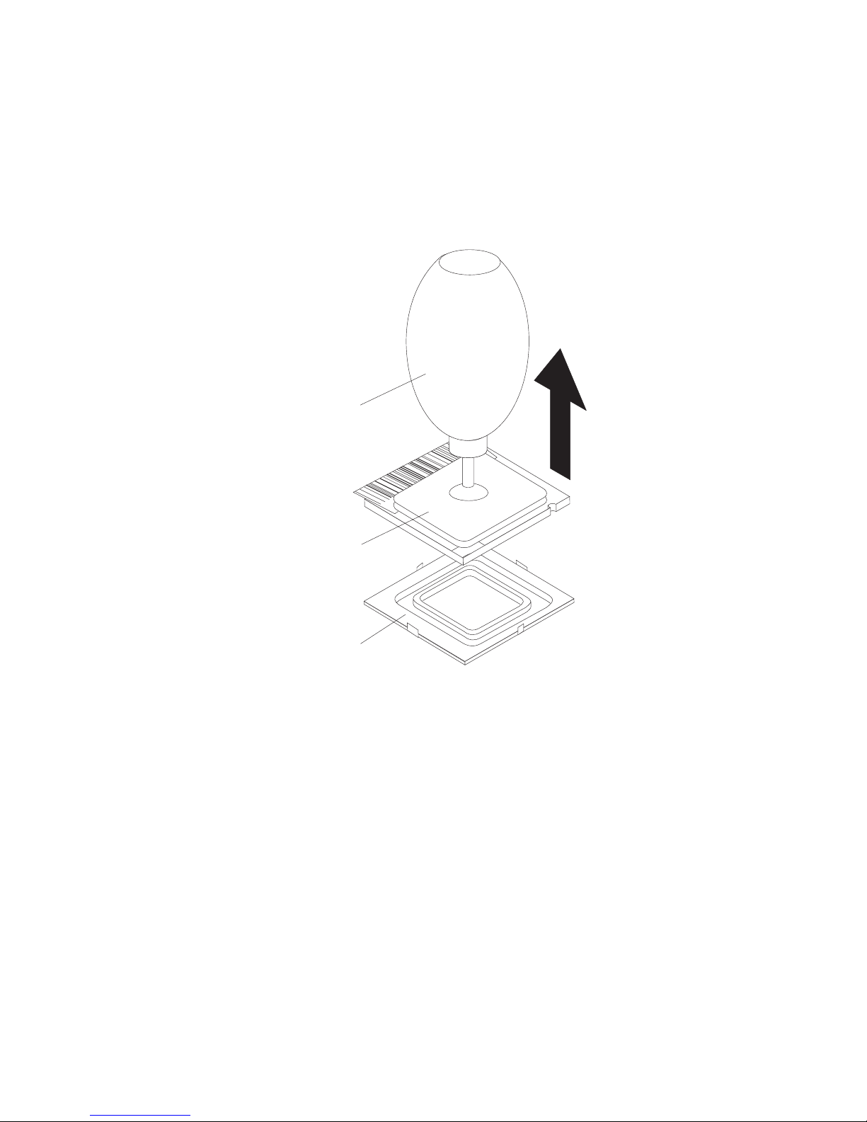
7. Open the microprocessor release latch to the fully open position.
8. Open the microprocessor bracket frame.
Attention: Use the vacuum tool that comes with the replacement part to
remove the microprocessor. Dropping the microprocessor during removal can
damage the contacts. Also, contaminants on the microprocessor contacts, such
as oil from your skin, can cause connection failures between the contacts and
the socket.
9. Remove the microprocessor.
Vacuum tool
Microprocessor
Socket
a. Squeeze and hold the bladder of the tool; then, place the suction cup on
the microprocessor and release the bladder.
b. Using the tool, carefully lift the microprocessor straight up and out of the
socket, and place it on a static-protective surface.
c. Squeeze the bladder of the tool to release the microprocessor from the
suction cup.
10. If you are instructed to return the microprocessor, follow all packaging
instructions, and use any packaging materials for shipping that are supplied to
you.
Installing the microprocessor
To install the replacement microprocessor, complete the following steps:
1. Make sure that the microprocessor bracket frame and release latch are both
fully open.
Chapter 4. Removing and replacing server components 61
Page 80

Attention: The microprocessor contacts are fragile; handle the
microprocessor very carefully. You can use the vacuum tool to install the
microprocessor.
2. Align the microprocessor with the socket (note the alignment mark and the
position of the notches); then, carefully place the microprocessor on the
socket, close the microprocessor bracket frame, and close the microprocessor
release latch.
Note: The microprocessor fits only one way on the socket.
3. If you are installing a new heat-exchanger assembly, peel off the protective
backing from the thermal material that is on the underside of the new heat
exchanger. If you are reinstalling a heat-exchanger assembly that was
previously removed, see “Thermal grease” on page 63 for instructions for
replacing the contaminated or missing thermal grease; then, continue with step
4 of this procedure.
4. Make sure that the heat-exchanger assembly release latch is fully opened.
Heat-exchanger assembly
Release latch
Alignment pins
62 IBM System x3250 Types 4364, 4365, and 4366: Problem Determination and Service Guide
Alignment hole
Page 81

5. With the heat-exchanger assembly at an angle as shown in the illustration,
carefully align the heat-exchanger assembly with the microprocessor and the
heat exchanger bracket on the system board. Make sure that the alignment
pins (the two heat-exchanger nibs that are closer to the microprocessor)
protrude through the alignment hole (the opening in the side of the heat
exchanger socket) and that the flange of the heat sink rests under the lip of
the heat-sink socket.
6. Gently press the assembly into place.
7. Close the heat-exchanger-assembly release latch, catching it under the hook
on the socket.
8. Replace the air baffle.
9. Install the cover (see “Installing the cover” on page 29).
10. Slide the server into the rack.
11. Connect the cables and power cords.
12. Turn on all attached devices and the server.
Thermal grease
The thermal grease must be replaced whenever the heat exchanger has been
removed from the top of the microprocessor and is going to be reused or when
debris is found in the grease.
To replace damaged or contaminated thermal grease on the microprocessor and
heat exchanger, complete the following steps:
1. Place the heat-exchanger assembly on a clean work surface.
2. Remove the cleaning pad from its package and unfold it completely.
3. Use the cleaning pad to wipe the thermal grease from the bottom of the heat
exchanger.
Note: Make sure that all of the thermal grease is removed.
4. Use a clean area of the cleaning pad to wipe the thermal grease from the
microprocessor; then, dispose of the cleaning pad after all of the thermal grease
is removed.
Microprocessor
0.01 mL of
thermal grease
5. Use the thermal-grease syringe to place 16 uniformly spaced dots of 0.01 mL
each on the top of the microprocessor.
Chapter 4. Removing and replacing server components 63
Page 82

Note: 0.01mL is one tick mark on the syringe. If the grease is properly applied,
approximately half (0.22 mL) of the grease will remain in the syringe.
6. Install the heat exchanger onto the microprocessor as described in “Installing
the microprocessor” on page 61.
Removing the system board
System board
(3 screws)
Heat-exchanger
retention module
(4 screws)
System board
(5 screws)
To remove the system board, complete the following steps:
1. Read the safety information that begins on page vii, and “Installation
guidelines” on page 25.
2. Turn off the server, and disconnect all power cords and external cables; then,
remove the server cover (see “Removing the cover” on page 28).
3. Remove the riser-card assembly with adapters, and place them on a
static-protective surface for reinstallation (see “Removing an adapter” on page
30).
4. Remove the SAS/SATA controller if one is installed (see “Removing the
SAS/SATA controller (hot-swap models)” on page 54) and place it on a
static-protective surface for reinstallation.
5. Remove all DIMMs, and place them on a static-protective surface for
reinstallation (see “Removing a memory module (DIMM)” on page 40).
6. Disconnect all cables from the system board.
64 IBM System x3250 Types 4364, 4365, and 4366: Problem Determination and Service Guide
Page 83

7. Remove the microprocessor heat-exchanger assembly and microprocessor;
then, place them on a static-protective surface for reinstallation (see
“Removing the microprocessor” on page 60).
8. Note the orientation of the microprocessor retention module.
9. Remove the four screws that hold the microprocessor retention module to the
system board; then, lift the retention module out of the server.
10. Remove the remaining eight screws that secure the system board to the
chassis, and put the screws in a safe place.
11. Lift the system board out of the server.
Installing the system board
Note: When you reassemble the components in the server, be sure to route all
cables carefully so that they are not exposed to excessive pressure.
To reinstall the system board, complete the following steps:
1. Align the system board with the chassis, and replace the eight screws that you
removed in step 10 of “Removing the system board” on page 64.
2. Orient the microprocessor retention module as shown in the illustration.
3. Replace the microprocessor retention module. Secure it with the four screws
that you removed in step 9 of “Removing the system board” on page 64.
4. Replace the microprocessor and microprocessor heat-exchanger assembly
(see “Installing the microprocessor” on page 61).
5. Reconnect to the system board the cables that you disconnected in step 6 of
“Removing the system board” on page 64.
6. Replace the SAS/SATA controller if you removed one (see “Installing the
SAS/SATA controller (hot-swap models)” on page 55).
7. Replace the DIMMs (see “Installing a memory module (DIMM)” on page 40).
8. Replace the riser-card assembly and adapters.
9. Replace the server cover (see “Installing the cover” on page 29).
10. Slide the server into the rack.
11. Connect all external cables and the power cord; then, turn on the server.
Chapter 4. Removing and replacing server components 65
Page 84

Important: Perform the following updates:
v Either update the server with the latest SAS/SATA or SATA firmware or restore
the pre-existing firmware from a diskette or CD image.
v Update the DMI/SMBIOS (see “Updating the DMI/SMBIOS data” on page 14).
66 IBM System x3250 Types 4364, 4365, and 4366: Problem Determination and Service Guide
Page 85

Chapter 5. Diagnostics
This chapter describes the diagnostic tools that are available to help you solve
problems that might occur in the server.
If you cannot diagnose and correct a problem by using the information in this
chapter, see Appendix A, “Getting help and technical assistance,” on page 117 for
more information.
Diagnostic tools
The following tools are available to help you diagnose and solve hardware-related
problems:
v POST beep codes, error messages, and error logs
The power-on self-test (POST) generates beep codes and messages to indicate
successful test completion or the detection of a problem. See “POST” for more
information.
v Troubleshooting tables
These tables list problem symptoms and actions to correct the problems. See
“Troubleshooting tables” on page 81.
v System-board LEDs
Use the system-board LEDs to diagnose system errors quickly. See
“System-board LEDs” on page 92 for more information.
v Diagnostic programs, messages, and error messages
The diagnostic programs are the primary method of testing the major
components of the server. The diagnostic programs are on the IBM Enhanced
Diagnostics CD. See “Diagnostic programs, messages, and error codes” on page
94 for more information.
POST
When you turn on the server, it performs a series of tests to check the operation of
the server components and some optional devices in the server. This series of tests
is called the power-on self-test, or POST.
If a power-on password is set, you must type the password and press Enter, when
you are prompted, for POST to run.
The power-on self-test beep codes indicate the detection of a problem.
v One beep indicates successful completion of POST, with no errors.
v More than one beep indicates that POST detected a problem. Error messages
also are displayed during startup if POST detects a hardware-configuration
problem. See “POST beep codes” and “POST error codes” on page 71 for more
information.
POST beep codes
A beep code is a combination of short or long beeps or series of short beeps that
are separated by pauses. For example, a “1-2-3” beep code is one short beep, a
pause, two short beeps, and pause, and three short beeps. A beep code indicates
that POST has detected a problem.
© Copyright IBM Corp. 2007 67
Page 86

A single problem might cause more than one error message. When this occurs,
correct the cause of the first error message. The other error messages usually will
not occur the next time POST runs.
Exception: If there are multiple error codes or diagnostics LEDs that indicate a
microprocessor error, the error might be in the microprocessor or in the
microprocessor socket. See “Microprocessor problems” on page 85 for information
about diagnosing microprocessor problems.
v Follow the suggested actions in the order in which they are listed in the Action column until the problem
is solved.
v See Chapter 3, “Parts listing, Type 4364, 4365, or 4366 server,” on page 15 to determine which
components are customer replaceable units (CRU) and which components are field replaceable units
(FRU).
v If an action step is preceded by “(Trained service technician only),” that step must be performed only by a
trained service technician.
Beep code Description Action
1-1-3 CMOS write/read test failed.
1-1-4 BIOS EEPROM checksum failed. (Trained service technician only) Replace the
1-2-1 Programmable interval timer failed. (Trained service technician only) Replace the
1-2-2 DMA initialization failed. (Trained service technician only) Replace the
1-2-3 DMA page register write/read failed. (Trained service technician only) Replace the
1-2-4 RAM refresh verification failed.
1. Reseat the battery.
2. Clear CMOS, see “System-board switches
and jumpers” on page 7.
3. Replace the following components one at
a time, in the order shown, restarting the
server each time:
a. Battery
b. (Trained service technician only)
System board
system board.
system board.
system board.
system board.
1. Reseat the DIMMs.
2. Replace the following components, one at
a time, in the order shown:
a. DIMMs
b. (Trained service technician only)
System board
68 IBM System x3250 Types 4364, 4365, and 4366: Problem Determination and Service Guide
Page 87

v Follow the suggested actions in the order in which they are listed in the Action column until the problem
is solved.
v See Chapter 3, “Parts listing, Type 4364, 4365, or 4366 server,” on page 15 to determine which
components are customer replaceable units (CRU) and which components are field replaceable units
(FRU).
v If an action step is preceded by “(Trained service technician only),” that step must be performed only by a
trained service technician.
Beep code Description Action
1-3-1 First 64K RAM test failed.
1. Reseat the DIMMs.
2. Replace the lowest-numbered pair of
DIMMs with an identical known good pair
of DIMMs; then, restart the server. If the
beep code error remains, go to 3b. Return
one DIMM at a time from the failed pair to
its connector, restarting the server after
each DIMM, to identify the failed DIMM.
3. Replace the following components, one at
a time, in the order shown, restarting the
server each time:
a. DIMMs
b. (Trained service technician only)
System board
2-1-1 Secondary DMA register failed. (Trained service technician only) Replace the
system board.
2-1-2 Primary DMA register failed. (Trained service technician only) Replace the
system board.
2-1-3 Primary interrupt mask register failed. (Trained service technician only) Replace the
system board.
2-1-4 Secondary interrupt mask register failed. (Trained service technician only) Replace the
system board.
3-3-3 No operational memory in system.
1. Make sure that the server contains the
correct number of DIMMs, in the correct
order; install or reseat DIMMs; then, restart
the server.
Important: In some memory
configurations, the 3-3-3 beep code might
sound during POST, followed by a blank
monitor screen. If this occurs and the Boot
Fail Count option in the Start Options of
the Configuration/Setup Utility program is
enabled, you must restart the server three
times to reset the configuration settings to
the default configuration (the memory
connector or bank of connectors enabled).
2. Replace the following components one at
a time, in the order shown, restarting the
server each time:
a. DIMMs
b. (Trained service technician only)
System board
Chapter 5. Diagnostics 69
Page 88

Error logs
The server generates up to three error logs:
v The POST error log contains the three most recent error codes that were
generated during POST.
v The system-event/error log contains the complete log of POST error messages
since the last time you cleared the log. If an optional Remote Supervisor Adapter
II SlimLine is installed, the system-event/error log also contains system error
messages from the Remote Supervisor Adapter II SlimLine.
v The system-event log contains messages that were generated by the mini-BMC
for monitored events, such as a threshold that is reached or a device that fails.
The system-event/error log and the system-event log are limited in size. When the
system-event/error log is full, new entries overwrite older entries. When the
system-event log is full, new entries will not overwrite existing entries; therefore, you
must periodically clear the log through the Configuration/Setup Utility program (the
menu choices are described in the User’s Guide). When you are troubleshooting an
error, be sure to clear the system-event/error log and the system-event log so that
you can find current errors more easily.
Important: After you complete a repair or correct an error, clear the system-event
log to turn off the system-error LED on the front of the server.
Entries that are written to the system-event/error log and system-event log during
the early phase of POST show an incorrect date and time as the default time
stamp; however, the date and time are corrected as POST continues.
Each log entry is displayed on its own page. To move from one entry to the next,
use the Up Arrow and Down Arrow keys.
You can view the contents of the POST error log, the system-event log, and the
system-event/error log from the Configuration/Setup Utility program.
When you are troubleshooting PCI Express slots, note that the error logs report the
PCI Express buses numerically. The numerical assignments vary depending on the
configuration. You can check the assignments by running the Configuration/Setup
Utility program (see the User’s Guide for more information).
Viewing error logs from the Configuration/Setup Utility program
For complete information about using the Configuration/Setup Utility program, see
the User’s Guide.
To view the error logs, complete the following steps:
1. Turn on the server.
2. When the prompt Press F1 for Configuration/Setup is displayed, press F1. If
you have set both a power-on password and an administrator password, you
must type the administrator password to view the error logs.
3. Use one of the following procedures:
v To view the POST error log, select Error Logs, and then select POST Error
Log.
v To view the system-event/error log, select Error Logs, and then select
System Event/Error Log.
v To view the system-event log, select Advanced Setup, select IPMI, and then
select System Event Log.
70 IBM System x3250 Types 4364, 4365, and 4366: Problem Determination and Service Guide
Page 89
Clearing the error logs
For complete information about using the Configuration/Setup Utility program, see
the User’s Guide.
To clear the error logs, complete the following steps:
1. Turn on the server.
2. When the prompt Press F1 for Configuration/Setup is displayed, press F1. If
3. Use one of the following procedures:
Note: The POST error log is automatically cleared with each system restart.
POST error codes
The following table describes the POST error codes and suggested actions to
correct the detected problems.
you have set both a power-on password and an administrator password, you
must type the administrator password to view the error logs.
a. To clear the BMC system-event log, select Advanced Setup --> IPMI. Set
Clear System Event Log to Enabled; then, press Esc. The log will be
cleared at the next system startup, which occurs when you save the settings
and exit the Configuration/Setup Utility program.
b. To clear the system-event/error log, select Error logs, and then select
System Event/Error Log. When any log entry is displayed, press Enter
(Clear event/error logs is highlighted on each entry page).
v Follow the suggested actions in the order in which they are listed in the Action column until the problem
is solved.
v See Chapter 3, “Parts listing, Type 4364, 4365, or 4366 server,” on page 15 to determine which
components are customer replaceable units (CRU) and which components are field replaceable units
(FRU).
v If an action step is preceded by “(Trained service technician only),” that step must be performed only by a
trained service technician.
Error code Description Action
062 Three consecutive boot failures using the
default configuration.
101, 102 System board failure. (Trained service technician only) Replace the system
151 Real-time clock error.
1. Update the system firmware to the latest level
(see “Updating the firmware” on page 11).
2. (Trained service technician only) Replace the
system board.
board
1. Reseat the battery.
2. Clear CMOS, see “System-board switches and
jumpers” on page 7.
3. Replace the following components one at a time,
in the order shown, restarting the server each
time:
a. Battery
b. (Trained service technician only) System
board
Chapter 5. Diagnostics 71
Page 90
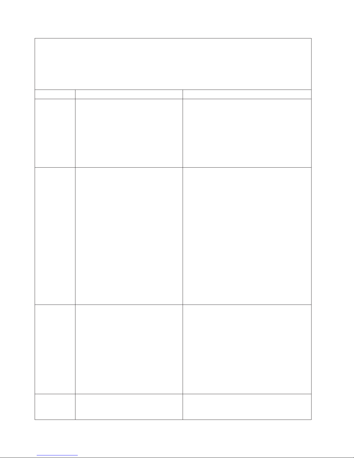
v Follow the suggested actions in the order in which they are listed in the Action column until the problem
is solved.
v See Chapter 3, “Parts listing, Type 4364, 4365, or 4366 server,” on page 15 to determine which
components are customer replaceable units (CRU) and which components are field replaceable units
(FRU).
v If an action step is preceded by “(Trained service technician only),” that step must be performed only by a
trained service technician.
Error code Description Action
161 Real-time clock battery error.
162 Invalid configuration information or CMOS
random-access memory (RAM) checksum
failure.
163 Real-time clock error. (time of day not set)
164 Memory size has changed.
1. Reseat the battery.
2. Clear CMOS, see “System-board switches and
jumpers” on page 7.
3. Replace the following components one at a time,
in the order shown, restarting the server each
time:
a. Battery
b. (Trained service technician only) System
board
1. Run the Configuration/Setup Utility program,
select Load Default Settings, and save the
settings.
2. Reseat the following components, one at a time,
in the order shown, restarting the server each
time:
a. Battery
b. Failing device (if the device is a FRU, the
device must be reseated by a trained service
technician only)
3. Replace the following components one at a time,
in the order shown, restarting the server each
time:
a. Battery
b. Failing device (if the device is a FRU, the
device must be replaced by a trained service
technician only)
c. (Trained service technician only) System
board
1. Run the Configuration/Setup Utility program,
select Load Default Settings, make sure that the
date and time are correct, and save the settings.
2. Reseat the battery.
3. Clear CMOS, see “System-board switches and
jumpers” on page 7.
4. Replace the following components one at a time,
in the order shown, restarting the server each
time:
a. Battery
b. (Trained service technician only) System
board
1. Run the Configuration/Setup Utility program; then,
exit, saving the configuration settings.
2. Reseat the DIMMs.
72 IBM System x3250 Types 4364, 4365, and 4366: Problem Determination and Service Guide
Page 91

v Follow the suggested actions in the order in which they are listed in the Action column until the problem
is solved.
v See Chapter 3, “Parts listing, Type 4364, 4365, or 4366 server,” on page 15 to determine which
components are customer replaceable units (CRU) and which components are field replaceable units
(FRU).
v If an action step is preceded by “(Trained service technician only),” that step must be performed only by a
trained service technician.
Error code Description Action
175 Service processor code on optional service
processor adapter damaged or not loaded.
Note: In this case, the service processor is
the optional Remote Supervisor Adapter II
SlimLine.
184 Power-on password damaged.
1. Update the firmware on the optional Remote
Supervisor Adapter II SlimLine (see “Updating the
firmware” on page 11).
2. Replace the optional Remote Supervisor Adapter
II SlimLine.
1. Restart the server and enter the administrator
password; then, run the Configuration/Setup
Utility program, select Load Default Settings,
and save the settings.
2. Reseat the battery.
3. Clear CMOS, see “System-board switches and
jumpers” on page 7.
4. Replace the following components one at a time,
in the order shown, restarting the server each
time:
a. Battery
b. (Trained service technician only) System
board
187 VPD serial number not set.
1. Reseat the optional Remote Supervisor Adapter II
SlimLine.
2. (Trained service technician only) Replace the
system board.
189 Three attempts were made to access the
server with an incorrect password.
Restart the server and enter the administrator
password; then, run the Configuration/Setup Utility
program and change the power-on password.
289 A DIMM has been disabled by the system.
1. Make sure that the DIMM is installed correctly
(see “Installing a memory module (DIMM)” on
page 40).
2. Reseat the DIMM.
3. Replace the DIMM.
301 Keyboard or keyboard controller error.
1. If you have installed a USB keyboard, run the
Configuration/Setup Utility program and enable
keyboardless operation to prevent the POST error
message 301 from being displayed during startup.
2. Reseat the keyboard cable in the connector.
3. Replace the following components one at a time,
in the order shown, restarting the server each
time:
a. Keyboard
b. (Trained service technician only) System
board
Chapter 5. Diagnostics 73
Page 92

v Follow the suggested actions in the order in which they are listed in the Action column until the problem
is solved.
v See Chapter 3, “Parts listing, Type 4364, 4365, or 4366 server,” on page 15 to determine which
components are customer replaceable units (CRU) and which components are field replaceable units
(FRU).
v If an action step is preceded by “(Trained service technician only),” that step must be performed only by a
trained service technician.
Error code Description Action
303 Keyboard controller error.
602 Invalid diskette boot record
604 Internal diskette drive error
962 Parallel port configuration error
1162 Serial port error
1. Reseat the keyboard cable in the connector.
2. Replace the following components one at a time,
in the order shown, restarting the server each
time:
a. Keyboard
b. (Trained service technician only) System
board.
1. Replace the diskette.
2. Reseat the diskette drive cables.
3. Replace the diskette drive.
1. Run the Configuration/Setup Utility program,
select Load Default Settings, and save the
settings.
2. Reseat the diskette drive signal cables.
3. Replace the diskette drive.
1. Run the Configuration/Setup Utility program and
make sure that the parallel port setting is correct.
2. (Trained service technician only) Replace the
system board.
1. Run the Configuration/Setup Utility program and
make sure that the serial port settings are correct.
2. (Trained service technician only) Replace the
system board.
74 IBM System x3250 Types 4364, 4365, and 4366: Problem Determination and Service Guide
Page 93
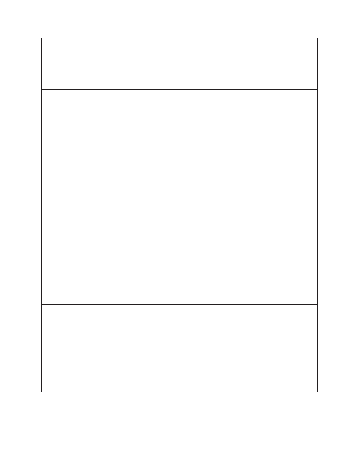
v Follow the suggested actions in the order in which they are listed in the Action column until the problem
is solved.
v See Chapter 3, “Parts listing, Type 4364, 4365, or 4366 server,” on page 15 to determine which
components are customer replaceable units (CRU) and which components are field replaceable units
(FRU).
v If an action step is preceded by “(Trained service technician only),” that step must be performed only by a
trained service technician.
Error code Description Action
178x Fixed disk error.
Note: x is the drive that has the error
1. Run the hard disk drive diagnostic tests on drive
x (see “Running the diagnostic programs” in the
Problem Determination and Service Guide on the
IBM System x Documentation CD).
2. Reseat the following components, depending on
the server model:
v Hot-swap models: Hard disk drive
v Simple-swap models:
a. Hard disk drive x
b. Hard disk drive x cable
3. Replace the following components one at a time,
depending on the server model, in the order
shown, restarting the server each time:
v Hot-swap models:
a. Hard disk drive x
b. Hard disk drive backplane
c. (Trained service technician only) System
board
v Simple-swap models:
a. Hard disk drive x
b. Hard disk drive x cable
c. (Trained service technician only) System
board
1800 Unavailable PCI hardware interrupt.
1. Run the Configuration/Setup Utility program and
adjust the adapter settings.
2. Remove each adapter one at a time, restarting
the server each time, until the problem is isolated.
1801 An adapter has requested memory
resources that are not available
1. Run the Configuration/Setup Utility program and
make sure that sufficient memory is installed in
the server.
2. Run the Configuration/Setup Utility program and
disable some other resources to make more
space available.
3. Replace the following components one at a time,
in the order shown, restarting the server each
time:
a. Each adapter
b. (Trained service technician only) System
board
Chapter 5. Diagnostics 75
Page 94

v Follow the suggested actions in the order in which they are listed in the Action column until the problem
is solved.
v See Chapter 3, “Parts listing, Type 4364, 4365, or 4366 server,” on page 15 to determine which
components are customer replaceable units (CRU) and which components are field replaceable units
(FRU).
v If an action step is preceded by “(Trained service technician only),” that step must be performed only by a
trained service technician.
Error code Description Action
1805 PCI option ROM checksum error
1810 PCI error
1962 A hard disk drive does not contain a valid
boot sector.
1. Remove the failing adapter.
2. Reseat each adapter.
3. Reseat the riser card.
4. Replace the following components one at a time,
in the order shown, restarting the server each
time:
a. Each adapter
b. Riser card
c. (Trained service technician only) System
board
1. Reseat the riser card.
2. Remove both adapters from the riser card.
3. Replace the following components one at a time,
in the order shown, restarting the server each
time:
a. Riser card
b. (Trained service technician only) System
board
1. Make sure that a startable operating system is
installed.
2. Run the hard disk drive diagnostic tests.
3. Reseat the following components:
a. Hard disk drive
b. Hard disk drive backplane cable or back plate
cables
4. Replace the following components one at a time,
in the order shown, restarting the server each
time:
a. (Hot-swap models) Hard disk drive cable
b. Hard disk drive
c. Hard disk drive backplane or back plate
d. (Trained service technician only) System
board
76 IBM System x3250 Types 4364, 4365, and 4366: Problem Determination and Service Guide
Page 95

v Follow the suggested actions in the order in which they are listed in the Action column until the problem
is solved.
v See Chapter 3, “Parts listing, Type 4364, 4365, or 4366 server,” on page 15 to determine which
components are customer replaceable units (CRU) and which components are field replaceable units
(FRU).
v If an action step is preceded by “(Trained service technician only),” that step must be performed only by a
trained service technician.
Error code Description Action
5962 IDE DVD drive configuration error.
1. Run the Configuration/Setup Utility program and
load the default settings (see “Using the
Configuration/Setup Utility program” on page 12).
2. Reseat the following components:
a. DVD drive cable
b. DVD drive
c. (Trained service technician only) System
board
3. Replace the components listed in step 2 one at a
time, in the order shown, restarting the server
each time.
8603 Pointing-device error.
1. Reseat the pointing device.
2. Replace the following components one at a time,
in the order shown, restarting the server each
time:
a. Pointing device
b. (Trained service technician only) System
board
00012000 Processor machine check error.
1. (Trained service technician only) Reseat the
microprocessor.
2. Replace the following components one at a time,
in the order shown, restarting the server each
time:
a. (Trained service technician only)
Microprocessor
b. (Trained service technician only) System
board
00019701 Processor failed BIST.
1. (Trained service technician only) Reseat the
microprocessor.
2. Replace the following components one at a time,
in the order shown, restarting the server each
time:
a. (Trained service technician only)
Microprocessor
b. (Trained service technician only) System
board
01298001 No update data for processor.
1. Update the BIOS code again.
2. (Trained service technician only) Reseat the
microprocessor.
3. (Trained service technician only) Replace the
microprocessor.
Chapter 5. Diagnostics 77
Page 96

v Follow the suggested actions in the order in which they are listed in the Action column until the problem
is solved.
v See Chapter 3, “Parts listing, Type 4364, 4365, or 4366 server,” on page 15 to determine which
components are customer replaceable units (CRU) and which components are field replaceable units
(FRU).
v If an action step is preceded by “(Trained service technician only),” that step must be performed only by a
trained service technician.
Error code Description Action
01298101 Bad update data for processor.
I9990301 Hard disk drive boot sector error.
I9990650 AC power has been restored.
1. Update the BIOS code again.
2. (Trained service technician only) Reseat the
microprocessor.
3. (Trained service technician only) Replace the
microprocessor.
1. Reseat the following components, depending on
the server model:
v Hot-swap models:
a. Hard disk drive
b. SAS/SATA controller
v Simple-swap models:
a. Hard disk drive
b. Hard disk drive cable
2. Replace the following components one at a time,
depending on the server model, in the order
shown, restarting the server each time:
v Hot-swap models:
a. Hard disk drive
b. Hard disk drive backplane
c. SAS/SATA controller
d. (Trained service technician only) System
board
v Simple-swap models:
a. Hard disk drive
b. Hard disk drive cable
c. (Trained service technician only) System
board
1. Check the power cables.
2. Check for interruption of the power supply.
Checkout procedure
The checkout procedure is the sequence of tasks that you should follow to
diagnose a problem in the server.
About the checkout procedure
Before you perform the checkout procedure for diagnosing hardware problems,
review the following information:
v Read the safety information that begins on page vii.
v The diagnostic programs provide the primary methods of testing the major
components of the server, such as the system board, Ethernet controller,
78 IBM System x3250 Types 4364, 4365, and 4366: Problem Determination and Service Guide
Page 97

keyboard, mouse (pointing device), serial ports, and hard disk drives. You can
also use them to test some external devices. If you are not sure whether a
problem is caused by the hardware or by the software, you can use the
diagnostic programs to confirm that the hardware is working correctly.
v When you run the diagnostic programs, a single problem might cause more than
one error message. When this happens, correct the cause of the first error
message. The other error messages usually will not occur the next time you run
the diagnostic programs.
Exception: If there are multiple error codes or LEDs that indicate a
microprocessor error, the error might be in the microprocessor or in the
microprocessor socket. See “Microprocessor problems” on page 85 for
information about diagnosing microprocessor problems.
v Before running the diagnostic programs, you must determine whether the failing
server is part of a shared hard disk drive cluster (two or more servers that share
external storage devices). If it is part of a cluster, you can run all diagnostic
programs except the ones that test the storage unit (that is, a hard disk drive in
the storage unit) or the storage adapter that is attached to the storage unit. The
failing server might be part of a cluster if any of the following conditions is true:
– You have identified the failing server as part of a cluster (two or more servers
sharing external storage devices).
– One or more external storage units are attached to the failing server and at
least one of the attached storage units is also attached to another server or
unidentifiable device.
– One or more servers are located near the failing server.
Important: If the server is part of a shared hard disk drive cluster, run one test
at a time. Do not run any suite of tests, such as “quick” or “normal” tests,
because this might enable the hard disk drive diagnostic tests.
v If the server is halted and a POST error code is displayed, see “Error logs” on
page 70. If the server is halted and no error message is displayed, see
“Troubleshooting tables” on page 81 and “Solving undetermined problems” on
page 114.
v For information about power-supply problems, see “Solving power problems” on
page 112.
v For intermittent problems, check the error log; see “Error logs” on page 70 and
“Diagnostic programs, messages, and error codes” on page 94.
Performing the checkout procedure
To perform the checkout procedure, complete the following steps:
1. Is the server part of a cluster?
v No: Go to step 2.
v Yes: Shut down all failing servers that are related to the cluster. Go to step 2.
2. Complete the following steps:
a. Turn off the server and all external devices.
b. Check the internal and external devices for compatibility at
http://www.ibm.com/servers/eserver/serverproven/compat/us/.
c. Check all cables and power cords.
d. Set all display controls to the middle positions.
e. Turn on all external devices.
Chapter 5. Diagnostics 79
Page 98

f. Turn on the server. If the server does not start, see “Troubleshooting tables”
on page 81.
g. Check the system-error LED on the operator information panel. If it is
flashing, check the LEDs on the system board (see “System-board LEDs” on
page 92).
h. Check for the following results:
v Successful completion of POST (see “POST” on page 67 for more
information)
v Successful completion of startup
3. Did one or more beeps sound?
v No: Find the failure symptom in “Troubleshooting tables” on page 81; if
necessary, run the diagnostic programs (see “Running the diagnostic
programs” on page 94).
– If you receive an error, see “Diagnostic error codes” on page 96.
– If the diagnostic programs were completed successfully and you still
suspect a problem, see “Solving undetermined problems” on page 114.
v Yes: Find the beep code in “POST beep codes” on page 67; if necessary,
see “Solving undetermined problems” on page 114.
80 IBM System x3250 Types 4364, 4365, and 4366: Problem Determination and Service Guide
Page 99

Troubleshooting tables
Use the troubleshooting tables to find solutions to problems that have identifiable
symptoms.
If you cannot find the problem in these tables, see “Running the diagnostic
programs” on page 94 for information about testing the server.
If you have just added new software or a new optional device and the server is not
working, complete the following steps before using the troubleshooting tables:
1. Check the system-error LED on the operator information panel; if it is lit, check
the LEDs on the system board (see “System-board LEDs” on page 92).
2. Remove the software or device that you just added.
3. Run the diagnostic tests to determine whether the server is running correctly.
4. Reinstall the new software or new device.
CD or DVD drive problems
v Follow the suggested actions in the order in which they are listed in the Action column until the problem
is solved.
v See Chapter 3, “Parts listing, Type 4364, 4365, or 4366 server,” on page 15 to determine which
components are customer replaceable units (CRU) and which components are field replaceable units
(FRU).
v If an action step is preceded by “(Trained service technician only),” that step must be performed only by a
trained service technician.
Symptom Action
The CD or DVD drive is not
recognized.
A CD or DVD is not working
correctly.
1. Make sure that:
v The IDE channel to which the CD or DVD drive is attached (primary) is
enabled in the Configuration/Setup Utility program.
v All cables and jumpers are installed correctly.
v The signal cable and connector are not damaged and the connector pins are
not bent.
v The correct device driver is installed for the CD or DVD drive.
2. Run the CD, CD-RW, or DVD drive diagnostic programs.
3. Reseat the following components:
a. CD or DVD drive
b. CD or DVD interface board cable
4. Replace the following components one at a time, in the order shown, restarting
the server each time:
a. CD or DVD drive
b. CD or DVD drive interface board cable
c. CD or DVD interface board
d. (Trained service technician only) System board
1. Clean the CD or DVD.
2. Run the CD or DVD drive diagnostic programs.
3. Check the connector and signal cable for bent pins or damage.
4. Reseat the CD or DVD drive.
5. Replace the CD or DVD drive.
Chapter 5. Diagnostics 81
Page 100

v Follow the suggested actions in the order in which they are listed in the Action column until the problem
is solved.
v See Chapter 3, “Parts listing, Type 4364, 4365, or 4366 server,” on page 15 to determine which
components are customer replaceable units (CRU) and which components are field replaceable units
(FRU).
v If an action step is preceded by “(Trained service technician only),” that step must be performed only by a
trained service technician.
Symptom Action
The CD or DVD drive tray is not
working.
1. Make sure that the server is turned on.
2. Insert the end of a straightened paper clip into the manual tray-release
opening.
3. Reseat the CD or DVD drive.
4. Replace the CD or DVD drive.
General problems
v Follow the suggested actions in the order in which they are listed in the Action column until the problem
is solved.
v See Chapter 3, “Parts listing, Type 4364, 4365, or 4366 server,” on page 15 to determine which
components are customer replaceable units (CRU) and which components are field replaceable units
(FRU).
v If an action step is preceded by “(Trained service technician only),” that step must be performed only by a
trained service technician.
Symptom Action
A cover lock is broken, an LED
is not working, or a similar
problem has occurred.
If the part is a CRU, replace it. If the part is a FRU, the part must be replaced by a
trained service technician.
Hard disk drive problems
v Follow the suggested actions in the order in which they are listed in the Action column until the problem
is solved.
v See Chapter 3, “Parts listing, Type 4364, 4365, or 4366 server,” on page 15 to determine which
components are customer replaceable units (CRU) and which components are field replaceable units
(FRU).
v If an action step is preceded by “(Trained service technician only),” that step must be performed only by a
trained service technician.
Symptom Action
Not all drives are recognized by
the hard disk drive diagnostic
test (the Fixed Disk test).
The server stops responding
during the hard disk drive
diagnostic test.
A hard disk drive was not
detected while the operating
system was being started.
Remove the drive indicated on the diagnostic tests; then, run the hard disk drive
diagnostic test again. If the remaining drives are recognized, replace the drive that
you removed with a new one.
Remove the hard disk drive that was being tested when the server stopped
responding, and run the diagnostic test again. If the hard disk drive diagnostic test
runs successfully, replace the drive that you removed with a new one.
Reseat all hard disk drives and cables; then, run the hard disk drive diagnostic
tests again.
82 IBM System x3250 Types 4364, 4365, and 4366: Problem Determination and Service Guide
 Loading...