

IBM System x3200 Type 4362, System x3200 Type 4363 Problem Determination And Service Manual
Page 1

System x3200 Types 4362 and 4363
Problem Determination and Service Guide
Page 2

Page 3

System x3200 Types 4362 and 4363
Problem Determination and Service Guide
Page 4

Note: Before using this information and the product it supports, read the general information in
Appendix B, “Notices,” on page 153, and the Warranty and Support Information document on the IBM
System x Documentation CD.
13th Edition (January 2009)
© Copyright International Business Machines Corporation 2007.
US Government Users Restricted Rights – Use, duplication or disclosure restricted by GSA ADP Schedule Contract
with IBM Corp.
Page 5

Contents
Safety ............................vii
Guidelines for trained service technicians ...............viii
Inspecting for unsafe conditions .................viii
Guidelines for servicing electrical equipment .............ix
Safety statements ........................x
Chapter 1. Introduction ......................1
Related documentation ......................1
Notices and statements in this document ................2
Features and specifications .....................3
Server controls, LEDs, and power ..................4
Front view ..........................4
Rear view ..........................6
Server power features......................7
Connectors, LEDs, and jumpers ...................9
System-board internal connectors .................9
System-board external connectors .................10
System-board optional-devices connectors ..............11
System-board LEDs ......................12
System-board jumpers .....................13
Chapter 2. Configuration information and instructions .........15
Updating the firmware ......................15
Configuring the server ......................15
Using the Configuration/Setup Utility program ............16
Using the ServerGuide Setup and Installation CD ...........20
Using the Boot Menu program ..................22
Enabling the Broadcom NetXtreme Gigabit Ethernet Boot Agent ......22
Configuring the Broadcom NetXtreme Gigabit Ethernet controller .....22
LSI Configuration Utility program .................23
Chapter 3. Parts listing, System x3200 Types 4362 and 4363.......27
Replaceable server components ..................28
Power cords ..........................33
Chapter 4. Removing and replacing server components ........35
Installation guidelines ......................35
System reliability guidelines ...................36
Working inside the server with the power on .............37
Handling static-sensitive devices .................38
Returning a device or component .................38
Removing and replacing Tier 1 CRUs ................39
Removing the side cover ....................39
Installing the side cover.....................40
Removing the lower bezel ....................41
Installing the lower bezel ....................42
Removing the upper bezel....................43
Installing the upper bezel ....................44
Removing an adapter .....................45
Installing an adapter ......................46
Cabling the optional ServeRAID-8s controller .............48
Removing and installing internal drives ...............52
Removing a hot-swap power supply ................64
© Copyright IBM Corp. 2007 iii
Page 6

Installing a hot-swap power supply ................66
Removing a memory module ...................67
Installing a memory module ...................68
Removing and replacing Tier 2 CRUs ................69
Removing the battery .....................69
Installing the battery ......................69
Removing the rear system fan ..................71
Installing the rear system fan...................72
Removing the front system fan assembly ..............73
Installing the front system fan assembly ...............74
Removing the simple-swap backplate ...............75
Installing the simple-swap backplate ................76
Removing the SAS/SATA hard disk drive backplane ..........76
Installing the SAS/SATA hard disk drive backplane ...........78
Removing the front-panel assembly ................79
Installing the front-panel assembly .................80
Removing the front USB connector assembly.............80
Installing the front USB connector assembly .............81
Removing the hot-swap power supply cage .............82
Installing the hot-swap power supply cage ..............83
Removing the SAS/SATA controller ................84
Installing the SAS/SATA controller .................85
Removing and replacing FRUs ...................86
Removing a non-hot-swap power supply ..............86
Installing a non-hot-swap power supply ...............88
Removing the microprocessor and fan sink .............89
Installing a microprocessor and fan sink...............91
Removing the system board ...................93
Installing the system board ...................94
Chapter 5. Diagnostics .....................95
Diagnostic tools ........................95
POST ............................95
POST beep codes ......................96
No-beep symptoms ......................98
Error logs ..........................99
POST error codes ......................100
Checkout procedure ......................109
About the checkout procedure ..................109
Performing the checkout procedure ................110
Checkpoint codes (trained service technicians only) ...........110
Troubleshooting tables ......................111
CD or DVD drive problems ...................111
Diskette drive problems ....................112
General problems ......................113
Hard disk drive problems ....................113
Intermittent problems .....................114
Keyboard, mouse, or pointing-device problems............114
Memory problems ......................116
Microprocessor problems ....................117
Monitor or video problems ...................117
Optional-device problems ...................119
Power problems .......................120
Serial port problems .....................121
ServerGuide problems.....................122
Software problems ......................122
iv System x3200 Types 4362 and 4363: Problem Determination and Service Guide
Page 7

Universal Serial Bus (USB) port problems .............123
Error LEDs ..........................124
Power-supply LEDs .......................125
Diagnostic programs, messages, and error codes ...........127
Running the diagnostic programs .................127
Diagnostic text messages ...................128
Viewing the test log......................128
Diagnostic error codes ....................129
Recovering from a BIOS update failure ...............137
System-error log messages ....................138
Solving SAS problems......................146
Solving power problems .....................146
Solving Ethernet controller problems ................147
Solving undetermined problems ..................148
Problem determination tips ....................148
Calling IBM for service .....................150
Appendix A. Getting help and technical assistance ..........151
Before you call ........................151
Using the documentation .....................151
Getting help and information from the World Wide Web .........152
Software service and support ...................152
Hardware service and support ...................152
IBM Taiwan product service ....................152
Appendix B. Notices ......................153
Trademarks..........................153
Important notes ........................154
Product recycling and disposal ..................155
Battery return program .....................156
Electronic emission notices ....................157
Federal Communications Commission (FCC) statement ........157
Industry Canada Class A emission compliance statement ........158
Australia and New Zealand Class A statement ............158
United Kingdom telecommunications safety requirement ........158
European Union EMC Directive conformance statement ........158
Taiwanese Class A warning statement ...............159
Chinese Class A warning statement ................159
Japanese Voluntary Control Council for Interference (VCCI) statement 159
Index ............................161
Contents v
Page 8

vi System x3200 Types 4362 and 4363: Problem Determination and Service Guide
Page 9

Safety
Before installing this product, read the Safety Information.
Antes de instalar este produto, leia as Informações de Segurança.
Pred instalací tohoto produktu si prectete prírucku bezpecnostních instrukcí.
Læs sikkerhedsforskrifterne, før du installerer dette produkt.
Lees voordat u dit product installeert eerst de veiligheidsvoorschriften.
Ennen kuin asennat tämän tuotteen, lue turvaohjeet kohdasta Safety Information.
Avant d’installer ce produit, lisez les consignes de sécurité.
Vor der Installation dieses Produkts die Sicherheitshinweise lesen.
Prima di installare questo prodotto, leggere le Informazioni sulla Sicurezza.
Les sikkerhetsinformasjonen (Safety Information) før du installerer dette produktet.
Antes de instalar este produto, leia as Informações sobre Segurança.
Antes de instalar este producto, lea la información de seguridad.
Läs säkerhetsinformationen innan du installerar den här produkten.
© Copyright IBM Corp. 2007 vii
Page 10

Guidelines for trained service technicians
This section contains information for trained service technicians.
Inspecting for unsafe conditions
Use the information in this section to help you identify potential unsafe conditions in
an IBM®product that you are working on. Each IBM product, as it was designed
and manufactured, has required safety items to protect users and service
technicians from injury. The information in this section addresses only those items.
Use good judgment to identify potential unsafe conditions that might be caused by
non-IBM alterations or attachment of non-IBM features or options that are not
addressed in this section. If you identify an unsafe condition, you must determine
how serious the hazard is and whether you must correct the problem before you
work on the product.
Consider the following conditions and the safety hazards that they present:
v Electrical hazards, especially primary power. Primary voltage on the frame can
cause serious or fatal electrical shock.
v Explosive hazards, such as a damaged CRT face or a bulging or leaking
capacitor.
v Mechanical hazards, such as loose or missing hardware.
To inspect the product for potential unsafe conditions, complete the following steps:
1. Make sure that the power is off and the power cord is disconnected.
2. Make sure that the exterior cover is not damaged, loose, or broken, and
observe any sharp edges.
3. Check the power cord:
v Make sure that the third-wire ground connector is in good condition. Use a
meter to measure third-wire ground continuity for 0.1 ohm or less between
the external ground pin and the frame ground.
v Make sure that the power cord is the correct type, as specified in “Power
cords” on page 33.
v Make sure that the insulation is not frayed or worn.
4. Remove the cover.
5. Check for any obvious non-IBM alterations. Use good judgment as to the safety
of any non-IBM alterations.
6. Check inside the server for any obvious unsafe conditions, such as metal filings,
contamination, water or other liquid, or signs of fire or smoke damage.
7. Check for worn, frayed, or pinched cables.
8. Make sure that the power-supply cover fasteners (screws or rivets) have not
been removed or tampered with.
viii System x3200 Types 4362 and 4363: Problem Determination and Service Guide
Page 11

Guidelines for servicing electrical equipment
Observe the following guidelines when you service electrical equipment:
v Check the area for electrical hazards such as moist floors, nongrounded power
extension cords, power surges, and missing safety grounds.
v Use only approved tools and test equipment. Some hand tools have handles that
are covered with a soft material that does not provide insulation from live
electrical currents.
v Regularly inspect and maintain your electrical hand tools for safe operational
condition. Do not use worn or broken tools or testers.
v Do not touch the reflective surface of a dental mirror to a live electrical circuit.
The surface is conductive and can cause personal injury or equipment damage if
it touches a live electrical circuit.
v Some rubber floor mats contain small conductive fibers to decrease electrostatic
discharge. Do not use this type of mat to protect yourself from electrical shock.
v Do not work alone under hazardous conditions or near equipment that has
hazardous voltages.
v Locate the emergency power-off (EPO) switch, disconnecting switch, or electrical
outlet so that you can turn off the power quickly in the event of an electrical
accident.
v Disconnect all power before you perform a mechanical inspection, work near
power supplies, or remove or install main units.
v Before you work on the equipment, disconnect the power cord. If you cannot
disconnect the power cord, have the customer power-off the wall box that
supplies power to the equipment and lock the wall box in the off position.
v Never assume that power has been disconnected from a circuit. Check it to
make sure that it has been disconnected.
v If you have to work on equipment that has exposed electrical circuits, observe
the following precautions:
– Make sure that another person who is familiar with the power-off controls is
near you and is available to turn off the power if necessary.
– When you are working with powered-on electrical equipment, use only one
hand. Keep the other hand in your pocket or behind your back to avoid
creating a complete circuit that could cause an electrical shock.
– When using a tester, set the controls correctly and use the approved probe
leads and accessories for that tester.
– Stand on a suitable rubber mat to insulate you from grounds such as metal
floor strips and equipment frames.
v Use extreme care when measuring high voltages.
v To ensure proper grounding of components such as power supplies, pumps,
blowers, fans, and motor generators, do not service these components outside of
their normal operating locations.
v If an electrical accident occurs, use caution, turn off the power, and send another
person to get medical aid.
Safety ix
Page 12

Safety statements
Important:
Each caution and danger statement in this documentation begins with a number.
This number is used to cross reference an English-language caution or danger
statement with translated versions of the caution or danger statement in the Safety
Information document.
For example, if a caution statement begins with a number 1, translations for that
caution statement appear in the Safety Information document under statement 1.
Be sure to read all caution and danger statements in this documentation before you
perform the procedures. Read any additional safety information that comes with
your server or optional device before you install the device.
x System x3200 Types 4362 and 4363: Problem Determination and Service Guide
Page 13

Statement 1:
DANGER
Electrical current from power, telephone, and communication cables is
hazardous.
To avoid a shock hazard:
v Do not connect or disconnect any cables or perform installation,
maintenance, or reconfiguration of this product during an electrical
storm.
v Connect all power cords to a properly wired and grounded electrical
outlet.
v Connect to properly wired outlets any equipment that will be attached to
this product.
v When possible, use one hand only to connect or disconnect signal
cables.
v Never turn on any equipment when there is evidence of fire, water, or
structural damage.
v Disconnect the attached power cords, telecommunications systems,
networks, and modems before you open the device covers, unless
instructed otherwise in the installation and configuration procedures.
v Connect and disconnect cables as described in the following table when
installing, moving, or opening covers on this product or attached
devices.
To Connect: To Disconnect:
1. Turn everything OFF.
2. First, attach all cables to devices.
3. Attach signal cables to connectors.
4. Attach power cords to outlet.
5. Turn device ON.
1. Turn everything OFF.
2. First, remove power cords from outlet.
3. Remove signal cables from connectors.
4. Remove all cables from devices.
Safety xi
Page 14

Statement 2:
CAUTION:
When replacing the lithium battery, use only IBM Part Number 33F8354 or an
equivalent type battery recommended by the manufacturer. If your system has
a module containing a lithium battery, replace it only with the same module
type made by the same manufacturer. The battery contains lithium and can
explode if not properly used, handled, or disposed of.
Do not:
v Throw or immerse into water
v Heat to more than 100°C (212°F)
v Repair or disassemble
Dispose of the battery as required by local ordinances or regulations.
xii System x3200 Types 4362 and 4363: Problem Determination and Service Guide
Page 15

Statement 3:
CAUTION:
When laser products (such as CD-ROMs, DVD drives, fiber optic devices, or
transmitters) are installed, note the following:
v Do not remove the covers. Removing the covers of the laser product could
result in exposure to hazardous laser radiation. There are no serviceable
parts inside the device.
v Use of controls or adjustments or performance of procedures other than
those specified herein might result in hazardous radiation exposure.
DANGER
Some laser products contain an embedded Class 3A or Class 3B laser
diode. Note the following.
Laser radiation when open. Do not stare into the beam, do not view directly
with optical instruments, and avoid direct exposure to the beam.
Class 1 Laser Product
Laser Klasse 1
Laser Klass 1
Luokan 1 Laserlaite
Appareil A Laser de Classe 1
`
Safety xiii
Page 16

Statement 4:
≥ 18 kg (39.7 lb) ≥ 32 kg (70.5 lb) ≥ 55 kg (121.2 lb)
CAUTION:
Use safe practices when lifting.
Statement 5:
CAUTION:
The power control button on the device and the power switch on the power
supply do not turn off the electrical current supplied to the device. The device
also might have more than one power cord. To remove all electrical current
from the device, ensure that all power cords are disconnected from the power
source.
2
1
xiv System x3200 Types 4362 and 4363: Problem Determination and Service Guide
Page 17

Statement 8:
CAUTION:
Never remove the cover on a power supply or any part that has the following
label attached.
Hazardous voltage, current, and energy levels are present inside any
component that has this label attached. There are no serviceable parts inside
these components. If you suspect a problem with one of these parts, contact
a service technician.
Statement 12:
CAUTION:
The following label indicates a hot surface nearby.
Statement 13:
DANGER
Overloading a branch circuit is potentially a fire hazard and a shock hazard
under certain conditions. To avoid these hazards, ensure that your system
electrical requirements do not exceed branch circuit protection
requirements. Refer to the information that is provided with your device for
electrical specifications.
Safety xv
Page 18

Statement 15:
CAUTION:
Make sure that the rack is secured properly to avoid tipping when the server
unit is extended.
xvi System x3200 Types 4362 and 4363: Problem Determination and Service Guide
Page 19

Chapter 1. Introduction
This Problem Determination and Service Guide contains information to help you
solve problems that might occur in the IBM System x3200 Types 4362 and 4363. It
describes the diagnostic tools that come with the server, error codes and suggested
actions, and instructions for replacing failing components.
Replaceable components are of three types:
v Tier 1 customer replaceable unit (CRU): Replacement of Tier 1 CRUs is your
responsibility. If IBM installs a Tier 1 CRU at your request, you will be charged for
the installation.
v Tier 2 customer replaceable unit: You may install a Tier 2 CRU yourself or
request IBM to install it, at no additional charge, under the type of warranty
service that is designated for the server.
v Field replaceable unit (FRU): FRUs must be installed only by trained service
technicians.
For information about the terms of the warranty and getting service and assistance,
see the Warranty and Support Information document.
Related documentation
In addition to this document, the following documentation also comes with the
server:
v Installation Guide
This printed document contains instructions for setting up the server and basic
instructions for installing some options.
v User’s Guide
This document is in Portable Document Format (PDF) on the IBM xSeries
Documentation CD. It provides general information about the server, including
information about features, and how to configure the server. It also contains
detailed instructions for installing, removing, and connecting optional devices that
the server supports.
v Rack Installation Instructions
This printed document contains instructions for installing the server in a rack.
v Safety Information
This document is in PDF on the IBM System x Documentation CD. It contains
translated caution and danger statements. Each caution and danger statement
that appears in the documentation has a number that you can use to locate the
corresponding statement in your language in the Safety Information document.
v Warranty and Support Information
This document is in PDF on the System x Documentation CD. It contains
information about the terms of the warranty and getting service and assistance.
®
Depending on the server model, additional documentation might be included on the
IBM System x Documentation CD.
The xSeries and System x Tools Center is an online information center that
contains information about tools for updating, managing, and deploying firmware,
device drivers, and operating systems. The xSeries and System x Tools Center is at
http://publib.boulder.ibm.com/infocenter/toolsctr/v1r0/index.jsp
© Copyright IBM Corp. 2007 1
Page 20

The server might have features that are not described in the documentation that
comes with the server. The documentation might be updated occasionally to include
information about those features, or technical updates might be available to provide
additional information that is not included in the server documentation. These
updates are available from the IBM Web site. Complete the following steps to check
for updated documentation and technical updates.
Note: Changes are made periodically to the IBM Web site. The actual procedure
might vary slightly from what is described in this document.
1. Go to http://www.ibm.com/servers/eserver/support/xseries/index.html/
2. From the Hardware list, select System x3200 and click Go.
3. Click the Install and use tab.
4. Click Product documentation.
Notices and statements in this document
The caution and danger statements that appear in this document are also in the
multilingual Safety Information document, which is on the IBM System x
Documentation CD. Each statement is numbered for reference to the corresponding
statement in the Safety Information document.
The following notices and statements are used in this document:
v Note: These notices provide important tips, guidance, or advice.
v Important: These notices provide information or advice that might help you avoid
inconvenient or problem situations.
v Attention: These notices indicate potential damage to programs, devices, or
data. An attention notice is placed just before the instruction or situation in which
damage could occur.
v Caution: These statements indicate situations that can be potentially hazardous
to you. A caution statement is placed just before the description of a potentially
hazardous procedure step or situation.
v Danger: These statements indicate situations that can be potentially lethal or
extremely hazardous to you. A danger statement is placed just before the
description of a potentially lethal or extremely hazardous procedure step or
situation.
2 System x3200 Types 4362 and 4363: Problem Determination and Service Guide
Page 21

Features and specifications
The following information is a summary of the features and specifications of the
server. Depending on the server model, some features might not be available, or
some specifications might not apply.
Table 1. Features and specifications
Microprocessor:
v One Intel
Pentium D microprocessor, dual-core
or quad-core
v 2 MB or 4 MB Level-2 cache
v 800 or 1066 MHz front-side bus
(FSB)
Memory:
v Minimum: 512 MB
v Maximum: 8 GB
v Types: PC2-5300 double-data-rate 2
(DDR2)
v Connectors: four dual inline memory
module (DIMM) connectors, two-way
interleaved
Drives (depending on the model):
v Diskette (optional internal or external
USB): 1.44 MB
v Hard disk drive: SAS or SATA
v One of the following optical IDE
drives:
– CD-ROM
– DVD-ROM (optional)
– DVD-ROM/CD-RW (optional)
– Multiburner (optional)
Drive bays (depending on the
model):
v Two 5.25 in. bays (one optical drive
installed)
v One 3.5 in. removable-media drive
bay
v Four 3.5 in. or 2.5 in. hard disk drive
bays
PCI expansion slots (depending on
the model):
v One PCI Express x8 slot
v One PCI Express x1 slot
v Three PCI 32-bit/33 MHz slots
®
Xeon®3000 sequence or
Fans:
Three speed-controlled fans.
Power supply:
One of the following:
v Two redundant 430 watt (90-240 V ac)
v One nonredundant 400 watt (90-240 V
ac)
Size:
v Height: 438 mm (17.25 in.)
v Depth: 540 mm (21.25 in.)
v Width: 216 mm (8.5 in.)
v Weight: 16.3 kg (36 lb) to 25.2 kg (56
lb) depending upon configuration
Integrated functions:
v Mini baseboard management controller
(mini-BMC)
v Broadcom BCM5721 10/100/1000
Ethernet controller on the system board
with RJ-45 Ethernet port
v Two serial ports
v One parallel port
v Four-port Serial ATA controller
v One internal SAS port (mini-PCI slot)
v Six Universal Serial Bus (USB) v2.0
ports (two on front and four on rear)
v Keyboard port
v Mouse port
v ATA-100 single-channel IDE controller
(bus mastering)
v ATI ES1000 video controller
– Compatible with SVGA and VGA
– 16 MB SDRAM video memory
Diagnostic LEDs:
v Fans
v Memory
v Power supply
Acoustical noise emissions:
v Sound power, idling: 5.0 bel
v Sound power, operating: 5.3 bel
Environment:
v Air temperature:
– Server on: 10° to 35°C (50° to 95°F)
Altitude: 0 to 914 m (2998.0 ft)
– Server off: -40° to 60°C (-40° to 140°F)
Altitude: 0 to 2133 m (7000.0 ft)
v Humidity (operating and storage): 8% to
80%
Heat output:
Approximate heat output in British thermal
units (Btu) per hour:
v Minimum configuration: 630 Btu per hour
(185 watts)
v Maximum configuration: 1784 Btu per hour
(523 watts)
Electrical input:
v Sine-wave input (50 or 60 Hz) required
v Input voltage and frequency ranges
automatically selected
v Input voltage low range:
– Minimum: 100 V ac
– Maximum: 127 V ac
v Input voltage high range:
– Minimum: 200 V ac
– Maximum: 240 V ac
v Input kilovolt-amperes (kVA) approximately:
– Minimum: 0.20 kVA (all models)
– Maximum: 0.55 kVA
Notes:
1. Power consumption and heat output vary
depending on the number and type of
optional features installed and the
power-management optional features in
use.
2. These levels were measured in controlled
acoustical environments according to the
procedures specified by the American
National Standards Institute (ANSI) S12.10
and ISO 7779 and are reported in
accordance with ISO 9296. Actual
sound-pressure levels in a given location
might exceed the average values stated
because of room reflections and other
nearby noise sources. The declared
sound-power levels indicate an upper limit,
below which a large number of computers
will operate.
Chapter 1. Introduction
3
Page 22

Server controls, LEDs, and power
This section describes the controls and light-emitting diodes (LEDs) and how to turn
the server on and off.
Front view
The following illustration shows the controls, LEDs, and connectors on the front of
the server.
Power-on
LED
Power-control
button
Hard disk drive
activity LED
System-error
LED
USB connectors
CD-eject or
DVD-eject button
CD or DVD drive
activity LED
Optional
diskette-eject
button
Optional
diskette drive
activity LED
Power-on LED
When this LED is lit, it indicates that the server is turned on. When this LED
is off, it indicates that ac power is not present, or the power supply or the
LED itself has failed. The LED will flash if the system is turned off and the
power cord is still attached to the server.
Note: If this LED is off, it does not mean that there is no electrical power in
the server. The LED might be burned out. To remove all electrical power
from the server, you must disconnect the power cords from the electrical
outlets.
Power-control button
Press this button to turn the server on and off manually.
Hard disk drive activity LED
When this LED is flashing, it indicates that a hard disk drive is in use.
System-error LED
When this amber LED is lit, it indicates that a system error has occurred.
An LED on the system board might also be lit to help isolate the error. See
Chapter 5, “Diagnostics,” on page 95 for additional information.
USB connectors
Connect USB devices to these connectors.
4 System x3200 Types 4362 and 4363: Problem Determination and Service Guide
Page 23

CD-eject or DVD-eject button
Press this button to release a CD from the CD drive or a DVD from the
DVD drive.
CD or DVD drive activity LED
When this LED is lit, it indicates that the CD drive or DVD drive is in use.
(Optional) External diskette-eject button
Press this button to release a diskette from the diskette drive.
(Optional) External diskette drive activity LED
When this LED is lit, it indicates that the diskette drive is in use.
Hot-swap hard disk drive activity LED (some models)
On some server models, each hot-swap drive has a hard disk drive activity
LED. When this green LED is flashing, it indicates that the associated hard
disk drive is in use.
When the drive is removed, this LED also is visible on the hard disk drive
backplane, next to the drive connector. The backplane is the printed circuit
board behind drive bays 4 through 7.
Hot-swap hard disk drive status LED (some models)
On some server models, each hot-swap hard disk drive has an amber
status LED. If this amber status LED for a drive is lit, it indicates that the
associated hard disk drive has failed.
If an optional ServeRAID adapter is installed in the server and the LED
flashes slowly (one flash per second), the drive is being rebuilt. If the LED
flashes rapidly (three flashes per second), the adapter is identifying the
drive.
When the drive is removed, this LED also is visible on the hard disk drive
backplane, below the hot-swap hard disk drive activity LED.
Chapter 1. Introduction 5
Page 24

Rear view
The following illustration shows the connectors and indicators on the rear of the
server.
Power cord
AC power LED
DC power LED
Serial 2
Mouse
Keyboard
Serial 1
Parallel
Video
USB (2)
Ethernet
USB (2)
Remote Supervisor
Adapter II SlimLine
Ethernet
Fixed power supply
Hot-swap power supplies
AC power LED
DC power LED
Power-cord connector
Connect the power cord to this connector.
Serial 2 connector
Connect a 9-pin serial device to this connector.
Mouse connector
Connect a mouse device to this connector.
Keyboard connector
Connect a keyboard to this connector.
Serial 1 connector
Connect a 9-pin serial device to this connector.
Parallel connector
Connect a parallel device to this connector.
Video connector
Connect a monitor to this connector.
USB connectors
Connect USB devices to these connectors.
6 System x3200 Types 4362 and 4363: Problem Determination and Service Guide
Page 25

Ethernet connector
Use this connector to connect the server to a network.
Ethernet transmit/receive activity LED
This LED is on the Ethernet connector on the rear of the server. When this
LED is lit, it indicates that there is activity between the server and the
network.
Ethernet link status LED
This LED is on the Ethernet connector on the rear of the server. When this
LED is lit, it indicates that there is an active connection on the Ethernet
port.
Remote Supervisor Adapter II SlimLine Ethernet connector
Use this connector to connect the Remote Supervisor Adapter II SlimLine to
a network.
AC power LED
On some server models, each hot-swap power supply has an ac power
LED and a dc power LED. During typical operation, both the ac and dc
power LEDs are lit.
DC power LED
On some server models, each hot-swap power supply has a dc power LED
and an ac power LED. During typical operation, both the ac and dc power
LEDs are lit.
Server power features
When the server is connected to an ac power source but is not turned on, the
operating system does not run, and all core logic is shut down; however, the server
can respond to remote requests to turn on the server.
Turning on the server
Approximately 20 seconds after the server is connected to ac power, the
power-control button becomes active, and you can turn on the server and start the
operating system by pressing the power-control button.
The server can also be turned on in any of the following ways:
v If a power failure occurs while the server is turned on, the server will restart
automatically when power is restored.
v If your operating system supports the systems-management software for an
optional Remote Supervisor Adapter II SlimLine, the systems-management
software can turn on the server.
v If your operating system supports the Wake on LAN feature, the Wake on LAN
feature can turn on the server.
v If an optional Remote Supervisor Adapter II SlimLine is installed in the server, the
server can be turned on from the Remote Supervisor Adapter II SlimLine user
interface.
Note: When 4 GB or more of memory (physical or logical) is installed, some
memory is reserved for various system resources and is unavailable to the
operating system. The amount of memory that is reserved for system resources
depends on the operating system, the configuration of the server, and the
configured PCI optional devices.
Chapter 1. Introduction 7
Page 26

Turning off the server
When you turn off the server and leave it connected to ac power, the server can
respond to remote requests to turn on the server. To remove all power from the
server, you must disconnect it from the power source.
Some operating systems require an orderly shutdown before you turn off the server.
See your operating-system documentation for information about shutting down the
operating system.
Statement 5:
CAUTION:
The power control button on the device and the power switch on the power
supply do not turn off the electrical current supplied to the device. The device
also might have more than one power cord. To remove all electrical current
from the device, ensure that all power cords are disconnected from the power
source.
2
1
The server can be turned off in any of the following ways:
v You can turn off the server from the operating system, if your operating system
supports this feature. After an orderly shutdown of the operating system, the
server will be turned off automatically.
v You can press the power-control button to start an orderly shutdown of the
operating system and turn off the server, if your operating system supports this
feature.
v If the operating system stops functioning, you can press and hold the
power-control button for more than 4 seconds to turn off the server.
v If an optional Remote Supervisor Adapter II SlimLine is installed in the server, the
server can be turned off from the Remote Supervisor Adapter II SlimLine user
interface.
v If the Wake on LAN feature turned on the server, the Wake on LAN feature can
turn off the server.
v The server can turn itself off as an automatic response to a critical system
failure.
8 System x3200 Types 4362 and 4363: Problem Determination and Service Guide
Page 27

Connectors, LEDs, and jumpers
The following illustrations show the connectors, light-emitting diodes (LEDs), and
jumpers on the system board. The illustrations might differ slightly from your
hardware.
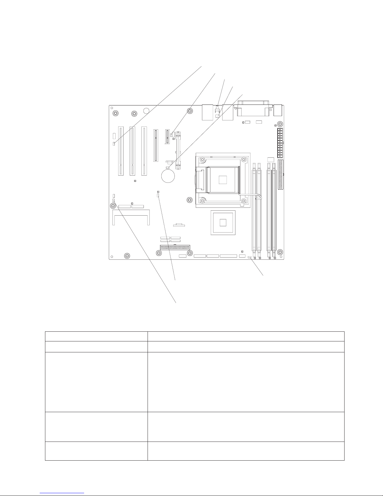
System-board internal connectors
The following illustration shows the internal connectors on the system board.
Rear system fan connector
Microprocessor fan
Serial 2 connector
Wake-on-LAN
Battery
SAS/SATA
controller
connector
SATA drive
connectors (4)
IDE connector
Power connector
(24 pin)
Power connector
(4 pin)
Drive connector
(optional)
Microprocessor
connector
DIMM 1 connector
DIMM 2 connector
DIMM 3 connector
DIMM 4 connector
Hard disk drive fan connector
Front panel connector
Hard disk drive backplane connector
USB tape drive connector
mini-BMC JTAG connector
Front USB connector
Chapter 1. Introduction 9
Page 28

System-board external connectors
The following illustration shows the external input/output (I/O) connectors on the
system board.
Serial 2
Mouse
Keyboard
Serial 1
Parallel
Video
USB (2)
Ethernet
USB (2)
Remote Supervisor
Adapter II SlimLine
Ethernet
10 System x3200 Types 4362 and 4363: Problem Determination and Service Guide
Page 29

System-board optional-devices connectors
The following illustration shows the system-board connectors for user-installable
optional devices.
Slot 5, PCI 32-bit/33 MHz
Slot 4, PCI 32-bit/33 MHz
Slot 3, PCI 32-bit/33 MHz
Slot 2, PCI Express x8
Slot 1, PCI Express x1
Remote Supervisor Adapter II SlimLine
DIMM 1
DIMM 2
DIMM 3
DIMM 4
Chapter 1. Introduction 11
Page 30

System-board LEDs
The following illustration shows the LEDs on the system board.
VRD power fault LED
mini-BMC heartbeat LED
System power LED
DASD fan error LED
Microprocessor
fan error LED
Standby power LED
System fan error LED
DIMM 1 error LED
DIMM 2 error LED
DIMM 3 error LED
DIMM 4 error LED
12 System x3200 Types 4362 and 4363: Problem Determination and Service Guide
Page 31
System-board jumpers
The following illustration shows the jumpers on the system board.
System rest (nopop) (JP3)
Serial 2 switch (JP9)
NMI button
NMI button switch (SW1)
Clear CMOS jumper (JP 2)
mini-BMC force update jumper (JP 1)
Force power on jumper(JP8)
Boot block jumper (JP6)
The following table describes the function of each jumper block.
Table 2. System-board jumper blocks
Jumper name Description
Mini-BMC force update (JP1) Pins 1 and 2: Normal (default)
Clear CMOS (JP2)
v Pins 1 and 2: Keep CMOS data (default)
v Pins 2 and 3: Clear the CMOS data, which clears the power-on
password
Note: Changing the position of this jumper does not affect the
administrator password check if an administrator password is set.
If the administrator password is set and forgotten, remove and
then reinstall the battery.
Boot block (JP6)
v Pins 1 and 2: Normal (default)
v Pins 2 and 3: Recover boot block (see “Recovering from a BIOS
update failure” on page 137)
Force power-on (JP8) Pins 1 and 2: Use the power-control button to start the server
(default)
Chapter 1. Introduction 13
Page 32

14 System x3200 Types 4362 and 4363: Problem Determination and Service Guide
Page 33

Chapter 2. Configuration information and instructions
This chapter provides information about updating the firmware and using the
configuration utilities.
Updating the firmware
The firmware for the server is periodically updated and is available for download on
the Web. Go tohttp://www.ibm.com/servers/eserver/support/xseries/index.html to
check for the latest level of firmware, such as BIOS code, vital product data (VPD)
code, device drivers, and service processor firmware.
When you replace a device in the server, you might have to either update the
server with the latest version of the firmware that is stored in memory on the device
or restore the pre-existing firmware from a diskette or CD image.
The following items are downloadable from the Web at http://www.ibm.com/servers/
eserver/support/xseries/index.html:
v BIOS code
v Diagnostics programs
v Mini-BMC firmware
v Ethernet firmware
™
v ServeRAID
v SAS firmware
firmware
Major components contain VPD code. You can select to update the VPD code when
you update the BIOS code.
Configuring the server
The following configuration programs are available to configure the computer:
v Configuration/Setup Utility program
The Configuration/Setup Utility program is part of the basic input/output system
(BIOS) code in the server. You can use this program to configure serial port
assignments, change interrupt request (IRQ) settings, change the device startup
sequence, set the date and time, set passwords, and set the chassis intrusion
detector. For information about using this utility program, see “Using the
Configuration/Setup Utility program” on page 16.
v IBM ServerGuide Setup and Installation CD
The ServerGuide
that are designed for the server. Use this CD during the installation of the server
to configure basic hardware features, such as an integrated SAS/SATA controller
with RAID capabilities, and to simplify the installation of the operating system.
For information about using this CD, see “Using the ServerGuide Setup and
Installation CD” on page 20.
v Boot Menu program
The Boot Menu program is part of the BIOS code in the server. Use it to
temporarily assign a device to be first in the startup sequence, overriding the
startup sequence that is set in the Configuration/Setup Utility program. For
information about using this utility program, see “Using the Boot Menu program”
on page 22.
™
program provides software-setup tools and installation tools
© Copyright IBM Corp. 2007 15
Page 34

v Broadcom NetXtreme Gigabit Ethernet Boot Agent
The Broadcom NetXtreme Gigabit Ethernet Boot Agent is part of the BIOS. You
can use it to configure the network as a startable device, and you can customize
where the network Startup optional devices occur in the startup sequence.
Enable and disable the Broadcom NetXtreme Gigabit Ethernet Boot Agent from
the Configuration/Setup Utility program. For information, see “Enabling the
Broadcom NetXtreme Gigabit Ethernet Boot Agent” on page 22.
v Broadcom NetXtreme Gigabit Ethernet controller configuration
To configure the integrated Gigabit Ethernet controller, see “Configuring the
Broadcom NetXtreme Gigabit Ethernet controller” on page 22.
v LSI Configuration Utility program
Use the LSI Configuration Utility program to configure the integrated SAS/SATA
controller with RAID capabilities and the devices that are attached to it. For
information about using this program, see “LSI Configuration Utility program” on
page 23.
1. If the server is a simple-swap SATA model and you have installed an optional
IBM Simple-swap SAS/SATA Adapter Option Kit (for RAID support) you can
use the LSI Configuration Utility program to configure the simple-swap SATA
hard disk drives, see “LSI Configuration Utility program” on page 23.
2. If you install an optional RAID controller in the server, such as the
ServeRAID-8s controller, use the configuration software that comes with the
adapter to configure the drives.
The following table lists the different server configurations and the applications
available for configuring and managing RAID arrays.
Table 3.
RAID array configuration
(before operating system is
Server configuration
Integrated SATA and no SAS
controller card installed
SAS/SATA controller card
(LSI 1064) installed
ServeRAID-8s adapter
installed
installed)
None None
LSI Utility (BIOS Utility
CTRL+C), ServerGuide
ServeRAID Manager
Hardware Boot CD, BIOS
Utility (CTRL+A),
ServerGuide
Using the Configuration/Setup Utility program
This section provides instructions for starting the Configuration/Setup Utility program
and descriptions of the menu choices that are available.
Starting the Configuration/Setup Utility program
To start the Configuration/Setup Utility program, complete the following steps:
1. Turn on the server. If the server is already on when you start this procedure,
you must shut down the operating system, turn off the server, wait a few
seconds until all in-use LEDs are turned off, and restart the server.
2. When the message Press F1 for Configuration/Setup, Press F12 for Boot
Menu is displayed, press F1. (This prompt is displayed on the screen for only a
few seconds. You must press F1 quickly.) If you have set both a power-on
password and an administrator password, you must type the administrator
RAID array management
(after operating system is
installed)
MyStorage (for monitoring
storage only)
ServeRAID Manager,
ARCCONF (CLI)
16 System x3200 Types 4362 and 4363: Problem Determination and Service Guide
Page 35

password to access the full Configuration/Setup Utility menu. If you do not type
the administrator password a limited Configuration/Setup Utility menu is
available.
3. Follow the instructions on the screen.
Configuration/Setup Utility menu choices
The following choices are on the Configuration/Setup Utility main menu. Depending
on the version of the BIOS code, some menu choices might differ slightly from
these descriptions.
Note: When you use the server for the first time, you might want to use the
Configuration/Setup Utility menu choice Load Default Settings to reset the
Configuration/Setup Utility menu choices to the factory default settings, in case they
were changed before you received the server. Otherwise, some choices might not
be displayed in the menu.
v System Summary
Select this choice to view configuration information, including the amount of
installed memory. When you make configuration changes through other choices
in the Configuration/Setup Utility program, the changes are reflected in the
system summary; you cannot change settings directly in the system summary.
This choice is on the full and limited Configuration/Setup Utility menu.
– Processor Summary
Select this choice to view the processor information, including the type, speed,
and cache size of the microprocessor.
v System Information
Select this choice to view information about the server. When you make changes
through other choices in the Configuration/Setup Utility program, some of those
changes are reflected in the system information; you cannot change settings
directly in the system information.
This choice is on the full Configuration/Setup Utility menu only.
v Devices and I/O Ports
Select this choice to view or change device assignments and input/output (I/O)
ports. Select this choice to enable or disable the mini-PCI Express SAS and
Ethernet controllers, and standard connectors (such as serial and parallel).
Enable is the default setting for all controllers. If you disable a device, it cannot
be configured, and the operating system will not be able to detect it (this is
equivalent to disconnecting the device). If you disable the mini-PCI Express
SAS/SATA controller and no SAS adapter is installed, the server will have no
SAS capability. If you disable the integrated Ethernet controller and no Ethernet
adapter is installed, the server will have no Ethernet capability.
This choice is on the full Configuration/Setup Utility menu only.
– Serial Port 1
Select this choice to set up the serial port 1.
– Serial Port 2
Select this choice to set up the serial port 2.
– Parallel Port Setup
Select this choice to setup the parallel port.
– Remote Console Redirection
Select this choice to enable and configure serial remote video and keyboard
redirection.
– Internal Floppy Disk
Chapter 2. Configuration information and instructions 17
Page 36

Select this choice to disable or enable the internal diskette drive.
– Mouse
Select this choice to specify whether the mouse is installed or not installed.
– Planar Ethernet
Select this choice to disable or enable the Ethernet on the system board.
– System MAC Address
Select this choice to view the MAC addresses for network devices that are
installed in the server.
– Parallel ATA
Select this choice to disable or enable the Parallel ATA.
– Serial ATA
Select this choice to disable or enable the Serial ATA.
– Native Mode Operation
Select this choice to configure the Native Mode Operation.
– SATA Controller Mode Option
Select this choice to configure the SATA Controller Mode Option.
– SATA AHCI
Select this choice to configure the SATA AHCI. This selection is hidden if the
SATA Controller Mode Option is set to compatible.
– Video
Select this choice to view the video information.
v Date and Time
Select this choice to set the date and time in the server, in 24-hour format
(hour:minute:second).
This choice is on the Configuration/Setup Utility menu only.
v System Security
Select this choice to set password settings. See “Using passwords” on page 20
for more information about passwords. You can also enable the chassis intrusion
detector to alert you each time the server cover is removed.
– Administrator Password
This choice is on the full Configuration/Setup Utility menu only.
Select this choice to set or change an administrator password. An
administrator password is intended to be used by a system administrator; it
limits access to the full Configuration/Setup Utility menu. If an administrator
password is set, the full Configuration/Setup Utility menu is available only if
you type the administrator password at the password prompt.
– Power-on Password
Select this choice to set or change a power-on password.
v Startup Option
Select this choice to view or change the startup options. Changes in the startup
options take effect when you restart the server.
You can set keyboard operating characteristics, such as the keyboard speed, and
you can specify whether the server starts with the keyboard number lock on or
off.
You can enable a virus-detecting test that checks for changes in the boot record
when the server starts.
– Startup Sequence Options
18 System x3200 Types 4362 and 4363: Problem Determination and Service Guide
Page 37

Select this choice to view the Startup Sequence Options menu. The startup
sequence specifies the order in which the server checks devices to find a boot
record. The server starts from the first boot record that it finds.
v Advanced Setup
Select this choice to change values for advanced hardware features, such as
CPU options and PCI configuration.
Important: The server might malfunction if these options are incorrectly
configured. Follow the instructions on the screen carefully.
This choice is on the full Configuration/Setup Utility menu only.
– CPU Option
Select this choice to view the Advanced Processor Options information.
– PCI Bus Control
Select this choice to view the system resources that are used by the installed
PCI or PCI-Express devices.
– IPMI
Select this choice to view the IPMI specification version, BMC
hardware/firmware version, system event log, LAN settings, and to enable or
disable the clear system event log and BIOS POST watchdog. Disable is the
default setting for clearing the system event log and BIOS POST watchdog.
- View System Event Log
Select this choice to view the System Event Log.
- LAN settings
Select this choice to view the Mini-BMC, IP, subnet, and gateway
addresses.
– NMI Option
Select this choice to enable or disable the NMI reboot. Enabled is the default
setting.
v Error Logs
Select this choice to view or clear error logs.
– Post Error Log
Select this choice to view the Post Error log entries.
– System Event/Error Log
Select this choice to view the system event and error messages that the
system generated during POST and runtime. Press Enter to erase the system
event/error log.
v Save Settings
Select this choice to save the changes that you have made in the settings.
v Restore Settings
Select this choice to cancel the changes that you have made in the settings and
restore the previous settings.
v Load Default Settings
Select this choice to cancel the changes that you have made in the settings and
restore the factory settings.
v Exit Setup
Select this choice to exit from the Configuration/Setup Utility program. If you have
not saved the changes that you have made in the settings, you are asked
whether you want to save the changes or exit without saving them.
Chapter 2. Configuration information and instructions 19
Page 38

Using passwords
You can use any combination of up to seven characters (A–Z, a–z, and 0–9) for the
power-on (user) password or the administrator password.
If you set a power-on password and an administrator password, you can type either
password at the password prompt that appears as you start the computer. However,
if you want to change the settings in the Configuration/Setup Utility program, you
must type the administrator password to access the full Configuration/Setup Utility
menu. If you type the power-on password, you have access to only the limited
Configuration/Setup Utility menu.
Keep a record of the password in a secure place. If you forget the power-on or
administrator password, you can regain access to the computer through one of the
following methods:
v If you have forgotten the power-on password and an administrator password is
set, type the administrator password at the power-on prompt. Start the
Configuration/Setup Utility program and change the power-on password.
v Remove the battery and then install the battery.
Using the ServerGuide Setup and Installation CD
The ServerGuide Setup and Installation CD contains a setup and installation
program that is designed for your server. The ServerGuide program detects the
server model and optional hardware devices that are installed and uses that
information during setup to configure the hardware. The ServerGuide program
simplifies operating-system installations by providing updated device drivers and, in
some cases, installing them automatically.
If the ServerGuide Setup and Installation CD did not come with the server, you can
download the latest version of the ServerGuide program. You can download a free
image of the ServerGuide Setup and Installation CD, or you can purchase the CD.
To download the image, go to the IBM ServerGuide Web page
athttp://www.ibm.com/pc/qtechinfo/MIGR-4ZKPPT.html. To purchase the latest
ServerGuide Setup and Installation CD, go to the ServerGuide fulfillment Web site
at http://www.ibm.com/servers/eserver/xseries/systems_management/serverguide/
sub.html.
The ServerGuide program has the following features:
v An easy-to-use interface
v Diskette-free setup, and configuration programs that are based on detected
hardware
v ServeRAID Manager program, which configures your ServeRAID adapter or
integrated SAS/SATA controller with RAID capabilities
v Device drivers that are provided for the server model and detected hardware
v File-system type that is selectable during setup
ServerGuide features
Features and functions can vary slightly with different versions of the ServerGuide
program. To learn more about the version that you have, start the ServerGuide
Setup and Installation CD and view the online overview. Not all features are
supported on all server models.
The ServerGuide program requires a supported IBM server with an enabled
startable (bootable) CD drive. In addition to the ServerGuide Setup and Installation
CD, you must have the operating-system CD to install the operating system.
20 System x3200 Types 4362 and 4363: Problem Determination and Service Guide
Page 39

The ServerGuide program performs the following tasks:
v Sets system date and time
v Detects an installed SAS RAID adapter or controller and runs the SAS RAID
configuration program
v Checks the microcode (firmware) levels of a ServeRAID adapter and determines
whether a later level is available from the CD
v Detects installed hardware options and provides updated device drivers for most
adapters and devices
v Provides diskette-free installation for supported Windows
®
operating systems
v Includes an online readme file with links to tips for your hardware and operating
system installation
Setup and configuration overview
When you use the ServerGuide Setup and Installation CD, you do not need setup
diskettes. You can use the CD to configure any supported IBM server model. The
setup program provides a list of tasks that are required to set up the server model.
On a server with a ServeRAID adapter or integrated SAS/SATA controller with RAID
capabilities, you can run the Adaptec RAID configuration programs to create logical
drives.
Note: Features and functions can vary slightly with different versions of the
ServerGuide program.
When you start the ServerGuide Setup and Installation CD, the program prompts
you to complete the following tasks:
v Select your language.
v Select your keyboard layout and country.
v View the overview to learn about ServerGuide features.
v View the readme file to review installation tips for your operating system and
adapter.
v Start the operating-system installation. You will need your operating-system CD.
Typical operating system installation
The ServerGuide program can reduce the time it takes to install an operating
system. It provides the device drivers that are required for your hardware and for
the operating system that you are installing. This section describes a typical
ServerGuide operating-system installation.
Note: Features and functions can vary slightly with different versions of the
ServerGuide program.
1. After you have completed the setup process, the operating-system installation
program starts. (You will need your operating-system CD to complete the
installation.)
2. The ServerGuide program stores information about the server model, service
processor, hard disk drive controllers, and network adapters. Then, the program
checks the CD for newer device drivers. This information is stored and then
passed to the operating-system installation program.
3. The ServerGuide program prompts you to insert your operating-system CD and
restart the server. At this point, the installation program for the operating system
takes control to complete the installation.
Chapter 2. Configuration information and instructions 21
Page 40

Installing your operating system without using ServerGuide
If you have already configured the server hardware and you are not using the
ServerGuide program to install your operating system, complete the following steps
to download the latest operating-system installation instructions from the IBM Web
site:
Note: Changes are made periodically to the IBM Web site. The actual procedure
might vary slightly from what is described in this document.
1. Go to http://www.ibm.com/servers/eserver/support/xseries/index.html/
2. From the Hardware list, select System x3200 and click Go.
3. Click the Install and use tab.
4. Click Product documentation.
5. Select the installation instructions for your operating system.
Using the Boot Menu program
The Boot Menu program is a built in, menu-driven configuration utility program that
you can use to temporarily redefine the first startup device without changing
settings in the Configuration/Setup Utility program.
To use the Boot Menu program, complete the following steps:
1. Restart the server.
2. Press F12.
3. Select the startup device.
The next time the server is started, it returns to the startup sequence that is set in
the Configuration/Setup Utility program.
Enabling the Broadcom NetXtreme Gigabit Ethernet Boot Agent
The Broadcom NetXtreme Gigabit Ethernet Boot Agent is part of the BIOS. You can
use it to configure the network as a startable device, and you can customize where
the network Startup optional devices occurs in the startup sequence. Enable and
disable the Broadcom NetXtreme Gigabit Ethernet Boot Agent from the
Configuration/Setup Utility program.
To enable the Broadcom NetXtreme Gigabit Ethernet boot agent, complete the
following steps:
1. From the Configuration/Setup Utility main menu, select Startup Option and
press Enter.
2. Select Planar Ethernet PXE/DHCP and use the Right Arrow (→) key to set it to
Planar Ethernet.
3. Under the Startup Option→ Startup Sequence Options menu choice, set the
network-planar device as the first startup device.
4. Select Save Settings and press Enter.
Configuring the Broadcom NetXtreme Gigabit Ethernet controller
The Ethernet controller is integrated on the system board. It provides an interface
for connecting to a 10 Mbps, 100 Mbps, or 1 Gbps network and provides full duplex
(FDX) capability, which enables simultaneous transmission and reception of data on
the network. If the Ethernet port in the server supports auto-negotiation, the
22 System x3200 Types 4362 and 4363: Problem Determination and Service Guide
Page 41

controller detects the data-transfer rate (10BASE-T, 100BASE-TX, or 1000BASE-T)
and duplex mode (full-duplex or half-duplex) of the network and automatically
operates at that rate and mode.
You do not have to set any jumpers or configure the controller. However, you must
install a device driver to enable the operating system to address the controller. For
device drivers and information about configuring the Ethernet controller, see the
Broadcom NetXtreme Gigabit Ethernet Software CD that comes with the server. To
find updated information about configuring the controller, complete the following
steps.
Note: Changes are made periodically to the IBM Web site. The actual procedure
might vary slightly from what is described in this document.
1. Go to http://www.ibm.com/servers/eserver/support/xseries/index.html/
2. From the Hardware list, select System x3200 and click Go.
3. Click the Install and use tab.
4. Click Product documentation.
LSI Configuration Utility program
Use the LSI Configuration Utility program to configure and manage redundant array
of independent disks (RAID) arrays. Be sure to use this program as described in
this document.
v Use the LSI Configuration Utility program to:
– Perform a low-level format on a hard disk drive
– Create an array of hard disk drives with or without a hot-spare drive
– Set protocol parameters on hard disk drives
The integrated SAS/SATA controller with RAID capabilities supports RAID arrays.
You can use the LSI Configuration Utility program to configure RAID 1 (IM), RAID
1E (IME), and RAID 0 (IS) for a single pair of attached devices. If you install a
different type of RAID adapter, follow the instructions in the documentation that
comes with the adapter to view or change settings for attached devices.
In addition, you can download an LSI command-line configuration program from
http://www.ibm.com/support/.
When you are using the LSI Configuration Utility program to configure and manage
arrays, consider the following information:
v The integrated SAS/SATA controller with RAID capabilities supports:
– Integrated Mirroring (IM) with hot-spare support (also known as RAID 1)
Use this option to create an integrated array of two disks plus an optional hot
spare. All data on the primary disk can be migrated.
– Integrated Mirroring Enhanced (IME) with hot-spare support (also known as
RAID 1E)
Use this option to create an integrated mirror enhanced array of three to eight
disks, including an optional hot spare.
– Integrated Striping (IS) (also known as RAID 0)
Use this option to create an integrated striping array of two to eight disks. All
data on the array disk will be deleted.
Chapter 2. Configuration information and instructions 23
Page 42

v Hard disk drive capacities affect how you create arrays. The drives in an array
can have different capacities, but the RAID controller treats them as if they all
have the capacity of the smallest hard disk drive.
v If you use an integrated SAS/SATA controller with RAID capabilities to configure
a RAID 1 (mirrored) array after you have installed the operating system, you will
lose access to any data or applications that were previously stored on the
secondary drive of the mirrored pair.
v If you install a different type of RAID controller, see the documentation that
comes with the controller for information about viewing and changing settings for
attached devices.
Starting the LSI Configuration Utility program
To start the LSI Configuration Utility program, complete the following steps:
1. Turn on the server.
2. When the prompt <<< Press <CTRL><C> to start LSI Configuration Utility
>>> is displayed, press Ctrl+C. If you have set an administrator password, you
are prompted to type the password.
3. To select a controller (channel) from the list of adapters, use the arrow keys and
press Enter.
4. To change the settings of the selected items, follow the instructions on the
screen. If you select Raid Properties, SAS Topology,orAdvanced Adapter
Properties additional screens are displayed.
When you have finished changing settings, press Esc to exit from the program;
select Save to save the settings that you have changed.
Formatting a hard disk drive
Low-level formatting removes all data from the hard disk. If there is data on the disk
that you want to save, back up the hard disk before you perform this procedure.
Note: Before you format a hard disk, make sure that the disk is not part of a
mirrored pair.
To format a drive, complete the following steps:
1. From the list of adapters, select the controller (channel) for the drive that you
want to format and press Enter.
2. Select SAS Topology and press Enter.
3. Select Direct Attach Devices and press Enter.
4. To highlight the drive that you want to format, use the Up Arrow and Down
Arrow keys. To scroll left and right, use the Left Arrow and Right Arrow keys or
the End key. Press Alt+D.
5. To start the low-level formatting operation, select Format and press Enter.
Creating a RAID array of hard disk drives
To create a RAID array of hard disk drives, complete the following steps:
1. From the list of adapters, select the controller (channel) for the drives that you
want to mirror.
2. Select RAID Properties.
3. Select the type of array that you want to create.
4. Use the arrow keys to highlight the first drive in the pair; then, press the Minus
(-) or Plus (+) key to change the mirror value to Primary.
24 System x3200 Types 4362 and 4363: Problem Determination and Service Guide
Page 43

5. Continue to select the next drive using the Minus (-) or Plus (+) key until you
have all the drives for your array.
6. Press C to create the disk array.
7. Select Apply changes and exit menu to create the array.
Chapter 2. Configuration information and instructions 25
Page 44

26 System x3200 Types 4362 and 4363: Problem Determination and Service Guide
Page 45

Chapter 3. Parts listing, System x3200 Types 4362 and 4363
The following replaceable components are available for the System x3200 Types
4362 and 4363 servers models 32x, 34x, 42x, 44x, 52x, 54x, 62x, 3Bx, 3Dx, 4Bx,
4Dx, 5Bx, 5Dx, and 6Bx except as specified otherwise in Table 4 on page 28.
1
19
18
20
21
17
16
15
14
13
12
11
2
10
3
4
5
6
7
8
9
© Copyright IBM Corp. 2007 27
Page 46
Replaceable server components
Replaceable components are of three types:
v Tier 1 customer replaceable unit (CRU): Replacement of Tier 1 CRUs is your
responsibility. If IBM installs a Tier 1 CRU at your request, you will be charged for
the installation.
v Tier 2 customer replaceable unit: You may install a Tier 2 CRU yourself or
request IBM to install it, at no additional charge, under the type of warranty
service that is designated for your server.
v Field replaceable unit (FRU): FRUs must be installed only by trained service
technicians.
For information about the terms of the warranty and getting service and assistance,
see the Warranty and Support Information document.
Table 4. Parts listing, Types 4362 and 4363
CRU part
number
Index Description
1 Chassis assembly 42C8916
2 Front-panel assembly 25R8866
3 Front USB connector assembly (cable) 26K7340
4 CD-ROM, Half-high, primary (type 4363, models 1Bx,
1Dx, 2Bx, 2Dx, 3Bx, 3Dx, 4Bx, 4Cx, 4Dx, 5Bx, 5Dx, 5Fx,
5Gx, 6Bx, 6Dx, 7Bx, 7Dx, 8Bx, 8Dx, EBx)
4 DVD/CD-RW, alternate (type 4363, models 1Bx, 1Dx, 2Bx,
2Dx, 3Bx, 3Dx, 4Bx, 4Cx, 4Dx, 5Bx, 5Dx, 5Fx, 5Gx, 6Bx,
6Dx, 7Bx, 7Dx, 8Bx, 8Dx, EBx)
4 CD-RW drive, 48X, alternate (type 4362, models 12x, 14x,
22x, 24x, 32x, 34x, 42x, 43x, 44x, 52x, 54x, 56x, 57x,
62x, 64x, 72x, 74x, 82x, 84x, E2x, E3x, E4x, E5x, EAx,
ECx)
4 CD-RW drive, 48X, primary (type 4362, models 12x, 14x,
22x, 24x, 32x, 34x, 42x, 43x, 44x, 52x, 54x, 56x, 57x,
62x, 64x, 72x, 74x, 82x, 84x, E2x, E3x, E4x, E5x, EAx,
ECx)
4 CD-ROM drive, 48x (optional) 39M3517
4 Multiburner (optional) 39M3519
4 DVD-ROM drive, 16/48 (optional) 39M3515
4 DVD-RAM drive, Rambo 8 (optional) 42C0951
5 Diskette Drive, 1.44 MB (optional internal) 33P3343
6 Bezel, diskette drive (optional) 25R8857
7 Bezel, upper 42C8912
8 Bezel, lower 42C8913
9 Hard disk drive, SATA, 80 GB, fixed/simple-swap, with tray
(optional)
9 Hard disk drive, SATA, 160 GB, fixed/simple-swap, with
tray (type 4362, models 43x, 57x) (type 4363, models
4Cx, EBx)
(Tier 1)
39M0135
26K5429
39M3509
39M3511
39M4503
39M4507
CRU part
number
(Tier 2)
FRU part
number
28 System x3200 Types 4362 and 4363: Problem Determination and Service Guide
Page 47

Table 4. Parts listing, Types 4362 and 4363 (continued)
Index Description
9 Hard disk drive, SATA, 250 GB, fixed/simple-swap, with
CRU part
number
(Tier 1)
39M4511
CRU part
number
(Tier 2)
tray (optional)
9 Hard disk drive, SAS, 36GB, 10K, hot-swap, with tray
39R7364
(optional)
9 Hard disk drive, SAS, 73 GB, 10 K, hot-swap, with tray
39R7348
(optional)
9 Hard disk drive, SAS, 300 GB, 10 K, hot-swap, with tray
39R7344
(optional)
9 Hard disk drive, SAS, 36 GB, 15 K, hot-swap, with tray
39R7346
(optional)
9 Hard disk drive, SAS, 73 GB, 15 K, hot-swap, with tray
39R7366
(optional)
9 Hard disk drive, SATA, 80 GB, hot-swap, with tray
39M4521
(optional)
9 Hard disk drive, SATA, 160 GB, hot-swap, with tray (type
39M4525
4362, model 57x) (type 4363, model 5Gx)
9 Hard disk drive, SATA, 250 GB, hot-swap, with tray
39M4529
(optional)
9 Hard disk drive, SATA, 500 GB, hot-swap, with tray
39M4517
(optional)
9 Hard disk drive, combo (optional) 39M3539
9 Hard disk drive, SATA, 500 GB (optional) 39M4533
9 Hard disk drive, SATA, 73 GB (optional) 39R7340
9 Hard disk drive, SATA, 146 GB (optional) 39R7342
9 Hard disk drive, slim ultrabay enhanced Rambo 5. 42C0959
9 DVD, 16/48X 39M3569
10 Retention bracket, PCI 13N2993
11 Hard disk drive cage, 3.5 in. drives 42C8910
11 Hard disk drive cage, 2.5 in. drives 42C8911
12 Hard disk drive backplane (for 2.5 in. and 3.5 in Hot-Swap
39Y9757
SAS/SATA hard disk drives) (type 4362, models 14x, 24x,
44x, 56x, 57x, 62x, 64x, 72x, 74x, 84x, E3x, E4x, E5x)
(type 4363, models 1Dx, 2Dx, 4Dx, 5Gx, 5Fx, 6Bx, 6Dx,
7Bx, 7Dx, 8Dx)
12 Hard disk drive backplate (for 3.5 in. Simple-Swap SATA
25R8842
hard disk drives) (type 4362, models 12x, 22x, 32x, 42x,
43x, 52x, 82x, EAx, ECx, E2x) (type 4363, models 1Bx,
2Bx, 3Bx, 4Bx, 4Cx, 5Bx, 8Bx)
13 Hard disk drive duct assembly (for part number 42C8910) 39Y9860
13 Hard disk drive duct assembly (for part number 42C8911) 42C7507
14 System board assembly 43W5050
15 SAS/SATA controller (type 4362, models 14x, 24x, 44x,
42C1279
56x, 57x, 62x, 64x, 72x, 74x, 84x, E3x, E4x, E5x) (type
4363, models 1Dx, 2Dx, 4Dx, 5Fx, 5Gx, 6Bx, 6Dx, 7Bx,
7Dx, 8Dx)
FRU part
number
Chapter 3. Parts listing, System x3200 Types 4362 and 4363 29
Page 48

Table 4. Parts listing, Types 4362 and 4363 (continued)
CRU part
number
Index Description
16 Microprocessor, 1.86 GHz (type 4362, models 42x, 43x,
44x, E4x) (type 4363, models 4Bx, 4Cx, 4Dx, EBx)
16 Microprocessor, 2.13 GHz (type 4362, model 52x, 54x,
56x, 57x, E5x, ECx) (type 4363, models 5Dx, 5Bx, 5Fx,
5Gx)
16 Microprocessor, 2.13 GHz 2x4MB (type 4362, models 72x,
74x) (type 4363, models 7Bx, 7Dx)
16 Microprocessor, 2.4 GHz (type 4362, models 62x, 64x)
(type 4363, models 6Bx, 6Dx)
16 Microprocessor, 3.2 GHz 1MB (type 4362, models 12x,
14x) (type 4363, models 1Bx, 1Dx)
16 Microprocessor, 1.8 GHz (type 4362, models 82x, 84x)
(type 4363, models 8Bx, 8Dx)
16 Microprocessor, 2.4 GHz quad core 105 watt (optional) 43W5052
16 Microprocessor, 2.8 GHz (type 4362, models 22x, 24x,
E2x, E3x) (type 4363, models 2Bx, 2Dx)
16 Microprocessor, 3.4 GHz (type 4362, models 32x, EAx)
(type 4363, model 3Bx)
17 Fan sink 43W0401
18 Side cover with lock 25R8836
19 Power supply, non-redundant 400 watt (type 4362, models
12x, 14x, 22x, 24x, 32x, 34x, 42x, 43x, 44x, 52x, 54x,
62x, 72x, 82x, 84x, E2x, E3x, E4x, EAx, ECx) (type 4363,
models 1Bx, 1Dx, 2Bx, 2Dx, 3Bx, 3Dx, 4Bx, 4Cx, 4Dx,
5Bx, 5Dx, 6Bx, 7Bx, 8Bx, 8Dx, EBx)
19 Power supply, non-redundant 401 watt alternate (type
4362, models 12x, 14x, 22x, 24x, 32x, 34x, 42x, 43x, 44x,
52x, 54x, 62x, 72x, 82x, 84x, E2x, E3x, E4x, EAx, ECx)
(type 4363, models 1Bx, 1Dx, 2Bx, 2Dx, 3Bx, 3Dx, 4Bx,
4Cx, 4Dx, 5Bx, 5Dx, 6Bx, 7Bx, 8Bx, 8Dx, EBx)
19 Power supply, redundant, 430 watt (type 4362, models
56x, 57x, 64x, 74x, E5x) (type 4363, models 5Fx, 5Gx,
6Dx, 7Dx)
20 Memory, 512 MB 533/667 MHz PC2-4200/5300 ECC
(type 4362, models 12x, 14x, 22x, 32x, 42x, 82x, 24x,
34x, 43x, 44x, 52x, 54x, 56x, 57x, 62x, 64x, 84x, E2x,
E3x, E4x, E5x, EAx) (type 4363, models 1Bx, 1Dx, 2Bx,
3Bx, 4Bx, 8Bx, 2Dx, 3Dx, 4Cx, 4Dx, 5Bx, 5Dx, 5Fx, 5Gx,
6Bx, 6Dx, 8Dx)
20 Memory, 1 GB 533/667 MHz PC2-4200/5300 ECC (type
4362, models 72x, 74x, ECx) (type 4363, models 7Dx,
EBx)
20 Memory, 2 GB 667 MHz PC2-5300 ECC (optional) 41Y2854
21 System fan, rear 25R8829
Access panel 25R8859
Battery, 3.0 volt 33F8354
(Tier 1)
41Y2725
41Y2728
CRU part
number
(Tier 2)
FRU part
43W0297
43W0296
43W5150
number
41Y3848
41Y3849
41Y3850
42C2004
42C1458
39Y7330
39Y7321
39Y7281
30 System x3200 Types 4362 and 4363: Problem Determination and Service Guide
Page 49

Table 4. Parts listing, Types 4362 and 4363 (continued)
Index Description
Battery, 8i SAS (optional) 25R8118
Bezel, accent (optional) 39R9373
Bezel blanks (optional) 26K7331
Bezel, rack assembly (optional) 39R9364
Bezel, rack assembly (optional) 42C8943
Bezel, SSF filler (optional) 26K8680
Bezel, SAS filler (optional) 39M4375
Bezels, filler (optional) 39R9372
Bezels, filler (optional) 42C8941
Bezels, filler (optional) 42C8942
Bottom cover (optional) 39R9363
Bracket, EIA (optional) 39Y9758
C2 switch 39Y9783
Cable, diskette drive (optional) 39Y9728
CD/DVD-ROM bezel kit (optional) 13N2450
Cable, 400 watt DAS (type 4362, models 24x, 44x, 62x,
14x, 72x, 84x, E3x, E4x) (type 4363 models 1Dx, 2Dx,
4Dx, 6Bx, 7Bx, 8Dx)
Cable, IDE signal 13N2466
Cable management arm (optional) 39Y9761
Cable, SAS 4X signal (type 4362, models 14x, 24x, 44x,
56x, 57x, 62x, 64x, 72x, 74x, 84x, E3x, E4x, E5x) (type
4363, models 1Dx, 2Dx, 4Dx, 5Fx, 5Gx, 6Bx, 6Dx, 7Bx
7Dx, 8Dx)
Cable, serial port 2 42C1053
Cable, signal (optional) 42C8919
Cable, SCSI SAS 610 MM, SFF-8484 RA TO SFF-8087 43W4473
Cable, SAS/SATA 610 MM, SFF-8484 RA to4-SATASS
panel mount
Hard disk drive carrier 42C7495
Hot-swap drive label 41Y3903
EMC I/O shield 25R8843
EMC shield kit 13N2997
Feet 13N2985
iSCSI adapter (optional) 39Y6148
iSCSI adapter (optional) 42C1772
Keyboard, US 42C0060
Keylock, keyed-alike (optional) 26K7363
Keylock, keyed-random 26K7364
Kit, Retainer (for optical and diskette drives) 39R9369
CRU part
number
(Tier 1)
CRU part
number
(Tier 2)
25R8849
41Y3884
43W4477
FRU part
number
Chapter 3. Parts listing, System x3200 Types 4362 and 4363 31
Page 50

Table 4. Parts listing, Types 4362 and 4363 (continued)
Index Description
Kit, shield 13N2997
Miscellaneous hardware kit (optional) 39Y9773
Miscellaneous hardware kit (optional) 39Y9837
Miscellaneous parts kit (optional) 00N7193
Mouse, optical, 2-button 39Y9875
Panel mount cable assembly, SATA (type 4362, model
12x, 22x, 32x, 42x, 43x, 52x, 82x, EAx, ECx, E2x) (type
4363, model 1Bx, 2Bx, 3Bx, 4Bx, 4Cx, 5Bx, 8Bx)
Power supply cage (for redundant or hot-swap power
supplies) (type 4362, models 56x, 57x, 64x, E5x) (type
4363, models 5Fx, 5Gx, 6Dx)
PSU adapter bracket (type 4362, models 12x, 14x, 22x,
24x, 32x, 42x, 43x, 44x, 52x, 62x, 72x, 82x, 84x, E2x,
E3x, E4x, EAx, ECx) (type 4363, models 1Bx, 1Dx, 2Bx,
2Dx, 3Bx, 4Bx, 4Cx, 4Dx, 5Bx, 6Bx, 7Bx, 8Bx, 8Dx, EBx)
Rack Chassis (optional) 39Y9760
Retention module (for fan sink) 25R8873
SCSI adapter (optional) 39R8785
SCSI adapte 3U (optional) 43W4325
SIL3811 SCSI card (IDE toO SATA) (optional) 42C1438
Support CD (optional) 43W8319
System board I/O shield 43W4986
System service label 43W0417
Tray (type 4362, model 43x (type 4362, model 43x) type
4363, models 4Cx, EBx)
CRU part
number
(Tier 1)
13N2413
42C7509
CRU part
number
(Tier 2)
39Y7283
FRU part
number
25R8864
32 System x3200 Types 4362 and 4363: Problem Determination and Service Guide
Page 51

Power cords
For your safety, IBM provides a power cord with a grounded attachment plug to use
with this IBM product. To avoid electrical shock, always use the power cord and
plug with a properly grounded outlet.
IBM power cords used in the United States and Canada are listed by Underwriter’s
Laboratories (UL) and certified by the Canadian Standards Association (CSA).
For units intended to be operated at 115 volts: Use a UL-listed and CSA-certified
cord set consisting of a minimum 18 AWG, Type SVT or SJT, three-conductor cord,
a maximum of 15 feet in length and a parallel blade, grounding-type attachment
plug rated 15 amperes, 125 volts.
For units intended to be operated at 230 volts (U.S. use): Use a UL-listed and
CSA-certified cord set consisting of a minimum 18 AWG, Type SVT or SJT,
three-conductor cord, a maximum of 15 feet in length and a tandem blade,
grounding-type attachment plug rated 15 amperes, 250 volts.
For units intended to be operated at 230 volts (outside the U.S.): Use a cord set
with a grounding-type attachment plug. The cord set should have the appropriate
safety approvals for the country in which the equipment will be installed.
IBM power cords for a specific country or region are usually available only in that
country or region.
IBM power cord part
number Used in these countries and regions
39M5206 China
39M5102 Australia, Fiji, Kiribati, Nauru, New Zealand, Papua New Guinea
39M5123 Afghanistan, Albania, Algeria, Andorra, Angola, Armenia, Austria,
Azerbaijan, Belarus, Belgium, Benin, Bosnia and Herzegovina,
Bulgaria, Burkina Faso, Burundi, Cambodia, Cameroon, Cape
Verde, Central African Republic, Chad, Comoros, Congo
(Democratic Republic of), Congo (Republic of), Cote D’Ivoire
(Ivory Coast), Croatia (Republic of), Czech Republic, Dahomey,
Djibouti, Egypt, Equatorial Guinea, Eritrea, Estonia, Ethiopia,
Finland, France, French Guyana, French Polynesia, Germany,
Greece, Guadeloupe, Guinea, Guinea Bissau, Hungary, Iceland,
Indonesia, Iran, Kazakhstan, Kyrgyzstan, Laos (People’s
Democratic Republic of), Latvia, Lebanon, Lithuania, Luxembourg,
Macedonia (former Yugoslav Republic of), Madagascar, Mali,
Martinique, Mauritania, Mauritius, Mayotte, Moldova (Republic of),
Monaco, Mongolia, Morocco, Mozambique, Netherlands, New
Caledonia, Niger, Norway, Poland, Portugal, Reunion, Romania,
Russian Federation, Rwanda, Sao Tome and Principe, Saudi
Arabia, Senegal, Serbia, Slovakia, Slovenia (Republic of),
Somalia, Spain, Suriname, Sweden, Syrian Arab Republic,
Tajikistan, Tahiti, Togo, Tunisia, Turkey, Turkmenistan, Ukraine,
Upper Volta, Uzbekistan, Vanuatu, Vietnam, Wallis and Futuna,
Yugoslavia (Federal Republic of), Zaire
39M5130 Denmark
39M5144 Bangladesh, Lesotho, Macao, Maldives, Namibia, Nepal,
Pakistan, Samoa, South Africa, Sri Lanka, Swaziland, Uganda
Chapter 3. Parts listing, System x3200 Types 4362 and 4363 33
Page 52

IBM power cord part
number Used in these countries and regions
39M5151 Abu Dhabi, Bahrain, Botswana, Brunei Darussalam, Channel
Islands, China (Hong Kong S.A.R.), Cyprus, Dominica, Gambia,
Ghana, Grenada, Iraq, Ireland, Jordan, Kenya, Kuwait, Liberia,
Malawi, Malaysia, Malta, Myanmar (Burma), Nigeria, Oman,
Polynesia, Qatar, Saint Kitts and Nevis, Saint Lucia, Saint Vincent
and the Grenadines, Seychelles, Sierra Leone, Singapore, Sudan,
Tanzania (United Republic of), Trinidad and Tobago, United Arab
Emirates (Dubai), United Kingdom, Yemen, Zambia, Zimbabwe
39M5158 Liechtenstein, Switzerland
39M5165 Chile, Italy, Libyan Arab Jamahiriya
39M5172 Israel
39M5095 220 - 240 V
Antigua and Barbuda, Aruba, Bahamas, Barbados, Belize,
Bermuda, Bolivia, Caicos Islands, Canada, Cayman Islands,
Colombia, Costa Rica, Cuba, Dominican Republic, Ecuador, El
Salvador, Guam, Guatemala, Haiti, Honduras, Jamaica, Mexico,
Micronesia (Federal States of), Netherlands Antilles, Nicaragua,
Panama, Peru, Philippines, Saudi Arabia, Thailand, Taiwan,
United States of America, Venezuela
39M5081 110 - 120 V
Antigua and Barbuda, Aruba, Bahamas, Barbados, Belize,
Bermuda, Bolivia, Caicos Islands, Canada, Cayman Islands,
Colombia, Costa Rica, Cuba, Dominican Republic, Ecuador, El
Salvador, Guam, Guatemala, Haiti, Honduras, Jamaica, Mexico,
Micronesia (Federal States of), Netherlands Antilles, Nicaragua,
Panama, Peru, Philippines, Saudi Arabia, Thailand, Taiwan,
United States of America, Venezuela
39M5219 Korea (Democratic People’s Republic of), Korea (Republic of)
39M5199 Japan
39M5068 Argentina, Paraguay, Uruguay
39M5226 India
39M5233 Brazil
34 System x3200 Types 4362 and 4363: Problem Determination and Service Guide
Page 53

Chapter 4. Removing and replacing server components
Replaceable components are of three types:
v Tier 1 customer replaceable unit (CRU): Replacement of Tier 1 CRUs is your
responsibility. If IBM installs a Tier 1 CRU at your request, you will be charged for
the installation.
v Tier 2 customer replaceable unit: You may install a Tier 2 CRU yourself or
request IBM to install it, at no additional charge, under the type of warranty
service that is designated for your server.
v Field replaceable unit (FRU): FRUs must be installed only by trained service
technicians.
See Chapter 3, “Parts listing, System x3200 Types 4362 and 4363,” on page 27 to
determine whether a component is a Tier 1 CRU, Tier 2 CRU, or FRU.
For information about the terms of the warranty and getting service and assistance,
see the Warranty and Support Information document.
Installation guidelines
Before you remove or replace a component, read the following information:
v Read the safety information that begins on page vii and the guidelines in
“Handling static-sensitive devices” on page 38. This information will help you
work safely.
v When you install your new server, take the opportunity to download and apply
the most recent firmware updates. This step will help to ensure that any known
issues are addressed and that your server is ready to function at maximum levels
of performance. To download firmware updates for your server, go to
http://www.ibm.com/servers/eserver/support/xseries/index.html/, select System
4362 or 4363 from the Hardware list, click Go, and then click the Download tab.
For additional information about tools for updating, managing, and deploying
firmware, see the xSeries and System x Tools Center at http://
publib.boulder.ibm.com/infocenter/toolsctr/v1r0/index.jsp
v Before you install optional hardware devices, make sure that the server is
working correctly. Start the server, and make sure that the operating system
starts, if an operating system is installed, or that a 19990305 error code is
displayed, indicating that an operating system was not found but the server is
otherwise working correctly. If the server is not working correctly, see Chapter 5,
“Diagnostics,” on page 95 for more information.
v Observe good housekeeping in the area where you are working. Place removed
covers and other parts in a safe place.
v If you must start the server while the cover is removed, make sure that no one is
near the server and that no other objects have been left inside the server.
v Do not attempt to lift an object that you think is too heavy for you. If you have to
lift a heavy object, observe the following precautions:
– Make sure that you stand safely without slipping.
– Distribute the weight of the object equally between your feet.
– Use a slow lifting force. Never move suddenly or twist when you lift a heavy
object.
– To avoid straining the muscles in your back, lift by standing or by pushing up
with your leg muscles
© Copyright IBM Corp. 2007 35
Page 54

v Make sure that you have an adequate number of properly grounded electrical
outlets for the server, monitor, and other devices.
v Back up all important data before you make changes to disk drives.
v Have a small flat-blade screwdriver available.
v You do not have to turn off the server to install or replace hot-swap power
supplies, hot-plug adapters, or hot-plug Universal Serial Bus (USB) devices.
However, you must turn off the server before performing any steps that involve
removing or installing system-board cables.
v Blue on a component indicates touch points, where you can grip the component
to remove it from or install it in the server, open or close a latch, and so on.
v Orange on a component or an orange label on or near a component indicates
that the component can be hot-swapped, which means that if the server and
operating system support hot-swap capability, you can remove or install the
component while the server is running. (Orange can also indicate touch points on
hot-swap components.) See the instructions for removing or installing a specific
hot-swap component for any additional procedures that you might have to
perform before you remove or install the component.
v When you are finished working on the server, reinstall all safety shields, guards,
labels, and ground wires.
v For a list of supported optional devices for the server, see http://www.ibm.com/
servers/eserver/serverproven/compat/us/.
System reliability guidelines
To help ensure proper cooling and system reliability, make sure that:
v If the server has redundant power, each of the power-supply bays has a power
supply installed in it.
v There is adequate space around the server to allow the server cooling system to
work properly. Leave approximately 50 mm (2 in.) of open space around the front
and rear of the server. Do not place objects in front of the fans. For proper
cooling and airflow, replace the server cover before turning on the server.
Operating the server for extended periods of time (more than 30 minutes) with
the server cover removed might damage server components.
v You have followed the cabling instructions that come with optional adapters.
v You have replaced a failed fan within 48 hours.
v You do not run the server without the air baffle installed. Operating the server
without the air baffle might cause the microprocessor to overheat.
v The microprocessor socket always contains a microprocessor and fan sink.
v For redundant and hot-swappable operation on some models, the power supplies
are connected to 200-240 V ac.
36 System x3200 Types 4362 and 4363: Problem Determination and Service Guide
Page 55

Working inside the server with the power on
Attention: Static electricity that is released to internal server components when
the server is powered-on might cause the server to halt, which could result in the
loss of data. To avoid this potential problem, always use an electrostatic-discharge
wrist strap or other grounding system when working inside the server with the
power on.
The server supports hot-plug, hot-add, and hot-swap devices and is designed to
operate safely while it is turned on and the cover is removed. Follow these
guidelines when you work inside a server that is turned on:
v Avoid wearing loose-fitting clothing on your forearms. Button long-sleeved shirts
before working inside the server; do not wear cuff links while you are working
inside the server.
v Do not allow your necktie or scarf to hang inside the server.
v Remove jewelry, such as bracelets, necklaces, rings, and loose-fitting wrist
watches.
v Remove items from your shirt pocket, such as pens and pencils, that could fall
into the server as you lean over it.
v Avoid dropping any metallic objects, such as paper clips, hairpins, and screws,
into the server.
Chapter 4. Removing and replacing server components 37
Page 56

Handling static-sensitive devices
Attention: Static electricity can damage the server and other electronic devices.
To avoid damage, keep static-sensitive devices in their static-protective packages
until you are ready to install them.
To reduce the possibility of damage from electrostatic discharge, observe the
following precautions:
v Limit your movement. Movement can cause static electricity to build up around
you.
v The use of a grounding system is recommended. For example, wear an
electrostatic-discharge wrist strap, if one is available. Always use an
electrostatic-discharge wrist strap or other grounding system when working inside
the server with the power on.
v Handle the device carefully, holding it by its edges or its frame.
v Do not touch solder joints, pins, or exposed circuitry.
v Do not leave the device where others can handle and damage it.
v While the device is still in its static-protective package, touch it to an unpainted
metal part on the outside of the server for at least 2 seconds. This drains static
electricity from the package and from your body.
v Remove the device from its package and install it directly into the server without
setting down the device. If it is necessary to set down the device, put it back into
its static-protective package. Do not place the device on the server cover or on a
metal surface.
v Take additional care when handling devices during cold weather. Heating reduces
indoor humidity and increases static electricity.
Returning a device or component
If you are instructed to return a device or component, follow all packaging
instructions, and use any packaging materials for shipping that are supplied to you.
38 System x3200 Types 4362 and 4363: Problem Determination and Service Guide
Page 57

Removing and replacing Tier 1 CRUs
Replacement of Tier 1 CRUs is your responsibility. If IBM installs a Tier 1 CRU at
your request, you will be charged for the installation.
The illustrations in this document might differ slightly from your hardware.
Removing the side cover
Attention: Operating the server for more than 30 minutes with the side cover
removed might damage server components. For proper cooling and airflow, replace
the side cover before turning on the server.
To remove the side cover, complete the following steps.
Cover-release
latch
Key lock
1. Read the safety information that begins on page vii and “Installation guidelines”
on page 35.
2. If you are replacing a non-hot-swap component, turn off the server and all
attached devices; then, disconnect all power cords and external cables.
3. Unlock the side cover.
4. Press the cover-release latch down, as indicated by the two arrows on the latch,
and tilt the top of the side cover away from the chassis.
5. Lift the side cover off the server and set it aside.
6. If you are instructed to return the side cover, follow all packaging instructions,
and use any packaging materials for shipping that are supplied to you.
Chapter 4. Removing and replacing server components 39
Page 58
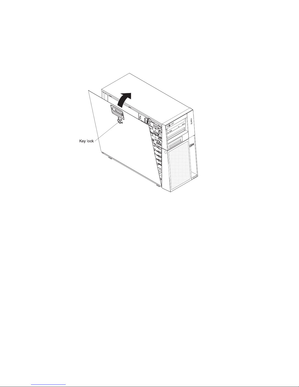
Installing the side cover
Attention: For proper cooling and airflow, replace the side cover before you turn
on the server. Operating the server for extended periods of time (more than 30
minutes) with the side cover removed might damage server components.
To install the side cover, complete the following steps.
1. Make sure that all cables, adapters, and other components are installed and
seated correctly and that you have not left loose tools or parts inside the server.
Also, make sure that all internal cables are correctly routed.
2. If you removed the upper and lower bezels, reinstall them before you replace
the side cover (see “Installing the upper bezel” on page 44 and “Installing the
lower bezel” on page 42).
Important: The cover lock must be in the unlocked (opened) position before
you install the side cover.
3. Position the lip on the bottom edge of the side cover on the ledge on the bottom
of the chassis; then, tilt the top of the cover into position on the chassis until it
latches securely into place.
4. Lock the side cover.
5. Reconnect the external cables and power cords; then, turn on the attached
devices and turn on the server.
40 System x3200 Types 4362 and 4363: Problem Determination and Service Guide
Page 59
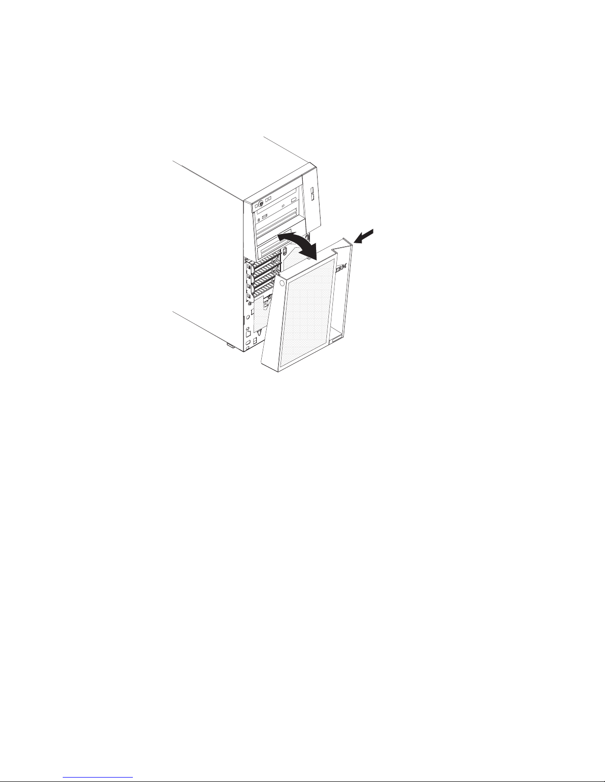
Removing the lower bezel
When your work with some devices, such as the drives in bays 4 through 7, you
must first remove the lower bezel to access the devices.
To remove the lower bezel, complete the following steps.
1. Read the safety information that begins on page vii and “Installation guidelines”
on page 35.
2. If you are replacing a non-hot-swap component, turn off the server and all
attached devices; then, disconnect all power cords and external cables.
3. Unlock the side cover.
Note: You do not have to remove the side cover to remove the lower bezel.
4. Press the round blue release button on the right side of the lower bezel and tilt
the lower bezel forward to disengage and remove it from the chassis.
5. If you are instructed to return the lower bezel, follow all packaging instructions,
and use any packaging materials for shipping that are supplied to you.
Chapter 4. Removing and replacing server components 41
Page 60
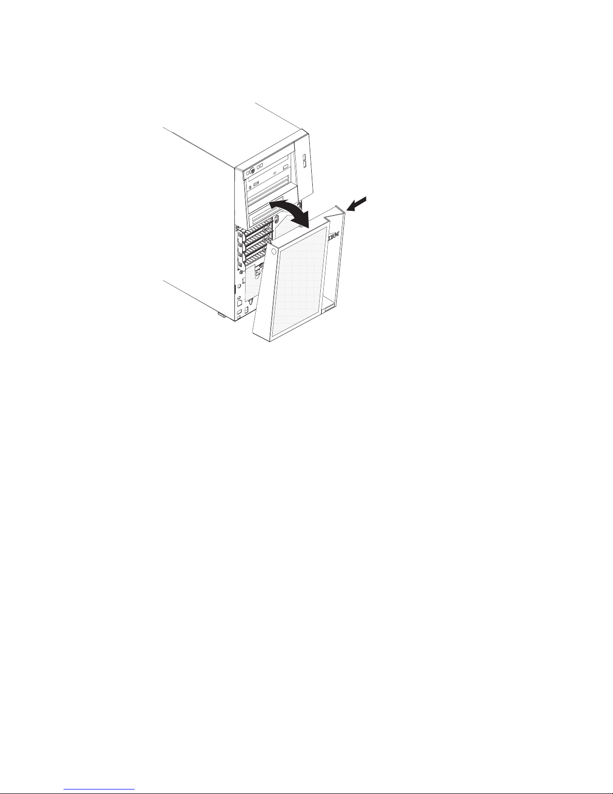
Installing the lower bezel
To install the lower bezel, complete the following steps.
1. Insert the two bottom tabs on the lower bezel into the corresponding holes in
the front of the chassis.
2. Press the top of the lower bezel into position on the chassis until it locks
securely into place.
3. Lock the side cover.
4. Reconnect the external cables and power cords; then, turn on the attached
devices and turn on the server.
42 System x3200 Types 4362 and 4363: Problem Determination and Service Guide
Page 61
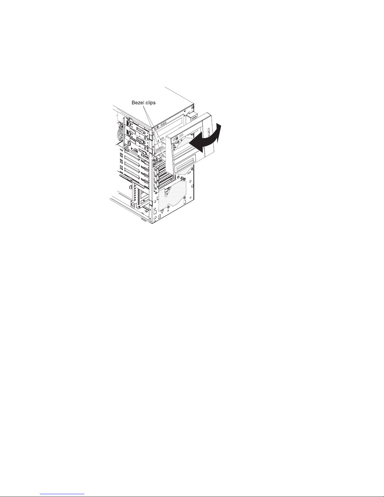
Removing the upper bezel
When you work with some devices, such as the drives in bays 1 through 3, you
must first remove the upper bezel to access the devices.
To remove the upper bezel, complete the following steps.
1. Read the safety information that begins on page vii and “Installation guidelines”
on page 35.
2. If you are replacing a non-hot-swap component, turn off the server and all
attached devices; then, disconnect all power cords and external cables.
3. Unlock and remove the side cover (see “Removing the side cover” on page 39).
4. Remove the lower bezel (see “Removing the lower bezel” on page 41).
5. Carefully pull the two bezel clips on the left side of the upper bezel away from
the chassis; then, rotate the upper bezel to the right side of the server to
disengage the two right-side tabs from the chassis.
6. If you are instructed to return the upper bezel, follow all packaging instructions,
and use any packaging materials for shipping that are supplied to you.
Chapter 4. Removing and replacing server components 43
Page 62
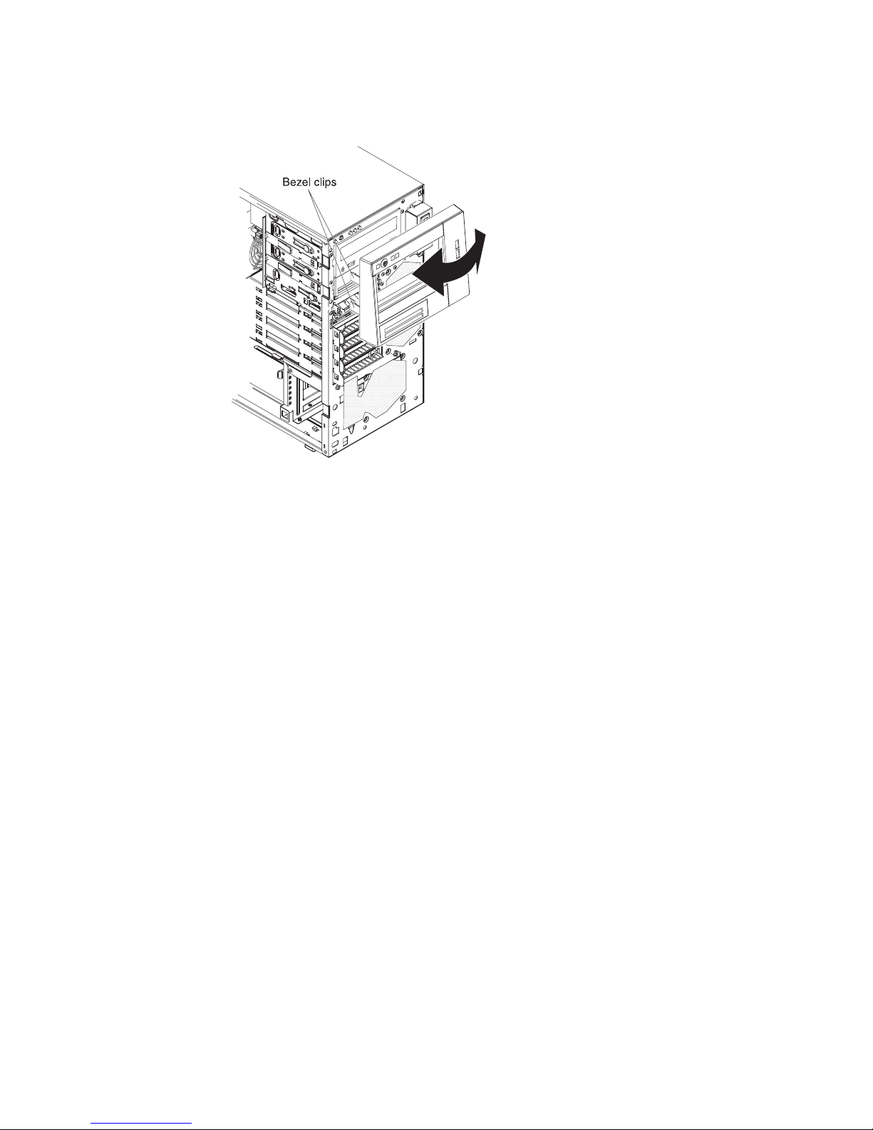
Installing the upper bezel
To install the upper bezel, complete the following steps.
1. Insert the two right-side tabs on the upper bezel into the corresponding holes on
the right side of the chassis.
2. Rotate the upper bezel to the left side of the chassis and press the bezel clips
onto the corresponding indentations on the left side of the chassis.
3. Install the lower bezel (see “Installing the lower bezel” on page 42).
4. Install the side cover (see “Installing the side cover” on page 40).
5. Lock the side cover.
6. Reconnect the external cables and power cords; then, turn on the attached
devices and turn on the server.
44 System x3200 Types 4362 and 4363: Problem Determination and Service Guide
Page 63
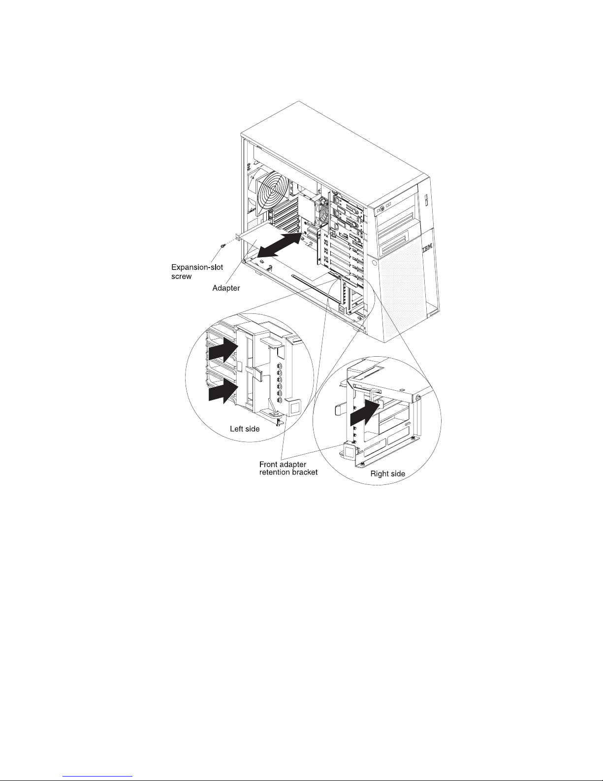
Removing an adapter
To remove an adapter, complete the following steps.
1. Read the safety information that begins on page vii and “Installation guidelines”
on page 35.
2. Turn off the server and all attached devices; then, disconnect all power cords
and external cables.
3. Unlock and remove the side cover (see “Removing the side cover” on page 39).
4. Disconnect any cables to the adapter or any cables that impede access to the
adapter.
5. If you are removing a full-length adapter, press on the retaining tab on the left
side of the front adapter-retention bracket until the release lever on the right
side of the bracket clicks into place.
6. Remove the expansion-slot screw at the rear of the adapter.
7. Carefully grasp the adapter by its top edge or upper corners, and pull the
adapter from the server.
Attention: Expansion-slot covers must be installed in all empty slots. This
maintains the electronic emissions standards of the computer and ensures
proper ventilation of computer components.
Chapter 4. Removing and replacing server components 45
Page 64

8. If the adapter is not being replaced, install an expansion-slot cover in the
expansion-slot opening.
9. If you are instructed to return the adapter, follow all packaging instructions, and
use any packaging materials for shipping that are supplied to you.
Installing an adapter
For information about the types of adapters that the server supports and other
information that you might consider when you install an adapter, see the User’s
Guide. For the locations of the expansion slots and optional device connectors see
“System-board optional-devices connectors” on page 11.
Notes:
1. If you are replacing a Remote Supervisor Adapter II SlimLine, it must be
installed in its dedicated connector on the system board (see “System-board
optional-devices connectors” on page 11).
2. When you start the server for the first time after you install a Remote Supervisor
Adapter II SlimLine, the startup process will take several minutes longer than a
typical startup.
To install a replacement adapter, complete the following steps.
46 System x3200 Types 4362 and 4363: Problem Determination and Service Guide
Page 65

1. Check the instructions that come with the adapter for any requirements,
restrictions, or cabling instructions. It might be easier to route cables before
you install the adapter.
2. Follow the instructions that come with the adapter to set jumpers or switches, if
any.
3. Touch the static-protective package that contains the adapter to any unpainted
metal surface on the server. Then, remove the adapter from the
static-protective package. Avoid touching the components and gold-edge
connectors on the adapter.
4. If you are installing a full-length adapter, remove the blue adapter guide (if any)
from the end of the adapter.
Adapter guide
5. Carefully grasp the adapter by the top edge or upper corner, and move the
adapter directly from the static-protective package to the expansion slot. Align
the adapter with the expansion slot guides; then, press the adapter firmly into
the expansion slot. For full-length adapters, make sure that the front edge of
the adapter is properly seated in the correct slot in the front adapter-retention
bracket.
6. Install an expansion-slot screw at the rear of the adapter.
7. If you are installing a full-length adapter, press on the release lever on the right
side of the front adapter-retention bracket to release the retaining tab on the
left side of the bracket.
8. Connect required cables to the adapter. Route cables so that they do not block
the flow of air from the fans.
9. Install and lock the side cover (see “Installing the side cover” on page 40).
10. Reconnect the external cables and power cords; then, turn on the attached
devices and turn on the server.
Chapter 4. Removing and replacing server components 47
Page 66

Cabling the optional ServeRAID-8s controller
When you install the optional ServeRAID-8s controller card, follow the instructions
in the following sections to route the cables in the server (depending on your
model).
Installing the simple-swap SATA cable
The following is an illustration of the optional 4-drop combination signal and power
simple-swap SATA cable for cabling the ServeRAID-8s controller card in
simple-swap SATA servers:
Figure 1.
Power connector
Drive backplate connector
ServeRAID-8s controller connector
To install the optional 4-drop combination signal and power simple-swap SATA
cable, complete the following steps:
1. Read the safety information that begins on page vii and “Installation guidelines”
on page 35.
2. Turn off the server and all attached devices; then, disconnect all power cords
and external cables.
3. Unlock and remove the side cover (see“Removing the side cover” on page 39
).
4. Remove the front system fan assembly:
a. Disconnect the fan assembly cable from the system board and make a
note of where the cable was connected for later installation.
b. Press and hold the drive cage release tab on the side of the drive cage;
then, rotate the drive cage out of the chassis until the retaining tab on top
of the cage locks into place.
c. Pull out on the front system fan assembly release tabs (at the blue dots);
then, rotate the fan assembly away from the drive cage slightly.
d. Remove the cables from the slots on the fan assembly and remove the fan
assembly from the drive cage.
5. Disconnect the existing SATA controller cable from the hard disk drive
backplate and from the controller; then, remove them from the server.
6. Connect the ServeRAID-8s controller connector end (see Figure 1) of the
optional 4-drop combination signal and power simple-swap SATA cable to the
48 System x3200 Types 4362 and 4363: Problem Determination and Service Guide
Page 67

ServeRAID-8s controller card; then, for each installed drive, attach one drop
from the 4-drop end of the cable to the drive backplate connector (see Figure 1
on page 48) on the drive cage backplate and connect the power connector to
a power drop on the system power cable. Route the cable as shown in the
following illustration.
ServeRAID-8s
4-drop cable
7. Replace the front system fan assembly.
a. Insert the fan assembly retaining tab over the right edge of the hard disk
drive backplate; then, rotate the fan assembly toward the backplate. Do not
fully close the fan assembly.
b. Route the 4-drop end of the combination signal and power cable through
one of the slots on the edge of the fan assembly; then, route the hard disk
drive power drop cable through the other slot on the edge of the fan
assembly. Ensure that the cables will not be pinched between the fan
assembly and the hard disk drive backplate when the fan assembly is
installed.
c. Rotate the fan assembly toward the backplate until the release tabs are
fully engaged.
d. Rotate the drive cage back into the server until it stops; then, press and
hold the retaining tab on top of the drive cage while rotating the drive cage
into the chassis until it locks into place.
8. Reconnect the fan assembly cable to the system board.
Note: Before you continue, check all internal power cables to make sure that
they are connected to the system board and other optional devices.
9. Install the side cover (see “Installing the side cover” on page 40).
10. Lock the side cover.
11. Reconnect the external cables and power cords; then, turn on the attached
devices and turn on the server.
Chapter 4. Removing and replacing server components 49
Page 68

Figure 2.
Installing the hot-swap SAS/SATA cable
The following is an illustration of the optional single-drop hot-swap SAS/SATA cable
for cabling the ServeRAID-8s controller card in hot-swap SAS and hot-swap SATA
servers:
Drive backplane connector
ServeRAID-8s controller connector
To install the optional single-drop hot-swap SAS/SATA cable, complete the following
steps:
1. Read the safety information that begins on page vii and “Installation guidelines”
on page 35.
2. Turn off the server and all attached devices; then, disconnect all power cords
and external cables.
3. Unlock and remove the side cover (see “Removing the side cover” on page
39).
4. Remove the front system fan assembly:
a. Disconnect the fan assembly cable from the system board and make a
note of where the cable was connected for later installation.
b. Press and hold the drive cage release tab on the side of the drive cage;
then, rotate the drive cage out of the chassis until the retaining tab on top
of the cage locks into place.
c. Pull out on the front system fan assembly release tabs (at the blue dots);
then, rotate the fan assembly away from the drive cage slightly.
d. Remove the cables from the slots on the fan assembly and remove the fan
assembly from the drive cage.
5. Disconnect the existing SAS/SATA controller cable from the hard disk drive
backplane and from the controller; then, remove them from the server.
6. Connect the ServeRAID-8s controller connector end (see Figure 2 ) of the
optional single-drop hot-swap SAS/SATA cable to the ServeRAID-8s controller
card; then, attach the other end of the cable to the hard disk drive backplane
(see Figure 2 ) on the drive cage. Route the cable as shown in the following
illustration.
50 System x3200 Types 4362 and 4363: Problem Determination and Service Guide
Page 69

ServeRAID-8s
single-drop cable
7. Replace the front system fan assembly.
a. Insert the fan assembly retaining tab over the right edge of the hard disk
drive backplane; then, rotate the fan assembly toward the backplane. Do
not fully close the fan assembly.
b. Route the single-drop signal cable through one of the slots on the edge of
the fan assembly; then, route the hard disk drive power drop cable through
the other slot on the edge of the fan assembly. Ensure that the cables will
not be pinched between the fan assembly and the hard disk drive
backplane when the fan assembly is installed.
c. Rotate the fan assembly toward the backplane until the release tabs are
fully engaged.
d. Rotate the drive cage back into the server until it stops; then, press and
hold the retaining tab on top of the drive cage while rotating the drive cage
into the chassis until it locks into place.
8. Reconnect the fan assembly cable to the system board.
Note: Before you continue, check all internal power cables to make sure that
they are connected to the system board and other optional devices.
9. Install the side cover (see “Installing the side cover” on page 40).
10. Lock the side cover.
11. Reconnect the external cables and power cords; then, turn on the attached
devices and turn on the server.
Chapter 4. Removing and replacing server components 51
Page 70

Removing and installing internal drives
See the User’s Guide for information about the types of drives that the server
supports. The following figure shows the location of the drive bays in the server.
Bay 1
Bay 2
Bay 3
Bay 4
Bay 5
Bay 6
Bay 7
52 System x3200 Types 4362 and 4363: Problem Determination and Service Guide
Page 71

Removing a CD or DVD drive
To remove a CD or DVD drive, complete the following steps.
1. Read the safety information that begins on page vii and “Installation guidelines”
on page 35.
2. Turn off the server and all attached devices; then, disconnect all power cords
and external cables.
3. Unlock and remove the side cover (see “Removing the side cover” on page 39).
4. Remove the lower bezel (see “Removing the lower bezel” on page 41).
5. Remove the upper bezel (see “Removing the upper bezel” on page 43).
6. Disconnect the power and signal cables from the drive that is to be removed.
7. Press and hold the blue release button on the side of the bay to release the
drive; then, pull the drive out of the front of the server.
8. Remove the drive retainer clip from the side of the drive. Save the clip to use
when you install the replacement drive.
9. If you are instructed to return the drive, follow all packaging instructions, and
use any packaging materials for shipping that are supplied to you.
Chapter 4. Removing and replacing server components 53
Page 72

Installing a CD or DVD drive
To install a CD or DVD drive, complete the following steps.
1. If you are replacing a removed drive with a new drive, make sure that:
v You have all the cables and other equipment that is specified in the
documentation that comes with the new drive.
v You check the instructions that come with the new drive to determine
whether you must set any switches or jumpers on the drive.
v You have removed the drive retainer clip on the side of the old drive and
have it available for installation on the new drive.
Note: If you are installing a drive that contains a laser, observe the following
safety precaution.
54 System x3200 Types 4362 and 4363: Problem Determination and Service Guide
Page 73

Statement 3:
CAUTION:
When laser products (such as CD-ROMs, DVD drives, fiber optic devices,
or transmitters) are installed, note the following:
v Do not remove the covers. Removing the covers of the laser product
could result in exposure to hazardous laser radiation. There are no
serviceable parts inside the device.
v Use of controls or adjustments or performance of procedures other
than those specified herein might result in hazardous radiation
exposure.
DANGER
Some laser products contain an embedded Class 3A or Class 3B laser
diode. Note the following.
Laser radiation when open. Do not stare into the beam, do not view
directly with optical instruments, and avoid direct exposure to the
beam.
Class 1 Laser Product
Laser Klasse 1
Laser Klass 1
Luokan 1 Laserlaite
Appareil A Laser de Classe 1
`
2. Touch the static-protective package that contains the drive to any unpainted
metal surface on the server; then, remove the drive from the package and
place it on a static-protective surface.
3. Follow the instructions that come with the drive to set jumpers or switches, if
there are any.
Note: You might find it easier to install the new drive from the front and then
attach the cables.
4. If you are installing a 3.5 in. drive in bay 2, attach a 5.25 in. conversion kit to
the 3.5 in. drive.
5. Remove the drive retainer clip from the side of the drive cage of bay (see the
illustration at the beginning of this section). Slide the drive retainer clip to the
left to remove it from the drive cage; then, snap the drive retainer clip into the
screw holes on the side of the drive (the blue side of the drive retainer clip
should be facing outward).
6. Push the drive into the bay.
Chapter 4. Removing and replacing server components 55
Page 74
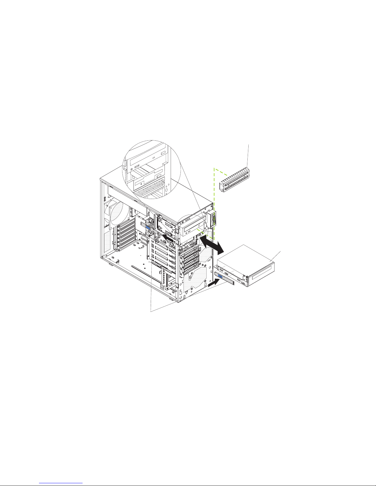
7. Connect the power and signal cables to the drive.
Note: Route the signal cable so that it does not block the airflow to the rear of
the drives or over the microprocessor and dual inline memory modules
(DIMMs).
8. Install the upper bezel (see “Installing the upper bezel” on page 44).
9. Install the lower bezel (see “Installing the lower bezel” on page 42).
10. Install and lock the side cover (see “Installing the side cover” on page 40).
11. Reconnect the external cables and power cords; then, turn on the attached
devices and turn on the server.
Removing a tape drive
EMC shield
Tape drive
Drive retainer clip
To remove a tape drive, complete the following steps:
1. Read the safety information that begins on page vii and “Installation guidelines”
on page 35.
2. Turn off the server and peripheral devices, and disconnect the power cords and
all external cables.
3. Unlock and remove the side cover (see “Installing the side cover” on page 40).
4. Remove the upper bezel (see “Installing the upper bezel” on page 44).
5. Remove the lower bezel (see “Installing the lower bezel” on page 42).
6. Disconnect the power and signal cables from the drive that is to be removed.
7. Press and hold the blue release button on the side of the bay to release the
drive; then, pull the drive out of the front of the server.
8. Remove the drive retainer clip from the side of the drive. Save the clip to use
when you install the replacement drive.
9. If you are instructed to return the drive, follow all packaging instructions, and
use any packaging materials for shipping that are supplied to you.
56 System x3200 Types 4362 and 4363: Problem Determination and Service Guide
Page 75
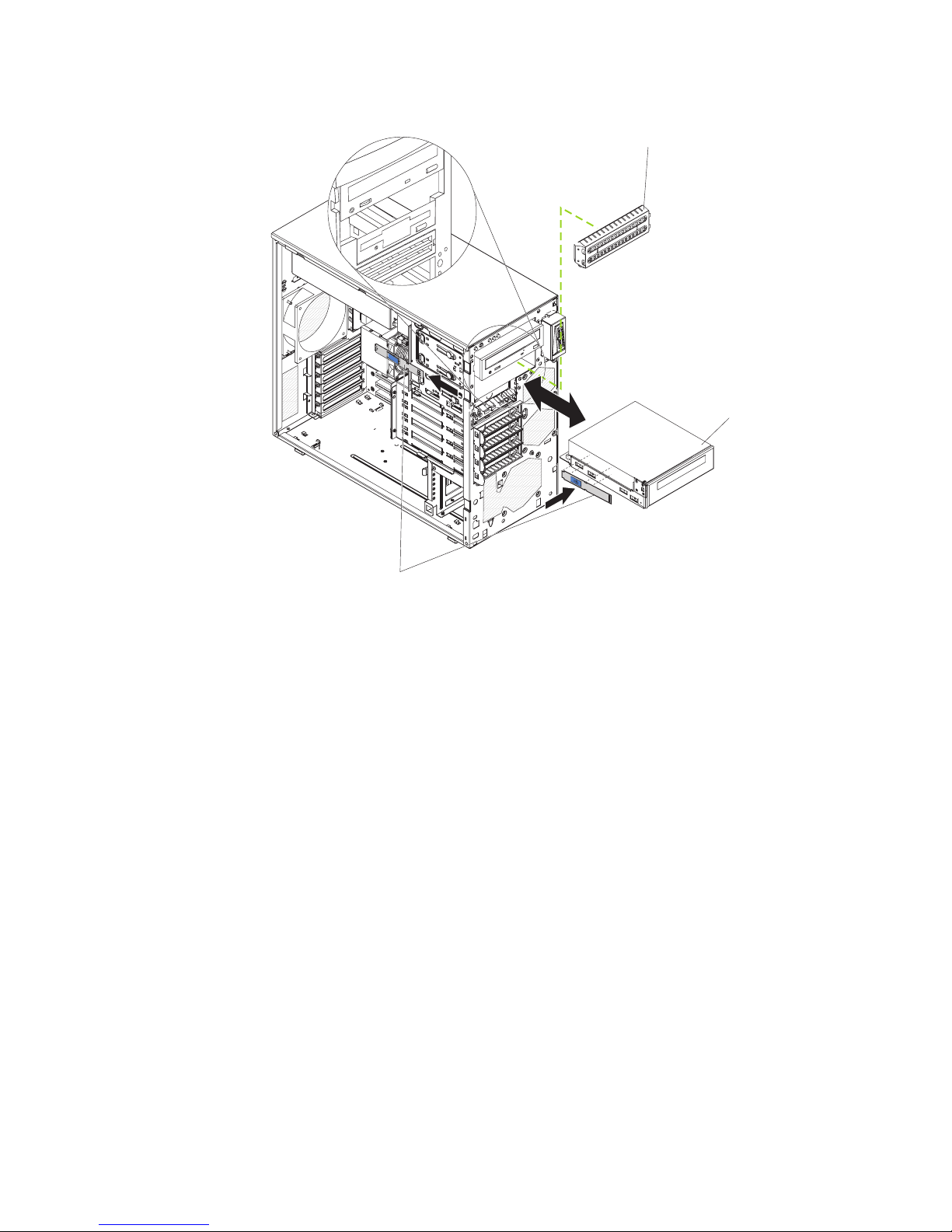
Installing a tape drive
EMC shield
Tape drive
Drive retainer clip
To install a tape drive, complete the following steps:
Note: It is necessary to remove power connector P9 from the interposer cable
when installing the DDS 5 tape drive in hot-swap models. Refer to the instructions
that come with the drive.
1. If you are replacing a removed drive with a new drive, make sure that:
v You have all the cables and other equipment that is specified in the
documentation that comes with the new drive.
v You check the instructions that come with the new drive to determine
whether you must set any switches or jumpers on the drive.
v You have removed the drive retainer clip on the side of the old drive and
have it available for installation on the new drive.
2. Read the safety information that begins on page vii and “Installation guidelines”
on page 35.
3. Turn off the server and peripheral devices, and disconnect the power cords
and all external cables.
4. Unlock and remove the side cover (see “Installing the side cover” on page 40).
5. Remove the upper bezel (see “Installing the upper bezel” on page 44).
6. Remove the lower bezel (see “Installing the lower bezel” on page 42).
7. Touch the static-protective package that contains the drive to any unpainted
metal surface on the server; then, remove the drive from the package and
place it on a static-protective surface.
8. Set any jumpers or switches on the drive according to the documentation that
comes with the drive.
9. Remove the drive retainer clip from the side of the drive cage of bay (see the
illustration at the beginning of this section). Slide the drive retainer clip to the
Chapter 4. Removing and replacing server components 57
Page 76

left to remove it from the drive cage; then, snap the drive retainer clip into the
screw holes on the side of the drive (the blue side of the drive retainer clip
should be facing outward).
10. Push the drive into the bay.
11. Connect one end of the applicable signal cable into the rear of the drive and
make sure that the other end of this cable is connected into the applicable
connector on the system board.
12. Route the signal cable so that it does not block the airflow to the rear of the
drives or over the microprocessor and dual inline memory modules (DIMMs).
13. If you have another drive to install or remove, do so now.
14. Connect the power cable to the rear of the drive. The connectors are keyed
and can be inserted only one way.
58 System x3200 Types 4362 and 4363: Problem Determination and Service Guide
Page 77
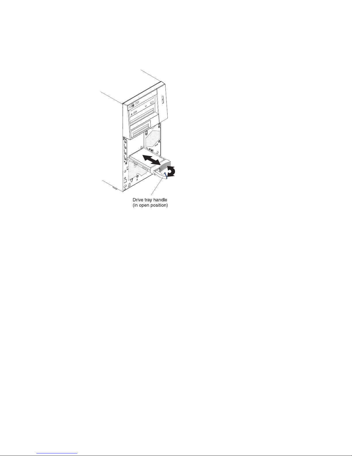
Removing a hot-swap hard disk drive
This procedure applies only to server models that have hot-swap hard disk drives.
To remove a hot-swap hard disk drive, complete the following steps.
1. Read the safety information that begins on page vii and “Installation guidelines”
on page 35.
Note: You do not have to turn off the server to remove hot-swap drives from
the hot-swap drive bays.
2. Unlock the side cover. The side cover does not have to be removed.
3. Remove the lower bezel (see “Removing the lower bezel” on page 41).
4. Rotate the drive tray handle of the drive assembly to be removed to the open
position.
5. Grasp the handle of the drive assembly to be replaced and pull the assembly
out of the bay.
6. If you are instructed to return the drive assembly, follow all packaging
instructions, and use any packaging materials for shipping that are supplied to
you.
Chapter 4. Removing and replacing server components 59
Page 78
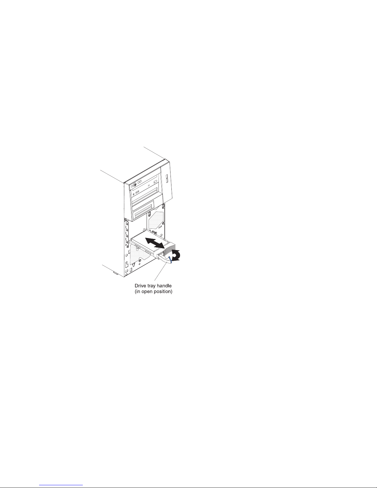
Installing a hot-swap hard disk drive
This procedure applies only to server models that have hot-swap hard disk drives.
Before you install a hot-swap hard disk drive, read the following information:
v The hot-swap drives must be either all SAS hard disk drives or all SATA hard
disk drives; the two types cannot be combined.
v Inspect the drive tray for signs of damage.
v You do not have to turn off the server to install hot-swap drives in the hot-swap
drive bays.
Note: If you install the maximum number of hot-swap hard disk drives (four),
remove the EMC shield that is attached inside the lower bezel.
To install a hot-swap hard disk drive, complete the following steps.
1. Touch the static-protective package that contains the drive to any unpainted
metal surface on the server; then, remove the drive from the package and place
it on a static-protective surface.
2. Make sure that the drive tray handle is in the open position.
3. Align the drive assembly with the guide rails in the bay; then, carefully slide the
drive assembly into the drive bay until the drive stops.
4. Rotate the drive tray handle to the closed position.
60 System x3200 Types 4362 and 4363: Problem Determination and Service Guide
Page 79

5. Check the hard disk drive status indicator to make sure that the hard disk drive
is operating correctly. (You might have to restart the server for the drive to be
recognized.) If the amber hard disk drive status LED for a drive is lit
continuously, it indicates that the drive is faulty and must be replaced. If the
green hard disk drive activity LED is flashing, this indicates that the drive is
being accessed.
Note: If the server is configured for RAID operation using an optional
ServeRAID controller, you might have to reconfigure the disk arrays after you
replace hard disk drives. See the ServeRAID documentation for additional
information about RAID operation and complete instructions for using
ServeRAID Manager.
6. Install the lower bezel (see “Installing the lower bezel” on page 42).
7. Lock the side cover.
Chapter 4. Removing and replacing server components 61
Page 80

Removing a simple-swap hard disk drive
This procedure applies only to server models that have simple-swap SATA hard disk
drives.
Attention: Simple-swap hard disk drives are not hot-swappable. Disconnect all
power from the server before you remove or install a simple-swap hard disk drive.
To remove a simple-swap hard disk drive, complete the following steps.
1. Read the safety information that begins on page vii and “Installation guidelines”
on page 35.
2. Turn off the server and all attached devices; then, disconnect all power cords
and external cables.
3. Unlock the side cover. The side cover does not have to be removed.
4. Remove the lower bezel (see “Removing the lower bezel” on page 41).
5. Pull the loops of the drive assembly that is to be removed toward each other;
then, pull the assembly out of the bay.
6. If you are instructed to return the drive assembly, follow all packaging
instructions, and use any packaging materials for shipping that are supplied to
you.
62 System x3200 Types 4362 and 4363: Problem Determination and Service Guide
Page 81

Installing a simple-swap hard disk drive
This procedure applies only to server models that have simple-swap SATA hard disk
drives.
Attention: Simple-swap hard disk drives are not hot-swappable. Disconnect all
power from the server you remove or install a simple-swap hard disk drive.
To install a simple-swap hard disk drive, complete the following steps.
1. Touch the static-protective package that contains the drive to any unpainted
metal surface on the server; then, remove the drive from the package and place
it on a static-protective surface.
2. Align the drive assembly with the guide rails in the bay.
3. Pull the loops of the drive assembly toward each other; then, carefully slide the
drive assembly into the drive bay until it stops and release the loops.
Note: Do not release the loops on the drive assembly until it is completely
seated.
4. Install the lower bezel (see “Installing the lower bezel” on page 42).
5. Lock the side cover.
6. Reconnect the external cables and power cords; then, turn on the attached
devices and turn on the server.
Chapter 4. Removing and replacing server components 63
Page 82

Removing a hot-swap power supply
This procedure applies only to server models that have hot-swap power supplies.
See “Removing a non-hot-swap power supply” on page 86 for information about the
removal of a non-hot-swap power supply.
When you remove or install a hot-swap power supply, observe the following
precautions.
Statement 8:
CAUTION:
Never remove the cover on a power supply or any part that has the following
label attached.
Hazardous voltage, current, and energy levels are present inside any
component that has this label attached. There are no serviceable parts inside
these components. If you suspect a problem with one of these parts, contact
a service technician.
64 System x3200 Types 4362 and 4363: Problem Determination and Service Guide
Page 83
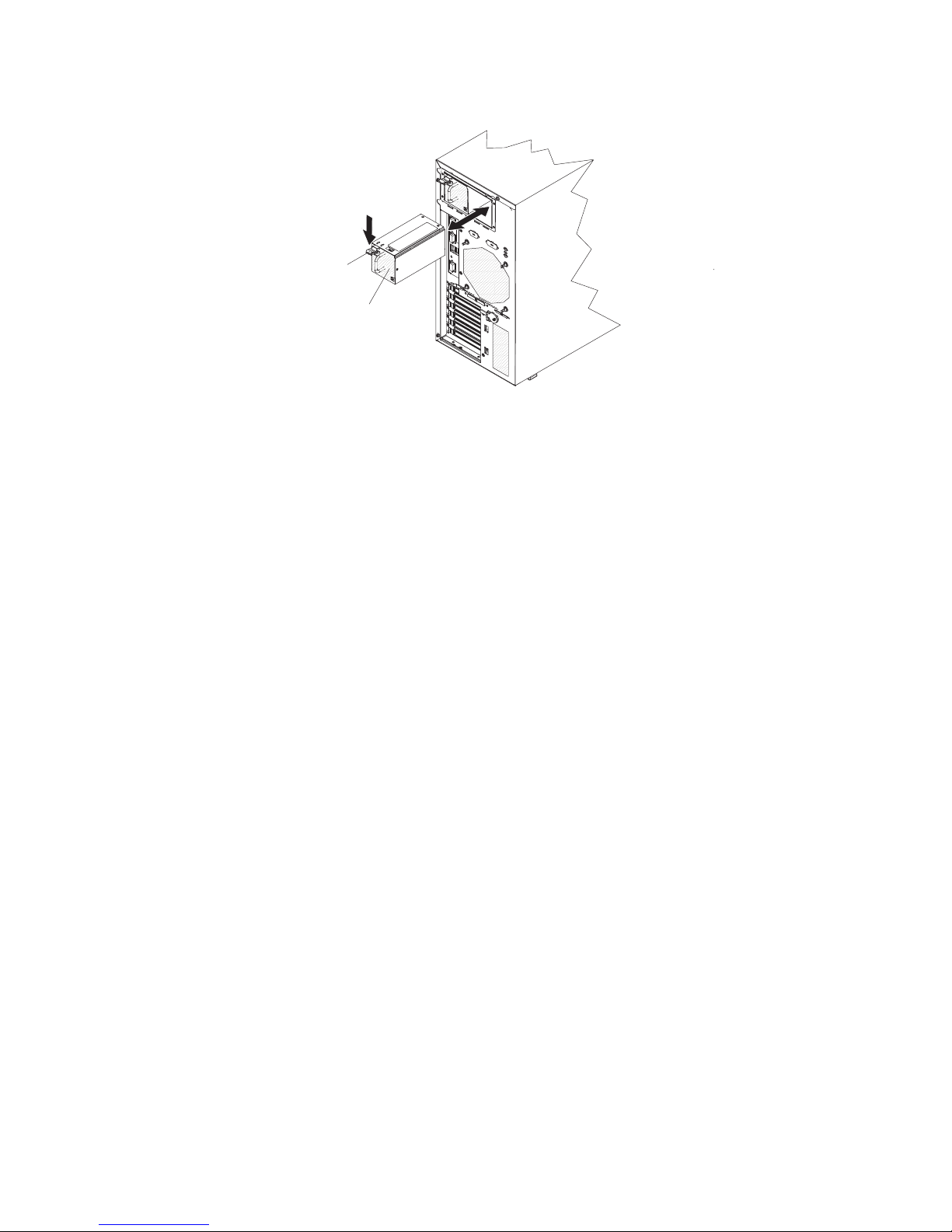
To remove a hot-swap power supply, complete the following steps.
Release lever
Hot-swap power
supply
1. Read the safety information that begins on page vii and “Installation guidelines”
on page 35.
2. Disconnect the power cord from the power supply that is to be removed.
3. Press down on the orange release lever and pull the power supply out of the
bay, using the handle.
4. If you are instructed to return the power supply, follow all packaging instructions,
and use any packaging materials for shipping that are supplied to you.
Chapter 4. Removing and replacing server components 65
Page 84

Installing a hot-swap power supply
This procedure applies only to server models that have hot-swap power supplies.
See “Installing a non-hot-swap power supply” on page 88 for information about the
installation of a non-hot-swap power supply.
To install a hot-swap power supply, complete the following steps.
Release lever
Hot-swap power
supply
1. Place the power supply into the bay guides.
2. Using the handle, push the power supply toward the front of the chassis until it
locks into place.
3. Connect one end of the power cord into the connector on the back of the power
supply and connect the other end of the power cord into a properly grounded
electrical outlet.
4. Make sure that both the ac and dc power LEDs on the rear of the power supply
are lit, indicating that the power supply is operating correctly.
66 System x3200 Types 4362 and 4363: Problem Determination and Service Guide
Page 85

Removing a memory module
To remove a dual inline memory module (DIMM), complete the following steps.
1. Read the safety information that begins on page vii and “Installation guidelines”
on page 35.
2. Turn off the server and all attached devices; then, disconnect all power cords
and external cables.
3. Unlock and remove the side cover (see “Removing the side cover” on page 39).
4. Disconnect any cables that impede access to the DIMMs.
5. Locate the DIMM connector that contains the DIMM that is to be replaced (see
“System-board optional-devices connectors” on page 11 for DIMM slot
locations).
Attention: To avoid breaking the DIMM retaining clips or damaging the DIMM
connectors, open and close the clips gently.
6. Carefully open the retaining clips on each end of the DIMM connector and
remove the DIMM.
7. If you are instructed to return the DIMM, follow all packaging instructions, and
use any packaging materials for shipping that are supplied to you.
Chapter 4. Removing and replacing server components 67
Page 86

Installing a memory module
Note: If you are replacing a faulty DIMM, make sure that the replacement DIMM is
the correct type of memory. If you are adding DIMMs, install the DIMMs in the
sequence shown in the following table. See the User’s Guide for additional
information about the type of memory that is compatible with the server.
Number of DIMMs Connectors
One DIMM 1
Two DIMMs 1, 3
Three DIMMs Not recommended
Four DIMMs 1, 3, 2, 4
To install a DIMM, complete the following steps.
1. Make sure that the retaining clips on each end of the DIMM connector are fully
open.
2. Touch the static-protective package that contains the DIMM to any unpainted
metal surface on the server; then, remove the new DIMM from the package.
3. Turn the DIMM so that the DIMM keys align correctly with the slot.
Attention: To avoid breaking the retaining clips or damaging the DIMM
connectors, open and close the clips gently.
4. Insert the DIMM into the connector by aligning the edges of the DIMM with the
slots at the ends of the DIMM connector. Firmly press the DIMM straight down
into the connector by applying pressure on both ends of the DIMM
simultaneously. The retaining clips snap into the locked position when the DIMM
is firmly seated in the connector. If there is a gap between the DIMM and the
retaining clips, the DIMM has not been correctly installed. Open the retaining
clips, remove the DIMM, and then reinsert it.
5. Reconnect any cables that were disconnected during removal.
6. Install the side cover (see “Installing the side cover” on page 40).
7. Lock the side cover if it was unlocked during removal.
8. Reconnect the external cables and power cords; then, turn on the attached
devices and turn on the server.
68 System x3200 Types 4362 and 4363: Problem Determination and Service Guide
Page 87

Removing and replacing Tier 2 CRUs
You may install a Tier 2 CRU yourself or request IBM to install it, at no additional
charge, under the type of warranty service that is designated for the server.
The illustrations in this document might differ slightly from your hardware.
Removing the battery
To remove the battery, complete the following steps.
1. Read the safety information that begins on page vii and “Installation guidelines”
on page 35.
2. Turn off the server and all attached devices; then, disconnect all power cords
and external cables.
3. Unlock and remove the side cover (see “Removing the side cover” on page 39).
4. Remove any adapters that impede access to the battery.
5. Locate the battery on the system board (see “System-board internal connectors”
on page 9).
6. Remove the battery:
a. Use a fingernail to press the top of the battery clip away from the battery.
The battery pops up when released.
b. Use your thumb and index finger to lift the battery from the socket.
Installing the battery
The following notes describe information that you must consider when replacing the
battery in the server.
v You must replace the battery with a lithium battery of the same type from the
same manufacturer.
v To order replacement batteries, call 1-800-426-7378 within the United States, and
1-800-465-7999 or 1-800-465-6666 within Canada. Outside the U.S. and
Canada, call your IBM marketing representative or authorized reseller.
v After you replace the battery, you must reconfigure the server and reset the
system date and time.
v To avoid possible danger, read and follow the following safety statement.
Chapter 4. Removing and replacing server components 69
Page 88

Statement 2:
CAUTION:
When replacing the lithium battery, use only IBM Part Number 33F8354 or an
equivalent type battery recommended by the manufacturer. If your system has
a module containing a lithium battery, replace it only with the same module
type made by the same manufacturer. The battery contains lithium and can
explode if not properly used, handled, or disposed of.
Do not:
v Throw or immerse into water
v Heat to more than 100°C (212°F)
v Repair or disassemble
To install the battery, complete the following steps.
1. Follow any special handling and installation instructions that come with the
replacement battery.
2. Insert the new battery:
a. Tilt the battery so that you can insert it into the socket on the side opposite
the battery clip.
b. Press the battery down into the socket until it clicks into place. Make sure
the battery clip holds the battery securely.
3. Install the side cover (see “Installing the side cover” on page 40).
4. Lock the side cover if it was unlocked during removal.
5. Reconnect the external cables and power cords; then, turn on the attached
devices and turn on the server.
6. Start the Configuration/Setup Utility program and reset the configuration.
v Set the system date and time.
v Set the power-on password.
v Reconfigure the server.
See“Using the Configuration/Setup Utility program” on page 16 for details.
70 System x3200 Types 4362 and 4363: Problem Determination and Service Guide
Page 89

Removing the rear system fan
Attention:
v Replace a failed fan within 48 hours.
v To ensure proper cooling and airflow, do not operate the server for more than 30
minutes with the side cover removed.
To remove the rear system fan, complete the following steps.
Rubber
grommets
Rear system
Fan
1. Turn off the server and all attached devices; then, disconnect all power cords
and external cables.
2. Unlock and remove the side cover (see “Removing the side cover” on page 39).
3. Remove any adapters that impede access to the fan and the fan connector on
the system board (see “Removing an adapter” on page 45).
4. Disconnect the fan cable from the system board, making a note of where the
cable was connected, for later installation.
5. Grasp the fan with both hands and pull firmly, extending the rubber grommets.
The grommets will be pulled through the holes in either the fan or the chassis
and can then be removed.
6. Pull the fan up and out of the chassis.
7. If you are instructed to return the fan, follow all packaging instructions, and use
any packaging materials for shipping that are supplied to you.
Chapter 4. Removing and replacing server components 71
Page 90
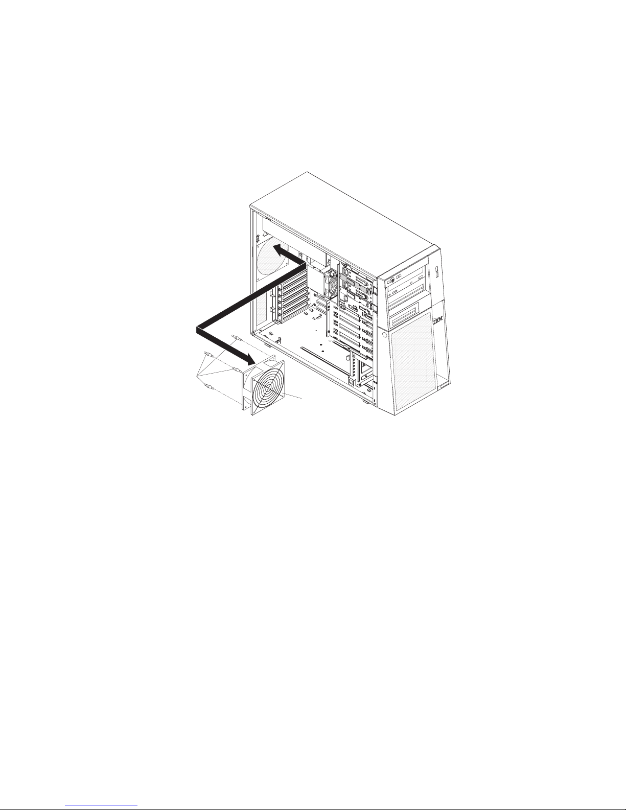
Installing the rear system fan
Attention:
v Replace a failed fan within 48 hours.
v To ensure proper cooling and airflow, do not operate the server for more than 30
minutes with the side cover removed.
To install the rear system fan, complete the following steps.
Rubber
grommets
Rear system
Fan
1. The replacement fan comes with the rubber grommets installed, however they
may have come out during shipment. If any of the rubber grommets are missing
from the fan install them on the fan before continuing. Use needle-nosed pliers
to pull the grommets through the holes in the fan.
2. Position the fan so that the grommets protrude through the holes in the chassis;
then, use needle-nosed pliers to pull the grommets through the holes from
outside the chassis.
3. Connect the fan cable to the system board (see “System-board internal
connectors” on page 9 for the location of the rear fan connector).
4. Install any adapters that were removed (see “Installing an adapter” on page 46).
5. Install the side cover (see “Installing the side cover” on page 40).
6. Lock the side cover if it was unlocked during removal.
7. Reconnect the external cables and power cords; then, turn on the attached
devices and turn on the server.
72 System x3200 Types 4362 and 4363: Problem Determination and Service Guide
Page 91

Removing the front system fan assembly
This procedure applies only to server models that have a front system fan
assembly.
Attention:
v Replace a failed fan within 48 hours.
v To ensure proper cooling and airflow, do not operate the server for more than 30
minutes with the side cover removed.
To remove the front system fan assembly, complete the following steps.
Release tabs
Slot
Front fan assembly
1. Read the safety information that begins on page vii and “Installation guidelines”
on page 35.
2. Turn off the server and all attached devices; then, disconnect all power cords
and external cables.
3. Unlock and remove the side cover (see “Removing the side cover” on page 39).
4. Disconnect the fan assembly cable from the system board, making a note of
where the cable was connected for later installation.
5. Press and hold the drive cage release tab; then, rotate the drive cage out of the
chassis until the retaining tab on top of the cage locks into place.
6. Pull out on the front system fan assembly release tabs; then, rotate the fan
assembly away from the drive cage slightly.
7. Remove the power cables from the slot on the fan assembly; then, rotate the
fan assembly away from the drive cage and remove the fan assembly from the
drive cage.
8. If you are instructed to return the fan assembly, follow all packaging instructions,
and use any packaging materials for shipping that are supplied to you.
Chapter 4. Removing and replacing server components 73
Page 92

Installing the front system fan assembly
This procedure applies only to server models that have a front system fan
assembly.
Attention:
v Replace a failed fan within 48 hours.
v To ensure proper cooling and airflow, do not operate the server for more than 30
minutes with the side cover removed.
To install the front system fan assembly, complete the following steps.
Release tabs
Slot
Front fan assembly
1. Insert the fan assembly retaining tab over the right edge of the hard disk drive
backplane; then, rotate the fan assembly toward the backplane. Do not fully
close the fan assembly.
2. Route the hard disk drive signal cable through the opening on the bottom edge
of the fan assembly; then, route the hard disk drive power cable through the slot
on the left edge of the fan assembly. Ensure that the hard disk drive cables will
not be pinched between the fan assembly and the hard disk drive backplane
when the fan assembly is installed.
3. Rotate the fan assembly toward the backplane until the release tabs are fully
engaged.
4. Rotate the drive cage toward the front of the server until it stops; then, press
and hold the retaining tab on top of the cage while rotating the drive cage into
the chassis until it locks into place.
5. Connect the fan assembly cable to the system board (see “System-board
internal connectors” on page 9 for the location of the front fan connector).
Note: Before you continue, check all internal power cables to be sure that they
are connected to the system board and other optional devices.
6. Install the side cover (see “Installing the side cover” on page 40).
7. Lock the side cover if it was unlocked during removal.
8. Reconnect the external cables and power cords; then, turn on the attached
devices and turn on the server.
74 System x3200 Types 4362 and 4363: Problem Determination and Service Guide
Page 93
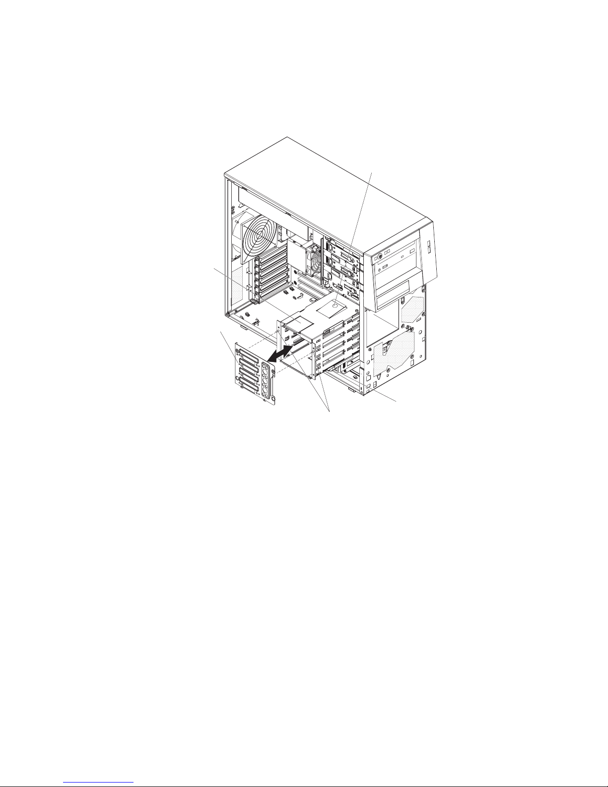
Removing the simple-swap backplate
This procedure applies only to server models that have a simple-swap backplate
installed on the back of the hard disk drive cage.
To remove the simple-swap backplate, complete the following steps.
Retaining
latch
Simple-swap
backplate
Retaining tab
Drive cage
Locating pins
release tab
1. Read the safety information that begins on page vii and “Installation guidelines”
on page 35.
2. Turn off the server and all attached devices; then, disconnect all power cords
and external cables.
3. Unlock and remove the side cover (see “Removing the side cover” on page
39).
4. Remove the lower bezel (see “Removing the lower bezel” on page 41).
5. Remove the simple-swap hard disk drives that are installed in the hard disk
drive cage (see “Removing a simple-swap hard disk drive” on page 62).
6. Remove the front fan assembly from the hard disk drive cage (see “Removing
the front system fan assembly” on page 73).
7. Disconnect the power cables from the simple-swap backplate.
8. Disconnect the signal cables from the system board.
9. Press and hold the drive cage release tab; then, rotate the drive cage out of
the chassis until the retaining tab on top of the cage locks into place.
10. Press up on the retaining latch at the top of the drive cage; then, tilt the top of
the simple-swap backplate away from the drive cage until it is clear of the
locating pins.
11. Lift the simple-swap backplate out of the lower lip on the drive cage.
12. If you are instructed to return the simple-swap backplate, follow all packaging
instructions, and use any packaging materials for shipping that are supplied to
you.
Chapter 4. Removing and replacing server components 75
Page 94
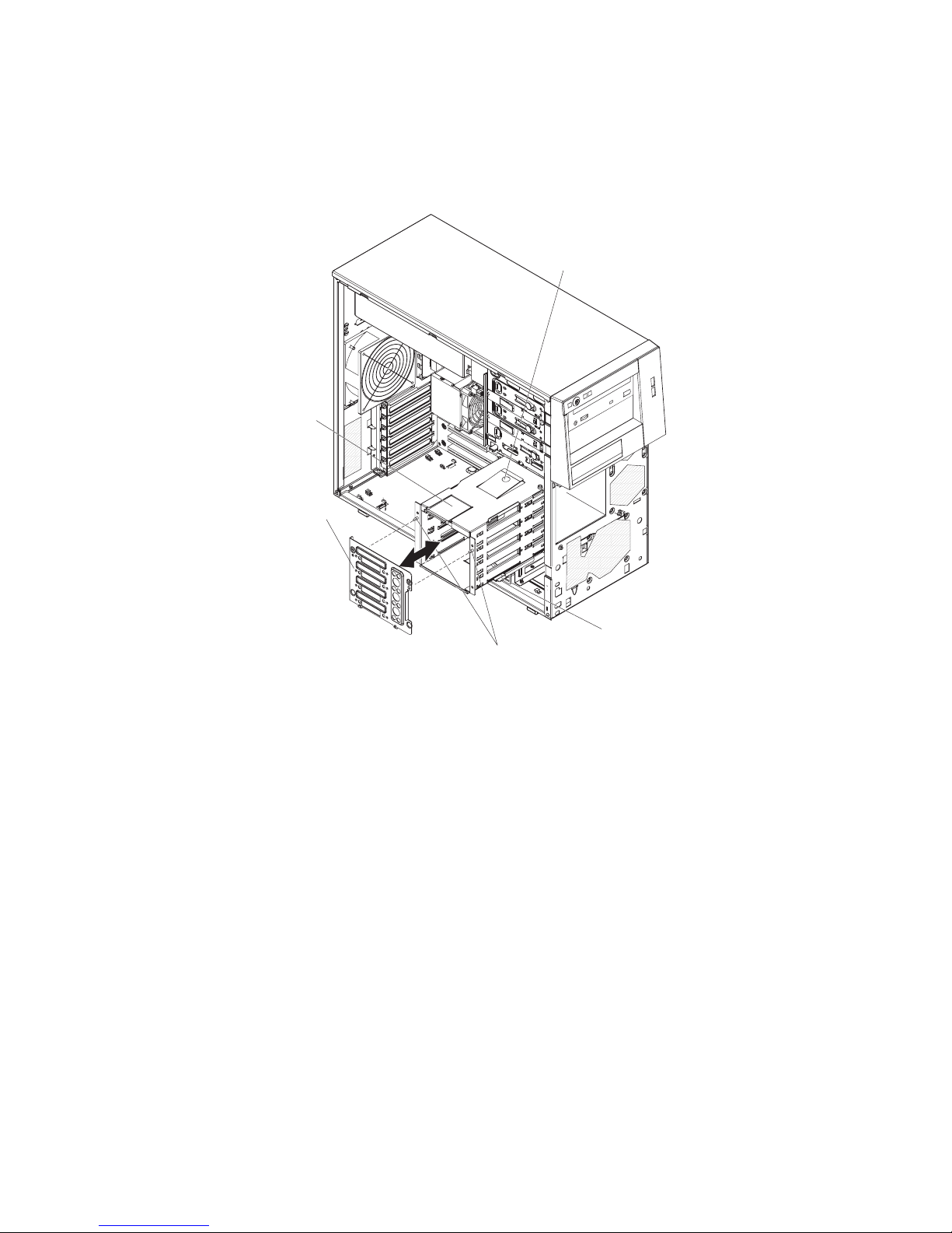
Installing the simple-swap backplate
This procedure applies only to server models that have a simple-swap backplate
installed on the back of the hard disk drive cage.
To install the simple-swap backplate, complete the following steps.
Retaining
latch
Simple-swap
backplate
Retaining tab
Drive cage
Locating pins
release tab
1. Position the bottom edge of the simple-swap backplate in the lower lip of the
drive cage.
2. Tilt the top of the simple-swap backplate toward the drive cage and over the
locating pins until the retaining latch is engaged.
3. Press and hold the retaining tab on top of the cage; then, rotate the drive cage
into the chassis until it locks into place.
4. Connect the signal cables to the system board (see “System-board internal
connectors” on page 9 for the location of the Serial ATA drive connectors).
5. Connect the power cables to the simple-swap backplate.
6. Install the front fan assembly on the hard disk drive cage (see “Installing the
front system fan assembly” on page 74).
7. Install the simple-swap hard disk drives that were removed from the hard disk
drive cage (see “Installing a simple-swap hard disk drive” on page 63).
8. Install the lower bezel (see “Installing the lower bezel” on page 42).
9. Install the side cover (see “Installing the side cover” on page 40).
10. Lock the side cover if it was unlocked during removal.
11. Reconnect the external cables and power cords; then, turn on the attached
devices and turn on the server.
Removing the SAS/SATA hard disk drive backplane
This procedure applies only to server models that have a SAS/SATA hard disk drive
backplane installed on the back of the hard disk drive cage.
76 System x3200 Types 4362 and 4363: Problem Determination and Service Guide
Page 95
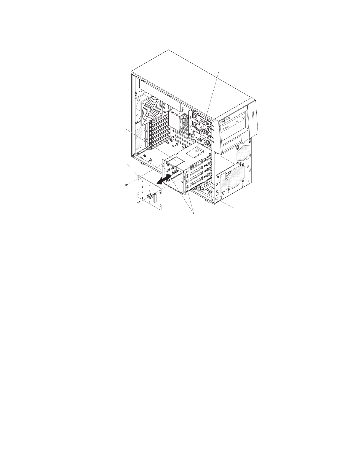
To remove the SAS/SATA hard disk drive backplane, complete the following steps.
Retaining tab
Retaining
latch
SAS
backplane
Drive cage
Locating pins
release tab
1. Read the safety information that begins on page vii and “Installation guidelines”
on page 35.
2. Turn off the server and all attached devices; then, disconnect all power cords
and external cables.
3. Unlock and remove the side cover (see “Removing the side cover” on page
39).
4. Remove the lower bezel (see “Removing the lower bezel” on page 41).
5. Remove the hot-swap SAS/SATA hard disk drives installed in the hard disk
drive cage (see “Removing a hot-swap hard disk drive” on page 59).
6. Remove the front fan assembly from the hard disk drive cage (see “Removing
the front system fan assembly” on page 73).
7. Disconnect the power and signal cables from the hard disk drive backplane.
8. Press and hold the drive cage release tab; then, rotate the drive cage out of
the chassis until the retaining tab on top of the cage locks into place.
9. Remove the two screws that secure the SAS/SATA hard disk drive backplane
to the drive cage.
10. Tilt the top of the hard disk drive backplane away from the drive cage until it is
clear of the locating pins.
11. Lift the SAS/SATA hard disk drive backplane out of the lower lip on the drive
cage.
12. If you are instructed to return the SAS/SATA hard disk drive backplane, follow
all packaging instructions, and use any packaging materials for shipping that
are supplied to you.
Chapter 4. Removing and replacing server components 77
Page 96

Installing the SAS/SATA hard disk drive backplane
This procedure applies only to server models that have a SAS/SATA hard disk drive
backplane installed on the back of the hard disk drive cage.
To install the hard disk drive backplane, complete the following steps.
Retaining tab
Retaining
latch
SAS
backplane
Drive cage
Locating pins
release tab
1. Place the bottom edge of the SAS/SATA hard disk drive backplane in the lower
lip of the drive cage.
2. Tilt the top of the SAS/SATA hard disk drive backplane toward the drive cage
and over the locating pins.
3. Install the two screws that secure the SAS/SATA hard disk drive backplane to
the drive cage.
4. Press and hold the retaining tab on top of the cage; then, rotate the drive cage
into the chassis until it locks into place.
5. Connect the power and signal cables to the hard disk drive backplane.
6. Install the front fan assembly onto the hard disk drive cage (see “Installing the
front system fan assembly” on page 74).
7. Install the hot-swap hard disk drives that were removed from the hard disk
drive cage (see “Installing a hot-swap hard disk drive” on page 60).
8. Install the lower bezel (see “Installing the lower bezel” on page 42).
9. Install the side cover (see “Installing the side cover” on page 40).
10. Lock the side cover if it was unlocked during removal.
11. Reconnect the external cables and power cords; then, turn on the attached
devices and turn on the server.
78 System x3200 Types 4362 and 4363: Problem Determination and Service Guide
Page 97

Removing the front-panel assembly
To remove the front-panel assembly, complete the following steps.
1. Read the safety information that begins on page vii and “Installation guidelines”
on page 35.
2. Turn off the server and all attached devices; then, disconnect all power cords
and external cables.
3. Unlock and remove the side cover (see “Removing the side cover” on page
39).
4. Remove the lower bezel (see “Removing the lower bezel” on page 41).
5. Remove the upper bezel (see “Removing the upper bezel” on page 43).
6. Slide the drives in bay 1 and bay 2 forward slightly (see “Removing a CD or
DVD drive” on page 53 for more information). It is not necessary to remove
these drives.
7. If the server has hot-swap power supplies, remove the power supplies and the
power-supply cage (see “Removing the hot-swap power supply cage” on page
82).
8. Disconnect the front-panel assembly cable from the system board, noting the
routing of the cable (see “System-board internal connectors” on page 9 for the
location of the front-panel connector).
9. Press up on the release tab of the front-panel assembly and pull the assembly
toward the rear of the server; then, remove the front-panel assembly from the
chassis.
10. If you are instructed to return the front-panel assembly, follow all packaging
instructions, and use any packaging materials for shipping that are supplied to
you.
Chapter 4. Removing and replacing server components 79
Page 98
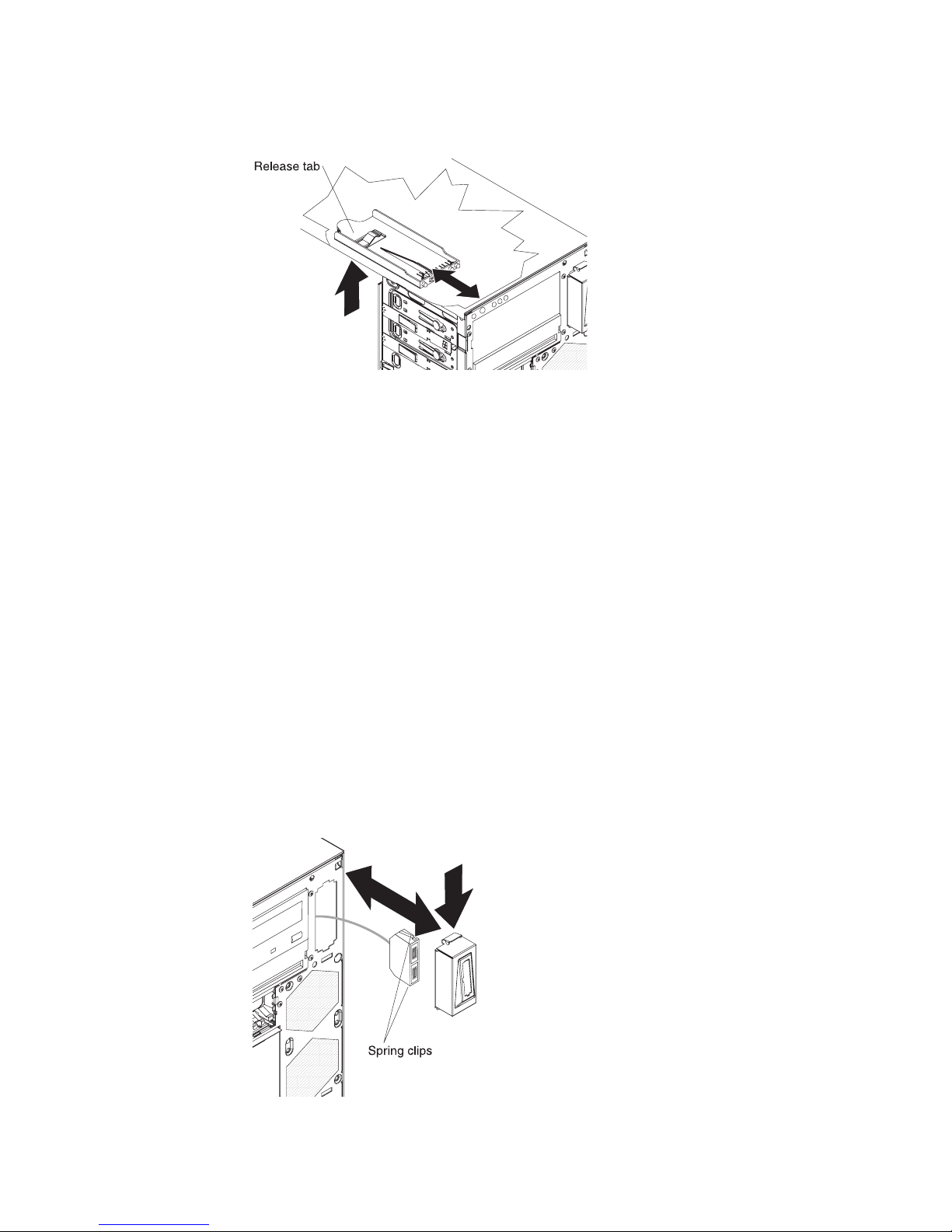
Installing the front-panel assembly
To install the front-panel assembly, complete the following steps.
1. Position the front end of the front-panel assembly in the channel above drive
bay 1 on the left side of the chassis.
2. Push the front-panel assembly toward the front of the chassis until it clicks into
place.
3. Reroute and connect the front-panel assembly cable to the system board (see
“System-board internal connectors” on page 9 for the location of the
front-panel connector).
4. If the server has hot-swap power supplies, install the power-supply cage and
the power supplies (see “Installing the hot-swap power supply cage” on page
83).
5. Push the drives in bay 1 and bay 2 into the drive bays (see “Installing a CD or
DVD drive” on page 54 for more information).
6. Install the upper bezel (see “Installing the upper bezel” on page 44).
7. Install the lower bezel (see “Installing the lower bezel” on page 42).
8. Install the side cover (see “Installing the side cover” on page 40).
9. Lock the side cover if it was unlocked during removal.
10. Reconnect the external cables and power cords; then, turn on the attached
devices and turn on the server.
Removing the front USB connector assembly
To remove the front USB connector assembly, complete the following steps.
1. Read the safety information that begins on page vii and “Installation guidelines”
on page 35.
80 System x3200 Types 4362 and 4363: Problem Determination and Service Guide
Page 99

2. Turn off the server and all attached devices; then, disconnect all power cords
and external cables.
3. Unlock and remove the side cover (see “Removing the side cover” on page
39).
4. Remove the lower bezel (see “Removing the lower bezel” on page 41).
5. Remove the upper bezel (see “Removing the upper bezel” on page 43).
6. Disconnect the front USB cable from the system board, noting the routing of
the cable (see “System-board internal connectors” on page 9 for the location of
the front USB connector).
7. Press down and hold the release tab on the top of the front USB housing;
then, tilt the top of the housing away from the chassis and lift the housing out
of the opening in the chassis.
8. Squeeze the spring clips on the sides of the front USB connector assembly
and pull the assembly out of the back of the housing.
9. Carefully pull the front USB cable out of the opening in the chassis.
10. If you are instructed to return the front USB connector assembly, follow all
packaging instructions, and use any packaging materials for shipping that are
supplied to you.
Installing the front USB connector assembly
To install the front USB connector assembly, complete the following steps.
1. Carefully insert the front USB cable through the opening in the front of the
chassis.
2. Squeeze the spring clips on the sides of the front USB connector assembly and
insert the assembly into the housing through the back of the housing.
3. Place the bottom edge of the housing into the bottom of the opening in the
chassis; then, tilt the top of the housing into position until it clicks into place.
4. Reroute and connect the front USB cable to the system board (see
“System-board internal connectors” on page 9 for the location of the front USB
connector).
5. Install the upper bezel (see “Installing the upper bezel” on page 44).
6. Install the lower bezel (see “Installing the lower bezel” on page 42).
7. Install the side cover (see “Installing the side cover” on page 40).
8. Lock the side cover if it was unlocked during removal.
9. Reconnect the external cables and power cords; then, turn on the attached
devices and turn on the server.
Chapter 4. Removing and replacing server components 81
Page 100

Removing the hot-swap power supply cage
This procedure applies only to server models that have hot-swap power-supplies.
To remove the power-supply cage, complete the following steps.
1. Read the safety information that begins on page vii and “Installation guidelines”
on page 35.
2. Turn off the server and all attached devices; then, disconnect all power cords
and external cables.
3. Unlock and remove the side cover (see “Removing the side cover” on page 39).
4. Remove both hot-swap power supplies (see “Removing a hot-swap power
supply” on page 64).
Note: It might be helpful to lay the server on its side for the remainder of this
procedure.
5. Disconnect the cables from the power-supply cage to the system board and all
internal components.
6. Remove the four screws that secure the power-supply cage to the chassis;
then, slide the cage toward the front of the server to disengage the retaining
clips from the top of the chassis and lift the cage out of the chassis.
7. If you are instructed to return the power-supply cage, follow all packaging
instructions, and use any packaging materials for shipping that are supplied to
you.
82 System x3200 Types 4362 and 4363: Problem Determination and Service Guide
 Loading...