

Page 1

IBM Sys te m Sto rage TS7600 with ProtecTIER
Installation Roadmap Guide
fortheTS7650G(3958DD4-Gateway)
GC53-1154-09
Page 2

Page 3

IBM Sys te m Sto rage TS7600 with ProtecTIER
Installation Roadmap Guide
fortheTS7650G(3958DD4-Gateway)
GC53-1154-09
Page 4

Note:
Before using this information and the product it supports, be sure to read the general information in the "Safety and
environmental notices" and "Notices" sections of this publication.
This edition applies to the TS7650G and to all subsequent releases and modifications until otherwise indicated in
new editions.
This edition replaces GC53–1154–06
© Copyright IBM Corporation 2008, 2010.
US Government Users Restricted Rights – Use, duplication or disclosure restricted by GSA ADP Schedule Contract
with IBM Corp.
Page 5

Contents
Figures ..............vii
Tables ...............ix
Safety and Environmental notices . . . xi
Safety notices ..............xi
Powercords..............xii
Environmental notices ..........xiii
Safety, danger, caution notices and
labels ...............xv
Homologation Statement ..........xv
D001................xvi
D002................xvi
D003................xvi
D004................xvi
D005................xvi
D006................xvii
D008................xvii
C001................xvii
C002................xviii
C003................xviii
C005................xviii
C007................xviii
C009................xix
C013................xix
C014................xix
C018................xix
C021................xix
C022................xix
C023.................xx
C026.................xx
C027.................xx
C028.................xx
C029.................xx
C030.................xx
C031................xxi
C032................xxi
C033................xxi
R001 Part 1 of 2 ............xxii
R001 Part 2 of 2 ............xxii
R002 ................xxiii
L001 ................xxiv
L002 ................xxiv
L003 ................xxiv
L004 ................xxv
L005 ................xxvi
L009 ................xxvi
L013 ................xxvi
L015 ................xxvii
L022 ................xxvii
L023 ................xxvii
About this document ........xxix
Who should read this document.......xxix
What's new in this edition.........xxix
Getting information, help, and service .....xxix
Getting help online ..........xxxi
Before you call for service ........xxxi
Getting help by telephone ........xxxi
Web sites ..............xxxi
Related IBM publications .........xxxii
IBM System Storage TS7600 with ProtecTIER
publications ............xxxii
TS7650G server publications.......xxxiii
DS4700 Express Disk Controller (1814 70H)
publications ............xxxiii
IBM System Storage DS5000 series storage
publication ............xxxiii
IBM DS8000 Storage System publications xxxiv
IBM XIV Storage System publications . . . xxxiv
DS4000 EXP810 Storage Expansion Unit (1812
81H) publications ..........xxxiv
Integrated Management Module(IMM)
publications ............xxxiv
System console publications .......xxxiv
WTI network switch publications ......xxxiv
How to send your comments .......xxxv
Chapter 1. Overview .........1
Terminology used in this document.......2
What is covered in this document .......4
What is not covered in this document ......5
Chapter 2. TS7650G ship group ....7
Chapter 3. Recommended TS7650G
configurations ............9
About the TS7650G server .........13
Chapter 4. Installing the TS7650G
hardware..............17
Read this first .............17
Disk storage configuration guidelines......18
Before you begin ............18
Finding the instructions you need .......20
Stand-alone gateway installation checklist ....23
Clustered gateway installation checklist .....26
Installing the server ...........30
Installing the TSSC and Ethernet switch .....30
Installing the WTI network power switch ....31
Installing the 1 Gb Ethernet switches ......33
Applying cable labels ...........35
Cabling a stand-alone gateway ........35
Stand-alone power connections .......36
Stand-alone TSSC and customer network
Ethernet connections ..........38
Stand-alone fibre channel connections ....42
© Copyright IBM Corp. 2008, 2010 iii
Page 6

Cabling a clustered gateway.........49
Clustered power connections .......49
Clustered Ethernet connections .......52
Clustered fibre channel connections .....61
Powering-up the components ........69
Disk expansion modules .........70
Disk controllers ............70
Servers ...............70
TSSC and KVM kit ...........71
Visually inspecting indicator and fault LEDs . . . 71
Next steps ...............72
Chapter 5. Setting up the TSSC for use
with theTS7650G server .......73
Establishing a connection between the TSSC and the
|
server ................73
||
Checking the TSSC microcode level ......74
||
Re-imaging the TSSC microcode .......75
||
Setting up the TSSC for use with the TS7650G. . . 77
Chapter 6. Configuring the RAS
package ..............83
Stand-alone Configuration .........84
Clustered Configuration ..........85
Verifying the cluster's Ethernet connections ....87
Chapter 7. RAS verification ......91
Verifying the systems attached to the TSSC ....91
Installing ProtecTIER Manager on the TSSC . . . 92
Calibrating the server battery ........92
Testing Call Home ............93
Chapter 13. Changing the system date
and time .............135
Chapter 14. Testing a clustered
system ..............139
Performing the system verification test .....139
Appendix A. Company information
worksheet.............141
Appendix B. IP address worksheet 145
Appendix C. Replication settings
worksheet.............153
Appendix D. Making a server
connection through the System
Management Module (IMM) .....155
Using a USB keyboard and monitor to alter the IP
address of the RSA on Server B in a cluster . . . 155
Using the TSSC or a service laptop ......156
Appendix E. Worldwide time zone
codes...............161
Appendix F. ProtecTIER Replication
Network Performance Validation
Utility for VTL Systems .......173
Chapter 8. Configuring ProtecTIER
using ptconfig ...........95
Prerequisites ..............95
Logging into the server ..........96
Configuring the first server with ptconfig ....97
Configuring the first server for VTL .....97
Configuring the first server for OpenStorage 102
Creating file systems ...........108
Chapter 9. Enabling the ProtecTIER
Replication Manager ........111
Chapter 10. Installing ProtecTIER
Manager .............113
Installing on a Windows-based workstation . . . 113
Installing on Linux ...........116
Chapter 11. Using ProtecTIER
Manager .............119
Adding a node to the ProtecTIER Manager GUI 119
Planning the repository ..........121
Creating the repository ..........122
Chapter 12. Upgrading ProtecTIER to
a cluster .............127
Configuring the second server........127
Appendix G. ProtecTIER Network
|
Performance Validation Utility for
|
OpenStorage Systems .......177
||
Accessibility............181
Notices ..............183
Trademarks ..............184
Electronic emission notices .........185
Federal Communications Commission statement 185
Industry Canada compliance statement....186
European Union Electromagnetic Compatibility
Directive ..............186
Australia and New Zealand Class A Statement 186
Germany Electromagnetic compatibility
directive ..............186
People's Republic of China Class A Electronic
Emission statement ..........187
Taiwan Class A compliance statement ....188
Taiwan contact information........188
Japan VCCI Council Class A statement ....188
Japan Electronics and Information Technology
Industries Association (JEITA) Statement (less
than or equal to 20 A per phase) ......188
Korean Communications Commission (KCC)
Class A Statement ...........189
iv IBM System Storage TS7600 with ProtecTIER: Installation Roadmap Guide
Page 7

Russia Electromagnetic Interference (EMI) Class
A Statement .............189
Index ...............191
Contents v
Page 8

vi IBM System Storage TS7600 with ProtecTIER: Installation Roadmap Guide
Page 9

Figures
1. Recommended stand-alone gateway server
|
||
||
||
||
|
||
|
||
||
|
|
||
frame layout ............11
2. Recommended clustered gateway server frame
layout ..............12
3. DD4 Server rear view - generic ......13
4. DD4 Server front view .........14
5. Operator information panel .......15
6. Documents required to install a new
stand-alone 3958 DD4 server .......21
7. Documents required to install new clustered
3958 DD4 servers ..........22
8. TSSC mounting location ........31
9. WTI network power switch .......33
10. Attaching the mounting brackets and power
cord...............34
11. Stand-alone power connections ......37
12. Customer and replication Ethernet connections
for stand-alone VTL configuration .....38
13. TSSC, KVM and customer network Ethernet
connections for stand-alone VTL configuration . 39
14. Customer and replication Ethernet connections
for stand-alone OpenStorage configuration . . 40
15. TSSC, KVM and customer network Ethernet
connections for stand-alone OpenStorage
configuration ............41
16. Customer host network Ethernet connections
for stand-alone OpenStorage configuration . . 42
17. Fibre channel connections for stand-alone VTL
configuration ............44
18. Host fibre channel connections for stand-alone
VTL...............46
19. Fibre channel connections for stand-alone
OpenStorage configuration .......47
20. Clustered TS7650G power cabling .....51
21. Clustered 1Gb Ethernet switch connections for
VTL configuration ..........53
22. Clustered 1Gb Ethernet switch connections for
OpenStorage configuration .......55
23. Clustered TSSC, KVM and customer network
Ethernet connections for VTL configuration . . 57
24. Clustered TSSC, KVM and customer network
Ethernet connections for OpenStorage
configuration ............59
25. Clustered customer network Ethernet
connections for OpenStorage configuration . . 60
26. Clustered fibre channel connections for VTL
configuration ............63
27. Clustered Host fibre channel labels.....65
28. Clustered fibre channel connections for
OpenStorage configuration .......67
29. Server operator panel .........71
||
30. IBM TS3000 System Console login window 75
||
31. IBM TS3000 System Console menu.....78
32. Console configuration utility screen ....79
33. Console Settings screen ........79
34. Console Time and Date screen: NTP server off 80
35. Console Time and Date screen: NTP server
running ..............81
36. Attached Systems screen ........91
||
37. Choose Install Folder window ......114
38. Choose Shortcut Folder window .....115
39. Choose Link folder..........117
40. ProtecTIER Manager screen .......120
41. Create repository planning wizard ....121
42. Repository meta data storage requirements
|
||
screen..............122
43. Create Repository Name window .....123
44. Repository size window ........124
45. Storage window ..........125
46. Repository resources dialog
47. Server selection screen ........133
48. Alerts Log ............140
49. Service laptop to RSA connection .....157
50. Local Area Connection Properties.....157
51. Integrated Management Welcome window 158
.......125
© Copyright IBM Corp. 2008, 2010 vii
Page 10

viii IBM System Storage TS7600 with ProtecTIER: Installation Roadmap Guide
Page 11

Tables
1. IBM Web sites for help, services, and
information ............xxx
2. Server rear view: Slot assignments, ports, and
|
||
||
||
|
||
|
||
|
||
||
connections ............13
3. DD4 Server front view .........14
4. Operator information panel .......15
5. Responsibilities matrix .........18
6. Stand-alone gateway installation checklist 23
7. Clustered gateway installation checklist 26
8. Stand-alone power connections ......37
9. Customer and replication Ethernet connections
for stand-alone VTL configuration .....39
10. TSSC, KVM and customer network Ethernet
connections for stand-alone VTL configuration . 39
11. Customer and replication Ethernet connections
for stand-alone OpenStorage configuration . . 40
12. TSSC, KVM and customer network Ethernet
connections for stand-alone OpenStorage
configuration ............41
13. Customer host network Ethernet connections
for stand-alone OpenStorage configuration . . 42
14. Fibre channel connections for stand-alone VTL
and OpenStorage...........45
15. Host fibre channel connections for stand-alone
VTL configuration ..........46
16. Fibre channel connections for stand-alone
OpenStorage configuration .......48
17. Clustered TS7650G power cabling .....52
18. Clustered 1 Gb Ethernet switch Ethernet
connections for VTL configuration .....54
19. Clustered 1 Gb Ethernet switch Ethernet
connections for OpenStorage configuration . . 55
20. Clustered TSSC, KVM and customer network
Ethernet connections for VTL configuration . . 57
21. Clustered TSSC, KVM and customer network
Ethernet connections for OpenStorage
configuration ............59
22. Clustered Ethernet host connections for
OpenStorage configuration .......60
23. Clustered fibre channel connections for VTL
installations ............64
24. Clustered Host fibre channel labels.....65
25. Clustered fibre channel connections for
OpenStorage installations ........68
26. Power-on sequences..........69
27. Server operator panel .........71
28. TSSC Interface ...........78
29. Example auto-detected system information 99
30. Example summary for first server and local
network .............100
31. Example updated summary of both servers
and local networks..........100
32. Site 1 – Server A VTL worksheet .....101
||
33. Site 1 – Server B VTL worksheet .....101
||
34. Site 2– Server A VTL worksheet .....101
||
35. Site 2– Server B VTL worksheet .....101
||
36. Example auto-detected system information 104
37. Example summary for first server and local
network .............104
38. Example updated summary of both servers
and local networks..........105
39. Site 1 – Server A OpenStorage worksheet 106
||
40. Site 1 – Server B OpenStorage worksheet 106
||
41. Site 2– Server A OpenStorage worksheet 106
||
42. Site 2– Server B OpenStorage worksheet 106
||
43. Example auto-detected system information 129
44. Example summary for first server and local
network .............129
45. Example updated summary of both servers
and local networks..........130
46. Site 1 – Server A worksheet .......130
||
47. Site 1 – Server B worksheet .......131
||
48. Site 2– Server A worksheet .......131
||
49. Site 2– Server B worksheet .......131
||
50. Company information worksheet .....141
51. Country codes
52. Factory-default server IP addresses for a
|
|
||
|
|
||
|
|
||
|
|
||
|
||
stand-alone VTL ProtecTIER server (3958 DD4
or 3958 AP1) ............146
53. Factory-default server IP addresses for a
stand-alone OpenStorage ProtecTIER server
(3958 DD4 or 3958 AP1) ........146
54. Factory-default server IP addresses for a
clustered VTL ProtecTIER system (3958 DD4
or 3958 AP1) ............147
55. Factory-default server IP addresses for a
clustered OpenStorage ProtecTIER system
(3958 DD4 or 3958 AP1) ........148
56. Customer IP addresses ........149
57. Customer and Replication IP addresses for
VTL or OpenStorage systems ......149
58. Host names and DNS settings for setting up
the TSSC with the TS7650G .......150
59. TSSC IP addresses ..........151
60. Base Clusters and Additional Storage
Component IP addresses........152
61. Replication policy information ......153
...........143
© Copyright IBM Corp. 2008, 2010 ix
Page 12

x IBM System Storage TS7600 with ProtecTIER: Installation Roadmap Guide
Page 13

Safety and Environmental notices
This section contains information about safety notices that are used in this guide
and environmental notices for this product.
Safety notices
Observe the safety notices when using this product. These safety notices contain
danger and caution notices. These notices are sometimes accompanied by symbols
that represent the severity of the safety condition.
Most danger or caution notices contain a reference number (Dxxx or Cxxx). Use
the reference number to check the translation in the IBM Systems Safety Notices,
G229-9054 manual.
The sections that follow define each type of safety notice and give examples.
Danger notice
A danger notice calls attention to a situation that is potentially lethal or extremely
hazardous to people. A lightning bolt symbol always accompanies a danger notice
to represent a dangerous electrical condition. A sample danger notice follows:
DANGER: An electrical outlet that is not correctly wired could place
hazardous voltage on metal parts of the system or the devices that
attach to the system. It is the responsibility of the customer to ensure
that the outlet is correctly wired and grounded to prevent an electrical
shock. (D004)
Caution notice
A caution notice calls attention to a situation that is potentially hazardous to
people because of some existing condition, or to a potentially dangerous situation
that might develop because of some unsafe practice. A caution notice can be
accompanied by one of several symbols:
If the symbol is... It means...
A generally hazardous condition not represented by other
safety symbols.
This product contains a Class II laser. Do not stare into the
beam. (C029) Laser symbols are always accompanied by the
classification of the laser as defined by the U. S.
Department of Health and Human Services (for example,
Class I, Class II, and so forth).
A hazardous condition due to mechanical movement in or
around the product.
© Copyright IBM Corp. 2008, 2010 xi
Page 14

If the symbol is... It means...
This part or unit is heavy but has a weight smaller than 18
kg (39.7 lb). Use care when lifting, removing, or installing
this part or unit. (C008)
Sample caution notices follow:
Caution
The battery is a lithium ion battery. To avoid possible explosion, do not
burn. Exchange only with the IBM-approved part. Recycle or discard the
battery as instructed by local regulations. In the United States, IBM
process for the collection of this battery. For information, call
1-800-426-4333. Have the IBM part number for the battery unit available
when you call. (C007)
Caution
The system contains circuit cards, assemblies, or both that contain lead
solder. To avoid the release of lead (Pb) into the environment, do not burn.
Discard the circuit card as instructed by local regulations. (C014)
Caution
When removing the Modular Refrigeration Unit (MRU), immediately
remove any oil residue from the MRU support shelf, floor, and any other
area to prevent injuries because of slips or falls. Do not use refrigerant
lines or connectors to lift, move, or remove the MRU. Use handholds as
instructed by service procedures. (C016)
®
has a
Power cords
Caution
Do not connect an IBM control unit directly to a public optical network.
The customer must use an additional connectivity device between an IBM
control unit optical adapter (that is, fibre, ESCON
®
, FICON®) and an
external public network . Use a device such as a patch panel, a router, or a
switch. You do not need an additional connectivity device for optical fibre
connectivity that does not pass through a public network.
For your safety, IBM provides a power cord with a grounded attachment plug to
use with this IBM product. To avoid electrical shock, always use the power cord
and plug with a properly grounded outlet.
IBM power cords used in the United States and Canada are listed by
Underwriter’s Laboratories (UL) and certified by the Canadian Standards
Association (CSA).
For units intended to be operated at 115 volts: Use a UL-listed and CSA-certified
cord set consisting of a minimum 18 AWG, Type SVT or SJT, three-conductor cord,
a maximum of 15 feet in length and a parallel blade, grounding-type attachment
plug rated 15 amperes, 125 volts.
For units intended to be operated at 230 volts (U.S. use): Use a UL-listed and
CSA-certified cord set consisting of a minimum 18 AWG, Type SVT or SJT,
xii IBM System Storage TS7600 with ProtecTIER: Installation Roadmap Guide
Page 15

three-conductor cord, a maximum of 15 feet in length and a tandem blade,
grounding-type attachment plug rated 15 amperes, 250 volts.
For units intended to be operated at 230 volts (outside the U.S.): Use a cord set
with a grounding-type attachment plug. The cord set should have the appropriate
safety approvals for the country in which the equipment will be installed.
IBM power cords for a specific country or region are usually available only in that
country or region.
Environmental notices
The environmental notices that apply to this product are provided in the
Environmental Notices and User Guide, Z125-5823-xx manual. A copy of this manual
is located on the publications CD.
Safety and Environmental notices xiii
Page 16

xiv IBM System Storage TS7600 with ProtecTIER: Installation Roadmap Guide
Page 17

Safety, danger, caution notices and labels
This section contains safety, danger, caution notices and labels that are used in this
guide for this product.
You should read all safety notices in entirety before completing any task.
Homologation Statement
Attention: This product is not intended to be connected directly or indirectly by
any means whatsoever to interfaces of public telecommunications networks,
neither to be used in a Public Services Network.
© Copyright IBM Corp. 2008, 2010 xv
Page 18

D001
D002
D003
DANGER
To prevent a possible shock from touching two surfaces with different
protective ground (earth), use one hand, when possible, to connect or
disconnect signal cables. (D001)
DANGER
Overloading a branch circuit is potentially a fire hazard and a shock hazard
under certain conditions. To avoid these hazards, ensure that your system
electrical requirements do not exceed branch circuit protection requirements.
Refer to the information that is provided with your device or the power
rating label for electrical specifications. (D002)
DANGER
If the receptacle has a metal shell, do not touch the shell until you have
completed the voltage and grounding checks. Improper wiring or grounding
could place dangerous voltage on the metal shell. If any of the conditions are
not as described, STOP. Ensure the improper voltage or impedance conditions
are corrected before proceeding. (D003)
D004
D005
DANGER
An electrical outlet that is not correctly wired could place hazardous voltage
on the metal parts of the system or the devices that attach to the system. It is
the responsibility of the customer to ensure that the outlet is correctly wired
and grounded to prevent an electrical shock. (D004)
DANGER
When working on or around the system, observe the following precautions:
Electrical voltage and current from power, telephone, and communication
cables are hazardous. To avoid a shock hazard:
v Connect power to this unit only with the IBM provided power cord. Do not
use the IBM provided power cord for any other product.
v Do not open or service any power supply assembly.
v Do not connect or disconnect any cables or perform installation,
maintenance, or reconfiguration of this product during an electrical storm.
v The product might be equipped with multiple power cords. To remove all
xvi IBM System Storage TS7600 with ProtecTIER: Installation Roadmap Guide
Page 19

hazardous voltages, disconnect all power cords.
v Connect all power cords to a properly wired and grounded electrical outlet.
Ensure that the outlet supplies proper voltage and phase rotation according
to the system rating plate.
v Connect any equipment that will be attached to this product to properly
wired outlets.
v When possible, use one hand only to connect or disconnect signal cables.
v Never turn on any equipment when there is evidence of fire, water, or
structural damage.
v Disconnect the attached power cords, telecommunications systems,
networks, and modems before you open the device covers, unless
instructed otherwise in the installation and configuration procedures.
v Connect and disconnect cables as described in the following procedures
when installing, moving, or opening covers on this product or attached
devices.
To disconnect:
1. Turn off everything (unless instructed otherwise).
2. Remove the power cords from the outlets.
3. Remove the signal cables from the connectors.
4. Remove all cables from the devices.
To connect:
1. Turn off everything (unless instructed otherwise).
2. Attach all cables to the devices.
3. Attach the signal cables to the connectors.
4. Attach the power cords to the outlets.
5. Turn on the devices.
v Sharp edges, corners and joints may be present in and around the system.
Use care when handling equipment to avoid cuts, scrapes and pinching.
D006
D008
C001
(D005)
DANGER
Heavy equipment—personal injury or equipment damage might result if
mishandled. (D006)
DANGER
Professional movers are to be used for all relocation activities. Serious injury
or death may occur if systems are handled and moved incorrectly. (D008)
CAUTION:
Safety, danger, caution notices and labels xvii
Page 20

C002
C003
Energy hazard present. Shorting might result in system outage and possible
physical injury. Remove all metallic jewelry before servicing. (C001)
CAUTION:
Only trained service personnel may replace this battery. The battery contains
lithium. To avoid possible explosion, do not burn or charge the battery.
Do not:
v Throw or immerse into water
v Heat to more than 100°C (212°F)
v Repair or disassemble
Exchange only with the IBM-approved part. Recycle or discard the battery as
instructed by local regulations. In the United States, IBM has a process for the
collection of this battery. For information, call 1-800-426-4333. Have the IBM part
number for the battery unit available when you call. (C002)
CAUTION:
C005
C007
The battery contains lithium. To avoid possible explosion, do not burn or charge
the battery. Do not:
v Throw or immerse into water
v Heat to more than 100°C (212°F)
v Repair or disassemble
Exchange only with the IBM-approved part. Recycle or discard the battery as
instructed by local regulations. In the United States, IBM has a process for the
collection of this battery. For information, call 1-800-426-4333. Have the IBM part
number for the battery unit available when you call. (C003)
CAUTION:
The battery is a nickel-cadmium battery. To avoid possible explosion, do not
burn. Exchange only with the IBM-approved part. Recycle or discard the battery
as instructed by local regulations. In the United States, IBM has a process for
the collection of this battery. For information, call 1-800-426-4333. Have the IBM
part number for the battery unit available when you call. (C005)
CAUTION:
The battery is a lithium ion battery. To avoid possible explosion, do not burn.
Exchange only with the IBM-approved part. Recycle or discard the battery as
instructed by local regulations. In the United States, IBM has a process for the
collection of this battery. For information, call 1-800-426-4333. Have the IBM part
number for the battery unit available when you call. (C007)
xviii IBM System Storage TS7600 with ProtecTIER: Installation Roadmap Guide
Page 21

C009
CAUTION:
C013
C014
C018
>18 kg (39.7 lb)
or
The weight of this part or unit is between 18 and 32 kg (39.7 and 70.5 lb). It
takes two persons to safely lift this part or unit. (C009)
CAUTION:
The doors and covers to the product are to be closed at all times except for
service by trained service personnel. All covers must be replaced and doors
locked at the conclusion of the service operation. (C013)
CAUTION:
The system contains circuit cards, assemblies, or both that contain lead solder.
To avoid the release of lead (Pb) into the environment, do not burn. Discard the
circuit card as instructed by local regulations. (C014)
18-32 kg (39.7-70.5 lb)
or
C021
C022
CAUTION:
This product is equipped with a 3-wire (two conductors and ground) power
cable and plug. Use this power cable with a properly grounded electrical outlet
to avoid electrical shock. (C018)
CAUTION:
The power distribution outlets provide 200 to 240 V ac. Use these outlets only
for devices that operate within this voltage range. (C021)
CAUTION:
The product might be equipped with a hard-wired power cable. Ensure that a
licensed electrician performs the installation per the national electrical code.
(C022)
Safety, danger, caution notices and labels xix
Page 22

C023
C026
C027
CAUTION:
Ensure the building power circuit breakers are turned off BEFORE you connect
the power cord or cords to the building power. (C023)
CAUTION:
This product might contain one or more of the following devices: CD-ROM
drive, DVD-ROM drive, DVD-RAM drive, or laser module, which are Class 1
laser products. Note the following information:
v Do not remove the covers. Removing the covers of the laser product could
result in exposure to hazardous laser radiation. There are no serviceable parts
inside the device.
v Use of the controls or adjustments or performance of procedures other than
those specified herein might result in hazardous radiation exposure.
(C026)
CAUTION:
C028
C029
C030
Data processing environments can contain equipment transmitting on system
links with laser modules that operate at greater than Class 1 power levels. For
this reason, never look into the end of an optical fiber cable or open receptacle.
(C027)
CAUTION:
This product contains a Class 1M laser. Do not view directly with optical
instruments. (C028)
CAUTION:
This product contains a Class 2 laser. Do not stare into the beam. (C029)
CAUTION:
Some laser products contain an embedded Class 3A or Class 3B laser diode.
Note the following information:
v Laser radiation when open.
v Do not stare into the beam, do not view directly with optical instruments, and
avoid direct exposure to the beam.
(C030)
xx IBM System Storage TS7600 with ProtecTIER: Installation Roadmap Guide
Page 23

C031
C032
C033
CAUTION:
The power-control button on the device does not turn off the electrical current
supplied to the device. The device might also have more than one connection to
dc power. To remove all electrical current from the device, ensure that all
connections to dc power are disconnected at the dc power input terminals.
(C031)
CAUTION:
Servicing of this product or unit is to be performed by trained service personnel
only. (C032)
CAUTION:
To reduce the risk of electric shock or energy hazards:
v This equipment must be installed by trained service personnel in a
restricted-access location, as defined by the NEC and IEC 60950, The Standard
for Safety of Information Technology Equipment.
v Connect the equipment to a reliably grounded, safety extra low voltage (SELV)
source. An SELV source is a secondary circuit that is designed so that normal
and single fault conditions do not cause the voltages to exceed a safe level (60
V direct current).
v The branch circuit overcurrent protection must be rated per the following
table.
v Use copper wire conductor only, not exceeding 3 m (9.8 ft.) in length and sized
according to the following table.
v Torque the wiring-terminal screws to the values in the following table.
v Incorporate a readily available approved and rated disconnect device in the
field wiring.
(C033)
The following table appears in the product documentation with actual values
substituted for xxx:
Circuit breaker rating Minimum: xxx amps
Maximum: xxx amps
Wire size xxx AWG
xxx mm2
Wiring-terminal screw torque xxx inch-pounds
xxx newton-meters
Safety, danger, caution notices and labels xxi
Page 24

R001 Part 1 of 2
Use the following general safety information for all rack-mounted devices:
DANGER
Observe the following precautions when working on or around your IT rack
system:
v Heavy equipment—personal injury or equipment damage might result if
mishandled.
v Always lower the leveling pads on the rack cabinet.
v Always install stabilizer brackets on the rack cabinet.
v To avoid hazardous conditions due to uneven mechanical loading, always
install the heaviest devices in the bottom of the rack cabinet. Always install
servers and optional devices starting from the bottom of the rack cabinet.
v Rack-mounted devices are not to be used as shelves or work spaces. Do not
place objects on top of rack-mounted devices.
v Each rack cabinet might have more than one power cord. Be sure to
disconnect all power cords in the rack cabinet when directed to disconnect
power during servicing.
v Connect all devices installed in a rack cabinet to power devices installed in
the same rack cabinet. Do not plug a power cord from a device installed in
one rack cabinet into a power device installed in a different rack cabinet.
v An electrical outlet that is not correctly wired could place hazardous
voltage on the metal parts of the system or the devices that attach to the
system. It is the responsibility of the customer to ensure that the outlet is
correctly wired and grounded to prevent an electrical shock.
R001 Part 2 of 2
(R001 part 1 of 2)
CAUTION:
v Do not install a unit in a rack where the internal rack ambient temperatures
will exceed the manufacturer's recommended ambient temperature for all your
rack-mounted devices.
v Do not install a unit in a rack where the air flow is compromised. Ensure that
air flow is not blocked or reduced on any side, front, or back of a unit used
for air flow through the unit.
v Consideration should be given to the connection of the equipment to the
supply circuit so that overloading of the circuits does not compromise the
supply wiring or overcurrent protection. To provide the correct power
connection to a rack, refer to the rating labels located on the equipment in the
rack to determine the total power requirement of the supply circuit.
v (For sliding drawers): Do not pull out or install any drawer or feature if the
rack stabilizer brackets are not attached to the rack. Do not pull out more than
one drawer at a time. The rack might become unstable if you pull out more
than one drawer at a time.
v (For fixed drawers): This drawer is a fixed drawer and must not be moved for
servicing unless specified by the manufacturer. Attempting to move the
xxii IBM System Storage TS7600 with ProtecTIER: Installation Roadmap Guide
Page 25

R002
drawer partially or completely out of the rack might cause the rack to become
unstable or cause the drawer to fall out of the rack.
(R001 part 2 of 2)
CAUTION:
Removing components from the upper positions in the rack cabinet improves
rack stability during relocation. Follow these general guidelines whenever you
relocate a populated rack cabinet within a room or building:
v Reduce the weight of the rack cabinet by removing equipment starting at the
top of the rack cabinet. When possible, restore the rack cabinet to the
configuration of the rack cabinet as you received it. If this configuration is not
known, you must observe the following precautions:
– Remove all devices in the 32U position and above.
– Ensure that the heaviest devices are installed in the bottom of the rack
cabinet.
– Ensure that there are no empty U-levels between devices installed in the
rack cabinet below the 32U level.
v If the rack cabinet you are relocating is part of a suite of rack cabinets, detach
the rack cabinet from the suite.
v Inspect the route that you plan to take to eliminate potential hazards.
v Verify that the route that you choose can support the weight of the loaded
rack cabinet. Refer to the documentation that comes with your rack cabinet for
the weight of a loaded rack cabinet.
v Verify that all door openings are at least 760 x 230 mm (30 x 80 in.).
v Ensure that all devices, shelves, drawers, doors, and cables are secure.
v Ensure that the four leveling pads are raised to their highest position.
v Ensure that there is no stabilizer bracket installed on the rack cabinet during
movement.
v Do not use a ramp inclined at more than 10 degrees.
v When the rack cabinet is in the new location, complete the following steps:
– Lower the four leveling pads.
– Install stabilizer brackets on the rack cabinet.
– If you removed any devices from the rack cabinet, repopulate the rack
cabinet from the lowest position to the highest position.
v If a long-distance relocation is required, restore the rack cabinet to the
configuration of the rack cabinet as you received it. Pack the rack cabinet in
the original packaging material, or equivalent. Also lower the leveling pads to
raise the casters off of the pallet and bolt the rack cabinet to the pallet.
(R002)
Safety, danger, caution notices and labels xxiii
Page 26

L001
L002
DANGER
Hazardous voltage, current, or energy levels are present inside any component
that has this label attached. Do not open any cover or barrier that contains
this label. (L001)
DANGER
Rack-mounted devices are not to be used as shelves or work spaces. (L002)
L003
DANGER
Multiple power cords. The product might be equipped with multiple power
cords. To remove all hazardous voltages, disconnect all power cords. (L003)
1
or
xxiv IBM System Storage TS7600 with ProtecTIER: Installation Roadmap Guide
2
Page 27

or
!
1
2
L004
3
1
DANGER
Hazardous voltage present. Voltages present constitute a shock hazard, which
can cause severe injury or death. (L004)
4
2
Safety, danger, caution notices and labels xxv
Page 28

L005
L009
CAUTION:
Hazardous energy present. Voltages with hazardous energy might cause heating
when shorted with metal, which might result in splattered metal, burns, or both.
(L005)
>240VA
CAUTION:
System or part is heavy. The label is accompanied by a specific weight range.
(L009)
L013
DANGER
Heavy equipment—personal injury or equipment damage might result if
mishandled. (L013)
xxvi IBM System Storage TS7600 with ProtecTIER: Installation Roadmap Guide
Page 29

L015
L022
CAUTION:
Danger! Arc Flash/Arc Blast hazard when disconnected with power on. Turn off
power before disconnecting. (L015)
CAUTION:
Class 3R visible and invisible laser radiation when open. Avoid direct eye
exposure. (L022)
L023
CAUTION:
Laser Aperture (L023)
Safety, danger, caution notices and labels xxvii
Page 30

xxviii IBM System Storage TS7600 with ProtecTIER: Installation Roadmap Guide
Page 31

About this document
|
|
|
|
|
|
|
|
This document provides information for initial installation of the IBM System
Storage®TS7650G ProtecTIER®De-duplication Gateway.
Note:
v If you are upgrading an existing system to ProtecTIER version 2.5, see the IBM
System Storage ProtecTIER Software Upgrade and Replication Enablement Guide, IBM
form number GC53–1196.
v If you are adding another Gateway server to cluster with an existing stand-alone
server, see the Standalone TS7650G to Clustered TS7650G MES Installation
Instructions - Cluster Connection Kit (FC 3447) PN46X6061 EC M11240
Who should read this document
This publication is intended for IBM service personnel only. The installation
procedures described in this document are to be performed by IBM service
personnel.
What's new in this edition
Technical changes occurring in this edition are identified with a vertical bar ( | )in
the left hand margin of the page.
|
|
|
|
|
|
The following functions and hardware are new for the 2.5 release:
v OpenStorage plug-in support for NetBackup
v 3958 DD4 server model. This server is based on the IBM System x3850 X5 Type
7145 AC1. When used as a server in the TS7650G, its machine type and model
are 3958 DD4. Use this machine type and model for service purposes.
v Support for ProtecTIER on Windows 7
|
|
|
|
|
|
|
|
The following functions were added in release 2.4:
v Many-to-one replication
v LUN masking
v Red Hat upgrade to version 5.4
Major changes in and additions to this document include the following:
v Chapter 6, “Configuring the RAS package,” on page 83
v Chapter 11, “Using ProtecTIER Manager,” on page 119
v Integrated Management Module
Getting information, help, and service
If you need help, service, technical assistance, or just want more information about
IBM products, you will find a wide variety of sources available from IBM to assist
you. Available services, telephone numbers, and Web links are subject to change
without notice.
© Copyright IBM Corp. 2008, 2010 xxix
Page 32

Information
IBM maintains pages on the World Wide Web where you can get information
about IBM products and services and find the latest technical information. For
more information refer to Table 1.
Table 1. IBM Web sites for help, services, and information
Description Web address (URL)
IBM home page http://www.ibm.com
Directory of worldwide
contacts
Support for IBM System
Storage and TotalStorage
products
http://www.ibm.com/planetwide
http://www.ibm.com/storage/support
Note: Go to this site for information about the TS7650G
and do the following :
1. Select Tape systems from the Product family list
2. Select TS7650G with ProtecTIER from the Product list
Help and service
You can call 1 (800) IBM SERV for help and service if you are in the U.S. or
Canada. You must choose the software or hardware option when calling for
assistance.
Note: This product is equipped with a Software Call Home feature. When enabled,
it will notify IBM Service of software error events. Not all countries currently
support this feature. Contact your next level of support for more information.
Choose the software option if you are uncertain if the problem involves TS7650G
software or TS7650G hardware. Choose the hardware option only if you are certain
the problem solely involves the TS7650G hardware.
When calling IBM for service regarding the TS7650G
Software option
Identify the TS7650G as your product and supply your customer number
as proof of purchase. The customer number is a 7-digit numeric (0000000
to 9999999) assigned by IBM when the PID is purchased and should be
located on the customer information worksheet or on the invoice from the
software purchase.
Hardware option
|
|
|
|
|
|
|
|
|
Provide the serial number and appropriate 4-digit Machine Type for the
hardware component that displays a problem (for example, 3958 DD1, 3958
DD3 or 3958 DD4).
Note: Cache modules and cache controllers are supported separately
within the TS7650G Gateway. If the problem is known to be in the IBM
attached storage component, select the hardware option and enter the
appropriate Machine Type and S/N (serial number) for the component. If
the attached storage is not IBM branded, contact the appropriate service
provider for the component.
xxx IBM System Storage TS7600 with ProtecTIER: Installation Roadmap Guide
Page 33

Getting help online
Be sure to visit the support page for the IBM System Storage TS7600 with
ProtecTIER, complete with FAQs, parts information, technical hints and tips,
technical publications, and downloadable files, if applicable. This page is at:
www.ibm.com/storage/support/
For additional Web sites, see “Web sites.”
Before you call for service
Some problems can be solved without outside assistance, by using the online help,
by looking in the online or printed documentation that comes with the TS7650G, or
by consulting the support Web page for the latest fixpack and service alerts. Be
sure to also read the information in any README files and release notes that come
with the TS7650G.
Getting help by telephone
With the original purchase of the IBM System Storage TS7600 with ProtecTIER, you
have access to extensive support coverage. During the product warranty period,
you may call the IBM Support Center (1 800 426-7378 in the U.S.) for product
assistance covered under the terms of the hardware IBM warranty or the software
maintenance contract that comes with product purchase.
Web sites
Please have the following information ready when you call:
v Either machine type and model or software identifier. The software identifier can
be either the product name (TS7650G) or the Product Identification (PID)
number.
v Either the serial numbers of the components or your proof of purchase.
v Description of the problem.
v Exact wording of any error messages.
v Hardware and software configuration information
If possible, have access to your computer when you call.
In the U.S. and Canada, these services are available 24 hours a day, 7 days a week.
In the U.K., these services are available Monday through Friday, from 9:00 a.m. to
6:00 p.m. In all other countries, contact your IBM reseller or IBM marketing
representative.
The most up-to-date information about your product, including documentation
and the most recent downloads, can be found at the following Web sites:
v The translated publications for this product are included with the product. These
documents and product specification sheets are also available from the following
Web site:
http://www-947.ibm.com/systems/support/supportsite.wss/
brandmain?brandind=5345868
v You can order publications through the IBM Publications Ordering System at the
following web site:
http://www.elink.ibmlink.ibm.com/publications/servlet/pbi.wss
v Access installation and technical support information via the Web at:
About this document xxxi
Page 34

www.ibm.com/support
v For DS4000 information, go to the following Web site:
www.ibm.com/servers/storage/support/disk/
v For DS5000 series information, go to the following:
http://www-03.ibm.com/systems/storage/disk/ds5000/
|
|
v For DS8000 series information, go to the following
http://www-03.ibm.com/systems/storage/disk/ds8000/
v For XIV information, go to the following:
http://publib.boulder.ibm.com/infocenter/ibmxiv/r2/index.jsp
v The IBM Web site for Independent Software Vendor (ISV) support is:
http://www-304.ibm.com/jct01005c/isv/index.html
v The IBM System Storage TS7600 with ProtecTIER Interoperability Matrix Web
site can be found at:
http://www-03.ibm.com/systems/support/storage/config/ssic/
displayesssearchwithoutjs.wss?start_over=yes
v For the latest information about SAN switches and directors, go to the following
Web site:
www.ibm.com/servers/storage/san
v For the latest information about IBM xSeries products, services, and support, go
to the following Web site:
www.ibm.com/eserver/xseries/
v For the latest information about operating system and HBA support, clustering
support, SAN fabric support, and Storage Manager feature support, see the
DS4000 Interoperability Matrix at the following Web site:
www.ibm.com/servers/storage/disk/ds4000/interop-matrix.html
v For product firmware and software downloads, as well as associated driver
code, go to the following Web site:
http://www-947.ibm.com/systems/support/supportsite.wss/
selectproduct?brandind=5000034&familyind=0&oldbrand=0&oldfamily=0
&oldtype=0&taskind=1&psid=bm
v For accessibility information, go to the following Web site:
http://www-03.ibm.com/able/product_accessibility/index.html
v For the latest information about product recycling programs, go to the following
Web site:
www.ibm.com/ibm/environment/products/prp.shtml
Related IBM publications
The following documents provide information about the IBM System Storage
TS7600 with ProtecTIER gateway server and recommended additional hardware
components.
IBM System Storage TS7600 with ProtecTIER publications
v IBM System Storage TS7600 with ProtecTIER Introduction and Planning Guide for the
TS7650G (3958 DD4), IBM form number GC53–1152
v IBM System Storage ProtecTIER User's Guide for Enterprise Edition and Appliance
Edition, IBM form number GC53–1156
xxxii IBM System Storage TS7600 with ProtecTIER: Installation Roadmap Guide
Page 35

v IBM System Storage TS7600 with ProtecTIER Problem Determination Guide for the
TS7650 Appliance and TS7650G (Gateway), IBM form number GC53-1157
v IBM System Storage ProtecTIER Software Upgrade and Replication Enablement Guide,
IBM form number GC53–1196
v IBM System Storage TS7600 with ProtecTIER Labeling Instructions for the
TS7650/TS7650G (3958 DD4 and 3958 AP1), IBM part number 46X6059
|
|
v IBM System Storage TS7650 Best Practices Guide for ProtecTIER v 2.5 and TS7650G
(Gateway) Attached Storage, IBM form number GA32-0646
TS7650G server publications
The following publications provide additional documentation about the gateway
server:
3958 DD4 server publications
The following publications provide additional documentation about the 3958 DD4
gateway server:
|
|
|
|
v IBM System x3850 X5 and x3950 X5 Types 7145 and 7146 Installation and User's
Guide
v IBM System x3850 X5 and x3950 X5 Types 7145 and 7146 Problem Determination and
Service Guide
|
|
|
|
|
|
|
|
|
|
|
|
|
|
|
|
The server might have features that are not described in the documentation that
you received with the server. The documentation might be updated occasionally to
include information about those features, or technical updates might be available
to provide additional information that is not included in the server documentation.
These updates are available from the IBM Web site. Complete the following steps
to check for updated documentation and technical updates in the product
information center:
1. In a Web browser, navigate to http://www.ibm.com/support/publications/us/
library/.
2. Click the Information Sets and Libraries tab.
3. Scroll down to the Servers section and click xSeries.
4. In the search box, type 7145.
5. Select System x3850 X5 7145.
6. Under Choose your task select Documentation.
7. Under See your results click View your page
8. Click the link for the document you want to view.
DS4700 Express Disk Controller (1814 70H) publications
The following publications provide additional documentation about the DS4700
Express Disk Controller (1814 70H):
™
v IBM System Storage DS4700 Express Storage
Maintenance Guide
v IBM TotalStorage DS4000 Storage Manager Version 10 Installation and Host Support
Guide for Windows 2000/Server 2003, NetWare, ESX Server, and Linux
Subsystem Installation, User's and
IBM System Storage DS5000 series storage publication
The following publication provides additional documentation about the IBM
System Storage DS5000 Storage Subsystems.
About this document xxxiii
Page 36

IBM System Storage DS5100 and DS5300 Storage Subsystem,
IBM DS8000 Storage System publications
The following publications provide additional documentation about the IBM
DS8000 Storage System:
|
|
|
|
|
v IBM DS8000 Storage System Introduction and Planning Guide for Customer
Configuration
v IBM DS8000 Storage System User Manual
v
v
IBM XIV Storage System publications
The following publications provide additional documentation about the IBM XIV
Storage System:
v IBM XIV Storage System (Types 2810 and 2812) Model A14 (Gen2) Introduction and
Planning Guide for Customer Configuration
v IBM XIV Storage System User Manual
v IBM XIV Storage System Pre-Installation and Network Planning Guide for Customer
Configuration
v IBM XIV Storage System Theory of Operation
DS4000 EXP810 Storage Expansion Unit (1812 81H) publications
The following publications provide additional documentation about the IBM
System Storage DS4000 EXP810 Storage Expansion Unit (1812 81H):
v IBM TotalStorage DS4000 EXP810 Storage Expansion Unit Installation, User's and
Maintenance Guide
v IBM TotalStorage DS4000 Storage Manager Version 10 Installation and Host Support
Guide for Windows 2000/Server 2003, NetWare, ESX Server, and Linux
Integrated Management Module(IMM) publications
The following publications provide additional documentation about the Integrated
Management Module(IMM) for DD4 servers.
|
|
|
v Integrated Management Module User's Guide
Note: The Integrated Management Module functions were handled by the RSA in
the DD3 and DD1 servers.
System console publications
The following publication provides information about the IBM System Storage
TS3000 System Console (TSSC):
v IBM System Storage TS3000 System Console (TSSC) Maintenance Information
WTI network switch publications
Publications for the Western Telematic network power switch can be found on the
manufacturer's Web site. Refer to www.wti.com.
xxxiv IBM System Storage TS7600 with ProtecTIER: Installation Roadmap Guide
Page 37

How to send your comments
Your feedback is important in helping to provide the most accurate and highest
quality information.
To submit any comments about this book or any other IBM System Storage TS7600
with ProtecTIER documentation:
v Send your comments by e-mail to starpubs@us.ibm.com. Be sure to include the
following information:
– Exact publication title and version
– Publication form number (for example, GC53-1196-03)
– Page, table, or illustration numbers that you are commenting on with a
detailed description of any information that should be changed
About this document xxxv
Page 38

xxxvi IBM System Storage TS7600 with ProtecTIER: Installation Roadmap Guide
Page 39

Chapter 1. Overview
The IBM System Storage TS7650G ProtecTIER De-duplication Gateway (TS7650G)
is available in two configurations — stand-alone and clustered.
|
|
|
|
|
Note: A 3958 DD4 may be clustered with a 3958 DD3. IBM does not support
clustering a 3958 DD4 with a 3958 DD1.
Note: IBM does support installing two clustered pairs of TS7650 Gateway servers
in a single frame via the RPQ process. This document does not address that
configuration.
The purchase of the stand-alone gateway includes:
v One gateway server (IBM machine type and model 3958 DD4).
v One licensed, preinstalled copy of Red Hat
®
Enterprise Linux®Advanced
Platform (version x86_64 or EM64T)
v One licensed, preinstalled copy of IBM ProtecTIER
Purchase of the clustered gateway includes:
v Two gateway servers, (IBM machine type and model 3958 DD4)
v One Cluster Connection Kit (Feature Code 3447) consisting of:
– One Western Telematic IPS-800E-D20 remote network power switch and
accompanying cables
– Two 1 Gb Ethernet switches and accompanying cables
v Two licensed, preinstalled copies of Red Hat
®
Enterprise Linux®Advanced
Platform (version x86_64 or EM64T)
v Two licensed, preinstalled copies of IBM ProtecTIER
In order for either configuration of the TS7650G to be fully functional, additional
hardware components are required. These components are purchased separately
and, with the exception of the IBM TS3000 System Console (TSSC) and TSSC
Ethernet switch, must be installed and configured at the customer site before
TS7650G installation begins.
Note: If the customer is using a TSSC that already exists at their location, the TSSC
must include Feature Code 2719, and be at software level 5.5.22 or higher. See the
IBM System Storage TS7600 with ProtecTIER Introduction and Planning Guide for the
TS7650G (3958 DD4), IBM form number GC53–1152 for additional information.
The lists below outline the additional recommended hardware components, based
on IBM best practices, for each configuration. IBM recommends using the
hardware components specified below to ensure optimal TS7650G functionality.
However, the actual components purchased and used are at the customer's
discretion, and may differ from those recommended.
Important:
This document references IBM 4.8 TB Fibre Channel Disk Controllers and IBM 7.2
TB Fibre Channel Disk Expansion Units in many of the hardware installation
figures, examples, and procedures.
© Copyright IBM Corp. 2008, 2010 1
Page 40

In addition to the IBM DS4700 disk controller, the TS7650G also supports the
DS5000 disk controller, the DS8000 disk controller and the XIV disk controller, as
well as various non-IBM storage solutions. If the customer has elected to use disk
storage components other than the IBM disk controllers mentioned above, the
figures, examples, and procedures in this document will not apply to the
configuration on which you are working. Therefore, it is suggested that you
determine the make and model of the disk storage components in use and, if
necessary, obtain the related product documentation before you begin installation
of the gateway.
The RAS code no longer sends call home packages for problems with any of the
disk storage products attached to the gateway including DS4700. DS5000, DS8000
and XIV.
Stand-alone gateway
v One IBM DS4700, DS5000, DS8000 or XIV disk controller
v Six IBM EXP810 disk expansion modules or equivalents
v One TSSC and Ethernet switch (Feature Code 2732)
v Two or more 25m LC/LC fibre channel cables (Feature Code 6025)
v Two 36u frames
Clustered Gateway
v Two IBM DS4700, DS5000, DS8000 or XIV disk controllers
v Twelve IBM EXP810 disk expansion modules or equivalents
v One TSSC and Ethernet switch (Feature Code 2732)
v Two or more 25m LC/LC fibre channel cables (Feature Code 6025)
v Two 36u frames
For more detailed information about the stand-alone and clustered gateways, see
Chapter 3, “Recommended TS7650G configurations,” on page 9.
Terminology used in this document
TS7650G or Gateway
These are terms for IBM's virtualization solution from the TS7650 family
that does not include a disk storage repository, allowing the customer to
choose from a variety of storage options. IBM does not support more than
one clustered pair of TS7650 Gateway servers in a single frame. The
TS7650G consists of the following:
Server There are three types of server that have been used in the
Gateway:
3958 DD4
This is a newer, higher performance server available in
December 2010. This server is based on the IBM System
x3850 X5 Type 7145-AC1. When used as a server in the
TS7650G, its machine type and model are 3958 DD4. Use
this machine type and model for service purposes.
3958 DD3
This is a higher performance server available in March
2009. This server is based on the IBM System x3850 M2
Type 7233. When used as a server in the TS7650G, its
machine type and model are 3958 DD3. Use this machine
type and model for service purposes.
2 IBM System Storage TS7600 with ProtecTIER: Installation Roadmap Guide
Page 41

3958 DD1
This is the original server available in August 2008. This
server is based on the IBM System x3850 M2 Type 7141.
When used as a server in the TS7650G, its machine type
and model are 3958 DD1. Use this machine type and
model for service purposes.
System console
The system console is a TS3000 System Console (TSSC). This
document uses the terms system console and TSSC interchangeably.
Under IBM best practices, the TS7650G also contains the following:
Disk controller
The customer must choose the disk controller for use with the
TS7650G. A list of compatible controllers is located at the IBM Tape
Systems Resource Library website: http://www-03.ibm.com/
systems/storage/tape/library.html#compatibility in the
TS7650/TS7650G ISV and interoperability matrix document.
Disk expansion unit
The customer must choose the disk expansion unit for use with the
TS7650G. A list of compatible expansion units is located at the IBM
Tape Systems Resource Library website: http://www-03.ibm.com/
systems/storage/tape/library.html#compatibility in the
TS7650/TS7650G ISV and interoperability matrix document.
OpenStorage
OpenStorage allows ProtecTIER to be integrated with NetBackup to
provide the means for backup-to-disk without using a virtual tape library
(VTL) emulation. Using a plug-in that is installed on an
OpenStorage-enabled media server, ProtecTIER can implement a
communication protocol that supports data transfer and control between
the backup server and the ProtecTIER server. Therefore, to support the
plug-in, ProtecTIER implements a storage server emulation.
replication
A process that transfers logical objects like cartridges from one ProtecTIER
repository to another. The replication function allows ProtecTIER
deployment to be distributed across sites. Each site has a single or
clustered ProtecTIER environment. Each ProtecTIER environment has at
least one ProtecTIER server. The ProtecTIER server that is a part of the
replication grid has two dedicated replication ports that are used for
replication. Replication ports are connected to the customer's WAN and are
configured on two subnets as default.
replication grid
A set of repositories that share a common ID and can potentially transmit
and receive logical objects through replication. A replication grid defines a
set of ProtecTIER repositories and actions between them and is configured
using the ProtecTIER Replication Manager. The ProtecTIER Replication
Manager is a software component that is installed on a ProtecTIER server
or a dedicated host. The ProtecTIER Replication Manager should be able to
recognize all the members of the entire network the ProtecTIER Replication
Manager handles on both replication subnets. The ProtecTIER Replication
Manager is deployed separately from the ProtecTIER Manager on the
customer's ProtecTIER server. The ProtecTIER Replication Manager
manages the configuration of multiple replication grids in an organization.
Chapter 1. Overview 3
Page 42

An agent on every node in each ProtecTIER server interacts with the server
and maintains a table of its grid members.
replication grid ID
A number from 0 to 63 that identifies a replication grid within an
organization.
replication grid member
A repository that is a member in a replication grid.
replication pairs
Two repositories within a replication grid that replicate from one to
another.
replication policy
A policy made up of rules that define a set of objects (for example, VTL
cartridges) from a source repository to be replicated to a target repository.
repository unique ID (RID)
A number that uniquely identifies the repository. The RID is created from
the replication grid ID and the repository internal ID in the grid.
replication timeframe
A scheduled period of time for replication to take place for all policies.
shelf A container of VTL cartridges within a ProtecTIER repository.
virtual tape library (VTL)
The ProtecTIER virtual tape library (VTL) service emulates traditional tape
libraries. By emulating tape libraries, ProtecTIER VTL enables you to
transition to disk backup without having to replace your entire backup
environment. Your existing backup application can access virtual robots to
move virtual cartridges between virtual slots and drives. The backup
application perceives that the data is being stored on cartridges while
ProtecTIER actually stores data on a deduplicated disk repository.
visibility switching
The automated process that transfers the visibility of a VTL cartridge from
its master to its replica and vice versa. The visibility switching process is
triggered by moving a cartridge to the source library Import/Export (I/E)
slot. The cartridge will then disappear from the I/E slot and appear at the
destination library's I/E slot. To move the cartridge back to the source
library, the cartridge must be ejected to the shelf from the destination
library. The cartridge will then disappear from the destination library and
reappear at the source I/E slot.
Server and Node
This document uses the terms server and node interchangeably.
Target and Destination
This document uses the terms target and destination interchangeably.
What is covered in this document
This document provides instructions for installing, cabling, and configuring the
gateway server(s) and any hardware components included in the purchase of the
TS7650G; installing the ProtecTIER, ProtecTIER Manager, and ProtecTIER
Replication Manager applications; and configuring the ProtecTIER software for use
with the TS7650G.
4 IBM System Storage TS7600 with ProtecTIER: Installation Roadmap Guide
Page 43

What is not covered in this document
This document does not address the following topics:
v Installation of the second dual-port Ethernet adapter in a legacy 3958 DD1
server, to prepare the server for use in replication. Refer to the IBM(r) System
Storage(tm) TS7600 with ProtecTIER Second Dual-Port Ethernet Card (Feature Code
3448) Installation Instructions, IBM part number 45E6768.
v Upgrades of the software on legacy 3958 DD1, 3958 DD3, or 3958 AP1servers.
Refer to IBM System Storage ProtecTIER Software Upgrade and Replication
Enablement Guide, IBM form number GC53–1196.
v Physical installation of the disk controllers or disk expansion modules. Disk
components must be installed prior to the installation of the TS7650G.
v Configuration and setup of any recommended hardware components that were
not included in the purchase of the TS7650G.
Components such as the disk controller and disk expansion modules must be
configured and operational prior to the installation of the TS7650G.
v Creation and configuration of replication grids. Refer to the IBM System Storage
ProtecTIER User's Guide for Enterprise Edition and Appliance Edition, IBM form
number GC53–1156
v Daily use and ongoing maintenance of the ProtecTIER, ProtecTIER Manager, and
ProtecTIER Replication Manager, software. Refer to the IBM System Storage
ProtecTIER User's Guide for Enterprise Edition and Appliance Edition, IBM form
number GC53–1156.
v Hardware or software troubleshooting. Refer to the IBM System Storage TS7600
with ProtecTIER Problem Determination Guide for the TS7650 Appliance and TS7650G
(Gateway), IBM form number GC53-1157.
Chapter 1. Overview 5
Page 44

6 IBM System Storage TS7600 with ProtecTIER: Installation Roadmap Guide
Page 45

Chapter 2. TS7650G ship group
Hardware ship group
The hardware ship group includes the following:
IBM System Storage TS7650 with ProtecTIER Publications CD
The TS7650G documentation CD contains the following service and
customer documentation for the TS7650G:
v IBM System Storage TS7600 with ProtecTIER Installation Roadmap Guide for
the TS7650G (3958 DD4), IBM form number GC53–1154
v IBM System Storage TS7600 with ProtecTIER Introduction and Planning
Guide for the TS7650G (3958 DD4), IBM form number GC53–1152
v IBM System Storage ProtecTIER User's Guide for Enterprise Edition and
Appliance Edition, IBM form number GC53–1156
v IBM System Storage TS7600 with ProtecTIER Problem Determination Guide
for the TS7650 Appliance and TS7650G (Gateway), IBM form number
GC53-1157
v IBM System Storage TS7600 with ProtecTIER Labeling Instructions for the
TS7650/TS7650G (3958 DD4 and 3958 AP1), IBM part number 46X6059
v IBM System Storage TS3000 System Console (TSSC) Maintenance Information
v Statement of Limited Warranty
Software ship group
The software ship group includes the following:
IBM System Storage ProtecTIER Enterprise Edition V2.5 DVD
This DVD contains the software for the gateway server that runs on the
Red Hat Linux operating system installed on the server. The server uses
the software to present the attached disk storage to host systems as "virtual
tape" and to perform other functions such as data deduplication.
IBM System Storage ProtecTIER Manager V2.5 DVD
This DVD contains the files required to install the ProtecTIER Manager
graphical user interface on workstations connected to the TS7650G through
a customer's Ethernet network. ProtecTIER Manager allows the user to
manage the virtual tape presented to host systems by the server.
IBM System Storage ProtecTIER Maintenance and Recovery Disk
This disk contains the Red Hat Enterprise Linux Advanced Platform
(version x86_64 or EM64T) operating system software, with the ProtecTIER
Kickstart configuration file (ks.cfg). In the event that system recovery
becomes necessary, use this DVD to reinstall Red Hat Linux on the affected
TS7650G servers.
© Copyright IBM Corp. 2008, 2010 7
Page 46

8 IBM System Storage TS7600 with ProtecTIER: Installation Roadmap Guide
Page 47

Chapter 3. Recommended TS7650G configurations
This chapter describes the recommended configurations for the TS7650G
stand-alone and clustered gateways.
|
|
|
|
|
|
|
|
For easier installation and maintenance, it is recommended that the components
included in the purchase of the TS7650G and the TSSC occupy one frame (the
server frame). There should be only one clustered pair of TS7650G servers per
frame, while the disk components occupy a second frame (the disk storage frame).
Figure 1 on page 11 and Figure 2 on page 12 show only the TS7650G components
installed in the server frame.
Important:
v IBM does support two clustered pairs of TS7650 Gateway servers in a single
frame via the RPQ process. This document does not address that configuration.
v Hardware components included in the purchase of the gateway are listed in
bold type below. Additional components used with the TS7650G are purchased
separately by the customer and may differ from the recommendations. A new
TSSC is ordered under FC 2732. If an existing TSSC is being used, it must
include Feature Code 2719. This feature provides a memory upgrade to 2 GB
total RAM and a second Ethernet card for the Service Console to allow
redundant connections into the service network. This feature only applies to
consoles shipped with features #2718, #2720, #2721 and #2730. See the IBM
System Storage TS7600 with ProtecTIER Introduction and Planning Guide for the
TS7650G (3958 DD4), IBM form number GC53–1152 for additional information.
v This document references IBM 4.8 TB Fibre Channel Disk Controllers and IBM
7.2 TB Fibre Channel Disk Expansion Units in many of the hardware installation
figures, examples, and procedures.
In addition to the IBM DS4700 disk controller, the TS7650G also supports the
DS5000 disk controller, the DS8000 disk controller and the XIV disk controller, as
well as various non-IBM storage solutions. If the customer has elected to use
disk storage components other than the IBM disk controllers mentioned above,
the figures, examples, and procedures in this document will not apply to the
configuration on which you are working. Therefore, it is suggested that you
determine the make and model of the disk storage components in use and, if
necessary, obtain the related product documentation before you begin
installation of the gateway.
v The RAS code no longer sends call home packages for problems with any of the
disk storage products attached to the gateway including DS4700. DS5000,
DS8000 and XIV.
Stand-alone gateway
v One TS7650G server
v One IBM DS4700, IBM DS5000, DS8000 or IBM XIV disk controller or equivalent
v Six IBM EXP810 disk expansion modules or equivalents
v One IBM TS3000 System Console (TSSC) and TSSC Ethernet switch
v Two 36u frames
© Copyright IBM Corp. 2008, 2010 9
Page 48

Clustered gateway
v Two TS7650G servers
v One Cluster Connection Kit, consisting of:
– One Western Telematic IPS-800E-D20 (WTI) remote network power switch
and accompanying cables
– Two 1Gb Ethernet switches and accompanying cables
v Two IBM DS4700, IBM DS5000, DS8000, or IBM XIV disk controllers or
equivalents
v Twelve IBM EXP810 disk expansion modules or equivalents
v One IBM TS3000 System Console (TSSC) and TSSC Ethernet switch
v Two 36u frames
®
Note: For convenience, the Windows version of the DS4000
application is provided on the IBM System Storage ProtecTIER Manager V2.5 DVD.
Storage Manager is used to monitor the health and connectivity status of the
recommended disk components, and to perform service and disk rebuilding tasks.
When extracting the .zip file, be sure to specify a target directory (such as
C:\StorageManager...) as a destination. Accepting the default destination will result
in an attempt to extract files to the CD-ROM drive (E:\) instead of to a location on
the hard drive, which will cause an error.
Storage Manager
10 IBM System Storage TS7600 with ProtecTIER: Installation Roadmap Guide
Page 49
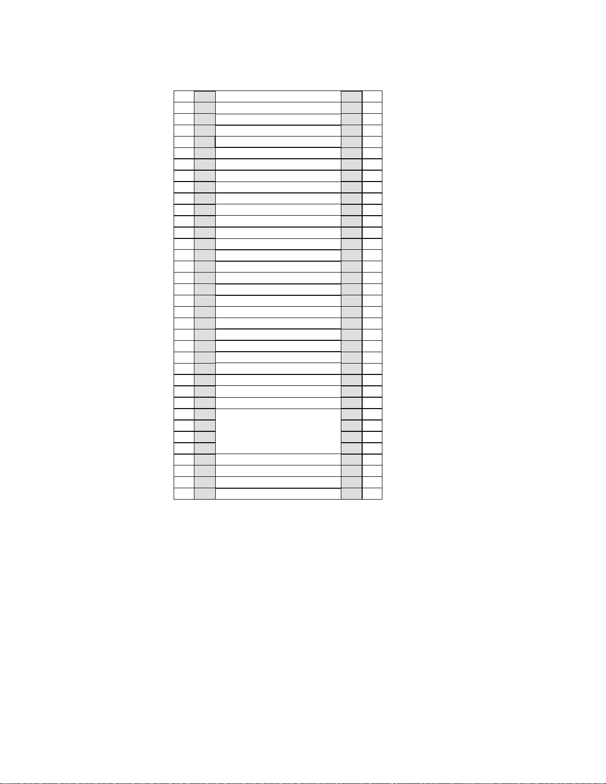
|
|
|
EIA
EIA
Holes
106
103
100
97
94
91
88
85
82
79
76
73
70
67
64
61
58
55
52
49
46
43
40
37
34
31
28
25
22
19
16
13
10
7
4
1
Unit
36
35
34
33
32
31
30
29
28
27
26
25
24
23
22
21
20
19
18
17
16
15
14
13
12
11
10
9
Empty (1u)
Empty (1u)
Empty (1u)
Empty (1u)
Empty (1u)
Empty (1u)
Empty (1u)
Empty (1u)
Empty (1u)
Empty (1u)
Empty (1u)
Empty (1u)
Empty (1u)
Empty (1u)
Empty (1u)
Empty (1u)
Empty (1u)
Empty (1u)
TSSC (1u)
KVM Tray + TSSC sw (1u)
Empty (1u)
Empty (1u)
Empty (1u)
Empty (1u)
Empty (1u)
Empty (1u)
Empty (1u)
Empty (1u)
8
7
ProtecTIER Server (4u)
6
5
4
Power Distribution Unit (PDU)
3
2
Power Distribution Unit (PDU)
1
Empty (1u)
Empty (1u)
EIA
Unit
36
35
34
33
32
31
30
29
28
27
26
25
24
23
22
21
20
19
18
17
16
15
14
13
12
11
10
9
8
7
6
5
4
3
2
1
EIA
Holes
106
103
100
97
94
91
88
85
82
79
76
73
70
67
64
61
58
55
52
49
46
43
40
37
34
31
28
25
22
19
16
13
10
7
4
1
ts760444
Figure 1. Recommended stand-alone gateway server frame layout
|
Chapter 3. Recommended TS7650G configurations 11
Page 50
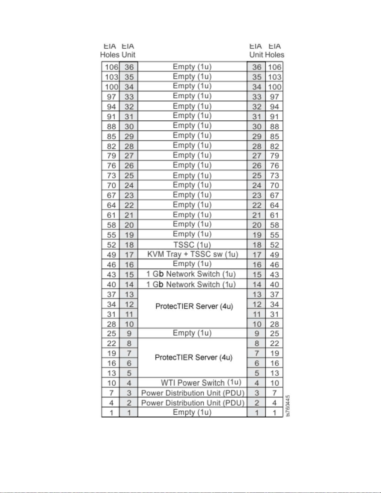
Figure 2. Recommended clustered gateway server frame layout
Note:
v In a clustered configuration, the bottom server in the frame is Server A, and the
top server in the frame is Server B.
12 IBM System Storage TS7600 with ProtecTIER: Installation Roadmap Guide
Page 51
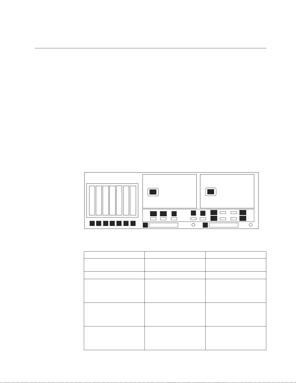
v Numbers in parentheses following components indicate the number of units (u)
the component occupies in the recommended 36u frame.
About the TS7650G server
This section describes the 3958 DD4 gateway server.
The TS7650G stand-alone and clustered gateways come with one or two servers,
respectively. The servers for VTL installation are equipped with
|
|
|
|
|
|
v Two Emulex fibre channel host bus adapters
v Two Qlogic QLE2562 dual port 8 Gb FC PCIe adapters
v One Intel Pro/1000 PT Quad Port Gb Ethernet PCIe adapter
The servers for OpenStorage installation are equipped with
v Two Qlogic QLE2562 dual port 8 Gb FC PCIe adapters
v Three Intel Pro/1000 PT Quad Port Gb Ethernet PCIe adapters
See Figure 3 and Table 2.
In addition, the Red Hat Enterprise Linux, ProtecTIER, and RAS package software
is factory-installed on the TS7650G servers.
ProtecTIER Server
1
111 1
2
222 22
3
3
4
4
3
1
2
4
|
|
Figure 3. DD4 Server rear view - generic
1
1
2
3
4
7
5
6
P1
A2
A1
8
B
V
P2
E1
S
E2
9
E3
E4
ts760751
|
|
|
|||
||||
|||
|||
|
|
|
|||
|
|
|
||
|
|
|
|
|
|
|
Table 2. Server rear view: Slot assignments, ports, and connections
Slot, Port or Connection VTL use OpenStorage use
1Slot 1: Emulex fibre channel Host
Bus Adapter (HBA)
2 Slot 2: Emulex fibre channel HBA Blank
3 Slot 3: Blank Intel Pro Quad-port gigabit
4 Slot 4: Blank Intel Pro Quad-port gigabit
5 Slot 5: Intel Pro Quad-port gigabit
Ethernet adapter (Port 1 =
Eth0, Port 2 = Eth1, Port 3 =
Eth2, Port 4 = Eth3)
Blank
Ethernet adapter (Port 1 =
Eth8, Port 2 = Eth9, Port 3 =
Eth10, Port 4 = Eth11)
Ethernet adapter (Port 1 =
Eth4, Port 2 = Eth5, Port 3 =
Eth6, Port 4 = Eth7)
Quad-port gigabit Ethernet
adapter (Port 1 = Eth0, Port 2
= Eth1, Port 3 = Eth2, Port 4
= Eth3)
Chapter 3. Recommended TS7650G configurations 13
Page 52
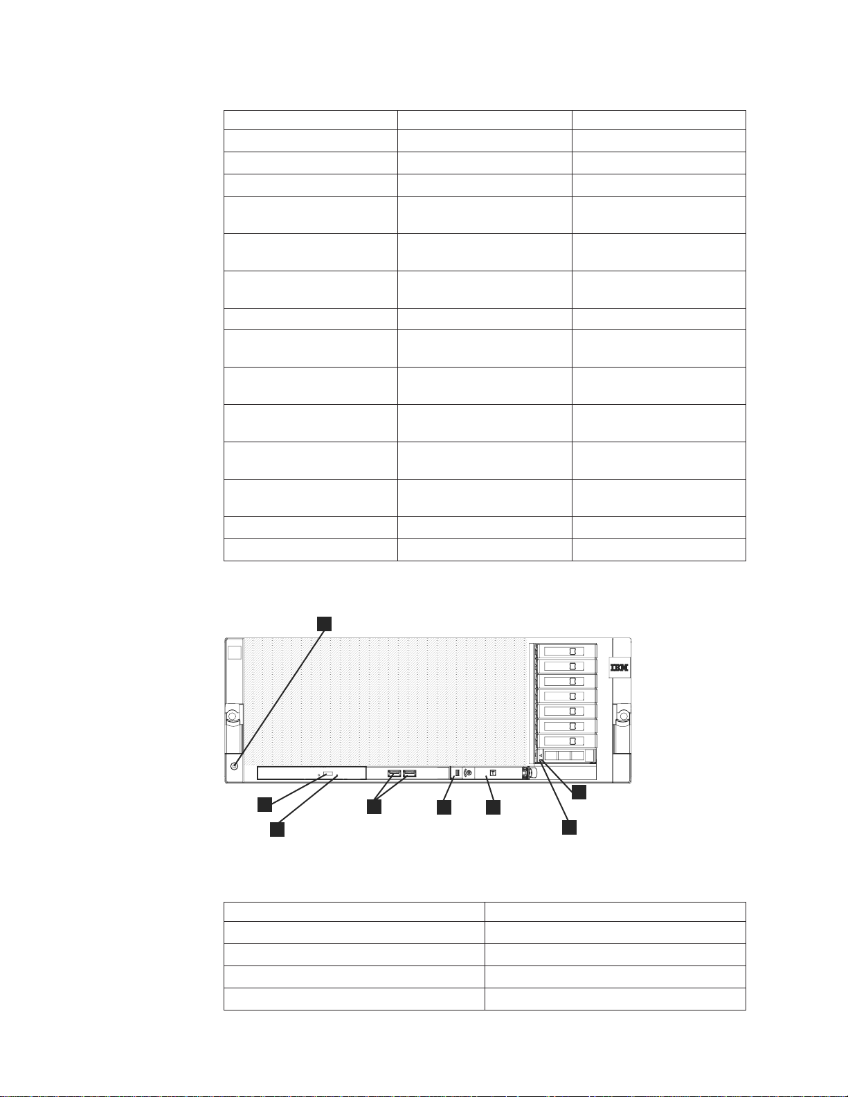
|
|||
|||
|||
|||
||||
||||
||||
|||
||||
||||
||||
||||
||||
|||
|||
Table 2. Server rear view: Slot assignments, ports, and connections (continued)
6 Slot 6: Qlogic HBA Qlogic HBA
7 Slot 7: Qlogic HBA Qlogic HBA
8 QPI Slot 1 Not used Not used
9 QPI Slot 2 Not used Not used
A1 Integrated Ethernet 1
port
A2Integrated Ethernet 2
port
B Integrated Ethernet 3
port
V RSA Video port
S Serial Attached SCSI
(SAS) port
E1 Universal Serial Bus
(USB) port 1
E2 Universal Serial Bus
(USB) port 2
E3 Universal Serial Bus
(USB) port 3
E4 Universal Serial Bus
(USB) port 4
P1 Power connection
P2 Power connection
(Eth4) (Eth12)
(Eth5) (Eth13)
SYS MGMT SYS MGMT
|
|
|
2
3
|
|
Figure 4. DD4 Server front view
1
8
4
5
6
7
ts760769
|
|
|
||
||
||
||
||
Table 3. DD4 Server front view
Callout Description
1 Electrostatic discharge connector
2 DVD-eject button
3 DVD drive activity LED
4 USB connectors
14 IBM System Storage TS7600 with ProtecTIER: Installation Roadmap Guide
Page 53
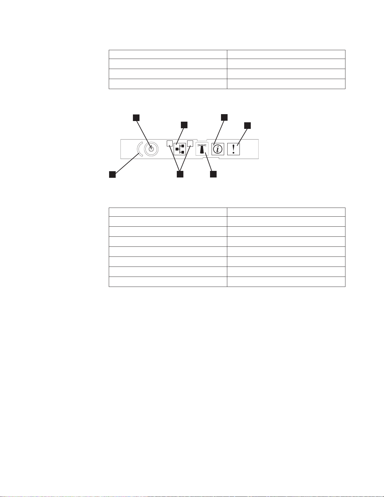
|
||
||
||
||
Table 3. DD4 Server front view (continued)
5 Scalability LED
6 Operator information panel
7 Hard disk drive activity LED
8 Hard disk drive status LED
|
|
|
6
7
1
2
1
5
|
|
Figure 5. Operator information panel
2
4
3
ts760171
|
|
|
||
||
||
||
||
||
||
||
Table 4. Operator information panel
Callout Description
1 Information LED
2 System-error LED
3 Locator button/locator LED
4 Ethernet port activity LEDs
5 Power control button cover
6 Power control button/power-on LED
7 Ethernet icon LED
|
|
Chapter 3. Recommended TS7650G configurations 15
Page 54

16 IBM System Storage TS7600 with ProtecTIER: Installation Roadmap Guide
Page 55

Chapter 4. Installing the TS7650G hardware
This chapter provides instructions for installing the TS7650G servers into the
recommended, customer-supplied 36u frame, and making all required power and
cable connections from the server to the hardware components recommended
under IBM best practices. To simplify installation and maintenance, it is
recommended that the components included in the purchase of the TS7650G,
including the TSSC and TSSC Ethernet switch, occupy one frame (the server
frame), while the disk components occupy a second frame (the disk storage frame).
|
|
Read this first
|
|
|
|
Attention: Any unused EIA units in the frame should be baffled, in order to
avoid recirculating air and overheating the system.
Read the notes below carefully. They provide important details regarding
installation of the gateway hardware components.
Important:
v This document references IBM 4.8 TB Fibre Channel Disk Controllers and IBM
7.2 TB Fibre Channel Disk Expansion Units in many of the hardware installation
figures, examples, and procedures.
In addition to the IBM DS4700 disk controller, the TS7650G also supports the
DS5000 disk controller, the DS8000 disk controller and the XIV disk controller, as
well as various non-IBM storage solutions. If the customer has elected to use
disk storage components other than the IBM disk controllers mentioned above,
the figures, examples, and procedures in this document will not apply to the
configuration on which you are working. Therefore, it is suggested that you
determine the make and model of the disk storage components in use and, if
necessary, obtain the related product documentation before you begin
installation of the gateway.
v The RAS code no longer sends call home packages for problems with any of the
disk storage products attached to the gateway including DS4700. DS5000,
DS8000 and XIV.
v The customer is responsible for ensuring that all hardware components other
than those included in the purchase of the TS7650G and the TSSC and the TSSC
Ethernet switch, are installed and configured before TS7650G installation begins.
v A USB keyboard and graphics-capable monitor are required to complete the
installation. These items are not provided in the TS7650G ship group; they must
be provided by the customer. The recommended screen resolution for the
ProtecTIER GUI is 1280 x 1024.
v Be sure to complete the installation of the TS7650G before installing any
miscellaneous equipment specification (MES) features. The installation
instructions for an MES feature assume that you are adding the feature to an
installed TS7650G.
© Copyright IBM Corp. 2008, 2010 17
Page 56

Disk storage configuration guidelines
The Account/Sales team, Business Partner, and ultimately the customer, is
responsible for ensuring that the disk storage is installed and configured before
you start the TS7650G installation process. The installation also depends on having
a customer-provided frame available at the customer site.
Gateway servers can attach to a variety of disk storage technologies, which may
have different installation and support terms depending upon machine type.
Warranty service upgrades (WSUs) or an installation service contract may be
required to cover storage devices that are considered to be customer setup (CSU),
or not considered to be IBM setup such as third-party disk storage subsystems.
|
|
|
|
Refer to the IBM System Storage TS7650 Best Practices Guide for ProtecTIER v 2.5 and
TS7650G (Gateway) Attached Storage, IBM form number GA32-0646 for more
detailed information on how to set up IBM DS4700, DS5000, DS8000 and XIV
storage systems.
TS7650G sales agreements may include a frame and disk storage as part of the
order. However, installation of frames and disk storage are not included in the
gateway installation process, and will require additional planning and
coordination.
If the disk storage is not operational when you arrive at the customer site, take the
following steps:
v Assess the situation to determine whether you are capable of performing the
task yourself, or if additional IBM resources are required:
– You may perform physical disk storage installation if the machine types are
properly entitled. Note that advanced setup tasks, including LUN
configuration and/or mirroring, are outside the scope of normal installation
support and may warrant additional charges.
– If additional installation resources are required, contact your Service Delivery
Manager (SDM) or your next level of support for advice on how you should
proceed.
v In the event that IBM disk storage was purchased without IBM installation
services, inform the customer that a Service Contract 44 (SC44) is required for
disk storage and/or frame installation, and additional charges will apply.
Before you begin
The TS7650G installation requires participation from the customer, as well as the
coordinated efforts IBM System Services Representative (SSR), Lab-based Services
(LBS), and trained ProtecTIER specialist. The table below outlines the division of
responsibilities:
Table 5. Responsibilities matrix
Task Customer
Complete the planning, preparation, and installation tasks described in
the IBM System Storage TS7600 with ProtecTIER Introduction and Planning
Guide for the TS7650G (3958 DD4), IBM form number GC53–1152.
18 IBM System Storage TS7600 with ProtecTIER: Installation Roadmap Guide
"
Trained
ProtecTIER
specialist and/or
LBS
SSRs
Page 57

Table 5. Responsibilities matrix (continued)
Trained
Task Customer
Meet the preinstallation requirements outlined in the IBM System Storage
TS7600 with ProtecTIER Introduction and Planning Guide for the TS7650G
(3958 DD4), IBM form number GC53–1152
Complete the worksheets provided in the IBM System Storage TS7600 with
ProtecTIER Introduction and Planning Guide for the TS7650G (3958 DD4),
IBM form number GC53–1152. For convenience, blank copies of the
worksheets are included as appendices in this document.
|
Purchase, install, and configure (if necessary), all hardware components
|
not included in the purchase of the gateway. Use the IBM System Storage
|||
|
TS7650 - Best Practices Guide for ProtecTIER v. 2.5 and TS7650G (Gateway)
|
Attached Storage for reference.
Confirm that an existing TSSC that is being used with the TS7650G has
Feature Code 2719.
Note: Unless an existing TSSC resides in the server frame and is used in
conjunction with a KVM switch, the customer must provide a USB
keyboard and graphics-capable monitor for server configuration.
Ensure that a separate USB keyboard and graphics-capable monitor are
available for use during installation.
Oversee project management for the installation and integration of the
engagement.
Oversee change management and process control for the installation. "
Coordinate and schedule IBM resources for customer installations, and act
as a focal point of contact for coordination of installation services.
Schedule and facilitate planning and solution assurance conference calls. "
Create and document the installation service process. "
Install the TS7650G hardware components purchased with the gateway,
into the server and disk storage frames.
|
Label and connect power, Ethernet, and fibre channel cables, including
|||
|
OST front-end cables, as necessary and applicable.
Connect the TS7650G to the customer's local area network and replication
network, if applicable.
Power-up the system. "
Verify accuracy of hardware installation and cabling. Perform visual
check of fault indicator LEDs.
Configure the TSSC for use with the TS7650G. "
Configure the RAS package on the servers. "
Test Call Home on the servers. "
|
Configure ProtecTIER on the stand-alone server or Server A in a cluster,
|||
|
including OST if applicable, and create the file system.
Install ProtecTIER Replication Manager on one of the ProtecTIER servers
being used for replication, if applicable.
Install ProtecTIER Manager on the TSSC or ProtecTIER Manager
workstation, register each server as a new ProtecTIER node, and create
the repository.
Add the second server (Server B) to the ProtecTIER cluster, if applicable. "
"
"
"
"
"
ProtecTIER
specialist and/or
LBS
"
"
"
"
"
SSRs
"
"
"
"
Chapter 4. Installing the TS7650G hardware 19
Page 58

Table 5. Responsibilities matrix (continued)
Trained
Task Customer
Verify cluster operation, if applicable. "
Perform RAS verification tasks. "
Release the system to the customer. Advise the customer that it is their
responsibility to create and configure the replication grid, if applicable.
Document and report installation results. "
ProtecTIER
specialist and/or
Finding the instructions you need
The flowcharts that follow show which documents, and in what order, you (or the
customer) will need when installing new3958 DD4 servers. All of the documents
shown are available in the ship group, in hardcopy or electronic format. The
flowcharts for upgrading legacy 3958 DD1, 3958 DD3, or 3958 AP1, servers are
located in the IBM System Storage ProtecTIER Software Upgrade and Replication
Enablement Guide, IBM form number GC53–1196.
SSRs
LBS
"
20 IBM System Storage TS7600 with ProtecTIER: Installation Roadmap Guide
Page 59

|
New Stand-alone
Documents required to install
a new stand-alone
ProtecTIER server with or
without replication
Introduction and
Planning Guide
(customer)
Best Practices Guide
ProtecTIER server
TS7650G or TS7650
Installation
Roadmap Guide
Labeling Instructions
Software Upgrade
and Replication
Enablement Guide
User’s Guide
ts760779
|
|
Figure 6. Documents required to install a new stand-alone 3958 DD4 server
|
Chapter 4. Installing the TS7650G hardware 21
Page 60

|
New clustered
Documents required to install
new clustered ProtecTIER
servers with or without
replication
Introduction and
Planning Guide
(customer)
ProtecTIER servers
Server A
Best Practices Guide
TS7650G or TS7650
Installation
Roadmap Guide
Labeling Instructions
Labeling Instructions
Software Upgrade
and Replication
Enablement Guide
Server B
Server B
installed?
Yes
No
|
|
Figure 7. Documents required to install new clustered 3958 DD4 servers
|
22 IBM System Storage TS7600 with ProtecTIER: Installation Roadmap Guide
User’s Guide
ts760780
Page 61

Stand-alone gateway installation checklist
About this task
The checklist below outlines the tasks required to successfully install the hardware
in a stand-alone gateway configuration. If you are installing a clustered gateway,
use the “Clustered gateway installation checklist” on page 26.
Important:
This document references IBM 4.8 TB Fibre Channel Disk Controllers and IBM 7.2
TB Fibre Channel Disk Expansion Units in many of the hardware installation
figures, examples, and procedures.
In addition to the IBM DS4700 disk controller, the TS7650G also supports the
DS5000 disk controller, the DS8000 disk controller and the XIV disk controller, as
well as various non-IBM storage solutions. If the customer has elected to use disk
storage components other than the IBM disk controllers mentioned above, the
figures, examples, and procedures in this document will not apply to the
configuration on which you are working. Therefore, it is suggested that you
determine the make and model of the disk storage components in use and, if
necessary, obtain the related product documentation before you begin installation
of the gateway.
The RAS code no longer sends call home packages for problems with any of the
disk storage products attached to the gateway including DS4700. DS5000, DS8000
and XIV.
Table 6. Stand-alone gateway installation checklist
U Task Description Where to find information
Section 1: Perform preinstallation verification
h 1–1 The disk components are installed in suitable
frames.
h 1–2 The frames are in a suitable location. N/A
h 1–3 The disk controllers are located within 25m (82
ft.) cable length of the server(s).
h 1–4 All RAID, logical drive, and LUN
configuration is completed.
|||
|
h 1–5a For VTL, two IP addresses were assigned for
|
|
|||
|
h 1–5b For OST, three to eight IP addresses were
|
|
|
h 1–6 One or more PCs on the customer's local area
use: One for the 3958-DD4 server and one for
the TSSC.
assigned for use: One for the 3958-DD4 server,
one for the TSSC, and up to six for the host
network.
network (LAN) have been designated as
ProtecTIER Manager workstations.
If this task was not completed prior to your
arrival, refer to “Read this first” on page 17
and “Disk storage configuration guidelines” on
page 18.
N/A
Customer
If these tasks were not completed prior to your
arrival, refer to “Read this first” on page 17
and “Disk storage configuration guidelines” on
page 18.
Customer
Customer
Customer
Chapter 4. Installing the TS7650G hardware 23
Page 62

Table 6. Stand-alone gateway installation checklist (continued)
U Task Description Where to find information
h 1–7 A separate USB keyboard and graphics-capable
monitor have been provided for use during
installation.
h 1–8 If applicable, ensure that replication
configuration efforts are being coordinated
between the source and destination sites.
Section 2: Install the gateway components
h 2–1 Have the customer suspend all I/O activity.
Power-off any components that are
powered-on, and shut down power to the
frames.
h 2–2 Install the server. “Installing the server” on page 30.
h 2–3a If the customer purchased a new TSSC and
TSSC Ethernet switch and has not yet installed
them, do so now then go to task 3-1.
h 2–3b If the customer has an existing TSSC (with FC
2719) and TSSC Ethernet switch, that can be
used with the gateway, go to task 3-1.
Section 3: Apply cable labels and make cable connections
h 3–1 Label and connect the power cords on the
server to the PDU.
h 3–2 If you installed a TSSC, label and connect the
power cable on the TSSC to the PDU.
h 3–3 If you installed a TSSC Ethernet switch, label
and connect the power cable on the switch to
the PDU.
h 3–4 Label and connect an Ethernet cable from the
server to the TSSC's Ethernet switch.
|||||
h 3–5 Label and connect an Ethernet cable from the
server to the customer's LAN.
h 3–6 Label and connect Ethernet cables from the
server to the customer's replication network, if
applicable.
h 3–7 Label and connect an Ethernet cable from the
RSA on the server to the TSSC's Ethernet
switch.
h 3–8 Label and connect an Ethernet cable from disk
controllers A and B to the TSSC's Ethernet
switch.
h 3–9 Label and connect an Ethernet cable from the
TSSC's external port (Eth2) to the customer's
LAN.
h 3–10 Label and connect fibre channel cables from
the server to disk controllers A and B.
|||||
h 3–11a For VTL, label and connect fibre channel cables
from the server to the customer's host network.
|||||
h 3–11b For OST, label and Ethernetl cables from the
server to the customer's host network.
Customer
Customer, LBS, and or trained ProtecTIER
specialist.
Refer to the component-specific documentation
for power-off instructions.
The TSSC Maintenance Information (MI),
provided on the IBM System Storage TS7650
with ProtecTIER Publications CD.
N/A
“Cabling a stand-alone gateway” on page 35.
“Cabling a stand-alone gateway” on page 35.
“Cabling a stand-alone gateway” on page 35.
“Cabling a stand-alone gateway” on page 35.
“Cabling a stand-alone gateway” on page 35.
“Cabling a stand-alone gateway” on page 35.
“Cabling a stand-alone gateway” on page 35.
“Cabling a stand-alone gateway” on page 35.
“Cabling a stand-alone gateway” on page 35.
“Cabling a stand-alone gateway” on page 35.
“Cabling a stand-alone gateway” on page 35.
“Cabling a stand-alone gateway” on page 35.
24 IBM System Storage TS7600 with ProtecTIER: Installation Roadmap Guide
Page 63

Table 6. Stand-alone gateway installation checklist (continued)
U Task Description Where to find information
Section 4: Power-up all components
h 4–1 Turn on the breaker(s) to power the PDUs. N/A
h 4–2 Power-up the disk expansion module(s). “Disk expansion modules” on page 70.
h 4–3 Power-up the disk controller. “Disk controllers” on page 70.
h 4–4 Power-up the server. “Servers” on page 70.
h 4–5 Power-up the TSSC, display panel, and TSSC
Ethernet switch
Section 5: Perform post-installation validation checks
h 5–1 Check power indicators for all components. “Visually inspecting indicator and fault LEDs”
h 5–2 Validate Ethernet link-up indicators on the
TSSC.
h 5–3 Validate Ethernet link-up indicators on the
customer's local area network (LAN) to the
server and the TSSC.
h 5–4 Validate fibre channel link-up indicators from
the disk controller to the server.
|||
|
h 5–5 Validate fibre channel (VTL) or Ethernet (OST)
|
|
|
Section 6: Prepare the TSSC for use with the TS7650G
h 6–1 Configure the TSSC's communication settings. “Setting up the TSSC for use with the
Section 7: Perform RAS package configuration and verification
h 7–1 Configure the RAS package on the server. Chapter 6, “Configuring the RAS package,” on
h 7–2 Perform RAS verification. Includes verifying
Section 8: SSR releases the system to trained ProtecTIER specialist or LBS representative
|||||
h 8–1 Configure ProtecTIER, including configuring
|
h 8–2 Install the ProtecTIER Replication Manager
h 8–3 Install ProtecTIER Manager and create the
h 8–4 Turn the system over to the customer. If
link-up indicators from the customer host to
the server.
attached systems and testing Call Home.
OST if applicable, and create the file system.
application, if applicable.
repository.
replication is being used, advise the customer
that it is their responsibility to create and
configure the replication grid.
“TSSC and KVM kit” on page 71.
on page 71.
“Visually inspecting indicator and fault LEDs”
on page 71.
“Visually inspecting indicator and fault LEDs”
on page 71.
“Visually inspecting indicator and fault LEDs”
on page 71.
“Visually inspecting indicator and fault LEDs”
on page 71.
TS7650G” on page 77.
page 83.
Chapter 7, “RAS verification,” on page 91.
Chapter 8, “Configuring ProtecTIER using
ptconfig,” on page 95.
Chapter 9, “Enabling the ProtecTIER
Replication Manager,” on page 111.
Chapter 10, “Installing ProtecTIER Manager,”
on page 113.
N/A
Chapter 4. Installing the TS7650G hardware 25
Page 64

Clustered gateway installation checklist
About this task
The checklist below provides a high-level overview of the tasks required to
successfully install the TS7650G in a clustered gateway configuration. If you are
installing a stand-alone gateway, use the “Stand-alone gateway installation
checklist” on page 23.
Important:
|
|
|
|
|
|
|
|
|
|
|
|
|
|
|
Table 7. Clustered gateway installation checklist
U Task Description Where to find information
Section 1: Perform pre-installation verification
h 1–1 The disk components are installed in suitable
h 1–2 The frames are in a suitable location. N/A
h 1–3 The disk controllers are located within 25m (82
h 1–4 All RAID, logical drive, and LUN configuration
|||
|
h 1–5a For VTL, three IP addresses were assigned for
|
|
|
|
This document references IBM 4.8 TB Fibre Channel Disk Controllers and IBM 7.2
TB Fibre Channel Disk Expansion Units in many of the hardware installation
figures, examples, and procedures.
In addition to the IBM DS4700 disk controller, the TS7650G also supports the
DS5000 disk controller, the DS8000 disk controller and the XIV disk controller, as
well as various non-IBM storage solutions. If the customer has elected to use disk
storage components other than the IBM disk controllers mentioned above, the
figures, examples, and procedures in this document will not apply to the
configuration on which you are working. Therefore, it is suggested that you
determine the make and model of the disk storage components in use and, if
necessary, obtain the related product documentation before you begin installation
of the gateway.
The RAS code no longer sends call home packages for problems with any of the
disk storage products attached to the gateway including DS4700. DS5000, DS8000
and XIV.
If this task was not completed prior to your
frames.
ft.) cable length of the server(s).
is completed.
use:
v One for 3958-DD4 Server A
v One for 3958-DD4 Server B
v One for the TSSC
arrival, refer to “Read this first” on page 17
and “Disk storage configuration guidelines” on
page 18.
N/A
Customer
If these tasks were not completed prior to your
arrival, refer to “Read this first” on page 17
and “Disk storage configuration guidelines” on
page 18.
Customer
26 IBM System Storage TS7600 with ProtecTIER: Installation Roadmap Guide
Page 65

Table 7. Clustered gateway installation checklist (continued)
U Task Description Where to find information
|||
|
h 1–5b For OST, up to fifteen IP addresses were
|
|
|
|
|
h 1–6 One or more PCs on the customer's local area
h 1–7 A separate USB keyboard and graphics-capable
h
1–8
Section 2: Install the gateway components
h 2–1 Have the customer suspend all I/O activity.
h 2–2 Install the WTI network power switch. “Installing the WTI network power switch” on
h 2–3 Install the 1 GB Ethernet switches. “Installing the 1 Gb Ethernet switches” on page
h 2–4 Install Server A (the bottom server). “Installing the server” on page 30
h 2–5 Install Server B (the top server). “Installing the server” on page 30
h 2–6a If the customer purchased a new TSSC and
h 2–6b If the customer has an existing TSSC (with FC
Section 3: Apply cable labels and make cable connections
h 3–1 Label and connect one of the power cords on
h 3–2 Label and connect the power cord on each 1
h 3–3 Label and connect the remaining power cords
h 3–4 If you installed a TSSC, label and connect the
h 3–5 If you installed a TSSC Ethernet switch, label
assigned for use:
v One for 3958-DD4 Server A
v One for 3958-DD4 Server B
v One for the TSSC
v Up to twelve for the OST host network
network (LAN) are designated as ProtecTIER
Manager workstations.
monitor have been provided for use during
installation.
If applicable, ensure that replication
configuration efforts are being coordinated
between the source and destination sites.
Power-off any components that are
powered-on, and shut down power to the
frames.
TSSC Ethernet switch, and has not yet installed
them, do so now, and then go to task 3-1.
2719) and Ethernet switch that can be used
with the gateway, go on to task 3-1.
the WTI network power switch to the PDU.
GB switch to the PDU.
on the WTI network power switch to the
servers.
power cord on the TSSC to the PDU.
and connect the power cord on the switch to
the PDU.
Customer
Customer
Customer
Customer, LBS, and or trained ProtecTIER
specialist.
Refer to the component-specific documentation
for power-off instructions.
page 31.
33.
The TSSC Maintenance Information (MI),
provided on the IBM System Storage TS7650
with ProtecTIER Publications CD.
N/A
“Cabling a clustered gateway” on page 49.
“Cabling a clustered gateway” on page 49.
“Cabling a clustered gateway” on page 49.
“Cabling a clustered gateway” on page 49.
“Cabling a clustered gateway” on page 49.
Chapter 4. Installing the TS7650G hardware 27
Page 66

Table 7. Clustered gateway installation checklist (continued)
U Task Description Where to find information
h 3–6 Label and connect an Ethernet cable from the
WTI network power switch to the top 1 GB
Ethernet switch.
h 3–7 Label and connect an Ethernet cable from the
bottom 1 GB switch to the top 1 GB Ethernet
switch.
h 3–8 Label and connect an Ethernet cable from
Server A to the bottom 1GB Ethernet switch.
h 3–9 Label and connect an Ethernet cable from
Server B to the bottom 1GB Ethernet switch.
h 3–10 Label and connect an Ethernet cable from
Server A to the TSSC's Ethernet switch.
|||||
h 3–11a Label and connect an Ethernet cable from
Server A to the customer's LAN.
|||
|
h 3–12 Label and connect Ethernet cables from Server
|
|
h 3–13 Label and connect Ethernet cables from Server
h 3–14 Label and connect an Ethernet cable from the
h 3–15 Label and connect an Ethernet cable from
|||||
h 3–16a Label and connect an Ethernet cable from
|||||
h 3–17 Label and connect an Ethernet cable from the
h 3–18 Label and connect an Ethernet cable from
h 3–19 Label and connect an Ethernet cable from the
|||
|
h 3–20 Label and connect fibre channel cables from
|
|
|||
|
h 3–21 Label and connect fibre channel cables from
|
|
|||||
h 3–22a For VTL, label and connect fibre channel cables
|||||
h 3–22a For OST, label and connect Ethernet cables
|||||
h 3–23a For VTL, label and connect fibre channel cables
|||||
h 3–23a For OST, label and connect Ethernet cables
A to the customer's replication network, if
applicable.
B to the customer's replication network, if
applicable.
RSA on Server A to the TSSC's Ethernet switch.
Server B to the TSSC's Ethernet switch.
Server B to the customer's LAN.
RSA on Server B to the TSSC's Ethernet switch.
controllers A and B of attached storage disk
controller-1, to the TSSC Ethernet switch.
TSSC's external port (Eth2) to the customer
network.
Server A to controllers A and B of the first
storage controller.
Server B to controllers A and B of the second
storage controller.
from Server A to the customer host network.
from Server A to the customer host network.
from Server B to the customer host network.
from Server B to the customer host network.
“Cabling a clustered gateway” on page 49.
“Cabling a clustered gateway” on page 49.
“Cabling a clustered gateway” on page 49.
“Cabling a clustered gateway” on page 49.
“Cabling a clustered gateway” on page 49.
“Cabling a clustered gateway” on page 49.
“Cabling a clustered gateway” on page 49.
“Cabling a clustered gateway” on page 49.
“Cabling a clustered gateway” on page 49.
“Cabling a clustered gateway” on page 49.
“Cabling a clustered gateway” on page 49.
“Cabling a clustered gateway” on page 49.
“Cabling a clustered gateway” on page 49.
“Cabling a clustered gateway” on page 49.
“Cabling a clustered gateway” on page 49.
“Cabling a clustered gateway” on page 49.
“Cabling a clustered gateway” on page 49.
“Cabling a clustered gateway” on page 49.
“Cabling a clustered gateway” on page 49.
“Cabling a clustered gateway” on page 49.
28 IBM System Storage TS7600 with ProtecTIER: Installation Roadmap Guide
Page 67

Table 7. Clustered gateway installation checklist (continued)
U Task Description Where to find information
Section 4: Power-up all components
Note: Tasks 4-4 and 4-5 can be performed in parallel.
h 4–1 Turn on the breaker(s) to power the PDUs. N/A
h 4–2 Power-up the disk expansion modules. “Disk expansion modules” on page 70.
h 4–3 Power-up the disk controllers. “Disk controllers” on page 70.
h 4–4 Power-up Server A. “Servers” on page 70.
h 4–5 Power-up Server B. “Servers” on page 70.
h 4–6 Power-up the TSSC, display panel, and TSSC
Ethernet switch.
Section 5: Perform post-installation validation checks
h 5–1 Check power indicators for all components. “Visually inspecting indicator and fault LEDs”
h 5–2 Validate Ethernet link-up indicators on TSSC. “Visually inspecting indicator and fault LEDs”
h 5–3 Validate Ethernet link-up indicators on the
customer network to the server and the TSSC.
h 5–4 Validate that all links on the internal Ethernet
network indicate 1000 Mbps, except for the
Ethernet connection to the WTI network power
switch, which indicates 100 Mbps.
“TSSC and KVM kit” on page 71.
on page 71.
on page 71.
“Visually inspecting indicator and fault LEDs”
on page 71.
“Visually inspecting indicator and fault LEDs”
on page 71.
All connections, except the connection to the
WTI network power switch, must be at 1000
Mbps for the cluster configuration to work.
h 5–5 Validate fibre channel link-up indicators from
the disk controller to the server.
|||||
h 5–6a For VTL, validate fibre channel link-up
|
|||||
h 5–6b For OST, validate Ethernet link-up indicators
|
Section 6: Prepare the TSSC for use with the TS7650G
h 6–1 Configure the TSSC's communication settings. “Setting up the TSSC for use with the
Section 7: Perform RAS package configuration and verification
h 7–1 Configure the RAS package on the server. Chapter 6, “Configuring the RAS package,” on
h 7–3 Perform RAS verification. Includes verifying
Section 8: SSR releases the system to trained ProtecTIER specialist or LBS representative
|||||
h 8–1 Configure ProtecTIER, including configuring
|
h 8–2 Install the ProtecTIER Replication Manager
h 8–3 Install ProtecTIER Manager and create the
h 8–4 Test the clustered system. Chapter 14, “Testing a clustered system,” on
||||
indicators from customer host to the server.
from customer host to the server.
attached systems and testing Call Home.
OST if applicable, and create the file system.
application, if applicable.
repository.
|
“Visually inspecting indicator and fault LEDs”
on page 71.
“Visually inspecting indicator and fault LEDs”
on page 71.
“Visually inspecting indicator and fault LEDs”
on page 71.
TS7650G” on page 77.
page 83.
Chapter 7, “RAS verification,” on page 91.
Chapter 8, “Configuring ProtecTIER using
ptconfig,” on page 95.
Chapter 9, “Enabling the ProtecTIER
Replication Manager,” on page 111.
Chapter 10, “Installing ProtecTIER Manager,”
on page 113.
page 139.
Chapter 4. Installing the TS7650G hardware 29
Page 68

Table 7. Clustered gateway installation checklist (continued)
U Task Description Where to find information
h 8–5 Turn the system over to the customer. If
replication is being used, advise the customer
that it is their responsibility to create and
configure the replication grid.
N/A
Installing the server
Use this procedure to install the server.
About this task
Important: The customer is responsible for ensuring that any recommended
hardware components that were not included in the purchase of the TS7650G, such
as disk controllers and disk expansion module, are installed in a frame, cabled, and
fully configured; before server installation begins.
Procedure
1. If any components installed in the server and/or disk storage frames are
powered-on, have the customer suspend all I/O activity, and then power-off
the components.
2. Physically install the server (or both servers, in a clustered gateway
configuration) into the server frame.
3. Once physical installation and labeling is complete, go to “Installing the TSSC
and Ethernet switch.”
Installing the TSSC and Ethernet switch
|
Use this procedure to install the TSSC and any related components.
Before you begin
Important: If the customer purchased a TSSC, you are required to install it and its
related components, along with the other gateway hardware. Failure to do so will
prevent the use of Call Home or IBM remote support.
Procedure
1. Physically install the TSSC and its related components into the server frame.
Use the documentation provided with the TSSC for installation instructions.
Attention: The recommended location for installing the TSSC is in EIA Unit
18. Use EIA holes 52, 53, and 54 for the installation of the rail assembly for the
TSSC. The rail pins should extend through holes 52 and 53 at the front and rear
of the frame. See Figure 8 on page 31 for the recommended mounting locations
for the TSSC.
The KVM and TSSC switch should be mounted directly under the TSSC in EIA
Unit 17. Use EIA holes 49, 50, and 51 for the installation of the KVM rail
assembly. Mounting clips should be placed in holes 49 and 51 (EIA Unit 17) in
the front and rear of the frame. Use the rail assembly mounting position at the
rear of the frame to secure the TSSC network switch when added after the
KVM assembly is installed.
30 IBM System Storage TS7600 with ProtecTIER: Installation Roadmap Guide
Page 69
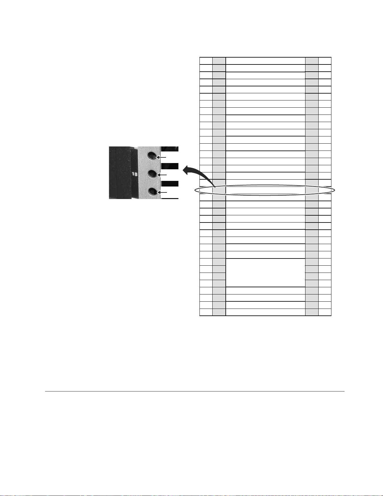
|
EIA
Hole 54
EIA
Hole 53
EIA
Hole 52
|
|
Figure 8. TSSC mounting location
EIA
Holes
106
103
100
97
94
91
88
85
82
79
76
73
70
67
64
61
58
55
52
49
46
43
40
37
34
31
28
25
22
19
16
13
10
7
4
1
EIA
Unit
36
35
34
33
32
31
30
29
28
27
26
25
24
23
22
21
20
19
18
17
16
15
14
13
12
11
10
9
8
7
6
5
4
Power Distribution Unit (PDU)
3
2
Power Distribution Unit (PDU)
1
Empty (1u)
Empty (1u)
Empty (1u)
Empty (1u)
Empty (1u)
Empty (1u)
Empty (1u)
Empty (1u)
Empty (1u)
Empty (1u)
Empty (1u)
Empty (1u)
Empty (1u)
Empty (1u)
Empty (1u)
Empty (1u)
Empty (1u)
Empty (1u)
TSSC (1u)
KVM Tray + TSSC sw (1u)
Empty (1u)
Empty (1u)
Empty (1u)
Empty (1u)
Empty (1u)
Empty (1u)
Empty (1u)
Empty (1u)
ProtecTIER Server (4u)
Empty (1u)
Empty (1u)
EIA
Unit
36
35
34
33
32
31
30
29
28
27
26
25
24
23
22
21
20
19
18
17
16
15
14
13
12
11
10
9
8
7
6
5
4
3
2
1
EIA
Holes
106
103
100
97
94
91
88
85
82
79
76
73
70
67
64
61
58
55
52
49
46
43
40
37
34
31
28
25
22
19
16
13
10
7
4
1
ts760448
|
2. When the physical installation is complete, do one of the following as
appropriate:
a. For a stand-alone gateway configuration, go to “Applying cable labels” on
page 35.
b. For a clustered gateway configuration, go to “Installing the WTI network
power switch.”
Installing the WTI network power switch
Use this procedure to install the WTI network power switch.
About this task
This procedure applies only to a clustered gateway configuration. If you are
installing a stand-alone gateway, go to “Applying cable labels” on page 35.
Chapter 4. Installing the TS7650G hardware 31
Page 70

Important: The WTI network power switch (if included, or if clustering) should be
positioned within one meter or closer to the TS7650G servers. The cables for the
WTI network power switch must be able to reach the power distribution units
(PDUs), and the cables from the TS7650G servers must be able to reach the WTI
network power switch. The ability for one server to power-off the other server in a
clustered environment is a design requirement. For this to occur, both servers must
be plugged into the WTI network power switch at all times. In addition, locating
the servers within one meter of the WTI network power switch will allow the
servers to remain connected to the network power switch if the servers are placed
in a service position.
Procedure
1. Physically install the WTI network power switch into the rear of the server
frame. To do so:
a. Align the supplied threaded nut clips with the center holes at the top and
bottom of the vertical, rectangular opening in the upper-left corner of the
server frame.
b. Place the WTI switch into the opening with the power outlets at the top,
and secure the mounting brackets to the frame using the mounting screws.
Note: You may need to rotate the WTI switch's mounting brackets to
facilitate mounting the switch so that the power receptacles face outward,
toward the back of the frame. This is required so that the power receptacles
are easily accessible for power connections.
32 IBM System Storage TS7600 with ProtecTIER: Installation Roadmap Guide
Page 71
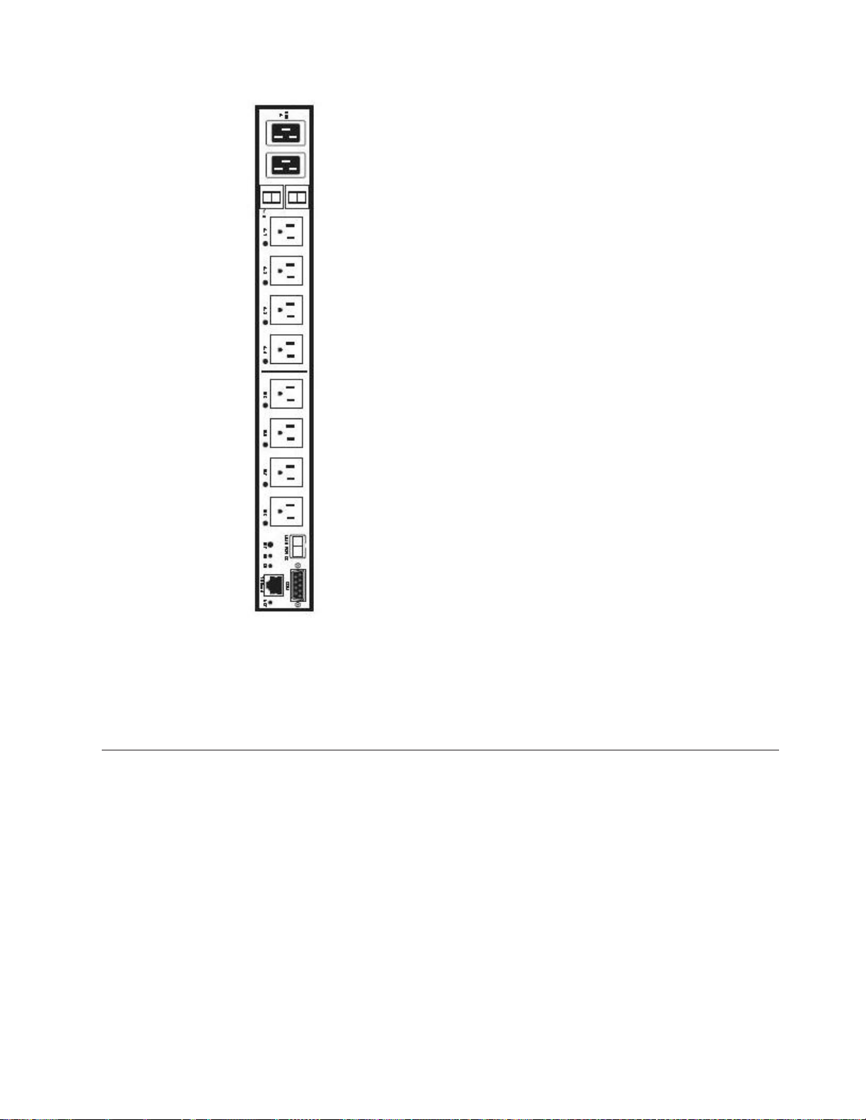
ts760201
Figure 9. WTI network power switch
Also refer to Figure 2 on page 12 for the recommended location of the WTI
network power switch in the server frame.
2. When physical installation is complete, go to “Installing the 1 Gb Ethernet
switches.”
Installing the 1 Gb Ethernet switches
|
Use this procedure to install the 1 Gb Ethernet switches.
About this task
|
|
IBM best practices recommends installing the 1 Gb Ethernet switches near the
middle of the clustered gateway server frame. See Figure 2 on page 12.
When performing the installation, use caution to avoid dislodging or damaging the
cabling within the frame.
Procedure
1. Attach the mounting brackets and power cords to the Ethernet switches. To do
so:
Chapter 4. Installing the TS7650G hardware 33
Page 72
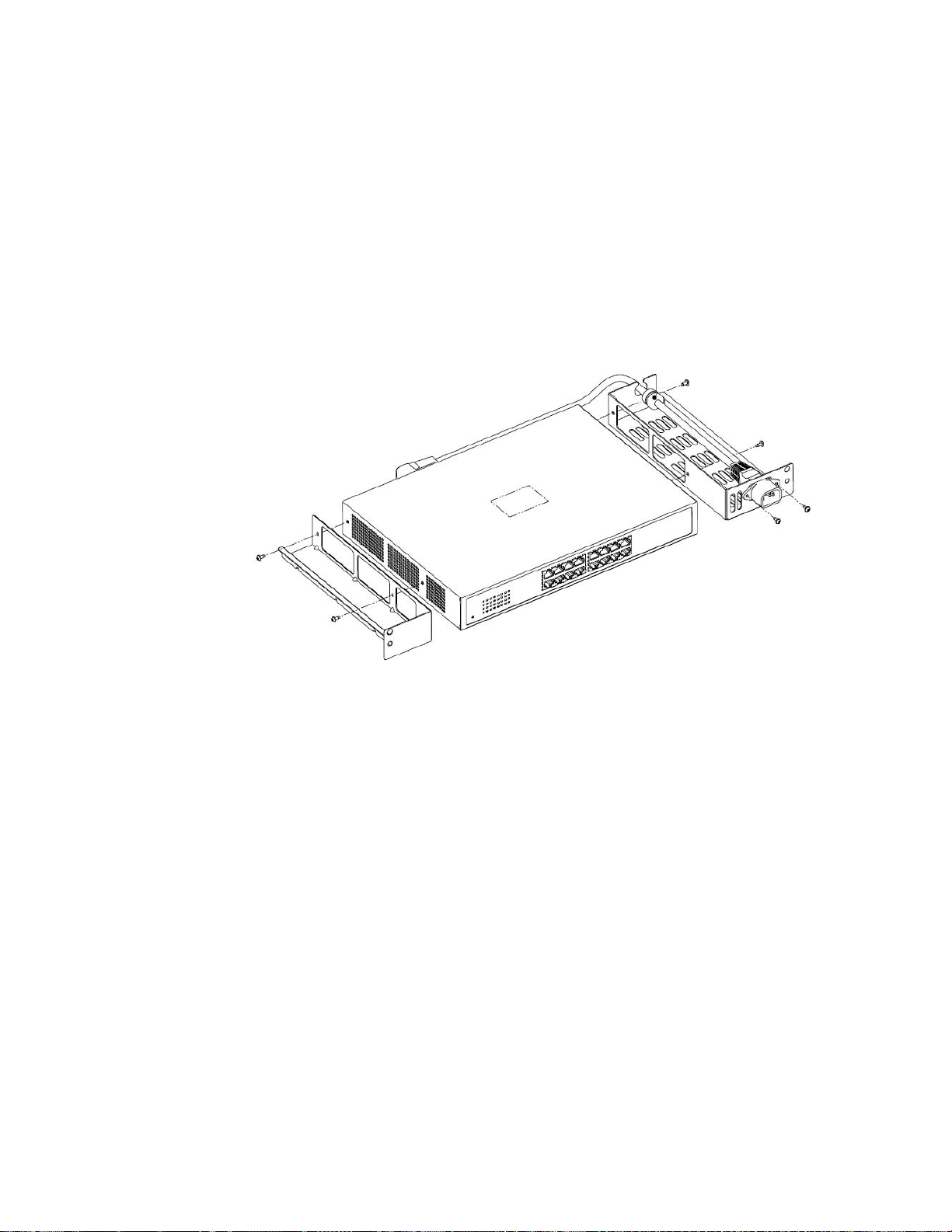
a. Attach the mounting brackets to the short-sides of the Ethernet switch,
making sure to align the perforated fan vents on the switch with the cut-out
areas on the brackets. See Figure 10.
b. Thread the power cord through the holes in the mounting bracket, making
sure that the tab extensions on the power cord are positioned on the outside
of the bracket.
c. Attach a protective grommet to the power cord, and fit the grommeted part
of the cord into the retention slot on the top of mounting bracket.
d. Plug the power cord into the power receptacle on the Ethernet switch.
e. Insert screws through the tab extensions on the power cord and into the
mounting bracket. Tighten the screws to attach the power cord to the
bracket.
ts760226
Figure 10. Attaching the mounting brackets and power cord
f. Place the air baffle on top of the mounting bracket without the power cord
(the left side bracket in the above illustration). Do not screw the air baffle to
the mounting bracket.
g. Repeat the above steps for the other Ethernet switch.
2. Attach the side rails to the server frame. To do so, working from the front side
of the frame:
a. Align the holes in the left side rail with the holes at positions 3 and 4 of the
frame. The guide pins on the side rail should point toward the back of the
server frame.
b. Insert one flanged screw into the hole at position 4 of the frame, tightening
the screw just enough to hold the rail in place.
c. Insert a second screw into the hole at position 3 of the frame, but do not
screw it in. Temporarily inserting this screw allows you to make sure that
both holes in the rail are properly aligned with both holes in the frame.
d. Tighten the screw in position 4, and then remove the temporary screw from
position 3.
e. Repeat the above steps for the right side rail and ensure that both side rails
are secure.
3. Install the air duct housing in the frame. To do so, working from the front side
of the frame:
34 IBM System Storage TS7600 with ProtecTIER: Installation Roadmap Guide
Page 73

a. Partially insert the large air duct housing into the frame by sliding it along
the side rails.
b. Insert long screws into the holes located near the bottom of each side of the
air duct housing.
c. Slide the plastic spacers over the backs of the screws.
d. Slowly slide the air duct housing into the frame, taking care to align the
screws with the holes in the frame.
e. Tighten the screws to secure the air duct housing to the frame.
4. Install the Ethernet switches into the air duct housing. To do so, working from
the back side of the frame:
a. Carefully slide one of the Ethernet switches into the air duct housing at
position 3 on the frame, with the Ethernet ports facing outward.
b. Aligning the top hole in the mounting bracket on the Ethernet switch with
the guide pins on the rails.
c. Insert a short flanged screw into the bottom holes on each side of the
mounting bracket, and tighten the screws to secure the Ethernet switch to
the rails.
d. Repeat the steps above for the other Ethernet switch.
5. When installation of the 1 Gb Ethernet switches is complete, go to “Cabling a
clustered gateway” on page 49.
Applying cable labels
Apply cable labels to the power, Ethernet and fibre channel cables.
About this task
Use the IBM System Storage TS7600 with ProtecTIER Labeling Instructions for the
TS7650/TS7650G (3958 DD4 and 3958 AP1), IBM part number 46X6059 for label
placement guidelines and instructions. When applying labels, align the center
reference lines on the label with the axis of the cable.
Cabling a stand-alone gateway
This procedure provides steps for cabling the components included in the purchase
of the TS7650G stand-alone gateway to each other, as well as to the power
distribution units (PDUs), the recommended disk controllers, and the customer
network.
About this task
For other supported components, review this information for general guidelines,
then refer to the manufacturers' documentation for details. More information, see
the IBM System Storage TS7650 Best Practices Guide for ProtecTIER v 2.5 and TS7650G
(Gateway) Attached Storage, IBM form number GA32-0646.
Tip: For simplicity and ease of use, the instructions for each type of cable
connection (power, Ethernet, and fibre channel) start on a new page.
Notes:
v Cat 5e or higher cable is required for all Ethernet connections.
v Route all cables through the cable management arms and secure with straps.
Chapter 4. Installing the TS7650G hardware 35
Page 74

v In the following diagrams, the letters TJ followed by a number (for example:
TJ5) indicate which outlet the associated component plugs into on the top PDU.
The letters BJ followed by a number (for example: BJ8) indicate which outlet the
associated component plugs into on the bottom PDU.
Stand-alone power connections
Use this section to cable the power connections of a stand-alone TS7650G.
About this task
Note: The power distribution units (PDUs) may have been preinstalled in the
recommended frame in a location different from that shown in the illustration. For
consistency and ease when troubleshooting, you may want to relocate the PDUs to
match Figure 11 on page 37.
36 IBM System Storage TS7600 with ProtecTIER: Installation Roadmap Guide
Page 75

Figure 11. Stand-alone power connections
Table 8. Stand-alone power connections
Callout From On Device To On Device/Location
3 Power outlet TSSC Ethernet switch (if
BJ4 Bottom PDU
you installed one) (SC
SW)
Chapter 4. Installing the TS7650G hardware 37
Page 76

Table 8. Stand-alone power connections (continued)
Callout From On Device To On Device/Location
4 Power outlet TSSC KVM switch (if you
installed one) (SC TSSC)
5 Power outlet 1 TSSC (if you installed
one) (SC)
6 Power outlet 2 TSSC (if you installed one
with a second power
outlet) (SC)
8 Power outlet 1 DD4A TJ8 Top PDU
9 Power outlet 2 DD4A BJ8 Bottom PDU
TJ4 Top PDU
BJ5 Bottom PDU
TJ5 Top PDU
Procedure
1. Label and connect the power cords according to Figure 11 on page 37 and
Table 8 on page 37.
Note: Depending on the TSSC's configuration, the TSSC may have one or two
power supplies. If only one power supply is present, connect the power cord to
the specified location (BJ4 or TJ4) on either of the PDUs.
2. Go to “Stand-alone fibre channel connections” on page 42.
Stand-alone TSSC and customer network Ethernet connections
|
|
The tasks in this section describe the network Ethernet connections for theTS7650G
server in a stand-alone configuration.
Ethernet connections for stand-alone VTL configuration
The tasks in this section describe the network Ethernet connections used with
theTS7650G server in a stand-alone configuration for OpenStorage.
About this task
Figure 12. Customer and replication Ethernet connections for stand-alone VTL configuration
38 IBM System Storage TS7600 with ProtecTIER: Installation Roadmap Guide
Page 77

|
|
Table 9. Customer and replication Ethernet connections for stand-alone VTL configuration
|||||
Callout From On Device To On Device/Location
|||||
1 Port 1, slot 5 Server A Customer Network Customer specified device
||||||
19 Port 3, slot 5 Server A Customer's replication
network
||||||
20 Port A2 Server A Customer's replication
network
Customer specified device
Customer specified device
|
Figure 13. TSSC, KVM and customer network Ethernet connections for stand-alone VTL
configuration
Table 10. TSSC, KVM and customer network Ethernet connections for stand-alone VTL configuration
Callout From On Device To On Device/Location
9 Port 5 TSSC Ethernet switch Port 1 TSSC
10 Port 2 TSSC Customer's local area
network
11 Port 4 TSSC Ethernet switch Port 4, slot 5 Server A
13 Port 6 TSSC Ethernet switch Port B Server A
21 Video port KVM Switch Video port SC KVM
22 Port 3 KVM Switch Video port, SC Server
Port U3
23 Port 1 KVM Switch Video port, Server A
Port E1
24 Port U1 KVM Switch Video Port SC KVM
Chapter 4. Installing the TS7650G hardware 39
Customer specified
device
Page 78

Procedure
1. Label and connect Ethernet cables (Cat 5e or higher) according to Table 9 on
page 39 and Table 10 on page 39.
Notes:
v Depending upon the model of the TSSC and TSSC network switch being
used, the port layout may differ from what is shown in Figure 13 on page 39.
If so, make the cable connections according to the port number assignments
specified in Table 10 on page 39, regardless of the position of the ports on the
TSSC or the switch. Refer to the IBM System Storage TS3000 System Console
(TSSC) Maintenance Information for detailed port information.
v Connection of the replication network cables is required only if the customer
is enabling the data replication feature.
2. Go to “Stand-alone fibre channel connections” on page 42.
Ethernet connections for stand-alone OpenStorage configuration
|
|
The tasks in this section describe the network Ethernet connections used with
theTS7650G server in a stand-alone configuration for OpenStorage.
About this task
Figure 14. Customer and replication Ethernet connections for stand-alone OpenStorage
configuration
|
Table 11. Customer and replication Ethernet connections for stand-alone OpenStorage configuration
|
Callout From On Device To On Device/Location
|||||
1 Port 1, slot 5 Server A Customer Network Customer specified device
|||||
15 Port 4, slot 3 Server A Customer's replication
||||||
network
16 Port 4, slot 4 Server A Customer's replication
||||||
network
|
Customer specified device
Customer specified device
40 IBM System Storage TS7600 with ProtecTIER: Installation Roadmap Guide
Page 79

|
|
|
|
Table 12. TSSC, KVM and customer network Ethernet connections for stand-alone OpenStorage configuration
Callout From On Device To On Device/Location
9 Port 5 TSSC Ethernet switch Port 1 TSSC
10 Port 2 TSSC Customer's local area
11 Port 4 TSSC Ethernet switch Port 4, slot 5 Server A
13 Port 6 TSSC Ethernet switch Port B Server A
21 Video port KVM Switch Video port SC KVM
22 Port 3 KVM Switch Video port, SC Server
23 Port 1 KVM Switch Video port, Server A
24 Port U1 KVM Switch Video Port SC KVM
Figure 15. TSSC, KVM and customer network Ethernet connections for stand-alone
OpenStorage configuration
Customer specified
network
Port U3
Port E1
device
Chapter 4. Installing the TS7650G hardware 41
Page 80
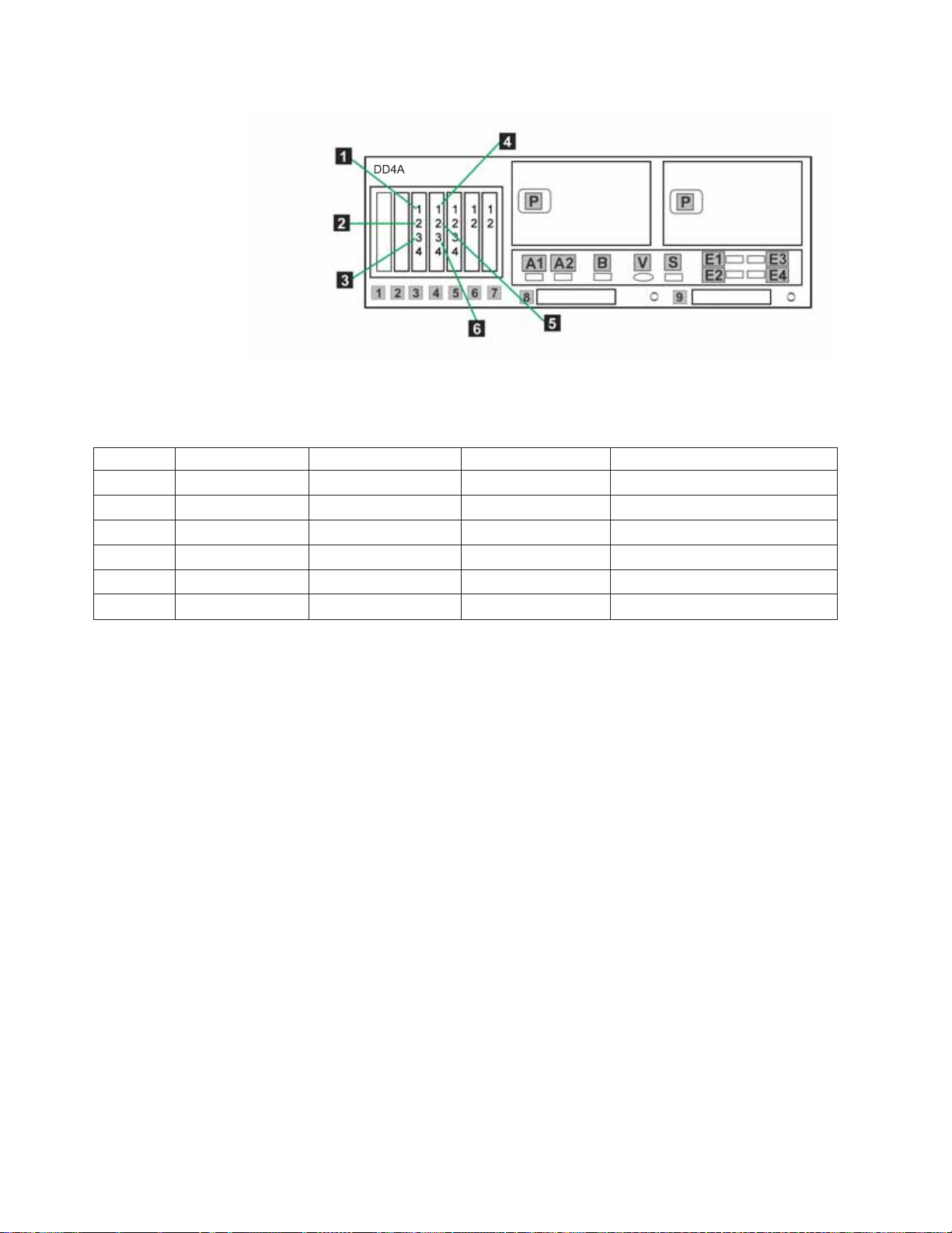
Figure 16. Customer host network Ethernet connections for stand-alone OpenStorage
configuration
|
Table 13. Customer host network Ethernet connections for stand-alone OpenStorage configuration
|
|||||
Callout From On Device To On Device/Location
|||||
1 Port 1, slot 3 Server A Designated device Customer's host network
|||||
2 Port 2, slot 3 Server A Designated device Customer's host network
|||||
3 Port 3, slot 3 Server A Designated device Customer's host network
|||||
4 Port 1, slot 4 Server A Designated device Customer's host network
|||||
5 Port 2, slot 4 Server A Designated device Customer's host network
|||||
6 Port 3, slot 4 Server A Designated device Customer's host network
|
Procedure
1. Label and connect Ethernet cables (Cat 5e or higher) according to Table 11 on
page 40, Table 12 on page 41 and Table 13.
Notes:
v Depending upon the model of the TSSC and TSSC network switch being
used, the port layout may differ from what is shown in Figure 15 on page 41.
If so, make the cable connections according to the port number assignments
specified in Table 12 on page 41, regardless of the position of the ports on the
TSSC or the switch. Refer to the IBM System Storage TS3000 System Console
(TSSC) Maintenance Information for detailed port information.
v Connection of the replication network cables is required only if the customer
is enabling the data replication feature.
2. Go to “Stand-alone fibre channel connections.”
Stand-alone fibre channel connections
|
|
42 IBM System Storage TS7600 with ProtecTIER: Installation Roadmap Guide
The tasks in this section describe the fibre channel connections for theTS7650G
server in a stand-alone configuration.
About this task
Important:
Page 81

|
|
|
This document references IBM 4.8 TB Fibre Channel Disk Controllers and IBM 7.2
TB Fibre Channel Disk Expansion Units in many of the hardware installation
figures, examples, and procedures.
|
|
|
|
|
|
|
|
|
|
|
|
|
|
|
|
In addition to the IBM DS4700 disk controller, the TS7650G also supports the
DS5000 disk controller, the DS8000 disk controller and the XIV disk controller, as
well as various non-IBM storage solutions. If the customer has elected to use disk
storage components other than the IBM disk controllers mentioned above, the
figures, examples, and procedures in this document will not apply to the
configuration on which you are working. Therefore, it is suggested that you
determine the make and model of the disk storage components in use and, if
necessary, obtain the related product documentation before you begin installation
of the gateway.
The RAS code no longer sends call home packages for problems with any of the
disk storage products attached to the gateway including DS4700. DS5000, DS8000
and XIV.
However, if the IP address of an SMTP server is provided during RAS package
configuration, the disk storage subsystems that communicate with the RAS
package (which includes DS4700 and DS5000 if they have firmware levels
supported by RAS) will send problem reports to the customer via email.
Chapter 4. Installing the TS7650G hardware 43
Page 82
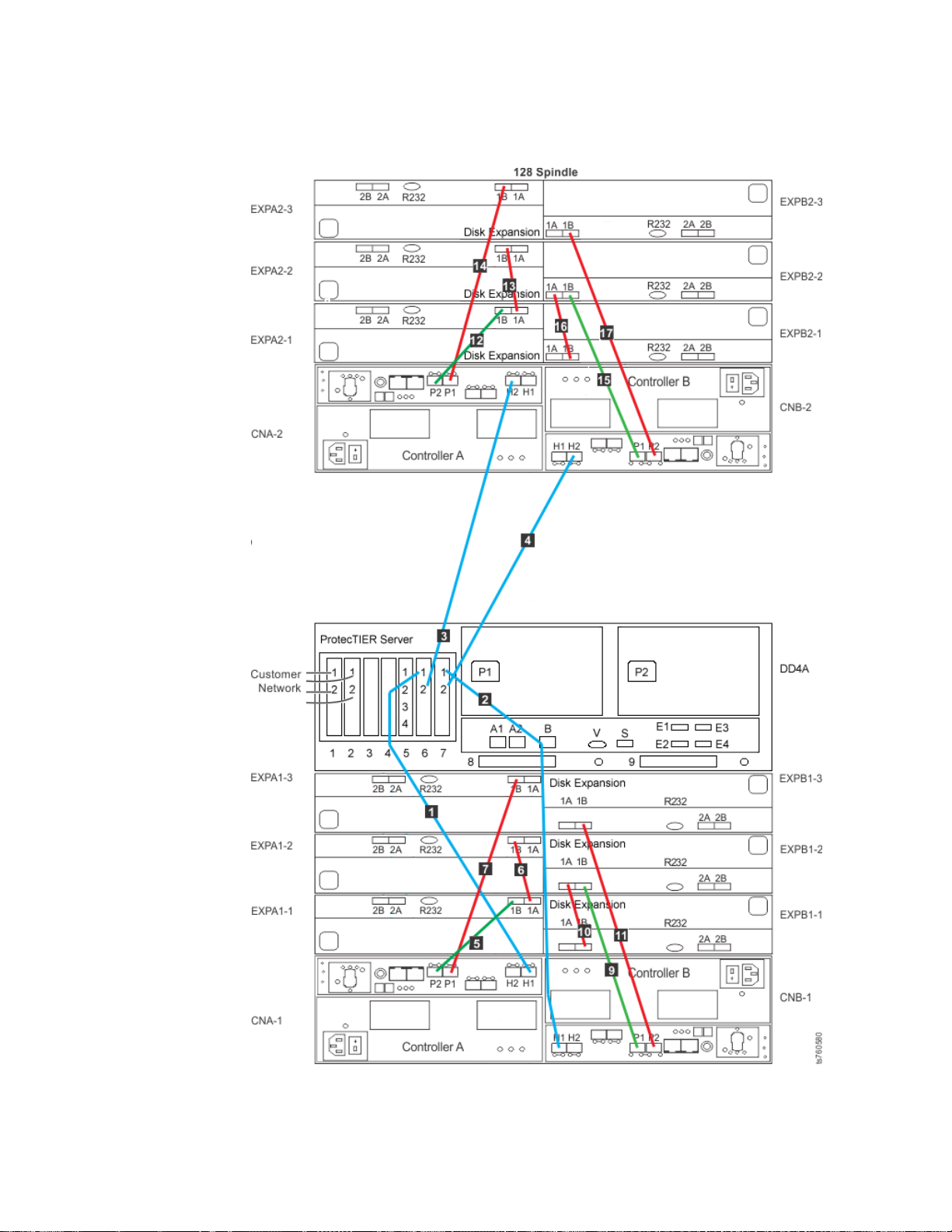
Fibre channel connections for a stand-alone VTL configuration
About this task
Figure 17. Fibre channel connections for stand-alone VTL configuration
44 IBM System Storage TS7600 with ProtecTIER: Installation Roadmap Guide
Page 83

Table 14. Fibre channel connections for stand-alone VTL and OpenStorage
Label From To Remarks
1 DD4A S6 1 Disk Array, Disk Controller A-1
H1
2 DD4A S7 1 Disk Array, Disk Controller B-1
H1
3 DD4A S6 2 Disk Array, Disk Controller A-2
H2
4 DD4A S7 2 Disk Array, Disk Controller B-2
H2
5 CNA-1 P2 Disk Array, Disk Expansion A1-1
1B
6 EXPA1-1 1A Disk Array, Disk Expansion A1-2
1B
7 CNA-1 P1 Disk Array, Disk Expansion A1-3
1B
8 CNB-1 P1 Disk Array, Disk Expansion B1-11BThis cable is used only in a
minimum storage configuration,
when only one expansion unit is
attached.
9 CNB-1 P1 Disk Array, Disk Expansion A1-2
1B
10 EXPB1-1 1B Disk Array, Disk Expansion B1-2
1A
11 CNB-1 P2 Disk Array, Disk Expansion B1-3
1B
12 CNA-2 P2 Disk Array, Disk Expansion A2-1
1B
13 EXPA2-1 1A Disk Array, Disk Expansion A2-2
1B
14 CNA-2 P1 Disk Array, Disk Expansion A2-3
1B
15 CNB-2 P1 Disk Array, Disk Expansion B2-2
1B
16 EXPB2-1 1B Disk Array, Disk Expansion B2-2
1A
17 CNB-2 P2 Disk Array, Disk Expansion B2-3
1B
22 CNB-2 P1 Disk Array, Disk Expansion B2-11BThis cable is used only in a
minimum storage configuration,
when only one expansion unit is
attached.
Chapter 4. Installing the TS7650G hardware 45
Page 84
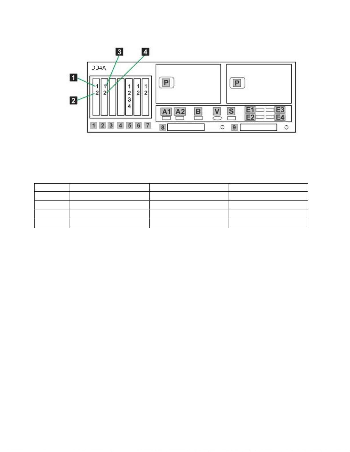
Figure 18. Host fibre channel connections for stand-alone VTL
Table 15. Host fibre channel connections for stand-alone VTL configuration
Label From To Remarks
1 DD4A S1 1 HOST 1
2 DD4A S1 2 HOST 2
3 DD4A S2 1 HOST 3
4 DD4A S2 2 HOST 4
Procedure
1. Connect fibre channel cables according to Table 14 on page 45 and Table 15.
Note: The customer must use an additional connectivity device between the
optical fibre directly connected to RMSS optical adapters (for example, Fibre,
ESCON, or FICON) and an external public network. It can be a patch panel,
router, switch, or other suitable device. Optical fibre connectivity that does not
go over a public network does not require an additional connectivity device.
2. Use Figure 17 on page 44 to verify that the recommended disk components are
cabled correctly. (Connections to the customer's host network not shown in this
figure).
3. Make any necessary adjustments to cable labeling or placement, then go to
“Powering-up the components” on page 69.
46 IBM System Storage TS7600 with ProtecTIER: Installation Roadmap Guide
Page 85
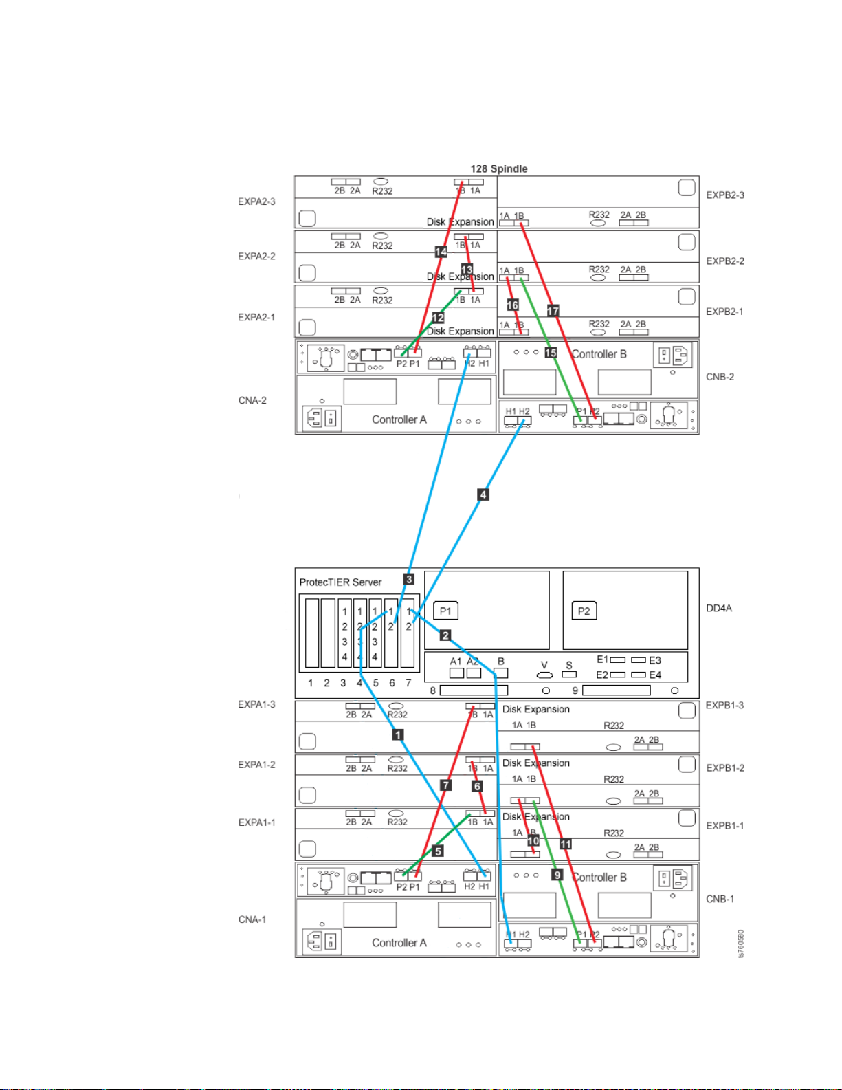
Fibre channel connections for a stand-alone OpenStorage configuration
About this task
Figure 19. Fibre channel connections for stand-alone OpenStorage configuration
Chapter 4. Installing the TS7650G hardware 47
Page 86

Table 16. Fibre channel connections for stand-alone OpenStorage configuration
Label From To Remarks
1 DD4A S6 1 Disk Array, Disk Controller A-1
H1
2 DD4A S7 1 Disk Array, Disk Controller B-1
H1
3 DD4A S6 2 Disk Array, Disk Controller A-2
H2
4 DD4A S7 2 Disk Array, Disk Controller B-2
H2
5 CNA-1 P2 Disk Array, Disk Expansion A1-1
1B
6 EXPA1-1 1A Disk Array, Disk Expansion A1-2
1B
7 CNA-1 P1 Disk Array, Disk Expansion A1-3
1B
8 CNB-1 P1 Disk Array, Disk Expansion B1-11BThis cable is used only in a
minimum storage configuration,
when only one expansion unit is
attached.
9 CNB-1 P1 Disk Array, Disk Expansion A1-2
1B
10 EXPB1-1 1B Disk Array, Disk Expansion B1-2
1A
11 CNB-1 P2 Disk Array, Disk Expansion B1-3
1B
12 CNA-2 P2 Disk Array, Disk Expansion A2-1
1B
13 EXPA2-1 1A Disk Array, Disk Expansion A2-2
1B
14 CNA-2 P1 Disk Array, Disk Expansion A2-3
1B
15 CNB-2 P1 Disk Array, Disk Expansion B2-2
1B
16 EXPB2-1 1B Disk Array, Disk Expansion B2-2
1A
17 CNB-2 P2 Disk Array, Disk Expansion B2-3
1B
22 CNB-2 P1 Disk Array, Disk Expansion B2-11BThis cable is used only in a
minimum storage configuration,
when only one expansion unit is
attached.
Procedure
1. Connect fibre channel cables according to Table 16.
Note: The customer must use an additional connectivity device between the
optical fibre directly connected to RMSS optical adapters (for example, Fibre,
ESCON, or FICON) and an external public network. It can be a patch panel,
48 IBM System Storage TS7600 with ProtecTIER: Installation Roadmap Guide
Page 87

router, switch, or other suitable device. Optical fibre connectivity that does not
go over a public network does not require an additional connectivity device.
2. Use Figure 19 on page 47 to verify that the recommended disk components are
cabled correctly. (Connections to the customer's host network not shown in this
figure).
3. Make any necessary adjustments to cable labeling or placement, then go to
“Powering-up the components” on page 69.
Cabling a clustered gateway
|
|
|
|
|
|
|
|
|
|
|
|
|
|
|
|
|
|
|
|
|
|
|
|
|
|
|
|
|
|
|
This section provides steps for cabling the components included in the purchase of
the TS7650G clustered gateway to each other, as well as to the power distribution
units (PDUs), to the recommended disk controllers, and to the customer network.
If any other components are being used, review this information for general
guidelines, then refer to the manufacturers' documentation for cabling details.
Tip: For simplicity and ease of use, the instructions for each type of cable
connection (power, Ethernet, and fibre channel) start on a new page. Within the
Ethernet and fibre channel sections there are separate VTL and OpenStorage
subsections.
Notes:
v Cat 5e or higher cable is required for all Ethernet connections.
v Route all cables through the cable management arms and secure with straps.
v When attaching power cords, do so in a way that they will not interfere with
future FRU replacement.
v In clustered configurations, the server in the lower position in the frame is
Server A (or Node A), and the server in the upper position in the frame is server
is Server B (or Node B).
v In the following diagrams, the letters TJ followed by a number (for example:
TJ5) indicate which outlet the associated component plugs into on the top PDU.
The letters BJ followed by a number (for example: BJ8) indicate which outlet the
associated component plugs into on the bottom PDU.
v When connecting power for the WTI network power switch, use the
product-specific cables designed for the switch. Other types of power cables will
not work.
v If non-recommended components are being used, review this chapter for general
guidelines, then refer to the manufacturer's documentation for details.
v When applying cable labels, align the center reference lines on the label with the
axis of the cable. Refer to the IBM System Storage TS7600 with ProtecTIER Labeling
Instructions for the TS7650/TS7650G (3958 DD4 and 3958 AP1), IBM part number
46X6059, located on the IBM System Storage TS7650 with ProtecTIER Publications
CD provided in the MES ship group, for detailed label placement guidelines and
instructions.
Clustered power connections
This task describes cabling the power connections for a clustered TS7650G.
Chapter 4. Installing the TS7650G hardware 49
Page 88

About this task
Note: The power distribution units (PDUs) may have been preinstalled in the
recommended frame in a location different from that shown in the illustration. For
consistency and ease when troubleshooting, you may want to relocate the PDUs to
match Figure 20 on page 51.
|
|
|
Note: The WTI network power switch is shown in color to the side in Figure 20 on
page 51. This is for clarity in showing the connections. Within the frame itself, the
WTI switch is also shown in the recommended placement at EIA unit 4.
50 IBM System Storage TS7600 with ProtecTIER: Installation Roadmap Guide
Page 89
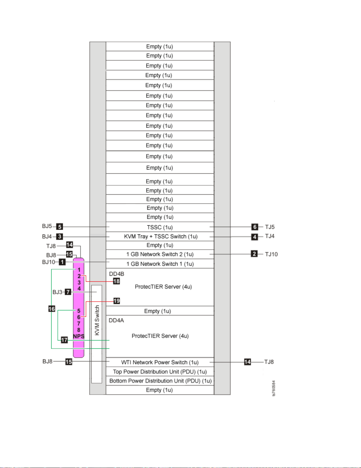
Figure 20. Clustered TS7650G power cabling
Chapter 4. Installing the TS7650G hardware 51
Page 90

Table 17. Clustered TS7650G power cabling
Callout From On Device To On Device/Location
1 Power outlet Ethernet switch 1 (bottom) (E
SW-1)
2 Power outlet Ethernet switch 2 (top) (E
SW-2
3 Power outlet TSSC Ethernet switch (if you
installed one) (SC SW)
4 Power outlet TSSC KVM switch (if you
installed one) (SC TSSC)
5 Power outlet 1 TSSC (if you installed one)
(SC)
6 Power outlet 2 TSSC (if you installed one
with a second power outlet)
(SC)
7 Power outlet KVM Switch BJ3 Bottom PDU
14 Top power outlet WTI network power switch TJ8 Top PDU
15 Bottom power
outlet
16 Power outlet 1 Server A Power outlet 1 WTI network power
17 Power outlet 2 Server A Power outlet 5 WTI network power
18 Power outlet 1 Server B Power outlet 2 WTI network power
19 Power outlet 2 Server B Power outlet 6 WTI network power
WTI network power switch BJ8 Bottom PDU
BJ10 Bottom PDU
TJ10 Top PDU
BJ4 Bottom PDU
TJ4 Top PDU
BJ5 Bottom PDU
TJ5 Top PDU
switch
switch
switch
switch
Procedure
1. Label and connect the power cords according to Figure 20 on page 51 and
Table 17.
2. Go to “Clustered 1 Gb Ethernet switch Ethernet connections.”
Clustered Ethernet connections
|
|
|
|
|
|
|
|
|
The tasks in this section describe the network Ethernet connections to the 1Gb
Ethernet switches, the TSSC, and the customer network for both VTL and
OpenStorage with theTS7650G server in a clustered configuration.
Clustered 1 Gb Ethernet switch Ethernet connections
This task describes the 1Gb Ethernet switch connections for theTS7650G server in a
clustered configuration.
Before you begin
Notes:
v Depending upon the model of the TSSC and TSSC network switch being used,
the port layout may differ from what is shown in Figure 21 on page 53 or
Figure 22 on page 55. If so, make the cable connections according to the port
number assignments specified in Table 18 on page 54 or Table 19 on page 55,
52 IBM System Storage TS7600 with ProtecTIER: Installation Roadmap Guide
Page 91
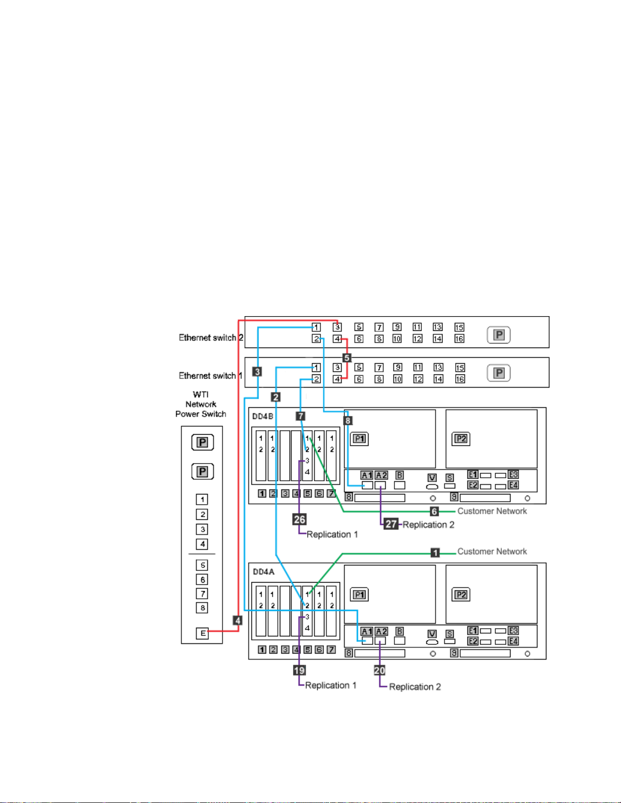
|
|
|
|
|
regardless of the position of the ports on the switch. Refer to the IBM System
Storage TS3000 System Console (TSSC) Maintenance Information for detailed port
information.
v Connection of the replication network cables is required only if the customer is
enabling the data replication feature.
Clustered 1 GB Ethernet switch Ethernet connections for VTL configuration:
This task shows the Ethernet cabling for the 1 GB Ethernet switches in a clustered
TS7650G for VTL configuration.
About this task
Note:
Depending upon the model of the network switch being used, the port layout may
differ from what is shown in Figure 21. If so, label the cables according to the port
number assignments specified in Table 18 on page 54, regardless of the position of
the ports on the TSSC or the switch.
Figure 21. Clustered 1Gb Ethernet switch connections for VTL configuration
Chapter 4. Installing the TS7650G hardware 53
Page 92

Table 18. Clustered 1 Gb Ethernet switch Ethernet connections for VTL configuration
Callout From On Device To On Device/Location
1 Port 1, slot 5 Server A Customer network Customer designated device
2 Port 1 Ethernet switch 1 Port 2, slot 5 Server A
3 Port 1 Ethernet switch 2 Port A1 Server A
4 Port 3 Ethernet switch 2 Ethernet port, E WTI network power switch
5 Port 4 Ethernet switch 2 Port 4 Ethernet switch 1
6 Port 1, slot 5 Server B Customer network Customer designated device
7 Port 2 Ethernet switch 1 Port 2, slot 5 Server B
8 Port 2 Ethernet switch 2 Port A1 Server B
19 Port 3, slot 5 Server A Customer's
replication network
20 Port A2 Server A Customer's
replication network
26 Port 3, slot 5 Server B Customer's
replication network
27 Port A2 Server B Customer's
replication network
Customer specified device
Customer specified device
Customer specified device
Customer specified device
Procedure
1. Label and connect Ethernet cables (Cat 5e or higher) according to Figure 21 on
page 53 and Table 18.
2. Go to “Clustered Ethernet connections” on page 52 to complete the Ethernet
cabling.
Clustered 1 Gb Ethernet switch Ethernet connections for OpenStorage
configuration:
This task shows the Ethernet cabling for the 1 Gb Ethernet switches in a clustered
TS7650G for OpenStorage configuration.
About this task
Note:
Depending upon the model of the network switch being used, the port layout may
differ from what is shown in Figure 22 on page 55. If so, label the cables according
to the port number assignments specified in Table 19 on page 55, regardless of the
position of the ports on the TSSC or the switch.
54 IBM System Storage TS7600 with ProtecTIER: Installation Roadmap Guide
Page 93

Figure 22. Clustered 1Gb Ethernet switch connections for OpenStorage configuration
Table 19. Clustered 1 Gb Ethernet switch Ethernet connections for OpenStorage configuration
Callout From On Device To On Device/Location
1 Port 1, slot 5 Server A Customer network Customer designated device
2 Port 1 Ethernet switch 1 Port 2, slot 5 Server A
3 Port 1 Ethernet switch 2 Port A1 Server A
4 Port 3 Ethernet switch 2 Ethernet port, E WTI network power switch
5 Port 4 Ethernet switch 2 Port 4 Ethernet switch 1
6 Port 1, slot 5 Server B Customer network Customer designated device
7 Port 2 Ethernet switch 1 Port 2, slot 5 Server B
8 Port 2 Ethernet switch 2 Port A1 Server B
15 Port 4, slot 3 Server A Customer's replication
Customer specified device
network
16 Port 4, slot 4 Server A Customer's replication
Customer specified device
network
17 Port 4, slot 3 Server B Customer's replication
Customer specified device
network
Chapter 4. Installing the TS7650G hardware 55
Page 94

Table 19. Clustered 1 Gb Ethernet switch Ethernet connections for OpenStorage configuration (continued)
Callout From On Device To On Device/Location
18 Port 4, slot 4 Server B Customer's replication
network
Customer specified device
Procedure
1. Label and connect Ethernet cables (Cat 5e or higher) according to Figure 22 on
page 55 and Table 19 on page 55.
2. Go to “Clustered Ethernet connections” on page 52 to complete the Ethernet
cabling.
Clustered TSSC and customer network Ethernet connections
|
|
This task describes the TSSC and customer network Ethernet connections for
theTS7650G server in a clustered configuration.
Before you begin
Notes:
|
|
|
|
|
|
|
|
|
|
v Depending upon the model of the TSSC and TSSC network switch being used,
the port layout may differ from what is shown in the following figures. If so,
make the cable connections according to the port number assignments specified
in the associated tables, regardless of the position of the ports on the switch.
Refer to the IBM System Storage TS3000 System Console (TSSC) Maintenance
Information for detailed port information.
v Connection of the replication network cables is required only if the customer is
enabling the data replication feature.
Clustered TSSC, KVM and customer network Ethernet connections for VTL
configuration:
This task describes the TSSC, KVM and customer network Ethernet connections for
theTS7650G server in a clustered configuration with VTL.
About this task
Note:
Depending upon the model of the TSSC and TSSC network switch being used, the
port layout may differ from what is shown in Figure 23 on page 57. If so, label the
cables according to the port number assignments specified in Table 20 on page 57,
regardless of the position of the ports on the TSSC or the switch.
56 IBM System Storage TS7600 with ProtecTIER: Installation Roadmap Guide
Page 95

Figure 23. Clustered TSSC, KVM and customer network Ethernet connections for VTL
configuration
Table 20. Clustered TSSC, KVM and customer network Ethernet connections for VTL configuration
Callout From On Device To On Device/Location
9 Port 5 TSSC Ethernet switch Port 1 TSSC
10 Port 2 TSSC Customer's local area
network
Customer specified
device
11 Port 4 TSSC Ethernet switch Port 4, slot 5 Server A
12 Port 3 TSSC Ethernet switch Port 4, slot 5 Server B
13 Port 6 TSSC Ethernet switch Port B Server A
14 Port 1 TSSC Ethernet switch Port B Server B
21 Video port KVM Switch Video port SC KVM
22 Port 3 KVM Switch Video port, SC Server
Port U3
23 Port 1 KVM Switch Video port, Server A
Port E1
24 Port U1 KVM Switch Video Port SC KVM
Chapter 4. Installing the TS7650G hardware 57
Page 96

Table 20. Clustered TSSC, KVM and customer network Ethernet connections for VTL configuration (continued)
Callout From On Device To On Device/Location
25 Port 2 KVM Switch Video port, Server B
Port E1
Procedure
1. Label and connect Ethernet cables (Cat 5e or higher) according to Table 20 on
page 57 and Figure 23 on page 57.
Notes:
Connection of the replication network cables is required only if the customer is
enabling the data replication feature.
2. Go to “Clustered fibre channel connections” on page 61.
Clustered TSSC, KVM and customer network Ethernet connections for
OpenStorage configuration:
|
|
The tasks in this section describe the TSSC, KVM and customer network Ethernet
connections for theTS7650G server in a clustered configuration with OpenStorage.
About this task
Note:
Depending upon the model of the TSSC and TSSC network switch being used, the
port layout may differ from what is shown in Figure 24 on page 59. If so, label the
cables according to the port number assignments specified in Table 21 on page 59,
regardless of the position of the ports on the TSSC or the switch.
58 IBM System Storage TS7600 with ProtecTIER: Installation Roadmap Guide
Page 97
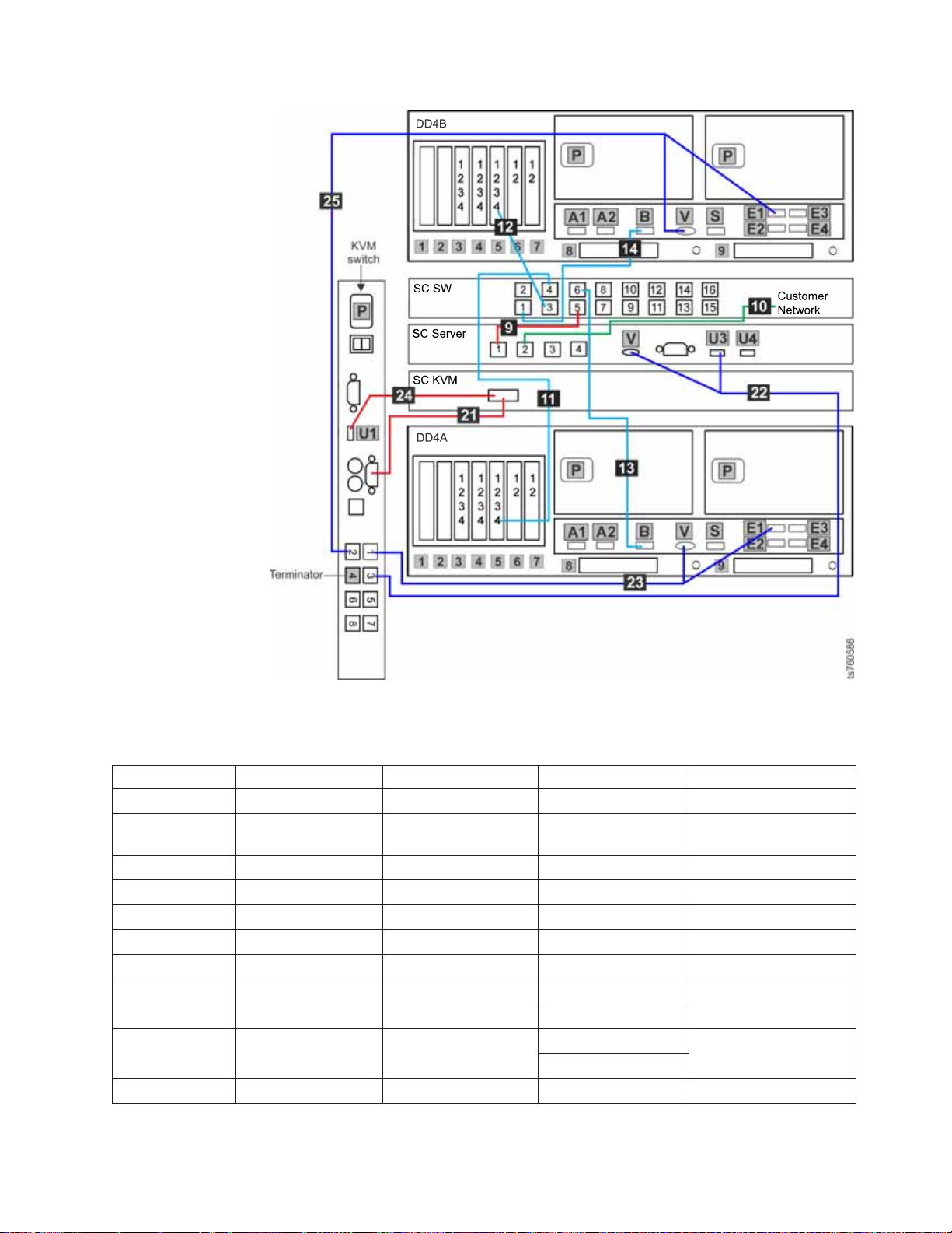
Figure 24. Clustered TSSC, KVM and customer network Ethernet connections for
OpenStorage configuration
Table 21. Clustered TSSC, KVM and customer network Ethernet connections for OpenStorage configuration
Callout From On Device To On Device/Location
9 Port 5 TSSC Ethernet switch Port 1 TSSC
10 Port 2 TSSC Customer's local area
network
Customer specified
device
11 Port 4 TSSC Ethernet switch Port 4, slot 5 Server A
12 Port 3 TSSC Ethernet switch Port 4, slot 5 Server B
13 Port 6 TSSC Ethernet switch Port B Server A
14 Port 1 TSSC Ethernet switch Port B Server B
21 Video port KVM Switch Video port SC KVM
22 Port 3 KVM Switch Video port, SC Server
Port U3
23 Port 1 KVM Switch Video port, Server A
Port E1
24 Port U1 KVM Switch Video Port SC KVM
Chapter 4. Installing the TS7650G hardware 59
Page 98
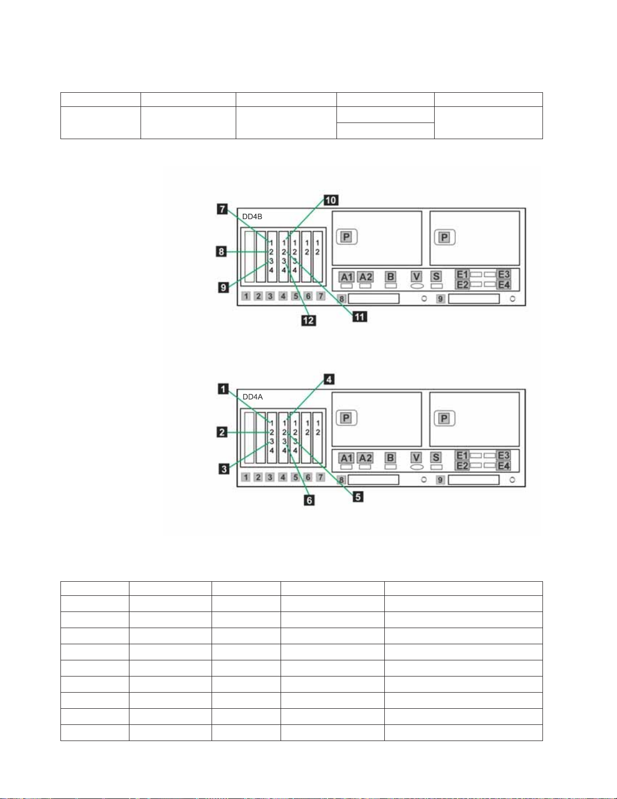
Table 21. Clustered TSSC, KVM and customer network Ethernet connections for OpenStorage
configuration (continued)
Callout From On Device To On Device/Location
25 Port 2 KVM Switch Video port, Server B
Port E1
Figure 25. Clustered customer network Ethernet connections for OpenStorage configuration
Table 22. Clustered Ethernet host connections for OpenStorage configuration
Callout From On Device To On Device/Location
1 Port 1, slot 3 Server A Designated device Customer's host network
2 Port 2, slot 3 Server A Designated device Customer's host network
3 Port 3, slot 3 Server A Designated device Customer's host network
4 Port 1, slot 4 Server A Designated device Customer's host network
5 Port 2, slot 4 Server A Designated device Customer's host network
6 Port 3, slot 4 Server A Designated device Customer's host network
7 Port 1, slot 3 Server B Designated device Customer's host network
8 Port 2, slot 3 Server B Designated device Customer's host network
9 Port 3, slot 3 Server B Designated device Customer's host network
60 IBM System Storage TS7600 with ProtecTIER: Installation Roadmap Guide
Page 99

Table 22. Clustered Ethernet host connections for OpenStorage configuration (continued)
Callout From On Device To On Device/Location
10 Port 1, slot 4 Server B Designated device Customer's host network
11 Port 2, slot 4 Server B Designated device Customer's host network
12 Port 3, slot 4 Server B Designated device Customer's host network
Procedure
1. Label and connect Ethernet cables (Cat 5e or higher) according to Table 21 on
page 59 and Figure 24 on page 59.
Notes:
Connection of the replication network cables is required only if the customer is
enabling the data replication feature.
2. Label and connect Ethernet cables (Cat 5e or higher) according to Figure 25 on
page 60 and Table 22 on page 60 for the customers host network.
3. Go to “Clustered fibre channel connections.”
Clustered fibre channel connections
|
|
This task describes the fibre channel connections for theTS7650G server in a
clustered configuration.
About this task
Important:
This document references IBM 4.8 TB Fibre Channel Disk Controllers and IBM 7.2
TB Fibre Channel Disk Expansion Units in many of the hardware installation
figures, examples, and procedures.
In addition to the IBM DS4700 disk controller, the TS7650G also supports the
DS5000 disk controller, the DS8000 disk controller and the XIV disk controller, as
well as various non-IBM storage solutions. If the customer has elected to use disk
storage components other than the IBM disk controllers mentioned above, the
figures, examples, and procedures in this document will not apply to the
configuration on which you are working. Therefore, it is suggested that you
determine the make and model of the disk storage components in use and, if
necessary, obtain the related product documentation before you begin installation
of the gateway.
The RAS code no longer sends call home packages for problems with any of the
disk storage products attached to the gateway including DS4700. DS5000, DS8000
and XIV.
However, if the IP address of an SMTP server is provided during RAS package
configuration, the disk storage subsystems that communicate with the RAS
package (which includes DS4700 and DS5000 if they have firmware levels
supported by RAS) will send problem reports to the customer via email.
Chapter 4. Installing the TS7650G hardware 61
Page 100

Clustered fibre channel connections for VTL configuration
|
|
This task describes the fibre channel connections for theTS7650G server in a
clustered configuration with VTL configuration.
62 IBM System Storage TS7600 with ProtecTIER: Installation Roadmap Guide
 Loading...