

Page 1

IBM System Storage SAN32B-E4
Installation, Service, and User Guide
Service information: 2498-E32
Read Before Using
This product contains software that is licensed under written license agreements. Your use of such software is subject to
the license agreements under which they are provided.
GA32-0798-00
Page 2

Page 3

IBM System Storage SAN32B-E4
Installation, Service, and User Guide
Service information: 2498-E32
GA32-0798-00
Page 4

Note:
Before using this information and the product it supports, read the information in “Notices” on page 55.
Copyright © 2008 Brocade Communications Systems, Inc. All Rights Reserved.
The following paragraph does not apply to any country (or region) where such provisions are inconsistent with
local law.
INTERNATIONAL BUSINESS MACHINES CORPORATION PROVIDES THIS PUBLICATION “AS IS” WITHOUT
WARRANTY OF ANY KIND, EITHER EXPRESS OR IMPLIED, INCLUDING, BUT NOT LIMITED TO, THE
IMPLIED WARRANTIES OF MERCHANTABILITY OR FITNESS FOR A PARTICULAR PURPOSE. Some states (or
regions) do not allow disclaimer of express or implied warranties in certain transactions; therefore, this statement
may not apply to you.
© Copyright IBM Corporation 2010.
US Government Users Restricted Rights – Use, duplication or disclosure restricted by GSA ADP Schedule Contract
with IBM Corp.
Page 5

Read this first
Getting help
For the latest version of your product documentation, visit the web at
www.ibm.com/shop/publications/order. Search by form number or title.
®
For more information about IBM
www.ibm.com/servers/storage/san/
®
IBM Redbooks
configurations, and more technical information. For redbooks associated with this
product, enter search terms on the following Web site: www.redbooks.ibm.com/.
For support information for this and other IBM products, see the IBM Support
Portal, www.ibm.com/supportportal. Search for the product Machine type or
product name.
For Fabric OS Release Notes and access to Fabric OS firmware downloads, go to
the IBM Support Portal, www.ibm.com/supportportal. Search for the product
Machine type or product name, and then follow links for Downloads. More
detailed instructions are available through the Accessing firmware updates and
OS documentation updates link on the product documentation CD that is shipped
with this product.
often provide in depth information about product best practices,
SAN products, see the following Web site:
You can also contact IBM within the United States at 1-800-IBMSERV
(1-800-426-7378). For support outside the United States, you can find the service
number at: www.ibm.com/planetwide/.
Visit www.ibm.com/contact for the contact information for your country or region.
For detailed information about the Fibre Channel standards, see the Fibre Channel
Industry Association (FCIA) Web site at: www.fibrechannel.org/
For information about storage industry standards, see the Storage Networking
Industry Association (SNIA) Web site at: www.snia.org/
Taiwan Contact Information
IBM Taiwan Product Service Contact Info:
IBM Taiwan Corporation
3F, No 7, Song Ren Rd., Taipei Taiwan
Tel: 0800-016-888
© Copyright IBM Corp. 2010 iii
Page 6

Accessibility features for the SAN32B-E4
Accessibility features help users who have a disability, such as restricted mobility
or limited vision, to use information technology products successfully.
Accessibility features
The following list includes the major accessibility features in this product:
v Light emitting diodes (LEDs) that flash at different rates, to represent the same
information as the colors of the LEDs
v Industry-standard devices for ports and connectors
v Management of the product through management applications is available
through Web and Graphical User Interface (GUI) options
Keyboard navigation
This product does not have an attached or integrated keyboard. Any keyboard
navigation is provided through the management software and GUI.
Vendor software
This product includes certain vendor software that is not covered under the IBM
license agreement. IBM makes no representation about the accessibility features of
these products. Contact the vendor for the accessibility information about its
products.
Related accessibility information
You can view the publications for this product in Adobe Portable Document
Format (PDF) using the Adobe Acrobat Reader. The PDFs are provided on a
product documentation CD-ROM that is packaged with the product. The CD-ROM
also includes an accessible HTML version of this document.
IBM and accessibility
See the IBM Human Ability and Accessibility Center web site at
www.ibm.com/able/ for more information about the commitment that IBM has to
accessibility.
How to send your comments
Your feedback is important in helping us provide the most accurate and
high-quality information. If you have comments or suggestions for improving this
document, send us your comments by e-mail to starpubs@us.ibm.com. Be sure to
include the following:
v Exact publication title
v Form number (for example, GC27-2270-00)
v Page numbers to which you are referring
You can also mail your comments to:
International Business Machines Corporation
Information Development
Department GZW
9000 South Rita Road
Tucson, Arizona 85744-0001 U.S.A.
iv SAN32B-E4 Installation, Service, and User Guide
Page 7

When you send information to IBM, you grant IBM a nonexclusive right to use or
distribute the information in any way it believes appropriate without incurring any
obligation to you.
Read this first v
Page 8

vi SAN32B-E4 Installation, Service, and User Guide
Page 9

Contents
Read this first ............iii
Getting help ..............iii
Taiwan Contact Information ........iii
Accessibility features for the SAN32B-E4.....iv
Accessibility features ..........iv
Keyboard navigation ..........iv
Vendor software ............iv
Related accessibility information ......iv
IBM and accessibility ..........iv
How to send your comments ........iv
Figures ...............ix
Tables ...............xi
Safety and environmental notices . . . xiii
Safety notices and labels..........xiii
Danger notices ............xiii
Caution notices ............xvi
Safety labels.............xvii
Attention notices ...........xviii
Rack safety ..............xix
Rack installation ...........xix
Rack relocation (19" rack).........xx
Product recycling and disposal........xxi
About this document ........xxiii
Product documents ...........xxiii
Brocade documents ...........xxiii
IBM and Brocade product matrix .....xxiv
Chapter 1. Introducing the SAN32B-E4 . 1
Port side of the switch ...........2
Nonport side of the switch .........3
Field-replaceable units (FRUs) ........4
Planning for encryption...........6
Chapter 2. Installing and configuring the
switch ...............9
Site preparation and installation guidelines ....10
Planning for cable management .......10
Items included with the switch ........11
Setting up the switch as a standalone unit ....11
Installing in an EIA cabinet .........13
Time required ............13
Items required ............13
Installation instructions .........13
Configuring the switch ..........19
Providing power to the switch .......20
Connecting a serial cable between the switch and
a host ...............21
Logging in to the serial console port .....21
Setting the switch IP address .......21
Connecting an Ethernet cable and opening a
Telnet session.............22
Setting the switch domain ID .......22
Setting the switch date and time ......22
Installing SFPs and attaching cables .....24
Managing cables............25
Verifying the correct operation of the switch and
backing up the configuration .......25
Configuring for encryption .........26
Summary of procedure .........26
Avoid double encryption .........27
Managing license keys (optional) .......27
Viewing current license keys........28
Adding a license key ..........28
Removing a license key .........28
Fabric OS firmware updates .........29
Chapter 3. Using and maintaining the
switch ...............31
Interpreting LEDs ............31
LEDs on the port side of the switch .....31
LEDs on the nonport side of the switch ....33
Interpreting POST results ..........34
Diagnostic testing ............35
Checking the FRUs ............36
Verifying power supplies .........36
Replacing a power supply ........36
Verifying fan assemblies .........39
Replacing a fan assembly.........39
Replacing the switch chassis.........41
Time required ............42
Items required ............42
Verifying need for replacement .......42
Recording critical switch and SAN information 42
Disconnecting from network and fabric ....44
Removing components from the chassis ....44
Installing the replacement chassis ......44
Installing components into the new chassis . . . 44
Verifying the correct operation of the system . . 45
Reconnecting the system to the network and
fabric ...............45
Verifying the correct configuration of the fabric 45
Changing the switch serial number .....46
Powering off the switch ..........46
Removing the battery ...........47
Appendix. Product specifications . . . 49
General specifications ...........49
Management ..............50
Size and weight .............51
Environmental requirements.........51
Power specifications ...........52
Data transmission ranges ..........52
Parts list (FRUs) .............52
© Copyright IBM Corp. 2010 vii
Page 10

Notices ..............55
Trademarks ..............57
Electronic emission notices .........58
Federal Communications Commission (FCC)
Class A Statement ...........58
Industry Canada Class A Emission Compliance
Statement ..............58
Avis de conformité à la réglementation
d'Industrie Canada ...........58
European Union EMC Directive Conformance
Statement ..............58
Germany Electromagnetic Compatibility Directive 59
People's Republic of China Class A Electronic
Emission Statement ...........60
Japan VCCI Council Class A Statement ....60
Japan Electronics and Information Technology
Industries Association (JEITA) Statement . . . 60
Korea Communications Commission (KCC) Class
A Statement .............60
Russia Electromagnetic Interference (EMI) Class
A Statement .............61
Australia and New Zealand Class A Statement 61
Index ...............63
viii
SAN32B-E4 Installation, Service, and User Guide
Page 11

Figures
1. Port side view ............3
2. Port numbering ...........3
3. Nonport side of the switch ........4
4. Power supply ............5
5. Fan assembly ............5
6. Switch chassis ............6
7. Rack assembly ...........14
8. Separating the inner and outer rails. ....15
9. Mounting the moving portion of the slide and
mounting brackets to the switch .....16
10. Mounting the fixed portion of the rail and the
locking brackets to the rack .......17
11. Inserting slides into the rack rails .....18
12. Switch configuration steps .......20
13. Installing an SFP into an upper port ....24
14. Encryption configuration ........27
15. Port side LEDs ...........31
16. Nonport side LEDs ..........33
17. Power supply locations ........37
18. Installing a new power supply ......38
19. Fan assembly locations .........40
20. Replacing a fan assembly ........41
21. Location of battery holder........47
© Copyright IBM Corp. 2010 ix
Page 12

x SAN32B-E4 Installation, Service, and User Guide
Page 13

Tables
1. Sample caution notices ........xvi
2. Brocade and IBM product and model
number matrix ...........xxiv
3. Installation tasks, time, and items required 9
4. Parts supplied with the rack-mount kit 14
5. System status LED patterns .......32
6. Power status LED patterns .......32
7. Ethernet LED patterns .........32
8. Port status LED patterns ........33
9. Power supply status LED patterns .....34
10. Fan status LED patterns ........34
11. Critical information checklist .......43
12. General specifications .........49
13. Management specifications .......50
14. Switch dimensions ..........51
15. Environmental requirements .......51
16. Power supply specifications .......52
17. Supported optics, speeds, cables, and distances 52
18. FRU part numbers ..........52
© Copyright IBM Corp. 2010 xi
Page 14

xii SAN32B-E4 Installation, Service, and User Guide
Page 15

Safety and environmental notices
This section contains information about:
v “Safety notices and labels”
v “Rack safety” on page xix
v “Product recycling and disposal” on page xxi
Safety notices and labels
When using this product, observe the danger, caution, and attention notices
contained in this guide. The notices are accompanied by symbols that represent the
severity of the safety condition. The danger and caution notices are listed in
numerical order based on their IDs, which are displayed in parentheses, for
example (D004), at the end of each notice. Use this ID to locate the translation of
these danger and caution notices in the IBM System Storage b-type Switch and Router
Safety Notices publication, which is shipped with this product.
The following notices and statements are used in IBM documents. They are listed
below in order of increasing severity of potential hazards. Follow the links for
more detailed descriptions and examples of the danger, caution, and attention
notices in the sections that follow.
v Note: These notices provide important tips, guidance, or advice.
v “Attention notices” on page xviii: These notices indicate potential damage to
programs, devices, or data.
v “Caution notices” on page xvi: These statements indicate situations that can be
potentially hazardous to you.
v “Danger notices”: These statements indicate situations that can be potentially
lethal or extremely hazardous to you. Safety labels are also attached directly to
products to warn of these situations.
v In addition to these notices, “Safety labels” on page xvii may be attached to the
product to warn of potential hazards.
Danger notices
A danger notice calls attention to a situation that is potentially lethal or extremely
hazardous to people. A lightning bolt symbol accompanies a danger notice to
represent a dangerous electrical condition. Read and comply with the following
danger notices before installing or servicing this device.
© Copyright IBM Corp. 2010 xiii
DANGER
To prevent a possible shock from touching two surfaces with
different protective ground (earth), use one hand, when possible, to
connect or disconnect signal cables. (D001)
Page 16

DANGER
Overloading a branch circuit is potentially a fire hazard and a
shock hazard under certain conditions. To avoid these hazards,
ensure that your system electrical requirements do not exceed
branch circuit protection requirements. Refer to the information
that is provided with your device or the power rating label for
electrical specifications. (D002)
DANGER
If the receptacle has a metal shell, do not touch the shell until you
have completed the voltage and grounding checks. Improper wiring
or grounding could place dangerous voltage on the metal shell. If
any of the conditions are not as described, STOP. Ensure the
improper voltage or impedance conditions are corrected before
proceeding. (D003)
DANGER
An electrical outlet that is not correctly wired could place
hazardous voltage on metal parts of the system or the devices that
attach to the system. It is the responsibility of the customer to
ensure that the outlet is correctly wired and grounded to prevent
an electrical shock. (D004)
A general electrical danger notice provides instructions on how to avoid shock
hazards when servicing equipment. Unless instructed otherwise, follow the
procedures in the following danger notice.
xiv SAN32B-E4 Installation, Service, and User Guide
Page 17

DANGER
When working on or around the system, observe the following
precautions:
Electrical voltage and current from power, telephone, and
communication cables are hazardous. To avoid a shock hazard:
v Connect power to this unit only with the IBM provided power
cord. Do not use the IBM provided power cord for any other
product.
v Do not open or service any power supply assembly.
v Do not connect or disconnect any cables or perform installation,
maintenance, or reconfiguration of this product during an
electrical storm.
v The product might be equipped with multiple power cords. To
remove all hazardous voltages, disconnect all power cords.
v Connect all power cords to a properly wired and grounded
electrical outlet. Ensure that the outlet supplies proper voltage
and phase rotation according to the system rating plate.
v Connect any equipment that will be attached to this product to
properly wired outlets.
v When possible, use one hand only to connect or disconnect
signal cables.
v Never turn on any equipment when there is evidence of fire,
water, or structural damage.
v Disconnect the attached power cords, telecommunications
systems, networks, and modems before you open the device
covers, unless instructed otherwise in the installation and
configuration procedures.
v Connect and disconnect cables as described below when
installing, moving, or opening covers on this product or attached
devices.
To disconnect:
1. Turn off everything (unless instructed otherwise).
2. Remove the power cords from the outlets.
3. Remove the signal cables from the connectors.
4. Remove all cables from the devices.
To connect:
1. Turn off everything (unless instructed otherwise).
2. Attach all cables to the devices.
3. Attach the signal cables to the connectors.
4. Attach the power cords to the outlets.
5. Turn on the devices.
(D005)
Safety and environmental notices xv
Page 18

Caution notices
A caution notice calls attention to a situation that is potentially hazardous to
people because of some existing condition. A caution notice can be accompanied
by different symbols, as in the examples below:
Table 1. Sample caution notices
If the symbol is... It means...
18-32 kg (39.7-70.5 lbs)
18-32 kg (39.7-70.5 lbs)
P/N 18P5850-B
SJ000752
svc00167
A hazardous electrical condition with less
severity than electrical danger.
A generally hazardous condition not
represented by other safety symbols.
A specification of product weight that
requires safe lifting practices. The weight
range of the product is listed below the
graphic, and the graphic and the wording of
the caution varies, depending on the weight
of the device.
A potential hazard of pinching the hand or
other body parts between parts.
A hazardous condition due to moving parts
nearby.
A hazardous condition due to the use of a
laser in the product. Laser symbols are
always accompanied by the classification of
the laser as defined by the U. S. Department
of Health and Human Services (for example,
Class I, Class II, and so forth).
Read and comply with the following caution notices before installing or servicing
this device.
CAUTION:
Energy hazard present. Shorting may result in system outage and
possible physical injury. Remove all metallic jewelry before servicing.
(C001)
CAUTION:
This part or unit is heavy but has a weight smaller than 18 kg (39.7
lb). Use care when lifting, removing, or installing this part or unit.
(C008)
CAUTION:
The system contains circuit cards, assemblies, or both that contain lead
solder. To avoid the release of lead (Pb) into the environment, do not
burn. Discard the circuit card as instructed by local regulations. (C014)
xvi SAN32B-E4 Installation, Service, and User Guide
Page 19

CAUTION:
This product is equipped with a 3-wire (two conductors and ground)
power cable and plug. Use this power cable with a properly grounded
electrical outlet to avoid electrical shock. (C018)
CAUTION:
This product might contain one or more of the following devices:
CD-ROM drive, DVD-ROM drive, DVD-RAM drive, or laser module,
which are Class 1 laser products. Note the following information:
v Do not remove the covers. Removing the covers of the laser product
could result in exposure to hazardous laser radiation. There are no
serviceable parts inside the device.
v Use of the controls or adjustments or performance of procedures
other than those specified herein might result in hazardous
radiation exposure.
(C026)
CAUTION:
The power-control button on the device does not turn off the electrical
current supplied to the device. The device might also have more than
one connection to dc power. To remove all electrical current from the
device, ensure that all connections to dc power are disconnected at the
dc power input terminals. (C031)
Safety labels
As an added precaution, safety labels are often installed directly on products or
product components to warn of potential hazards. These can be either danger or
caution notices, depending upon the level of the hazard.
The actual product safety labels may differ from these sample safety labels:
DANGER
Hazardous voltage, current, or energy levels are present inside
any component that has this label attached. Do not open any
cover or barrier that contains this label. (L001)
DANGER
Rack-mounted devices are not to be used as a shelf or work space.
(L002)
Safety and environmental notices xvii
Page 20

Attention notices
An attention notice indicates the possibility of damage to a program, device, or
system, or to data. An exclamation point symbol may accompany an attention
notice, but is not required. A sample attention notice follows:
Attention: Do not bend a fibre cable to a radius less than 5 cm (2 in.); you can
damage the cable. Tie wraps are not recommended for optical cables because they
can be easily overtightened, causing damage to the cable.
DANGER
Multiple power cords. The product might be equipped with
multiple power cords. To remove all hazardous voltages,
disconnect all power cords. (L003)
DANGER
Hazardous voltage present. Voltages present constitute a shock
hazard, which can cause severe injury or death. (L004)
xviii SAN32B-E4 Installation, Service, and User Guide
Page 21

Rack safety
Rack installation
DANGER
Observe the following precautions when working on or around your IT rack system:
v Heavy equipment—personal injury or equipment damage might result if
mishandled.
v Always lower the leveling pads on the rack cabinet.
v Always install stabilizer brackets on the rack cabinet.
v To avoid hazardous conditions due to uneven mechanical loading, always install the
heaviest devices in the bottom of the rack cabinet. Always install servers and
optional devices starting from the bottom of the rack cabinet.
v Rack-mounted devices are not to be used as shelves or work spaces. Do not place
objects on top of rack-mounted devices.
v Each rack cabinet might have more than one power cord. Be sure to disconnect all
power cords in the rack cabinet when directed to disconnect power during servicing.
v Connect all devices installed in a rack cabinet to power devices installed in the
same rack cabinet. Do not plug a power cord from a device installed in one rack
cabinet into a power device installed in a different rack cabinet.
v An electrical outlet that is not correctly wired could place hazardous voltage on the
metal parts of the system or the devices that attach to the system. It is the
responsibility of the customer to ensure that the outlet is correctly wired and
grounded to prevent an electrical shock.
(R001 part 1 of 2)
CAUTION:
v Do not install a unit in a rack where the internal rack ambient temperatures will
exceed the manufacturer ’s recommended ambient temperature for all your
rack-mounted devices.
v Do not install a unit in a rack where the air flow is compromised. Ensure that air flow
is not blocked or reduced on any side, front, or back of a unit used for air flow
through the unit.
v Consideration should be given to the connection of the equipment to the supply circuit
so that overloading of the circuits does not compromise the supply wiring or
overcurrent protection. To provide the correct power connection to a rack, refer to the
rating labels located on the equipment in the rack to determine the total power
requirement of the supply circuit.
v (For sliding drawers) Do not pull out or install any drawer or feature if the rack stabilizer
brackets are not attached to the rack. Do not pull out more than one drawer at a time.
The rack might become unstable if you pull out more than one drawer at a time.
v (For fixed drawers) This drawer is a fixed drawer and must not be moved for servicing
unless specified by the manufacturer. Attempting to move the drawer partially or
completely out of the rack might cause the rack to become unstable or cause the
drawer to fall out of the rack.
(R001 part 2 of 2)
Safety and environmental notices xix
Page 22

Rack relocation (19" rack)
CAUTION:
Removing components from the upper positions in the rack cabinet improves
rack stability during relocation. Follow these general guidelines whenever you
relocate a populated rack cabinet within a room or building:
v Reduce the weight of the rack cabinet by removing equipment starting at the
top of the rack cabinet. When possible, restore the rack cabinet to the
configuration of the rack cabinet as you received it. If this configuration is not
known, you must do the following:
– Remove all devices in the 32U position and above.
– Ensure that the heaviest devices are installed in the bottom of the rack
cabinet.
– Ensure that there are no empty U-levels between devices installed in the
rack cabinet below the 32U level.
– If the rack cabinet you are relocating is part of a suite of rack cabinets,
detach the rack cabinet from the suite.
– Inspect the route that you plan to take when moving the rack to eliminate
potential hazards.
– Verify that the route that you choose can support the weight of the loaded
rack cabinet. Refer to the documentation that came with your rack cabinet
for the weight of a loaded rack cabinet.
– Verify that all door openings are at least 760 x 2030 mm (30 x 80 in.).
– Ensure that all devices, shelves, drawers, doors, and cables are secure.
– Ensure that the four leveling pads are raised to their highest position.
– Ensure that there is no stabilizer bracket installed on the rack cabinet
during movement.
– Do not use a ramp inclined at more than 10 degrees.
– Once the rack cabinet is in the new location, do the following:
- Lower the four leveling pads.
- Install stabilizer brackets on the rack cabinet.
- If you removed any devices from the rack cabinet, repopulate the rack
cabinet from the lowest position to the highest position.
– If a long distance relocation is required, restore the rack cabinet to the
configuration of the rack cabinet as you received it. Pack the rack cabinet in
the original packaging material, or equivalent. Also, lower the leveling
pads to raise the casters off of the pallet and bolt the rack cabinet to the
pallet.
(R002)
xx SAN32B-E4 Installation, Service, and User Guide
Page 23

Product recycling and disposal
Refer to the IBM Systems Environmental Notices and User Guide (Z125-5823) for
translated environmental statements and information regarding product recycling
and disposal. This document may be provided either in printed version or on the
product documentation CD.
Safety and environmental notices xxi
Page 24

xxii SAN32B-E4 Installation, Service, and User Guide
Page 25

About this document
This document is intended for use by systems administrators and technicians
experienced with networking, Fibre Channel, and storage area network (SAN)
technologies. It describes how to install, service, and use the IBM System Storage
SAN32B-E4 (machine type 2498, model E32) Encryption Switch. Throughout this
document, the product is referred to as the encryption switch, the SAN32B-E4,or
simply the switch.
This document has been created to include information specific to SAN32B-E4
switches running on Fabric OS version 6.4.1 or later. This document does not
support all Fabric OS versions. It is specific to Fabric OS v6.4.1 or later.
Product documents
The following documents contain information related to this product. The
documentation may be printed material or may be on the documentation CD that
is shipped with the product. Newer versions of product documentation may be
available through the IBM Publications Center Web site www.ibm.com/shop/
publications/order. Search by publication title or publication number. Newer
versions may also be available through the IBM Support Portal
www.ibm.com/supportportal. Enter your product machine type (2498) or name in
the search field, and then select Documentation from the displayed page.
v IBM System Storage SAN32B-E4 Installation, Service, and User Guide, GA32-0798
(this document)
v IBM System Storage b-type Switch and Router Safety Notices
v IBM Environmental Notices and User Guide, Z125-5823
®
Brocade documents
IBM b-type switches use software licensed from Brocade Communications Systems,
Inc. You can find information related to the software that supports the director in
the following documents on the CD-ROM supplied with this product:
Brocade Fabric OS
v Fabric OS Administrator's Guide
v Fabric OS Command Reference Manual
v Fabric OS MIB Reference Manual
v Fabric OS Message Reference Manual
v Fabric OS Troubleshooting and Diagnostics Guide
v Fabric OS Fibre Channel over IP Administrator's Guide
v Fabric OS Encryption Administrator’s Guide Supporting Tivoli Key Lifecycle Manager
(TKLM) Environments
Brocade Fabric OS optional features
v Fabric Watch Administrator's Guide
v Web Tools Administrator's Guide
Brocade HBA publication
© Copyright IBM Corp. 2010 xxiii
Page 26

v Brocade Adapters Administrator’s Guide
IBM and Brocade product matrix
When you use any of the Brocade documents, you will notice that the model
numbers reflect the original Brocade products. Table 2 provides a product matrix
for you to use to correlate the Brocade products and models to the IBM product
names and machine types and model numbers. Products withdrawn from
marketing are not listed.
Table 2. Brocade and IBM product and model number matrix
Brocade product name IBM product name
Brocade DCX-4S SAN384B 2499 Model 192
Brocade DCX SAN768B 2499 Model 384
Brocade Encryption Switch SAN32B-E4 2498 Model E32
Brocade 48000 SAN256B Director 2109 Model M48
Brocade 8000 IBM Converged Switch B32 3758 Models B32 and L32
Brocade 7800 SAN06B-R 2498 Model R06
Brocade 7500E SAN04B–R 2005 Model R04
Brocade 5300 SAN80B-4 2498 Model B80
Brocade 5100 SAN40B-4 2498 Models B40 and 40E
Brocade 300 SAN24B-4 2498 Models B24 and 24E
IBM machine type and
model number
xxiv SAN32B-E4 Installation, Service, and User Guide
Page 27

Chapter 1. Introducing the SAN32B-E4
The SAN32B-E4 Encryption Switch is a high performance 32-port auto-sensing 8
Gbps Fibre Channel switch with cryptography (encryption/decryption) and data
compression capabilities. It is designed to encrypt data for enterprises to secure
their data against theft or unauthorized use, and to compress tape data for
maximum utilization of tape media. The switch is a network-based solution that
secures data-at-rest for heterogeneous tape drives, disk array LUNs, and virtual
tape libraries using IEEE Advanced Encryption Standard (AES) 256-bit algorithms.
In addition to its 32 Fibre Channel ports, the switch has:
v One RJ45 1000/100/10 Ethernet management port
v Two RJ45 Gigabit Ethernet (GE) ports for clustering interconnection and re-key,
and DEK synchronization within cluster
v One RJ45 serial console port
v One USB port for serviceability, error logging, and firmware upgrades
Deployment of encryption with the switch is non-disruptive. Data can be
encrypted without reconfiguration of the SAN, and provisioning can be
implemented without shutting-down applications. The switch can be configured
and managed with the Data Center Fabric Manager (DCFM) and CLI management
tools, and can be integrated with existing network infrastructure (FOS and M-EOS).
The encryption switch has these features
v 32 front-end 1, 2, 4, or 8 Gbps auto-sensing F, FL, E, EX, or M ports to connect
host servers, SAN disks, SAN tapes, edge switches, or core switches
v Encryption and decryption engines to provide in-line crypto services with up to
96 Gbps throughput for disk I/O and up to 48 Gbps throughput for tape I/O
(mix of ciphertext and cleartext traffic)
v Integrated with industry leading key management systems, including Lifetime
Key Management (LKM) and RSA Key Manager (RKM)
v Full 1:1 subscription on all 32 ports at 8 Gbps
v HA cluster, Data Encryption Key (DEK) cluster, and Encryption Group (EG) to
enable transparent failover, host MPIO failover, and centralized management of
multiple encryption switches
v Support for automatic expiry or CLI manual based re-keying
v Compliance with encryption standards: AES256-XTS 1619.1 (for disk);
AES256-GCM IEEE 1619.2 (for tape)
v Smart Card, available as a field-replaceable unit (FRU) from IBM, providing
additional encryption security management
v Hardware-based key management and generation
v Integrated Routing Fabric Service (optional) to enable encryption capabilities
across multiple fabrics
v NPIV support
v Two hot-swappable, redundant power supply FRUs
v Three hot-swappable fan FRUs in the N+1 configuration to provide
hardware-redundant cooling
v One RJ45 1000/100/10 Ethernet management port
© Copyright IBM Corp. 2010 1
Page 28

v Two RJ45 GE ports for clustering interconnection and re-key, and DEK
synchronization within cluster
v One RJ45 serial console port
v A USB port that facilitates firmware upgrades, serviceability, and system-log
functionality
v A switch subsytem and encryption subsystem which feature a CPU running at
1.3 GHz with integrated peripherals that provide high performance with low
power consumption
v Inter-Switch Link (ISL) Trunking (licensable), allowing up to eight ports (at
1.0625 Gbps, 2.125 Gbps, 4.25 Gbps, or 8.5 Gbps data rate) between a pair of
switches to be combined to form a single, logical ISL with a speed of up to 64
Gbps (full duplex) for optimal bandwidth utilization and load balancing
v Dynamic Path Selection (DPS), optimizing fabric-wide performance and load
balancing by automatically routing data to the most efficient available path in
the fabric
v Small Form-Factor Plugable (SFP) or SFP+ optical transceivers, providing
support for a combination of Short Wavelength (SWL), Long Wavelength (LWL),
or Extended Long Wavelength (ELWL) optical media among the switch ports
Note: The full range of 1, 2, 4, and 8 Gbps can only be achieved by a
combination of 4 Gbps SFPs (1, 2, and 4 Gbps) and 8 Gbps SFP+ (2, 4, and
8 Gbps).
v Fabric Operating System (Fabric OS) support, delivering distributed intelligence
throughout the network and enabling a wide range of applications including
Web Tools and zoning. Optional fabric services include: Adaptive Networking
with QoS, Extended Fabrics, Enhanced Group Management, Fabric Watch, ISL
Trunking, Integrated Routing, and End-to-End Performance Monitoring (APM).
v Extensive diagnostics and system-monitoring capabilities to enhance high
Reliability, Availability, and Serviceability (RAS)
v Port and performance scalability through an Encryption Performance Upgrade
license. The base configuration provides 34 Gbps of encryption bandwidth. Each
Encryption Performance Upgrade license activates an additional 34 Gbps
bandwidth. Each switch accepts two encryption-performance upgrades for a
total of 102 Gbps of encryption bandwidth. The front-end user ports in the basic,
first, and second levels of encryption bandwidth remain as 32 ports at 8 Gbps
Fibre Channel.
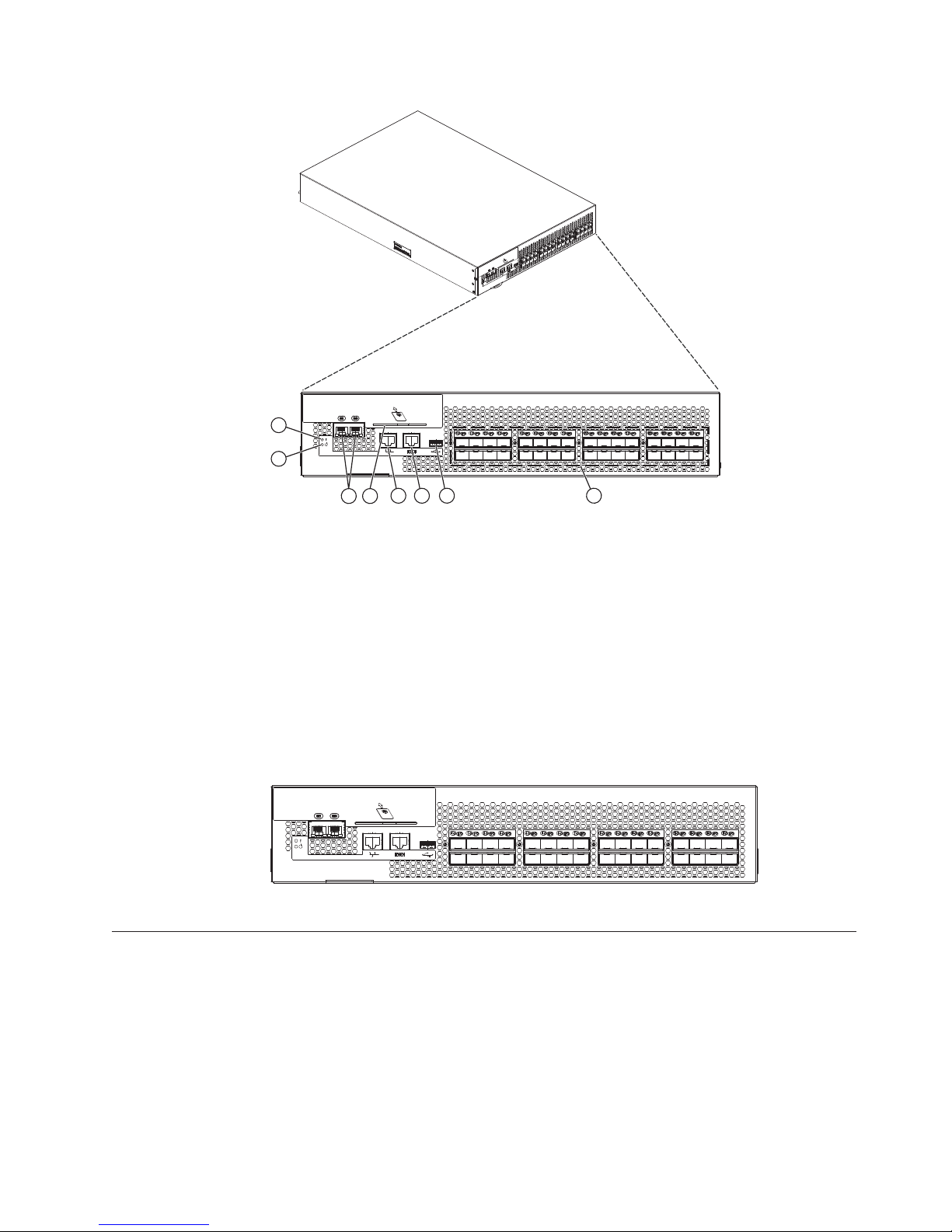
Port side of the switch
The port side (see Figure 1 on page 3 ) includes the switch power and status LEDs,
clustering and re-keying ports, Smart Card reader, management, console, and USB
port, and the Fibre Channel ports and their corresponding status LEDs.
2 SAN32B-E4 Installation, Service, and User Guide
Page 29
1
2
453
56 7 8
b32e4001
Figure 1. Port side view
1 System status LED 5 RJ45 GE management port
2 System power LED 6 RJ45 serial console port
3 RJ45 GE ports (for
7 USB port
clustering and
re-keying)
4 Smart Card reader 8 Fibre Channel ports (0 - 31)
The Fibre Channel ports are numbered from left to right on the faceplate; 0-15 on
the top row, and 16-31 on the bottom row (see Figure 2).
Figure 2. Port numbering
1
0
2
17
16
18
5
4
3
20
19
7
8
610
21
22
23
911
25
24
26
13
14
12
28
27
15
29
30
31
b32e4002
Nonport side of the switch
Figure 3 on page 4 shows the nonport side of the switch, which contain the
combined power supplies and fans.
Chapter 1. Introducing the SAN32B-E4 3
Page 30
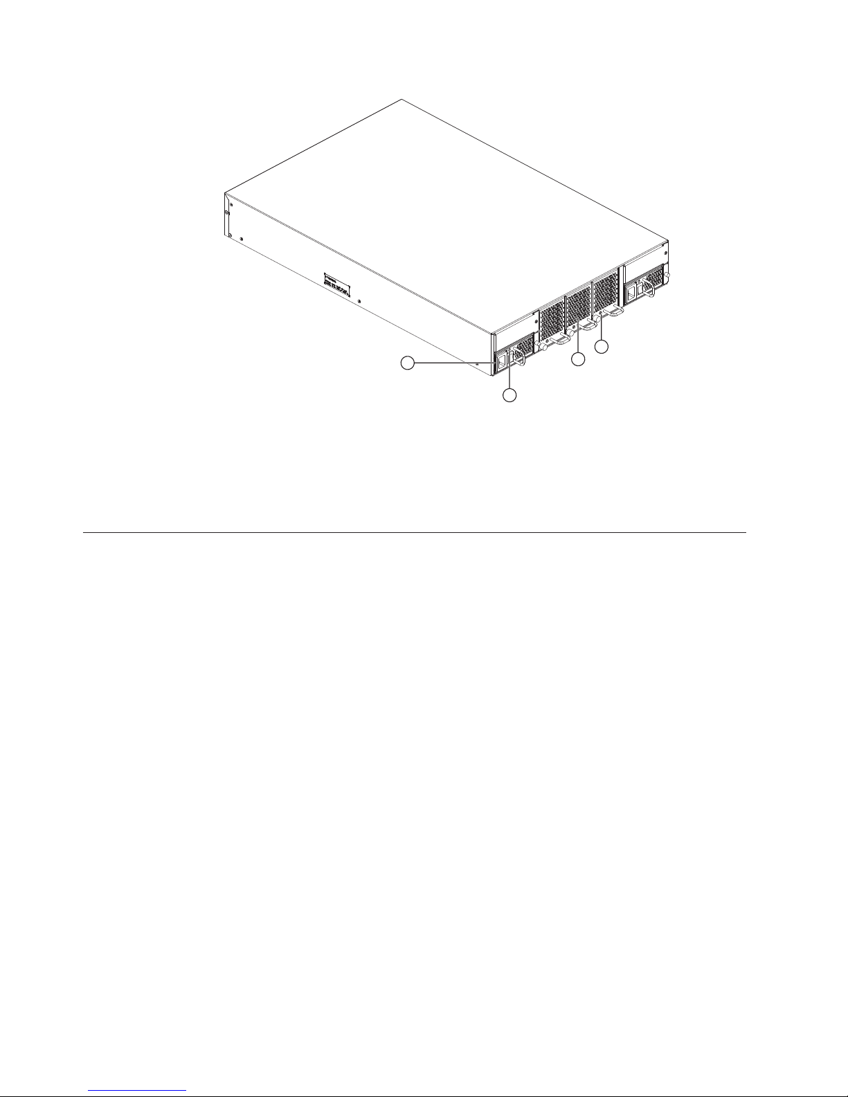
Figure 3. Nonport side of the switch
1 Power supply (2) 3 Fan (3)
2 Power supply status
LED
Field-replaceable units (FRUs)
The switch has two power supply (Figure 4 on page 5) and three fan assembly
(Figure 5 on page 5) FRUs that are redundant and hot swappable. The FRUs are
capable of functioning universally (100 - 240 VAC input range) without voltage
jumpers or switches. The power supply FRUs are identical and interchangeable;
the fan assembly FRUs are also identical and interchangeable. The switch chassis
itself (Figure 6 on page 6) is also a FRU.
1
4 Fan status LED
b32e4003
4
3
2
Smart cards, which provide additional encryption security management options,
are available through IBM as FRUs. See the Fabric OS Encryption Administrator’s
Guide Supporting Tivoli Key Lifecycle Manager (TKLM) Environments for more
information regarding this recommended optional functionality. Part numbers for
FRUs are listed in “Parts list (FRUs)” on page 52.
4 SAN32B-E4 Installation, Service, and User Guide
Page 31
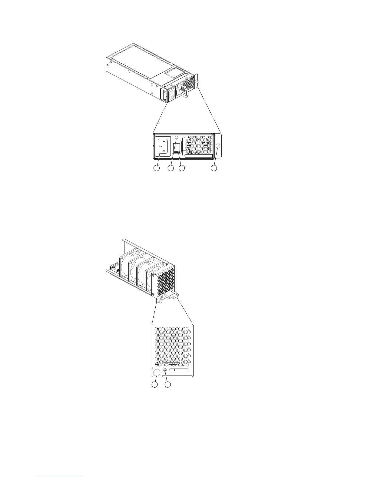
1 243
Figure 4. Power supply
b32e4004
1 Power-cord
connection
2 Power supply status
LED
3 Power switch
4 Captive screw
Figure 5. Fan assembly
1 Captive screw 2 Fan status LED
b32e4005
1 2
Chapter 1. Introducing the SAN32B-E4 5
Page 32

Figure 6. Switch chassis
Planning for encryption
Attention: Setup of this switch for encryption requires the use of this document
for the physical installation of the switch. Critical information required for enabling
and managing encryption is contained in the Fabric OS Encryption Administrator’s
Guide Supporting Tivoli Key Lifecycle Manager (TKLM) Environments, which is
included on the documentation CD-ROM that is shipped with the product. You
must use both documents in order to successfully set up the switch for encryption.
Careful attention to details of setup and configuration are essential to enabling a
secure encryption functionality. The following guidelines should be followed when
planning for encryption with the SAN32B-E4 switch or the 16-port encryption
blade (FS8-18), which is available for the SAN768B and SAN384B products.
v Redundancy of hardware is essential because if the encryption path is disrupted,
access to the encrypted data will be lost with a single encryption device. You
must have two encryption devices to ensure backup and access in the event that
one of the devices goes down. If one of the devices in the encryption pair is not
functioning, you will only have read access to the encrypted data on the
functioning device until the non-functioning device is restored. Redundancy of
hardware for encryption can be accomplished with the following:
– Two Key Vault locations on different devices
– Two encryption devices in any combination of encryption switches
(SAN32B-E4) and FS8-18 encryption blades (in SAN768B or SAN384B chassis)
v Cable planning for the encryption switch and its back-up and for a primary and
secondary key vault manager is critical. These devices can be separated by
distance as long as they can maintain constant communication contact. One
device must back up the other to ensure access to encrypted data. Refer to the
Fabric OS Encryption Administrator’s Guide Supporting Tivoli Key Lifecycle Manager
(TKLM) Environments for more information on Master Keys (MK).
v Begin with a limited application of encryption in a test environment and once an
expanded encryption test is successful, move the encryption into production
v Avoid dual encryption (Fabric encryption and device encryption). While this
should not cause any encryption errors, it will degrade performance.
b32e4006
6 SAN32B-E4 Installation, Service, and User Guide
Page 33

v There is no support of Cisco switches at this time by IBM. The section in the
Fabric OS Encryption Administrator’s Guide Supporting Tivoli Key Lifecycle Manager
(TKLM) Environments related to Cisco Fabric connectivity does not currently
apply.
v The use of Smart Cards provides additional encryption security management,
and is highly recommended. Smart cards can be ordered as FRUs through IBM.
v The Top Talker feature is not compatible with redirection zones. The Top Talker
feature should not be enabled when an encryption switch or blade is present in
the fabric.
v Alias zoning is not supported in encryption environments. You must use the real
WWPN.
v Refer to the "Steps for connecting to a TKLM appliance" section of the Fabric OS
Encryption Administrator’s Guide Supporting Tivoli Key Lifecycle Manager (TKLM)
Environments for detailed information on initial setup. That section includes the
following information:
– All switches you plan to include in an encryption group must have a secure
connection to the Tivoli Key Lifecycle Manager (TKLM). A local LINUX host
must be available to transfer certificates.
– Be sure that the clock time on the TKLM server and on the Brocade
encryption nodes are the same. A difference of only a few minutes can cause
the TLS connectivity to fail.
– Repeat the same steps for configuring both the primary and the secondary
key vault.
– Both the primary and secondary key vaults should be registered before
exporting MK or encrypting LUNs. If the secondary key vault is registered
midway after encryption is done for some of the LUNs, then the key database
should be backed up and restored on the secondary TKLM from the already
registered primary TKLM before registering the secondary TKLM.
– The following is a suggested order for the initial steps needed to create a
secure connection to TKLM. (Refer to the "Steps for connecting to a TKLM
appliance" section of the Fabric OS Encryption Administrator’s Guide Supporting
Tivoli Key Lifecycle Manager (TKLM) Environments for additional steps.)
1. Initialize all encryption nodes to generate Key authentication center (KAC)
certificates and export the signed KAC certificates to a local LINUX host.
2. Obtain the necessary user credentials and log in to the TKLM server
appliance from the TKLM management web console.
Chapter 1. Introducing the SAN32B-E4 7
Page 34

8 SAN32B-E4 Installation, Service, and User Guide
Page 35

Chapter 2. Installing and configuring the switch
Attention: Refer to “Planning for encryption” on page 6 for planning
recommendations specific to encryption.
You can install the SAN32B-E4 encryption switch in the following ways:
v As a stand-alone unit on a flat surface. For instructions and more information,
see “Setting up the switch as a standalone unit” on page 11.
v In an Electronic Industries Association (EIA) cabinet using the fixed rack mount
kit, slide rack mount kit, or the mid-mount rack kit. For more information, see
“Installing in an EIA cabinet” on page 13.
This chapter provides the following information:
v “Site preparation and installation guidelines” on page 10
v “Items included with the switch” on page 11
v “Setting up the switch as a standalone unit” on page 11
v “Installing in an EIA cabinet” on page 13
v “Configuring the switch” on page 19
v “Configuring for encryption” on page 26
v “Managing license keys (optional)” on page 27
Table 3. Installation tasks, time, and items required
Installation task Time estimate Items required
Site preparation and
unpacking the switch
Installing the rack mount kit 30 minutes Rack mount kit, 1/4-inch
Mounting and securing the
switch in the rack
Installing power cables and
powering on the switch
Establishing serial
connection, logging on to
switch, and configuring IP
addresses.
Installing an Ethernet cable,
opening a Telnet session, and
configuring the switch
domain ID, date and time,
and additional system
parameters. Verifying and
backing up configuration.
Installing SFPs, attaching and
managing fiber optic cables.
30 minutes None
15 minutes
10 minutes Power cables (provided in
20 minutes Serial cable (provided in the
20 minutes Ethernet cable for Telnet
15 minutes SFP optical transceivers, fiber
slotted-blade screwdriver,
11/32-inch wrench
the accessory kit)
accessory kit), workstation
computer with a serial port
or terminal server port and a
terminal emulator
application (such as
HyperTerminal), Ethernet IP
addresses for the switch
access. Refer to the Fabric OS
Administrator’s Guide for
more information.
optic cables, and hook and
loop cable wraps
© Copyright IBM Corp. 2010 9
Page 36

Attention: Read the “Safety notices and labels” on page xiii before
attempting any installation, maintenance, or service procedures.
Site preparation and installation guidelines
The following steps are required to ensure correct installation and operation.
1. Provide a space that is 2 rack units (2U) high. 1U is equal to 4.45 cm (1.75 in.).
2. Plan to install the switch with the nonport side facing the air-intake aisle.
Ensure that:
v A minimum of 90.1 cubic meters per hour (53 cubic feet per minute) of
airflow is available to the air intake vents on the nonport side of the switch.
v The air intake and exhaust vents have a minimum of 2 inches of airspace.
v The air temperature on the air intake side is less than 40° C (104° F) during
operation.
3. Ensure that dedicated electrical branch circuits with the following
characteristics are available:
v The primary outlet is correctly wired, protected by a circuit breaker, and
grounded in accordance with local electrical codes.
v The supply circuit, line fusing, and wire size are adequate, as specified by
the electrical rating on the switch nameplate.
v The power supply standards are met. See “Power specifications” on page 52.
Attention: To maximize fault tolerance, connect each power cord to a
separate power source.
4. Plan for cable management before installing the chassis.
Cables can be managed in a variety of ways, such as by routing cables below
the chassis, to either side of the chassis, through cable channels on the sides of
the cabinet, or by using patch panels.
5. For configuration of the switch:
v Plan for two IP addresses, and corresponding subnet masks and gateway
addresses. One IP address for the virtual IP address on the cluster
interconnect; and another IP address for the management port.
v Ensure that the following are available:
– Workstation with an installed terminal emulator, such as HyperTerminal
– Serial cable (provided)
– Three Ethernet cables
– Access to an FTP server for backing up the switch configuration or
collecting supportsave output data (optional)
– Brocade USB drive for collecting supportsave output data (optional)
– SFPs and compatible cables
Planning for cable management
Attention: The minimum bend radius for a 50 micron cable is 2 in. under full
tensile load and 1.2 in. with no tensile load.
Cables can be organized and managed in a variety of ways: for example, using
cable channels on the sides of the cabinet or patch panels to minimize cable
management. Following is a list of recommendations:
10 SAN32B-E4 Installation, Service, and User Guide
Page 37

v Plan for rack space required for cable management before installing the switch.
v Leave at least 1 meter (3.28 ft) of slack for each port cable. This provides room
to remove and replace the switch, allows for inadvertent movement of the rack,
and helps prevent the cables from being bent to less than the minimum bend
radius.
v If you are using ISL Trunking, consider grouping cables by trunking groups. The
cables used in trunking groups must meet specific requirements, as described in
the Fabric OS Administrator’s Guide.
v For easier maintenance, label the fiber optic cables and record the devices to
which they are connected.
v Keep LEDs visible by routing port cables and other cables away from the LEDs.
v Use hook and loop style straps to secure and organize fiber optic cables. Do not
use tie wraps on fiber optic cables; they can be easily overtightened and can
damage the optic fibers.
Items included with the switch
The following items are included with the standard shipment of the switch. When
you open the packaging, verify that these items are included in the package and
that no damage occurred during shipping.
Note: If any items are damaged or missing, within the United States and Canada,
contact the IBM Quality Hotline toll-free 1-800-442-6773 or direct dial in
other locations: 770-858-8459.
v The SAN32B-E4 switch, containing two power supplies and three fan assemblies
v Rack mount kit
v An accessory kit that contains the following items:
– SAN32B-E4 Installation, Service, and User Guide (this document).
– IBM documentation CD
– Warranty
– Translated safety notices
– Four rubber mounting feet, required for setting up the product as a
stand-alone unit
– Two grounded 6 ft. (1.8 m.) country-specific power cables
– Serial cable with an RJ-45 connector
– Paperpack of optional features license and key activation information (if
ordered)
Attention: Retain this paperpack in a safe place. The transaction keys in
the paperpack are required for activation of optional features on the switch.
Once a feature is activated, its activation key is associated with a specific
product WWN and serial number.
Setting up the switch as a standalone unit
To install the switch as a standalone unit, use the following procedure:
1. Unpack the switch and verify that all items listed in “Items included with the
switch” are present and undamaged.
2. Clean the four corner depressions on the bottom of the switch enclosure, place
an adhesive rubber foot in each one, and firmly press into place. The rubber
feet on the switch help prevent the switch from sliding off the supporting
surface.
Chapter 2. Installing and configuring the switch 11
Page 38

3. Place the switch on a flat, sturdy surface.
4. Provide power to the switch as described in “Providing power to the switch”
on page 20.
Attention: Do not connect the switch to the network until the IP address is
correctly set. For instructions on how to cable and configure the switch, and how
to set the IP address, see “Configuring the switch” on page 19.
12 SAN32B-E4 Installation, Service, and User Guide
Page 39

Installing in an EIA cabinet
Attention: Refer to “Rack safety” on page xix for danger and caution notices
related to rack and cabinet installations.
You can install the rack mount kit in only one way in a cabinet, with the port side
of the switch able to slide out of the exhaust-air side of the cabinet.
Note: Illustrations in this section may not match the specific switch being installed.
Time required
Approximately 45 minutes, not including configuration or cabling.
Items required
You need the following items to install the switch in a slide-rail rack:
v Straight slot screwdriver
v Rack space: 2U of rack space
v Two power cables that are provided with the switch
v Two power outlets
v Rack mount kit
Attention: Use the exact screws specified in the procedure for use with the switch
chassis. Using screws longer than 3/16 in. can damage the switch. The different
types of screws are listed in Table 4 on page 14. Make sure that you tighten all
screws used in this procedure.
Installation instructions
To install the switch in a slide-rail rack that meets EIA standards, use the following
procedure.
Note: These procedures use parts that are included in the rack-mount kit. These
parts are listed in Table 4 on page 14. The installation procedure
cross-references the items in this table. Be sure to use the referenced parts
when you perform each step.
Before you start the rack-mount installation process, locate the rack-mount slides
and the mounting bracket that are provided in the shipping container.
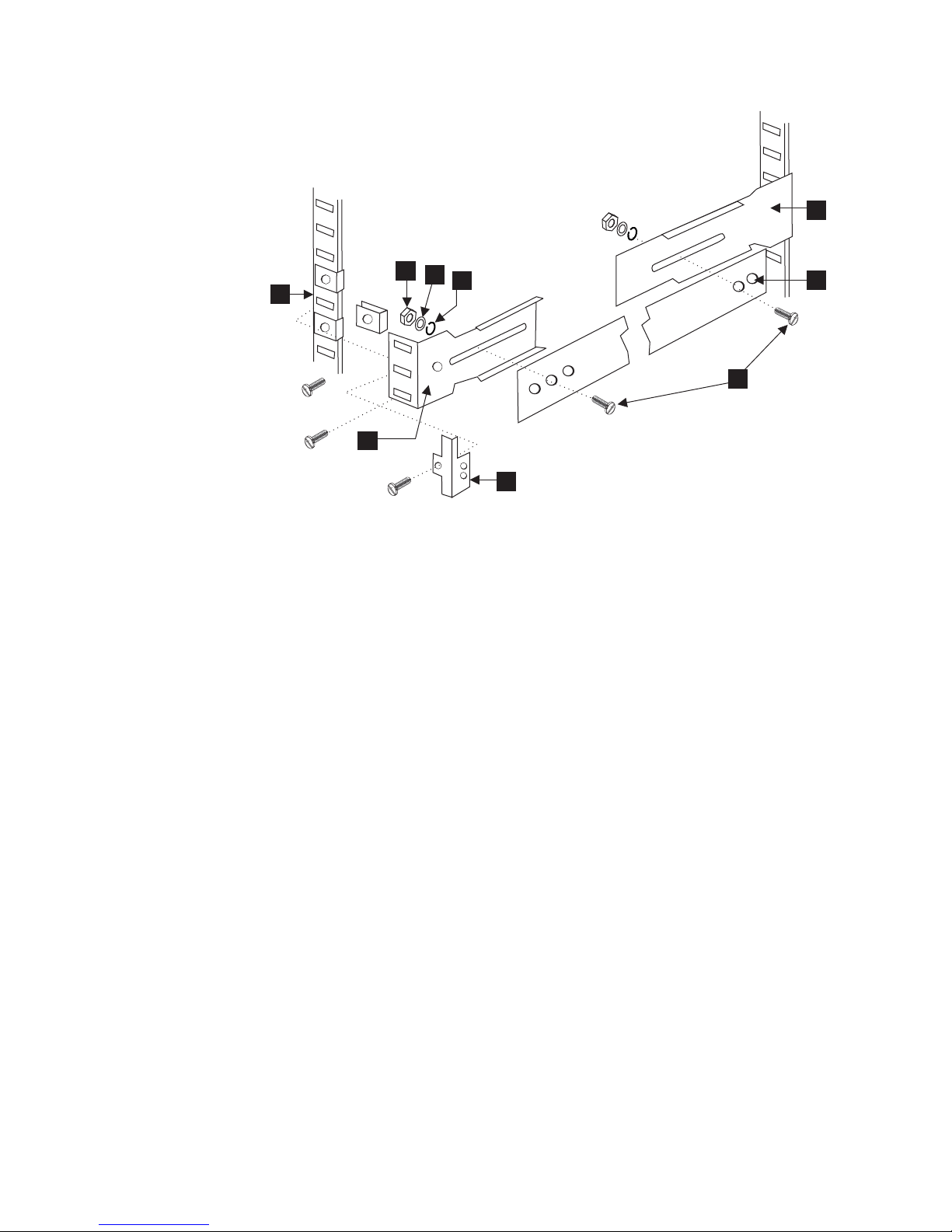
Figure 7 on page 14 shows the rack assembly. The number keys, such as 1, refer
to the items listed in Table 4 on page 14.
Chapter 2. Installing and configuring the switch 13
Page 40

4
4X
Inner Slide
3
Front of Switch
7
2X
Figure 7. Rack assembly
EIA Rack Rail
2
Outer Slide
6
2X
5X
9
8X
2X
See
1
Detail A
7
4X
5
7
4X
6
4X
10
8X
11
8X
12
8X
Detail A
SJ000153
1. Unpack the rack-mount kit and verify that all ordered items and parts are
present and undamaged. See Table 4 for a list of parts and the quantities
supplied.
Table 4. Parts supplied with the rack-mount kit
Item Description Quantity
1 Rack mount slide (inner and outer slide) 2
2 Right rack mount bracket (optional bracket
for front of switch)
3 Left rack mount bracket (optional bracket for
front of switch)
4 Rack mounting bracket (3-hole) 4
5 Nut clip, M5 11
6 Screw, 8-32 x 3/16 in., zinc 11
7 Screw, M5 x 12 11
8 Bracket to slide rack kit (contains items 9 -
12)
9 Screw, 8-32 x 3/8 in., zinc 8
10 Washer, flat, No. 8 8
11 Washer, lock, No. 8 8
12 Nut, hex, 8-32 8
1
1
1
14 SAN32B-E4 Installation, Service, and User Guide
Page 41

2. Separate the inner and outer slides.
a. Open one of the slides until the lock engages.
b. Press the lock release lever (1 in Figure 8) and remove the inner rail from
the outer rail.
1
SJ000046
Figure 8. Separating the inner and outer rails.
c. Repeat step 2a and step 2b for the other rail.
®
Note: For racks with flush-mount doors, such as the 9306 Netfinity
racks, do
not install the ears. Instead, use the rack-mount slides by attaching the
switch to the set of mounting holes, which are offset 3 inches into the
rack.
3. Install the inner (smaller) slide on the switch chassis, as Figure 7 on page 14
shows.
Attention: If you use screws longer than 3/16 in. you can damage the
switch.
a. Position the flat side of the inner rail along one side of the switch. Align the
holes in the rail with the threaded holes in the side of the switch chassis.
The chamfered end of the inner rail should face toward the rear of the
switch (away from the ports) as shown in Figure 9 on page 16.
b. Attach the inner rail by using three of the 8-32 x 3/16 in. zinc screws (6 in
Table 4 on page 14).
Chapter 2. Installing and configuring the switch 15
Page 42
1
6
3
Front
Figure 9. Mounting the moving portion of the slide and mounting brackets to the switch
c. Repeat step 3a on page 15 and step 3b on page 15 for the second inner rail
on the other side of the switch chassis.
4. Optional step: If desired, install the right rack mount bracket 2 (see Figure 7
on page 14) and the left rack mount bracket 3 on the switch chassis. Use
these brackets to secure the switch to the rack as shown in Figure 9.
Attention: Do not use screws longer than 3/16 in.; they can damage the
switch.
a. Position the left rack mount bracket at the left front corner of the switch
chassis. Align the two holes in the bracket with the two threaded holes in
the switch chassis.
b. Attach the bracket by using two of the 8-32 x 3/16 in. zinc screws (see 6
in Figure 7 on page 14)
c. Repeat step 4a and step 4b for the right rack mount bracket on the right
front corner of the switch chassis.
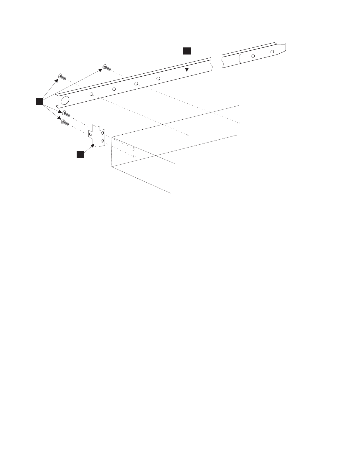
5. Attach all four of the 3-hole rack mounting brackets 4 in Figure 10 on page
17.
a. Position a 3-hole rack mounting bracket 4 at the end of one of the outer
slides.
b. Attach the bracket by using the 8-32 x 3/8 in. zinc screws 9. Ensure that
the screw heads are inside the slides.
c. Place one each of the following items on the outer end of the screw in the
order listed (see Detail A in Figure 7 on page 14):
1) Washer, flat No. 8 10
2) Washer, lock No. 8 11
3) Nut, hex, 8-32 12
d. Repeat steps 5a through 5c for the three remaining rail ends.
SJ000047
16 SAN32B-E4 Installation, Service, and User Guide
Page 43
4
12
11
10
1
5
9
4
3
Figure 10. Mounting the fixed portion of the rail and the locking brackets to the rack
SJ000048
6. Install the outer (larger) slides in the rack, as shown in Figure 10.
a. At the desired height, install the five M5 nut clips 5. Put three M5 nut
clips in the front of the rack and two in the back. The middle clip in the
front of the rack is for the locking ears.
Note: Some rack mount kits might use 10-32 nut clips in place of the M5
nut clips for the locking ears.
b. Attach the slides by using four M5 x 12 screws 7 (see Figure 7 on page
14).
c. Repeat step 6a and step 6b for the other rail.
7. Install the switch in the rack.
a. Position the switch in front of the rack. Insert the switch into the rack by
sliding the inner slides that are mounted on the switch into the outer slides
that are mounted on the rack. See Figure 11 on page 18.
Chapter 2. Installing and configuring the switch 17
Page 44

SJ000049
Figure 11. Inserting slides into the rack rails
b. Check the alignment of the slides by sliding the switch in and out of the
rack. Any difficulty moving the switch indicates lateral stress or
misalignment. If this situation occurs, adjust the slide positions until the
movement is smooth.
8. Optional step: If the right and left rack mount brackets are installed on the
front corners of the switch, attach both brackets to the cabinet rack by using M5
x 12 screws 7. See step 4 on page 16 and Figure 7 on page 14. The screws
should pass through the front of each bracket and the slide rail.
Note: Some rack mount kits might use 10-32 nut clips in place of the M5 nut
clips for the locking ears.
9. Continue with initial setup of the switch by following the procedures in
“Configuring the switch” on page 19.
Attention: Do not connect the switch to the network until you perform one of
the following steps:
v Set the internet protocol (IP) address.
v Verify that the default IP address does not conflict with the existing IP
addresses in the same network.
18 SAN32B-E4 Installation, Service, and User Guide
Page 45

Configuring the switch
You must configure the switch before it can operate within a network and fabric.
This section provides the basic steps required for the initial setup of the switch. For
instructions on configuring the switch to operate in a network containing switches
from other vendors, refer to the Fabric OS Administrator's Guide. For specific
information related to encryption and key management, refer to the Fabric OS
Encryption Administrator’s Guide Supporting Tivoli Key Lifecycle Manager (TKLM)
Environments
For more information about the commands used in these procedures, refer to the
Fabric OS Command Reference.
To configure the switch, perform the following tasks. Figure 12 on page 20
illustrates the flow of these configuration tasks.
v “Providing power to the switch” on page 20
v “Connecting a serial cable between the switch and a host” on page 21
v “Logging in to the serial console port” on page 21
v “Setting the switch IP address” on page 21
v “Connecting an Ethernet cable and opening a Telnet session” on page 22
v “Setting the switch domain ID” on page 22
v “Setting the switch date and time” on page 22
v “Installing SFPs and attaching cables” on page 24
v “Managing cables” on page 25
v “Verifying the correct operation of the switch and backing up the configuration”
on page 25
Attention: Do not connect the switch to the network until the IP address is
correctly set.
Chapter 2. Installing and configuring the switch 19
Page 46
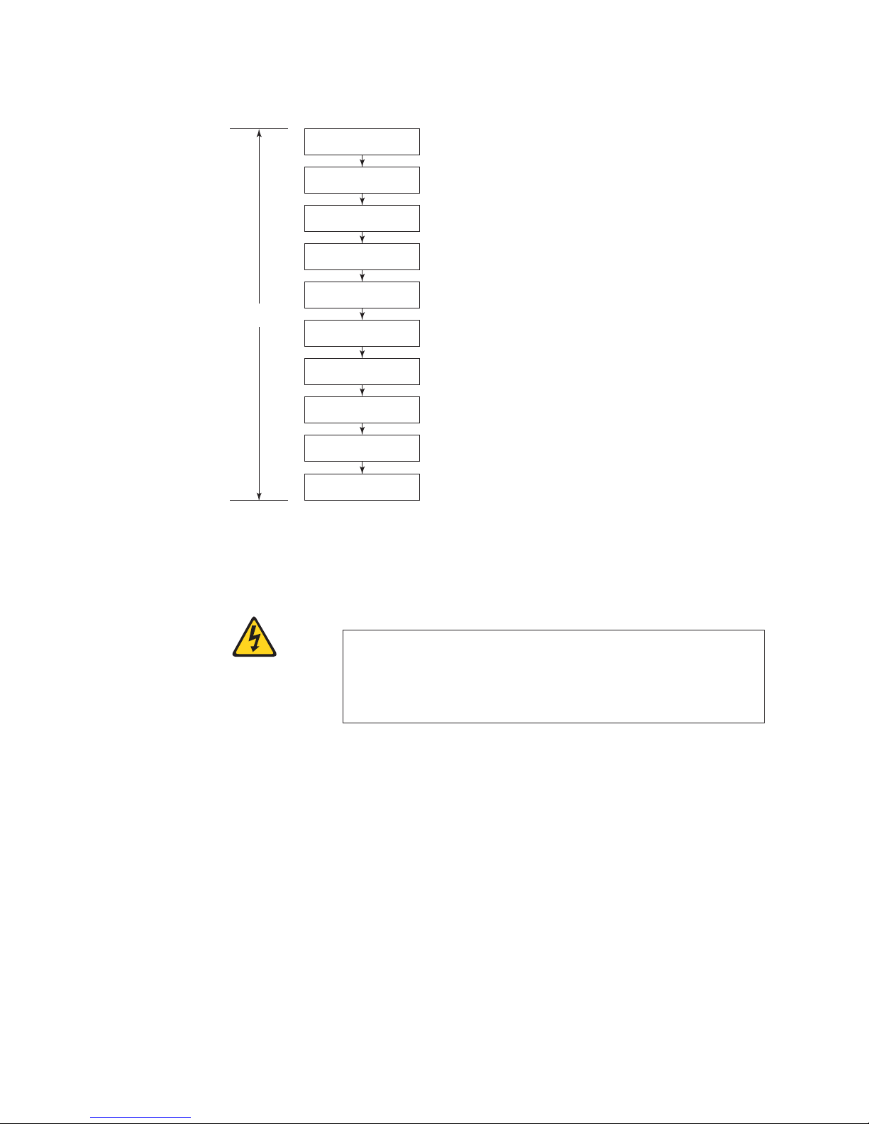
Switch Configuration
Connect serial cable
between switch and host
Login to serial console port
Log off serial console port
and disconnect serial cable
Connect Ethernet cable
Local
level
and open Telnet session
Set date and time
Verify operation and
back up configuration
Install SFPs and attach cables
Set IP address
Set Domain ID
Manage cables
b32e4007
Figure 12. Switch configuration steps
Providing power to the switch
DANGER
An electrical outlet that is not correctly wired could place
hazardous voltage on metal parts of the system or the devices that
attach to the system. It is the responsibility of the customer to
ensure that the outlet is correctly wired and grounded to prevent
an electrical shock. (D004)
Follow these steps to power on the switch
1. Connect the power cords to both power supplies
2. Connect the other end of the power cords to power sources. Ensure that the
cords have a minimum service loop of 6 in. available and are routed to avoid
stress.
Note: Power is supplied to the switch as soon as the first power supply is
3. Press the "|” area of both power switches.
4. After POST is complete, verify that the switch power LED on the port side is
green and the switch status LED on the port side is off.
Attention: Do not connect the switch to the network until the IP address is set.
20 SAN32B-E4 Installation, Service, and User Guide
connected and turned on. To protect against AC failure, connect the
power cords to outlets on separate circuits.
Page 47

Connecting a serial cable between the switch and a host
All basic configuration tasks in this guide are performed using a serial connection.
Follow these steps to connect a serial cable.
1. Remove the plug from the serial port and connect the serial cable provided
with the switch.
2. Connect the serial cable to the console port on the switch and to an RS-232
serial port on the workstation.
If the serial port on the workstation is RJ-45 instead of RS-232, remove the
adapter from the end of the serial cable and insert the exposed RJ-45 connector
into the RJ-45 serial port on the workstation.
3. Disable any serial communication programs running on the workstation.
4. Open a terminal emulator application (such as HyperTerminal on a PC, or
TERM, TIP, or Kermit in a UNIX environment), and configure the application
as follows:
v In a Windows environment:
Bits per second 9600
Databits 8
Parity None
Stop bits 1
Flow control None
v In a UNIX environment, enter the following string at the prompt:
tip /dev/ttyb -9600
If ttyb is already in use, then use ttya instead and enter the following string
at the prompt:
tip /dev/ttya -9600
Logging in to the serial console port
To log in to the switch through the serial connection, follow these steps.
1. Verify that the switch has completed POST. When POST is complete, the port
status and switch power and status LEDs return to a standard healthy state; for
information about LED patterns, see “Interpreting LEDs” on page 31.
2. When the terminal emulator application stops reporting information, press
Enter to display the login prompt.
3. Log in to the switch as admin, using the default password, password. You will
be prompted to change the default passwords at initial login.
Setting the switch IP address
Configure the switch with a static IP address.
1. Log into the switch using the default password, which is password.
2. Use the ipaddrset command to set the Ethernet IP address.
v Enter the IP address in dotted decimal notation as prompted.
Ethernet IP Address: 192.168.74.102
3. Complete the rest of the network information as prompted.
Ethernet Subnetmask: 255.255.255.0
Ethernet IP Address: 192.168.74.102
Ethernet Subnetmask: 255.255.255.0
Chapter 2. Installing and configuring the switch 21
Page 48

4. Optionally, verify that the address was correctly set by entering the
ipAddrShow command at the prompt.
5. Record the IP address on the pull out tab provided for this purpose on the port
side of the switch.
6. If the serial port is no longer required, use the logout command to log out of
the serial console, remove the serial cable, and replace the plug in the serial
port.
Connecting an Ethernet cable and opening a Telnet session
To create an Ethernet connection to the switch, follow these steps.
1. Remove the plug from the Ethernet port.
2. Connect an Ethernet cable to the switch Ethernet port and to the workstation or
to an Ethernet network containing the workstation.
3. Open a Telnet session on the workstation.
Note: The following information describes using the CLI but these tasks can be
performed using Web Tools or Data Center Fabric Manager .
Setting the switch domain ID
To set the switch domain ID, follow these steps.
1. Log on to the switch through Telnet, using the admin account.
2. Modify the domain ID if required.
The default domain ID is 1.
v If the switch is not powered on until after it is connected to the fabric and
the default domain ID is already in use, the domain ID for the new switch is
automatically reset to a unique value.
v If the switch is connected to the fabric after it has been powered on and the
default domain ID is already in use, the fabric will segment. To find the
domain IDs that are currently in use, run the fabricShow command on
another switch in the fabric.
a. Disable the switch by entering the switchDisable command.
b. Enter the configure command. The command prompts will display
sequentially; enter a new value or press Enter to accept each default value.
c. Enter y after the "Fabric param" prompt:
Fabric param (yes, y, no, n): [no] y
d. Enter a unique domain ID (such as the domain ID used by the previous
switch, if still available):
Domain: (1..239) [1] 3
e. Complete the remaining prompts or press Ctrl+D to accept the remaining
settings without completing all the prompts.
f. Re-enable the switch by entering the switchEnable command.
Setting the switch date and time
The date and time settings are used for logging events. Switch operation does not
depend on the date and time; a switch with an incorrect date and time value still
functions properly. However, because the date and time are used for logging, error
detection, and troubleshooting, you should set them correctly.
Perform the following steps to set the date and time of the switch.
22 SAN32B-E4 Installation, Service, and User Guide
Page 49

Setting the date
1. If necessary, log on to the switch by Telnet, using the admin account.
2. Enter the date command, using the following syntax:
date ""mmddHHMMyy""
The values represent the following:
v mm is the month; valid values are 01 through 12
v dd is the date; valid values are 01 through 31
v HH is the hour; valid values are 00 through 23
v MM is minutes; valid values are 00 through 59
v yy is the year; valid values are 00 through 99 (values greater than 69 are
interpreted as 1970 through 1999, and values less than 70 are interpreted as
2000-2069)
switch:admin> date
Fri Sep 26 12:29:46 UTC 2008
switch:admin> date "0926123008"
Fri Sep 26 12:30:00 UTC 2008
switch:admin>
Setting the time zone of the switch
To set the time zone, follow these steps.
1. If necessary, log on to the switch by Telnet, using the admin account.
2. Enter the tsTimeZone command as follows:
switch:admin> tstimezone [--interactive]/ [, timezone_fmt]
Use timezone_fmt to set the time zone by Country/City or by time zone ID,
such as MST.
The following example shows how to change the time zone to US/Mountain.
switch:admin> tstimezone
Time Zone : US/Pacific
switch:admin> tstimezone US/Mountain
switch:admin> tstimezone
Time Zone : US/Mountain
The following procedure describes how to set the current time zone using
interactive mode.
1. Enter the tsTimeZone command as follows:
switch:admin> tstimezone --interactive
You are prompted to select a general location.
Please identify a location so that time zone rules can be set correctly.
2. Enter the appropriate number or Ctrl+D to quit.
3. At the prompt, select a country location.
4. At the prompt, enter the appropriate number to specify the time zone region or
Ctrl+D to quit.
For more detailed information about the parameters of the tsTimeZone command,
refer to the Fabric OS Command Reference.
Chapter 2. Installing and configuring the switch 23
Page 50

Synchronizing local time with an external source
To synchronize the local time of the principal or primary switch with that of an
external NTP server, follow these steps.
1. If necessary, log on to the switch by Telnet, using the admin account.
2. Enter the tsClockServer command.
switch:admin> tsclockserver "<ntp1;ntp2>"
where ntp1 is the IP address or DNS name of the first NTP server, which the
switch must be able to access. The second ntp2 is the second NTP server and is
optional. The operand "<ntp1;ntp2>" is optional; by default, this value is LOCL,
which uses the local clock of the principal or primary switch as the clock
server.
The tsClockServer command accepts multiple server addresses in either IPv4,
IPv6, or DNS name formats. When multiple NTP server addresses are passed,
tsclockserver sets the first obtainable address as the active NTP server. The
others will be stored as backup servers that can take over if the active NTP
server fails. The principal or primary FCS switch synchronizes its time with the
NTP server every 64 seconds.
switch:admin> tsclockserver
LOCL
switch:admin> tsclockserver "132.163.135.131"
switch:admin> tsclockserver
132.163.135.131
switch:admin>
The following example shows how to set up more than one NTP server using a
DNS name:
switch:admin> tsclockserver "10.32.170.1;10.32.170.2;ntp.localdomain.net"
Updating Clock Server configuration...done.
Updated with the NTP servers
Changes to the clock server value on the principal or primary FCS switch are
propagated to all switches in the fabric
Installing SFPs and attaching cables
To install SFPs and cables to the switch, follow these steps.
1. If necessary, remove the plugs from the ports to be used.
2. Ensure that the bail (wire handle) is in the unlocked position. Place the SFP in
the correct position on the port (Figure 13).
!
b32e4008
Figure 13. Installing an SFP into an upper port
3. Slide the SFP into the port until it clicks into place. Close the bail.
24 SAN32B-E4 Installation, Service, and User Guide
Page 51

Note: Each SFP has a 10-pad gold-plated PCB-edge connector on the bottom.
Insert SFPs into the upper row of ports with this gold edge down. Insert
SFPs into the lower row of ports with the gold edge up.
4. Connect the cables to the transceivers. The cables used in trunking groups must
meet specific requirements. For a list of these requirements, see the Fabric OS
Administrator’s Guide.
Note: The cable connectors are keyed to ensure correct orientation. If a cable
does not install easily, ensure that it is correctly oriented.
a. Orient a cable connector so that the key (the ridge on one side of the
connector) aligns with the slot in the transceiver. Then, insert the cable into
the transceiver until the latching mechanism clicks. For instructions specific
to cable type, see the cable manufacturer’s documentation.
b. Repeat step a for the remaining cables.
5. Check the LEDs to verify that all components are functional. For information
about LED patterns, see “Interpreting LEDs” on page 31.
6. Verify the correct operation of the switch by entering the switchShow
command from the workstation.
Managing cables
Attention: The minimum bend radius for a 50 micron cable is 2 in. under full
tensile load and 1.2 in. with no tensile load.
Cables can be organized and managed in a variety of ways, including using cable
channels on the sides of the cabinet or patch panels to minimize cable
management. Following is a list of recommendations:
v Plan for rack space required for cable management before installing the switch.
v Leave at least 1 m (3.28 ft) of slack for each port cable. This provides room to
remove and replace the switch, allows for inadvertent movement of the rack,
and helps prevent the cables from being bent to less than the minimum bend
radius.
v If you are using ISL Trunking, consider grouping cables by trunking groups. The
cables used in trunking groups must meet specific requirements, as described in
the Fabric OS Administrator’s Guide.
v For easier maintenance, label the fiber optic cables and record the devices to
which they are connected.
v Keep LEDs visible by routing port cables and other cables away from the LEDs.
v Use hook-and-loop straps to secure and organize fibre optic cables. Do not use
tie wraps on fiber optic cables, because wraps are easily overtightened and can
damage the optical fibers.
Verifying the correct operation of the switch and backing up
the configuration
To verify the correct operation of the switch and to back up the switch
configuration, complete these steps:
1. Check the LEDs to verify that all components are functional. For information
about LED patterns, refer to “Interpreting LEDs” on page 31.
2. If necessary, log on to the switch by Telnet, using the admin account.
3. Run the portCfgPersistntEnable command to activate the FC ports for FC
operation.
Chapter 2. Installing and configuring the switch 25
Page 52

4. Verify the correct operation of the switch by entering the switchShow
command from the workstation. This command provides information about the
switch and its port status.
5. Verify the correct operation of the switch in the fabric by entering the
fabricShow command from the workstation. This command provides general
information about the fabric.
6. Back up the switch configuration to an FTP server by entering the
configUpload command and following the prompts.
This command uploads the switch configuration to the server, making it
available for downloading to a replacement switch if necessary.
It is recommended that the configuration be backed up on a regular basis to ensure
that a complete configuration is available for downloading to a replacement
switch. For specific instructions about how to back up the configuration, see the
Fabric OS Administrator’s Guide. The switchShow, fabricShow, and configUpload
commands are described in detail in the Fabric OS Command Reference.
Configuring for encryption
Note: Refer to the Fabric OS Encryption Administrator’s Guide Supporting Tivoli Key
Lifecycle Manager (TKLM) Environments for the procedures to configure the
encryption functions.
Summary of procedure
If the switch is being configured for the first time for encryption services, you will
need to perform several pre-initialization tasks related to configuring the
encryption node (switch), including:
v Generating the Critical Security Parameters (CSPs) and certificates
v Loading and setting up the certificates
v Establishing a trusted link (LKM Appliance)
v Configuring the global parameters and policies of the encryption group
v Generating and backing up the master key in RSA environments
v Handling key-vault high-availability
v Configuring cluster interconnect
After completing the pre-initialization tasks, you may need to perform several
tasks related to configuring the encryption group. Figure 14 on page 27
summarizes the flow of the encryption-configuration tasks.
26 SAN32B-E4 Installation, Service, and User Guide
Page 53

Node (switch)
level
Encryption Configuration
Pre-initialization setup
Generate critical security parameters
and certificates
Load and set up certificates
Establish Trusted Link (LKM
appliance)
Configure global parameters and
policies of encryption group
Generate and back-up master key in
RSA environments
Key Vault high availability handling
Configure cluster interconnect
Encryption group configuration
Crypto target container configuration
Encryption
group level
Crypto LUN (disk) configuration
Crypto tape configuration
Other configuration
Figure 14. Encryption configuration
If you have purchased the recommended optional Smart card FRU for additional
encryption security management, see the "Smart card usage" section of the Fabric
OS Encryption Administrator’s Guide Supporting Tivoli Key Lifecycle Manager (TKLM)
Environments for information on using that functionality.
Avoid double encryption
Encryption and decryption at the storage device level does not affect the
encryption switch or blade capabilities, and does not cause problems with
decrypting the data. However, double encryption adds the unnecessary need to
manage two sets of encryption keys, increases the risk of losing data, may reduce
performance, and does not add security.
Managing license keys (optional)
b32e4009
Depending on what has been ordered, certain licenses are factory-installed on the
switch. Feature licenses might be included as a paperpack item in the switch
shipping carton. This paperpack provides you with keys to unlock the features.
You can also purchase licenses separately from IBM.
Attention: Retain this paperpack in a safe place. The transaction keys in the
paperpack are required for activation of optional features on the switch. After a
feature is activated, its activation key is associated with a specific product WWN
and serial number.
Chapter 2. Installing and configuring the switch 27
Page 54

Refer to the following sections for information about viewing the current licenses,
adding a license, or removing a license. For more information on the following
procedures, see the Fabric OS Administrator's Guide and the Fabric OS Command
Reference.
Viewing current license keys
To view the licenses that are currently enabled on the switch, complete the
following steps.
1. Log in as admin.
2. Enter the licenseShow command. A list of the enabled licenses and their
features is displayed, as in the following example.
APswitch:admin> licenseshow
License Key: bQebzeRdScRfc0iK
License Key: SybbzQQ9edTzcd0X
APswitch:admin>
Web license
Zoning license
Adding a license key
Licenses for additional functionality may be purchased as feature codes through
IBM. Contact your IBM representative for more information. You will need to
supply IBM with the WWN to obtain a transaction key, which is sent in a
paperpack. To obtain the license key, follow the instructions included in the
paperpack. The transaction key and the switch WWN or product serial number are
required to obtain the license key.
To add a license to the switch, complete the following steps.
1. Log in as admin.
2. Enter the switchShow command to obtain the WWN of your switch. The
license key is a string of approximately 16 uppercase and lowercase letters and
digits. Case is significant. The key is an encrypted form of the system WWN
and the products licensed to run on this system.
3. Enter the licenseAdd command, followed by the license key enclosed in
quotation marks, as shown in the following example.
APswitch:admin> licenseadd "aBcDeFGh12345K"
License key aBcDeFGh12345 added
Enter the license key into the system exactly as issued. If you enter it
incorrectly, the license might be accepted, but it will not function.
4. After entering the license key, use the licenseShow command to verify that it is
valid. If a licensed product is not displayed, the license is invalid.
Note: After you enter a license, the licensed product is available immediately;
the system does not need to be rebooted.
Removing a license key
To remove a license from the switch, complete the following steps.
1. Log in as admin.
2. Enter the licenseRemove command, followed by the license key enclosed in
quotation marks, as in the following example.
APswitch:admin> licenseremove "bQebzbRdScRfc0iK"
removing license key "bQebzbRdScRfc0iK"
3. Save the license key information in case you want to reinstall it in the future.
28 SAN32B-E4 Installation, Service, and User Guide
Page 55

4. After removing the license key, the switch must be rebooted.
5. Use the licenseShow command to verify that the license key has been
removed.
Fabric OS firmware updates
To ensure optimum functioning of your system, IBM recommends operating your
system with the latest Fabric OS version and firmware updates. Refer to the latest
Fabric OS Release Notes and Interoperability Matrix for information regarding
Fabric OS compatibility. This is particularly important for fabrics with 1-Gbps
switches using earlier Fabric OS versions. Detailed information on downloading
and installing firmware are provided in the Fabric OS Administrator's Guide.
To access the appropriate matrix:
v Go to the IBM SAN web page www.ibm.com/systems/storage/san
v Select the appropriate product link
v On the displayed product page, click the Interoperability Matrix link in the
Learn more section.
Firmware release notes and download files are available through the IBM Support
Portal.
To view release notes and to download firmware:
v Go to the IBM Support Portal www.ibm.com/supportportal.
v Search for the product Machine type, 2498 or the product name.
v On the page that is displayed, select Download under the Task section.
v From the displayed page, select the Release notes link. Review the release notes
of the appropriate release version before installing the firmware update.
v Click the Release Firmware link and follow the online prompts to navigate to
the Brocade Downloads for IBM End Users page.
v Follow the links and instructions on the Brocade pages. Note that associated
FOS documentation can also be downloaded from this site.
Chapter 2. Installing and configuring the switch 29
Page 56

30 SAN32B-E4 Installation, Service, and User Guide
Page 57

Chapter 3. Using and maintaining the switch
This chapter provides information about operating and maintaining the switch and
includes these topics.
v “Interpreting LEDs”
v “Interpreting POST results” on page 34
v “Diagnostic testing” on page 35
v “Checking the FRUs” on page 36
Interpreting LEDs
System activity and status can be determined through the activity of the LEDs on
the switch. There are three possible LED states: no light, a steady light, and a
flashing light. The lights are green or a combination of green and amber.
Note: The LEDs may flash during boot, POST, or other diagnostic tests. This is
normal and does not indicate a problem.
LEDs on the port side of the switch
The port side of the switch has the following LEDs (see Figure 15).
v One system status LED (above) on the left side
v One system power LED (below) on the left side
v One Ethernet link LED at the Ethernet management port
v One Ethernet activity LED at the Ethernet management port
v One link LED at each GE port
v One activity LED at each GE port
v One port status LED for each Fibre Channel port
Figure 15 shows the LEDs on port side of the switch.
1
2
3
4
Figure 15. Port side LEDs
1 System status LED (amber) 5 Ethernet link LED (green)
2 System power LED (green) 6 Ethernet activity LED (green)
3 GE (cluster Ethernet) link LED (green) 7 Port status LED (green/amber, shown for
4 GE (cluster Ethernet) activity LED
(green)
© Copyright IBM Corp. 2010 31
5
3
6
4
7
port 5)
b32e4010
Page 58

System status LED patterns
The system status LED (1 in Figure 15 on page 31) indicates the overall system
status. Table 5 describes the meaning of different displays of the system status LED
and recommended action, if any.
Table 5. System status LED patterns
LED color Status of hardware Recommended action
No light System is on and functioning
properly.
Steady amber
(for more than
five seconds)
Indicates one of the following:
v Fan FRU or power supply
FRU is faulty
v Boot failed
v System is faulty
Note: This LED displays steady
amber during POST, this is
normal and does not indicate a
fault.
No action required.
Try the following:
v Verify that the fan FRU and power supply FRU are seated
correctly
v Replace the fan FRU or power supply FRU
v Reboot the system and monitor the system console output
through an attached serial cable.
Contact your IBM representative for guidance on the failure
indicated.
Power status LED patterns
The power status LED on the front of the switch (see 2 in Figure 15 on page 31)
indicates the status of the power supplied to the switch. Table 6 describes the
meaning of different displays of the power supply LED and recommended action,
if any.
Table 6. Power status LED patterns
LED color Status of hardware Recommended action
No light (off) System is off or there is an
internal power supply failure.
Steady green System is on and power
supplies are functioning
properly
Verify that system is powered on (power supply switches to
"|"), the power cables are attached, and your power source is
live.
If the system power LED is not green, the unit may be faulty.
Contact your IBM representative.
No action required.
Ethernet LED patterns
The Ethernet management port has two LEDs to indicate Ethernet link (3 and
5 Figure 15 on page 31) and Ethernet status/activity (4 and 6). Table 7
describes the meaning of different displays of the Ethernet LEDs and
recommended action, if any.
Table 7. Ethernet LED patterns
LED name LED color Status of hardware Recommended action
Ethernet link No light There is no link Verify that the Ethernet cable is
connected correctly.
Steady green There is a link No action required.
Ethernet
status/activity
No light No link activity No action required.
Flashing green There is link activity (traffic). No action required.
32 SAN32B-E4 Installation, Service, and User Guide
Page 59

Port status LED patterns
The switch has one LED below each Fibre Channel port (7 in Figure 15 on page
31) to indicate how that particular port is functioning. Table 8 describes the
meaning of different displays of the port LEDs and recommended action, if any.
Table 8. Port status LED patterns
LED color Status of hardware Recommended action
No light Indicates one of the following:
v No signal or light carrier (transceiver
or cable) detected
v The switch may be initializing
v Connected device is configured in an
offline status
Steady green Port is online (connected to external
device) but has no traffic.
Slow-flashing green
(on 1 second; then
off 1 second)
Fast-flashing green
(on 1/4 second;
then off 1/4 second)
Flickering green Port is online and data is flowing
Steady amber Port is receiving light or signal carrier,
Slow-flashing
amber (on 2
seconds; then off 2
seconds)
Fast-flashing amber
(on 1/2 second;
then off 1/2 second)
Port is online but segmented because of
a loopback cable or incompatible switch
connection.
Port is online and an internal loopback
diagnostic test is running.
through the port.
but it is not online yet.
Port is disabled because of diagnostics
or the portdDisable command.
SFP or port is faulty. Reset the port. Replace the SFP. If the problem does
Try the following :
v Verify that power LED is on
v Check the transceiver and cable
v Verify the switch has completed booting and
POST
v Verify the status of the connected device
No action required.
Verify that the correct device is attached to the
switch.
No action required.
No action required.
No action required.
Verify the diagnostic tests are not running.
Re-enable the port using the portEnable command.
not resolve, contact IBM.
LEDs on the nonport side of the switch
The LEDs on the nonport side of the switch provide status information for the two
power supplies and three fan assemblies. Figure 16 shows the location of these
LEDs on the nonport side of the switch.
1
Figure 16. Nonport side LEDs
1 Power supply status
LED (green/amber)
b32e4011
2
22
2 Fan status LED (green/amber)
Chapter 3. Using and maintaining the switch 33
1
Page 60

Power supply and fan status LED patterns
Each power supply has one LED (1 in Figure 16 on page 33) next to the AC
power switch. This LED indicates the status of the power supply. Table 9 describes
the meaning of different displays of the LEDs and recommended action, if any.
Table 9. Power supply status LED patterns
LED color Status of hardware Recommended action
No light Indicates one of the following:
v Power supply FRU is switched off
v Power supply FRU is not seated correctly
v Power cord is disconnected
v Power cord is not actively powered
v The power supply FRU has failed
Steady green Power supply is operating normally. No action required.
Steady amber
(for more than
5 seconds)
Indicates one of the following:
v Power supply FRU is switched off
v Power supply FRU is not seated correctly
v The power cable is disconnected
v The power supply FRU has failed
Note: When the switch is first powered on
the power supply status LED will show
amber until POST has completed.
Try the following:
v Verify that the power supply FRU is powered on
v Verify that the power supply FRU is seated
correctly
v Check the power cable connections
v Replace the power supply FRU
Try the following:
v Verify that the power supply FRU is powered on
v Verify that the power supply FRU is seated
correctly
v Check the power cable connection
v Replace the power supply FRU
Each fan assembly has one LED (2 in Figure 16 on page 33) next to the fan
assembly handle. Table 10 describes the meaning of different displays of the LEDs
and recommended action, if any.
Table 10. Fan status LED patterns
LED color Status of hardware Recommended action
No light Indicates one of the following:
v Fan FRU is not seated correctly
v Fan FRU is not receiving power
Steady green Fan assembly is operating normally. No action required.
Steady amber
(for more than
5 seconds)
Indicates one of the following:
v Fan FRU is not seated correctly
v One or more of the fans in the fan FRU has
failed
v The fan FRU was disabled by the user.
Note: When the switch is first powered on
the fan status LED will show amber until
POST has completed.
Try the following:
v Verify that the fan FRU is seated correctly
v Verify that the switch is powered on.
Try the following:
v Verify that the fan FRU is seated correctly
v Verify that the fan FRU is enabled (use the
fanEnable command)
v Replace the fan FRU
Interpreting POST results
POST is a system check that is performed each time the switch is powered on,
rebooted, or reset, and during which the LEDs may flash amber or green, or
remain steady. Total boot time with POST may take up to 3 minutes.
34 SAN32B-E4 Installation, Service, and User Guide
Page 61

Note: While not recommended, POST can be omitted after subsequent reboots by
using the fastBoot command or entering the diagDisablePost command to
persistently disable POST.
For more information about these commands, refer to the Fabric OS Command
Reference.
To determine whether POST completed successfully and whether any errors were
detected:
1. Verify that the LEDs on the switch indicate that all components are healthy (see
“Interpreting LEDs” on page 31). If one or more LEDs do not display a healthy
state:
a. Verify that the LEDs are not set to "beacon"(this can be determined through
the switchShow command or Web Tools). For information about how to
turn beaconing on and off, see the Fabric OS Administrator's Guide or the
Web Tools Administrator's Guide.
b. Follow the recommended action for the observed LED behavior, as listed in
the tables in “Interpreting LEDs” on page 31.
2. Verify that the switch prompt displays on the terminal of a computer
workstation that is connected to the switch. If the prompt does not display
when POST completes, press Enter. If the prompt still does not display, open
another Telnet session or access the switch through another management tool.
If this is not successful, the switch did not successfully complete POST. Contact
your IBM representative.
3. Using either Web Tools or the CLI, verify that the diagnostic status for all ports
in the switch is OK.
v If using Web Tools, select Port Admin or Status to display information about
the ports.
v If using the CLI, use the diagShow command
4. Review the system log for errors.
v If using Web Tools, errors are listed under Switch Events
v If using the CLI, errors detected during POST are written to the system log,
which is viewed using the errShow command. For more information about
this command, see the Fabric OS Command Reference. For information about
specific error messages, see the Fabric OS Message Reference
Diagnostic testing
In addition to POST, the Fabric OS includes diagnostic tests to troubleshoot the
hardware and firmware. This includes tests of internal connections and circuitry,
fixed media, and the transceivers and cables. The tests are implemented by
command, either through a Telnet session or through a terminal set up for a serial
connection to the switch. Some tests require the ports to be connected by external
cables, to allow diagnostics to verify the serializer/deserializer interface,
transceiver, and cable. Some tests require loopback plugs.
Diagnostic tests are run at link speeds of 1 Gbps, 2 Gbps, 4 Gbps, and 8 Gbps. For
information about diagnostic tests, refer to the Fabric OS Administrator’s Guide.
Chapter 3. Using and maintaining the switch 35
Page 62

Checking the FRUs
The power supplies and the fan assemblies are field-replaceable units (FRUs) and
can be replaced on site without the use of special tools. The power supplies and
fan assemblies are keyed to ensure correct orientation during installation. To
determine the status of these FRUs, use the following diagnostic procedures.
Follow the replacement procedures in “Replacing a power supply” and “Replacing
a fan assembly” on page 39 if you determine that any FRU is defective.
Verifying power supplies
The two power supplies are hot-swappable if replaced one at a time. They are
identical and fit into either slot. Fabric OS identifies the power supplies as follows
(viewing the switch from the non-port side):
Attention: Maintain both power supplies in operational condition for redundancy.
v Power supply #1 (3 in Figure 17 on page 37) on the right
v Power supply #2 (4) on the left
To determine if a power supply requires replacing, do either of the following:
v Check the power supply status LED above the On/Off switch (5 in Figure 18
on page 38). If the power supply status LED is not on, verify that the power
supply is on and seated and the power cord is connected to a functioning power
source. If the light does not turn green, the power supply may need to be
replaced.
v In Web Tools, click the Power Status icon.
v Enter the psShow command at the command prompt to display power supply
status as shown in the example below:
switch:admin> psshow
Power Supply #1 is OK
Power Supply #2 is OK
switch:admin>
v You can also use the switchStatusShow command to verify the status of the
power supplies and fan assemblies.
Refer to the Fabric OS Command Reference for more information about these
commands, and the Fabric OS Message Reference for information about specific error
messages.
Replacing a power supply
Attention: Before installing, removing, or replacing any component, read and
follow the “Safety notices and labels” on page xiii.
Note: Disassembling any part of the power supply voids the part warranty and
regulatory certifications. There are no user-serviceable parts inside the
power supply.
Attention: The cooling system relies on pressurized air, do not leave either of the
power supply slots empty longer than two minutes when the switch is operating.
If a power supply fails, leave the power supply in the switch until it can be
replaced.
This section describes how to remove and replace the power supply. Although
these FRUs can be removed and replaced without special tools, qualified personnel
36 SAN32B-E4 Installation, Service, and User Guide
Page 63
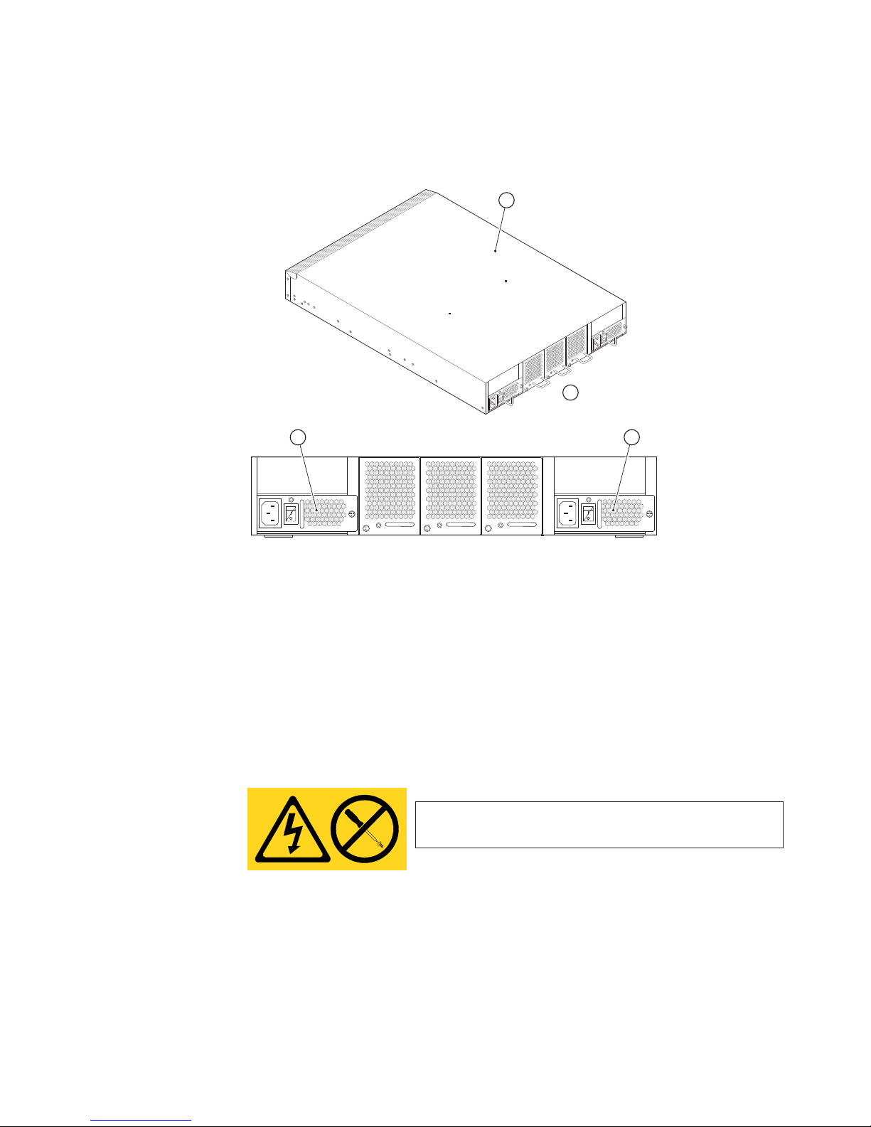
should perform the installation and service procedures. The switch can continue
operating during the FRU replacement if you follow the steps in the procedure.
The switch has two power supplies (3 and 4 in Figure 17).
1
Scale: 1/8" = 1"
2
4
Scale:
5/16" = 1"
Figure 17. Power supply locations
1 Switch chassis 3 Power supply #1
2 Non-port side 4 Power supply #2
Time required
Less than 2 minutes
Items required
v New power supply
v Phillips #1 screwdriver
DANGER
Hazardous voltage, current, or energy levels are present
inside any component that has this label attached. (L001)
3
b32e4012
Procedure
Note: To leave the switch in service during replacement of a power supply, verify
that the other power supply (the one not being replaced) has been powered
on for at least four seconds and has a steady green LED.
Complete the following steps to remove and replace a power supply.
Do not service, there are no serviceable parts.
Chapter 3. Using and maintaining the switch 37
Page 64

1. Power off the power supply being replaced by pressing the AC power switch
(7 in Figure 18) to “O”.
2. Unplug the power cord from the power supply that you are replacing.
3. Use a Phillips-head screwdriver to unscrew the captive screw (3).
4. Remove the power supply from the chassis by pulling the handle (4)onthe
power supply out, away from the chassis.
5. Verify that the AC switch on the new power supply is in the “O” (off)
position.
Attention: Do not force the installation. If the power supply/fan does not
slide in easily, ensure that it is correctly oriented before continuing.
6. Orient the power supply as shown in Figure 18, with the AC switch on the
left.
1
2
3
5 46
7
Figure 18. Installing a new power supply
1 switch chassis 5 status LED
2 power supply 6 AC power cord receptacle
3 captive screw 7 AC power switch
4 handle
3
4
2
b32e4013
7. Using the handle, gently push the power supply into the chassis until it is
firmly seated.
8. Secure the power supply to the chassis by tightening the captive screw with
the Phillips-head screwdriver.
9. Connect the power cord to the power supply and power on the supply by
pressing the AC power switch to “|”.
10. Verify that the LED (5) on the new power supply displays a steady green
light while the switch is operating. If the LED is not green, ensure that the
38 SAN32B-E4 Installation, Service, and User Guide
Page 65

power supply is securely installed and seated properly, athat both ends of the
power cord are secure, and that primary power is available.
11. Optionally, enter psShow at the command line prompt to view the power
supply status. For more information about this command, refer to the Fabric
OS Command Reference. Power supply status can also be viewed using the Web
Tools application.
Verifying fan assemblies
The three fan assemblies are hot-swappable if replaced one at a time. They are
identical and fit into any fan slot.
Attention: Maintain all three fan assemblies in operational condition for
redundancy.
Fabric OS identifies the power supply/fan assemblies as follows (viewing the
switch from the nonport side):
v Fan assembly #1 is on the right
v Fan assembly #2 is in the center
v Fan assembly #3 is on the left
To determine if a fan assembly requires replacing, do any of the following:
v Check the fan assembly status LED (2 in Figure 16 on page 33). If the fan
status LED is not on, verify that the fan is seated correctly. If the light does not
turn green, the fan assembly may need to be replaced.
v In Web Tools, check the Fan Status icon background color. It will be either
yellow or red if the fan has failed. When the fan is functioning correctly, the
background color is green.
v Enter the fanShow command at the command prompt to display the fan status
as shown in the example below:
switch:admin> fanshow
Fan 1 is OK, speed is 9507 RPM
Fan 2 is OK, speed is 9246 RPM
Fan 3 is OK, speed is 9337 RPM
Replacing a fan assembly
Attention: Before installing, removing, or replacing any component, read and
follow the “Safety notices and labels” on page xiii.
Note: Disassembling any part of the fan assembly voids the part warranty and
regulatory certifications. There are no user-serviceable parts inside the fan
assembly.
Attention: The cooling system relies on pressurized air, do not leave either of the
power supply slots empty longer than two minutes when the switch is operating.
If a fan assembly fails, leave it in the switch until it can be replaced.
This section describes how to remove and replace a fan assembly. Although these
FRUs can be removed and replaced without special tools, qualified personnel
should perform the installation and service procedures. The switch can continue
operating during the FRU replacement if you follow the steps in the procedure.
The switch has three fan assemblies (3, 4, and 5 in Figure 19 on page 40).
Chapter 3. Using and maintaining the switch 39
Page 66

1
AT
T
E
Max
N
T
im
m
I
O
um screw length for rack
ou
N
nting to be 5mm
:
or 13/6
4 in.
2
3
4
5
Scale:
5/16" = 1"
b32e4014
Figure 19. Fan assembly locations
1 Switch chassis 4 Fan assembly 2
2 Non-port side 5 Fan assembly 1
3 Fan assembly 3
Time required
Less than 2 minutes
Items required
v New fan assembly
v Phillips-head #1 screwdriver
Procedure
Complete the following steps to remove and replace a fan assembly.
1. Using a Phillips-head screwdriver, unscrew the captive screw (3 in Figure 20
on page 41) on the fan assembly.
40 SAN32B-E4 Installation, Service, and User Guide
Page 67

2
1
scale: 1/4" = 1"
3 4 5
6
3
Figure 20. Replacing a fan assembly
1 Switch chassis 4 Fan status LED
2 Fan assembly 5 Handle
3 Captive screw 6 Non-port side
Scale:
3/8" = 1"
2
b32e4015
2. Remove the fan assembly from the chassis by pulling the handle (5) out,
away from the chassis.
3. Orient the new fan assembly with the captive screw on the right
4. Gently push the fan assembly into the chassis until it is firmly seated.
Attention: Do not force the installation. If the fan assembly does not slide in
easily, ensure that it is correctly oriented before continuing.
5. Using a Phillips-head screwdriver, secure the fan assembly to the chassis by
tightening the captive screw.
6. Verify that the fan status LED (4) is lit (steady green) to indicate normal
operation. If the LED is not green, ensure that the fan assembly is fully seated
and securely installed
7. Optionally, enter fanShow at the command line prompt to view the fan
assembly status. For more information about this command, refer to the Fabric
OS Command Reference. The fan status can also be viewed using the Web Tools
application.
Replacing the switch chassis
Attention: The switch must be removed from the fabric and powered off to
perform this procedure. Contact IBM support if you have any questions about
whether the chassis requires replacement.
If any of the internal circuitry fails within the switch, the entire unit must be
replaced. Contact IBM technical support for assistance with ordering the
Chapter 3. Using and maintaining the switch 41
Page 68

replacement. Within the United States call 1-800-IBMSERV (1-800-426-7378). For
support outside the United States, you can find the service number at:
http://www.ibm.com/planetwide/.
Once you have received the replacement switch, follow the steps below and any
instructions included within the CRU package.
Attention: Before installing, removing, or replacing any component, read and
follow the “Safety notices and labels” on page xiii.
Time required
Approximately two hours
Items required
v Replacement switch
v Electrostatic discharge (ESD) grounding strap
v Serial cable and workstation computer with a terminal emulator application
(such as HyperTerminal for Windows systems or TIP for Solaris systems),
required only if serial console session used
v #2 Phillips screwdriver
DANGER
Hazardous voltage, current, or energy levels are present
inside any component that has this label attached. (L001)
Do not service, there are no serviceable parts.
Verifying need for replacement
Verify that replacement of the chassis is necessary. Ensure that the components are
firmly seated when troubleshooting, and contact IBM support with any questions
about whether the chassis should be replaced. Any of the following events might
indicate the need to replace the chassis:
v Visible mechanical damage to the chassis, including damage to sheet metal or
guides that prevents correct installation of components.
v Bent or damaged connectors inside the chassis.
v One or more components, such as a power supply or fan assembly, do not
function properly even after the component was replaced.
v The psShow or fanShow commands continue to show a faulty component even
though the component was replaced.
Recording critical switch and SAN information
All commands must be entered from a CLI session (Telnet or serial) to the switch
unless otherwise indicated.
For detailed information about Fabric OS commands, refer to the Fabric OS
Command Reference. Use Table 11 on page 43 to ensure that all required information
is recorded.
Note: Run the supportShow command, which will provide all of the information
in Table 11 on page 43 and more.
42 SAN32B-E4 Installation, Service, and User Guide
Page 69

Table 11. Critical information checklist
Configuration information
Location of "config-switch.txt" file
Location of "config-miscinfo.txt" file
IP address, subnet mask
WWN for switch chassis
SAN profile
Location of "SANbefor.txt" file
Notes regarding nsshow output
Notes regarding nsallshow output
Notes regarding switchshow output
Notes regarding fabricshow output
Output from supportshow command
Location of "spptshow.txt" file
Notes regarding supportshow output
Information about the new chassis
New factory serial number
New serial number (if available)
1. Open a Telnet session and log in to the switch as admin. The default password
is "password". Enable the logging function on your Telnet or serial console
connection.
2. Back up the current configuration.
v Enter configUpload; then, enter the requested information at the prompts.
This command uploads the switch configuration to the customer-defined FTP
server, making it available for downloading. For more information about this
command, refer to the Fabric OS Command Reference.
v Alternatively, you can save the configuration file to a Brocade USB drive.
3. Using a workstation, record the switch values (4 through 8 on page 44).
4. Record the IP address information.
Enter ipAddrShow -sw; then, copy the command output into the
"config-miscinfo.txt" file.
5. Display and record the manufacturer serial numbers.
Enter chassisShow; then, copy the command output into the
"config-miscinfo.txt"file.
6. Create a SAN profile by entering and recording the information provided by
the following commands:
v nsShow
v nsAllShow
v switchShow
v fabricShow
Copy the command output into a text file named "SANbefor.txt". After the
switch is restored to the fabric, this information can be used to verify that no
unintentional changes have occurred to the fabric.
7. Enter supportShow; then, copy the command output into a text file named
"spptshow.txt".
Chapter 3. Using and maintaining the switch 43
Page 70

Note: The supportShow command has a very long output and time for
completion. It may last 20 minutes or longer depending on the size of
the SAN.
This file provides a backup of all the information that might be required by
technical support. The information can be used after the switch is restored to
the fabric, to verify that no unintentional changes have occurred to the fabric.
8. Record the cable connections between the switch, and the target devices and
ports.
Disconnecting from network and fabric
1. Shut down the switch using the sysShutdown command.
2. Power off the chassis by pressing both AC power switches to "O". The power
supply status LED should turn off.
3. Remove the power cords from the power supplies and the power outlets.
DANGER
Multiple power cords. The product is equipped with multiple power
cords. To remove all hazardous voltages, disconnect all power cords. (L003)
4. Label all cables connected to the switch and record the connections.
5. Disconnect the cables and SFPs from the switch and set them aside.
Removing components from the chassis
1. Remove the power supplies (see “Replacing a power supply” on page 36).
2. Remove the fan assemblies (see “Replacing a fan assembly” on page 39).
3. Remove the switch from the rack. Verify and remove any mounting hardware
or screws that prevent the switch from being removed from the cabinet. If the
switch is installed on sliding rails, press the release mechanism on the rails to
allow full removal of the switch and inner rails.
4. Remove the rail hardware from the switch. Set it aside for attachment to the
new switch, making notes as necessary for the correct placement of parts.
(Refer to “Installing in an EIA cabinet” on page 13 for illustrations and
complete rack mount instructions.)
5. Set the switch aside for later return to IBM, following the instructions included
with the replacement switch.
Installing the replacement chassis
1. Unpack the new chassis, saving the packaging for returning the old chassis.
2. Install the rail hardware on the new chassis. Refer to any notes you made
during the removal steps and “Installing in an EIA cabinet” on page 13 for
illustrations and complete rack mount instructions.
Installing components into the new chassis
1. Replace the fan assemblies (see “Replacing a fan assembly” on page 39).
Attention: Do not force the installation. If the fan assembly does not slide in
easily, ensure that it is correctly oriented before continuing.
2. Replace the power supplies (see “Replacing a power supply” on page 36).
Attention: Do not force the installation. If the power supply does not slide in
easily, ensure that the power supply is correctly oriented before continuing.
3. Connect the power cords to the power supplies and the power outlets.
44 SAN32B-E4 Installation, Service, and User Guide
Page 71

4. Power-on the switch (see “Providing power to the switch” on page 20).
Note: Power is supplied to the switch as soon as the first power supply is
connected and turned on.
5. Verify that all components are functioning correctly by checking their LEDs. If
the LEDs do not indicate correct operation, try reinstalling the corresponding
component.
Verifying the correct operation of the system
1. Log in to the switch as admin.
2. Verify that the switch is functioning correctly by entering the switchShow or
switchStatusShow commands. The switchShow command displays switch and
port status information.
3. Verify that all the IP address information is correct by entering ipAddrShow
and checking the results against the IP information recorded in the
"config-miscinfo.txt" file.
Reconnecting the system to the network and fabric
1. Install the SFPs and reconnect the cables to the switch.
2. Organize the cables as required.
Attention: Do not route cables in front of the air exhaust vent (located on the
upper portion of the port side of the chassis).
Verifying the correct configuration of the fabric
Copying the command outputs from this section into a file is recommended.
1. Create an "after" SAN profile by entering the following commands and copying
the output to a text file named "SANafter.txt":
v nsShow
v nsAllShow
v switchShow
v fabricShow
2. Determine any differences between the information in the "SANafter.txt"file and
the information in the "SANbefor.txt" file created earlier. In particular, look for
differences in the following:
v Device types
v Number of devices
v ISL and port states
v Number of switches in the fabric
3. Resolve any issues or unintentional changes to the switch or fabric.
v If there are any mechanical problems, try reseating the associated component.
v If the configuration information is not correct for the switch, modify as
required. If necessary, the configuration saved before the replacement can be
downloaded using the configDownload command. The configDownload
command can be entered through a Telnet or serial session, but the switch
must have an Ethernet connection to the server name or IP of the host for
the download process to complete. For more information, refer to the help
configdownload command or the Fabric OS Command Reference.
v If other issues exist, contact IBM support.
Chapter 3. Using and maintaining the switch 45
Page 72

Changing the switch serial number
Attention: This procedure is to be used only if a switch has failed and it is
being replaced by a new switch.
In the event of a hardware failure, the replacement switch should be configured to
display the serial number of the original failed switch, in order to maintain
continuity in the IBM service system. Once you have installed the replacement
switch, follow the steps below to change the serial number displayed through the
switch or fabric management program.
Note: This serial number change procedure requires the user to login as "root".
1. Login as "root" on the switch.
2. Enter the root password "xxxxxxxx". Press Enter.
3. Enter the fruinfoset chassis 1 command. Press Enter.
4. ID: (none). Press Enter.
5. PN: (none). Press Enter.
6. SN: (none) > type "switch Serial Number". Press Enter.
7. RV: (none). Press Enter.
8. Chassis SN: (FAxxXxxxxxx). Press Enter.
To verify that the serial number has been entered correctly, follow these
steps:
9. Enter thefruinfoset chassis 1 command. Press Enter.
10. ID: (none). Press Enter.
11. PN: (none). Press Enter.
12. SN: (none) > Verify that the "switch Serial Number" displayed is the one you
entered. Press Enter.
13. RV: (none). Press Enter.
14. Chassis SN: (FA0xxXxxxxxx). Press Enter.
If the serial number displayed is not correct, repeat the above steps, beginning
with step 3.
Powering off the switch
To power off the switch:
1. Using the CLI, enter the sysShutDown command.
Note: This command shuts down the key processors and powers off the
switch. All LEDs go dark.
2. Set each AC power switch to “O”.
3. If necessary, disconnect both power cords from the switch and the facility
power to remove power from the system.
46 SAN32B-E4 Installation, Service, and User Guide
Page 73

Removing the battery
CAUTION:
The battery contains lithium. To avoid possible explosion, do not burn or charge
the battery. Do not:
v Throw or immerse into water
v Heat to more than 100°C (212°F)
v Repair or disassemble
Exchange only with the IBM-approved part. Recycle or discard the battery as
instructed by local regulations. In the United States, IBM has a process for the
collection of this battery. For information, call 1-800-426-4333. Have the IBM part
number for the battery unit available when you call. (C003)
Local regulations may require removing the battery prior to disposing of or
recycling this product. Complete these steps to remove the battery.
1. Disconnect all power and communication cables.
2. Remove all transceivers.
3. Unscrew captive screws and remove the power supplies and fan assemblies.
4. Unscrew the fasteners and remove the sheetmetal cover.
5. On the circuit board, go to the BC1 location (1 in Figure 21) and remove the
BR1225 battery from the holder.
Figure 21. Location of battery holder
6. Recycle the battery as appropriate.
Refer to the Environmental Notices and User Guide shipped with the product for
more information on battery recycling and disposal.
b32e4016
1
Chapter 3. Using and maintaining the switch 47
Page 74

48 SAN32B-E4 Installation, Service, and User Guide
Page 75

Appendix. Product specifications
This appendix provides the specifications for the SAN32B-E4 Encryption Switch.
v “General specifications”
v “Management” on page 50
v “Size and weight” on page 51
v “Environmental requirements” on page 51
v “Power specifications” on page 52
v “Data transmission ranges” on page 52
General specifications
Table 12 lists the general specifications for the switch.
Table 12. General specifications
Specification Description
Fibre Channel ports 32 FC ports universal (E, F, EX, FL, and M)
Ethernet ports Two (2) 1000Base Ethernet ports for I/O
Smart cards Recovery card
Compression for tape Hardware-based compression prior to
Encryption AES256-XTS block cipher core for disk
Data Encryption Keys Supports 64K Data-Encryption Keys (DEKs)
Re-key sessions Supports 12 re-key sessions (outstanding)
Crypto scalability Supports 256 target devices, 1024 host ports
Crypto performance Maximum bandwidth of 102 Gbps for disk
FC performance Support for 1, 2, 4, and 8 Gbps SFPs which
Certified maximum 6000 active nodes; combination of 56
synchronization during re-keying
encryption
encryption - IEEE 1619.1 compliant
AES256-GCM block cipher core for tape
encryption - IEEE 1619.2 compliant
AES256-ECB block cipher core for
third-party compatibility encryption support
- combination of disk LUN keys or tape pool
keys
per switch. For a given target, supports a
maximum of 2 concurrent re-key sessions could be a combination of manual or auto
(expiry based)
(disk array target ports or tape
target/library ports) per switch (quantity is
double for two-way HA cluster
configuration)
I/O traffic; maximum bandwidth of 51 Gbps
for tape I/O traffic
are full duplex capable
switches, 19 hops; larger fabrics certified as
required
© Copyright IBM Corp. 2010 49
Page 76

Table 12. General specifications (continued)
Specification Description
ISL trunking Frame-based trunking with up to eight 8
Gbps ports per ISL trunk; up to 64 Gbps per
ISL trunk
Aggregate bandwidth 512 Gbps per switch for non-encrypted
traffic
Maximum frame size 2112-byte payload for FC
Classes of service Class 2 (non-encrypted traffic), Class 3, Class
F (inter-switch frames)
Data traffic types Fabric switches supporting unicast, multicast
(255 groups), and broadcast
USB One USB port for system uploads and
downloads, and firmware upgrades
(supportsave, configUploads,
configDownloads)
Fabric services Simple Name Server (SNS), Registered State
Change Notification (RSCN), NTP v3, RCS
(Reliable Commit Service), Dynamic Path
Selection (DPS), Advance Zoning (default
zoning), Port/WWN zoning, broadcast
zoning, NPIV, FDML, Management Server,
FSPF, Fabric Watch, Extended Fabrics, ISL
Trunking, Advanced Performance
Monitoring (APM), Adaptive Networking,
Per data flow QoS, Ingress port rate limiting,
Traffic Isolation, Group Management,
Integrated Routing, and IPFC.
Management
Table 13 lists the management specifications for the switch. Refer to Fabric OS
Administration Guide for more information regarding management of the switch.
Table 13. Management specifications
Specification Description
Management Telnet, HTTP, LDAP, Syslog, SCP, Auditing,
IP Filtering, SNMP v1/v3 (FE MIB, FC
Management MIB), Advanced WEB Tools,
DCFM, SMI-S compliant, SMI-S scripting
toolkit
Security and management SSL, SSH v2, HTTPS, RADIUS, RBAC
(Role-Based Access Control), DH-CHAP
(between switches and end devices), port
binding, switch binding, Secure RPC,
Trusted Switch, change tracking
Management access Serial port (RJ-45) and one USB port.
Call-home integration enabled through
DCFM
50 SAN32B-E4 Installation, Service, and User Guide
Page 77

Size and weight
Table 13. Management specifications (continued)
Specification Description
Diagnostics and supportability POST and embedded online/offline
diagnostics, including RAStrace logging,
environmental monitoring, non-disruptive
daemon restart, RCping and Pathinfo (FC
traceroute), port mirroring (SPAN port),
automatic trace dump transfers in support of
FFDC (first--failure data capture),
supportsave utility
Key management Compatible with industry-leading key
management systems, including IBM Tivoli
Key Lifecycle Manager (TLKM).
Table 14 lists the dimensions and weight of the switch.
Table 14. Switch dimensions
Dimension Value
Height 2U = 86 mm (3.34 in)
Depth 635 mm (25 in)
Width 429 mm (16.88 in)
Weight (with two power supplies and no
SFPs installed)
22.4 kg (49.4 lb)
®
Environmental requirements
Table 15 lists the acceptable environmental ranges for both operating and
non-operating (such as during transportation or storage) conditions.
Table 15. Environmental requirements
Condition Acceptable range during operation Acceptable range during
Ambient
temperature
Humidity 10% to 85% RH non-condensing, at 40°C
Altitude 0 to 3 km (9,842 ft) above sea level 0 to 12 km (39,370 ft) above sea
Shock 20 G, 6 ms, half-sine wave Half sine, 33 G 11ms, 3/eg Axis
Vibration 0.5 G sine, sine, 0.4 grms random, 5-500Hz2.0 G sine, 1.1 grms random
Air flow 129.1 cubic meters per hour (76 CFM)
Heat
dissipation
0° to +40°C (32° to 104°F) -25° to 70°C (-13° to 158°F)
(104°F), with maximum gradient of 10%
per hour
Maximum; 90.1 cubic meters per hour (53
CFM) Nominal
1183 BTU/hr NA
non-operation
10% to 90% RH non-condensing,
at 70°C (158°F)
level
5-500 Hz
NA
Appendix. Product specifications 51
Page 78

Power specifications
The power supplies are universal and capable of functioning worldwide without
voltage jumpers or switches. They meet IEC 61000-4-5 surge voltage requirements
and are autoranging in terms of accommodating input voltages and line
frequencies. Each power supply has a built-in fan for cooling, pushing air towards
the port side of the switch. Table 16 lists the power supply specifications for the
switch.
Table 16. Power supply specifications
Specification Value
Input voltage 100 - 240 VAC, universal
Input line frequency 47 - 63 Hz
System power
consumption
Data transmission ranges
Table 17 provides the data transmission ranges for different cable types and port
speeds.
Note: The full range of 1, 2, 4, and 8 Gbps can only be achieved by a combination
of 4 Gbps SFPs (1, 2, and 4 Gbps) and 8 Gbps SFP+ (2, 4, and 8 Gbps).
285 Watts nominal
Table 17. Supported optics, speeds, cables, and distances
Multimedia
Transceiver
type Form factor Speed
SW SFP 1 Gbps 300 m 500 m 860 m N/A
SFP/SFP+ 2 Gbps 150 m 300 m 500 m N/A
SFP/SFP+ 4 Gbps 70 m 150 m 380 m N/A
SFP+ 8 Gbps 21 m 50 m 150 m N/A
LW SFP 2 Gbps N/A N/A N/A
SFP 4 Gbps N/A N/A N/A
SFP+ 8 Gbps N/A N/A N/A N/A
(62.5 microns)
(OM1)
Multimedia
(50 microns)
(OM2)
Multimedia
(50 microns)
(OM3)
Single mode
media (9
microns)
Parts list (FRUs)
The parts in listed Table 18 can be replaced by a customer. Refer to Chapter 3,
“Using and maintaining the switch,” on page 31 for information on interpreting
LED patterns and diagnostics and troubleshooting procedures to determine the
status of components. Refer to Figure 1 on page 3 and Figure 3 on page 4 for the
location of the parts listed below. Part numbers are subject to change, particularly
for SFP transceivers. Contact your IBM representative for current information on
part numbers for SFPs to meet your needs.
Table 18. FRU part numbers
Part
number Description
45W8655 Switch chassis assembly (replacement of chassis is required if internal circuitry
52 SAN32B-E4 Installation, Service, and User Guide
fails)
Page 79

Table 18. FRU part numbers (continued)
Part
number Description
45W3228 Power supply
45W0320 Fan assembly
45W8654 Smart card
For a listing of SFPs compatible with this product:
v Go to the IBM SAN products web page www.ibm.com/servers/storage/san/
v Select the product name from the displayed page
v On the displayed page, click the Interoperability matrix link in the Learn more
section
v In the Interoperability matrix, navigate to the Transceivers section
Appendix. Product specifications 53
Page 80

54 SAN32B-E4 Installation, Service, and User Guide
Page 81

Notices
This information was developed for products and services offered in the USA.
IBM may not offer the products, services, or features discussed in this document in
other countries. Consult your local IBM representative for information on the
products and services currently available in your area. Any reference to an IBM
product, program, or service is not intended to state or imply that only that IBM
product, program, or service may be used. Any functionally equivalent product,
program, or service that does not infringe on any IBM intellectual property right
may be used instead. However, it is the user's responsibility to evaluate and verify
the operation of any non-IBM product, program, or service.
IBM may have patents or pending patent applications covering subject matter
described in this document. The furnishing of this document does not give you
any license to these patents. You can send license inquiries, in writing to:
IBM Director of Licensing
IBM Corporation
North Castle Drive
Armonk, N.Y. 10504-1785
U.S.A.
For additional information, visit the web at:
www.ibm.com/ibm/licensing/contact/
The following paragraph does not apply to the United Kingdom or any other
country where such provisions are inconsistent with local law:
INTERNATIONAL BUSINESS MACHINES CORPORATION PROVIDES THIS
PUBLICATION “AS IS” WITHOUT WARRANTY OF ANY KIND, EITHER
EXPRESS OR IMPLIED, INCLUDING, BUT NOT LIMITED TO, THE IMPLIED
WARRANTIES OF NON-INFRINGEMENT, MERCHANTABILITY OR FITNESS
FOR A PARTICULAR PURPOSE. Some states do not allow disclaimer of express or
implied warranties in certain transactions, therefore, this statement may not apply
to you.
This information could include technical inaccuracies or typographical errors.
Changes are periodically made to the information herein; these changes will be
incorporated in new editions of the publication. IBM may make improvements
and/or changes in the product(s) and/or the program(s) described in this
publication at any time without notice.
Any references in this information to non-IBM web sites are provided for
convenience only and do not in any manner serve as an endorsement of those web
sites. The materials at those web sites are not part of the materials for this IBM
product and use of those web sites is at your own risk.
IBM may use or distribute any of the information you supply in any way it
believes appropriate without incurring any obligation to you.
Any performance data contained herein was determined in a controlled
environment. Therefore, the results obtained in other operating environments may
vary significantly. Some measurements may have been made on development-level
© Copyright IBM Corp. 2010 55
Page 82

systems and there is no guarantee that these measurements will be the same on
generally available systems. Furthermore, some measurement may have been
estimated through extrapolation. Actual results may vary. Users of this document
should verify the applicable data for their specific environment.
Information concerning non-IBM products was obtained from the suppliers of
those products, their published announcements or other publicly available sources.
IBM has not tested those products and cannot confirm the accuracy of
performance, compatibility or any other claims related to non-IBM products.
Questions on the capabilities of non-IBM products should be addressed to the
suppliers of those products.
If you are viewing this information in softcopy, the photographs and color
illustrations may not appear.
56 SAN32B-E4 Installation, Service, and User Guide
Page 83

Trademarks
IBM, the IBM logo, and ibm.com®are trademarks or registered trademarks of
International Business Machines Corporation in the United States, other countries,
or both. A complete and current list of other IBM trademarks is available on the
Web at www.ibm.com/legal/copytrade.shtml
Adobe, the Adobe logo, PostScript, and the PostScript logo are either registered
trademarks or trademarks of Adobe Systems Incorporated in the United States,
and/or other countries.
Java and all Java-based trademarks and logos are trademarks of Sun Microsystems,
Inc. in the United States, other countries, or both.
Linux is a registered trademark of Linus Torvalds in the United States, other
countries, or both.
Microsoft and Windows are trademarks of Microsoft Corporation in the United
States, other countries, or both.
UNIX is a registered trademark of The Open Group in the United States and other
countries.
Other product and service names might be trademarks of IBM or other companies.
Notices 57
Page 84

Electronic emission notices
The following statements apply to this product. The statements for other products
intended for use with this product will appear in their accompanying manuals.
Federal Communications Commission (FCC) Class A
Statement
This equipment has been tested and complies with the limits for a Class A digital
device, pursuant to Part 15 of the FCC Rules. These limits are designed to provide
reasonable protection against harmful interference when the equipment is operated
in a commercial environment. This equipment generates, uses, and can radiate
radio frequency energy and, if not installed and used in accordance with the
instruction manual, may cause harmful interference to radio communications.
Operation of this equipment in a residential area is likely to cause harmful
interference, in which case the user will be required to correct the interference at
his own expense.
Properly shielded and grounded cables and connectors must be used in order to
meet FCC emission limits. IBM is not responsible for any radio or television
interference caused by using other than recommended cables and connectors or by
unauthorized changes or modifications to this equipment. Unauthorized changes
or modifications could void the user's authority to operate the equipment.
This device complies with Part 15 of the FCC Rules. Operation is subject to the
following two conditions: (1) this device may not cause harmful interference, and
(2) this device must accept any interference received, including interference that
may cause undesired operation.
Industry Canada Class A Emission Compliance Statement
This Class A digital apparatus complies with Canadian ICES-003.
Avis de conformité à la réglementation d'Industrie Canada
Cet appareil numérique de la classe A est conform à la norme NMB-003 du
Canada.
European Union EMC Directive Conformance Statement
This product is in conformity with the protection requirements of EU Council
Directive 2004/108/EC on the approximation of the laws of the Member States
relating to electromagnetic compatibility. IBM cannot accept responsibility for any
failure to satisfy the protection requirements resulting from a non-recommended
modification of the product, including the fitting of non-IBM option cards.
Attention: This is an EN55022 Class A product. In a domestic environment this
product may cause radio interference in which case the user may be required to
take adequate measures.
Responsible manufacturer:
International Business Machines Corp.
New Orchard Road
Armonk, New York 10504
Tel: 919-499-1900
European community contact:
IBM Technical Regulations, Department M456
58 SAN32B-E4 Installation, Service, and User Guide
Page 85

IBM-Allee 1, 71137 Ehningen, Germany
Tel: +49 7032 15-2937
E-mail: tjahn@de.ibm.com
Germany Electromagnetic Compatibility Directive
Deutschsprachiger EU Hinweis:
Hinweis für Geräte der Klasse A EU-Richtlinie zur Elektromagnetischen
Verträglichkeit
Dieses Produkt entspricht den Schutzanforderungen der EU-Richtlinie
2004/108/EG zur Angleichung der Rechtsvorschriften über die elektromagnetische
Verträglichkeit in den EU-Mitgliedsstaaten und hält die Grenzwerte der EN 55022
Klasse A ein.
Um dieses sicherzustellen, sind die Geräte wie in den Handbüchern beschrieben zu
installieren und zu betreiben. Des Weiteren dürfen auch nur von der IBM
empfohlene Kabel angeschlossen werden. IBM übernimmt keine Verantwortung für
die Einhaltung der Schutzanforderungen, wenn das Produkt ohne Zustimmung der
IBM verändert bzw. wenn Erweiterungskomponenten von Fremdherstellern ohne
Empfehlung der IBM gesteckt/eingebaut werden.
EN 55022 Klasse A Geräte müssen mit folgendem Warnhinweis versehen werden:
"Warnung: Dieses ist eine Einrichtung der Klasse A. Diese Einrichtung kann im
Wohnbereich Funk-Störungen verursachen; in diesem Fall kann vom Betreiber
verlangt werden, angemessene Maßnahmen zu ergreifen und dafür
aufzukommen."
Deutschland: Einhaltung des Gesetzes über die elektromagnetische
Verträglichkeit von Geräten
Dieses Produkt entspricht dem "Gesetz über die elektromagnetische Verträglichkeit
von Geräten (EMVG)". Dies ist die Umsetzung der EU-Richtlinie 2004/108/EG in
der Bundesrepublik Deutschland.
Zulassungsbescheinigung laut dem Deutschen Gesetz über die
elektromagnetische Verträglichkeit von Geräten (EMVG) (bzw. der EMC EG
Richtlinie 2004/108/EG) für Geräte der Klasse A
Dieses Gerät ist berechtigt, in Übereinstimmung mit dem Deutschen EMVG das
EG-Konformitätszeichen - CE - zu führen.
Verantwortlich für die Einhaltung der EMV Vorschriften ist der Hersteller:
International Business Machines Corp.
New Orchard Road
Armonk, New York 10504
Tel: 919-499-1900
Der verantwortliche Ansprechpartner des Herstellers in der EU ist:
IBM Deutschland
Technical Regulations, Department M456
IBM-Allee 1, 71137 Ehningen, Germany
Tel: +49 7032 15-2937
E-mail: tjahn@de.ibm.com
Notices 59
Page 86

Generelle Informationen:
Das Gerät erfüllt die Schutzanforderungen nach EN 55024 und EN 55022 Klasse
A.
People's Republic of China Class A Electronic Emission
Statement
Japan VCCI Council Class A Statement
Translation: This is a Class A product based on the standard of the VCCI Council.
If this equipment is used in a domestic environment, radio interference may occur,
in which case, the user may be required to take corrective actions.
Japan Electronics and Information Technology Industries
Association (JEITA) Statement
Japanese Electronics and Information Technology Industries Association (JEITA)
Confirmed Harmonics Guideline (products less than or equal to 20 A per phase).
jjieta1
Korea Communications Commission (KCC) Class A Statement
Please note that this equipment has obtained EMC registration for commercial use.
In the event that it has been mistakenly sold or purchased, please exchange it for
equipment certified for home use.
60 SAN32B-E4 Installation, Service, and User Guide
Page 87

Russia Electromagnetic Interference (EMI) Class A Statement
Australia and New Zealand Class A Statement
Attention: This is a Class A product. In a domestic environment this product
might cause radio interference in which case the user might be required to take
adequate measures.
rusemi
Notices 61
Page 88

62 SAN32B-E4 Installation, Service, and User Guide
Page 89

Index
A
accessibility iv
features iv
IBM commitment iv
keyboard navigation iv
vendor software iv
address
IBM iv
attention notices
definition xviii
example xviii
B
backing up
configuration 25
battery removal 47
Brocade
documents xxiii
C
cabinet
installation 13
cable
management 10, 25
planning 10, 25
precautions 25
routing 10
cables
installing 24
caution notices
definition xvi
examples xvi
comments
sending to IBM iv
components
monitoring 31
configuration
backing up 25
configuring
encryption 26
switch 9, 19
connecting
Ethernet cable 22
switch and host 21
creating a serial connection 21
CRUs
fan assembly 36, 53
power supply 36, 53
smart card 53
switch chassis assembly 52
D
danger notices xiii
data transmission ranges 52
date
setting 22, 23
dimensions 51
director of licensing, address 55
disconnecting
power 46
disposal xxi
documentation
Brocade xxiii
Fabric Operating System (FOS) xxiii
IBM xxiii
domain ID
setting 22
double encryption 27
E
edition notice ii
electronic emission notices 58
encryption
configuration tasks 26
configuring 26
double 27
planning 6
pre-initialization tasks 26
redundancy 6
environmental
notices xiii, xxi
product recycling and disposal xxi
requirements 51
Ethernet
LED patterns 32
management port
location 2
F
Fabric Operating System (FOS)
documents xxiii
fan assembly
LED patterns 34
location 3
replacing 36, 39
status 36, 39
fan status
LED 34
Fibre Channel ports
location 2
status LEDs 33
field-replaceable units (FRUs) 4
FRUs 4
fan assembly 52
power supply 52
power supply/fan assembly 39
SFP 52
Smart card 7, 52
status 36
switch chassis 52
G
getting help iii
Gigabit Ethernet ports
location 2
guidelines
installation 10
H
help iii
I
IBM
accessibility commitment iv
address iv
notices 55
trademarks 57
installation
cables 24
guidelines 10
instructions 13
options 9
SFPs 24
slide-rail rack 13
stand-alone unit 11
installation time
time required 13
installing
rack-mount kit 13
switch 9
intellectual property 55
IP address
setting 21
K
keyboard navigation iv
L
labels, safety xvii
LED
fan status 34
power supply status 34
LEDs
activity 31
Ethernet 32
Fibre Channel port status 33
interpreting 31
location 31, 33
nonport side 33
port side 31
power status 32
system status 32
license
agreement iv
keys
managing 27
optionally licensed features 27
paperpack 11, 27
© Copyright IBM Corp. 2010
63
Page 90

license keys
adding 28
managing 27
removing 28
viewing 28
license, for patents 55
local time 24
logging in
serial console port 21
M
managing
cables 25
license keys 27
switch 31
master keys 6
monitoring
components 31
fan assembly 36
FRU status 36
power supply 36
N
network time protocol 24
nonport
LEDs 33
nonport side
components 3
features 3
notices
attention xviii
caution xvi
danger xiii
edition ii
environmental xiii, xxi
general 55
IBM 55
patents 55
safety xiii
types xiii
NTP time synchronization 24
O
operating
switch 31
optical cables 10
P
patents 55
physical dimensions 51
port
numbering 3
port side
components 2
fedatures 2
LEDs 31
ports
Ethernet management 2
Fibre Channel 2
Gigabit Ethernet 2
illustration 2
ports (continued)
serial 2
USB 2
POST 34
power 20
cord 3
removing 46
status LEDs 3, 32
supply
location 3
replacing 36
specifications 52
switch 3
power supply
LED patterns 34
status 36
power supply status
LED 34
power-on self-test 34
product
accessibility iv
documentation xxiii
features 1
product specifications 49
R
rack installation
required items 13
rack safety xix, xx
rack-mount kit 14
installation 13
instructions 13
parts 14
read this first iii
recycling xxi
removal
battery 47
removing
license keys 28
S
safety
labels xiii
notices xiii
rack xix, xx
serial connection
creating 21
serial console port
logging in 21
serial ports
location 2
setting
date 22, 23
domain ID 22
IP address 21
time 22
time zone 23
SFPs
installing 24
site
planning 10
preparation 10
slide-rail rack
installation 13
Smart card 7
stand-alone unit 11
switch
configuration 9, 19
connection to host 21
dimensions 51
domain ID 22
installation 9
items included 11
library xxiii
managing 31
nonport side 3
port side 2
powering off 46
providing power 20
serial connection 21
troubleshooting 35
verifying correct operation 25
weight 51
switch configuration
steps 19
synchronizing
local time 24
system status LEDs 32
T
Telnet 22
terminal emulator 21
time
setting 22
synchronization 24
time zone
setting 23
trademarks 57
troubleshooting 35
U
USB port 2
V
vendor software iv
verifying
switch operation 25
viewing
license keys 28
W
Web sites iii
weight 51
64 SAN32B-E4 Installation, Service, and User Guide
Page 91

Page 92

Part Number: 45W8661
Printed in USA
GA32-0798-00
(1P) P/N: 45W8661
 Loading...