

IBM System Storage EXP2512 Express Storage Enclosure, System Storage EXP2524 Installation, User's, And Maintenance Manual
Page 1

System Storage EXP2512 Express Storage Enclosure and
System Storage EXP2524 Express Storage Enclosure
Installation, User’s, and Maintenance Guide
GA32-0965-01
Page 2

Page 3

System Storage EXP2512 Express Storage Enclosure and
System Storage EXP2524 Express Storage Enclosure
Installation, User’s, and Maintenance Guide
GA32-0965-01
Page 4

Note: Before using this information and the product it supports, read the general information in Appendix B, “Notices,” on page 47,
the Systems Safety Notices and Environmental Notices and User Guide documents on the IBM Documentation CD, and the
Warranty Information document that comes with the product.
Third Edition (November 2011)
© Copyright IBM Corporation 2010, 2011.
US Government Users Restricted Rights – Use, duplication or disclosure restricted by GSA ADP Schedule Contract
with IBM Corp.
Page 5

Safety
Before installing this product, read the Safety Information.
Antes de instalar este produto, leia as Informações de Segurança.
Pred instalací tohoto produktu si prectete prírucku bezpecnostních instrukcí.
Læs sikkerhedsforskrifterne, før du installerer dette produkt.
Lees voordat u dit product installeert eerst de veiligheidsvoorschriften.
Ennen kuin asennat tämän tuotteen, lue turvaohjeet kohdasta Safety Information.
Avant d'installer ce produit, lisez les consignes de sécurité.
Vor der Installation dieses Produkts die Sicherheitshinweise lesen.
Prima di installare questo prodotto, leggere le Informazioni sulla Sicurezza.
Les sikkerhetsinformasjonen (Safety Information) før du installerer dette produktet.
Antes de instalar este produto, leia as Informações sobre Segurança.
Antes de instalar este producto, lea la información de seguridad.
Läs säkerhetsinformationen innan du installerar den här produkten.
© Copyright IBM Corp. 2010, 2011 iii
Page 6

Important:
Each caution and danger statement in this document is labeled with a number. This
number is used to cross reference the English-language caution or danger
statement with translated versions of the caution or danger statement in the IBM
®
Systems Safety Notices document.
For example, if a caution statement is labeled “D005a,” translations for that caution
statement are in the IBM Systems Safety Notices document under “D005a.”
Be sure to read all caution and danger statements in this document before you
perform the procedures. Read any additional safety information that comes with the
server or optional device before you install the device.
DANGER
Hazardous voltage, current, or energy levels are present inside any
component that has this label attached. Do not open any cover or barrier
that contains this label.
(L001)
DANGER
Rack-mounted devices are not to be used as shelves or work spaces.
(L002)
iv System Storage EXP2512 and EXP2524: Installation and Maintenance Guide
Page 7

DANGER
Multiple power cords. The product might be equipped with multiple power
cords. To remove all hazardous voltages, disconect all power cords.
(L003)
or
1
2
!
1
2
Safety v
Page 8

DANGER
When working on or around the system, observe the following precautions:
Electrical voltage and current from power, telephone, and communication
cables are hazardous. To avoid a shock hazard:
v Connect power to this unit only with the provided power cord. Do not
use the provided power cord for any other product.
v Do not open or service any power supply assembly.
v Do not connect or disconnect any cables or perform installation,
maintenance, or reconfiguration of this product during an electrical
storm.
v The product might be equipped with multiple power cords. To remove all
hazardous voltages, disconnect all power cords.
v Connect all power cords to a properly wired and grounded electrical
outlet. Ensure that the outlet supplies proper voltage and phase rotation
according to the system rating plate.
v Connect any equipment that will be attached to this product to properly
wired outlets.
v When possible, use one hand only to connect or disconnect signal
cables.
v Never turn on any equipment when there is evidence of fire, water, or
structural damage.
v Disconnect the attached power cords, telecommunications systems,
networks, and modems before you open the device covers, unless
instructed otherwise in the installation and configuration procedures.
v Connect and disconnect cables as described in the following procedures
when installing, moving, or opening covers on this product or attached
devices.
To disconnect:
1. Turn off everything (unless instructed otherwise).
2. Remove the power cords from the outlets.
3. Remove the signal cables from the connectors.
4. Remove all cables from the devices.
To connect:
1. Turn off everything (unless instructed otherwise).
2. Attach all cables to the devices.
3. Attach the signal cables to the connectors.
4. Attach the power cords to the outlets.
5. Turn on the devices.
(D005a)
vi System Storage EXP2512 and EXP2524: Installation and Maintenance Guide
Page 9

CAUTION:
>18 kg (39.7 lb)
or
18-32 kg (39.7-70.5 lb)
or
The weight of this part or unit is between 18 and 32 kg (39.7 and 70.5 lb). It
takes two persons to safely lift this part or unit. (C009)
Safety vii
Page 10

viii System Storage EXP2512 and EXP2524: Installation and Maintenance Guide
Page 11

Contents
Safety ............................iii
Chapter 1. Introduction......................1
The IBM Documentation CD ....................3
Hardware and software requirements ................3
Using the Documentation Browser .................3
Notices and statements in this document................5
Features and operating specifications .................6
What the EXP2500 offers .....................7
Major components of the EXP2500 ..................7
Chapter 2. Installation ......................9
Inventory checklist ........................9
Installing the EXP2500 in a rack ...................9
Installing hot-swap hard disk drives .................10
Cabling the EXP2500 ......................13
Connecting the power cords ....................15
Systems-management software support................15
Chapter 3. EXP2500 controls, LEDs, and power............17
Front view: components .....................17
Front view: LEDs ........................18
Rear view: power supply .....................19
Rear view: ESMs ........................20
EXP2500 power features .....................21
Powering on the EXP2500 ...................21
Powering off the EXP2500 ...................22
Turning off the EXP2500 in an emergency..............23
Turning on the EXP2500 after an emergency.............24
Chapter 4. Parts listing, EXP2512 and EXP2524 expansion enclosures...25
Replaceable EXP2500 components .................25
EXP2512 expansion enclosure parts listing .............26
EXP2524 expansion enclosure parts listing .............27
Installation guidelines ......................29
System reliability guidelines ...................29
Handling static-sensitive devices .................29
Working with hot-swap hard disk drives ................30
Replacing a hot-swap hard disk drive ................30
Replacing an ESM .......................35
Replacing a hot-swap power supply .................36
Replacing the bezels.......................37
Removing the bezels......................37
Installing the bezels ......................37
Replacing the midplane......................38
Chapter 5. Solving problems ...................41
Chapter 6. Remote management and system diagnostics ........43
Launching the EXP2500 ESM command-line interface ..........43
EXP2500 ESM command-line reference ...............43
Appendix A. Getting help and technical assistance ..........45
© Copyright IBM Corp. 2010, 2011 ix
Page 12

Before you call .........................45
Using the documentation .....................45
Getting help and information from the World Wide Web ..........45
Software service and support ...................46
Hardware service and support ...................46
IBM Taiwan product service ....................46
Appendix B. Notices ......................47
Trademarks ..........................47
Important notes.........................48
Particulate contamination .....................49
Documentation format ......................49
Electronic emission notices ....................50
Federal Communications Commission (FCC) statement .........50
Industry Canada Class A emission compliance statement ........50
Avis de conformité à la réglementation d'Industrie Canada ........50
Australia and New Zealand Class A statement ............50
European Union EMC Directive conformance statement.........50
Germany Class A statement ...................51
Japan Voluntary Control Council for Interference (VCCI) Class A Statement 52
Japan Electronics and Information Technology Industries Association (JEITA)
statement .........................52
Korea Communications Commission (KCC) Class A Statement ......52
Russia Electromagnetic Interference (EMI) Class A statement.......52
People's Republic of China Class A electronic emission statement .....53
Taiwan Class A compliance statement ...............53
Index ............................55
x System Storage EXP2512 and EXP2524: Installation and Maintenance Guide
Page 13

Chapter 1. Introduction
This Installation, User’s, and Maintenance Guide contains instructions for setting up
your IBM System Storage
®
EXP2512 Express Storage™Enclosure and IBM System
Storage EXP2524 Express Storage Enclosure and provides the instructions for
replacing components. The IBM System Storage EXP2512 and IBM System
Storage EXP2524 are referred to in this document as the EXP2500, unless
specified otherwise.
This document contains information about:
v Setting up and cabling the EXP2500
v Starting and configuring the EXP2500
v Replacing components
v Solving problems
The EXP2500 provides high-capacity, Serial Attached SCSI (SAS), nearline SAS, or
Solid State disk storage. The EXP2512 supports up to 12 SAS or nearline SAS
hard disk drives and the EXP2524 supports up to 24 SAS, nearline SAS, or Solid
State hard disk drives. The EXP2500 delivers fast, high-volume data transfer,
retrieval, and storage functions among multiple drives. The EXP2500 is designed
for continuous, reliable service; the modular, redundant hard disk drives and power
supplies (with fans) use hot-swap technology for easy replacement without turning
off the EXP2500.
The EXP2500 comes with two 800-watt ac power supplies, one environmental
services module (ESM), a filler panel to cover the empty ESM bay, and 12 or 24
drive filler panels, depending on the storage enclosure model. The drive filler panels
can be replaced with optional hard disk drives.
If firmware and documentation updates are available, you can download them from
the IBM support website. The EXP2500 might have features that are not described
in the documentation that comes with the unit, and the documentation might be
updated occasionally to include information about those features, or technical
updates might be available to provide additional information that is not included in
the EXP2500 documentation.
Note: Changes are made periodically to the IBM website. Procedures for locating
firmware and documentation might vary slightly from what is described in this
document.
To check for updates, go to http://www.ibm.com/systems/support/. For firmware
updates, click Downloads. For documentation updates, click Documentation.
The EXP2500 comes with a limited warranty. For more information about the terms
of your warranty, see the Warranty and Support Information document that comes
with the EXP2500.
© Copyright IBM Corp. 2010, 2011 1
Page 14

Record information about the EXP2500 in Table 1. You will need this information if
you have to call for service.
Table 1. Product identification record
Product name IBM System Storage EXP2512 Express Storage Enclosure or
BM System Storage EXP2524 Express Storage Enclosure
Machine type 1727-HC1 or 1727-HC2
Serial number
EXP2500 ID number
The machine type, model, and serial number are on the label chassis flange and on
the agency label located on top of the chassis. The machine type, model, and serial
number may also be on the label located on the vertical recess on the left bezel.
The following illustration shows the product name and serial number label on the
front of the EXP2512. The locations are the same for the EXP2524.
Note: The illustrations in this document might differ slightly from your hardware.
Machine type, model, and serial number
Product name
Use Table 2 to keep a record of the hard disk drives that are installed in or attached
to the EXP2500. This information can be helpful when you install additional hard
disk drives or if you have to report a hardware problem. Make a copy of this table
before you record information in it, in case you need extra space to write new
values later, or when you update the EXP2500 configuration.
Table 2. Drive location information record
Drive location Drive part and model number Drive serial number
Bay 1
Bay 2
Bay 3
Bay 4
Bay 5
Bay 6
Bay 7
Bay 8
Bay 9
Bay 10
Bay 11
Bay 12
Bay 13
Bay 14
Bay 15
2 System Storage EXP2512 and EXP2524: Installation and Maintenance Guide
Page 15

Table 2. Drive location information record (continued)
Drive location Drive part and model number Drive serial number
Bay 16
Bay 17
Bay 18
Bay 19
Bay 20
Bay 21
Bay 22
Bay 23
Bay 24
The IBM Documentation CD
The IBM Documentation CD contains documentation for the EXP2500 in Portable
Document Format (PDF) and includes the IBM Documentation Browser to help you
find information quickly.
Hardware and software requirements
The IBM Documentation CD requires the following minimum hardware and
software:
v Microsoft Windows XP, Windows 2000, or Red Hat Linux
v 100 MHz microprocessor
v 32 MB of RAM
v Adobe Acrobat Reader 3.0 (or later) or xpdf, which comes with Linux operating
systems
Using the Documentation Browser
Use the Documentation Browser to browse the contents of the CD, read brief
descriptions of the documents, and view documents, using Adobe Acrobat Reader
or xpdf. The Documentation Browser automatically detects the regional settings in
your server and displays the documents in the language for that region (if
available). If a document is not available in the language for that region, the
English-language version is displayed.
Use one of the following procedures to start the Documentation Browser:
v If Autostart is enabled, insert the CD into the CD or DVD drive. The
Documentation Browser starts automatically.
v If Autostart is disabled or is not enabled for all users, use one of the following
procedures:
– If you are using a Windows operating system, insert the CD into the CD or
DVD drive and click Start --> Run.IntheOpen field, type
e:\win32.bat
where e is the drive letter of the CD or DVD drive, and click OK.
– If you are using Red Hat Linux, insert the CD into the CD or DVD drive; then,
run the following command from the /mnt/cdrom directory:
sh runlinux.sh
Chapter 1. Introduction 3
Page 16

Select the EXP2500 from the Product menu. The Available Topics list displays all
the documents for the EXP2500. Some documents might be in folders. A plus sign
(+) indicates each folder or document that has additional documents under it. Click
the plus sign to display the additional documents.
When you select a document, a description of the document is displayed under
Topic Description. To select more than one document, press and hold the Ctrl key
while you select the documents. Click View Book to view the selected document or
documents in Acrobat Reader or xpdf. If you selected more than one document, all
the selected documents are opened in Acrobat Reader or xpdf.
To search all the documents, type a word or word string in the Search field and
click Search. The documents in which the word or word string appears are listed in
order of the most occurrences. Click a document to view it, and press Crtl+F to use
the Acrobat search function, or press Alt+F to use the xpdf search function within
the document.
Click Help for detailed information about using the Documentation Browser.
4 System Storage EXP2512 and EXP2524: Installation and Maintenance Guide
Page 17

Notices and statements in this document
The caution and danger statements in this document are also in the multilingual
IBM Systems Safety Notices document, which is on the IBM Documentation CD.
Each statement is numbered for reference to the corresponding statement in the
IBM Systems Safety Notices document.
The following notices and statements are used in this document:
v Note: These notices provide important tips, guidance, or advice.
v Important: These notices provide information or advice that might help you avoid
inconvenient or problem situations.
v Attention: These notices indicate potential damage to programs, devices, or
data. An attention notice is placed just before the instruction or situation in which
damage might occur.
v Caution: These statements indicate situations that can be potentially hazardous
to you. A caution statement is placed just before the description of a potentially
hazardous procedure step or situation.
v Danger: These statements indicate situations that can be potentially lethal or
extremely hazardous to you. A danger statement is placed just before the
description of a potentially lethal or extremely hazardous procedure step or
situation.
Chapter 1. Introduction 5
Page 18

Features and operating specifications
Table 3 contains a summary of the features and operating specifications of the
EXP2500. Depending on your EXP2500 model, some features might not be
available, or some specifications might not apply.
Table 3. Features and operating specifications
General:
v Modular components
– High-capacity disk drives
– Environmental services module
(ESM)
– Power supplies with built-in fan
units
v Technology
– Supports disk array technology
– SAS host interface, redundant
data storage, power and cooling
system, and ESMs
– Hot-swap technology for hard
disk drives, power supplies, and
ESMs
v User interface
– Built-in power, activity, and fault
LEDs, identification labeling on
components, rear LEDs, and
connectors
– Easy-to-replace hard disk drives,
power supplies with built-in fan
units, and ESMs
Hard disk drive storage:
Maximum hard disk drives
EXP2512: 12
Drive type: SAS and nearline SAS
EXP2524: 24
Drive type: SAS, nearline SAS, and
Solid State
ESMs:
Technology and interfaces:
SAS interface: Two 26-pin, mini-SAS
connectors per ESM
Acoustical noise emissions:
For maximum system configurations
(12 hard disk drives installed)
v Sound power (idling): 6.1 bels
v Sound power (operating): 6.1 bels
v Sound pressure (idling): 48 dBA
v Sound pressure (operating): 48
dBA
AC power supply with built-in fan:
v The EXP2500 comes with two
hot-swap 800 watt (100 - 240 V
ac) power supplies.
v The two power supplies provide
redundant power to the EXP2500.
Size:
v Height: 8.7 cm (3.4 in.)
v Depth: 55.6 cm (21.9 in.)
v Width: 44.6 cm (17.6 in.)
v Weight (approximate):
8.7 kg (19.2 lb) for an empty unit
16.6 kg (36.5 lb) for a standard
unit
26.7 kg (58.8 lb) for a fully
configured unit
Environment:
v Air temperature:
– EXP2500 on: 10° to 35°C (50°
to 95°F); altitude: 30.5 (100 ft)
below to 3000 m (9840 ft)
above sea level; temperature
change: 10°C (18°F) per hour
– EXP2500 off: 10° to 50°C (14°
to 120°F); maximum altitude:
3000 m (9840 ft); temperature
change: 15°C (27°F) per hour
v Humidity:
– EXP2500 on: 20% to 80%
– EXP2500 off: 10% to 90%
– Maximum dew point: 26°C
(79°F)
– Maximum humidity gradient:
10% per hour
Heat output
Approximate heat output in British
thermal units (Btu) per hour:
v Minimum configuration: 188 Btu
(55 watts)
v Maximum configuration 821 Btu
(240 watts)
Electrical input:
v Sine-wave input (50-60 Hz) required
v Input voltage low range:
– Minimum: 90 V ac
– Maximum: 127 V ac
v Input voltage high range:
– Minimum: 200 V ac
– Maximum: 264 V ac
Notes:
1. Power consumption and heat
output vary depending on the
number and type of optional
features that are installed and the
power-management optional
features that are in use.
2. These levels were measured in
controlled acoustical environments
according to the procedures
specified by the American National
Standards Institute (ANSI) S12.10
and ISO 7779 and are reported in
accordance with ISO 9296. Actual
sound-pressure levels in a given
location might exceed the average
stated values because of room
reflections and other nearby noise
sources. The declared sound-power
levels indicate an upper limit, below
which a large number of computers
will operate.
6 System Storage EXP2512 and EXP2524: Installation and Maintenance Guide
Page 19

What the EXP2500 offers
The EXP2500 provides several features for easy operation, including the following
features:
v Customer replaceable units (CRUs)
The major CRUs in the EXP2500 are SAS, nearline SAS, or Solid State hard
disk drives, ESMs, and power supplies. See “Replaceable EXP2500
components” on page 25.
v Fault indicators
All CRUs have fault or status light emitting diodes (LEDs) to indicate hardware
failures.
v Redundant cooling and power capabilities
The EXP2500 uses a dual ac input power system. The redundant cooling of the
fans enables continued operation if up to three fans fail. The EXP2500 comes
with two 800-watt hot-swap power supplies, which provide redundant power for
all EXP2500 configurations. If a problem occurs with one of the power supplies,
the other power supply can meet the power requirements.
Major components of the EXP2500
Orange on a component or label indicates that the component can be hot-swapped.
You can install or remove a hot-swap component while the EXP2500 is running. For
information about installing hot-swap components, see Chapter 4, “Parts listing,
EXP2512 and EXP2524 expansion enclosures,” on page 25.
Blue on components and labels indicates touch points, where you can grip a
component, move a latch, and so on.
The following illustrations show the major components of the EXP2512 and
EXP2524.
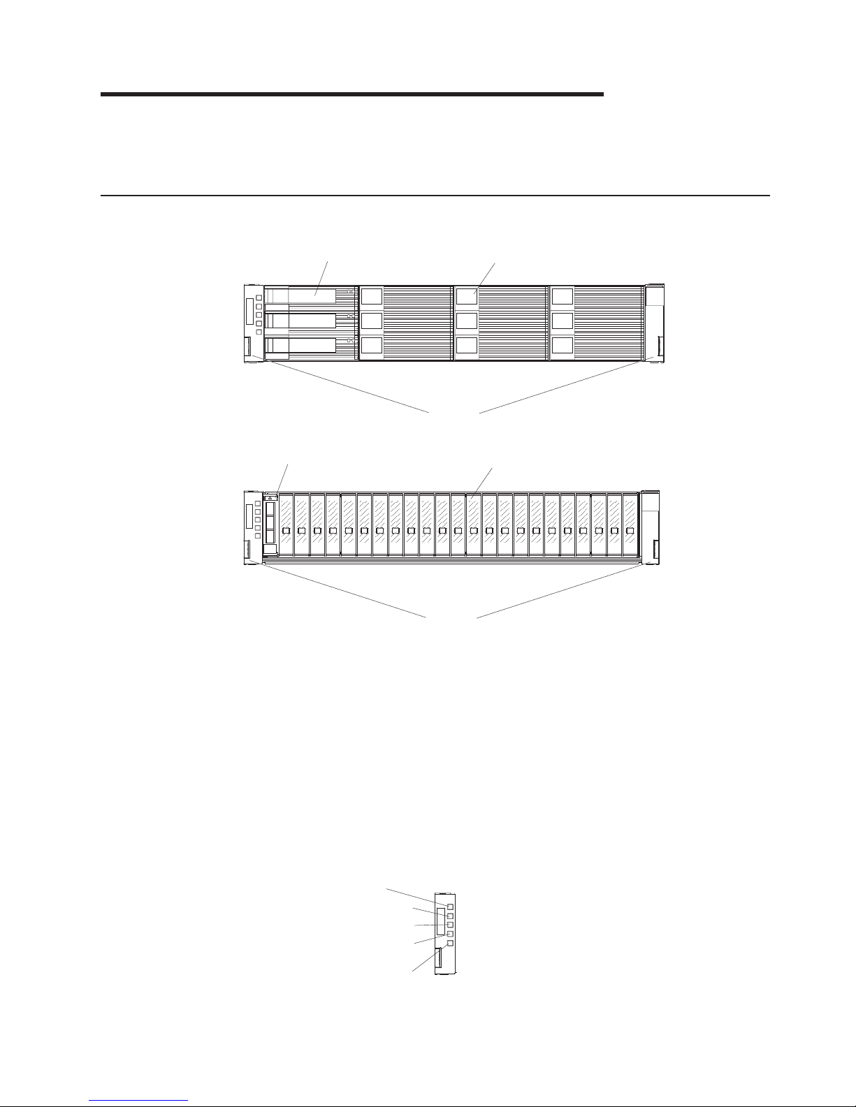
Front view of the EXP2512
Hot-swap hard disk drive
Bezels
Filler panel
Chapter 1. Introduction 7
Page 20

Front view of the EXP2524
Hot-swap hard disk drive
Bezels
Filler panel
Rear view of the EXP2512 and EXP2524
ESM
Filler panel
IN
OK
Hot-swap power supplies
IN
OK
8 System Storage EXP2512 and EXP2524: Installation and Maintenance Guide
Page 21

Chapter 2. Installation
This chapter provides information about installing and cabling the EXP2500. The
EXP2500 connects to a RAID controller in a server. For the supported RAID
controllers to which the EXP2500 can connect, see the System Storage
Interoperation Center (SSIC) at http://www.ibm.com/systems/support/storage/config/
ssic.
Inventory checklist
After you unpack the EXP2500, make sure that you have the following items:
v Hardware:
– IBM System Storage EXP2512 Express Storage Enclosure or IBM System
Storage EXP2524 Express Storage Enclosure
– Two rack jumper power cords
– Two front bezels (left and right)
– One rack installation hardware kit:
- Two rails (right and left assembly)
- Eight M5 screws
- Eight spacers
v Printed documents:
– IBM Rack Installation Instructions for the IBM System Storage EXP2512 and
EXP2524 Express Storage Enclosure
– IBM Important Notices
– IBM Warranty Information
v Online documents:
– IBM System Storage EXP2512 and System Storage EXP2524 Express
Storage Enclosure Installation and User’s Guide (this document)
– IBM Systems Safety Notices
– IBM Systems Environmental Notices and User's Guide
Installing the EXP2500 in a rack
You can install the EXP2500 in an Electronic Industries Association (EIA) 310
standard rack cabinet. For complete rack cabinet installation instructions, see the
Rack Installation Instructions document that comes with the EXP2500.
© Copyright IBM Corp. 2010, 2011 9
Page 22

Installing hot-swap hard disk drives
The EXP2512 supports up to 12 IBM SAS or nearline SAS hard disk drives. The
EXP2524 supports up to 24 IBM SAS, nearline SAS, and Solid State hard disk
drives.
Each drive comes preinstalled in a drive tray, ready for installation in the EXP2500.
(Do not detach the drive from the tray.) Be sure to record the location information
for each drive in Table 2 on page 2.
The EXP2500 comes with filler panels in the drive bays. Before you install a new
hard disk drive, remove the filler panel and save it for future use. Each of the drive
bays must contain either a filler panel or a hard disk drive.
To install a hard disk drive in the EXP2500, complete the following steps. You can
install drives while the EXP2500 is turned on.
1. Read the instructions that come with the hard disk drive.
2. Read the safety information that begins on page iii and “Installation guidelines”
on page 29.
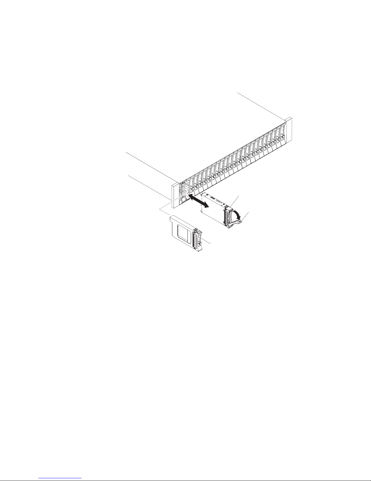
3. Remove the filler panel from the bay into which you want to install the hard disk
drive:
a. Insert a finger into the square hole on the left side of the filler panel to grip
and pull the filler panel out of the drive bay.
b. Save the filler panel for future use.
10 System Storage EXP2512 and EXP2524: Installation and Maintenance Guide
Page 23

4. Installing a 2.5-inch hot-swap drive:
a. Touch the static-protective package that contains the hard disk drive to any
unpainted surface on the outside of the enclosure; then, remove the hard
disk drive from the package.
b. Make sure that the drive-tray handle is in the open (unlocked) position.
c. Align the drive assembly with the guide rails in the bay.
Drive-tray
assembly
Drive handle
Filler
panel
d. Gently push the drive-tray assembly into the bay until the drive stops.
e. Rotate the drive-tray handle to the closed (locked) position.
Chapter 2. Installation 11
Page 24
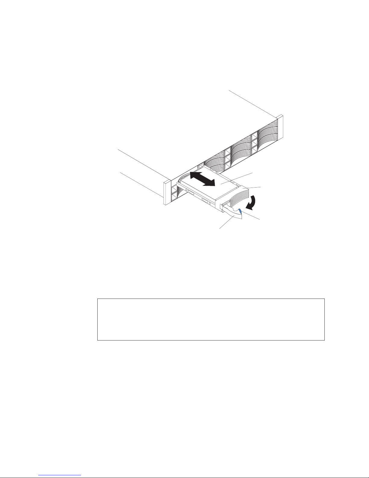
5. Installing a 3.5-inch hot-swap drive:
a. Touch the static-protective package that contains the hard disk drive to any
unpainted surface on the outside of the enclosure; then, remove the hard
disk drive from the package.
b. Make sure that the tray handle is open; then, slide the hard disk drive into
the hot-swap bay.
Hard disk drive
Drive tray
Latch
Tray handle
c. Push the tray handle to the right into the closed (latched) position.
6. Check the drive LEDs:
a. When a drive is ready for use, the green activity LED and the amber status
LED on the drive are off.
b. If the amber status LED is lit and not flashing, remove the drive from the
unit and wait 10 seconds; then, reinstall the drive. If the amber LED is
flashing, the drive is rebuilding.
Controller management information: In some cases, the RAID controller automatically
resets the drive to the Hot Spare or Rebuild state. If the drive state does not change
automatically (the amber LED stays lit), see your RAID controller management
documentation for information about manually changing the state of the drive from the
current state to another state, such as Hot Spare or Ready. The amber LED should turn off
within 10 seconds after the drive state changes.
7. Configure the hard disk drive, using the RAID controller management software.
Note: Refer to your RAID Adapter documentation to determine if your RAID
Adapter supports the hard drives used. The 3 Gbps RAID Adapters may not support
3 TB hard drives. If any hard drive is not supported, it is reported as Unrecognized.
12 System Storage EXP2512 and EXP2524: Installation and Maintenance Guide
Page 25

Cabling the EXP2500
The EXP2500 comes with one ESM, which enables you to connect the EXP2500 to
a RAID controller or a BladeCenter SAS connectivity module or another EXP2500
expansion enclosure. Depending on the capabilities of the RAID controller, you can
add multiple EXP2500 units to provide a chain of EXP2500s to the RAID controller.
See the documentation that comes with the RAID controller or the device that
contains the RAID controller for information about the capabilities of the RAID
controller.
When attached to the BladeCenter SAS connectivity module, a EXP2500 can be
used in conjunction with the BladeCenter blade server RAID controllers. Only a
single EXP2500 enclosure can be attached to a BladeCenter SAS connectivity
module SAS port but multiple EXP2500 enclosures can be attached to a
BladeCenter SAS connectivity module.
The EXP2500 ESM contains three 26-pin mini-SAS connectors. There are two In
(↑) connectors and one Out (↓) connector. If your RAID controller supports more
than one EXP2500 per physical port, you can connect two or more EXP2500s by
chaining them together. See the documentation that comes with your RAID
controller or the device that contains the RAID controller for more information.
To connect a RAID controller or BladeCenter SAS connectivity module to one or
more EXP2500s that have one ESM each, complete the following steps:
1. Connect one EXP2500 to the RAID controller or BladeCenter SAS connectivity
module:
a. Connect one end of a SAS cable to the RAID controller or one of the two
b. Connect the other end to the In (↑) SAS connector on the ESM in the
SAS ports on the BladeCenter SAS connectivity module.
EXP2500.
SAS cable
EXP2500
IN
OK
SAS cable
EXP2500
IN
OK
To the IBM SAS RAID controller or
BladeCenter SAS connectivity module
IN
OK
IN
OK
2. If your RAID controller supports connecting multiple EXP2500s, connect a
second EXP2500 to the first EXP2500:
a. Connect one end of a SAS cable to the Out (↓) SAS connector on the ESM
of the EXP2500 that you just connected.
b. Connect the other end of the SAS cable to one of the In (↑) SAS connectors
on the ESM on the next EXP2500.
Chapter 2. Installation 13
Page 26

c. Repeat steps 2a on page 13 and 2b on page 13 for each EXP2500 that you
add.
14 System Storage EXP2512 and EXP2524: Installation and Maintenance Guide
Page 27

Connecting the power cords
The EXP2500 comes with two power cords. You can connect the power cords to a
primary power unit inside the rack cabinet, such as a properly grounded ac power
distribution unit (PDU) or uninterruptible power supply.
Note: Power cords, specific to a country, can be purchased separately.
For information about the initial startup of the EXP2500, see “EXP2500 power
features” on page 21.
Systems-management software support
The EXP2500 provides software alert functions through the systems-management
functions that are provided by the management software that comes with your RAID
controller.
The following alerts are supported:
v Hard disk drive failure
v Power-supply failure
v Fan failure
v Normal operating temperature exceeded
Chapter 2. Installation 15
Page 28

16 System Storage EXP2512 and EXP2524: Installation and Maintenance Guide
Page 29
Chapter 3. EXP2500 controls, LEDs, and power
This section describes the controls and light-emitting diodes (LEDs) and how to turn
the EXP2500 on and off.
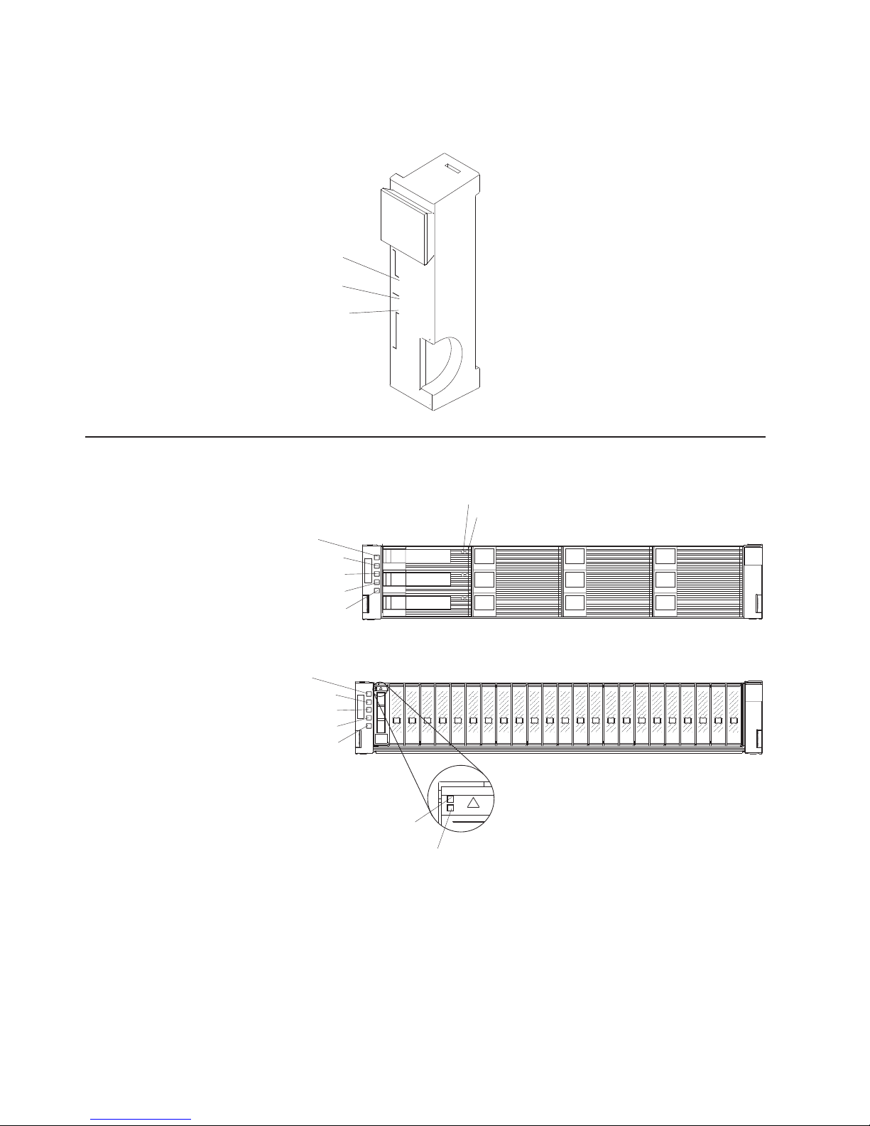
Front view: components
The components on the front of the EXP2512 are shown in the following illustration.
Hot-swap hard disk drive
Bezels
Filler panel
The components on the front of the EXP2524 are shown in the following illustration.
Hot-swap hard disk drive
Bezels
Filler panel
Hot-swap hard disk drive
You can install up to 12 hot-swap SAS or nearline SAS hard disk drives in
the EXP2512 and up to 24 hot-swap SAS or nearline SAS hard disk drives
in the EXP2524.
Filler panel
Bezel (left side)
© Copyright IBM Corp. 2010, 2011 17
The EXP2500 comes with filler panels in the drive bays. Before you install a
hard disk drive, remove the filler panel and save it for future use. Each of
the 12 or 24 drive bays must contain either a filler panel or a hard disk
drive.
The left bezel contains the EXP2500 LEDs, as shown in the following
illustration. For a description of the LEDs, see “Front view: LEDs” on page
18.
Power-on LED
Reserved for future use
Locator LED
Overtemperature LED
System error LED
Page 30
Bezel (right side)
Front view: LEDs
The LEDs on the front of the EXP2512 are shown in the following illustration.
Reserved for future use
On the EXP2512, the right bezel contains the hard disk drive identification
information, as shown in the following illustration.
Drives 1 - 4
Drives 5 - 8
Drives 9 - 12
Power-on LED
Locator LED
Overtemperature LED
System error LED
1 - 4
5 - 8
9 - 12
Hard disk drive activity LED
Hard disk drive status LED
The LEDs on the front of the EXP2524 are shown in the following illustration.
Power-on LED
Reserved for future use
Locator LED
Overtemperature LED
System error LED
Drive activity
LED (green)
Drive status
LED (amber)
Power-on LED (green)
When this green LED is lit, it indicates that the power supply is turned on
and is supplying both 5-volt and 12-volt dc power to the EXP2500.
Locator LED (blue)
This blue LED can be lit by the systems-management software on the RAID
controller that is connected to the EXP2500, to aid in visually locating the
EXP2500.
18 System Storage EXP2512 and EXP2524: Installation and Maintenance Guide
Page 31
Overtemperature LED (amber)
When this amber LED is lit, it indicates that the EXP2500 is in an
overtemperature condition.
System error LED (amber)
When this amber LED is lit, it indicates that the unit has a fault, such as in
a power supply, ESM, or hard disk drive.
Hard disk drive activity LED (green)
Each hard disk drive has an activity LED. When this green LED is flashing,
it indicates drive activity.
Hard disk drive status LED (amber)
Each hard disk drive has a status LED. When this amber LED is lit
continuously, it indicates a drive failure. When it is flashing, it indicates that
a drive Identify or Rebuild is in progress.
Rear view: power supply
The two hot-swap power supplies are on the rear of the EXP2500.
Attention: The EXP2500 comes with two installed power supplies. When one
power supply fails, the power-supply unit must be replaced to reestablish
redundancy. When you replace a failed unit with a new power supply, make sure
that you perform this operation in less than 10 minutes to prevent overheating.
The power-supply controls and connectors are shown in the following illustration.
Handle
Release
tab
IN
OK
AC power
connector
Release tab
Press the release tab to the right and rotate the handle downward to
remove the power supply.
Handle
Use the handle to install or remove the power supply.
AC power connector
Connect the power cord for the power supply to this connector.
Note: There is no power switch on the power supply. A power supply is active
when a power cord is connected to it and to a power source.
Chapter 3. EXP2500 controls, LEDs, and power 19
Page 32

The LEDs on the power supply are shown in the following illustration.
DC power
LED (green)
Fault LED
(amber)
AC power in
LED (green)
IN
OK
AC power LED (green)
When this green LED is lit, it indicates that the EXP2500 is receiving ac
power.
DC power LED (green)
When this green LED is lit, it indicates that the EXP2500 is turned on and is
supplying both 5-volt and 12-volt dc power to the EXP2500.
Fault LED (amber)
When this amber LED is lit, it indicates that a power supply or fan has
failed or that a redundant power supply is not turned on.
OK to remove LED (blue)
Not in use.
Rear view: ESMs
The connectors on the ESM are shown in the following illustration.
SAS out connector
Service port
Ethernet port
SAS in connector
SAS out
connector
Service
port
Ethernet
port
SAS in
connectors
Connect a SAS cable to this connector and to the SAS In (↑) connector of
another EXP2500.
This port is reserved for service technicians.
The Ethernet port is used for remote management and diagnostics.
Note: Do not connect the Ethernet port to the public network.
Connect a SAS cable to this connector and to an IBM SAS RAID controller
or the SAS Out (↓) connector of another EXP2500 enclosure.
20 System Storage EXP2512 and EXP2524: Installation and Maintenance Guide
Page 33

The LEDs on the ESM are shown in the following illustration.
ESM error
LED (amber)
Power-on
LED (green)
Locator
LED (blue)
SAS link
LEDs
Power-on LED (green)
When this green LED is lit, it indicates that the ESM is receiving power.
ESM error LED (amber)
When this amber LED is lit, it indicates that the ESM unit has a fault.
Locator LED (blue)
This blue LED can be lit by the systems-management software on the RAID
controller that is connected to the EXP2500, to aid in visually locating the
ESM.
SAS link LED (green)
When this green LED is lit, it indicates that two of the x4 SAS links through
the SAS cable are successful.
Ethernet link LED (green)
When this green LED is lit, it indicates that the Ethernet port link is good.
Ethernet speed LED (green)
When this green LED is lit, it indicates that the Ethernet port is operating at
100 Mbps and when this LED is off, the Ethernet port is operating at 10
Mbps.
Ethernet
speed LED
(green)
Ethernet
link LED
(green)
SAS link
LEDs
EXP2500 power features
This section contains instructions for powering on and off the EXP2500 in normal
and emergency situations.
If you are powering on the EXP2500 after an emergency shutdown or power
outage, see “Turning on the EXP2500 after an emergency” on page 24.
Powering on the EXP2500
To power-on the EXP2500 for the initial startup, complete the following steps:
1. Check the system documentation for all the hardware devices that you want to
turn on and to determine the correct power-on sequence.
2. Make sure that:
a. All SAS and Ethernet cables are connected correctly.
b. All hard disk drives are locked securely in place.
c. Both power cords are connected to the power supplies on the rear of the
EXP2500 and to properly grounded electrical outlets.
Chapter 3. EXP2500 controls, LEDs, and power 21
Page 34

Note: There is no power-on switch on the EXP2500 or on the power
supplies. A power supply is active when a power cord is connected to it and
to a power source.
The EXP2500 might take a few seconds to power-on. During this time, you might
see the EXP2500 amber fault LED, green power LED, power supply LEDs, and
blue system locator LED turn on and off intermittently. When the power-on
sequence is completed, only the green power LEDs on the front and rear should
remain lit. If one or more amber fault LEDs remain lit, see Chapter 5, “Solving
problems,” on page 41.
Powering off the EXP2500
Attention: Except in an emergency situation, never power-off if any fault LEDs
are lit on the EXP2500. Correct the fault before you attempt to power-off the
enclosure, using the correct troubleshooting or servicing procedure. For more
information, see Chapter 5, “Solving problems,” on page 41.
DANGER
Multiple power cords. The product might be equipped with multiple power
cords. To remove all hazardous voltages, disconnect all power cords.
(L003)
or
1
2
!
1
2
22 System Storage EXP2512 and EXP2524: Installation and Maintenance Guide
Page 35

The EXP2500 is designed to run continuously, 24 hours a day. Turn off the power
only under one or more of the following conditions:
v Instructions in a hardware or software procedure require you to turn off the
power.
v A service technician tells you to turn off the power.
v A power outage or emergency situation occurs. See “Turning off the EXP2500 in
an emergency.”
To turn off the EXP2500, complete the following steps:
1. Make sure that all amber status or fault LEDs on the EXP2500 are off. If any
status or fault LEDs are lit (on hard disk drives, power supplies, or ESMs),
identify or correct the problems before you turn off the power. For more
information, see Chapter 5, “Solving problems,” on page 41.
2. On the server to which the EXP2500 is connected, either directly or through
another supported device that contains a RAID controller to which the EXP2500
is connected, close all operating-system windows and programs; then, shut
down the server.
3. Shut down any device that contains a RAID controller to which the EXP2500 is
connected.
4. Remove power from both EXP2500 power supplies.
Turning off the EXP2500 in an emergency
Attention: Emergency situations might include fire, flood, extreme weather
conditions, or other hazardous circumstances. If a power outage or emergency
situation occurs, always turn off all power switches on all computing equipment.
This will help safeguard your equipment from potential damage due to electrical
surges when power is restored. If the EXP2500 loses power unexpectedly, it might
be due to a hardware failure in the power system or midplane. See Chapter 5,
“Solving problems,” on page 41.
To turn off the EXP2500 during an emergency situation, complete the following
steps:
1. If you have time, stop all activity and check the LEDs (front and rear). Make
note of any status or fault LEDs that are lit so that you can correct the problem
when you turn on the power again.
Note: See the documentation that comes with your RAID controller for
information about correcting the problem.
2. On the server to which the EXP2500 is connected, either directly or through
another supported device that contains a RAID controller to which the EXP2500
is connected, close all operating-system windows and programs; then, shut
down the server.
3. Shut down any device that contains a RAID controller to which the EXP2500 is
connected.
4. Remove power from both EXP2500 power supplies.
Chapter 3. EXP2500 controls, LEDs, and power 23
Page 36

Turning on the EXP2500 after an emergency
To restart the EXP2500 after an emergency shutdown, or if a power failure or a
power outage occurred, complete the following steps:
1. After the emergency situation is over or power is restored, check the EXP2500
for damage. If there is no visible damage, continue with step 2; otherwise, have
your unit serviced.
2. Check the system documentation for the hardware devices that you intend to
turn on, and determine the correct power-on sequence.
Note: Be sure to power-on the EXP2500 before or at the same time you
power-on the device that contains the RAID controller to which the EXP2500 is
connected.
3. Turn on each connected device, according to the power-on sequence that is
described in the documentation that comes with the device.
4. Connect the EXP2500 power cables to power both power supplies on the rear
of the EXP2500.
5. Make sure that only the power (green) LEDs on the front and rear are lit. If one
or more of the fault (amber) LEDs are lit, see Chapter 5, “Solving problems,” on
page 41 for instructions.
6. Use the RAID controller management software as applicable to check the status
of the EXP2500.
24 System Storage EXP2512 and EXP2524: Installation and Maintenance Guide
Page 37

Chapter 4. Parts listing, EXP2512 and EXP2524 expansion
enclosures
The replaceable components that are available for the EXP2512 and EXP2524
expansion enclosures are described in this chapter. To check for an updated parts
listing, go to http://www.ibm.com/systems/support/.
Replaceable EXP2500 components
Replaceable components are of three types:
v Tier 1 customer replaceable unit (CRU): Replacement of Tier 1 CRUs is your
responsibility. If IBM installs a Tier 1 CRU at your request, you will be charged for
the installation.
v Tier 2 customer replaceable unit: You may install a Tier 2 CRU yourself or
request IBM to install it, at no additional charge, under the type of warranty
service that is designated for your server.
v Field replaceable unit (FRU): FRUs must be installed only by trained service
technicians.
For information about the terms of the warranty and getting service and assistance,
see the IBM Warranty and Support Information document that comes with the
EXP2500.
© Copyright IBM Corp. 2010, 2011 25
Page 38

EXP2512 expansion enclosure parts listing
The following illustration and Table 4 provide a parts listing for the EXP2512
expansion enclosure.
1
2
5
7
8
ININ
OKOK
ININ
OKOK
7
6
3
4
5
Table 4. EXP2512 parts listing
Index Description
CRU part
number
(Tier 1)
CRU part
number
(Tier 2)
FRU
part
number
1 Bezel kit 69Y0239
2 Midplane assembly 81Y9609
3 Filler panel, 3.5-inch hard disk drive 42R7992
4 3.5-inch hard disk drive
300 GB 15 K SAS hard disk drive 49Y1935
450 GB 15 K SAS hard disk drive 49Y1936
600 GB 15 K SAS hard disk drive 49Y1937
1 TB 7.2 K nearline SAS hard disk drive 49Y1939
2 TB 7.2 K nearline SAS hard disk drive 49Y1938
3 TB 7.2 K nearline SAS hard disk drive 81Y9879
5 2 U rail kit 69Y0233
6 Filler panel, ESM 69Y0237
7 800-watt power supply, ac 45W8229
8 ESM 69Y0236
IBM 1-meter SAS cable 39R6530
IBM 3-meter SAS cable 39R6532
Service pass-thru cable 43W9310
Power cord, rack jumper, 2.8-meter 39M5377
1
26 System Storage EXP2512 and EXP2524: Installation and Maintenance Guide
Page 39

EXP2524 expansion enclosure parts listing
The following illustration and Table 5 provide a parts listing for the EXP2524
expansion enclosure.
1
2
5
7
8
ININ
OKOK
ININ
OKOK
7
6
3
4
5
Table 5. EXP2524 parts listing
Index Description
CRU part
number
(Tier 1)
CRU part
number
(Tier 2)
FRU
part
number
1 Bezel kit 49Y1990
2 Midplane assembly 81Y9834
3 Filler panel, 2.5-inch hard disk drive 45W8680
4 2.5-inch hard disk drive
146 GB 15 K SAS hard disk drive 49Y1932
300 GB 15 K SAS hard disk drive 81Y9914
300 GB 10 K SAS hard disk drive 49Y1931
600 GB 10 K SAS hard disk drive 81Y9600
900 GB 10 K SAS hard disk drive 81Y9894
500 GB 7.2 K nearline SAS hard disk drive 49Y1934
1 TB 7.2 K nearline SAS hard disk drive 81Y9876
200 GB Solid State disk drive 81Y9868
400 GB Solid State disk drive 81Y9870
5 2 U rail kit 69Y0233
6 Filler panel, ESM 69Y0237
7 800-watt power supply, ac 45W8229
8 ESM 69Y0236
IBM 1-meter SAS cable 39R6530
IBM 3-meter SAS cable 39R6532
Service pass-thru cable 43W9310
1
Chapter 4. Parts listing, EXP2512 and EXP2524 expansion enclosures 27
Page 40

Table 5. EXP2524 parts listing (continued)
Index Description
Power cord, rack jumper, 2.8-meter 39M5377
CRU part
number
(Tier 1)
CRU part
number
(Tier 2)
FRU
part
number
28 System Storage EXP2512 and EXP2524: Installation and Maintenance Guide
Page 41

Installation guidelines
Before you install the EXP2500, read the following information:
v Read the safety information that begins on page iii and the guidelines in
“Handling static-sensitive devices.” This information will help you work safely.
v Make sure that you have an adequate number of properly grounded electrical
outlets for the EXP2500 and other devices that you will connect to the EXP2500.
v Back up all important data before you make changes to disk drives.
v You do not have to turn off the EXP2500 to install or replace hot-swap power
supplies or hot-swap hard disk drives.
v Orange on a component or label indicates that the component can be
hot-swapped. You can install or remove a hot-swap component while the
EXP2500 is running.
v Blue on components and labels indicates touch points, where you can grip a
component, move a latch, and so on.
System reliability guidelines
To help ensure proper cooling and system reliability, make sure that the following
requirements are met:
v Each of the drive bays has a drive or a filler panel and electromagnetic
compatibility (EMC) shield installed in it.
v Each of the power-supply bays has a power supply installed in it.
v Each of the ESM bays has an ESM or a filler panel installed in it.
v There is adequate space around the EXP2500 to allow the cooling system to
work correctly. Leave approximately 50 mm (2.0 in.) of open space around the
front and rear of the EXP2500. Do not place objects behind the power supplies.
v You have replaced a failed power supply within 48 hours.
v You have replaced a removed hot-swap hard disk drive with a new drive or filler
panel.
Handling static-sensitive devices
Attention: Static electricity can damage the EXP2500 and other electronic
devices. To avoid damage, keep static-sensitive devices in their static-protective
packages until you are ready to install them.
To reduce the possibility of damage from electrostatic discharge, observe the
following precautions:
v Limit your movement. Movement can cause static electricity to build up around
you.
v Handle the device carefully, holding it by its edges or its frame.
v Do not touch solder joints, pins, or exposed circuitry.
v Do not leave the device where others can handle and damage it.
v While the device is still in its static-protective package, touch it to an unpainted
metal part of the EXP2500 for at least 2 seconds. This drains static electricity
from the package and from your body.
v Remove the device from its package and install it directly into the EXP2500
without setting down the device. If it is necessary to set down the device, put it
back into its static-protective package. Do not place the device on the EXP2500
or on a metal surface.
Chapter 4. Parts listing, EXP2512 and EXP2524 expansion enclosures 29
Page 42

v Take additional care when you handle devices during cold weather. Heating
reduces indoor humidity and increases static electricity.
Working with hot-swap hard disk drives
Before you remove a hard disk drive, review the following information:
Hot-swap hardware
You can replace a failed hard disk drive without turning off the EXP2500.
Therefore, you can continue to operate the EXP2500 while a hard disk
drive is removed or installed. These drives are known as hot-swap drives.
Hard disk drives
The EXP2500 supports IBM SAS or nearline SAS hard disk drives. Each
drive comes preinstalled in a drive tray, ready for installation in the
EXP2500. (Do not detach the drive from the tray.) You can install the drives
directly into the 12 drive bays on the front of the EXP2500. Before you
remove any drives, record the location information for each drive in Table 2
on page 2.
Attention: If you remove a drive, you must reinstall it in the same bay. If
you reinstall a hard disk drive in the wrong bay, you might lose data.
Hard disk drive LEDs
Each hard disk drive has two LEDs that indicate the status of the drive. The
drive LED states and descriptions are shown in the following table.
LED LED state Description
Activity (green) Flashing Flashes during read/write
Status (amber) Flashing Flashes to indicate that the
Status (amber) Lit Is lit continuously to
Replacing a hot-swap hard disk drive
Hard disk drive problems include any malfunctions that delay, interrupt, or prevent
successful I/O activity between the hosts and the hard disk drives in the EXP2500.
This includes transmission problems between the host controllers, the ESMs, and
the drives. This section explains how to replace a failed drive.
Check the hardware and software documentation that comes with your server to
determine whether there are restrictions regarding hard disk drive configurations.
Some system configurations might not allow mixing different hard disk drive
capacities or types within an array.
or inquiry operations to the
hard disk drive
hard disk drive is being
rebuilt or that the hard disk
drive has been identified
by the RAID controller
management software
indicate a drive failure
To replace a hot-swap hard disk drive, complete the following steps:
1. Read the instructions that come with the hard disk drive.
2. Read the safety information that begins on page iii and “Installation guidelines”
on page 29.
30 System Storage EXP2512 and EXP2524: Installation and Maintenance Guide
Page 43
3. Locate the hard disk drive that you want to remove.
Attention: Never hot-swap a hard disk drive when its green activity LED is
flashing. Hot-swap a drive only when its amber status LED is lit (not flashing) or
when the drive is inactive (activity LED is off).
4. Removing a 2.5-inch hot-swap drive:
a. Slide the release latch (orange) up gently to unlock the drive handle.
Drive-tray
assembly
Drive handle
Filler
panel
b. Grasp the handle and pull the drive partially out of the bay and wait at least
20 seconds before you remove the drive from the EXP2500. This enables
the drive to spin down and avoids possible damage to the drive.
c. Make sure that there is proper identification (such as a label) on the hard
disk drive; then, gently slide it completely out of the EXP2500. If the drive
has failed, indicate that on the label.
d. Skip to step 6.
Chapter 4. Parts listing, EXP2512 and EXP2524 expansion enclosures 31
Page 44

5. Removing a 3.5-inch hard disk drive.
a. Press the latch on the right end of the tray handle to release it.
Hard disk drive
Drive tray
Latch
Tray handle
b. Pull out the tray handle to the open position.
c. Grasp the handle and pull the drive partially out of the bay and wait at least
20 seconds before you remove the drive from the EXP2500. This enables
the drive to spin down and avoids possible damage to the drive.
d. Make sure that there is proper identification (such as a label) on the hard
disk drive; then, gently slide it completely out of the EXP2500. If the drive
has failed, indicate that on the label.
32 System Storage EXP2512 and EXP2524: Installation and Maintenance Guide
Page 45

6. Installing a 2.5-inch hot-swap drive:
a. Touch the static-protective package that contains the hard disk drive to any
unpainted surface on the outside of the enclosure; then, remove the hard
disk drive from the package.
b. Make sure that the drive-tray handle is in the open (unlocked) position.
c. Align the drive assembly with the guide rails in the bay.
Drive-tray
assembly
Drive handle
Filler
panel
d. Gently push the drive-tray assembly into the bay until the drive stops.
e. Rotate the drive-tray handle to the closed (locked) position.
Chapter 4. Parts listing, EXP2512 and EXP2524 expansion enclosures 33
Page 46

7. Installing a 3.5-inch hot-swap drive:
a. Touch the static-protective package that contains the hard disk drive to any
unpainted surface on the outside of the enclosure; then, remove the hard
disk drive from the package.
b. Make sure that the tray handle is open; then, slide the hard disk drive into
the hot-swap bay.
Hard disk drive
Drive tray
Latch
Tray handle
c. Push the tray handle to the right into the closed (latched) position.
8. Check the hard disk drive LEDs:
v When the drive is ready for use, the green activity LED and the amber status
LED are off.
v If the amber status LED is lit and not flashing, remove the drive from the unit
and wait 10 seconds; then, reinstall the drive. If the status LED is flashing,
the drive is rebuilding.
Controller management information: In some cases, the RAID controller automatically
resets the drive to the Hot Spare or Rebuild state. If the drive state does not change
automatically (the amber LED stays lit), see your RAID controller management
documentation for information about manually changing the state of the drive from the
current state to another state, such as Hot Spare or Ready. The amber LED should turn off
within 10 seconds after the drive state changes.
34 System Storage EXP2512 and EXP2524: Installation and Maintenance Guide
Page 47
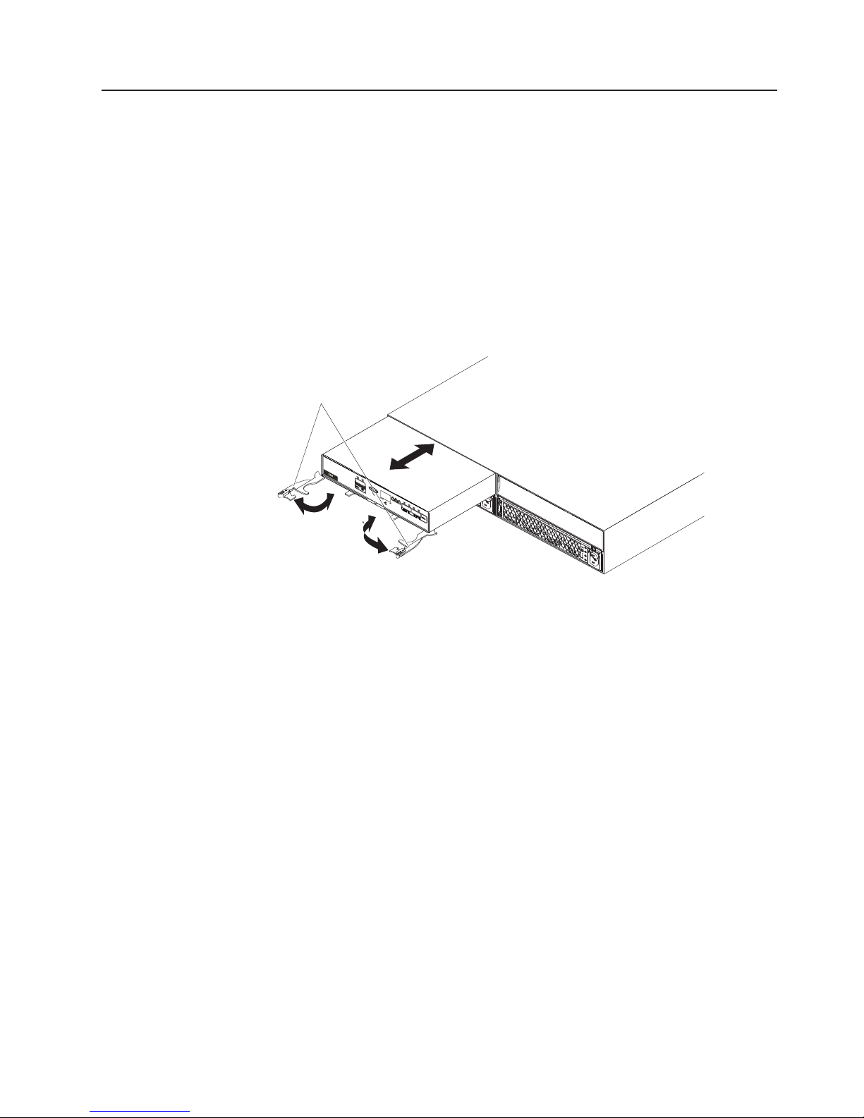
Replacing an ESM
If you are replacing the only ESM in the EXP2500, you must turn off power to the
EXP2500 before you replace the ESM. Refer to the documentation that comes with
your RAID controller for additional information and instructions.
To replace an ESM, complete the following steps:
1. Read the safety information that begins on page iii and “Installation guidelines”
2. If the EXP2500 contains only one ESM, turn off the power to the EXP2500.
3. Disconnect the SAS cable from the ESM.
4. Open the two release levers. The ESM moves out of the bay approximately
on page 29.
For more information, see “Powering off the EXP2500” on page 22.
0.6 cm (0.25 inch).
Release
levers
IN
OKOK
IN
OKOK
5. Slide the ESM out of the bay and set it aside.
6. Make sure that the release levers on the new ESM are in the open position.
7. Slide the new ESM into the bay until it stops.
8. Push the release levers to the closed position.
9. Connect the SAS cable to the ESM.
10. Turn on the power to the EXP2500. For more information, see “Powering on
the EXP2500” on page 21.
11. Go to http://www.ibm.com/servers/storage/support/ to check for ESM code
updates. For more information, see the download instructions on page 1.
Chapter 4. Parts listing, EXP2512 and EXP2524 expansion enclosures 35
Page 48

Replacing a hot-swap power supply
Before you replace a power supply, read the following important information:
v The power supply does not require preventive maintenance.
v Both power supplies must be installed to maintain cooling.
v Use only power supplies that the EXP2500 supports.
To replace a hot-swap power supply, complete the following steps:
1. Read the safety information that begins on page iii and “Installation guidelines”
on page 29.
2. Disconnect the power cord from the electrical outlet and from the power supply.
3. On the left side of the power supply, press the orange release tab to the right
just enough to release the handle (no more than 6 mm [0.25 in.]) as you rotate
the handle downward.
IN
Release tab
OKOK
IN
OKOK
Power supply
Handle
4. Using the handle, gently slide the power supply out of the EXP2500.
5. Hold the new power supply so that the handle is fully extended.
6. Gently slide the power supply into the EXP2500 until it stops. Rotate the handle
upward into the closed position until it clicks.
7. Connect the power cord to the power supply and to a properly grounded
electrical outlet.
Note: After the power cord is connected to the electrical outlet, make sure that
the ac and dc power (green) LEDs are lit and the fault (amber) LED is off.
36 System Storage EXP2512 and EXP2524: Installation and Maintenance Guide
Page 49

Replacing the bezels
The left bezel contains the LEDs; the right bezel shows the hard disk drive IDs. See
the illustrations in “Front view: components” on page 17
Removing the bezels
Left bezel
Handles
To remove either the left or right bezel, complete the following steps:
1. If the EXP2500 is on a table or other flat surface, elevate the EXP2500 front
slightly or extend the front over the table edge.
2. Grasp the handle on the front of the bezel and pull until the bezel is clear of the
bottom tab on the chassis flange.
3. Lift the bezel off the chassis flange.
Installing the bezels
To install either the left or right bezel, complete the following steps:
1. Fit the cutout that is on the top of the bezel over the tab on the chassis flange.
2. Rotate the bezel down until it snaps into place. Make sure that the inside
surface of the bezel is flush with the chassis.
Right bezel
Chapter 4. Parts listing, EXP2512 and EXP2524 expansion enclosures 37
Page 50

Replacing the midplane
The midplane assembly must be replaced only by a trained service provider.
To replace the midplane assembly, complete the following steps.
Attention: To prevent data loss, you must shut down the storage enclosure
before you begin the procedure to replace the midplane assembly.
1. Read the safety information that begins on page iii and “Installation guidelines”
on page 29.
2. Turn off the power to the EXP2500 and disconnect all cables. For more
information, see “Powering off the EXP2500” on page 22.
3. Carefully remove each hard disk drive and label it with the drive slot from
which it was removed (see “Replacing a hot-swap hard disk drive” on page
30). The drives must be inserted back in the same slot from which they were
removed.
4. Remove the two power supplies (see “Replacing a hot-swap power supply” on
page 36).
5. Remove the ESM and filler panel (see “Replacing an ESM” on page 35).
6. Remove the enclosure from the rack cabinet, turn it on its side with the bottom
facing toward you, and place the enclosure on a flat surface.
7. Remove the two screws from the bottom of the enclosure. Label these screws
as to the location from which they are removed and place them aside.
8. Turn the enclosure top side up and place it on a flat surface. Remove the four
screws on the right and left sides that secure the midplane assembly to the
front of the enclosure. Label the four screws as to the location from which they
are removed and place them aside. (See the illustration in step 7.)
9. Remove the four screws on the right and left sides of the enclosure that
secure the midplane assembly to the chassis. Label the four screws as to the
location from which they are removed and place them aside. (See the
illustration in step 7.)
38 System Storage EXP2512 and EXP2524: Installation and Maintenance Guide
x4
x2
x4
Page 51

10. Remove the midplane assembly from the chassis. Rotate the midplane
assembly up about 45° and then lift it out. Set the midplane assembly on a flat
surface.
Midplane assembly
11. Remove the six screws that attach the midplane to the midplane assembly and
lift off the failed midplane.
Midplane assembly
Midplane
12. Unpack the replacement midplane and align the six screw holes on the
midplane with the six screw holes on the midplane assembly. Secure the
midplane to the midplane assembly with the six screws that you removed in
step 11.
Chapter 4. Parts listing, EXP2512 and EXP2524 expansion enclosures 39
Page 52

13. Replace the midplane assembly in the enclosure chassis:
a. Grasp the midplane assembly with two hands and hold it at a 45° angle.
Tab
Midplane assembly
b. Insert the three tabs on the midplane assembly into the tab holes in the
enclosure and rotate the front of the assembly down.
14. Secure the midplane assembly to the chassis on both the right and left sides
of the enclosure by using the four screws that you removed in step 9 on page
38.
15. Insert the four screws that secure the midplane assembly to the enclosure on
both the right and left front flanges by using the four screws that you removed
in step 8 on page 38.
16. Turn the enclosure on its side with the bottom facing toward you and insert the
two screws on the bottom of the enclosure by using the two screws that you
removed in step 7 on page 38.
17. Reinstall the ESM and blank filler panel (see “Replacing an ESM” on page 35).
18. Reinstall the two power supplies (see “Replacing a hot-swap power supply” on
page 36).
19. Reinstall the hard disk drives making sure that each drive is inserted back in
the same slot from which it was removed (see “Replacing a hot-swap hard disk
drive” on page 30).
20. Power-on the enclosure (see “Powering on the EXP2500” on page 21).
21. Check the LEDs to make sure that the enclosure is fully operational.
40 System Storage EXP2512 and EXP2524: Installation and Maintenance Guide
Page 53

Chapter 5. Solving problems
The following table contains troubleshooting information to help you solve some
basic problems that you might have with the EXP2500.
Table 6. Troubleshooting information
Component Problem indicator Possible cause Possible solutions
Hard disk drive Amber fault LED lit Drive failure Replace the failed hard disk drive. See “Replacing a
hot-swap hard disk drive” on page 30.
ESM Board failure Replace the failed ESM. See “Replacing an ESM”
on page 35.
Front panel General machine
fault
All components All green LEDs off The EXP2500 is
turned off
ac or dc power
failure
Power-supply
failure
Midplane failure Have the EXP2500 serviced.
Hard disk drives Amber fault LED
flashing
Power supply Amber fault LED lit;
green dc power LED
off
Power supply Amber fault LED lit;
green ac power LED
off
Front panel Amber
overtemperature LED
lit
ESM SAS link LED off SAS
Drive rebuild or
identity in process
Power supply
failure; power
supply turned off;
minimum hard disk
drives not installed
No ac power to
power supply
Filler panel missing Make sure that the ESM filler panel is installed in
Environment Turn off the system until the environment
Fan failure Replace the power supply with the failed fans.
communication
failure
A status or fault LED somewhere on the EXP2500
is lit. Check for amber LEDs on components. See
Chapter 3, “EXP2500 controls, LEDs, and power,”
on page 17.
Make sure that all EXP2500 power cables are
connected and that the power is on. If applicable,
make sure that the main circuit breakers for the rack
are turned on.
Check the main circuit breaker and ac or dc outlet.
Replace the power supply. See “Replacing a
hot-swap power supply” on page 36.
No action is required.
1. Install four or more hard disk drives, turn off the
power, and turn it on again.
2. If the power-supply switch is on, turn off the
power supply and then turn it on again. If the
condition remains, replace the power supply.
See “Replacing a hot-swap power supply” on
page 36.
Check the ac power cord or breaker.
v If ac power is good at the source, replace the
power cord.
v If the power supply has failed, replace the power
supply. See “Replacing a hot-swap power supply”
on page 36.
the correct ESM bay.
temperature returns to within the defined operating
temperature range.
1. Reconnect the SAS cable.
2. Replace the SAS cable.
3. If the LED is still off, replace the ESM or the
device into which the other end of the SAS
cable is connected.
© Copyright IBM Corp. 2010, 2011 41
Page 54

Table 6. Troubleshooting information (continued)
Component Problem indicator Possible cause Possible solutions
One or more hard
disk drives
All hard disk
drives
Front panel Power supply Make sure that the cables are connected and the
Some or all
components
Drives Unable to access any
Subsystem Random errors Midplane failure Have the EXP2500 serviced.
One or more green
LEDs off
Intermittent or
sporadic power loss to
the EXP2500
drives
No activity to the
drives
No activity to the
drives
Damaged or loose
SAS cables
ESM failure Use the RAID controller management software to
Midplane failure Have the EXP2500 serviced.
Hardware failure If any other LEDs are lit, have the EXP2500
Defective ac or dc
power source or
partially connected
power cord
Power-supply
failure
Midplane failure Have the EXP2500 serviced.
SAS cable
ESM failure Have the EXP2500 serviced.
No action is required.
No action is required.
Check the SAS cables and connections.
check the drive status. Replace the ESM. See
“Replacing an ESM” on page 35.
power supplies are turned on.
serviced.
1. Check the ac or dc power source.
2. Secure all installed power cables and power
supplies.
3. If applicable, check the power components
(power supplies, uninterruptible power supply,
and so on).
4. Replace defective power cables.
Check for a fault LED on the power supply and
replace the failed power supply. See “Replacing a
hot-swap power supply” on page 36.
1. Make sure that the SAS cables are undamaged
and correctly connected.
2. Replace the cables.
42 System Storage EXP2512 and EXP2524: Installation and Maintenance Guide
Page 55

Chapter 6. Remote management and system diagnostics
You can use the command-line interface of the EXP2500 environmental service
module (ESM) to perform system diagnostics and other subsystem management
tasks. Before you can issue any commands, you must connect to the EXP2500
ESM Ethernet port, establish a session with the EXP2500 ESM, and then launch its
command-line interface.
Launching the EXP2500 ESM command-line interface
Complete the following steps to launch the EXP2500 ESM command-line interface:
1. Use Telnet, or a terminal application that supports Telnet, to connect to the
EXP2500 ESM Ethernet port that has a default address of 192.168.128.101 and
a subnet mask of 255.255.0.0.
2. Enter USERID as the login name and press ENTER. Leave the password field
blank. The command-line interface launches.
See EXP2500 ESM command-line reference for the list of commands.
EXP2500 ESM command-line reference
Table 7. List of Commands the EXP2500 Environmental Service Module (ESM) Supports
Command Usage Description
dhcp on|off timeout_in_ seconds Enables/Disables DHCP. Specify timeout. 0 (zero) or unspecified means no
timeout
cfgip IP_address Subnet_mask
gateway
collsvcsnap Displays all config and status information, such as error logs and state
dmesg Displays the history buffer of system print strings
drivetemps Gets current disk-drive temperatures
drvpres startphy endphy Displays present status of the drive
dumperrorlog Displays error log contents as hex records
enclamptest on|off Turns on or off all LEDs for testing purposes
esmcompatcheck Resets the ESM
esmstatus Shows the lockdown status of the ESM
istat Provides chassis-specific expander information
netif Displays MAC and TCP/IP addresses for all network interfaces
password new_password Changes the user password
phyerrregs phyStart [phyEnd] Displays PHY Error Registers on PHY phynum (in hex)
phystat Prints PHY Status Table
ping host_name_length Issues a single ICMP 'Echo Request' packet to a specified host. Length is
showenc Displays Detailed Enclosure Inventory Data
showfwlevels Displays firmware levels for all devices connected to the system
showinventory Displays information about all the components
uptime Informs how long the system has been running
Sets IP configuration. Example: cfgip 192.168.0.3 255.255.255.0 192.168.0.2
capture buffers
the 'send buffer' size. Default is 56 bytes
© Copyright IBM Corp. 2010, 2011 43
Page 56

44 System Storage EXP2512 and EXP2524: Installation and Maintenance Guide
Page 57

Appendix A. Getting help and technical assistance
If you need help, service, or technical assistance or just want more information
about IBM products, you will find a wide variety of sources available from IBM to
assist you. This section contains information about where to go for additional
information about IBM and IBM products, what to do if you experience a problem
with your system, and whom to call for service, if it is necessary.
Before you call
Before you call, make sure that you have taken these steps to try to solve the
problem yourself:
v Check all cables to make sure that they are connected.
v Check the power switches to make sure that the system and any optional
devices are turned on.
v Use the troubleshooting information in your system documentation, and use the
diagnostic tools that come with your system. Information about diagnostic tools is
in the Problem Determination and Service Guide on the IBM Documentation CD
that comes with your system.
v Go to the IBM support website at http://www.ibm.com/systems/support/ to check
for technical information, hints, tips, and new device drivers or to submit a
request for information.
You can solve many problems without outside assistance by following the
troubleshooting procedures that IBM provides in the online help or in the
documentation that is provided with your IBM product. The documentation that
comes with IBM systems also describes the diagnostic tests that you can perform.
Most systems, operating systems, and programs come with documentation that
contains troubleshooting procedures and explanations of error messages and error
codes. If you suspect a software problem, see the documentation for the operating
system or program.
Using the documentation
Information about your IBM system and preinstalled software, if any, or optional
device is available in the documentation that comes with the product. That
documentation can include printed documents, online documents, readme files, and
help files. See the troubleshooting information in your system documentation for
instructions for using the diagnostic programs. The troubleshooting information or
the diagnostic programs might tell you that you need additional or updated device
drivers or other software. IBM maintains pages on the World Wide Web where you
can get the latest technical information and download device drivers and updates.
To access these pages, go to http://www.ibm.com/systems/support/ and follow the
instructions. Also, some documents are available through the IBM Publications
Center at http://www.ibm.com/shop/publications/order/.
Getting help and information from the World Wide Web
On the World Wide Web, the IBM website has up-to-date information about IBM
systems, optional devices, services, and support. The address for IBM System x
and xSeries®information is http://www.ibm.com/systems/x/. The address for IBM
BladeCenter
for IBM IntelliStation®information is http://www.ibm.com/intellistation/.
© Copyright IBM Corp. 2010, 2011 45
®
information is http://www.ibm.com/systems/bladecenter/. The address
®
Page 58

You can find service information for IBM systems and optional devices at
http://www.ibm.com/systems/support/.
Software service and support
Through IBM Support Line, you can get telephone assistance, for a fee, with usage,
configuration, and software problems with System x and xSeries servers,
BladeCenter products, IntelliStation workstations, and appliances. For information
about which products are supported by Support Line in your country or region, see
http://www.ibm.com/services/sl/products/.
For more information about Support Line and other IBM services, see
http://www.ibm.com/services/, or see http://www.ibm.com/planetwide/ for support
telephone numbers. In the U.S. and Canada, call 1-800-IBM-SERV
(1-800-426-7378).
Hardware service and support
You can receive hardware service through your IBM reseller or IBM Services. To
locate a reseller authorized by IBM to provide warranty service, go to
http://www.ibm.com/partnerworld/ and click Find Business Partners on the right
side of the page. For IBM support telephone numbers, see http://www.ibm.com/
planetwide/. In the U.S. and Canada, call 1-800-IBM-SERV (1-800-426-7378).
In the U.S. and Canada, hardware service and support is available 24 hours a day,
7 days a week. In the U.K., these services are available Monday through Friday,
from 9 a.m. to 6 p.m.
IBM Taiwan product service
IBM Taiwan product service contact information:
IBM Taiwan Corporation
3F, No 7, Song Ren Rd.
Taipei, Taiwan
Telephone: 0800-016-888
46 System Storage EXP2512 and EXP2524: Installation and Maintenance Guide
Page 59

Appendix B. Notices
This information was developed for products and services offered in the U.S.A.
IBM may not offer the products, services, or features discussed in this document in
other countries. Consult your local IBM representative for information on the
products and services currently available in your area. Any reference to an IBM
product, program, or service is not intended to state or imply that only that IBM
product, program, or service may be used. Any functionally equivalent product,
program, or service that does not infringe any IBM intellectual property right may be
used instead. However, it is the user's responsibility to evaluate and verify the
operation of any non-IBM product, program, or service.
IBM may have patents or pending patent applications covering subject matter
described in this document. The furnishing of this document does not give you any
license to these patents. You can send license inquiries, in writing, to:
IBM Director of Licensing
IBM Corporation
North Castle Drive
Armonk, NY 10504-1785
U.S.A.
INTERNATIONAL BUSINESS MACHINES CORPORATION PROVIDES THIS
PUBLICATION “AS IS” WITHOUT WARRANTY OF ANY KIND, EITHER EXPRESS
OR IMPLIED, INCLUDING, BUT NOT LIMITED TO, THE IMPLIED WARRANTIES
OF NON-INFRINGEMENT, MERCHANTABILITY OR FITNESS FOR A
PARTICULAR PURPOSE. Some states do not allow disclaimer of express or
implied warranties in certain transactions, therefore, this statement may not apply to
you.
Trademarks
This information could include technical inaccuracies or typographical errors.
Changes are periodically made to the information herein; these changes will be
incorporated in new editions of the publication. IBM may make improvements and/or
changes in the product(s) and/or the program(s) described in this publication at any
time without notice.
Any references in this information to non-IBM websites are provided for
convenience only and do not in any manner serve as an endorsement of those
websites. The materials at those websites are not part of the materials for this IBM
product, and use of those websites is at your own risk.
IBM may use or distribute any of the information you supply in any way it believes
appropriate without incurring any obligation to you.
IBM, the IBM logo, and ibm.com are trademarks or registered trademarks of
International Business Machines Corporation in the United States, other countries,
or both. If these and other IBM trademarked terms are marked on their first
occurrence in this information with a trademark symbol (
indicate U.S. registered or common law trademarks owned by IBM at the time this
information was published. Such trademarks may also be registered or common law
trademarks in other countries. A current list of IBM trademarks is available on the
web at “Copyright and trademark information” at http://www.ibm.com/legal/
copytrade.shtml.
®or™
), these symbols
© Copyright IBM Corp. 2010, 2011 47
Page 60

Adobe and PostScript are either registered trademarks or trademarks of Adobe
Systems Incorporated in the United States and/or other countries.
Cell Broadband Engine is a trademark of Sony Computer Entertainment, Inc., in the
United States, other countries, or both and is used under license therefrom.
Intel, Intel Xeon, Itanium, and Pentium are trademarks or registered trademarks of
Intel Corporation or its subsidiaries in the United States and other countries.
Java and all Java-based trademarks are trademarks of Sun Microsystems, Inc., in
the United States, other countries, or both.
Linux is a registered trademark of Linus Torvalds in the United States, other
countries, or both.
Microsoft, Windows, and Windows NT are trademarks of Microsoft Corporation in
the United States, other countries, or both.
UNIX is a registered trademark of The Open Group in the United States and other
countries.
Other company, product, or service names may be trademarks or service marks of
others.
Important notes
Processor speed indicates the internal clock speed of the microprocessor; other
factors also affect application performance.
CD or DVD drive speed is the variable read rate. Actual speeds vary and are often
less than the possible maximum.
When referring to processor storage, real and virtual storage, or channel volume,
KB stands for 1024 bytes, MB stands for 1,048,576 bytes, and GB stands for
1,073,741,824 bytes.
When referring to hard disk drive capacity or communications volume, MB stands
for 1,000,000 bytes, and GB stands for 1,000,000,000 bytes. Total user-accessible
capacity can vary depending on operating environments.
Maximum internal hard disk drive capacities assume the replacement of any
standard hard disk drives and population of all hard disk drive bays with the largest
currently supported drives that are available from IBM.
Maximum memory might require replacement of the standard memory with an
optional memory module.
IBM makes no representation or warranties regarding non-IBM products and
services that are ServerProven
®
, including but not limited to the implied warranties
of merchantability and fitness for a particular purpose. These products are offered
and warranted solely by third parties.
IBM makes no representations or warranties with respect to non-IBM products.
Support (if any) for the non-IBM products is provided by the third party, not IBM.
48 System Storage EXP2512 and EXP2524: Installation and Maintenance Guide
Page 61

Some software might differ from its retail version (if available) and might not include
user manuals or all program functionality.
Particulate contamination
Attention: Airborne particulates (including metal flakes or particles) and reactive
gases acting alone or in combination with other environmental factors such as
humidity or temperature might pose a risk to the device that is described in this
document. Risks that are posed by the presence of excessive particulate levels or
concentrations of harmful gases include damage that might cause the device to
malfunction or cease functioning altogether. This specification sets forth limits for
particulates and gases that are intended to avoid such damage. The limits must not
be viewed or used as definitive limits, because numerous other factors, such as
temperature or moisture content of the air, can influence the impact of particulates
or environmental corrosives and gaseous contaminant transfer. In the absence of
specific limits that are set forth in this document, you must implement practices that
maintain particulate and gas levels that are consistent with the protection of human
health and safety. If IBM determines that the levels of particulates or gases in your
environment have caused damage to the device, IBM may condition provision of
repair or replacement of devices or parts on implementation of appropriate remedial
measures to mitigate such environmental contamination. Implementation of such
remedial measures is a customer responsibility.
Table 8. Limits for particulates and gases
Contaminant Limits
Particulate v The room air must be continuously filtered with 40% atmospheric dust
Gaseous v Copper: Class G1 as per ANSI/ISA 71.04-1985
1
ASHRAE 52.2-2008 - Method of Testing General Ventilation Air-Cleaning Devices for
Removal Efficiency by Particle Size. Atlanta: American Society of Heating, Refrigerating and
Air-Conditioning Engineers, Inc.
2
The deliquescent relative humidity of particulate contamination is the relative humidity at
which the dust absorbs enough water to become wet and promote ionic conduction.
3
ANSI/ISA-71.04-1985. Environmental conditions for process measurement and control
systems: Airborne contaminants. Instrument Society of America, Research Triangle Park,
North Carolina, U.S.A.
1
spot efficiency (MERV 9) according to ASHRAE Standard 52.2
v Air that enters a data center must be filtered to 99.97% efficiency or
greater, using high-efficiency particulate air (HEPA) filters that meet
MIL-STD-282.
v The deliquescent relative humidity of the particulate contamination
must be more than 60%
v The room must be free of conductive contamination such as zinc
whiskers.
v Silver: Corrosion rate of less than 300 Å in 30 days
2
.
3
.
Documentation format
The publications for this product are in Adobe Portable Document Format (PDF)
and should be compliant with accessibility standards. If you experience difficulties
when you use the PDF files and want to request a web-based format or accessible
PDF document for a publication, direct your mail to the following address:
Information Development
IBM Corporation
205/A015
Appendix B. Notices 49
Page 62

3039 E. Cornwallis Road
P.O. Box 12195
Research Triangle Park, North Carolina 27709-2195
U.S.A.
In the request, be sure to include the publication part number and title.
When you send information to IBM, you grant IBM a nonexclusive right to use or
distribute the information in any way it believes appropriate without incurring any
obligation to you.
Electronic emission notices
Federal Communications Commission (FCC) statement
Note: This equipment has been tested and found to comply with the limits for a
Class A digital device, pursuant to Part 15 of the FCC Rules. These limits are
designed to provide reasonable protection against harmful interference when the
equipment is operated in a commercial environment. This equipment generates,
uses, and can radiate radio frequency energy and, if not installed and used in
accordance with the instruction manual, may cause harmful interference to radio
communications. Operation of this equipment in a residential area is likely to cause
harmful interference, in which case the user will be required to correct the
interference at his own expense.
Properly shielded and grounded cables and connectors must be used in order to
meet FCC emission limits. IBM is not responsible for any radio or television
interference caused by using other than recommended cables and connectors or by
unauthorized changes or modifications to this equipment. Unauthorized changes or
modifications could void the user's authority to operate the equipment.
This device complies with Part 15 of the FCC Rules. Operation is subject to the
following two conditions: (1) this device may not cause harmful interference, and (2)
this device must accept any interference received, including interference that may
cause undesired operation.
Industry Canada Class A emission compliance statement
This Class A digital apparatus complies with Canadian ICES-003.
Avis de conformité à la réglementation d'Industrie Canada
Cet appareil numérique de la classe A est conforme à la norme NMB-003 du
Canada.
Australia and New Zealand Class A statement
Attention: This is a Class A product. In a domestic environment this product may
cause radio interference in which case the user may be required to take adequate
measures.
European Union EMC Directive conformance statement
This product is in conformity with the protection requirements of EU Council
Directive 2004/108/EC on the approximation of the laws of the Member States
relating to electromagnetic compatibility. IBM cannot accept responsibility for any
failure to satisfy the protection requirements resulting from a nonrecommended
modification of the product, including the fitting of non-IBM option cards.
50 System Storage EXP2512 and EXP2524: Installation and Maintenance Guide
Page 63

Attention: This is an EN 55022 Class A product. In a domestic environment this
product may cause radio interference in which case the user may be required to
take adequate measures.
Responsible manufacturer:
International Business Machines Corp.
New Orchard Road
Armonk, New York 10504
914-499-1900
European Community contact:
IBM Technical Regulations, Department M456
IBM-Allee 1, 71137 Ehningen, Germany
Telephone: +49 7032 15-2937
E-mail: tjahn@de.ibm.com
Germany Class A statement
Deutschsprachiger EU Hinweis:
Hinweis für Geräte der Klasse A EU-Richtlinie zur Elektromagnetischen
Verträglichkeit
Dieses Produkt entspricht den Schutzanforderungen der EU-Richtlinie 2004/108/EG
zur Angleichung der Rechtsvorschriften über die elektromagnetische Verträglichkeit
in den EU-Mitgliedsstaaten und hält die Grenzwerte der EN 55022 Klasse A ein.
Um dieses sicherzustellen, sind die Geräte wie in den Handbüchern beschrieben zu
installieren und zu betreiben. Des Weiteren dürfen auch nur von der IBM
empfohlene Kabel angeschlossen werden. IBM übernimmt keine Verantwortung für
die Einhaltung der Schutzanforderungen, wenn das Produkt ohne Zustimmung der
IBM verändert bzw. wenn Erweiterungskomponenten von Fremdherstellern ohne
Empfehlung der IBM gesteckt/eingebaut werden.
EN 55022 Klasse A Geräte müssen mit folgendem Warnhinweis versehen werden:
“Warnung: Dieses ist eine Einrichtung der Klasse A. Diese Einrichtung kann im
Wohnbereich Funk-Störungen verursachen; in diesem Fall kann vom Betreiber
verlangt werden, angemessene Maßnahmen zu ergreifen und dafür aufzukommen.”
Deutschland: Einhaltung des Gesetzes über die
elektromagnetische Verträglichkeit von Geräten
Dieses Produkt entspricht dem “Gesetz über die elektromagnetische Verträglichkeit
von Geräten (EMVG)”. Dies ist die Umsetzung der EU-Richtlinie 2004/108/EG in
der Bundesrepublik Deutschland.
Zulassungsbescheinigung laut dem Deutschen Gesetz über die
elektromagnetische Verträglichkeit von Geräten (EMVG) (bzw. der
EMC EG Richtlinie 2004/108/EG) für Geräte der Klasse A
Dieses Gerät ist berechtigt, in Übereinstimmung mit dem Deutschen EMVG das
EG-Konformitätszeichen - CE - zu führen.
Verantwortlich für die Einhaltung der EMV Vorschriften ist der Hersteller:
International Business Machines Corp.
New Orchard Road
Armonk, New York 10504
914-499-1900
Appendix B. Notices 51
Page 64

Der verantwortliche Ansprechpartner des Herstellers in der EU ist:
IBM Deutschland
Technical Regulations, Department M456
IBM-Allee 1, 71137 Ehningen, Germany
Telephone: +49 7032 15-2937
E-mail: tjahn@de.ibm.com
Generelle Informationen:
Das Gerät erfüllt die Schutzanforderungen nach EN 55024 und EN 55022
Klasse A.
Japan Voluntary Control Council for Interference (VCCI) Class A
Statement
Translation: This is a Class A product based on the standard of the VCCI Council.
If this equipment is used in a domestic environment, radio interference may occur,
in which case, the user may be required to take corrective actions.
Japan Electronics and Information Technology Industries Association
(JEITA) statement
Japanese Electronics and Information Technology Industries Association (JEITA)
Confirmed Harmonics Guideline (products less than or equal to 20 A per phase)
Korea Communications Commission (KCC) Class A Statement
Please note that this equipment has obtained EMC registration for commercial use.
In the event that it has been mistakenly sold or purchased, please exchange it for
equipment certified for home use.
Russia Electromagnetic Interference (EMI) Class A statement
52 System Storage EXP2512 and EXP2524: Installation and Maintenance Guide
Page 65

People's Republic of China Class A electronic emission statement
Taiwan Class A compliance statement
Appendix B. Notices 53
Page 66

54 System Storage EXP2512 and EXP2524: Installation and Maintenance Guide
Page 67

Index
A
ac power connector 19
ac power LED 20
ac power supply specifications 6
accessible documentation 49
activity LED, hard disk drive 19
alerts, systems-management software 15
assistance, getting 45
attention notices 5
B
bezel
installing 37
LEDs 17
locator LED 18
overtemperature LED 19
power-on LED 18
removing 37
system error LED 19
C
cabling 13
caution statements 5
chaining the EXP2500s 13
Class A electronic emission notice 50
command-line interface 43
components of EXP2500 7
contamination, particulate and gaseous 49
CRU part numbers (EXP2512) 26
CRU part numbers (EXP2524) 27
D
danger statements 5
dc power LED 20
dimensions of EXP2500 6
documentation CD 3
documentation format 49
drive path, redundant 13
E
electrical input specifications 6
electronic emission Class A notice 50
emergency situation
restarting EXP2500 24
shutting down EXP2500 23
environmental service module (ESM) 43
environmental specifications 6
ESM
connectors 20
error LED 21
Ethernet link LED 21
Ethernet port 20
ESM (continued)
Ethernet speed LED 21
LEDs 21
locator LED 21
power-on LED 21
replacing 35
SAS in connector 20
SAS link LED 21
SAS out connector 20
service port 20
ESM error LED 21
Ethernet link LED (on ESM) 21
Ethernet port (ESM) 20
Ethernet speed LED (on ESM) 21
EXP2500
chaining 13
major components 7
F
fans and redundant cooling 7
fault LED (on power supply 20
FCC Class A notice 50
features and operating specifications 6
front LEDs
hard disk drive activity LED 19
locator LED 18
overtemperature LED 19
power-on LED 18
system error LED 19
G
gaseous contamination 49
getting help 45
H
hard disk drive
activity LED 19
information record 2
installing 2.5-inch 11, 33
installing 3.5-inch 12, 34
LED states and descriptions 30
removing 2.5-inch 31
removing 3.5-inch 32
replacing 30
specifications 6
status LED 19
hardware service and support 46
heat output specifications 6
help, getting 45
hot-swap components
hard disk drive 17
power supply 19
hot-swap power supply
controls and connectors 19
© Copyright IBM Corp. 2010, 2011 55
Page 68

hot-swap power supply (continued)
replacing 36
humidity specifications 6
I
IBM Support Line 46
important notices 5
information record for hard disk drive 2
installation guidelines 29
installing
hot-swap hard disk drive 10
inventory checklist 9
L
LEDs
ac power 20
dc power 20
ESM error 21
Ethernet link (on ESM) 21
Ethernet speed (on ESM) 21
fault 20
hard disk drive states and descriptions 30
left bezel 17
locator LED (on bezel) 18
locator LED (on ESM) 21
overtemperature LED (on bezel) 19
power-on 21
power-on LED (on bezel) 18
SAS link LED (on ESM) 21
system error LED (on bezel) 19
locator LED
on bezel 18
on ESM 21
M
midplane assembly
replacing 38
N
noise emissions 6
notes 5
notes, important 48
notices 47
electronic emission 50
FCC, Class A 50
notices and statements 5
O
operating specifications 6
overtemperature LED
on bezel 19
P
particulate contamination 49
parts listing 25
power cabling 15
power requirement specifications 6
power supply
controls and connectors 19
replacing 36
specifications 6
power-off the EXP2500 23
power-on LED
on bezel 18
power-on LED (ESM) 21
power-on the EXP2500 21
power-supply
ac power connector 19
ac power LED 20
dc power LED 20
fault LED 20
problems and solutions 41
product identification record 2
R
replacement parts 25
replacing
ESM 35
hard disk drive 30
midplane 38
power supply 36
restarting the EXP2500 24
S
SAS in connector (ESM) 20
SAS link LED (on ESM) 21
SAS out connector (ESM) 20
serial number label 2
service port (ESM) 20
shut down in an emergency 23
shut down the EXP2500 23
size of EXP2500 6
software service and support 46
specifications, EXP2500 6
statements and notices 5
static-sensitive devices, handling 29
status LED, hard disk drive 19
support, website 45
system error LED
on bezel 19
system reliability guidelines 29
systems-management alerts 15
systems-management software support 15
T
telephone numbers 46
temperature specifications 6
trademarks 47
troubleshooting 41
56 System Storage EXP2512 and EXP2524: Installation and Maintenance Guide
Page 69

turning off the EXP2500 23
turning off the EXP2500 in an emergency 23
turning on the EXP2500 21
U
United States electronic emission Class A notice 50
United States FCC Class A notice 50
W
website
publication ordering 45
support 45
support line, telephone numbers 46
weight of EXP2500 6
Index 57
Page 70

58 System Storage EXP2512 and EXP2524: Installation and Maintenance Guide
Page 71

Page 72

Part Number: 90Y8809
Printed in USA
GA32-0965-01
(1P) P/N: 90Y8809
 Loading...