

IBM System Storage DCS, System Storage DCS3700, System Storage DCS3860 Installation And Migration Manual
Page 1

IBM System Storage DCS Series with Gen2 controllers
Hard Disk Drive and Storage Enclosure
Installation and Migration Guide
IBM
GA32-0962-07
Page 2

Note
Before using this information and the product it supports, be sure to read the general information in “Notices and
statements in this document” on page x and “Notices” on page 61.
This edition applies to version 11 modification 20 of the IBM DS Storage Manager, and to all subsequent releases
and modifications until otherwise indicated in new editions.
This edition replaces GA32-0962-06.
© Copyright IBM Corporation 2008, 2015.
US Government Users Restricted Rights – Use, duplication or disclosure restricted by GSA ADP Schedule Contract
with IBM Corp.
Page 3

Contents
Figures ............... v
Tables ............... vii
Introduction............. ix
Supported IBM System Storage DCS Series with
Gen2 controllers ............. ix
Receiving product updates and support notifications ix
DS Storage Subsystem installation and support
guides ................ ix
Notices and statements in this document ..... x
Chapter 1. Prerequisites to adding
capacity and hard disk drive migration . 1
Preparing the storage subsystem........ 1
Preparing to export and import drives...... 3
Determining the supported number of drives and
drive loop pairs ............. 4
Verifying controller, NVSRAM, and ESM firmware
compatibility .............. 4
Storage subsystem profile ......... 5
Physical View pane ........... 6
Upgrading ESM and controller firmware ..... 6
Drive migration limitations ......... 7
Verifying hard disk drive model compatibility ... 8
Viewing the product ID and model of a hard disk
drive ................. 9
Bringing storage subsystems and drive loops into
optimal state .............. 11
Intermixing storage enclosures ........ 11
Chapter 2. Adding or migrating hard
disk drives ............. 13
Considerations ............. 13
Handling static-sensitive devices ....... 14
Adding new hard disk drives ........ 14
Migrating hard disk drives ......... 15
Step 1: Preliminary activities........ 16
Step 2: Verifying drive migration enable settings 17
Step 3: Placing drives offline........ 17
Step 4: Removing drives ......... 18
Step 5: Inserting drives ......... 19
Migrating arrays within the same storage subsystem 21
Chapter 3. Adding or migrating storage
enclosures ............. 25
Considerations ............. 25
Step 1: Preliminary activities......... 26
Adding new storage enclosures with new hard
disk drives ............. 27
Migrating storage enclosures with hard disk
drives that have defined logical drive
configurations ............ 27
Step 2: Preparing and backing up the drives ... 28
Step 3: Shutting down and moving the storage
enclosures ............... 29
Step 4: Verifying the drive migration enable settings 30
Step 5: Installing and setting storage enclosure IDs 30
Step 6: Cabling, turning on, and verifying storage
enclosure operation ............ 31
Cabling the new enclosures ........ 31
Connecting storage enclosures at the end
(bottom) of a drive loop ......... 31
Connecting storage enclosures at the end
(bottom) of a SAS drive cable loop scheme in a
DCS3700 and DCS3860 storage subsystems with
Gen2 controllers configuration ....... 32
Returning the drive/loop channel to optimal
state ................ 33
Storage subsystem SAS drive channel/loop
schemes for enclosures in a DCS3700
configuration ............. 33
Storage subsystem SAS drive channel/loop
schemes for enclosures in a DCS3860 with Gen2
controllers configuration ......... 35
Cabling multiple enclosures ........ 36
Step 7: Inserting drives and cabling additional
storage enclosures ............ 38
Step 8: Inserting hard disk drives and placing
logical drives online ........... 38
Chapter 4. Upgrading a storage
subsystem controller ........ 41
Upgrade considerations .......... 41
Host attachment and premium feature
entitlements ............. 41
Storage firmware migration ........ 42
Alternative procedure to upgrade a storage
subsystem controller enclosure ....... 42
Supported upgrades .......... 43
Configuration behavior after an upgrade and
storage subsystem replacement ....... 44
Storage subsystem behavior when turning on the
power with no drives attached ....... 46
Performing an upgrade .......... 46
Redeploying the original storage subsystem ... 53
Redeployment limitations......... 53
Configuration behavior in a redeployed storage
subsystem .............. 54
Appendix. Getting information, help,
and service ............. 57
Before you call ............. 57
Using the documentation .......... 57
Finding Storage Manager software, controller
firmware, and readme files ......... 57
Getting help and information from the World Wide
Web ................. 58
Software service and support ........ 59
© Copyright IBM Corp. 2008, 2015 iii
Page 4

Hardware service and support ........ 59
Taiwan Contact Information ......... 59
Fire suppression systems .......... 59
Notices .............. 61
Trademarks .............. 63
Important notes ............. 64
Particulate contamination.......... 65
Documentation format........... 65
Electronic emission notices ......... 66
Federal Communications Commission Statement 66
Industry Canada Compliance Statement .... 66
Australia and New Zealand Class A Statement 66
European Union Electromagnetic Compatibility
Directive .............. 66
Taiwan Class A Statement ........ 67
Germany Electromagnetic Compatibility Directive 67
People's Republic of China Class A Statement .. 68
Japan Voluntary Control Council for Interference
Class A Statement ........... 68
Japan Electronics and Information Technology
Industries Association Statement ...... 69
Korean Communications Commission Class A
Statement .............. 69
Index ............... 71
iv IBM System Storage DCS Series with Gen2 controllers Hard Disk Drive and Storage Enclosure Installation and Migration
Guide
Page 5

Figures
1. Subsystem Management Logical/Physical
View of exported drives ........ 18
2. Drive CRU assembly ......... 19
3. Best practice for reordering a defined array by
using empty bays in one storage enclosure .. 21
4. Best practice for reordering a defined array by
using empty bays in two storage enclosures.. 21
5. Reordering multiple defined arrays across
previously used bays in two storage enclosures 22
6. Subsystem Management Logical/Physical
View of missing logical drives ...... 22
7. Connecting the first EXP3800/DCS3700
expansion enclosure.......... 35
8. Adding enclosures .......... 37
9. Firmware compatibility flowchart for a storage
subsystem upgrade .......... 49
© Copyright IBM Corp. 2008, 2015 v
Page 6

vi IBM System Storage DCS Series with Gen2 controllers Hard Disk Drive and Storage Enclosure Installation and Migration
Guide
Page 7

Tables
1. Supported drives and drive loop pairs in
storage subsystems .......... 4
2. Machine types, supported controller firmware,
and supported Storage Manager software ... 5
3. Compatible storage enclosure ESM firmware
level by machine type and model number... 5
4. Drive migration limitations based on controller
firmware levels............ 8
5. Snapshot of profile information identifying the
product ID of the drive in bay 12 of enclosure
ID 1 ............... 10
6. Storage enclosure compatibility with storage
subsystems by model for DCS Series storage
subsystems............. 12
7. DCS3700 and EXP3800 expansion enclosures
supported by controller firmware levels ... 12
8. Connecting storage enclosures at the end
(bottom) of a SAS drive cable loop scheme in a
DCS3700 and DCS3860 storage subsystems
with Gen2 controllers configuration .... 33
9. Supported replacement storage subsystems 43
10. Snapshot of profile information that identifies
the storage subsystem worldwide identifier
(ID) ............... 45
11. Limits for particulates and gases ..... 65
© Copyright IBM Corp. 2008, 2015 vii
Page 8

viii IBM System Storage DCS Series with Gen2 controllers Hard Disk Drive and Storage Enclosure Installation and Migration
Guide
Page 9

Introduction
This document describes how to add new SAS hard disk drives or a new IBM
System Storage®storage enclosures that contain new SAS hard disk drives to an
existing IBM storage subsystem configuration. This document also describes how
to migrate hard disk drives or IBM System Storage storage enclosures that contain
hard disk drives from one storage subsystem to another.
This document also describes how to replace the storage subsystem with a new
storage subsystem of the same or different model. In this case, all the hard disk
drives and storage enclosures in the original configuration become part of the new
configuration.
Before you begin, familiarize yourself with the information in Chapter 1,
“Prerequisites to adding capacity and hard disk drive migration,” on page 1. Your
familiarity with the information described in this document is critical to preventing
loss of data availability, and in some cases, loss of data.
Supported IBM System Storage DCS Series with Gen2 controllers
IBM System Storage DCS Series include the following storage models:
v IBM System DCS3700 Storage Subsystem with Gen2 Controllers
v IBM System DCS3860 Storage Subsystem with Gen2 Controllers
Receiving product updates and support notifications
®
Be sure to download the latest levels of the following packages at the time of
initial installation and when product updates become available:
v DS Storage Manager host software
v Controller firmware
v Environmental service modules (ESM) firmware
v Hard disk drive firmware
Important: Keep your system up-to-date with the latest firmware and other
product updates by subscribing to receive support notifications.
For more information about how to register for support notifications, see
http://www.ibm.com/systems/support/ and click My notifications.
DS Storage Subsystem installation and support guides
This document frequently refers to the IBM System Storage DS Storage Manager
Version 11.2 Installation and Host Support Guide for the storage subsystems.
To access the documentation related to your storage subsystem, operating system,
and DS Storage Manager version from the IBM Support Portal, complete the
following steps:
1. Go to http://www.ibm.com/support/entry/portal.
2. Under Choose your products, click Browse for a product or Search for a
product.
3. Under Choose your task, click Documentation.
© Copyright IBM Corp. 2008, 2015 ix
Page 10

4. Under See your results, click View your page.
5. In the Product documentation box, click the link for the publication that you
want to access.
Notices and statements in this document
The caution and danger statements in this document are also in the multilingual
Safety Information document, which is on the IBM Support Software DVD. Each
statement is numbered for reference to the corresponding statement in your
language in the Safety Information document.
The following notices and statements are used in this document:
v Note: These notices provide important tips, guidance, or advice.
v Important: These notices provide information or advice that might help you
avoid inconvenient or problem situations.
v Attention: These notices indicate potential damage to programs, devices, or data.
An attention notice is placed just before the instruction or situation in which
damage might occur.
v Caution: These statements indicate situations that can be potentially hazardous
to you. A caution statement is placed just before the description of a potentially
hazardous procedure step or situation.
v Danger: These statements indicate situations that can be potentially lethal or
hazardous to you. A danger statement is placed just before the description of a
potentially lethal or hazardous procedure step or situation.
Before installing this product, read the following danger and caution notices.
Statement 1
x IBM System Storage DCS Series with Gen2 controllers Hard Disk Drive and Storage Enclosure Installation and Migration
Guide
Page 11

DANGER
Electrical current from power, telephone, and communication cables is
hazardous.
To avoid a shock hazard:
v Do not connect or disconnect any cables or perform installation,
maintenance, or reconfiguration of this product during an electrical storm.
v Connect all power cords to a properly wired and grounded electrical outlet.
v Connect to properly wired outlets any equipment that will be attached to
this product.
v When possible, use one hand only to connect or disconnect signal cables.
v Never turn on any equipment when there is evidence of fire, water, or
structural damage.
v Disconnect the attached power cords, telecommunications systems,
networks, and modems before you open the device covers, unless
instructed otherwise in the installation and configuration procedures.
v Connect and disconnect cables as described in the following table when
installing, moving, or opening covers on this product or attached devices.
To Connect: To Disconnect:
1. Turn everything OFF.
2. First, attach all cables to devices.
3. Attach signal cables to connectors.
4. Attach power cords to outlet.
5. Turn device ON.
1. Turn everything OFF.
2. First, remove power cords from outlet.
3. Remove signal cables from connectors.
4. Remove all cables from devices.
Statement 3
CAUTION:
When laser products (such as CD-ROMs, DVD drives, fiber optic devices, or
transmitters) are installed, note the following:
v Do not remove the covers. Removing the covers of the laser product could
result in exposure to hazardous laser radiation. There are no serviceable parts
inside the device.
v Use of controls or adjustments or performance of procedures other than those
specified herein might result in hazardous radiation exposure.
Introduction xi
Page 12

DANGER
1
2
Some laser products contain an embedded Class 3A or Class 3B laser diode.
Note the following.
Laser radiation when open. Do not stare into the beam, do not view directly
with optical instruments, and avoid direct exposure to the beam.
Statement 4
≥ 18 kg (39.7 lb) ≥ 32 kg (70.5 lb) ≥ 55 kg (121.2 lb)
CAUTION:
Use safe practices when lifting.
Statement 5
CAUTION:
The power control button on the device and the power switch on the power
supply do not turn off the electrical current supplied to the device. The device
also might have more than one power cord. To remove all electrical current from
the device, ensure that all power cords are disconnected from the power source.
Statement 8
xii IBM System Storage DCS Series with Gen2 controllers Hard Disk Drive and Storage Enclosure Installation and Migration
Guide
Page 13

CAUTION:
Never remove the cover on a power supply or any part that has the following
label attached.
Hazardous voltage, current, and energy levels are present inside any component
that has this label attached. There are no serviceable parts inside these
components. If you suspect a problem with one of these parts, contact a service
technician.
Statement 29
CAUTION:
This equipment is designed to permit the connection of the earthed conductor of
the dc supply circuit to the earthing conductor at the equipment.
This equipment is designed to permit the connection of the earthed conductor of
the dc supply circuit to the earthing conductor at the equipment. If this
connection is made, all of the following conditions must be met:
v This equipment shall be connected directly to the dc supply system earthing
electrode conductor or to a bonding jumper from an earthing terminal bar or
bus to which the dc supply system earthing electrode conductor is connected.
v This equipment shall be in the same immediate area (such as, adjacent
cabinets) as any other equipment that has a connection between the earthed
conductor of the same dc supply circuit and the earthing conductor, and also
the point of earthing of the dc system. The dc system shall not be earthed
elsewhere.
v The dc supply source shall be located within the same premises as this
equipment.
v Switching or disconnecting devices shall not be in the earthed circuit
conductor between the dc source and the point of connection of the earthing
electrode conductor.
Statement 30
Introduction xiii
Page 14

CAUTION:
To reduce the risk of electric shock or energy hazards:
v This equipment must be installed by trained service personnel in a
restricted-access location, as defined by the NEC and IEC 60950-1, First
Edition, The Standard for Safety of Information Technology Equipment.
v Connect the equipment to a reliably grounded safety extra low voltage (SELV)
source. An SELV source is a secondary circuit that is designed so that normal
and single fault conditions do not cause the voltages to exceed a safe level (60
V direct current).
v The branch circuit overcurrent protection must be rated 20 A.
v Use 12 American Wire Gauge (AWG) or 2.5 mm2 copper conductor only, not
exceeding 4.5 meters in length.
v Incorporate a readily available approved and rated disconnect device in the
field wiring.
CAUTION:
This unit has more than one power source. To remove all power from the unit,
all DC MAINS must be disconnected.
Cable Warning
WARNING: Handling the cord on this product or cords associated with
accessories sold with this product will expose you to lead, a chemical known to the
State of California to cause cancer and birth defects or other reproductive harm.
Wash hands after handling.
xiv IBM System Storage DCS Series with Gen2 controllers Hard Disk Drive and Storage Enclosure Installation and Migration
Guide
Page 15

Chapter 1. Prerequisites to adding capacity and hard disk drive migration
The following notes describe general information that you must consider when
you perform the procedures in this document.
v Check the controller firmware readme files, the documentation that comes with
your hardware, and this guide for the following information:
– The latest information about storage subsystem and storage enclosure
compatibility
– The latest information and rules about storage enclosure cabling to the
storage subsystem drive port
– Any requirements of the installed microcode and firmware to support the
storage subsystem and storage enclosure
v To prevent damage to the storage subsystem or to the storage enclosure
backplane, ensure that the hard disk drives are compatible with your storage
subsystem before you install them. Refer to the storage subsystem
announcement letter for information about compatible devices.
v For more information about the procedures in this document, contact your IBM
marketing representative or authorized reseller.
Preparing the storage subsystem
To prepare the target and source storage subsystems to add storage capacity or
migrate hard disk drives, complete the following steps. Unless it is specified
otherwise, perform the following steps on the target subsystem for adding new
hard disk drive capacity and on both the target and source storage subsystems for
migrating hard disk drives with data.
Attention: Failure to complete the following steps before you add storage
capacity or migrate hard disk drives might result in loss of data availability or loss
of data.
1. Complete a full backup of all data on the storage subsystem.
2. Ensure that the backup was successful.
3. Verify the hardware compatibility and requirements by reviewing the
information in “Determining the supported number of drives and drive loop
pairs” on page 4 and the storage subsystem announcement letters. If addition
of storage enclosures is required, review “Intermixing storage enclosures” on
page 11 and the cabling information in the Installation, User's, and Maintenance
Guide for any special cabling requirements.
4. If you want to perform a drive migration between storage subsystems, verify
that the drives can be migrated to the new storage subsystem.
Note: Currently, drives with disk pools cannot be migrated from one
subsystem to another. The data in the disk pool must be backed up to a tape
or to drives that are part of traditional arrays. Then, the data is restored to
newly created disk pools in another storage subsystem. For more information,
see the “Drive migration limitations” on page 7 section.
5. Ensure that the storage subsystem has the latest controller firmware,
nonvolatile storage random access memory (NVSRAM), and ESM firmware.
Also, ensure that the installed controller firmware in the storage subsystem
© Copyright IBM Corp. 2008, 2015 1
Page 16

supports the drives and storage enclosures. See “Verifying controller,
NVSRAM, and ESM firmware compatibility” on page 4.
6. Ensure that the hard disk drive firmware is the latest level. Upgrading drive
firmware is a nonconcurrent operation. Schedule a maintenance window
during which you can stop input and output to the storage subsystem for
drive firmware updates.
Note: 3 Gbps SAS drives in a 6-Gbps SAS enclosure or 6-Gbps SAS drive in a
3-Gbps SAS enclosure is not supported.
7. Verify that the storage subsystem is in Optimal state and does not stop in the
middle of long running tasks such as modifications to the dynamic logical
drive expansion (DVE) or Array RAID levels. See the Recovery Guru function
in the Storage Subsystem Management window for instructions on bringing
the storage subsystem into Optimal state. Also, see “Bringing storage
subsystems and drive loops into optimal state” on page 11.
8. Resolve any critical errors reported in the Storage Subsystem MEL.
9. Save and store the storage subsystem profile and configuration script along
with the collect all support data bundle.
Attention: To prevent loss of data, do not store storage subsystem profiles or
collect all support data information in the same location as the logical drives
defined on your storage subsystem.
10. Obtain and activate any required premium features.
11. Ensure that the hard disk drives are compatible. See “Verifying hard disk
drive model compatibility” on page 8. Also, see the information for your
drives in the announcement letter.
12. If you are adding capacity, see Chapter 2, “Adding or migrating hard disk
drives,” on page 13 or Chapter 3, “Adding or migrating storage enclosures,”
on page 25, depending on the task you are performing.
13. (For the source storage subsystem only) Stop all programs, services, and
processes in the host servers that access the logical drives defined in the
migrated hard disk drives.
14. (For the source storage subsystem only) Ensure that no programs, services, or
processes are running in the background that might write data to the logical
drives. For example, Microsoft MSCS service periodically writes to the
Quorum disk.
15. (For the source storage subsystem only) Unmount the file systems to flush
I/O from the server cache to disk.
Note:
a. In a Microsoft Windows environment, remove the drive letter or the
mount points of the mapped LUNs instead of unmounting the file
systems.
b. See your operating-system documentation for detailed information about
the unmount procedure.
16. Back up the changes that you made during this procedure.
17. If the migrated drives are FDE drives and were configured as part of secured
array, save the storage subsystem security (lock) key to unlock the drives after
installing them in a new storage subsystem. Without this key, the controllers
cannot unlock the drives to perform input and output processes. For details
about the security key, see the IBM System Storage DS Storage Manager Version
11.2 Installation and Host Support Guide.
2 IBM System Storage DCS Series with Gen2 controllers Hard Disk Drive and Storage Enclosure Installation and Migration
Guide
Page 17

If the migrated drives from the storage subsystem operate in external license
key management mode, ensure that the new storage subsystem also operates
in external license key management mode and uses the same external key
server.
18. See the applicable chapter to complete the task that you plan to perform.
v Chapter 2, “Adding or migrating hard disk drives,” on page 13.
v Chapter 3, “Adding or migrating storage enclosures,” on page 25.
v Chapter 4, “Upgrading a storage subsystem controller,” on page 41.
Preparing to export and import drives
Complete the following steps on the source storage subsystem to prepare to export
drives:
1. Save the storage subsystem configuration so that a copy of the array
configuration is available, if the export fails.
2. Stop all I/O and unmount or disconnect the file system.
3. Back up the array data.
4. Use the Locate Array function in the Storage Subsystem Manager window to
identify the physical disks that are associated with the array. Then, label each
drive with source and target storage subsystem names, array name, and total
number of drives in the array. After the drives are exported or offline, you
might not be able to use the array locate function to locate the drives that are
part of an array, depending on the version of installed controller firmware.
5. Ensure that you have enough blank drive canisters or new drives to cover the
drive bays from which the drives are removed to maintain airflow in the
storage enclosure.
6. If the source storage subsystem contains secured full data encryption (FDE)
arrays, save a copy of the security key in the target storage subsystem.
Verify the following on the target (destination) storage subsystem to prepare to
export drives:
v You have enough drive bays for the drives.
v The storage subsystem supports the drives. You cannot exceed the maximum
number of drives that the storage subsystem supports.
v The storage subsystem supports the RAID level that you are importing. You
cannot exceed the maximum number of logical drives that the storage subsystem
supports.
v The target storage subsystem supports RAID level 6, if you are importing RAID
level 6.
v The controllers in the storage subsystem have the latest version of controller
firmware.
v The latest DS Storage Manager software is installed.
v You have purchased and enabled any premium feature keys.
v If the source storage subsystem operates in external key management mode, the
target storage subsystem also operates in external key management mode and is
managed by the same external key manager. That way, you do not have to
supply the security key to unlock the secured FDE drives when importing them.
Otherwise, save the security key in the source storage subsystem.
Chapter 1. Prerequisites to adding capacity and hard disk drive migration 3
Page 18

Determining the supported number of drives and drive loop pairs
Use the information in this section to determine the hardware requirements before
you migrate storage subsystems or add hard disk drives. Table 1 provides a list of
the supported number of drives and drive loop pairs for each storage subsystem
by machine type and model number. It also specifies storage enclosure license
requirements.
Table 1. Supported drives and drive loop pairs in storage subsystems
Maximum
drive
Machine
Storage subsystem
DCS3700 with Gen2
Controllers
DCS3860 with Gen2
Controllers
Notes:
1. The DCS3700 expansion enclosure is the only supported drive expansion enclosure for
the DCS3700 with Gen2 controllers storage subsystem.
2. The EXP3800 and DCS3700 expansion enclosures are the only supported drive expansion
enclosure for the DCS3860 storage subsystem.
1
2
type
1818 90C 180 1 None
1813 96C 360 0 None
Model
number
Maximum
drives
loop/channel
pairs
Storage
enclosure
license
requirement
Verifying controller, NVSRAM, and ESM firmware compatibility
Use the information in this section to verify controller, NVSRAM, and ESM
firmware compatibility before you migrate storage subsystems or add hard disk
drives. For firmware compatibility between the migrating and original hardware,
the controller firmware and NVSRAM of the target migration storage subsystem
must be at the levels that are indicated in Table 2 on page 5.
You can use the DS Storage Manager Client software and the controller firmware
to upgrade the ESM firmware while the storage subsystem receives I/O from the
host server, if you select only one storage enclosure to download the ESM
firmware at a time in the Select Drive Enclosure To Download ESM Firmware
Window.
Note:
1. See the most recent readme file that is included with the storage subsystem
controller firmware package. To access the most recent readme file, see
“Finding Storage Manager software, controller firmware, and readme files” on
page 57.
2. See the readme file for any I/O operation requirements. Some controller
firmware upgrade scenarios might require that you first quiesce host I/O
operations.
3. See the readme file to ensure that the firmware is compatible with the
controller firmware in the storage subsystem that you are upgrading.
4. Although you can upgrade the storage subsystem and ESM firmware while it
processes I/O from the host server, schedule upgrades to occur during time
periods of low I/O between the storage subsystems and host servers.
Table 2 on page 5 lists the supported machine types, model numbers, and the latest
version of released Storage Manager software and controller firmware levels for
4 IBM System Storage DCS Series with Gen2 controllers Hard Disk Drive and Storage Enclosure Installation and Migration
Guide
Page 19

each machine type. Review the announcement letter for your drives and the
readme file of the ESM and hard disk drive firmware package for any controller
firmware and ESM firmware requirements.
Table 2. Machine types, supported controller firmware, and supported Storage Manager
software
Storage subsystem Machine
type
DCS3700 with Gen2 Controllers 1818 90C 8.20.xx.xx 11.20.xx.xx
DCS3860 with Gen2 Controllers 1813 96C 8.20.xx.xx 11.20.xx.xx
Model Supported
controller
firmware
12
level
Supported Storage
Manager software
version
Important:
1. For the latest NVSRAM versions, see http://www.ibm.com/systems/support/
storage/disk/.
2. To verify software version levels or to identify possible interim updates to
firmware and NVSRAM file versions that are described in Table 2, go to
http://www.ibm.com/systems/support/storage/disk/.
Before you update the controller firmware and NVSRAM to the version that is
indicated in Table 3, see the readme file included in the controller firmware
code package for information about upgrades or stepping-stone controller
firmware upgrades that you must perform first.
Table 3 lists storage enclosure models by name, machine type, model number,
and current ESM firmware level.
Table 3. Compatible storage enclosure ESM firmware level by machine type and model
number
Storage subsystem and storage
enclosure product name/model
DCS3700 expansion enclosure 1818 80E 039C or later
DCS3860 EXP3800 1813 80E 039C or later
Storage subsystem profile
When the Storage Subsystem Profile window opens, click the All tab and scroll
through the Profile For Storage Subsystem section to locate the following
information.
Note: The Profile For Storage Subsystem section contains all the profile
information for the entire subsystem. Therefore, it might be necessary to scroll
through a large amount of information to locate the firmware level numbers.
Storage Subsystem
v NVSRAM version
v Controller firmware (or appware, bootware, or both) version
See the following example of profile information.
Machine
type
Model
number ESM firmware level
Chapter 1. Prerequisites to adding capacity and hard disk drive migration 5
Page 20

Controller in Enclosure 0, Slot A
Status: Online
Current configuration
Firmware version: 06.10.07.00
Appware version: 06.10.07.00
Bootware version: 06.10.07.00
NVSRAM version: 1722F600R910V05
Drives
v Firmware level
ESM
v ESM card firmware level
Physical View pane
Select a procedure to view the firmware level from the Physical View pane of the
Storage Subsystem Management window.
To obtain the controller firmware level:
Right-click the Controller icon in the Physical View pane of the Storage
Subsystem Management window and select Properties. The Controller
Enclosure properties window opens, and the properties for that controller
are shown.
You must perform this step for each individual controller.
To obtain the ESM firmware and drive enclosure component firmware levels:
1. In the Physical View pane of the Storage Subsystem Management
window, click the Drive Enclosure Component icon (the icon farthest
to the right). The Drive Enclosure Component Information window
opens.
2. Click the ESM icon in the left pane. The ESM information is shown in
the right pane of the Drive Enclosure Component Information window.
3. Locate the firmware level of each ESM in the drive enclosure.
You must perform this step for each storage enclosure.
Upgrading ESM and controller firmware
Use the information in this section to upgrade the ESM and controller firmware in
the source and target storage subsystems before you start the migration procedure.
To upgrade ESM and controller firmware, complete the following steps:
1. Upgrade the DS Storage Manager software to the latest version. For more
information, see the applicable IBM System Storage DS Storage Manager
Installation and Support Guide. To access the latest document, go to
http://www.ibm.com/systems/support/storage/disk/.
Note: To maintain compatibility, update the multi-path software on the host
server to the level that is supported by or released with the controller firmware
that you intend to download. For details about software compatibility, see
http://www.ibm.com/systems/support/storage/config/ssic/index.jsp.
2. Upgrade the storage enclosure ESM firmware. You can use DS Storage Manager
and controller firmware to update the ESM firmware while the storage
subsystem is processing I/O from the host server if the ESM firmware
download is performed to only one storage enclosure at a time. If you select
6 IBM System Storage DCS Series with Gen2 controllers Hard Disk Drive and Storage Enclosure Installation and Migration
Guide
Page 21

multiple entries in the ESM firmware download window for ESM firmware
download, you must quiesce I/O operations from the host servers before you
start the ESM firmware download process.
Note: Even though the storage subsystem supports controller and ESM
firmware upgrade while the storage subsystem processes I/O from the host
server, schedule controller and ESM firmware upgrades to occur during time
periods of low I/O between the storage subsystems and host servers.
3. Upgrade the controller firmware and NVSRAM. See Table 2 on page 5 and step
1 on page 6.
Note: See the readme file in the DS Storage Manager controller firmware
package that is associated with the applicable host operating system
environment for a support statement about the concurrent controller firmware
download .
Attention: Before you upgrade the controller firmware, see the readme file that
comes with the firmware for any special prerequisite tasks, ESM firmware, and
stepping-stone controller firmware that must be installed before the controller can
be upgraded. Failure to do so might result in loss of data availability. There are
certain minimum controller firmware level requirements that are associated with
various storage enclosures. See “Intermixing storage enclosures” on page 11,
“Intermixing storage enclosures” on page 11, and “Intermixing storage enclosures”
on page 11 for related information.
Drive migration limitations
In general, drives with existing data and logical drives configuration can be
migrated between storage subsystems that have the same level of controller
firmware installed or from a source storage subsystem that has an older version of
controller firmware installed than the one installed in the destination storage
subsystem. However, it is a best practice to limit the drive migration between
storage subsystems of the same level of controller firmware. The reason is that
different versions of controller firmware might implement different metadata
(DACstore) data structures to store the logical drive information. These metadata
(DACstore) data structures are not interchangeable. If a newer version of controller
firmware changes the metadata structure, all of the controller firmware versions
older than this controller firmware cannot decode the metadata structure to obtain
the logical drive information in the migrated drives and recreate them in the
destination storage subsystem. But, this newer version of controller firmware
normally includes the code to decode the previous metadata structure that it
changes to allow the migration of the drives in the storage subsystem with older
version of controller firmware. For more information about drive migration
limitations based on controller firmware levels, see Table 4 on page 8.
Only the logical drive and array definitions along with their data can be migrated
between storage subsystems. The Host-to-LUN mappings and the configuration
definition and data of the copy services premium features like FlashCopy,
VolumeCopy and Remote Mirroring must be removed prior to drive migration.
Depending on the version of the installed controller firmware, the LUN mappings
and the copy service configuration information can be saved in script file so that
they can be recreated in the destination storage subsystem. If the drives with data
cannot be migrated to the destination storage subsystem, one has to backup the
data in those drives to a different medium like tape and then restores the data into
the destination storage subsystem.
Chapter 1. Prerequisites to adding capacity and hard disk drive migration 7
Page 22

Table 4. Drive migration limitations based on controller firmware levels
Source storage
subsystem controller
firmware level
7.8x.xx.xx or later 8.2x.xx.xx Drives can be
7.7x.xx.xx 7.8x.xx.xx or later Drives can be
7.8x.xx.xx or later 7.8x.xx.xx Drives can be
7.8x.xx.xx or later 7.7x.xx.xx or earlier Drives cannot be
Destination storage
subsystem controller
firmware level Action Notes
migrated.
migrated into the
destination storage
subsystem when it is
powered up and
optimal.
migrated.
migrated.
Drives with disk pool
configuration cannot
be migrated between
storage subsystems.
1. Drives with disk
pool
configuration
cannot be
migrated between
storage
subsystems.
2. DS3500 and
DCS3700 storage
subsystems with
controller
firmware version
7.86 or later
support T10PI. If
an array has been
configured and
T10PI enabled, it
cannot be
migrated to a
storage subsystem
with controller
firmware version
7.84 or earlier.
Verifying hard disk drive model compatibility
Use the information in this section to verify hard disk drive compatibility before
you start the migration procedure or to add hard disk drives.
v Do not use the drive product identifier as the only source to determine drive
compatibility for a subsystem. Drives that have the same product identifier
might require a different mounting tray or interposer in a storage subsystem.
Instead, use the drive option part number or drive CRU part number to check
for drive compatibility in a storage subsystem.
v Ensure that the drives can operate at the interface speed of the drive
loop/channel. If not, the drives are in Bypassed mode or are not identified by
the controllers. In a few instances, inserting a drive with the wrong drive
interface speed causes problems in the drive loops which could result in loss of
data access.
8 IBM System Storage DCS Series with Gen2 controllers Hard Disk Drive and Storage Enclosure Installation and Migration
Guide
Page 23

v Some storage subsystem and expansion enclosures can support different drive
interface speeds. Ensure that these storage subsystem and expansion enclosure
speed switches are set to the correct values to support the drive interface speeds.
Intermixing storage subsystems and expansion enclosures that support different
drive interface speeds is not supported. The drive loop/channel must be set to
support the lowest drive interface speed.
v Do not install a DS3000, a DS4000, or a DS5000 storage subsystem drive in a
DCS Series storage subsystem.
v T10PI capable drives require controller firmware version 10.77.xx.xx and later.
v The DCS3700 storage expansion enclosure is supported with both the IBM
System DCS3700 and DCS3860 Storage Subsystems with Gen2 Controllers.
v The EXP3800 storage expansion enclosure is supported with the DCS3860
storage subsystem with Gen2 Controllers only.
v For information about supported drive capacity and interface and drive speeds,
contact your IBM marketing representative or authorized reseller, go to
http://www.ibm.com/systems/support/storage/disk/, or see the latest Storage
Subsystem announcement.
Viewing the product ID and model of a hard disk drive
Use the information in this section to view the product ID and model of a hard
disk drive by using the storage server profile before you start the migration
procedure or to add hard disk drives. You can determine the product ID and
model of a hard disk drive from the storage server profile through the menu
option in the Subsystem Management window. To get the profile, in the Subsystem
Management window, click Storage Subsystem ->View Profile When the Storage
Subsystem Profile window is shown, click the Drives tab and scroll down to view
the product ID and model of a hard disk drive.
See Table 5 on page 10 for a sample profile that indicates the product ID of the
drive in bay 12 of enclosure ID 1 as ST3146756FC F. The Speed and Current Data
Rate fields show that this drive is a 15 krpm drive and is operating at 4-Gbps
Fibre Channel date rate. In addition, the drive is security capable and in a secure
state that allows input and output processing to the drive from the controller.
Chapter 1. Prerequisites to adding capacity and hard disk drive migration 9
Page 24

Table 5. Snapshot of profile information identifying the product ID of the drive in bay 12 of
enclosure ID 1
HOT SPARE COVERAGE:
The following arrays are not protected: 0
Total hot spare drives: 0
Standby: 0
In use: 0
DETAILS
Drive at Enclosure 1, Slot 12
Status: Optimal
Mode: Assigned
Raw capacity: 136.732 GB
Usable capacity: 136.232 GB
World-wide identifier: 20:00:00:1d:38:1d:1d:d0:00:00:00:00:00:00:00:00
Associated array: 0
Port Channel ID
0 1 11/0xD4
1 5 11/0xD4
Security Capable: Yes
Secure: Yes
Read/write accessible: Yes
Security key identifier: 27000000600A0B80004777A40000717049A6B239
Speed: 15,015 RPM
Current data rate: 4 Gbps
Product ID: ST3146756FC F
Firmware version: E097
Serial number: 3QN07PR700009912TLHK
Vendor: IBM-SSG
Date of manufacture: October 16, 2008
Drive at Enclosure 1, Slot 13
Status: Optimal
Mode: Assigned
Raw capacity: 136.732 GB
Usable capacity: 136.232 GB
World-wide identifier: 20:00:00:1d:38:1d:1e:7b:00:00:00:00:00:00:00:00
Associated array: 0
Port Channel ID
0 5 12/0xD3
1 1 12/0xD3
Security Capable: Yes
Secure: Yes
Read/write accessible: Yes
Security key identifier: 27000000600A0B80004777A40000717049A6B239
Speed: 15,015 RPM
Current data rate: 4 Gbps
Product ID: ST3146756FC F
10 IBM System Storage DCS Series with Gen2 controllers Hard Disk Drive and Storage Enclosure Installation and Migration
Guide
Page 25

Bringing storage subsystems and drive loops into optimal state
You can add or migrate storage enclosures only while the storage subsystem is
turned on and in optimal state. To bring storage subsystems and drive loops into
optimal state, complete the following steps:
1. Bring the storage subsystem to Optimal state before you reconfigure it with
new hardware.
2. Use the DS Storage Manager Client program to display the status of the storage
subsystem and to correct any problems that might cause the storage subsystem
to enter Needs Attention state.
3. Verify that all indicator lights on the storage subsystem are in Optimal state.
4. Use the Read_Link_Status function of the DS Storage Manager Client program
and the storage subsystem MEL to verify that all components in the drive loop
are in Optimal state. (Optimal state indicates that there are no drive loop
component errors in the event log and no errors in the Read_Link_Status
window.) Use the drive channel diagnostics to determine whether the drive
loop/channel is in Optimal state. For more information about the RLS and
drive channel diagnostics if they are supported by the installed version of your
controller firmware, see the Subsystem Management window online help of the
DS Storage Manager Client program.
5. If the arrays are in degraded state because of a failed drive, correct the problem
before migration.
Note: If necessary, contact IBM support for assistance with event log
interpretation.
Before you add drives or storage enclosures, verify that the storage subsystem is
not performing any of the following tasks:
v Dynamic logical drive capacity expansion
– Dynamic logical drive expansion (DVE)
– Dynamic capacity expansion (DCE)
v Logical drive segment size modification
v Array RAID-level modification
v User-initiated array redundancy checking (click Array > Check Redundancy in
the Storage Subsystem Management window)
v Remote mirror logical drive synchronization
v FlashCopy®or VolumeCopy logical drive creation
v Logical drive reconstruction or copyback (logical drive sparing)
Intermixing storage enclosures
This section describes general information about intermixing storage enclosures in
a storage subsystem. Use the information in this section to plan a storage
subsystem migration or to add hard disk drives.
For the DCS3700 with Gen2 Controllers, IBM supports the DCS3700 storage
expansion enclosure. For the DCS3860 storage subsystem, IBM supports both the
EXP3800 and DCS3700 storage expansion enclosures.
When you increase the capacity of your storage subsystem in either of these ways,
you might choose to add external drive enclosures of the same model and type or
of different types. IBM does not support the combination of every external drive
Chapter 1. Prerequisites to adding capacity and hard disk drive migration 11
Page 26

enclosure type and model in every storage subsystem configuration. In addition,
not all controller firmware levels support all available storage enclosures or storage
subsystems.
In general, if a storage subsystem supports multiple storage enclosures with
different model numbers and machine types, you can connect the storage
enclosures to the storage subsystem on the same redundant drive loop/channel by
using the cabling rules that are described in the storage subsystem documentation.
As a best practice, group the storage enclosures by model and machine type when
you connect cables in the same redundant drive loop/channels. However, because
of storage enclosure architecture differences, there might be certain restrictions
when you connect some combinations of storage enclosures in the same drive
loop/channel.
Table 6. Storage enclosure compatibility with storage subsystems by model for DCS Series storage subsystems
Storage subsystem DCS3700 Expansion Enclosure EXP3800
DCS3700 with Gen2 Controllers
DCS3860 with Gen2 Controllers U U
Table 7. DCS3700 and EXP3800 expansion enclosures supported by controller firmware levels
Firmware level DCS3700 Expansion
07.84.xx.xx Yes No
07.86.xx.xx or later Yes Yes
U
EXP3800
Enclosure
Important: To avoid unpredictable results, do not change the speed of a drive loop
while the storage subsystem is turned on. Also, the storage enclosures must be
power cycled for the new speed setting to be recognized correctly.
To change the speed of a drive loop, complete the following steps:
1. Prepare applications for storage subsystem shutdown.
2. Shut down the storage subsystem.
3. Shut down the storage enclosures.
4. Change the storage enclosure speed settings.
5. Turn on the power to the storage enclosures.
6. Turn on the power to the storage subsystem.
7. Restore storage subsystem host application operations.
Note: For more information about turning on a storage subsystem and turning it
off, see the documentation that comes with your storage subsystem. For more
information, see http://www.ibm.com/systems/support/storage/disk/.
12 IBM System Storage DCS Series with Gen2 controllers Hard Disk Drive and Storage Enclosure Installation and Migration
Guide
Page 27

Chapter 2. Adding or migrating hard disk drives
To add hard disk drives to the storage subsystem configuration or place the drives
(that made up a RAID array) in different drive bays, see the following sections:
v To add new hard disk drives to an existing storage subsystem, see “Adding new
hard disk drives” on page 14.
Note: Any hard disk drive might contain configuration data. Unless you intend
to migrate drives from another storage subsystem (retaining its configuration
data), always use this procedure to add hard disk drives to an existing storage
subsystem configuration.
v To add new unassigned drives in different drive bays, see “Adding new hard
disk drives” on page 14.
v To migrate drives from one storage subsystem configuration to another, see
“Migrating hard disk drives” on page 15.
v To rearrange the drives (that made up a RAID array) in different drive bays in
the same storage subsystem, see “Migrating arrays within the same storage
subsystem” on page 21.
Before you begin, review Chapter 1, “Prerequisites to adding capacity and hard
disk drive migration,” on page 1.
Considerations
The following notes describe information that you must consider when you add a
hard disk drive to a controller or a storage enclosure:
v Observe proper electrostatic discharge (ESD) procedures when you handle
electronic equipment. For more information, see “Handling static-sensitive
devices” on page 14.
v Never alter the physical configuration of a storage subsystem while the power is
turned off unless you are instructed to do so as part of a configuration
procedure. Specifically, never attach storage components to, or remove storage
components from, a configured storage subsystem while the power is turned off.
v Updated readme files contain important configuration and procedural
information that supersede information in this document. Always check the
readme file before you perform any procedure or activity described in this
document. To access the most recent readme file, see “Finding Storage Manager
software, controller firmware, and readme files” on page 57.
v Before you migrate hard disk drives, complete the following steps to establish
drive model compatibility:
1. Check the drive CRU form factor options.
2. If the form factors are not the same, there are no replacement parts such as
bezels and drive trays. For more information, see the announcement letter,
the Installation, User's, and Maintenance Guide for your storage subsystem, and
your IBM marketing representative or authorized reseller.
3. If the form factors are the same, check to determine whether the drive is
supported by the storage subsystem.
4. Ensure that the drive can operate at the storage subsystem drive
loop/channel Fibre Channel or SAS speed. For more information, see the
© Copyright IBM Corp. 2008, 2015 13
Page 28

documentation for your storage subsystem, the storage subsystem profile, the
announcement letters at the IBM website, or contact your IBM marketing
representative or authorized reseller.
v You can migrate drives from systems that have controller firmware level 6.xx or
earlier to storage subsystems that have controller firmware level 7.xx or later, or
DS Storage Manager software version 10.xx or later. (For information about the
type of logical drives that can be migrated, see item “Verifying controller,
NVSRAM, and ESM firmware compatibility” on page 4.) However, you cannot
migrate drives from systems with controller firmware version 7.xx or later to
systems with controller firmware level 6.xx or earlier.
Ensure that the controller firmware level of both the source and target storage
subsystems. Upgrade both the source and target storage subsystems to the same
controller firmware if possible.
Handling static-sensitive devices
Attention: Static electricity can damage electronic devices and your system. To
avoid damage, keep static-sensitive devices in their static-protective packages until
you are ready to install them.
To reduce the possibility of electrostatic discharge (ESD), observe the following
precautions:
v Limit your movement. Movement can cause static electricity to build up around
you.
v Handle the device carefully, holding it by its edges or its frame.
v Do not touch solder joints, pins, or exposed printed circuitry.
v Do not leave the device where others can handle and damage it.
v While the device is still in its static-protective package, touch it to an unpainted
metal part of the system unit for at least 2 seconds. This drains static electricity
from the package and from your body.
v Remove the device from its package and install it directly into the system unit
without setting down the device. If it is necessary to set down the device, put it
back into its static-protective package. Do not place the device on the system
unit cover or on a metal surface. Take additional care when you handle devices
during cold weather. Heating reduces indoor humidity and increases static
electricity.
Adding new hard disk drives
This section describes the procedure to add new hard disk drives to empty drive
bays either in storage subsystems or storage enclosures. If you plan to add a used
drive, ensure that there is no configuration data on the drive that you need to
preserve. A used drive is a drive that is removed from an existing storage
subsystem. It might be configured as part of the RAID array. Add drives to a
storage subsystem only while the power is turned on and the storage subsystem is
in Optimal state. For more information, see “Bringing storage subsystems and
drive loops into optimal state” on page 11.
Important:
v Do not perform this procedure if you are migrating drives from another DCS
storage subsystem. This procedure deletes the logical drive configuration in the
14 IBM System Storage DCS Series with Gen2 controllers Hard Disk Drive and Storage Enclosure Installation and Migration
Guide
Page 29

migrated hard disk drives. Instead, see the instructions in “Migrating storage
enclosures with hard disk drives that have defined logical drive configurations”
on page 27.
v Perform the prerequisites that are described in Chapter 1, “Prerequisites to
adding capacity and hard disk drive migration,” on page 1 before you perform
the activities that are described in this chapter.
To add new drives to the storage subsystem, complete the following steps:
1. Insert drives (one at a time) into the empty drive bays.
2. Wait (up to 5 minutes) until each drive fully spins up and appears in the IBM
DS Storage Subsystem Management window before you insert the next drive.
3. If the drives were shown with configuration, select the Drive icon in the
Physical view and then select the Storage Subsystem Management window
menu function Advanced -> Recovery -> Initialize -> Drive to erase the
configuration data in the drive.
4. If the new drive is an FDE drive and you do not have the storage subsystem
security key to unlock it, use the secure erase function to reprovision the drive
before you use it.
Migrating hard disk drives
When you migrate hard disk drives from multiple storage subsystems to a single
storage subsystem, move all of the hard disk drives from each storage subsystem
as an independent set. Ensure that all hard disk drives are transferred before you
move another set. If you do not transfer hard disk drives as sets, the newly
relocated arrays/logical drives that are defined by using these drives might not
appear in the Storage Subsystem Management window.
The procedure for migrating hard disk drives that contain configuration data that
you want to preserve is in the following sections:
v “Step 1: Preliminary activities” on page 16
v “Step 2: Verifying drive migration enable settings” on page 17
v “Step 4: Removing drives” on page 18
Important: Do not use the procedure in this section if you are unsure of the quality
of the data on the hard disk drives. Importing incorrect configuration data could
cause a storage subsystem failure. Ensure that the storage subsystem has the
recommended controller firmware version provided on the IBM Support website. If
possible, clear the metadata by installing the drive in an expansion enclosure that
is directly connected to the host; then, either format the drive or write zeros
pattern to the last 1 GB of drive data.
Drives with disk pools cannot be migrated from one subsystem to another. The
data in the disk pool must be backed up to a tape or to drives that are part of
traditional arrays. Then, the data is restored to newly created disk pools in another
storage subsystem.
IBM DS Storage Manager 10.xx or later with controller firmware level 07.xx.xx.xx
or later supports import migration of RAID arrays that contain logical drives with
data when the following prerequisites and limitations are observed:
v RAID arrays are created by an IBM storage subsystem that uses controller
firmware level 06.xx.xx.xx or later.
Chapter 2. Adding or migrating hard disk drives 15
Page 30

v Hard disk drives in a RAID array must be supported in the target storage
enclosure. Read the Installation, User's, and Maintenance Guide for the target
storage enclosure to determine compatibility.
v The target migration storage subsystem must be up and running optimally with
controller firmware 07.xx.xx or later and must be greater than or equal to the
firmware version of the original subsystem.
Note: For more information, see the “Drive migration limitations” on page 7
section.
Step 1: Preliminary activities
This section describes the procedure to migrate drives from a functioning storage
subsystem configuration to another storage subsystem configuration, if the drives
contain configuration data that you want to preserve. Add such drives to a storage
subsystem only while the power is turned on and the storage subsystem is in
Optimal state. See “Bringing storage subsystems and drive loops into optimal
state” on page 11 for additional information about assessing the state of a storage
subsystem.
To complete the preliminary activities, complete the following steps:
1. Perform the procedure in Chapter 1, “Prerequisites to adding capacity and
hard disk drive migration,” on page 1.
2. Stop all programs, services, or processes in the host servers that access the
logical drives that are defined in the migrated hard disk drives. Ensure that
no programs, services, or processes are running in the background that write
data to the logical drives. (For example, the Microsoft MSCS service
periodically writes to the Quorum disk.)
3. Unmount the file systems to flush I/O from the server cache to disks.
Note:
a. In a Microsoft Windows environment, remove the drive letter or the
mount points of the mapped LUNs instead of unmounting the file
systems.
b. See the documentation for your operating system for detailed information
about the unmount procedure.
4. Back up the logical drives.
5. Ensure that the storage subsystem controller and NVSRAM of both the source
and destination systems are at or above the levels described in Table 2 on
page 5.
6. Ensure that the names of the logical drives that are associated with hard disk
drives on both the source and destination systems are unique.
Note: Periods are not supported as part of label names.
7. If you have not already, save and store the profile and configuration script
along with the collect all support data bundle of the storage subsystem from
which the drives are migrated.
8. Remove all storage partition mappings to logical drives in arrays that are to
be moved.
9. Delete any FlashCopy images of the logical drives that are defined on the
drives that you plan to migrate.
10. Remove any remote mirror relationships that use the logical drives that are
defined on the drives that you plan to migrate.
16 IBM System Storage DCS Series with Gen2 controllers Hard Disk Drive and Storage Enclosure Installation and Migration
Guide
Page 31

11. Ensure that the arrays and logical drives are in Optimal state before you start
the migration process. For more information, see “Bringing storage subsystems
and drive loops into optimal state” on page 11 section.
Note: An array must be in Optimal state before it can be moved. All failed
drives must be replaced and rebuilt into the array before it can be exported.
12. If you migrate storage enclosures from lower speed Fibre Channel
environment to a higher speed Fibre Channel environments, verify that the
Fibre Channel hard disk drives that you plan to migrate are each capable
operation and that you installed the latest firmware.
13. Save the storage subsystem profile of the target migration storage subsystem
in a location other than the logical drives that you plan to migrate.
14. If the migrated drives are FDE drives and were configured as part of secured
array, save the storage subsystem security (lock) key to unlock the drives after
you install them in a new storage subsystem. Without this key, the controllers
cannot unlock the drives to perform input and output processes. For details
about the security key, see the IBM System Storage DS Storage Manager Version
11.2 Installation and Host Support Guide.
15. If the migrated drives are from storage subsystems that operate in external
license key management mode, ensure that the new storage subsystem also
operates in external license key management mode and uses the same external
key server. Otherwise, save the storage subsystem security (lock) key to
unlock the drives.
Step 2: Verifying drive migration enable settings
Note: There is no need to verify drive migration enable settings in storage
subsystems or storage enclosures with controller firmware level 7.xx or later and
Storage Manager software version 10.xx or later.
Step 3: Placing drives offline
Place the arrays that are defined on the hard disk drives that you plan to migrate
in Offline state. Use the Export Array feature as described in this section.
The Export Array function is available on storage subsystems or storage enclosures
with controller firmware level 7.xx or later and Storage Manager software version
10.xx or later.
To export the drives, complete the following steps:
1. In the Storage Subsystem Management window, right-click the name of the
array that you want to migrate.
2. Select Advanced -> Export from the pull-down menu.
3. Read and complete each of the tasks listed in the Export Array window. Select
the check box next to each task after you complete it.
Note:
a. Selecting the check box beside each task does not automatically cause the
task to be completed. You must complete each task. Selecting the check box
helps you track the tasks that you complete and enables the Export button
on the Export Array window.
4. After you complete all tasks and select the check box beside each task, click
Export.
5. In the Export Array dialog window, type yes and click OK.
Chapter 2. Adding or migrating hard disk drives 17
Page 32

After a successful export, the array appears in Exported - ready to import state
when you hover the mouse pointer over the Array icon, and the drives appear
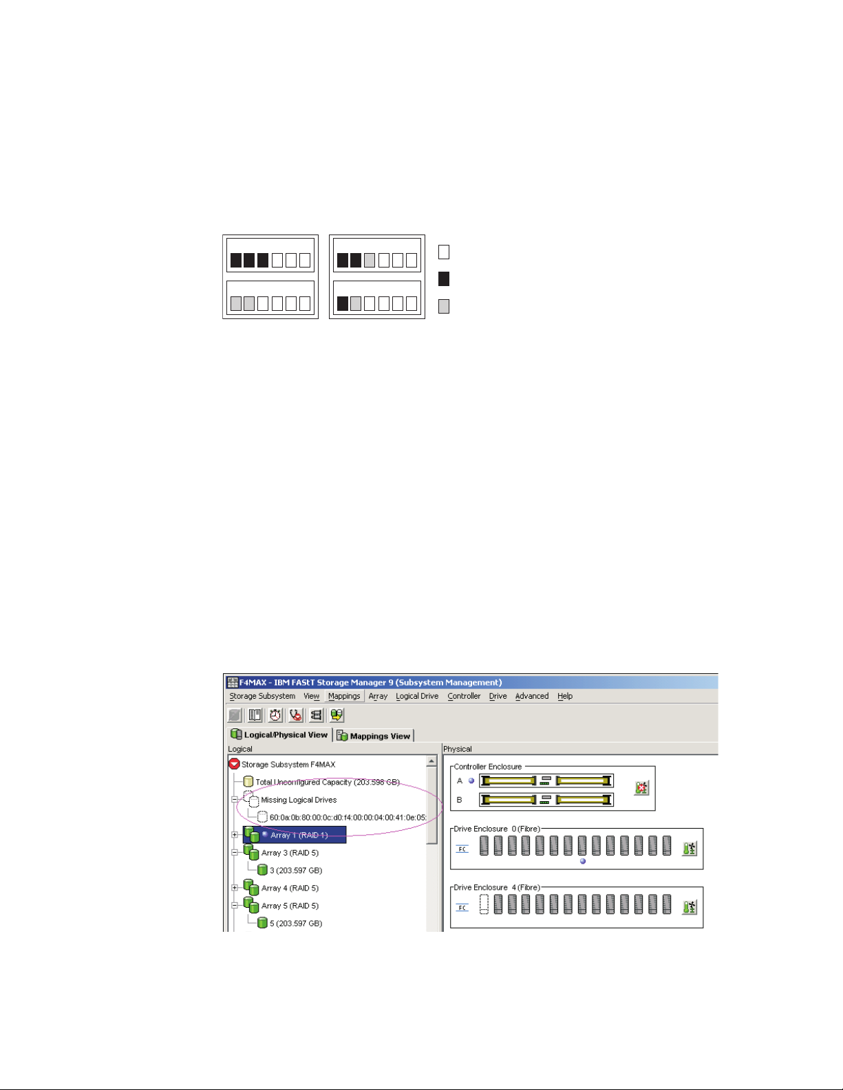
in Offline state. See Figure 1.
Figure 1. Subsystem Management Logical/Physical View of exported drives
6. Click Close to close the Export Array window.
Step 4: Removing drives
See the Installation, User’s and Maintenance Guide before you perform this procedure
to ensure that it applies to your storage subsystem.
To remove the hard disk drives, complete the following steps.
Note: Remove the drives one at a time from the storage enclosure.
1. While the power to the storage subsystem is still turned on, press the inside of
the bottom of the tray handle to release the blue latch.
2. Lift the closed latch to its open position. (The latch is at a 90° angle to the front
of the drive when it is open.)
Note: Your hard disk drives might have a different latching mechanism than
the one shown in Figure 2 on page 19. See the documentation that comes with
your storage enclosure for details.
3. Using the handle, slowly pull the drive 1.27 cm (0.5 in.) out of the drive bay.
Note: For DCS3700 with Gen2 Controllers slowly pull the drive forward until it
hits the drawer cross brace.
4. Wait at least 30 seconds to allow the hard disk drive to spin down before you
remove it from the drive bay.
5. Place the hard disk drive into an ESD bag or container before you move it to
the new DS4000 storage subsystem.
18 IBM System Storage DCS Series with Gen2 controllers Hard Disk Drive and Storage Enclosure Installation and Migration
Guide
Page 33
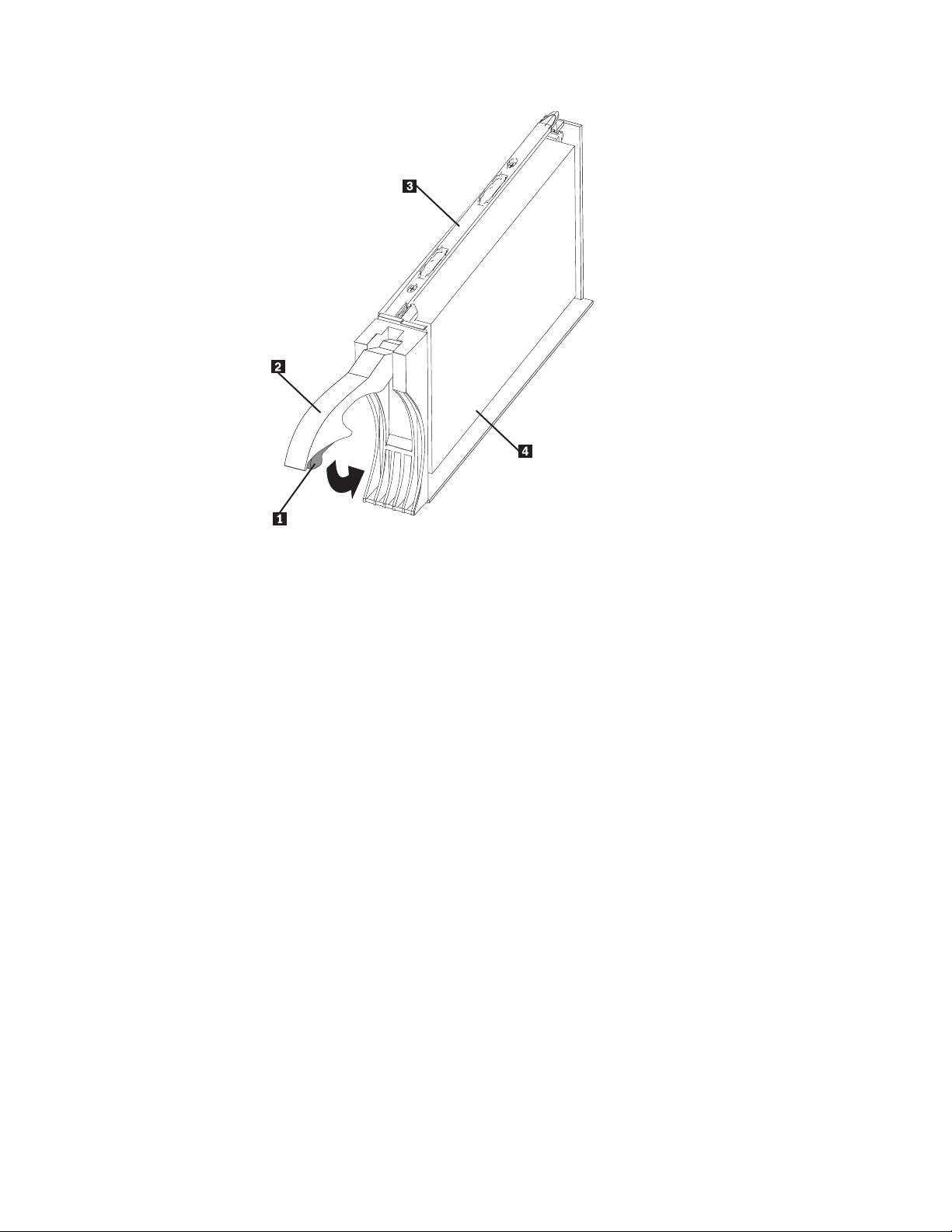
Figure 2. Drive CRU assembly
Legend:
1 Blue latch
2 Drive CRU handle
3 Tray
4 Fibre Channel hard disk drive
Attention: Orient drives horizontally and place them in applicable ESD bags or
containers before relocation. In transit, use moving equipment that prevents
shock to the drives. Never stack drives.
Step 5: Inserting drives
Note:
1. When you migrate hard disk drives from multiple storage subsystems to a
single storage subsystem, move all of the hard disk drives from each storage
subsystem as an independent set. Ensure that all hard disk drives are
transferred before you move another set. If you do not transfer hard disk drives
as sets, the newly relocated arrays/logical drives that are defined by using
these drives might not appear in the Storage Subsystem Management window.
2. Ensure that the drives are compatible with the storage enclosure. For example,
insert a 2-GB drive into a storage enclosure that supports 2-GB drives.
3. The Import Array function is available on storage subsystems or storage
enclosures with controller firmware level 7.xx or later and Storage Manager
software version 10.xx or later.
Important: Insert migrated drives one at a time while the storage subsystem is
turned on and is optimal state to prevent any drive migration problems.
To insert the drives in the target migration storage subsystem, complete the
following steps:
Chapter 2. Adding or migrating hard disk drives 19
Page 34
1. While the destination storage subsystem is turned on, insert the migrating
drives into an empty drive bay one at a time. Wait (up to 5 minutes) until the
inserted drive is fully spun up and displayed in the Storage Subsystem
Management window before you insert the next drive. Arrays appear in
Contingent state (with an arrow icon) until all of the drives in the array are
inserted. The array appears in Exported - ready to import state.
2. If the migrated drives are FDE drives and were configured as part of secured
array, use the saved security key to unlock the drives. Without this security key,
the controllers cannot unlock the drives to retrieve the array configuration data
and data on the drives. Therefore, you cannot import any array/logical drive
configuration from the drives or access data in the drives.
3. Complete the following steps to migrate all of the drives, import the array:
a. Right-click on the name of the array that you want to import in the Storage
Subsystem Management window.
b. Select Advanced -> Import from the pull-down menu.
c. In the confirmation window, click OK.
d. Click Import.
e. In the Import Array window, type yes and click OK.
After a successful import, the message Array was imported successfully is
displayed in the dialog box.
f. Click Close.
4. If any of the following conditions occur, contact IBM support for assistance:
v The Empty Drive Bay icon ( ) is displayed for the drive bay into which
you inserted the migrating drive.
v The Failed Unconfigured Drive icon ( ) or the Failed Configured Drive
icon ( ) is displayed for the drive bay into which you inserted the
migrating drive.
v Array configuration data on the drives that you added is incomplete.
v You cannot import the array.
Attention:
Do not initialize a hard disk drive that you want to keep (by right-clicking its
icon and selecting Initialize from the menu) if it contains configuration or user
data. Initializing any drives in a defined array causes all hard disk drives that
are known to make up that array to return to the Unconfigured Capacity
storage pool, deleting their array definitions from the DS4000 storage
subsystem configuration. The user data on such drives is lost.
When the arrays are online, they are ready to for you to configure and map to
host servers. You might also then re-create FlashCopy images of the logical
drives.
5. Use the DS Storage Manager program to view the storage partitioning
definitions and make any necessary corrections.
Note: The source storage subsystem might indicate that the logical drives are
missing. To remove the missing logical drives, right-click each entry and select
Delete from the menu.
20 IBM System Storage DCS Series with Gen2 controllers Hard Disk Drive and Storage Enclosure Installation and Migration
Guide
Page 35
Migrating arrays within the same storage subsystem
1 2 3 4 5 6
Before After
Empty slot
Drive associated with array
1 2 3 1 2
3
Before After
Empty slot
Drive associated with array
Important
1. Ensure that your controller firmware is at or above the level shown in Table 2
on page 5. Do not rearrange more than one array at a time.
2. Unmount the file systems to flush I/O from the server cache to disks.
Note:
a. In a Microsoft Windows environment, remove the drive letter or the mount
points of the mapped LUNs instead of unmounting the file systems.
b. See the documentation for your operating system for detailed information
about the unmount procedure.
3. Export Array and Import Array functions are available on storage subsystems
or storage enclosures with controller firmware level 7.xx or later and Storage
Manager software version 10.xx or later.
Note: Because disk pool does not support exporting and importing functions,
this functionality is not applicable to drives in disk pools.
Using the configuration data on existing drives, you can redistribute the drives
that make up a RAID array across a storage subsystem to which you might be
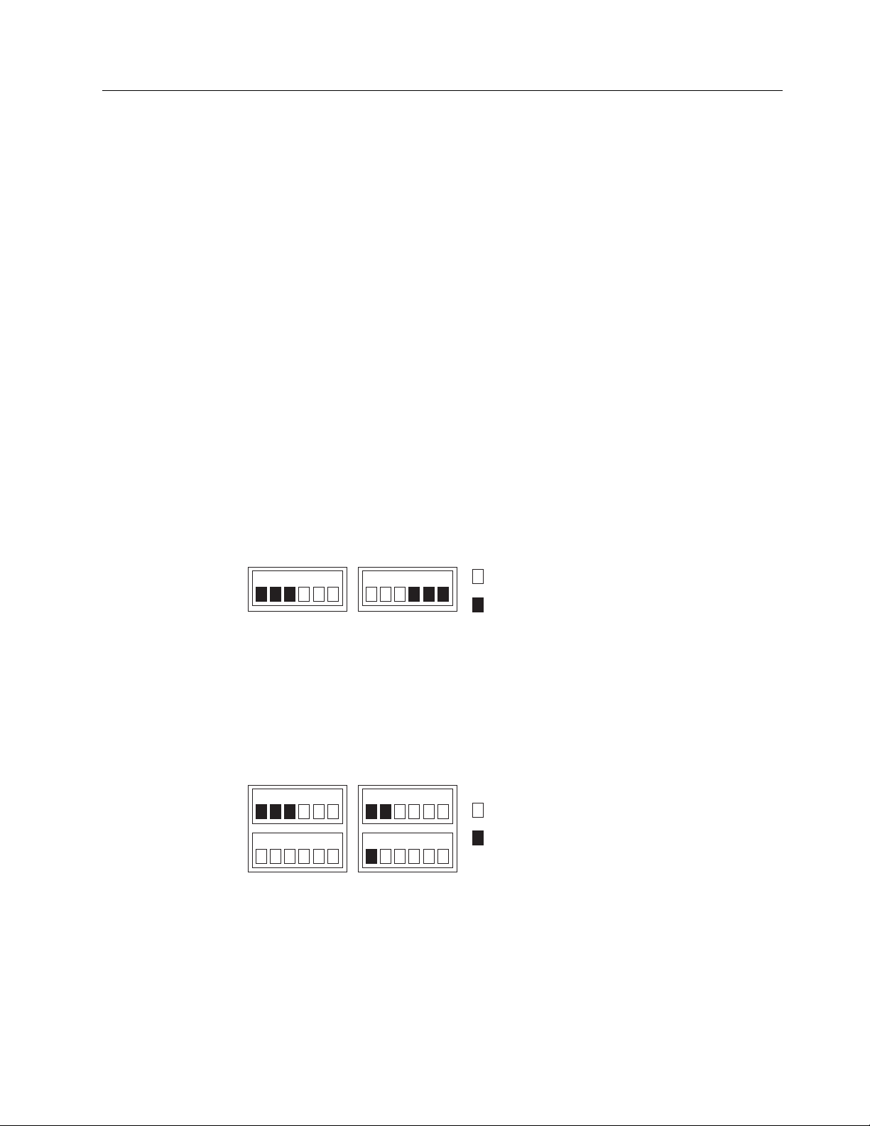
adding storage enclosures. Figure 3 illustrates a storage array that is distributed
across three drives on a single storage device before and after reordering. When
you redistribute each drive to a different position in the same storage enclosure,
which is a best practice, the array is automatically redistributed.
Figure 3. Best practice for reordering a defined array by using empty bays in one storage
enclosure
Figure 4 illustrates a storage array that is distributed across three drives on a single
storage device before reordering across two storage devices. When the drives are
redistributed across an additional storage enclosure in the storage subsystem,
which is a best practice, the array is automatically redistributed.
Figure 4. Best practice for reordering a defined array by using empty bays in two storage
enclosures
Figure 5 on page 22 illustrates two arrays that are distributed across five drives
and two storage enclosures before and after reordering the same drives across
other drive bays in the same two storage enclosures.
Note:
Chapter 2. Adding or migrating hard disk drives 21
Page 36
v Using the Export function is equivalent to placing the array in Offline state. See
1 2 3 1 2 A
3 B
A B
Before After
Empty slot
Drive associated with array
Drive associated with array
“Step 3: Placing drives offline” on page 17 for details on exporting an array.
v When you install the first drive in its new location within the storage subsystem,
the Array icon appears with an arrow but does not change to Online state
automatically. You must use the Import function to place the array in Online
state.
Figure 5. Reordering multiple defined arrays across previously used bays in two storage
enclosures
To reorder drives that make up arrays across different drive bays in the same
storage subsystem configuration, complete the following steps:
1. Start the DS Storage Manager Client program and open the Storage Subsystem
Management window (for the storage subsystem whose drives you are
reordering).
2. Mark the drives in the arrays.
3. Export the arrays that you plan to move.
4. Unlatch the drives. Wait at least 2 minutes for each drive to spin down.
5. Remove the drives from the bays.
6.
Note: Figure 6 shows the array status as missing an array in subsystem
because the array was not exported before the drives that made up the array
were removed from the storage subsystem.
Ensure that all of the drives that made up the arrays are removed from their
Figure 6. Subsystem Management Logical/Physical View of missing logical drives
bays.
22 IBM System Storage DCS Series with Gen2 controllers Hard Disk Drive and Storage Enclosure Installation and Migration
Guide
Page 37

7. Reinsert all of the drives that made up a single array into the empty bays of
the storage enclosure. Do not insert the drives into empty bays that are part of
another array definition whose drives are still inserted in the storage
enclosures. Data on the drives that you insert is replaced with the
reconstructed data from the previously installed RAID array.
8. The system does not bring the array online automatically. You must use the
Import function to import the array configuration and place the array online.
9. Repeat steps 7 and 8 for each of the arrays that were removed from the
storage enclosure.
10. Use the DS Storage Manager Client program to save a storage subsystem
profile and collect the all support data bundle. This information is necessary
to restore a storage subsystem configuration in the event of a catastrophic
failure. Migration from one storage subsystem configuration to another
requires that you save both storage subsystem configuration profiles and
collect all support data bundles. For more information, see the DS Storage
Manager Client program Subsystem Management window online help, or go
to http://www.ibm.com/systems/support/storage/disk/ to access the latest
applicable IBM System Storage DS Storage Manager Version 11.2 Installation and
Host Support Guide.
Important: To avoid loss of data if a RAID array failure occurs, do not store
storage subsystem profiles and collect all support data bundles in the same
location as the logical drives.
Note: Do not reinsert drives from multiple arrays in random order into the
storage enclosures.
Chapter 2. Adding or migrating hard disk drives 23
Page 38

24 IBM System Storage DCS Series with Gen2 controllers Hard Disk Drive and Storage Enclosure Installation and Migration
Guide
Page 39

Chapter 3. Adding or migrating storage enclosures
This chapter describes the procedure to add storage enclosures in a storage
subsystem. It also describes the procedure to migrate storage enclosures from an
existing storage subsystem to another working optimal storage subsystem. If the
destination storage subsystem is a working configuration, follow the procedure in
this chapter to move one or all of the storage enclosures from another storage
subsystem configuration into it. The storage subsystem is in Working state when
the storage subsystem controllers successfully start with at least two drives in the
drive channel.
Note: To migrate the drives in the integrated drive-controller enclosure to another
storage subsystem configuration without an integrated drive-controller enclosure,
you must purchase a storage enclosure for these drives.
Important: Observe proper ESD procedures when you handle electronic
equipment. For more information, see “Handling static-sensitive devices” on page
14.
Attention:
Make additions to the storage subsystem only while the power is turned on and
the storage subsystem is in Optimal state. For more information, see “Bringing
storage subsystems and drive loops into optimal state” on page 11. You can
complete this process while the storage subsystem is receiving I/O from the host
server; however, because the drive loops are interrupted momentarily during the
addition process, schedule the addition to occur during periods of low I/O
between the storage subsystems and host servers.
Considerations
The following notes describe information that you must consider when you add a
hard disk drive to a controller or a storage enclosure:
v Updated readme files contain important configuration and procedural
information that supersede information in this document. Always check the
readme file before you perform any procedure or activity that is described in
this document. To access the most recent readme file, see “Finding Storage
Manager software, controller firmware, and readme files” on page 57.
v Never alter the physical configuration of a storage subsystem while it is turned
off unless you are instructed to do so as part of a storage subsystem
configuration procedure. Specifically, never attach storage components to or
remove storage components from a configured storage subsystem while it is
turned off.
v Every storage subsystem model has unique storage enclosure cabling rules. See
the Installation, User’s and Maintenance Guide for your storage subsystem for
information about the storage enclosure cabling rules. You must follow the
cabling rules to maintain proper storage subsystem operation.
v When you migrate hard disk drives from multiple storage subsystems to a single
storage subsystem, move all of the hard disk drives from each storage subsystem
as an independent set. Before you move the next set of hard disk drives, ensure
that all the hard disk drives from the previous set are transferred. If you do not
transfer hard disk drives as sets, the newly relocated arrays/logical drives might
not appear in the Storage Subsystem Management window.
© Copyright IBM Corp. 2008, 2015 25
Page 40

v Before you migrate hard disk drives, perform the following steps to establish
drive model compatibility:
1. Check the drive CRU form factor options.
2. If the form factors are the same, check to determine whether the subsystem
supports the drive. If the form factors are not the same, there are no
replacement parts such as bezels and drive trays. For more information, see
the announcement letter and the Installation, Users, and Maintenance Guide for
your storage subsystem, and your IBM marketing representative or
authorized reseller.
3. Ensure that the drive can operate at the storage subsystem drive
loop/channel Fibre Channel or SAS speed. For more information, see
“Verifying hard disk drive model compatibility” on page 8.
v Not all combinations of the supported storage enclosures are supported as
storage enclosures intermixed behind storage subsystems.
v Check for drive compatibility in a storage subsystem configuration before you
insert a drive in an empty drive slot.
v Always connect the storage subsystem controller drive channel port to either the
top or bottom EXP3800 or DCS3700 storage expansion enclosure ESM drive port.
v Ensure that the enclosure IDs of each storage enclosure in a redundant drive
loop/channel pair behind a storage subsystem have unique values in the single
digit (x1) position.
The following procedure combines the steps to add storage enclosures that contain
new drives to a storage subsystem configuration with the steps to migrate storage
enclosures. There are indicators in the steps that are specific to either adding or
migrating enclosure tasks. If you are migrating storage enclosures, do not perform
the steps that are indicated as being only for adding storage enclosures:
performing steps for adding storage enclosures might cause the deletion of the
logical drive configuration in the migrated hard disk drives.
Step 1: Preliminary activities
Before you add or migrate storage enclosures, complete the following steps:
1. Ensure that the power to the storage subsystem is turned on and the storage
subsystem is in Optimal state.
If this is a migrating enclosure task, also ensure that the subsystem in which
the enclosures are to be migrated is turned on and is in Optimal state. For more
information, see the Recovery guru for DCS3700 or DCS3860 with Gen2
controllers storage subsystems, or “Bringing storage subsystems and drive
loops into optimal state” on page 11. You can perform this procedure while the
storage subsystem is processing I/O from or to the host server; however,
because the drive loops are interrupted momentarily during the addition
process, schedule any additions to occur during time periods of low I/O
between the storage subsystem and host servers.
Review the readme file and the IBM System Storage DS Storage Manager Version
11.2 Installation and Host Support Guide that is associated with the
operating-system environment of the host servers that connect to the storage
subsystem for any additional restrictions or required preparation tasks that are
specific to your operating-system environment. To access the latest IBM System
Storage DS Storage Manager Version 11.2 Installation and Host Support Guide, go to
http://www.ibm.com/systems/support/storage/disk/.
2. Perform a collect all support data bundles and save the storage subsystem
configuration.
26 IBM System Storage DCS Series with Gen2 controllers Hard Disk Drive and Storage Enclosure Installation and Migration
Guide
Page 41

3. Ensure that the storage subsystem supports the storage enclosures that you are
trying to add or migrate.
4. In the drive enclosure migration situation, verify the controller firmware level
of both the source and target storage subsystems. Upgrade both source and
target storage subsystems to the same controller firmware if possible.
5. If the storage enclosure that is to be migrated is not the same type as the
existing storage enclosures (some or all), see “Intermixing storage enclosures”
on page 11 for intermix information.
6. If you are adding new enclosures with new drives, proceed with the steps in
“Adding new storage enclosures with new hard disk drives”; otherwise,
proceed to the steps in “Migrating storage enclosures with hard disk drives that
have defined logical drive configurations.”
Adding new storage enclosures with new hard disk drives
To add new storage enclosures with new hard disk drives, complete the following
steps:
1. Set the enclosure ID of the additional storage enclosures with Fibre Channel
drive ports that have a mechanical enclosure ID switch.
Each enclosure in the storage subsystem configuration must have a unique
enclosure ID. In addition, the IDs of enclosures (including the storage
subsystem with internal drive bays) that are connected together in the same
redundant drive loop/channel pair must each have a unique rightmost digit.
For example, 01, 02, 03, 04 or 11, 12, 13, 14 are the correct IDs of the enclosures,
including the subsystems with internal drives that are connected together in a
drive loop/channel, whereas 01, 11, 21, 31 or 11, 11, 22, 33 are not the correct
IDs of the enclosures that are connected together in a drive loop/channel pair
(including the subsystems with internal drives) because the rightmost digits in
the enclosure IDs are not unique (01, 11, 21, 31) or the enclosure IDs are not
unique (11, 11, 22, 33).
The DCS3700 and EXP3800 storage enclosures have a display mechanism to
show the enclosure ID. The enclosure ID is automatically set by the controller
firmware. You can change the enclosure ID using the IBM DS Storage Manager
client.
For more information, see the documentation that comes with your storage
enclosure.
If the storage subsystem to which the storage enclosure attaches is a DCS3700
or DCS3860 storage subsystem with Gen2 controllers, the enclosure IDs of
additional storage enclosures must be unique to the storage subsystem. The
enclosure IDs are normally set to 00 at the factory.
2. Proceed to “Step 6: Cabling, turning on, and verifying storage enclosure
operation” on page 31. Do not perform Activities 3–5.
Migrating storage enclosures with hard disk drives that have defined logical drive configurations
Before you begin, review the “Drive migration limitations” on page 7 section.
Drives with disk pools cannot be migrated from one subsystem to another. The
data in the disk pool must be backed up to a tape or to drives that are part of
traditional arrays. Then, the data is restored to newly created disk pools in another
storage subsystem.
To migrate storage enclosures with hard disk drives that have defined logical drive
configurations, complete the following steps.
Chapter 3. Adding or migrating storage enclosures 27
Page 42

1. Ensure that controller firmware and NVSRAM in both the target migration
storage subsystem and the storage subsystem that contains the enclosures that
are to be migrated are at the levels in Table 2 on page 5.
2. Ensure that the firmware of the ESMs in the storage enclosures that you plan
to migrate are at the levels in Table 3 on page 5.
3. Ensure that the firmware of the ESMs in the storage enclosures that are
attached to the target migration storage subsystem is at the levels in Table 3
on page 5.
4. Data on drives migrate with those drives when the drives are installed on
another storage subsystem. For a successful migration, perform steps 5, 6, 7
and 8 that follow.
5. Delete the storage partitioning mappings of the logical drives.
6. Ensure that all of the IDs of the storage enclosures in the redundant drive
loop/channel have unique single digit (x1) values.
7. In addition to array configuration information, any storage partitioning
configuration data on drives migrate with those drives when they are installed
on another storage subsystem. For this reason, take the following precautions
to facilitate the migration process and prevent problems in storage
partitioning configuration data migration:
a. If a storage partitioning premium feature is enabled on both the original
and destination storage subsystems, ensure that the defined host ports,
hosts, and host group names are unique to each storage subsystem that is
involved in the migration.
b. If you must use identical names on both storage subsystems, make the
names unique before you perform the drive migration. If necessary,
customize the storage partitioning information about the storage
subsystem to which you migrated the drives after you complete the
migration.
8. Delete any FlashCopy images of logical drives that are defined in the hard
disk drives.
9. Remove any remote mirror relationships that involve the logical drives that
are defined on the drives that you plan to migrate.
10. Proceed to “Step 2: Preparing and backing up the drives.”
Step 2: Preparing and backing up the drives
To prepare and back up the drives, complete the following steps.
Note: The following procedure is for migrating enclosures with drives that have
defined arrays/logical drives only. Do not perform this procedure if you are
adding enclosures with new drives or drives that contain unneeded data.
1. If the arrays and logical drives that are involved are not in Optimal state,
perform the steps that are necessary to bring these arrays and logical drives to
Optimal state before you attempt migration. Use the Recovery Guru function in
the Storage Subsystem Management window of the DS Storage Manager Client
program. For more information, “Bringing storage subsystems and drive loops
into optimal state” on page 11.
2. If the drive enclosures that you plan to migrate are not in Optimal state,
perform the steps that are necessary to bring them to Optimal state before you
attempt migration. Use the Recovery Guru function in the Storage Subsystem
Management window of the DS Storage Manager Client program. For more
information, see “Bringing storage subsystems and drive loops into optimal
state” on page 11.
28 IBM System Storage DCS Series with Gen2 controllers Hard Disk Drive and Storage Enclosure Installation and Migration
Guide
Page 43

3. Perform a backup of the logical drives that are defined in the storage
enclosures.
4. Monitor the storage subsystem event log for any errors in the drive loop or its
components for several days before you migrate storage enclosures.
5. Stop all programs, services, or processes in the host servers that access the
logical drives that are defined in the migrated hard disk drives. ensure that
there are not any running background programs, services, or processes that
write data to the logical drives. (For example, Microsoft MSCS service
periodically writes to the “Quorum” disk.)
6. Unmount the file systems to flush I/O from the server cache to disks.
Note:
a. In a Microsoft Windows environment, remove the drive letter or the mount
points of the mapped LUNs instead of unmounting the file systems.
b. See the documentation for your operating system for detailed information
about the unmount procedure.
7. Save the storage subsystem profile and storage subsystem configuration, and
collect all support data bundles of the target storage subsystem in a location
other than the logical drives that you plan to migrate.
8. Place the arrays that are defined in the storage enclosures that you plan to
migrate in Offline state. Use the Export Array feature. See “Step 3: Placing
drives offline” on page 17 for details.
9. If the migrated drives are FDE drives and were configured as part of a secured
array, save the security key to unlock the drives after you install them in a new
storage subsystem. Without this key, the controllers cannot unlock the drives to
perform read and write operations.
Step 3: Shutting down and moving the storage enclosures
To shut down and move the storage enclosure, complete the following steps.
Note: The following procedure is for migrating enclosures with drives that have
defined arrays/logical drives only. Do not perform this procedure if you are
adding enclosures with new drives or drives that contain unneeded data.
1. Because removing a storage enclosure from a storage subsystem disrupts the
drive loops, shut down the storage subsystem while you remove the storage
enclosures for migration to another storage subsystem. If you cannot shut
down the storage subsystem, reconfigure only one drive loop, making sure that
the drive loop that you modify is connected correctly and in Optimal state
before you attempt to reconfigure the other drive loop. For more information,
see “Bringing storage subsystems and drive loops into optimal state” on page
11.
Take this precaution to prevent the arrays from being inadvertently failed by
the storage subsystem controllers because two or more drives in the arrays
cannot be reached through either drive loop in the redundant drive loop pair.
Complete the following steps to verify that the drive loops are in Optimal state:
a. Physically trace the actual cable connections to ensure that connections are
properly modified and that the cable connectors are firmly inserted into the
SFPs.
b. Ensure that the following LEDs are not lit or flashing in the modified drive
loop:
v ESM fault
v Port bypass
Chapter 3. Adding or migrating storage enclosures 29
Page 44

v ID conflict
c. Ensure that the controller drive loop LED remains lit. If the controller drive
loop LED is turned off, there are problems in the drive loop, and the loop
initialization primitives (LIPs) are generated by the storage subsystem
controller.
d. In the DS Storage Manager Client Subsystem Management window, verify
that there are no Loss of ESM path redundancy errors in the storage
enclosures that are not migrated.
Do not modify the second drive loop in the redundant drive loop pair until
you are sure that the first modified drive loop is operating in Optimal state.
2. Turn off the power to the storage enclosures and move them to the storage
subsystem to which you plan to migrate them.
Attention: A storage enclosure with 60 drives weighs up to 101 kg (223 lb). If
necessary, remove the drives and other storage enclosure components to reduce
the weight of the unit for easier handling. Mark each drive before you remove
it so that you can return it to the same drive bay when you reassemble the
components. The DCS3700 and EXP3800 storage enclosures might require a lift
tool and a relocation kit to move the storage enclosures from one location to
another. For more information, see the storage enclosure documentation.
Step 4: Verifying the drive migration enable settings
Attention: There is no need to verify drive migration enable settings in storage
enclosures with controller firmware level 7.xx or later and Storage Manager
software version 10.xx or later.
Step 5: Installing and setting storage enclosure IDs
Note: The following procedure is for migrating enclosures with drives that have
defined arrays/logical drives only. Do not perform this procedure if you are
adding enclosures with new drives or drives that contain unneeded data.
To install and set storage enclosure IDs, complete the following steps:
1. When the storage enclosures and drives are at the location of the storage
subsystem to which you are migrating them, install them into the rack. If the
drives were removed during transit, return them to the bays from which they
were removed, unlatched and no less than 1.27 cm (0.5 in.) away from their full
insertion points in the drive bays. If the drives were not removed, unlatch and
pull them out no less than 1.27 cm (0.5 in.) away from their full insertion points
in the drive bays.
2. Ensure that the enclosure ID of each enclosure in a storage subsystem
configuration is unique. For more information, see “Adding new storage
enclosures with new hard disk drives” on page 27.
Important: If the storage subsystem to which the storage enclosure attaches is a
DCS3700 or DCS3860 storage subsystem with Gen2 controllers, the IDs of
additional storage enclosures must be unique to the storage subsystem. The
enclosure IDs of these storage subsystems is normally set to 00 at the factory.
Note: Before you migrate hard disk drives, be sure to determine the compatibility
of drive model capacity, interface type, and speed. For specific information about
your drive options in the most current environment, see “Verifying hard disk drive
model compatibility” on page 8.
30 IBM System Storage DCS Series with Gen2 controllers Hard Disk Drive and Storage Enclosure Installation and Migration
Guide
Page 45

Step 6: Cabling, turning on, and verifying storage enclosure operation
This procedure is for both adding and migrating storage enclosures. The following
notes describe information that you must consider when you connect the storage
enclosure:
v Connect the new storage enclosure first to any unused drive ports, especially if
you are adding storage enclosures of a different type to the configuration.
v If there are not any unused drive ports, connect the new storage enclosure to the
existing drive loop that can accommodate additional storage enclosures.
v Add only one storage enclosure at a time to a drive loop, if you intend to attach
multiple storage enclosures.
v See the documentation that comes with your storage subsystem to attach the
storage enclosures to the storage subsystem.
Attention: Do not power on a storage subsystem with new drives installed in
the new storage enclosures. Either remove the drives completely or pull out the
drives about one-half inch from the storage enclosure before powering on the
storage subsystem. Otherwise, the controllers might not boot up.
Cabling the new enclosures
To complete the addition of storage enclosures, cable the storage enclosures to the
end of the storage enclosure drive loop to which you are migrating them. Add
only one enclosure at a time to a drive loop, if you intend to attach multiple
storage enclosures.
Connect the storage enclosure to any unused drive ports when you add storage
enclosures to an existing configuration, especially if you are adding enclosures of a
different type to the configuration. See the documentation that comes with your
storage subsystem to attach the storage enclosures to the storage subsystem.
You might find that connection to the end (at the bottom) directly attached to
controller B is best practice because if the existing configuration is not planned for
cabling-in storage enclosures at the top or the middle of the drive loop, cluttered
drive loop cabling might hinder troubleshooting or cause cabling errors. Only
typical expansion enclosure additions are shown in the procedure and graphics in
these sections. However, the instructions can be adapted for all expansion
enclosure addition scenarios. For the appropriate cabling scenario and to adapt the
instructions to add an expansion enclosure to an existing drive loop in a storage
subsystem configuration, see the storage subsystem Installation, User's and
Maintenance Guide.
Connecting storage enclosures at the end (bottom) of a drive loop
Connecting a new storage enclosure to the end of the drive loop is the best
practice to avoid cluttered drive loop cabling that might hinder troubleshooting or
cause cabling errors.
To connect a storage enclosure at the end (bottom) of a drive loop, complete the
following steps:
1. Extend one of the drive loops (that is, drive loop/channel that is connected to
controller A) in a storage subsystem redundant drive loop/channel pair by
Chapter 3. Adding or migrating storage enclosures 31
Page 46

connecting the ESM port of the top ESM in the last storage enclosure on the
existing drive loop/channel A to the ESM port of the top ESM in the new
storage enclosure.
2. Ensure that there are not any drives fully inserted in the drive bays; then, turn
on the power to the added storage enclosure.
3. Wait a few seconds. Check the drive port LEDs to ensure that the link to the
new storage enclosure is up and optimal and that there are no link problems in
the modified drive loop A. Ensure that the SAS link service (SAS port) LEDs
are not lit or intermittently lit. Using the DS Storage Manager Client Subsystem
Management window, verify that the storage enclosure is added and displayed
in the Logical/Physical view of the window. To return the drive loop/channel
to optimal state, see “Returning the drive/loop channel to optimal state” on
page 33.
4. In the drive loop/channel that is connected to controller B, move the
connection from controller B drive port to the ESM port in the bottom ESM of
the last storage enclosure in the existing drive loop/channel B to the ESM port
of the bottom ESM in the new storage enclosure. Controller B drive port is now
connected to the ESM port of the new storage enclosure.
5. Wait a few seconds. Check the drive port LEDs to ensure that the link to the
new storage enclosure is up and optimal and that there are no link problems in
the modified drive loop B. Ensure that the SAS link service (SAS port) LEDs
are not lit or intermittently lit. Using the DS Storage Manager Client Subsystem
Management window, verify that the storage enclosure is added and displayed
in the Logical/Physical view of the window. To return the drive loop/channel
to optimal state, see “Returning the drive/loop channel to optimal state” on
page 33. The existing storage enclosures are shown with Drive enclosure lost
redundancy path errors until you establish the cabling connection described in
the next step.
6. In drive loop B, cable the ESM port in the bottom ESM of the new storage
enclosure to the ESM port in the bottom ESM of the last storage enclosure in
drive loop B.
7. Wait a few seconds. Check the drive port LEDs to ensure that the link to the
new storage enclosure is up and optimal and that there are no link problems in
the modified drive loop B. Ensure that the SAS link service (SAS port) LEDs
are not lit or intermittently lit. Using the DS Storage Manager Client Subsystem
Management window, verify that the storage enclosure is added and displayed
in the Logical/Physical view of the window. To return the drive loop/channel
to optimal state, see “Returning the drive/loop channel to optimal state” on
page 33. The existing storage enclosures are shown with Drive enclosure lost
redundancy path errors until you establish the cabling connection described in
the earlier step.
8. The DS Storage Manager Client Subsystem Management window displays a
new storage enclosure with no drives in the configuration.
Connecting storage enclosures at the end (bottom) of a SAS drive cable loop scheme in a DCS3700 and DCS3860 storage subsystems with Gen2 controllers configuration
For DCS3700 and DCS3860 storage subsystem with Gen2 controllers configurations
with an initial drive loop/channel cabling scheme, Table 8 on page 33 shows how
you cable the ports. A port enclosed by () indicates that you remove the connection
as part of the step.
32 IBM System Storage DCS Series with Gen2 controllers Hard Disk Drive and Storage Enclosure Installation and Migration
Guide
Page 47

Table 8. Connecting storage enclosures at the end (bottom) of a SAS drive cable loop
scheme in a DCS3700 and DCS3860 storage subsystems with Gen2 controllers
configuration
Step Storage subsystem Drive expansion 2 Drive expansion 3
1 on page
31
4 on page
32
6 on page
32
ControllerAControllerBtop ESM bottom
ESM
OUT IN
Drive port
x
(IN) IN
IN OUT
top ESM bottom
Returning the drive/loop channel to optimal state
To return the drive loop/channel to optimal state, complete the following steps:
1. Reseat the cable.
2. Use a new cable.
3. Check the new storage enclosure compatibility with the existing storage
enclosures.
4. Check for any special cabling requirements.
5. Perform any additional suggestions as indicated by the Recovery Guru function
in the Storage Subsystem Management window.
6. If necessary, contact your IBM marketing representative or authorized reseller
for assistance.
7. If the problem remains, contact IBM support for assistance.
ESM
Storage subsystem SAS drive channel/loop schemes for enclosures in a DCS3700 configuration
The DCS3700 storage subsystem with Gen2 controllers supports up to two
DCS3700 storage enclosures per physical expansion port, so multiple DCS3700
storage enclosures can be connected by chaining them together.
The following illustration shows the supported cabling configuration to connect a
DCS3700 storage subsystem with Gen2 controllers to the storage enclosures, and
between the storage enclosures with SAS drive channels.
Chapter 3. Adding or migrating storage enclosures 33
Page 48

To connect the DCS3700 storage system with Gen2 controllers RAID controllers A
and B to multiple DCS3700 expansion enclosures, complete the following steps:
1. Connect the DCS3700 expansion enclosure to controller A:
a. Connect one end of a SAS cable to the drive expansion port on controller A.
b. Connect the other end of the SAS cable to one of the In (↑) SAS connectors
on the ESM in SBB slot A in the DCS3700 expansion enclosure.
2. Connect the SAS cable of the DCS3700 expansion enclosure to the next
DCS3700 expansion enclosure in the chain:
a. Connect one end of a SAS cable to the Out (↓) SAS connector on the ESM in
SBB slot A of the DCS3700 expansion enclosure that you connected.
b. Connect the other end of the SAS cable to one of the In (↑) SAS connectors
on the ESM in SBB slot A in the next DCS3700 expansion enclosure in the
chain.
34 IBM System Storage DCS Series with Gen2 controllers Hard Disk Drive and Storage Enclosure Installation and Migration
Guide
Page 49
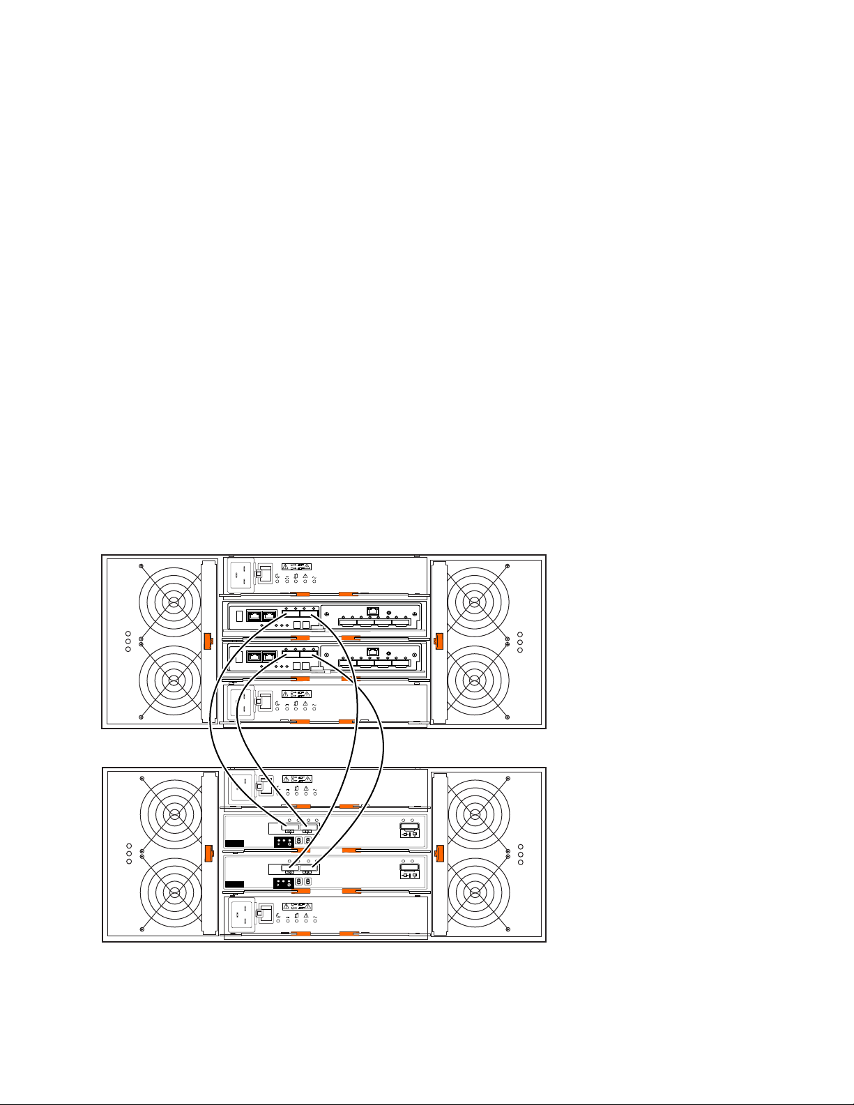
3. Connect the last DCS3700 expansion enclosure in the chain to controller B:
ACDC
2
1
I
O
ACDC
2
1
I
O
Lnk Lnk
ACDC
2
1
I
O
ACDC
2
1
I
O
!
ID/Diag
!
1
2
Lnk Lnk Lnk Lnk
! !
ESM
Lnk Lnk
!
ID/Diag
!
1
2
Lnk Lnk Lnk Lnk
! !
ESM
!
!
dcsi0050
a. Connect one end of a SAS cable to the drive expansion port on controller B.
b. Connect the other end of the SAS cable to one of the In (↑) SAS connectors
on the ESM in SBB slot B in the last DCS3700 expansion enclosures of the
chain that you created.
4. In reverse order (last in chain to first in chain), connect the ESM in SBB slot B
to the DCS3700 first expansion enclosure in the chain:
a. Connect one end of a SAS cable to the Out (↓) SAS connector on the right
ESM of the DCS3700 expansion enclosure that you just connected.
For detailed information about cabling the DCS3700 storage enclosures to the
DCS3700 configuration, see the IBM System Storage DCS3700 Storage Subsystem with
Gen2 Controllers Installation, User's, and Maintenance Guide..
Storage subsystem SAS drive channel/loop schemes for enclosures in a DCS3860 with Gen2 controllers configuration
The DCS3860 storage system with Gen2 controllers supports up to five
EXP3800/DCS3700 expansion enclosures with two physical expansion ports.
Multiple EXP3800/DCS3700 expansion enclosures can be connected by chaining
them together.
The following illustration shows the supported cabling configuration to connect a
DCS3860 storage subsystem with Gen2 controllers to the storage enclosures and
between the storage enclosures with SAS drive channels.
Figure 7. Connecting the first EXP3800/DCS3700 expansion enclosure
Complete the following steps to connect the first EXP3800/DCS3700 expansion
enclosure to the DCS3860 storage system with Gen2 controllers .
Chapter 3. Adding or migrating storage enclosures 35
Page 50

1. Connect one end of a SAS cable to the drive expansion port 1 on controller A
and the other end to the In (↑) SAS connector 1 on the ESM located in slot A of
the EXP3800/DCS3700 expansion enclosure.
2. Connect one end of a SAS cable to the drive expansion port 1 on controller A
and the other end to the In (↑) SAS connector 1 on the ESM located in slot A of
the EXP3800/DCS3700 expansion enclosure.
3. Connect one end of a SAS cable to the drive expansion port 1 on controller B
and the other end to the In (↑) SAS connector 2 on the ESM located in slot A.
4. Connect one end of a SAS cable to the drive expansion port 2 on controller B
and the other end to the In (↑) SAS connector 2 on the ESM located in slot B.
5. Wait until the status of the storage system is Optimal.
6. Add drives to the storage enclosure one at a time. Add drive only after the
IBM DS Storage Manager recognizes the drive you added earlier. Wait at least
30 seconds for the IBM DS Storage Manager to recognize a newly added drive.
Cabling multiple enclosures
The following illustration shows the supported cabling configuration to connect a
DCS3860 storage subsystem with Gen2 controllers to multiple storage enclosures
and between the storage enclosures with SAS drive channels.
36 IBM System Storage DCS Series with Gen2 controllers Hard Disk Drive and Storage Enclosure Installation and Migration
Guide
Page 51
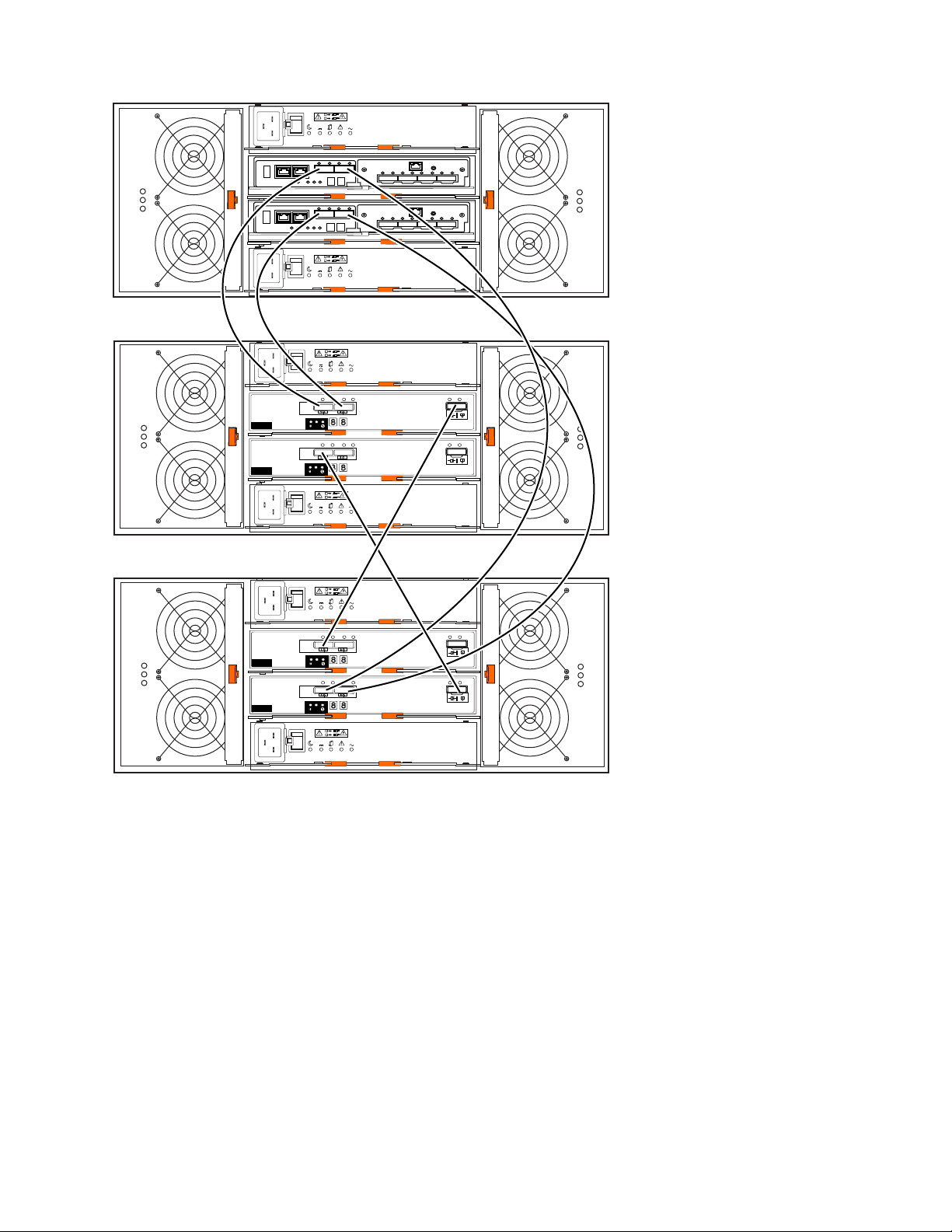
Lnk Lnk
ACDC
2
1
I
O
ACDC
2
1
I
O
!
ID/Diag
!
1
2
Lnk Lnk Lnk Lnk
! !
ESM
Lnk Lnk
!
ID/Diag
!
1
2
Lnk Lnk Lnk Lnk
! !
ESM
!
!
ACDC
2
1
I
O
ACDC
2
1
I
O
Lnk Lnk
ACDC
2
1
I
O
ACDC
2
1
I
O
!
ID/Diag
!
1
2
Lnk Lnk Lnk Lnk
! !
ESM
Lnk Lnk
!
ID/Diag
!
1
2
Lnk Lnk Lnk Lnk
! !
ESM
!
!
dcsi0052
Figure 8. Adding enclosures
1. Ensure that the status of the DCS3860 with Gen2 Controllers storage system is
2. Use the expansion enclosure Rack Installation Instructions document to install
3. Connect the power cables to the new expansion enclosure and power it on.
4. Connect one end of a SAS cable to the Out (↓) SAS connector on the ESM
5. Connect the other end to the In (↑) SAS connector 1 on the ESM located in slot
6. Remove the cable from the In (↑) SAS connector 1 on the ESM located in slot B
Optimal.
the new expansion enclosure in the rack.
located in slot A of the earlier/last EXP3800/DCS3700 expansion enclosure in
the configuration.
A of the EXP3800/DCS3700 expansion enclosure you want to add.
of the earlier/last EXP3800/DCS3700 expansion enclosure and connect it to the
In (↑) SAS connector 1 on the ESM located in slot B of the EXP3800/DCS3700
expansion enclosure you want to add.
Chapter 3. Adding or migrating storage enclosures 37
Page 52

7. Remove the cable from the In (↑) SAS connector 2 on the ESM located in slot B
of the earlier/last EXP3800/DCS3700 expansion enclosure and connect it to the
In (↑) SAS connector 2 on the ESM located in slot B of the EXP3800/DCS3700
expansion enclosure you want to add.
8. Connect one end of a SAS cable to the In (↑) SAS connector 1 on the ESM
located in slot B of the earlier/last EXP3800/DCS3700 expansion enclosure and
connect the other end of the SAS cable to the Out (↓) SAS connector on the
ESM located in slot B of the EXP3800/DCS3700 expansion enclosure you want
to add.
9. Repeat steps 2 on page 37 through 8 to add more EXP3800/DCS3700 expansion
enclosures. You can add up to five expansion enclosures.
Step 7: Inserting drives and cabling additional storage enclosures
Note: Complete the following procedure only if you are adding enclosures with
new drives. Otherwise, go to “Step 8: Inserting hard disk drives and placing logical
drives online.”
To insert drives and connect additional storage enclosures, complete the following
steps:
1. Insert the applicable drives into empty drive bays in the new enclosure one at a
time. Wait (up to 5 minutes) until the inserted drive fully spins up and is
identified in the Storage Subsystem Management window; then, insert the next
hard disk drive.
2. To connect additional storage enclosures to a drive loop pair, repeat the steps of
the applicable procedure in Step 6. Do not proceed to add additional storage
enclosures if you are still having problems with the modified drive loop and
the newly inserted drives. This step completes the procedure to add enclosures
with new drives.
Attention: Plan carefully before you add enclosures to the middle or the top
of the drive loop. Cabling errors might cause loss of data availability, or loss of
data.
Step 8: Inserting hard disk drives and placing logical drives online
Note: To ensure that the arrays are on the Storage Subsystem Management
window, move all of the hard disk drives as independent sets when you migrate
hard disk drives from multiple storage subsystems to a single storage subsystem.
Ensure that each set successfully transfers before you move another set of drives.
To migrate enclosures with drives that contain logical drive configuration data,
complete the following steps:
1. For each additional enclosure that you intend to migrate to the drive loop pair,
perform the procedure in “Step 5: Installing and setting storage enclosure IDs”
on page 30 and “Step 6: Cabling, turning on, and verifying storage enclosure
operation” on page 31.
Attention: Plan carefully before you add enclosures to the middle or the top
of the drive loop. Cabling errors might cause loss of data availability, or loss of
data.
2. Insert the drives into the empty drive bays in the new enclosure, one at a time.
Wait (up to 5 minutes) until each drive pair fully spins up and is identified in
the Storage Subsystem Management window; then, insert the next hard disk
drive pair.
38 IBM System Storage DCS Series with Gen2 controllers Hard Disk Drive and Storage Enclosure Installation and Migration
Guide
Page 53
3. The array and logical drive information is shown on the Logical/Physical view
of the Storage Subsystem Management window. The arrays appear in
Contingent state (with an arrow icon) until all of the drives in the array are
inserted. The array appears in Exported - ready to import state.
4. If the migrated drives are FDE drives and were configured as part of a secured
array, use the saved security key from the storage subsystems that these drives
are migrated from to unlock the drives. Without this security key, the
controllers cannot unlock the drives to retrieve the array configuration data and
data on the drives.
5. Complete the following steps:
a. Click the name of the array that you want to import in the Storage
Subsystem Management window.
b. Click Advanced -> Maintenance -> Import Array.
c. In the confirmation window, click OK.
d. Click Import.
e. In the Import Array window, type yes and click OK.
f. Click Close.
6. If any of the following conditions remain, contact IBM support for assistance.
v The Empty Drive Bay icon ( ) is displayed for the drive bay into which
you inserted the migrating drive.
v The Failed Unconfigured Drive icon ( ) or the Failed Configured Drive
icon ( ) is displayed for the drive bay into which you inserted the
migrating drive.
v Array configuration data on the drives that you added is incomplete.
Attention: Do not initialize a hard disk drive that you want to keep (by
right-clicking its icon and selecting Initialize from the pull-down menu) if it
contains configuration or user data. Initializing any of the drives in a defined
array causes all hard disk drives in an array to return to the Unconfigured
Capacity storage pool, deleting their array definitions from the configuration.
The user data on such drives is lost.
Result: When the arrays are online, they are ready for you to configure and
map to host servers. You might also then re-create FlashCopy images and
remote mirror relationships.
7. Use the DS Storage Manager program to view the storage partitioning
definitions and make any necessary corrections.
8. The storage subsystem that the drives are migrated from displays the logical
drives that are defined in these drives as missing LUNs. To remove these
missing LUN entries, right-click each entry and select Delete from the menu.
You completed the procedure for migrating enclosures.
Chapter 3. Adding or migrating storage enclosures 39
Page 54

40 IBM System Storage DCS Series with Gen2 controllers Hard Disk Drive and Storage Enclosure Installation and Migration
Guide
Page 55

Chapter 4. Upgrading a storage subsystem controller
This chapter describes the procedure to replace the storage subsystem controller in
a working configuration with a new storage subsystem controller of the same or
different model. All the hard disk drives and storage enclosures in the original
configuration are part of the new configuration. Use the procedures in this chapter
only if no drives are attached to the new storage subsystem. This procedure is also
referred to as controller head-swapping. If the new storage subsystem is part of a
working configuration where the storage subsystem controllers are booted with at
least two drives, see Chapter 3, “Adding or migrating storage enclosures,” on page
25 to migrate the drives and storage enclosures instead.
IBM support is available for controller upgrade assistance, but you must contact
your IBM marketing representative or authorized reseller as first-line support. For
more information, see “Getting information, help, and service,” on page 57.
Only the replacement of the controller in a single working storage subsystem
configuration with another controller is supported. To consolidate the storage
enclosures behind multiple controllers in multiple working storage subsystem
configurations, perform the applicable controller swap procedure that is described
in this chapter to upgrade one working storage subsystem configuration. Then, see
Chapter 3, “Adding or migrating storage enclosures,” on page 25 for instructions
for migrating the storage enclosures in the other storage subsystems into the new
controller storage subsystem configuration.
A readme file is available with the latest information and instructions for each
storage subsystem. To access the most recent readme file, see “Finding Storage
Manager software, controller firmware, and readme files” on page 57.
Upgrade considerations
Consider the following information before you upgrade a storage subsystem.
Host attachment and premium feature entitlements
The following notes describe information about host attachment and premium
feature entitlements that you must consider before you upgrade a storage
subsystem.
v To enable premium features in a new or replacement configuration that were
enabled in an original configuration, you must purchase the applicable
entitlements for the new or replacement storage subsystem, if that premium
feature is not standard in the new or replacement storage subsystem. In
addition, IBM assigns host attachment kits only to specific storage subsystems.
You must also purchase the applicable host attachment kits for new or
replacement storage subsystems.
v After the upgrade, premium features that were previously enabled in the
original storage subsystem along with the enable-by-default premium features in
the new storage subsystem are automatically placed in Out of Compliance state.
You must generate new premium feature SAFE keys to re-enable premium
features.
© Copyright IBM Corp. 2008, 2015 41
Page 56

Follow the instructions in the Premium Features Activation instructions that
come with the Premium Feature kits to generate the premium feature keys. Also,
to generate new premium feature keys, go to http://www-912.ibm.com/
PremiumFeatures/.
Storage firmware migration
The following notes describe information about controller firmware migration that
you must consider before you upgrade a storage subsystem:
v You can migrate the drives and storage enclosures in a storage subsystem to a
new controller only if the firmware in the controllers of the storage subsystem
and the new controller have the same major release version.
v To perform a migration from an original storage subsystem controller with
firmware version 7.xx or later to a new storage subsystem controller with
firmware version 7.xx or later , the controller firmware version in the original
controller must be the same as or earlier than the controller firmware version in
the new controller. As an exception, if either the original or the new DS3500 or
DCS3700 with Gen2 Controllers has controller firmware version 7.8x.xx.xx or
later installed, the original and the new DS3500 or DCS3700 with Gen2
Controllers must be upgraded to the same version as that of the 7.8x.xx.xx or
later controller firmware, before the head-swap. Two extra new drives might
need to be purchased to bring up the new storage subsystem for controller
firmware upgrading. Otherwise, the controller firmware in the new controller is
placed in the Controller Lock Down state.
Complete the following steps, if the 7.xx or later firmware version in the new
storage subsystem is earlier than the 7.xx or later firmware version in the
original controller:
1. Purchase two additional hard disk drives.
2. Build a configuration with the new hard disk drives and the new DS3500 or
DCS3700 with Gen2 Controllers subsystem enclosure. You might also need to
add a drive expansion enclosure if there are not any available drive slots in
the new DS3500 or DCS3700 with Gen2 Controllers storage subsystem
enclosure.
3. Use the storage enclosure or drive migration procedures that are listed in this
document to add existing enclosures or hard disk drives to the new storage
subsystem configuration.
4. After successful migration, remove the storage enclosure with which you
started the new storage subsystem, if necessary.
Note: For more information, see the “Drive migration limitations” on page 7
section.
Alternative procedure to upgrade a storage subsystem controller enclosure
There is an alternative method to upgrade a storage subsystem controller
enclosure. To bring the new storage subsystem controller into an optimal state, you
must obtain a minimum of two new drives and a storage expansion enclosure (if
the storage subsystem controller did not have any available drive slots). Then you
must migrate the drives and drive expansion enclosure from the original storage
subsystem to the new storage subsystem.
To upgrade the storage subsystem controller by using this alternative method,
complete the following steps:
1. Plan the upgrade. For more information, refer to step 1 on page 46.
42 IBM System Storage DCS Series with Gen2 controllers Hard Disk Drive and Storage Enclosure Installation and Migration
Guide
Page 57
2. Purchase two new drives and a drive expansion enclosure (if there are not any
available drive slots in the new storage subsystem).
3. Prepare the new storage subsystem for the upgrade:
a. Unpack the new storage subsystem, and install it in a rack.
b. If required, unpack and connect the storage enclosure to the new storage
subsystem. Install the two new drives in the drive slots.
c. Power on the drive expansion enclosure (if installed) and the storage
subsystem.
d. Connect the new storage subsystem to the systems management network.
Use the default IP addresses of the controllers, and record the version of the
controller firmware on the new storage subsystem.
The default TCP/IP address of controller A Ethernet port 1 is
192.168.128.101. The default TCP/IP address of controller A Ethernet port
2 is 192.168.129.101. The default TCP/IP address of controller B Ethernet
port 1 is 192.168.128.102. The default TCP/IP address of controller B
Ethernet port 2 is 192.168.129.102.
4. Prepare the original storage subsystem for the upgrade. For more information,
refer to step 3 on page 47.
5. Update the controller firmware in the new storage subsystem with the latest
online version. To determine the appropriate version of firmware to be installed
in the new storage subsystem, refer to Figure 9 on page 49.
a. Perform steps 4c-4g (see 4 on page 48) and 5a or 5b and 5c (see 5 on page
50) to upgrade the controller firmware and to switch from the original to
the new storage subsystem.
6. Migrate the drive and drive expansion enclosures to the new storage subsystem
configuration. For more information, refer to “Migrating storage enclosures
with hard disk drives that have defined logical drive configurations” on page
27.
7. Prepare the new storage subsystem for use. For more information, refer to step
6 on page 51.
Supported upgrades
The following table describes the supported storage subsystem upgrades. You can
submit a request for price quote (RPQ) to your IBM marketing representative or
authorized reseller for upgrading scenarios of the storage subsystem that are not
described in this table.
Table 9. Supported replacement storage subsystems
Storage subsystem model Supported replacement storage subsystem models
DCS3700 DCS3700, DCS3700 with Performance Module controllers, DCS3700 with Gen2
Controllers.
DCS3700 with Performance
Module controllers
DCS3700 with Gen2
Controllers
DCS3860 DCS3860, DCS3860 with Gen2 controllers
DCS3860 with Gen2
controllers
DCS3700, DCS3700 with Performance Module controllers, DCS3700 with Gen2
Controllers.
DCS3700, DCS3700 with Performance Module controllers, DCS3700 with Gen2
Controllers.
DCS3860 with Gen2 controllers
Chapter 4. Upgrading a storage subsystem controller 43
Page 58

Configuration behavior after an upgrade and storage subsystem replacement
The following notes describe the identifier and premium feature behavior after an
upgrade and storage subsystem replacement:
v Worldwide name (WWN):
The worldwide names that the original storage subsystem uses before the
upgrade are not returned when the upgrade is complete. Instead, the new
storage subsystem is identified by WWNs that are based on a new embedded
unique identifier.
See your application documentation, device-driver user guide, or related
documentation for detailed instructions for updating the WWN of the storage
subsystem in the application or device driver. Additionally, to review the readme
file and the related IBM System Storage DS Storage Manager Installation and
Support Guide for information about any preparation tasks or
operating-system-specific restrictions, go to http://www.ibm.com/systems/
support/storage/disk/.
v Controller IP addresses:
When the storage subsystem controllers are assigned static IP addresses, the IP
addresses are stored in the controller NVSRAM and in the DACstore on the
hard disk drives. If the replacement storage subsystem controllers are assigned
the same IP addresses as the original storage subsystem controllers, the two
devices have duplicate IP address in the Ethernet network, if the original storage
subsystem controller is deployed. Best practice is to assign new unique IP
addresses to replacement storage subsystem controllers.
v Storage array identifier (SAI or SA identifier):
The storage array identifier, or SA identifier, is the identifier that the DS Storage
Manager host software (SMclient) uses to uniquely identify managed storage
subsystems. The new storage subsystem continues to use the SA identifier of the
original DS4000 storage subsystem. This ID is displayed in the storage
subsystem profile as the storage subsystem worldwide identifier (ID). See
Table 10 on page 45.
44 IBM System Storage DCS Series with Gen2 controllers Hard Disk Drive and Storage Enclosure Installation and Migration
Guide
Page 59

Table 10. Snapshot of profile information that identifies the storage subsystem worldwide
identifier (ID)
PROFILE FOR STORAGE SUBSYSTEM: DS5K (2/26/09 6:16:43 PM)
SUMMARY------------------------------
Number of controllers: 2
High performance tier controllers: Enabled
RAID 6: Enabled
... ... ...
Number of drives: 2
Mixed drive types: Enabled
Current drive type(s): Fibre/Full Disk Encryption(FDE) (2)
Total hot spare drives: 0
Standby: 0
In use: 0
Drive Security: Enabled
Security key identifier: 27000000600A0B80004777A40000717049A6B239
... ... ... ...
Current configuration
Firmware version: 07.50.04.00
NVSRAM version: N1818D53R1050V07
EMW version: 10.50.G5.09
AMW version: 10.50.G5.09
Pending configuration Staged firmware download supported: Yes
Firmware version: None
NVSRAM version: None
Transferred on: None
Controller enclosure audible alarm: Disabled
NVSRAM configured for batteries: Yes
Start cache flushing at (in percentage): 80
Stop cache flushing at (in percentage): 80
Cache block size (in KB): 8
Media scan frequency (in days): 30
Failover alert delay (in minutes): 5
Feature enable identifier: 39313435332039313535362049A6AFD8
Feature pack: DS5300
Feature pack submodel ID: 93
Storage subsystem world-wide identifier (ID): 600A0B80004776C20000000049A6BD08
v SAFE premium feature identifier (SAFE ID) and premium feature enable status:
Chapter 4. Upgrading a storage subsystem controller 45
Page 60

The new storage subsystem retains the SAFE ID of the original storage
subsystem. It also retains all of the features that were previously enabled on the
original storage subsystem. However, the features are set to Out of Compliance
state. As a result, the system sends alert notices and establishes a Needs
Attention condition. Also, any features that are marked in the NVSRAM for
automatic enablement in the new controller are enabled, although their feature
states are also set to Out of Compliance state. You must re-enable the premium
features with the premium feature SAFE key files. Also, to generate new SAFE
keys, go to https://www-912.ibm.com/PremiumFeatures/jsp/keyPrereq.jsp.
Because IBM assigns premium feature entitlements only to specific storage
subsystems, you must purchase the applicable entitlements for the new storage
subsystem to enable all of the premium features that were previously enabled on
the original storage subsystem. This SAFE ID is shown in the storage subsystem
profile as a feature enable identifier. See Table 10 on page 45.
Storage subsystem behavior when turning on the power with no drives attached
The storage subsystem controllers use the metadata (DACstor) that is stored on the
hard disk drives to synchronize. When the controllers are started with no hard disk
drives attached, they are in a split brain condition. The storage subsystem is shown
on the Enterprise Management window as a single entity. However, the controller
firmware cannot be upgraded when the controller boots with no hard disk drives.
To upgrade the controller, obtain two new hard disk drives to bring the storage
subsystems into Optimal state with hard disk drives attached (you do not need to
upgrade the controller firmware in all cases).
Performing an upgrade
To upgrade a storage subsystem in a configuration, complete the following steps.
Note:
1. Ensure that the data in the existing configuration is backed up in a secure place
before you start the upgrade procedure.
2. For more information about performing an upgrade, see “Upgrade
considerations” on page 41.
1. Planning the upgrade.
To plan the upgrade, complete the following steps:
a. See “Supported upgrades” on page 43 to determine whether the new
storage subsystem controller is a supported replacement for the original
storage subsystem controller. However, you must submit a request for price
quote (RPQ) if the new storage subsystem controller model is not a
supported replacement.
b. Purchase the premium feature entitlements that are enabled in the original
storage subsystem for the new storage subsystem, if that premium feature is
not standard in the new storage subsystem.
c. Purchase the host attachment entitlement kits for the new storage
subsystem.
d. Purchase additional storage enclosures, if the original storage subsystem
integrates the drives and controllers and the new storage subsystem model
contains the controllers only.
e. Lay out the storage enclosure cabling to the new storage subsystem, if the
cabling is different from that of the original storage subsystem. See the
46 IBM System Storage DCS Series with Gen2 controllers Hard Disk Drive and Storage Enclosure Installation and Migration
Guide
Page 61

Installation, User's and Maintenance Guide for your storage subsystem for
information about the storage enclosure cabling rules.
f. Purchase any additional hardware that is required to cable the existing
storage enclosures to the new storage subsystem by using the storage
enclosure cabling layout as a guide.
g. Ensure that the original subsystem is in Optimal state. For more
information, see “Bringing storage subsystems and drive loops into optimal
state” on page 11 and the Recovery Guru in the DS Storage Manager
Subsystem Management window.
h. Perform a full backup of the original storage subsystem and schedule it for
downtime.
i. Retrieve the proofs of purchase for both the original and new storage
subsystems and for any additional premium feature entitlements on the new
and original storage subsystems.
j. If there are any switch zoning definitions or applications that rely on the
storage subsystem worldwide names, plan to update them to use the new
storage subsystem worldwide names after the migration to the new storage
subsystem is complete.
2. Preparing the new storage subsystem.
To prepare the new storage subsystem for the upgrade, complete the following
steps:
a. Unpack the new storage subsystem and install it in a rack. Do not connect it
to the storage enclosures that are attached to the original storage subsystem.
b. Connect the new storage subsystem to the systems-management network by
using the default IP addresses of the controllers, and record the version of
the controller firmware on the new storage subsystem.
The default TCP/IP address of controller A Ethernet port 1 is
192.168.128.101 and the default TCP/IP address of controller A Ethernet
port 2 is 192.168.129.101. The default TCP/IP address of controller B
Ethernet port 1 is 192.168.128.102 and the default TCP/IP address of
controller B Ethernet port 2 is 192.168.129.102.
3. Preparing the original storage subsystem.
To prepare the original storage subsystem for the upgrade, complete the
following steps:
a. If any long-running tasks are processing in the original storage subsystem,
ensure that they complete processing. Examples of long-running tasks are:
v Dynamic logical drive capacity expansion
– Dynamic logical drive expansion (DVE)
– Dynamic capacity expansion (DCE)
v Logical drive segment size modification
v Array RAID-level modification
v User-initiated array redundancy checking (on the Storage Subsystem
Management window, click Array -> Check Redundancy)
v Remote mirror logical drive synchronization FlashCopy image or
VolumeCopy image logical drive creation
v Logical drive reconstruction or copyback
b. Save the storage subsystem profile in a safe location and not on the logical
drives that are mapped from the original storage subsystem.
c. Record the version of the controller firmware that is on the storage
subsystem.
Chapter 4. Upgrading a storage subsystem controller 47
Page 62

d. Collect all support data of the original storage subsystem.
e. In the host servers, stop all programs, services, and processes that access the
logical drives that are defined in the migrated hard disk drives. Also, ensure
that no programs, services, or processes that write data to the logical drives
are running in the background.
f. Unmount the file systems to flush I/O from the server cache to disks.
Note:
1) If you are using a Windows operating system, remove the drive letter or
the mount points of the drive-to-LUN map definitions, instead of
unmounting the file systems.
2) See your operating-system documentation for information about the file
system unmount procedure.
g. If the original subsystem contains FDE drives that were configured as part
of a secured array, save the storage subsystem security (lock) key to unlock
the drives. Without this key, the controllers cannot unlock the
security-enabled FDE drives. Save the key in a safe location and not on the
logical drives that are mapped from the original storage subsystem. Use the
Validate Security key menu function in the storage manager subsystem to
validate the saved security key file and associated pass-phrase. The storage
subsystem security (lock) key must be saved with both local or external
FDE key management policies.
h. Perform an incremental backup of the data that was changed since the full
backup that you performed in step 1h on page 47.
i. Ensure that the environmental service modules (ESMs) and hard disk drives
in the original storage subsystem are updated to the latest firmware version.
To download the latest firmware version, go to http://www.ibm.com/
systems/support/storage/disk/.
4. Upgrading the controller firmware.
To upgrade the controller firmware, complete the following steps:
a. Use the following flowcharts to determine the firmware version that is
required in the new storage subsystem. To download the latest firmware
level, go to http://www.ibm.com/systems/support/storage/disk/.
Note: The controller firmware is normally listed as either xx.yy.zz.aa or
xxyyzzaa, where xx.yy or xxyy is the controller firmware version used for
compatibility checking. If the first x is 0, it might not be identified. For
example, 08.20.09.00 is the same as 08.20.09.00. The firmware version that is
used for compatibility checking in this example is 8.20.
48 IBM System Storage DCS Series with Gen2 controllers Hard Disk Drive and Storage Enclosure Installation and Migration
Guide
Page 63

No
Yes
Finish
dg1dr004
No
Yes
Start
Is the version of
controller firmware
in the subsystemoriginal
less than or equal to
the version of
controller firmware
in new
subsystem?
Upgrade the controller
firmware in the new
subsystem to the same or
later version than the
controller firmware in the
throughoriginal subsystem
the Storage Manager
Client GUI after first
configuring it with
two new drives.
Upgrade both the and theoriginal
new DS3500, DCS3700, DCS3860,
DCS3700 with Gen2 controllers,
DCS3860 with Gen2 controllers,
or the DCS3700 Performance Module
Controllers subsystem to the
same version of the 8.2x controller
firmware before the head-wap.
You might need toNote:
purchase two extra drives
to upgrade the new
storage subsystem.
Is
8.2x
the version
of the controller
firmware on the
or theoriginal new
DS3500, DCS3700, DCS3860,
DCS3700 with Gen2 controllers,
DCS3860 with Gen2 controllers
or the DCS3700 Performance
Module Controllers
subsystem?
Figure 9. Firmware compatibility flowchart for a storage subsystem upgrade
b. If you configured the new storage subsystem with at least two new drives
to get the storage subsystem into Optimal state for updating the controller
firmware, perform one of the following tasks:
v Leave the new storage subsystem configuration as is. Perform steps 4c-4g,
5a or 5b, and 5c-5e to prepare the original subsystem configuration for
drive and drive enclosure migration and to turn off power of the original
storage subsystem. Use the procedure in Chapter 3, “Adding or migrating
storage enclosures,” on page 25 to migrate the drives and storage
enclosures in the original storage subsystem into the new storage
subsystem configuration. After you migrate all of the drives and storage
Chapter 4. Upgrading a storage subsystem controller 49
Page 64

expansion enclosures to the new storage subsystem configuration,
perform the appropriate steps in step 6 on page 51 to prepare the new
storage subsystem for use.
v Turn off the power to the new storage subsystem controller and remove
the two drives (along with the additional storage enclosure, if attached).
Continue with step 4c to replace the controller in the original storage
subsystem with the new controller.
c. Save the full configuration of the original storage subsystem into an SMcli
script file. Be sure to select the check boxes for storage subsystem settings,
logical drive configurations, logical drive-to-LUN map definitions, and
topology before you proceed with the configuration save. Ensure that the
location that you are saving to is not any of the logical drives that are
mapped from the original storage subsystem.
d. Delete any FlashCopy images of the logical drives.
e. Delete any VolumeCopy logical drive pairs.
f. Delete any remote mirror relationships.
g. Delete any hosttoLUN mapping definitions in the original storage
subsystem.
5. Switching from the original to the new storage subsystem.
To switch from the original to the new storage subsystem, complete the
following steps:
a. Perform one of the following tasks to export arrays, depending on the
availability of hot-spare drives and unconfigured drives in the storage
subsystem:
v If hot-spare drives or unconfigured hard disk drives are installed in the
original storage subsystem, export all of the defined arrays.
v If no hot-spare drives or unconfigured hard disk drives are installed in
the original storage subsystem, keep one array on the original storage
subsystem and export all the other arrays. One array must be in Optimal
state for the storage subsystem to be up and running.
Note: An error occurs if you try to export the last defined array in a
storage subsystem configuration and no hot-spare drives or unconfigured
drives are installed.
To export an array by using the Storage Subsystem Management window,
right-click the name of the array and click Advanced -> Maintenance ->
Export Array, and follow the instructions in the pop-up window. You can
also use the Start Array array name Export command in the IBM Storage
Manager Client script window. The DS3000 storage subsystem supports
these array functions though the SMcli interface. See the Storage Manager
online help for the SMcli command syntax.
b. Turn off the power to the original controller first; then, turn off the power to
the storage enclosures. This is the best practice power-off sequence. See the
documentation that comes with the storage subsystem for details on the
power-off sequence.
Note: The storage subsystem controller must be powered off before the
storage enclosure.
c. Label all the cables that are connected to the original storage subsystem
enclosure.
d. Wait until the LEDs on the storage subsystem chassis are off; then,
disconnect all cables from the storage subsystem chassis.
50 IBM System Storage DCS Series with Gen2 controllers Hard Disk Drive and Storage Enclosure Installation and Migration
Guide
Page 65

e. Remove the original storage subsystem enclosure from the rack.
f. Install the new storage subsystem enclosure in the rack, if you did not do so
in step 2a on page 47.
Note: See the documentation that comes with the storage subsystem for rack
installation instructions.
g. If the original storage subsystem is an integrated drive and controller model
and the new storage subsystem model contains the controllers only, install
any additional storage enclosures in the new storage subsystem and move
the drives from the original storage subsystem to the storage enclosure.
Note: If there are enough empty drive bays in the existing storage
enclosures, you can move the drives in the original integrated
drive-controller enclosure to the empty drive bays.
h. Insert the SFPs into the new storage subsystem drive loop/channel port
bays, and cable the storage enclosures to the new storage subsystem, using
the cabling layout that you defined in step 1e on page 46.
Note: The IBM service technician who performs the upgrade does not
recable the storage enclosures to meet the storage subsystem cabling
requirement or run new host connections. This is the responsibility of the
customer. The IBM service technician makes only host and drive channel
connections to the storage subsystem.
i. Insert the SFPs into the new storage subsystem host port bays, and cable the
host interface ports and the storage subsystem management ports of the new
storage subsystem enclosure.
j. Ensure that all of the storage enclosures are set to the same speed for each
drive channel/loop.
6. Preparing the new storage subsystem for use.
To prepare the new storage subsystem for use, complete the following steps:
a. If the controller TCP/IP addresses are assigned by using DHCP, update the
DHCP records with the new controller Ethernet port MAC addresses.
Note: The controllers first check for a DHCP server during the boot process.
If the controllers do not detect a DHCP server, they use either the static IP
address (if defined) or the default IP addresses. For more information about
changing the controller IP addresses, see the IBM System Storage DS Storage
Manager Installation and Support Guide. For updated documentation, go to
http://www.ibm.com/systems/support/storage/disk/.
b. If necessary, turn off the power to the storage enclosures. Do not turn off
the power to the new storage subsystem controller. Check the storage
enclosure LEDs to ensure that the storage enclosures are connected properly.
c. Turn off the power to the new storage subsystem controller.
Note: If the TCP/IP addresses of the Ethernet management ports are
statically defined for the original storage subsystem controllers, the TCP/IP
addresses are used for the same Ethernet management ports in the new
controllers. However, if all of the drives in the original storage subsystem
are secured FDE drives, the controllers are not able to read the configuration
data in the hard disk drives until they are unlocked. The statically defined
TCP/IP addresses that are stored in the hard disk drives are not available
until they are unlocked.
Chapter 4. Upgrading a storage subsystem controller 51
Page 66
d. Connect the new storage subsystem to the IBM DS Storage Manager Client
either through the out-of-band method by using the applicable TCP/IP
addresses of the controller Ethernet management ports, or through the
in-band method through Fibre Channel connections.
Note: The new storage subsystem identifies itself as the machine type that
it replaced until you download the applicable NVSRAM firmware for the
new storage subsystem.
e. If there are FDE drives that were configured as part of a secured array, use
the security key backup file to unlock the secured (locked) FDE drives.
Note: If all of the drives in the original storage subsystem are security
enabled FDE drives (FDE drives that were defined as part of secured
arrays), both controllers are booted to No Drives Found state. This is
because the controllers cannot unlock the drives without the applicable
security key. When the security enabled FDE drives are unlocked, both
controllers are rebooted so that the controllers can read the configuration
data that is stored in the drives.
If all the FDE drives are from storage subsystems that operate in external
license key management mode, use the security key file you saved (see step
3g on page 48) to unlock the secured FDE drives.
f. Ensure that the new storage subsystem configuration is in Optimal state and
that all of the drives are identified. Use the Recovery Guru in the DS Storage
Manager Client Subsystem Management window to resolve any Needs
Attention conditions.
g. Update the controller firmware of the new storage subsystem to the latest
available version, if required.
h. Download the applicable NVSRAM firmware for the new storage
subsystem.
i. Ensure that all of the arrays are online and in Optimal state.
j. If there are any ghost hard disk drives or hard disk drives that are indicated
as incompatible, or if any of the following conditions persist, contact IBM
support for assistance:
v The Empty Drive Bay icon ( ) is displayed for the drive bay into which
you inserted the migrating drive.
v The Failed Unconfigured Drive icon ( ) or the Failed Configured
Drive icon ( ) is displayed for the drive bay into which you inserted
the migrating drive.
v Array configuration data on the drives that you added is incomplete.
v You cannot import the array.
k. Use the Enable Identifier storage subsystem premium feature to generate
and apply premium feature keys to remove Out of Compliance errors on
enabled premium features from the original storage subsystem. See the
instructions that come with the Enable Identifier premium feature for
information about generating the premium feature keys.
l. Extract the applicable SMCli commands in the configuration script file that
you saved in step 4c on page 50 to re-create the FlashCopy images,
VolumeCopy images, remote mirror relationships, and host-to-LUNs map
definitions, as required.
52 IBM System Storage DCS Series with Gen2 controllers Hard Disk Drive and Storage Enclosure Installation and Migration
Guide
Page 67

m. Ensure that each enclosure ID in each drive loop/channel contains a
unique first-position digit (x1). In addition, if the storage enclosures are
recabled behind the new storage subsystem controller, modify the
second-position digit (x10) so that it is the same in all IDs for all the
storage enclosures in a drive channel/loop.
If you are using the external key management method to manage the key
for the FDE drives, convert the key management method from local to
external management. For more information, see the IBM System Storage DS
Storage Manager Version 11.2 Installation and Host Support Guide
n. Update the switch zoning definitions and any applications that rely on the
storage subsystem worldwide names to use the new storage subsystem
worldwide names.
7. Redeploying the original storage subsystem controller.
You can redeploy the original storage subsystem if it is used in a configuration
in which all of the installed hard disk drives are new. For more information,
see “Redeploying the original storage subsystem.”
Redeploying the original storage subsystem
The following notes describe information that you must consider before you
redeploy the original storage subsystem.
Redeployment limitations
Controller replacement of a partial set of the storage enclosures, hard disk drives,
or both that were part of a working configuration is not supported. In addition,
you can redeploy the original storage subsystem controller only if new hard disk
drives are used in the redeployed subsystem. This is a requirement regardless of
whether the original storage subsystem is redeployed in the same Ethernet
network.
A hard disk drive is new if it is not used in any storage subsystem configuration.
A hard disk drive that is inserted in a hard disk drive bay of an operational
configuration, even if it is not configured as part of any array, is a used hard disk
drive. When you redeploy by using new hard disk drives, a new storage array
identifier (SA ID or storage subsystem worldwide name) is generated, which
allows the management of the redeployed original and the new storage subsystem
in the same Ethernet network.
In rare circumstances, the newly generated storage array identifier of the
redeployed original storage subsystem is the same as the storage array identifier
that was adopted in the new storage subsystem from the migrated hard disk
drives. When this happens, the DS Storage Manager Client program cannot
manage the redeployed original and new storage subsystem. Also, DS Storage
Manager Client program version 10.50 or later identifies both of these subsystems
as one managed entry in the Enterprise Management window. To verify this
condition, complete the following steps:
1. Exit from the DS Storage Manager Client program.
2. Turn off the power to either the redeployed original or the new storage
subsystem.
3. Restart the DS Storage Manager Client program and retrieve the storage
subsystem worldwide name from the storage subsystem profile. See Table 10 on
page 45.
Chapter 4. Upgrading a storage subsystem controller 53
Page 68

4. Repeat steps 1 on page 53 through 3 on page 53 with the other storage
subsystem turned on only to determine the storage subsystem worldwide
name.
5. If the storage subsystem worldwide names are the same for both the
redeployed original storage subsystem and the new storage subsystem, contact
IBM support for help.
Configuration behavior in a redeployed storage subsystem
The following notes describe the identifier and premium feature behavior in a
redeployed storage subsystem.
Important: IBM support is available to assist if you plan to redeploy a replaced
storage subsystem. For more information, see “Getting information, help, and
service,” on page 57.
v Worldwide name (WWN):
The worldwide names that the original storage subsystem uses are retained on
the redeployed system. So, the association between any hosts and the storage
subsystem is lost.
v Storage array identifier or SA identifier:
Attention: IBM does not support migrating a subset of hard disk drives in an
existing configuration to a new configuration with a new storage subsystem
while the remaining hard disk drives are installed in an existing storage
subsystem configuration.
If both the new and redeployed storage subsystem have the same SA identifier,
serious problems result when you start the DS Storage Manager SMclient
program. The storage subsystem that the DS Storage Manager SMclient program
arbitrarily selects is manageable, and the other storage subsystem is
unmanageable. Contact IBM resellers or IBM support if the new and redeployed
storage subsystems have the same SA identifier.
v SAFE premium feature identifier (SAFE ID):
The original storage subsystem generates a new SAFE ID when it is redeployed,
enabling none of the premium features from the original system. This new SAFE
ID prevents the system from using any premium feature key files that were
previously acquired and re-enabling any premium features. In cases in which the
original storage subsystem contained preinstalled NVSRAM codes to enable
certain premium features, NVSRAM codes are cleared from the storage
subsystem when the storage subsystem is redeployed and turned on for the first
time. Therefore, premium features that were enabled as standard features do not
reactivate on the redeployed system. The system retains full data availability, but
you must generate new premium feature keys to re-enable premium features.
Ensure to have the necessary proof of purchase. To regenerate the new premium
feature keys, ensure that you have the machine type, model, and serial number
that you previously used to generate the premium feature on the original
storage subsystem. Then, go to http://www-912.ibm.com/PremiumFeatures/,
select the option to reactivate the premium feature, and follow the instructions
on the website. Do not select the 'activating premium features' option to
regenerate premium feature keys for the original subsystems. You can also
generate new premium feature keys by contacting your IBM representatives or
resellers.
v Controller IP addresses:
When the storage subsystem controllers are assigned static IP addresses, the IP
addresses are stored in the controller NVSRAM and in the DACstore on the
hard disk drives. If the replacement storage subsystem controllers are assigned
54 IBM System Storage DCS Series with Gen2 controllers Hard Disk Drive and Storage Enclosure Installation and Migration
Guide
Page 69

the same IP addresses as the original storage subsystem controllers, the two
devices have duplicate IP address in the Ethernet network because the original
controller uses the static IP addresses from the NVSRAM when it is redeployed.
Best practice is to assign new unique IP addresses to replacement storage
subsystem controllers.
Chapter 4. Upgrading a storage subsystem controller 55
Page 70

56 IBM System Storage DCS Series with Gen2 controllers Hard Disk Drive and Storage Enclosure Installation and Migration
Guide
Page 71

Appendix. Getting information, help, and service
If you need help, service, or technical assistance or want more information about
IBM products, you will find a wide variety of sources available from IBM to assist
you. This section contains information about where to go for additional
information about IBM and IBM products, what to do if you experience a problem
with your system, and whom to call for service, if it is necessary.
Before you call
Before you call, ensure that you take these steps to try to solve the problem
yourself:
v Check all cables to ensure that they are connected.
v Check the power switches to ensure that the system and any optional devices
are turned on.
v Use the troubleshooting information in your system documentation, and use the
diagnostic tools that come with your system. Information about diagnostic tools
is in the Problem Determination and Service Guide for your storage subsystem.
v See “Getting help and information from the World Wide Web” on page 58 to
access the IBM support websites you can use to check for technical information,
hints, tips, and new device drivers.
You can solve many problems without outside assistance by following the
troubleshooting procedures that IBM provides in the DS Storage Manager online
help or in the documents that are provided with your system and software. The
information that comes with your system also describes the diagnostic tests that
you can perform. Most subsystems, operating systems, and programs come with
information that contains troubleshooting procedures and explanations of error
messages and error codes. If you suspect a software problem, see the information
for the operating system or program.
Using the documentation
Information about your IBM system and preinstalled software, if any, is available
in the documents that come with your system. This includes printed books, online
documents, readme files, and help files. See the troubleshooting information in
your system documentation for instructions for using the diagnostic programs. The
troubleshooting information or diagnostic programs might contain indications that
you will need additional or updated device drivers, or other software.
Finding Storage Manager software, controller firmware, and readme files
DS Storage Manager software and controller firmware are available on the product
DVD and can also be downloaded from the Web.
Important: Before you install DS Storage Manager software, consult the readme
file. Updated readme files contain the latest device driver versions, firmware levels,
limitations, and other information not found in this document.
1. Go to https://www-947.ibm.com/support/entry/portal/hardware/
system_storage/disk_systems.
© Copyright IBM Corp. 2008, 2015 57
Page 72

2. Click the link for your storage subsystem.
3. In the Downloads page, click the Download tab, and then click Storage
Manager, firmware, HBA, tools, support, and pubs (including readme files).
The Downloads page for the subsystem opens.
4. For Storage Manager software, click the Storage Mgr tab.
5. For the readme file, in the “Current version and readme files” column on the
Storage Mgr page, click the readme file link for your host operating system. For
controller firmware, click the Firmware tab.
Getting help and information from the World Wide Web
On the World Wide Web, the IBM support websites have up-to-date information
about storage subsystems and DS Storage Manager software, including
documentation and the most recent software, firmware, and NVSRAM downloads.
IBM System Storage Disk Storage Systems
Go to http://www.ibm.com/systems/support/storage/disk/ for links to
software and firmware downloads, readme files, and support pages for all
IBM System Storage disk storage systems.
IBM System Storage Interoperation Center (SSIC)
Go to http://www.ibm.com/systems/support/storage/config/ssic/
index.jsp for technical support information, including the latest firmware
levels.
IBM System Storage Productivity Center
For the latest documentation that supports the IBM System Storage
Productivity Center, a new system that is designed to provide a central
management console for IBM System Storage DS4000®, DS5000™, DS8000®,
and SAN Volume Controller, go to http://publib.boulder.ibm.com/
infocenter/tivihelp/v4r1/index.jsp.
IBM System Storage
Go to http://www.ibm.com/systems/support/storage/disk/ for the latest
support information for host operating systems, HBAs, clustering, storage
area networks (SANs), DS Storage Manager software and controller
firmware.
Storage Area Network (SAN) Support
For information about using SAN switches, including links to SAN user
guides and other documents, go to http://www.ibm.com/systems/
support/storage/san.
Fix Central
Go to http://www.ibm.com/eserver/support/fixes for fixes and updates
for software, hardware, and host operating systems.
IBM System Storage products
Go to http://www.storage.ibm.com for information about all IBM System
Storage products.
IBM Publications Center
For IBM publications, go to http://www.ibm.com/shop/publications/
order/.
58 IBM System Storage DCS Series with Gen2 controllers Hard Disk Drive and Storage Enclosure Installation and Migration
Guide
Page 73
Software service and support
f2 c007 90
Through the IBM Support Line, you can get telephone assistance with usage,
configuration, and software problems, for a fee. For information about which
products are supported by Support Line in your country or region, go to
http://www.ibm.com/services/sl/products.
For more information about Support Line and other IBM services, see
http://www.ibm.com/services/, or see http://www.ibm.com/planetwide/ for
support telephone numbers. In the U.S. and Canada, call 1-800-IBM-SERV
(1-800-426-7378).
Hardware service and support
You can receive hardware service through your IBM reseller or IBM Services. To
locate a reseller authorized by IBM to provide warranty service, go to
http://www.ibm.com/partnerworld/ and click Find Business Partners on the
right side of the page. For IBM support telephone numbers, see
http://www.ibm.com/planetwide/. In the US and Canada, call 1-800-IBM-SERV
(1-800-426-7378).
In the US and Canada, hardware service and support is available 24 hours a day, 7
days a week. In the U.K., these services are available Monday through Friday, from
9 a.m. to 6 p.m.
Taiwan Contact Information
This topic contains the product service contact information for Taiwan.
IBM Taiwan Product Service Contact Information:
IBM Taiwan Corporation
3F, No 7, Song Ren Rd., Taipei Taiwan
Tel: 0800-016-888
Fire suppression systems
A fire suppression system is the responsibility of the customer. The customer's own
insurance underwriter, local fire marshal, or a local building inspector, or all,
should be consulted in selecting a fire suppression system that provides the correct
level of coverage and protection. IBM designs and manufactures equipment to
internal and external standards that require certain environments for reliable
operation. Because IBM does not test any equipment for compatibility with fire
suppression systems, IBM does not make compatibility claims of any kind nor
does IBM provide recommendations on fire suppression systems.
Appendix. Getting information, help, and service 59
Page 74

60 IBM System Storage DCS Series with Gen2 controllers Hard Disk Drive and Storage Enclosure Installation and Migration
Guide
Page 75

Notices
This information was developed for products and services offered in the U.S.A.
IBM may not offer the products, services, or features discussed in this document in
other countries. Consult your local IBM representative for information on the
products and services currently available in your area. Any reference to an IBM
product, program, or service is not intended to state or imply that only that IBM
product, program, or service may be used. Any functionally equivalent product,
program, or service that does not infringe any IBM intellectual property right may
be used instead. However, it is the user's responsibility to evaluate and verify the
operation of any non-IBM product, program, or service.
IBM may have patents or pending patent applications covering subject matter
described in this document. The furnishing of this document does not grant you
any license to these patents. You can send license inquiries, in writing, to:
IBM Director of Licensing
IBM Corporation
North Castle Drive
Armonk, NY 10504-1785
U.S.A.
For license inquiries regarding double-byte character set (DBCS) information,
contact the IBM Intellectual Property Department in your country or send
inquiries, in writing, to:
Intellectual Property Licensing
Legal and Intellectual Property Law
IBM Japan Ltd.
1623-14, Shimotsuruma, Yamato-shi
Kanagawa 242-8502 Japan
The following paragraph does not apply to the United Kingdom or any other
country where such provisions are inconsistent with local law: INTERNATIONAL
BUSINESS MACHINES CORPORATION PROVIDES THIS PUBLICATION "AS IS"
WITHOUT WARRANTY OF ANY KIND, EITHER EXPRESS OR IMPLIED,
INCLUDING, BUT NOT LIMITED TO, THE IMPLIED WARRANTIES OF
NON-INFRINGEMENT, MERCHANTABILITY OR FITNESS FOR A PARTICULAR
PURPOSE. Some states do not allow disclaimer of express or implied warranties in
certain transactions, therefore, this statement may not apply to you.
This information could include technical inaccuracies or typographical errors.
Changes are periodically made to the information herein; these changes will be
incorporated in new editions of the publication. IBM may make improvements
and/or changes in the product(s) and/or the program(s) described in this
publication at any time without notice.
Any references in this information to non-IBM websites are provided for
convenience only and do not in any manner serve as an endorsement of those
websites. The materials at those websites are not part of the materials for this IBM
product and use of those websites is at your own risk.
© Copyright IBM Corp. 2008, 2015 61
Page 76

IBM may use or distribute any of the information you supply in any way it
believes appropriate without incurring any obligation to you.
Licensees of this program who wish to have information about it for the purpose
of enabling: (i) the exchange of information between independently created
programs and other programs (including this one) and (ii) the mutual use of the
information which has been exchanged, should contact:
IBM Corporation
Almaden Research
650 Harry Road
Bldg 80, D3-304, Department 277
San Jose, CA 95120-6099
U.S.A.
Such information may be available, subject to appropriate terms and conditions,
including in some cases, payment of a fee.
The licensed program described in this document and all licensed material
available for it are provided by IBM under terms of the IBM Customer Agreement,
IBM International Program License Agreement or any equivalent agreement
between us.
Any performance data contained herein was determined in a controlled
environment. Therefore, the results obtained in other operating environments may
vary significantly. Some measurements may have been made on development-level
systems and there is no guarantee that these measurements will be the same on
generally available systems. Furthermore, some measurements may have been
estimated through extrapolation. Actual results may vary. Users of this document
should verify the applicable data for their specific environment.
Information concerning non-IBM products was obtained from the suppliers of
those products, their published announcements or other publicly available sources.
IBM has not tested those products and cannot confirm the accuracy of
performance, compatibility or any other claims related to non-IBM products.
Questions on the capabilities of non-IBM products should be addressed to the
suppliers of those products.
All statements regarding IBM's future direction or intent are subject to change or
withdrawal without notice, and represent goals and objectives only.
All IBM prices shown are IBM's suggested retail prices, are current and are subject
to change without notice. Dealer prices may vary.
This information is for planning purposes only. The information herein is subject to
change before the products described become available.
This information contains examples of data and reports used in daily business
operations. To illustrate them as completely as possible, the examples include the
names of individuals, companies, brands, and products. All of these names are
fictitious and any similarity to the names and addresses used by an actual business
enterprise is entirely coincidental.
COPYRIGHT LICENSE:
62 IBM System Storage DCS Series with Gen2 controllers Hard Disk Drive and Storage Enclosure Installation and Migration
Guide
Page 77

Trademarks
This information contains sample application programs in source language, which
illustrate programming techniques on various operating platforms. You may copy,
modify, and distribute these sample programs in any form without payment to
IBM, for the purposes of developing, using, marketing or distributing application
programs conforming to the application programming interface for the operating
platform for which the sample programs are written. These examples have not
been thoroughly tested under all conditions. IBM, therefore, cannot guarantee or
imply reliability, serviceability, or function of these programs. The sample
programs are provided "AS IS", without warranty of any kind. IBM shall not be
liable for any damages arising out of your use of the sample programs.
Each copy or any portion of these sample programs or any derivative work, must
include a copyright notice as follows:
© (your company name) (year). Portions of this code are derived from IBM Corp.
Sample Programs.
© Copyright IBM Corp. _enter the year or years_.
If you are viewing this information softcopy, the photographs and color
illustrations may not appear.
IBM, the IBM logo, and ibm.com®are trademarks or registered trademarks of
International Business Machines Corp., registered in many jurisdictions worldwide.
Other product and service names might be trademarks of IBM or other companies.
A current list of IBM trademarks is available on the web at Copyright and
trademark information at www.ibm.com/legal/copytrade.shtml.
Adobe, the Adobe logo, PostScript, and the PostScript logo are either registered
trademarks or trademarks of Adobe Systems Incorporated in the United States,
and/or other countries.
IT Infrastructure Library is a registered trademark of the Central Computer and
Telecommunications Agency which is now part of the Office of Government
Commerce.
Intel, Intel logo, Intel Inside, Intel Inside logo, Intel Centrino, Intel Centrino logo,
Celeron, Intel Xeon, Intel SpeedStep, Itanium, and Pentium are trademarks or
registered trademarks of Intel Corporation or its subsidiaries in the United States
and other countries.
Linux is a registered trademark of Linus Torvalds in the United States, other
countries, or both.
Microsoft, Windows, Windows NT, and the Windows logo are trademarks of
Microsoft Corporation in the United States, other countries, or both.
ITIL is a registered trademark, and a registered community trademark of The
Minister for the Cabinet Office, and is registered in the U.S. Patent and Trademark
Office.
UNIX is a registered trademark of The Open Group in the United States and other
countries.
Notices 63
Page 78

Important notes
Java and all Java-based trademarks and logos are trademarks or registered
trademarks of Oracle and/or its affiliates.
Cell Broadband Engine is a trademark of Sony Computer Entertainment, Inc. in the
United States, other countries, or both and is used under license therefrom.
Linear Tape-Open, LTO, the LTO Logo, Ultrium, and the Ultrium logo are
trademarks of HP, IBM Corp. and Quantum in the U.S. and other countries.
Processor speed indicates the internal clock speed of the microprocessor; other
factors also affect application performance.
CD or DVD drive speed is the variable read rate. Actual speeds vary and are often
less than the possible maximum.
When referring to processor storage, real and virtual storage, or channel volume,
KB stands for 1024 bytes, MB stands for 1 048 576 bytes, and GB stands for
1 073 741 824 bytes.
When referring to hard disk drive capacity or communications volume, MB stands
for 1 000 000 bytes, and GB stands for 1 000 000 000 bytes. Total user-accessible
capacity can vary depending on operating environments.
Maximum internal hard disk drive capacities assume the replacement of any
standard hard disk drives and population of all hard disk drive bays with the
largest currently supported drives that are available from IBM.
Maximum memory might require replacement of the standard memory with an
optional memory module.
IBM makes no representation or warranties regarding non-IBM products and
services that are ServerProven, including but not limited to the implied warranties
of merchantability and fitness for a particular purpose. These products are offered
and warranted solely by third parties.
IBM makes no representations or warranties with respect to non-IBM products.
Support (if any) for the non-IBM products is provided by the third party, not IBM.
Some software might differ from its retail version (if available) and might not
include user manuals or all program functionality.
64 IBM System Storage DCS Series with Gen2 controllers Hard Disk Drive and Storage Enclosure Installation and Migration
Guide
Page 79

Particulate contamination
Attention: Airborne particulates (including metal flakes or particles) and reactive
gases acting alone or in combination with other environmental factors such as
humidity or temperature might pose a risk to the storage enclosure that is
described in this document. Risks that are posed by the presence of excessive
particulate levels or concentrations of harmful gases include damage that might
cause the storage enclosure to malfunction or cease functioning altogether. This
specification sets forth limits for particulates and gases that are intended to avoid
such damage. The limits must not be viewed or used as definitive limits, because
numerous other factors, such as temperature or moisture content of the air, can
influence the impact of particulates or environmental corrosives and gaseous
contaminant transfer. In the absence of specific limits that are set forth in this
document, you must implement practices that maintain particulate and gas levels
that are consistent with the protection of human health and safety. If IBM
determines that the levels of particulates or gases in your environment have
caused damage to the storage enclosure, IBM may condition provision of repair or
replacement of storage enclosure or parts on implementation of appropriate
remedial measures to mitigate such environmental contamination. Implementation
of such remedial measures is a customer responsibility.
Table 11. Limits for particulates and gases
Contaminant Limits
Particulate v The room air must be continuously filtered with 40% atmospheric
Gaseous v Copper: Class G1 as per ANSI/ISA 71.04-1985
1
ASHRAE 52.2-2008 - Method of Testing General Ventilation Air-Cleaning Devices for Removal
Efficiency by Particle Size. Atlanta: American Society of Heating, Refrigerating and
Air-Conditioning Engineers, Inc.
2
The deliquescent relative humidity of particulate contamination is the relative humidity at
which the dust absorbs enough water to become wet and promote ionic conduction.
3
ANSI/ISA-71.04-1985. Environmental conditions for process measurement and control systems:
Airborne contaminants. Instrument Society of America, Research Triangle Park, North
Carolina, U.S.A.
dust spot efficiency (MERV 9) according to ASHRAE Standard 52.21.
v Air that enters a data center must be filtered to 99.97% efficiency or
greater, using high-efficiency particulate air (HEPA) filters that meet
MIL-STD-282.
v The deliquescent relative humidity of the particulate contamination
must be more than 60%2.
v The room must be free of conductive contamination such as zinc
whiskers.
3
v Silver: Corrosion rate of less than 300 Å in 30 days
Documentation format
The publications for this product are in Adobe Portable Document Format (PDF)
and should be compliant with accessibility standards. If you experience difficulties
when you use the PDF files and want to request a Web-based format or accessible
PDF document for a publication, direct your mail to the following address:
Information Development
IBM Corporation
205/A015
3039 E. Cornwallis Road
P.O. Box 12195
Notices 65
Page 80

Research Triangle Park, North Carolina 27709-2195
U.S.A.
In the request, be sure to include the publication part number and title.
When you send information to IBM, you grant IBM a nonexclusive right to use or
distribute the information in any way it believes appropriate without incurring any
obligation to you.
Electronic emission notices
Federal Communications Commission Statement
This explains the Federal Communications Commission's (FCC’s) statement.
This equipment has been tested and found to comply with the limits for a Class A
digital device, pursuant to Part 15 of the FCC Rules. These limits are designed to
provide reasonable protection against harmful interference when the equipment is
operated in a commercial environment. This equipment generates, uses, and can
radiate radio frequency energy and, if not installed and used in accordance with
the instruction manual, might cause harmful interference to radio communications.
Operation of this equipment in a residential area is likely to cause harmful
interference, in which case the user will be required to correct the interference at
his own expense.
Properly shielded and grounded cables and connectors must be used in order to
meet FCC emission limits. IBM is not responsible for any radio or television
interference caused by using other than recommended cables and connectors, or by
unauthorized changes or modifications to this equipment. Unauthorized changes
or modifications could void the user's authority to operate the equipment.
This device complies with Part 15 of the FCC Rules. Operation is subject to the
following two conditions: (1) this device might not cause harmful interference, and
(2) this device must accept any interference received, including interference that
might cause undesired operation.
Industry Canada Compliance Statement
This Class A digital apparatus complies with Canadian ICES-003.
Cet appareil numérique de la classe A est conform à la norme NMB-003 du
Canada.
Australia and New Zealand Class A Statement
Attention: This is a Class A product. In a domestic environment this product
might cause radio interference in which case the user might be required to take
adequate measures.
European Union Electromagnetic Compatibility Directive
This product is in conformity with the protection requirements of European Union
(EU) Council Directive 2004/108/EC on the approximation of the laws of the
Member States relating to electromagnetic compatibility. IBM cannot accept
responsibility for any failure to satisfy the protection requirements resulting from a
non-recommended modification of the product, including the fitting of non-IBM
option cards.
66 IBM System Storage DCS Series with Gen2 controllers Hard Disk Drive and Storage Enclosure Installation and Migration
Guide
Page 81
Attention: This is an EN 55022 Class A product. In a domestic environment this
product might cause radio interference in which case the user might be required to
take adequate measures.
Responsible Manufacturer:
International Business Machines Corp.
New Orchard Road
Armonk, New York 10504
914-499-1900
European community contact:
IBM Deutschland GmbH
Technical Regulations, Department M372
IBM-Allee 1, 71139 Ehningen, Germany
Tele: +49 7032 15-2941
Email: lugi@de.ibm.com
Taiwan Class A Statement
Germany Electromagnetic Compatibility Directive
Deutschsprachiger EU Hinweis: Hinweis für Geräte der Klasse A EU-Richtlinie
zur Elektromagnetischen Verträglichkeit
Dieses Produkt entspricht den Schutzanforderungen der EU-Richtlinie
2004/108/EG zur Angleichung der Rechtsvorschriften über die elektromagnetische
Verträglichkeit in den EU-Mitgliedsstaaten und hält die Grenzwerte der EN 55022
Klasse A ein.
Um dieses sicherzustellen, sind die Geräte wie in den Handbüchern beschrieben zu
installieren und zu betreiben. Des Weiteren dürfen auch nur von der IBM
empfohlene Kabel angeschlossen werden. IBM übernimmt keine Verantwortung für
die Einhaltung der Schutzanforderungen, wenn das Produkt ohne Zustimmung der
IBM verändert bzw. wenn Erweiterungskomponenten von Fremdherstellern ohne
Empfehlung der IBM gesteckt/eingebaut werden.
EN 55022 Klasse A Geräte müssen mit folgendem Warnhinweis versehen werden:
“Warnung: Dieses ist eine Einrichtung der Klasse A. Diese Einrichtung kann im
Wohnbereich Funk-Störungen verursachen; in diesem Fall kann vom Betreiber
verlangt werden, angemessene Mabnahmen zu ergreifen und dafür
aufzukommen.”
Notices 67
Page 82
Deutschland: Einhaltung des Gesetzes über die elektromagnetische
Verträglichkeit von Geräten
Dieses Produkt entspricht dem “Gesetz über die elektromagnetische Verträglichkeit
von Geräten (EMVG).” Dies ist die Umsetzung der EU-Richtlinie 2004/108/EG in
der Bundesrepublik Deutschland.
Zulassungsbescheinigung laut dem Deutschen Gesetz über die
elektromagnetische Verträglichkeit von Geräten (EMVG) (bzw. der EMC EG
Richtlinie 2004/108/EG) für Geräte der Klasse A
Dieses Gerät ist berechtigt, in übereinstimmung mit dem Deutschen EMVG das
EG-Konformitätszeichen - CE - zu führen.
Verantwortlich für die Einhaltung der EMV Vorschriften ist der Hersteller:
International Business Machines Corp.
New Orchard Road
Armonk,New York 10504
Tel: 914-499-1900
Der verantwortliche Ansprechpartner des Herstellers in der EU ist:
IBM Deutschland GmbH
Technical Regulations, Abteilung M372
IBM-Allee 1, 71139 Ehningen, Germany
Tele: +49 7032 15-2941
Email: lugi@de.ibm.com
Generelle Informationen:
Das Gerät erfüllt die Schutzanforderungen nach EN 55024 und EN 55022 Klasse
A.
People's Republic of China Class A Statement
Japan Voluntary Control Council for Interference Class A Statement
This explains the Japan Voluntary Control Council for Interference (VCCI)
statement.
68 IBM System Storage DCS Series with Gen2 controllers Hard Disk Drive and Storage Enclosure Installation and Migration
Guide
Page 83
Japan Electronics and Information Technology Industries
jjieta1
jjieta2
Association Statement
This explains the Japan Electronics and Information Technology Industries
Association (JEITA) statement for less than or equal to 20 A per phase.
This explains the JEITA statement for greater than 20 A per phase.
Korean Communications Commission Class A Statement
This explains the Korean Communications Commission (KCC) statement.
Notices 69
Page 84

70 IBM System Storage DCS Series with Gen2 controllers Hard Disk Drive and Storage Enclosure Installation and Migration
Guide
Page 85

Index
A
accessible documentation 65
add
new hard disk drives 13
storage enclosures 25
used hard disk drives 14
adding hard drives, considerations 25
additional storage enclosures
cabling 38
inserting drives 38
AppWare 4
array
cannot bring online 19
configuration data for drives
incomplete 19
arrays, migrating 21
attention 19, 26, 29
attention notices x
B
backup
logical drives 16, 28
storage subsystem data 1
BootWare 4
bottom of drive loop, connect storage
enclosures 31
C
cable
trace connections 29
cabling, storage enclosure 31
cannot bring array online 19
catastrophic failure 21
caution statements x
change Fibre Channel speed settings 12
Class A electronic emission notice 66
configuration behavior, redeployed
storage subsystem 54
configuration data 15
considerations, upgrade 41
contamination, particulate and
gaseous 65
controller
drive loop LED 29
firmware level 2
by machine type 4
by model number 4
by NVSRAM version 4
current 4
firmware, verify level 1, 4, 16
controller firmware 4
upgrading 6
customize storage partitioning
information 16
D
danger statements x
DCS ix
documentation
websites 58
documentation format 65
documentation, using 57
drive ID and model, determining 9
drive loop
optimal state 11
speed change procedure 12
drive migration
prerequisites 1
settings
re-enable 14
drive migration enable settings
verifying 30
drive migration limitations 7
drive migration settings, verifying 17
drive/loop channel 33
drives
CRU assembly 18
do not appear marked as Failed 19
do not display 19
will not spin up 13
drives, removing 18
DS Storage Manager
publications ix
DS Storage Manager publications ix
DS3000 ix
DS4000 ix
DS4000 Storage Subsystem
firmware 4
NVSRAM 4
profile 1
DS4000 support
Web site 4
DS4300
enclosure IDs 27
Storage Subsystem firmware and
NVSRAM 4
Turbo Storage Subsystem firmware
and NVSRAM 4
DS4400 Storage Subsystem firmware and
NVSRAM 4
DS4500 Storage Subsystem firmware and
NVSRAM 4
DS5000 ix
DS5000 Storage Subsystem
firmware 4
NVSRAM 4
DS5000 support
Web site 4
E
electronic emission Class A notice 66
electrostatic discharge (ESD) bags 19
electrostatic discharge (ESD)
procedure 13
electrostatic discharge procedure 14
Empty Drive icon 19
end of drive loop, connect storage
enclosures 31
errors
loss of ESM path redundancy 29
ESD procedures 14
ESM Fault LED 29
ESM firmware
EXP500 4
EXP700 4
upgrade during I/O 4
upgrading 6
version, current 4
event logs, interpreting 11
EXP500
ESM firmware 4
ID switch location 27, 30
EXP700
ESM firmware 4
ID switch location 27, 30
export drives 3
exporting drives 17
F
Failed icons 19
FAStT200
enclosure IDs 27
HA Storage Server firmware and
NVSRAM 4
Storage Subsystem firmware and
NVSRAM 4
FAStT500 RAID controller firmware and
NVSRAM 4
FCC Class A notice 66
Fibre Channel
insert drives 13, 14, 19, 27, 38
trace cable connections 29
fire suppression 59
firmware
compatibility 4
controller 4
controller and NVSRAM levels 16
controller, NVSRAM, and ESM
levels 1
current 4
ESM, version by storage enclosure 4
updates 4
firmware and NVSRAM
DS4300
Storage Subsystem 4
Turbo Storage Subsystem 4
DS4400 Storage Subsystem 4
DS4500 Storage Subsystem 4
FAStT200
HA Storage Subsystem 4
Storage Subsystem 4
FAStT500 RAID controller 4
FlashCopy
delete 16
© Copyright IBM Corp. 2008, 2015 71
Page 86

FlashCopy (continued)
re-create 19
G
gaseous contamination 65
GBIC 29
gigabit interface converter 29
H
handling static-sensitive devices 14
hard disk drive model 8
hard disk drives
add new 13, 14
add storage enclosures containing 25
add used 14
ID/Model Number 13
migrate 15
prerequisites 1
removal 18
will not spin up 13
hard disk drives, adding 13
hard disk drives, migrating 13
hard drives
inserting 38
hardware service and support 59
help
center 11
online 21
prevent data loss 21
Host attachment 41
host group names, unique 16
host names, unique 16
host ports, unique 16
I
IBM 11
icon
Empty Drive 19
Failed 19
Subsystem Management window 19
ID
conflict LED 29
switch location 27
ID/model number, hard disk drive 13
identify
1 Gbps FC drives 13
firmware updates 4
impact of new storage subsystem
on identification 44
on premium features 44
import array 19
import drives 3
important notices x
insert drives 38
insert Fibre Channel drives 19
intermixing storage enclosures 11
L
LED
controller drive loop 29
ID conflict 29
LED (continued)
port bypass 29
limitations, redeployment 53
logical drive
backup 16, 28
flashcopies, delete 16
verify name 16
Loop Initialization Primitive (LIP) 29
loss of ESM path redundancy error 29
M
machine type 1722
Model 60U 4
Model 60X 4
Model 6LU 4
Model 6LX 4
machine type 1740
Model 1RU 5
Model 1RX 5
machine type 1742
Model 1RU 4
Model 1RX 4
Model 90U 4
Model 90X 4
machine type 1818
Model 51A, 53A 4
machine type 3542
Model 1RU 4
Model 1RX 4
Model 2RU 4
Model 2RX 4
machine type 3552
Model 1RU 4
Model 1RX 4
machine type 3560
Model 1RU 5
Model 1RX 5
maximum
allowable drive loop pairs 4
allowable drives 4
menu option
Initialize 19
Place → Offline 16, 28
Place → Online 19
migrate hard disk drives 15
migrated drives
bezels for 26
migrating arrays 21
migration, storage firmware 42
model and product ID, determining 9
model number
DS4000 EXP500
1RU 5
1RX 5
DS4000 EXP700
1RU 5
1RX 5
DS4000 EXP710
710 5
DS4100
100 4
DS4300
60U 4
60X 4
DS4300 Single Controller
6LU 4
model number (continued)
DS4300 Single Controller (continued)
6LX 4
DS4300 Turbo
60U 4
60X 4
DS4400
1RU 4
1RX 4
DS4500
90U 4
90X 4
DS4800
80x 4
82x 4
84x 4
88x 4
DS5000
51A 4
53A 4
FAStT200
1RU 4
1RX 4
2RU 4
2RX 4
FAStT500
1RU 4
1RX 4
My Support ix
N
new enclosures, cabling 31
new storage subsystem impact 44
notes x
notes, important 64
notices 61
electronic emission 66
FCC, Class A 66
notices and statements x
NVSRAM
DS4000 Storage Subsystem 4
verify level 1, 4
version, by controller firmware
level 4
NVSRAM and controller firmware
DS4300
Storage Subsystem 4
Turbo Storage Subsystem 4
DS4400 Storage Subsystem 4
DS4500 Storage Subsystem 4
FAStT200
HA Storage Subsystem 4
Storage Subsystem 4
FAStT500 RAID controller 4
O
offline state 19, 28
online help 21
online state 19
optimal state 16, 19, 26, 28, 29
orientation
hard disk drives 19
72 IBM System Storage DCS Series with Gen2 controllers Hard Disk Drive and Storage Enclosure Installation and Migration
Guide
Page 87

P
particulate contamination 65
Physical View pane 6
place drive online 38
port bypass LED 29
premium feature
impact of new storage subsystem
on 44
premium feature entitlements 41
prerequisites
adding capacity 1
drive migration 1
prevent
shock 19, 29
procedure
add new hard disk drives 13
add storage enclosures 25
electrostatic discharge (ESD) 13
migrate hard disk drives 15
save a module profile report 21
save a storage subsystem profile 21
product ID and model, determining 9
profile
DS4000 Storage Subsystem 21
DS5000 Storage Subsystem 21
purchase
entitlements 4
R
re-enable
drive migration settings 14
Read_Link_Status
function 11
readme 57
readme file 26
redeploying 53
redistributing data 21
remote mirror
logical drive synchronization 21
relationships
remove 16
remove
drives 16, 29
hard disk drives 18
remote mirror relationships 16
storage components 13, 15, 25
storage enclosure 29
reordering data 21
restore a storage subsystem
configuration 21
S
SAS drive channel/loop schemes
DCS3700 33
SATA
insert drives 19
Saving a module profile report and state
capture information to help prevent
data loss 21
schedule upgrades 26
service 57
service, software 59
set storage enclosure ID 30
settings
drive migration
re-enable 14
Fibre Channel speed 12
SFP 29
shutdown
storage enclosure 12
storage server 12
small form-factor pluggable 29
speed settings
drive loop 12
state
Needs Attention 11
offline 16, 19, 28
online 19
optimal 11, 14, 16, 19, 26, 28, 29
statements and notices x
static-sensitive devices, handling 14
storage
DS4000 Storage Subsystem profile 1,
21
DS5000 Storage Subsystem profile 21
storage enclosure operation,
verifying 31
storage enclosure speed setting 30
storage enclosure weight 29
storage enclosures
ESM firmware level 4
ID setting 27, 30
storage enclosures, intermixing 11
storage enclosures, migrating 27
Storage Manager
installation and support guide 21, 26
Storage Manager software
where to obtain 57
storage partitioning definitions, view 19
storage server
configuration migration 21
controller firmware level 4
physical configuration, alter 13, 15,
25
status 11
upgrade NVSRAM version 4
storage subsystem
identification 44
optimal state 11
preparing 1
restore configuration 21
storage subsystem behavior 46
storage subsystem profile
restore 21
save 1, 21
storage 1, 21
striping data 21
Subsystem Management window
icon 19
support notifications ix
support, software 59
supported replacements 43
switches
ID 27
synchronization
remote mirror logical drive 21
T
technical assistance 57
trace cable connections 29
trademarks 63
troubleshooting 57
turning off
storage enclosure 12
turning on
storage enclosure 12
storage server 12
turning on, storage enclosure 31
U
United States electronic emission Class A
notice 66
United States FCC Class A notice 66
unmount file systems 16, 28
updates (product updates) ix
upgrade 46
schedule 4, 26
storage subsystem
in configuration 41
upgrade controller enclosure, alternative
procedure 42
used hard disk drives 14
V
verifying
drive migration enable settings 30
verifying storage enclosure operation 31
View profile 5
W
Web site
DS4000 documentation ix
DS4000 support 4
DS5000 support 4
websites
list 58
weight of drive storage enclosure 29
window
Client Subsystem Management 21,
29
Read_Link_Status 11
Storage Subsystem Management 16,
19, 28, 38
Index 73
Page 88

74 IBM System Storage DCS Series with Gen2 controllers Hard Disk Drive and Storage Enclosure Installation and Migration
Guide
Page 89

Page 90

IBM®
Printed in USA
GA32-0962-07
 Loading...