

Page 1

System i and System p
Cabling your server
Page 2

Page 3

System i and System p
Cabling your server
Page 4

Note
Before using this information and the product it supports, read the information in “Notices,” on
page 179 and the manual IBM Systems Safety Information, G229-9054.
Tenth Edition (August 2006)
© Copyright International Business Machines Corporation 2004, 2006. All rights reserved.
US Government Users Restricted Rights – Use, duplication or disclosure restricted by GSA ADP Schedule Contract
with IBM Corp.
Page 5

Contents
Cabling your server . . . . . . . . . .1
Select by model . . . . . . . . . . . . .2
Serial uninterruptible power supply conversion
cable . . . . . . . . . . . . . . . . 162
References . . . . . . . . . . . . . . 163
Back views of a model 9405-520 or 9406-520 . . 166
Back view of a model 7037-A50 server . . . . 168
Back view of a model 9110-51A server . . . . 169
Back view of a model 9115-505 . . . . . . 169
Back views of a model 9131-52A server . . . . 170
Back views of a model 9133-55A server . . . . 171
Back view of a 7047-185 workstation . . . . 171
Back views of a model 9111-285 workstation . . 172
Back view of a model 9110-510 server . . . . 173
Back views of a model 9111-520 server . . . . 174
Back views of a model 9113-550 server . . . . 176
Back view of the OpenPower 710 server . . . 176
Back views of the OpenPower 720 server . . . 176
Cabling the Thin Console for System i5 . . . . 177
Appendix. Notices . . . . . . . . . 179
Trademarks . . . . . . . . . . . . . . 180
Regulatory notices . . . . . . . . . . . . 181
Class A Notices . . . . . . . . . . . . 181
Class B Notices . . . . . . . . . . . . 183
Terms and conditions . . . . . . . . . . . 185
Product recycling and disposal . . . . . . . 185
Battery return program . . . . . . . . . . 186
IBM Cryptographic Coprocessor Card Return
Program . . . . . . . . . . . . . . . 186
© Copyright IBM Corp. 2004, 2006 iii
Page 6

iv System i and System p: Cabling your server
Page 7

Cabling your server
Learn how to cable your server or workstation.
If you are installing a new server and have not created a customized setup checklist, see Creating a
customized initial server setup checklist. The initial server setup checklist provides an end-to-end setup
checklist for you to use throughout the entire initial server setup of your server. The checklist is intended
to ensure that the system is capable of starting and that it is functional before you perform more complex
and custom configurations. For more information, see Initial server setup.
To learn more about the consoles available for your server, see the following descriptions. Then, for more
information, see Planning for consoles, interfaces, and terminals.
Advanced System Management Interface
The Advanced System Management Interface (ASMI) is the interface to the service processor that
allows you to perform general and administrator-level service tasks such as reading service
processor error logs, reading vital product data, setting up the service processor, and controlling
the system power. The ASMI may also be referred to as the service processor menus. Set up
access to the ASMI if you plan to manage the IBM® AIX®, Linux®, or i5/OS® operating systems
without an HMC.
Hardware Management Console
The Hardware Management Console (HMC) is a dedicated workstation that runs integrated
system management software. The HMC manages hardware tasks and configures logical
partitions on managed systems. It also acts as a focal point for hardware detection and reporting.
Operations Console (for IBM System i5™ and eServer™ i5 models only)
Operations Console allows you to use one or more PCs to access and control, either remotely or
locally, the server console and control panel functions. Set up Operations Console if you plan to
manage the i5/OS operating system in a partitioned environment or if you plan to manage a
server with the i5/OS operating system in a nonpartitioned environment. If you plan to manage
a server with i5/OS in a nonpartitioned environment, you must also set up access to the ASMI to
communicate with the service processor.
Twinaxial Console (for IBM System i5 and eServer i5 models only)
The twinaxial console uses a basic command-line interface to access and manage the server, and it
does not require the use of a PC to act as a console. Set up the twinaxial console if you plan to
manage the i5/OS operating system in a partitioned environment or if you plan to manage a
server with the i5/OS operating system in a nonpartitioned environment. If you plan to manage
a server with i5/OS in a nonpartitioned environment, you must also set up access to the ASMI to
communicate with the service processor.
Thin Console for System i5™ (for IBM System i5 and eServer i5 models only)
The Thin Console provides a 5250 emulation session as a console for an i5/OS logical partition
only for select models that are not managed by a Hardware Management Console (HMC).
Additional hardware support is not required because it connects to the model directly using one
of the HMC ports and is configured in i5/OS as an HMC using all virtual resources. This console
device is not supported on an Ethernet network even if the model is already connected. A cable
must connect this device directly to the HMC port (either HMC1 or HMC2) on the server, and no
other console device can be attached to the remaining HMC port. This console device is
supported on the following IBM System i5 and eServer i5 models: 9405-520, 9406-520, and
9406-550.
© Copyright IBM Corp. 2004, 2006 1
Page 8

Select by model
Select the model that you want to cable.
IBM System i5 and IBM eServer i5 models
v 9405-520
v 9406-520
v 9406-550
v 9406-570
v 9406-595
IBM System p5™ and IBM eServer p5 servers
v 7037-A50
v 9110-51A
v 9110-510
v 9111-520
v 9113-550
v 9115-505
v 9116-561
v 9117-570
v 9118-575
v 9119-590
v 9119-595
v 9131-52A
v 9133-55A
IBM IntelliStation® POWER™ servers
v 7047-185
v 9111-285
IBM eServer OpenPower™ servers
v OpenPower 710
v OpenPower 720
Cabling your model 9406-520 with a console
For a graphical representation of the slots and connectors that are referred to in this topic, see the back
views of the model.
Cabling a model 9406-520 and an ASMI console
Complete the following tasks to cable your server:
Before you begin
__ If you have hardware features that are not installed, install them now. See Installing features and replacing parts
for instructions.
2 System i and System p: Cabling your server
Page 9

Connecting the Advanced System Management Interface (ASMI)
__ If you plan to connect a PC (with a browser) to the server to access the ASMI, see Accessing the ASMI using a
Web browser for instructions.
__ If you plan to access the ASMI using the ASCII terminal, see Accessing the ASMI using an ASCII console for
instructions.
Cabling the expansion units
__ Do you have an expansion unit?
v Yes. For instructions on how to set up your expansion unit, click the following link. Do not plug the
expansion-unit power cord into the power outlet, as directed by the following link, until later in the checklist.
Expansion units
v No. Proceed to the next section, Connecting the external cables.
Connecting the external cables
__ If you are using any optional adapters (such as token ring or 8-port EIA-232), connect the cables to the
appropriate adapter connectors in the PCI slots of your machine.
Use the table in “Cables and adapters” on page 163 to connect the cables to the matching adapters on the back
of your server. Not all adapters are shown.
Note: If the cable did not come with your server, you will have to supply it.
Attaching devices using the system ports
__ If you have an IBM System p5 or eServer p5 server and want to access the ASMI when the system is in standby,
attach an ASCII terminal to a system port on the back of the server. For views of the back of each server, see
References.
__ If you have an IBM System p5 or eServer p5 server and want to access the ASMI remotely when the system is in
standby, attach a modem to a system port on the back of the server. For views of the back of each server, see
References.
__ If you have an IBM System p5 or eServer p5 server and are connecting it to an uninterruptible power supply,
refer to the documentation that is included with your uninterruptible power supply. You might need additional
hardware.
__ If you have an IBM System i5 or eServer i5 server and are connecting it to an uninterruptible power supply, the
serial uninterruptible power supply conversion cable is required. See “Serial uninterruptible power supply
conversion cable” on page 162 for instructions.
Notes:
1. For the IBM System p5 or eServer p5 servers, any other application that uses a system port requires a system port
adapter to be installed in a PCI slot.
2. The attachment of high availability cluster multiprocessing IBM (HACMP™) cables to the system ports on the
back of the server is not supported.
Connecting the power cords
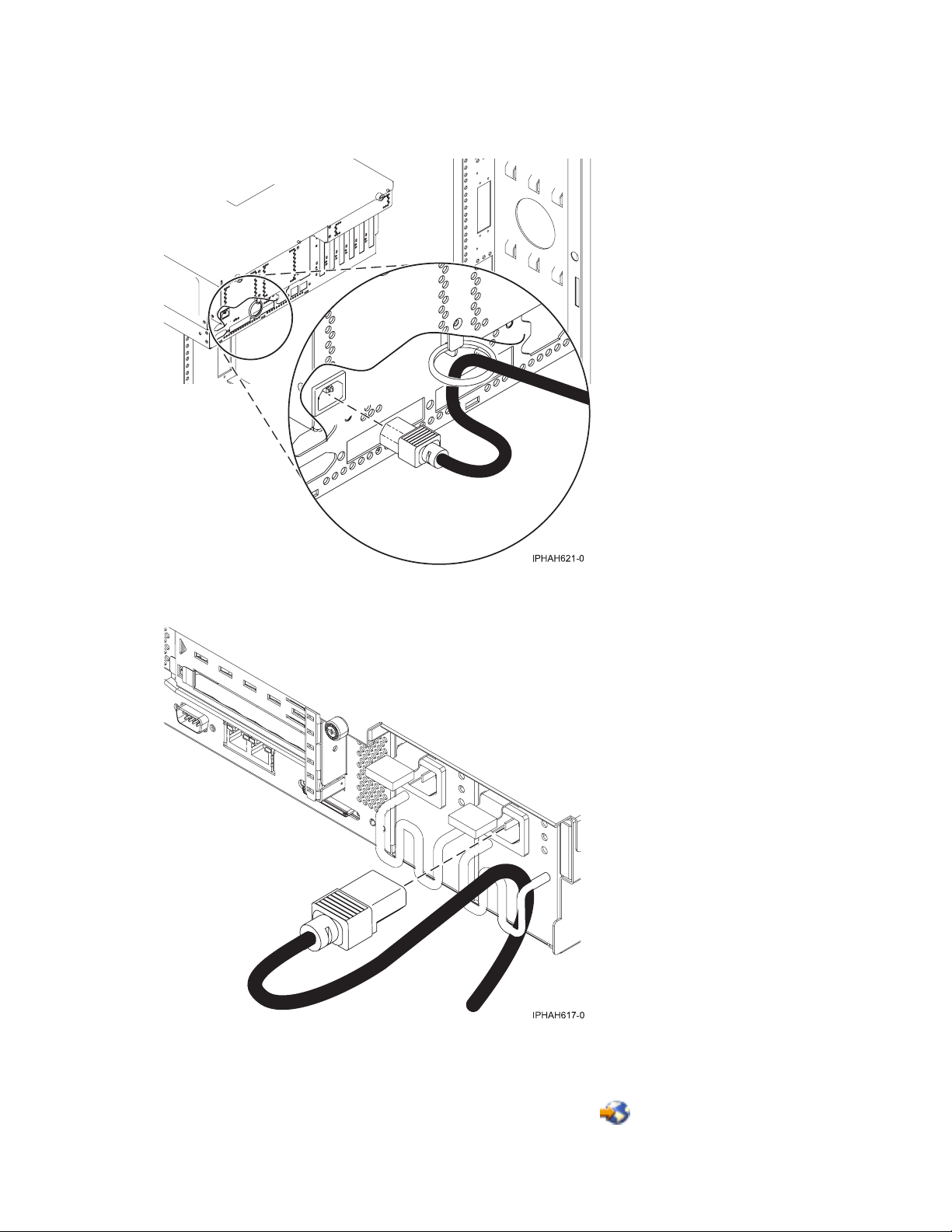
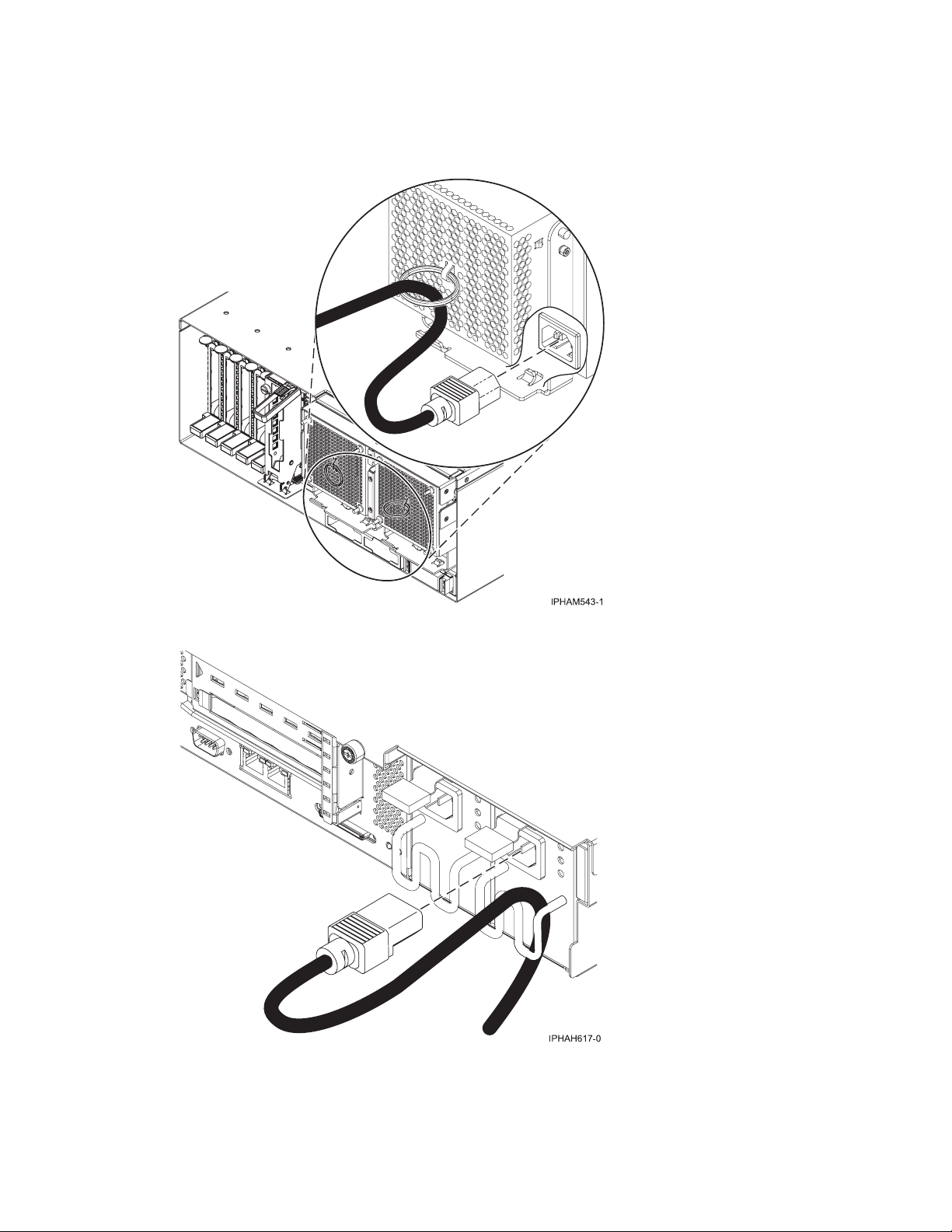
__ Power cords should be routed through the retention rings or under the retention brackets that are provided to
prevent the power cords from becoming unplugged unexpectedly.
Cabling your server 3
Page 10

Connecting the power cords
__ If your server is equipped with a retention ring, route the power cord through the ring before you plug it
into the back of the server. See the following figure as an example:
__ If your server is equipped with a retention bracket, route the power cord under the bracket before you
plug it into the back of the server. See the following figure as an example:
__ Plug the power cords into the system, display, and attached devices.
4 System i and System p: Cabling your server
Page 11

Routing the cables through the cable-management arm
__ Is your server installed in a rack?
v No. Proceed to the next section, Starting your server.
v Yes. Do the following:
__ Put the system into the service position.
v For the models 510 and 510Q, see Place the model 9110-510 or OpenPower 710 in the service position.
v For the models 520, 520Q, 550, 550Q, 560Q, and 570, see Place the rack-mounted system or expansion
unit in the service position.
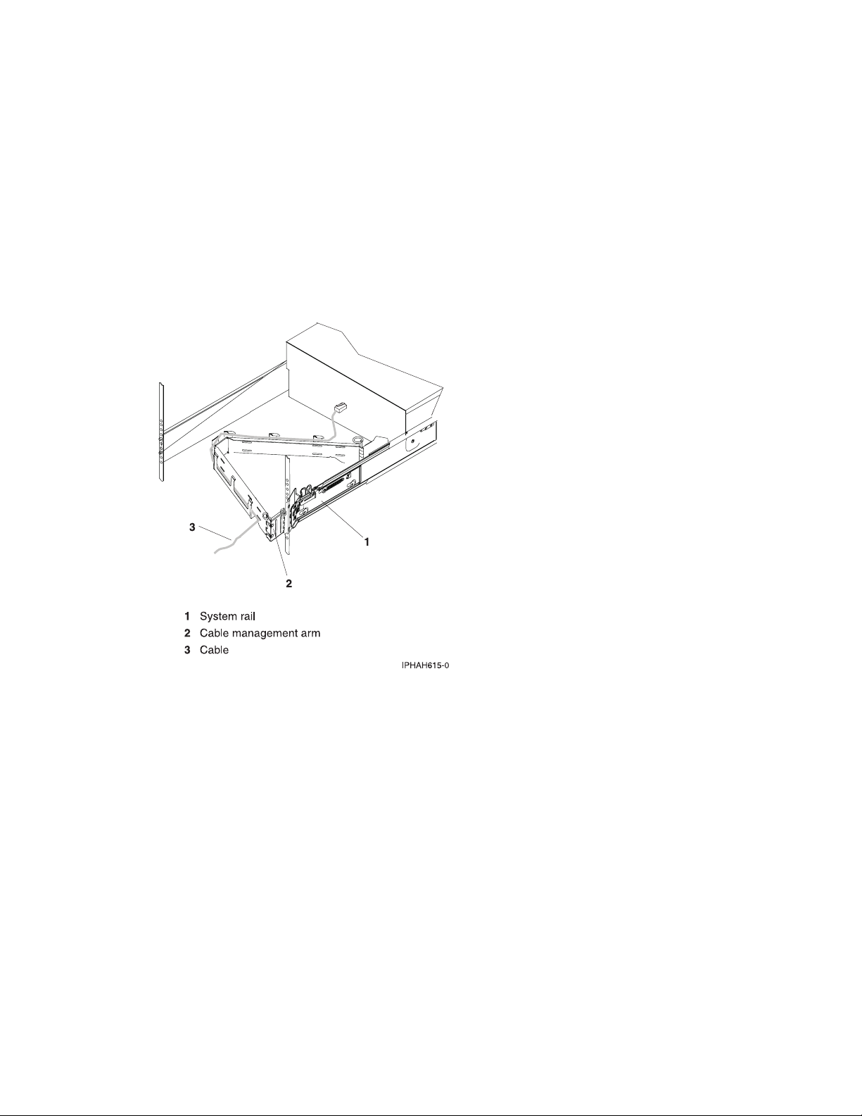
__ Route the cables through the hooks along the cable-management arm and secure them with the straps
provided.
__ After attaching the cables to the cable-management arm, go to the front of the rack and move the system
drawer in and out. Observe cables and cable-management-arm movement to verify that the cables are not
binding.
Starting your server
__ Power the system on (see Powering the system on and off).
Note: Expect a delay between the time when power is applied to the server or workstation and when an initial
program load (IPL) can be performed. When power is initially applied to the server or workstation, the service
processor performs a self-check and will leave the control panel blank for up to two minutes. Wait until the C1XX
XXXX progress codes are completed and 01 is displayed on the control panel before you perform an IPL or
change control panel functions.
Cabling your server 5
Page 12

After you finish
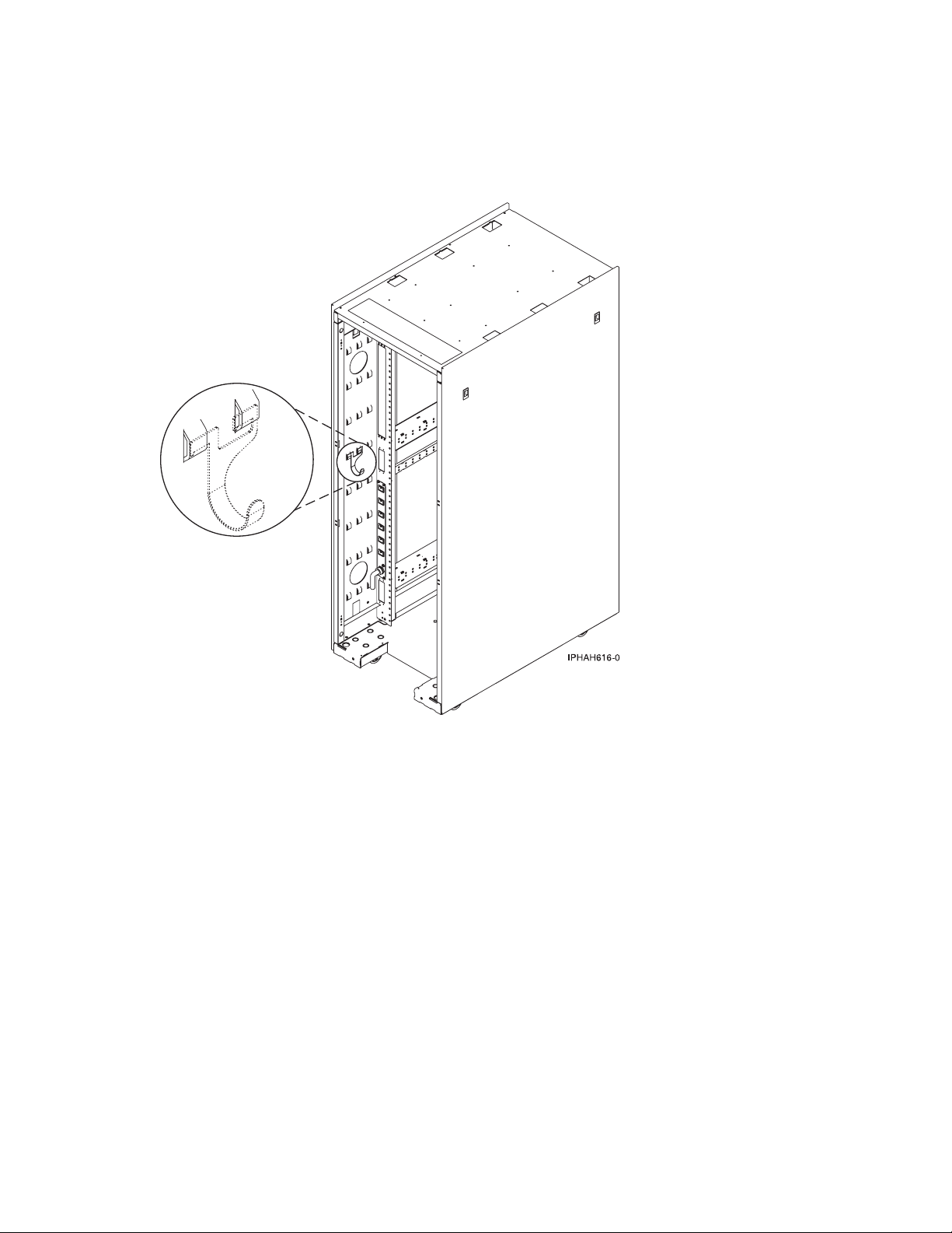
__ Did you receive a cable hook with your rack shipment?
v No. Proceed to the next item.
v Yes. The cable hook can help manage the server cables in the back of the rack. To install the cable hook, slide
it into the slots located on the back of the rack as shown in the following figure:
__ Return to your initial server setup checklist and complete the next step.
6 System i and System p: Cabling your server
Page 13

Cabling a model 9406-520 and a Hardware Management Console (HMC)
DANGER
working on or around the system, observe the following precautions:
When
Electrical voltage and current from power, telephone, and communication cables are hazardous. To
avoid a shock hazard:
v Connect power to this unit only with the IBM provided power cord. Do not use the IBM
provided power cord for any other product.
v Do not open or service any power supply assembly.
v Do not connect or disconnect any cables or perform installation, maintenance, or reconfiguration
of this product during an electrical storm.
v The product might be equipped with multiple power cords. To remove all hazardous voltages,
disconnect all power cords.
v Connect all power cords to a properly wired and grounded electrical outlet. Ensure that the outlet
supplies proper voltage and phase rotation according to the system rating plate.
v Connect any equipment that will be attached to this product to properly wired outlets.
v When possible, use one hand only to connect or disconnect signal cables.
v Never turn on any equipment when there is evidence of fire, water, or structural damage.
v Disconnect the attached power cords, telecommunications systems, networks, and modems before
you open the device covers, unless instructed otherwise in the installation and configuration
procedures.
v Connect and disconnect cables as described in the following procedures when installing, moving,
or opening covers on this product or attached devices.
To Disconnect:
1. Turn off everything (unless instructed otherwise).
2. Remove the power cords from the outlets.
3. Remove the signal cables from the connectors.
4. Remove all cables from the devices
To Connect:
1. Turn off everything (unless instructed otherwise).
2. Attach all cables to the devices.
3. Attach the signal cables to the connectors.
4. Attach the power cords to the outlets.
5. Turn on the devices.
(D005)
Complete the following tasks to cable your server:
Before you begin
__ If you have hardware features that are not installed, install them now. See Installing features and replacing parts
for instructions.
Cabling your server 7
Page 14

Cabling the expansion units
__ Do you have an expansion unit?
v Yes. For instructions on how to set up your expansion unit, click the following link. Do not plug the
expansion-unit power cord into the power outlet, as directed by the following link, until later in the checklist.
Expansion units
v No. Proceed to the next section, Connecting the external cables.
Connecting the external cables
__ If you are using any optional adapters (such as token ring or 8-port EIA-232), connect the cables to the
appropriate adapter connectors in the PCI slots of your machine.
Use the table in “Cables and adapters” on page 163 to connect the cables to the matching adapters on the back
of your server. Not all adapters are shown.
Note: If the cable did not come with your server, you will have to supply it.
Attaching devices using the system ports
__ If you have an IBM System p5 or eServer p5 server, the system ports on the back of the server are disabled
when your server is connected to an HMC.
__ If you have an IBM System i5 or eServer i5 server and are connecting it to an uninterruptible power supply, the
serial uninterruptible power supply conversion cable is required. See “Serial uninterruptible power supply
conversion cable” on page 162 for instructions. Do not plug the uninterruptible-power-supply power cord into
the outlet, and do not start your server.
Note: The attachment of high availability cluster multiprocessing IBM (HACMP) cables to the system ports on the
back of the server is not supported.
Connecting the power cords
__ Power cords should be routed through the retention rings or under the retention brackets that are provided to
prevent the power cords from becoming unplugged unexpectedly.
__ If your server is equipped with a retention ring, route the power cord through the ring before you plug it
into the back of the server. See the following figure as an example:
8 System i and System p: Cabling your server
Page 15

Connecting the power cords
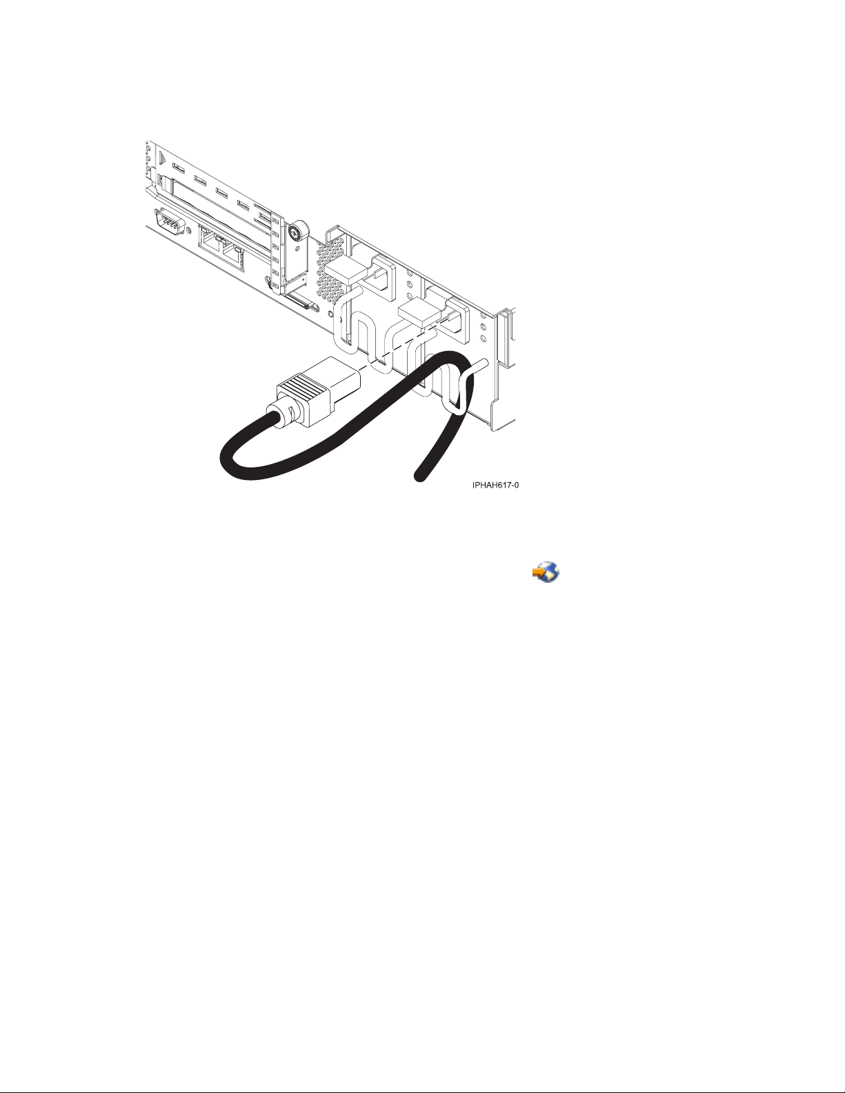
__ If your server is equipped with a retention bracket, route the power cord under the bracket before you
plug it into the back of the server. See the following figure as an example:
__ Plug the power cords into the system, display, and attached devices. Do not connect the power cords to a
power source until instructed to do so.
Note: If you connect your server to a power source before the HMC is configured as the DHCP server, the
server will initialize using the default IP address values (HMC1 as 192.168.2.147 and HMC2 as 192.168.3.147)
instead of waiting for an address value from the HMC. If you inadvertently connect your server to a power
source, the IP address value will be corrected in the HMC configuration portion of the installation.
Connecting the Hardware Management Console cables
__ Cable the HMC (see Cabling the HMC).
Routing the cables through the cable-management arm
__ Is your server installed in a rack?
v No. Proceed to the next section, After you finish.
v Yes. Do the following:
__ Put the system into the service position.
v For the models 510 and 510Q, see Place the model 9110-510 or OpenPower 710 in the service position.
v For the models 520, 520Q, 550, 550Q, 560Q, and 570, see Place the rack-mounted system or expansion
unit in the service position.
Cabling your server 9
Page 16

Routing the cables through the cable-management arm
__ Route the cables through the hooks along the cable-management arm and secure them with the straps
provided.
__ After attaching the cables to the cable-management arm, go to the front of the rack and move the system
drawer in and out. Observe cables and cable-management-arm movement to verify that the cables are not
binding.
10 System i and System p: Cabling your server
Page 17

After you finish
__ Did you receive a cable hook with your rack shipment?
v No. Proceed to the next item.
v Yes. The cable hook can help manage the server cables in the back of the rack. To install the cable hook, slide
it into the slots located on the back of the rack as shown in the following figure:
__ Return to your initial server setup checklist and complete the next step.
Cabling the Operations Console attachment for model 9406-520
Learn how to connect the Operations Console, power cords, external cables, and the optional electronic
customer support cable, cable the expansion units, attach devices, install the PCI Cryptographic
Coprocessor card, and route the cables.
Cabling your server 11
Page 18

DANGER
working on or around the system, observe the following precautions:
When
Electrical voltage and current from power, telephone, and communication cables are hazardous. To
avoid a shock hazard:
v Connect power to this unit only with the IBM provided power cord. Do not use the IBM
provided power cord for any other product.
v Do not open or service any power supply assembly.
v Do not connect or disconnect any cables or perform installation, maintenance, or reconfiguration
of this product during an electrical storm.
v The product might be equipped with multiple power cords. To remove all hazardous voltages,
disconnect all power cords.
v Connect all power cords to a properly wired and grounded electrical outlet. Ensure that the outlet
supplies proper voltage and phase rotation according to the system rating plate.
v Connect any equipment that will be attached to this product to properly wired outlets.
v When possible, use one hand only to connect or disconnect signal cables.
v Never turn on any equipment when there is evidence of fire, water, or structural damage.
v Disconnect the attached power cords, telecommunications systems, networks, and modems before
you open the device covers, unless instructed otherwise in the installation and configuration
procedures.
v Connect and disconnect cables as described in the following procedures when installing, moving,
or opening covers on this product or attached devices.
To Disconnect:
1. Turn off everything (unless instructed otherwise).
2. Remove the power cords from the outlets.
3. Remove the signal cables from the connectors.
4. Remove all cables from the devices
To Connect:
1. Turn off everything (unless instructed otherwise).
2. Attach all cables to the devices.
3. Attach the signal cables to the connectors.
4. Attach the power cords to the outlets.
5. Turn on the devices.
(D005)
To cable your server:
Connecting the Operations Console. Choose from the options below.
__ Option 1: To connect the Operations Console cable (directly attached):
__ Shut down and unplug the PC that will serve as the system console.
__ Locate the Operations Console cable (part number 97H7557). Connect the Operations Console cable to the
corresponding connector on the 2793 or 2794 adapter in the appropriate position on the back of the server.
v Position C3 for the model 520
v Position C2 for the models 550 and 570
__ Connect the other end of the Operations Console cable to the first or only system port, which is located on
the back of the PC that is being used as the console.
__ Option 2: To connect the Ethernet cable (on a network (LAN)):
__ Shut down and unplug the PC that will serve as the system console.
12 System i and System p: Cabling your server
Page 19

Connecting the Operations Console. Choose from the options below.
__ Connect an Ethernet or token-ring cable from the PC that will serve as the system console to your local
network. Connect another network cable from the same local network to the first embedded Ethernet port
(P1-T5) or the adapter card in the appropriate position on the back of the server.
v Position C5 or C2 for the model 520
v Position C4 for the model 550
v Position C4 or C6 for the model 570
Connecting the electronic customer support cable (optional)
Electronic customer support helps automate management of your server and streamline your support. Use the
IBM eServer Technical Support Advantage information that is included with your server to learn about
electronic customer support or see the Support for iSeries™ family We b site (www-1.ibm.com/servers/eserver/
support/iseries/index.html). You can configure electronic customer support by using the iSeries Setup and
Operations CD that came with your server. For more information, see Service and support.
__ Connect a telephone cable to the RJ11 connector of the adapter in the appropriate position.
v Position C3 for the model 520
v Position C2 for the models 550 and 570
__ Connect the other end of the telephone cable to an analog telephone jack.
Cabling the expansion units
__ Do you have an expansion unit?
v Yes. To set up your expansion unit, see Expansion units.
Note: Do not plug the expansion-unit power cord into the power outlet, as directed by the directions in
Expansion units, until later in this checklist
v No. Proceed to the next section, Attaching devices using the system ports.
Attaching devices by using the system ports
__ If you have an IBM System i5 or eServer i5 server and are connecting it to an uninterruptible power supply, the
serial uninterruptible power supply conversion cable is required. See “Serial uninterruptible power supply
conversion cable” on page 162 for instructions. Do not plug the uninterruptible-power-supply power cord into
the outlet and do not start your server.
Note: The attachment of high availability cluster multiprocessing (HACMP) cables to the system ports on the back of
the server is not supported.
Installing the PCI Cryptographic Coprocessor card
__ Do you have a PCI Cryptographic Coprocessor card?
v Yes. Install it now using the PCI-X Cryptographic Coprocessor instructions. This card was shipped in a
separate box. Return here after the card is installed.
v No. Proceed to the next section, Connecting the power cords.
Connecting the power cords
__ You should route the power cords through the retention rings or under the retention brackets that are provided
to prevent the power cords from becoming unplugged unexpectedly.
Cabling your server 13
Page 20

Connecting the power cords
__ If your server is equipped with a retention ring, route the power cord through the ring before you plug
it into the back of the server, as shown here:
__ If your server is equipped with a retention bracket, route the power cord under the bracket before you
plug it into the back of the server, as shown here:
__ Are you installing an uninterruptible power supply?
__ No. Connect the server power cords to the server. Do not plug the power cord into the power outlet. Do
not start your server.
__ Yes. To complete the installation of the uninterruptible power supply, see the Powerware Web site
(www.oem.powerware.com/ibm-ups/Products/9910Solutions/ina.asp)
.
14 System i and System p: Cabling your server
Page 21

Connecting the external cables
__ Use the table in “Cables and adapters” on page 163 to connect the cables to the matching adapters on the back
of your server. If the cable did not come with your server, you will have to supply it.
If you do not have any external cables to connect to the adapters on the back of your server or expansion unit,
continue with the next section.
Routing the cables through the cable-management arm
__ Is your server installed in a rack?
v No. Proceed to the next section.
v Yes. Do the following:
__ Put the system into the service position. See Place the rack-mounted system or expansion unit in the
service position.
__ Route the cables through the hooks that are located along the cable-management arm and secure them
with the straps that are provided, as shown here:
__ After attaching the cables to the cable-management arm, go to the front of the rack and move the system
drawer in and out. Observe the cables and cable-management-arm movement to verify that the cables are
not binding.
Cabling your server 15
Page 22

After you finish
__ Did you receive a cable hook with your rack shipment?
v No. Proceed to the next item.
v Yes. The cable hook can help manage the server cables in the back of the rack. To install the cable hook, slide
it into the slots located on the back of the rack as shown in the following figure:
__ Return to your initial server setup checklist and complete the next step.
Cabling a model 9405-520 or 9406-520 and a twinaxial console
Learn how to connect the twinaxial cable, power cords, external cables, and the optional electronic
customer support cable, cable the expansion units, attach devices, install the PCI Cryptographic
Coprocessor card, route the cables, and start the server.
16 System i and System p: Cabling your server
Page 23

DANGER
working on or around the system, observe the following precautions:
When
Electrical voltage and current from power, telephone, and communication cables are hazardous. To
avoid a shock hazard:
v Connect power to this unit only with the IBM provided power cord. Do not use the IBM
provided power cord for any other product.
v Do not open or service any power supply assembly.
v Do not connect or disconnect any cables or perform installation, maintenance, or reconfiguration
of this product during an electrical storm.
v The product might be equipped with multiple power cords. To remove all hazardous voltages,
disconnect all power cords.
v Connect all power cords to a properly wired and grounded electrical outlet. Ensure that the outlet
supplies proper voltage and phase rotation according to the system rating plate.
v Connect any equipment that will be attached to this product to properly wired outlets.
v When possible, use one hand only to connect or disconnect signal cables.
v Never turn on any equipment when there is evidence of fire, water, or structural damage.
v Disconnect the attached power cords, telecommunications systems, networks, and modems before
you open the device covers, unless instructed otherwise in the installation and configuration
procedures.
v Connect and disconnect cables as described in the following procedures when installing, moving,
or opening covers on this product or attached devices.
To Disconnect:
1. Turn off everything (unless instructed otherwise).
2. Remove the power cords from the outlets.
3. Remove the signal cables from the connectors.
4. Remove all cables from the devices
To Connect:
1. Turn off everything (unless instructed otherwise).
2. Attach all cables to the devices.
3. Attach the signal cables to the connectors.
4. Attach the power cords to the outlets.
5. Turn on the devices.
(D005)
To cable your server:
Connecting the twinaxial cable
__ On the back of the server, locate the position that contains card 2746. This is your twinaxial adapter card. The
card should be in the appropriate position.
v Position C5 or C2 for the model 520
v Position C4 for the model 550
v Position C4 or C6 for the model 570
__ Locate the 8-port twinaxial attachment cable (part number 21F5093). Attach the cable to the connector on the
2746 twinaxial adapter card.
Cabling your server 17
Page 24

Connecting the twinaxial cable
__ Connect a twinaxial cable from the workstation that you will use as the system console to port 0 on the 8-port
twinaxial attachment cable.
Note: The workstation address of your console must be set to 0. To set the address, see the reference material
that was included with your workstation.
Connecting the electronic customer support cable (optional)
Electronic customer support helps automate management of your server and streamline your support. Use the
IBM eServer Technical Support Advantage information that is included with your server to learn about
electronic customer support or see the Support for iSeries family We b site (www-1.ibm.com/servers/eserver/
support/iseries/index.html). You can configure electronic customer support by using the iSeries Setup and
Operations CD that came with your server. For more information, see Service and support.
__ Connect a telephone cable to the RJ11 connector of the adapter in the appropriate position.
v Position C3 for the model 520
v Position C2 for the models 550 and 570
__ Connect the other end of the telephone cable to an analog telephone jack.
Cabling the expansion units
__ Do you have an expansion unit?
v Yes. To set up your expansion unit, see Expansion units.
Note: Do not plug the expansion-unit power cord into the power outlet, as directed by the directions in
Expansion units, until later in this checklist
v No. Proceed to the next section, Attaching devices using the system ports.
Attaching devices by using the system ports
__ If you have an IBM System i5 or eServer i5 server and you are connecting it to an uninterruptible power supply,
the serial uninterruptible power supply conversion cable is required. See “Serial uninterruptible power supply
conversion cable” on page 162 for instructions. Do not plug the uninterruptible-power-supply power cord into
the outlet and do not start your server.
Note: The attachment of high availability cluster multiprocessing (HACMP) cables to the system ports on the back of
the server is not supported.
Installing the PCI Cryptographic Coprocessor card
__ Do you have a PCI Cryptographic Coprocessor card?
v Yes. Install it now using the PCI-X Cryptographic Coprocessor instructions. This card was shipped in a
separate box. Return here after the card is installed.
v No. Proceed to the next section, Connecting the power cords.
Connecting the power cords
__ You should route the power cords through the retention rings or under the retention brackets that are provided
to prevent the power cords from becoming unplugged unexpectedly.
18 System i and System p: Cabling your server
Page 25

Connecting the power cords
__ If your server is equipped with a retention ring, route the power cord through the ring before you plug it
into the back of the server, as shown here:
__ If your server is equipped with a retention bracket, route the power cord under the bracket before you
plug it into the back of the server, as shown here:
__ Are you installing an uninterruptible power supply?
__ No. Connect the server power cords to the server. Do not plug the power cord into the power outlet. Do not
start your server.
__ Yes. To complete the installation of the uninterruptible power supply, see the Powerware Web site
(www.oem.powerware.com/ibm-ups/Products/9910Solutions/ina.asp)
.
Cabling your server 19
Page 26

Connecting the external cables
__ See the table in “Cables and adapters” on page 163 to connect the cables to the matching adapters on the back
of your server.
Note: If the cable did not come with your server, you will have to supply it.
Routing the cables through the cable-management arm
__ Is your server installed in a rack?
v No. Proceed to the next section, Starting your server.
v Yes. Do the following:
__ Put the system into the service position. See Place the rack-mounted system or expansion unit in the service
position.
__ Route the cables through the hooks that are located along the cable-management arm and secure them with
the straps that are provided, as shown here:
__ After attaching the cables to the cable-management arm, go to the front of the rack and move the system
drawer in and out. Observe the cables and cable-management-arm movement to verify that the cables are
not binding.
Starting your server
__ Plug in and turn on your console.
__ Plug in your server or uninterruptible power supply and attached expansion units.
__ Open the control panel door on the front of the server. The control panel should be lit and display 01 N V=F. The
server is not yet powered on.
Note:
1. Expect a delay between the time when power is applied to the server or workstation and when an initial
program load (IPL) can be performed. When power is initially applied to the server or workstation, the
service processor performs a self-check and will leave the control panel blank for up to two minutes. Wait
until the C1XX XXXX progress codes are completed and 01 is displayed on the control panel before you
perform an IPL or change control panel functions.
2. If 01 N V=F is not displayed, you might need to change the mode. To change the mode, see Access control
panel functions in the iSeries Information Center.
__ Press the white Power On button. There is a short delay until the server powers on, approximately 5 to 20
minutes. When the server powers on, the control panel displays 01 B N V=F. If the control panel displays A900
2000, the console is not connected yet.
20 System i and System p: Cabling your server
Page 27

After you finish
__ Did you receive a cable hook with your rack shipment?
v No. Proceed to the next item.
v Yes. The cable hook can help manage the server cables in the back of the rack. To install the cable hook, slide
it into the slots located on the back of the rack as shown in the following figure:
__ Return to your initial server setup checklist and complete the next step.
See the back views of the model to see the slots and connectors.
Cabling a model 9405-520 or 9406-520 and a Thin Console
Learn how to connect the Thin Console, power cords, external cables, and the optional electronic
customer support cable, cable the expansion units, attach devices, install the PCI Cryptographic
Coprocessor card, route the cables, and start the server.
Cabling your server 21
Page 28

DANGER
working on or around the system, observe the following precautions:
When
Electrical voltage and current from power, telephone, and communication cables are hazardous. To
avoid a shock hazard:
v Connect power to this unit only with the IBM provided power cord. Do not use the IBM
provided power cord for any other product.
v Do not open or service any power supply assembly.
v Do not connect or disconnect any cables or perform installation, maintenance, or reconfiguration
of this product during an electrical storm.
v The product might be equipped with multiple power cords. To remove all hazardous voltages,
disconnect all power cords.
v Connect all power cords to a properly wired and grounded electrical outlet. Ensure that the outlet
supplies proper voltage and phase rotation according to the system rating plate.
v Connect any equipment that will be attached to this product to properly wired outlets.
v When possible, use one hand only to connect or disconnect signal cables.
v Never turn on any equipment when there is evidence of fire, water, or structural damage.
v Disconnect the attached power cords, telecommunications systems, networks, and modems before
you open the device covers, unless instructed otherwise in the installation and configuration
procedures.
v Connect and disconnect cables as described in the following procedures when installing, moving,
or opening covers on this product or attached devices.
To Disconnect:
1. Turn off everything (unless instructed otherwise).
2. Remove the power cords from the outlets.
3. Remove the signal cables from the connectors.
4. Remove all cables from the devices
To Connect:
1. Turn off everything (unless instructed otherwise).
2. Attach all cables to the devices.
3. Attach the signal cables to the connectors.
4. Attach the power cords to the outlets.
5. Turn on the devices.
(D005)
To cable your server:
Connecting the Thin Console
__ Complete the setup instructions that were provided with the Thin Console, such as:
v Connect the keyboard, mouse, power cable, and Ethernet cable to the ports on the Thin Console.
v Plug in the monitor, and power it on.
v Plug in the Thin Console. It automatically powers on.
__ Select the keyboard language, and then press Enter.
22 System i and System p: Cabling your server
Page 29

Connecting the Thin Console
__ Connect the other end of the Ethernet cable directly to the HMC port (either HMC 1 or HMC 2) on the server.
Connections and ports are labeled to facilitate the setup process.
Notes:
v You cannot attach any other console device to the remaining HMC port.
v If you are connecting the Thin Console to an existing server, the DST Sign-on window might display.
Figure 1. Back view of a Thin Console for System i5
Connecting the electronic customer support cable (optional)
Electronic customer support helps automate management of your server and streamline your support. Use the
IBM eServer Technical Support Advantage information that is included with your server to learn about
electronic customer support or see the Support for iSeries family We b site (www-1.ibm.com/servers/eserver/
support/iseries/index.html). You can configure electronic customer support by using the iSeries Setup and
Operations CD that came with your server. For more information, see Service and support.
__ Connect a telephone cable to the RJ11 connector of the adapter into position C3.
__ Connect the other end of the telephone cable to an analog telephone jack.
Cabling the expansion units
__ Do you have an expansion unit?
v Yes. To set up your expansion unit, see Expansion units.
Note: Do not plug the expansion-unit power cord into the power outlet, as directed by the directions in
Expansion units, until later in this checklist
v No. Proceed to the next section, Attaching devices using the system ports.
Cabling your server 23
Page 30

Attaching devices by using the system ports
__ If you have an IBM System i5 or eServer i5 server and you are connecting it to an uninterruptible power supply,
the serial uninterruptible power supply conversion cable is required. See “Serial uninterruptible power supply
conversion cable” on page 162 for instructions. Do not plug the uninterruptible-power-supply power cord into
the outlet and do not start your server.
Note: The attachment of high availability cluster multiprocessing (HACMP) cables to the system ports on the back of
the server is not supported.
Installing the PCI Cryptographic Coprocessor card
__ Do you have a PCI Cryptographic Coprocessor card?
v Yes. Install it now using the PCI-X Cryptographic Coprocessor instructions. This card was shipped in a
separate box. Return here after the card is installed.
v No. Proceed to the next section, Connecting the power cords.
Connecting the power cords
__ You should route the power cords through the retention rings or under the retention brackets that are provided
to prevent the power cords from becoming unplugged unexpectedly.
__ If your server is equipped with a retention ring, route the power cord through the ring before you plug it
into the back of the server, as shown here:
24 System i and System p: Cabling your server
Page 31

Connecting the power cords
__ If your server is equipped with a retention bracket, route the power cord under the bracket before you
plug it into the back of the server, as shown here:
__ Are you installing an uninterruptible power supply?
__ No. Connect the server power cords to the server. Do not plug the power cord into the power outlet. Do not
start your server.
__ Yes. To complete the installation of the uninterruptible power supply, see the Powerware Web site
(www.oem.powerware.com/ibm-ups/Products/9910Solutions/ina.asp)
Connecting the external cables
.
__ Use the table in “Cables and adapters” on page 163 to connect the cables to the matching adapters on the back
of your server.
Note: If the cable did not come with your server, you will have to supply it.
Routing the cables through the cable-management arm
__ Is your server installed in a rack?
v No. Proceed to the next section, Starting your server.
v Yes. Do the following:
__ Put the system into the service position. See Place the rack-mounted system or expansion unit in the service
position.
Cabling your server 25
Page 32

Routing the cables through the cable-management arm
__ Route the cables through the hooks that are located along the cable-management arm and secure them with
the straps that are provided, as shown here:
__ After attaching the cables to the cable-management arm, go to the front of the rack and move the system
drawer in and out. Observe the cables and cable-management-arm movement to verify that the cables are
not binding.
Starting your server
__ Plug in your server or uninterruptible power supply and attached expansion units.
__ Open the control panel door on the front of the server. The control panel should be lit and display 01 N V=F. The
server is not yet powered on.
Note:
1. Expect a delay between the time when power is applied to the server or workstation and when an initial
program load (IPL) can be performed. When power is initially applied to the server or workstation, the
service processor performs a self-check and will leave the control panel blank for up to two minutes. Wait
until the C1XX XXXX progress codes are completed and 01 is displayed on the control panel before you
perform an IPL or change control panel functions.
2. If 01 N V=F is not displayed, you might need to change the mode. To change the mode, see Access control
panel functions in the iSeries Information Center.
__ When prompted, enter a new HMC access password. This password is case sensitive.
__ Press the white Power On button. There is a short delay of approximately 5 to 20 minutes until the server
powers on. When the server powers on, the control panel displays 01 B N V=F. If the control panel displays A900
2000, the console is not connected yet.
26 System i and System p: Cabling your server
Page 33

After you finish
__ Did you receive a cable hook with your rack shipment?
v No. Proceed to the next item.
v Yes. The cable hook can help manage the server cables in the back of the rack. To install the cable hook, slide
it into the slots located on the back of the rack as shown in the following figure:
__ Return to your initial server setup checklist and complete the next step.
See the back views of the model to see the connectors.
Cabling your model 9405-520 with a console
For a graphical representation of the slots and connectors that are referred to in this topic, see the back
views of the model.
Cabling a model 9405-520 or 9406-520 and a twinaxial console
Learn how to connect the twinaxial cable, power cords, external cables, and the optional electronic
customer support cable, cable the expansion units, attach devices, install the PCI Cryptographic
Coprocessor card, route the cables, and start the server.
Cabling your server 27
Page 34

DANGER
working on or around the system, observe the following precautions:
When
Electrical voltage and current from power, telephone, and communication cables are hazardous. To
avoid a shock hazard:
v Connect power to this unit only with the IBM provided power cord. Do not use the IBM
provided power cord for any other product.
v Do not open or service any power supply assembly.
v Do not connect or disconnect any cables or perform installation, maintenance, or reconfiguration
of this product during an electrical storm.
v The product might be equipped with multiple power cords. To remove all hazardous voltages,
disconnect all power cords.
v Connect all power cords to a properly wired and grounded electrical outlet. Ensure that the outlet
supplies proper voltage and phase rotation according to the system rating plate.
v Connect any equipment that will be attached to this product to properly wired outlets.
v When possible, use one hand only to connect or disconnect signal cables.
v Never turn on any equipment when there is evidence of fire, water, or structural damage.
v Disconnect the attached power cords, telecommunications systems, networks, and modems before
you open the device covers, unless instructed otherwise in the installation and configuration
procedures.
v Connect and disconnect cables as described in the following procedures when installing, moving,
or opening covers on this product or attached devices.
To Disconnect:
1. Turn off everything (unless instructed otherwise).
2. Remove the power cords from the outlets.
3. Remove the signal cables from the connectors.
4. Remove all cables from the devices
To Connect:
1. Turn off everything (unless instructed otherwise).
2. Attach all cables to the devices.
3. Attach the signal cables to the connectors.
4. Attach the power cords to the outlets.
5. Turn on the devices.
(D005)
To cable your server:
Connecting the twinaxial cable
__ On the back of the server, locate the position that contains card 2746. This is your twinaxial adapter card. The
card should be in the appropriate position.
v Position C5 or C2 for the model 520
v Position C4 for the model 550
v Position C4 or C6 for the model 570
__ Locate the 8-port twinaxial attachment cable (part number 21F5093). Attach the cable to the connector on the
2746 twinaxial adapter card.
28 System i and System p: Cabling your server
Page 35

Connecting the twinaxial cable
__ Connect a twinaxial cable from the workstation that you will use as the system console to port 0 on the 8-port
twinaxial attachment cable.
Note: The workstation address of your console must be set to 0. To set the address, see the reference material
that was included with your workstation.
Connecting the electronic customer support cable (optional)
Electronic customer support helps automate management of your server and streamline your support. Use the
IBM eServer Technical Support Advantage information that is included with your server to learn about
electronic customer support or see the Support for iSeries family We b site (www-1.ibm.com/servers/eserver/
support/iseries/index.html). You can configure electronic customer support by using the iSeries Setup and
Operations CD that came with your server. For more information, see Service and support.
__ Connect a telephone cable to the RJ11 connector of the adapter in the appropriate position.
v Position C3 for the model 520
v Position C2 for the models 550 and 570
__ Connect the other end of the telephone cable to an analog telephone jack.
Cabling the expansion units
__ Do you have an expansion unit?
v Yes. To set up your expansion unit, see Expansion units.
Note: Do not plug the expansion-unit power cord into the power outlet, as directed by the directions in
Expansion units, until later in this checklist
v No. Proceed to the next section, Attaching devices using the system ports.
Attaching devices by using the system ports
__ If you have an IBM System i5 or eServer i5 server and you are connecting it to an uninterruptible power supply,
the serial uninterruptible power supply conversion cable is required. See “Serial uninterruptible power supply
conversion cable” on page 162 for instructions. Do not plug the uninterruptible-power-supply power cord into
the outlet and do not start your server.
Note: The attachment of high availability cluster multiprocessing (HACMP) cables to the system ports on the back of
the server is not supported.
Installing the PCI Cryptographic Coprocessor card
__ Do you have a PCI Cryptographic Coprocessor card?
v Yes. Install it now using the PCI-X Cryptographic Coprocessor instructions. This card was shipped in a
separate box. Return here after the card is installed.
v No. Proceed to the next section, Connecting the power cords.
Connecting the power cords
__ You should route the power cords through the retention rings or under the retention brackets that are provided
to prevent the power cords from becoming unplugged unexpectedly.
Cabling your server 29
Page 36
Connecting the power cords
__ If your server is equipped with a retention ring, route the power cord through the ring before you plug it
into the back of the server, as shown here:
__ If your server is equipped with a retention bracket, route the power cord under the bracket before you
plug it into the back of the server, as shown here:
__ Are you installing an uninterruptible power supply?
__ No. Connect the server power cords to the server. Do not plug the power cord into the power outlet. Do not
start your server.
__ Yes. To complete the installation of the uninterruptible power supply, see the Powerware Web site
(www.oem.powerware.com/ibm-ups/Products/9910Solutions/ina.asp)
.
30 System i and System p: Cabling your server
Page 37
Connecting the external cables
__ See the table in “Cables and adapters” on page 163 to connect the cables to the matching adapters on the back
of your server.
Note: If the cable did not come with your server, you will have to supply it.
Routing the cables through the cable-management arm
__ Is your server installed in a rack?
v No. Proceed to the next section, Starting your server.
v Yes. Do the following:
__ Put the system into the service position. See Place the rack-mounted system or expansion unit in the service
position.
__ Route the cables through the hooks that are located along the cable-management arm and secure them with
the straps that are provided, as shown here:
__ After attaching the cables to the cable-management arm, go to the front of the rack and move the system
drawer in and out. Observe the cables and cable-management-arm movement to verify that the cables are
not binding.
Starting your server
__ Plug in and turn on your console.
__ Plug in your server or uninterruptible power supply and attached expansion units.
__ Open the control panel door on the front of the server. The control panel should be lit and display 01 N V=F. The
server is not yet powered on.
Note:
1. Expect a delay between the time when power is applied to the server or workstation and when an initial
program load (IPL) can be performed. When power is initially applied to the server or workstation, the
service processor performs a self-check and will leave the control panel blank for up to two minutes. Wait
until the C1XX XXXX progress codes are completed and 01 is displayed on the control panel before you
perform an IPL or change control panel functions.
2. If 01 N V=F is not displayed, you might need to change the mode. To change the mode, see Access control
panel functions in the iSeries Information Center.
__ Press the white Power On button. There is a short delay until the server powers on, approximately 5 to 20
minutes. When the server powers on, the control panel displays 01 B N V=F. If the control panel displays A900
2000, the console is not connected yet.
Cabling your server 31
Page 38

After you finish
__ Did you receive a cable hook with your rack shipment?
v No. Proceed to the next item.
v Yes. The cable hook can help manage the server cables in the back of the rack. To install the cable hook, slide
it into the slots located on the back of the rack as shown in the following figure:
__ Return to your initial server setup checklist and complete the next step.
See the back views of the model to see the slots and connectors.
Cabling a model 9405-520 or 9406-520 and a Thin Console
Learn how to connect the Thin Console, power cords, external cables, and the optional electronic
customer support cable, cable the expansion units, attach devices, install the PCI Cryptographic
Coprocessor card, route the cables, and start the server.
32 System i and System p: Cabling your server
Page 39

DANGER
working on or around the system, observe the following precautions:
When
Electrical voltage and current from power, telephone, and communication cables are hazardous. To
avoid a shock hazard:
v Connect power to this unit only with the IBM provided power cord. Do not use the IBM
provided power cord for any other product.
v Do not open or service any power supply assembly.
v Do not connect or disconnect any cables or perform installation, maintenance, or reconfiguration
of this product during an electrical storm.
v The product might be equipped with multiple power cords. To remove all hazardous voltages,
disconnect all power cords.
v Connect all power cords to a properly wired and grounded electrical outlet. Ensure that the outlet
supplies proper voltage and phase rotation according to the system rating plate.
v Connect any equipment that will be attached to this product to properly wired outlets.
v When possible, use one hand only to connect or disconnect signal cables.
v Never turn on any equipment when there is evidence of fire, water, or structural damage.
v Disconnect the attached power cords, telecommunications systems, networks, and modems before
you open the device covers, unless instructed otherwise in the installation and configuration
procedures.
v Connect and disconnect cables as described in the following procedures when installing, moving,
or opening covers on this product or attached devices.
To Disconnect:
1. Turn off everything (unless instructed otherwise).
2. Remove the power cords from the outlets.
3. Remove the signal cables from the connectors.
4. Remove all cables from the devices
To Connect:
1. Turn off everything (unless instructed otherwise).
2. Attach all cables to the devices.
3. Attach the signal cables to the connectors.
4. Attach the power cords to the outlets.
5. Turn on the devices.
(D005)
To cable your server:
Connecting the Thin Console
__ Complete the setup instructions that were provided with the Thin Console, such as:
v Connect the keyboard, mouse, power cable, and Ethernet cable to the ports on the Thin Console.
v Plug in the monitor, and power it on.
v Plug in the Thin Console. It automatically powers on.
__ Select the keyboard language, and then press Enter.
Cabling your server 33
Page 40

Connecting the Thin Console
__ Connect the other end of the Ethernet cable directly to the HMC port (either HMC 1 or HMC 2) on the server.
Connections and ports are labeled to facilitate the setup process.
Notes:
v You cannot attach any other console device to the remaining HMC port.
v If you are connecting the Thin Console to an existing server, the DST Sign-on window might display.
Figure 2. Back view of a Thin Console for System i5
Connecting the electronic customer support cable (optional)
Electronic customer support helps automate management of your server and streamline your support. Use the
IBM eServer Technical Support Advantage information that is included with your server to learn about
electronic customer support or see the Support for iSeries family We b site (www-1.ibm.com/servers/eserver/
support/iseries/index.html). You can configure electronic customer support by using the iSeries Setup and
Operations CD that came with your server. For more information, see Service and support.
__ Connect a telephone cable to the RJ11 connector of the adapter into position C3.
__ Connect the other end of the telephone cable to an analog telephone jack.
Cabling the expansion units
__ Do you have an expansion unit?
v Yes. To set up your expansion unit, see Expansion units.
Note: Do not plug the expansion-unit power cord into the power outlet, as directed by the directions in
Expansion units, until later in this checklist
v No. Proceed to the next section, Attaching devices using the system ports.
34 System i and System p: Cabling your server
Page 41

Attaching devices by using the system ports
__ If you have an IBM System i5 or eServer i5 server and you are connecting it to an uninterruptible power supply,
the serial uninterruptible power supply conversion cable is required. See “Serial uninterruptible power supply
conversion cable” on page 162 for instructions. Do not plug the uninterruptible-power-supply power cord into
the outlet and do not start your server.
Note: The attachment of high availability cluster multiprocessing (HACMP) cables to the system ports on the back of
the server is not supported.
Installing the PCI Cryptographic Coprocessor card
__ Do you have a PCI Cryptographic Coprocessor card?
v Yes. Install it now using the PCI-X Cryptographic Coprocessor instructions. This card was shipped in a
separate box. Return here after the card is installed.
v No. Proceed to the next section, Connecting the power cords.
Connecting the power cords
__ You should route the power cords through the retention rings or under the retention brackets that are provided
to prevent the power cords from becoming unplugged unexpectedly.
__ If your server is equipped with a retention ring, route the power cord through the ring before you plug it
into the back of the server, as shown here:
Cabling your server 35
Page 42
Connecting the power cords
__ If your server is equipped with a retention bracket, route the power cord under the bracket before you
plug it into the back of the server, as shown here:
__ Are you installing an uninterruptible power supply?
__ No. Connect the server power cords to the server. Do not plug the power cord into the power outlet. Do not
start your server.
__ Yes. To complete the installation of the uninterruptible power supply, see the Powerware Web site
(www.oem.powerware.com/ibm-ups/Products/9910Solutions/ina.asp)
Connecting the external cables
.
__ Use the table in “Cables and adapters” on page 163 to connect the cables to the matching adapters on the back
of your server.
Note: If the cable did not come with your server, you will have to supply it.
Routing the cables through the cable-management arm
__ Is your server installed in a rack?
v No. Proceed to the next section, Starting your server.
v Yes. Do the following:
__ Put the system into the service position. See Place the rack-mounted system or expansion unit in the service
position.
36 System i and System p: Cabling your server
Page 43

Routing the cables through the cable-management arm
__ Route the cables through the hooks that are located along the cable-management arm and secure them with
the straps that are provided, as shown here:
__ After attaching the cables to the cable-management arm, go to the front of the rack and move the system
drawer in and out. Observe the cables and cable-management-arm movement to verify that the cables are
not binding.
Starting your server
__ Plug in your server or uninterruptible power supply and attached expansion units.
__ Open the control panel door on the front of the server. The control panel should be lit and display 01 N V=F. The
server is not yet powered on.
Note:
1. Expect a delay between the time when power is applied to the server or workstation and when an initial
program load (IPL) can be performed. When power is initially applied to the server or workstation, the
service processor performs a self-check and will leave the control panel blank for up to two minutes. Wait
until the C1XX XXXX progress codes are completed and 01 is displayed on the control panel before you
perform an IPL or change control panel functions.
2. If 01 N V=F is not displayed, you might need to change the mode. To change the mode, see Access control
panel functions in the iSeries Information Center.
__ When prompted, enter a new HMC access password. This password is case sensitive.
__ Press the white Power On button. There is a short delay of approximately 5 to 20 minutes until the server
powers on. When the server powers on, the control panel displays 01 B N V=F. If the control panel displays A900
2000, the console is not connected yet.
Cabling your server 37
Page 44

After you finish
__ Did you receive a cable hook with your rack shipment?
v No. Proceed to the next item.
v Yes. The cable hook can help manage the server cables in the back of the rack. To install the cable hook, slide
it into the slots located on the back of the rack as shown in the following figure:
__ Return to your initial server setup checklist and complete the next step.
See the back views of the model to see the connectors.
Cabling your model 7037-A50 server
For a graphical representation of the slots and connectors that are referred to in this topic, see the back
view of the model.
Attention: This product is equipped with a three-wire power cable and plug for the user’s safety. Use
this power cable with a properly grounded electrical outlet to avoid electrical shock.
Complete the following tasks to cable your server:
Before you begin
__ If you have hardware features that are not installed, install them now. See Installing features and replacing parts
for instructions.
38 System i and System p: Cabling your server
Page 45
Connecting the power cords
__ Connect the system’s power supply to a power source.
Connecting the external cables
__ Connect a TTY terminal or terminal emulator to a serial port (T4 or T5), or connect a display monitor to an
optional graphics adapter in one of the PCI slots (P1-C5 through P1-C9).
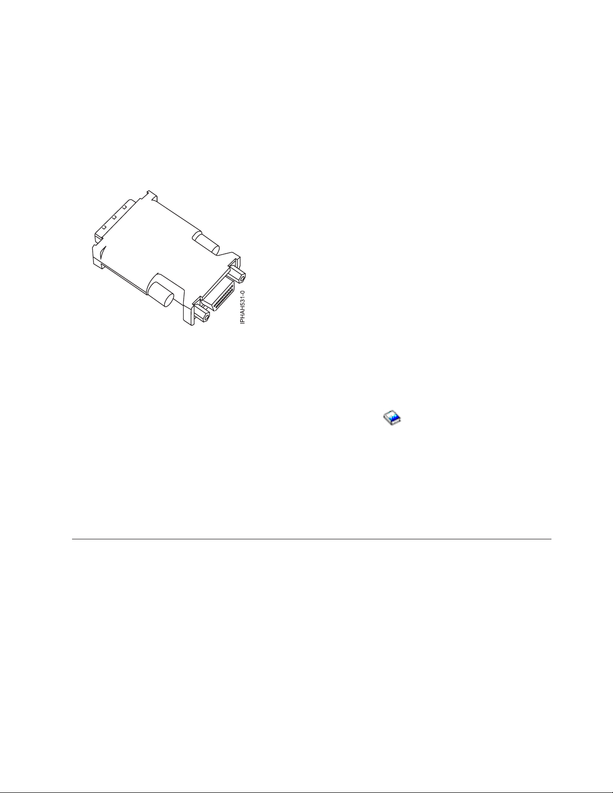
Tip: Some graphics adapters require a DVI-I to VGA converter. If you are using one of these graphics adapters,
attach the supplied converter (04N7533) to your monitor cable before connecting to the graphics adapter.
Figure 3. DVI-I to VGA converter
__ Connect a keyboard and mouse to the rear USB ports (T6 and T7), or connect a keyboard and mouse to the front
USB ports (T1 and T2).
__ If you want to connect the system with your network, connect a network cable to one of the Ethernet ports (T8
or T9).
__ If you are using any optional adapters (such as token ring or 8-port EIA-232), connect the cables to the
appropriate adapter connectors in the PCI slots of your server.
See Adapters, Devices, and Cable Information for Multiple Bus Systems
(http://publib16.boulder.ibm.com/
pseries/en_US/infocenter/base/hardware_docs/pdf/380516.pdf) for a description of cables and adapters that
might be installed on your server.
Note: If the cable did not come with your server, you will have to supply it.
__ Route the cables through the cable-management arm, and secure the cables with the straps provided.
After you finish
_ Return to your initial server setup checklist and complete the next step.
Cabling your model 9110-51A server with a console
For a graphical representation of the slots and connectors that are referred to in this topic, see the back
view of the model.
Cabling a model 9110-51A and an ASMI console
Complete the following tasks to cable your server:
Before you begin
__ If you have hardware features that are not installed, install them now. See Installing features and replacing parts
for instructions.
Cabling your server 39
Page 46

Connecting the Advanced System Management Interface (ASMI)
__ If you plan to connect a PC (with a browser) to the server to access the ASMI, see Accessing the ASMI using a
Web browser for instructions.
__ If you plan to access the ASMI using the ASCII terminal, see Accessing the ASMI using an ASCII console for
instructions.
Cabling the expansion units
__ Do you have an expansion unit?
v Yes. For instructions on how to set up your expansion unit, click the following link. Do not plug the
expansion-unit power cord into the power outlet, as directed by the following link, until later in the checklist.
Expansion units
v No. Proceed to the next section, Connecting the external cables.
Connecting the external cables
__ If you are using any optional adapters (such as token ring or 8-port EIA-232), connect the cables to the
appropriate adapter connectors in the PCI slots of your machine.
Use the table in “Cables and adapters” on page 163 to connect the cables to the matching adapters on the back
of your server. Not all adapters are shown.
Note: If the cable did not come with your server, you will have to supply it.
Attaching devices using the system ports
__ If you have an IBM System p5 or eServer p5 server and want to access the ASMI when the system is in standby,
attach an ASCII terminal to a system port on the back of the server. For views of the back of each server, see
References.
__ If you have an IBM System p5 or eServer p5 server and want to access the ASMI remotely when the system is in
standby, attach a modem to a system port on the back of the server. For views of the back of each server, see
References.
__ If you have an IBM System p5 or eServer p5 server and are connecting it to an uninterruptible power supply,
refer to the documentation that is included with your uninterruptible power supply. You might need additional
hardware.
__ If you have an IBM System i5 or eServer i5 server and are connecting it to an uninterruptible power supply, the
serial uninterruptible power supply conversion cable is required. See “Serial uninterruptible power supply
conversion cable” on page 162 for instructions.
Notes:
1. For the IBM System p5 or eServer p5 servers, any other application that uses a system port requires a system port
adapter to be installed in a PCI slot.
2. The attachment of high availability cluster multiprocessing IBM (HACMP) cables to the system ports on the back
of the server is not supported.
Connecting the power cords
__ Power cords should be routed through the retention rings or under the retention brackets that are provided to
prevent the power cords from becoming unplugged unexpectedly.
40 System i and System p: Cabling your server
Page 47
Connecting the power cords
__ If your server is equipped with a retention ring, route the power cord through the ring before you plug it
into the back of the server. See the following figure as an example:
__ If your server is equipped with a retention bracket, route the power cord under the bracket before you
plug it into the back of the server. See the following figure as an example:
__ Plug the power cords into the system, display, and attached devices.
Cabling your server 41
Page 48

Routing the cables through the cable-management arm
__ Is your server installed in a rack?
v No. Proceed to the next section, Starting your server.
v Yes. Do the following:
__ Put the system into the service position.
v For the models 510 and 510Q, see Place the model 9110-510 or OpenPower 710 in the service position.
v For the models 520, 520Q, 550, 550Q, 560Q, and 570, see Place the rack-mounted system or expansion
unit in the service position.
__ Route the cables through the hooks along the cable-management arm and secure them with the straps
provided.
__ After attaching the cables to the cable-management arm, go to the front of the rack and move the system
drawer in and out. Observe cables and cable-management-arm movement to verify that the cables are not
binding.
Starting your server
__ Power the system on (see Powering the system on and off).
Note: Expect a delay between the time when power is applied to the server or workstation and when an initial
program load (IPL) can be performed. When power is initially applied to the server or workstation, the service
processor performs a self-check and will leave the control panel blank for up to two minutes. Wait until the C1XX
XXXX progress codes are completed and 01 is displayed on the control panel before you perform an IPL or
change control panel functions.
42 System i and System p: Cabling your server
Page 49
After you finish
__ Did you receive a cable hook with your rack shipment?
v No. Proceed to the next item.
v Yes. The cable hook can help manage the server cables in the back of the rack. To install the cable hook, slide
it into the slots located on the back of the rack as shown in the following figure:
__ Return to your initial server setup checklist and complete the next step.
Cabling your server 43
Page 50

Cabling a model 9110-51A and a Hardware Management Console
(HMC)
DANGER
working on or around the system, observe the following precautions:
When
Electrical voltage and current from power, telephone, and communication cables are hazardous. To
avoid a shock hazard:
v Connect power to this unit only with the IBM provided power cord. Do not use the IBM
provided power cord for any other product.
v Do not open or service any power supply assembly.
v Do not connect or disconnect any cables or perform installation, maintenance, or reconfiguration
of this product during an electrical storm.
v The product might be equipped with multiple power cords. To remove all hazardous voltages,
disconnect all power cords.
v Connect all power cords to a properly wired and grounded electrical outlet. Ensure that the outlet
supplies proper voltage and phase rotation according to the system rating plate.
v Connect any equipment that will be attached to this product to properly wired outlets.
v When possible, use one hand only to connect or disconnect signal cables.
v Never turn on any equipment when there is evidence of fire, water, or structural damage.
v Disconnect the attached power cords, telecommunications systems, networks, and modems before
you open the device covers, unless instructed otherwise in the installation and configuration
procedures.
v Connect and disconnect cables as described in the following procedures when installing, moving,
or opening covers on this product or attached devices.
To Disconnect:
1. Turn off everything (unless instructed otherwise).
2. Remove the power cords from the outlets.
3. Remove the signal cables from the connectors.
4. Remove all cables from the devices
To Connect:
1. Turn off everything (unless instructed otherwise).
2. Attach all cables to the devices.
3. Attach the signal cables to the connectors.
4. Attach the power cords to the outlets.
5. Turn on the devices.
(D005)
Complete the following tasks to cable your server:
Before you begin
__ If you have hardware features that are not installed, install them now. See Installing features and replacing parts
for instructions.
44 System i and System p: Cabling your server
Page 51

Cabling the expansion units
__ Do you have an expansion unit?
v Yes. For instructions on how to set up your expansion unit, click the following link. Do not plug the
expansion-unit power cord into the power outlet, as directed by the following link, until later in the checklist.
Expansion units
v No. Proceed to the next section, Connecting the external cables.
Connecting the external cables
__ If you are using any optional adapters (such as token ring or 8-port EIA-232), connect the cables to the
appropriate adapter connectors in the PCI slots of your machine.
Use the table in “Cables and adapters” on page 163 to connect the cables to the matching adapters on the back
of your server. Not all adapters are shown.
Note: If the cable did not come with your server, you will have to supply it.
Attaching devices using the system ports
__ If you have an IBM System p5 or eServer p5 server, the system ports on the back of the server are disabled
when your server is connected to an HMC.
__ If you have an IBM System i5 or eServer i5 server and are connecting it to an uninterruptible power supply, the
serial uninterruptible power supply conversion cable is required. See “Serial uninterruptible power supply
conversion cable” on page 162 for instructions. Do not plug the uninterruptible-power-supply power cord into
the outlet and do not start your server.
Note: The attachment of high availability cluster multiprocessing (HACMP) cables to the system port on the back of
the server is not supported.
Connecting the power cords
__ Power cords should be routed through the retention rings or under the retention brackets that are provided to
prevent the power cords from becoming unplugged unexpectedly.
__ If your server is equipped with a retention ring, route the power cord through the ring before you plug it
into the back of the server. See the following figure as an example:
Cabling your server 45
Page 52

Connecting the power cords
__ If your server is equipped with a retention bracket, route the power cord under the bracket before you
plug it into the back of the server. See the following figure as an example:
__ Plug the power cords into the system, display, and attached devices. Do not connect the power cords to a
power source until instructed to do so.
Note: If you connect your server to a power source before the HMC is configured as the DHCP server, the
server will initialize using the default IP address values (HMC1 as 192.168.2.147 and HMC2 as 192.168.3.147)
instead of waiting for an address value from the HMC. If you inadvertently connect your server to a power
source, the IP address value will be corrected in the HMC configuration portion of the installation.
Connecting the Hardware Management Console cables
__ Cable the HMC (see Cabling the HMC).
Routing the cables through the cable-management arm
__ Is your server installed in a rack?
v No. Proceed to the next section, After you finish.
v Yes. Do the following:
__ Put the system into the service position.
v For the models 510 and 510Q, see Place the model 9110-510 or OpenPower 710 in the service position.
v For the models 520, 520Q, 550, 550Q, 560Q, and 570, see Place the rack-mounted system or expansion
unit in the service position.
46 System i and System p: Cabling your server
Page 53
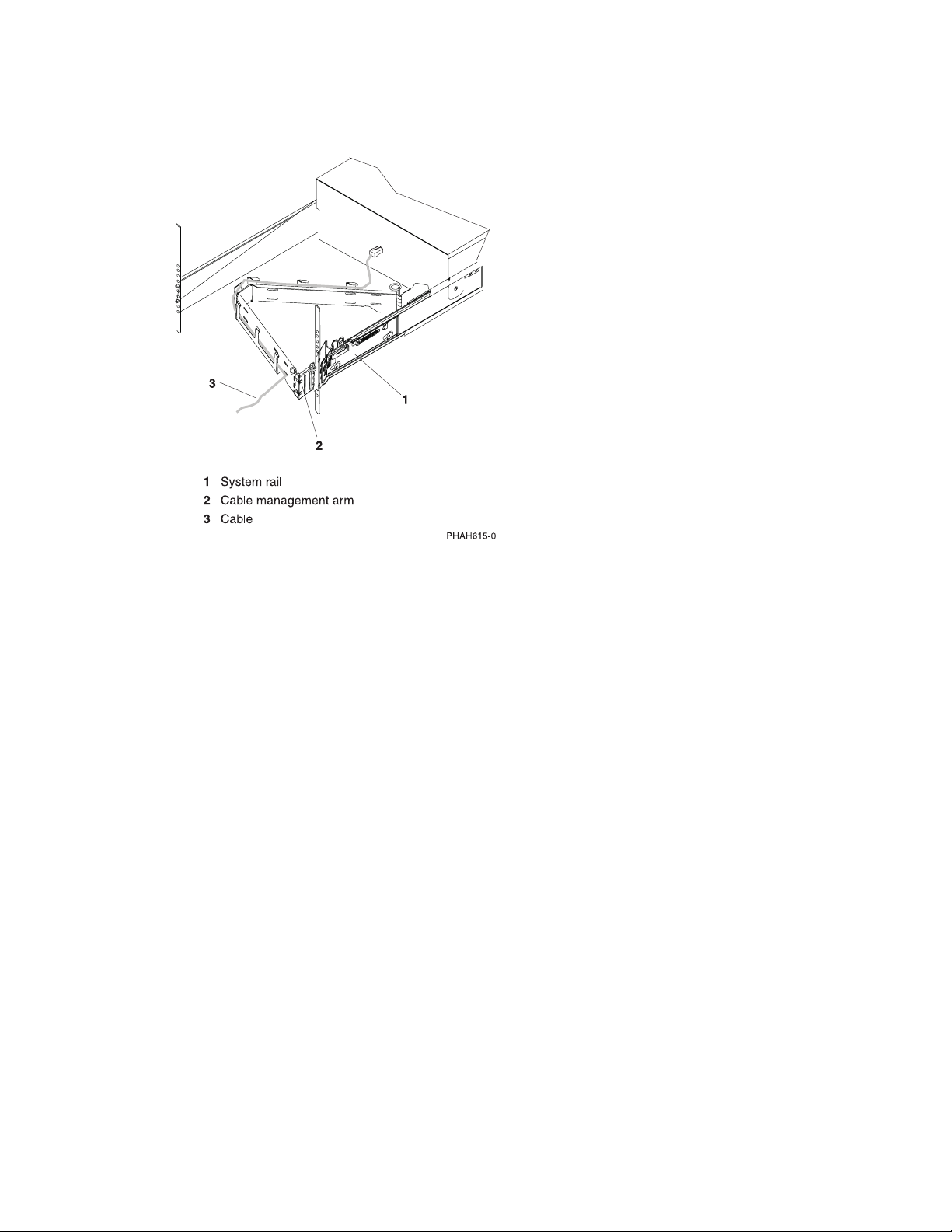
Routing the cables through the cable-management arm
__ Route the cables through the hooks along the cable-management arm and secure them with the straps
provided.
__ After attaching the cables to the cable-management arm, go to the front of the rack and move the system
drawer in and out. Observe cables and cable-management-arm movement to verify that the cables are not
binding.
Cabling your server 47
Page 54
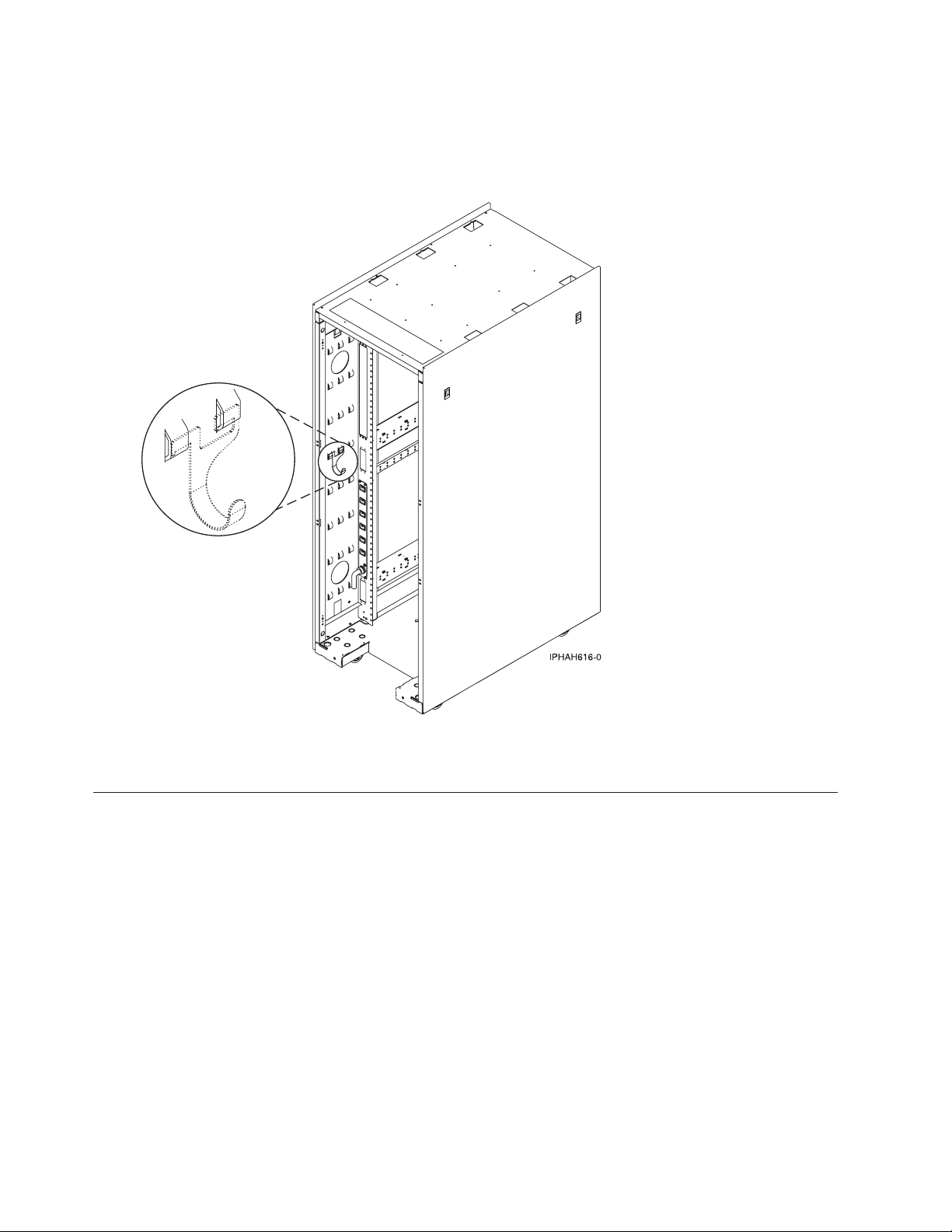
After you finish
__ Did you receive a cable hook with your rack shipment?
v No. Proceed to the next item.
v Yes. The cable hook can help manage the server cables in the back of the rack. To install the cable hook, slide
it into the slots located on the back of the rack as shown in the following figure.
__ Return to your initial server setup checklist and complete the next step.
Cabling your model 9115-505 with a console
For a graphical representation of the slots and connectors that are referred to in this topic, see the back
view of the model.
Cabling a 9115-505 and an ASMI console
Complete the following tasks to cable your server:
Before you begin
__ If you have hardware features that are not installed, install them now. See Installing features and replacing parts
for instructions.
Connecting the Advanced System Management Interface (ASMI)
__ If you plan to connect a PC (with a browser) to the server to access the ASMI, see Accessing the ASMI using a
Web browser for instructions.
48 System i and System p: Cabling your server
Page 55

Connecting the Advanced System Management Interface (ASMI)
__ If you plan to access the ASMI using the ASCII terminal, see Accessing the ASMI using an ASCII console for
instructions.
Connecting the external cables
__ If you are using any optional adapters (such as token ring or 8-port EIA-232), connect the cables to the
appropriate adapter connectors in the PCI slots of your machine.
See Adapters, Devices, and Cable Information for Multiple Bus Systems
(http://publib16.boulder.ibm.com/
pseries/en_US/infocenter/base/hardware_docs/pdf/380516.pdf) for a description of cables and adapters that
might be installed on your server.
Note: If the cable did not come with your server, you will have to supply it.
Attaching devices using the system ports
__ If you have an IBM System p5 or eServer p5 server and want to access the ASMI when the system is in standby,
attach an ASCII terminal to a system port on the back of the server. For views of the back of each server, see
References.
__ If you have an IBM System p5 or eServer p5 server and want to access the ASMI remotely when the system is in
standby, attach a modem to a system port on the back of the server. For views of the back of each server, see
References.
__ If you have an IBM System p5 or eServer p5 server and are connecting it to an uninterruptible power supply,
refer to the documentation that is included with your uninterruptible power supply. You might need additional
hardware.
Notes:
1. For the IBM System p5 or eServer p5 servers, any other application that uses a system port requires a system port
adapter to be installed in a PCI slot.
2. The attachment of high availability cluster multiprocessing IBM (HACMP) cables to the system ports on the back
of the server is not supported.
Connecting the power cords
__ Power cords should be routed through the retention rings or under the retention brackets that are provided to
prevent the power cords from becoming unplugged unexpectedly.
Cabling your server 49
Page 56

Connecting the power cords
__ If your server is equipped with a retention ring, route the power cord through the ring before you plug it
into the back of the server. See the following figure as an example:
__ If your server is equipped with a retention bracket, route the power cord under the bracket before you
plug it into the back of the server. See the following figure as an example:
__ Plug the power cords into the system, display, and attached devices.
50 System i and System p: Cabling your server
Page 57

Routing the cables through the cable-management arm
__ Is your server installed in a rack?
v No. Proceed to the next section, Starting your server.
v Yes. Do the following:
__ Put the system into the service position.
v For the models 510 and 510Q, see Place the model 9110-510 or OpenPower 710 in the service position.
v For the models 520, 520Q, 550, 550Q, 560Q, and 570, see Place the rack-mounted system or expansion
unit in the service position.
__ Route the cables through the hooks along the cable-management arm and secure them with the straps
provided.
__ After attaching the cables to the cable-management arm, go to the front of the rack and move the system
drawer in and out. Observe cables and cable-management-arm movement to verify that the cables are not
binding.
Starting your server
__ Power the system on (see Powering the system on and off).
Note: Expect a delay between the time when power is applied to the server or workstation and when an initial
program load (IPL) can be performed. When power is initially applied to the server or workstation, the service
processor performs a self-check and will leave the control panel blank for up to two minutes. Wait until the C1XX
XXXX progress codes are completed and 01 is displayed on the control panel before you perform an IPL or
change control panel functions.
Cabling your server 51
Page 58

After you finish
__ Did you receive a cable hook with your rack shipment?
v No. Proceed to the next item.
v Yes. The cable hook can help manage the server cables in the back of the rack. To install the cable hook, slide
it into the slots located on the back of the rack as shown in the following figure:
__ Return to your initial server setup checklist and complete the next step.
52 System i and System p: Cabling your server
Page 59

Cabling a 9115-505 and a Hardware Management Console (HMC)
DANGER
working on or around the system, observe the following precautions:
When
Electrical voltage and current from power, telephone, and communication cables are hazardous. To
avoid a shock hazard:
v Connect power to this unit only with the IBM provided power cord. Do not use the IBM
provided power cord for any other product.
v Do not open or service any power supply assembly.
v Do not connect or disconnect any cables or perform installation, maintenance, or reconfiguration
of this product during an electrical storm.
v The product might be equipped with multiple power cords. To remove all hazardous voltages,
disconnect all power cords.
v Connect all power cords to a properly wired and grounded electrical outlet. Ensure that the outlet
supplies proper voltage and phase rotation according to the system rating plate.
v Connect any equipment that will be attached to this product to properly wired outlets.
v When possible, use one hand only to connect or disconnect signal cables.
v Never turn on any equipment when there is evidence of fire, water, or structural damage.
v Disconnect the attached power cords, telecommunications systems, networks, and modems before
you open the device covers, unless instructed otherwise in the installation and configuration
procedures.
v Connect and disconnect cables as described in the following procedures when installing, moving,
or opening covers on this product or attached devices.
To Disconnect:
1. Turn off everything (unless instructed otherwise).
2. Remove the power cords from the outlets.
3. Remove the signal cables from the connectors.
4. Remove all cables from the devices
To Connect:
1. Turn off everything (unless instructed otherwise).
2. Attach all cables to the devices.
3. Attach the signal cables to the connectors.
4. Attach the power cords to the outlets.
5. Turn on the devices.
(D005)
Complete the following tasks to cable your server:
Before you begin
__ If you have hardware features that are not installed, install them now. See Installing features and replacing parts
for instructions.
Cabling your server 53
Page 60
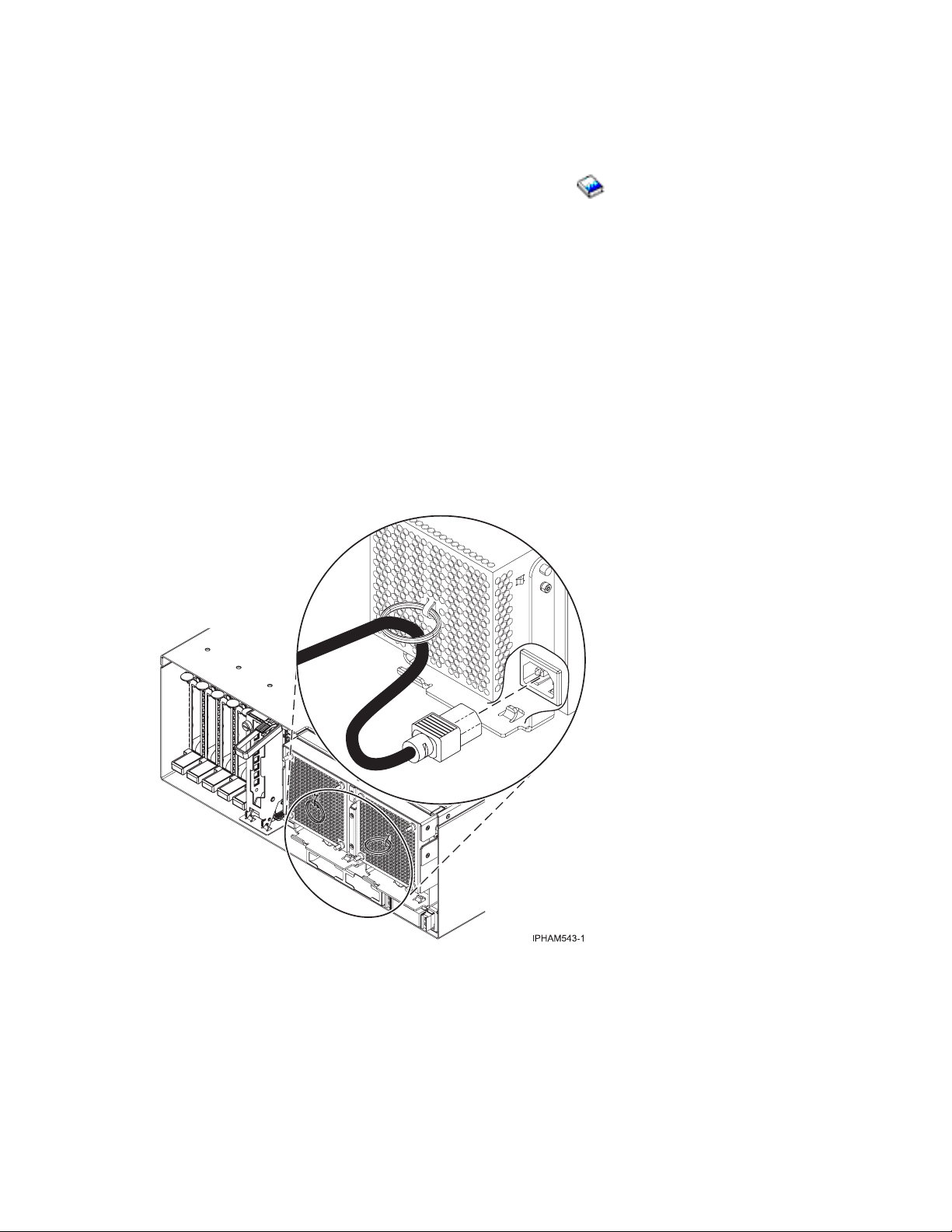
Connecting the external cables
__ If you are using any optional adapters (such as token ring or 8-port EIA-232), connect the cables to the
appropriate adapter connectors in the PCI slots of your machine.
See Adapters, Devices, and Cable Information for Multiple Bus Systems
pseries/en_US/infocenter/base/hardware_docs/pdf/380516.pdf)
for a description of cables and adapters that
(http://publib16.boulder.ibm.com/
might be installed on your server.
Note: If the cable did not come with your server, you will have to supply it.
Attaching devices using the system ports
__ If you have an IBM System p5 or eServer p5 server, the system ports on the back of the server are disabled
when your server is connected to an HMC.
Note: The attachment of high availability cluster multiprocessing (HACMP) cables to the system ports on the back of
the server is not supported.
Connecting the power cords
__ Power cords should be routed through the retention rings or under the retention brackets that are provided to
prevent the power cords from becoming unplugged unexpectedly.
__ If your server is equipped with a retention ring, route the power cord through the ring before you plug it
into the back of the server. See the following figure as an example:
54 System i and System p: Cabling your server
Page 61

Connecting the power cords
__ If your server is equipped with a retention bracket, route the power cord under the bracket before you
plug it into the back of the server. See the following figure as an example:
__ Plug the power cords into the system, display, and attached devices. Do not connect the power cords to a
power source until instructed to do so.
Note: If you connect your server to a power source before the HMC is configured as the DHCP server, the
server will initialize using the default IP address values (HMC1 as 192.168.2.147 and HMC2 as 192.168.3.147)
instead of waiting for an address value from the HMC. If you inadvertently connect your server to a power
source, the IP address value will be corrected in the HMC configuration portion of the installation.
Connecting the Hardware Management Console cables
__ Cable the HMC (see Cabling the HMC).
Routing the cables through the cable-management arm
__ Is your server installed in a rack?
v No. Proceed to the next section, After you finish.
v Yes. Do the following:
__ Put the system into the service position.
v For the models 510 and 510Q, see Place the model 9110-510 or OpenPower 710 in the service position.
v For the models 520, 520Q, 550, 550Q, 560Q, and 570, see Place the rack-mounted system or expansion
unit in the service position.
Cabling your server 55
Page 62

Routing the cables through the cable-management arm
__ Route the cables through the hooks along the cable-management arm and secure them with the straps
provided.
__ After attaching the cables to the cable-management arm, go to the front of the rack and move the system
drawer in and out. Observe cables and cable-management-arm movement to verify that the cables are not
binding.
56 System i and System p: Cabling your server
Page 63

After you finish
__ Did you receive a cable hook with your rack shipment?
v No. Proceed to the next item.
v Yes. The cable hook can help manage the server cables in the back of the rack. To install the cable hook, slide
it into the slots located on the back of the rack as shown in the following figure:
_ Return to your initial server setup checklist and complete the next step.
Cabling your model 9131-52A server with a console
For a graphical representation of the slots and connectors that are referred to in this topic, see the back
views of the model.
Cabling a model 9131-52A and an ASMI console
Complete the following tasks to cable your server:
Before you begin
__ If you have hardware features that are not installed, install them now. See Installing features and replacing parts
for instructions.
Connecting the Advanced System Management Interface (ASMI)
__ If you plan to connect a PC (with a browser) to the server to access the ASMI, see Accessing the ASMI using a
Web browser for instructions.
Cabling your server 57
Page 64

Connecting the Advanced System Management Interface (ASMI)
__ If you plan to access the ASMI using the ASCII terminal, see Accessing the ASMI using an ASCII console for
instructions.
Cabling the expansion units
__ Do you have an expansion unit?
v Yes. For instructions on how to set up your expansion unit, click the following link. Do not plug the
expansion-unit power cord into the power outlet, as directed by the following link, until later in the checklist.
Expansion units
v No. Proceed to the next section, Connecting the external cables.
Connecting the external cables
__ If you are using any optional adapters (such as token ring or 8-port EIA-232), connect the cables to the
appropriate adapter connectors in the PCI slots of your machine.
See Adapters, Devices, and Cable Information for Multiple Bus Systems
(http://publib16.boulder.ibm.com/
pseries/en_US/infocenter/base/hardware_docs/pdf/380516.pdf) for a description of cables and adapters that
might be installed on your server.
Note: If the cable did not come with your server, you will have to supply it.
Attaching devices using the system ports
__ If you have an IBM System p5 or eServer p5 server and want to access the ASMI when the system is in standby,
attach an ASCII terminal to a system port on the back of the server. For views of the back of each server, see
References.
__ If you have an IBM System p5 or eServer p5 server and want to access the ASMI remotely when the system is in
standby, attach a modem to a system port on the back of the server. For views of the back of each server, see
References.
__ If you have an IBM System p5 or eServer p5 server and are connecting it to an uninterruptible power supply,
refer to the documentation that is included with your uninterruptible power supply. You might need additional
hardware.
Notes:
1. For the IBM System p5 or eServer p5 servers, any other application that uses a system port requires a system port
adapter to be installed in a PCI slot.
2. The attachment of high availability cluster multiprocessing IBM (HACMP) cables to the system ports on the back
of the server is not supported.
Connecting the power cords
__ Power cords should be routed through the retention rings or under the retention brackets that are provided to
prevent the power cords from becoming unplugged unexpectedly.
58 System i and System p: Cabling your server
Page 65

Connecting the power cords
__ If your server is equipped with a retention ring, route the power cord through the ring before you plug it
into the back of the server. See the following figure as an example:
__ If your server is equipped with a retention bracket, route the power cord under the bracket before you
plug it into the back of the server. See the following figure as an example:
__ Plug the power cords into the system, display, and attached devices.
Cabling your server 59
Page 66

Routing the cables through the cable-management arm
__ Is your server installed in a rack?
v No. Proceed to the next section, Starting your server.
v Yes. Do the following:
__ Put the system into the service position.
v For the models 510 and 510Q, see Place the model 9110-510 or OpenPower 710 in the service position.
v For the models 520, 520Q, 550, 550Q, 560Q, and 570, see Place the rack-mounted system or expansion
unit in the service position.
__ Route the cables through the hooks along the cable-management arm and secure them with the straps
provided.
__ After attaching the cables to the cable-management arm, go to the front of the rack and move the system
drawer in and out. Observe cables and cable-management-arm movement to verify that the cables are not
binding.
Starting your server
__ Power the system on (see Powering the system on and off).
Note: Expect a delay between the time when power is applied to the server or workstation and when an initial
program load (IPL) can be performed. When power is initially applied to the server or workstation, the service
processor performs a self-check and will leave the control panel blank for up to two minutes. Wait until the C1XX
XXXX progress codes are completed and 01 is displayed on the control panel before you perform an IPL or
change control panel functions.
60 System i and System p: Cabling your server
Page 67

After you finish
__ Did you receive a cable hook with your rack shipment?
v No. Proceed to the next item.
v Yes. The cable hook can help manage the server cables in the back of the rack. To install the cable hook, slide
it into the slots located on the back of the rack as shown in the following figure:
__ Return to your initial server setup checklist and complete the next step.
Cabling your server 61
Page 68

Cabling a model 9131-52A and a Hardware Management Console
(HMC)
DANGER
working on or around the system, observe the following precautions:
When
Electrical voltage and current from power, telephone, and communication cables are hazardous. To
avoid a shock hazard:
v Connect power to this unit only with the IBM provided power cord. Do not use the IBM
provided power cord for any other product.
v Do not open or service any power supply assembly.
v Do not connect or disconnect any cables or perform installation, maintenance, or reconfiguration
of this product during an electrical storm.
v The product might be equipped with multiple power cords. To remove all hazardous voltages,
disconnect all power cords.
v Connect all power cords to a properly wired and grounded electrical outlet. Ensure that the outlet
supplies proper voltage and phase rotation according to the system rating plate.
v Connect any equipment that will be attached to this product to properly wired outlets.
v When possible, use one hand only to connect or disconnect signal cables.
v Never turn on any equipment when there is evidence of fire, water, or structural damage.
v Disconnect the attached power cords, telecommunications systems, networks, and modems before
you open the device covers, unless instructed otherwise in the installation and configuration
procedures.
v Connect and disconnect cables as described in the following procedures when installing, moving,
or opening covers on this product or attached devices.
To Disconnect:
1. Turn off everything (unless instructed otherwise).
2. Remove the power cords from the outlets.
3. Remove the signal cables from the connectors.
4. Remove all cables from the devices
To Connect:
1. Turn off everything (unless instructed otherwise).
2. Attach all cables to the devices.
3. Attach the signal cables to the connectors.
4. Attach the power cords to the outlets.
5. Turn on the devices.
(D005)
Complete the following tasks to cable your server:
Before you begin
__ If you have hardware features that are not installed, install them now. See Installing features and replacing parts
for instructions.
62 System i and System p: Cabling your server
Page 69

Cabling the expansion units
__ Do you have an expansion unit?
v Yes. For instructions on how to set up your expansion unit, click the following link. Do not plug the
expansion-unit power cord into the power outlet, as directed by the following link, until later in the checklist.
Expansion units
v No. Proceed to the next section, Connecting the external cables.
Connecting the external cables
__ If you are using any optional adapters (such as token ring or 8-port EIA-232), connect the cables to the
appropriate adapter connectors in the PCI slots of your machine.
See Adapters, Devices, and Cable Information for Multiple Bus Systems
(http://publib16.boulder.ibm.com/
pseries/en_US/infocenter/base/hardware_docs/pdf/380516.pdf) for a description of cables and adapters that
might be installed on your server.
Note: If the cable did not come with your server, you will have to supply it.
Attaching devices using the system ports
__ If you have an IBM System p5 or eServer p5 server, the system ports on the back of the server are disabled
when your server is connected to an HMC.
Note: The attachment of high availability cluster multiprocessing IBM (HACMP) cables to the system ports on the
back of the server is not supported.
Connecting the power cords
__ Power cords should be routed through the retention rings or under the retention brackets that are provided to
prevent the power cords from becoming unplugged unexpectedly.
__ If your server is equipped with a retention ring, route the power cord through the ring before you plug it
into the back of the server. See the following figure as an example:
Cabling your server 63
Page 70

Connecting the power cords
__ If your server is equipped with a retention bracket, route the power cord under the bracket before you
plug it into the back of the server. See the following figure as an example:
__ Plug the power cords into the system, display, and attached devices. Do not connect the power cords to a
power source until instructed to do so.
Note: If you connect your server to a power source before the HMC is configured as the DHCP server, the
server will initialize using the default IP address values (HMC1 as 192.168.2.147 and HMC2 as 192.168.3.147)
instead of waiting for an address value from the HMC. If you inadvertently connect your server to a power
source, the IP address value will be corrected in the HMC configuration portion of the installation.
Connecting the Hardware Management Console cables
__ Cable the HMC (see Cabling the HMC).
Routing the cables through the cable-management arm
__ Is your server installed in a rack?
v No. Proceed to the next section, After you finish.
v Yes. Do the following:
__ Put the system into the service position.
v For the models 510 and 510Q, see Place the model 9110-510 or OpenPower 710 in the service position.
v For the models 520, 520Q, 550, 550Q, 560Q, and 570, see Place the rack-mounted system or expansion
unit in the service position.
64 System i and System p: Cabling your server
Page 71

Routing the cables through the cable-management arm
__ Route the cables through the hooks along the cable-management arm and secure them with the straps
provided.
__ After attaching the cables to the cable-management arm, go to the front of the rack and move the system
drawer in and out. Observe cables and cable-management-arm movement to verify that the cables are not
binding.
Cabling your server 65
Page 72

After you finish
__ Did you receive a cable hook with your rack shipment?
v No. Proceed to the next item.
v Yes. The cable hook can help manage the server cables in the back of the rack. To install the cable hook, slide
it into the slots located on the back of the rack as shown in the following figure:
__ Return to your initial server setup checklist and complete the next step.
Cabling your model 9133-55A server with a console
For a graphical representation of the slots and connectors that are referred to in this topic, see the back
views of the model.
Cabling a model 9133-55A and an ASMI console
Complete the following tasks to cable your server:
Before you begin
__ If you have hardware features that are not installed, install them now. See Installing features and replacing parts
for instructions.
Connecting the Advanced System Management Interface (ASMI)
__ If you plan to connect a PC (with a browser) to the server to access the ASMI, see Accessing the ASMI using a
Web browser for instructions.
66 System i and System p: Cabling your server
Page 73

Connecting the Advanced System Management Interface (ASMI)
__ If you plan to access the ASMI using the ASCII terminal, see Accessing the ASMI using an ASCII console for
instructions.
Cabling the expansion units
__ Do you have an expansion unit?
v Yes. For instructions on how to set up your expansion unit, click the following link. Do not plug the
expansion-unit power cord into the power outlet, as directed by the following link, until later in the checklist.
Expansion units
v No. Proceed to the next section, Connecting the external cables.
Connecting the external cables
__ If you are using any optional adapters (such as token ring or 8-port EIA-232), connect the cables to the
appropriate adapter connectors in the PCI slots of your machine.
See Adapters, Devices, and Cable Information for Multiple Bus Systems
(http://publib16.boulder.ibm.com/
pseries/en_US/infocenter/base/hardware_docs/pdf/380516.pdf) for a description of cables and adapters that
might be installed on your server.
Note: If the cable did not come with your server, you will have to supply it.
Attaching devices using the system ports
__ If you have an IBM System p5 or eServer p5 server and want to access the ASMI when the system is in standby,
attach an ASCII terminal to a system port on the back of the server. For views of the back of each server, see
References.
__ If you have an IBM System p5 or eServer p5 server and want to access the ASMI remotely when the system is in
standby, attach a modem to a system port on the back of the server. For views of the back of each server, see
References.
__ If you have an IBM System p5 or eServer p5 server and are connecting it to an uninterruptible power supply,
refer to the documentation that is included with your uninterruptible power supply. You might need additional
hardware.
Notes:
1. For the IBM System p5 or eServer p5 servers, any other application that uses a system port requires a system port
adapter to be installed in a PCI slot.
2. The attachment of high availability cluster multiprocessing IBM (HACMP) cables to the system ports on the back
of the server is not supported.
Connecting the power cords
__ Power cords should be routed through the retention rings or under the retention brackets that are provided to
prevent the power cords from becoming unplugged unexpectedly.
Cabling your server 67
Page 74

Connecting the power cords
__ If your server is equipped with a retention ring, route the power cord through the ring before you plug it
into the back of the server. See the following figure as an example:
__ If your server is equipped with a retention bracket, route the power cord under the bracket before you
plug it into the back of the server. See the following figure as an example:
__ Plug the power cords into the system, display, and attached devices.
68 System i and System p: Cabling your server
Page 75

Routing the cables through the cable-management arm
__ Is your server installed in a rack?
v No. Proceed to the next section, Starting your server.
v Yes. Do the following:
__ Put the system into the service position.
v For the models 510 and 510Q, see Place the model 9110-510 or OpenPower 710 in the service position.
v For the models 520, 520Q, 550, 550Q, 560Q, and 570, see Place the rack-mounted system or expansion
unit in the service position.
__ Route the cables through the hooks along the cable-management arm and secure them with the straps
provided.
__ After attaching the cables to the cable-management arm, go to the front of the rack and move the system
drawer in and out. Observe cables and cable-management-arm movement to verify that the cables are not
binding.
Starting your server
__ Power the system on (see Powering the system on and off).
Note: Expect a delay between the time when power is applied to the server or workstation and when an initial
program load (IPL) can be performed. When power is initially applied to the server or workstation, the service
processor performs a self-check and will leave the control panel blank for up to two minutes. Wait until the C1XX
XXXX progress codes are completed and 01 is displayed on the control panel before you perform an IPL or
change control panel functions.
Cabling your server 69
Page 76
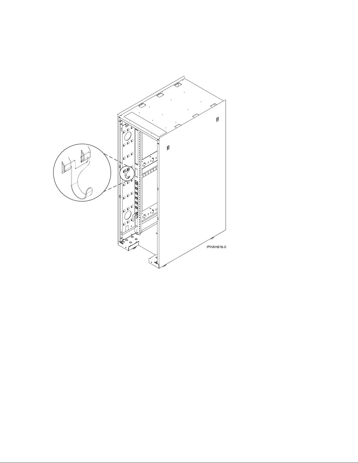
After you finish
__ Did you receive a cable hook with your rack shipment?
v No. Proceed to the next item.
v Yes. The cable hook can help manage the server cables in the back of the rack. To install the cable hook, slide
it into the slots located on the back of the rack as shown in the following figure.
__ Return to your initial server setup checklist and complete the next step.
70 System i and System p: Cabling your server
Page 77

Cabling a model 9133-55A and a Hardware Management Console
(HMC)
DANGER
working on or around the system, observe the following precautions:
When
Electrical voltage and current from power, telephone, and communication cables are hazardous. To
avoid a shock hazard:
v Connect power to this unit only with the IBM provided power cord. Do not use the IBM
provided power cord for any other product.
v Do not open or service any power supply assembly.
v Do not connect or disconnect any cables or perform installation, maintenance, or reconfiguration
of this product during an electrical storm.
v The product might be equipped with multiple power cords. To remove all hazardous voltages,
disconnect all power cords.
v Connect all power cords to a properly wired and grounded electrical outlet. Ensure that the outlet
supplies proper voltage and phase rotation according to the system rating plate.
v Connect any equipment that will be attached to this product to properly wired outlets.
v When possible, use one hand only to connect or disconnect signal cables.
v Never turn on any equipment when there is evidence of fire, water, or structural damage.
v Disconnect the attached power cords, telecommunications systems, networks, and modems before
you open the device covers, unless instructed otherwise in the installation and configuration
procedures.
v Connect and disconnect cables as described in the following procedures when installing, moving,
or opening covers on this product or attached devices.
To Disconnect:
1. Turn off everything (unless instructed otherwise).
2. Remove the power cords from the outlets.
3. Remove the signal cables from the connectors.
4. Remove all cables from the devices
To Connect:
1. Turn off everything (unless instructed otherwise).
2. Attach all cables to the devices.
3. Attach the signal cables to the connectors.
4. Attach the power cords to the outlets.
5. Turn on the devices.
(D005)
Complete the following tasks to cable your server:
Before you begin
__ If you have hardware features that are not installed, install them now. See Installing features and replacing parts
for instructions.
Cabling your server 71
Page 78

Cabling the expansion units
__ Do you have an expansion unit?
v Yes. For instructions on how to set up your expansion unit, click the following link. Do not plug the
expansion-unit power cord into the power outlet, as directed by the following link, until later in the checklist.
Expansion units
v No. Proceed to the next section, Connecting the external cables.
Connecting the external cables
__ If you are using any optional adapters (such as token ring or 8-port EIA-232), connect the cables to the
appropriate adapter connectors in the PCI slots of your machine.
See Adapters, Devices, and Cable Information for Multiple Bus Systems
(http://publib16.boulder.ibm.com/
pseries/en_US/infocenter/base/hardware_docs/pdf/380516.pdf) for a description of cables and adapters that
might be installed on your server.
Note: If the cable did not come with your server, you will have to supply it.
Attaching devices using the system ports
__ If you have an IBM System p5 or eServer p5 server, the system ports on the back of the server are disabled
when your server is connected to an HMC.
Note: The attachment of high availability cluster multiprocessing (HACMP) cables to the system ports on the back of
the server is not supported.
Connecting the power cords
__ Power cords should be routed through the retention rings or under the retention brackets that are provided to
prevent the power cords from becoming unplugged unexpectedly.
__ If your server is equipped with a retention ring, route the power cord through the ring before you plug it
into the back of the server. See the following figure as an example:
72 System i and System p: Cabling your server
Page 79
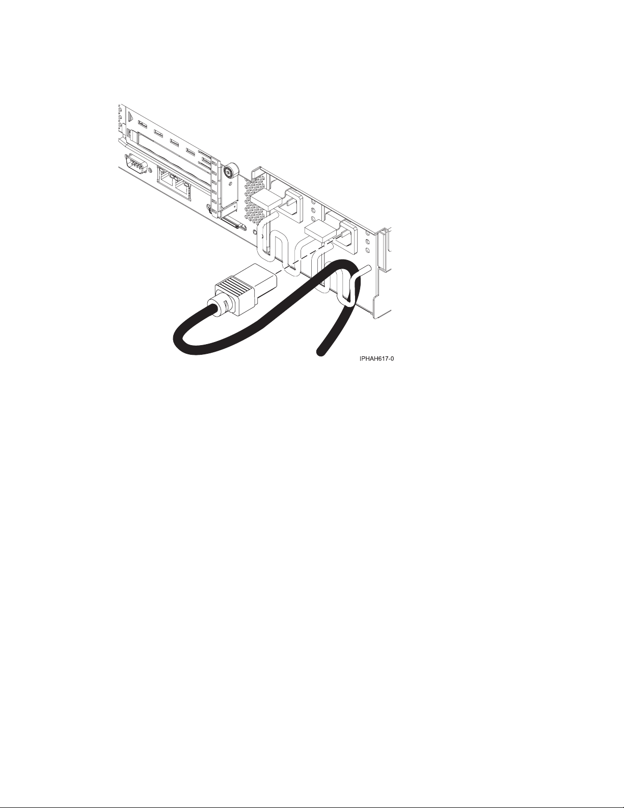
Connecting the power cords
__ If your server is equipped with a retention bracket, route the power cord under the bracket before you
plug it into the back of the server. See the following figure as an example:
__ Plug the power cords into the system, display, and attached devices. Do not connect the power cords to a
power source until instructed to do so.
Note: If you connect your server to a power source before the HMC is configured as the DHCP server, the
server will initialize using the default IP address values (HMC1 as 192.168.2.147 and HMC2 as 192.168.3.147)
instead of waiting for an address value from the HMC. If you inadvertently connect your server to a power
source, the IP address value will be corrected in the HMC configuration portion of the installation.
Connecting the Hardware Management Console cables
__ Cable the HMC (see Cabling the HMC).
Routing the cables through the cable-management arm
__ Is your server installed in a rack?
v No. Proceed to the next section, After you finish.
v Yes. Do the following:
__ Put the system into the service position.
v For the models 510 and 510Q, see Place the model 9110-510 or OpenPower 710 in the service position.
v For the models 520, 520Q, 550, 550Q, 560Q, and 570, see Place the rack-mounted system or expansion
unit in the service position.
Cabling your server 73
Page 80
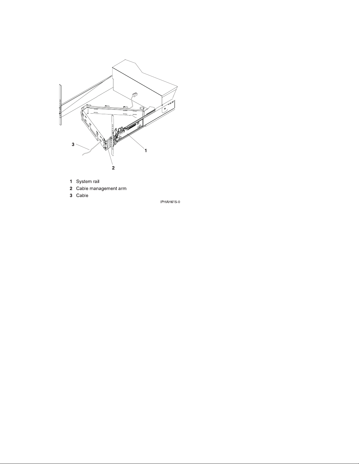
Routing the cables through the cable-management arm
__ Route the cables through the hooks along the cable-management arm and secure them with the straps
provided.
__ After attaching the cables to the cable-management arm, go to the front of the rack and move the system
drawer in and out. Observe cables and cable-management-arm movement to verify that the cables are not
binding.
74 System i and System p: Cabling your server
Page 81

After you finish
__ Did you receive a cable hook with your rack shipment?
v No. Proceed to the next item.
v Yes. The cable hook can help manage the server cables in the back of the rack. To install the cable hook, slide
it into the slots located on the back of the rack as shown in the following figure:
__ Return to your initial server setup checklist and complete the next step.
Cabling your 7047-185 workstation
For a graphical representation of the slots and connectors that are referred to in this topic, see the back
view of the model.
Attention: This product is equipped with a three-wire power cable and plug for the user’s safety. Use
this power cable with a properly grounded electrical outlet to avoid electrical shock.
Complete the following tasks to cable your system unit:
Before you begin
__ If you have hardware features that are not installed, install them now. See Installing features and replacing parts
for instructions.
Connecting the power cords
__ Connect the system’s power supply to a power source.
Cabling your server 75
Page 82

Connecting the external cables
__ Connect a TTY terminal or terminal emulator to a serial port (T4 or T5), or connect a display monitor to an
optional graphics adapter in one of the PCI slots (P1-C5 through P1-C9).
Tip: Some graphics adapters require a DVI-I to VGA converter. If you are using one of these graphics adapters,
attach the supplied converter (04N7533) to your monitor cable before connecting to the graphics adapter.
Figure 4. DVI-I to VGA converter
__ Connect a keyboard and mouse to the rear USB ports (T6 and T7), or connect a keyboard and mouse to the front
USB ports (T1 and T2).
__ If you want to connect the system with your network, connect a network cable to one of the Ethernet ports (T8
or T9).
__ If you are using any optional adapters (such as token ring or 8-port EIA-232), connect the cables to the
appropriate adapter connectors in the PCI slots of your system unit.
See Adapters, Devices, and Cable Information for Multiple Bus Systems
(http://publib16.boulder.ibm.com/
pseries/en_US/infocenter/base/hardware_docs/pdf/380516.pdf) for a description of cables and adapters that
might be installed on your workstation.
Note: If the cable did not come with your workstation, you will have to supply it.
After you finish
_ Return to your initial setup checklist and complete the next step.
Cabling your 9111-285 workstation with a console
For a graphical representation of the slots and connectors that are referred to in this topic, see the back
views of the model.
Cabling a 9111-285 and an ASMI console
Complete the following tasks to cable your workstation:
Before you begin
__ If you have hardware features that are not installed, install them now. See Installing features and replacing parts
for instructions.
Connecting the Advanced System Management Interface (ASMI)
__ If you plan to connect a PC (with a browser) to the workstation to access the ASMI, see Accessing the ASMI
using a Web browser for instructions.
__ If you plan to access the ASMI using the ASCII terminal, see Accessing the ASMI using an ASCII console for
instructions.
76 System i and System p: Cabling your server
Page 83

Connecting the external cables
__ If you are using any optional adapters (such as token ring or 8-port EIA-232), connect the cables to the
appropriate adapter connectors in the PCI slots of your machine.
See Adapters, Devices, and Cable Information for Multiple Bus Systems
pseries/en_US/infocenter/base/hardware_docs/pdf/380516.pdf)
for a description of cables and adapters that
(http://publib16.boulder.ibm.com/
might be installed on your workstation.
Note: If the cable did not come with your workstation, you will have to supply it.
Attaching devices using the system ports
__ If you have an IBM System p5 or eServer p5 server and want to access the ASMI when the system is in standby,
attach an ASCII terminal to a system port on the back of the server. For views of the back of each server, see
References.
__ If you have an IBM System p5 or eServer p5 server and want to access the ASMI remotely when the system is in
standby, attach a modem to a system port on the back of the server. For views of the back of each server, see
References.
__ If you have an IBM System p5 or eServer p5 server and are connecting it to an uninterruptible power supply,
refer to the documentation that is included with your uninterruptible power supply. You might need additional
hardware.
Notes:
1. For the IBM System p5 or eServer p5 servers, any other application that uses a system port requires a system port
adapter to be installed in a PCI slot.
2. The attachment of high availability cluster multiprocessing IBM (HACMP) cables to the system ports on the back
of the server is not supported.
Connecting the power cords
__ Power cords should be routed through the retention rings or under the retention brackets that are provided to
prevent the power cords from becoming unplugged unexpectedly.
__ If your workstation is equipped with a retention ring, route the power cord through the ring before you
plug it into the back of the workstation. See the following figure as an example:
Cabling your server 77
Page 84

Connecting the power cords
__ If your workstation is equipped with a retention bracket, route the power cord under the bracket before
you plug it into the back of the workstation. See the following figure as an example:
__ Plug the power cords into the system, display, and attached devices.
Starting your workstation
__ Power the system on (see Powering the system on and off).
Note: Expect a delay between the time when power is applied to the server or workstation and when an initial
program load (IPL) can be performed. When power is initially applied to the server or workstation, the service
processor performs a self-check and will leave the control panel blank for up to two minutes. Wait until the C1XX
XXXX progress codes are completed and 01 is displayed on the control panel before you perform an IPL or
change control panel functions.
After you finish
_ Return to your initial setup checklist and complete the next step.
78 System i and System p: Cabling your server
Page 85

Cabling a 9111-285 and a Hardware Management Console (HMC)
DANGER
working on or around the system, observe the following precautions:
When
Electrical voltage and current from power, telephone, and communication cables are hazardous. To
avoid a shock hazard:
v Connect power to this unit only with the IBM provided power cord. Do not use the IBM
provided power cord for any other product.
v Do not open or service any power supply assembly.
v Do not connect or disconnect any cables or perform installation, maintenance, or reconfiguration
of this product during an electrical storm.
v The product might be equipped with multiple power cords. To remove all hazardous voltages,
disconnect all power cords.
v Connect all power cords to a properly wired and grounded electrical outlet. Ensure that the outlet
supplies proper voltage and phase rotation according to the system rating plate.
v Connect any equipment that will be attached to this product to properly wired outlets.
v When possible, use one hand only to connect or disconnect signal cables.
v Never turn on any equipment when there is evidence of fire, water, or structural damage.
v Disconnect the attached power cords, telecommunications systems, networks, and modems before
you open the device covers, unless instructed otherwise in the installation and configuration
procedures.
v Connect and disconnect cables as described in the following procedures when installing, moving,
or opening covers on this product or attached devices.
To Disconnect:
1. Turn off everything (unless instructed otherwise).
2. Remove the power cords from the outlets.
3. Remove the signal cables from the connectors.
4. Remove all cables from the devices
To Connect:
1. Turn off everything (unless instructed otherwise).
2. Attach all cables to the devices.
3. Attach the signal cables to the connectors.
4. Attach the power cords to the outlets.
5. Turn on the devices.
(D005)
Complete the following tasks to cable your workstation:
Before you begin
__ If you have hardware features that are not installed, install them now. See Installing features and replacing parts
for instructions.
Cabling your server 79
Page 86

Connecting the external cables
__ If you are using any optional adapters (such as token ring or 8-port EIA-232), connect the cables to the
appropriate adapter connectors in the PCI slots of your machine.
See Adapters, Devices, and Cable Information for Multiple Bus Systems
pseries/en_US/infocenter/base/hardware_docs/pdf/380516.pdf)
for a description of cables and adapters that
(http://publib16.boulder.ibm.com/
might be installed on your workstation.
Note: If the cable did not come with your workstation, you will have to supply it.
Attaching devices using the system ports
__ If you have an IBM System p5 or eServer p5 server, the system ports on the back of the server are disabled
when your server is connected to an HMC.
Note: The attachment of high availability cluster multiprocessing IBM (HACMP) cables to the service processor
communications ports on the back of the server is not supported.
Connecting the power cords
__ Power cords should be routed through the retention rings or under the retention brackets that are provided to
prevent the power cords from becoming unplugged unexpectedly.
__ If your workstation is equipped with a retention ring, route the power cord through the ring before you
plug it into the back of the workstation. See the following figure as an example:
80 System i and System p: Cabling your server
Page 87

Connecting the power cords
__ If your workstation is equipped with a retention bracket, route the power cord under the bracket before
you plug it into the back of the workstation. See the following figure as an example:
__ Plug the power cords into the system, display, and attached devices. Do not connect the power cords to a
power source until instructed to do so.
Note: If you connect your workstation to a power source before the HMC is configured as the DHCP server, the
workstation will initialize using the default IP address values (HMC1 as 192.168.2.147 and HMC2 as
192.168.3.147) instead of waiting for an address value from the HMC. If you inadvertently connect your
workstation to a power source, the IP address value will be corrected in the HMC configuration portion of the
installation.
Connecting the Hardware Management Console cables
__ Cable the HMC (see Cabling the HMC).
After you finish
_ Return to your initial setup checklist and complete the next step.
Cabling your model 9406-520 with a console
For a graphical representation of the slots and connectors that are referred to in this topic, see the back
views of the model.
Cabling a model 9406-520 and an ASMI console
Complete the following tasks to cable your server:
Before you begin
__ If you have hardware features that are not installed, install them now. See Installing features and replacing parts
for instructions.
Cabling your server 81
Page 88

Connecting the Advanced System Management Interface (ASMI)
__ If you plan to connect a PC (with a browser) to the server to access the ASMI, see Accessing the ASMI using a
Web browser for instructions.
__ If you plan to access the ASMI using the ASCII terminal, see Accessing the ASMI using an ASCII console for
instructions.
Cabling the expansion units
__ Do you have an expansion unit?
v Yes. For instructions on how to set up your expansion unit, click the following link. Do not plug the
expansion-unit power cord into the power outlet, as directed by the following link, until later in the checklist.
Expansion units
v No. Proceed to the next section, Connecting the external cables.
Connecting the external cables
__ If you are using any optional adapters (such as token ring or 8-port EIA-232), connect the cables to the
appropriate adapter connectors in the PCI slots of your machine.
Use the table in “Cables and adapters” on page 163 to connect the cables to the matching adapters on the back
of your server. Not all adapters are shown.
Note: If the cable did not come with your server, you will have to supply it.
Attaching devices using the system ports
__ If you have an IBM System p5 or eServer p5 server and want to access the ASMI when the system is in standby,
attach an ASCII terminal to a system port on the back of the server. For views of the back of each server, see
References.
__ If you have an IBM System p5 or eServer p5 server and want to access the ASMI remotely when the system is in
standby, attach a modem to a system port on the back of the server. For views of the back of each server, see
References.
__ If you have an IBM System p5 or eServer p5 server and are connecting it to an uninterruptible power supply,
refer to the documentation that is included with your uninterruptible power supply. You might need additional
hardware.
__ If you have an IBM System i5 or eServer i5 server and are connecting it to an uninterruptible power supply, the
serial uninterruptible power supply conversion cable is required. See “Serial uninterruptible power supply
conversion cable” on page 162 for instructions.
Notes:
1. For the IBM System p5 or eServer p5 servers, any other application that uses a system port requires a system port
adapter to be installed in a PCI slot.
2. The attachment of high availability cluster multiprocessing IBM (HACMP) cables to the system ports on the back
of the server is not supported.
Connecting the power cords
__ Power cords should be routed through the retention rings or under the retention brackets that are provided to
prevent the power cords from becoming unplugged unexpectedly.
82 System i and System p: Cabling your server
Page 89
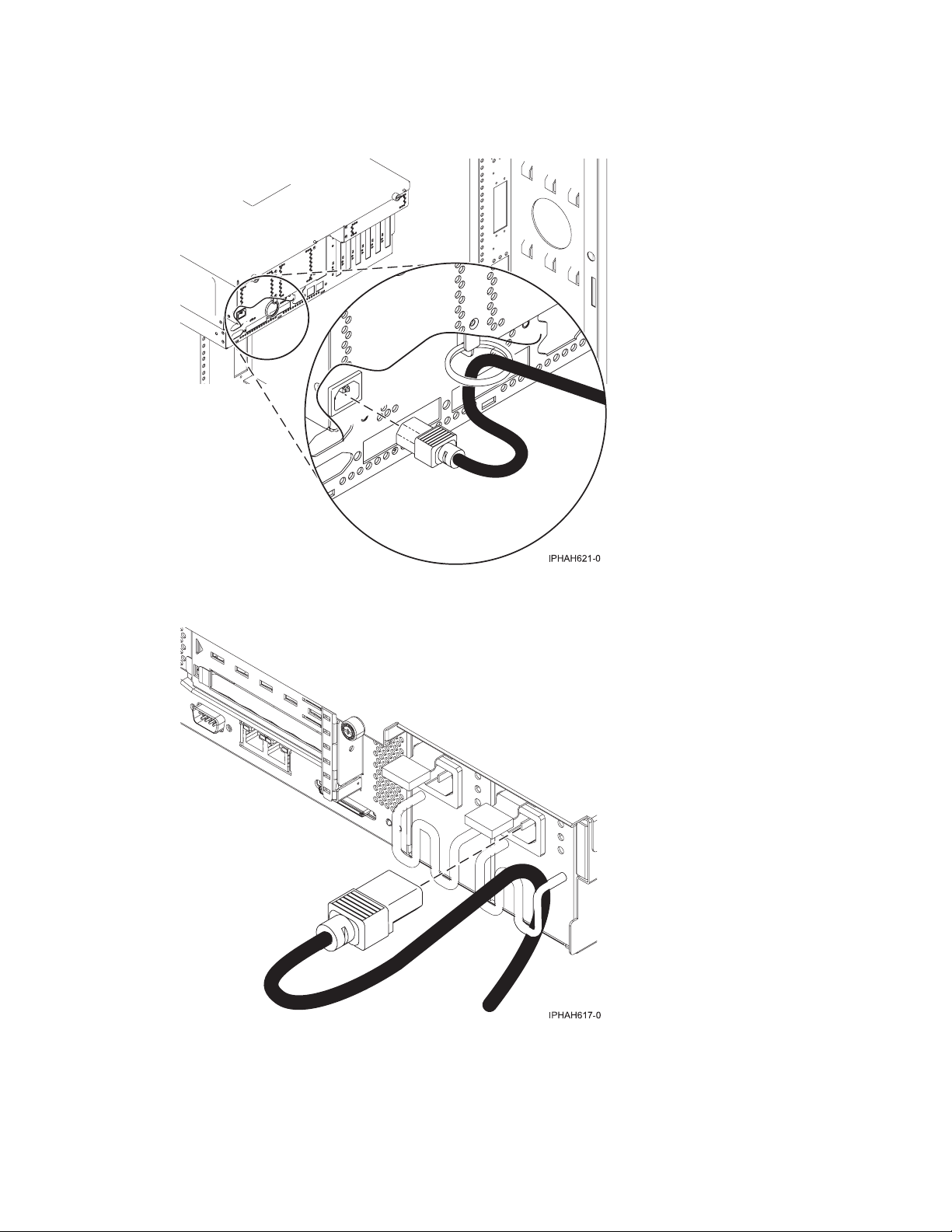
Connecting the power cords
__ If your server is equipped with a retention ring, route the power cord through the ring before you plug it
into the back of the server. See the following figure as an example:
__ If your server is equipped with a retention bracket, route the power cord under the bracket before you
plug it into the back of the server. See the following figure as an example:
__ Plug the power cords into the system, display, and attached devices.
Cabling your server 83
Page 90

Routing the cables through the cable-management arm
__ Is your server installed in a rack?
v No. Proceed to the next section, Starting your server.
v Yes. Do the following:
__ Put the system into the service position.
v For the models 510 and 510Q, see Place the model 9110-510 or OpenPower 710 in the service position.
v For the models 520, 520Q, 550, 550Q, 560Q, and 570, see Place the rack-mounted system or expansion
unit in the service position.
__ Route the cables through the hooks along the cable-management arm and secure them with the straps
provided.
__ After attaching the cables to the cable-management arm, go to the front of the rack and move the system
drawer in and out. Observe cables and cable-management-arm movement to verify that the cables are not
binding.
Starting your server
__ Power the system on (see Powering the system on and off).
Note: Expect a delay between the time when power is applied to the server or workstation and when an initial
program load (IPL) can be performed. When power is initially applied to the server or workstation, the service
processor performs a self-check and will leave the control panel blank for up to two minutes. Wait until the C1XX
XXXX progress codes are completed and 01 is displayed on the control panel before you perform an IPL or
change control panel functions.
84 System i and System p: Cabling your server
Page 91

After you finish
__ Did you receive a cable hook with your rack shipment?
v No. Proceed to the next item.
v Yes. The cable hook can help manage the server cables in the back of the rack. To install the cable hook, slide
it into the slots located on the back of the rack as shown in the following figure:
__ Return to your initial server setup checklist and complete the next step.
Cabling your server 85
Page 92

Cabling a model 9406-520 and a Hardware Management Console (HMC)
DANGER
working on or around the system, observe the following precautions:
When
Electrical voltage and current from power, telephone, and communication cables are hazardous. To
avoid a shock hazard:
v Connect power to this unit only with the IBM provided power cord. Do not use the IBM
provided power cord for any other product.
v Do not open or service any power supply assembly.
v Do not connect or disconnect any cables or perform installation, maintenance, or reconfiguration
of this product during an electrical storm.
v The product might be equipped with multiple power cords. To remove all hazardous voltages,
disconnect all power cords.
v Connect all power cords to a properly wired and grounded electrical outlet. Ensure that the outlet
supplies proper voltage and phase rotation according to the system rating plate.
v Connect any equipment that will be attached to this product to properly wired outlets.
v When possible, use one hand only to connect or disconnect signal cables.
v Never turn on any equipment when there is evidence of fire, water, or structural damage.
v Disconnect the attached power cords, telecommunications systems, networks, and modems before
you open the device covers, unless instructed otherwise in the installation and configuration
procedures.
v Connect and disconnect cables as described in the following procedures when installing, moving,
or opening covers on this product or attached devices.
To Disconnect:
1. Turn off everything (unless instructed otherwise).
2. Remove the power cords from the outlets.
3. Remove the signal cables from the connectors.
4. Remove all cables from the devices
To Connect:
1. Turn off everything (unless instructed otherwise).
2. Attach all cables to the devices.
3. Attach the signal cables to the connectors.
4. Attach the power cords to the outlets.
5. Turn on the devices.
(D005)
Complete the following tasks to cable your server:
Before you begin
__ If you have hardware features that are not installed, install them now. See Installing features and replacing parts
for instructions.
86 System i and System p: Cabling your server
Page 93
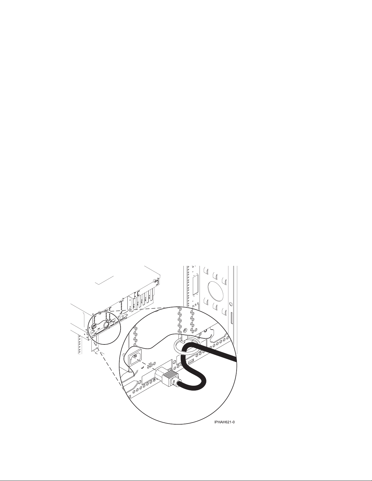
Cabling the expansion units
__ Do you have an expansion unit?
v Yes. For instructions on how to set up your expansion unit, click the following link. Do not plug the
expansion-unit power cord into the power outlet, as directed by the following link, until later in the checklist.
Expansion units
v No. Proceed to the next section, Connecting the external cables.
Connecting the external cables
__ If you are using any optional adapters (such as token ring or 8-port EIA-232), connect the cables to the
appropriate adapter connectors in the PCI slots of your machine.
Use the table in “Cables and adapters” on page 163 to connect the cables to the matching adapters on the back
of your server. Not all adapters are shown.
Note: If the cable did not come with your server, you will have to supply it.
Attaching devices using the system ports
__ If you have an IBM System p5 or eServer p5 server, the system ports on the back of the server are disabled
when your server is connected to an HMC.
__ If you have an IBM System i5 or eServer i5 server and are connecting it to an uninterruptible power supply, the
serial uninterruptible power supply conversion cable is required. See “Serial uninterruptible power supply
conversion cable” on page 162 for instructions. Do not plug the uninterruptible-power-supply power cord into
the outlet, and do not start your server.
Note: The attachment of high availability cluster multiprocessing IBM (HACMP) cables to the system ports on the
back of the server is not supported.
Connecting the power cords
__ Power cords should be routed through the retention rings or under the retention brackets that are provided to
prevent the power cords from becoming unplugged unexpectedly.
__ If your server is equipped with a retention ring, route the power cord through the ring before you plug it
into the back of the server. See the following figure as an example:
Cabling your server 87
Page 94

Connecting the power cords
__ If your server is equipped with a retention bracket, route the power cord under the bracket before you
plug it into the back of the server. See the following figure as an example:
__ Plug the power cords into the system, display, and attached devices. Do not connect the power cords to a
power source until instructed to do so.
Note: If you connect your server to a power source before the HMC is configured as the DHCP server, the
server will initialize using the default IP address values (HMC1 as 192.168.2.147 and HMC2 as 192.168.3.147)
instead of waiting for an address value from the HMC. If you inadvertently connect your server to a power
source, the IP address value will be corrected in the HMC configuration portion of the installation.
Connecting the Hardware Management Console cables
__ Cable the HMC (see Cabling the HMC).
Routing the cables through the cable-management arm
__ Is your server installed in a rack?
v No. Proceed to the next section, After you finish.
v Yes. Do the following:
__ Put the system into the service position.
v For the models 510 and 510Q, see Place the model 9110-510 or OpenPower 710 in the service position.
v For the models 520, 520Q, 550, 550Q, 560Q, and 570, see Place the rack-mounted system or expansion
unit in the service position.
88 System i and System p: Cabling your server
Page 95

Routing the cables through the cable-management arm
__ Route the cables through the hooks along the cable-management arm and secure them with the straps
provided.
__ After attaching the cables to the cable-management arm, go to the front of the rack and move the system
drawer in and out. Observe cables and cable-management-arm movement to verify that the cables are not
binding.
Cabling your server 89
Page 96

After you finish
__ Did you receive a cable hook with your rack shipment?
v No. Proceed to the next item.
v Yes. The cable hook can help manage the server cables in the back of the rack. To install the cable hook, slide
it into the slots located on the back of the rack as shown in the following figure:
__ Return to your initial server setup checklist and complete the next step.
Cabling the Operations Console attachment for model 9406-520
Learn how to connect the Operations Console, power cords, external cables, and the optional electronic
customer support cable, cable the expansion units, attach devices, install the PCI Cryptographic
Coprocessor card, and route the cables.
90 System i and System p: Cabling your server
Page 97

DANGER
working on or around the system, observe the following precautions:
When
Electrical voltage and current from power, telephone, and communication cables are hazardous. To
avoid a shock hazard:
v Connect power to this unit only with the IBM provided power cord. Do not use the IBM
provided power cord for any other product.
v Do not open or service any power supply assembly.
v Do not connect or disconnect any cables or perform installation, maintenance, or reconfiguration
of this product during an electrical storm.
v The product might be equipped with multiple power cords. To remove all hazardous voltages,
disconnect all power cords.
v Connect all power cords to a properly wired and grounded electrical outlet. Ensure that the outlet
supplies proper voltage and phase rotation according to the system rating plate.
v Connect any equipment that will be attached to this product to properly wired outlets.
v When possible, use one hand only to connect or disconnect signal cables.
v Never turn on any equipment when there is evidence of fire, water, or structural damage.
v Disconnect the attached power cords, telecommunications systems, networks, and modems before
you open the device covers, unless instructed otherwise in the installation and configuration
procedures.
v Connect and disconnect cables as described in the following procedures when installing, moving,
or opening covers on this product or attached devices.
To Disconnect:
1. Turn off everything (unless instructed otherwise).
2. Remove the power cords from the outlets.
3. Remove the signal cables from the connectors.
4. Remove all cables from the devices
To Connect:
1. Turn off everything (unless instructed otherwise).
2. Attach all cables to the devices.
3. Attach the signal cables to the connectors.
4. Attach the power cords to the outlets.
5. Turn on the devices.
(D005)
To cable your server:
Connecting the Operations Console. Choose from the options below.
__ Option 1: To connect the Operations Console cable (directly attached):
__ Shut down and unplug the PC that will serve as the system console.
__ Locate the Operations Console cable (part number 97H7557). Connect the Operations Console cable to the
corresponding connector on the 2793 or 2794 adapter in the appropriate position on the back of the server.
v Position C3 for the model 520
v Position C2 for the models 550 and 570
__ Connect the other end of the Operations Console cable to the first or only system port, which is located on
the back of the PC that is being used as the console.
__ Option 2: To connect the Ethernet cable (on a network (LAN)):
__ Shut down and unplug the PC that will serve as the system console.
Cabling your server 91
Page 98

Connecting the Operations Console. Choose from the options below.
__ Connect an Ethernet or token-ring cable from the PC that will serve as the system console to your local
network. Connect another network cable from the same local network to the first embedded Ethernet port
(P1-T5) or the adapter card in the appropriate position on the back of the server.
v Position C5 or C2 for the model 520
v Position C4 for the model 550
v Position C4 or C6 for the model 570
Connecting the electronic customer support cable (optional)
Electronic customer support helps automate management of your server and streamline your support. Use the
IBM eServer Technical Support Advantage information that is included with your server to learn about
electronic customer support or see the Support for iSeries family We b site (www-1.ibm.com/servers/eserver/
support/iseries/index.html). You can configure electronic customer support by using the iSeries Setup and
Operations CD that came with your server. For more information, see Service and support.
__ Connect a telephone cable to the RJ11 connector of the adapter in the appropriate position.
v Position C3 for the model 520
v Position C2 for the models 550 and 570
__ Connect the other end of the telephone cable to an analog telephone jack.
Cabling the expansion units
__ Do you have an expansion unit?
v Yes. To set up your expansion unit, see Expansion units.
Note: Do not plug the expansion-unit power cord into the power outlet, as directed by the directions in
Expansion units, until later in this checklist
v No. Proceed to the next section, Attaching devices using the system ports.
Attaching devices by using the system ports
__ If you have an IBM System i5 or eServer i5 server and are connecting it to an uninterruptible power supply, the
serial uninterruptible power supply conversion cable is required. See “Serial uninterruptible power supply
conversion cable” on page 162 for instructions. Do not plug the uninterruptible-power-supply power cord into
the outlet and do not start your server.
Note: The attachment of high availability cluster multiprocessing (HACMP) cables to the system ports on the back of
the server is not supported.
Installing the PCI Cryptographic Coprocessor card
__ Do you have a PCI Cryptographic Coprocessor card?
v Yes. Install it now using the PCI-X Cryptographic Coprocessor instructions. This card was shipped in a
separate box. Return here after the card is installed.
v No. Proceed to the next section, Connecting the power cords.
Connecting the power cords
__ You should route the power cords through the retention rings or under the retention brackets that are provided
to prevent the power cords from becoming unplugged unexpectedly.
92 System i and System p: Cabling your server
Page 99
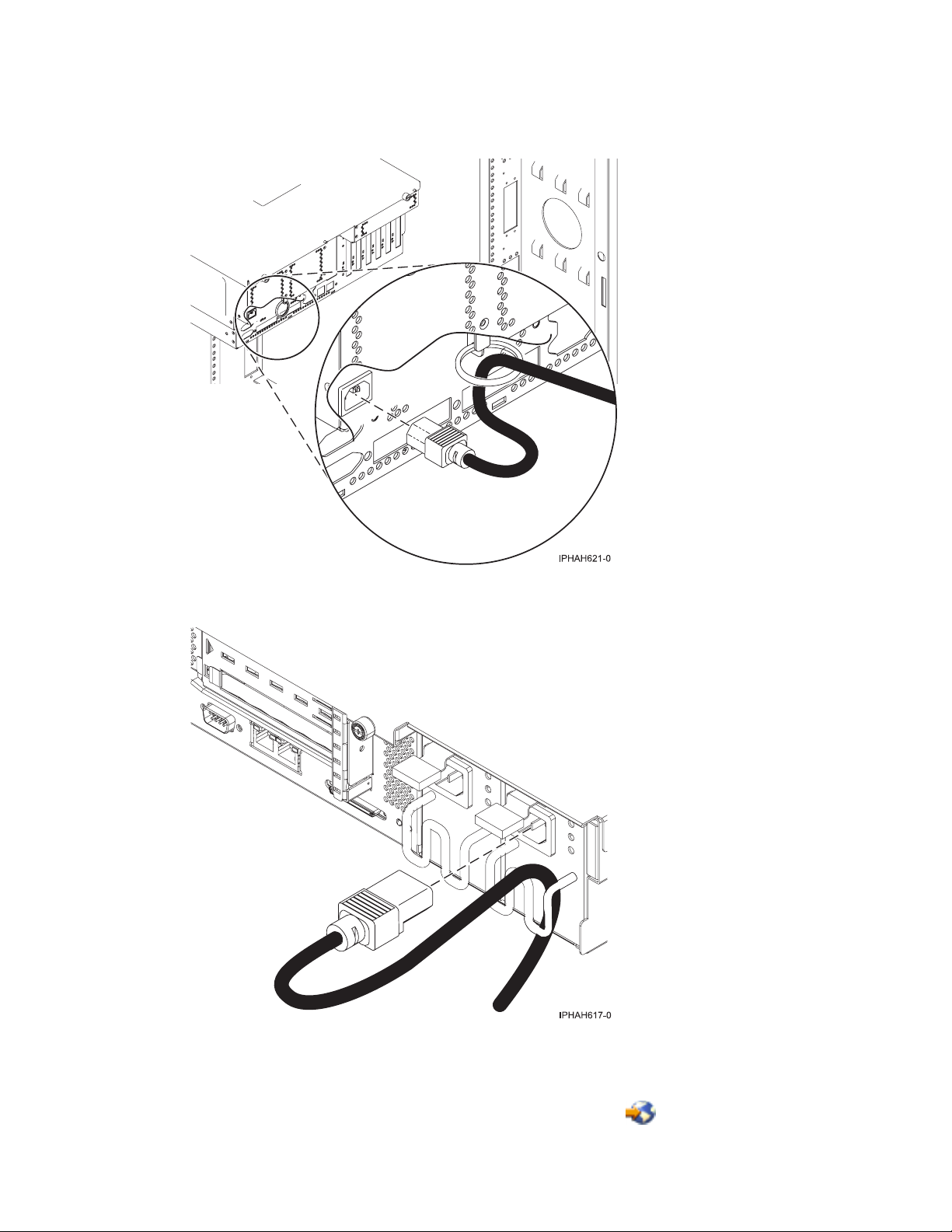
Connecting the power cords
__ If your server is equipped with a retention ring, route the power cord through the ring before you plug
it into the back of the server, as shown here:
__ If your server is equipped with a retention bracket, route the power cord under the bracket before you
plug it into the back of the server, as shown here:
__ Are you installing an uninterruptible power supply?
__ No. Connect the server power cords to the server. Do not plug the power cord into the power outlet. Do
not start your server.
__ Yes. To complete the installation of the uninterruptible power supply, see the Powerware Web site
(www.oem.powerware.com/ibm-ups/Products/9910Solutions/ina.asp)
.
Cabling your server 93
Page 100

Connecting the external cables
__ Use the table in “Cables and adapters” on page 163 to connect the cables to the matching adapters on the back
of your server. If the cable did not come with your server, you will have to supply it.
If you do not have any external cables to connect to the adapters on the back of your server or expansion unit,
continue with the next section.
Routing the cables through the cable-management arm
__ Is your server installed in a rack?
v No. Proceed to the next section.
v Yes. Do the following:
__ Put the system into the service position. See Place the rack-mounted system or expansion unit in the
service position.
__ Route the cables through the hooks that are located along the cable-management arm and secure them
with the straps that are provided, as shown here:
__ After attaching the cables to the cable-management arm, go to the front of the rack and move the system
drawer in and out. Observe the cables and cable-management-arm movement to verify that the cables are
not binding.
94 System i and System p: Cabling your server
 Loading...