

Page 1

f
Systems
Page 2

IBM
System/370
Systems
Model
145
Operating Procedures
This manual contains reference material and operating
to
procedures required
Model 145 Processing Unit
attachments.
Console File
Console Printer-Keyboard
is
The reader
knowledge and previolls operating experience on a
similar system.
operating procedures for individual
and
1400/7010
IBM System/360 Bibliography, GA22-6822.
assllmed to have a basic
operate the
and
Order numbers for manuals containing
Emulators can be
IBM
System/370
the
following integrated
computer
input/output
found
in
the
devices.
Page 3

PREFACE
This publication
procedures for the
Unit.
This manual
is
a graphic presentation
IBM
System/370 Model 145 Processing
is
divided into
five
of
major sections.
the operating
• Introduction
• Console Indicators, Switches and Keys
Describes the console indicators, switches, and keys.
Only information required by the operator
is
tained in this section.
• Printer-Keyboard
Describes the mechanical features
of
the PR-KB and
contains information required by the operator for
normal
PR-KB operation and maintenance.
• Operating Procedures
Describes general operation, system initialization and
error procedures required by the operator for normal
system operation.
• Features
Provides reference information on the integrated
adapter and available emulators.
This manual is intended
operators. The operator
of
knowledge
System/360 operating procedures.
as
a reference document for
is
assumed
to
have a basic
con-
file
First Edition (September, 1970)
Changes are periodically made to the information herein; refer to the latest SRL
Newsletter for the editions that are applicable and current.
Requests for copies
or to the
the
P.O. Box 6, Endicott, N.Y. 13760. A form for readers' comments
the back
sent to the above-mentioned address.
IBM
IBM
Systems Development Division, Product Publications, Department 171,
of
of
IBM
sales office serving your locality. This manual has been prepared by
the publication.
publications should be made to your
If
the form has been removed, comments may be
IBM
representative
is
provided at
© Copyright International Business Machines Corporation 1970
Page 4

INTRODUCTION
CONSOLE INDICATORS, SWITCHES,
PRINTER-KEYBOARD
OPERATING PROCEDURES
and
KEYS
GLOSSARY
FEATURES
and
INDEX
iii
Page 5

This
visual
page
numbers
keys
on
Operating
keys
and
this
manual.
VISUAL CONTENTS
contents
the
system
are
provides a quick
for
descriptions
control
procedures
located
in
panel.
using
the
operating
of
these
method
indicators, switches,
indicators, switches,
procedures section
of
finding
and
of
~
~
45
~
o
~
On"
45
c=J
00000000~~§~00000
6500000600068~066~
14
,
:::::.';:;:" I ,-;::-;.
I
&5366~~6i66c56
D:::'~"D"'"
21
...
uo~
L.:......-...:c.cu-......
8
::-::
::::
~M
••
:--:;.:-,
":,,
8
'"""-"::;",::'1
080008088800000000
00~~~~008~6;6'6b666
9 10 10
12 I I 12
M666b666~666'6l6666
13 II 13
39
r:::l
~
1.--."
•
""C
~IG'SIfIll
~13
~
39
~
...
1
12
~D
o
iv
EJB
Page 6

• CONTENTS
Introduction
Console I ndicators, Switches, and Keys
System Check
CPU
Status Indicators .
Console File
System Indicators
Display Assembler
A-Register
Toggle Switches . . .
Address Compare Switch
Storage
Rate Switch
Check
Control Switch
Diagnostic/Console
Rotary Switches A through
Use
Meters.
Keys.
Printer-Keyboard .
Printer-Keyboards
Printer
Carriage
Character and Function Keys
Indicators and Control Keys (3210 and 3215)
Forms
Platen Removal and Replacement (3210 and 3215)
Print
Print Element Cleaning (3210) . . . . . .
Controls (3210) .
Ribbon
Insertion (3210
Element Removal and Replacement (3210)
. . .
Indicators
Indicators.
Out
Roller Switch
Display Roller Switch
Select Switch
File Control Switch
H.
. . . .
Controls (3210
Replacement . . . . . . . .
and
3215)
(3210 and 3215)
and
3215) . . . .
10
11
12
13
14
15
16
17
18
19
20
21
22
24
24
25
26
27
28
29
30
30
31
32
Operating Procedures
7
Magnetic Disk Cartridge
8
Disk Cartridge
Manual Operations.
PR-KB
8
9
Initial Microprogram Program Load (lMPL)
IMPL Error Recovery
Initial Program Load
IPL Error Recovery
On
Power
Off
Power
Power Failure Recovery
Emergency
I nstruction Step
Set IC (Instruction Counter)
Clear Storage
Data Compare Trap .
3210 Model
System Check Error Recovery
Manual Store/Display
Automatic
System Environment Recording and Editing
Program (SEREP)
Features.
Integrated File
Emulators
Glossary
Index
Insertion and Removal
Pull Switch (EPO)
2 Printer-Keyboard
System Checkout Program .
Adapter.
Handling
(lPU.
Operations
34
34
34
36
38
38
39
39
39
39
39
39
39
39
40
40
40
40
41
42
44
45
45
45
46
47
ABBREVIATIONS
ADDR
ASCP
CF
CPU
DIAGN
EPO
EXE
GP
IC
IMPL
Address
Automatic
Console File
Central
Diagnostic
Emergency
Execute
General Purpose
Instruction
Initial Microprogram Program Load
System Checkout Program
Processing
Power
Off
Counter
Unit
INTV
REOD Intervention Required
I/O
IPL Initial Program Load
MAN
PR-KB Printer-Keyboard
PSW
SDBO
SYS
TOD
CLK
Input/Output
Manual
Program Status Word
Storage Data
System
Time
of
Bus
Day Clock
Out
v
Page 7

SYSTEM/370 MODEL 145 CONSOLE
..
"·""
~"
8
~
o
~
0
..
"
I
""~"'''''
..
u I
D~r
D~~:
r.::l~
~~
r:r::.JD
~
D
~D
o
BB
C:::=======:=::E!~.";:::;.
00800000~~~~00000
5500000600066~066~
L.--.Cycl.----II
~
~
~;=.
_======.:::::J
OAU
Iii
r.-:.::-,
,
,,~..
r.:.,-.:::":I
800008000000000000
~0~~~~00366'"66i;:~:::666
@,@@@@~@0j
r;;::-]
~
BG
i
,
....
El
Uf\-J
~TOA(
(l'Yln
..............
,,"
00000
AOV"lSS i
'0"'
r=l
L:..J
~
~
~
~
Page 8

INTRODUCTION
This
is
a graphic
only
information
Model
145
Order
number
cedures for individual
in
the
IBM
This manual covers
for
normal system
nate
unnecessary
only
by service personnel
but
are
covered in
tem.
System/370
input/output
tines.
The
language
gram Program Load (I MPL) disk
and
is
inserted
to
the
system.
When
power
loaded
into
operating
necessary
Processing
for
procedures
Unit
and
manuals
to
containing
input/output
System/360 Bibliography, GA22-6822.
information
operation.
information.
are
not
maintenance
Model
145
performs
operations
routines
instruction
into
is
applied
control
by
executing
executed
are
being processed.
the
Console File before
to
the
storage and
operate
manual.
the
It
contains
System/370
integrated devices.
operating
devices can be
required
An
effort
Controls
by
was
and
the
made
indicators
described in this manual
documentation
data
for
manipulations
microprogram rou-
determined
contains
by
The
I nitial Micropro-
the
microprogram
the
power
system,
the
the
system
microprogram
is
ready
pro-
found
operator
to
el
imi-
used
the
sys-
and
machine
is
applied
to
load
the
operating system (OS, DOS, etc.)
gram. These programs are loaded by using
gram Load
Operating
program
1.
(I
PL)
procedure
procedures
can
be
run
that
are:
Disk Cartridge I nsertion (I M P L disk)
2. Power-on
I
MPL
3.
4.
Whenever
dures
I
PL
must
(automatic
the
operating
power
be
followed. When
with power-on)
system
is
removed from
trol storage and main storage are invalid.
A visual
controls
To
encouraged
of
is
the
contents
and
indicators
evaluate
to
manual.
documentation
the
use
Your
in
is
provided
on
approach
the
Reader's
comments
future
manuals.
in
this
manual.
are necessary
(if required)
power
to
aid in
the
system
used in
Comment
will help
or a standalone
the
I nitial Pro-
before a problem
the
system
is
dropped,
control
this
quickly
panel.
manual,
Form
to
provide
these
locating
you
in
pro-
both
the
better
proce-
con-
are
back
Introduction
7
Page 9

SYSTEM CHECK INDICATORS
•
CONSOLE
INDICATORS,
SWITCHES,
8
l
----
-
-'}=---:-=-""!f
I '
~u1!lo~oCJU~~::';~OOO~O
c:::::::t
~~~rir)(?.iS~:;,a\~,~~~M
_
..
-
,-."~~~,
.---,' ,
'.-
Cl60oo30M~oooooooo
- =['·"1
c>6~51j~oo~66MCi,)666
-
I
I
and
KEYS
,
\
L
•..
_,
SYSTEM CHECKS
CLOCK
DIAGN
000000000000000000
Ii
~~~===n
rr=M·REG=;J
SYSTEM CHECKS
CY~LE
~UAD~~~~ATE
~
:~~:
PARITY
~
~~~~
CHECK-----lJ
STaR
000000080000000000
If
a system check indicator
system check error recovery procedure.
is
on, refer
to
the
SEL
8
Page 10

CPU
•
STATUS INDICATORS
(;)~~o~o~i:5i'!jC5..5j50oo~o
~e~~6~oo6~~~~~~
,.".",."
.•
",.
"""
,,"
"",,,,
o~"3oo~oo-~-<:!loooooooo
i:5~~0~oo366b6~666
,.,,""
"'~'''''''\''~'''''''\I,
NOTE
I
ndicators
service personnel and
nance
/
"
@]@J
EJ
,,'
~i\
~O
O@
c:::J
//
EXE COMP CLOCK STOR
000066660000000000
EXE CPLT
rno
0
BE)
AOR
n
INDICATOR
TRAP
TRAP
CYCle
Jl
I ndlcotes CPU
1. Pressing
2.
The
RATE switch
3.
A match being
of
operation.
stopped
the
STOP key.
INV
AOR
M2
detected
TOO
X-LATE CLOCK LOG ECC PWR IMPL
CONDITION
state
reached
In
the
INSTRUCTION
while
SNG
os
u result of:
In
the
address
not
described in
documentation.
CF
STEP
position.
match
mode
the
chart
are
described in mainte-
are
for
ADR
COMP MATCH
CLOCK
STOP
TOD
CLOCK I NVLD
LOG PRES
SNG
ECC CHK
CF
PWR
ON
IMPL REOD
I ndicates
main storage
ing
as a result
the
I ndicates
clock
Indicates
turned
I ndicates
When
position
I ndicates
corrected.
Indicates
I ndicates
been initiated.
routine
that
the
address (real
matches
an
address
of
the
ADDRESS COMPARE CONTROL switch.
that
not
running).
that
off
by
that
the
CHECK CONTROL switch
and
the
that
that
that
is
executed.
the
match
operation.
match
the
CPU
the
time-of-day clock
successfully executing a
a log is
present
LOG PRES
one
of
the
power
is
an
operation
The
indicator
An IMPL is required if
or
logical) being used
address
set
condition
is
applied
The
is
controlled
in an
immediate
is
in
the
log area
indicator
data
or
check
to
the
which resulted in a system reset has
is
turned
into
switches CDEFGH
action
taken
by
stop
condition
invalid.
The
set
clock
instruction.
of
main storage.
is
in
the
STOP
is
on,
run
SEREP.
bits
from
storage
console
file.
off
when
the
the
indicator
to
access
by
the
the
setting
indicator
AFTER
has
system
dur-
CPU
of
(CPU
is
LOG
been
reset
remains
on.
Console I
ndicators,
Switches,
and Keys 9
Page 11

• CONSOLE FILE INDICATORS
~
____
~~~C~O~N~SO~L~E~F~IL=E~
DISK
CPU
________
~I~I
____
8
~CO~N~S~O~LE~F~I~LE~AE~G~IS~T~EA~S
________
___
0000000050666616666
Console File Checks
Re-IMPL
the
service representative.
Console File Register
These
when
error
continues,
indicators
any
are
console
record
used
by
file
check
indicator
the
indicators
service personnel.
and
is
on.
notify
If
your
10
Page 12

SYSTEM INDICATORS
•
8
6
@]~
~o
c::::J
O[§
C!JO
o
BB
SYS
MAN WAIT TeST LOAD
00000
o~~o~o~~~~~ooooo
~e~~6~OO~
o6oooooo~doooooooo
~O~~~oo50666~660
INDICATOR
SYSTEM
MANUAL
WAIT
TEST
LOAD
The
SYSTEM
in progress
The
MANUAL
stopped
interrupts
are
possible
The
WAIT
(CPU
place).
state
and
gram being
The
TEST
switches
1. RATE
2. CHECK
3.
4. ADDRESS COMPARE
The
LOAD
(JPL) is in progress.
pressed
fully.
indicator
and
either
indicator
or
the
system
are
handled.
only
when
indicator
clock
running
but
If
an
interrupt
processing is
executed.
indicator
are
DIAGNOSTIC/CONSOLE
indicator
and
turns
not
in
the
CONTROL
off
is
FUNCTION
is
on
when CPU
use
meter
is running.
is
on
when
is in a soft-stop
Manual store/display
the
MANUAL
is
on
when
no
occurs,
started
on
when
process
is
on
when
It
turns
when
the
the
the
system
instruction
the
CPU
under
any
of
or
normal
FI
CONTROL
the
on
when
initial
operations
CPU
state.
indicator
processing
is
taken
control
the
following
position.
LE
CONTROL
Initial Program Load
the
LOAD key
PSW
is
are
clock
is
All
pending
operations
is
on.
is in a
wait
taking
out
of
of
the
pro-
is
loaded success-
state
wait
Console
I ndlcators,
Switches,
and
Keys
11
Page 13

DISPLAY
•
/
.
ASSEMBLER
OUT
ROLLER
SWITCH
DPlV
ASSEMBLER
1 MREGISTEA
2
SO&O
3
CO~TAOL
..
MB2,M83,N2.N3
S B REGISTER
6 Z REGISTER
70
REGISTER
8
Me
REGISTER
OUT
REGISTER
The DISPLAY ASSEMBLER OUT roller switch provides
full-time display of the following.
a
INFORMATION DISPLAYED
ROLLER POSITION
1
2
3*
4*
5*
6*
7*
B*
Note
1:
Protect
stack key associated with
address in
bytes
1,2,
and
Byte 0
Note
MB-2
3.
Byte
1
the
Note
2
I
Storage Data
MB-3
Note
*Positions 3
1
C-Register
B-Register
Z-Register
D-Register
MCKA
2:
Byte
2
I
M-Register Bytes 1,2, and 3
Bus-Out
through
N2
the
8 are
I
Displays
I
I
selected channel.
for
service usc.
Byte
N3
3
12
Page 14

A-REGISTER
DISPLAY
ROLLER
SWITCH
8
~
0:'
B·
c::::J O@]
o
The
A-REGISTER
STORAGE
ROLLER
~~~o~ofu~~~~jj~
~oo6~oo~6~6~l~
0;:;
I
8666&56600606&3660 0666d66660666d6660
I
0666cp666066ocp666 66066p6660660cp6oo
@[§J
06~0030o~~00000000
~3l6~60036606d6660
II
II
@O
[£]0
EJE]
El
B
ElS
DISPLAY roller switch
SELECT
POSITION
switch
to
display
Byte
0
B
is
the
following.
II~
I~
II~
j:~§F
6155\'56
G
used
with
the
INFORMATION DISPLAYED
Byte
1
Byte
A
REGISTER
DISPLAY
1
STORAGE/EXT
REGS
2 DOCUMENTARY CNSL
3 S,P, T, L REGISTERS
4 SYSTEM AEGISTER
5
CHAN
INTERFACE
6 CHAN WORD A
7 CHANWORDO
8
(UAN
WORD C
Byte
2
3
1
2*
3*
4*
5*
6*
7*
8*
Position 1 is
described in
manual.
*Positions 2 through
When
the
CPU
is
in a soft-stopped
cator
on),
the
indicators
address.
8 are
display
TI-Register
S-Register
System
MPX Channel Registers
the
Store/Display
for
service use.
state
the
next
Storage
or
External
T A-Register
P-Register
Register Bytes 0, 1,
or
Selector
Register
(Store
TT-Register
T-Register
and
2
Channel External Word GTAG
Channel Word A (External Word GSTAT)
Channel Word B
(External
Word GBS)
Channel Word C (External Word GBUF)
section
of
this
(MANUAL indi-
instruction
Select
Sw)
TE-Register
L-Register
H-Register
Console I
ndicators,
Switches,
and
Keys
13
Page 15

TOGGLE SWITCHES
~@_36r;O;.l;~~~1l"*
["
..
:~.~::
.... : .. : ..
··_···_···_·····""····1
"··~r;~~(I;(~i1~)(')~(';:"~)(';CJ~;~)~)~'()
oao
[~·i;;~;·;;~;fi;;:~:i;~;,;7~~~~,;·ii·~{
(~)
C::::=
__
:::Dfr.lIr::::::::.::.:::
.. : ...
S6ooo6o~bt:bo()()(XK'cJ
~~1;w'~:;g~;:67,-~;;;Z~;
r0.~~~:.<?i.~:i.0~'~}~~.~.~'.~~~:?~~:...,
::..~.::.,
Lamp Test
All console indicators should light when
toggle switch
can be
is
operated
operated
at
any
to
time
the
TEST
without
position.
affecting system oper-
ation.
Interval Timer
NORMAL
Th
is
position
IBM
System/370 Principles
enables
the
timer
of
for
use as described in
Operation,
DISABLE
This
position disables
the
timer
is
tions.
Time
is
available
not
location
for
available
other
program use.
the
interval timer.
to
the
data
flow
80
(hexadecimal 50) in main storage
Time of Day Clock
ENABLE
The
set
switch
clock
SET
must
be in
instruction
the
to
perform
ENAB
LE
SET
its
function.
the
LAMP
The
GA22-7000.
The
content
for
timer
position
TEST
switch
the
func-
for
of
the
Address Compare Control
This
switch
is
STORAGE
action
taken
SELECT
by
match.
SYNC/NORM
This
position
it provides a
in a stop
sync
on
an address match.
STOP
The
STOP
position
stop
whenever an address
CPU, press
tion,
the
the
TEST
IMMED STOP
This
position
maintenance
tion,
the
TEST
used with
the
of
the
START
indicator
is
for
documentation.
indicator
the
ADDRESS COMPARE
rotary
switches
CPU as a result
switch
is
pulse
for
service use
is
for
customer
match
key. With
is
on.
service use
is
on.
of
the
normal
use
is
detected.
the
and
is described in
With
the
and
determines
an address
operating
and
does
and
provides a soft-
switch in
switch in
not
To
this
and
the
compare
position;
result
restart
posi-
the
this
posi-
the
the
SECURE
Executing
SECURE
14
the
set
position
clock
does
instruction
not
affect
with
the
clock value.
the
switch
in
the
Console File Register Display
These switches
described in
are
used by service personnel
maintenance
documentation.
and
are
Page 16

• ADDRESS COMPARE SWITCH
~~~o~ofu~~~~~ooo~o
~e~Q29_6~oo6~~6~~5
~@tJ~
1=====;:(="""""=""=,0",::;;=".,,,,-;,,,
c:sl
;==-='==============t
'\"'\"\"
f:~
,/0
'
~~GIC
1
bCOUNTER
CTRLWOAD I
ADA.
C"CWORO
ADA TRAP
(§JB
ADDRESS
AIF -DATA
A@Y.STOIIE
• •
COMPARE
Customer
8
~~~oooo~
~~l~~ooB66666P660
--@~
~~@::"",@
.ElS
::@-.-
=..:~@~~~o~~~~~_~
El
OMM
G
I
.110
·COUNHII
OATACOMPj
TilAI'
REAL
AOII
AN Y (R
This
processing. With
for
the
DATA
This
matches
a
data
I/O (INPUT/OUTPUT)
This
address
CDEFGH,
an I/O
I-COUNTER (Real
This
storage uddress
CDEFGH,
main storage.
DATA COMPARE
This
ing a particular
the
Use
eal Address)
position
main storage access
address
position allows a
position
position causes a
position
data
of
set
STORE
the
address
store
operation.
of
matches
and
operation.
and
is
compare
the
switch
the
switch in
in
console
set
the
switch
the
address
the
operation
or
matches
the
operation
TRAP
used
to
storage
trap
is
used
for
this
position, a match
when
the
storage
switches
match
in
console
allows a
when
set
in console
is
storing
CDEFGH.
the
switches
match
Logical Address)
match
when
the
the
address
determine
byte
location
is
an
in
instruction
what
procedure.
normal
program
address
matches
storage address
CDEFGH
when
the
switches
or
fetching
real
or
logical
console
switches
fetch
instruction
to
be
modified.
occurs
during
storage
data
main
from
is
caus-
See
for
•
This
access main
switches
is
set
•
The
condition
CONTROL
switch provides a
storage
CDEFGH,
to
the
MAIN
STORAGE
action
taken
by
is
determined
toggle switch.
match
matches
and
the
the
the
STORAGE
CPU as a result
by
the
when
the
address
position.
ADDRESS
address used
set
in
console
SELECT
of
the
switch
match
COMPARE
to
ANY (Logical Address)
This
position
of
the
switch
main storage address used
address
Service
The
described
set
in
Use
remaining
in
maintenance
console
switches
positions
Console I ndicators, Switches, and Keys
allows a
to
match
access storage
CDEFGH.
are
for
service personnel
documentation.
when
matches
the
and
logical,
the
are
15
Page 17

STORAGE
SELECT SWITCH
8
IF=======================~===~~
~0~o~ofu~~~J~ooo~o
M~Cii50_66~ooM~MM
/~.:",:H'
.
4f:!:i;.i..::
..
;;.",.",~
""""'~,I':k
';:'"
..
1;"",
,I'""
"'''o'.n
.•
'''·''
ii,.
",
,.,;.,,:p.,,:;,f,:·~,;;,.i"""""
,:~,
. "
STORAGE SELECT
r-
:::NC:~C9JMAIN
EXT
REO
CHAN
CHAN 3 •
II
~==========CHAN4
~R~:~:;g;GE
2.
•
•
o~Eoo~oo~dooooo;o~
~3~t:l~oo566M~066
El
MoM
G
EXP
LOCAL
STOR
REGS
• This switch selects
display
operations.
COMPARE switch
CONTROL
Customer
MAIN
STORAGE
Th
is
position
processing
toggle switch
Use
of
the
and
for
manual
storage.
LOCAL
This
display
STORAGE
position
of
of
General·Purpose
the
NOTE
Use
the
alter/display
to
alter/display
main
ever possible.
the
It
is
and
switch
switch
function
or
proper
storage
for
also used with
the
ADDRESS COMPARE
for
address
is
used
store
and
is
used
and
F 10ating·Point registers.
of
local storage
the
match
for
normal program
display
for
manual
the
PR·KB
when·
manual
ADDRESS
functions.
of
main
store
store/
and
Service
The
Use
remaining
positions
of
sonnel and are described in
the
switch are
maintenance
for
service
per·
documentation.
16
Page 18

RATE SWITCH
8
~0~O~000~0E~~OOO~O
6~~~6~o66~~5~&6
/ I
~@~@@~']2
[§
RATE
PROCESSSINGLECYCLE
o
@
• The RATE switch controls
processes instructions .
• This switch,
causes
to
light.
in
the
TEST indicator on
i
88.11
HAnD
any position
~~ooo6oo6~oooooooo
03~0~oo566b66b666
~
e G
El
MM1S
G
•..•.
J.
STOP
the
rate
at
which
the
other
than
PROCESS,
the
lower console panel
CPU
Customer Use
PROCESS
This position
processing.
INSTRUCTION STEP
complete
One
pending interrupts allowed by
uted
for each operation of
The
CPL T indicator
of
the
switch
is
machine language instruction (including all
the
machine enters
is
turned
the
soft-stop state, and
on.
used for normal program
the
system mask)
START
key.
the
is
exec-
EXE
Service Use
The
remaining position
personnel and is described
of
Console I ndicators, Switches, and Keys 17
th
is
switch
in
maintenance
is
for
use by service
documentation.
Page 19

•
CHECK
t~'i."
AFTE~~TAV
DISABLE.
CHECK
~
CONTROL
CONTROL
.HAAO
SWITCH
8
STOF
•
This
switch
a
machine
•
This
switch,
the
TEST
Customer
PROCESS
This
position
processing
cording
STOP
This
processing
recording
With
program
cessing
tic
logout
channel
After
Environment
when
of
logout
AFTER
position
when
of
the
storage (locations
and
can
control
a diagnostic logout,
controls
check
in
any
indicator
Use
of
the
an
data
LOG
of
the
an
logout
switch in
turns
on
contain
check,
Recording
the
action
occurs.
position
on
the
switch
is
operating
is used.
switch
is
operating
data
is
used.
this
position,
128
the
LOG
information
or
an interface
and
taken
by
the
CPU
other
than
process, causes
lower console panel
used for normal program
system with
used
for
system
through
PRES
the
operator
Edit
Program (SEREP).
automatic
normal program
without
a diagnostic
704)
indicator.
about a machine
check.
runs
to
automatic
logout
stops
The
the
System
when
light.
re-
into
prodiagnos·
check,
Service
The
personnel
Use
remaining positions
and
';
NOTE
:
Programs using storage locations
704
program storage.
operator
of
are described
are invalid
must
after
re-IPL.
the
switch are used by service
in
maintenance
a diagnostic
To
continue
documentation.
128
logout
processing,
through
into
the
18
Page 20

DIAGNOSTIC/CONSOLE FILE CONTROL SWITCH
e
o~~o~o~~~~j~ooo~o
OOO0i3660~~
o
DIAGNOSTIC/CONSOLE FILE CONTROL
II
STORAGE
IL-
EXE CTRL
SWSA·H
@EAO
LOAD
SWS
A.H
WORD.
O~OooOoog~ooooooo
I:iOMii8oo56666ct:)660
MODE
II
~LSEL
~
.RECYCLE
•
CE
• The DIAGNOSTIC/CONSOLE
controls console file
• This switch, in any position other than PROCESS/IMPL,
causes
the TEST indicator on the lower console panel
light.
and
FILE
CONTROL
diagnostic functions .
switch
to
Customer Use
PROCESS/I MPL
This position
processing
of
and
the switch
for
loading
is
used
for
from
the console file.
normal program
Service Use
The remaining positions
personnel
and
are
described in maintenance documentation.
of
the switch
are
for
use
by
service
Console I ndicators, Switches, and Keys 19
Page 21

ROTARY
SWITCHES A THROUGH H
8
O~/!lo~~ll.~OOO~O
~e~~oobg~~~sg
o
C=::::::==~===:J··"·i·C=i·---·"==··-··-·-"-=··
~~oooOoae~OOOOOOOO
~~~~i§oo566666P666
===~~~~~~
@@@@@@"@@)
, A CON$m'
FILE
AbpRn!
I I CCDNSO! E
FIl'
byTE
eDlINT
0 I E I F
WOAD
I
ADDRESS G I I
STORE/DISPLAY
BYH
~
tHAn
ADDRESS I
flEce; I
SWITCHES
AB
CD
CDEFGH
EFGH
FG
FGH
FGH
H
20
LABEL
DATA
CF
ADDRESS
CONSOLE
BYTE
MAIN
FILE
COUNT
STORAGE
ADDRESS
CONTROL
STORAGE
ADDRESS
ADDRESS
WORD
LOAD
UNIT
ADDRESS
STORE
DISPLAY
ADDRESS
BYTE/X-LATE
REGS
the
Specifies
Specifies
diagnostic
value
the
track/sector
microprogram
Provides a service
Specifies
and
Used
manual
Used
Specifies
Used
Specifies
the
address
by
service
main storage
for
store/display
to
display General-Purpose
the
load-unit
to
store/display
the
byte
of
data
function
compare
personnel
and
address
local storage.
to
be
FUNCTION
to
be
entered
address
of
load
operations.
described in
address
to
specify a
address
for
functions.
compare
switch
and
for
altered
during
on
manual
store
operations.
the
console
file
on
certain
the
manual
control
maintenance
store/display
storage
documentation.
address
functions.
Floating-Point Registers.
Initial Program Load (JpL)
manual
store
operations.
operations
for
operations.
Page 22

USE
METERS
c:::::=::::::J
c=:=J Customer
c=:=J Service
o Key Switch
Two
direct
reading use meters record operating time.
meter
records
cords service time.
mines which
Your service representative has
Whenever he
maintenance in
service
The
meters record only
meters run
because these operations
meter runs
each
time
meter
for
the
customer
of
the
is
performing scheduled
the
to
run.
manual store and display
for
a minimum
meter
operating time and
The
position
two
meters
CPU, he sets
CPU
start
of
is
started.
the
of
the
key switch deter-
is
to
record operating time.
the
key
for
this switch.
or
unscheduled
the
switch
to
operating time.
operations
the
CPU
clock. Either
approximately
other
cause
The
one
One
re-
the
second
Console Indicators, Switches,
and
Keys
2.1
Page 23

•
The
KEYS
keys
in
this
chart
procedures section
B
@)~
~o
C:=J
O@l
C!JO
o
BEl
are
of
further
this
manual.
described
in
the
@l@~~
~
El
ElG
EJ
OMM
operating
G
22
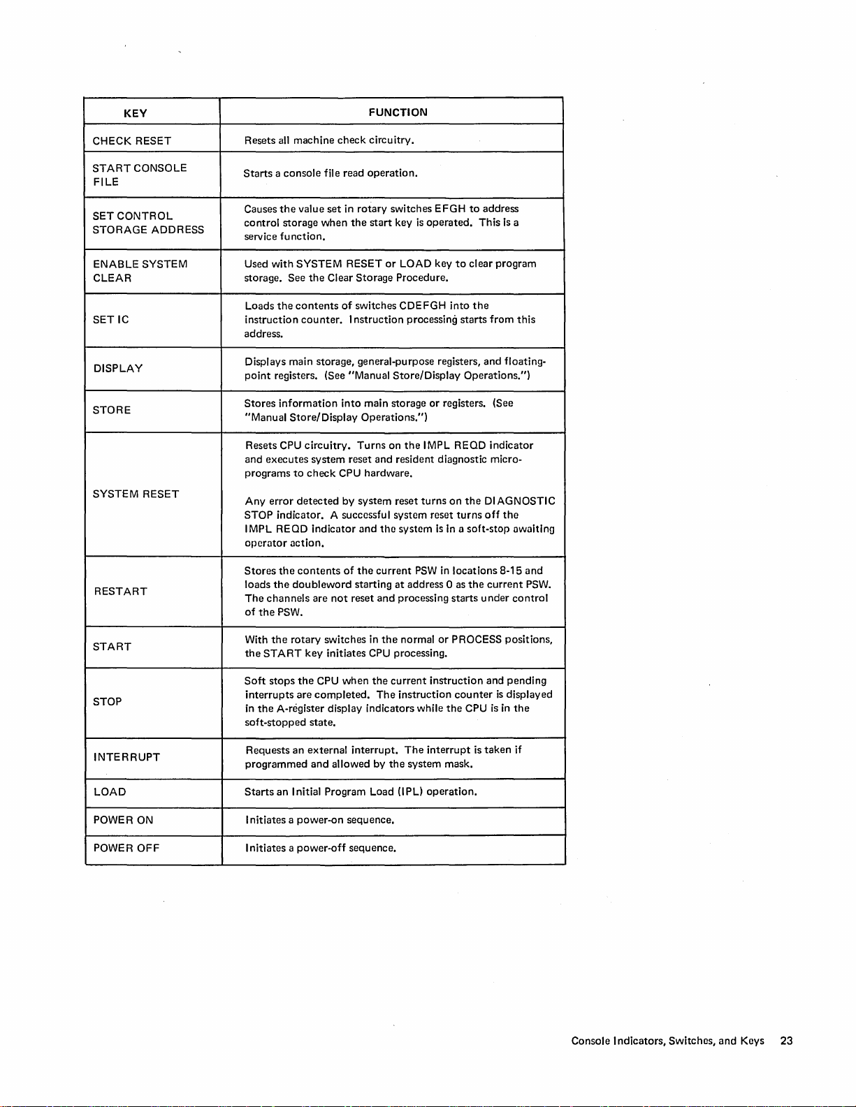
Page 24
KEY
CHECK RESET
Resets all machine
check
FUNCTION
circuitry.
START
CONSOLE
FILE
SET
CONTROL
STORAGE
ADDRESS
ENABLE SYSTEM
CLEAR
SETIC
DISPLAY
STORE
SYSTEM
RESET
RESTART
Starts a console
Causes
the
control
service
function.
Used
with
storage.
the
Loads
instruction
file read
value
set
storage
in
when
SYSTEM RESET
See
the
Clear
contents
of
counter.
operation.
rotary
switches EFGH
the
start
key
is
or
Storage
LOAD key
Procedure.
switches CDEFGH
I
nstruction
processing
operated.
to
into
starts
address.
Displays main storage, general-purpose registers,
point
registers. (See "Manual
Stores
information
"Manual
Store/Display
Resets CPU
and
executes
programs
Any
STOP
to
error
detected
indicator. A successful system reset
into
circuitry.
system
check
CPU hardware.
reset
by
I MPL REOD Indicator
operator
Stores
loads
The
of
the
the
channels
the
PSW.
action.
contents
doubleword
are
not
of
Store/Display
main storage
Operations.")
Turns
on
and
resident diagnostic micro-
system
reset
and
tho
system
the
current
starting
reset
at
and
processing
or
registers.
the
IMPL REOD
turns
on
Is
In
PSW
in
address 0 as
Operations.")
the
turns
a soft-stop awaiting
locations
starts
to
address
This
clear
the
and
DI
off
the
under
current
Is
a
program
from
this
floating-
(See
indicator
AGNOSTIC
the
8-15
and
PSW.
control
START
STOP
INTERRUPT
LOAD
POWER
POWER
ON
OFF
With
the
rotary
the
START
Soft
stops
interrupts
in
the
A-register display indicators while
soft-stopped
Requests
programmed
Starts
an
I nitiates a
I
nitiates a power-off
switches in
key
initiates CPU processing.
the
CPU
are
when
completed.
state.
an
external
and
allowed by
interrupt.
I nitial Program Load (I pL)
power-on
sequence.
sequence.
the
the
The
the
normal
current
instruction
The
interrupt
system
operation.
or
PROCESS positions,
instruction
counter
the
CPU
is
and
is
is
taken
mask.
pending
displayed
in
the
if
Console Indicators,
Switches,
and
Keys
23
Page 25

PRINTER-KEYBOARD
PRINTER-KEYBOARDS
The
printer-keyboard
that
provides
alter/display
3210-1 Console Printer-Keyboard
(PR-KB)
and
is
an
input/output
operator
control
device
functions.
3215
Console Printer-Keyboard
24
Page 26

•
PRINTER
CONTROLS
(3210)
I mpression Control Lever
This
lever
is
can
be
positioned
closest
to
mum
striking force
farthest
maximum
ator
can
the
lever in
identified
the
platen
from
the
striking force
vary
the
the
by
in
any
of
is
number 1 and
of
the
platen
is
of
density
of
appropriate
its small red-ball
print
number 5 and
the
NOTE
When changing
move
it
forward
out
of
or
backward.
the
the
position
notch
before
five
notches.
element.
print
print
notch.
of
represents
represents
element.
impression
the
lever, first
moving
handle,
The
notch
The
by
it
the
notch
The
placing
which
mini-
the
oper-
Ribbon
Provides
operator
ribbon
the
When it
for
Lift
for
to
for
bottom
is
printing.
Lever
ribbon
wear
select
either
printing. When
half
of
the
moved
to
the
Ribbon Load Lever
Raises
the
threading
latches
to
ribbon
the
keep
guide
ribbon.
the
ribbon
~
I mpression
distribution
the
top
or
bottom
the
lever
is
ribbon
is
positioned
right,
the
top
to a more
accessible
I n its right-hand
guides raised.
Control
by
permitting
moved
half
is
position,
Lever
half
of
to
the
for
printing.
positioned
position
the
the
the
left,
for
lever
Ribbon
Lift
Lever -
__
Ribbon
Load Lever
Printer-Keyboard
25
Page 27

•
CARRIAGE
CONTROLS
(3210
and
3215)
Forms Load Lever
When
this
lever
is
pulled
sensing lever moves
forms
to
be inserted.
makes
the
PR-KB
away
not
Copy Control Lever
Compensates
for
the
thickness
toward
from
This
ready.
the
turns
of
the
keyboard,
platen
and
on
INTVN REOD
multiple-part
the
forms-
permits
and
forms.
the
When
the
lever
moves closer
Platen Knobs
When
either
knob
right
platen
knob
by
changing
To
knob
knob
the
adjust
the
in
and
hold
as required
is
moved
to
the
print
is
rotated,
provides fine
vertical
vertical alignm
it
against
to
obtain
toward
alignment.
the
element.
the
paper
adjustment
ent,
the
spring
the
desired vertical
keyboard,
is
indexed.
to
press
the
tension.
the
platen
The
the
forms
right
platen
Turn
the
alignment.
26
Page 28
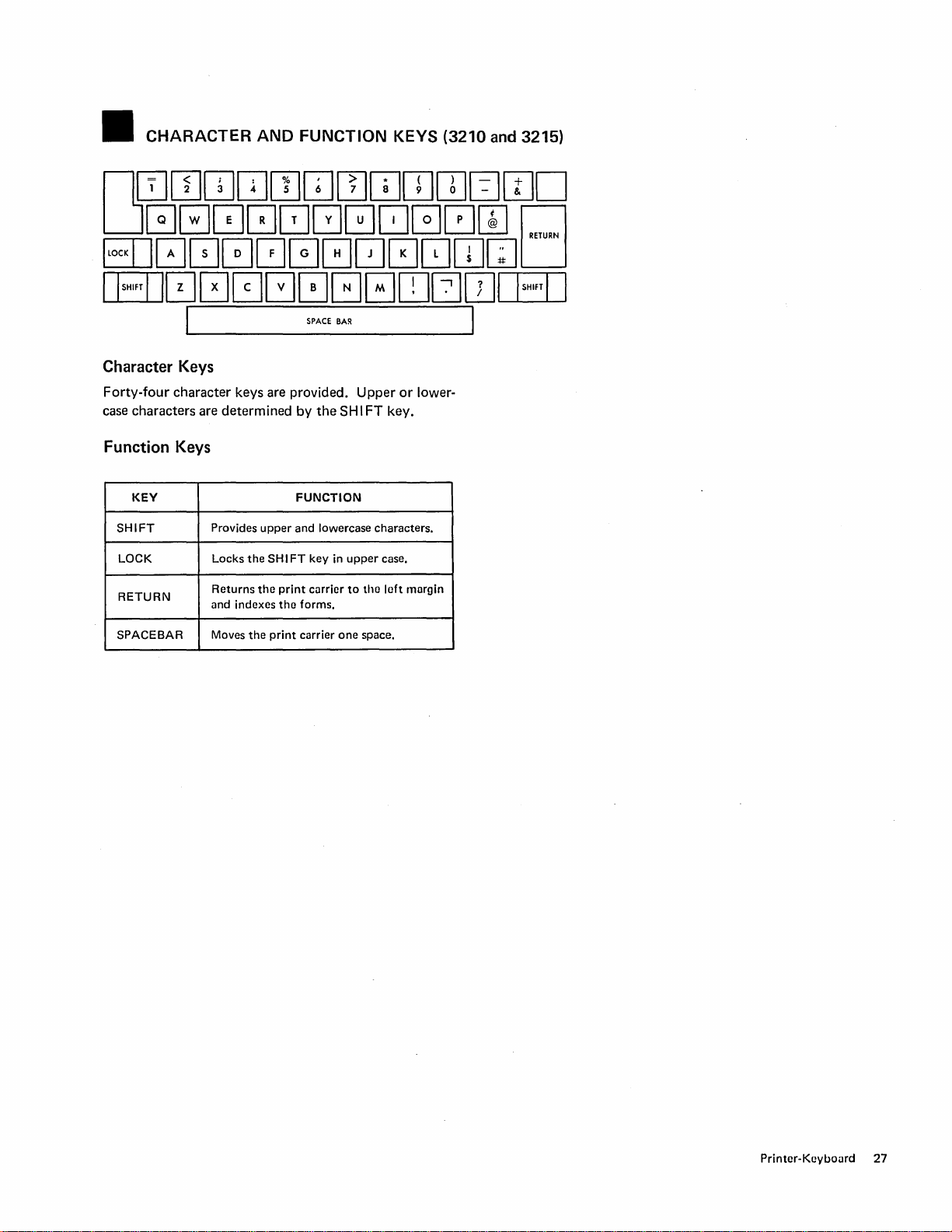
• CHARACTER
Character Keys
Forty-four
case
character
characters
keys are provided.
are
determined
Function Keys
AND
FUNCTION KEYS (3210
Upper
by
the
SH I FT key.
or
lower-
and
3215)
KEY
SHIFT
LOCK
RETURN
SPACEBAR Moves the
Provides upper and lowercase characters.
Locks the
Returns the
und indexes tho forms.
FUNCTION
SH I FT
key in upper
print
currier
print
currier one space.
to
tho
case.
loft
margin
Printer-Keyboard 27
Page 29

INDICATORS
•
The following control keys
the
PR-KB.
I
CANCEL
I
AND
CONTROL KEYS (3210
and
indicators
are
provided on
and
3215)
~
~
I READY I
Legend
INDICATORS
KEYS
o D
INDICATOR
INTVN REQD
ALTER/DISPLAY
MODE
ALARM
The
ready.
A
accepted.
An
tervention
printer
request
alarm
is
out
for
an
alter/display
command
is
required
CONDITION
of
forms
or
was
issued,
by
the
operator.
the
PR-KB is
operation
and
manual
not
was
in-
PROCEED
REQUEST
PENDING
28
The
PR-KB is
characters.
AL
TER/DISPLAY
A
request
is
turned
the
off
CPU.
by
unlocked
This
indicator
operation
when
key,
was
the
and
ready
is
turned
or
by
initiated.
attention
to
a read
status
accept
on
by
command.
The
indicator
is
accepted
the
Page 30

KEY
NOT
READY
CANCEL
READY
Places
Used
made
issue
the
Places
printer.
the
to
an
the
printer
in a
not
terminate a read
error
in
data
read
entry.
command
the
same
PR-KB in
FUNCTION
ready
condition.
command
Normally,
again.
ready
state
when
when
the
the
forms
operator
program
are
in
has
will
the
ALTER/DISPLAY
END
ALARM
REQUEST
RESET
• RIBBON
3210
Printer-Keyboard
To
remove
1.
Press
2. Raise
3. Move
Lift
4.
ribbon
Position
5.
platen.
6.
Slide
Position
7.
into
8.
To
the
9. Move
and
the
NOT
the
top
the
ribbon
the
ribbon
from
the
the
ribbon
the
place.
rewind
direction
the
ribbon
new
cartridge
excess
Requests
end
display
Terminates a read,
Resets
Requests
When
or
an
alter/display
mode.
the
alarm
the
programming,
REPLACEMENT
replace a
cover.
the
of
ribbon:
READY
load lever
cartridge
ribbon
cartridge
through
on
ribbon,
the
arrow.
load lever
key.
to
straight
guide.
with
the
the
turn
to
slots
cartridge
ends
CPU
the
up
the
either
the
extreme
an
alter/display
operation,
write,
indicator.
to
initiate
this
extreme
and
ribbon
in
the
posts
cartridge
or
alter/display
a read
allows
right.
remove
facing
ribbon
and
left.
operation.
the
PR-KB
command
the
operator
the
the
guides.
press
post
in
When
remains
operation.
to
the
to
enter
used
to
in
alter/
PR-KB.
data
.
3215
Printer-Keyboard
• Use
only
wise,
the
To
remove
1.
Press
2. Ra ise
Remove
3.
4.
Position
pin
press
5.
Thread
the
the
6.
Rewind
and
the
the
the
the
sticking
the
the
path
shown
ribbon.
any
cartridge
3215
ribbon
cllrtridges in
loclltinu pin will
replace a ribbon:
NOT
READY
top
cover.
ribbon
and
hole
in
the
up
out
of
the
cartridge
post
ribbon
in
slack
in
into
through
the
in
the
the
direction
decal
be
dumuned.
key.
cartridge.
bottom
ribbon
place.
the
on
ribbon
of
this
of
the
feed
ribbon
the
printer.
by
turning
the
machine;
cartridge
mechanism
guides
following
Do
the
arrow.
other-
over
not
left
the
and
twist
(front)
Printer-Keyboard
29
Page 31

II FORMS
• Do
not
Place
1.
2. Raise
3. Move
4. I nsert
5. Move
6. Guide
7. Position
8.
9.
II
the
the
the
knob
until
the
feed pins, making sure
holes
in
first
print
Close
the
Press
the
PLATEN
INSERTION
use forms
forms
top
cover.
forms
the
paper
the
forms
the
paper
the
forms.
the
paper
line using
top
cover.
READY key.
thicker
on
load lever
behind
paper
load lever
between
than
the
lower rack
away
the
comes
toward
the
that
for
correct
the
right platen knob.
REMOVAL
(3210
platen and
out
the
AND
and
3215)
three
part.
of
the
forms
from
the
keyboard.
turn
in
front.
the
keyboard.
retaining clips and
pins engage
vertical alignment
REPLACEMENT (3210
the
the
stand.
platen
the
margin
of
the
and
3215)
Removal
1. Press
2. Raise
3. Move
4. Press
assembly
Platen Latch
the
NOT READY key.
the
top
cover.
the
forms
load lever
down
the
platen latches
and
lift
the
platen
toward
at
out.
the
both
keyboard.
ends
of
the
platen
Replacement
1. Position
2.
Center
the
the
the
platen
platen
end
shaft
with
plate
in
and press
the
ratchet
the
groove
the
Platen Latch
at
platen
teeth
the
into
to
the
right end
place.
right.
of
30
Page 32

•
PRINT
ELEMENT
REMOVAL
AND
REPLACEMENT (3210)
Removal
1.
Press
the
2 Raise
3. Note
4. Lift
5. Lift
Print
Release
Pri
Element
nt
Element
the
the
the
Lever
NOT READY key.
the
top
cover.
direction
print
print
--
of
element
element
iiiiiiii:::-~-:-";;;;::'il;''::.
the
arrow
on
release lever.
off
the
element
the
print
post.
element.
Replacement
1. I nstall
the
print
arrow pointing in
2. Lower
the
place.
element
the
release lever
on
same
to
the
element
direction
lock
the
it was
print
post
with
on
removal.
element
the
in
Print
Element
Post
-~~;:::;::
Printer-Kcybollrd
31
Page 33
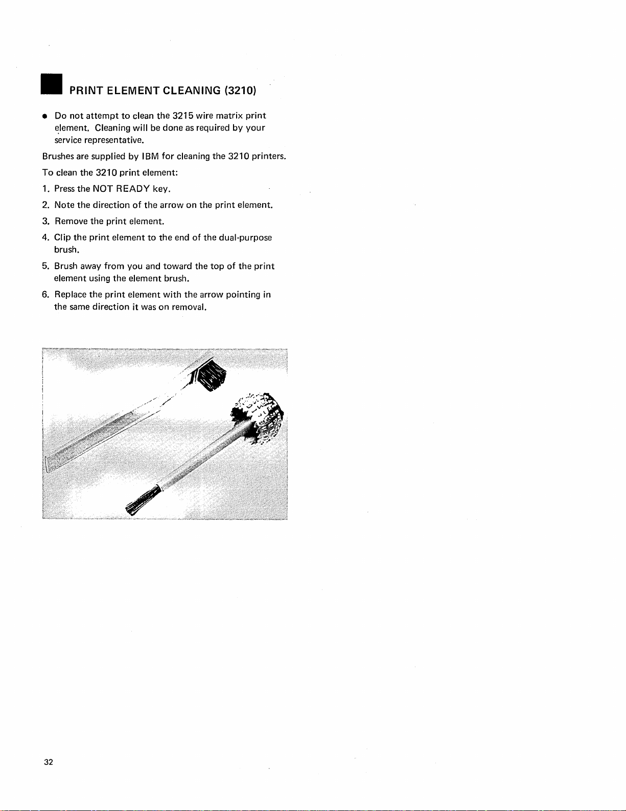
•
PRINT
• Do
not
~Iement.
service representative.
Brushes are supplied by
To
clean
1. Press
Note
2.
3. Remove
4. Clip
5. Brush away
6.
the
brush.
element
Replace
the
same
ELEMENT CLEANING (3210)
attempt
the
the
the
the
print
using
the
to
Cleaning will
3210
print
NOT READY key.
direction
print
element
from
you
the
print
element
direction
clean
the
be
IBM
element:
of
the
element.
to
and
element
it was
3215
done
for
cleaning
arrow
the
end
toward
brush.
with
on
removal.
wire matrix
as required
the
3210
on
the
print
of
the
dual-purpose
the
top
of
the
arrow pointing in
print
by
your
printers.
element.
the
print
32
Page 34

OPERATOR NOTES:
Printcr-KcylJo<Jrd
33
Page 35
OPERATING
m
MAGNETIC
•
Store
the
disk cartridges
console file access
• Handle cartridges carefully because
mation
• Replace envelopes when
• Keep
• When
storage
• Do
• Do
• Keep
magnetic fields.
•
Do
r;w
...
essential
the
the
compartment.
not
touch
not
attempt
the
not
smoke
DISK
AND
to
cartridge
cartridge
the
exposed disk surface.
to
cartridge away from metallic materials
when
CARTRIDGE
REMOVAL
PROCEDURES
DISK
CARTRIDGE
in
the
locations provided
door.
system
in
clean
operation.
they
are defective.
its envelope when
is
in
use,
store
the
disk surface.
handling cartridges.
INSERTION
they
the
envelope
HANDLING
contain
not
infor-
in use.
in
and
in
the
the
Insertion
1. Open
2. Remove
3. With
. 4. As a check
the
envelope
the
loading
as
the
cover
center
of
does
not,
the
.Iabel facing
slots
Removal
1.
Open
the
the
2. Lift
3.
Return
storage
cartridge
the
compartment.
disk drive cover.
cartridge from its envelope and
to
the
storage
until it
on
disk position,
is
being closed. It should slide
the
disk
re-insert
disk drive cover.
cartridge
compartment.
you,
lower
the
is
stopped
without
the
disk.
straight
to
by
watch
distorting
up
and
out
its envelope and place it
the
the
return
cartridge into
locating surfaces .
centering
the
disk. I f it
of
the
cone
into
the
console file.
in
the
the
the
34
Page 36

~
___
~,--:"~~::::::::=j
Disk
Cartridge
Centering
Loading
Cone
Slot
Operating Procedures
35
Page 37

• PR-KB MANUAL
Data
Entry
During a
turned
quired.
operator.
program-controlled
on
when
entry
of
This
information
The
operation
data
is
is
OPERATIONS
read
operation,
from
the
keyboard
entered
ended
into
by
the
pressing
PROCEED
is
re-
system
the
END key.
by
is
the
Alter/Display
Alter/display
from
the
eration,
Display
by
the
Alter
operations
PR-KB.
the
location(s) accessed, and
operations
operator.
operations
Alter/Display
1. Press
2. Press
3. Wait
4.
the
the
for
to
turn
Type
the
dress
of
displayed
STORAGE
AREA
iviAI N
STORAGE
STORAGE
CPU STOP key
ALTER/DISPLAY
both
on.
appropriate
the
from
KEY
Operations
are
performed
The
PR-KB provides a record
print
data
The
data
is
not
change
the
Procedure
ALTER/DISPLAY
two-character
information
the
or
register
following.
ALTER
MNEMONIC
AM
AK
from
changed.
stored
key.
by
the
the
data
storage
data.
MODE
mnemonic
to
be altered
DISPLAY
MNEMONIC
operator
of
involved.
for
and
OM
DK
the
op-
inspection
PROCEED
and
ad-
or
ADDRESS
000000-03
000000-03F F F F
RANGE
F F F F
GENERAL-PURPOSE
REGISTER
FLOATING-POINT
REGISTER
CURRENT
PSW
Alter
Data
may
be
entered,
bar
to
skip
over
positions
the
skipped-over
out
each
time
the
operation,
5.
To
key.
36
press
continue
the
program
AG
AF
AP
one
digit
not
being altered.
positions
spacebar
remains
is
operated.
ALTER/DISPLAY
processing, press
at a time,
unchanged
OG
DF
OP
using
The
To
end
or
END key.
the
the
and
the
CPU
space-
data
prints
alter
START
in
O-F
0,2,4,6
None required
Display
Data
continues
pressed.
is
printed
When
operation
not
inserted, press
until
zeros
is
started
starting
the
are
at
the
ALTER/DISPLAY
typed
to
the
automatically.
the
RETURN
address specified
or
END key
left
of
the
address,
When zeros
key.
and
is
the
are
Page 38

NOTE
When
the operation
key, the
DISPLAY
PR-KB
MODE
When the operation
alter/display mode
alter/display of general-purpose and floating-point
For
registers, a wraparound
is
ended with the ALTER/DISPLAY
remains
in
alter/display mode
indicator on).
is
terminated with the
is
terminated.
is
performed
(F
to 0 for
(AL
END
GP
TER/
key,
registers, and 6 to 0 for floating-point registers).
When addressing main storage, either a word or byte
address may be used. I f the starting address
PR-KB
word boundary, the
spaces and aligns
is
not on a
at
the byte
addressed.
Alter/Display Examples
In
the following examples, the X's represent digits
played or entered and printed by the PR-KB.
MAIN
STORAGE
DM
000080
XXXXXX XXXXXXXX
XXXXXXXX XXXXXXXX (Press
or
END
key)
DM
8D (Press the RETURN key)
XXXXXX XXXXXXXX
XXXXXXXX----------XX
the
ALTER/DISPLAY
XXXXXXXX---------·XX
XXXXXXXX XXXXXXXX (Press the ALTER/DISPLAY
or
END
key)
AM
480 (Press the RETURN key)
AL
XXXXXXXX XXXX (Press the
END
key)
TER/D ISPLA Y
dis-
or
Alter/Display
INVAL
Prints when one of
1.
2. The second character
3.
CHAR
The first character of a mnemonic
S,
L,
and C are used by service personnel.
An
invalid digit
Error
Messages
the
following errors occurs.
is
not A
is
not
M,
S,
L,
K,
C,
is
typed when addressing or altering
G,
or
D.
F, or
data.
4. The
CANCEL key
is
pressed.
INVAL ADDR
Prints when
1.
I nvalid starting address.
2.
The updated address exceeds the capacity of specified
one of the following errors occurs.
storage.
P.
FLOATING-POINT REGISTER
OF
2
XXXXXXXX XXXXXXXX
STORAGE
OK
009000
KEY
XXXXXXXX-·····-···XX
XXXXXXXX XXXXXXXX XXXXXXXX (Press the
ALTER/DISPLAY
or
END
key)
Each word contains four storage keys.
CURRENT
PSW
AP
XXXXXXXX XXXXXXXX
The current
PSW
is
not altered until a doubleword
is
typed.
Operating
Procedures
37
Page 39

m
INITIAL
1.
Ensure
IMPL
disk
2.
Set
all
rotary switches
tions. Ensure
toggle
switch
If
power
3.
matic
IMPL
CONSOLE FILE
• The I
•
MPL R EQD
on and the
When
the console file starts reading, the START
SOLE
FI
MICROPROGRAM PROGRAM
that
forms are inserted
is
mounted
in
to
that
the
ADDRESS COMPARE CONTROL
is
in
the SYNC/NORM position.
is
not on, press the
occurs.
If
power
key.
and
CF
START CONSOLE FILE key turns red.
LE
key turns white.
in
the
PR-KB
the console file.
their normal operating posi-
POWER-ON
is
on, press the START
PWR
ON
indicators are turned
• The message, GO-NO-GO COMPLETE,
PR-KB.
•
When
control storage
console file and the
the
START CONSOLE
• The system reset routine
indicator
is
turned off, and the
(MANUAL indicator
• The
IMPL
operation takes approximately one minute.
is
loaded, power
CF
PWR
FI
LE
key are turned off.
is
executed, the
is
on).
ON
CPU
is
LOAD
and the
key. An auto-
CON-
is
printed on the
is
removed from
indicator and the
IMPL
REOD
in
a soft-stop state
(lMPL)
iii
IMPL ERROR RECOVERY
Switches Set Properly?
IMPL Disk Mounted?
Attempt
If
using
your service representative.
to
re-IMPL using the START CONSOLE
unsuccessful, press the POWER-OFF key and re-IMPL
the
POWER-ON
INDICATOR
START
CONSOLE
FILE
KEY
RED
RED
OFF
key.
If
the error continues, notify
IMPL
REaD
ON ON Disk mounted
ON
ON
CF ERROR
PWR
ON
ON
OFF
Error
during loading
Control
of
system reset.
storage loaded.
CONDITION
improperly
FI
of
LE
key.
or
control
Error
not
turning
storage
in execution
COMMENTS
A system check
is
on.
The
DIAGN
STOP
or
a CF check
indicator
indicator
is
on.
38
Page 40
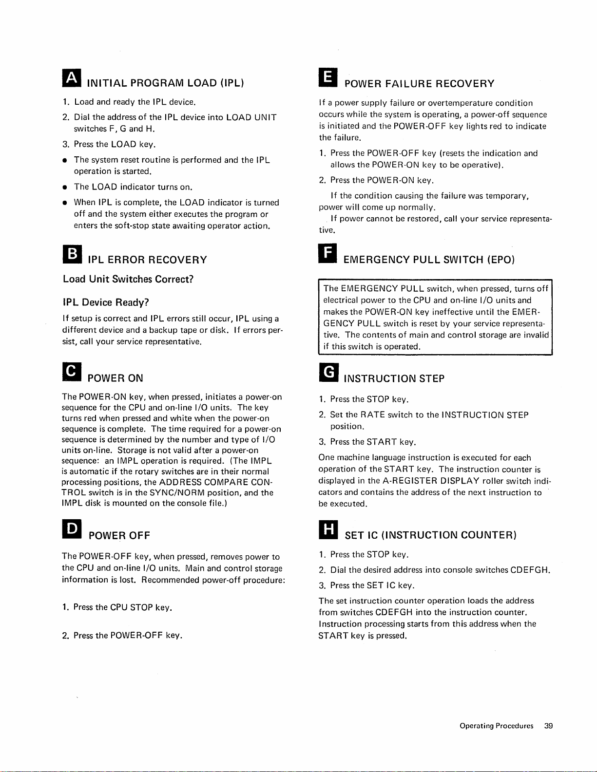
II
INITIAL
1.
Load
and
Dial
2.
3. Press
•
•
• When IPL
II
Load
IPL
If
different
sist, call
the
switches
the
The
system
operation
The
LOAD
off
and
the
enters
the
IPL
Unit
Device Ready?
setup
is
correct
device
your
PROGRAM
ready
the
I PL device.
address
ERROR
of
F, G
and
LOAD key.
reset
routine
is
started.
indicator
is
complete,
system
soft-stop
the
I PL device
H.
is
turns
the
either
executes
state
awaiting
RECOVERY
Switches Correct?
and
IPL
errors
and a backup
service
representative.
LOAD
into
performed
on.
LOAD
indicator
the
operator
still
occur,
tape
or
disk.
(IPL)
LOAD
and
the
program
IPL using a
If
errors
UN
I PL
is
turned
or
action.
IT
per-
II
POWER
If a
power
occurs
while
is
initiated
the
failure.
1.
Press
the
allows
2. Press
power
tive.
II
the
If
the
will
If
power
EMERGENCY
The
EMERGENCY
electrical
makes
the
GENCY
tive.
The
if
this
switch
FAILURE
supply
failure
the
system
and
the
POWER-OFF
POWER-OFF
the
POWER-ON
POWER-ON key.
condition
come
power
POWER-ON
PULL
contents
up
cannot
switch
is
operated.
causing
normally.
be
PULL
to
the
of
RECOVERY
or
overtemperature
is
operating, a power-off
key
lights red
key
(resets
the
key
to
be
operative).
the
failure
was
restored,
PULL
CPU
is
main
call
SWITCH (EPO)
switch,
and
on-line
key
ineffective
reset
by
and
control
your
when
your
service
condition
indication
temporary,
service
pressed,
I/O
units
until
the
representa-
storage
sequence
to
indicate
and
representa-
turns
and
EMER-
are
invalid
off
B POWER ON
The
POWER-ON
sequence
turns
sequence
sequence
units
sequence:
is
processing
TROL
IMPL disk
for
red
when
on-line.
automatic
switch
m POWER
ThePOWER-OFF
the
CPU
and
information
1. Press
2. Press
the
the
key,
the
CPU
pressed
is
complete.
is
determined
Storage
an
IMPL
if
the
positions,
is
in
the
is
mounted
OFF
key,
on-line
is
lost.
CPU
STOP
POWER-OFF
when
pressed,
and
on-line
and
white
The
time
by
the
is
not
valid
operation
rotary
switches
the
ADDRESS
SYNC/NORM
on
the
console
when
pressed,
I/O
units.
Recommended
key.
key.
initiates a power-on
I/O
units.
The
when
the
power-on
required
number
is
required_ (The IMPL
Main
for a power-on
and
type
after a power-on
are
in
their
normal
COMPARE
position,
file.)
removes
and
power-off
CON-
and
power
control
procedure:
key
of
I/O
the
storage
to
m
INSTRUCTION
1. Press
2.
3. Press
One
operation
displayed
cators
be
the
Set
the
position.
the
machine
of
in
and
executed.
STOP
RATE
START
language
the
the
contains
m SET IC
1. Press
2.
3. Press
The
from
I
nstruction
START
Dial
the
set
switches
the
STOP
desired
the
SET
instruction
processing
key
is
STEP
key.
switch
to
the
key.
instruction
START
A-REGISTER
the
key.
address
The
(INSTRUCTION
key.
address
I C
counter
CDEFGH
pressed.
key.
starts
into
operation
into
the
from
INSTRUCTION
is
executed
instruction
DISPLAY
of
the
next
roller
instruction
COUNTER)
console
switches
loads
instruction
this
address
the
STEP
for
each
counter
switch
CDEFGH.
address
counter.
when
is
indito
the
Operating Procedures
39
Page 41

m
CLEAR
Main
storage
cedure.
1.
Hold
position.
2. Press
All
of
main
affected.
m
DATA
the
the
storage
can
ENABLE
SYSTEM
STORAGE
be
cleared
SYSTEM
RESET
is
cleared
COMPARE
to
zeros
CLEAR
or
to
zeros;
TRAP
by
LOAD
the
following
key
key.
control
in
the
storage
pro-
operated
is
not
1. Press
2.
3.
4.
5.
6. Press
When a store
location
COMP MATCH
a
the
the
(located
tion
•
The
sole
alter/display
power.
the
Set
the
ADDRESS
COMPARE
Set
the
address
ified in
Set
value.
Set
switch
soft-stop
To
console
data
the
ADDRESS
to
the
to
state.
A-REGISTER
determine
storage
in
counter
3210
3210
Model 2
PR-I<B
A line
switch
STOP
switches A and B to
the
START
operation
the
byte,
the
.
MODEL 2 PRINTER-KEYBOARD
for
functions
key.
TRAP
of
switches
STOP
value
indicator
The
DISPLAY
the
subtract
current
console
data
is
provided
COMPARE
position.
the
storage
CDE
COMPARE
position.
key.
modifies
set
in
switches A and
is
turned
instruction
address
entry
the
PSW)
are
of
functions
and
not
for
byte
FG H.
the
the
roller
the
current
from
wri.te
allowed.
turning
switch
to
location
desired
CONTROL
specified
B,
on
and
the
counter
the
is
switch
indicators.
instruction
instruction
value
the
same
operations.
on
the
DATA
being
byte
match
toggle
storage
the
ADR
CPU
displayed
that
length
in
the
as
the
However,
and
turning
mod-
byte
enters
in
modified
code
instruc-
con-
off
m
SYSTEM
If a
system
errors
continue,
service
representative.
40
check
CHECK
indicator
record
is
the
indicators
ERROR
on,
re-IMPL
RECOVERY
and
re-IPL.
and
notify
your
If
Page 42
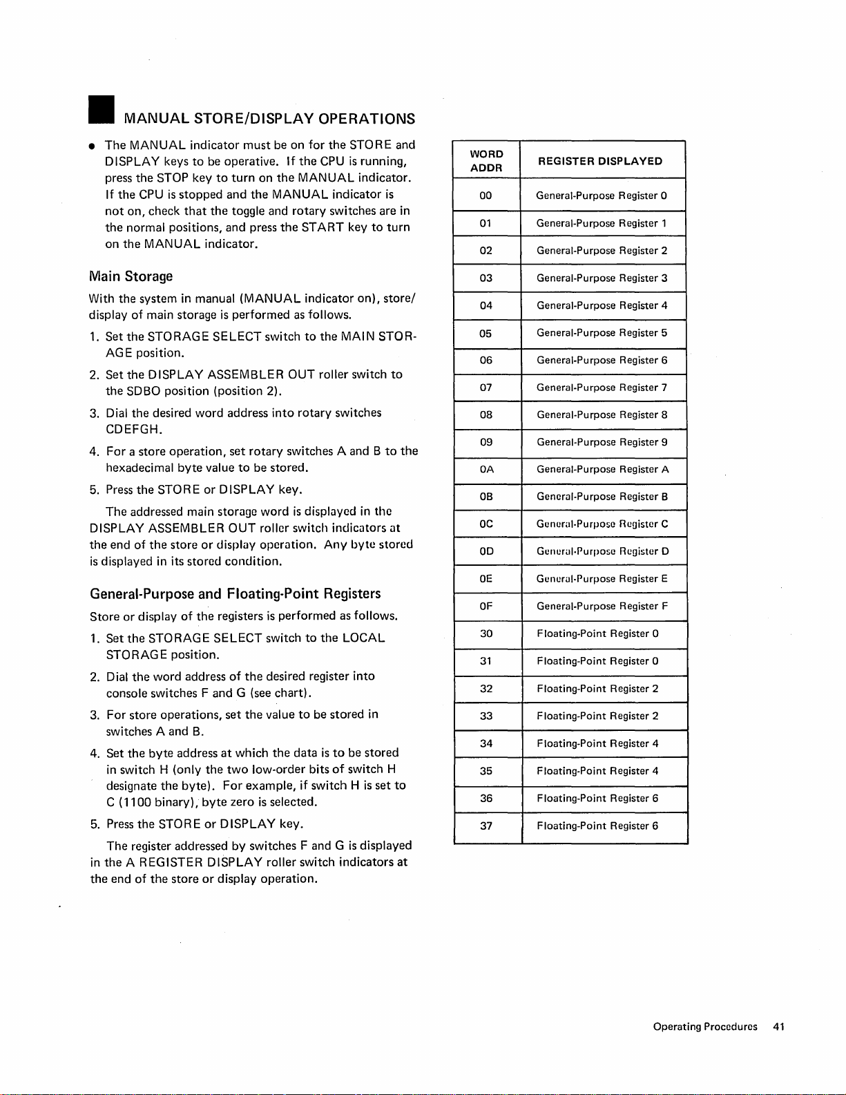
•
MANUAL
•
The
MANUAL
DISPLAY keys
press
the
If
the
CPU
not
on,
the
normal positions,
on
the
MANUAL
Main
Storage
With
the
system
display
1.
Set
of
the
check
main storage
STORAGE
STORE/DISPLAY OPERATIONS
indicator
to
STOP key
is
stopped
that
in manual (MANUAL
must
be
operative.
to
turn
and
the
toggle and
and
indicator.
is
performed
SELECT
be
on
the
the
MANUAL
press
switch
on
for
If
the
MANUAL
rotary
the
START
indicator
as follows.
to
the
CPU
indicator
switches are in
the
STORE
is
running,
indicator.
key
on),
MAIN STOR-
AG E position.
Set
the
2.
3.
the
Dial
DISPLAY ASSEMBLER
SDBO position
the
desired
(position
word
address
2).
into
OUT
rotary
roller switch
switches
CDEFGH.
4.
For a store
hexadecimal
5. Press
The
DISPLAY ASSEMBLER
the
end
is
displayed in its
the
operation,
byte
STORE
set
rotary
value
to
or
DISPLAY key.
addressed main storage
OUT
of
the
store
or
display opcrlltion.
stored
condition.
switches A and B
be
stored.
word
is
dispillyed
in
roller switch indiclltors
Any
byte
General-Purpose and Floating-Point Registers
Store
or
display
1.
Set
the
STORAG
2. Dial
the
console switches F
3.
For
store
switches A
4.
Set
the
in
switch H (only
designate
C
(1100
5. Press
in
the
the
The
register addressed
the
A REG ISTER D ISPLA Y roller switch
end
of
of
the
STORAGE
E
position.
word
address
operations,
and
B.
byte
address
the
byte).
binary),
STORE
the
store
or
registers
SELECT
of
the
and
G (see
set
the
at
which
the
two
low-order bits
For
example,
byte
zero
is
or
DISPLAY key.
by
switches F and G is
display
is
performed
switch
to
the
desired register
chart).
value
to
be
stored
the
data
is
if
switch H is
selected.
operation.
as follows.
LOCAL
into
in
to
be
stored
of
switch H
displayed
indicators
is
to
turn
store/
to
the
at
stored
set
and
to
to
the
at
WORD
ADDR
00
01
02
03
04
05
06
07
08
09
OA
OB
OC
00
OE
OF
30
31
32
33
34
35
36
37
REGISTER
General-Purpose
General-Purpose
General-Purpose
General-Purpose
General-Purpose
General-Purpose
General-Purpose
General-Purpose
General-Purpose
General-Purpose
General-Purpose
General·Purpose
Gunural·Purpose
GUllurul·Purpose Reoistcr 0
Gunerul·Purpose
General-Purpose
Floating-Point
Floating-Point
Floating-Point
Floating-Point
Floating-Point
Floating-Point
Floating-Point
Floating-Point
DISPLAYED
Register
Register
Register
Register
Register 4
Register 5
Register 6
Register
Register 8
Register 9
Register A
Register
Ruoistcr C
Register
Register F
Register 0
Register
Register
Register
Register
Register
Register
0
2
2
4
4
6
Register 6
0
1
2
3
7
B
E
Operating
Procedures
41
Page 43

•
AUTOMATIC
•
The
purpose
a customer environment by maximum usage
ponents
• ASCP provides a quick
attached
used by
to
obtain a reliability
total system.
• The program
municates with
(preferably a printer). After
operator
and
follows
out.
• ASCP requires a dedicated system and does
under
• ASCP provides
ready devices. I/O devices
tested are:
Direct Access Devices - 2311, 2314, 2321
Tapes -
Readers/Punches Printers -
Displays Consoles Terminal Adapters -
Magnetic Character Reader - 1419
of
of
the
I/O devices as a system. The program can be
both
readies
the
control
2415,
1403,
2250,
3210,
SYSTEM CHECKOUT PROGRAM (ASCP)
ASCP
is
to
simulate system operation
system.
checkout
the
customer and the service representative
report
is
loaded from
the
operator
the
device selected as an
step-by-step instructions
of
an operating system.
automatic
2420,
2400
2540,
1404, 1443 Model
2260
3215
2701,2702
of
CPU
channels and
on
the condition
the
console
via some
the
configuration and testing
that
can be configured and
2520, 2501, 1442 Model N 1
fi
output
program
output
that
N1
of
all com-
of
Ie
and com-
device
is
loaded,
are printed
not
the
device
run
the
of
in
Program Concepts
After
the
system has been initialized and
is
completed,
Each
fore configuration,
each device,
commands
nels reflect
vide maximum use of
The program
old of system overrun
overrun
erated with each
The
test
gram.
the
reliability run
I/O device, attached
is
tested. The program
control unit,
to
the
devices. As soon as control units
busy conditions,
the
attempts
without
con'dition. When all
CPU
test, a reliability
continues until
the
Operating Instructions
1. Load
2. Press
3. Ready
4. Ready
5. Press
the
first ASCP disk on
the
START CONSOLE FILE key.
the
device
to
be used as
Instructions for running
out
on
the
output
the
devices
RUPT key
printed (after
devices made ready are
Reliability reports are printed
printout
to
the
I NTE R R UPT key
for interpretation of reports).
device.
to
continue. When
about
10 seconds), check
the
configuration
is
started.
to
the
system and readied be-
attempts
or
channel busy by initiating I/O
CPU
tests are started
system.
to
keep
the
system
on
the
actually encountering an
of
the
devices have been op-
report
is
printed.
operator
the
be tested and press
in
the
terminates
the
console file.
the
output
program are printed
the
unit table
table.
to
continue
at
intervals (see sample
device.
the
that
the
the
INTERis
all
program.
to
or
to
keep
chan-
pro-
thresh-
pro-
Page 44
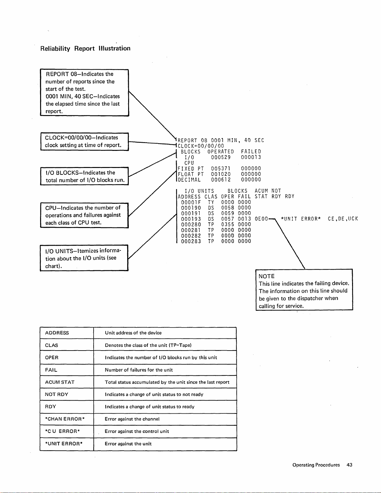
Reliability Report Illustration
REPORT
number
start
0001 MIN,
the
of
of
the
elapsed
OS-Indicates
reports
since
test.
40
SEC-Indicates
time
since
the
the
the
last
report.
CLOCK=OO/OO/OO-Indicates
clock setting
I/O
BLOCKS-Indicates
total
CPU-Indicates
operations
each class
I/O
UNITS-Itemizes
tion
about
number
and
of
the
at
time
of
report.
of
I/O blocks run.
the
number
failures against
CPU
test.
informa-
I/O
units
the
(see
chart).
of
r
____
--.lREPORT
08
0001
CLOCK=OO/OO/OO
BLOCKS
OPERATED
I/O 000529 000013
CPU
FIXED
FLOAT
DECIMAL
ADDRESS
I/O
00001F
000190
000191
000193
000280
000281
000282
000283
PT
PT
UNITS
CLAS
TY
DS
DS
DS
TP
TP
TP
TP
005371
001020
000612
OPER
0000 0000
0058 0000
0059 0000
0057 0013
0355 0000
0000 0000
0000 0000
0000 0000
MIN,
40
FAILED
000000
000000
000000
BLOCKS
FAIL
SEC
ACUM
STAT
OEOO
NOTE
This
The
be given
calling
NOT
RDY
RDY
*UNIT
line indicates
information
to
the
dispatcher
for
service.
ERROR*
the
failing device.
on
this
CE,DE,UCK
line
should
when
Unit
ADDRESS
CLAS
OPER Indicates
FAIL
ACUM
STAT
NOT
RDY
RDY Indicates a
*CHAN
*C U
*UNIT
ERROR*
ERROR*
ERROR-
address
Denotes
Number
Total
status
Indicates a change
Error
against
Error
against
Error
against
of
the
class
the
number
of
failures
accumulated
change
the
the
the
the
device
of
for
of
of
channel
control
unit
the
of
unit
unit
unit
I/O
the
unit
(TP=Tape)
blocks
unit
by
the
status
status
unit
to
to
run
since
not
ready
by
this
the
ready
unit
last
report
Operating
Procedures
43
Page 45
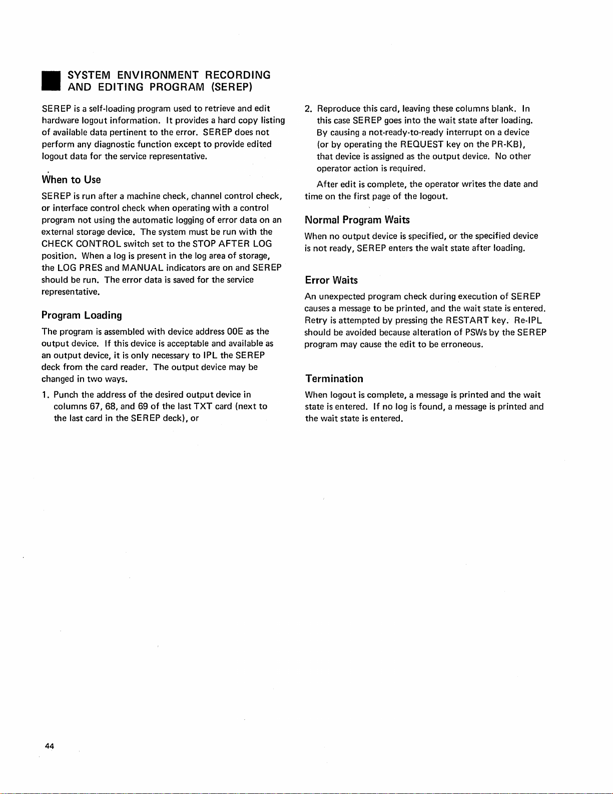
SYSTEM
•
AND
SE R
EP
is
a self-loading program used
hardware logout information. It provides a hard
of
available
perform any diagnostic
logout
data
When
to
Use
SEREP is run
or
interface
program
external storage device.
CHECK CONTROL switch
position. When a log
the
should be run.
representative.
LOG
not
PRES
ENVIRONMENT
EDITING
data
pertinent
for
the
service representative.
after
a machine check, channel control check,
control
using
the
and
The
PROGRAM (SEREP)
to
the
error. SER
function
check when operating with a control
automatic
The
is
present
MANUAL indicators are
error
except
system must be run with
set
to
in
data
is
saved for
RECORDING
to
retrieve and
to
logging
of
the
STOP
the
log
provide edited
area
the
EP
error
AFTER
on
service
Program Loading
The
program
output
an
output
deck from
changed
1. Punch
columns 67,
the
is
assembled with device address
device. If this device
device, it
the
in
two
the
last card in
is
only
card reader.
ways.
address of
68,
and
the
SER
the
69
ODE
is
acceptable and available as
necessary
The
desired
of
the
EP
to
output
output
last TXT card
deck),
or
IPL
the
device may be
device in
copy
does
data
of
storage,
and
SEREP
(next
edit
listing
not
on
the
LOG
SEREP
as
the
to
an
2. Reproduce this card, leaving these columns blank.
this case SEREP goes
By
causing a not-ready-to-ready
(or by operating
that
device
is
assigned as
operator
After
time
on
edit
the
action
is
complete,
first page
into
the
the
REQUEST key on
the
is
required.
the
operator
of
the
logout.
wait
interrupt
output
state
after
on a device
the
device. No
writes
the
loading.
PR-KB),
other
date
Normal Program Waits
When no
is
output
not
ready, SEREP
device
enters
is
specified,
the
wait
or
the
specified device
state
after
loading.
Error Waits
An
unexpected
causes a message
Retry
is
should be avoided because alteration
program may cause
program check during
to
be
attempted
by pressing
the
printed,
edit
to
execution
and
the
wait
the
RESTART key. Re-IPL
of
PSWs
be erroneous.
of
state
by
is
the
Termination
When logout
state
is
the
wait
is
entered.
state
is
complete,
If no log
entered.
a message
is
found,
is
printed and
a message
the
is
printed and
In
and
SEREP
entered.
SEREP
wait
44
Page 46
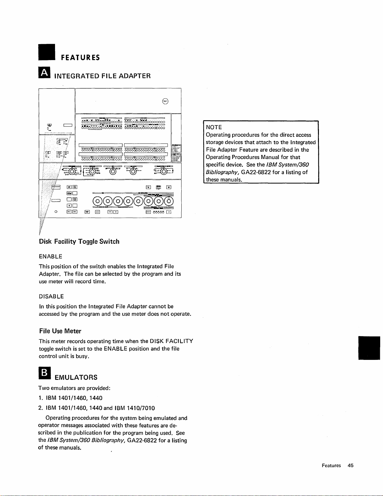
FEATURES
INTEGRATED
~~~o~o~<:\~oo~~ooo~o
~e~~66n~o~~~~~16
t
~~D!?
i
@i.~
Gffi
0::-.9=-
@]~
~O
O[§
GO
o
BEJ
FILE
~@@@@®@2
~
B
EJG
Disk Facility Toggle Switch
ENABLE
of
the
This position
Adapter.
use meter will record time.
The
switch enables
file can be selected by
ADAPTER
8
OMoo~o~-~~oooooooo
~~~~~oo56606dP606
EI
MM15
G
the
Integrated File
the
program and its
NOTE
Operating procedures
storage devices
File Adapter Feature are described in
Operating Procedures Manual for
specific device. See
Bibliography, GA22-6822
these manuals.
that
for
attach
the
IBM
the
direct
to
the
System/360
for
a listing
Integrated
that
access
the
of
DISABLE
In
this position
accessed by
File
Use
This meter records operating time when
toggle switch
control
II
Two
1 .
2.
operator
scribed
the
of
unit
EMULATORS
emulators are provided:
IBM
1401
IBM
1401/1460,1440
Operating procedures
in
IBM
these manuals.
the
the
program and
Integrated File
the
Adapter
use
meter
Meter
is
set
to
the
ENABLE position and
is
busy.
/1460,
messages associated with these features are de-
the
System/360 Bibliography, GA22-6822 for a listing
1440
publication
and
for
for
IBM
1410/7010
the
system being emulated and
the
program being used. See
cannot
does
the
be
not
DISK FACILITY
the
operate.
file
Features
45
Page 47
•
GLOSSARY
Automatic
system diagnosis.
Hard
can be
Initial Microprogram Program
for
loading
logical
by B+X+D.
Soft
and
is
on.
System Environment Recording and Edit Program: A standalone
program used
information from main storage.
Real Address:
System
Stop: A stop
handled and
the
Address:
Stop: A
timer
updates are handled if requested and
Checkout
in
the
control storage area
The
stop
in
which
on
error
The
actual physical address
Program: A standalone program used for
which
the
ClK
STPD indicator
load
calculated effective address
the
conditions
CPU clock continues
CPU
clock
is
stopped. No interrupts
is
on.
(lMPl):
of
to
edit
An
operation
a microprogram-controlled CPU.
of
an operand formed
to
run. Interrupts
the
MAN
UAl
and
print
hardware logout
in
main storage.
that
indicator
provides
46
Page 48

.INDEX
abbreviations
adapter,
address
address
ADR
alarm
alarm reset
alter/display
A-register
ASCP
automatic
auxiliary
byte
byte/x-late
integrated
compare
compare
COMP
MATCH
indicator
key
error
messages
examples 37
mode
indicator
key
29
procedure
display
42
system
console
count
switches, console
regs
[I
cancel
key
carriage
CF PWR
character keys
check
check
console
system 8
check reset
cleaning
clear storage
clock
console
byte
checks
disk
disk
IMPL
IMP L procedure
indicators
register
control
control
control
control
controls
carriage
printer
copy
CPU status
CSL
current
(PR-KB)
controls
ON
indicator
control
indicators
file·
key
print
procedure
stop
indicator
file
count
switches
10
cartridge
handling
error
recovery
display
keys
(PR-KB)
lever, impression
storage address switches
storage
(PR-KB)
26
25
control
lever
indicators
(~IMPL)
PSW,
alter/display
v
file
control
switch
(PR-KB)
(PR-KB)
37
28
36
roller
checkout
operations
switch
(PR-KB)
(PR-KB)
switch
10
23
element
insertion
34
10
switch
loading
(PR-KB)
45
switch
15
indicator
28
29
switch
program 42
20
29
9
27
18
(PR-KB)
40
9
20
and removal
38
38
14
28
(PR-KB)
(see
IMPL)
9
file
26
36
40
26
9
13
32
14
20
20
25
34
data compare
data switches
diagnostic/console
disk
cartridge
handling
insertion
removal
disk
facility
display
display
II
emergency
emulators
enable system clear
end key
EPO
switch
error
error
IMPL
IPL
power
system check
EXE
CPL T
switch
assembler
key
pull
(PR-KB)
messages
recovery
38
39
failuro
indicator
trap
20
34
34
34
23
switch
45
39
(PR-KB)
file
out
39
40
40
45
roller
key
29
II
features
file
integrated
(see
floating-point
forms
forms
function
45
adapter
console
insertion
load lever
keys
file)
register,
(PR-KB)
(PR-KBI
(PR-KB)
m
glossary
general-purpose registers,
D
IMPL
IMPL
IMPL
impression
indicators
A-register
console
CPU status 9
display assembler
PR-KB
system
system
initial
initial
instruction
integrated
interrupt
46
38
error
recovery
REQD
indicator
control
display
file
10
28
11
check
microprogram
program
file
key
load
step
adapter
23
procedure
lever
out
8
program
39
control
switch
switch
39
23
37
9
45
alter/display
30
26
27
alter/display
9
(PR-KB)
13
12
load
39
45
12
(PR-KB)
38
25
38
19
36
36
Index
47
Page 49

interval
timer
switch
introduction
I
NTVN
invalid
address
invalid
character
IPL
39
I P L
error
REQD
recovery
7
indicator
(PR-KB)
(PR-KB)
39
13
keys
PR-KB
system
knobs,
lamp
lamp
levers
copy
forms
impression
ribbon I itt
ribbon
lights
load
load
load
lock
LOG
II
magnetic
main
main
MAN
manual
CPU console
floating-point
general-purpose registers 41
main
PR-KB
current
floating-point
general-purpose registers
main
storage
memory
meters,
file
system 21
II
not
m
operating
alter/display
ASCP
automatic
auxiliary
clear storage
data
disk
emergency
EPa
IMPL
IMPL
initial
27,28
control
platen
(see
test
(PR-KB)
control
load 26
(see
indicator
key
unit
key
PRES
storage address switches
storage,
indicator
operations
(see
use
45
ready
compare
cartridge
error
microprogram
panel
(PR-KB)
indicators)
switch
14
26
control
25
load
25
indicators)
11
23
address switches
(PR-KB)
indicator
disk
storage
alter/display
PSW
storage
key
key
procedures
42
system
console
39
38
27
handling
alter/display
11
store/display
registers
41
36
registers
36
36
storage)
(PR-KB)
36
checkout
40
40
trap
insertion
pull
switch
recovery
40
program
14
(PR"KB)
37
37
23
26
25
20
9
procedure
(PR-KB)
41
36
36
29
program
and removal
39
38
20
load
28
34
36
38
42
34
operating
m
paper
platen
power
power
power
printer
print
printer-keyboards
PR-KB
procedures
proceed
II
rate
ready
request
request
restart
return
ribbon
roller
rotary
SEREP
set I C
set
set
shift
SNG
spacebar
start
start
status
procedures
initial
program
instruction
IPL
39
IPL
error
failure
off
on
manual
IC
insertion
(PR-KB)
failure
off
23
on
23
controls
element
manual
indicator
switch
key
key
pending
key
key
(PR-KB)
lever
switch
assembler
switches A
(instruction
IC
key
control
key
ECC
(PR-KB)
console
key
indicators,
recovery
disk
store/display
44
39
Environment
26
(see
(PR-KB)
(PR-KB)
(PR-KB)
display
44
storage address
(PR-KB) 27
CHK
23
magnetic
manual
power
power
power
PR-KB
SEREP
set
system check
System
knobs
removal
replacement
key
procedure
key
procedure
cleaning
removal
replacement
lift
load lever
replacement
A-register
display
step
39
39
30
recovery
39
39
(PR-KB)
32
31
operations
17
23
25
25
23
file
(continued)
load
39
39
39
cartridge
recovery
operations
error
(PR-KB)
30
(PR-KB)
31
operating
indicator
29
indicator
handling
operations
recovery
Recording
30
39
24
procedures)
(PR-KB)
29
29
27
13
out
12
through H 20
counter)
27
key
23
CPU 9
39
25
36
28
9
28
23
36
39
40
and
34
41
Editing
Program
44
48
Page 50

stop
after
log 18
stop
key
storage clear
storage
storage select
store
store
switch
address
address
A-register
A
check
console
diagnostic/console
disk
display
emergency
interval
lamp
rate
storage select
time
switches,
system
system
system
System
system
system reset
23
key,
alter/display
display
address
key
23
compare
compare
display
through H 20
control
file
facility
assembler
pull
timer
test
17
of
day
toggle
check
check
checkout
Environment
indicators
key
40
switch
control
roller
18
register
45
out
39
14
14
16
clock
14
error
recovery
indicators
program
23
16
switches
15
display
file
control
12
14
8
automatic
Recording
11
36
13
14
40
20
14
and
19
Editing
42
Program
44
II
TEST
indicator
time
of
day
clock
TOO
CLOCK
toggle
switches
type
ball
(see
use
meters
file
45
system
WAIT
word
1401/1460,1440
1401/1460,1440
3210-1
3210-2
3215
21
indicator
address
Printer-Keyboard
Printer-Keyboard
Printer-Keyboard
11
switch
INVLO
14
print
element)
11
switches
Emulator
and
14
9
20
45
1410/7010
24
40
24
Emulator
45
Index
49
Page 51

IBM
System/370
Operating Procedures
Model 145
READER'S
COMMENT
FORM
Order
No.
GA24-3554-0
• Rate
•
•
•
this
manuals
Very
Good
Fair
Poor
Very
Is
all
the
Yes
No (explain below)
Is
the
information
Yes
No (explain
Thank
you
include
please
manual compared
you
have used.
Good
Poor
information
for
you
you
are
below)
your
reply.
your
name and address.
to
other
require
looking
If
you
Operating Procedures
as
an
for
easy
would
operator
to
like
a response,
included?
find
and
use?
Name
Street
City
.
State.
ZIP Code
Page 52
GA24-3554-0
YOUR COMMENTS, PLEASE
This SRL
programmers, and operators
back
is
part
of
a library that
of
this form, together with your comments
of
serves
IBM
lications for your use. Each reply
ble
for writing and publishing this material.
of
the property
Please note: Requests for copies
IBM
system should
IBM.
be
directed to your
of
office serving your locality.
Fold
-
--
--
-
-,-
NO POSTAGE STAMP NECESSARY
as
a reference source for systems analysts,
systems. Your answers to the questions on the
will
help us produce better pub-
will
be
carefully reviewed
All
comments and suggestions become
publications and for assistance
IBM
representative or to the
- - -- - - - -
BUSINESS
POSTAGE
IBM
P.
Endicott, N.
WILL
Corporation
O.
Box
by
the persons responsi-
-----------
REPLY
IF
MAILED
BE
PAID
6
Y.
13760
in
utilizing your
IBM
branch
MAIL
IN THE
BY
•••
UNITED
-~-------
STATES
FIRST
CLASS
PERMIT
NO. 170
ENDICOTT,
- -
N.
Fold
----I
Y.
()
c
~
»
0'
:J
to
r-
5'
CD
en
-<
!!l
CI)
3
......
w
o
"
~
o
Q.
~
~
~
CJ1
o
'0
CI)
Ql
...
:;'
cc
'tI
a
o
CI)
Q.
~
CI)
III
Attention: Product Publications, Dept.
- - -
------
- -
---
Fold
International Business Machines Corporation
Data Processing
112 East Post Road, White Plains, N.Y. 10601
(USA Only)
IBM
World Trade Corporation
821
United Nations Plaza
New York, New York
(International)
Division-
10017
171
- - - - - - -
--
- -
-------
---------
-------
Fold
5'
c
en
~
 Loading...