

Page 1
Systems Reference Library
IBM
System/360
Operating Guide
Model
30
File
Number
Form
8360-01
A24-3373-2
This
reference
the
IBM 2030
Keyboard
additional
devices,
Bibliography,
(attached
information
refer
publication
Processing
to
the
for
to
the
publications
Form
A22-6822.
describes
Unit
and
IBM
8ystem/360
operation
operator
the
of
listed
IBM 1052
Model
the
various
in
the
procedures
Printer
30).
For
input/output
IBM
8ystem/360
for
Page 2
Third
Edition
This
is a
released
Form
Number
reprint
in
the
of
A24-3373-1
following
Pages
Technical
Affected
incorporating
Newsletter.
~
changes
N24-0390
Significant
contained
subsequent
Copies
This
Publications,
Address
@)
International
ii
of
this
manual
comments
changes
in
this
revisions
and
has
Dept.
20
or
additions
publication
or
Technical
other
IBM
been
prepared
171,
regarding
Business
to
will
publications
by
P. O. Box
this
publication
Machines
December
the
specifications
be
reported
Newsletters
the
IBM
6,
Endicott,
Corporation
in
can
be
Systems
to
28,
obtained
New
this
1965
1966
through
Development
York
13760
address.
IBM
Branch
Division,
Offices.
Product
Page 3
CONTENTS
IBM
SYSTEM/360
MODEL
30
OPERATING
GUIDE
..........................
5
IBM
2030
System
Control
Panel
. . . . . . . . .
..
6
Operator's
Control
Panel
(OC
P).
. . . . .
..
6
Console
Controls.
. . . . . . . . . . . . . . .
..
9
Operation
Controls
. . . . . . . . . . . . . . . .
10
Push
Buttons
.....................
12
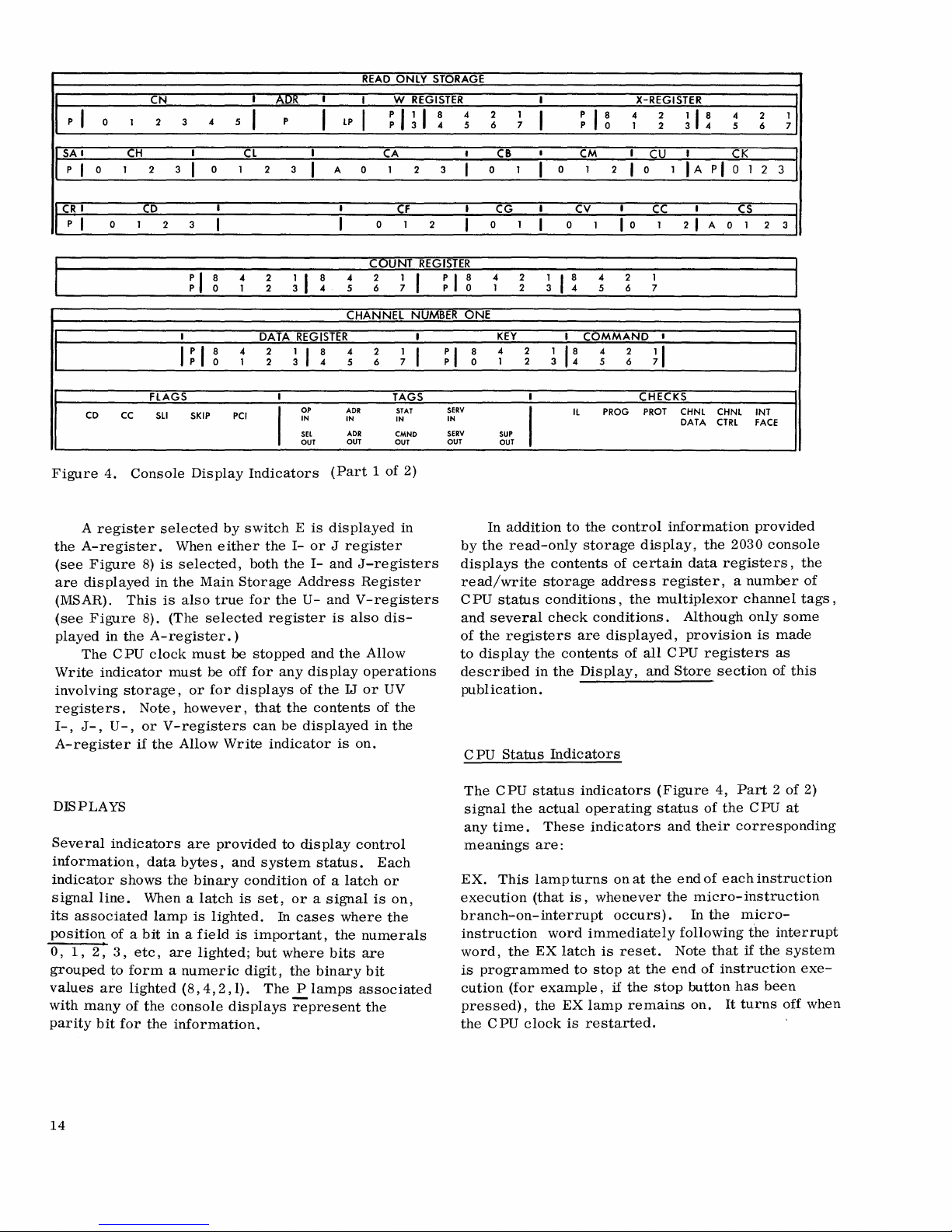
Displays
........................
14
Use
Meters
.....................
18
SYSTEM
OPERATIONS
.................
19
System
Power-On
and
Power-Off
.......
19
Program
Load
Routine
. . . . . . . . . . . . . .
19
Dis
play
Information
From
Storage
. . . . . .
20
Store
Information
into
Storage
. . . . . . . . .
20
Single-Instruction
Processing
.........
24
Single-Cycle,
Display,
and
Store
Operations.
. . . . . . . . . . . . . . . . . . . .
24
Processing a Program
Section.
. . . . . .
25
Starting
at a Specific
Instruction
(Set
IC)
Procedure
..................
25
Manual
Intervention
. . . . . . . . . . . . . . .
27
Microprogram
Test
Routines
.............
27
Basic
Test
......................
27
Display
Read/Write
Storage
...........
27
Alter
Read/Write
Storage
. . . . . . . . . . . .
28
Alter a Block
of
Read/Write
Storage
.....
28
IBM 1052
PRINTER-KEYBOARD
..........
29
IBM 1050
OPERATIONS
....
37
EXTENDED
BINARY
-CODED-DECIMAL
INTERCHANGE
CODE
(EBCDIC)
.........
41
GLOSSARY
OF
TERMS
.................
44
INDEX
............................
46
iii
Page 4
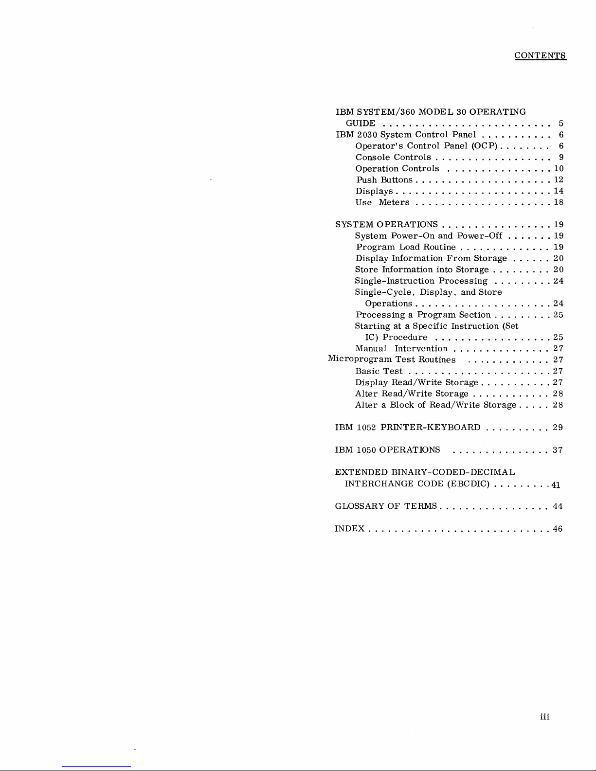
Figure
1.
IBM
System/360
Model
30
with
IBM
1052
Printer
Keyboard
4
Page 5
IBM
SYSTEM/360
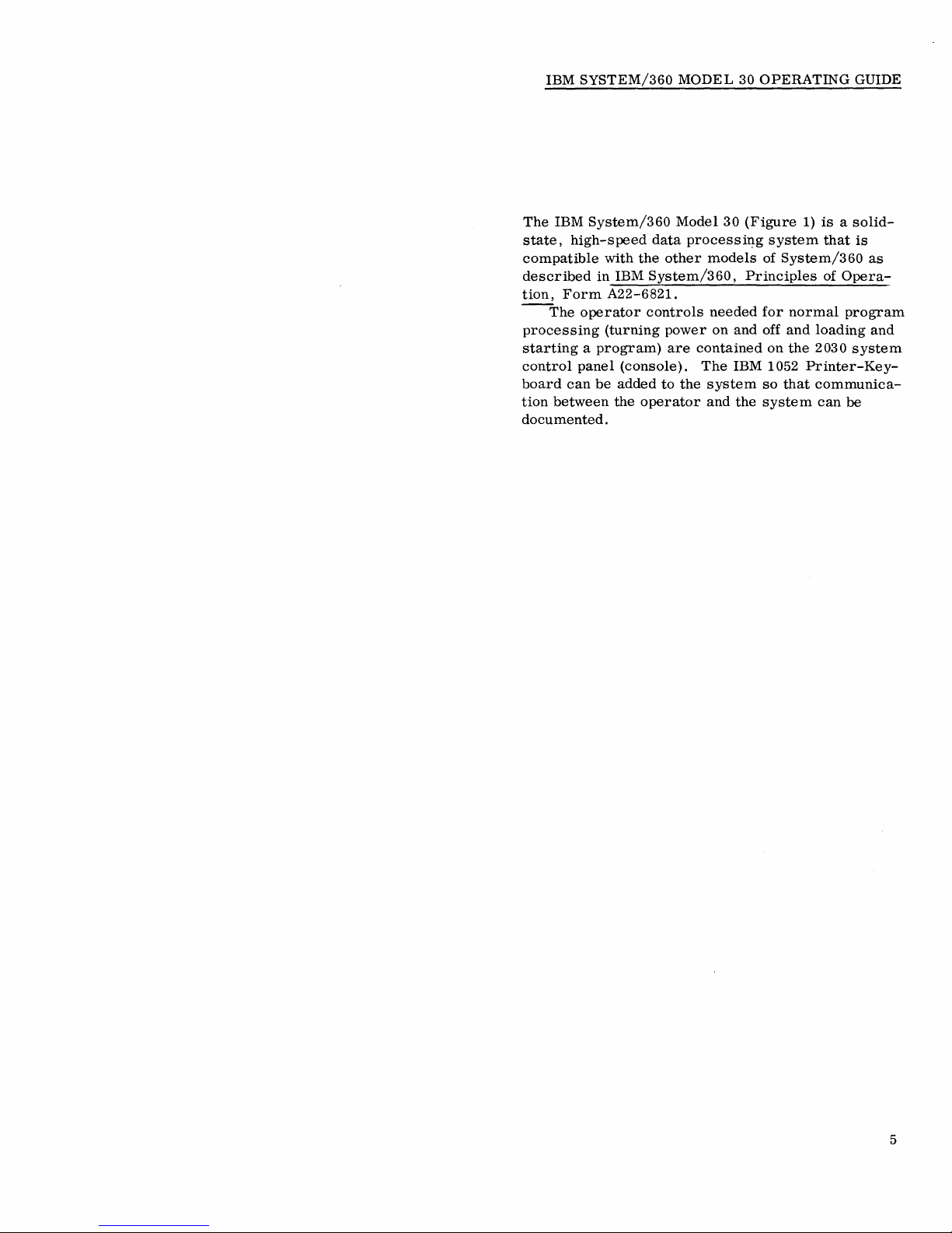
The
IBM
System/360
state,
high-speed
compatible
described
tion,
--The
processing
Form
operator
with
the
in
IBM
A22-6821.
(turning
starting a program)
control
board
tion
panel
can
be
between
(console).
added
the
operator
documented.
MODEL
Model
data
processi~g
other
models
System/360,
controls
power
are
needed
on
contained
The
to
the
system
and
30
OPERATING
30
(Figure
of
Principles
for
and
off
IBM 1052
so
the
system
1)
is a solid-
system
that
System/360
of
normal
and
loading
on
the
2030
Printer-Key-
that
communica-
can
GUIDE
is
as
Opera-
program
and
system
be
5
Page 6
IBM
2030
SYSTEM
The
IBM
2030
with a number
that
permit
modes,
tion.
on a panel
system
neer's
console
Panel
tons,
indicators.
the
panel,
Processing
all
controls
and
These
control
panel.
is
(OC
three
operation
observation
indicators
(Figure
designated
P).
16-position
Except
the
Units)
and
problem-program
CONTROL
Central
of
indicators
2)
console
The
lower
This
section
for
OCP
is
in
indicators
processing.
PANEL
Processing
and
of
the
system
of
the
and
controls
that
serves
and
an
right-hand
as
the
Operator's
contains
rotary
the
nomenclature
identical
System/360.
necessary
Unit
manual
in
results
are
as
both
IBM
Customer
portion
four
switches,
on
all
CPU's
The
for
is
provided
controls
any
of
of
any
assembled
an
operator's
of
Control
push
and
printed
OCP
normal
several
opera-
Engi-
the
but-
six
on
(Central
contains
I/O
devices.
sequence
units.
Note:
The
applying
output
1.
devices:
Press
light
2.
Set
3.
Press
4.
Turn
5.
Set
depends
follo\\ing
or
removing
the
to
come
the
Rate
the
power
the
Rate
The
2030
2030
time
on
the
procedure
Stop
on.
switch
Start
on
or
switch
required
number
electrical
key
to
the
key.
off
on
the
to
the
for a power-on
of
on-line
must
be
power
and
wait
for
Single-Cycle
I/o
unit.
Process
I/O
used
when
to
input/
the
l\lanual
position.
position.
OPERATOR'S
This
section
has
the
following
Power-On
The
I/O
units
reset
not
the
are
reset.
on.
storage
turbed.
and
restored
Key
power-on
starts
function
general-[Xlrpose
as
The
CPU
so
that
Hence,
storage.
The
I/O
If
power
power-on
On
taken
reset.
light
for
cannot
sequencing
remains
that
The
CONTROL
of
the
2030
controls
sequence
when
occurs.
are
any
clock
information
system
without
units
are
be
brought
off)
unit.
po\ver-on
PANEL
console
and
for
this
key
All
data-flow
or
floating-point
priorities
is
reset
in
power
destroying
sequenced
up
is
interrupted
until
corrective
All
on-line
sequence
(OCP)
(lower
indicators:
the
CPU
is
pressed.
that
to
prevent
storage
can
information
ON
for a unit,
I/O
bypasses
right
and
all
registers
happen
access
is
be
turned
one
by
further
(console
action
units
corner)
on-line
A
system
(but
registers)
to
turn
to
not
dis-
off
in
main
one.
Power
is
are
also
off-line
6.
Press
tion.
This
procedure
cycle
in
accessed.
nel
that
removing
contents
If
power
(because
the
line
continue
any
channel
on.
Power-Off
This
key
I/O
units.
altered
if
\!.,Trite
forced
just
during
a
storage-read
indicator
to
read
the
console
ensures
which
read/write
Thus,
might
have
power
of
to
storage.
is
removed
maintenance
terminators
CPU
operations.
must
Key
removes
The
contents
the
is
ensure
are
that
not
Start
key
to
that
the
system
any
electrical
been
the
unit
from
is
must
be
on
as
power
power-off
cycle
has
storage
caused
does
required)
be
The
long
to
of
main
been
is
surge
by
not
the
last
relocated
last
as
the
the
CPU
storage
operation.
taken
on), a manual-\\Tite
the
contents
of
lost.
resume
applying
affect
not
I/O
is
being
on
opera-
in
the
or
the
unit
a
chan-
on a channel.
in
order
I/O
unit
on
system
and
all
are
is
on-line
not
except
(the Allo\\,-
cycle
is
the
location
to
that
6
Page 7

READ
ONLY
ST
RAGE
N
I
....e.J.1!!.
I
I
W
RE
ISTER
I
X-RE
ISTER
• I
0 1 2 3
. 5
I
.
I
LP
I
~
I U
8
·
2 1
I
~ I ~
.
2
~
I :
. 2 1
. 5 6 7
1 2 5
6 7
SA
I H
I I A
I
C8
M I
I
• I
0
1 2
3 I
0 1
2
3
I
A 0 1 2 3
I
0
1
I
0 1 2
I 0
1 I A
pi
0
1 2 3
I
F
I
G
I
V
I
I
:S
• I
0
1 2 3
I
I
0 1
2
I
0
1
I
0 1
10
1
21
A
0
1
2
3
R
I R
n
~
I
I
~ I ~
~
I :
HANN
NUMBER
:JNE
AA
I K Y
MMA
I ~ I
~
; I
1
I
~
I
8
~
I:
~
I
7
0
FLA
S
TA
S
HE
KS
CC
SlI
SKIP
PCI
0'
IN
&TAY
stlV
I
.ROG
.ROT
CHNl
CHNl
INT
DATA
(TRl
FACE
'"
AD.
CMHD
~UV
'U'
OUT
OUT
OUT
OUT
OUT
NIJMBER
TW
DATA
REGISTER
I
KEY
I
COMMAND
~ I ~
~
I :
~
I
: I
~
~
I
~
I
FLAGS
TAGS
CHECKS
SKIP
0'
AD,
STAT
SfRV
I
PROG
PROT
CHNl
CHNL
INT
IN
DATA
(TRl
fACE
'"
AD'
CMNO
IUV
SU'
OUT OUT
OUT
OUT
OUT
MPX
HAN~L
TA~
MPX
HANNEL
BUS
-
Ol
REGI
TER
0'
AD.
STAT
SUV
'"
CMNO
IUV
SU,
1
8
IN IN
OUT
OUT
OUI
OUT
OUT
3.
.
MAIN2T
RAGE
ADDRESS
RE(
ISTER
I
MAIN
~
I
1
: I
~
~
I
8
I
STOR
: I
~
1
AUX
7
. 7
STOR
MAIN
S ORAY!'
DATA
REGISk.R
I
ALU
UTPUT
PU
STATUS
PU
CHECKS
.18
11
I
18
118
EX
MATCH
~l~~~
STOR STOR
. 2 8 . 2 1
. 2
·
2 1
AoR
DATA
8-REGISTER I
A-REGISTER
1050
1050 B A
ALU
INTV
REQ
REG
REG
~ I ~
. 2
;1
:
.
2 1
I
.
I
~
. 2
;
I:
·
2 1
M.X
SEL
COM.
ROS ROS
(TRL
1
2
5 6 7 .
1 2 5 6 7
CHNL
CHNl
MOOE
AoR
SAl$
REG
D
§
SyStEM
INTTM~
ReSET
COMPARE ADDRESS
ROAR
C:U
B
RESET
IC
D
CHECK
~
RESET
TEST
B B
IOIS.LAyl
ROS
CONTROL
INHI81T
PROCESS
ROS
ifop
\ I /
SCAN
ADDRESS
COMPARE
ROAR
SYNC
---\...ROC
1
ESr~~~'pELAYEO
ROARSTOP~
~SARSTOP
EARLY
--:JI,\,,--SAR
RESTART
ROAR5TOP
~
~~~~~T~~~ET
R:fr~~T
R~t~RR:;:::~
I
POWER
I
ON
o
CHECK CONTROL
DISABLE
PROCESS
STOP
oIAGNO:=S
I!=START
I
POWER
I
0"
I NSTRUCTION
ADD
ESS
- R05
ADDRESS
00000
B
Page 8
I/O
interruption
Power-Off
I/O
interruptions
tion.
The
Power-Off
Power-On
The
recommended
1.
Press
Manual
attached
enter
2.
Press
Emergency
The
Emergency
electrical
units)
with
of
storage
As
the
name
should
be
be
used
manually
The
system
switches.
environment
power.
system
Contact
power
Key
key.
the
light
I/O
the
manual
the
Pull
power
no
regard
may
implies,
reset
If
the
is
cannot
conditions
is
operated.
are
lost
key
power-off
console
to
come
units
Stop
do
state.
Power-Off
Switch
Pull
Switch
(including
to
be
altered
the
only
if
necessary.
by
the
is
protected
temperature
too
high,
the
Customer
be
are
reset
Therefore,
during a power-off
takes
precedence
procedure
key
and
wait
on.
(The
Stop
not
cause
the
)
key.
removes
power
to
all
sequencing.
if
this
switch
Emergency
This
Customer
by
these
thermal
of
the
switches
Engineer.
operating
Engineer
maintained.
when
any
over
for
keys
system
all
primary
on-line
The
is
Pull
switch
overload
drop
whenever
the
pending
opera-
the
is:
the
on
to
I/O
contents
operated.
Switch
must
system
the
Test
Indicator
The
Test
Check
set
to
Load
Indicator
This
indicator
and
released.
program
PSW
is
Load
Key
This
key
10\ving
1.
An
2.
The
3.
The
This
4.
The
all
storage.
light
Control,
Process
is
successfully
set
into
is
used
functions
automatic
CPU
basic
test
clear
the
flag
is
on
ROS
(normal
turns
It
remains
circuitry).
to
initialize
occur:
System
clock
is
test
microprogram
is
looped
UCW
bytes
whenever
Control,
the
or
processing
on
when
the
on
until
completed
See
the
Reset
started.
128
times.
microprogram
in
the
UCW
Address
Rate
switch
position).
Load
the
load
(the
the
Load
system.
is
performed.
is
performed.
is
run
area
Compare,
is
key
is
pressed
micro-
initial-load
Key
The
to
reset
of
auxiliary
not
section.
f01-
System
This
indicator
the
use
section.
Manual
This
light
and
that
as
the
console
is
on.
\Vait
Indicator
When
this
no
instruction
occurs,
program.
(SYS)
meters
)
(MAN)
indicates
no
channel
System
controls
light
processing
Indicator
is
normally
is
running.
Indicator
that
operation
light
is
off).
are
effective
is
on,
the
processing
is
initiated
on
(See
the
CPU
Several
CPU
occurs.
whenever
the
clock
is
in
progress
of
only
when
clock
If
as
required
either
Use
Meters
is
stopped
the
manual
this
is
running
an
interruption
by
of
(as
lamp
the
long
but
5.
The
analyzes
address
(load-unit
pleted,
been
turned
Note
that
key
is
pressed.
is
then
Interrupt
When
this
the
external
external
nizes
this
Switches
These
rotary
operator
load
microprogram
switches
of
address).
the
successfully
off.
the
system
effective
Key
key
is
old
interruption
interruption
F,
G, H,
switches
for
the
G,
the
program-loading
Initial
Program
set
mask
The
system
as
soon
as
pressed,
PSW
is
altered
is
pending.
only
and
J
are
following
is
begun.
H,
and J to
\Vhen
this
Load
up,
and
the
is
reset
mask
the
IPL
the
interruption
to
indicate
The
if
programmed
normally
operations:
This
determine
I/O
routine
(IPL)
Load
when
in
the
PSW
system
used
routine
device
is
PSW
light
the
load
IPL
is
set
code
that
to
by
the
the
com-
has
is
PSW
up.
of
an
recog-
do
so.
8
Page 9
1.
Manual
a ROS
2.
Manual
and
3.
Manual
storage
~
described
Switch F is
tions
(see
Feature,
particular
tions
(see
bility
Feature,
address
J).
The
functions
in
also
IBM
Form
significance
IBM
alteration
(F,
entry
of
entry
of a
or
into a data-flow
detail
in
used
System/360
A24-3255).
System/360
Form
CONSOLE CONTROLS
The
manual
operator
seyeral
controls
to
initiate
modes,
and
system
to
operations.
Note:
Storage
main-storage
initiated
to
ensure
from
that
Protection
alteration
the
console.
useful
altered.
Data
and
Address
Eight
rotary
entering
of
data
these
sixteen-position
hexadecimal
A,
B,
C,
and D are
manual
age,
switches
register
Switches
operations
or
to
are
and
F,
instruction
address,
These
system
or
four
through
These
set
address,
switches
switches
Entry
switches
or
addresses
digit
(four
used
involving
up a compare
connected
to
the
compare
G, H,
and J are
enter
manual
the A-and
are
of
an
G,
H,
the
load-unit
byte
of
of
these
other
sections
for
1400
Model
for
1620
Model
A24-3365).
on
the
2030
operation
perform
is
or
display
Care
data
is
Swit
are
provided
into
switches
bits
plus
to
enter
address.
to
the
(match)
a ROS
address, a load-unit
data
are
connected
B-registers.
normally
instruction
and
information
register
four
compatibility
address
J).
address
switches
of
this
1400
Compatibility
(G,
into
(H
and
are
manual.
opera-
or
H,
main
J).
Switches F and G have
compatibility
30,
console
display
not
effective
1620
in
permit
any
and
during
opera-
Compati-
the
of
store
operations
must
be
exercised
not
unintentionally
ches
for
manually
the
system.
provides
parity).
an
address
main
or
auxiliary
main-storage
Switches
These
Each
one
for
stor-
four
address
circuits.
used
to
set
up
an
into
the
system.
to
the
data-flow
used
as
follows:
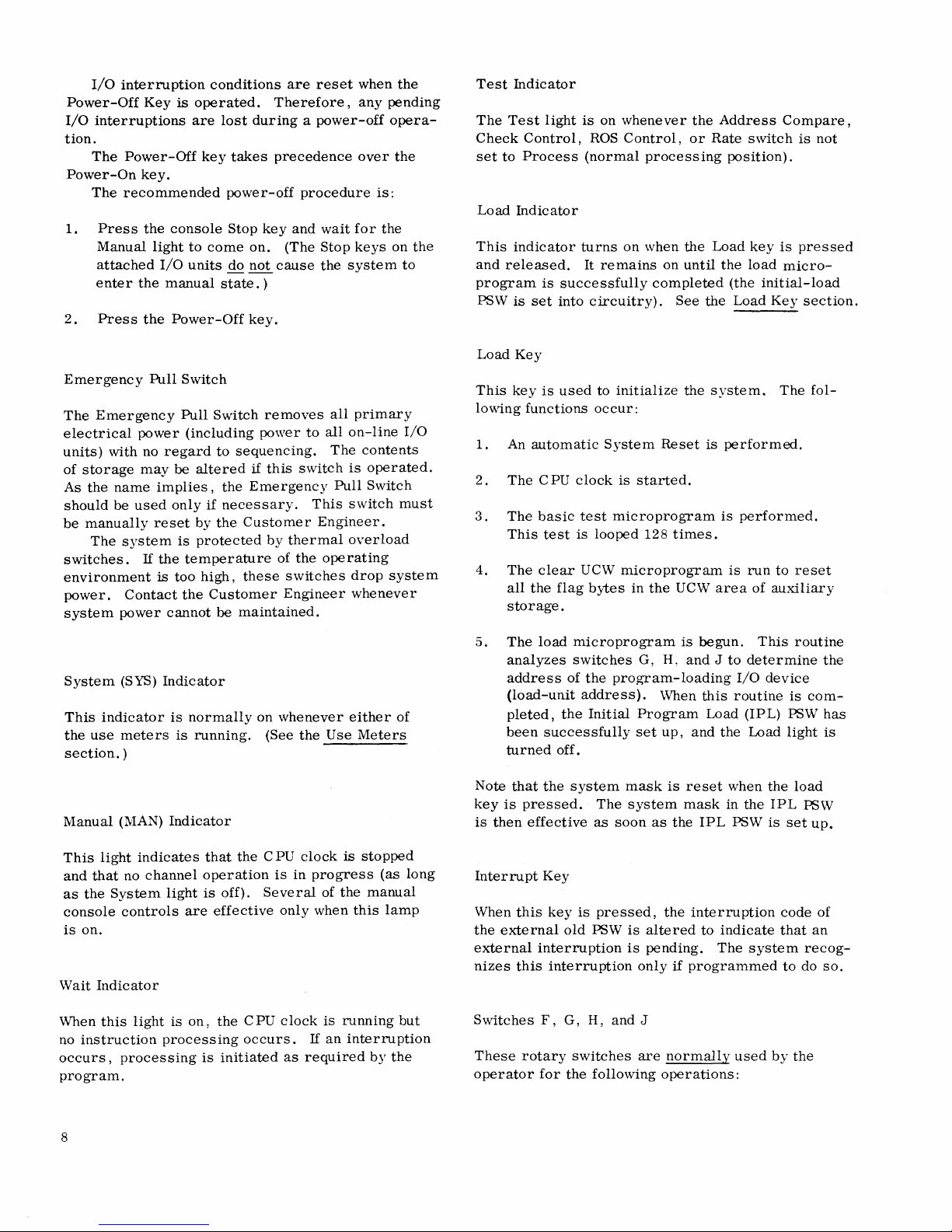
Switch
A,B,C,D
A,B,C,D
F,G,H,J
G,H,J
H,J
The
specific
switches
are
detailed
publication.
Switches F and G also
the
1400
and
1620
Display-Storage
This
control
from
(or
do
not
addition,
into
any
The
dual-concentric
to
access
shown
Use
described
can
store
have
full-time
proviSion
main-storage
the
registers
on
the
dial
of
the
Storage-Display
in
the
into
section.
~s
MS
\ I
~
~
0
v"
0
/I
5
')
Figure
3.
Display-Storage
Function
A
stop
or
matched
the
Main
(MSDR)
ter
(WX),
A
main-storage
store
or
An
instruction-Start
ROS-Start
operation.
The
load-unit
and
channel
the
program
A
data
byte
or
auxiliary
data-flow
functions
in
various
compatibility
Selection
be
used
to
certain)
indicators
is
made
or
auxiliary-storage
rotary
and
(Figure
Display
"'TI
-i
~
~
3).
and
restart
against
Storage
or
the
display
address
address
address
is
to
be
storage,
register.
provided
sections
have
functions
features.
Dial
display
system
on
to
display
switch
system
Selector
Store
Selection
address
the
contents
Data
Register
ROS
address
address
operations.
address
for a manual
(I/O
from
to
be
loaded),
loaded
or
by
these
unique
information
registers
the
console.
from
labeled E is
control
switch
Operations
Switch
to
for
device
which
into
into
eight
of
this
that
or
location.
points
be
of
regis-
manual
or
a
main
a
to
In
store
used
is
9
Page 10
OPERATION
Four
rotary
any
of
several
these
controls
Customer
useful
light
the
Process
Rate
The
control
to
the
is
on
Switch
three
are:
Engineer,
if
modes
Instruction
When
the
Rate
plete
instruction
interruptions)
is
pressed.
the A-and
next
instruction.
identical
is
pressed.
I/O
pleted
is
pressed
next
to
If
an
input/output
instruction
before
instruction
CONTROLS
control
modes
are
normally
programmer
these
four
position.
of
Step
(INSN
switch
(including
is
executed
After
the
B-registers
The
the
stop
and
all
the
final
again
during
is
processed.
switches
of
system
certain
and
switches
operation
STE
P)
is
in
this
each
instruction
contain
stop
that
that
occurs
instruction
associated
stop
occurs.
the
are
provided
operation.
used
only
of
their
operator.
are
provided
Position
position,
all
pending
time
has
the
then
when
is
chaining
chaining
to
by
the
functions
The
not
all
by
this
one
unmasked
the
Start
been
address
occurs
the
Stop
executed,
If
the
start
operation,
allow
Althougb
IBM
are
Test
set
to
com-
key
executed,
of
the
is
key
the
is
com-
key
the
Diagnostic
In
this
under
Disable
When
errors
otherwise
that
certain
is,
automatic
addressing
be
accessed.
problem
Process
This
for
problem-program
check
is
automatically
contents
gram
and
originates a machine
to
the
Form
Position
mode,
control
Position
the
system
are
logged
the
is
program
Position
position
occurs,
of
the
status
IBM
System/360
A22-6821).
system
of a
failure
system
correction
not
of
word
special
is
operated
(in
associated
errors
provided;
Results
in
this
the
Check
the
malfunction
initiated.
machine
in
fixed
control
in
microprogram.
in
is
ignored.
cannot
of
read-only
and
obtained
mode
Control
processing.
trap
This
check
register
main-storage
check
Principles
case
of
an
this
mode,
check
Note,
be
ignored;
circuitry),
however,
storage
the
wrong
while
processing
may
be
wrong.
switch
When a
microprogram
routine
stores
and
locations
interruption
of
Operation,
error
parity
word
is
used
parity
the
(refer
is
but
that
will
a
the
pro-
Process
This
program
Position
position
processing.
Single-Cycle
When
the
Rate
advances
is
pressed.
is
used
Check
The
reaction
I/O
as
follows:
only
for
Control
setting
when
channels.
of
the
Rate
Position
switch
one
ROS
Data
overruns
input/output
Switch
of
this
switch
an
error
Several
switch
is
in
this
cycle
may
operations.
determines
is
detected
courses
is
position,
each
occur
of
used
time
the
in
the
action
the
if
for
the
this
are
normal
system
Start
mode
system
CPU
allowed
or
key
Stop
Position
Detection
of a parity
unconditional
check
masks.
system
Restart
When
system
the
1.
is
Position
an
error
response
Address
With
the
operated
Restart, a System
micro-diagnostic
executed,
address
and
an
instruction
CPU
clock
I/O
data
in
occurs
is
Compare
Address
the
instruction
specified
error
in
stop,
overruns
this
mode.
in
this
dependent
switch
Compare
Reset
and
clear-UCW
by
switches
cycle
this
mode
regardless
may
mode,
upon
as
follows:
switch
is
initiated,
counter
F,
is
started.
occur
the
the
set
routines
is
G,
causes
of
resultant
setting
to
the
set
to
H,
and
an
machineif
the
of
SAR
basic
are
the
J,
10
Page 11
2.
With
Restart
the
floating-point,
address
F,
G, H,
is
initiated
storage,
Compare
3.
\Vith
Restart
that
initiated.
4.
With
position,
H,
an
I-cycle
Address
This
switch
circuit
Address
Address
when
an
is
in
any
read-only
switches
the
main-storage
positions
as
follows:
the
Address
or
circuitry
register
and
depending
the
Address
Without
of ROAR
the
Address
the
and J is
Compare
determines
is
connected
Register
Register
address
position
storage
A,
B,
and
ROAR
registers
or
J,
and
(with
sWitch).
Restart
address
placed
is
started.
Switch
(ROAR)
(SAR) ,
match
that
address
C,
and
address
the
associated
Compare
Restart
UCWs)
is
set
the
or
without
on
switch
Storage
(not
general-purpose,
are
as
specified
resulting
affecting
the
setting
Compare switch
Reset,
operation
except
Compare
that
switch
specified
in
the
instruction
to
whether
the
and
the
Read-Only
or
to
the
the
occurs.
contains
the
register
D;
other
positions
register.
system
set
to
ROAR
Bypass
reset,
the
by
switches
position,
ROS
microprogram
main
of
the
Address
set
to
ROAR
is
identical
no
reset
is
set
to
any
by
switches
F,
counter
CPU
match
Storage
Main-Storage
system! s reaction
\Vhen
the
switch
term
ROAR,
is
compared
The
responses
apply
switch
the
to
are
to
other
G,
and
to
Early
ROAR
With
this
contents
by
switches
the
CPU
ROS
cycle)
cators
to
and
one
and
ROAR
ROAR
ROAR
These
the
D.
at
D.
display
ROS
The
the
Restart
Restart
Restart
three
of a match
B,
C,
and D causes
specified
are
the
general-purpose
or
the
UCW
For
before
the
For
is
identical
to
operate;
essing
In
cannot
the
function
that
no
reset
Stop
setting,
of
the
ROAR
A,
B, C,
clock
is
and
the
the
word-address
ROS
address
Without
Storage
settings
between
by
switches
flag
bytes
ROAR
Restart,
ROAR
ROAR
Restart
except
hence,
be
ROAR
is
the
is
Restart
same
performed.
Position
processing
match
and
turned
off
system
address
word
djsplayed,
specified
Reset,
Bypass
are
a ROAR
the
ROAR
F,
or
reset.
CPU
is
reset.
Storage
that
main
normal
done
in
as
with
proceeds
the
address
D.
When
the
(at
the
end
stops.
of
set
the
in
switches
The
ROS
however,
in
switches
and
Positions
similar
G, H,
in
address
to
be
and
that
and
reset
J.
floating-point
registers
Bypass,
storage
is
problem-program
this
mode.
without
Reset
ROAR
Restart
until
specified
match
of
the
ROAR
word
just
A,
A,
B, C,
the
switches
to
In
no
registers,
are
reset
the
function
not
permitted
position,
except
the
occurs,
current
indi-
prior
B,
C,
is
the
occurrence
A,
the
value
case
proc-
the
Process
This
Position
position
processing.
ROAR SYNC
This
position
Engineering
by
switches
of
the
read-only
register)
ROAR
With
the
fied
occurs,
the
.
Stop
this
setting,
contents
by
switches
the
ROS
cycle
is
used
for
Position
provides a sync
purposes)
A,
B,
when
C,
and D matches
storage
Position
system
of
the
ROAR
A,
B,
C,
CPU
clock
is
in
progress)
normal
pulse
the
address
operation
match
and
D.
turned
and
the
problem-program
(for
Field
address
register
the
off
the
proceeds
address
When
(at
the
system
specified
contents
(WX
until
speci-
this
match
end
stops.
of
SAR
Restart
When a
is
forced
and
clear-UCW
specified
the
instruction
started.
SAR
Stop
When a
C,
and D occurs
stopped
match
SAR
In
A,
occurs.
Delayed
this
mode, a match
B, C,
Position
match
into
occurs
the
routines
by
switches
counter,
Position
match
between
at
the
end
Stop
and D causes
in
ROAR.
F,
the
in
this
of
the
Position
between
this
mode, a fixed
The
are
performed,
G, H,
and
an
SAR
mode,
write
the
CPU
basic
micro-diagnostic
and J is
instruction
and
switches
the
CPU
cycle
in
the
SAR
clock
to
address
the
loaded
cycle
clock
which
and
stop
address
into
is
A,
B,
is
the
switches
at
the
11
Page 12
conclusion
a
match
before
ROS
This
ROS
This
(scan
Inhibit
In
this
fashion
by
the
Process
This
occurs.
the
Control
switch
Scan
Position
mode
ROS
CF
Stop
mode,
except
CF
field)
Position
position
of
execution
clock
Switch
is
is
used
or
read/write
processing
is
PUSH BUTTONS
Several
the
initiate
button
switch
push
operator
system
describes
is
operated.
button
to
All
pending
stops.
primarily
when
Position
that
microprogram
are
ignored.
used
for
switches
perform
functions.
the
resulting
of
the
for
certain
storage)
occurs
normal
manual
The
instruction
interruptions
Field
Engineering
diagnostic
are
run.
in
the
stops
program
are
provided
operations
title
given
function
when
in
which
are
taken
use.
tests
normal
(determined
processing.
to
allow
or
to
to
each
the
restart,
system
altered
Word
ROAR
This
(WX
H,
the
when
Reset
the
not
if
before
Selection
Reset
key
registers)
and
J.
CPU
the
If
the
function
Basic
initiated,
storages
Start
Key
If
the
Start
example,
processing
Machine
If
the
function,
the
Clear
zeros.
located
If
at
processing
Reset
Key
the
same
that
Key
is
used
The
clock
Start
ROAR
Test
that
are
not
key
after
continues
status
Start
the
Basic
UCW
the
Start
address
starts.
sections.
current
mask
restart
section).
to
manually
from
ROAR
is
stopped;
key
is
Reset
but
before
and
Clear
is,
reset
is
pressed
the
Stop
is
unaffected.
key
is
Test
routine
key
0000
(See
)
system
in
local
(see
the
contents
Reset
its
pressed.
key
is
the
UCW
the
UCW
to
zeros.
after a normal
key
as
if
no
pressed
routine
resets
is
operated
is
loaded
Start
mask
storage
Current
alter
key
of
is
the
active
Program
switches
function
pressed
Start
Key
microprograms
flag
bytes
is
pressed),
stop
had
after a Start
is
performed,
all
UC\V
again,
into
Reset
Key
controls
has
not
been
Status
ROAR
address
F,
only
when
is
initiated
after a System
is
pressed,
are
in
the
MPX
stop
(for
instruction
occurred.
Reset
and
flag
bytes
the
PSW
circuitry,
and
ROAR
the
G,
to
and
Power-On
Power-Off
Emergency
These
controls
Control
System
Panel
Reset
Pressing
ters
(except
registers
and
all
I/o
the
I/O
units).
pressed
the
after
Basic
initiated.
times,
during
so
this
Also,
the
current
12
Key,
Key,
Pull
are
section.
Key
this
key
the
in
local
units
In
operation
Test
and
(The
Basic
disregard
time.)
when
the
system
and
Switch
discussed
resets
the
CPU
general-purpose
storage),
(including
addition,
UCW
the
See
System
mask
of
Reset
Test
various
the
the
all
when
the
routine
ROAR
Reset
is
reset.
in
the
Operator's
clock,
and
controls
sense
the
System
all
floating-point
in
and
status
Start
Reset
microprograms
is
looped
error
indicators
Reset
Key
key
is
operated,
However,
regis-
the
CPU,
key
is
key,
128
section.
upon
for
are
Set
IC
Key
This
key
Counter
F,
G,
H,
clock
is
IC
key
is
is
displayed
system
are
stops.
completed
Processing
when
the
If
the
function,
entered
Check
This
The
clock
from
Reset
key
Check
running
is
used
(IC)
address
and
J,
stopped
pressed,
in
begins
Start
Set
IC
the
instruction
switches
Key
resets
Reset
or
to
manually
from
and
is
(Manual
the
altered
the B-and
Any
outstanding
before
key
key
this
at
the
is
pressed.
is
pressed
F,
all
machine-check
key
may
stopped).
alter
the
contents
active
light
only
is
instruction
A-registers,
channel
microprogram
new
instruction
after a System
counter
G,
H,
be
used
the
when
on).
is
and
logic
at
set
Instruction
of
switches
the
When
address
and
the
share
stop 0 ccurs.
address
to
the
J.
circuits.
any
time
CPU
the
Set
cycles
Reset
address
(C
PU
Page 13
Stop
Key
When
this
stopped
1.
state
The
pleted,
2.
All
pending
and
3.
Any
I/O
If
data
completed
System
the
until
light
1050)
device-end
in a chain
Note
that
stroyed
and
restarted
address
B-
of
and
A-registers.
When
multiplexor
request
selector
This
system
traps
channel
provision
operations
progress
Even
data
can
be
cycle
is
being
manual
store
However,
operated,
store
key
cycle,
It
(in
can
Interval
When
this
to
is
storage
the
is
advisable,
which
be
verified.
the
switch
generate
off,
the
timer
Timer
key
is
when:
instruction
interruptions
operation
or
command
before
stays
is
engaged
is
for
that
the
machine
the
program
(by
operation
the
next
the
system
channel
(microprogram
is
permits
has
been
though
these
stored
used
and
if
the
Store
the
data
is
operated
data
to
therefore,
data
is
manually
Switch
Interval
is
on,
program
interval
locations
pressed,
being
in
the
processed
progress
chaining
the
CPU
clock
on
as
long
in
an
I/O
accepted
I/O
device).
environment
that
of
the
instruction
is
in
the
is
allowed
allowed
input-terminal
even
though
manually
operations
or
displayed.
for a channel
display
is
be
circuits
or
Dis
stored
only
during a channel-operation
manually
to
stored)
(INT
Timer
the
feature
interval
interruptions.
timer
is
ignored
are
system
have
been
has
is
involved,
is
stopped.
as
any
operation;
for
the
last
was
in
progress
Start
key).
is
displayed
stopped
to
accept
branches),
to
accept
the
2030
interrupted.
are
At
operation,
are
play
key
or
displayed.
stored
display
so
TMR)
is
installed
timer
and
not
changed.
enters
has
serviced,
been
I/O
unit
command
is
state,
share-
data
and
program
in
progress,
the
instant
inactive.
is
held
is
not
any
that
is
allowed
If
the
the
the
been
com-
finished.
it
The
(except
that
is
not
de-
can
The
in
the
the
and
the
cycles.
multi-
the
If
the
stored.
location
storing
and
switch
main-
is
a
be
in
Store
Key
This
key
by
switches
selected
E).
If a
byte
is
both
the B-and
stored
See
the
When
(AS)
is
D
specify
stored.
displayed
The
operation.
accessed,
Lamp
Test
Pressing
2030
console
system
program
will
be
Display
The
function
Store
key,
altered.
ters
that
can
be
displayed.
Main-storage
locations
storage
D
to
the
The
Main
display
If
the
original
when
the
the
MSDR
If
the
ROS
Check
the
(Stop
the
the
Control
system
key
contents
Start
causes
Hand J to
by
the
register
entered
in
all
the
Store
main
selected
the
The
data
in
both
CPU
clock
If
main
the
Key
this
key
to
operation
execution
slightly
Key
of
except
The
Display
do
not
are
displayed
area
deSired,
address
Storage
the
contents
value
program
can
be
control,
is
allowed
was
pressed
of
key
is
the
hexadecimal
Display
is
selected
into
that
A-registers.
registers
and
Display
storage
by
switch
address
into
byte
the B-and
must
or
auxiliary
Allow
Write
causes
turn
on.
and
can
if
desired.
dimmer
this
key
that
the
key
have
their
(MS)
and
and
of
the
Data
of
the
in
the
is
restarted,
restored
Rate,
switches
to
and
the M SDR
pressed
be
entered
Storage
by
switch
Selection
register
Information
selectable
Section.
(MS)
or
auxiliary
E,
switches
which
(from
switches
A-registers.
be
stopped
storage
light
must
all
indicator
This
test
be
performed
(The
than
during
is
similar
accessed
is
provided
own
console
auxiliary-storage
by
setting
switches
location
Register
to
(MSDR)
accessed
MSDR
will
record
after
the
Address
are
all
set
come
to a normal
the
manual
need
not
to
resume
byte
specified
into
the
area
dial
E,
the
and
displayed
by
switch
storage
A,
B,
the
data
byte
Hand
for
the
store
is
being
be
off.
lights
does
not
during
console
normal
to
that
of
location.
so
that
indicators
switch E to
A,
B,
C,
be
displayed.
is
used
storage
be
needed
this
display
Compare,
to
Process,
stop
light
be
restored
program
(switch
data
in
cannot
be
E.
C,
and
is
J)
is
on
the
affect
lamps
operation.
the
is
not
regis-
(AS)
the
and
to
location.
value
so
operation.
and
and
is
on),
before
operation.
)
13
Page 14
II
P I
II
ILSA
I
1 P I 0
0
1
CN
1 2 3
CH
2
4
I
0 1 2 3
3 I
f
5 I
Cl
AQR
P
READ
ONLY STORAGE
I
LP
I
I
A
I
I
I
0
W
REGISTER
~ I ~
I
CA
1 2 3
4 2 1
8
4 5 6
I
I
I
7
CB
1
0
I
I
0 1 2
I
~
CM
X-REGISTER
8 4 2
I
0 1 2 3 4
I
CU
1 I A
I 0
2 3
I
i 1
1
I
1
5 6
I
CK
o 1
pi
4 2
I 8
I
CR
I
I P I
I
'I
CD
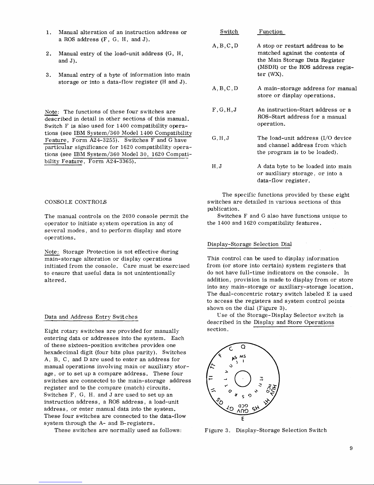
Figure
the
(see
are
(MSAR).
(see
played
Write
involving
registers.
I-,
A-register
4.
register
A
A-register.
Figure
displayed
Figure
in
The
indicator
J-,
0 1
CC
Console
This
the
CPU
storage,
Note,
U-,
if
CD
2
3
I
I
~
flAGS
SLI
SKIP
Display
selected
When
8)
is
selected,
in
the
is
also
8).
(The
A-register.
clock
must
must
or
however,
or
V-registers
the
Allow
I
I
4
2
2
1
DATA
8 4 2
0 1 2 4
I
I
PCI
I
Indicators
by
switch E is
either
the I-or J register
both
the I-and
Main
Storage
true
for
the U-and
selected
be off
for
)
be
stopped
for
displays
that
can
Write
register
any
the
be
indicator
REGISTER
8
~
I
OP
IN
set
OUT
(Part 1 of
displayed
Address
is
and
dis
play
of
the
contents
displayed
I
0
I
C
UNT
4
2 1 I P I 8
6 7 P 0
5
CHANNEL
4 2 1
6
5
ADR
IN
ADR
OUT
J-registers
Register
V-registers
also
dis-
the
Allow
operations
IJ
or
UV
of
in
is
on.
CF
1
NUMBER
7
TAGS
STAT
IN
CMND
OUT
2)
in
the
the
2
REGISTER
I
~
I
I
SfRV
IN
SERV
OUT
I
CG
1
0
I
4
2
2
1
ONE
KEY
4 2 1
8
1 2
0
SUP
OUT
In
addition
by
the
read-only
displays
the
read/write
CPU
status
and
several
of
the
registers
to
display
described
publication.
CPU
Status
I
0
I
8
1
4
3
I
3
I!
I
IL
I
to
contents
storage
conditions,
check
the
contents
in
the
Indicators
I
CV
1
I 0
4
5 2 6
COMMAND
4
5
PROG
the
control
storage
of
address
conditions.
are
displayed,
Display,
I
CC
1
2
I A
1
7
I
2
6
i I
CHECKS
PROT
CHNL
DATA
information
display,
certain
the
data
register, a number
the
multiplexor
Although
provision
of
all
CPU
registers
and
Store
CS
o 1
CHNl
INT
CTRL
FACE
provided
2030
registers,
channel
only
is
section
I
2
3 I
I
I
console
some
made
as
of
this
the
of
tags,
DISPLAYS
Several
information,
indicator
signal
its
position
0,
grouped
values
with
parity
indicators
shows
line.
associated
of a
1,
2;
3,
to
are
many
of
bit
for
are
provided
data
bytes,
the
binary
When a latch
lamp
is
lighted.
bit
in a field
etc,
are
lighted;
form a numeric
lighted
(8,4,2,1).
the
console
the
information.
and
system
condition
is
set,
is
important,
but
digit,
The P lamps
displays
to
display
status.
of a latch
or a signal
In
cases
where
the
binary
represent
14
control
where
the
bits
Each
or
is
on,
the
numerals
are
bit
associated
the
The
CPU
status
signal
any
meanings
EX.
execution
the
time.
This
actual
These
are:
lampturns
(that
is,
branch-on-interrupt
instruction
word,
is
programmed
cution
pressed),
the
CPU
the
(for
clock
word
EX
latch
to
example,
the
EX
is
indicators
operating
indicators
on
at
whenever
occurs).
immediately
is
reset.
stop
at
if
the
lamp
remains
restarted.
(Figure
status
and
the
the
the
end
stop
4,
of
the
their
end
of
each
micro-
In
the
following
Note
that
of
instruction
button
on.
It
Part 2 of
CPU
2)
at
corresponding
instruction
instruction
micro-
the
interrupt
if
the
system
exe-
has
been
turns
off
when
Page 15
I
P
P
P
P
P
CD CC
OP
IN
I
~
MAIN
I 8
I
~
I
I
flAGS
Sli
SKIP
MPX
ADR
STAT
IN IN
2
4
1 2
STORAGE
4 2
B-REGISTER I
4 2
2
1
CHANNEl
SERV
IN
8 4 2 1
~
I
4
5
DATA
REGISTER
8
I 8
4 2
4 2
5
d
1
3 4
SEl
OUT
P
P
PCI
DATA
4 2
8
I
1
0
I
OP
IN
SEL
I
OUT
TAGS
ADR
OUT
7
6
I
I AlU
1
I
1
7
6
I
CHANNEL
REGISTER
, 8
1
3 4
2
ADR
IN
ADR
OUT
SERV
CMND
OUT
OUT
MAIN STORAGE ADDRESS
P
P
P
P 0
I
~
I 8
8
I
4
1
4 2
4
1
NUMBER
4 2
5 6
TAGS
STAT
IN IN
CMND
OUT
SUP
OUT
2
; I
2
OUTPUT
1
A-REGISTER
2
1
3 4
2
I
I
18
18
I
~
I
SERV
SERV
OUT
8
4
TWO
P I 8
P 0 1
REGISTER
4 2
6 7
5
4
2 1
4
2
5
6
KEY
4
I
SUP
OUT
I
MPX
(~HANNEL
P 8
P 0 1
1
I
1
7
I COMMAND I
1
2
2
4 2
MAIN
STOR
AUX
STOR
3 4
EX
1050
INTV
MPX
CHNL
I
IL
2
CPU
8 4 2 1
PROG
BUS
1
3
STATUS
MATCH
SEL
CHNL
CHECKS
PROT
RECiISTER
1050
REQ
COMP
MODE
7
CHNL CHNL
DATA
6 7
STOR
ADR
B A
REG
ROS ROS
ADR SALS
5 6
- OUT
8 4 2 1
4 5
~~~~
I
INT
FACE
CTRL
CPU CHECKS
STOR
DATA
REG
ALU
CTRL
REG
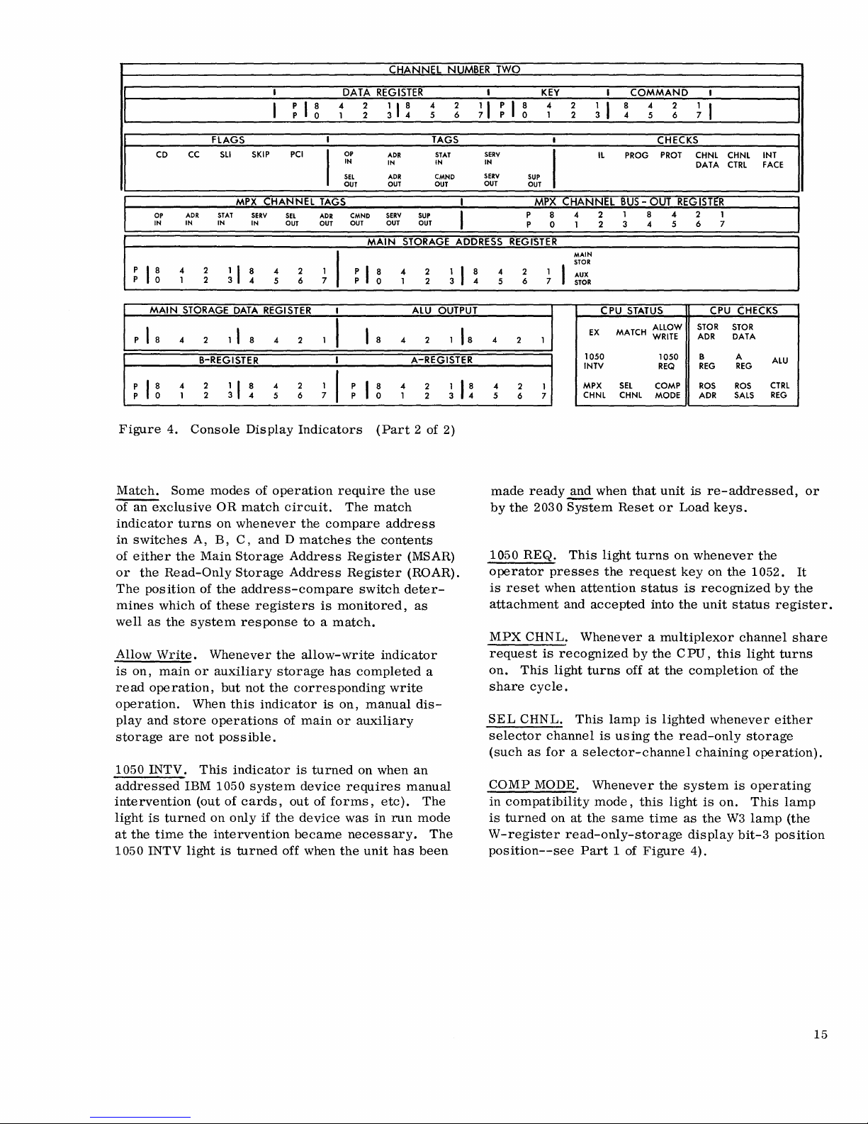
Figure
Match.
of
an
exclusive
4.
Some
indicator
in
switches
of
either
the
or
the
Read-Only
The
position
mines
well
Allow
is
read
which
as
the
Write.
on,
main
operation,
operation.
play
and
store
storage
are
1050 INTV.
addressed
intervention
light
is
turned
at
the
time
1050 INTV
Console
modes
OR
turns
on
A,
B,
Main
of
the
of
these
system
Whenever
or
auxiliary
but
When
operations
not
possible.
This
IBM 1050
(out
of
on
the
intervention
light
is
Display
of
match
whenever
C,
Storage
Storage
Indicators
operation
circuit.
the
and D matches
Address
Address
address-compare
registers
res
panse
to a match.
the
allow-write
storage
not
the
corresponding
this
indicator
of
main
indicator
system
cards,
only
if
the
is
device
out
device
became
turned
off
when
require
compare
is
monitored,
has
is
on,
or
turned
of
forms,
the
(Part
the
The
match
address
the
contents
Register
Register
switch
indicator
completed
write
manual
auxiliary
on
when
requires
etc).
was
in
run
necessary.
unit
has
2 of 2)
use
(MSAR)
(ROAR).
deter-
as
a
dis-
an
manual
The
mode
The
been
made
ready
by
the
2030
1050
REQ.
operator
is
reset
presses
when
attachment
MPX
CHNL.
request
on.
share
SEL
selector
(such
CaMP
in
is
is
This
light
cycle.
CHNL.
channel
as
for a selector-channel
MODE.
compatibility
turned
on
W-register
position--see
~
when
that
unit
System
This
and
Reset
light
the
attention
accepted
or
turns
request
status
into
on
Whenever a multiplexor
recognized
turns
This
at
the
by
off
lamp
is
using
Whenever
mode,
this
same
the
at
is
lighted
the
the
time
CPU,
the
light
read-only-storage
Part
1 of
Figure
is
re-addressed,
Load
keys.
whenever
key
on
the
is
recognized
the
unit
this
completion
whenever
read-only
chaining
system
is
on.
as
the
W3
display
4).
the
1052.
status
channel
light
of
storage
operation).
is
operating
This
lamp
bit-3
or
It
by
the
register.
share
turns
the
either
lamp
(the
position
15
Page 16

CPU
Check
In
the
central
circuits.
latch
check
Whenever a check
is
set.
(MC)
MC
Register
Position
0
1
2
3
4
5
6
7
Except
any
of
parity
duplicate
use
the
operation
these
in
the
check
parity
is
for
complemented
When
the
CPU
sing
with
anyone
call
the
Customer
Registers
Indicators
processing
and a bit
register,
the
ALU
lights
is
associated
is
made
bit
(input
performed
form,
stops
or
Engineer.
unit
is
turned
as
follows:
Indication
A-REG
B-REG
STaR
CTRL
ROS SALS
Storage
Latches)
ROS ADR
STaR
ALU
check,
an
indication
register.
because
is
complemented
in
both
and
the
during
more
of
are
several
is
detected, a check
on
in
the
ADR
REG
(Read-Only
Sense
Amplifier
DATA
the
turning
of
detected
In
the
the
ALU
uncomplemented
answers
normal
these
are
program
indicators
check
machine-
on
of
bad
ALU,
does
and
a
not
the
and
compared).
proces-
on,
Main-Storage
For
CPU
or
indicators
or
from
either
MSDR
display
display
depending
These
output
MAIN
When
lamps)
being
AUX
When
MSAR
address
ALU
indicators,
of
For
manual
the
Output
indicators
of
the
STaR
on,
indicates
displayed
STaR
on,
lamps)
is
the
upon
this
this
Data
Register
multiplexor-channel
dis
play
information
main
or
auxiliary
therefore,
contents
of
the
operations,
data
byte
being
the
setting
Display
provide
full-time
arithmetic-logic
Indicator
light
(located
that a main-storage
by
the
MSAR
Indicator
light
(located
indicates
being
displayed
that
(MSDR)
operations,
being
transferred
storage.
provide
R-register.
the
MSDR
stored,
of
2030
displayed,
console
dis
unit
(ALU).
to
the
right
lights.
to
the
right
an
auxiliary-storage
by
the
MSAR
Display
full-time
indicators
switches.
play
of
the
address
of
the
lights.
The
of
these
to
etc.,
the
MSAR
is
The
following
on
the
2030
portions
The
here
because
registers.
B-
and
These
indicators
contents
During
A-register
switches
When
processing
an
interruption)
dition
(such
instruction
(I-register
contents).
16
registers
console
of
the
console,
ALU
Output
of
A-Register
of
the B-and
manual
depends
(see
the
the
system
stopped
or
as
when
counter
contents)
(left
is
its
relationship
Displays
provide
A-registers.
operations,
on
the
Display
is
and
when
the
(IC)
and
have
full-time
center
Figure
and
3).
not a register
with
full-time
the
settings
Key
section).
in
the
Wait
the
program
in
the
process-stop
Stop
key
is
is
displayed
the
A-register
indicators
upper
but
the
display
display
of
console
state
is
waiting
pressed),
in
the
(J-register
left
is
listed
actual
of
the
from
the
(instruction
for
con-
the
B-register
Main
Storage
When
the
processing
address
of
During
dis
played
several
the
(switch
internal
setting
E)
When
order
hexadecimal
the
MSAR
is
addressed
MPX
storages).
Note
the
process-stop
instruction
is
displayed
tion
code
Address
MAIN
operations
the
manual
in
the
of
the
and/or
the
AUX
specify
(that
that
when
to
be
in
is
not
Register
STaR
indicator
these
main-storage
operations,
MSAR
lights
system
registers,
Display
rotary
STaR
which
is,
digit
the
switches
indicator
(four
part
local
system
condition,
executed
the B-and
displayed.
(MSAR)
is
on
lights
location
the
may
apply
Storage
Selection
A,
is
high-order
of
auxiliary
storage
is
in
the
address
(instruction
A-registers.
Display
during
display
being
the
accessed.
information
to
any
depending
dial
B, C,
on,
the
bits)
storage
or
one
of
Wait
state
of
the
counter--IC)
The
normal
of
upon
and
D.
high-
of
the
or
in
next
opera-
Page 17

Multiplexor-Channel
Dis
plays
Selector-Channel
Displays
MPX
Channel
These
sent
to
MPX
These
of
lights
from
the
multiplexor
Channel
lights
various
the
lines.
OP
IN.
The
that
an
I/O
with
the
channel.
ADR IN
that
is
the
on
The
address
bus-in.
transmission
a
control
STAT
that
mation
IN.
the
unit
selected
on
bus-in.
Bus-Out
indicate
Register
the
byte
main-storage
channel.
Tags
provide
display
multiplexor-channel
operational
unit
is
address
of
(Bus-in
network
to
the
The
status
I/O
selected
in
(ADR IN)
the
currently
is
for
CPU.)
in
unit
in
(OP
and
the
information
(STAT IN)
has
of
information
data
register
of
the
I/O
IN)
is
selected
data
placed
(MSDR)
current
status
interface
lamp
indicates
in
communication
light
indicates
I/O
and
control
transfer
light
indicates
status
infor-
being
control
unit
from
Several
channel.
indicators
The
selector-channel
lights
refer
to
The
Count
Number
byte
to
set
Data
Whenever.a
One
count
for
GUV-GCD)
to
HUV-HCD).
Register
lights)
main-storage
by a channel,
of
information
Key
These
storage
associated
lights
(CAW)
provide
with
are
provided
Channel
one;
Number
the
Channel
selector-channel
Register
is
used
(located
selector-channel
or
selector-channel
share
these
lights
provide
being
transferred.
full-time
protection
the
Start
key
I/O
for
One
Number
two.
above
to
observe
one
two
cycle
full-time
display
for
all
instruction.
each
selector
lights
refer
Two
the
Channel
the
current
(switch E set
(switch
is
E
initiated
display
of
the
main-
commands
to
SERV
IN.
that
the
data.
SEL
OUT.
that
the
channel
device
ADR
cates
out
the
CMND
OUT.
that
is
the
CPU
requests
OUT.
indicates
command.
SERV
OUT.
indicates
on
bus-in
SUPP
OUT.
indicates
pressed,
progress,
is
being
unit.
The
Service
selected
various
are
The
being
I/O
select
I/O
polled
service.
The
address
address
data
to
the
that
that
or
that
that
or
effected
information
and
control
control
The
command
the
information
The
service
the
CPU
has
provided
The
suppress
status
command-control
that a malfunction
with
in
unit
out
units
unit.
has
and
regard
(SERV IN)
is
ready
(SEL
OUT)
attached
to
determine
out
(ADR OUT)
is
inform::ttion
)
out
(CMND OUT)
on
bus-out
out
(SERV OUT)
accepted
data
on
out
(SUPP
data
transfers
chaining
(selective)
to
the
light
to
send
light
to
the
whether
on
bus-out.
network
the
information
bus-out.
OUT)
are
selected
indicates
or
receive
indicates
multiplexor
any
light
indi-
(Bus-
from
light
is
a
light
light
sup-
is
in
reset
I/O
Command,
The
four
low-order
are
displayed
by
these
Flags
This
group
of
five
which a channel
command
follows:
CD.
This
light
indicates
CC.
This
light
indicates
SLl.
This
light
(suppress-length
cates
that
the
program
event
of a wrong-length
SKIP.
This
light
information-transfer
read
backward,
PCl.
This
indicates
ruption
the
channel.
that
condition
or
light
(program-control
the
when
bits
of
lights.
indicators
will
record.
specifies
to
storage
sense
channel
the
the
CCW
displays
should
be
chaining
command
not
be
suppression
during a read,
operation.
will
generate
CCW
takes
operation
the
manner
executed,
of
data
addresses.
chaining.
indication)
notified
in
of
interruption)
an
inter-
control
code
in
as
indi-
the
of
17
Page 18

Selector-Channel
The
nine
tag
indicators
perform
indicators
Channel
the
for
Tags
same
the
section).
Selector-Channel
Each
selector
circuits
that
channel
continually
When a malfunction
check
light
is
turned
IL.
If
the
SLI
flag
length
bytes
the
I/O
condition)
in
the
number
unit.
is
assigned
of
bytes
Tags
for
functions
multiplexor
Checks
has a number
monitoF
is
detected,
on.
These
is...!!Qi
on,
turned
storage
requested
each
as
on
selector
the
corresponding
channel
channel
the
checks
this
light
when
the
area
is
or
offered
channel
(see
MPX
of
check
operation.
appropriate
are:
(incorrect
number
not
equal
by
the
of
to
CK.
This
trol
bits
(that
CM,
CU.
tion.
They
or
auxiliary)
or
write
operation.
CN,
CH, C L.
the
next
ROS
LP.
This
the
read-only
temperature
operating
w-
and
X-Register.
address
CS.
machine
of
This
control
field
provides a source
is,
generates
These
two
determine
is
to
participate
These
word.
light
indicates
storage
of
main
range.
the
ROS
word
field
supplies
points.
fields
which
fields
that
unit
storage
These
just
status
of
constants).
control
storage
in a particular
control
the
air
is
low,
or
is
below
indicators
read.
indications
data
storage
area
the
address
pressure
that
the
display
and
con-
opera-
(main
read
of
in
the
optimum
the
to
various
PROG.
the
PROT.
that
of
rent
CHNL
channel
the
channel
main
storage
operation.
Data..
This
This
indicates
error
main
CHNL
in
the
storage
CTRL.
indicates
channel
INT
by
controls
Face.
sequencing
Read-Only
In
general,
Engineering
tion
of
each
CA,
CB, CC,
operation
CD.
This
registers
given
register
destination
light
(program
has
detected a programming
light
(protection
attempted
that
is
protected
This
light
that
the
channel
information
during
This
that a machine
has
The
interface
problems
Storage
these
indicators
use.
ROS
field
CF,
of
the
ALU.
field
selects
to
receive
can
transferred
an
I/O
light
malfunction
occurred.
on
Displays
Therefore,
is
presented
CG,
CV.
one
the
output
be
used
during a single
check)
indicates
check)
to
violate a portion
for
(channel
has
data
detected a parity
operation.
(channel
control
the
are
control
check
I/O
for
interface.
Customer
only a short
here.
These
of
as
ROS
the
of
both
cycle.
fields
several
the
the
error.
indicates
the
cur-
check)
to
or
from
check)
affecting
is
caused
descrip-
control
system
ALU.
source
that
A
and
USE
METERS
The
2030
console
that
measure
and a Customer
a
key
switch
meter
Engineer
he
is
performing
maintenance
cause
the
(determined
ever
the
1.
The
2.
There
3.
A
or
the
holds
CE
CPU
CPU
is
manual
determines
CE
in
by
progress.
either
meter
productive
light
stays
the
1050)
is
until
device-end
in a chain
after
the
The
use
for a minimum
it
is
started.
has
operating
Engineer's
meter
the
key
either
the
CPU,
meter
to
key-switch
clock
is
is
not
in
an
interruption
store
or
The
System
is
running.
activity
on
as
is
engaged
for
that
Stop
key
meter
of
two
direct-reading
time; a customer's
meter.
whether
is
operating.
for
scheduled
he
operate.
running
the
wait
this
switch;
will
setting)
and
state
the
or
set
One
operates
either:
pending,
dis
play
operation
indicator
It
indicates
is
in
progress.
long
as
any
I/o
in
an
I/O
operation
occurs
I/O
is
(customer
400
for
device).
pressed.
milliseconds
the
or
meters
meter
The
position
customer's
The
Customer
and
whenever
unscheduled
the
switch
of
these
when-
or,
or
is
in
is
on
when
that
The
System
unit
(except
(that
last
command
This
can
CE)
operates
each
time
of
to
meters
some
occur
18
Page 19

SYSTEM
OPERATIONS
SYSTEM
Power
system
successfully
line
cannot
Panel
POWER-ON
to
all
power-on
to
the
be
section.
system
sequence.
brought
CPU,
the
completed.
AND
units
up
on
system
See
PROGRAM LOAD ROUTINE
Prepare
to
Systems
mation
Card
When
punched
The
be
loaded
concerning
I/O
the
cards, a card
following
the
I/O
as
follows.
Reference
Unit
Preparation
program
steps
unit
Library
the
to
generally
from
particular
be
loaded
reader
readers:
• Run
•
the
a
nonprocess
ticular
Place
the
cards
out
runout
card
reader.
program-load
of
the
as
hopper.
•
Press
the
The
card
reader
reader
is
start
now
ready
deck.
POWER-OFF
is
brought
If
power
an
I/O
unit
power-on
the
Operator's
which
the
(Refer
to
publication
I/O
is
contained
must
apply
read
feed
described
deck
in
key.
to
read
up
during
cannot
that
sequence
program
the
appropriate
for
unit
be
initialized.
to
all
by
for
the
read-feed
the
a
be
is
on-
Control
is
infor-
involved.)
in
card
performing
the
par-
program
Tape
I/O
Unit
When a magnetic
the
problem
•
Open
reels
•
Place
the
•
Thread
the
•
Wind
well
•
Close
•
Press
The
tape
called
Console
With
the
load
unit
1.
Set
the
H,
channel
address
program:
the
and
the
left
reel
the
take-up
the
past
the
the
unit
on
by
the
Operation
system
set
up:
the
address
program
and.J
(see
address
in
tape
tape
is
Preparation
tape
unit
unit
door
read/write
tape
reel
hub
and
tape
along
reel.
until
the
read/write
access
door.
load-rewind
now
ready
program-load
(Program
power
to
of
be
on
the
loaded
Figure
is
switches
is
being
for
assembly.
containing
lock
it
the
the
load-
head.
key.
to
be
Loading)
and
the
I/O
load
in
2,
OCP
set
in
s'vvitch G;
Hand
used
access
the
in
place.
tape
path
point
used
routine.
appropriate
unit
rotary
section).
J.
to
to
the
program
and
marker
as
input
that
switches
the
load
tape
on
onto
is
when
I/O
contains
G,
The
unit
Disk
I/O
Unit
Preparation
When
the
program
disk
unit:
•
Turn
the
•
allows
Place
the
the
program
drive
start
The
disk
storage
is
on.
is
to
disk-drive
device
disk
pack
on
the
disk
key.
unit
be
meter
to
be
containing
drive
is
ready
loaded
switch
used
and
when
from a magnetic
on.
This
for
input/output.
the
desired
operate
its
the
ready
light
disk-
2.
3.
Make
sure
Compare,
in
the
PROCESS
center
section).
portion
off
only
the
PROCESS
Press
the
2030
console.
OCP
section)
pressed,
has
been
new
PSW
that
and
(see
Figure
when
all
position.
Load
turns
and
it
completed
has
been
the
ROS
Check
position
The
2) of
four
key
on
The
Load
on
turns
(when
completed).
Control,
Control
(see
Test
light
the
of
these
the
OCP
light
when
off
after
the
switches
Figure
20:30
switches
portion
(see
the
Load
the
loading
Rate,
on
the
console
Figure
load
Address
are
2,
right
OC P
are
of
key
routine
of
the
all
is
in
the
2,
is
19
Page 20

A
system
is
pressed.
looped
128
automatically
storages.
the
contents
program
reset
is
initiated
The
Basic
Test
microprogram
times. A microprogram
It
is
loaded;
resets
mayor
of
core
the
may
storage
this
UC\V's
not
into
is
dependent
when
in
be
necessary
which
the
(ROS)
the
multiplexor
the
upon
Load
program.
After
the
will
proceed
loaded
this.
Therefore,
the
program
to
be
taken.
the
wait
operating
action
is
1.
Press
light
2.
Load
F,
using
section
3.
Press
instruction
program
immediately
is
written
determine
If
the
state
after
procedures
to
be
initiated:
the
Stop
on).
Wait
an
instruction
G, H, and J
the
set-IC
of
this
the
start
address
has
unless
in
sue
h a
system
operating
what
system
the
program
may
key
to
enter
for
the
address
into
IC
key
(see
publication).
key
to
loaded.
been
loaded,
the
manner
subsequent
is
programmed
has
indicate
that
stopped
system
from
(Instruction
IC
in
start
processing
processing
program
as
to
prevent
procedures
action
been
the
state
light
to
rotary
Counter)
the
Push
DISPLAY INFORMATION FROM STORAGE
The
contents
when
the
OCP
CPU
Figure
on,
indicates
has
been
cycle
the
status
has
of
any
byte
CPU
clock
is
stopped
is
on)
and
the
Allow-Write
3)
section
is
off.
of 2030
The
Allow-Write
that a read-from-storage
completed
not
been
but
performed.
of
storage
console--Part
that
the
can
(the
Manual
indicator
indicator,
associated
be
operation
key
is
then
to
clear
new
the
and
is
to
go
loaded,
following
(Manual
turn
off.
switches
buttons
at
the
dis
played
light
on
(in
2 of
when
write
to
by
3.
Set
(switch
upon
is
to
portion
4.
Place
switches
Note:
If
set
rotary
the
desired
If
auxiliary
is
then
set
5.
Press
Figure
6.
Make
STOR
storage),
the
display
7.
The
displayed
(Part
address
set
rectly.
The
8.
displayed
indicators
9.
When
stop
the
operator
SINGLE-CYCLE
and
10.
Only when
should
STORE
INFORMATION INTO STORAGE
the
rotary
E)
whether
be
used
of
the
address
A,B,C,
a
byte
switch A to
MPX
is
used,
in
switches
the
2).
sure
(main
is
right
of
(see
address
in
2 of
Figure
desired.
up
rotary
)
data
stored
in
the
system
key
does
turn
on
all
system
display-storage-select
to
the
MS
or
AS
Main
Storage
in
this
operation).
Figure
of
2.)
of
and D
auxiliary
LS
the
(Figure
storage
(for
desired
(multiplexor)
the
address
C and D.
display
that
on
the
key
the
storage)
on.
These
the
main-storage
Part
2 of
of
the
accessed
the
main-storage
3).
(You
switches
in
the
the
main-storage
the
2030
and
not
allow a display
should
to
turn
manual
the
preceding
reset
(lower
appropriate
or
A UX STOR
indicators
Figure
Make
may
A,
addressed
console.
wait
set
the
off
light.
be
performed.
position
or
Auxiliary
(See
byte
2).
is
to
Local
Storage)
storage
of
the
left
section
indicator,
address
3).
location
address
sure
this
inadvertently
B, C,
and D incor-
location
data
lights
are
of
rate
switch
the
system
nine
items
switch
(depending
Storage
lower
in
rotary
be
displayed,
or
position.
desired
of
MAIN
(auxiliary
are
just
register
is
then
register
is
the
have
is
register
on and
storage,
to
light
fail,
to
byte
to
the
Procedure
The
contents
played
that
the
essing
1.
Press
console--Figure
the
pending
2.
After
cator
when
test
is
in
the
current
the
is
of
any
storage
the
following
light
is
progress):
stop
key
instruction
interrupts
system
off
and
the
out
2).
have
stops,
position
procedure
and
normal
(lower
The
is
been
the
manual
can
is
program
left
portion
system
processed,
serviced.
allow-wrIte
light
20
used
stops
is
on.
be
of
and
dis-
(assume
proc-
2030
after
all
indi-
Store
operations
That
is,
the
be
altered
manual
light
allow-write
off,
the
store
see
Figure
storage
cannot
Procedure
To
store a byte
1.
When
pressed),
the
manual
contents
if
the
is
indicator
key
2)
is
be
the
system
the
are
similar
of
allow-write
on
(C
PU
is
(on OC P
interlocked
altered.
into
storage:
stops
allow-write
light
is
on.
any
clock
on
or
section
to
display
poSition
indicator
stopped).
the
manual
so
that
(stop
key
indicator
of
of
is
2030
the
has
operations.
storage
off
If
light
can
and
the
is
console,
contents
been
is
off
and
the
of
Page 21

2.
3.
Select
the
rotary
(switch
into
Main
into
Auxiliary
Figure
Set
the
into
rotary
the
area
of
storage
display-storage-selection
E).
Use
the
MS
Storage
and
Storage
the
(see
2).
address
of
switches
the
selected
A,
(to
position
AS
position
lower
B,
C,
be
byte
and
altered)
switch
for
storing
for
section
of
storage
D.
with
storing
of
compatibility
cedure
from
as
described
Storage
sections.
of a
particular
1.
Set
rotary
auxiliary
modes).
and
Use
this
location
switch A to
storage
in
Store
section
Follow
the
Display
Information
to
determine
in
auxiliary
the
(Figure
the
appropriate
Information
desired
5):
in
Storage
the
storage.
area
pro-
address
of
Note:
~ge,
Storage)
If
you
set
or
position.
to
be
used
4.
Set
the
rotary
tation
5.
Press
portion).
6.
The
data
main
storage
2030
console.
played
storage
of
Figure
sure
the
desired
Addressing
In
most
instances,
or
display
descriptions,
reference.
are
not
applicable
or
used
only
are
rotary
to
the
Then
in
auxiliary
byte
switches
of
byte).
the
store
byte
byte
address
3).
correct
location.
Bytes
in
auxiliary
however,
The
in
special
going
to
store a byte
switch A to
desired
set
switches C and D to
MPX
storage.
of
information
Hand J (hexadecimal
key
(see
Figure
to
be
stored
data
register
The
address
is
stored
Check
of
you
is
displayed
register
these
data
is
AUxiliary
will
have
indicators
entered
Storage
storage.
are
provided
other
areas
of
to
operator
use,
situations
into
l.S
(for
Local
(multiplexor
the
to
be
stored
2,
lower
is
dis
played
indicators
at
which
in
indicators
onto
no
need
The
following
here
auxiliary
or
not
(such
as
auxiliary
storage)
address
in
represen-
in
on
the
the
dis-
the
main-
(see
Part
to
make
the
to
store
for
storage
used,
for
left
the
2
Figure
5.
Rotary
Switch
A
21
Page 22

Switch A Setting
MPX
0
Auxiliary
Multiplexor
trol
Storage
Words 0 through
Accessed
Channel
Unit
31
Con-
The
desired
register
is
specified
Switch D Setting
byte
in
by
the
selected
switch
floating-point
D
as
follows:
Selected
Byte
MPX
MPX2
MPX3
MPX4
MPX5
MPX
LS
Note:
The
The
lVIPX 1 and
that
have
MPX
3,
on
2030' s (with
that
have
1
6
MPX 0 setting
MPX 2 settings
16K
or
more
MPX
4,
MPX
32K
the
224
subchannel
Multiplexor
Control
Multiplexor
Control
Multiplexor
Control
Multiplexor
Control
159
Multiplexor
trol
Multiplexor
trol
Local
or
Words
Words
\Vords
Words
':Vords
Words
Storage
is
on
main-storage
5,
and
more
main-storage
special
Channel
Channel
Channel
Channel
Channel
160
Channel
192
all
2030
are
MPX 6 settings
Unit
32
through
Unit
64
through
Unit
96
through
Unit
128
through
Unit
through
Unit
through
consoles.
on
all
2030} s
addresses.
feature.
63
95
127
Con-
191
Con-
223
are
addresses)
8 0
9
A 2
B 3
C
D
E 6
F 7
In
all
floating-point
tained
characteristic
7
contained
point
1,2,3,4,5,
CPU-Registers
During
are
or
1.
in
the
of
byte
O.
In
short
in
formats,
multiplexor-channel
temporarily
store
in
this
Set
switch C to
high-order
is
contained
floating-point
bytes
1,
2,
the
fraction
6,
and
7.
Stored
stored
area:
5.
formats,
bit
formats,
and
in
Local
in
loeal
1
4
5
the
sign
(bit
0) of
byte 0 and
in
bit
positions 1 through
the
3.
In
long
is
contained
Storage
operations
storage.
is
fraction
floating-
by
bytes
CPU
To
con-
the
is
registers
display
2.
Set
rotary
3.
Set
the
desired
C
and D as
General-Purpose
C'JBneral-purpose
by
setting
equivalent
The
ter
is
switch
Floating-Point
Selection
Floating-point
lected
tively.
22
switch C to
(0
for
desired
specified
poSitions 0 through
registers
by
setting
switch B to
byte
described
Register
registers 0 through
register
byte
by
switch D (bytes 0 through 3 by
Register
switch C to
in
the
the
O.
address
in
the
Selection
eorres
0, F for
selected
3).
(Special
0,
2,
0,
in
following
ponding
register
Feature)
4,
and 6 are
2,
4,
rotary
15
general
or
switches
sections.
are
selected
hexadecimal
15).
regis-
se-
6,
res
pec-
2.
Set
switch D to
follows:
Switch D Setting
8
9
A
B
C
D
E
F
Unit
1.
Control
Make
setting
and
Word
sure
(MPX 0 to
features).
Stored
(UCW)
that
switch A is
the
desired
Register
(Instruction
~
}
G
(Instruction
U 1
(Data
vf
L
(Instruction
D
(General-Purpose
Register)
S
(CPU
Selection
MPX
6,
register
Selected
Function)
Operation
Address)
Status)
set
to
the
depending
storage
(Cnmeral
Address)
Length)
Data
proper
upon
as
Code)
IVIPX
model
Page 23

Switch Unit-Control Words Selected (depends upon
Switch
Figure
2.
3.
switch-A
C
t
0
1
2
3
4
5
6
7 7,23 39,55 71,87
8
9
10,26
A
B
11,27
C
12,28
D
13,29 45,61
E
14,30
F
15,31 47,63 79,95 111,127
A-
MPX 0 MPX 1 MPX 2 MPX
6.
Set
switch C to
in
Figure
Set
switch D to
selected
setting)
32,48
0,16
1,17
33,49
2,18
34,50
3,19
35,51
4,20
36,52
5,21 37,53
6,22
38,54
8,24
40,56 72,88
9,25
41,57
42,58
43,59
44,60
46,62
Selection
6.
DCW
64,80 96,112
65,81
66,82
67,83
68,84
69,85
70,86
73,89
74,90
75,91
76,92 108,124
77,93 109,125 141,157
78,94
of
select
select
as
follows:
128,144
129,145
97,113
130,146
98,114
99,115 131,147 163,179 195,211
100,116
101,117
102,118
103,119
104,120
105,121
106,122
107,123 139,155 171,187 203,219
110,126
Dnit
132,148
133,149
134,150 166,182
135,151
136,152 168,184 200,216
137,153 169,185 201,217
138,154
140,156
142,158 174,190
143,159 175,191
3
MPX
Control
the
desired
the
desired
UCW
capacity
160,176
161,177
162,178 194,210
164,180 196,212
165,181 197,213
167,183 199,215
170,186
172,188
173,189
MPX
4
Words
DC\V's
byte
from
192,208
198,214
202,218
204,220
205,221
206,222
207,223
5
as
and
193,209
MPX
shown
the
The
format
This
section
of
DCW
bytes.
Channel
Status
Flags Byte
a 1 2
Figure
Channel
Bit
7.
Status
o
1
2
3
4
5
6
6
7
*Combinations
3
0
0
1
1
of
the
DCW's
presents a description
Op
and
Count
High
Low High
3
Dnit
Control
Word
Byte:
Function
Not
Dsed
(Channel
Channel
Interface
First
Status
Incorrect
Program
Control
Control
Status
Next
Length
Check
Protection
of
Bits 3 and 4 Indicate:
4
o
Handling
1
Device
expecting
o
Status
1
Status
is
Data
4
Format
Received
*
Check
data;
instructed
status
stacked
is
in
shown
of
Address
Low
5
Data
Check
Check
*
expecting
at
Interrupt
in
Figure
the
contents
Next
CCW
High
6
Check)
to
stop;
control
Buffer
Address
Low
7
in
2030.
data
unit
7.
(IB)
Switch
D
Setting
0 0
1 1
2
3 3
4 4
5 5
6 6
7 7
8 0
9
A 2
B 3
C 4
D
E
F
Byte
Selected
2
1
5
6
7 7
In
DC\V
(depends
setting
First
lected
for
selects
C
(Figure
one
in
of
of
two
by
example,
MPX 0 and
selects
6),
of
bytes 0 through
DCW
O.
switch D is
3
of
DCW 0
Second
lected
for
selects
C
(Figure
lects
by
example,
selects
~
in
DCW
of
MPX 0 and
6),
upon
switches A and
DCW's
switch
C:
switch
se-
If,
A
switch
DCW's 0 and
switch D selects
7
(Thus,
set
is
two
switch
if
to
3,
byte
selected.)
DCW's
If,
C:
switch
A
se-
switch
DCW's 0 and
switch D se-
of
bytes 0 through
16.
16
16
C)
Op
and
Bit
o
1
2
3
4
5
6
7
Current
The
various
displayed
the
allow-write
Flags
Byte
Function
Chain
Data
Command
Suppress-
Length
Skip
Program-Controlled
Active
Output
(write)
Decrement
Program-Status-Word
portions
at
any
time
of
that
the
indicator
Address
Chaining
Indication
Data
Address
(PSW)
current
the
CPD
is
off.
(CDA)
(CC)
Interrupt
Selection
PSW
clock
(S
can
is
LI)
be
off
(PCI)
and
23
Page 24

PSW
Field
System
Protection
AScn
Machine-Check
Mask
PSW
Wait
Problem
Inte
Code
Instruction
Code
Condition
Program
Mask
Key
Mode B9
Field
State
State
rru
ption
Length
Code
Mask
Local
B8
B9
protection
played
B9
Local
B9
B9
(available
storage,
8C
two
register).
BB
is
spond
mask.
BB
Storage
(high-order
(bit
(bit
(can
(high-order
in a four-bit
Address
key
from
4)
5)
Storage
(bit
6)
(bit
7)
in
bits
also
high-order
to
the
(low-order
(Hexadecimal)
four
bits).
can
also
the
Q-register.
Address
old
PSW
16
through
be
decoded
bits
of
four
code
branch-on-condition
four
The
be
dis-
(Hexadecimal)
in
main
31).
from
the
G
bits)
This
to
corre-
bits)
the
cessing
Data
is
dewibed.
may
instructions
as
That
of
may
cution
processing
other
difference
can
of
poses)
instruction
and
SINGLE-CYCLE,
OPERATIONS
Although
primarily
wish
into,
essed
stopped
this
exce
exchanged
not
lost
occur
contrasted
is,
an
an
I/O
operation
occur
of
the
instructions
affect
the
program
rather
When
the
A-register
single-cycle
for
to
examine
various
one
after
operation:
pt
that
when
Note,
at
different
being
with
I/O
before
next
this
in
time-of-occurrence
expected
than
CPU
to
be
Customer
registers.
machine-cycle
the
the
operation
between
the
interruption
instruction.
interruption
should
processed
indicators.
the
cycle
the
Rate
switch
however,
times
processed
normal
for a relatively
the
have
program
only
stops,
DffiPLAY, AND
contents
instruction
start
been
be
run
one
the
operations
Engineering
An
at a time
is
completed.
is
much
slower.
CPU
and
I/O
devices
is
used
as
that
I/O
interruptions
in
the
sequence
in
single-cycle
processing.
indicating
key
is
In
may
processed.
results, a segment
(for
instruction
address
is
displayed
of,
instruction
completion
slow
pressed
normal
occur
of
an
check-out
at a time.
of
STORE
are
intended
use,
or
store
and
the
To
I/O
for
program
after
If
interruption
the
in
you
information
can
perform
just
of
mode
unit
exe-
several
this
pur-
next
the
B-
may
be
proc-
system
Instruction
Address
SINGLE-INSTRUCTION
One
method
to
process
interruptions,
address
display.
To
1.
Press
cesing),
and
step
2.
Press
and
When
basically
24
is
process
then
position
service
this
in
that
one
then
the
wait
set
the
procedure
the
(available
can
be
instruction
and
stop.
displayed
one
instruction
Stop
key
for
the
Rate
(see
Start
key
all
pending
is
same
in
PROCESSING
used
to
debug
at a time,
The
next
in
the B-and
at a time:
(if
necessary
the
Manual
switch
Figure
way
2).
to
process
interruPtions.
used,
the
as
during
IJ
register)
programs
service
instruction
to
light
to
to
the
instruction
each
program
normal
all
A-register
stop
proc-
come
on,
instruction
is
run
proc-
is
1.
Use
Instruction
instruction.
to
registers
2.
Place
(see
3.
Press
desired.
At
the
display
of
storing
in
other
is
made
1.
With
select
2.
For
Dis
the
procedure
be
processed
(Part 2 of
the
rate
Figure
the
start
completion
or
store
or
displaying
sections
with
the
the
Manual
switch
display
play
key.
described
ProceSSing
The
is
switch
2).
key
of
any
information.
of
this
Display-Stor-Sel
light
to
the
of
the
to
address
displayed
Figure
in
the
once
machine
storage
publication.)
on,
desired
selected
under
arrive
of
the
in
the B-and
4).
single-cycle
for
each
cycle
(Note
data
switch
set
the
location.
location,
Single-
at
the
desired
next
instruction
A-
position
machine
you
that
are
The
display-storage-
cycle
can
the
methods
presented
selection
(switch
press
the
E):
Page 25

3.
To
store
data,
set
the
representation
into
switches H and
Figure 8 indicates
various
are
portant
during
sent
resulting
what
areas
displayed
to
realize
single-cycle
to
or
from
console
is
expected.
the
that
can
during
that
an
I/O
indications
of
the
J.
general
be
display
data
operations.
device
PROCESSING A PROGRAM
To
examine
section
1.
Set
C,
(see
2.
Load
Load
3.
If
Start
key
when
stop
(including
address
conditions
program
then
procedure
Processing
The
program
If
so,
zero
after
segment
when
you
interruption
desired
the
Interval
interval
program
to
the
STARTING
the
results
of a program,
the
desired
and D and
Figure
the
program
Routine
the
load
program
key
after
again
after
the
program
then
occurs
all
match
produced
segment.
be
processed,
described
may
the
Interval
tbe
system
and
then
restart
will
results.
Timer
timer
interrupts
segment,
OFF
position
AT A
caused
use
stop
place
2)
in
the
as
section.
the
first
the
second
is
after
pending
occurred.
section.
use
the
Timer
has
entered
the
program,
occur
and
If
your
but
you
set
the
(see
SPECIFIC
address
the
clears
by
Subsequent
one
program
Figure
PROCEDURE
1.
Press
the
Stop
key.
appropriate
information
Press
functions
selected
operation.
overruns
hexadecimal
to
the
Store
and
where
can
be
of
the
It
is
occur
Therefore,
can
be
lost
and
may
not
be
exactly
SECTION
by
processing
the
following
in
procedure:
switches
Address-Compare
SAR
delayed
described
storage,
stop.
stop
being
loaded).
execution
interruptions)
You
the
processing
stop
in
the
Press
(this
of
can
Program-
press
the
stop
The
the
instruction
in
which
now
of
instructions
at a time,
in
the
Single-Instruction
Interval
may
decrement
by
Timer
using
feature.
through
processed a program
the
stopped
you
do
not
while
Interval
INSTRUCTION
state.
an
interval
may
not
depends
want
checking
Timer
2,
lower
obtain
to
have
out
left).
timer
upon
switch
(SET
stored
key.
they
im-
data
the
a
A,
B,
switch
position.
the
Start
occurs
third
the
examine
the
can
the
Then,
the
a
IC)
2.
Set
the
F,
G,
3.
Press
4.
Press
the
Note:
If
an
~
be
used
Program
address
J.
If
you
error
to
clear
processing
that
desire
instruction
described
in
section.
An
important
segment
may
supervisor
an
instruction
should
"sees"
be
handled
the
supervisor
if a privileged
problem
different
should
are
ment.
storage
of
the
is
CPU
manually
Anyone
should
being
altered
segment.
store
know,
in
when
If
this
location
current
in
the
is
If
you
have
used.
Other
operations,
state.)
results
you
location
supervisor
in
the
are
alter
performing
fields
due
To
ure:
1.
Store
a PSW
one
performing
have
an
used
because
use
main-storage
other
purposes.)
information
ment.
supervisor)
desired
H,
the
invalid
will
and
Set-
Start
occur.
this
instruction
J.
IC
key.
address
check
starts
was
set
to
stop
has
been
processed,
the
Process a Section
point
start
in
mode.
problem
mode.
(by
using
in
If
you
problem
instructions
(A
instruction
The
program
than
from
your
starting
are
not
and
sure,
address
is
the
PSW. When
mode;
problem
not
in
the
bit
7 of
this
an
intimate
in
the
to
the
requirements
avoid
performing a number
you
in
main-storage
this
intimate
knowledge
certain
This
that
applies
For
example,
system
address
key.
is
entered, a machine-
The
Check
Reset
condition.
at
the
instruction
into
switches
just
after a particular
use
F,
the
of a
to
note
is
that
your
problem
the
program
expected.
mode
then
attempt
set-IC
mode,
interruption
is
encountered
run
program,
stopping
you
can
B9
(hexadecimal).
and
routine)
the
as
if
they
may
Therefore,
what
the
program
display
problem/supervisor
this
bit
is a zero,
when
it
is a one,
mode.
desired
local
type
knowledge
current
can
storage
of
use
mode,
location
operation,
of
PSW
may
of
your
the
following
the
address
type
of
operation
of
the
IBM
programming
addresses
the
mask,
PSW
to
mode
0,
is
loaded
your
(problem
and
instruction
1,
program
in
switches
key
G, H,
procedure
Program
program
stop
to
start
that
system
were
occurs
in
the
then
give
mode
local
bit
the
the
you
can
however,
program
have
program
of
manual
proced-
O.
should
program
systems
2,
etc
with
can
and
in
at
you
you
seg-
Bit
of
CPU
B9.
to
(Any-
for
seg-
or
in
7
be
being
25
Page 26

Register to be Displayed
Usual Function
Where Displayed
J
U
v
L
T
o
R
S
G
H
*
FI
*FT
Q
Instruction Address (high-order bits)
Instruction Address (low-order bits)
Data Address (high-order bits)
Data Address (low-order bits)
Data Length
Auxiliary Storage Address
General
Purpose Data Register
Storage Data Register
Status (CPU)
Instruction
Priority Status Register
Multiplexor Channel
Multiplexor Channel Tags
Storage-Protection key in
4-bits)
block
Operation
Storage-Protectection
of
storage just used (low
Code
Bus-In
PS#
(High
key
4-bits)
of
A-register
register
A-register
register
A-register
register
A-register
register
A-register
A-register
A-register
A-register
A-register
A-register
A-register
A-register
A-register
A-register
(also
the
if
the
(also
if
the
(also
if
the
(also
if
the
(Also has own display in moin-storage
indicators)
high-order
allow-write
the
low-order
allow-write
the
high-order
allow-write
the
low-order
allow-write
eight
indicator
eight
indicator
eight
indicator
eight
indicator
bits
is
bits
is
bits
is
bits
is
of
off)
of
off)
of
off)
of
off)
the
main-storage address !
the
main-storage address
the
main-storage address
the
main-storage address
data-register
*C
*F
*TT
*TI
* JI
*GS
*GT
*
GUV-GCD
*HS
*HT
* HUV-HCD
Note:
* Indicates
Interval Timer Count
External
0)
GUV contains storage address for
for
contains
selector-channel
Sel
HUV contains storage address for
for
tains
selector-channel
Interrupt: Interval Timer (bit
Console (bit 1) Six
interrupts (bits 2 through
1050 Documentary Console Tags
1050 Documentary Console Bus-In
Direct Control Bus-In
Selector
Channel
Selector
Channel
selector-channel
the
current
ector
Cha nne I
Selector
Channel
selector-channel
the
current byte
that
you
cannot
direct-control
7)
One
Status
One
Tags
one.
GCD
byte
count
one
Two
Sta tus
Two
Tags
two.
HCD
count
two.
manually store
for
for
A-register
A-register
A-register
A-register
A-register
A-register
A-register
data
GUV in moin-storage address
GCD
A-register
A-register
data
HUV
con-
data
each)
in
the designated register
in
count register (18 bits
in
main-storage address
register.
each).
register.
HCD in
count
register (18 bits
Figure
8.
Display
26
Page 27

address
starting
2.
After
then
press
you
to
MANUAL
Various
type
of
manual
example,
(it
must
be
the
various
I/O
units
for
information).
not
explicitly
basic
card
a 1052
Printer
indicators
little
difficulty.
however,
operator
How
requires
can
be
used.
procedures
can
be
used
•
Messages
operator
as
0,
enter
the
operator
form
should supply
describes
loaded
point
each
press
the
start,
indicate
of
run
of
the
System-Reset
Start
key
using
your
INTERVENTION
conditions
may
operation
the
hopper
reloaded
I/O
(refer
units
to
the
on a card
by
indicate
The
indicate
system
(for
Keyboard,
on
the
I/O
units
As
the
it
becomes
to
see
does
manual
at
the
Each
the
increasingly
the
indicators
operator
attention? A variety'of
depends
installation.
are:
in
Main
Storage.
can
be
placed
1,
2,
and
3)
and
the
wait
state.
can
examine
any
necessary
information
what
the
the
program
your
program
twice.
the
PSW
arise
to
be
the
operator).
specific
2030
I/O
device
system
This
in
that
performed.
reader
the
I/O
console,
state
segment.
segment
key
once.
procedure
location
require
may
Lights
condition
device
publication
however,
conditions.
at
you
Then
O.
some
For
empty
of
the
In
on
example: a CPU, a printer,
and a card
can
number
on
know
be
inspected
of
I/O
difficult
all
when
read-punch),
with
units
increases,
for
the
I/o
units.
an
I/O
unit
the
methods
upon
the
operating
in
storage
the
system
When
the
action.
(to
messages
Procedures
Messages
locations
programmed
wait
state
message
The
programmer
the
operator)
Signify.
that
to
the
is
entered,
and
(such
per-
that
the
can
allows
does
a
to
attention.
then
be
One
used
MICROPROGRAM
Several
IBM
be
that
programming
Note:
requests.
unintentionally
BASIC
This
and
circuitry.
and
test
Customer
useful
all
console
These
TEST
test
is
used
the
I/O
microprograms,
Engineer,
to
the
operations
tests
Care
alter
exercises
to
detect
Functions
channels
routine.
The
basic
test
restarted
cedure
switch
it
is
on
and
DISPLAY
This
storage
1.
after a System
is
performed,
is
set
normal
off.
READ/WRITE
test
can
locations
Set
the
to
for
be
Check
of
the
preceding
to
provide
TEST
ROUTINES
programmer
switches
are
are
disregard
must
be
exercised
useful
basic
malfunctions
that
are
not
is
initiated
Reset
unless
Disable.
all
The
machine-check
STORAGE
used
to
display
as
follows:
Control
procedures
more
specifiC
normally
that
are
stored
and
operator.
reset
before
resumed.
storage-protection
6.0
data.
components
caused
control
tested
when
or
the
Check
test
read/write
by
the
when
loops
lights
successive
switch
to
Stop.
information.
used
by
in
ROS
Be
normal
as
not
to
of
the
system
by
CPU
this
HOS
system
an
IPL
Control
128
times:
to
flash
main-
can
the
can
sure
storage
is
pro-
Note:
The
system
enter
wait
state
is
unavailable
of
cards).
• If
an
IBl\l 1052
program
the
•
The
(special
can
operator
program
feature)
should
if
it
cannot
from
an
I/O
Printer-Keyboard
be
written
when
can
I/O
be
to
units
written
whenever
be
programmed
proceed
unit
(card
type
out
require
to
sound
an
I/O
because
reader
is
used,
messages
attention.
the
unit
requires
to
data
out
the
alarm
to
2.
3.
"1.
5.
Press
the
System
Enter
the
address
dis
played,
then
Enter
G,
II,
Press
locations
us
press
the
ROS 2.dclress OBF7,
and
J,
the
Start
in
Reset
of
ing
switches
Set
IC
and
the
key
the
main-storage
the
key.
ROAR
to
display
key.
first
F,
using
location
G, H,
switches,
Reset
key.
succeeding
data
register.
to
be
and J and
F,
27
Page 28

ALTER
READ/WRITE
STORAGE
This
test
can
be
used
to
alter
the
contents
of suc-·
cessive
main-storage
locations
as
follows:
1.
Set
the
Check
Control
switch
to
Stop.
2.
Press
the
System
Reset
key.
3.
Enter
the
address
of
the
first
location
to
be
altered
using
switches
F,
G. H,
and
J,
and
then
Set
IC
ke
y .
4.
Enter
ROS
address
OBF6,
using
switches
F,
G,
Hand
J,
and
the
ROAR
Reset
key.
5.
Enter
the
desired
character(s)
from
switches
Hand
J.
Press
the
Start
key
for
each
con-
secutive
byte
to
be
altered.
The
microprogram
stops
after
each
location
is
altered.
This
step
is
repeated
as
many
times
as
required.
ALTER A BWCK
OF
READ/\VRITE
STORAGE
This
test
can
be
used
to
alter
the
contents
of a
specified
block
of
main
storage.
The
character
set
in
switch
Hand J is
loaded
into
all
locations,
28
starting
at
the
address
initially
set
in
switches
F,
G, H,
and
J,
and
ending
with
the
location
addressed
by
switches
A,
B,
C,
and
D.
1.
Set
the
Check
Control
to
Stop.
2.
Press
the
System
Reset
key.
3.
Enter
the
address
of
the
first
location
to
be
altered,
using
switches
F,
G,
H,
and
J,
and
then
press
the
Set
IC
key.
4.
Enter
ROS
address
OBF6,
using
switches
F,
G,
H,
and
J,
and
the
ROAR
Reset
key.
5.
Enter
the
address
of
the
last
main-storage
location
to
be
affected
from
switches
A,
B,
C,
and
D.
6.
Set
the
Address
Compare
switch
to
SAR
Stop.
7.
Set
the
ROS
Control
switch
to
Inhibit
CF
Stop.
8.
Enter
the
desired
character
in
switches
Hand
J.
(Use
00
to
reset
the
block.)
9.
Press
the
Start
key.
The
system
stops
after
the
location
addressed
by
switches
A,
B, C,
and D has
been
altered.
Page 29

The
IBM 1052
sole
printer-keyboard
Communication
therefore,
1052, a variety
available
These
the
Control
is
located
attachable
• One
•
Two
• One
•
One
devices
IBM
The
keyboard
reader
punch
to
2030
Unit
in
maximum
through
printers
Printer-Keyboard
between
effected
increase
the
through
of IBM 1050
(including
Processing
and
the
1051
2030.
number
this
(either
(either
card
the
card
for
the
operator
the
console
flexibility
the
Unit
Attachment
of
feature
or
or
is
the
System/360
and
1052.
devices
of
1052)
are
through
1050
console
are:
paper
tape)
paper
tape).
basic
Model
program
Besides
the
system.
attached
an
IBM 1051
feature,
devices
con-
is,
the
is
which
to
30.
To
distinguish
operations
line
loop
operations
as
already
Line
loop
line.
These
local
1050
all
operate
To
summarize:
1.
On-line
and
2.
Off-line
the
2030.
3.
Home
either
and
and
home
can
described,
refers
operations
devices
off-line
refers
the
2030.
refers
loop
on-line
between
local
be
on-line
to
refers
or
IBM 1052
operations
loop.
and
Home
to
among
operations
can
remote
to
the
2030.
to
operations
to
operations
to
operations
off-line.
PRINTER-KEYBOARD
data
communications
we
use
the
terms
loop
1050
device
the
2030
or
off-line,
the
local
1050
devices.
on
the
communications
occur
only
between
1050
terminals
between
that
devices
do
not
on a local
involve
that
basis,
These
devices
the
2030
(even
basis.
2030
This
Signifying
in
tion
ferring
tape
that
the
An
from
Keyboard.
communications
(located
with
munication
is,
devices
by
used
be
can
communications
Additional
while
the
type
of
operation
that
operations
provides
data
from
listing
do
Interdependent
console
example
Additional
up
messages
the
in
operated
occur
not
the
to
2030.
the
2030
near
26
are
at
or
depend
devices
is
link
not
data
on-line
the
can
be
if
CPU
power
use-rental
1050
devices
is
the
1050
devices
that
affect
for
media
conversion
card
to
preparation,
on
2030
operations
are
termed
an
operator
by
means
flexibility
linle
Here
the
2030)
can
remote
sent
The
1050
can
be
operated
and
received
controlled
local
1050
communications
with
same
time
operation.
operated
is
is
are
called
the
2030).
paper
and
functions.
between
request
of
the
is
gained
the
exchange
terminals.
and
I/O
the
2030.
as
separately
off)
on a 24-hour
not
charged
used
in
off-line
are
not
Off-line
(such
tape),
on-line
IBM 1052
by
not
the
card
other
1050
the
operations.
for
information
through a data
local
1050
information
This
off-line
the
local
sent
or
devices
link
can,
This
off-line
from
for
this
manner.
(off-line
being
used
opera-
as
trans-
or
operations
2030
Printer-
devices
com-
only.
1050
received
not
being
however,
operation
data
the
paper
and
That
4.
Line
tions.
Because
cal
that
of
1051
feature.
data
1.
2.
Local
on
by
Multiplexor
The
multiplexor
positions
is
the
in
time-dependent
the
programmer
the
terms
Off-line
Modell
loops:
One
of
operated
The
other,
cation
off-line
1050
one
loop.2.E..
switches
unit
address
always
loop
refers
usag"e
on-line
line-loop
Control
The
1051
these,
on-line
called
capabilities
with
respect
devices
the
on
the
Channel
of
channel
of
main
storage,
IF
(hexadecimal).
to
communications
of
I/O
devices
applications,
fully
and
off-line.
operations
Unit
Modell
called
other
or
line
can
local
Address
the
address.
the
off-line
and
to
be
(line
units.
1050
can
understand
require
with
the
Master
has
two
home
loop,
to
the
loop,
has
can
be
operated
the
2030.
transferred
loop
or
console
In a 2030
the
1050
System/360
line
become
it
is
important
the
meanings
an
control
can
2030.
data
communi-
to
operate
home
is a fixed
with
console
Model
opera-
criti-
IBM
Station
unit
be
only
loop)
8,192
address
30
29
Page 30

processing
of
main
storage
console
ment
nected
for
is
both
console.
console
console
any
tively
(one
allows
through
example, a system
connected
systems
Hence,
from
If
a
system
address
combination).
assigned
plexor-channel
Address
1050
multiplexor-channel
address
lation
IBM 1052
The
and
is
set
time.
Lights,
following
functional
operation.
The
IBM
be
used
with
units
that
use
or
the
other,
for
the
possibility
the
channel-to-channel
to a system
use
IF
communication
either
has
the
can
be
The
to
be
polling
09
can
also
by
the
Switches,
describes
keys
for
1052
Printer-Keyboard
System/360
have
16,384
address
not
with
with
as
the
system.
224
subchannels
IF,
1050
first
or
priority.
be
used
address.
Customer
the
on-line
Model
or
IF
or
both).
of
two
16,384
8,192
address
is
5F,
or
DF
attachment
last
in
in
any
Engineer
and
Functional
1050
lights,
1050
30
are:
more
positions
5F
for
the
This
arrange-
systems
adapter.
storage
storage
for
the
provided
feature,
(only
can
terms
of
2030
The
desired
at
instal-
Keys
switches,
home-loop
models
that
1050
con-
If,
positions
positions,
1050
to
a
the
one,
not
be
selec-
multi-
for
the
can
The
1052
available"
If
the
is
installed
Model
•
When a command
tab,
spaces.
• No
line-feed
•
Tab,
function.
Any
will
operate,
formed.
4.
The
1052
IBM 1051
Model 6 as
Model 8 provides
functions
ment.
the
basic
does
not
1050
I/O
Model 6 can
basis.
Systems
in
the
6,
certain
functions
backspace,
action
occurs
select
Backs
pace,
programs
but
the
Model 8 (Figure
Model
N1
the
standard
the
necessary
This
model
IBM 1052
provide
devices
the
or
be
obtained
(See
your
IBM
Console
1051
is
or
Model
line
Attachment
Nl
are
inoperative:
sent
to
feed,
when a ribbon
is
received
and
Line-feed
that
provide
functions
and
replaces
12)
for
will
is
console
basic
mechanisms
in a system
provides
switch
Printer-Keyboard,
capability
features
for
that
only
on
an
representative.)
Feature
and
in
the
1052
the
Model 6 to
the
1052
shift
and
by
the
Model
keys
do
these
functions
not
be
per-
used
with
the
the
1052
keyboard.
and
console
require
control
but
adding
environ-
for
it
more
switches.
"as
6.
not
1.
Model 3 (Figure
1051
configuration.
2.
Model 5 (Figure
Model
or
features
the
basic
in
the
3.
Model 6 (Figure
Model
the
basic
does
1050
30
Modell
Nl
Control
IBM 1052
system.
Nl.
IBM 1052
not
provide
I/O
devices
9)
is
used
whenever
Control
requiring
10)
Unit
Unit
is
used
when
switches
is
Printer-Keyboard)
11)
is
used
Model 6 provides
Printer-Keyboard,
the
c<:lpability
or
features
used
with
1050
(in
with
switch
for
that
the
in
the
the
IBM 1051
I/O
addition
the
IBM 1051
control
adding
require
IBM
console
components
to
are
used
for
but
it
more
switches.
The
blank
and
are
not
action
occurs
select
is
problem
tions
will
functions
the
codes
sent
to
occurs.
with
attached
character
fix
sequence
Tab,
Backspace,
the
functions
provided
when a ribbon
received
program
operate
are
not
representing
the
Model
Prefix
1052
and
the
are
associated
in
the
1052
by
the
written
with.
Model
performed.
one
8, a s
pace
codes
are
Model
printable
ignored.
and
Line-feed
Model
shift
1052
Model
to
control
8,
Whenever
of
these
with
accepted
8,
but
character
with
8.
and
even
no
the
keys
these
Also,
line
feed
8. Any
these
func-
though
one
functions
printing
by
the
1051
prefix
in
the
are
keys
no
the
of
is
pre-
Page 31

I7j
~.
t1
CD
SYSTEM
ATTEND
@
UNATTEND
:0
~
t-i
to
~
SET
~
0
c.n
t>.:>
~
0
0..
CD
.......
W
:;;:.;
CD
a-
0
p:l
t1
0..
p:l
8.
r.J).
~
......
c:-t-
(J
::r'
"d
p:l
;:j
CD
.......
MASTER
PRINTER
1
PRINTER
2 KEYBOARD
READER
2
CPU
PUNCH 2
STOP
CODE
AUTO
FILL
PUNCH
SYSTEM
EOB
SYSTEM
TEST
REC
REC
REC
NORMAL
MANUAL
SEND
SEND
ON
SENSE
ON
PROGRAM
~'NO
~END
§ON
§ON
REC
REC
®OFF
§OFF
§
~OFF
§
~
§ §
~
@DIAl
OFF
HOME
HOME
HOME HOME
OFF
HOME
OFF
OFF
BKSP
DUP
AUTO
DISC
OFF
11 I II
III
II
II I II
1111 I 11111
11111
III
1111111
II
II
I
1111 I 11111
III
II
III
1111111111
II
1111 I 11111
III
II
II
II I III
II II
II
I
III
1\
III
II
11111
11111
III
II
I
o 5 10 15 20 25 30 35
"0
'" 50 55 60 65
70
75
80 85 90 95 100 105 110 115 120 125 130
AlTN
CODING
~
FEED
SINGLE
CY
RDR
~~;::~
LINE
@OFF
§OFF
HOME
HOME
~
ALARM
B
D
B
D
B
B
Page 32

w
~
N
~.
t-S
(!)
I-'
@
?
~
SET
to
~
I-'
0
C)l
N
~
0
0-
~
C)l
~
(!)
'<
0-
0
p.:l
t-S
0-
p.:l
;:l
0-
W
§.
c+
\.)
~
'1j
p.:l
;:l
~
DD
PRINTER
1
PRINTER
2
KEYBOARD
READER
2
CPU
PUNCH 2
AUTO
Fill
PUNCH
SYSTEM
EOB
NORMAL
PROGRAM
MANUAL
@ON
@ON
@ON
§ON
@ON
§ON
@ON
@
§
@
OFF OFF
OFF
OFF
OFF OFF
OFF
BKSP
DUP
AUTO
11111111
" III " I " I I I"" I " "
111111
" "
II
I "
1111 I 111111
II
/I
I
/1111111
II
I " I I "
II
II
" I
111111
/III
I" " II
II " II
,,1111 " 1111
I,
IIIIIIIJ
I
10
15
20 25 30 35 40
45
50 55 60 65
70
75 80 85 90 95 100 105 110 115 120 125 130
ALTN
CODING
BYPASS
RESTORE
EOA
EOB
EOT
RDR
PREFIX
CANCEL
STOP
r::;l
~
SINGLE
CY
RDR
STOP
STOP
@ON
§
OFF
DB
DB
DB
DO
Page 33

"Tj
~.
r-::
CD
r-'
f-'
@
I---l
td
~
sn
r-'
PRINTER
KEYBOARD
CPU
OFF
OFF
OFF
0
c.n
I.'\:)
~
0
0...
11111/1111
1111111111
/1111
11111
11111111111111
II
1111
11111111111111
II
111111111111111111
d
III
"
1/11
111111111
"
III"
111111111/11111111
"
o 5 10 15 20 25
30
35
40 45
50 55
60 65
70
75
80 85
90
95
100
105
110 115 120
125
130
DO
~
OJ
~
CD
'<
0-
0
p:i
r-::
0...
p:i
;:::s
0...
lfl
S.
<+
0
::r'
"d
p:i
BYPASS
RESTORE
EOA
EOB
EOT
RDR
CANCEL
STOP
PREFIX
;:::s
CD
>-'
D
Page 34

CN
~
~
~.
"i
(1)
~
PRINTER
KEYBOARD
CPU
~
~
OJ
~
OFF
OFF
OFF
~
0
Ql
t.,;)
~
0
0..
1111
"
II II
1111111111
III"
111111
"
III
" I "
III " III I III
"I
II
,,1,,"
I " I
till
1111111
11111111
III
JlIIIIII
til
II
" "
I"
"
III " 1111111111
" I
o 5
10
IS 20 25 30
3S
.40
.45
SO
S5
60 6S 70
7S
80
as
90
9S
100
lOS
110 115 120 12S
130
DO
~
00
~
(1)
'<
0-
0
P'
"i
0..
§
0..
r:J)
~
1-'.
<""t-
O
i:J"
RDR
"
P'
BYPASS
RESTORE
EOA
EOI
EOT
PREFIX
CANCEL
STOP
;:J
~
D
Page 35

The
following
Model
• A 13
• A 12
•
•
No
the
controls
Model
•
8:
1/8
1/2
Six
lines
Character s pacing
additional
Model 8.
Also,
the
are
8:
Left
and
margins
•
Single-double
•
Paper
release
•
Tab
clear-set
• Ribbon
•
End-of-line
•
Pressure
The
Systems
is
required
1052 Model 8.
inch
inch
per
inch
special
following
removed
right
are
fixed),
shift
lever,
bell,
feed
Console
(in
the
items
are
pin
feed
platen,
(maximum)
line
feeding,
of
ten
features
functions
or
inoperative
margin
index
set
lever,
bar,
lever,
and
rolls.
Attachment
1051
Model
standard
printing
per
inch
are
available
and
(the
left
N1)
to
on
line,
and
manual
on
and
Feature
attach
the
the
for
right
a
nect
switch
a
ready
is
initiated.
Request
Pressing
to
be
attachment
attachment
attention
Proceed
The
proceed
channel
and/or
When
locked
System
Program
sequences
nent
control,
not
printed
neither
is
stored.
With
feature,
have
its
on
by a two-character
as
well
position
lock
to
is
condition
Key
the
established
holds
becomes
interrupt
Light
light
is
available
Reader-2
the
proceed
and
an
Program/Duplicate
Position.
from
or
character
the
1051 Home
an
output
home-component-recognition
as
having
to
satisfy
the
1051
returned
interrupt
request
in
this
is
indicates
input
light
interlock
any
and
the
punched.
of a
other
its
the
attachment
to
the
home
with
device-end
key
causes
the
1051
attachment.
attention
available,
initiated
for
operator-initiated
through
is
is
status
at
in
that
the
on,
the
removed
the
Switch
Two-character
source
cause
two-character
During a read
two-character
Component
than
the
program
control
assignment
output
select
during
or
on
an
attention
until
which
the
CPU.
1051
1051
home
keyboard
from
program
the
proper
sequences
command,
control
Recognition
first
printer
latch
sequence
switch
and
in
ready
write
position,
status
status
The
1051
the
1051
time
an
attachment
keyboard
loop.
is
un-
Reader
2.
control
compo-
are
sequence
must
turned
the
home
inter-
commands.
CPU
Connect
CPU
On. In
nects
the
1050
the
1051 when
a 1050
1050
1050
the
CPU
1050
or
operational
not-operational
ready
interrupt
CSW.
Off.
In
system
write
commands
code 3 (device
Switch
the
CPU-on
to
the
CPU.
this
switch
signal
to
with
the
off
position,
completely
are
not
operational).
position,
If
is
all
thrown
this
dc
switch
power
to
the
results. A transition
1050
operational
the
device-end
this
off-line.
then
rejected
When
initiates
bit
switch
Any 1050
with
the
con-
is
on
on
position,
on
in
takes
the
read
condition
CPU
in
from
a
con-
Duplicate
position:
1.
Manual
the
feature
2.
The
it
is
betic
punched.
3.
The
attachment
output
being
Position.
component
1051 Home
is
prefix
punched.
character
output
not
effective.
code
select
is
not
With
this
assignment
Component
is
not
printed
The
following
is
then
stored,
and
ready
dependent
switch
Recognition
home-component-recognition
on.
in
is
required
or
stored,
numeric
printed,
interlock
upon
any
the
duplicate
special
or
to
of
the
latches
and
but
alpha-
and
the
1051
35
Page 36

Auto-Fill
Switch
Feature)
In
the
on
position,
automatically
execution
and
the
idle
are
System
This
on-line
operational
1050
This
is
terminated
It
is
or
by
1050
This
on
the
status
into
time
tab.
Write
same
period
codes
are
In
the
off
position,
not
generated.
Attend/Unattend
switch
must
operations,
condition
Intervention-Required
light
turns
reset
by
the
a 2030
Request
light
the
turns
1052
is
is
recognized
unit
status
system
Light
(with
the
1051
fill
characters
generated
of
commands
of
not
printer
time.
read
fill
by
the
functions
are
On
into
storage.
characters
Switch
be
in
the
attend
or
the
1051
to
the
2030-1051
Light
on
whenever a command
with
an
intervention-required
next
1050
read
reset.
(on 2030
on
whenever
pressed.
by
It
is
the
attachment
register.
Auto-Fill
(idle
1051
interlocked
read
Special
code)
during
such
as
the
new
during
commands,
(idle
code)
(1051 Model 1 Only)
position
will
not
for
indicate
attachment.
(on 2030
Console)
execution
or
write
command,
Console)
the
1050
request
reset
when
attention
and
accepted
are
line
the
all
an
condition.
key
I/O
Assignment
The
I/O
assignment
1050
I/O
devices
disconnect
the
1050
(CPU
made
in
the
Al
ternate
When
numeric
character
Alternate
nate-code
cancel
keyboard
them
home
connect
available
home
-C
the
alternate
key
is
Code--Zero
key
character
entry
unit-exception
not
read
into
Alternate
nate
(End
a
normal
character
six
code
of
Block)
(EOT)
Code--Five
key
end
is
produces
For a description
1050
lights,
to
IBM 1050
Switches
to
the
from
loop
is
switch
to
the
position.
ode
Key
code
is
pressed
generated.
and
the
is
generated
with
channel-end,
statuses.
storage.
and
the
character
to
the
keyboard
not
read
the
switches,
Operator's
switches
desired
the
1050
switched
on),
the
CPU
key
on
the
(Cancel).
zero
The
(EOB).
5-key
is
into
storage.
same
of
other
and
manual
Guide,
transfer
1050
completely.
to
on-line
devices
must
have
is
held
1052,
Whenever
key
are
that
terminates
device-end,
cancel
Whenever
are
pressed,
generated.
entry.
function
standard
controls,
Form
the
various
loop,
or
they
When
operation
that
are
to
be
their
switches
down
while
a
a 1050
control
the
alter-
pressed, a unique
the
and
character
the
This
The
Alternate
as
or
alter-
an
EOB
initiates
EO B
code
EOB.
optional
is
refer
A24-3125.
36
Page 37

Re ad
Inquiry
To
send
1.
Make
connect
2.
Press
3.
Wait
4. Make
home
from
5.
Make
home
from a 1054
6.
Enter
the
card).
first.
enter
is
pressed.
7.
Reading
back
a. A reader
b.
Note:
so
stopped
.·8.
The
data
when
9.
To
a.
b.
data
from
sure
switch
the
for
the
sure
or
.Q!l
the
1052.
sure
or
.£!l
data.
keyboard
Assume
Then
data
locked
when
from
to
the
paper
Pressing
1052.
The
that text
at
operation
from
Reader 2 is
stop
the
Press
Press
(EOT).
the
that
1050
is
request
proceed
that
the
position
that
the
position
or
1056.
You
and
that
press
from
the
the
the
keyboard
stop
tape).
the
normal
reading
the
wrong
can
the
1052
operation
and
hold
the
1052-
1050
to
2030:
in
power
the
is
on
position.
key.
light
(on 1052)
keyboard
if
you
wish
Reader-2
if
you
wish
can
enter
data
reader
(either
you
enter
the
home-reader
reader.
home-reader
reader
can
by:
code
read
home-reader
procedure
will
not
inadvertently
point
in
be
continued
(the
keyboard
stopped--step
from
the
the
alternate
5-key
(EOB)
on
and
switch
to
switch
to
alternately
paper
data
The
1052
start
be
transferred
in
the
stop
is
to
the
message.
by
entering
is
7).
1052:
code
the
to
turn
is
in
enter
is
in
enter
tape
from
start
keyboard
key
card
key
use
step"
unlocked
key.
or
the
CPU
on.
the
data
the
data
from
or
the
key
is
(or
on
the
be
6-key
1052
to
a"
10.
To
stop
a.
b.
11.
At
the
turns
automatic
attempted
input.
Note
that
control
of
operations
controlling
from
the
1050
The
operation
This
stop
Word)
byte
entered
off,
return
copying
Reader
the
If
the
from
keyboard
and
the
2.
,data
attachment
more
data
If
the
count
the
N + 1
character
but
is
not
entered
to
or
from
EOB/EOTprint
in
the
bypass
At EO
keyboard
on
feed
Reader
is
initiated
remains
input.
Cancel
A
board
proceed
has
Operation
cancel
during a re
control
operation
light
the
operation
The
EOB
the
last
data
or
The
EOB
the
card
feeds
far
end
of
off.
The
carrier
to
1050
operations
the
program.
can
be
accomplished
the
2030
devices.
can
occurs
count
the
when
goes
1052,
is
line
feed
input,
and a hold
was
remains
characters
was
N,
transferred
Reader
(unless
mode).
B,
the
proceed
locked. A hold
2.
An
automatic
to
ad
comes
(the
reader
(or
character
(or
or
the
enough
the
operation,
keyboard
any
1050
is
written
also
the
to
the
locked,
is
initiated
being
busy
are
and
data
prints
to
2,
any
1050
can
be
inquiry
on,
start
IBM 1050 OPERATIONS
from
EOT)
EOT)
trailing
to
return
printer
with
That
be
CCW
zero.
proceed
an
condition
read
until
then
is
(if
storage.
all
printable
the
light
Reader
character
is
character
edge
generate
the
is
locked
and
the
2030
is,
the
only
to
recognize
stopped
(Channel
If
data
automatic
to
any
from
EOB
transferred
from
a
printable
printers
is
turned
is
read)
is
of
the
proceed
line
feed
copying
are
preceding
if
the
by
was
light
1050
is
Reader
is
detected.
the
keyboard,
If
data
characters
are
off.
2:
and
the
is
character)
condition
carrier
printer
initiated
at
provided
key
any
return
copying
from
time
the
has
the
after
keyboard
not
been
read
(after
from
tape,
read
from
the
card
stop.
light
an
is
the
under
program
requests
channel.
Command
being
turned
carrier
printer
placed
2,
on
the
No
to
storage.
was
being
up
deselected
The
is
placed
and
line
the
key-
the
still
pressed).
37
Page 38

A
cancel
operation
alternate-code
holding
The
the
The
read
proceed
alternate-code
locked, a hold
and
an
automatic
initiated.
to
storage.
to
the
the
cancel
The
data
character
Programming
characters
key
inquiry
light
is
condition
carrier
cancel
is
executed
and
the
operation
turned
is
character
transferred
is
generated.
by
zero
key
key
down.
is
off.
placed
return
and
is
determines
pressing
while
then
The
keyboard
on
Reader
line
not
to
storage
the
still
terminated.
is
2,
feed
is
transferred
what
is
done
before
the
program,
and a single
during
the
carrier
Off - Line 1050
Home
Component
manner
when
the
line
feed
Functions
the
carrier
returns
occurs.
return.
Recognition
1050
is
operated
automatically
Printing
operates
off-line.
is
suppressed
in
its
normal
Read-Inquiry
Recognition
With
the
active
tions
as
Initial
Feature)
Home
in
the
1051,
described
Selection
Printer 1 (either
selected
Execution
If
the
output
for
of
operator
to
monitor
monitoring.
Read-Inquiry
can:
1.
2.
Prefix
before
Put
and
outputs
entering
the
PROG/DUP
manually
monitoring
to
program
If
the
operator
to
enter
his
inquiry
continuously
during
that
tests
portion
Command
Component
Initiated
the
in
1052
the
or
(with Home
Recognition
read-inquiry
following
by
Start
1053)
Command
desires a different
during
on
data,
and
the
off
or
inquiry
from
switch
switch-select
outputs.
mode
presses
for
of
(He
must
before
from
the
Reader
entering
home
Reader 2 select-and-ready
the
inquiry
Component
feature
command
paragraphs.
I/O
Instruction
is
automatically
or
an
operation,
the
keyboard
in
the
DUP
the
desired
return
EOB.
reader
2,
the
adapter
operation.
func-
additional
he
mode
the
switch
)
Start
key
1050
I/O
Prefix
Printer
Printer
Selection
1
2
Punch 2 on
Printer
Printer
Punch
1 off
2 off
2 off
*Ribbon Shift
*Ribbon Shift down
*Single-
Line
*Double-Line
*Requires
Select
Note: When
Reader
selected
Operations
If
the
Automatic
feature
the
2,
and
on.
Terminated
execution
in
1050
Punch 1 are
of a
intervention-required
1.
An
automatic
attempted
printers.
from
the
the
intervention-required
and
before
carrier
but
may
The
keyboard
the
operation.
up
Feed
Feed
Ribbon
the
1051.
is
operating
by
command
status:
not
carrier
off-line,
1050
is
Prefix
Prefix
Prefix
Prefix
Prefix
Prefix
Prefix
Prefix
Prefix
Prefix
Shift
always
1
2
4
5
6
8
A
B
C
D
and
Line
Feed
on-line,
Reader
automatically
Intervention-Required
is
return
be
executed
may
condition
returned
terminated
and
line
have
to
after
to
feed
to
monitoring
be
returned
the
cause
is
removed,
on-line
by
1,
an
is
of
End
Operation
At
the
end
of
each
read
inquiry
output
Carrier
When
right
38
devices
Return
operating
margin
are
deselected.
on-line,
without a carrier
if
the
carrier
command,
return
all
reaches
signal
1050
the
from
2.
3.
If
paper
reader
The
after
stops
paper
the
condition
returned
If
cards
or
reader
The
cards
tape
tape
cause
is
to
were
stops
must
was
being
within
must
of
the
removed
on-line
being
within
be
read,
the
paper
the
record
be
manually
being
repositioned
intervention-required
and
before
the
operation.
punched
manually
the
or
card
released
read,
being
tape
read.
1050
is
the
punch
processed.
or
ejected.
Page 39

Halt
I/O
EBCDI
Figure
code.
13;
for
For
the
the
PrTC/EBCD
EBCDI
code,
code
Figure
14.
refer
to
Keyboard
If a
halt
I/O
entry,
The
turned
status
return
flags
Write
If a
command,
immediately.
status
An
ated.
Read
If a
command,
channel-end
established.
until
time
established.
An
tiated
the
keyboard
off.
are
and
are
turned
halt
I/O
and
automatic
Any
from
halt
I/O
the
normal
device-end
automatic
to
any
Entry
command
operation
is
locked
Channel-end
established,
the
line
feed
off.
command
the
current
Channel-end
an
interrupt
carrier
chaining
Reader
the
2
command
data
transfer
status
and
The
attachment
end
and
Any
chaining
carrier
monitoring
is
is
terminated
and
and
is
is
executed
write
condition
return
flags
is
executed
an
of
media
an
interrupt
return
printers.
executed
the
proceed
status
an
automatic
initiated.
command
status
and
are
turned
is
terminated
interrupt
and
is
flags
and
and
reached,
are
during a keyboard
immediately.
light
is
device-end
carrier
Any
chaining
during a write
is
terminated
and
device-end
are
established.
line
feed
is
initi-
off.
during a read
and
condition
1050
remain
condition
turned
line
feed
at
are
off.
is
are
busy
which
ini-
Input
The
following
26
26
10
26
_L
4
Printer
.1
Space
93
All
other
entered
Output
The
follOWing
26
26
10
26
-~ 1-,+
codes
Lower-case
Upper-case
Numeric
Special
Total
Lower-case
Upper-case
Numeric
Special
graphics
-,
+!
control
backspace)
/blank
1050
control
into
storage.
codes
graphics
are
alphabetic
alphabetic
(0
through
are
alphabetic
alphabetic
(0
through
translated
9)
#@/,-$&.
codes
(line
codes
translated
9)
#@/,-$&.=<;:%'>*)"(¢?
on input:
(a
through
(A
through
=(;:%' > *)"(¢?
feed,
are
deleted
on
(a
through
(A
through
new
output:
z)
Z)
and
z)
Z)
line,
not
tab)
Codes
The
following
between
the
automatic
1050
PrTC/EBCD
translation
and
is
performed
the
System/360
1
Space
16 1050
105
Total
/blank
control
codes
39
Page 40

UPPER
CASE
PTTC/EBCD
Character
Space
A
B
C
D
E
F
G
H
I
J
K B 2
L
M
N
0
P
Q
R
S
A
B
A
B
A 2
B
A
B
A
B
A
B
A
B
A
B
A
B
A
B
B I
B
B
B
B 4
B
B
B
A
4
8
4
4
4
4
8
8
4
4
4
8
8
2
2
2
2
2
2
2
2
I
1
I
I
I
I i
I I
1 n
I
1
Character
Space
a
b
c
d
e
f
9
h
i
k
m
0
p B
q
r
s
LOWER
CASE
PTTC/EBCD
8
8
8
8
8
4 2 I
4
4
4
4
4
4
4
B
A
B
A
B
A
B
A
B
A
A
B
A
B
A
B
A
B
A
B
B
B
B 2
B 4
B
B
B
B
A
I
2
2
I
I
2
I
2
I
I
2
I
I
2
I
2
I
2
T
U
V
W A
X A
Y
Z
+
.....,
-
j
~
?
I
=
<
i
:
%
I
A
A
A
A
A
A
B
A
B
B
B 8
A
A
A
>
* 8
(
)
II
PF
(Punch
Off)
HT
(Harizontal
LC
(Lower
DEL
RES
(Restore)
NL
(New Line) B
BS
(Backspace)
IL
(Idle) B
BYP
(Bypass)
LF
(Line
EOB
PRE
(Prefix)
PN
(Punch
RS
(Reader
UC
(Upper
EOT
(Delete)
Feed)
(End
of Block)
(End
of
Tab)
Case)
On)
Stop)
Case)
Transmission)
A
B
A
B
A
B
A
B
B
B
A
A
A
A
2
4
4
2
4
2
4
8
8 1
8 2 I
2
8
8
8
8
8
8
8
8
8
8
8
8
8
8
8
8
8
8
8
8
2
2
2 I
4
4
4
2
4
2
2
2
4
4 I
4
2
4
2
4
4 I
4 2
4 2
4
4
2
4
2
4
4
4
2
4
2
4
I
I
I
t
u A
v
w A
x
Y
z
& B
-
I
I
I
I
I
I
I
I
I
I
I
I
I
I
$
@
/
,
,
I
2
3
4 4
5 4
6
7
8
9
0
PF
(Punch
Off)
HT
(Horizontal
LC
(Lower
DEL
RES
NL
(New Line)
BS
(Backspace)
IL
(Idle)
BYP
LF
(Line
EOB
PRE
(Prefix)
PN
(Punch
RS
(Reader
UC
(Upper
EOT
Case)
(Delete)
(Restore)
(Bypass)
Feed)
(End
of
On)
Stop)
Case)
(End
of
Tab)
Block)
Transmission)
B
B
B
B A
B A
B A
B A
B
B
B
B
A
A
A
A
A
A
A
A
A
A
A
A
A
A
4
4
4
4
8
8
8
8
8
8 2
4
4
8
8
8
4
8
4
8
4
8
4
8
4
8
8
4 I
8
4 2
8
4
8
4
8
4
4
8
4
8
4
8
4
8
8 4
4
8
2
2
2
2 I
2
2
2
2 I
2
2
2
2
2
2
2
2 1
2
2
I
I
I
I
I
I
I
I
I
I
I
I
I
I
1
1
1
1
Figure
13.
Perforated
Tape
and
Transmission
40
Code/EBCn
Page 41

EXTENDED
BINARY
-CODED-DECIMAL
INTERCHANGE
CODE (EBCDIC)
Figure
14
shows
bit
positions,
bit
patterns,
card-
punch
patterns,
graphic
characters,
and
control
characters
for
EBCDIC.
41
Page 42

~
~
~
~
sP
,Ci-
&
Jt
/GJ:
PF
RES
BYP
PN
HT
NL
LF
RS
LC
BS
EOB
UC
DEL
IL
PRE
Eor
¢
!
Q§
$
,
<
...
%
( )
-
+
;
>
I
-,
?
Exceptions:
CD
12-0-9
-8-1
®
No Punches
0
12-11-9-8-1
0
12
®
11-0-9-8-1
0
11
8)
12-11-0-9-8-1
®
12-11-0
~
:
*
@
I
=
"
Bit
Positions
0,
1
Bit
Positions
2,
3
'"
CII
..c
u
c
;:)
a..
'0,
c
..
CII
..c
u
c
;:)
a..
'0,
C
"-
-0'
11')'
~'
'"
c
:~
cs
a..
;0
"-
-0'
.0-
~'
C
~
()
a..
;0
®
12-0
@
11-0
@
0-8-2
@
0
Figure
14A.
Extended
Binary
Coded
Decimal
Interchange
Code
42
~
..c
u
c
;:)
a..
'0,
C
@
0-1
@
11-0-9-1
@
12-11
Page 43

Control
Characters
Punch
PF
HT
LC
DEL
RES
NL
Special
¢
Cent
Period,
Less-than Sign
<
(
Left Parenthesis
Plus Sign
+
Vertical
I
Ampersand
&
Exclamation Point
Dollar
$
Examples Type
PF
%
R
a
Off
Horizontal Tab
Lower
Case
Delete
Restore
New
Line
GraE!hic
Sign
Decimal Point
Bar, Logical OR
Sign
Control
Character
Special
Graphic
Upper
Case
Lower
Case
Control
Character,
function
assigned
Characters
not
yet
Backspace
BS
Idle
IL
BYP
Bypass
LF
Line Feed
End
of
Prefix
NOT
Sign,
Pattern
234567
Block
Hyphen
EOB
PRE
Asterisk
*
Ri
ght Parenthesi s ?
Semicolon
-,
Logical
- Minus
/ Slash
,
Comma
%
Percent
Underscore
Bit
Bit Positions
01
00 00 0100
01101100
11
01
1001
10000001
00
11
0000
Zone
12-11-0
PN
RS
UC
EOT
SP
Greater-than
>
Question
Colon
I
Number Sign
@
At
Prime, Apostrophe
Equal Sign
Quotation
Hole
Punches
12
12
Punch
Reader Stop
Upper Case
End
Space
Sign
Pattern
I
-9
- 4
0-8-4
11
';'
9
-0
- 1
-9
- 8 - 1
I
I
I
On
of
Transmission
Sign
Mark
Mark
Digit
Punches
Figure
14B.
Key
to
Figure
14A.
43
Page 44

GLOSSARY
OF
TERMS
Auxiliary
Storage
(AUX
or
AS)
1.
Any
storage
media
(tape,
disk,
external
core
storage,
etc)
not
contained
within
the
CPU.
2.
An
addendum
to
CPU
main
storage
containing
CPU
local
storage
and
multiplexor
storage.
Local
storage
contains
the
sixteen
general-
purpose
and
the
four
floating-point
registers,
and
certain
other
areas
that
cannot
be
accessed
directly
by
the
programmer.
Multiplexor
storage
contains
unit
control
words
(UCW's)
that
maintain
records
of
I/O
unit
operations.
Central
Processing
Unit
(CPU).
This
unit
contains
the
controls,
programs,
and
storage
facilities
of
the
system.
Hexadecimal.
A
base-sixteen
numeric
representation
using
four
bits
that
are
arbitrarily
assigned
values
of
8,
4,
2,
and
1.
All
bit
combinations
are
valid.
Binary
Value
Binary
Value
8421
Hex
Value
8421
Hex
Value
0000
0
1000
8
0001
1
1001
9
0010
2
1010
A
0011
3
1011
B
0100
4
1100
C
0101
5
1101
D
0110
6
1110
E
0111
7 1111
F
Hexadecimal
notation
is
used
both
for
addressing
and
arithmetic
functions.
Interruption.
The
interruption
system
permits
the
CPU
to
change
state
as a result
of
conditions
ex-
ternal
to
the
system
(in
input/output
units)
or
in
the
CPU
itself.
Local
Storage.
See
Auxiliary
Storage.
Manual
Light.
The
System/360
Model
30
manual
light
is
on
when
the
CPU
is
in
the
stopped
state.
Certain
manual
operations
(such
as
manual
display)
are
permitted
only
when
the
CPU
is
in
the
stopped
state.
44
Manual
State.
In
the
manual
(or
stopped)
state,
the
manual
light
is
on.
Instructions
are
not
executed,
and
interruptions
are
not
honored.
Mask. A tool
used
by
the
programmer
either
to
allow
or
inhibit
certain
interruptions.
Microprogram.
A
sequence
of
control
operations
within
the
CPU.
Multiplexor
Storage.
See
Auxiliary
Storage.
Operator's
Control
Panel
(OCP).
The
operator's
control
panel
section
of
the
system
console
consists
of
those
controls
normally
required
to
run a job.
These
are:
the
power-on,
power-off,
interrupt,
and
load
keys,
the
load-unit
address
rotary
switches
G,
H,
and
J,
and
the
five
lights
labeled
SYS
(system),
MAN
(manual),
WAIT,
TEST,
and
LOAD.
Problem
Program.
Any of
the
class
of
routines
that
perform
data
proceSSing
operations,
including
routines
that
solve
problems,
monitor
and
control
industrial
processes,
sort
and
merge
records,
perform
computations,
process
transactions
against
stored
records,
etc.
Problem
State.
In
this
state,
all
privileged
in-
structions
are
invalid
and
will
cause a program
interruption.
When
the
CPU
is
in
the
problem
state,
bit
15
of
the
PSW
is
on.
Problem/supervisor
status
is
not
indicated
on
the
console.
Program
Status
Word
(PSW).
The
program
status
word
contains
the
information
required
for
proper
program
operation.
Read-Only
Storage
(ROS).
This
storage
medium
in
the
System/360
Model
30
is
the
control
system,
and
hence
contains
the
microprograms
necessary
to
implement
the
various
functions
of
the
system.
Read/Write
Storage.
Core
storage
is
used
as
required
in
the
execution
of
problem
programs.
Some
areas
of
read/write
storage
are
reserved
(see
System/360
Principles
of
Operation,
Form
A22-6821,
and
Ssstem/360
Model
30
Functional
Characteristics,
Form
A24-3231).
ROS.
See
Read-Only
Storage
Page 45

Running
the
CPU
State.
executes
interruptions
In
the
instructions
(if
not
running
masked
or
(if
off).
operating
not
waiting)
state,
and
Acts
in
or
interrupting
response
to
requirements
the
flow of
for
operations.
altering
Status.
System
supervisor,
and
stopped/operating.
Stopped
Supervisor
executed
the
State.
in
following
Controls
Program. A control
the
input/output
Coordinates
Maintains
states
are
wait/running,
See
Manual
supervisor
functions:
system
the
resources.
flow of
defined
as:
problem/
masked/interruptable,
State.
routine,
state,
that
performs
.
operations.
operations
through
which
the
is
CPU.
Supervisor
bit
15
Tag.
State.
is
off.
Symbols
operation.
Trap. A change
automatically
UCW. See
Wait
State.
instructions
on.
The
interruptions
initiated
Auxiliary
In
are
CPU
clock
are
All
instructions
that
give
information
in
microprogramming
by
some
Storage.
the
wait
state
processed.
continues
executed
unless
are
about
machine
(wait
light
Bit
14 of the PSW
to
run,
masked
valid.
an
that
is
condition.
on), no
however,
off.
PSW-
I/O
is
and
45
Page 46

INDEX
Address
(1052) 29
Address
Compare
Switch
11
Address
Entry
Switches
9
Addressing
AUX
Storage
21
ADR IN 17
ADR
OUT
17
Allow
Write
15
Alter a Block
of
Read/Write
Storage
28
Alternate-Code
Key
36
Alter
Read/Write
Storage
28
ALU
Output
16
A-Register
16
Assignment
(I/O)
Switches
36
Attend/Unattend
Switch
36
Auto-Fill
Switch
36
AUX
STOR
Indicator
16
Basic
Test
27
B-Register
16
Bus-Out
(MPX)
17
Cancel
Operation
37
CC
17
CD
17
Check
Control
Switch
10
Check
Indicators
(C
PU) 16
Check
Reset
Key
12
Channel
Status
Byte
23
CHNL
CTRL
18
CHNL
DATA
18
CMND
OUT
17
Codes
39,
43
Command
17
COMP
MODE 15
Console
Controls
9
CPU
Check
Indicators
16
CPU
Connect
Switch
35
CPU
Status
Indicators
14
Data
Entry
Switches
9
Data
Register
17
Diagnostic
(Check
Control
Switch)
10
Disable
(Check
Control
Switch)
10
Display
from
Storage
20
Display
Key
13
Display
Operation
24
Display
Read/Write
Storage
27
Displays
14
Display-Storage
Selection
Dial
9
Early
ROAR
Stop
(Address-Compare
Switch)
11
EBCDIC
41
46
Emergency
Pull
Switch
8
EX
14
Flags
17
Floating-Point
Registers
22
General-Purpose
Registers
22
Glossary
of
Terms
44
Halt
I/O
(lO50)
39
Home
Loop
29
IL
18
Inhibit
CF
Stop
(ROS
Control
Switch)
12
INSN
STEP
(Rate
Switch)
10
Instruction
Step
10
Interrupt
Key
8
Interval
Timer
Switch
13
Intervention-Required
Light
36
INT
FACE
18
INTV
(1050) 15
I/O
Assignment
Switches
36
Key
17
Keys
(1052)
30
Lamp
Test
Key
13
Lights
(1052)
30
Line
Loop
29
Load
Indicator
8
Load
Key
8
Load
Program
19
Local
Storage
22
LP
18
LS 22
Main
Storage
Address
Register
(MSAR)
16
Main-Storage
Data
Register
(MSDR) 16
MAIN
STOR
Indicator
16
Manual
Indicator
8
Manual
Intervention
27
Match
15
Microprogram
Tests
27
MPX
CHNL
15
MPX
Storages
22
Multiplexor-Channel
Dis
plays
1 7
Multiplexor
Channel
Tags
17
OCP
6
Off-Line
29
Off -
Line
1050
Functions
38
On-Line
29
Page 47

Operation
Operations
Operations
Required
Operator's
Op
and
OP
IN 17
PCI
Power-Off
Power-Off
Power-On
Power-On
Prefix
Printer
Proceed
Controls
(1050) 37
Terminated
Control
Flags
17
Key
Key
Selection
Keyboard
Light
38
Byte
19
6
19
6
38
(1052)
35
ProceSSing a Program
Process
Process
Process
Process
PROG
(Address-Compare
(Check
(Rate
(ROS
Control
Switch)
Control
18
Program/Duplicate
Program
Program
PROT
PSW
PTTC/EBCD
Push
Rate
Read
Read-Inquiry
Read-Only
Registers
REG
Request
Request
Restart
ROAR
ROAR
ROAR
Switch)
ROAR
ROAR SYNC
ROS
ROS
Rotary
Load
Section
18
(Current)
Buttons
Switch
Inquiry
Storage
16
(1050) 15
Key
Light
(Check
Reset
Key
Restart
Restart
11
Stop
(Address-Compare
(Address-Compare
Control
Scan
Switch
(ROS
Switches
19
ProceSSing
23
39
12
10
37
Command
Displays
35
36
Control
12
(Address
Storage
Control
(F,
10
by
Panel
23
Section
Switch)
10
Switch)
Switch
Switch)
Compare
Bypass
12
Switch)
G,
H,
Intervention-
(OCP)
6
29
25
Switch)
10
12
35
25
38
18
10
Switch)
(Address-Compare
Switch)
Switch)
12
J)
8
11
11
11
11
SAR
SAR
SAR
SEL
Delayed
Restart
Stop
CHNL
Stop
(Address-Compare
(Address-Compare
15
Selector-Channel
Selector-Channel
Selector-Channel
SEL
OUT 17
SERV
IN 17
SERV
Set
Set
OUT
IC
IC
17
Key
12
Procedure
Single-Cycle
Single-Cycle
Single-Cycle
Operation
(Rate
Single-Instruction
SKIP
SLI
Start
STAT
Status
Stop
Stop
Store
Store
Store
SUPP
Switch
Switch
Switches
System
System
System
Tags
Test
Tests
Unit
Use
Wait
W-Register
X-Register
17
17
Key
12
IN 17
Indicators
(Check-Control
Key
13
into
Storage
Key
13
Operation
OUT
17
A 21
E 9
(1052)
Indicator
Operations
Reset
Key
(MPX)
17
Indicator
(Microprogram)
Control
Meters
Word
18
Indicator
18
18
(Address-Compare
Checks
Displays
Tags
18
25
10
24
Switch)
Processing
(CPU)
14
Switch)
20
24
30
8
19
12
8
27
(UCW) 22
8
Switch)
18
17
10
10
Switch)
24
,Switch) 11
11
11
47
Page 48

A24-3373-2
International
Data
Processing
112
East
Post
Business
Division
Road,
White
Machines
Plains,
Corporation
N.Y.10S01
[USA Only]
IBM World
821
[
International]
United
Trade
Nations
Corporation
Plaza,
New
York,
New
York
10017
l>-
tv
~
I
W
W
'J
W
I
tv
 Loading...