

Page 1

2210 Nways Multiprotocol Router
Service and Maintenance Guide
SY27-0345-06
Page 2

Page 3

IBM
2210 Nways Multiprotocol Router
Service and Maintenance Guide
SY27-0345-06
Page 4

Note
Before using this information and the product it supports, be sure to read the general information under
Appendix D, “Notices” on page D-1 and “Electronic Emission Notices” on page D-1.
Seventh Edition (November 1998)
This edition applies to the IBM 2210 Nways Multiprotocol Router.
Order publications through your IBM representative or the IBM branch office serving your locality. Publications are not stocked at the
address given below.
Forms for readers’ comments appear at the front and back of this publication. If the forms have been removed, address your com-
ments to:
Department CGF
Design & Information Development
IBM Corporation
P. O. Box 12195
RESEARCH TRIANGLE PARK NC 27709
U.S.A.
When you send information to IBM, you grant IBM a nonexclusive right to use or distribute the information in any way it believes
appropriate without incurring any obligation to you.
Copyright International Business Machines Corporation 1994, 1998. All rights reserved.
Note to U.S. Government Users — Documentation related to restricted rights — Use, duplication or disclosure is subject to
restrictions set forth in GSA ADP Schedule Contract with IBM Corp.
Page 5

Contents
About This Manual .................................. vii
Who Should Read This Manual ........................... vii
Library Description . . . . . . . . . . . . . . . . . . . . . . . . . . . . . . . . . . ix
Library Ordering Information ............................. xi
Obtaining Softcopy Information .......................... xii
System Library Subscription Service ......................... xii
Visit Our Web Site ................................... xii
Summary of Changes ................................. xii
Chapter 1. Models, Indicators, and FRUs .................... 1-1
Models of the IBM 2210 ................................ 1-1
Indicators on the IBM 2210 .............................. 1-4
Reset Button . . . . . . . . . . . . . . . . . . . . . . . . . . . . . . . . . . . . . . 1-5
Inside Views . . . . . . . . . . . . . . . . . . . . . . . . . . . . . . . . . . . . . . . 1-5
Chapter 2. Problem Determination . . . . . . . . . . . . . . . . . . . . . . . . 2-1
Chapter 3. Diagnostics . . . . . . . . . . . . . . . . . . . . . . . . . . . . . . . 3-1
Diagnosing Hardware Problems ........................... 3-1
Diagnosing Software Problems ............................ 3-3
Service Aids . . . . . . . . . . . . . . . . . . . . . . . . . . . . . . . . . . . . . . . 3-4
Chapter 4. Removal and Replacement Procedures .............. 4-1
Handling Static-Sensitive Devices .......................... 4-2
Cover . . . . . . . . . . . . . . . . . . . . . . . . . . . . . . . . . . . . . . . . . . . 4-2
System Board . . . . . . . . . . . . . . . . . . . . . . . . . . . . . . . . . . . . . . 4-5
Single In-line Memory Module (SIMM) ....................... 4-15
Power Supply . . . . . . . . . . . . . . . . . . . . . . . . . . . . . . . . . . . . . 4-19
Fan . . . . . . . . . . . . . . . . . . . . . . . . . . . . . . . . . . . . . . . . . . . 4-27
LED Panel . . . . . . . . . . . . . . . . . . . . . . . . . . . . . . . . . . . . . . . 4-29
Installing An Optional Adapter in Models 14T and 24x ............. 4-32
Installing a Second Service Port in Models 14T and 24x ............ 4-39
Appendix A. Access Methods and Attaching an ASCII Terminal ..... A-1
| Access Methods . . . . . . . . . . . . . . . . . . . . . . . . . . . . . . . . . . . A-1
| Attaching an ASCII Terminal to the Service Port ................. A-3
ASCII Terminals and Setup Attributes ....................... A-4
Setup Attributes . . . . . . . . . . . . . . . . . . . . . . . . . . . . . . . . . . . . A-5
| Bringing Up a Command Line Console ...................... A-7
| Configuration Methods . . . . . . . . . . . . . . . . . . . . . . . . . . . . . . . . A-7
Appendix B. Service Kit . . . . . . . . . . . . . . . . . . . . . . . . . . . . . B-1
Appendix C. Parts Listing . . . . . . . . . . . . . . . . . . . . . . . . . . . . C-1
Appendix D. Notices . . . . . . . . . . . . . . . . . . . . . . . . . . . . . . . . D-1
| Notice to Users of Online Versions of This Book ................. D-1
Electronic Emission Notices ............................. D-1
Telecommunication Notices . . . . . . . . . . . . . . . . . . . . . . . . . . . . . D-4
Safety Notices . . . . . . . . . . . . . . . . . . . . . . . . . . . . . . . . . . . . D-6
Copyright IBM Corp. 1994, 1998 iii
Page 6

UL Notices . . . . . . . . . . . . . . . . . . . . . . . . . . . . . . . . . . . . . . . D-13
Trademarks . . . . . . . . . . . . . . . . . . . . . . . . . . . . . . . . . . . . . . D-13
Glossary . . . . . . . . . . . . . . . . . . . . . . . . . . . . . . . . . . . . . . . X-1
Index . . . . . . . . . . . . . . . . . . . . . . . . . . . . . . . . . . . . . . . . . . X-9
iv 2210 Service and Maintenance
Page 7

Figures
0-1. IBM 2210 Nways Multiprotocol Router Library Overview ........ viii
1-1. Models 1Sx and 1Ux ............................ 1-1
1-2. Model 12T . . . . . . . . . . . . . . . . . . . . . . . . . . . . . . . . . . 1-1
1-3. Model 12E . . . . . . . . . . . . . . . . . . . . . . . . . . . . . . . . . . 1-1
1-4. Model 127 . . . . . . . . . . . . . . . . . . . . . . . . . . . . . . . . . . . 1-2
1-5. Model 128 . . . . . . . . . . . . . . . . . . . . . . . . . . . . . . . . . . . 1-2
1-6. Model 14T . . . . . . . . . . . . . . . . . . . . . . . . . . . . . . . . . . 1-2
1-7. Model 24T . . . . . . . . . . . . . . . . . . . . . . . . . . . . . . . . . . 1-2
1-8. Model 24E . . . . . . . . . . . . . . . . . . . . . . . . . . . . . . . . . . 1-3
1-9. Model 24M . . . . . . . . . . . . . . . . . . . . . . . . . . . . . . . . . . 1-3
1-10. Model 24M with an Optional Adapter Installed .............. 1-3
1-11. Model 24M with the 4-port Dial Access Modem Card Installed .... 1-4
1-12. LEDs on Port Side of Models 12T ..................... 1-4
1-13. LEDs on the Side Opposite the Ports for Models 12T ......... 1-4
1-14. Reset Button . . . . . . . . . . . . . . . . . . . . . . . . . . . . . . . . . 1-5
1-15. View without Cover (12x Models) ..................... 1-5
1-16. View without Cover (24x Models) ..................... 1-6
1-17. View of Cable Connections (12x Models) ................ 1-6
1-18. View of Cable Connections (24x Models) ................ 1-7
4-1. Removing the Side Screws ......................... 4-3
4-2. Removing the Cover ............................. 4-3
4-3. Replacing the Cover ............................. 4-4
4-4. Replacing the Screws and Mounting Bracket .............. 4-4
4-5. Cables Attached to the System Board (12x Models) .......... 4-5
4-6. Non-ISDN System Board (12x Models) .................. 4-6
4-7. ISDN System Board ............................. 4-6
4-8. Ethernet Port (12x Models) ......................... 4-7
4-9. Non-ISDN System Board (12x Models) .................. 4-7
4-10. ISDN System Board (12x Models) ..................... 4-8
4-11. Attach Cables to the System Board (12x Models) ............ 4-8
4-12. Cables Attached to the System Board - 14T Model ........... 4-9
4-13. Cables Attached to the System Board - 24x Models ......... 4-10
4-14. Retainer Screws on 14T and 24X Models ............... 4-11
4-15. Ethernet Port . . . . . . . . . . . . . . . . . . . . . . . . . . . . . . . . 4-12
4-16. System Board Retainer Screws (14T and 24x Models) ........ 4-13
4-17. Attach Cables to the System Board - 14T Models .......... 4-14
4-18. Attach Cables to the System Board - 24x Models ........... 4-14
4-19. Removing the DRAM SIMM in 12x Models ............... 4-15
4-20. Replacing the DRAM SIMM in 12x Models ............... 4-16
4-21. Removing the Flash SIMM (14T and 24x Models) .......... 4-17
4-22. Installing the Flash SIMM (14T and 24x Models) ........... 4-18
4-23. Connections to the Power Supply (12x Models) ............ 4-19
4-24. Removing the Screws from the Power Supply (12x Models) ..... 4-20
4-25. Replacing the Corner Screws (12x Models) .............. 4-21
4-26. Connections to the Power Supply (12x Models) ............ 4-22
4-27. Removing the Screws from the Power Supply (14T and 24x Models) 4-23
4-28. Connections to the Power Supply (14T and 24x Models) ...... 4-24
4-29. Connections to the Power Supply (14T and 24x Models) ...... 4-25
4-30. Replacing the Power Supply Cover ................... 4-26
4-31. Removing the Fan ............................. 4-27
Copyright IBM Corp. 1994, 1998 v
Page 8

4-32. Replacing the Fan ............................. 4-28
4-33. Removing the LED Panel (12x Models) ................. 4-29
4-34. Replacing the LED Panel (12x Models) ................. 4-30
4-35. Removing the LED Panel (14T and 24x Models) ........... 4-31
4-36. Replacing the LED Panel (14T and 24x Models) ........... 4-32
4-37. Assembling the Riser Card ........................ 4-34
4-38. Installing the Adapter Enablement Feature ............... 4-35
4-39. Installing the Optional Adapter (Actual adapter may appear different) 4-37
4-40. Removing the Adapter (Actual adapter may appear different) .... 4-38
4-41. Installing the EIA 232 Service Port Feature .............. 4-39
4-42. Installing the 14.4 Kbps Modem Port Feature ............. 4-40
4-43. Upgrading the 4-Port Dial Access Adapter ............... 4-42
| A-1. Local Terminal Connection to the EIA-232 Service Port ....... A-1
| A-2. Remote Connection to 14.4 Kbps Modem Port Feature (14T and 24x
| Models) . . . . . . . . . . . . . . . . . . . . . . . . . . . . . . . . . . . A-2
| A-3. Remote Terminal Connection to the Primary or Secondary EIA-232
| Service Port . . . . . . . . . . . . . . . . . . . . . . . . . . . . . . . . A-2
| A-4. Attaching an ASCII Terminal to the Service Port ........... A-4
A-5. Setup Attributes for the IBM 3101 Display Terminal ......... A-5
vi 2210 Service and Maintenance
Page 9

About This Manual
This manual provides service information for the IBM 2210 Nways Multiprotocol
Router (hereafter referred to as the
Who Should Read This Manual
The intended user of this book is the person responsible for servicing the IBM
2210.
IBM 2210
).
Copyright IBM Corp. 1994, 1998 vii
Page 10
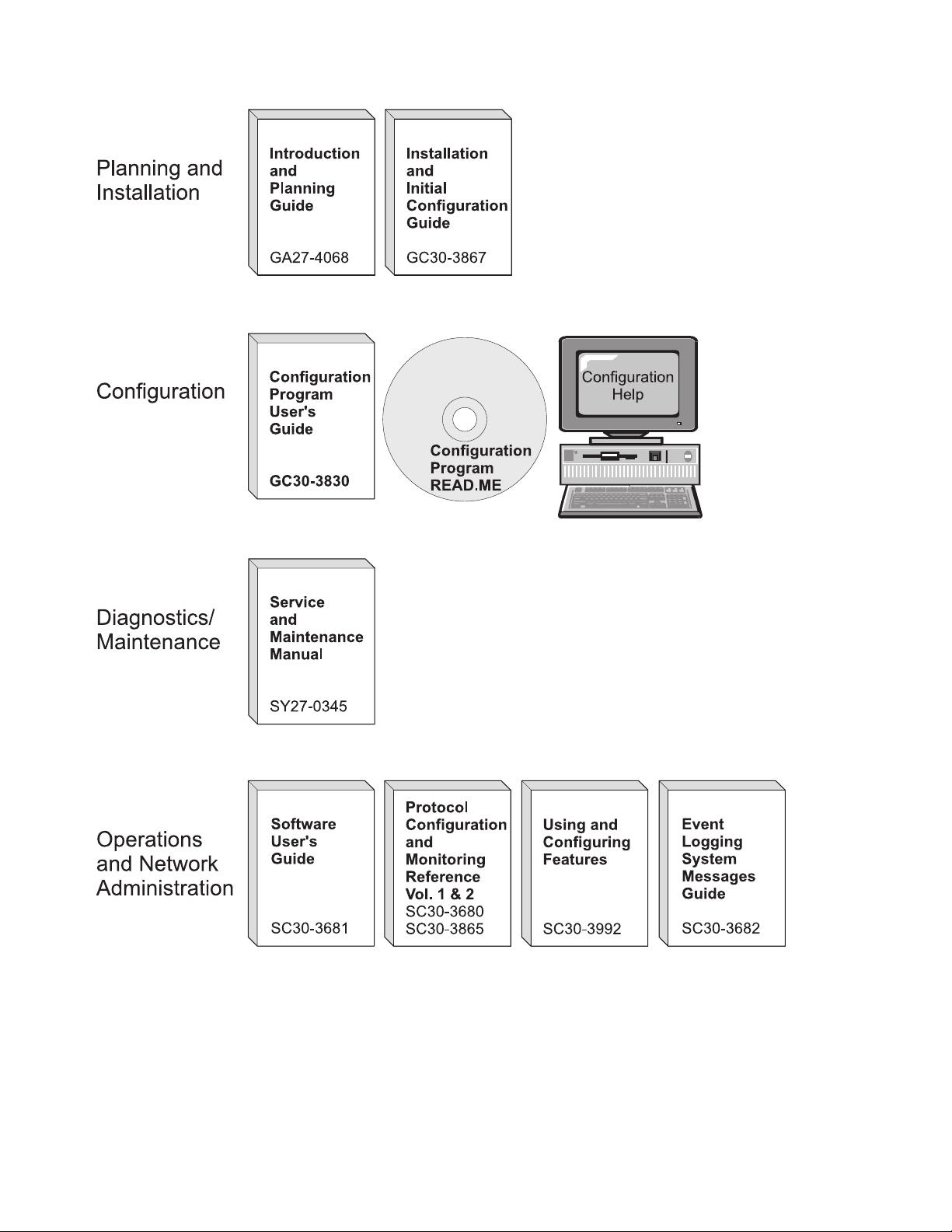
Figure 0-1. IBM 2210 Nways Multiprotocol Router Library Overview
viii 2210 Service and Maintenance
Page 11

Library Description
Introduction and Planning
GA27-4068
IBM 2210 Nways Multiprotocol Router Introduction and Planning
Guide
This book is shipped with the 2210. It explains how to prepare for
your network and for installation.
This book provides translations of danger notices and other safety
information.
GC30-3867
IBM 2210 Nways Multiprotocol Router Installation and Initial Configuration Guide
It explains how to prepare for installation, install the 2210, perform
an initial configuration, and verify that the installation is successful.
This book provides translations of danger notices and other safety
information.
Diagnostics and Maintenance
SY27-0345
IBM 2210 Nways Multiprotocol Router Service and Maintenance
Manual
This book is shipped with the 2210. It provides instructions for
diagnosing problems with and repairing the 2210.
Operations and Network Management
SC30-3681
SC30-3680
SC30-3865
SC30-3682
Software User’s Guide for Multiprotocol Routing Services
This book explains how to:
Configure, monitor, and use the IBM Multiprotocol Routing Ser-
vices software shipped with the router.
Use the Multiprotocol Routing Services command-line router
user interface to configure and monitor the network interfaces
and link-layer protocols shipped with the router.
Protocol Configuration and Monitoring Reference Volume 1 for
Multiprotocol Routing Services
Protocol Configuration and Monitoring Reference Volume 2 for
Multiprotocol Routing Services
These books describe how to access and use the Multiprotocol
Routing Services command-line router user interface to configure
and monitor the routing protocol software shipped with the router.
They include information about each of the protocols that the
devices support.
IBM Nways Event Logging System Messages Guide
This book contains a listing of the error codes that can occur, along
with descriptions and recommended actions to correct the errors.
| SC30-3992
| This book details how to configure and use the features for Multi-
| protocol Routing Services. These features include bandwidth reser-
About This Manual ix
Using and Configuring Features for Multiprotocol Routing Services
Page 12

| vation, WAN restoral, WAN reroute, DIALs, and Network Address
| Translation (NAT).
x 2210 Service and Maintenance
Page 13

Configuration
Online help The help panels for the Configuration Program assist the user in
understanding the program functions, panels, configuration parame-
ters, and navigation keys.
GC30-3830
Configuration Program User’s Guide for Multiprotocol Routing Ser-
vices
This book discusses how to use the Configuration Program.
GG24-4446
IBM 2210 Nways Multiprotocol Router Description and Configuration
Scenarios
This book contains examples of how to configure protocols using
IBM Multiprotocol Routing Services.
Safety
SD21-0030
Caution: Safety Information - Read This First
This book provides translations of caution and danger notices appli-
cable to the installation and maintenance of an IBM 2210.
Library Ordering Information
All 2210 publications can be ordered separately.
These publications are shipped in hardcopy with the 2210:
IBM 2210 Nways Multiprotocol Router Introduction and Planning Guide
IBM 2210 Nways Multiprotocol Router Installation and Initial Configuration
Guide
IBM 2210 Nways Multiprotocol Router Service and Maintenance Manual
|
Configuration Program User’s Guide for Multiprotocol Routing Services
Caution: Safety Information - Read This First
These publications are shipped with the Configuration Program in softcopy on a
CD-ROM:
IBM 2210 Nways Multiprotocol Router Introduction and Planning Guide
IBM 2210 Nways Multiprotocol Router Installation and Initial Configuration
Guide
IBM 2210 Nways Multiprotocol Router Service and Maintenance Manual
Software User’s Guide for Multiprotocol Routing Services
Protocol Configuration and Monitoring Reference Volume 1 for Multiprotocol
Routing Services
Protocol Configuration and Monitoring Reference Volume 2 for Multiprotocol
Routing Services
IBM Nways Event Logging System Messages Guide
|
Using and Configuring Features for Multiprotocol Routing Services
IBM Multiprotocol Routing Services and IBM 2210 Softcopy Library
About This Manual xi
Page 14

Obtaining Softcopy Information
Softcopy BookManager READ library information is available for many of the 2210
publications in the
single order for the CD-ROM, use form number SK2T-6012.
IBM Networking Systems Softcopy Collection Kit.
To place a
Yearly subscriptions to the
product number 5636-PUB, are available through your branch office representative.
Order feature code 2003 and media code 5003 for CD-ROM format.
IBM Networking Systems Softcopy Collection Kit
System Library Subscription Service
The 2210 publications are available via the System Library Subscription Service
(SLSS). Use machine type 2210 and program number 5765-B86 to receive 2210
publications.
Visit Our Web Site
Visit the IBM 2210 Web site at http://www.networking.ibm.com/22ð/22ðprod.html
for:
| Storage Estimator
| Performance testing results
| Configuration programs and MRS code
Publications
Questions and answers
,
Summary of Changes
Changes to the
Manual
The technical changes and additions are indicated by a vertical line (|) to the left of
the change.
include:
The 8-Port Dial Access Adapter
Access and Configuration Methods
IBM 2210 Nways Multiprotocol Router Service and Maintenance
xii 2210 Service and Maintenance
Page 15
Chapter 1. Models, Indicators, and FRUs
Use the illustrations in this chapter for reference when:
Diagnosing problems with the IBM 2210
Repairing the IBM 2210
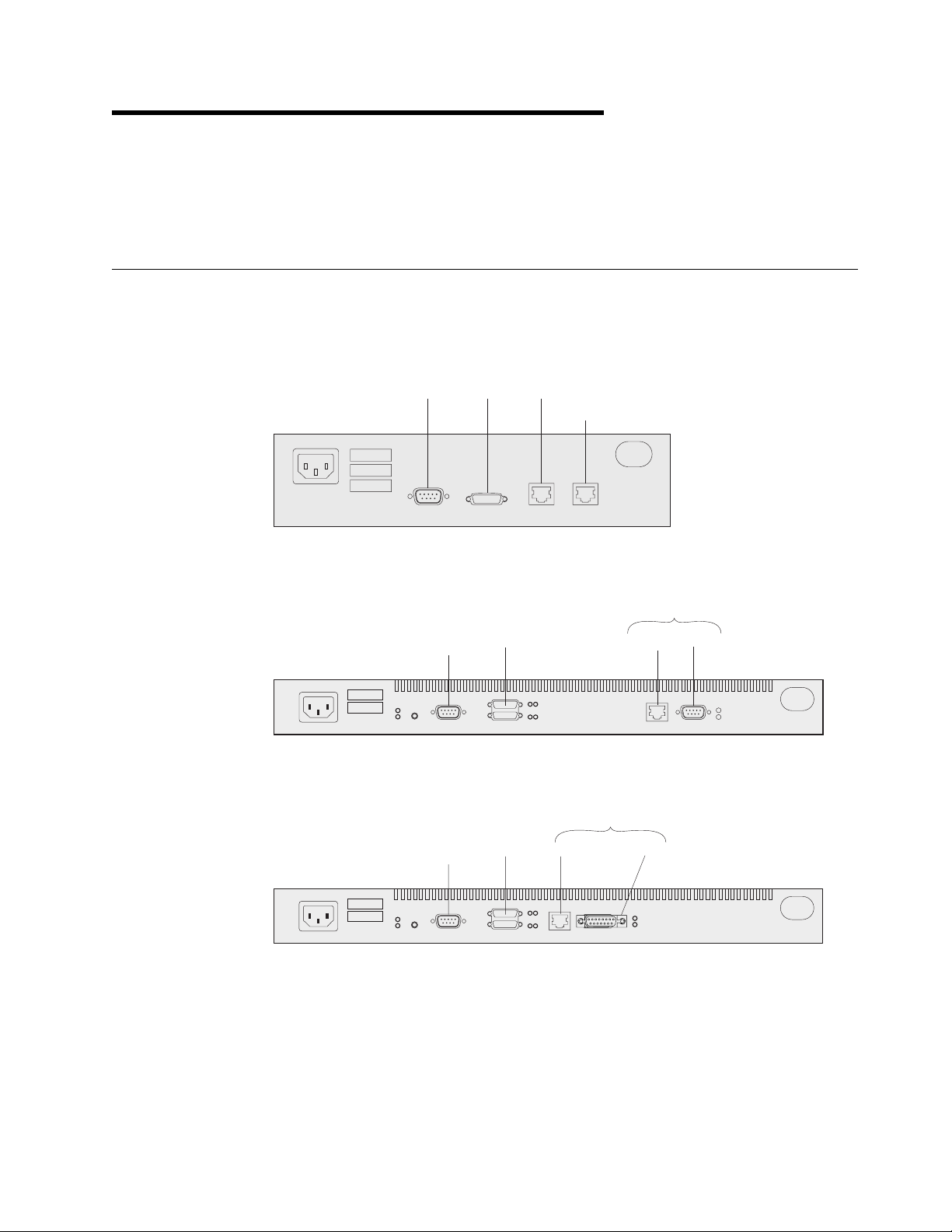
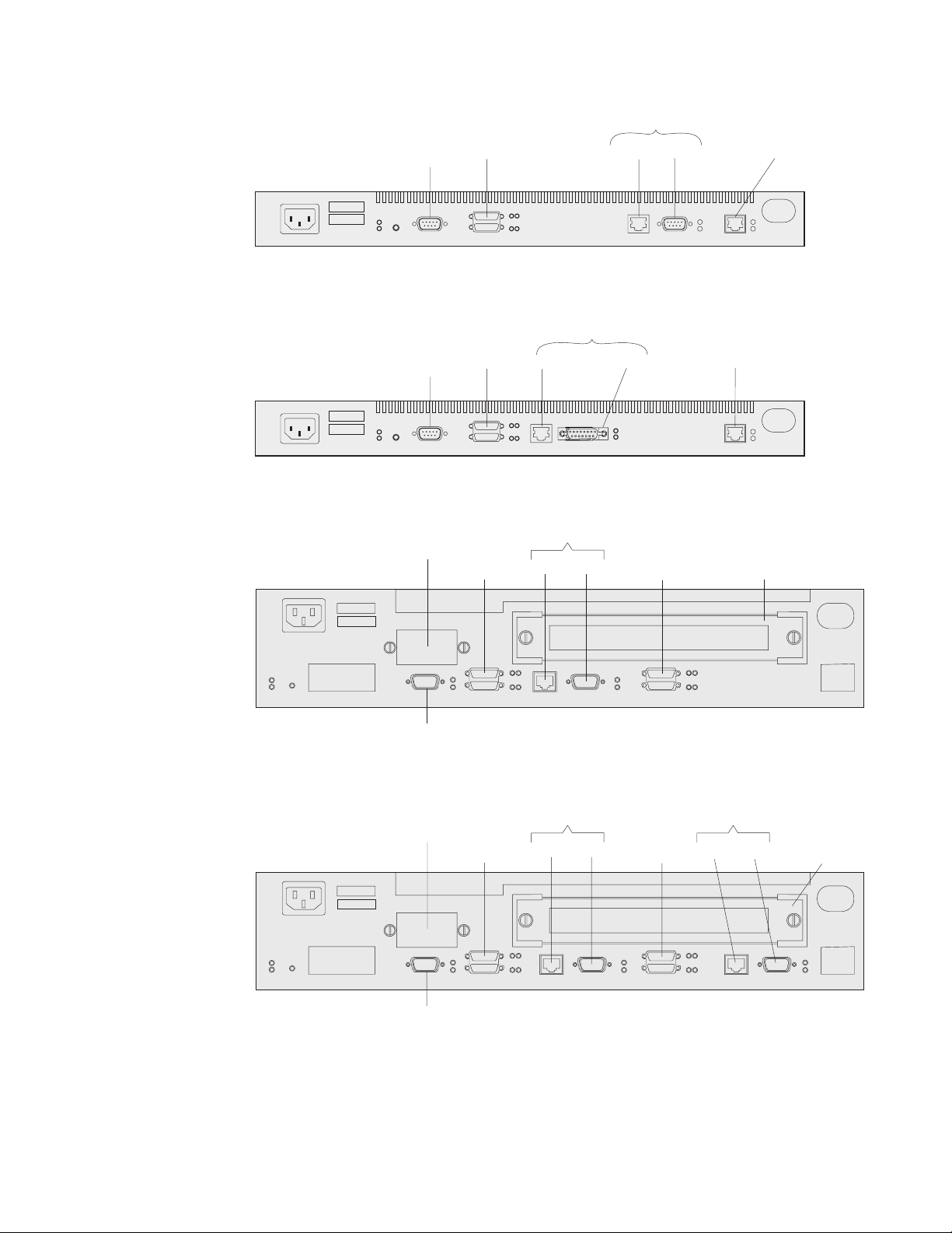
Models of the IBM 2210
The ports of the different models of the IBM 2210 are shown below. The 12x
models shown in each illustration differ only in the amount of DRAM and flash
memory they contain.
Service
100-240VAC10
0.25-0.15A 50/60Hz
Figure 1-1. Models 1Sx and 1Ux
Service
Port
Figure 1-2. Model 12T
WAN Ethernet
ISDN-BRI
Token-Ring
WANs UTP STP
Ethernet
Service
Port
Figure 1-3. Model 12E
Copyright IBM Corp. 1994, 1998 1-1
WANs 10 BASE-T
AUI
Page 16
Token-Ring
Figure 1-4. Model 127
Figure 1-5. Model 128
Service Port
Service
Port
Service
Port
Secondary
WANs UTP STP ISDN-BRI
Ethernet
WANs 10 BASE-T
Token-Ring
WANs WANs
UTP STP
AUI ISDN-BRI
Module Slot
Primary Service Port
Figure 1-6. Model 14T
Service Port
Primary Service Port
Figure 1-7. Model 24T
Secondary
Token-Ring
WANs WANs
UTP STP
Token-Ring
UTP STP
Module Slot
1-2 2210 Service and Maintenance
Page 17
Service Port
Primary Service Port
Figure 1-8. Model 24E
Secondary
Ethernet
10 BASE-T AUI
WANs WANs
Ethernet
10 Base-T AUI
Module Slot
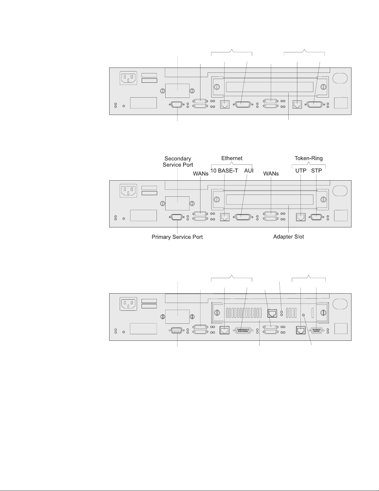
Figure 1-9. Model 24M
Second
Service Port
WANs WANs
Primary Service Port
Ethernet
10 BASE-T AUI
Adapter
Slot
Figure 1-10. Model 24M with an Optional Adapter Installed
Port
LEDs
Token-Ring
UTP STP
Adapter
Power OK
Chapter 1. Models, Indicators, and FRUs 1-3
Page 18
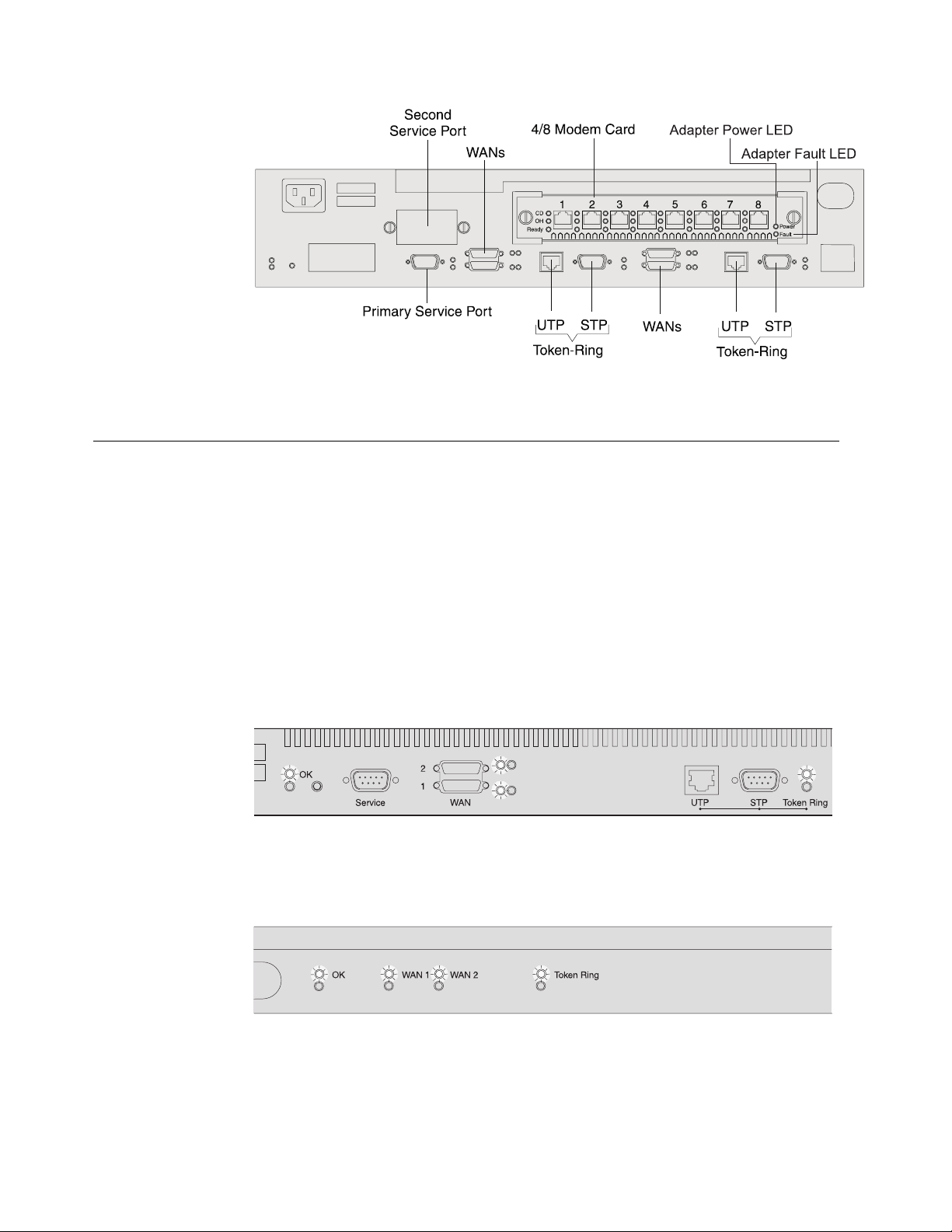
Figure 1-11. Model 24M with the 4-port Dial Access Modem Card Installed
Indicators on the IBM 2210
The IBM 2210 has green and amber light-emitting diodes (LEDs) that indicate the
status of the system and of individual ports.
Green indicates normal operation.
Amber indicates the presence of a problem.
The indicators appear on the side of the IBM 2210 containing the ports and are
duplicated on the side that is opposite the ports. This arrangement allows the cus-
tomer to use either side as the “front.”
Figure 1-12 shows the indicators that appear on the side of the IBM 2210 con-
taining the ports. Note that this illustration shows Model 12T; the port LEDs on
different models are tailored to the particular ports supported.
Figure 1-12. LEDs on Port Side of Models 12T
Figure 1-13 shows the indicators on the side of the IBM 2210 that is opposite the
ports.
Figure 1-13. LEDs on the Side Opposite the Ports for Models 12T
1-4 2210 Service and Maintenance
Page 19
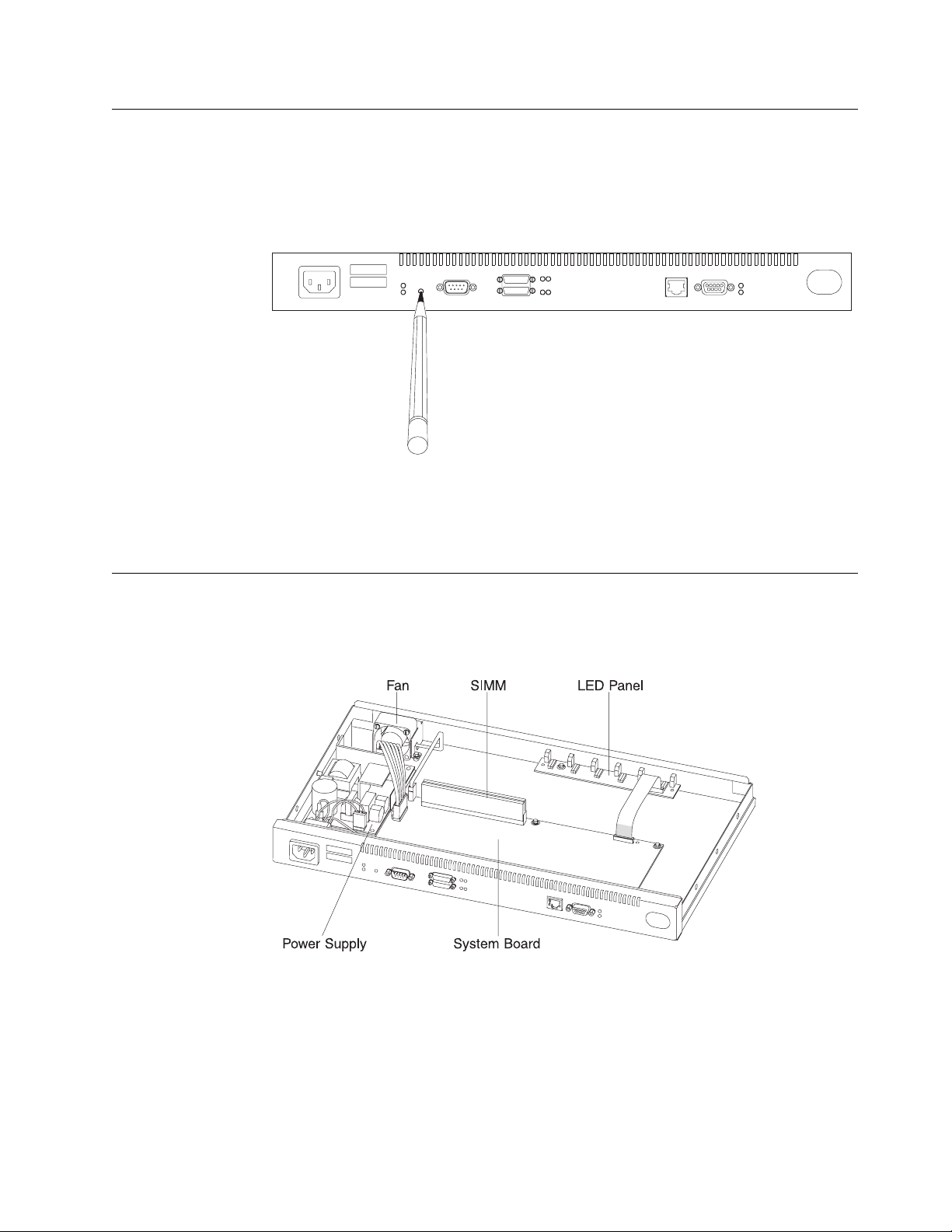
Reset Button
The reset button, shown in Figure 1-14, works in this fashion:
If you press it, you will reload the operational code.
If you press it within 10 seconds of powering on, you will start the Extended
POST. See “Extended POST” on page 3-1 for more information.
Figure 1-14. Reset Button
The reset button is recessed to prevent accidental activation. Use a pen or pencil
to press it.
Inside Views
FRUs in the IBM 2210 12x Models
Figure 1-15. View without Cover (12x Models)
Chapter 1. Models, Indicators, and FRUs 1-5
Page 20
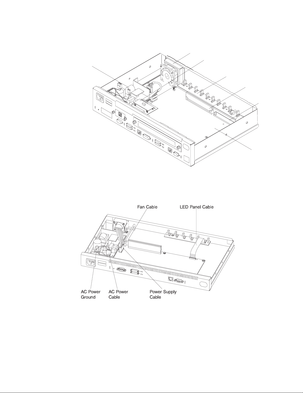
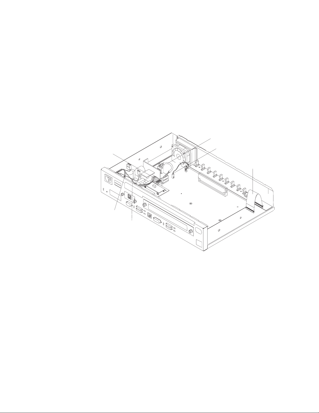
FRUs in the IBM 2210 x4x Models
Power Supply
Fan
Modem or Sevice
Port Card
LED Panel
DRAM
SIMM
Flash SIMM
System Board
Figure 1-16. View without Cover (24x Models)
Cables in the IBM 2210 12x Models
Figure 1-17. View of Cable Connections (12x Models)
1-6 2210 Service and Maintenance
Page 21
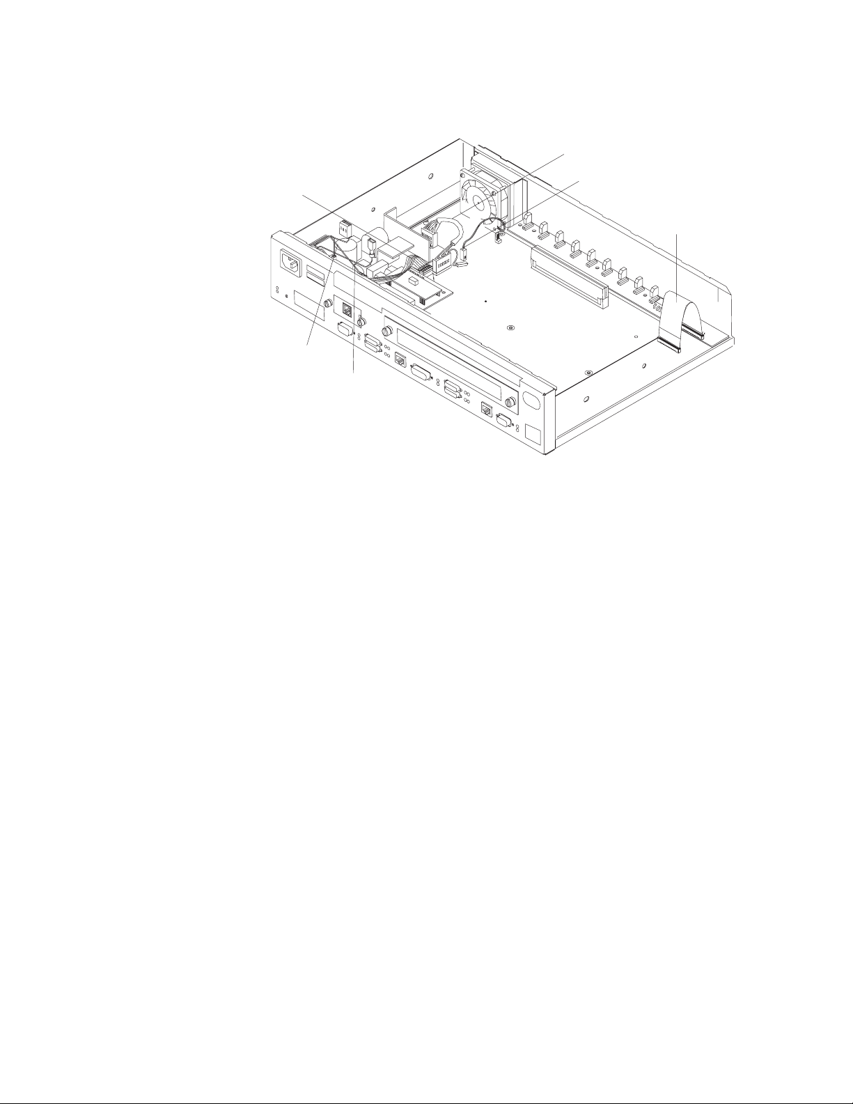
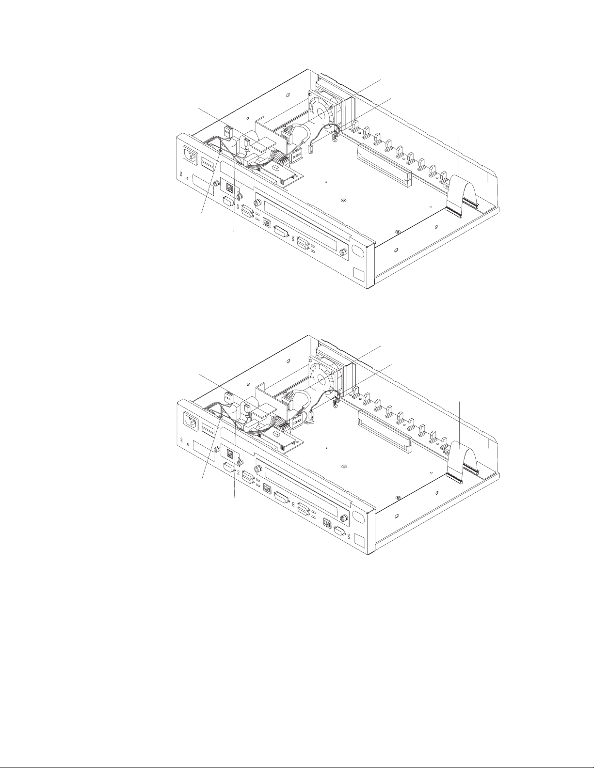
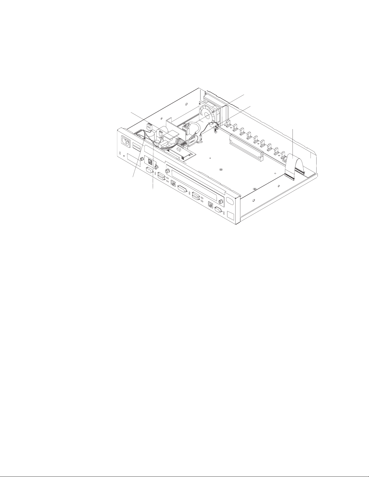
Cables in the IBM 2210 x4x Models
Power Supply Cable
Reset Cable
AC Power Ground
AC Power Cable
Figure 1-18. View of Cable Connections (24x Models)
Fan Cable
LED Panel Cable
Chapter 1. Models, Indicators, and FRUs 1-7
Page 22

1-8 2210 Service and Maintenance
Page 23

Chapter 2. Problem Determination
Use the maintenance analysis procedures (MAPs) in this chapter when the IBM
2210 is not operating normally.
Before using the MAPs, read these notes:
Review the diagnostic instructions in Chapter 3, “Diagnostics” on page 3-1.
When a MAP instructs you to replace a field-replaceable unit (FRU), see
Chapter 4, “Removal and Replacement Procedures” on page 4-1.
Chapter 1, “Models, Indicators, and FRUs” contains reference material and
illustrations that you may wish to consult while using the MAPs.
| Note: Box images that support the DIALs Server Function require certain PROM
| Load/Dump Program versions. Models 12x require PROM Load/Dump revision
| level 1.6 or higher. If you have an earlier version you must order a PROM
| upgrade. Models x4x require revision level 2.20 or higher. The code is available on
| the Web at: http://www.networking.ibm.com/support/downloads/221ð
Copyright IBM Corp. 1994, 1998 2-1
Page 24

MAP 0100: Start
– Gather problem determination information from the customer.
– Find the symptom in Table 2-1 and take the appropriate action.
Table 2-1. Initial Symptoms
Symptom Action
All LEDs stay on. Replace the system board.
An amber LED is on or blinking. Go to “MAP 0120: LEDs Indicate a Fault”
No LEDs on one or both sides of the IBM
2210 are on.
One LED is not working. Go to “MAP 0140: One LED is Not
Fan is not running. Go to Step 005 on page 2-11.
There is a communication problem between
the IBM 2210 and a network, that is, one or
more ports are not working though the
machine is powered on.
The service port is not working.
The service port amber LED is on or
blinking.
The IBM 2210 is experiencing intermittent or
data throughput problems.
The service terminal display is unreadable. Go to “MAP 0190: Service Terminal
The second service port is not working.
The second service port amber LED is on or
blinking.
The optional adapter is not working.
The green adapter status LED is off.
The Dial Access Adapter is not working.
The green adapter status LED is off or the
amber adapter status LED is on or blinking.
001
on page 2-4
Go to “MAP 0130: No LEDs Are On” on
page 2-8
Working” on page 2-10
If no LEDs are on, go to “MAP 0130: No
LEDs Are On” on page 2-8
If any amber LED is on or blinking, go to
“MAP 0120: LEDs Indicate a Fault” on
page 2-4
If the LEDs do not indicate a fault, go to
“MAP 0110: Communication Problem” on
page 2-3
Go to “MAP 0160: Service Port on 12x
Model Is Not Working” on page 2-13 for a
12x model. Go to “MAP 0170: Primary
Service Port on 14T or 24x Model Is Not
Working” on page 2-14 for a 14T or 24x
model.
Go to “MAP 0150: Intermittent Problem
Isolation” on page 2-11
Display Unreadable” on page 2-17.
Go to “MAP 0180: Second Service Port Is
Not Working” on page 2-15.
Go to “MAP 0200: Optional Adapter or Dial
Access Adapter Is Not Working” on
page 2-21.
Go to “MAP 0200: Optional Adapter or Dial
Access Adapter Is Not Working” on
page 2-21.
2-2 2210 Service and Maintenance
Page 25

MAP 0110: Communication Problem
001
– Make sure that:
The fan is clear of any obstructions.
The room temperature is within limits (5° to 41°C [50° to 104°F])
Did you find a problem?
Yes No
002
Continue with Step 004.
003
Resolve the problem. Then, go to “MAP 0210: Verify Operation” on page 2-23.
004
Is the fan running?
Yes No
005
Replace the fan. Then, go to “MAP 0210: Verify Operation” on page 2-23.
006
– Run the System Extended Diagnostics. For assistance, go to “Operational
Diagnostics” on page 3-2. If you are unable to resolve the problem, contact your
next level of support.
Chapter 2. Problem Determination 2-3
Page 26
MAP 0120: LEDs Indicate a Fault
Diagnose a problem reported by the LEDs in the following sequence:
1. Use Table 2-2 to diagnose the error conditions reported by the system LEDs,
because these take precedence over the port LEDs. (For example, if the
system amber LED is on, it does not matter which port LEDs are on.)
Note: Throughout this manual, the term
system LEDs
refers to the green (OK)
and amber LEDs on the left side of the IBM 2210.
This table is valid after power-on or Extended POST completes.
2. If the system LEDs appear to indicate no problem, go to Step 001 in the MAP.
Table 2-2. System LED States
Green Amber Action
On Off Router loaded and operational.
On or Off On Replace the system board.
Off Blinking Replace the DRAM SIMM.
On Blinking There is no router load module available, no boot
configuration has been entered, or the configured
boot path is not available. Additional information can
be obtained by attaching a service terminal to the
IBM 2210. If the problem cannot be resolved locally,
call the network administrator.
Blinking On Replace the flash SIMM on models 14T and 24x.
For 12x models, refer to “MAP 0160: Service Port on
12x Model Is Not Working” on page 2-13.
Blinking Blinking Load in process.
001
Did this LED state result from powering on the IBM 2210 normally?
Yes No
002
– Go to Step 004
003
– Go to Step 019 on page 2-6.
004
Did this LED state result from running the Extended POST?
Yes No
005
– Go to Step 007 on page 2-5.
2-4 2210 Service and Maintenance
Page 27

006
– Go to Step 012.
007
Run an external wrap test on the port. For assistance, go to “Operational
Diagnostics” on page 3-2.
Is the port amber LED blinking?
Yes No
008
There is a problem with the software or with the network. Contact your next
level of support for instructions about reviewing the system error log.
009
Were the wrap plugs installed correctly during the Extended POST?
Yes No
010
Repeat the Extended POST using the wrap plugs correctly. Take any action
that is indicated.
011
Replace the system board. Then, go to “MAP 0210: Verify Operation” on
page 2-23.
012
Is an amber port LED blinking?
Yes No
013
Go to Step 023 on page 2-6.
014
– If this is the primary service port on the 14T and 24x models, continue at “MAP
0170: Primary Service Port on 14T or 24x Model Is Not Working” on page 2-14.
– If this is the secondary service port on the 14T or 24x models, continue at “MAP
0180: Second Service Port Is Not Working” on page 2-15.
– If this is an optional adapter, continue at “MAP 0200: Optional Adapter or Dial
Access Adapter Is Not Working” on page 2-21.
(Step 014 continues)
Chapter 2. Problem Determination 2-5
Page 28

014 (continued)
Was a wrap plug installed on this port before you ran Extended POST?
Yes No
015
Repeat the Extended POST using a wrap plug for this port. For assistance,
go to Chapter 3, “Diagnostics” on page 3-1.
Is the amber LED for this port on or blinking?
Yes No
016
Go to Step 023.
017
Replace the system board. Then, go to “MAP 0210: Verify Operation” on
page 2-23.
MAP 0120 (continued)
018
Replace the system board. Then, go to “MAP 0210: Verify Operation” on
page 2-23.
019
Is the amber system LED on or blinking?
Yes No
020
Run the System Extended Diagnostics. For assistance, go to “Operational
Diagnostics” on page 3-2.
Did you find a problem?
Yes No
021
Contact your next level of support for instructions about reviewing the
system error log.
022
Resolve the problem. Then, go to “MAP 0210: Verify Operation” on
page 2-23.
023
(Step 023 continues)
2-6 2210 Service and Maintenance
Page 29

023 (continued)
Find the fault condition exhibited by this IBM 2210 in Table 2-2 on page 2-4.
Perform the action indicated. Then, go to “MAP 0210: Verify Operation” on
page 2-23.
Chapter 2. Problem Determination 2-7
Page 30

MAP 0130: No LEDs Are On
001
Are the LEDs on the opposite side of the unit on?
Yes No
002
Go to Step 008.
003
Are the LEDs on the port side on?
Yes No
004
Replace the system board. Then, go to “MAP 0210: Verify Operation” on
page 2-23.
005
Remove the cover using the instructions in “Removing the Cover” on page 4-2.
Is the cable connecting the system board to the LED panel securely seated?
Yes No
006
Seat the cable. Go to “MAP 0210: Verify Operation” on page 2-23.
007
Replace the LED panel. Then, go to “MAP 0210: Verify Operation” on page 2-23.
008
Is the fan running?
Yes No
009
Make sure that:
The IBM 2210 is plugged into the wall outlet.
The wall outlet has the correct voltage.
The line voltage at the end of the power cord is correct.
(Step 009 continues)
2-8 2210 Service and Maintenance
Page 31

009 (continued)
Did you find a problem?
Yes No
010
Replace the power supply. Then, go to “MAP 0210: Verify Operation”
on page 2-23.
011
Correct the problem, then, go to “MAP 0210: Verify Operation” on
page 2-23.
012
Replace the system board. Then, go to “MAP 0210: Verify Operation” on
page 2-23.
Chapter 2. Problem Determination 2-9
Page 32

MAP 0140: One LED is Not Working
001
– Stop the IBM 2210 by unplugging the power cord from the power outlet.
– Plug the IBM 2210 power cord back into the power outlet.
All LEDs should be on for 0.5 seconds after power-on.
Were all the LEDs on?
Yes No
002
Is the defective LED on the port side of the IBM 2210?
Yes No
003
Is the cable connecting the system board to the LED panel
securely seated?
Yes No
004
Seat the cable. Go to “MAP 0210: Verify Operation” on
page 2-23.
005
Replace the LED panel. Then, go to “MAP 0210: Verify Operation” on
page 2-23.
006
Replace the system board. Then, go to “MAP 0210: Verify Operation” on
page 2-23.
007
The problem is not with the hardware. Call your next level of support.
2-10 2210 Service and Maintenance
Page 33

MAP 0150: Intermittent Problem Isolation
001
– Make sure that:
All cables are attached correctly.
The room temperature is not outside the limits [5° to 41°C (50° to 104°F)].
Did you find a problem?
Yes No
002
Continue with Step 004.
003
Resolve the problem. Then, go to “MAP 0210: Verify Operation” on page 2-23.
004
Is the fan running?
Yes No
005
Are any of the LEDs on? Check the LEDs on both sides of the IBM
2210.
Yes No
006
Make sure that:
The IBM 2210 is plugged into the wall outlet.
The wall outlet has the correct voltage.
The line voltage at the end of the power cord is correct.
Did you find a problem?
Yes No
007
Replace the power supply. Then, go to “MAP 0210: Verify
Operation” on page 2-23.
008
Correct the problem. Then, go to “MAP 0210: Verify Operation” on
page 2-23.
009
(Step 009 continues)
Chapter 2. Problem Determination 2-11
Page 34

009 (continued)
Replace the fan. Then, go to “MAP 0210: Verify Operation” on page 2-23.
010
Run the System Extended Diagnostics. For assistance, go to “Operational
Diagnostics” on page 3-2.
Did you find a problem?
Yes No
011
Contact your next level of support for instructions about reviewing the system
error log.
012
Resolve the problem. Then, go to “MAP 0210: Verify Operation” on page 2-23.
MAP 0150 (continued)
2-12 2210 Service and Maintenance
Page 35

MAP 0160: Service Port on 12x Model Is Not Working
001
Run the Extended POST using a wrap plug in the service port. For assistance, go
to Chapter 3, “Diagnostics” on page 3-1.
Is the system green LED blinking and the system amber LED on?
Yes No
002
There is a problem with the attached device or its cable.
003
Replace the system board. Then, go to “MAP 0210: Verify Operation” on
page 2-23.
Chapter 2. Problem Determination 2-13
Page 36

MAP 0170: Primary Service Port on 14T or 24x Model Is Not Working
001
Run the Extended POST using a wrap plug in the service port. For assistance, go
to Chapter 3, “Diagnostics” on page 3-1.
Is the service port amber LED on or blinking?
Yes No
002
There is a problem with the attached device or its cable.
003
Replace the system board. Then, go to “MAP 0210: Verify Operation” on
page 2-23.
2-14 2210 Service and Maintenance
Page 37

MAP 0180: Second Service Port Is Not Working
001
Is the service port green LED on?
Yes No
002
Check the connection to the system board.
Is the service port seated correctly in the socket?
Yes No
003
Seat the service port in the socket firmly.
Is the problem corrected?
Yes No
004
Go to Step 007.
005
Go to “MAP 0210: Verify Operation” on page 2-23.
006
Go to Step 007.
007
Run the Extended POST using a wrap plug in the service port. For assistance, go
to Chapter 3, “Diagnostics” on page 3-1.
Is the service port green LED on?
Yes No
008
Go to Step 010.
009
Problem is corrected. Go to “MAP 0210: Verify Operation” on page 2-23.
010
(Step 010 continues)
Chapter 2. Problem Determination 2-15
Page 38

010 (continued)
Is the service port amber LED blinking?
Yes No
011
Is the service port amber LED on?
Yes No
012
Make sure the service port is seated correctly.
Is the service port seated correctly?
Yes No
013
Seat the service port correctly and then go to Step 007 on
page 2-15.
MAP 0180 (continued)
014
Go to Step 016.
015
Replace the system board. Then, go to “MAP 0210: Verify Operation” on
page 2-23.
016
Replace the service port. Then, go to “MAP 0210: Verify Operation” on
page 2-23.
2-16 2210 Service and Maintenance
Page 39

MAP 0190: Service Terminal Display Unreadable
Symptom Explanation Conditions That Could Cause This Symptom
While you are diagnosing a
problem, a terminal attached to the
service port of the 2210 displays
random characters instead of readable text.
001
Does the IBM 2210 go to the active state within 2 minutes of resetting or powering on?
Active state is indicated by the green system LED on and the amber system
LED off.
Yes No
002
Incorrect configuration setting of the terminal or 2210
service port.
Incorrect terminal/device (ac) grounds.
Defective, incorrectly shielded, or incorrectly grounded RS
EIA 232 cable between the terminal and the 2210.
Defective terminal or terminal emulator.
High ambient electromagnetic interference (EMI) levels.
Power line disturbances.
Defective 2210 system board.
Go to Step 004
003
Go to Step 007 on page 2-18
004
Is the bootstrap monitor active with the green system LED on and the amber
system LED blinking?
Yes No
005
Go to “MAP 0100: Start” on page 2-2.
006
The bootstrap monitor cannot find a boot path. You must correct the boot problem
before you can correct the display problem
– Press the service terminal break key sequence and press Enter.
A typical terminal break key sequence for PC terminal emulators is Alt-b. Most
ASCII terminals have a Break key (often used in conjunction with the Ctrl key).
(Step 006 continues)
Chapter 2. Problem Determination 2-17
Page 40

MAP 0190 (continued)
006 (continued)
– Press Ctrl-c at the service terminal.
The 2210 autobauds to the terminal speed. The > prompt should be displayed at
this time.
The terminal speed is not saved and the next time the 2210 is reset or powered off,
the service port will use the old speed.
– Continue at Step 001 on page 2-17 when you have resolved the boot problem.
007
– Press the service terminal break key sequence and press Enter.
You should try this a number of times before proceeding.
A typical terminal break key sequence is Alt-b.
– Press Ctrl-p at the service terminal.
Is a readable message displayed on the service terminal?
Yes No
008
– Go to Step 010
009
– Go to Step 013 on page 2-19
010
– Press Reset and wait for the system green (OK) and amber LEDs to start
blinking or the system green (OK) to come on and the amber LED to be blinking.
– Press the service terminal break key sequence and press Enter.
– Press Ctrl-c at the service terminal.
The terminal displays the > prompt.
– Enter uc at the prompt.
The 2210 displays the hardware configuration. The first line shows the auto-baud
speed and the configured service port baud rate, if they are different.
Note: The uc command is not available for the 14T and 24x models.
Are different auto-baud and configured speeds displayed?
Yes No
011
– Go to Step 013 on page 2-19.
012
(Step 012 continues)
2-18 2210 Service and Maintenance
Page 41

012 (continued)
– Set the terminal to the configured console baud rate displayed.
– Press the service terminal break key sequence and press Enter.
This action causes the 2210 to auto-baud.
– Enter Ctrl-c.
The > prompt should be displayed. If the console baud rate is satisfactory, you can
reboot the 2210 and the terminal will work. If the console baud rate is unsatisfactory and you want to change the rate:
1. Enter bc at the > prompt and select an IBD boot module.
2. Wait for the Config (only)> prompt to be displayed.
3. Enter set baudrate 0 at the Config (only)> prompt.
4. Set the terminal to the desired baud rate.
5. Press the terminal break key sequence and press Enter to force the 2210 to
auto-baud to the new terminal speed.
Note: When using a terminal emulator, you might have to stop and restart the
emulator when switching speeds for the emulator to display correctly.
– Continue at Step 013.
013
The terminal should now operate correctly and the new terminal speed has been
saved.
Is the terminal functioning correctly?
Yes No
014
– Go to Step 016
015
– Go to Step 027 on page 2-20
016
Is the terminal or the IBM 2210 grounded correctly?
Yes No
017
Ground the device correctly. Go to “MAP 0210: Verify Operation” on
page 2-23.
018
(Step 018 continues)
Chapter 2. Problem Determination 2-19
Page 42

018 (continued)
Is the RS 232 cable between the terminal and the IBM 2210 grounded cor-
rectly and shielded?
Yes No
019
Ground or shield the cable correctly or replace the cable. Go to “MAP 0210:
Verify Operation” on page 2-23.
020
Is the terminal or the terminal emulator functioning correctly?
Yes No
021
Replace the terminal or the terminal emulator. Go to “MAP 0210: Verify
Operation” on page 2-23.
MAP 0190 (continued)
022
Is the IBM 2210 in an area with high ambient electromagnetic interference?
Yes No
023
Are there power line disturbances?
Yes No
024
The IBM 2210 system board is defective.
Replace the system board. Go to “MAP 0210: Verify Operation” on
page 2-23.
025
Install an uninterruptible power supply to minimize the effects of the power
fluctuations. Go to “MAP 0210: Verify Operation” on page 2-23.
026
Move the IBM 2210 to a more isolated area. Go to “MAP 0210: Verify Operation”
on page 2-23..
027
Go to “MAP 0210: Verify Operation” on page 2-23.
2-20 2210 Service and Maintenance
Page 43

MAP 0200: Optional Adapter or Dial Access Adapter Is Not Working
Note: See Figure 1-10 on page 1-3 or Figure 1-11 on page 1-4 for position of
adapter status LED.
001
Is the adapter green status LED on?
Yes No
002
Is the adapter firmly seated in the riser?
Yes No
003
Seat the adapter firmly in the riser, then go to Step 001.
004
Is the power cable connected correctly to the riser card, and the riser
card seated firmly in the socket?
Yes No
005
Connect the cables correctly and make sure the riser card is firmly in
the socket.
006
Test the power supply.
Is the power supply OK?
Yes No
007
Replace the power supply.
– Go to “MAP 0210: Verify Operation” on page 2-23.
008
Replace the riser card.
Go to “MAP 0210: Verify Operation” on page 2-23.
009
(Step 009 continues)
Chapter 2. Problem Determination 2-21
Page 44

009 (continued)
Is this the Dial Access Adapter?
Yes No
010
Replace the adapter, then go to “MAP 0210: Verify Operation” on
page 2-23.
011
Is the amber status LED on or blinking?
Yes No
012
Replace the adapter, then go to “MAP 0210: Verify Operation” on
page 2-23.
Note: The Dial Access Adapter feature has two 4-port Dial Access Modem
Cards and a Dial Access Base Adapter. Any of these cards could be failing.
Replace the cards one at a time and retry.
MAP 0200 (continued)
013
Power down, reseat the adapter, and reinstall.
Is the amber status LED light still on or blinking.
Yes No
014
Go to “MAP 0210: Verify Operation” on page 2-23.
015
Do you have the maintenance terminal (PC) needed to run diagnostics?
Yes No
016
Power down and replace the Dial Access Adapter. Then go to “MAP 0210:
Verify Operation” on page 2-23.
017
Run the diagnostics program. Look at the error code to determine which 4-port Dial
Access Modem Card to replace.
Power down and replace the appropriate 4-port Dial Access Modem Card. Then go
to “MAP 0210: Verify Operation” on page 2-23.
2-22 2210 Service and Maintenance
Page 45

MAP 0210: Verify Operation
001
Reinstall the covers of the IBM 2210.
Is an ASCII terminal attached to the IBM 2210?
Yes No
002
Run the Extended POST. For assistance, go to Chapter 3, “Diagnostics” on
page 3-1.
Is any amber LED on or blinking?
Yes No
003
Go to Step 007.
004
Go to “MAP 0120: LEDs Indicate a Fault” on page 2-4.
005
Run the System Extended Diagnostics. For assistance, go to “Operational
Diagnostics” on page 3-2.
Did the diagnostics complete with no trouble found?
Yes No
006
Perform the action indicated by the diagnostics.
Run the System Extended Diagnostics again, taking any action that is indi-
cated. If you are unable to resolve the problem, contact your next level of
support.
007
Return the IBM 2210 to the customer.
Chapter 2. Problem Determination 2-23
Page 46

2-24 2210 Service and Maintenance
Page 47

Chapter 3. Diagnostics
The IBM 2210 diagnostic programs test the system hardware and detect hardware
problems. The diagnostic routines include three types of tests:
Power-on self-test (POST)
Extended POST
Menu-driven diagnostics
The diagnostic package includes service aids that may be used to display the diagnostic logs and to view the vital product data (VPD).
| Note: When using a locally attached terminal to run the IBM 2210 diagnostic pro| grams, the service port line speed must be set to 9600 bps. This setting is a con| stant and cannot be changed.
Diagnosing Hardware Problems
Running the diagnostics requires complete control of the IBM 2210.
Attention: Do not shut down the IBM 2210 without the knowledge and permission
of the customer. Contact the customer’s system administrator before shutdown.
Power-On Self-Test
The power-on self-test (POST) provides a basic confidence test of the IBM 2210
processor, memory, and interfaces.
Starting the POST
The POST runs automatically whenever the IBM 2210 is powered on. If the
machine is already powered on and you want to execute the POST:
1 Stop the IBM 2210 by unplugging the power cord from the power outlet.
2 Plug the IBM 2210 into the power outlet.
3 If the system green (OK) LED is off and the system amber LED is on after
Extended POST
It is possible to run an extended POST that does not require attachment of a terminal. Extended POST allows you to test memory more extensively than normal
POST. Follow these steps to run diagnostics without a terminal:
about 2 minutes, run the Extended POST.
1 Stop the IBM 2210 by unplugging the power cord from the power outlet.
2 Disconnect the cables from the ports.
3 Plug the IBM 2210 into the power outlet. Wait for a port green LED to flash
(2 to 3 seconds) and then push the reset button once. (See Figure 1-14 on
page 1-5.)
Copyright IBM Corp. 1994, 1998 3-1
Page 48

4 If the Extended POST has completed successfully:
The green LEDs for the system (OK) and for any port with wrap plugs
will be on.
The port amber LEDs will be off (or blinking if no wrap plug is installed).
For the 12x models, the system (OK) green LED blinking with the system
amber LED on indicates that the service port external wrap test has failed.
5 To run the extended POST again, press the reset button after 2 minutes.
6 To end extended POST, power off the IBM 2210 by unplugging the power
cord from the power outlet.
7 Be sure to remove any wrap plugs from the IBM 2210 before applying power
to reload the router. Do not leave wrap plugs on unused ports.
| Above references to wrap plugs do not apply if an internal wrap is performed during
| extended POST. An internal wrap is performed if the following levels of boot code
| are installed:
| IBM 2210 12x models if you have the boot code level 1.62 or higher.
| IBM 2210 models 1S4, 1S8, 1U4, and 1U8 if you have the boot code level 1.32
| or higher.
| IBM 2210 x4x models if you have the boot code level 2.40 or higher.
Operational Diagnostics
To run the menu-driven operational diagnostics, attach an ASCII terminal to the
IBM 2210. If no terminal is available, run the Extended POST, as described in
“Extended POST” on page 3-1.
If an ASCII terminal is already attached to the IBM 2210, continue with “Running
the Diagnostics.” Otherwise, go to Appendix A, “Access Methods and Attaching an
ASCII Terminal” on page A-1 for instructions.
Note: Because running the diagnostics requires complete control of the IBM 2210,
be sure to notify the customer’s system administrator before shutdown.
Running the Diagnostics
You can execute the diagnostics:
Immediately after attaching an ASCII terminal
When an ASCII terminal is already attached and the router user interface is in
operation.
Immediately After Attaching an ASCII Terminal.:
diately after attaching a terminal:
To start the diagnostics imme-
1 If the IBM 2210 is not already unplugged, unplug it from the power outlet.
2 To start the diagnostics, plug the power cord into the outlet and, when the
green system LED is on and the amber system LED is blinking, or both
green and amber system LEDs are blinking, press Ctnl-c.
3-2 2210 Service and Maintenance
Page 49

3 The greater-than sign (>) will appear on the display.
4 Type diag and press Enter.
5 The Diagnostic Main Menu will appear after the System Diagnostics run.
While the Router User Interface Is In Operation:
the router user interface is in operation:
To start the diagnostics while
1 Press Ctnl-p. An asterisk (\) will appear.
2 Type reload and press Enter.
3 Press Ctnl-c. The greater-than sign (>) will appear on the display.
4 Type diag and press Enter.
5 The Diagnostic Main Menu will appear.
Diagnostic Main Menu:
System Diagnostics
ports through an internal wrap.
System Extended Diagnostics
external wrap tests of all ports.
WAN/LAN Wrap Menu
this menu you can also test the cable attached to a port. After you select this
option, additional menus will help you define the test.
The Diagnostic Main Menu has the following options:
tests the processor, the memory, and the communication
executes the System Diagnostics tests plus
allows you to run a wrap test on a specific port. From
Diagnostic Utilities
an additional menu will allow you to choose a specific service aid. See
“Service Aids” on page 3-4 for more information.
If a diagnostic test fails, a message will be displayed giving:
A description of the test that failed
A return code
An action to take
The return code provides additional information that may be requested by the next
level of support.
When you are ready to exit from the diagnostics, type x and press Enter at the
main menu. The POST will run.
Diagnosing Software Problems
In order to diagnose software problems, you need to capture as much information
about the problem as possible and call your software support center. The software
support center will guide you through the steps needed to collect data relating to a
problem; these steps may include examination of the log, trace, and dump. Service
personnel dealing with software problems should record the symptoms of the
problem.
provides access to service aids. After you select this option,
Chapter 3. Diagnostics 3-3
Page 50

Possible symptoms of a software problem:
A component stops operating and hardware diagnostics do not identify a hard-
ware problem
System stalls
A severe drop occurs in system performance
Data is incorrectly transmitted
A system does not receive data that was correctly transmitted
Service Aids
Service aids are utility programs that provide additional diagnostic assistance. The
service aids for the IBM 2210 are for use under the direction of support personnel.
They allow you to:
Display the diagnostic log
Display the vital product data (VPD)
Display Diagnostic Log
Diagnostic information is stored in a hexadecimal dump format.
Display Vital Product Data (VPD)
For the 12x models, the VPD for this machine is displayed in a hexadecimal format.
For the 14T 1Sx, 1Ux, and 24x models, the VPD for this machine is displayed in
character format.
3-4 2210 Service and Maintenance
Page 51

Chapter 4. Removal and Replacement Procedures
Note: Before installing the IBM 2210, be sure to read “Electronic Emission
Notices” on page D-1.
This chapter contains replacement procedures for the following FRUs:
System board
Single in-line memory module (SIMM)
Power supply
Fan
LED panel
The following features for models 14T and 24x:
– Adapter Enablement Feature
– Optional adapters:
| - 1-port 25-Mbps ATM Interface Adapter
- 1-port ISDN Basic Rate Interface Adapter
- 4-port S/T ISDN BRI Adapter
- 4-port U ISDN BRI Adapter
| - 1-port E1-120 Ohm ISDN PRI Adapter
| - 1-port T1/J1 ISDN PRI Adapter
| - 4-port Dial Access Adapter
| - 8-port Dial Access Adapter
| - 4-port Dial Access Modem Card Upgrade feature
- 4-port WAN Concentration Adapter
- 8-port WAN Concentration Adapter
– Optional second service port card
- 14.4-Kbps Modem Card
- EIA-232 Service Port Card
| – 4 MB Additional Flash Feature
| – 8 MB Additional Flash Feature
| – 16 MB DRAM Memory Expansion Feature
| – 32 MB DRAM Memory Expansion Feature
Note: Any procedure without a specific model number can be used on all models.
Any figures for those procedures will show a 12x model for illustration purposes.
Before you begin, inspect the IBM 2210 for unsafe conditions. Use
Safety for IBM Service Representatives
inspection.
Copyright IBM Corp. 1994, 1998 4-1
, S229-8124, to guide you through this
Electrical
Page 52

DANGER
An electrical outlet that is not correctly wired could place hazardous
voltage on metal parts of the IBM 2210 or the devices that attach to
the IBM 2210. It is the responsibility of the customer to ensure that
the outlet is correctly wired and grounded to prevent an electrical
shock.
Before installing or removing signal cables, ensure that the power
cord for the IBM 2210 is unplugged.
When possible, use one hand to connect or disconnect signal cables
to prevent a possible shock from touching two surfaces with different
electrical potentials.
During an electrical storm, do not connect or disconnect any cables.
Note: For translations of this safety notice, see “Safety Notices” on page D-6.
Handling Static-Sensitive Devices
Certain components, such as planars and memory modules, can be damaged by
static electricity discharge. These components are shipped in an antistatic bag to
prevent such damage. An electrostatic discharge (ESD) protection device must be
used when handling these components.
Take the following precautions:
Do not remove the component from the antistatic bag until you are ready to
replace a component in the IBM 2210.
With the component still in its antistatic bag, touch the metal frame of the IBM
2210.
Hold the component by its edges. Avoid touching solder joints or pins.
Handle the components carefully in order to prevent permanent damage.
Cover
Removing the Cover
DANGER
Hazardous voltages exist inside this machine when it is powered
on. Anytime you service this unit with the cover off, be sure to
unplug the power cord.
Note: For translations of this safety notice, see “Safety Notices” on
page D-6.
1 Unplug the power cord from the outlet.
4-2 2210 Service and Maintenance
Page 53

2 If the IBM 2210 is installed in a rack, remove the screws attaching the IBM
2210 to the rack.
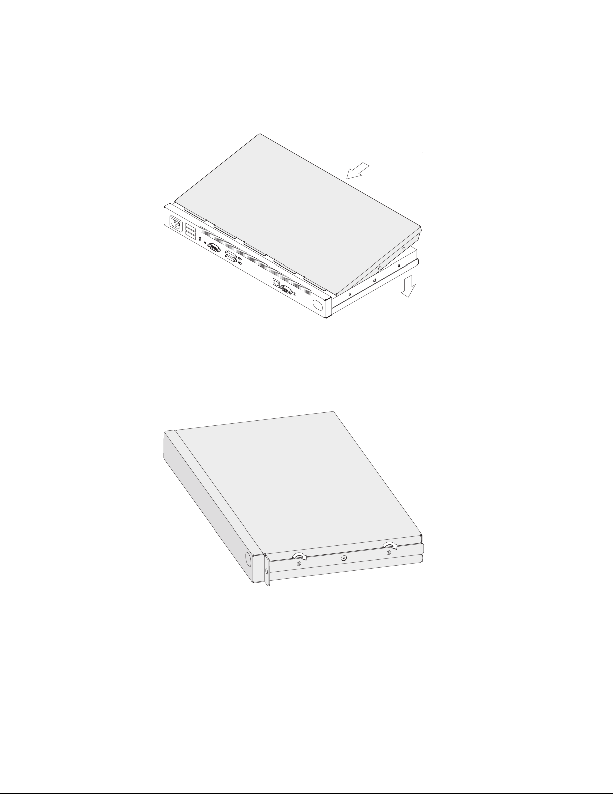
3 Remove the two screws that attach the mounting brackets to either side of
the IBM 2210. Then remove the center screw that attaches the cover to the
side of the IBM 2210. Note the position of the mounting bracket ears as you
remove the mounting brackets.
Figure 4-1. Removing the Side Screws
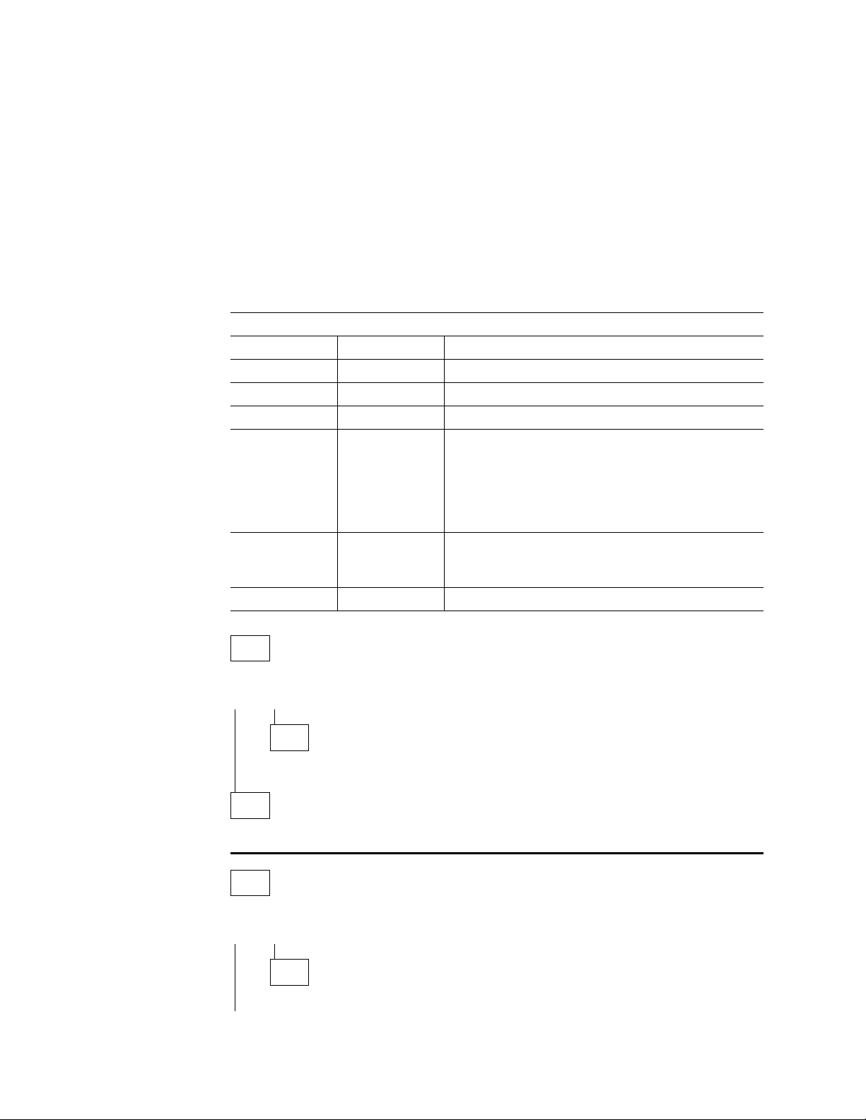
4 Position the IBM 2210 so that the port side is facing you. From this position,
lift the rear portion of the cover and slide it away from you.
Figure 4-2. Removing the Cover
5 Be sure to store the mounting brackets and screws with the cover.
Chapter 4. Removal and Replacement Procedures 4-3
Page 54
Reinstalling the Cover
1 Position the IBM 2210 so that the port side is facing you. From this position,
elevate the rear portion of the cover and slide it onto the IBM 2210.
Figure 4-3. Replacing the Cover
2 Replace the screws that attach the cover and mounting brackets to each side
of the machine. Be sure that the screw with the Phillips head is installed in
the middle hole.
Figure 4-4. Replacing the Screws and Mounting Bracket
3 If the IBM 2210 was mounted in a rack, return it to the rack.
4 Plug the power cord into the outlet.
4-4 2210 Service and Maintenance
Page 55
System Board
Refer to “Handling Static-Sensitive Devices” on page 4-2 before removing or
installing a system board.
Removing the System Board for 12x Models
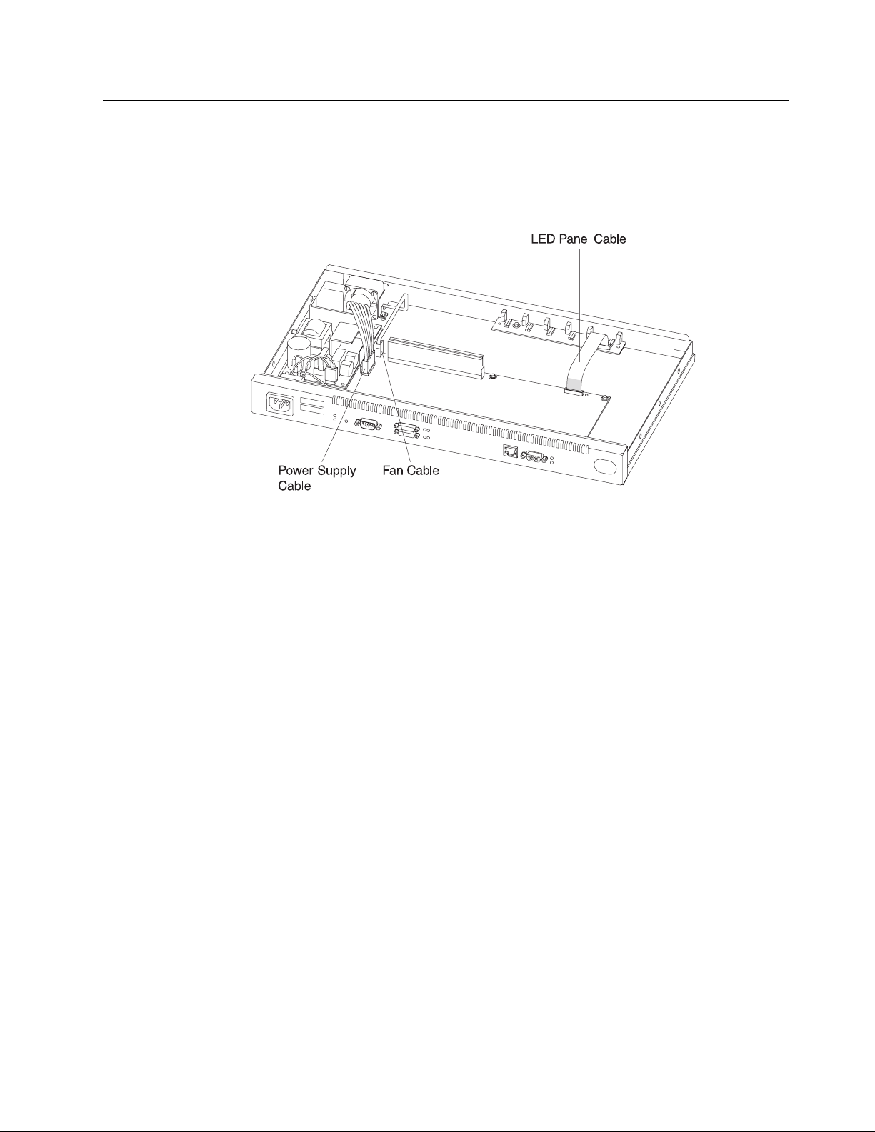
Figure 4-5. Cables Attached to the System Board (12x Models)
1 Remove the power supply cable connector by pulling out the retaining clips
with your fingers or a screwdriver and then rocking the connector from front
to back as you pull up.
2 Remove the fan cable by rocking it from front to back as you pull up.
3 To remove the LED panel cable, use a screwdriver on either side of the con-
nector to lift the blue retaining latch. Pull the cable from the latch. Note as
you remove this cable that the blue coloring on the end of the cable faces the
blue latch.
4 Remove the system board retainer screws using a nut driver. Figure 4-6 on
page 4-6 and Figure 4-7 on page 4-6 show the locations of the retainer
screws for system boards that do and do not support ISDN.
Chapter 4. Removal and Replacement Procedures 4-5
Page 56
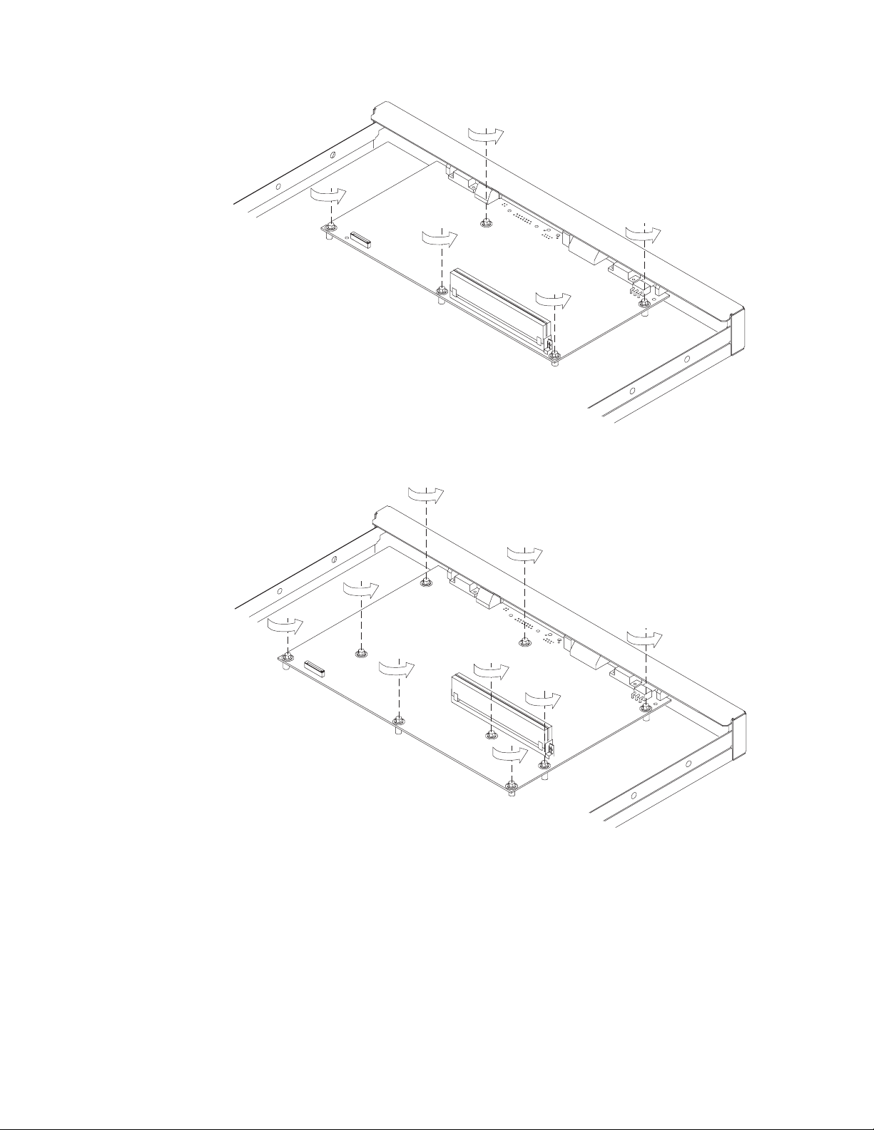
Figure 4-6. Non-ISDN System Board (12x Models)
Figure 4-7. ISDN System Board
5 Using a nut driver, remove the hex screws from the service port and from the
token-ring port, if present on this IBM 2210.
6 If you have an Ethernet port, remove both screws from the bracket on the
port, noting the position of the bracket as you remove it.
4-6 2210 Service and Maintenance
Page 57

Figure 4-8. Ethernet Port (12x Models)
7 With a screwdriver, remove the remaining slotted screws that attach the WAN
ports to the front panel.
8 You will transfer the single in-line memory module (SIMM) from this system
board to the new one. Go to “Removing the Dynamic Random Access
Memory (DRAM) SIMM for 12x Models” on page 4-15 for instructions for
removal. After you remove the SIMM, lift the system board out of the unit.
Replacing the System Board for 12x Models
1 Place the system board in the IBM 2210.
2 Go to “Replacing the DRAM SIMM for 12x Models” on page 4-16 for
instructions on replacing the SIMM. Then, continue with step 3.
3 Replace the system board retainer screws using a nut driver. Figure 4-9 and
Figure 4-10 on page 4-8 show the locations of the retainer screws for
system boards that do and do not support ISDN.
Figure 4-9. Non-ISDN System Board (12x Models)
Chapter 4. Removal and Replacement Procedures 4-7
Page 58

Figure 4-10. ISDN System Board (12x Models)
4 Using a nut driver, replace the hex screws in the service port and in the
token-ring port, if present on this IBM 2210.
5 If you have an Ethernet port, replace the bracket. See Figure 4-8 on
page 4-7 for reference.
6 Replace the remaining slotted screws that attach the WAN ports to the front
panel.
Figure 4-11. Attach Cables to the System Board (12x Models)
7 To attach the LED panel cable, slide the cable into the connector making
sure that the blue coloring on the end of the cable faces the blue latch. Be
sure to slide the cable into the latch as far as possible. Press down on the
blue retaining latch to secure the cable.
4-8 2210 Service and Maintenance
Page 59
8 Attach the fan cable by pressing firmly down until it clicks into place.
9 Position the power supply cable connector so that the side of the connector
with the tabs faces the retaining clips. Then, press firmly down until it clicks
into place.
10 Reinstall the cover. See “Reinstalling the Cover” on page 4-4 for
instructions.
Note: The customer must reload operational code and configuration infor-
mation after the system board is replaced.
Removing the System Board for 14T and 24x Models
Power Supply Cable
Reset Cable
Fan Cable
AC Power Ground
AC Power Cable
Figure 4-12. Cables Attached to the System Board - 14T Model
LED Panel Cable
Chapter 4. Removal and Replacement Procedures 4-9
Page 60

Power Supply Cable
Reset Cable
AC Power Ground
AC Power Cable
Figure 4-13. Cables Attached to the System Board - 24x Models
Fan Cable
LED Panel Cable
1 Remove any optional adapters, if installed. See “Removing the Optional
Adapter” on page 4-38 for the removal procedure.
2 Remove the power supply cable connector by pulling out the retaining clips
with your fingers or a screwdriver and then rocking it from front to back as
you pull up.
3 Remove the fan cable by rocking it from front to back as you pull up.
4 Remove the reset card cable from the system board.
5 Remove the Adapter Enablement Feature, if installed. See “Removing the
Adapter Enablement Feature” on page 4-36 for the removal procedure.
6 Remove the LED panel cable by using a screwdriver on either side of the
connector to lift the blue retaining latch. Pull the cable from the latch. Note
as you remove this cable that the blue coloring on the end of the cable faces
the blue latch.
7 Remove the second service port, if one is installed. See “Removing the EIA
232 Service Port Feature in Models 14T and 24x” on page 4-40 or
“Removing the 14.4 Kbps Modem Port Feature in Models 14T and 24x” on
page 4-41 for the appropriate procedure.
8 Remove the system board retainer screws using a nut driver. Figure 4-14 on
page 4-11 shows the location of the retainer screws.
4-10 2210 Service and Maintenance
Page 61

Figure 4-14. Retainer Screws on 14T and 24X Models
9 Using a nut driver, remove the hex screws from the service port and from the
token-ring ports, if present on this IBM 2210.
10 Remove both screws from the bracket on the Ethernet ports, if present on
this IBM 2210, noting the position of the bracket as you remove it.
Chapter 4. Removal and Replacement Procedures 4-11
Page 62

Figure 4-15. Ethernet Port
11 Using a screwdriver, remove the remaining slotted screws that attach the
WAN ports to the front panel.
12 You will transfer memory modules from this system board to the new one.
Go to “Removing the Dynamic Random Access Memory (DRAM) SIMM for
12x Models” on page 4-15 and “Removing the Flash and DRAM SIMMs in
Model 14T and 24x” on page 4-17 for instructions for removal. After you
remove the memory, lift the system board out of the unit.
Replacing the System Board for 14T and 24x Models
1 Place the system board in the IBM 2210.
2 Go to “Replacing the DRAM SIMM for 12x Models” on page 4-16 and
“Installing the Flash and DRAM SIMMs in Models 14T and 24x” on
page 4-18 for instructions on replacing the memory. Then, continue with
step 3.
3 Use a nut driver to replace the system board retainer screws. Figure 4-16
on page 4-13 shows the location of the retainer screws.
4-12 2210 Service and Maintenance
Page 63

Figure 4-16. System Board Retainer Screws (14T and 24x Models)
4 Using a nut driver, replace the hex screws in the service port and in the
token-ring port, if present on this IBM 2210.
5 Replace the bracket on the Ethernet port, if present. See Figure 4-8 on
page 4-7 for reference.
6 Replace the remaining slotted screws that attach the WAN ports to the front
panel.
Chapter 4. Removal and Replacement Procedures 4-13
Page 64
Power Supply Cable
Reset Cable
Fan Cable
AC Power Ground
AC Power Cable
Figure 4-17. Attach Cables to the System Board - 14T Models
Power Supply Cable
Fan Cable
Reset Cable
LED Panel Cable
LED Panel Cable
AC Power Ground
AC Power Cable
Figure 4-18. Attach Cables to the System Board - 24x Models
7 To attach the LED panel cable, slide the cable into the connector making
sure that the blue coloring on the end of the cable faces the blue latch. Be
sure to slide the cable into the latch as far as possible. Press down on the
blue retaining latch to secure the cable.
8 Replace the Adapter Enablement Feature, if installed. See “Installing the
Adapter Enablement Feature” on page 4-35 for the installation procedure.
9 Attach the reset card cable to the system board.
4-14 2210 Service and Maintenance
Page 65

10 Attach the fan cable by pressing firmly down until it clicks into place.
11 Position the power supply cable connector so that the side of the connector
with the tabs faces the retaining clips. Then, press firmly down until it clicks
into place.
12 Reinstall the cover. See “Reinstalling the Cover” on page 4-4 for
instructions.
Note: The customer must reload operational code and configuration infor-
mation after the system board is replaced.
Single In-line Memory Module (SIMM)
Refer to “Handling Static-Sensitive Devices” on page 4-2 before removing or
installing a SIMM.
Removing the Dynamic Random Access Memory (DRAM) SIMM for 12x
Models
Note: The figures in this procedure are based on the 12x models. The location of
the DRAM socket is similar in the other models and the procedures are identical.
Figure 4-19. Removing the DRAM SIMM in 12x Models
Chapter 4. Removal and Replacement Procedures 4-15
Page 66
1 Push back the retaining tabs located at each end of the SIMM socket. The
SIMM will fall forward.
2 Remove the SIMM by gently pulling it toward you.
Replacing the DRAM SIMM for 12x Models
Figure 4-20. Replacing the DRAM SIMM in 12x Models
1 Tilt the top of the SIMM toward you and slide it into the retainer.
2 Press the SIMM backward until the retaining tabs are holding it securely.
4-16 2210 Service and Maintenance
Page 67
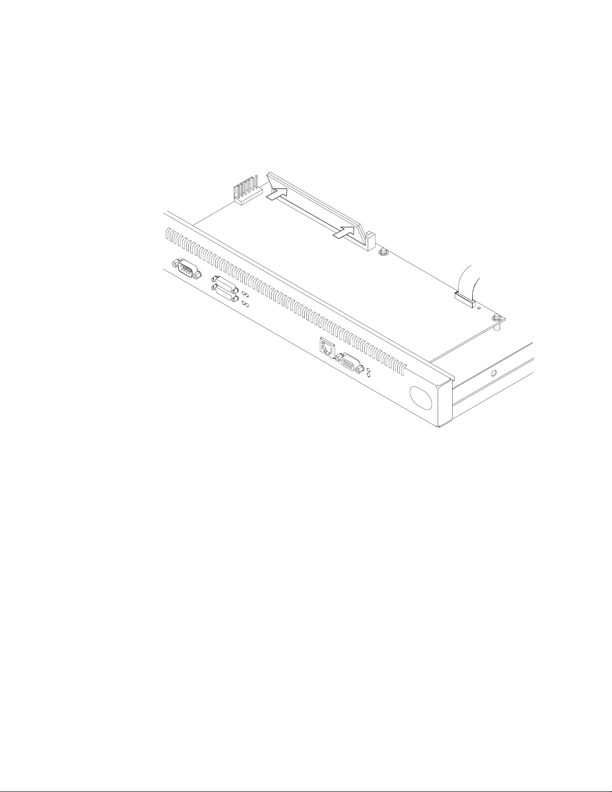
Removing the Flash and DRAM SIMMs in Model 14T and 24x
Figure 4-21. Removing the Flash SIMM (14T and 24x Models)
1 Remove the cover from the IBM 2210 as described in “Removing the Cover”
on page 4-2.
2 Push back the retaining tabs located at each end of the SIMM socket. The
SIMM will fall backwards.
3 Remove the SIMM by gently pulling it away from you.
4 Replace the cover on the IBM 2210 as described in “Reinstalling the Cover”
on page 4-4.
5 Verify that the IBM 2210 is functioning correctly by using “MAP 0210: Verify
Operation” on page 2-23.
Chapter 4. Removal and Replacement Procedures 4-17
Page 68
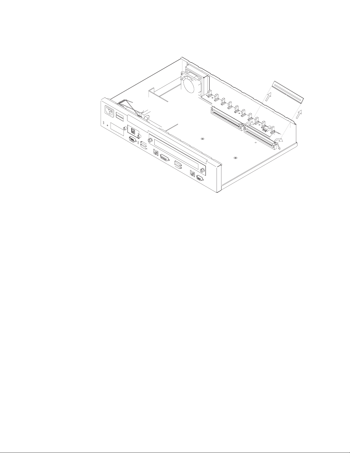
Installing the Flash and DRAM SIMMs in Models 14T and 24x
| Note: When using 32 MB of memory with a 14T or 24x model you must be at
| revision level 2.34 or higher of the PROM Load/Dump Program.
Refer to “Handling Static-Sensitive Devices” on page 4-2 before removing or
installing a flash SIMM.
Figure 4-22. Installing the Flash SIMM (14T and 24x Models)
1 Remove the cover from the IBM 2210 as described in “Removing the Cover”
on page 4-2.
2 Tilt the top of the SIMM away from you and slide it into the retainer.
3 Press the SIMM forward until the retaining tabs are holding it securely.
4 Replace the cover on the IBM 2210 as described in “Reinstalling the Cover”
on page 4-4.
5 Verify that the IBM 2210 is functioning correctly by using “MAP 0210: Verify
Operation” on page 2-23.
4-18 2210 Service and Maintenance
Page 69
Power Supply
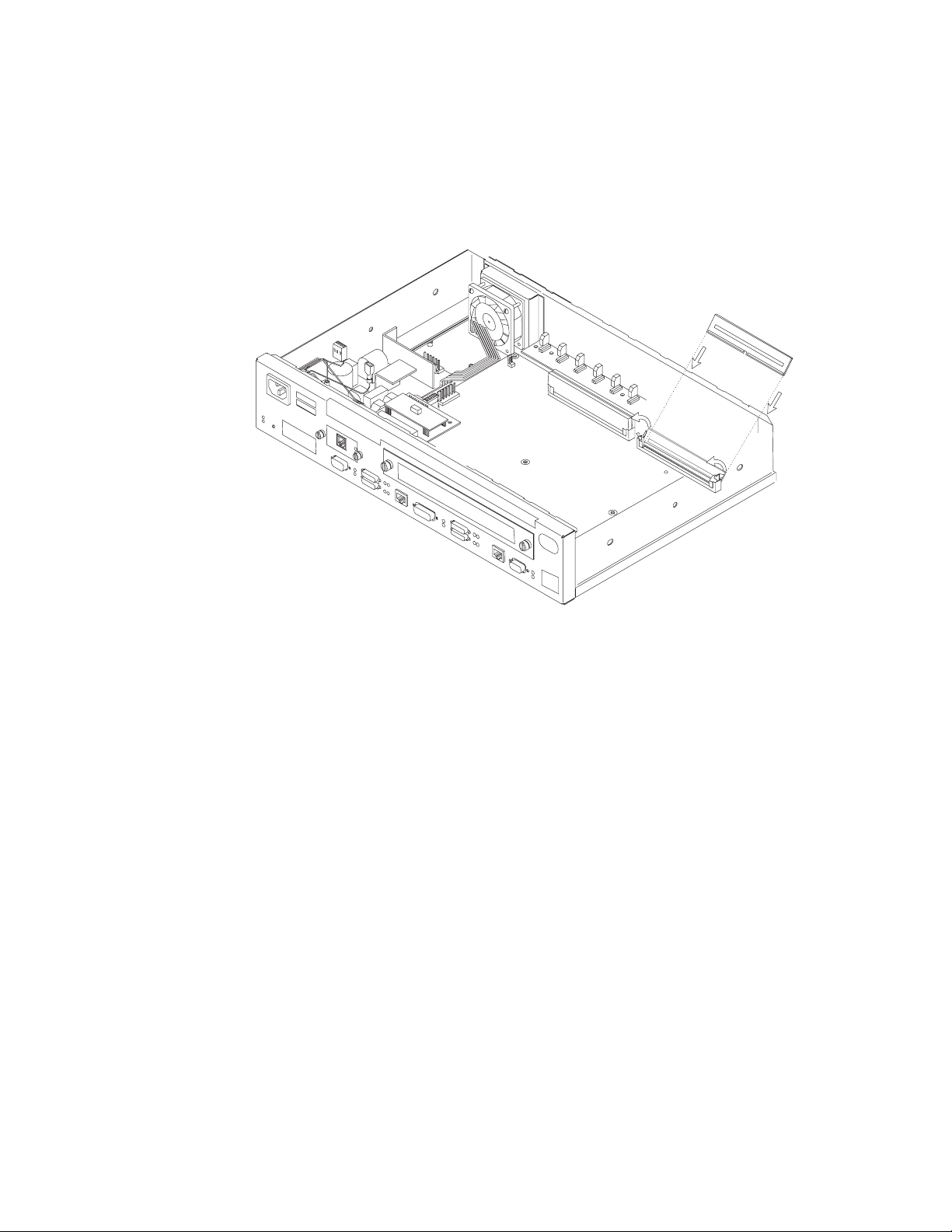
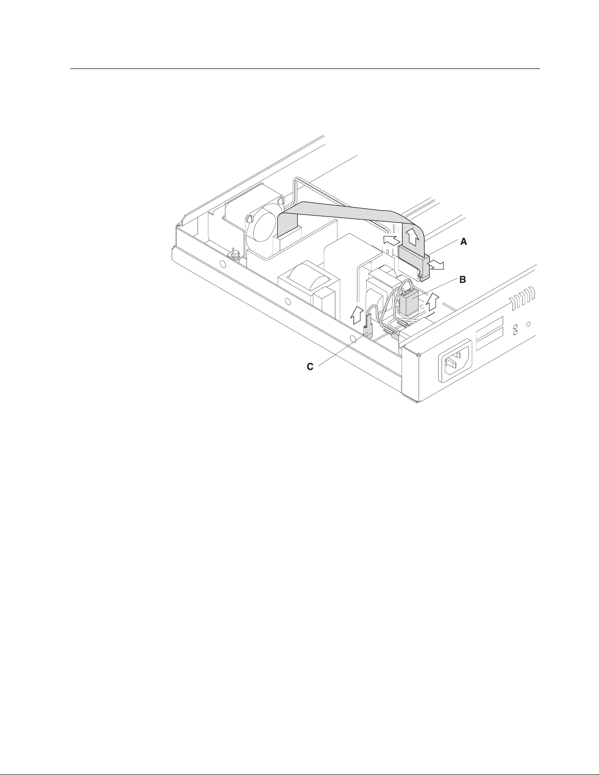
Removing the Power Supply for 12x Models
Figure 4-23. Connections to the Power Supply (12x Models)
1 Remove the connector to the system board (A) by pulling out the retaining
clips with your fingers or a screwdriver and then rocking the connector from
front to back as you pull up.
2 Remove the connector to the ac power source (B).
3 Remove the spade lug terminal ground for the ac power source (C), using
needle-nose pliers.
Chapter 4. Removal and Replacement Procedures 4-19
Page 70
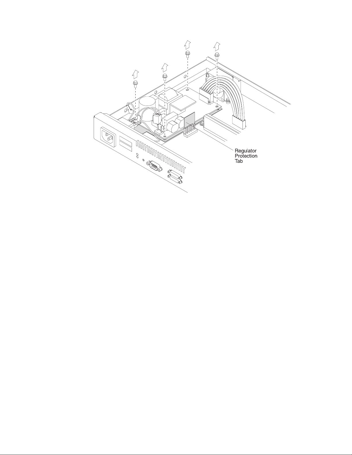
Figure 4-24. Removing the Screws from the Power Supply (12x Models)
4 Remove the four corner hex screws from the power supply.
5 Lift the power supply out of the system unit. Be sure to leave the insulator in
place when you remove the power supply and note the position of the regulator protection tab.
4-20 2210 Service and Maintenance
Page 71

Replacing the Power Supply for 12x Models
Figure 4-25. Replacing the Corner Screws (12x Models)
1 Place the power supply on top of the insulator, being sure the regulator pro-
tection tab is perpendicular to the base of the unit. Replace the four hex
screws.
Chapter 4. Removal and Replacement Procedures 4-21
Page 72
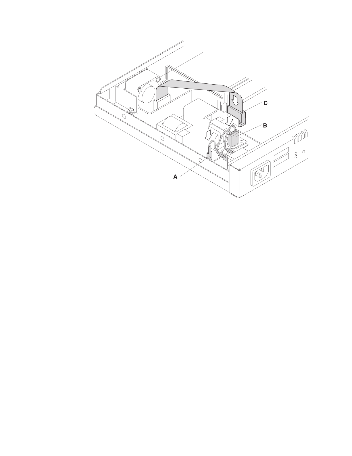
Figure 4-26. Connections to the Power Supply (12x Models)
2 Replace the spade lug terminal ground (A).
3 Replace the connector to the ac power source (B).
4 Position the connector to the system board (C) so that the side of the con-
nector with the tabs faces the retaining clips. Then, press firmly down until it
clicks into place. Be sure it is firmly seated.
Removing the Base Power Supply for 14T and 24x Models
To remove the power supply:
1 Remove the screws that attach the power supply cover to the chassis as
shown in Figure 4-27 on page 4-23.
4-22 2210 Service and Maintenance
Page 73

Figure 4-27. Removing the Screws from the Power Supply (14T and 24x Models)
2 Remove the connector to the system board by pulling out the retaining clips
with your fingers or a screwdriver and then rocking it from front to back as
you pull up.
Chapter 4. Removal and Replacement Procedures 4-23
Page 74

Power Supply Cable
Reset Cable
AC Power Ground
AC Power Cable
Figure 4-28. Connections to the Power Supply (14T and 24x Models)
Fan Cable
LED Panel Cable
3 If the Adapter Enablement Feature feature is installed, remove the connector
to the adapter riser card.
4 Remove the power supply cover by sliding the cover toward the fan until the
leading edge of the cover clears the front panel, then lifting.
5 Remove the connector from the adapter power supply, if installed, to the ac
power source.
6 Remove the connector to the ac power source.
7 Remove the four corner hex screws from the power supply.
8 Lift the power supply out of the system unit. Be sure to leave the insulator in
place when you remove the power supply and note the position of the regulator protection tab.
4-24 2210 Service and Maintenance
Page 75
Replacing the Power Supply for 14T and 24x Models
1 Place the power supply on top of the insulator, being sure the regulator pro-
tection tab is perpendicular to the base of the unit. Replace the four hex
screws.
Power Supply Cable
Reset Cable
AC Power Ground
AC Power Cable
Figure 4-29. Connections to the Power Supply (14T and 24x Models)
Fan Cable
LED Panel Cable
2 Replace the connector to the ac power source.
3 Replace the connector from the adapter power supply, if installed, to the ac
power source.
Chapter 4. Removal and Replacement Procedures 4-25
Page 76

Figure 4-30. Replacing the Power Supply Cover
4 Replace the power supply cover over the power supply by sliding the cover
forward until the leading edge is beneath the front panel. Make sure that the
reset card cable is beneath the cover and not between the cover and the
front panel.
4-26 2210 Service and Maintenance
Page 77

Also make sure that the connectors feed through the space between the side
and rear of the cover and the connectors without the jumpers are connected
to the power supplies.
5 Replace the screws that attach the power supply cover to the chassis as
shown in Figure 4-30 on page 4-26.
6 If the Adapter Enablement Feature is installed, position the connector to the
adapter riser card so that the side of the connector with the tabs faces the
retaining clips. Then, press firmly down until it clicks into place. Be sure it is
firmly seated.
7 Position the connector to the system board so that the side of the connector
with the tabs faces the retaining clips. Then, press firmly down until it clicks
into place. Be sure it is firmly seated.
8 If the Adapter Enablement Feature is installed, connect the jumpers between
the base power supply and the adapter power supply together.
Fan
Note: For the 14T and 24x models, removing the power supply cover will ease the
fan removal process. Instructions on removing and replacing the power supply
cover are contained in “Removing the Base Power Supply for 14T and 24x Models”
on page 4-22 and “Replacing the Power Supply for 14T and 24x Models” on
page 4-25.
Removing the Fan
Figure 4-31. Removing the Fan
Chapter 4. Removal and Replacement Procedures 4-27
Page 78

Replacing the Fan
1 Remove the connector to the system board by rocking it from front to back as
you pull up.
2 Remove the screws from the mounting bracket that encases the fan on the
12x models. On the 14T and 24x models, remove the screws that attach the
fan to the rear of the IBM 2210 chassis.
3 Lift the fan from the system unit.
Figure 4-32. Replacing the Fan
1 Place the fan in the system unit, making sure that it is positioned so that it
fits tightly against the wall of the IBM 2210 and the cable faces the center of
the machine.
2 Replace the screws that attach the fan to the bottom of the machine on the
12x models. On the 14T and 24x models, replace the screws that attach the
fan to the rear of the IBM 2210 chassis.
3 Attach the connector to the system board by pressing down firmly until it
clicks into place.
4-28 2210 Service and Maintenance
Page 79

LED Panel
Removing the LED Panel for 12x Models
Figure 4-33. Removing the LED Panel (12x Models)
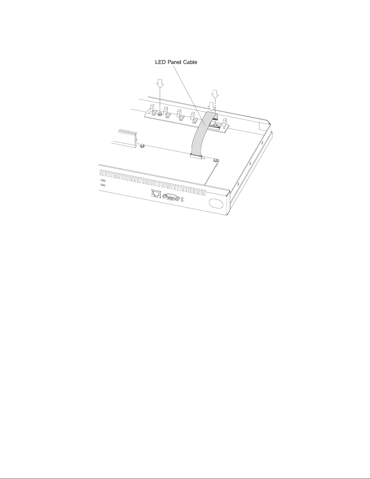
1 To remove the LED panel cable, use a screwdriver on either side of the con-
nector to lift the blue retaining latch. Pull the cable from the latch. Note as
you remove this cable that the blue coloring on the end of the cable faces the
blue latch.
2 Remove the two screws that attach the LED panel to the floor of the
machine.
3 Slide the LED panel toward the center of the machine until the bulbs clear
the wall of the system unit.
Chapter 4. Removal and Replacement Procedures 4-29
Page 80
Replacing the LED Panel for 12X Models
Figure 4-34. Replacing the LED Panel (12x Models)
1 Slide the LED panel into place, making sure the LED bulbs fit into the
openings on the wall of the machine.
2 Replace the two screws that attach the LED panel to the floor of the
machine.
3 Attach the LED panel cable by sliding the cable into the connector, making
sure that the blue coloring on the end of the cable faces the blue latch. Be
sure to slide the cable into the latch as far as possible. Press down on the
blue retaining latch to secure the cable.
4-30 2210 Service and Maintenance
Page 81
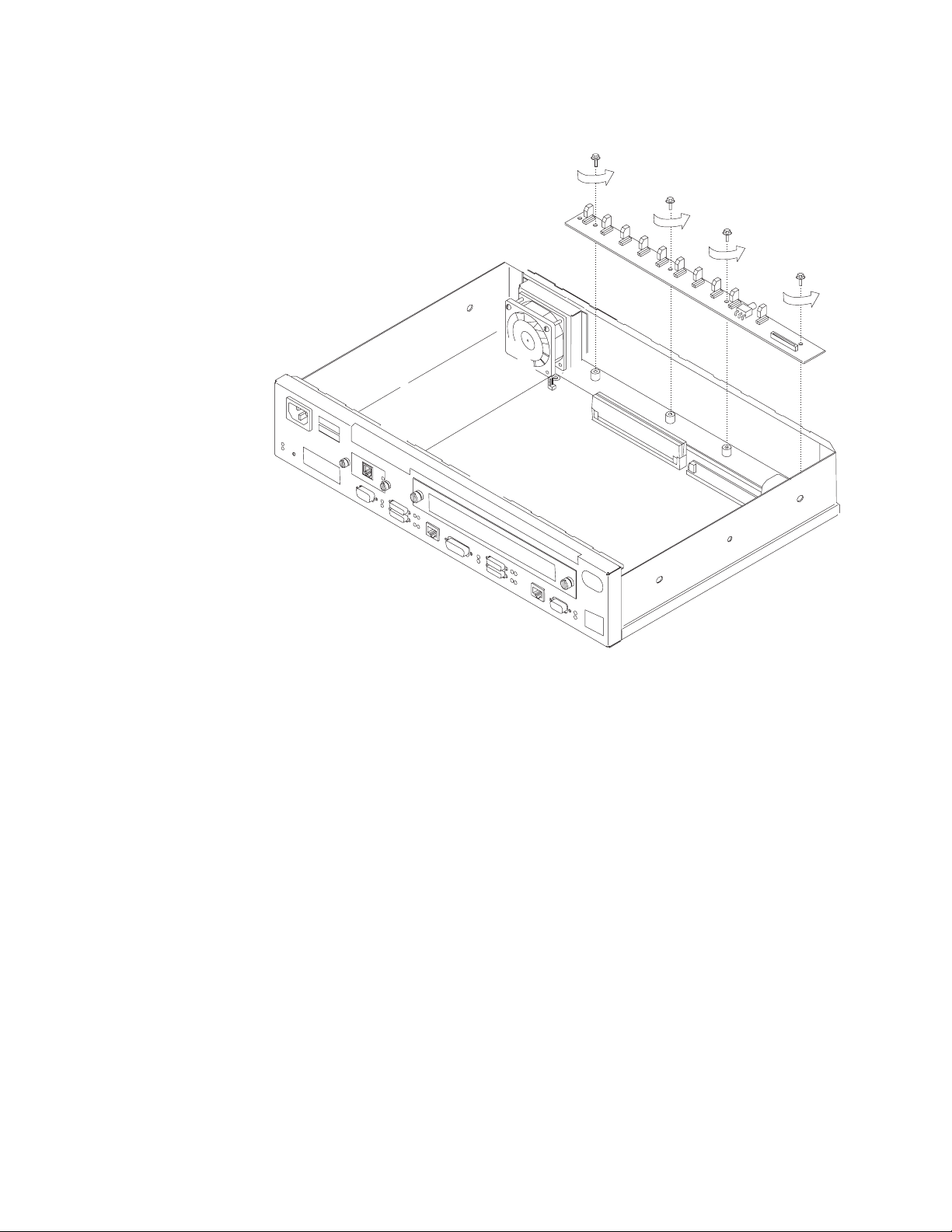
Removing the LED Panel for 14T and 24x Models
Figure 4-35. Removing the LED Panel (14T and 24x Models)
1 To remove the LED panel cable, use a screwdriver on either side of the con-
nector to lift the blue retaining latch. Pull the cable from the latch. Note as
you remove this cable that the blue coloring on the end of the cable faces the
blue latch.
2 Remove the four screws that attach the LED panel to the floor of the
machine.
3 Slide the LED panel toward the center of the machine until the bulbs clear
the wall of the system unit.
Chapter 4. Removal and Replacement Procedures 4-31
Page 82

Replacing the LED Panel for 14T and 24X Models
Figure 4-36. Replacing the LED Panel (14T and 24x Models)
1 Slide the LED panel into place, making sure the LED bulbs fit into the
openings on the wall of the machine.
2 Replace the four screws that attach the LED panel to the floor of the
machine.
3 Attach the LED panel cable by sliding the cable into the connector, making
sure that the blue coloring on the end of the cable faces the blue latch. Be
sure to slide the cable into the latch as far as possible. Press down on the
blue retaining latch to secure the cable.
Installing An Optional Adapter in Models 14T and 24x
Installing an optional adapter in a model 14T or 24x requires that the IBM 2210
Adapter Enablement Feature be already installed. To determine that the feature is
installed, remove the faceplate, look into the opening, and look for the guide rails.
| Note: If you are installing a 4- or 8-port Dial Access Adapter with the x4x model
| you must have or install the PROM Load/Dump Program revision level 2.40 or
| higher.
| Note: If you are replacing one adapter type with a different adapter type and you
| are not using the configuration program, use the talk 6 delete interface command
4-32 2210 Service and Maintenance
Page 83

| to delete any virtual interfaces, for example, dial circuits, associated with the
| adapter prior to removing the adapter. The talk 6 delete interface command
| deletes the interface you explicitly state in the command line. The interface in
| current use will not be deleted unless you specify that interface name in the
| command line.
If the guide rails are visible, the feature is installed and you can continue the installation at “Installing Optional Adapters” on page 4-36.
If the guide rails are not visible, you should begin the installation at “Installing the
Adapter Power Supply.”
Installing the Adapter Power Supply
1 Remove the cover as directed in “Removing the Cover” on page 4-2, if not
already removed.
2 Remove the power supply cover and keep the three fastening screws. See
“Removing the Base Power Supply for 14T and 24x Models” on page 4-22
for detailed instructions.
3 Turn over the cover.
4 Place the insulator inside the top of the cover.
5 Place the power supply on the insulator and fasten it in position to the top of
the power supply cover using the four securing screws.
6 Attach the dc power cable to the power supply and feed the cable through
the access slot.
7 Attach the ac power cable to the power supply and replace the cover over
the existing power supply, using the original screws. Make sure that the lip
of the cover goes under the lip of the frame.
Assembling the Riser Card
Refer to “Handling Static-Sensitive Devices” on page 4-2 before removing or
installing the riser card to the system board.
Chapter 4. Removal and Replacement Procedures 4-33
Page 84
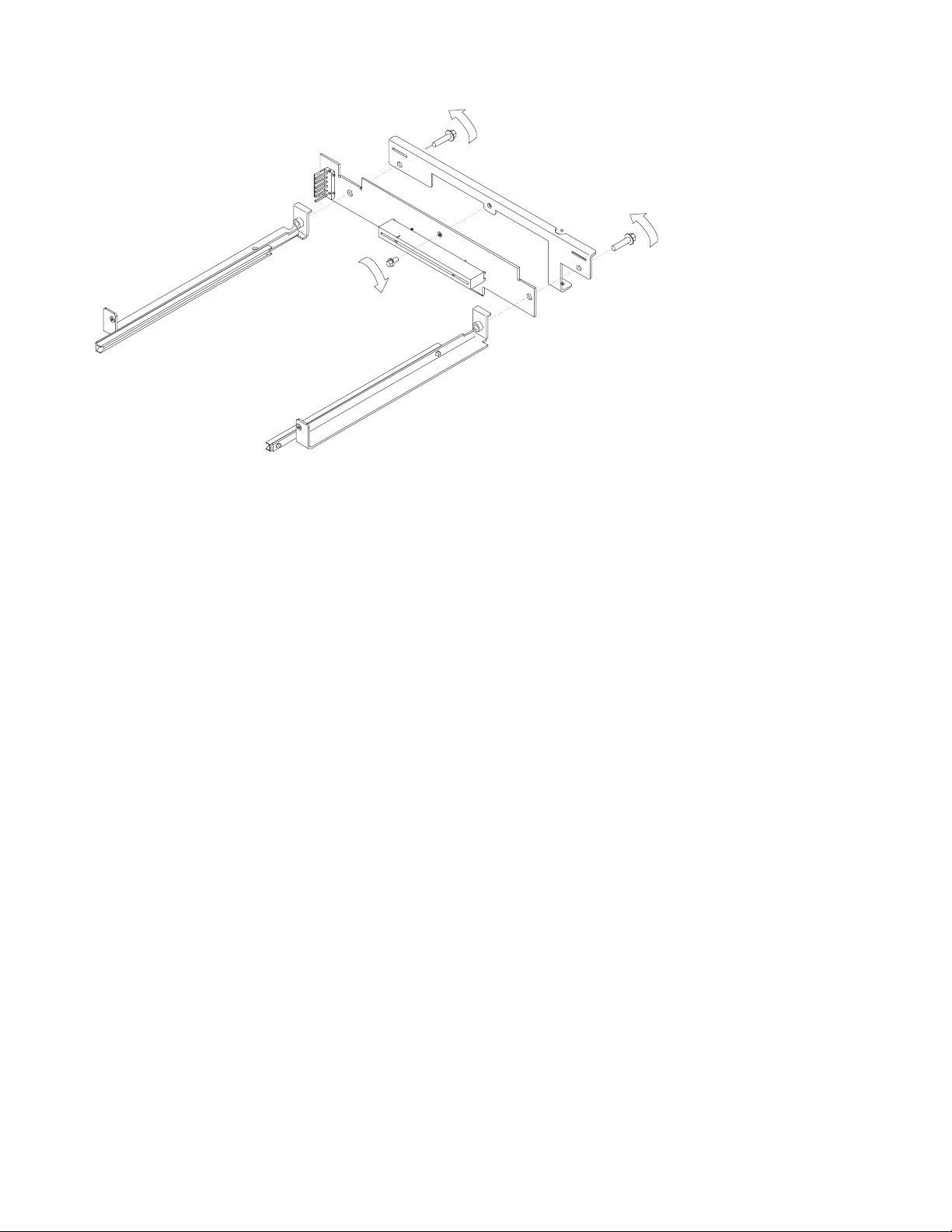
Figure 4-37. Assembling the Riser Card
1 Attach the riser card Assembly with the supplied screw to the riser brace as
shown in Figure 4-37.
2 Attach the left guide assembly to the riser brace.
3 Attach the right guide assembly to the riser brace.
Note: Position the guide assemblies as far from each other as possible
before tightening screws.
4-34 2210 Service and Maintenance
Page 85

Installing the Adapter Enablement Feature
Figure 4-38. Installing the Adapter Enablement Feature
1 Carefully place the assembly in position and plug the riser card assembly into
the socket on the system board.
2 Fasten the rear of the assembly to the system board using the supplied
screw.
Chapter 4. Removal and Replacement Procedures 4-35
Page 86

3 Fasten the front of the assembly to the front frame using the supplied screws.
4 Insert an optional adapter into the module slot to ensure the adapter fits into
the assembly correctly.
5 Tighten all screws on the assembly.
6 Attach the dc power cable to the connector on the left-hand side of the riser
card assembly. Make sure the connector with the jumper is connected to the
riser card.
7 Connect the jumpers between the base power supply and the adapter power
supply together.
8 Replace the IBM 2210 cover as described in “Reinstalling the Cover” on
page 4-4.
9 Verify that the IBM 2210 is functioning correctly by using “MAP 0210: Verify
Operation” on page 2-23.
Removing the Adapter Enablement Feature
1 Remove the IBM 2210 cover as described in “Removing the Cover” on
page 4-2.
2 Detach the dc power cable from the connector on the left-hand side of the
riser card assembly.
3 Remove the front screws of the assembly from the front frame.
4 Remove the screw that fastens the rear of the assembly to the system board.
5 Carefully lift the assembly and riser board out of the socket on the system
board.
6 Remove the adapter power supply from the power supply cover.
Installing Optional Adapters
Refer to “Handling Static-Sensitive Devices” on page 4-2 before removing or
installing any of the optional adapters.
4-36 2210 Service and Maintenance
Page 87

Figure 4-39. Installing the Optional Adapter (Actual adapter may appear different)
1 Unplug the power cord.
2 Remove the blank faceplate by loosening the two screws and pulling the
plate toward you.
3 Check to ensure that the Adapter Enablement Feature is installed. Look
inside the module slot and ensure that the guide rails for the card are
present.
If the guide rails are not visible, an authorized service representative must
install the Adapter Enablement Feature. If you have not ordered the Adapter
Enablement Feature, you should do so before proceeding.
If the feature is not installed, refer to the
Router Service and Maintenance Manual
IBM 2210 Nways Multiprotocol
.
4 Remove the adapter from the antistatic bag.
5 While holding the adapter carefully by the front plate insert it into the
opening. Make sure that the edges of the adapter line up with the guide
rails.
6 Press the adapter into the slot.
7 Secure the adapter in place by tightening the screws.
8 Plug the power cord into the outlet.
Chapter 4. Removal and Replacement Procedures 4-37
Page 88

9 Verify that the IBM 2210 is functioning correctly by using “MAP 0210: Verify
Operation” on page 2-23.
Removing the Optional Adapter
Figure 4-40. Removing the Adapter (Actual adapter may appear different)
1 Unplug the power cord.
2 Remove the screws holding the adapter in place.
3 Remove the adapter by gently pulling it toward you.
4 Replace the blank faceplate or install new adapter and tighten the two
screws.
5 Plug the power cord into the outlet.
6 Verify that the IBM 2210 is functioning correctly by using “MAP 0210: Verify
Operation” on page 2-23.
4-38 2210 Service and Maintenance
Page 89
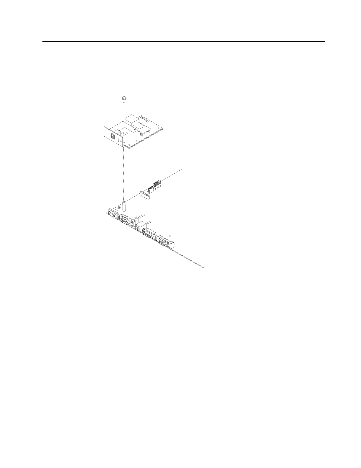
Installing a Second Service Port in Models 14T and 24x
Refer to “Handling Static-Sensitive Devices” on page 4-2 before removing or
installing a second service port card.
Installing the EIA 232 Service Port Feature in Models 14T and 24x
Figure 4-41. Installing the EIA 232 Service Port Feature
1 Remove the cover from the IBM 2210 as described in “Cover” on page 4-2.
2 Remove the blank Service Port faceplate by unscrewing the two screws.
3 Save the faceplate and screws.
4 Insert the EIA 232 Service Port Feature connection into the connector on the
system board.
5 Using the two screws from the blank faceplate secure the front of the Service
Port Card faceplate to the frame of the IBM 2210.
6 Fasten the middle of the EIA 232 Service Port Feature to the standoff on the
system board using the supplied Philips-head screw.
7 Replace the cover as described in “Reinstalling the Cover” on page 4-4.
Chapter 4. Removal and Replacement Procedures 4-39
Page 90

8 Verify that the IBM 2210 is functioning correctly by using “MAP 0210: Verify
Operation” on page 2-23.
Removing the EIA 232 Service Port Feature in Models 14T and 24x
1 Remove the cover from the IBM 2210 as described in “Cover” on page 4-2.
2 Remove the two screws that secure the EIA 232 Service Port Feature to the
IBM 2210 frame.
3 Remove the Philips-head screw that attaches the middle of the EIA 232
Service Port Feature to the standoff on the system board.
4 Remove the EIA 232 Service Port Feature connection from the system board.
5 Lift the EIA 232 Service Port Feature out of the IBM 2210 chassis.
Installing the 14.4 Kbps Modem Port Feature in Models 14T and 24x
Figure 4-42. Installing the 14.4 Kbps Modem Port Feature
1 Remove the cover from the IBM 2210 as described in “Cover” on page 4-2.
2 Remove the blank Service Port faceplate by unscrewing the two screws.
3 Save the faceplate and screws.
4 Insert the 14.4 Kbps Modem Port Feature connection into the connector on
the system board.
4-40 2210 Service and Maintenance
Page 91

5 Attach the 14.4 Kbps Modem Port Feature to the system board by inserting
the alignment post through the top of the modem and screwing in the post.
6 Using the two screws from the blank faceplate secure the front of the Modem
Card faceplate to the frame of the 2210.
7 Replace the cover as described in “Reinstalling the Cover” on page 4-4.
8 Verify the IBM 2210 is functioning correctly by using “MAP 0210: Verify
Operation” on page 2-23.
Removing the 14.4 Kbps Modem Port Feature in Models 14T and 24x
1 Remove the cover from the IBM 2210 as described in “Cover” on page 4-2.
2 Remove the two screws that secure the 14.4 Kbps Modem Port Feature to
the IBM 2210 frame.
3 Unscrew the alignment post and remove it from the modem.
4 Remove the 14.4 Kbps Modem Port Feature connection from the system
board.
5 Lift the 14.4 Kbps Modem Port Feature out of the IBM 2210 chassis.
Chapter 4. Removal and Replacement Procedures 4-41
Page 92

Upgrading the 4-Port Dial Access Adapter Using the 4-Port Dial
Access Modem Card Feature
Note: This procedure assumes that you have a 4-port Dial Access Adapter
installed in your IBM 2210.
Rear Blanking
Plate
C
D
O
1
H
R
e
a
d
y
2
3
4
Front
Blanking
Plate
5
6
7
8
Powe
r
Fa
u
lt
4 Port
Connector Plug
Blanking
Plate
Screws
Figure 4-43. Upgrading the 4-Port Dial Access Adapter
To upgrade the 4-port Dial Access Adapter with a new 4-port Dial Access Modem
Card:
1. Remove the Dial Access Adapter from the 2210 as described in “Removing the
Optional Adapter” on page 4-38.
2. Remove the 4-port Dial Access Modem Card from the anti-static bag.
3. Place the bag on a flat surface and place the Dial Access Adapter that you
removed from the IBM 2210 on top of the bag.
4. Using a flat-blade screwdriver, remove the blanking plate from the Dial Access
Adapter faceplate and store in a safe place. You will need to replace this if the
4-port Dial Access Modem Card is removed from the adapter.
5. Angle the upgrade such that the RJ-11 jacks align with the ports on the
faceplate.
6. Align the 4-port connector plug on the 4-port Dial Access Modem Card and the
connector receptacle on the Dial Access Adapter.
7. Press firmly on the 4-port Dial Access Modem Card over the words PRESS
HERE TO INSERT.
8. Using a nut driver, secure the 4-port Dial Access Modem Card in place with the
three (3) screws provided.
9. Reinstall the Dial Access Adapter as described in “Installing Optional Adapters”
on page 4-36.
4-42 2210 Service and Maintenance
Page 93

10. Store the antistatic bag in a safe place. You will need this if you remove the
adapter from the IBM 2210.
Removing the 4-Port Dial Access Modem Card
To remove the 4-port Dial Access Modem Card from the Dial Access Adapter:
1. Remove the adapter from the IBM 2210 as described in “Removing the
Optional Adapter” on page 4-38.
2. Using a nut driver, remove the three screws securing the 4-port Dial Access
Modem Card.
3. Grasp the 4-port Dial Access Modem Card upgrade by the connector next to
the words PRESS HERE TO INSERT.
4. Lift and wiggle the connector until the 4-port Dial Access Modem Card plug
comes free of the Dial Access Adapter socket.
5. Replace the 4-port Dial Access Modem Card as described in “Upgrading the
4-Port Dial Access Adapter Using the 4-Port Dial Access Modem Card Feature”
on page 4-42, if desired.
6. Reinstall the Dial Access Adapter as described in “Installing Optional Adapters”
on page 4-36.
Chapter 4. Removal and Replacement Procedures 4-43
Page 94

4-44 2210 Service and Maintenance
Page 95

Appendix A. Access Methods and Attaching an ASCII
Terminal
To run the menu-driven diagnostics, you must attach an ASCII terminal to the
| service port of the IBM 2210. This chapter explains how to access the IBM 2210’s
| operational and configuration software. The chapter also lists the ASCII terminals
| that are supported and provides information about setup attributes.
Access Methods
|
| The IBM 2210 software must be configured as part of the installation process.
| Therefore, you have to access the software in one of the following ways:
| Locally through a null-modem adapter and serial cables supplied with this
| product that are attached to the EIA-232 service port using an ASCII con| nection. See Figure A-1.
| Remotely using dial-in (over telephone lines) through a modem attached to the
| EIA-232 primary service port or the secondary service port, if installed. You can
| also use an ASCII connection. The secondary service port can be either an
| EIA-232 Service Port Feature or a 14.4 Kbps Modem Port Feature. See
| Figure A-2 on page A-2 and Figure A-3 on page A-2.
|
| Access Pro-
| Default IP
| Physical Attachment| Line Protocol
| tocol
| Address
| Service port + null modem
| Asynchronous
| ASCII terminal
| Service port + external modem
| characters
| emulation| Not applicable
| Any IP network interface| IP| Telnet| No defaults
| An ASCII connection requires an ASCII terminal or workstation running an ASCII
| terminal emulator.
| Once the IBM 2210 is operational in the network, you can access the IBM 2210 by
| Telnetting from a network-connected workstation. This workstation must be
| attached to any of the IBM 2210’s IP-capable network interfaces. The network inter| face can be on a LAN adapter or WAN adapter because both support IP routing.
| The Telnet workstation can be locally or remotely connected.
Table A-1. User Console Attachment Options
|
Copyright IBM Corp. 1994, 1998 A-1
Figure A-1. Local Terminal Connection to the EIA-232 Service Port
Page 96

|
|
|
Figure A-2. Remote Connection to 14.4 Kbps Modem Port Feature (14T and 24x Models)
Figure A-3. Remote Terminal Connection to the Primary or Secondary EIA-232 Service
Port
| Service Port Default Settings
| These are the default settings for the serial port:
| Speed 9600 bps
| Parity None
| Data Bits 8
| Stop Bits 1
| You can configure the service port speed for the following bit rates; however, the
| speed must match the speed configured for the ASCII terminal. The IBM 2210 also
| supports auto-baud.
| 300
| 1200
| 2400
| 4800
| 9600
| 19 200
| 38 400
| Modem Support
| Modem Requirements
| The modem must be connected to the service port on the IBM 2210, use asynchro| nous operation, and be compatible with the Attention (AT) command set. A modem
| connected to a 2210 service port must be configured with the following character| istics:
| No echo
| Suppress results code
| Auto-answer
A-2 2210 Service and Maintenance
Page 97

| Hardware (RTS/CTS) flow control
| Modem DTE speed fixed to match 2210 service port speed (9600 recom| mended).
| Consult your modem documentation on how to configure and save these settings.
| Remote Connection for Service
| To resolve a problem with your IBM 2210, IBM service personnel may request per| mission to establish a temporary, remote connection to the IBM 2210. In most situ| ations, the IBM service personnel will not be at a remote workstation that is
| connected to your IP network. Consequently, remote access must be established
| using a modem. Whenever you authorize IBM service personnel to establish such
| a remote connection, you must:
| Connect and configure the modem before the remote service session can begin
| Provide the service personnel with the telephone number of a modem con-
| nected to the service port of the target IBM 2210 or to a modem that is con| nected to the service port on an IBM 2210 that is on the same network as the
| target IBM 2210
| Provide service personnel with the password or other necessary information for
| access to any security protection features
| Modem Settings
| The following modems have been tested for use with the IBM 2210:
| IBM 7852, Model 400
| Zoom/FaxModem 56Kx
| Atlas 33.6 External PC Data/Fax Modem
| For instructions on setting-up these and possibly other modems to operate with
| your IBM 2210, see: http://www.networking.ibm.com/support/221ð
Attaching an ASCII Terminal to the Service Port
|
| Attach an ASCII terminal or emulator (with the appropriate emulation software) to
| the service port to provide local or remote access to the IBM 2210 as shown in
| Figure A-4 on page A-4.
Appendix A. Access Methods and Attaching an ASCII Terminal A-3
Page 98
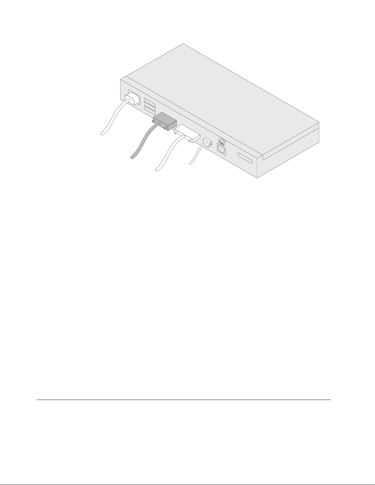
100-240VA
0.4-0.2A50/60H
C
10
z
|
Figure A-4. Attaching an ASCII Terminal to the Service Port
| When locally attaching a terminal to the IBM 2210 service port, the speed (baud
| rate) configured for the service port must match the speed of the connected ter| minal if the IBM 2210 has been configured to use a specific baud rate. If the IBM
| 2210 is configured for auto-baud the IBM 2210 learns the ASCII terminal’s line
| speed when the user types the terminal break key sequence and presses Enter. A
| typical break key sequence for PC terminal emulators is Alt-B (refer to the terminal
| emulator documentation). Most ASCII terminals have a Break key (often used in
| conjunction with the Ctrl key).
| Note: When using a locally attached terminal to run the IBM 2210 diagnostic pro| grams, the service port line speed must be set to 9600 bps. This setting is a con| stant and cannot be changed.
| When connecting a IBM 2210 to a remote terminal by two modems connected by
| telephone lines, you must follow these rules:
| If the modems are running at a speed of 9600 or lower and they do
not
| support hardware compression, the IBM 2210 service port speed and the ter| minal speed must match the modems’ line speed.
| If the modems are running hardware compression, the IBM 2210 service port
| speed and the terminal speed should exceed the modems’ line speed.
Note: The IBM 2210 service port can be damaged by static electricity discharge. It
is shipped with a plastic port cover to prevent such damage. Remove the plastic
cover when you are attaching a terminal and store it in a safe place. When you
disconnect the terminal, reinstall the plastic cover.
ASCII Terminals and Setup Attributes
The DEC VT100 ASCII terminal is supported, as well as devices, such as personal
computer systems, that are configured to emulate it. Configure a VT100 with:
No parity
8-bit word length
1 stop bit
A-4 2210 Service and Maintenance
Page 99
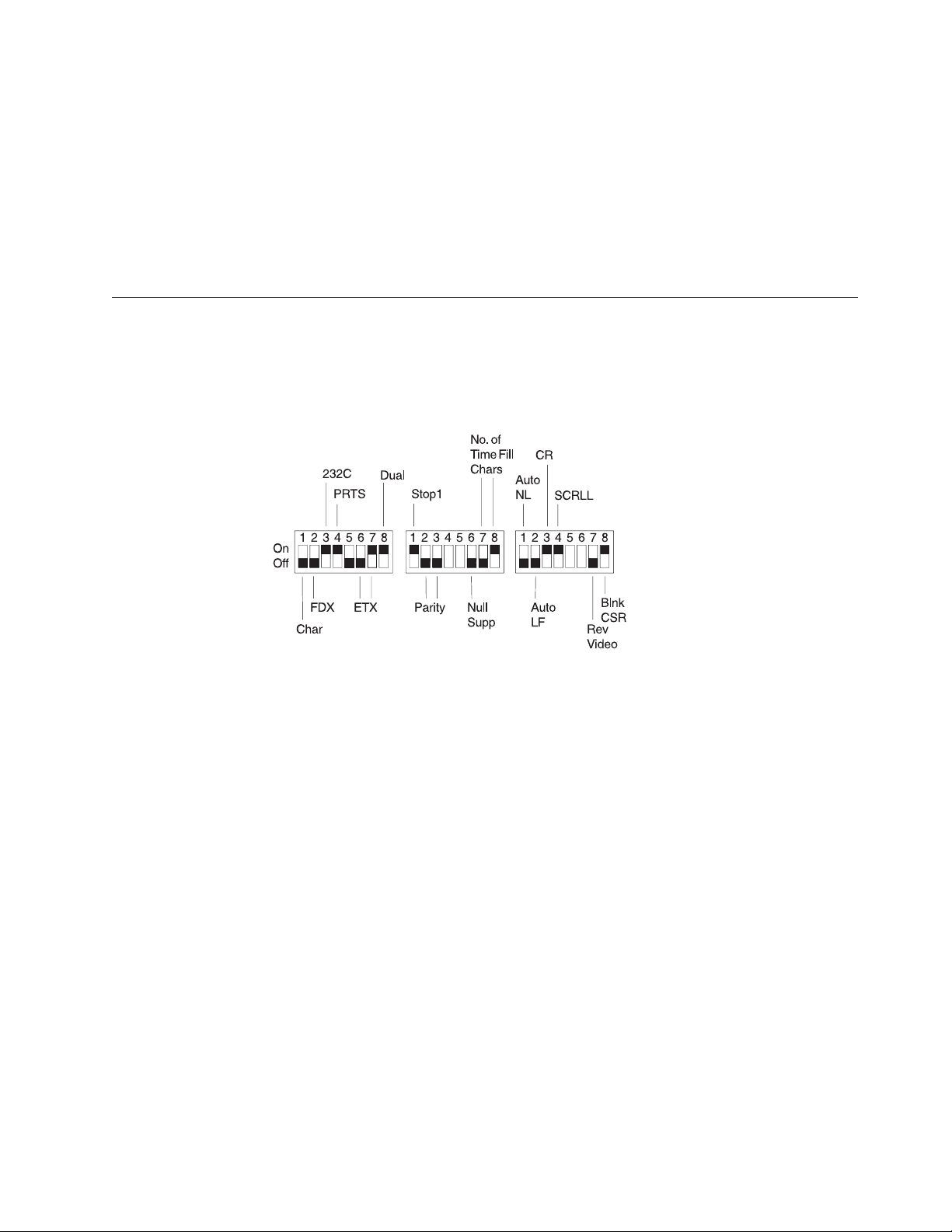
300 bps–38.4 Kbps bit rate
| The terminal speed must match the serial port speed.
The following terminals are also supported:
IBM 3101 Display Terminal
IBM 3151 ASCII Display Station
IBM 3161 ASCII Display Station
Configure these terminals as shown in “Setup Attributes.”
Setup Attributes
IBM 3101 Setup Attributes
Use Figure A-5 to determine the settings for the setup attributes for the IBM 3101
ASCII terminal.
Figure A-5. Setup Attributes for the IBM 3101 Display Terminal
| The 2210 can use this terminal at all bit rates (in bps) up to 19200. The terminal
| speed must match the serial port speed.
IBM 3151 Setup Attributes
Activate setup mode in the IBM 3151 terminal by pressing the Ctrl and Setup keys.
The Ctrl key is located on the lower left of the keyboard. The Setup key is located
on the upper right of the keyboard.
Use Table A-2 on page A-6 to help you determine the settings for the setup attributes.
Save the setup information by highlighting the Save function using the cursor keys.
Exit by pressing the Ctrl and Setup keys.
Appendix A. Access Methods and Attaching an ASCII Terminal A-5
Page 100

Table A-2. Setup Attributes for the IBM 3151
Attribute Setting
Machine Mode 3151
Scroll JUMP
Auto LF OFF
Line Wrap OFF
Operating Mode ECHO
Word Length (bits) 8
Stop Bit 1
Turnaround Character CR
Line Control IPRTS
Break Signal (ms) 500
Send Null Suppress ON
Supported bit rates (in bps) are:
1200
2400
4800
9600
19200
38400
| The terminal speed must match the serial port speed.
IBM 3161 Setup Attributes
Activate setup mode in the IBM 3161 terminal by pressing the Ctrl and Setup keys.
The Ctrl key is located on the lower left of the keyboard. The Setup key is located
on the upper right of the keyboard. The terminal displays a setup attribute panel.
Change the attributes by moving the cursor to the various fields and typing over the
information in the field. Use Table A-3 to help you determine the settings for the
setup attributes.
Press Send to save the attributes on this panel.
Table A-3. Setup Attributes for the IBM 3161
Attribute Setting
Machine Mode 3161
Operating Mode ECHO
Interface RS-232C
Line Control IPRTS
Turnaround Character CR
Stop Bit 1
Word Length (bits) 8
Response Delay (ms) 100
Break Signal (ms) 500
Supported bit rates (in bps) are:
1200
2400
4800
9600
19200
A-6 2210 Service and Maintenance
 Loading...