

IBM 4800-741, SurePOS 721, SurePOS 741, SurePOS 781, SurePOS 722 Hardware Service Manual
...Page 1

SurePOS 700 Seri es
SurePOS 700-721/741/781, 722/742/782
Hardw are
Service Guide
SA27-4329-04Updated July 14, 2008
Page 2

Page 3

SurePOS 700 Seri es
SurePOS 700-721/741/781, 722/742/782
Hardw are
Service Guide
SA27-4329-04Updated July 14, 2008
Page 4

Updated July 14, 2008
Note
Before using this information and the product it supports, be sure to read the general information under Appendix B, “Safety
information,” on page 97 and Appendix C, “Notices,” on page 103.
Fourth Edition (October 2007)
This edition applies to SurePOS 700 Models 721/741/781 and 722/742/782.
Current versions of Retail Store Solutions documentation are available on the IBM Retail Store Solutions Web site at
http://www.ibm.com/solutions/retail/store/support. Click Publications.
A form for reader’s comments is also provided at the back of this publication. If the form has been removed, address
your comments to:
IBM Corporation
Retail Store Solutions Information Development
Department ZBDA
PO Box 12195
Research Triangle Park, North Carolina 27709 USA
you send information to IBM, you grant IBM a nonexclusive right to use or distribute whatever information you
When
supply in any way it believes appropriate without incurring any obligation to you.
© Copyright International Business Machines Corporation 2003, 2008.
US Government Users Restricted Rights – Use, duplication or disclosure restricted by GSA ADP Schedule Contract
with IBM Corp.
Page 5

Updated July 14, 2008
Contents
||
||
Figures . . . . . . . . . . . . . . . . . . . . . . . . . . . vii
Tables . . . . . . . . . . . . . . . . . . . . . . . . . . . .ix
Preface . . . . . . . . . . . . . . . . . . . . . . . . . . . .xi
About this guide . . . . . . . . . . . . . . . . . . . . . . . . .xi
Who should use this guide . . . . . . . . . . . . . . . . . . . .xi
How this guide is organized . . . . . . . . . . . . . . . . . . .xi
Related publications . . . . . . . . . . . . . . . . . . . . . .xi
Sure POS Models 7x1 and 7x2 important driver information . . . . . . . . xii
Publications accessibility . . . . . . . . . . . . . . . . . . . . . xii
Summary of changes . . . . . . . . . . . . . . . . . . . . . . xiii
July 2008 . . . . . . . . . . . . . . . . . . . . . . . . . . . xiii
October, 2007 . . . . . . . . . . . . . . . . . . . . . . . . . xiii
March, 2007 . . . . . . . . . . . . . . . . . . . . . . . . . . xiii
August, 2006 . . . . . . . . . . . . . . . . . . . . . . . . . xiii
March, 2006 . . . . . . . . . . . . . . . . . . . . . . . . . . xiii
July, 2005 . . . . . . . . . . . . . . . . . . . . . . . . . . . xiii
Providing feedback . . . . . . . . . . . . . . . . . . . . . . .xv
Chapter 1. Introducing the SurePOS 700 Models . . . . . . . . . . . .1
Physical characteristics . . . . . . . . . . . . . . . . . . . . . .2
Dimensions . . . . . . . . . . . . . . . . . . . . . . . . .2
Controls and indicators . . . . . . . . . . . . . . . . . . . . .2
Connectors . . . . . . . . . . . . . . . . . . . . . . . . . .4
Cooling . . . . . . . . . . . . . . . . . . . . . . . . . . .8
Environmental and temperature . . . . . . . . . . . . . . . . . .8
Power . . . . . . . . . . . . . . . . . . . . . . . . . . . .9
Power switch operation . . . . . . . . . . . . . . . . . . . . .9
Uninterruptible power supply (optional) . . . . . . . . . . . . . . .10
Power management . . . . . . . . . . . . . . . . . . . . . .12
Features and options . . . . . . . . . . . . . . . . . . . . . .13
Video function . . . . . . . . . . . . . . . . . . . . . . . .15
Local area network . . . . . . . . . . . . . . . . . . . . . .15
Audio and headphones . . . . . . . . . . . . . . . . . . . . .15
PC I/O . . . . . . . . . . . . . . . . . . . . . . . . . . .16
System memory . . . . . . . . . . . . . . . . . . . . . . .16
Optional USB DASD . . . . . . . . . . . . . . . . . . . . . .16
USB support . . . . . . . . . . . . . . . . . . . . . . . . .16
Unique software interface . . . . . . . . . . . . . . . . . . . .17
I/O devices . . . . . . . . . . . . . . . . . . . . . . . . . .17
Cash drawers . . . . . . . . . . . . . . . . . . . . . . . .18
Voltage setting for the 4689 DBCS SurePOS Receipt Journal printer . . . .19
Powered USB connectors . . . . . . . . . . . . . . . . . . . .20
System and driver support . . . . . . . . . . . . . . . . . . . . .21
Operating systems . . . . . . . . . . . . . . . . . . . . . .21
Drivers . . . . . . . . . . . . . . . . . . . . . . . . . . .21
BIOS . . . . . . . . . . . . . . . . . . . . . . . . . . .21
Compatibility . . . . . . . . . . . . . . . . . . . . . . . . . .22
Hardware . . . . . . . . . . . . . . . . . . . . . . . . . .22
Software . . . . . . . . . . . . . . . . . . . . . . . . . .22
© Copyright IBM Corp. 2003, 2008 iii
Page 6

Updated July 14, 2008
Calling for service . . . . . . . . . . . . . . . . . . . . . . . .23
Chapter 2. Removal and replacement procedures . . . . . . . . . . .25
Before you begin . . . . . . . . . . . . . . . . . . . . . . . .26
Cables, connectors, and headphones . . . . . . . . . . . . . . . .26
Connecting your cash drawer to SurePOS Models 721, 741, and 781 . . . . .27
Removing the slanted I/O trays . . . . . . . . . . . . . . . . . . .28
Removing the covers . . . . . . . . . . . . . . . . . . . . . .29
Removing the top plate . . . . . . . . . . . . . . . . . . . . . .32
Removing the CD-ROM . . . . . . . . . . . . . . . . . . . . .33
Removing the hard disk drive . . . . . . . . . . . . . . . . . . .36
Removing the exhaust fan (Models 742 and 782 only) . . . . . . . . . .38
Replacing the insulating rubber seal (Models 722, 742, and 782 only) . . . . .39
Removing the spline . . . . . . . . . . . . . . . . . . . . . . .41
Removing the I/O modules . . . . . . . . . . . . . . . . . . . .42
Removing the I/O module holders . . . . . . . . . . . . . . . . . .43
Removing the air duct (Models 722, 74x, 78x, and C4x) . . . . . . . . . .44
Removing the processor fan (Models 742, 782 only) . . . . . . . . . . .45
Removing the heat sink and processor . . . . . . . . . . . . . . . .45
Removing the control switch card . . . . . . . . . . . . . . . . . .47
Removing the power supply . . . . . . . . . . . . . . . . . . . .48
Removing the riser card . . . . . . . . . . . . . . . . . . . . .49
Removing the planar . . . . . . . . . . . . . . . . . . . . . . .54
Removing the UPS . . . . . . . . . . . . . . . . . . . . . . .56
Removing the expansion housing . . . . . . . . . . . . . . . . . .58
Removing the UPS battery . . . . . . . . . . . . . . . . . . . .60
Removing the front USB card . . . . . . . . . . . . . . . . . . .61
Removing the memory modules . . . . . . . . . . . . . . . . . .62
Removing the front service housing components (wide models only) . . . . .64
Removing the system and bezel latches . . . . . . . . . . . . . .64
Removing the pull-out handle . . . . . . . . . . . . . . . . . .66
Removing the cable guide . . . . . . . . . . . . . . . . . . . .66
Removing the cable guide arm assembly . . . . . . . . . . . . . .67
Chapter 3. Problem determination . . . . . . . . . . . . . . . . .73
Preliminary checklist . . . . . . . . . . . . . . . . . . . . . . .73
Problem isolation . . . . . . . . . . . . . . . . . . . . . . . .74
Special tools requirements . . . . . . . . . . . . . . . . . . . .75
Using the RAID application . . . . . . . . . . . . . . . . . . . .75
Determining a hard drive failure . . . . . . . . . . . . . . . . . .75
Replacing and rebuilding a hard drive . . . . . . . . . . . . . . .77
Accessing the RAID setup menu . . . . . . . . . . . . . . . . .77
Chapter 4. Diagnostics and configuration settings . . . . . . . . . .79
Service and diagnostics . . . . . . . . . . . . . . . . . . . . .79
Using the BIOS setup program . . . . . . . . . . . . . . . . . . .79
Navigation and menus . . . . . . . . . . . . . . . . . . . . .79
Saving settings . . . . . . . . . . . . . . . . . . . . . . . .80
Boot device order . . . . . . . . . . . . . . . . . . . . . . .80
Restoring CMOS default settings . . . . . . . . . . . . . . . . . .80
Appendix A. Parts catalog . . . . . . . . . . . . . . . . . . . .83
Assembly 1: Models 721, 741 and 781 . . . . . . . . . . . . . . . .84
Assembly 2: Models 722, 742, and 782 . . . . . . . . . . . . . . . .88
Assembly 3: Slanted I/O tray . . . . . . . . . . . . . . . . . . . .92
Assembly 4: Front service assembly . . . . . . . . . . . . . . . . .94
iv SurePOS 700 Series: SurePOS 700-721/741/781, 722/742/782 Hardware Service Guide
Page 7

Updated July 14, 2008
Line cord assemblies . . . . . . . . . . . . . . . . . . . . . .96
Appendix B. Safety information . . . . . . . . . . . . . . . . . .97
Appendix C. Notices . . . . . . . . . . . . . . . . . . . . . . 103
Electronic emission notices . . . . . . . . . . . . . . . . . . . . 105
Federal Communications Commission (FCC) statement . . . . . . . . 105
European Union EMC Directive conformance statement . . . . . . . . 105
Industry Canada Class A Emission Compliance statement . . . . . . . 106
Avis de conformité aux normes d’Industrie Canada . . . . . . . . . . 106
Germany . . . . . . . . . . . . . . . . . . . . . . . . . 106
Australia and New Zealand . . . . . . . . . . . . . . . . . . . 106
Chinese Class A warning statement . . . . . . . . . . . . . . . . 107
Japanese power line harmonics compliance statement . . . . . . . . . 107
Japanese Voluntary Control Council for Interference (VCCI) statement 107
Korean communications statement . . . . . . . . . . . . . . . . 107
Taiwanese Class A warning statement . . . . . . . . . . . . . . . 108
Taiwan contact information . . . . . . . . . . . . . . . . . . . . 108
Cable ferrite requirement . . . . . . . . . . . . . . . . . . . . . 108
Electrostatic Discharge (ESD) . . . . . . . . . . . . . . . . . . . 108
Product Recycling and disposal . . . . . . . . . . . . . . . . . . 109
Battery return program . . . . . . . . . . . . . . . . . . . . . .110
For Taiwan: . . . . . . . . . . . . . . . . . . . . . . . . .110
For the European Union: . . . . . . . . . . . . . . . . . . . . 111
For California: . . . . . . . . . . . . . . . . . . . . . . . . 111
Flat panel displays . . . . . . . . . . . . . . . . . . . . . . .112
Monitors and workstations . . . . . . . . . . . . . . . . . . . .112
Trademarks . . . . . . . . . . . . . . . . . . . . . . . . . .112
Appendix D. Intel software license agreement (final, single user) . . . .113
Important - read before copying, installing or using . . . . . . . . . . .113
Copyright license . . . . . . . . . . . . . . . . . . . . . . .113
Ownership of software and copyrights . . . . . . . . . . . . . . .113
Limited media warranty . . . . . . . . . . . . . . . . . . . .113
Exclusion of other warranties . . . . . . . . . . . . . . . . . .113
Limitation of liability . . . . . . . . . . . . . . . . . . . . . .114
Termination of this agreement . . . . . . . . . . . . . . . . . .114
Applicable laws . . . . . . . . . . . . . . . . . . . . . . .114
Government restricted rights . . . . . . . . . . . . . . . . . .114
Index . . . . . . . . . . . . . . . . . . . . . . . . . . . .115
Part number index . . . . . . . . . . . . . . . . . . . . . . .119
Contents v
Page 8

Updated July 14, 2008
vi SurePOS 700 Series: SurePOS 700-721/741/781, 722/742/782 Hardware Service Guide
Page 9

Updated July 14, 2008
Figures
1. Example of the wide and narrow SurePOS 700 series . . . . . . . . . . . . . . . . .1
2. Front panel controls and indicators . . . . . . . . . . . . . . . . . . . . . . . . .3
3. Front panel connectors . . . . . . . . . . . . . . . . . . . . . . . . . . . . .4
4. Overview of rear panel . . . . . . . . . . . . . . . . . . . . . . . . . . . . .4
5. Rear view of input/output available on all models . . . . . . . . . . . . . . . . . . .5
6. USB-only configuration (models 7x1) . . . . . . . . . . . . . . . . . . . . . . . .6
7. USB-only configuration (models 7x2) . . . . . . . . . . . . . . . . . . . . . . . .6
8. RS-485 and USB configuration . . . . . . . . . . . . . . . . . . . . . . . . . .7
9. Location of UPS configuration switches . . . . . . . . . . . . . . . . . . . . . .11
10. UPS rear view . . . . . . . . . . . . . . . . . . . . . . . . . . . . . . . .12
11. Setting the cash drawer using the jumper override . . . . . . . . . . . . . . . . . .18
12. Location of printer jumper on the I/O card . . . . . . . . . . . . . . . . . . . . . .19
13. Example of the powered USB port . . . . . . . . . . . . . . . . . . . . . . . .20
14. Serial number and machine information . . . . . . . . . . . . . . . . . . . . . .23
15. Processor power cable . . . . . . . . . . . . . . . . . . . . . . . . . . . .26
16. Removing the slanted I/O tray . . . . . . . . . . . . . . . . . . . . . . . . . .28
17. Removing the front bezel . . . . . . . . . . . . . . . . . . . . . . . . . . . .29
18. Opening the modesty cover . . . . . . . . . . . . . . . . . . . . . . . . . . .30
19. Replacing the top cover . . . . . . . . . . . . . . . . . . . . . . . . . . . .31
20. To p plate screws . . . . . . . . . . . . . . . . . . . . . . . . . . . . . . .32
21. Opening units with front-service housing . . . . . . . . . . . . . . . . . . . . . .33
22. Removing the CD-ROM . . . . . . . . . . . . . . . . . . . . . . . . . . . .34
23. Example of serial ATA connector (Model C42 only) . . . . . . . . . . . . . . . . . .35
24. Hard disk drive and brackets . . . . . . . . . . . . . . . . . . . . . . . . . .37
25. Master and slave connectors . . . . . . . . . . . . . . . . . . . . . . . . . .37
26. Exhaust fan (Models 742, and 782 only) . . . . . . . . . . . . . . . . . . . . . .38
27. Location of alignment pen holes . . . . . . . . . . . . . . . . . . . . . . . . .39
28. Location of alignment pen holes . . . . . . . . . . . . . . . . . . . . . . . . .40
29. Removing the spline . . . . . . . . . . . . . . . . . . . . . . . . . . . . .41
30. Opened I/O latch . . . . . . . . . . . . . . . . . . . . . . . . . . . . . . .42
31. I/O module holders . . . . . . . . . . . . . . . . . . . . . . . . . . . . . .43
32. Removing the air duct . . . . . . . . . . . . . . . . . . . . . . . . . . . . .44
33. Processor fan and levers . . . . . . . . . . . . . . . . . . . . . . . . . . . .45
34. Heat sink and processor . . . . . . . . . . . . . . . . . . . . . . . . . . . .46
35. Removing the control switch card . . . . . . . . . . . . . . . . . . . . . . . . .47
36. Removing the power supply . . . . . . . . . . . . . . . . . . . . . . . . . . .48
37. Example of Model 742 and 782 processor power cable . . . . . . . . . . . . . . . . .48
38. Removing feature cards . . . . . . . . . . . . . . . . . . . . . . . . . . . .49
39. Serial connectors . . . . . . . . . . . . . . . . . . . . . . . . . . . . . . .50
40. Removing the I/O card cables . . . . . . . . . . . . . . . . . . . . . . . . . .50
41. Power connector . . . . . . . . . . . . . . . . . . . . . . . . . . . . . . .51
42. Dump switch . . . . . . . . . . . . . . . . . . . . . . . . . . . . . . . .52
43. Riser card latch . . . . . . . . . . . . . . . . . . . . . . . . . . . . . . .53
44. Example of stand-offs . . . . . . . . . . . . . . . . . . . . . . . . . . . . .54
45. Planar location . . . . . . . . . . . . . . . . . . . . . . . . . . . . . . .55
46. Power supply housing bracket . . . . . . . . . . . . . . . . . . . . . . . . . .56
47. Lifting the bracket . . . . . . . . . . . . . . . . . . . . . . . . . . . . . .56
48. Removing the UPS . . . . . . . . . . . . . . . . . . . . . . . . . . . . . .57
49. Position of system unit and expansion housing . . . . . . . . . . . . . . . . . . . .58
50. Prying the expansion housing latch upward . . . . . . . . . . . . . . . . . . . . .59
51. Removing the UPS battery . . . . . . . . . . . . . . . . . . . . . . . . . . .60
52. Removing the front USB card . . . . . . . . . . . . . . . . . . . . . . . . . .61
53. Opening the memory module latches . . . . . . . . . . . . . . . . . . . . . . .62
© Copyright IBM Corp. 2003, 2008 vii
Page 10

Updated July 14, 2008
54. Replacing the memory modules . . . . . . . . . . . . . . . . . . . . . . . . .63
55. Removing the system latch . . . . . . . . . . . . . . . . . . . . . . . . . . .64
56. Removing the bezel latch . . . . . . . . . . . . . . . . . . . . . . . . . . . .65
57. Attaching the pull-out handle . . . . . . . . . . . . . . . . . . . . . . . . . .66
58. Removing the cable guide . . . . . . . . . . . . . . . . . . . . . . . . . . .67
59. Positioning the cable guide arm assembly . . . . . . . . . . . . . . . . . . . . .68
60. Attaching the cable guide arm assembly . . . . . . . . . . . . . . . . . . . . . .69
61. Extra cord length during routing . . . . . . . . . . . . . . . . . . . . . . . . .70
62. Cable assembly arm with cables securely in place . . . . . . . . . . . . . . . . . .71
63. RAID hard drive failure pop-up . . . . . . . . . . . . . . . . . . . . . . . . . .75
64. Disk drive failure . . . . . . . . . . . . . . . . . . . . . . . . . . . . . . .76
65. Boot up warning . . . . . . . . . . . . . . . . . . . . . . . . . . . . . . .77
66. Example of the RAID setup menu . . . . . . . . . . . . . . . . . . . . . . . .78
67. Location of CMOS jumper—Model 741 and 781 . . . . . . . . . . . . . . . . . . .81
68. Location of CMOS jumper—Model 721 . . . . . . . . . . . . . . . . . . . . . . .81
viii SurePOS 700 Series: SurePOS 700-721/741/781, 722/742/782 Hardware Service Guide
Page 11

Updated July 14, 2008
Tables
1. Models and descriptions . . . . . . . . . . . . . . . . . . . . . . . . . . . .2
2. Rear icons and definitions . . . . . . . . . . . . . . . . . . . . . . . . . . . .5
3. Port DC loads . . . . . . . . . . . . . . . . . . . . . . . . . . . . . . . .9
4. Features and options . . . . . . . . . . . . . . . . . . . . . . . . . . . . .13
5. Cash drawer jumper settings . . . . . . . . . . . . . . . . . . . . . . . . . .18
6. Actions to isolate the cause of a problem . . . . . . . . . . . . . . . . . . . . . .74
7. CMOS jumper and pin location by model . . . . . . . . . . . . . . . . . . . . . .81
8. Power cords for all models . . . . . . . . . . . . . . . . . . . . . . . . . . .96
© Copyright IBM Corp. 2003, 2008 ix
Page 12

Updated July 14, 2008
x SurePOS 700 Series: SurePOS 700-721/741/781, 722/742/782 Hardware Service Guide
Page 13

Updated July 14, 2008
Preface
About this guide
This guide describes the removal and replacement procedures for the IBM
SurePOS 700 Models 721/741/781 and 722/742/782, which are commonly referred
to in this guide as the SurePOS 700.
Who should use this guide
This guide is to be used by trained point-of-sale equipment service representatives.
How this guide is organized
This guide is organized as follows:
v Chapter 1, “Introducing the SurePOS 700 Models,” on page 1 describes the
physical dimensions, features, and options of the product.
v Chapter 2, “Removal and replacement procedures,” on page 25 describes the
replacement and removal procedures.
v Chapter 3, “Problem determination,” on page 73 describes the problem
determination procedures.
v Chapter 4, “Diagnostics and configuration settings,” on page 79 describes the
BIOS setup and other control procedures.
v Appendix A, “Parts catalog,” on page 83 lists part numbers for field-replacable
units (FRUs).
v Appendix C, “Notices,” on page 103 contains trademarks that are referenced in
the guide and other miscellaneous notices.
v Appendix B, “Safety information,” on page 97 contains translations of the safety
notices.
v
Related publications
The following IBM publications are also available from the IBM Retail Store
Solutions Web site at http://www.ibm.com/solutions/retail/store/support.
v Safety Information – Read This First, GA27-4004
|
|
|
|
|
|
|
|
|
|
|
© Copyright IBM Corp. 2003, 2008 xi
v SurePOS 700-721/741/781, 722/742/782 Planning, Installation, and Operation
Guide, GA27-4328
v SurePOS 722/742/782, 723/743/783 Operating System Installation Guide,
GA27-4357
v Point of Sale Options and I/O Devices Service Guide, GC30-9737
v SureMark 4610 Printers User’s Guide, GA27-4151
v SureMark 4610 Printers Hardware Service Guide, GY27-0355
v Point of Sale Subsystem Programming Reference and User’s Guide, SC30-3560
v Point of Sale Subsystem Installation, Keyboards, and Code Pages, GC30-3623
v 4820 SurePoint Solution Planning, Installation and Service Guide, GA27-4231
v 4820 SurePoint Solution System Reference, SA27-4249
Additional information on the CANPOS keyboard is located in the following
publication:
v SurePOS 500/600 Series Systems: Planning, Installation and Operation Guide,
GA27-4254
Page 14

Sure POS Models 7x1 and 7x2 important driver information
SurePOS Models 7x1 and 7x2 require new POS input/output (I/O) and local area
network (LAN) drivers. Existing drivers for Models 4694 and Models 4800 will not
work properly with these products. This notice applies to all operating systems:
DOS, 4690, Microsoft Windows, and Linux. Additionally, a hard drive image for a
predecessor product will not work properly. Be sure to download the appropriate
drivers from the IBM Retail Web site at http://www.ibm.com/solutions/retail/store/
support.
Publications accessibility
The softcopy version of this guide and other related publications are accessibility
enabled.
Updated July 14, 2008
xii SurePOS 700 Series: SurePOS 700-721/741/781, 722/742/782 Hardware Service Guide
Page 15

Updated July 14, 2008
Summary of changes
July 2008
|
|
October, 2007
|
|
|
March, 2007
August, 2006
March, 2006
(GA27-4328-04) Added new FRU numbers.
This version (GA27-4328-04) is retitled to specify the SurePOS 700 models to
which this publication applies.
Updated Introduction
Updated notices.
Minor wording updates.
This update provides the RoHS-compliant field replacement part numbers.
This version (SA27-4329-02) contains removal and replacement information and
field-replacement unit numbers for the front-service housing option.
July, 2005
This version (SA27-4329-01) documents the addition of the SurePOS 700 Models
722, 742, and 782 and other model variations.
© Copyright IBM Corp. 2003, 2008 xiii
Page 16

Updated July 14, 2008
xiv SurePOS 700 Series: SurePOS 700-721/741/781, 722/742/782 Hardware Service Guide
Page 17

Updated July 14, 2008
Providing feedback
Your feedback is important in helping IBM provide accurate and high-quality
information.
You can use either of these ways to provide feedback:
v Go to http://www.ibm.com/solutions/retail/store. Click Support, then click
Publications. Click the publication comments within the introductory text.
Provide the requested information and your comments. Be sure to include the
name and form number of the document in the [Publication ID] field.
v Print and complete the form at the end of this document. Return the form to IBM
by mail or by giving it to an IBM representative.
If applicable, include a reference to the specific location of the text (for example, the
page or table number) on which you are commenting.
Between major revisions of this document, there might be minor technical updates.
The latest version of this document is available on the Retail Store Solutions Web
site at www.ibm.com/solutions/retail/store/support/publications/.
© Copyright IBM Corp. 2003, 2008 xv
Page 18

Updated July 14, 2008
xvi SurePOS 700 Series: SurePOS 700-721/741/781, 722/742/782 Hardware Service Guide
Page 19

Updated July 14, 2008
Chapter 1. Introducing the SurePOS 700 Models
The IBM SurePOS 720 are offered in a wide footprint and a narrow footprint. Your
packaging options determine the width of the unit. A unique cover-set feature
provides a broad selection of cover options and colors (see Table 1 on page 2).
Figure 1. Example of the wide and narrow SurePOS 700 series
© Copyright IBM Corp. 2003, 2008 1
Page 20

Table 1 describes the available models.
Updated July 14, 2008
Table 1. Models and descriptions
Entry products for cost-sensitve applications:
SurePOS 720 Model
4800:
721 VIA C3 1.2 GHz
722 Intel Celeron 2.0 GHz
Value products that balance cost and high performance:
SurePOS 740 Model
4800:
741 Intel Celeron 2.0 GHz
C41 Intel Celeron 2.0 GHz without installed
POS I/O ports
742 Intel Celeron D 326, 2.5 GHz
C42 Intel Celeron D 326, 2.5 GHz without
installed POS I/O ports
E42 Intel Celeron D 326, 2.5 GHz with
Microsoft Windows Embedded for Point of
Service preloaded
High performance products for intensive POS applications:
SurePOS 780 Model
4800:
781 Intel Pentium 4, 2.4 GHz
W81 Intel Pentium 4, 2.4 GHz with Microsoft
Windows XP Professional preloaded
782 Intel Pentium 4 531, 3.0 GHz
For compatibility with your hardware peripherals and software applications, see
“Compatibility” on page 22.
Physical characteristics
This section gives you the physical characteristics for the SurePOS 720 as narrow,
wide, and wide with uninterruptible power supply (UPS) models.
Dimensions
The dimensions for the wide and narrow models are as follows:
Footprint Width Depth Height Weight
Wide 442 mm
Narrow 320 mm
Wide with UPS 442 mm
Controls and indicators
Figure 2 on page 3 describes the front panel controls and indicators.
(17.4
(12.6
(17.4
in.)
in.)
in.)
475 mm
in.)
(18.7
475 mm
in.)
(18.7
475 mm
in.)
(18.7
116 mm
in.)
(4.6
116 mm
in)
(4.6
116 mm
in.)
(4.6
11.8 kg
lbs)
(26
10.0 kg
lbs)
(22
17.7 kg
lbs)
(39
2 SurePOS 700 Series: SurePOS 700-721/741/781, 722/742/782 Hardware Service Guide
Page 21

Updated July 14, 2008
B
A
C
DE FG
Figure 2. Front panel controls and indicators. Note: Use of the front headphone jack
overrides the rear line-out jack.
A Recessed dump switch
B System power switch
C Headphone jack (Models 74* and 78* only)
D Hard disk drive indicator
E Power indicator
F UPS indicator (only with wide footprint and UPS installed; otherwise
covered)
G UPS switch (only with wide footprint and UPS installed; otherwise covered)
Indicators F and G display only if you install the optional UPS.
Note:
Chapter 1. Introducing the SurePOS 700 Models 3
Page 22

Connectors
Updated July 14, 2008
SurePOS 720 offer a unique configuration for connecting POS input and output
(I/O) devices. Most of the POS-specific I/O function is contained on a riser card that
connects into the main processor board.
The SurePOS models support both the RS-485 POS I/O (4694 family), as well as
the powered USB I/O, (IBM SurePOS 700 family). A unique tailgate design, which
includes IBM SurePorts, allows for different configurations of I/O that you can later
upgrade or change in the field. The rear I/O panels are cable-attached to the riser
card.
Note: The front panel of Models 740 and 780 provides one 12V POS USB 2.0 and
two PC USB 2.0 connectors. See Figure 3.
Figure 3. Front panel connectors.
Figure 4 provides an overview of the rear panel for both wide and narrow footprints:
AC D
Figure 4. Overview of rear panel
A UPS and cable connections for wide models only
B IBM SurePorts: USB and/or RS-485 I/O connections
B
C PC I/O on all models
D Power inlet and PCI slots (and serial ports on Models 74* and 78*).
4 SurePOS 700 Series: SurePOS 700-721/741/781, 722/742/782 Hardware Service Guide
Page 23

Updated July 14, 2008
Figure 5 shows a closer view of the I/O connections that are available on all models
and Table 2 defines the icons on the connections.
Figure 5. Rear view of input/output available on all models
Table 2. Rear icons and definitions
Icon → Definition Icon → Definition
Mouse
IBM PS/2® compatible
keyboard
Printer
Display
Ethernet local area
network (LAN)
USB (USB 1.1 on
Model 721, USB 2.0
on Models 721, 722,
741, 742, 781, and
782)
External serial devices
(such as a scale and
a scanner).
Microphone
Line (audio) in
Line (audio) out
Chapter 1. Introducing the SurePOS 700 Models 5
Page 24

Updated July 14, 2008
IBM SurePorts Point of Sale connections
Attention
Hot plugging of powered USB devices is not supported.
USB-only configuration: Figure 6 shows the configuration with only USB
connections.
DEFGH
BC
A
Figure 6. USB-only configuration (models 7x1)
DEFGH
BC
A
Figure 7. USB-only configuration (models 7x2)
H, G, F, E, D, and C, B, A
All 12-V powered USB ports, except C, which is a 24-V USB port.
Note: The letters shown on the USB connectors are used to identify the
connector space and the order of connection per card. As an
example, for each card, the system first recognizes a device
connected to the A USB port before recognizing the device
connected to the B USB port. This auto-sensing feature applies to
each card; therefore, the system could recognize card 1, USB port
B, then C, before recognizing the USB port D on card 2.
3A, 3B
IBM cash drawer ports.
Note: Port 3A automatically detects an IBM cash drawer. Customers with
RS-485 scanner, or a secondary RS-485 display.
9A
6 SurePOS 700 Series: SurePOS 700-721/741/781, 722/742/782 Hardware Service Guide
non-IBM cash drawers should read the voltage considerations
described in “Cash drawers” on page 18.
Page 25

Updated July 14, 2008
RS-485 and USB configuration: Figure 8 shows the RS-485 and USB
configuration.
BC
A
Figure 8. RS-485 and USB configuration
3A, 3B
IBM cash drawer ports.
Note: Port 3A automatically detects an IBM cash drawer. Customers with
non-IBM cash drawers should read the voltage considerations
described in “Cash drawers” on page 18.
IBM RS-485 primary display
4A
79B 4A 5A
5A IBM RS-485 primary POS keyboard
7 RS-485 printer
You cannot connect a RS-485 attached printer and a USB attached
Note:
printer to a unit at the same time. Only one printer can be connected
to the system at a time.
9B
9A,
RS-485 scanner, or a secondary RS-485 display.
C, B, A
USB ports. C (left port) is 24 V, B and A are powered 12 V.
Chapter 1. Introducing the SurePOS 700 Models 7
Page 26

Cooling
Cooling is provided through forced-air cooling by a fan contained in the power
supply. Air vents must not be blocked, and the vents must have two inches of
clearance from cabinet walls, trash cans, and papers.
Environmental and temperature
The following environmental characteristics apply:
v Operating temperature: +10 to 40°C (+50 to 104°F) with 8% to 80% relative
humidity
v Shipping: -40 to +60°C (-40 to +140°F)
v Storage: 0 to +60°C (32 to +140°F)
Updated July 14, 2008
8 SurePOS 700 Series: SurePOS 700-721/741/781, 722/742/782 Hardware Service Guide
Page 27

Updated July 14, 2008
Power
Attention
Hot plugging of powered USB devices is not supported.
This section describes the power, power switches and power management.
The power requirements for the SurePOS 720:
v Input voltage: 100 - 127 V or 200 - 240 V AC nominal
v Frequency: 50 - 60 Hz, ±3 Hz
v Power consumption: 60 W typical, 200 W max.
Table 3 for the maximum continuous DC load rating for each port.
See
Table 3. Port DC loads.
Notes:
1. Total 12-V current for all external loads is 5 A max. Total 5-V current available for all
external loads is 5 A max.
2. Two printers cannot be attached to the system simultaneously.
3. Only one cash drawer can be activated at any time.
24-V printer ports 3.0 A
38-V printer ports 2.1 A
24-V/38-V cash drawer ports 1.0 A 150 mS pulse
12-V ports (RS-485) 1.0 A/port
12-V port (USB) 1.5 A/port
5-V RS-485 1.0 A/port
5-V PS/2 keyboard/mouse 0.5 A/port
5-V in all USB ports 0.5 A/port
Total 12-V current for all external loads is 5 A maximum.
Total 5-V current for all external loads is 5 A maximum.
Power switch operation
During normal operation, the power switch on the SurePOS 700 Series operates as
you would expect. Push the switch to turn the machine on, push it again and the
unit powers off. There are some exceptions:
1. You can program the switch to operate differently. For example, if your operating
system supports power management, you can program the switch to behave as
a standby or resume switch. For more information, refer to the documentation
included with your operating system or power management software.
2. A delay can occur when powering off, if you press the power button when the
unit is running its power-on self-test (POST).
3. Sometimes you cannot initiate a controlled shutdown because the application or
system is hung. Press and hold the power switch until the unit powers off.
Note: This is not the recommended method of powering off the SurePOS 700
Series. Use it only when no other method is available to power off the
Chapter 1. Introducing the SurePOS 700 Models 9
Page 28

system. If you power off the unit by pressing and holding the power
switch, some programmed events do not function until the unit is
powered on again. Examples of these programmed events are IBM Wake
on LAN®, and others.
Uninterruptible power supply (optional)
The technical characteristics of the uninterruptible power supply (UPS) are as
follows:
v Capacity: 500 VA/300 W
v Run time: 2.5 minutes minimum at full-rated (500 VA) load with a new,
fully-charged battery
v Output voltage in battery mode: 113 V AC ± 10% for low range; 220 V AC ± 10%
for high range.
v Frequency (in backup mode): 60 Hz ±3 Hz for line frequency > 55 Hz; 50 Hz ±3
Hz for line frequency < 55 Hz (output waveform is a stepped sinewave
approximation)
v Transfer time: <8 ms typical, 10 ms max, AC to battery
characteristics of the batteries are as follows:
The
v Replaceable by persons with typical PC hardware upgrade skills.
v Recharge time is 8 hours typical, with a maximum of 16 hours for a fully depleted
battery.
v Battery type is 12-V, 5-AH, sealed, leak-proof, maintenance-free lead-acid type.
Updated July 14, 2008
Battery life
With a new, fully-charged battery, the UPS is capable of delivering full output for 2.5
minutes. Typical POS configurations require much less power. A typical system unit
with LCD operator display can last 15 minutes with a new, fully charged battery,
depending on print activity and 60 minutes if the terminal is in standby mode. The
battery charge capacity decreases over time and this decrease is accelerated by
heavy usage. Regular deep discharges of the battery can dramatically reduce its
useful service life. The useful life of a battery in a typical environment is one to
three years.
Input voltage
The UPS option cannot sense low- versus high-line voltages. Separate units are
designed for low- and high-line voltages. Units cannot be converted between high-
and low-line voltage. Figure 10 on page 12 shows the power outlets and connectors
of the UPS.
Attention: Damage to the UPS will occur if incorrect line voltage is applied to the
unit.
System unit interface
The UPS has an RS-232 (EIA 232)-compatible output that can connect to one of
the system unit RS-232 ports to communicate UPS status (AC power loss, low
battery) to the operating system (OS), or application. The interface is compatible
with the Microsoft Windows default UPS implementations.
10 SurePOS 700 Series: SurePOS 700-721/741/781, 722/742/782 Hardware Service Guide
Page 29

Updated July 14, 2008
Configuration switches
The DIP switches are located on the front panel of the UPS subassembly (see A
in Figure 9). These switches allow you to select whether the ON or OFF state of the
connected system unit controls the operation of the UPS during an AC power
outage.
Standalone mode: When both switches are set to the OFF or the up position
(factory default), the UPS always enters battery mode during an AC outage. The
unit remains in battery mode until AC is restored or until the battery is discharged.
On-battery and low-battery signals are available to the associated system when an
RS-232 cable connection is in place, but there is no control of the UPS from the
system unit. This mode of operation is typical for the standby type of power
supplies commonly found in the marketplace.
Host-dependent mode: The host-dependent mode is when both DIP switches are
set in the ON or down position. During an AC outage, the UPS does not remain in
battery mode for more than five seconds unless there is an active RS-232
connection present from a powered-on system unit. If the system unit is powered
on, the UPS remains in standby mode. If the system unit is powered off, the unit
does not stay in standby mode. When AC power is restored, AC power is again
available at the UPS output. This setting is useful for situations where systems units
are powered down at the close of business and the main store power is also shut
down. This setting prevents the UPS from switching into standby mode and
discharging the battery when the store power is removed.
A
Figure 9. Location of UPS configuration switches
Chapter 1. Introducing the SurePOS 700 Models 11
Page 30

Updated July 14, 2008
Figure 10. UPS rear view. A: Circuit breaker; B: Power inlet; C: RS-232 port ; D: AC
outlets
Power management
Power management on the SurePOS 720 is based on the standard desktop PC
model. Depending on OS and drivers used, all models are capable of being placed
into a standby state with AC power applied. Protection from AC power events is
provided by an optional UPS that can be integrated into the wide-footprint unit.
Support is provided for the following industry standards and conventions:
v ACPI - APM
v Wake on LAN
v Wake on real-time clock alarm
v Wake on PS/2 keyboard/mouse
12 SurePOS 700 Series: SurePOS 700-721/741/781, 722/742/782 Hardware Service Guide
Page 31
Updated July 14, 2008
Features and options
Table 4. Features and options
SurePOS 720,
Model 4800-721
Attribute
CPU VIA C3 1.2
GHz/133MHz
Chipset Intel 815E/ICH2 Intel 845GV,
Memory PC133-MHz
SDRAM, 128 MB
standard 512 MB
max 2 sockets
NVRAM 128 KB
Hard disk
(optional)
CD- ROM
Zero or one 40 GB or larger
ATA100/7200 RPM
External USB Internal 24X IDE; external USB; boot support included
(All
optional)
Video Analog, VGA
interface only, no
DVI
Integrated into chipset
Dual display support via PCI feature card option
Video
64 MB max, shared with system memory
memory
Audio-
Front
Audio
None
Mic in, Line in/out
-Rear
PC I/O PS/2 keyboard
PS/2 mouse PS/2 mouse PS/2 mouse
No USB on front
2x PC USB 1.1 on
rear
2x RS-232 (unpowered)
LAN Intel Ethernet 10/100
Wake on LAN® enabled
Wireless support by feature card
SurePOS
720, Model
4800-722
®
Intel
Celeron™ 2.0
GHz,
ICH4
DDR 333-MHz Max 256 MB
standard 2 GB max, 2
sockets
SurePOS
740, Model
4800-741
Intel Celeron
2.0 GHz/400
MHz
Intel
845GV/ICH4
SurePOS 740,
Model 4800-742
Intel Celeron D
326 2.5 GHz
Intel 915GV,
ICH6R
DDR2 533-MHz,
256 MB standard
2 GB max, 2
sockets
Zero, one or
two 40 GB or
larger
Zero, one or two
SATA-I/7200RPM;
40GB
ATA100/7200
RPM
Analog VGA, standard
DVI with adapter card option
Front headphone jack
1 powered
USB 2.0 port
1 powered USB
2.0; 2 PC USB 2.0
on front 2x
PC USB 2.0
on front
2x USB 2.0 on rear 2x USB 2.0 on
rear
4x RS-232
(unpowered)
4x RS-232
(unpowered)
parallel printer
SurePOS 780,
Model
4800-781
Intel Pentium®4
2.4
GHz/533Mhz
Intel
845GV/ICH4
DDR 333-MHz
Max 512 MB
standard 2 GB
max, 2 sockets
One standard
or two 80 GB or
larger
ATA100/7200
RPM
1 powered USB
2.0 port on front
2x PC USB 2.0
on front
2x USB 2.0 on
rear
4x RS-232
(unpowered)
SurePOS 780,
Model
4800-782
Intel Pentium 4
531 3.0 GHz
Intel 915GV,
ICH6R
DDR2
533-MHz Max
256 MB
standard 2 GB
max, 2 sockets
SATA-I/
7200RPM:
1
standard, 2
optional
1 powered
USB 2.0; 2 PC
USB 2.0
2x USB 2.0 on
rear
4x RS-232
(unpowered)
Chapter 1. Introducing the SurePOS 700 Models 13
Page 32

Table 4. Features and options (continued)
SurePOS 720,
Model 4800-721
Attribute
SurePOS
720, Model
4800-722
Slots
2 PCI (no ISA) Approx. 1/2 length (195 mm/7.6 in.
max)
Diskette
Drive
DVD or
CD- RW
Standby
power
SurePOS
740, Model
SurePOS 740,
Model 4800-742
4800-741
2 PCI or 1 PCI
and 1 x1 Lane PCI
Express
External USB optional
External USB
Internal UPS (optional – wide only)
Updated July 14, 2008
SurePOS 780,
Model
4800-781
2 PCI (no ISA)
Approx. 1/2
length (195
mm/7.6 in.
max)
SurePOS 780,
Model
4800-782
2 PCI or 1 PCI
and 1 x1 Lane
PCI Express
14 SurePOS 700 Series: SurePOS 700-721/741/781, 722/742/782 Hardware Service Guide
Page 33

Updated July 14, 2008
Video function
The integrated chipset on the system board provides the video function. Video
storage uses system DRAM and utilizes technology that provides extra video
memory as needed and releases it back to the operating system when not in use.
Using the BIOS setup, you can permanently allocate memory to system memory or
to video memory. All video subsystems support modes up to 1600 x 1200
resolution.
Video drivers are available for many versions of Windows and Linux; support for the
4690 is embedded in the operating system. DOS uses the video subsystem in
standard DOS modes.
Local area network
IBM provides special local area network (LAN) drivers for the SurePOS 720, without
requiring different drivers for different boards. The product is shipped with
integrated, auto-sensing 10/100 Mbps Ethernet support and uses Intel LAN
hardware.
Note: Existing LAN drivers for 4694, and earlier models of 4800 are not compatible
1
1
with SurePOS 720.
Other LAN information is as follows:
v Support is provided for Dynamic Host Configuration Protocol (DHCP) and
Preboot Execution Environment (PXE), but not for the Remote Program Load
(RPL) or Novell NetWare protocols
v Wireless connectivity is offered through the use of an added PCI feature card
v Compatibility is provided for the following industry standards:
– IEEE 802.3i 10Base-T/100Base-T physical layer interface
– IEEE 802.3u auto negotiation
Audio and headphones
The SurePOS 720 of products contain an AC97 compatible audio subsystem. The
product is capable of driving conventional speakers or headphones with the line-out
output, but cannot drive non-powered speakers (such as the early models of the
4820 display with optional speaker kit). Connecting headphones to the front audio
jack disconnects the line-out jack on the rear.
PC speaker tones are coupled into the audio subsystem (line-out).
Note: The front headphone jack is not available on Models 721 and 722.
1. Depends upon your operating system.
Chapter 1. Introducing the SurePOS 700 Models 15
Page 34

PC I/O
Updated July 14, 2008
The core chipsets have standard interfaces for the following devices:
v PS/2 keyboard and mouse
v Parallel printer
v Two RS-232 ports
Models 741, 742, 781 and 782 contain two additional RS-232 channels. Drivers are
required to enable these ports (for all operating systems) and are available through
the support page on the Web (http://www.ibm.com/solutions/retail/store/support and
then select support.) . Because these ports are PCI devices and fully Plug and Play
compliant, applications must use OS and BIOS calls to discover their locations in
the system’s I/O map. Also, these applications must be able to share the PCI
interrupt structure, if interrupt support is required.
v USB
– Model 721 supports two PC USB 1.1 compatible ports on the rear
– Model 741 and Model 781 support two PC USB 2.0 compatible ports on the
rear, and an additional two PC USB 2.0 ports on the front. These models also
have a powered 12V POS/USB port on the front, which is driven by the USB
controller on the riser card.
– Model 742, and 782 support two PC USB 2.0 compatible ports on the rear
and two additional USB 2.0 ports on the front. These models also have a
powered 12V POS/USB port on the front (except Model 722), which is driven
by the USB controller card on the planar.
Note:
System memory
All system boards have two memory sockets. The factory-installed base memory
occupies one of the sockets. An empty socket depends upon the initial order for
base memory. Use only memory provided by IBM Retail. Note that not all third-party
memory modules work with every product. IBM performs extensive life and reliability
testing to insure that the memory offered by IBM will operate correctly over all
voltage and temperature ranges.
Optional USB DASD
External USB drives, such as HDD/ZIP, diskette or memory key, operate with the
product; IBM provides USB boot support. Yo u have to test any specific USB device
not offered by IBM Retail prior to use. This requirement is especially necessary due
to the implementation differences between drive suppliers.
USB support
The SurePOS 720 contain two different USB subsystems. The base subsystem is
implemented on the main processor board and uses the core USB support provided
by the motherboard chipset. Model 721 supports the USB 1.1 standard; Models
741, 742, 781 and 782 support the USB 2.0 standard. All motherboard USB
controllers are Universal Host Controller Interface (UHCI) compliant.
USB 1.1 devices can be used with USB 2.0 ports (at USB 1.1 speeds), and
USB 2.0 devices will work on USB 1.1 ports (at USB 1.1 speeds).
Models 7x1
The POS USB PC ports are all driven from the POS riser card and comply with the
USB 1.1 standard. These controllers are all OHCI compliant (except those
machines containing the front-powered POS USB 2.0 port).
16 SurePOS 700 Series: SurePOS 700-721/741/781, 722/742/782 Hardware Service Guide
Page 35

Updated July 14, 2008
Models 7x2
The POS USB PC ports are all driven from the POS riser card and comply with the
USB 2.0 standard. These controllers are all Universal Host Controller Interface
(UHCI) or Enhanced Host Controller Interface (EHCI) compliant.
Unique software interface
For the software programmer, the SurePOS 720 appear as a PCI-based PC system
unit with the usual PC peripherals . The unique POS function is packaged on the
PCI riser card. The following unique functions are also provided in the system unit:
v Two PCI feature card slots or optionally on the Models 742 and 782, 1 PCI and 1
x1 Lane PCI Express feature card slots
v 128 KB of nonvolatile random access memory (NVRAM)
v A ROM that connects to the system ROM during POST to provide additional
function and information
v An interface to the RS-485 (EIA 485) subsystem, if the system is equipped with
RS-485 ports. IBM drivers and operating systems isolate these changes from the
application.
v An interface to the POS USB subsystem. IBM drivers and operating systems
isolate these changes from the application.
I/O devices
SurePOS 720 support a wide range of displays, keyboards, printers, cash drawers,
and scanners. See the IBM Retail Stores Web site at http://www.ibm.com/solutions/
retail/store/support,
Additional I/O information is available in the following publications:
Note:
for a list of currently supported devices.
USB I/O devices
SurePOS 700 Series: Options and I/O Devices Service Guide,
SY27-0392
RS-485 I/O devices
Store Systems POST I/O Devices Installation and Operation Guide,
GA27-4028
Chapter 1. Introducing the SurePOS 700 Models 17
Page 36

Cash drawers
Updated July 14, 2008
The SurePOS 720 are preconfigured from the factory to work correctly with all IBM
cash drawers. In this automatic mode, the system can correctly detect the
difference between IBM 24-V and IBM 38-V cash drawers. Cash drawer port 3A
provides auto-sensing function for an IBM cash drawer.
Note: Automatic mode sets the cash drawer operating voltage for both cash drawer
ports. If you connect a 24-V cash drawer to port 3A and connect a second
drawer, it must also be a 24-V drawer.
If you are using a non-IBM drawer, the automatic mode will not work correctly, and
damage to either the cash drawer, system unit, or both is possible. If a customer
has two connected cash drawers, both drawers must be the same voltage.
You can configure the cash drawer voltage (24 V or 38 V) by using the
configuration options on the POS configuration setup program or with the jumper
override. Figure 11 shows the location of the cash drawer voltage jumper on the
riser card and a diagram with the position of the jumpers.
JP2 JP3
3
2
1
Figure 11 . Setting the cash drawer using the jumper override. Tip: Using Adobe Acrobat, you
can magnify the digital picture to see a close-up view of the card
Table 5 provides the correct jumper settings for the 24 V and 38 V cash drawers:
Table 5. Cash drawer jumper settings
Voltage Jumper JP2 Jumper JP3
Automatic setup (default) Not used 2-3
Manual 24 V 2-3 1-2
Manual 38 V 1-2 1-2
18 SurePOS 700 Series: SurePOS 700-721/741/781, 722/742/782 Hardware Service Guide
Page 37

Updated July 14, 2008
Voltage setting for the 4689 DBCS SurePOS Receipt Journal printer
To operate correctly with the SurePOS Models 721, 741, and 781, customers with
the 4689 DBCS SurePOS Receipt Journal printer must set the printer voltage to 24
V. All other RS-485 printers will work correctly with the SurePOS 700 at the default
setting of 38 V.
To configure the printer voltage to 24 V, you set the jumpers JP1 and JP2. Both
jumpers must have the same setting. Select pins 1-2 for 38 V (default) or pins 2–3
for 24 V. Figure 12 shows the location of the printer jumper.
38 24
JP1
JP2
Figure 12. Location of printer jumper on the I/O card. Tip: Using Adobe Acrobat, you can
magnify the digital picture to see a close-up view of the card.
Chapter 1. Introducing the SurePOS 700 Models 19
Page 38

Powered USB connectors
The powered USB connectors provide additional power from the host to devices
that require more power than is available from the USB standard Type A connector.
As shown in Figure 13, additional power is supplied through another set of contacts
that are contained within the powered USB connector.
The powered USB receptacle consists of two connectors that are integrated within a
common shielded housing. These two connectors are stacked vertically inside the
common housing. The upper connector contains four contacts that are used for
powering the attached device. The lower connector is a fully compliant USB Type A
connector capable of mating with either a standard USB Type A plug or a powered
USB plug. In other words, the bottom half of the connectors are standard USB Type
A ports to which USB I/O devices can be attached.
Updated July 14, 2008
A
B
Figure 13. Example of the powered USB port. A is the power section of the connector and
B is the standard USB section of connector.
Powered USB connectors provide the following features:
v Additional power for USB POS I/O devices needing more than 5 V.
v Unique keying and color coding of the 12-V and 24-V connectors, which prevents
unintentionally attaching a connector to the wrong type of port.
v Positive mechanical retention latch between the plug and receptacle to prevent
inadvertent disconnections.
Non-POS I/O devices
The SurePOS 720 support most of the following non-POS I/O devices:
v Many, but not all, USB mass-storage devices such as diskette drives, CD-ROM,
and memory key. Lack of standardization precludes a list of the devices that are
not supported. Boot mode is supported for most devices that support USB boot.
v IBM VGA monitors (CRT and LCD)
v Industry-standard PC keyboards, mice, and printers
v Standard USB and RS-232 devices with appropriate drivers, software, and
operating systems
20 SurePOS 700 Series: SurePOS 700-721/741/781, 722/742/782 Hardware Service Guide
Page 39

Updated July 14, 2008
System and driver support
This section describes the supported operating systems, BIOS information, and
driver requirements.
Operating systems
SurePOS 720 support the following operating systems:
v 4690 OS V4R1
v Windows 2000/SPx
v Windows XP/SP2
v WEPOS (Windows XP Embedded for Point of Service
v IBM Retail Environment for SUSE Version 2 Novell Linux
v PC DOS
Problem resolution procedures typically require the installation of the latest
Note:
fix pack.
Drivers
Driver packages are available on the IBM Web site (http://www.ibm.com/solutions/
retail/store/support) for download for all supported operating systems. A complete
list is provided on the web site. Drivers are provided for video, LAN, USB, audio,
RS-232 (if required) and POS I/O. In many cases, the default drivers shipped with
the operating system will be satisfactory.
BIOS
SurePOS 720 use a technology that allows an upgradeable BIOS. IBM provides
utilities to upgrade the BIOS and updates are published on the support Web site.
You are responsible to perform BIOS upgrades as required. BIOS upgrades are not
covered by IBM warranties or maintenance agreements.
Chapter 1. Introducing the SurePOS 700 Models 21
Page 40

Compatibility
Hardware
Software
Updated July 14, 2008
To ensure that the SurePOS 720 operate smoothly with any previous hardware
equipment and software programs, carefully review the following requirements.
v All cash drawers. Customers with non-IBM cash drawers must use the POS I/O
configuration screen or jumper override to set the correct operating voltage.
Failure to do so may damage the cash drawer or the system unit. See “Cash
drawers” on page 18.
v 4820 DVI displays (Models 741, 742, 781 and 782 only) require a video card
that supports Digital Video Interactive (DVI). The output port is installed in the
feature card slot. Note:DVI displays are only supported on Models 741 and 781.
v 4820 displays with the integrated speaker feature require a PCI audio card
with integrated speaker amplification.
v The maximum length of PCI card slots is 195 mm (7.5 in.).
v New and unique drivers for all operating systems are required for all
functions in the product.
v Software migration considerations:
– DOS:
- New LAN drivers are required, with modifications to LAN configuration files
such as PROTOCOL.INI
- Modifications are required to CONFIG.SYS and AUTOEXEC.BAT
Applications with hardcoded routines to specific interrupt request (IRQ) levels,
–
I/O addresses, might experience migration problems.
– Applications requiring COM ports 3 or greater must be capable of using a PCI
compliant, Plug and Play device that uses the shared interrupt architecture.
– Third-party memory modules do not work with every product.
– Windows and Linux:
- Reinstall the operating system.
- After Windows is installed, install the appropriate drivers (downloaded from
the IBM Web site), and then install the applications.
- Existing operating system images for the 4694 or previous models of 4800
are not compatible with the SurePOS 720. However, after you install the
operating system, typical HDD imaging utilities should operate correctly.
7x2 IBM 4690 OS must be Version 4, Release 1
–
Redundant Array of Inexpensive Disks (RAID) program (Models
742 and 782 only)
The RAID2 function provides support for redundant hard disk drives. Supported only
on the Microsoft Windows operating systems, RAID provides an error message
should one of the two hard disk drives experience a failure. For more information,
see the IBM SurePOS 700 Software Installation Guide.
2. Also referred to as the Redundant Array of Independent Disks
22 SurePOS 700 Series: SurePOS 700-721/741/781, 722/742/782 Hardware Service Guide
Page 41
Updated July 14, 2008
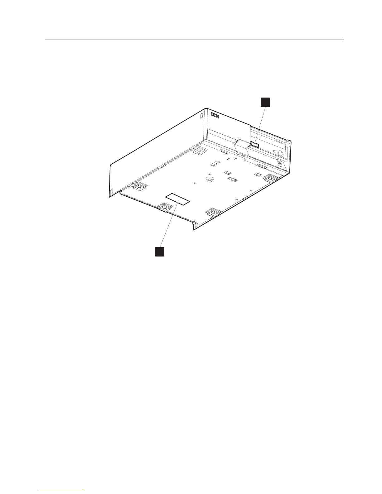
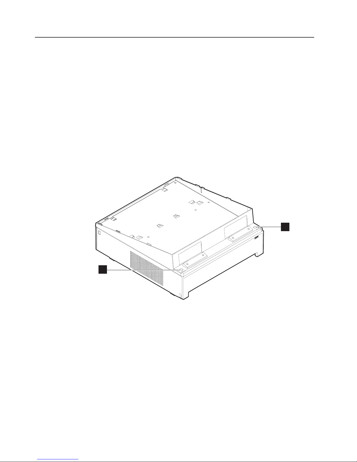
Calling for service
When you call IBM for warranty information or service, be sure to have the serial
number, machine type and model number available.
Figure 14 shows the location of this information on the SurePOS 720
A
B
Figure 14. Serial number and machine information
Note: Both positions A and B show the serial number and machine type-model
number.
Chapter 1. Introducing the SurePOS 700 Models 23
Page 42

Updated July 14, 2008
24 SurePOS 700 Series: SurePOS 700-721/741/781, 722/742/782 Hardware Service Guide
Page 43

Updated July 14, 2008
Chapter 2. Removal and replacement procedures
Before you begin . . . . . . . . . . . . . . . . . . . . . . . .26
Cables, connectors, and headphones . . . . . . . . . . . . . . . .26
Connecting your cash drawer to SurePOS Models 721, 741, and 781 . . . . .27
Removing the slanted I/O trays . . . . . . . . . . . . . . . . . . .28
Removing the covers . . . . . . . . . . . . . . . . . . . . . .29
Removing the top plate . . . . . . . . . . . . . . . . . . . . . .32
Removing the CD-ROM . . . . . . . . . . . . . . . . . . . . .33
Removing the hard disk drive . . . . . . . . . . . . . . . . . . .36
Removing the exhaust fan (Models 742 and 782 only) . . . . . . . . . .38
Replacing the insulating rubber seal (Models 722, 742, and 782 only) . . . . .39
Removing the spline . . . . . . . . . . . . . . . . . . . . . . .41
Removing the I/O modules . . . . . . . . . . . . . . . . . . . .42
Removing the I/O module holders . . . . . . . . . . . . . . . . . .43
Removing the air duct (Models 722, 74x, 78x, and C4x) . . . . . . . . . .44
Removing the processor fan (Models 742, 782 only) . . . . . . . . . . .45
Removing the heat sink and processor . . . . . . . . . . . . . . . .45
Removing the control switch card . . . . . . . . . . . . . . . . . .47
Removing the power supply . . . . . . . . . . . . . . . . . . . .48
Removing the riser card . . . . . . . . . . . . . . . . . . . . .49
Removing the planar . . . . . . . . . . . . . . . . . . . . . . .54
Removing the UPS . . . . . . . . . . . . . . . . . . . . . . .56
Removing the expansion housing . . . . . . . . . . . . . . . . . .58
Removing the UPS battery . . . . . . . . . . . . . . . . . . . .60
Removing the front USB card . . . . . . . . . . . . . . . . . . .61
Removing the memory modules . . . . . . . . . . . . . . . . . .62
Removing the front service housing components (wide models only) . . . . .64
Removing the system and bezel latches . . . . . . . . . . . . . .64
Removing the pull-out handle . . . . . . . . . . . . . . . . . .66
Removing the cable guide . . . . . . . . . . . . . . . . . . . .66
Removing the cable guide arm assembly . . . . . . . . . . . . . .67
Routing the cables . . . . . . . . . . . . . . . . . . . . .69
This chapter describes how to remove and replace the field replacement parts.
© Copyright IBM Corp. 2003, 2008 25
Page 44

Before you begin
Before you begin any of the following procedures, follow these steps:
1. Switch the power OFF at the system unit.
CAUTION:
Never attempt to service this product with AC power present. Only apply
AC power after the machine is fully assembled.
2. Disconnect the power cord from the external power source.
3. Remove any attached devices and I/O connections from the unit.
4. Establish personal grounding before touching the units. For more information,
see “Federal Communications Commission (FCC) statement” on page 105.
5. Before servicing the inside of the machine and after you have removed the top
cover, verify that no system board LEDs (red) are illuminated. A red LED
indicates the presence of power; you must remove the AC power cord before
continuing.
Cables, connectors, and headphones
Updated July 14, 2008
The following tips will assist you when removing and replacing parts for the
SurePOS 720.
v All cables and connectors are keyed; therefore, you cannot insert a cable in an
incorrect location.
v When connecting a powered USB cable to the back of the unit, insert the
connector with the latch on the bottom. A bottom latch allows for ease in
disconnecting. For the front USB cables, insert the connector in the usual
manner, with the latch on the top.
Figure 15. Processor power cable
v For Models 74* and 78*, installing a headphone overrides the line-out speaker.
26 SurePOS 700 Series: SurePOS 700-721/741/781, 722/742/782 Hardware Service Guide
Page 45

Updated July 14, 2008
v Models 742 and 782 contain a processor power cable. See A in Figure 15 on
page 26
v Model C42 contains a serial ATA connector.
v When routing the cables for the front-service housing option, allow extra length at
the connector end by forming a loop before attaching the cable into the cable
guide. This extra length prevents undue strain on the connector.
Connecting your cash drawer to SurePOS Models 721, 741, and 781
The SurePOS 720 Models 721, 741, and 781 are preconfigured from the factory to
work correctly with all IBM cash drawers. Connecting your IBM cash drawer to port
3A on the system unit activates the auto-sensing circuitry. In this automatic mode,
the system can correctly detect the difference between IBM 24-V and IBM 38-V
cash drawers.
Note: For both IBM and non-IBM cash drawers: If a customer has two connected
cash drawers, both drawers must be the same voltage.
Chapter 2. Removal and replacement procedures 27
Page 46
Removing the slanted I/O trays
The slanted I/O tray installs on the top of the system unit and groups the IBM
printer and keyboard with specific dimensions. The tray has a raised edge that is
low in the front. The sides slope up toward the rear and are higher at the rear than
at the front.
The top of the system unit serves as a built-in flat I/O tray. Use this surface when
grouping IBM and non-IBM peripheral devices with varying dimensions.
Note: A version of the slanted I/O tray is available that can be placed on the
wide-footprint SurePOS 700 in an integrated environment. Other versions of
the tray can be placed directly on the counter or on the full-size cash drawer.
The cash drawers provide a built-in flat I/O tray.
To remove a slanted I/O tray, follow these instructions:
1. Working from above the system unit, remove the screws from the holes (A in
Figure 16) inside of each corner of the I/O tray.
Updated July 14, 2008
A
A
Figure 16. Removing the slanted I/O tray
2. Lift off the I/O tray.
3. To remove the front mount clips, push each of the front mounting tabs forward
until it unlatches.
4. To replace the I/O tray, install the clips, place it on top of the system and install
the screws.
28 SurePOS 700 Series: SurePOS 700-721/741/781, 722/742/782 Hardware Service Guide
Page 47

Updated July 14, 2008
Removing the covers
The following steps apply to all models and to both the wide and narrow features.
The covers consists of the following parts:
v Front bezel
v Hinged rear door (modesty cover)
v To p cover
A
A
Figure 17. Removing the front bezel
1. Remove the front bezel following these steps:
a. See Figure 17. Press the left latch and depress the center latch to loosen
the bezel.
b. Press the right latch to release the bezel and pull it forward, lifting the bezel
from the machine.
Chapter 2. Removal and replacement procedures 29
Page 48

Updated July 14, 2008
B
Figure 18. Opening the modesty cover
2. Open the modesty cover by placing your hand firmly in the middle of the
modesty cover and pulling. The latches (B in Figure 18) will release
automatically.
30 SurePOS 700 Series: SurePOS 700-721/741/781, 722/742/782 Hardware Service Guide
Page 49

Updated July 14, 2008
C
Figure 19. Replacing the top cover
3. See Figure 19 and locate the metal holding clip, C, located in the rear center
of the top cover. Push this clip downward and push the cover backward a few
inches before lifting upward to remove.
To replace the top cover:
1. Hold the cover in position over the system unit so that the front is aligned with
the line on the metal top and drop the cover onto the machine. Slide the cover
forward to lock into place.
2. Close the modesty cover by pressing downward on the door. Replace the bezel
by aligning the hooks on the bottom of the bezel with the slots on the frame and
snapping the top into place.
Chapter 2. Removal and replacement procedures 31
Page 50

Removing the top plate
To remove the top plate:
1. Remove the front bezel and top cover by following the steps in “Removing the
covers” on page 29.
Updated July 14, 2008
D X8
Figure 20. Top plate screws
2. See Figure 20. Locate and remove the eight screws (D) holding the top plate.
3. Slide the cover backward and then lift upward to remove.
Important
Before servicing the inside of the machine and after you have removed the
top cover, verify that no system board LEDs (red) are illuminated. A red
LED indicates the presence of power; you must remove theACpower cord
before continuing.
4. To replace, reverse these procedures.
To ensure stability, locate the screw holes imprinted with an arrow. These
Note:
32 SurePOS 700 Series: SurePOS 700-721/741/781, 722/742/782 Hardware Service Guide
should contain screws.
Page 51

Updated July 14, 2008
Removing the CD-ROM
Follow these steps to remove the CD-ROM:
Models with the front-service housing option
For models with front-service housing installed, follow these instructions:
1. Remove the front bezel as follows:
a. See Figure 17 on page 29. Press the left latch and depress the center latch
to loosen the bezel.
b. Press the right latch to release the bezel and pull it forward, lifting the bezel
from the machine.
Figure 21. Opening units with front-service housing
2. See Figure 21. Press upward on the left latch and use the pull-out handle to
extend the system unit from the housing until it stops.
Note: Be sure to use a cart to support the system unit if it is completely
3. Open the media access door by removing the two screws.
4. Continue with step 3 on page 34 below.
5. To replace, reverse these steps.
For all other models:
1. Follow the instructions in “Removing the covers” on page 29 to remove the front
bezel and top cover.
removed.
Chapter 2. Removal and replacement procedures 33
Page 52

Updated July 14, 2008
2. Follow the instructions in “Removing the top plate” on page 32 to remove the
top plate.
D
C
Figure 22. Removing the CD-ROM
3. Unplug the attached cables.
Note: Model C42 connects to the CD-ROM with serial ATA connectors. Unplug
these connectors (A in Figure 23 on page 35) by squeezing on the
latch and pulling outward.
34 SurePOS 700 Series: SurePOS 700-721/741/781, 722/742/782 Hardware Service Guide
Page 53

Updated July 14, 2008
Figure 23. Example of serial ATA connector (Model C42 only)
4. See Figure 22 on page 34 and remove the screws D from the front of the unit
that hold the CD-ROM C in place.
5. Push the CD-ROM backward and lift it from the unit.
6. To replace the CD-ROM, reverse these procedures.
Chapter 2. Removal and replacement procedures 35
Page 54

Removing the hard disk drive
Models with the front-service housing option
For models with front-service housing installed, follow these instructions:
1. Remove the front bezel as follows:
a. See Figure 17 on page 29. Press the left latch and depress the center latch
to loosen the bezel.
b. Press the right latch to release the bezel and pull it forward, lifting the bezel
from the machine.
See Figure 21 on page 33. Press upward on the latch and use the pull-out
2.
handle to extend the system unit from the housing.
Note: Be sure to a cart to support the system unit if it is completely removed.
3. Open the media access door by removing the two screws.
4. If installed, follow the instructions in “Removing the CD-ROM” on page 33.
5. Continue with step 4 on page 37 below.
6. To replace, reverse these steps.
For all other models:
Updated July 14, 2008
Follow these steps to remove and replace the hard disk drive:
1. Follow the instructions in “Removing the covers” on page 29 to remove the front
bezel and top cover.
2. Follow the instructions in “Removing the top plate” on page 32 to remove the
top plate.
3. If installed, follow the instructions in “Removing the CD-ROM” on page 33.
36 SurePOS 700 Series: SurePOS 700-721/741/781, 722/742/782 Hardware Service Guide
Page 55
Updated July 14, 2008
D
C
F
E
F
D
Figure 24. Hard disk drive and brackets
4. See Figure 24 and remove the screws (D) holding the hard disk drive bracket
(E).
5. Grasp and move the hard disk drive and bracket assembly to the left to release
the bottom hooks. Then move the unit upward and out.
Slave connector
(gray)
Hard Drive
Master connector
(black)
Figure 25. Master and slave connectors
Chapter 2. Removal and replacement procedures 37
Page 56

Updated July 14, 2008
6. Unplug the cables attached to the hard disk drive. See Figure 25 on page 37
and note that the end connector is the master connector, which is black, and
should always be plugged into the master hard disk drive. The slave connector,
which is gray, is installed to an optional, second hard disk drive in the lower
position.
7. Remove the screws (F in Figure 24 on page 37) that hold the hard disk drive
to the bracket.
8. Slide the hard disk drive (C in Figure 24 on page 37) out of the bracket.
9. To replace the hard disk drive, reverse these steps.
Notes:
a. When re-attaching the cables, be sure to place the extra cable length in the
space provided beneath the hard disk drive.
b. The connector that plugs into the system board is blue.
Removing the exhaust fan (Models 742 and 782 only)
Follow these steps to remove and replace the exhaust fan:
1. Follow the instructions in “Removing the covers” on page 29 to remove the front
bezel and top cover.
2. Follow the instructions in “Removing the top plate” on page 32 to remove the
top plate.
Figure 26. Exhaust fan (Models 742, and 782 only)
3. Locate and remove the two screws (see A in Figure 26) holding the exhaust
fan in the housing.
38 SurePOS 700 Series: SurePOS 700-721/741/781, 722/742/782 Hardware Service Guide
Page 57

Updated July 14, 2008
4. Carefully remove the fan connector from the card.
5. Lift to remove.
Figure 27. Location of alignment pen holes
6. To replace, align the fan with the two alignment holes (see A in Figure 27) on
the housing.
7. Tighten the two screws to secure the fan.
8. Attach the connector to the planar board.
Replacing the insulating rubber seal (Models 722, 742, and 782 only)
Follow these steps to replace the insulating rubber seal located on the housing.
1. Follow the instructions in “Removing the covers” on page 29 to remove the front
bezel and top cover.
Chapter 2. Removal and replacement procedures 39
Page 58
Updated July 14, 2008
Figure 28. Location of alignment pen holes
2. Locate the rubber seal (A in Figure 28) on the housing and near the exhaust
fan.
3. Pull to remove.
To reinstall:
1. Align the rubber seal with the holes on the chassis, insuring that each
cone-shaped protrusion has a matching hole.
2. Using a pair of pliers, pull the cone-shaped protrusions through the holes.
40 SurePOS 700 Series: SurePOS 700-721/741/781, 722/742/782 Hardware Service Guide
Page 59
Updated July 14, 2008
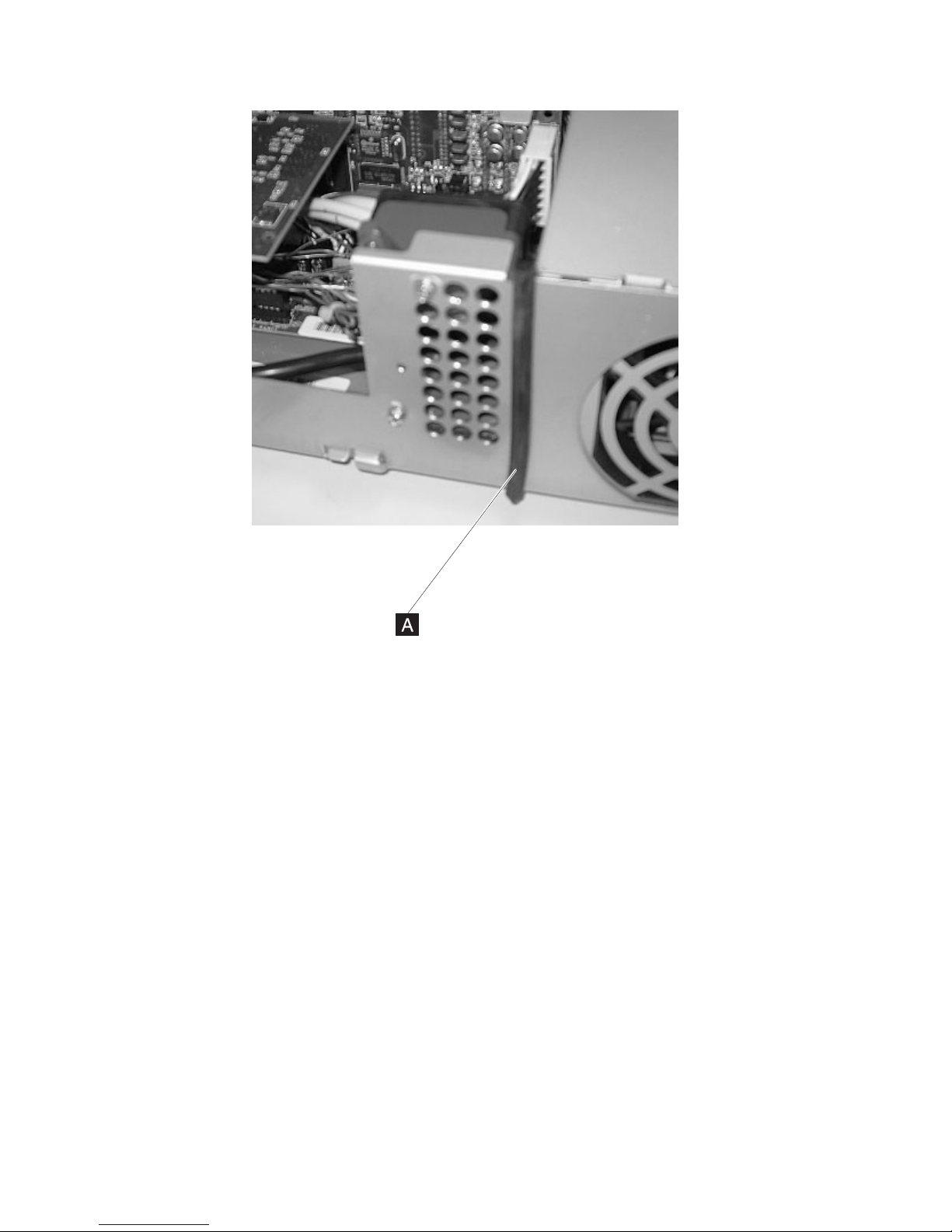
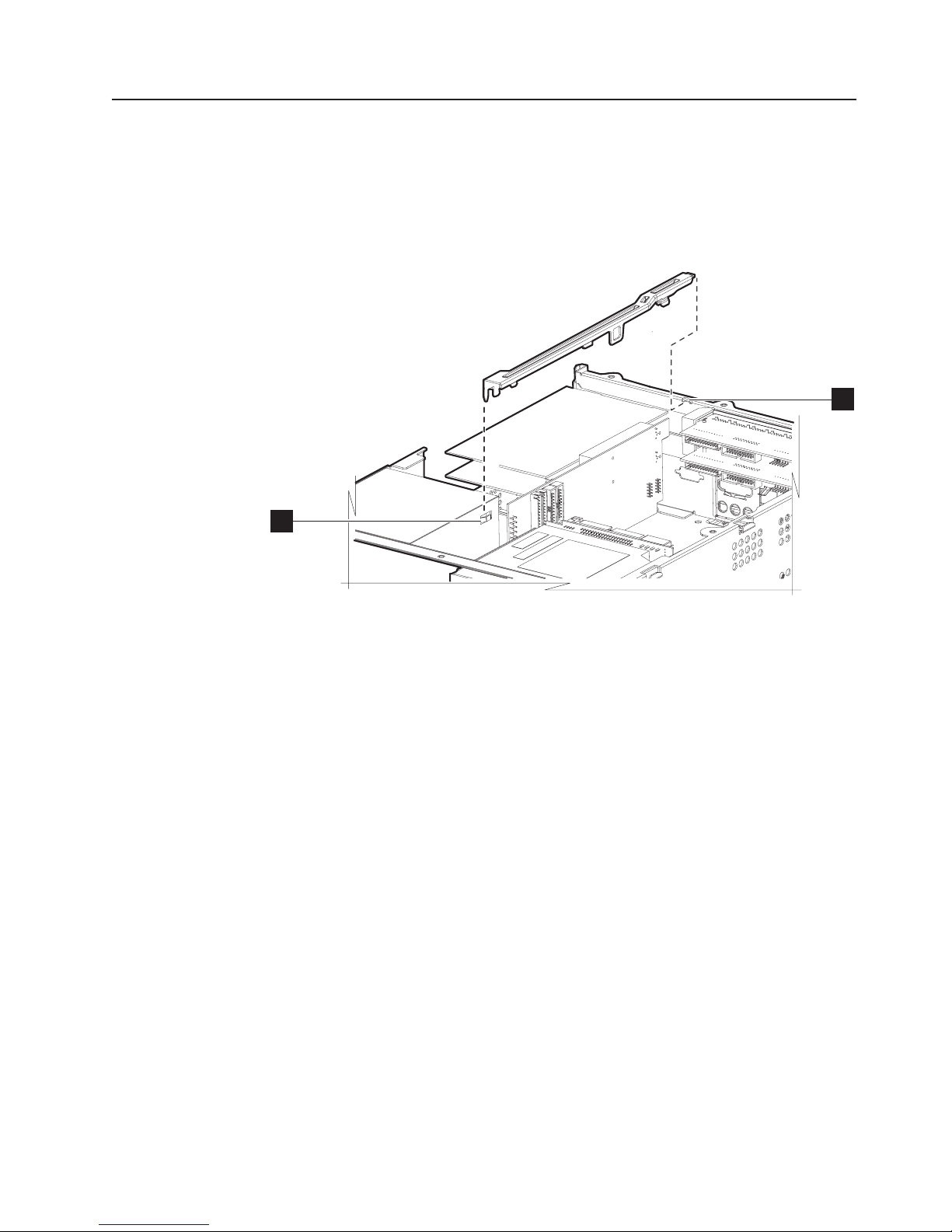
Removing the spline
To remove the spline:
1. Follow the instructions in “Removing the covers” on page 29 to remove the front
bezel and top cover.
2. Follow the instructions in “Removing the top plate” on page 32 to remove the
top plate.
W
ZZ
Figure 29. Removing the spline
3. See Figure 29. Locate the spline and lift it upward from notch (Z in Figure 29)
and then outward from notch (W).
4. To replace the spline, reverse these procedures.
Chapter 2. Removal and replacement procedures 41
Page 60

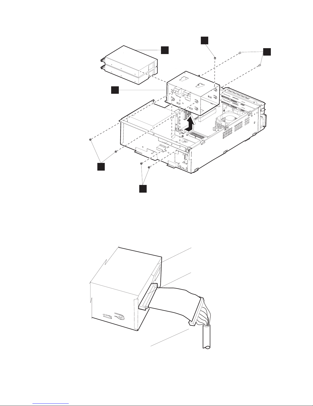
Removing the I/O modules
To remove the I/O modules:
1. Follow the instructions in “Removing the covers” on page 29 to remove the front
bezel and top cover.
2. Follow the instructions in “Removing the top plate” on page 32 to remove the
top plate.
3. If required for your model, follow the instructions in “Removing the air duct
(Models 722, 74x, 78x, and C4x)” on page 44
4. If required for your model, follow the instructions in “Removing the processor fan
(Models 742, 782 only)” on page 45.
5. Remove any cable attachments from the I/O modules.
Updated July 14, 2008
B
A
Figure 30. Opened I/O latch
6. See Figure 30. Locate the I/O modules latch, (A in Figure 30). Open the latch
by grasping and turning it in a clockwise direction.
7. Press tab (B) and slide the I/O module out of the slot.
8. To replace an I/O module, reverse these procedures.
Before installing a new RS-485 module, ensure that the jumpers on the
Note:
new module match the removed, old module.
42 SurePOS 700 Series: SurePOS 700-721/741/781, 722/742/782 Hardware Service Guide
Page 61
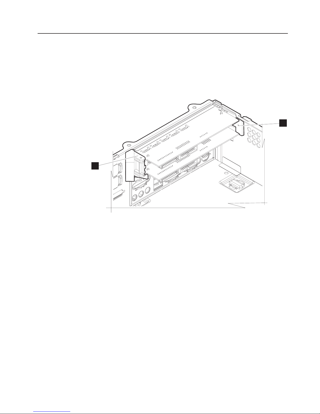
Updated July 14, 2008
Removing the I/O module holders
To remove the I/O module holders, follow these steps:
1. Follow the steps in “Removing the covers” on page 29 to remove the covers.
2. For wide machines, follow the instructions “Removing the expansion housing”
on page 58 to remove the UPS housing.
3. Follow the steps in “Removing the top plate” on page 32 to remove the top
plate.
A
A
A
Figure 31. I/O module holders
4. Follow the steps in “Removing the I/O modules” on page 42 to remove the I/O
modules.
5. Remove the screws (not shown) securing the I/O module holders (A in
Figure 31).
6. To replace the I/O module holders, reverse these steps.
Chapter 2. Removal and replacement procedures 43
Page 62
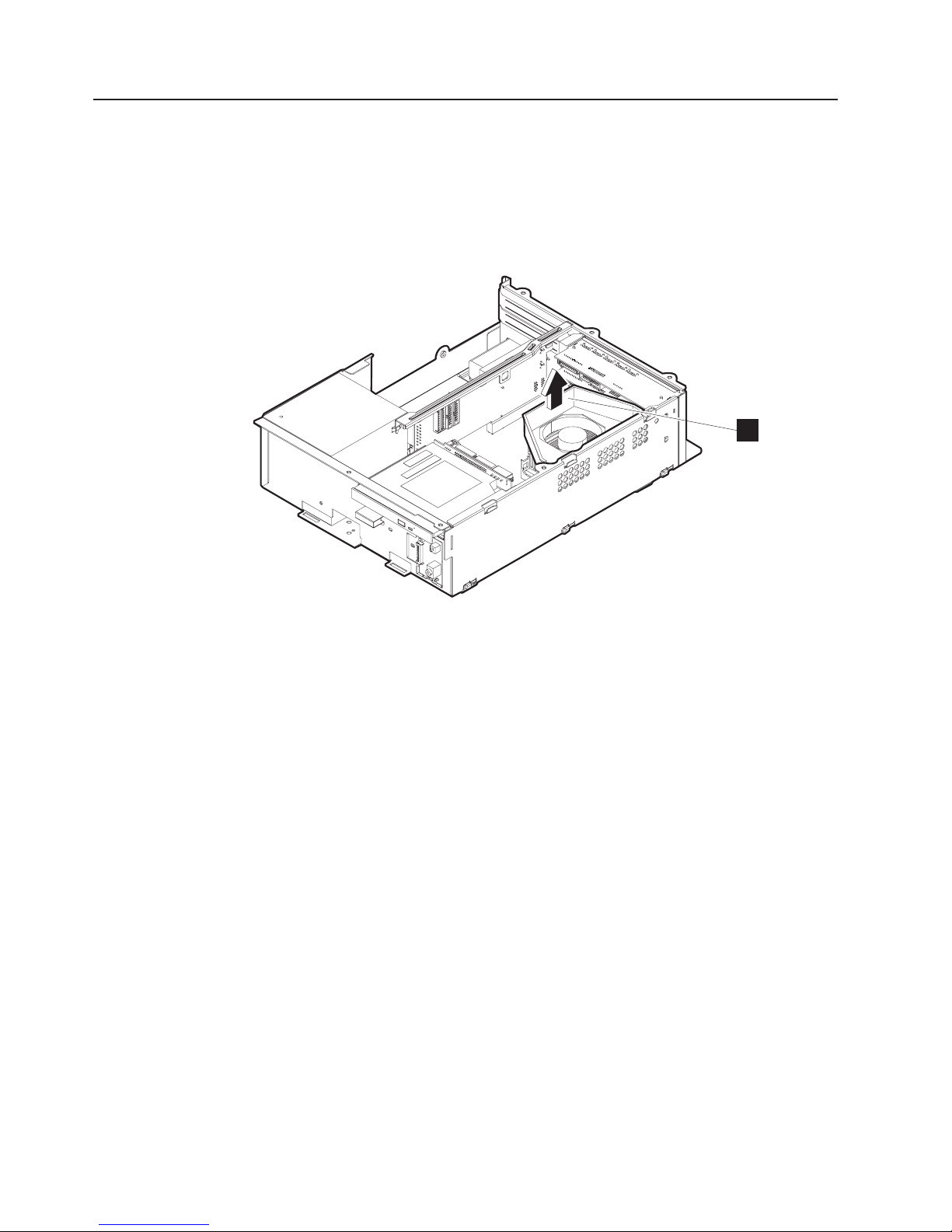
Removing the air duct (Models 722, 74x, 78x, and C4x)
To remove the air duct:
1. Follow the instructions in “Removing the covers” on page 29 to remove the front
bezel and top cover.
2. Follow the instructions in “Removing the top plate” on page 32 to remove the
top plate.
Updated July 14, 2008
A
Figure 32. Removing the air duct
3. See Figure 32. Lift the air duct (A) from the fan.
4. Reinstall in reverse order.
44 SurePOS 700 Series: SurePOS 700-721/741/781, 722/742/782 Hardware Service Guide
Page 63
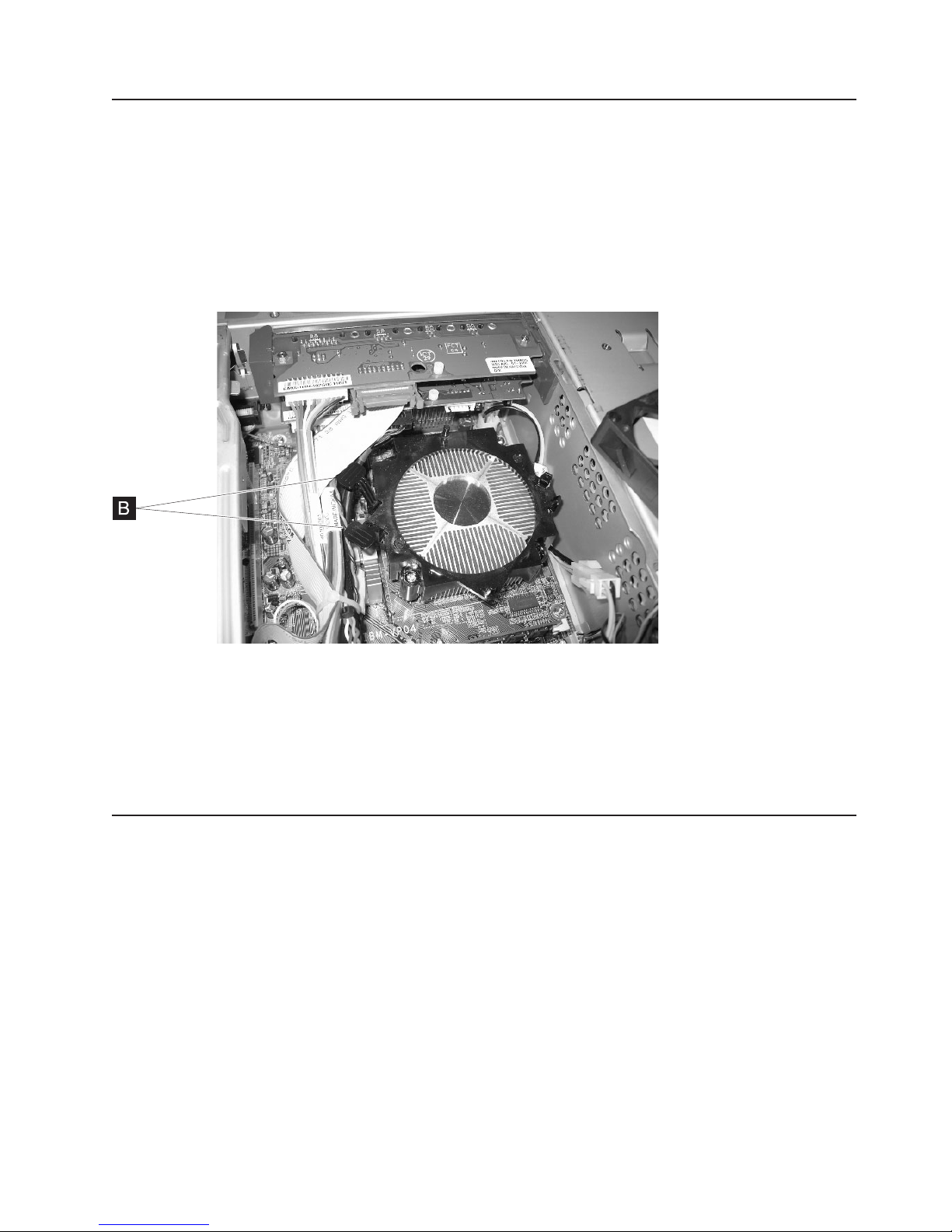
Updated July 14, 2008
Removing the processor fan (Models 742, 782 only)
Follow these steps to remove and replace the processor fan:
1. Follow the instructions in “Removing the covers” on page 29 to remove the front
bezel and top cover.
2. Follow the instructions in “Removing the top plate” on page 32 to remove the
top plate.
3. Follow the instructions in “Removing the air duct (Models 722, 74x, 78x, and
C4x)” on page 44.
Figure 33. Processor fan and levers
4. Remove the processor fan by pressing down on the levers (B in Figure 33) to
release the connections.
5. Lift to remove.
6. To replace, align the fan with the board connectors and press down to lock into
place.
Removing the heat sink and processor
Attention: Establish personal grounding before touching this unit. For more
information, see “Federal Communications Commission (FCC) statement” on page
105.
To remove the heat sink and processor:
1. Follow the instructions in “Removing the covers” on page 29 to remove the
front bezel and top cover.
2. Follow the instructions in “Removing the top plate” on page 32 to remove the
top plate.
3. If installed, remove the air duct.
4. For Models 7x2, go to step 9 on page 46. For Models 7x1, continue with the
steps.
Chapter 2. Removal and replacement procedures 45
Page 64

Updated July 14, 2008
M
N
Figure 34. Heat sink and processor
Models 7x1
5. Locate the heat sink latches on each side of the heat sink.
6. Press down to unlock each latch and then lift upward on the heat sink (M) to
remove.
Note: When the heat sink is removed, you can locate the processor (N)
7. See Figure 34. Press down on the processor latch, and move sideways and up
to unlock. Lift out the processor, carefully keeping your fingers on each side of
the module.
8. Go to step 10.
Models 7x2
9. Loosen the four captured screws to remove the heat sink.
All Models
To replace the processor and heat sink, reverse these procedures.
10.
Note: Models 742 and 782 contain a LGA 775 CPU socket. This socket
contains very finely pitched pins. You must take care when servicing the
CPU as any damage to the socket results in a non-functional system
board. Be sure to use the section cup tool provided with the FRU
processor.
46 SurePOS 700 Series: SurePOS 700-721/741/781, 722/742/782 Hardware Service Guide
Page 65

Updated July 14, 2008
Removing the control switch card
To remove the control switch card:
1. Follow the instructions in “Removing the covers” on page 29 to remove the front
bezel and top cover.
A
B
Figure 35. Removing the control switch card
2. See Figure 35. Remove the screw (A) holding the card in place.
3. Lift the card from the unit.
4. Unplug the cable that is attached to the card connector (B).
5. To replace the card, reverse these procedures.
Chapter 2. Removal and replacement procedures 47
Page 66

Removing the power supply
To remove the power supply:
1. Follow the instructions in “Removing the covers” on page 29.
2. Follow the instructions in “Removing the top plate” on page 32.
Updated July 14, 2008
Q
Figure 36. Removing the power supply
3. Follow the instructions in “Removing the spline” on page 41.
Figure 37. Example of Model 742 and 782 processor power cable
4. Disconnect the internal power cord connected to the power supply.
48 SurePOS 700 Series: SurePOS 700-721/741/781, 722/742/782 Hardware Service Guide
Page 67

Updated July 14, 2008
Note: For Models 742 and 782, disconnect the connector from the processor
power cable (see A in Figure 37 on page 48).
5. Disconnect all cables.
6. See Figure 36 on page 48. Remove the screws (Q) holding the power supply
to the housing.
7. Lift to remove the power supply from the unit.
8. To replace the power supply, reverse these procedures.
Removing the riser card
To remove the riser card:
1. Follow the instructions in “Removing the covers” on page 29.
2. Follow the instructions in “Removing the top plate” on page 32.
P
Figure 38. Removing feature cards
3. See Figure 38 to locate any installed feature cards and retaining screws (P).
Remove the screws and pull outward to remove the feature card.
4. Follow the instructions in “Removing the spline” on page 41.
Chapter 2. Removal and replacement procedures 49
Page 68

Figure 39. Serial connectors
Updated July 14, 2008
5. Note the cable routings, and then unplug two serial connectors (if installed)
from the left side of the riser card. See A in Figure 39.
Figure 40. Removing the I/O card cables
50 SurePOS 700 Series: SurePOS 700-721/741/781, 722/742/782 Hardware Service Guide
Page 69

Updated July 14, 2008
6. Remove the four I/O card cables, if installed. See B in Figure 40 on page 50.
Note the locations for other possible connections.
Figure 41. Power connector
7. Remove the power connector from the riser card. See C in Figure 41
Chapter 2. Removal and replacement procedures 51
Page 70

Updated July 14, 2008
Figure 42. Dump switch
8. Unplug the dump switch from the riser card. See D in Figure 42.
52 SurePOS 700 Series: SurePOS 700-721/741/781, 722/742/782 Hardware Service Guide
Page 71

Updated July 14, 2008
Figure 43. Riser card latch
Model 7x2 only
9. Release the mechanical latch (see E in Figure 43) retaining the riser card as
follows:
a. Tilt the riser toward the latch.
b. With your hand, unhook the latch.
Lift out the riser card.
10.
All Models
To replace the riser card, reverse these procedures.
11.
When replacing the riser card, ensure that the cash drawer voltage
Note:
setting matches the voltage setting on the old riser card. See “Cash
drawers” on page 18 for additional information.
Chapter 2. Removal and replacement procedures 53
Page 72

Removing the planar
1. Follow the instructions in “Removing the covers” on page 29.
2. Follow the instructions in “Removing the top plate” on page 32.
3. Follow the instructions in “Removing the riser card” on page 49 and “Removing
the I/O modules” on page 42.
4. If installed, remove the air duct. See “Removing the air duct (Models 722, 74x,
78x, and C4x)” on page 44.
5. Follow the instructions in “Removing the processor fan (Models 742, 782
only)” on page 45
Updated July 14, 2008
Figure 44. Example of stand-offs
6. Remove the eight standoffs (see A in Figure 44) for the parallel, video and
serial ports.
7. Unplug all attached cables.
Note: For Models 742 and 782, disconnect the connector from the processor
power cable (see A in Figure 37 on page 48).
A
54 SurePOS 700 Series: SurePOS 700-721/741/781, 722/742/782 Hardware Service Guide
Page 73

Updated July 14, 2008
7X (Model 781, 741, C41)
D
5X (Model 721)
Figure 45. Planar location
8. See Figure 45. Locate and remove the screws from the planar board (D).
Model 721 has five screws. Models 7x2, 74*, and 78* have seven screws.
9. Lift the planar upward from the housing.
10. To replace planar, reverse these procedures.
Chapter 2. Removal and replacement procedures 55
Page 74
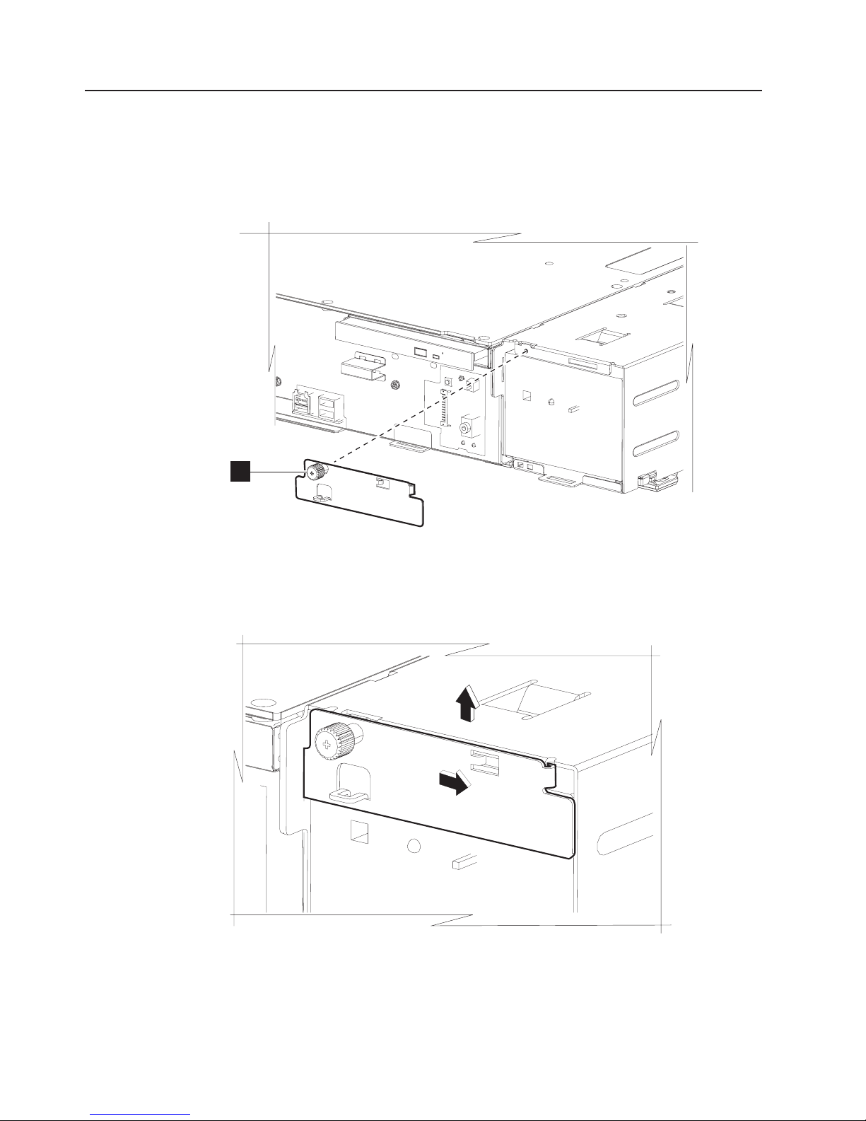
Removing the UPS
Note: This procedure applies to the wide machine feature only.
1. Remove the front bezel by referring to Figure 17 on page 29.
2. Unplug and remove all of the power cords and the serial cable, if installed.
Updated July 14, 2008
R
R
Figure 46. Power supply housing bracket
3. See Figure 46. Untighten the screw (R) on the UPS lock.
Figure 47. Lifting the bracket
4. Slide the bracket to the right and the lift it out of the expansion housing.
56 SurePOS 700 Series: SurePOS 700-721/741/781, 722/742/782 Hardware Service Guide
Page 75
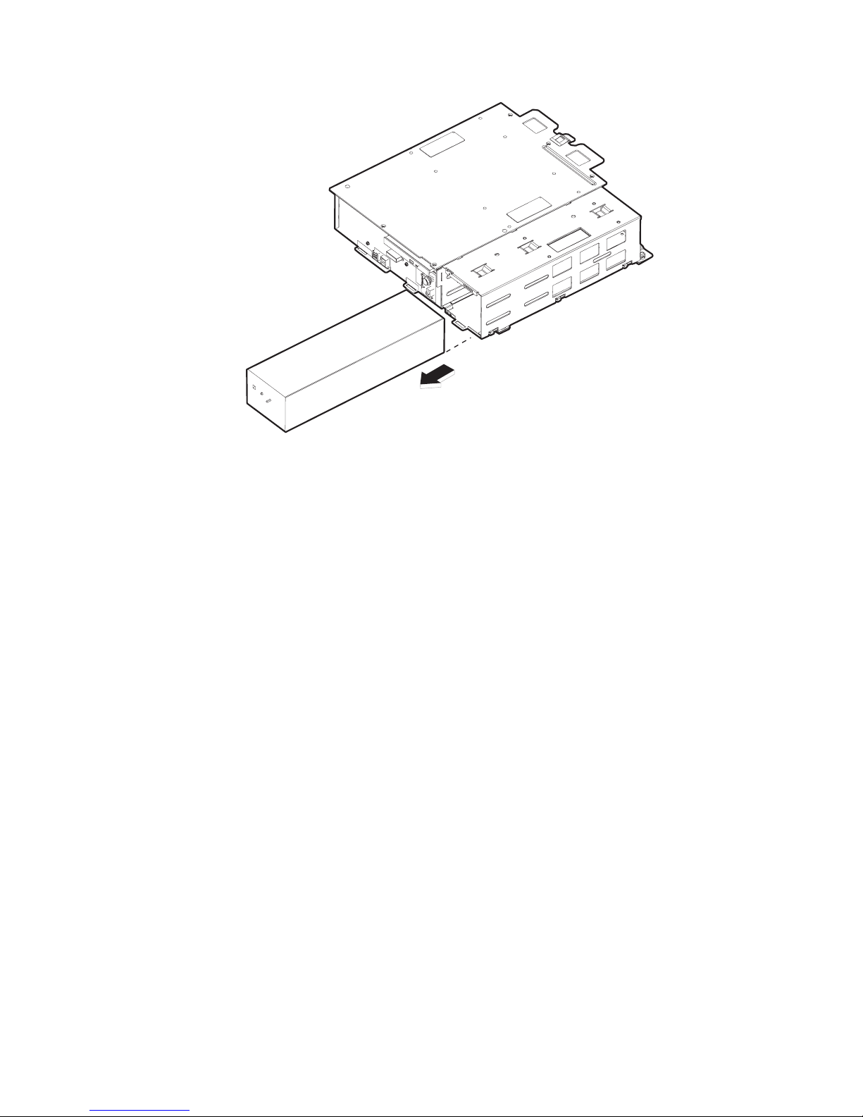
Updated July 14, 2008
Figure 48. Removing the UPS
5. See Figure 48 and slide the UPS from the expansion housing.
6. To replace the UPS, reverse these procedures and note the following:
Correctly reset the UPS configuration switches. See “Configuration
Note:
switches” on page 11
Chapter 2. Removal and replacement procedures 57
Page 76

Removing the expansion housing
1. Follow the instructions in “Removing the covers” on page 29.
2. Follow the instructions in “Removing the UPS” on page 56.
Updated July 14, 2008
Figure 49. Position of system unit and expansion housing
3. Place the system unit and the expansion housing in the position shown in
Figure 49. This position assists with the removal process as the rubber feet do
not touch the counter.
58 SurePOS 700 Series: SurePOS 700-721/741/781, 722/742/782 Hardware Service Guide
Page 77
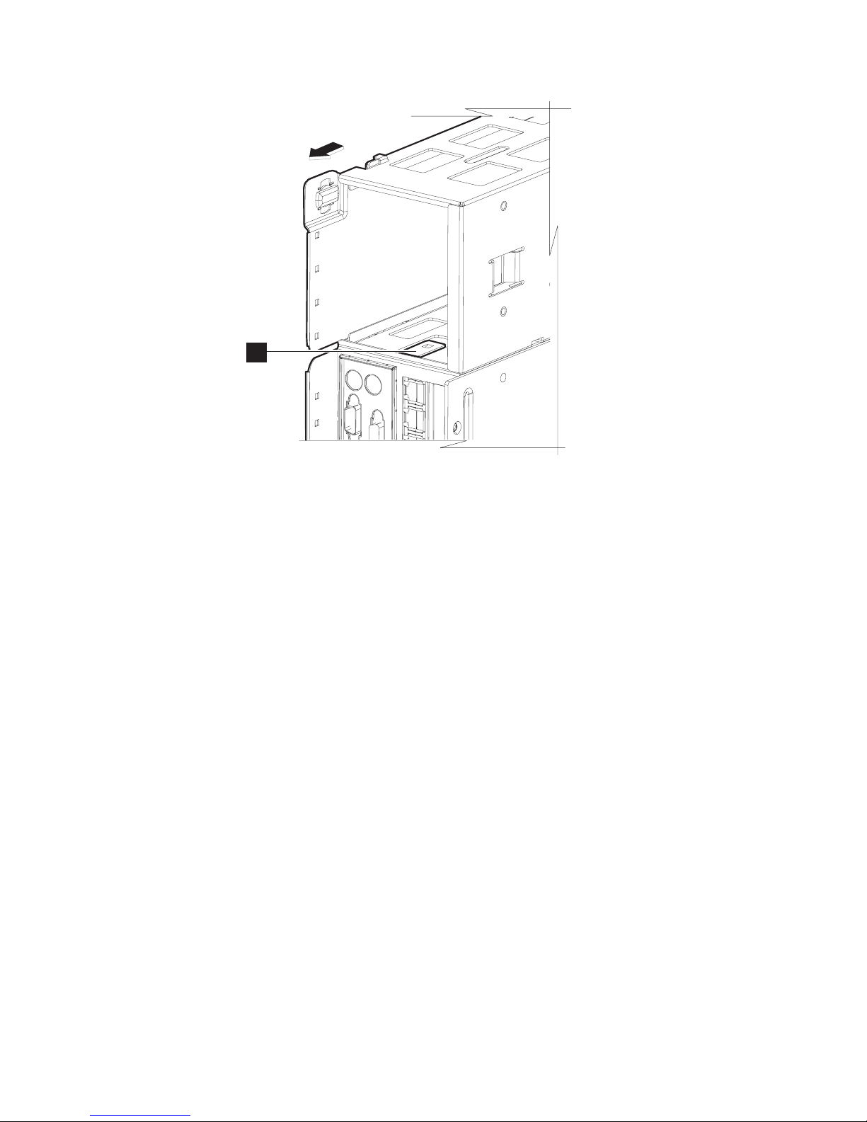
Updated July 14, 2008
A
Figure 50. Prying the expansion housing latch upward
4. Locate the latch (A in Figure 50) inside of the power supply housing. Using a
screwdriver, pry the latch upward.
5. Push the power supply housing backward from the unit until it unlatches.
Note: Before you install the expansion housing, be sure that the latch is flush
with the side of the housing, and not bent inward.
6. To install the expansion housing, reverse these procedures.
Note: Be sure the latch (A in Figure 50) is engaged and the expansion
housing bracket is securely fastened.
Chapter 2. Removal and replacement procedures 59
Page 78
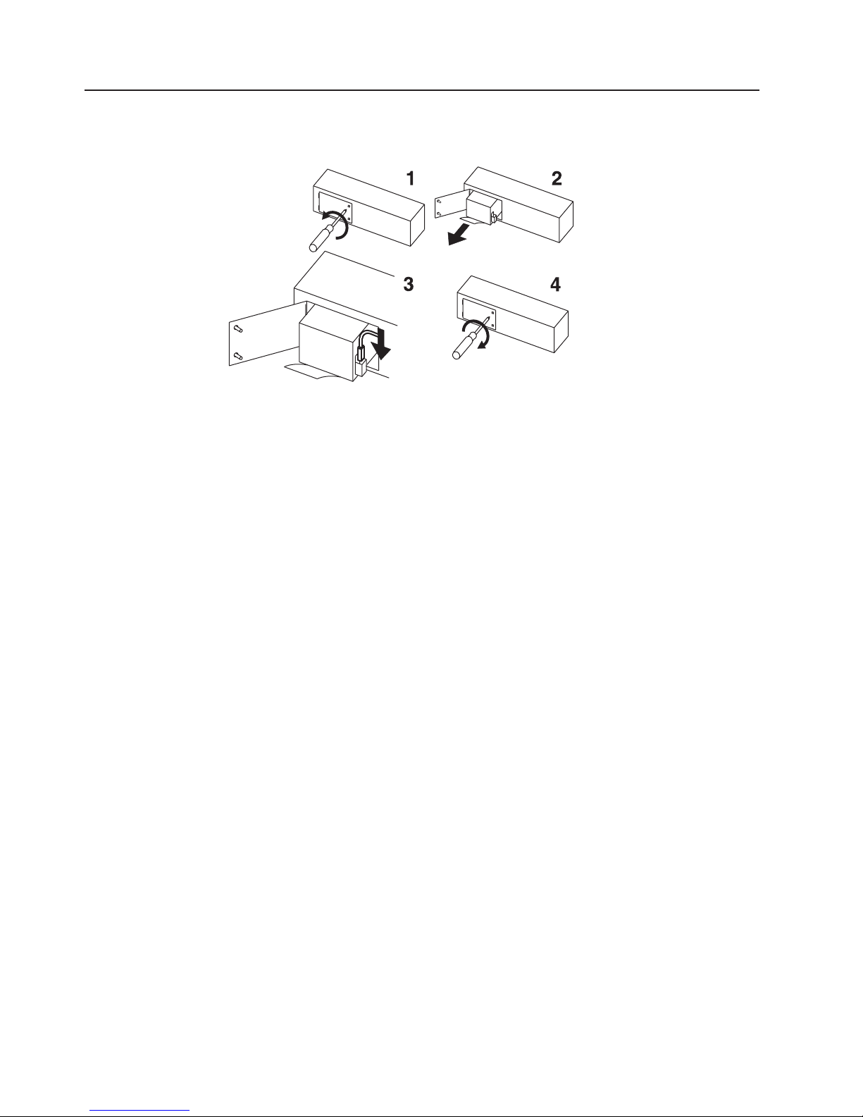
Removing the UPS battery
1. Follow the instructions in “Removing the UPS” on page 56.
Figure 51. Removing the UPS battery
2. Follow the pictorial directions on connecting the battery to the UPS, noting the
exceptions (in bold) below:
a. See Figure 51, Picture 1. With the UPS on its side, remove the battery door.
b. See Picture 2. Pull the battery out of the UPS such that you can view the
wiring and plug.
c. Disconnect all plugs to the battery.
d. Properly dispose of the old battery.
e. To install a new battery, reverse these procedures.
Updated July 14, 2008
60 SurePOS 700 Series: SurePOS 700-721/741/781, 722/742/782 Hardware Service Guide
Page 79
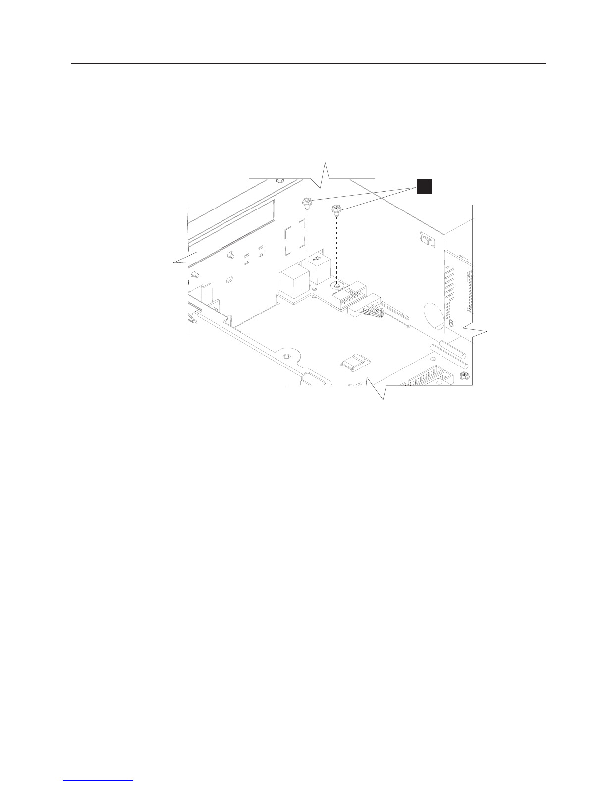
Updated July 14, 2008
Removing the front USB card
1. Follow the instructions in “Removing the covers” on page 29.
2. Follow the instructions in “Removing the top plate” on page 32
3. Follow the instructions in “Removing the hard disk drive” on page 36.
4. Disconnect the cable attached to the USB card.
A
Figure 52. Removing the front USB card
5. Remove the two screws (A in Figure 52) holding the USB card to the system
unit.
6. Lift card and remove it from the front of the unit.
7. To replace card, reverse these procedures.
Chapter 2. Removal and replacement procedures 61
Page 80

Removing the memory modules
1. Follow the instructions in “Removing the covers” on page 29 to remove the front
bezel and top cover.
2. Follow the instructions in “Removing the top plate” on page 32 to remove the
top plate.
3. Follow the instructions in “Removing the air duct (Models 722, 74x, 78x, and
C4x)” on page 44 to remove the air duct.
4. See Figure 53. Locate the memory modules and slots.
Updated July 14, 2008
0
Figure 53. Opening the memory module latches
5. Press downward on the white tabs (O) on both sides of the memory-module
connectors until they are both at a 45-degree angle. The memory module rises
slightly in the connector.
6. Touching only the upper corners of the memory module, lift it gently until the
module is free from the connector.
To replace the memory modules, follow these instructions:
1. Note the alignment notches along the bottom of the module where it plugs into
the connector.
62 SurePOS 700 Series: SurePOS 700-721/741/781, 722/742/782 Hardware Service Guide
Page 81
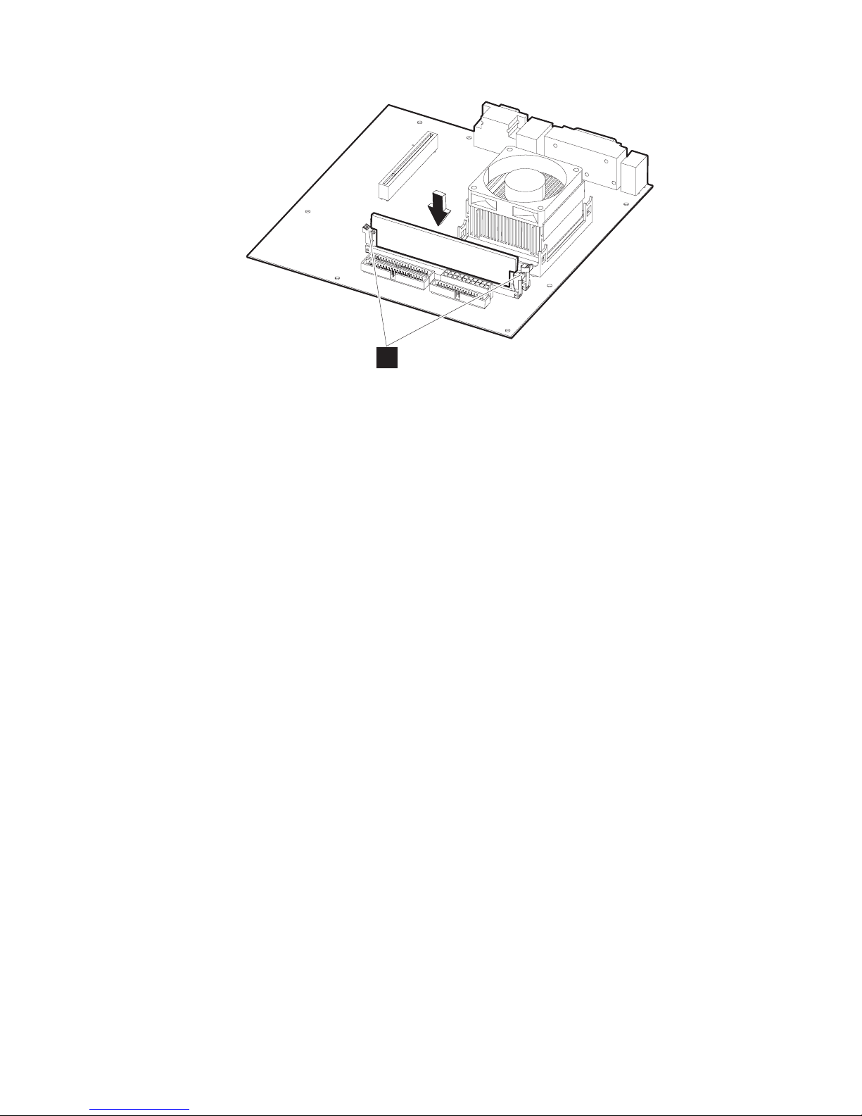
Updated July 14, 2008
0
Figure 54. Replacing the memory modules
2. Touching only the top corners of the memory module, align the connector tabs
and press down firmly. The white tabs (O in Figure 54) on the connector on
the planar board will close as the module is inserted. When inserted correctly,
the white tabs are completely closed.
3. Replace the top plate, air duct, and covers.
Chapter 2. Removal and replacement procedures 63
Page 82

Updated July 14, 2008
Removing the front service housing components (wide models only)
This section pertains to models with the front service housing option.
Removing the system and bezel latches
Follow these steps to remove the rear and bezel latches from the 4800 unit:
1. Set the unit on a flat surface.
2. See Figure 17 on page 29 and follow the steps to remove the front bezel.
3. Remove the power supply screw holding the system latch and retain for reuse.
Figure 55. Removing the system latch
4. Remove the system latch and discard.
5. Align the new system latch to the corner of the unit as shown in Figure 55,
insert screw and tighten.
64 SurePOS 700 Series: SurePOS 700-721/741/781, 722/742/782 Hardware Service Guide
Page 83

Updated July 14, 2008
Figure 56. Removing the bezel latch
6. See Figure 56 and remove the screw holding the bezel latch and remove the
latch.
7. Position the new bezel latch downward.
8. Insert and tighten the screw.
Chapter 2. Removal and replacement procedures 65
Page 84

Removing the pull-out handle
Follow these steps to install the pull-out handle:
1. Set the unit on a flat surface.
2. See Figure 17 on page 29 and follow the steps to remove the front bezel.
3. Slide the pull-out handle to the left of the clip and rotate as shown. Slide to the
right to remove.
Updated July 14, 2008
Figure 57. Attaching the pull-out handle
4. To replace, align the handle to the clip at approximately a 45-degree angle. See
Figure 57.
5. Place the pull-out handle on the clip and slide it to the right for a secure fit.
Removing the cable guide
Follow these instructions to replace the cable guide:
1. Pull the 4800 unit from the front of housing and place on a cart
2. Remove the velcro strap holding the cables.
3. Remove the screw holding the cable guide.
4. Remove the cable guide from the 4800 unit and also remove the cables.
66 SurePOS 700 Series: SurePOS 700-721/741/781, 722/742/782 Hardware Service Guide
Page 85

Updated July 14, 2008
Figure 58. Removing the cable guide
To replace:
5. Reverse these procedures to reinstall the cable guide.
Removing the cable guide arm assembly
1. Pull the 4800 unit from the front of housing and place on a cart
2. Extend the cable guide assembly arm and open the velcro strips from the cable
guide and the cable guide arm assembly.
3. Remove all cables from the cable arm assembly and place aside.
4. Remove the cable guide arm assembly by squeezing and lifting it from the
bottom peg and then from the top peg.
Chapter 2. Removal and replacement procedures 67
Page 86

To replace:
Updated July 14, 2008
Figure 59. Positioning the cable guide arm assembly
5. See Figure 59. Fold the cable guide arms so that the screw heads are adjacent
to each other.
68 SurePOS 700 Series: SurePOS 700-721/741/781, 722/742/782 Hardware Service Guide
Page 87

Updated July 14, 2008
Figure 60. Attaching the cable guide arm assembly
6. See Figure 60. Align the holes on the cable guide arm assembly with the pegs
on the 4800 unit. Insert the top peg first and then slightly squeeze the unit to
insert the bottom peg.
7. Complete the steps described in “Routing the cables.”
Routing the cables
Important
Ensuring that the cables are neatly routed reduces entanglements and saves
space.
For ease of installation, IBM recommends that you route the cables in the following
order:
1. Power cord
2. Ethernet
3. Cash drawer and other peripheral devices (mouse, keyboard, printer)
Follow these instructions to route the cables:
1. Complete the instructions described in “Removing the cable guide” on page 66.
2. Open all of the velcro strips on the cable guide and the cable guide assembly
arm.
Chapter 2. Removal and replacement procedures 69
Page 88

Updated July 14, 2008
3. For each cable, insert the connector end into the system unit first, then route it
through the cable guide. You can close the velcro loop around the cord at this
time or later in the cable routing process.
Figure 61. Extra cord length during routing
Tip for routing the mouse, keyboard, and printer cables
When routing these cables, allow extra length at the connector end by
forming a loop (see Figure 61) before continuing with the cable into the
cable guide. This extra length prevents undue strain on the connector.
4. With the cable guide arm assembly perpendicular to the system unit, continue to
route the cable along the outside of the cable guide arm assembly, closing the
velcro strips where appropriate to secure.
Do not plug the power cord into the receptacle at this time, or attach the
Note:
cables to the devices.
70 SurePOS 700 Series: SurePOS 700-721/741/781, 722/742/782 Hardware Service Guide
Page 89

Updated July 14, 2008
Figure 62. Cable assembly arm with cables securely in place
5. After all cables are routed and properly arranged, close the velcro strips.
6. See Figure 62. Ensure that the cables with cable arm assembly is properly
secured by freely moving the arm backward and forward. If this action is difficult
or impeded, open the velcro strips and rearrange the cables to allow additional
slack.
7. Gently close the cable guide assembly arm and lift it behind the latch.
Chapter 2. Removal and replacement procedures 71
Page 90

Updated July 14, 2008
72 SurePOS 700 Series: SurePOS 700-721/741/781, 722/742/782 Hardware Service Guide
Page 91

Updated July 14, 2008
Chapter 3. Problem determination
Problems with the SurePOS 700 can be caused by software errors or hardware
failures. This chapter contains problem-analysis tables to help determine the cause
of a problem and how to solve it.
When you power on the SurePOS 700, the system runs a power on self test
(POST). A successful POST is indicated by:
v A single beep
v The power and UPS status indicators are both on and not blinking.
If the POST is unsuccessful, see “Problem isolation” on page 74.
Preliminary checklist
If you have a problem with the SurePOS 700, first use the following checklist:
1. Make sure that all I/O devices are connected correctly.
2. Make sure that AC power is connected.
3. Make sure that the contrast and the brightness controls on the display are
adjusted correctly.
4. Make sure that all installed hardware (such as a memory module, feature card,
printer, or mouse) and cables are connected correctly and securely.
5. Power ON and listen for one or two beeps at the completion of the POST.
6. If POST does not complete, power OFF the SurePOS 700 and remove any
optional adapters and all I/O devices except a single keyboard and display.
7. If POST still fails to complete, see “Problem isolation” on page 74.
© Copyright IBM Corp. 2003, 2008 73
Page 92

Problem isolation
If the SurePOS 700 fails, follow the procedures that are described in Table 6. If you
cannot solve the problem, contact a trained service technician.
Updated July 14, 2008
Table 6. Actions to isolate the cause of a problem
Problem Action to perform
The power indicator
remains off.
1. Check that the AC power cord is plugged into both the wall
outlet and the back of the terminal.
2. Ensure that AC power is present at the wall outlet.
Continuous series of
beeps
Video display is failing
(totally blank screen, no
cursor displayed, screen is
unreadable, or other
display problems).
1. Check to see if memory is bad or missing.
1. Verify that the video-display cables are securely connected.
2. Ensure that the video-display power cord is plugged in and
powered on.
3. Verify that the power indicator on the system unit and the
indicator light on the display are lit.
4. Adjust contrast and brightness controls on the display.
5. Use the reference documentation (if available) for the
display.
6. Exchange the video display.
Keyboard does not work
or only some keys work.
1. Make sure that the keyboard is securely attached to the
keyboard port.
2. Move your fingers across the keys. Make sure that no keys
are stuck.
3. Make sure that you are on a screen that allows typing.
Some screens do not allow you to type on them.
One or more POS I/O
devices are failing.
1. Ensure that the I/O devices are securely and correctly
connected to the system unit.
2. If the device has its own power cord and power switch,
ensure that it has power and that the power switch is on.
3. Exchange the cables.
4. If a POS I/O device is available that is known to be good,
substitute it for the failing device to help in isolating the
failure.
An optional feature
See the service information for the adapter.
adapter is failing.
System does not power off
when the power switch is
Press and hold the power button until the unit powers off.
(approximately 5 seconds)
pressed.
Notes:
1. Some devices that attach to the system have test instructions. Refer to those
instructions when testing those devices.
2. Record any error message or symptom so that this information is available
when service is called.
3. When using application software, you might receive error messages that apply
to the software. Refer to the software manual for explanations of those
messages.
74 SurePOS 700 Series: SurePOS 700-721/741/781, 722/742/782 Hardware Service Guide
Page 93
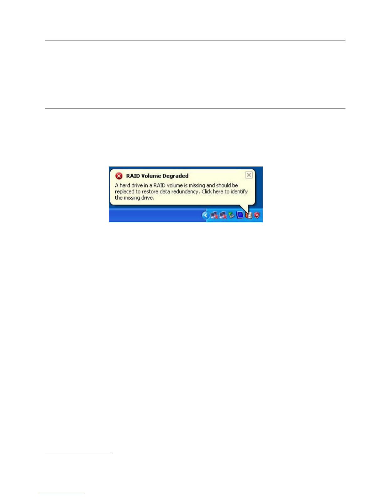
Updated July 14, 2008
Special tools requirements
You may need to order the following tools, which are not included in the toolkit:
v Ethernet wrap plug
v Tri-connector (serial and parallel) wrap plug
v USB mouse, required for POS Device Diagnostics
v PS/2-style or POS keyboard
Using the RAID application
The Redundant Array of Inexpensive Disks (RAID)3 application supports Models
742 and 782 with two hard disk drives and the Microsoft Windows operating
system. RAID provides an error message should one of the two hard disk drives
experience a failure (see Figure 63).
Figure 63. RAID hard drive failure pop-up
Determining a hard drive failure
When the RAID program indicates a hard drive failure, you can determine which
drive has failed using one of the following two methods:
Method one: Clicking on the RAID icon
1. From the Microsoft Windows Task bar, click on the RAID icon. This icon is
present only if abnormal activity occurred, such as a failed drive, and during an
array rebuilding. The Intel Storage Utility (see Figure 64 on page 76. ) opens.
3. RAID is also referred to as the Redundant Array of Independent Disks.
Chapter 3. Problem determination 75
Page 94
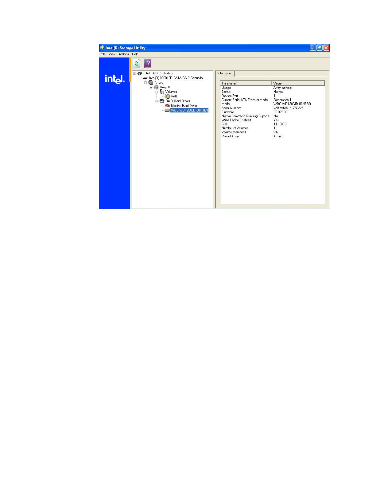
Updated July 14, 2008
Figure 64. Disk drive failure
2. Determine which hard disk drive has failed by opening the detected hard drive
(see Figure 64). In the example, the detected hard drive’s Device Port is 1;
therefore, the failed hard drive is located on Device Port 0.
3. Initiate shutdown and power off the machine (Start, Shutdown, press the power
switch, or follow the procedure for your business.)
4. Continue with the steps described in “Replacing and rebuilding a hard drive” on
page 77.
Method two: Entering RAID during start-up
1. Shutdown and reboot the machine (Start, Shutdown, press the power switch,
or follow the procedure for your business.)
76 SurePOS 700 Series: SurePOS 700-721/741/781, 722/742/782 Hardware Service Guide
Page 95
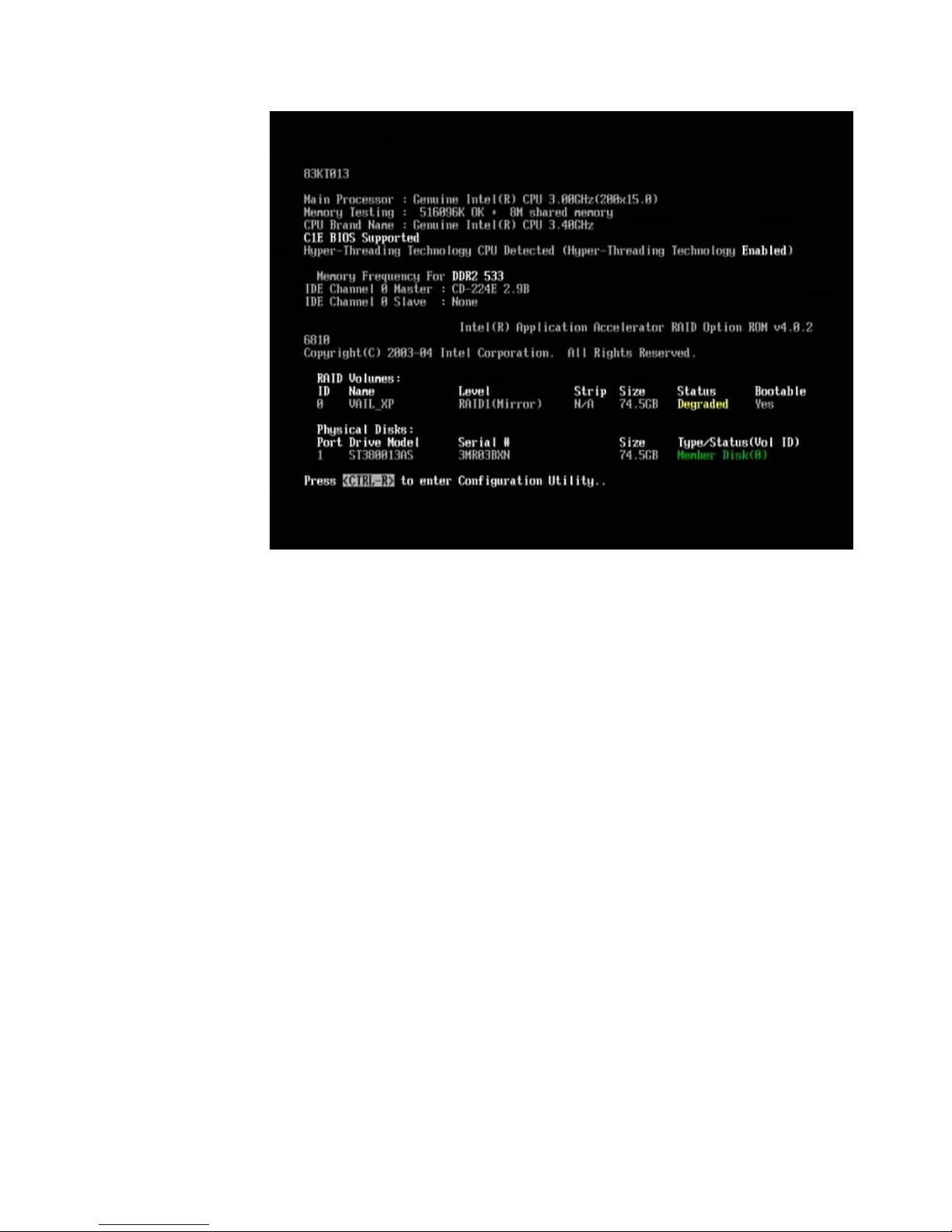
Updated July 14, 2008
Figure 65. Boot up warning
2. During the reboot, a screen appears that displays information on the failing disk.
See Figure 65. Note the Device Port number of the failing disk.
3. Power off the machine.
4. Continue with the steps described in “Replacing and rebuilding a hard drive.”
Replacing and rebuilding a hard drive
Note: Before beginning these procedures, you should have completed one of the
two methods on determining the failed hard disk drive.
1. Follow steps one through three in “Removing the hard disk drive” on page 36 to
open the machine.
2. Trace the serial ATA cables from the hard disk drives to he system board.
Note: Drive 0 connects to serial ATA connector 0 and Drive 1 connects to serial
ATA connector 1.
3. Continue with the instructions in “Removing the hard disk drive” on page 36 to
remove and replace the failing hard disk drive.
4. Re-assemble the machine and power on.
After the operating system has loaded, the RAID application will automatically
begin re-building the hard disk drive. During this process, you can use the
machine normally. Rebuilding time will vary depending upon the size of the
partition, amount of data and system activity during the rebuild.
Accessing the RAID setup menu
After enabling the RAID function from the BIOS setup menu, you can enter the
setup menu by pressing CTRL and R on the keyboard. Pressing CTRL and R
allows you to enter the RAID setup menu before the Windows operating system
Chapter 3. Problem determination 77
Page 96

Updated July 14, 2008
starts. Figure 66 is an example of the menu.
Figure 66. Example of the RAID setup menu
78 SurePOS 700 Series: SurePOS 700-721/741/781, 722/742/782 Hardware Service Guide
Page 97

Updated July 14, 2008
Chapter 4. Diagnostics and configuration settings
This chapter provides information on the diagnostics, CMOS, and configuration
settings for the SurePOS 720.
Important Information
SurePOS 720 require new POS I/O and LAN drivers. Existing drivers for
Models 4694 and Models 4800 will not work properly with these products. This
notice applies to all operating systems: DOS, 4690, Windows, and Linux.
Additionally, a hard drive image for a predecessor product will not work
properly. Be sure and download the appropriate drivers from the IBM Retail
web site: http://www.ibm.com/solutions/retail/store/support.
Service and diagnostics
The service and diagnostics programs for the SurePOS 720 are available from the
Retail Stores Web site at www.ibm.com/solutions/retail/store.
Follow these steps to run the diagnostics:
1. Download the appropriate diagnostics image from the Web site and copy it to
your media.
2. Ensure that your BIOS settings on the terminal are set to allow booting from the
media for your installation.
3. Boot your system using the executable file.
Using the BIOS setup program
The BIOS Setup Utility is a program for viewing and configuring system functions.
Some examples of these system functions are:
v Setting the system time and date
v Changing the boot device order
v Configuring power management settings
v Cash drawer power configuration
v Setting passwords
settings controlled by the BIOS Setup utility are stored in nonvolatile memory.
The
The default settings for most system functions controlled by the BIOS Setup Utility
are acceptable for the majority of environments.
Navigation and menus
Use an attached PC keyboard to execute, navigate, and configure options. Start the
BIOS Setup utility during the POST by pressing Del when the system prompts you
to enter setup.
Note: If the keyboard is USB-connected, you must connect to a PC USB port, and
not a powered-USB port.
Menus allow configuration of different system functions. Menus preceded by the >
symbol have submenus. Use the arrow key to navigate the menus and use the Esc
key to exit them. After you select a submenu, press Enter to open it.
© Copyright IBM Corp. 2003, 2008 79
Page 98

Saving settings
Changes made in the BIOS Setup Utility must be saved so they can take affect on
the next system boot. Exceptions are the time and date, which are updated and
saved immediately. To save changes, select Save & Exit Setup on the main menu,
or press F10 at any time. To exit Setup without saving changes, select Exit
Without Saving or press Esc on the main menu.
You can save your settings to a file using the CMOS Save Utility and then copy
them to other units using the CMOS Restore Utility. These utilities can be
downloaded from the IBM Retail Store Solutions Web site at www.ibm.com/
solutions/retail/store
Boot device order
The boot device order is a setting that you can configure. This function controls the
devices from which the system can be booted and the order in which they are
started. This function is located on the Advanced BIOS Features menu as First
Boot Device, Second Boot Device, and Third Boot Device. Navigate to each
item and press Enter to see a list of available boot devices.
The system default is:
v First Boot Device = USB-HDD
v Second Boot Device = HDD-0
v Third Boot Device = LAN
Updated July 14, 2008
this setting, the system attempts to boot first from a diskette in a USB diskette
With
drive, then from hard disk drive 0, then from the LAN. If no items are bootable, the
system will repeatedly try the boot list in order until successful.
Restoring CMOS default settings
To clear your CMOS settings and restore the default settings, follow these steps:
Note: Be sure to record your customized settings to reset them later.
1. Power off the system unit and disconnect the AC power cord.
2. Follow the instructions in “Removing the covers” on page 29 to remove the
covers and in “Removing the top plate” on page 32 to remove the top plate.
80 SurePOS 700 Series: SurePOS 700-721/741/781, 722/742/782 Hardware Service Guide
Page 99

Updated July 14, 2008
Figure 67. Location of CMOS jumper—Model 741 and 781
Figure 68. Location of CMOS jumper—Model 721
3. See A in Figure 67 or B in Figure 68 to locate your CMOS jumper on the
planar. See Table 7 for the correct pins and position to clear your CMOS
settings.
Table 7. CMOS jumper and pin location by model
Model CMOS Jumper Pins for normal operation Pins to clear CMOS
721 JP5
741, 781 JP4
4. Move the pins to position 2-3 and wait for 5 seconds.
5. Return the pins to position 1-2.
6. Re-plug the AC cord and power-on the system. Your system now has the
default CMOS settings.
Restoring the CMOS default settings may be necessary if a password is lost
Note:
or forgotten.
1-2 2-3
Chapter 4. Diagnostics and configuration settings 81
Page 100

Updated July 14, 2008
82 SurePOS 700 Series: SurePOS 700-721/741/781, 722/742/782 Hardware Service Guide
 Loading...