

Page 1

SurePOS 500 Model XX3
Technical System Reference
Version: 1.3
SurePOS 500 Model XX3 Technical Reference, v 1.3 Page 1 of 81
Page 2

Change History
Changes resulting in document revisions will be summarized in this table in reverse chronological sequence.
Version Date Change Description
1.0 1/28/04 Initial Draft
1.1 3/18/04 Revised copy with Engineering inputs, MSR programming interface
1.2 3/25/04 Updated System Block diagram, Presence sensor status, and ASIC
control registers.
1.3 4/1/04 Update Video Memory
SurePOS 500 Model XX3 Technical Reference, v 1.3 Page 2 of 81
Page 3

CONTENTS
i. Introduction................................................................................................................................................. 5
iii. Who should read this manual................................................................................................................... 6
iiii. Related publications ................................................................................................................................7
Chapter 1 Model Specifications................................................................................................ 8
Factory Select Feature................................................................................................................................11
Optional Features .......................................................................................................................................11
Ship Group.................................................................................................................................................. 12
Chapter 2 Supported Devices.................................................................................................. 13
Operating System Support.......................................................................................................................... 14
System Software......................................................................................................................................... 14
Maintenance Package ................................................................................................................................14
Chapter 3 Architectural Overview ........................................................................................ 15
System Block Diagram................................................................................................................................16
Main Board Block Diagram ......................................................................................................................... 17
Chapter 4 Physical Characteristics....................................................................................... 19
Dimensions ................................................................................................................................................. 19
Weights ....................................................................................................................................................... 19
Ports, Controls and Indicators..................................................................................................................... 20
Indicators..................................................................................................................................................... 21
User Control................................................................................................................................................ 21
Chapter 5 Tower Logic................................................................................................................. 21
Processor.................................................................................................................................................... 21
8245GV Memory Controller Hub, (GMCH)............................................................................................... 21
I/O Controller Hub, Intel ICH4..................................................................................................................... 22
Optional Second Video Adapter.................................................................................................................. 22
Network....................................................................................................................................................... 24
Extended POS Features ............................................................................................................................. 24
PC Card Support (Models 553 and 563) ....................................................................................................24
Chapter 6 Power Supply Unit................................................................................................... 25
Power Management.................................................................................................................................... 25
Power Control ............................................................................................................................................. 25
Chapter 7 LCD Panel.................................................................................................................... 25
LCD Specifications...................................................................................................................................... 25
Touch Panel................................................................................................................................................ 26
DISK DRIVE................................................................................................................................................27
Chapter 8 POS I/O Specifications......................................................................................... 27
MSR ............................................................................................................................................................ 27
External Stereo Speaker Unit .....................................................................................................................28
2x20 Displays.............................................................................................................................................. 29
APA Display ................................................................................................................................................ 30
Boot Control ................................................................................................................................................ 30
Setup Configuration Utility ..........................................................................................................................31
Operating System ....................................................................................................................................... 31
Maintenance Package ................................................................................................................................31
Programming Interface ...............................................................................................................................32
Appendix A -Psychometrics ......................................................................................................32
Appendix B Power Specifications.......................................................................................... 34
Appendix C Standards Compliance ..................................................................................... 35
Safety/EMC................................................................................................................................................. 35
SurePOS 500 Model XX3 Technical Reference, v 1.3 Page 3 of 81
Page 4

Appendix D Memory Map........................................................................................................... 37
I/O Map .................................................................................................................................................. 38
PCI Configuration........................................................................................................................................ 40
Interrupt and DMA Assignments................................................................................................................. 41
DMA Assignments ......................................................................................................................................42
Special SurePOS 500-XX3 POS Devices Interfaces.................................................................................. 42
Appendix E ASIC PCI Function 1: POS UARTs ......................................................... 46
Appendix F Connectors ...............................................................................................................48
Appendix G Input/Output device commands................................................................. 56
Appendix H Notices........................................................................................................................ 77
SurePOS 500 Model XX3 Technical Reference, v 1.3 Page 4 of 81
Page 5

i. Introduction
The IBM 4840 SurePOS 500 Series Point of Sale System is designed to drive the POS transactions within
your food service, hospitality, petroleum, and specialty retail providers worldwide.
SurePOS 500 – Model 563 (LEADERSHIP, MULTIMEDIA)
The sleek leadership model of this family displays excellent visibility in bright light via a 12 inch or 15 inch
dual-bulb touch screen that provides the widest viewing angle for training many people at once, wireless
capability through a PC Card type-II slot, and a headphone jack for private, quiet training in active
environments. An independent video adapter is available as an option to display a multimedia image on a
second LCD for advertising or up selling. A presence sensor saves you money by automatically switching the
display on and off based on the operator's proximity. Where stringing cable is not practical, a PC Card
expansion slot enables the use of wireless capability.
SUREPOS 500- Model 553 (VALUE, MULTIMEDIA)
If you need full-motion video, a wide viewing angle through a 12.1 inch single bulb active color LCD, wireless
capability through a PC Card type-II slot, and a touch screen, the SurePOS 553 will more than meet your
needs. It includes audio support/speakers as standard, as well as a headphone port and a microphone port.
SurePOS 500 - Model 543 (ENTRY, DUAL BULB)
If you need full-function POS or combined POS/back-office terminal at an entry price point, the 543 is the
right choice for you. It offers a dual-bulb active color LCD and the same processing power as the model 553,
all at a lower total cost of ownership.
SurePOS 500 – Model 533 (ENTRY, SINGLE BULB)
If you need full-function POS or combined POS/back-office terminal at an entry price point, the 543 is the
right choice for you. It offers a dual-bulb active color LCD and the same processing power as the model
553, all at a lower total cost of ownership.
If you need full-function POS or combined POS/back-office terminal at an entry price point, the 533 is the right
choice for you. It offers a single-bulb active color LCD and the same processing power as the model 553, all
at a low total cost of ownership.
SurePOS 500 Model XX3 Technical Reference, v 1.3 Page 5 of 81
Page 6

ii. About this manual
This manual contains software and hardware information about the IBM SurePOS 500 Series. This manual is
organized as follows:
• “Chapter 1. General description” on page 1 introduces the various models, the I/O devices that can
be attached, and product features.
• Chapter 2. Supported devices, Operating system Supported, and POS Application Interfaces.
• “Chapter 3. System configuration and system board layout” on page 15 describes the system board
and provides details about product features.
• “Chapter 4. Physical specifications” on page 19 provides detailed specifications and planning
information.
• “Chapter 5. Description of Tower Logic components.”
• “Chapter 6. Power supply” on page 26 describes the features of the power supply.”
• “Chapter 7. LCD Panel Specification. “
• “Chapter 8. POS I/O Specifications. “
• “Appendix A. System Unit Operating Temperature and Humidity Ranges. “
• “Appendix B. Power Specifications. “
• “Appendix C. Standards Compliance.”
• “Appendix D. Memory Map, PCI Configuration, Interrupt / DMA assignments and I/O Ranges.”
• “Appendix E. ASIC PCI Function POS UARTS.”
• “Appendix F. Connectors”
• “Appendix G. Input/Output device commands” on page 49 commands and their usage for the
SurePOS 500 Series I/O devices.
• “Appendix H. Notices” on page 65 provides legal notices, electronic emission notices, and trademark
information.
iii. Who should read this manual
This guide is intended for technical personnel who will plan, install, setup, and operate the point-of-sale
terminal. These personnel will also carry out preliminary diagnostic procedures using the information in this
manual, before making a service call.
SurePOS 500 Model XX3 Technical Reference, v 1.3 Page 6 of 81
Page 7

iiii. Related publications
The following IBM publications are available from the IBM Retail Store Solutions Web site at
www.ibm.com/solutions/retail/store/
From there, select Support, then, under Related Links, select Publications.
• Safety Information – Read This First, GA27–4004
• SurePOS 500 Series Installation and Operation Guide, GA27–4254
• SurePOS 500 Series Hardware Service Guide, GY27–0396
• 4610 SureMark Point-of-Sale Printers Hardware Service Manual, GY27–0355
• 4610 SureMark Point-of-Sale Printers User’s Guide, GA27–4151
• 4820 SurePoint Solutions Installation and Service Guide, GA27–4231
• 4820 SurePoint Solutions System Reference, SY27–4249
Driver and service diskette information
The following driver and diagnostic programs are available on the IBM Retail Store
Solutions Web site at www.ibm.com/solutions/retail/store/
SurePOS 500 Series Device Drivers
SurePOS 500 Series Service Diskette
At that site, select Support, then under Software select Download Software
Maintenance and select SurePOS 500 Series.
SurePOS 500 Model XX3 Technical Reference, v 1.3 Page 7 of 81
Page 8

Chapter 1 Model Specifications
Model Summary
Model Processor Dual
Video
4840- 533
4840-543 2.0 GHZ
4840-553
PCCARD/AUDIO
2.0 GHZ
Celeron
Celeron
2.0 GHZ
Celeron
Option No No 12-in
Option No Yes 12-in Dual
Option No Yes 12-in
Presence
Sensor
Spk
Tablet Memory
er
Single Bulb
Bulb
Single Bulb
128 Std
256,512,1G, 2GB
128 Std 256,512,1G,
2GB
128 Std 256,512,1G,
2GB
Mass Storage
40 GB HDD 7200
RPM
512 MB Compact
Flash
40 GB HDD 7200
RPM
40 GB HDD 7200
RPM
4840-563
PCCARD/AUDIO
2.0 GHZ
Celeron
Standard Yes Yes 12-in Dual
Bulb
15-in
128 Std 256,512,1G,
2GB
40 GB HDD 7200
RPM
SurePOS 500 Model XX3 Technical Reference, v 1.3 Page 8 of 81
Page 9

Model Specifications
Processor
PSB Speed
Chipset
BIOS
Main Memory
Video
LCD
Touch
Audio
Mass Storage
LAN
Expansion
Presence
Sensor
I/O Ports and
Connectors
I/O Devices
Indicators
Controls
4840-533 4840-543 4840-553 4840-563
800x600 12.1-in
TFT (1 bulb)
n/a n/aAC97 compliant
No No No Yes
Intel Celeron 2.0 GHz
400 MHz
Intel 845GV
Award-based
128 MB 266 MHz DDR standard
2 slots (2 GB max)
Intel Extreme Graphics (8MB ) plus DVMT (Max 64MB) (Note 1)
Dual Video Adapter 32Mb (Note 2)
800x600 12.1-in TFT
(2 bulb)
Amplified Stereo
Speakers
Ultra ATA/100 (Parallel)
512MB Compact Flash or 40 GB 3.5-in IDE HDD
10/100BaseT Ethernet
n/a PC Card - 1 Type II PC Card - 1 Type
2 StandardUSB (tablet)
Mouse/Kybd (front/rear)
4 Standard USB (2 front/2 rear)
1 12V Powered USB (rear)
1 24V Powered USB (rear)
2 Cash Drawer
3 Unpowered RS232
1 Powered RS232 (External Customer Display)
Headphone/Microphone (553/563premium model only)
External Floppy
External CRT
Parallel Port
External Floppy
External Floppy (USB)
External CD ROM (USB)
MSR (3-Track/JUCC)
Integrated 2x20
Distributed 2x20
Distributed APA
HDD activity
LCD Brightness
800x600 12.1-in TFT
(1 bulb)
Infra-red
AC97 compliant
Amplified stereo
speakers
RJ45 LAN
Power
Power
800x600 12.1-in
TFT (2 bulb)
1024x768 15-in.
AC97 compliant
amplified stereo
speakers
TFT
II
SurePOS 500 Model XX3 Technical Reference, v 1.3 Page 9 of 81
Page 10

Volume (with speaker kit)
OS
Power Supply
Mounting
Security
– Free Standing (with and without foot)
– Free Standing on cash drawer (std or compact)
– Integration Trays: SST/kybd counter, 4610 counter, Std/compact cash drawer
– Wall Mount
DOS 2000, Windows ( 2000, XP, XPe), Linux
130W/200 W max
Power On Password
Bolt down/Tray Mounting
Notes:
1. Dynamic Video Memory Technology (DVMT) and Pre-Allocated Video Memory
With the appropriate Windows video driver the Extreme Graphics video controller, 845GV, is allocated a
variable UMA memory size. This is based on the real time requirements of the application software. For nonWindows operating systems where the DVMT driver is not available, a second ‘pre-allocated’ and fixed UMA
memory size defined. This pre-allocated memory is set to 8Mb and is not related to or combined with the
DMVT UMA memory size.
memory. If a Windows operating system is in use with Intel’s DVMT driver loaded, an additional memory size
is allocated (consumed) from system memory. The maximum DVMT memory size allocated will be 64MB.
The total system memory consumed for on-board video controller usage is the total of pre-allocated and
DMVT memory could total 72MB (8MB + 64MB).
The pre-allocated memory is always available and is consuming 8Mb system
2. Dual Video adapter memory requirement- this optional factory installed feature utilizes 32Mb of UMA
memory as video memory. The combined video memory usage of the base 845GV video chipset utilizing
DVMT technology and the second video adapter requires the system memory be configured at 256Mb. This is
to insure sufficient memory for Operating System, Application, and video usage.
SurePOS 500 Model XX3 Technical Reference, v 1.3 Page 10 of
81
Page 11

Factory Select Feature
Mass Storage 40GB HDD or 512 MB Compact Flash (Model 533)
Memory 128MB, 256MB, 512 MB, 1GB, 2 GB
LCD 12-in or 15-in (Model 563 only)
Dual Video All Models Factory install feature code
Optional Features
Unless otherwise stated, all features are designated as customer set up and plant/field.
Order
Code
128 MB DDR Memory Field Install
256 MB DDR Memory Field Install
512 MB DDR Memory Field Install
1 GB DDR Memory Field Install
2 GB DDR Memory Field Install
Mounting Foot New P/N, 4820
Integrated 2x20 Customer Display New P/N
Distributed 2x20 Customer Display Existing P/N
Distributed APA Customer Display Existing P/N
3-Track MSR New P/N
JUCC MSR New P/N
Integration Tray for Printer/Kybd New
Counter Integration Kit (SST/kybd) New
Standard CD Integration Kit (4610/kybd) New
Compact CD Integration Tray (kybd) New
Cash Drawer (standard, compact) Existing P/N
Compact A/N POS Keyboard Existing P/N
Y-cable, CANPOS/Mouse Existing P/N? right
External USB CD ROM New P/N
External USB Floppy Drive New P/N
External Floppy (existing) Existing P/N
Serial Cable, RJ45 to DB9, 0.7m Existing P/N
Serial Cable, RJ45 to DB9, 2.0m Existing P/N
4820 Attachment Kit Existing P/N(updated)
4610-TF6/7 Power Cable, 0.7m New P/N
4610-TF6/7 Power Cable, 2.0m New P/N
Feature P/N Comments
mounting
angle?
SurePOS 500 Model XX3 Technical Reference, v 1.3 Page 11 of
81
Page 12

Ship Group
The following items are included with the unit:
Cat 5 Ethernet Cable (4.3m), P/N 42L0098
Serial Cable, RJ45 to DB9 (0.7m), P/N 03R7887
The following items are picked packed per order at IBM Distribution Center:
Warranty Sheet
Installation, Operations, and Planning (optional with specify code)
Regulatory and Safety Messages Booklet (GA27-4004)
Power cord selected by country code
SurePOS 500 Model XX3 Technical Reference, v 1.3 Page 12 of
81
Page 13

Chapter 2 Supported Devices
The following industry standard devices have been tested for use with SurePOS 500-XX3 subject to operating
restrictions defined in the Operating System support section. Other industry devices may be supported using
standard interfaces, however, no testing has been done to insure functionality in all aspects.
Port Device Hot Plug
Support
(note 1)
RS232
CRT (Video)
USB
Parallel
Keyboard/Mouse
PC Card (PCMCIA)
Headphone/Mic
Notes:
1. Assumes device natively supports hot plugging and can be hot plugged with
any operating system
2. CANPOS MSR option mutually exclusive with SurePOS 500 MSR option
– 4610-TF6/TF7 Single Station Thermal
Printer
– 4610-TG3, TG4, TG5
– 4820-4FD/4FT (MSR option supported)
– USB Crystal (if in plan)
– 4610-GB3 (Macarena Fiscal USB)
– 4610-TG3/TG4/TG5
– IBM USB Floppy Drive, P/N 05K9276
– IBM USB Keyboard, P/N 10K3849 (OBI
P/N)
– IBM Memory Key P/N 22P9025
– IBM 4685-S01/L0H Handheld Scanner
– MicroSolutions BackPack CD ROM No
– IBM PS/2 Keyboard
– IBM Mouse (required Y-cable)
– Compact Retail A/N Keyboard (note 3)
– Symbol Spectrum 24
– CardPlus PCMCIA CD ROM
– SanDisk Solid State File (not bootable)
– IBM P/N 30H2203 or equivalent Yes
No
No
Yes USB not
supported
on DOS
Yes
Yes
(n/a
DOS)
SurePOS 500 Model XX3 Technical Reference, v 1.3 Page 13 of
81
Page 14

Operating System Support
SurePOS 500-XX3 supports the following operating systems. Unless otherwise noted, all national language
variations are supported. Operating Systems which can be remote loaded are noted.
Operating System Support
DOS 2000 (Note 1)
Windows
2000
XP/Xpe
Linux (note 2)
Notes:
1. DOS Full screen modes not supported
2. IBM Retail Environment for SuSe Linux
3. Windows DBCS versions (Japanese/Korean/Chinese) supported
Yes
Yes
Yes
Yes
System Software
POS Application Interface Drivers
POS Application drivers may be more restrictive on operating system support. Refer to the OPOS/JavaPOS
specifications for supported operating systems.
Operating System POS Application Interface Extensions
(MSRs, Customer Displays, Cash Drawer, Tone,
Presence Sensor)
DOS Direct Com port interface
Windows OPOS 1.7.0
JavaPOS 1.7.0
IBM Retail Environment for SuSe
Linux
JavaPOS 1.7.0
Maintenance Package
There is a DOS-based diagnostic package used to perform error detection/fault isolation activities.
SurePOS 500 Model XX3 Technical Reference, v 1.3 Page 14 of
81
Page 15

Chapter 3 Architectural Overview
SurePOS 500 Model XX3 Technical Reference, v 1.3 Page 15 of
81
Page 16

System Block Diagram
9/1/03
MSR
Speaker Kit
Presence Sensor/LED Card
backlight
inverter
card
LCD
CPU
signal
Main card
DIMM
DIMM
Tablet Card
Tablet Card
USB x 2
Touch
(Panel or Ring)
24Feb2003
button card
Int 2x20
Tailgate
USB x 2
Tailgate
Main
Vcore
Power Supply
pwr button
headphone
microphone
kbd/mouse
floppy
HDD
power
HDD
signal
pc card
dual video option
HDD/Compact Flash
12v/24v
SurePOS 500 Model XX3 Technical Reference, v 1.3 Page 16 of
81
Page 17

Main Board Block Diagram
SurePOS 500 Model XX3 Technical Reference, v 1.3 Page 17 of
81
Page 18

CPU
Celeron/P4
GMCH
Intel 82845GV
ICH4
Intel 82801DB
4 Phase Vcor
Regulator
CRT
6X USB 2.0
AC 97 Am p/
Codec
PCI Bus
DDR DIMMs
PHY
XTAL
XTAL
XTAL
XTAL
Scal ing/Tx
ETHERNET
IDE HDD
FIRMWARE HUB
Speakers/
volume
control
14.318Mhz
LVDS
PCI
25Mhz
32.768Khz
24Mhz
Ether net PHY
ICH4 RTC
AC97 Audi o
Cl k Synthesi zer
Hub
LVDS Video Signaling
5X
USB 2.0
4XUSB
USB 2.0
Dual Video
Adapter
Master
Clock
Synthesiz
er
100/133Mhz
100/133Mhz
66Mhz
48Mhz
66Mhz
48Mhz
33Mhz
14.318Mhz
48Mhz
33Mhz
33Mhz
CRT
Connec tor
PC-Card
Slot
CPU
GMC H GTL Bus
GMCH HUB Link
GMCH Video
ICH4 HUB Link
ICH4 USB
ICH4 PCI
ICH4 Refrence
SUPER I /O
SUPER I /O
FWH
SUPER I/O
SMSC
COM1
COM2
Serial Port A
Serial Port B
Parallel
Floppy
KB/MS
PCI
ASIC
comm4
HW Monitor
IR Touch Frame
LCD PANEL
- TTL Parallel
- LVDS Serial
L CD Ta blet
Tablet Card
- IR Touch Controller
- LVDS Receiver
- Vregulation, Touch ID Straps
- Connectors: 2x USB, MSR,
Backlight Card
Tablet Cable, LCD-TTL, LCD-LVDS
- Single/Dual Bulb
- LCD ID Straps
MSR
I/O Port Summary 1. USB1 (Side Fore) Serial: 1. COM1 (Tailgate port A)
USB: 2. USB2 (Side Aft) 2. COM2 (Tailgate port A)
3. USB3 (Tablet Right) 3. COM3 (Tablet, Tablet)
4. USB4 (Tablet Left) 4. COM4 (Int/Ext VFD port)
5. USB5 (Hub) 5. COM5 (Tablet, Touch)
COM3
COM4
COM5
COM6
8
0
5
1
2X
Presence Sensor
Int/Ext VFD
MSR
Touch
Serial Port C
Brightness Control
Cash Drawer
Button
Card
- Up and Down
Brightness Buttons
* Note: One CRT Connector
on Tailgate is multiplexed
between Dual Video Adapter
and On-board Video
CABLE
SurePOS 500 Model XX3 Technical Reference, v 1.3 Page 18 of
81
Page 19

Chapter 4 Physical Characteristics
Dimensions
Height (mm) Counter 15" Counter 12" Wallmount 12" Wallmount 15"
Tablet at 15 Degrees 408 379 N/A N/A
Tablet Max 410 384 N/A N/A
Front Cable Routing Plate Add 14 ? Add 14 ? N/A N/A
Width (mm)
Tablet 383 321 321 383
Tablet w/ MSR 426 364 364 426
Base 212 212 217 ? 217 ?
Depth (mm)
Base 221 221 N/A N/A
Base w/ Cable Plate TBD TBD N/A N/A
Total Front to Rear Tablet
at 15 Degrees
Total Front to Rear Tablet
at 60 Degrees
268 264 250 ? 252 ?
338 325 tbd 311 ? tbd 320 ?
Weights
Tower + 12-in Tablet 9.5 kg (23 lbs)
Tower + 15-in Tablet System Unit, 15-in. 11.7 kg (24.5 lbs)
Integrated 2x20 Display 0.21 kg (0.38 lbs)
Distributed 2x20 Display 0.55 kg (1.2 lbs)
Distributed APA Display 0.73 kg (1.6 lbs)
MSR (3 track or JUCC) 0.16 kg (0.41 lbs)
SurePOS 500 Model XX3 Technical Reference, v 1.3 Page 19 of
81
Page 20

Ports, Controls and Indicators
Port Location and Marking
Front Access Area (rotated)
Rear Tailgate
DISPLAY
SurePOS 500 Model XX3 Technical Reference, v 1.3 Page 20 of
81
Page 21

Indicators
Function Color Location State
Power Green Tower Front Off -System Off
Blinking - Standby/during POST
On - Operational
HDD Yellow Tower Front Off - NO activity
Blinking - HDD activity
Ethernet Green Rear (Ethernet
connector)
Left LED States
– Off - 10 Mb mode
– On - 100 Mbit
Right LED States
– Off - No link
– On - Good Link
User Control
Function Color Actuation Location Operation
Power White Momentary Behind access door on
tower
Brightness Blue Momentary Tablet 2 buttons, bright
Toggles state between
OFF and ON
up/down
Chapter 5 Tower Logic
Processor
Intel mPGA478 Pentium 4 Socket
400/533MHz PSB (100/133 MHz external bus clock)
1.8GHz - 2.8GHz Processor speeds
Processor support is limited to Pentium 4 2.4 GHz by thermal and power supply considerations.
8245GV Memory Controller Hub, (GMCH)
System Memory Controller
– PC2100 (DDR266) (PC1600 (DDR200) not supported)
– Non-ECC, unbuffered DIMMs
– 2GB total memory; 2 DIMM sockets
- No double sided, x16 DDR sdram supported
– Supported DIMM sizes: 128MB, 256MB, 512 MB, 1 GB
Integrated Extreme Graphics 3D Controller
– 256 bit engine
– 64 MB maximum UMA video memory
– Synchronous LCD/CRT support
– LVDS Panel support
Video Support Implementation Notes:
SurePOS 500 Model XX3 Technical Reference, v 1.3 Page 21 of
81
Page 22

1. Without the optional second video adapter, internal LCD and external monitor resolutions and
refresh rates will be the same. With the second video adapter feature, internal LCD and external
monitor resolutions and refresh rates can be independent of each other..
I/O Controller Hub, Intel ICH4
PCI Bus Controller, Rev 2.2, 33MHz
10/100 Ethernet MAC
IDE Controller, ATA 100/66/33
USB 2.0 EHCI Universal Host controller
AC 97 2.3 Audio Link
Interrupt Controller
Power Management Logic, ACPI 2.0
Firmware Hub Interface
DMA Controller
Real Time Clock/CMOS RAM
Optional Second Video Adapter
SurePOS 500-XX3 provides a dual video adapter to allow for true multi-monitor support on the internal LCD
and externally attached monitor. This allows different screens and independent touch on both monitors. This
is supported on all Windows operating systems.
The daughter card consists of the following elements:
nvidia GeForce2 MX
local video memory
The daughter card provides the following functions:
64-bit graphics engine
32 MB video memory (capable of 8 MB) ?
60, 75, XX Hz refresh rates
SVGA CRT output (replaces onboard video out)
Supports Windows 98 and 2000 Dual Display
Supported color depths/resolutions:
Notes:
1. There are jumpers installed in production on the main card when the optional second video
adapter not ordered. If the second video adapter is installed and you wish to provide a mirrored
output on the SVGA port - the video card would have to be removed and these jumpers added
to the planar board.
Audio (Models 553 and 563)
In combination with the south bridge, the audio subsystem provides business quality stereo sound for
multimedia and voice capable applications. The subsystem includes a headphone and microphone jack and
external speaker assembly.
SurePOS 500 Model XX3 Technical Reference, v 1.3 Page 22 of
81
Page 23

The audio subsystems provides the following functions:
Audio Codec 97 Revision 2.3 compliant Audio
Full duplex capability
The audio subsystem consists of the following elements:
Realtek Codec AL202A integrated headphone amplifier
Headphone and microphone jack
External amplified speaker assembly
Implementation Notes:
Volume control is through normal Windows multimedia controls in combination with a volume
control on the speaker unit.
Bass/Treble slides in windows volume control will not be functional
This subsystem can be disabled in through Setup.
SurePOS 500 Model XX3 Technical Reference, v 1.3 Page 23 of
81
Page 24

Network
The network subsystem consists of the following elements:
Integrated Intel MAC (ICH4)
External 10/100 Mbit PHY, 82562ET
EEPROM for MAC address
The network system provides the following functions:
10/100 Mbps ethernet
Support for wake up on LAN using Magic Packet
Stores register values, MAC address
Extended POS Features
The Extended POS I/O subsystem is attached to PCI bus and provides support for additional I/O ports and
miscellaneous function.
The I/O subsystem consists of the following elements:
ASIC for UART/POS
80C51
The I/O subsystem provides the following functions:
Support for 4 additional serial ports
Cash Drawer control
LCD Brightness and contrast control
Internal IR Presense sensor port
PC Card Support (Models 553 and 563)
The PC Card subsystem provides for the capability to attach PC Cards (PCMCIA). SurePOS 500-XX3
provides a slot to accommodate a single Type 1 or 2 PC Card.
The subsystem consists of the following elements:
TI PC1410A PCI-to-PC Card Controller
Type I/II Card Socket
The subsystem provides the following functions:
Meets PC Card Standard 7
PC 98/99 compliant
3.3v/5v PC Card16 and 3.3v CardBus support
This subsystem can be disabled through Setup.
SurePOS 500 Model XX3 Technical Reference, v 1.3 Page 24 of
81
Page 25

Chapter 6 Power Supply Unit
The main AC power supply is enclosed in a separate metal box but enclosed within the Tower system unit.
The heat generated within this supply is separated from the main electronics cavity and is dissipated by an
integrated fan assembly. Reference the SurePOS 500-XX3 Power Supply specification for additional details.
Power Management
SurePOS 500-XX3 supports both APM and ACPI power management schemes. APM is supported in DOS
and Linux. ACPI is supported in Windows 2000/XP. Windows NT 4.0 does not support APM or ACPI.
Hibernation mode is not supported.
Power Management Option Supported Power States
APM Off, APM Standby, APM Enabled, Full On
ACPI Global States: G0, G1, G2
Sleep States: S0, S1, S5
Power Control
SurePOS 500-XX3 supports the following power state changes based upon event:
Power Switch Yes Yes
LAN Yes Yes
Alarm Yes Yes
Touch No Yes
Presence No Yes
Keyboard/Mouse (PS/2, USB) No Yes
The power switch can be configured in 3 modes for APM and ACPI unless otherwise noted:
Disable - Switch operation is ignored (not for Win2K)
Enabled - Switch operates like hard power switch - toggles between G0 - G2
Resume - Switch operates like resume switch - toggles between G0 and G1
Power On Resume
Chapter 7 LCD Panel
LCD Specifications
Interface
Minimum Brightness
(cd/m**2)(w/o
sensor)
Active Area (mm)
Resolution (pixels)
Contrast Ratio
Horizontal Viewing
12.1" TFT
(1 CCFL)
TTL TTL LVDS
160 320 250
246 x 184.5 246 x 184.5 304.1 x 228.1
0.48MP (800 x 600) 0.48MP (800 x 600) 0.79MP (1024
300:1 300:1 350:1
+/- 45 +/- 65 +/- 60
12.1-inch TFT
(2 CCFL)
15-inch TFT
(2 CCFL)
x 768)
SurePOS 500 Model XX3 Technical Reference, v 1.3 Page 25 of
81
Page 26

Angle (deg)
(for CR>=10:1)
Vertical Viewing
Angle (deg)
(for CR>=10:1)
Backlight Life
(half brightness)
Thickness (mm)
+10, -30 +40, -60 +/- 45
20,000 hrs 50,000 hrs 40,000 hrs
6.9 (max) 11.5 11
Touch Panel
Type Infra-red
Input Method
Controller
Resolution
Accuracy (std dev)
Accuracy (max err)
Finish
Transmissiveness
Travel
Touch Activation
Force
Surface Hardness
Abrasion
Resistance
Finger, stylus
(.25-in diameter
min.)
1024x1024
0.080-in.
0.047-in. (96%)
0.222-in (4%)
Chem Etch
92%
N/A
None
Glass
n/A
SurePOS 500 Model XX3 Technical Reference, v 1.3 Page 26 of
81
Page 27

DISK DRIVE
SurePOS 500 supports industry standard 3.5-inch form factor hard disk drives with AT interface. The
maximum thickness supported is 25.4 mm.
Formatted Capacity (GB)
Interface
Rotational Speed
Buffer Size
Performance
Seek Time (ms) <10 typ
Track to Track (ms) 2
Latency (ms) 6.81
Transfer Rates (Mbytes/sec) UltraDMA: 100
Power Consumption
Read/Write on Track
5400 rpm or 7200 rpm
40.2 GB
IDE (AT)
512 KB
PIO: 16.6
5 W
Chapter 8 POS I/O Specifications
MSR
SurePOS 500-XX3 supports two msr types: 3-Track and JUCC. The SurePOS 500-XX3 3-Track MSR
features enhanced configuration options over the predecessor models to improve compatibility with existing
business partner applications. The enhancements include
Enable/Disable Carriage Return
Enable/Disable Sentinals
Programmable Sentinels
Individually selectable Tracks
FLASH firmware
Compatibility mode w/ previous generation
The MSR will support mini-cards as well as metalized cards.
Track Configuration
Coercivity of Magnetic Stripe
Read Direction
Swipe Speed
Maximum Jitter
Error Rate
Electrical Interface
Rated Life
Note
1. The interface is set by customer using switch before installation. Default is RS232.
3-Track MSR Option JUCC Option
ISO 7811 Tracks 1,2,3 JIS II, ISO Track 2
300 to 4000 Oe 300 to 4000 Oe
Bi-directional Unidirectional
5 to 60 inches per second 5 to 60 inches per second
12% 12%
Less than 0.5% Less than 0.5%
Serial or PS/2 Keyboard
(note 1)
500,000 swipes 500,000 swipes
Serial
SurePOS 500 Model XX3 Technical Reference, v 1.3 Page 27 of
81
Page 28

External Stereo Speaker Unit
SurePOS 500-XX3 supports an external stereo speaker unit. The speaker unit is a self-contained assembly
which attaches to SurePOS 500-XX3 using mounting screws. There is a connection provided for input, power
and signal, to the speaker unit. The speaker unit contains the drivers and a 1 W per channel amplifier.
Design
Drivers
Type
Impedance
Magnetic Shielding
Frequency Response
Output
(rms EIAJ 10% THD 1kHz)
Loudness
S/N Ratio
Channel Separation
Total Harmonic Distortion
Input Voltage
Input Sensitivity
Input Impedance
Power Consumption
Input Terminal
2 element, 1 way, sealed design
7 x 4 (28 mm x 40 mm x 15 mm deep)
12 ohm impedance
Yes
160Hz - 11 kHz (+/- 3 dB)
1W + 1 W
82 dB +/- 3 dB (1 Watt/ch @ 1 m)
65 dB (IEC A weighted, ref 1 W)
40 dB
10%
10.8V V DC +/- 10%
1 V (1 W, 1kHz)
12 ohm (1 kHz)
4 W at maximum volume setting
Molex 70555-0038 (power + signal)
SurePOS 500 Model XX3 Technical Reference, v 1.3 Page 28 of
81
Page 29

2x20 Displays
Technology
Format
Brightness (w/o
lens)
Display Color (w/o
lens)
Adjustment
Character Box
Character Height
(mm)
Emulations
Character Sets
(IBM Multi-mode)
User Defined
Characters
Electrical
Interface
Power
Power
Consumption
(all pixels
energized)
Attachment Cable
Integrated 2x20 Distributed 2x20
Vacuum Fluorescent
2 rows, 20 characters
300 cd/m
2
None Multi-position detent
5 x 7 5 x 7
7.74 x 4.15 9.5 x 4.45
Logic Controls Emulation or IBM Multi-Mode
Code Page 437 (US/Euro)
Code Page 897 (Katakana)
Code Page 858 (Int'l)
Code Page 852 (Central Europe)
Code Page 855 (Cyrillic)
Code Page 857 (Turkey)
Code Page 862 (Israel)
Code Page 863 (Can Fr)
Code Page 864 (Arabic)
Code Page 865 (Nordic)
Code Page 808 (Cyrillic Russian)
Code Page 869 (Greece)
Logic Controls Mode: 1
IBM Mode: 8
TTL Serial RS232
5V 12V
6W 7.2 W
Pigtail 3.8 m (12 ft)
Green
300 cd/m
2
SurePOS 500-XX3 supports an integrated and distributed 2x20 customer display. The integrated display
mounts externally to the rear cover and provides a 3 position adjustable viewing range. The distributed
display is a free standing design using existing 4690 style covers using the
displays are Euro Ready.
SurePOS 500 Model XX3 Technical Reference, v 1.3 Page 29 of
SurePOS 500-XX3 color. The
81
Page 30

APA Display
SurePOS 500-XX3 supports an external all points addressable customer display. This is intended to meet
Technology
Brightness
Format (dot)
Active Area (mm)
Dot Size (mm)
Dot Pitch (mm)
Display Color
Modes
Built in Font Code Pages for Character
Mode
5x7 A/N (4 and 5 line mode)
8x16 A/N English (2 line mode)
8x16 A/N Katakana (2 line mode)
16x16 Kanji (2 line mode)
16x16 Hanguel (2 line mode)
16x16 Simplified Chinese (2 line
mode)
16x16 Traditional Chinese (2 line
mode)
Character Box Height (mm)
5x7
8x16
16x16
Electrical Interface
Power Consumption
Adjustment
Attachment Cable
DBCS language requirements. It attaches to the SurePOS 500-XX3 external customer display port which
provides power and signal.
Vacuum Fluorescent
300 cd/m
160 x 40
132.55 x 32.95
0.58 (W) x 0.58 (H)
0.83 (W) x 0.83 (H)
Green
(peak wavelength 505 nm)
All Points Addressable (160x40)
Character Mode
Futaba Standard
IBM Code Page 437 modified
Futaba Standard
JIS X 208-1990
KS C 5601-1992
GB-2321-80
BIG5
3.90 (H) x 5.56 (W)
6.39 (H) x 13.03 (W)
13.03 (H) x 13.03 (W)
RS232 with 12 V power
6W (typ)
8.4 (max)
Multiposition
2
3.8m
.1 Software Description
Boot Control
The following boot options are available:
LAN RPL - PXE 2.0 and IBM RPL only.
External Diskette Drive (standard or USB)
USB CD ROM
Hard Disk Drive
SurePOS 500 Model XX3 Technical Reference, v 1.3 Page 30 of
81
Page 31

Compact Flash Drive
Memory Key
Wireless LAN and Solid State File Drives in the PCMCIA slot are not supported for remote load or operating
system boot.
Setup Configuration Utility
The Configuration Setup Utility program provides menus for querying and configuration the system. The
menus can be navigated using touch or a keyboard attached to the PS/2 keyboard port or USB port.
The Setup Configuration Utility can be password protected. The password can be entered through on screen
keypad or keyboard, and can only be numerical. If the password is forgotten, it can be cleared using the
CMOS Clear Jumper located near the memory DIMM.
Query vital product data (machine type/model, BIOS level)
Set date and time
Set startup options (boot sequence)
Set power management options
Set Advanced Options
I/O Enable/Disable/Configuration
Subsystem Enable/Disable (Ethernet, Audio, PCMCIA)
Operating System
SurePOS 500-XX3 supports the following operating systems:
DOS 2000
Windows 2000
Windows XP/Xpe
IBM Retail Environment for SuSe Linux
Maintenance Package
The following driver and diagnostic programs are available on the IBM Retail Store
Solutions Web site at
SurePOS 500 Series Device Drivers
SurePOS 500 Series Service Diskette
At that site, select Support, then under Software select Download Software
Maintenance and select SurePOS 500 Series.
www.ibm.com/solutions/retail/store/
DOS-based service diagnostics are provided on diskette.
SurePOS 500 Model XX3 Technical Reference, v 1.3 Page 31 of
81
Page 32
Programming Interface
Vital Product Data
SurePOS 500-XX3 provides Vital Product Information that includes:
Machine Type/Model
Machine Serial Number
BIOS/Flash ID
System Board ID
MAC Address
VPD is accessed using IBM standard INT 15h interface for finding the VPD data area within the system
post/bios ROM address space. It is also shadowed into the flash ROM at address F000:FFA0
Vital Product Data (VPD) is the information about an IBM system that can be read with software. The data n
includes machine type, machine serial number, BIOS/FLASH ID, system board unique ID, etc. The physical
location of the VPD is in the EEPROM attached to the custom SurePOS 500-XX3 ASIC. This information will
also be shadowed into the flash ROM at address F000:FFA0 as is standard on all IBM PC's. SurePOS 500XX3 BIOS will implement the IBM standard INT 15h interface for finding the VPD data area within the System
POST/BIOS ROM.
Much of the VPD information will be written into the DMI strings where the info can be extracted by
applications such as RDM. During the manufacturing process, the machine unique data will be written into the
EEPROM VPD area by the test process. POST will extract the data from the EEPROM for the outside
interfaces to retrieve, such as SMBIOS. Machine unique data can include Model, box serial number, and
planar serial number.
Appendix A -Psychometrics
Classification
Category/Class Reference Standard
Class C - Modified C-S 1-9700-000
Temperature/Humidity Limits
Condition Temp Limits (Dry Bulb) Relative Humidity Max. Wet Bulb Temp
Operating 5 to 40 °C 8 to 80 % 27 °C
Power Off 0 to 52 °C 5 to 95 % 27 °C
Storage 0 to 60 °C 5 to 80 % 29 °C
Shipment -40 to 60 °C 5 to 100 % 29 °C
Psychometric Specifications at sea level. Upper limit for dry bulb temperature must be de-rated 1 C for
every 137 meters of elevation above 915 meters. Upper limit for wet bulb temperature must be de-rated 1 C
for every 274 meters of elevation above 305 meters.
Altitude Limits
The product is designed to operate up to 3050 meters (10,000 ft.)
Heat Dissipation
SurePOS 500 Model XX3 Technical Reference, v 1.3 Page 32 of
81
Page 33

SurePOS 500-XX3 relies on convection cooling so placement requires the ambient air adjacent to the unit
does not exceed supported maximums. The vents cannot be blocked to prevent access to ambient air.
Spill/Chemical Resistance
The system unit will be designed to meet the following standards for liquid spill resistance when mounted in
normal configurations. The spill specification does not apply to the cable attached I/O devices such as the
distributed customer display or scanners:
IBM RSS Chemical Resistance Test
NEMA Type 5 rating per NEMA Standards Publication/No. 250-1997 Enclosures for Electrical
Equipment (National Electrical Manufacturers Association)
IP 52 rating per IEC 529 (Degrees of Protection by enclosures (IP Code)
Internally tested to IP 52 but not declared in safety report.
SurePOS 500 Model XX3 Technical Reference, v 1.3 Page 33 of
81
Page 34
Appendix B Power Specifications
The following chart defines the input requirements and power consumption specifications:
Power Consumption
Off (attached to mains) 7 Watts
Suspend Not supported
Standby 49 Watts
On (idle, no I/O) 60 Watts -?
On (idle, I/O: cd, msr, 2x20, printer) 79 Watts
On (max, printing) 82 Watts
Input Voltage/Frequency
Maximum kVA
AC Input Connector/Cable
Leakage current
Inrush
100 ~ 127, 200 ~ 240 V AC (nominal)
50 or 60 Hz (+/- 3 Hz)
Sinusoidal, trapezoidal, or square wave inputs
0.21
IEC 320 C14, unshielded right angle type
1.0 ma maximum
< 50 A (peak, first cycle)
A. Vibration, Shock, and Drop
1. Operating
Attribute Category/Class Reference Standard
Vibration Class V3 C-S 1-9711-002
Shock Class S3 C-S 1-9711-007
1. Non-Operating
Item
Packaged (individual, nonpalletized)
Unpackaged
Vibration
Shock (drop table)
Levels
50 g's min
Reference Standard
IBM C-H 1-9711-005
C-H 1-9711-001
C-H 1-9711-004
A. Acoustics
1. Classification
Item Category/Class Reference Standard
Acoustics 2B C-S 1-1710-006
SurePOS 500 Model XX3 Technical Reference, v 1.3 Page 34 of
81
Page 35
1. Noise Emission Values
Measurement Operator Position Idle
<LwA>u (bels)
<LwA>m (Operator Position) (bels)
<LpA>m (Operator Position) (dBA)
All measurements made in accordance with ISO DIS 7779 and reported in conformance with ISO DIS
7574/4.
Appendix C Standards Compliance
Safety/EMC
Category Standard
External Safety UL 60950, 3rd Edition
CAN/CSA 22.2 No. 60950, 3rd Edition
IEC 60950/EN60950, 2nd Edition with
Amendments 1,2, 3, and 4 with all country
deviations
CE Mark (Declaration of Conformity)
Mexico NOM-19
Korea
China
Japan
Taiwan
Saudi Arabia
IBM Safety IBM C-S 3-0501-070, Product Safety, IBM
Requirements
IBM C-S 3-0501-033, Product Safety, Certification
Requirements
IBM C-S 3-0501-201, Product Safety, National
Requirements
Electrostatic Discharge
(ESD) Susceptibility
Electromagnetic Interference
(EMI)
Radiated Electromagnetic
Susceptibility (RES)
Electrical Fast
Transient/Power Line
Transient (EFT/PLT)
IBM RSS Retail Hardened ESD Levels
IBM C-S 2-0001-005 Class 2
EN 55024:1998 (EN 61000-4-2:1995)
Air: Level 3 (8KV)
Contact: Level 2 (4KV)
Performance Criterion: B
FCC Part 15 Class A
Canada EMI Class A (ICES-003)
CISPR 22 Radiated Class A, Conducted Class B
(EN55022): 1998
VCCI Class A
Taiwan EMI CNS-13438 Class A
Korea EMI MIC Notice No. 1996-78 Class A
New Zealand EMI Class A
Australia EMI Class A
IBM C-S 2-0001-012 Bands 1 through 9
EN 50024: 1998 (EN61000-4-3) Criteria A
EN 50024: 1998 (EN61000-4-4) Criteria B
IBM C-S 2-0001-001 Class 2
SurePOS 500 Model XX3 Technical Reference, v 1.3 Page 35 of
81
Page 36

Near Field Phenomena C-S 2-0001-040 Low Frequency Emissions from
Visual Display Units
Power Line Disturbance/Ring EN50024: 1998 (EN 61000-4-11)
IBM C-S 2-4700-033
Lightning Surge Susceptibility EN50024: 1998 (EN61000-4-5, Criteria B)
IBM C-S 2-0001-022
IBM C-P 2-0001-025
IBM C-B 2-0001-033
Immunity to conducted
disturbances
EN55024:1998
EN61000-4-6 Criteria A
IBM C-B 2-0001-035
Power Frequency Magnetic
Field Immunity
EN55024:1998
EN61000-4-8 Criteria A
IBM C-B 2-0001-028
Power Line Harmonics
IBM N-B 2-4700-017, Class A (EN 61000-3-2)
(Power Correction Factor)
Voltage Flucutations and
N-B 2-4700-038 (EN 61000-3-3)
Flicker
SurePOS 500 Model XX3 Technical Reference, v 1.3 Page 36 of
81
Page 37

Appendix D Memory Map
ADDRESS
RANGE (DEC)
0 to 639K 00000 to
639K 9FC00 to
640K to 767K A0000 to
768K to 815K C0000 to
816K to 895K CC000 to
896K to 1MB E0000 to
1MB to 16MB 100000 to
16MB to 4GB20M
4GB-20M to
4GB-19M
4GB-19M to
4GB-18M
4GB-18M to 4GB
- 17M
4GB-17M to 4GB
- 2M
4GB -2M to 4GB FFE00000 to
ADDRESS
RANGE
(HEX)
9FC00
9FFFF
BFFFF
CBFFF
DFFFF
FFFFF
FFFFFF
1000000 to
FEBFFFFF
FEC00000 to
FECFFFFF
FED00000 to
FEDFFFFF
FEE00000 to
FEEFFFFF
FEF00000 to
FFDFFFFF
FFFFFFFF
SIZE ISA BUS
512K positive,
1K positive,
128K positive,
48K positive,
80K positive,
128K positive,
15MB positive,
4060MB subtractive only PCI Space
1MB subtractive only APIC Configuration space
1MB subtractive only PCI - hub interface
1MB subtractive only APIC Configuration space
15MB subtractive only PCI - hub interface
2MB subtractive only System ROM BIOS, extended
DECODE
subtractive
subtractive
subtractive
subtractive
subtractive
subtractive
subtractive
DESCRIPTION
Conventional DOS memory
EBDA (Extended BIOS Data)
moveable by HIMEM, QEMM,
386MAX
Intel 82845GVLegacy Video
Buffer
Intel 82845GV Video ROM BIOS
(shadowed)
PCI/ISA Space, DOS memory
managers
System ROM BIOS (ISA Bus,
main memory shadowed) and
USB Legacy space
PCI/ISA Space
BIOS for PCI devices, A20 Alias
of System BIOS
SurePOS 500 Model XX3 Technical Reference, v 1.3 Page 37 of
81
Page 38

I/O Map
ADDRESS
(HEX)
0000-001F 32 bytes Intel 82801DB (ICH4), Master DMA Controller Intel 82801DB
0020-003F 32 bytes Intel 82801DB (ICH4), Master Interrupt
0030-003F 16 bytes Intel 82801DB (ICH4), Interrupt Controller #1 Intel 82801DB
0040-005F 32 bytes Intel 82801DB (ICH4), Counter/Timer 1 Intel 82801DB
0060 1 byte SMC LPC47M192 Keyboard Data (on ISA data
0061, 63, 65,
67
0064 1 byte SMC LPC47M192, 8042 Keyboard Controller,
0062, 64, 66,
68-6F
0070, bit 7
write only
0070, bits 6:0 7 bits Intel 82801DB (ICH4), Real Time Clock (RTC)
0071 1 byte Intel 82801DB (ICH4), RTC and CMOS Data Intel 82801DB
0072-0077 6 bytes Intel 82801DB (ICH4), RTC and CMOS Intel 82801DB
0078-007F 8 bytes AVAILABLE Intel 82801DB
0080 1 byte POST Checkpoint Register N/A
0081-008F 15 bytes Intel 82801DB (ICH4), DMA Controller Intel 82801DB
0090-0091 2 bytes AVAILABLE Intel 82801DB
0092 1 byte Intel 82801DB (ICH4), System Control Register Intel 82801DB
0093-009F 13 bytes Intel 82801DB (ICH4), DMA Controller Intel 82801DB
00A0-00B1 18 bytes Intel 82801DB (ICH4), Slave Interrupt Controller Intel 82801DB
00B2-00B3 2 bytes Intel 82801DB (ICH4), Power Management Intel 82801DB
00B4-00BF 12 bytes Intel 82801DB (ICH4), Slave Interrupt Controller Intel 82801DB
00C0-00DF 32 bytes Intel 82801DB (ICH4), Slave DMA Controller Intel 82801DB
00E0-00EF 16 bytes Intel 82801DB (ICH4), Intel 82801DB
00F0-00FF 16 bytes Intel 82845GV (MCH4), numeric data processor Intel 82845GV
01F0-01F7 8 bytes IDE Channel 0 (decoded by Intel 82801DB
0295-0296 6 bytes SMC LPC47M192 Index/Data port for LPC SMC LPC47M192
SIZE (DEC) DESCRIPTION REFERENCE
(ICH4)
Intel 82801DB
Controller
bus)
1 byte each Intel 82801DB (ICH4), System Port B, NMI
controller
Command and Status Byte (on ISA data bus)
1 bit Intel 82801DB (ICH4), Enable/Disable NMI Intel 82801DB
AVAILABLE Intel 82801DB
Address
(ICH4))
(ICH4)
(ICH4)
(ICH4)
SMC LPC47M192
Intel 82801DB
(ICH4)
SMC LPC47M192
(ICH4)
(ICH4)
Intel 82801DB
(ICH4)
(ICH4)
(ICH4)
(ICH4)
(ICH4)
(ICH4)
(ICH4)
(ICH4)
(ICH4)
(ICH4)
(ICH4)
(ICH4)
(ICH4)
(MCH4)
Intel 82801DB
(ICH4)
SurePOS 500 Model XX3 Technical Reference, v 1.3 Page 38 of
81
Page 39

interface
02F8-02FF 8 bytes SMC LPC47M192, Serial Port 2 (Motherboard) SMC LPC47M192
0377, bit 7 1 bit SMC LPC47M192, Floppy Disk Change SMC LPC47M192
0378-037F 8 bytes SMC LPC47M192, Parallel Port (typical, setup
default)
03F0-03F5 8 bytes SMC LPC47M192, Floppy Controller SMC LPC47M192
03F6 1 byte IDE Channel 0 (decoded by Intel 82801DB
(ICH4))
03F7,bit 7 1 bit IDE, Floppy Disk Change (Intel 82801DB
(ICH4))
03F7,bits 6:0 7 bits IDE Status Channel 0 (decoded by Intel
82801DB (ICH4))
03F8-03FF 8 bytes SMC LPC47M192, Serial Port 1 (Motherboard) SMC LPC47M192
0CF8-0CFB 4 bytes Intel 82845GV/Intel 82801DB (ICH4) PCI
Configuration Address Register
0CFC-0CFF 4 bytes Intel 82845GV/Intel 82801DB (ICH4) PCI
Configuration Data Register
SMC LPC47M192
Intel 82801DB
(ICH4)
Intel 82801DB
(ICH4)
Intel 82801DB
(ICH4)
Intel MHC4 and
ICH4
Intel MCH4 and
ICH4
SurePOS 500 Model XX3 Technical Reference, v 1.3 Page 39 of
81
Page 40

PCI Configuration
IDSEL
Connection
AD(00)
internal
AD(24) Intel Ethernet Controller 0 8h 80004000 to
AD(25) TI 1211 PCMCIA Controller 0 9h 80004800 to
AD(26) Secondary Video controller
AD(20) SurePOS 500-XX3 custom
Intel 82845GV MCH4
Fn 0: Host Bridge
Fn 2: VGA Graphics
Intel 82801DB (ICH4)
Fn 0: USB controller
Fn 1: USB controller
Fn 2: USB controller
Fn 0: PCI to PCI Bridge
Fn 0: ISA Bridge
Fn 1: IDE Controller
Fn 3: SMBus Controller
Fn 5: Audio Multimedia
(Cedar card)
ASIC
Fn 0: POS interface/special
functions
Fn 1: UARTs interace
PCI DEVICE PCI Bus
Number
0
0 1Dh
0 0Ah 80005000 to
0 7h
PCI
Device
Number
(hex)
0
1Eh
1Fh
PCI IO Register
Address range (hex)
80000000 to
800000FC
80001000 to
800010FC
8000E800 to
8000E8FC
8000E900 to
8000E9FC
8000EA00 to
8000EAFC
8000F000 to
8000F0FC
8000F800 to
8000F8FC
8000F900 to
8000F9FC
8000FB00 to
8000FBFC 8000FD00
to 8000FDFC
800048FC
800048FC
800050FC
80003800 to
800038FC
80003900 to
800039FC
SurePOS 500 Model XX3 Technical Reference, v 1.3 Page 40 of
81
Page 41

Interrupt and DMA Assignments
Most IRQ assignments are dynamic because of Plug-and-Play and PCI configuration. However, some are
fixed based on legacy requirements, as shown in the table below. Because the SurePOS 500-XX3 design will
make use of the APIC interrupt controller in the ICH4, there will be 20 interrupts instead of 16 as we had in
the previous designs. The legacy ISA interrupts are the same from 0 - 15, and interrupts 16-19 correspond
to the PCI interrupts INTA, INTB, INTC, and INTD. Thus PCI devices no longer need to take an ISA interrupt
with the APIC design.
IRQ Number Resource Notes...
0 System Timer NS (Not Sharable)
1 PS2 Keyboard NS
2 Cascade NS
6 Floppy Drive NS, available if floppy not attached or
enabled
8 RTC NS
12 Mouse NS, available is mouse not attached or
enabled
13 Floating Point NS
14 HDD controller NS
Below is a list of other resources that will be configured to any available interrupt:
Resource Notes
Serial A Relocate and can be Disabled
Serial B Relocate and can be Disabled
LPT1 Relocate and can be Disabled
Ethernet Relocate and can be Disabled
PCMCIA Relocate and can be Disabled
Audio Relocate and can be Disabled
USB Relocate and can be Disabled
MSR Relocate and can be Disabled
VFD Relocate and can be Disabled
Serial C Relocate and can be Disabled
SurePOS 500 Model XX3 Technical Reference, v 1.3 Page 41 of
81
Page 42

DMA Assignments
DMA DATA WIDTH SYSTEM RESOURCE
0 8 bits only User Available for ISA bus
1 8 bits only User Available for ISA bus (normally used for LAN)
2 8 bits only RESERVED, Floppy
3 8 bits only Parallel Port if ECP, otherwise User Available for ISA bus
4
5 16 bits only User Available for ISA bus
6 16 bits only User Available for ISA bus
7 16 bits only User Available for ISA bus
Note: Channels 0-3 can transfer data in 64KB pages and channels 5-7 can transfer data in 128KB pages.
RESERVED - Cascade Channel
Special SurePOS 500-XX3 POS Devices Interfaces
ASIC PCI Function 0: POS Interface - special devices
Function 0 of the SurePOS 500-XX3 ASIC contains the interface for several special Point of Sale devices.
The Presence Sensor Interface is explained below. The EEPROM control, UART enable/disable control, and
the other functions are available by request for the ASIC specification from Partnerline. These items are
controllable through Setup and DOS tools, or intended for usage only by the BIOS, thus their interface details
are not included in this document. Below is the PCI Configuration space of function 0, with the Presence
Sensor device details in the next section.
31-24 23-16 15-8 7-0 Address
Device ID (02A2h) Vendor ID (1014h) 00h
Status Register Command Register 04h
Class Code (088000h) Revision
Reserved (00h) Header Type (80h) Latency Timer
(00h)
RW Control Registers (16 Bytes of I/O Space)
EEPROM (128 Bytes of Memory Space)
Reserved (00000000h) 18h
Reserved (00000000h) 1Ch
Reserved (00000000h) 20h
Reserved (00000000h) 24h
Reserved (00000000h) 28h
PCI Subsystem Vendor/Subsystem ID (loaded from Config EEPROM)
Reserved (00000000h) 30h
Reserved (00000000h) 34h
Reserved (00000000h) 38h
Reserved (00h) Reserved (00h)
Interrupt Pin Use
INTA# (01h)
Cache Line Size
(00h)
Interrupt Line
(01h) 08h
ID
0Ch
10h
14h
2Ch
3Ch
Reserved (00h) Reserved (00h)
Note: The interrupt in Function 0 is meant for Presence Sensor logic.
SurePOS 500 Model XX3 Technical Reference, v 1.3 Page 42 of
Interrupt Status
Register A
81
Reserved (00h) 40h
Page 43

Interrupt Status Register A (Read Only)
Offset 41h
Bit
3 Status of UART 3 Interrupt Status (0: No Interrupt, 1: Interrupt Asserted)
2 Status of UART 2 Interrupt Status (0: No Interrupt, 1: Interrupt Asserted)
1 Status of UART 1 Interrupt Status (0: No Interrupt, 1: Interrupt Asserted)
0 Status of UART 0 Interrupt Status (0: No Interrupt, 1: Interrupt Asserted)
The UARTs are compatible with standard 16550 FIFO UARTs. Refer to datasheet of 16550
for the details on how interrupts are cleared via the UART’s registers.
RW Control Registers Description
All the I/O related registers are handled through the PCI Base Address Register (BAR) at offset of 10h of the
PCI Config Space. During the PCI initialization, 16 bytes of I/O space will be allocated for the following control
registers for the control of various I/O devices:
I/O Address Offset Description
00h Presence Sensor Control Register
01h Function 0 Interrupt Status Register
02h EEPROM Control Register
03h UART Control Register
04h Distributed VFD Register
05h VFD Register 1
06h - Keyboard Control Register
07h - 0Fh - Reserved
Presence Sensor Control Register 0 (Read/Write) Register offset 00h
Bit 0: Presence detect (0: Detected, 1: Not Detected, i.e. active low.) Reflects the detect signal coming from
the Presence Sensor circuit (pin E_DETECT#) Read only. This bit is only valid when interrupt mode is
inabled.
Bit 1: Calibrate (0: Calibration not active, 1: Calibration is activated, power-up value is 1.) To enable the
trigger of calibration, software needs to write a “1” to this bit. The power up default = 0. When trigger is
enabled (i.e. Bit 1 = 1), the Calibrate signal (pin E_CALIBRATE) will go active (high) when the input signal
(pin E_CALIBRATE_TRG) is high (being triggered from the 8051).
Bit 2: Presence sensing enable/disable (0: Disable, 1: Enable, power-up value us 1) read/write bit with
power-up value as 0. It is used to enable/disable the presence sensor function.
The polled Presence Sensor status can be read via the following steps:
SurePOS 500 Model XX3 Technical Reference, v 1.3 Page 43 of
81
Page 44

1. Determine the PM (Power management) Base IO address. This is done by reading the PCI configuration
register 40h-43h of the LPC Interface PCI device. The LPC device is on PCI bus 0, device 1Fh, function
0.
2. 2. Perform logical AND of the lowest word of what is read above with FFFEh. In other words, make the
lowest bit = 0 (it always reads a 1 for some reason.)
3. Add 2Bh to the PM Base IO address.
4. Do an IO read of this address and check bit 4 for the Presence Sensor status. A '1' means the sensor is
detecting, and a '0' means the sensor is not detecting.
Function 0 Interrupt Status Register (Read/Write) Register offset 01h
Bit 0: Status of Presence Sensor detection interrupt (0: No Interrupt, 1: Interrupt Asserted)
An interrupt will be generated (if the presence function is enabled) if the pin E_DETECT# goes low (“0”).
Software has to clear the interrupt status register by writing a 0 to bit 0 after the interrupt service is done. This
register is a direct mapped register to the Function 0 PCI configuration space at offset 41h. The power-up
default value of this register is 00h.
EEPROM Control Registers (Read/Write) Register offset 02h
D7 D6 D5 D4 D3 D2 D1 D0 Function
x x x x x x x Y 1: Read EEPROM contents into ASIC memory.
x x x x x x Y x 1: Write ASIC memory contents into EEPROM.
Note that all EEPROM is automatically loaded into ASIC RAM upon power-on reset
(through PCI reset signal)
By writing a “1” to bit 0 of EEPROM Control Register, the ASIC will transfer (read) the contents (128 bytes) of
EEPROM from the physical chip (through pins E_SCL and E_SDA) to the internal RAM in the ASIC. The bit 0
will remain read as “1” until the read operation (i.e. shifting of EEPROM data to RAM) is completed, this bit 0
will be cleared (i.e. set to “0”). So, software should monitor this bit 0, as RAM data only valid when it is “0”. By
writing a “1” to bit 1 of EEPROM Control Register, the ASIC will transfer (write) the contents in the internal
RAM (128 bytes) to the external EEPROM (through pins E_SCL and
E_SDA). The bit 1 will remain as “1”, but once the write operation (i.e. shifting of RAM data to EEPROM 0) is
completed, this bit 1 will be cleared (i.e. set to “0”). So, software should monitor this bit 1 as write operation
only complete when this bit is “0”.
UART Control Registers (Read/Write) Register offset 03h
Default Value Of UART Control Register (before EEPROM is loaded): F0h
(The above default value above is the value of UART Control Register in the case when Configuration
EEPROM is not loaded or can not be loaded for any reason).
Bit Function Default (Before EEPROM loaded)
7 UART 0: 1- Enabled, 0 – Disable 1
6 UART 1: 1- Enabled, 0 – Disable 1
5 UART 2: 1- Enabled, 0 – Disable 1
4 UART 3: 1- Enabled, 0 – Disable 1
SurePOS 500 Model XX3 Technical Reference, v 1.3 Page 44 of
81
Page 45

3 Reserved 0
2 Reserved 0
1 Reserved 0
0 Reserved 0
Distributed VFD Registers (Read Only) Register offset 04h
Bit 0 of this register is the logic level of the input pin, E_DIST_VFD_PRESENT#.
VFD Registers (Write Only) Register offset 05h
Default Value Of VFD Control Register (before EEPROM is loaded): 07h
Bit 0: Enable/disable the Distributed VFD TX output, i.e. Pin E_D_VFD_TX. This is a write only register and is
set to “1” upon power up/reset. When bit 0 is “1”, the D_VFD_TX output is enabled.
Bit 1: Enable/disable the Integrated VFD TX output, i.e. Pin E_INT_VFD_TX. This is a write only register and
is set to “1” upon power up/reset. When bit 1 is “1”, the INT_VFD_TX output is enabled.
Bit 2: How the D_VFD_TX pin behaves when enabled by bit 0. If bit 2 is “0”, D_VFD_TX will be disabled when
Integrated is present (i.e. when signal INT_VFD_PRESENT# is low). If bit 2 is “1”, D_VFD_TX will be enabled
regardless of the present of Integrated VFD. Bit 2 will be set to “1” upon power up/reset.
Keyboard Control Registers (Write Only) Register offset 06h
Default Value Of Keyboard Control Register (before EEPROM is loaded): 01h
Bit 0: Enable/disable PS/2 keyboard on the planar. When bit 0 is set to “1”, the keyboard will be enabled.
SurePOS 500 Model XX3 Technical Reference, v 1.3 Page 45 of
81
Page 46
Appendix E ASIC PCI Function 1: POS UARTs
In the custom ASIC, SurePOS 500-XX3 provides 4 additional 16550 compatible UARTs, one of which is
general use and the other 3 are special-use. The IO address and IRQ are programmable through function 1
of the ASIC.
Below are the identification value registers for the UART PCI function:
PCI Vendor ID: 1014h
PCI Device ID: 02A4h
PCI Subsystem Vendor ID: 1014h
PCI Subsystem ID: 02A5h
COM port/UART Assignments:
COM3 (VFD) = Base Address 0: UART 0 base I/O address (eight bytes)
COM4 (MSR) = Base Address 1: UART 1 base I/O address (eight bytes)
COM5 (Touch) = Base Address 2: UART 2 base I/O address (eight bytes)
COM6 (general) = Base Address 3: UART 3 base I/O address (eight bytes)
Configuration Registers for Function 1:
31-24 23-16 15-8 7-0 Address
Device ID (02A4h) Vendor ID (1014h) 00h
Status Register Command Register 04h
Class Code (070002h) Revision ID (01h) 08h
Reserved (00h) Header Type (00h) Latency Timer
(00h)
Claims 8 I/O addresses for UART 0
Claims 8 I/O addressesfor UART 1
Claims 8 I/O addresses for UART 2
Claims 8 I/O addresses for UART 3
Reserved (00000000h) 20h
Reserved (00000000h) 24h
Reserved (00000000h) 28h
PCI Subsystem Vendor/Subsystem ID (loaded from Config EEPROM)
Reserved (00000000h) 30h
Reserved (00000000h) 34h
Reserved (00000000h) 38h
Reserved (00h) Reserved (00h)
Interrupt Pin Use
INTB# (02h)
Cache Line Size
(00h)
Interrupt Line
0Ch
10h
14h
18h
1Ch
2Ch
3Ch
Reserved (00h) Reserved (00h)
SurePOS 500 Model XX3 Technical Reference, v 1.3 Page 46 of
Interrupt Status
Register B
81
Reserved (00h) 40h
Page 47

Interrupt Status Register B (Read Only) Offset 41h
Bit 3 = Status of UART 3 Interrupt Status (0: No Interrupt, 1: Interrupt Asserted)
Bit 2 = Status of UART 2 Interrupt Status (0: No Interrupt, 1: Interrupt Asserted)
Bit 1 = Status of UART 1 Interrupt Status (0: No Interrupt, 1: Interrupt Asserted)
Bit 0 = Status of UART 0 Interrupt Status (0: No Interrupt, 1: Interrupt Asserted)
SurePOS 500 Model XX3 Technical Reference, v 1.3 Page 47 of
81
Page 48
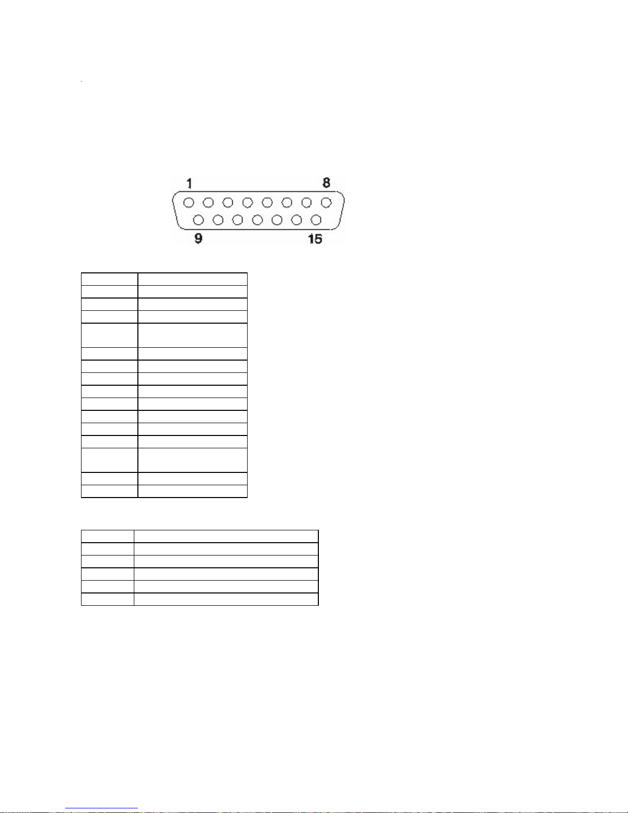
Appendix F Connectors
Distributed Customer Display Connector
Pin Connector
1 CD (carrier detect)
2 RxD (receive data)
3 TxD (transmit data)
4 DTR (data terminal
ready)
5 Ground
6 Ground
7 +5 V dc Main
8 +12 V dc
9 +12 V dc
10 +5 V dc Main
11 Dist_VFD present
12 DSR (data set ready)
13 RTS (request to
send)
14 CTS (clear to send)
15 RI (ring indicate)
Speaker Connector
Pin Connector
1 +12V DC
2 Ground
3 Line Left
4 Line Right
5 Ground.
SurePOS 500 Model XX3 Technical Reference, v 1.3 Page 48 of
81
Page 49

RJ45 Serial Port Connector
RJ45 to 9 Pin Cable Wiring
SurePOS 500 Model XX3 Technical Reference, v 1.3 Page 49 of
81
Page 50

MSR connector
Pin Signal
1 +5V
2 Serial Data Out (TTL)
3 Serial Data In (TTL)
4 Ground
5 KBD Enable (low enables kybd data to system)
6 Keyboard data
7 Keyboard clock
8 Ground
USB port connector (x 6)
Pin Connector
1 5V VBus
2 -Data
3 +Data
4 Ground
SurePOS 500 Model XX3 Technical Reference, v 1.3 Page 50 of
81
Page 51

USB Plus Power 12V/24V
Pin Signal
Shell Shield
1 VBus
2 D-
3 D+
4 Ground
5 Ground
6 Vplus (12V or 24V)
7 Vplus (12 or 24V)
8 Ground
Keyboard/Mouse connector
Pin Signal I/O
1 Keyboard Data I/O
2 Mouse Data I/O
3 Ground
Pin Signal I/O
4 +5 V Main
5 Keyboard Clock I/O
6 Mouse Clock
SurePOS 500 Model XX3 Technical Reference, v 1.3 Page 51 of
81
Page 52
Microphone connector
Pin Signal
Tip
Ring
Base
Input
+5 V
Ground
Headphone Connector
Pin Signal
Tip
Ring
Base
Left channel audio
Right channel audio
Ground
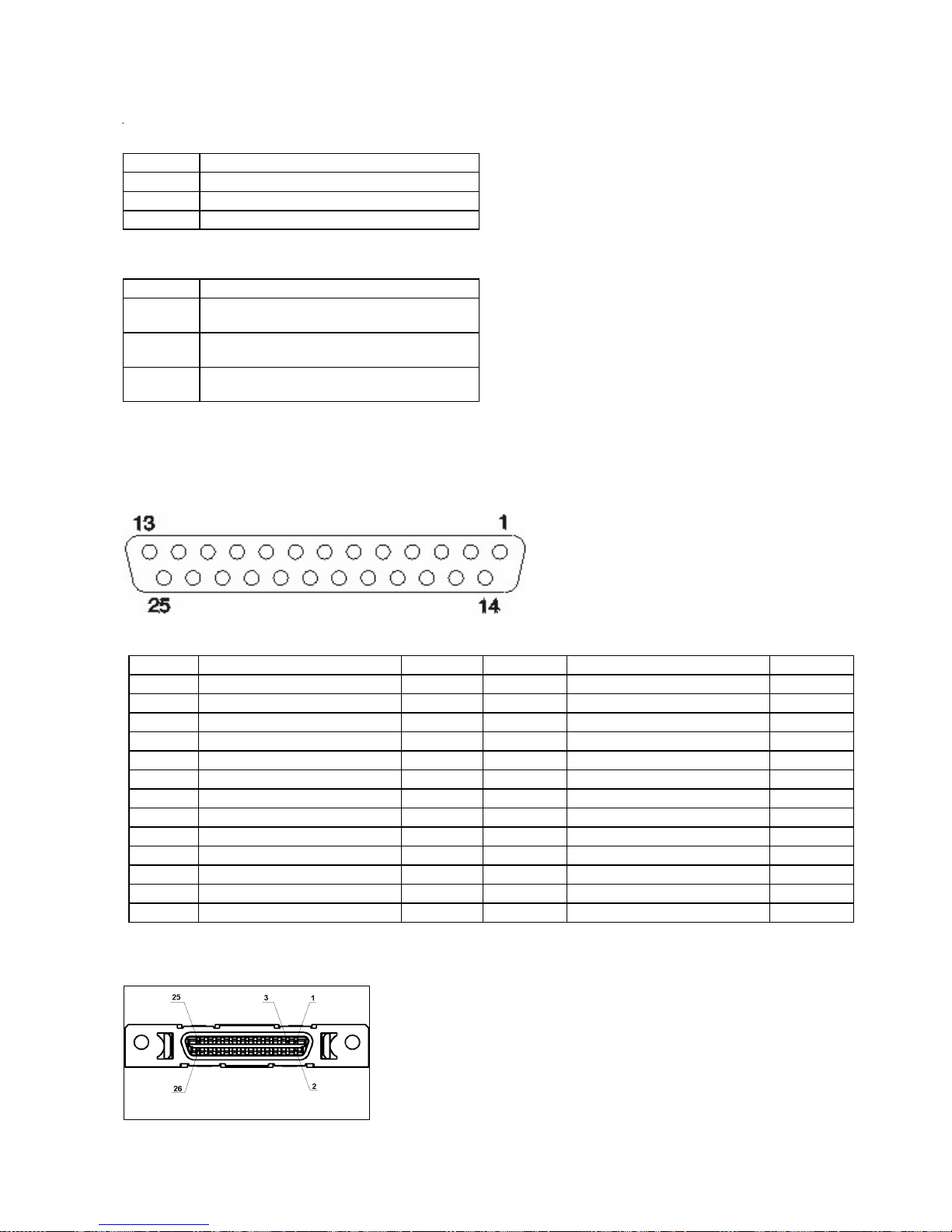
Parallel Connector
Pin Signal I/O Pin Signal I/O
1 STROBE# I/O 14 ATUO FC XT# O
2 Data bit 0 I/O 15 Error# I
3 Data bit 1 I/O 16 INIT# O
4 Data bit 2 I/O 17 SLCT IN# O
5 Data bit 3 I/O 18 Ground
6 Data bit 4 I/O 19 Ground
7 Data bit 5 I/O 20 Ground
8 Data bit 6 I/O 21 Ground
9 Data bit 7 I/O 22 Ground
10 ACK# I 23 Ground
11 Busy I 24 Ground
12 PE I 25 Ground
13 SLCT
External Diskette Drive Connector
SurePOS 500 Model XX3 Technical Reference, v 1.3 Page 52 of
81
Page 53

Pin No. Signal name I/O Signal Description
1 GND
Power Ground
2 +5V
Power Supply
3 GND
Power Ground
4 GND
Power Ground
5 N.C
6 DR0 O Drive Select 0. Select drive 0.
7 MTR0 O Motor Control 0
8 DIR O Direction. Direction of head movement (0 =
inward motion, 1 = outward motion)
9 WDATA O Write Data. Encoded data to the drive for write
operations.
10 GND
Power Ground
11 DRVDEN0 O Drive density select 0
12 RDATA I Read Data. Raw serial bit stream from the
drive for read operations.
13 N.C
14 N.C
15 N.C
16 N.C
17 INDEX I Index. Sense to detect that the head is
positioned over the beginning of a track
18 N.C
19 N.C
20 GND
Power Ground
21 STEP O Step. Low pulse for each track-to-track
movement of the head.
22 WGATE O Write Gate. Signal to the drive to enable
current flow in the write head.
23 TRK0 I Track 0. Sense to detect that the head is
24 WRTPROT I Write Protect. Sense for detection that the
SurePOS 500 Model XX3 Technical Reference, v 1.3 Page 53 of
positioned over track 0.
81
Page 54

diskette is write protected (causes write
commands to be ignored)
25 HDSEL O Head Select. Selects the side for R/W
operations (0 = side 1, 1 = side 0)
26 DSKCHG I Disk Change. Sense that the drive door is
open or the diskette has been changed
Ethernet connector
Pin Signal I/O
1 TxD+ O
2 TxD- O
3 RxD+ I
4 Ground
5 Ground
6 RxD- I
7 Ground
8 Ground
External video connector
Pin Connector
1 Red
2 Green
3 Blue
4 Monitor ID2 - not
used
5 Ground
6 Red ground
7 Green ground
8 Blue ground
9 no connector
10 Gound
11 No connector
12 MON ID1
13 Horizontal sync
SurePOS 500 Model XX3 Technical Reference, v 1.3 Page 54 of
81
Page 55

14 Vertical Sync
15 MON ID3
Cash Drawer (x2)
Pin Connector
1 Ground
2 Sense
3 Open
4 24V
Internal Customer Display
Pin Connector
1 +5V Main
2 Transmit Data
3 Int VFD Present
4 Ground
SurePOS 500 Model XX3 Technical Reference, v 1.3 Page 55 of
81
Page 56

Appendix G Input/Output device commands
This appendix lists the commands and their usage for the SurePOS 500 Series I/O devices.
VFD commands
This section describes the following VFD commands: v Emulation Mode Select v
Character Set Select v User Character Definition v Brightness Control v Alphanumeric
Message Scroll v Backspace v Horizontal Tab v Line Feed v Carriage Return v Test v
Display Position v Normal Display v Vertical Scroll v Cursor On v Cursor Off v Reset
Note: The command code format shown in the following topics is the hexadecimal
value followed by the ASCII representation of that value within brackets.
Emulation mode select (00) <NULL>
00 nn
Purpose:
Sets the specified emulation mode.
This example sets Logic Controls emulation mode:
00 00
Character set select (02) <STX>
Note: This command is only effective in IBM Mode.
02 nn
Purpose:
Selects the specified character set.
This example selects the US/European character set:
02 00
User character definition (03) <EXT>
03 nn
Purpose:
Defines a custom character.
Logic Controls Emulation Mode
The byte that follows the command byte contains an ASCII character between X'20' and X'7F' of a keyboard
key to be redefined. This byte is followed by five bytes, which define the bit patterns of the user-defined
character. Logic Controls Emulation Mode only allows one keyboard key to be redefined. This means that
there is only one user-definable character in this mode. Once a key is redefined, any occurrence of that
character on the display will change to the user-defined character. If a new key is redefined, the previously
redefined key is restored to the original character in all places on the display and the newly redefined key will
SurePOS 500 Model XX3 Technical Reference, v 1.3 Page 56 of
81
Page 57

be changed to the user-definable character. Table 38 on page 51 shows the format of these five bytes.
Note: A -character in the table indicates a do-not-care bit. The other values relate to the character pixel
positions shown in the diagram following the table. A value of 1 in the appropriate place in the data stream
indicates that the related pixel position is on; a 0 indicates that it is off.
* This is maintained for application compatibility with displays with 5x8 character boxes.
←––––5pixelswide ––––→
IBM Mode
The byte that follows the command byte represents an address between X'15' and X'1A', or
between X'1C' and X'1E' in the currently selected character set. This byte is followed by eight
bytes, which define the actual bit patterns of the user-defined character. Table 39 on page 52
shows the format of these eight bytes.
Note: A -character in the table indicates a do-not-care bit. The other values relate to the character
pixel positions shown in the diagram following the table. A value of 1 in the appropriate place
in the data stream indicates that the related pixel position is on; a 0 indicates that it is off.
* This is maintained for application compatibility with displays with 5x8 character boxes.
←––––5pixelswide ––––→
Brightness control (04) <EOT>
Alphanumeric message scroll (05) <ENG>
Purpose:
Specifies a message of up to 45 characters to continuously scroll across the top line of the display.
(Any text on the bottom line does not change.) Any data received after the 45th character are ignored
except for a carriage return (X'0D'). The message starts to display when the carriage return command
is received. If the cursor position is on the top line when this command is received, it is moved to the
first position on the bottom line. If it is on the bottom line, its position does not change. Data continues
scrolling on the top line until a valid character (backspace, horizontal tab, line feed, carriage return, or
display position command is written to the top line. The Test and Reset commands stop the scrolling
message regardless of the display position.
Backspace (08) <BS>
Purpose:
Decrements the cursor position by one and clears any character displayed in
that position. If the write position is at the lower left, the position is moved to
the upper right, and if it is at the upper left, it is moved to the lower right. This
commands stops the scrolling alphanumeric message if the cursor position is
on the top line when this command is sent.
04 nn
Purpose:
05 xxx...
08
Horizontal tab (09) <HT>
SurePOS 500 Model XX3 Technical Reference, v 1.3 Page 57 of
81
Page 58

Purpose:
Line feed (0A) <LF>
09
Increments the cursor position by one. No characters are erased. This
command stops the scrolling message if the cursor position is on the top line
when the command is sent. At the end of a line, the display behavior is
determined by the state of the display control mode as follows:.
Normal Display Control Mode (DC1)
If the cursor is at the upper right position, it is moved to the lower left
position. If the cursor is at the lower right position, it is moved to the
upper left position.
Vertical Scroll Display Control Mode (DC2)
If the cursor is at the upper right position, it is moved to the lower left
position. If the cursor is at the lower right position, the characters
displayed on the bottom line are moved to the top line, the bottom line
is cleared, and the cursor is moved to the lower left position.
Purpose:
The display behavior is determined by the state of the display control mode as follows:.
Normal Display Control Mode (DC1)
The cursor is moved to the same position in the complementary line. In this mode, a line
feed command stops the scrolling alphanumeric message if the cursor is on the top line
when this command is sent.
Vertical Scroll Display Control Mode (DC2)
If the cursor is on the top line, it is moved to the complementary position on the bottom line. If
the cursor position is on the bottom line, all characters on that line are moved to the top line,
the bottom line is cleared, and the cursor position is unchanged. This command always stops
the scrolling alphanumeric message.
Carriage return (0D) <CR>
Purpose:
Causes the cursor to move to the leftmost position of the current line. This
command stops the scrolling alphanumeric message if the cursor position is
on the top line when this command is sent.
Test (0F) <SI>
0A
0D
Purpose:
SurePOS 500 Model XX3 Technical Reference, v 1.3 Page 58 of
0F
Causes the first 40 characters in the currently selected character set to be
displayed once. At the end of the test, a test pattern is written that turns all
pixels ON. At the end of the test, the display is cleared and is reset to the
power-on state as described at “Reset (1F) <US>” on page 55.
81
Page 59

Display position (10) <DLE>
10 nn
Purpose:
Normal display control mode (11) <DC1>
11
Purpose:
Sets normal display control mode (DC1) and permits data to be written to
either line. After writing a character, the cursor moves one position to the right.
When the display position is at the last position of the top line, the cursor
moves to the first position of the bottom line. When the display position is at
the last position of the bottom line, the cursor moves to the first position of the
top line. The display remains in DC1 mode until a DC2 mode command is
issued, a reset command is issued, or power is removed from the display.
Vertical scroll display control mode (12) <DC2>
Purpose:
Sets vertical scroll display control mode (DC2) and permits data to be written
to either line. When the display position is at the last position of the top line,
the cursor moves to the first position of the bottom line. When either valid
character data, a Horizontal Tab command, or a Line Feed command is sent
to the last position of the bottom line, the data on the bottom line is transferred
to the top line and the cursor is moved to the lower left position. Note that a
Carriage Return command does not cause the data on the bottom line to be
transferred to the top line. This is the power-on and Reset command default
setting. The display remains in DC2 mode until a DC1 mode command is
issued.
Cursor on (13) <DC3>
Purpose:
Turns on the cursor. This is the power-on default setting.
Cursor off (14) <DC4>
12
13
14
Purpose:
Reset (1F) <US>
Purpose:
SurePOS 500 Model XX3 Technical Reference, v 1.3 Page 59 of
Turns off the cursor.
1F
81
Page 60

Causes the display to reset some programmable parameters back to the
power-on state, which is defined as:
v Cursor on.
v Scrolling alphanumeric message off.
v All pixels of (all character positions are filled with X'20').
v Write position for next write is at position X'00' (top left).
v Default code page (437) selected.
v DC2 mode enabled.
v Default (Logic Controls) emulation mode selected.
v Brightness set to 100%.
v IBM user-defined characters are not erased. The Logic Controls user-defined character key
is reset.
All byte values between X'00' and X'1F' not defined in this section are ignored by the display in Logic Controls
mode. User-defined characters in the IBM mode that have not been defined previously are spaces.
APA commands
This section describes the following APA VFD commands: v Backspace Without
Deleting v Line Feed v Carriage Return v Clear Display v Display Position v Delete to
End of Line v Dimming v Cursor Mode v Screen Mode v Horizontal Scroll v Display
Mode v User Definable Font v Graphic Display Mode v Double Size Letter in
Horizontal v Character Code Set of Full Size Letter v Character Code Set of Half Size
Letter v Horizontal Scroll on All Lines v Font Selection
Note: The command code format shown in the following topics is in hexadecimal
format.
Backspace without deleting
Purpose:
The write-in position is shifted to the left one digit and the displaying screen is
not changed. This command is ignored when the write-in position is on the
least significant digit.
Line feed
Purpose:
The write-in position is shifted to the next row on the same digit position. If the
write-in position is on the bottom row, the displayed character is scrolled up to
the upper row and all characters on the bottom row are cleared. The write-in
position is not changed. The displayed character under the screen mode of the
24x24-dot 1 row+16x16-dot 2 rows is not scrolled up from the row of 16x16dot format to 24x24-dot.
08
0A
Carriage return
SurePOS 500 Model XX3 Technical Reference, v 1.3 Page 60 of
81
Page 61

Purpose:
Clear display
Purpose:
Display position
Purpose:
0D
The write-in position is shifted to the most significant digit of the same row. If
the write-in position is on the most significant digit, the command is ignored.
1B 5B 32 4A
All the displayed characters are erased. The write-in position is not changed.
Instead of writing the character from the first digit, the write-in start position
can be specified with this command. The write-in position is shifted with Py
and Px. (It is based on the half-size letter of the font, which is specified with
the Screen Mode command.) Py indicates the position of the row and Px
the digit. Py and Px must be defined under the following conditions:
v If Py is 0, it is set to 1 (X'31').
v If Py is greater than the bottom row, it is set to the bottom row.
v If Px is 0, it is set to 1 (X'31').
v If Px is greater than the least digit, it is set to the least digit.
A special form of the Display Position command exists (Esc
1B 5B 48 27), which sets the write-in position to the home position (Py=1
and Px=1).
Delete to end of line
1B 5B 30 4B
Purpose:
The displayed characters from the write-in position to the end position on the
same row are erased. The write-in position is not shifted.
Dimming
1B 5C 3F 4C 44 Ps
Purpose:
Luminance can be adjusted into six levels using this command. The data byte following the
command sequence (represented by Ps in the preceding command format), changes the dimming
level. When the module is turned on, the level is set to 5 (100%).
Ps Luminance %
0 (X'30') 0 1 (X'31') 31.6
Appendix E. Input/Output device commands 57
Ps Luminance %
SurePOS 500 Model XX3 Technical Reference, v 1.3 Page 61 of
81
Page 62

2 (X'32') 45
3 (X'33') 58.8
4 (X'34') 70.4
5 (X'35') 100 (default)
Cursor mode
1B 5C 3F 4C 43 Ps
Purpose:
Ps
0 (X'30') 1 (X'31') 2 (X'32')
Screen mode
This command is only available in 5x7-dot screen mode. The data byte following the command sequence
(represented by Ps in the preceding command format), changes the cursor mode. The cursor is always
displayed at the write-in position. The cursor is formed by five dots located at the bottom of 5x7-dot matrix
character font.
Mode
No lighting (default)
Blinking
Lighting
No Lighting Blinking Lighting
The cursor does not display. This is the default setting when power is turned on.
The cursor flashes ON and OFF every 0.3 seconds at the blank digit.
The cursor displays. If the write-in position is assigned to the position at which a character is displaying, the
cursor displays instead of the character.
1B 5C 3F 4C 53 Ps
Purpose:
The data byte following the command sequence (represented by Ps in the
preceding command format), changes the screen mode.
Ps Mode
6 (X'36') 5x7 dots, 4 rows (default)
7 (X'37') 5x7 dots, 5 rows
8 (X'38') 16x16 dots, 2 rows
Horizontal scroll
SurePOS 500 Model XX3 Technical Reference, v 1.3 Page 62 of
81
Page 63

1B 5C 3F 4C 48 Pm 3B Pl 3B Pt 3B Pn 3B Pd
Purpose:
This command initiates horizontal scrolling. The control bytes embedded in the
command sequence (represented by Pm, Pl, Pt, and Pn in the preceding
command format), change the scrolling characteristics. Pd...Pd represents the
data bytes.
58 SurePOS 500 Series System Reference
Pm 6 (X'36'): 5x7 dots, 4 rows 7 (X'37'): 5x7 dots, 5 rows 8 (X'38'):
16x16 dots, 2 rows
Pl 1 ˜ 4 (X'31' ˜ X'34'): Pm=6 1 ˜ 5 (X'31' ˜ X'35'): Pm=7 1, 2
(X'31', X'32'): Pm=8
Pt 1 (X'31'): 1 line/10 ms 1 (X'32'): 1 line/20 ms Pn The number of data bytes (1 for
half size letter, 2 for full size letter, maximum is 128 (X'80'). Pd...Pd This
represents the data characters.
The following list explains how the Horizontal Scroll command operates:
1B 5B Ps 6D
Purpose:
This command sets the display mode characteristics. The control byte embedded in the command
sequence (represented by Ps) sets the mode.
Reviewers Does reverse mode mean that the character is flipped horizontally, or simply that the
character color and background color are reversed?
User-definable font set
1B 5C 3F 4C 57 33 Pf 3B Pn 3B Pc 3B Pd...Pd
Purpose:
This command specifies a user-definable font set. The control bytes
embedded in the command sequence (represented by Pf, Pn, and Pc in the
preceding command format), change the font characteristics. Pd...Pd
represents the font data bytes.
Pf (font size) 1 (X'31'): 5x7 dots (ANK) 2
Pn (font NO) 1 ˜ 32 (X'31' ˜ X'33', 32) Pf=1, 2
(registration 2hex digitsx7Pf=1, 2 address) 4 hex digits
(Pf=3) Pd...Pd 2hex digitsx7Pf=1
(X'32'): 8x16 dots 3 (X'33'):
16x16 dots
1 ˜ 16 (X'31' ˜ X'31', 36) Pf=3 Pc
2 hex digits x 16 Pf=2 2hex
digitsx2x16Pf=3
Graphic display mode
SurePOS 500 Model XX3 Technical Reference, v 1.3 Page 63 of
Note: All data is stored into RAM. You must issue this command every
time you switch on the power.
81
Page 64

Purpose:
This command specifies the graphic display mode. The control bytes embedded in the command
sequence (represented by Px, Py, Ph, and Pw in the preceding command format), change the
graphic display characteristics. Pd represents the data byte.
Double size letter in horizontal
1B 23 Ps
Purpose:
This command sets a character with double size letter in horizontal. It is
available for all full size letter, all half size letter, and ANK font.
Ps 5 = Normal size letter 6 = Double size letter in horizontal
60 SurePOS 500 Series System Reference
Character code set of full size letter
??
Purpose:
Can’t figure this out from the spec.
Character code set of half size letter
??
Purpose:
Can’t figure this out from the spec.
Horizontal scroll on all lines
The format of the Horizontal Scroll Select command is as follows:
1B 5C 3F 4C 4D 53
Purpose
This command sets horizontal scroll mode. The format of the Horizontal Scroll Release command is
as follows:
Purpose
This command resets horizontal scroll mode. The format of the Horizontal Scroll Display Mode Set
SurePOS 500 Model XX3 Technical Reference, v 1.3 Page 64 of
1B 5C 3F 4C 4D 45
81
Page 65

command is as follows:
Purpose:
This command sets horizontal scrolling options. The control bytes embedded in the command
sequence (represented by Pm, Pl, Pt, and Pn in the preceding command format), change the
scrolling characteristics. Pd...Pd represents the data bytes. This command does not affect previous
display settings.
The format of the Horizontal Scroll Start command is as follows:
1B 5C 3F 4C 4D Pm 3B Pl 3B Pt 3B Pn 3B Pd...Pd
1B 5C 3F 4C 4D 47
Purpose
This command starts horizontal scrolling on all lines. All subsequent
commands are ignored until a Scroll Mode Release command is sent.
The following list explains how the Horizontal Scroll On All Lines command
operates:
v Any codes not described here are ignored.
v The most recent Display Mode Set command becomes effective in one
screen scroll setting before the Scroll Start command is performed.
v A screen scrolls from right to left, dot by dot.
v The range of the display of being scrolled is defined by the screen mode
setting.
v The command is canceled when Pn = X'00'. After it is canceled, displayed
characters are cleared and the write-in position moves to the most
significant digit of the row.
v The command can be executed on a single line only.
v A character’s Display Mode Set command (reverse, blinking, and so on)
can be added with the display data frame. If the command is written twice
or more in one scroll data frame, only the first command is valid; others are
ignored.
v When message data are changed, you must reissue this command.
While scrolling, the User Definable Font Set command is not available.
v Space data is written in the other rows except those selected with the Pl
code.
Font selection
Purpose:
The command stream is as follows:
Pn 30: English -IBM code page 437 modified (default)
SurePOS 500 Model XX3 Technical Reference, v 1.3 Page 65 of
1B 53 Pn
Selects the language font to use.
31: Japanese -JIS X 0208-1990
32: Korean -KS C 5601-1992
81
Page 66

33: Simplified Chinese -GB-2321
34: Traditional Chinese -BIG5
Cash drawer commands
This section describes the following cash drawer commands: v Open Cash Drawer 1 v
Open Cash Drawer 2 v Close Cash Drawer 1 v Close Cash Drawer 2
Open cash drawer 1
To open cash drawer 1, use the following command, which sends an ASCII Bell
character to the customer display serial port:
Open cash drawer 2
To open cash drawer 2, use the following 2-command sequence, which sends an
Escape character followed by an ASCII Bell character to the customer display serial
port:
07
1B 07
Status cash drawer 1
To obtain status information for cash drawer 1, use the following command, which
sends an ASCII Ack character to the customer display serial port. See “Cash drawer
status information” for a description of the cash drawer status byte.
Status cash drawer 2
To obtain status information for cash drawer 12, use the following 2-command
sequence, which sends an Escape character followed by an ASCII Ack character to
the customer display serial port. See “Cash drawer status information” for a description
of the cash drawer status byte.
Cash drawer status information
To obtain status information for a cash drawer, send one of the status commands just
described. The status byte returned indicates one of the following:
MSR data received
This section describes the data received from the MSR when a card is swiped. The
MSR is an input-only device, and therefore does not use commands. The JUCC MSR
attaches to a serial port as a standard RS-232 device. The 3-track MSR has a slide
switch, which enables you to connect it either as a standard RS-232 serial device or
through the keyboard interface. (If you choose the latter connection, the incoming data
appears to come from a keyboard so no device driver is needed.)
06
1B 06
SurePOS 500 Model XX3 Technical Reference, v 1.3 Page 66 of
81
Page 67

3-Track MSR data
Incoming data from the 3-track MSR has the following format:
JUCC MSR data
Incoming data from the JUCC MSR has the following format:
Programming
Interface Description
Track data switch
On the 3 track MSR, the track data interface is chosen with a slide switch located on the MSR such that it is
only accessible when the MSR is not attached. One setting of the switch will cause the MSR to send track
data with a serial interface at 19200 baud with 8 bits, no parity and 1 stop bit. The other setting of the slide
switch will cause the MSR to send track data via the PS/2 keyboard interface. A pin button located so that it
is not accessible with the MSR is fully installed is used to reset the MSR’s configuration to the factory default
state.
SurePOS 500 Model XX3 Technical Reference, v 1.3 Page 67 of
81
Page 68

s
Configuration Word
The configuration word is used to alter the format of the track data returned from the MSR. In the default
configuration the MSR reads ISO 7811 format cards. There are three possible data tracks. Track one is
formatted as 7 bit 1 parity data and is limited to a maximum of 79 characters. Tracks two is formatted as 5 bit
1 parity format with a maximum of 40 characters. Track three is also 5 bits 1 parity format but is limited to no
more than 107 characters. Before the track data can be sent to the host each character must be converted to
ASCII codes. For track one this is simply a matter of clearing the parity bit and adding 32 to the data value.
For tracks two and three you clear the parity bit and add 48 to the data value. The following table shows the
character set for the different tracks and their corresponding ASCII values:
MSR track code to ASCII code conversion chart
Track 2 &
Track 1
value Character
0 32 0x20 ' ' 32 64 0x40 ' @ ' 0 48 0x30 ' 0 '
1 33 0x21 ' ! ' 33 65 0x41 ' A ' 1 49 0x31 ' 1 '
2 34 0x22 ' " ' 34 66 0x42 ' B ' 2 50 0x32 ' 2 '
3 35 0x23 ' # ' 35 67 0x43 ' C ' 3 51 0x33 ' 3 '
4 36 0x24 ' $ ' 36 68 0x44 ' D ' 4 52 0x34 ' 4 '
5 37 0x25 ' % ' 37 69 0x45 ' E ' 5 53 0x35 ' 5 '
6 38 0x26 ' & ' 38 70 0x46 ' F ' 6 54 0x36 ' 6 '
7 39 0x27 ' ' ' 39 71 0x47 ' G ' 7 55 0x37 ' 7 '
8 40 0x28 ' ( ' 40 72 0x48 ' H ' 8 56 0x38 ' 8 '
9 41 0x29 ' ) ' 41 73 0x49 ' I ' 9 57 0x39 ' 9 '
10 42 0x2A ' * ' 42 74 0x4A ' J ' 10 58 0x3A ' : '
11 43 0x2B ' + ' 43 75 0x4B ' K ' 11 59 0x3B ' ; '
12 44 0x2C ' , ' 44 76 0x4C ' L ' 12 60 0x3C ' < '
13 45 0x2D ' - ' 45 77 0x4D ' M ' 13 61 0x3D ' = '
14 46 0x2E ' . ' 46 78 0x4E ' N ' 14 62 0x3E ' > '
15 47 0x2F ' / ' 47 79 0x4F ' O ' 15 63 0x3F ' ? '
16 48 0x30 ' 0 ' 48 80 0x50 ' P '
17 49 0x31 ' 1 ' 49 81 0x51 ' Q '
18 50 0x32 ' 2 ' 50 82 0x52 ' R ' Color Key
19 51 0x33 ' 3 ' 51 83 0x53 ' S '
20 52 0x34 ' 4 ' 52 84 0x54 ' T '
21 53 0x35 ' 5 ' 53 85 0x55 ' U '
22 54 0x36 ' 6 ' 54 86 0x56 ' V '
23 55 0x37 ' 7 ' 55 87 0x57 ' W '
24 56 0x38 ' 8 ' 56 88 0x58 ' X '
25 57 0x39 ' 9 ' 57 89 0x59 ' Y '
26 58 0x3A ' : ' 58 90 0x5A ' Z '
27 59 0x3B ' ; ' 59 91 0x5B ' [ '
28 60 0x3C ' < ' 60 92 0x5C ' \ '
29 61 0x3D ' = ' 61 93 0x5D ' ] '
30 62 0x3E ' > ' 62 94 0x5E ' ^ '
31 63 0x3F ' ? ' 63 95 0x5F ' _ '
ASCII
va lu e
DecHex DecHex DecHex
Track 1
value Character
ASCII
va lu e
Track 3
vaue Character
Control va l ue
Standard Sentinal values
ASCII
va lu e
SurePOS 500 Model XX3 Technical Reference, v 1.3 Page 68 of
81
Page 69

The data from the card is returned as shown in the following Baccus Naur Form:
Track data: <Track1><CR><Track2><CR><Track3><CR>
Track1: [<Start Sentinel 1><Data1>{1,82}<End Sentinel>]|[<Error>]
Track2: [<Start Sentinel 2><Data2>{1,40}<End Sentinel>]|[<Error>]
Track3: [<Start Sentinel 3><Data2>{1,107}<End Sentinel>]|[<Error>]
CR: 0x0D or Carriage Return
Start Sentinel 1: 0x25
1
or value in configuration byte 2
Start Sentinel 2: 0x3B or value in configuration byte 3
Start Sentinel 3: 0x2B or value in configuration byte 4
End Sentinel: 0x3F or value in configuration byte 5
Error: 0x45
Data1:
0x21 to 0x5F
Data2: 0x31 to 0x3F
Data3: 0x31 to 0x3F
If a track is read incorrectly an ASCII ‘E’ is returned in place of the bad track. The following table shows the
format of the MSR configuration word:
Byte1 Configuration bits Factory Default
Bit Function PS/2 RS-232
0 CR enabled 1 0
1 Raw data mode 0 0
2 track 1 disabled 0 0
3 track 2 disabled 0 0
4 track 3 disabled 0 0
5 Strip Sentinels 0 0
6 Use Custom Configuration 0 0
7 Hide Error tracks 0 0
Byte 2 SS1 0x25 0x25
Byte 3 SS2 0x3B 0x3B
Byte 4 SS3 0x2B 0x2B
Byte 5 ES 0x3F 0x3F
Byte 1, Bit 0: Carriage return Enabled
This bit enables the inclusion of Carriage returns between the tracks. This defaults to ‘0’ or no Carriage
1
ASCII conversion of characters used in this document are: 0x25=’%’, 0x3B=’;’, 0x2B=’+’, 0x3F=’?’, 0x45=’E’. For
more ASCII character conversions see ISO-646-US-ASCII.
SurePOS 500 Model XX3 Technical Reference, v 1.3 Page 69 of
81
Page 70

returns when the data interface is 2-wire serial and defaults to ‘1’ or Carriage returns after tracks when PS/2 is
the data interface.
Byte 1, Bit 1: Raw Data Mode
In this mode control characters within the track data are not removed from the return data. In some MSRs the
control characters, “!”#%&’*+,:;<=>?[\]^-“, are removed from the track data before it is sent to the host. This
mode sends exactly the characters found within the data track with no interpretation or removal. If this MSR
does not currently remove control characters then this command has no effect. Any sentinel values
discovered between the first start sentinel and the last end sentinel are to be treated as data.
Byte 1, Bit 2: Track 1 disabled
When set to ‘1’ this bit disables or hides track 1 data. Factory default is ‘0’, track 1 enabled.
Byte 1, Bit 3: Track 2 disabled
When set to ‘1’ this bit disables or hides track 2 data. Factory default is ‘0’, track 2 enabled.
Byte 1, Bit 4: Track 3 disabled
When set to ‘1’ this bit disables or hides track 3 data. Factory default is ‘0’ on 3-track MSR and ‘1’ on 2-track
JUCC models.
Byte 1, Bit 5: Hide Sentinels
When set to ‘1’ the Sentinels are not included in the returned data. Factory default is ‘0’; Sentinels included in
the MSR data.
Byte 1, Bit 6: Use Custom Configuration
This bit defaults to ‘0’. When this bit is set, the custom configuration in the rest of the configuration word is
used. When not set the factory default configuration is used.
Byte 1, Bit 7: Hide Error tracks
When set to ‘1’ this bit prevents the MSR from returning ‘E’ or 0x45 for bad tracks. If all three tracks on the
card were corrupted no data would be sent to the host. If track 1 were bad then only tracks 2 and 3 would be
sent to the host. The default setting is ‘0’, send ‘E’ for bad tracks.
Byte 2: Track 1 start sentinel
The value in this byte is used as the track one start sentinel. It is set to 0x25 or ‘%’ by default. The value
assigned to this byte must be an ASCII code between 33 and 95(‘1‘to‘_‘). This value is substituted in the
return data in place of the sentinel found in the track data.
Byte 3: Track 2 start sentinel
The value in this byte is used as the track two start sentinels. It is set to 0x3B by default. The value assigned
to this byte must be an ASCII code between 49 and 63(‘1’to’?’). This value is substituted in the return data in
place of the sentinel found in the track data.
SurePOS 500 Model XX3 Technical Reference, v 1.3 Page 70 of
81
Page 71

Byte 4: Track 3 start sentinel
The value in this byte is used as the track three start sentinels. It is set to 0x2B by default. The value
assigned to this byte must be an ASCII code between 49 and 63(‘1’to’?’). This value is substituted in the
return data in place of the sentinel found in the track data.
Byte 5: End sentinel
The value in this byte is used as the track end sentinel. It is set to 0x3F by default. The value assigned to
this byte must be an ASCII code between 49 and 63(‘1’to’?’). This value is substituted in the return data in
place of the sentinel found in the track data.
Modes
The MSR operates in three modes, functional, command and update. Functional mode is the power on
default mode used by the host application to receive MSR track data. Command mode is used by a
configuration application to change the format and behavior of the MSR when in functional mode. The update
mode is entered from command mode and is used as a means of updating the MSR’s firmware. All command
communications between the MSR and the host is through the 2-wire serial interface regardless of the
position of the data selection slide switch. MSR track data is always returned on the 2-wire serial interface on
the JUCC model and on the 2-wire serial or PS/2 interface as selected by the MSR’s interface select switch
on the 3-track model.
Functional Mode
The MSR powers up into the functional mode. In this mode the MSR sends track data to the host on either
the 2-wire serial interface or the PS/2 interface. The MSR data interface used is determined by the position of
the data interface slide switch. The JUCC MSR will not have a slide switch and will always return data on the
2-wire serial interface. The format of the track data is determined by the configuration word loaded.
When in this mode the MSR accepts only one command, the enter command mode command. All other
commands should be ignored. Only MSR track data in the configured format is sent to the host. The MSR
start command mode command must be sent before device status can be read. As the MSR transitions from
Functional mode to Command mode a command success string should be sent to the host.
Command Mode
Command mode is entered when a command mode massage is received from the host on the 2-wire serial
interface. In this mode the user can configure the functional mode behavior of the MSR. When configuration
is completed a command is sent that returns the MSR to the functional mode.
When in this mode the MSR accepts commands that change the configuration word, start update mode, or
start functional mode
Update Mode
Update mode is entered when an update command is received from the host while the MSR is in command
mode. In this mode the host updates the MSR’s firmware. The new firmware is checked for correctness and
replaces the old firmware. The code update command interface is to comply with the in circuit programming
specification described in Philips Semiconductors application note AN461 2002 Jun 24 for the Philips
89C51Rx2 device.
SurePOS 500 Model XX3 Technical Reference, v 1.3 Page 71 of
81
Page 72

Reset switch
A pin hole reset switch is provided on the MSR unit in a location not accessible when the MSR is fully
installed. When the user presses this switch the MSR configuration word stored in flash is changed back to
the factory default and the unit restarts. The configuration word in RAM is replaced by the new flash word
when the MSR restarts.
The JUCC reader will communicate via the 2-wire serial interface only and there should not be a slide switch
on the JUCC MSR.
Command Set
The commands sent to the MSR will be used to either configure the format and features of the MSR return
data or to update the MSR firmware. No changes to the configuration are permanent until a commit
command is sent. This means that configuration word changes will be lost at power off unless they are
committed.
Control commands
All command strings to the MSR are to be in the following format:
MSR command: “:nnxxxx11cc[dd]{0,16}ss”
nn: one byte hexadecimal number representing number of command and data bytes in command
string, value between 0x00 and 0x10.
xxxx: four byte address used in memory commands, not used and should be considered don’t care.
cc: hexadecimal command value between 0 to 127 return values are 128 to 255.
dd: 0 to 16 data bytes in hexadecimal format associated with the command.
ss: checksum, negative of the sum of the values in the command string. Summing all the hex values
in the command string including the checksum should equal zero.
All commands except the “get configuration” commands will only be followed by a fail/success response. The
success response will be “.” and the fail response will be “X”. Characters sent to the MSR are to be repeated
back to the host as they are received. The use of upper and lower case letters are can be used in the
hexadecimal numbers.
The MSR response to the “get configuration” command will be formatted as:
:nn0000117F <b1><b2><b3><b4><b5><revision string[11]>
nn: number of data bytes; b1 through b5 plus the length of the revision string.
bx: hexadecimal number representing bytes 1 through 5 of the configuration word .
revision string: Up to 11 byte long description string showing firmware revision information.
Suggested format is “REV x.xx.”
An example would be the command to enter command mode, “:0100001110.” This shows the “:nn000011”
preamble, the hexadecimal command byte “10” and a byte count of 01. The MSR would respond with the
character ‘.’ to indicate a successful command.
SurePOS 500 Model XX3 Technical Reference, v 1.3 Page 72 of
81
Page 73

The following table shows all the commands:
Function Comman
Format
d Byte
Reset “00” “:0100001100EE”
Set Configuration “01” :0600001101<b1><b2><b3><b4><b5><ss>
ss = - (18h +b1+b2+b3+b4+b5)
Get Configuration “02” :0200001102<source><ss> : source = “00” from RAM or “01” from flash.
From ram: “:020000110200EB”
From flash: “020000110201EA”
Start Update
“07” “:0100001107E7”
Mode
Commit
“09”
“:0100001109E5”
Configuration
Custom
/x0A “:020000110A<value><ss>
Configuration
Enable/Disable
value=”01” enable custom configuration: “:020000110A01E2”
value=”00” disable custom configuration. “:020000110A00E3”
Start Command
“10” “:0100001110DE”
Mode
Start Functional
“11” “:0100001111DD”
Mode
General device responses are:
Function ID byte Format
Status “7F” :nn0000117F<b1><b2><b3><b4><b5><revision string[11]><ss>
Data return
“82” :nn00001182<command><data packet><ss>
(not used )
Command
Response w/ no
Success ‘.’
Fail ‘X’
data
Command specific responses are:
Function
Reset
Success Response Fail Response
“.” “X”
Set Configuration
“.” “X”
SurePOS 500 Model XX3 Technical Reference, v 1.3 Page 73 of
81
Page 74

Function
(return status)
Get Configuration
(return status)
Start Update Mode
Commit
Configuration
Custom
Configuration
Enable/Disable
Start Command
Mode
Start Functional
Mode
All changes to the configuration word are stored in RAM until a Commit Configuration command is sent. A
commit configuration command stores the configuration word into flash where it is retrieved the next time
power is restored.
Success Response Fail Response
“.:nn0000117F<b1><b2><b3><b4><b5
“X”
><revision string[11]><ss>”
“.” “X”
“.” “X”
“.” “X”
“.” “X”
“.” “X”
General command format:
:nnxxxxiiccddss
:
beginning of command marker
nn number of command bytes beyond the id byte in hexadecimal.
xxxx 16 bit Don’t care address bytes not used for MSR control commands.
ii Command id byte, should be “11” for MSR commands.
cc Hexadecimal format MSR command ID byte.
dd 0 to 16 bytes of data in hexadecimal format.
ss hexadecimal format checksum byte. The sum of this number and all the other bytes in the command
after the beginning of the command marker should equal zero.
If the sum of all the bytes in the command is not zero or if the command is not a valid command then the MSR returns
‘X’. a ‘.’ is returned for successful commands. Commands requiring return data return either a ‘.’ followed by
a return data string or ‘X’.
Update mode details
The code update command interface is to comply with the in circuit programming specification described in Philips
Semiconductors application note AN461 2002 Jun 24 for the Philips 89C51Rx2 device. In general the microcontroller
program will enter the in circuit programming code when a start update mode command is sent. An example would be if
SurePOS 500 Model XX3 Technical Reference, v 1.3 Page 74 of
81
Page 75

a P889C51RB2 part were used. In this case the code would enable the shadow boot block by setting the ENBOOT bit to
‘1’ and then jumping into ROM at location FC00h. If the watchdog timer is used it should be disabled before jumping to
the ISP code.
3-Track MSR
2-wire serial communication
By default, data from a successful card read is presented to the host with only the start sentinel [SS], followed
by the card data, followed by the end sentinel [ES]. The [SS] for track 1 is ASCII "%". The [SS] for track 2 is
ASCII ";". The [SS] for track 3 is ASCII "+". The [ES] for all tracks is ASCII "?". In the case of an
unsuccessful read, an ASCII "E" is returned without a [SS] or [ES] for that track or tracks. For example "EEE"
would be returned for all tracks if all three tracks had bad data. For example if only track 2 had an error, then
the reader would send [SS]track 1 data[ES]E[SS]track 3 data[ES].
Host commands to the MSR are sent through the 2-wire serial interface at 19200 Baud in the 8 bit, 1 stop no
parity format.
PS/2 Keyboard communication
By default, data from a successful card read is presented to the host with only the start sentinel [SS], followed
by the card data, followed by the end sentinel [ES] and a carriage return [CR]. The [SS] for track 1 is ASCII
"%". The [SS] for track 2 is ASCII ";". The [SS] for track 3 is ASCII "+". The [ES] for all tracks is ASCII "?". In
the case of an unsuccessful read, an ASCII "E" is returned without a [SS] or [ES] for that track or tracks. For
example "E[CR]E[CR]E[CR]" would be returned for all tracks if all three tracks had bad data. For example if
only track 2 had an error, then the reader would send [SS]track 1 data[ES][CR]E[CR][SS]track 3
data[ES][CR].
JUCC MSR
The JUCC MSR communicates to the host through the 2-wire serial interface only. The PS/2 interface is not
present. Since there are only two tracks of data, only tracks one and two are used. Commands that effect
track three are ignored. Data returned does not include track three information. On a successful read the
data returned on a JUCC MSR in factory default configuration would appear as follows:
<Start Sentinel 1><Data1><End Sentinel><Start Sentinel 2><Data1><End Sentinel>
An unsuccessful read would return an error character or ‘E’ fore each of the tracks and would appear for two
bad tracks as “EE.”
If there are 2 blocks of data on the card, the reader should ignore the ‘unknown’ (non-ISO compliant) data and only
present to the host the ‘known’ (ISO-compliant) data.
Usage
Card Speed
The 3-track reader shall be capable of reading a standard card, a 12% jitter card and a 60% amplitude card
at speeds ranging from 5 to 45 inches per second. Similarly, the JUCC reader shall be capable of reading a
standard card, a 12% jitter card and a 60% amplitude card at speeds between 5 and 45 inches per second.
The reader should be capable of reading the data from a card in both directions. The reader should "assume"
the data will be read from the card in the reverse direction, as the position of the reader on the terminal is
designed for "backward" swiping.
SurePOS 500 Model XX3 Technical Reference, v 1.3 Page 75 of
81
Page 76

The ability to read Bank of America mini cards and other non-ISO standard cards is desired. Since some of
these cards have higher track density consideration should be given to accommodating them. This effort
should not endanger the MSR’s ability to read ISO compliant cards.
SurePOS 500 Model XX3 Technical Reference, v 1.3 Page 76 of
81
Page 77

Appendix H Notices
This information was developed for products and services offered in the U.S.A.
IBM may not offer the products, services, or features discussed in this document in other countries. Consult
your local IBM representative for information on the products and services currently available in your area.
Any reference to an IBM product, program, or service is not intended to state or imply that only that IBM
product, program, or service may be used. Any functionally equivalent product, program, or service that does
not infringe any IBM intellectual property right may be used instead. However, it is the user’s responsibility to
evaluate and verify the operation of any non-IBM product, program, or service.
IBM may have patents or pending patent applications covering the subject matter in this document. The
furnishing of this document does not give you any license to these patents. You can send license inquiries, in
writing, to:
IBM Director of Licensing
IBM Corporation
North Castle Drive
Armonk, NY 10504-1785
U.S.A.
For license inquiries regarding double-byte (DBCS) information, contact the IBM Intellectual Property
Department in your country or send inquiries, in writing, to:
IBM World Trade Asia Corporation
Licensing
2-31 Roppongi 3-chome, Minato-ku
Tokyo 106, Japan
The following paragraph does not apply to the United Kingdom or any other country where such provisions
are inconsistent with local law: INTERNATIONAL BUSINESS MACHINES CORPORATION PROVIDES THIS
PUBLICATION ″AS IS″ WITHOUT WARRANTY OF ANY KIND, EITHER EXPRESS OR IMPLIED,
INCLUDING, BUT NOT LIMITED TO, THE IMPLIED WARRANTIES OF NON-INFRINGEMENT,
MERCHANTABILITY, OR FITNESS FOR A PARTICULAR PURPOSE. Some states do not allow disclaimer
of express or implied warranties in certain transactions, therefore, this statement may not apply to you.
This information could include technical inaccuracies or typographical errors. Changes are periodically made
to the information herein; these changes will be incorporated in new editions of the publication. IBM may
make improvements and/or changes in the product(s) and/or program(s) described in this publication at any
time without notice.
IBM may use or distribute any of the information you supply in any way it believes appropriate without
incurring any obligation to you.
Electronic emission notices
Federal Communications Commission (FCC) Statement
This equipment has been tested and found to comply with the limits for a Class A digital device, pursuant to
Part 15 of the FCC Rules. These limits are designed to provide reasonable protection against harmful
interference when the equipment is operated in a commercial environment. This equipment generates, uses,
and can radiate radio frequency energy and, if not installed and used in accordance with the instruction
SurePOS 500 Model XX3 Technical Reference, v 1.3 Page 77 of
81
Page 78

manual, may cause harmful interference to radio communications. Operation of this equipment in a residential
area is likely to cause harmful interference, in which case the user will be required to correct the interference
at his own expense.
Properly shielded and grounded cables and connectors must be used in order to meet FCC emission limits.
IBM is not responsible for any radio or television interference caused by using other than recommended
cables and connectors or by unauthorized changes or modifications to this equipment. Unauthorized changes
or modifications could void the user’s authority to operate the equipment.
This device complies with part 15 of the FCC Rules. Operation is subject to the following two conditions: (1)
this device may not cause harmful interference, and (2) this device must accept any interference received,
including interference that may cause undesired operation.
Industry Canada Class A emission compliance statement
This Class A digital apparatus complies with Canadian ICES-003.
Avis de conformité aux normes d’industrie Canada
Cet appareil numérique de la classe A est conforme à la norme NMB-003 du Canada.
European Community (EC) mark of conformity statement
This product is in conformity with the protection requirements of EC Council Directive 89/336/EEC on the
approximation of the laws of the Member States relating to electromagnetic compatibility. IBM cannot accept
responsibility for any failure to satisfy the protection requirements resulting from a non-recommended
modification of the product, including the fitting of non-IBM option cards.
This product has been tested and found to comply with the limits for Class A Information Technology
Equipment according to CISPR 22 / European Standard EN 55022. The limits for Class A equipment were
derived for commercial and industrial environments to provide reasonable protection against interference with
licensed communication equipment.
Warning: This is a Class A product. In a domestic environment this product may cause radio interference, in
which case the user may be required to take adequate measures.
Germany
Zulassungsbescheinigung laut dem Deutschen Gesetz über die elektromagnetische Verträglichkeit
von Geräten (EMVG) vom 30. August 1995 (bzw. der EMC EG Richlinie 89/336).
66 SurePOS 500 Series System Reference
Dieses Gerät ist berechtigt in Übereinstimmung mit dem Deutschen EMVG das EG-Konformitätszeichen -CE
-zu führen.
Verantwortlich für die Konformitätserklärung nach Paragraph 5 des EMVG ist die IBM Deutschland
Informationssysteme GmbH, 70548 Stuttgart.
Informationen in Hinsicht EMVG Paragraph 3 Abs. (2) 2:
EN 55022 Klasse A Geräte müssen mit folgendem Warnhinweis versehen werden:
″Warnung: dies ist eine Einrichtung der Klasse A. Diese Einrichtung kann im Wohnbereich Funkstörungen
verursachen; in diesem Fall kann vom Betreiber verlangt werden, angemessene Maβnahmen durchzuführen
und dafür aufzukommen.″
EN 50082–1 Hinweis:
SurePOS 500 Model XX3 Technical Reference, v 1.3 Page 78 of
81
Page 79

″Wird dieses Gerät in einer industriellen Umgebung betrieben (wie in EN 50082–2 festgelegt), dann kann es
dabei eventuell gestört werden. In solch einem Fall ist der Abstand bzw. die Abschirmung zu der industriellen
Störquelle zu vergröβern.″
Anmerkung:
Um die Einhaltung des EMVG sicherzustellen sind die Geräte, wie in den IBM Handbüchern angegeben, zu
installieren und zu betreiben.
Australia and New Zealand
Attention: This is a Class A product. In a domestic environment this product may cause radio interference, in
which case the user may be required to take adequate measures.
Japanese power line harmonics compliance statement
Japanese Voluntary Control Council for Interference (VCCI) statement
This product is a Class A Information Technology Equipment and conforms to the standards set by the
Voluntary Control Council for Interference by Technology Equipment (VCCI). In a domestic environment this
product may cause radio interference in which case the user may be required to take adequate measures.
Mercury-added statement
The fluorescent lamp in the liquid crystal display contains mercury. Dispose of it as required by local
ordinances and regulations.
Trademarks
IBM, PS/2, SurePOS, and OS/2 are trademarks of the International Machines Corporation in the United
States or other countries or both.
Microsoft, Windows, Windows NT, and the Windows 95 logo are trademarks or registered trademarks of
Microsoft Corporation.
Intel is a trademark of Intel corporation in the United States, or other countries, or both.
Java and all Java-based trademarks are trademarks of Sun Microsystems, Inc. in the United States, or other
countries, or both.
Other company, product, and service names may be trademarks or service marks of others.
SurePOS 500 Model XX3 Technical Reference, v 1.3 Page 79 of
81
Page 80

SurePOS 500 Model XX3 Technical Reference, v 1.3 Page 80 of
81
Page 81

END OF DOCUMENT
SurePOS 500 Model XX3 Technical Reference, v 1.3 Page 81 of
81
 Loading...