

Page 1

SurePOS 300
Installation and Service Guide for
4810/4910
Model x4x
G362-0560-00March 2009
Page 2

Page 3

SurePOS 300
Installation and Service Guide for
4810/4910
Model x4x
G362-0560-00March 2009
Page 4

March 2009
Note
Before using this information and the product it supports, be sure to read the general information under Appendix B, “Safety
information,” on page 51 and Appendix C, “Notices,” on page 57.
March 2009
This edition applies to Model x4x of the IBM 4810/4910 Point of Sale terminal and to all subsequent releases and
modifications until otherwise indicated in new editions.
Current versions of Retail Store Solutions documentation are available on the IBM Retail Store Solutions Web site at
http://www.ibm.com/solutions/retail/store/support. Click Publications.
IBM welcomes your comments. You can send your comments to the following address:
IBM Corporation
Retail Store Solutions Information Development, Department ZBDA
PO Box 12195
Research Triangle Park, North Carolina, 27709
U.S.A.
When you send information to IBM, you grant IBM a nonexclusive right to use or distribute whatever information you
supply in any way it believes appropriate without incurring any obligation to you.
© Copyright International Business Machines Corporation 2005, 2009.
US Government Users Restricted Rights – Use, duplication or disclosure restricted by GSA ADP Schedule Contract
with IBM Corp.
Page 5

March 2009
Contents
Tables ............................v
Figures ...........................vii
About this guide ........................ix
Who should read this manual ....................ix
Related publications and drivers ...................ix
Publications accessibility ......................x
Notice statements ........................x
Providing feedback ........................x
Chapter 1. Introduction ......................1
Product summary ........................1
IBM SurePOS 300 models ....................1
Standard features Model x4x ...................1
Optional features Model x4x ...................2
Planning information .......................2
Required classification of 24V I/O cables (DP-3 information)........2
Powered USB device attachment .................2
Physical dimensions ......................2
User information .........................4
Controls and indicators (front view) .................4
Rear connectors ........................6
Chapter 2. Getting started.....................9
Hardware information .......................9
Software information .......................9
Operating system preload - Model E4x ...............9
Chapter 3. Removal and installation procedures for the 4810/4910 SurePOS
300 ............................11
Removing and installing the top cover ................12
Removing and installing the hard disk drive ..............14
Removing and installing the hard disk drive and hard disk tray as an assembly 15
Removing and installing the flash drive ................16
Removing and installing the memory module ..............17
Removing and installing the front-panel card ..............18
Removing and installing the I/O connector card .............19
Removing and installing the riser card and the I/O connector card as an
assembly ..........................20
Removing and installing the power supply ...............21
Removing and installing the hard disk drive air duct ...........22
Resetting the system board CMOS settings ..............23
Removing and installing the battery .................23
Removing and installing the system board ...............25
Removing and installing the front cover ................27
Chapter 4. Problem determination .................29
Problem determination tools ....................29
Supported memory keys .....................29
Using the IBM diagnostics for POS systems and peripherals package.....29
Diagnostics memory key setup ..................29
Troubleshooting ........................30
© Copyright IBM Corp. 2005, 2009 iii
Page 6

March 2009
Preliminary checklist .......................30
Power LED operation .....................31
Beep codes .........................31
POST messages displayed to the system monitor ...........31
Symptoms .........................32
Suspected Fault .......................34
Chapter 5. Parts catalog .....................37
Assembly 1: Field-replaceable units .................38
Chapter 6. Power cords .....................41
Appendix A. Connector Pinouts ..................43
Keyboard/Mouse Connector ....................43
RS232 Connector ........................44
Powered RS232 Connector ....................45
External VGA Connector .....................46
Ethernet Connector .......................47
USB Connector.........................47
Headphone/Line-in/Microphone Connector ...............48
Cash Drawer Connector .....................48
Powered USB Connector .....................49
Appendix B. Safety information ..................51
Appendix C. Notices ......................57
Electronic emission notices ....................59
Federal Communications Commission (FCC) statement .........59
European Union EMC Directive conformance statement .........59
Industry Canada Class A Emission Compliance statement ........60
Avis de conformité aux normes d’Industrie Canada ..........60
Germany ..........................60
Australia and New Zealand ...................60
Chinese Class A warning statement ................61
Japanese power line harmonics compliance statement .........61
Japanese Voluntary Control Council for Interference (VCCI) statement . . . 61
Korean communications statement ................61
Taiwanese Class A warning statement ...............62
Taiwan contact information ....................62
Cable ferrite requirement .....................62
Electrostatic Discharge (ESD) ...................62
Product Recycling and disposal ...................63
Battery return program ......................64
For Taiwan: .........................64
For the European Union: ....................65
For California: ........................65
Flat panel displays .......................66
Monitors and workstations .....................66
Trademarks ..........................66
Index ............................67
Part number index .......................69
iv SurePOS Installation and Service
Page 7

March 2009
Tables
1. Summary of features ..............................1
2. Optional features ...............................2
3. Power consumption ..............................3
4. Port power ratings ...............................4
5. LED operation ................................5
6. Rear connector icons and descriptions (USB) .....................6
7. LED operation ................................31
8. Beep Codes ................................31
9. POST messages displayed to the system monitor...................32
10. 4810/4910 Problem symptoms table........................32
11. Suspected Fault Table .............................34
12. Power cords ................................41
13. Keyboard/Mouse Connector ...........................43
14. RS232 Connector ..............................44
15. Powered RS232 Connector ...........................45
16. External VGA Connector ............................46
17. Ethernet Connector ..............................47
18. USB Connector ...............................47
19. Headphone/Line-in/Microphone Connector .....................48
20. Cash Drawer Connector ............................48
21. Powered USB Connector ............................49
© Copyright IBM Corp. 2005, 2009 v
Page 8

March 2009
vi SurePOS Installation and Service
Page 9

March 2009
Figures
1. Dimensions of the 4810/4910 SurePOS 300 .....................3
2. Front view of 4810/4910 system unit ........................5
3. Rear view of the 4810/4910 model x4x (RS232) ....................6
4. Rear view of the 4810/4910 model x4x (USB) ....................6
5. Removing and installing the top cover .......................12
6. Service label ................................13
7. Removing the hard disk drive ..........................14
8. Removing the hard drive and hard drive tray as an assembly ..............15
9. Removing the flash drive ............................16
10. Opening the memory-module retainer clips .....................17
11. Memory-module retainer clips in the open position. ..................17
12. Installing the memory module ..........................17
13. Closing the memory-module retainer clips .....................17
14. Removing and replacing the front-panel card ....................18
15. Removing the I/O connector card .........................19
16. Removing the riser card and the I/O connector card as an assembly ............20
17. Removing the power supply ...........................21
18. Removing the hard drive air duct .........................22
19. Locating and resetting the CMOS jumper ......................23
20. Removing and installing the battery ........................24
21. Removing the system board...........................25
22. Tilting and removing the system board .......................26
23. Removing the front cover ............................27
24. Keyboard/Mouse Connector ...........................43
25. RS232 Connector ..............................44
26. Powered RS232 Connector ...........................45
27. External VGA Connector ............................46
28. Ethernet Connection .............................47
29. USB Connector ...............................47
30. Cash Drawer Connector ............................48
31. Powered USB Connector ............................49
© Copyright IBM Corp. 2005, 2009 vii
Page 10

March 2009
viii SurePOS Installation and Service
Page 11

March 2009
About this guide
This guide provides product-planning information, replacement and removal
procedures, problem determination, and a parts listing of field-replaceable units
(FRUs) for Model x4x of the IBM SurePOS 300 (also referred to as the 4810/4910).
Within this guide, the terms 4810/4910 or Model x4x refer to the IBM SurePOS 300.
The chapters are organized as follows:
v Chapter 1, “Introduction,” on page 1 provides an overview of the 4810/4910 x4x.
v Chapter 2, “Getting started,” on page 9 provides information about the hardware
and software that ships with the Model x4x.
v Chapter 3, “Removal and installation procedures for the 4810/4910 SurePOS
300,” on page 11 describes how to install and remove the components of Model
x4x of the 4810/4910 SurePOS 300.
v Chapter 4, “Problem determination,” on page 29 describes problem determination
and diagnostics information for the IBM SurePOS 300 Models.
v Chapter 5, “Parts catalog,” on page 37 provides information about the
field-replaceable units (FRUs) for the product.
v Chapter 6, “Power cords,” on page 41 provides information about power cords.
Safety information and notices are in the appendixes.
Who should read this manual
This manual is intended for use by experienced personnel responsible for installing
and maintaining Model x4x SurePOS 300.
Related publications and drivers
The following IBM publications are available from IBM Retail Store Solution Web
site at http://www.ibm.com/solutions/retail/store. Select Support, then select
Publications.
v Safety and Regulatory Information - Read this First , GA27-4004
v SureMark 4610 Printers User’s Guide, GA27-4151
v SureMark 4610 Printers Hardware Service Guide, GY27-0355
v SureMark 4610 Printers DBCS Hardware Service Manual, GY27-0397
v SureMark 4610 Printers User’s Guide for Models 2CR and 2NR, GA27-5003
v SureMark 4610 Printers Hardware Service Guide for Models 2CR and 2NR,
GA27-5004
v 4820 SurePoint Solution Planning, Installation and Service Guide, GA27-4231
v 4820 SurePoint Solution System Reference, SA27-4249
v Point of Sale Options and I/O Devices Service Guide, GC30-9737
v SurePOS 300 Operating System Installation Guide, GA27-4360
Model x4x of the IBM 4810/4910 SurePOS 300 requires UPOS drivers at level 1.9.6
or higher. IBM drivers are available from the IBM Retail Store Solutions Web site at
http://www.ibm.com/solutions/retail/store. Select Support, then select the link under
Peripheral Drivers to access these drivers:
v OLE for POS (OPOS)
v JavaPOS
© Copyright IBM Corp. 2005, 2009 ix
Page 12

v POS for Linux
Additional technical information is available at http://www.ibm.com/solutions/retail/
store/support. Ask your questions in the TechLine section located at the bottom of
this webpage.
Publications accessibility
The softcopy version of this guide and other related publications are accessibility
enabled.
Notice statements
Notices contained in this guide are defined as follows:
Notes: These notices provide important tips, guidance, or advice.
Important: These notices provide information or advice that might help you avoid
inconvenient or problem situations.
Attention: These notices indicate potential damage to programs, devices, or data.
An attention notice is placed just before the instruction or situation in which damage
could occur.
March 2009
Caution: These statements indicate situations that can be potentially hazardous to
you. A caution statement is placed just before the description of a potentially
hazardous procedure step or situation.
Danger: These statements indicate situations that can be potentially lethal or
extremely hazardous to you. A danger statement is placed just before the
description of a potentially lethal or extremely hazardous procedure step or
situation.
Providing feedback
Your feedback is important in helping IBM provide accurate and high-quality
information.
To provide feedback:
v Go to http://www.ibm.com/solutions/retail/store. Click Support, then click
Publications. Click the publication comments within the introductory text.
Provide the requested information and your comments. Be sure to include the
name and form number of the document in the [Publication ID] field.
v You can mail your comments to:
IBM Corporation Retail Store Solutions
Information Development Department ZBDA
P.O. Box 12195 Research Triangle Park,
North Carolina 27709 USA
Be sure to include the name and form number of the document.
If applicable, include a reference to the specific location of the text (for example, the
page or table number) on which you are commenting.
x SurePOS Installation and Service
Page 13

March 2009
Between major revisions of this document, there might be minor technical updates.
The latest version of this document is available on the Retail Store Solutions Web
site at www.ibm.com/solutions/retail/store/support/publications/.
About this guide xi
Page 14

March 2009
xii SurePOS Installation and Service
Page 15

March 2009
Chapter 1. Introduction
This chapter describes the characteristics of model x4x of the IBM 4810/4910
SurePOS 300 Point of Sale terminal.
Product summary
The 4810/4910 Point of Sale terminal consists of a PC-compatible core with ports
enabling you to attach retail I/O devices. Designed specifically for distributed
environments, the 4810/4910 can be mounted under a check stand or counter.
terminal:
IBM SurePOS 300 models
The following can be included with the 4810/4910 Point of Sale terminal:
v 4810–340 IBM SurePOS 300 system unit (no preload)
v 4810–E40 Windows
v 4910–E4S 4810–E40 base system unit bundled with a 4610 or 4679 Single
Station Printer and Non-Touch Monitor (in some countries)
v 4910–E4D 4810–E40 base system unit bundled with a 4610 Dual Station Printer
and Non-Touch Monitor (in some countries)
v 4910–E4T 4810–E40 base system unit bundled with a 4610 Single Station
Printer and 4820 Touch Monitor
v 4910–E4F 4810–E40 base system unit bundled with 4820 Non-Touch Monitor
®
preload units
Standard features Model x4x
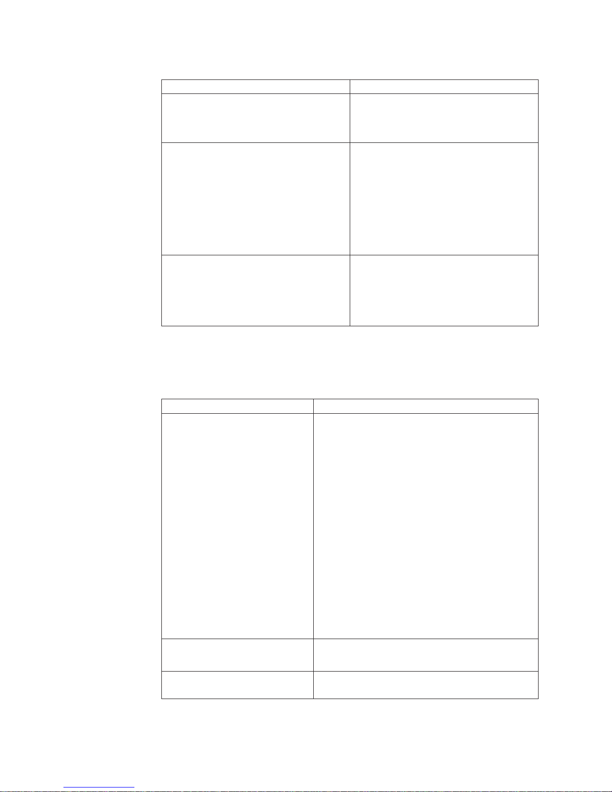
Table 1 describes the features of Model x4x of the 4810/4910 SurePOS 300.
Table 1. Summary of features
Type of feature Description
CPU Intel ULV Celeron M 373 (1.0GHz)
Core chip set Intel 910GMLE / ICH6M
I/O ports v Two VGA
Memory v Two DIMM slots for 400 MHz DDR2 RAM
Video Intel Graphics Media Accelerator 900
v Two RS-232 ports standard (nine pin male D-shell)
v Three USB 2.0 high speed ports:
– Two rear
– One front
v Keyboard and mouse ports, PS/2 compatible
v One - line in
v One - microphone
v One - line-out/headphone
v One - 10/100Mb Ethernet LAN (RJ45)
v One - 5V/12V powered RS232 (nine pin female D-shell)
v One - Cash drawer port, standard IBM 24V-compatible
v One - 24V Powered USB 2.0
v One - 12V Powered USB 2.0
v RS232 Connector Card installed
– Three 5V/12V powered RS232 (nine pin female D-shell)
v USB Connector Card installed
– Three 12V Powered USB2.0
v 512 MB standard, expandable to 2 GB
© Copyright IBM Corp. 2005, 2009 1
Page 16

Product introduction
Table 1. Summary of features (continued)
Type of feature Description
LAN Broadcom BCM5906M 10/100Mb
Clock Nonvolatile real-time clock
Media 3.5-inch SATA Hard Disk Drive or optional 4GB Modular-Flash
Audio Analog Devices AD1882 Codec
Optional features Model x4x
Table 2. Optional features
Type of feature Description
Storage 160 GB hard disk drive or 4 GB modular flash drive
SurePort cards 5V/12V Powered RS-232 connector card or powered USB connector
Memory 512 MB, 1 GB, or 2 GB total system memory
March 2009
Drive
card
Planning information
Required classification of 24V I/O cables (DP-3 information)
Attention: Powered USB 24V ports are intended for use with POS printers (IBM
SureMark 4610). All IBM POS printer cables are classified as UL Data-Processing
Cables DP-3. For safe use of these ports, any third-party cables must meet the
same requirements.
Powered USB device attachment
Attaching powered USB devices should adhere to the requirements of Section 2.3.3
of the Universal Serial Bus OEM Point-of-Sale Device Interface Specification.
Devices falling outside this specification may operate properly, but are not
supported.
Physical dimensions
Figure 1 on page 3 shows the dimensions of the product.
2 SurePOS Installation and Service
Page 17

March 2009
Height
Product introduction
Width
Depth
Figure 1. Dimensions of the 4810/4910 SurePOS 300
v Width: 245 mm (9.65 in.)
v Depth: 257 mm (10.12 in.)
v Height: 90 mm (3.54 in.)
v Weight: 4.53 kg (10.0 lb.) nominal
Power requirements and consumption
This section describes the power requirements and power consumption of the
SurePOS 300 Point of Sale terminal.
Power input:
v AC Input Connector: IEC 320 C14
v Input Voltage: 100-127, 200-240 VAC
v Input Frequency: 50 or 60 Hz (+/- 3Hz)
Power consumption:
Table 3. Power consumption
Power State EnergyStar (1) Point-of-Sale (2)
OFF (S5) 2.0 W 2.0 W
Suspend-to-RAM (S3) 2.5 W 2.5 W
Standby (S1) 20 W 31 W
On, idle (S0) 27 W 55 W
(1) Configured with 15" analog VGA monitor, PS/2 keyboard and PS/2 mouse at
115V AC input voltage with Wake-on-LAN enabled.
(2) Configured with 15" IBM LCD 4820 Touch Display, IBM 2x20 Customer Display,
IPM POS 4610 printer, PS/2 keyboard and PS/2 mouse at 115V AC input voltage
with Wake-on-LAN enabled.
Chapter 1. Introduction 3
Page 18

Product introduction
March 2009
Port power ratings:
Table 4. Port power ratings
Port/name Port Voltage Ratings Maximum Current
Powered Serial Ports
C/D/E/F
USB (2 back, 1 front) 5V 0.5A
12V powered USB – A/B/C/D 12V 1.5A
24V powered USB – E 24V 3.0A
Cash Drawer 24V 1.0 A / 150 ms pulse
Keyboard and Mouse 5V 1.0A
5V 1.0A
12V 1.0A
Notes:
1. Suspend-to-RAM (S3) wake-capable ports include:
v USB ports 1 and 2
v PS/2 keyboard and mouse ports
v 12V powered USB port A (RS232 connector card)
v 12V powered USB port D (USB connector card)
Note that 12V is not present during Suspend-to-RAM (S3). Ports are enabled for
wake through BIOS setup.
2. Combined, the wake-enabled USB ports 1 and 2, the 12V USB port, and the
PS/2 keyboard and mouse ports can only support a maximum 5V load of 1.5A
without the modular flash drive installed or 1.2A with the modular flash drive
installed.
3. The total 12V current for all external loads is 3A.
4. The total 5V current for all external loads is 3.5A.
Environmental considerations
These are the temperature and humidity requirements:
v Operating: +5°C to 40°C (41° to 104°F) with 8% to 80% relative humidity
v Shipping: −40°C to +60°C (−40° to 140° F), which includes condensation but not
rain
v Storage: 0°C to +60°C (32° to 140° F)
A fan contained in the power supply provides forced-air cooling. All the vents on the
front and rear of the 4810/4910 must have 51 mm (2 in.) minimum clearance.
The 4810/4910 SurePOS 300 meets applicable worldwide Electromagnetic
Compatibility (EMC) standards. Refer to Appendix C, “Notices,” on page 57 for a
complete description.
User information
Controls and indicators (front view)
Figure 2 on page 5 shows the indicators that are available on the front view of the
4810/4910 system unit.
4 SurePOS Installation and Service
Page 19

March 2009
Product introduction
Figure 2. Front view of 4810/4910 system unit
These are the descriptions of the indicators that are on the front cover:
This indicates a standard USB port.
This LED indicates HDD activity.
This LED indicates the 4810 power state. Hold down the power
button for 4 seconds to power off.
Table 5. LED operation
System state LED state or operation
Off (No AC supplied) OFF
Off (AC supplied) (Note: this state can be
entered by holding the power button down
for at least 4 seconds)
On (POST) Blinking (0.5 second ON, 0.5 second OFF)
On (Normal operation after post '8B'h) ON
S1 (Standby) Blinking (0.5 second ON, 0.5 second OFF)
S3 (Suspend to RAM) Blinking (0.5 second ON, 0.5 second OFF)
Blip (0.25 second ON, 1.75 seconds OFF)
Chapter 1. Introduction 5
Page 20

Product introduction
Rear connectors
Figure 3 and Figure 4 show examples of the rear view of the 4810/4910 model x4x.
Figure 3. Rear view of the 4810/4910 model x4x (RS232)
March 2009
3
CD1
Figure 4. Rear view of the 4810/4910 model x4x (USB)
Table 6. Rear connector icons and descriptions (USB)
Icon Description
Mouse port
PS/2 or compatible keyboard port
USB ports
VGA display port
CD1
3
6 SurePOS Installation and Service
Port for first and second external serial devices, such as a scale
or a scanner
Third, fourth, fifth, and sixth external serial device ports. These
connectors also provide 12V and 5V for external devices.
Page 21

March 2009
Product introduction
Table 6. Rear connector icons and descriptions (USB) (continued)
Icon Description
Ethernet LAN cable port
Microphone port
Audio input port
Port for audio output, such as self-amplified speakers or
headphones
Power cord inlet connector
USB, 12V powered port
B
12V
24V
USB, 24V powered port
A
Cash drawer port
Indicates that USB wake devices are supported when attached to
this port
Security screw location
This symbol indicates the location where a security screw can be
optionally installed by a customer to protect access to the inside
of the system unit. (IBM does not provide this screw.) The screw
is an M3 and can protrude into the unit for 6 to 9 mm. The screw
head needs to be a pan head or the equivalent. The screw head
outside diameter is to be 8 mm maximum, and the screw head
height can be up to 3.5 mm.
Chapter 1. Introduction 7
Page 22

Product introduction
March 2009
8 SurePOS Installation and Service
Page 23

March 2009
Chapter 2. Getting started
Hardware information
The hardware shipping carton contains:
v One SurePOS 300 unit
v One power cord
v Safety and regulatory documents
v Modular flash drive (MFD); this is optional
Note: You can purchase this unit with the standard 160 GB hard disk drive and
install the 4 GB modular flash drive feature. See “Removing and installing
the flash drive” on page 16.
Software information
Operating system preload - Model E4x
The Model E4x incorporates a preloaded Windows operating system. All hardware
features are the same for all models.
Preload features:
v Windows XP
v Windows®Embedded for Point of Service (WEPOS)
Refer to IBM 4810/4910 SurePOS 300 Operating System Installation Guide for
information about installing other operating systems.
®
© Copyright IBM Corp. 2005, 2009 9
Page 24

March 2009
10 SurePOS Installation and Service
Page 25

March 2009
Chapter 3. Removal and installation procedures for the
4810/4910 SurePOS 300
This section describes how to remove and install the components of Model x4x of
the 4810/4910 SurePOS 300. These are the procedures that are included:
v “Removing and installing the top cover” on page 12
v “Removing and installing the hard disk drive” on page 14
v “Removing and installing the hard disk drive and hard disk tray as an assembly”
on page 15
v “Removing and installing the flash drive” on page 16
v “Removing and installing the memory module” on page 17
v “Removing and installing the front-panel card” on page 18
v “Removing and installing the I/O connector card” on page 19
v “Removing and installing the riser card and the I/O connector card as an
assembly” on page 20
v “Resetting the system board CMOS settings” on page 23
v “Removing and installing the power supply” on page 21
v “Removing and installing the hard disk drive air duct” on page 22
v “Removing and installing the battery” on page 23
v “Removing and installing the system board” on page 25
v “Removing and installing the front cover” on page 27
© Copyright IBM Corp. 2005, 2009 11
Page 26

Removing and installing the top cover
1
March 2009
2
3
1
Figure 5. Removing and installing the top cover
To open the top cover:
1. Switch OFF the power to the unit. Unplug the power cord from the system unit.
2. Attention: Establish personal grounding before touching this unit.
3. If a security screw is present, remove it using the appropriate tool (to be
provided by the customer). Refer to Figure 4 on page 6 for the location of the
optional security screw and to Table 6 on page 6 for more information about the
security screw.
4. Press the side latches 1.
5. Slide the top cover back 2 for approximately 15 mm (5/8 in.), then lift it up3.
Note: Notice the SERVICE LABEL that is located on the inside of the top cover;
see Figure 6 on page 13.
12 SurePOS Installation and Service
Page 27

March 2009
Figure 6. Service label
To replace the top cover:
1. Place the top cover so that it is approximately 15 mm (5/8 in.) from the front of
the unit.
2. Slide the top forward until the latches make a clicking noise and are engaged.
Check both side latches to ensure that both latches are fully latched and appear
to align up evenly with the sides of the top cover.
Chapter 3. Removal and installation procedures for the 4810/4910 SurePOS 300 13
Page 28

Removing and installing the hard disk drive
This section describes how to remove, install and replace the hard drive unit. To
remove the hard drive and the hard drive tray as an assembly, see “Removing and
installing the hard disk drive and hard disk tray as an assembly” on page 15.
Note: The hard drive assembly might not be installed on a unit where the modular
flash drive is installed instead.
March 2009
1
2
2
Figure 7. Removing the hard disk drive
To remove the hard disk drive:
1. Open the unit. See “Removing and installing the top cover” on page 12.
2. Rotate the hard drive retainer 1 to the fully open position as shown by the
arrow in the figure.
3. Grasp the hard drive on each side 2 and lift it up and out of the system unit.
To install the hard disk drive:
1. When replacing the hard drive into the hard drive tray, the hard drive connectors
face the front of the system unit. Ensure that the hard drive is firmly in place.
2. Replace the cover. See “Removing and installing the top cover” on page 12.
14 SurePOS Installation and Service
Page 29

March 2009
Removing and installing the hard disk drive and hard disk tray as an
assembly
1
3
3
2
2
3
Figure 8. Removing the hard drive and hard drive tray as an assembly
To remove the hard drive and tray as an assembly:
v Open the unit. See “Removing and installing the top cover” on page 12.
v Grasp the tray assembly1 where the arrows originate 2.
v Pull the tray assembly in an upward direction as shown by the arrows; this will
disengage the tray assembly retainers.
To install the hard drive and tray as an assembly:
1. Align the hard drive tray with the three alignment features 3. Move the hard
drive tray down and over the alignment features 3 and snap into place.
2. Ensure that the hard drive is completely seated on the alignment pins and the
front of the tray is correctly positioned in the slots on the chassis.
3. Replace the cover. See “Removing and installing the top cover” on page 12.
Chapter 3. Removal and installation procedures for the 4810/4910 SurePOS 300 15
Page 30

Removing and installing the flash drive
1
March 2009
2
Figure 9. Removing the flash drive
To remove the flash drive or to access the system board to install a flash drive:
1. Open the unit. See “Removing and installing the top cover” on page 12.
2. If present, remove the hard drive tray assembly. See “Removing and installing
the hard disk drive and hard disk tray as an assembly” on page 15.
3. To remove the flash drive, gently lift the flash drive1 straight up and off the
white plastic guide pin2.
To replace or install a flash drive:
1. Align the flash drive 1 with the white plastic guide pin2 and with the
connectors on the system board. Push down until the flash drive is seated.
2. Replace the hard drive tray assembly. See “Removing and installing the hard
disk drive and hard disk tray as an assembly” on page 15
3. Replace the top cover. See “Removing and installing the top cover” on page 12.
16 SurePOS Installation and Service
Page 31

March 2009
Removing and installing the memory module
2
Figure 10. Opening the memory-module
retainer clips
Figure 11. Memory-module retainer clips in
the open position.
To remove the memory module:
1. Open the unit. See “Removing and installing the top cover” on page 12.
2. Remove the hard drive and tray assembly. See “Removing and installing the
hard disk drive and hard disk tray as an assembly” on page 15
3. Rotate the memory-module-retainer clips1 to the open position. The memory
module is disengaged from the memory connector. See Figure 11.
4. Lift the memory module2 straight up to remove it from the memory connector.
See Figure 11.
1
1
2
Figure 12. Installing the memory module
To install the memory module:
1. Position the replacement memory module1 over the memory connector. Be
sure the notch on the memory module aligns correctly with the connector
key2 on the memory connector. See Figure 12.
2. Align the memory module with the memory socket and push down engaging the
memory-module retainer clips; push down firmly to engage.
Note: Be sure the memory-module retainer clips are fully closed. See
Figure 13.
3. Replace the hard drive and tray assembly. See “Removing and installing the
hard disk drive and hard disk tray as an assembly” on page 15.
4. Replace the top cover. See “Removing and installing the top cover” on page 12.
Chapter 3. Removal and installation procedures for the 4810/4910 SurePOS 300 17
Figure 13. Closing the memory-module
retainer clips
Page 32

Removing and installing the front-panel card
1
Figure 14. Removing and replacing the front-panel card
To remove the front-panel card:
1. Open the unit. See “Removing and installing the top cover” on page 12.
2. Remove the hard drive and tray assembly. See “Removing and installing the
hard disk drive and hard disk tray as an assembly” on page 15.
3. Disconnect the front-panel card cable1 from the system board .
4. Remove the two screws2 that attach the front-panel card assembly to the
front cover.
5. Slide the front-panel card assembly out.
6. To replace the front-panel card assembly, reverse this procedure.
March 2009
2
18 SurePOS Installation and Service
Page 33

March 2009
Removing and installing the I/O connector card
Figure 15. Removing the I/O connector card
2
1
3
To remove the I/O connector card:
1. Open the unit. See “Removing and installing the top cover” on page 12.
2. Squeeze the blue plastic connector-card retainer at the top and bottom (where
the two small arrows 3 are located in Figure 15) to unlatch. Rotate the I/O
connector-card retainer outward to the open position 1 as shown.
3. Slide the I/O connector card2 out of the slot.
4. To install the I/O connector card, reverse this procedure.
Note: The I/O connector card must be fully installed before the connector card
latch is rotated closed.
Chapter 3. Removal and installation procedures for the 4810/4910 SurePOS 300 19
Page 34

March 2009
Removing and installing the riser card and the I/O connector card as
an assembly
1
2
Figure 16. Removing the riser card and the I/O connector card as an assembly
To remove the riser card and the I/O connector card as an assembly:
1. Open the unit. See “Removing and installing the top cover” on page 12.
Note: The HDD tray can remain in place.
2. Lift the riser card assembly1 up and out to access the cable.
3. Disconnect the cable2 by pinching the latch on the connector that connects to
the riser card assembly.
4. To install the riser card assembly, reverse this procedure, being careful to avoid
pinching the cables.
5. Be sure to press down on the riser-card assembly at the locations indicated in
blue on the riser card and on the I/O connector card assembly to ensure that it
is snapped into place.
20 SurePOS Installation and Service
Page 35

March 2009
Removing and installing the power supply
3
1
2
Figure 17. Removing the power supply
To remove the power supply:
1. Open the unit. See “Removing and installing the top cover” on page 12.
Note: The HDD tray can remain in place.
2. Lift out the riser card assembly. See “Removing and installing the riser card and
the I/O connector card as an assembly” on page 20.
3. Disconnect the power-supply cable1 from the system board.2.
4. Lift up the front end of the power supply 3 and then lift it out of the chassis.
5. To install the power supply, reverse this procedure.
Chapter 3. Removal and installation procedures for the 4810/4910 SurePOS 300 21
Page 36

Removing and installing the hard disk drive air duct
2
1
March 2009
1
Figure 18. Removing the hard drive air duct
Attention: The hard drive front air duct must be installed correctly to allow the
flow of air for the hard drive; incorrect installation can result in hard drive failure.
The hard disk drive air duct should not be removed unless it is broken or installed
improperly. Once the air duct is removed, it typically cannot be reinstalled. A new air
duct (one that has never been installed) must be installed in the unit.
To remove the hard drive air duct:
1. Open the unit. See “Removing and installing the top cover” on page 12.
2. Using a small flat blade screw driver, unlatch the snap latches1 on the left
and right sides of the hard drive air duct and remove the air duct2.
3. To install the hard drive front air duct, reverse this procedure.
22 SurePOS Installation and Service
Page 37

March 2009
Resetting the system board CMOS settings
1
Figure 19. Locating and resetting the CMOS jumper
Follow these steps to reset the system board CMOS to the default settings:
1. Open the unit. See “Removing and installing the top cover” on page 12.
2. Remove the hard drive assembly. See “Removing and installing the hard disk
drive and hard disk tray as an assembly” on page 15.
3. If a flash drive is installed, remove it. See “Removing and installing the flash
drive” on page 16.
4. Remove the riser card and the I/O connector card. See “Removing and
installing the riser card and the I/O connector card as an assembly” on page 20.
5. Locate the CMOS jumper 1 as shown in Figure 19.
6. Remove the jumper from the left and middle pins and place it on the middle and
right pins; leave it there for at least 10 seconds.
7. Re-install the jumper to the original position on the left and middle pins.
8. Reverse the steps to reassemble the unit.
Removing and installing the battery
Note: The system board coin cell battery is a Lithium Manganese Dioxide type.
Chapter 3. Removal and installation procedures for the 4810/4910 SurePOS 300 23
Page 38

March 2009
1
2
Figure 20. Removing and installing the battery
1. Open the unit. See “Removing and installing the top cover” on page 12.
2. Remove the battery1 by sliding it up in the direction of the arrow as shown.
3. To install the battery, reverse this procedure. Be sure that the battery orientation
is correct, with the '+' sign facing toward the memory modules 2, as shown.
24 SurePOS Installation and Service
Page 39

March 2009
Removing and installing the system board
3
1
2
Figure 21. Removing the system board
To remove the system board:
1. Open the unit. See “Removing and installing the top cover” on page 12.
2. Remove the hard drive assembly. See “Removing and installing the hard disk
drive and hard disk tray as an assembly” on page 15.
3. Remove the riser card assembly. See “Removing and installing the riser card
and the I/O connector card as an assembly” on page 20.
4. Disconnect the front-panel card cable1 and power supply cable2.
5. Remove the memory. See “Removing and installing the memory module” on
page 17.
6. Remove the flash drive, if installed. See “Removing and installing the flash
drive” on page 16.
7. Remove the four system-board retaining screws3 on the system board. See
Figure 21.
Chapter 3. Removal and installation procedures for the 4810/4910 SurePOS 300 25
Page 40

March 2009
8. Remove the system board by tilting it 4 as shown in Figure 22; then lift up
5.
4
Figure 22. Tilting and removing the system board
9. To install the system board, reverse this procedure.
Note: Be sure the system board is aligned with the 4 screw holes correctly
before installing the 4 retaining screws.
5
26 SurePOS Installation and Service
Page 41

March 2009
Removing and installing the front cover
1
3
2
Figure 23. Removing the front cover
To remove the front cover:
1. Open the unit. See “Removing and installing the top cover” on page 12.
2. Remove the hard drive assembly. See “Removing and installing the hard disk
drive and hard disk tray as an assembly” on page 15.
3. Release the bottom two retaining tabs2 one at a time, applying pressure to
separate the front cover from the chassis.
4. Release the top three retaining tabs1 one at a time, and slide the cover to the
right 3 to separate the front cover from the chassis.
5. Unsnap the sixth retaining tab as you move the front cover toward the right 3.
To install the front panel:
1. Align all five of the front panel retainers.
2. Push the front panel toward the chassis and snap into position.
Chapter 3. Removal and installation procedures for the 4810/4910 SurePOS 300 27
Page 42

March 2009
28 SurePOS Installation and Service
Page 43

March 2009
Chapter 4. Problem determination
Note: Refer to IBM Safety Information - Read This First, GA27-4004, before
beginning the procedures in this chapter.
Hardware failures, BIOS errors, or firmware errors can cause problems with the
4810/4910 SurePOS 300. This chapter contains information to assist in problem
determination and the identification of needed repair actions.
Problem determination tools
The following tools can be helpful in performing problem determination with the
4810/4910 SurePOS 300:
v USB memory key loaded with the IBM diagnostics for POS systems and
peripherals. Instructions for loading the available diagnostics onto a memory key
are given at the IBM RSS support web site:
http://www.ibm.com/solutions/retail/store/support under the Diagnostic
heading on the panel.
v IBM powered serial port wrap plug. (IBM P/N 44V2079)
v IBM standard serial port wrap plug. (IBM P/N 44V2078)
v Security screw removal tool (needed only if the customer has installed the
optional, customer-supplied security screw). Neither the screw or the removal tool
is supplied by IBM.
Supported memory keys
The following memory keys are supported for usage with the IBM diagnostics for
POS systems and peripherals:
IBM USB 2.0 (1 GB)
v FRU: 41D9746
PNY USB 2.0 (1 GB)
v Part number: P-FD01GU20-RF
Using the IBM diagnostics for POS systems and peripherals package
Diagnostics for the IBM SurePOS 300 Models x4x are available in the IBM
diagnostics for POS systems and peripherals package. This package installs to a
supported memory key, as described above.
Diagnostics memory key setup
See the README file found at the RSS support web site: http://www.ibm.com/
solutions/retail/store/support under the Diagnostic heading for directions on how
to setup your diagnostics memory key.
1. Obtain a memory key. See “Supported memory keys” described above.
2. Access the IBM Retail Store Solutions Web site at: www.ibm.com/solutions/
retail/store/support.
3. Select Support on the left side of the panel, then select IBM SurePOS 300
Series.
4. Next, select SurePOS 300-34x Downloads.
© Copyright IBM Corp. 2005, 2009 29
Page 44

Problem determination
5. Download the update program to a temporary location on the PC’s hard-disk
6. In most cases, the Diagnostics key should boot on the IBM SurePOS 300 unit
7. BIOS setup allows specific configuration of both the USB ports and the BIOS
March 2009
drive. Run the self-extracting program and respond to the messages that
display. This program writes the updates and provides instructions on inserting
the memory key.
by inserting the USB memory key into the unit and then powering ON the
system.
boot device boot order. In some cases, the configuration of these parameters
may prevent the booting of the IBM RSS diagnostics USB memory key. To
ensure that the BIOS setup configuration is correct, please follow the directions
below:
a. Insert the IBM RSS diagnostic USB memory key.
b. Power ON the system.
c. Press DEL when prompted to enter BIOS setup.
d. Open the “Advanced BIOS Feature" menu.
e. Open the “Hard Disk Boot Priority” menu.
f. Verify the inserted IBM RSS diagnostics USB memory key is located at the
top of the boot order.
g. If the IBM RSS diagnostics USB memory key is attached to the front USB
port (adjacent to the power button and power/hard disk LEDs), continue to
the next step; otherwise, the IBM RSS diagnostic USB memory key should
boot after pressing F10 to save changes and to exit BIOS setup.
h. To enable the front USB port, enter the “Integrated Peripherals” menu.
i. Select the USB Configuration option.
j. Ensure the “Front USB Control” option is set to Enabled.
k. Press F10 to save settings and exit setup.
After the diagnostic program initiates, an attached keyboard can be used, if
available. The diagnostics program will ask you to accept the User License
Agreement. Click the I Agree button. The next screen contains a selection menu for
System Components, Point Of Sale Devices, and Utilities (for VPD, and others) with
sub-menus dynamically-tailored for the SurePOS 300.
Troubleshooting
Following is a list of items to consider when diagnosing your 4810/4910 SurePOS
300 unit:
v The preliminary checklist provides items to be verified at the start of each service
call.
v The problem symptoms table provides a list of potential problem reports, along
with the recommended problem determination steps to perform.
v The suspected fault table provides a list of the main service parts and
recommended steps to perform if that part is suspected of being defective.
Preliminary checklist
Begin each service call by checking all of the items in this preliminary checklist. If,
after performing all the steps, a problem still exists, refer to Table 10 on page 32 to
continue problem determination.
1. Verify that the power and device communication cables are securely and
correctly connected.
30 SurePOS Installation and Service
Page 45

March 2009
2. Verify that any externally-powered I/O devices connected to an AC power outlet
are operating correctly and that the devices are powered ON.
3. Verify that the contrast and brightness controls on the video display (if attached)
are set correctly.
4. Observe the power indicator. The power indicator LED operation is shown in the
Table 7.
5. If the machine will boot, reboot the machine (without the USB memory key
installed) and listen to the beep codes. If a monitor is attached, observe the
system health check status. Refer to Table 8.
Note: Be sure to observe the customer-reported symptom prior to booting with
6. If the front USB port is disabled, use another USB port if possible. If booting
from the USB key is disabled, refer to 7a on page 30.
Power LED operation
The powered LED functions as an indicator of the system power state. Table 7
defines the operation of the power LED.
Table 7. LED operation
System State LED State or operation
Off (No AC supplied) OFF
Off - (AC supplied) Note: this state can be
entered by holding the power button down
for at least 4 seconds
On (POST) Blinking (0.5 second ON, 0.5 second OFF)
On (Normal operation after post '8B'h) ON
S1 (Standby) Blinking, (0.5 second ON, 0.5 second OFF)
S3 (Suspend to RAM) Blinking (0.5 second ON, 0.5 second OFF)
Problem determination
the memory key.
Blip (0.25 second ON, 1.75 seconds OFF)
Beep codes
The following table describes the beep codes you may hear during servicing of the
4810/4910 SurePOS 300 and what the beep tones mean.
Table 8. Beep Codes
Beeps System state
Continuous tone immediately after poweringONNo memory. All inserted memory failed
One short beep after POST completion POST completed successfully
POST messages displayed to the system monitor
The following table summarizes all messages that may be displayed on the system
monitor during POST.
Chapter 4. Problem determination 31
Page 46
Problem determination
Table 9. POST messages displayed to the system monitor
Message Meaning/Action
Hard Disk S.M.A.R.T. Failure The hard disk is reporting an internal error
CMOS Checksum Error The CMOS has become corrupt. It is
System Health Check
v Memory status
v System board status
v Hard disk health check
March 2009
that may result in the loss of data. It is
recommended that all relevant data on the
drive be moved to a safe storage media.
recommended that defaults be restored
through BIOS setup:
1. Power ON the system.
2. Press DEL when prompted to enter
setup.
3. Select "Load Optimized Defaults" and
press F10 to save settings and exit BIOS
setup.
This test is run at the end of POST and
provides a summary of POST tests, as well
as a more thorough inspection of the hard
disk drive. The results of all tests will be
visible for 5 seconds after completion of
tests.
Symptoms
The following table summarizes all symptoms for problems for the 4810/4910.
Table 10. 4810/4910 Problem symptoms table
Symptom Actions
System unit does not boot
Power LED does not light and the
system boots
Time of day not maintained across
AC removal.
v Unplug from the power outlet, wait at least 5
seconds, re-plug the power outlet, and then power
ON. Verify that the power light on the front panel is
ON. Look for any error messages on an attached
monitor and listen for a beep at the completion of
POST.
v Disconnect all I/O devices, and power ON the
system. If the system powers ON and boots up
correctly, then the problem is likely to be an I/O
device. Reconnect each device one at a time, from
the powered OFF state, booting the system
completely after each device connection. If the
system does not power up after connecting a
device, then that device or cable is likely the failure
point.
v Check for a blown fuse, a tripped circuit breaker, or
a power failure.
v Verify that all internal cables are securely
connected.
1. Replace the front panel card/cable assembly.
2. Replace the system board.
1. Replace the system battery.
32 SurePOS Installation and Service
Page 47

March 2009
Problem determination
Table 10. 4810/4910 Problem symptoms table (continued)
Symptom Actions
System Getting Blue Screens Often, blue screens are caused by OS, driver, or
application software issues. Diagnosing blue screens
should be handled through a software diagnostic path.
To determine if the hardware has contributed to a blue
screen situation, run the system unit diagnostics,
including running the extended diagnostics for the
hard drive.
Slow System Behavior Run the RSS system unit diagnostics test to
determine if the system unit hardware is having any
problems detected by the diagnostics; if not, invoke a
software diagnostic path.
Ethernet Connection slow Run the RSS system unit diagnostics test, including
the Ethernet test, while the system is connected to the
Ethernet; if not, invoke a software diagnostic path.
No Audio Confirm that speaker cables are securely plugged into
the system unit. Run the RSS system unit diagnostics
test, including the audio test. Confirm that the proper
audio driver is installed.
No Video
Serial IO Device Not Working
USB IO Device Not Working
1. Confirm that the monitor power cord is attached.
2. Confirm that there is a solid connection of the
video cable to the system unit in the correct
monitor port.
3. Ensure that the monitor is powered ON.
4. Perform monitor diagnostics.
1. Examine the device cable and replace if indicated.
2. Run self tests on the device and replace if
indicated.
3. Use the RSS diagnostic program and the
appropriate wrap plug tool. If this test is
successful, then the problem relates to the IO
device or to a non-hardware system software
problem.
4. Replace a SurePort card if the port is part of the
SurePort card.
1. Confirm operation of the IO port USB connection
using the memory key to boot diagnostics through
that port.
Chapter 4. Problem determination 33
Page 48

Problem determination
Table 10. 4810/4910 Problem symptoms table (continued)
Symptom Actions
Cash Drawer not working Note: The cash drawer port is located on the riser
HDD not enumerated by POST, OS
doesn’t boot.
Continuous tone after POST
March 2009
card.
1. Boot the RSS diagnostics memory key.
2. Choose the POS I/O tests from the main screen.
Check to see if the cash drawer test appears on
the screen; if this test does not appear, replace
the riser card.
3. If the cash drawer test appears on the screen, run
the cash drawer diagnostic test. If the cash drawer
diagnostic test passes, the cash drawer is
functioning.
If the cash drawer diagnostic test does not pass,
attach a known "good" cash drawer mechanism
and run the cash drawer test again. If the test sill
does not pass – replace the riser card. If the test
passes – replace the cash drawer.
Follow the steps in Table 9 on page 32.
1. Confirm presence and proper seating of the
DIMM.
2. If a DIMM socket is available, move the DIMM to
the other socket.
3. Replace DIMM.
Suspected Fault
If, based on the symptoms, a fault is suspected in a particular FRU, the confirming
checks in the table below should be performed.
Table 11. Suspected Fault Table
FRU Evaluation
HDD
HDD card/tray assembly
1. Verify that the HDD connector is fully
seated into the HDD card connector.
2. Examine the boot sequence in the BIOS
setup. Verify HDD is in the boot
sequence.
3. During POST, verify the HDD Health
Check runs successfully.
4. Run the RSS diagnostics, including the
extended diagnostics for the hard drive.
5. If above tests pass, re-imaging/reinstalling the OS may be required.
1. Verify that HDD connector is fully seated
into the HDD card connector
2. Examine for interface card damage.
Replace if damaged.
3. Confirm proper seating of the HDD
interface card in the motherboard
connector.
34 SurePOS Installation and Service
Page 49

March 2009
Problem determination
Table 11. Suspected Fault Table (continued)
FRU Evaluation
Modular Flash Drive Run the system unit tests. Does the system
unit test identify the modular flash drive as
an option? No – Replace the flash drive. Yes
– Run the test for the modular flash drive.
Does the test pass? No – Replace flash
drive.
System Board
USB Connector Card Try booting the USB key in the questionable
RS-232 Connector card
Memory Module Run the RSS system unit diagnostic tests.
Power Supply
Battery/coin cell
1. During POST, verify the system board
check program runs successfully. If not,
remove and/or re-seat all cables and
board-board connections as follow:
v Riser
v Power Connector
v Power switch card cable
v Memory
v HDD Assembly
Note: Disconnect all external cables and
reconnect one at a time from the
powered OFF state. Power ON
completely after each device connection
to determine if a device is causing a
problem.
2. Clear CMOS with the jumper.
3. If there is a problem with a port, use RSS
diagnostics to perform the wrap plug test
on the serial port.
USB port.
1. Try booting the USB key in the
questionable USB port.
2. Use the RSS diagnostic wrap plug test
on the suspected serial port.
During boot of the diagnostic memory key, a
memory test is run. Upon completion of the
test, press the ENTER key to request the
extended diagnostic test for the memory.
1. Verify AC power is available at the power
outlet.
2. Verify the power cord is plugged into the
outlet.
3. Re-seat the power cord in the system
unit.
4. Connect the system unit with a different
power cord.
5. Re-seat the 2 power supply cables inside
the system unit.
1. Check that the battery is installed
properly.
2. Re-seat the battery.
Chapter 4. Problem determination 35
Page 50

Problem determination
Table 11. Suspected Fault Table (continued)
FRU Evaluation
IO Connector Card Latch Physical examination.
Top Cover Physical examination.
March 2009
36 SurePOS Installation and Service
Page 51

March 2009
Chapter 5. Parts catalog
Assembly 1: Field-replaceable units .................38
This chapter provides parts information available for the Model x4x system units.
See the hardware service guide for each peripheral device for parts information
about the device.
© Copyright IBM Corp. 2005, 2009 37
Page 52

Parts catalog
Assembly 1: Field-replaceable units
1
2
March 2009
4
10
11
3
5
7
6
8
9
12
13
14
38 SurePOS Installation and Service
Page 53

March 2009
Assembly 1: (continued)
Asm–
Index
1– 4810/4910 System Unit Assembly
–1 44V2034 1 Top cover
–2 44V2031 1 Power supply
–3 44V2036 1 Riser card assembly
–4 44V2039 1 I/O Connector card latch
–5 44V2025 1 SurePort Serial Connector card (RS232)
–5 44V2026 1 SurePort USB Connector card
–6 44V2033 1 Hard-disk drive card/tray assembly
–7 44V2032 1 Hard-disk drive, 160 GB
–8 44V2027 1 Memory module, 0.5 GB
–8 44V2028 1 Memory module, 1 GB
–9 44V2041 1 Modular flash drive, 4 GB
–10 45P6222 1 Battery, coin cell (CR2032)
–11 44V2038 1 System board (planar)
–12 44V2040 1 Hard-disk-drive air duct
–13 44V2035 1 Front-panel card (Includes cable)
–14 44V2037 1 Front cover
– 44V2030 1 Miscellaneous hardware kit containing the following: 4 card (circuit board) screws, 4
– 4810/4910 Tools
– 44V2078 1 Wrap plug, 9 pin standard serial port (RS232)
– 44V2079 1 Wrap plug, 9 pin powered serial port (RS232)
Part
Number Units Description
HDD mounting screws, 4 HDD mounting rubber grommets, 1 foot (rubber), 1 foot
screw, 4 serial (RS232)/VGA port jack screws, 1 modular flash drive support post.
– 4810/4910 Options and I/O (announced January 2009)
– 44V2047 1 Display, 1x11 LED, RS232
– 44V2013 1 Display cable, 1x11 LED, 9 pin powered serial, 3.8 meter
– 44V2011 1 Cable, 40 char/APA VFD/LCD customer display, 9 pin powered serial, 3.8 meter
– 44V2014 1 Cable, converter, 9 pin powered serial port to 15 pin powered serial port
– 44V2048 1 Value Cash drawer, black
– 4910 Express Options and I/O
– 41D7062 1 4610-TF6 Express single station printer, Serial (RS232) interface
– 44V2049 1 4610-TF6 Express single station printer, USB interface
– 41D7063 1 4610-TF7 Express single station printer, Serial (RS232) interface
– 44V2050 1 4610-TF7 Express single station printer, USB interface
– 44V2051 1 4610-2NR Express dual station printer (no interface card)
– 44V2052 1 4610-2CR Express dual station printer (no interface card)
– 44D0158 1 4610-2NR/2CR Interface card, Serial (RS232)
– 44D0159 1 4610-2NR/2CR Interface card, USB
– 41D0403 1 4679-GCN Express single station printer, Serial (RS232) interface, (China only)
– 41D7087 1 4820-2GD Express 12″ Non-touch display
– 44V2053 1 4820-5GB Express 15″ Touch display
Chapter 5. Parts catalog 39
Page 54

Assembly 1: (continued)
March 2009
40 SurePOS Installation and Service
Page 55

March 2009
Chapter 6. Power cords
Table 12. Power cords
FRU P/N Usage
39M5066 Argentina, Paraguay, Uruguay
39M5079 Antigua and Barbuda, Aruba, Bahamas, Barbados, Belize, Bermuda, Bolivia, Canada, Cayman Islands, Costa
39M5100 Australia, Fiji, Kiribati, Nauru, New Zealand, Papua New Guinea
39M5121 Afghanistan, Albania, Algeria, Andorra, Angola, Armenia, Austria, Azerbaijan, Belarus, Belgium, Benin, Bosnia
39M5128 Denmark
39M5142 Bangladesh, Lesotho, Maceo, Maldives, Namibia, Nepal, Pakistan, Samoa, South Africa, Sri Lanka, Swaziland,
39M5149 Abu Dhabi, Bahrain, Botswana, Brunei Darussalam, Channel Islands, Cyprus, Dominica, Gambia, Ghana,
39M5156 Liechtenstein, Switzerland
39M5163 Chile, Italy, Libyan Arab Jamahiriya
39M5197 Japan
39M5204 China (SAR)
39M5217 Korea (Democratic Peoples Republic of), Korea (Republic of)
39M5224 India
39M5231 Brazil
39M5245 Taiwan
39M5170 Israel
39M5077 Columbia, United States (required in Chicago), 1.8 meter non-locking
39M5135 Japan, 4.3 meter locking
39M5107 United States, 4.3 meter locking
39M5162 Chile, 2.8 meter non-locking
39M5065 Argentina, 2.8 meter non-locking
39M5099 Australia, 2.8 meter non-locking
39M5078 Columbia, 2.8 meter non-locking
39M5230 Brazil, 2.8 meter non-locking
Rica, Columbia, Cuba, Dominican Republic, Ecuador, El Salvador, Guam, Guatemala, Haiti, Honduras, Jamaica,
Mexico, Micronesia (Federal States of), Netherlands Antilles, Nicaragua, Panama, Peru, Philippines (HV use),
Saudi Arabia, Thailand, Turks and Caicos Islands, United States, Venezuela
and Herzegovina, Bulgaria, Burkina Faso, Burundi, Cambodia, Cameroon, Cape Verde, Central African Republic,
Chad, Comoros, Congo (Democratic Republic of), Congo (Republic of), Cote D’Ivoire (Ivory Coast), Croatia
(Republic of), Czech Rep, Dahomey, Djibouti, Egypt, Equatorial Guinea, Eritrea, Estonia, Ethiopia, Finland,
France, French Guyana, French Polynesia, Gabon, Georgia, Germany, Greece, Guadeloupe, Guinea, Guinea
Bissau, Hungary, Iceland, Indonesia, Iran, Kazakhstan, Kyrgyzstan, Laos (Peoples Democratic Republic of),
Latvia, Lebanon, Lithuania, Luxembourg, Macedonia (former Yugoslav Republic of), Madagascar, Mali,
Martinique, Mauritania, Mauritius, Mayotte, Moldova (Republic of), Monaco, Mongolia, Morocco, Mozambique,
Netherlands, New Caledonia, Niger, Norway, Poland, Portugal, Reunion, Romania, Russian Federation, Rwanda,
Sao Tome and Principe, Saudi Arabia, Senegal, Serbia, Slovakia, Slovenia (Republic of), Somalia, Spain,
Suriname, Sweden, Syrian Arab Replublic, Tajikistan, Tahiti, Togo, Tunisia, Turkey, Turkmenistan, Ukraine, Upper
Volta, Uzbekistan, Vanuatu, Vietnam, Wallis and Futuna, Yugoslavia (Federal Republic of), Zaire
Uganda
Grenada, Guyana, Hong Kong, Iraq, Ireland, Jordan, Kenya, Kuwait, Liberia, Malawi, Malaysia, Malta, Myanmar
(Burma), Nigeria, Oman, Qatar, Saint Kitts & Nevis, Saint Lucia, Saint Vincent and the Grenadines, Seychelles,
Sierra Leone, Singapore, Sudan, Tanzania (United Republic of), Trinidad & Tobago, United Arab Emirates
(Dubai), United Kingdom, Yemen, Zambia, Zimbabwe, Uganda
Note: Unless otherwise indicated, all power cords are 4.3 meter (14.1 feet)
non-locking.
© Copyright IBM Corp. 2005, 2009 41
Page 56

March 2009
42 SurePOS Installation and Service
Page 57

March 2009
Appendix A. Connector Pinouts
Keyboard/Mouse Connector
6
4
2
Figure 24. Keyboard/Mouse Connector
Table 13. Keyboard/Mouse Connector
Pin Signal
1 Keyboard Data
2 Mouse Data
3 Ground
45V
5 Keyboard Clock
6 Mouse Clock
1
5
3
© Copyright IBM Corp. 2005, 2009 43
Page 58

RS232 Connector
March 2009
1
6
Figure 25. RS232 Connector
Table 14. RS232 Connector
Pin Signal Direction
1 Carrier Detect (DCD) Input
2 Received Data (RxD) Input
3 Transmitted Data (TxD) Output
4 Data Terminal Ready (DTR) Output
5 Common Ground
6 Data Set Ready (DSR) Input
7 Request to Send (RTS) Output
8 Clear to Send (CTS) Input
9 Ring Indicator (RI) Input
5
9
44 SurePOS Installation and Service
Page 59

March 2009
Powered RS232 Connector
5
9
Figure 26. Powered RS232 Connector
Table 15. Powered RS232 Connector
Pin Signal Direction
1 12V Output
2 Received Data (RxD Input
3 Transmitted Data (TxD) Output
4 Data Terminal Ready (DTR) Output
5 Common Ground
6 Data Set Ready (DSR) Input
7 Request to Send (RTS) Output
8 Clear to Send (CTS) Input
9 5V Output
1
6
Appendix A. Connector Pinouts 45
Page 60

External VGA Connector
March 2009
5
4
9
10
15
14
Figure 27. External VGA Connector
Table 16. External VGA Connector
Pin Signal
1RED
2 GREEN
3 BLUE
4N/C
5 Ground
6 RED Ground
7 GREEN Ground
8 BLUE Ground
95V
10 Ground
11 N/C
2
12 SDA (I
C)
13 HSync
14 VSync
2
15 SCL (I
C)
123
678
111213
46 SurePOS Installation and Service
Page 61

March 2009
Ethernet Connector
Figure 28. Ethernet Connection
Table 17. Ethernet Connector
Pin 10/100Base-T Signal 10/100Base-T Direction
1 TxD+ Output
2 TxD- Output
3 RxD+ Input
6 RxD- Input
18
USB Connector
1 2 3 4
Figure 29. USB Connector
Table 18. USB Connector
Pin Connector
1 5V VBus
2 -Data
3 +Data
4 Ground
Appendix A. Connector Pinouts 47
Page 62

Headphone/Line-in/Microphone Connector
Table 19. Headphone/Line-in/Microphone Connector
Pin Signal
Tip Left channel audio
Ring Right channel Audio
Base Ground
Cash Drawer Connector
14
March 2009
Figure 30. Cash Drawer Connector
Table 20. Cash Drawer Connector
Pin Connector
1 Ground
2 Sense
3 Open
4 24V
48 SurePOS Installation and Service
Page 63

March 2009
Powered USB Connector
5
1
Figure 31. Powered USB Connector
Table 21. Powered USB Connector
Pin Connector
1 5V VBus
2 -Data
3 +Data
4 Ground
5 Ground
6 12V or 24V
7 12V or 24V
8 Ground
8
6
2
7
4
3
Appendix A. Connector Pinouts 49
Page 64

March 2009
50 SurePOS Installation and Service
Page 65

March 2009
Appendix B. Safety information
Danger:
Before you begin to install this product, read the safety information in IBM
Safety Information — Read This First, GA27-4004. This booklet describes safe
procedures for cabling and plugging in electrical equipment.
Gevaar:
Voordat u begint met de installatie van dit produkt, moet u eerst de
veiligheidsinstructies lezen in de brochure Veiligheidsinstructies—Lees dit
eerst, GA27-4004. Hierin wordt beschreven hoe u electrische apparatuur op
een veilige manier moet bekabelen en aansluiten.
Perigo:
Antes de começar a instalar este produto, leia as informações de segurança
contidas em Informações Sobre Seguranaça—Leia Isto Primeiro, GA27-4004.
Esse folheto descreve procedimentos de segurança para a instalação de
cabos e conexões em equipamentos elétricos.
Fare!
Før du installerer dette produkt, skal du læse sikkerhedsforskrifterne i
Sikkerhedsforskrifter—Lœs dette først GA27-4004. Vejledningen beskriver den
fremgangsmåde, du skal bruge ved tilslutning af kabler og udstyr.
© Copyright IBM Corp. 2005, 2009 51
Page 66
March 2009
Gevaar
Voordat u begint met het installeren van dit produkt, dient u eerst de
veiligheidsrichtlijnen te lezen die zijn vermeld in de publikatie IBM Safety
Information — Read This First, GA27-4004. In dit boekje vindt u veilige
procedures voor het aansluiten van elektrische appratuur.
VAARA
Ennen kuin aloitat tämän tuotteen asennuksen, lue julkaisussa
Turvaohjeet—Luetämä ensin, GA27-4004, olevat turvaohjeet. Tässä kirjasessa
on ohjeet siitä, miten sähkölaitteet kaapeloidaan ja kytketään turvallisesti.
Danger
Avant d’installer le présent produit, consultez le livret Informations pour la
sécurité–Lisez-moi d’abord, GA27-4004, qui décrit les procédures à respecter
pour effectuer les opérations de câblage et brancher les équipements
électriques en toute sécurité.
Vorsicht
Bevor mit der Installation des Produktes begonnen wird, die
Sicherheitshinweise in Sicherheitsinformationen—Bitte zuerst lesen, IBM Form
GA27-4004. Diese Veröffentlichung beschreibt die Sicherheitsvorkehrungen für
das Verkabeln und Anschlieβen elektrischer Geräte.
52 SurePOS Installation and Service
Page 67

March 2009
Vigyázat
Mielôtt megkezdi a berendezés üzembe helyezését, olvassa el a IBM Safety
Information — Read This First, GA27-4004 könyvecskében leírt biztonsági
információkat. Ez a könyv leírja, milyen biztonsági intézkedéseket kell
megtenni az elektromos berendezés huzalozásakor illetve csatlakoztatásakor.
Pericolo
prima di iniziare l’installazione di questo prodotto, leggere le informazioni
relative alla sicurezza riportate nell’opuscolo Informazioni di sicurezza—Prime
informazioni da leggere in cui sono descritte le procedure per il cablaggio ed il
collegamento di apparecchiature elettriche.
Fare
Før du begynner å installere dette produktet, må du lese
sikkerhetsinformasjonen i Sikkerhetsinformasjon—Les dette først, GA27-4004
som beskriver sikkerhetsrutinene for kabling og tilkobling av elektrisk utstyr.
Perigo
Antes de iniciar a instalação deste produto, leia as informações de segurança
Informações de Segurança—Leia Primeiro, GA27-4004. Este documento
descreve como efectuar, de um modo seguro, as ligações eléctricas dos
equipamentos.
Appendix B. Safety information 53
Page 68

March 2009
Peligro
Antes de empezar a instalar este producto, lea la información de seguridad en
Información de Seguridad—Lea Esto Primero, GA27-4004. Este documento
describe los procedimientos de sequridad para cablear y enchufar equipos
eléctricos.
Varning—livsfara
Innan du börjar installera den här produkten bör du läsa
säkerhetsinformationen i dikumentet Säkerhetsföreskrifter—Läs detta först,
GA27-4004. Där beskrivs hur du på ett säkert sätt ansluter elektrisk utrustning.
54 SurePOS Installation and Service
Page 69

March 2009
IBM
IBM
GA27-4004
GA27-4004
Appendix B. Safety information 55
Page 70

GA27-4004
GA27-4004
GA27-4004
GA27-4004
GA27-4004
GA27-4004
IBM
March 2009
56 SurePOS Installation and Service
Page 71

March 2009
Appendix C. Notices
This information was developed for products and services offered in the U.S.A.
IBM may not offer the products, services, or features discussed in this document in
other countries. Consult your local IBM representative for information on the
products and services currently available in your area. Any reference to an IBM
product, program, or service is not intended to state or imply that only that IBM
product, program, or service may be used. Any functionally equivalent product,
program, or service that does not infringe any IBM intellectual property right may be
used instead. However, it is the user’s responsibility to evaluate and verify the
operation of any non-IBM product, program, or service.
IBM may have patents or pending patent applications covering the subject matter in
this document. The furnishing of this document does not give you any license to
these patents. You can send license inquiries, in writing, to:
IBM Director of Licensing
IBM Corporation
North Castle Drive
Armonk, NY 10504-1785
U.S.A.
For license inquiries regarding double-byte character set (DBCS) information,
contact the IBM Intellectual Property Department in your country or send inquiries,
in writing, to:
IBM World Trade Asia Corporation
Licensing
2-31 Roppongi 3-chome, Minato-ku
Tokyo 106, Japan
The following paragraph does not apply to the United Kingdom or any other country
where such provisions are inconsistent with local law: INTERNATIONAL BUSINESS
MACHINES CORPORATION PROVIDES THIS PUBLICATION "AS IS" WITHOUT
WARRANTY OF ANY KIND, EITHER EXPRESS OR IMPLIED, INCLUDING, BUT
NOT LIMITED TO, THE IMPLIED WARRANTIES OF NON-INFRINGEMENT,
MERCHANTABILITY, OR FITNESS FOR A PARTICULAR PURPOSE. Some states
do not allow disclaimer of express or implied warranties in certain transactions,
therefore, this statement may not apply to you.
This information could include technical inaccuracies or typographical errors.
Changes are periodically made to the information herein; these changes will be
incorporated in new editions of the publication. IBM may make improvements and/or
changes in the product(s) and/or program(s) described in this publication at any
time without notice.
IBM may use or distribute any of the information you supply in any way it believes
appropriate without incurring any obligation to you.
Any references in this information to non-IBM Web sites are provided for
convenience only and do not in any manner serve as an endorsement of those
Web sites. The materials at those Web sites are not part of the materials for this
IBM product and use of those Web sites is at your own risk.
© Copyright IBM Corp. 2005, 2009 57
Page 72

March 2009
Information concerning non-IBM products was obtained from the suppliers of those
products, their published announcements or other publicly available sources. IBM
has not tested those products and cannot confirm the accuracy of performance,
compatibility or any other claims related to non-IBM products. Questions on the
capabilities of non-IBM products should be addressed to the suppliers of those
products.
This information is for planning purposes only. The information herein is subject to
change before the products described become available.
58 SurePOS Installation and Service
Page 73

March 2009
Electronic emission notices
Federal Communications Commission (FCC) statement
This equipment has been tested and found to comply with the limits for a Class A
digital device, pursuant to Part 15 of the FCC Rules. These limits are designed to
provide reasonable protection against harmful interference when the equipment is
operated in a commercial environment. This equipment generates, uses, and can
radiate radio frequency energy and, if not installed and used in accordance with the
instruction manual, may cause harmful interference to radio communications.
Operation of this equipment in a residential area is likely to cause harmful
interference, in which case the user will be required to correct the interference at
his own expense.
Properly shielded and grounded cables and connectors must be used in order to
meet FCC emission limits. IBM is not responsible for any radio or television
interference caused by using other than recommended cables and connectors or by
unauthorized changes or modifications to this equipment. Unauthorized changes or
modifications could void the user’s authority to operate the equipment.
This device complies with part 15 of the FCC Rules. Operation is subject to the
following two conditions:
1. This device may not cause harmful interference, and
2. This device must accept any interference received, including interference that
may cause undesired operation.
European Union EMC Directive conformance statement
This product is in conformity with the protection requirements of EU Council
Directive 2004/108/EC on the approximation of the laws of the Member States
relating to electromagnetic compatibility. IBM cannot accept responsibility for any
failure to satisfy the protection requirements resulting from a non-recommended
modification of the product, including the fitting of non-IBM option cards.
This product has been tested and found to comply with the limits for Class A
Information Technology Equipment according to CISPR 22/European Standard EN
55022. The limits for Class A equipment were derived for commercial and industrial
environments to provide reasonable protection against interference with licensed
communication equipment.
Attention: This is a Class A product. In a domestic environment this product may
cause radio interference in which case the user may be required to take adequate
measures.
European Community contact:
IBM Technical Regulations
Pascalstr. 100, Stuttgart, Germany 70569
Telephone: 0049 (0)711 785 1176
Fax: 0049 785 1283
E-mail: tjahn@de.ibm.com
Appendix C. Notices 59
Page 74

Industry Canada Class A Emission Compliance statement
This Class A digital apparatus complies with Canadian ICES-003.
Avis de conformité aux normes d’Industrie Canada
Cet appareil numérique de la classe A est conforme à la norme NMB-003 du
Canada.
Germany
Zulassungsbescheinigung laut dem Deutschen Gesetz über die
elektromagnetische Verträglichkeit von Geräten (EMVG) vom 30. August 1995
(bzw. der EMC EG Richlinie 89/336).
Dieses Gerät ist berechtigt in Übereinstimmung mit dem Deutschen EMVG das
EG-Konformitätszeichen - CE - zu führen.
Verantwortlich für die Konformitätserklärung nach Paragraph 5 des EMVG ist die
IBM Deutschland Informationssysteme GmbH, 70548 Stuttgart
Informationen in Hinsicht EMVG Paragraph 3 Abs. (2) 2:
Das Gerät erfüllt die Schutzanforderungen nach EN 50082–1 und EN 55022 Klasse A.
March 2009
EN 55022 Klasse A Geräte müssen mit folgendem Warnhinweis versehen werden:
″Warnung: dies ist eine Einrichtung der Klasse A. Diese Einrichtung kann im
Wohnbereich Funkstörungen verursachen; in diesem Fall kann vom Betreiber
verlangt werden, angemessene Maβnahmen durchzuführen und dafür
aufzukommen.″
EN 50082–1 Hinweis:
″Wird dieses Gerät in einer industriellen Umgebung betrieben (wie in EN 50082–2
festgelegt), dann kann es dabei eventuell gestört werden. In solch einem Fall ist der
Abstand bzw. die Abschirmung zu der industriellen Störquelle zu vergröβern.″
Anmerkung:
Um die Einhaltung des EMVG sicherzustellen sind die Geräte, wie in den IBM
Handbüchern angegeben, zu installieren und zu betreiben.
Australia and New Zealand
Attention: This is a Class A product. In a domestic environment this product may
cause radio interference, in which case the user may be required to take adequate
measures.
60 SurePOS Installation and Service
Page 75

March 2009
Chinese Class A warning statement
Attention: This is a Class A product. In a domestic environment this product may
cause radio interference in which case the user may be required to take adequate
measures.
Japanese power line harmonics compliance statement
Japanese Voluntary Control Council for Interference (VCCI) statement
Attention: This product is a Class A Information Technology Equipment and
conforms to the standards set by the Voluntary Control Council for Interference by
Technology Equipment (VCCI). In a domestic environment this product may cause
radio interference in which case the user may be required to take adequate
measures.
Korean communications statement
Please note that this device has been approved for business purposes with regard
to electromagnetic interference. If you find this is not suitable for your use, you may
exchange it for a non-business purpose one.
Appendix C. Notices 61
Page 76

Taiwanese Class A warning statement
Taiwan contact information
March 2009
IBM Taiwan Product Service Contact Info:
IBM Taiwan Corporation
3F, No 7, Song Ren Road, Taipei Taiwan
Telephone: 0800-016-888
Cable ferrite requirement
All cable ferrites are required to suppress radiated EMI emissions and must not be
removed.
Electrostatic Discharge (ESD)
Attention: ESD damage can occur when there is a difference in charge between
the part, the product, and the service person. No damage will occur if the service
person and the part being installed are at the same charge level.
62 SurePOS Installation and Service
Page 77

March 2009
ESD Damage Prevention
Anytime a service action involves physical contact with logic cards, modules,
back-panel pins, or other ESD sensitive (ESDS) parts, the service person must be
connected to an ESD common ground point on the product through the ESD wrist
strap and cord.
The ESD ground clip can be attached to any frame ground, ground braid, green
wire ground, or the round ground prong on the AC power plug. Coax or connector
outside shells can also be used.
Handling Removed Cards
Logic cards removed from a product should be placed in ESD protective containers.
No other object should be allowed inside the ESD container with the logic card.
Attach tags or reports that must accompany the card to the outside of the container.
Product Recycling and disposal
This unit must be recycled or discarded according to applicable local and national
regulations. IBM encourages owners of information technology (IT) equipment to
responsibly recycle their equipment when it is no longer needed. IBM offers a
variety of product return programs and services in several countries to assist
equipment owners in recycling their IT products. Information on IBM product
recycling offerings can be found on IBM’s Internet site at http://www.ibm.com/ibm/
environment/products/prp.shtml.
Español:
Esta unidad debe reciclarse o desecharse de acuerdo con lo establecido en la
normativa nacional o local aplicable. IBM recomienda a los propietarios de equipos
de tecnología de la información (TI) que reciclen responsablemente sus equipos
cuando éstos ya no les sean útiles. IBM dispone de una serie de programas y
servicios de devolución de productos en varios países, a fín de ayudar a los
propietarios de equipos a reciclar sus productos de TI. Se puede encontrar
información sobre las ofertas de reciclado de productos de IBM en el sitio web de
IBM http://www.ibm.com/ibm/environment/products/prp.shtml.
Notice: This mark applies only to countries within the European Union (EU) and
Norway.
Appliances are labeled in accordance with European Directive 2002/96/EC
concerning waste electrical and electronic equipment (WEEE). The Directive
determines the framework for the return and recycling of used appliances as
applicable throughout the European Union. This label is applied to various products
to indicate that the product is not to be thrown away, but rather reclaimed upon end
of life per this Directive.
Remarque : Cette marque s’applique uniquement aux pays de l’Union Européenne
et à la Norvège. L’etiquette du système respecte la Directive européenne
2002/96/EC en matière de Déchets des Equipements Electriques et Electroniques
Appendix C. Notices 63
Page 78

March 2009
(DEEE), qui détermine les dispositions de retour et de recyclage applicables aux
systèmes utilisés à travers l’Union européenne. Conformément à la directive, ladite
étiquette précise que le produit sur lequel elle est apposée ne doit pas être jeté
mais être récupéré en fin de vie.
In accordance with the European WEEE Directive, electrical and electronic
equipment (EEE) is to be collected separately and to be reused, recycled, or
recovered at end of life. Users of EEE with the WEEE marking per Annex IV of the
WEEE Directive, as shown above, must not dispose of end of life EEE as unsorted
municipal waste, but use the collection framework available to customers for the
return, recycling, and recovery of WEEE. Customer participation is important to
minimize any potential effects of EEE on the environment and human health due to
the potential presence of hazardous substances in EEE. For proper collection and
treatment, contact your local IBM representative.
Disposal of IT products should be in accordance with local ordinances and
regulations.
Battery return program
This product may contain sealed lead acid, nickel cadmium, nickel metal hydride,
lithium, or lithium ion battery. Consult your user manual or service manual for
specific battery information. The battery must be recycled or disposed of properly.
Recycling facilities may not be available in your area. For information on disposal of
batteries outside the United States, go to http://www.ibm.com/ibm/environment/
products/batteryrecycle.shtml or contact your local waste disposal facility.
In the United States, IBM has established a return process for reuse, recycling, or
proper disposal of used IBM sealed lead acid, nickel cadmium, nickel metal hydride,
and other battery packs from IBM equipment. For information on proper disposal of
these batteries, contact IBM at 1-800-426-4333. Please have the IBM part number
listed on the battery available prior to your call.
For Taiwan:
Please recycle batteries.
64 SurePOS Installation and Service
Page 79

March 2009
For the European Union:
Notice: This mark applies only to countries within the European Union (EU)
Batteries or packaging for batteries are labeled in accordance with European
Directive 2006/66/EC concerning batteries and accumulators and waste batteries
and accumulators. The Directive determines the framework for the return and
recycling of used batteries and accumulators as applicable throughout the European
Union. This label is applied to various batteries to indicate that the battery is not to
be thrown away, but rather reclaimed upon end of life per this Directive.
Les batteries ou emballages pour batteries sont étiquetés conformément aux
directives européennes 2006/66/EC, norme relative aux batteries et accumulateurs
en usage et aux batteries et accumulateurs usés. Les directives déterminent la
marche à suivre en vigueur dans l’Union Européenne pour le retour et le recyclage
des batteries et accumulateurs usés. Cette étiquette est appliquée sur diverses
batteries pour indiquer que la batterie ne doit pas être mise au rebut mais plutôt
récupérée en fin de cycle de vie selon cette norme.
For California:
In accordance with the European Directive 2006/66/EC, batteries and accumulators
are labeled to indicate that they are to be collected separately and recycled at end
of life. The label on the battery may also include a chemical symbol for the metal
concerned in the battery (Pb for lead, Hg for mercury and Cd for cadmium). Users
of batteries and accumulators must not dispose of batteries and accumulators as
unsorted municipal waste, but use the collection framework available to customers
for the return, recycling and treatment of batteries and accumulators. Customer
participation is important to minimize any potential effects of batteries and
accumulators on the environment and human health due to the potential presence
of hazardous substances. For proper collection and treatment, contact your local
IBM representative.
This notice is provided in accordance with Royal Decree 106/2008 of Spain: The
retail price of batteries, accumulators and power cells includes the cost of the
environmental management of their waste.
Perchlorate material – special handling may apply
Refer to http://www.dtsc.ca.gov/hazardouswaste/perchlorate.
Appendix C. Notices 65
Page 80

The foregoing notice is provided in accordance with California Code of Regulations
Title 22, Division 4.5, Chapter 33: Best Management Practices for Perchlorate
Materials. This product/part includes a lithium manganese dioxide battery which
contains a perchlorate substance.
Flat panel displays
The fluorescent lamp in the liquid crystal display contains mercury. Dispose of it as
required by local ordinances and regulations.
Monitors and workstations
Connecticut - Please see the web site of the Department of Environmental
Protection at http://www.ct.gov/dep for information about recycling covered
electronic devices in the State of Connecticut, or telephone the Connecticut
Department of Environmental Protection at 1-860-424-3000.
Oregon - For information regarding recycling covered electronic devices in the state
of Oregon, go to the Oregon Department of Environmental Quality site at
http://www.deq.state.or.us/lq/electronics.htm.
Washington - For information about recycling covered electronic devices in the
State of Washington, go to the Department of Ecology Web site at
https://fortress.wa.gov/ecy/recycle/ or telephone the Washington Department of
Ecology at 1-800Recycle.
March 2009
Trademarks
The following are trademarks of International Business Machines Corporation in the
United States or other countries, or both:
AnyPlace Kiosk(tm)
AnyPlace POS Hub(tm)
DB2
DB2 Universal Database
IBM and the IBM logo
PS/2
SureMark
SurePoint
SurePOS
Wake on LAN
WebSphere
Microsoft, Windows, Windows NT, and the Windows logo are trademarks of
Microsoft Corporation in the United States, other countries, or both.
Celeron and Intel are trademarks of Intel corporation in the United States, or other
countries.
Java and all Java-based trademarks and logos are trademarks or registered
trademarks of Sun Microsystems, Inc. in the United States, or other countries, or
both.
Other company, product, or service names may be trademarks or service marks of
others.
66 SurePOS Installation and Service
Page 81

March 2009
Index
Special characters
,memory key 29
A
accessibility of publications x
air duct 22
B
battery removal 23
battery return program 64
battery, European Union 64
C
cable ferrite requirement 62
checklist, problem determination 30
Class A compliance statement
Australia and New Zealand 60
China 61
European Union 59
FCC (USA) 59
Germany 60
Industry Canada 60
Japan 61
Taiwan 62
CMOS 23
connectors, rear 6
F
features, model 1
ferrite requirement 62
flash drive removal 16
flat panel displays 66
front cover removal 27
front view 4
front-panel card removal 18
FRU part numbers 37
H
hard disk drive
air duct removal 22
assembly removal and replacement 15
removal and replacement 14
humidity requirements 4
I
I/O connector card removal 19
J
Japanese power line harmonics compliance
statement 61
Japanese Voluntary Control Council for Interference
statement 61
jumper, CMOS 23
D
damage from electrostatic discharge 62
Diagnostics 29
dimensions, physical 2
disposal of equipment 63
DP-3 2
E
electronic emissions notices 59
Australia and New Zealand 60
China 61
European Union 59
FCC (USA) 59
Germany 60
Industry Canada 60
Japan 61
Korea 61
Taiwan 62
electrostatic discharge (ESD) 62
end of life disposal 63
equipment disposal 63
K
Korean communications statement 61
L
LED indicators 4
M
memory key setup 29
memory keys 29
memory module removal 17
mercury-added statement 66
model features 1
N
notices 51, 57
battery recycling 64
cable ferrites 62
electronic emissions 59
electrostatic discharge (ESD) 62
end of life disposal 63
IBM 57
© Copyright IBM Corp. 2005, 2009 67
Page 82

O
opening the unit 12
P
parts catalog, FRUs 37
perchlorate 65
physical dimensions 2
power cords 41
power supply, removal 21
preliminary checklist 30
problem determination 29
tools 29
problem symptoms 32
product overview 1
R
rear connectors 6
removal and replacement
battery 23
flash drive 16
front cover 27
front-panel card 18
hard disk drive 14
hard disk drive air duct 22
hard drive assembly 15
I/O connector card 19
memory module 17
power supply 21
riser and I/O card assembly 20
system board 25
top cover 12
riser card and I/O assembly removal 20
March 2009
S
safety information 51
security screw removal tool 29
serial port wrap plug 29
system board removal 25
T
Taiwanese battery recycling statement 64
temperature and humidity requirements 4
top cover removal and replacement 12
trademarks 66
troubleshooting 30
68 SurePOS Installation and Service
Page 83

March 2009
Part number index
Part
Number
41D0403 1– 39
41D7062 1– 39
41D7063 1– 39
41D7087 1– 39
44D0158 1– 39
44D0159 1– 39
44V2011 1– 39
44V2013 1– 39
44V2014 1– 39
44V2025 1–5 39
44V2026 1–5 39
44V2027 1–8 39
44V2028 1–8 39
44V2030 1– 39
44V2031 1–2 39
44V2032 1–7 39
44V2033 1–6 39
44V2034 1–1 39
44V2035 1–13 39
44V2036 1–3 39
44V2037 1–14 39
44V2038 1–11 39
44V2039 1–4 39
44V2040 1–12 39
44V2041 1–9 39
44V2047 1– 39
44V2048 1– 39
44V2049 1– 39
44V2050 1– 39
44V2051 1– 39
44V2052 1– 39
44V2053 1– 39
44V2078 1– 39
44V2079 1– 39
45P6222 1–10 39
Asm–
Index Page
© Copyright IBM Corp. 2005, 2009 69
Page 84

March 2009
70 SurePOS Installation and Service
Page 85

Readers’ Comments — We’d Like to Hear from You
SurePOS 300
Installation and Service Guide for 4810/4910
Model x4x
Publication No. G362-0560-00
We appreciate your comments about this publication. Please comment on specific errors or omissions, accuracy,
organization, subject matter, or completeness of this book. The comments you send should pertain to only the
information in this manual or product and the way in which the information is presented.
For technical questions and information about products and prices, please contact your IBM branch office, your IBM
business partner, or your authorized remarketer.
When you send comments to IBM, you grant IBM a nonexclusive right to use or distribute your comments in any
way it believes appropriate without incurring any obligation to you. IBM or any other organizations will only use the
personal information that you supply to contact you about the issues that you state on this form.
Comments:
Thank you for your support.
Send your comments to the address on the reverse side of this form.
If you would like a response from IBM, please fill in the following information:
Name Address
Company or Organization
Phone No. E-mail address
Page 86

___________________________________________________________________________________________________
Readers’ Comments — We’d Like to Hear from You
G362-0560-00
_________________________________________________________________________________________
Fold and Tape Please do not staple Fold and Tape
NO POSTAGE
NECESSARY
IF MAILED IN THE
UNITED STATES
Cut or Fold
Along Line
BUSINESS REPLY MAIL
FIRST-CLASS MAIL PERMIT NO. 40 ARMONK, NEW YORK
POSTAGE WILL BE PAID BY ADDRESSEE
IBM Corporation
Retail Store Solutions Information Development, Dept ZBDA
P. O. Box 12195
RESEARCH TRIANGLE PARK NC 27709-9990
_________________________________________________________________________________________
Fold and Tape Please do not staple Fold and Tape
G362-0560-00
Cut or Fold
Along Line
Page 87

Page 88

March 2009
Printed in USA
G362-0560-00
 Loading...