

IBM SurePoint 4820-42D, SurePoint 4820-4FT, SurePoint 4820-42T, SurePoint 4820-4FD, SurePoint 4820-46D System Reference Manual
...Page 1

4820 SurePoint Soluti o n
System Reference
SA27-4249-05
Page 2

Page 3

4820 SurePoint Soluti o n
System Reference
SA27-4249-05
Page 4

Note
Before using this information and the product it supports, be sure to read the general information under
Appendix D, “Notices,” on page D-1 and “Electronic emission notices” on page D-2.
Sixth Edition (October 2003)
This edition applies to the 4820 SurePoint Solution and to all subsequent releases and modifications until otherwise
indicated in new editions.
This publication is available on the IBM Retail Stores solutions electronic Support web site.
1. Go to
www.ibm.com/solutions/retail/store/
2.
Select Support
3.
Select Publications to access IBM Retail Store Solutions— Electronic Publications web site.
Order
publications through your IBM representative or the IBM branch office serving your locality. Publications are not
stocked at the address given below.
A
form for reader’s comments is also provided at the back of this publication. If the form has been removed, address
your comments to:
IBM Corporation, Information Development, Department CJMA
PO
Box 12195
Research Triangle Park, North Carolina, 27709 USA
When
you send information to IBM, you grant IBM a nonexclusive right to use or distribute whatever information you
supply in any way it believes appropriate without incurring any obligation to you.
©
Copyright International Business Machines Corporation 1999, 2003. All rights reserved.
US
Government Users Restricted Rights – Use, duplication or disclosure restricted by GSA ADP Schedule Contract
with IBM Corp.
Page 5

Contents
About this book . . . . . . . . . . . . . . . . . . . . . . .ix
Who should read this book . . . . . . . . . . . . . . . . . . . .ix
Related publications . . . . . . . . . . . . . . . . . . . . . .ix
Tell us what you think . . . . . . . . . . . . . . . . . . . . . .xi
Figures . . . . . . . . . . . . . . . . . . . . . . . . . . xiii
Tables . . . . . . . . . . . . . . . . . . . . . . . . . .xv
Accessibility . . . . . . . . . . . . . . . . . . . . . . . . xvii
Summary of Changes . . . . . . . . . . . . . . . . . . . . . xix
Part 1. Introduction
Chapter 1. Introducing the IBM 4820 SurePoint Solution . . . . . . . . 1-1
Summary of models and features . . . . . . . . . . . . . . . . . 1-3
Product advantages . . . . . . . . . . . . . . . . . . . . . . 1-3
Product summary—12-inch models . . . . . . . . . . . . . . . . . 1-4
Hardware options . . . . . . . . . . . . . . . . . . . . . . 1-4
Supported operating systems . . . . . . . . . . . . . . . . . . 1-5
Touch drivers and diagnostics . . . . . . . . . . . . . . . . . 1-6
Front view of 4820 SurePoint Solution . . . . . . . . . . . . . . . 1-7
Rear view of 4820 SurePoint Solution . . . . . . . . . . . . . . . 1-8
System software . . . . . . . . . . . . . . . . . . . . . . 1-8
Product summary—10-inch models . . . . . . . . . . . . . . . . . 1-9
Front and rear views . . . . . . . . . . . . . . . . . . . . . 1-9
Supported operating systems . . . . . . . . . . . . . . . . . . 1-9
Environmental requirements . . . . . . . . . . . . . . . . . . . 1-10
Power usage . . . . . . . . . . . . . . . . . . . . . . . . 1-10
Spill resistance . . . . . . . . . . . . . . . . . . . . . . . 1-10
Calling for service . . . . . . . . . . . . . . . . . . . . . . 1-10
Part 2. IBM 4820 SurePoint Solution Models 42D, 42T, 4FD, 4FT
Chapter 2. System specifications and planning information . . . . . . . 2-1
Product summary . . . . . . . . . . . . . . . . . . . . . . . 2-1
Hardware features . . . . . . . . . . . . . . . . . . . . . . 2-1
Display . . . . . . . . . . . . . . . . . . . . . . . . . 2-1
Video interface . . . . . . . . . . . . . . . . . . . . . . 2-1
Input/output (I/O) . . . . . . . . . . . . . . . . . . . . . . 2-2
Indicators and user controls . . . . . . . . . . . . . . . . . . 2-2
External ports . . . . . . . . . . . . . . . . . . . . . . . 2-2
Power management . . . . . . . . . . . . . . . . . . . . . 2-2
Optional features . . . . . . . . . . . . . . . . . . . . . . . 2-3
Magnetic stripe reader (model 42T) . . . . . . . . . . . . . . . . 2-3
©
Copyright IBM Corp. 1999, 2003
iii
Page 6

Pointing device (models 42D, 42T) . . . . . . . . . . . . . . . . 2-3
External keyboard (models 42T and 4FT) . . . . . . . . . . . . . . 2-3
System software . . . . . . . . . . . . . . . . . . . . . . . 2-4
Supported modes . . . . . . . . . . . . . . . . . . . . . 2-4
Windows setting requirement . . . . . . . . . . . . . . . . . . 2-4
Chapter 3. Installation and operating information . . . . . . . . . . . 3-1
Option installation . . . . . . . . . . . . . . . . . . . . . . 3-1
Cable connections and routing . . . . . . . . . . . . . . . . . . 3-1
Pedestal mounting . . . . . . . . . . . . . . . . . . . . . . 3-2
Adjusting the display . . . . . . . . . . . . . . . . . . . . . 3-2
Chapter 4. System diagnostics and scan codes . . . . . . . . . . . . 4-1
Using the 4820 42T/4FD POS Terminal Service diskette . . . . . . . . . . 4-1
Using the OSD menu . . . . . . . . . . . . . . . . . . . . . 4-1
Exiting the OSD Menu . . . . . . . . . . . . . . . . . . . . 4-2
Using Manual Adjust . . . . . . . . . . . . . . . . . . . . . 4-2
Keypad and scan code arrangement . . . . . . . . . . . . . . . . 4-2
Part 3. IBM 4820 SurePoint Solution Models 46D, 46R, 46T
Chapter 5. System specifications and planning information . . . . . . . 5-1
Product summary . . . . . . . . . . . . . . . . . . . . . . . 5-1
Hardware features . . . . . . . . . . . . . . . . . . . . . . 5-1
Display . . . . . . . . . . . . . . . . . . . . . . . . . 5-1
Video interface . . . . . . . . . . . . . . . . . . . . . . 5-1
POS input/output (I/O) . . . . . . . . . . . . . . . . . . . . 5-2
Indicators and user controls . . . . . . . . . . . . . . . . . . 5-2
External ports . . . . . . . . . . . . . . . . . . . . . . . 5-2
Power management . . . . . . . . . . . . . . . . . . . . . . 5-2
Transition diagram . . . . . . . . . . . . . . . . . . . . . 5-3
Optional features . . . . . . . . . . . . . . . . . . . . . . . 5-3
Keypads . . . . . . . . . . . . . . . . . . . . . . . . . 5-3
Manager’s keylock . . . . . . . . . . . . . . . . . . . . . 5-3
Magnetic stripe reader (MSR) . . . . . . . . . . . . . . . . . . 5-3
Audio kit . . . . . . . . . . . . . . . . . . . . . . . . . 5-3
System software . . . . . . . . . . . . . . . . . . . . . . . 5-4
Supported modes . . . . . . . . . . . . . . . . . . . . . 5-4
Windows setting requirement . . . . . . . . . . . . . . . . . . 5-4
Chapter 6. Installation and operating information . . . . . . . . . . . 6-1
Option installation . . . . . . . . . . . . . . . . . . . . . . 6-1
Cable connections and routing . . . . . . . . . . . . . . . . . . 6-1
Pedestal mounting . . . . . . . . . . . . . . . . . . . . . . 6-2
Adjusting the display . . . . . . . . . . . . . . . . . . . . . 6-3
Chapter 7. System diagnostics . . . . . . . . . . . . . . . . . 7-1
Using the OSD menu . . . . . . . . . . . . . . . . . . . . . 7-1
Exiting the OSD Menu . . . . . . . . . . . . . . . . . . . . 7-1
iv
4820 SurePoint Solution System Reference
Page 7

Using Manual Adjust . . . . . . . . . . . . . . . . . . . . . 7-2
Chapter 8. Connector pinouts . . . . . . . . . . . . . . . . . . 8-1
Video connector assignments . . . . . . . . . . . . . . . . . . . 8-1
RS485 pin connector assignments . . . . . . . . . . . . . . . . . 8-1
Power supply pin voltages . . . . . . . . . . . . . . . . . . . . 8-2
Part 4. IBM 4820 SurePoint Solution Models 48D, 48T
Chapter 9. System specifications and planning information . . . . . . . 9-1
Product summary . . . . . . . . . . . . . . . . . . . . . . . 9-1
Hardware features . . . . . . . . . . . . . . . . . . . . . . 9-1
Display . . . . . . . . . . . . . . . . . . . . . . . . . 9-1
Video interface . . . . . . . . . . . . . . . . . . . . . . 9-1
POS input/output (I/O) . . . . . . . . . . . . . . . . . . . . 9-2
Indicators and user controls . . . . . . . . . . . . . . . . . . 9-2
External ports . . . . . . . . . . . . . . . . . . . . . . . 9-2
Power management . . . . . . . . . . . . . . . . . . . . . . 9-2
Managing the screen savers . . . . . . . . . . . . . . . . . . 9-3
Optional features . . . . . . . . . . . . . . . . . . . . . . . 9-3
Keypads . . . . . . . . . . . . . . . . . . . . . . . . . 9-3
Manager’s keylock . . . . . . . . . . . . . . . . . . . . . 9-3
Magnetic stripe reader (MSR) . . . . . . . . . . . . . . . . . . 9-3
Audio kit . . . . . . . . . . . . . . . . . . . . . . . . . 9-3
System software . . . . . . . . . . . . . . . . . . . . . . . 9-4
Chapter 10. Installation and operating information . . . . . . . . . . 10-1
Option installation . . . . . . . . . . . . . . . . . . . . . . 10-1
Cable connections and routing . . . . . . . . . . . . . . . . . . 10-1
Adjusting the display . . . . . . . . . . . . . . . . . . . . . 10-2
Brightness controls . . . . . . . . . . . . . . . . . . . . . 10-2
MicroTouch TouchWare . . . . . . . . . . . . . . . . . . . 10-2
Chapter 11. System diagnostics and pinout connections . . . . . . . . 11-1
Diagnostics for model 48D (non-touch) . . . . . . . . . . . . . . . 11-1
Using the MicroTouch TouchWare . . . . . . . . . . . . . . . . . 11-1
Locating the touchscreen controller information . . . . . . . . . . . 11-1
Touchscreen properties dialog box . . . . . . . . . . . . . . . . 11-2
Calibrating the touchscreen . . . . . . . . . . . . . . . . . . 11-2
Customizing the touch response mode . . . . . . . . . . . . . . 11-3
Selecting a touch mode . . . . . . . . . . . . . . . . . . . 11-4
Configuring the touch sound . . . . . . . . . . . . . . . . . . 11-4
Connector pinouts . . . . . . . . . . . . . . . . . . . . . . 11-5
USB power voltage . . . . . . . . . . . . . . . . . . . . . 11-5
Part 5. IBM 4820 SurePoint Solution Models 4WT, 4GT
Chapter 12. System specifications and planning information . . . . . . 12-1
Product summary . . . . . . . . . . . . . . . . . . . . . . 12-1
Contents
v
Page 8

Hardware features . . . . . . . . . . . . . . . . . . . . . . 12-1
Display . . . . . . . . . . . . . . . . . . . . . . . . . 12-1
Video interface . . . . . . . . . . . . . . . . . . . . . . 12-2
POS input/output (I/O) . . . . . . . . . . . . . . . . . . . . 12-2
Indicators and user controls . . . . . . . . . . . . . . . . . . 12-2
External ports . . . . . . . . . . . . . . . . . . . . . . 12-2
Power management . . . . . . . . . . . . . . . . . . . . . 12-2
Managing the screen savers . . . . . . . . . . . . . . . . . 12-3
Optional features . . . . . . . . . . . . . . . . . . . . . . 12-3
Keypads . . . . . . . . . . . . . . . . . . . . . . . . 12-3
Manager’s keylock . . . . . . . . . . . . . . . . . . . . . 12-3
Magnetic stripe reader (MSR) . . . . . . . . . . . . . . . . . 12-4
Audio kit . . . . . . . . . . . . . . . . . . . . . . . . 12-4
System software . . . . . . . . . . . . . . . . . . . . . . 12-4
Chapter 13. Installation and operating information . . . . . . . . . . 13-1
Option installation . . . . . . . . . . . . . . . . . . . . . . 13-1
Cable connections and routing . . . . . . . . . . . . . . . . . . 13-1
Adjusting the display . . . . . . . . . . . . . . . . . . . . . 13-2
Brightness controls . . . . . . . . . . . . . . . . . . . . . 13-2
MicroTouch TouchWare . . . . . . . . . . . . . . . . . . . 13-2
Chapter 14. System diagnostics and pinout connections . . . . . . . . 14-1
Using the MicroTouch TouchWare . . . . . . . . . . . . . . . . . 14-1
Locating the touchscreen controller information . . . . . . . . . . . 14-1
Touchscreen properties dialog box . . . . . . . . . . . . . . . 14-2
Calibrating the touchscreen . . . . . . . . . . . . . . . . . . 14-2
Customizing the touch response mode . . . . . . . . . . . . . . 14-3
Selecting a touch mode . . . . . . . . . . . . . . . . . . . 14-4
Configuring the touch sound . . . . . . . . . . . . . . . . . . 14-4
Connector pinouts . . . . . . . . . . . . . . . . . . . . . . 14-4
USB power voltage . . . . . . . . . . . . . . . . . . . . . 14-4
Part 6. IBM 4820 SurePoint Solution Models 10D, 1FR
Chapter 15. System specifications and planning information . . . . . . 15-1
Product summary . . . . . . . . . . . . . . . . . . . . . . 15-1
Hardware features . . . . . . . . . . . . . . . . . . . . . . 15-1
Display . . . . . . . . . . . . . . . . . . . . . . . . . 15-1
Video interface . . . . . . . . . . . . . . . . . . . . . . 15-1
Supported video modes . . . . . . . . . . . . . . . . . . . 15-2
Indicators and user controls . . . . . . . . . . . . . . . . . . 15-2
External ports . . . . . . . . . . . . . . . . . . . . . . 15-2
Power management . . . . . . . . . . . . . . . . . . . . 15-2
Chapter 16. Installation and operating information . . . . . . . . . . 16-1
Pedestal mounting . . . . . . . . . . . . . . . . . . . . . . 16-1
Adjusting the display image . . . . . . . . . . . . . . . . . . . 16-1
Other methods to adjust the display . . . . . . . . . . . . . . . 16-2
vi
4820 SurePoint Solution System Reference
Page 9

Part 7. Appendixes
Appendix A. Mounting the pedestal . . . . . . . . . . . . . . . . A-1
Mounting the distributed pedestal . . . . . . . . . . . . . . . . . A-1
Attaching the free-standing pedestal to the counter . . . . . . . . . . . A-2
Appendix B. Troubleshooting common problems . . . . . . . . . . . B-1
Appendix C. Mounting surface templates . . . . . . . . . . . . . . C-1
Mounting dimensions—Models 10D, 1FR . . . . . . . . . . . . . . . C-2
Appendix D. Notices . . . . . . . . . . . . . . . . . . . . . D-1
Electronic emission notices . . . . . . . . . . . . . . . . . . . D-2
Federal communications commission (FCC) statement . . . . . . . . . D-2
Industry Canada class A emission compliance statement . . . . . . . . D-2
Avis de conformité aux normes d’Industrie Canada . . . . . . . . . . D-2
European Community (CE) mark of conformity statement . . . . . . . . D-2
Germany . . . . . . . . . . . . . . . . . . . . . . . . D-3
Australia / New Zealand . . . . . . . . . . . . . . . . . . . D-3
Japanese power line harmonics compliance statement . . . . . . . . . . D-3
Japanese Voluntary Control Council for Interference (VCCI) statement . . . . . D-4
Korean Communications Statement . . . . . . . . . . . . . . . . D-4
Taiwanese class A warning statement . . . . . . . . . . . . . . . . D-4
Chinese Class A warning statement . . . . . . . . . . . . . . . . D-5
Electrostatic discharge (ESD) . . . . . . . . . . . . . . . . . . D-5
Trademarks . . . . . . . . . . . . . . . . . . . . . . . . D-6
Index . . . . . . . . . . . . . . . . . . . . . . . . . . X-1
Contents
vii
Page 10

viii
4820 SurePoint Solution System Reference
Page 11

About this book
This guide provides software and hardware information on the IBM 4820 SurePoint
Solution and is organized as follows:
Part 1, “Introduction” contains Chapter 1, “Introducing the IBM 4820 SurePoint Solution,”
which describes all models and available options for the 4820 SurePoint Solution.
Part 2, “IBM 4820 SurePoint Solution Models 42D, 42T, 4FD, 4FT” provides information
about models 42D, 42T, 4FT, and 4FD.
Part 3, “IBM 4820 SurePoint Solution Models 46D, 46R, 46T” provides information
about models 46D, 46T.
Part 4, “IBM 4820 SurePoint Solution Models 48D, 48T” provides information about
models 48D, 48T.
Part 5, “IBM 4820 SurePoint Solution Models 4WT, 4GT” provides information about
models 4WT, 4GT.
The appendixes provide information for all models and are organized as follows:
v
Appendix B, “Troubleshooting common problems” provides information on resolving
common problems.
v
Appendix C, “Mounting surface templates” provides drilling measurements for
installing the distributed pedestal and the free-standing pedestal to a counter.
Throughout
this guide, the following numeric terms refer to the following:
4800 IBM SurePOS 700
4810 IBM SurePOS 300
4820 4820 SurePoint Solution
4694 4694 Point of Sale Terminal
4840 4840 Point of Sale Terminal
Who should read this book
This guide is intended for system planners, system programmers, and technical
personnel trained in the use of point-of-sale equipment.
Related publications
The following IBM publications are also available from the IBM Retail Store Solutions
web site at www.ibm.com/solutions/retail/store/. From the store page, click on Support.
v
IBM SurePOS 700 Series System Reference, SA27-4224
v
IBM 4820 SurePoint Solution: Installation and Service Guide, GA27-4231
©
Copyright IBM Corp. 1999, 2003
ix
Page 12

v
IBM 4694 Point-of-Sale Terminals: Installation and Operation Manual, SA27-4005
v
IBM 4694 Point-of-Sale Terminals: Hardware Service Manual, SY27-0364
v
IBM SurePOS 500 Series Point-of-Sale Terminals: System Reference, SA27-4225
v
IBM SurePOS 720, 740, and 780 Planning, Installation and Operation Guide,
GA27-4328
v
IBM SurePOS 720, 740, and 780 Hardware Service Guide, SA27-4329
v
IBM SurePOS 700 Series: Options and I/O Devices Service Guide, SY27-0392
Driver and Service Diskette Information
v
Terminal hardware folder
–
4820 downloads
-
4694/4695/ISA Service Diskette, Version 5.33 or later
-
RS232 Service Diskette
v
Peripheral Drivers folder
–
POSS for Windows download
–
MicroTouch
™
TouchWare
™
–
POSS for DOS download
–
OPOS drivers download
–
Java POS drivers download
x
4820 SurePoint Solution System Reference
Page 13

Tell us what you think
Your feedback is important in helping to provide the most accurate and high-quality
information. Please take a few moments to tell us what you think about this book. The
only way for us to know if you are satisfied with our books, or how we might improve
their quality is through feedback from customers like you. If you have any comments
about this book:
v
Visit our home page at www.ibm.com/solutions/retail/store/ and then select the
Support button. From there, you can take the link to the Publications Web page
where you will find a feedback page for entering comments and sending them to us.
Be
sure to include the name and part number of the book.
v
Fill out one of the forms at the back of this book and return it by mail or by giving it
to an
IBM representative.
If
applicable, include a reference to the specific location of the text on which you are
commenting. For instance, include the page or table number.
Between major revisions of this guide we may make minor technical updates. The latest
softcopy version of this guide is available on the Publications Web page
www.ibm.com/solutions/retail/store/. Click on Support, then on Publications.
About this book
xi
Page 14

xii
4820 SurePoint Solution System Reference
Page 15

Figures
1-1. 4820 SurePoint Solution with features and available pedestals . . . . . . . . . . . 1-2
1-2. Front view of 4820 . . . . . . . . . . . . . . . . . . . . . . . . . . 1-7
1-3. Rear view of 4820 . . . . . . . . . . . . . . . . . . . . . . . . . . 1-8
1-4. Views of Models 10D and 1FR . . . . . . . . . . . . . . . . . . . . . . 1-9
2-1. Power Management Transition Diagram . . . . . . . . . . . . . . . . . . . 2-3
4-1. Keypad and scan code arrangement . . . . . . . . . . . . . . . . . . . . 4-3
5-1. Power Management Transition Diagram . . . . . . . . . . . . . . . . . . . 5-3
6-1. View of Model 46D, 46T Cable Connections . . . . . . . . . . . . . . . . . 6-1
10-1. View of Model 48D, 48T Cable Connections . . . . . . . . . . . . . . . . . 10-1
13-1. Model 4WT, 4GT cable connections . . . . . . . . . . . . . . . . . . . . 13-1
16-1. Pictorial view display adjustments . . . . . . . . . . . . . . . . . . . . 16-2
A-1. Distributed pedestal mounting . . . . . . . . . . . . . . . . . . . . . . A-1
C-1. Distributed pedestal mounting template . . . . . . . . . . . . . . . . . . . C-1
C-2. Free-standing pedestal mounting template . . . . . . . . . . . . . . . . . . C-2
C-3. Mounting dimensions . . . . . . . . . . . . . . . . . . . . . . . . . C-3
©
Copyright IBM Corp. 1999, 2003
xiii
Page 16

xiv
4820 SurePoint Solution System Reference
Page 17

Tables
1-1. Available 4820 SurePoint Solution models . . . . . . . . . . . . . . . . . . 1-1
1-2. 4820 SurePoint Solution models and features . . . . . . . . . . . . . . . . . 1-3
1-3. 4820 SurePoint Solution hardware options . . . . . . . . . . . . . . . . . . 1-4
1-4. 4820 SurePoint Solution supported operating systems . . . . . . . . . . . . . . 1-5
1-5. Summary by model of touch drivers, calibration/test, and diagnostic diskette . . . . . . . 1-6
1-6. 4820 SurePoint Solution system software . . . . . . . . . . . . . . . . . . 1-8
1-7. Environmental requirements . . . . . . . . . . . . . . . . . . . . . . 1-10
1-8. Power usage values . . . . . . . . . . . . . . . . . . . . . . . . . 1-10
2-1. 4820 SurePoint Solution Hardware Features . . . . . . . . . . . . . . . . . 2-1
2-2. 4820 SurePoint Solution System Software . . . . . . . . . . . . . . . . . . 2-1
2-3. Power Management States . . . . . . . . . . . . . . . . . . . . . . . 2-2
2-4. Supported Modes . . . . . . . . . . . . . . . . . . . . . . . . . . 2-4
3-1. Cable types and icons . . . . . . . . . . . . . . . . . . . . . . . . 3-1
5-1. 4820 SurePoint Solution Hardware Features . . . . . . . . . . . . . . . . . 5-1
5-2. 4820 SurePoint Solution System Software . . . . . . . . . . . . . . . . . . 5-1
5-3. Power Management States . . . . . . . . . . . . . . . . . . . . . . . 5-2
5-4. Supported Modes . . . . . . . . . . . . . . . . . . . . . . . . . . 5-4
6-1. Summary of Cable Types, Identifying Icons, and Examples . . . . . . . . . . . . 6-1
8-1. Cable Connector Pinouts . . . . . . . . . . . . . . . . . . . . . . . . 8-1
8-2. Power Supply Pin Voltages . . . . . . . . . . . . . . . . . . . . . . . 8-2
9-1. 4820 SurePoint Solution Hardware Features . . . . . . . . . . . . . . . . . 9-1
9-2. 4820 SurePoint Solution System Software . . . . . . . . . . . . . . . . . . 9-1
9-3. Power Management States . . . . . . . . . . . . . . . . . . . . . . . 9-2
10-1. Summary of Cable Types, Identifying Icons, and Examples . . . . . . . . . . . . 10-1
11-1. Touchscreen Status Messages . . . . . . . . . . . . . . . . . . . . . 11-1
11-2. Summary of Touch Modes . . . . . . . . . . . . . . . . . . . . . . . 11-4
11-3. USB Power and Voltage . . . . . . . . . . . . . . . . . . . . . . . 11-5
12-1. 4820 SurePoint Solution Hardware Features . . . . . . . . . . . . . . . . . 12-1
12-2. 4820 SurePoint Solution System Software . . . . . . . . . . . . . . . . . 12-1
12-3. Power management states . . . . . . . . . . . . . . . . . . . . . . . 12-2
13-1. Cable types . . . . . . . . . . . . . . . . . . . . . . . . . . . . 13-2
14-1. Touchscreen status messages . . . . . . . . . . . . . . . . . . . . . 14-1
14-2. Summary of touch todes . . . . . . . . . . . . . . . . . . . . . . . 14-4
14-3. USB power and voltage . . . . . . . . . . . . . . . . . . . . . . . . 14-5
15-1. 4820 SurePoint Solution Hardware Features . . . . . . . . . . . . . . . . . 15-1
15-2. Supported video modes . . . . . . . . . . . . . . . . . . . . . . . . 15-2
15-3. Power Management States . . . . . . . . . . . . . . . . . . . . . . 15-2
©
Copyright IBM Corp. 1999, 2003
xv
Page 18

xvi
4820 SurePoint Solution System Reference
Page 19

Accessibility
Accessibility features help a user who has a physical disability, such as restricted
mobility or limited vision, to use the 4800 SurePOS terminals successfully. The following
is a
high-level list of the accessibility features:
v
All controls are located on the front of the machine, in easy reach.
v
Industry-standard serial and USB ports allow alternative I/O devices.
v
Manuals are available in .PDF format and can be downloaded from the Web. See
“Related publications” on page ix for the URL.
v To
assist users with color-vision deficiencies, the power LED blinks as well as
changes color when in low-power mode.
v
Displays are driven at 60 Hz to eliminate problems caused by screen flicker.
©
Copyright IBM Corp. 1999, 2003
xvii
Page 20

xviii
4820 SurePoint Solution System Reference
Page 21

Summary of Changes
October 2003
This edition adds information about the 4820 SurePoint Solution models 4WT
and 4GT.
July 2002
This edition contains information about Models 10D and 1FR of the 4820
SurePoint Solution and information.
March 2002
This edition contains information about the integrated touch pedestal available
for the 4694 Point of Sale terminal.
September 2000
This edition contains information about the 4820 SurePoint Solution models
42D, 42T, 4FD, and 4FT.
February 2000
This edition contains information about the features of models 48D and 48T of
the 4820 SurePoint Solution:
v
Universal Serial Bus (USB) connectivity
v
Audio capability
v
TMDS (Transition Minimized Differential Signaling) digital video interface
v
DVI (Digital Visual Interface).
©
Copyright IBM Corp. 1999, 2003
xix
Page 22

xx
4820 SurePoint Solution System Reference
Page 23

Part 1. Introduction
Chapter 1. Introducing the IBM 4820 SurePoint Solution . . . . . . . . 1-1
Summary of models and features . . . . . . . . . . . . . . . . . 1-3
Product advantages . . . . . . . . . . . . . . . . . . . . . . 1-3
Product summary—12-inch models . . . . . . . . . . . . . . . . . 1-4
Hardware options . . . . . . . . . . . . . . . . . . . . . . 1-4
Supported operating systems . . . . . . . . . . . . . . . . . . 1-5
Touch drivers and diagnostics . . . . . . . . . . . . . . . . . 1-6
Front view of 4820 SurePoint Solution . . . . . . . . . . . . . . . 1-7
Rear view of 4820 SurePoint Solution . . . . . . . . . . . . . . . 1-8
System software . . . . . . . . . . . . . . . . . . . . . . 1-8
Product summary—10-inch models . . . . . . . . . . . . . . . . . 1-9
Front and rear views . . . . . . . . . . . . . . . . . . . . . 1-9
Supported operating systems . . . . . . . . . . . . . . . . . . 1-9
Environmental requirements . . . . . . . . . . . . . . . . . . . 1-10
Power usage . . . . . . . . . . . . . . . . . . . . . . . . 1-10
Spill resistance . . . . . . . . . . . . . . . . . . . . . . . 1-10
Calling for service . . . . . . . . . . . . . . . . . . . . . . 1-10
©
Copyright IBM Corp. 1999, 2003
Page 24

4820 SurePoint Solution System Reference
Page 25

Chapter 1. Introducing the IBM 4820 SurePoint Solution
The IBM 4820 SurePoint Solution (see Figure 1-1 on page 1-2) is the next generation of
displays, offering full-screen and touch display performance in a single reliable solution.
Table 1-1 describes the available models.
Table 1-1. Available 4820 SurePoint Solution models
Screen Size
Model
Color
Touch
Touch
Connection Type
Video type,
Active matrix
technology LCD
12 in
4820-42D
Pearl white
Non-touch, display only
Analog, SVGA,
color
4820-42T
Pearl white
Capacitive
RS-232
4820-4FD
Iron gray
Non-touch, display only
4820-4FT
Iron gray
Resistive
RS-232
4820-46D
Pearl white
Non-touch
4820-46R
Pearl white
Resistive
RS485
4820-46T
Pearl white
Capacitive
4820-48D
Pearl white
Non-touch
Digital Video
Interactive (DVI),
color
4820-48T
Pearl white
Capacitive
USB
4820-4WT
Pearl white
Capacitive
USB
Analog, SVGA,
color
4820-4GT
Iron gray
10 in
4820-10D
Pearl white
Non-touch, display only
4820-1FR
Iron gray
v
Display only indicates that the magnetic stripe reader (MSR), keypad, and keylock
are not supported.
v
IBM 4820 SurePoint Solution Models 42T and 4FT connect to products that require
an
RS-232 connection.
v
IBM 4820 SurePoint Solution Models 46D, 46T, and 46R connect to the IBM 4694
system unit.
v
IBM 4820 SurePoint Solution Models 48D and 48T connect to the IBM SurePOS 700
Series and to products with DVI-D and USB connectivity.
v
IBM 4820 SurePoint Solution Models 4WT and 4GT connect to the IBM SurePOS
720, 740, and 780 and to products with analog video and USB connectivity.
v
IBM 4820 SurePoint Solution Models 10D and 1FR connect to any standard analog
VGA or DVI-I subsystem. Specifically, these models can connect to the IBM 4694
system unit, to the IBM SurePOS 700 Series, the IBM SurePOS 500/600 series, and
to
the IBM 4810 SurePOS 300.
Note:
Touch, MSR, keypad, keylock, and point device options are not available for
10-inch models.
©
Copyright IBM Corp. 1999, 2003
1-1
Page 26

S1
S2
MSR
Audio kit
Distributed
pedestal
Pointing
device
4820
Keypad
Integrated
pedestal
Free-standing
pedestal
Figure 1-1. 4820 SurePoint Solution with features and available pedestals
1-2
4820 SurePoint Solution System Reference
Page 27

Summary of models and features
Table 1-2 summarizes the models and features of the 4820 SurePoint Solution:
Table 1-2. 4820 SurePoint Solution models and features
Model
MSR Keypad
Pointing
Device¹
Video² Keylock Touch / Driver
Touch
Technology
Host System
4820-42D
None
PS/2
Analog
No
None
Supports all
4820-42T
RS-232
PS/2
RS-232 /
MicroTouch
Capacitive
PC
4820-4FD³
RS232 None
None Analog
No
None
4840
4810
4820-4FT³
RS-232 /
MicroTouch
Resistive Sensor
4820-46D
None
PS/2
Analog
Yes
None
4694
4820-46T
RS485
PS/2
RS-485 / POS
suite
Capacitive
4820-46R
RS-485
PS/2
Resistive
4820-48D
USB
DVI
Yes
MicroTouch
None
4800
4694-206
⁴
4820-48T
Capacitive
4820-10D
None
Analog
No
None
Supports all
4820-1FR³
4820-4WT
Touch Only
None
Analog
No
MicroTouch
Capacitive
Supports all
4820-4WT
Touch+I/O
USB
Yes
4820-4GT
Touch Only³
None
No
4820-4GT
Touch+I/O³
USB
Yes
¹Pointer uses native Windows
®
mouse driver.
²Video uses native Windows video driver.
³Iron gray covers.
⁴4690 V2R3 support available.
Product advantages
The 4820 SurePoint Solution offers these advantages:
Chapter 1. Introducing the IBM 4820 SurePoint Solution
1-3
Page 28

v
Models 4xx have a compact design with a 12.1-in. viewing area comparable to a
larger CRT
v
Models 10D and 1FR provide a larger viewing area than a 10-in. color CRT
v
Lower power consumption and less heat dissipation compared to a standard CRT
v
High brightness, active matrix, SVGA (800 x 600) resolution display for full-motion
video in multimedia applications
v
Direct attachment to 4694 SVGA or SurePOS 730/750 DVI port, no adapter required
v
Integrated and distributed mounting configurations with the IBM SurePOS 700 Series
and 4694 POS Terminals
v
VESA-compliant mounting option for custom configurations (for example, wall
hanging)
v
Hardware brightness controls
v
Available in display-only or touch models (touch offered in 12-inch screen size only)
v
Spill resistant
v Up to
16.7 million colors
v
Pearl white casing (models 46D, 48D, 42D, 46T, 48T, 42T, 4WT, and 10D)
v
Iron gray casing (models 4FD, 4FT, 4GT, and 1FR)
v
For all models, except 10D and 1FR, optional equipment includes keypad,
International Standards Organization (ISO) 3-track and 2-head MSR, manager’s
keylock, pointing device, and audio kit
Product summary—12-inch models
Table 1-3 summarizes the 4820 SurePoint Solution hardware options. Table 1-6 on page
1-8 describes the supported system software, and Table 1-4 on page 1-5 describes the
supported operating systems.
Hardware options
Table 1-3. 4820 SurePoint Solution hardware options
Optional Hardware
Description
Keypad
v
32-key with ISO 3 track MSR, or
v
32-key with JUCC MSR, or
v
PS/2 keyboard connection
v
USB keyboard
MSR
ISO 3 track or JUCC
Pointing Device
v
PS/2 mouse type
v
USB model (models 48D, 48T, 4WT, 4GT)
1-4
4820 SurePoint Solution System Reference
Page 29

Table 1-3. 4820 SurePoint Solution hardware options (continued)
Optional Hardware
Description
Mounting
v
Integrated pedestal
v
Integrated touch pedestal
–
Short:10 in. (255 mm)
–
Tall:15 in.(380 mm)
v
Distributed pedestal
–
Short: 9.38 in. (240 mm)
–
Tall: 13.80 in. (352 mm)
v
Free-standing pedestal
v
VESA bracket
Security
Manager’s keylock (469X)
Sound
Note: Requires sound card with amplified
output (speaker out). For example, Sound
Blaster sound card PCI 16 or Yamaha sound
card WF192XG
Audio kit available
Supported operating systems
Table 1-4. 4820 SurePoint Solution supported operating systems
Operating
System
Models
42D, 42T, 4FD,
4FT
46D, 46T, 46R
48D, 48T
4WT, 4GT
DOS
U U U U
Windows 95
U
Not supported
Windows NT 4.0
U U U U
Windows 98
U U U U
Windows 2000
U U U U
Windows XP
U U U U
Windows Java
™
Virtual Machine
(JVM)
U U
(JavaPOS)
U
(JavaPOS)
U
(JavaPOS)
4690
U
Version 2,
Release 2
Version 2, Release
3
Version 2, Release
3
Chapter 1. Introducing the IBM 4820 SurePoint Solution
1-5
Page 30

Touch drivers and diagnostics
Table 1-5. Summary by model of touch drivers, calibration/test, and diagnostic diskette
4820 Model
Touch
Driver
Calibration/Test
Service/Diagnostic
4FD
N/A
4820 42T/4FD POS Terminal Service
diskette
4FT
MicroTouch TouchWare
42D
N/A
42T
MicroTouch TouchWare
46D
N/A
4694 Service/Diagnostics diskette
46R, 46T IBM POS
4694 Service/Diagnostics diskette
48D
N/A
IBM POS Device Diagnostics (POS Suite)
48T
MicroTouch TouchWare
4WT
N/A
IBM POS Device Diagnostics (POS Suite)
4GT
MicroTouch TouchWare
1-6
4820 SurePoint Solution System Reference
Page 31
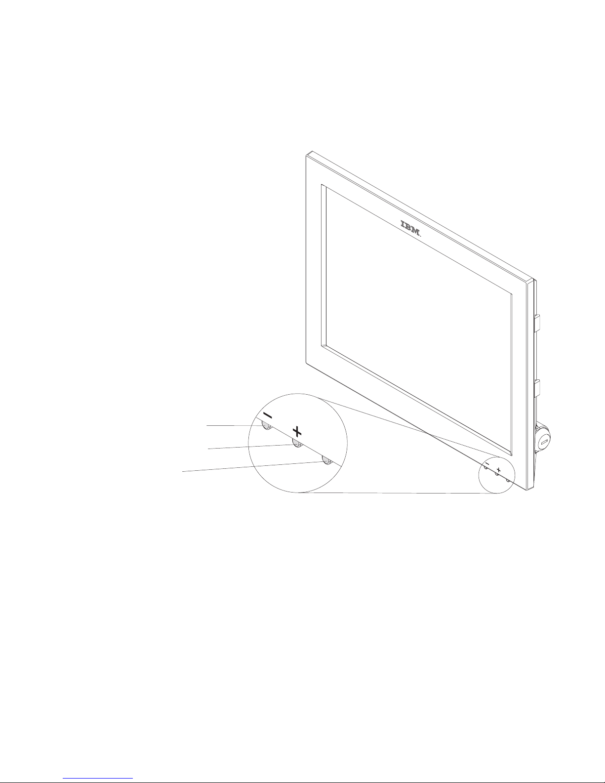
Front view of 4820 SurePoint Solution
Figure 1-2 is a front view of the 12-inch (models 4xx) 4820 SurePoint Solution, which
shows the location of the control buttons.
- Brightness
+ Brightness
Power
Suspend/Resume
Figure 1-2. Front view of 4820
Chapter 1. Introducing the IBM 4820 SurePoint Solution
1-7
Page 32
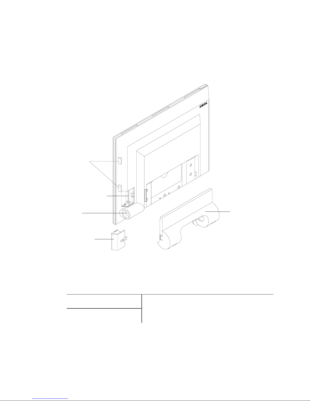
Rear view of 4820 SurePoint Solution
Figure 1-3 is a rear view of the 12-inch (models 4xx) 4820 SurePoint Solution. This
view shows the keypad, the locating tabs for the MSR, and the audio kit, connector, and
connector cover. Note the location of the manager’s keylock.
System software
Table 1-6. 4820 SurePoint Solution system software
System Software
POSS Drivers, MicroTouch
TouchWare
You can obtain the appropriate software for your 4820
SurePoint Solution from the IBM Retail Store Solutions Web
site:http://www..ibm.com/solutions/retail/store/ (from the store
page, click on Support).
Maintenance package: service
diskette, publications
Keypad/MSR
locating Tabs
Keypad/MSR connector
Key lock
cylinder
Keypad/MSR
connector cover
Mounting bracket cover/
Audio kit
Figure 1-3. Rear view of 4820. Options shown may not be available on all models.
1-8
4820 SurePoint Solution System Reference
Page 33

Product summary—10-inch models
IBM offers the 10-inch screen size 4820 SurePoint Solution Models 10D and 1FR as
lower-cost, more compact alternatives for customers who require display-only function
and have limited space available (see Figure 1-4). Compared to CRTs, these models
have the following advantages:
v
Less bulky
v
Requires significantly less power
v
Extremely low emissions
v
Larger image size than 10-inch color CRT
Front and rear views
Figure 1-4 shows the front and rear views of Models 10D and 1FR:
Supported operating systems
The 4820 SurePoint Solution Models 10D and 1FR support the following operations
systems:
v
DOS
v
Windows 95, 98, 2000, and NT 4.0
v
Windows Java Virtual Machine (JVM) and JavaPOS
v
4690 system, Version 2 Release 2, and Version 2 Release 3
Figure 1-4. Views of Models 10D and 1FR
Chapter 1. Introducing the IBM 4820 SurePoint Solution
1-9
Page 34

Environmental requirements
Table 1-7 shows the humidity and temperature limits for the 4820 SurePoint Solution.
Table 1-7. Environmental requirements
Temperature (dry
bulb)
Maximum
temperature (wet
bulb)
Relative humidity
Operating
0 to
40°C
(32° to 104° F)
27° C
(81° F)
8 to
80%
Storage
-20 to 60°C
(-4° to 140° F)
29° C
(84° F)
5 to 90 %
Ensure that the cooling vents are not blocked by papers, signs, or other items.
Power usage
Table 1-8 lists the power consumption and input voltage values for the 4820 SurePoint
Solution.
Table 1-8. Power usage values
Power consumption (on and
operating)
Input voltage
Models 10F, 1FD
20
watts
100 to 240 V AC nominal
All other models
35
watts
Spill resistance
The 4820 SurePoint Solution is designed to meet the following standards:
v
National Electrical Manufacturers Association (NEMA) Type 5 rating per NEMA
Standards Publication number 250–1991 Enclosures for Electrical Equipment
v IP 52
rating per IEC 529
Calling for service
When you call IBM for warranty information or service, be sure to have the following
information available:
v
Machine type/model
v
Serial number
Locate
this information on the lower right edge at the rear of the machine.
1-10
4820 SurePoint Solution System Reference
Page 35

Part 2. IBM 4820 SurePoint Solution Models 42D, 42T, 4FD, 4FT
Chapter 2. System specifications and planning information . . . . . . . 2-1
Product summary . . . . . . . . . . . . . . . . . . . . . . . 2-1
Hardware features . . . . . . . . . . . . . . . . . . . . . . 2-1
Display . . . . . . . . . . . . . . . . . . . . . . . . . 2-1
Video interface . . . . . . . . . . . . . . . . . . . . . . 2-1
Input/output (I/O) . . . . . . . . . . . . . . . . . . . . . . 2-2
Indicators and user controls . . . . . . . . . . . . . . . . . . 2-2
External ports . . . . . . . . . . . . . . . . . . . . . . . 2-2
Power management . . . . . . . . . . . . . . . . . . . . . 2-2
Transition diagram . . . . . . . . . . . . . . . . . . . . 2-3
Optional features . . . . . . . . . . . . . . . . . . . . . . . 2-3
Magnetic stripe reader (model 42T) . . . . . . . . . . . . . . . . 2-3
Pointing device (models 42D, 42T) . . . . . . . . . . . . . . . . 2-3
External keyboard (models 42T and 4FT) . . . . . . . . . . . . . . 2-3
System software . . . . . . . . . . . . . . . . . . . . . . . 2-4
Supported modes . . . . . . . . . . . . . . . . . . . . . 2-4
Windows setting requirement . . . . . . . . . . . . . . . . . . 2-4
Chapter 3. Installation and operating information . . . . . . . . . . . 3-1
Option installation . . . . . . . . . . . . . . . . . . . . . . 3-1
Cable connections and routing . . . . . . . . . . . . . . . . . . 3-1
Pedestal mounting . . . . . . . . . . . . . . . . . . . . . . 3-2
Adjusting the display . . . . . . . . . . . . . . . . . . . . . 3-2
Chapter 4. System diagnostics and scan codes . . . . . . . . . . . . 4-1
Using the 4820 42T/4FD POS Terminal Service diskette . . . . . . . . . . 4-1
Using the OSD menu . . . . . . . . . . . . . . . . . . . . . 4-1
Exiting the OSD Menu . . . . . . . . . . . . . . . . . . . . 4-2
Exiting through time-out . . . . . . . . . . . . . . . . . . 4-2
Using Manual Adjust . . . . . . . . . . . . . . . . . . . . . 4-2
Keypad and scan code arrangement . . . . . . . . . . . . . . . . 4-2
©
Copyright IBM Corp. 1999, 2003
Page 36

Models 42D, 42T, 4FD, 4FT
4820 SurePoint Solution System Reference
Page 37

Chapter 2. System specifications and planning information
This section summarizes the specifications of the 4820 SurePoint Solution, and
provides details on the optional hardware and software features.
Product summary
This section summarizes the specifications of 4820 SurePoint Solution.
Table 2-1. 4820 SurePoint Solution Hardware Features
Hardware Features
Description
Keypad (Models 42D, 42T)
A
32-key with ISO 3 track MSR or a 32-key with
JUCC MSR
MSR
ISO 3 track or JUCC
Pointing Device
PS/2 mouse type
Mounting
v
Integrated, distributed, or free-standing
pedestal
v
VESA bracket
Cables
v
Multi-connector cable with RS232, MSR, and
optional keyboard connections, 0.7m, 1.8m or
3.8m
v
Analog , 1.8m, 3.8m
Power
External power brick
Table 2-2. 4820 SurePoint Solution System Software
System Software
Maintenance package: service
diskette, publications
You can obtain the appropriate software for your 4820
SurePoint Solution from the IBM Retail Store Solutions Web
site: www.ibm.com/solutions/retail/store/ (from the store page,
click on Support).
Hardware features
This section describes the physical features of the 4820 SurePoint Solution.
Display
The 4820 SurePoint Solution provides a 12.1 inch TFT SVGA display with 800 x 600
resolution. The display can provide up to 16.7 million colors, subject to host pc
limitations. Autoscaling is standard with VGA support.
Video interface
The 4820 SurePoint Solution, models 42D, 42T, 4FT, and 4FD have an analog
interface.
©
Copyright IBM Corp. 1999, 2003
2-1
Page 38

Input/output (I/O)
The 4820 SurePoint Solution allows the following I/O devices:
v
Touch screen, MSR, and keypad (Model 42T only)
v
RS232 I/O
v
Pointing device (Model 42T only), mouse
Indicators and user controls
The 4820 SurePoint Solution provides the following indicators and user controls:
v
Dual color LED:green power-on indicator; orange backlight dim
v
Power on and off
v
Brightness
External ports
The 4820 SurePoint Solution provides the following external ports:
v
RS232 touch, keypad, MSR input: 4-pin
v
Video: MDR 20-pin
v DC
power input
Power management
Power management is through DPMS and complies with the VESA standard. The table
below describes the power management states.
Table 2-3. Power Management States
Operation Mode
RS485 / Analog
Off
5W
DPMS Off
5W
DPMS Suspend
5W
DPMS Standby
5W On
20W
2-2
4820 SurePoint Solution System Reference
Page 39
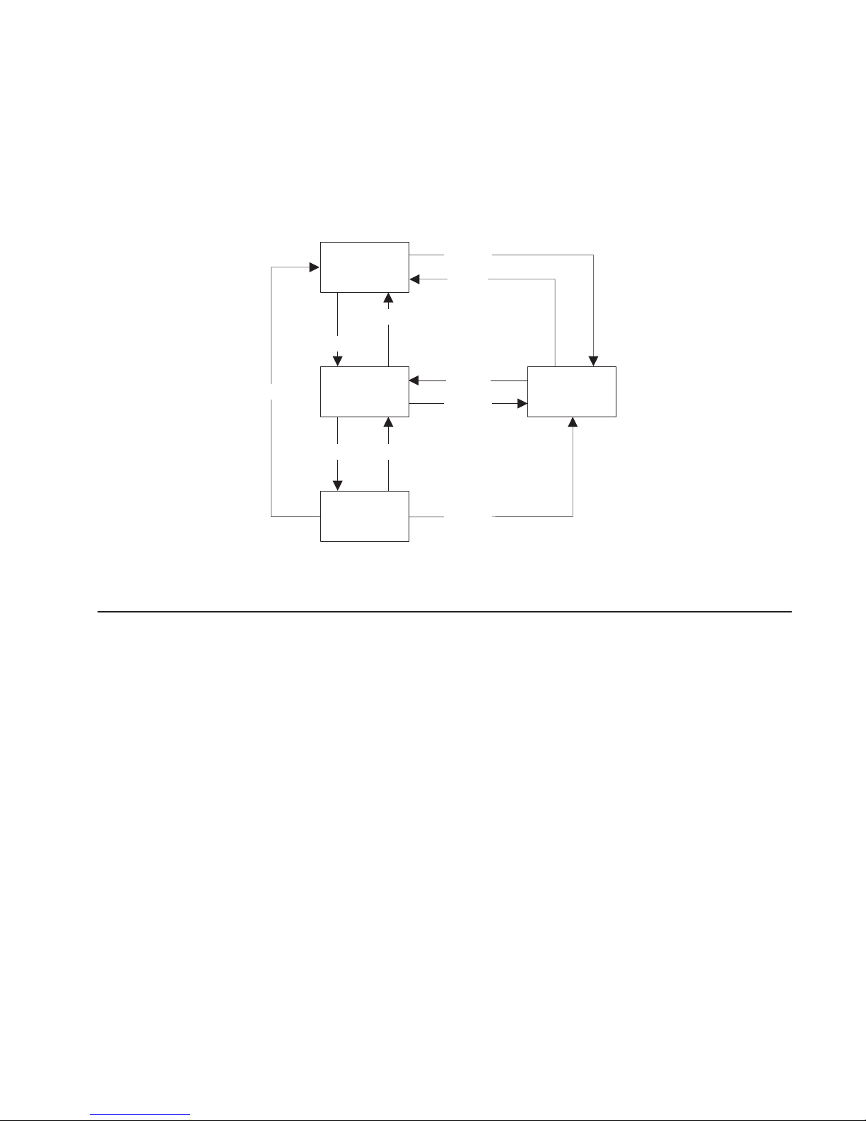
Transition diagram
The diagram below shows the transition between standby and normal operation.
Normal
Standby DC-off
Switch-off
DPMS on
Switch (toggle)*
Switch (toggle)
*No Video/DPMS by OSD
DC-out
DC-out
DC-out
DC-in
*DC-in
DPMS off
Optional features
This section describes the optional features available on the 4820 SurePoint Solution.
Magnetic stripe reader (model 42T)
The supported MSRs available are the International Organization for Standardization
(ISO) 3- track and the Japanese Unified Cash Card (JUCC) 2-head.
Note:
Model 4820-42T does not support JUCC.
Pointing device (models 42D, 42T)
You can connect an IBM PS/2 compatible pointing device to the 6–pin mini DIN
connector plug.
External keyboard (models 42T and 4FT)
The 4820 SurePoint Solution models 42T and 4FT support one PS/2 compatible
keyboard for maintenance purposes. The following conditions apply:
Scan codes
See Figure 4-1 on page 4-3,
Host PC dependency
Host pc must support keyboard hot plugging
Figure
2-1. Power Management Transition Diagram
Chapter 2. System specifications and planning information
2-3
Page 40

The 4820 supports an external keyboard when you attach it at system power-on.
Support is independent of attached keypad. If you attach the keyboard after powering
on, the keyboard is activated until you power off. The keypad is disabled during this
time. To activate the keypad after you activate the external keyboard, you must cold
start the system with the external keyboard detached. The transition of activating the
keyboard occurs only one time per power on/off cycle.
System software
You can obtain the appropriate software for the 4820 SurePoint Solution from the IBM
Retail Sore Solutions Web site: http://www.ibm.com/solutions/retail/store (from the store
page, click on Support).
Supported modes
Table 2-4 lists the supported modes and frequencies.
Table 2-4. Supported Modes
Modes
Supported Frequencies
SVGA
56, 60, 72, 75 Hz
Graphics adapter (VGA)
60, 70, 72, 75 Hz
Windows setting requirement
When you install the 4820 SurePoint Solution with the Windows operating system,
ensure that the display setting is 800 x 600. The 4820 operates at a VGA setting of 640
x
480, but the image is not optimized.
2-4
4820 SurePoint Solution System Reference
Page 41
Chapter 3. Installation and operating information
This section summarizes the installation and operation methods of the 4820 SurePoint
Solution. IBM recommends that you refer to the IBM 4820 SurePoint Solution
Installation and Service Guide for complete instructions.
Option installation
IBM recommends that you install the options for the 4820 SurePoint Solution in the
following order:
1.
MSR
2.
Keypad (Model 42T only)
3.
Pointing device (Model 42T only)
Cable connections and routing
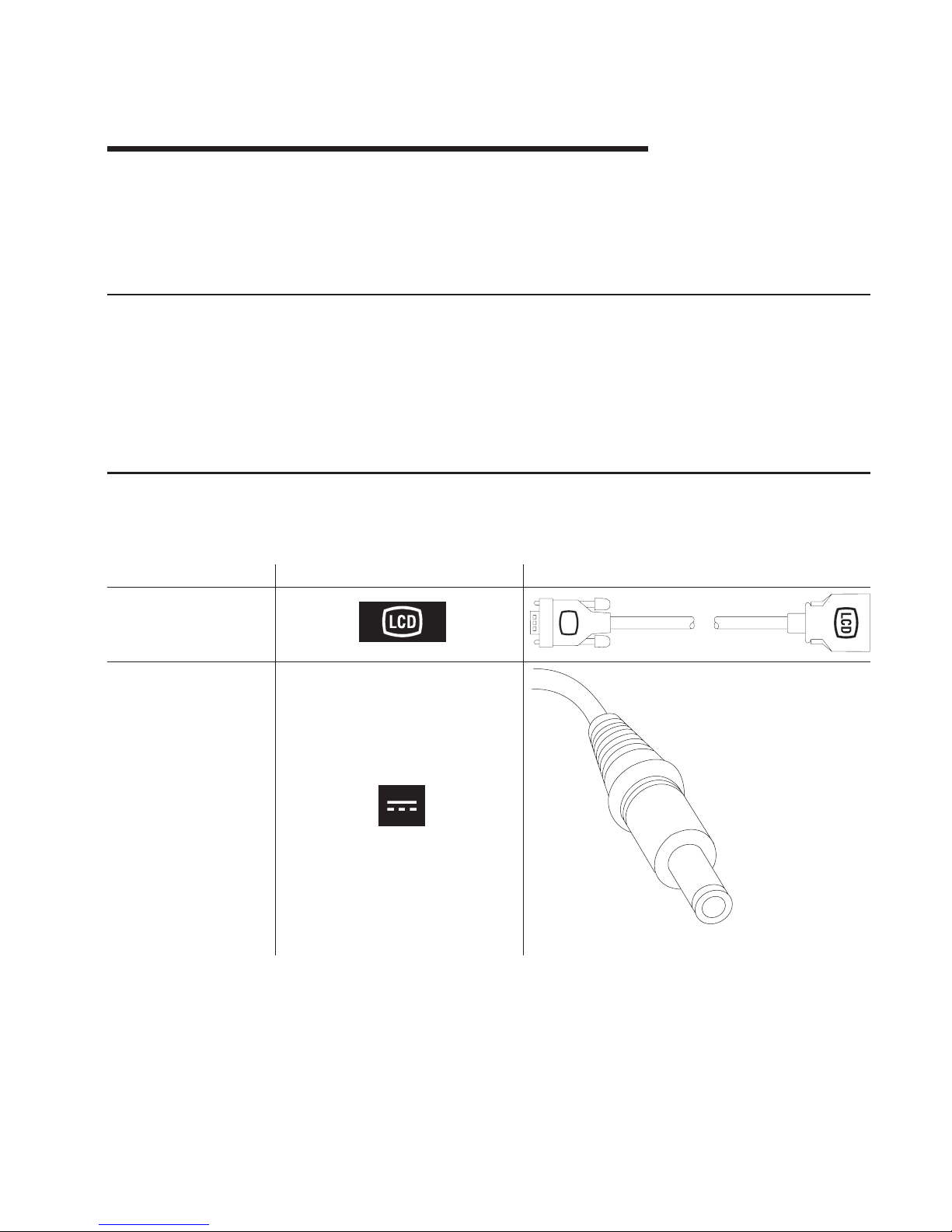
Table 3-1 summarizes the cable connections for the 4820 SurePoint Solution.
Table 3-1. Cable types and icons
Type
Identifying Icon
Cable
Analog
Power
. ©
Copyright IBM Corp. 1999, 2003
3-1
Page 42

Table 3-1. Cable types and icons (continued)
Type
Identifying Icon
Cable
Multi-connector cable for
model 42T
4
PS/2 keyboard connector
(for diagnostics)
RS-232 Touch
RS-232
(Touch/MSR/keypad)
RS-232 MSR
Host end 4820 end
Keypad /
Keyboard
Multi-connector cable for
model 4FT
RS-232 Touch
RS-232
(Touch/MSR)
RS-232 MSR
Host end 4820 end
The following is a list of cables that require routing through the free-standing pedestal of
the 4820 SurePoint Solution:
v
Video
v
Power
v
Pointing device
Pedestal mounting
The 4820 SurePoint Solution models 42D, 42T, 4FT, and 4FD can be attached to a
free-standing pedestal. Optionally, you can mount the pedestal to the counter. A
mounting template is provided for installation of the pedestal (refer to Figure C-2 on
page C-2.) See “Mounting the distributed pedestal” on page A-1 for instructions.
Adjusting the display
This section summarizes the methods of adjusting the 4820 SurePoint Solution.
Brightness menu
Available when you press the minus or plus buttons.
OSD menu
The on-screen display menu appears when you press the minus and plus
buttons simultaneously. For additional information, see “Using the OSD menu”
on
page 7-1.
4820 Video Quality Test Pattern
This file is available from the Web support site. Use this file when the Auto
Adjust menu item fails to produce satisfactory results.
4820 42T/4FD POS Terminal Service diskette
This diskette is available from the Web support site and allows you to calibrate
the touch and test the MSR.
3-2
4820 SurePoint Solution System Reference
Page 43

Chapter 4. System diagnostics and scan codes
This section describes the diagnostics.
Using the 4820 42T/4FD POS Terminal Service diskette
The service diskette is available from the support Web site. Before you begin
diagnostics, ensure your connections are as following:
v
RS-232 touch connects to COM 1
v
RS-232 MSR connects to COM 2
After
you boot your system with the diskette, a menu appears that allows you to
calibrate the touch and test the MSR.
Using the OSD menu
The OSD menu allows you to adjust the display settings such as contrast, brightness,
clock phase, and image position.
To
open the OSD menu, press and hold the minus (−) and plus (+) buttons at the same
time. The following menu appears:
Auto Adjust
Manual Adjust
Brightness
Contrast
Information
Reset
______________________________
(+) Select
(-) Scroll
(+&-) Exit
Auto Adjust
Automatically adjusts the settings. Use this option when you install the display
and at other times when image quality degrades.
Manual Adjust
Allows you to regulate the clock, phase, and image position. See “Using
Manual Adjust” on page 4-2.
Brightness
Allows you to regulate the display’s brightness setting.
Contrast
Allows you to regulate the display’s contrast settings.
Information
Provides the current screen resolution, the horizontal, and the vertical sync
signal frequencies.
©
Copyright IBM Corp. 1999, 2003
4-1
Page 44

Reset Presents Yes or No dialogue box that allows you to reset the menu settings to
the default values.
Exiting the OSD Menu
To
exit the OSD menu, press the minus (−) and plus (+) buttons at the same time. The
system saves your values.
Exiting through time-out
The OSD menu times-out after approximately 20 seconds of inaction. The system does
not save the settings.
Using Manual Adjust
Normally, you do not need to use Manual Adjust since Auto Adjust sets the
parameters at the optimum default value. However, Manual Adjust allows you to:
v
Decrease the screen noise
v
Adjust the screen display position and size
To
reduce the noise, adjust the Phase and Clock parameters.
Keypad and scan code arrangement
Figure 4-1 on page 4-3 shows the key arrangement of the keypad and the scan code
definitions.
4-2
4820 SurePoint Solution System Reference
Page 45

F1
05
F005
6C
F06C
06
F006
75
F075
04
F004
7D
F07D
0C
F00C
14
F014
03
F003
6B
F06B
0B
F00B
73
F073
83
F083
74
F074
0A
F00A
11
F011
01
F001
69
F069
09
F009
72
F072
78
F078
7A
F07A
07
F007
29
F029
76
F076
70
F070
79
F079
4A
F04A
7B
F07B
7C
F07C
66
F066
5A
F05A
7
F5
4
F9
1
Esc
0
F2
8
F6
5
F10
2
+
/
F3
9
F7
6
F11
3
-
*
F4 S1
Ctrl
F8 S2
Alt
F12
SP
BkSP
Ent
Scan code definition
Figure 4-1. Keypad and scan code arrangement. Upper code denotes “make” and lower
denotes “break” code
Chapter 4. System diagnostics and scan codes
4-3
Page 46

4-4
4820 SurePoint Solution System Reference
Page 47

Part 3. IBM 4820 SurePoint Solution Models 46D, 46R, 46T
Chapter 5. System specifications and planning information . . . . . . . 5-1
Product summary . . . . . . . . . . . . . . . . . . . . . . . 5-1
Hardware features . . . . . . . . . . . . . . . . . . . . . . 5-1
Display . . . . . . . . . . . . . . . . . . . . . . . . . 5-1
Video interface . . . . . . . . . . . . . . . . . . . . . . 5-1
POS input/output (I/O) . . . . . . . . . . . . . . . . . . . . 5-2
Indicators and user controls . . . . . . . . . . . . . . . . . . 5-2
External ports . . . . . . . . . . . . . . . . . . . . . . . 5-2
Power management . . . . . . . . . . . . . . . . . . . . . . 5-2
Transition diagram . . . . . . . . . . . . . . . . . . . . . 5-3
Optional features . . . . . . . . . . . . . . . . . . . . . . . 5-3
Keypads . . . . . . . . . . . . . . . . . . . . . . . . . 5-3
Manager’s keylock . . . . . . . . . . . . . . . . . . . . . 5-3
Magnetic stripe reader (MSR) . . . . . . . . . . . . . . . . . . 5-3
Audio kit . . . . . . . . . . . . . . . . . . . . . . . . . 5-3
System software . . . . . . . . . . . . . . . . . . . . . . . 5-4
Supported modes . . . . . . . . . . . . . . . . . . . . . 5-4
Windows setting requirement . . . . . . . . . . . . . . . . . . 5-4
Chapter 6. Installation and operating information . . . . . . . . . . . 6-1
Option installation . . . . . . . . . . . . . . . . . . . . . . 6-1
Cable connections and routing . . . . . . . . . . . . . . . . . . 6-1
Pedestal mounting . . . . . . . . . . . . . . . . . . . . . . 6-2
Adjusting the display . . . . . . . . . . . . . . . . . . . . . 6-3
Chapter 7. System diagnostics . . . . . . . . . . . . . . . . . 7-1
Using the OSD menu . . . . . . . . . . . . . . . . . . . . . 7-1
Exiting the OSD Menu . . . . . . . . . . . . . . . . . . . . 7-1
Exiting through time-out . . . . . . . . . . . . . . . . . . 7-1
Using Manual Adjust . . . . . . . . . . . . . . . . . . . . . 7-2
Chapter 8. Connector pinouts . . . . . . . . . . . . . . . . . . 8-1
Video connector assignments . . . . . . . . . . . . . . . . . . . 8-1
RS485 pin connector assignments . . . . . . . . . . . . . . . . . 8-1
Power supply pin voltages . . . . . . . . . . . . . . . . . . . . 8-2
©
Copyright IBM Corp. 1999, 2003
Page 48

Models 46D, 46R, 46T
4820 SurePoint Solution System Reference
Page 49

Chapter 5. System specifications and planning information
This section summarizes the specifications of the 4820 SurePoint Solution, and
provides details on the optional hardware and software features.
Product summary
This section summarizes the specifications of 4820 SurePoint Solution.
Table 5-1. 4820 SurePoint Solution Hardware Features
Hardware Features
Description
Keypad
v A
32-key with ISO 3 track MSR or a 32-key
with JUCC MSR
MSR
ISO 3 track or JUCC
Pointing Device
v
PS/2 mouse type
Mounting
Integrated, integrated touch, distributed;
free-standing, or VESA bracket
Security
Manager’s keylock
Cables
v
RS485 , 0.8m, 1.8m or 3.8m
v
Analog , 0.8m, 1.8m or 3.8m
Power
v
External power brick
Table 5-2. 4820 SurePoint Solution System Software
System Software
POSS Drivers
You can obtain the appropriate software for your 4820
SurePoint Solution from the IBM Retail Store Solutions Web
site: www.ibm.com/solutions/retail/store (from the store page,
click on Support).
Maintenance package: service
diskette, publications
Hardware features
This section describes the physical features of the 4820 SurePoint Solution.
Display
The 4820 SurePoint Solution provides a 12.1 inch TFT SVGA display with 800 x 600
resolution. The display can provide up to 16.7 million colors, subject to host PC
limitations. Autoscaling is standard with VGA support.
Video interface
The 4820 SurePoint Solution, models 46D and, 46T, have an analog interface.
©
Copyright IBM Corp. 1999, 2003
5-1
Page 50

POS input/output (I/O)
The 4820 SurePoint Solution provides the following Point-of-Sale I/O devices:
v
Touch screen, key pad, and MSR
v
RS485 I/O
v
Pointing device; mouse
Indicators and user controls
The 4820 SurePoint Solution provides the following indicators:
v
Dual color LED:green power-on indicator; orange backlight dim or off
The
4820 SurePoint Solution provides the following user controls:
v
Power on/Resume
v
Brightness
External ports
The 4820 SurePoint Solution provides the following external ports:
v
RS485 touch, keypad, MSR input: 4-pin SDL
v
Video: MDR 20-pin
v DC
power input
v
Keypad/MSR (custom)
Power management
Power management is through DPMS and complies with the VESA standard. The table
below describes the power management states.
Table 5-3. Power Management States
Operation Mode
Analog
Off
5W
DPMS Off
5W
DPMS Suspend
5W
DPMS Standby
5W On
20W
5-2
4820 SurePoint Solution System Reference
Page 51

Transition diagram
The diagram below shows the transition between standby and normal operation.
Normal
Standby DC-off
Switch-off
DPMS on
Switch (toggle)*
Switch (toggle)
*No Video/DPMS by OSD
DC-out
DC-out
DC-out
DC-in
*DC-in
DPMS off
Optional features
This section describes the optional features available on the 4820 SurePoint Solution.
Keypads
An
optional 32-key keypad is available with either an ISO 3 track MSR or JUCC MSR.
Manager’s keylock
As an
option, the 4820 SurePoint Solution allow for a two-position manager’s keylock.
Magnetic stripe reader (MSR)
The two MSRs available are the International Organization for Standardization (ISO) 3track and the Japanese Unified Cash Card (JUCC) 2-head.
Audio kit
The audio kit option is available for all models of the 4820 SurePoint Solution. This kit
provides an integrated microphone, and stereo speakers molded into a single unit. This
unit replaces the mounting cover.
Note:
The audio kit requires a sound card with amplified output (speaker out). Sound
cards with these characteristics are Sound Blaster sound card PCI128 or
Yamaha sound card WF192XG.
Figure
5-1. Power Management Transition Diagram
Chapter 5. System specifications and planning information
5-3
Page 52

System software
You can obtain the appropriate software for the 4820 SurePoint Solution from the IBM
Retail Sore Solutions Web site: www.ibm.com/solutions/retail/store/ (from the store
page, click on Support).
v
Terminal hardware folder
–
4820 downloads
-
4694/4695/ISA Service Diskette, version 5.33 or later
–
Peripheral drivers folder
-
POSS for DOS download
-
OPOS drivers download
-
Java POS drivers download
Supported modes
Table 5-4 lists the supported modes and frequencies.
Table 5-4. Supported Modes
Modes
Supported Frequencies
SVGA
56, 60, 72, 75 Hz
Graphics adapter (VGA)
60, 70, 72, 75 Hz
Windows setting requirement
When you install the 4820 SurePoint Solution with the Windows operating system,
ensure that the display setting is 800 x 600. The 4820 operates at a VGA setting of 640
x
480, but the image is not optimized.
5-4
4820 SurePoint Solution System Reference
Page 53

Chapter 6. Installation and operating information
This section summarizes the installation and operation methods of the 4820 SurePoint
Solution. IBM recommends that you refer to the IBM 4820 SurePoint Solution
Installation and Service Guide for complete instructions.
Option installation
IBM recommends that you install the options for the 4820 SurePoint Solution in the
following order:
1.
Manager’s keylock
2.
Keypad and MSR
3.
Pointing device
4.
Audio kit
Note:
You can attach either the MSR or the keypad with MSR to the 4820 SurePoint
Solution.
Cable connections and routing
Figure 6-1 shows the view of the cable connections for the 4820 SurePoint Solution.
Table 6-1. Summary of Cable Types, Identifying Icons, and Examples
Type
Identifying Icon
Cable
Analog
Analog
(Video)
Power
R 485
(Touch/Keypad/MSR)
S
Figure 6-1. View of Model 46D, 46T Cable Connections
©
Copyright IBM Corp. 1999, 2003
6-1
Page 54

Table 6-1. Summary of Cable Types, Identifying Icons, and Examples (continued)
Type
Identifying Icon
Cable
Audio (icon located on
audio kit)
RS485
4
Cable not shown.
Power
.
The following is a list of cables that require routing through the distributed and
integrated pedestal of the 4820 SurePoint Solution:
v
Video
v
Power
v
RS485 (Touch/Keypad/MSR)
v
Pointing device
v
Audio cables (when applicable)
Pedestal mounting
The 4820 SurePoint Solution can be attached to either a distributed, integrated,
free-standing, or VESA mounting. However, you must prepare the mounting surface for
the installation of the distributed pedestal. See “Mounting the distributed pedestal” on
page A-1 for instructions.
6-2
4820 SurePoint Solution System Reference
Page 55

Adjusting the display
This section summarizes the methods of adjusting the 4820 SurePoint Solution, models
46D, 46T.
Brightness menu
Available when you press the minus or plus buttons.
OSD menu
The on-screen display menu appears when you press the minus and plus
buttons simultaneously. For additional information, see “Using the OSD menu”
on
page 7-1.
Auto Adjust Assistance file
This file is available from the Web support site. Use this file when the Auto
Adjust menu item fails to produce satisfactory results.
Chapter 6. Installation and operating information
6-3
Page 56

6-4
4820 SurePoint Solution System Reference
Page 57

Chapter 7. System diagnostics
This section describes the diagnostics.
Using the OSD menu
The OSD menu allows you to adjust the display settings such as contrast, brightness,
clock phase, and image position.
To
open the OSD menu, press and hold the minus (−) and plus (+) buttons at the same
time. The following menu appears:
Auto Adjust
Manual Adjust
Brightness
Contrast
Information
Reset
______________________________
(+) Select
(-) Scroll
(+&-) Exit
Auto Adjust
Automatically adjusts the settings. Use this option when you install the display
and at other times when image quality degrades.
Manual Adjust
Allows you to regulate the clock, phase, and image position. See “Using
Manual Adjust” on page 7-2.
Brightness
Allows you to regulate the display’s brightness setting.
Contrast
Allows you to regulate the display’s contrast settings.
Information
Provides the current screen resolution, the horizontal, and the vertical sync
signal frequencies.
Reset Presents Yes or No dialogue box that allows you to reset the menu settings to
the default values.
Exiting the OSD Menu
To
exit the OSD menu, press the minus (−) and plus (+) buttons at the same time. The
system saves your values.
Exiting through time-out
The OSD menu times-out after approximately 20 seconds of inaction. The system does
not save the settings.
©
Copyright IBM Corp. 1999, 2003
7-1
Page 58

Using Manual Adjust
Normally, you do not need to use Manual Adjust since Auto Adjust sets the
parameters at the optimum default value. However, Manual Adjust allows you to:
v
Decrease the screen noise
v
Adjust the screen display position and size
To
reduce the noise, adjust the Phase and Clock parameters.
7-2
4820 SurePoint Solution System Reference
Page 59

Chapter 8. Connector pinouts
This section describes the connector pinouts.
Video connector assignments
Table 8-1. Cable Connector Pinouts
4694 system connector
Description
4820 connector
1
Red (coaxial )
2 6
Coaxial (shield)
1 2
Green (coaxial)
4 7
Coaxial (shield)
3 3
Blue (coaxial)
6 8
Coaxial (shield)
5 13
White
7 10
Black
8 14
Green
9 5
Red
10 15
Yellow
11 12
Brown
12 11
Green
13 4
Orange
14 9
Purple
15
RS485 pin connector assignments
Pin
Description
1
Reserved
2
Serial I/O A
3
Serial I/O B
4
Reserved
©
Copyright IBM Corp. 1999, 2003
8-1
Page 60

Power supply pin voltages
Table 8-2 describes the power supply pin voltages and provides an example of the
connector.
Table 8-2. Power Supply Pin Voltages
Pin
Voltage
Example
1
+14.5 to +17.0
2
1
2
Ground
8-2
4820 SurePoint Solution System Reference
Page 61

Part 4. IBM 4820 SurePoint Solution Models 48D, 48T
Chapter 9. System specifications and planning information . . . . . . . 9-1
Product summary . . . . . . . . . . . . . . . . . . . . . . . 9-1
Hardware features . . . . . . . . . . . . . . . . . . . . . . 9-1
Display . . . . . . . . . . . . . . . . . . . . . . . . . 9-1
Video interface . . . . . . . . . . . . . . . . . . . . . . 9-1
POS input/output (I/O) . . . . . . . . . . . . . . . . . . . . 9-2
USB devices and hot swapping . . . . . . . . . . . . . . . . 9-2
Indicators and user controls . . . . . . . . . . . . . . . . . . 9-2
External ports . . . . . . . . . . . . . . . . . . . . . . . 9-2
Power management . . . . . . . . . . . . . . . . . . . . . . 9-2
Managing the screen savers . . . . . . . . . . . . . . . . . . 9-3
Optional features . . . . . . . . . . . . . . . . . . . . . . . 9-3
Keypads . . . . . . . . . . . . . . . . . . . . . . . . . 9-3
Manager’s keylock . . . . . . . . . . . . . . . . . . . . . 9-3
Magnetic stripe reader (MSR) . . . . . . . . . . . . . . . . . . 9-3
Audio kit . . . . . . . . . . . . . . . . . . . . . . . . . 9-3
System software . . . . . . . . . . . . . . . . . . . . . . . 9-4
Chapter 10. Installation and operating information . . . . . . . . . . 10-1
Option installation . . . . . . . . . . . . . . . . . . . . . . 10-1
Cable connections and routing . . . . . . . . . . . . . . . . . . 10-1
Adjusting the display . . . . . . . . . . . . . . . . . . . . . 10-2
Brightness controls . . . . . . . . . . . . . . . . . . . . . 10-2
MicroTouch TouchWare . . . . . . . . . . . . . . . . . . . 10-2
Chapter 11. System diagnostics and pinout connections . . . . . . . . 11-1
Diagnostics for model 48D (non-touch) . . . . . . . . . . . . . . . 11-1
Using the MicroTouch TouchWare . . . . . . . . . . . . . . . . . 11-1
Locating the touchscreen controller information . . . . . . . . . . . 11-1
Controller type . . . . . . . . . . . . . . . . . . . . . 11-1
Firmware version . . . . . . . . . . . . . . . . . . . . 11-1
Touchscreen status . . . . . . . . . . . . . . . . . . . . 11-1
Touchscreen properties dialog box . . . . . . . . . . . . . . . . 11-2
Calibrating the touchscreen . . . . . . . . . . . . . . . . . . 11-2
Customizing the touch response mode . . . . . . . . . . . . . . 11-3
Selecting a touch mode . . . . . . . . . . . . . . . . . . . 11-4
Configuring the touch sound . . . . . . . . . . . . . . . . . . 11-4
Customizing the touch sound . . . . . . . . . . . . . . . . 11-5
Connector pinouts . . . . . . . . . . . . . . . . . . . . . . 11-5
USB power voltage . . . . . . . . . . . . . . . . . . . . . 11-5
©
Copyright IBM Corp. 1999, 2003
Page 62

Models 48D, 48T
4820 SurePoint Solution System Reference
Page 63

Chapter 9. System specifications and planning information
This section summarizes the specifications of the 4820 SurePoint Solution, and
provides details on the optional hardware and software features.
Product summary
This section summarizes the specifications of 4820 SurePoint Solution.
Table 9-1. 4820 SurePoint Solution Hardware Features
Hardware Features
Description
Keypad
One of the following:
v
32-key with ISO 3 track MSR
v
32-key with JUCC MSR
MSR
ISO 3 track or JUCC
Pointing Device
USB pointing device
Mounting
Integrated or distributed; VESA bracket
Multi-media
Audio kit with 1.8m or 3.8m attachment cables
Security
Manager’s keylock
Cables
v
DVI, 0.8m, 1.8m, 3.8m
v
USB, 0.7m, 1.8m, 3.8m
Power
Powered USB connector
Table 9-2. 4820 SurePoint Solution System Software
System Software
POSS Drivers, MicroTouch
TouchWare
You can obtain the appropriate software for your 4820
SurePoint Solution from the IBM Retail Store Solutions Web
site: www.ibm.com/solutions/retail/store (from the store page,
click on Support).
Maintenance package: service
diskette, publications
Hardware features
This section describes the physical features of the 4820 SurePoint Solution.
Display
The 4820 SurePoint Solution provides a 12.1 inch TFT SVGA display with 800 x 600
resolution. Although limited by the host PC, the display can provide up to 257k colors.
Autoscaling is dependent on the host pc.
Video interface
The 4820 SurePoint Solution model 48D, 48T provides a digital interface.
©
Copyright IBM Corp. 1999, 2003
9-1
Page 64

POS input/output (I/O)
The 4820 SurePoint Solution provides the following Point-of-Sale I/O devices:
v
Touch screen, key pad, and MSR
v
USB I/O
v
Pointing device; mouse
USB devices and hot swapping
Universal Serial Bus (USB) is an open industry standard (IEEE and EIA) for a 12 Mbps
serial bus. This standard makes system functionality easy to expand.
Systems that are USB-compliant detect when you add or remove a USB peripheral
device. This process is known as enumeration. Enumeration identifies and manages the
necessary device state changes during the attachment and removal. The USB system
automatically configures each added USB device as soon as the device is physically
attached to the system. You no longer need to install drivers or configure dip switches,
jumpers, IRQ settings, and I/O addresses. This feature of USB is referred to as hot
swapping, plug and play, hot plugging, or hot insertion.
Indicators and user controls
The 4820 SurePoint Solution provides the following indicators and user controls:
v
Dual color LED:green power-on/resume indicator; orange backlight dim (system off)
v
Power on/Resume
v
Brightness
External ports
The 4820 SurePoint Solution provides the following external ports:
v
USB touch, keypad, MSR input: 2 standard (non-powered) USB output
v
Video 26-pin miscellaneous data record (MDR) input
v DC
input on
v
Keypad/MSR (custom)
Power management
Power management is through DPMS and complies with the VESA standard. The table
below describes the power management states.
Table 9-3. Power Management States
Operation Mode
RS485/Analog
USB/Digital
Off
5W 3W
DPMS Off
5W 3W
DPMS Suspend
5W 3W
DPMS Standby
5W 3W On
20W
15W
The events for power management are as follows:
9-2
4820 SurePoint Solution System Reference
Page 65

Suspend/Resume switch
This switch toggles the power management state.
Touchscreen/Keypad sleep timer
This timer is activated when the time set elapses after the last keypad or touch
panel access.
Touchscreen/Keypad touch
The wake signal is activated by touching the touchscreen or keypad when in
standby operation mode.
DPMS DPMS controls the power management state according to the sync status.
Managing the screen savers
To
ensure that your operating system screen saver works with the screen saver of the
4820 SurePoint Solution, IBM recommends the following changes:
Note:
These change will ensure that PosNtouchScreenSaverTime operates properly.
The control panel of your operating system contains the following programs that affect
the screen saver function:
Display
An
icon that resides in Control Panel represent display. Ensure that the screen
saver of the Display is set to None.
Power management (if applicable)
An
icon that resides in Control Panel represent power management. Ensure
that the Turn Off Monitor timer is set to Never.
Optional features
This section describes the optional features available on the 4820 SurePoint Solution.
Keypads
An
optional 32-key keypad is available with either an ISO 3 track MSR or JUCC MSR.
Manager’s keylock
As an
option, the 4820 SurePoint Solution allows for a two-position manager’s keylock.
Magnetic stripe reader (MSR)
The two MSRs available are the International Organization for Standardization (ISO) 3track and the Japanese Unified Cash Card (JUCC) 2-head.
Audio kit
The audio kit option is available for all models of the 4820 SurePoint Solution. This kit
provides an integrated microphone, and stereo speakers molded into a single unit. This
unit replaces the mounting cover.
Chapter 9. System specifications and planning information
9-3
Page 66

Note: The audio kit requires a sound card with amplified output (speaker out). Sound
cards with these characteristics are Sound Blaster sound card PCI128 or
Yamaha sound card WF192XG.
System software
You can obtain the appropriate software for the 4820 SurePoint Solution from the IBM
Retail Store Solutions Web site: www.ibm.com/solutions/retail/store/ (from the store
page, click on Support).
v
Peripheral drivers folder
–
POSS for Windows download, which includes the IBM POS Device Diagnostics
–
POSS for DOS download
–
OPOS drivers download
–
Java POS drivers download
–
MicroTouch Touchware
9-4
4820 SurePoint Solution System Reference
Page 67
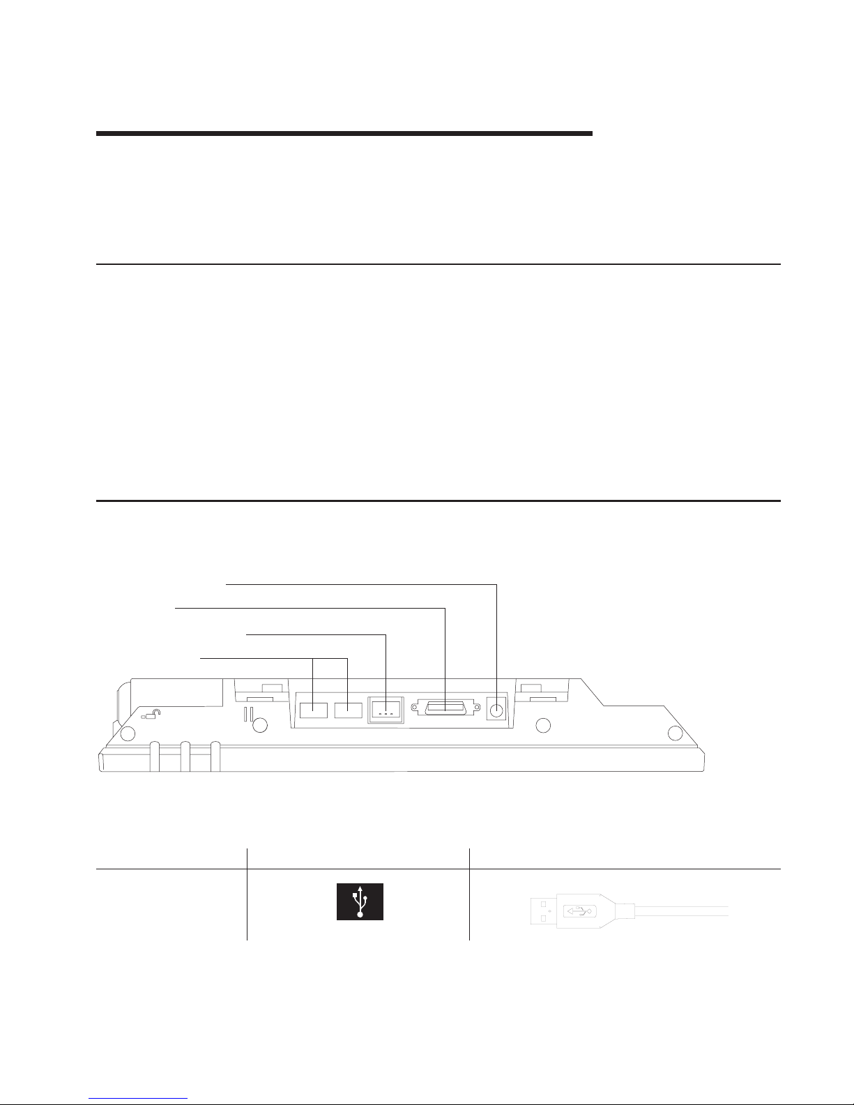
Chapter 10. Installation and operating information
This section summarizes the installation and operation methods of the 4820 SurePoint
Solution. IBM recommends that you refer to the IBM 4820 SurePoint Solution
Installation and Service Guide for complete instructions.
Option installation
IBM recommends that you install the options for the 4820 SurePoint Solution in the
following order:
1.
Manager’s keylock
2.
Keypad and MSR
3.
Pointing device
4.
Audio kit
Note:
You can attach either the MSR or the keypad with MSR to the 4820 SurePoint
Solution.
Cable connections and routing
Figure 10-1 shows the view of the cable connections for the 4820 SurePoint Solution.
Table 10-1. Summary of Cable Types, Identifying Icons, and Examples
Type
Identifying Icon
Cable
USB out
AUX: power in
Video
USB in / power in
USB (out)
Figure 10-1. View of Model 48D, 48T Cable Connections
©
Copyright IBM Corp. 1999, 2003
10-1
Page 68

Table 10-1. Summary of Cable Types, Identifying Icons, and Examples (continued)
Type
Identifying Icon
Cable
DVI
Audio (icon located on
audio kit)
USB power input
4 .
Auxiliary power input
Note: Power is not necessary when connecting to
the SurePOS 700 Series.
The following is a list of cables that require routing through the distributed and
integrated pedestal of the 4820 SurePoint Solution:
v
Power
v
USB (Touch/Keypad/MSR)
v
Pointing device
v
Audio cables (when applicable)
Adjusting the display
This section summarizes the methods of adjusting the 4820 SurePoint Solution, models
48D and 48T.
Brightness controls
Pressing the plus or the minus keys adjusts the screen brightness.
MicroTouch TouchWare
The MicroTouch Touchware software driver allows you to calibrate the touch screen,
select modes, and configure the touch sound and cursor positions.
10-2
4820 SurePoint Solution System Reference
Page 69

Chapter 11. System diagnostics and pinout connections
The 4820 SurePoint Solution models 48D and 48T connect through USB and to the
IBM SurePOS 700 Series system unit. This section describes diagnostic information
and pinout connections for models 48D and 48T.
Diagnostics for model 48D (non-touch)
The IBM POS Device Diagnostics provides diagnostic information and problem
solutions for the 4820 SurePoint Solution, model 48D. This program installs with the
POSS for Windows software. The IBM POS Device Diagnostics contains an extensive
help program, which enables you to diagnose and resolve problems with the MSR,
keypad, and pointing device.
Using the MicroTouch TouchWare
This section describes how to calibrate the touchscreen and customize the touch
response.
Locating the touchscreen controller information
The touchscreen controller information window provides information about the type,
firmware version, and status of your touchscreen. Locate the controller by selecting the
Hardware tab from the TouchWare.
Controller type
The Controller Type field displays the model name of your touchscreen controller.
Firmware version
The Firmware Version field displays the revision number of the firmware in your
TouchWare controller.
Touchscreen status
The Touchscreen Status field provides valuable information about whether the
touchscreen hardware is operating properly. Table 11-1 lists the possible messages that
are displayed in the Status field:
Table 11-1. Touchscreen Status Messages
Message
Definition
Recommended Action
OK
Touchscreen found and
operational
None
©
Copyright IBM Corp. 1999, 2003
11-1
Page 70

Table 11-1. Touchscreen Status Messages (continued)
Message
Definition
Recommended Action
A/D Error
Touchscreen hardware error
Replace unit
ASIC Error
Hardware Error
PWM
NOVRAM Error
Checksum error in NOVRAM,
using defaults
Random access memory
(RAM) Error
Checksum error in read-only
memory (ROM)
Touchscreen Not Found
TouchWare was unable to
communicate with the
touchscreen
Check that all cables for
correctly connected.
Touchscreen properties dialog box
Problem
Recommended Action
You have touch, but cannot open the
Touchscreen Properties dialog box.
Only the touchscreen USB driver was installed
and the TouchWare was not completely
installed. Unplug your touchscreen from the
USB port and reinstall the TouchWare.
The Touchscreen Properties dialog box always
opens to the Hardware tab
The TouchWare is unable to find or
communicate with the touchscreen controller.
v
Check the Controller Information box on the
Hardware tab. If the OK message displays,
contact technical support.
v If
the message NOT FOUND displays, review
the cable connections
Calibrating the touchscreen
Calibration defines the dimensions and center of the active area of the touchscreen.
Calibration also aligns the touchscreen-active area to the underlying . Calibrate your
touchscreen when:
v
You initially install the TouchWare
v
The cursor does not accurately follow your finger movement
v
You change the resolution or mode
v
You adjust the touchscreen controller frequency using the Stabilize Cursor function
v
You enable or disable the Filtering option
Note:
During calibration, the lift-off position of your touch, and not the touchdown
position, determines the calibration point. If your finger is not correctly positioned
on
the screen, you can slide your finger to the center of the target. Hold your
finger as still as possible after you reach the calibration point. Do not use any
swinging motion during lift-off.
11-2
4820 SurePoint Solution System Reference
Page 71

1.
Allow the 4820 SurePoint Solution to warm-up at least one-half hour before you
begin calibration.
2.
Open the Touchscreen Properties dialog box. Select the Calibrate tab.
3.
Click Calibrate. A calibration target appears in the lower left corner of the screen.
4.
Touch the touchscreen and position your fingertip to completely cover the target.
Hold your touch for at least three seconds.
5.
Lift your finger off of the screen when you are satisfied that you accurately touched
the target.
6.
Touch the touchscreen and position your fingertip to completely cover the next
target. Hold your touch for at least three seconds.
7.
Lift your finger off of the screen. The program saves the new calibration values and
displays the following dialog box:
8.
Test the calibration as follows:
a.
Touch random points on the screen and check that the system locates the
cursor underneath your finger.
b.
Drag your finger across the screen. Check that the cursor accurately follows
your movements.
c.
Touch each corner and along each edge of the screen. Check that the cursor
reaches the full image area and that you can touch and activate all icons and
menus across the entire screen
9.
If
any part of the test fails, calibrate the touchscreen again.
Customizing the touch response mode
The touch response mode defines how your touch emulates the functions of a mouse.
For example, you can define a touch to produce a button down (pressing a mouse
button) or button up (releasing the mouse button). Touch modes also define how your
touch produces a mouse click and double click. TouchWare allows the following touch
modes:
Desktop (default)
The system moves the cursor to the touch point, but does not generate a
button down as long as you continue to slide your finger around the screen.
When you pause and hold your finger steady, the system generates a mouse
button down. You can now slide your finger around the screen with this
position. When you lift your finger, the system generates a button up.
Drawing
The system moves the cursor to the touch point and immediately generates a
button down. You can slide your finger around the screen with the button held
down. When you lift your finger, the system generates a button up.
Button The system moves the cursor to the touch point and immediately generates a
button down and up (a click). To drag, slide your finger around the screen
(button down). When your lift your finger, the system generates a button up.
Click The system moves the cursor to the touch point and then immediately
generates a button down and up (a click). Click mode does not generate a
second button down, does not support drag and does not generate a mouse
event on finger lift-off.
Chapter 11. System diagnostics and pinout connections
11-3
Page 72

Lift-off The system moves the cursor to the touch point, but does not generate a
mouse button down. You can slide your finger around the screen and your
movements are followed; however, the system generates mouse move events
only. Lifting your finger off of the screen generates a mouse button down. The
system then waits for a system-defined time delay, and generates a button up.
Drag is not supported; however lift-off mode is useful for applications that
requires greater accuracy.
Touchdown
The system moves the cursor to the touch point, generates a button down,
waits for a system-defined time delay, and generates a button up. The system
does not generate a mouse event on finger lift-off. Drag is not supported in this
mode.
Table
11-2 describes how to click, double click, and drag, using the different touch
modes.
Table 11-2. Summary of Touch Modes
Touch Mode
How to Click
How to Double-Click How to Drag
Desktop
Touch the object and
lift your finger.
Touch twice in quick
succession in the same
place.
Touch the object,
pause briefly, and slide
your finger.
Drawing
Button
Touch the object
Click
Not supported
Lift-off
Touchdown
Touch the object.
Provides a pause for
user to receive visual
feedback that a button
was pressed and
released.
Selecting a touch mode
Use the Touch Settings tab or the Special tab to select a touch mode. Some touch
modes require you to select options on both tabs.
Configuring the touch sound
You can configure your touchscreen so that a beep is produced when you touch the
screen, or when you remove your touch. To enable or disable the touch sound:
v
Select the Touch Settings tab to access the Touch Sound option.
v
Click Beep to cycle through the choices:
–
Beep on touchdown produces a beep when you touch the screen
–
Beep on lift-off produces a beep when you lift your finger off the screen.
–
Beep off produces no sound when you touch the screen. This is the default
setting.
11-4
4820 SurePoint Solution System Reference
Page 73

Customizing the touch sound
If
you enable the touch sound, you can customize the frequency, or pitch, and duration
of
the touch sound. To customize the touch sound:
v
Select the Special tab to access the Custom Touch Sound options.
v
Click the right and left arrows to change the frequency, or pitch, and duration of the
touch sound. The range of settings are as follows:
–
Frequency: 200 to 5000 Hz in 10 Hz increments; the default is 1500 Hz
–
Duration: 50 to 600 mx in 10 mx increments; the default is 200 mx
Connector pinouts
This section describes the connector pinouts.
USB power voltage
The powered USB cable should provide approximately 12 volts DC to the 4820
SurePoint Solution. Table 11-3 describes the pins and provides an example of the USB
cable.
Table 11-3. USB Power and Voltage
Pin
DC
Voltage
Example
1
4.75 to 5.25 V
Pin 4
Pin 5
Pin 6
Pin 3
Pin 2
Pin 1
2, 3
Data
4, 5
Ground
6
10.8 to 12.6 V
Chapter 11. System diagnostics and pinout connections
11-5
Page 74

11-6
4820 SurePoint Solution System Reference
Page 75

Part 5. IBM 4820 SurePoint Solution Models 4WT, 4GT
Chapter 12. System specifications and planning information . . . . . . 12-1
Product summary . . . . . . . . . . . . . . . . . . . . . . 12-1
Hardware features . . . . . . . . . . . . . . . . . . . . . . 12-1
Display . . . . . . . . . . . . . . . . . . . . . . . . . 12-1
Video interface . . . . . . . . . . . . . . . . . . . . . . 12-2
POS input/output (I/O) . . . . . . . . . . . . . . . . . . . . 12-2
USB devices and hot swapping . . . . . . . . . . . . . . . 12-2
Indicators and user controls . . . . . . . . . . . . . . . . . . 12-2
External ports . . . . . . . . . . . . . . . . . . . . . . 12-2
Power management . . . . . . . . . . . . . . . . . . . . . 12-2
Managing the screen savers . . . . . . . . . . . . . . . . . 12-3
Optional features . . . . . . . . . . . . . . . . . . . . . . 12-3
Keypads . . . . . . . . . . . . . . . . . . . . . . . . 12-3
Manager’s keylock . . . . . . . . . . . . . . . . . . . . . 12-3
Magnetic stripe reader (MSR) . . . . . . . . . . . . . . . . . 12-4
Audio kit . . . . . . . . . . . . . . . . . . . . . . . . 12-4
System software . . . . . . . . . . . . . . . . . . . . . . 12-4
Chapter 13. Installation and operating information . . . . . . . . . . 13-1
Option installation . . . . . . . . . . . . . . . . . . . . . . 13-1
Cable connections and routing . . . . . . . . . . . . . . . . . . 13-1
Adjusting the display . . . . . . . . . . . . . . . . . . . . . 13-2
Brightness controls . . . . . . . . . . . . . . . . . . . . . 13-2
MicroTouch TouchWare . . . . . . . . . . . . . . . . . . . 13-2
Chapter 14. System diagnostics and pinout connections . . . . . . . . 14-1
Using the MicroTouch TouchWare . . . . . . . . . . . . . . . . . 14-1
Locating the touchscreen controller information . . . . . . . . . . . 14-1
Controller type . . . . . . . . . . . . . . . . . . . . . 14-1
Firmware version . . . . . . . . . . . . . . . . . . . . 14-1
Touchscreen status . . . . . . . . . . . . . . . . . . . . 14-1
Touchscreen properties dialog box . . . . . . . . . . . . . . . 14-2
Calibrating the touchscreen . . . . . . . . . . . . . . . . . . 14-2
Customizing the touch response mode . . . . . . . . . . . . . . 14-3
Selecting a touch mode . . . . . . . . . . . . . . . . . . . 14-4
Configuring the touch sound . . . . . . . . . . . . . . . . . . 14-4
Customizing the touch sound . . . . . . . . . . . . . . . . 14-4
Connector pinouts . . . . . . . . . . . . . . . . . . . . . . 14-4
USB power voltage . . . . . . . . . . . . . . . . . . . . . 14-4
©
Copyright IBM Corp. 1999, 2003
Page 76

Models 4WT, 4GT
4820 SurePoint Solution System Reference
Page 77

Chapter 12. System specifications and planning information
This section summarizes the specifications of the 4820 SurePoint Solution, and
provides details on the optional hardware and software features.
Product summary
This section summarizes the specifications of 4820 SurePoint Solution.
Table 12-1. 4820 SurePoint Solution Hardware Features
Hardware Features
Description
Keypad
Either of the following:
v
32-key with ISO 3 track MSR
v
32-key with JUCC MSR
MSR
ISO 3 track or JUCC
Pointing device
USB pointing device
Mounting
Integrated or distributed; VESA bracket
Multimedia
Audio kit with 1.8m or 3.8m attachment cables
Security
Manager’s keylock
Cables
v
Analog video, 0.8m, 1.8m, 3.8m
v
USB, 0.7m, 1.8m, 3.8m
Power
Either of the following:
v
Powered USB connector
v
External power brick
Table 12-2. 4820 SurePoint Solution System Software
System Software
POSS Drivers, MicroTouch
TouchWare
You can obtain the appropriate software for your 4820
SurePoint Solution from the IBM Retail Store Solutions Web
site: www.ibm.com/solutions/retail/store/ (from the store page,
click on Support).
Maintenance package: service
diskette, publications
Hardware features
This section describes the physical features of the 4820 SurePoint Solution.
Display
The 4820 SurePoint Solution provides a 12.1 inch TFT SVGA display with 800 x 600
resolution. Although limited by the host PC, the display can provide up to 257k colors.
Autoscaling is dependent on the host pc.
©
Copyright IBM Corp. 1999, 2003
12-1
Page 78

Video interface
The 4820 SurePoint Solution model 4WT, 4GT provides an analog interface.
POS input/output (I/O)
The 4820 SurePoint Solution provides the following Point-of-Sale I/O devices:
v
Touch screen, key pad, and MSR
v
USB I/O
v
Pointing device; mouse
USB devices and hot swapping
Universal Serial Bus (USB) is an open industry standard (IEEE and EIA) for a 12 Mbps
serial bus. This standard makes system functionality easy to expand.
Systems that are USB-compliant detect when you add or remove a USB peripheral
device. This process is known as enumeration. Enumeration identifies and manages the
necessary device state changes during the attachment and removal. The USB system
automatically configures each added USB device as soon as the device is physically
attached to the system. You no longer need to install drivers or configure dip switches,
jumpers, IRQ settings, and I/O addresses. This feature of USB is referred to as hot
swapping, plug and play, hot plugging, or hot insertion.
Indicators and user controls
The 4820 SurePoint Solution provides the following indicators and user controls:
v
Dual color LED:green power-on/resume indicator; orange backlight dim (system off)
v
Power on/Resume
v
Brightness
External ports
The 4820 SurePoint Solution provides the following external ports:
v
USB touch, keypad, MSR input (Touch + I/O models only)
v
Two standard (non-powered) USB output
v
Video 26-pin analog video input
v DC
input
Power management
Power management is through DPMS and complies with the VESA standard. The table
below describes the power management states.
Table 12-3. Power management states
Operating mode
USB/analog
Off
3W
DPMS Off
3W
DPMS Suspend
3W
12-2
4820 SurePoint Solution System Reference
Page 79

Table 12-3. Power management states (continued)
Operating mode
USB/analog
DPMS Standby
3W On
15W
The events for power management are as follows:
Suspend/Resume switch
This switch toggles the power management state.
Touchscreen/Keypad sleep timer
This timer is activated when the time set elapses after the last keypad or touch
panel access.
Touchscreen/Keypad touch
The wake signal is activated by touching the touchscreen or keypad when in
standby operation mode.
DPMS DPMS controls the power management state according to the sync status.
Managing the screen savers
To
ensure that your operating system screen saver works with the screen saver of the
4820 SurePoint Solution, IBM recommends the following changes:
Note:
These change will ensure that PosNtouchScreenSaverTime operates properly.
The control panel of your operating system contains the following programs that affect
the screen saver function:
Display
An
icon that resides in Control Panel represent display. Ensure that the screen
saver of the Display is set to None.
Power management (if applicable)
An
icon that resides in Control Panel represent power management. Ensure
that the Turn Off Monitor timer is set to Never.
Optional features
This section describes the optional features available on the 4820 SurePoint Solution.
Keypads
For Touch + I/O models only, an optional 32-key keypad is available with either an ISO
3
track MSR or JUCC MSR.
Manager’s keylock
For Touch + I/O models only, the 4820 SurePoint Solution allows for an optional
two-position manager’s keylock.
Chapter 12. System specifications and planning information
12-3
Page 80

Magnetic stripe reader (MSR)
For Touch + I/O models only, Two MSRs are available:
v
International Organization for Standardization (ISO) 3- track
v
Japanese Unified Cash Card (JUCC) 2-head
Audio kit
The audio kit option is available for all models of the 4820 SurePoint Solution. This kit
provides an integrated microphone, and stereo speakers molded into a single unit. This
unit replaces the mounting cover.
Note:
The audio kit requires a sound card with amplified output (speaker out). Sound
cards with these characteristics are Sound Blaster sound card PCI128 or
Yamaha sound card WF192XG.
System software
You can obtain the appropriate software for the 4820 SurePoint Solution from the IBM
Retail Store Solutions Web site: www.ibm.com/solutions/retail/store/ (from the store
page, click on Support).
v
Peripheral drivers folder
–
POSS for Windows download, which includes the IBM POS Device Diagnostics
–
POSS for DOS download
–
OPOS drivers download
–
Java POS drivers download
–
MicroTouch Touchware
12-4
4820 SurePoint Solution System Reference
Page 81
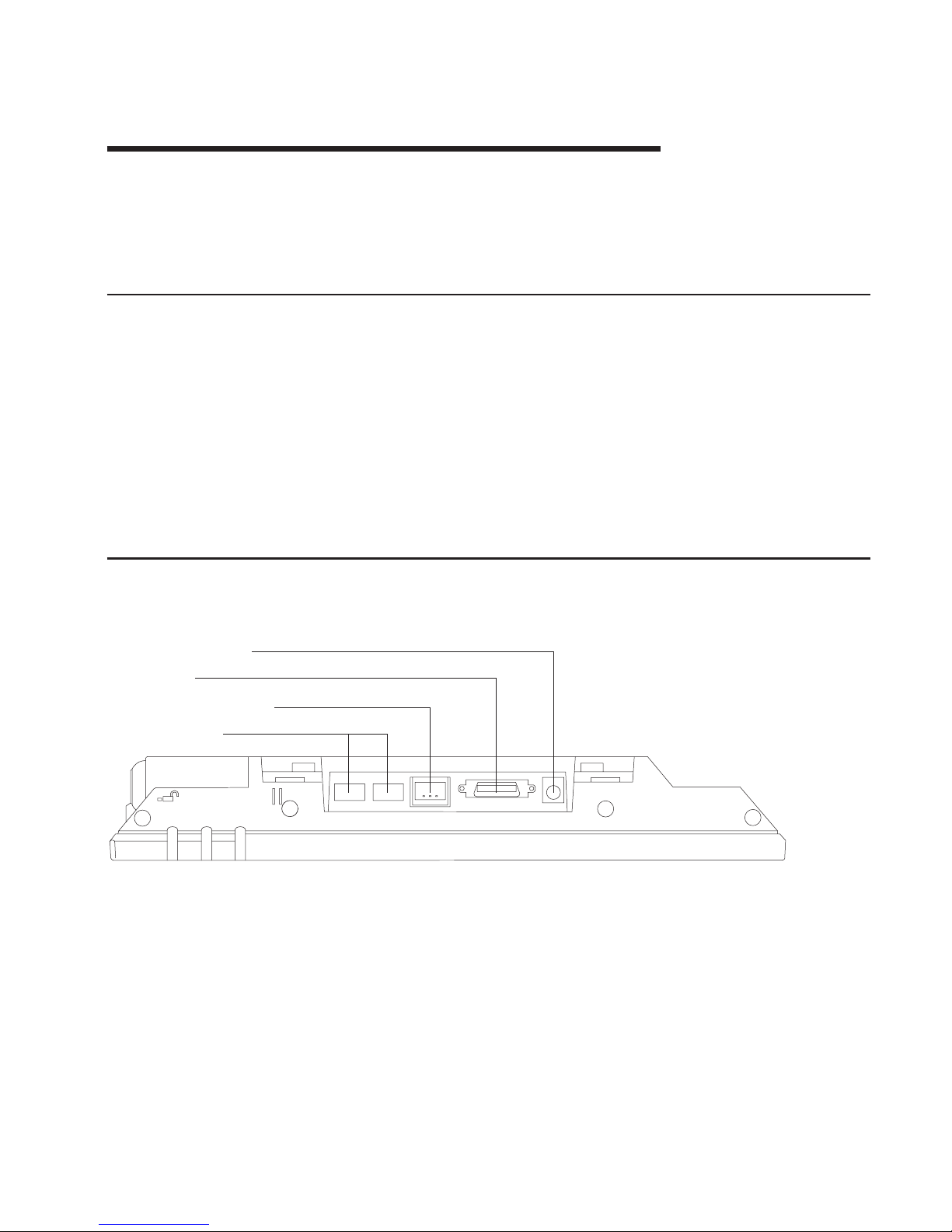
Chapter 13. Installation and operating information
This section summarizes the installation and operation methods of the 4820 SurePoint
Solution. IBM recommends that you refer to the IBM 4820 SurePoint Solution
Installation and Service Guide for complete instructions.
Option installation
IBM recommends that you install the options for the 4820 SurePoint Solution in the
following order:
1.
Manager’s keylock
2.
Keypad and MSR
3.
Pointing device
4.
Audio kit
Note:
You can attach either the MSR or the keypad with MSR to the 4820 SurePoint
Solution.
Cable connections and routing
Figure 13-1 shows the view of the cable connections for the 4820 SurePoint Solution.
AUX: power in
Video
USB in / power in
USB (out)
Figure 13-1. Model 4WT, 4GT cable connections
©
Copyright IBM Corp. 1999, 2003
13-1
Page 82

Table 13-1. Cable types
Type
Identifying Icon
Cable
USB out
Analog video
Audio (icon located on
audio kit)
USB power input
4 .
Auxiliary Power input
Note: Power is not necessary when connecting to
the SurePOS 700 Series.
The following cables require routing through the distributed and integrated pedestal of
the 4820 SurePoint Solution:
v
Power (models 4WT, 4GT)
v
USB (Touch/Keypad/MSR)
v
Pointing device
v
Audio cables (when applicable)
Adjusting the display
This section summarizes the methods of adjusting the 4820 SurePoint Solution, models
4WT, 4GT.
Brightness controls
Pressing the plus or the minus keys adjusts the screen brightness.
MicroTouch TouchWare
The MicroTouch Touchware software driver allows you to calibrate the touch screen,
select modes, and configure the touch sound and cursor positions.
13-2
4820 SurePoint Solution System Reference
Page 83

Chapter 14. System diagnostics and pinout connections
The 4820 SurePoint Solution models 4WT and 4GT connect through USB to the IBM
Point of Sale system unit. This section describes diagnostic information and pinout
connections for models 4WT and 4GT.
Using the MicroTouch TouchWare
This section describes how to calibrate the touchscreen and customize the touch
response.
Locating the touchscreen controller information
The touchscreen controller information window provides information about the type,
firmware version, and status of your touchscreen. Locate the controller by selecting the
Hardware tab from the TouchWare.
Controller type
The Controller Type field displays the model name of your touchscreen controller.
Firmware version
The Firmware Version field displays the revision number of the firmware in your
TouchWare controller.
Touchscreen status
The Touchscreen Status field provides valuable information about whether the
touchscreen hardware is operating properly. Table 14-1 lists the possible messages that
are displayed in the Status field:
Table 14-1. Touchscreen status messages
Message
Definition
Recommended Action
OK
Touchscreen found and
operational
None
A/D Error
Touchscreen hardware error
Replace unit
ASIC Error
Hardware Error
PWM
NOVRAM Error
Checksum error in NOVRAM,
using defaults
random access memory (RAM)
Error
Checksum error in read-only
memory (ROM)
Touchscreen Not Found
TouchWare was unable to
communicate with the
touchscreen
Check that all cables for
correctly connected.
©
Copyright IBM Corp. 1999, 2003
14-1
Page 84

Touchscreen properties dialog box
Problem
Recommended Action
You have touch, but cannot open the
Touchscreen Properties dialog box.
Only the touchscreen USB driver was installed
and the TouchWare was not completely
installed. Unplug your touchscreen from the
USB port and reinstall the TouchWare.
The Touchscreen Properties dialog box always
opens to the Hardware tab
The TouchWare is unable to find or
communicate with the touchscreen controller.
v
Check the Controller Information box on the
Hardware tab. If the OK message displays,
contact technical support.
v If
the message NOT FOUND displays, review
the cable connections
Calibrating the touchscreen
Calibration defines the dimensions and center of the active area of the touchscreen.
Calibration also aligns the touchscreen-active area to the underlying . Calibrate your
touchscreen when:
v
You initially install the TouchWare
v
The cursor does not accurately follow your finger movement
v
You change the resolution or mode
v
You adjust the touchscreen controller frequency using the Stabilize Cursor function
v
You enable or disable the Filtering option
Note:
During calibration, the lift-off position of your touch, and not the touchdown
position, determines the calibration point. If your finger is not correctly positioned
on
the screen, you can slide your finger to the center of the target. Hold your
finger as still as possible after you reach the calibration point. Do not use any
lateral motion during lift-off.
1.
Allow the 4820 SurePoint Solution to warm-up at least one-half hour before you
begin calibration.
2.
Open the Touchscreen Properties dialog box. Select the Calibrate tab.
3.
Click Calibrate. A calibration target appears in the lower left corner of the screen.
4.
Touch the touchscreen and position your fingertip to completely cover the target.
Hold your touch for at least three seconds.
5.
Lift your finger off of the screen when you are satisfied that you accurately touched
the target.
6.
Touch the touchscreen and position your fingertip to completely cover the next
target. Hold your touch for at least three seconds.
7.
Lift your finger off of the screen. The program saves the new calibration values and
displays the following dialog box:
8.
Test the calibration as follows:
a.
Touch random points on the screen and check that the system locates the
cursor underneath your finger.
14-2
4820 SurePoint Solution System Reference
Page 85

b.
Drag your finger across the screen. Check that the cursor accurately follows
your movements.
c.
Touch each corner and along each edge of the screen. Check that the cursor
reaches the full image area and that you can touch and activate all icons and
menus across the entire screen
9.
If
any part of the test fails, calibrate the touchscreen again.
Customizing the touch response mode
The touch response mode defines how your touch emulates the functions of a mouse.
For example, you can define a touch to produce a button down (pressing a mouse
button) or button up (releasing the mouse button). Touch modes also define how your
touch produces a mouse click and double click. TouchWare allows the following touch
modes:
Desktop (default)
The system moves the cursor to the touch point, but does not generate a
button down as long as you continue to slide your finger around the screen.
When you pause and hold your finger steady, the system generates a mouse
button down. You can now slide your finger around the screen with this
position. When you lift your finger, the system generates a button up.
Drawing
The system moves the cursor to the touch point and immediately generates a
button down. You can slide your finger around the screen with the button held
down. When you lift your finger, the system generates a button up.
Button The system moves the cursor to the touch point and immediately generates a
button down and up (a click). To drag, slide your finger around the screen
(button down). When your lift your finger, the system generates a button up.
Click The system moves the cursor to the touch point and then immediately
generates a button down and up (a click). Click mode does not generate a
second button down, does not support drag and does not generate a mouse
event on finger lift-off.
Lift-off The system moves the cursor to the touch point, but does not generate a
mouse button down. You can slide your finger around the screen and your
movements are followed; however, the system generates mouse move events
only. Lifting your finger off of the screen generates a mouse button down. The
system then waits for a system-defined time delay, and generates a button up.
Drag is not supported; however lift-off mode is useful for applications that
requires greater accuracy.
Touchdown
The system moves the cursor to the touch point, generates a button down,
waits for a system-defined time delay, and generates a button up. The system
does not generate a mouse event on finger lift-off. Drag is not supported in this
mode.
Table
14-2 on page 14-4 describes how to click, double click, and drag, using the
different touch modes.
Chapter 14. System diagnostics and pinout connections
14-3
Page 86

Table 14-2. Summary of touch todes
Touch mode
How to click
How to double-click How to drag
Desktop
Touch the object and
lift your finger.
Touch twice in quick
succession in the same
place.
Touch the object,
pause briefly, and slide
your finger.
Drawing
Button
Touch the object
Click
Not supported
Lift-off
Touchdown
Touch the object.
Provides a pause for
user to receive visual
feedback that a button
was pressed and
released.
Selecting a touch mode
Use the Touch Settings tab or the Special tab to select a touch mode. Some touch
modes require you to select options on both tabs.
Configuring the touch sound
You can configure your touchscreen so that a beep is produced when you touch the
screen, or when you remove your touch. To enable or disable the touch sound:
v
Select the Touch Settings tab to access the Touch Sound option.
v
Click Beep to cycle through the choices:
–
Beep on touchdown produces a beep when you touch the screen
–
Beep on lift-off produces a beep when you lift your finger off the screen.
–
Beep off produces no sound when you touch the screen. This is the default
setting.
Customizing the touch sound
If
you enable the touch sound, you can customize the frequency, or pitch, and duration
of
the touch sound. To customize the touch sound:
v
Select the Special tab to access the Custom Touch Sound options.
v
Click the right and left arrows to change the frequency, or pitch, and duration of the
touch sound. The range of settings are as follows:
–
Frequency: 200 to 5000 Hz in 10 Hz increments; the default is 1500 Hz
–
Duration: 50 to 600 mx in 10 mx increments; the default is 200 mx
Connector pinouts
This section describes the connector pinouts.
USB power voltage
The powered USB cable should provide approximately 12 volts DC to the 4820
SurePoint Solution. Table 14-3 on page 14-5 describes the pins and provides an
14-4
4820 SurePoint Solution System Reference
Page 87

example of the USB cable.
Table 14-3. USB power and voltage
Pin
DC
Voltage
Example
1
4.75 to 5.25 V
Pin 4
Pin 5
Pin 6
Pin 3
Pin 2
Pin 1
2, 3
Data
4, 5
Ground
6
10.8 to 12.6 V
Chapter 14. System diagnostics and pinout connections
14-5
Page 88

14-6
4820 SurePoint Solution System Reference
Page 89

Part 6. IBM 4820 SurePoint Solution Models 10D, 1FR
Chapter 15. System specifications and planning information . . . . . . 15-1
Product summary . . . . . . . . . . . . . . . . . . . . . . 15-1
Hardware features . . . . . . . . . . . . . . . . . . . . . . 15-1
Display . . . . . . . . . . . . . . . . . . . . . . . . . 15-1
Video interface . . . . . . . . . . . . . . . . . . . . . . 15-1
Supported video modes . . . . . . . . . . . . . . . . . . . 15-2
Indicators and user controls . . . . . . . . . . . . . . . . . . 15-2
External ports . . . . . . . . . . . . . . . . . . . . . . 15-2
Power management . . . . . . . . . . . . . . . . . . . . 15-2
Chapter 16. Installation and operating information . . . . . . . . . . 16-1
Pedestal mounting . . . . . . . . . . . . . . . . . . . . . . 16-1
Adjusting the display image . . . . . . . . . . . . . . . . . . . 16-1
Other methods to adjust the display . . . . . . . . . . . . . . . 16-2
©
Copyright IBM Corp. 1999, 2003
Page 90

Models 10D, 1FR
4820 SurePoint Solution System Reference
Page 91

Chapter 15. System specifications and planning information
This section summarizes the specifications of the 4820 SurePoint Solution, and
provides details on the hardware and software features. For installation information, see
the Installation and Service Guide, GA27–4231.
Product summary
This section summarizes the specifications of 4820 SurePoint Solution.
Table 15-1. 4820 SurePoint Solution Hardware Features
Hardware Features
Description
Mounting
Integrated, distributed, free-standing, or VESA
bracket
Cables
v
Analog , 1.0m or 2.6m (15-pin VGA
connector)
v
Analog, 1.0m or 3.8m (DVI-I connector)
Power
External power brick
You can obtain the 4820 SurePoint Solution publications from the IBM Retail Store
Solutions Web site: www.ibm.com/solutions/retail/store/(from the store page, click on
Support).
Hardware features
This section describes the physical features of the 4820 SurePoint Solution.
Display
The 4820 SurePoint Solution provides a 10.1 inch TFT SVGA display with 800 x 600
resolution. The display can provide up to 16.7 million colors, subject to host PC
limitations. Autoscaling is standard with VGA support.
Video interface
The 4820 SurePoint Solution Models 10D and 1FR provide an analog interface with
cables that will attach to either a 15-pin D-shell style connector or a DVI-I connector.
©
Copyright IBM Corp. 1999, 2003
15-1
Page 92

Supported video modes
Table 15-2 lists the supported video modes:
Table 15-2. Supported video modes
Mode
Resolution
fV
(Hz)
fH
(kHz)
Pixel Rate (MHz)
VGA
640x350
70
31.47
25.18
640x400
720x350
28.32
720x400
640x480
60
25.18
72
37.86
31.5
75
37.5
SVGA
800x600
56
37.88
40 72
48.08
50 75
46.88
49.5
60 37 to 88 40
Indicators and user controls
The 4820 SurePoint Solution provides the following user controls:
v
Power on/Resume
v
Brightness
External ports
The 4820 SurePoint Solution provides the following external ports:
v
Video: 15-pin D-shell style connector
v
Power
Power management
The table below describes the power management states.
Table 15-3. Power Management States
Operation Mode
Analog
Off
5W
Active Off
5W On
20W
15-2
4820 SurePoint Solution System Reference
Page 93

Chapter 16. Installation and operating information
This section summarizes the installation and operation methods of the 4820 SurePoint
Solution. IBM recommends that you refer to the IBM 4820 SurePoint Solution
Installation and Service Guide for complete instructions.
Pedestal mounting
The 4820 SurePoint Solution can be attached to either a distributed, integrated,
free-standing, or VESA mounting. However, you must prepare the mounting surface for
the installation of the distributed pedestal. See Appendix A, “Mounting the pedestal,” on
page A-1 for instructions.
Adjusting the display image
Figure 16-1 on page 16-2 shows how to automatically adjust your display for Models
10D and 1FR of the 4820 SurePoint Solution. If you do not obtain the desired results
with these procedures, use the manual adjustments.
©
Copyright IBM Corp. 1999, 2003
16-1
Page 94
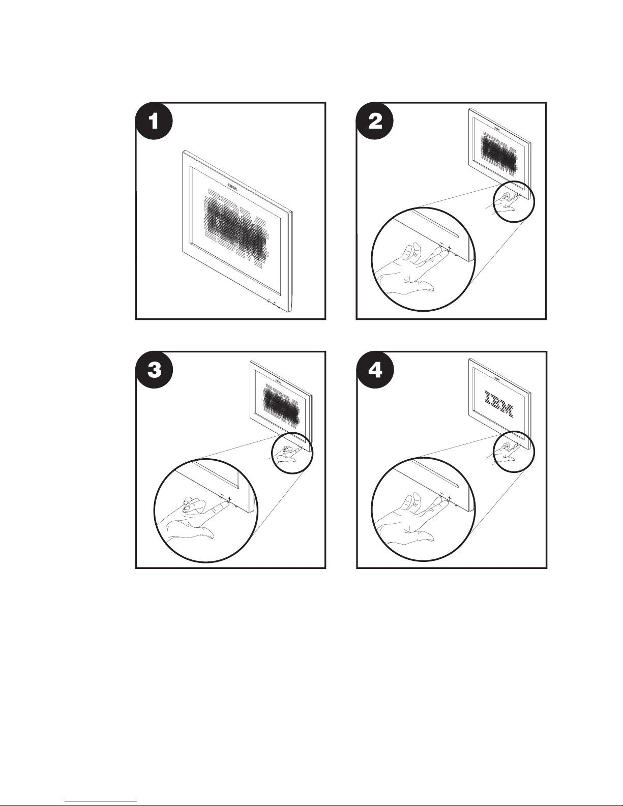
Other methods to adjust the display
Other methods to adjust the 4820 SurePoint Solution display are as follows:
Brightness menu
Available when you press the minus or plus buttons.
Figure 16-1. Pictorial view display adjustments
16-2
4820 SurePoint Solution System Reference
Page 95

OSD menu
The on-screen display (OSD) menu appears when you press the minus and
plus buttons simultaneously. For additional information, see “Using the OSD
menu” on page 7-1.
Chapter 16. Installation and operating information
16-3
Page 96

16-4
4820 SurePoint Solution System Reference
Page 97

Part 7. Appendixes
©
Copyright IBM Corp. 1999, 2003
Page 98

4820 SurePoint Solution System Reference
Page 99

Appendix A. Mounting the pedestal
Mounting the distributed pedestal
The distributed pedestal is available in short and long versions. Both pedestals bolt to
your counter; therefore, installation is the same. Figure A-1 shows the mounting order.
Follow these steps to attach the distributed pedestal to the counter:
1.
Using the template provided on Appendix C, “Mounting surface templates,” on page
C-1 mark the screw hole locations for drilling through the counter. Use a 8 mm or
5/16 inch bit to drill the four screw holes.
Pedestal
Mounting surface
Metal support bracket
M6 screws
Figure A-1. Distributed pedestal mounting
©
Copyright IBM Corp. 1999, 2003
A-1
Page 100

Note: To route cables through the counter, drill two 7/8 inch holes through the
counter. Trim the remaining material between the holes with a small saw or
chisel.
2.
Place the pedestal so that the receiving bolts align with the counter screw holes.
3.
Use the enclosed M6 screws to secure the pedestal to the counter as shown in
Figure A-1 on page A-1. The slots located in the metal support bracket allow you to
position the pedestal for maximum stability.
Attaching the free-standing pedestal to the counter
Follow these steps to mount the 4820 SurePoint Solution to your counter.
1.
Using the template (see Figure C-2 on page C-2) as a guide, mark the screw hole
locations for drilling through the counter. Use 8 mm bit, or 5/16 inch bit to drill the
four screw holes.
2.
Place the pedestal so that the mounting bolts align with the counter screw holes.
3.
Use the enclosed M6 screws to secure the pedestal to the counter. The slots
located in the metal support bracket allow you to position the pedestal for maximum
stability.
4.
Continue with your installation.
Mounting the pedestal
A-2
4820 SurePoint Solution System Reference
 Loading...