

Page 1

Front cover
Model Driven Systems
Development with
Rational Products
Understanding context
Understanding collaborations
Understanding distribution
of responsibilities
ibm.com/redbooks
Brian Nolan
Barclay Brown
Laurent Balmelli
Tim Bohn
Ueli Wahli
Page 2

Page 3

International Technical Support Organization
Model Driven Systems Development with
Rational Products
February 2008
SG24-7368-00
Page 4

Note: Before using this information and the product it supports, read the information in
“Notices” on page ix.
First Edition (February 2008)
This edition applies to IBM Rational Systems Developer, Version 7.
© Copyright International Business Machines Corporation 2008. All rights reserved.
Note to U.S. Government Users Restricted Rights -- Use, duplication or disclosure restricted by GSA ADP
Schedule Contract with IBM Corp.
Page 5

Contents
Notices . . . . . . . . . . . . . . . . . . . . . . . . . . . . . . . . . . . . . . . . . . . . . . . . . . . . . . . ix
Trademarks . . . . . . . . . . . . . . . . . . . . . . . . . . . . . . . . . . . . . . . . . . . . . . . . . . . . x
Preface . . . . . . . . . . . . . . . . . . . . . . . . . . . . . . . . . . . . . . . . . . . . . . . . . . . . . . . xi
The team that wrote this book . . . . . . . . . . . . . . . . . . . . . . . . . . . . . . . . . . . . . xii
Become a published author . . . . . . . . . . . . . . . . . . . . . . . . . . . . . . . . . . . . . . . xiii
Comments welcome. . . . . . . . . . . . . . . . . . . . . . . . . . . . . . . . . . . . . . . . . . . . . xiv
Chapter 1. Introduction. . . . . . . . . . . . . . . . . . . . . . . . . . . . . . . . . . . . . . . . . . 1
The challenges of systems development . . . . . . . . . . . . . . . . . . . . . . . . . . . . . . 2
The changed context for systems development . . . . . . . . . . . . . . . . . . . . . . 2
Management of complexity . . . . . . . . . . . . . . . . . . . . . . . . . . . . . . . . . . . . . . 3
Creative/dynamic and transactional complexity . . . . . . . . . . . . . . . . . . . . . . 3
Overview of model-driven systems development . . . . . . . . . . . . . . . . . . . . . . . 4
The benefits of modeling . . . . . . . . . . . . . . . . . . . . . . . . . . . . . . . . . . . . . . . . 4
Central problems MDSD addresses . . . . . . . . . . . . . . . . . . . . . . . . . . . . . . . 4
Benefits of model-driven systems development . . . . . . . . . . . . . . . . . . . . . . 8
Core processes of model-driven systems development . . . . . . . . . . . . . . . 13
Prerequisites/required foundational concepts/languages . . . . . . . . . . . . . . 15
How the book is organized . . . . . . . . . . . . . . . . . . . . . . . . . . . . . . . . . . . . . 16
Chapter 2. Definitions, design points, and key concepts . . . . . . . . . . . . . 17
Definitions. . . . . . . . . . . . . . . . . . . . . . . . . . . . . . . . . . . . . . . . . . . . . . . . . . . . . 18
System . . . . . . . . . . . . . . . . . . . . . . . . . . . . . . . . . . . . . . . . . . . . . . . . . . . . 18
Service . . . . . . . . . . . . . . . . . . . . . . . . . . . . . . . . . . . . . . . . . . . . . . . . . . . . 18
Requirement . . . . . . . . . . . . . . . . . . . . . . . . . . . . . . . . . . . . . . . . . . . . . . . . 18
Model . . . . . . . . . . . . . . . . . . . . . . . . . . . . . . . . . . . . . . . . . . . . . . . . . . . . . 18
Artifact . . . . . . . . . . . . . . . . . . . . . . . . . . . . . . . . . . . . . . . . . . . . . . . . . . . . . 19
Use case . . . . . . . . . . . . . . . . . . . . . . . . . . . . . . . . . . . . . . . . . . . . . . . . . . . 19
Operation . . . . . . . . . . . . . . . . . . . . . . . . . . . . . . . . . . . . . . . . . . . . . . . . . . 20
Actor . . . . . . . . . . . . . . . . . . . . . . . . . . . . . . . . . . . . . . . . . . . . . . . . . . . . . . 20
Locality . . . . . . . . . . . . . . . . . . . . . . . . . . . . . . . . . . . . . . . . . . . . . . . . . . . . 20
Connection . . . . . . . . . . . . . . . . . . . . . . . . . . . . . . . . . . . . . . . . . . . . . . . . . 21
Design points . . . . . . . . . . . . . . . . . . . . . . . . . . . . . . . . . . . . . . . . . . . . . . . . . . 21
Four basic principles . . . . . . . . . . . . . . . . . . . . . . . . . . . . . . . . . . . . . . . . . . 21
Additional design points . . . . . . . . . . . . . . . . . . . . . . . . . . . . . . . . . . . . . . . 22
Key concepts . . . . . . . . . . . . . . . . . . . . . . . . . . . . . . . . . . . . . . . . . . . . . . . . . . 24
Model levels . . . . . . . . . . . . . . . . . . . . . . . . . . . . . . . . . . . . . . . . . . . . . . . . 25
Viewpoints. . . . . . . . . . . . . . . . . . . . . . . . . . . . . . . . . . . . . . . . . . . . . . . . . . 26
© Copyright IBM Corp. 2008. All rights reserved. iii
Page 6

Views. . . . . . . . . . . . . . . . . . . . . . . . . . . . . . . . . . . . . . . . . . . . . . . . . . . . . . 28
Transformation methods . . . . . . . . . . . . . . . . . . . . . . . . . . . . . . . . . . . . . . . 28
Summary: The core MDSD process. . . . . . . . . . . . . . . . . . . . . . . . . . . . . . . . . 32
Chapter 3. Black-box thinking: Defining the system context . . . . . . . . . . 35
The importance of understanding context . . . . . . . . . . . . . . . . . . . . . . . . . . . . 36
The system in context . . . . . . . . . . . . . . . . . . . . . . . . . . . . . . . . . . . . . . . . . 37
An important context: Usage . . . . . . . . . . . . . . . . . . . . . . . . . . . . . . . . . . . . 37
Usage-driven versus feature-driven system design . . . . . . . . . . . . . . . . . . 38
Actors and boundaries . . . . . . . . . . . . . . . . . . . . . . . . . . . . . . . . . . . . . . . . . . . 40
Primary and secondary actors . . . . . . . . . . . . . . . . . . . . . . . . . . . . . . . . . . 41
Questions to discover actors . . . . . . . . . . . . . . . . . . . . . . . . . . . . . . . . . . . . 42
Actors and value . . . . . . . . . . . . . . . . . . . . . . . . . . . . . . . . . . . . . . . . . . . . . 42
Actors and the system boundary. . . . . . . . . . . . . . . . . . . . . . . . . . . . . . . . . 43
I/O entities . . . . . . . . . . . . . . . . . . . . . . . . . . . . . . . . . . . . . . . . . . . . . . . . . . . . 45
Use cases. . . . . . . . . . . . . . . . . . . . . . . . . . . . . . . . . . . . . . . . . . . . . . . . . . . . . 46
Writing a brief description . . . . . . . . . . . . . . . . . . . . . . . . . . . . . . . . . . . . . . 50
Actor involvement in use cases. . . . . . . . . . . . . . . . . . . . . . . . . . . . . . . . . . 51
Use case flows of events . . . . . . . . . . . . . . . . . . . . . . . . . . . . . . . . . . . . . . . . . 52
Level of detail in use case flows . . . . . . . . . . . . . . . . . . . . . . . . . . . . . . . . . 52
Initiation of the use case . . . . . . . . . . . . . . . . . . . . . . . . . . . . . . . . . . . . . . . 53
Using activity diagrams . . . . . . . . . . . . . . . . . . . . . . . . . . . . . . . . . . . . . . . . 54
Understanding collaboration from a black-box perspective . . . . . . . . . . . . . . . 54
Identifying operations . . . . . . . . . . . . . . . . . . . . . . . . . . . . . . . . . . . . . . . . . 55
Requests: The key to operations . . . . . . . . . . . . . . . . . . . . . . . . . . . . . . . . . . . 57
Specifying request signatures . . . . . . . . . . . . . . . . . . . . . . . . . . . . . . . . . . . 58
Information in the MDSD model . . . . . . . . . . . . . . . . . . . . . . . . . . . . . . . . . 58
Message naming: A quiz . . . . . . . . . . . . . . . . . . . . . . . . . . . . . . . . . . . . . . . 59
Toward better requests . . . . . . . . . . . . . . . . . . . . . . . . . . . . . . . . . . . . . . . . 60
Identifying operations from the sequence diagram . . . . . . . . . . . . . . . . . . . 62
Refactoring operations . . . . . . . . . . . . . . . . . . . . . . . . . . . . . . . . . . . . . . . . . . . 65
More about operations . . . . . . . . . . . . . . . . . . . . . . . . . . . . . . . . . . . . . . . . 65
Summary. . . . . . . . . . . . . . . . . . . . . . . . . . . . . . . . . . . . . . . . . . . . . . . . . . . 67
Chapter 4. White-box thinking: Understanding collaboration . . . . . . . . . 69
Operation realization . . . . . . . . . . . . . . . . . . . . . . . . . . . . . . . . . . . . . . . . . . . . 70
The logical viewpoint. . . . . . . . . . . . . . . . . . . . . . . . . . . . . . . . . . . . . . . . . . 70
Operation analysis . . . . . . . . . . . . . . . . . . . . . . . . . . . . . . . . . . . . . . . . . . . . . . 72
Flowdown to further levels . . . . . . . . . . . . . . . . . . . . . . . . . . . . . . . . . . . . . 76
Chapter 5. Understanding distribution of responsibility. . . . . . . . . . . . . . 79
Localities . . . . . . . . . . . . . . . . . . . . . . . . . . . . . . . . . . . . . . . . . . . . . . . . . . . . . 80
Localities and systems engineering . . . . . . . . . . . . . . . . . . . . . . . . . . . . . . 80
Locality semantics. . . . . . . . . . . . . . . . . . . . . . . . . . . . . . . . . . . . . . . . . . . . 81
iv Model Driven Systems Development with Rational Products
Page 7

Connection semantics. . . . . . . . . . . . . . . . . . . . . . . . . . . . . . . . . . . . . . . . . 81
Localities and nodes . . . . . . . . . . . . . . . . . . . . . . . . . . . . . . . . . . . . . . . . . . 82
Localities, services, and interfaces . . . . . . . . . . . . . . . . . . . . . . . . . . . . . . . 82
Design trades . . . . . . . . . . . . . . . . . . . . . . . . . . . . . . . . . . . . . . . . . . . . . . . 83
Sequence diagrams with localities . . . . . . . . . . . . . . . . . . . . . . . . . . . . . . . 85
Joint realization . . . . . . . . . . . . . . . . . . . . . . . . . . . . . . . . . . . . . . . . . . . . . . . . 86
Joint realization tables. . . . . . . . . . . . . . . . . . . . . . . . . . . . . . . . . . . . . . . . . 88
Chapter 6. Tool support for MDSD. . . . . . . . . . . . . . . . . . . . . . . . . . . . . . . . 93
Model structure. . . . . . . . . . . . . . . . . . . . . . . . . . . . . . . . . . . . . . . . . . . . . . . . . 94
Organizing an MDSD model . . . . . . . . . . . . . . . . . . . . . . . . . . . . . . . . . . . . 94
Level 0 model organization . . . . . . . . . . . . . . . . . . . . . . . . . . . . . . . . . . . . . 95
MDSD UML Profile . . . . . . . . . . . . . . . . . . . . . . . . . . . . . . . . . . . . . . . . . . . 97
Stereotypes . . . . . . . . . . . . . . . . . . . . . . . . . . . . . . . . . . . . . . . . . . . . . . . . . 98
Levels of decomposition . . . . . . . . . . . . . . . . . . . . . . . . . . . . . . . . . . . . . . 100
Actors . . . . . . . . . . . . . . . . . . . . . . . . . . . . . . . . . . . . . . . . . . . . . . . . . . . . 101
Logical entities . . . . . . . . . . . . . . . . . . . . . . . . . . . . . . . . . . . . . . . . . . . . . 102
Use cases and operations. . . . . . . . . . . . . . . . . . . . . . . . . . . . . . . . . . . . . 105
Distribution entities . . . . . . . . . . . . . . . . . . . . . . . . . . . . . . . . . . . . . . . . . . 107
Automation . . . . . . . . . . . . . . . . . . . . . . . . . . . . . . . . . . . . . . . . . . . . . . . . . . . 108
Creating MDSD artifacts. . . . . . . . . . . . . . . . . . . . . . . . . . . . . . . . . . . . . . . . . 109
UML diagrams for systems modeling . . . . . . . . . . . . . . . . . . . . . . . . . . . . 109
Preparing the environment . . . . . . . . . . . . . . . . . . . . . . . . . . . . . . . . . . . . 109
Preparing the Workbench . . . . . . . . . . . . . . . . . . . . . . . . . . . . . . . . . . . . . 110
Installing the MDSD plug-in. . . . . . . . . . . . . . . . . . . . . . . . . . . . . . . . . . . . 114
Modeling the system as a black box . . . . . . . . . . . . . . . . . . . . . . . . . . . . . 118
Modeling the system at level 1 . . . . . . . . . . . . . . . . . . . . . . . . . . . . . . . . . 133
Creating a localities diagram . . . . . . . . . . . . . . . . . . . . . . . . . . . . . . . . . . . 138
Chapter 7. MDSD and SysML . . . . . . . . . . . . . . . . . . . . . . . . . . . . . . . . . . . 143
Introduction. . . . . . . . . . . . . . . . . . . . . . . . . . . . . . . . . . . . . . . . . . . . . . . . . . . 144
MDSD (RUP SE) as contributor to SysML . . . . . . . . . . . . . . . . . . . . . . . . 144
MDSD with SysML . . . . . . . . . . . . . . . . . . . . . . . . . . . . . . . . . . . . . . . . . . 144
Basics of SysML. . . . . . . . . . . . . . . . . . . . . . . . . . . . . . . . . . . . . . . . . . . . . . . 145
Areas of focus of SysML . . . . . . . . . . . . . . . . . . . . . . . . . . . . . . . . . . . . . . 146
Requirements modeling . . . . . . . . . . . . . . . . . . . . . . . . . . . . . . . . . . . . . . 146
Block semantics . . . . . . . . . . . . . . . . . . . . . . . . . . . . . . . . . . . . . . . . . . . . 150
Block definition diagram . . . . . . . . . . . . . . . . . . . . . . . . . . . . . . . . . . . . . . 150
Internal block diagram . . . . . . . . . . . . . . . . . . . . . . . . . . . . . . . . . . . . . . . . 153
Ports . . . . . . . . . . . . . . . . . . . . . . . . . . . . . . . . . . . . . . . . . . . . . . . . . . . . . 153
Constraints . . . . . . . . . . . . . . . . . . . . . . . . . . . . . . . . . . . . . . . . . . . . . . . . 156
Parametrics . . . . . . . . . . . . . . . . . . . . . . . . . . . . . . . . . . . . . . . . . . . . . . . . 158
Behavior modeling . . . . . . . . . . . . . . . . . . . . . . . . . . . . . . . . . . . . . . . . . . 160
Contents v
Page 8

MDSD with SysML . . . . . . . . . . . . . . . . . . . . . . . . . . . . . . . . . . . . . . . . . . . . . 161
Blocks as basic structural units . . . . . . . . . . . . . . . . . . . . . . . . . . . . . . . . . 161
Understanding context . . . . . . . . . . . . . . . . . . . . . . . . . . . . . . . . . . . . . . . 161
Using blocks to stand for systems. . . . . . . . . . . . . . . . . . . . . . . . . . . . . . . 161
Requirements and understanding context . . . . . . . . . . . . . . . . . . . . . . . . 163
Understanding collaborations . . . . . . . . . . . . . . . . . . . . . . . . . . . . . . . . . . 164
Understanding distribution of responsibilities . . . . . . . . . . . . . . . . . . . . . . 166
Parametrics . . . . . . . . . . . . . . . . . . . . . . . . . . . . . . . . . . . . . . . . . . . . . . . . 167
Summary of SysML basics . . . . . . . . . . . . . . . . . . . . . . . . . . . . . . . . . . . . . . . 172
Chapter 8. Conclusion . . . . . . . . . . . . . . . . . . . . . . . . . . . . . . . . . . . . . . . . 175
Why we build systems . . . . . . . . . . . . . . . . . . . . . . . . . . . . . . . . . . . . . . . . . . 176
Systems engineering . . . . . . . . . . . . . . . . . . . . . . . . . . . . . . . . . . . . . . . . . . . 176
Systems concerns . . . . . . . . . . . . . . . . . . . . . . . . . . . . . . . . . . . . . . . . . . . . . 177
How does MDSD fit in? . . . . . . . . . . . . . . . . . . . . . . . . . . . . . . . . . . . . . . . . . 178
Appendix A. MDSD use case specification template. . . . . . . . . . . . . . . . 181
Revision History . . . . . . . . . . . . . . . . . . . . . . . . . . . . . . . . . . . . . . . . . . . . 183
Document Approval. . . . . . . . . . . . . . . . . . . . . . . . . . . . . . . . . . . . . . . . . . 183
Table of Contents . . . . . . . . . . . . . . . . . . . . . . . . . . . . . . . . . . . . . . . . . . . 184
Use-Case Specification: <Use-Case Name> . . . . . . . . . . . . . . . . . . . . . . . . 185
1 Brief Description. . . . . . . . . . . . . . . . . . . . . . . . . . . . . . . . . . . . . . . . . . . 185
2 Actor Catalog . . . . . . . . . . . . . . . . . . . . . . . . . . . . . . . . . . . . . . . . . . . . . 185
3 Preconditions . . . . . . . . . . . . . . . . . . . . . . . . . . . . . . . . . . . . . . . . . . . . . 186
4 Postconditions . . . . . . . . . . . . . . . . . . . . . . . . . . . . . . . . . . . . . . . . . . . . 186
5 Basic Flow of Events . . . . . . . . . . . . . . . . . . . . . . . . . . . . . . . . . . . . . . . 186
6 Alternative Flows . . . . . . . . . . . . . . . . . . . . . . . . . . . . . . . . . . . . . . . . . . 188
7 Subflows. . . . . . . . . . . . . . . . . . . . . . . . . . . . . . . . . . . . . . . . . . . . . . . . . 190
8 Extension Points . . . . . . . . . . . . . . . . . . . . . . . . . . . . . . . . . . . . . . . . . . 191
9 Special Requirements . . . . . . . . . . . . . . . . . . . . . . . . . . . . . . . . . . . . . . 191
10 Additional Information . . . . . . . . . . . . . . . . . . . . . . . . . . . . . . . . . . . . . 191
Appendix B. Additional material . . . . . . . . . . . . . . . . . . . . . . . . . . . . . . . . 193
Locating the Web material . . . . . . . . . . . . . . . . . . . . . . . . . . . . . . . . . . . . . . . 193
Using the Web material . . . . . . . . . . . . . . . . . . . . . . . . . . . . . . . . . . . . . . . . . 194
Abbreviations and acronyms . . . . . . . . . . . . . . . . . . . . . . . . . . . . . . . . . . . 195
Related publications . . . . . . . . . . . . . . . . . . . . . . . . . . . . . . . . . . . . . . . . . . 197
IBM Redbooks publications . . . . . . . . . . . . . . . . . . . . . . . . . . . . . . . . . . . . . . 197
Other publications . . . . . . . . . . . . . . . . . . . . . . . . . . . . . . . . . . . . . . . . . . . . . 197
Online resources . . . . . . . . . . . . . . . . . . . . . . . . . . . . . . . . . . . . . . . . . . . . . . 198
How to get IBM Redbooks . . . . . . . . . . . . . . . . . . . . . . . . . . . . . . . . . . . . . . . 198
Help from IBM . . . . . . . . . . . . . . . . . . . . . . . . . . . . . . . . . . . . . . . . . . . . . . . . 198
vi Model Driven Systems Development with Rational Products
Page 9

Index . . . . . . . . . . . . . . . . . . . . . . . . . . . . . . . . . . . . . . . . . . . . . . . . . . . . . . . 199
Contents vii
Page 10

viii Model Driven Systems Development with Rational Products
Page 11

Notices
This information was developed for products and services offered in the U.S.A.
IBM may not offer the products, services, or features discussed in this document in other countries. Consult
your local IBM representative for information on the products and services currently available in your area.
Any reference to an IBM product, program, or service is not intended to state or imply that only that IBM
product, program, or service may be used. Any functionally equivalent product, program, or service that
does not infringe any IBM intellectual property right may be used instead. However, it is the user's
responsibility to evaluate and verify the operation of any non-IBM product, program, or service.
IBM may have patents or pending patent applications covering subject matter described in this document.
The furnishing of this document does not give you any license to these patents. You can send license
inquiries, in writing, to:
IBM Director of Licensing, IBM Corporation, North Castle Drive, Armonk, NY 10504-1785 U.S.A.
The following paragraph does not apply to the United Kingdom or any other country where such
provisions are inconsistent with local law: INTERNATIONAL BUSINESS MACHINES CORPORATION
PROVIDES THIS PUBLICATION "AS IS" WITHOUT WARRANTY OF ANY KIND, EITHER EXPRESS OR
IMPLIED, INCLUDING, BUT NOT LIMITED TO, THE IMPLIED WARRANTIES OF NON-INFRINGEMENT,
MERCHANTABILITY OR FITNESS FOR A PARTICULAR PURPOSE. Some states do not allow disclaimer
of express or implied warranties in certain transactions, therefore, this statement may not apply to you.
This information could include technical inaccuracies or typographical errors. Changes are periodically made
to the information herein; these changes will be incorporated in new editions of the publication. IBM may
make improvements and/or changes in the product(s) and/or the program(s) described in this publication at
any time without notice.
Any references in this information to non-IBM Web sites are provided for convenience only and do not in any
manner serve as an endorsement of those Web sites. The materials at those Web sites are not part of the
materials for this IBM product and use of those Web sites is at your own risk.
IBM may use or distribute any of the information you supply in any way it believes appropriate without
incurring any obligation to you.
Information concerning non-IBM products was obtained from the suppliers of those products, their published
announcements or other publicly available sources. IBM has not tested those products and cannot confirm
the accuracy of performance, compatibility or any other claims related to non-IBM products. Questions on
the capabilities of non-IBM products should be addressed to the suppliers of those products.
This information contains examples of data and reports used in daily business operations. To illustrate them
as completely as possible, the examples include the names of individuals, companies, brands, and products.
All of these names are fictitious and any similarity to the names and addresses used by an actual business
enterprise is entirely coincidental.
COPYRIGHT LICENSE:
This information contains sample application programs in source language, which illustrate programming
techniques on various operating platforms. You may copy, modify, and distribute these sample programs in
any form without payment to IBM, for the purposes of developing, using, marketing or distributing application
programs conforming to the application programming interface for the operating platform for which the
sample programs are written. These examples have not been thoroughly tested under all conditions. IBM,
therefore, cannot guarantee or imply reliability, serviceability, or function of these programs.
© Copyright IBM Corp. 2008. All rights reserved. ix
Page 12

Trademarks
The following terms are trademarks of the International Business Machines Corporation in the United States,
other countries, or both:
developerWorks®
IBM®
Learning Solutions®
Rational®
The following terms are trademarks of other companies:
Java, and all Java-based trademarks are trademarks of Sun Microsystems, Inc. in the United States, other
countries, or both.
Microsoft, and the Windows logo are trademarks of Microsoft Corporation in the United States, other
countries, or both.
Other company, product, or service names may be trademarks or service marks of others.
Rational Rose®
Rational Unified Process®
Redbooks®
Redbooks (logo) ®
RequisitePro®
RUP®
SoDA®
WebSphere®
x Model Driven Systems Development with Rational Products
Page 13

Preface
This IBM® Redbooks® publication describes the basic principles of the
Rational® Unified Process® for Systems Engineering, which is IBM Rational’s
instantiation of model-driven systems development (MDSD).
MDSD consists of a set of transformations that progressively refine knowledge,
requirements, and design of complex systems. MDSD begins with activities and
artifacts meant to promote an understanding of the system's context.
Requirements problems often arise from a lack of understanding of context,
which, in MDSD, means understanding the interaction of the system with entities
external to it (actors), understanding the services required of the system, and
understanding what gets exchanged between the system and its actors.
Managing context explicitly means being aware of the shifts in context as you go
from one model or decomposition level to the next.
MDSD suggests that a breadth-first collaboration based approach across
multiple viewpoints is more effective than a traditional depth-first functional
decomposition in creating an architecture that will not only meet requirements,
but will prove to be more resilient in the face of inevitable change. MDSD also
seeks to provide an effective distribution of responsibilities across resources.
Joint realization and abstractions such as localities provide an effective and
elegant way of accomplishing this.
Finally, the ability to attach attributes and values to modeling entities and the
parametric capabilities of SysML provide a basis for doing simulations or other
models to meet cost, risk, and other concerns.
© Copyright IBM Corp. 2008. All rights reserved. xi
Page 14

The team that wrote this book
This book was produced by a team of specialists from around the world working
at the International Technical Support Organization, San Jose Center.
Brian Nolan is a course developer for IBM Software Group, Rational Learning
Solutions® and Services, specializing in model-driven development. Prior to his
current position, he was the regional practice lead for the Rational Unified
Process for Systems Engineering. Dr. Nolan holds a Ph.D. degree in the classics
from Ohio State University.
Barclay Brown is an executive consultant in the system engineering practice in
IBM Global Business Services. Prior to this, he was the Worldwide Community of
Practice leader for Rational Solution Architecture. He leads client engagements
in aerospace and defense, system development, and IT enterprise architecture,
helping clients transform their engineering organizations using IBM technologies,
methods, and tools. Barclay has been a practitioner, consultant, and speaker on
system engineering methods for over 8 years. His experience spans some 24
years in project management, system engineering, architectural modeling, and
requirements analysis. His current specialization includes model-driven system
development, enterprise architecture, estimation methods, and solution
architecture. He is the designer of the model-driven system development course,
offered by IBM. Barclay holds degrees in electrical engineering, psychology, and
business.
Dr. Laurent Balmelli is a manager at IBM in charge of architecting the new
generation of offerings and tools for systems engineering and product
development. He has been a research staff member at T.J. Watson Research
Center and IBM Tokyo Research Labs, and a member of several leadership
councils in IBM since 2000. Since 2003, Dr. Balmelli has represented IBM within
the SysML standard team and is one of the lead authors of the SysML language
specification. He was recently awarded the position of invited professor at Keio
University in Tokyo, Japan, where he currently resides.
Tim Bohn is currently the Worldwide Community of Practice Leader for Solution
Architecture. Tim has been active in the Systems community for many years,
helping customers adopt MDSD in their practice. Tim has been with IBM Rational
Software for 12 years, in both technical and management roles. Prior to joining
Rational, Tim worked as a software engineer and systems engineer for 16 years.
Tim holds a BS and MS degree from the University of Southern California, where
he also guest lectures.
xii Model Driven Systems Development with Rational Products
Page 15

Ueli Wahli is a Consultant IT Specialist at the IBM International Technical
Support Organization in San Jose, California. Before joining the ITSO over 20
years ago, Ueli worked in technical support at IBM Switzerland. He writes
extensively and teaches IBM classes worldwide about WebSphere® Application
Server and WebSphere and Rational application development products. In his
ITSO career, Ueli has produced more than 40 IBM Redbooks. Ueli holds a
degree in Mathematics from the Swiss Federal Institute of Technology.
Thank you
We would like to thank the following individuals for their help with this book:
Thanks to several authors who participated, but whose contributions we were
not able to include in this edition: Christopher Alderton, Keith Bagley, James
Densmore, Steven Hovater, and Russell Pannone
Thanks to the reviewers, especially David Brown, who made extensive
suggestions for improvement throughout
Thanks to our managers for their support
Thanks to Dr. Murray Cantor, for his thought, leadership, encouragement, and
support
Thanks to Yvonne Lyon, IBM Redbooks Editor, for editing this book
Thanks to our families for their patience, support, and encouragement
throughout this project
Become a published author
Join us for a two- to six-week residency program! Help write an IBM Redbooks
publication dealing with specific products or solutions, while getting hands-on
experience with leading-edge technologies. You will have the opportunity to team
with IBM technical professionals, Business Partners, and Clients.
Your efforts will help increase product acceptance and customer satisfaction.
As a bonus, you will develop a network of contacts in IBM development labs, and
increase your productivity and marketability.
Find out more about the residency program, browse the residency index, and
apply online at:
ibm.com/redbooks/residencies.html
Preface xiii
Page 16

Comments welcome
Your comments are important to us!
We want our Redbooks to be as helpful as possible. Send us your comments
about this or other Redbooks in one of the following ways:
Use the online Contact us review Redbooks form found at:
ibm.com/redbooks
Send your comments in an e-mail to:
redbooks@us.ibm.com
Mail your comments to:
IBM Corporation, International Technical Support Organization
Dept. HYTD Mail Station P099
2455 South Road
Poughkeepsie, NY 12601-5400
xiv Model Driven Systems Development with Rational Products
Page 17

Chapter 1. Introduction
This book is based on work done at IBM Rational by Dr. Murray Cantor and
others. In a series of articles for Rational, Dr. Cantor sets out the basic principles
of the Rational Unified Process for Systems Engineering (RUP® SE), which is
IBM Rational’s instantiation of model driven systems development (MDSD)
This chapter provides an introduction to MDSD, discusses the challenges it was
designed to address, and some of the benefits of using it. It provides a core set of
concepts to enhance understanding the methodology, and provides an overview
of the rest of the book. It also indicates what knowledge is needed as a
prerequisite to understanding the material we present.
1
1
.
1
L. Balmelli, D. Brown, M. Cantor, and M. Mott, Model-driven systems development, IBM Systems
Journal, vol 45, no. 3, July/September 2006, pp. 569-585 is the most recent.
http://www.research.ibm.com/journal/sj/453/balmelli.html
See also the series of articles in the Rational Edge, August-October, 2003
© Copyright IBM Corp. 2008. All rights reserved. 1
Page 18

The challenges of systems development
As the world moves into the Information Age, the rate of change is increasing.
Information is enabling new business models, such as eBay or Amazon.com, and
as a result new demands are placed upon the information systems. System
complexity is increasing in response to the capability of languages, technology,
and global information flow. Coincident with increasing complexity, the pace of
change is creating a need to reduce the time required to deliver solutions.
Systems development has not kept pace with the demands to deliver more
capability in less time. Development teams, using traditional methods, often still
fail to deliver capability, which can be fatal to a business in the Information Age.
The changed context for systems development
Computing technology has advanced so that modern systems are thousands of
times more powerful than their predecessors. This change removed resource
constraints and is changing the approach to system delivery in fundamental
ways. Historically teams struggled to deploy as much functionality using as little
computer resource as possible. The development team's primary goal was to
delivery a working system—cost, especially over a system's life cycle, was a
secondary solution. Solutions were often highly customized and proprietary.
Development life cycles were longer, and we could regularly schedule updates.
In modern systems, fewer components provide more functionality and therefore
have greater code counts. Integration is critical. Our systems must integrate with
today and tomorrow's systems now. Within the systems themselves, we must
integrate components from a variety of sources. We have many technology
choices, and software permeates everything. We have improved software
development productivity, but our software has increased tenfold in size
must update our systems constantly, yet reduce costs across the life span of the
system. We must innovate, but also manage risk; we must meet new technical
challenges, but also manage cost.
2
. We
Within the aerospace and defense markets, the changes are especially dramatic
due to the changing nature of threats in conjunction with the changes to
technology. During the Cold War, defense agencies and suppliers built large and
expensive systems. Because these systems were focused on defending against
other high technology threats, the high cost and time to develop was not seen as
a major issue. With the threats posed by terrorism, this has changed. Terrorists
cause disruption with relatively low cost devices and also change their tactics
2
David Longstreet, Software Productivity Since 1970, 2002
(http://www.softwaremetrics.com/Articles/history.htm).
cited in Cantor, Rational Unified Process for Systems Engineering, Part 1: Introducing RUP SE
Version 2.0, The Rational Edge, August 2003
2 Model Driven Systems Development with Rational Products
Page 19

rapidly. Hence the methods that worked for the Cold War do not work in the
current environment. In today's world, defense systems require agility and
net-centricity. Systems must become much more agile and capabilities must be
deployed more quickly. Our development methods must help us integrate and
deploy complex and scalable functionality more quickly.
Management of complexity
Our world is very complex—and becoming more complex daily.
manage complexity, before it overwhelms us. Methods for managing complexity
can help us prosper in our complex world. Model driven systems development
(MDSD) is such a method.
At its core, MDSD is quite simple, but very powerful in its simplicity;
extraordinarily complex things are built from simple pieces.
wide range of domains, and across a wide range of levels of abstraction from
very abstract to very concrete, from business modeling to the modeling of
embedded software. MDSD is not just a method for reasoning about and
designing software systems, it is a method for reasoning about and designing
large complex systems consisting of workers, hardware and software.
The power of MDSD lies in the power of its abstractions.
Creative/dynamic and transactional complexity
In building systems, we are faced with two different kinds of complexity:
Creative/dynamic complexity and transactional complexity:
We face creative/dynamic complexity because we need teams of people to
work together creatively to architect optimal, robust systems.
We face transactional complexity when we try to manage all the components
that make up a complex system.
3
We must
4
It applies across a
5
Transactional complexity can be managed with MDSD.
3
Cantor, Rational Unified Process for Systems Engineering, Part 1: Introducing RUP SE Version 2.0,
The Rational Edge, August 2003,
http://www.ibm.com/developerworks/rational/library/content/RationalEdge/aug03/f_rupse_m
c.pdf
4
Booch covers this point in Object-Oriented Design and Analysis with Applications, 3rd Edition,
Addison Wesley, Reading, MA, 2007. When designing a complex software system, it is essential to
decompose it into smaller and smaller parts, each of which we may then refine independently. In
this manner, we satisfy the very real constraint that exists upon the channel capacity of human
cognition …, page 19.
5
See Blanchard and Fabryky’s definition: Blanchard and Fabryky, Systems Engineering and
Analysis, third edition, Prentice Hall, 1998, quoted by Murray Cantor (see footnote 3).
Chapter 1. Introduction 3
Page 20

Creative/dynamic complexity can be managed with a governance process.
(The governance process must be enabling and not confining.)
Governance more and more becomes a matter of managing risk in an innovative
world; of balancing innovation and risk.
Overview of model-driven systems development
Model-driven systems development is the progressive, iterative refinement of a
set of models to drive development of your system.
The benefits of modeling
Why do we model? We model to manage complexity, to simplify and abstract
essential aspects of a system. We model so that we can test inexpensively
before we build, so that we can erase with a pencil before we have to demolish
with a sledgehammer.
The models are the architecture—they provide us with multiple views of the
system and promote our understanding.
Model-driven systems development leverages the power of modeling to address
a set of problems that have plagued systems development. We discuss some of
these problems in the sections that follow. MDSD uses a set of transformations to
iteratively refine our models and our understanding of the system to be built.
6
Central problems MDSD addresses
MDSD addresses a core set of system development problems:
Overwhelming complexity: Managing complexity by managing levels of
abstraction and levels of detail
Not considering appropriate viewpoints: Multiple views to address multiple
concerns
System does not meet functional, performance and other system concerns:
Integration of form and function
Lack of scalability: Isomorphic composite recursive structures and method to
address scalability
6
This is an adaptation of a quote from Frank Lloyd Wright: An architect's most useful tools are an
eraser at the drafting board, and a wrecking bar at the site
4 Model Driven Systems Development with Rational Products
Page 21

Managing complexity by managing levels of abstraction and levels of detail
Very often, when dealing with a system of systems, it is difficult to manage the
details of system design at different levels of abstraction and detail. Issues at one
level of the system get intertwined with issues at another; requirements and
design at one level get confused with requirements and design at another.
Think of it this way—if your concern is to travel from Cambridge, England to
Rome, Italy, you will be thinking about planes, trains, and automobiles—you
probably do not want to be thinking about the wiring in the airplane, or the details
of the air control system, or the brake system in the car.
Engineers have a tendency to want to jump down to the details. So when they
talk about a system for getting you to your destination, they are as likely to talk
about problems with the air control software or the wiring of a piece of hardware
as they are to talk about larger-grained issues. This can lead to confusion and
errors—diving too deep too early causes integration problems and constrains a
solution too early. Requirements are usually best understood in context; jumping
levels leads to a loss of context.
In our consulting practice at IBM, we have found it useful to manage the level of
abstraction, and to use the appropriate level of detail for the level of abstraction
under consideration. Also, we use a formal meta model to provide rigor to our
reasoning.
decomposition. Model level refers to what phase of our thinking we are
in—analysis models should be less detailed than design models, for example.
Decomposition level refers to how deep we are in the structural hierarchy of the
system.
7
Briefly, we consider two kinds of levels: model levels and levels of
This is one of the foundational concepts for MDSD. For example, if we are
creating a model for analysis, and we want to reason about distribution issues,
we should use entities that do not commit us too early to design decisions.
8
If we
are reasoning about the enterprise, we use entities that are appropriate for that
level of decomposition, and keep our thinking at that level until it is appropriate to
go to the next level of decomposition.
7
L. Balmelli, J. Densmore, D. L. Brown, M. Cantor, B. Brown, and T. Bohn, Specification for the
Rational Unified Process for Systems Engineering—Semantics and Metamodel, Technical Report
RC23966, IBM Thomas J. Watson Research Center, Hawthorne, NY 10532, (May 2006)
8
Localities in MDSD are a good example of this. See the discussion in chapters 2 and 5.
Chapter 1. Introduction 5
Page 22

Multiple views to address multiple concerns
Our life is complicated, our systems are complex.9 They are built from many
parts; often there are many systems working together to accomplish a goal. Our
minds do not handle certain kinds of complexity well. In mathematics, when we
deal with multi-variable equations, we isolate variables, solve for them, and
substitute them back into the equation.
We must provide a mechanism for doing the same thing with systems.
10
We do
the same thing when we design and construct buildings. A building is a system.
When we construct a building, we draw up many different plans: One for the
electricity, another for the plumbing, different views of the exterior. To address the
complexity of our systems, we have to create viewpoints that address multiple
concerns. These can vary from system to system. Common viewpoints might
include the logical viewpoint (what is the functionality), the distribution viewpoint
(where does the functionality take place), the data viewpoint (what domain
entities are manipulated), and the worker viewpoint (what human roles are
involved). MDSD is explicitly designed to promote the creation of different
viewpoints to address different concerns.
Integration of form and function
Function does not occur in a vacuum. It is hosted by physical form. Form exists to
carry out function. We build systems to accomplish goals. The systems that we
build do not exist in a vacuum—they are physical things. The goals that we have
for a system, the functionality that we would like it to exhibit, are realized by forms
or structures. The form that a system takes must support the goals that we have
for it. Both the functionality of the systems and the systems themselves are
constrained: we want something to occur within a specified amount of time; we
do not want the system to harm its users or innocent bystanders.
Our systems generally must fit into certain spaces, weigh less than a certain
amount. The goal of system design is to create a set of forms that will provide
desired functionality within a set of constraints. MDSD ensures that system goals
are met by distributing functionality across cooperating entities while reasoning
about system performance, and other constraints.
9
See the discussion on increased complexity in Cantor and Roose, Hardware/software
codevelopment using a model-driven systems development (MDSD) approach, The Rational Edge,
IBM developerWorks®, December 2005,
http://www.ibm.com/developerworks/rational/library/dec05/cantor/index.html?S_TACT=105AG
X15&S_CMP=EDU
10
See the discussion of abstraction, decomposition, and other topics in Booch et al.,
Object-Oriented Analysis and Design with Applications, 3rd Edition, Addison-Wesley, 2007,
chapters 1 and 2
6 Model Driven Systems Development with Rational Products
Page 23

Two analogies
Consider two analogies here: Project management and restaurant ownership.
Project management
If you are a project manager, you want to complete your project on schedule and
within budget. You have a set of people who will carry out a set of tasks. Your job
is to schedule the tasks, assign them to workers, and ensure that the project
remains on schedule and finishes within budget. Now consider a system to be a
project—not the task of building the system, but the system itself. There is a set
of tasks that you want the system to perform, you must distribute those tasks to a
set of resources, and you want the tasks to be accomplished within a certain
schedule, budget, and other constraints. Reasoning about this distribution
problem is a core pillar of MDSD.
Restaurant ownership
Now imagine that you want to start a restaurant. Your goals might be varied and
personal, but one of them better be to make a profit. There will be many aspects
involved in making a profit, but one of them will be to maximize your
throughput—that is, to serve as many quality meals as possible to as many
customers as possible. You have many options at your disposal to accomplish
this. Each option has a cost associated with it. You have to balance costs with the
return inherent in each option.
You might start with a short-order cook in front of a stove, behind a counter with
stools for the customers. Your rent is low, because you need very little space.
Your salaries are low, because you only have to hire a cook or two. But the cook
has to invite the customer to sit down, then take the order, cook it, deliver it, and
wash dishes. You soon discover that your one employee can only handle a small
number of customers at one time, because he or she has to do virtually
everything. Your cook is very good, so word gets around. People come to the
diner in droves, but soon get frustrated because of the long wait and lack of
seating. Your cook gets burnt out, because he or she has to be constantly on the
go. The throughput of your restaurant is limited, as are its profits.
You could add tables and some wait staff. Your rent has gone up because your
space has increased, as have your salaries because your staff is increased, but
you can increase the output of the cook because he or she can focus on the
cooking, and the throughput of the restaurant through the division of
responsibilities. Still, you will likely be constrained by the capabilities of the wait
staff. Now they have to greet the customers, seat them, take their orders, bring
them to the kitchen, retrieve the orders, carry them to the tables, give the
customers their bills, collect the money, clear the table, and set it again for the
next customers. Customers are frustrated because it takes so long to get seated,
get their meals, and get their checks. You risk losing customers. So you add staff
to clear and set the tables.
Chapter 1. Introduction 7
Page 24

You can see how the situation progresses. Many restaurants now have someone
to greet the customer, someone to seat them, someone to take their order,
someone to pour beverages, someone to cook the order, someone to deliver it to
the table, someone to deliver and collect the bill, someone to clear and set
tables. The end goals remain the same, the tasks to be performed remain the
same, but specialized roles are created to increase the restaurant’s capacity and
throughput. However, as noted before, the increased capacity comes at a cost,
both in increased salaries and increased management complexity—you now
have quite a staff to manage. The cost must be balanced against the increased
capacity.
Finally, as opposed to suffering through these options by painful experience and
trial and error, you could model the various options and run simulations to learn
what could happen and to better understand the implications of your options. You
might save yourself a lot of pain, suffering, and the loss of your time and money.
You would certainly be better informed about your options, and increased
knowledge reduces uncertainty and risk.
MDSD provides ways to reason about these issues—both for systems and for
business processes.
Scalability: Isomorphic composite structures and recursion
Systems are composite structures; that is, they are made up of distinct pieces.
Not only are they composite structures, they are isomorphic;
of the composite structure has a similar or identical structure itself. Composite
isomorphic structures lend themselves to being processed recursively. MDSD is
scalable because it is a recursive methodology. We can use it to reason about a
system of any size. At each level of abstraction (or more precisely, at each model
level, and at each level of decomposition)
12
we perform basically the same
activities: understand the context of the system under consideration, understand
the collaboration required to achieve the system’s desired goals, and understand
how function is distributed across form to achieve system goals within a set of
constraints.
11
that is, each piece
Benefits of model-driven systems development
MDSD provides many benefits. These are some of of the more significant ones:
Reduction of risk
Enhanced team communication
11
Isomorphic comes from the Greek ισο (iso) meaning “same” and μορφοσ (morphos) “form”
12
See Chapter 2 discussion of model levels.
8 Model Driven Systems Development with Rational Products
Page 25

Explicit processes for reasoning about system issues and performing trade
studies
Early detection of errors
Integration as you go, better architecture
Traceability
Reduction of risk
MDSD, in conjunction with appropriate governance, can significantly reduce the
risks of system development. The goal of many of the activities of MDSD is to
reduce risk. The creation of models is the creation of an architecture. We build
models to increase understanding, increased understanding reduces what is
unknown both technically in the domain space, and operationally in the project
management space—our technical knowledge increases as we complete
iterations. At the same time, as we produce concrete deliverables we gain better
estimates of time to completion. Increased levels of specificity reduce the
variance in a solution space. However, MDSD does not create an artificial level of
specificity at any point; the creation of false levels of specificity is often an
unrecognized trap leading to false confidence and nasty surprises. Increase in
knowledge and reduction of variance are prime risk reducers.
Enhanced team communication
Words can be slippery, elusive, and imprecise. Models can improve
communication because they make specific a particular aspect of a system.
They also can make system issues
visible through the use of diagrams. Often it
is easier to point to a picture or diagram than it is to describe something in words.
The very act of modeling or diagramming can force you to be concrete and
specific. We have seen many times in our consulting practice (and many years of
experience across many industries) the value of looking at a diagram, set of
diagrams, or models. In one customer we worked with, MDSD diagrams were
printed out on a plotter, posted in a central lobby, and became the focal point for
discussions about the system across a broad set of stakeholders.
13
Improved communication across a development organization also occurs as a
result of MDSD. Engineers in different disciplines have a unifying language they
can use to deal with systems issues. Systems engineers can create models that
can be handed to the engineers in multiple disciplines (hardware, software, and
others) as specification for their design; common use case models can drive
system development, testing, and documentation.
13
Again, see Booch et al., Object-Oriented Analysis and Design with Applications, 3rd Edition,
Addison-Wesley, 2007, chapter 1: Models provide a means to reason about a part of the
system—necessary due to cognitive limits of the human—while maintaining on overall coherence
of the parts
Chapter 1. Introduction 9
Page 26

Common languages promote common understanding. Unified Modeling
Language (UML) and Systems Modeling Language (SysML) derive from the
same meta object framework; products in one or the other are likely to be
understandable across diverse disciplines. By focusing on usage, collaboration,
and distribution, better cross-organizational discussions can take place. Use
cases, or common system threads, can unify stakeholders, developers, and
users. Beyond systems and software engineering MDSD also provides the
framework for reasoning about the integration of concerns across all of the
engineering disciplines (for example, thermal, structure, electrical, and
navigation).
Explicit processes for reasoning about system issues
Often, many of our design decisions are implicit, the result of many years of
experience. While this can be valuable (we do value experience), it can also lead
to premature design decisions, or decisions that have not been adequately
reasoned through, communicated, tested, or verified.
Complexity also demands explicit processes. A commercial pilot would not think
of taking off with a plane full of passengers without a checklist of tasks and safety
checks. We follow a repeatable process to improve quality and consistency. By
designing the process to address specific issues and risks, we increase our
chances for success.
MDSD has been designed to address a specific set of issues in the development
of complex systems. Explicit processes also improve communications. Design
decisions are taken out of the heads of engineers, documented through models,
and progressively refined. In MDSD, process is not just the checking off of steps,
but performing repeatable tasks to produce quality artifacts—the quality of the
process is judged by the quality of the results—where possible by executable
results, that is, a running system or piece of a system.
14
Early detection of errors
One of the benefits of a well designed process for designing systems is the early
detection and resolution of errors. Figure 1-1 shows the cost of errors rising
exponentially as they are discovered later in the system development life cycle.
14
See Walker Royce, Software Project Management: A Unified Framework, Addison-Wesley, 1998.
Also Kurt Bittner and Ian Spence, Managing Iterative Software Development Projects,
Addison-Wesley, 2006.
10 Model Driven Systems Development with Rational Products
Page 27
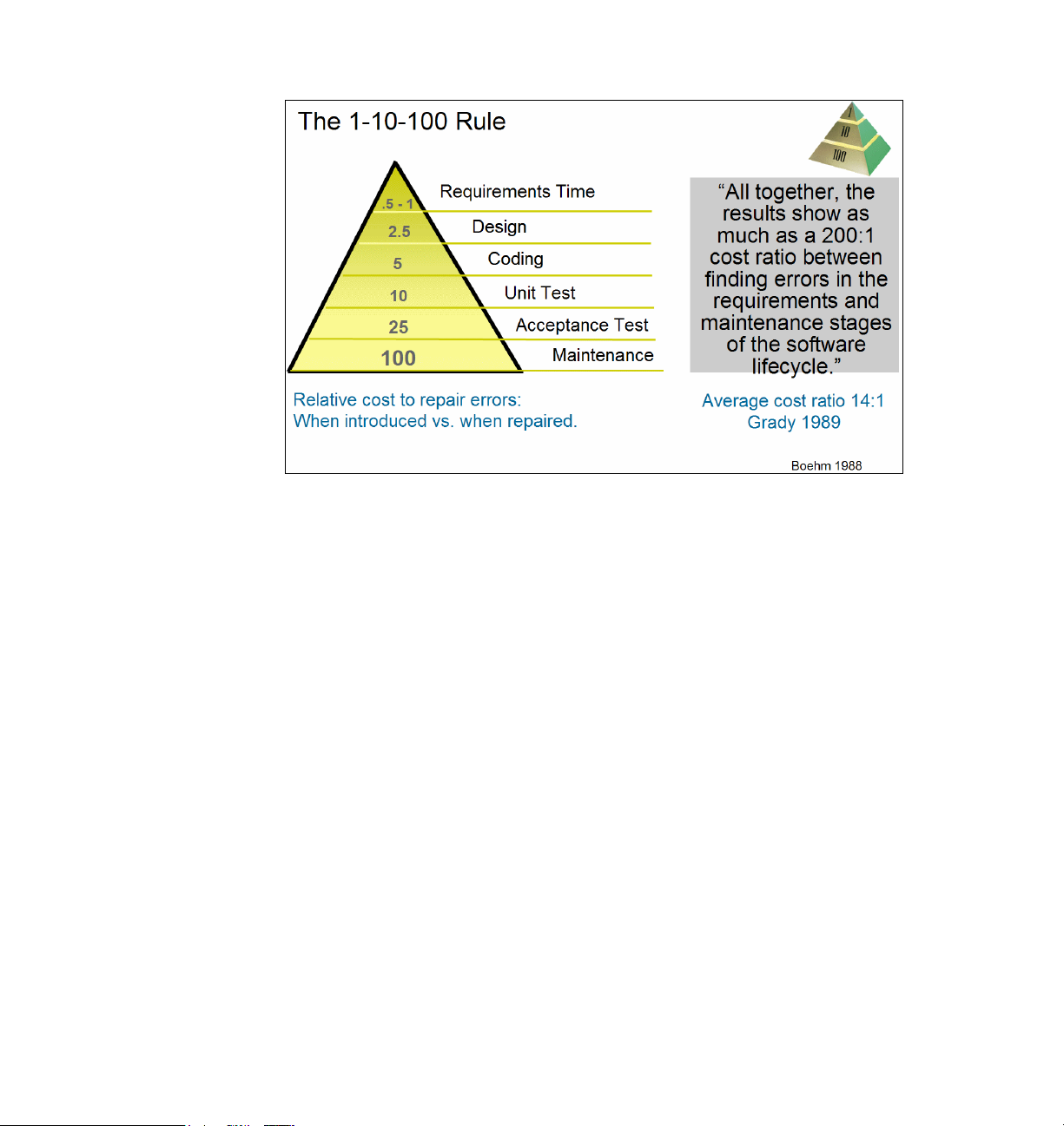
Figure 1-1 High cost of requirements errors
Our experience has shown us that iterating through the production of a set of
artifacts improves both the artifacts themselves and the system that is the end
product. Each progressive step in the process of defining context, defining
collaborations, and specifying the distribution of responsibilities across a set of
cooperating entities highlights ambiguities in previous steps, uncovers problems
or issues in design, and provides the opportunity to correct mistakes early in the
development process at a much lower cost than when they go undetected until
later.
MDSD is based on many years of experience across a wide range of customers
and projects. We have seen the benefits of well designed activities applied
iteratively to a set of concrete artifacts that can be tested.
Integration as you go—better architecture
One of our greatest challenges in developing systems is to integrate functionality
successfully, avoid duplication of functionality, and avoid brittle architectures.
Cantor provides the following example:
One image satellite ground support system that is currently being fielded was
built with a functional decomposition architecture. The system requirements
included the ability to plan missions, control the satellites, and process the
collected data for analysis. Accordingly, the developer built three subsystems:
mission planning, command and control, and data processing. Each of these
Chapter 1. Introduction 11
Page 28

subsystems was given to an independent team for development. During the
project, each team independently discovered the need for a database with the
satellite's orbital history (the satellites can, to some extent, be steered to
different orbits as needed). So each team built its own separate database,
using separate formats. But the information needs to be consistent for the
overall system to operate correctly, and now, the effort required to maintain
these three databases is excessive and could easily have been avoided had
the team done some kind of object analysis, including a study of the
enterprise data architecture.
15
MDSD seeks to avoid this kind of duplication of functionality by promoting a
breadth-first analysis of functionality across a set of collaborating entities.
Collaboration, both in the development process, and in system functionality is at
the heart of MDSD.
Traceability
Traceability is usually a requirement for the systems that we build. Often, it is an
explicit contract item: You
the requirements of the system have been implemented and tested. Apart from
contract requirements, traceability is needed to do effective fault or impact
analysis: If something goes wrong, we must determine what caused the fault; if
some requirement must be changed, or added, we must determine what parts of
the system will be affected.
Providing traceability can be an onerous requirement. Many times it is done
manually at significant cost both in the original development and later through
testing and maintenance. Manual methods of providing traceability are difficult to
maintain and error-prone.
shall provide traceability matrices to demonstrate how
MDSD can help lighten the burden of providing and then maintaining traceability
information. Three of the core processes of MDSD, operations analysis, logical
decomposition and joint realization tables, allow for a great deal of the
traceability problem to be automated. SysML provides semantic modeling
support for traceability. The Rational Software Delivery Platform also provides
tools and support for traceability.
Well defined semantics
Talking about the various parts of a system, at their different levels, and talking
about their relationships, can be difficult and confusing without well defined
semantics. MDSD has a well defined meta model which promotes clarity of
discussion (see the aforementioned citation
15
Cantor, Thoughts on Functional Decomposition, The Rational Edge, April 2003,
http://www.ibm.com/developerworks/rational/library/content/RationalEdge/apr03/Functiona
lDecomposition_TheRationalEdge_Apr2003.pdf
12 Model Driven Systems Development with Rational Products
15
).
Page 29

Core processes of model-driven systems development
Model-driven systems development is essentially a simple process, but no less
powerful because of its simplicity; in fact, we believe its elegance and simplicity
contributes to its power. Furthermore, it is correct in that it is constructed from
first principles. It starts with the definition of a system and then provides
constructs for defining each of the parts of the system. It also provides an
underlying meta model to maintain coherence of the model design as a team
reasons about the various parts of the system.
Model-driven systems development is an extension to the Rational Unified
Process (RUP). As such, it has a well defined set of roles, activities, and artifacts
that it produces. Furthermore it exists as a plug-in for the Rational Method
Composer (RMC). Within the context of the Rational Unified Process, however,
its essential simplicity is not necessarily immediately apparent within the phases,
work flows, and activities. One of the goals of this document is to demonstrate its
essential simplicity and power.
The various activities of MDSD are centered around three goals:
Defining context
Defining collaborations
Distributing responsibilities
These activities are carried out at each model level, and at each level of system
decomposition. As noted previously, MDSD is a recursive or fractal process—this
is part of what makes it simple and powerful.
16
Defining context
Confusion about context is one of the prime causes of difficulty in system
development and requirements analysis. If you are not sure what the boundaries
of your system are, you are likely to make mistakes about what its requirements
are. Lack of clarity at this point in the development process, if carried through to
deployment of the system, can be extraordinarily expensive—systems get
delivered that do not meet the expectations of their stakeholders, or faults occur
in expensive hardware systems after they have been deployed, and have to be
recalled, redesigned, and redeployed. Or the system never gets deployed at all,
after millions of dollars have been spent in its development.
Defining context means understanding where the system fits in its enterprise,
domain, or ecosystem. Understanding context in a system of systems also
means understanding where the various pieces of the system fit and how they
relate to each other.
16
Correspondence with Michael Mott, IBM Distinguished Engineer
Chapter 1. Introduction 13
Page 30

One of the most difficult areas of defining or understanding context is being
aware of context shifts, especially in systems of systems. A context shift occurs
when you go from talking about a system within an enterprise to talking about
one of its subsystems. At that point, you are considering the subsystem to be a
system in its own right. It will have its own set of actors, likely to be other
subsystems of the original system under consideration. It is important to manage
these context shifts carefully, and to keep straight where in the system you are at
a particular point. Technically, we call this set of levels within the system its
decomposition levels.
box views are one of the ways MDSD manages this context shift.
17
An explicit transformation between black box and white
18
Understanding the intended usage of a system is one of the most powerful
means of analyzing it and its requirements effectively. Usage drives the
functional requirements for the system. What we want the system to do
determines its functionality. In MDSD, use cases represent the most important
usages of the system. Use cases help define the context of the system; use
cases also help put other related requirements into a context.
An essential set of artifacts is produced as we reason about context at any level:
Context diagram
Use case model
Requirements diagram (optional using SysML)
Analysis model
Defining collaborations
Brittle, stove-piped architectures are expensive and difficult to maintain or
extend. MDSD promotes horizontal integration by emphasizing collaborations at
the core of the methodology. Even when we are examining the context of a
system, we investigate how it collaborates with other entities in its domain or
enterprise. As we analyze candidate architectures and perform trade studies, we
investigate how the internal pieces of the system collaborate together to realize
its functionality.
Scalability is achieved through system decomposition and operational analysis.
The interaction of a set of systems at any given level of abstraction or
decomposition determines the interactions of subsequent levels.
Essential list of artifacts:
Sequence diagrams
Analysis model
Package diagram/overview of logical architecture
17
See the aforementioned citation (footnote 15).
18
See Chapter 2, “Transformation methods” on page 28, and discussion in Chapters 3 and 4.
19
Ibid.
14 Model Driven Systems Development with Rational Products
19
Page 31

Distributing responsibilities
Perhaps the greatest challenge in developing any system, but most especially in
developing large, complex, systems of systems, is to ensure that all constraints
on the system are met while still delivering the desired functionality. How we
distribute functional responsibilities across both the logical and distribution
entities is the third major theme of MDSD.
Two concepts are used in MDSD to facilitate this. The first is the use of what is
called a
Joint realization tables help us reason about functionality across a set of
Localities help us reason about quality of service measures at a level of
Essential list of artifacts:
Locality diagrams
Joint Realization tables
Deployment diagrams (design level and lower)
joint realization table. The second is the use of localities.
system viewpoints—logical, distribution, data, process, and worker, for
example.
abstraction that promotes flexibility in eventual implementation. One of the
temptations of Systems Engineering is to jump ahead to an implementation
based on experience rather than explicit reasoning and design. Localities are
intended to encourage explicit documentation of design decisions and
trade-offs. They can form the basis for trade studies in the trade space.
Prerequisites/required foundational concepts/languages
Basic familiarity with the Rational Unified Process is assumed, but is not strictly
necessary to understand this book.
Iterative development is at the core of the Rational Unified Process. We assume
that in any innovative, high-risk project (and what new systems development
project is not, in one way or another?) some form of iterative development will be
used because it is a major risk reducer.
The Rational Unified Process, and MDSD as an extension of it, are both use
case driven. We discuss use cases in Chapter 3, “Black-box thinking:
Defining the system context” on page 35, as a core part of MDSD, but we do not
cover in detail how they can serve as the basis for effective iterative development;
nor how to manage an iterative development project based on use cases.
20
We do not discuss program or project management as such in this document. For the important
role of iterative development, see Walker Royce, Software Project Management: A Unified
Framework, and Kurt Bittner and Ian Spence, Managing Iterative Software Development Projects,
(both cited in footnote 14).
20
Chapter 1. Introduction 15
Page 32

For this, readers should refer to RUP’s project management discipline and
Bittner’s book just cited.
UML
Knowledge of the basics of UML is assumed. Readers should be familiar with the
basic structure and behavioral diagrams in UML, and should know the pieces
that make up the diagrams. They should have knowledge of the basic entities of
UML such as classes, operations, use cases.
21
SysML
This book assumes basic knowledge of SysML.22
The most important parts of SysML to be considered in this book are:
Requirements modeling
Structure modeling with blocks
Parametrics
The use of SysML is not required to get benefits from MDSD; however, MDSD is
optimized by using SysML semantics and capabilities. SysML was created with
the intent to provide richer semantics for systems than UML provides. Some of
the central issues that MDSD addresses were drivers behind important
semantics in SysML. We will provide discussion of these as they occur in this
book.
How the book is organized
This chapter provides an introduction to MDSD. Chapter 2 covers definitions,
design points and key concepts, while Chapters 3, 4, and 5 cover the core of
MDSD. Chapter 6 discusses model structure and use of Rational Systems
Developer to create MDSD artifacts. Chapter 7 gives an overview of those
SysML concepts required for MDSD, and suggestions for using SysML with
MDSD. These can be read independently, while Chapters 2, 3, 4, and 5 stand as
a virtual unit.
21
There is no lack of material available on UML. A good starting point might be Martin Fowler, UML
Distilled: A Brief Guide to the Standard Object Modeling Language, 3rd edition, 2003. The standard
references are James Rumbaugh, Ivar Jacobsen, and Grady Booch, Unified Modeling Language
Reference Manual, 2004, and Grady Booch, James Rumbaugh, and Ivar Jacobsen, Unified
Modeling Language User Guide, 2005
22
The Object Management Group developed and manages the SysML specification:
http://www.omgsysml.org
16 Model Driven Systems Development with Rational Products
Page 33

2
Chapter 2. Definitions, design points,
and key concepts
To understand MDSD, we must set forth some key definitions and discuss key
concepts and design points. This chapter defines important terms as used in
MDSD, discusses some of the key concepts of MDSD, and sets out some of the
motivations for its design.
1
1
This chapter uses material from, and adapts, two articles: L. Balmelli, D. Brown, M. Cantor, and M.
Mott, Model-driven systems development, IBM Systems Journal, vol 45, no. 3, July/September
2006, pp. 569-585, and Cantor, Rational Unified Process for Systems Engineering, The Rational
Edge, August 2003. Used with permission.
© Copyright IBM Corp. 2008. All rights reserved. 17
Page 34

Definitions
The following definitions are important to an understanding of MDSD. We provide
them here for clarity in the discussions in the rest of the chapters of this book.
System
A system is a set of resources that is organized to provide services. The services
enable the system to fulfill its role in collaboration with other systems to meet
some useful purpose. Systems can consist of combinations of hardware,
software (including firmware), workers, and data. This definition of systems is
extremely general: a product, such as an automobile or a computer, is a system;
a business or its components are also systems. Businesses can be organized
into larger enterprises that are also systems, for example, the health-care
system.
Service
At a high level, a service is a mechanism by which the needs or wants of the
requestor are satisfied. In a given context, the term service represents either a
service specification or a service implementation, or both. A
is the definition of a set of capabilities that fulfill a defined purpose. A
implementation
fulfills the service contract.
service specification
service
realizes the behavior described in the service specification and
In MDSD, the service specification can be a UML or SysML interface. The
service implementation is represented by the logical and distribution projections
or viewpoints of the model.
2
Requirement
A requirement is a condition or capability to which the system must conform.
Model
A model is defined as a collection of all the artifacts that describe the system.
2
Wikipedia’s article on Service (System Architecture) defines service as follows: In the context of
enterprise architecture, service-orientation and service-oriented architecture, the term service
refers to a discretely defined set of contiguous and autonomous business or technical functionality.
Organization for the Advancement of Structured Information Standards (OASIS) defines service as
a mechanism to enable access to one or more capabilities, where the access is provided using a
prescribed interface and is exercised consistent with constraints and policies as specified by the
service description. In this document we use the term somewhat loosely, as defined in the text.
18 Model Driven Systems Development with Rational Products
Page 35

Artifact
Use case
Generally, model-driven development (MDD) is a technique for addressing
complex development challenges by dealing with complexity through abstraction.
Using this technique, complex systems are modeled at different levels of
specificity. As the development program proceeds, the model undergoes a series
of transformations, with each transformation adding levels of specificity and
detail.
This last quote is very important in regard to the process to be described in the
following chapters, and also sets the stage for the possibility of automation
through transformations as in Rational Software Architect and Rational Software
Modeler (RSx).
An artifact is defined as any item that describes the system, including a diagram,
matrix, text document, or the like.
A use case is a sequence of events that describes the collaboration between the
system and external actors to accomplish the goals of the system. In other
words, the use case is a way to specify the behavior required of the system and
external entities in response to a given sequence of stimuli.
This definition is different from the standard definition of use case as found in
virtually all the literature on use cases. The authors of the Systems Journal
article explain:
In working with the systems community, who typically interact with large
teams requiring precise communications, we found that the common informal
definition of a use case (namely, a description of a service that the software
provides, which provides value to the actor) is inadequate for a variety of
reasons. A
use cases more closely resemble collaboration than behavior. Value is far too
subjective a term to be included in the definition of a framework element. In
any case, the entity receiving benefit from the system behavior might not
include the actors in the collaboration. In addition, the software definition of a
use case does not provide for scalability.
This definition provides scalability because it is isomorphic with the definition of
an operation, that is, they both consist of a sequence of events. In fact, the
difference is one of context, as will be seen below. Operations at any given level
are instances of one or more use cases for entities at the next lower level. Also
note that this does not emphasize a
collaboration.
service … is a behavior of the system. The actual semantics of
sequence of steps, but rather emphasizes the
Chapter 2. Definitions, design points, and key concepts 19
Page 36

Operation
Actor
Locality
An operation is defined as follows in the UML 2.0 specification:
An operation is a behavioral feature of a classifier that specifies the name,
type, parameters, and constraints for invoking an associated behavior.
The MDSD meta model defines operations as follows:
An operation represents a service delivered by a system.
An actor is anything that interacts with the system. Examples of actors include
users, other systems, and the environment, including time and weather. There is
often confusion between
external to the system, and thus are actors. The specification of workers in a
system is captured in the worker viewpoint
users and workers. In systems engineering, users are
3
—that is, how one would elaborate on
what the workers must do, and how to produce a set of instructions for them.
Finally, we explain a concept introduced by Cantor to facilitate reasoning about
the distribution of functionality across physical resources, localities.
A
locality is defined as a member of a system partition representing a
generalized or abstract view of the distribution of functionality. Localities can
perform operations and have attributes appropriate for capturing non-functional
characteristics.
4
Localities can be represented either as stereotyped SysML blocks or as
stereotyped UML classes.
Associated with localities are connections. Figure 2-1 shows two localities and
one connection.
3
This document discusses the difference between actors and workers, but does not deal in detail
with the worker viewpoint.
4
Original discussion of localities occurs in M. Cantor, RUP SE: The Rational Unified Process for
Systems Engineering, The Rational Edge, November 2001,
http://www.ibm.com/developerworks/rational/library/content/RationalEdge/archives/nov01.
html
20 Model Driven Systems Development with Rational Products
Page 37

Figure 2-1 Two localities and a connection
Connection
Connections are defined as generalized physical linkages. Connections are
characterized by what they carry or transmit and the necessary performance and
quality attributes in order to specify their physical realization at the design level.
They are linked to the concept of a
to specify what can flow through an association and its ports (data, power, fuel).
In UML, connections are represented by stereotyped associations.
Design points
MDSD is intended to provide a framework for reasoning about the whole
spectrum of systems concerns.
Four basic principles
MDSD provides support for constructing a sound architecture on the basis of four
principles: separation of concerns, integration, system decomposition, and
scalability.
flow port in SysML, which allows the designer
Chapter 2. Definitions, design points, and key concepts 21
Page 38

Separation of concerns
Separation of concerns allows developers to address each set of stakeholder
concerns independently.
Integration
Integration is achieved by requiring the use of a common set of design elements
across multiple sets of concerns.
System decomposition
System decomposition subdivides the system by structure, rather than by
function, enabling the framework to provide levels of structure that enable parallel
development.
Scalability
Scalability is achieved by using the same framework, whether the system under
construction is an enterprise or a product component or anything in between.
This last point gives MDSD great power and elegance—we can use it to reason
effectively about any system, from organization to product component. It
dispenses with artificial complexity introduced by having a different methodology
at each level, and identifies powerful abstractions common to each. It creates a
methodology that is easily internalized by practitioners and applicable to many
domains.
Additional design points
The design of MDSD is also intended to:
Apply the RUP framework to systems development
Employ the appropriate semantics and modeling languages
Provide tool assets
Maintain all model levels as program assets
Let us now take a look at each one.
Apply the RUP framework to systems development
The RUP life cycle and disciplines are shown in Figure 2-2. MDSD follows the
RUP in these ways:
Life cycle: Focusing on removing risks, MDSD follows RUP's four phases by
leveraging the team's evolving understanding of the project details.
5
The following material is adapted from Cantor, Rational Unified Process for Systems Engineering,
The Rational Edge, August 2003.
22 Model Driven Systems Development with Rational Products
5
Page 39

Iterations: MDSD advocates a series of system builds based on risk
identification and mitigation; an iteration will generally include at least one
system build. In particular, all of the artifacts, including the detailed project
plans, evolve through iterations. A key feature that RUP SE inherits from RUP
is a rejection of waterfall development and the use of iterative development.
Disciplines: MDSD follows the focus areas, or
disciplines shown in
Figure 2-2, which provide a number of views into the underlying process
definition and the effort that will be carried out by the team in developing the
system. Although the RUP project team contains systems engineers, there is
no separate systems engineering discipline. Rather, systems engineers play
one or more RUP roles and participate in one or more RUP disciplines. Note
that the disciplines' work flows and activities are modified to address broader
system problems. These modifications are described in the following sections.
Figure 2-2 RUP Process Framework (adopted by MDSD)
As explained next, MDSD supplements RUP with additional artifacts, along with
activities and roles to support the creation of those artifacts. These are described
in more detail in “Creating MDSD artifacts” on page 109.
In addition, as a RUP framework plug-in, MDSD provides the opportunity to
employ these underlying RUP management principles to systems development:
Results-based management
Architecture-centric development
Chapter 2. Definitions, design points, and key concepts 23
Page 40

Employ the appropriate semantics and modeling languages
SysML was developed in response to the same kind of issues that MDSD
addresses. In fact, concepts from MDSD influenced the design of SysML:
Several of the constructs in SysML were developed with MDSD (or RUP SE at
the time) in mind. In particular, the use of parametrics enables effective
reasoning about many systems engineering concerns.
However, you can also use UML 2.0 to express MDSD concepts. This document
is written to accommodate the use of both modeling languages.
Provide tool assets
To support MDSD, IBM Rational Software provides an RMC plug-in that
describes the MDSD extension to RUP in detail, along with Rational Software
Delivery Platform (SDP) and Rational RequisitePro® tool add-ins.
Maintain all model levels as program assets
A systems life span often outlasts the initial requirements and enabling
technologies. Over time this leads to either outdated or otherwise insufficient
functionality, or unacceptably cost of ownership. It follows, therefore, that an
effective architecture framework should maintain model views at increasing
levels of specificity: The top levels establish context and specification; the lower
levels establish components and bills of materials. Traceability should be
maintained throughout.
Maintaining these levels provides the setting for reasoning about the impact of
the changes. Changes in mission usually results in changes at the top level in the
model that flow to the lower levels. Changes in technology permit either different
design trades or different realizations of the current design. MDSD provides the
needed model levels and traceability.
Key concepts
The MDSD framework consists of two kinds of artifact: static artifacts, namely,
representations of the system in its context and the things that comprise the
system; and
fulfill their role in the system. The static artifacts enable separation of concerns
and scalability and provide the semantics for system decomposition. The
dynamic artifacts enable integration of concern. The framework consists of three
types of element, namely
24 Model Driven Systems Development with Rational Products
dynamic artifacts, namely, how the static elements collaborate to
model levels, viewpoints, and views.
Page 41

Model levels
A model level is defined as a subset of the system model that represents a
certain level of specificity (abstract to concrete); lower levels capture more
specific technology choices. Model levels are not levels of decomposition; in fact,
a model level can contain multiple levels of decomposition.
Model levels are elements designed to group artifacts with a similar level of detail
and are customizable to meet your needs and terminology. However, the levels
discussed in the following have proved to be useful in practice (Table 2-1).
Table 2-1 Model levels in the RUP SE architecture framework
Model level Expresses
Context System black box—the system and its actors (though this is a
black-box view of the system, it is a white-box view of the enterprise
containing the system)
Analysis System white box—initial system partitioning in each viewpoint that
establishes the conceptual approach
Design Realization of the analysis level in hardware, software, and people
Implementation Realization of the design model into specific configurations
Context level
The context level treats the entire system as a single entity, a black box. This
level addresses the system’s interaction with external entities.
Note that in Table 2-1 the system black box is a white-box view of the enterprise.
Understanding this shift in context is essential to success with MDSD. That is,
when we expand the enterprise black box to a white-box view, the system and
other entities in the enterprise will be represented. When we shift our focus to a
system
black box, the other entities will be its actors.
Analysis level
At the analysis level, the system’s internal elements are identified and described
at a relatively high level. Which elements are described at this level depends
upon the viewpoint. For example, in the logical viewpoint [see Table 2-2],
subsystems are created to represent abstract, high-level elements of
functionality. Less abstract elements are represented as sub-subsystems, or
classes. In the distribution viewpoint, localities are created to represent the
places where functionality is distributed.
Chapter 2. Definitions, design points, and key concepts 25
Page 42

Design level
At the design level, the decisions that drive the implementation are captured. In
the transition from the analysis to the design level, subsystems, classes, and
localities are transformed into hardware, software, and worker designs. This is
not a direct mapping from system elements to designs, rather, design decisions
are made by deriving the design from the functionality represented in the
subsystems and classes. These design decisions are constrained by the
supplementary requirements and distribution choices represented by the
localities and their attributes. The resulting design transformation realizes all of
the specifications from the analysis level. In other words, the system architecture
is specified at the analysis level, creating requirements that the design level must
satisfy.
Implementation level
At the implementation level, decisions about technology choices for the
implementation are captured. Commercial products can be specified, or items
might be specified for internal implementation. As before, moving from the design
level to the implementation level is a transformation, but this time the mapping is
more direct. For example, at the design level, the functional activities of a worker
are mapped to a position specification with a defined set of skills. Then, at this
level, the specification can be fulfilled either by hiring someone with the correct
skill set (similar to choosing a commercial product with certain capabilities) or by
training an individual to acquire the required skills (similar to doing an internal
implementation).
Viewpoints
A viewpoint is defined as a subset of the architecture model that addresses a
certain set of engineering concerns. The same artifact can appear in more than
one viewpoint. Viewpoints allow framework users to separately address different
engineering concerns while maintaining an integrated, consistent representation
of the underlying design. Table 2-2 describes the core RUP SE viewpoints.
26 Model Driven Systems Development with Rational Products
Page 43

Table 2-2 Core SE RUP viewpoints
Viewpoint Expresses Concern
Worker
Logical
Distribution
Information
Geometric
Process
Roles and responsibilities
of system workers
Logical decomposition of
the system as a coherent
set of SysML blocks that
collaborate to provide the
desired behavior
Distribution of the
physical elements that
can host the logical
services
Information stored and
processed by the system
Spatial relationships
between physical
systems
Threads of control that
carry out computational
elements
Worker activities, human.system
interaction, human performance
specification
Adequate system functionality to realize
use cases
System extensibility and maintainability
Internal reuse
Good cohesion and connectivity
Adequate system physical characteristics to
host functionality and meet supplementary
requirements
Sufficient system capacity to store data;
sufficient system throughput to provide
timely data access
Manufacturability, accessibility
Sufficient partitioning of processing to
support concurrency and reliability needs
The set of viewpoints is fluid and has grown over time. Most development efforts
do not require all of the viewpoints shown in Table 2-2. Further, viewpoints are
extensible to address program domain specific needs, such as security or safety.
Generally these extended viewpoints can reuse the semantics of the core set of
viewpoints.
A particular viewpoint might not be useful at all model levels. For example,
hardware developers are a category of (internal) program stakeholders
concerned with the allocation of functionality and distribution of hardware within
the system. However, at the analysis model level, decisions about where
functionality will be implemented (in hardware, software, or workers) have not yet
been made. As a result, there is typically no need for a hardware viewpoint at the
analysis model level. However, if the system involves actual hardware
development, then one certainly does need a hardware viewpoint at the more
specific (lower) model levels.
Although different architectures require different sets of viewpoints, almost all
require the logical and distribution viewpoints.
Chapter 2. Definitions, design points, and key concepts 27
Page 44

Views
Views constitute the intersection of viewpoints and model levels. Views contain
artifacts (that is, objects used to document engineering data) that describe how
the viewpoint’s engineering concern is addressed at a particular model level.
Table 2-3 includes a sample set of view artifacts. In practice, each program
chooses the view artifacts that meet its individual needs. The project’s set of view
artifacts is what the RUP calls the development case, which includes the choice
of artifacts and prescriptive guidance on how to document them, along with
guidelines, templates, and checklists.
The framework might leave the impression that the views contain unrelated
artifacts. In reality, there are many relationships between the artifacts. These
relationships are captured in the MDSD meta model.
Table 2-3 RUP SE architecture framework (cells shows sample model views)
Model
levels
Worker Logical Information Distribution Process Geometric
Model viewpoints
6
Context Role
definition,
activity
modeling
Analysis Partitioning
of system
Design Operator
instructions
Implementation
Hardware and software configuration
Use case
diagram
specification
Product logical
decomposition
Software
component
design
Transformation methods
MDSD includes novel, related artifacts for transformation methods between
model levels. The generation of these artifacts and their relationships requires
new techniques. These techniques are described next.
Enterprise
data view
Product data
conceptual
schema
Product data
schema
Domaindependent
views
Product
locality view
ECM
(electronic
control
media)
design
Product
process
view
Timing
diagrams
Domaindependent
views
Layouts
MCAD
(mechanical
computerassisted
design)
6
See footnote 7 on page 5
28 Model Driven Systems Development with Rational Products
Page 45

MDSD starts with system decomposition, that is, the division of a system into
elements in order to improve comprehension of the system and the way in which
it meets the needs of the user. Because of the limited capability of humans to
understand complexity, a
appropriate.
set of elements, each of which has a comprehensible set of requirements.
Sometimes, to manage complexity in very large systems, system decomposition
must be applied recursively.
Effective application of system decomposition requires the means of modeling
the system from a variety of viewpoints and at increasing levels of specificity. In
addition, a set of transformations between model levels is required as a basis of
the development process. These transformations provide a means of deriving the
next level of specificity while maintaining traceability and coherence for the entire
model. MDSD consists of creating the model artifacts as a means of specifying
the system elements and their integration. An artifact is defined as any item that
describes the architecture, including a diagram, matrix, text document, or the like.
This model provides a common means for facilitating collaboration across the
engineering disciplines, coordinating iterative development methods, and
assigning technical and managerial responsibilities.
7
In this approach, the system is decomposed into a comprehensible
divide and conquer system decomposition approach is
System of systems decomposition
In this subsection, we describe a method of object oriented logical decomposition
to describe a hierarchical system of systems. Additionally, we discuss a number
of principles, found in traditional systems development, that underpin the MDSD
framework discussed.
A system encapsulates the resources it requires to deliver its services. Systems
can be decomposed into systems, each of which also encapsulates all of their
resources. Because systems control their resources and can encapsulate other
systems, a
applied to recursively decompose a system into other systems, which are
themselves decomposed further. During such recursive decomposition it is
important to understand at which
discussion. Although terms such as
system
discuss
The term
System level 1 represents the root system (by definition, there is always exactly
one system level 1 system). An overview of the key artifacts in two system levels
is shown in Figure 2-3.
7
B. Blanchard and W. Fabrycky, Systems Engineering and Analysis, 3rd Edition, Prentice Hall, 1998
system of systems is a recursive pattern. A process can therefore be
level in the hierarchy we stand during a
superordinate system and subordinate
are relevant when discussing the pattern, it is sometimes more useful to
system levels because more than two levels can be considered.
system level indicates the relative position in the overall hierarchy:
Chapter 2. Definitions, design points, and key concepts 29
Page 46

Figure 2-3 shows the pattern that allows the framework to support recursive
system decomposition. The dotted lines between the systems indicate UML
dependencies.
These system levels are called decomposition levels in the MDSD meta model.
Figure 2-3 Levels of system decomposition
Operations analysis
Classical use case analysis is a form of requirements decomposition; therefore, it
is inadequate to meet the needs of systems development.
8
L. Balmelli, D. Brown, M. Cantor, and M. Mott, Model-driven systems development, IBM Systems
Journal, vol 45, no. 3, July/September 2006, p. 571: Requirements-driven systems development
methods define requirements early in the life cycle, after which the techniques of functional
decomposition are applied to determine the mapping of requirements to system components. At
every level of the hierarchy, functional analysis derives requirements, and engineering methods
derive measures of effectiveness. Once the requirements are described in sufficient detail, detailed
design activities begin. As systems become more complex and integrated, with fewer components
delivering more capability, this traditional approach becomes unwieldy due to the large number of
possible mappings. It is common for a modern system, such as an automobile, to have thousands
of detailed requirements and thousands of components, resulting in millions of possible mappings.
Faced with this dilemma, developers limit the level of integration, resulting in systems that may be
highly capable but are brittle and difficult to maintain. MDSD methods mitigate this explosion of
mappings by providing levels of abstraction.
30 Model Driven Systems Development with Rational Products
8
Page 47

In MDSD, the techniques of use case analysis are extended to operations
analysis. Operations analysis consists of the following recursive pattern:
1. Decompose the system to create a context for the system elements.
2. Treat the system operations as use case scenarios for the elements.
3. Describe the scenarios in which the elements, as black boxes, interact to
realize the system operations.
4. Derive the operations of the elements from the scenarios.
This pattern can be applied starting at the enterprise, which contains the system
of interest (hence the context level for the MDSD framework). In this application
of the pattern, the enterprise is treated as a system and the system to be
developed as a component.
9
The system decomposition creates the context for the elements; thus, context is
maintained at every level of the system hierarchy. The operations analysis
provides a method for creating traceability between the use cases, which define
the business or mission needs, and the system components that satisfy those
needs. The maintenance of this context at each level of the hierarchy was a key
insight during our development of MDSD. The use cases at the top level of the
system hierarchy define the interactions of the system with external entities in
order to fulfill its mission. These interactions are analyzed to identify the
operations that the system provides in order to fulfill its role in the use cases.
Operations analysis forms the basis of the use case realization. The operations
are combined into interfaces or services.
Operations analysis uses sequence diagrams to recursively derive system
component black-box requirements at every level of the hierarchy. An operation
realization is created for each operation, and the realization is performed
concurrently across the system components identified in the architectural
analysis activity. This will be treated at greater length below and in “Operation
analysis” on page 72.
Joint realization
In developing the system model, use cases are written, system components are
defined, and the interactions between the components are described. This is
standard practice for modeling a system. For large-scale developments, we must
design across multiple viewpoints concurrently, distributing functionality to the
various pieces of the system. We also decompose the system, divide and
suballocate the requirements, and develop links for traceability purposes.
9
This is elaborated in chapters 3 and 4.
Chapter 2. Definitions, design points, and key concepts 31
Page 48

The new mechanism for connecting all of these items is a joint realization table
(JRT). The joint realization method is how the JRT is completed, and is therefore
the process by which decomposition is accomplished within MDSD. Joint
realization is covered in “Joint realization” on page 86.
Requirement derivation
With current requirements-driven development methods, the system’s
nonfunctional requirements (NFRs) are often found in a software requirements
specification or similar document. The engineers decompose the functional
requirements and then document them in a specification tree. The objective is to
continue to suballocate functionality into ever-finer levels of granularity until the
details are sufficiently documented for development to proceed. MDSD differs
from this approach by decomposing the system into components, in contrast to
traditional methods that decompose the requirements into a specification tree.
MDSD is able to recursively define the component architecture at each level of
the hierarchy; after this, the NFRs are suballocated to the components. The JRT
is used in this approach to link the system behavior, logical components,
distribution components, and NFRs into a coherent model that maintains context
and traceability throughout the system analysis. With this method, MDSD
provides a robust means for system decomposition and modeling
Summary: The core MDSD process
.
We have discussed a set of transformations that form the basis of MDSD.
The first transformation is black box to white box, from specification to realization.
This is both structural and behavioral; we decompose the system structurally
(system → subsystems) through system decomposition. We decompose the
system behaviorally in the context of collaborations through operation analysis.
We unify these transformations with joint realization.
First of all, we would like to point out the alternation between specification and
realization—in the black-box view, we specify or derive the functional
requirements (use cases and operations), the constraints on those functional
requirements, and we specify the constraints on the system as a whole. These
requirements are analyzed in the context of collaborations with system's actors.
In the white-box view(s), we analyze how the system will
requirements, and how it will meet the constraints imposed on it (both constraints
on the behavior and constraints on the system itself). This involves
understanding collaborations across multiple viewpoints. We look at both the
collaborations from the perspective of a single viewpoint with sequence
diagrams, and across multiple viewpoints with joint realization tables.
32 Model Driven Systems Development with Rational Products
realize those
Page 49

Operation analysis also involves a black box to white box transformation—first we
specify the system operations (derived from the white-box
a system black-box view, then we realize those operations in system white-box
diagrams consisting of collaborating subsystems.
The aforementioned alternation noted occurs in both the model levels and the
system decomposition levels:
In model levels, specification at one level is realized in the next. Note,
however, that the realization becomes the specification for the next lower
level. So, specification at the context level is realized in the analysis level. This
is turn is the specification for the design level.
In system decomposition level, specifications at the enterprise level [or level
N] are realized in the system level [or level N + 1]. This set of realizations
becomes the specifications for the subsystem level.
We discuss these transformations in detail in the following chapters.
enterprise analysis) in
Chapter 2. Definitions, design points, and key concepts 33
Page 50

34 Model Driven Systems Development with Rational Products
Page 51

Chapter 3. Black-box thinking:
Defining the system context
Model-driven systems development helps to manage the complexity of designing
a system. This chapter discusses the importance of understanding context, how
context drives usage, and how usage helps us discover requirements that ensure
that the system meets the stakeholder needs.
3
© Copyright IBM Corp. 2008. All rights reserved. 35
Page 52

The importance of understanding context
Understanding context is critical in creating systems that accomplish the goals
for which they are built.
In systems engineering, context includes the set of things (people, other
systems, and so forth) with which the system interacts and how those
interactions proceed so that the system can fulfill its role in the enterprise.
Understanding context, then, means understanding the interaction of the system
with entities external to it (actors), understanding the services required of the
system, and understanding what gets exchanged between the system and its
actors. Understanding context is also important for ensuring that the appropriate
requirements exist or will be developed.
Managing context explicitly means being aware of the shifts in context as you go
from one model or decomposition level to the next. In this chapter we discuss
how to delineate the boundaries of the system, how it relates to its enclosing
enterprise, and how we proceed from a black-box perspective to a white-box
perspective while maintaining context.
Context and description
Describing something seems at first glace to be a simple task. In practice,
however, a number of issues arise. Consider an ordinary pencil. How would you
describe it? While it is tempting to leap into writing an actual description, consider
the question literally.
1
How would you describe the pencil, that is, how would you proceed to arrive
at a description?
The answer depends on the viewpoint from which the describer is operating.
Now imagine that you are an engineer working for a pencil manufacturing
company. Does this viewpoint affect how you would describe the pencil?
Certainly—you would probably focus on the construction aspects, dimensions,
specifications, and materials of the pencil. An accountant from the same firm
might focus on the labor and material costs of the same pencil. A buyer from an
office supply company would likely be more interested in the price, packaging,
and market appeal of the pencil.
How you describe something depends on your particular viewpoint. Which
description is the real one, or the right one? Of course, none is more real or right
than any of the others—all have their purposes.
1
Balmelli et al., Model-driven systems development, IBM Systems Journal, vol. 45 no. 3, p. 576
36 Model Driven Systems Development with Rational Products
Page 53

The system in context
In MDSD, we consider multiple viewpoints in describing a system. We must make
choices about what to describe, where to start, and how to know we are done. To
begin, we place the system in its context. This might seem like an obvious step,
but many systems are described without reference to their context; or, if context
is considered, it does not play a central role in the development methodology. It is
natural to describe the pencil in isolation, considering only, or mainly, the
attributes and qualities of the pencil in a vacuum, so to speak.
If we wish to describe the pencil in its context, then we must first choose the
context in which the pencil exists. We might consider the pencil as a
stock-keeping unit (SKU) in an inventory system. This would give us one kind of
contextual description. Yet another context would be the pencil as an item being
manufactured, a participant in the many shaping, assembly, and finishing
processes it undergoes. The context we choose is determined by our needs.
Consider also a car. The context in which we intend to use it will determine many
of its features and requirements. If it is to be used in an urban setting for daily
transportation, it will be a very different car than a stock car to be raced on a
track, or a Formula One racer. The context will impose a different set of features
and services required from the car.
An important context: Usage
In MDSD, one of the most important contexts to consider is usage, that is, how a
system is used, and how it interacts with entities outside itself as it is used. Why?
Because our purpose is to develop a system, or enhance an existing one, one of
our most important considerations should be that the system is
base our designs on the actual usages to which the system is to be put, we will
be assured that we build what is needed. After all, systems are built to be used!
Relating this to a set of services is fairly straightforward. The system will be used
through the services it provides. In fact, the usage provides context for the
services. How the system will be used, either by people or other systems, helps
determine what services the system needs to provide.
This dynamic—of describing a system in the context of its usage—might seem
completely obvious, but in our experience it is rarely done, or if done, is
minimized in importance. Most large systems are built based on requirements
written by teams of people with varying ideas and requirements, each with some
idea of how the system is to be used. Seldom is a unified and comprehensive
picture of the system’s usage created. Required features of the system are listed
and even elaborated, without being connected to actual usages.
Chapter 3. Black-box thinking: Defining the system context 37
useful. If we can
Page 54

The process is ironic in fact. Those writing the requirements for the system
clearly imagine using the system as they write, but what they write are
requirements, features, and attributes. They usually do not fully describe the
usages they are imagining that give rise to those features. Then, system
engineers and designers read these requirements and attempt to re-imagine how
the system will be used! Misunderstandings and unfortunate assumptions result
in a system that is only a partial fit for the intended uses.
Even when a document (or documents) such as a CONOPS (concept of
operations) is provided, the context is not maintained, nor is traceability provided
throughout the whole development process.
So, while there are many possible contexts from which to describe a system, the
most important one is its usage. By placing a system in the context of the people
and other systems with which it interacts, identifying the usages that deliver
value, and describing the precise nature of those usages, we describe a system
in the most
useful way possible!
Usage-driven versus feature-driven system design
To make this important idea clear, let us consider an example. Automobile
navigation systems based on the Global Positioning System (GPS) satellite
network have become fairly common in recent years. From examining and
comparing these systems and how they operate, it seems clear that for the most
part, they were designed by considering the features they should have instead of
the usages they should perform. If a designer (or more likely, a committee of
designers) were to sit down and try to write the requirements for a new GPS
navigation product, they would likely write a list of features similar to this:
GPS navigation system features:
– Plot route from current location to an address.
– Enter addresses by choosing the city, then street, then street number.
– Select fastest, shortest, or highway-avoiding routes.
– Locate nearest point-of-interest by category (restaurant, fuel station).
– Display remaining distance and time to destination.
– Resume navigation to destination after power on.
– Warn when off route and re-route based on new current location.
– Retrace my route back to my starting point.
Nothing here is bad or incorrect. Such a list, however, ignores a number of
important aspects of how such a system might be used in actual practice. If,
instead of trying to list features, the designers try to list how the system will
actually be used, quite a different picture emerges. Asking What will the system
be used for? instead of What should the system do? produces a list more like
this:
38 Model Driven Systems Development with Rational Products
Page 55

GPS navigation system usages:
– Help me identify my destination using the information I know.
– Guide me to a destination.
– Find a Mexican restaurant that is on my way to my destination.
– Show me the hotels that I can reach in about 5 more hours of driving.
– Where are the truck stops in the cities I will pass through today?
This is quite a different kind of list. By describing the actual usages to which the
system will be put, and basing our designs on those, we are assured that the
system we design will meet the real needs. It is also interesting to note that many
of these usages can be accomplished with little additional development effort,
and no additional hardware. They are a matter of imagination. By combining
existing elements, we can perform interesting new usages, provided we imagine
these in our design process.
The important question to ask at this point is, What is the relationship between
the features and the usages? The answer to this is one of the keys to
understanding the MDSD modeling process. Usages are, in a way, combinations
of various features or services arranged in a sequence so as to provide value.
Instead of using a set of features as the sole statement of requirements of a
system, what if we were to describe a comprehensive set of system usages, and
then from these, derive the necessary features and functions? This would result
in an architecture optimized for usage. We would be sure that we have all of the
capabilities needed to perform (or realize) the usages, and we would be sure we
have not required any unnecessary functions.
Then, if we took it a step further, and used the same usage-based models to
design subsystems and components within the overall system, we could provide
comprehensive traceability. We could show precisely how even the most minute
operation of a component contributes to particular system usages. Changes to
any part of the system could be analyzed for impact to all other system elements,
and we would be assured of complete requirements coverage.
This is the kind of model MDSD can produce through system decomposition and
operation analysis, as introduced in “System decomposition” on page 22 and
“Operations analysis” on page 30, and explained in “Operation analysis” on
page 72. Of course, we still have to consider how constraints on functionality and
on the system itself will influence the architecture, and we will do that when we
consider localities and joint realization.
Chapter 3. Black-box thinking: Defining the system context 39
Page 56

MDSD Step 1: Define the system context
Defining the system context is the first step in the MDSD process.2 First of all, we
define the context of any system to be an enterprise. If we consider the system to
be level 1 in system decomposition levels, then the enterprise is level 0. As noted
before, this also applies more generically—the entity under consideration, our
system is level n in some hierarchy of system decomposition, and our enterprise
is level n-1.
By examining the enterprise, its goals, and its components, we will understand
the system in its context. The goals of an enterprise will be realized by its
collaborations with external entities and supported by the collaboration of internal
components. These internal components (or entities, to use a slightly less
overloaded term) will collaborate through a set of enterprise operations to
support the enterprise’s collaboration with its enclosing context. Any enterprise
operation that our system under consideration participates in will in fact be a
candidate, if not an actual, system use case. To determine what the enterprise
operations are, we must analyze the enterprise’s use cases and actors. In other
words, we must understand the collaboration of the enterprise with its actors to
discover its operations. These operations lead to system use cases. Additionally,
the other internal entities of the enterprise are usually our system’s actors.
Actors and boundaries
In the following sections we discuss discovering actors and use cases as part of
understanding the context of the system under consideration.
MDSD Step 2: Finding actors
After choosing an entity in your MDSD model, the next step is to find actors for
this entity.
another system) in relation to the entity under consideration. By definition, they
are outside the entity and interact with it.
For example, if we are building a guidance system within a commercial aircraft,
and the aircraft is our entity, then it is likely the passengers would be its actors,
while the captain and crew can be represented as part of the aircraft, and thus
are not actors. To be a little more exact, we are not representing the passenger
as an actor, we are actually representing the passenger role. Actors represent
the roles played by people and outside systems in relation to our entity. Other
actors for the commercial aircraft might include the control tower, regional air
traffic control center, and the ground crew.
2
See also Task: Define the system context in the Rational Unified Process (RUP) v7
3
Ibid, Task: Find Actors and Use Cases
40 Model Driven Systems Development with Rational Products
3
Actors represent the roles played by entities (either a person or
Page 57

Finding actors in the MDSD modeling process is only slightly different from
finding actors in ordinary software-focused use case modeling. The difference is
usually one of scale or context. With a software application as the system, we are
really only looking for people and systems that interact with, or use the
application to be our actors. With actors in MDSD we take a broader view, and
must look for any entity that interacts with ours. This term
Not all things that touch a system interact with it. For example, should rain be an
actor to the aircraft? Well, it depends on whether the aircraft has a requirement to
interact with the rain. If, for instance, as with some cars, the presence of rain
triggers the windshield wipers and defogger, then the rain is indeed causing an
interaction and should be shown as an actor.
In finding actors we are looking for entities that take part in interactions that
involve system functionality. Remember that the purpose of the model is to
describe system functionality through usage scenarios, so it is the participants in
those scenarios that we seek for actors. Can inanimate, passive objects be
actors? Probably not, unless they are systems themselves. A voting machine
does not interact with a ballot, nor does a gun interact with the bullet. These
items will be captured later in the model as I/O entities.
Primary and secondary actors
Primary, or initiating actors are those who initiate system usage while
secondary, or
course of it performing some function initiated by a primary actors. As I order a
book from an online store, that store’s system interacts with my bank’s system to
validate my credit card. To the store’s system, I am a primary actor (customer)
and the bank system is a secondary actor. The bank system only interacts with
the online store system in the processing of doing something for me. Without me,
there is no need for an interaction with the bank. This is not to say that primary
actors are more important than secondary actors, or that somehow the system is
more
for them. The notion of primary and secondary actors is important because
not all actors will initiate usages of the system—some will simply participate in
usages initiated by others.
participating actors, are those who interact with the system in the
interact is important.
Note that we cannot designate primary and secondary actors as such in the
model, because a particular actor might function as the initiator of one system
usage, while being only a participant in another. We simply use this distinction to
aid in discovering all of the actors. Often, primary actors are mentioned first, and
in thinking about what the system does for them, other secondary or participating
actors are discovered as well.
A common trap that befalls new MDSD modelers, is to try to come up with
usages for all of the actors discovered. Because some of the actors will be
secondary (participating) actors, they will not have their
Chapter 3. Black-box thinking: Defining the system context 41
own use cases.
Page 58

For example, take an online bookseller. Actors identified are the customer and
the bank credit card system. Both are valid actors, though it is likely only the
customer will be a primary actor who initiates a system usage (purchase book).
The bank credit card system will likely turn out to be a participating actor in this
usage.
At this stage in the modeling process we seek to identify all actors—those who
will turn out to be primary, secondary, or both.
Questions to discover actors
The following questions, based on those used in software application use case
modeling, can be helpful in identifying actors:
Who/what uses the system?
Who/what gets or receives something from this system?
Who/what provides something to the system?
Where in the company (or in the world) is the system used?
Who/what supports and maintains the system?
What other systems use this system?
What outside conditions or events must the system detect and respond to?
Who/what can request or command the system to do something?
Who/what must the system communicate with to do anything identified in the
aforementioned questions?
Actors and value
Value is a difficult term to define clearly.4 Most definitions of actors state that a
use case always provides a meaningful result of value to the actor. In reality, it is
easy to see that while value is always created by a use case, it is not always the
actor who receives that value. Take the case of a payroll clerk printing paychecks
using a payroll system. Does the payroll clerk receive value from this? Perhaps, if
one of the paychecks is the clerk’s own, but the lion’s share of the value accrues
to the enterprise itself. An even more vexing case is the common situation in
aerospace and defense systems of a system firing a weapon at an enemy target.
Clearly the enemy target is an actor, but does it receive value? One could
perhaps say whimsically that it receives negative value, but the clearer answer is
that the firing of the weapon produces value for the enterprise by defending the
fleet, or maintaining a position.
In MDSD, we find it best to simply require that use cases provide a meaningful
result of value, without requiring that the value be assigned to an actor.
4
See “Use case” on page 19
42 Model Driven Systems Development with Rational Products
Page 59

In this actor discovery process, two opposite concerns often emerge. To some it
seems that the identification of the actors is a limited, even trivial concern and
they resist doing this work. The obvious response to this is that if the activity is
trivial, then go ahead and do it in a few minutes and be done with it. In reality of
course, it is usually much more interesting work, takes more than a few minutes,
and fosters interesting conversations about the system almost immediately.
The other concern often raised is that the number of actors is unlimited, and thus
the task of identifying all of them is enormous. This usually results from a
misunderstanding of the nature of actors and how they represent roles, not
individual people or systems. For instance, a system might interact with hundreds
of different employees across several divisions to collect time sheet information.
There might be a tendency to think that an actor is needed for each employee, for
each division’s employees, or perhaps for each type of employee (manager,
technician, engineer). In actuality, probably only one actor is needed. An actor
like
staff member might capture the role that all of these employees play with
respect to the system. So in identifying actors, the key question is not so much
Who uses the system? but What roles are there interacting with the system?
Actors and the system boundary
In systems engineering, we pay a great deal of attention to system boundaries,
interfaces and interface specifications. MDSD includes this kind of analysis
explicitly. By identifying all of the entities with which a system interacts (actors)
and all of the information and physical items (I/O entities) exchanged with the
system, an MDSD model captures what is needed to specify system interfaces.
As the model proceeds to develop deeper levels of decomposition, more detailed
subsystem interface specifications can be captured in the same way. In a sense,
you can produce such system interface specifications
model. This is useful to note, since much work is often devoted to producing
interface specifications as a separate activity, and this might be redundant effort
when using MDSD.
for free from an MDSD
In fact, system quality can be positively affected by the integration of such efforts
into the overall MDSD modeling activity, instead of assigning them as separate
efforts by separate teams, as is often done. Part of the effectiveness of MDSD
comes from its comprehensiveness—that it integrates a number of often
disparate system engineering or enterprise architecture activities, including:
Requirements modeling
Specification trees
Traceability analysis
Interface specifications
Concept-of-operation analysis
Functional block diagrams
Logical or conceptual architecture
Chapter 3. Black-box thinking: Defining the system context 43
Page 60

MDSD Step 3: Create a context diagram
A context diagram in MDSD is a diagram that shows a system element in the
context of the entities with which it interacts. In the case of an enterprise context
diagram, we represent the enterprise, and all of the enterprise actors discovered,
each with a relationship to the enterprise. The enterprise, of course, is treated as
a black box in this diagram, since no internal workings are shown—only the
interfaces it has with the outside world.
It is surprising how illuminating such a diagram is in the early stages of
developing a system! By showing an entity and everything with which it interacts
in a single view, it becomes straightforward (though not necessarily easy) to
reason about the precise positioning of the entity in relation to its world.
An example context diagram is shown in Figure 3-1.
Figure 3-1 Sample context diagram
44 Model Driven Systems Development with Rational Products
Page 61

I/O entities
Here, we consider I/O entities and how they can be identified.
MDSD Step 4: Finding I/O entities
As actors are identified and placed on the context diagram, I/O entities can begin
to be identified. An I/O entity is something that is exchanged between an actor
and the system under consideration. It can be information or a physical item, and
can be either sent or received by the system to or from the actor. Each I/O entity
is associated with an actor and is designated as either sent or received (or both)
by that actor.
If the system under consideration were an online bookstore, I/O entities would
include books (received by actor) and money (sent by actor). I/O entities are
drawn on the context diagram with associations to actors.
I/O entities are useful in several ways. In the early stages of the model, they are
used to more fully understand actors and the nature and purpose of their
interaction with the system. As the model develops, I/O entities are also used as
parameters to fully specify operations, and also form the basis for a domain
model that can be created later. I/O entities are often simply identified in the early
stages of the model and are later elaborated with attributes as the model
develops.
With the addition of I/O entities, the static portion of the context model is
complete, and we move on to the behavioral aspects of it—finding use cases and
operations.
An example of a context diagram with I/O entities is shown in Figure 3-2.
Chapter 3. Black-box thinking: Defining the system context 45
Page 62

Figure 3-2 Retail system context diagram
Use cases
Use case modeling in MDSD is done very much like traditional use case
modeling for software applications, so all of the guidance in the many books and
courses on use case modeling, such as Mastering Requirements Management
with Use Cases from Rational University (course REQ480) applies in general. In
the following sections, therefore, we highlight the important aspects of use case
modeling as it related to MDSD.
46 Model Driven Systems Development with Rational Products
Page 63

In the previous chapter, we explained how MDSD involved the following
conceptual steps:
1. Decompose the system to create a context for the system elements.
2. Treat the system operations as use case scenarios for the elements.
3. Describe the scenarios in which the elements, as black boxes, interact to
realize the system operations.
4. Derive the operations of the elements from the scenarios.
Let us bring this up a level to the enterprise, and change terms appropriately:
1. Decompose the enterprise to create a context for the enterprise elements.
2. Treat the enterprise operations as use case scenarios for the elements (one
of which will be our system.
3. Describe the scenarios in which the elements, as black boxes, interact to
realize the enterprise operations.
4. Derive the operations of the elements from the scenarios. These elements will
be the element use cases.
Because this is a recursive process, we also apply it to lower level elements such
as subsystems. In each case, the same process applies—all that changes is the
context.
Note that in step 2 we treat the entity operations as use case scenarios. We can
do this because use cases and operations are essentially isomorphic, that is,
they have the same structure; only their context is different.
A use case is defined variously. The standard definition is that a use case
represents a dialog or sequence of steps between a system and its actors that
returns a result of value. MDSD defines a use case as described in “Use case”
on page 19:
A use case is a sequence of events that describes the collaboration between
the system and external actors to accomplish the goals of the system. In
other words, the use case is a way to specify the behavior required of the
system and external entities in response to a given sequence of stimuli.
An operation also consists of a sequence of steps, performed by the entity under
consideration and its actors. It also has a return value. It also represents a
collaboration of entities to achieve the return value.
If we are using UML as our modeling language, it is no accident that we use a
UML collaboration to represent both use case and operation realizations, or that
a sequence diagram is considered to be a representation of that collaboration.
Chapter 3. Black-box thinking: Defining the system context 47
Page 64

Therefore, in the discussion that follows, much of what is said about use cases
also applies to operations.
MDSD Step 5: Finding use cases
Identifying use cases is an important step in this process, and is, at the same
time simple, profound, and vitally important. Use cases form the basis from which
the dynamic part of the MDSD model is derived. What we are seeking to do here
is to identify the complete set of planned usages of an entity when the entity is
treated as a black box. This is probably the hardest part—staying to a black-box
perspective of an entity. Often those doing this kind of modeling have deep
knowledge of the internals of the particular entity and it is a challenge to keep the
focus at a high level. We often find ourselves reassuring such teams that we will
get to work on the lower-level interactions—which interest them far more—soon
enough and emphasize that the purpose is to derive the lower level interactions
from an analysis of the fundamental usages of the higher level entity—its reason
for being. By keeping to this high level focus, the higher level use cases can be
developed more quickly and the lower levels developed in due time.
Finding use cases involves
and asking, how do these actors we have identified interact with the entity? What
are the complete entity usages? What are the major results of value produced by
the entity? When we next expand the entity to its white-box view, we will be
asking the same questions of the subentities. In the case of an enterprise, we will
look at the system and its actors in the white-box expansion.
What do you use your car for?
We often use this illustration in our MDSD courses to help people understand
use cases. If I ask a group what they use their cars for, the first response will
likely be, to get from point A to point B. I ask them where those places are
because I have never seen them on a map. I also ask them if they wake up in the
morning and say to themselves, today I want to get from point A to point B. They
laugh and realize that getting from point A to point B is not a real usage. It is too
vague. So I ask them to forget that they know anything about use cases or
computers for that matter, and just answer the question: What do you use your
car for?
With some thought, we come up with a number of complete usages of the car,
such as:
Commute to work (and back home)
Go shopping
Go on vacation
Take the kids to school
Travel to a remote bike ride
stepping back and looking at the entity as a black box,
48 Model Driven Systems Development with Rational Products
Page 65

The first point of discussion is whether these are actually separate usages or all
just aspects of some
an important consideration. The question boils down to, how similar are these
usages, and how different? This can be a difficult question to answer until the
details of each usage are specified, so our general guidance is, if it seems they
might be different enough to warrant separate use cases, keep them separate
until it is clear they can be combined. Note also that similar usages might give
rise to new and important requirements. If we omit the go on vacation use case,
we might build a car with a two gallon fuel tank—great for commuting and
shopping, but no good for long trips. On balance, it pays to try to discover the
required usages and then combine them as possible.
To continue our example, a little more thinking should produce additional usages
for the car such as these:
Listen to music.
Watch a movie.
Cool off (this was mentioned by a group in Florida in the summer).
Put the baby to sleep (all mothers know that car motion can be sleep
inducing).
Take a nap (just check the parking lots during lunch time for evidence of this;
one vehicle I know allows the heater to run with the engine off to keep a
napper warm for a while).
master use case, such as travel from point to point. This is
Each usage must be complete, that is, it must reflect a complete goal that
someone has. By listen to music, we do not mean listen to music as one drives to
a destination, we mean using the car to listen to music. This is also an important
point. With use cases, we are after the main, complete usages. It is always useful
to ask the question: Could this use case be a part of some larger usage? This is
not an attempt to consolidate or combine use cases just so that there are fewer,
but an attempt to find the real, complete usages of the system.
An example might help here. If we ask what the stakeholders for a large supply
chain system use the system for, we might get answers like, look up inventory
levels, determine re-order points, and so forth. Are these complete usages? They
could be, and they will work as use cases, but it should be considered that maybe
there is one larger usage that encompasses both of these smaller interactions.
One could ask if determining re-order points is one of the purposes of the
system, or is it really in the service of some larger goal, such as maintain
inventory levels? If the latter, then we could try using that as the use case and
see if it can be expressed as a flow of events. If so, we have found something
closer to the heart of the system’s purpose, and a better use case.
Chapter 3. Black-box thinking: Defining the system context 49
Page 66

Writing a brief description
As these use cases are identified, a brief description should be written. This
serves several purposes. It clarifies the author (or group) thinking on what the
use case really encompasses. Often good use case names are brief, and not too
specific. For instance, does the use case maintain inventory levels include the
receiving ordered goods, or only the ordering and purchasing side of the
process? This can be stated in the brief description. Often such decisions are
clarified when the use cases are identified and initially discussed, but such
discussions are easily forgotten unless recorded in the brief description of the
use case.
The best brief descriptions read like a Reader’s Digest condensation of the actual
use case. They state who accomplishes what with the system in the specific
usage. They are written much like a use case flow of events, but in very broad
terms. A possible brief description for maintain inventory levels could be:
Marketing determines needed inventory levels based on sales projections.
Warehousing and distribution report on current levels. Systems determines
needed order quantities weekly and generates purchase orders for approval
by procurement staff.
If these use cases are being identified in a workshop setting, have someone in
the workshop create a brief description based on the group discussion at the
time the use case is identified. This is a good check—if there is not enough
known to write a brief description, then perhaps the use case is too vague, or we
do not have the right stakeholders and subject matter experts in attendance.
As we have noted previously, it can be very useful to analyze at least a portion of
the enterprise to understand its use cases and operations, especially those
which involve our system under consideration, If the enterprise is large and
complex, we might not want to analyze all of its use cases and operations, but
only those that we can identify as involving our system. It might be useful to draw
a use case diagram for the enterprise level. Later we will draw them for other
levels as well, but we will keep them separate. In an enterprise level use case
diagram, the enterprise is considered as the system, and thus is not shown, so
the diagram must be labeled so that it is clear to what system the use cases
refers (Figure 3-3).
50 Model Driven Systems Development with Rational Products
Page 67

Figure 3-3 Retail use case diagram
An enterprise use case diagram can show all use cases for the enterprise or a
subset of them as just noted for clarity. What is important is that all the use cases
shown are at the same level of decomposition, that is, the enterprise level, or
level 0. Actors shown are enterprise actors—the same ones shown on the
enterprise context diagram if one has been developed. Because the enterprise is
treated as a black box, no workers are shown. Workers (people inside the
system) will likely become actors at lower levels of abstraction.
Actor involvement in use cases
One of the most common omissions made in use case modeling for MDSD is to
overlook some actor interaction. It is easy enough to identify the primary, or
initiating actor associated with a use case, but it is easy to overlook other actors
who have a supporting role in the carrying out of the use case. In MDSD, this is a
particularly serious omission, because the actor interactions allow the
identification of the operations the system must perform to realize the use case.
This will be seen in later steps as the operations analysis proceeds, but for now,
understand that all actor interactions must be captured. Such omissions can, of
course, be discovered and provided later, but the recommendation here is to try
to identify all of the system interactions—do not skip any for the sake of brevity or
speed.
Chapter 3. Black-box thinking: Defining the system context 51
Page 68

Use case flows of events
Here we discuss how to write use case flows of events.
MDSD Step 6: Write use case flows of events
With the use cases identified, the next step is to write flows of events. As noted
before, use case modeling is, for the most part, done in MDSD exactly as in
traditional use case modeling, Here we offer just a few highlights of the most
important things to remember in writing a flow of events for MDSD.
Level of detail in use case flows
One of the common questions asked about use cases is How much detail should
be included in a use case? The question implies that there is a sort of sliding
scale of detail that one can increase or decrease. Actually, it is simpler than that.
Use cases should contain enough detail to fully explain the actor interactions
necessary to accomplish the use case. Thus the use case will keep to the
black-box perspective, and not contain any details about what happens inside the
system to accomplish the use case. Some exceptions can be made to this rule,
but let us consider the dangers before we explain those.
If, while writing a use case, we begin to include details about what is happening
inside the system, we risk spiraling down into system details that will prevent us
from seeing the important aspects of the level of abstraction we are examining.
Remember that the focus of the use case is the interactions between the
elements outside the system and the system itself.
Use cases are statements of requirements, and thus should not include
white-box design decisions, even if they are known at this point. For one thing,
they can change multiple times as the design is validated, and for another, such
details will be specified at a lower level of abstraction, and thus would be
redundant here.
That use cases should keep to a black-box perspective is not to say that they
should not be specific and detailed within that perspective. Sometimes we see
use cases that contain steps akin to this:
The user enters the important information into the system.
Use cases should indeed specify what information is required, either by stating
the data items directly or by specific reference to a data dictionary or other
outside source. As we will see, this information can be included in the model in
the form of operation signatures as the use cases are analyzed, and it can also
be further modeled in the domain diagrams.
52 Model Driven Systems Development with Rational Products
Page 69

While use case flows of events can be written in many formats, we find that a
simple numbered list of steps is the most useful. Remember that one of the main
purposes of use cases is to be readable by many stakeholders. To make this
possible, use cases should be written in plain language and using terms familiar
to the organization. It does no good to write in IT-oriented technical language,
even if this is more precise, since it will hinder understanding and genuine
agreement from stakeholders.
The MDSD template for a use case is shown in Appendix A, “MDSD use case
specification template” on page 181. Note that this template has two alternate
formats for the flow of events. The plain numbered list of steps should be used for
enterprise and element use cases, and the table format, with columns for both
black- and white-box steps, should be used for operation realizations, derived in
the flowdown process as described in succeeding sections.
Initiation of the use case
In MDSD, we require that actors initiate all use cases. Why is this? Since we are
building a model in which we will ultimately express all system functionality as
operations of system elements, what we are after is all of the functionality that
can be requested of these elements. We will derive the needed operations from
this set of requests. It will be seen later why system functionality that is assumed
to be initiated by the system itself must be represented as part of a larger
behavior that is initiated by an actor, but for now, simply write use cases as if
they are initiated by an actor. Here is how.
It might take some looking to determine the correct actor to represent the initiator
of the use case. A common case is behavior that is initiated based on a
schedule. If such behavior is actually initiated based on an outside scheduler
system, then this can be the actor. If the behavior is initiated by a clock, and the
clock is external to the system, then the clock can be represented as an actor. In
the rare case when the behavior is initiated by system, based on time, and the
only time reference or clock is also inside the system, the best choice is to have
an actor called
to happen. This might seem awkward, but by doing this all behavior will be
captured as part of operations.
We have also found it best to adopt the convention of beginning each use case
with the phrase This use case begins when… followed by the event that starts
the use case. Some examples are shown here.
time. This allows behavior to be modeled as if time is requesting it
Chapter 3. Black-box thinking: Defining the system context 53
Page 70

Examples of use case initiation:
This use case begins when the console operator selects to review the
program log.
This use case begins at 4:00 am daily.
This use case begins when the scheduling system requests the nightly
reconciliation process to begin.
This use case begins when it is time to check for the presence of rain.
Using activity diagrams
If the flow of events in a use case is complex, and especially if there are
numerous or complex alternative flows of events, it might be helpful to draw an
activity diagram to illustrate the entire flow of events. Activity diagrams have the
advantage of being able to show all alternate flows in one view, but have the
disadvantage of obscuring the main flow. Swimlanes can also be added to these
diagrams to show the responsibilities of the actors and the system.
We do not use activity diagrams in place of sequence diagrams in the MDSD
flowdown process. We have found that sequence diagrams have clearer
semantics for operations analysis, and that it is easier to extract traceability
information from the models using sequence diagrams.
be clear that activity diagrams are used in MDSD as an optional view, to help
illustrate complex use case flows of events. We have seen many situations
where they were not used at all, with no ill affects, and others where they were
used only for complex use cases.
5
For now, it should just
Understanding collaboration from a black-box perspective
If we have completed our work through the previous MDSD step, what we have
now is a complete set of use cases. The next step is to answer the question,
What operations must the entity be capable of, in order to make possible all of
the usages described in these use cases? To answer this question, we perform
operation identification.
5
Swimlanes and call operation actions in activity diagrams provide an alternative for those who are
more comfortable using activity diagrams. We do not treat this option in this document.
54 Model Driven Systems Development with Rational Products
Page 71

Identifying operations
Here we discuss operation identification by using sequence diagrams.
MDSD Step 7: Operation identification
Operation identification involves the use of a sequence diagram. Sequence
diagrams show the same flow of events described in a use case, but use a very
specific format and method to show them. The flow of events of each use case is
shown as a series of interactions, more specifically requests from one entity to
another. The use case is carried out as entities makes requests of one another.
We create two kinds of sequence diagrams in MDSD—black-box and white-box.
In a black-box sequence diagram, only the entity and its actors are placed on the
diagram while in a white-box sequence diagram, multiple elements within the
entity are used in addition to the actors. For operation identification, we need only
a black-box sequence diagram. We will use white-box sequence diagrams later.
For each use case, draw a black-box sequence diagram with lifelines for the
entity and each of the actors involved in the main flow of that use case, or any of
its alternate flows. Then, following the flow of events in the use case, write a
sequence of requests that fulfill the use case. For example, consider the use
case commute to work mentioned before. The entity is the car. The flow of events
might initially be written as follows:
1. This use case begins when the driver approaches and unlocks the car.
2. The driver starts the car and allows it to warm up.
3. The driver drives the car to the work location.
4. And so forth...
We must
We do this by asking, for each step or set of steps in the use case, what request
is being made of the system do to something. Sometimes this takes a
combination of imagination and reading ahead in the use case to determine the
actual purpose of things.
In the example here, we might ask what request is being made in the first step.
By approaching the car, is the driver making some request of the car? It might be
tempting to draw this on a sequence diagram as an arrow from the driver to the
system, and label it as approach car but this is not correct (Figure 3-4).
transform this plain language flow of events into a series of requests.
Chapter 3. Black-box thinking: Defining the system context 55
Page 72

Figure 3-4 Incorrect sequence diagram
This would mean that the driver is requesting the car to approach. What is the
right way to represent this? We get the answer from the second part of that step
in the use case. When the driver approaches the car, he or she is actually
requesting the car to unlock. We thus draw a message arrow from the driver to
the car and label it
implementation—the unlocking can be accomplished by an automatic proximity
key, a biometric sensor, a conventional key, or any other means. This is one of
the important features of MDSD. Because we treat the car as a black box in
describing this use case, we
performs the required behavior.
One might note here that after the analysis of this use case fragment, the driver
approaching the car turns out not to be significant in the design of the system.
Unless we are planning on designing a car that somehow detects the driver
approaching, the use case should really begin with the driver unlocking the car
(Figure 3-5).
unlock. Note that this allows great flexibility in
abstract away all of the details of how the car
Figure 3-5 Correct sequence diagram
56 Model Driven Systems Development with Rational Products
Page 73

Requests: The key to operations
The concept of characterizing all behavior of the system as a series of requests
is one of the most difficult for the new MDSD practitioner to grasp, so its purpose
and conceptual basis bears a bit more explanation here. When we think about
the idea of a system performing some action, it is tempting to think of this
vacuum
something that the car does, and that is enough said. This leads us to think of
systems as composed of elements each performing some set of functions.
When we model a system in this way, we are tempted to produce something akin
to process flow diagrams (or block diagrams) that simply show the order in which
functions are performed. What it leaves out, is precisely how these functions are
made to perform in sequence, and how the parts of the system collaborate to
produce desired behavior. Tacit in these diagrams is some kind of master control
flow that causes things to happen. If the master controller is made explicit, and
shown as controlling or collaborating with other pieces of the system, fine; but
often the controller is implicit in the control flow, and we have found implicit
designs or assumptions to be problematical. Systems in reality are not so
mysterious. Behavior happens as a result of parts of the system interacting with
each other and the world, not through some hidden, unspecified master
controller, as some process diagrams imply.
In MDSD, we characterize systems as collections of elements that communicate
with each other by, in essence, if not literally, making requests of each other. So
instead of describing the unlocking of the car as the action of the driver (unlock
the car) and the action of the car (unlock), we describe this behavior as the driver
requesting the car to unlock. Sometimes the request is not so easy to determine.
If the behavior I am trying to describe is a home owner sending in a mortgage
payment, it is tempting to think of this as the homeowner’s action (send mortgage
payment). Instead, we ask, what is the homeowner requesting the mortgage
company to do here? If we were to read ahead a bit in such a use case, we
would find that the next thing that happens is that the mortgage company
receives the payment and applies it to the homeowner’s mortgage account.
, that is, with no reference to any other element. So the car unlocking is
in a
Instead of describing this as series of actions taken by actors and elements
(send, receive, apply) we can describe this behavior as the homeowner
requesting the mortgage company to apply their mortgage payment. Apply
mortgage payment, when shown as a request the homeowner makes of the
mortgage company, is a much more concise and specific description of the
behavior. It has the added benefit of speaking directly to a purpose of the
system. Systems do not exist to send and receive data. They exist to do things
such as applying mortgage payments.
Chapter 3. Black-box thinking: Defining the system context 57
Page 74

Specifying request signatures
We can make such a request more complete by including the notation of the
entities carried along with it. A request from the homeowner to the mortgage
company to apply the payment must be accompanied by the actual payment.
Thus we would write the request fully as:
apply mortgage payment (mortgage payment)
A full signature also specifies the entities that travel back to the requester as a
result of the request. If the mortgage company is expected to send back a
statement as a result of the payment, the full signature would then read:
apply mortgage payment (mortgage payment, statement)
In practice, we sometimes omit these full signatures (request along with entities
items passed back and forth) in the early stages of building the model. If
including the signature adds clarity and does not slow down the modeling
process, then by all means it can be included as the models are developed. If
additional research or thinking is required to fully specify the signatures, then a
decision can be made to either spend that time on the first pass, return later, or
perhaps delegate this work to a sub-team.
Entities included in signatures should match the level of decomposition at which
the modeler is working. When working with an enterprise use case for instance,
we might use customer information to refer to a set of information that at a lower
level would be further described as a set of specific fields. These entities
exchanged between system elements and actors also appear in the model as the
I/O entities discussed earlier in the section on context diagrams. They also
become the foundation for the more complete domain model described in a later
section.
Information in the MDSD model
An MDSD model is an abstraction of the system being developed, in fact,
multiple abstractions at different levels. Thus we seek to represent information in
the model also in an abstract way. The information entities that appear in the
signatures of messages are one way to do this. In these messages, we show
information at a high level, for example, we might show something like
information
purchasing history, and so forth. This allows us to show the information used at a
high level, recognizable by all stakeholders. Most stakeholders are not able to
makes sense of a detailed information design, such as a database schema or
data dictionary, and these would be far too much information for the purposes of
the higher levels in the model.
58 Model Driven Systems Development with Rational Products
, instead of listing out name, address, phone, account number,
customer
Page 75

I/O entities are another way to abstract information, and can also represent
physical items as well. Information entities can also be I/O entities if they are sent
or received outside the system. Both I/O entities and information entities can be
used to create a domain model, or even multiple domain models at various levels
of abstraction in the model. A domain model is a UML class or SysML block
diagram showing the entities and their relationships, such as multiplicity
(one-to-one, one-to-many) and generalization/inheritance.
Message naming: A quiz
Because this topic is so important, let us review the principles covered so far with
a little exercise. Which of the messages in the following diagram seem to be
correct, and which seem to contain an error? It should be noted that this is
merely a grouping of independent messages for presentation purposes, no
sequence is implied (Figure 3-6).
Figure 3-6 Which messages are correct?
The best way to do this quiz is to read each message in its full plan language
form using the term
The first message would be read: The human resources system requests the
payroll system to send the payroll record. If this sounds like a correct
statement of the behavior of the system, then this message is well-named—it
does and it is. It means that the payroll system must be capable of sending a
payroll record, which seems sensible.
requests:
Chapter 3. Black-box thinking: Defining the system context 59
Page 76

The second would be read: The human resources system requests the
payroll system to get the payroll record. This now seems odd. It implies that
the payroll system must get the payroll record. From where? From some other
system? Would not the payroll system be expected to have the payroll record
in its database somewhere? This message likely indicates a very common
error. The use case step probably reads something like this: The human
resources system gets the payroll record from the payroll system.
This correct line in the use case flow was mistranslated into the message just
illustrated. The message should have been translated as a request from the
human resources system to the payroll system to send (or provide, deliver)
the payroll record.
Taking the third, fourth, and fifth messages in the illustration, we should find
that if we read them in their full English version as shown, they do indeed
make sense, and that the indicated operations make sense as operations of
the payroll system:
– Calculate deductions
– Change benefit plan
–Pay bonus
The final message reads: The payroll system requests the human resources
system to complete benefit enrollment. Assuming that completing benefit
enrollment is something the human resources system has to be capable of
doing, this message is shown correctly.
Toward better requests
When first creating MDSD models, practitioners tend toward using
transactional-sounding names such as send, receive, accept, provide, and the
like. Using the earlier example of a car, when the driver goes to unlock the car,
we might be tempted to write a request from the driver to the car to accept the
key, followed by an internal function of the car to unlock the door, as shown in
Figure 3-7.
60 Model Driven Systems Development with Rational Products
Page 77

Figure 3-7 Unlocking car: Cumbersome sequence
While this might be technically correct, it is less than optimal in the model for two
main reasons. First, the car does not exist for the purpose of accepting a key.
Even if unlocking the car were required to be by key versus some other means,
saying that the required function for the car is to accept a key is not true, and
misleading. Second, it requires an internal function, shown as a reflexive arrow
on the sequence diagram, to be clear about what is going on.
This pattern, or we should say, anti-pattern, of a transaction-oriented message
immediately followed by an internal function is quite commonly used by new
practitioners. The solution is to combine the two by asking, what is the
real
function that is required of the car? To get at this, we can simply ask, why is the
driver inserting the key (or sending the data) into the car. The answer is of course
that the driver is really not just requesting the car to accept the key, but
requesting the car to unlock. Thus we can better model it as a single message,
unlock. Optionally, we can add key as a parameter on the unlock request, since
the key is passed between the driver and the car as part of the request
(Figure 3-8).
Figure 3-8 Unlocking car: Better sequence
Chapter 3. Black-box thinking: Defining the system context 61
Page 78

In addition to making the model more compact and succinct, this fits our intuitive
understanding of what is happening. As a driver, what I want the car to do is
unlock. If it accepted my key without unlocking, I am not happy. So the real
requirement on the car is for it to be able to unlock, and this single request shows
that.
The questions to ask in creating the requests that populate a sequence diagram,
are first, who is requesting what or whom to do what? In the aforementioned
example, while the use case states the driver unlocks the car the request is
actually from the driver to the car to unlock. It is the car that unlocks itself in
response to a request from the driver. In many cases, asking who is requesting
what? leads to a good, solid message name that clearly indicates the real action
of the system at that point. Such messages are somehow satisfying in that they
clearly communicate the meaning and intent of the request, and not just its form.
If the messages in your model tend to be of the form, send this, or receive that, or
get this, or provide that, then the real purpose of the system interaction is hidden
behind these generic, transaction-oriented terms.
The way around this, when confronted with, say, a send customer profile,
message is to ask, why is the system sending the customer profile to this other
entity? Perhaps the answer is that the other entity needs the customer profile so
it can validate the customer’s credit limit, in which case validate credit limit would
be a much better name for that message. Keep asking why, until you get good,
solid answers about what is going on.
It is also important to try to keep messages named in the commonly used
language and jargon of the enterprise in which you are working. While modelers
who have trained analytical minds might come up with superior terms, it is more
important to keep models in a language that can be readily understood by
business stakeholders. In a recent engagement, models were printed on large
rolls of paper and hung in a high traffic area so that everyone in the company
could see them. With only a brief explanation of what the models represent,
stakeholders with no UML or modeling training could understand the models,
primarily because they were couched in familiar business language.
Identifying operations from the sequence diagram
Once we have developed the black-box sequence diagrams for each of the use
cases, we are ready to identify the operations—our reason for doing all the
sequence diagrams. Looking at a black-box sequence diagram, focus on an
element and you see that some of the arrows are pointing in toward the element’s
lifeline (the vertical line dropping from the element at the top of the diagram) and
some arrows point away from this lifeline.
62 Model Driven Systems Development with Rational Products
Page 79

To determine an entity’s operations on a sequence diagram, note the arrows
pointing into the lifeline and originating from another lifeline only. When working
with paper models—such as those on flip charts—we often circle these
arrowheads in a bright color to emphasize their importance. Each arrow pointing
in toward the enterprise element’s lifeline represents a candidate operation for
the enterprise. Why? An arrow represents a message that carries a request—a
request being made of the entity. If the system is to work, the entity must be
capable of responding to that request when it is initiated. Thus the entity must
have an operation that corresponds to the request.
To put it simply, if the entity is at some point requested, by any actor, to unlock,
then it is required that the entity have an operation called
unlock. It is as simple
as that. So, we can read the operations for the entity right off of the sequence
diagram we have just drawn, by simply noting the arrows that point in towards its
lifeline (Figure 3-9).
Figure 3-9 Sequence diagram with arrowheads circled in red
At this point it is often asked why arrows that point out (away) from the element’s
lifeline do not represent operations of the element; after all, they seem to be
something the element must do. Indeed, the system must issue the requests
represented by those arrows, but the system does not just make these requests
at any time. Because we have modeled the actual sequence of operations, we
know when the system must take such an action, and it is as a part of fulfilling the
previously requested operation.
Chapter 3. Black-box thinking: Defining the system context 63
Page 80

For example, consider a message arrow going from the driver to the navigation
system, requesting the navigation system to route to destination, followed by an
arrow from the navigation system to the GPS satellite, requesting it to confirm
current location. In this case, route to destination becomes an operation of the
navigation system, while confirm current location does not. Why? Because
confirm current location is performed by the GPS satellite, and the navigation
system requests this as part of route to destination. Requesting the navigation
system to route to destination implies that the navigation system must determine
the current position, and it does this by requesting the GPS satellite to do it.
There is no need to think through all this though—just take only the arrows
pointing in towards the enterprise as the operations for the entity (Figure 3-10).
Figure 3-10 Sequence with red circle only on the arrowhead of route to destination}
In the initial modeling stages, which are often done using flip charts rather than a
modeling tool, one must be careful to identify the operations using this principle.
When the models are transferred into a UML or SysML modeling tool, we can
assign an operation to the receiver of the message, if one already exists that
corresponds to our message, or we can create an operation and it will be
assigned to the receiving class.
Incidentally, what do messages that represent requests of actors mean on this
diagram? Because we are not designing and building the actors, we do not take
them to indicate design requirements on the actors, however, they do indeed
represent
these are effectively requests by the system for the actors to do something. As
awkward as it might seem for the system to be making requests of actors, this
formulation is actually quite useful, because it expresses specifically how actors
will interact with the system. In the case of non-human actors, that is, other
systems, these interactions must match the interface capabilities of those
systems, an important point of coordination. In fact, this is true of human actors
as well—just try asking a service representative for a service they do not offer!
64 Model Driven Systems Development with Rational Products
interface requirements on these actors. What the model says is that
Page 81

This is a benefit of an MDSD model—it maps these interaction requirements in
the same model with system functional requirements and usage scenarios,
ensuring consistency.
Having now determined our set of candidate operations, by producing sequence
diagrams for all use cases (including alternate flows), we now move to the next
major step, during which we will produce a consistent, optimal set of operations.
Refactoring operations
Here we consider refactoring and consolidating operations.
MDSD Step 8: Refactoring and consolidating enterprise operations
It might seem that we have determined all of the operations necessary for an
entity to fulfill all of its use cases, but there is one final step. In most situations, we
find that due to the elapsed time it takes to create a complete use case model,
and the fact that usually multiple modelers are involved, we must ensure that the
operations determined from the analysis of the entire collection of use cases do
not include redundant or overlapping operations.
To do this, review the list of operations that you have identified from analysis of all
the entity’s use cases. Look for any operations that might be similar but named
slightly differently. For example, if in one use case an operation was identified
called start-up and in another initialize we might look more closely into these to
see if they could be treated as the same operation. If so, then rename one or
both of them so they are the same, and make any necessary adjustments to the
use case flows of events and black-box sequence diagrams to make it all
consistent.
In the early stages of an MDSD model, you can expect lots of this kind of
refactoring and rethinking of the model.
More about operations
Now that we have identified the set of operations necessary to fulfill (or
accomplish) the use cases, let us look more closely at what an operation is and
what it represents in an MDSD model. Operations are like use cases, in that they
are flows of events that accomplish something. In addition, they do show
primarily interactions between system elements and actors, while hiding
functionality internal to those elements.
Chapter 3. Black-box thinking: Defining the system context 65
Page 82

They are unlike use cases in that they are not complete system usages, but are
more atomic. Operations also
they continue until they are finished (or fail) without requiring the actors to invoke
any further operations. If there were a need for an additional operation invoked by
the actor, that would be the end of this operation and the start of another.
Operations can have interactions with other elements and actors as they run, but
have only a single invocation by the element or actor who invokes them.
For example, when I request my car to start by turning the key in the ignition, the
car starts, or does not, with no further interaction with me. The car can have
additional interactions with other actors, say a GPS satellite, in the course of
starting, but it runs to completion without needing me for anything. Based on how
we derive operations using sequence diagrams, this run to completion feature
takes care of itself—no special attention to it is necessary.
In an optimal system architecture, we would expect operations to be used in
more than one use case. We would also expect most use cases to need more
than one operation for their fulfillment. There are exceptions. A use case in which
the system interacts only with its initiating actor, and only once at initiation of the
use case, would be accomplished by a single operation.
If no operations participate in collaborations for multiple use cases, then the
architecture might be taking a
For example, if I ended up with a separately implemented customer information
subsystem in each of my enterprise applications, I have probably failed to
achieve good optimization. At the same time, if accomplishing a use case
involves many rapid interactions between system elements, performance might
suffer. MDSD does not solve this automatically. If it did, human architects would
be unnecessary! MDSD does provide a way to reason about these kinds of
trade-offs. The objective is to create an optimal set of operations for an entity,
and, as we will soon see, other elements within it.
run to completion, meaning that once invoked,
stove-piped pattern, which is usually non-optimal.
With operations in hand, we can proceed to the next decomposition level of the
system.
Figure 3-11 shows a completed context diagram with the entity under
consideration, its actors and I/O entities, and entity operations. Note that there is
a significant amount of information in this diagram: we have a better sense of the
boundaries of the entity, we have a better understanding of what functionality it
must provide, and we have a high level view of what information gets passed
between the entity and its actors. In other words, we have a better understanding
of its context.
66 Model Driven Systems Development with Rational Products
Page 83

Figure 3-11 An enterprise context diagram showing actors, I/O entities, and enterprise operations
Summary
We have spent this chapter looking at a black-box point of view. We have
considered the system, enterprise, or entity as a black box and explored its
context so that we can understand what is expected of it, and what collaborations
it participates in within that context.
Having gained this explicit understanding, we proceed to the next larger step in
MDSD’s transformations, that of examining the entity as a white box, exposing
the internal elements, collaborations, and distribution of responsibilities within it.
As noted previously, we also will be transitioning from specification to realization;
in looking at the black box, we discover what is required of the entity. In looking at
the white box, we begin to design how the entity will realize what is required of it.
Chapter 3. Black-box thinking: Defining the system context 67
Page 84

68 Model Driven Systems Development with Rational Products
Page 85

Chapter 4. White-box thinking:
Understanding collaboration
In the previous chapter, we examined the system from a black-box perspective to
understand what services are required of the system we are considering, and
how it collaborates with other entities outside of it to fulfill the goals of the larger
enterprise. In this chapter, we break open the black box, and look at the system
from a white-box perspective.
4
We begin with the logical viewpoint. This tends to lead to more flexible
architectures, as opposed to beginning with the distribution viewpoint. We
address the distribution viewpoint in the next chapter.
1
See article by Murray Cantor, The role of logical decomposition in system architecture, August,
2007, http://www.ibm.com/developerworks/rational/library/aug07/cantor/
© Copyright IBM Corp. 2008. All rights reserved. 69
1
Page 86

Operation realization
Here we discuss logical system elements and the use of context diagrams.
MDSD Step 9: Operation realization
The question we must answer now is, how are the operations we have uncovered
accomplished using a collaboration of elements at the next level of
decomposition? So far, we have treated the system under consideration as a
single black box, and avoided any mention of elements inside. Now, we will
determine the logical system elements within the entity and map out how they
collaborate to accomplish each of the system operations. Indirectly of course,
this also shows us how they collaborate to fulfill the system use cases.
The logical viewpoint
When thinking about what would make good elements at the next level, it is
tempting to move toward a physical decomposition of the system under
consideration and use these as our logical elements. If we have been
considering a car, we might be tempted to put physical subsystems such as the
drivetrain, suspension, electrical and fuel systems as our next level elements. In
some cases, where the physical constraints on the system might in fact
determine how much functionality we can provide, we will need to proceed in this
way. However, in cases where the physical constraints are not as important,
starting with the physical, while perhaps a familiar method, has the potential
disadvantage of stifling innovation by pre-supposing a specific implementation.
Creating a logical, rather than physical architecture first, allows more creative
reasoning about the overall architecture of the system. In thinking this way,
similar elements can be grouped together, while disparate concerns can be
separated, increasing modularity. Trade-offs between coupling (interconnections
between elements) and cohesion (tightly connected elements combined into
one) can be evaluated and decided. In our next steps, specifically joint
realization, we will consider how the different viewpoints must be overlaid one
upon the other to create an overall architecture.
The creation of any particular logical architecture requires real domain expertise
and experience and involves many factors beyond the scope of this book. While
there are architectural principles that can be applied, MDSD does not
automatically create these elements. It does, however, provide frameworks for
reasoning explicitly about the kinds of issues that directly influence the
architecture. The process of designing the architecture is an interactive one,
involving initial formulations and revisions. The practical approach is to make an
initial draft of a set of elements, perform the next steps in the flowdown, and use
this to either validate or refine the element choices.
70 Model Driven Systems Development with Rational Products
Page 87

Note that logical elements can be either system elements that contain some
combination of hardware, software, people and information, or can be workers.
A worker is a human that is part of the system at the level above, and thus is not
represented as an actor. For example, if my enterprise (level 0) system is an
aircraft, we would likely consider the pilot to be inside the system of the aircraft,
thus the pilot does not appear as an actor at level 0—in fact, the pilot does not
appear at all at level 0. At level 1 we have the pilot, along with logical elements
such as navigation, weapons, environment, and so forth.
So the pilot could come out as a worker—a
human system element. The pilot is
still inside the enterprise, so we do not call him or her an actor, but within the
scope of level 1, all the system elements—system and worker—interact with
each other and are in a sense actors to each other. Note also that this is a
choice—the pilot could remain as a worker, hidden inside another system 1
element, say something like aircraft command and control. In this case, the pilot
would not appear at level 1, and could come out as a worker at level 2.
MDSD Step 10: Creating element context diagrams
As logical elements are determined, it helps to create context diagrams to show
these elements and their relationships to actors, and to each other. To create a
context diagram for a level 1 system element, we draw the element, along with all
of other elements with which it interacts. The elements can be one of three
possible types:
Actors, which also appear on the level 0 context diagram
Other level 1 system elements
Level 1 workers
Context diagrams can be created for each logical element. Like an enterprise
context diagram, these show a certain element, its actors, and their I/O entities.
When drawn in a UML or SysML modeling tool, these context diagrams also
serve as collecting points for the operations that will be derived for these
elements (Figure 4-1). Note the shifting focus or context here—if we choose to
look at each element in a particular level as our system under consideration, the
other elements at that same level will be its actors.
2
With an initial cut at the logical elements for this model level or level of
decomposition, we are ready to proceed to the realization of the operations.
2
Currently no modeling tool handles this issue well. Several workarounds are possible—differing
coloration of the elements in different diagrams is a possibility.
Chapter 4. White-box thinking: Understanding collaboration 71
Page 88

Figure 4-1 Level 1 context diagram showing both human and non-human actors
Operation analysis
For each operation, the question we next need to answer is, how is this operation
accomplished (or realized) as a collaboration of elements at the next level of
decomposition? To answer this, we first write out the flow of events for the
operation. Normally, when we write a flow of events, say for a use case, we keep
to a black-box perspective exclusively. To realize an operation as a collaboration
of lower level elements, clearly we need both black- and white-box perspectives.
In a way, we already have the black-box perspective of each operation. Look at
the black-box sequence diagram of any use case that uses this operation. You
will see a series of messages (requests) beginning with the one that invokes the
operation. Follow this series of messages until you hit the next operation on the
same element, or the end of the use case, whichever comes first and stop. What
you have traced is the set of black-box interactions that accomplish this
operation.
72 Model Driven Systems Development with Rational Products
Page 89

In Figure 4-2 the operation reject trade, from a black-box perspective, would
encompass the Enterprise Application’s request of the Quality Officer to update
trade status, as well as Enterprise Application’s request of the Quality Engineer
to update trade status.
Note that some operations consist of only one black-box interaction, the one that
invokes that operation. This is the case with Provide Energy or AS Trade Details
in the same diagram.
Figure 4-2 Black-box sequence diagram
It helps to keep this black-box sequence in mind as we proceed to the work of
creating the white-box expansion of the operation. To create this expansion, first
we will write an operation specification for each operation. This operation
specification, like a use case specification, describes a sequence of events to
accomplish a goal. To write one for an operation, we work our way through the
black-box description of the operation, and elaborate the black-box actions into
white box, by explaining how the elements at the next decomposition level
collaborate to accomplish the operation.
In the accompanying example, we show how the operation initiate new sale is
realized by a collaboration of the point of sale and order processing elements
(here called subsystems).
Chapter 4. White-box thinking: Understanding collaboration 73
Page 90

Enterprise operation: Initiate New Sale
Black-box perspective:
– Clerk starts new sale
– The system enables the scanner
White-box perspective:
– The Point-of-Sale subsystem clears the transaction, brings up a new
sales screen, and requests the Order Processing subsystem to create a
new sales list
– The Order Processing subsystem starts a new sales list
– The Point-of-Sale subsystem enables the scanner
So that we can add additional items to the white-box expansion, we use a tabular
format for an operation specification such as Figure 4-3. This template can be
customized to meet the needs of specific modeling situations.
Figure 4-3 Operation specification example
74 Model Driven Systems Development with Rational Products
Page 91

The heart of an operation specification is the flow of events. The columns to the
left, system actor action and black-box step, allow the modeler to show the
black-box flow of events for the operation. This can be useful as the white-box
flow is being developed. Because this black-box flow also appears identically in
the use case specification in which this operation is used, in practice we
sometimes delete this black-box information after the operation’s white-box
sequence has solidified. The white-box steps incorporate all of the behavior
specified in the black-box steps, described at this lower level of abstraction.
In the white-box sequence, notice that we do not use the term
use the name of the enterprise. Anytime the black-box flow named something
that the system or the enterprise does, we must translate that into what the
elements of the system or enterprise do. Main flows are thus expanded, followed
by any alternate flows as shown in the example.
The table also contains columns for process and locality, which are not
completed initially, but will be used later to express joint realization of the
operations.
With the flow of events created, we now draw a white-box sequence diagram to
allow us to determine the operations that the elements at this level must perform
to realize the operation from the level above. White-box sequence diagrams are
quite similar to the black-box sequence diagrams. The difference is that instead
of a single UML classifier (or SysML block) to represent the system, we instead
use multiple UML classifiers (or SysML blocks) representing the logical elements
at this decomposition level.
We then translate the white-box expansion flow of events developed before, into
requests made between these logical system elements and the actors. In the
example of Figure 4-4, the actors In Store Customer and Bank Credit Card
System interact with the Sales Clerk (modeled here as an element, but could
have been shown as a worker (if we do not plan to further decompose) and six
logical system elements.
system nor do we
Chapter 4. White-box thinking: Understanding collaboration 75
Page 92

Figure 4-4 White-box sequence diagram for operation Compute Online Sale
In the same way as described for black-box sequence diagrams, operations are
identified for system elements by looking for arrows pointing in towards each
logical element. Note that with the black-box sequence diagram, we identify only
operations on a single system element (the enterprise) while with the white-box
sequence diagram we identify operations on all the elements at the next level.
Thus we only use the black-box sequence diagram to get started (for example,
when analyzing the enterprise use cases), and can use white-box sequence
diagrams at every level below that.
As the operations for each element at this level are identified by realizing each
operation from the level above, they are refactored and consolidated in the same
way we described previously.
Flowdown to further levels
To continue the flowdown to levels below level n, the same process is used.
Each operation of each level n logical element is realized using an operation
specification and white-box sequence diagram, thus identifying operations on
elements at the next level.
76 Model Driven Systems Development with Rational Products
Page 93

MDSD Step 11: Create use case models at levels below the enterprise
A common observation at this point in the flowdown process is that it seems we
do not need use cases at levels below the enterprise. We need enterprise use
cases to get the flowdown going, but then flowdown proceeds from operation to
operation without requiring use cases at other levels, right? Well, yes and no.
It is true that flowdown to determine logical system elements and the
collaborations and operations does not require the development of use cases,
but for the model to achieve completeness, attention should be given to use
cases at levels 1, 2, 3, and so forth.
Use cases at level 1 (and below) are useful for several purposes similar to the
widely known uses of use cases, namely for testing and project management.
They are also useful for documentation, since they show how the element is
used, that is, how its operations are used in sequence to accomplish a specific
result. The team responsible for building and testing a level 1 element, can use
the use cases for this element to schedule iterative builds and releases, and also
to derive test cases. Yes, they would also test using the element’s operations, but
these operations are atomic and do not always reflect complete usages.
Use cases for elements at any level can be determined from the operation
realizations at the level above. For example, looking at the white-box sequence
diagram of an enterprise operation, imagine shining a flashlight beam down the
page from the level 1 element. The light would illuminate only the interactions
with that element. The set of these interactions comprise a use case for that
element. The sequence of events, including both the requests made of the
element and the requests made by the element, are precisely one case of usage.
This sequence shows how this element is used to accomplish a higher level
purpose, namely the realization of the enterprise operation, and in turn the
higher level purpose of fulfilling the enterprise use case.
It is important to see the interdependence between the use cases of elements at
level 1. The complete usages of each level 1 element are intertwined with those
of the other level 1 elements with which it collaborates to fulfill an enterprise
operation. You can think of an enterprise operation realization as a use case for
each level 1 element that participates in its realization. In practice, depending on
the purposes of the model being developed, it might or might not be necessary to
do the work to pull these use cases out of the realizations, using the flashlight
technique mentioned before, and to draw them out as use cases, complete with
use case diagrams and flows of events.
In general, if there is a team chartered to build an element, then this kind of work
is useful at that level; if the element in question is simply for analysis purposes
and will not be designed and built as such, then this work might not be justified.
Chapter 4. White-box thinking: Understanding collaboration 77
Page 94

78 Model Driven Systems Development with Rational Products
Page 95

5
Chapter 5. Understanding distribution
of responsibility
In the previous two chapters, we have examined the general transformation from
looking at the system as a black box to looking at it as a white box, and
understanding its context, its collaboration with other entities, and the distribution
of responsibilities across logical entities in both the black-box and white-box
perspectives. In doing so, we have concentrated primarily on the logical
viewpoint. In this chapter, we turn our focus to the distribution viewpoint.
Joint realization is the MDSD technique for integrating various viewpoints in one
table, allowing us to reason about systems concerns across as many viewpoints
as necessary. Localities are the means for reasoning visually about distribution of
logical responsibilities to locations where processing will take place. We discuss
them first.
© Copyright IBM Corp. 2008. All rights reserved. 79
Page 96

Localities
Here we consider the importance of localities in relation to systems engineering.
MDSD Step 12: Developing a locality model
The logical viewpoint is useful for reasoning about system functionality,
segmentation, element interaction, collaboration and interfaces at various model
and decomposition levels. The distribution viewpoint is needed to reason about a
different set of concerns. In virtually every system, we need to reason about
where functionality should be deployed, not just what functionality should be
implemented. Distributing the system elements and their functions involves
concerns such as space, time, and communication pathways. Decisions made
here affect performance, maintainability, reliability, and cost.
Localities and systems engineering
In systems engineering, the physical resources are a part or aspect of the
system. It follows that semantics need to be provided to reason about the
properties of the elements of the physical realization of the system. More
specifically, the outcome of a systems engineering effort includes a detailed
specification of the hardware to be built or acquired. Note that systems
engineering does not include the hardware engineering disciplines (mechanical,
electrical) but does include sufficient specification to be used as input to the
hardware design team.
As we have discussed, MDSD uses an analysis level, distribution viewpoint
diagram called
decomposed into elements that host the logical subsystem services. Locality
diagrams are the most abstract expression of this decomposition. They express
where processing occurs without tying the processing locality to a specific
geographic location, or even the realization of the processing capability to
specific hardware. Locality refers to proximity of resources, not necessarily
location, which is captured in the design model. For example, a locality view
might show that the system enables processing on a space satellite and a
ground station. The processing hosted at each locality is an important design
consideration.
The locality diagrams show the initial partitioning, how the system's physical
elements are distributed, and how they are connected. The term locality is used
because locality of processing is often an issue when considering primarily
nonfunctional requirements.
80 Model Driven Systems Development with Rational Products
system locality view. In the distribution viewpoint, the system is
Page 97

Locality semantics
Localities are used to capture the distribution characteristics of the system class,
In particular, localities have class and instance attributes, and measures of
effectiveness captured as tagged values. Because localities are parts of the
system that host or implement functionality, they are used to reason about
nonfunctional or quality aspects of the system.
Localities have two default sets of tags:
Quality: Reliability, availability, performance, capacity, and so forth
Management: Cost and technical risk
These locality characteristics form a nominal set. Each development team should
determine the best set of characteristics for their project. This determination
could be a development case specification activity.
Locality characteristics are set to meet their derived requirements. There is a
subtle difference between characteristics and requirements. For example, for
good engineering reasons, you might specify a locality that exceeds
requirements. In “Localities, services, and interfaces” on page 82 we show that
localities host subsystem services.
Connection semantics
Localities are joined by connections, which represent the physical linkages
between localities. Connections are stereotyped associations with tagged values,
again capturing characteristics. Nominal connection tags are:
1
Throughput: Transfer rate, supported protocols
Management: Cost, technical risk
Because localities host services, connections must pass service invocations. In
fact, there are at least three types of flow we have to consider in systems:
Control flow
Data flow
Material flow
Consider, for example, the throttle in an automobile. The throttle linkage is the
control connection that transmits the service requests (open or close) to the
throttle. The gas line is also a connection to the throttle. The gasoline itself is not
a service request, but rather a
services. Finally, there can be a network
containing an ongoing stream of environment and automobile status data that is
used to adjust the response to the throttle.
1
A development case is a RUP artifact to customize a development process.
raw material used by the throttle to perform its
data connection to the throttle
Chapter 5. Understanding distribution of responsibility 81
Page 98

Localities and nodes
The UML documentation states that UML nodes are classifiers that have
processing ability and memory. Used in deployment diagrams, the UML node
semantics support reasoning about the hosting processors for the software
components. The implicit assumption is that the physical resources are outside
the software under consideration. For example, in software engineering, the
hardware is often seen as an enabling layer below the operating system. UML
does provide design and implementation-level artifacts for deployment diagrams:
Descriptor diagrams: For the design level
Instance diagrams: For the implementation level
In particular, instance deployment diagrams are meant to capture configurations
and actual choices of hardware and software, and to provide a basis for system
analysis and design, serving as an implementation level in the distribution
viewpoint.
The UML reference manual describes an instance version of a deployment
diagram as a diagram that shows the configuration of run-time processing nodes
and component instances and objects that live in them.
In MDSD, this intent is to model the places where services are performed, that is,
where the functionality described in the logical models happens. Modeling
localities allows for reasoning about the distribution of functionality. Localities
express a set of constraints on the realization of the functionality performed by
hardware, software and people. Using localities, engineers can model what
functionality can (and cannot) be grouped together.
Localities, services, and interfaces
A locality specifies places where logical services are provided. In practice, each
locality will provide a subset of the services of one or more of the logical
subsystems. The determination of those services is an outcome of the joint
realization.
The set of hosted subsystem services for a given locality should be captured with
UML or SysML interfaces. Subsystems are classifiers, and their services are
classifier operations. Both UML and SysML allow operations, and therefore
subsystem services, to be organized into interfaces. That is, an interface is a
subset of subsystem services. In this approach, we define the needed interfaces
for each of the subsystems and then assign them to the appropriate localities.
Generally, there will be more than one interface associated to a locality
2
See further discussion and illustration (Figure 5-1)
82 Model Driven Systems Development with Rational Products
2
.
Page 99

Design trades
Design trades is the name of a common systems engineering technique: Building
a set of alternate design approaches; analyzing the cost, quality, and feasibility of
the alternatives; and then choosing the best solution. The locality view supports
design trades by containing more than one locality diagram, each representing a
different conceptual approach to the physical decomposition and distribution
viewpoint of the system. It also supports reasoning about the various parameters
associated with the localities through their tagged values in UML and the
parametrics in SysML. These associated parameters can be used to drive
simulations in external programs such as Matlab.
Figure 5-1 and Figure 5-2 are locality diagrams that document different
engineering approaches to a click-and-mortar enterprise with a number of retail
stores, central warehouses, and a Web presence.
The first solution (Figure 5-1) shows processing capability in the stores. The
second solution (Figure 5-2) shows all terminals connected directly to a central
office processor. In each case, characteristics can be set for the localities that are
required to realize the design:
The first solution uses in-store caching to improve performance, because
The second example becomes more attractive as bandwidth across the
system performance might be constrained by network bandwidth. This
architecture, however, can come at a maintenance and hardware
procurement cost due to distributed nature of hardware and software.
Upgrades to software will have to be performed across the whole network.
network increases, due, let us say, to the introduction of fiber optics. In this
case, there is not so much a performance penalty, and maintenance and
upgrades become easier and less expensive due to the centralized nature of
the processing.
It is precisely for reasoning about these kinds of issues that we use localities and
connections. Today, most people would agree that Figure 5-1 represents a better
design; however, the solution in Figure 5-2 might be considered superior in a few
years, as cost of increased bandwidth decreases and network reliability
increases.
Chapter 5. Understanding distribution of responsibility 83
Page 100

Figure 5-1 System locality view: Example 1
Figure 5-2 System locality view: Example 2
84 Model Driven Systems Development with Rational Products
 Loading...